A limited-scope, fact-gathering investigation into this occurrence was conducted in order to produce this short summary report, and allow for greater industry awareness of potential safety issues and possible safety actions.
What happened
At 1455 (Western Standard Time) on 16 February 2015, Happy Buccaneer (cover) berthed at the Roy Hill Wharf, Port Hedland, which was under construction. On board were 47 modules for the wharf, with individual weights of up to 931 t. The larger modules could take up to 24 hours to lift off the ship and place into position on the wharf pilings.
At 1235 on 22 February, the fifth module had been placed in position. Later that afternoon, the ship was moved along the wharf, in preparation for a lift the next day and, at 1800, work for the day was stopped.
At 0600 on 23 February, the crew was tasked by the chief mate with clearing an area for stacking hatch covers in order to gain access to the next module. The work involved moving packs of load spreaders[1] from on top of the hatch covers to the ’tween deck.[2]
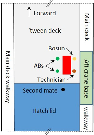
Figure 1: Positions of the crew
Source: Australian Transport Safety Bureau (ATSB)
At 0630, after a tool box talk,[3] the crew started the work. Working with the second mate on deck were two able-bodied seamen (AB) tasked with hooking up the packs of load spreaders. The boatswain (bosun), the ship’s technician and two Abs were on the ’tween deck (Figure 1), to position the packs and remove the sling hooks. All crew involved in the moving of the load spreaders had performed this task before and were familiar with the operation.
The second mate was operating the crane’s[4] 25 t auxiliary hook using a wireless remote control unit. The remote allowed him to move around the area to maintain a good line of sight while lifting from the deck, and to move to the edge of the hatch opening when lowering the packs.
By about 0900, two packs of load spreaders had been moved and the third pack had been lowered to the ’tween deck. The two ABs removed their hooks and left the chain slings hanging against the side of the pack. They then moved clear, towards the centre of the hold.
The technician was having difficulty removing the sling hook on his corner so the bosun went to assist him. Once the sling hook had been freed, they began walking forward between the load spreaders and the side of the hold. As they walked, the bosun signalled to the second mate to raise the hook.
When the technician and the bosun were about half way along the side of load spreaders, the two ABs saw the topmost load spreader lift up and start to slide off the top of the pack. They shouted warnings to the second mate and the two men, however, there was not enough time for either of the men to move clear and they were both struck by the load spreader as it slid towards them.
On the bridge, the chief mate heard the loud noise of the load spreader falling. As he made his way to the ’tween deck he called the second mate on the radio and asked what had happened. When he got closer, he heard the cries of the injured men. He called the master, advised that there had been an accident and that medical assistance was required. The master asked the ship’s agent, who was on board at the time, to arrange for medical assistance from ashore.
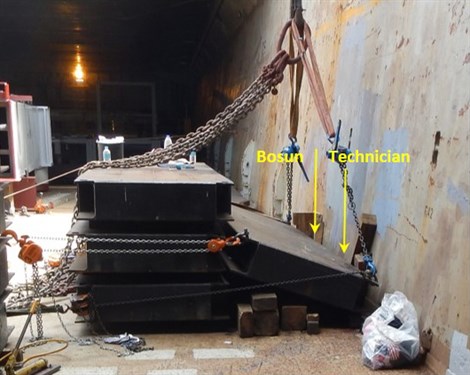
When the chief mate arrived at the accident site, he saw the bosun and the technician lying in awkward positions on top of the load spreader (Figure 2). The technician’s right leg was pinned under the load spreader and he had fractured both legs. The bosun was not trapped but had suffered fractures to his lower left leg. The chief mate updated the master as to the severity of the situation and began arranging first aid.
Figure 2: Fallen load spreader
Source: AMSA
At about 0910, the first paramedics from McConnell Dowell, the company constructing the wharf, arrived. Shortly afterwards, other emergency service personnel from McConnell Dowell, the Fire and Emergency Service and St John Ambulance arrived.
The injured men were freed by the ship’s crew with the assistance of shore personnel. Both were then stabilised and prepared for evacuation. At about 1005, the bosun was lifted ashore and taken to Port Hedland hospital. About 50 minutes later, the technician was lifted ashore and taken to the hospital.
Treatment for the leg fractures of both men required extensive orthopaedic surgery. The technician’s right leg had to be amputated below the knee and he also had a fractured pelvis.
On 24 February, both men were transferred to a hospital in Perth. They continued to receive medical treatment there until they were well enough to travel home.
ATSB comment
The crew’s usual practice was to lift the load spreaders as a pack of four by attaching the sling hooks to the bottom spreader. Timber was placed between each load spreader and the pack was not lashed or secured by any means as a single unit.
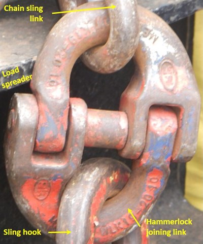
After releasing the chain hooks from the spreaders, the slings were left against the side of the pack. When raised, the chain hooks were dragged up the pack’s side. In this instance, the hammerlock link (Figure 3), used to attach the sling’s hook to the chain, probably caught on the lip of the topmost load spreader and lifted it to the point where it was able to slide sideways off the pack.
Figure 3: Hammerlock joining link
Source: AMSA
The crane’s auxiliary hook winch was fitted with a soft start/stop feature to avoid shock loads. Therefore, when the remote control’s lever was moved to the neutral position to stop the hook, it would take a few moments for the hook to slow and then stop. This feature meant the hook continued to lift the load spreader after the lever was placed in the stop position.
When the load spreader started sliding sideways, the bosun and technician were not clear of the pack. Further, their position between the pack and the side of the cargo hold restricted their ability to move away from the falling spreader.
Safety action
Whether or not the ATSB identifies safety issues in the course of an investigation, relevant organisations may proactively initiate safety action in order to reduce their safety risk. The ATSB has been advised of the following proactive safety action in response to this occurrence.
Spliethoff's Bevrachtingskantoor
Spliethoff's Bevrachtingskantoor, Happy Buccaneer’s managers, advised that they have taken the following action to avoid a similar accident:
Additional (simulator) training and instruction will be given to crane operators with emphasis on:
Hook speed during simultaneous crane movements, and that the crane shall not be moved until there has been clear communications by hand, radio or other method.
Crane operators, banksmen (dogmen) and assisting crew should be aware of each other’s location and movement of suspended loads.
Rigging gear shall be guided until it is free of obstacles and equipment should be made safe for lifting prior to the lift.
Lifts, formed of multiple loose items, will be combined and secured to form a single unit prior to lifting.
Safety message
Other than unintended falling / dropping, there are numerous other hazards associated with suspended load operations. Some of those hazards continue posing a serious injury risk even after the load is landed. Risks can be particularly high when the load comprises a number of unsecured components that can move as individual units. Lifting and handling procedures and practices should anticipate the hazards (through risk assessment) and be planned to minimise the associated risks.
The ATSB SafetyWatch program highlights the broad safety concerns that come from investigation findings and from the occurrence data reported by industry. Marine work practices are one of those safety concerns.
Purpose of safety investigations
The objective of a safety investigation is to enhance transport safety. This is done through:
identifying safety issues and facilitating safety action to address those issues
providing information about occurrences and their associated safety factors to facilitate learning within the transport industry.
It is not a function of the ATSB to apportion blame or provide a means for determining liability. At the same time, an investigation report must include factual material of sufficient weight to support the analysis and findings. At all times the ATSB endeavours to balance the use of material that could imply adverse comment with the need to properly explain what happened, and why, in a fair and unbiased manner. The ATSB does not investigate for the purpose of taking administrative, regulatory or criminal action.
Terminology
An explanation of terminology used in ATSB investigation reports is available here. This includes terms such as occurrence, contributing factor, other factor that increased risk, and safety issue.
Publishing information
Released in accordance with section 25 of the Transport Safety Investigation Act 2003
Ownership of intellectual property rights in this publication
Unless otherwise noted, copyright (and any other intellectual property rights, if any) in this report publication is owned by the Commonwealth of Australia.
Creative Commons licence
With the exception of the Coat of Arms, ATSB logo, and photos and graphics in which a third party holds copyright, this publication is licensed under a Creative Commons Attribution 3.0 Australia licence.
Creative Commons Attribution 3.0 Australia Licence is a standard form licence agreement that allows you to copy, distribute, transmit and adapt this publication provided that you attribute the work.
The ATSB’s preference is that you attribute this publication (and any material sourced from it) using the following wording: Source: Australian Transport Safety Bureau
Copyright in material obtained from other agencies, private individuals or organisations, belongs to those agencies, individuals or organisations. Where you wish to use their material, you will need to contact them directly.
[1] For placing under very heavy loads, the steel load spreaders measured 4.0 x 1.2 x 0.3 m and weighed 2.4 t.
[2] A ’tween deck is a fixed or moveable deck between the hold floor and the hatch cover.
[3] A safety focussed discussion, undertaken by a work team before starting work, to cover key elements of the task and the risks involved.
[4] A Huisman-Itrec, 700 t heavy lift, mast crane, which does not have an operator’s cabin.
On 28 December 2014, an Indonesia Air Asia Airbus A320 aircraft, registered PK-AXC, was conducting a regular public transport flight from Juanda International Airport, Surabaya to Changi International Airport, Singapore. Radar contact with the aircraft was lost while it was en route over the Karimata Strait, Indonesia. The aircraft impacted into water shortly after radar contact was lost. During the search and rescue operation, items of wreckage were found floating about 30 NM southeast of the aircraft’s last known radar position.
The National Transportation Safety Commission of Indonesia (NTSC) is the agency responsible for investigating this occurrence. The NTSC requested the ATSB to provide a flight recorder specialist to assist in the download and analysis of the flight recorders from the aircraft. The ATSB provided this assistance as part of the Australian Government Indonesia Transport Safety Assistance Package (ITSAP).
In accordance with clause 5.23 of Annex 13 to the Convention on International Civil Aviation (ICAO Annex 13), the ATSB appointed an Accredited Representative to assist the NTSC and initiated an investigation under the Australian Transport Safety Investigation Act 2003.
On 1 December 2015, the NTSC published the final report into this investigation.
The National Transport Safety Committee of Indonesia is responsible for releasing the investigation report.
National Transportation Safety Committee Ministry Of Transportation Republic Of Indonesia Transportation Building 3rd Floor Jalan Medan Merdeka Timur No. 5 Jakarta Pusat 10110 Indonesia
On 16 February 2015, track maintenance was being conducted at Montgomery between Sale and Bairnsdale. To allow a passenger train to pass through the section, the maintenance gang cleared the track and track protection was lifted. However, when the gang vacated the line, an item of equipment was left on the track.
As the V/Line passenger train approached the work site, the driver saw the obstruction. In response, the driver made an emergency brake application but was unable to bring the train to a stand before it collided with the equipment. The train remained on the track and there were no injuries to passengers or rail personnel.
What the ATSB found
The ATSB found that an item of maintenance equipment had been moved along the track away from the immediate area of works. Subsequently, this equipment was overlooked when the track was cleared of workers and other tools.
The task of ensuring that the line was clear had cascaded to a third party within the maintenance gang. There was no formal system in place to manage this process of informal delegation.
What's been done as a result
As a result of this and other related Safeworking incidents V/Line has advised that a Safety Review of infrastructure rules, procedures and training has been implemented.
Safety message
Track maintenance personnel should be particularly vigilant to ensure that no obstruction remains on the line when authorising the passage of a train through a work site.
Network managers should ensure that systems and processes minimise the potential for maintenance equipment to be left on track.
The occurrence
On 16 February 2015, track works were planned for Montgomery, about 7 km from Sale. The works involved sleeper renewal and excavation works at a level crossing. To facilitate the site excavation works, a Hi-Rail excavator was required, and this was to travel on-track from Sale.
To protect the movement of this Hi-Rail excavator from Sale to the work site, and the on-track activities of the maintenance gang, the Signaller at Sale issued a Track Warrant at 0705. The Track Warrant meant that trains were prevented from entering this section of track.
Those involved in the works included:
the Protection Officer, a contractor responsible for safe working and the holder of the Track Warrant
a Ganger-In-Charge, a V/Line employee responsible for the site works
a V/Line Ganger performing the role of a Leading Hand
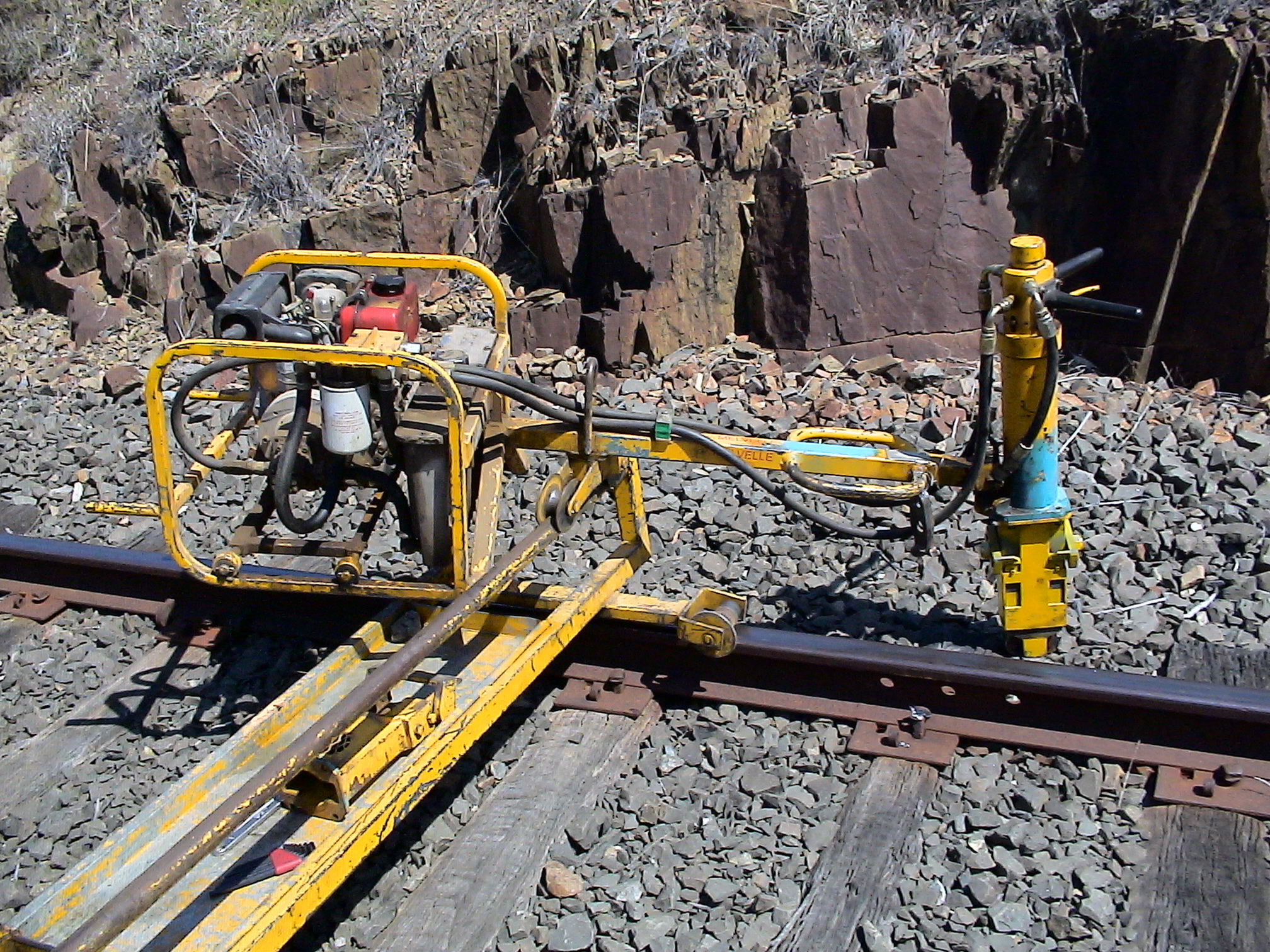
As part of the maintenance works, hand and light mechanical tools were being used. One of the tools was a dog spike puller (Figure 1). At some point, when it was not being used, the dog spike puller was moved along the track, about 20 m away from the work area, and left unattended.
Figure 1: A dog spike puller similar to that used at Montgomery
Source: Melvelle Equipment Corp
The Melbourne to Bairnsdale passenger service 8403 was scheduled to depart Sale at 1020. To allow this train through the work site, the Track Warrant would need to be returned at least 20 minutes prior to its departure. To facilitate the return of the Warrant, the Protection Officer drove the 15 minutes back to the signal office at Sale Railway Station to arrive before 1000.
At the worksite, the gang stopped work at about 0955 and off-tracked in preparation for the returning of the Warrant and the passage of the train. In clearing the track, the gang overlooked the dog spike puller.
When the gang had off-tracked, the ‘Leading Hand’ of the gang gave the Ganger-In-Charge an ‘okay’ hand signal. This signal indicated that he believed the track was clear and that the Protection Officer could return the Track Warrant to the Signaller at Sale.
Using his mobile phone, the Ganger-in-Charge communicated the clear track to the Protection Officer, who was with the Signaller in Sale. As a result, the Track Warrant was returned at 1000. This released the section for train operations.
At the work site, the gang had commenced morning break and remained off track.
Train 8403 departed Sale at 1027. It consisted of an N class locomotive and five cars, with 120 passengers on board.
The train was approaching the work site at about 98 km/h. The locomotive driver noticed an obstruction on the line and in response made a full service brake application, followed shortly after by an Emergency application. He also sounded the air horn to attract the attention of the gang, although they thought it was sounded as a greeting.
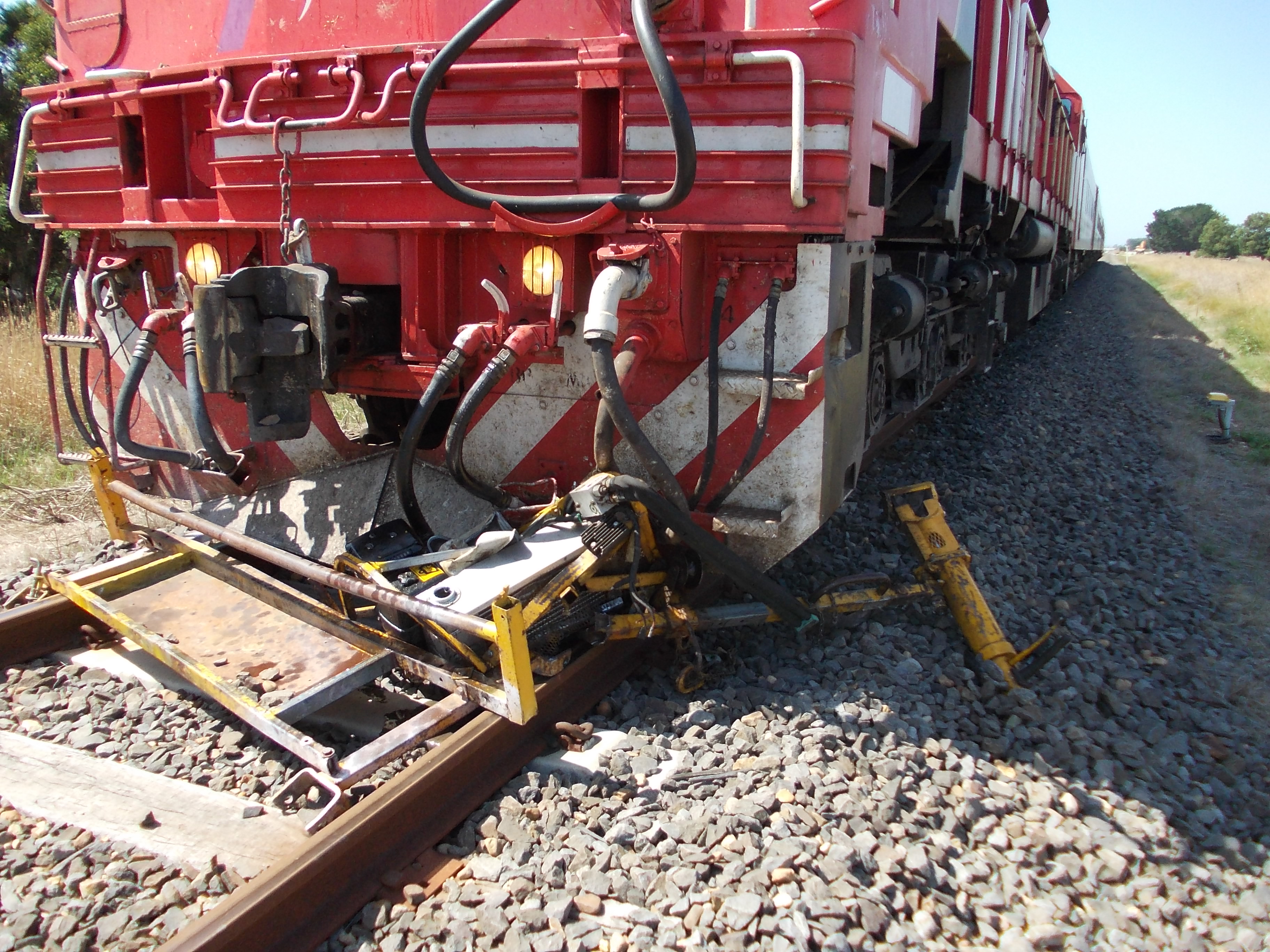
The train could not stop in time to prevent the collision with the dog spike puller that had been left on the track. The equipment was pushed along the track by the locomotive and train 8403 came to a stop at 1033, about 380 m past the crossing.
Figure 2: Destroyed dog spike puller under the cow catcher of locomotive N452
Source: V/Line Pty Ltd
The rail service was terminated and passengers completed their journeys by bus replacement.
Context
Safeworking system
The line between Sale and Bairnsdale was a single line. It was one of a small number of lines in Victoria that still operated under the Train Staff and Ticket Safeworking system. This system uses a Staff as the authority for trains to travel or occupy the line between two locations. There is only one Staff for each section and it is physically transferred to the crew of the train that is authorised to use the section. The purpose of this Safeworking system is to prevent more than one train occupying a single line section between locations at any one time.
Track Force Protection
Requirements
Protection for workers must be provided before work can be carried out on a rail line. This protection can take several forms dependent on the activity. Protection can range from local hand signalling protection to manage through traffic, to a Track Warrant where trains are excluded from the section.
In this instance, a Track Warrant was the form of protection used. This protection covered both the movement of the Hi-Rail excavator from Sale and the maintenance activities of the gang at the work site.
A Track Warrant is the authority for infrastructure work activities. It can be issued by either a Train Controller or a Signaller to the Supervisor or Person in Charge of the work site as authority to foul the line. Track Warrants may be issued for infrastructure maintenance activities where one or more track vehicles or track machines are to be used.
On the Train Staff and Ticket Safeworking system, whenever a Track Warrant is issued for track force protection, the Staff for the section must also be handed to the holder of the Track Warrant. In this instance, the Protection Officer for the maintenance works held the Staff while the Warrant was in place.
Before returning a Track Warrant, the rules required the person holding the Track Warrant to ensure that the line was clear. Another requirement was that a Track Warrant was to be returned at least 20 minutes prior to the scheduled arrival time of a train that was to enter the affected section of line.
Personnel qualifications
The Protection Officer, Ganger-In-Charge and the Ganger acting as ‘Leading Hand’ all held Train Track Co-ordinator Level 3 competencies. These qualifications allowed them to institute and manage Track Force Protection arrangements and they were all aware of the requirement to ensure the track was clear before returning a Track Warrant.
Local contracting arrangements
Contractors are often used to perform the Safeworking role of providing track force protection. This was the situation in this instance, with the Protection Officer a contractor. This freed up the V/Line Ganger-In-Charge to supervise work site activities.
Safety analysis
Clearing track of equipment
It was known by all key parties that the track was to be cleared prior to the return of the Track Warrant at 1000 for the passage of a train. However, when clearing the site in preparation for the return of the Warrant, the dog spike puller was overlooked.
The dog spike puller had been moved away from the direct area of works and left unattended. It is probable that this led to the lead Ganger overlooking that it was still on the track.
The Ganger-In-Charge was occupied with other tasks and his view of the track was restricted by trucks parked near the track. He accepted the ‘okay’ signal from the Ganger acting as ‘Leading Hand’ that the track was clear. This confirmation of a clear track was then relayed by mobile phone to the Protection Officer who was offsite.
Safeworking systems and processes
Use of Track Warrant protection
The decision to protect both the Hi-Rail on-track movement to the worksite and the gang’s worksite activities with a Track Warrant was consistent with the provisions of the Book of Rules and Operating Procedures 1994. However, because of the Train Staff and Ticket Safeworking system on this line, use of a Track Warrant introduced the requirement for the Protection Officer to travel to Sale.
Return of Track Warrant and Staff
The requirements of the Train Staff and Ticket Safeworking system meant that the Protection Officer needed to return the Warrant and Staff to Sale before 1000 to allow the passage of the next train. To meet his obligations to ensure the line was clear, the Protection Officer adopted an informal process to inform himself of the condition of the line prior to returning the Track Warrant and Staff.
This practice of Protection Officers leaving a worksite on the Train Staff and Ticket system, prior to the line being clear, was an accepted practice. This practice allowed works to continue while the Protection Officer was in transit to the Signaller, and so enhanced productivity.
Informal delegation of task of ensuring track was clear
The Protection Officer was now relying on receiving a message that the line was clear from the Ganger-In-Charge. Instead of ascertaining the condition of the line themselves, the Protection Officer had informally delegated this task.
At the worksite, there was a further cascading of this task. To focus on other duties, the Ganger-In-Charge had passed immediate work-site supervision to another employee, the Ganger acting as ‘Leading Hand’. This included the responsibility of overseeing the off-tracking of the gang and their equipment prior to the passage of train 8403.
The cascading of this task was informal and there was no defined delegation of roles. All those involved were capable of undertaking the task. However, the task focus may have been diminished through the delegation. In any case, the cascading of this role probably heightened the potential for individual error.
Findings
From the evidence available, the following findings are made with respect to the collision between Passenger train 8403 and maintenance equipment at Montgomery, Victoria on 16 February 2015. These findings should not be read as apportioning blame or liability to any particular organisation or individual.
Safety issues, or system problems, are highlighted in bold to emphasise their importance. A safety issue is an event or condition that increases safety risk and (a) can reasonably be regarded as having the potential to adversely affect the safety of future operations, and (b) is a characteristic of an organisation or a system, rather than a characteristic of a specific individual, or characteristic of an operating environment at a specific point in time.
Contributing factor
The dog spike puller was overlooked when the maintenance gang cleared the track to permit the passage of train 8403. As a result, the line was obstructed and the dog spike puller was impacted by the train.
Other factor that increased risk
There were no formal systems in place to manage the accepted practice of Protection Officers leaving a work site to return a Track Warrant and Train Staff, prior to ceasing works, off-tracking and ensuring the line was clear. This practice led to the informal delegation of responsibility for ensuring the track was clear to others at the work site. [Safety issue]
Safety issues and actions
The safety issues identified during this investigation are listed in the Findings and Safety issues and actions sections of this report. The Australian Transport Safety Bureau (ATSB) expects that all safety issues identified by the investigation should be addressed by the relevant organisation(s). In addressing those issues, the ATSB prefers to encourage relevant organisation(s) to proactively initiate safety action, rather than to issue formal safety recommendations or safety advisory notices.
Depending on the level of risk of the safety issue, the extent of corrective action taken by the relevant organisation, or the desirability of directing a broad safety message to the rail industry, the ATSB may issue safety recommendations or safety advisory notices as part of the final report.
Safeworking systems and processes
There were no formal systems in place to manage the accepted practice of Protection Officers leaving a work site to return a Track Warrant and Train Staff, prior to ceasing works, off-tracking and ensuring the line was clear. This practice led to the informal delegation of responsibility for ensuring the track was clear to others at the work site.
The sources of information during the investigation included:
The Protection Officer
The Ganger-In-Charge
The Ganger (Leading Hand)
V/Line Pty Ltd
Skilled Rail Services.
Reference
Book of Rules and Operating Procedures 1994.
Submissions
Under Part 4, Division 2 (Investigation Reports), Section 26 of the Transport Safety Investigation Act 2003 (the Act), the Australian Transport Safety Bureau (ATSB) may provide a draft report, on a confidential basis, to any person whom the ATSB considers appropriate. Section 26 (1) (a) of the Act allows a person receiving a draft report to make submissions to the ATSB about the draft report.
A draft of this report was provided to the Protection Officer, Ganger-In-Charge, Ganger, V/Line Pty Ltd, and Skilled Rail Services. Submissions were reviewed and where considered appropriate, the text of the draft report was amended accordingly.
Purpose of safety investigations
The objective of a safety investigation is to enhance transport safety. This is done through:
identifying safety issues and facilitating safety action to address those issues
providing information about occurrences and their associated safety factors to facilitate learning within the transport industry.
It is not a function of the ATSB to apportion blame or provide a means for determining liability. At the same time, an investigation report must include factual material of sufficient weight to support the analysis and findings. At all times the ATSB endeavours to balance the use of material that could imply adverse comment with the need to properly explain what happened, and why, in a fair and unbiased manner. The ATSB does not investigate for the purpose of taking administrative, regulatory or criminal action.
Terminology
An explanation of terminology used in ATSB investigation reports is available here. This includes terms such as occurrence, contributing factor, other factor that increased risk, and safety issue.
Publishing information
Released in accordance with section 25 of the Transport Safety Investigation Act 2003
Ownership of intellectual property rights in this publication
Unless otherwise noted, copyright (and any other intellectual property rights, if any) in this report publication is owned by the Commonwealth of Australia.
Creative Commons licence
With the exception of the Coat of Arms, ATSB logo, and photos and graphics in which a third party holds copyright, this publication is licensed under a Creative Commons Attribution 3.0 Australia licence.
Creative Commons Attribution 3.0 Australia Licence is a standard form licence agreement that allows you to copy, distribute, transmit and adapt this publication provided that you attribute the work.
The ATSB’s preference is that you attribute this publication (and any material sourced from it) using the following wording: Source: Australian Transport Safety Bureau
Copyright in material obtained from other agencies, private individuals or organisations, belongs to those agencies, individuals or organisations. Where you wish to use their material, you will need to contact them directly.
On 11 February 2015, an Airbus A320 aircraft, registered VH‑VND and operated by Tiger Airways, was conducting a scheduled passenger service from Hobart Airport, Tasmania to Melbourne Airport, Victoria.
At about 1750 Eastern Daylight-saving Time, about 9 NM (17 km) north of Melbourne Airport, and after the flight crew had been cleared by air traffic control to conduct a visual approach, the aircraft descended below the minimum safe altitude, though the aircraft remained in controlled airspace.
During the descent, both flight crew became pre-occupied with other tasks inside the flight deck, which had the effect of increasing their workload and distracting them from monitoring the aircraft’s flight path and altitude. About two minutes after commencing descent on the visual approach, the flight crew levelled the aircraft after realising that it appeared to be low on profile. A safety alert issued by air traffic control soon followed, where in response, the aircraft was climbed to intercept the recommended visual approach descent profile. The remainder of the flight was uneventful and the aircraft landed on runway 16 at Melbourne Airport.
What the ATSB found
The ATSB found that after being vectored off the expected pre-planned shortened arrival route, and then cleared for a visual approach, a combination of increased workload and distraction diverted the flight crew’s attention from monitoring the aircraft’s descent. During the descent, the captain elected to intercept the final approach course by entering a radial intercept waypoint into the aircraft’s auto-flight system, which differed from the first officer’s more familiar plan to conduct a localiser intercept. This had the effect of diverting both crew members’ attention to inside the flight deck, as they discussed and demonstrated the intercept and resulting flight mode reversions. The aircraft continued to descend below the normal approach profile and entered the 500 ft vertical buffer at the base of the control area step. This reduced separation with terrain and any aircraft operating outside controlled airspace.
The flight crew’s mental model of the approach was not consistent with the actual flight path of the aircraft. This affected their ability to fly a normal descent profile and remain within the required control area step.
The flight crew miscalculated and did not adequately communicate the aircraft’s descent from 3,000 ft during the conduct of a visual approach. This limited their awareness of the descent rate and the below-profile altitude of the aircraft during a critical phase of flight.
Safety message
Flight crew should be mindful that during higher workload phases of flight, such as during approach and landing, introducing tasks that divert both flight crew members’ attention from monitoring the aircraft’s flight profile and altitude should be minimised. Further, if tasks that bring attention into the flight deck are required to be completed during a visual approach, pilots must ensure that at least one pilot monitors the aircraft’s flight path profile and energy state. Setting an appropriate lower altitude limit may be an effective risk control to alert flight crew and/or prevent the aircraft’s descent below a desired altitude. Communication and confirmation of any changes to the aircraft’s flight modes are also important during this period.
The occurrence
On 11 February 2015, an Airbus A320 aircraft, registered VH-VND (VND) and operated by Tiger Airways Australia Pty. Ltd. (Tigerair), was operating a scheduled passenger service from Hobart Airport, Tasmania to Melbourne Airport, Victoria. The flight, including departure and climb from Hobart, was uneventful until shortly prior to the commencement of descent into Melbourne.
Descent preparation and descent from flight level 360
At about 1710 Eastern Daylight-saving Time,[1] and prior to commencing the descent, the flight crew were issued a clearance from air traffic control (ATC) to conduct a WAREN EIGHT ALPHA standard arrival route (STAR) for runway 16[2](see Appendix A). In preparation for the arrival, the first officer, who was pilot flying (PF),[3] entered the STAR into the aircraft’s auto-flight system.
After completing other normal pre‑descent flight deck preparation, the flight crew recalled that they conducted an approach and landing briefing, which included a review of the prescribed arrival route and any potential flight restrictions including controlled airspace limits and terrain along the intended flight path. Following the briefing, ATC advised the flight crew that they could expect track shortening. The PF sought clarification about the expected track shortening, to which ATC responded to expect ‘SANDR direct ROCKDALE approximately’ (see Appendix A). ATC also advised the arrival was to be flown at maximum speed and that any STAR speed restrictions were cancelled.
The PF reported amending the previously entered active flight plan to reflect the expected vectoring. The PF stated that a more accurate computed descent profile would be displayed by having the expected track shortening and the associated instrument approach as the active flight plan. At that time, they also selected the complete STAR as the secondary flight plan.
The PF recalled reviewing the controlled airspace limitations along the modified flight planned route. This revealed that the programmed altitude limitations along the flight path would maintain the aircraft within the limits of the controlled airspace steps. The captain reported that as the area along the expected track-shortened route was familiar, the control steps for the arrival along that route were not fully briefed.
After the descent preparations were complete, the PF commanded the aircraft’s auto-flight system to descend the aircraft from flight level (FL) 360[4] to FL 250 using a managed descent flight mode. In this mode, the aircraft followed a pre-computed profile that allowed for aircraft deceleration and airspace restrictions along the active flight planned route.
Upon commencing the descent, ATC re-cleared the flight crew to descend and maintain 9,000 ft and to expect a left circuit for runway 16. To assist the flight crew with descent planning, ATC advised the flight crew that they had 46 track miles remaining to the runway.
After being cleared by ATC for further descent, the flight crew descended to 5,000 ft and advised that they were maintaining that altitude and reported visual.[5] ATC followed with a stepped descent clearance to 3,000 ft and provided information to the flight crew that they would be vectored for a turn onto base leg of the circuit in 3 NM (6 km).
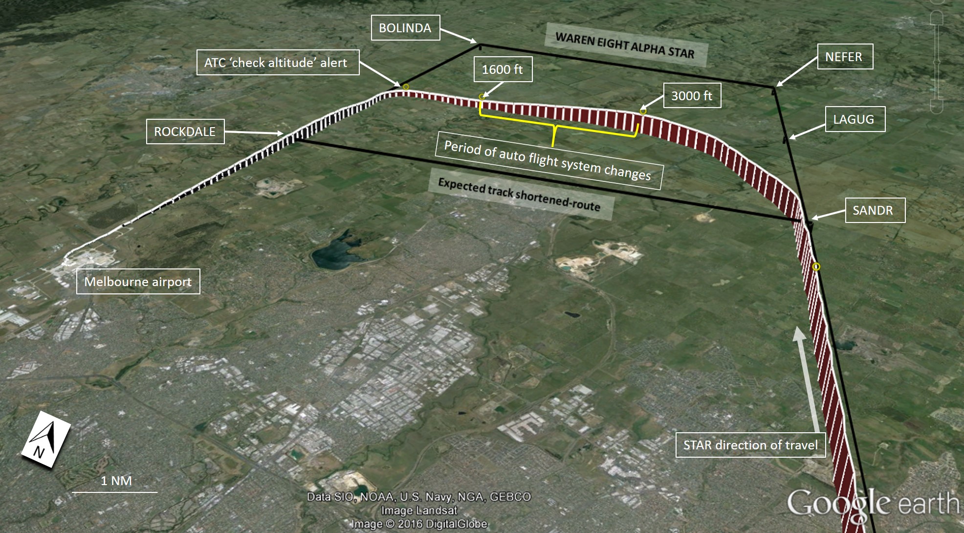
At 1748, which coincided with the aircraft being located at about the SANDR waypoint, ATC advised the flight crew that the STAR was cancelled and to turn left onto a heading of 290°M (Figure 1). To comply with ATC heading and descent instructions, the flight crew used the aircraft’s heading and vertical speed/flight path angle (V/S FPA) mode selectors, both located on the aircraft’s Flight Control Unit (FCU). The use of the aircraft’s selected modes allowed the flight crew to vary the aircraft’s lateral track and descent manually.
Figure 1: Recorded flight route of VH-VND showing approximate period where flight plan modification and mode changes were conducted
Source: Google Earth modified by ATSB
About one minute after turning onto a heading of 290°, ATC instructed the flight crew to turn further left onto a heading of 260°. While on that heading, ATC advised the flight crew that they were 6 NM (11 km) to the left of the runway 16 centreline and requested the flight crew to report the runway in sight.
At about 1749, the flight crew reported being visual with the runway. At 1749:46 ATC instructed them to turn further left onto a heading of 240° to intercept final, and cleared them to conduct a visual approach[6] for runway 16. The flight crew were also instructed to change radio frequency and to contact Melbourne tower when established on final approach.
The captain reported inputting a radial intercept waypoint into the aircraft’s auto-flight system after being cleared to conduct the visual approach. This method of intercepting the localiser using a radial intercept waypoint was preferred as it provided more accurate tracking guidance. The method of inserting a radial intercept waypoint was a valid procedure highlighted in the operator’s flight crew operating manual (FCOM) for conducting an intercept (see the section titled Approach procedures) during a visual approach.
Visual approach from 3,000 ft
At 1749:51, the PF armed the approach mode (APPR)[7] and engaged both autopilots, as the intent was to conduct a visual approach with an intercept of the instrument landing system (ILS) from the current heading. The PF also set a missed approach altitude of 4,000 ft in the altitude select window on the FCU, which was in accordance with the altitude setting requirements for the conduct of a visual approach in the Tigerair operations manual part B.
At 1749:54, when the aircraft was about 5 NM (9 km) from the extended runway centreline or about 10 NM (18 km) in a direct line from the runway, the PF commanded the aircraft to descend from 3,000 ft by using the vertical speed (V/S) mode. The captain reported being aware that the V/S mode was being used, but unaware of the descent rate that followed.
The flight crew made a number of selections on the FCU and aircraft configuration changes in the period from 1749:55 to 1751:15. At 1750:17, the ILS approach mode (ILS) disarmed and the lateral flight mode changed to the navigation (NAV) mode. This was likely the result of the flight crew selecting a direct to command in the auto-flight system after the ILS had already been armed. This initiated a series of automatic flight mode reversions.
The period of time for which both flight crew reportedly went ‘heads in’ (that is, both pilots had their attention inside the cockpit) the flight deck to program and discuss the radial intercept, flight mode reversions and auto-flight system changes was uncertain, but likely occurred from 1750:25 to 1751:14.
After the incident, the captain reported that by conducting the radial waypoint inbound intercept, the PF needed to go ‘heads in’ to confirm the new flight plan entry, which was probably not ideal for that phase of flight. The PF perceived this period was already one of high workload. Table 1 highlights the key events during that time.
Table 1: Relevant recorded flight data from VH-VND after the flight crew commenced the visual approach from 3,000 ft
Time
Pressure altitude (ft)
(QNH corrected)
Selected vertical speed changes
Glideslope deviation (see operational information)
Localiser deviation
Aircraft configuration
Relevant flight mode changes and selections
1749:51
3050
Heading (HDG), Localiser (LOC) armed
1749:54
3040
-1000 ft/min
2.2 dots high
3.4 dots left
V/S
1750:02
3000
-1400 ft/min
1.7 dots high
Flap 1
1750:08
3040
Gear down
1750:17
2770
NAV armed
1750:25
2610
LOC armed
1750:30
2510
-1300 ft/min
1.1 dots high
1750:36
2420
Flap 2
1750:41
2270
-1400 ft/min
ON SLOPE
3.2 dots left
1750:44
2220
-1300 ft/min
0.3 dots low
HDG
1750:52
2040
-1200 ft/min
0.9 dots low
3.2 dots left
1750:55
1960
-1000 ft/min
0.8 dots low
3.2 dots left
1751:00
1860
-800 ft/min
1.1 dots low
3.1 dots left
1751:03
1810
NAV armed
1751:14
1650
3.3 dots low
3.4 dots left
Flap 3
1751:15
1640
0 ft/min
3.6 dots low
3.4 dots left
V/S pushed to level off
1751:44
1600
3.2 dots low
1751:51
1610
0 ft/min
4.8 dots low
3.8 dots left
NAV
1752:23
1630
+1000 ft/min
5.1 dots low
ON LOC
V/S
1752:31
1650
LOC armed
1752:35
1650
4.7 dots low
ON LOC
LOC capture
1752:45
1860
LOC
1753:23
2000
ON SLOPE
ON LOC
G/S / LOC
Source: Operator quick access recorder (QAR) data modified by the ATSB
At 1751:15, about 1 minute and 21 seconds after commencing descent from 3,000 ft, the captain reportedly pressed the V/S push-button on the FCU to level the aircraft. The captain reported observing the aircraft’s flight profile at that time being ‘a bit low’, and was more consistent with the expected runway intercept altitude from a track-shortened SANDR direct to ROCKDALE (ROC) route. At 1751:24, the flight crew established communication with Melbourne tower after changing to the tower frequency.
At 1751:42, the Melbourne approach controller became aware of the aircraft’s altitude of 1,600 ft and attempted to contact the flight crew. This attempt to alert the flight crew to the low altitude failed as the flight crew had changed to the tower frequency earlier than instructed. The approach controller then instructed the tower controller to alert the crew of the aircraft’s low altitude, which the tower controller did.
At 1751:59, the tower controller issued a safety alert[8] to the flight crew to check their altitude, as the aircraft was below profile altitude and had entered the 500 ft vertical buffer at the base of the control area (CTA) step, reducing separation with terrain and any aircraft operating outside controlled airspace.
At 17:52:23, the flight crew initiated a climb to 2,000 ft where the auto-flight system subsequently intercepted the ILS glide slope and made an uneventful landing.
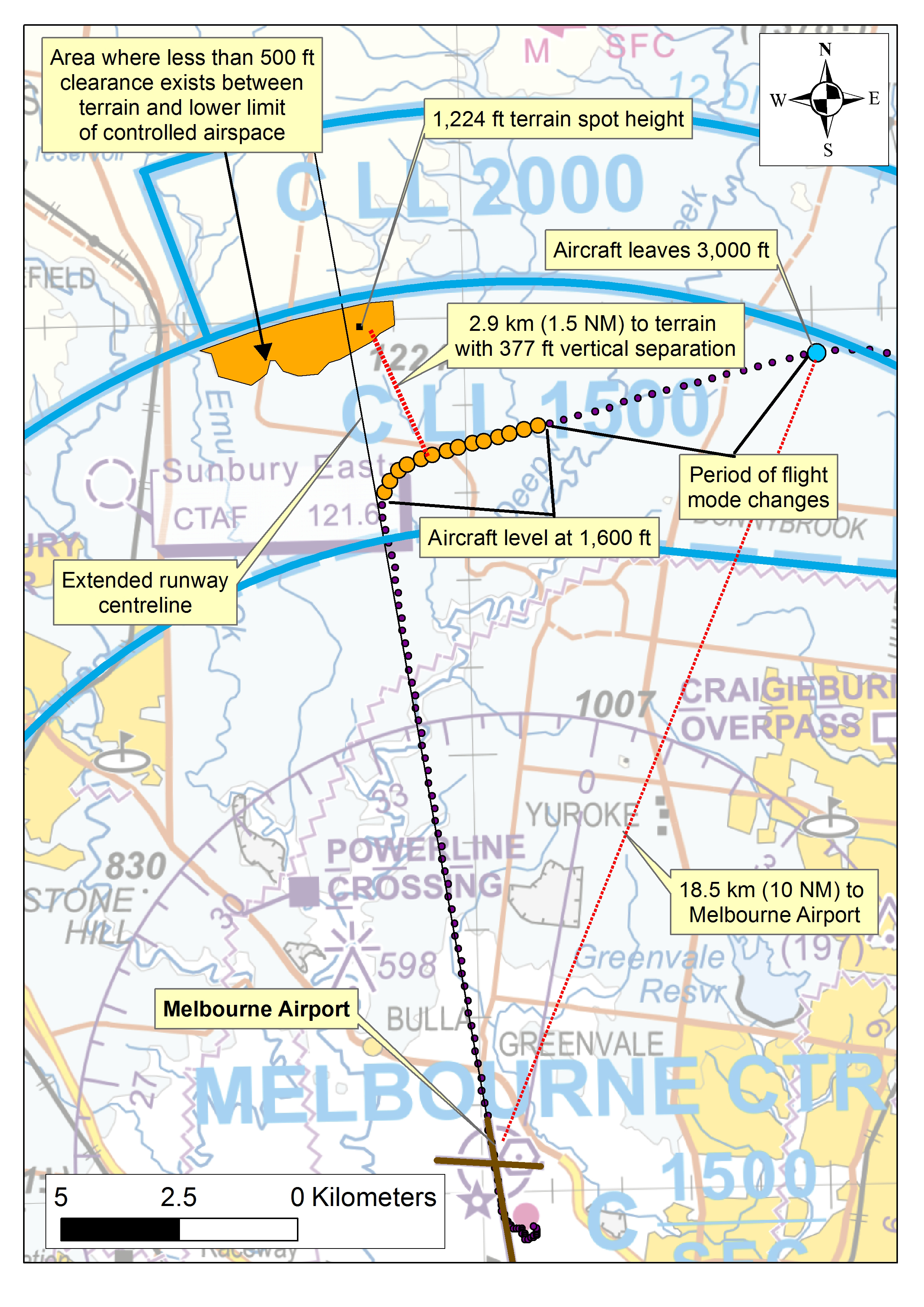
After landing, the captain contacted Melbourne Air Traffic Control to discuss the altitude safety alert. They advised that the aircraft had descended to 1,600 ft, which was below the required altitude for flight in that section of CTA. The minimum altitude in that section of CTA for aircraft that were not visual was 2,700 ft, and for aircraft that were visual, it was 2,000 ft as they were required to maintain a 500 ft buffer above the 1,500 ft CTA lower limit (Figure 2).
Figure 2: Flight pathand altitude of VH-VND(black and orange dots) relative to the controlled area steps and terrain during the visual approach to Melbourne Airport
The captain held an Air Transport Pilot (Aeroplane) Licence and was appropriately qualified to conduct the flight. The captain:
had about 14,380 hours of aeronautical experience, of which approximately 4,280 hours were on the A320/A321
had about 7,800 hours total time in command
held a current Class 1 Aviation Medical Certificate
reported no recent or ongoing medical or personal issues.
Training
In 2013, the captain was certified as a ground instructor. This role was additional and separate to the captain’s usual activities as a line pilot. In fulfilling this role, the captain was responsible for the provision of specialist operational training as required by the head of checking and training. The ground instructor role differed from that of a line-training captain in that the duties did not pertain to in-flight training. Additional, role-specific training and competencies were required for a pilot to be endorsed as a line-training captain.
The captain had conducted a number of approaches for runway 16 at Melbourne Airport during initial and recurrent training assessments. The approaches were mainly instrument landing system (ILS) approaches, however a visual approach for runway 16 from a track-shortened route was conducted in 2014.
First officer
The first officer held an Air Transport Pilot (Aeroplane) Licence and was appropriately qualified to conduct the flight. The first officer:
had about 2,690 hours of aeronautical experience, of which approximately 250 hours were on the A320/A321
held a current Class 1 Aviation Medical Certificate
reported no recent or ongoing medical or personal issues.
Training
The first officer conducted line training on the A320 in 2014, which included conducting a number of ILS approaches for runway 16 at Melbourne Airport. Although there was no recorded evidence that a visual approach was made for runway 16 at Melbourne Airport from a track-shortened route or radar vectors, the pilot had conducted visual approaches into other major airports. The pilot completed the required training program and was approved to commence line-flying operations in January 2015.
Aircraft information
Auto-flight descent modes
Managed descent mode
Flight crew normally control the descent of an Airbus A320 using the aircraft’s auto-flight system in either managed descent mode, or a selected descent mode. With the managed descent mode engaged, the aircraft follows a descent profile computed by the Flight Management Guidance System (FMGS), based upon the flight plan and descent conditions entered by the crew. This mode is only available if the aircraft follows a programmed lateral navigation track (NAV). During descent in managed descent mode, the FMGS optimises the descent profile and ensures compliance with all programmed altitude constraints without crew intervention.
Selected (basic) descent modes
In a selected descent mode, the flight crew controls the aircraft descent by making appropriate selections on the Flight Control Unit (FCU). Selected descent modes include vertical speed (V/S), flight path angle (FPA), and open descent.
In V/S mode, the auto-flight system adjusts the aircraft pitch attitude to maintain a set vertical speed as selected by the crew on the FCU. The aircraft descends to the altitude selected by the crew on the FCU, disregarding any intervening FMGS-programmed altitude constraints. If an FCU altitude limit lower than the aircraft’s current altitude is not set, the auto-flight system will continue descending the aircraft at the commanded vertical speed until the flight crew intervene, or there is an Enhanced Ground Proximity Warning System (EGPWS) (see the section titled Enhanced Ground Proximity Warning System) terrain or aircraft configuration warning alerting the flight crew to intervene. Flight crews sometimes prefer to use V/S mode to initiate further descent from a captured altitude, or incrementally change the descent rate to regain a preferred flight path profile.
Approach mode
Pushing the approach mode (APPR) push-button illuminates the APPR switch light and arms the FMGS for localiser and glideslope capture and tracking. One of the aircraft’s very high frequency navigation (VHF NAV) receivers must be tuned to an ILS frequency before APPR mode can be engaged. Once armed, localiser (LOC) is displayed in blue in the roll mode column of the Flight Mode Annunciator (FMA) and, in the pitch mode column, glide slope (G/S) is displayed in blue to indicate that the APPR mode has been armed.
The localiser capture point is variable and depends on intercept angle and closure rate with the centreline. The glideslope capture point is also variable and depends on the closure rate. The APPR light remains illuminated after localiser and glideslope capture and LOC and G/S are displayed in green on the FMA as the active engaged modes. ILS identifier, approach track and ILS/distance measuring equipment (DME) distance are displayed on the Primary Flight Display (PFD) on the lower left, when both LOC and G/S are the active modes. The localiser and glideslope deviation scales are displayed when the localiser frequency is tuned and the ILS (labelled LS on VH-VND) is selected on the Electronic Flight and Information System (EFIS) control panel.
Descent indications
The aircraft’s descent progress relative to the FMGS-computed descent profile is displayed by a symbol adjacent to the altitude scale representing the aircraft’s vertical deviation. The symbol moves above the central position as the aircraft descends beneath the FMGS-computed profile, and below the central position as the aircraft deviates above the FMGS-computed descent profile. The vertical deviation symbol remains displayed on the PFD despite the ILS push-button being selected on the EFIS panel, until the aircraft captures the LOC and GS. Deviation from the FMGS computed descent profile is also presented as a digital value on the progress page of the multipurpose control and display unit (MCDU).
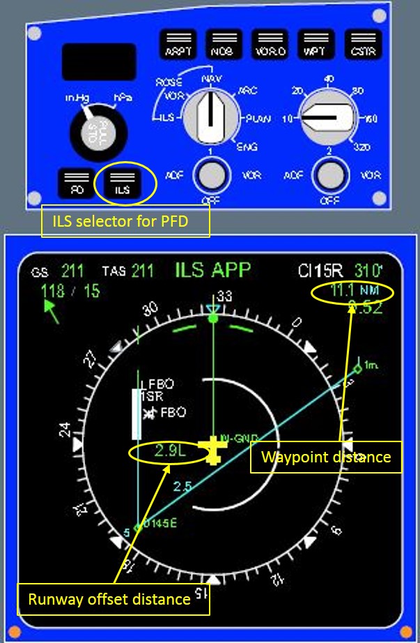
In this case, the vertical deviation indicator would have been inaccurate as the indications related to the current aircraft altitude relative to the pre-programmed track-shortened route. The track‑shortened route was the active flight plan during most of the visual approach. Other available sources of information to assist the flight crew with determining a more appropriate descent profile were limited, but included:
cross-referencing other data sources such as the DME displayed on the PFD
monitoring the glideslope indication when within range
referencing the runway offset distance displayed on the navigation display (ND)
using the range ring on the ND to determine the approximate runway intercept distance
requesting Air Traffic Control (ATC) for the derived radar distance to the runway from the current intercept heading
using the runway PAPI or T-VASIS guidance when within range.
Figure 3: Example of a navigation display (ND) with distance information and cross track error displayed
Source: Tigerair FCTM, modified by ATSB
Enhanced Ground Proximity Warning System
The aircraft was fitted with an EGPWS. The EGPWS considers a range of data and in-flight parameters, and provides a distinctive warning to flight crew if the aircraft enters a potentially hazardous position in relation to the earth’s surface. No EGPWS warnings were triggered during this occurrence.
Meteorological information
The flight crew reported that the weather conditions at the time of the incident did not adversely affect the ability to conduct the flight. The flight crew confirmed that visual conditions existed prior to leaving 3,000 ft for the visual approach.
Operational information
Navigation
Operation of the Instrument Landing System (ILS)
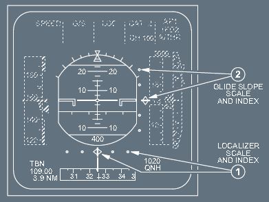
The ILS provides lateral and vertical position data necessary to align the aircraft with the runway for approach and landing. The system uses angular deviation signals from the glideslope antennas (located approximately 1,000 ft from the touchdown point on the runway) and the localiser antennas (located past the far end of the runway). The glideslope signals provide the angular deviation from the nominal glide path (usually 3°) and the aircraft’s auto-flight system generates fly-up or fly-down commands to enable the flight crew to track the glide path down to the touchdown point on the runway. Glideslope deviation is displayed on the PFD in units of dots, where one dot equates to 0.4° deviation from the glide path.
The localiser signals provide the angular deviation from the runway centreline and the autopilot generates fly-left or fly-right commands to track the centreline until the landing roll is completed. Localiser deviation is displayed on the PFD in units of dots where one dot equates to 0.8° deviation from the localiser.
Figure 4: Primary flight display showing an example of instrument landing system (ILS) scale indications
Source: Tigerair FCOM
Approach procedures
Standard Arrival Route (STAR) information
To program a STAR such as the WAREN EIGHT ALPHA arrival into the FMGS, the flight crew were required to select the appropriate arrival from the MCDU flight plan arrivals page. After selecting the arrival, a relevant approach such as the runway 16 ILS approach is selected and appended to the STAR. This inserted additional en route waypoints such as the final approach fix (FAF) to the flight plan and would later provide localiser and glideslope guidance when within the capture area. Manual selection of the ROCKDALE (ROC) Non-directional beacon (NDB) waypoint was required to amend the flight plan route to comply with ATC clearances and other enroute constraints, before briefing the arrival and the approach.
Selection of the full WAREN EIGHT ALPHA STAR included tracking to intercept the final approach path for runway 16 at a greater distance than the track-shortened route from SANDR to ROCKDALE. To intercept a 3° profile from the track-shortened route, the aircraft would intercept final approach at about 4 NM (7 km) from the runway at an altitude of about 1,680 ft.
In contrast to the track-shortened route, the calculated runway intercept distance if the flight crew maintained a heading of 240° after flying radar vectors to the north, was about 9 NM (17 km). The profile altitude required for a recommended 3° profile at that distance was about 3,500 ft.
Visual approach
The operator’s flight crew operating manual (FCOM) outlined the standard operating procedure for the conduct of a visual approach. It included general information about conducting the approach on a nominal 3° glideslope, using visual references. The method for conducting a visual approach included:
the autopilot is off
both flight directors are off
the use of flight path vector (‘the BIRD’)[9] is recommended
autothrust use is recommended with managed speed.
The flight crew training manual (FCTM) highlighted that, although the approach should be flown visually, having the cross-track error distance displayed on the ND provided the pilot with a visual cue as to the lateral position of the aircraft to the runway centreline. The cross-track error could be obtained by performing a direct to (DIR TO) radial inbound intercept on the last available waypoint (such as ROCKDALE or the ILS FAF) positioned on the extended runway centreline.
Although the FCTM recommended that the visual approach be conducted by amending the FMGS flight plan to include a radial inbound intercept, the company’s operations manual Part A stated that any flight path changes to the FMGS below 10,000 ft should be avoided where possible. Instead, it highlighted that using basic flight modes (selected modes) in the terminal area was preferred where a visual procedure could not be planned. This ensured that flight crew’s primary focus of attention was monitoring the aircraft’s flight path, the surrounding terrain, and potential aircraft conflicts, by having ‘two heads up’ at all times. Further, it was highlighted that flight crew must not rely solely on the FMGS, but should reference all applicable navigation aids to ensure safe navigation in the terminal area.
The missed approach altitude setting requirements for a visual approach was highlighted in the Tigerair operations manual Part B. It stated that for visual approaches, the missed approach altitude for the instrument missed approach procedure for the landing runway must be set.
Final approach course intercept
The FCTM highlighted to flight crew that, to ensure a smooth interception of the final approach course, the aircraft’s ground speed should be appropriate for the runway intercept angle and the distance remaining to the runway (Appendix B). In an attempt to ensure a smooth interception of the extended runway centreline, the Captain elected to input a radial inbound waypoint. The FCTM stated that where ATC provided radar vectors, the flight crew would use the direct to radial inbound (DIR TO RADIAL IN-BND) function. This would:
ensure proper flight plan sequencing
provide a comprehensive ND display
assist lateral interception
allow for the vertical deviation to be computed on reasonable distance assumptions.
When intercepting the final approach course using this method, the flight crew should correctly sequence the flight plan before pressing the approach push-button. If the localiser was armed or engaged before a DIR TO was actioned, the armed flight mode would revert to NAV, meaning that the localiser would have to be rearmed, which could increase workload. In this occurrence, the PF had pressed the approach push-button before the DIR TO was actioned.
Descent monitoring procedures
The operator’s procedures provided guidance regarding descent monitoring. This included the reference to appropriate pages on the MCDU and the use of vertical profile information on the PFD, where applicable. The descent procedure called for careful monitoring, including guidance that during non-precision approaches, appropriate distance/altitude checks will be called. This was of particular importance where an altitude/height versus range/fix was required.
FMA monitoring
The operator’s procedures required the pilot flying to ‘announce’ the FMA following the initiation of the descent, and for the pilot monitoring to confirm that annunciation. This required the pilot flying to state the auto-flight mode change annunciated on the FMA associated with the commencement of descent, and the pilot monitoring to check the annunciation and respond. Importantly, the effect of those changes on the flight path must be monitored on basic flight instruments associated with heading, speed, altitude, V/S and the like.
Other occurrences
The ATSB is aware of a number of occurrences on scheduled passenger transport flights where a flight crew have descended either below their normal flight path profile during a visual approach or below a minimum descent altitude while conducting an instrument approach. These involved different operators and different aircraft types to the occurrence involving VH-VND, but the fundamental nature of these occurrences is similar (see www.atsb.gov.au).
At 2019 Eastern Standard Time on 24 July 2011, a Thai Airways Boeing 777-3D7 aircraft, registered HS-TKD, was conducting a runway 34 VOR approach to Melbourne Airport, Victoria. During the approach, the tower controller observed that the aircraft was lower than required and asked the flight crew to check their altitude. The tower controller subsequently instructed the crew to conduct a go-around. However, while the crew did arrest the aircraft’s descent, there was a delay of about 50 seconds before they initiated the go-around and commenced a climb to the required altitude.
The ATSB established that the captain may not have fully understood some aspects of the aircraft’s automated flight control systems and probably experienced ‘automation surprise’ when the aircraft pitched up to capture the VOR[10] approach path. As a result, the remainder of the approach was conducted using the autopilot’s flight level change mode. In that mode, the aircraft’s rate of descent is unrestricted and therefore may be significantly higher than that required for an instrument approach. In addition, the flight crew inadvertently selected a lower than stipulated descent altitude, resulting in descent below the specified segment minimum safe altitude for that stage of the approach and the approach not being managed in accordance with the prescribed procedure.
On 16 July 2012 at about 0830 New Zealand Standard Time[11], an Airbus A320-232 aircraft, registered VH-VQA and operated by Jetstar Airways (Jetstar), was conducting an Area Navigation (Required Navigation Performance) approach to runway 05 at Queenstown, New Zealand. During the approach the aircraft descended below two segment minimum safe altitudes. Upon recognising the descent profile error, the crew climbed the aircraft to intercept the correct profile and continued the approach to land.
The ATSB found that, contrary to their intentions, the flight crew continued descent with the auto-flight system in open descent mode, which did not provide protection against infringing the instrument approach procedure’s segment minimum safe altitudes. The ATSB also found that the flight crew was not strictly adhering to Jetstar’s sterile flight deck procedures, which probably allowed them to become distracted.
The ATSB found that the Jetstar procedures did not specifically draw the flight crew’s attention to unchanged auto-flight system modes during descent or prompt crew reconsideration of the most suitable descent mode at any point during descent. Additionally, the Jetstar’s procedures allowed the crew to select the altitude to which they were cleared by air traffic control on the flight control unit altitude selector, irrespective of intervening altitude constraints. This combination of procedures provided limited protection against descent through segment minimum safe altitudes.
On 8 March 2013, the flight crew of a Qantas Airways Limited (Qantas) A330 aircraft, registered VH-EBV, was conducting a visual approach to Melbourne Airport, Victoria. The captain was the pilot flying with autopilot engaged.
Soon after being cleared for the approach, on descent through 3,000 ft, the captain set an altitude target of 1,000 ft in the auto-flight system and selected the landing gear down, the first stage of wing flap and 180 kt as the target speed. The descent was continued in auto-flight open descent mode and reached a maximum descent rate of 2,200 ft/min. As the aircraft was descending through about 1,800 ft, the first officer advised the captain that they were low. The captain reduced the rate of descent by selecting auto-flight vertical speed mode but a short time later the enhanced ground proximity warning system (EGPWS) provided ‘TERRAIN’ alerts followed by ‘PULL UP’ warnings. The crew carried out an EGPWS recovery manoeuvre and subsequently landed via an instrument approach.
At the time of the EGPWS alert, the aircraft had descended to 1,400 ft, which in that area was 600 ft above ground level, with 9 NM (17 km) to run to touchdown. This was 100 ft below the control area lower limit and 1,900 ft below a normal 3° descent profile.
While on approach to Melbourne, Victoria, a Jetstar Airways (Jetstar) Airbus A320 aircraft left 3,000 ft on descent, entering the 500 ft buffer above the lower limit of controlled airspace. When the aircraft passed 2,500 ft, the aircraft left controlled airspace. The aircraft again re-entered controlled airspace as it reached the airspace with a lower limit 1,500 ft, 11 NM south of Melbourne. The elapsed time from the point the aircraft left 3,000 ft to the point it re-entered controlled airspace was about 1 minute and 15 seconds. The aircraft was outside controlled airspace for about 45 seconds. There was no conflict with other known air traffic and the approach continued normally from 2,100 ft following intercept of the intended descent profile.
This incident highlighted the need for clear procedural guidance and careful auto-flight system management under conditions where the transition from a STAR to an instrument approach procedure is interrupted. Furthermore, under these conditions, awareness of the position of the aircraft relative to the intended vertical profile, relevant controlled airspace boundaries and lowest safe altitudes assumes elevated significance. The incident also highlights the importance of seeking clarification if an ATC instruction or clearance appears incomplete.
While conducting a visual approach into Melbourne Airport, Victoria on 11 February 2015, the flight crew of an Airbus A320 aircraft descended below the nominal 3° descent profile and entered the 500 ft vertical buffer at the base of the control area (CTA) step. This reduced separation with nearby terrain and with any aircraft operating outside controlled airspace. The flight crew were alerted to the aircraft’s low altitude by air traffic control after levelling the aircraft close to the lower limit of controlled airspace. The flight crew subsequently climbed the aircraft to regain a normal approach profile by capturing the Instrument Landing System (ILS) glide slope. The approach continued and an uneventful landing was made onto runway 16. This analysis will examine the factors that contributed to the abnormal descent, and review the risk controls as they apply to visual approaches.
Approach and descent management
Prior to descent, the flight crew were cleared by Air Traffic Control (ATC) to commence an arrival to Melbourne by flying the WAREN EIGHT ALPHA standard arrival route (STAR). The flight crew reported fully briefing the arrival and associated ILS approach, which included reviewing the arrival route, CTA steps and surrounding terrain. Soon after, however, the STAR clearance was amended to a track-shortened route which brought the final runway intercept closer, to about 4 NM (7 km) from the threshold, with an on-profile intercept altitude of about 1,680 ft. Although the flight crew did not fully re-brief the entire track-shortened route at that time, they reported reviewing any applicable restrictions/limitations and calculated the aircraft’s descent based on those requirements.
As the aircraft approached the SANDR waypoint, however, the flight crew were radar vectored to the north of the expected track-shortened route, which positioned the aircraft in an area that was unplanned by the flight crew. It also meant that there was little time to re-brief and review the surrounding terrain and to identify the higher CTA step that the aircraft was being vectored into. During the radar vectoring, ATC was responsible for terrain clearance and flight within controlled airspace; on completion of the vectors, however, ATC had instructed the flight crew to resume own navigation and that they were cleared for the visual approach. This transferred the responsibility for terrain clearance and flight within the CTA steps back to the crew. Despite ATC giving the flight crew a position fix from the extended runway centreline, it was likely that this information alone was insufficient, and the flight crew had lost awareness of the altitude that would be required to remain above the vertical buffer for the CTA steps.
To comply with the vectors north of the SANDR waypoint, the flight crew needed to revert to basic flight modes (selected modes) and forego the programmed altitude constraints that were active to limit the aircraft had it remained on the STAR. This meant that more onus was placed on the flight crew to adjust the aircraft’s vertical profile manually to ensure the aircraft remained on the desired 3° visual approach flight path profile. Further, the altitude protections set on the aircraft’s flight control unit (FCU) were removed when the missed approach altitude for the landing runway’s instrument approach was set as per procedures. As this was higher than the aircraft’s altitude, more attention was required from the flight crew to ensure the aircraft did not descend below the desired altitude.
Reverting to basic flight modes (selected modes) and deviating off the pre-programmed route also removed some of the information available to assist the flight crew in managing the aircraft’s vertical profile. The vertical deviation indicator, which was available if the ILS push-button on the EFIS was not selected, was only accurate if the aircraft was on, or close to, the programmed route.
The captain reported that an alternative method of using the ILS glideslope as a reference was useful, and recalled mentioning this to the first officer, who was the pilot flying (PF) during the approach. The captain observed that during the approach, the ILS glide slope indications were active and indicated that the aircraft was initially above the glide slope, which was consistent with their expectation. As a result, the flight crew probably considered the glide slope indications to be valid and useful for flight path guidance. It was therefore likely that when not focussed on the activities associated with reprogramming the Flight Management and Guidance System (FMGS) and demonstrating the radial intercept, which resulted in flight mode reversions, the PF used the glide slope for profile guidance. This probably resulted in the early descent from 3,000 ft during the visual approach, and the multiple V/S changes made by the PF in an attempt to capture the on-slope indications. Following a glide slope indication with more track miles to fly than the straight-line distance to the glideslope antenna would, with reference to the track miles to run, result in a shallower flight path than the nominal 3° profile. This required a reduced descent rate from what would normally be expected. In addition, the PF also became more distracted as the aircraft approached the on-slope indications and the aircraft continued to descend below profile. Reference by the crew to the other available cues before commencing descent for the visual approach would have increased the likelihood of the aircraft remaining at an appropriate profile altitude until the runway intercept.
Approach path profile
The method used by the flight crew to calculate the required descent point to achieve an optimal 3° profile was not effective, as the descent had commenced early given the aircraft’s actual versus intended position. Further, the PF was likely uncertain about the aircraft’s profile and relative position as it descended, as indicated by the number of VS changes made, the appropriateness of those changes, and that the aircraft continued to descend well below the nominal 3° visual approach profile. The time available and the PF’s capacity to calculate and re-assess the aircrafts position and descent was likely impeded by having:
to re-assess the relative position of the aircraft and its appropriate configuration
to perform the tasks associated with the role of PF
to divert their attention to observe the reprogramming of the FMGS
to observe the demonstration of the flight mode reversions
to complete the aircraft configuration and checklists in preparation for landing
a resulting increased workload.
The operations manual Part A recommendation was not to use FMGS or make flight plan changes in the terminal area but instead to use basic flight modes (selected modes) to conduct an intercept. This would have provided the flight crew the opportunity to prioritise their attention on more critical tasks associated with the final stages of the approach and ensured both crew were not focussed inside the flight deck at the same time. This was important as the conduct of a visual approach using selected flight modes put more onus on the flight crew for flight path management.
In addition to the increased attention required to maintain the flight path profile, the altitude setting procedure to set the missed approach altitude for the runway instrument approach removed the only altitude constraint that would automatically level the aircraft when using selected descent modes. Other alerts, however, such as the aircraft’s enhanced ground proximity warning system (EGPWS), would still have been available to alert the crew to a low altitude/terrain proximity as a final defence, in the event that the aircraft’s descent continued undetected.
Data entry and crew co-ordination
During the visual approach, it was likely that there was a degree of demonstration or instruction between the flight crew in relation to data inputting in relation to the radial intercept and mode awareness. Although it is possible the intention of the captain was to increase the first officer’s understanding of the auto-flight system and approach management, the captain was not approved as a line-training captain. It is also likely that the captain was required to explain the radial intercept to the first officer so the first officer could check the inputs made by the captain. It is therefore likely that, independent of an instructional focus, there was probably little consideration of the effect the instruction or explanation would have on the relatively inexperienced first officer’s workload or the ability of the flight crew to manage the aircraft’s descent during that phase of flight.
Distraction
Researchers (United Kingdom Civil Aviation Authority, 2013) have found that distraction has been a major factor affecting flight crew allocation of attention when monitoring breaks down. Humans are capable of attending to more than one task through the use of selective attention techniques, however they have limited total cognitive capacity. If one of the tasks consumes all the attentional capacity of a crew member, then task shedding will occur. Distraction has been found to have been instrumental in the breakdown of monitoring in major accident investigations[12]. In these instances, flight crew became distracted during an important phase of flight. This distraction resulted in a breakdown in monitoring and combined with the flight crew inappropriately managing their workload, this led to the loss of the pilot flying’s understanding of the state or position of the aircraft.
In the occurrence event, the captain’s decision to explain the process for programming the radial waypoint intercept to the PF meant that both flight crew diverted their attention away from other flight deck tasks. While this was necessary to ensure the data entered was accurate, this distraction resulted in the flight crew’s reduced performance in effectively monitoring the aircraft’s descent profile shortly after commencing descent on the visual approach.
Workload
Workload has been defined as ‘reflecting the interaction between a specific individual and the demands imposed by a particular task. Workload represents the cost incurred by the human operator in achieving a particular level of performance’ (Orlady & Orlady, 1999, p.203). A discussion of the effect of workload on the completion of a task requires an understanding of an individual’s strategies for managing tasks.
An individual has a finite set of mental resources they can assign to a set of tasks (for example, performing a take-off). These resources can change given the individual’s experience, training, and the level of stress and fatigue being experienced at the time. An individual will seek to perform at an optimum level of workload by balancing the demands of their tasks. When workload is low, the individual will seek to take on tasks. When workload becomes excessive the individual must, as a result of their finite mental resources, shed tasks.
An individual can shed tasks in an efficient manner by eliminating performance on low-priority tasks. Alternately, they can shed tasks in an inefficient fashion by abandoning tasks that should be performed. Tasks make demands on an individual’s resources through the mental and physical requirements of the task, temporal demands and the wish to achieve performance goals (Hart & Staveland, 1988; Lee & Liu, 2003).
The flight crew reported that they felt their workload increased once they received vectors to the north following the SANDR waypoint. They stated that the approach requirement changed from the modified route, SANDR direct ROCKDALE (ROC) approach that they had programmed into the FMGS, and this increased their workload.
The PF reported that the vector changes put them in a position where they had not been able to review the control area steps. The PF felt that by the time they had been vectored onto the final intercept heading and cleared for a visual approach, he was behind the aircraft. The increase in workload, combined with the distraction caused by both crew being involved in the re‑programming of the FMGS, decreased the flight crew’s ability to monitor and correctly assess the aircraft’s descent profile.
Flight path monitoring
Monitoring has been very broadly defined by the Flight Safety Foundation (2014) as: ‘adequately watching, observing, keeping track of, or cross-checking.’ (p.3) It has been more fully defined by the United Kingdom Civil Aviation Authority (UK CAA) (2013) as:
The observation and interpretation of the flight path data, configuration status, automation modes and on-board systems appropriate to the phase of flight. It involves a cognitive comparison against the expected values, modes and procedures. It also includes observation of the other crew member and timely intervention in the event of deviation. (p.9)
Monitoring is an extensive set of behavioural skills that all flight crew members are expected to have. This skill set is outlined in the aircraft operator’s standard operating procedures. It involves the primary roles of monitoring the aircraft’s flight path, communications, and the activities of the pilot flying. The difficulties that flight crew can have with maintaining effective monitoring is due to the difficulties in sustaining vigilance. Vigilance decreases as interaction with a system decreases. Therefore, as the pilot monitoring is not directly controlling the system being monitored, it can be harder for them to stay alert to changes. Flight crew members rarely receive direct feedback on the effectiveness or consistency of their monitoring, unlike the feedback they get by flying an aircraft manually.
In a study conducted to identify issues with flight crew checklist use and monitoring behaviour, researchers found that monitoring deviations were grouped into three clusters: late or omitted callouts, omitted verification and not monitoring aircraft state or position (Dismukes & Berman, 2010). In failing to monitor the aircraft state or position, the researchers found that most instances resulted from competing concurrent task demands on the crew’s attention. This leaves an individual vulnerable to losing track of the status of one task while being engaged in another. Crew are taught workload management in crew resource management training but this tends to focus on priorities and distributing the workload amongst crew members and not on how to manage attention when juggling concurrent task demands.
The captain stated that once the flight crew had gone ‘heads in’ to re-program the FMGC, the aircraft went below the descent profile. After programming the new intercept waypoint into the FMGC, the captain looked outside and saw the aircraft was lower than expected. The captain reported that their mental model of where the aircraft should be at the time was not consistent with where the aircraft was. The captain stated that had they been more aware of the aircraft’s position, they might have recognised they were below the profile. It took a little longer for the flight crew to determine they were low on profile, and it was not until the ATC altitude alert was issued that they commenced the climb.
Due to both flight crew’s attention being diverted from the monitoring task after commencing descent for the visual approach, their ability to detect the aircraft’s descent below profile became adversely affected. This resulted in the aircraft descending below profile altitude and entering the 500 ft vertical buffer at the base of the CTA step, reducing separation with terrain and any aircraft operating outside controlled airspace.
Mental models and perception
Researchers have stated that an individual’s mental models are representations of the world based on the individual’s knowledge and built on sensation and perception (Johnson-Laird, 2010; Wickens & Flach, 1988). Sensation is the human sensory system’s ability to detect or determine changes to the sensory inputs picked up by our sensory channels (visual, auditory, haptic, etc.). Perception occurs by assigning meaning to these sensory inputs, and the transfer of this information from perception to working memory/reasoning faculties is controlled by our attentional processes. Therefore, sensation is a passive process and perception is active in that an individual will select, organise and interpret data from the senses. Mental models are shaped by perceptions and vice versa – the process is dynamic and cyclic.
An individual’s ability to gather information relating to their current environment and task is critically influenced by the state of the individual’s knowledge or the mental model constructed (Wickens & Flach, 1988). Individuals will use mental models to reason and infer what will happen next in their world and what actions they need to take in order to get an optimal outcome based on their understanding of how the world works within the current context (Johnson-Laird, 2010; Staggers & Norcio, 1993).
Individuals can make incorrect inferences if there is a mismatch between what is sensed and the meaning given to it through the perceptual processes. In selection or placement of perceptual attention, experienced operators generally rely on a strategy of efficient sampling of reliable information sources (Wickens & Flach, 1988).
Following the vectoring to the north, the flight crew’s workload increased and they became distracted by both going ‘heads in’ to re-programme the FMGS. At that time, they did not get the opportunity to re-set their mental model of how the approach should proceed and they prepared the aircraft for landing too early. This is evidenced by the crew commencing descent early, selecting multiple vertical speeds which were not appropriate for their position, and configuring the aircraft for final approach.
Further evidence of the crew having an incorrect mental model of the aircraft’s position is in the captain’s statement that, on looking up from the FMGS re-programming task, it took 30 seconds for them to realise that the aircraft was not where they had expected it to be. This realisation was coincident with the ATC safety alert to check their altitude.
Summary
The aircraft continued descent below the recommended visual approach profile and entered the 500 ft vertical buffer at the base of the CTA step, reducing separation with terrain and any aircraft operating outside controlled airspace. The ability of the flight crew to assess the aircraft’s relative position accurately and manage the flight path profile was reduced after being vectored off the pre-programmed shortened route. The subsequent involvement of both flight crew to reprogram the FMGS and the conduct of various flight deck activities created a distraction. This increased workload, and distracted the crew from the primary task of monitoring, assessing, and managing the aircraft’s approach path.
Flight crew are reminded that descending near the terminal area during a visual approach using selected flight modes requires vigilance in flight path monitoring. This is especially the case when lower altitude constraints/limits are no longer available with a selected flight mode, and the aircraft is navigated in an unplanned area, off a pre-determined route.
Findings
From the evidence available, the following findings are made with respect to the flight path management and descent toward the lower limit of controlled airspace involving Airbus A320, registered VH‑VND and operated by Tiger Airways Australia Pty Limited (Tigerair). The incident occurred about 9 NM (17 km) north of Melbourne Airport, Victoria on 11 February 2015. These findings should not be read as apportioning blame or liability to any particular organisation or individual.
Contributing factors
The flight crew's mental model of the aircraft's position relative to the control area steps and terrain during the vectors north of the pre-briefed track-shortened arrival route was not consistent with what was flown. This affected the flight crew's ability to recognise they were below the required altitude.
The flight crew’s attention was diverted from the required task of flight path monitoring due to the re-programming of the Flight Management and Guidance System (FMGS) during a visual approach. This increased their workload and reduced their ability to detect that the aircraft had descended toward the lower limit of controlled airspace.
Demonstration and discussion of flight mode reversions that occurred after re-programming the Flight Management Guidance System (FMGS) reduced the flight crew's ability to calculate and manage the aircraft's descent.
Other findings
The Melbourne tower controller issued a safety alert to the flight crew after they had already levelled the aircraft, prompting them to climb the aircraft back to profile altitude, which re‑established terrain and traffic separation assurance.
Decisions regarding whether to conduct an investigation, and the scope of an investigation, are based on many factors, including the level of safety benefit likely to be obtained from an investigation. For this occurrence, a limited-scope, fact-gathering investigation was conducted in order to produce a short summary report, and allow for greater industry awareness of potential safety issues and possible safety actions.
Publishing information
Released in accordance with section 25 of the Transport Safety Investigation Act 2003
Ownership of intellectual property rights in this publication
Unless otherwise noted, copyright (and any other intellectual property rights, if any) in this report publication is owned by the Commonwealth of Australia.
Creative Commons licence
With the exception of the Coat of Arms, ATSB logo, and photos and graphics in which a third party holds copyright, this publication is licensed under a Creative Commons Attribution 3.0 Australia licence.
Creative Commons Attribution 3.0 Australia Licence is a standard form licence agreement that allows you to copy, distribute, transmit and adapt this publication provided that you attribute the work.
The ATSB’s preference is that you attribute this publication (and any material sourced from it) using the following wording: Source: Australian Transport Safety Bureau
Copyright in material obtained from other agencies, private individuals or organisations, belongs to those agencies, individuals or organisations. Where you wish to use their material, you will need to contact them directly.
On 2 January 2015 a Schempp-Hirth Nimbus 2 glider, registered VH-GOV, collided with terrain near Benalla, Victoria. The pilot, the sole occupant, was fatally injured.
The Gliding Federation of Australia (GFA) requested the technical assistance from the ATSB in the recovery of flight data from a damaged data-logging device to assist with the investigation into the occurrence. To facilitate this assistance and protect the information received from the GFA, an external investigation was initiated under the provisions of the Australian Transport Safety Investigation Act 2003.
The ATSB successfully downloaded the damaged data-logging device on 23 January 2015 and provided the GFA with a copy of the data.
Further information may be obtained by contacting the Gliding Federation of Australia.
At about 0525 Western Standard Time on 11 February 2015, the pilot of a Robinson R22 helicopter, registered VH-APP, departed from a camp site north of Kalbarri, Western Australia, with a passenger on board. The purpose of the flight was to conduct a reconnaissance of the area where goats were to be mustered that day. The role of the passenger was to point out landmarks relevant to the mustering operation. There was some confusion about the landmarks, but the pilot and passenger completed their reconnaissance then landed at another site (the goat yards) where the passenger disembarked.
From the goat yards, the pilot was to return to the muster area to commence the mustering operation. The passenger was himself also involved in the mustering operation, and had a ground vehicle pre-positioned at the goat yards.
When they landed at the goat yards, the passenger disembarked the helicopter under the supervision of the pilot, but the pilot still had some important points that he needed to clarify with the passenger. Rather than shut down the engine, the pilot elected to leave the helicopter running. After applying cyclic and collective control friction,[1] he disembarked the helicopter to follow the passenger. Having caught up with the passenger about 30 m from the running helicopter, they then engaged in a conversation to clarify the points of concern to the pilot.
The pilot was unable to recall the exact length of time, but sometime in excess of about 2 minutes later, just as the pilot and passenger had concluded their conversation, the pilot heard the helicopter engine RPM increase and almost simultaneously, noticed that the helicopter was lifting clear of the ground. The helicopter climbed to a height of about 3 to 4 m above the ground and yawed through about 80 degrees to the left. The helicopter travelled backwards for a distance of about 8 m, remaining laterally level, and sank back to the ground with a significantly nose-high attitude. The tail of the helicopter struck the ground first, followed by the rear end of the skids. The tail rotor blades separated from the helicopter as the tail struck the ground and the rear part of the left skid broke away during the impact. The helicopter settled upright but during the accident sequence, the main rotor blades struck the ground and stopped abruptly. When the pilot was satisfied that it was safe to approach the helicopter, he moved forward and shut the engine down. Although the helicopter remained upright, it was substantially damaged (Figure 1). The pilot and passenger were both uninjured.
Figure 1: Helicopter damage
Source: Pilot
Pilot comments
The pilot believed that despite the application of control frictions, the vibration of the helicopter over the following couple of minutes (as he was engaged in conversation with the passenger) was enough to allow the collective to vibrate up with a commensurate application of engine power. He also commented that he was surprised at how quickly the accident happened. From the moment he heard the engine RPM begin to increase to the collision with terrain, was only a few seconds.
The pilot noted that he was possibly distracted at the time of the accident. Although he was an experienced mustering pilot, he had not mustered goats for some time. He was anxious to commence mustering as soon as possible that morning, mindful that in hot conditions goats were often more difficult to muster than cattle. Added to the distraction of perceived time pressure, the pilot had limited sleep during the evening prior to the accident and was generally mindful that it was likely to be a challenging day ahead. The pilot considered that with the benefit of hindsight, these distractions may have combined to influence his judgement in managing the circumstances surrounding the accident.
Robinson R22 Pilot’s Operating Handbook
The Normal Procedures in the R22 Pilot’s Operating Handbook (POH) includes the caution: ‘Never leave helicopter flight controls unattended while engine is running.’[2] The POH also includes a number of important safety tips and notices. One Safety Notice with relevance to this accident is Safety Notice 17, which includes the following text:
NEVER EXIT HELICOPTER WITH ENGINE RUNNING
Several accidents have occurred when pilots momentarily left their helicopters unattended with the engine running and rotors turning. The collective can creep up, increasing both pitch and throttle, allowing the helicopter to lift off or roll out of control.
Along with a range of important reference information about Robinson Helicopters, the R22 POH is available on the Robinson Helicopter Company website under the Publications tab.
Company Operations Manual
The company Operations Manual permitted pilots to leave a company helicopter unattended with the engine running for a period not exceeding 5 minutes, under specific conditions. Those conditions related primarily to the operational circumstances and the operating environment. The conditions also required the pilot to lock the controls and ensure that passengers and any other personnel in the vicinity of the helicopter were appropriately managed. The pilot believed that he was operating in accordance with those conditions at the time of the accident.
Safety message
Leaving any vehicle unattended with the engine running carries considerable risk. Even where appropriate approvals are in place, pilots are encouraged to exercise extreme caution when considering the circumstances, and not allow perceived time pressures or other external factors to affect their judgement.
CASA Flight Safety Australia magazine Issue 91 (March/April 2013) includes an article titled Don’t Walk Away which discusses regulatory issues surrounding leaving a helicopter unattended with the engine running. Pilots and operators are encouraged to ensure that they are familiar with the relevant regulations and the conditions attached to any associated exemptions. Furthermore, operators are encouraged to seek advice from CASA where any doubt exists regarding application of the regulations or associated exemptions. The article also provides a summary of some accidents that resulted when pilots left helicopters unattended with the engine running. A copy of the March/April 2013 edition of the CASA Flight Safety Australia magazine is available on the CASA website.
Decisions regarding whether to conduct an investigation, and the scope of an investigation, are based on many factors, including the level of safety benefit likely to be obtained from an investigation. For this occurrence, a limited-scope, fact-gathering investigation was conducted in order to produce a short summary report, and allow for greater industry awareness of potential safety issues and possible safety actions.
Publishing information
Released in accordance with section 25 of the Transport Safety Investigation Act 2003
Ownership of intellectual property rights in this publication
Unless otherwise noted, copyright (and any other intellectual property rights, if any) in this report publication is owned by the Commonwealth of Australia.
Creative Commons licence
With the exception of the Coat of Arms, ATSB logo, and photos and graphics in which a third party holds copyright, this publication is licensed under a Creative Commons Attribution 3.0 Australia licence.
Creative Commons Attribution 3.0 Australia Licence is a standard form licence agreement that allows you to copy, distribute, transmit and adapt this publication provided that you attribute the work.
The ATSB’s preference is that you attribute this publication (and any material sourced from it) using the following wording: Source: Australian Transport Safety Bureau
Copyright in material obtained from other agencies, private individuals or organisations, belongs to those agencies, individuals or organisations. Where you wish to use their material, you will need to contact them directly.
On 10 February 2015, at about 1145 Eastern Daylight-saving Time (EDT), an instructor and student were conducting an in-ground-effect[1] hover lesson in a Robinson R22, registered VH-YLP (YLP) at Orange Airport, New South Wales.
The lesson had covered individual effect and use of the pedals, the collective[2] and the cyclic[3] and included student practice immediately after each instructor demonstration. Throughout the lesson, the student had progressed from individual use of each control separately, to coordinating combinations of the three controls.
The instructor reported that at times during the student practice, the student allowed the helicopter to hover sideways or forwards, and instead of easing the cyclic or pushing the cyclic in the opposite direction to counter this movement, the student incorrectly pushed it in the direction of movement. Hence on a couple of occasions, the instructor re-briefed the correct procedure.
In the last few minutes of the hour long lesson, the student requested a little more time to practice the new sequences. A few moments into this practice, at about 3 ft above ground level (AGL), with the student controlling the cyclic and the instructor lightly controlling the pedals and collective, the helicopter began to roll to the right and move rearwards. The student reacted quickly, but moved the cyclic further backwards and to the right, which resulted in an increase in the rearward speed in this direction. The instructor attempted to regain control, but due to the sudden rearward movement of the cyclic, his thumb had bent back behind his wrist. The instructor managed to ‘grab’ the collective and lift it up a small amount, but by the time any significant control input could be applied, the right skid had struck the ground (Figure 1). The helicopter rolled further to the right, and fell onto the ground. The manner in which the helicopter had pivoted around the right skid and fallen onto its side was described by both the instructor and operator as dynamic rollover[4].
The student and instructor exited the helicopter and moved clear. The instructor was not injured, however the student received minor injuries and the helicopter was substantially damaged.
Instructor experience and comments
The instructor had about 735 hours of helicopter flying experience, with the majority of their commercial experience working as an instructor.
Prior to the lesson, the instructor had conducted a 45-minute pre-flight briefing with the student. This covered the aims, objectives and sequences to be covered in the flight lesson, and also looked at preventative measures to assist in mitigating against any potential threats and errors, including dynamic rollover.
During the flying component of the lesson, the in-ground-effect hover had been practiced at about 3ft. The instructor also reported that with the high temperature and density altitude on the day, the helicopter had limited excess power available.
Figure 1: VH-YLP showing initial contact point
Source: Operator
At the time of the accident, the instructor reported that the student was using all three controls and the instructor was lightly on the collective and pedals, monitoring the student’s performance.
Due to the hot and dry conditions in the previous few weeks, the ground was very hard and dry and caused the helicopter to bounce when the skid first impacted the ground. This further exacerbated the helicopter’s instability.
The instructor felt that as soon as the helicopter tilted to the right, the blades probably struck the ground; the instructor also commented how quickly the whole event happened.
In hindsight, the instructor felt that as the student had progressed so well throughout the lesson, this had possibly influenced the decision for a little less intense instructor engagement, with a belief that with direction, the student would be able to recover the helicopter from the rearward motion. This allowed critical moments of delay when attempting to regain control when it was required.
Student experience and comments
The student had a total of about 5 flying hours, all on helicopters. This was the student’s first lesson in hovering and fifth lesson overall. The student reported that, with the intense instruction throughout the session, it is possible that they both lost situational awareness in relation to proximity to the ground. The student reported that at the time of the loss of control, the instructor had control of the collective and the pedals while they retained control of the cyclic.
The student commented that they felt it would be advantageous to practice sequences such as effects of controls at a higher altitude, gradually moving closer to the ground with increased competence.
The student also noted that they often felt quite tired at the end of an hour long lesson, as there was so much new information to understand and put into practice.
Figure 2: Detached right door and damaged rotor blades
Source: Operator
Operator comments
During the last ten minutes of the dual lesson, the heel of the right skid contacted the ground and the helicopter moved approximately 4 m to the right before coming to rest on its right side.
It is most likely that applied collective pitch may have been the reason for the movement laterally. When the helicopter moved rearward, the student was instructed to correct the unwanted movement. Initially the student applied incorrect aft cyclic, which increased the velocity of the unwanted movement and a subsequent sink off the ‘ground cushion’ created by the downwash from the rotor blades.
The company also identified that the hover height for the sequence was too low.
ATSB Comment
As noted by the instructor and the operator, the pivoting roll by the helicopter to the right, around the skid in contact with the ground, and subsequent loss of control is consistent with the phenomenon known as dynamic rollover.
A helicopter is susceptible to this later roll, but some factor must first cause the helicopter to roll or pivot around a skid until its crucial rollover angle is reached. This angle is around 5° to 8 ° dependent on the type of helicopter, winds and loading.
Once started, dynamic rollover cannot be stopped by application of opposite cycle control alone. Even with full left cyclic applied, the main rotor thrust vector and its moment follows the aircraft as it continues rolling to the right. Quickly reducing collective pitch is the most effective way to stop dynamic rollover from developing.
The role of the instructor as pilot in command is a dynamic and complex one. There remains a fine balance between providing an interesting and beneficial learning experience for your student and keeping the situation safe.
A manual produced by the Civil Aviation Safety Authority (CASA) Australia and the Civil Aviation Authority (CAA) New Zealand for helicopter instructors has many useful tips and tools relating to the principles and methods of flight instruction. It includes 28 chapters on flying sequences from ab initio through to mountain flying awareness.
The manual discusses the need to always closely supervise student practice sequences and to not allow students to make mistakes. It also highlights the necessity of using the correct handing over and taking over model, so there is never any doubt as to who has control at any one time.
In relation to the hovering sequence, it notes that this exercise demands a high degree of coordination and should not be taught until the student has acquired a reasonable state of competence in the first five lessons. An alternative technique is to use slow flight to introduce hovering. This procedure take the form of low, slow flight into the wind across a suitable clear area. Speed and height are progressively reduced in successive passes until the helicopter is creeping forward at a walking pace in ground effect and is then momentarily halted before transitioning into forward flight again. These momentary pauses are in fact periods of hovering, and are gradually extended as competency improves.
Whether or not the ATSB identifies safety issues in the course of an investigation, relevant organisations may proactively initiate safety action in order to reduce their safety risk. The ATSB has been advised of the following proactive safety action in response to this occurrence.
Operator
As a result of this occurrence, the aircraft operator has advised the ATSB that they are taking the following safety actions:
Flight training operations
Since the accident, the company has advised that the hover height should not be below about 1.5 – 2.0 m (5.0 – 6.5 ft) of skid height, particularly in the first or second hover lesson
Instructor’s hand position must be kept closer to the cyclic during a student’s early training and control should be taken as soon as an unwanted movement starts; do not allow rearward movement of the helicopter at this stage of training
Care should be taken to adhere to the power limits in the pilot operating handbook and guidance in the operations manual. Caution should be applied to monitor the helicopter’s height above the ground.
Decisions regarding whether to conduct an investigation, and the scope of an investigation, are based on many factors, including the level of safety benefit likely to be obtained from an investigation. For this occurrence, a limited-scope, fact-gathering investigation was conducted in order to produce a short summary report, and allow for greater industry awareness of potential safety issues and possible safety actions.
Publishing information
Released in accordance with section 25 of the Transport Safety Investigation Act 2003
Ownership of intellectual property rights in this publication
Unless otherwise noted, copyright (and any other intellectual property rights, if any) in this report publication is owned by the Commonwealth of Australia.
Creative Commons licence
With the exception of the Coat of Arms, ATSB logo, and photos and graphics in which a third party holds copyright, this publication is licensed under a Creative Commons Attribution 3.0 Australia licence.
Creative Commons Attribution 3.0 Australia Licence is a standard form licence agreement that allows you to copy, distribute, transmit and adapt this publication provided that you attribute the work.
The ATSB’s preference is that you attribute this publication (and any material sourced from it) using the following wording: Source: Australian Transport Safety Bureau
Copyright in material obtained from other agencies, private individuals or organisations, belongs to those agencies, individuals or organisations. Where you wish to use their material, you will need to contact them directly.
On 1 February 2015, the pilot of a Robinson R44 helicopter, registered VH-YYF, prepared for a local flight at Warwombie Station, near Hughenden, Queensland. The pilot did not observe any abnormalities during the pre-flight inspection, with oil quantity within the normal range, about 80 L of fuel on board, and no water or other contaminants found during a fuel drain and check. The helicopter was loaded within the normal operating weight and balance limitations. The temperature was 20 °C, the sky clear of cloud and the wind was calm.
At about 0800 Eastern Standard Time (EST), the helicopter lifted off normally. At about 20 ft above ground level, the pilot lowered the nose of the helicopter in attempt to gain forward speed and transition from hover to forward flight. The helicopter then sank quickly and the rotor rpm decayed. The pilot pulled back on the cyclic[1] control in an attempt to flare and reduce the rate of descent, prior to contacting the ground. The left skid contacted the ground first and then the helicopter spun to the right. The rear of the right skid dug into the ground and the helicopter rolled onto the right side. The pilot selected the master switch off before exiting the helicopter uninjured. The helicopter sustained substantial damage (Figure 1).
Pilot comments
The pilot had about 9,000 hours total helicopter aeronautical experience. He had practiced autorotations often and believed that his experience enabled him to escape uninjured. The incident had happened very quickly and he was unsure what had caused the helicopter to sink and lose rotor rpm.
Figure 1: Damage to VH-YYF
Source: Daniel Cook
Safety message
The Robinson Helicopter Company Safety Notice SN-24 stated that rotor stall due to low RPM causes a very high percentage of helicopter accidents. These mostly occur close to the ground during take-off and landing. Safety Notice SN-10 reminds pilots to have their ‘reflexes conditioned so they will instantly add throttle and lower collective to maintain RPM in any emergency’.
The pilot in this incident had completed significant number of practice autorotations. The avoidance of injury highlights the benefits of practice. The following links provide information regarding practice autorotations:
Decisions regarding whether to conduct an investigation, and the scope of an investigation, are based on many factors, including the level of safety benefit likely to be obtained from an investigation. For this occurrence, a limited-scope, fact-gathering investigation was conducted in order to produce a short summary report, and allow for greater industry awareness of potential safety issues and possible safety actions.
Publishing information
Released in accordance with section 25 of the Transport Safety Investigation Act 2003
Ownership of intellectual property rights in this publication
Unless otherwise noted, copyright (and any other intellectual property rights, if any) in this report publication is owned by the Commonwealth of Australia.
Creative Commons licence
With the exception of the Coat of Arms, ATSB logo, and photos and graphics in which a third party holds copyright, this publication is licensed under a Creative Commons Attribution 3.0 Australia licence.
Creative Commons Attribution 3.0 Australia Licence is a standard form licence agreement that allows you to copy, distribute, transmit and adapt this publication provided that you attribute the work.
The ATSB’s preference is that you attribute this publication (and any material sourced from it) using the following wording: Source: Australian Transport Safety Bureau
Copyright in material obtained from other agencies, private individuals or organisations, belongs to those agencies, individuals or organisations. Where you wish to use their material, you will need to contact them directly.
On 1 February 2015, at about 0800 Western Standard Time (WST), a Cessna 210 aircraft, registered VH-SMP (SMP), departed from Kununurra Airport, Western Australia, for a scenic flight over King George falls with the pilot and five passengers on board.
The pilot returned to Kununurra after about 2 hours. During the approach, the pilot selected the landing gear selector to the down position. However, the green landing gear down indicator light did not illuminate. In addition, the landing gear pump continued to operate until the landing gear pump circuit breaker popped. The pilot observed that the right and left main landing gear appeared to be in the down and locked position. However, the pilot was unable to observe the nose landing gear.
As he was unable to verify the position of the nose landing gear, the pilot conducted a missed approach and held at about 1,500 ft above the ground level to investigate the reason for the malfunction. The pilot also broadcast on the common traffic advisory frequency (CTAF) his intentions and briefed the passengers.
The pilot selected the landing gear down and up another two times. However, in the down selection, there was no green landing gear down light and the landing gear pump continued to operate until the circuit breaker popped. The pilot inspected the landing gear down light globe and determined it was operational.
The pilot then used the ‘landing gear fails to extend’ and ‘manual gear extension’ checklists, and conducted a manual gear extension. The main landing gear was observed to be in the down position, but there was still no landing gear down green light.
The pilot contacted the operator first via a text message using a mobile phone, and then on the company radio frequency. After consulting with the operator, the pilot conducted a low-level pass over the runway to enable the operator to observe the landing gear position from the ground.
During the low-level pass, the operator observed the landing gear and reported to the pilot that the landing gear appeared to be in the down position. The operator told the pilot that it was likely to be an indication problem. The pilot returned SMP for a landing on runway 12 and briefed the passengers for the landing.
At about 1020, SMP landed, with the main landing gear wheels touching down first. The pilot held full back pressure on the elevator controls to hold the nose wheel off the runway for as long as possible. After about 100 m, the nose of the aircraft sank on to the runway. At this point, the nose wheel collapsed, the propeller struck the runway, and the aircraft came to a stop. Once the aircraft was stationary, the pilot completed the shutdown checks. The pilot and passengers then exited the aircraft through the two front doors.
The pilot and five passengers were uninjured. The aircraft sustained minor damage, including damage to the propeller, nose wheel, and engine cowling.
Pilot comment
The pilot reported that when the manual gear extension hand pump was used to pump the gear down, and was pumped until it could not be pumped further, it felt just like when the gear is in the down and locked position.
The pilot indicated that SMP last flew on 12 January 2015, about 3 weeks before the incident flight, and that there was no outstanding maintenance.
Owner investigation
The owner of the aircraft conducted an investigation into the incident. As part of their investigation, they determined that one of the nose landing gear down lock pins had failed. The pin had failed in the area of the machined groove for the pin retention roll pin (Figure 1). The failed down lock pin migrated out and interfered with the nose landing gear actuator. This movement prevented the nose landing gear down lock mechanism from engaging in the down and locked position (Figure 2). The other down lock pin was serviceable.
Figure 1: Failed nose landing gear downlock pin
Source: Aircraft owner
Figure 2: SMP nose landing gear downlock assembly, showing the failed downlock pin preventing actuator movement to the locked position
Source: Aircraft owner, modified by the ATSB
Cessna Service Bulletin
Cessna Service Bulletin SEB95-20Nose Landing Gear Actuator Downlock Inspection dated 29 December 1995, recommended the inspection of the nose landing gear downlock actuator pins to determine the security of the pins.
Cessna had introduced the service bulletin as they had received reports that the nose landing gear actuator downlock pins had cracked and failed. It was found that the pins had failed at a circumferential groove that was used to secure the pin in the actuator bearing end. The service bulletin indicated that non-compliance could result in failure of the nose landing gear to lock in the down position and possibly collapse.
The recommended inspection was to be carried out initially within the next 200 hours operation or 12 months, whichever occurred first. Subsequent inspections at each landing gear retraction check were not to exceed 200 hours of operation thereafter. After the installation of the downlock actuator pin replacement, the repetitive inspection was not required.
Aircraft maintenance
SMP was manufactured in 1976 and, at the time of the incident, the aircraft had 9,965 hours total time in service. The aircraft was maintained under the Civil Aviation Safety Authority (CASA) maintenance schedule (Civil Aviation Regulations 1988 (CAR) Schedule 5). As the nose landing gear was inspected in accordance with Schedule 5, the operator reported that they did not need to comply with Cessna SEB95-20.
The periodic (100 hourly or 12-month) maintenance inspections were carried out in August 2014 at 9,871 hours total time in service (94 hours prior to the accident). This maintenance was conducted in accordance with the CASA maintenance schedule (Schedule 5). Schedule 5 did not include a specific inspection requirement to determine the security of the down lock pins.
NTSB investigation into similar failures
The US National Transport Safety Board (NTSB) investigated an accident involving a Cessna R182 aircraft, registered N6149S at Allegheny County Airport, West Mifflin, Pennsylvania on 18 May 2005 where the nose landing gear collapse during the landing.[1]
The NTSB determined that one of the downlock actuator pins (the same part number as SMP) on the nose landing gear actuator had failed and migrated out. The pin contacted the actuator arm piston, and prevented the full travel of the nose landing gear to the down and locked position. The NTSB examined the downlock pin and found that it had failed due to a fatigue crack. The investigation also found that the Cessna Service Bulletin SEB95-20Nose Landing Gear Actuator Downlock Pin Inspection had not been carried out. The investigation found over 30 other nose landing gear collapses that were attributed to the actuator down lock pins on similarly equipped Cessna aircraft.
The NTSB also investigated another similar accident involving a Cessna R182 aircraft, registered N5274S, at Ames Municipal Airport, Ames, Iowa, on 22 October 2006 where the nose landing gear collapse during the landing.[2]
The NTSB determined that one of the downlock actuator pins (the same part number as SMP) on the nose landing gear actuator assembly bearing end had failed and migrated out. The pin contacted the actuator arm piston, and prevented the full travel of the nose landing gear to the down and locked position. Both downlock pins were found to have fatigue cracks. Again, there was no evidence that Cessna Service Bulletin SEB95-20 had been complied with.
ATSB comment
On 12 September 2011, a flight control system event occurred involving Cessna 210N, VH-JHF, 48 km West of Bourke Airport, NSW. The ATSB investigation (AO-2011-115) found that reported elevator control input difficulties resulted from the fracture of the aircraft’s two horizontal stabiliser rear attachment brackets. The nature of the failures was typical of the damage sustained by aircraft as they age and move beyond the manufacturer's originally intended design life.
The investigation identified that maintaining class B aircraft in accordance with the Civil Aviation Safety Authority (CASA) maintenance schedule, without due regard to the manufacturer’s or other approved data, does not adequately provide for the continuing airworthiness of those aircraft.
As a result of the investigation the ATSB issued CASA a Safety Recommendation AO-2011-115-SR-050:
The Australian Transport Safety Bureau recommends that CASA proceed with its program of regulatory reform to ensure that all aircraft involved in general aviation operations are maintained using the most appropriate maintenance schedule for the aircraft type.
Safety action
Whether or not the ATSB identifies safety issues in the course of an investigation, relevant organisations may proactively initiate safety action in order to reduce their safety risk. The ATSB has been advised of the following proactive safety action in response to this occurrence.
Aircraft owner
As a result of this occurrence, the aircraft operator has advised the ATSB that the aircraft owner has taken the following safety actions:
Aircraft maintenance
Subsequent to the incident, the aircraft owner replaced the landing gear down lock pins with updated pins on two other aircraft that the owner is responsible for, and found no abnormalities with the removed pins or the nose landing gear actuator bearing ends.
Safety message
This accident highlights the importance of comprehensive, periodic maintenance inspections and the role manufactures continuing airworthiness instructions in maintaining ageing aircraft. As aircraft age, the original maintenance schedules may not be sufficient to ensure the aircraft’s ongoing safety. As a result of investigation report AO-2011-115 the ATSB encourages registration holders of class B aircraft to review their aircraft’s maintenance schedule to determine if it is the most appropriate for their aircraft and to ensure that it adequately provides for the continuing airworthiness of the aircraft.
In 2007, the ATSB released research report B20050205 - How Old is Too Old? The impact of ageing aircraft on aviation safety and is available from the ATSB website. The report found that some aircraft manufacturers have recognised that the original maintenance schedules may not be sufficient to ensure the aircraft’s (ongoing) safety. Those manufacturers have developed additional continuing airworthiness information. The report concluded that adequate maintenance of ageing aircraft requires the participation and ongoing cooperation of aircraft manufacturers, regulatory authorities, owners, operators, and maintainers.
In 2012, in recognition of the Australian general aviation aging aircraft fleet, CASA released a discussion paper Ageing Aircraft Management Plan (AAMP). The discussion paper makes the following relevant points:
As an aircraft ages up to and beyond its original design assumptions, the nominated maintenance program needs to be modified to take into account ageing issues. In particular, inspections of key areas or components not usually accessed.
CASA and Authorised Persons are obliged to take into account all relevant maintenance data or information pertinent to a particular aircraft type. This includes manufacturer’s data, Airworthiness Directives, Service Bulletins and other continuing airworthiness information.
CASA Maintenance Schedule 5 was originally conceived as a minimum schedule of maintenance activities, to be undertaken on a very limited range of relatively simple, ‘orphan’ aircraft
CASA Maintenance Schedule 5 was not originally intended to address ageing aircraft related issues. The literal application of this schedule on its own was not intended to replace the manufacturer’s instructions for continued airworthiness, where available.
The adequate maintenance of ageing aircraft requires the participation and ongoing cooperation of aircraft manufacturers, regulatory authorities, owners, operators, and maintainers.
Decisions regarding whether to conduct an investigation, and the scope of an investigation, are based on many factors, including the level of safety benefit likely to be obtained from an investigation. For this occurrence, a limited-scope, fact-gathering investigation was conducted in order to produce a short summary report, and allow for greater industry awareness of potential safety issues and possible safety actions.
Publishing information
Released in accordance with section 25 of the Transport Safety Investigation Act 2003
Ownership of intellectual property rights in this publication
Unless otherwise noted, copyright (and any other intellectual property rights, if any) in this report publication is owned by the Commonwealth of Australia.
Creative Commons licence
With the exception of the Coat of Arms, ATSB logo, and photos and graphics in which a third party holds copyright, this publication is licensed under a Creative Commons Attribution 3.0 Australia licence.
Creative Commons Attribution 3.0 Australia Licence is a standard form licence agreement that allows you to copy, distribute, transmit and adapt this publication provided that you attribute the work.
The ATSB’s preference is that you attribute this publication (and any material sourced from it) using the following wording: Source: Australian Transport Safety Bureau
Copyright in material obtained from other agencies, private individuals or organisations, belongs to those agencies, individuals or organisations. Where you wish to use their material, you will need to contact them directly.
On 29 January 2015, the student pilot of a Cessna 172S aircraft, registered VH-EOP, taxied for a solo training flight at Moorabbin Airport, Victoria. The student was cleared by air traffic control (ATC) to taxi via taxiway ‘A’ (Figure 1) to the holding point on taxiway ‘G’ for a departure from runway 13 Left (13L).
Figure 1: Extract of Moorabbin Airport En Route Supplement Australia entry
Source: Airservices Australia
As EOP passed the ‘A2’ taxiway, the right wingtip struck the rudder of another Cessna 172S aircraft, registered VH-EOT, which was stationary at the holding point for runway 13 Right (13R) on the ‘A2’ taxiway, and less than half a metre behind the marked holding line (Figure 2). The student pilot of EOP was unaware of the collision and continued to taxi to the holding point for runway 13L. A flight instructor on board EOT advised ATC of the collision and the controller directed the pilot of EOP to taxi back to the run-up bay. He was then advised of the collision and the instructor of EOT inspected both aircraft for damage. EOP was undamaged and EOT sustained minor damage to the rudder.
Pilot comments
The student pilot of EOP reported that he taxied on the yellow marked taxi line and assumed that this would provide adequate clearance from the stationary aircraft.
He subsequently had a taxi lesson focused on maintaining adequate clearance from other aircraft and obstacles, which he believed would be valuable training for all student pilots.
Figure 2: Moorabbin Airport, EOP taxi route and location of EOT
Source: Google earth
Safety action
Whether or not the ATSB identifies safety issues in the course of an investigation, relevant organisations may proactively initiate safety action in order to reduce their safety risk. The ATSB has been advised of the following proactive safety action in response to this occurrence.
Moorabbin Airport operator
As a result of this occurrence, the airport operator is taking the following safety actions:
Taxi line repaint
A work order has been raised to extend the left turn taxiway line to join the northern apron right side taxi line (Figure 3). This will increase the distance between an aircraft taxiing via taxiways ‘A’ and ‘G’ and an aircraft holding at the ‘A2’ holding point.
Figure 3: Taxiway line to be extended
Source: Google earth
Safety message
This incident highlights the importance of maintaining a good lookout when taxiing. Practice in taxiing an aircraft assists pilots to develop an awareness of where the extremities of the aircraft structure are going to track during ground manoeuvring.
Decisions regarding whether to conduct an investigation, and the scope of an investigation, are based on many factors, including the level of safety benefit likely to be obtained from an investigation. For this occurrence, a limited-scope, fact-gathering investigation was conducted in order to produce a short summary report, and allow for greater industry awareness of potential safety issues and possible safety actions.
Publishing information
Released in accordance with section 25 of the Transport Safety Investigation Act 2003
Ownership of intellectual property rights in this publication
Unless otherwise noted, copyright (and any other intellectual property rights, if any) in this report publication is owned by the Commonwealth of Australia.
Creative Commons licence
With the exception of the Coat of Arms, ATSB logo, and photos and graphics in which a third party holds copyright, this publication is licensed under a Creative Commons Attribution 3.0 Australia licence.
Creative Commons Attribution 3.0 Australia Licence is a standard form licence agreement that allows you to copy, distribute, transmit and adapt this publication provided that you attribute the work.
The ATSB’s preference is that you attribute this publication (and any material sourced from it) using the following wording: Source: Australian Transport Safety Bureau
Copyright in material obtained from other agencies, private individuals or organisations, belongs to those agencies, individuals or organisations. Where you wish to use their material, you will need to contact them directly.