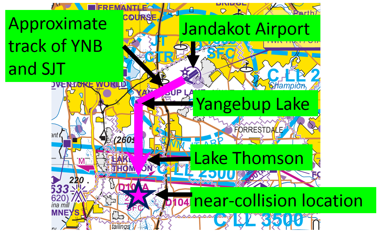
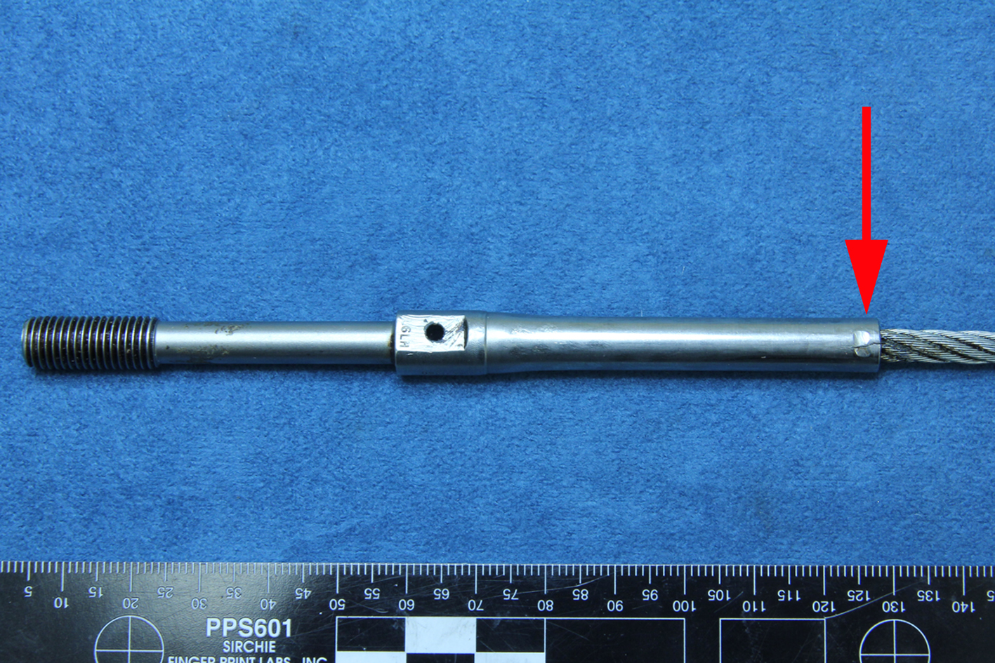
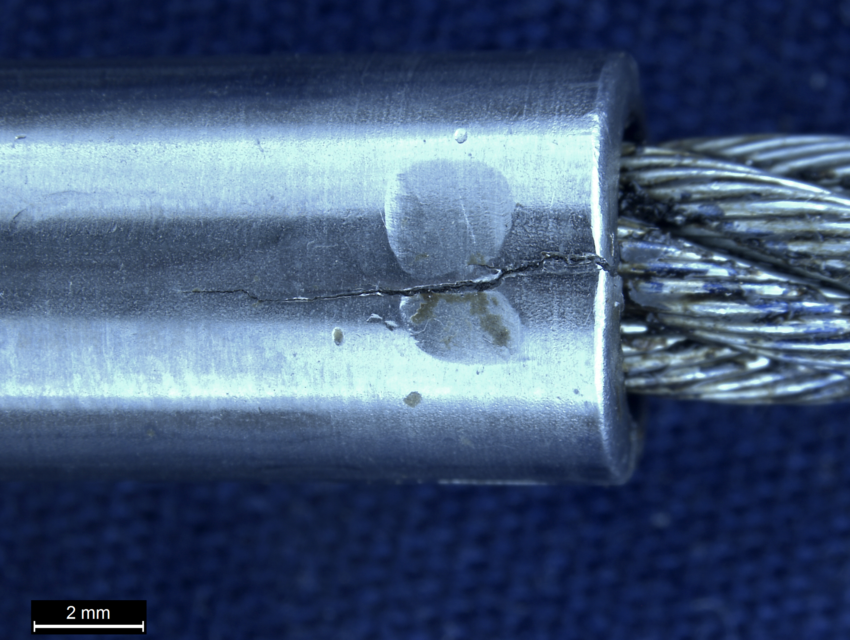
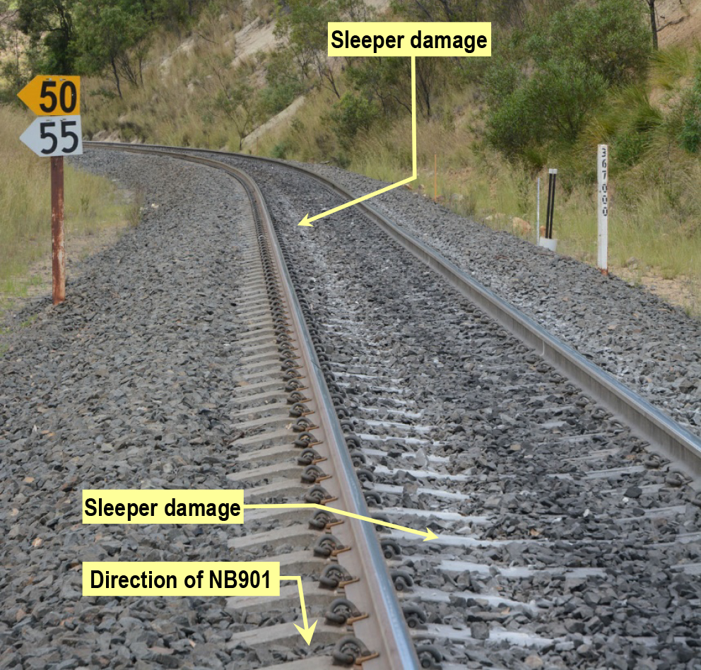
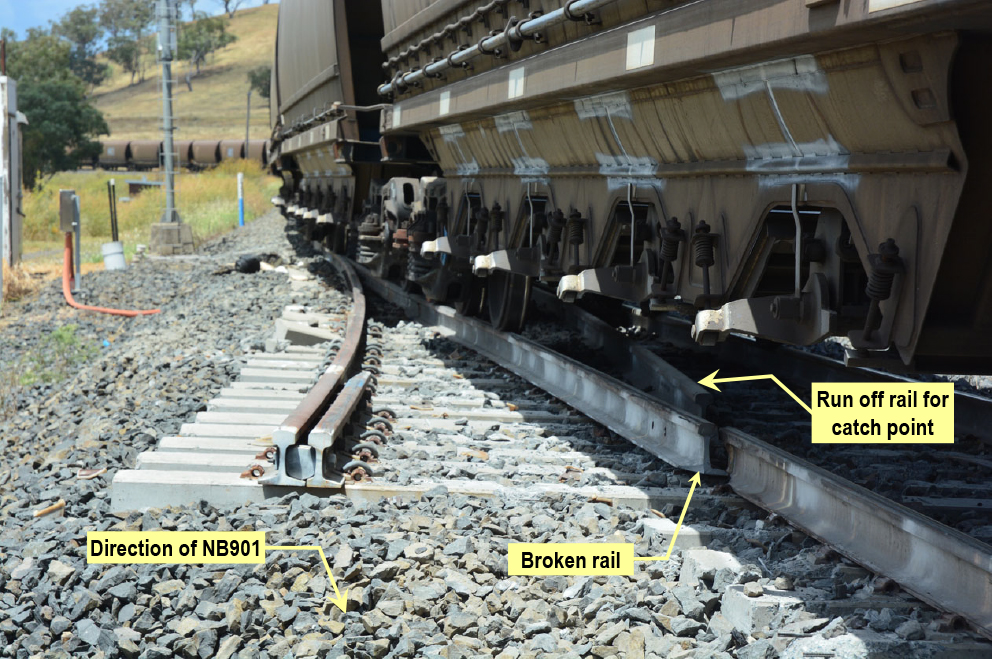
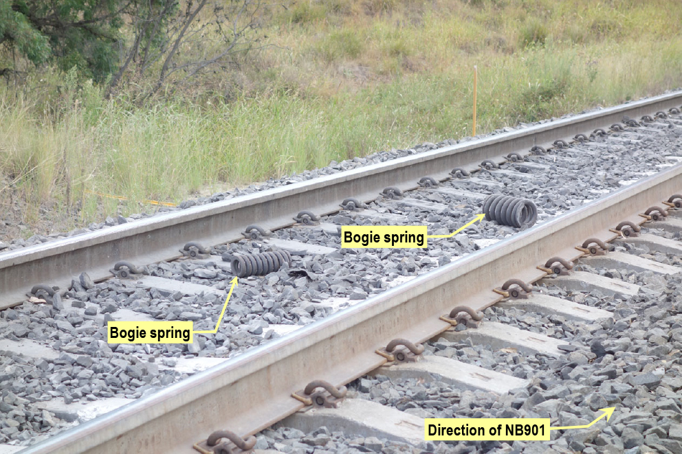
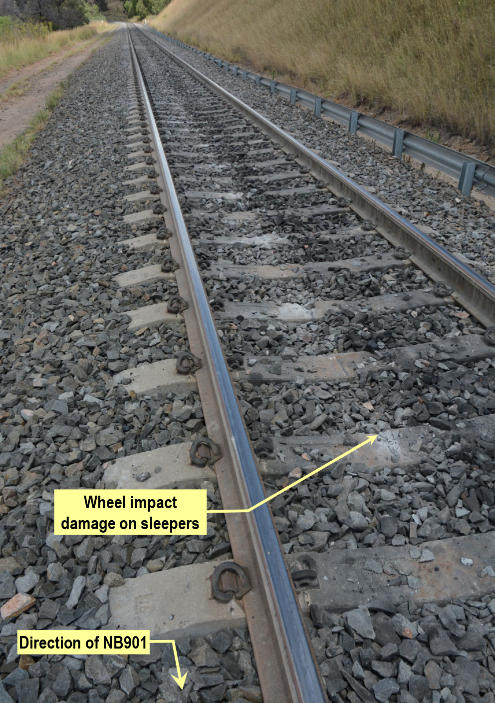
On 10 February 2015, a Drifter and a Thruster ultralight aircraft, recreational registration 25-0452 and 10-0339 respectively, both collided with terrain approximately 7km south of Donnington Airpark, near Townsville, QLD.
Recreational Aviation Australia (RA-Aus) is the organisation responsible for investigating this accident. As part of its investigation, RA-Aus requested technical assistance from the Australian Transport Safety Bureau (ATSB) in the examination of physical components from the involved aircraft. To protect the information supplied by RA-Aus to the ATSB and the ATSB's investigative work to assist RA-Aus, the ATSB initiated an investigation under the Transport Safety Investigation Act 2003.
Results of a visual examination of the physical components were provided to RA-Aus on 8 April 2015.
At about 0513 on 12 March 2015, the driver of a Sydney Trains A-set passenger train operated the train in the wrong running direction from Mt Druitt station. Instead of travelling towards St Marys on the Down Suburban line, he drove 761 m in the opposite direction towards Blacktown. The driver only braked after a network control officer (NCO)[1] contacted him and told him to stop. At the time, only the driver and guard were on board.
At the same time, a Pacific National freight train was about four kilometres away and travelling towards the passenger train on the same line. The NCO also called the driver of the freight train and told him to stop. There were no injuries or damage as a result of this incident.
What the ATSB found
The ATSB found that a number of factors contributed to the driver losing awareness of the way the train was facing. It was likely the driver was:
confused about the direction due to changing ends seven times
distracted from the main task of driving as he had spent over 3 hours at Mt Druitt station performing other tasks before he started driving
at risk of making an error due to his high workload
feeling under pressure to move the train
impaired by fatigue due to being awake for over 21 hours and in the low range of the circadian sleep cycle.
Sydney Trains fatigue management processes were ineffective in identifying the fatigue impairment experienced by the driver.
The guard did not take any action to stop the train although the guard was aware that the train was running in the wrong direction.
What's been done as a result
Sydney Trains conducted an internal safety investigation and is implementing several safety actions in response to that internal report.
Safety message
Rail operators should ensure that adequate strategies exist to safeguard against fatigue impairment of train crew. It should also be noted that train crew have a responsibility to decline a shift if they feel that their performance may be affected by fatigue.
On Wednesday 11 March 2015, at about 1840,[2] a storm blew a house roof off and into the rail corridor. The roof landed on the tracks at Mt Druitt, which affected the overhead electrical supply. Consequently, the track between Blacktown and Penrith was partially closed and Sydney Trains passenger train, 165-S, was held at Mt Druitt station. Passengers disembarked and continued their journey by other means.
Sydney Trains’ Train Crew Assignment Centre (TCAC) decided that the existing train crew would need to be relieved if the train was going to be held at Mt Druitt station for an extended time. TCAC called a driver and guard who were on a stand-by roster and offered them the extra shift. Both accepted and made their way to Central station. The guard signed on at 2000 and the driver at 2100.
Before going to Mt Druitt, the driver and guard completed a passenger service from Central to Hornsby. After this trip they were directed to Mt Druitt station to relieve the train crew on 165-S.
They travelled separately to Mt Druitt station. The guard arrived at 0128 and the driver at 0154. Both went to the country end of platform 3 where the previous train crew were waiting to be relieved. The driver received handover information about problems with the train from the previous driver. He was advised that:
the overhead electrical supply was off
the internal cab lights were not working
the external lights were flashing on and off
the pantographs were down and the pantograph pump was not responding
the Metronet train radio was not working
the faults had been reported to mechanical control.
The previous driver left the station and, at 0205, the driver unsuccessfully attempted to log into the train’s control system and turn on the internal cab lights. The guard was also unsuccessful in attempting to log in to the system.
As the train radio was not working, the guard and driver exchanged mobile phone numbers to enable communication between them. A network control officer (NCO) reported after the incident that he was unable to establish effective communication with the driver until he obtained the driver’s mobile number around 0500. Meanwhile, much of the communication from the signal box throughout the night was via the guard’s mobile phone or via the Mt Druitt station staff, who would walk down to the platform and speak to the driver.
At 0216, the driver walked to the train’s cab at the city end in an attempt to log into the train’s control system. He was again unable to do so. He phoned the guard and requested that they change ends. He returned to the country end at 0218, passing the guard on the platform who went to the city end of the train.
At 0257, overhead power was restored to all running lines. At 0311, a member of Mt Druitt station staff walked down onto the platform and told the driver that the signal box was trying to contact him. The driver phoned the NCO, who informed the driver that power was restored and that he should get ready to depart.
The driver again attempted to log into the train’s computer system, but was unable to do so. The driver phoned mechanical control about logging in and they gave him further instructions to try to rectify the fault. The driver’s login attempts were again unsuccessful. He was then advised to go to the cab at the city end and try to log in there.
At 0332, the driver walked from the country end to the city end and found the guard on the phone to mechanical control discussing the train’s computer system. They both tried to log in. Their attempts were unsuccessful. The driver made his way back to the country end of the train to try a similar process, but was again unsuccessful.
At 0349, the driver left the country end of the train and walked along the platform while speaking to mechanical control on his phone. Halfway along the platform he turned back and returned to the cab at the country end of the train.
A few minutes later, the driver walked from the country end towards the city end. Mechanical control sent a train technician to assist the driver. He arrived at 0352 and met the driver on the platform. Both the train technician and the driver then walked along the platform to the city end of the train where they attempted to get the train working. The train technician requested the driver assist him with the procedure. Once again, the attempt was unsuccessful.
At 0403, the driver and train technician changed from the city to the country end of the train. Both the driver and train technician worked on restarting the train. After a few attempts, they were successful in raising the pantographs. Other issues, such as the train radio, needed attention by the train technician. The train technician left the train at 0436 to get his laptop from the work van. The technician returned to the country end and was successful in restarting the train’s computer. This restored the destination indication panel on the train, but did not fix the train radio problem.
The driver left the train again to go up to the concourse level to the toilet. The driver was on the phone the entire time until returning to the train. At 0452, the guard received a call from the Rail Management Centre discussing problems with the train and asking to inform the driver to move the train soon. The guard spoke to the driver about this message. At 0453, a member of Mt Druitt station staff walked to the country end of the train and passed a message to the driver that the signal box was trying to contact him.
At 0455, an NCO spoke to the driver on his mobile phone and asked the driver if everything was good and if he was ready to go. The driver told the NCO about the problems with the train radio. Just as the driver was asking about his instructions and where he was going, the NCO ended the call to take another call. He then called back at 0458. During this call, he told the driver to operate the train to St Marys, terminate the train, and then return to Macdonaldtown Stabling Yard. The driver stated, ‘OK, I understand’.
The driver called the guard at 0502 and asked to change ends with him. The driver and train technician then walked together towards the city end of the train. At the same time, the guard walked towards the country end. The three met in the middle of the platform and talked for a few seconds. The guard assumed that they were changing ends not to move the train, but to rectify more problems. After a short conversation between the guard and the train technician, the driver and train technician continued to the city end of the train. This was the final change of ends before the driver moved the train.
The driver had changed ends seven times in 3 hours.
The guard was informed that the train could run without a functioning train radio - the NCO said, ‘it’s getting critical, we need him to move’. At 0505, an NCO called the driver and asked if the driver still had a problem. The driver said that they were about to conduct a continuity test after which they would be ready to depart. The NCO said to the driver, ‘(we are) trying to get you motivated, that’s all’.
The occurrence
The train technician, having completed his work, left the driver at the city end of the train at 0507 and departed the station. At 0511, an NCO called the driver and asked when he would be departing. The driver responded that they were departing ‘just now, just now’ but said he would talk with the guard first and probably depart ‘in five seconds’. Meanwhile, the guard called the driver on the train’s intercom system.
The guard informed the driver that he was in the wrong cab if they were heading to St Marys. The driver acknowledged that he heard this information. The driver and guard then discussed the continuity test before exchanging bell signals at 0512. The internal bell signals are used for communication between the driver and the guard. A single bell (all right) was given by the driver at 05:12:46; the guard returned this at 5:12:51.
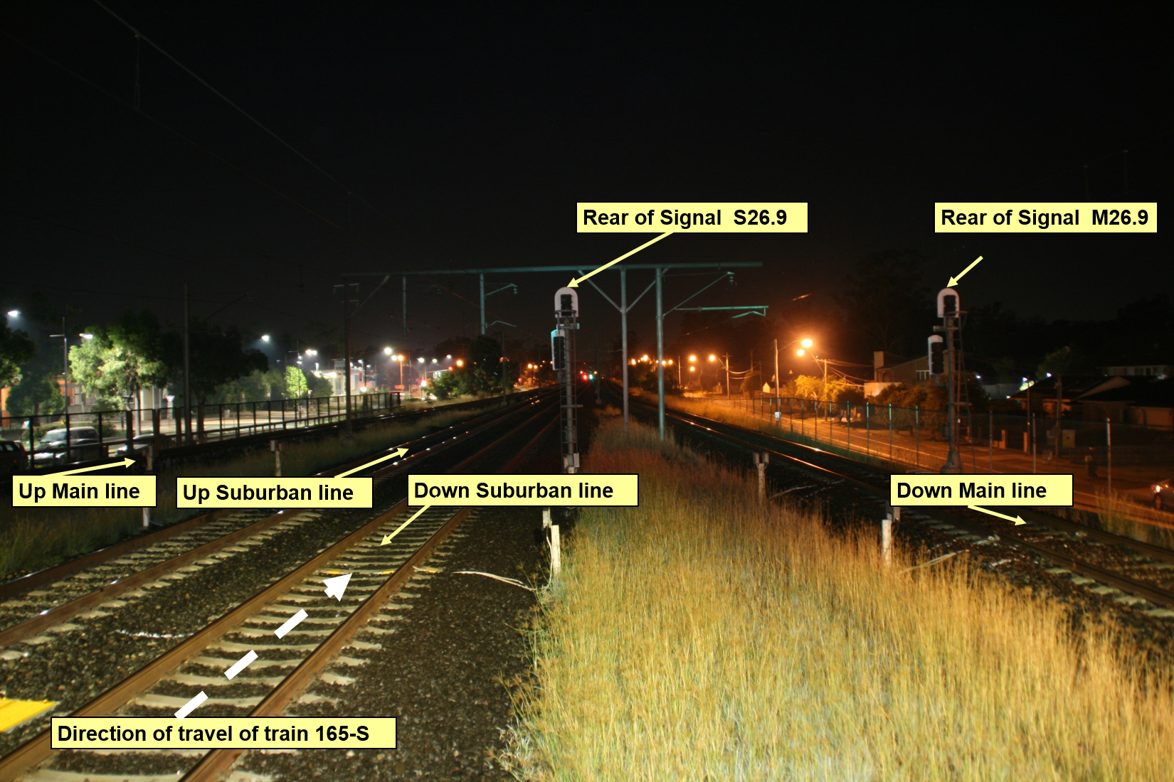
Immediately after finishing the conversation with the guard, the driver engaged the power handle to 68% to move the train. The time was 0513:05. The train moved away from Mt Druitt station in the up running direction on the Down Suburban line[3] (Figure 1). The train was travelling in the wrong running direction. The driver said he had his head down and was focussed on the controls. The guard was at the door of the train as it moved away from the station. The guard said that the reason the focus was towards the platform was in case late running passengers attempted to get onto the train.
Figure 1: Night time view from Platform 3 (city end)
The white arrow shows the wrong running direction that train 165-S travelled on the Down Suburban line.
Source: Sydney Trains
At 0513:30, after the train had travelled 111 m, the driver adjusted the power handle to 49%, a normal setting for the train to coast. At the same time, NCOs were observing the train movements on their Train Visibility System screen. They observed that the train was heading in the wrong running direction. An NCO made a call to the driver via his mobile phone at 0514:38 and told him to stop the train immediately and not move it any further. The driver said that he would do so and applied the brakes immediately.
At the same time a freight train, CA63, about 4 km away was travelling on the same Down Suburban line towards 165-S. It had just passed through Blacktown station and was approaching Doonside. An NCO contacted the crew of the freight train and told them to stop. This train was stopped before Doonside station.
Before the freight train was stopped, it was travelling in the correct running direction with line-side signals providing the driver with indications along the route. It is likely the driver of the freight train would have reached a signal at stop before reaching the passenger train. This was because the presence of the passenger train would have been detected by the signalling system, setting the signals to stop between it and the freight train.
Meanwhile, the driver of the passenger train had no signals facing him and no mechanism warning him of the freight train ahead. The available defences were the awareness of the driver and guard on the train, and the vigilance of the NCOs watching the Train Visibility System screen in the signal box.
Post-occurrence events
The time was 0514:46 when 165-S came to a stand with the leading car (city end) located at 42.470 km. It had travelled 761 m since leaving the station. During the trip, the train had reached a maximum speed of 33 km/h.
At 0515, the guard made a call to the signal box and enquired whether the driver had authority to head in the wrong running direction. The guard was told that the driver did not have this authority. The NCO again phoned the driver and instructed him to hold the train until an Incident Rail Commander arrived.
At 0521, the Rail Management Centre Shift Manager instructed an Incident Rail Commander to attend. He arrived at 0545 and tested both train crew for the presence of alcohol. Both returned a negative result. The driver was requested to change ends and drive the train back to Mt Druitt station. Authority was given and, at 0614, the train departed, arriving at Mt Druitt station a few minutes later. Both crew were drug tested at 0633. These results were also negative.
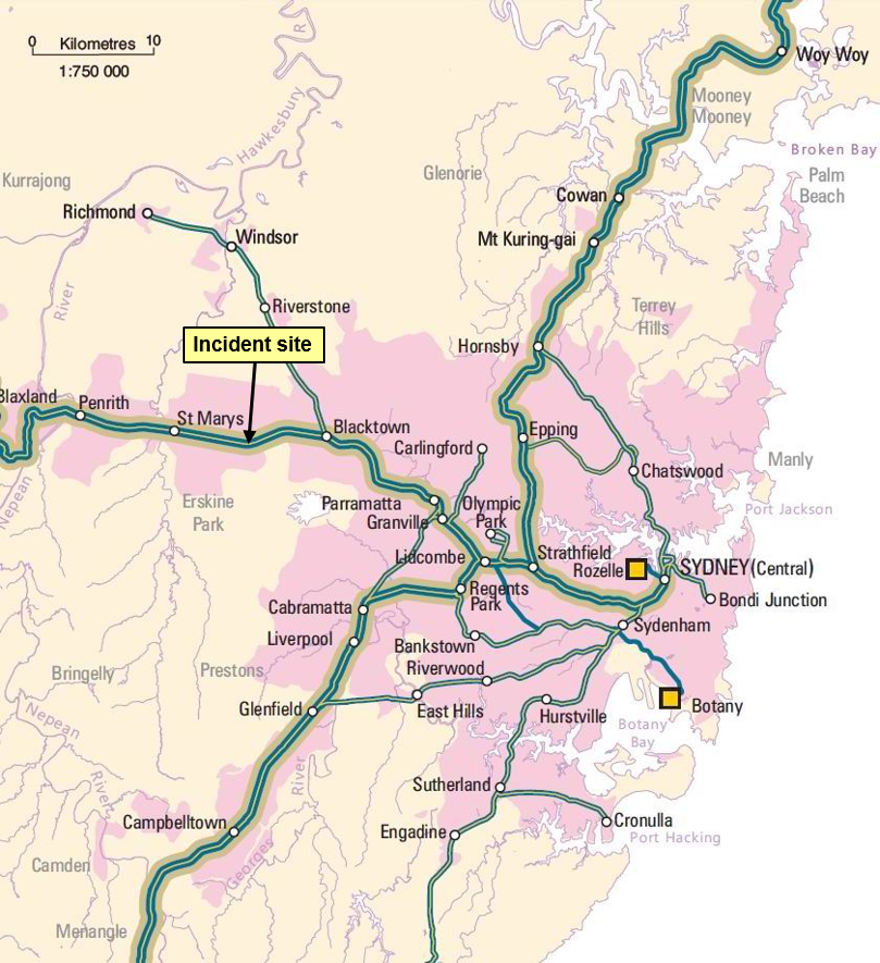
The incident occurred at Mt Druitt station on the Down Suburban line. Mt Druitt is located 43 km west of Sydney (Figure 2).
Figure 2: Location of incident at Mt Druitt
This map shows the major railway lines in the Sydney metropolitan area including the western line where the incident occurred.
Source: Geoscience Australia
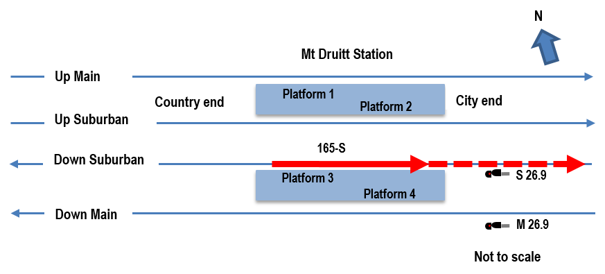
There were four platforms and four standard gauge lines at Mt Druitt station, the Up and Down Suburban lines and the Up and Down Main lines. Platform 3 is next to the Down Suburban line (Figure 3).
Figure 3: Line information Mt Druitt
The red arrow shows the direction that train 165-S travelled on the Down Suburban line.
Source: OTSI
Train information
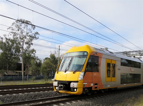
Sydney Trains operated the train involved in the incident. The set number of the train was A19. On the day of the incident, it was completing run 165-S. The A-set or Waratah train is an electric multiple unit. It consisted of eight cars with a driving car at each end (Figure 4), two motor cars located next to each driving car, and two trailing cars in the centre of the train. Waratah trains first entered service on the NSW rail network in 2011.
Figure 4: A-set driving car
Source: Sydney Trains
Crew information
The driver and guard were based at Central station, Sydney. Both lived in the inner suburbs of Sydney and had less than 30 minutes travel time to work.
The driver was an experienced driver, starting as a metropolitan train driver in April 2005. He was familiar with the route, fully qualified and medically fit.
The guard was less experienced, having started as a guard in June 2013. The guard was qualified and medically fit.
The driver and guard had not previously worked together.
Environmental conditions
The storm that had caused the network delays the previous evening had long since passed by the time of the incident. Other than some rain showers between 0248 and 0258, there were no adverse weather conditions.
The overnight minimum temperature was 17.5°C as recorded by the Bureau of Meteorology at Horsley Park, approximately 10 km from Mt Druitt station.
It was still dark when the incident occurred at 0513. Sunrise was at 0553.
Network management
NCOs in the Blacktown, Penrith, and St Marys signal boxes control train movements in the area around Mt Druitt. The train controller in the Rail Management Centre at Central also has visibility of train movements throughout the network.
Train maintenance
A private company, Downer Rail, was the contracted entity responsible for A-set train maintenance at the time of the incident. On the morning of the incident, a train technician from Downer Rail attended the site and assisted the driver to restart the train. He left before the driver moved the train.
Safety analysis
Introduction
The driver of passenger train 165-S drove the train in the wrong direction for 761 m. Previously the guard had warned the driver that he was in the wrong cab if he was going to St Marys. The guard did not take any action when the driver started driving in the wrong running direction. An NCO quickly realised the train was heading in the wrong running direction and contacted the driver to stop 165-S.
The driver did not realise the direction that the train was facing before moving the train. This was despite being familiar with the station, the route that he was to operate over, and the guard reminding him that he was at the wrong end of the train. A combination of changing ends a number of times, the length of time at the station, a high workload, and fatigue are the likely reasons he lost awareness of which way he was facing. The driver also felt under pressure to get the train moving after several telephone conversations with NCOs.
This section examines the contributing factors that led to the driver’s action including his work schedule and some preconditions for his unsafe act. It also explores the role of the guard and Sydney Trains fatigue management system.
Factors affecting the actions of the train crew
Time of day
The period between 0200 and 0600 is well established as a period of reduced performance. This is due to the effects of the circadian cycle, which predisposes humans to sleep during the night and be wakeful during the day. When we reverse these activities and work through the night and sleep during the day, we compromise the quality and the quantity of sleep, as well as the quality of the work performed. Thus, time of day creates an additional element of fatigue risk in 24−hour rail operations. The increase in fatigue and the deterioration in performance with time on task have been shown to occur more rapidly overnight.[4]
Another factor that affected the driver’s performance was the night environment. Although there was adequate lighting around the platform and train, the darkness limited visual cues about the direction he was facing. The signal that was closest to the driver was facing the other way. It was designed for trains travelling in the Down direction on the Down Suburban line. The driver said he could not see or did not notice this signal.
Fatigue impairment
In the context of human performance, fatigue is a physical and psychological condition primarily caused by prolonged wakefulness and/or insufficient or disturbed sleep.[5] The National Transport Commission recognises five main factors contributing to fatigue impaired work performance:
the duration of a duty period (time on task), and the rest breaks within and between shifts
inadequate sleep (or sleep debt), which results from inadequate duration and quality of prior sleeps
circadian effects, which involve working and sleeping against natural body rhythms that normally program people to sleep at night and be awake and work during the day
the type or nature of the task being undertaken (workload)
the work environment.
These factors are compounded by a person’s body clock, environmental conditions, stress, age and personal health and fitness.[6] Fatigue can have a range of influences on performance, such as decreased short-term memory, slowed reaction time, decreased work efficiency, reduced motivational drive, increased variability in work performance, and increased errors of omission.[7] Transport accident investigation agencies have identified fatigue impairment as a causal factor in many accidents and incidents.
The driver indicated during an interview that at the start of the shift he felt exhausted, then while he was working on the train ‘adrenaline kicked in’. However, as the shift progressed, he got tired. He said that at the time of the incident he ‘felt drowned - exhausted in the cab'. As an explanation for why this incident happened, he said it was ‘particularly to do with so many hours without sleep’. It should be noted that the driver had a personal responsibility to declare himself unfit for work if he felt that his performance would be affected by fatigue. Research has shown that assessing your own level of fatigue is difficult.[8] There are also a number of reasons why train crew are reluctant to decline an extra shift. Although not indicated by the crew in this incident, common reasons cited by train crew for accepting shifts when fatigued include the loss of income and gaining a reputation as someone who is not reliable.
The scheduling of drivers to work in the early hours of the morning is unavoidable. Knowing the risks associated with early morning shifts is important to optimise the rostering of train crew. The selection of this driver to work this shift increased his risk of error.
Given the driver’s actions and his reported state of fatigue impairment, as well as the established links between fatigue impairment and increased error, Sydney Trains’ management of fatigue risk was investigated.
Driver’s roster
An examination of the driver’s roster, including the incident shift, showed that he had worked 12 of the previous 14 days. In addition, this shift, a stand-by shift, was his tenth consecutive shift. The previous shifts all started in mid-afternoon or in the evening. He worked no morning shifts. This meant he was in a pattern of going to bed around 0100 and sleeping in. He said that if he had not worked this shift he would have gone to bed about midnight. The incident occurred at 0513, a time when he had planned to be sleeping.
The driver said that he started the day about 0800 and spent the day visiting friends. Rostered as a stand-by driver he received a call from train crewing at 2022.
Some of the rostering principles set down by Sydney Trains are:
maximum shift length is set as 9 hours for the driver of a suburban train
workers new to shift work or returning should not be rostered on night work or early morning for their first shift
total hours worked should be no more than 48 hours per week
break of 11 hours between shifts
maximum number of shifts is 12 in a 14 day period
limit night shifts and early morning starts
schedule frequent breaks during a night shift or if the work involves sustained mental or physical activity.
Although the driver considered that he was affected by fatigue when the incident occurred, Sydney Trains use of bio-mathematical modelling did not predict that the driver’s roster would place him at risk. Their assessment of the suitability of the roster for managing fatigue risk was based primarily on the use of a bio-mathematical fatigue modelling program known as the Fatigue Audit Interdyne (FAID).
Bio-mathematical models attempt to predict the effects of different working patterns on subsequent job performance, with regard to the scientific relationships between work hours, sleep, and performance.[9] FAID does not predict fatigue but rather predicts a sleep opportunity, demonstrating only that the organisation has provided employees with an adequate opportunity to sleep, producing a work-related fatigue score.[10]
When evaluating rosters, there are a number of documented limitations with over-reliance on bio-mathematical models such as FAID. Because the distribution of fatigue across a given population of employees working the same roster is significant, it is difficult to generalise from the average data generated by a bio-mathematical model. As noted by the NSW Independent Transport Safety Regulator (ITSR):
…fatigue models are appropriate to use as one tool to help evaluate group rosters to help identify how aspects of fatigue exposure are distributed. Model outputs... should never be the sole basis for a safety risk management decision regarding work hours.[11]
FAID, along with other bio-mathematical models, is a useful tool to account for hours of sleep opportunity provided, thereby providing an indication of fatigue exposure across a group of employees. It cannot account for the hours of sleep actually achieved by individuals, nor for the quality of that sleep. These additional factors necessitate the use of multiple layers of controls to manage fatigue-related risk.
Sydney Trains’ management system included policies, procedures, and training to address train crew fatigue impairment. These systems provide guidance for management and employees to ensure there is an awareness of countermeasures in this area. This case should serve as an opportunity to review the rostering of train crew, especially those called in on the stand-by roster.
Time pressure
For most transport operators there is a balance between on-time running and having a safe system. ‘To achieve both safety and on-time running requires the ability to identify hazards that can disrupt services or compromise safety and efficiently manage the risks those hazards create’.[12]
Both train crew received a number of calls from NCOs throughout the shift. The train was expected to be moved once power was restored to the electrical supply. It is likely that NCOs were concerned about delays to the upcoming morning peak. This concern was communicated to both the guard and the driver.
The conversation between the NCO and the driver two minutes before he eventually moved the train was as follows:
Person
Voice recording
NCO
‘Are you right to depart though?’
Driver
‘Yeah, I have just confirmed with the box’.
NCO
‘So how long before you depart?’
Driver
‘Just now, just now’.
NCO
‘So are you on the move?’
Driver
‘Yes - no. I am just going to confirm with the guard … probably 5 seconds’.
NCO
‘Ok thank you’.
The driver said later, 'I felt under pressure to get moving from the box. I moved a few seconds after talking to the (signal) box’.
Communication was hampered by the train radio not working. Initially, this meant information to the driver was relayed via the guard and station staff. Eventually communication was made directly to the driver via his mobile phone. Normally drivers must turn off their mobile phones when driving, but an exception is made when the train radio is not working.
Area control also contacted the guard. The guard was told, correctly, that the train could be moved without a working train radio. The NCO asked that the driver be reminded that a document about this had been released the previous week.[13] The guard was also told that, ‘it’s getting critical that we need him to move’.
Research suggests that a call from a controller to explain a delay increases pressure on the driver to perform.[14] ‘In general, under stress, attention appears to channel or tunnel, reducing focus on peripheral information and tasks and centralising focus on main tasks’.[15] The tunnelling of attention can be a good thing or a bad thing for performance. In this case, the driver said he was completely focussed on the controls in front of him. It is likely that this contributed to him confusing the direction in which he was about to move.
Workload
The driver experienced a period of sustained high workload during his time at Mt Druitt station in the hours leading up to the incident. For over three hours, he made or received a large number of phone calls communicating with network control, train maintenance and the guard. He was on his feet during this time, either standing in the train cab, walking to the other end of the platform or walking up to the concourse.
Research has shown that a high workload can result in slower task performance and errors. ‘Unusual or high workload situations and situations where people are under time pressure can contribute to fatigue related incidents. Rather than causing fatigue in the traditional sense, workload has been described as a factor which can either mask or augment the effects of fatigue. People working under time pressure, or with a high workload, are most likely to make errors at the time of day that this incident occurred.’ [16]
Time at station
The amount of time the driver spent at the station before starting to drive may have affected his performance. The driver had been at Mt Druitt station since 0154 and, for the majority of the time, working and problem-solving to get the train started. For three hours, his focus of attention was directed at fixing problems with the train. The driver’s attention was away from the routine task of driving. When he departed, it was likely his mind was still engaged with the previous task he had spent so much time working on.
The driver said at interview that, after eventually moving the train, ‘when I put my head up, something was weird in my brain. I saw we were not on the right path, with 10 years’ experience as a driver. So everything it was upside down’.
Research suggests that an extended time spent at the station serves to dislocate the driver’s attention from the primary task and safe working. This research found that inattentiveness was deemed to arise primarily from the consequence of disengagement from an active driving state, which gives rise to the process of distraction and reduced situation awareness.[17]
Multiple end changes
Since arriving at Mt Druitt station at 0154, the driver had changed ends seven times. On another occasion, he walked half way along the platform and returned. He had also left the train and walked up to the concourse on two occasions. The timing of driver movements is shown in the table below:
Time
Driver actions
0154
Arrives at Mt Druitt Station and goes to country end of train
0211
Leaves train and goes up to concourse level
0216
Changes from country to city end
0218
Changes from city to country end
0332
Changes from country to city end
0342
Changes from city to country end
0347
Starts to change from country to city end, stops half way and returns
0351
Changes from country to city end
0403
Changes from city to country end
0448
Leaves train and goes up to concourse level
0502
Changes from country to city end
0513
Driver starts driving wrong way from city end of train
It is likely that changing ends on multiple occasions confused the driver. After the train technician arrived, the driver and train technician changed ends twice together (0403 and 0502) and the driver may have thought he would be returning to the country end. He said he thought the train technician would be travelling to St Marys with him. After the train technician left the driver in the cab, the driver should have returned to the country end. Instead the driver prepared to move the train, exchanged bell signals with the guard, received a phone call from the signal box and an intercom call from the guard, then moved the train shortly afterwards.
The role of the guard
The use of a driver and guard is an important measure to mitigate the risk of driver error. ‘Train Crew are responsible for the safety of all passengers on the train, and must be prepared to stop a train immediately if an emergency situation arises. The Train Crew must assist each other to provide for the safety of all passengers’.[18]
A guard provides a level of redundancy in the system. It is essential that guards are not reluctant to take action in an emergency.
The guard was less experienced than the driver. They had not previously worked together. The guard reminded him at least twice that he was in the wrong end of the train if they were going to travel to St Marys. The driver recalled that the guard had told him this. It seems that the driver did not assimilate the significance of the advice, given all that was going on at the time.
The guard took no action when the train started moving in the wrong running direction. This was despite knowing the train was going the wrong way. The guard thought that the driver might have received authority to do this. After the incident, the guard contacted the Rail Management Centre to ask them if they had given authority from the driver to go in the wrong running direction, perhaps being issued a Special Proceed Authority. The guard was told that they had not given any such authority to the driver.
If the guard thought the train was going in the wrong running direction a number of actions could have been taken. These included:
calling the driver and asking him what he was doing
giving a bell signal, of two bells, which tells the driver to stop immediately
operate the emergency brake isolating cock to bring the train to a stand.
Instead, the guard made a decision to watch for passengers on the platform that may have been trying to board the train before it moved off. There were few passengers on the station at the time.
Since the late 1970s, aviation accident investigation agencies have identified ‘authority gradients’ existing between crew contributing to incidents. One significant aviation accident where an authority gradient was a contributing factor was the collision of two Boeing 747s at Tenerife Airport, in 1977. The crash killed 583 people, making it the deadliest accident in aviation history.
‘In a study of 249 airline pilots in the United Kingdom, nearly 40 percent of first officers stated that they failed to communicate safety concerns to their captains on more than one occasion for reasons that included a desire to avoid conflict and in deference to the captain’s experience and authority’.[19]
In 2003, a passenger train derailed at Waterfall, NSW killing 7 persons including the driver. The Special Commission of Inquiry set up to investigate this accident found that an authority gradient existed between the guard and driver. This was one of the factors that discouraged the guard from responding in the emergency. One recommendation discussed improving driver and guard training to encourage teamwork and discourage authority gradients.[20]
Both driver and guard from the Mt Druitt incident had received training about effective communication and teamwork, the guard most recently in 2013.
Track configuration
The track configuration between Westmead and St Marys is different to many other areas in the Sydney metropolitan network. In most multiple track areas, the sequence of tracks will generally be an Up line next to a Down line. The track configuration at Mt Druitt placed both Down lines next to each other, and both Up lines next to each other. This has caused confusion to some drivers and maintenance staff in the past. There is no evidence that this contributed to the driver moving the train in the wrong direction.
From the evidence available, the following findings are made with respect to the wrong running direction of a Sydney Trains passenger service, 165-S, that occurred at Mt Druitt, NSW on 12 March 2015. These findings should not be read as apportioning blame or liability to any particular organisation or individual.
Safety issues, or system problems, are highlighted in bold to emphasise their importance. A safety issue is an event or condition that increases safety risk and (a) can reasonably be regarded as having the potential to adversely affect the safety of future operations, and (b) is a characteristic of an organisation or a system, rather than a characteristic of a specific individual, or characteristic of an operating environment at a specific point in time.
Contributing factors
The driver lost awareness of the direction he was to travel due to changing ends seven times in 3 hours while dealing with tasks not usually associated with driving while the train was stationary at Mt Druitt station.
The driver spent over 3 hours at Mt Druitt station performing other tasks before he started driving, his focus of attention directed at fixing problems with the train. When he departed, it was likely his mind was still engaged with the previous task.
The driver experienced a period of sustained high workload during his time at Mt Druitt station in the hours leading up to the incident.
The driver felt that he was under pressure to move the train after receiving multiple telephone calls questioning when he would be moving.
It is likely that the driver of train 165-S was experiencing some level of fatigue impairment when he started driving the train in the wrong running direction.
The time of day when the incident occurred is known to be in the low range of the circadian sleep cycle.
Sydney Trains' fatigue management processes were ineffective in identifying the fatigue impairment experienced by the driver. [Safety issue]
The guard did not take action, either to stop the train or warn the driver, when the driver started driving in the wrong running direction.
Other factors that increased risk
The driver did not assimilate information from the guard, who told him, on two occasions, that he was in the wrong end for the instructed direction of travel.
Other findings
The NCO recognised that train 165-S had started moving in the wrong running direction. The timely action by the NCO in stopping both trains (165-S and CA63) was fortunate.
Safety issues and actions
Depending on the level of risk of the safety issue, the extent of corrective action taken by the relevant organisation, or the desirability of directing a broad safety message to the rail industry, the ATSB may issue safety recommendations or safety advisory notices as part of the final report.
Fatigue management
Sydney Trains' fatigue management processes were ineffective in identifying the fatigue impairment experienced by the driver.
The sources of information during the investigation included:
Downer Rail
Sydney Trains
References
Battelle Memorial Institute (1998). An Overview of the scientific literature concerning fatigue, sleep, and the circadian cycle. Report prepared for the Office of the Chief Scientific and Technical Advisor for Human Factors, United States Federal Aviation Administration.
Dawson, D., Noy, Y.I., Harma, M., Akerstedt, T. & Belenky, G. (2011). Modelling fatigue and the use of fatigue models in work settings. Accident Analysis and Prevention, 43, pp 549-564.
Independent Transport Safety Regulator (2010). Transport Safety Alert 34 - Use of bio-mathematical models in managing risks of human fatigue in the workplace.
McInerney, P.A. (2005). Final Report of the Special Commission of Inquiry into the Waterfall Rail Accident Vol. 1.
National Transport Commission (2008). Management of Fatigue in Rail Safety Workers. National Rail Safety Guideline.
National Transportation Safety Board. (2011). Safety Recommendation A-11-39.
Naweed, A. (2013). Psychological factors for driver distraction and inattention in the Australian and New Zealand rail industry. Accident Analysis and Prevention, 60.
RailCorp. (2013). TWP 100 Responsibilities of Train Crew. TOM Notice No. 16.
Staal, M. A. (2004). Stress cognition and human performance – A literature review and conceptual framework. NASA Technical Memorandum. NASA/TM—2004–212824.
Van Dongen, H.P.A., Maislin, G., Mulligan, J.M., Dinges, D.F. (2003). The cumulative cost of additional wakefulness: Dose-response effects on neurobehavioral functions and sleep physiology from chronic sleep restriction and total sleep deprivation. Sleep, 26, pp117-126.
Williamson, A., Lombardi, D.A., Folkard, S., Stutts, J., Courtney, T.K. & Connor, J.L. (2011). The link between fatigue and safety. Accident Analysis and Prevention, 43, pp 498-515.
Submissions
Under Part 4, Division 2 (Investigation Reports), Section 26 of the Transport Safety Investigation Act 2003 (the Act), the Australian Transport Safety Bureau (ATSB) may provide a draft report, on a confidential basis, to any person whom the ATSB considers appropriate. Section 26 (1) (a) of the Act allows a person receiving a draft report to make submissions to the ATSB about the draft report.
A draft of this report was provided to:
Downer Rail
the Downer Rail train technician
Office of the National Rail Safety Regulator
Pacific National
Sydney Trains
the train crew of 165-S
Submissions were received from Downer Rail, the Office of National Rail Safety Regulator, Pacific National, Sydney Trains, and the train crew of 165-S.
The submissions were reviewed and where considered appropriate, the text of the report was amended accordingly.
Purpose of safety investigations
The objective of a safety investigation is to enhance transport safety. This is done through:
identifying safety issues and facilitating safety action to address those issues
providing information about occurrences and their associated safety factors to facilitate learning within the transport industry.
It is not a function of the ATSB to apportion blame or provide a means for determining liability. At the same time, an investigation report must include factual material of sufficient weight to support the analysis and findings. At all times the ATSB endeavours to balance the use of material that could imply adverse comment with the need to properly explain what happened, and why, in a fair and unbiased manner. The ATSB does not investigate for the purpose of taking administrative, regulatory or criminal action.
Terminology
An explanation of terminology used in ATSB investigation reports is available here. This includes terms such as occurrence, contributing factor, other factor that increased risk, and safety issue.
Publishing information
Released in accordance with section 25 of the Transport Safety Investigation Act 2003
Ownership of intellectual property rights in this publication
Unless otherwise noted, copyright (and any other intellectual property rights, if any) in this report publication is owned by the Commonwealth of Australia.
Creative Commons licence
With the exception of the Coat of Arms, ATSB logo, and photos and graphics in which a third party holds copyright, this publication is licensed under a Creative Commons Attribution 3.0 Australia licence.
Creative Commons Attribution 3.0 Australia Licence is a standard form licence agreement that allows you to copy, distribute, transmit and adapt this publication provided that you attribute the work.
The ATSB’s preference is that you attribute this publication (and any material sourced from it) using the following wording: Source: Australian Transport Safety Bureau
Copyright in material obtained from other agencies, private individuals or organisations, belongs to those agencies, individuals or organisations. Where you wish to use their material, you will need to contact them directly.
On the morning of 28 February 2015, an instructor and student were conducting a training flight in a Robinson R22, registered VH-CMK, at Archerfield Airport, Queensland. The objective of the flight was to teach the student how to manage jammed anti-torque pedal[1] and jammed collective[2] emergencies. Conditions were fine and clear with a light and variable wind.
The flight commenced with the instructor flying the helicopter in a set direction, demonstrating how to effectively control the helicopter with the pedals jammed in position. The jammed pedal condition was simulated by holding the pedals in a set position with foot pressure, then manipulating the other flight controls and adjusting engine power and airspeed to control the helicopter. Satisfied that the key elements of the demonstration had been effectively addressed and nearing the boundary of the area in which the helicopter had been cleared to operate, the instructor turned the helicopter through about 180 degrees and commenced a similar demonstration travelling in the opposite direction.
During the second demonstration, the helicopter was established in forward flight around 15 ft above the ground at an airspeed of about 40 kt. The instructor simulated a jammed pedal condition, setting the left pedal slightly forward of the neutral position. As the demonstration progressed, the instructor elected to complete the exercise by conducting a simulated jammed pedal run-on[3] landing. The helicopter touched down on a grass surface near the northern boundary of the airport, just outside the runway strips associated with runways 22R/04L and 22L/04R. The grass in the area where the helicopter touched down was slightly longer than the grass on the runway strips, but the instructor was comfortable continuing with the run-on landing, noting that it was not uncommon to operate helicopters on that surface.
The demonstration went as expected up until the point that the helicopter touched down. Still travelling forward at about 10 to 15 kt, the helicopter bounced slightly and yawed to the left. The instructor discontinued the demonstration at that moment, allowing himself full use of the pedals, but he was unable to correct the yaw before the helicopter touched down again. When the helicopter touched down a second time after a very short and shallow bounce, even though the helicopter was level, the forward part of the right skid dug into a surface undulation. The right skid then effectively acted as a pivot, tipping the helicopter to the right. The instructor fully lowered the collective, but the roll continued. The instructor then applied left cyclic[4] but he was unable to stop the helicopter rolling onto its right side.
Aware that a fuel leak had developed, the instructor closed the fuel shut-off valve and turned the master electrical switch off. The instructor and student moved to a safe distance following which the instructor contacted air traffic control (who alerted emergency services). The instructor and student suffered minor injuries and the helicopter was substantially damaged.
Instructor comment
The instructor made the following comments in relation to the accident:
The nature of the surface (outside the runway strips) probably contributed to the accident, given the manner in which the right skid dug into a surface undulation. There was a current NOTAM[5] at the time of the accident stating that grass areas were soft and wet, but the reason the skid dug in rather than skipped forward, seemed to relate more directly to the slightly undulating nature of the surface, rather than how firm the surface was. During future similar exercises involving run-on landings on unprepared surfaces, the instructor intends to inspect the surface for suitability beforehand.
The instructor was mindful of the possibility of dynamic rollover[6] under the circumstances, so consciously avoided applying power and collective as the helicopter tipped.
The instructor had invited the student to place his hands and feet lightly on the controls during the demonstration, to maximise the training benefit of the exercise. The instructor commented that the student may have inadvertently applied some pressure on the pedals during the accident, which could have reduced the effectiveness of the instructor’s attempt to correct the yaw after the initial bounce.
Safety message
This accident highlights the manner in which some hazards may not be immediately obvious. Helicopter training organisations are encouraged to consider the quality of the landing area surface during hazard identification and risk assessment processes associated with training operations, particularly those that involve run-on landings.
Decisions regarding whether to conduct an investigation, and the scope of an investigation, are based on many factors, including the level of safety benefit likely to be obtained from an investigation. For this occurrence, a limited-scope, fact-gathering investigation was conducted in order to produce a short summary report, and allow for greater industry awareness of potential safety issues and possible safety actions.
Publishing information
Released in accordance with section 25 of the Transport Safety Investigation Act 2003
Ownership of intellectual property rights in this publication
Unless otherwise noted, copyright (and any other intellectual property rights, if any) in this report publication is owned by the Commonwealth of Australia.
Creative Commons licence
With the exception of the Coat of Arms, ATSB logo, and photos and graphics in which a third party holds copyright, this publication is licensed under a Creative Commons Attribution 3.0 Australia licence.
Creative Commons Attribution 3.0 Australia Licence is a standard form licence agreement that allows you to copy, distribute, transmit and adapt this publication provided that you attribute the work.
The ATSB’s preference is that you attribute this publication (and any material sourced from it) using the following wording: Source: Australian Transport Safety Bureau
Copyright in material obtained from other agencies, private individuals or organisations, belongs to those agencies, individuals or organisations. Where you wish to use their material, you will need to contact them directly.
At 0400 on 28 February 2015, a harbour pilot boarded the container ship Maersk Garonne for its passage into Fremantle’s Inner Harbour. The pilotage generally progressed as intended by the pilot until the ship approached the entrance channel 40 minutes later. At this stage, he became concerned that the assisting harbour tugs would not be at the channel’s entrance before the ship.
At 0442¾, the pilot decided to delay entering the channel by taking Maersk Garonne outside (south of) the channel and entering it later. At 0448, the ship grounded in charted shallow water. The ship did not suffer any damage and was re-floated on the rising tide about 3½ hours later.
What the ATSB found
The ATSB investigation found that bridge resource management was not effectively implemented on board Maersk Garonne. As a result, the ship’s bridge team was not fully engaged in the pilotage and did not effectively monitor the ship’s passage. While the master retained responsibility for safe navigation of the ship, the harbour pilot was the only person actively focused on the pilotage. Consequently, single-person errors that occurred went undetected or inadequately challenged and uncorrected.
The investigation identified that Fremantle Pilots’ publicly available passage planning guidance for the pilotage was inadequate and was not effectively implemented. Further, Fremantle Pilots’ pilotage procedures did not include abort points or contingency plans for identified risks.
The investigation also found that procedures for tugs to be on station at the entrance to the port, or for their co-ordinated movement, were not clearly defined.
What has been done
Fremantle Pilots, the port’s pilotage provider, has reviewed and updated its website, procedures and training with respect to pilotage, passage planning and communications. This includes simulator training for emergencies.
Svitzer Australia, the towage provider, has updated its procedures to include defined on-station times for tugs.
Fremantle Ports, the port authority, has advised that it has clarified the role of the vessel traffic service in assisting ship arrivals and berthing.
The safety actions noted above, together with joint simulator exercises, clarify the roles and responsibilities of all parties with respect to monitoring and management of pilotages. This increases safety margins and reduces the likelihood of a similar incident in the future.
Maersk Garonne’s managers have issued fleet circulars to emphasise and clarify the roles and responsibilities of the master and ship’s crew during navigation with a pilot on board. The managers have also implemented a fleet-wide program that includes education and auditing to ensure compliance with bridge procedures.
Safety message
Comprehensive passage planning that includes risk-assessed contingency planning is vital to safe pilotage and underpins effective bridge resource management. The potentially severe consequences of a pilotage accident means that a low accident rate in the past is not a reliable indicator of safety risk.
The occurrence
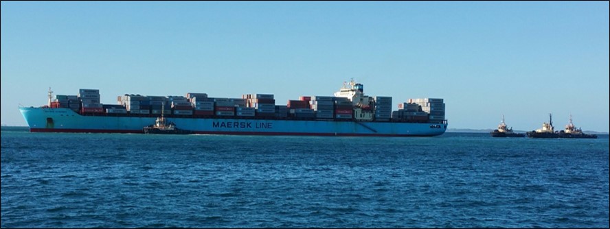
During the early hours of 28 February 2015, the 292 m, 4,318 TEU,[1] fully cellular container ship Maersk Garonne (Figure 1) arrived off the Port of Fremantle, Western Australia, after a voyage from Singapore. At 0200,[2] the master arrived on the ship’s navigation bridge (bridge) and at 0300, he took over the conduct (con) of the ship as it approached the Fremantle outer pilot boarding ground. The second mate, who was the officer of the watch (OOW), remained on the bridge to assist the master when required.
Figure 1: Maersk Garonne aground and being assisted by tugs
Source: Tristan Yuswak
Just before 0400, the 4-8 third mate[3] came to the bridge and took over the watch from the second mate. The master directed him to go on deck to escort the pilot to the bridge. By 0403, the harbour pilot and an observer[4] had boarded Maersk Garonne.
At 0400, the weather was fine and clear with the wind from the south-southeast at 9 knots.[5] The forecast was for winds of 15-20 knots from the southeast. Low water was at 0352 (0.51 m) with high water expected at 1849 (0.97 m).
At 0406, the pilot and observer arrived on the bridge. The master and pilot exchanged information and discussed the pilotage at the chart table, over the navigational chart. The pilot was informed that the main engine was at half ahead, the engine had been tested astern, the ship was on hand steering and that all equipment was working as expected. The thrusters were being tested at that time. Maersk Garonne’s draught was 12.2 m forward and 12.4 m aft.
The pilot ordered full ahead and altered the ship’s heading[6] towards the Approach Channel. The master positioned himself behind the engine telegraph in preparation for engine orders and the OOW, the third mate, was at the chart table plotting positions as the transit progressed.
At 0407, the pilot made VHF radio contact with the Port of Fremantle[7] and advised the duty vessel traffic service officer (VTSO) that Maersk Garonne was approaching the Fairway Landfall buoy. The route for the ship into the port via the Deepwater Channel (DWC) was confirmed, and that there was no outbound traffic. The pilot and master then continued discussing the pilotage, including the information provided on Fremantle Pilots’ ‘master/pilot exchange of information’ (MPX) form and the ship’s pilot card. This included the pilot’s intended track from the pilot boarding ground to the berth, where to expect the tugs, tide and weather conditions and berthing arrangements.
By 0410, conversations on the bridge included some social topics. The pilot and observer were engaged in varied discussions when the pilot was not giving helm orders.
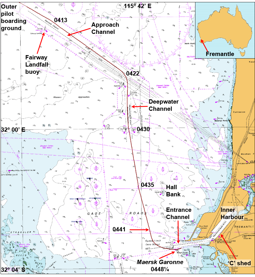
Figure 2: Section of navigational chart Aus 112 showing Maersk Garonne’s track
Source: Australian Hydrographic Service (annotated by ATSB)
At 0413, the ship passed the Fairway Landfall buoy (Figure 2) and continued in a south-easterly direction at 14 knots,[8] toward the DWC, about 3 miles[9] off. At 0422, the pilot ordered 10° of starboard rudder and at 0426, a heading of 178°.
At 0430, Maersk Garonne exited the DWC, at a speed of about 16 knots. The pilot then ordered a heading of 170° towards the port entrance channel, about 3½ miles further south. Between helm orders, the bridge conversations continued on marine and social topics, mostly between the pilot and the observer.
At about this time, the chief mate arrived on the bridge to relieve the third mate as OOW for the arrival. They discussed the situation and exchanged watch information.
At 0435, the pilot contacted VTS and reported that the ship was passing Hall Bank (Figure 2). He also confirmed the ship’s berthing arrangements (port side alongside at berth 8). The VTSO replied that Maersk Garonne was all clear to enter the Inner Harbour and that the tugs were ‘getting underway’. Both tugs had been berthed close to each other at the C Shed wharf, about 1½ miles from the entrance channel entrance (one of them, Svitzer Falcon, had departed the wharf by 0433).
At 0435½, the pilot ordered a heading of 165° and 2 minutes later, the main engine was reduced to half ahead.
At 0436, after the third mate had plotted the position on the chart, the chief mate took over the watch. The third mate then left the bridge to stand by at the forward mooring station.
Table 1: Selected ship data leading up to the grounding
Local time
Heading (True)
Speed (Knots)
Main engine status
Rudder (degrees)
Turn rate (⁰/min to Port)
04:35:00
170
16.7
Full ahead
-
-
04:37:32
166
16.3
Half ahead
-
-
04:41:07
166
14.5
Slow ahead
Port 20
0
04:41:36
159
14.2
Slow ahead
Hard to Port
20
04:42:58
123
10.9
Slow ahead
Midships
25
04:44:29
102
9.2
Slow ahead
Stbd 10
14
04:44:59
099
8.9
Slow ahead
Midships
9
04:45:23
098
8.8
Slow ahead
Port 20
7
04:45:35
098
8.7
Slow ahead
Hard to Port
11
04:46:48
082
7.9
Half ahead
Hard to Port
18
04:47:07
079
7.4
Half ahead
Hard to Port
16
04:48:00
071
2.1
Half ahead
Hard to Port
12
04:48:27
070
0.2
Stop
Hard to Port
0
Source: Maersk Garonne’s voyage data recorder
At 0437, the pilot attempted to establish contact with the two tugs assigned to the ship. A response was received immediately from Svitzer Falcon. The pilot advised its master of the intended berthing arrangements and to make fast on the starboard shoulder.[10]
At 0440, the Svitzer Falcon’s master advised the pilot that the other tug, Svitzer Eagle, was letting go his lines. The pilot said he would keep going and then advised Svitzer Falcon to make fast off the starboard quarter. Shortly after, Svitzer Eagle’s master called and the pilot advised him to make fast on the starboard shoulder. The pilot did not know that Svitzer Eagle had not left the wharf.
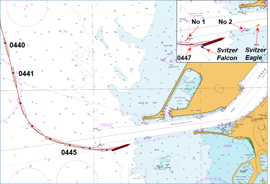
At 0441, the pilot ordered 20° of port rudder and slow ahead on the main engine to commence the turn to the entrance channel (Figure 3). Thirty seconds later, he ordered hard to port to slow the ship for entry into the channel.
At 0442¾, the pilot advised Svitzer Falcon’s master of his intentions and said that he was '…just going to go south of that first green buoy there…just want to wash a bit more speed off, so I'm just going to keep that one to port, then I'll come in between the two greens’. The ‘first green buoy’ was the starboard hand buoy No. 1 and the other ‘green’ was beacon No. 2 (Figure 3 insert). After communicating this intention of taking the ship south of the entrance channel and entering it later, the pilot advised Svitzer Falcon's master to pass down the ship’s port side.
At 0443, with Maersk Garonne’s speed at 10.9 knots and the ship turning at 25° per minute to port, the pilot ordered midships rudder. The master immediately queried the pilot. The pilot responded that he was ‘…just going to go south of this first green buoy captain, just come in…from that direction’ as he had ‘to kill a little bit of time for the second tug’ because ‘the second tug is running a little bit late.’ The master acknowledged his understanding, and that there was ‘no problem.’ At this time, Svitzer Falcon was to the south of the starboard hand buoy No. 1. Meanwhile, Svitzer Eagle was just leaving the wharf.
At 0444½, as the ship bore down on buoy No. 1, the pilot ordered 10° of starboard rudder. The ship’s speed was now 9.2 knots and its turn rate had reduced to 14° per minute. The ship was on a heading of 102° and its bridge was positioned approximately in the middle of the entrance channel (Figure 3). Svitzer Eagle was now off the wharf and visible to the pilot about 1½ miles distant.
Soon after, the chief mate queried the pilot as the starboard hand buoy No. 1 was on the port bow. The pilot advised him that the ship would pass to starboard of the buoy. The chief mate then alerted him to the shallow water ahead.
At 0445, the pilot, also aware of the shoal ahead, ordered midships rudder and, in quick succession, port 20° and hard to port.
Figure 3: Section of navigational chart Aus 113 showing Maersk Garonne’s track from 0440 at one-minute intervals (inset shows the grounded ship and the tugs at 0448½)
Source: Australian Hydrographic Service (annotated by ATSB)
At 0446¾, as the ship passed buoy No. 1 (abeam of the ship’s bridge), the pilot ordered half ahead on the main engine in an attempt to turn more quickly to port and enter the channel. He also said aloud that the ship ‘could be in a spot of bother here’. The ship was approximately parallel to the entrance channel, still turning to port and its speed was 7.9 knots.
At 0447¼, the master informed the pilot that the echo sounder was showing a depth of 1 m under the keel. The pilot noted the depth and ordered the bow thruster full power to port. Maersk Garonne’s speed was 7.4 knots and over the following 70 seconds the ship slowed and came to a gentle stop as its hull rode up onto the sand and mud bottom to the south of the entrance channel. At 0448¼, the chief mate stated that the ship had no speed, and shortly thereafter, the pilot ordered the main engine to stop. Svitzer Eagle was then about 2 cables[11] from the ship’s bow.
Subsequently, the pilot made a number of unsuccessful attempts to re-float the ship using its main engine, bow and stern thrusters and the tugs. At 0502, he informed the VTSO that the ship had grounded. He requested an additional tug and a relief pilot.
At 0542, the relief pilot boarded the ship. The original pilot remained on board to assist. By this time, the ship’s crew had inspected the cargo holds and sounded the tanks and depths surrounding the ship. The damage assessments did not indicate a breach in the ship’s hull.
Over the following hours, 900 m³ of water ballast was discharged from the forward tanks to reduce the forward draught to assist re-floating. Two additional tugs also arrived to assist.
By 0824, Maersk Garonne was re-floated using its main engine and thrusters with the four tugs assisting. The VTSO then directed that the ship be moved to and anchored in Gage Roads to await hull inspections and investigations.
On the following morning, 1 March, divers conducted an underwater hull inspection. No breaches were found and damage was limited to minor paint scraping.
Main engine trials were completed satisfactorily in the afternoon and the ship was safely berthed in Fremantle that evening.
At 1100 on 3 March, after completing its cargo operations, Maersk Garonne departed Fremantle.
At the time of the incident Maersk Garonne was registered in Denmark and classed with Bureau Veritas. The ship was owned and managed by Maersk.[12] It was on a regular service between ports in Asia and Australia and frequently called at Fremantle.
Maersk Garonne was fitted with navigational equipment required for a ship of its size under SOLAS.[13] The navigation equipment included an electronic chart display and information system (ECDIS) and two radars, which both had automatic radar plotting aid (ARPA) and other target tracking functions. Both radars had data inputs from the ship’s automatic identification system (AIS) transceiver and global positioning system (GPS) receiver unit.
The ship had a multi-national, mostly Filipino, crew of 18. This included four mates with an additional third mate on board to assist in maintaining the rest hour requirements of the STCW Code.[14]
The master had 39 years at sea and held a Romanian master mariner’s certificate of competency. He had sailed as master for 14 years and been with Maersk for the last 7 years. It was his first assignment on Maersk Garonne and he had joined about 2 months before the incident.
The chief mate held a Philippines master mariner’s certificate of competency, first obtained in 2007. He had been at sea for 16 years, all on container ships. He had sailed as chief mate for 7 years and been with Maersk for the previous 5 years. It was his first time on Maersk Garonne and he had joined about 7 weeks before the incident. The chief mate did not keep watches at sea.
The helmsman at the time of the incident was an able seaman with 28 years of seagoing experience, 22 of which had been on container ships. He had been with Maersk for 15 years. His routine duties on many ships had included those as a helmsman. He had joined Maersk Garonne 2 weeks before the grounding.
Port of Fremantle
The Port of Fremantle is Western Australia’s principal national and international sea gateway for container and general cargo trades.[15] Fremantle is a sheltered, all-weather port situated on the west coast about 20 km from the State capital, Perth.
The port operates from two locations: the Inner Harbour is located at the entrance to the Swan River and the Outer Harbour is about 20 km to the south at Kwinana-Cockburn Sound. The port had 2,277 ship visits in the 2013-14 financial year and handled more than 700,000 TEU.[16]
The Fremantle Port Authority operating under the name Fremantle Ports is the port’s strategic manager. Fremantle Ports publishes, and makes available online,[17] a Port Information Guide, which provides relevant port and related information for port users. The information includes details for communications, pilotage, arrival and departure requirements, port navigation, security and safety.
Pilotage in the Port of Fremantle is compulsory for ships over 150 GT,[18] unless the master holds a pilotage exemption certificate, and any ship so directed by the harbour master. Pilotage services are provided by Fremantle Pilots.
Fremantle Pilots
Fremantle Pilots (FP) is a privately owned company[19] that provides contracted pilotage services within the Port of Fremantle and to the ports of Albany and Bunbury as required. Fremantle Pilots provides service to more than 5,100 vessel movements annually. Pilot bookings are managed through the Port of Fremantle via the vessel’s contracted shipping agent.
All pilots undertake continuous professional development including bridge resource management (BRM) and related training, manned model and ship simulator ship-handling training, including contingency planning for emergencies.
The pilot assigned to Maersk Garonne on 28 February held an unrestricted licence as a port pilot issued by Fremantle Ports and a master mariner’s certificate of competency issued by the Australian Maritime Safety Authority (AMSA). He had 15 years of pilotage experience in various Australian ports and had worked for FP since 2004.
Passage plan
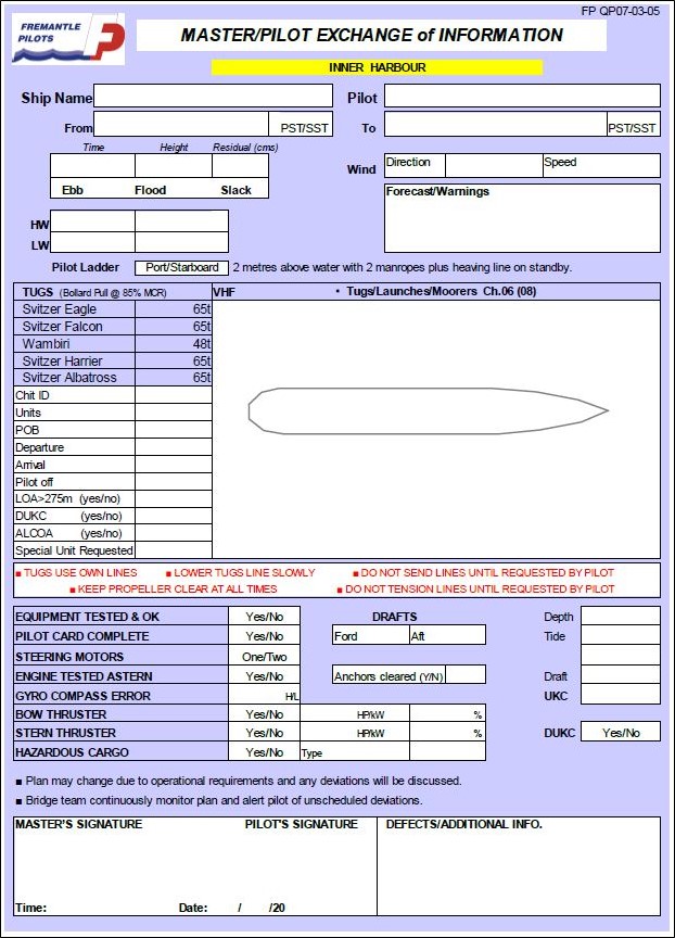
Fremantle Pilots provides information on its website[20] for ships’ masters relevant to arrival in Fremantle. This includes a master - pilot exchange of information (MPX) form (Appendix A) and waypoint lists to ‘assist vessel masters with preparing their passage plan’. The company also stated that ‘a detailed plan for the proposed passage is a requirement’ and that passage planning was through the master - pilot exchange. The MPX form was based upon IMO principles to assist:
gathering all information relevant to the contemplated voyage or passage
detailed planning of the whole voyage or passage from berth to berth…
execution of the plan; and monitoring the progress of the vessel in the implementation of the plan.
The information stated that the ‘role of our Pilot is to create a shared mental model of the plan and establish themselves within the bridge team utilising proper bridge resource management (BRM) practices.’ The information also cautioned that ‘waypoints lists are typical arrivals and departures (courses) and any variations will (be) discussed by the Pilot with the Master and bridge team accordingly.’
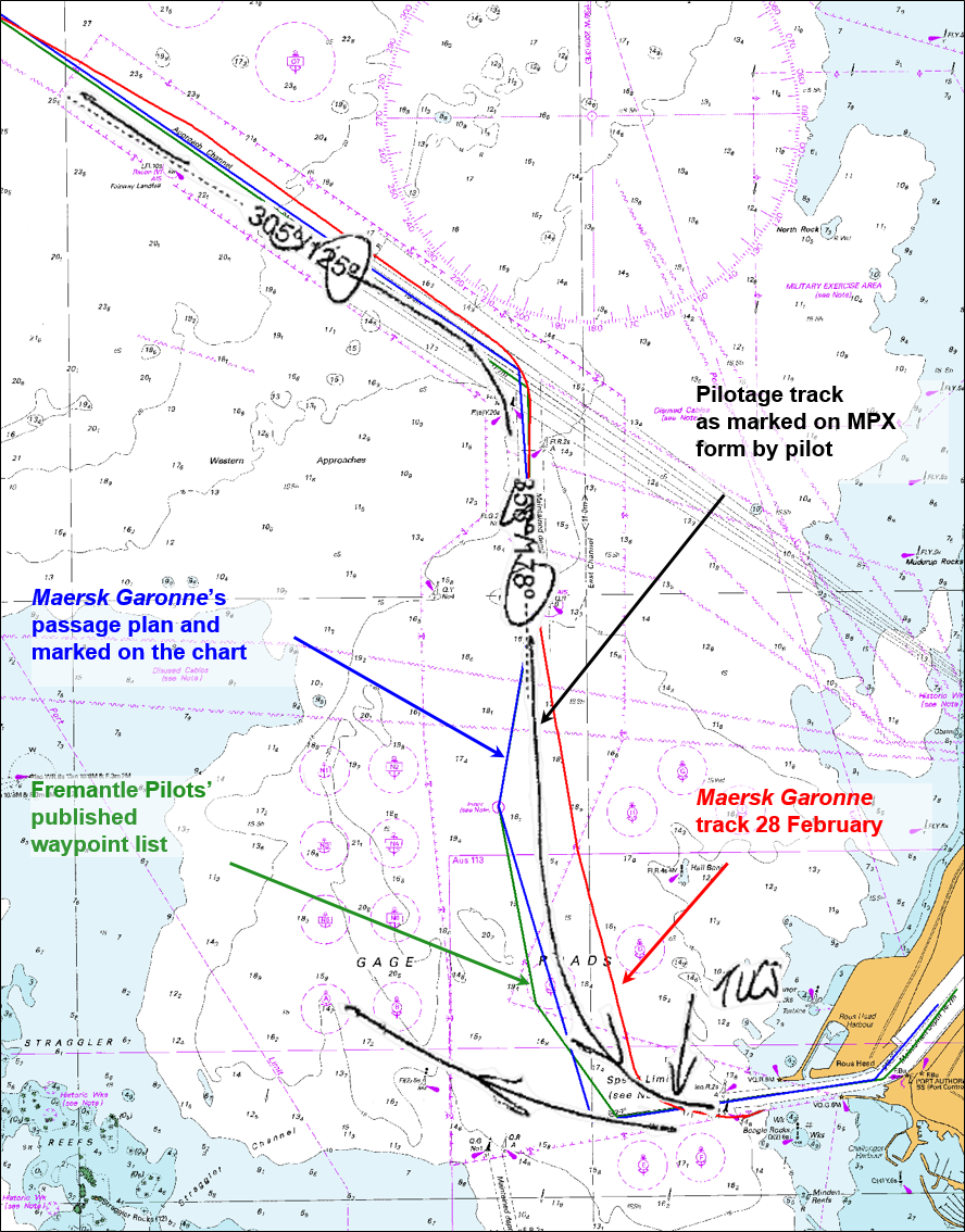
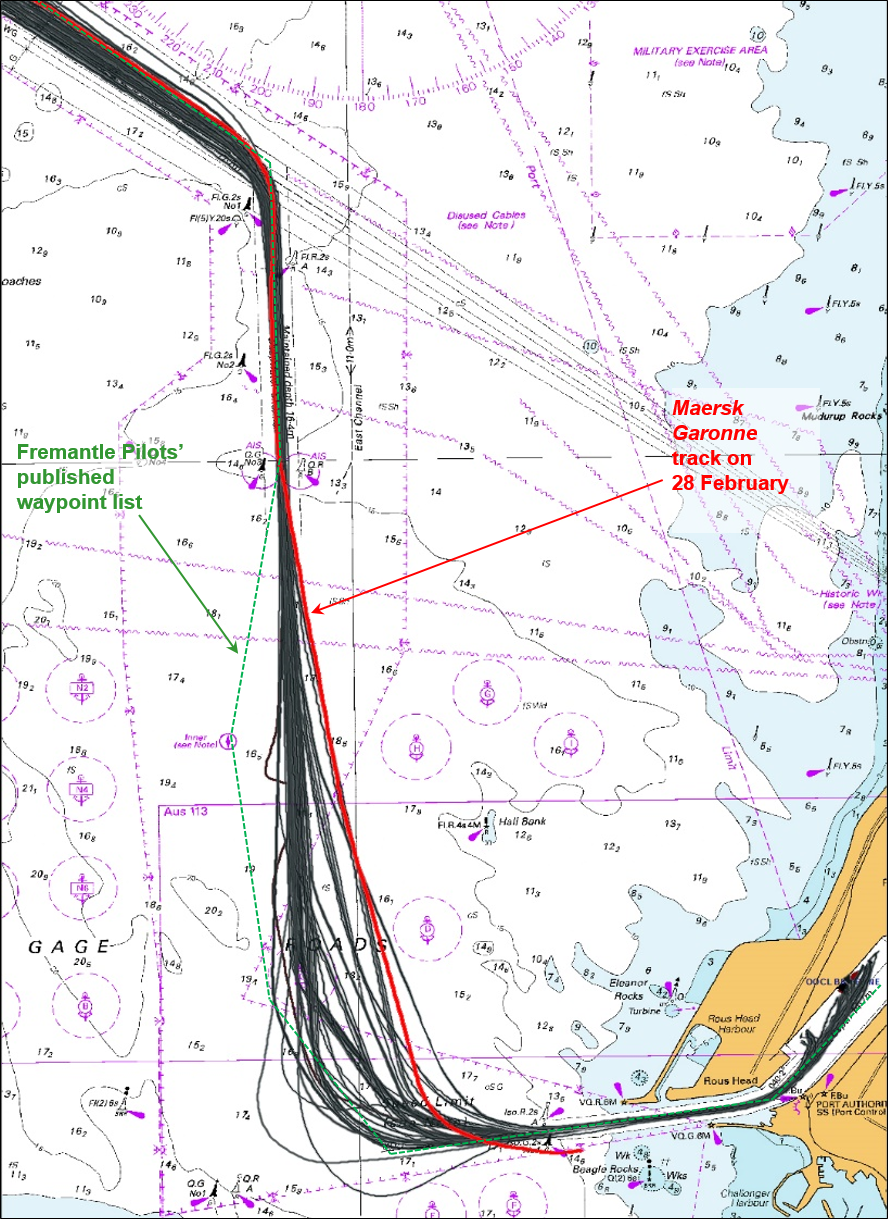
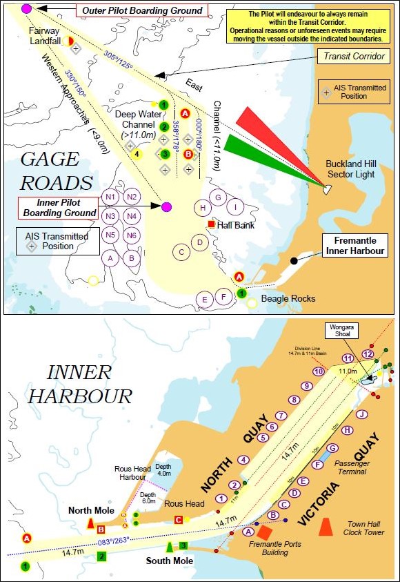
The inbound track, described by the arrival waypoint list, from the outer boarding ground to the Inner Harbour, is shown in green in Figures 5 and 6.
Portable pilotage unit
Fremantle Pilots issues its pilots with portable pilotage units (PPU). A PPU is an aid to pilotage operations with the intent to improve safety and efficiency of the operation. Its primary use is to provide independent, accurate GPS position, course and speed information. A PPU also provides other information such as charts, passage plan and AIS information. All pilots are trained in the use of the equipment and FP requires a PPU to be used for all pilotages from the outer boarding ground to Gage Roads.
Fremantle Pilots’ Procedures and Guidelines[21] stated that the PPU is to ‘provide additional information to assist the pilot’s assessment and decision making processes, and should be used in conjunction with all means available to the pilot.’ It is, however, ‘…not to be used as the sole means of assessing situational awareness’ and was not ‘to interfere with the comprehensive process required of the Master/Pilot exchange of information.’
Towage
The towage requirements for a ship entering the Port of Fremantle are set by the harbour master and outlined in the Port Information Guide. Towage requirements for ships over 275 m in length are assessed on a case by case basis. The ship’s agent orders the tugs through Fremantle Ports with a minimum of 2 hours’ notice required for the tugs to be on station.
For entry into the Inner Harbour, FP’s procedures require assisting tugs to be on station near the entrance buoys ‘A’ and ‘1’ before the ship’s arrival.
The pilot may make contact with the tugs to confirm they are in position, before arrival at the entrance buoys. The procedures stated that no ship is to enter the Inner Harbour without the assigned tug/s in attendance. The accepted practice was that the tugs be in position and/or made fast before the ship entered the entrance channel. Any tug delays were to be relayed to the pilot, who would determine if an adjustment in speed or course is necessary and/or to abort the approach.
Safe navigation
The Bridge Procedures Guide[22] states that safe navigation of a ship requires that it not be exposed to unnecessary danger and that at all times it can be controlled within acceptable margins. This requires effective command, control, communication and management of the ship.
A key accepted and practised principle of safely navigating a ship is bridge resource management (BRM). Passage planning is central to BRM. Regulation, training, guidelines, and multiple procedures apply to these concepts and enshrine them and their usage in the maritime industry.
Bridge resource management
Bridge resource management (BRM) is defined as the use and coordination of all the skills and resources (people, procedures and equipment) available to the entire bridge team to achieve the established goal of optimum safety and efficiency.[23] All individuals make errors, and BRM aims to minimise the occurrence and outcome of errors through the best possible use of resources.
All ship’s navigators must have training, and demonstrate competence, in BRM techniques.[24]
In areas of increased risk to safe navigation, a pilot is often added to the ship’s navigation team. The pilot’s local knowledge and practised piloting techniques are intended to, and should, reduce risks to an acceptable level.
The ship’s master and the pilot are responsible for taking steps to actively engage and include other members of the ship’s bridge team in the pilotage. Through effective BRM, all personnel involved in the navigation of the ship should have a clear understanding of, and expectations for, the pilotage. However, where marine casualties have occurred with a pilot on board, many have been attributed to flawed master - pilot relationships. In many cases, when the pilot boarded the ship, the master and deck officers ceased to monitor navigation and the position of the ship.
Bridge resource management is a broad topic which covers many inter-related subjects, including but not limited to:
shared mental model
situational awareness
error management
contingency planning
challenge and response
distractions and interruptions.
Safety management systems
The organisations responsible for ensuring Maersk Garonne was safely navigated into the Port of Fremantle included Maersk (the ship’s managers), Fremantle Pilots and Fremantle Ports. Each organisation had a safety management system (SMS), training and processes aimed at achieving that objective.
Each SMS included sections relating to BRM and passage planning and the master - pilot exchange of information (MPX).
Passage planning
Passage planning is necessary to allow the entire bridge team to arrive at a shared understanding of what ‘should’ happen during the passage and thus ensure the ship can be safely navigated between ports from berth to berth. The margins of safety in restricted coastal waters can be critical, limiting the time available to take corrective action when required. Careful passage planning is used to make a pilotage passage safer, for example, by setting limits that make unsafe deviations from the plan readily apparent.
The ship’s master is required to develop a plan for its safe and efficient passage between ports.[25] Detailed plans are needed to ensure appropriate margins of safety are maintained at all times.
The International Maritime Organization (IMO) provides guidelines[26] for voyage planning, which comprises four distinct stages:
appraisal during which all information relevant to the passage is considered
planning when a detailed plan for the voyage is prepared
execution of the plan, including suitable alterations to the passage plan as required by circumstances
monitoring the execution of the plan including ensuring all navigators know and understand it.
Section 2.6 of the Bridge Procedures Guide, states:
Of particular importance is the need to monitor the position of the ship approaching the wheel over position at the end of the track, and checking that the ship is safely on the new track after alteration of course.
Pilotage
A ship is exposed to higher risks in pilotage areas because of the reduced margins of safety due to factors which often include reduced depth and width of fairways, increased traffic, tidal variations and stronger currents. The pilot, as the port’s primary risk mitigation tool for the pilotage area, provides skills and local area knowledge - valuable additions to the bridge team’s resources.
However, a pilot is not a replacement for any of the ship’s bridge team members. The master and the ship’s bridge team are always responsible for its safe navigation, even when navigating with a pilot.[27] It is necessary, therefore, that the ship’s crew works with the pilot by observing good BRM practice in executing the agreed passage plan. This approach helps all to work together to ensure that errors are detected early and corrected before the ship is put into any danger.
Master - pilot exchange
The master - pilot information exchange (MPX) is the first opportunity for the pilot and master to exchange critical information to facilitate a safe and effective pilotage. In effect, it is the meeting in which the pilot and the master agree on a common passage plan. Alterations are made as required to decide how the pilotage will be done jointly. The MPX aims to ensure that the ship’s bridge team and the pilot share the same understanding of, and expectations for, the pilotage. It also helps to establish appropriate working relationships with defined roles and responsibilities.
At 0400 on 28 February 2015, a harbour pilot boarded Maersk Garonne for its passage into Fremantle. The master informed him that the ship’s equipment and machinery were in working order. In turn, the pilot briefed the master and marked his intended course on the diagram in the master - pilot exchange (MPX) form. The ship’s officer of the watch (OOW) and helmsman were also on the bridge.
Over the next 35 minutes, the pilotage generally progressed as intended by the pilot. However, as the ship exited the Deepwater Channel (DWC), the pilot conducted the ship to the east of both the planned track on the ship’s chart and his own intended track on the MPX form. At no stage did the ship’s bridge team members challenge the pilot regarding this deviation from the plan.
Figure 4: Sections of navigational chart Aus 113 showing the progress of Maersk Garonne and the tugs from 0441
Source: Australian Hydrographic Service (annotated by ATSB)
Then, as the ship approached the entrance channel, the pilot became concerned that it would arrive there before the two harbour tugs were in position. After some radio communications with one of the tug masters, the pilot decided to delay the ship’s entry into the channel.
At 0443, the pilot began manoeuvring Maersk Garonne to delay entering the channel (Figure 4). He intended to do so by taking the ship outside, and south of, the channel and then enter between the starboard hand buoy No. 1 and beacon No. 2. However, at 0448, while it was still outside the channel, the ship grounded in an area of charted shallow water.
Execution of the pilotage
Master - pilot exchange
The Fremantle Pilots’ (FP) passage planning for inbound ships, utilised a MPX form based on the IMO’s recommended operational procedures[28] for maritime pilots. This form contained harbour and towage information, transit corridor and channel chartlets and checklist prompts for items of discussion (see Appendix A).
Further, FP’s procedures and guidelines stated:
It should be further noted that the Master/Pilot Information Exchange form does not fulfil the purpose of a passage plan and is used only as a means of effectively exchanging information between the Pilot and the Master to facilitate a safe and effective pilotage operation.
For the arrival of Maersk Garonne, the MPX took place immediately after the pilot arrived on the bridge. This was normal practice, and bridge audio recordings show that the principal information exchange took place before the ship passed the Fairway Landfall buoy. During this discussion, brief mention was made of intended tracks by indicating that the transit would be via the DWC, and that tugs were expected just outside the entrance channel.
However, several items were not discussed, at any stage during this time, or the remainder of the pilotage, including:
ship’s speeds
planned track details, such as true courses, course alterations, wheel over positions, cross-track error limits and main engine/speed requirements/changes
contingency plans and/or abort points
communication with VTS and tugs.
After the MPX was completed, the master did not update the OOW with the information exchanged, including the pilot’s intended track, which was different to that marked on the ship’s chart. Further, no designated roles and responsibilities in support of the pilot were assigned to the ship’s bridge team members. Such duties may have encouraged them to become more actively engaged in the pilotage. Consequently, members of the ship’s bridge team remained unaware of important details of the pilotage passage that were essential to safe navigation.
Passage planning
The passage plan for a pilotage forms the basis on which all bridge team members involved build their understanding of what the pilotage will involve. This model should then be shared between all personnel involved in the navigation of the ship into port.
Fremantle Pilots required a passage plan to be prepared for any, and all, pilotages. Its procedures and guidelines stated:
An essential part of the Pilot's passage plan is the laying down of courses between the point of origin and proposed destination.
Once on board the vessel, the Pilot, in consultation with the Master and his bridge team, will complete the plan making alterations as required.
MaerskGaronne’s master’s passage plan included the pilotage into Fremantle’s Inner Harbour. The ship’s SMS procedures required specific items to be marked on the chart, including:
parallel indexing
methods and frequency of position fixing
clearing lines and bearings
safe speed and necessary speed alterations
changes in machinery status
contingency plans
abort positions.
However, only the safe speed and speed alterations were included in the passage plan, and only the planned track was marked on the chart. This suggests that the ship’s bridge team members expected the pilot to provide much of the missing information.
Planned courses
There were three possible intended tracks for Maersk Garonne's pilotage into the Port of Fremantle on 28 February (shown in different colours in Figure 5):
derived from FP’s published waypoint list (green)
MaerskGaronne’s passage plan marked on the ship’s chart (blue)
pilot’s intended track marked on the MPX form (black).
None of these tracks was followed - the ship actually followed the track shown in red. Further, the three different, possible intended tracks meant that the ship’s bridge team members did not have the same understanding as the pilot of the track he intended to follow.
Awareness and understanding of the plan
At no stage was either OOW briefed on the key details discussed during the MPX. Therefore, the OOWs were unaware that the courses marked on the ship’s chart were not to be followed. Further, the pilot did not inform the ship’s master or bridge team members that he intended to conduct the ship to the east of the marked courses and the hand drawn track on the MPX form.
As a result, the ship’s bridge team members were unable to develop and maintain a shared understanding and mental model of the plan and expectations for the pilotage as it progressed. Their ability to maintain situational awareness was compromised by not knowing what the plan was. Hence, they were not actively engaged in the pilotage and were therefore unable to assist in the detection and management of errors or deviations from the plan.
Further, no opportunities to clarify the plan and then jointly execute and monitor it were taken. For example, the significant deviation from the charted course on departure from the DWC was not communicated or challenged.
Previous tracks
The ATSB investigation analysed recent inbound pilotage tracks of ships similar in size to Maersk Garonne during the 2 months preceding its grounding. The tracks of more than 40 ships greater than 250 m in length are shown below (Figure 6).
All tracks were within the approved Fremantle Ports transit corridor, however, the analysis showed that none of the tracks was consistent with FP’s published waypoint list (green line in Figure 6). The analysis also showed that MaerskGaronne’s track on 28 February was at the eastern extremity of the others. Had the ship followed the published track it would have been 6 cables further to the west. This would then have provided more time and distance for the second tug to be on station, or its position to be verified, and for the pilot to consider aborting the approach.
Figure 5: Comparison of Maersk Garonne's intended and actual tracks on 28 February
Source: Australian Hydrographic service (annotated by ATSB)
Transit speed
Fremantle Ports’ Port Information Guide states that ships transiting channels shall maintain a speed consistent with safe navigation. In addition, the port’s operational parameters stated that ships with draughts greater than 12 m should not exceed 13 knots in the DWC. However, the pilot’s MPX form did not refer to recommended speeds or speed restrictions for the transit.
MaerskGaronne’s master’s passage plan for the pilotage included maximum and minimum speeds. The maximum speed south of the DWC was 12 knots, reducing to less than 8 knots for the entrance channel.
However, Maersk Garonne transited the DWC at about 16 knots. The pilot maintained this speed until south of Hall Bank, when the main engine speed was reduced to half ahead. The ship’s speed reduced slowly until the pilot started the turn towards the entrance channel, at which time it was 14.5 knots. The pilot intended to maintain a higher speed to improve the ship’s manoeuvrability as in his experience the ship did not turn well at slow speed.
Figure 6: Inbound pilotage tracks of ships greater than 250 m in length in the 2 months preceding the grounding
Source: Australian Hydrographic Service (annotated by ATSB)
Neither the pilot nor any of the ship’s bridge team members discussed the ship’s speed at any time. The speed was consistently above the maximums mentioned in the port’s operating parameters and Maersk Garonne’s passage plan. Had the speed been maintained within the port parameters and/or the ship’s passage plan, the ship would have arrived at the pilot’s intended position to turn towards the entrance at least 3 minutes later than it did (0441). While 3 minutes would not have ensured either of the tugs was on station on time, it would have provided more time on board the ship to detect, manage and potentially recover from the errors that occurred.
Contingency planning
Contingency planning is a risk management tool, which adds significant control to better manage emergencies. Anticipation of, and preparation for, an adverse event makes the reaction to it more effective. The reaction may then be one from a known and practised range of options, rather than an unknown, instantaneous reaction in an unexpected and stressful situation. Learning only from real emergencies is not practical and therefore should be enhanced through training, ideally simulation, in a controlled environment, especially for foreseeable risks.
The harbour pilot is the local knowledge expert and is employed to conduct the ship because of this specific knowledge. MaerskGaronne’s pilot had many years of pilotage experience, including more than 10 years in Fremantle, and was also an experienced ship’s master. He was familiar with the ship’s manoeuvring characteristics, having conducted it numerous times in or out of the port.
Maersk Garonne’s maximum draught of 12.2 m and length overall of 292 m were at the upper end of ship size/dimensions permitted in Fremantle. The ship’s manoeuvring information poster was also displayed on the bridge. At interview, the pilot stated that the size and manoeuvrability of the ship at various speeds influenced the decisions he made regarding the ship’s track and turns.
The pilot knew the information about the ship and had a comprehensive knowledge of the pilotage area. He should, therefore, have been keenly aware that the ‘no-go area’ outside the marked channel was unsuitable for a deep draught vessel. Therefore, entering the channel between starboard hand buoy No. 1 and beacon No. 2 should never have been considered a safe option.
At interview, the pilot acknowledged that he was aware that going south of the channel was not an option for the large ship. He also indicated that his plan (that is, going south of the channel) was an ‘ambitious manoeuvre’ to overcome earlier errors but he thought he would still ‘make it’. These statements support the fact that experts also make poor decisions in unexpected situations, particularly when pressed for time. They also highlight the importance of contingency planning.
Fremantle Pilots’ (FP) procedures included guidelines on the identification, assessment and management of hazards and risks. These were recorded using job hazard analysis (JHA) documents. The JHA for Inner Harbour arrival identified risks such as the tugs not standing by and ship’s system faults, and provided risk controls for such events. However, neither the JHA, nor other FP’s procedures, included any formalised contingency plans for the risks identified.
Similarly, ‘no-go areas’ and abort points should have been marked on the ship’s chart. Hence, the ship’s bridge team, especially the master, should have known that navigating outside the channel was not a safe option. However, when the pilot informed him of his intentions, the master did not have an appropriate level of situational awareness and agreed with the pilot without a challenge.
At 0441, the pilot commenced the turn toward the entrance. At 0442¾, he informed the tug master of his intention to go south of the first green buoy (the starboard hand buoy No. 1). Figure 7 shows the final stages of the grounding with an indicative turning circle, based on the ship’s manoeuvring information,[29] shown. This simple analysis shows that options, though limited, remained available to safely manoeuvre or stop the ship before it passed south of the entrance channel.
No contingency plans were recorded or discussed. Therefore, when the tugs were not on station as the pilot expected, he did not have any preplanned or practised manoeuvres to fall back on. He then had to make decisions quickly and under increasing levels of stress. This resulted in manoeuvring the deep draught ship into charted shallow waters outside the marked channel.
Figure 7: Maersk Garonne’s track with the ship’s turning circle overlaid
Source: Australian Hydrographic Service (annotated by ATSB)
Bridge resource management
MaerskGaronne’s safety management system contained a procedure for navigation with a pilot on board. This procedure outlined the strategies and requirements for the master and bridge team members to follow. The subjects mentioned included crewmember responsibilities, communications, master - pilot exchange, manoeuvring, the route to be followed and the passage plan. However, many of these were not followed and BRM was ineffective.
Roles and responsibilities
Safe navigation requires that all bridge team members involved are aware of their roles and responsibilities. Analysis of marine incidents by AMSA has identified that many incidents are attributed to single-person errors.[30] During pilotage, many of the navigational decisions are made by the pilot alone. Therefore, to make it more likely that single-person errors (made by the pilot) are detected early, all bridge team members must have an understanding of individual roles and responsibilities in executing the agreed plan.
The master and the ship’s bridge team are always responsible for its safe navigation, and are therefore expected to participate fully in navigation during pilotage. They must continue to monitor the safe passage of the ship and critically appraise the pilot’s advice. In order to do this, and to ensure safe and efficient navigation, they should fully support the pilot as a valuable resource and addition to the team.
On 28 February, when the pilot took the conduct of Maersk Garonne, in effect, he became the only one actively focused on the pilotage. After the initial exchange of information between the master and pilot, no tasks were assigned to, or updates provided to the bridge team. There was, then, an absence of clearly defined roles and responsibilities for team members.
Shared mental model
Each individual member of a team will develop a mental model of what they think will occur during the task being completed. Each person’s mental model is based upon the information available to them at the time. Ensuring that each member of a bridge team shares the same mental model of the passage plan is central to effective BRM.
Shared mental models serve three critical purposes: they help people to describe, explain and predict events in a common environment. Any team that must adapt quickly to changing tasks might draw on shared or common mental models for those tasks. In order to adapt effectively, team members must be able to predict what their teammates are going to do, and what they are going to need to be able to do it.[31]
At the start of the pilotage, as Maersk Garonne approached the Fairway Landfall buoy, the ship’s bridge team members shared a common mental model of the progress of the pilotage. The intended track through the DWC, marked by the pilot on the MPX form, was consistent with that on the ship’s chart as per its passage plan (Figure 5).
However, as the ship left the DWC, the pilot ordered a heading of 170°. From this point, the pilot’s intended track diverged from the ones marked on the ship’s chart and the MPX form. The ship’s bridge team members did not challenge this deviation and subsequently, no longer had a shared mental model for the pilotage.
Situational awareness
A team’s situational awareness is closely associated with the concept of shared mental model. Situational awareness has been variously defined, including simply as knowing what is going on around you. In relation to a ship’s passage, it includes knowing what has recently happened, what is happening and, based on where the ship is, what is about to happen.
Careful observation and understanding of the situation around you should achieve one of two things: it should reinforce your understanding and confidence in the mental model of the passage, or it should highlight a misunderstanding or an error and trigger actions to clarify or correct the situation.
Situational awareness is dependent on working memory and is, therefore, affected by distraction, interruption and stimulus overload. Collective (team) situational awareness can be enhanced by:
monitoring the progress of the agreed plan
communicating with each other about the situation to share individual awareness and discuss differences
anticipating next conditions
checking one another.
There were many resources available on board Maersk Garonne to assist in establishing and maintaining situational awareness. These included ship’s equipment such as the radars and the AIS receiver, as well as human resources which could be assigned to gather or verify information.
As the ship left the DWC, and navigated to the east of the ship’s passage plan track, the master and OOW progressively lost situational awareness. Their mental models of the pilotage changed and they were unable to anticipate or monitor the ship’s progress against an agreed plan. Despite this, they did not communicate with the pilot or each other to attempt to clarify the plan or the deviation from it.
There was no agreed plan, and, as a consequence, there was no shared mental model of the pilotage. The pilot was the only one who knew what his plan was. Therefore, he was the only one that was in a position to be able to maintain situational awareness.
However, the pilot did not have his personal pilotage unit (PPU), as required by FP procedures, to assist him. Before boarding the ship, he found the PPU was not charged. As there was no spare battery, he left the PPU charging. He did not consider using the ship’s power supply to charge/use the PPU.
In addition to this, while Maersk Garonne was not required to have an electronic chart display and information system (ECDIS), it was fitted with one.[32] However, the ECDIS was not operational. The master had identified this in the pre-arrival notification but Fremantle Ports did not pass this information to the pilot. Nor did the master inform the pilot of this during the MPX.
Consequently, as other position monitoring resources on board were not effectively used, and without the PPU or ECDIS to monitor the passage, the pilot believed that the ship was further to the west than it was. However, this was not the case and his decision-making was hampered. The situation was compounded when the pilot became occupied with contacting the tugs.
Error management
The detection and management of errors is a key safety aspect in the process of avoiding serious incidents. Having accepted the premise that all individuals make errors, error management then seeks to detect and control the mistakes to minimise any negative outcomes.
There are two components to error management:
error reduction – measures designed to limit the occurrence of errors
error containment – measures designed to limit the adverse consequences of those errors that still occur.
The capacity of a system to minimise the outcome of an error, or series of errors, is determined by the system’s margin for error. The bigger the margin for error, the greater the capacity to overcome errors. Time is a key common element in error management. The more time available to detect, assess and respond to an error, the more appropriate the response is likely to be.
On board Maersk Garonne, none of the bridge team members adequately monitored the actions of other members of the team or the ship’s progress. As a consequence, there was no effective detection and management of, or recovery from, errors which occurred, as the bridge team members did not:
clarify and agree upon the planned or intended track
engage all team members in the pilotage
delegate tasks, such as ensuring the locations and movement of tugs
ensure everyone had a common mental model of the intended passage
challenge the deviation from the planned track
have in place or discuss contingency plans
use all bridge equipment to monitor the ship’s progress
critically appraise and verify communications regarding movement of the tugs.
Hence, the margins for error eroded and this led to the ship being navigated outside the channel.
Challenge and response
Effective communication is central to bridge resource management (BRM). It is essential to prevent errors leading to undesirable outcomes. Challenge and response is a BRM technique in which a person’s perception of an error, in the execution of the plan, is confirmed or denied by asking and/or responding to questions. That is, if unsure of exactly what is occurring, a person should ask others to clarify the situation, and a response is required.
While the pilot’s plan was not communicated to the rest of the bridge team, it should have been evident to the OOW that the track marked on the ship’s chart was not being followed (when the ship exited the DWC). That neither OOW raised this important matter with the master or the pilot is indicative of the level of BRM. The OOW only challenged the pilot when the ship was outside the entrance channel and with the starboard hand buoy to port. The ship was now in a ‘no-go area’ with shallow water ahead. However, the challenge was ineffective, as it was too late.
Distractions
Interruptions or distractions during the completion of a task increase the likelihood of error. Distractions can be related to the task or from some external, unrelated source or event. An individual, or team, can also become completely occupied (fixated) with one event or task and therefore distracted from the overall objective.
Minimising possible distractions is important for effective BRM. For example, many ships, and passenger ships in particular, have a ‘red zone’ system during periods of increased risk to navigation, such as pilotages. This method restricts access and internal communication to the bridge to only those involved in navigational tasks. This reduces unnecessary and undesirable sources of distraction.
During this pilotage there were a number of distractions with attempting to establish contact with both tugs, by radio and then visually. The pilot was trying to establish whether or not the second tug would be on station before the ship arrived at the entrance channel. These distractions occupied the pilot’s attention just as the ship was approaching a period of heightened activity and manoeuvring. Throughout this period, he did not check the ship’s position by any means available and relied upon the leading lights as a transit for the wheel over point. However, the ship was much further to the east than he believed.
As the turn commenced, the pilot used the rudder hard to port to slow the ship in preparation for entering the entrance channel. He then became concerned that the tugs would not be on station as he expected so he altered his plan and decided to go south of the channel. He ordered the rudder midships to slow the rate of turn. However, he became concerned that the ship would collide with No. 1 buoy. His attention now turned to avoiding the buoy and he ordered starboard rudder to ensure the ship would pass south of it. This manoeuvre became his focus to the exclusion of other critical navigational risks.
Had the pilot had an accurate understanding and appraisal of the ship’s position and its progress during the turn, he could have manoeuvred to avoid the shallow water before becoming fixated with clearing the buoy.
Change of OOW
The need to change the OOW during a pilotage is a foreseeable risk. The change involves possible disruption to the bridge team and distraction of personnel, including the pilot. There is also the risk of loss of information during the handover, a loss of the shared mental model and loss of situational awareness.
The pilotage from the Fremantle outer pilot boarding ground to the Inner Harbour should have taken about 90 minutes. The ship’s third mate took over the 4-8 watch at 0400, and was to be at the forward mooring station for berthing shortly after 0430. Consequently, two changes of watch occurred in 30 minutes. The chief mate took over at about 0430, when the ship was passing Hall Bank. This was also at about the time the pilot became occupied with contacting the tugs and then turning the ship towards the entrance channel.
The risks associated with handing over the watch during the pilotage had not been considered and the change of OOW added unnecessary distractions.
Observers
There is the potential for additional personnel on the bridge of a ship during pilotage operations to be a distraction.[33] While the presence of observers on the bridge at such times may sometimes be acceptable, it needs to be carefully managed. For example, there is a need for observers for training purposes, of pilots and ship’s crew, and for checking or auditing purposes.
During the pilotage of Maersk Garonne, a navigational student observer was occupying some of the pilot’s time and attention. In such situations, the interaction of observers with the bridge team, and especially the pilot, needs to be controlled to prevent distraction. Bridge recordings show that the pilot and observer were engaged in conversation, interspersed with communications with the ship’s personnel, as late as 0444¾. This was during a period of heightened activity as it was when the chief mate commented that the starboard hand buoy No. 1 was off the port bow and just after the pilot had ordered 10° of starboard rudder to avoid the buoy.
The dynamic between pilot and ship’s bridge team members altered due to the presence of the observer and his interaction with the pilot.[34] Further, while this was not identified as having directly contributed to the incident, the conversation between the observer and the pilot reduced the opportunity for the ship’s crew to interact with the pilot. This factor may have affected the building of a shared mental model and maintaining situational awareness.
External resources in pilotage
Vessel traffic service
Fremantle Ports maintains a 24-hour vessel traffic service (VTS)[35] in accordance with international guidelines. As part of its function, the VTS organises and manages traffic within its VTS area, and provides essential information related to ship movements.
The duty VTS officer (VTSO) is required to maintain a continuous watch, monitoring shipping traffic and provide information to ships, pilots, tugs and other users. The VTSO also provides information about ship movements, berth allocations and other matters related to the safety of navigation and weather within port waters.
At 0435 on 28 February, the VTSO provided tug information, which was taken by the pilot as confirmation that his plan (mental model) was progressing as expected. Therefore, the pilot continued with his plan and started the turn toward the entrance channel. Had the communication between the VTSO and pilot clearly identified that both tugs had not yet departed the wharf, the pilot may have decided to alter his plan or abort the approach to the entrance channel.
Tugs and towage
Tugs are essential resources for safely berthing a ship. Therefore, clear and unambiguous plans, information and communications are required to ensure the most effective use of tugs. In this way, the tugs, their roles and expectations can be integrated into the shared mental model for the pilotage.
At 0435, the VTSO advised the pilot that the tugs were getting underway. However, only one tug had departed the wharf. About 3 minutes later, the pilot contacted the tugs. The master of the tug that was underway answered promptly and informed the pilot that the other tug was on the way. Consequently, he believed that both tugs were en route to the entrance channel buoys. Therefore, he decided to continue the pilotage but altered the positions (forward or aft) for making fast the tugs based upon their expected order of arrival.
At 0440½, the master of the tug that was still alongside the wharf contacted the pilot, just as he was starting the ship’s turn toward the entrance channel. The pilot informed him to make fast on the starboard shoulder. However, neither the fact that the tug was still alongside the wharf nor its expected time at the entrance channel buoys were discussed. It was not until 0444 that the tug departed the wharf. In the meantime, the pilot had started the turn to port and had to alter his plan after not being able to sight the tug.
Entry into the Inner Harbour required tugs to be in attendance. Fremantle Pilots’ (FP) accepted practice was for the tugs to be in position and/or made fast before the ship entered the entrance channel. As tugs being delayed was a foreseeable risk, FP should have had measures in place to ensure clear and unambiguous communications between pilots and tugs. Such measures should necessarily include contingency plans to mitigate risk in the event that tugs are delayed.
Further, Fremantle Ports and its contracted towage provider had not adequately ensured that such risks to the port were mitigated. Procedures for tugs to be on station at the entrance to the port, or for their co-ordinated movement, were not clearly defined.
From the evidence available, the following findings are made with respect to the grounding of the container ship Maersk Garonne at the entrance to the Port of Fremantle, Western Australia, on 28 February 2015. These findings should not be read as apportioning blame or liability to any particular organisation or individual.
Safety issues, or system problems, are highlighted in bold to emphasise their importance. A safety issue is an event or condition that increases safety risk and (a) can reasonably be regarded as having the potential to adversely affect the safety of future operations, and (b) is a characteristic of an organisation or a system, rather than a characteristic of a specific individual, or characteristic of an operating environment at a specific point in time.
Contributing factors
At 0448 on 28 February 2015, Maersk Garonne grounded in charted shallow water while it was being manoeuvred outside the shipping channel at the harbour entrance.
The harbour pilot conducting MaerskGaronne had decided to delay the ship’s entry into the entrance channel because it was arriving there earlier than the two harbour tugs assigned to assist it.
MaerskGaronne’s speed until approaching the entrance channel had exceeded both the ship’s passage plan speed and the port’s recommended speed resulting in it arriving there at least 3 minutes earlier than it would have at those slower speeds.
The manoeuvre to delay the ship’s entry into the channel had become the pilot’s primary focus in the period leading up to the grounding.
The pilot was not carrying a portable pilotage unit as required by Fremantle Pilots’ procedures and this affected his ability to accurately monitor the ship’s position and progress.
The ship’s bridge team members did not effectively challenge the pilot’s plan to take the ship outside the channel or take any action to prevent the grounding.
Bridge resource management (BRM) was not effectively implemented on board Maersk Garonne. The ship’s passage plan for the pilotage was inadequate, its bridge team members were not actively engaged in the pilotage and they did not effectively monitorthe ship’s passage. [Safety Issue]
Fremantle Pilots’publicly available information to assist ships' masters with preparing a berth to berth passage plan was inadequate and ineffectively implemented. The information provided consisted essentially of a list of waypoints, which wasroutinely not followed.[Safety issue]
Fremantle Pilots’procedures did not include any contingency plans, including abort points, for risks identifiedfor the pilotage. [Safety issue]
Procedures for harbour tugsto meet inbound ships andfor their co-ordinated movement in the Fremantle pilotage area were not clearly defined. On 28 February,inadequate co-ordination of the tugs and ineffective communication between Maersk Garonne’s pilot and the tug masters resulted in both tugs, the second one in particular,being significantly delayed from when they could reasonably have been expected to be on station.[Safety issue]
Safety issues and actions
The safety issues identified during this investigation are listed in the Findings and Safety issues and actions sections of this report. The Australian Transport Safety Bureau (ATSB) expects that all safety issues identified by the investigation should be addressed by the relevant organisation(s). In addressing those issues, the ATSB prefers to encourage relevant organisation(s) to proactively initiate safety action, rather than to issue formal safety recommendations or safety advisory notices.
All of the directly involved parties were provided with a draft report and invited to provide submissions. As part of that process, each organisation was asked to communicate what safety actions, if any, they had carried out or were planning to carry out in relation to each safety issue relevant to their organisation.
The initial public version of these safety issues and actions are repeated separately on the ATSB website to facilitate monitoring by interested parties. Where relevant the safety issues and actions will be updated on the ATSB website as information comes to hand.
Bridge resource management
Bridge resource management (BRM) was not effectively implemented on board Maersk Garonne. The ship’s passage plan for the pilotage was inadequate, its bridge team members were not actively engaged in the pilotage and they did not effectively monitor the ship’s passage.
Fremantle Pilots’ publicly available information to assist ships' masters with preparing a berth to berth passage plan was inadequate and ineffectively implemented. The information provided consisted essentially of a list of waypoints, which was routinely not followed.
Procedures for harbour tugs to meet inbound ships and for their co-ordinated movement in the Fremantle pilotage area were not clearly defined. On 28 February, inadequate co-ordination of the tugs and ineffective communication between Maersk Garonne’s pilot and the tug masters resulted in both tugs, the second one in particular, being significantly delayed from when they could reasonably have been expected to be on station.
The sources of information during the investigation included:
the master and crewmembers of Maersk Garonne
the marine pilot on board the ship at the time of the grounding
Maersk Line Ship Management
Fremantle Pilots
Fremantle Ports
the Australian Maritime Safety Authority (AMSA).
References
Australian Maritime Safety Authority 2009, Marine Notice 07/2009 Bridge Resource Management (BRM) and Torres Strait Pilotage, AMSA, Canberra. Note that this marine notice has been cancelled and may contain information which is no longer applicable.
Australian Maritime Safety Authority 2012, Marine Order 21 (Safety of navigation and emergency procedures) 2012, AMSA, Canberra.
Australian Maritime Safety Authority 2013, Marine Notice 15/2013 Vessel Traffic Services – Responsibilities of Authorities, AMSA, Canberra.
Di Lieto, A 2015, Bridge Resource Management, Hydeas, Brisbane, Australia.
Greche, RG, Horbery, TJ & Koester, T 2008, Human factors in the maritime domain, CRC Press, London.
International Chamber of Shipping (ICS) 2007, Bridge Procedures Guide, 4th Ed, ICS, London.
International Maritime Organisation (IMO), 1974, The International Convention for the Safety of Life at Sea, 1974, as amended (SOLAS 1974), IMO, London.
International Maritime Organisation (IMO) 1978, International Convention on Standards of Training Certification and Watchkeeping for Seafarers, 1978, as amended (STCW Code), IMO, London.
International Maritime Organisation (IMO) 2004, Resolution A.960(23) Recommendations on training and certification and operational procedures for maritime pilots other than deep-sea pilots, IMO, London.
International Maritime Organisation (IMO) 2004, Resolution A.893(21) Guidelines for voyage planning, IMO, London.
Jonker, C.M., van Riemsdijk, M.B. and Vermuelen, B 2011, ‘Shared Mental Models’, Coordination, Organizations, Institutions, and Norms in Agent Systems VI, Springer, Canada, pp. 132-51.
Reason, J 2008, The Human Contribution, Ashgate, Farnham, England.
Schager, B 2008, Human error in the maritime industry, Marine Profile Sweden.
Submissions
Under Part 4, Division 2 (Investigation Reports), Section 26 of the Transport Safety Investigation Act 2003 (the Act), the Australian Transport Safety Bureau (ATSB) may provide a draft report, on a confidential basis, to any person whom the ATSB considers appropriate. Section 26 (1) (a) of the Act allows a person receiving a draft report to make submissions to the ATSB about the draft report.
A draft of this report was provided to the Australian Maritime Safety Authority (AMSA), the Danish Maritime Accident Investigation Board, Maersk Line Ship Management, Fremantle Ports, Svitzer Australia, Fremantle Pilots, the pilot on board at the time, and Maersk Garonne’s master, chief mate and third mate.
Submissions were received from AMSA, Maersk Line Ship Management, Fremantle Ports, Svitzer Australia, Fremantle Pilots and the pilot on board at the time. The submissions were reviewed and where considered appropriate, the text of the report was amended accordingly.
Appendices
Appendix A – Fremantle Pilots’ Master/Pilot exchange form
Fremantle Pilots’ Master/Pilot exchange of information form, reproduced below, comprises two A4 sized pages and is available from www.fremantlepilots.com.au
Purpose of safety investigations
The objective of a safety investigation is to enhance transport safety. This is done through:
identifying safety issues and facilitating safety action to address those issues
providing information about occurrences and their associated safety factors to facilitate learning within the transport industry.
It is not a function of the ATSB to apportion blame or provide a means for determining liability. At the same time, an investigation report must include factual material of sufficient weight to support the analysis and findings. At all times the ATSB endeavours to balance the use of material that could imply adverse comment with the need to properly explain what happened, and why, in a fair and unbiased manner. The ATSB does not investigate for the purpose of taking administrative, regulatory or criminal action.
Terminology
An explanation of terminology used in ATSB investigation reports is available here. This includes terms such as occurrence, contributing factor, other factor that increased risk, and safety issue.
Publishing information
Released in accordance with section 25 of the Transport Safety Investigation Act 2003
Ownership of intellectual property rights in this publication
Unless otherwise noted, copyright (and any other intellectual property rights, if any) in this report publication is owned by the Commonwealth of Australia.
Creative Commons licence
With the exception of the Coat of Arms, ATSB logo, and photos and graphics in which a third party holds copyright, this publication is licensed under a Creative Commons Attribution 3.0 Australia licence.
Creative Commons Attribution 3.0 Australia Licence is a standard form licence agreement that allows you to copy, distribute, transmit and adapt this publication provided that you attribute the work.
The ATSB’s preference is that you attribute this publication (and any material sourced from it) using the following wording: Source: Australian Transport Safety Bureau
Copyright in material obtained from other agencies, private individuals or organisations, belongs to those agencies, individuals or organisations. Where you wish to use their material, you will need to contact them directly.
Preliminary report
Report release date: 21/05/2015
The information contained in this Preliminary report is released in accordance with section 25 of the Transport Safety Investigation Act 2003 and is derived from the ongoing investigation of the occurrence. Readers are cautioned that new evidence will become available as the investigation progresses that will enhance the ATSB's understanding of the accident as outlined in this Preliminary report. As such, no analysis or findings are included in this report.
What happened
During the morning of 28 February 2015, Maersk Garonne was under Fremantle marine pilot guidance on entry to the Port of Fremantle, Western Australia. At 0441 the pilot ordered port helm to bring the ship around to enter the port Inner Harbour entrance channel. During the turning manoeuvre, attempts to delay the ship’s arrival at the entrance beacons led to the ship passing south of the channel. At 0448 the ship grounded to the south of channel beacons number 1 and number 2. The ship was refloated at 0824 and taken to anchor.
What the ATSB has found so far
Based on preliminary information provided to the ATSB, it was apparent that the ship’s bridge crew had not been directly and actively engaged with the pilotage as it progressed, and were broadly unaware of the pilotage plan. Procedures had not been enacted and actions not taken to ensure the full bridge resources available to the pilot and master were utilised.
Investigation direction
The investigation is ongoing and will focus on:
pilotage procedures, planning and practices, information exchange and contingency planning for Fremantle pilotage
the existence, relevance, understanding and implementation of procedures by the pilotage company, port and ship to reduce the risk of grounding
bridge team dynamics, resource management and personnel engagement during pilotage
the implementation and effectiveness of bridge resource management training.
On 27 February 2015, the pilot of a Fletcher FU-24 aircraft, registered VH-KXT (KXT), and the pilot of a Gippsland GA-200 aircraft, registered VH-AGZ (AGZ), were conducting aerial agricultural operations on a property 13 km south-west of Cootamundra, New South Wales.
The pilots were using two runways, one aligned in approximately the 01/19 direction, and the other 06/24. Both of the aircraft were taking off from runway 06, however AGZ was landing on runway 24, and KXT was landing on runway 19. With both aircraft taking a similar amount of time to spread their fertiliser load, they were in an alternating sequence at the landing area.
After completing spreading one area, the pilot of AGZ reloaded and departed to locate the next paddock to be spread. It took about 5 minutes to determine the boundaries and commence spreading. At about 1015 Eastern Daylight-saving Time, as KXT was on final approach for runway 19, the pilot looked for AGZ on approach to runway 24, but did not see the aircraft. At about the same time, AGZ was on approach to land on runway 24 and the pilot looked for KXT approaching or on the runway, but did not sight that aircraft.
As KXT landed, the pilot was momentarily distracted as he observed the loader truck near the fence. AGZ was in the landing roll on runway 24 when the pilot sighted KXT about 10 m from his right wing. KXT was then in the landing roll on runway 19 and the pilot returned his gaze from the loader to the front of the aircraft, just as the propeller collided with the right wingtip and then the tail of AGZ.
Both aircraft sustained substantial damage and the pilots were not injured.
The pilot of KXT commented that this incident highlights the importance of a thorough briefing between pilots prior to commencing operations.
On 27 February 2015, the pilot of a Liberty XL-2 aircraft registered VH-CZT, conducted circuits at Moorabbin Airport, Victoria. At the completion of the first circuit, the pilot flared the aircraft to land on runway 17 Left (17L). The main landing gear contacted the runway and the aircraft bounced into the air. The pilot immediately applied full power and conducted a go-around.
The pilot then conducted a second circuit and established the aircraft on final approach to the runway about 3-4 kt slower than the previous approach. The aircraft touched down normally and the pilot then performed a touch-and-go and continued the circuit.
On the third approach to runway 17L, as the pilot flared the aircraft for the landing, it collided with the runway. The aircraft then bounced into the air and the pilot initiated a go-around by applying full power and slight forward pressure on the control stick. Instead of climbing away, the aircraft struck the runway again and veered to the left. The pilot applied right rudder in an attempt to counteract the left yaw and the aircraft again became airborne before colliding with the runway and skidding towards the grass to the left of the runway.
During the accident sequence, the main landing gear collapsed and the propeller and left wingtip struck the runway, resulting in substantial damage. The pilot was not injured.
This incident highlights how different aircraft types and configurations can affect the approach profile and landing characteristics. The visual cues and the control inputs required to conduct safe landings vary depending on many factors including aircraft design and performance, weight and balance, and environmental conditions including wind strength and direction.
On 20 February 2015, at about 1130 Western Standard Time (WST), a Diamond DA20 aircraft, registered VH-YNB (YNB), taxied at Jandakot Airport, Western Australia, for a flight to the training area south of the airport, with a trainee instructor and a flight instructor on board. The instructor was seated in the left seat and acting as a student pilot, with the trainee instructor in the right seat. The sequence to be practiced was climbing and descending, with emphasis on keeping a good lookout and maintaining awareness of other traffic at all times.
At about the same time, the pilot of a Mooney M20 aircraft, registered VH-SJT (SJT), taxied for a private flight to Busselton Airport with three passengers on board. The instructor of YNB observed the Mooney taxiing. During the taxi, the pilot of SJT demonstrated to the front seat passenger, how to close the aircraft door. The pilot then elected to leave the door open to improve comfort in the aircraft as it was a warm day, and planned to have the passenger close the door prior to take-off.
At about 1136, the aerodrome controller (ADC) cleared YNB for take-off from runway 24 Right (24R) and advised the pilot of helicopter traffic ahead, which the trainee instructor reported in sight. About 16 seconds later, the pilot of SJT reported ready at the holding point for runway 24R. The ADC cleared SJT for take-off about 23 seconds later, at 1137, and did not advise of any traffic. The pilot of SJT then commenced the take-off run and directed the front seat passenger to close the door. The front seat passenger was unable to fully close the door, resulting in air flowing in on the passengers seated in the back seat and articles being blown around inside the cabin. The pilot continued with the take-off and asked the passengers to stay calm and silent, and the door was left partially open. Both aircraft departed Jandakot via Yangebup Lake at about 1,000 ft (Figure 1).
Figure 1: Perth Visual Terminal Chart with relevant points overlaid
Source: Airservices Australia annotated by the ATSB
After passing Yangebup Lake, the trainee instructor of YNB switched the radio from Jandakot Tower to Perth Centre frequency and changed the transponder code from 3000 to 1200.[1] The pilot of SJT did likewise, and when changing the transponder code, realised that he had departed with the transponder selected to ‘Standby’ rather than ‘Alt’. He observed a high-wing aircraft about 2 NM away in his 2 o’clock position[2] and assumed it was the aircraft that had departed Jandakot ahead of him and assessed that his track to Lake Thomson would be well clear of that aircraft. He then turned onto a heading of 192° and established the aircraft in a climb to 1,500 ft.
When overhead Lake Thomson, the trainee instructor of YNB conducted a climb to 1,500 ft. At 1,500 ft, he lowered the aircraft nose and levelled off to check the area ahead was clear of traffic and both pilots scanned from right to left and did not see any aircraft. The instructor then observed SJT pass diagonally from behind and left to right about 20 ft above YNB. The trainee instructor sighted SJT as it appeared from overhead to pass YNB.
At about 1141, the instructor of YNB called the pilot of SJT on Perth Centre frequency and advised that SJT had just passed straight over the top of them. The pilot of SJT responded and looked behind but did not see YNB. He assumed that it was the pilot of the high-wing aircraft, some distance away, who had contacted him and did not believe there was any risk of collision. SJT continued to Busselton with the door partially open.
At about 1144, the instructor of YNB asked the Tower controller whether SJT had been given YNB as traffic and as the ADC had handed over to another controller, was told they would find out but did not subsequently provide a response.
Pilot comments
The pilot of SJT reported that in future he plans to absolutely identify the type, and maintain visual contact with, aircraft in the control zone. He had misidentified the aircraft he sighted and should have realised it was not the Diamond that had taken off in front of him. In future, he would close the door himself prior to commencing the take-off run. Despite the distraction from the passengers due to the open door, he maintained his focus on the take-off, initial climb and after take-off checks. The distraction may have resulted in his misidentifying the aircraft ahead.
Airservices Australia investigation
Airservices Australia conducted an internal investigation into the incident and found the following:
Both aircraft were operating under the visual flight rules (VFR) and the take-off clearance was issued to SJT about 60 seconds after the clearance was issued to YNB.
The Manual of Air Traffic Services (MATS) Version 30 section 9.1.5 Traffic Information, paragraph 9.1.5.1 stated that in Class D airspace VFR aircraft will be provided traffic information on other VFR aircraft. Section 9.1.6 Traffic information assessment and content, paragraph 9.1.6.2 stated to ‘Pass traffic information to qualifying aircraft when data assessment indicates the possibility of conflict’.
No traffic information was passed to SJT on the preceding departure of YNB. The controller assessed that based on the existing separation at departure and the expected speed differential of the aircraft, no possibility of conflict existed inside Class D airspace between YNB and SJT.
The information available suggested that the aircraft came into conflict 2 NM beyond the Jandakot control zone boundary. The absence of secondary surveillance radar data for SJT was consistent with the pilot report that their transponder remained in standby mode until approximately the time of the conflict with YNB. As both aircraft were then outside controlled airspace they were not subject to a separation service. Due to the absence of surveillance data for SJT, no opportunity existed for a controller to identify the conflict.
Safety action
Whether or not the ATSB identifies safety issues in the course of an investigation, relevant organisations may proactively initiate safety action in order to reduce their safety risk. The ATSB has been advised of the following proactive safety action in response to this occurrence.
Operator of VH-YNB
As a result of this occurrence, the operator of YNB has advised the ATSB that they have reminded all students and company pilots to remain vigilant in looking outside for other aircraft.
Safety message
This incident highlights the importance of being aware of other aircraft operating in the area, particularly around airport departure points. While operating in Class D airspace, pilots and air traffic control have a dual responsibility to maintain situational awareness of other traffic. When departing into Class G airspace it is important for pilots to continue their awareness of other aircraft and to keep a good lookout at all times.
Two similar incidents were investigated by the ATSB where an open door resulted in pilot distraction. The reports are available at the following links:
Decisions regarding whether to conduct an investigation, and the scope of an investigation, are based on many factors, including the level of safety benefit likely to be obtained from an investigation. For this occurrence, a limited-scope, fact-gathering investigation was conducted in order to produce a short summary report, and allow for greater industry awareness of potential safety issues and possible safety actions.
Publishing information
Released in accordance with section 25 of the Transport Safety Investigation Act 2003
Ownership of intellectual property rights in this publication
Unless otherwise noted, copyright (and any other intellectual property rights, if any) in this report publication is owned by the Commonwealth of Australia.
Creative Commons licence
With the exception of the Coat of Arms, ATSB logo, and photos and graphics in which a third party holds copyright, this publication is licensed under a Creative Commons Attribution 3.0 Australia licence.
Creative Commons Attribution 3.0 Australia Licence is a standard form licence agreement that allows you to copy, distribute, transmit and adapt this publication provided that you attribute the work.
The ATSB’s preference is that you attribute this publication (and any material sourced from it) using the following wording: Source: Australian Transport Safety Bureau
Copyright in material obtained from other agencies, private individuals or organisations, belongs to those agencies, individuals or organisations. Where you wish to use their material, you will need to contact them directly.
The Civil Aviation Safety Authority (CASA) released Airworthiness Directive AD/GEN/87 Primary Flight Control Cable Assembly Retirement in February 2015 which required the retirement of control cable assemblies after 15 years in service. Following the release of the AD, CASA received a service difficulty report where a cable terminal fitting exhibited cracking after less than 10 years in service. As the cable exhibited cracking prior to the retirement life stated in the AD, it was requested that the Australian Transport Safety Bureau (ATSB) examine the terminal to determine the mode of failure, and if it was the same mechanism as that described in the AD.
The submitted terminal exhibited four longitudinal cracks extending approximately 5mm from the end of the terminal. Small indentations were identified on either side of two of the cracks on opposite sides of the terminal. These were considered to be an artefact of the swaging process. The location and orientation of the cracking was different to those of the terminals examined previously as part of investigation AE-2012-028. There was no evidence of the highly branched cracking that was seen in other examples and which is normally associated with stress corrosion cracking.
The cracking on the submitted terminal likely initiated as a result of the mechanical damage that occurred during the manufacturing process. The terminal has been returned to CASA, who are continuing their investigations into the origin of the terminal and the mechanical damage.
Figure 1: Terminal submitted to the ATSB, crack location arrowed
Source: ATSB
Figure 2: Magnified view of terminal, showing the mechanical damage either side of the crack
Source: ATSB
______________________
The information contained in this web update is released in accordance with section 25 of the Transport Safety Investigation Act 2003.
At approximately 0510[1] on 15 February 2015, the leading bogie on the leading wagon of empty Pacific National (PN) coal train NB901 derailed after climbing the railhead at 366.811[2] km while descending the grade between Ardglen and Kankool. The bogie travelled in a derailed state for approximately 1,950 metres before it collided with No. 51 catchpoints at Kankool. The impact caused the first wagon to uncouple from the rear of the third locomotive and veer towards a cutting wall. The derailed wagon and the following 18 wagons came to rest concertinaed in various positions within an 80-metre earthen cutting. The three locomotives continued until an automatic brake application, triggered when the train parted, brought them to a stand at 369.450 km in the Kankool to Chilcotts Creek section.
Of the 19 derailed wagons, 18 sustained severe damage and were decommissioned and the third locomotive received minor damage. The derailment damaged approximately 1,900 metres of track and 2,377 concrete sleepers. This included the total destruction of 115 metres of track, three sets of points and 1393 sleepers. The train crew did not report any injuries.
What the ATSB found
The ATSB found that train management procedures, designed to keep the train stretched and reduce in-train forces on descending grades, were not adhered to as the train descended between Ardglen and Kankool. This induced sufficient compressive forces in the train to affect the first wagon. As a result, the flange tip of the left hand side wheel of No.3 axle on the leading wagon gripped and climbed the railhead of the outside (down side[3]) rail and derailed as it transitioned a right hand curve in the section at 366.811 km.
What's been done as a result
PN revised its train-handling guidelines for Electronically Controlled Pneumatic (ECP)-braked trains and train crew monitoring program to ensure conformance to the train management requirements.
The Australian Rail Track Corporation (ARTC) replaced the damaged infrastructure and installed an additional flange lubrication system in the Ardglen to Kankool section to minimise friction in the wheel/rail interface.
Safety message
Operators are to maintain constant vigil to ensure the correct application of train management procedures. Any departure from or non-conformance to the procedures, whether major or minor, can result in catastrophic damage to both track and rolling stock.
Pacific National (PN) service NB901 was an empty coal train en route from Port Waratah (Newcastle) for loading at a mine at Turrawan, near Narrabri. It consisted of three locomotives and 82 wagons.
At approximately 0130 on 15 February 2015, a crew took charge of NB901 as it transited through PN’s maintenance facilities at Greta. During safety tests in preparation for departure, they observed a fault indication on a computer display screen in the leading locomotive. Maintenance staff identified that the fault related to the second (middle) locomotive (9206). However, As it did not affect the safety or operation of NB901, the fault was recorded for later repair.
At 0221, NB901 departed Greta for the mine approximately 40 minutes ahead of schedule. Maintenance staff conducted a roll by[4] safety inspection as NB901 departed. The train was stopped briefly to replace a missing brake shoe key on a wagon part-way along.
The train crew described the journey after departing Greta as uneventful and NB901 did not incur any delays en route. NB901 passed through Murrurundi at 0449 where it commenced climbing the grade up and over the Liverpool Ranges. The grade crested inside a tunnel at Ardglen.
Exiting the tunnel, the driver set up dynamic braking[5] to control the speed of NB901 down the grade towards Kankool. However, an additional 20% - 30% application of the Electronically Controlled Pneumatic (ECP) service braking system in combination with the dynamic braking, as required by PN’s Train Handling Guidelines for ECP Trains (dated 17 November 2014), was not made. The ECP brake application was required to keep the train stretched and control the in-train forces to prevent its sudden compression when the rear of the train crested the grade. Instead, the driver used only dynamic braking to control the speed and in-train forces during the descent.
Passing through Kankool at 0513, with dynamic braking still applied, the crew felt the train ‘surge’ followed by an alert of a 120% brake application that appeared on the driver’s computer screen. This alert indicated that a loss of air had occurred on the train causing an automatic brake application. Despite the automatic brake application, the locomotives continued until the driver brought them to a stand at 369.450 km[6] at approximately 0515 by using the locomotive independent brake.
The crew noticed dust appear in the locomotive rear vision mirrors. As a result, the driver immediately reported the ‘loss of air’ on the train to the Australian Rail Track Corporation (ARTC) Network Control Centre North (NCCN) at Broadmeadow (Newcastle). At the same time, the second driver exited the locomotive cabin to investigate the situation and found that the train had parted from behind the third locomotive. Shortly afterwards, the second driver further reported that approximately 10 wagons had derailed and formed in a concertinaed pattern in a cutting.
The driver reported the derailment to the NCCN and PN’s Divisional Control Centre at Waratah before shutting down and securing the locomotives. The second driver continued further back along the track to secure the rear portion of the train.
With the arrival of first response and recovery personnel, both crew members were breath-tested onsite by supervising staff with negative results. Supervising staff subsequently drove both crew members to the PN depot at Werris Creek. Here, the crew underwent drug testing and both returned a negative result.
The Main North line remained closed for four days for recovery of the damaged rolling stock and track restoration.
Kankool is a locality situated on the Main North line, between Maitland and Werris Creek. (Figure 1) It is situated between Murrurundi, in the Upper Hunter region, and Willow Tree, in the Liverpool Plains region of NSW.
Figure 1: Location of Kankool
Source: Geoscience Australia, annotated by ATSB
Weather
Bureau of Meteorology records for the nearby township of Murrurundi indicated that weather conditions at the time of the derailment were cool, dry and clear. The minimum temperature was 14.3 °C and the maximum was 32.0 °C. The weather was found not to have contributed to the incident.
Train information
General
NB901 consisted of three locomotives (TT128, 9206, TT116), two RHDH type wagons and 80 NHDH type wagons. It had a total mass of 2,293 tonnes and measured 1,325 metres in length. Each wagon weighed 23 tonnes tare.
Train braking systems
Although the locomotives were of different classes, each was fitted with ECP (service) braking and dynamic (regenerative) braking systems that were fully compatible and controllable from the leading locomotive.
Traditional train pneumatic brakes rely on the driver’s brake controller producing a pneumatic signal relayed down a brake pipe along the train to activate a pneumatic valve and triggers air to be pathed to the brake cylinders. The force generated by the air compressing in the brake cylinders actuates a mechanical linkage and a force is applied to a friction material against the wheel tread face to brake the train. There is a time delay in braking between the front of the train and the rear of the train due to the propagation rate of the pneumatic signal along the brake pipe.
ECP braking is an electronically controlled pneumatic system that applies or releases the service brake on each wagon almost simultaneously at the driver’s command. The system connects from the locomotives to each wagon both electrically and pneumatically. Also incorporated in the system is a shadowing feature that automatically applies the brakes should the electrical or pneumatic connections between the wagons break, such as when the train parts and the train air supply inadvertently vents to atmosphere. With ECP, an electronic signal is sent to a car control device (CCD) mounted on each wagon and initiates the brakes to apply simultaneously along the length of the train. The CCD triggers an air flow to the brake cylinders and braking occurs in a similar fashion to the traditional pneumatic brake system.
The ECP system has the ability for the incremental application or release of the brakes to provide the driver with a greater control of the train braking. In downhill situations, the driver can apply dynamic braking and apply the ECP brakes in small proportioned applications to stabilise the train and improve train handling.
Dynamic braking is a function on locomotives designed to reduce wear and heat in the friction type braking equipment on the train. Being a supplementary system, it provides an additional means to control train speed however, it is not a substitute for the train air brakes (electronically controlled or otherwise). Normally, electrical power is supplied to rotate the traction motors that in turn drive the locomotive wheels. With dynamic braking, the function of the traction motors is reverse and the traction motors become electrical generators. When using dynamic braking, the current generated by the traction motors is converted to heat and dissipated through an electrical resistor bank on the locomotive. Increasing or decreasing the amount of electrical resistance varies the retardation or a braking effect on the rotating locomotive wheels and the train.
Maintenance history
Wagon maintenance history records indicated that the following scheduled inspections had been conducted on unit train 29 that formed NB901:
The records also indicated all safety critical defects located during the inspections had been actioned in accordance with maintenance standards.
Wagon couplings and in-train force control
The RHDH-type wagons were permanently coupled as a 2-pack set using a fixed drawbar coupling. The NHDH-type wagons were coupled as 4-pack sets using fixed drawbars. Automatic couplings connect the sets together and to the locomotives.
Fixed drawbar coupling assemblies are used to reduce play and to transmit longitudinal in-train forces, both tensile and compressive, generated between the wagons when the train is in motion. Resilient draft gear packages also form part of the assemblies for both drawbar and automatic couplings to dampen the in-train forces between wagons.
Train crew
General
Both crew members were attached to the PN depot at Werris Creek. The driver had a total of 14 years rail experience, 10 of which were driving trains. The assistant driver had three years rail experience as a trainee driver.
Both crew members held the required qualifications and competencies to operate the train over the route. There were no medical restrictions on either crew member.
Fatigue
An examination of the rosters for the driver and the assistant driver for the previous 14 days did not identify any evidence to support fatigue management issues in relation to the train crew involved in the incident. After two book-off days, they worked day shifts locally on Friday before crewing another train from Werris Creek to Port Waratah on Saturday. At Port Waratah, they undertook an eight-hour rest break before signing on duty at 0100 to work NB901 from Greta back to Werris Creek.
PN use a fatigue management program based on the Fatigue Audit InterDyne (FAID) system in accordance with its SMS and there was no evidence that fatigue contributed to this incident.
ECP train handling procedures
In 2011, PN and ARTC entered into a project to increase the length and capacity of coal trains operating between Narrabri and Port Waratah from 72 wagons and 25 tonne axle load (TAL) to 82 wagons with a 30 TAL. As part of the project, ARTC, as track owner, was required to upgrade the track and its maintenance procedures prior to the commencement of the 30 TAL project while PN, as rolling stock operator, was required to review the ECP train handling guidelines.
PN engaged independent contractors to conduct the engineering analysis for the 30 TAL. The analysis included the testing of fully loaded trains operating over the route on 22, 23 and 24 March 2011. The tests were used to measure the traction forces, head end dynamic braking forces and banking forces on the trains. The analysis identified and initiated mitigation strategies for any potential issues associated with the increased train lengths and axle loads, particularly when ascending and descending the steep grades over the Liverpool Ranges. The Train Handling Guidelines for ECP trains were developed as a result of these tests.
Significantly, the testing and analysis did not include unloaded trains; as was NB901. As a result, the differences in the handling characteristics between loaded and unloaded trains were not considered and not included in the guidelines. Despite this, the trial results and the Train Handling Guidelines for ECP Trains were accepted by ARTC as track owner.
The guidelines were issued to train crews as a Local Safety Notice (LSN) dated 17 November 2014. The LSN specified the train handling requirements for train crews operating ECP-braked trains in the Hunter Valley and North West Plains region.
The LSN required the following actions by the driver:
dynamic brake be set up in preparation for the descent of grades
an initial ECP (service) brake application of 20% to 30% (as per driver’s computer screen display) be applied (to keep the train stretched)
the use of dynamic braking up to 250kN[8] tractive effort
management of the train braking to maintain constant tractive effort on the train. This included blending with ECP braking should the forces under dynamic braking exceed the prescribed 250kN.
Event recorder analysis
Analysis of the on-board event recorders from the three locomotives of NB901 for the five-kilometre section between Ardglen and Kankool indicated the following:
Although dynamic braking was set up and engaged at the commencement of the descent at Ardglen, the LSN-prescribed 20% to 30% ECP brake application was not made
The speed of the train exceeded the posted speed limit of 50 km/h by 3 km/h and 9 km/h on two occasions during the descent. Despite this, on both occasions, only increased dynamic braking was used to reduce the train speed
Locomotive tractive effort peaked at 338kN on the approach to the point of the derailment (366.811 km). At this time, maximum dynamic braking was engaged with the coupling between the third locomotive and the leading wagon was most likely bearing the full weight of the trailing train
The train was travelling at 32 km/h when it derailed at 0510.26, still with peak dynamic braking applied
The first indication of the derailment registered at 0513.04 when the train air supply pressure fell, indicating an automatic (emergency) brake application on the train. The train was travelling at 54 km/h at the time with dynamic braking engaged and 111kN tractive effort. The automatic brake application coincided with the train parting and the train air supply venting to atmosphere at No.51 catchpoints at 368.587 km
The locomotives continued until the driver brought them to a stand at 0514.25 at 369.450 km using the independent brake system on the locomotives.
In total, the leading wagon travelled approximately 1,950 metres in a derailed state before parting from the rear locomotive at the catchpoints and coming to rest. The locomotives continued for a further several hundred metres before coming to a stand.
Track information
General
NB901 was operating on part of the Main North line leased by the ARTC from the NSW Government. The single line, standard gauge track[9] consisted of continuously welded 60 kg/m rail fastened to concrete sleepers by resilient clips. Crossing loops along the single-line track permitted train-crossing movements.
Track speed for freight trains descending the ruling 1:40 gradient from Ardglen to Kankool varies between 50 and 60 km/h. Track curvature in the section varies above 240 metres radius.(Figure 2)
The section between Ardglen and Kankool was not equipped with a track-mounted wheel flange lubrication system to reduce friction or wear between the wheel and the rail on curves.
Figure 2: Curve and Gradient Diagram
Source: ARTC with annotation by ATSB
Track maintenance
Track maintenance history records indicated that the following inspections had been conducted recently in the vicinity of the derailment site:
Date
Inspection Type
Kilometrage
Comment
6, 10 and 13 February 2015
Collapsed embankment inspection
367.080 km
3, 6, 10 and 13 February 2015
Track Patrol (Hi-rail, walk or train)
289.015 to 411.175 km
3, 6 and10 February 2015
Inspect bunching pointsvia track patrol single track
Unscheduled asset inspection: Culvert inspection due to 30 TAL project
366.746 km
19 December 2014
Unscheduled asset inspection: Culvert inspection due to 30 TAL project
367.080 km
18 December 2014
Points and crossings general inspection
368.670 + 368.583
(51, 52, 52a + 53 catchpoints, Kankool)
1 month overdue
(within 36 day latitude)
9 December 2014
Earthen works general
289.015 to 411.175 km
Due 29 October 2014
(over 36 day latitude)
7 December 2014
Speno ultrasonic test
364.757 to 378.350 km
31 August 2014
Rail profile grind
366.750 km to 367.000 km
Next scheduled 17 December 2014 (not done)
16 July 2014
Rerailing and tamping for30 tonne axle load
365.700 to 365.830 km
366.750 to 366.850 km
The records also indicated that, apart from the rail profile grinding, all other inspections were conducted within the required time intervals.
Train Control
ARTC’s NCCN at Broadmeadow manages the train movements between Port Waratah and Narrabri. The signalling system operates in accordance with ARTC Network Rule ANSY 500 Rail Vehicle Detection System. NB901 was operating under clear signals at the time with no proposed crossing movements before Werris Creek.
Post incident examinations
Track
The track was examined post-incident with the following observations:
A point of mount (POM) on the down rail at 366.811 km, shortly after it had transitioned into a 240 metre radius curve, indicated that NB901 had derailed after climbing the rail head at that point. (Figure 3) The wheel mark continued for approximately one and a half metres to a point of drop (POD) where the derailed wheels had dropped from the railhead onto the sleepers and track bed.
Figure 3: Point of mount and point of drop on the down side rail
Source: ATSB
Around the area of the POM, significant wear was observed to the gauge (inside) face of the down side rail. (Figure 4) Although the wear was still within prescribed ARTC limits, the worn gauge face was inducing full flange contact between the wheels and the railhead as trains traversed the curve. Similar rail wear conditions were also observed on the opposite up side rail on the reverse 240 metre curve prior.
Figure 4: Diagram of rail wear, contact point and forces at POM
Source: ARTC, with annotation by ATSB
There were no rail lubrication systems fitted to this section of track or any evidence of recent rail lubrication leading up to the incident site. This was despite recommendations made in an ARTC report for higher axle loads in the Hunter Valley that the numbers and placement of lubricators be assessed to optimise lubrication effectiveness over the section between 357.000 to 374.000 kms (Pages River to Willow Tree).
The concrete sleepers between the POM and No.51 catchpoints exhibited chipping on their approach side consistent with the derailed wheels running along the track. (Figure 5).
Figure 5: Sleeper damage caused by dragging bogie
Source: ATSB
A number of timber sleepers prior to No.51 catchpoints also exhibited flange marks on the top of the sleepers and corners of the base plates consistent with derailed wheels running over the sleepers
In the vicinity of No.51 catchpoints:
the electric point machine and drive rods for the catchpoint suffered extensive damage
the tip of the switch blade for the catchpoint was shattered
the up rail had broken at a weld.
Most of the damage to No.51 catchpoints occurred when the derailed wheels tracked on the inside runoff rail of the catchpoints, breaking the up rail past the catchpoints and directing the following wagons off the track towards the cutting embankment. (Figure 6)
No.52 and No.53 points were destroyed.
Figure 6: Damage at No.51 Points
Source: ATSB
Rolling stock
NB901 was examined onsite on the day of the incident with the following noted:
The 63 wagons remaining on track were in a serviceable condition with no obvious defective safety critical components
A king pin, various side bearer components and a number of spring nests had been ejected from a derailed wagon and were located on the track in an area between 30 and 150 metres after the POM. (Figure 7) The presence of these components at this point indicated that a wagon body had lifted from a bogie during the derailment sequence.
Figure 7: Bogie springs on track
Source: ATSB
Although dragged from the POM to the catchpoint, the derailed bogie tracked parallel to the track centre during its passage through the section. (Figure 8) Despite lifting at one point during the derailment sequence, the alignment of the flange marks also indicated that the derailed bogie had remained attached to the wagon body, most likely by the connecting brake lever (that was later noted still attached to the wagon body). Associated with this were wheel impact or wear marks on the external face of end slope panel of the leading end of the wagon. The wheel marks on the end slope panel were further evidence that the wagon body had lifted off the bogie during the derailment sequence.
Figure 8: Wheel impact damage on track
Source: ATSB
While the derailed wagons concertinaed in the cutting approximately 300 metres south of the Glenyalla Road level crossing, the locomotives continued before coming to a stand several hundred metres beyond the main incident site. Examination indicated that they were in a serviceable condition with no obvious defective safety critical components. However, minor damage was observed on the rear of the third locomotive, TT116, and this most likely occurred during separation from the leading wagon, RHDH 99071M. The damage consisted of minor body panel damage, dislodgement of the connector cable for the ECP brake system, dislodgement of the receptacle box for the ECP brake system cable from its mounts and high force impact marks on the automatic coupler shank. (Figure 9)
Figure 9: Damaged electrical equipment on rear locomotive TT116
Source: ATSB
One wagon wheel set from a bogie had detached and landed in grassy vegetation alongside the New England Highway close to passing road traffic. (Figure 10)
Figure 10: Position of wheelset near New England Highway
Source: ATSB
The derailment of wagon RHDH 99071M initiated the derailment of a further 18 wagons which came to rest in a concertinaed pattern within an 80 metre cutting. However, due to their unsafe position, they were not examined on-site in detail. A protection order was subsequently placed on the wagons for their recovery to holding facilities at Werris Creek and later safe examination.
The derailed wagons were examined at Werris Creek on 24 February 2015 with the following observations:
The damage to the bogie frames and wagon body of RHDH 99071M was consistent with that sustained in the derailment
Significant wear and flattening had occurred on the flange tips of the left side wheels from the leading bogie of the leading wagon, RHDH 99071M. This damage was consistent with derailed wheels running on the ballast for a significant period. The condition of the wheels indicated that this was most likely the first wagon to derail in the incident. No wheel sets from the other derailed wagons exhibited such flange damage. (Figure 11)
Figure 11: Damage on L3 Wheel
Source: ATSB
Measurement of the two wheelsets from the leading bogie of RHDH 99071M indicated that they were within prescribed tolerance. This included the flange thicknesses that were near full wheel profile. No abnormal or excessive wear patterns were observed on the wheels other than the flange wear and flattening. Measurements from the other wheelsets inspected also indicated they were within tolerance with no abnormal wear patterns or conditions.
There were no abnormal wear patterns or conditions observed in the centre castings or side-bearer housings of the derailed wagon or its bogies
There was no evidence of any contamination on the wheel flanges
The presence of minor wheel impact or wear marks on the external face of the wagon body end slope panel indicated that the derailed bogie had remained tethered to the wagon, but did not dislodge, when dragged
The damage to the remaining wagons was consistent with that sustained in the derailment. The safety critical components of these wagons were in a serviceable condition
There was significant twisting and deformation observed on the rubber element plates in the draft gear packages on various wagons that dampen the longitudinal in-train forces between wagons. However, this damage did not appear to be recent or accident related. (Figures 12 and 13)
Figure 12: Typical damage to rubber element plates
Source: ATSB
Figure 13: Diagram of draft gear and fixed drawbar arrangement
Source: PN annotated by ATSB
Although controlling in-train forces, it could not be positively concluded that the condition of these rubber elements contributed any role in the derailment sequence. Despite this, PN commenced a change-out program for the draft gear package. Amongst other issues, PN also commenced a program of continued monitoring of the train handling techniques for drivers and introduced an updated inspection regime for the replacement draft gear packages.
The derailment occurred when the L3 wheel on the leading wagon of NB901, RHDH 99071M, climbed up and over the railhead. (Figure 14) With the two pack RHDH wagons immediately behind the locomotives, the derailed wagon, being first in the consist, bore considerable compressive forces on the first drawbar. These forces were the result of the downhill run in of the train, the curving resistance as it transitioned into a tight 240 metre radius curve in the track and the locomotives being dynamically braked.
Two main factors were considered likely for the wheel to climb. The first factor related to the train management of NB901 as it traversed the Ardglen to Kankool section and the non-conformance to the LSN. The second factor related to the wheel/rail interface.
Figure 14: Wheel configuration of first derailed wagon
Source: PN annotated by ATSB
Conformance to Pacific National Local Safety Notice
PN developed the LSN as part of a hazard mitigation strategy to address the hazard of in-train forces within its 82 wagon trains. The strategy also included the use of blended braking (ECP plus Dynamic) as the control measure for the hazard.
The locomotive event recorder data extracted from all three locomotives indicated that the required 20% to 30% ECP brake application had not been made in accordance with the LSN after the train crested the grade at Ardglen. Instead, only dynamic braking was engaged as NB901 commenced the descent towards Kankool. With the wagons only part way over the crest, the train remained in a ‘stretched’ condition.
As the train crested the peak of the grade, without any ECP braking applied to maintain the stretch and stabilise the train, the wagons compressed against the locomotives under dynamic braking. As a result, the compressive forces on the locomotive couplings, measured as tractive effort on the driver’s enunciator panel, increased markedly.
As the dynamic braking increased to maximum, the retardation effort further increased and eventually exceeding the LSN prescribed limit of 250kN. However, the driver did not make the required ECP brake application to stretch the train and reduce the tractive effort once it exceeded the LSN limits. The sole use of dynamic braking to manage train speed is common when driving older trains that are equipped with only conventional air brake systems.
Train crew records indicated that the driver of NB901 had long-term experience with conventional air-braked trains and limited experience with trains fitted with an ECP braking system, although deemed competent for both braking systems.
At interview, the driver stated that it was usual practice for unloaded trains to descend the grade from Ardglen to Kankool using dynamic braking only. Yet, despite an ongoing competency assessment program by PN, the driver recalled only ever undergoing one assessment on ECP trains descending steep grades. This assessment was conducted on a loaded train travelling from Werris Creek to Newcastle. However, the non-conformance to the LSN and the use of dynamic braking only on the steep declines was not picked up during the assessment.
Two over speed events of 3 km/h and 9 km/h over the posted 50 km/r speed board also occurred during NB901’s descent from Ardglen to Kankool. However, ECP braking was not used in conformance with the LSN to manage NB901’s speed or the retardation effort placed on the train.
The LSN made no distinction about any handling differences between loaded and empty trains. However, train crews considered that the LSN requirements were guidelines and related only to heavier, loaded trains, particularly as they required greater speed control when travelling towards Newcastle in the opposite direction of NB901.
Because of the non-conformances identified with the LSN, in March 2015, PN revised the LSN to clarify that it related to both loaded and unloaded trains. In June 2015, as well as reiterating the train management procedures for loaded and unloaded trains, PN further prescribed that the speed and tractive effort of trains operating in an empty condition between Ardglen and Chillcotts Creek be reduced to a maximum of 40 km/h and 230kN. In October 2015, PN reduced the area of the 40 km/h speed limit back towards Kankool.
Wheel/rail interface
Records indicated that the rails in the vicinity of the POM had been replaced as part of the 30 TAL project in July 2014. In August 2014, the profile of rails was ground so as to:
control the contact points on the flanges of train wheels
reduce friction between the wheel and the rail
reduce wheel and rail wear.
The records also indicated that the rails were programmed for replacement due to railhead wear in December 2014. However, this had been deferred to ARTC’s 2015 – 2016 re-railing program. The rails were replaced post incident during track repairs.
Despite the refurbishment of the rails in August 2014, the down (outside) rail at the POM had worn heavily on the gauge face and railhead. Although still within wear limits, the wear pattern indicated that the wheels were making full flange contact on the gauge face while traversing the curve. Subsequent measurement of the railhead wear indicated a 27% material loss, this was within ARTC’s 32% maximum wear criterion. Further, the gauge face of this rail had worn to an angle of 16.5 degrees off vertical. Although within ARTC’s 26-degree criterion, the angle promoted wheel climbing due to the lack of clearance between the flange tip and the rail. Subsequently, when the train compressed, the combination of elevated lateral and longitudinal forces, a light wagon weight and the full flange contact on the outside rail all increased the likelihood for a wheel to climb. The likelihood for wheel climb is particularly greater on wheels with full thickness flanges where flatter profile angles and less flange/rail clearance promote climbing on the railhead in comparison to worn wheels. The flanges on the L3 wheel of RHDH 99071M were near full thickness.
At the time the wheel climbed the rail, the wagon was compressed between the locomotives and the other 81 wagons of the train. Without any ECP brake application made to keep the train stretched, the in-train forces compressed the wagons against the locomotives when dynamic braking was engaged. This was evident by the position of various bogie components on the ground in close proximity after the POM. While normally confined in the centre casting assembly of the bogie, their position relative to the POM suggests that the in-train forces were of such to lift the wagon body completely off the bogie. Despite the presence of light but continuous wheel marks on the railhead, the location of the expelled bogie components indicated that the wagon body had lifted after the wheel had derailed. (Figure 3)
Although the wagon body had lifted, the derailed bogie remained connected to the wagon body by the handbrake assembly remaining intact. Significantly, event recorder data indicated that the tractive effort on the locomotives was exceeding the 250kN LSN limit at the same time L3 wheel climbed the rail.
Both the running and gauge faces of the railhead were clean, dry and shiny; and without contamination from any nearby vegetation or sullage from passing trains. Further, there were no abnormal surface conditions on the running faces of the rail. As a result, all these conditions combined to cause a higher coefficient of friction between the rail and the wheel flange.
There were no abnormal conditions observed on the wheel tread or flange of L3 wheel with recent machining marks still evident. Further, despite the tight track curvature over the Liverpool Ranges, there was no evidence of any flange lubrication on the wheels of the derailed wagons. This indicated that no lubrication transfer had occurred when passing over prior flange lubrication systems. ARTC have subsequently installed additional flange lubricators in the section between Kankool and Ardglen.
Summary
The L3 wheel of the leading wagon RHDH 99071M climbed the down (outside) rail and derailed at 366.811 km when the lateral and longitudinal in-train forces of the train exceeded the vertical forces keeping the wagon on significantly worn track. Although the wear to the rails was within ARTC specifications and standards, compounding the likely causes of the derailment were a combination of full flange contact by the wheel, a lack of lubrication on the rail and dry weather conditions. Subsequently, the wagon body also lifted off the bogie. The in-train forces were not adequately managed because an ECP brake application, designed to keep the train stretched and control the in-train forces, was not made as prescribed by the LSN. The derailed wheel then continued undetected until it struck No.51 catch points where the following 18 wagons also derailed. The remainder of the train stayed on track.
Findings
From the evidence available, the following findings are made with respect to the derailment of Pacific National empty coal service NB901 at Kankool NSW on 15 February 2015. These findings should not be read as apportioning blame or liability to any particular organisation or individual.
Safety issues, or system problems, are highlighted in bold to emphasise their importance. A safety issue is an event or condition that increases safety risk and (a) can reasonably be regarded as having the potential to adversely affect the safety of future operations, and (b) is a characteristic of an organisation or a system, rather than a characteristic of a specific individual, or characteristic of an operating environment at a specific point in time.
Contributing factors
The derailment of NB901 occurred when the heavy use of the dynamic brake without an accompanying ECP brake application generated excessive in-train forces causing L3 wheel of the leading wagon RHDH 99071M to climb the railhead on the down rail as it traversed a tight curve.
The derailment sequence was also promoted by a lack of lubrication on a rail with a raised coefficient of friction.
Other factors that increased risk
The Local Safety Notice, which prescribed the train handling requirements when descending steep grades, did not adequately highlight that the procedures also related to empty trains.
Development of the Local Safety Notice was based solely on the analysis conducted on loaded trains and without reference to empty trains.
Other findings
There were two speed infractions during NB901s descent of the grade but not at the point of derailment.
Safety issues and actions
Whether or not the ATSB identifies safety issues in the course of an investigation, relevant organisations may proactively initiate safety actions in order to reduce their safety risk. The ATSB has been advised of the following proactive safety actions taken in response to this occurrence:
Additional safety actions taken by Pacific National
Pacific National has advised of the proactive safety actions:
the Local Safety Notice “Train Handling Guidelines for ECP Trains” was revised to also highlight the requirements for the working of empty Electronically Controlled Pneumatic braked trains on steep grades
conformance to the requirements of the Local Safety Notice “Train Handling Guidelines for ECP Trains” were included as part of its train crew monitoring program.
Sources and submissions
Sources of information
The sources of information during the investigation included the:
Pacific National
Australian Rail Track Corporation
Statements made by the crew members of NB901
Pacific National Event Recorder Analysis Report
Pacific National 30 TAL Project Analysis Report.
References
Pacific National Local Safety Notice “Train Handling Guidelines for ECP Trains”
ARTC Emergency Management procedure TA44
RISSB Glossary of Railway Terminology Version 1.0.
Submissions
Under Part 4, Division 2 (Investigation Reports), Section 26 of the Transport Safety Investigation Act 2003 (the Act), the Australian Transport Safety Bureau (ATSB) may provide a draft report, on a confidential basis, to any person whom the ATSB considers appropriate. Section 26 (1) (a) of the Act allows a person receiving a draft report to make submissions to the ATSB about the draft report.
A draft of this report was provided to the following parties:
Pacific National
Australian Rail Track Corporation
the Office of National Rail Safety Regulator
the crew members of NB901.
Submissions were received from all parties, with the exception of the train crew of NB901. The submissions were reviewed and where considered appropriate, the text of the draft report was amended accordingly.
Purpose of safety investigations
The objective of a safety investigation is to enhance transport safety. This is done through:
identifying safety issues and facilitating safety action to address those issues
providing information about occurrences and their associated safety factors to facilitate learning within the transport industry.
It is not a function of the ATSB to apportion blame or provide a means for determining liability. At the same time, an investigation report must include factual material of sufficient weight to support the analysis and findings. At all times the ATSB endeavours to balance the use of material that could imply adverse comment with the need to properly explain what happened, and why, in a fair and unbiased manner. The ATSB does not investigate for the purpose of taking administrative, regulatory or criminal action.
Terminology
An explanation of terminology used in ATSB investigation reports is available here. This includes terms such as occurrence, contributing factor, other factor that increased risk, and safety issue.
Publishing information
Released in accordance with section 25 of the Transport Safety Investigation Act 2003
Ownership of intellectual property rights in this publication
Unless otherwise noted, copyright (and any other intellectual property rights, if any) in this report publication is owned by the Commonwealth of Australia.
Creative Commons licence
With the exception of the Coat of Arms, ATSB logo, and photos and graphics in which a third party holds copyright, this publication is licensed under a Creative Commons Attribution 3.0 Australia licence.
Creative Commons Attribution 3.0 Australia Licence is a standard form licence agreement that allows you to copy, distribute, transmit and adapt this publication provided that you attribute the work.
The ATSB’s preference is that you attribute this publication (and any material sourced from it) using the following wording: Source: Australian Transport Safety Bureau
Copyright in material obtained from other agencies, private individuals or organisations, belongs to those agencies, individuals or organisations. Where you wish to use their material, you will need to contact them directly.
The pilot obtained and studied relevant meteorological forecasts and submitted to Townsville Air Traffic Control a flight plan for a flight Townsville-Julia Creek-Townsville, operating in accordance with the Visual Flight Rules (VFB). He did not hold an instrument rating and was therefore restricted to VFR operations. The planned route was via Thornton Gap and Wando Vale on each sector and the nominated cruising altitudes were 8000 feet outbound and 7000 feet on the return sector. The forecasts indicated that VFR flight in accordance with the flight plan would be possible but, over the eastern section of the route, scattered stratus cloud base 1000/2000 feet and visibility decreasing to 5000 metres was expected in rain showers. The forecast for Townsville indicated that, between 1200 and 1800 hours for periods not exceeding 30 minutes, there would be heavy rain showers with 5/8 stratus cloud base 1000 feet and visibility decreasing to 4000 metres.
The flight from Townsville to Julia Creek was completed without known incident and with only the pilot on board. Four passengers boarded at Julia Creek and the return flight to Townsville commenced.
Shortly after the aircraft departed Julia Creek, the pilot was advised of amended forecast cloud conditions for the eastern section of the route. The amended forecast included scattered stratus cloud base 1000/2000 feet, scattered cumulus cloud base 2000 feet to 4000 feet and scattered strato-cumulus. At 1439 hours the pilot reported his position as abeam of Richmond and that his amended cruising altitude was 9,000 feet.
At about 1445 hours weather conditions in the Townsville Control Zone began to deteriorate with rain and reduced visibility. A Special weather report issued at Townsville at 1500 hours indicated visibility 6000 metres in heavy showers with 2/8 stratus cloud base 600 feet. This report and subsequent special weather reports issued at 1510 hours and 1530 hours were not communicated to VH-ROC. At 1520 hours the pilot reported his position to Townsville Flight Service Unit (FSU) as Wando Vale, on descent to 5000 feet, and his estimated time of arrival at Townsville at 1600 hours. He was advised that the Townsville Control Zone was then closed to VFR operations, the Thornton Gap was closed and that Townsville Air Traffic Control considered his most suitable route to be via Charters Towers.
At 1528 hours the pilot asked if it seemed that Thornton Gap was "going to clear in the near future or not" and he was advised that advice from the Control Tower was "your best chance would be below two via the Charters Towers railway line. It doesn't look as though Thornton Gap will clear. We are open now VFR to the north through east to south but still closed to the west and south-west". The pilot replied that he would be tracking via Charters Towers.
By 1533 hours the Control Zone was opened to VFR operations but Thornton Gap, which is outside the Zone, appeared to be still in an area of adverse weather. At 1539 hours the pilot asked for an appraisal of the weather at Thornton Gap adding that "from my present position I can see the western side and it appears to be fairly good". He was informed that the tower controllers could not see much past Mount Bohle (some 7 km west of the airport) in that direction. The pilot then advised that "west of the ranges the cloud base is approximately three thousand and only broken cumulus".
At 1541 hours the pilot reported "from my position I can see most of Thornton Gap. I'd like a clearance to track via Thornton Gap". The aircraft was then operating outside controlled airspace and the pilot was instructed to call Townsville Approach Control approaching Thornton Gap. The pilot established communication with Townsville Approach Control at 1548 hours and advised "approaching Thorntons Gap at three thousand. Request clearance through Thorntons Gap. From the western side Thorntons Gap looks quite okay. The shower activity just between Thorntons Gap and the City". The aircraft was given a clearance to make a visual approach via Thornton Gap and was requested to "report one five DME". At 1550 hours, on request, the pilot advised he was 23 miles by DME from the airport and at 1554 hours, again on request, reported DME distance as "one six and we're approaching one thousand". He was instructed to continue a visual approach, given information on traffic in the circuit area and requested to report again when 10 miles by DME. The pilot did not acknowledge this instruction and information and there was no response to subsequent calls directed to the aircraft by Approach Control. The Alert Phase of Search and Rescue procedures was declared at 1605 hours and an Army helicopter operating in the area commenced search action.
The helicopter checked the eastern side of the Thornton Gap area and the pilot advised that the cloud was "right on the ground". The Distress Phase was declared at 1615 hours and, at this time, the helicopter pilot estimated the cloud base as 750 feet, some 300 feet below the level of the Gap. There was drizzling rain in the area. Soon after 1630 hours, the wreckage of VH-ROC was located on the south-eastern side of Mount Cataract, some 8 km north-east of Thornton Gap and 4 km north of the track bearing 062 magnetic from Thornton Gap to Townsville.
The aircraft had struck trees near the crest of the hill on the heading of about 015 in a slightly right wing low attitude, climbing on a 5° gradient. It was severely damaged by contact with the trees and dived steeply to the ground while rolling to the left. Detailed examination of the aircraft did not reveal any evidence of unserviceability or malfunction which might have contributed to the accident.
Evidence of persons on the ground in the vicinity of Thornton Gap and the accident site indicates that there was drizzle, rain periods, low cloud and reduced visibility in the area throughout the day.