Section 21 (2) of the Transport Safety Investigation Act 2003 (TSI Act) empowers the Australian Transport Safety Bureau (ATSB) to discontinue an investigation into a transport safety matter at any time. Section 21 (3) of the TSI Act requires the ATSB to publish a statement setting out the reasons for discontinuing an investigation.
On 19 May 2015, the ATSB commenced an investigation into an EGPWS warning and missed approach involving a SAAB 340B, VH-OLL, 7 km north of Wynyard Airport, Tasmania on 13 May 2015.
Approaching Wynyard, the crew elected to conduct a Sector A, GNSS Arrival procedure followed by a circling approach onto runway 27.
After passing the final approach fix and still on descent in visual conditions, the PF turned the aircraft onto a right downwind for runway 27. Moments later the crew received an EGPWS TERRAIN warning and they elected to conduct a missed approach. The crew re-briefed and conducted the VOR-Z Runway 27 approach and landed without incident.
The ATSB reviewed the FDR data and interviewed the crew. The data revealed that the EGPWS rate of closure spiked as the aircraft crossed the coast during the manoeuvre onto the right downwind leg. The coastline at Wynyard has a raised landmass known as Table Cape with several masts located on top of the feature.
All approaches were conducted well within guidelines and the crew acted appropriately in regard to the missed approach. As there were no safety issues identified, the ATSB has decided to discontinue its investigation.
At about 1300 Central Standard Time on 17 May 2015, the pilot of a Raytheon B200, registered VH-ZCO, taxied at Darwin Airport for a flight to Jabiru, in the Northern Territory. The flight was an aeromedical retrieval flight, with a doctor and flight nurse on board. The weight of the aircraft was just under the maximum permitted take-off weight. The weather conditions were fine and clear, with a light breeze from the north-east.
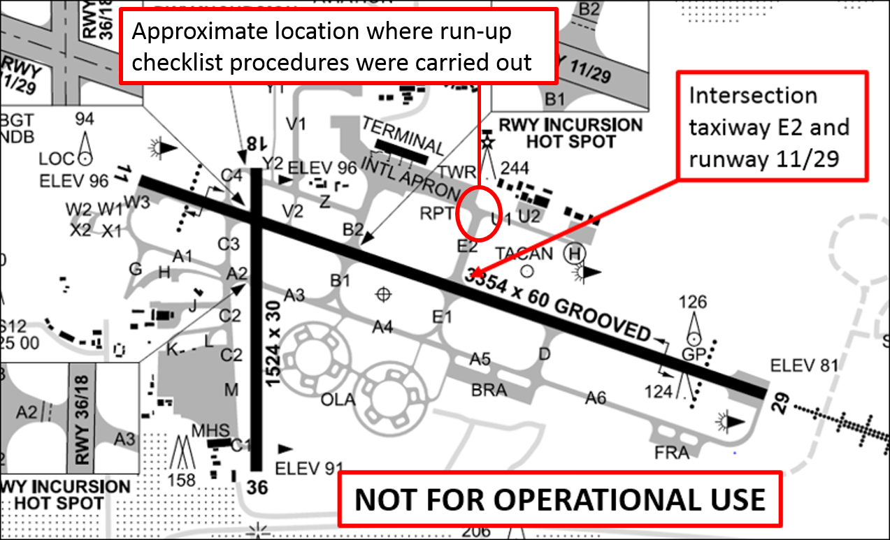
The pilot positioned the aircraft at the intersection of taxiways U1 and E2 to complete pre-flight run-up checklist procedures. During the first flight of the day, the operator’s run-up checklist procedures included a check to confirm that the wing and horizontal stabiliser de-ice system was serviceable. The wing and horizontal stabiliser de-ice system includes pneumatically inflatable boots fitted to the leading edges of those surfaces (see later description for more detail). The pilot recalled that all run-up checks were normal, including the wing and horizontal stabiliser de-ice system check. Following completion of the run-up checklist procedures, the pilot taxied to the holding point on taxiway E2 before departing from that intersection on runway 11 (Figure 1).
Figure 1: Excerpt from Darwin Airport aerodrome chart showing the approximate location where run-up checklist procedures were carried out and the intersection from which the aircraft commenced take-off
Source: Airservices Australia, additions by the ATSB
The take-off was initiated with the flaps retracted, consistent with the operator’s normal procedures for a take-off under the prevailing conditions. The take-off proceeded normally up to the point that the aircraft reached decision speed[1] and the pilot rotated the aircraft to the take-off pitch attitude. At that point, the pilot noticed that the aircraft did not ‘unstick’[2] as readily as normally expected. At about the same time, the pilot recalled that the stall warning horn sounded.[3] The pilot continued with the take-off and the aircraft lifted off, but it was not climbing or accelerating as efficiently as normal. Despite the relatively poor performance, the pilot was able to build speed slowly by holding the aircraft in ground effect.[4]
After achieving a positive rate of climb, the pilot retracted the landing gear. As the aircraft continued a shallow climb, the pilot carefully balanced airspeed and rate of climb as the stall warning horn continued to sound intermittently. After passing about 200 ft above ground level, the pilot was able to reduce the pitch attitude to allow the aircraft to accelerate further. Beyond that point, the stall warning horn no longer sounded.
Satisfied that the aircraft had reached a safe altitude, the pilot inspected the wings in an attempt to ascertain the reason for the poor take-off performance and stall warning. At that point, the pilot noticed that the right wing de-ice boots appeared to be inflated. Due to the position of the sun, the pilot was unable to immediately ascertain if the boots on the left wing were also inflated. Nonetheless, the pilot was confident that the inflated condition of the wing de-ice boot (or boots) explained the poor performance and stall warning. The pilot immediately cycled the wing and horizontal stabiliser de-ice system control switch in an attempt to deflate the boots, but cycling the switch appeared to have no effect.
As the aircraft continued to accelerate, the pilot noticed that aileron control forces were abnormally light. The pilot surmised that light aileron control forces were the result of a disturbance in the airflow over the wing associated with the inflated leading edge de-ice boot (or boots). As the aircraft turned and its orientation changed with respect to the position of the sun, the pilot was able to clearly see that the boots on the left wing were also inflated.
The pilot advised air traffic control that a return to Darwin was necessary. Air traffic control initially asked the pilot if runway 36 was acceptable, but uncertain about aircraft performance and noting a crosswind on runway 36, the pilot indicated a preference for runway 11 (runway 11 is substantially longer than runway 36). The pilot was subsequently cleared by air traffic control to make a circuit for runway 11.
Given concerns regarding aircraft performance and control, the pilot elected to land with approach flap[5] selected, and added 20 kt to the approach reference speed. Making the approach at this speed allowed the pilot to comply with the operator’s stabilised approach criteria, while providing increased confidence with respect to aircraft performance and controllability.
The pilot had no difficulty handling the aircraft during the circuit and landing, but noted that substantially more power than normal was required to hold the desired speed. The stall warning horn remained silent throughout the approach and landing. The pilot landed without further incident and taxied to the aircraft parking position. The wing de-ice boots remained inflated until the engines were shut down.
Subsequent inspection by engineering staff found that the wing de-ice boots inflated again during an engine ground run, without having been selected. The boots returned to normal operation when the wing and horizontal stabiliser de-ice system control switch was cycled.[6] Numerous subsequent system tests (in accordance with the relevant maintenance manual) found that the wing and horizontal stabiliser de-ice system functioned normally, and the aircraft was returned to service. The operator also advised CASA of the occurrence.
Raytheon B200 wing and horizontal stabiliser de-ice system
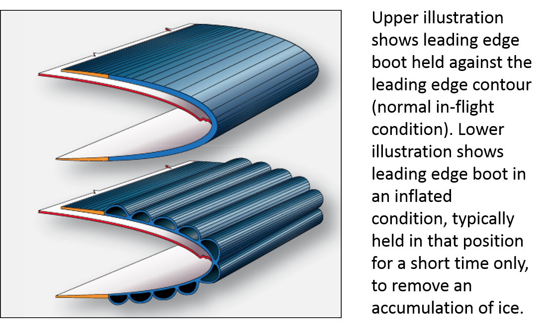
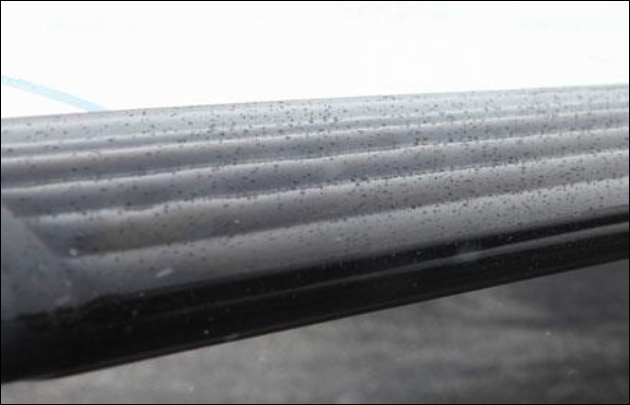
On the Raytheon B200, the leading edge of the wings and the horizontal stabiliser can be protected from an accumulation of ice by inflatable boots. The wing has an inner boot between the fuselage and engine nacelle, and an outer boot that extends from outboard of the engine nacelle. The boots are normally held down by a vacuum, and only inflated when an appropriate selection is made by the pilot. The boots are inflated by pneumatic pressure, and expand in a manner intended to shed any accumulated ice (Figures 2 and 3). Regulated high-pressure engine bleed air supplies pressure and a vacuum source for the wing and horizontal stabiliser de-ice system.
Figure 2: Pneumatic leading edge de-ice boot (representation) in the normal (deflated) condition and the inflated condition
Source: FAA, description added by the ATSB
Figure 3: Inflated Raytheon B200 wing leading edge de-ice boot
Source: Aircraft operator
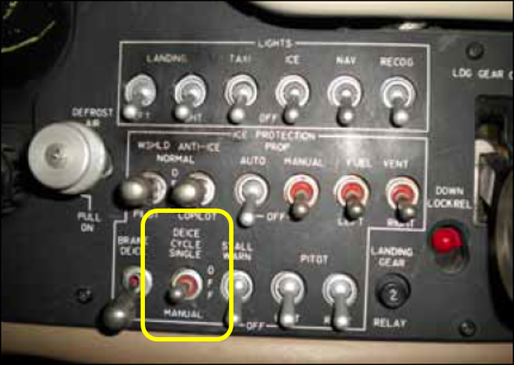
The wing and horizontal stabiliser de-ice boots are operated by a three-position switch, spring-loaded to the centre OFF position (Figure 4). When the switch is selected to the DEICE CYCLE SINGLE (up) position, the wing boots are inflated for 6 seconds, followed by the horizontal stabiliser boots, which are inflated for 4 seconds to complete the cycle. The switch must be selected up again to commence another cycle. When the switch is selected to the MANUAL (down) position, the wing and horizontal stabiliser boots inflate simultaneously, and remain inflated while the switch is held in the MANUAL position. When the switch is released back to the centre OFF position, the boots deflate.
Figure 4: Raytheon B200 ice protection panel (typical) – wing and horizontal stabilizer de-ice control switch highlighted
Source: FAA
Apart from a visual inspection of the de-ice boots, there are no direct indications of the status of the boots available to the pilot. Aircraft pneumatic system gauges provide an indirect indication of boot function by indicating a momentary reduction in pneumatic pressure (and momentary needle movement on the gyro suction gauge) as pressure is redirected, but there is nothing that directly alerts the pilot to an inflated boot condition.
Where required by the operator’s checklist procedures, the wing and horizontal stabiliser de-ice system is checked by selecting the switch to the up position, and monitoring pneumatic pressure (momentary decrease) and boot inflation for a single cycle. The switch is then held in the down position to check system operation in the manual mode, again expecting the boots to inflate with a corresponding momentary decrease in pneumatic pressure.
The aircraft flight manual includes a warning to pilots not to cycle the de-ice boots during take-off. The manual does not expand on the reasons for the warning, but it probably relates substantially to degradation in the aerodynamic qualities of the wing and horizontal stabiliser associated with inflated leading edge boots, and the associated impact on aircraft performance and control.
Pilot comments
The pilot believed that the wing de-ice boots probably remained inflated following the wing and horizontal stabiliser de-ice system check, and that the inflated condition of the boots went unnoticed following the check. The pilot could recall completing the checklist procedures as normal, by monitoring the pneumatic pressure gauges and the status of the wing boots during the check, but not specifically confirming that the wing boots had deflated following the check. The pilot also noted that even though the checklist procedure did not specifically call for confirmation that the wing de-ice boots had deflated following the check, it was normal practise to check them.
The pilot also commented that if the wing de-ice boots did remain inflated following the wing and horizontal stabiliser de-ice system check, a number of circumstantial factors may have increased the likelihood that their inflated condition went unnoticed. These factors included:
The orientation of the aircraft with respect to the position of the sun (at the time the checks were completed) was such that the status of the wing de-ice boots may not have been readily apparent without a concentrated inspection.
The taxi from the point where the pilot completed the run-up checklist procedures to the holding point of the runway was relatively short (see Figure 1). A short taxi following the run-up checks reduced the likelihood that inflated wing de-ice boots would have been noticed during a normal lookout while taxiing.
Flying conditions were such that it was unlikely that the wing and horizontal stabiliser de-ice system would be required during the flight. This may have reduced the intensity of the pilot’s focus on the wing and horizontal stabiliser de-ice system check, and reduced the likelihood that the inflated condition of the wing de-ice boots would be noticed at the completion of the check.
Safety action
Whether or not the ATSB identifies safety issues in the course of an investigation, relevant organisations may proactively initiate safety action in order to reduce their safety risk. The ATSB has been advised that following this incident, the operator issued a safety bulletin to company B200 pilots, drawing their attention to the incident and highlighting the importance of checking that the wing de-ice boots deflate following a cycle of the de-ice system.
Safety message
Pilots operating Raytheon B200 or similar aircraft, fitted with pneumatic wing and horizontal stabiliser de-ice boots, are encouraged to take particular care when inspecting the boots during the system function check. Pilots are cautioned that the status of the boots may not be immediately obvious under some conditions, and that a concentrated inspection may be necessary. This may require the assistance of an external observer to assist with monitoring the status of the de-ice boots, particularly the boots fitted to the leading edge of the horizontal stabiliser which may not be visible from the cockpit.
Any aerofoil leading edge contamination, damage or distortion has the potential to significantly adversely affect aircraft performance and handling qualities, and aerodynamic stall characteristics. This incident highlights the significance of the manufacturer’s warning not to cycle the de-ice boots during take-off.
Decisions regarding whether to conduct an investigation, and the scope of an investigation, are based on many factors, including the level of safety benefit likely to be obtained from an investigation. For this occurrence, a limited-scope, fact-gathering investigation was conducted in order to produce a short summary report, and allow for greater industry awareness of potential safety issues and possible safety actions.
Publishing information
Released in accordance with section 25 of the Transport Safety Investigation Act 2003
Ownership of intellectual property rights in this publication
Unless otherwise noted, copyright (and any other intellectual property rights, if any) in this report publication is owned by the Commonwealth of Australia.
Creative Commons licence
With the exception of the Coat of Arms, ATSB logo, and photos and graphics in which a third party holds copyright, this publication is licensed under a Creative Commons Attribution 3.0 Australia licence.
Creative Commons Attribution 3.0 Australia Licence is a standard form licence agreement that allows you to copy, distribute, transmit and adapt this publication provided that you attribute the work.
The ATSB’s preference is that you attribute this publication (and any material sourced from it) using the following wording: Source: Australian Transport Safety Bureau
Copyright in material obtained from other agencies, private individuals or organisations, belongs to those agencies, individuals or organisations. Where you wish to use their material, you will need to contact them directly.
On 15 May 2015, at about 0600 Western Standard Time (WST), a Cessna 207 aircraft, registered VH-WOX (WOX), departed Kununurra Airport, Western Australia, for a local scenic charter flight with a pilot and four passengers on board. A few minutes later, a Cessna 208B (Caravan) aircraft, registered VH-LNH (LNH), also departed Kununurra for a local scenic charter flight, operated by another company, with a pilot and 12 passengers on board. Three other Cessna Caravan aircraft from that company departed at around the same time, with LNH the third of the four Caravans in sequence.
The pilot of WOX reported maintaining visual and listening awareness of the other aircraft throughout the scenic flight. On returning to Kununurra, the company procedure for WOX was to overfly the airfield at 2,000 ft then descend about 5 NM to the north before returning and joining the circuit on base leg for runway 12. The company procedure for LNH was to approach the airfield from the south and join the circuit on the crosswind leg for runway 12. While conducting aerial work to the north of the field, the pilot of WOX heard the pilots of the first two of the Caravans broadcast inbound calls on the common traffic advisory frequency (CTAF).
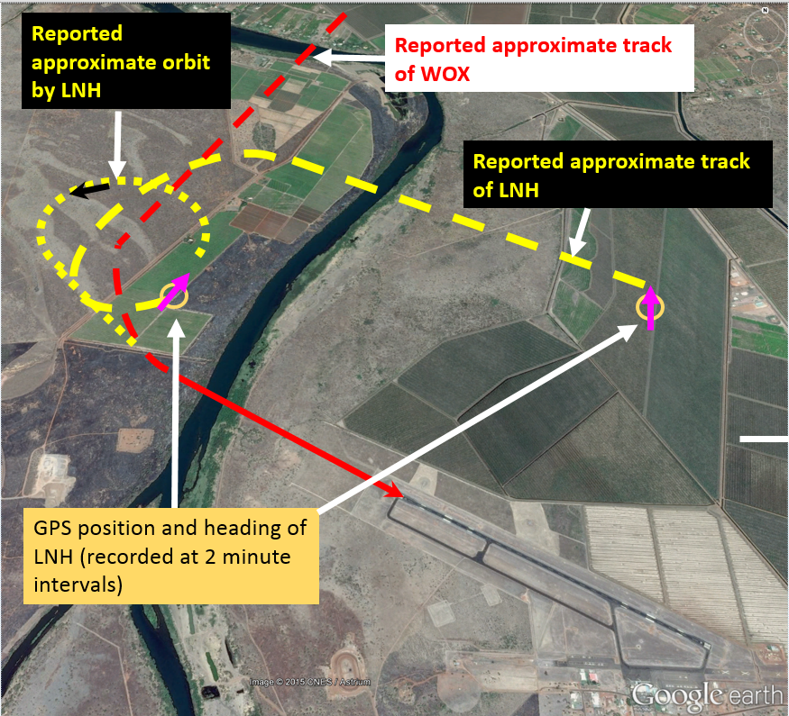
At about 0812,[1] when about 5 NM from the airfield on an extended base leg, the pilot of WOX broadcast that they had completed airwork and were tracking to join on base for runway 12 (Figure 1). At the time, the first of the Caravans had landed and the pilot of the second Caravan, then ahead of WOX, had broadcast turning base. About 10 seconds later, LNH broadcast joining midfield crosswind. Eight seconds after the broadcast from LNH, the pilot of WOX reported being about 2 NM from the runway, on base leg. The pilot of WOX then broadcast that they had both the aircraft ahead on final approach, and LNH abeam WOX and turning downwind, in sight.
The pilot of LNH reported conducting an oval-shaped circuit pattern, flying a curved base leg with a constant left turn from the downwind leg to the final leg for runway 12. After commencing the turn, the pilot of LNH reported hearing the broadcast from WOX stating they had LNH in sight. The pilot of LNH did not sight WOX and assumed the pilot would sequence to join the circuit behind LNH.
At about 0813, the pilot of WOX turned onto final for runway 12 and broadcast doing so. The Caravan ahead had landed and cleared the runway. LNH did not broadcast turning base and the pilot of WOX assumed that LNH was then still well behind WOX. When about three quarters of the way through the continuous left turn from downwind and approaching the final leg, the pilot of LNH configured the aircraft for landing and selected full flap. At that time, the pilot of LNH reported hearing WOX broadcast turning final. A few seconds later, the pilot of LNH sighted WOX ahead, to the right, slightly above, and in close proximity to LNH. The pilot of LNH then continued a steeper left turn to increase separation with WOX. As the aircraft turned to the north-east, the pilot of LNH sighted a company aircraft on downwind and at about 0815, broadcast conducting a left orbit. The pilot of LNH also asked the pilot of the following aircraft to conduct an orbit to increase separation between those two aircraft.
At that time, WOX was on late final approach to runway 12. The pilot of WOX assumed LNH had conducted the orbit to increase separation and ensure WOX would be clear of the runway. The pilot of WOX was not aware of the separation issue subsequently reported by LNH. Both aircraft landed safely without further incident.
Figure 1: Kununurra aerodrome with the approximate aircraft tracks
Source: Google earth annotated by the ATSB
Pilot comments
Pilot of VH-WOX
The pilot of WOX provided the following comments:
The aircraft that landed ahead of WOX had completed a normal square base leg and the pilot assumed that LNH would therefore do the same.
The aircraft ahead of WOX was closer to WOX than LNH was, when the pilot joined base. The pilot assessed that there was sufficient distance for adequate separation from the aircraft ahead and from LNH, and therefore did not ask the pilot of LNH to confirm they had WOX in sight.
Pilot of VH-LNH
The pilot of LNH provided the following comments:
The pilot had not sighted WOX when the pilot broadcast joining base, and assumed it would join behind LNH.
As the wind was about 15 kt from the south-east, the downwind leg of the circuit was completed in relatively short time.
The pilot of LNH had previously worked for the company that operated WOX. While flying for that company, the pilot joined an offset base leg to intercept the final leg at about 2.5 to 3 NM. The pilot believed that WOX would have conducted a similar joining procedure. From this procedure, the pilot assumed that WOX would therefore sequence behind LNH, which was already in the circuit.
Operator comments
The operator of LNH provided the following comments:
Joining the circuit on base was not a standard procedure. Pilots of aircraft joining the circuit in a non-standard manner were required to give way to aircraft established in the circuit.
There was never a formal nor an informal company procedure to conduct an oblong circuit. The use of a constant turn from downwind to final has subsequently been removed from pilot training and that change communicated to all company pilots.
Safety action
Whether or not the ATSB identifies safety issues in the course of an investigation, relevant organisations may proactively initiate safety action in order to reduce their safety risk. The ATSB has been advised of the following proactive safety action in response to this occurrence.
Operator of VH-LNH
The operator of LNH issued a safety notice to company pilots titled Circuit Operations. The notice included the following:
Pilots were directed to fly a standard rectangular base leg to enable greater visibility of aircraft in the circuit area. The practice of conducting a curved approach was to cease immediately.
Pilots were reminded to complete all cockpit checks early when joining the circuit. This was to maximise the time available for pilots to scan outside the aircraft and to avoid distractions.
Pilots were reminded to make position reports in a timely manner and acknowledge radio calls where required. A double-click of the radio transmitter was not deemed to be an acceptable means of a read-back.
Operator of VH-WOX
As a result of this occurrence, the operator of WOX has advised the ATSB that they are taking the following safety actions:
Company aircraft are to track for a 3 NM final when there is other traffic in the circuit.
Company pilots are to confirm with other aircraft that they have visual confirmation of the location of their aircraft. If they do not, then the pilot is to ensure they maintain separation.
Safety message
As detailed in the booklet A pilot’s guide to staying safe in the vicinity of non-controlled aerodromes, ATSB research found that, between 2003 and 2008, there were 709 airspace-related events at, or in the vicinity of non-towered aerodromes. This included 60 serious incidents and six accidents (mid-air and ground collisions). Most of the 60 serious incidents were near mid-air collisions.
Issues associated with unalerted see-and-avoid have been detailed in the ATSB research report Limitations of the See-and-Avoid Principle. The report highlights that unalerted see-and-avoid relies entirely on the pilot’s ability to sight other aircraft. Broadcasting on the CTAF is known as radio-alerted see-and-avoid, and assists by supporting a pilot’s visual lookout for traffic. An alerted search is more likely to be successful as knowing where to look greatly increases the chances of sighting traffic. The report is available at the ATSB website.
This incident highlights the importance of broadcasting an aircraft’s position and of other pilots in the vicinity then ensuring they have the aircraft sighted following the broadcast.
Decisions regarding whether to conduct an investigation, and the scope of an investigation, are based on many factors, including the level of safety benefit likely to be obtained from an investigation. For this occurrence, a limited-scope, fact-gathering investigation was conducted in order to produce a short summary report, and allow for greater industry awareness of potential safety issues and possible safety actions.
Publishing information
Released in accordance with section 25 of the Transport Safety Investigation Act 2003
Ownership of intellectual property rights in this publication
Unless otherwise noted, copyright (and any other intellectual property rights, if any) in this report publication is owned by the Commonwealth of Australia.
Creative Commons licence
With the exception of the Coat of Arms, ATSB logo, and photos and graphics in which a third party holds copyright, this publication is licensed under a Creative Commons Attribution 3.0 Australia licence.
Creative Commons Attribution 3.0 Australia Licence is a standard form licence agreement that allows you to copy, distribute, transmit and adapt this publication provided that you attribute the work.
The ATSB’s preference is that you attribute this publication (and any material sourced from it) using the following wording: Source: Australian Transport Safety Bureau
Copyright in material obtained from other agencies, private individuals or organisations, belongs to those agencies, individuals or organisations. Where you wish to use their material, you will need to contact them directly.
On 15 May 2015 at about 0135 Eastern Standard Time, an Airbus A319 aircraft, registered VH‑VCJ and operated by Skytraders Pty Ltd, was positioning to commence an approach to runway 16 at Melbourne airport. Following the receipt of a clearance to descend the aircraft to 3,000 ft, the pilot flying (PF) made a number of autoflight mode selections. These mode selections led to the autothrust system disengaging and the engines entering the thrust lock condition. The PF’s actions to correct the condition resulted in an unexpected increase in thrust.
In response to the thrust increase, the PF made a number of pitch-down inputs and retarded the thrust levers. The pitch-down inputs, when combined with the increased thrust, resulted in the aircraft developing a high rate of descent with an accelerating airspeed. The aircraft descended below the cleared altitude and a Terrain Avoidance and Warning System (TAWS) alert activated. The PF responded to the alert by declaring an intent to ‘go around’ and advanced the thrust levers to full power. When the engines responded with increased power, the PF again reacted with pitch-down inputs. A further two TAWS alerts activated before the PF reversed the descending flight path and started to climb the aircraft.
What the ATSB found
The ATSB found that a number of autoflight mode selection errors led to the aircraft’s engines entering the thrust locked condition. The correct procedure when disconnecting the autothrust was not completed, which in turn resulted in the unexpected sudden power increase.
The ATSB also found that the PF likely experienced pitch-up illusions during periods of unexpected and rapid thrust increase. The PF instinctively responded with pitch-down side stick inputs that resulted in the initial high speed and high rate of descent, as well as continued descent after initiating a go-around.
The rapidly changing aircraft state led to the crew experiencing a high workload. This significantly limited their capacity to identify the autoflight system mode changes and respond to the aircraft's high airspeed and high rate of descent.
The pilot monitoring’s ability to identify and influence the rapidly changing situation was likely affected by the non-routine nature of actions of the PF, multiple autoflight system mode changes and alerts, the reduced communication between the crew, and a focus on the flap limitation airspeeds.
Safety message
A pitch-up illusion can affect the most experienced pilot. Ideally, adherence to instrument scan techniques, setting and maintaining known aircraft attitudes for specific phases of flight, and using flight aids such as autopilots and/or flight directors, are all strategies to reduce the risk of responding inappropriately to pitch-up illusions. However, when pilots are experiencing a high workload this can be difficult to achieve. In this case, there are benefits in increasing crew communication, to enable more time to identify issues and consider solutions as well as to facilitate the pilot monitoring’s ability to monitor the situation.
Aviation operators conduct non-technical skills training for their pilots. An occurrence such as this demonstrates the way in which topics such as human error prevention and detection, information processing, decision making and communication continue to be relevant.
The occurrence
Introduction
On the evening of 14 May 2015 an Airbus A319, call-sign Snowbird Two (SND2) departed Perth, Western Australia for Melbourne, Victoria. The aircraft was registered as VH-VCJ and operated by Skytraders Pty Ltd as a passenger charter service with 5 crew and 18 passengers. The aircraft’s flight crew consisted of two captains. The pilot-in-command occupied the left seat and was the pilot flying (PF).[1] The other captain occupied the right seat and was performing the pilot monitoring (PM) duties.
As the aircraft was positioning to commence the approach into Melbourne, the PF made a number of inadvertent autoflight mode selections, which led to the autothrust system disengaging and the engines entering the thrust lock condition. The PF’s actions to correct the thrust lock resulted in an unexpected increase in thrust. In response to the thrust increase, the PF made a number of pitch-down inputs and retarded the thrust levers. The pitch-down inputs, when combined with the increased thrust, resulted in the aircraft developing a high rate of descent with an accelerating airspeed. This led to the aircraft descending below the cleared altitude, as well as the triggering of a number of Terrain Avoidance and Warning System (TAWS) alerts. During the subsequent response to these alerts, the aircraft did not commence climbing for about another 10 seconds, and after two further TAWS alerts had activated.
Events leading up to the inadvertent autoflight mode selections
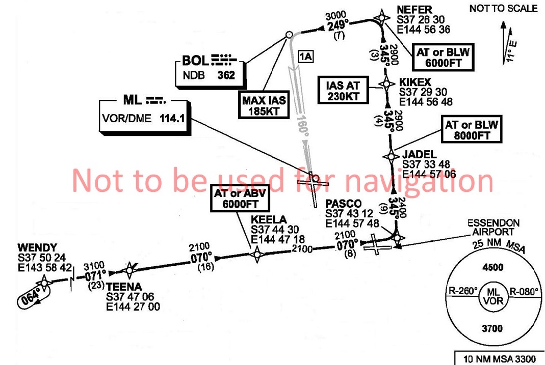
Approaching Melbourne and before commencing descent, the flight crew set up the aircraft’s flight management guidance system and then briefed for an expected WENDY 1A standard arrival route (STAR) procedure, with an instrument landing system (ILS)[2] approach to runway 16[3] for landing (Figure 1). Shortly after, air traffic control (ATC) cleared the aircraft for the WENDY 1A STAR. In the early morning of 15 May 2015, at about 0120 Eastern Standard Time,[4] the aircraft commenced the descent into Melbourne.
The PF commenced the descent with the following autoflight systems and modes selected:
Autopilot 1 (AP1) was controlling the aircraft.
Lateral navigation was in the ‘navigation’ (NAV) mode, while vertical navigation was in the ‘descent’ mode, both of which were managed modes[5] where the aircraft follows a pre-planned horizontal and vertical flight path loaded in the flight management guidance computer.
Autothrust system was on, with the thrust levers at the managed thrust position—the climb thrust detent that equated to a thrust lever angle of 22.5 degrees.
Figure 1: The Wendy 1A standard arrival procedure to Melbourne runway 16 ILS approach
Source: Airservices Australia
At 0128, SND2 called ATC and advised that the aircraft was on descent to a cleared altitude of 9,000 ft, and that they had received ATIS[6] information Romeo.
As SND2 approached waypoint KIKEX (Figure 1) at 0134:25, ATC cleared the aircraft to descend to 3,000 ft and for the ILS approach to runway 16. The PF set 3,000 ft into the altitude function of the aircraft’s flight control unit (FCU). At that time, the aircraft was passing 5,900 ft at an indicated airspeed of 253 kt.
Approaching waypoint NEFER, at 0135:30 and passing about 4,700 ft, SND2 commenced a left turn towards BOL (Figure 1). At 0136:38 the PF requested, and the PM selected, flap 1. The flaps reached this setting two seconds later. At 0136:39, the aircraft had completed the turn and rolled level on the NEFER to BOL track.
The inadvertent autoflight mode selections and following events
The following sequence of events, covering the next 39 seconds of flight, was drawn from the aircraft’s digital flight data recorder (DFDR), cockpit voice recorder (CVR) and crew interviews. This period can be divided into three distinct phases:
inadvertent FCU selections
thrust increases and the PF’s responses
recovery.
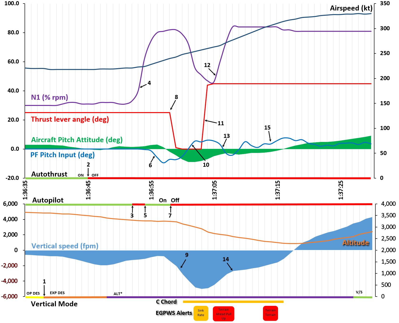
The sequence of events from 0136:35 is graphically presented in a data plot at Figure 2. Specific points on that data plot[7] are identified to enable a clearer understanding of the rapidly changing events.
Figure 2: Data plots based on DFDR and CVR Data
The arrowed numbers identify specific events referred to in the sequence of events. The vertical grid lines each represent 1 second. Source: ATSB
Inadvertent FCU selections
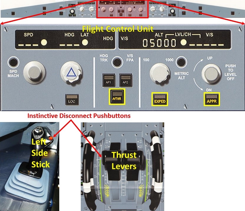
As the aircraft descended through 3,600 ft at 0136:39, the PF announced an intent to ‘arm the approach’. This required the PF to press the APPR (approach) pushbutton on the FCU. Instead, the PF pressed the EXPED (expedite) pushbutton (see Figure 3), resulting in the autoflight vertical mode changing from the open descent mode[8] to the expedite descent mode[9] (point 1). Over the next 5 seconds the vertical descent rate increased from around 800 ft/min to around 1600 ft/min, while the airspeed remained stable at around 220 kt.
Figure 3: Autoflight controls
The flight control unit is expanded and, from left to right, the A/THR, EXPED and APPR buttons highlighted. The PF’s instinctive disconnect buttons on the side stick and thrust levers are also identified. Source: Airbus and ATSB
After a few seconds the PM identified that the vertical mode had changed to expedite descent and announced this change to the PF. At 0136:44, upon recognising the incorrect mode selection the PF, in an apparent attempted to correct the error, pressed the A/THR[10] (autothrust) pushbutton (to off) (point 2). Pressing the A/THR pushbutton had a number of effects:
The autothrust system disengaged and the engines’ thrust was locked at the thrust level prior to disconnection—idle thrust, which was the commanded thrust at that time (the thrust lock condition).
The master caution light and aural alert (a single chime) triggered.
The electronic centralised aircraft monitoring system[11] THR LK message (thrust lock) was displayed, with an associated procedure.
A yellow flashing THR LK message was displayed in the flight mode annunciator on both pilots’ primary flight displays.[12]
Almost immediately, at 0136:47, the PM recognised and announced the thrust lock condition. At about the same time, the autoflight system’s vertical mode transitioned to altitude acquire (ALT* on the vertical mode section of Figure 4), identifying that the autoflight system had captured the 3,000 ft target altitude.
At 0136:51, the PM announced that the aircraft had captured the target altitude. At about the same time the PF recognised the thrust lock condition and pressed the ‘instinctive disconnect’ buttons on both the side stick and thrust levers (see Figure 3). The PF later recalled that the intent behind that action was to reduce the aircraft’s airspeed and to retard the thrust levers. The use of the instinctive disconnect pushbuttons had the following effects:
The action of pressing the instinctive disconnect pushbutton on the sidestick disconnected the autopilot (point 3), which in turn triggered the autopilot disconnect aural alert (‘CAVALRY CHARGE’). The CAVALRY CHARGE sounded for 1 second.
The pressing of the thrust lever instinctive disconnect pushbutton caused the thrust lock condition to disengage. It also removed the THR LK message from the electronic centralised aircraft monitoring system and the pilots’ flight mode annunciators. As the thrust levers remained set to the climb detent, the commanded thrust changed from idle to climb.
Thrust increases and the PF’s responses
At 0136:53 the engines began to respond to the commanded thrust change by rapidly increasing thrust (point 4). At about the same time, the PF reconnected the autopilot (point 5) but left the autothrust system disconnected. The PF responded to the rapidly increasing thrust by applying pitch-down inputs on the sidestick (point 6). The PF did not recall applying pitch-down input during post occurrence interviews, but did recall thinking that the aircraft was pitching up.
As a result of the PF’s pitch-down inputs on the side stick, at 0136:58 the autopilot disengaged (point 7). This disconnection again triggered the autopilot disconnect aural (CAVALRY CHARGE) alert, which sounded for 1 second. At the same time, the PF rapidly moved the thrust levers to idle (point 8). At this point, the aircraft’s airspeed was 240 kt and increasing, and the PM asked if the flaps should be retracted. The PF responded in the affirmative.
The PF’s pitch-down inputs, coupled with the aircraft’s high thrust level and the now downward flight vector, resulted in the aircraft’s airspeed and vertical rate of descent rapidly increasing (point 9). At 0137:00 the altitude warning (C CHORD aural alert) commenced. It continued to sound for 15 seconds. As the engine thrust reduced (from the thrust levers being moved back to idle) the PF transitioned from pitch-down to pitch-up inputs on the side stick (point 10). As a result, the rate of descent stabilised and then decreased.
At 0137:02, the first of the terrain avoidance and warning system (TAWS) alerts triggered. This alert, a ground proximity warning system Mode 1 SINK RATE caution, repeated twice. The PF responded by rapidly placing the thrust levers fully forward (point 11) and instructed the PM to advise ATC that they were ‘going around’. At 0137:05 the engines began to respond to the commanded thrust change and rapidly increased thrust (point 12). At the same time the second TAWS alert, an enhanced ground proximity warning system TERRAIN AHEAD, PULL UP, TERRAIN AHEAD warning activated, which ended after 3 seconds. The PF again responded to the rapidly increasing thrust by reducing the pitch-up inputs and then commencing pitch-down inputs (point 13). This reduced the rate at which the aircraft’s rate of descent was decreasing, which had the effect of prolonging the period that the aircraft was descending.
Recovery
At 0137:08 the PF began to introduce pitch-up commands, which further reduced but did not arrest the aircraft’s rate of descent (point 14). At 0137:13 the third TAWS alert, a ground proximity warning system Mode 2 TERRAIN TERRAIN PULL UP warning activated, ending after 2 seconds. The PF responded with increasing pitch-up commands (point 15), which began to arrest the rate of descent. At 0137:15, the PM advised ATC that the aircraft was ‘going around’.
The lowest altitude attained by the aircraft during the occurrence, as recorded by the digital flight data recorder (DFDR), was 2,280 ft at 0137:17. At the same time, the flaps were recorded as being fully retracted. The lowest recorded height above ground level recorded by the radio altimeter was 1,100 ft. The aircraft’s maximum speed while the flaps were in the process of retracting was 314 kt.
At 0137:17, the ATC minimum safe altitude warning[13] alert activated for SND2 at the ATC workstation. ATC data identified that the aircraft was descending through 2,300 ft at that time. The lowest recorded altitude by ATC was 2,200 ft. As the aircraft began to climb, ATC cleared the aircraft to climb to 4,000 ft and notified SND2 that a low altitude safety warning had triggered. The aircraft was cleared to and continued to climb to 5,000 ft. The flight crew requested vectors to intercept the ILS approach for runway 16. The aircraft landed on runway 16 at 0150 without further incident.
Pilot recollection of the occurrence
The PM later recalled an impression that there was a lot of button pressing, as well as disconnecting and reconnecting of the autopilot during the event. The PM did not recall any TAWS alerts and neither pilot recalled hearing the altitude alert.
Cockpit voice recorder data identified that the PF did not verbalise any intention to change flight mode selections or other actions during the occurrence, other than the initial call identifying an intention to arm the approach.
The PM commented on the low lighting levels set for the flight instruments, which he considered may have resulted in a difficulty in identifying what selections the PF was making on the FCU.
The Airbus A320 aircraft is a twin engine, narrow body, short to medium range commercial passenger aircraft. The Airbus A320 family of aircraft comprises the A318, A319, A320 and A321 variants. Based on the original A320, the A319 is a shorter variant.
The air operator’s certificate authorised passenger charter operations using the Airbus A319. The operator used an A320 based simulator for training and proficiency checks.
Personnel information
The pilot flying
The pilot flying (PF) held an Air Transport Pilot (Aeroplane) Licence (ATP(A)L) and had accumulated about 17,250 hours of aeronautical experience. Of these, approximately 2,835 hours were on Airbus A320 type aircraft. In the 90 days preceding the occurrence, the PF had logged 69.5 hours, of which 57.1 were on A319.
The PF held a current Class 1 medical certificate, and as a condition of that certificate was required to wear distance vision correction and have available reading correction. These vision requirements were determined to have not influenced the occurrence.
About three months prior to the occurrence, the PF had completed a recurrent training session to a satisfactory standard in an A320 simulator, and in April 2015 a line check in an A319. The PF was current with all training requirements. The PF’s training reports identified that he had satisfactorily completed the required competency checks and was properly trained and proficient on the A320; however, of the 10 training records available that preceded the occurrence, there were two that contained reports of an occasional tendency to rush actions, and that this led to procedural lapses.
The PF was one of three flight crew employed by the operator who were authorised to conduct instrument training and checking on the A320 aircraft family. The PF was cross-trained on the operator’s other aircraft type, the CASA 212, and was also authorised to conduct training and checking on that type. Additionally, the PF held a management role, although the time required to conduct this role was reducing.
A significant proportion of the PF’s recent flight hours leading up to the occurrence were assigned to conducting check flights on the A319, rather than as the primary operating crewmember. The PF’s training and checking reports did not identify any recency or skill detriment resultant from the PF’s management and/or training roles. However, as the records were limited to approximately five years there was insufficient evidence to assess this further.
The pilot monitoring
The pilot monitoring (PM) held an ATP(A)L with a current Class 1 medical certificate, and had accumulated about 12,290 hours of aeronautical experience, of which about 2,200 hours were on an Airbus A320 type aircraft. The PM was also a check and training captain. Prior to the occurrence, the PM had completed a recurrent training session in an Airbus A320 simulator in February 2015 and a line check in July 2014.
Operations manuals
The operator’s Operations Manual suite was subdivided into five parts. The relevant parts to the investigation included:
Part A – Operations Manual (OPSA). OPSA contained company policy, requirements and standard operating procedures (SOP)
Part B – Aeroplane type operating procedures (OPSB). A suite of manuals that contained specific aeroplane type operating procedures and requirements.
The Operations Manual suite was supplemented by Notices to Aircrew. These notices were temporary information that required urgent distribution and notification to the company’s aircrew. There were no notices relevant to the occurrence.
OPSB covered company specific matters that related to a particular aircraft type. The OPSB-A319 stated that flight crew were to use Airbus A319 procedures and limitations, unless modified by information contained within that manual. OPSB-A319 did not include any company specific A319 procedures that were relevant to the investigation.
Airbus procedures were published in company tailored Airbus A319 manuals as part of the OPSB suite. These manuals included the Flight Crew Operating Manual (FCOM), Flight Crew Training Manual (FCTM) and Quick Reference Handbook (QRH).
Aircraft information
The operator’s Airbus documentation was A320 family based. The source of the information presented in this section is the operator’s A320 family FCOM, FCTM and QRH, which Airbus had tailored to meet specifications of the operator’s aircraft, including VH-VCJ.
The primary flight display and flight mode annunciator
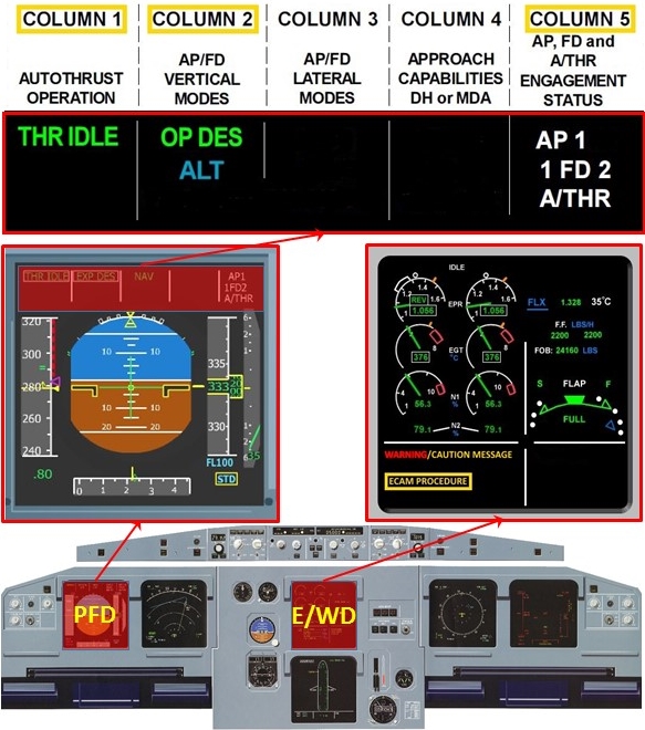
The pilot’s primary flight display (PFD) is the outboard of the pilot’s two display screens (Figure 4). The PFD incorporated the primary flight instruments, as well as the flight mode annunciator (FMA). The FMA, which is located just above the primary flight instruments in the top section of the PFD, showed the status of the:
autothrust in column 1
autopilots and flight directors vertical and lateral modes in columns 2 and 3 respectively
approach capabilities and set decision height or minimum descent altitude in column 4
engagement status of the autopilots, flight directors and autothrust in column 5.
The FCOM section on normal procedures stated that:
The PF should call out any FMA change, unless specified differently (e.g. CAT II & III task sharing). Therefore, the PF should announce:
‐ All armed modes with the associated color (e.g. blue, magenta): "G/S blue", "LOC blue".
‐ All active modes without the associated color (e.g. green, white): "NAV", "ALT".
The PM should check and respond, "CHECKED" to all FMA changes called out by the PF.
Figure 4: The PFD and E/WS displays expanded, with FMA highlighted
Source: Airbus, modified by ATSB
The electronic centralised aircraft monitor
The electronic centralised aircraft monitor (ECAM) monitors aircraft systems, displays aircraft system information, and specifies flight crew actions to be taken in the event of abnormal or emergency situations. The ECAM components relevant to this investigation included the engine/warning display (E/WD) (see Figure 4) and the flight warning computer’s aural and visual alerting systems.
The E/WD display provides the flight crew with the following types of information. On the:
upper part of the display, primary engine parameters, fuel, and slats/flaps position
lower part of the display, warning and caution messages and ECAM procedures.
When the ECAM detects a failure, and there is no flight phase inhibition active,[14] the flight warning computer generates alert messages, aural alerts, and synthetic voice messages. The flight warning computer also drives the master warning light and master caution light. The E/WD displays the alert message as well as the procedures to be followed by the flight crew.
Individual aircraft system failures are graded according to their safety effect on the aircraft, which in turn prioritises how multiple failures are presented to the flight crew. The ECAM has three failure mode levels:
Level 3: Red warning, denoting a dangerous aircraft configuration, limiting flight condition or system failure that alters flight safety that requires immediate action. They are accompanied by: - a continuous repetitive chime or a specific synthetic voice aural alert - illumination of the master warning light - a warning message on the E/WD.
Level 2: Amber caution, denoting a system failure that does not have a direct consequence on flight safety. The flight crew should be aware of the condition and, time and situation permitting, these cautions should be considered without delay. They are accompanied by: - a single chime aural alert - illumination of the master caution light - a caution message on the E/WD.
Level 1: Amber caution, requiring crew monitoring. These failures are accompanied by: - a caution message on the E/WD, generally without an accompanying procedure.
In the event of simultaneous failures, a level 3 warning has priority over a level 2 caution, which has priority over a level 1 caution.
ECAM procedures
The FCOM included some basic crew co-ordination procedures associated with the conduct of abnormal and emergency actions. For response to an ECAM, the crewmember that first recognises the ECAM was required to reset the master warning/caution and announce the title failure as indicated on the E/WD. The PF should then order ECAM actions. This cues the PM to manage the failure by first confirming the failure and then conducting the procedure as displayed on the lower section of the E/WD.
OPSA included the following with respect to emergency and abnormal checklists:
Emergency drills and procedures were to be carried out as per the relevant aircraft emergency checklists and/or in accordance with ECAM procedures.
If a drill required the movement of a thrust lever, this was to be called for by the PM and conducted by the PF.
Autoflight system
The autoflight system (AFS) comprised four broad functional subsystems:
Input: through the multifunctional control and display units (which were not relevant for this investigation) and the flight control unit (FCU).
Data: from the aircraft’s navigation systems, as well as performance and navigational data.
Computing: through the two flight management guidance systems (FMGS).
Output: to the flight directors, autopilots, autothrust, and the electronic flight information system that included the PFD and navigation displays.
The FMGS had two distinct functions:
Flight management, which enabled the aircraft to follow a pre-planned route with vertical, horizontal and speed profiles, through computing the aircraft’s position in conjunction with stored performance and navigational data.
Flight guidance, which controlled the flight directors, autopilots and autothrust.
The autopilots, flight directors, and autothrust used two types of guidance modes to direct the aircraft:
Managed guidance, where the FMGS guided the aircraft along a pre-planned route with vertical and speed profiles computed by the FMGS’s flight management function.
Selected guidance, where the FMGS’s flight guidance function guided the aircraft using targets for lateral, vertical and speed profiles set by the flight crew through the FCU.
The flight control unit
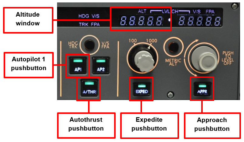
The horizontal and vertical controls for the aircraft’s AFS were located on the glare-shield FCU (Figure 3) equidistant to both pilots. There were a number of switches that selected various modes and functions of the AFS, including anticlockwise, from left to right (Figure 5), the:
AP1 pushbutton, which engaged or disengaged autopilot number 1
A/THR pushbutton, which armed, activated or disconnected the autothrust
EXPED pushbutton, which engaged the expedite mode
APPR pushbutton, which armed, disarmed, engaged or disengaged the approach modes
altitude window, which displayed the altitude target as selected by the flight crew.
Expedite descent
The expedite mode is used in climb or descent to reach the target altitude that is set on the FCU altitude window (Figure 5) using a maximum vertical gradient. The expedite mode will ignore any altitude and/or speed constraint set in the flight management part of the FMGS. When the aircraft is in the descent phase, and the EXPED pushbutton on the FCU is pressed (Figure 5), the AFS will enter the expedite descent mode (EXP DES). In this mode:
the autopilot or flight director will command the aircraft to increase the vertical speed by pitching the aircraft down
the autothrust will command idle thrust
with flap selected, the target speed is the limit speed for the flap setting selected
the first column of the FMA will display THR IDLE, while the second column will display EXP DES (see Figure 4).
The selection of another managed or selected vertical guidance mode, or the selection of a higher altitude on the FCU, will disengage the expedite mode. The expedite mode will automatically disengage when the FMGS captures the target altitude set in the FCU altitude window. When this occurs, column 2 of the FMA (Figure 4) will display ALT*.
Figure 5: Part of the FCU with AP1, A/THR, EXPED and APP pushbuttons as well as the altitude window highlighted in red
Source: flightdecksolutions.com modified by the ATSB
Autothrust system
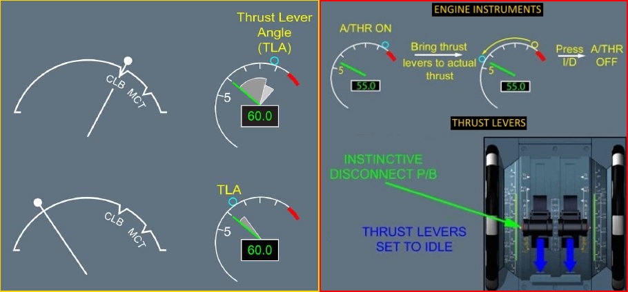
The autothrust computer is part of the flight guidance system. It interfaces with each engine’s electronic control unit. With autothrust active, the autothrust computer does not move the thrust levers to match the commanded thrust, but instead uses the thrust lever angle (TLA) to determine the maximum thrust that autothrust can command. The E/WD display shows the TLA (that is, the position of the thrust levers) as a small blue circle on the top engine instrument indicator (left side of Figure 6). With autothrust active, the normal position for the thrust levers is the climb detent on the thrust lever range.
Figure 6: The thrust lever angle
Engine instruments showing the relationship between the thrust lever angle and the TLA, (left hand diagram) and the autothrust disengagement procedure (right hand diagram). Source: Airbus, modified by ATSB
The normal method for disconnecting autothrust is by pressing the instinctive disconnect pushbutton on the thrust levers (right side of Figure 6). Pressing the instinctive disconnect pushbutton transfers the commanded thrust from the autothrust computer to the position of the thrust levers. When disconnecting autothrust, the PF should first ensure that the thrust levers are matched to approximately the current thrust setting, as indicated by the TLA on the E/WD, before pressing the instinctive disconnect pushbutton. If the pilot does not match the TLA to the actual thrust when the instinctive disconnect pushbutton is pressed, engine thrust will change to that commanded by the thrust lever position.
In the event of a failure of the instinctive disconnect pushbuttons, an alternative method of disconnecting autothrust is to press the A/THR pushbutton on the FCU (Figure 5). This is not a recommended method of disconnection as it will result in the engines entering the thrust lock mode. In the thrust lock mode:
thrust is frozen and remains locked at the thrust value when the A/THR pushbutton was pressed
column 1 of the FMA (Figure 4) will display THR LK, flashing, in amber
the master caution light will flash and the single chime audio alert will sound
the ECAM caution messages AUTOFLT: A/THR OFF and ENG: THRUST LOCKED will be displayed on the E/WD
the E/WD will display the procedure THR LEVERS … MOVE.
As indicated by the ECAM procedure displayed on the E/WD, the required method for disengaging thrust lock is to move the thrust levers. Pressing the instinctive disconnect pushbutton will also disengage thrust lock, however, if the TLA is not matched to the frozen thrust, the thrust will change to that commanded by the thrust lever position. Both methods of disengaging thrust lock will clear the THR LK message from the FMA and the ECAM caution from the E/WD.
Altitude alert system
The flight warning computer will generate an altitude warning when the aircraft approaches or deviates from a preselected altitude or flight level (Figure 5). The warning comprises an aural ‘C chord’ alert, and the PFD altitude window pulsing yellow or flashing amber. The warning may be cancelled by either selecting a new altitude, pressing one of the cancellation pushbuttons, or returning the aircraft to the altitude selected on the FCU.
Instrument lighting
The A320 instrument panels have both integral instrument lighting and flood lighting. The brightness of all panel lighting is adjustable. Each pilot has individual instrument and flood lighting controls for that station’s lighting, while the centre instrument panels also have individual flood lighting and integral lighting controls.
Aircraft flaps
The aircraft had five selectable stages of flap: UP, 1, 2, 3, and FULL. The flap 1 setting, in the approach configuration, is extension of the leading edge slats only. The limit speed for this flap setting is 230 kt.
Terrain avoidance and warning system
VH-VCJ was fitted with a terrain avoidance and warning system (TAWS). The TAWS comprised two primary systems. The first, a ground proximity warning system, used the aircraft’s radio altimeter to produce aural and visual alerts when the aircraft’s radio height was between 30 ft and 2,450 ft, and certain flight conditions were met. These flight conditions were separated into five modes. The relevant modes to this investigation were:
Mode 1: Excessive rate of descent. This mode produced the SINK RATE caution and PULL UP warning aural alerts
Mode 2: Excessive terrain closure rate. This mode produced the TERRAIN TERRAIN caution and the PULL UP warning aural alerts.
The second was a terrain hazard warning system, commonly called an enhanced ground proximity warning system. The terrain hazard warning system used a worldwide terrain database, as well as aircraft navigation system input to produce a:
terrain awareness display that provided predicted terrain conflict and terrain representation on the pilot’s navigation display
calculated terrain clearance floor, which improved terrain warning during final approach and landing.
The terrain awareness system also produced aural alerts associated with terrain conflicts. These alerts were the TERRAIN AHEAD, PULL UP warning and the TERRAIN AHEAD caution.
The abnormal procedures section of the FCOM contained the following procedures for TAWS alerts:
“PULL UP” - “TERRAIN AHEAD PULL UP” Simultaneously: AP................................................................................OFF PITCH..........................................................................PULL UP Pull to full backstick and maintain in that position. THRUST LEVERS.......................................................TOGA SPEED BRAKES lever................................................CHECK RETRACTED BANK...........................................................................WINGS LEVEL or ADJUST Best climb performance is obtained when close to wings level. Then, for “TERRAIN AHEAD PULL UP” only, and if the crew concludes that turning is the safest way of action, a turning maneuver can be initiated. - When flight path is safe and the warning stops: Decrease pitch attitude and accelerate. - When speed is above VLS, and vertical speed is positive: Clean up aircraft, as required.
“TERRAIN TERRAIN” – “TOO LOW TERRAIN”: Adjust the flight path, or initiate a go-around.
“TERRAIN AHEAD": Adjust the flight path. Stop descent. Climb and/or turn, as necessary, based on analysis of all available instruments and information.
“SINK RATE” – “DON’T SINK”: Adjust pitch attitude and thrust to silence the alert.
The standard operating procedures section in OPSA included specific requirements with respect to TAWS alerts and warnings. This section stated, that, while these systems were not infallible, all TAWS alerts and warnings require an immediate and positive response. With respect to any TAWS warning, the required response was to level the wings and initiate a maximum gradient climb to the minimum sector altitude for the sector being flown. The response to an alert varied according to the stage of flight, but in essence involved correcting the condition that gave rise to the alert.
Operational philosophy
Communication
In a Flight Operations Briefing Notes (FOBN), Airbus[15] identified the critical role of effective communications between flight crew. The FOBN stated that the communication between the flight crew ‘allows sharing of goals and intentions and enhancing crew’s situational awareness’. With respect to the topic of communication between the flight crew, the FCTM contained the following:
The term "cross-cockpit communication" refers to communication between the PF and the PM. This communication is vital for any flight crew. Each time one flight crewmember adjusts or changes information and/or equipment on the flight deck, the other flight crewmember must be notified, and an acknowledgement must be obtained.
Such adjustments and changes include:
- Flight management guidance systems (FMGS) alterations
- Changes in speed or Mach …
- Flight path modifications
- System selections...
When using cross-cockpit communication, standard phraseology is essential to ensure effective flight crew communication. This phraseology should be concise and exact, and is defined…
Take action when things do not go as expected
The FCTM included guidance for flight crew on what to do when the aircraft is not performing as expected.
If the aircraft does not follow the desired vertical or lateral flight path, or the selected targets, and if the flight crew does not have sufficient time to analyze and solve the situation, the flight crew must immediately take appropriate or required actions, as follows:
The PF should change the level of automation:
‐ From managed guidance to selected guidance, or ‐ From selected guidance to manual flying.
Optimal use of automation
When interfacing with automation, such as when arming or selecting various autoflight modes or selecting guidance targets, Airbus[16] recommended adherence to the following:
before performing any action on the flight control unit (FCU), check that the knob or pushbutton is the correct one for the desired function
after each action on the FCU, verify the result of this action on the FMA and by reference to the aircraft flight path and airspeed response
announce all changes in accordance with standard calls as defined in SOPs.
Meteorological information
The pilots reported that during the relevant period of the occurrence, the aircraft was in cloud with showers, and the visibility was zero.
ATIS
Prior to descent, the flight crew transcribed the latest ATIS for Melbourne. That ATIS was designated as information Romeo and stated that:
runway 16 was the arrivals runway, and the runway condition was wet
low visibility procedures were in force
the wind was 230° at 10 kt
cloud was scattered[17] at 200 ft and broken at 500 ft[18]
visibility was 10 km reducing to 6 km in rain
the temperature was 11 °C
the barometric pressure was 1034 hPa
low visibility procedures were in force.
Bureau of Meteorology
The Bureau of Meteorology provided a number of weather observations for Melbourne Airport that covered the period from when the aircraft commenced descent, at about 0120, until it landed at 0150. The observations recorded the:
wind as being from the south west at about 10 kt
visibility as 5 km in drizzle
cloud as few at 300 ft, broken at 1,400 ft and broken at 2,400 ft
temperature as 11 °C, while the dew point was fluctuating between 10 °C and 11 °C.
The observations also included a forecast, indicating that over the following three hours, for periods of between 30 and 60 minutes, visibility would decrease to 3 km in showers, rain and drizzle, with the cloud becoming broken at 300 ft.
Air traffic services
Minimum Safe Altitude Warning
The Australian Advanced Air Traffic System (commonly known as TAAATS) is fitted with a Minimum Safe Altitude Warning (MSAW) system to assist in the prevention of controlled flight into terrain.
TAAATS used a general terrain monitoring type of MSAW system that monitors the aircraft’s reported altitude (Mode C)[19] against a terrain map. The terrain map is based on a mosaic grid comprising areas of about 0.5 km square with each square set to an altitude represented by the highest terrain within that square, with obstacle data (such as towers or buildings) overlaid on that map. A predictive function calculates an aircraft’s rate of descent from a number of Mode C returns and projects this rate of descent and the aircraft’s track forward 60 seconds. If the projection predicts that the aircraft would impact the terrain map, a warning is provided to the controller.
Human performance related information
As part of this investigation, several human factors-related aspects were considered in the context of the flight crew’s actions during the descent. These included the:
PF experiencing pitch-up illusions with thrust changes
PF inadvertently pressing the EXPED pushbutton and what could be considered other inadvertent actions by the PF
effect of fatigue
role of workload on both crew.
The pitch-up illusion
Pitch-up illusions are a vestibular misperception of acceleration, confused with a climb, and is amplified when visual cues are absent. Given that it was night-time, there would have been very limited visual cues outside the aircraft available to the pilots. The pitch-up illusion is also referred to as a somatogravic effect when referring to what a pilot experiences and is explained by Stott (2011) as follows:
…forward acceleration of the aircraft produces an equal inertial acceleration acting backwards on the pilot and increasing the sense of pressure from the back of the seat….The sensory information provided by the otolithic system[20] is exactly similar to the…sensation of backward tilt…Thus from non-visual sensations a pilot is unable to distinguish between an actual backward tilt associated with the climb and an illusory sense of tilt associated with forward acceleration.
The pilot’s pitch-down inputs during the descent are consistent with this type of pitch-up illusion event.
Airbus perspective on pitch-up illusions
Airbus has identified the all-engine go-around as a specific manoeuvre where the pitch-up illusion can adversely affect the outcome of a normal procedure. In July 2011, Airbus published a procedural review of the all-engine go-around manoeuvre in their Safety First magazine.
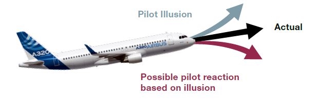
The review was initiated as a result of a number of poorly handled all-engine go-arounds. Most real world go-arounds were conducted at light weights and with high thrust. It was found that the likely consequence of not maintaining the correct pitch attitude during the go-around is acceleration towards the flap limit speed—when autothrust is not active, there is no speed protection to prevent a flap limit speed exceedance. A representation of the pitch-up, or what Airbus termed the false climb illusion, is shown in Figure 7.
Figure 7: Pitch-up illusion
Pitch-up (somatogravic) illusion, experienced as a result of acceleration during the go-around manoeuvre, showing the illusion as experienced by the pilot and the possible response to pitch-down. Source: Airbus
The review included the following points pertinent to the second event, where the PF introduced pitch-down inputs while conducting the go-around manoeuvre:
All pilots must know the required initial pitch target for their aircraft BEFORE commencing a missed approach. They must maintain that pitch target by following the [speed reference system] commands in manual flight. With the autopilot engaged, they should use this knowledge to confirm the autopilot behaviour.
The go-around pitch target for the A320 was quoted as 15 degrees nose up, the importance of which was highlighted as follows:
During a manual Go Around, if the required pitch is not reached or maintained, linear acceleration will result. Research has shown that this may cause a “false climb illusion”. The false climb illusion may lead a pilot to believe that the aircraft is already above the required pitch. Consequently, a pilot may respond with an opposite and dangerous pitch-down input.
Inadvertent pilot actions
Regarding the PF’s inadvertent selection of the EXPED pushbutton, Reason (1990) stated that
A slip is a type of error which result from some failure in the execution stage of an action sequence…These slips could arise because, in a highly routinized set of actions, it is unnecessary to invest the same amount of attention in the matching process….with oft-repeated tasks it is likely that [they] become automatized to the extent that they accept rough rather than precise approximations to the expected inputs.
Additionally, consideration was given to the outcome when similar objects (in this case, the pushbuttons A/THR, EXPED and APPR) were confused for each other. Perceptual confusion is a type of attentional slip and on that, Wickens and Hollands (2000) stated the following:
Perceptual confusions occur because a person may recognise a match for the proper object with an object that looks like it, is in the expected location, or does a similar job…
The pushbuttons on the FCU were the same colour and size. Colour coding and placement of objects has an effect on perception, in the sense that if two items are the same colour, then using colour-coding can tie together items that are spatially separated on the display (Wickens and Hollands, 2000). Additionally, two items on a cluttered display will be more easily integrated or compared if they share the same colour (different from the clutter), but the shared colour may disrupt the ability to focus attention on one while ignoring the other.
In addition to considering objects of similar size and shape, the effect of flight deck lighting was also considered. Woodson and Conover (1964) described several important factors that should be considered in the design of any lighting system:
suitable brightness for the task at hand
uniform lighting for the task at hand
suitable brightness contrast between task and background
lack of glare from either the light source or the work surface
suitable quality and colour of illumination and surfaces.
With regard to the FCU pushbutton layout, lighting and colour coding (see Figure 5), the physical similarities (shape, size, and colour) and close proximities between the A/THR, EXPED and APPR pushbuttons on the FCU could have contributed to any perceptual confusion.
Decision making and conscious automaticity
Wickens and Hollands (2000) outline that when undertaking a task, we must translate the information that is perceived about the environment into an action, and this action may be either an immediate response, or based on a more thorough, time-consuming evaluation.
In relation to the PF’s reaction to the thrust lock condition, the limitations of decision making were considered, as was the concept of automatic actions. As outlined by Klein and Klinger (1991) cited in Harris (2011), naturalistic decision making is characterised by ‘dynamic and continually changing conditions, real-time reactions to these changes, ill-defined tasks, time pressure, significant consequences for mistakes’.
In instances where actions that have become well-learned, ‘it is as though practice leads to a mental repackaging of our behaviour…that can be set off with only a brief conscious thought…’ (Wheatley and Wegner, 2001). In this case, the PF pressing the instinctive disconnect buttons was achieved without any time-consuming conscious elements.
Fatigue
The International Civil Aviation Organization (ICAO 2016) defined fatigue as:
A physiological state of reduced mental or physical performance capability resulting from sleep loss, extended wakefulness, circadian phase, and/or workload (mental and/or physical activity) that can impair a person’s alertness and ability to perform safety related operational duties.
Fatigue can have a range of adverse influences on human performance. These include:
slowed reaction time
decreased work efficiency
increased variability in work performance
lapses or errors of omission (Battelle Memorial Institute 1998).
Time of day can be important for determining whether an individual is in a circadian low or high. Human circadian rhythm is partially determined by the environmental light-dark cycle (Duffy, Kronauer, & Czeisler, 1996). The challenge can be for people to maintain alertness during the night-time hours and reduced sleepiness during the daytime rest break.
The Civil Aviation Safety Authority (2012) stated the following:
The circadian cycle has two periods of sleepiness, known as the circadian trough and the circadian dip. The circadian trough occurs typically between 0200 and 0500 hours (or dawn). During the circadian trough the body’s temperature is at its lowest level and mental performance, especially alertness, is at its poorest.
In the context of time on duty, Goode (2003) identified numerous studies that show an empirical relationship between work patterns and deteriorating performance. In accidents where fatigue was attributed, 20 per cent occurred in the tenth (or more) hour of duty.
Caldwell (2003) stated that ‘the primary determinant of the level of fatigue is the time awake since the last sleep period.’ Russo and others (2005) found that ‘significant visual perceptual, complex motor, and simple reaction time impairments began in the 19th hour of continuous wakefulness.’ As part of an NTSB study of short haul domestic air carrier accidents from 1978 to 1990, ‘time since awake’ was a predominant factor, and often related to ‘ineffective decision making’.
The following data was relevant to the PF’s fatigue assessment. The PF:
usually obtained about 7 hours of sleep a night between 2300 and 0600
had conducted two flights over the previous 3 days (one of which was a positioning flight)
duty ended at 2115 the previous day, resulting in a 17 hour break prior to starting duty on the day of the occurrence
woke at about 0600 and commenced duty in Melbourne at 1415
reported feeling well rested
positioned to Perth, before operating the occurrence flight
recalled feeling ‘okay’ around the time of the occurrence, but had been awake for about 19.5 hours.
The occurrence took place at about 0130, which was 11 hours and 15 minutes after the PF’s duty commenced. However, the descent was taking place close to a known window of circadian low. Along with the night conditions, with a relatively low-level of lighting in the flight deck, this may have contributed to feelings of sleepiness.
The ATSB evaluated the PF’s level of fatigue using two biomathematical models, Fatigue Avoidance Scheduling Tool (FAST) and System for Aircraft Fatigue Evaluation (SAFE). These models are decision aids designed to assess and forecast performance changes induced by sleep restriction and time of day.
Both models indicated a moderate level of fatigue. The FAST results indicated that at the time of the occurrence, there was a moderate likelihood that the PF was experiencing a level of fatigue known to have a demonstrated effect on performance. The SAFE results predicted that the PF would have felt ‘moderately tired, let down’ at the time of the occurrence, and in a moderate to high-risk category for experiencing the effects of fatigue.
The following data was relevant to the PM’s fatigue assessment. The PM:
usually obtained about 7.5 hours sleep a night between 2300 and 0630
was on a rostered period of leave in the two weeks prior to the occurrence
was in Perth on the day of the occurrence and woke at about 0630 Western Standard Time,[21] and had therefore been awake for about 17 hours at the time of the occurrence
commenced duty in Perth at 1800
reported feeling well rested and having adequate sleep the night before the occurrence
did not report any fatigue-related concerns associated with the occurrence flight.
Operator fatigue management
Organisations holding an Air Operator Certificate are generally required to comply with the Civil Aviation Orders Part 48 Flight Time Limitations (CAO 48). However, the Civil Aviation Safety Authority had granted the operator an exemption from CAO 48, under a specific instrument. This exemption was in force at the time of the occurrence. In place of the CAO 48 limitations, the operator was required to observe specific flight and duty limits contained in schedules to the instrument. With respect to this occurrence, the following flight and duty limits were relevant:
where the previous duty period did not exceed 12 hours, the time free of duty shall be 10 hours
the maximum hours per flight duty period for a local start time between 1300 and 1459, with one or two sectors, was 13 hours
flight deck duty limits for operations involving two crew was 10 hours.
Workload
In the context of aviation, workload has been described as ‘reflecting the interaction between a specific individual and the demands imposed by a particular task. It represents the cost incurred by the human operator in achieving a particular level of performance’ (Orlady and Orlady, 1999). A person experiences workload differently, based on their individual capabilities and the local conditions at the time. These conditions can include the following:
training and experience in the situation at hand
the operational demands during that phase of flight
if the person is experiencing the effects of fatigue
level of automation in use, and the mental requirements in interpreting their actions.
Research on unexpected changes in workload during flight has found that pilots who encounter abnormal or emergency situations experience a higher workload with an increase in the number of errors compared to pilots who do not experience these situations (Johannsen and Rouse, 1983).
Additionally, Holmes and others (2003) outline that high workload and distractions can result in a pilot scanning fewer instruments and checking each instrument less frequently.
Pilot recency and skill decay
The Civil Aviation Safety Regulations CASR 1998Part 61: Flight Crew Licencing outlines that recent experience, or recency, refers to undertaking particular flight operations in the past 90 days. These flying experiences include take-off and landings, or instrument approaches, for example. Recency will generally be measured by flight hours (Haslbeck and others, 2014) or sectors flown (Ebbatson, and others, 2010).
The concept of maintaining recency is important to reduce flight skill decay. In a commercial aviation context, Childs and Spears (1986) suggest that cognitive and procedural elements of flying skills decay more rapidly than control-oriented skills. Pilots were observed to have difficulty correctly identifying cues and classifying situations, although once a situation was correctly classified, they remembered what to do. Therefore, they propose that flying training should focus on pilot monitoring skills and recognition of different situations.
Despite the PF having management responsibilities, the PF had almost 70 hours in the previous 90 days, albeit with a significant training duty component. As a result, there was insufficient evidence to determine whether recency and/or skill decay had any influence on the flight crew’s actions.
Operator crew resource management training
The operator’s Operations Manual part A included the statement that ‘flight crewmembers should complete the major elements of the full length [crew resource management (CRM)] course over a three-year recurrent training cycle’. The Civil Aviation Advisory Publication (CAAP) SMS-3(1) Non-Technical Skills Training and Assessment for Regular Public Transport Operations provides the Civil Aviation Safety Authority’s preferred method for training in the human performance aspects of flight crew work performance. This CAAP provides the following definition of CRM:
A team training and operational philosophy with the objective of ensuring the effective use of all available resources to achieve safe and efficient flight operations.
CRM is now more commonly referred to as non-technical skills, which are defined as follows:
…the mental, social, and personal-management abilities that complement the technical skills of workers [and] include competencies such as decision-making, workload management, team communication, situation awareness, and stress management.
The operator’s CRM training program required pilots to complete a two-day classroom-based CRM course within one year of starting with the operation, and an annual refresher course. These courses were run by an external training provider, and the subjects included:
human perception and the learning process
personality type, delegation
leadership and effective communication skills
effective communication and co-ordination within the flight crew and between crewmembers
implications of automation on CRM.
Pilots also undertook a CRM course during command upgrade training, and each company line check and operational proficiency check also included an assessment of CRM principles as they were applied during normal, non-normal and emergency procedures. The ATSB was not able to determine the methods by which CRM principles were assessed.
A review of the company’s line check reports showed that ‘crew management/co-operation’ was an assessment criteria for the departure, en route, approach and landing phases of flight. Additionally, ‘CRM technique’ was assessed as a general criteria. The ATSB did not identify any specific criteria included in the operator proficiency check records.
Related occurrences
A review of the ATSB’s occurrence database did not identify any recent similar occurrences on scheduled passenger transport flights that were investigated by the ATSB.
While conducting an arrival procedure, prior to commencing an approach into Melbourne, Victoria on 15 May 2015, the Skytraders Airbus A319 descended to about 2,200 ft, which was below the ATC-assigned altitude of 3,000 ft. The crew broke off the arrival procedure and climbed to the new ATC cleared altitude of 5,000 ft before returning to land at Melbourne.
During the descent below 3,000 ft, the aircraft’s Terrain Avoidance and Warning System (TAWS) initiated a number of warning alerts, the speed limit for the aircraft flaps was exceeded, and the Minimum Safe Altitude Warning System (MSAW) initiated an alert to the ATC controller. Critically, during the 26 seconds from the time that the PF pressed the instinctive disconnect pushbutton on the thrust levers to when the aircraft reached its minimum altitude, the aircraft descended just over 1,000 ft and increased speed by about 100 kt.
The event was initiated by an inadvertent switch selection by the pilot flying (PF). This was followed by a combination of errors, rapidly changing events, high workload and an apparent response to a pitch-up illusion, resulting in the aircraft quickly developing a very high rate of descent and increasing airspeed.
Inadvertent FCU selections
As the aircraft was approaching the localiser for Melbourne runway 16, the PF recalled intending to arm the aircraft’s autoflight system (AFS) to capture the localiser for the approach. This required the PF to press the APPR pushbutton on the Flight Control Unit (FCU). Instead, the PF mistakenly pressed the EXPED pushbutton and the AFS entered the expedite descent mode. In an apparent attempt to cancel the expedite descent mode, the PF inadvertently pressed the A/THR pushbutton, which was adjacent to the EXPED pushbutton.
The acts of pressing the EXPED and then the A/THR pushbuttons were both predicated by a prior intention to act, but neither action went as planned. In this case, this prior intention was the pressing of the APP push button, which was part of a routine set of actions. Routine actions are generally characterised as requiring less attention.
The pressing of the A/THR was an apparent instinctive reaction to realising that an error had been made. Both selections were consistent with unintentional slips. Furthermore, the similar size, shape and colour of the EXPED and APPR buttons on the FCU, as well as their close proximity, may have contributed to the error. The lighting conditions in the flight deck may have increased the difficulty for the pilot monitoring (PM) to monitor the actions of the PF.
Reaction to ‘thrust lock’ condition
After the PF inadvertently pressed the A/THR pushbutton on the FCU, the Flight Mode Annunciator and Electronic Centralised Aircraft Monitor (ECAM) identified that the autothrust system had disengaged and the thrust locked at the existing setting, which was idle. The ECAM notified the flight crew of this change by displaying the THR LK caution message, as well as an associated procedure. The flight warning computer simultaneously sounded the caution aural alert, while the FMA’s autothrust column displayed the changed mode. The PM immediately identified this changed autothrust condition and verbally notified the PF of the change. It could not be determined whether this call was in response to the ECAM notification with associated master caution aural alert, or the FMA change.
Normal procedure for disconnecting the autothrust system was to press the autothrust instinctive disconnect (I/D) pushbutton, but this procedure first required the pilot to match the position of the thrust lever with the actual thrust setting. The thrust lever angle indicator assisted in this process. The aim of the THR LK ECAM procedure was to remove the engines’ locked thrust condition. That procedure also included matching the thrust lever position to the actual thrust setting.
On becoming aware that the engines’ thrust had been locked, the PF reacted by pressing the autopilot and autothrust instinctive disconnect pushbuttons, thereby removing the thrust lock condition. The likely intent of disconnecting both autopilot and autothrust was to revert to a fully manual flight mode. This is supported by the simultaneous disconnection of the autopilot and autothrust systems through the use of the instinctive disconnect buttons, an automatic action to complete the apparent intent.
However, in disconnecting the autothrust, the PF did not match the thrust levers to the current power, or set a desired power. This was likely to be a lapse, which is ‘simply omitting to perform one of the required steps in a sequence of actions’ (Harris, 2011). As to why this lapse occurred, the PF’s incomplete response to the ‘thrust lock’ condition may have been a result of a response consistent with a perceived urgency to handle an undesirable state, particularly as the instinctive disconnect pushbuttons were designed for a quick response
High thrust with pitch-down attitude
As a result of not matching the thrust lever angle to the locked thrust setting when disengaging the thrust lock condition, the thrust increased to the climb setting at which the thrust levers were positioned. This resulted in a significant, unexpected thrust increase. The PF responded by applying pitch-down inputs on the side stick and a few seconds later retarded the thrust levers to idle. The pitch-down attitude with high thrust—the engines did not respond to the commanded thrust reduction for a further few seconds—resulted in the aircraft adopting a rapidly accelerating downward vector. At about this time the altitude alert began to chime and, shortly thereafter, the aircraft descended through its clearance limit altitude.
As the aircraft passed through the clearance limit altitude, the first of the TAWS alerts triggered. The PF responded with a declared intent to go-around and rapidly positioned the thrust levers to full power. However, the PF did not raise the aircraft’s pitch attitude to the recommended 15 degrees nose up for the conduct of a go-around. While the PF commenced some pitch-up commands, the aircraft’s attitude remained well below the horizon, resulting in a continuation of the accelerating airspeed and high rate of descent.
Just as the engines began to increase thrust, the second TAWS alert triggered. The procedural response to this second alert was to apply full backstick and maintain that position while setting the thrust to maximum power. However, the PF again responded to the increasing engine thrust with pitch-down commands, resulting in a continuation of the aircraft’s downward flight path. The PF arrested the descent after about 10 seconds, during which time a further TAWS alert triggered.
The flap overspeed
During the period of high thrust, the PM selected the flaps from 1 to UP as the aircraft was accelerating through 260 kt. The slats were not fully retracted for a further 12 seconds, by which time the aircraft had accelerated to more than 310 kt. The limit speed for flap 1 was 230 kt.
The effect of pitch-up illusions during rapid thrust increases
The PF did recall applying pitch-down side stick input during the rapid thrust increases and did not identify the increasing rate of descent, resulting from the nose-down attitude. The PF did, however, recall thinking that the aircraft was pitching up. Throughout the occurrence, the night conditions and operations within cloud resulted in the absence of a natural horizon. It was therefore likely that the PF’s pitch-down side stick inputs were in response to pitch-up (somatogravic) illusions caused by the unexpected and rapid increase in thrust. The PF’s susceptibility to the effects of pitch-up illusions was possibly exacerbated by also experiencing a high workload, which would likely reduce monitoring of flight instruments.
The effect of the pitch-up illusion influenced the breach of altitude, the EGPWS alerts, and the exceedance of the flap limit speed.
The PM’s ability to influence the events
The primary role of the PM is to monitor the aircraft’s flight path and performance and immediately bring any concern to the PF’s attention. However, Dismukes and Berman (2010) have shown that, while flight crew monitoring is an important defence that is performed appropriately in the vast majority of cases, it does not always catch flight crew errors and equipment malfunctions. They also noted:
…even though automation has enhanced situation awareness in some ways…it has undercut situation awareness by moving pilots from direct, continuous control of the aircraft to managing and monitoring systems, a role for which humans are poorly suited.
When considering whether the PM was likely to be able to identify and therefore influence the events that led to the flap overspeed and the breaching of the cleared altitude, the following factors were considered. The:
PM verbally identified the expedite descent mode change and the appearance of the ‘thrust lock’ condition
PM had difficulty in identifying the PF’s actions, being unable to see the PF selections on the FCU
lighting levels in the flight deck were low
reduced communication between the flight crew—specifically, the PF did not communicate an intended response to the expedite descent mode engagement, THR LK ECAM message, or the various autopilot disconnections and reconnections
PF did not announce mode changes annunciated on the FMA as required by the standard operating procedures, those changes being resultant from FCU and autoflight system inputs made by the PF
PF’s response to the thrust lock condition was contrary to normal procedure
PM’s attention was probably focused on the flap speed, when the aircraft started to rapidly accelerate early in the occurrence. By the time that the PM had selected the flap up, the aircraft had developed a very high rate of descent and descended through the clearance limit altitude
PM recalled that there was ‘a lot of button pressing’ throughout the occurrence, and that the autopilot was disengaged several times.
The period of time from the inadvertent FCU selections through to the aircraft returning to a positive rate of climb was short, but characterised by rapidly changing events with multiple visual and aural alerts. The PM’s ability to identify and influence the rapidly changing situation was likely affected by the non-routine nature of the event, actions of the PF, reduced communication between the flight crew and an apparent focus on the flap speed exceedance as the aircraft started to accelerate.
Crew workload
Pilots who encounter abnormal or emergency situations experience a higher workload with an increase in performance errors compared to pilots who do not experience these situations (Johannsen and Rouse, 1983). During the occurrence, the attention of the flight crew was likely divided between a number of different information cues and task requirements, from the time the PF made the inadvertent selections on the FCU, through to when the aircraft began to climb. These included:
multiple aural warnings and alerts
identifying and responding to mode changes, including appropriate actions to address the THR LK ECAM message
disengagements and re-engagement of the autopilot
focus on airspeed (mostly by the PM)
interactions with ATC towards the end of the occurrence sequence.
At the time, the aircraft was in the descent phase, which inherently has a higher workload. The PM recalled that the workload became very high after the inadvertent FCU selections occurred. The high workload experienced by the PM was demonstrated in the use of an incorrect call sign during ATC communications, as the aircraft started to climb out.
The degree of recollection from both crew after the occurrence also indicated that they experienced a high workload over a short period of time, as details including the numerous aural warnings (including the EGPWS), one of the inadvertent FCU selections and autopilot changes were not recalled. Overall, the high workload the flight crew experienced appeared to have limited their capacity to identify mode changes, such as autopilot disconnections, and to respond to the aircraft’s undesired high rate of descent.
Crew fatigue
The PF awoke at a normal time of 0630, signed on at Melbourne and did not report receiving any rest before or during the operation from Perth to Melbourne. It is reasonable to conclude that, due to time awake, time on duty and the time of day, the PF was probably experiencing a level of fatigue known to have at least some effect on performance. This was predicted by biomathematical fatigue models. There was, however, insufficient evidence to indicate that fatigue contributed to the occurrence. The ATSB also did not ascertain any systemic issues associated with the operator's management of fatigue.
Findings
From the evidence available, the following findings are made with respect to the descent below minimum permitted altitude involving an A319, VH-VCJ, near Melbourne Airport, Victoria on 15 May 2015. These findings should not be read as apportioning blame or liability to any particular organisation or individual.
Safety issues, or system problems, are highlighted in bold to emphasise their importance. A safety issue is an event or condition that increases safety risk and (a) can reasonably be regarded as having the potential to adversely affect the safety of future operations, and (b) is a characteristic of an organisation or a system, rather than a characteristic of a specific individual, or characteristic of an operating environment at a specific point in time.
Contributing factors
The pilot flying inadvertently selected the EXPED pushbutton instead of the APPR pushbutton, and, in an attempt to correct the error, pressed the A/THR pushbutton, creating a thrust lock condition.
In attempting to remove the thrust lock condition, the pilot flying pressed the instinctive disconnect pushbutton but did not move the thrust levers to match the locked thrust setting. As the thrust was locked at idle while the thrust levers were set to climb thrust, this resulted in an unexpected, significant thrust increase.
The pilot flying likely experienced pitch-up illusions during two rapid thrust increases and responded to these illusions with pitch-down sidestick input.
Pitch-down inputs by the pilot flying, combined with a very high thrust setting, resulted in a very high rate of descent with rapidly increasing airspeed. This led to the breach of the cleared minimum descent altitude, as well as triggering a number of Enhanced Ground Proximity Warning System alerts.
The rapidly changing aircraft state led to the crew experiencing a high workload. This was likely to have limited their capacity to identify mode changes and to respond to the aircraft’s undesired high airspeed and rate of descent.
The pilot monitoring’s ability to identify and influence the rapidly changing situation was likely affected by the non-routine actions of the pilot flying, the reduced communication between flight crew and an apparent focus on the flap speed exceedance as the aircraft started to accelerate.
Other factors that increased risk
At the time of the occurrence, the pilot flying was likely experiencing a level of fatigue known to have a demonstrated effect on performance, predominantly due to the time of day and time awake.
The aircraft’s rapidly increasing airspeed resulted in the limit speed for the extension of the aircraft slats being significantly exceeded.
Sources and submissions
Sources of information
The sources of information during the investigation included:
the aircraft’s cockpit voice recorder and flight data recorder
the flight crew
Skytraders Pty Ltd
the Bureau d’Enquêtes et d’Analyses.
Airbus SAS
Airservices Australia
Bureau of Meteorology.
References
Battelle Memorial Institute 1998, An Overview of the scientific literature concerning fatigue, sleep, and the circadian cycle, Report prepared for the Office of the Chief Scientific and Technical Advisor for Human Factors, US Federal Aviation Administration.
Caldwell Jr, JA & Caldwell, JL, 2003. Fatigue in aviation: A guide to staying awake at the stick. Ashgate: Burlington, Vermont.
Childs, JM and Spears, WD., 1986. Flight-skill decay and recurrent training. Perceptual Motor Skills, pp.235-242
Dismukes, R. and Berman, B., 2010. Checklists and Monitoring in the Cockpit: Why Crucial Defenses Sometimes Fail, NASA Ames Research Center
Duffy JF, Kronauer RE, & Czeisler CA. 1996, Phase-shifting human circadian rhythms: influence of sleep timing, social contact and light exposure. The Journal of Physiology, 15, 289-297.
Ebbatson, M., Harris, D., Huddlestone, J. and Sears, R., 2010. The relationship between manual handling performance and recent flying experience in air transport pilots, Ergonomics, 53:2, 268-277.
Haslbeck A, Kirchner P, Schubert E, & Bengler K, 2014, A Flight Simulator Study to Evaluate Manual Flying Skills of Airline Pilots, Proceedings of the Human Factors and Ergonomics Society 58th Annual Meeting. Available on pro.sagepub.com
Goode, JH., 2003. Are pilots at risk of accidents due to fatigue? Journal of safety research, 34(3), pp.309-313.
Harris, D., 2011. Human Performance on the Flight Deck, Ashgate Publishing Ltd., Surrey, England
Holmes, S., Bunting, A., Brown, D., Hiatt, K., Braithwaite, M., & Harrigan, M. (2003). Survey of spatial disorientation in military pilots and navigators. Aviation, Space, and Environmental Medicine, 74, 957-965
International Civil Aviation Organization 2016, Manual for the Oversight of Fatigue Management Approaches, 2nd edition, Montreal, Canada.
Johannsen, G & Rouse, WB, 1983. Studies of planning behavior of aircraft pilots in normal, abnormal, and emergency situations. Systems, Man and Cybernetics, IEEE Transactions on, (3), pp.267-278.
Noyes, J., 2007. Automation and Decision Making, Decision Making in Complex Environments, Ashgate Publishing Limited, Aldershot, England
Orlady, HW, & Orlady, LM, 1999. Human factors in multi-crew flight operations. Ashgate: Aldershot, UK p.203.
Reason, J. 1890. Human Error, Cambridge University Press, United Kingdom
Russo, M., Johnson, D., Escolas, S. and Hall, S., 2005. Visual Perception, Psychomotor Performance, and Complex Motor Performance During an Overnight Air Refueling Simulated Flight, Aviation, Space and Environmental Medicine, Vol. 76, pp. C92-103
Stott, R.J., Spatial Orientation and Disorientation, in Nicholson, A. (ed.), 2011, The Neurosciences and the Practice of Aviation Medicine, Ashgate Publishing Limited, Surrey, England, pp.55-91
Wheatley, T. and Wegner, DM. 2001. The Psychology of Automaticity of Action, International Encyclopaedia of the Social & Behavioural Sciences, In Smelser, NJ and Baltes, PB, Elsevier Science Ltd.
Wickens, CD. And Holland, JG. 2000. Engineering Psychology and Human Performance, Prentice Hall, New Jersey, USA
Woodson, W. and Conover, D., 1964. Human engineering guide for equipment designers, University of California Press, Los Angeles, USA
Submissions
Under Part 4, Division 2 (Investigation Reports), Section 26 of the Transport Safety Investigation Act 2003 (the Act), the Australian Transport Safety Bureau (ATSB) may provide a draft report, on a confidential basis, to any person whom the ATSB considers appropriate. Section 26 (1) (a) of the Act allows a person receiving a draft report to make submissions to the ATSB about the draft report.
A draft of this report was provided to:
The flight crew
Skytraders Pty Ltd
The Bureau d’Enquêtes et d’Analyses.
Airbus SAS
Civil Aviation Safety Authority.
Submissions were received from Skytraders Pty Ltd, the flight crew, the Bureau d’Enquêtes et d’Analyses, and the Civil Aviation Safety Authority. The submissions were reviewed and where considered appropriate, the text of the report was amended accordingly.
Glossary
A319
Airbus A319 model aircraft
A320
Airbus A320 family of aircraft
AFS
Autoflight system
ALT*
Altitude acquire is engaged
AP1
Autopilot number 1
APPR
Approach pushbutton
ATC
Air traffic control
ATIS
Automatic terminal information service
ATP(A)L
Air transport pilots (aeroplane) licence
ATS
Autothrust system
A/THR
Autothrust pushbutton
C
Celsius
CVR
Cockpit voice recorder
DFDR
Digital flight data recorder
ECAM
Electronic centralised aircraft monitor
EGPWS
Enhanced ground proximity warning system
EXPED
Expedite pushbutton
EXP DES
Expedite descent vertical mode
E/WD
Engine/warning display
FCOM
Flight crew operating manual
FCTM
Flight crew training manual
FCU
Flight control unit
ft
Feet
FMA
Flight mode annunciator
FMGS
Flight management guidance system
FWC
Flight warning computer
GPWS
Ground proximity warning system
hPa
Hectopascals
ILS
Instrument landing system
I/D
Instinctive disconnect
km
Kilometre
kt
Knots
MSAW
Minimum safe altitude warning system
NAV
Navigation lateral mode
PF
Pilot flying
PFD
Pilot’s flight display
QRH
Quick reference handbook
OP DES
Open descent vertical mode
OPSA
Operations Manual part A
OPSB
Operations Manual part B
PM
Pilot monitoring
SNB2
Snowbird 2
SOP
Standard operating procedures
STAR
Standard arrival
TAAATS
The Australian advanced air traffic system
TAWS
THR LK
Terrain avoidance and warning system
Thrust lock condition
TLA
Thrust lever angle
Purpose of safety investigations
The objective of a safety investigation is to enhance transport safety. This is done through:
identifying safety issues and facilitating safety action to address those issues
providing information about occurrences and their associated safety factors to facilitate learning within the transport industry.
It is not a function of the ATSB to apportion blame or provide a means for determining liability. At the same time, an investigation report must include factual material of sufficient weight to support the analysis and findings. At all times the ATSB endeavours to balance the use of material that could imply adverse comment with the need to properly explain what happened, and why, in a fair and unbiased manner. The ATSB does not investigate for the purpose of taking administrative, regulatory or criminal action.
Terminology
An explanation of terminology used in ATSB investigation reports is available here. This includes terms such as occurrence, contributing factor, other factor that increased risk, and safety issue.
Publishing information
Released in accordance with section 25 of the Transport Safety Investigation Act 2003
Ownership of intellectual property rights in this publication
Unless otherwise noted, copyright (and any other intellectual property rights, if any) in this report publication is owned by the Commonwealth of Australia.
Creative Commons licence
With the exception of the Coat of Arms, ATSB logo, and photos and graphics in which a third party holds copyright, this publication is licensed under a Creative Commons Attribution 3.0 Australia licence.
Creative Commons Attribution 3.0 Australia Licence is a standard form licence agreement that allows you to copy, distribute, transmit and adapt this publication provided that you attribute the work.
The ATSB’s preference is that you attribute this publication (and any material sourced from it) using the following wording: Source: Australian Transport Safety Bureau
Copyright in material obtained from other agencies, private individuals or organisations, belongs to those agencies, individuals or organisations. Where you wish to use their material, you will need to contact them directly.
On 11 May 2015, a Boeing 737 aircraft, registered VH-VOP and operated by Virgin Australia International, conducted a scheduled passenger service from Sydney, New South Wales to Christchurch, New Zealand.
Shortly after midnight, the aircraft landed on runway 29 at Christchurch. Runway 29 was shorter than the main runway at Christchurch. The aircraft landed within the required touchdown zone, using full reverse thrust, speedbrakes, and the autobrake system engaged the wheel brakes. Recorded flight data showed that the aircraft initially achieved, and at times exceeded the selected AUTOBRAKE 3 target deceleration rate. However, after crossing the runway intersection, the aircraft did not continue to decelerate as expected and the crew believed the aircraft appeared to slide or skid. In response, the crew overrode the autobrakes and applied hard manual braking while retaining full reverse thrust for longer than used in normal operations. The crew also corrected a minor directional deviation. The aircraft came to a stop about 5 m from the runway end. There were nil recorded injuries or aircraft damage.
What the ATSB found
The ATSB found that, due to increased workload, the crew misperceived the runway surface conditions and believed it was damp when in fact it was wet. As there was no regulatory direction on how a damp runway was to be considered for aircraft landing performance purposes, the operator’s policy was to treat a damp runway the same as a dry runway. As a result, the crew established the aircraft’s landing performance based on a dry rather than a wet runway and the expected runway 29 landing performance was not achieved.
The ATSB also found that, several months prior, the operator had changed its policy whereby damp runways had previously been treated as wet runways.
Based on the crew’s observations and a review of the available recorded data, it was very likely that the surface conditions on the later part of the runway had degraded to the extent that they adversely affected the aircraft’s braking capability. It was also possible that the aircraft experienced viscous aquaplaning. However, the initial exceedance of the target deceleration rate, combined with the crew’s actions, likely prevented a runway overrun.
Further, a post-incident analysis of the flight data recorder by the aircraft manufacturer found that a 5 kt tailwind existed on final approach and landing. This also significantly affected the aircraft’s landing performance and further reduced safety margins.
Additionally, and along with the United States Federal Aviation Administration, the ATSB found that the 15 per cent in-flight safety margin applied to actual landing distances during landing performance calculations may be inadequate under certain runway conditions. In these conditions, additional conservatism is encouraged.
Safety message
This incident highlights the adverse consequences of crew experiencing a high workload during critical phases of flight, including missing important information needed to determine an accurate landing performance.
In addition, runway surface condition and braking action reports (intended for the benefit of other pilots landing aircraft after them) can be subjective, and the terminology used to describe these can be inconsistent. Considerable efforts have been made by organisations such as the United States Federal Aviation Administration to address this issue with the introduction of the runway condition assessment matrix.
The occurrence
Sequence of events
On 12 May 2015, shortly after midnight local time, a Boeing 737-800 aircraft, registered VH-VOP (VOP) and operated by Virgin Australia International as Velocity 134, touched down on runway 29 at Christchurch, New Zealand. During the landing roll, the aircraft did not decelerate as expected and the crew believed it appeared to slide or skid. The crew responded to the situation and the aircraft came to a stop about 5 m from the runway end.
Pre-flight preparations
Earlier in the evening of 11 May 2015, the crew arrived at Sydney, New South Wales for the scheduled passenger service to Christchurch. During flight preparations in Sydney, the crew reviewed the notice to airmen (NOTAM)[1] and applicable weather forecasts. The NOTAMs indicated that works in progress would be occurring on the northern end of runway 02 at Christchurch, resulting in a reduced runway length on the main runway. The NOTAM also stated that runway 20 was closed for landing. There was no significant weather forecast for their arrival, but rain was expected later the next morning (after the scheduled arrival time), and at that time, the conditions were favourable to runway 02. The operator’s flight dispatch notes indicated that there were no landing performance weight restrictions for their arrival with the forecast weather conditions.
At 0941 Coordinated Universal Time (UTC),[2] VOP departed Sydney and climbed to flight level (FL)[3] 390. The first officer (FO) was designated as the pilot flying and the captain was the pilot monitoring.[4]
First contact with Christchurch air traffic control
The captain reported that, at about 1135, he contacted air traffic control (ATC) on the Christchurch Information frequency and requested the automatic terminal information service (ATIS)[5] for Christchurch Airport. The crew received the ATIS ‘X-ray’ (X) details, which advised that the runway surface conditions were dry and to expect an approach to runway 02. These details were consistent with the crew’s pre-flight assessment of the forecast conditions. The crew recorded these details on the take-off data card[6] and then prepared for the approach. Due to forecast turbulence over the Southern Alps, the crew had previously briefed the cabin crew on the need to prepare the cabin for the approach earlier than normal.
At around the same time, the crew of an Airbus A320 (A320) aircraft inbound to Christchurch and ahead of VOP, were in contact with Christchurch Area ATC. ATC advised the A320 crew that it was now raining at Christchurch Airport and the runway-in-use was about to change due to a variation in the surface wind conditions.
At 1136, ATIS ‘Yankee’ (Y) was issued, indicating that runway 29 was now in-use and the surface conditions were dry.
The A320 crew continued discussions with ATC regarding the changing weather conditions at Christchurch. The crew determined that, rain on the reported dry runway rendered it wet, therefore, they were unable to land at Christchurch due to performance restrictions and elected to divert to Wellington.
Change in ATIS and approach
At 1146, the crew of VOP established contact with Christchurch Area ATC on a different frequency from the A320 crew. The crew advised ATC that they were at waypoint ‘VANDA’ (Figure 1) maintaining FL 390 and were in receipt of ATIS X. ATC began to clear the crew to descend for the ‘BELEE 1’ arrival but then asked them to standby. Shortly after, ATC advised the crew that ATIS Y was now available with a visual approach to runway 29 and that there were ‘quite a few changes from the previous, you want to have a listen’. About 1 minute later ATC contacted the crew and advised they were cleared to descend to FL 160 for the ‘BELEE 1 Charlie’ standard arrival route for runway 29 (Figure 1). The crew acknowledged the clearance and responded ‘Velocity 160’, inadvertently transposing their cleared flight level for their call sign. ATC then confirmed their call sign as ‘Velocity 134’ and advised that ATIS Y was current with a QNH[7] of ‘993’. The crew acknowledged the QNH and requested the surface wind, which was reported as 250° at 12 kt, maximum 18 kt. The crew recorded these details on the take-off data card.
Having been notified of the change in runway-in-use, the crew commenced their preparations for the revised approach. Also, around this time, the crew noted weather ahead on the aircraft’s weather radar at waypoint ‘BELEE’, requiring a track deviation.
Figure 1: VH-VOP actual flight path (in blue) and BELEE 1 Charlie arrival route (yellow)
Source: Google earth and operator, annotated by the ATSB
The crew reported that, in order to manage an increased workload associated with the revised approach, they divided the duties. The captain focussed on entering the approach into the flight management system and assessed the aircraft’s landing performance to determine the suitability of runway 29 (which was shorter than the expected runway 02). The FO managed the weather deviation and focussed on the implications of landing on a shorter runway. The crew also discussed holding at waypoint ‘CHARR’ if additional time was needed to prepare for the approach. Due to the higher than normal workload, the captain reported that they did not get the opportunity to listen to ATIS Y.[8]
At 1149, the crew commenced their descent. Shortly after, the crew made a public address for the cabin crew to prepare for the approach.
At 1150, ATIS ‘Zulu’ (Z) was issued. At 1151, ATC advised the crew that it had been issued and that the runway was now wet with light rain. The crew acknowledged the call by responding ‘Velocity 134’. The crew did not listen to the ATIS as the details had been passed on by ATC. The details were not recorded on the take-off data card, but the crew specifically recalled being advised of light rain.
At 1152, the crew requested a 10 NM deviation to the right of track due to weather, which was approved by ATC.
At 1154, the A320 crew established communications with the same Christchurch Area ATC as VOP and advised they were diverting to Wellington. Shortly after, the pilot of another aircraft that had departed Christchurch at about 1146, advised the A320 crew that they considered runway 29 to be ‘damp, not wet’. When questioned, the crew of the departing aircraft indicated that they had taken off from runway 29 about 5-10 minutes prior and confirmed that they considered the surface conditions to be damp not wet. ATIS Y was active at the time of that aircraft’s departure and had not yet changed to ATIS Z (which indicated the runway was wet).
At 1155, the crew of VOP requested another deviation 15 NM to the right of track. ATC approved the crew to track as required around weather and then to waypoint ‘BISUP’ once clear. The crew then requested further clearance to track direct to ‘CHARR’ due to weather in the vicinity of BISUP. This was approved by ATC.
The captain, at this time, referenced the Airport Analysis Manual (refer to section titled Airport Analysis Manual (AAM) – Landing performance limit weight) to determine the aircraft’s landing performance limit weight for runway 29 with nil wind and flap 40.[9] Believing that the runway surface conditions had been reported as ‘damp’ by ATC, the captain determined that the dry limit weight would be about 68.2 t, which exceeded the aircraft’s maximum certified landing weight and their expected landing weight of 60.1 t. The crew were aware that if the rain continued and the runway was then wet rather than damp, they would have been about 1 t over the limit weight. From their experience, the crew established that AUTOBRAKE 3[10] was the most appropriate brake selection for landing.
At 1157, the crew of VOP advised ATC that they were clear of weather and were now tracking to CHARR. Prior to reaching CHARR, the FO provided a briefing for the revised approach, which included reviewing the arrival procedure, the runway, the aircraft configuration and performance limitations, and the identification and management of threats.
Monitoring the wind conditions
The crew received further descent instructions and were transferred to the next Christchurch ATC frequency. At 1201, the crew were advised that ATIS ‘Alpha’ (A) was current and the QNH was 992. ATC also advised that the surface wind was easing, indicating 240° at 5 kt and that it had stopped raining at the airport. The crew replied ‘understood’.
During the descent, the captain continued to monitor the wind conditions and assessed that a 5 kt tailwind on the longer runway 02 was more limiting than using the shorter runway 29 with nil wind.
At 1204, the crew requested an update on the surface wind and were advised that it was ‘easing back around to the south’, indicating 220° at 5 kt. Shortly after, ATC advised the crew that the surface wind had remained steady for the last 5 minutes at about 230° at 5 kt. In response, the captain questioned the availability of runway 20, to which ATC advised that it was not available for a few hours due to the works in progress, and their options were either runway 29 or runway 02 with a reduced length.
At 1208, the crew were cleared by ATC for the visual approach to runway 29 and advised that the surface wind was 200° at 3 kt, but it appeared to be changing to light and variable. Shortly after, the crew contacted Christchurch Tower ATC. During the approach, the FO focused on managing the aircraft’s profile and speed to ensure the approach was stable.
At 1211, ATC advised the crew that the surface wind was now calm.[11] Soon after, ATC cleared the crew to land on runway 29. Around this time, the captain reported he now could see the runway surface and assessed the runway as being damp rather than wet, as the surface did not appear reflective.
Landing on runway 29
At 1214, the aircraft touched down on runway 29 within the touchdown zone. Immediately after, full reverse thrust was applied and the speedbrakes deployed.
During the landing roll, as the aircraft passed the runway 02/20 and 11/29 intersection (Figure 7), the FO reported that he did not receive the expected sensation of being restrained against the seat belt and shoulder harness and the aircraft did not decelerate as expected. The FO also indicated that it felt like the aircraft was sliding. In response, the FO made a call to the effect of ‘aquaplaning’ or ‘skidding’ and applied constant ‘hard’ (but not full) manual braking, overriding the autobrake system. The captain noted that there was a lot more surface water on that section of the runway than what was observed at the beginning of runway 29.
The captain assisted the FO with manual braking. Both crew reported that they could feel the rudder/brake pedals ‘pulsing’, which indicated the antiskid system was operating. The crew elected to keep reverse thrust deployed to assist with braking.
The FO reported that he was focusing on the red runway end lights and noticed the aircraft drift slightly right, which he then corrected to bring the aircraft back onto the centreline. The captain reported that, when reverse thrust was stowed near the runway end, there was enough surface water on the runway to create a wall of spray. The FO reported that the aircraft came ‘slowly sliding’ to a stop about 5 m from the runway end lights. The aircraft was then taxied to the terminal.
About 3 minutes after landing, ATIS ‘Bravo’ (B) was issued, where the runway-in-use changed to runway 02 and the reported surface conditions were changed to ‘damp’.
Following engine shutdown, the crew re-checked the landing performance data for a damp (dry) runway. They also considered the amount of water spray observed at the runway end and believed the surface conditions at that time were not damp. Soon after, the captain spoke to a ground engineer who had also observed the significant amount of water spray. The engineer stated that water seemed to pool in that area of the runway when it rained. The captain and FO had not previously been aware of any tendency for water to pool on that runway. The FO conducted a visual inspection of the aircraft’s tyres with an engineer to see if any reverted rubber was present; none was detected. Figure 2 provides a timeline of the key events leading up to the incident.
A cabin crew member recalled that, during the landing, she heard the brakes ‘squealing’, but the aircraft did not slow down. She could also smell burning rubber and was unable to see outside as there was a large amount of water spray.
Post-flight discussion with Christchurch Tower
After disembarkation, the FO visited and spoke to Christchurch Tower staff to discuss the landing. The FO advised the Tower officer that there was a lot of standing water present at the end of runway 29, which probably was not visible from the Tower position. The officer agreed that the water was not visible. The officer also indicated they did observe the aircraft stop at the runway end for some time. The FO stated that they had planned on a damp runway as reported, however, the amount of water spray observed suggested otherwise. The FO further indicated that they noticed the standing water after crossing the runway intersection. The officer replied that another operator would reportedly not use runway 29 after they ran off the end in March 2015.[13]
The FO commented that they mainly used runway 02 and rarely used runway 29. The Tower officer noted that runway 29 was only used when there was a ‘screaming north-wester’ and they believed it was only the second time they had seen it used when wet.
The captain held a valid Air Transport Pilot (Aeroplane) Licence and Class 1 Aviation Medical Certificate. He had a total flying experience of 8,912 hours, of which 4,978 hours were in the Boeing 737 aircraft. The captain had been operating from Christchurch for the previous 7 years.
This was the fifth day of duties on the captain’s roster, which included both domestic and international flights. While the captain reported that the flight conducted the previous day was ‘fatiguing’, he felt well rested and in good health for the incident flight. There was no evidence to indicate a level of fatigue known to affect performance beyond what would reasonably be experienced towards the end of a duty late in the evening.
First officer
The first officer (FO) held a valid Air Transport Pilot (Aeroplane) and Class 1 Aviation Medical Certificate. He had a total flying experience of 8,229 hours, of which 2,786 hours were in the Boeing 737 aircraft. The FO had been operating from Christchurch for the previous 5 years.
This was the FO’s third day on roster and he reported feeling well rested and in good health. Although the FO reported feeling tired after the incident flight, there was no additional evidence to indicate a level of fatigue known to affect performance beyond what would reasonably be experienced towards the end of a duty late in the evening.
Aircraft information
Post-flight inspection
Following the incident, an engineer inspected VH-VOP’s (VOP) tyres and reported nil evidence of abnormal wear or damage indicative of reverted rubber aquaplaning (refer to section titled Aquaplaning). The tyre pressures were also normal and the aircraft’s maintenance logs showed no pre‑existing defects with the brake system. However, the engineer noted that the engines and fuselage were covered in dirty water, consistent with reverse thrust being used at high power settings.
Several days following the incident, the number 3 and 4 tyres were replaced as canvas was showing through the tread face. The exact condition of the tyres prior to the incident flight and whether this contributed to reduced braking effectiveness during landing was unknown. However, it was likely that the aircraft was flown in this period and the tyres inspected during normal daily checks.
Autobrake system
Once selected by the crew, the autobrake system supplies metered brake pressure during the landing roll to maintain a specified deceleration rate until the aircraft comes to a stop. The system has four landing selections (1, 2, 3 and MAX) that correspond to a target deceleration rate. For AUTOBRAKE 3, as selected by the crew of VOP, the target deceleration rate was 7.2 ft/sec/sec (0.224 g). If, during autobrake application, the crew applies a manual input of over 750 psi, the autobrake system will disconnect and disarm.
Antiskid system
During brake application, the antiskid system automatically controls the brake system to prevent the wheels from skidding. The system compares the aircraft’s speed with the rotational speed of each main wheel. If the wheel speed is too slow, the brake on that wheel will momentarily release. This allows the wheel speed to increase and prevents skidding.
Boeing advised that the operation of the antiskid system would not normally be felt by the crew through the brake pedals. However, if many wheels experienced a skid concurrently, for example, if all of the wheels contacted a slippery section on the runway, the crew may feel ‘bumps’ or ‘pulses’ in the pedals. This would occur due to large changes in brake pressure as the antiskid system responds to sudden variations in runway friction.
The United States Federal Aviation Administration (FAA)[14] also stated that the brakes should be applied firmly throughout the deceleration process. Specifically, when maximum braking is required, maintain maximum brake pressure and allow the antiskid system to operate. The antiskid system pulsing is caused by the modulation of the brake pressure and indicates that the system is operating normally, though this may be disconcerting to the pilot.
Main landing gear brake pressure recording switch
A review of the recorded data for the flight (refer to section titled Recorded information - Flight data recorder (FDR) analysis) identified no system failures. However, the brake pressure applied during the landing could not be determined due to an anomaly with a switch that controlled what brake pressures (main or alternate) were recorded on the flight data recorder (FDR). This resulted in the alternate,[15] rather than the main brake pressures being recorded for the incident flight. After being made aware of the anomaly, the operator identified four other aircraft with a similar defect. The defective switch on these aircraft and VOP were replaced.
Meteorological information
Forecast weather at Christchurch
An aerodrome forecast (TAF) for Christchurch was issued at 0629 on 11 May 2015, valid between 0600 on 11 May 2015 and 0600 on 12 May 2015. The TAF predicted light and heavy rain from 2200, after the aircraft’s arrival at Christchurch. This forecast was viewed by the crew prior to departing Sydney. After departing at 0941, a subsequent TAF was issued at 1102, which forecast light rain for the aircraft’s arrival and heavy rain expected later the next day (refer to Appendix A – Christchurch aerodrome forecasts (TAFs) and automatic terminal information service (ATIS)).
Actual weather at Christchurch
Weather radar imagery showed that light to moderate rain passed through the Christchurch area between 1130 and 1207 (Figure 3), prior to the aircraft landing at 1214. MetService reported that a small amount of rain was recorded, but they considered it unlikely that this resulted in standing water on the runway.
Image shows light (yellow) to moderate (blue) rain passing overhead Christchurch Airport between 1130 (left) and 1207 (right); VOP touchdown was at 1214. Source: MetService, annotated by the ATSB
Christchurch Airport had four anemometer (wind) sensors located 1,000 ft from each runway end. MetService provided the ATSB with one-minute interval data recorded by the automatic weather station, which captured temperature and wind data. The temperature at the time of landing was 12 °C. A graphical depiction of the changing wind (° Magnetic)[16] between 1135 and 1220 is shown in Figure 4.
Figure 4: Christchurch Airport one-minute interval wind data between 1135 and 1220
Images shows the changing wind speed (in red) and direction (in blue). Source: MetService, modified by the ATSB
Automatic terminal information service (ATIS)
Throughout the aircraft’s flight and arrival, multiple changes to the Christchurch Airport automatic terminal information service (ATIS) reports were issued. Relevant aspects of the ATIS reports from the time the crew first obtained the ATIS until 3 minutes after landing is shown in Table 5.[17]
Table 6 provides a summary of the key radio calls made between Christchurch air traffic control (ATC), the crew of VOP, the A320 crew, and the pilot of the departing aircraft.
Table 6: Summary of the key radio calls made on the Christchurch ATC frequencies
Time (UTC)
Summary of radio calls
1134:03
ATC advised the A320 crew that the surface wind had changed and it was raining at Christchurch. Shortly after, ATC further advised the crew that the runway-in-use was about to change to runway 29.
1139:41
The A320 crew advised ATC that they were unable to land on runway 29.
1143:00
The A320 crew advised ATC that they were diverting to Wellington.
The above radio calls were made on a different ATC frequency to those made below.
1146:01
The crew of VOP advised ATC that they were at waypoint ‘VANDA’ at FL 390 and were in receipt of ATIS X-ray with a QNH of 992.
1146:02
ATC instructed the crew to descend to FL 160 and advised that they were cleared for the BELEE 1 arrival. ATC then advised the crew to standby.
1146:24
ATC advised the crew that, prior to providing the arrival clearance, ATIS ‘Y’ was now current with runway 29 in-use, visual approaches and ‘quite a few changes from the previous, you want to have a listen’.
1147:37
ATC instructed the crew to descend to FL 160 when ready and that they were cleared for the BELEE 1 Charlie arrival to runway 29.
1147:51
The crew read back the clearance but replied ‘Velocity 160’. ATC confirmed their call sign as ‘Velocity 134’ and advised that ATIS Yankee was current with a QNH of 993.
Time (UTC)
Summary of radio calls cont…
1148:12
The crew confirmed their call sign and the QNH. The crew then requested the surface wind at Christchurch to which ATC advised it was 250° at 12 kt maximum 18 kt.
1151:17
ATC advised the crew that ATIS Zulu had been issued; the runway was wet with light rain, visibility had reduced to 20 km and the cloud was broken[19] at 6,000 ft. The crew replied ‘Velocity 134’.
1152:52
The crew requested a 10 NM diversion right of track. ATC approved the diversion and once clear of weather to track direct to ‘BISUP’.
1154:12
The crew of an A320 aircraft initially for Christchurch contacted ATC and confirmed they were diverting to Wellington.
1154:45
The pilot of an aircraft that had departed Christchurch advised the A320 crew that they ‘would call the runway 29 take-off damp not wet’.
1154:57
The pilot of the departing aircraft repeated that they had taken off from runway 29 about 5-10 minutes prior and they considered the runway to be damp.
1155:14
The crew of VOP requested a 15 NM diversion right of track. ATC advised the crew that they could track as required around the weather and then to BISUP once clear.
1155:26
The crew advised ATC that the weather was bordering BISUP and requested direct to ‘CHARR’ once clear of the weather. The revised clearance was approved by ATC.
1157:16
The crew advised ATC that they were clear of weather and tracking to CHARR. ATC acknowledged the crew and provided descent instructions.
1201:29
ATC provided the crew with further descent instructions and advised the ‘weather is Alpha’ and the QNH was 992. The crew read back the descent instruction and QNH.
1201:46
ATC also advised the crew that the surface wind was ‘easing off a bit’, indicating 240° at 5 kt and that it had stopped raining at the field. The crew replied ‘understood’.
1203-1204
The crew received several descent instructions from ATC, which were read back.
1204:54
The crew asked ATC for an update on the wind. ATC advised that it was ‘easing back around to the south but indicating 220° at 5 kt’. The crew received further descent instructions.
1205:28
ATC advised the crew that the surface wind for the last 5 minutes had remained steady at 230° at 5 kt and the wind at 2,000 ft was 350° at 26 kt.
1205:42
The crew asked ATC if runway 20 was available. ATC advised that it wasn’t available due to the works in progress at the northern end. Excavations were being conducted on that end and it wouldn’t be available for a few hours ‘so it’s runway 29 or 02 with reduced length at the moment’.
1209:05
After receiving further descent instructions, ATC advised the crew that the surface wind was 200° at 3 kt and that it ‘looks like it is going to light and variable’.
1211:12
ATC advised that the surface winds were now calm.
1213:23
ATC cleared the aircraft to land on runway 29.
1257:30
The FO went to the Christchurch Control Tower and advised of the standing water at the end of runway 29.
Air traffic control assessing runway surface conditions
The New Zealand Airways Manual of Air Traffic Services stated that, when information was not available from the aerodrome (airport) operator, air traffic service personnel should use their best judgement to describe the runway surface conditions. This included the centre half of the width of paved runways, and should be described as either of the following:
damp: the surface shows a change of colour due to moisture
wet: the surface is soaked but there is no standing water
water patches: significant patches of standing water are visible
flooded: extensive standing water is visible.
The Manual further indicated that braking action reports[20] were only to be provided by the airport operator and/or pilots, and should include the type of aircraft reporting if known.
The operator of VOP established that ATC personnel at Christchurch would regularly seek advice from the airport operator regarding the runway surface conditions. It was unknown if such information was obtained by ATC prior to VOP landing.
Runway-in-use selection
The runway-in-use indicates the runway considered by ATC to be the most suitable for the aircraft types expected to be taking off and landing at that location. The Manual of Air Traffic Services specified that, when selecting the runway-in-use, controllers should take into account the traffic circuit patterns, the available runway length, position of the sun, the approach and landing aids available, and noise considerations.
When the winds were calm or light (less than 5 kt), the main prepared runway should normally be the runway-in-use. However, where doubt existed, the prevailing local wind conditions should be taken into account when establishing the preferred runway. If the runway-in-use was not considered suitable, a pilot may request an alternative.
Christchurch Airport information
Christchurch International Airport has two runways – runway 02/20 and 11/29 (Figure 7). Runway 02/20 was used for 93 per cent of all operations, while runway 11/29 was generally only used in north‑westerly wind conditions. The captain, FO and Christchurch Tower controller also reported that runway 29 was infrequently used.
Runway 02/20, the main runway, was 3,288 m in length and had a grooved[21] surface. A notice to airmen (NOTAM), valid for the aircraft’s time of arrival, indicated works in progress (WIP) on the northern end of runway 02/20. This resulted in a reduced length of 1,920 m on runway 02, however, the full length was available with 60 minutes’ prior notice to ATC. Runway 20 was closed for landing.
At the time of the incident, runway 29 was the runway-in-use. It was 1,703 m in length, had a 60 m clearway at the end, and was not grooved. The National Aeronautics Space Administration conducted a comparative analysis of braking performance for various aircraft types on grooved and non-grooved runway pavements. That testing showed that grooved runways provided substantially increased aircraft braking capability and directional control, improved runway surface water drainage and more rapid wheel spin-up rates. The runway has since been grooved and the length extended to 1,741 m, with a 60 m clearway.[22]
The operator’s supplementary port information for Christchurch highlighted that a portion of the manoeuvring[23] and apron[24] areas were not visible from the ATC tower.
Figure 7: Christchurch Airport showing the runway directions and works in progress
Source: Google earth, annotated by the ATSB
Closed-circuit television footage
Closed-circuit television (CCTV) from the terminal showed the aircraft landing on runway 29 (Figure 8 – frames 1 and 2). While the quality of that footage was limited, around or shortly after crossing the runway 02/20 and 11/29 intersection, there was a spray of water observed coming from the aircraft (Figure 8 - frames 3 and 4).
Figure 8: Screenshots of footage showing VH-VOP landing on runway 29
Images show the spray of water first visible in frame 3 and then more apparent in frame 4. Source: Christchurch International Airport Limited, annotated by the ATSB
CCTV footage of the apron area showed a reflective surface indicative of a ‘wet’ surface. The drainage characteristics of the apron were unknown, but they were unlikely to be the same as that for a runway. Therefore, it was not possible to establish if these conditions were representative of that present on runway 29 at the time.
Post-incident runway inspection
While an assessment of the runway condition was not done immediately following the incident, an inspection was conducted several days later. That inspection found that the runway intersection was relatively flat with a slight camber out from the centreline to the runway edges. There did not appear to be any wheel rutting or deformations in the runway surface that were conducive to the formation of standing water.
Rubber removal and Gilsonite application
In October 2014, rubber removal on runway 11/29 had been undertaken followed by the application of Gilsonite. At Christchurch Airport, about 66 per cent of the airside pavement surface is asphalt that rarely receives aircraft traffic loadings. This pavement deteriorates from environmental factors and is replaced about every 12-15 years due to embrittlement and cracking, which creates foreign object debris. The application of Gilsonite is a preservation agent that extends the life of the pavement surface. Upon application, there is an initial reduction in pavement friction before undergoing a curing process, which allows the friction values to progressively return to status quo.
Runway surface friction testing
New Zealand Civil Aviation Authority Advisory Circular AC139-13 stated that the runway surface condition has a major impact on the safety of aircraft operations, particularly relating to landing performance. Airport operators are required to closely monitor runway friction levels to ensure they are kept at an acceptable level. To do this, operators should regularly conduct friction testing to build up an overview of the runway condition over a period of time to identify any deterioration. The results of such testing are assessed based on the following levels, which determine the action to be taken.
Design objective level – DOL: The friction level to be achieved or exceeded on a new or resurfaced runway within one year.
Maintenance planning level – MPL: The friction level below which corrective maintenance action should be initiated.
Minimum friction level – MFL: If the friction level is below the minimum friction level, maintenance should be arranged to restore the friction level and a NOTAM issued advising that the runway may be slippery when wet. If the friction level is significantly below, the airport operator should consider withdrawing the runway from use when wet.
Christchurch Airport tested both runways every 3 months using continuous friction measuring equipment[25] (GripTester).[26] This testing was conducted at both 3 m and 6 m from the runway centreline and at speeds of 65 km/h (35 kt) and 95 km/h (51 kt). The lower speed determines the overall mix of macro-texture and micro-texture/contaminant/drainage condition of the runway surface.[27] The higher speed provides a further indication of the surface’s macro-texture.
Following the application of Gilsonite in October 2014, the friction testing results showed that a considerable portion of runway 11/29 was below the MPL. Follow-up testing conducted on 9 March 2015 showed a marked improvement. However, the last third of runway 29 (western end), from about 1,100 m onwards, was mostly below the MPL at both speeds. In response, the airport operator reported that they undertook a light water cut[28] of the centre section (16 m) of the last third (western) of runway 29 in June 2015. Despite this, there was no appreciable improvement in the runway friction levels. The operator of VOP reported that they were not aware of these results prior to the incident, although there was no requirement for airport operators to advise of such.
Although not applicable to these results, a NOTAM was issued after this incident for 26 June - 29 August 2015 stating that the eastern third of runway 11/29 may be slippery when wet. Subsequent to runway 11/29 being grooved in August-September 2015, testing showed that the majority of the runway was above the MPL and exceeded the design objective level in some areas.
Recorded information
Flight data recorder (FDR) analysis
The aircraft was fitted with a FDR and following the incident, the data was downloaded by the operator and provided to the ATSB. The aircraft’s recorded data was also analysed by Boeing. The data showed the following (Figure 9):
A stable approach[29] with flaps 40 was performed.
There was a 5 kt tailwind and essentially zero crosswind just prior to touchdown.
The flare[30] was initiated at a radio altitude of about 30 ft.
The aircraft settled onto the right main landing gear immediately followed by the left main landing gear.
Initial touchdown occurred at a computed airspeed of 138 kt, which was 3 kt above the flap 40 landing reference speed of 135 kt (VREF40).
The aircraft’s actual landing weight was 60,164 kg.
The aircraft touched down within the touchdown zone. Based on the crew’s report of the aircraft coming to rest about 5 m from the runway end, Boeing established that the aircraft touchdown point was about 920 ft (about 280 m) beyond the runway 29 threshold.
Immediately after touchdown, the autobrakes engaged, and the speed brakes and thrust reversers deployed.
With the autobrakes engaged, the AUTOBRAKE 3 target deceleration rate of 0.224 g was initially achieved and then exceeded to a maximum of 0.29 g.
At a computed speed of about 79 kt, shortly after crossing the runway intersection, the autobrakes were disengaged and manual braking commenced. During the application of manual braking, the aircraft’s deceleration reduced to below the AUTOBRAKE 3 target rate. The rate decreased despite the crew applying greater than AUTOBRAKE 3 pressure to override the autobrakes and the FO reported applying ‘hard’ braking with the captain assisting.[31] Overall, the average deceleration from touchdown to the aircraft stopping was about 0.179 g. Refer to Appendix B for a graphical representation of the aircraft’s deceleration during the landing.
The commanded brake pressures during landing could not be verified as the alternate brake pressures were recorded instead of the main brake pressures (refer to section titled Main landing gear brake pressure recording switch).
A minor directional deviation was observed during the later stages of the landing to maintain runway heading, consistent with that reported by the FO (Figure 9).
Reverse thrust was reduced to idle when at a ground speed of about 20 kt. Reverse thrust was normally reduced when the aircraft’s airspeed was about 60 kt.
Figure 9: Aircraft’s ground path and recorded data after crossing the runway 11/29 and 02/20 intersection
Image shows the aircraft’s ground path (in yellow) and recorded data after crossing the runway 11/29 and 02/20 intersection (the zigzag yellow line on the last section of the runway was the result of flight data recording limitations). Source: Google earth, annotated by the ATSB
Boeing simulations
Boeing conducted simulations using the recorded data available in an attempt to characterise the amount of brake pressure applied and the runway conditions. While assumptions were made regarding the runway condition and commanded brake pressure, the results indicated that ‘good’ braking capability was initially achieved until the aircraft crossed the runway intersection. Between the intersection and the runway end, the aircraft’s braking capability significantly reduced. Deceleration throughout the landing was initially consistent with the characteristics of a wet runway and then consistent with a flooded runway after crossing the runway intersection. Boeing further stated that, since runway 29 was not grooved, if standing water was present between the intersection and runway end, the aircraft’s braking capability would have been reduced.
Operational information
Industry landing performance requirements and advice
Certified landing data and Civil Aviation Order 20.7.1B (June 2005)
Certified landing data is used during pre-flight planning to establish the maximum take-off weight at which the aircraft can subsequently land within the available landing distance at the destination or alternate airport. This data is determined during aircraft certification under flight testing conditions and does not represent all operational situations, and excludes the use of reverse thrust. To take into account the differences between testing and normal operations, a safety margin of 1.67 and 1.92[32] is applied to this data for a dry and wet runway respectively (Figure 10). The landing performance charts in the Virgin Australia Airlines (VAA) and Virgin Australia International (VAI) (collectively known as VAA VAI) Airport Analysis Manual (AAM) are derived from certified data.
Consequently, the Civil Aviation Safety Authority (CASA) Civil Aviation Order (CAO) 20.7.1B, section 11.1, issued in June 2005, stipulated that the landing distance required for a jet-engine aircraft involved in regular public transport operations was either:
when landing on a dry runway, 1.67 times the distance required to bring the aircraft to a stop on a dry runway
when landing on a wet runway, 1.92 times the distance required to bring the aircraft to a stop on a dry runway or the distance set out in the flight manual or operations manual for operating on a wet runway.
Figure 10: Graphical representation of certified landing data and the safety margins for a dry and wet runway
Source: Flight Safety Foundation (2009b)
Southwest Airlines accident and FAA safety alert 06012
On 8 December 2005, a Southwest Airlines Boeing 737 ran off the end of runway 31 Centre after landing at Chicago Midway International Airport, Chicago, Illinois, United States (US). The US National Transportation Safety Board (NTSB) determined that the probable cause of the accident was the pilots’ failure to use available reverse thrust in a timely manner to safety slow or stop the aircraft after landing, which resulted in a runway overrun. Also found contributing was the operator’s failure to provide clear and consistent guidance on policies and procedures relating to arrival landing distance calculations, and a failure to include a safety margin in the arrival assessment to account for operational uncertainties. However, at the time, the FAA did not require or standardise arrival landing distance assessments nor specify safety margins for these assessments.
Following the accident, the FAA conducted an audit to evaluate the adequacy of the relevant regulations and guidance, which found:
About 50 per cent of the operators surveyed did not have policies for assessing whether sufficient landing distance existed at the time of arrival, even when conditions were different and worse than those planned prior to departing.
Not all operators who performed landing distance assessments had procedures that considered the runway surface conditions or reduced braking action reports.
Many operators who performed landing distance assessments did not apply a safety margin to the expected actual landing distance; operators who did were inconsistent in applying an increasing safety margin as the expected actual landing distance increased.
Some operators had developed their own contaminated runway landing performance data or were using data from third parties. In some cases, the data had been misused or was not updated with the aircraft manufacturer’s current data, or had shorter landing distances when compared with manufacturer data for the same conditions.
Landing distances published in the Airplane Flight Manual were determined during flight testing and were not representative of normal operations (certified data). These flights were conducted by test pilots demonstrating the shortest landing distance for a given aircraft weight, with a ‑3.5° approach angle, high touchdown sink rates and the use of maximum manual braking. Therefore, the landing distances in the Manual were shorter than the landing distances normally achieved.
Wet and contaminated landing distance data may not represent normal operations as it was typically computed using the dry, smooth, hard surface runway data established during certification. This, along with other factors that affect landing distances, were taken into consideration with the addition of a significant safety margin for pre-flight planning. However, the regulations did not specify a particular safety margin for arrival landing distance assessments and it was left largely to the operator and/or the crew to determine.
Manufacturers did not provide standardised ‘advisory’ landing distance information. However, most turbojet manufacturers provided information for a range of runway or braking action conditions using varying deceleration devices and settings under a variety of meteorological conditions. This information was contained in a wide variety of documents, dependent on the manufacturer.
As a result of the NTSB’s investigation into the accident, they recommended that the FAA immediately require operators to conduct arrival landing distance assessments before every landing based on existing performance data, actual conditions, and incorporating a minimum safety margin of 15 per cent
Consequently, on 31 August 2006, the FAA issued a safety alert for operators (SAFO)[33] (SAFO 06012 – Landing Performance Assessment at Time of Arrival (Turbojets)). The SAFO stated:
This SAFO urgently recommends that operators of turbojet airplanes develop procedures for flightcrews to assess landing performance based on conditions actually existing at time of arrival, as distinct from conditions presumed at time of dispatch. Those conditions include weather, runway conditions, the airplane’s weight, and braking systems to be used. Once the actual landing distance is determined an additional safety margin of at least 15% should be added to that distance. Except under emergency conditions flightcrews should not attempt to land on runways that do not meet the assessment criteria and safety margins as specified in this SAFO.
The FAA indicated that the landing distance assessment should be conducted as close to the time-of-arrival, taking into consideration the crew’s workload, using the most up-to-date information. However, such an assessment did not need to be made before every landing, only when the conditions at the destination deteriorated while en route.
For the assessment, the 15 per cent safety margin should be added to the actual landing distance[34] and the resultant distance should be within the landing distance available.[35] The FAA considered this to be the minimum acceptable safety margin for normal operations. While the FAA recognised that the 15 per cent had not been substantiated, the margin was established based on historic links to the safety factor used for a wet/slippery runway for dispatch (pre-flight) landing requirements, which was already in existence.
Advisory landing data and Civil Aviation Order 20.7.1B (May 2014)
In response to the FAA SAFO 06012 recommendations, some manufacturers of jet-engine aircraft, including Boeing and Airbus, introduced actual landing distance information to assist pilots with making a more accurate in-flight assessment of the landing distance required. This information is classified as ‘advisory’ data and assumes the use of reverse thrust. It is designed to be used to determine a landing distance (actual landing distance) that can be realistically achieved taking into account the actual weather and runway conditions existing at the time-of-arrival, as distinct from the conditions prevailing during pre-flight planning. These conditions include the reported braking action, braking systems to be used, aircraft weight, approach speed, altitude, runway slope, wind and temperature. Once the actual landing distance has been calculated, a safety margin of 15 per cent (1.15) is applied to determine the landing distance required.
In May 2014, CASA amended CAO 20.7.1B to align the landing distance requirements for regular public transport jet-engine aircraft with a maximum take-off weight greater than 5,700 kg with international practice. This change provided a before take-off (using certified data) and in‑flight landing distance determination (using either advisory or certified data):
Before take-off: When landing on a dry runway, the landing distance required is 1.67 times the distance required to bring the aircraft to a stop on a dry runway; and when landing on a wet runway, 1.92 times the distance required, or the distance set out in the flight manual or operations manual for operating on a wet runway.
In-flight: If actual landing distance data is supplied, the landing distance required is 1.15 times the actual landing distance. If this data is not available, the 1.67 and 1.92 before take-off safety margins apply.
At the time of the CAO change, CASA also published Civil Aviation Advisory Publication 235-5(0). The publication explained the amendment to the landing distance requirements and the inclusion of the 15 per cent in-flight safety margin. The purpose of the publication, similar to the FAA’s SAFO, was to provide guidance and explanatory information about the meaning of the amended regulatory requirement, and describe methods to help comply with these requirements.
Boeing incorporates actual landing distance charts in the Performance In-flight section of the Quick Reference Handbook (QRH). Some operators have the 15 per cent safety margin incorporated into these charts, removing the need to manually apply the margin to the actual landing distance.
Inadequate 15 per cent safety margin and FAA SAFO 15009
In response to several landing events where the braking coefficient was found to be less than what was expected for a wet runway, the FAA issued SAFO 15009 in August 2015 (after this incident). The SAFO (SAFO 15009, Turbojet Braking Performance on Wet Runways) warned operators and pilots of jet-engine (turbojet) aircraft that:
…advisory data for wet runway landings may not provide a safe stopping margin under all conditions.
While the FAA recognised that landing overruns on wet runways usually involved multiple contributing factors, an analysis of these events raised concerns regarding stopping performance assumptions. The cause of the underperformance was not fully understood, but the FAA cited possible factors relating to runway conditions including texture, drainage, puddling in wheel tracks and active precipitation. Specifically, the analysis showed that, 30-40 per cent of additional stopping distance may be required in certain cases where the runway was very wet, but not flooded. This indicated that:
…applying a 15% safety margin to wet runway time-of-arrival advisory data as, recommended by SAFO 06012, may be inadequate in certain wet runway conditions.
As a result of the above, the FAA suggested that operators should consider applying additional conservatism in their time-of-arrival assessment when either:
active moderate to heavy precipitation existed on a non-grooved or non-porous friction course overlay runway
active heavy precipitation existed on a grooved or porous friction course overlay runway.
Operator’s landing performance procedures
Requirement to review landing performance
In February-March 2015, Virgin Australia New Zealand (VANZ) was incorporated into Virgin Australia International (VAI). The VAA VAI Operating Policies and Procedures – General manual detailed the landing performance procedures for prior to take-off (prior to dispatch) and prior to arriving at the destination:
Prior to dispatch, the Pilot-in-Command (PIC) must ensure that the maximum performance landing weight limit is not exceeded in accordance with CAO 20.7.1B.[36]
Prior to arrival, the PIC must review landing performance to determine that sufficient landing distance is available with adequate safety margin. This review should include consideration for:
- The runway of intended use
- The conditions existing at the estimated time of arrival
- The aircraft configuration and means of deceleration that will be used for landing.
An assessment of no change to the conditions since pre-dispatch landing weight limit calculation may constitute this review.
For diversion to an alternate, an assessment of landing weight and determination that sufficient landing distance is available with adequate safety margin shall be completed prior to arrival.
Cross-checking landing performance
For take-off, the Operating Policies and Procedures – General manual stated that crews must ensure that the environmental and load sheet information used to derive take-off performance data was cross‑checked. Once that data was derived, the other pilot must independently cross‑check the calculation by completing a full recalculation and verifying the base-line data used for the calculation and the final extracted figures. The other pilot must also independently verify the accuracy of the data entered into the flight management system. There was no such requirement for crews to independently cross-check landing performance information and the resulting calculation.
Sources to be used for landing performance
For the incident flight, the crew used the AAM to establish the aircraft’s landing performance. At that time, the VAA VAI Performance and Loading Manual (Boeing 737) indicated that landing performance was to be determined by referencing the tabulated factored landing data prepared for each location in the AAM (Christchurch shown in Figure 11 below). However, when a non-normal condition occurred in-flight, the un-factored non‑normal configuration landing distances for various runway surface conditions contained in the QRH (Figure 13 below) were to be used.
The crew of VOP had previously operated under VANZ, and indicated that during this time they had used the AAM in‑flight to establish their landing performance and had used the QRH for determining non-normal landing distances in-flight and during simulator assessments. Prior to CAO 20.7.1B (May 2014), VAA and VAI crews were also using the AAM in-flight, however, the operator reported that they would also use the QRH (Figure 13 below) to plan a ‘landing solution’ in-flight.
Guidance regarding Civil Aviation Order 20.7.1B changes
Following the CAO 20.7.1B amendments, the operator received feedback from crews indicating the changes to in-flight landing performance requirements were ambiguous and that there were various interpretations as to how they could be applied. In response, the operator published an article (referred to as a ‘Q and A’) in September 2014 on the VAA and VAI intranet. The article provided guidance to crews on complying with the regulations and techniques for planning a suitable stopping solution. Specifically, the article highlighted the following:
For pre-dispatch landing performance determination, refer to the factored figures provided in the AAM.
For in-flight, the normal configuration landing distances in the QRH (Figure 13 below) should be consulted. The new requirement was to add a 15 per cent safety margin to the actual landing distance, taking into account the planned flap setting, autobrake selection and actual conditions. This equated to the landing distance required.
If the landing distance required was in excess of the landing distance available, a higher autobrake setting should be used. If AUTOBRAKE 3 was not sufficient with the safety margin, but MAX AUTO or MAX MANUAL was, a suitable solution would be to plan to land with AUTOBRAKE 3 and override with manual braking. This was applicable if the landing distance required was ‘just outside’ the landing distance available. However, if it was ‘well above’, MAX AUTO should be used.
The landing distances are predicated on touching down at 1,000 ft. A touch down beyond this point would rapidly compromise the 15 per cent safety margin, even if the aircraft landed within the touchdown zone.
The Q and A provided a mechanism for the operator to issue expanded standardisation guidance, in a timely manner, regarding the use of in‑flight landing data under the amended CAO. This information was for educational purposes only; the techniques discussed were recommendations only and did not constitute policy. The captain and FO reported they were not aware of this particular Q and A prior to the occurrence.
The operator reported that the corresponding policy had not been updated at the time of the occurrence as they were still seeking clarification from CASA regarding the CAO requirements and waiting on additional data from Boeing.
VANZ to VAA VAI transition training on landing performance
As part of the VANZ transition to VAA VAI, the New Zealand crews were required to undergo additional training prior to operating Australian registered aircraft for VAA VAI. The crews participated in a two-day training course where they were advised of the landing performance requirements stipulated in the May 2014 version of CAO 20.7.1B. The crews were made aware of the dispatch and in-flight requirements. For dispatch, the maximum landing weight with the 1.67 and 1.92 safety margins was applied, as previously used by the crew. For in-flight, the dispatch maximum landing weight method could be used or the QRH landing distance data with a 15 per cent margin applied.
However, the training noted that using the QRH was a recent rule change and the corresponding update of the operator’s policy was still pending. Consequently, in the interim, crews were instructed to use the dispatch maximum landing weight found in the AAM (or the onboard performance tool (OPT)[37] when requested).
Landing performance calculations
While the crew used the AAM on the incident flight as required, a review of the aircraft’s landing performance for the flight was conducted referencing both the AAM and QRH. Each review considered the runway and weather conditions used by the crew, the conditions reported on the current ATIS (A), and the actual wind information established from the FDR (refer to section titled Recorded information – Flight data recorder analysis).
The VAA VAI AAM landing performance charts are provided for specific airports and flap settings (refer to Appendix C for an example of the AAM chart). These charts are presented in a cross‑tabulation[38] format where, based on the runway-in-use, variables such as the wind and runway surface conditions are used to establish the landing limit weight. The aircraft is only permitted to land provided the actual landing weight does not exceed the weight stipulated on the chart, unless a higher emergency exists. The crew then determine what level of braking is suitable for the landing. The Christchurch runway 29 landing chart for 40 flap was referenced by the crew (Figure 11).
Figure 11: AAM extract for runway 29 at Christchurch Airport[39]
Image shows the AAM extract for runway 29 at Christchurch Airport with 40 flap, highlighting (in red) the wind information and landing limit weights for a dry and wet runway. Source: Virgin Australia Airlines, annotated by the ATSB
Based on the conditions used by the crew (dry (damp) runway surface and nil wind), the resulting AAM landing limit weight was 68.2 t, which was above the aircraft’s maximum structural landing weight of 66.3 t. This was also 8.1 t above the aircraft’s actual estimated landing weight of 60.1 t, and therefore, considered suitable for landing. Similarly, with a 3 kt headwind and 5 kt tailwind determined from the ATIS (reported) and the FDR (actual) respectively, the aircraft was also able to land on a dry runway. However, for a wet runway surface, the aircraft was not certified to land under any of these conditions. With nil wind, the aircraft was about 1 T above the landing limit weight and with a 5 kt tailwind, it was about 5.7 kt too heavy (Table 12).
Table 12: Comparison of AAM landing limit weight between the conditions used by the crew, and for the reported and actual wind conditions
Actual conditions determined from the FDR (5 kt tailwind)
Dry
69.34
68.2
63.0
Wet
60.06
59.1
54.4
VOP’s landing weight was 60,164 kg (about 60.2 t)
The AAM provides crews with the knowledge of whether or not the aircraft can land on a particular runway in the current conditions and with the expected landing weight. However, the crew still need to determine the appropriate level of braking to ensure the aircraft can safely land on the available runway length. This is achieved through crew experience and training. The Boeing 737 NG Flight Crew Training Manual stated that:
For normal operation of the autobrake system select a deceleration setting.
Settings include:
- MAX: Used when minimum stopping distance is required. Deceleration rate is less than that produced by full manual braking
- 3: Should be used for wet or slippery runways or when landing rollout distance is limited. If adequate rollout distance is available, autobrake setting 2 may be appropriate
- 1 or 2: These settings provide a moderate deceleration suitable for all routine operations.
Experience with various runway conditions and the related airplane handling characteristics provide initial guidance for the level of deceleration to be selected…
…If stopping distance is not assured with autobrakes engaged, the PF [pilot flying] should immediately apply manual braking sufficient to assure deceleration to a safe taxi speed within the remaining runway.
Quick Reference Handbook (QRH) – Actual landing distance
The QRH normal configuration landing distance chart (Figure 13 and Appendix D) is used to calculate the aircraft’s (predicted) actual landing distance based on a level of reported braking action and autobrake setting. To do this, crews calculate an adjustment for up to seven variables (aircraft weight (WT ADJ), altitude (ALT ADJ), wind (WIND ADJ), runway slope (SLOPE ADJ), temperature (TEMP ADJ), approach speed (APP SPD ADJ) and partial/nil reverse thrust if applicable (REVERSE THRUST ADJ). Each adjustment is then added or subtracted to a baseline reference distance (REF DIST – this distance includes an air distance allowance of 305 m (1,000 ft).[41] The resulting calculation predicts the actual landing distance. Effectively, the QRH provides what is considered a ‘landing solution’ as it takes into account all the necessary variables to determine an aircraft’s landing performance.
In some cases, the 15 per cent in-flight safety margin is incorporated into this chart. However, if this is not the case, the safety margin is then added to the calculated actual landing distance to establish the landing distance required. At the time of the incident, the operator’s QRH chart did not include the safety margin and no such guidance was included on the version of the chart used by the VAA VAI crews.
In addition, there was no specific guidance provided to the operator’s crews on whether the adjustments were to be exact (interpolated) or rounded to the nearest conservative value. Boeing indicated to the ATSB that they did not promote any particular calculation technique, allowing operators to make that determination based on the knowledge of their crews and operating environment. While Boeing considered interpolation acceptable, they would suggest rounding up in terms of weights and speeds, and being conservative, so not to induce errors.
Figure 13: QRH normal configuration landing distances with 40 flap for ‘good’ reported braking action
Source: Virgin Australia Airlines
The ATSB used the normal configuration QRH landing distance chart for flaps 40 to calculate the predicted actual landing distance (without a 15 per cent safety margin) and the landing distance required (incorporating a 15 per cent safety margin) for VOP (Table 14). The calculations took into account varying autobrake configurations, approach speed additives, and the surface wind conditions used by the crew, and the reported (ATIS) and actual (FDR) wind conditions. Table 14 shows the landing performance calculations for both dry and wet runways. While there were no reports of braking action, ‘good’ reported braking action[42] reported braking action was used for the wet runway calculations. To establish the most precise distances, the adjustments were interpolated. Specifically, the calculations showed:
Conditions used by the crew (orange): The crew planned the landing using a dry runway, AUTOBRAKE 3, nil wind and VREF + 5 kt (approach speed). The QRH calculated actual landing distance using these conditions was about 123 m shorter than the landing distance that was available for runway 29. However, if the 15 per cent safety margin was applied, the landing distance required would have exceeded the landing distance available, requiring the use of a higher braking selection. If the wet (‘good’ reported braking action) data was used, the landing distance required increased by about 15 m.
Reported conditions (green): For a wet (‘good’ reported braking action) runway with AUTOBRAKE 3, VREF + 5 kt and the 3 kt headwind reported by the ATIS the calculated actual landing distance was about 131 m shorter than the landing distance available. If the 15 per cent safety margin was applied, the landing distance required exceeded the landing distance available by about 104 m.
Actual conditions (blue): For a wet (‘good’ reported braking action) runway with AUTOBRAKE 3, VREF + 5 kt, and the unreported 5 kt tailwind (later determined from the FDR), the calculated actual landing distance was about 5 m greater than the landing distance available. If the 15 per cent safety margin was applied, the landing distance required exceeded the landing distance available by about 261 m.
The FDR analysis determined that the aircraft landed with an airspeed of VREF + 3 kt and an actual air distance of about 280 m (2 kt slower and 25 m less than the QRH assumptions respectively). For the actual conditions, these should have resulted in an actual landing distance about 58 m less than the landing distance available. However, the average deceleration achieved from 138 kt at touchdown to the aircraft being stopped about 1,418 m later was about 0.179 g. AUTOBRAKE 3 performance is predicated on 0.224 g deceleration. Therefore, despite initially exceed AUTOBRAKE 3 performance and the later application of firm manual braking, the overall landing performance achieved on the wet runway was less than what would have normally been achieved with AUTOBRAKE 3. If the 15 per cent safety margin was applied, the calculated landing distance required would have exceeded the landing distance available by about 189 m.
Overall, under all of the above conditions, to meet the landing distance requirements stipulated in CAO 20.7.1B, AUTOBRAKE MAX or MAX MANUAL braking would have been required. As shown in Table 14 (black text), the landing distance required was within the runway length available on either a wet (with good reported braking action) or dry runway.
Table 14: Comparison of QRH actual landing distances for a dry and wet (‘good’ reported braking action) runway
Table shows a comparison of the QRH actual landing distances for a dry and wet (‘good’reported braking action) runway with varying brake selections for the conditions used by the crew (nil wind), and the reported (3 kt headwind) and actual (5 kt tailwind) conditions, and the corresponding landing distance required.
Environmental effects on the actual landing distance
As previously discussed, the crew were of the understanding that there was nil wind and the runway was damp (dry). The ATIS current at the time of landing indicated that the runway was wet and there was a 3 kt headwind, but Boeing later determined that there was a 5 kt tailwind. While the difference in wind component between the ATIS and that established by Boeing could not be resolved, environmental factors can have a significant effect on aircraft landing performance. In this case, as shown in Figure 15, the wet runway and 5 kt tailwind accounted for a 0.7 and 7.9 per cent increase respectively in the actual landing distance. The remaining distance between this, and when VOP was stopped, was attributable to the additional effects of the runway surface conditions (3.2 per cent). Combined, these environmental conditions resulted in about a 12 per cent increase to the actual landing distance.
Figure 15: Effect of environmental conditions on the actual landing distance (not to scale)
Source: ATSB
Underestimated conditions and effect on safety margins
The International Civil Aviation Organization (ICAO) has recognised that information provided by personnel assessing and reporting runway surface conditions is crucial to the effectiveness of runway condition reporting.
A misreported runway condition alone should not lead to an accident or incident. Operational margins should cover for a reasonable error in the assessment, including unreported changes in the runway condition. But a misreported runway condition can mean that the margins are no longer available to cover for other operational variance (such as unexpected tailwind, high and fast approach above threshold or long flare).[43]
To gain an appreciation of when the 15 per cent in-flight safety margin may be inadequate, the ATSB compared the QRH landing distances for varying brake settings. Specifically, this was done to examine the potential reduction in the safety margin when the runway condition (reported braking action) was underestimated.
If the runway conditions were reported ‘dry’ and this was used to calculate the QRH landing distance, when in fact the conditions were wet ‘good’ reported braking action,[44] for AUTOBRAKE 3, the difference would be negligible (less than 1 per cent). However, if AUTOBRAKE MAX or MAX MANUAL braking were used, the landing distance for the actual conditions would be 18 per cent or 38 per cent (respectively) greater than the landing distance calculated for the reported conditions (Figure 16). Similarly, if the conditions were reported wet ‘good’ reported braking action but were actually wet ‘medium’ reported braking action, for AUTOBRAKE 3, the difference would be about a 12 per cent increase. For AUTOBRAKE MAX and MAX MANUAL braking, the difference would be an increase of at least 27 per cent and 34 per cent respectively.
Figure 16: Comparison of QRH landing distances when the runway conditions are underestimated
Image shows a comparison of QRH landing distances when the runway conditions are underestimated between ‘dry’ to ‘good’ and ‘good’ to ‘medium’ reported braking action. Source: ATSB
Electronic devices for performance calculations
Boeing recognised that using charts (AAM and QRH) to establish landing performance continue to be a viable option. However, the use of electronic devices such as the Boeing OPT was encouraged. A tool such as OPT allows crews to perform real-time, precise extraction of data based on current weather and runway conditions, without the need for complex calculations and extensive guidance.
Similarly, the International Air Transport Association has also recognised that operators must provide performance data to enable crews to operate aircraft safety, economically and in accordance with applicable rules and practices. To assist with this, the International Air Transport Association has developed the standardised computerised aircraft performance tool, which allows performance calculations to be generated electronically using an iPad.
Runway surface conditions and braking action reports
Information regarding runway conditions are normally available from three sources:
a description of the runway surface condition by either air traffic control, pilots and/or airport personnel
pilot braking action reports
readings from runway friction measuring devices as used by airport personnel.
While extensive research has been conducted to establish a correlation between runway friction measuring device readings and aircraft braking friction capability, the results have been inconclusive (FAA, 2016). Consequently, the following will focus on the first two sources of information.
Runway surface conditions
The VAA VAI Performance and Loading Manual (Boeing 737), effective from February 2015, defined runway surface conditions as either dry, damp, wet or contaminated. Specifically, a damp runway was:
A runway surface that is not dry, but has insufficient moisture to make it appear reflective. A damp runway shall be considered a wet runway.
However, during the incorporation of VANZ into VAI, this definition was changed due to operational requirements with flying into some locations in New Zealand. Further, the operator indicated that there was no guidance on damp runways in CAO 20.7.1B, but the change was consistent with the European Aviation Safety Agency (EASA) definition detail below. Subsequently, a flight crew operating notice was also issued in February 2015 and stated that:
A runway is considered damp when the surface is not dry, but when moisture on it does not give it a shiny appearance. For performance purposes, a damp runway may be considered to be dry.
The amended definition was consistent with the crew’s understanding of how a damp runway was classified and treated for performance purposes at the time of the incident. The Manual was later amended to reflect this change.
Broadly, the term ‘damp’ to describe runway surface conditions is used inconsistently. In Australia, CASA considers a runway to be either, dry, wet or contaminated; they do not use the term damp. However, Airservices Australia use the terms, damp, wet, water patches and flooded. Internationally, ICAO defines runway surface conditions as:
dry, wet or contaminated (Annex 6 – Operation of Aircraft)
damp, wet or standing water (Doc 4444 – Air Traffic Management; Annex 14 – Aerodromes)
damp, wet, water patches or flooded (Doc 9137 – Airport Services Manual)
Larger aircraft manufacturers provide performance and limitation data for dry and wet runway surface conditions, but not damp. Consequently, and unless otherwise directed, operators determine how a damp runway should be treated for performance purposes. As detailed above for VAA VAI, prior to the VANZ transition, a damp runway was considered wet, but after, it was considered dry. At the time of the incident, the EASA also stated that a damp runway, other than a grass runway, may be considered to be dry. An informal review of other Australian operators found that the term damp was applied inconsistently.
A CASA subject matter expert indicated to the ATSB that they would consider a damp runway to be wet for performance purposes. Similarly, Boeing and the FAA (refer to section titled Operational information -Runway surface conditions and braking action reports - Achieving standardisation) also considered a damp runway to be wet. The International Federation of Air Line Pilots’ Association Runway Safety Manual quoted the Joint Aviation Authorities, which stated that evidence had become available, which established that a damp runway did not provide an equivalent braking surface as a dry runway. This was further highlighted by the United Kingdom Civil Aviation Authority (Civil Aviation Publication 789 Requirements and Guidance Material for Operators – The Use of Performance Data Appropriate to the Existing Runway Conditions):
Operators should be aware of the importance of using the performance data appropriate to the existing runway conditions…It is not sufficient for a runway to be considered, for performance purposes, as dry when it is wet solely on the basis that it is constructed with, for example, grooves or porous friction course pavement…Although a runway may have a grooved or porous surface, it may not be possible to demonstrate that it retains an 'effectively dry' braking action when wet. This may be because the type of surface is inherently not physically capable of retaining dry braking friction characteristics in the presence of sufficient moisture to be termed 'wet'.
Braking action reports
Similar to that observed with runway surface conditions, the terminology used by pilots to describe the braking characteristics of an aircraft varies amongst organisations. For example, the Airservices Australia Aeronautical Information Package and Boeing 737 flight crew operating manual use the terms ‘good, medium or poor’, while ICAO use the terms ‘good, medium-good, medium, medium-good and poor’. Until recently, the FAA also used the term ‘fair’.
Subjective assessment and inconsistent terminology
A BMT Fleet Technology presentation to the European Aviation Safety Agency Runway Friction and Aircraft Braking – The way forward Workshop in March 2010 highlighted the limitations associated with assessing runway surface conditions. Specifically, the visibility of the surface conditions may be affected by visual field of range, ambient visibility (precipitation, illumination of the surface at night, fog/freezing fog), depth perception, contaminant feature contrast (low light reducing shadows, bright sunlight creating glare, contaminant reflectivity), and eyesight.
Similarly, the FAA SAFO 06012 highlighted that runway surface conditions may be reported using several types of descriptive terms and that pilot braking action reports were subjective. Specifically, the possibility of two pilots operating identical aircraft under the same conditions reporting a different level of braking action. This may be attributed to specific differences between the aircraft, the aircraft’s weight, pilot technique used for landing, or the pilot’s experience and expectations. The assessment of an aircraft’s braking capability relies on pilot judgement.
The subjective nature and inconsistent terminology used to describe runway surface conditions and reported braking assessments has been widely recognised by industry.
Firstly, the FAA (2015b) outlined the reliance on pilots for assessing conditions:
Pilot-reported braking action is a subjective assessment of runway slipperiness. The pilot bases the assessment on observations of braking deceleration and directional controllability during landing rollout.
The runway surface condition at airports is a critical safety concern…water on runways can have a significant impact on aircraft performance…braking action is an area where there is little standardization between pilots, industry and regulators…There are many different definitions of these terms, and their use may lead flight crews into believing that a runway is safe to use for their aircraft when it may not actually be safe; miscalculating the landing rollout length; or configuring the aircraft incorrectly for landing.
Comfort and others (2010) outlined some of the inherent challenges in assessing conditions:
…challenges with the accuracy of friction measurement…surface contaminants are visually assessed, not measured…human factors affect RCR [runway condition reporting] accuracy... terminology used to describe runway conditions by RIs [runway inspectors] is not standardised…runway state (dry, wet, contaminated) and condition descriptions used to describe aeroplane TaLP [take-off and landing performance] are not standardized or harmonized...
To enhance the safety of operations it is clear that crews of arriving aircraft have an understanding of the prevailing conditions at an airport and more importantly can gain an expectation of how their aircraft is likely to handle. For this to happen there must be a harmonised system of runway condition reporting. At present there is a lack of harmonisation of the runway state definitions of the various regulatory bodies…Specifically, there is a disconnect between the treatment of grooved/PFC [porous friction course overlay] runways in JAR-OPS and scientific research into dry, damp and wet runway states.
In a previous research report, the ATSB (2009) highlighted the lack of standardisation in defining braking conditions:
Definitions of braking actions are another area where there is little standardisation between pilots, industry and regulators…Less than adequate runway condition information in heavy precipitation is a safety issue and a potential contributing factor to runway excursion accidents. Where this information does exist, it is often conflicting (reported by multiple sources), generic (uses general terms), misleading (only applicable to certain aircraft types), or outdated (due to the dynamic nature of weather)…On wet runways, there is generally little information available to flight crews on the depth of any standing water on the runway.
The measurement of certain parameters suffer from inherent ambiguity in the aviation industry. A prime example is runway condition. There simply has not been an agreed industry standard on reporting runway conditions and determining its relationship with runway friction and aircraft braking performance...The current industry approach is to measure and report runway friction periodically using standard equipment and wet surface conditions. However, it also is common practice to rely on pilots' subjective reporting, particularly for contaminated runways.
Johnsen (2007) emphasised the risks of basing braking action on pilot assessments alone:
The pilot’s assessment of braking action is a personal judgment that is influenced by a number of factors; given the same conditions and aircraft, two pilots likely will judge the conditions differently. Various factors affect the pilot’s perception. Braking action on a long runway, for example, might be perceived as better than braking action on a shorter, marginal runway where the end seems to approach substantially faster.
Giesman (2005) specifically highlighted the subjectiveness of the term ‘damp’:
Damp runway…friction was reduced compared to dry…friction may be better than wet…subjective term…
The Flight Safety Foundation (date unknown) also outlined the risks posed by pilot subjectivity and other factors:
Pilot braking action reports can be affected by the reporting crew’s experience and the equipment they are operating…Pilot braking action reports generally are the most recent information available and therefore provide information about changing runway conditions. However, pilot reports are subjective. The pilot of a small airplane may perceive different braking conditions than the pilot of a large airplane. The braking action assessment also can be influenced by the airplane’s weight, approach speed, amount of wheel braking applied and the location on the runway where the highest amount of wheel braking is used.
The CASA subject matter expert, who was also a member of the ICAO Flight Operations Panel, advised the ATSB that the terminologies used to describe braking action were not standardised. It would be difficult to achieve standard reporting as it was reliant on how the pilot assessed the landing and the technique used, which was subjective. However, the officer indicated that, in the future, ICAO will require pilots to make braking action reports and they will be provided with guidance material to assist with reporting. Further, if an aircraft had not recently landed, air traffic control would be required to make a subjective assessment of whether the runway was dry, damp or wet.
The deficiencies and limitations for assessing and reporting runway surface conditions using the existing methods were also highlighted in the FAA report (Subbotin and Gardner, 2013) Takeoff and Landing Performance Assessment Validation Effort of the Runway Condition Assessment Matrix (refer to section titled Operational information -Runway surface conditions and braking action reports - Achieving standardisation). These included:
pilot reports were too subjective in nature
standard definitions of pilot report terms did not exist
training and guidance was not given to pilots on how or when to report braking action
there was no correlation between pilot reports from different aircraft types
most aircraft manufacturers did not provide performance data in terms of braking action
friction-measuring devices could only be operated on certain runway surface conditions and there was a lack of repeatable readings on consecutive measurements
there was no correlation between runway coefficient of friction (Mu)[45] and aircraft braking performance
there were various terms and definitions used to describe runway surface contaminants
inconsistent or lack of reporting accurate contaminant depth on a runway made it difficult to determine aircraft performance degradation.
Achieving standardisation
Following the 2005 Southwest Airlines overrun accident, the FAA found that industry practices did not have adequate guidance and regulations addressing operations on non-dry, non-wet runways. As a result, the FAA formed the takeoff and landing performance assessment aviation rulemaking committee (known as TALPA ARC) to make recommendations on improving the safety of operations on wet or contaminated runways. Most notably, the committee found that (Subbotin & Gardner, 2013):
…there was a lack of a standard means to assess and communicate actual runway conditions at the time of arrival, particularly when conditions have changed, in terms that directly relate to aircraft landing performance.
The committee’s primary recommendations were to use a runway condition assessment matrix (RCAM – Figure 17 and Appendix E) and to ensure the use of common terminology by those involved in the process of determining and reporting runway surface conditions and their effect on aircraft performance. The matrix provided a methodology for communicating actual runway conditions to pilots based on expected aircraft performance. Of note, the matrix considered a damp runway to be wet.
The matrix also provided criteria relating to control and braking. For example, ‘good’ reported braking action was defined as, braking deceleration was normal for the amount of braking applied and directional control was normal. For ‘medium’ reported braking action, braking deceleration was noticeably reduced for the amount of braking applied and directional control was also noticeably reduced.
Figure 17: RCAM extract
Source: FAA
In 2009, a validation effort to assess the RCAM was commenced and the results were documented in the report Takeoff and Landing Performance Assessment Validation Effort of the Runway Condition Assessment Matrix. This process involved validating the correlation between the matrix surface condition descriptions and pilot braking action reports, and determining the useability of the matrix for airport operators and pilots. Based on the results of the validation efforts, it was recommended that the FAA implement the RCAM.
In August 2016, the FAA notified operators, pilots, training providers and other personnel that they would be implementing the RCAM in the US, effective from 1 October 2016 (SAFO 16009 – Runway assessment and condition reporting). The matrix would be used by airport operators to perform assessments of runway conditions and by pilots to interpret the reported runway conditions. The SAFO highlighted that:
The RCAM is presented in a standardized format, based on airplane performance data supplied by airplane manufacturers, for each of the stated contaminant types and depths. The RCAM replaces subjective judgments of runway surface conditions with objective assessments tied directly to contaminant type and depth categories.
Further to the FAA’s efforts to achieve harmonisation with runway condition reporting, ICAO also intend to standardise the reporting of runway conditions in an attempt to reduce runway excursion events. Becoming applicable on 5 November 2020, ICAO will be adopting the RCAM, which will allow crews to more accurately determine aircraft take-off and landing performance. ICAO highlighted that this will provide a solution to a long outstanding problem with correlating aircraft performance to runway state information in a more objective manner.
In September 2016, EASA issued a notice of proposed amendment (2016-11) regarding aircraft performance requirements for commercial air transport operations. The purpose of the amendment was to increase the current level of safety in relation to aircraft performance, to improve harmonisation with the FAA, and to align with ICAO. Specifically, EASA stated their intention to delete the ‘damp’ runway definition as this condition would be included in their definition of a ‘wet’ runway.
Flight following services
The operator’s Flight Dispatch Policy Manual stated that flight following services were provided to all Virgin Australia aircraft[46] to primarily enhance and contribute to the safety of a flight. This service was the responsibility of the flight dispatcher and commenced from the time a flight plan was submitted to air traffic services until confirmation of a safe landing. It included the advice and provision of operationally critical information (OCI), and other information relevant to the safe and efficient operation of that flight. While the Manual detailed what was considered OCI, of most relevance to this incident was:
Any other operational requirements assessed by the dispatcher to be relevant to the operation of the flight.
The manual also noted that, due to operational constraints with high frequency radios and a short sector length of less than 3 hours, the transmission of OCI could not be assured. However, it was a dispatcher's duty of care to attempt to contact the crew by radio or to relay OCI advice via ATC, which may affect the safe continuation of the flight.
During pre-flight planning, the crew were provided with the Christchurch TAF issued at 0629 and were aware of rain forecast for later in the morning. The operator’s investigation found that the revised TAF issued at 1102 was not transmitted to the crew in-flight. They assessed that the change in weather conditions was not considered OCI and had no operational significance to the aircraft en route to Christchurch.
An aircraft’s brakes provide the primary means for stopping, but their contribution to the total stopping force varies significantly with the runway conditions and groundspeed. The amount of braking force on the tyre depends on the tyre to runway surface friction and the weight on the wheel. The presence of contaminants such as water, ice or slush can lift the tyre above the runway surface on a layer of water. This phenomenon is known as 'aquaplaning' or 'hydroplaning'.
The presence of a layer of water can reduce the coefficient of friction between the tyres and the runway in three ways: viscous, dynamic and reverted rubber aquaplaning. All three can degrade both the braking and cornering capability of the aircraft, thereby affecting deceleration and directional control.
Reverted rubber aquaplaning: This occurs when the heat from a locked-wheel being dragged across a wet surface generates steam. The pressure of the steam is sufficient to raise the centre of the tyre off the runway surface while the edges remain in contact. Heat from the steam reverts the rubber to its natural state, leaving a black, gummy deposit of reverted rubber on the tyre. It will also typically leave distinctive marks on the runway.
Dynamic aquaplaning: This occurs when a build-up of hydrodynamic pressure at the tyre-runway surface area creates an upward force that lifts part or all of the tyre off the surface. Total aquaplaning will occur when there is complete separation between the tyre and surface, and wheel rotation stops. The depth of water required to support dynamic aquaplaning varies from 0.1 inch (2.54 mm) for a well-worn tyre to 0.3 inches (7.62 mm) for new tyres with full tread depth. The speed required to generate sufficient water pressure to raise the tyre off the runway depends on the tyre pressure and if the wheel is rotating as it moves through the water. If the tyre is rotating, the minimum speed will be nine times the square root of the tyre pressure. If the tyre is not rotating, the minimum speed will be 7.7 times the square root of the tyre pressure. In this case, this equated to 129 kt and 110 kt respectively. This was about 35 kt and 16 kt above VOP’s recorded computed speed after crossing the runway 11/29 and 02/20 intersection.
Viscous aquaplaning: This occurs when the runway surface is lubricated by a thin film of water, reducing the coefficient of friction. The tyre is unable to penetrate this film and contact with the surface is partially lost. Essentially, it makes the runway slippery. When operating on damp or wet runways, a loss of tyre braking and cornering ability is mainly attributable to this type of aquaplaning. However, it is most severe on runways with a smooth texture, where a layer of water only 0.01 inches (0.254 mm) deep can significantly reduce the coefficient of friction. This can occur at any tyre speed. Generally, there is little or no post-event evidence available to determine if viscous aquaplaning has occurred.
Runway excursions
Runway veer-offs (when an aircraft departs the side of the runway) and overruns (when an aircraft departs the end of a runway) are collectively termed runway excursions. The international aviation community has invested a considerable amount of time and resources into reducing the risk of runway excursions. Some of the research into runway excursions has found:
Boeing analysis of event data between 2003 and 2010 showed that 68 per cent of runway landing overruns occurred after a stable approach, 55 per cent touched down within the touchdown zone, 90 per cent landed on an other-than-dry runway and 42 per cent landed with a tailwind of 5 kt or greater. The analysis emphasised that a runway overrun was frequently the result of more than one contributing factor occurring simultaneously. Figure 18 shows the common factors in runway overruns during landing. The size of the circle represents the relative frequency the item was a contributing factor to the overrun.
Figure 18: Factors in landing runway overruns
Source: Jenkins & Aaron (2012)
ATSB reviewed world-wide runway excursion accidents between 1998 and 2007 and found that there were 141 accidents involving commercial jet aircraft that resulted in 550 fatalities to passengers, crew and persons on the ground. Of these accident, 120 occurred during landing. The most common types of contributing factors were crew technique or decision-related factors, and weather-related factors.
Flight Safety Foundation (2009c) (briefing note (2009a)) runway safety initiative found that commercial transport aircraft worldwide were involved in 417 runway excursion accidents between 1995 and March 2008. Of this, 79 per cent occurred during landing. Among these landing excursions, 47 per cent were overruns. The Foundation recognised that runway excursions were usually the result of one or more factors. Specifically, some of the following factors contribute to runway overruns:
incorrect assessment of landing distance for prevailing wind and runway conditions
unanticipated runway conditions
unanticipated wind shear or tail wind
extended flare
ground spoilers/speed brakes not deployed
brake/antiskid malfunction
touchdown long
inaccurate surface wind information
unstable approach
late braking
hydroplaning/aquaplaning
approach and touchdown fast.
National Aerospace Laboratory NLR (van Es, 2005) examined 400 landing overrun accidents between 1970 and 2004 and found that the corresponding accident rate had reduced by a factor of three over the past 35 years. This decrease was most likely due to improvements in braking devices such as antiskid and autobrakes, a better understanding of runway friction issues, and safety awareness campaigns. The study also highlighted that, often the surface condition varied along the runway. For example, only part of the runway was flooded with pools of standing water while the remainder was wet. Of the accidents examined, 48 per cent occurred on a wet/flooded runway. The research also concluded that there appeared to be a significant increase in the risk of landing overruns when one of the following factors was present:
On 24 November 2010, the crew of a Boeing 737 aircraft were preparing to land on runway 12 at Hobart, Tasmania. The crew were informed that the runway was wet, but understood that the braking was ‘good’. Based on the reported weather, aircraft weight and airport conditions, the FO determined that a flap setting of 30° and the use of AUTOBRAKE 3 would provide sufficient braking for the landing. When at about 1,000 ft, the crew were advised by ATC that the wind was tending more northerly and they were offered the option of landing on runway 30. For various reasons, the crew elected to continue the approach to runway 12.
The touchdown and initial deceleration was reported to be normal. When at about 60 kt and three quarters of the way through the landing roll with reverse thrust stowed and autobrakes disengaged, the captain assumed control of the landing and braking. Soon after, the braking response was not as expected and the captain increased braking pressure until no further braking could be applied. The FO reported that it felt like the aircraft was sliding or aquaplaning. The cabin crew also reported that the deceleration did not feel normal in the last portion of the landing.
The captain re-introduced reverse thrust. The FO noted that once the aircraft reached the runway threshold markings at the southern end, the aircraft’s speed decreased significantly. The aircraft overran the runway onto the sealed stopway and came to a stop about 4 m beyond the runway end.
To lengthen the life and prevent the surface from breaking up, the runway had been resealed in February 2010. Some sections of the runway had broken up and required patching, and the patching was not grooved. After the incident, the runway and stopway area were inspected. While no damage was found it was noted that there was rubber build-up around the runway 30 touchdown area; runway patching in this area had not been re-grooved.
After touching down on runway 29 at Christchurch Airport, New Zealand, the aircraft did not decelerate as expected during the later stages of the landing roll. In response, the crew overrode the autobrakes, applied hard manual braking and retained the use of reverse thrust until near the runway end. The aircraft stopped about 5 m from the runway end.
A review of the recorded flight data confirmed that the approach was stable, the approach speed was normal, the aircraft landed within the touchdown zone and in proximity to the required touchdown point. Deceleration devices (speedbrakes and autobrakes) were deployed in a timely manner.
The runway was not inspected immediately following the incident. Therefore, the amount of water present during the landing was unknown. However, a later runway inspection found no indications that the later part of runway 29 was predisposed to the formation of standing water. Further, along with the brake pressures not being recorded, the ATSB was unable to establish if the runway surface friction, including the application of Gilsonite, contributed to the reduced braking capability.
This analysis will examine why the crew misperceived the runway surface conditions and how this affected the aircraft’s landing performance. It considers runway surface conditions and the terminology used to report on this. Further, the requirements and adequacy of landing distance calculations is discussed along with the operator’s policy and procedures for this. The analysis also explores the provision of weather information to crews in-flight.
Misperceived critical landing information
Citing Hart (n.d.), Orlady and Orlady (1999) defined workload as:
…a hypothetical construct that reflects the interaction between a specific individual and the demands imposed by a particular task. Workload represents the cost incurred by the human operator in achieving a particular level of performance
A person experiences workload differently based on their individual capabilities and the local conditions at the time. Kantowitz and Casper in Wiener and Nagel (1988) indicated that people are most reliable under levels of moderate workload. However, extremes of workload increases the possibility of error. It was further acknowledged that workload may be affected by factors not under the crew’s control, such as weather and communication requirements
Both crew reported experiencing a higher-than-normal workload during the later stages of the flight. Prior to the descent, the crew were of the understanding that runway 02 was in-use and they had completed their preparations for this approach. However, due to shifting wind conditions, the runway-in-use changed to runway 29. The crew were advised of this change and they subsequently commenced preparations for the revised approach. Also around this time, the crew made several track deviations due to weather. The crew's workload increased considerably having to manage the runway change and weather deviations.
Green and others (1996) also recognised that:
As the demands of the task, or the workload, are increased, the standard of our performance increases until an optimum level of workload and performance is achieved. Any increase in workload after this point leads to a degradation in performance. At extremely high levels of workload (overload), important information may be missed due to the narrowing or focusing of attention onto only one aspect of the task.
The crew’s high workload coincided with the time when critical information was conveyed by air traffic control (ATC) regarding the changing reported runway surface conditions at Christchurch (from dry to wet). The crew inadvertently missed this information and based on a pilot broadcast of the perceived runway conditions, they believed the conditions were reported as damp, rather than wet. Further, due to the higher than normal workload, the crew did not get the opportunity to listen to the automatic terminal information system reports indicating it was raining at the airport and/or the runway was wet.
Consequently, in accordance with the operator’s procedures for a damp runway, the crew determined if the aircraft could land on runway 29 based on a dry runway from the operator’s Airport Analysis Manual (AAM). If the crew had used a wet runway as a reference, the AAM would have indicated a safe landing was not possible.
Runway 29 landing performance exceeded
According to the AAM, with a wet runway surface, the aircraft’s actual landing weight was above the landing performance limit weight for both the reported and actual wind conditions by about 100 kg and 5.7 T respectively. Therefore, at the time of landing, the aircraft exceeded the AAM landing performance limitations for runway 29.
The captain assessed that the initial part of runway 29 was damp. A pilot who departed Christchurch about 30 minutes prior to VH-VOP (VOP) landing had also reported that the runway surface was damp rather than wet. However, the surface conditions were reported wet by ATC and the amount of water spray observed during the later stages of the landing indicated that this section of the runway at least was wet.
At the time of landing, the reported wind conditions from the automatic terminal information service indicated a 3 kt headwind, while the actual wind determined by the flight data recorder showed a 5 kt tailwind. Notably, the automatic weather station data was showing a change in the wind direction around this time and the automatic terminal information service issued shortly after landing indicated the wind was now variable.
The Quick Reference Handbook (QRH) landing distance charts provide a landing solution by taking into account braking selections. With AUTOBRAKE 3, as selected by the crew, for a wet runway (‘good’ reported braking action):
For the reported wind conditions, the calculated actual landing distance was within the landing distance available. However, when the 15 per cent in-flight safety margin stipulated in the Civil Aviation Safety Authority (CASA) Civil Aviation Order (CAO) 20.7.1B was applied, the landing distance required exceeded the landing distance available.
For the actual wind conditions, both the calculated actual landing distance and landing distance required exceeded the landing distance available (air distance of 305 m and reference speed plus 5 kt). However, when taking into account the reduced air distance and speed at touchdown established from the flight data recorder, the calculated actual landing distance was within the landing distance available, but the landing distance required exceeded it.
Therefore, to meet the CASA in-flight landing distance requirements, a setting of AUTOBRAKE MAX or MAX MANUAL would have been required. Landing performance calculations are designed to ensure the aircraft stops within the confines of the runway. By exceeding these requirements, the risk of an overrun event is increased.
Of significance, the QRH calculations also showed that the wet runway, 5 kt tailwind and additional effects from the runway surface conditions combined, increased the aircraft’s expected actual landing distance by about 12 per cent.
Determining brake configuration for landing
The operator’s AAM could be used both pre-dispatch and in-flight to determine if the aircraft’s expected landing weight was below the landing limit weight for each runway with the given wind and runway surface conditions. In this case, for a dry runway, the AAM indicated that the aircraft could land on runway 29.
However, unlike the QRH, the AAM does not provide a landing solution. Therefore, the crew, based on their judgement and training, determine the braking configuration required. While the crew had minimal experience landing on runway 29, their decision to use AUTOBRAKE 3 was based on their experience from operating at airports with similar runway lengths. This judgement was consistent with the guidance in the Boeing 737 flight crew training manual.
During transition training the crew were instructed to use the AAM rather than the QRH for in-flight landing performance. If the QRH had been referenced and the CAO 20.7.1B 15 per cent in-flight safety margin applied, the crew would have determined that they were unable to land on runway 29 when both dry and wet, using AUTOBRAKE 3 and with the given environmental conditions. Consequently, MAX AUTO or MAX MANUAL braking would have been required to safely land.
If a higher level of braking had been used, the aircraft would have initially decelerated at a greater rate. The aircraft would have then entered the standing water at a slower speed and likely stopped sooner.
Runway 29 surface conditions and reduced braking
A small amount of rain had passed through the Christchurch area shortly before the aircraft’s arrival. Around this time, the pilot of a departing aircraft reported the runway 29 surface conditions as ‘damp’, though the automatic terminal information service issued shortly afterwards indicated the runway was ‘wet’, equating to ‘good’ reported braking action.
After passing the runway intersection during landing, the aircraft did not decelerate as expected, and closed-circuit television footage showed a spray of water coming from the aircraft. Similarly, water spray was also observed when stowing reverse thrust. There was no runway inspection conducted immediately after the landing. Therefore, it was not possible to assess the amount of water present at the time of landing or if any tyre marks were visible. A later inspection did not detect any irregularities, although water was said to sometimes pool on the later part of the runway.
Despite the first officer (FO) applying manual braking in excess of the AUTOBRAKE 3 selection and the captain assisting, the aircraft’s deceleration reduced rather than increased. This was consistent with Boeing’s assessment via simulations that the runway conditions were initially likened to a wet runway and then with a flooded runway after the intersection.
Further, the crew indicated that, when sensing the antiskid operating they were applying close to or maximum manual braking effort. This, combined with the minor directional deviation, showed that there were variations in the runway surface friction. Also, runway 11/29 was not grooved at the time, which was known to reduce aircraft braking capability and affect directional control.
When referencing the United States Federal Aviation Administration (FAA) runway condition assessment matrix, the noticeably reduced braking capability of the aircraft with near to maximum manual braking being applied and the minor directional deviation would indicate that the braking action was ‘good to medium’ or ‘medium’ during the later stages of the landing. Therefore, it was very likely that the amount of water on the later part of runway 29 did exceed the limits that would achieve a 'good' braking action.
Although there was no physical evidence of reverted rubber aquaplaning and the aircraft’s speed after passing the runway intersection was below the minimum speeds required for dynamic aquaplaning, viscous aquaplaning could not be discounted.
Therefore, despite the crew applying hard braking, the amount of water on the runway along with the possibility of viscous aquaplaning resulted in a reduced braking capability of the aircraft.
Operator’s change in damp runway definition
Several months prior to the incident, the Virgin Australia Airlines/Virgin Australia International’s policy on calculating performance for a damp runway changed. The policy changed from a damp runway being considered wet to now being treated as dry. The crew were aware of the change in definition, and believing the runway surface conditions were damp, they determined if the aircraft was able to land based on a dry runway. This established that they could land on runway 29. The crew were also aware that they could not land if the runway was wet.
Irrespective of the crew’s incorrect understanding of the runway condition, if the operator’s previous definition had applied at the time, the crew would have used wet instead of dry landing performance data. This would have likely resulted in the crew seeking an alternative landing solution such as changing runways (if available), holding to burn off fuel or diverting to another airport.
Regulatory direction regarding damp runways
While the term ‘damp’ was used by air traffic service providers and airport operators internationally to describe runway surface conditions, it was not used by CASA or by major aircraft manufacturers for providing performance data. Consequently, there was no regulatory direction from CASA to operators on how a damp runway was to be considered for performance purposes. Instead, it was the operator who determined if a damp runway was treated as dry or wet. In this case, the definition adopted by Virgin Australia Airlines/Virgin Australia International was based on operational requirements and that used the by European Aviation Safety Agency.
In addition, the term has been applied inconsistently among Australian operators. This is of particular concern since research has shown that a damp runway may not provide an equivalent braking surface as a dry runway. This increases the risk of an excursion as a result of overestimating an aircraft’s braking efficiency.
Cross-checking environmental information and landing performance
Cross-checking is a fundamental element in all multi‑crew operations, and is a vital mechanism for detecting errors. For example, when one crew member calculates aircraft performance, the other cross-checks the base-line data (including the environmental information) and calculation, or duplicates the calculation. The absence of a cross-check removes an opportunity for crews to identify errors before they lead to consequences.
At the time of the incident, Virgin Australia Airlines/Virgin Australia International had a policy requiring crews to cross‑check take-off performance data. However, there was no such requirement for cross-checking in-flight environmental information and landing performance calculations. An informal review of other Australian operators found that one or both of these were to be cross‑checked. For example, one operator requires the automatic terminal information service details, in particular the QNH, to be verified and viewed by more than one crew member.
An exploratory study of error detection processes during normal line operations conducted by Thomas and others (2004) found that 57 per cent of all errors observed remained undetected by the crew. The study also identified that cross-checking and monitoring of other crew actions was the most frequently observed error detection process. Overall, the authors concluded:
With reference to the errors that were detected, the result of this study suggest that error detection is more easily accomplished by the crew-member who was not responsible for the error. Accordingly, this study emphasised the importance of crew cooperation in the multi-crew environment and highlights the essential role of monitoring and cross-checking in maintaining safety.
When the captain, as the pilot monitoring, obtained the environmental information (automatic terminal information service) from ATC, the FO was focusing on his pilot flying duties and was not as attentive to the details provided. Therefore, cross-checking the landing performance calculations alone would not have identified the misperceived runway conditions as the FO was also of the understanding that the runway conditions were damp. However, in-line with the research above, if the FO had to independently cross-check the environmental information, it was likely that he would have identified that the runway conditions were in fact wet. The subsequent cross-check of the landing performance calculations using this information would have established that they could not land on runway 29 at that time.
Guidance provided through an uncontrolled mechanism
While it was recognised that the operator was providing crews with clarification on the CAO 20.7.1B changes, the ‘Q and A’ guidance contained critical information regarding landing performance determination. As this guidance was only accessible on the operator's intranet, there was no mechanism for knowing who had read the information. Therefore, the operator could not be assured that the critical information contained in the Q and A had been read, understood and uniformly applied by crews.
Flight following
Crews should be made aware of changing weather conditions that potentially reduce their landing options available at the intended destination. This would assist crews with deciding whether to continue to their destination, hold until the conditions improve or to burn off fuel (to decrease landing weight), or divert to another airport.
After reviewing the Christchurch aerodrome forecast prior to departing Sydney, the crew were expecting rain later in the morning. However, an amended forecast was issued while the aircraft was en route, indicating light rain for their arrival. The operator assessed that this change in conditions was not operationally critical and therefore, the information was not passed to the crew. While the crew could obtain the weather in-flight by other means and were later advised by ATC of rain at the airport, the forecast rain reduced their landing options at Christchurch. The aircraft was unable to land on runway 29 when wet, runway 20 was closed due to the works in progress and the wind conditions were least favourable for runway 02 at the time.
If the above weather information had been provided to the crew earlier in the flight through flight following services, particularly during a period of low workload, this would have allowed them more time to consider the implications and assess alternatives. An increased awareness of the changing conditions may have also acted as a primer for the information later provided by ATC regarding the runway surface conditions.
Subjective assessment of runway conditions
It has been widely recognised by industry that runway surface conditions and pilot braking action reports are subjective and the terminology used to describe these are inconsistent. In this incident, this issue was highlighted by the differences in how the runway conditions were assessed by the pilot of the previously departing aircraft, the crew of VOP, the aircraft’s actual performance as recorded by the flight data recorder, and what was recorded by the automatic terminal information service.
Various organisations have highlighted that ambiguous braking action reports may result in a miscalculation of the landing rollout length. This was confirmed by the ATSB’s calculations utilising the QRH for the Boeing 737. These calculations showed that, in some circumstances, if the runway surface conditions and braking action were under-reported, the landing performance would also be underestimated. This subsequently reduces, and in some cases exceeds safety margins.
The Southwest Airlines overrun accident led to the FAA instigating the development and implementation of a runway condition assessment matrix. This matrix will assist in achieving a harmonised, consistent approach to assessing runway conditions.
In-flight landing distance safety margin
As highlighted by the International Civil Aviation Organization, operational margins should cover for a reasonable error in runway condition assessment. However, a misreported condition may mean that margins are no longer available to account for other operational variances.
The FAA recommended that ‘at least’ or ‘a minimum’ of a 15 per cent safety margin should be added to actual landing distance calculations as a minimum acceptable margin for normal operations. However, in response to several landing events, in late 2015 (after this incident), the FAA recognised that 15 per cent may be inadequate under certain wet runway conditions and subsequently encouraged operators to apply additional conservatism.
While the FAA has recognised that the margin had not been substantiated, they, combined with the ATSB’s calculations, show that the safety margin may be inadequate under certain conditions. Specifically, the ATSB found that underestimating these conditions may diminish, and in some circumstances, exceed the 15 per cent safety margin applied to the landing performance data.
CASA introduced the 15 per cent in-flight safety margin for landing distance requirements in the 2014 amendment to CAO 20.7.1B based on the FAA recommendation, but did not include the provision of ‘at least’ or ‘a minimum of…’. CASA advised the ATSB that the CAO is a document that contains legal requirements and as such, is not expressed in terms of ‘at least the following…’ or ‘a minimum of…’. Further, CASA indicated that regulatory requirements represent the absolute minimum required by law and it is incumbent on the operator to determine if they need to operate, or if circumstances dictate they should operate, above the regulatory minimum. The corresponding Civil Aviation Advisory Publication (235-5(0)) to the CAO 20.7.1B amendment provided guidance and explanatory information about the changes made. This publication also stipulated a 15 per cent in-flight safety margin.
Although not considered to have contributed to this incident, in some circumstances there is an increased risk of a runway excursion by only using the 15 per cent in-flight safety margin instead of ‘a minimum of…’ or ‘at least’ 15 per cent. Civil Aviation Advisory Publication 235-5(0) would provide a suitable mechanism for highlighting the FAA’s observations and encouraging additional conservatism above the minimum regulatory requirement of 15 per cent.
When compared with other methods for establishing landing performance, such as the AAM and electronic devices, the operator’s QRH is more complex. To determine the actual landing distance using the QRH, seven adjustments are required to be calculated by the crew: weight, altitude, wind, runway slope, temperature, approach speed and use of reverse thrust. These adjustments are added/subtracted from a reference distance to determine the aircraft's actual landing distance. The CAO 20.7.1B 15 per cent safety margin is then added onto the resultant actual landing distance to establish the landing distance required. This complexity may increase if the adjustments are to be interpolated rather than rounded to the nearest conservative value.
The QRH normal configuration landing distance charts would generally be referenced by crews in‑flight when there was a change from the pre-dispatch conditions, such as the runway surface conditions, the runway-in-use or diverting to another airport. A change in conditions would typically increase workload experienced by crew. As shown in this incident, the change in runway-in-use, combined with the weather deviations, increased the crew’s workload. It is well‑known that crew experiencing a high workload will be more likely to make errors. As previously discussed, effective cross-checking can assist with error detection and may provide the last line of defence against an occurrence. However, measures to prevent errors in the first place should be implemented when possible.
Operator’s landing performance policy and guidance inconsistent
At the time of the incident, the operator’s policy stipulated that the AAM was to be used for determining landing performance. While it was recognised that the operator was in discussions with CASA regarding the CAO 20.7.1B changes, the policy differed from the guidance provided in the Virgin Australia Q and A. The Q and A indicated that the AAM was to be used pre-dispatch and the QRH used in-flight. However, it was not known if the inconsistency between the policy and guidance resulted in confusion among crews. Irrespective, CAO 20.7.1B allowed both the AAM (certified data) and QRH (advisory data) to be used to establish landing performance in-flight.
Further, during transition training for the incorporation of Virgin Australia New Zealand into Virgin Australia International, the New Zealand crews were instructed to use the AAM to determine their in-flight landing performance. This was considered an interim measure until the operator’s policy had been updated to reflect the CAO 20.7.1B changes. However, the Q and A guidance advised crews to use the QRH in‑flight. While the crew of VOP were not aware of the Q and A prior to the incident, their transition training was consistent with the policy but contradicted the guidance.
Crew’s actions prevented a runway excursion
According to the AAM, the aircraft was unable to land on runway 29 when wet. The QRH indicated that, for a wet runway with ‘good’ reported braking action, the actual landing distance was marginally less than the landing distance available with the actual reduced air distance and reference speed. However, the surface conditions on the later part of the runway likely resulted in less than ‘good’ reported braking action, which reduced the aircraft’s braking capability. Consequently, the aircraft was stopped about 5 m from the runway end. It was likely that the initial exceedance of the AUTOBRAKE 3 deceleration rate, combined with the crew's application of hard manual braking and retaining reverse thrust prevented a runway excursion.
Findings
From the evidence available, the following findings are made with respect to the reduced braking effectiveness during landing involving a Virgin Australia International Airlines Boeing 737-800, registered VH-VOP that occurred at Christchurch Airport, New Zealand on 11 May 2015. These findings should not be read as apportioning blame or liability to any particular organisation or individual.
Safety issues, or system problems, are highlighted in bold to emphasise their importance. A safety issue is an event or condition that increases safety risk and (a) can reasonably be regarded as having the potential to adversely affect the safety of future operations, and (b) is a characteristic of an organisation or a system, rather than a characteristic of a specific individual, or characteristic of an operating environment at a specific point in time.
Definitions of the following headings are provided in the section titled Terminology used in this report.
Contributing factors
Due to the crew experiencing increased workload, the crew misperceived critical landing information, which resulted in the aircraft’s landing performance being determined based on a damp (dry) runway rather than a wet runway.
The runway surface conditions combined with the autobrake selection resulted in the aircraft exceeding the landing performance limitations for runway 29 for both the reported and actual wind conditions.
Using the operator's Airport Analysis Manual to establish that the aircraft could land safely on runway 29 relied on the crew's judgement to determine the braking level required. While that judgement was consistent with the flight crew training manual, the Quick Reference Handbook indicated that a higher braking level than chosen was needed to meet the landing distance safety margin requirements.
It was very likely that the amount of water on the later part of runway 29 resulted in less than 'good' braking action. Along with the possibility of viscous aquaplaning and despite the crew applying hard braking, this water resulted in a reduced braking capability.
Several months prior to the incident, Virgin Australia Airlines/Virgin Australia International changed their policy on calculating landing performance for damp runways from referencing a wet runway to a dry runway. [Safety issue]
There was no regulatory direction from the Civil Aviation Safety Authority on how a damp runway was to be considered for aircraft landing performance.[Safety issue]
Virgin Australia Airlines/Virgin Australia International did not have a policy requiring crews to independently cross-check environmental information and landing performance calculations in-flight, removing an opportunity to detect crew errors.[Safety issue]
Other factors that increased risk
The operator provided guidance on landing performance through an uncontrolled mechanism, which did not provide assurance that crews had read, understood and applied the critical information contained within that guidance.
The flight following department did not highlight to the crew the changing weather conditions, which had the effect of minimising their landing options for Christchurch.
The subjective nature of assessing runway surface conditions and braking action, increases the risk of incorrect landing performance determination.
Civil Aviation Order 20.7.1B stipulated that a 1.15 (15 per cent) safety margin was to be applied to the actual landing distance for jet-engine aircraft with a maximum take-off weight greater than 5,700 kg. This safety margin may be inadequate under certain runway conditions, which increases the risk of a runway excursion. The corresponding guidance in Civil Aviation Advisory Publication 235-5(0) had not been updated to account for this.[Safety issue]
The inherent complexity of re-calculating landing performance data in-flight using the operator’s Quick Reference Handbook increases the risk of errors, especially during times of elevated crew workload.
Other findings
The operator's guidance was inconsistent with its policy for determining in-flight landing performance.
Initial aircraft autobraking above the required deceleration rate, combined with the crew’s application of hard manual braking and delayed stowage of reverse thrust, likely reduced the risk of a runway excursion.
The main landing gear brake pressure recording switch was faulty, therefore, the amount of brake pressure applied during landing was not recorded by the flight data recorder.
Safety issues and actions
The safety issues identified during this investigation are listed in the Findings and Safety issues and actions sections of this report. The Australian Transport Safety Bureau (ATSB) expects that all safety issues identified by the investigation should be addressed by the relevant organisation(s). In addressing those issues, the ATSB prefers to encourage relevant organisation(s) to proactively initiate safety action, rather than to issue formal safety recommendations or safety advisory notices.
Depending on the level of risk of the safety issue, the extent of corrective action taken by the relevant organisation, or the desirability of directing a broad safety message to the aviation industry, the ATSB may issue safety recommendations or safety advisory notices as part of the final report.
The initial public version of these safety issues and actions are repeated separately on the ATSB website to facilitate monitoring by interested parties. Where relevant the safety issues and actions will be updated on the ATSB website as information comes to hand.
Change in ‘damp’ definition for performance purposes
Several months prior to the incident, Virgin Australia Airlines/Virgin Australia International changed their policy on calculating landing performance for damp runways from referencing a wet runway to a dry runway.
Virgin Australia Airlines/Virgin Australia International did not have a policy requiring crews to independently cross-check environmental information and landing performance calculations in‑flight, removing an opportunity to detect crew errors.
In-flight landing distance safety margin may be inadequate
Civil Aviation Order 20.7.1B stipulated that a 1.15 (15 per cent) safety margin was to be applied to the actual landing distance for jet-engine aircraft with a maximum take-off weight greater than 5,700 kg. This safety margin may be inadequate under certain runway conditions, which increases the risk of a runway excursion. The corresponding guidance in Civil Aviation Advisory Publication 235‑5(0) had not been updated to account for this.
Additional safety action
Whether or not the ATSB identifies safety issues in the course of an investigation, relevant organisations may proactively initiate safety action in order to reduce their safety risk. The ATSB has been advised of the following proactive safety action in response to this occurrence.
Operational restrictions at Christchurch
The operator issued a flight crew operational notice, effective from 12 May 2015 and valid until 23 July 2015, indicating that runway 11/29 at Christchurch was not be used when the runway surface conditions were reported ‘damp’ or ‘wet’, unless an overriding emergency dictated otherwise. The availability of the runway under those conditions would be reviewed once their internal investigation had been completed. This restriction was later removed after runway 29 was grooved and the operator’s internal investigation had been completed.
Simulator training
As a result of this incident, the operator incorporated crew training on landing distance calculations, touchdown points, and manual braking techniques following autobrake disconnection into their recurrent simulator sessions.
Safety margin incorporated into the actual landing distance charts
Subsequent to the incident, the operator has advised the ATSB that they are in the process of having the 15 per cent safety margin incorporated into the actual landing distance charts in the Performance In-flight section of the Quick Reference Handbook (QRH).
Civil Aviation Authority of New Zealand
The Civil Aviation Authority of New Zealand highlighted that any braking action report from the airport operator would need to be standardised, although previous efforts to do this via friction testing has had limited acceptance worldwide. However, the United States Federal Aviation Administration runway condition assessment matrix, in real-time, provides standardised information. This, along with using the associated takeoff and landing performance assessment procedures, which have already been accepted by aircraft manufacturers, can provide reliable and repeatable certified landing performance data. Standardised pilot braking action reports combined with the use of the matrix can potentially provide useful guidance. As of 31 July 2018, the Civil Aviation Authority of New Zealand Civil Aviation Rules Part 139.103 (b) (3) states that an aerodrome maintenance program must:
…provide for the measurement and provision of real-time surface condition reporting when a runway is contaminated using standardised reporting methods.
The above rule will allow guidance on braking action reporting to be more readily incorporated into operational procedures.
Sources and submissions
Sources of information
The sources of information during the investigation included:
the crew of VH-VOP
Virgin Australia Airlines/Virgin Australia International
New Zealand Transport Accident Investigation Commission
Civil Aviation Safety Authority. (2013). Consultation Draft – Amendment of CAO 20.7.1B and CAO 20.7.4: Briefing document – May 2013.
Civil Aviation Safety Authority. (2014a). New performance provisions for CAO 20.7.1B and CAO 20.7.4 (Civil Aviation Advisory Publication 235-5(0)).
Civil Aviation Safety Authority. (2014b). Notice of final rule making: Aeroplane weight & performance limitations (NFRM OS 13/03).
Civil Aviation Safety Authority. (2014c). Civil Aviation Order 20.7.1B – Aeroplane weight and performance limitations – specified aeroplanes above 5 700 kg, or 2 722 kg if driven by 2 or more jet engines – all operations. Retrieved from www.legislation.gov.au/Details/F2014C01352
Dismukes, R.K., Berman, B.A., & Loukopoulos, L.D. (2007). The limits of expertise: Rethinking Pilot Error and the Causes of Airline Accidents. Aldershot, Ashgate.
European Aviation Safety Agency. (2016). Notice of Proposed Amendment 2016-11: Review of aeroplane performance requirements for commercial air transport operations. Retrieved from www.easa.europa.eu/system/files/dfu/NPA%202016-11.pdf
Federal Aviation Administration. (2006). Landing Performance Assessment at Time of Arrival (Turbojets) (Safety Alert to Operators SAFO 06012).
Federal Aviation Administration. (2015a). Turbojet Braking Performance on Wet Runways (Safety Alert to Operators SAFO 15009). Retrieved from www.nbaa.org/ops/safety/SAFO15009.pdf
Federal Aviation Administration. (2016). Frequently Asked Questions about the Take-off and Landing Performance Assessment (TALPA) Initiative for Airport Operators.
Green, R.G., Muir, H., James, M., Gradwell, D., & Green, R.L. (1996). Human factors for pilots (2nd ed.). Aldershot: Ashgate.
Harris,D. (2000). Human Performance on the Flight Deck. Surrey: Ashgate.
International Air Transport Association. (2011). Preventing Runway Excursions: Landing on wet/Contaminated Runways. Retrieved November 13, 2015.
International Air Transport Association. (2016). Guidance Material for Improving Flight Crew Monitoring (1st ed.).
International Civil Aviation Organization. (n.d.). Manual of Aircraft Accident and Incident Investigation (DOC 9756-AN/965). Montreal, Canada: International Civil Aviation Organization.
International Civil Aviation Organization. (2016). Adoption of Amendment 13 to Annex 14, Volume I (letter AN 4/1.2.26-16/19). Montreal, Canada: International Civil Aviation Organization.
Jenkins, M., & Aaron Jnr, R.F. (2012). Reducing runway landing overruns, Boeing AERO, 47, 15‑19.
National Academies of Sciences, Engineering, and Medicine. (2008) Analysis of Aircraft Overruns and Undershoots for Runway Safety Areas. Retrieved from www.trb.org/Publications/Blurbs/159849.aspx
National Transportation Safety Board. (2007). Runway Overrun and Collision, Southwest Airlines Flight 1248, Boeing 737-7H4, N471WN, Chicago Midway International Airport, Chicago, Illinois. December 8, 2005 (NTSB/AAR-07-06). Retrieved from www.ntsb.gov/investigations/AccidentReports/Reports/AAR0706.pdf
Orlady, H.W., & Orlady, L.M. (1999). Human Factors in Multi-Crew Flight Operations. Aldershot: Ashgate.
Yager, T.J. (1969). Comparative braking performance of various aircraft on grooved and ungrooved pavements. Retrieved from ntrs.nasa.gov/search.jsp?R=19690011092
Submissions
Under Part 4, Division 2 (Investigation Reports), Section 26 of the Transport Safety Investigation Act 2003 (the Act), the Australian Transport Safety Bureau (ATSB) may provide a draft report, on a confidential basis, to any person whom the ATSB considers appropriate. Section 26 (1) (a) of the Act allows a person receiving a draft report to make submissions to the ATSB about the draft report.
A draft of this report was provided to the crew of VH-VOP, Virgin Australia Airlines/Virgin Australia International, the Civil Aviation Safety Authority, the Civil Aviation Authority of New Zealand, the New Zealand Transport Accident Investigation Commission, The Boeing Company, and the National Transportation Safety Board.
Submissions were received from the crew of VH-VOP, Virgin Australia Airlines/Virgin Australia International, the Civil Aviation Safety Authority, the Civil Aviation Authority of New Zealand, and The Boeing Company. The submissions were reviewed and where considered appropriate, the text of the report was amended accordingly.
Terminology used in this report
Occurrence: accident or incident.
Safety factor: an event or condition that increases safety risk. In other words, it is something that, if it occurred in the future, would increase the likelihood of an occurrence, and/or the severity of the adverse consequences associated with an occurrence. Safety factors include the occurrence events (e.g. engine failure, signal passed at danger, grounding), individual actions (e.g. errors and violations), local conditions, current risk controls and organisational influences.
Contributing factor: a safety factor that, had it not occurred or existed at the time of an occurrence, then either: (a) the occurrence would probably not have occurred; or (b) the adverse consequences associated with the occurrence would probably not have occurred or have been as serious, or (c) another contributing factor would probably not have occurred or existed.
Other factors that increased risk: a safety factor identified during an occurrence investigation, which did not meet the definition of contributing factor but was still considered to be important to communicate in an investigation report in the interests of improved transport safety.
Other findings: any finding, other than that associated with safety factors, considered important to include in an investigation report. Such findings may resolve ambiguity or controversy, describe possible scenarios or safety factors when firm safety factor findings were not able to be made, or note events or conditions which ‘saved the day’ or played an important role in reducing the risk associated with an occurrence.
Safety issue: a safety factor that (a) can reasonably be regarded as having the potential to adversely affect the safety of future operations, and (b) is a characteristic of an organisation or a system, rather than a characteristic of a specific individual, or characteristic of an operational environment at a specific point in time.
Safety action: the steps taken or proposed to be taken by a person, organisation or agency in response to a safety issue.
Appendices
Appendix A – Christchurch aerodrome forecasts (TAFs) and automatic terminal information service (ATIS)
OPR INFO: RUNWAY 02 REDUCED LENGTH DUE WORK IN PROGRESS NORTH REFER NOTAM BRAVO 2400 AND YELLOW PAGES
WIND: 010/08
VIS: 40KM
CLD: NSC
TEMPERATURE: 16
DEW POINT: 06
QNH: 992
2000FT WIND: REPORTED 350/26
ATIS Y
ATISNZ NZCH Y 1136
APCH: VA
RWY: 29
SFC: DRY
OPR: RWY02 RED LEN DUE WIP N REF B2400 AND YEL PGS
WIND: 250/12 MAX18
VIS: 40KM
PWX: RA
CLD: SCT060
TT: 14
DP: 08
QNH: 993
2000FT: R350/26
PAC: IAB
ATIS Z
ATISNZ NZCH Z 1150
APCH: VA
RWY: 29
SFC: WET
OPR: RWY02 RED LEN DUE WIP N REF B2400 AND YEL PGS
WIND: 250/10 MAX15
VIS: 20KM
PWX: -RA
CLD: BKN060
TT: 13
DP: 09
QNH: 993
2000FT: R350/26
PAC: IAB
ATIS A
ATISNZ NZCH A 1157
APCH: VA
RWY: 29
SFC: WET
OPR: RWY02 RED LEN DUE WIP N REF B2400 AND YEL PGS
WIND: 220/07
VIS: 20KM
PWX:
CLD: BKN070
TT: 13
DP: 09
QNH: 993
2000FT: R350/26
PAC: IAB
ATIS B
ATISNZ NZCH B 1217
APCH: RNAV
RWY: 02
SFC: DAMP
OPR: RWY02 RED LEN DUE WIP N REF B2400 AND YEL PGS
WIND: VRB03
VIS: 30KM
PWX:
CLD: NSC
TT: 12
DP: 09
QNH: 991
2000FT: R280/20
PAC: IAB
Appendix B – VH-VOP deceleration during landing
The AUTOBRAKE 3 target deceleration rate compared with the average deceleration for VH-VOP measured in g’s, where negative values indicate deceleration (left axis), and the computed airspeed and groundspeed (right axis) from just prior to touchdown on runway 29.
Source: ATSB
Appendix C – Airport Analysis Manual landing performance chart for flap 40
Source: Virgin Australia Airlines
Appendix D –Quick Reference Handbook normal configuration landing distance chart for flap 40
Source: Virgin Australia Airlines
Appendix E – Runway condition assessment matrix (RCAM)
Source: Federal Aviation Administration
Purpose of safety investigations
The objective of a safety investigation is to enhance transport safety. This is done through:
identifying safety issues and facilitating safety action to address those issues
providing information about occurrences and their associated safety factors to facilitate learning within the transport industry.
It is not a function of the ATSB to apportion blame or provide a means for determining liability. At the same time, an investigation report must include factual material of sufficient weight to support the analysis and findings. At all times the ATSB endeavours to balance the use of material that could imply adverse comment with the need to properly explain what happened, and why, in a fair and unbiased manner. The ATSB does not investigate for the purpose of taking administrative, regulatory or criminal action.
Terminology
An explanation of terminology used in ATSB investigation reports is available here. This includes terms such as occurrence, contributing factor, other factor that increased risk, and safety issue.
Publishing information
Released in accordance with section 25 of the Transport Safety Investigation Act 2003
Ownership of intellectual property rights in this publication
Unless otherwise noted, copyright (and any other intellectual property rights, if any) in this report publication is owned by the Commonwealth of Australia.
Creative Commons licence
With the exception of the Coat of Arms, ATSB logo, and photos and graphics in which a third party holds copyright, this publication is licensed under a Creative Commons Attribution 3.0 Australia licence.
Creative Commons Attribution 3.0 Australia Licence is a standard form licence agreement that allows you to copy, distribute, transmit and adapt this publication provided that you attribute the work.
The ATSB’s preference is that you attribute this publication (and any material sourced from it) using the following wording: Source: Australian Transport Safety Bureau
Copyright in material obtained from other agencies, private individuals or organisations, belongs to those agencies, individuals or organisations. Where you wish to use their material, you will need to contact them directly.
Section 21 (2) of the Transport Safety Investigation Act 2003 (TSI Act) empowers the Australian Transport Safety Bureau (ATSB) to discontinue an investigation into a transport safety matter at any time. Section 21 (3) of the TSI Act requires the ATSB to publish a statement setting out the reasons for discontinuing an investigation.
On 14 May 2015, the ATSB commenced an investigation into a reported wake turbulence event involving a Bombardier Dash 8, VH-QOY and operated by QantasLink at Sydney Airport, New South Wales, on 7 May 2015.
During runway 34 parallel runway operations at Sydney Airport, the Dash 8 aircraft on approach reportedly encountered wake turbulence from a preceding A330 aircraft. The Dash 8 aircraft commenced uncommanded pitch and roll movements prior to being stabilised by the crew. A review of the flight data indicated that the bank angle was less than initially reported by the crew. No alerts or warnings were triggered in the aircraft (the bank angle did not exceed 30 degrees). As per standard operating procedures the crew conducted a go-around.
The ATSB did not identify any organisational or systemic issues that contributed to the incident and assessed that no safety issues would be identified through further investigation. On that basis, the ATSB has decided to discontinue its investigation.
On 24 April 2015, a Bombardier DHC-8 aircraft, registered VH-TQM, was operating QantasLink flight QF2274 from Port Lincoln to Adelaide, South Australia.
During the approach to runway 30, in instrument meteorological conditions and with vertical navigation (VNAV) flight director mode engaged, the airspeed reduced. As the flight crew responded, an uncommanded disengagement of the aircraft’s flight director occurred. The flight crew re‑engaged the flight director and selected vertical speed mode. That mode resulted in the aircraft descending below the approach profile and 100 ft below a segment minimum safe altitude.
As the aircraft drew nearer to the runway, the flight crew received an obstacle proximity warning, since their projected approach path would bring them too close to a tower. In response, the crew conducted a missed approach and instead landed the aircraft on runway 05. No damage or injuries were sustained.
What the ATSB found
Flight director dropouts had occurred previously – including on that aircraft and on that day. On those occasions the flight director had automatically re-engaged in the same mode it had dropped out in. As the flight crew expected this would happen again, they continued the approach. The reason for the uncommanded disengagement of the aircraft's flight director was not established. The previous flight director dropouts had not been reported by company flight crew, affecting the operator's ability to resolve the issue and to educate flight crew about it.
The manual re-engagement of the flight director was done during a period of high workload and focus on other tasks and the flight crew did not identify the incorrect active mode. The captured vertical speed resulted in the aircraft descending too fast for the approach profile. Without the protection provided by VNAV mode, the aircraft descended below a segment minimum safe altitude. The altitude and vertical speed resulted in the activation of an obstacle proximity warning.
The elevation of the tower was incorrect on the published approach chart and in the terrain database, and there had been previous occurrences of obstacle warnings on that approach. There were also deficiencies in the induction and route information provided to flight crew about the instrument approach.
What has been done as a result
Following this occurrence, QantasLink immediately prohibited use of the GNSS RWY 30 approach and has since undertaken a range of education, training and operational safety actions.
Airservices Australia amended the approach chart with the correct height of the tower. While safe obstacle clearance existed on the approach profile, they also amended the approach procedure to increase the clearance above the obstacle, with the aim of eliminating proximity alerts to aircraft on the approach profile.
Safety message
This incident highlights the importance of auto-flight system mode awareness and the adverse effects of flight crew expectation and high workload. It also demonstrates the value of operators conducting a thorough risk assessment and making flight crew aware of hazards associated with airport approaches.
Reporting of technical faults, even those that occur momentarily and resolve quickly, is important as it enables the operator to resolve the issue and educate flight crew.
The occurrence
On 24 April 2015, at about 1900 Central Standard Time,[1] a QantasLink Bombardier DHC-8-300 aircraft, registered VH-TQM (TQM), departed Port Lincoln, South Australia (SA) on a scheduled passenger flight (QF2274) to Adelaide, SA. On board were the flight crew, comprising a captain and first officer, two cabin crewmembers and 40 passengers. The captain was pilot flying (PF) and the first officer pilot monitoring (PM) for the departure.[2]
After passing the transition altitude of 10,000 ft above mean sea level (AMSL), the crew switched roles so the first officer became pilot flying (PF). The flight crew planned to conduct the area navigation (RNAV) ‘-Z’ global navigation satellite system (GNSS) approach to runway 30 on arrival in Adelaide (Figure 1).
Figure 1: Extract of RNAV-Z (GNSS) Runway 30 approach
Note the 1,316 ft tower on the approach path
Source: Jeppesen – annotated by ATSB
After reaching their cruising altitude of flight level (FL) 150,[3] the PM contacted air traffic control (ATC) who confirmed they could expect the runway 30 RNAV-Z approach. The flight crew then briefed for that approach, including highlighting that the approach was steeper than normal and had a long final segment. The captain reported that the briefing was broken by air traffic control instructions, and that they did not identify that there was an obstacle on the approach path.
After clearing the flight crew to descend to 9,000 ft, ATC advised them to expect radar vectors for a right circuit via initial approach fix (IAF) PADEK, which the PM entered into the flight management system (FMS).
Air traffic control subsequently issued radar vectors, cleared the aircraft to descend to 6,000 ft, and requested the crew to reduce aircraft speed. The aircraft descended to 6,000 ft and then remained level for about 7 NM.
At about 1945, the aircraft was 3.5 NM north of PADEK and ATC cleared the crew to track direct to PADEK for the RNAV-Z approach and to descend to 4,000 ft. Passing 4,770 ft, the flight crew selected an alerting altitude of 680 ft in the assigned altitude selector (AAS) in accordance with standard procedures for the RNAV approach.
As the aircraft passed PADEK, the PM selected the vertical speed (VS) mode on the flight guidance controller, and then armed the lateral (LNAV) and vertical navigation (VNAV) mode (see the section titled Auto-flight modes). The autopilot captured the approach and the aircraft descended in VNAV and LNAV mode from PADEK to PADEI. The aircraft turned at PADEI passing about 4,500 ft. The PF then elected to configure the aircraft for landing, which was slightly earlier than normal.
The flight crew lowered the landing gear, set the reference bug on the airspeed indicator to the (calculated) minimum reference speed of 115 kt and selected flap 15 to configure the aircraft for landing. These actions were completed by 4,200 ft.
According to the flight and radar data, as the aircraft descended through about 4,200 ft (at 1949:34), the groundspeed decreased over the next 18 seconds from about 114 kt to 93 kt, while the airspeed increased gradually from 118 kt to 121 kt over the same period (‘1’ in Figure 2). That indicated an increase in headwind component of about 24 kt. Both ground and airspeed then increased at similar rate until just after 19:51:02.
Figure 2: VH-TQM approach to Adelaide showing airspeed, groundspeed and altitude
Source: ATSB
Passing about 3,400 ft, the PM observed a decay in airspeed, with the speed trending towards the minimum reference speed (‘2’ in Figure 2). The PM called ‘speed’ and the PF responded by increasing the thrust. The speed continued to decay, so the PM again called ‘speed’ and the PF further increased the thrust, and the speed soon returned into the normal range (see the section titled Speed decay).
Passing about 3,200 ft and 8.5 NM from the threshold, uncommanded disengagement of the flight director lateral and vertical navigation modes occurred (‘3’ in Figure 2). The ‘FD NAV DATA INVALID’[4] message appeared on the advisory display panel (ID-802) and the flight director bars dropped out on the electronic attitude direction indicator (EADI) display, but the autopilot remained engaged.
The PF noticed the message and called for a go-around. The PM hesitated, assuming that the flight director modes would re-engage quickly and automatically, as it had on two flights earlier that day. That did not occur, so the PM re-engaged the flight director in VS mode first, then LNAV, but did not then engage VNAV mode (which was the normal sequence of mode activation). Consequently, the aircraft descended on the lateral approach path, at the vertical speed that existed at the time the VS mode was engaged and therefore not necessarily on the published approach profile (‘4’ in Figure 2). Both flight crewmembers reported that they thought VNAV mode was set and therefore they did not crosscheck the navigation modes at that time.
The aircraft deviated below the published approach path and, at about 6.1 NM prior to PADEM, descended 100 ft below the segment minimum safe altitude of 2,000 ft, by ‘clipping’ the step in the minimum safe altitude profile (‘4’ in Figure 3).
Figure 3: Plot of radar data showing vertical profile of runway 30 RNAV approach and aircraft descent
Source: ATSB
At 6 NM to PADEM, the segment minimum altitude decreased to 1,620 ft and although the aircraft was below the approach profile, it did not descend below that altitude restriction.
At 1,864 ft, about 5.7 NM prior to PADEM and descending at about 660 ft per minute, the crew received an enhanced ground proximity warning system (EGPWS) ‘CAUTION OBSTACLE’ alert, due to a tower located about 4.8 NM from PADEM (Figure 1). The flight crew initially did not take any action as they believed the caution was spurious. Six seconds later, at 1,798 ft (100 ft below the approach path) and descending at 590 ft per minute, the crew received an EGPWS ‘OBSTACLE, OBSTACLE, PULL UP’ warning. In response, the PF initiated a missed approach.
According to the radar data, the aircraft descended to a minimum altitude of about 1,745 ft AMSL,[5] when 5.6 NM from the runway threshold, which was above the segment minimum safe altitude of 1,620 ft.
As they conducted the missed approach, the PM advised ATC that they were going around due to spurious instrument indications. The aircraft passed over the tower climbing (in the missed approach) through about 2,200 ft and climbed to 3,800 ft in accordance with the missed approach procedure. The aircraft was subsequently repositioned and landed on runway 05 at about 2022.
Flight crew experience and approach familiarity
The captain held an Air Transport Pilot (Aeroplane) Licence and had a total flying experience of 3,885 hours, of which 1,132 hours were on the DHC-8-300 (Q300) aircraft. The captain joined QantasLink in 2013, and was transferred from Cairns to QantasLink’s Adelaide base about 2 months before the incident to support the Q300 operations.
The FO held an Air Transport Pilot (Aeroplane) Licence and had a total flying experience of 2,664 hours, of which 32 hours were on the Q300 aircraft. The FO was transferred to Adelaide from Brisbane, where they had been operating the DHC-8-400 (Q400) since joining QantasLink in 2014. This was the FO’s second flight after being checked to line on the Q300. As the FO had not yet completed one year with QantasLink, a crosswind limitation of 15 kt was mandated by the operator for take-off and landing.
In establishing a flight crew base in Adelaide, and as part of the QantasLink Management System Airport Assessment, all approaches into Adelaide were reviewed. That review did not identify any increased operational risk.
The route qualification training package for Adelaide operations did not include information on the RNAV runway 30 approach. In addition, the route manual did not detail the obstacle and its proximity to the approach. Neither of the pilots had previously conducted the runway 30 RNAV approach.
The flight crew commented that they were unfamiliar with that approach and were not aware of the obstacle or its proximity to the flight path prior to the incident. They further reported that, had they known there was an obstacle, they would have highlighted it as a threat when briefing for the approach.
QantasLink reported that the GNSS RWY30 approach was used infrequently due to prevailing winds and ATC sequencing onto the primary runway 05/23 but strong north-westerly winds led the crew to conduct this approach.
The QantasLink investigation of this occurrence found that another operator within the Qantas Group had previously experienced EGPWS alerts on approaches to Adelaide runway 30. This had resulted in action to redesign the RNAV–P required navigation performance (RNP) approach to avoid tracking over the obstacle.
At the time of the incident, the ATSB had been notified of eight other EGPWS alerts at Adelaide runway 30 since 2004. These included one event involving a Qantas Boeing 737 aircraft on 16 September 2007, in which the crew conducted a missed approach before landing on runway 05.
There was no established method of sharing information on safety matters with other Qantas Group airlines at the time of the incident. The operator, however, provided the results of their investigation of this incident to other Qantas Group airlines. They also advised that formal ways of sharing safety information within the group were being considered.
Speed reduction and pitch change
Recorded flight data (Figure 4) showed a reduction in engine torque concurrent with a decrease in airspeed (red) from 136 kt to 121 kt over 6 seconds from 1951:00, and then to 104 kt over the next 19 seconds. The airspeed reduction occurred following a reduction in torque with the aircraft configured for landing (landing gear and flaps extended). The change in torque over that period was likely due to pilot input.
As the airspeed decreased through 121 kt, the aircraft pitched up (orange) from -1° to +7° over 12 seconds and the aircraft’s rate of descent increased from 1,440 ft per minute to 2,280 ft per minute, before again decreasing. The engine torque (green) increased during the same period from about 20 per cent to 104 per cent before decreasing. That was consistent with the PF’s recollection that she had momentarily increased torque to maximum because she had been used to flying the Q400 which had a detent on the torque lever, whereas the Q300 did not.
Figure 4: Extract of flight data highlighting the speed, pitch and torque changes
Source: ATSB
Although VNAV mode was not a parameter recorded in the flight data, the flight director and autopilot were engaged immediately prior to the pitch-up and the flight crew reported that VNAV mode was also active at that time.
The aircraft manufacturer advised that, below 5,000 ft, the VNAV mode maintained the vertical profile to within an accuracy of 224 ft, with an additional 30 ft altimetry error. That tolerance was sufficient to allow the observed deviation below the 3.1° approach profile with VNAV mode engaged. Furthermore, engagement of that mode may also have resulted in the aircraft pitching up to maintain the 3,000 ft minimum segment altitude ‘step’ (see the section titled Auto‑flight modes) and the flight director dropping out due to an invalid data error. The autopilot remained engaged throughout the change in pitch attitude.
From 1950:14, the normal acceleration parameter (G) showed increasing scatter, consistent with the presence of turbulence (Figure 4). The shorter period fluctuations in airspeed were also indicative of turbulence.
In the hour between the aircraft’s departure from Port Lincoln and its arrival at Adelaide, there were six changes to the Adelaide automatic terminal information service (ATIS). This showed the changing weather as a front passed through the area. The ATIS included a forecast of severe turbulence above FL 160, but not at the altitude the aircraft was operating at during the approach.
Windshear avoidance and recovery
The operator’s flight crew operating manual (FCOM), defined severe windshear as ‘that which produces airspeed changes greater than 15 knots.’
The flight crew did not identify windshear or turbulence as the reason for the speed decay. The PF thought that either the power setting had not been appropriate for the configuration, or the aircraft pitch attitude changed when the flight director was armed in approach mode, causing the speed decay. The flight data, however, showed that the aircraft had completed the turn onto the approach fix and had been configured and armed in approach mode about 3 minutes prior to the rapid decrease in airspeed.
The FCOM detailed that ‘If inadvertently caught in a severe undershoot shear and/or intense downdraft: Carry out a missed approach…’ The FCOM further stated:
If preventative action proves unsuccessful and flight path control becomes marginal due to windshear during take-off or approach, conduct the Terrain Avoidance Procedure.
The flight crew must make the determination of flight path control …based on the pilots’ experience and judgement of the situation and is to some extent subjective. As a guideline, marginal flight path control may be indicated by uncontrolled changes from normal steady state flight conditions in excess of:
- 15 knots indicated airspeed, - 500 feet per minute vertical speed, - 5 degrees pitch attitude, - 1 dot displacement from the glideslope, or - Unusual power lever position for a significant period of time.
The flight data showed that the aircraft encountered speed variations greater than 15 kt, pitch attitude change greater than 5º, and change in vertical speed greater than 500 ft per minute.
The operator’s investigation into the incident found that both flight crewmembers had completed appropriate training in windshear recognition and conduct of the terrain avoidance procedure.
Auto-flight modes
In LNAV mode, the auto-flight system guides the aircraft along the FMS-programmed lateral track. During a descent in VNAV mode, the auto-flight system guides the aircraft along the FMS‑programmed vertical profile, at the speed computed by the FMS.
The flight crew select VNAV mode by a switch on the flight guidance controller. When selected, the VNAV indicator illuminates on the glare shield.
In accordance with the flight crew operations manual, the crew had to communicate any changes to the flight director mode. The autopilot would normally be engaged or disengaged by the pilot flying, who must advise the pilot monitoring when doing so.
Flight director dropout
The flight crew reported that they experienced two flight director dropouts on flights earlier that day. The first of these was on a different (Q300) aircraft. On both previous occasions the flight director was in LNAV/VNAV modes with the aircraft tracking for the initial approach fix (rather than on the approach). Those dropouts caused momentary loss of lateral and vertical navigational guidance. Unlike the incident approach, however, on both previous occasions the flight director automatically re‑engaged with the same autopilot modes.
The flight crew did not recall any failure flags or any associated ID802[6] advisory messages with the earlier dropouts, but on the incident flight, the FD NAV DATA INVALID message displayed.
The aircraft manufacturer stated that it was not clear what had caused the uncommanded disengagement of VNAV/LNAV mode. They advised that it was possible that significant air data variations or accelerations related to windshear may have caused it, however those conditions were not obvious on the flight data traces. Additionally, the autopilot uses the same air data information and it did not automatically disengage in response to the windshear event. They observed that a normal acceleration spike of 0.54 g (1.0 g being unaccelerated flight) was recorded at essentially the same time as the dropout.
The PF commented that if the flight director disengages in the Q400, the autopilot also drops out and the pilot is then hand-flying the aircraft. In TQM (Q300), however, the flight director dropped out but the autopilot remained engaged.
After the event, the PF reported asking the maintenance engineers whether the flight director dropouts were a known issue on the Q300. The maintenance engineers reportedly responded that there was no history of this occurring on the fleet. QantasLink subsequently surveyed other Q300 crew, seven of whom responded that they had experienced flight directors dropping out, but had not recorded them in the maintenance log.
Mode awareness
Ineffective auto-flight system mode awareness has been identified as a contributing factor in many occurrences since the introduction of complex auto-flight systems (Federal Aviation Administration (FAA) 1996). A report into operations of flight path management systems (PARC/CAST Flight Deck Automation Working Group 2013) stated:
The 1996 FAA report identified insufficient autoflight mode awareness as an important vulnerability area…
Since that report was published, some changes to flight deck equipment design have been made in new aircraft to address this vulnerability area (e.g., only showing selected target values or modes on the PFD, to foster the pilots reviewing the information on the mode annunciator display rather than on the mode selection panel).
In addition, the issue has been addressed in training through increased emphasis on mode awareness and in some operators’ flightcrew procedures by having the pilots call out all mode changes. However, other operators find this use of callouts to be too burdensome and a potential distraction.
These mitigations are only partially successful. The data analysis reveals that autoflight mode selection, awareness and understanding continue to be common vulnerabilities…
The FAA report made several broad recommendations to address this and related concerns.
Enhanced ground proximity warning system alert and warning
During the approach, the flight crew received an EGPWS alert CAUTION OBSTACLE, followed 6 seconds later by an EGPWS warning OBSTACLE, OBSTACLE, PULL UP.
When the ground proximity alert and then warning activated, the flight crew reported that they assessed them to be spurious activations. The FCOM stated that the required response to the EGPWS caution was to ‘adjust the configuration, flight path or speed of the aircraft to correct the unsafe condition’. There was no indication of any response from the flight crew following the obstacle alert.
When the EGPWS warning activated, the flight crew responded by conducting a missed approach. The FCOM stated that the required response to the warning was to ‘immediately conduct the Terrain Avoidance Procedure.’
Although the aircraft was about 100 ft below the 3.1° approach profile when the EGPWS warning triggered, it was not below the 1,620 ft step (which was 255 ft above the tower height). Hence, the aircraft was above the obstacle clearance height required for the approach and within tolerances for approach according to the operations manual. Activation of the warning was due to a combination of the aircraft’s rate of descent and deviation below the approach profile.
The terrain database installed on the EGPWS unit had the height of the tower as 1,325 ft, which was the height of 1,316 ft on the approach chart rounded up to the nearest 25 ft. The correct height of the tower was subsequently found to be 1,365 ft and the chart has since been amended. The EGPWS database, however, had not been amended at the time of completion of this report. Had the EGPWS unit had the correct tower height (1,365 ft), it still would have generated the same alert and warning. Airservices Australia advised that the height error was due to corruption of an obstacle database.
Honeywell advised that the database update is on hold pending ‘further conversations with Airservices Australia and QantasLink to verify that the amended tower height, combined with any Runway 30 approach angle changes, would not result in nuisance EGPWS obstacle alerts and warnings.’
Missed approach versus terrain avoidance procedure
The operator’s missed approach procedure involves setting the thrust to take-off/go-around (TO/GA) setting, which uses 10 per cent less torque than the terrain avoidance procedure (maximum take-off power setting). Despite this, the crew’s actions in conducting the missed approach silenced the warning and there were no further EGPWS warnings.
The PF commented that they did not conduct the terrain avoidance procedure although they knew it and had practised it in the simulator. At the time, with the rapid sequence of events, their natural reaction was to ‘get out of there’.
The PF further reported having then to prompt the PM for the ‘positive rate’ callout in the missed approach. The PM commented that they were concerned that, with the flight director dropout, low‑speed event and the EGPWS warnings, there may have been an issue with the aircraft’s navigation system.
Workload
The flight crew reported that they were operating in a high workload environment during the occurrence sector. That high workload was due to the adverse weather conditions, a high volume of traffic approaching Adelaide, and receiving unexpected tracking vectors from ATC on the approach. They further stated that with the decay in speed and the flight director dropping out, ‘it was a high workload… it posed higher stress levels, [they were] under pressure at the time.’
Orlady and Orlady (1999) defined workload as ‘reflecting the interaction between a specific individual and the demands imposed by a particular task. It represents the cost incurred by the human operator in achieving a particular level of performance.’ A person experiences workload differently, based on their individual capabilities and the local conditions at the time. These conditions can include the following:
training and experience in the situation at hand
the operational demands during that phase of flight
the person is experiencing the effects of fatigue
the level of automation in use and the mental requirements in interpreting their actions.
Research on unexpected changes in workload during flight has found that pilots who encounter abnormal or emergency situations experience a higher workload with an increase in the number of errors compared to pilots who do not experience these situations (Johannsen and Rouse, 1983).
According to the ATSB research report Perceived pilot workload and perceived safety of RNAV (GNSS) approaches (www.atsb.gov.au), survey results showed that, for pilots of category A and B aircraft, the RNAV approach was one of the highest workload approaches in terms of mental workload, physical workload and time pressure.
A combination of the aircraft’s high rate of descent and deviation below the approach profile triggered an enhanced ground proximity warning system (EGPWS) warning for an obstacle on the approach path. The flight crew initiated a missed approach in response to the warning, which had the desired effect in mitigating the proximity to the obstacle but was not in accordance with the operator’s procedures. The following analysis examines the factors that contributed to the descent below profile and EGPWS warning, as well as the recovery actions taken by the crew.
Speed decay event
The aircraft speed initially decayed due to a reduction in torque with the aircraft configured for landing. At about the same time, the aircraft pitched up, possibly as commanded by the autopilot as the aircraft approached the 3,000 ft minimum safe segment altitude.
Although the flight crew responded to the decay in airspeed, they did not assess that flight path control had become marginal, or identify that the speed reduction was due to windshear or turbulence. Consequently, the flight crew did not carry out the terrain avoidance procedure or missed approach at that time.
Continuation of the approach increased the flight crew’s workload as they responded to the variations in speed, thrust and attitude. As a result, their attention was probably focussed on correcting the flight path when the flight director dropped out.
Following the decay in airspeed, increase in torque, and pitch-up, the aircraft developed a higher rate of descent than required for the approach. That vertical speed was subsequently captured by the selection of vertical speed (VS) autopilot mode.
Flight director dropout
The flight director dropout was concurrent with a sudden reduction in normal acceleration, however the exact cause of the dropout was not able to be determined.
The flight director had dropped out on two previous sectors that day, on two different aircraft. On those occasions, it had almost immediately come back in with the same autopilot modes engaged. The flight crew therefore expected it would do so again on the incident sector, but it did not. The flight crew did not recognise the dropout on the incident sector as being different from the earlier dropouts.
The flight crew had not recorded the previous, momentary flight director dropouts on the aircraft’s technical log and the operator subsequently found other instances of non-reporting of the same issue. This may have been because it presented as a temporary glitch that resolved itself quickly. The non-reporting, however, indicated that flight director dropouts may have become an accepted fault by flight crew, which reduced the ability of the aircraft operator to address the issue and to educate flight crew on the required responses.
Workload and mode awareness
The flight director dropout occurred shortly after the flight crew responded to the decay in airspeed. At the same time (as the dropout), the aircraft was approaching the final approach fix (PADEF), so the captain was reviewing the approach plate, taking their attention away from re-engaging the flight director. The combination of managing the speed decay while conducting the instrument approach probably resulted in the crew experiencing high workload. That in turn may have impeded confirmation of the autopilot mode when the captain re-engaged the flight director, or discussion of whether a different manifestation of the flight director dropout had occurred. Consequently, and probably due to their expectations after the earlier dropouts, the crew thought that the vertical navigation (VNAV) mode had re‑engaged.
The operator’s investigation found that because the VNAV switch light was placed on the glare shield (not on the flight guidance controller), the pilot monitoring was required to alternate their scan between the VNAV switch and the flight guidance controller. Those ergonomics, along with the flight crew’s focus on other tasks such as reviewing the approach plate and talking to the cabin crew and passengers, may have led to them not re-engaging the VNAV mode after the flight director dropout.
For the remainder of the approach, neither member of the flight crew detected that VS mode was engaged. The pilot flying recalled seeing the aircraft was not on the glideslope (flight path). While that may have provided a cue that VNAV mode was not engaged, it did not trigger checking of the autopilot mode settings.
In accordance with standard operating procedures, the flight crew were permitted to conduct the area navigation (RNAV) approach without a serviceable flight director. Because the flight crew did not recognise that the aircraft was in VS mode, however, they did not address the glideslope deviation or set the assigned altitude selector to alert them to the segment altitudes. This resulted in the crew not detecting the descent below the approach profile.
Obstacle warning and missed approach
When the aircraft was about 100 ft below the approach path (but above that segment minimum safe altitude, and descending at about 590 ft per minute) the flight crew received a ground proximity warning of a tower 255 ft below the approach profile and about 0.6 NM in front of the aircraft. The flight crew thought the obstacle proximity alert and warning were spurious but the first officer conducted a missed approach in response to the warning.
The operator found that both flight crewmembers were appropriately trained in the terrain avoidance procedure, but that it was infrequently performed, compared with the missed approach procedure. The first officer commented that, at the time, their natural reaction was to initiate a climb and because the flight crew conducted missed approaches more regularly, that also contributed to them conducting that procedure in lieu of the terrain avoidance procedure.
The aircraft operator’s investigation also found that ‘given the high workload environment and impact of managing multiple threats and errors directly prior to this manoeuvre, it is likely that the flight crew lacked the spare cognitive capacity to retrieve the rarely used terrain avoidance manoeuvre from their long-term memory.’
Lack of awareness of the obstacle, combined with the crew experiencing a high workload, may also have contributed to their decision to conduct a missed approach rather than the terrain avoidance procedure.
The flight crew had not previously conducted the RNAV approach to runway 30 at Adelaide and no information about the obstacle or its proximity to the approach path was included in the operator’s information provided to the flight crew prior to the flight. This unfamiliarity reduced the likelihood of identifying it as a risk in their approach briefing. The flight crew received air traffic control instructions while conducting that briefing, which may have contributed to not identifying the obstacle on the approach plate.
In addition, the captain commented that the flight director dropout had contributed to their assumption that the ground proximity warning was spurious because there seemed to be a series of abnormalities indicative of a navigation system fault.
Orasanu (2010) explains that flight crew decision-making errors can often occur at the ‘situation assessment’ phase.
Situation assessment involves defining the problem, assessing the level of risk associated with it and determining the amount of time available for solving it…If risk is high and time is limited, action may be taken without thorough understanding of the problem.
Orasanu also outlined that situation assessment errors can occur when cues are misinterpreted, such as in this case with the crew’s assumption that the ground proximity warning was spurious. Despite their assessment that the warning was spurious, the flight crew conducted a missed approach in response to the obstacle warning.
In submission to the draft of this report, the Civil Aviation Safety Authority stated that:
The key purpose of the EGPWS is to provide an independent system to alert the flight crew that their mental model is in error. Therefore, it is not a system that should be open to “interpretation” in the first place. From a regulatory perspective, EGPWS provides a final line of defence and it is to be expected that flight crew are “surprised” by its activation.
Findings
From the evidence available, the following findings are made with respect to an enhanced ground proximity warning system warning involving a Bombardier DHC-8 aircraft, registered VH‑TQM, near Adelaide Airport, South Australia on 24 April 2015. These findings should not be read as apportioning blame or liability to any particular organisation or individual.
Contributing factors
During approach, for reasons that could not be established, uncommanded disengagement of the aircraft's flight director and vertical navigation mode occurred.
Contrary to the operator’s procedure, the approach was continued following disengagement of the flight director. That was probably due in part to an expectation that it would automatically re-engage in a similar manner to that experienced on previous flights that day.
During manual re-engagement of the flight director during a period of high workload and focus on other tasks, vertical speed mode was engaged without the knowledge of the pilot flying. As a result, the vertical flight path protection provided by the vertical navigation mode was removed.
A combination of the unrecognised vertical speed mode selection and the relatively high captured descent rate resulted in descent below a minimum safe altitude and activation of an obstacle proximity warning.
Other factors that increased risk
The pilot flying conducted a missed approach instead of a terrain avoidance procedure in response to the obstacle proximity warning, which reduced the obstacle clearance margin of the aircraft's flight path. The use of an incorrect procedure was probably due to high workload at the time.
Flight director dropouts had occurred previously and not been reported by company flight crew, probably due to acceptance (or normalisation) of the faults. This non-reporting affected the operator's ability to resolve the issue and to educate flight crew about it.
The Adelaide induction material and route manual provided to the crew did not include information on the hazards of the RNAV-Z runway 30 approach, including its steep flight path and proximity to the obstacle.
Other findings
The tower height as shown on the approach chart (1,316 ft) was 49 ft lower than its actual height. While the incorrect height was also in the terrain database for the enhanced ground proximity warning system (EGPWS), it did not affect the activation of the EGPWS obstacle warning.
Safety issues and actions
Whether or not the ATSB identifies safety issues in the course of an investigation, relevant organisations may proactively initiate safety action in order to reduce their safety risk. The ATSB has been advised of the following safety action in response to this occurrence.
QantasLink
The aircraft operator (QantasLink) took the following safety actions:
Immediately after the occurrence, QantasLink issued a notice to flight crew immediately following the incident, prohibiting use of the RNAV approach to runway 30 at Adelaide.
The next simulator cyclic was based in Adelaide and included terrain avoidance procedures.
A safety information bulletin was published to all flight crew highlighting the key lessons learnt from the event. This included a reminder to pilots about the importance of reporting all system failures, including transient flight director dropouts.
The port assessment criteria were amended to require specific management consideration of operational and/or training requirements for any approach where the flight path angle is other than 3°.
The induction package for Adelaide was amended to include the RNAV (GNSS) runway 30 approach.
New format Jeppesen approach plates have been adopted that highlight tower locations better than the old style in use at the time of the occurrence.
Airservices Australia
Airservices Australia amended the approach chart with the correct height of the tower. While safe obstacle clearance existed on the approach profile, they also amended the approach procedure to increase the clearance above the obstacle, with the aim of eliminating proximity alerts to aircraft on the approach profile.
Sources and submissions
Sources of information
The sources of information during the investigation included the:
flight crew
flight data from the aircraft vehicle recorders
enhanced ground proximity warning system data
radar data from Airservices Australia
aircraft operator (QantasLink)
manufacturer of the aircraft’s avionics system (Honeywell)
aircraft manufacturer (Bombardier)
Airservices Australia.
References
Johannsen, G & Rouse, WB, 1983. Studies of planning behaviour of aircraft pilots in normal, abnormal, and emergency situations. Systems, Man and Cybernetics, IEEE Transactions on, (3), pp.267-278.
Orlady, HW, & Orlady, LM, 1999. Human factors in multi-crew flight operations. Ashgate: Aldershot, UK p.203.
Under Part 4, Division 2 (Investigation Reports), Section 26 of the Transport Safety Investigation Act 2003 (the Act), the Australian Transport Safety Bureau (ATSB) may provide a draft report, on a confidential basis, to any person whom the ATSB considers appropriate. Section 26 (1) (a) of the Act allows a person receiving a draft report to make submissions to the ATSB about the draft report.
A draft of this report was provided to the flight crew, aircraft operator (QantasLink), avionics manufacturer (Honeywell), aircraft manufacturer (Bombardier), US National Transportation Safety Board (NTSB), Transportation Safety Board of Canada, Airservices Australia and the Civil Aviation Safety Authority (CASA).
Submissions were received from the flight crew, QantasLink, Honeywell, NTSB, Airservices Australia and CASA. The submissions were reviewed and where considered appropriate, the text of the report was amended accordingly.
Purpose of safety investigations
The objective of a safety investigation is to enhance transport safety. This is done through:
identifying safety issues and facilitating safety action to address those issues
providing information about occurrences and their associated safety factors to facilitate learning within the transport industry.
It is not a function of the ATSB to apportion blame or provide a means for determining liability. At the same time, an investigation report must include factual material of sufficient weight to support the analysis and findings. At all times the ATSB endeavours to balance the use of material that could imply adverse comment with the need to properly explain what happened, and why, in a fair and unbiased manner. The ATSB does not investigate for the purpose of taking administrative, regulatory or criminal action.
Terminology
An explanation of terminology used in ATSB investigation reports is available here. This includes terms such as occurrence, contributing factor, other factor that increased risk, and safety issue.
Publishing information
Released in accordance with section 25 of the Transport Safety Investigation Act 2003
Ownership of intellectual property rights in this publication
Unless otherwise noted, copyright (and any other intellectual property rights, if any) in this report publication is owned by the Commonwealth of Australia.
Creative Commons licence
With the exception of the Coat of Arms, ATSB logo, and photos and graphics in which a third party holds copyright, this publication is licensed under a Creative Commons Attribution 3.0 Australia licence.
Creative Commons Attribution 3.0 Australia Licence is a standard form licence agreement that allows you to copy, distribute, transmit and adapt this publication provided that you attribute the work.
The ATSB’s preference is that you attribute this publication (and any material sourced from it) using the following wording: Source: Australian Transport Safety Bureau
Copyright in material obtained from other agencies, private individuals or organisations, belongs to those agencies, individuals or organisations. Where you wish to use their material, you will need to contact them directly.