On 5 September 2016, at about 0737 Central Standard Time (CST), a Cessna 441 aircraft, registered VH-NAX (NAX), departed from Adelaide Airport on a charter flight to Coorabie aircraft landing area (ALA), South Australia. On board were the pilot and nine passengers.
At about 30 NM from Coorabie, the pilot of NAX broadcast on the common traffic advisory frequency advising that they were inbound to the aerodrome. The pilot of another aircraft operated by the same company, that had landed some minutes earlier on runway 14 at Coorabie ALA, responded to the broadcast, advising the pilot of NAX to use runway 32 due to the downwards slope on runway 14 (Figure 1). The pilot of NAX had not previously operated into Coorabie ALA, but had studied prior to the flight the information provided by the operator (see Pilot hazard awareness below) with respect to any hazards associated with their landing. In addition, as the other company aircraft had landed safely, they elected to conduct a straight-in approach to runway 32. The pilot then positioned the aircraft on about a 10 NM final to runway 32.
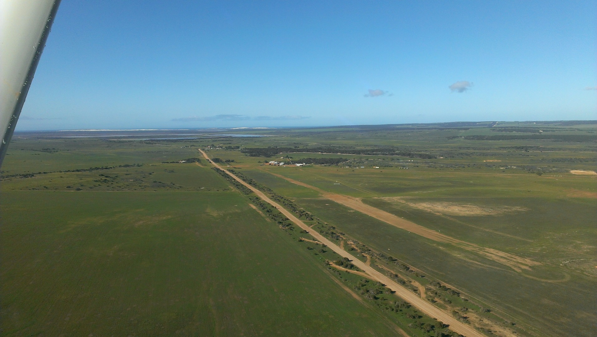
Figure 1: Coorabie ALA facing south
Source: ALA operator
At about 0900, when the aircraft was on final approach to runway 32, the pilot reported that the aircraft decelerated suddenly (from about 120 to 110 kt). At the same time, there was a slight shudder of the right engine and a change in the sound of the propeller pitch. The pilot immediately increased the power to both engines and levelled the aircraft off. The pilot checked the engine instruments and the annunciator panel, and there were no abnormal indications.
The pilot then conducted a go-around and a left circuit at about 1,100 ft above ground level. The aircraft subsequently landed on runway 32. While back-tracking, the pilot sighted a power pole on a hill beyond the runway 32 threshold (in the direction from which the aircraft had just approached). After shutting the aircraft down, the pilot noticed damage to the right propeller blades and suspected that the aircraft had struck a powerline (Figure 2). Witnesses on the ground confirmed that they had seen and heard the aircraft strike the powerline.
The pilot and passengers were not injured. The aircraft sustained minor damage.
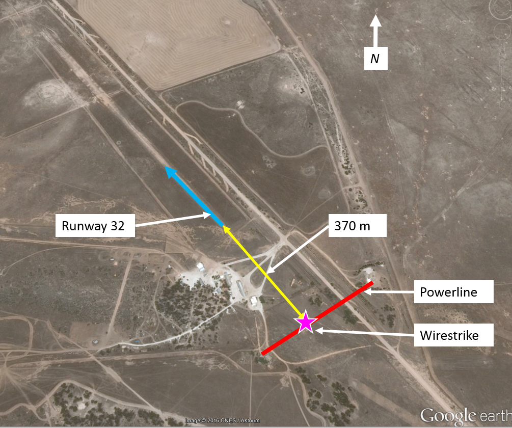
Figure 2: Coorabie ALA showing the powerline 370 m from the threshold
Source: ALA operator
Pilot comments
The pilot of NAX had planned to overfly the runway, inspect the landing area and then join the circuit on the downwind leg for runway 14. The pilot commented that if they had overflown the airstrip prior to commencing the approach, they may still not have identified the powerline as the poles and wire were difficult to see. There was one pole near a house and the next pole was some distance away on terrain rising from the runway threshold. The company pilot who had landed before NAX did not sight the powerline during their strip inspection (overflying the runway).
The pilot further commented that if they had conducted a steeper approach they may not have struck the powerline.
Pilot hazard awareness
The pilot reported that they had not been alerted to the presence of the wire before operating at the aerodrome. The pilot had reviewed the company strip guide information for Coorabie ALA and photos of the runway provided by the aerodrome operator.
The information provided included a sketch of the runway and its direction (14/32), the latitude and longitude, length (900 m), width (25 m), elevation (75 ft) and under Special procedures: ‘Slight rise to NW end Small hill’.
Wire marking standards
The requirements for mapping and marking powerlines and their supporting structures were published in Australian Standard AS 3891.1, Part 1, Permanent marking of overhead cables and their supporting structures and AS 3891.2, Part 2, Marking of overhead cables for low level flying. The ALA was not used as described in Clause 3.2 of AS 3891.1 nor were the powerlines in an area involved in planned low-flying operations as described in AS 3891.2. The powerlines did not require marking in accordance with either Australian Standard.
Advisory material
The Civil Aviation Advisory Publication (CAAP) 92-1(1) Guidelines for aeroplane landing areas, provided guidance on how pilots may determine the suitability of an aeroplane landing area (ALA) such as the recommended obstacle clearance standards and suggested landing area markings. The CAAP defined an obstacle free area to mean ‘there should be no wires or any other form of obstacles above the approach and take-off areas, runway, runway strips, fly-over areas or water channels’. The minimum landing area physical characteristics recommended in the CAAP for aircraft (other than single-engine and centre-line thrust aeroplanes not exceeding 2,000 kg maximum take-off weight) for day operations is depicted in Figure 3. This shows the approach and take-off area should be clear of wires within 900 m of the runway ends above a 5 per cent (3°) slope.
Figure 3: Recommended landing area characteristics
Source: Civil Aviation Safety Authority
Powerline
The powerline was located about 370 m from the runway threshold and about 7.5 m above ground level. The powerline was below the recommended slope gradient of 5 per cent (Figure 3).
The operator of the ALA reported that they had spoken to a representative from the aircraft operator and advised them of the existence of the powerline prior to the flight. The ALA operator had identified the powerline as a hazard and reported that they had requested the infrastructure provider to fit markers to the powerline about 12 months prior to the incident.
The power insfrastructure provider advised the ATSB that the ALA operator had enquired with the then distribution licensees about the fitting of markers to the powerline in 2012 and 2015. In 2012, the distribution licensee investigated and determined that the span of the powerline was too long to take the additional load of the markers. In 2015, the request for the markers was raised again by the ALA operator in conjunction with a request for a quote on a transformer upgrade. There was no follow-up with the provider about these requests.
Runway illusions
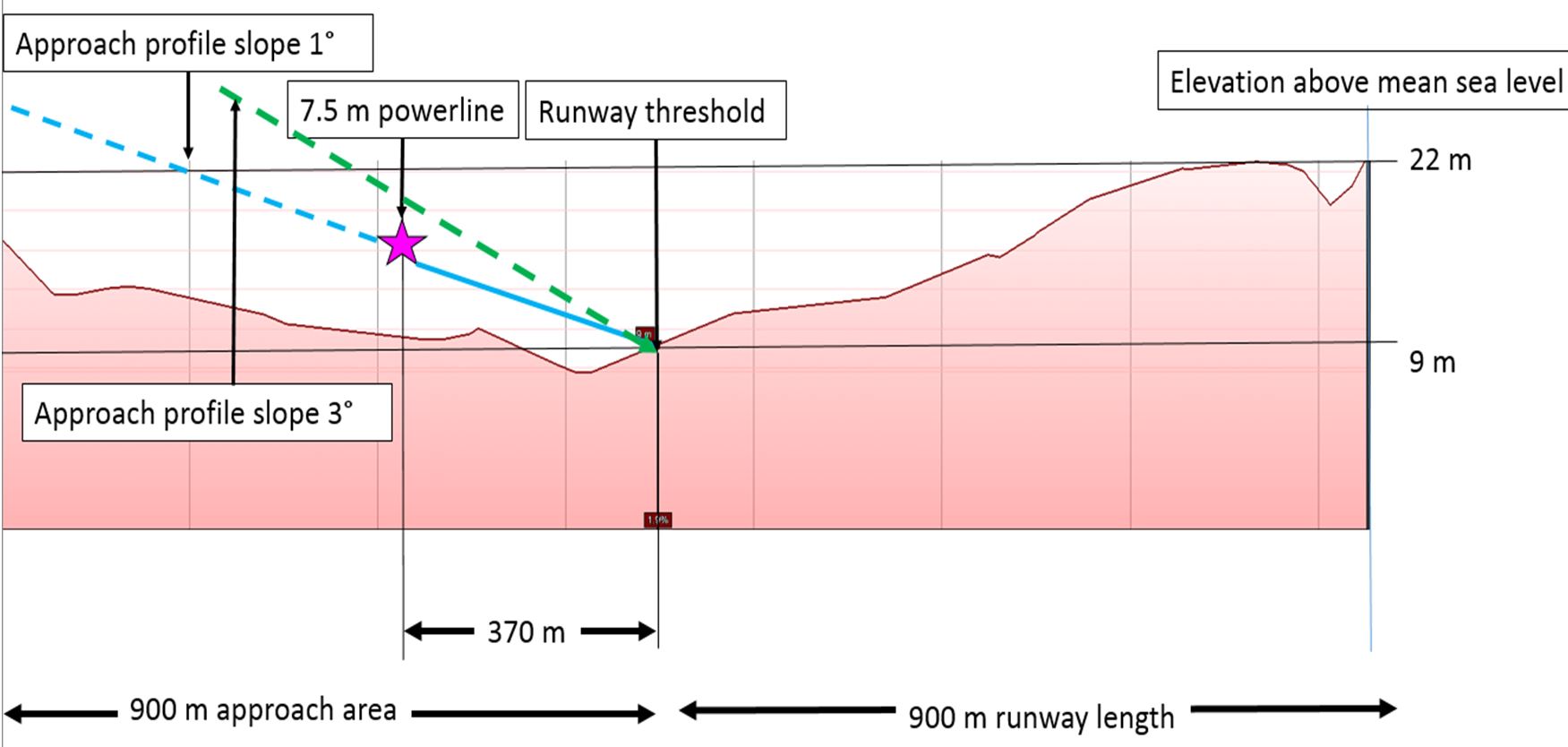
The profile of Coorabie ALA runway 32 and the approach area of 900 m (based on the recommended dimensions specified in Figure 3), obtained from Google earth, is depicted in Figure 4. The cleared area commencing from the runway threshold was about 1,170 m in length. Along that length, the profile rose from 9 m (30 ft) to 22 m (72 ft) elevation at the nominated runway length of 900 m, with higher ground rising to about 29 m (90 ft) beyond 900 m. The information provided to the operator by the ALA operator was that the runway length was 900 m, suggesting that the rising terrain beyond that point was not part of the runway. The stated runway elevation was 75 ft (23 m).
As can be seen in Figure 4, the terrain at the powerline was about the same height as the runway 32 threshold, with a dip in between. The glide path from a powerline 7.5 m above the terrain to the runway threshold was about 1°. A normal approach path is about 3°.
Runway slope is one environmental condition that can affect a pilot’s perception of the aircraft’s position relative to a normal approach profile. Flight Safety Foundation Approach and landing accident reduction tool kit briefing note 5.3 – Visual illusions stated that an uphill slope creates the illusion of being too high. That illusion may induce the pilot to ‘correct’ the approach resulting in a lower flight path, or may prevent the pilot from detecting when the aircraft is too low during the approach.
The briefing note advises that to reduce the effects of visual illusions, flight crews should assess approach hazards and be trained to recognise and understand the factors and conditions that cause visual illusions.
Figure 4: Coorabie ALA runway 32 and 900 m approach area profile
Source: Google earth annotated by ATSB
ATSB comment
It is essential for pilots to be aware of hazards prior to operating into an aerodrome. The location of known hazards and obstacles such as powerlines should be included in aerodrome information that is provided to pilots and aircraft operators who are permitted to operate at the airfield. As runway slope can result in visual illusions that may affect a pilot’s judgement of the approach profile, runway slope information should also be included in operational information.
CAAP 166-1(3): Operations in the vicinity of non-controlled aerodromes stated that straight-in visual approaches are not a recommended standard procedure. They can be conducted provided certain conditions are met, including that pilots must be able to assure themselves of the aerodrome’s serviceability and that hazards have been identified.
Safety action
Whether or not the ATSB identifies safety issues in the course of an investigation, relevant organisations may proactively initiate safety action in order to reduce their safety risk. The ATSB has been advised of the following safety action in response to this occurrence.
Powerline owner
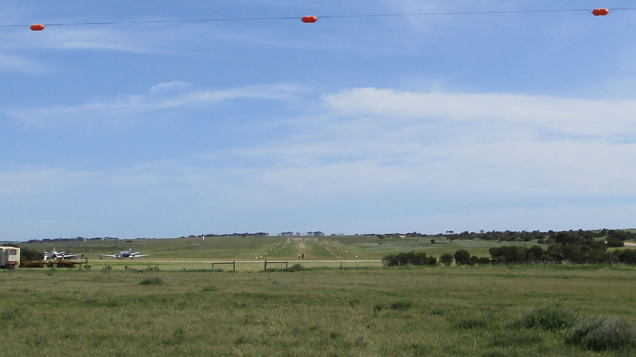
Following the incident (at the time of repairing the wire), the infrastructure provider marked the wire with three round orange markers (Figure 5).
Figure 5: Powerline with orange markers
Source: ALA operator
Aircraft operator
As a result of this occurrence, the aircraft operator has advised the ATSB that they are taking the following safety actions:
Notice to operational crew
The company issued the following directives in a notice to operational crew:
Operations to new ALAs require specific chief pilot approval.
ALAs that have not been used by company aircraft for more than 12 months are treated as new.
All operations to ALAs require an overhead join to check the runway.
Straight-in approaches to ALAs are not permitted.
Safety message
Research conducted by the ATSB found that 166 aircraft wirestrikes were reported to the ATSB between July 2003 and mid-June 2011 and another 101 occurred and were unreported but identified by electricity distribution and transmission companies. The majority of wirestrike occurrences were associated with aerial agriculture operations, however, 22 occurrences (8 per cent) involved private operations. Further information is in the research report, Under reporting of aviation wirestrikes.
The ability of pilots to detect powerlines depends on the physical characteristics of the powerline such as the spacing of power poles, the orientation of the wire, and the effect of weather conditions, especially visibility.
Depending on the environmental conditions, powerlines may not be contrasted against the surrounding environment. Often the wires will blend into the background vegetation and cannot be recognised. In addition, the wire itself can be beyond the resolving power of the eye: that is, the size of the wire and limitations of the eye can mean that it is actually impossible to see the wire. As such, pilots are taught to use additional cues to identify powerlines, such as the associated clearings or easements in trees or fields that can underlie the powerline, or the power poles and buildings to which the powerlines may connect.
Risks associated with operations to private airstrips can be mitigated by ALA owners assessing their airstrips against the guidance in CAAP 92-1(1) Guidelines for aeroplane landing areas. Such risk assessments would benefit from giving consideration to first time users of the ALA.
Decisions regarding whether to conduct an investigation, and the scope of an investigation, are based on many factors, including the level of safety benefit likely to be obtained from an investigation. For this occurrence, a limited-scope, fact-gathering investigation was conducted in order to produce a short summary report, and allow for greater industry awareness of potential safety issues and possible safety actions.
Publishing information
Released in accordance with section 25 of the Transport Safety Investigation Act 2003
Ownership of intellectual property rights in this publication
Unless otherwise noted, copyright (and any other intellectual property rights, if any) in this report publication is owned by the Commonwealth of Australia.
Creative Commons licence
With the exception of the Coat of Arms, ATSB logo, and photos and graphics in which a third party holds copyright, this publication is licensed under a Creative Commons Attribution 3.0 Australia licence.
Creative Commons Attribution 3.0 Australia Licence is a standard form licence agreement that allows you to copy, distribute, transmit and adapt this publication provided that you attribute the work.
The ATSB’s preference is that you attribute this publication (and any material sourced from it) using the following wording: Source: Australian Transport Safety Bureau
Copyright in material obtained from other agencies, private individuals or organisations, belongs to those agencies, individuals or organisations. Where you wish to use their material, you will need to contact them directly.
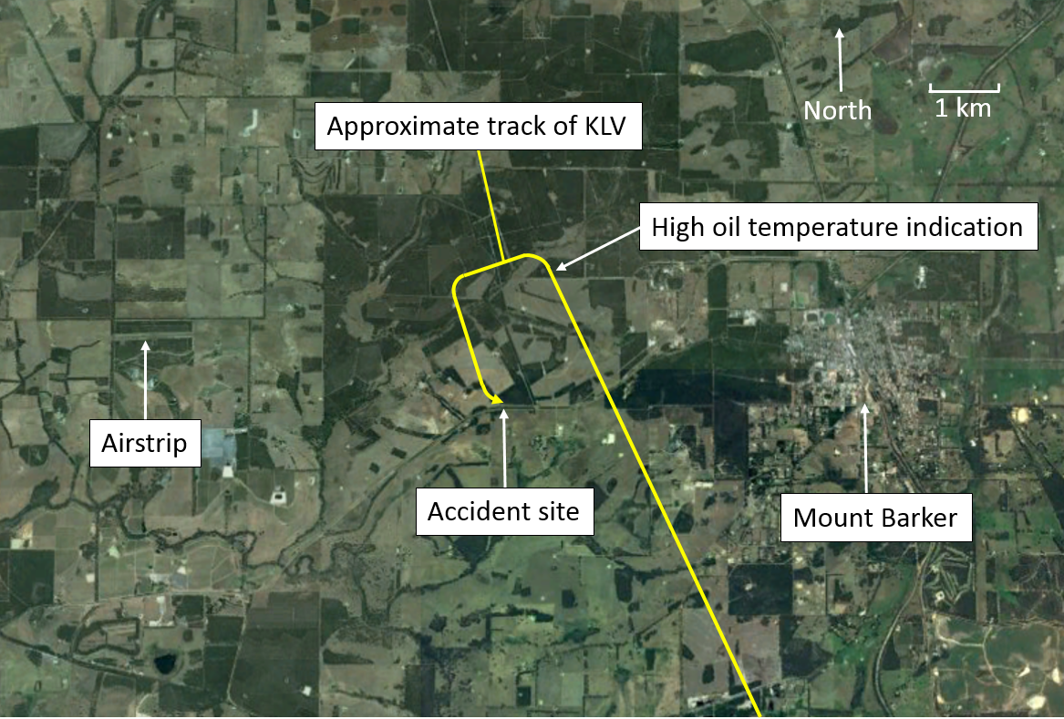
On 4 September 2016, at about 1655 Western Standard Time (WST), an amateur-built Van’s RV-9A aircraft registered VH-KLV (KLV), departed Albany Airport, Western Australia (WA), for a flight to Jandakot Airport, WA. On board the private flight were a pilot and one passenger.
About 15 minutes into the flight, the aircraft was north-west of Mount Barker and climbing through about 4,000 ft. At this time, the pilot observed an oil temperature indication greatly exceeding the normal operating limit, all other engine indications appeared normal. The pilot immediately reduced power to idle and turned the aircraft towards an airstrip to the west of Mount Barker (Figure 1). As the aircraft descended through about 2,500 ft, the pilot assessed that they did not have sufficient altitude to glide to the airstrip. The pilot then elected to conduct a precautionary[1] landing.
Figure 1: Approximate flight path of VH-KLV
Source: Google maps, modified by ATSB
The pilot identified a section of disused road as suitable to conduct the precautionary landing and positioned the aircraft to make a curving approach to the road. At about 200 ft above ground level, the pilot detected the aircraft becoming low and applied power to continue the approach. The engine responded briefly before losing all power. The pilot identified that they did not have sufficient height to glide to the disused road. To avoid powerlines located next to the disused road, the pilot elected to fly the aircraft into trees.
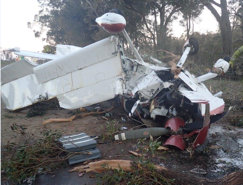
The aircraft struck the tree canopy and slowed to a near stop before falling onto the disused road. The aircraft landed nose first before overturning and coming to rest inverted (Figure 2). The weight of the aircraft prevented the pilot from opening the sliding canopy. The pilot and passenger exited through the broken windscreen.
The pilot and passenger sustained minor injuries and the aircraft was substantially damaged.
Figure 2: VH-KLV after the accident
Source: Western Australia Police
Pilot comments
The pilot of VH-KLV provided the following comments:
After the pilot identified the high oil temperature, they prepared for a precautionary landing. They did not consider a forced[2] landing until the engine failed.
The pilot advised that when they are flying, they are always looking for places to land as if the engine fails there is only a short time to decide where to land.
The aircraft is fitted with a four point harness. This worked extremely well and prevented more serious injuries.
Engineering examination
Due to the limited scope of this investigation a post-accident engineering examination was not conducted. The cause of the high oil temperature indication was not determined.
Safety message
This incident highlights the importance of actively managing an emergency situation. The pilot identified the abnormal engine indication and elected to conduct a precautionary landing while the engine continued to develop power. Once an engine malfunction is identified it is important to consider that remaining power may be inconsistent and unreliable.
The US Federal Aviation Administration airplane flying handbook chapter: Emergency procedures provides information on effective management of precautionary and forced landings.
The RV-9A is not an aerobatic aircraft, however, KLV was fitted with a four-point aerobatic type harness. Four-point harnesses provide superior occupant protection during an accident, in particular when an aircraft overturns. The fitment and use of the four-point harness most likely prevented more serious injuries to the occupants.
Decisions regarding whether to conduct an investigation, and the scope of an investigation, are based on many factors, including the level of safety benefit likely to be obtained from an investigation. For this occurrence, a limited-scope, fact-gathering investigation was conducted in order to produce a short summary report, and allow for greater industry awareness of potential safety issues and possible safety actions.
Publishing information
Released in accordance with section 25 of the Transport Safety Investigation Act 2003
Ownership of intellectual property rights in this publication
Unless otherwise noted, copyright (and any other intellectual property rights, if any) in this report publication is owned by the Commonwealth of Australia.
Creative Commons licence
With the exception of the Coat of Arms, ATSB logo, and photos and graphics in which a third party holds copyright, this publication is licensed under a Creative Commons Attribution 3.0 Australia licence.
Creative Commons Attribution 3.0 Australia Licence is a standard form licence agreement that allows you to copy, distribute, transmit and adapt this publication provided that you attribute the work.
The ATSB’s preference is that you attribute this publication (and any material sourced from it) using the following wording: Source: Australian Transport Safety Bureau
Copyright in material obtained from other agencies, private individuals or organisations, belongs to those agencies, individuals or organisations. Where you wish to use their material, you will need to contact them directly.
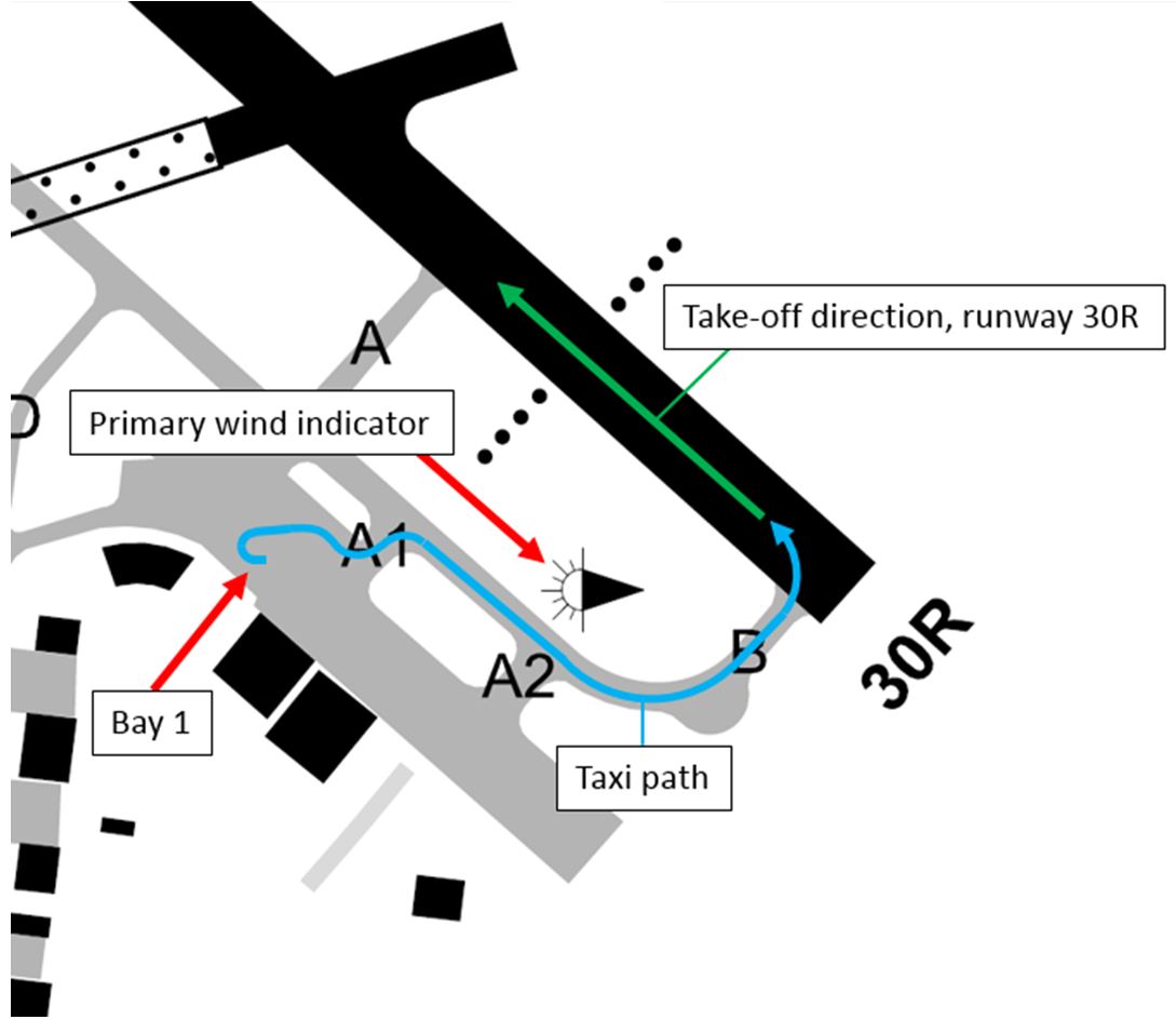
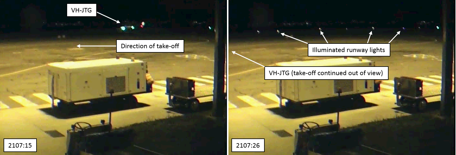
On 19 August 2016, a JetGo Australia Embraer EMB-135LR, registered VH-JTG (JTG), operated scheduled passenger flight JG65 from Tamworth, New South Wales (NSW), to Brisbane, Queensland (Qld). At 2104 Eastern Standard Time (EST), the aircraft began to taxi from parking bay 1 to runway 30 right (30R) with the taxiway and runway lights not activated (Figure 1). At 2107, the captain taxied the aircraft onto the runway and immediately began the take-off run. During the take-off run, at a speed of about 70 knots, the first officer detected the runway lights were not illuminated and activated them using the pilot activated lighting (PAL) (Figure 2). The flight crew continued the take-off.
Figure 1: Taxi path overview (both incidents)
Source: Airservices Australia, modified by ATSB
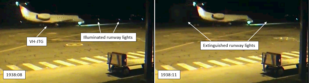
Figure 2: Take-off run of JTG on 19 August showing runway lights not activated (left) and then activated (right)
Source: Airport Operator
On 28 August 2016, the same aircraft operated scheduled passenger flight JG65 from Tamworth to Brisbane. At 1937, the aircraft began to taxi from parking bay 1 to runway 30R. As the aircraft taxied, the runway and taxiway lights extinguished (Figure 3). The flight crew continued to taxi, lined up on runway 30R and selected the aircraft landing lights on. At 1940, 48 seconds after lining up, the aircraft began the take-off run and departed runway 30R with the runway lights not activated.
No persons were injured, and the aircraft was not damaged in the incidents.
Figure 3: JTG taxiing on 28 August with runway lights illuminated (left) and then extinguished (right)
Source: Airport Operator
Runway and taxiway lighting
The taxiway and runway lighting at Tamworth Airport was controlled by a PAL system combined with an aerodrome frequency response unit (AFRU), known as AFRU + PAL. To activate the lights, pilots were required to transmit a sequence of three transmissions on the common traffic advisory frequency (CTAF). Each transmission was to have a maximum duration of 1 second with the break between transmissions being a maximum of 1 second. On receipt of the appropriate transmission sequence, the airport lights were activated and the AFRU broadcast the automatic message: ‘Tamworth Airport CTAF, runway lighting on’ on the Tamworth CTAF.
Once the AFRU + PAL system was activated, the airport lighting remained on for 30 minutes. If it was reactivated during this period, the lighting would remain on for 30 minutes from the time of reactivation. 10 minutes prior to the end of the 30-minute activation period, the primary wind indicator (windsock) lights commence flashing to warn users that the airport lighting is about to extinguish (Figure 4). In addition, an automated message ‘Tamworth Airport CTAF, lights 10 minutes remaining’ was broadcast on the CTAF to advise 10 minutes of runway lighting remaining.
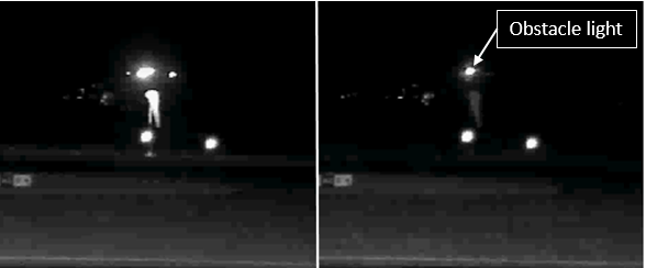
Figure 4: Flashing primary wind indicator showing the windsock illuminated when the runway lights were active (left) and not illuminated (right)
Source: Airport Operator
On 19 August, at 2039, the AFRU broadcast ‘Tamworth Airport CTAF, lights 10 minutes remaining’, the lights then extinguished at 2049. At 2107, during the take-off run of JTG, the first officer broadcast an AFRU + PAL activation sequence on the Tamworth CTAF and the runway lights illuminated.
On 28 August, at 1928, the AFRU broadcast ‘Tamworth Airport CTAF, lights 10 minutes remaining’, the lights then extinguished at 1938. At 2007, an AFRU + PAL activation sequence was broadcast by another aircraft and the runway lights illuminated.
There was no indication that the AFRU + PAL system was malfunctioning on the nights of the incidents.
Captain comments
The same pilot was operating as captain of JTG during both incidents. The captain provided the following comments:
The captain did not notice that the runway lights were extinguished during either incident and were not aware until notified after each incident.
The taxiway lights at Tamworth are of the recessed centreline type. The taxi from bay 1 to runway 30R is over a rise. Therefore, only three to four taxiway lights are normally visible from the point at which you turn onto the taxiway. The captain remarked that the raised type taxiway side lights found at other airports are more easily visible.
Wind information for pre-flight planning is obtained through the flight crew electronic flight bag or automatic weather information service (AWIS). Therefore, they will only observe the windsock as a back-up, if it is available and close.
During turn-around between flights, the flight crew do not wear headsets and will not hear the 10 minutes remaining broadcast if it occurs during this time.
The responsibility for ensuring the airport lighting would be active was not assigned to either flight crewmember. There was no procedure for ensuring the airport lighting would be illuminated for the departure.
Both incidents occurred at the end of long duty days, so fatigue may have been a factor.
First officer comments – 19 August
The first officer of the 19 August incident provided the following comments:
The tiller in the Embraer 135 is located on the captain’s side. Therefore, the first officer always acts as pilot monitoring[1] (PM) during taxi. The taxi from bay 1 to runway 30R is short and a period of intense workload. During this time, the first officer did not look outside the cockpit.
The first officer did not look outside of the cockpit until the aircraft began moving during the take-off run. Once they looked outside, they immediately felt that something was not right. About five seconds later, the first officer detected that the runway lights were not illuminated.
The first officer was PM for this flight. As PM, they were able to quickly activate the PAL and resolve the issue, and did not consider aborting the take-off.
The first officer used the take-off data card for wind information and did not look at the windsock prior to departure.
First officer comments – 28 August
The first officer of the 28 August incident provided the following comments:
The first officer did not notice that the runway lights were extinguished and was not aware until notified after the incident.
The primary wind indicator at Tamworth is situated so that it is illuminated by light from the adjacent apron lighting and a red obstacle light is located above the windsock. On subsequent flights to Tamworth, the first officer has observed that this gives the appearance of the windsock being illuminated when the runway lighting is extinguished (Figure 4).
Aircraft lighting
The Embraer 135 is fitted with three landing lights and two taxi lights. The combination of these lights provides a substantial amount of illumination in front of the aircraft.
The taxi lights are used from the beginning of taxi until after departure. Prior to commencing the take-off run, the landing lights are also selected on. The landing lights provide considerably more illumination than the taxi lights.
All flight crew described the aircraft lighting as extremely effective at illuminating the runway ahead of the aircraft and reported no controllability issues during the take-off runs.
Parking apron lighting
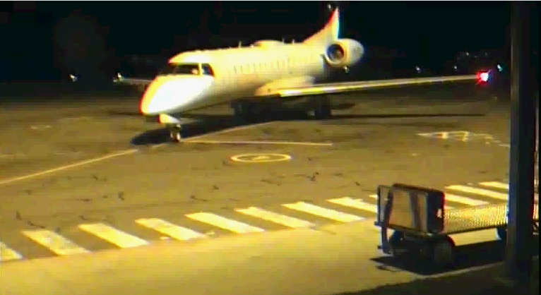
Prior to both incidents, the aircraft parked at bay 1 for the embarkation of passengers (Figure 5). This bay is substantially lit by apron floodlights. These lights are not part of the PAL system and remain illuminated when the PAL system extinguishes the runway and taxiway lights.
All three flight crew commented that the apron lighting degraded night-vision and the short taxi from bay 1 to runway 30R did not allow time for eyes to adjust to the dark surrounds of the runway.
Figure 5: JTG parked at bay 1
Source: Airport Operator
Environmental conditions
Last light[2] on 19 August 2016 occurred at 1757, three hours and ten minutes before the take-off. At 2017, the moon was 19 degrees above the horizon and about 99 per cent visible. There was a clear sky.
Last light on 28 August 2016 occurred at 1802, one hour and 38 minutes before the take-off. The moon was below the horizon and the sky was clear.
ATSB comment
Two different PAL systems exist at Australian airports, PAL and AFRU + PAL. The activation sequence for each system is different.
CTAF recordings for the period surrounding each incident showed multiple unsuccessful attempts by other aircraft to activate the AFRU + PAL using the sequence of transmissions for a PAL system.
While this did not contribute to the incidents, pilots are reminded to be familiar with the identification and use of the different systems.
Safety Analysis
The illumination provided by the aircraft taxi and landing lights made it difficult to detect that the PAL was not activated. Due to the rise on the taxiway, the crew would only have been able to see a few lights ahead of the aircraft, and these would have been illuminated by the aircraft lights. Adding to this, both crew did not have an expectation that the lights may have been extinguished as the cues available did not assist. The auditory 10-minute PAL extinguishing warning could not be heard without headphones, and the windsock flashing light warning was not noticed as the crew obtained wind information using the flight crew electronic flight bag or AWIS.
As the company standard operating procedures did not assign a task of ensuring the runway lights were selected on to a specific role prior to taxi, there was also no procedural prompt to the crew.
The short taxi with a high workload further reduced the chance of detection.
Findings
The crew did not activate the airport lighting and did not detect that the lighting was off prior to the take-off run.
Available lighting from the aircraft taxi and landing lights, a lack of crew expectation, a short taxi with high workload, and no assigned role or procedure to check for runway lighting resulted in the crew not detecting the lack of runway lights.
Safety action
Whether or not the ATSB identifies safety issues in the course of an investigation, relevant organisations may proactively initiate safety action in order to reduce their safety risk. The ATSB has been advised of the following proactive safety action in response to these occurrences.
Aircraft operator
As a result of these incidents, the aircraft operator has advised the ATSB that they are taking the following safety actions:
Changes to procedures
When activating the aircraft taxi lights the pilots must ensure that they confirm the status of the PAL.
When conducting night operations at an unmanned airport, the pilots must activate the PAL or AFRU + PAL by keying the microphone on the appropriate frequency unless the aircraft immediately ahead has already done so. For example, if the aircraft 10 minutes ahead has turned the lights on it will not be necessary to activate the lights again as the lights will normally remain on for a period of 30 to 60 minutes depending upon the installation.
If no traffic is evident then the pilots must activate the PAL prior to taxi for departure and within 15 nm of the aerodrome and whilst above the lowest safe altitude for arrival.
Safety message
These incidents demonstrate the impact workload stress can have on operations. The short taxi created a high workload situation which impacted on the flight crews’ ability to detect the extinguished runway lighting.
The incident on the 28 August also highlights the hazards associated with change blindness, inattention blindness and expectation bias.
Change blindness occurs when a person does not notice that something is different about the visual environment relative to before the change. Research has shown that in some cases, quite dramatic changes are not detected, particularly if changes occur when the observer is not looking at the relevant part of the visual environment at the time. In this incident the flight crew did not detect the runway lights extinguish during taxi prior to departure.
The Transport Canada article Deadly Omissions includes further information on change blindness, inattention blindness and expectation bias.
Decisions regarding whether to conduct an investigation, and the scope of an investigation, are based on many factors, including the level of safety benefit likely to be obtained from an investigation. For this occurrence, a limited-scope, fact-gathering investigation was conducted in order to produce a short summary report, and allow for greater industry awareness of potential safety issues and possible safety actions.
Publishing information
Released in accordance with section 25 of the Transport Safety Investigation Act 2003
Ownership of intellectual property rights in this publication
Unless otherwise noted, copyright (and any other intellectual property rights, if any) in this report publication is owned by the Commonwealth of Australia.
Creative Commons licence
With the exception of the Coat of Arms, ATSB logo, and photos and graphics in which a third party holds copyright, this publication is licensed under a Creative Commons Attribution 3.0 Australia licence.
Creative Commons Attribution 3.0 Australia Licence is a standard form licence agreement that allows you to copy, distribute, transmit and adapt this publication provided that you attribute the work.
The ATSB’s preference is that you attribute this publication (and any material sourced from it) using the following wording: Source: Australian Transport Safety Bureau
Copyright in material obtained from other agencies, private individuals or organisations, belongs to those agencies, individuals or organisations. Where you wish to use their material, you will need to contact them directly.
On 25 August 2016, a Robinson R44 helicopter, registered VH-EYD (EYD), departed from Bankstown Airport on a training flight to Camden Airport, New South Wales. On board were a student pilot and a flight instructor. After completing exercises in the Camden area, the helicopter returned towards Bankstown.
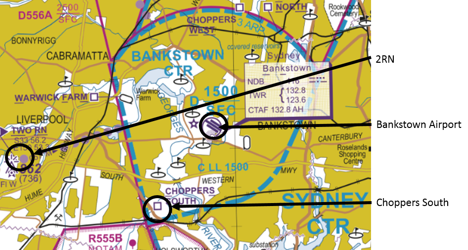
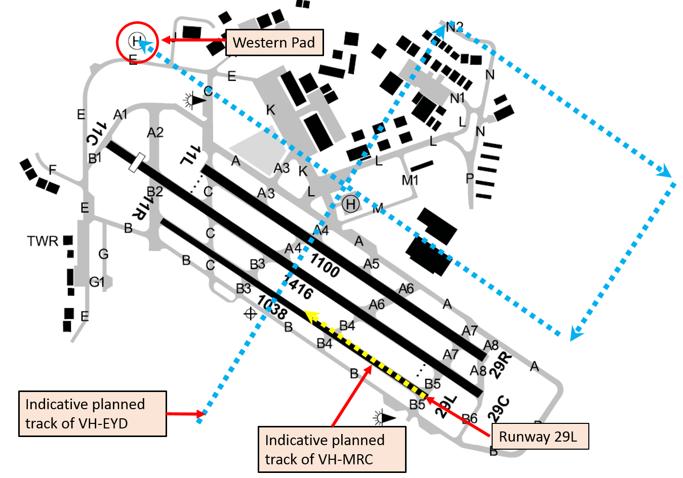
According to air traffic control (ATC) audio data, at about 1607 Eastern Standard Time (EST), the instructor of EYD contacted the Bankstown aerodrome controller (ADC), advising that they were at inbound reporting point 2RN at 1,000 ft (Figure 1). The ADC instructed EYD to track via, and report at, ‘Choppers South’ reporting point at 500 ft. EYD then tracked via Choppers South at 500 ft, but the instructor omitted to advise ADC when they were overhead that point.
Figure 1: Extract of Sydney Visual Terminal Chart
Source: Airservices Australia – annotated by ATSB
At about 1610, the solo student pilot of a Cessna 152 aircraft, registered VH-MRC (MRC), who was conducting circuit training at Bankstown Airport, contacted the ADC and stated that MRC was on the downwind circuit leg, and requested clearance to depart the control zone on the upwind circuit leg. The ADC instructed the pilot of MRC to ‘go around from base, maintain 1,000 ft and depart on upwind’.
The pilot of MRC asked the ADC to repeat the instruction and then read back ‘MRC going around from base and depart at 1,000 ft’. The pilot of MRC then continued their approach, descending on the base leg and final approach to about 300 ft above the runway before commencing a go-around. At about 1613, passing about 500 ft on climb, the pilot of MRC advised the ADC that they were going around and departing at 1,000 ft upwind.
The ADC reported that they sighted MRC about mid-way along the runway, lower than the assigned altitude of 1,000 ft, and also sighted EYD about 200 m away at about the same altitude (Figure 2). The ADC immediately issued a safety alert[1] to the pilot of MRC advising of a helicopter (EYD) to their left crossing midfield at 500 ft. The ADC then issued a safety alert to EYD advising of the Cessna (MRC) in the go-around.
The instructor of EYD had already sighted MRC and commenced a right turn to increase separation. On receiving the safety alert, the pilot of EYD continued the right turn to pass behind MRC. EYD landed at the western helipad without further incident. MRC departed to the training area, before returning to land at Bankstown Airport, also without further incident.
Figure 2: Indicative aircraft tracks
Source: Airservices Australia – annotated by ATSB
Aerodrome control and radio frequencies
There were two Tower frequencies and two ADC positions at Bankstown, with ADC1 having responsibility for arrivals and departures on runways 29 right/11 left and 29/11 centre; ADC2 was responsible for the training circuit with runway 29 left/11 right.
The two Tower frequencies at Bankstown were combined at the time of the incident, and one controller occupied the ADC position. When combined, pilots of aircraft operating on either the circuit Tower frequency or the arrivals and departures Tower frequency would have been able to hear transmissions on the other frequency. Although the pilots of MRC and EYD had different radio frequencies selected, they were combined such that the transmissions made on both frequencies could be heard on either frequency.
Pilot comments
Pilot of MRC
The pilot of MRC was a student with 41 hours of aeronautical experience, six of which were solo. They provided the following comments:
They had not departed from the circuit runway to the training area previously and were not sure how to do so or what to expect from ATC.
Their understanding of a go-around was to descend as if on a normal approach to the runway, discontinue the approach on final at about 300 ft, apply full power and commence a climb, and diverge to the left of the runway.
They misunderstood the ADC’s instruction, but were unsure why the controller had not noticed the aircraft descending on base and final before it commenced the go-around.
They were not aware of the Choppers South arrival procedure until after the incident.
If the instruction had been sequenced differently, with the direction to maintain 1,000 ft first, it would have made the ADC’s expectations clearer.
Controller comments
The ADC commented that if the pilot of MRC had maintained 1,000 ft there would not have been a separation issue. Having issued the instruction to maintain 1,000 ft, the ADC turned their focus to monitoring other aircraft and communicating with the pilots of other aircraft in the control zone.
The controllers have a liaison role with local flying schools, which involves visiting them and talking to the students, and they also invite students to the tower during quiet periods. This liaison fosters a safer working relationship between pilots and air traffic control.
Go-around
Aeronautical Information Package (AIP) En Route (ENR) 1.1 – 16.4 stated:
At Class D aerodromes with parallel runways where contra-rotating circuit operations are in progress, if ATC instructs, or a pilot initiates a go around, the pilot must:
commence climb to circuit altitude
position the aircraft on the active side and parallel to the nominated duty runway, while maintaining separation from other aircraft and
follow ATC instructions or re-enter the circuit from upwind.
The Manual of Air Traffic Services defined a go-around as a ‘procedure in which the pilot discontinues the approach immediately and rejoins for another circuit, or proceeds as directed by ATC’.
The ADC commented that when they issued the instruction to go around, they expected the pilot of MRC to terminate their approach and maintain 1,000 ft while continuing to fly the circuit geographically.
En Route Supplement Australia
The ERSA entry for Bankstown included the following under the heading Class D:
‘CAUTION: HELICOPTERS OVERFLY RUNWAYS MIDFIELD AT 500FT.’
Operator comments
The operator of MRC provided the following comments:
Helicopter pilots inbound via Choppers South should be aware that crossing a training circuit runway is inherently risky as a go around can occur at any time and is obviously more likely to occur with low time student pilots who are more likely to not have their approach to land stabilised.
It is also very likely that during their initial solo circuit training students will be more likely to be focussing on the preceding traffic they are following and will be less likely to see crossing helicopter traffic in their peripheral vision.
Bankstown is a very busy training environment, which can have sudden increases in traffic volume. ATC needs to be aware of this as it is very difficult for student pilots to monitor traffic and radio calls and make broadcasts when conjoined frequencies are in operation, and there is a heavy traffic load.
It is, and it always will be, company policy to safely fly the aeroplane first, navigate to the southern side of the runway and then communicate their intentions/actions.
Safety action
Whether or not the ATSB identifies safety issues in the course of an investigation, relevant organisations may proactively initiate safety action in order to reduce their safety risk. The ATSB has been advised of the following proactive safety action in response to this occurrence.
Operator of VH-MRC
As a result of this occurrence, the operator of MRC has advised the ATSB that they are taking the following safety actions:
Amended operations manual
The operator of MRC is proposing to amend their operations manual to read:
Unlicensed solo pilots are not permitted to request circuits on arrival or when inbound to Bankstown. Unlicensed solo pilots may only depart the training circuit after they have demonstrated proficiency in the procedure to an instructor and a note has been made in the training record to that effect
Safety message
The Civil Aviation Safety Authority booklet, Class D airspace, advises pilots that when operating in Class D airspace, they must sight and maintain separation from other aircraft. Pilots and ATC have a dual responsibility to maintain situational awareness of other traffic.
Decisions regarding whether to conduct an investigation, and the scope of an investigation, are based on many factors, including the level of safety benefit likely to be obtained from an investigation. For this occurrence, a limited-scope, fact-gathering investigation was conducted in order to produce a short summary report, and allow for greater industry awareness of potential safety issues and possible safety actions.
Publishing information
Released in accordance with section 25 of the Transport Safety Investigation Act 2003
Ownership of intellectual property rights in this publication
Unless otherwise noted, copyright (and any other intellectual property rights, if any) in this report publication is owned by the Commonwealth of Australia.
Creative Commons licence
With the exception of the Coat of Arms, ATSB logo, and photos and graphics in which a third party holds copyright, this publication is licensed under a Creative Commons Attribution 3.0 Australia licence.
Creative Commons Attribution 3.0 Australia Licence is a standard form licence agreement that allows you to copy, distribute, transmit and adapt this publication provided that you attribute the work.
The ATSB’s preference is that you attribute this publication (and any material sourced from it) using the following wording: Source: Australian Transport Safety Bureau
Copyright in material obtained from other agencies, private individuals or organisations, belongs to those agencies, individuals or organisations. Where you wish to use their material, you will need to contact them directly.
On 31 May 2016 at 1018 Eastern Standard Time (EST), Virgin Australia Airlines flight VA1615, an Embraer ERJ 190 aircraft, registered VH-ZPJ (ZPJ), departed Melbourne Airport on a scheduled passenger service to Mildura Airport, Victoria. On board the aircraft were 2 flight crew, three cabin crew and 81 passengers. The aircraft captain was the pilot flying (PF) and the first officer was the pilot monitoring (PM).[1]
About 40 NM from Mildura and just prior to ZPJ leaving controlled airspace, air traffic control (ATC) passed the flight crew traffic information about two aircraft operating above 10,000 ft to the west of Mildura Airport. In addition, there was also a public transport flight inbound to Mildura from Broken Hill and a light twin-engine aircraft inbound to Mildura on a converging track to ZPJ. The PM on board ZPJ contacted the light twin-engine aircraft and confirmed they would arrive at Mildura after ZPJ. The estimated arrival time for the public transport flight at Mildura was also later than the estimate for ZPJ, and consequently the flight crew on board ZPJ did not consider any of the traffic passed to them by ATC would conflict with their own arrival.
The aircraft operating to the west of Mildura were a GippsAero GA10 aircraft, registered VH-XGY (XGY), conducting spin testing supported by a Gippsland Aeronautics GA-8 ‘chase plane’, registered VH-XGA (XGA), from the same company.
ZPJ joined the Mildura Airport circuit on the crosswind leg for a left visual circuit to land on runway 09.
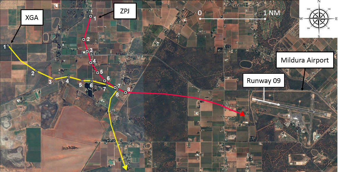
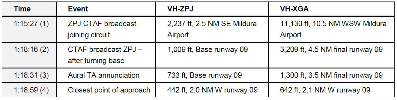
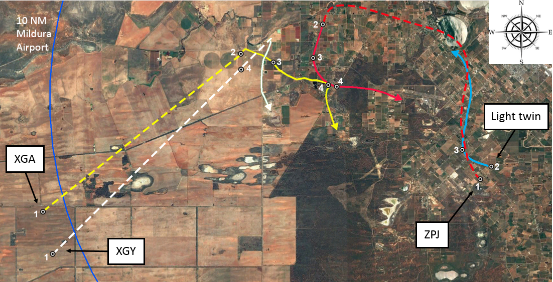
On the base leg of the circuit, the flight crew on board ZPJ heard their traffic collision alert system (TCAS) announce a traffic advisory (TA) aural alert (see TCAS limitations on approach). They glanced at their TCAS display to check the relative position of the traffic, which indicated it was to their right (position 1 in Figure 1). The flight crew looked out the right window of the flight deck and identified the traffic to their right and high against the skyline. The traffic appeared to them to be stationary in the windscreen relative to their own aircraft and with a high closure rate (from TCAS data the aircraft were 1.25 NM apart at the time of the TA alert).[2]
The PM on board ZPJ contacted the other traffic on the radio and requested their intentions. The other traffic was XGA, which was leading XGY back to Mildura Airport for a straight-in approach to runway 09. When the pilot of XGA responded that they were tracking for a straight-in approach to runway 09, the PM assessed they were on a collision course on their present track. They also recognised that there would be a potential risk of collision if both aircraft performed a go-around to the south of the main runway. Therefore, the PM responded to the pilot of XGA to immediately turn and remain south of the airport. The pilot of XGA identified ZPJ ahead of them on approach to runway 09 and responded that they would discontinue their approach and manoeuvre to the south of the airport.[3]
The PF on board ZPJ decided to discontinue their approach to land on runway 09, as they were too late for their turn onto final and therefore not in a stabilised condition.[4] However, the PM indicated to the PF that they could not execute a go‑around manoeuvre because there was another aircraft joining the circuit on crosswind (the light twin-engine aircraft). The PF decided that continuing the approach to land was not an option and therefore executed the go‑around to the south of runway 09, maintained separation from the other traffic on crosswind and then landed from the subsequent circuit. During the go-around manoeuvre, the aircraft’s TCAS detected XGA pass about 200 ft above and 0.125 NM behind ZPJ (position 7 & 8 in Figure 1).
Figure 1: Traffic conflict between ERJ 190 (VH-ZPJ) and GA-8 (VH-XGA)
Source: Google earth, annotated by ATSB based on Virgin Australia Airlines TCAS data (numbers indicate the relative positions of the conflict aircraft at the same time)
Airspace
Class E airspace
A Class E controlled airspace corridor extends from Melbourne to overhead Mildura Airport with a lower limit of FL 125.[5] In Class E airspace, instrument flight rules (IFR) traffic, such as ZPJ, require a clearance. Visual flight rules (VFR) traffic, such as XGA and XGY, do not require a clearance, but should monitor the Class E airspace air traffic service frequency. In Class E airspace, IFR flights are separated from other IFR flights and receive traffic information on VFR flights as far as practicable. ZPJ left Class E airspace on descent to Mildura about 37 NM from Mildura Airport, at which point ZPJ entered Class G airspace for the remainder of the flight.
Class G airspace
Class G airspace is non-controlled airspace. IFR and VFR traffic are permitted without a clearance and there is no separation service provided by ATC. Mildura Airport is a non-controlled aerodrome with a discrete common traffic advisory frequency (CTAF), which is a different frequency from the surrounding Class G airspace area frequency. About 10 NM to the north-west of Mildura Airport is Wentworth Aerodrome. Wentworth uses the same CTAF as Mildura.
Radio broadcasts at non-controlled aerodromes
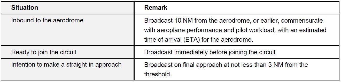
The following Table 1 indicates the non-controlled aerodrome radio broadcast requirements for inbound aircraft in accordance with the aeronautical information publication (AIP).
Table 1: Summary of broadcasts required for inbound aircraft at non-controlled aerodromes
Incident flight radio broadcasts
During the spin testing of XGY, XGY was classified as ‘lead’ aircraft and XGA as ‘in-trail’. The pilot of XGA set one of their two radio frequencies to their company frequency, for communication with XGY, and the other to area frequency, for communication with other traffic if required. While operating on the area frequency, the pilot of XGA heard a broadcast from ZPJ that they were inbound to Mildura from Melbourne, and a broadcast from another public transport aircraft inbound to Mildura from Broken Hill. On completion of the spin testing, XGA assumed the lead from XGY at about 10,000 ft and 11–12 NM from Mildura Airport. Shortly after the lead change, the pilot of XGA changed from area frequency to the Mildura CTAF.
The pilot of XGA made a 10 NM broadcast on CTAF, which included their position, altitude and intentions for a 5 NM straight in approach for final approach to runway 09. They received an immediate response from the public transport aircraft tracking from Broken Hill, who provided an estimated time of arrival for their 5 NM final approach position for runway 09. The pilot of XGA responded with a revised estimate for their arrival on the ground at Mildura Airport, which was the same time as the other aircraft’s estimate for their 5 NM final position. At the end of this exchange, XGA, with XGY in-trail, was about 7 NM from Mildura Airport tracking to the north-east to intercept a 5 NM final position, at 140–150 kt airspeed, descending at about 2,000 ft per minute. The pilot of XGA heard no radio broadcasts from ZPJ on CTAF and assumed they had already landed.
XGA made a right turn onto final approach for runway 09 at about 3,200 ft, 4.5 NM[6] from the runway threshold. Shortly after the turn, the pilot of XGA heard a broadcast requesting their intentions from ZPJ. Following the initial exchange of broadcasts with ZPJ, the pilot of XGA visually identified ZPJ about 2 NM ahead on approach to runway 09. They recognised that ZPJ had right-of-way and made a broadcast that they were ‘breaking off’ their approach to runway 09 and turning south.
The PM duties on board ZPJ included managing the radio communications with other traffic. During the approach to join the circuit, and subsequently while flying the circuit, the captain was preoccupied with PF duties and did not comprehend all the radio broadcasts. However, the PM made several CTAF broadcasts, which started at 42 NM from Mildura at 01:06:35. The last broadcast before entering the Mildura circuit was just prior to ZPJ crossing overhead runway 09 to join crosswind at 01:15:27. The next CTAF broadcast made by ZPJ was at 01:18:16, after they turned base. The flight crew received a TA at 01:18:31 and subsequently made a broadcast to challenge the intentions of XGA at 01:18:43.
Incident aircraft geometry
The following Table 2 indicates the positions of ZPJ and the conflict aircraft XGA. Figure 2 depicts the geometry of traffic in the vicinity with numbering in accordance with Table 2. The positions of the aircraft are based upon TCAS data from ZPJ.
Table 2: Aircraft geometry
Figure 2: Aircraft geometry from Table 2
Source: Google earth, annotated by ATSB based on Virgin Australia Airlines TCAS data.
TCAS limitations on approach
The traffic alert and collision avoidance system (TCAS) II, will display traffic to the flight crew as: other traffic, proximate traffic, traffic advisory,[7] or resolution advisory.[8] However, only traffic advisories and resolution advisories trigger an aural alert to the flight crew.
The collision avoidance system logic is based on the concepts of sensitivity level (SL), threshold time (tau) for issuing a traffic alert or resolution advisory, and protected volume of airspace around the TCAS equipped aircraft. The higher the SL, the greater the volume of protected airspace. As SL reduces, the volume of protected airspace reduces and TCAS functions may become inhibited.
Tau is an approximation of the time, in seconds, to the closest point of approach of another aircraft. This forms the basis for the alerting functions and therefore the volume of protected airspace. Therefore, a reduction in the TCAS SL reduces the volume of protected airspace by reducing the value of tau.
Below 1,000 +/-100 ft above ground level, the TCAS SL reduces from SL3 to SL2. For the ERJ 190 this equates to 900 ft when on descent and 1,100 ft when on climb. From SL3 to SL2 the tau reduces from 25 seconds to 20 seconds and resolution advisories are inhibited. Below 500 +/-100 ft above ground level, TCAS aural alerts are inhibited. For the ERJ 190 this equates to 400 ft when on descent and 600 ft when on climb. Close to the ground, the windshear and ground proximity warning system alerts have a higher alert priority.
The PM on board ZPJ commented that during the visual circuit they changed the focus of their scan from inside the cockpit to outside the cockpit. They suspect that XGA was probably displayed as other traffic on their TCAS before they received the TA alert. However, there are no company procedures specific to the use of TCAS at non-controlled aerodromes. Company procedures emphasise the importance of flight crew maintaining a ‘constant lookout when operating within a CTAF’, and use positive altitude separation or alternatively coordinate a track deviation with conflict aircraft.[9]
Limitations with visual sighting
Three limitations to sighting other traffic, of interest to this incident, are:
alerted search versus unalerted search
lack of relative motion on collision course
effects of complex backgrounds
Alerted search versus unalerted search
Traffic alerts may come from radio calls or TCAS at a non-controlled aerodrome. Knowing where to look has been shown to improve visual detection of other traffic. The PF on board ZPJ was alerted to the potential conflict by TCAS, and then visually identified XGA. The pilot of XGA was alerted to the potential conflict following ZPJ’s radio broadcast on the base circuit leg, and then visually identified ZPJ.
Lack of relative motion on collision course
The PF on board ZPJ commented that when they visually sighted XGA, the aircraft appeared to be stationary in the windscreen, which indicated a potential collision course. In this case ZPJ would also appear stationary to the pilot of XGA. Lack of relative motion against a background reduces the probability of visual detection.
Effects of complex backgrounds
When the PF on board ZPJ visually identified XGA, XGA was above the horizon (higher altitude relative to ZPJ) and against a background of sky. For the pilot of XGA, ZPJ was lower and against a background of terrain. The pilot of XGA was therefore required to detect the contrast between the aircraft and terrain to detect ZPJ. A terrain background may create a complex background and reduce the probability of visual detection.
Safety analysis
The AIP directs pilots to the minimum required radio broadcasts when operating at non-controlled aerodromes and the pilots of ZPJ and XGA complied with these requirements. However, it is likely that the pilot of XGA was not on the Mildura CTAF when the PM on board ZPJ made a broadcast that they were joining the Mildura circuit. When the pilot of XGA switched to the Mildura CTAF they were initially occupied with communicating with another public transport aircraft inbound from the north and considered this aircraft to be their only potential conflict. It could not be determined why the flight crew on board ZPJ did not comprehend the presence of a potential conflict from this radio traffic. However, the flight crew of ZPJ had previously dismissed these two aircraft (XGA and XGY) as a potential conflict for their arrival.
After ZPJ turned onto the base leg for runway 09, the PM made a base radio broadcast. It could not be determined why the pilot of XGA did not comprehend the presence of a potential conflict from this broadcast. However, the investigation could not rule out the possibility that other aircraft operating at Mildura or Wentworth made broadcasts which interfered with one or several of the broadcasts made by ZPJ or XGA.
Shortly after the base leg radio broadcast from the PM in ZPJ, the flight crew were alerted to the presence of XGA by a TCAS TA aural alert. At this time ZPJ was below 900 ft and therefore TCAS resolution advisory was inhibited. However, the TCAS visual display of the relative position of XGA cued their visual search and facilitated a quick identification. XGA appeared to the flight crew on board ZPJ as stationary against a background of sky. Therefore, to the pilot of XGA, ZPJ was probably against a more complex background with no relative motion, contributing to the difficulty for the pilot of XGA to detect ZPJ before they were alerted by the radio call by ZPJ.
The radio broadcast from the PM on board ZPJ directed to the ‘traffic inbound to Mildura from the west’ alerted the pilot of XGA to the presence of other traffic and cued them to search for the conflict. The PM on board ZPJ then directed the pilot of XGA to ‘turn immediately away to the south’ to avoid a potential collision either during their turn onto final approach or in the event that both aircraft attempted a simultaneous go-around manoeuvre on the south side of runway 09.
After receiving an acknowledgement from the pilot of XGA, the flight crew on board ZPJ turned their attention to the execution of their go-around manoeuvre as their turn onto the final leg of the circuit was late due to their preoccupation with monitoring XGA. However, during their turn to join the upwind circuit leg for runway 09 on the south side of the runway, XGA continued to converge to a closest point of 0.125 NM behind and about 200 ft above ZPJ before making an abrupt turn to the south. This was the result of the intention of the pilot flying XGA to join the upwind leg of the circuit to the south of runway 09, before they realised that ZPJ was also conducting a go-around from their approach.
Findings
These findings should not be read as apportioning blame or liability to any particular organisation or individual.
The pilot of XGA was probably not monitoring Mildura CTAF when the PM on board ZPJ broadcast joining the Mildura circuit.
The flight crew of ZPJ did not detect the broadcast from XGA that they were intending to join a straight in approach to runway 09.
After a separation strategy was agreed, XGA continued to close on ZPJ to a closest point of approach of 0.125 NM behind and 200 ft above ZPJ when ZPJ started their go-around.
Both aircraft made the required broadcasts on the CTAF.
The flight crew on board ZPJ were cued to the conflict by their TCAS traffic advisory alert.
The pilot on board XGA was cued to the conflict by the radio broadcast from ZPJ.
Safety message
Despite compliance with the radio broadcast requirements, a traffic conflict occurred in an environment with limited manoeuvring options for a high-capacity public transport aircraft. This incident highlights the importance of an alerted search to the successful identification of potential conflict traffic. Further information is available from ATSB Research report: Limitations of the See-and-Avoid Principle.
The ATSB SafetyWatch highlights the broad safety concerns that come out of our investigation findings and from the occurrence data reported to us by industry. One of the safety concerns relates to safety around non-controlled aerodromes.
Decisions regarding whether to conduct an investigation, and the scope of an investigation, are based on many factors, including the level of safety benefit likely to be obtained from an investigation. For this occurrence, a limited-scope, fact-gathering investigation was conducted in order to produce a short summary report, and allow for greater industry awareness of potential safety issues and possible safety actions.
Publishing information
Released in accordance with section 25 of the Transport Safety Investigation Act 2003
Ownership of intellectual property rights in this publication
Unless otherwise noted, copyright (and any other intellectual property rights, if any) in this report publication is owned by the Commonwealth of Australia.
Creative Commons licence
With the exception of the Coat of Arms, ATSB logo, and photos and graphics in which a third party holds copyright, this publication is licensed under a Creative Commons Attribution 3.0 Australia licence.
Creative Commons Attribution 3.0 Australia Licence is a standard form licence agreement that allows you to copy, distribute, transmit and adapt this publication provided that you attribute the work.
The ATSB’s preference is that you attribute this publication (and any material sourced from it) using the following wording: Source: Australian Transport Safety Bureau
Copyright in material obtained from other agencies, private individuals or organisations, belongs to those agencies, individuals or organisations. Where you wish to use their material, you will need to contact them directly.
At about 2310 Eastern Standard Time (EST), a Hawker Beechcraft Corporation B300C, registered VH‑NAO (NAO), taxied at Sydney Airport, New South Wales (NSW) for a flight to Coffs Harbour, NSW to retrieve a patient. On board were the pilot and three medical staff. The weather was fine and clear.
The pilot made a taxi call and air traffic control (ATC) cleared NAO to taxi from the domestic 5 apron where the aircraft was parked, with a requirement to give way to an inbound company aircraft (taxiing to the domestic 5 apron) and hold short of taxiway delta.
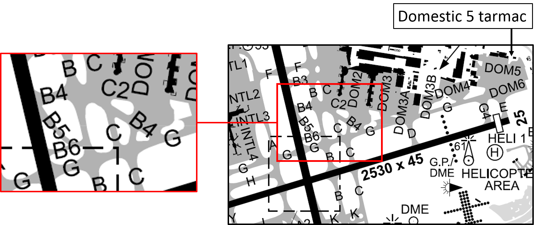
At about the time that NAO taxied, activities commenced in association with planned aerodrome works near the intersection of taxiways golf, charlie and domestic 2 (see Figure 1). Two work safety officers moved to the area in separate vehicles to establish the worksite. Establishment of the worksite included placement of red lights across affected taxiways and covering (taping over) existing green taxiway centreline and lead-in lighting. Placement of red lights and covering of existing lights was intended to delineate the closed areas of affected taxiways.
Figure 1: Excerpt from aerodrome chart showing the location of the relevant taxiways
Source: Airservices, modified by the ATSB
Other aerodrome works activities required the closure of runway 16R, north of golf. Associated with that work, the controller switched off the runway lights north of the intersection of the runway with golf. Additionally, runway 07/25 was closed.
Once the inbound company aircraft was clear, the pilot of NAO was given further taxi clearance. The cleared route was intended to take the aircraft around the worksite that was being established, and to approach runway 16R at the point from which the aircraft could depart. The pilot was cleared as follows:
…taxi golf, bravo 4, and then left at bravo to the golf holding point runway 16R, just to go around the worksite.
After placing red lights at the eastern and western ends of the worksite on golf, a safety officer moved to the northern end of the worksite on charlie. The safety officer parked the vehicle on the centreline of charlie, facing west across the taxiway, and commenced placing red lights across the taxiway between the position of the vehicle and where charlie meets bravo 4. By then, NAO was on bravo 4, and the safety officer was aware of the location and expected taxi route of the aircraft.
Soon after the safety officer commenced placing red lights across charlie, the pilot contacted ATC to confirm the instruction to turn left into bravo, then back onto golf. The controller advised the pilot that they were ‘just crossing charlie now, so bravo is just coming up on your left, about 50 m, and then you’ll be right into golf’. At that point, the pilot believed that they had already passed charlie, and were now required to make a sharp left turn into bravo, following the green taxiway lights.
The pilot turned left, believing that they were entering bravo, where in fact, the aircraft was entering charlie, in the area where the safety officer was in the process of placing red lights. As the pilot made the turn, they were not aware of the position of the safety officer, who by then had placed four of seven red lights across charlie. The safety offer saw that NAO had turned onto charlie and waved at the pilot believing that the aircraft would stop. The pilot did not report seeing the safety officer but saw the vehicle and manoeuvred the aircraft to the western side of the centreline to pass the vehicle. The left-wing tip of the aircraft passed about 2 to 3 m from the safety officer who moved further out the way as the aircraft passed. At the time, the vehicle warning beacon was operating, and the headlights were on. The safety officer was wearing a high visibility vest.
About ten seconds after advising the pilot of NAO that they were crossing charlie, and that bravo was a further 50 m ahead, the controller observed the aircraft turning into charlie. The controller immediately advised the pilot that the aircraft was heading towards the worksite and restated the requirement to ‘continue to the north-west on bravo 4, and then bravo will be on your left’. The pilot advised the controller that the situation was ‘confusing’ and that they would turn around. The controller informed the pilot that there were safety vehicles in the area that could provide assistance if required. The pilot declined that offer, and advised the controller that they would ‘just get round this one’, confirming that the safety vehicle on charlie was sighted.
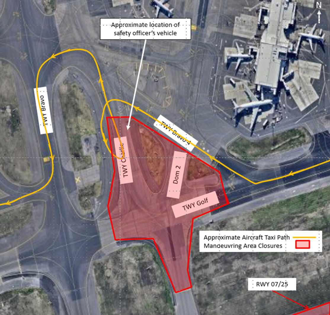
The pilot made a 180 degree turn on charlie and headed north, back towards bravo 4. The safety officer saw that NAO was returning and moved the vehicle off the centre line. The pilot passed the vehicle and taxied onto bravo 4, before making a left turn onto bravo, as initially intended. The approximate taxi path of the aircraft and the position of the safety vehicle at the time the aircraft entered charlie are shown in Figure 2.
The pilot taxied southward on bravo, but turned right towards runway 16R on bravo 6, contrary to the clearance which was to taxi to the runway holding point on golf. ATC advised the pilot that the aircraft appeared to be entering bravo 6, and that golf was the taxiway ‘just to the south’.
With the aircraft on bravo 6, ATC checked with the safety officer managing the runway 16R closure to confirm that the aircraft could enter the closed part of the runway at that point without causing any concerns, to which the responsible safety officer replied ‘affirm’. The pilot asked ATC if they required the aircraft to reposition, but ATC was able to provide a clearance to enter the runway at the bravo 6 intersection. ATC cleared the aircraft to enter at bravo 6 and taxi south on the runway to the point at which golf intersects the runway (the runway was available for take-off south of that intersection). The aircraft taxied forward then took off from runway 16R without further incident.
Figure 2: Approximate aircraft taxi path and location of safety officer’s vehicle
Source: Aircraft operator, modified by the ATSB
Safety analysis
Aerodrome works
Aerodrome works on golf had been underway at Sydney aerodrome since early in 2016 and were undertaken during the aerodrome curfew period. Airservices Australia Aeronautical Information Circular (AIC)[1] H38/15 provided a summary of the works, including a statement that ‘operational restrictions will be advised by NOTAM’[2]. On the night of the occurrence, the relevant NOTAM came into effect at 1300 UTC (2300 EST), and included the following operational restrictions:
TWY RESTR DUE WIP
TWY G BTN TWY B AND TWY B4 NOT AVBL
TWY C BTN TWY B4 AND RWY 07/25 NOT AVBL
TWY DOM2 BTN TWY B4 AND TWY G NOT AVBL
Although the pilot was aware of the aerodrome works, they were unaware of this particular NOTAM.
Taxi route
The taxi route by which the pilot was cleared was uncommon. The pilot had considerable experience operating at Sydney, but could not recall having followed the taxi path previously, either during the day or at night. Under normal circumstances, the pilot would have expected to taxi to runway 16R via golf. At the time of the occurrence, taxi via golf was not available because of the works. Similarly, runway 07/25 was also unavailable for taxi.
Aerodrome lighting conditions and taxiway markings
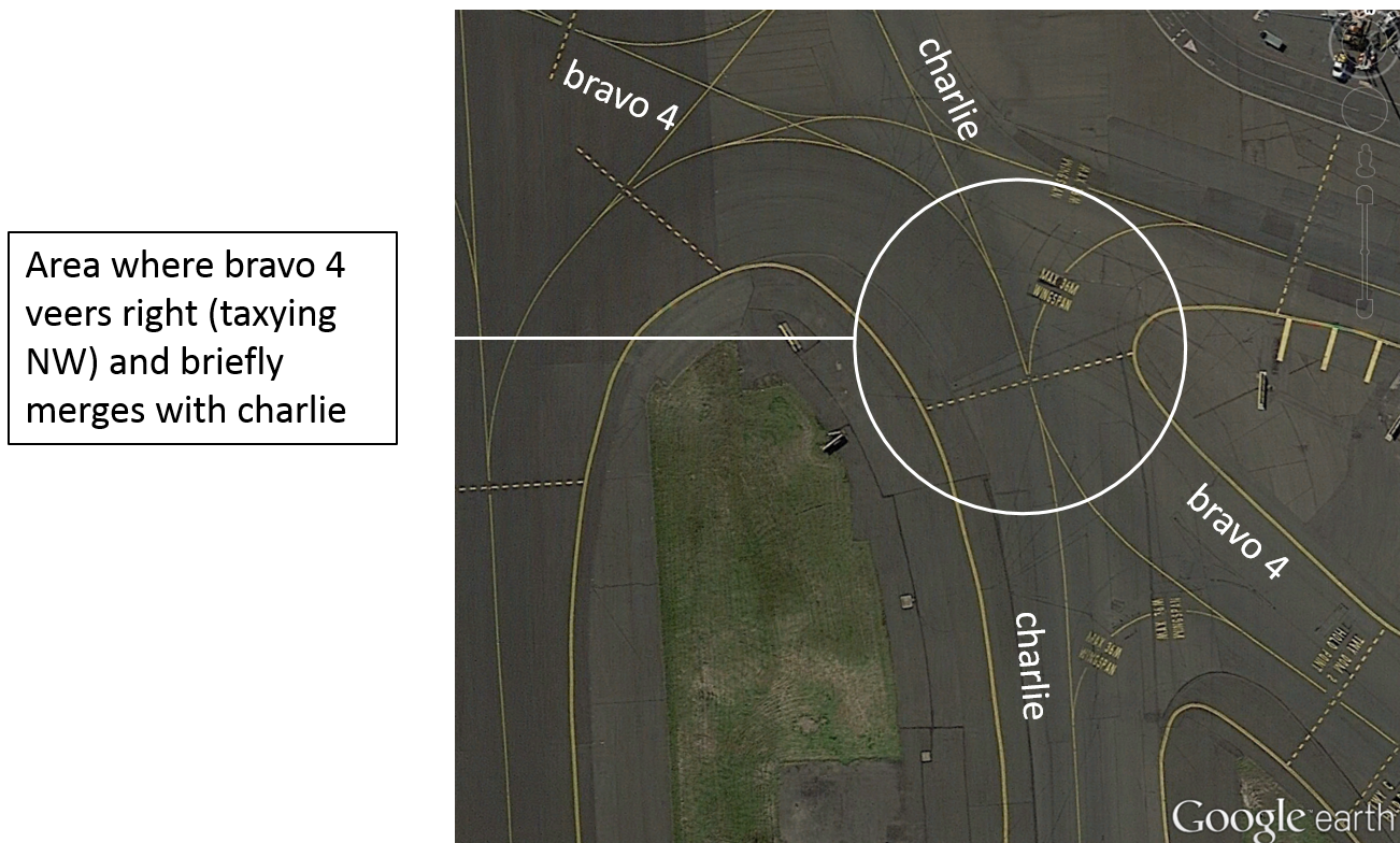
The taxi paths through the open space at the junction of bravo 4, charlie and charlie 2, are complex. Numerous guidance markings and lights complicate the area, and bravo 4 merges with charlie for a short distance as the two taxiways cross (Figure 3). A curve in bravo 4 as it meets charlie may have given the pilot the impression that the aircraft had arrived at the intersection of bravo 4 and bravo, being the point at which a sharp left turn was required. This expectation by the pilot may have been reinforced by the fact that the aircraft had just passed domestic 2, which the pilot may have misinterpreted as charlie.
The potentially confusing characteristics of the taxiway junction would have been exacerbated at night. At the time of the occurrence, additional vehicle lights were moving about the area, some steady (head/tail lights) and some flashing, and the partially established worksite lighting would have further complicated the environment. The pilot expected that some lights may have already been covered or turned off, which added to the potential for confusion over taxiway identification.
Figure 3: Taxiway intersection showing the area where bravo 4 veers right (taxying NW) and bravo 4 and charlie merge for a short distance
Source: Google earth, modified by the ATSB
At the time of the occurrence, the lead-in lighting to charlie and the charlie taxiway lighting had not yet been covered. This may have given the impression that the taxiway was still available, perhaps further reinforcing in the pilot’s mind that they had already passed charlie, and reached bravo. The taxiway signage was not affected by the works and was illuminated at the time of the occurrence. The pilot commented that their mental picture of the area was different to what they encountered at the time of the occurrence.
For similar reasons, as the pilot turned into bravo 6 (from bravo) to approach runway 16R, they were initially under the impression that they had reached golf.
Electronic charts
The operator had recently installed electronic charts (e‑charts) in the aircraft. Using GPS information, e‑charts can provide near real-time on-aerodrome positional information. At the time of the occurrence, the pilot was using paper charts, because they were more comfortable with paper charts and had not been trained in the use of e‑charts. The use of e‑charts was not mandated by the operator.
ATSB Comment
Continuing aircraft operations in the vicinity of a worksite while that worksite is only partially established, can be problematic. Operational considerations should be carefully balanced with the safety implications of allowing aircraft to continue to operate near a partially established worksite.
Under some circumstances, particularly where other complicating factors exist (such as poor ambient lighting conditions), it may be prudent to identify a transition period, and temporarily restrict aircraft movements until the worksite is fully established. The transition period would essentially be the time from which ATC release control of an area to a safety officer, until the safety officer then advises that establishment of the worksite is complete.
Airservices provided comment in relation to establishing a transition period, advising that the potential for a transition period to cause additional confusion around the availability of the work surface, or create additional disruption during times of high traffic levels would need to be taken into consideration. They consider the current process of instructing pilots with detailed taxi routes, as was the case in this occurrence, is effective. ATC will treat work areas as unavailable once an area is released to the work safety officer.
Findings
These findings should not be read as apportioning blame or liability to any particular organisation or individual.
The pilot was unaware of relevant taxiway closures until advised by ATC as part of their taxi clearance.
The pilot became confused about the position of the aircraft as they taxied past the worksite on bravo 4, probably due to a combination of factors, including:
The pilot was not familiar with the taxi route, and the taxi route took the aircraft through a complex junction of taxiways at night.
The worksite was only partially established (not all red lights were in place, and some existing taxiway lighting had yet to be covered).
The pilot was not familiar with the use of e‑charts, which may have assisted with their orientation under the circumstances.
Safety action
Whether or not the ATSB identifies safety issues in the course of an investigation, relevant organisations may proactively initiate safety action in order to reduce their safety risk. The ATSB has been advised of the following proactive safety action in response to this occurrence.
Aircraft operator
As a result of this occurrence, the aircraft operator has advised the ATSB that they are considering the following safety actions:
Implementation of a training program to cover some contributing factors identified in the internal company report dealing with the occurrence, including the use of e-charts and other similar technologies.
Development or acquisition of safety promotional material for staff, dealing with aircraft operations near worksites.
Safety message
This occurrence highlights the potential hazards involved when mixing aircraft operations with aerodrome works. The potential for misunderstanding or confusion is significant, particularly at night and in complex movement areas. The potential for confusion is further elevated when a worksite is in the process of being established. Relevant authorities are encouraged to carefully consider the risks involved and implement appropriate risk management strategies to minimise the likelihood of a misunderstanding or confusion.
Additionally, pilots are encouraged to stop and seek clarification from ATC if there is any doubt about the cleared taxi route. Similarly, ATC officers are encouraged to direct an aircraft to stop if they have any doubt about the intentions of the pilot, or there is any evidence that taxi instructions have been misunderstood. Timely and effective communication is essential to a shared understanding in a dynamic operational environment, particularly when the environment is complicated by unusual circumstances.
Decisions regarding whether to conduct an investigation, and the scope of an investigation, are based on many factors, including the level of safety benefit likely to be obtained from an investigation. For this occurrence, a limited-scope, fact-gathering investigation was conducted in order to produce a short summary report, and allow for greater industry awareness of potential safety issues and possible safety actions.
Publishing information
Released in accordance with section 25 of the Transport Safety Investigation Act 2003
Ownership of intellectual property rights in this publication
Unless otherwise noted, copyright (and any other intellectual property rights, if any) in this report publication is owned by the Commonwealth of Australia.
Creative Commons licence
With the exception of the Coat of Arms, ATSB logo, and photos and graphics in which a third party holds copyright, this publication is licensed under a Creative Commons Attribution 3.0 Australia licence.
Creative Commons Attribution 3.0 Australia Licence is a standard form licence agreement that allows you to copy, distribute, transmit and adapt this publication provided that you attribute the work.
The ATSB’s preference is that you attribute this publication (and any material sourced from it) using the following wording: Source: Australian Transport Safety Bureau
Copyright in material obtained from other agencies, private individuals or organisations, belongs to those agencies, individuals or organisations. Where you wish to use their material, you will need to contact them directly.
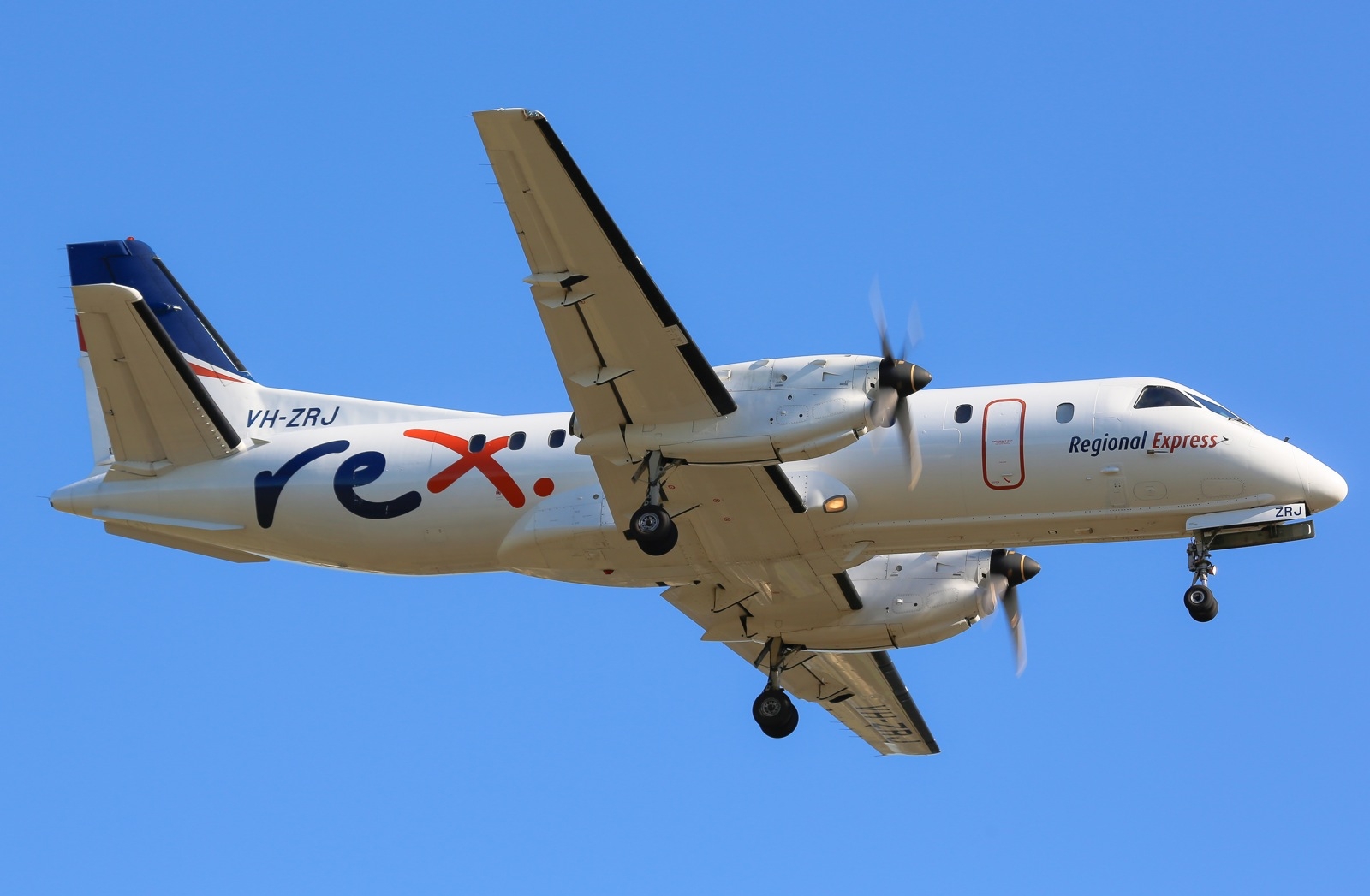
On 23 August 2016, at about 0634 Eastern Standard Time (EST), a Regional Express Saab 340B aircraft, registered VH-ZRJ, taxied at Ballina/Byron Gateway Airport, for a scheduled passenger flight to Sydney, New South Wales. On board were two flight crewmembers, one cabin crewmember and 22 passengers (Figure 1).
Figure 1: VH-ZRJ
Source: Victor Pody
All engine indications had been normal throughout the start and after-start procedures. The crew elected to use runway 06 for take-off. The runway was wet so the flight crew selected the environmental control system (ECS) off for take-off in accordance with the operator’s standard operating procedures.
Shortly after take-off, the captain called ‘positive rate gear up’ and the first officer selected the landing gear up. While the gear was retracting, the crew heard loud bangs and the left engine performance degraded noticeably, reducing the climb performance. The crew also noticed that the left engine instruments were fluctuating rapidly and indicating a high inter-turbine temperature. At that time, the cabin crewmember advised the flight crew that passengers could see flames coming from the left engine.
The flight crew kept the aircraft tracking straight ahead over water and climbing. Based on the noises and engine instrument indications, the crew identified the issue as a compressor stall and carried out the failure management procedure. This included reducing the power on the left engine and setting maximum continuous thrust on the right. Reducing the power also reduced the banging noises to popping noises.
At about 0639, the first officer contacted air traffic control (ATC) and declared a PAN.[1] The crew then commenced the checklist procedures for a compressor stall from the operator’s quick reference handbook. The checklist procedure involves trying to increase the rearward flow of air through the compressor via the low- and high-pressure bleed valves and the engine anti-ice bleed valves. Although reducing the fuel flow to the left engine reduced the popping noises, the compressor stall continued. The crew therefore commenced the appropriate failure management procedure to shut down the left engine and feather the left propeller.
At about 0650, the crew shut down the left engine and the first officer advised ATC that they had one engine inoperative. The crew also advised ATC that once they had completed their checks, they would return to Ballina via an area navigation (RNAV) approach.
After levelling out at 5,000 ft, the captain completed two to three holding patterns while the crew completed all relevant checklists. They then made an RNAV approach to runway 24. The captain reported that the approach and landing went smoothly and the aircraft landed at about 0720.
During the landing roll, as the captain moved the thrust lever on the right engine from flight idle to ground idle, the aircraft deviated to the right of the runway centreline. The captain later commented that this was probably associated with asymmetric propeller drag (the left propeller was feathered and the right propeller generated more drag as the right thrust lever was moved into ground idle). The captain moved the right engine thrust lever forward, out of ground idle, and the aircraft straightened up. The taxi to the bay was uneventful. There were no injuries to crew or passengers and no damage to the aircraft.
Pilot comments
The captain commented that ECS is usually selected ON for take-off on the first flight of the day (see Similar incidents). However, as the runway was wet, the crew selected ECS to OFF for this take-off, which was the standard procedure because of the performance considerations associated with a wet runway. In this incident, it is unlikely that the ECS selection contributed to the compressor stall, as the stall did not clear despite reducing the fuel flow and managing the bleed air in the failure management checks.
Both members of the flight crew commented that their simulator training, dealing with compressor stalls and one-engine inoperative scenarios, had been invaluable in contributing to their effective management of the situation. A compressor stall scenario that the captain had recently practised in the simulator was very similar to the incident, except that during the actual incident, the noises were louder and the instrument fluctuations more varied.
The captain also commented that the aircraft was easier to handle than the simulator during the compressor stall/one engine-inoperative situation, except during the landing roll where the simulator did not mirror the yawing tendency when ground idle is selected.
Engineering report
Engineers reviewed the flight data from the incident flight, which confirmed a compressor stall had occurred. No exceedances of torque, inter-turbine temperature, or turbine speed (rpm) limits (Ng and Np) were recorded. Borescope inspections of the engine did not detect any compressor damage. After finding no fault that may have caused the compressor stall, engineers replaced the hydromechanical unit (HMU) in accordance with the manufacturer’s fault isolation procedure.
The SAAB 340B Aircraft operations manual includes the following in the description of the HMU:
The HMU provides high pressure metered fuel for combustion. It contains a high-pressure vane pump and a pressure regulator and metering valve that schedules fuel to meet the various engine operating conditions and demands. The HMU also controls the variable geometry system (inlet guide vanes and stage 1 and 2 stator vanes) and the start and anti-ice bleed valve to provide for efficient and smooth engine operation throughout the entire speed range.
Significantly, the variable geometry system is instrumental in minimising the risk of compressor stall.
After replacing the HMU, engineers conducted ground runs of the engine with no defects found and the aircraft was returned to service.
Compressor stall
A turbine compressor stall occurs when there is a breakdown in airflow through the compressor. This can lead to a flow reversal, banging sounds and flame expulsion. The normal (rearward) air flow can usually be restored by reducing the engine power or thrust setting. Despite the noise, flames and associated heat, a compressor stall often results in no damage to the engine.
Similar occurrences
ATSB investigation 200300040 reported two incidents involving compressor stalls shortly after take-off in different Saab 340B aircraft. Both of those incidents also occurred on the first flight of the day. In response, the engine manufacturer made some recommendations to the operator of those aircraft, including that the operator consider amending procedures to include the selection of ECS ON for the first flight of the day. Use of the ECS opens the bleed air valves and reduces the likelihood of compressor stalls. The report stated that use of ECS on the first flight of the day would counteract the conditions of temperature inversions that were usually more pronounced in the early morning.
Safety message
This incident highlights the importance of well-designed simulator training and robust failure management procedures. Faced with an abnormal scenario, from their training and robust procedures, the crew was able to manage the situation efficiently and safely.
Decisions regarding whether to conduct an investigation, and the scope of an investigation, are based on many factors, including the level of safety benefit likely to be obtained from an investigation. For this occurrence, a limited-scope, fact-gathering investigation was conducted in order to produce a short summary report, and allow for greater industry awareness of potential safety issues and possible safety actions.
Publishing information
Released in accordance with section 25 of the Transport Safety Investigation Act 2003
Ownership of intellectual property rights in this publication
Unless otherwise noted, copyright (and any other intellectual property rights, if any) in this report publication is owned by the Commonwealth of Australia.
Creative Commons licence
With the exception of the Coat of Arms, ATSB logo, and photos and graphics in which a third party holds copyright, this publication is licensed under a Creative Commons Attribution 3.0 Australia licence.
Creative Commons Attribution 3.0 Australia Licence is a standard form licence agreement that allows you to copy, distribute, transmit and adapt this publication provided that you attribute the work.
The ATSB’s preference is that you attribute this publication (and any material sourced from it) using the following wording: Source: Australian Transport Safety Bureau
Copyright in material obtained from other agencies, private individuals or organisations, belongs to those agencies, individuals or organisations. Where you wish to use their material, you will need to contact them directly.
On 11 August 2016, track maintenance was to be undertaken east of Ballarat Railway Station. To protect the work group, three sets of points within the work area were remotely Blocked to prevent them being operated from the train control system (TCS). However, the points unexpectedly operated when a route was set by the train controller for a train to travel from Wendouree to Ballarat Station. There were no injuries or equipment damage.
What the ATSB found
The ATSB found that the train controller had placed a Block on the three sets of points, but these ‘Blocks’ were ineffective due to design errors within the TCS. Train control for the location had been moved from Ballarat to the Melbourne control centre about three months earlier and the new configuration lacked full points-Blocking functionality.
The ATSB found that the software written to provide the points-Blocking functionality within the TCS did not include coding for points that lay outside the selected route but within its overlap. The Wendouree-to-Ballarat route-setting required three sets of points in the overlap to be in a defined position. The absence of Blocking software for the overlap meant that these points were not Blocked and were able to be remotely moved when the route request was executed by the TCS. It was also found that neither Factory- nor Site-Acceptance testing of the new system considered this scenario. As a result, the deficiency was not identified at this early stage.
The system configuration for the relocated train control was uncommon for the Victorian regional network. It placed reliance on the TCS to perform the points-Blocking function rather than also providing an additional level of defence to the interlocking.
What's been done as a result
V/Line have issued instructions for track workers to isolate points prior to undertaking work on them.
The TCS software designer, UGL Pty Limited, have updated their instructions for software development and testing of unit-lever interlockings, to specifically require overlaps to be included in the Blocking functionality.
Safety message
It is critical that system designers ensure that the functionality and performance requirements needed to meet all operational scenarios are incorporated within the design. It is also important that effective check and test processes are developed to fully validate system functionality.
Ballarat Railway Station, Victoria
Source: ATSB
Occurrence
The incident occurred in Ballarat, a Victorian regional city located about 100 km west of Melbourne. Ballarat is linked to Melbourne and other regional centres by the regional rail network managed by V/Line.
At about 1230 on 11 August 2016, track maintenance personnel were preparing to commence maintenance works near Ballarat Railway Station. The maintenance included points cleaning and was to be conducted under Lookout Protection.
To prevent the unintended movement of points, the Signal Maintenance Technician (SMT) in charge of the maintenance group contacted the train controller for the Ballarat location and requested that a Block[1] be applied to motor point №s 35 (two sets) and 37 (one set) (Figure 1).
Figure 1: Points 35D, 35U and 37 adjacent to Ballarat Railway Station
Note that the Normal position for points 35U and 35D was for the respective turnouts and not the straight-ahead direction. The Normal position for points 37 was for the straight.Source: ATSB
System logs indicate that the train controller first Blocked 35D and 35U points and subsequently Blocked 37 points. These Blocks were placed through the train control system (TCS).
At about 1251, the train controller prepared a route from signal BAT2[2] to BAT24, using a ‘route-setting’ feature of the TCS, for train 7130 to travel from Wendouree to Ballarat. Wendouree Station is approximately 4.5 rail-kilometres from Ballarat Station.
The TCS cleared the route between BAT2 to BAT8 and stacked[3] the remainder of the route, from BAT8 to BAT24, pending the required pre-conditions being met. The system would automatically execute the control commands and create the route when those conditions were satisfied.
At about 1257, points 35 and 37 moved to meet overlap requirements for the BAT8 to BAT24 route and the full route was established. The previously applied blocks to 35 points (two sets) and 37 points did not prevent their movement during the execution of the route.
The SMT in the field noticed the movement of the points and contacted the train controller to confirm the application of the Blocks. The controller confirmed that the Blocks had been applied but acknowledged the points had moved. Due to this apparent anomaly, the controller notified the Senior Train Controller.
The maintenance workers were not affected by the unexpected movement of the points and there were no injuries.
A logger recording of the train control system (TCS) for the period preceding and during the incident provided detail of track routes, the status of points, signal position and train position and movements. From the commencement of the available recording (from 1242), points 35U and 35D were already Blocked (identified by blue highlight, Figure 2) and both were set for the diverge, their ‘Normal’ position. Train 8129 arrived at Ballarat Platform 1 at about 1245.
Train 8129 was recorded as leaving Ballarat and then arriving at Wendouree Station at about 1251. At Wendouree, the train was to reverse direction and return to Ballarat Station as train 7130. At this time, 35 points remained Blocked and 37 points were not yet Blocked (Figure 2).
Figure 2: Signal and points status when train 8129 terminated at Wendouree Station
Source: V/Line TCS recording
The recording showed that at 1251:08, the train controller called a route between signals BAT2 and BAT24 to bring train 7130 from Wendouree to platform 2 at Ballarat. Soon after, the system indicated a clear route from BAT2 to BAT8. The request for the remainder of the route from BAT8 to BAT24 was automatically stored (stacked) pending the operation of the Lydiard Street level crossing gates.
A short time later, the recording indicated a number of actions taken by the train controller. Blocking previously applied to 35 points was removed and the points were operated to their Reverse (straight) position, and then the Block re-applied at 1253:43. Then 37 points were operated to their Normal (straight) position and a Block applied at 1254:05 (Figure 3).
Figure 3: Extract of panel display showing status of 35 and 37 points at 1254:05
Source: V/Line TCS recording
At 1254:26, the controller called a route between BAT102 (at Wendouree Station) and BAT2 in preparation for the departure of train 7130 from Wendouree Station. Then, upon operation of the level crossing protection at Gillies Street, the system cleared BAT102 signal permitting train 7130 to depart from Wendouree.
At 1256:43, the Lydiard Street level crossing was activated. The Lydiard Street gates are not automatic and are controlled from Centrol[4]. At 1257:29, the level crossing gates were detected in their Road-Closed/Rail-Open position, at which point the TCS called the previously-stored route between BAT8 and BAT24.
A few seconds later, the TCS recording showed 35 and 37 points had operated and moved to their Normal and Reverse positions respectively. In both cases, the logger recording indicated that Blockings applied by train control had remained, and there was no evidence that the points operation had resulted from a train controller input.
By 1257:48, the system had cleared BAT8 signal for the passage of train 7130. The route was set for the passage of the train to platform 2 at Ballarat Station with 35 and 37 points in their altered positions (Figure 4).
Figure 4: System status when the route from 8 to 24 signal was cleared (green line)
The display shows BAT8 signal cleared for train 7130 to proceed to BAT24 signal (for berthing at platform 2). The Lydiard Street gates are depicted in the Road-Closed position. Blocking facilities (shown in blue) have been applied to both 35 and 37 points.Source: V/Line TCS recording
At 1300:04, train 7130 occupied the track indicating its arrival at the Ballarat Station platform.
Ballarat signalling
Background
Between 2005 and 2016, the control of points and signals at Ballarat was conducted using a local control panel and relay interlocking[5]. The local panel incorporated unit-lever[6] control of points and signals and provided a monitoring function with indications for signal, turnout position, and track occupancy.
Relocation of Ballarat train control
The implementation of Centralised Traffic Control (CTC)[7] between Melbourne and Ballarat in May 2016 required transfer of the control of points and signals at Ballarat to Centrol in Melbourne.
CTC systems (which are non-vital[8]) interface in the field with signal interlocking (which is vital[9]) to provide remote monitoring and control of the total system. The Centrol TCS for Ballarat was a SigView system developed and supplied by UGL[10]. The SigView workstation provides a graphical user interface (GUI)[11] to display indications for signal aspect, turnout position, track occupancy, and train information. Keyboard and mouse inputs allow for both unit-lever and Entrance-Exit[12] controls for points and signals.
When CTC was implemented at Ballarat, a MicroLok[13] computer-based interlocking (CBI) was used to facilitate the interface, allowing the relay interlocking at Ballarat to remain largely unchanged. MicroLok provides the interface between SigView and the relay interlocking (Figure 5).
Figure 5: The interface between the SigView, MicroLok and interlocking systems
Source: ATSB
Signalling systems usually include both vital controls (signalling interlocking) and non-vital controls (local control panel and/or CTC system). The signal interlocking is designed to provide fail-safe protection for train operations. In other words, the system ensures that field equipment (such as points and signals) is controlled in a manner that will maintain separation between all rail traffic detected (by track circuits) on the network. The CTC system and control panel affords the ability to send commands to operate points and signals, but the interlocking will only allow operation if all prerequisite conditions are satisfied.
In most cases, only trains can be reliably detected by track circuits (and consequently the signal interlocking), whereas maintenance workers and their equipment are not. Because of this, additional process controls are implemented to ensure adequate protection of workers on track.
Blocking facilities are a process control often used for the protection of maintenance workers. Blocking may be applied to exclude rail traffic from a track section, or to prevent the unintended operation of equipment during maintenance activity. For the signalling system at Ballarat, the Blocking functionality existed within the SigView system.
SigView Train Control System
In relation to the real-time monitoring and management of field signalling equipment, SigView provides the train controller with a video display unit (VDU) system display and a keyboard and mouse to enter control requests. To avoid unnecessary field communication, SigView incorporates a feature called Pseudo-Interlocking. Pseudo-interlocking is a model within the TCS that reflects the requirements of the signal interlocking in the field, so that only valid commands that are able to be actioned by the interlocking will be sent by the SigView system.
The SigView TCS provides the controller with several assistive features. One is the option of using the Entrance-Exit method for setting routes. SigView also incorporates Route-Stacking. This is a function by which SigView stores valid requested routes that are currently unavailable. When the routes become available, the system automatically issues the request to the interlocking.
SigView also provides for Blocking to be applied to points, signals, and tracks. The intent of a ‘Block’ is to prevent the unintended or automatic operation of points and signals, and to prevent clearing of signals that protect Blocked points or tracks.
Signal control tables
The sequence of events suggested that the operation of 35 and 37 points was related to the control of signal BAT8. The signal control tables[14] and the signalling circuits were examined to comprehend the operation of BAT8. The signal control tables defined the requirements for clearing a route from BAT8 to BAT24, and included (but were not limited to) the following:
That all tracks between signals BAT8 and BAT24 be unoccupied
That 35 points (in the overlap) be in their Normal position
That 37 points (in the overlap) be in their Reverse position
The noting of a requirement for interlocking with level crossings.
The control tables also defined the requirements for operating 35 and 37 points, and included (but were not limited to) the following:
That points trackage be unoccupied
That no routes had been set over the points.
Examination of the Ballarat signalling documentation revealed that the circuit diagrams were consistent with the requirements of the control tables. Therefore, so long as the specified conditions were met, SigView would issue commands to operate points and clear signals.
Interlocking
The interface circuitry between the control system and interlocking was such that all control functionality and indications were achieved through discrete Inputs and Outputs. Under this type of control, the only way for points to operate was for the interlocking to receive a control signal via the interface circuits. In this case, a MicroLok Computer Based Interlocking (CBI) interface connected the SigView control system with the relay interlocking at Ballarat.
The Route-Setting feature of the SigView Train Control System (TCS) provides for the automatic setting of points required to complete a particular route. Depending on the signalling design for each route, the interlocking may also require points outside of the direct route (such as in an overlap) to be in a particular position to permit the route being set.
In this instance, an Entrance-Exit route had been requested between BAT2 and BAT24 signals. This route consisted of two component sub-routes; BAT2 to BAT8 and BAT8 to BAT24. All conditions were met for the first sub-route from BAT2, so the request was issued from SigView to the Ballarat signal interlocking. However, the route ahead of BAT8 was not available due to the interlocking requirements at Lydiard Street level crossing and the lay of 35 and 37 points within the overlap. The route request from BAT8 was therefore stored by the Route-Stacking function until conditions within the SigView pseudo-interlocking were met.
Once the Lydiard Street level crossing was detected in the Road-Closed position, the conditions for BAT8 signal were met except for the lay of 35 and 37 points. At this point, SigView automatically issued a request to move 35 and 37 points to their required position. The previously applied Blocking of 35 and 37 points (on SigView) to protect maintenance workers, did not stop the command to move the points being issued to the interlocking.
Ballarat TCS Blocking functionality
The route-setting functionality of the TCS system only evaluated the Blocked points between the entrance and exit signals and did not take into consideration the Blocking of points that lay within the overlap. UGL subsequently modified both Factory- and Site-Acceptance test procedures for control of unit-lever relay interlockings to explicitly test the Blocking functionality in overlaps.
Testing and commissioning of new control
Testing conducted by UGL was limited to the software functions that had been included in the design and did not include testing of other possible operational scenarios or conditions.
There was no explicit requirement to test the Blocking of points in the overlap (outside the entrance and exit for a route) either as part of the factory testing or during on-site commissioning.
Reconfiguration of signalling control
Relocation of train control from Ballarat to Melbourne, resulted in the adoption of the SigView TCS. As part of this reconfiguration of train control for Ballarat, the in-field relay interlocking was retained and a computer based interlocking (CBI) (MicroLok) introduced to provide the communication interface between SigView and the relay interlocking.
However at other locations controlled by the Ballarat TCS, the interlockings were designed to provide points keying functionality[16] ensuring a second level of protection by implementing a Train Controller-initiated Block (a SigView function) to the specific points using the interlocking.
On the SigView screen, manual control of specific points is achieved by using a graphical depiction of a three-position (Normal-centre-Reverse) rotary switch, or ‘points key’. The points key is set to the centre position where routing of trains and control of points is to be done automatically by the TCS. However, if the points key is manually switched to either the Reverse or Normal position, the points are controlled to that position.
At other locations controlled by the SigView TCS, the signal blocking function also incorporated a points keying function as a second level of protection. That is, if a command was issued to Block a set of points in the Normal position, the system would also simulate placing the corresponding point key to the Normal position, thereby preventing automatic control. Similarly, for Blocking of points in the Reverse position.
Combining the points keying functionality with the signal Blocking command had not been implemented for the Ballarat TCS. Consequently, the system did not prevent the interlocking from responding to automatic SigView routing commands for points 35 and 37.
From the evidence available, the following findings are made with respect to the signalling control system irregularity that occurred at Ballarat, Victoria, on the 11 August 2016. These findings should not be read as apportioning blame or liability to any particular organisation or individual.
Contributing factors
Software written to manage the points-Blocking functionality within the Ballarat SigView Train Control System (TCS) did not include coding for points that lay within the overlap of the selected route
The factory testing and commissioning of the new TCS configuration for Ballarat did not include processes that tested the Blocking and response of points in signalling overlap areas.
Other factors that increased risk
The implementation of Blocking functionality for Ballarat differed from other locations controlled by the Ballarat TCS by not incorporating points-keying functionality.
Safety actions
Whether or not the ATSB identifies safety issues in the course of an investigation, relevant organisations may proactively initiate safety action in order to reduce their safety risk.
The ATSB has been advised of the following proactive safety actions in response to this occurrence:
V/Line instituted several interim mitigation actions, including conducting a system review of points-Blocking, and issuing formal instructions for track workers to place points individually into the ‘Hand’ mode
UGL issued an internal engineering instruction that identified the design deficiency and the necessary changes to the design, check, and test processes for software development. Design procedures were modified to explicitly require overlaps to be included in the Blocking expression and both the Factory- and Site-Acceptance test procedures were similarly modified
SigView expressions and functionality were modified such that when points are Blocked in a position contrary to that required for a route, then if requested by the train controller the route called will be suppressed by SigView and not stacked
Examination of similar scenarios resulted in extensive testing and minor changes to SigView expressions for other adjacent points that have been installed, tested and in use since late September 2016, with no further Blocking issues observed.
Appendices
Appendix A – SigView TCS replay sequence of events
Time
SigView event description
Comment
1242
35U and 35D points shown blocked
37 points are not yet blocked
1245
Train 8129 arrives at Ballarat station
1251
Train 8129 arrives at Wendouree station
12:51:08
Entrance button
Controller calling a route from number 2 signal to number 24 signal (Ballarat)
12:51:12
Exit button
12:51:16
Route set BAT2-BAT8. Route stored BAT8-BAT24
12:51:29
Train number 8129 change to 7130
12:53:26
Blocking removed from 35 points
The replay does not show the ‘Unblock’ button being pressed before the block is removed from 35 points
However, it is evident that the actions controlling 35 and 37 points have been undertaken by the controller
12:53:29
35 points loss of Normal detection
12:53:38
35 points Reverse detection
12:53:42
Block button & block applied to 35 points Reverse
12:53:51
37 points loss of Reverse detection
12:53:59
37 points Normal detection
12:54:03
Block button & block applied to 37 points Normal
12:54:26
Entrance button
Controller calling a route from number 102 signal to number 2 signal (departure from Wendouree)
12:54:28
Exit button
12:54:34
7130 identified as ‘Express’. Gillies St LX operating
12:55:09
Route set BAT102-BAT2.
12:55:17
Track 102T occupied
Train 7130 departure from Wendouree
12:56:43
Lydiard St LX operating, 2AT occupied
Lydiard St level crossing gates in the Road-Closed position is a requirement for locking a route from number 8 signal
12:57:29
Lydiard St LX gates road-closed, BAT8 route yellow
12:57:36
35 & 37 points loss of detection
Number 35 and 37 points running. However, there is no indication that this has resulted from a controller input
12:57:43
35 points normal detection
12:57:44
37 points reverse detection
12:57:48
Route set BAT8-BAT24
Number 8 signal clear
13:00:04
Track A38T occupied
Train 7130 arrival at platform 2, Ballarat
Sources and submissions
Sources of information
The sources of information during the investigation included:
V/Line Pty Ltd
UGL Limited.
Submissions
Under Part 4, Division 2 (Investigation Reports), Section 26 of the Transport Safety Investigation Act 2003 (the Act), the Australian Transport Safety Bureau (ATSB) may provide a draft report, on a confidential basis, to any person whom the ATSB considers appropriate. Section 26 (1) (a) of the Act allows a person receiving a draft report to make submissions to the ATSB about the draft report.
A draft of this report was provided to V/Line, ONRSR, TSV, and UGL Limited.
Any submissions from those parties were reviewed and where considered appropriate, the text of the draft report was amended accordingly.
Purpose of safety investigations
The objective of a safety investigation is to enhance transport safety. This is done through:
identifying safety issues and facilitating safety action to address those issues
providing information about occurrences and their associated safety factors to facilitate learning within the transport industry.
It is not a function of the ATSB to apportion blame or provide a means for determining liability. At the same time, an investigation report must include factual material of sufficient weight to support the analysis and findings. At all times the ATSB endeavours to balance the use of material that could imply adverse comment with the need to properly explain what happened, and why, in a fair and unbiased manner. The ATSB does not investigate for the purpose of taking administrative, regulatory or criminal action.
Terminology
An explanation of terminology used in ATSB investigation reports is available here. This includes terms such as occurrence, contributing factor, other factor that increased risk, and safety issue.
Publishing information
Released in accordance with section 25 of the Transport Safety Investigation Act 2003
Ownership of intellectual property rights in this publication
Unless otherwise noted, copyright (and any other intellectual property rights, if any) in this report publication is owned by the Commonwealth of Australia.
Creative Commons licence
With the exception of the Coat of Arms, ATSB logo, and photos and graphics in which a third party holds copyright, this publication is licensed under a Creative Commons Attribution 3.0 Australia licence.
Creative Commons Attribution 3.0 Australia Licence is a standard form licence agreement that allows you to copy, distribute, transmit and adapt this publication provided that you attribute the work.
The ATSB’s preference is that you attribute this publication (and any material sourced from it) using the following wording: Source: Australian Transport Safety Bureau
Copyright in material obtained from other agencies, private individuals or organisations, belongs to those agencies, individuals or organisations. Where you wish to use their material, you will need to contact them directly.
On 19 August 2016 at 1458, a Port Phillip Sea Pilot boarded Bow Singapore outside Port Phillip, Victoria. The pilot was to conduct the ship through The Rip and the South Channel to an anchorage in the northern part of Port Phillip.
At 1614, as the ship neared the eastern end of the South Channel, the rudder ceased responding to helm inputs and remained at 5° to port. The ship started swinging towards the edge of the channel. Steering was regained a short time later but, despite the efforts of the pilot, the ship grounded at 1617.
On 20 August at 0040, Bow Singapore was re-floated, with the assistance of the rising tide and a tug. The ship proceeded to anchor and, later, to the discharge berth in Geelong. After discharging cargo the hull was inspected by divers and no damage was found.
What the ATSB found
The ATSB found Bow Singapore’s steering gear ceased working and the rudder remained at 5° to port. A telemotor solenoid, controlling the rudder’s movement to starboard, had stopped responding to electrical signals. This initiated an uncontrolled turn towards the edge of the channel and shallow water.
The company’s procedures for a steering gear failure required a change in operation from the bridge to local emergency operation from the steering gear room. However, the procedures did not include the steps to be taken on the bridge prior to that change, such as using non follow-up mode and changing to alternate telemotor and/or pump systems.
The planned maintenance system for the steering gear did not include or contain any schedules for any detailed inspections or scheduled parts replacement. In addition, the hydraulic system port and starboard solenoids were painted green and red respectively, to match the side of the ship that each is on when mounted on the shuttle valve. However, this was opposite to the direction the rudder would move when they were operated.
What's been done as a result
Odfjell Management, the ship’s managers, arranged for a manufacturer’s representative of the steering gear to attend the ship when it arrived in Singapore. The solenoids and shuttle valves for both steering systems were replaced, the relief valves were opened and examined and the oil was changed. No faults that could cause the failure were found.
The ship managers have now included a 6‑monthly job entry into their planned maintenance system for the opening and inspection of the steering gear’s solenoids. In addition, the telemotor solenoids have been repainted so that the colours now match the direction of rudder movement, rather than the side of the ship on which they are mounted.
Further, the fleet wide safety management system procedure for ‘steering gear failure’ has been amended to include reference to ship specific emergency change over procedures.
Safety message
For equipment, particularly that which is critical to the safe operation of a ship, it is important that there is a well-formulated maintenance plan that includes inspection, testing and planned maintenance.
The occurrence
On 19 August 2016 at 1450,[1] the 105 m chemical and products tanker Bow Singapore, approached the Port Phillip pilot boarding ground. The ship was bound for the port of Geelong, Victoria. The bridge team consisted of the master, second mate as the officer of the watch (OOW) and a seaman as the helmsman.
At 1458, a Port Phillip Sea Pilot boarded the ship for the inbound transit (Figure 1), through The Rip and South Channel to an anchorage off the Port of Geelong. The master and pilot exchanged information regarding the ship and the inward passage and the pilot then took the conduct.[2]
Figure 1: Section of chart AUS 158 showing the track of Bow Singapore
Source: Australian Hydrographic Service with annotation by the ATSB
At 1505:13, the pilot instructed the helmsman to steer a heading[3] of 042°. Shortly after, the ship entered The Rip and was turned into the South Channel on an east by south course. The transit through the channel continued as intended by the pilot.
At 1600, the ship was approaching the eastern end of the South Channel at a speed of 13.5 knots.[4] At that time the third mate took over the navigational watch from the second mate as OOW and another seaman took over as helmsman.
At 1611:43, the pilot ordered a heading of 093° (Figure 2, point 1), an alteration of about 7° to port. The order was repeated back by the helmsman, and at 1612:32 he advised the pilot that the ship’s heading was 093° (Figure 2, point 2). The helmsman then used the rudder, as needed, to maintain that heading.
At 1613:38, the helmsman applied 5° of port rudder and then went back to midships. A few seconds later, he checked the rudder indicator and saw that the rudder had remained at 5° to port (Figure 2, point 3). He gave a series of starboard rudder movements in quick succession, however the rudder remained at 5° to port and he then informed the ship’s bridge team of the problem.
At about 1614, the OOW took the helm from the helmsman. He changed to the non follow-up (NFU) mode[5] and made a series of starboard rudder movements. Again, the rudder did not respond and remained at 5° to port.
Figure 2: Bow Singapore’s rudder movements, speed and position prior to grounding
Source: ATSB
By 1614:10, the pilot became aware that there was a problem with the steering gear and ordered ‘hard to starboard’. He then asked the master about changing the steering system to NFU mode. In response to the pilot’s order, the OOW put the NFU lever to starboard again. A few seconds later, the pilot then asked the master to change over the steering pumps.
At 1614:35, the pilot ordered 'stop engine’, which was acknowledged by the ship’s bridge team and 7 seconds later the engine telegraph was moved to stop.
At 1614:52, the pilot asked for ’full astern’.
By 1615:03, the master had changed the main steering pumps from number one to number two as requested by the pilot and the OOW had changed the steering (telemotor) system[6] from number one to number two. The rudder then started to respond to the NFU starboard demand. A few seconds later the pilot observed that the rudder was moving to starboard (Figure 2, point 4).
By 1615:14, the pilot again ordered ‘full astern’ and 10 seconds later the ship’s engine was full astern.
At 1615:32, the pilot made VHF radio contact with the Port of Melbourne[7] and advised the duty Lonsdale vessel traffic service officer (VTSO) that Bow Singapore was about to run aground.
Shortly after, at 1615:58, the pilot observed that the rudder was now hard to starboard and the ship had slowed to 10 knots and he ordered ‘stop engine’. He then considered the options that may prevent the ship from running aground.
At 1616:07, the main engine had stopped and shortly after the ship’s bridge team mentioned the rudder was still hard to starboard. The pilot then ordered ‘slow ahead’ to increase the water flow over the rudder and assist the manoeuvre away from the shallow water.
However, by 1616:38, the ship had slowed considerably and in the limited time available, going slow ahead on the main engine had little effect. About 6 seconds later, the pilot ordered ‘stop engine’ and then ‘slow astern’. He then informed the master the ship had run aground and asked for the ship’s crewmembers to stand by the anchors.
At 1617:22, the pilot contacted Lonsdale VTS and reported the ship had grounded on the sandbank (Figure 2, point 5).
Over the next 7 minutes the pilot attempted to manoeuvre the ship off the sandbank by increasing astern power and using the bow thruster. Although the ship did move, the pilot’s efforts to re-float the ship were ultimately unsuccessful.
The crew then started taking soundings of empty ballast tanks, the full cargo tanks and the water depth around the ship. No ingress or egress was found and the ship’s crewmembers continued to monitor until the ship was re-floated.
On 20 August at 0040, with the assistance of a tug and the rising tide, Bow Singapore was re‑floated. It then proceeded to the anchorage off the Port of Geelong. Subsequent underwater hull inspections/survey did not indicate any damage to the ship.
Bow Singapore was fitted with a Kawasaki Precision Machinery RV21-022 steering gear (Figure 3). It was a two (simplex) ram Rapson slide system with two identical hydraulic systems. Each system included a hydraulic pump, directional control (shuttle) valve and electrical control systems.
Figure 3: Bow Singapore’s steering gear
Source: ATSB
The rudder was moved by the hydraulic shuttle valve directing high pressure oil from the pump to one of the two rams. The valve consisted of a spring-centred shuttle operated by two opposing solenoids. When electrical power[8] was applied to a solenoid, it moved the shuttle directing the flow of oil to a ram and the rudder moved. When the signal was removed, the valve’s internal springs returned the shuttle to a neutral position and the rudder stopped moving.
Manual (emergency) operation can be performed locally by inserting a pin (Figure 4, blue arrow) into the back of the required solenoid and pushing the shuttle valve across (red arrow – rudder to port, green arrow – rudder to starboard).
Figure 4: Steering system one solenoid valve arrangement
Source: ATSB
The solenoid’s electrical connection consisted of two hard-mounted pins that protrude from the mounting face of the solenoid. They made contact with spring-loaded receivers when the solenoid was mounted on the body of the shuttle valve.
Prior to departure from the last port, both steering gear systems were tested from the bridge and the steering gear room, as part of the normal departure routines. No faults were recorded. The ship departed on steering system number one, as was the normal practice, and operated without fault for the voyage to Port Phillip.
While the ship was aground in Port Phillip, the steering gear was inspected and tested by the ship’s engineers and an electrician. They first confirmed that the telemotor signal had reached the number one starboard solenoid.[9] However, the solenoid did not respond to the starboard telemotor signals. Next, the port and starboard solenoids were manually operated and the rudder responded in both directions. The telemotor test was repeated and the rudder, again, did not respond to starboard telemotor signals.
The manual testing showed that the solenoid, shuttle valve and pump were operating as expected. Therefore, the fault was unlikely to be mechanical and more likely to be an electrical fault associated with the starboard solenoid. The engineers then changed the solenoid and the steering gear resumed normal operation.
When the solenoid that had been replaced was bench tested on board Bow Singapore it operated as designed. The solenoid was further tested in the ATSB laboratory and it also worked as designed and the coil’s current flow and resistance were as per the specification. It was then disassembled and visually inspected and no abnormal conditions were evident.
As no fault could be found with the solenoid, the ATSB identified two other possible reasons for the failure:
An intermittent fault. Although an intermittent fault is possible, it is unlikely as this condition has not reoccurred and there is no history of this fault having previously occurred.
A high-resistance contact. The solenoid’s electrical pins were clean and showed no signs of mechanical damage. There was also no sign of arcing and/or heat discoloration that can sometimes be found with a poor electrical connection. However, this does not rule out the possibility of a high-resistance (dry) joint having developed. As the steering gear returned to normal operation, after fitting another solenoid, it is possible that if there was a poor connection, it was restored during the solenoid changeover.
Further inspection of the steering gear in Singapore, by the manufacturer’s representative, also found nothing to explain why the steering gear had stopped responding.
In summary, from the evidence provided by the ship, the manufacturer’s representative and the ATSB laboratory, no mechanical or electrical fault could be found to establish why the steering gear failed to respond to starboard telemotor signals.
Emergency procedures
The International Safety Management (ISM) Code[10] requirements are mandatory for Bow Singapore and its management company to comply with. Part A (Implementation), Section 8.1 (Emergency preparedness) states:
The Company should identify potential emergency shipboard situations, and establish procedures to respond to them.
Therefore, a procedure should contain all steps, in a logical order, so the operators can respond to a problem expediently and enable the best possible outcome.
However, the management company’s (Odfjell Management) procedure for ‘steering gear failure’ stated:
Inform the Master and Engineer on duty
Engage the emergency steering
Call up an additional look-out if necessary
…
…
Reduce speed or stop engines, if necessary
Hence, an immediate change in operation from the bridge to local emergency operation from the steering gear room. The procedure did not include steps to be taken on the bridge, such as the use of the NFU mode or changing over pumps and/or telemotors.
However, the crewmembers had made an on board procedure stating the above (Figure 5) and affixed it to the bridge steering console. The ship’s bridge team followed the steps in the on board procedure after the helmsman reported the issue with the steering gear.
Therefore, there was an inconsistency between the company-controlled documented procedure and the procedure affixed to the steering console. The company procedure would have resolved a loss of steering control from the bridge but required local operation to work. However, during pilotage in restricted waters, there is a limited time available to respond. Hence, the time required for crewmembers to proceed to the steering gear room and operate locally would not be the most expedient way to respond to a steering failure.
Equipment knowledge
Guidance regarding equipment knowledge is contained in Section 3.2, Regulation 26, Chapter V, SOLAS[11] (Safety of Navigation), which specifically states:
All ships’ officers concerned with the operation and/or maintenance of steering gear shall be familiar with the operation of the steering systems fitted on the ship and with procedures for changing from one system to another.
The ship’s bridge team initially responded to the steering failure by changing over to NFU mode. When the rudder did not respond, they changed over from steering pump number one to two and steering (telemotor) system number one to two, the reverse order of the procedure affixed to the steering console (Figure 5).
Their actions of changing both the pump and telemotor over to the other system was due to their understanding that cross operation of systems one and two was not possible (for example, number one telemotor could not control number two steering system), however, it was. Notwithstanding, the actions of the ship’s bridge team were appropriate, timely and in excess of what had been documented in the company’s emergency procedure.
As stated in the SOLAS requirements, the management company’s procedures need to document how to change over from one system to another and that the crew are adequately trained to ensure system knowledge is accurate. However, the company’s emergency procedure did not provide these directions and in lieu of this the ship’s crew had made their own ship-specific procedure.
Maintenance procedures
The ISM Code, Part A (Implementation), Section 10.3 (Maintenance of the ship and equipment) states:
The Company should identify equipment and technical systems the sudden operational failure of which may result in hazardous situations. The SMS should provide for specific measures aimed at promoting the reliability of such equipment or systems.
The management company’s planned maintenance system (PMS) schedule contained monthly and three-monthly checks for the steering gear. It required the crewmembers to test the alarms, check for leaks and to check the auto start of the standby pump in case of any alarm. Prior to each dry-docking (twice in a 5 year period), Odfjell Management had the steering gear inspected by the manufacturer’s representative. A repair specification was then compiled based on the results of the inspection report.
The PMS also required checks of the steering gear’s hydraulic oil, which were sampled three times a year, and sent ashore for analysis.[12] Although oil analysis is a useful tool, it has limitations. It cannot identify all age and wear related problems, such as the hardening/flattening of O-rings, a change in a spring’s characteristics or leakage past a valve.
Similarly, electrical systems would benefit from planned maintenance inspections, such as electrical insulation testing, checking terminations for tightness and checking that relays and timers are properly seated in their bases.
Further, the PMS schedule for the steering gear did not include the manufacturer’s recommendations for a monthly check[13] of the solenoid valves. In addition, detailed inspections or scheduled parts replacement were not included. Therefore, the continued safe operation of the steering gear was reliant, for the most part, on breakdown maintenance when components failed.
Planned maintenance systems that include regular and thorough maintenance and visual inspections, as well as operational tests, better reduce the risk of machinery failure than operational tests alone. This is particularly important for systems that are critical to the safe operation of the ship.
Equipment labelling and visual cues
Each hydraulic system had two solenoids that moved a shuttle valve which directed the flow of oil to a ram which moved the rudder. Manual (emergency) operation of the solenoids required a pin to be inserted into the back of the required solenoid to push the shuttle valve across. That action would then move the rudder in that direction.
System number one’s solenoids were each painted and stencilled for identification. The port solenoid had a ‘P’ stencilled on it and likewise the starboard solenoid had an ‘S’. However, the dominant information was the colour that they had been painted. The solenoid bodies were painted a colour that was opposite to the direction the rudder would move. The red solenoid was painted green (starboard) but when operated moved the rudder to port. Likewise, the green solenoid was painted red (port) but when operated moved the rudder to starboard.
Therefore, this could create confusion when crewmembers operating the solenoids locally receive a rudder order from the bridge. For example, receiving an order for port 5 could be interpreted as either operating the port solenoid or the red starboard solenoid. Although the colouring of the solenoids did not contribute to this occurrence, in an emergency situation, the risk of a helm order being incorrectly applied would increase. The added complexity of steering a ship from the steering gear room and the likelihood of an error occurring would be further increased due to the colouring found on the solenoids.
Similar past incidents
Flag States with the responsibility to investigate safety occurrences have investigated similar incidents regarding steering gear failures and the crew’s limited understanding of steering gear systems and shipboard maintenance procedures.
Flag Gangos
On 12 August 2014, the outbound bulk carrier Flag Gangos collided with the berthed oil tanker Pamisos on the Mississippi River at Gretna, Louisiana. The Flag Gangos subsequently collided with a pier at the facility where the Pamisos was berthed, and the pier struck and damaged a fuel barge, berthed behind the Pamisos.
The US National Transportation Safety Board (NSTB) investigated the collision. Its final investigation report (NTSB/MAB-15/25, accident number DCA14FM015), stated that the ‘probable cause’ was a delay in completing a mandatory upgrade to the vessel’s steering system and a ‘failure to routinely test the steering gear’s hydraulic fluid for debris as required by the manufacturer’.
Halit Bey
On 22 April 2014, the chemical and products tanker Halit Bey was proceeding up the St. Lawrence River, under the conduct of a pilot, when steering control was lost. The vessel veered to port and exited the navigational channel, running aground on the south side of the river off Grondines, Quebec. The vessel was later re-floated with the assistance of two tugs.
The Transportation Safety Board (TSB) of Canada investigated the grounding (report M14C0045). The findings with potential relevance to the current investigation included:
The bridge crew was not adequately familiarized with the characteristics of the Halit Bey's steering control system and did not know how to regain steering control after the autopilot override alarm activated.
After steering control was lost, the vessel veered to port, towards the shore.
The crew’s attempt to reduce speed and anchor the vessel were unsuccessful, in the limited time available, to prevent the vessel from exiting the navigational channel and running aground.
If crew members are not familiarized with all aspects of the operation of safety critical equipment, such as a vessel’s steering control system, there is a risk that they will not have the knowledge required to operate the system proficiently or regain control in the event that it is lost.
Orsula
On 15 December 2011, the bulk carrier Orsula departed Contrecœur, Quebec, in ballast for Baie‑Comeau, Quebec. While proceeding down the St. Lawrence River under the conduct of a pilot, the vessel lost steering control and ran aground at 1329 on the Battures de Gentilly, 1.25 miles northeast of Bécancour wharf, Quebec. About 48 hours later, it was re-floated on the first attempt using tugs.
The Canadian TSB investigated the grounding (report M11L0160). The findings with potential relevance to the current investigation included:
Steering control was lost when the port steering system potentiometer failed while the rudder angle was at 10º to starboard, causing the vessel to veer to starboard and leave the dredged channel.
The bridge crew members were not familiar with the use of the non-follow-up mode or with switching the steering system selector switch from port to starboard to regain steering control.
The master switched the steering system selector switch from port to starboard, which restored steering control, but it was too late to prevent the vessel from running aground.
Arcadia
On 22 October 1996, the oil tanker Arcadia was under the conduct of a pilot inbound for a refinery at Anacortes, Washington. The loss of steering occurred due to a loose electrical connection on the steering gear's number one hydraulic control solenoid. The connection was overlooked during a regular maintenance check.
The Washington State Department of Ecology published an investigation report (publication # 98-253). The lessons learnt and recommendations with potential relevance to the current investigation included:
Steering gear is a critical vessel safety system. As such, steering gear systems must be properly maintained. However tedious, inspections of the electrical connections of the system must be part of the maintenance program. The maintenance program should be structured to minimize the opportunity for human errors.
Ensure that steering gear is properly maintained under a comprehensive planned maintenance program that minimizes the likelihood of human error and conforms with the International Management Code for the Safe Operation of Ships and for Pollution Prevention (ISM Code), especially Section 10. All electrical connections should be regularly checked for integrity as part of such a steering gear maintenance program.
From the evidence available, the following findings are made regarding the grounding of Bow Singapore, under pilotage, in Port Philip on 19 August 2016. These findings should not be read as apportioning blame or liability to any particular organisation or individual.
Safety issues, or system problems, are highlighted in bold to emphasise their importance. A safety issue is an event or condition that increases safety risk and (a) can reasonably be regarded as having the potential to adversely affect the safety of future operations, and (b) is a characteristic of an organisation or a system, rather than a characteristic of a specific individual, or characteristic of an operating environment at a specific point in time.
Contributing factors
Bow Singapore’s steering gear stopped responding to helm inputs and the rudder remained at 5° to port. This initiated an uncontrolled turn towards the edge of the channel and shallow water.
Other factors that increased risk
The company’s procedures for a steering gear failure required a change in operation from the bridge to local emergency operation from the steering gear room. However, the procedures did not include the steps to be taken on the bridge prior to that change, such as using non follow-up mode and changing to alternate telemotor and/or pump systems.
The number one steering system telemotor solenoid stopped responding to helm inputs. However, when examined and tested, the solenoid functioned as designed and no faults were found.
Bow Singapore’s planned maintenance system for the steering gear did not include or contain any schedules for any detailed inspections or parts replacement. [Safety issue]
The hydraulic system solenoids were painted red or green to match the side of the ship that each were mounted on, but that was opposite to the direction the rudder would move.
Other findings
The actions of the bridge team were both timely and appropriate as well as being in excess of the requirements of the procedure that was in place at the time of the incident.
Safety issues and actions
The safety issue identified during this investigation is listed in the Findings and Safety issues and actions sections of this report. The Australian Transport Safety Bureau (ATSB) expects that all safety issues identified by the investigation should be addressed by the relevant organisation(s). In addressing those issues, the ATSB prefers to encourage relevant organisation(s) to proactively initiate safety action, rather than to issue formal safety recommendations or safety advisory notices.
All of the directly involved parties were provided with a draft report and invited to provide submissions. As part of that process, each organisation was asked to communicate what safety actions, if any, they had carried out or were planning to carry out in relation to each safety issue relevant to their organisation.
The initial public version of these safety issues and actions are repeated separately on the ATSB website to facilitate monitoring by interested parties. Where relevant the safety issues and actions will be updated on the ATSB website as information comes to hand.
Steering gear planned maintenance instructions
Bow Singapore’s planned maintenance system for the steering gear did not include or contain any schedules for detailed inspections or parts replacement.
Safety issue description:Bow Singapore’s planned maintenance system for the steering gear did not include or contain any schedules for detailed inspections or parts replacement.
Sources and submissions
Sources of information
The sources of information during the investigation included the:
interviews of the directly involved crew of Bow Singapore
interview of the pilot
automatic identification systems and voyage data recorder data
documents provided by Odfjell Management
Kawasaki Heavy Industries (S) Pty. Ltd.
Submissions
Under Part 4, Division 2 (Investigation Reports), Section 26 of the Transport Safety Investigation Act 2003 (the Act), the Australian Transport Safety Bureau (ATSB) may provide a draft report, on a confidential basis, to any person whom the ATSB considers appropriate. Section 26 (1) (a) of the Act allows a person receiving a draft report to make submissions to the ATSB about the draft report.
A draft of this report was provided to the master and directly involved crew of Bow Singapore, the pilot, Odfjell Management, the regional harbour master, Transport Safety Investigation Bureau, Singapore and the Australian Maritime Safety Authority.
Submissions were received from the pilot, Odfjell Management, Transport Safety Investigation Bureau, Singapore and the Australian Maritime Safety Authority. The submissions were reviewed and where considered appropriate, the text of the report was amended accordingly.
Purpose of safety investigations
The objective of a safety investigation is to enhance transport safety. This is done through:
identifying safety issues and facilitating safety action to address those issues
providing information about occurrences and their associated safety factors to facilitate learning within the transport industry.
It is not a function of the ATSB to apportion blame or provide a means for determining liability. At the same time, an investigation report must include factual material of sufficient weight to support the analysis and findings. At all times the ATSB endeavours to balance the use of material that could imply adverse comment with the need to properly explain what happened, and why, in a fair and unbiased manner. The ATSB does not investigate for the purpose of taking administrative, regulatory or criminal action.
Terminology
An explanation of terminology used in ATSB investigation reports is available here. This includes terms such as occurrence, contributing factor, other factor that increased risk, and safety issue.
Publishing information
Released in accordance with section 25 of the Transport Safety Investigation Act 2003
Ownership of intellectual property rights in this publication
Unless otherwise noted, copyright (and any other intellectual property rights, if any) in this report publication is owned by the Commonwealth of Australia.
Creative Commons licence
With the exception of the Coat of Arms, ATSB logo, and photos and graphics in which a third party holds copyright, this publication is licensed under a Creative Commons Attribution 3.0 Australia licence.
Creative Commons Attribution 3.0 Australia Licence is a standard form licence agreement that allows you to copy, distribute, transmit and adapt this publication provided that you attribute the work.
The ATSB’s preference is that you attribute this publication (and any material sourced from it) using the following wording: Source: Australian Transport Safety Bureau
Copyright in material obtained from other agencies, private individuals or organisations, belongs to those agencies, individuals or organisations. Where you wish to use their material, you will need to contact them directly.
On 17 August 2016, at about 0926 Central Standard Time (CST), an Alliance Airlines Fokker F27 MK 50 aircraft (Fokker 50), registered VH-FKV (FKV), and operating with callsign ‘Unity 3201’, landed on runway 12 at Adelaide Airport, South Australia (SA) after a flight from Olympic Dam, SA. The flight crew consisted of a captain seated in the left seat and a check captain seated in the right seat acting as the first officer. Also on board were two cabin crewmembers and 49 passengers.
Air traffic control (ATC) audio recordings showed that at 0926:53, after FKV had rolled through the intersection with runway 23, the aerodrome controller (ADC) cleared an aircraft for take-off on runway 23 (Figure 1).
Figure 1: Adelaide Airport
Source: Airservices Australia – annotated by ATSB
At the end of runway 12, FKV then exited runway 12 onto taxiway D2. After vacating the runway, the check captain switched the aircraft radio from the ATC Tower frequency to Ground frequency and reconfigured the aircraft in accordance with standard operating procedures after landing. The check captain was unable to immediately contact the surface movement controller (SMC) due to congestion on the Ground frequency. The SMC position had combined SMC and airways clearance[1] delivery responsibility.
At 0927:46, the ADC cleared a Jetstar Airbus A320 aircraft, registered VH-VGI (VGI), to land on runway 23. At that stage, the ADC sighted the A320 about 3 NM away on final approach. The flight crew of FKV did not hear that clearance.
Shortly after entering taxiway D2, the check captain, seated on the right of FKV looked outside and sighted an aircraft in the take-off roll on runway 23 and also sighted the A320 on final approach. They estimated that the A320 was 5 to 6 NM away. Based on that estimate, the check captain assessed that they would probably be cleared to cross runway 23 behind the departing aircraft and in front of the landing A320, and then turned their attention inside the cockpit to complete their after-landing checks.
As FKV approached holding point D2, the flight crew had not received an ATC clearance to cross runway 23, and the flight crew therefore assumed they were going to stop at the holding point. The check captain was still waiting for a break in transmissions to make their initial contact with the SMC to advise ‘Adelaide Ground, Unity 3201 for bay 50 golf’.
The SMC was issuing a clearance to another aircraft when they sighted FKV taxiing on taxiway D2 towards the direction the controller was facing. At 0927:49, the SMC told the flight crew of an aircraft awaiting an airways clearance to standby, then immediately said ‘Unity 3201 hold short of runway 23, I’ve got you going to 50 golf’.
The check captain of FKV reported that the start of the transmission from the SMC was over-transmitted and what they heard was ‘runway 23 and I’ve got you for bay 50 golf’. As the instruction included the parking bay, the check captain thought the SMC had instructed them to ‘cross runway 23…’ and read back ‘cross runway 23 to 50 golf, Unity 3201’. The SMC thought the pilot read back ‘short runway 23...’ and assumed that the word ‘hold’ had been ‘clipped’. Both flight crewmembers of FKV thought they had received a clearance to cross runway 23.
The ADC sighted FKV on taxiway D2 and heard the SMC say ‘hold short’, but did not hear the response from the flight crew. The ADC scanned runway 23 to check it was still clear for the landing A320, which was then over buildings and less than 30 seconds from touchdown, and then commenced a handover of the ADC position to another controller.
At 0928:10, the SMC coordinated[2] with the ADC and cleared a vehicle to cross runway 12.
The captain (in the left seat) of FKV then looked to their left and stated ‘clear left’ and taxied the aircraft onto runway 23 to cross. The check captain then looked to their right and sighted the A320 and reported that it was a lot closer than they had expected.
The SMC had looked down at their screen to check the flight strip for the aircraft awaiting a clearance. As the controller looked up, they saw FKV crossing the holding point.
At 0928:21, the SMC called ‘hold short’ and immediately realising that was not the correct instruction, said ‘Unity expedite expedite Unity’. The SMC could then see the A320 in the go-around. The ADC heard the SMC call ‘expedite’ and looked up to see the A320 about 100 ft above the runway – already in the go-around. At 0928:25, the ADC directed the A320 crew to go around.
The captain of FKV continued to taxi the aircraft across the runway and onto taxiway D1 and did not sight the A320 at any time. The A320 (VGI) returned to land without further incident.
Flight crew (FKV) comments
Check captain acting as first officer
The check captain commented that a crossing instruction fitted with their judgment of the situation when they first sighted the A320 while taxiing on D2. They were close to the holding point when they received the initial (hold short) instruction from ATC, and assessed that there was a level of urgency in the SMC’s voice which indicated to them that it was a crossing instruction.
The sun was behind the A320 on final approach to runway 23, which may have affected the check captain’s initial estimate, when they first entered taxiway D2, of how far away the A320 was. However, it was not a factor when FKV taxied onto the runway. At that time, the check captain estimated that the A320 was about 1.5 NM away at about 200 ft above the runway. The check captain decided not to advise the left-seat captain then of the A320 as they had already entered the runway.
There was no confusion in the flight deck over whether they had been instructed to cross the runway or not, they both thought that was the clearance.
The clearance was clipped or over-transmitted and led them to believe it was ‘cross’ not ‘hold short’. In hindsight, the pilot commented that maybe they should have reconfirmed the clearance to cross because the words were clipped, but they expected the readback would give the SMC confirmation that what they understood was correct and the opportunity to detect any misunderstanding. They did not hear anything that sounded like ‘hold short’. It was possible that the check captain had pushed their transmit (push-to-talk (PTT)) button which had momentarily over-transmitted the SMC’s call.
If the check captain had sighted the A320 later in the taxi and closer to the holding point, they would probably have expected to hold short rather than cross in front of it.
The controller’s addition of the bay information to the instruction was not consistent with a hold short instruction. The standard clearance is either hold short (with no further instructions), or cross and taxi to your bay or with additional taxiing instructions.
It was possibly a professional courtesy so the pilot did not have to respond with their bay number, but it added to their expectation that it was a crossing instruction. The flight crew had contacted their company personnel about 100 NM prior to their arrival and were issued with parking bay 50G. It was standard procedure to advise the SMC of their bay number on first contact with the SMC. The SMC presumably gets the bay allocation from the airport ground personnel, and provided that information to the flight crew to save a radio transmission. However, its addition to the end of the hold short instruction misled the pilots.
In the absence of any communication with the SMC prior to reaching the holding point, they would have stopped at the holding point rather than enter the runway.
When discussing the incident afterwards, the captain told the check captain that they had not been aware of or sighted the A320 at any time. The check captain commented that maybe they should have told the captain ‘there is one rolling and one on final’ when they first saw the two aircraft to increase the captain’s situational awareness.
Captain
The captain was normally based in New Zealand and commented that to cross an active runway there, pilots are required to contact the ADC on the Tower frequency for a clearance.
The captain was intending to stop at the holding point, but proceeded to cross when they thought they got the clearance to do so. They had to increase power to accelerate, having slowed ready to stop.
The bay number was a non-normal addition to a taxi instruction, possibly provided as the check captain had not yet been able to give the normal transmission with their bay allocation after exiting the runway.
Controller comments
The air traffic controllers provided the following comments.
Aerodrome controller
It was a quiet and routine traffic sequence and the weather at the time was benign.
The voice equipment was fitted in 2013 to Adelaide Tower. The Tower was a ‘quiet tower’, which means that the controllers can only hear the transmissions on the frequency they are controlling, in their own headsets. Although the ADC could hear the SMC give the instruction to hold short, they could not hear any response from flight crew on the Ground frequency.
Prior to the implementation of the quiet tower, controllers could hear transmissions on the other frequencies on speakers in the Tower. The ADC commented that this improved their situational awareness, particularly from a coordination perspective.
The ADC commented that since the incident, in a similar situation, they would wait for the aircraft to land before commencing a handover.
The ADC commented that following the incident there would be a greater focus among the controllers, not just on the instructions controllers give, but that it is not complete until you get adequate readback that responds to all the components of the clearance. In addition, there should be no taxi instruction beyond a hold short instruction.
Controller taking over from aerodrome controller
The controller in the process of a handover/takeover with the ADC was looking at the weather display and listening to the ADC handing over, when they heard the SMC say ‘hold short’ and then ‘expedite’. The controller looked across and sighted FKV half way across the runway and the A320 in the go-around.
The controller commented that before the ‘quiet tower’ they could all hear each other’s radio, which improved their situational awareness.
The controller also commented that when they receive a call from a pilot, they sometimes miss the first part of the transmission. The controller reported that this is a known fault that the controllers have reported via the Airways systems issues reporting scheme (see below). They also advised that they have become desensitised to hearing only part of the readback, which negates the effectiveness of the readback.
The controller advised that there were a number of things that could have prevented the incident:
if the SMC had heard the readback correctly
better scanning by air traffic controllers and pilots of aircraft approaching and crossing runways
stop bars[3] could have been an effective risk control even without hearing the readback or effective scanning.
The controller commended the actions of the A320 flight crew.
Surface movement controller
The SMC was confident they had given the hold short instruction clearly.
The SMC thought that the Unity flight crew would be expecting to hold short because there was no way they were going to be cleared to cross in front of the landing A320. The SMC commented that if they had not contacted Unity 3201 as they were approaching the holding point, they would have stopped. Because the aircraft was taxiing towards the runway and it is difficult to tell if the aircraft is slowing down, the SMC issued the hold short instruction to be sure they would stop.
They commented that they added the bay number to the hold short instruction to save a transmission, as another aircraft was waiting for their clearance. They were not sure why they did not pick up the incorrect readback, but they did not hear the first word.
The SMC asserted that in most of the transmissions in Adelaide, the initial second of a readback is clipped, for example they only hear ‘short’ instead of ‘hold short’. The controller thought the readback was ‘short runway 23’ not ‘cross runway 23’. As they thought the pilot would be expecting to hold short, the controller was expecting the readback to be ‘hold short’ and that expectation affected what the controller heard.
In Adelaide Tower, it is difficult to tell when a controller’s PTT button is released and whether the frequency is open or closed. Normally for a ‘hold short’ readback, you would be expecting two words but they get used to looking for one word. If you are not certain of a readback, you are meant to ask again, but if they don’t get the first word every time, it can lead to a lot of additional transmissions. Maybe if radio operators push the PTT button and then wait two heartbeats before they start talking, that technique may prevent transmissions being clipped.
The pilots may not hear the controllers’ instructions clearly either as they are also not listening in a perfect environment.
The airport ground staff provide the ADC with bay allocations, which the ADC then put on the flight strip. When the pilots first make contact with the SMC, they state the bay allocated by their company and the SMC checks that matches the bay number on the strip.
The SMC did not hear the ADC clear the A320 to land (or the other aircraft to take off) because they were issuing a clearance at the time.
If the A320 had landed and FKV had crossed the runway, they may have just got across in front of it but it would have been close.
If the airport had stop bar lights, the incident would more than likely not have occurred.
Manual of air traffic services
In the Manual of air traffic services (MATS), under section 12.3.1.11 Taxiing across runways, section 12.3.1.11.1 Intermediate holding points, stated: ‘Do not include positions beyond required intermediate holding points in taxi instructions.’
Airways systems issues database report
Airservices Australia provided the ATSB with a copy of the relevant Airways systems issues database (ASID) report. In June 2013, the ASID report from Adelaide ATC stated that inbound calls from pilots were clipped at the beginning of calls. This could be heard on recorded audio from the tower transmissions and was compared with transmissions recorded prior to the implementation of the new radio system. Following ATC transmissions, when the controller releases the PTT, the voice communications control system switch remains in the transmit state for 200 milliseconds, known as the guard period. During this period, receive audio is blocked, therefore the audio from pilots is dropped.
In August 2014, the report was updated to state that the clipping issue had been incorporated into the voice system training manual. On 17 December 2015, the comment added was ‘Vendor has advised that this defect will be addressed in the next software release which is currently scheduled for delivery in June 2016’. There was no indication what, if anything, was delivered in that release to address the issue.
On 25 August 2016, a comment was added to the report indicating that rather than a system defect, the cut-off responses could be ‘mostly attributed to poor radio technique by pilots or ATC’. Furthermore, ‘it is also important that controllers release PTT as soon as possible to ensure that the receiver is unmuted’.
The ASID entry dated 17 December 2015 was based on information received from the vendor. Airservices sought input from the vendor on whether they believed the reported issue was a defect and whether the guard period could be adjusted.
Airservices received a response from the vendor with a list of issues which the vendor aimed to address in the next release and the guard period issue was included in this list. Airservices has investigated this issue and has determined it is not a system issue, given that the guard period of 200 milliseconds is less than other voice communication systems used by Airservices and the same as used in other Integrated Tower Automation Suite (INTAS) towers where there has been no observed replication of this issue. It was instead concluded that this issue was due to controller actions related to extended engagement of the foot PTT beyond the end of their transmissions. Airservices considers that the issue was not prevalent in the occurrence as was communicated by the interviewees.
Airservices Australia comment
Airservices Australia provided the following comments in response to the ATSB draft report.
Quiet tower
Although some controllers prefer speakers to increase their situational awareness, it may also result in considerable noise when all three positions are open during periods of increased traffic. Such noise is particularly distracting for controllers that have transitioned from an enroute environment where headsets are used and speakers are not permitted.
Additionally, ATC procedures are designed to ensure controllers can perform their duties safely without reliance on speakers. The use of speakers does not always increase situational awareness and should not be relied upon as an effective threat barrier.
Clipped transmissions
The recorded audio leading up to, during and after the occurrence did not contain any clipped transmissions related to the ‘fault’ reported.
Adelaide Tower Line Manager's and Shift Manager's regular monitoring of the controller's air ground communications have observed that pilot transmissions may occasionally be missing the first part of the call (clipped transmissions are less than one second in duration). This typically occurs when the pilot commences their response prior to the controller releasing the press to talk (PTT) button. However, clipping of this nature does not occur frequently and not to a point where controllers would become desensitised to only hearing part of the readback.
Existing ATC procedures require the controller to obtain a correct readback of instructions (in accordance with per AIP GEN 3.4 -12). In the absence of the correct and complete readback, the controller must challenge the readback until they are satisfied it is correct.
Audio sample
Airservices randomly sampled 90 minutes of audio from 1 August 2016 at Adelaide and did not identify any calls which had a clipped the transmission.
On 12 September, Airservices reviewed the radio technique of a controller in the tower using a foot PTT and noted that there was a significant (0.5-1 second) delay from the end of the delivery of the instruction by the controller to the time when the controller disengaged the foot PTT. This anomaly in the controller's technique resulted in a number of clipped pilot transmissions due to them starting the readback whilst the foot PTT was still engaged. The controller's error was rectified by using the in-line PTT which decreased the delay of the controller releasing the foot PTT.
Additionally, the Voice Communications and Control System (VCCS) enables controllers to view the status of the transmitter and receiver.
ATSB comment
The A320 crew are to be commended for their actions in preventing a potentially more serious incident occurring.
The flight crew of FKV thought they were cleared to cross the runway probably because of the bay allocation at the end of the hold short instruction. An effective sighting of the aircraft on final approach may have led them to query their understood instruction to cross the runway.
The SMC heard one word in response and mis-heard it as ‘short’ rather than ‘cross’ and that assumed ‘hold’ had been clipped from the transmission. The SMC did not question the pilots about the missing word as they had some previous experiences of the beginning of transmissions being clipped. As there was a ‘quiet tower’ communications system, there was no opportunity for the ADC to hear this pilot read-back to the SMC and notice the misunderstandings before the runway incursion.
The ADC was in the process of handover/takeover and was not watching the landing A320 or the runway as they assumed FKV would hold short and that the runway was clear.
Safety message
The risk of runway incursions and other separation events can be minimised through good communication. This incident highlights the importance of:
controllers and flight crews using correct phraseology
controllers and pilots challenging instructions which they have not heard or understood fully
pilots looking carefully for aircraft or other hazards before entering an active runway.
Decisions regarding whether to conduct an investigation, and the scope of an investigation, are based on many factors, including the level of safety benefit likely to be obtained from an investigation. For this occurrence, a limited-scope, fact-gathering investigation was conducted in order to produce a short summary report, and allow for greater industry awareness of potential safety issues and possible safety actions.
Publishing information
Released in accordance with section 25 of the Transport Safety Investigation Act 2003
Ownership of intellectual property rights in this publication
Unless otherwise noted, copyright (and any other intellectual property rights, if any) in this report publication is owned by the Commonwealth of Australia.
Creative Commons licence
With the exception of the Coat of Arms, ATSB logo, and photos and graphics in which a third party holds copyright, this publication is licensed under a Creative Commons Attribution 3.0 Australia licence.
Creative Commons Attribution 3.0 Australia Licence is a standard form licence agreement that allows you to copy, distribute, transmit and adapt this publication provided that you attribute the work.
The ATSB’s preference is that you attribute this publication (and any material sourced from it) using the following wording: Source: Australian Transport Safety Bureau
Copyright in material obtained from other agencies, private individuals or organisations, belongs to those agencies, individuals or organisations. Where you wish to use their material, you will need to contact them directly.