Loss of control and collision with terrain involving Cessna 172, VH-EWE, near Moorabbin Airport, Victoria, on 8 June 2018

Final report

Report release date: 24/04/2020

Safety summary

What happened

At about 1710 on 8 June 2018, the pilot of a Cessna Aircraft Company 172S, registered VH-EWE, was returning to Moorabbin Airport, Victoria, following a one-hour private flight. While on final approach, and shortly after receiving clearance to land, the pilot transmitted ‘we’ve got engine failure’. Shortly after, witnesses observed the aircraft’s left wing and nose drop, consistent with an aerodynamic stall. The aircraft collided with terrain in a residential street about 680 m from the airport. The pilot was fatally injured, and a post-impact fuel-fed fire destroyed the aircraft.

There was minor damage to one residence and a vehicle, there were no injuries to persons on the ground.

What the ATSB found

The ATSB examined the aircraft’s engine, its components and fuel system, but was unable to determine the reason for the reported engine power loss. The investigation also found that when control of the aircraft was lost, there was insufficient height to recover.

Safety message

The loss of engine power while on final approach presents a scenario where there may be limited forced landing options, especially when there is insufficient height to glide to the airport. This is particularly relevant where the approach is over built-up areas, such as at Moorabbin Airport. The ATSB publication, Avoidable Accidents No. 3 - Managing partial power loss after take-off in single-engine aircraft provides guidance that is also applicable to an engine failure occurring at low-level during an approach. Taking positive action and ensuring that control is maintained has a much better survivability potential than when control of the aircraft is lost. In addition, using the aircraft structure and surroundings to absorb energy and decelerate the aircraft can assist in minimising injury.

Having a clear, defined emergency plan prior to the critical stages of the flight, such as approach, removes indecision and reduces pressure on the pilot while in a high stress situation. Further, flying the approach as per manufacturer and airport procedures places the aircraft in the optimum configuration and position.

Proficiency in in-flight emergencies can be improved by regularly practicing these emergencies. The United States Federal Aviation Administration safety briefing September/October 2010 described this as ‘imbuing the quantity of all your flying, however limited, with quality’.


The occurrence

What happened

On 8 June 2018, a Cessna Aircraft Company C172S, registered VH-EWE (EWE), was being operated on a private flight from Moorabbin Airport, Victoria. The flight was the first one after scheduled maintenance and the pilot, an employee of the maintenance organisation, was the sole occupant.

The aircraft departed Moorabbin Airport at 1604 Eastern Standard Time.[1] Flight tracking data showed that it climbed to an altitude of 3,000 ft above mean sea level and tracked towards Tyabb, Victoria. EWE then tracked south toward Hastings, south-east to Inverloch, and north-east toward Leongatha, before heading north-west to return to Moorabbin Airport (Figure 1 inset).

Figure 1: VH-EWE flight path

Figure 1: VH-EWE flight path.
Source: Flight Aware flight data and Google Earth, modified by ATSB

Source: Flight Aware flight data and Google Earth, modified by ATSB

At 1706, the pilot advised Moorabbin Air Traffic Control (ATC)[2] that EWE was at reporting point GMH,[3] at 1,500 ft and inbound to Moorabbin. ATC acknowledged and instructed the pilot to join base (see the section titled Circuit operations) for runway 35 Right (35R), the expected arrival runway when tracking from GMH. At 1711, due to the number of aircraft tracking for 35R, ATC subsequently requested EWE change runways to 35 Left (35L), which the pilot accepted.

At 1712:41, EWE was cleared to land on runway 35L and this was acknowledged by the pilot. ATC’s observation of EWE during the approach was that the aircraft was a little low, but not unusually so, with flaps extended and a slight nose-up attitude.

At about the time the aircraft was cleared to land, witnesses on the ground observed EWE heading toward Moorabbin and described hearing the engine ‘spluttering’, ‘struggling’ and that it ‘sounded like a lawn mower struggling to start’. Some witnesses also reported the aircraft was quite low and slower than expected. Witnesses located 120 m from the accident site reported EWE was heading in a westerly direction, at a height of about 25 m (82 ft) above the ground, with no engine noise.

At 1713:05, the pilot of EWE broadcast MAYDAY[4] and stated ‘we’ve got engine failure’. In response, the tower controller directed his attention to EWE and observed that the aircraft was ‘low’ and the nose had ‘started to pitch up’ before the MAYDAY call was finished. At the completion of the MAYDAY transmission, the surface movement controller looked toward EWE and also noticed the aircraft was in a nose‑up attitude. About 2–3 seconds later, they both observed the left wing and nose drop, before they lost sight of the aircraft below the tree line.

The MAYDAY broadcast also prompted several pilots to look toward EWE.[5] These pilots reported observing that EWE was:

  • initially in a shallow left turn, with increased angle of bank, prior to a left wing drop
  • in ‘a sharp left turn’, then the left wing dropped
  • ‘near to a 30˚ bank to the west…the aircraft lost considerable height in this manoeuvre and continued in this state’ [before he lost sight]
  • ‘banked in an uncontrolled state at about 150–200 ft…heading toward the ground’.

A security camera located two houses to the west of the accident site captured the accident sequence. The footage showed EWE enter the frame in a slight left bank and initially on about a westerly heading. The aircraft was descending with a nose attitude appearing higher than that for a normal glide (Figure 2). As the aircraft passed behind a tree, the aircraft appeared to stall, indicated by the sharp reduction in pitch attitude and left wing drop (see the section titled Stall characteristics and recovery). The left wing subsequently clipped the power service line[6] to a corner property. The footage showed that the wing flaps were in the retracted position.

Figure 2: Security camera footage

Figure 2: Security camera footage.
Source: Supplied, modified by ATSB

Source: Supplied, modified by ATSB

EWE collided with the top of a concrete column and tubular steel fence located at the front of a property. The propeller and nose wheel impacted the grass verge with the aircraft stopping behind a parked vehicle on the southern side of the street (Figure 3). A severe post‑impact fuel‑fed fire commenced immediately. Witnesses reported that ignited aircraft fuel leaked from EWE and flowed along the street gutter.

The pilot was fatally injured, and a post-impact fuel-fed fire destroyed the aircraft. There was also some damage to a residential property and the parked car. There were no injuries to members of the public.

Figure 3: Accident site

ao2018048_figure-3_final.jpeg

Source: ATSB

__________

  1. Eastern Standard Time (EST): Coordinated Universal Time (UTC) + 10 hours.
  2. Moorabbin ATC had a tower controller and a surface movement controller (SMC) on duty at the time of the occurrence. ATC, for the remainder of the report, refers to the tower controller.
  3. GMH is an identifiable landmark 7 nm east of Moorabbin used as an entry point for aircraft visually approaching the airport.
  4. MAYDAY: an internationally recognised radio call announcing a distress condition where an aircraft or its occupants are being threatened by serious and/or imminent danger and the flight crew require immediate assistance.
  5. Two pilots were located on the ground at Moorabbin, the others were on final to 35R at about the same time EWE was tracking to 35L.
  6. The service wire connects a property to the power distribution lines.

Context

Pilot information

The pilot held a Commercial Pilot Licence (Aeroplane), issued in January 1989, with single- and multi-engine aeroplane ratings and had accrued about 1,400 hours of total flight experience. The pilot held the appropriate licences and qualifications and met all currency requirements to operate VH‑EWE (EWE).

The pilot conducted his last flight review in a Cessna 182 on 14 July 2017, 11 months prior to the accident. Competencies demonstrated at this time included:

  • entry and recovery from stall
  • recovery from incipient spin
  • management of engine failure after takeoff and in the circuit area (simulated)
  • performance of forced landing (simulated).

The pilot’s training records showed he conducted a ‘recurrency’ flight with an instructor, in a Cessna 172, on 25 August 2017. Comments from that flight included that the approach speed was ‘initially a little slow’ and the pilot had ‘a tendency to use aileron in an approach stall recovery’. Normal, flapless and glide approaches to Moorabbin were also practiced. The instructor noted that they worked on power settings and attitudes on the approach, resulting in subsequent approaches being ‘much improved’ and that pilot flew to a ‘safe standard’.

The pilot’s logbook did not record any additional stall and/or engine failure training, either formal or informal. It was possible, however, that this practice had been conducted without being documented. The pilot had flown once in the preceding 30 days and had flown less than 2 hours in the preceding 90 days, all in the Cessna 172.

Medical information

The pilot held a current Class 1 aviation medical certificate, with restrictions. These restrictions had been successfully managed by the pilot and the Civil Aviation Safety Authority (CASA), for several years.

Post-mortem and toxicological examinations of the pilot did not reveal any medical issues that may have contributed to the accident. Additionally, there were no indicators that the pilot was experiencing a level of fatigue known to affect performance.

Aircraft information

General

EWE was a Cessna Aircraft Company 172S all-metal, four-seat, high-wing aircraft designed for general utility and training purposes (Figure 4). EWE was powered by a Lycoming IO‑360-L2A fuel-injected piston engine and fitted with a McCauley two-blade, fixed-pitch propeller. The aircraft was manufactured in the United States in 2006 and first registered in Australia the same year. EWE had been owned and operated by the same flight training organisation since 2007 and had accumulated 6,348 hours in service prior to the accident flight.

A Garmin G1000 (G1000) integrated flight deck system was installed in EWE. The G1000 system consists of two display units, presenting flight instruments, position, navigation, communication and identification information to the pilot. Each display had two slots for secure digital (SD) memory cards, one for the navigation database and one for flight plans, software updates and flight data logging. SD cards were installed in the slots of at least one of the display units at the time of the accident.

EWE was fitted with a standard stall warning system, which consisted of a stall warning horn and scoop assembly. The warning system was designed to activate the horn between 5–10 knots above the stall speed in all configurations.

Weight and balance calculations showed that the aircraft was well within the weight and centre‑of‑gravity limits at all stages of the flight.

Figure 4: VH-EWE

Figure 4: VH-EWE.
Source: Phil Vabre

Source: Phil Vabre

Fuel system information

The Cessna 172 fuel system has a total capacity of 212 litres (of which 200 litres is useable) and consists of two vented integral fuel tanks, one in each wing. The tank is located in the inboard section of each wing and has two fuel pick-ups, forward and aft. Surrounding each pick-up is a baffle, to reduce any sloshing affecting fuel flow downstream.

A fuel selector valve lever (Figure 5), operated by the pilot, allows fuel to gravity flow from either the left or right, or both wing tanks to a reservoir (feeder) tank. The handle is indexed and therefore cannot be fitted incorrectly. The Cessna 172 pilot operating handbook (POH) recommends checking the fuel selector is in the BOTH position prior to engine start, prior to take-off, and before landing.

An auxiliary pump[7] draws fuel from the reservoir and delivers it, under pressure, to the engine‑driven pump and fuel injector unit.[8] The fuel injector unit meters the fuel/air ratio that is delivered to the flow divider, which distributes the fuel to each cylinder nozzle, for combustion.

A fuel shut-off valve is located between the auxiliary and engine driven pumps. The POH requires the fuel shut-off valve to be selected to ‘off’ (closed) in the event of a forced landing due to engine failure.[9] The fuel shut-off valve is located separate to the fuel selector valve to prevent inadvertent shutting of the fuel system when selecting between tanks. Fuel shut-off valve operation, via mechanical linkage, is achieved by pulling the knob full out (rearward).

Figure 5: Typical Cessna 172 fuel and engine control locations

Figure 5: Typical Cessna 172 fuel and engine control locations.
Source: ATSB

Source: ATSB

The throttle is configured so that it is open in the forward position and closed in the full aft position. The throttle also has a friction lock to hold it at the selected position. The mixture control allows the pilot to vary the fuel/air mixture entering the engine. The ‘rich’ position is fully forward. Moving the control aft leans the mixture and full aft is idle-cutoff (engine shutdown).

Each tank has a low fuel sensor that indicates when the tank quantity drops below about 18 L for 60 seconds. The POH states that in this condition, a LOW FUEL amber message will flash on the annunciator panel for about 10 seconds, then remain steady. There is no aural warning for low fuel. In addition, the POH recommends that if the selected tank is less than one‑quarter full (28L), uncoordinated/unbalanced flight with respect to rudder input should be avoided for periods longer than 30 seconds.

Maintenance information and history

EWE was maintained in accordance with a CASA-approved System of Maintenance, which required a periodic check to be conducted every 105 hours or 6 months, whichever came first. A review of the aircraft logbooks did not identify any significant incidents, accidents or major repairs in the aircraft’s maintenance history. EWE was last flown on 3 June 2018, with no reports of concern about its serviceability prior to it entering routine maintenance.

Maintenance prior to accident flight

EWE underwent scheduled maintenance during the week of 4-8 June 2018 at the flight training organisation’s maintenance facility at Moorabbin Airport. This included a periodic inspection, other scheduled maintenance, and minor additional maintenance/rectifications. A scheduled engine change was also completed. In addition, the fuel selector handle was removed, painted and reinstalled, and the stall warning air scoop was replaced and tested.

The accident pilot, who was also a licenced aircraft maintenance engineer (LAME), worked on the airframe and was assisted by an apprentice. The engine change was conducted by another LAME.

At the completion of the maintenance, the aircraft was washed and readied for engine runs. An initial ground run was carried out, for about 5–10 minutes. The LAME who had conducted the engine change reported that he conducted a leak check and adjusted the idle mixture, with satisfactory results. A second engine run, of about 20–30 minutes, was then conducted and included checks of the magnetos, fuel flow, cylinder head temperatures, exhaust gas temperatures and oil pressure. Once the engine oil reached operating temperature, the idle RPM was noted to be a little low and was adjusted accordingly. EWE was then returned to the hangar, engine cowls were fitted, and a new maintenance release issued.

While there was no formal requirement for a test flight, the chief engineer advised it was standard procedure for LAME’s holding pilot licences to conduct an ‘acceptance flight’ in the aircraft at the completion of major work. Several pilot-licenced LAMEs took it in turns to conduct these flights with the knowledge of the flight training organisation.

The acceptance flights were generally about 60 minutes duration and operated at about 65‑75 per cent power, to help bed the piston rings, when an overhauled engine had been installed. A visual inspection and leak check was then conducted after landing. The chief engineer surmised the pilot had ‘done about 50’ of these flights during the approximate 20 years he had been working for the company.

Engine history and overhaul information

The Lycoming IO-360-L2A is a four-cylinder, direct drive, horizontally opposed, air-cooled, fuel‑injected piston engine. Engine serial number L-32890-51E was installed new in one of the flight school's aircraft in 2006 and removed twice for 3,000 hour scheduled overhaul. After each overhaul, the engine was installed in a different aircraft. The second installation was in EWE.

The engine was inspected and overhauled at an authorised maintenance and overhaul facility in Victoria. The facility received the engine on 10 April 2018 and the engine inspection worksheets did not indicate any issue with the engine strip and inspection.

The scheduled maintenance included replacement of the engine hoses, baffles and mount components. Two overhauled magnetos were fitted at this time. In addition, inspection of the fuel injection supply lines was conducted in accordance with the United States Federal Aviation Administration (FAA) airworthiness directive (AD) 2015‑19‑07. The flow divider was replaced with an overhauled item. The fuel injector and fuel nozzles were disassembled, cleaned and inspected. The flow divider, fuel injector and fuel nozzles were bench tested with satisfactory results.[10] They were then fitted to the engine for the engine post-maintenance test-bed runs.

Following overhaul, the engine was run on the overhaul facility’s test bed on 25 May 2018 with satisfactory results. The engine test schedule included two runs, for a total of 75 minutes, with a shutdown and oil level check in between runs.

Additional maintenance carried out during the engine change included:

  • idle mixture and idle RPM adjustment[11]
  • replacement of two engine control rod ends due to wear.

Site and wreckage information

The accident site was located on a residential street in the Melbourne suburb of Mordialloc, about 680 m south of the runway 35L threshold. A school oval (210 m long by 120 m wide) was situated about 50 m south of the accident site (Figure 6).

Figure 6: Accident site location

Figure 6: Accident site location.
Source: Victoria Police, modified by ATSB

Source: Victoria Police, modified by ATSB

Security camera footage, along with statements from two nearby witnesses, were used to calculate the height of the aircraft at the time of the apparent stall. From this, EWE was estimated to be about 85 ft above ground level at the commencement of the loss of control.

The security footage showed the landing light was in operation immediately prior to the collision with terrain, which was consistent with the aircraft electrical system being energised. The fire initiation point could not be determined. However, it was likely the energised electrical system or hot engine components ignited the fuel on board.

The post-impact fire destroyed the cabin section of the fuselage and most of the left wing, which precluded a complete examination of those sections of the aircraft. The on-site examination of the wreckage identified:

  • no evidence of in-flight break-up
  • no evidence of pre-existing damage or anomalies in the flight control system that may have contributed to a loss of control
  • at the point of impact the propeller was not rotating and the flaps were retracted.

The engine assembly and fuel selector valve were retained for further examination. One of the G1000 units was identified in the wreckage, however the SD cards were destroyed in the fire and no data was able to be retrieved.

Engine and fuel systems examination

Engine examination

The engine was disassembled and examined at a CASA-approved engine overhaul facility under the supervision of the ATSB. The engine condition was consistent with the operated life of the engine and limited run time (bedding in) following the recent overhaul.

Fire and heat damage prevented functional testing of the engine ancillary components. However, visual examination of the engine-driven fuel pump did not identify any anomalies that may have affected its operation. Disassembly and examination of the magnetos, vacuum pump, oil pump and associated oil system components, and drivetrain similarly did not identify any failure or condition that may have affected engine operation.

The throttle and mixture controls were identified in the forward positions. The fuel injector was found in the open (full power) condition, consistent with throttle being fully forward, and the throttle valve had full and free movement. The fuel metering section of the injector was severely damaged by fire and heat, however it was noted there was no evidence of oil contamination. Engine fuel system component disassembly and inspection did not identify any failure, seizure or blockage that may have prevented fuel flow to the engine cylinders.

The spark plugs were noted to be a darker colour than standard, this could be due to:

  • an engine running rich
  • the ‘bedding in’ phase, for up to 25 hours after the overhaul
  • the engine being flooded during an attempted restart.

It is unlikely that the engine was running excessively rich, as this was the first flight after the overhaul and the engine and fuel components had been tested prior to reinstallation. In addition, the pilot probably adjusted the mixture control for each phase of flight in accordance with normal operating procedure and should have identified if there was a higher than usual fuel flow. Witness reports of the engine spluttering or struggling to start may be indicative of the pilot attempting an engine restart.

In summary, examination of the engine did not identify any failures or issues that may have contributed to the loss of engine power.

Fuel system examination

Examination of the fuel system identified that:

  • both fuel tank filler caps were secure[12]
  • the inboard section of the left wing, including fuel tank, was destroyed by the fire
  • the right wing, including fuel tank, had minor heat damage, to the inboard section only
  • a small fracture to the right tank inboard skin upper half that was likely a result of impact forces
  • about 2 litres of fuel drained from the right tank when the wing was inverted
  • the fuel shut-off valve was in the off (closed) selection
  • the fuel selector valve was mid-travel between the ‘left’ and ‘both’ ports.

It was standard practice to fuel the flight school aircraft to ‘full’, however an accurate ‘fuel on board’ figure was not recorded. Fuel delivery records showed the EWE was fuelled after its last flight, prior to entering maintenance and the amount of fuel uplifted was consistent with completely filling the tanks.

Fuel usage calculations (including on-ground engine runs) indicated there should have been about 121–146 L on board EWE at the time of the accident, of which between 109–134 L was usable.[13] Considering a worst-case scenario, with the aircraft being operated solely on one tank for the engine runs and flight, fuel calculations indicated that there should have been 17 L (11 L useable) remaining in the selected tank. Additionally, flight with the left tank full and the right nearly empty would likely have induced noticeable flight handling characteristics.

Given the duration of the accident flight, it was considered unlikely that there was any problem with the fuel quality. That assessment is supported by the fact that a number of other aircraft used the same fuel source, with no reported issues.

Meteorological information

The Bureau of Meteorology’s Moorabbin Airport automatic weather station recorded a temperature of 13˚C and a 13 kt northerly wind at 1700 on 8 June 2018. This corresponded with the conditions recorded on the Moorabbin Airport automatic terminal information service, which the pilot acknowledged receiving.

Sunset occurred at 1706, 7 minutes prior to the accident. After the pilot declared MAYDAY, EWE was observed in a left turn toward the west. Calculations and recorded video showed that sun glare and lighting conditions would not have reduced visibility at the time of the accident.

Approach profile considerations

Standard approach and glide profiles

The Cessna 172 POH does not provide approach profile guidance, however, it does contain the following information regarding landing approaches:

Normal landing approaches can be made with power on or power off with any flap setting within the flap airspeed limits. Surface winds and air turbulence are usually the primary factors in determining the most comfortable approach speeds.

The glide distance capability of aircraft varies with the effect of ambient wind, reducing with a headwind component. A headwind is most commonly experienced during an approach to land and was present during the accident approach.

The glide distance capability of the aircraft also reduces with flap extension and an increase in bank angle. The best gliding distance capability of the Cessna 172 is achieved with wings level and the flaps fully retracted. However, an approach is typically conducted with flaps extended. Retracting the flaps to increase gliding distance results in an initial reduction in lift and associated loss of height. Furthermore, the POH instructs that FULL flap be used for a forced landing without power to facilitate the lowest possible touchdown groundspeed. Multiple configuration changes at low level however, may distract a pilot and make it more difficult to maintain control of the aircraft.

Forced landing

Forced landing without engine power

The Cessna 172 POH provided guidance on restart procedures for an engine failure during flight should sufficient height and time be available. The POH also included guidance for ‘engine failure after take-off’. While not directly related to this occurrence, the guidance was relevant to an engine failure on approach as it occurs at low-level, with limited options and time to effect a successful landing.

ENGINE FAILURE IMMEDIATELY AFTER TAKEOFF

1. Airspeed   - 70 KIAS - Flaps UP
                     - 65 KIAS - Flaps 10° - FULL

2. Mixture Control - IDLE CUTOFF (pull full out)

3. FUEL SHUTOFF Valve - OFF (pull full out)

4. MAGNETOS Switch - OFF

5. Wing Flaps - AS REQUIRED (FULL recommended)

6. STBY BATT Switch - OFF

7. MASTER Switch (ALT and BAT) - OFF

8. Cabin Door - UNLATCH

9. Land - STRAIGHT AHEAD

The ATSB publication Avoidable Accidents No. 3 - Managing partial power loss after take-off in single-engine aircraft outlined the hazards associated with engine power loss at low height and strategies to minimise the associated risk. In addition, the guidance included ‘knowing that you have planned your action under non-stressful and controlled circumstances should give you the confidence to carry out the actions in an emergency situation’.

Moorabbin Airport

Moorabbin Airport is located 21 km south-east of Melbourne, Victoria at an elevation of 55 ft above means sea level. The airport is home to a range of general aviation activities including flying training, flight charter, aviation maintenance, and general and recreation aviation operations. The published circuit altitude is 1,000 ft.

The standard approach to runway 35 left (35L) and runway 35 right (35R) involves flight over a nature reserve, a residential area, the Woodlands Golf Course and a light industrial area (Figure 7). Lower Dandenong Road forms the southern boundary of the airport and has powerlines running along its southern edge and the airport perimeter chain-link fence to the north. The area from the fence to the start of 35L, about 240 m, consists of undulating, clear grass ground and two internal airport service roads.

Figure 7: Overview of Moorabbin Airport vicinity showing VH-EWE departure and approach track

Figure 7: Overview of Moorabbin Airport vicinity showing VH-EWE departure and approach track.
Source: Google Earth, modified by ATSB

Source: Google Earth, modified by ATSB

Options for forced landing

Theoretical glide distances were calculated for three points (last radio call, midway between last radio call and MAYDAY call, and the MAYDAY call location) using ATC recorded audio, radar data, flight tracking data and witness reports. At each point, it was theoretically possible to make the edge of the airport with a perfect glide. However, accounting for the effects of wind, flap configuration, tolerances on the data and reaction time of the pilot, this may not have been achievable.

The school oval and Woodlands Golf Course were possible landing options for the pilot if he believed he could not glide to the runway. The golf course as a landing option was deemed impractical as EWE was calculated to be at, or near, overhead the golf course at a height above the ground of around 300 ft at the time of the MAYDAY.

The security footage and witness reports indicate that EWE may have turned left and been heading in a westerly direction shortly after the MAYDAY call. Based on this, it was possible that the pilot was attempting to conduct a forced landing on the school oval. EWE’s estimated location during the MAYDAY call would have required a 180˚ left turn in order to conduct a southerly, downwind landing on the oval. The oval was about 210 m at its longest point, which is shorter than the approximately 375 m required for the Cessna 172 to land and come to rest.

Engine power loss during approach and forced landing guidance

FAA guidance

The United States Federal Aviation Administration publication Airplane Flying Handbook, Chapter 17 Emergency Procedures advises that when an emergency landing in terrain makes extensive aeroplane damage inevitable, pilots should keep in mind that keeping the cabin area relatively intact will help minimise injuries. This can be accomplished by using dispensable structure (wings, landing gear, fuselage bottom) to absorb the impact before it affects the occupants. In addition, vegetation, including brush and small trees, can provide considerable cushioning and braking effect without destroying the aeroplane.

Most pilots instinctively—and correctly—look for the largest available flat and open field for an emergency landing. If beyond gliding distance of a suitable open area, the pilot should judge the available terrain for its energy absorbing capability.

It was noted that EWE’s final approach was slightly lower than usual, prior to the MAYDAY broadcast. Chapter 8 Approaches and Landings includes accident statistics that show that a pilot is at more risk of an accident during the approach and landing than in any other phase of a flight. Further, following established procedures reduces the likelihood of an accident or mishap.

In addition, the guidance advised that in an emergency, such as an engine failure, elevator back pressure should not be applied to stretch a glide back to the runway. This will likely lead to the airplane landing short and may even result in a loss of control if the airplane stalls.

Other guidance

Flight Safety Australia published the article Your one and only: mitigating the risk of engine failure in singles in March 2019. This article highlighted that, while rare, engine failures should still be considered in the pre-flight planning.

Although reassuring, the statistics on engine failure don’t give licence to assume engine failure in a single won’t happen to you. Rather than passively waiting for power loss and falling back on trained responses, pilots must actively defend their aircraft against the consequences of engine failure. Know your aircraft and procedures. Fly as high as practical, keep your options open and have a clear plan rehearsed for engine failure during every sequence of flight.

CASA developed ‘a ten-part video series providing tips and advice from experts about keeping safe and legal’ titled Out-n-Back. Episode 8 Emergency procedures recommended that ‘the more you practise forced landings, the more readily those immediate vital actions will kick in, and the less daunting and intimidating your task will seem’.

Stall characteristics and recovery

An aerodynamic stall occurs when airflow separates from the wing’s upper surface and becomes turbulent, resulting in reduced lift and increased drag. In addition to any stall warning devices, pilots are trained to recognise an impending stall via sight, sound and feel.

A stall can be identified by an increasing descent rate, often accompanied by a rapid reduction in pitch attitude. An uncommanded roll or ‘wing drop’ may also occur when one wing stalls earlier than the other. Stall recovery practically involves lowering the nose of the aircraft and, if available, applying power to increase airspeed. Pilots are trained and assessed in stall identification and recovery during initial flight training and also during regular ongoing flight reviews. The POH stated that altitude loss of a C172, during a stall recovery, may be as much as 230 ft.

Circuit operations

In order to assure a safe and orderly traffic flow into and out of an airport, a standard circuit traffic pattern is used. The circuit consists of four legs: crosswind, downwind, base and final as shown in Figure 7, with standardised methods for joining the pattern to avoid traffic conflicts.

Figure 7: Standard circuit pattern

Figure 8: Standard circuit pattern.
Source: Airservices Australia

Source: Airservices Australia

Similar occurrences/research

A review of the ATSB national aviation occurrence database for single-engine piston-powered aeroplanes was conducted for the period January 2009 to January 2019. In total, out of 1,346 engine failure occurrences, 103 resulted in a loss of control. Engine failure or malfunction is not common, however there is increased pressure on the pilot when it occurs at critical stages of a flight, such as take-off and during final approach.

ATSB investigations

AO-2018-050

On 3 July 2018, the pilot, and sole occupant, of a Cessna 172RG aircraft, registered VH‑LCZ, was conducting circuit operations at Parafield Airport, South Australia. At about 1758 Central Standard Time,[14] while under the night VFR[15] operations, the engine failed, likely due to carburetor icing. The engine failed at a position during the final approach that did not permit the aircraft to glide to the runway, and afforded limited alternative landing area options. While descending during the forced landing at night, the aircraft struck a power line and then collided with terrain, resulting in minor injury to the pilot and substantial damage to the aircraft.

While a successful landing was not achieved in this instance, the pilot's actions after realising he would not reach the runway closely followed the guidance in the Federal Aviation Authority pilot’s handbook (Airplane Flying Handbook). The pilot’s actions in maintaining control of the aircraft maximised the likelihood of a successful forced landing.

AO-2015-079

Late in the afternoon on Sunday 19 July 2015, an amateur-built Stoddard Hamilton Glasair SH‑2FT two-seat aeroplane, registered VH-HRG and operated in the Experimental category, was seen flying due north, consistent with the downwind leg of a circuit for landing at Wedderburn Airport, New South Wales. Witnesses stated that they heard the aircraft’s engine surge twice and then silence, prior to hearing the aircraft collide with wooded terrain about 900 m north of the runway threshold. No witness reported seeing the aircraft turn onto the base leg or final approach, nor the aircraft collide with terrain. The pilot sustained serious injuries, the passenger was fatally injured and the aircraft was destroyed.

The ATSB found that during the turn onto final approach to land, the aeroplane’s engine ceased operating, probably due to carburetor icing. Following the loss of power, the pilot was unable to control the aircraft’s descent to an appropriate forced landing area before colliding with the ground.

AO-2014-149

On the morning of 14 September 2014, the pilot and passenger of an amateur-built Van's Aircraft RV-6, a two-seat aeroplane, registered VH-TXF, approached Mudgee Airport, following a 25‑minute flight. Witnesses stated that the pilot conducted a tight left turn onto final approach at a slow speed and low height. The witnesses also recalled hearing the aeroplane’s engine ‘splutter’ and then silence during the turn. The aeroplane continued its high-angle-of-bank left turn until it collided with terrain about 300 m south-west and short of the runway threshold. The pilot and passenger were fatally injured and the aeroplane was substantially damaged.

The ATSB found that during the turn onto final approach to land, the aeroplane’s engine ceased operating, likely due to carburetor icing. Analysis of the aeroplane’s global positioning system data showed that it was common for this pilot to fly approaches at lower than recommended circuit heights and at speeds close to the aircraft’s stall speed. The aeroplane’s airspeed before the engine failure was within about 0.5 kt of the estimated stall speed during the high-bank turn. After the engine failure, it is likely the aeroplane entered an aerodynamic stall. The associated loss of control was not recovered and the aircraft continued in the turn until it collided with terrain.

__________

  1. The auxiliary pump is operated by the pilot and primarily used for engine starting and in the event of an engine-driven pump failure.
  2. The fuel injector is referred to as the fuel/air control unit in the airframe documentation.
  3. Closing the fuel shut-off valve prevents fuel from flowing to the ‘hot’ engine and spark plugs, removing a potential ignition source.
  4. The fuel injector had been previously overhauled by the same facility in August 2013. The test sheet from this overhaul was compared with the most recent. In both cases, all parameters were within limits. In addition, there was little difference in actual figures between the two bench tests.
  5. The idle adjustments made at overhaul are within manufacturer’s limitations. Minor adjustments may then be conducted at fitment, to suit the airframe characteristics.
  6. The right filler cap was secure on the right wing. The left filler cap was located in the fire-damaged remains of the left wing, in a closed and secure configuration.
  7. Fuel calculations considered the ‘maximum’ and ‘reasonably expected’ fuel burn for various phases of ground operations and flight.
  8. Central Standard Time (CST): Universal Coordinated Time (UTC) + 9.5 hours.
  9. Visual flight rules (VFR): a set of regulations that permit a pilot to operate an aircraft only in weather conditions generally clear enough to allow the pilot to see where the aircraft is going.

Safety analysis

VH-EWE (EWE) experienced an engine power loss while on final approach to land at Moorabbin Airport. The pilot transmitted a MAYDAY distress message, which was shortly followed by a loss of control and subsequent collision with terrain. The analysis will examine the factors involved in the engine power loss and subsequent loss of control.

Engine power loss

The pilot had been in contact with Moorabbin air traffic control for over 6 minutes with no indication of any engine issues. The pilot transmitted MAYDAY, stating ‘engine failure’, about 20 seconds after acknowledging his clearance to land, consistent with the engine issue developing relatively rapidly.

The engine had been operated, during testing and in the aircraft, for about 4 hours, with no indication of abnormalities. Further, the engine examination did not identify a mechanical reason for the loss of power. In the absence of an identified mechanical failure, the ATSB considered the possibility of a fuel-related issue.

Fuel calculations indicated there should have been over 100 L on board EWE at the time of the accident. In addition, the intense post-impact fire was consistent with there being a substantial quantity of fuel on board.

Wreckage examination identified that the right wing had minor heat damage whereas the forward fuselage and left wing were almost entirely consumed by the fire. In addition, the engine issue occurred shortly after EWE turned right onto final. The investigation therefore explored the possibility that EWE had been operated solely on the right fuel tank during maintenance runs and flight, resulting in fuel starvation that was potentially influenced by un‑porting of the fuel tank outlet. The fuel selector valve position prior to the accident could not be determined. However, fuel tank selection should be checked prior to start, prior to takeoff and before landing to ensure that fuel is drawn from both fuel tanks simultaneously. Further, the fuel quantity in both tanks would normally be monitored by the pilot throughout the flight to identify any fuel consumption variation.

In addition, the following factors opposed this hypothesis:

  • there should have been at least 17 L (11 L useable) remaining in the right tank at the time of the accident, even if the entire flight was conducted using fuel from the right wing tank
  • conducting a coordinated turn should avoid un‑porting of the fuel tank outlet in low-fuel quantity conditions
  • the LOW FUEL warning should have indicated if the fuel quantity was less than 18 L for 60 seconds however, as there is no aural warning for low fuel, the pilot may have missed any activation of the warning light during the relatively high workload period setting up for landing
  • flight with the left tank full and right nearly empty would likely induce flight characteristics that would be noticed by the pilot.

Therefore, while the uneven fire damage was unusual, there was insufficient evidence to determine that fuel starvation occurred following operation solely on the right tank. Further, there was insufficient evidence to determine if a temporary interruption to fuel flow or other intermittent fuel starvation event occurred.

Witness reports of unusual engine sounds of an engine struggling to start could be indicative of the pilot attempting to restore power. However, it was also likely that the pilot closed the fuel shut off valve, which was consistent with a decision to conduct a forced landing without engine power.

In summary, the reason for the engine power loss could not be determined.

Loss of control

The final approach path was situated over residential and light industrial areas, with few options for an off-airport landing. The pilot had worked at, and flown out of, Moorabbin Airport for many years, so was presumably aware that the departure and approach paths offered limited options for off-airport forced landings. Air traffic control’s observation of EWE’s approach was that the aircraft was a little low but not unusually so. In normal circumstances, the lower than normal height would not have affected the landing. In this occurrence, however, it reduced the likelihood of being able to safely glide to the airfield following the engine failure.

After the pilot’s MAYDAY transmission, both air traffic controllers noted that EWE’s nose attitude increased. This may have been indicative of the pilot attempting to extend the glide to the airport. Acknowledging that such an action would be instinctive when faced with the potential of a forced landing over an unsuitable area, the most important actions are to ‘continue flying the aircraft’ and achieve best glide speed. Raising the nose, without the addition of power, reduces airspeed, which can lead to loss of control if the aircraft slows excessively. The pilot also retracted the flaps, consistent with attempting to achieve the best glide distance. However, with the flaps retracted, the aircraft’s stall speed also increased.

The theoretical glide distance from the approximate location of the MAYDAY call, in ideal conditions, indicated it may have been possible to reach the airport property short of runway 35L. However, given the headwind and time required for the pilot to identify and react to the situation, had he attempted to conduct a forced landing straight ahead it is likely the aircraft would have landed just short of the airport.

Notwithstanding the chance of the touchdown occurring on a relatively busy road, landing short of, and passing through, the perimeter fence would have reduced the aircraft’s forward momentum. In addition, the open grassed area between the fence and runway threshold was relatively energy‑absorbent and free of obstacles. As such, and consistent with advice provided by the United States Federal Aviation Administration, a forced landing in these conditions was conducive to increased survivability.

The ATSB considered whether the school oval may have appeared more desirable to the pilot than a forced landing straight ahead, which presented buildings, roads, power lines and the airport perimeter fence. This may have prompted the reported left turn shortly after the MAYDAY broadcast. However, the act of turning increases the angle of bank and, in turn, the stall speed if back pressure is applied.

Ultimately, the left wing drop and sharp nose drop were consistent with an aerodynamic stall. In addition, the aircraft was calculated to be at about 85 ft when the stall occurred, considerably lower than the published minimum height required for stall recovery.

The pilot’s last flight review, 11 months prior to the accident, included practice engine failures. While the pilot may have conducted additional practice in the intervening time, there was no documented evidence of any additional practice, either formal or informal, having been conducted. The extent to which the pilot’s recency in management of emergencies influenced the development of the accident could not be determined. However, regularly practicing the appropriate emergency response improves readiness and proficiency, should an engine power loss occur.

When faced with in‑flight emergencies such as a loss of engine power, pilots needs to make decisions on how to manage the situation under conditions of stress, uncertainty, high workload, and time pressure.

During pre‑landing planning, considering factors such as wind direction and landing options on and off the airfield will likely reduce the pilot’s mental workload if an engine power loss occurs. While it was not possible to determine the degree to which the pilot considered the potential for an engine power loss, pre-planning generally mitigates the detrimental effects of decision-making under stress.

Findings

From the evidence available, the following findings are made with respect to the loss of control and collision with terrain involving a Cessna Aircraft Company 172S, registered VH-EWE that occurred near Moorabbin Airport, Victoria on 8 June 2018. These findings should not be read as apportioning blame or liability to any particular organisation or individual.

Contributing factors

  • During final approach, for reasons that could not be determined, VH-EWE experienced an engine power loss, at a position that afforded limited clear landing area options.
  • Following the engine power loss, control of the aircraft was lost at a height insufficient for recovery prior to collision with terrain.

Sources and submissions

Sources of information

The sources of information during the investigation included:

  • the Civil Aviation Safety Authority
  • Airservices Australia
  • Cessna Aircraft Company (manufacturer)
  • the flight training organisation

References

Australian Transport Safety Bureau Avoidable Accidents No. 3 - Managing partial power loss after takeoff in single-engine aircraft

United States Federal Aviation Administration (FAA) Airplane Flying Handbook. Available on the FAA website www.faa.gov

FAA Safety briefing September/October 2010

Civil Aviation Safety Authority (Australia) Out-n-back. Available via www.casa.gov.au

Submissions

Under Part 4, Division 2 (Investigation Reports), Section 26 of the Transport Safety Investigation Act 2003 (the Act), the Australian Transport Safety Bureau (ATSB) may provide a draft report, on a confidential basis, to any person whom the ATSB considers appropriate. Section 26 (1) (a) of the Act allows a person receiving a draft report to make submissions to the ATSB about the draft report.

A draft of this report was provided to the Civil Aviation Safety Authority, Airservices Australia, the United States National Transportation Safety Board, the aircraft and engine manufacturers, the aircraft maintainer, and the flight-training organisation.

Submissions were received from the Civil Aviation Safety Authority, Airservices Australia, the United States National Transportation Safety Board, the aircraft and engine manufacturers, the aircraft maintainer, and the flight training organisation. The submissions were reviewed and, where considered appropriate, the text of the report was amended accordingly.

Purpose of safety investigations & publishing information

Purpose of safety investigations

The objective of a safety investigation is to enhance transport safety. This is done through:

  • identifying safety issues and facilitating safety action to address those issues
  • providing information about occurrences and their associated safety factors to facilitate learning within the transport industry.

It is not a function of the ATSB to apportion blame or provide a means for determining liability. At the same time, an investigation report must include factual material of sufficient weight to support the analysis and findings. At all times the ATSB endeavours to balance the use of material that could imply adverse comment with the need to properly explain what happened, and why, in a fair and unbiased manner. The ATSB does not investigate for the purpose of taking administrative, regulatory or criminal action.

Terminology

An explanation of terminology used in ATSB investigation reports is available here. This includes terms such as occurrence, contributing factor, other factor that increased risk, and safety issue.

Publishing information 

Released in accordance with section 25 of the Transport Safety Investigation Act 2003

Published by: Australian Transport Safety Bureau

© Commonwealth of Australia 2020

image_5.png

Ownership of intellectual property rights in this publication

Unless otherwise noted, copyright (and any other intellectual property rights, if any) in this report publication is owned by the Commonwealth of Australia.

Creative Commons licence

With the exception of the Coat of Arms, ATSB logo, and photos and graphics in which a third party holds copyright, this publication is licensed under a Creative Commons Attribution 3.0 Australia licence.

Creative Commons Attribution 3.0 Australia Licence is a standard form licence agreement that allows you to copy, distribute, transmit and adapt this publication provided that you attribute the work.

The ATSB’s preference is that you attribute this publication (and any material sourced from it) using the following wording: Source: Australian Transport Safety Bureau

Copyright in material obtained from other agencies, private individuals or organisations, belongs to those agencies, individuals or organisations. Where you wish to use their material, you will need to contact them directly.

Preliminary report

Report release date: 18/07/2018

This preliminary report details factual information established in the investigation’s early evidence collection phase and has been prepared to provide timely information to the industry and public. Preliminary reports contain no analysis or findings, which will be detailed in the investigation’s final report. The information contained in this preliminary report is released in accordance with section 25 of the Transport Safety Investigation Act 2003.

On 8 June 2018, a Cessna Aircraft Company C172S, registered VH-EWE (EWE), was being operated on a private flight from, and intending to return to, Moorabbin Airport, Victoria. The flight was the first one after scheduled maintenance. The pilot, an employee of the maintenance organisation, was the sole occupant.

The aircraft departed Moorabbin Airport at about 1600 Eastern Standard Time.[1] Recorded Air Traffic Control (ATC) data showed that the aircraft climbed to an altitude of 3,000 ft above mean sea level and tracked towards Tyabb, Victoria.

At 1707, the pilot reported to Moorabbin ATC that EWE was at reporting point GMH at 1,500 ft, inbound to Moorabbin. ATC instructed the pilot to join base for runway 35 Right (R). At 1710, ATC requested EWE change runways to 35 Left (L), due to the number of aircraft tracking for 35R. The pilot accepted the runway change and at 1712, EWE was cleared to land on runway 35L. At 1713, the pilot of EWE broadcast a MAYDAY[2] radio call and stated “we’ve got engine failure”. Shortly after, the aircraft was observed in a descending left turn.

The aircraft initially contacted a power line and fence before coming to rest on a residential street against a parked car (Figure 1). The pilot was fatally injured and a post-impact fuel-fed fire destroyed the aircraft. There was also damage to a residential property and the parked car.

Figure 1: Accident site

Figure 1: Accident site of Cessna Aircraft C172S, registered VH-EWE, near Moorabbin Airport, Victoria

Source: ATSB

Aircraft information

The Cessna 172S aircraft was manufactured in 2006. It had 6,348 hours in service prior to the accident flight and was predominantly used for flight training. The aircraft was fitted with a Lycoming IO-360-L2A fuel injected engine and McCauley two-blade, fixed pitch propeller.

The maintenance carried out on EWE before the accident flight included a periodic inspection and scheduled engine change. A valid maintenance release had been issued just prior to the accident flight.

The installed engine had recently undergone a scheduled inspection and overhaul at another maintenance facility. As part of that process, the engine had been run on a test bed at the overhaul facility for about 2 hours. Post installation into EWE, it was reported that the engine was twice operated on the ground for a total of about 30 minutes.

Wreckage examination

On-site examination of the wreckage and surrounding ground markings indicated that the aircraft collided with terrain in a nose‑down attitude. The tail of the aircraft twisted clockwise as a result of the impact with the fence and was inverted. Evidence of the fire extended down the street, and was indicative of fuel being released with the rupturing of the fuel tanks.

The degree of propeller damage observed on-site was consistent with the engine not producing power at the time of impact. The engine, propeller and several other components were retained for further examination.

The aircraft was not equipped with a flight data recorder or cockpit voice recorder, nor was it required to be.

Engine and propeller examination

The engine and propeller were subsequently examined at an independent engine overhaul facility, under ATSB supervision. Representatives from the Civil Aviation Safety Authority, the aircraft maintenance organisation, the engine overhaul facility, and the aircraft insurer were present at the engine disassembly.

This examination did not identify evidence of a mechanical failure of the engine. Some additional components, including those associated with the fuel system, were retained for further examination.

Ongoing investigation

The investigation is continuing and will include consideration of the:

  • examination of retained aircraft and engine components
  • maintenance documentation
  • pilot’s experience
  • aircraft fuel records
  • audio analysis of engine sound (from ATC radio recordings)
  • available electronic data.

__________
The information contained in this preliminary report is released in accordance with section 25 of the Transport Safety Investigation Act 2003 and is derived from the initial investigation of the occurrence. Readers are cautioned that new evidence will become available as the investigation progresses that will enhance the ATSB's understanding of the accident as outlined in this preliminary report. As such, no analysis or findings are included in this report.

Purpose of safety investigations

The objective of a safety investigation is to enhance transport safety. This is done through:

  • identifying safety issues and facilitating safety action to address those issues
  • providing information about occurrences and their associated safety factors to facilitate learning within the transport industry.

It is not a function of the ATSB to apportion blame or provide a means for determining liability. At the same time, an investigation report must include factual material of sufficient weight to support the analysis and findings. At all times the ATSB endeavours to balance the use of material that could imply adverse comment with the need to properly explain what happened, and why, in a fair and unbiased manner. The ATSB does not investigate for the purpose of taking administrative, regulatory or criminal action.

Terminology

An explanation of terminology used in ATSB investigation reports is available here. This includes terms such as occurrence, contributing factor, other factor that increased risk, and safety issue.

Publishing information 

Released in accordance with section 25 of the Transport Safety Investigation Act 2003

Published by: Australian Transport Safety Bureau

© Commonwealth of Australia 2018

image_5.png

Ownership of intellectual property rights in this publication

Unless otherwise noted, copyright (and any other intellectual property rights, if any) in this report publication is owned by the Commonwealth of Australia.

Creative Commons licence

With the exception of the Coat of Arms, ATSB logo, and photos and graphics in which a third party holds copyright, this publication is licensed under a Creative Commons Attribution 3.0 Australia licence.

Creative Commons Attribution 3.0 Australia Licence is a standard form licence agreement that allows you to copy, distribute, transmit and adapt this publication provided that you attribute the work.

The ATSB’s preference is that you attribute this publication (and any material sourced from it) using the following wording: Source: Australian Transport Safety Bureau

Copyright in material obtained from other agencies, private individuals or organisations, belongs to those agencies, individuals or organisations. Where you wish to use their material, you will need to contact them directly.
__________

  1. Eastern Standard Time (EST): Coordinated Universal Time (UTC) + 10 hours.
  2. MAYDAY: an internationally recognised radio call announcing a distress condition where an aircraft or its occupants are being threatened by serious and/or imminent danger and the flight crew require immediate assistance.

Occurrence summary

Investigation number AO-2018-048
Occurrence date 08/06/2018
Location Near Moorabbin Airport
State Victoria
Report release date 24/04/2020
Report status Final
Investigation level Defined
Investigation type Occurrence Investigation
Investigation status Completed
Mode of transport Aviation
Aviation occurrence category Collision with terrain
Occurrence class Accident
Highest injury level Fatal

Aircraft details

Manufacturer Cessna Aircraft Company
Model 172S
Registration VH-EWE
Serial number 172S10361
Sector Piston
Operation type Private
Departure point Moorabbin Airport, Victoria
Destination Moorabbin Airport, Victoria
Damage Destroyed

Fire on board Iron Chieftain, Port Kembla, New South Wales, on 18 June 2018

Final report

Report release date: 11/05/2021

Executive summary

What happened

On 18 June 2018, during cargo discharge operations while alongside at Port Kembla, New South Wales (NSW), a fire broke out in the internal cargo handling spaces of the self-unloading (SUL) bulk carrier Iron Chieftain.

The ship’s crew initiated an emergency response but shipboard efforts to control the fire were ineffective. The fire soon established itself and spread to the exterior of the ship, setting the discharge boom on deck alight. The ship’s crew were evacuated and shore firefighting services from Fire and Rescue New South Wales (FRNSW) took charge of the response to the fire. The fire was contained and eventually extinguished about 5 days after it started.

The ship sustained substantial structural damage, including breaches of two fuel oil tanks, and key components of the SUL system were largely destroyed. The ship was declared a constructive total loss and subsequently dispatched to be recycled. There were no serious injuries or pollution of the sea reported.

What the ATSB found

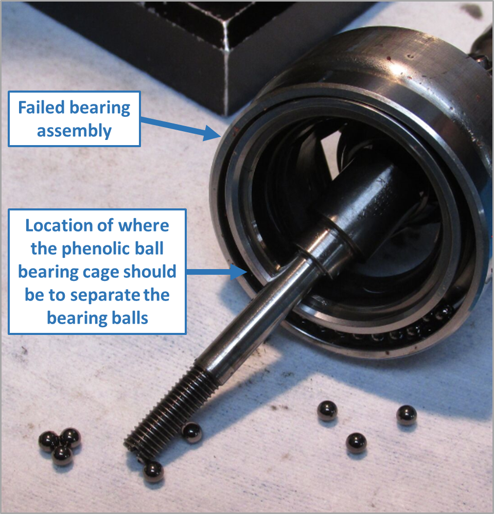
The ATSB investigation concluded that the fire originated in Iron Chieftain’s C-Loop space and was likely the result of a failed bearing in the ship’s conveyor system which created the heat necessary to ignite the rubber conveyor belt. The ATSB also determined that the ship did not have an emergency contingency plan for responding to fire in the ship’s SUL spaces and that there were technical failures of the ship’s alarm systems during the emergency response to the fire. Furthermore, some aspects of the shipboard response likely aided the fire’s development while others increased risk by removing shipboard capability.

The ATSB found that the risk of fire in Iron Chieftain’s C-Loop space was identified and documented by the ship’s operators, CSL Australia, as being unacceptable about 5 years before the fire. This risk rating was primarily due to the absence of an effective means of fire detection and fire suppression for the SUL system spaces. However, measures taken to address the risk were either inadequate or ineffective. Furthermore, the lack of adequate regulatory requirements or standards related specifically to the fire safety of SUL ships has been a factor in several fires, including Iron Chieftain. The ATSB also identified that the regulatory oversight of Iron Chieftain did not identify any deficiencies related to the safety factors identified by this investigation, or to the ship’s inherent high fire safety risk and management of that risk.

In addition, the ATSB identified a safety issue related to the marine firefighting capability of FRNSW as well as other safety factors related to the inconsistent conduct of ship’s drills and Port Kembla’s emergency response plans.

What has been done as a result

In response to this accident, the CSL Group (the parent company of the ship’s owners and managers—CSL Australia) initiated a fire risk mitigation project across its global fleet with the aim of:

  • improving fire detection and suppression technology
  • reviewing firefighting policy
  • setting minimum fire safety standards for early fire detection and suppression at the ship design and build stage.

The ship’s managers advised that linear heat detection systems and/or closed circuit television camera systems integrated with video analytics to provide or enhance the capability for early fire detection were installed on board six conveyor belt-equipped SUL ships operated by CSL Australia with installation of similar systems planned for a seventh ship. A CSL Australia-operated SUL ship with internal conveyor spaces was equipped with a Hi-Fog water mist fixed fire-extinguishing system covering the ship’s internal SUL spaces. In addition, one ship with external conveyor systems was equipped with a deluge system and installation of a deluge system is intended for at least one other ship. Additionally, ship‑specific emergency contingency plans for fires in the SUL spaces have been developed and implemented across the CSL Australia fleet.

The Australian Maritime Safety Authority (AMSA) and Lloyd’s Register have undertaken to approach the International Maritime Organization (IMO) and the International Association of Classification Societies (IACS) respectively, to raise the identified safety issue related to the inadequacy of fire safety standards or regulations for SUL system spaces. However, due to limited detail and a timeframe to seek resolution of the safety issue by the IMO, the ATSB has issued a safety recommendation to AMSA. The ATSB will continue to monitor the safety issue while actively working to highlight and promote awareness of the issue.

With respect to the regulatory oversight of SUL bulk carriers, AMSA has provided its inspectors and delegated organisations with updated guidance related to the focus of audits and inspections particularly with regard to the fire safety risk aspects associated with these ships. In addition, AMSA is progressing an inspection campaign concentrating on SUL bulk carriers operating in Australian waters, with a focus on fire safety and emergency preparedness.

Fire and Rescue New South Wales has advised that work is underway through the Australasian Fire and Emergency Service Authorities Council (AFAC) Working Group for Marine Firefighting to produce a nationally consistent approach to marine firefighting which will inform the development of new FRNSW standard operating guidelines. In addition, FRNSW continues to undertake familiarisation and training exercises to improve marine firefighting capability and awareness. While welcoming the safety action, the ATSB has issued a recommendation that FRNSW takes further action to address the safety issue related to marine firefighting capability.

The PANSW advised that the Port Kembla Marine Oil and Chemical Spill Contingency Plan and the Crisis Management Plan were to be updated to reflect the guidelines for responding to fires on a vessel as described in the NSW State Waters Marine Oil and Chemical Spill Contingency Plan.

In addition, the Memorandum of Understanding in relation to Hazardous Material Incidents on Inland and State Waters between Transport for NSW (NSW Maritime), FRNSW and the PANSW was being updated, with changes including specific handover arrangements being considered.

Safety message

The investigation into the fire on board Iron Chieftain has highlighted the inadequacy of fire safety regulations and standards for the cargo handling spaces on board self-unloading bulk carriers. The effectiveness of a shipboard response to a fire depends primarily on the ability to detect the fire at an early stage and quickly extinguish it at the source. Where it has been identified that the lack of such systems has resulted in the risk of a fire in a space being unacceptable, suitable control measures need to be implemented in order to reduce the risk to an acceptable level.

The introduction of mandatory minimum standards for suitable fire detection and extinguishing systems, to address the known high fire risk spaces of self-unloading bulk carriers, can significantly reduce the risk of major fires in these spaces. Additionally, the introduction of standards governing the fire resistance properties of conveyor belts used in shipboard systems can help reduce the likelihood of ignition in the first place.


The occurrence

Overview

On 18 June 2018, a fire broke out on board the Australian registered, 202 m self-unloading (SUL) bulk carrier Iron Chieftain during discharge of the ship’s cargo of dolomite in Port Kembla, New South Wales. The fire quickly overwhelmed the ship’s crew, and it took shore firefighting services about 5 days to contain and extinguish the fire. The ship sustained substantial damage as a result of the fire and was subsequently declared a constructive total loss (CTL)[1]

Arrival and cargo operations

At about 0222 Eastern Standard Time[2] on 15 June 2018, Iron Chieftain (Figure 1) arrived at the pilot station off Port Kembla, New South Wales, following a voyage from Ardrossan, South Australia. The ship was loaded with about 41,832 tonnes (t) of dolomite.[3] At 0530, a pilot embarked the ship and by 0700, Iron Chieftain was safely alongside, (starboard side to) at berth number 113, owned and operated by BlueScope Steel.

Figure 1: Iron Chieftain on fire at Port Kembla

Iron Chieftain on fire at Port Kembla

Source: ATSB

The ship commenced discharging cargo shortly after berthing, at about 0755. The cargo was discharged into trucks through a shore-side hopper using the ship’s self-unloading system (Figure 2). The system consisted of a series of hydraulically operated gates under the cargo holds through which cargo was deposited onto conveyor belts running in tunnels under the ship’s holds. The cargo was transported to two smaller athwartships transfer conveyor belts, up a vertical conveyor belt system, known as the C-Loop elevator, and then across the ship’s deck to the shore-side hopper and trucks via a discharge boom (see the section titled The self-unloading system).

Figure 2: Iron Chieftain's self-unloading system

Iron Chieftain's self-unloading system

Source: CSL Australia, annotated by the ATSB

On 15 June 2018, the first day of discharging, the tunnel conveyors had to be briefly stopped to rectify a frozen conveyor idler roller.[4] Cargo discharge operations proceeded without incident for the next 3 days with the exception of a few unexplained automatic system stoppages. On each occasion, the system’s programmable logic controller was reset, and discharge continued without issue. The expected completion time for cargo discharge operations was on the morning of 18 June 2018.

Cargo rounds

The ship’s deck officers and integrated ratings (IR)[5] maintained 4-hour cargo watches in port. The officers controlled and monitored the cargo discharge operation at the SUL system control console on the navigation bridge (bridge) while the IRs monitored operations on deck. The ship’s engine room was unattended at night,[6] with the duty engineer notified of any alarms through the engineer’s alarm panel in their cabins.

As part of their duties during cargo watch, IRs conducted fire and safety rounds of the ship, which included checks of the SUL system. The rounds consisted of checks of the cargo discharge boom on deck, the vertical C-Loop space, the athwartships transfer belts (at the bottom of the C-Loop space), and along each fore and aft tunnel under the cargo holds (Figure 2). These rounds were usually conducted at least twice during every 4-hour watch.

In addition, the ship’s deck mechanic conducted regular inspections of the SUL system spaces between the hours of 0800 and 1700, with an additional round at evening (usually between 2000‑2100) before retiring for the day. The deck mechanic’s inspection consisted of a general visual check of the system and conveyor belts as well as the use of a pyrometer[7] for temperature checks of various components such as bearings, rollers, and motors.

Activity leading up to the fire

On the morning of 16 June 2018, the ship took on heavy fuel oil (HFO) bunkers. Following bunkering, the total quantity of HFO held on board was recorded as being about 952 t, of which about 815 t was held in the port and starboard HFO tanks, adjacent to the C-Loop space, with the remainder in the engine room’s settling and service tanks.

On the evening of 17 June 2018, during safety rounds of the SUL system, the 1600–2000 IR observed that the rubber coverings had come off a conveyor idler at the base of the C-Loop elevator belts. He reported that this was advised to the chief mate.

At about 2000, the deck mechanic conducted a safety round of the SUL system. The deck mechanic reported that the system was operating satisfactorily during his round with no issues observed. The 2000–0000 IR also conducted two safety rounds during his watch with nothing of significance reported.

At 0100 on 18 June, the 0000–0400 IR conducted a safety round of the SUL system. At the conclusion of the round, at about 0125, the SUL system was reported to be operating smoothly with no abnormal odour, noise, or observations.

The fire

At 0300, the IR radioed the second mate, who was the officer of the watch, and informed him that he was about to start his rounds again. The second mate started the ventilation fan (located on the foc’sle) which provided airflow through the tunnels from forward to aft. By this time, just under 40,000 t of cargo had been discharged from the ship’s five cargo holds with about 2,000 t remaining to be discharged from hold number 3 (Figure 3). The hatch covers on hold number 3 were open with those on the four empty cargo holds closed.

Figure 3: Iron Chieftain – Ship’s plans highlighting relevant spaces and information

Iron Chieftain – Ship’s plans highlighting relevant spaces and information

Source: CSL Australia, modified and annotated by the ATSB

At the time the IR commenced his rounds, the wind was south-westerly, at about force three[8] (7‑10 knots), blowing offshore across the ship’s deck from starboard to port. The IR walked to the aft end of the cargo discharge boom on the ship’s main deck and climbed up to the port side of the boom. As the IR walked forward along the port side of the boom, he noticed an unusual smell. The IR quickly continued forward and crossed over to the starboard side at the discharge end of the boom. Once on the starboard side of the boom, the IR smelled something similar to rubber and started to walk aft to make his way back down to the deck. As the IR neared the aft end of the boom, he saw something that looked like white smoke or dust coming from the C-Loop casing door on the main deck, which was always open during cargo operations (Figure 4). As the IR climbed down from the boom to the deck and walked to the door, the smoke reportedly abruptly changed from white to black.

Alarm raised

The IR immediately used his radio to report the strange smell and smoke to the second mate on the bridge and requested that cargo discharge be stopped. The IR considered entering the C‑Loop space but decided that it was too dangerous due to the large amount of smoke. The second mate acknowledged the IR’s report and asked him to confirm his request for the cargo discharge to be stopped. The IR confirmed this and then made his way to the bridge using the ship’s elevator. Once on the bridge, the IR and second mate could clearly see black smoke rising from below the bridge front where the C-Loop casing was located.

At 0306, the second mate stopped cargo discharge by closing the gates at the bottom of the cargo hold and shutting down the SUL conveyor belt systems. This stopped the system’s conveyor belts in sequence, with the tunnel conveyor belts stopping first, then the transfer belts, the C-Loop belts and finally the discharge boom conveyor belt.

At about 0307, the second mate telephoned the chief mate and first engineer to alert them to the situation and inform that cargo discharge had been stopped. The chief mate acknowledged the report, dressed, and proceeded to the main deck to assess the situation while the first engineer advised the second mate to call the deck mechanic. When the chief mate arrived on deck, he saw black smoke at the aft end of the discharge boom and concluded that there was a fire in the C‑Loop space or tunnels and radioed the second mate to raise the alarm.

Shortly after, the chief mate was joined by the deck mechanic. Together they attempted to open the valve for the C-Loop dust suppression spray system, which was in front of the accommodation to port of the C-Loop casing. However, they could not approach it due to the smoke and heat emanating from the C-Loop casing. They decided to go back to the emergency muster station and organise an emergency party to return and open the valve.

Figure 4: C-Loop casing door and C-Loop spray system valve
 

C-Loop casing door and C-Loop spray system valve

Source: ATSB, modified and annotated

Meanwhile, the IR went back down to the deck, using the ship’s elevator, to start setting up fire hoses for firefighting and boundary cooling. The IR went to the port side of the main deck but due to the amount of smoke being blown to port, made his way around to the starboard side and began to rig the fire hoses for boundary cooling.

At 0311, the second mate activated the ship’s fire alarm,[9] which sounded for 13 seconds before unexpectedly stopping. The second mate used the bridge telephone to call the master who had heard the alarm. He then activated the fire alarm again, which sounded for 12 seconds before again stopping. About 8 seconds later, the alarm sounded for 1 second, and soon after, for 2 seconds before going silent. By this time, several crewmembers, including the off‑duty IRs, had been woken by the alarms. Most of them turned on their radios, heard reports of the fire and began making their way to the emergency muster station, located outside the fire control station, on the starboard side of A-deck, aft of the accommodation.

At 0312, the master arrived on the bridge. By this time, the second mate had notified shore personnel of the fire and they began to evacuate their trucks from the wharf area. The second mate then left the bridge to go down and assist with firefighting efforts. Once on deck, the second mate joined the 0000–0400 IR in rigging hoses for boundary cooling the C-Loop casing from the starboard side of the main deck.

At 0313, a smoke detector activated the fire alarm, which sounded for 9 seconds. The master checked the fire detection system control panel and saw that a number of zones had activated. The master then attempted to sound the ship’s general emergency alarm[10] to muster the ship’s crew. The alarm sounded but stopped after four short blasts. The master tried to sound the general emergency alarm again, but it did not work. Shortly after, the master broadcast a request over the radio to the BlueScope Steel shift supervisor ashore requesting that emergency services be notified. The master then made an announcement on the ship’s public address system notifying the ship’s crew of the fire and instructing them to proceed immediately to the ship’s emergency muster station.  

Just after 0314, the fire detection system panel indicated ‘fire’ followed by ‘system failure’. This sequence continued for the next minute or so. By this time, the second engineer, who was the duty engineer, had been woken by the engineer’s alarm in his cabin (also activated by the fire detection system). He went up to the bridge to see what was happening and, on seeing the activity, decided to proceed to his muster station in the engine control room. On his way down, he met the electrical engineer who accompanied him to the engine room. Shortly after, the second engineer radioed the bridge that he was at his muster station in the engine control room.

At about 0315, some 10 minutes after the initial detection of the fire, the BlueScope Steel shift supervisor ashore called the emergency services and reported a fire on board Iron Chieftain. The shift supervisor then advised the master that emergency services had been notified and were on their way.

At 0316, the third mate arrived at his muster station on the bridge to assume his emergency duties of managing external communications. The third mate reminded the master that the general emergency alarm should be sounded to muster the ship’s crew. The master told him that he had tried to sound the alarm but that it did not work. The third mate then suggested that he would go around the accommodation and physically check that everyone was awake and aware of the fire. The master agreed and the third mate left the bridge and made his way down through the ship’s accommodation notifying personnel along the way, including the chief engineer, first engineer and third engineer.

Shipboard response to the fire

At about 0318, Fire and Rescue New South Wales (FRNSW) began to assign assets to respond to the fire. As per its standard operational procedures, FRNSW tasked two fire appliances[11] to respond to the incident, which was initially described as a ‘fire in galley or crew quarters.

At about the same time, the chief mate reported to the master that the seat of the fire was still unknown and that he was unable to approach the main deck door to the C-Loop space due to smoke and heat. Meanwhile, several crewmembers had gathered at the ship’s emergency muster station.

The chief mate briefed the gathered crew on the situation and gave orders for further actions. These included:

  • starting the emergency fire pump
  • shutting ventilation flaps around the accommodation
  • starting boundary cooling
  • organising the emergency party.

The two-person emergency party consisted of the deck mechanic and the chief IR. They were instructed to don the two fireman outfits and self-contained breathing apparatus (SCBA) stored in the fire control station, approach the C-Loop casing, close the C-Loop casing door on the main deck and open the dust suppression spray system valve. The chief mate then went to the bridge and started the cargo hold washing pump that supplied water to the spray system.[12] At 0319, the second engineer radioed to report that the engine room’s forward bulkhead adjoining the C-Loop space was very hot. The master acknowledged the report and asked the second engineer to shut down ventilation to the ship’s accommodation. Shortly after, the second engineer reported that the paint on the engine room forward bulkhead was starting to blister.

By this time, the chief engineer had made his way to the bridge. He observed that several fire zones, including those covering the engine room, were active on the ship’s fire detection system control panel.

At 0320, the master radioed the chief mate with instructions for two men in fireman outfits and SCBA sets to locate the source of the fire and for at least two men to be sent down into the engine room to set up boundary cooling of the bulkhead. By this time, the master had started the main and emergency fire pumps.

At 0321, the third mate arrived at the muster station and, together with an IR, set off for the foc’sle to retrieve the two fireman outfits, SCBA sets and spare air cylinders stored in the foc’sle store. Once there, they noticed that the ventilation fan blowing air through the tunnels and the SUL system spaces was still operating. The IR reported this over the radio and asked for it to be stopped. The pair then gathered the stored equipment and made their way back to the emergency muster station.

At 0322, the second engineer broadcast multiple reports over the radio that there was a ‘big fire’ in the engine room. The master acknowledged the report and ordered the chief mate to send any SCBA-equipped crew to the engine room. The master reported the fire in the engine room to the BlueScope Steel shift supervisor ashore who in turn reported this to Port Kembla vessel traffic information centre (VTIC). The master also checked with the shift supervisor as to the status of shore firefighting services and was reassured that they were not far away. By this time, FRNSW assets were en-route to the port.

Meanwhile, the two-person emergency party, equipped with fireman outfits and SCBA sets, made their way to the front of the accommodation and attempted, unsuccessfully, to open the C-Loop spray valve. They also noticed that the tunnel ventilation fan was still running. They returned to the muster station to replace their air cylinders and to get a tool to help open the pressurised valve.

Shortly after, the chief engineer followed by the master, ordered the engine room to be evacuated as use of the engine room’s carbon dioxide (CO2) fixed fire-extinguishing system was being contemplated. The master and chief engineer then left the bridge for the muster station. Before leaving, and in preparation for the imminent release of CO2, the chief engineer activated the bridge emergency stops, which shut down the:

  • accommodation and cargo hold fans
  • other engine room auxiliary machinery, including the diesel and fuel oil transfer pumps.

On the way down, the master went to his cabin to attend to two family members who were visiting, and found the chief mate assisting them prepare for evacuation.

The chief engineer manually stopped the air conditioning system fans and ordered that all fuel quick closing valves (QCVs) be activated, and engine room fire flaps closed in preparation for CO2 release. At 0323, the second engineer reported that the fuel QCVs in the fire control station had been activated while the first engineer shut the engine room’s funnel doors, dampers, and flaps.

The chief engineer then went to the fire control station and checked that the main fire pump, emergency fire pump and the general service pump were running. He also ordered that the emergency generator be started manually but not put on-line while the main generators in the engine room were still powering the ship. The second engineer and third engineer went to the emergency generator room and manually started the emergency generator. Soon after, the activation of the QCVs took effect and the ship’s main generators shut down thereby blacking out the ship. The chief engineer then ordered the emergency generator brought on-line.

Arrival of Fire and Rescue New South Wales

At about 0325, about 10 minutes after the initial FRNSW notification and 20 minutes after the fire was first detected, the first FRNSW assets began arriving at the port facility. At about this time, the master ordered all crew to the muster station for a headcount to ensure that there was no one left in the engine room when CO2 was released.

By 0329, the master had completed a headcount and confirmed that all personnel were accounted for. All engineers were clear of the engine room while the chief mate, second mate, two IRs and one trainee IR were engaged in boundary cooling forward of the accommodation with five fire hoses.

At 0330, Port Kembla VTIC notified the harbour master of the fire on board Iron Chieftain. At about the same time, the first FRNSW assets were arriving on the wharf.

Meanwhile, the emergency party returned to the C-Loop casing with a wheel spanner and successfully opened the C-Loop spray valve. This time, the tunnel ventilation fan was reported as being stopped likely as a result of the main generators shutting down. Shortly after, the master ordered all crew to prepare to evacuate the ship.

Fire and Rescue New South Wales operations

18 June 2018

At about 0333, the first FRNSW firefighters boarded the ship. The first arriving firefighters observed that there was heavy, black smoke with significant heat and flame issuing from the C‑Loop casing at deck level. They also noted that the discharge boom conveyor belt on deck was smouldering along its entire length but was not alight. The firefighters set up a defensive firefighting strategy and escalated the FRNSW response to a ‘5th alarm level’.[13] Meanwhile, FRNSW began to notify other relevant agencies and organisations including Marine Rescue New South Wales, Environmental Protection Agency (EPA), Roads and Maritime Services (RMS), New South Wales Police and ambulance services.

The ship’s master, aided by other senior officers, briefed FRNSW firefighters on the situation and explained that there was a fire most probably in the C-Loop space. The crew also began to disembark the ship on the master’s orders. The master, chief mate, chief engineer, and the ship’s emergency party (deck mechanic and chief IR) remained on board to assist FRNSW with familiarisation of the ship’s spaces and gaining access to the C-Loop casing.

The master discussed the option of activating the engine room CO2 fixed fire-extinguishing system with FRNSW firefighters and advised that the system was prepared and ready for release. The firefighters concurred with this course of action and, shortly after, the chief engineer flooded the engine room with CO2. By this time, the emergency generator had been successfully brought on-line although, in the course of completing this task, the first engineer reported smoke and a minor fire in the emergency switchboard.

At 0350, the Port Kembla harbour master declared a port emergency and suspended all shipping activity. The harbour master also established contact with FRNSW over the telephone and delegated incident controller status to them.

By this time, the discharge boom conveyor belt on deck was alight, with the fire spreading rapidly (Figure 5). FRNSW firefighters on scene advised that it would be a protracted response and requested additional resources. The firefighters then focused on extinguishing the visible fire on the discharge boom. FRNSW noted that 22 people, including the ship’s crew, and the master’s family, had been evacuated from the ship. Over the following days, members of the ship’s crew, often including the master and chief engineer, returned to the ship to assist firefighting efforts and assessment activities, including making entry to the C-Loop casing with FRNSW firefighters.

Figure 5: Boom conveyor on fire

Boom conveyor on fire

Source: Port Authority of New South Wales

At about 0351, the tug Barunga, assigned by Port Kembla VTIC to assist with firefighting efforts, arrived on scene. VTIC advised FRNSW firefighters that the tug could be contacted on very high frequency (VHF) radio channel 11 and provided the tug master’s mobile telephone number. About 20 minutes later, tug Svitzer Kiama also arrived on scene. The port’s pilot boat, which was equipped with a forward-looking infrared camera, also provided imagery and on-water assistance to FRNSW throughout the response to the incident.

By 0400, FRNSW firefighters decided that internal firefighting operations on the ship were impossible due to the volume of smoke but continued with defensive firefighting operations.

At 0420, on the harbour master’s orders, Port Kembla VTIC formally transferred incident controller status from the Port Authority of New South Wales to FRNSW.

By 0447, firefighting crews began to withdraw from the ship as the fire gained intensity and they became aware of the two HFO tanks adjacent to the C-Loop space. Defensive firefighting continued and the ship was reported to be well alight internally with large volumes of smoke.

At 0457, a senior FRNSW officer arrived on scene, assumed the incident controller (IC) role, and began to set up an Incident Management Team (IMT). By about 0532, a FRNSW mobile command centre (MCC)[14] had arrived on site.

By 0606, the IMT was established and included representatives from FRNSW, the ship, police, and the port authority. An anti-pollution boom was also installed around the ship by the port authority and tug support remained in place (Figure 6). Representatives from the ship’s owners, Canada Steamship Lines Australia (CSL Australia) also arrived on site later that day.

Figure 6: Port Kembla tugs assisting with firefighting efforts

Port Kembla tugs assisting with firefighting efforts

Source: Port Authority of New South Wales

At about 0703, FRNSW made the decision to stop the emergency generator and isolate all shipboard power. Internal temperatures were measured at about 200 °C with no elevated external temperatures. By 0830, FRNSW considered the fire contained and extinguishment plans were being developed. Meanwhile, high-expansion firefighting foam was being sourced from across NSW and interstate.

By 0942, the firefighting strategy began to transition from defensive to offensive firefighting using foam. At about 1144, firefighters reported zero visibility at the C-Loop casing door with temperatures between 46‑56 °C. Shortly after, the ship’s master went aboard to provide assistance with opening the bow access hatch to the forward end of the SUL system tunnel spaces. Meanwhile, firefighting continued using aerial appliances and without the firefighters entering the C-Loop space (Figure 7).

Figure 7: Firefighting using aerial appliances

Figure 7: Firefighting using aerial appliances

Source: Fire and Rescue New South Wales

At 1200, the harbour master re-opened the port to shipping.

At 1659, temperatures of about 109 °C were recorded in holds number 3 and 4. Soon after, a changeover of the IMT got underway in accordance with FRNSW Standard Operating Guidelines (SOG) and, at about 1800, crews were rotated.

Sometime that evening, firefighters tasked with conducting an internal assessment, accessed the port tunnel via the bow access hatch. They made their way aft down the port tunnel and reported an active fire at the aft end of the tunnel as well as the sound of falling metal objects.

At 2106 that night, firefighters attempted to gain access to the SUL system spaces through the C‑Loop casing door but reported that access was too dangerous for firefighting operations. Infrared imagery indicated that the fire was active in the C-Loop space and aft sections of the tunnels (Figure 8).

Figure 8: Infrared imagery on 18 June

Infrared imagery on 18 June

Source: Port Authority of New South Wales (left) and FRNSW (right)

19 June 2018

At 0029 on 19 June 2019, firefighters using SCBA sets entered the tunnel spaces through the access hatch on the ship’s bow. The crews proceeded aft down the starboard tunnel and noted minimal indications of fire on the starboard side. At about midships, the crews crossed over from the starboard tunnel to the port tunnel through a communicating passageway.

Once on the port side, the crews saw a fire burning at the aft end of the port tunnel. A fire hose was lowered through an access hatch midships between holds number 2 and 3. The crews advanced as far as the hose would allow before they had to withdraw due to their air cylinders running low. The hose was lashed to the ship’s structure and left in place. On deck, firefighting crews connected foam monitors to the hose lines and commenced introducing low-expansion foam into the tunnels. This had the effect of forcing smoke and hot gases aft and out through the C-Loop. The effectiveness of this strategy was then monitored on an hourly basis.

At about 0200, IMT and crew changeovers took place. At 0243, the discharge boom conveyor belt fire on deck was fully extinguished.

By 0428, firefighters reported that access aft in the tunnels was restricted from about 50 m from the C-Loop due to water, foam, and submerged obstructions. The firefighting strategy was modified to using hoses in a vertical attack from the deck through hatches adjacent to the superstructure.

At 0516, firefighters in SCBA sets entered the ship’s accommodation to retrieve crew personal effects and documents. The ship’s living quarters were identified to have high carbon monoxide (CO) levels.

At 1058, the master and chief engineer boarded the ship to retrieve the HFO tank sounding logs and other records. Shortly after, ship’s staff and members of the IMT began considering the risk of the HFO tank bulkheads being breached. While the master and chief engineer worked to assess if there was a leak from the HFO tanks, FRNSW ceased all water application to the C-Loop space.

At 1230, a multi-agency briefing took place. Options were discussed for obtaining temperatures of the HFO tanks. It was considered too dangerous for readings to be taken physically on board the ship. Instead, FRNSW hazardous materials (HAZMAT) crews were assigned to monitor the lower explosive limit (LEL) gas readings[15] from the HFO tanks vents. HAZMAT crews were also assigned to the tug to take temperature readings of the port side HFO tank while an aerial firefighting appliance was assigned to monitor the temperature of the starboard tank. Meanwhile, the strategy of application of low-expansion foam continued while FRNSW awaited receipt of high‑expansion foam supplies.

At 1350, HAZMAT crews found LEL readings at the HFO tank vents were negligible.

At 1446, the temperature in the port and starboard HFO tanks had reached 45 °C and 50 °C, respectively.

At 1524, on the master’s advice, FRNSW crews began to attempt to activate the C-Loop spray system. However, because the system was not part of the fire main, the ship’s international shore connection[16] could not be used to connect to the spray system line. A suitable connection was then fabricated by BlueScope Steel and, by 1552, water application through the C-Loop spray system was activated.

By 1600, temperatures in the post and starboard tanks had increased to 60 °C and 50 °C, respectively.

At 1721, FRNSW assessed that the internal conveyor belt had probably collapsed resulting in a deep-seated rubber fire. All tunnel ventilation was shut to seal the space and to reduce the chimney effect caused by smoke and hot gases being drawn up to the top of the C-Loop space. Foam was being applied through the C-Loop stores hatch and the C-Loop casing door, with boundary cooling being conducted using other FRNSW assets and tugs (Figure 9). LEL levels and temperature readings continued to be monitored at 30-minute intervals. By this time, some high-expansion foam supplies had arrived from the Australian Capital Territory while further deliveries were awaited from Queensland and elsewhere in New South Wales.

Figure 9: Foam application to C-Loop space

Foam application to C-Loop space

Foam being introduced through the C-Loop stores hatch aft of cargo hold number 5. In background, note hose leading to foam applicator in the C‑Loop casing door.

Source: Fire and Rescue New South Wales, annotated by the ATSB

By 2115, HFO tanks temperatures had increased to 55 °C at the starboard tank and 88 °C at the port tank. An assessment of the ship’s stability showed that the ship was stable with a draught of about 9.9 m. It was also assessed that a maximum draught of 11 m was allowable before there was a risk of the ship grounding. Firefighting operations remained in defensive mode and CSL Australia representatives were assigned the task of collating engineering details and assessing the consequences of continued water application.

20 June 2018

At 0343 on 20 June 2018, the FRNSW IC and CSL Australia determined that, based on the ship’s stability and volume of water applied, the rubber conveyor belts were likely to be under water. Water application through the C-Loop spray system was therefore shut off.

Shortly after, the tug assisting with boundary cooling on the ship’s port side was called away to other duties. At 0427, the FRNSW IC requested that a tug be stationed permanently at the ship to assist with firefighting efforts. Subsequently, tug Barunga was permanently assigned to the ship.

At about 0800, a consultant from the Minton, Treharne, and Davies Group (MTD) with expertise in fire science arrived on site. [17] The consultant was engaged to provide liaison services between CSL Australia and other authorities including FRNSW, as well as to provide fire science analysis and advice to expedite the extinguishment of the fire.

At 1132, the local emergency plan was activated. An Emergency Operations Centre (EOC) was set up at a port authority building located a short distance from the wharf. The IC (and incident control) transferred from the FRNSW MCC on the wharf to the EOC at the port authority building.

In addition, local and regional emergency operations controllers started to assist with the management of the response.

Separately, the Port Kembla harbour master, acting on behalf of the port authority, engaged a marine salvage firm, Ardent Oceania, to provide salvage and fire advice. Representatives from the salvors arrived late that afternoon.

Shortly after midday, a FRNSW remotely piloted aircraft system (RPAS) was deployed to assist firefighting efforts by providing aerial daylight and thermal imagery  (Figure 10).

Figure 10: RPAS footage of Iron Chieftain on fire on 20 June

RPAS footage of Iron Chieftain on fire on 20 June

Source: Fire and Rescue New South Wales

At 1309, fire crews accessed the ship’s engine room to determine if there were any signs of fire and found that temperatures within the space were normal. At about 1345, the ship’s chief engineer went aboard to inspect the engine room and machinery to check temperatures and HFO quantities and, to assess the feasibility of restoring power to the ship.

At 1453, a specialist tank-gauging device was obtained from a nearby fuel storage facility to assist with measuring the temperatures and quantities of HFO in the tanks. Shortly after, preparations were made to resume application of water through the C-Loop spray system and hydrants. At about 1535, the deck discharge boom was freed from the shore hopper, on which it had come to rest as the ship’s draught increased. The discharge boom was then stabilised and locked in position.

At 1600, HFO tanks temperatures were recorded as 63 °C at the starboard tank and 105 °C at the port tank.

At 1916, a decision was made to implement a change in firefighting strategy with high-expansion foam to be introduced directly into the C-Loop space using four lines. It was estimated that 1600 cubic metres (m3) of foam would be required to fill the space. By this time, sufficient foam stocks had arrived to begin to implement this strategy with further stocks expected later that evening to allow for topping-up of the foam.

At 2149, the initial estimate of foam required to fill the C-Loop space was revised to 2500 m3. By this time, the C-Loop spray system had been stopped because the spray nozzles were found to be completely ineffective.

Fire extinguished

During the night of 20 June 2018 and the morning of 21 June 2018, the C-Loop was filled with foam and tugs continued boundary cooling. The foam was regularly topped up and temperatures continued to be monitored. On 21 June, at 1233, soundings of the HFO tanks indicated a discrepancy in tank levels. By 1352, the port HFO tank was confirmed to be leaking oil, probably into the C-Loop space as inspections of the engine room had found no sign of HFO. By 1645, a leak was confirmed in the starboard HFO tank as well.

On 22 June 2018, at 0755, firefighting crews along with ship’s engineers completed an assessment of the cargo holds, engine room and superstructure. The low temperature readings and gas monitoring readings obtained indicated that extinguishment had been achieved (Figure 11). The inspections also revealed that HFO, firefighting water or a combination of both had leaked from the tunnels into cargo hold number 3. FRNSW continued to maintain the foam blanket in the C-Loop space while monitoring the situation and beginning preparations to hand over the site.

Figure 11: Iron Chieftain, with the fire extinguished

Iron Chieftain, with the fire extinguished

Source: ATSB

At 0600 on 23 June 2018, temperatures and LEL readings remained stable. At 1837 on 23 June, the hatch covers of cargo hold number 5 were opened with no obvious signs of fire observed although it was evident that HFO and/or firefighting water had leaked into this cargo hold as well. At 1552 on 24 June, FRNSW handed over the site to New South Wales Police and CSL Australia.

Over the 7-day duration of the incident, a total of 245 FRNSW appliances and 192 officers and specialist staff attended the fire. In addition,  marine firefighters from Victoria’s Metropolitan Fire and Emergency Services Board (MFB) attended the Iron Chieftain incident at FRNSW’s invitation to observe and assist the IMT as subject matter experts.

There was no reported pollution to the marine environment and, except for minor damage to the shore discharge hopper, no significant damage to port infrastructure. FRNSW reported minor injuries to several firefighters over the course of the incident.

Fire damage assessment

Iron Chieftain sustained substantial damage including breaches of the two HFO tanks as a result of the fire. The SUL system components and spaces bore the brunt of the fire damage. The boom was significantly damaged with parts of the conveyor belt and associated structures destroyed. In the C-Loop space, the drive motors, pulleys, idlers and associated belt equipment showed varying degrees of fire, heat and smoke damage. The inner and outer conveyor belts that comprised the C-Loop elevator were destroyed. There was also significant structural damage to support members resulting in the collapse of several conveyor rollers.

At the bottom of the C-Loop space, in addition to the fire damage, there was also HFO contamination and water. It was estimated that a total of about 507 m3 (approximately 456 t) of HFO was lost from the port and starboard HFO tanks into the C-Loop space and tunnels. The aft ends of the port and starboard tunnels sustained fire damage to conveyor belts and associated structures and fittings.

As a result of the substantial damage sustained due to the fire, Iron Chieftain was declared a constructive total loss (CTL). The ship remained at Port Kembla for several months while work continued to remove and dispose of the remaining fuel and contaminated firefighting water on board. On 27 March 2019, the ship departed Port Kembla under tow, for Aliaga, Turkey to be recycled (Figure 12).

Figure 12: Iron Chieftain, departing Australia under tow

Iron Chieftain, departing Australia under tow

Source: ALP Maritime

__________

  1. A constructive total loss (CTL), in the case of damage to a ship, occurs when the cost of repairing the damage under its insurance terms would exceed the value of the ship when repaired.
  2. Eastern Standard Time (EST): Coordinated Universal Time (UTC) + 10 hours.
  3. Dolomite is a light yellow or brown coloured mineral stone used as a sintering agent and flux in metal processing. As a bulk cargo, dolomite is considered non-combustible, with a low fire risk.
  4. A non-driven roller supporting the belt and the load carried on the belt.
  5. Integrated ratings are qualified to perform the duties of both an able seaman and an engine rating.
  6. The ship was equipped, surveyed, and certified to operate with the machinery spaces periodically unattended.
  7. A pyrometer is a device used to remotely measure the temperature of an object or surface.
  8. The Beaufort scale of wind force, developed in 1805 by Admiral Sir Francis Beaufort, enables sailors to estimate wind speeds through visual observations of sea states.
  9. Continuous ringing of the ship’s bells.
  10. The general emergency alarm signal is at least seven short blasts followed by one long blast on the ship’s whistle and repeated on the ship’s alarm bell system.
  11. Fire appliance: A fire appliance means any vehicle that forms part of the equipment of a fire brigade and that is equipped with an audible warning device and flashing lights. This includes tankers, pumpers, aerial firefighting appliances and other specialised appliances.
  12. The cargo hold washing pump supplied the C-Loop spray system, tunnel spray system and deck washing line.
  13. Alarm Response Protocols (ARP) are a standardised response level for incidents within specific areas of NSW. Under FRNSW Standard Operating Guidelines, a 5th alarm level denoted a significant structural fire. At a 5th alarm level, 10 firefighting appliances, three aerial appliances, hazardous material appliances, senior officers and an Incident Management Team, among other resources, are deployed.
  14. The Mobile Command Centre (MCC) provides a platform for FRNSW Incident Management Teams (IMT) and interagency liaison officers to command, control and coordinate the response and recovery phases during major emergencies and events.
  15. Lower explosive limit (LEL) is the concentration (by percentage) of a hydrocarbon gas or vapour in air below which there is insufficient hydrocarbon to support and propagate combustion.
  16. An international shore connection consists of a standard flange that is fitted to the ship’s fire main. It allows land-based fire services hose to supply the ship’s fire main. The ship’s part of the international shore connection also has a flange. Once the flanges have been bolted together, fire service pumps can supply water to the ship’s fire main.
  17. The Minton, Treharne and Davies Group (MTD) are a consultancy with expertise in matters relating to science and engineering in the marine industry.

Context

Iron Chieftain

Iron Chieftain was a gravity fed, C-Loop, self-unloading bulk carrier built in 1993 by Hyundai Heavy Industries in Ulsan, Republic of Korea. At the time of the fire, the ship was Australian registered and classed with Lloyd’s Register.

The ship was purpose-built for Broken Hill Proprietary (BHP) [18] who owned and operated it from 1993 to 2003 carrying coal from Port Kembla, New South Wales (NSW) to Whyalla, South Australia (SA) and iron ore back to Port Kembla. In December 2003, Iron Chieftain was purchased from BHP by Canada Steamship Lines Australia (CSL Australia). The ship was operated by CSL Australia and employed on the Australian coast carrying cargoes including coal, iron ore and dolomite.

The ship was equipped with the necessary navigational, firefighting and lifesaving equipment required by SOLAS[19] for a ship of its size (see the section titled The self-unloading system). This included a Japan Radio Corporation JCY 1850 voyage data recorder (VDR)[20] from which information useful to the investigation was recovered, including bridge voice recordings.

Ship’s crew

Iron Chieftain was manned by crews operating on an 8-week roster with most of the crew assigned to the ship for several years.

At the time of the fire, Iron Chieftain had a multi-national crew of 20 Ukrainian, Australian, New Zealand, and Philippines nationals.

The master had about 14 years of seagoing experience, held a Ukrainian master’s certificate of competency and the equivalent Australian certificate of recognition. The master had about 10 years’ experience on SUL ships most of which was with the CSL Group. He first joined Iron Chieftain about 7 years previously (as third mate) and had worked almost exclusively on board the ship since. He had about 8 months experience as master and this was his third trip in command of Iron Chieftain. He had joined the ship about 2 weeks before the fire.

The chief mate had about 22 years of seagoing experience, held a Ukrainian master’s certificate of competency and the equivalent Australian certificate of recognition. The chief mate had about 16 years’ experience on SUL ships of which the last 8 years were with the CSL Group. He had about 11.5 years’ experience as chief mate and had worked on Iron Chieftain for the previous 2.5 years. He had joined the ship about a month before the fire.

The second mate had about 18 years of seagoing experience, held a Ukrainian chief mate’s certificate of competency and the equivalent Australian certificate of recognition. The second mate had about 12 years’ experience on SUL ships most of which was with the CSL Group. He had about 10 years’ experience as second mate. This was his first trip on board Iron Chieftain, which he had joined about 2 weeks before the fire.

The third mate had about 15 years of seagoing experience and held an Australian deck watchkeeper certificate of competency. The third mate had about 8 years’ experience on various ships in the CSL fleet including on SUL ships. He had about 5 years as third mate and had worked on Iron Chieftain for about 8 months. He had joined the ship about 2 weeks before the fire.

The chief engineer had about 15 years of seagoing experience, held a Ukrainian chief engineer’s certificate of competency and the equivalent Australian certificate of recognition. The chief engineer had about 10 years’ experience on SUL ships with the CSL Group. He had worked on Iron Chieftain for the previous 5 years and this was his third trip as chief engineer. He had joined the ship about 3 weeks before the fire.

The second engineer had about 12 years of seagoing experience, held a Philippines engineering watchkeeper certificate of competency and the equivalent Australian certificate of recognition. The second engineer had about 7 years’ experience in the rank with all of it on board Iron Chieftain. He had joined the ship about 3 weeks before the fire.

The deck mechanic had about 12 years of seagoing experience, held a Ukrainian rating’s qualifications and the equivalent Australian certification of recognition. The deck mechanic had about 8 years’ experience on SUL ships with the CSL Group, all of it on board Iron Chieftain. He had joined the ship about 2 weeks before the fire.

The 0000–0400 IR had about 20 years of seagoing experience and held an Australian integrated rating’s qualifications. The IR had worked on Iron Chieftain for about 7 years and had joined the ship about 3 weeks before the fire.

The rest of the ship’s ratings held appropriate qualifications for their roles, and they had all served on board Iron Chieftain previously.

Cargo

The ship’s cargo for the voyage from Ardrossan, SA to Port Kembla, NSW was granular dolomite in bulk. The ship was carrying three separate parcels of different grades of dolomite in its five cargo holds.[21]

The ship’s previous cargo was coal, shipped from Gladstone, Queensland (QLD) to Whyalla, SA. Prior to loading the dolomite in Ardrossan, the ship’s cargo holds, and tunnels were cleaned and then washed. Some of the residues from the previous coal cargo were disposed of ashore while some was swept into piles and consolidated near the aft end of the tunnels and near the athwartships transfer belts. The total quantity of remaining coal residues was estimated by ship’s staff to have been between 3 and 4 cubic metres (m3).

Dolomite

Dolomite is a very hard and compact, light yellow or brown coloured mineral stone composed of calcium magnesium carbonate. The International Maritime Solid Bulk Cargoes Code (IMSBC Code)[22] classified dolomite as a Group C cargo. Group C consisted of cargoes which are neither liable to liquefy (Group A) nor possess chemical hazards (Group B).

The IMSBC Code entry for dolomite states that the cargo is ‘non-combustible’ and has a low fire risk with no special hazards.

The self-unloading system

General description

Self-unloading bulk carriers were an innovation that originated in the Great Lakes of Canada and the United States. The concept allowed these ships to operate at ports with limited or no traditional bulk-handling facilities and infrastructure.

Iron Chieftain’s self-unloading (SUL) system was based on a design by Stephens-Adamson Canada. The system was designed to achieve a maximum discharge rate of 3,000 tonnes (t) per hour for a cargo of coal or iron ore. At the time of the fire, cargo was being discharged to trucks ashore at a slower rate of about 500–700 t per hour.

The SUL system consisted of the cargo holds and gates, the mainly rubber conveyor belt systems (see the section titled Conveyor belt specifications and condition), and the discharge boom on deck. The conveyor belt systems in turn comprised the tunnel conveyors (port and starboard), the transfer conveyors (port and starboard), the vertical C-Loop elevator and the boom conveyor on deck. The SUL system also consisted of several pulleys and hundreds of idlers of various types.

Holds

Iron Chieftain’s five cargo holds were each designed with tapered hoppers at the bottom that led to hydraulically operated gates. These gates directed cargo on to one of the two tunnel conveyor belts below. There were 66 gates in total (33 on each side)[23] and each gate was fitted with a hydraulically operated vibrator to facilitate the free flow of cargo.

The hopper slopes, hold inclines, and hogbacks[24] were lined with ultra‑high molecular weight (UHMW) polyethylene sheeting to reduce friction and assist with the gravity feed of the cargo. The rate of cargo flow through the gates to the hold conveyor belts below was controlled by adjusting the gate openings. The gates provided for cargo flow control but did not form a watertight or airtight seal when closed.

Each of the five cargo holds had a standard, weathertight hatch cover on the main deck. The hatch cover consisted of two panels on a hatch coaming that rolled in an athwartships direction to open and close the hatch.

Tunnel conveyors

There were two hold conveyors (tunnel conveyors), port and starboard, that ran longitudinally under the cargo holds. The tunnels themselves were about 2 m in height with a common area at the forward end near the bow and at the aft end near the C-Loop elevator. Additionally, there was a communicating passage between the two tunnels amidships. The tunnels could be accessed from the C-Loop space aft, through an access hatch at the bow and through access hatches on deck.

Each tunnel conveyor belt was about 2.1 m wide, 20 mm thick and about 278 m long (in total). The tunnel conveyor belts were arranged in a ‘trough’ profile supported by idler rollers with the drive pulley[25] at the aft end driven by electric motors. The tunnel conveyor belts were hydraulically tensioned at their forward end. The tunnel conveyors transported cargo from the hold gates and deposited them on the transfer conveyor belts at the base of the C-Loop elevator (Step 1 in Figure 13).

Transfer conveyors

There were two transfer conveyor belts, port and starboard, one each at the aft end of each tunnel conveyor belt. The transfer belts were oriented in the athwartships direction, perpendicular to the tunnel belts. Each transfer conveyor belt was about 2.1 m wide, 26 mm thick and about 19 m long (in total). The transfer conveyors were driven by electric motors and were mechanically tensioned. The transfer conveyors moved the cargo from the tunnel conveyors to a discharge hopper above the horizontal section of the C-Loop outer belt at the bottom of the C-Loop space (Step 2 in Figure 13).

C-Loop system

The C-Loop vertical elevator system was situated on the ship’s centreline, aft of the transfer belts, with the aft bulkhead of the space contiguous with the engine room’s forward bulkhead. The vertical space housing the C-Loop system emerged from the upper deck just forward of the accommodation to form a C-Loop ‘casing’ or ‘tower’. At the bottom of the C-Loop space, forward of the transfer belts and between the port and starboard tunnels, there was a space containing a small workshop and storage area. There were also two small spillage clean-up conveyors on either side at the base of the C-Loop belts.

The C-Loop conveyor belts consisted of an outer electric motor-driven conveyor belt loop onto which the cargo was loaded from the transfer belts (Step 3 in Figure 13). The outer belt was paired with a passive (non-motor driven) inner belt which rotated in the opposite direction to the outer belt so as to ‘sandwich’ the cargo and transport it vertically up the C-Loop elevator tower (Step 4 in Figure 13). The inner and outer belt loops separated at the top where the cargo was discharged into a chute and on to the discharge boom conveyor (Step 5 in Figure 13).

The outer belt was about 2.6 m wide, 23 mm thick and about 95 m long while the inner belt was about 2.7 m wide, 23 mm thick and about 69.5 m long. The C-Loop belts were hydraulically tensioned.

Discharge boom conveyor

The discharge boom conveyor on deck transported the cargo from the termination of the C-Loop elevator belts, just forward of the accommodation, to receiving facilities ashore or on another vessel (Step 6 in Figure 13). The boom conveyor belt was enclosed within corrugated metal roofing with timber anti-spill liners. The boom was 72 m long giving it a working radius of about 56 m from the ship’s side. The boom could be hydraulically slewed up to 90° to either side and luffed up to an angle of 18° from the horizontal. The discharge boom conveyor was driven by electrical motors.

The boom conveyor belt was about 1.9 m wide, 22 mm thick and about 165.8 m long.

Figure 13: General operation of Iron Chieftain's SUL system

General operation of Iron Chieftain's SUL system

Source: CSL Group, modified and annotated by the ATSB

Control, monitoring and safety systems

SUL operations console

The SUL system was controlled and operated by the ship’s officers from a control console located in the ship’s bridge. The control system incorporated a programmable logic controller (PLC) and a computer to provide a display and a control interface for the operation of the system. There was no recoverable data available from the computer system or the PLC. There were no reported alarms or automatic shutdowns of the SUL system prior to the fire.

CCTV

The SUL system included closed-circuit television (CCTV), with the images displayed at the control console on the bridge. The CCTV system comprised 12 cameras with five fixed cameras distributed through each of the port and starboard tunnels. The cameras in the tunnels faced forward and monitored the aftermost gates for each hold. In addition, there were two portable cameras, one used to monitor the cargo hold being discharged and the other positioned at the discharge end of the boom conveyor on deck. There were no cameras in the C-Loop space. The second mate reported that there were no signs of fire on the CCTV in the time leading up to the fire. There was no recorded CCTV data available.

Gas monitoring system

The hold conveyor tunnels had a gas monitoring system with sensors located at the aft and forward end of the tunnels. The system’s sensors could monitor oxygen, methane, carbon monoxide and hydrogen sulphide gas levels as well as the concentration of any flammable gases in the tunnel atmosphere (as a percentage of the lower explosive limit described previously). The control and monitoring equipment for this system was in the chief engineer’s office on the upper deck, which was unmanned at the time of the fire. The system was not connected to the ship’s bridge or fire detection and alarm systems and there was no recoverable data available.

Emergency stops

The SUL system had thirteen emergency stops distributed throughout the tunnel spaces, C-Loop space, and boom conveyor. Activating an emergency stop closed all the hold gates, turned off the gate vibrators and stopped all conveyor belts.

The system had an in-built control that ensured that any stoppage of the conveyor belts occurred in a sequential order. The tunnel conveyor belts stopped first followed by the transfer conveyors, the C-Loop belts and finally the boom conveyor. This ensured that any load on the belt was run off before the system comes to a standstill.

Conveyor belt safety systems

The conveyor belts had additional protection systems installed. These included electrical protection devices offering overcurrent and thermal protection for the belt drive motors as well as belt slippage[26] and belt drift[27] detection systems.

The C-Loop belts did not have belt drift detection sensors installed and misalignment of these belts was prevented by keeping the ship’s list to a minimum during cargo operations. Red and green lights on the ship’s foremast and on the external SUL casing indicated the ship’s list. There were also red, amber, and green lights at regular intervals in the tunnels to indicate load on the tunnel conveyor belts.

There was no evidence to indicate the ship had a list during cargo operations that may have caused a belt misalignment and no indications of a parted conveyor belt in the SUL system. There were also no apparent issues with the various electrical systems and components serving the SUL system.

Rules and regulations

There were no SOLAS regulations or requirements covering the SUL system equipment or conveyor belt standards. Similarly, there are also no classification society rules governing the flammability of conveyor belt systems or the fitting of fire detection or fixed fire extinguishing systems in the SUL system spaces.

Conveyor belt specifications and condition

Rubber conveyor belts are usually composed of two key elements—a central ‘carcass’ which provides the tensile strength and mechanical characteristics of the belt and, top and bottom rubber covers which protect the carcass. The carcass could be of textile (fabric) or steel cord construction.

Iron Chieftain’s conveyor belts were of a multi-ply, polyester/nylon fabric construction with rubber covers. The belt carcasses were made up of layers (or plies) of polyester and nylon adhered to each other. The tunnel belts, transfer belts and boom belt were of 5-ply construction while the C‑Loop belts were of 6-ply construction.

Table 1 summarises key information related to the lifespan, grade, and specifications of the various conveyor belt rubber in use on board Iron Chieftain, based on an assessment conducted in April 2018.

Table 1: Iron Chieftain - Conveyor belt details

Conveyor beltInstallation dateGrade of belt rubberRemaining lifespan
Tunnel conveyor (P)1993 (Original)RMA 21 year
Tunnel conveyor (S)1993 (Original)RMA 21 year
Transfer conveyor (P)2014AS1332-M2 years
Transfer conveyor (S)2014AS1332-M1 year
Outer C-Loop belt2014AS1332-M1 year
Inner C-Loop belt2014AS1332-M2 years
Boom conveyor2014AS1332-M6 to 12 months

Source: CSL Australia

Grade of conveyor belt rubber

The original design specification for the SUL system required the conveyor belt rubber covers to be of Rubber Manufacturer’s Association (RMA) Grade 2 rubber[28] (or an equivalent German Institute for Standardization Grade N rubber).[29] The current international standard equivalent to RMA Grade 2 rubber is Association for Rubber Products Manufacturers (ARPM) Grade 2 rubber.[30]

The port and starboard tunnel conveyor belts were still the original belts installed by the shipbuilders, Hyundai. They had been in use since 1993 and were of RMA Grade 2 rubber (ARPM Grade 2). The C-Loop inner and outer belts, the transfer conveyor belts, and the boom conveyor belts were replaced in January 2014 with belts of AS 1332 Grade M rubber,[31] manufactured by Goodyear.

Properties of the conveyor belt rubber

The RMA Grade 2 (ARPM Grade 2) rubber conveyor belt covers, originally installed on board Iron Chieftain and still in use in the tunnels, was classified as a general-purpose rubber cover.[32] ARPM Grade 2 rubber was described as having ‘good to excellent abrasion resistance properties’ but the description did not include any reference to flame or heat resistance.[33]

Similarly, the AS1332 Grade M rubber covers comprising the other conveyor belts on board were also considered to be general-purpose rubber. The relevant Australian standard (AS1332-2000) did not include any requirements for flame or heat resistance properties for AS1332 Grade M rubber.[34]

The AS1332-2000 standard referred to two other standards[35] which described the methods of testing conveyor and elevator belting for ignitability, flame propagation characteristics and maximum surface temperature of belting subjected to friction. Variations of the mandated tests were performed to determine if the AS 1332 Grade M rubber exhibited any flame or heat resistance properties generally tested for in belts (such as self‑extinguishing properties or minimal ‘afterglow’ requirements).

The tests were conducted at the ATSB’s laboratories in Canberra and used a sample of spare conveyor belt retrieved from Iron Chieftain. The tests showed that the belt was capable of catching fire through the application of flame as well as through the application of heat. Once alight, the flame was self-sustaining, even after the original source of ignition had been removed, and the fire continued burning until the entire test sample had been consumed.

The tests confirmed that the AS1332 Grade M rubber used in Iron Chieftain’s C-Loop, transfer belts and boom conveyor did not exhibit any flame or heat resistance properties.

Condition of conveyor belts

An inspection of the ship’s conveyor belts carried out in December 2015 assessed the condition of the C-Loop belts, boom belt and transfer belts as ‘good’, the port tunnel belt as ‘fair’ and the starboard tunnel belt as ‘poor’.

At the time of the fire, the tunnel and boom conveyor belts were generally described as being in a ‘worn’ condition. The C-Loop belts were described as being in a ‘poor’ condition with metal fasteners, which was a common method used to repair existing splices that had started delaminating until permanent repairs were carried out. Repairs were performed on the C-Loop inner belt in December 2015 and on the C-Loop outer belt in December 2017. These repairs involved the splicing of new sections of belt into the existing belt using metal clamps, to repair damaged sections where the belt had started to delaminate. In addition, there were several other minor repairs carried out by the ship’s crew as part of routine maintenance.

Delamination or damage, particularly to the edges of the conveyor belts, can aid ignition and fire spread due to the greater surface area presented and the thinner nature of the rubber material.

Fire detection, containment, and extinguishment

SOLAS regulations, specifically Chapter II-2, sets out the fire protection, fire detection and fire extinction regulations for ships. In Australia, the Australian Maritime Safety Authority’s (AMSA) Marine Order 15 gives effect to Chapter II-2.[36]

As a regulated Australian vessel, Iron Chieftain was required to comply with the relevant SOLAS fire safety regulations.

At the time of the fire, Iron Chieftain held Cargo Ship Safety Construction and Cargo Ship Safety Equipment Certificates issued by the ship’s classification society, Lloyd’s Register. The certificates and associated surveys showed that the ship complied with the relevant requirements of Chapter II-2 of SOLAS including those requirements regarding fire safety systems, appliances, and plans.

Fire detection system

Iron Chieftain was equipped with a Thorn Minerva T880 32-zone fire detection system. The ship was divided into 17 fire-detection zones utilising 139 individual smoke, flame or temperature detectors spread across the ship’s accommodation, machinery, and other spaces.

There were no fire detectors installed in any of the SUL system spaces.

The activation of a detector head would set off an audible alarm on the ship’s bridge with a visual indication of the relevant zone and detector. The alarm could then be silenced while the detector activation was investigated and dealt with. If investigation found that there was no cause for concern, then the system was reset at the bridge fire panel. In the event the bridge audible alarm was not silenced within a set period, the ship’s fire alarm signal consisting of the continuous ringing of the ship’s bells would automatically activate.

Unresolved anomaly

A report from an authorised technician’s inspection of the ship’s fire detection system from May 2016 noted an anomaly arising from an internal issue with the fire alarm panel. The anomaly meant that when the system was reset from a detector activation, zone 1 detectors would indicate as active and the ship’s fire alarm would be activated. The report also noted that the anomaly only occurred at the system reset stage and did not hinder the correct activation of detectors. The report concluded with a recommendation that the fire alarm panel be replaced in the near future. The anomaly was not reported to the Australian Maritime Safety Authority (the ship’s flag State administration) as the system was still considered operational.

In November 2017, the fire detection and alarm system was serviced and tested by an authorised technician. The system, including the general alarm system, was noted to have been operating correctly and there was no reference to the anomaly.

At the time of the fire, the fire detection system anomaly remained unresolved. Accounts from several of the ship’s crewmembers mentioned the anomaly and the resulting instances of spurious activation of the ship’s fire alarm. They reported that, when the ship’s fire alarm activated, crew generally waited for a PA announcement or the sounding of the general emergency alarm before responding.

Fire containment

The design and layout of Iron Chieftain’s SUL system meant that the 140 m long port and starboard tunnels, along with the vertical C-Loop casing and communicating spaces, formed one large compartment. There were no internal divisions or doors fitted that could be used to further compartmentalise the space. There was also no means of sealing the upper termination of the C‑Loop, where the inner and outer belts separated to deposit cargo onto the boom conveyor.

In addition, the cargo hold gates were not airtight making it almost impossible to completely seal off the SUL system space.

Fire extinguishment

Iron Chieftain’s fire plan showed the following firefighting appliances covering the ship’s C-Loop and tunnel spaces:

  • Twenty-four fire hydrants with manual valves
  • sixteen fire hose reels with nozzles and 38 mm fire hoses (15 m in length).

In addition, there were 22 fire hydrants and 11 fire hose boxes (with nozzles and hoses) capable of covering the boom conveyor on the ship’s upper deck.

The fire hydrants were served by the ship’s fire main line (fire main), and water could be supplied by three pumps—a main fire pump, a general service pump and an emergency fire pump. The emergency fire pump was connected to the emergency switchboard and emergency generator. The pumps could be started from the bridge, engine control room, fire control station and locally at each pump. The fire main had two isolation valves located on the upper deck—one isolated the deck from the engine room and the other isolated the deck from the tunnel fire main.

There were five portable dry powder extinguishers located at the bottom of the C-Loop space, although they were not required by the fire plan.

Fixed fire-extinguishing system

There was no fixed fire-extinguishing system fitted to protect the C-Loop or tunnel spaces on board Iron Chieftain.

SOLAS required a fixed gas fire-extinguishing system[37] be fitted to protect cargo spaces[38] of ships above a certain size. However, the regulations also allowed ships to be exempt[39] from this requirement if they were constructed and intended solely for the carriage of cargoes that were considered to constitute a low fire risk.[40]Iron Chieftain held an exemption certificate on the basis that the ship only carried the cargoes listed in the certificate. Iron Chieftain’s list of permitted cargoes included coal, ore and cargoes listed in groups A and C of the IMSBC Code (such as dolomite).

Iron Chieftain’s engine room and machinery spaces were protected by a gas (carbon dioxide) fixed fire-extinguishing system.

Dust suppression and cleaning systems

The C-Loop conveyor belts and tunnels were fitted with a dust-suppression and cleaning spray system. These systems were neither designed nor intended for firefighting purposes although the ship’s crew treated them as such.

The C-Loop spray system consisted of 39 spray nozzles (20 on the port side and 19 on the starboard side) directed at the belts but not at the bearings supporting either ends of the idler rollers (Figure 14). The C-Loop spray system was not part of the fire main. The system was supplied by a hold washing pump located in the engine room, which usually drew fresh water from a dedicated hold washing tank although it could be set up to draw seawater. The piping to the C‑Loop spray system was routed to the upper deck where there was an isolation valve to port of the C-Loop casing, just forward of the accommodation. This isolation valve had to be manually opened to allow water flow to the C-Loop spray system.

Figure 14: C-Loop spray system nozzle

C-Loop spray system nozzle

A C-Loop dust suppression spray system nozzle directed at where the conveyor belt would normally be. Note the exposed idler rollers of the C-Loop elevator belt system.

Source: MTD

The tunnel spray system consisted of eight nozzles (four in each tunnel). The system was supplied by the same hold washing pump that supplied the C-Loop spray system although the manual isolation valve for the tunnel system was in the engine room. In addition, each of the eight spray nozzles had their own individual, manually operated valves that were normally kept shut. At the time of the fire, these valves were shut, and they remained so throughout the incident.

The hold washing pump and its associated suction and discharge valves could be controlled from the bridge. The control panel had instructions attached to it which emphasised the need to ensure that at least one spray valve was open before the pump was started. This was because the system had no pressure relief valve. Operating the pump with the valves closed would pressurise the system and make it harder to operate manual valves.

The C-Loop spray nozzles were reported to have been in very poor condition. Furthermore, when the spray system was set up for dust suppression (as it was at the time of the fire),[41] the water spray pressure was usually too low to be effective for firefighting.

Fire safety on board SUL bulk carriers

The International Safety Management (ISM) Code[42] has as its objective the prevention of human injury or loss of life and the avoidance of damage to the environment and to property. Among other things, it requires companies to provide for safe practices in ship operations, to assess all identified risks to ships, personnel and the environment and, to establish appropriate safeguards against these risks. The Code aims to achieve this by requiring companies to develop, implement and maintain a safety management system (SMS), with instructions and procedures to ensure the safe operation of ships, to prepare for and respond to emergencies and to conduct regular audits and reviews of the system. SOLAS Chapter IX requires relevant ships to comply with the ISM Code.

Iron Chieftain’s shipboard SMS consisted of general procedures and instructions broadly grouped under sections such as fleet operations, company operations and safety and environmental procedures. In addition, the SMS included a specific set of procedures and instructions for the operation of SUL bulk carriers including a section on general safety.

The SMS section on general safety for SUL bulk carriers contained information on safe work practices as well as sub-sections on how to prevent and deal with conveyor belt fires.

Prevention of conveyor belt fires

The procedures emphasised that there were no smoke or heat detectors in the C-Loop space or tunnels and that ‘frequent’ fire rounds by ship’s personnel were necessary, especially when the SUL system was in operation. Therefore, the documented instructions for the prevention of conveyor belt fires concentrated on guidance for personnel conducting fire rounds.

Some key pieces of advice for these fire patrols included the need to use all senses of sight, smell, and hearing during fire rounds and to check for:

  • overheating bearings or rollers
  • noise or squeaking sounds from bearings
  • hydraulic oil leaks, oily rags, or smoke
  • normal running of belts
  • rubbing of belts against spilled cargo.

During cargo discharge operations on board Iron Chieftain, the deck mechanic spent most of his time inspecting the SUL system and monitoring its operation but only between the hours of 0800‑1700 (and with one additional inspection at night). The deck mechanic checked temperatures of machinery and other components of the SUL system but did not record these. The ship’s IRs conducted fire and safety rounds of the SUL system spaces every 2 hours, but they did not conduct temperature checks and relied largely upon their senses to detect any abnormalities in the system.

Procedures for dealing with belt fires

The general safety procedures for the SUL system provided advice on dealing with conveyor belt fires. It stated that rubber belt fires were highly toxic with acrid smoke and required the use of SCBA sets when fighting these fires. It also stated that the C-Loop casing and tower acted as a high riser encouraging the fire. The procedure also stated that the shore fire brigade should be contacted immediately for assistance.

Other key points in the advice for dealing with belt fires are summarised below:

  • if the belt catches fire while running, do not stop the belt
  • train fire hoses on the running belt at intervals to cool other parts of the belt
  • hose down the seat of the fire
  • start loop sprinkler system if fitted
  • shut hold gates and gate pumps
  • tunnel exhausts must be kept running initially but stopped when entry is made
  • evacuate and seal exits if efforts prove insufficient or fire becomes unmanageable.

The procedures clarified that the water sprinkler (dust suppression spray) system was not automatic and that the water output might prove inadequate. Nevertheless, the guidance stated that this system should be started immediately in the event of a fire until fire hoses could be readied. It also advised that the arrangement should be tested regularly to ensure spray nozzles did not become clogged.

In addition to the guidance in the procedures, there was relevant information in an operations checklist that covered the use of the ship’s dust suppression, cleaning, and deluge systems. It advised that, in the event of an overheating belt caused by a bearing failure or by fire, one should:

  • sound the alarm
  • ensure all persons are accounted for (muster)
  • open deluge valve located on accommodation front [C-Loop dust suppression spray system valve]
  • start hold cleaning pump with seawater suction
  • in event of belt fire, do not stop the belt
  • reverse tunnel ventilation fan motor direction to suck out smoke
  • if the cargo hold above the fire is empty, consider opening the hatch lid and gates to apply water with fire hoses.

By keeping the belt running, the entire length of the belt could be cooled by fire hoses at a single location. The movement of the belt also prevented any one section of belt from coming into prolonged contact with a hot spot such as seized idler or pulley.

Both the general SMS procedures for dealing with belt fires and the water deluge systems operations checklist instructed that, if the conveyor belt was on fire, it was not to be stopped. Most of the ship’s crew were also aware that in the event of a conveyor belt fire, the belt should not be stopped. Past instances of overheated frozen idlers and failed bearings had been dealt with by closing the cargo hold gates to stop cargo flow, keeping the belt running and cooling it with water until the failed components had cooled sufficiently for the system to be stopped and repaired.

Response on 18 June 2018

Upon detecting the fire, the IR reported a ‘smell’ and ‘smoke’ to the second mate. There was no definitive mention of ‘fire’. The IR also requested that cargo discharge be stopped. The second mate promptly shut down the system which stopped the conveyor belts in sequence with the boom conveyor belts being the last to stop.

With the belt stopped, the option of training fire hoses on the running belt at intervals to cool other parts of the belt was lost.

Another firefighting option recommended in the procedures was the opening of the hatch overs of cargo hold number 5 and directly attacking the seat of the fire (at the base of the C-Loop). Cargo hold number 5 was empty at the time of the fire, but this firefighting option was not attempted during the shipboard response.

At the time the fire was detected, the tunnel ventilation fan was operating and blowing air through the tunnels from the forward to aft. The direction of the tunnel ventilation fan was not reversed nor was it manually stopped. The fan eventually stopped with the loss of power as a result of the activation of the fuel quick closing valves (QCVs) in preparation for the release of CO2 into the engine room.

SUL fire safety risk assessment

The IMSBC Code required on board operational fire safety risk assessments to be carried out by the ship's crew for cargo handling areas on SUL bulk carriers featuring internally installed conveyor systems.[43]

The IMSBC Code stated:

Routine on board operational fire safety risk assessments shall be carried out by the ship’s crew for cargo handling areas on self-unloading bulk carriers featuring internally installed conveyor systems within the ship's structure. Due consideration shall be given to fire prevention and the effective operation of fire detection systems, containment and suppression under all anticipated operating conditions and cargoes. The fire safety risk assessments shall be detailed in the ship’s Safety Management System (SMS) together with a recommended timing to provide regular assessments.

The Code required these risk assessments be detailed in the ship’s SMS together with a recommended interval to provide for regular reviews of the assessments.[44] The IMO resolution amending the Code to introduce the requirement for the risk assessment was adopted in June 2015 and first appeared in its 2016 edition. The inclusion of this requirement in the Code was a result of safety action following an investigation into a fire on board an SUL bulk carrier in the UK in 2010 (see the sub section titled Yeoman Bontrup in Fires involving SUL bulk carriers). Although the amendments to the Code were adopted in 2015, many SUL ship owners and operators had already implemented this requirement and conducted or started conducting these risk assessments. 

Iron Chieftain’s SMS section on general safety for SUL bulk carriers included a documented requirement for an annual on-board review of the ship-specific SUL fire safety risk assessment. This requirement was also reflected in the company’s schedule of drills, training, and reviews as a part of the master’s annual review of the SMS that was required by the ISM Code.

The SMS included general guidance and procedures to support the effective conduct of risk assessments on board. However, there were no specific instructions or guidance in the SMS for the conduct of the SUL fire safety risk assessments.

SUL fire safety risk on board Iron Chieftain

CSL Australia provided the ATSB with a collation of fire safety risk assessments of SUL system spaces for ships owned and operated by them, including one for Iron Chieftain. The risk assessments were dated 10 April 2013 and had not been annually reviewed or updated following the initial assessment.

Iron Chieftain’s SUL fire safety risk assessment (from 2013) evaluated the operational fire safety risk for the different locations/components that constituted the ship’s SUL system—the tunnel spaces, the transfer belts, the C‑Loop elevator and the boom (Appendix A). The assessment identified the cargo‑handling equipment in each location, associated hazards, and existing control measures before assessing the residual fire safety risk. The risk assessment document also included summaries of past SUL ship fires and their causes.

The hazards identified in the four different SUL system spaces were the same and consisted of hot bearings, hot idlers, and the potential for belt slippage.

Existing risk control measures were divided into fire detection and fire suppression measures. Fire detection measures common to all four locations included belt slippage detectors, temperature checks by the deck mechanic and fire rounds by ship’s IRs. The risk assessment also recorded the CCTV in the tunnel spaces as a fire detection control measure.

Fire suppression measures listed in the risk assessment were the ship’s fire main as well as the dust suppression and cleaning water spray systems.

The residual risk rating was obtained by multiplying the consequence rating (1—5) by the likelihood rating (1—5). Risk ratings lower than 4 were considered ‘generally acceptable’ while ratings 15 and higher were considered as ‘generally unacceptable’.

The residual fire safety risk for Iron Chieftain based on the existing control measures was assessed as follows (Table 2):

Table 2: Iron Chieftain SUL fire safety risk ratings

LocationSeverity of consequenceLikelihoodRisk
TunnelsCatastrophic (5)Remote (2)Higher than acceptable but not unacceptable (10)
Transfer beltsCatastrophic (5)Remote (2)Higher than acceptable but not unacceptable (10)
C-Loop elevatorCatastrophic (5)Occasional (3)Generally unacceptable (15)
Discharge boomModerate (3)Remote (2)Generally acceptable (6)

Source: CSL Australia

The results of the risk assessment showed that, for the C-Loop elevator in particular, the fire safety risk was ‘generally unacceptable’ in the absence of any further control measures.

The risk assessment included a section on ‘planned future control measures’ which, if implemented, would reduce the fire safety risk to an acceptable level. These planned future measures included heat detection systems for pulley and idler bearings, a low-pressure sprinkler system and a procedure for use in the event of a fire.

At the time of the fire, these long-planned control measures had not been implemented.

SUL fire safety risk on board other CSL Australia ships

The risk assessment documents from April 2013 showed that two other CSL Australia ships, CSL Pacific and CSL Whyalla, were assessed as having ‘generally unacceptable’ levels of fire risk in one or more of their SUL system spaces. Fire safety risk assessments for other CSL Australia SUL ships were updated in September 2018, after the Iron Chieftain fire. The updated risk assessment document from 2018 showed that the fire safety risk on one of these ships, CSL Whyalla, remained at a ‘generally unacceptable’ level.

Emergency preparedness and firefighting

Emergency contingency plans

Iron Chieftain’s SMS required that any contingencies that might arise during the operation of the ship be dealt with according to the ship’s contingency plans. These contingency plans were contained in a master document titled the Emergency Contingency Plan (ECP).

The SMS stated that instruction and training were to be carried out for various emergencies using the relevant contingency plans in the ECP. Following each exercise or drill, a review was to be conducted with the aim of identifying improvements to the contingency plan. The plans were also to be used as tools to familiarise crew with the different circumstances of an emergency and the actions required. The SMS stated that the principle was to use the plans as a framework so that in a genuine emergency or in a training exercise, the ship’s crew could act ‘confidently and without delay’.

Iron Chieftain’s ECP comprised a class-approved Shipboard Oil Pollution Emergency Plan (SOPEP)[45] as well as 26 additional emergency contingency plans covering various potential emergency scenarios such as grounding, collision, and fires. There were emergency contingency plans specifically tailored to fires and explosions in the accommodation, engine room, on deck and during bunkering. However, there were no emergency contingency plans for fires in the SUL system spaces.

ECPs from seven other CSL Australia SUL or conveyor belt equipped vessels were examined and six were found not to have specific contingency plans for SUL system fires or conveyor belt fires.

Drills and exercises

Iron Chieftain’s SMS stated that the master was responsible for the effective training and exercising of contingency plans according to the company’s schedule of drills, training, and reviews. The schedule described in the SMS included mandatory drills required by the regulations as well as specialised drills required by the company.

Fire and abandon ship drills

Iron Chieftain’s SMS reflected SOLAS requirements for mandatory abandon ship and fire drills. SOLAS required that every crewmember participate in at least one abandon ship and one fire drill every month. If more than 25 per cent of the ship’s crew had not participated in an abandon ship or fire drill on board that ship in the last month (for example, after a crew change), then drills of the ship’s crew had to take place within 24 hours of the ship leaving port.

Emergency drills including an abandon ship drill and a fire drill were last held on board Iron Chieftain on 25 May 2018 (24 days before the fire). Following these drills, a crew change of five crewmembers took place on 27 May in Gladstone, QLD. A further crew change of nine crewmembers took place on 5 June at Whyalla, SA. This crew change included the second mate (on duty when the fire started) for his first assignment on the ship. The other regular crew who joined the ship had been off for about 8 weeks and therefore, had not participated in a drill on board the ship in the last month.

On Iron Chieftain’s departure from Whyalla on 7 June, 14 of the ship’s crew of 20, had not participated in an abandon ship or fire drill in the last month. Despite that, there were no drills conducted in the 24 hours after the ship left port nor were any conducted in the intervening time before the ship called at Port Kembla.

Fire drills involving the SUL system spaces

The company’s training schedule included a requirement for additional fire drills on SUL bulk carriers. These drills were focussed on fighting fires in the SUL system spaces and were additional to the SOLAS-mandated fire drills. The drill schedule specified drills involving the C‑Loop conveyor belts, the boom conveyor belt, the tunnel conveyor belts and cargo fires on the belts. These additional SUL system fire drills were to be held monthly on a rotating basis.

The ship’s record of training showed that no SUL system fire drills had been held in the five months preceding the fire.

The last SUL system fire drill held on board Iron Chieftain was a fire drill involving the boom conveyor, held on 17 Jan 2018. However, the participants in this drill, including the master, were predominantly crew from the opposite duty cycle to those who were on board Iron Chieftain at the time of the fire. There was a fire drill involving a fire in the SUL system tunnel spaces conducted by the master on duty at the time of the fire on 30 November 2017. However, the other participants in this drill were also predominantly crew from the opposite duty cycle. The last SUL system fire drill involving the master and most of the officers who were on board Iron Chieftain at the time of the fire was on 29 October 2017.

Analysis of the training records showed that, in the 12 months preceding the fire, only five SUL system fire drills were conducted. Of these five drills, three scenarios involved a fire on the discharge boom and two involved fires in the tunnel spaces. The last documented fire drill involving the C-Loop belts or C-Loop space was reported to have been in January 2016.

Familiarisation

All of Iron Chieftain’s crew at the time of the fire had served on board the ship before with the exception of the second mate and the deck cadet. A shipboard familiarisation checklist had been completed for the second mate. The checklists included reminders to ensure the new joiner was made aware of the ship’s emergency signals, muster stations, emergency duties and actions in the event smoke or fire was detected.

The checklists also specified role-specific tasks such as familiarisation with the procedures relevant to deck officers. This included a note advising officers to refer to operational checklists that might be relevant to them (such as the one related to the use of the ship’s water spray systems).

Alarm signals and mustering

SOLAS regulations required ships to post a muster list detailing, among other things, the ship’s alarm signals, actions in the event of the various alarms and emergency duties in the event of different emergencies.

On board Iron Chieftain, the muster list identified the fire alarm signal as the ‘continuous sounds of the alarm bell’. The muster list also stated that ’fire will be investigated by duty IR/ duty engineer and announced on the PA system’.

The ship’s SOLAS fire training manual[46] also identified the fire alarm signal as the ‘continuous ringing of the ship’s alarm bells’. The training manual stated that it was the duty officer’s responsibility to have the cause of the alarm investigated. If a fire was confirmed or, if the duty officer believed the alarm to be of ‘a serious nature’, the manual required that the general emergency alarm be sounded and that ship’s personnel mustered. Alternatively, if the alarm was found to be false, an announcement to that effect was to be made on the ship’s PA system.

In addition to the muster list and training manual, a ‘Welcome letter’ was provided to visitors to the ship which also included information alarms and mustering. The letter described the fire alarm as the ‘continuous sounding of the alarms accompanied by four long blasts on the ship’s whistle’ and instructed visitors to proceed to the muster station immediately on hearing it.

Use of ship’s elevator

The ship’s SMS stated that, in the event of an emergency alarm being sounded the elevator was not to be used by anyone on board. Signs prohibiting the use of the elevator in emergency situations were posted in the elevator car. However, evidence indicates that the elevator was used by ship’s staff early in the response to the fire.

Muster and headcount

The muster list and other procedures related to emergency response and firefighting instructed that after mustering, all personnel were to be accounted for and that this was to be reported to the ship’s bridge.

Analysis of VDR audio recordings showed no evidence of a headcount being taken or reported to the bridge during the initial muster and response. The first verified report of a headcount was at about the time when shore firefighting services began to arrive, at about 0329, half-an-hour after the fire was first reported. The master ordered all crew to the muster station for a headcount in preparation for the activation of the engine room’s carbon dioxide (CO2) fixed fire-extinguishing system.

Electrical power and firefighting

Electrical power for Iron Chieftain’s machinery and equipment including fire pumps, ballast pumps, ventilations fans, alarm systems and SUL system equipment depended on the ship’s generators. Iron Chieftain’s main power-generating capability when alongside were the main generators and an emergency generator.[47]

Main generators

Iron Chieftain was equipped with three Hyundai 6L28/32H diesel engine-driven main generators each with a rated power output of 1,050 kW. The main generators, located in the ship’s engine room, powered the ship’s main fire pump, general service pump, fuel transfer pumps, cargo hold washing pump, SUL system conveyor belt drive motors, hydraulic power packs, cargo hold hatch cover operating equipment and ventilation fans. The emergency fire pump was supplied by the main generators but could also be powered by the emergency generator.

Activation of the engine room CO2 system

The activation of a ship’s fixed fire-extinguishing system was a command decision that could only be ordered by the master. Following the arrival of FRNSW at the ship, the master, after consultation with FRNSW, decided to activate the engine room’s CO2 fixed fire‑extinguishing system. The master’s reasoning behind the activation of the system was that if a fire was active in the engine room, the CO2 system would extinguish it, and if not, the CO2 system would ‘inert’ the engine room and prevent a fire from spreading to the space and causing further damage.

The activation of the emergency stops on the bridge and the fuel QCVs in the fire control station in preparation for the release of CO2 had the effect of shutting down the main generators. This consequently also rendered almost all equipment and machinery on board inoperable except for those capable of being supplied by the emergency generator. The equipment rendered inoperable included the:

  • main fire pump
  • general service pump
  • fuel transfer pumps
  • hold washing pump and C-Loop spray system
  • machinery to open and close the hatch covers
  • hydraulic power packs and drive motors for the SUL system, including for the hold gates
  • tunnel ventilation fan.
Emergency generator

SOLAS regulations required that cargo ships have an emergency source of electrical power capable of supplying electrical power, for a certain period, to services deemed essential for safety in an emergency.[48] Where the emergency source of electrical power was an emergency generator, it had to be capable of starting automatically and supplying the required load to the emergency switchboard within 45 seconds of the failure of the main source of electrical power. The services required to be supplied included, among others, emergency lighting at key locations around the ship, the fire detection and alarm system and a fire pump. 

Iron Chieftain was equipped with a SsangYong NTA-495-GCM1 diesel engine-driven emergency generator with a rated power output of 120 kW. The emergency generator and switchboard were in a room on the upper deck separate from the ship’s engine room. Accounts from the chief engineer and other engineers indicated that when the generator was brought on-line, there was a minor fire in the emergency switchboard. However, this was quickly dealt with and did not interfere with the subsequent operation and supply of power from the emergency generator.

Following neutralisation of the main generators, the emergency generator remained as the sole source of shipboard power. It supplied emergency lighting and shipboard firefighting water through the emergency fire pump, until it was shut down and isolated by Fire and Rescue New South Wales (FRNSW). This was because FRNSW standard practice generally considered electricity a ‘critical factor’[49] and it was usually isolated during firefighting operations. When the emergency generator was stopped and isolated, all shipboard power and the use of machinery and equipment it was powering was lost.

Maintenance, testing and inspection

Iron Chieftain’s SMS required that all firefighting and lifesaving equipment be inspected on a weekly basis using a checklist. Examination of the checklists for the months preceding the fire showed that these checks were marked as being completed regularly.

Records showed that the ship’s fire alarm, general emergency alarm and water spray systems had been regularly checked and marked as satisfactory with no issues logged. The last weekly checks completed were recorded for the week of 4 June to 10 June 2018, about a week before the fire.

Records also showed that the ship’s emergency generator, emergency fire pump and main fire pump had not been marked as checked in the last two weekly checklists. The last logged checks were recorded in the week of 21 May to 27 May 2018. Previous checklists indicated that this equipment had been checked and found to be operating satisfactorily.

Origin and cause of the fire

Fire investigations

The Iron Chieftain fire was the subject of an investigation by FRNSW Fire Investigation and Research Unit (FIRU). Additionally, the marine consulting group of Minton, Treharne, and Davies (MTD) were engaged by the CSL Group to investigate and report on the origin and cause of the fire.

FIRU and MTD investigators attended the ship both during and after the fire, conducted inspections of accessible spaces and spoke to involved personnel. The following is a summary of relevant observations from both investigations.

Cargo

Both the FIRU and MTD investigations considered it highly unlikely that the ship’s cargo of dolomite was associated with the cause or origin of the fire.

With regard to the residues of the ship’s previous coal cargo, the MTD investigation report noted that these residues may have provided additional fuel for the fire. The FIRU investigation observed that although it was possible that coal dust was the initial ignition source, the conveyor belt rubber would still have been the communicating fuel source that spread the fire.

Accommodation

The exterior of the ship, in particular the front of the accommodation and superstructure, showed significant smoke staining.

The interior of the ship’s accommodation was also smoke stained to various degrees. Inspections of the superstructure and accommodation showed that the spaces surrounding the C-Loop tower were the most affected by the fire.

There were areas of localised fire damage due to heat conduction, structural distortion and buckled decks in the spaces and cabins adjacent to (Figure 15) and directly above the C-Loop space. The severity of this damage increased as one progressed upwards in the accommodation. Apart from the few spaces surrounding and above the C-Loop casing, fire had not spread further into the accommodation.

The evidence suggested that the fire did not originate in any of the accommodation spaces or compartments surrounding the C-Loop casing.

Figure 15: Locker in the ship's accommodation adjacent to the C-Loop space

Locker in the ship's accommodation adjacent to the C-Loop space

Source: ATSB

Main deck and cargo holds

Inspections of the main deck by the FIRU showed that the hatch covers for hold number 3 were open and that there was evidence of coal dust on deck.

The SUL system boom had been fire‑damaged with some of the conveyor belt and timber shuttering destroyed (Figure 16). Other components of the boom such as the idlers, pulleys, drive motors and gear boxes showed signs of heat, fire, or smoke damage. Both the FIRU investigation and the MTD investigation considered the fire on the boom to be consequential to the initial fire and a result of a transfer of heated material from below.

The interior of the cargo holds, particularly holds number 4 and 5, had sustained heat damage and were stained by HFO and water.

Figure 16: Fire damage to the SUL system boom

Fire damage to the SUL system boom

Source: MTD

Machinery spaces

The engine room showed widespread smoke damage and evidence of heat conduction and damage to the forward bulkhead that separated it from the C-Loop space. The forward bulkhead and the deck head above showed signs of burnt paint, deformation and heat damage to fittings and machinery in the vicinity (Figure 17). The evidence indicated that the heat had been directed from within the C-Loop space and both investigations assessed that the fire did not originate in the engine room.

Figure 17: Heat damage to engine room forward bulkhead

Heat damage to engine room forward bulkhead

Source: ATSB

Tunnel spaces

At the bow, as the FIRU investigators descended into the tunnel spaces through the access hatch, they noted the tunnel ventilation fan in operation and observed that it forced air down into the tunnels with considerable force.

There was minimal evidence of fire damage at the bow end of the tunnels. The FIRU considered it unlikely that the ignition source was in the tunnel conveyor belts based on the absence of any transported burnt material near the bow end of the tunnels.

Proceeding aft down the port tunnel, about halfway down, there was increasing fire damage and oxidation further aft. The tunnel conveyor belt in the vicinity of hold number 4 had been completely consumed by the fire. The level of damage increased significantly at the aft end of the tunnel where the transfer belt was located. There were heavy fuel oil (HFO) deposits on the deckhead, and a fire hose reel showed considerable damage with the fire hose itself completely consumed by the fire.

At the aft end of the starboard tunnel, the fire damage was considerably less than on the port side. The corresponding fire hose reel as the one destroyed on the port side showed little fire damage although it was oil-stained, and the rubber conveyor belt was largely intact (Figure 18, top). Both tunnels showed evidence of coal and coal dust on the hold gates, conveyor structures and deck.

The workshop area between the aft ends port and starboard tunnels also showed a greater degree of damage to steel structures and electrical fittings structures located on the port side compared to the starboard side (Figure 18, centre). There was conveyor belt rubber left on the starboard side whereas the belt in a similar position on the port side was missing (most probably consumed in the fire).

The MTD investigation made similar observations to the FIRU above, noting that fire damage appeared to be minimal at the forward end of the tunnels and increased significantly further aft. The MTD investigation also documented the significantly greater damage in the port tunnel compared to the starboard. The investigation noted that this disparity was possibly the result of the greater airflow in the port tunnel due to the open or partially open access hatches that were used to lower fire hoses down to the tunnels.

Figure 18: Disparity in fire damage between port tunnel (left) and starboard tunnel (right)

Disparity in fire damage between port tunnel (left) and starboard tunnel (right)

Source: Fire and Rescue New South Wales

Transfer belts

In the vicinity of the athwartships transfer belts, the cages surrounding the port transfer belt showed greater deformation than the cage surrounding the starboard belt. A fixed floodlight on the port side also showed significantly more damage than the corresponding floodlight on the starboard side (Figure 18, bottom). A 38 mm FRNSW fire hose was observed tied-off , aimed at the port transfer conveyor belt and observed to be leading forward, up the port tunnel to an access hatch on deck.

The MTD investigation also noted the increased levels of fire damage in the area of the port transfer belt compared to the starboard transfer belt and the tied-off fire hose leading to the access hatch. As with the surrounding areas, there were clearly noticeable oil and water residues.

C-Loop space

There was limited access to the C-Loop space for investigators due to safety reasons. The FIRU investigators noted that the upper levels of the C-Loop space showed significant oxidation and deformation of steel structural members. Further down, near the bottom of the C-Loop space, there was a thick coating of HFO with evidence of HFO deposits high up on the bulkheads of the space indicating that the HFO leak occurred sometime after the fire began.

The MTD investigation documented severe smoke damage at the main deck entrance to the C‑Loop space and noted that the C-Loop dust suppression spray system valve was in the ‘open’ position. At the upper, discharge end of the C-Loop, the drive motors, pulleys, idlers, and associated equipment had been damaged by fire, heat, and smoke.

About midway down the C-Loop space, the inner and outer conveyor belts of the C-Loop were absent and the associated conveyor components were severely fire damaged. There was significant deformation of the athwartship ship’s structural members with several pulling free of the bulkheads. Several idlers had pulled free of their supports and fallen down into the C-Loop space.

Further down, near the bottom of the C-Loop space, in addition to the fire damage, there was also HFO and water contamination (Figure 19). There was also clear evidence of the further tensional structural damage to ship’s support members. There were remnants of the burnt conveyor belts as well as displaced idlers that had fallen from above.

Figure 19: Bottom of C-Loop space, looking aft

Figure 19: Bottom of C-Loop space, looking aft

Note HFO coating on bulkheads at height above the deck.

Source: MTD

At the base of the C-Loop, where the transfer belts deposited cargo into the C-Loop loading hopper, there were collapsed idlers and a few cubic metres of coal residues mixed with water and HFO.

There was also significant damage to the various hydraulic systems serving the SUL system. However, the reservoirs of hydraulic oil for the various systems showed little or no decrease in oil levels and engine room alarm logs showed no hydraulic system alarms leading up to the fire.

HFO tanks

On either side of the central C-Loop space and tower were bulkheads forming the forward boundary of the HFO tanks. The ship’s structural strength members in this area had buckled under compressive forces. On the port side of the C-Loop space, including on the HFO tank bulkhead, there were significant, solidified carbonaceous residues. Clearing the residues exposed a crack that penetrated the full thickness of the bulkhead to the HFO tank. Further examination showed another larger crack, at least 5 mm in breadth extending the full thickness of the plate. There was also evidence of a further potential crack extending upwards.

There were also cracks identified in the starboard HFO tank bulkhead, albeit smaller than on the port side.

Idlers and pulleys

As part of the MTD investigation, accessible SUL system conveyor belt idlers and pulleys were examined. Some of the idlers and pulleys associated with the tunnel conveyors were in the fire-affected area and displayed damage consistent with attack by fire. Other idlers forming part of the C-Loop elevator system had collapsed and were buried in the debris at the base of the C-Loop. These idlers and their bearings could not be examined and consequently could not be discounted as potential sources of ignition. However, examinations of their mounting brackets did not show any severe localised heat damage, metal deformation, mechanical damage or any of the other signs usually associated with a failed idler or idler bearing.

The investigation found four specific areas of interest during the examination of the accessible C‑Loop idlers and pulleys (Figure 20).

C-Loop inner belt support idler

A C-Loop inner belt support idler (Figure 20, Component A) about mid-way up the C-Loop space exhibited signs of impact damage possibly associated with the collapse of the tension pulley or fire damage to the conveyor belt or both. The idler had fallen and impacted ship’s structure below. However, it was considered unlikely it interfered with the belt’s movement even if it collapsed before the fire began. The damage was assessed as probably a result of the fire rather than causative.

C-Loop inner belt tensioning pulley

The tensioning pulley for the C-Loop inner belt (Figure 20, Component B) had also collapsed and wedged near the base of the C-Loop. One of its bearings was found to be displaced and showed evidence of heat damage. However, the damage was more consistent with mechanical impact from falling down into the C-Loop space followed by exposure to the fire rather than due to a failure during normal operations.

C-Loop outer belt return pulley

The cover of the C-Loop outer belt return pulley’s (Figure 20, Component C) port side bearing showed signs of being slightly displaced from its original position. However, this was more consistent with a bearing in the early stages of a potential failure rather than a bearing that had already failed.

Starboard lower snub impact idler assembly

At the base of the C-Loop was a series of idler rollers and impact idlers[50] collectively known as the lower snub impact assembly (Figure 20, Component D).[51] The lower snub impact idler of the C-Loop inner belt assembly consisted of aft and forward components.

Figure 20: Location of idlers and pulleys of relevance to the fire investigation

Location of idlers and pulleys of relevance to the fire investigation

Source: CSL Australia, modified and annotated by the ATSB

The forward component comprised an impact idler covered with rubber impact discs which remained intact, although fire damaged. The aft component consisted of five idlers and served the inner belt of the C-Loop. The bearings of the port side outboard idler showed no signs of mechanical failure, nor did the central idlers. However, the bearing of the starboard side outboard idler and most of its metal components were destroyed (Figure 21). The degree of damage was considered highly unlikely to have been the result of fire damage and was not observed at any other bearings.

Figure 21: Failed starboard outboard bearing of lower snub impact idler and intact bearing on port side (for comparison)

Failed starboard outboard bearing of lower snub impact idler and intact bearing on port side (for comparison)

Source: MTD

Visual examination of the damaged bearing indicated that the bearing shaft was displaced laterally from the bearing housing by about 35 mm. There was also visible damage to the idler shaft as well as evidence of erosion of the inner surface of the idler-shaft interface (Figure 22).

Figure 22: Image showing damage to idler bearing

Image showing damage to idler bearing

Source: MTD

The ship’s original drawings showed that, of the five idlers comprising the aft components of the snub impact assembly, the central three idlers were rubber-cushioned impact idlers while the outer two were solid-type rollers. The MTD investigator’s examination indicated that the installed idlers all appeared to be metal idlers with remnants of burnt conveyor belt stuck to them but no evidence of rubber impact discs.

During a safety round of the SUL system on 17 June 2018, the 1600–2000 IR had reported that some rubber impact discs had come free from an idler roller at the base of the C-Loop. The IR also stated that the observed idler missing the rubber impact cushions was situated under the C‑Loop outer belt and therefore, unlikely to be related to the failure of the inner belt’s lower snub impact idler bearing. Additionally, it was reported that it was a relatively regular occurrence for impact idlers to lose the rubber impact discs.

It is possible that the central three rubber-cushioned impact idlers had been replaced with solid metal idlers at some point in time. This change may have increased the loading on the outboard idlers which may in turn have increased wear and tear and reduced the life of the bearing. Iron Chieftain’s planned maintenance system (PMS) records indicated that the lower snub impact idler’s bearings had been replaced during the ship’s last drydock in 2014. The ship’s PMS also required annual inspections of the impact idler and its bearings with the last inspection logged in November 2017. Greasing of the bearings was undertaken using a semi-automatic system. While there were no records of greasing in the PMS system, statements from the ship’s officers and crew generally indicated that the idlers were usually well lubricated.

FIRU investigation conclusions

The FIRU investigation concluded that the fire originated in the conveyor belt system, possibly in the port transfer conveyor belt, although a full excavation and examination of the transfer conveyor belts could not be conducted. The most likely hypothesis developed by the FIRU was that a roller beneath the port transfer conveyor belt had seized creating friction and resulting in the thermal runaway[52] of the belt which brought the rubber to its ignition temperature (between 260‑316 °C). The short length of the transfer conveyor belt meant there was minimal time for any heat to dissipate and the likely fuel source was rubber, which disintegrated and was transported up the C-Loop along the conveyor belt system.

The C-Loop space, which was open at the top, acted as a chimney allowing it to draw smoke, heat and hot gases from below. The combustion process was aided and accelerated by the tunnel ventilation fan forcing air through the tunnels towards the C-Loop and by the open hatch covers of cargo hold number 3. The situation was further exacerbated by the fact that the C-Loop space had a fuel source (the rubber of the inner and outer belts) distributed throughout its height.

The breach of the HFO tanks during the fire allowed HFO to leak out and become an additional fuel source.

CSL-commissioned investigation conclusions

Based on the available evidence and pattern of damage, the MTD investigation concluded that the fire originated in the SUL system of the ship, most probably in the C-Loop space. The most likely cause of the fire was assessed as being the failure of the starboard outboard bearing of the lower snub impact idler of the C-Loop inner belt. The bearing failure resulted in the overheating of an idler and consequent ignition of the conveyor belt.

The fire acted upon the HFO tank bulkheads and the resulting movement, expansion and buckling of the bulkheads exceeded the strength of HFO tank structures. This resulted in fractures to the HFO tank bulkheads that extended through the tank plate thickness and allowed HFO to flow into the C-Loop space, adding fuel to the fire. The height of the water and oil marks on the C-Loop space bulkheads suggest that a significant amount of firefighting water had been delivered to the space before the HFO started to leak. That is, the HFO leaks occurred after the fire had been burning for some time.

CSL Australia

Canada Steamship Lines Australia (CSL Australia) is part of the CSL Group headquartered in Montreal, Canada. CSL Group owns and operates fleets of specialised SUL vessels, offshore transhippers, and bulk carriers worldwide.

CSL Australia was established in 1999, based in Sydney, NSW. In 2021, the company operated a fleet of 14 vessels including 10 Australian‑ and Bahamas‑registered vessels equipped with some form of SUL or conveyor belt systems. These included hybrid SUL vessels, transhipment shuttles, a floating offshore transfer barge and SUL transhipment barges.

Following purchase from BHP in December 2003, Iron Chieftain was initially managed by Inco Ships. However, in April 2015, CSL Australia took over management of Iron Chieftain.

Safety management system

With the change of ship management, a new SMS, titled the Australian Vessel Management System (AVMS) was implemented on board Iron Chieftain. The effectiveness of the implementation of the various policies, procedures, instructions and processes comprising the company’s SMS was regularly audited both internally, by the company, and externally, by commercial vetting organisations. Additionally, AMSA, as the organisation responsible for regulation of the ISM Code and its requirements in Australia, also conducted certain ISM Code audit and certification activity (see the section titled Australian Maritime Safety Authority for details).

Audits and inspections

Annual internal ISM audits were conducted by CSL Australia in 2015 and 2016, and by a marine safety consultant, on behalf of CSL Australia, in 2017. The audits identified a number of minor safety-related and administrative observations and non-conformances. None identified any issues relevant to the unacceptably high fire safety risk identified in the SUL system or to the absence of a reviewed or updated SUL fire safety risk assessment as required by the SMS and training schedule. The 2017 audit noted that the basic cause of the identified observations and non‑conformances was that the ship’s management team was not thoroughly familiarised with the AVMS.

The ship was also subject to annual inspections by RightShip[53] , who were engaged by CSL Australia. The most recent survey, in November 2017, identified minor deficiencies related to the ship’s lifeboat engine and oil leaks in the engine room and forecastle.

Australian Maritime Safety Authority

As the flag State administration, the Australian Maritime Safety Authority (AMSA) is responsible for checking and monitoring that Australian vessels comply with the requirements of various Acts and subordinate legislation including those that give effect to relevant mandatory international conventions.

Class certification and surveys

AMSA delegates certain flag State administration functions to recognised organisations. These recognised organisations, usually classification societies, take on certain survey and certification functions on behalf of AMSA for vessels registered in Australia.

Iron Chieftain was classed with Lloyd’s Register. As a recognised organisation acting on behalf of AMSA, Lloyd’s Register surveyed the ship to ensure compliance with relevant legislation and issued the appropriate statutory certificates under the applicable marine orders.

In November 2017, Lloyd’s Register conducted annual surveys for Iron Chieftain’s safety construction and safety equipment certificates, among others. The safety surveys did not identify any issues related to the ship’s fire safety or emergency preparedness. Following completion of the surveys, the relevant certificates were appropriately endorsed.

There were other special surveys conducted in May 2018, however these were related to hull and structural issues and not relevant to fire safety or emergency preparedness.

ISM Code compliance

AMSA is the competent authority responsible for regulation of the ISM Code and its requirements in Australia. As such, AMSA[54] conducted audit activity and certification related to the ISM Code for Australian‑registered vessels, including for the issue and maintenance of documents of compliance (DOC)[55] and safety management certificates (SMC).[56]

Following CSL Australia’s assumption of ship management responsibilities and the implementation of the new SMS in April 2015, AMSA conducted an initial SMC audit of Iron Chieftain on 23 September 2015. As an initial SMC audit, all elements of the ISM Code were audited by the AMSA auditor. The audit included interaction with ship’s officers with safety‑relevant responsibilities and the audit report recorded that subjects such as emergency preparedness, drill plans and records, and fire prevention were covered with the relevant officers.

The audit recorded one minor observation regarding training in the use of the new SMS not being provided to the ship’s officers. Following the audit, the ship was issued with a full-term SMC (valid for five years) subject to an intermediate audit between the second and third anniversary of the SMC issue date. The intermediate SMC audit was planned for July 2018 (the fire occurred in June).

In addition to ISM Code certification activity, AMSA monitored ISM Code compliance in conjunction with flag State inspections, in line with AMSA procedures.

Flag State inspections

International conventions give responsibilities to Australia (and other States) to check and control ships in a State’s waters to ensure that they do not pose a threat to the safety of the ship, crew, cargo or the environment. AMSA is empowered to perform this enforcement function through the implementation of flag State control (FSC) and port State control (PSC) regimes. Under the FSC program, AMSA is responsible for monitoring the operational safety standards of Australian-flagged ships. According to AMSA, compliance with regulations is monitored through a sampling process as AMSA, like many other regulators, is not resourced to be able to ensure compliance. The obligation to ensure compliance rests with the regulated entity (for example, the ship owner) while the role of AMSA is to hold the regulated entity to account in meeting its obligations.

AMSA employs marine surveyors to conduct PSC and FSC inspections among other duties. AMSA surveyors conduct inspections on Australian-flagged vessels, in a similar manner to arrangements applied to foreign-flagged ships.  

Iron Chieftain was subject to AMSA flag State inspections on a roughly biannual basis. Between September 2015 and April 2017, five flag State inspections were conducted. Of these, two inspections identified no deficiencies and the other three identified a small number of safety‑related deficiencies none of which resulted in the ship’s detention. The flag State inspections did not identify any issues relevant to the unacceptably high fire safety risk identified in the 2013 SUL fire safety risk assessment.

The most recent flag State inspections were conducted in October 2017 in Gladstone, Queensland and in April 2018 in Port Kembla, NSW. The reports from these flag State inspections showed that they did not identify any deficiencies on board the ship. AMSA ship inspection checklists used in the FSC inspections were unavailable for examination.

AMSA investigations

According to AMSA, the primary purpose of its regulatory investigations is prosecution. AMSA’s decisions to investigate are informed by several elements including the existence/extent of fatalities, injuries or pollution, the prospect for success, any precedent that may be set and the potential deterrence any outcome might provide to encourage future voluntary compliance.

In the case of the Iron Chieftain fire, noting that the ATSB had initiated an investigation, AMSA determined that there was little value in it also investigating the fire.

Emergency management in New South Wales

Emergency management arrangements

In NSW, the State Emergency and Rescue Management Act 1989 (SERM Act 1989) sets out the general legal and governance framework for emergency management. Emergency management planning within the state is a structured process that comprises three types of plans at state, regional or local level—emergency management plans, supporting plans and sub-plans.

Emergency management plans are the main plans which outline the overarching management arrangements and documents the agreed roles and functions of various agencies.

Supporting plans are prepared by NSW government agencies or ‘functional area’ to describe the arrangements by which support services will be coordinated. For example, ‘functional areas’ include Transport Services, Environmental Services and Health Services.

Sub-plans are action plans for a specific hazard, critical task, or special event. A sub plan may be required where the planning is more specialised or detailed than can be provided for in an emergency management plan. For example, a sub-plan may be required specifically to deal with bushfires, floods, fires, or storms.

Emergency Management Plans

The NSW State Emergency Management Plan (EMPLAN)[57] set out the State‑level approach to emergency management, the governance and coordination arrangements and roles and responsibilities of agencies. The State EMPLAN and other NSW emergency response plans do not require formal activation as they are always considered active.

The State EMPLAN identified responsible agencies, known as ’combat agencies’, in relation to specific hazards and emergencies (Table 3). A combat agency was defined as ‘the agency primarily responsible for controlling the response to a particular emergency’.

Table 3: NSW EMPLAN - Emergencies and responsible agencies

EmergencyResponsible agency
Fire (within a fire district)Fire and Rescue NSW

Hazardous materials

·   On land

·   Inland waters

·   State waters


·   Fire and Rescue NSW

·   Fire and Rescue NSW

·   Relevant port authority

Marine oil and chemical spillsRelevant port authority

Source: Resilience NSW

In addition to a combat agency, the State EMPLAN also defined a ’lead agency’ as ‘the agency who has overall leadership in a given situation’. The lead agency could be the combat agency or some other agency. The plan did not specify responsible lead agencies identified emergencies.

The State EMPLAN did not include guidance for a shipboard fire nor did it specifically list such an emergency or assign a responsible agency.

Regional EMPLAN

The Illawarra South Coast Regional Emergency Management Plan (2012)[58] detailed the arrangements for emergencies that had the potential to impact the Illawarra South Coast Region Emergency Management area. The Regional EMPLAN covered the local government areas (LGA) of Wollongong, Shellharbour, Kiama, Shoalhaven, Eurobodalla, and Bega Valley. Port Kembla is located in the Wollongong LGA.

The Regional EMPLAN used the term ’lead agency’ and defined it as ‘the agency identified in the State EMPLAN as the agency primarily responsible for controlling the response to a particular emergency’. The plan identified Fire and Rescue NSW (FRNSW) as the lead agency for urban industrial and commercial fires and for bush and grass fires within a fire district. NSW Maritime (NSW Roads and Maritime Services)[59] was identified as the lead agency for a major marine transportation incident and for marine oil and chemical spills.

There was no specific information for a shipboard fire in the Regional EMPLAN that was in force at the time of the fire. In February 2019, an updated version of the Regional EMPLAN was published.[60]

Local EMPLAN

The Illawarra Local Emergency Management Plan (2017)[61] detailed the arrangements for emergencies within the LGAs of Wollongong, Shellharbour, and Kiama.

The Local EMPLAN used the term ‘combat agency’ to identify responsible agencies for specific emergencies. The plan identified FRNSW as the combat agency responsible for fires including industrial, commercial, and residential fires. The relevant port or maritime authorities were identified as the responsible combat agency for sea-based transport emergencies.

There was no specific information for a shipboard fire in the Local EMPLAN.

NSW State Waters Marine Oil and Chemical Spill Contingency Plan

The NSW State Waters Marine Oil and Chemical Spill Contingency Plan (State spill contingency plan)[62] , issued in December 2016, was a sub-plan to the State EMPLAN and the National Plan,[63] produced by NSW Roads and Maritime Services (RMS).

The plan outlined the arrangements to deal with marine oil or chemical spills and maritime incidents such as groundings, collisions, disabled vessels or fire on a vessel that could result in an oil or chemical spill into State waters of NSW.[64] Responsibility for responding to incidents in NSW State waters was based on geographical divisions and shared between NSW Maritime (RMS) and the three major ports managed by the Port Authority of New South Wales (PANSW): Newcastle, Sydney and Port Kembla. Incidents on the high seas (outside State waters) were dealt with by AMSA.

The State spill contingency plan used the term ‘combat agency’ to refer to the agency responsible for controlling the response to a maritime incident. The PANSW (Port Kembla) was the assigned combat agency with responsibility for responding to maritime incidents and emergencies between Garie Beach to Gerroa, including Port Kembla.

All combat agencies for maritime incidents use a version of the Australasian Inter-Service Incident Management System (AIIMS)[65] incident control system, called the Oil Spill Response Incident Control System (OSRICS),[66] to control and manage maritime incident and emergency response. The system provided for four main functions: planning, operations, logistics and, finance and administration. Officers were appointed to oversee each function with an Incident Controller (IC) responsible for controlling all operational activity in response to an incident.

Roles and responsibilities

The plan required the PANSW, in its capacity as combat agency, to:

  • notify appropriate agencies and higher-level control within an agency of an incident or emergency
  • provide an incident controller
  • provide trained emergency response staff to control the incident or emergency response
  • provide trained equipment operators
  • make available emergency response equipment under its control
  • establish an incident control centre (ICC) from which the incident or emergency will be controlled.

Where the PANSW was supporting a combat agency, it was required to:

  • provide trained emergency response staff
  • make available emergency response equipment under its control
  • provide a liaison officer.

According to the State spill contingency plan, FRNSW were a supporting agency for marine oil and chemical spills and could be called upon to provide advice and support to the combat agency.[67]

Guidelines for responding to a fire on a vessel

Appendix 17 of the State spill contingency plan, the Guidelines for Responding to a Fire on a Vessel, was developed to:

…complement the maritime incident response arrangements described in the NSW State Waters Marine Oil and Chemical Spill Contingency Plan in recognition of the additional coordination required and complexities involved in responding to a fire on a vessel, either at sea or in a port.

The purpose of the guidelines was to ensure a coordinated approach to responding to a fire on a vessel, regardless of the vessel location, and to describe the approach and the communications arrangements between the incident controller, the vessel and the supporting agencies.

Combat agency for a fire on a vessel

The guidelines designated the responsible combat agency for a shipboard fire based on geographical divisions in a similar manner to marine spills. The guidelines stated:

Fire on a vessel in port will normally be responded to according to the port’s local incident response contingency plan. A vessel when in a port including moored at a wharf is in State waters and under the NSW emergency management arrangements the Port Authority of NSW or NSW Maritime is the combat agency for the response unless control is handed to Fire & Rescue NSW. It is preferable that the Port Authority of NSW or NSW Maritime is in control of the response and work closely with Fire & Rescue NSW using an MAICT approach.

Based on the geographical divisions outlined in the appendix, the responsible combat agency for a shipboard fire in Port Kembla was the PANSW (Port Kembla). On the morning of 18 June 2018, however, when Port Kembla’s harbour master formally transferred incident controller status from PANSW to FRNSW, control of the response to the incident (the combat agency role) transitioned to FRNSW (which was allowed under the guidelines). FRNSW subsequently maintained the incident controller and combat agency roles until the conclusion of the incident response on 24 June 2018.

MAICT approach

For maritime incidents, such as a shipboard fire, involving large commitments of FRNSW personnel and resources, the maritime combat agencies agreed to use a Multi-Agency Incident Control Team (MAICT) approach based on the OSRICS structure. The MAICT approach used the following principles:

  • the combat agency would provide the incident controller (IC), planning and administration functions
  • FRNSW would provide the operations officer
  • the logistics function would be provided by either the combat agency or FRNSW, depending on the size and complexity of the required response
  • the combat agency would establish the incident control centre (ICC) at a suitable location
  • a forward command post may be established and managed by the operations officer
  • additional positions, such as vessel coordinator and fire operations coordinator, may be appointed.

The guidelines stated that the vessel coordinator should be ‘a marine officer of a Port Authority of NSW, marine pilot or marine surveyor’. A vessel coordinator was to be appointed when there was a need to have a person on the ship to act as a single point of contact for communications to and from the vessel and reporting to the IC. The guidelines also stated that ‘such a person should have a strong marine background to provide accurate information about the vessel, its cargo (if any) and the location and nature of the fire’.

The guidelines stated that the fire operations coordinator should be an experienced FRNSW officer. A fire operations coordinator was to be appointed to provide advice and assistance when the ship’s crew needs assistance to fight a fire.

There was no documented record of the roles of vessel coordinator or fire operations coordinator being appointed in response to this occurrence. Accounts of the incident response, however, indicated that the intent of these roles were fulfilled by personnel performing other functions, from other organisations or on an as-needed basis.  

NSW South Coast Marine Oil and Chemical Spill Contingency Plan

The NSW South Coast Marine Oil and Chemical Spill Contingency Plan (NSW South Coast spill contingency plan)[68] was a supporting plan to the NSW State spill contingency plan and was used to coordinate local resources in responding to a maritime incident in the NSW South Coast regional area. The plan indicated that reference to an oil or chemical spill in the plan included any maritime incident that had the potential to result in an oil or chemical spill (such as a fire).

As with the State spill contingency plan, PANSW was identified as the combat agency for maritime incidents in certain areas, including Port Kembla and the surrounding area. The South Coast regional spill contingency plan did not include specific guidelines for responding to shipboard fires although it was stated that it was to be read in conjunction with the State spill contingency plan (which did contain such guidelines).

Other arrangements

In addition to the arrangements contained in the State spill contingency plan, a memorandum of understanding (MoU) existed between NSW Maritime, FRNSW and the former port corporations that were subsequently amalgamated to form the PANSW (see the section titled Port Authority of New South Wales). The MoU outlined combat agency responsibilities and supporting arrangements in relation to hazardous materials incidents including oil and chemical spills. Similar to the arrangements in the State spill contingency plan, combat agency responsibility for hazardous materials incidents in the waters of Port Kembla was assigned to the relevant port corporation.

Port Authority of New South Wales

On 1 July 2014, the port corporations of Sydney, Newcastle and Port Kembla were amalgamated to create the Port Authority of New South Wales (PANSW). The PANSW manages the navigation, security and operational safety needs of commercial shipping in six NSW ports, including Port Kembla, and appoints their harbour masters.

Transport for NSW issues a Port Safety Operating Licence (PSOL) to the PANSW. The PSOL covers port safety functions that must be undertaken in designated NSW ports. The PSOL also sets out the relevant performance standards and requirements that must be met by the licensee (PANSW) in the fulfillment of these functions. Port safety functions performed by the port authority include port communications, investigation of marine pollution incidents and emergency response, among others.

The licence required PANSW to respond to port-related emergencies and incidents as required by the relevant NSW emergency plans and by the State spill contingency plan. The licence also required the port authority to have emergency response plans with documented operational procedures for its emergency response activities and conduct annual exercises.

Port Kembla

Port Kembla is the deepest harbour on the eastern seaboard of Australia and is one of three major ports in the State of NSW. Port Kembla was established in the late 1890s to service the needs of regional industries such as the export of coal from the Illawarra region and the import of raw materials and steel products for the steel industry. Over time, the port diversified its trade base to include general and break-bulk cargoes, containers, and motor vehicle imports.

The port operates across two precincts, the inner harbour, and the outer harbour. The outer harbour accommodates the common user terminals and bulk liquids facility while the inner harbour includes coal, grain, car, container, and general cargo terminals. The BlueScope Steel terminals, where Iron Chieftain was berthed, were in the inner harbour.

Svitzer Australia held the licence to provide towage services at Port Kembla. As part of their services, Svitzer were required to provide a certain number of tugs with specified firefighting capabilities to respond to any emergencies within the port limits when required by the harbour master.

Emergency response plans and exercises

As part of this investigation, the ATSB sought procedures and plans relevant to a shipboard fire in Port Kembla. The documents provided included a PANSW Crisis Management Plan and a Port Kembla Marine Oil and Chemical Spill Contingency Plan.

Additional documents provided included standard operating procedures for Port Kembla’s vessel traffic information centre (VTIC) and a suite of documents being prepared for Port Kembla’s proposed future transition from a VTIC to a vessel traffic service (VTS). The sections of the VTIC operating procedures that dealt with emergencies were largely restricted to information gathering and notification while the proposed future VTS procedures were considered irrelevant to the investigation.

Port Kembla Marine Oil and Chemical Spill Contingency Plan

According to the PANSW, the Port Kembla Marine Oil and Chemical Spill Contingency Plan (Port Kembla spill contingency plan) was applicable to a shipboard fire response in the port. The plan was dated August 2015, was a sub-plan to the Illawarra Local EMPLAN and referenced a superseded, 2012 version of the State spill contingency plan.

The stated aim of the plan was to outline the arrangements to deal with marine oil and chemical spills or potential spills within the Port Kembla harbour boundaries. The plan used the term ‘combat agency’ as defined in the Illawarra Local EMPLAN and confirmed that, for the area covered by the plan, the PANSW (Port Kembla) was the relevant combat agency.

The Port Kembla spill contingency plan went into detail on the arrangements in place to respond to a marine spill. The practical arrangements outlined in the plan, including the use of the OSRICS concept and the key roles required to be filled by PANSW as a combat agency for a marine spill, were largely similar to those in the 2016 State spill contingency plan. However, the Port Kembla spill contingency plan did not contain any information related to the response to a shipboard fire, nor did it include any reference to the guidelines for such a response as described in the 2016 State spill contingency plan.

PANSW Crisis Management Plan

The port authority’s crisis management plan (May 2016) provided the main guidelines for managing the strategic response to a major incident affecting the port authority’s activities and was to be applied in conjunction with other response procedures, including State plans. The plan stated that it was not intended to provide comprehensive instructions or precise actions for any given situation but to provide simple, clear checklists, guidelines, and reminders about the main elements and key factors in an effective response. The crisis management plan was not specific to Port Kembla but applied generally to the PANSW.

The plan included guidelines for various incident scenarios. For each scenario, the guidelines documented a lead agency, a combat agency, and a support agency. They also provided some guidance on the port authority’s role in each scenario and a few key high-level steps that the port authority could take in the immediate response to the incident.

One of the incident scenarios described was for a fire or explosion aboard vessels. In such a scenario, the guidelines delegated the lead agency and support agency roles to the PANSW with responsibility for the overall coordination of the response, exercise of harbour master powers and provision of technical advice, transport and logistics support. The plan delegated the combat agency role for a shipboard fire to FRNSW. In addition to the advice on key roles, the guidelines outlined certain key steps that could be facilitated by the port such as cessation of shipboard operations, notifications, communications, evacuation, liaison operations and information gathering.

The crisis management plan did not include detailed operational procedures and very little other information for the emergency response to a shipboard fire in port. The plan also did not integrate or reflect details of the guidelines for responding to fires on a vessel described in the NSW State spill contingency plan.

Annual exercises

The conduct of annual exercises was a requirement of the PSOL. Port Kembla also had a maritime firefighting training agreement with FRNSW that covered the familiarisation of shore firefighters with the port’s tugs and their firefighting arrangements. The harbour master also reported that familiarisation visits to ships were organised for FRNSW firefighters however there was no documented record of these visits available.

On 17 May 2018, the PANSW led a multi-agency maritime incident response exercise, designated ‘Exercise Whale’, in Port Kembla’s outer harbour. The exercise scenario was based on a large visiting oil tanker catching fire and involved an explosion, missing casualties, and an oil spill within the port. Although the drill was based on a shipboard fire, there was no actual ship involved in the exercise. Participants included PANSW, FRNSW, NSW Police, NSW RMS, Svitzer tugs and Park Fuels (operators of the bunkering service at Port Kembla).

The drill’s stated objectives were to engage FRNSW and other stakeholders to deploy to the port in an incident, to engage NSW RMS and NSW Police in the maintenance of on-water safety while the emergency response proceeded and to demonstrate effective use of the port’s spill containment boom.

The exercise was initiated by notifications to VTIC, followed by onward notifications to the harbour master, FRNSW and other agencies based on the Port Kembla spill contingency plan. An ICC was set up by the harbour master with a VTIC officer acting as IC. The simulated fire at the oil tanker berth was dealt with by tugs, shore-based fire monitors and FRNSW who established an on-scene commander. Meanwhile, a NSW Police patrol vessel and the port’s pilot boat patrolled the waters around the affected area. The port’s oil pollution resources and spill containment booms were also deployed during the drill.

The delegation of roles and functions in the exercise implied that PANSW assumed the combat agency role, with FRNSW conducting the operational response with the support of the tugs and the berth’s firefighting assets.

Overall, the drill was considered to have met its objectives by the organisers. Outcomes of the drill included recommendations for reviews of the communications plan for emergencies and the need to make familiarisation of the port a priority for local FRNSW personnel.

BlueScope Steel

BlueScope Steel owns and operates the Port Kembla Steelworks and, at the time of the fire, operated five berths in Port Kembla.

BlueScope Steel’s emergency response plan for incidents at the bulk berths covered alert signals for various situations and response actions to incidents affecting the facility. While the plan did not specifically address the scenario of a shipboard fire, it did provide guidance on general actions in the event of an external emergency. In such a scenario, the plan designated a department emergency controller who would oversee the assembly of personnel in a suitable area and attempt to address the cause of the emergency.

If on-site resources were insufficient to manage the emergency, the controller would attempt to contain it while additional resources such as FRNSW arrived. The plan also detailed the firefighting resources available at the facility, such as the fire hydrants located on the wharf.

Port Kembla’s emergency response plans did not allocate any specific responsibilities to BlueScope Steel, in the event of an emergency. In practice, BlueScope Steel had a supporting role and were responsible for the safety of their own personnel and controlling access to the site. In addition, BlueScope Steel personnel notified FRNSW and Port Kembla VTIC of the fire and provided meeting rooms and office space when necessary during the response.

Fire and Rescue New South Wales

Fire and Rescue NSW (FRNSW) is the State Government agency responsible for the provision of fire, rescue, and HAZMAT services in urban areas across New South Wales. FRNSW is also a key agency involved in the response phase of most emergency or disaster events throughout NSW.

The ATSB incident database indicates that 34 shipboard fires occurred in NSW ports or off the NSW coast in the last three decades.[69] Of these notified occurrences, only five reports had information indicating FRNSW involvement in the fire (including Iron Chieftain). Major shipboard fires in NSW have been a relatively rare occurrence and ones involving FRNSW participation even rarer.

Marine firefighting in NSW

FRNSW did not maintain a specialised marine firefighting capability. Firefighters were provided a range of skills and training in the course of their progression through the organisation. Incident management teams (IMT),[70] usually comprised of senior officers, were trained to respond to a wide variety of scenarios across a range of industries and communities through familiarisation, training, drills, exercises, and engagement. In addition, FRNSW capability incorporated marine assessment teams, although these were largely focussed on HAZMAT incidents.

According to FRNSW, the most likely risks and scenarios that firefighters could be expected to encounter based on the nature of the local industry and community were to be captured and assessed in station-level or zone office-level risk registers.[71] The assessment in the risk registers could then be used to tailor training and resourcing best equip firefighting personnel for their local area. For example, in the Port Kembla area, resourcing could be concentrated on preparing firefighters for port and shipboard fires and large industrial fires among others. However, at the time of the ATSB investigation, these registers had not been developed.

Training

FRNSW training material included a shipping training manual that was issued in 1996. Shipping‑related training was to be provided to FRNSW firefighters as part of station training plans. The ATSB requested copies of the station training plans showing when shipping training was last provided to the first responders[72] to the Iron Chieftain fire. However, no documented evidence of the provision of specific shipping training was provided.

The training manual compared ship fires to shore fires with similar features such as warehouse fires, workshop fires and hotel fires. The manual included a general introduction to ships and ship types, information on shipboard fire firefighting systems and techniques and other aspects of firefighting unique to ships such as ship stability and other safety considerations. The information in it was generally relevant in certain areas but in places was outdated or inaccurate. Some examples of the anomalies and errors, the training manual stated that:

  • ‘In a cargo vessel, the engine and boiler rooms are usually located amidships.’
    • [The vast majority of modern ships have the machinery spaces located aft]
  • ‘Container ships are designed to carry up to 3,600 containers…’
    • [Modern container ships calling at Australian ports can carry more than 7,000 containers with the largest ships in existence capable of carrying over 21,000 containers.]
  • ‘If you do use CO2, leave the affected area closed for at least ten minutes to allow burning materials to cool below their ignition temperature.’
    • [CO2 has limited cooling effect and premature entry into a space can cause a fire to re‑ignite.]
  • ‘You should enter the engine room through the shaft tunnel.’
    • [Any entry into a fire-affected space should be by the safest means of access based on a risk assessment under the prevailing circumstances.]
  • ‘All ships over 1000 t are required by International Maritime Law to provide an international shore connection on both sides of the ship.’
    • [SOLAS requires ships above 500 gross tonnage to carry at least one international shore connection.]

The FRNSW shipping training manual included brief descriptions of various types of ships such as container ships, car carriers and tankers. However, there was no section on bulk carriers. The manual also made no mention of the ship’s emergency generator or of its significance in firefighting operations.

Standard Operating Guidelines

FRNSW issued Standard Operating Guidelines (SOG) to describe the standardised method used to manage all emergency incidents attended by FRNSW resources. The SOG document provided general incident management guidelines as well as more detailed ones for specific scenarios and functions such as bushfires, aircraft incidents, land transport and tunnel incidents, rescue, and special incidents among others.

There were no specific FRNSW guidelines for a marine‑ or shipping-related emergency, although FRNSW, using the AIIMS system, would generally seek the advice of subject matter experts to assist in the formulation of incident action plans.

Equipment and resources

FRNSW firefighters and fire appliances were not provided with marine-specific firefighting resources, tools, or equipment as standard.

Evidence indicates that FRNSW first responders were initially not equipped with an international shore connection that could be used to pressurise the ship’s fire main. Communication with the port’s tugs was also hampered by the absence of a suitable communication method and by the lack of very high frequency (VHF) radios, which is standard marine voice communication equipment.

Foam was identified as key to the extinguishment of the C-Loop fire early in the response. However, obtaining the type(s) of foam in the necessary quantities required to implement a successful extinguishment strategy took time and required FRNSW to call on foam stocks in NSW and from interstate.

There were no marine-specific documentary resources or aide-memoires for use by first responders when confronted with a shipboard fire. Generic incident action plan templates were available, but first responders needed to rely upon recalling past marine training or experience when developing firefighting strategies and applying tactics for a shipboard fire.

Marine firefighting in Australia

ATSB investigations

The ATSB has investigated a number of shipboard fires across Australia, some of them major. Prior to Iron Chieftain, the most recent shipboard fires that resulted in substantial damage to the involved ships were both in Western Australia (WA). In 2014, the ATSB investigated fires on the livestock carrier Ocean Drover in Fremantle and the bulk carrier Marigold in Port Hedland, WA. These investigations offered an insight into the organisational and operational marine firefighting arrangements in WA, and their development over the last two decades.

Department of Fire and Emergency Services, WA

WA’s Department of Fire and Emergency Services (DFES) arranged brigades into three classifications based on their marine firefighting capability:

  • Marine fire assessment and suppression capability (MFASC) brigades
    • An MFASC brigade has the training, specialist equipment, procedures, and crews to respond to and suppress a marine fire alongside or at sea.
  • Marine fire support (MFS) brigades
    • An MFS brigade has the appropriate training and understanding of equipment to support an MFASC brigade in the response to a marine fire alongside but were not expected to enter the interior of a burning vessel.
  • Marine fire assessment and containment (MFAC) brigades
    • An MFAC brigade is a volunteer brigade that has the appropriate training and equipment to mount an initial response to a marine fire incident alongside, assess the fire and contain it until additional expertise could be mobilised.

Marine firefighting training was targeted at each of these brigades based on their classification and the capabilities required of each.

The ATSB investigations into the fires in WA identified that training was delivered using the 2014 edition of the DFES marine firefighting manual. The manual included shipping-related material similar to that in the FRNSW manual although updated, with greater detail and with more information relevant to modern shipping. In addition, the DFES manual included a section on dry bulk carriers with a description of an SUL vessel similar to Iron Chieftain. The DFES manual also included case studies and examples of previous ship fires highlighting important lessons relevant to shipboard firefighting.

Brigades located at select WA ports were provided with a ‘ship firefighting cache’ in easily transportable boxes. The cache contained an international shore connection, spanners, specialised thermometers, couplings, fittings, and other tools to enable firefighters to readily operate onboard a ship on fire.

Crews are also provided a ‘ship fire response checklist’, stored in the ship firefighting cache. The checklist was a response guide to assist fire crews in dealing with a marine fire and recording incident information. The ship firefighting checklist was part of a larger, ready-use document called a ‘marine fire emergency response guide’. The guide included information for use by ICs or IMTs when assessing priorities and determining strategy and tactics at a ship fire incident. The guide also contained a flowchart that provided a sequence of actions to take based on the effectiveness of firefighting efforts and forms to record shipboard temperature and stability parameters.

Fire Rescue Victoria

Fire Rescue Victoria (FRV)[73] has a legislated responsibility for fire and HAZMAT incidents within the waters of the Port of Melbourne, an area covering approximately 1,000 sq. km of Port Philip Bay, Victoria, and a developed marine firefighting capability.

FRV organisational structure includes a marine commander to oversee marine operations and specialist marine firefighters are located at selected stations around Melbourne in close proximity to port infrastructure. These career firefighters are provided specialist marine firefighting training[74] to respond to shipboard fires, rescues, and other incidents like chemical spills on ships and in ports.

FRV also operate several marine firefighting vessels (fireboats) and marine firefighters have access to dedicated caches of equipment.

National initiatives

During the course of this investigation, the Australasian Fire and Emergency Service Authorities Council (AFAC)[75] established a marine working group (including representatives from FRNSW and FRV) to develop common doctrine and minimum standards for equipment and training related to national marine firefighting capability. AFAC members include FRNSW, DFES and FRV as well as other fire and emergency services organisations from across Australia and New Zealand. Additionally, AMSA is an AFAC affiliate.

FRNSW review of Iron Chieftain incident

Following the Iron Chieftain fire and emergency response, FRNSW conducted several reviews at various organisational levels in an effort to identify aspects of the response that worked well and areas for improvement.

Overall, these reviews concluded that a good outcome had been achieved with good incident command and with extinguishment achieved without the ship grounding, pollution, serious injury or damage to port infrastructure and facilities.

A number of positive strategic elements were identified. On the other hand, some of the key observations and areas of improvement identified by FRNSW, included:

  • communication with external agencies was not always effective
    • Initially there was no direct way to contact the tug masters. Mobile phones were the main source of communication once contact numbers were obtained.
  • critical factors must be identified and dealt with based on the conditions of the incident, not in a generic way based on previous incidents
    • Electricity was identified as a critical factor and switched off. This affected a number of the ship’s systems, including stability.
  • the role of Planning Officer was not filled for some of the incident
    • As a result, certain longer-term planning functions did not occur, for example, consideration for the duration of the incident and handover requirements.
  • the number of handovers and change of IMT roles that took place with the change of shift meant that there were unnecessary changes to strategies and tactics
  • senior Officers did not report to the assigned staging location
    • This led to delays with handovers taking place and officers being released at the end of their shift
  • fatigue for members of the IMT working on night shifts.

Fires involving SUL bulk carriers

A review of past fires involving SUL bulk carriers with conveyor belt systems identified several occurrences with circumstances relevant to this investigation.

Halifax

On 6 April 1993, a fire broke out in the tunnel spaces of the Canada registered, SUL bulk carrier Halifax whilst underway on the St. Mary’s River, Ontario, Canada. The fire resulted in damage to the ship with a loss of one life but was successfully extinguished by the ship’s crew with an hour.

The Transportation Safety Board of Canada (TSB) investigated the fire and published report number M93C0001. The investigation found that the fire started when hydraulic oil mist from a disconnected hose was ignited by a halogen lamp that was missing its protective cover. The ship’s crew fought the fire by making entry to the tunnels from the forward end, opening the cargo hold hatch covers and directing fire hoses at the seat of the fire. The cooling of the cargo holds, and flooding of the tunnel proved effective in preventing the fire from spreading. The tunnel ventilations fans were not used for fear of feeding the fire and the sprinkler system in the loop belt casing area was turned on to cool the belts.

Ambassador

On 31 December 1994, a fire broke out in the conveyor belt system of the Vanuatu‑registered, SUL bulk carrier Ambassador during cargo (rock phosphate) discharge operations at the port of Belledune, New Brunswick, Canada. The fire spread to the ship's accommodation, and the combined efforts of the ship's crew and shore fire departments were required to extinguish it, some 28 hours later. The fire resulted in significant damage to the ship’s SUL system, tunnels and part of the accommodation.

Canada’s TSB investigated the fire and published report number M94M0057. The investigation found that, during a suspension of cargo operations, a section of a conveyor belt ignited, probably because the belt was in contact with an overheated roller. The investigation concluded that the roller probably overheated due to a bearing failure or to being jammed with refuse.

The investigation also found that:

  • the fixed sprinkler system in the loop belt casing was ineffective in controlling a major fire
  • the open top of the loop belt casing and the hold gates to cargo hold number 3, which were not airtight, allowed a continuous supply of oxygen to the fire
  • some of the shipboard firefighting equipment was sub-standard
  • the crew had not been drilled in firefighting during weekly emergency drills
  • none of the shore-based firefighters had been trained in fighting shipboard fires

The investigation report noted that Ambassador complied with SOLAS, Vanuatu and Canadian regulations.

The report stated that early detection and prompt extinguishing of fires in cargo conveyor systems depends on the presence of personnel in the area. Furthermore, on board Ambassador, the sprinkler system proved inadequate and the area of the fire was not covered by a fixed fire‑extinguishing system.

TSB records indicated that, in the 15 years before the Ambassador fire, there had been at least eight fires on board Canadian SUL ships. These included the fire on Algosoo in 1986 and the fire on H.M. Griffith in 1989, both at Port Colborne, Ontario, Canada. None of the ships involved were fitted with a fire-detection or fixed fire-extinguishing system capable of suppressing large fires, and all the fires required direct firefighting by ship personnel.

The TSB recommended that the Canadian Department of Transport review the requirements for fire protection systems for tunnel areas on Canadian self-unloaders, with a view to ensuring a capability for suppressing large fires. It was subsequently assessed that improved procedural approaches to fire prevention adopted by operators appeared to be effective and therefore, no further regulatory amendments were pursued.

The TSB also recommended that the Canadian Department of Transport seek support from the International Maritime Organization (IMO) in addressing the need for enhanced fire detection and extinguishing systems in the tunnel area of SUL ships. This recommendation received insufficient support and no approach was made to the IMO.

Yeoman Bontrup

On 2 July 2010, a major fire and explosion occurred on board the Bahamas‑registered, SUL bulk carrier Yeoman Bontrup during cargo (granite) loading at Glensanda Quarry, Loch Linhe, United Kingdom (UK). The fire was discovered near the bottom of the vertical conveyor belt system during repair work to a hopper and it spread rapidly to the adjacent engine room, accommodation and steering gear compartment. The ship’s crew attempted to fight the fire, but they eventually evacuated the ship, and it was left to burn out. The fire resulted in significant damage to the ship including a violent explosion which tore the poop deck from the ship.

The United Kingdom’s Marine Accident Investigation Branch (MAIB) investigated the grounding and published Report No. 5/2011. The MAIB determined that the most likely cause of the fire was the ignition of the vertical conveyor belt by hot debris from the hopper repair work.

The investigation found that although Yeoman Bontrup complied with the extant standards, attempts to contain and fight the fire were hampered by the following factors:

  • the conveyor belt systems posed a high fire risk
  • the lack of an effective means of early detection meant that the fire was already well established by the time it was detected
  • the fire spread quickly through the compartment, making manual firefighting difficult due to the absence of means of containing the fire
  • the compartment was not equipped with a fixed fire-extinguishing system.

The investigation also found that the ship’s crew were not practised in fighting a fire in the cargo handling spaces and the drill schedule did not specify requirements for such drills despite the recognised high risk.

Following the fire, Yeoman Bontrup’s owners established an SUL operator and owners forum with representation covering 90 per cent of the SUL industry, including CSL. The forum agreed to jointly fund the testing of suitable fire detection and extinguishing systems

The MAIB recommended that the Bahamas Maritime Authority (BMA), supported by the UK’s Maritime and Coastguard Agency (MCA), submit proposals to the IMO to review and improve fire detection, containment and extinguishing standards for cargo handling areas on board SUL vessels and to develop standards for conveyor belt fire resistance properties. The BMA proposed that a general requirement to perform fire safety risk assessments for cargo conveyor spaces on SUL bulk carriers be placed in the IMSBC Code while testing and assessment of suitable fire detection and extinguishing systems for SUL vessels continued.

The proposed amendments to the IMSBC Code were adopted in June 2015 and entered into force from 1 January 2017 (and could be applied voluntarily from 1 January 2016). With regard to the development of standards for conveyor belt fire resistance properties, the BMA noted there was an existing International Organization for Standardization (ISO) standard regarding flammability and that the SUL group considered the issue emphasised but noted the need for balance between fire resistance and flexibility. Consequently, the BMA did not take this recommendation forward.

In addition to safety action by the ship’s flag State, the ship’s manager implemented a number of safety actions including amending the drill schedule to include a requirement for fire drills in the cargo handling areas of SUL vessels.

Fires on board CSL Australia ships

By the time of the fire, CSL Australia was almost certainly aware of the safety concerns highlighted by past SUL ship fires and of the lessons learned as a result. The CSL Group participated in the SUL forum organised in response to the Yeoman Bontrup fire and was instrumental in the development and trialling of new fire detection and extinguishment technology. Safety action prompted by some of these fires had also been incorporated into CSL Australia procedures, including the added requirement for SUL system fire drills and the need for annual fire safety risk assessments of SUL system spaces.

Spencer Gulf (2017)

On 11 January 2017, a fire broke out in the external conveyor belt system of the Australia registered domestic commercial vessel (DCV), Spencer Gulf, following cargo transfer operations off Whyalla, SA. The fire was detected on the vessel’s external conveyor and boom conveyor whilst alongside a bulk carrier. The fire was extinguished, about two hours after it was detected, by ship’s crew with firefighting assistance from the bulk carrier and tugs. The vessel sustained damage to the boom, supporting conveyor structure, electrical systems, and instrumentation.

The fire was investigated by CSL Australia with external expert assistance. The cause of the fire was determined to be heat generated due to friction as a result of stoppage in the boom conveyor while the main drive pulley continued to run. The investigation report noted that that there was no fire suppression system covering the vessel’s SUL system and that the firefighting capabilities of the vessel alone were insufficient to handle a fire of this magnitude.

The investigation examined the SUL fire safety risk assessment for Spencer Gulf[76] and noted that there had been a failure to implement identified ‘planned future control measures’ such as linear heat detection systems that may have provided advanced warning and additional response time. The investigation concluded that there was a failure to manage the risk of fire on board the vessel.

Although notified of the incident, AMSA did not have direct regulatory responsibility for DCVs at that time as State regulators effectively regulated DCVs through delegations from the National regulator (AMSA). The incident was also not reported to the ATSB nor was it required to be as the fire occurred while the vessel’s operations were exclusively within State waters.

Spencer Gulf (2020)

On 20 September 2020, a fire was detected in Spencer Gulf’s main hopper during cargo operations off Whyalla, SA. The fire was visually detected during checks by the vessel’s deck mechanic following a shutdown of the vessel’s conveyor system initiated by an alarm for a high material level in the hopper. The fire was extinguished by crew within an hour of detection with no injuries reported. The vessel sustained fire damage to a conveyor belt, three impact idlers and an electrical sensor.

CSL Australia’s investigation identified failed bearings on two rubber-covered impact idlers. The idlers had seized following the bearing failures which resulted in friction, heat build-up and subsequent smouldering of the conveyor belt. There was no system in place to detect high temperatures in the impact idler’s bearings. The heat from the fire damaged a sensor in the vicinity of the idlers which resulted in the high material level alarm and shutdown of the conveyor system.

Donnacona

On 8 September 2020, a fire was detected on the boom of the Australia registered, SUL bulk carrier Donnacona during cargo (magnetite) transfer operations off Cape Preston, Western Australia. The fire was detected visually by the duty rating who witnessed smoke and flames issuing from the boom whilst the ship was alongside a bulk carrier. The fire was extinguished within an hour of detection by the ship’s crew using fire hoses with the conveyor belt kept running. The fire resulted in damage to the pulley bearings on the boom and minor injury to a crewmember.

CSL Australia’s investigation identified a collapsed bearing as the cause of the fire with the resulting friction from the collapsed bearing likely igniting the grease in the bearing housing. The ship was equipped with a high bearing temperature alarm and monitoring system however, the system was not set up with a hierarchy of critical alarms and that the number of alarms generated overwhelmed the user.

__________

  1. In 2001, BHP merged with Billiton to form BHP Billiton. However, in 2018, ‘Billiton’ was dropped from the organisation’s name and is now known as BHP.
  2. International Maritime Organization, 2014, The International Convention for the Safety of Life at Sea (SOLAS) 1974 as amended, IMO, London.
  3. A voyage data recorder is designed to collect and store data from various shipboard systems in compliance with SOLAS requirements.
  4. Granular Dolomite: 10 mm, 20 mm, and 30 mm grades.
  5. The primary aim of The International Maritime Solid Bulk Cargoes (IMSBC) Code is to facilitate the safe stowage and shipment of solid bulk cargoes by providing information on the dangers associated with the shipment of certain types of solid bulk cargoes and instructions on the procedures to be adopted when the shipment of solid bulk cargoes is contemplated.
  6. Hold numbers 1 and 5 had six gates each on either side while hold numbers 2, 3 and 4 had seven gates each on either side.
  7. An inverted ‘V’ shaped steel structure in the cargo holds.
  8. The drive pulley is driven by the drive train (motor). The drive pulley transmits the driving force to the conveyor belt.
  9. The belt slip detector worked by detecting any discrepancy between the speed of the drive pulley and the speed of another non-driven pulley or idler on the same belt, in this case, the tail pulley (return pulley).
  10. Belt drift occurs when the belt deviates laterally from the system’s optimal alignment.
  11. RMA (Rubber Manufacturers Association).
  12. DIN (Detaches Institut fur Normung): German Institute for Standardization.
  13. ARPM (Association for Rubber Products Manufacturers): Formed in 2011, the ARPM took over the rights for the publishing, sale and editing of former RMA publications including those related to standards.
  14. Australian Standard 1332-2000: Australian Standard for Conveyor belting – Textile reinforced.
  15. Association for Rubber Products Manufacturers, 2011, Conveyor and Elevator Belt Handbook, Fourth Edition, Indianapolis, US.
  16. Conveyor belt rubber covers with high-temperature service and flame-resistance service classifications were designated ARPM-HR (Classes 1, 2 and 3).
  17. Under the AS1332-2000 standard, rubber with fire and heat resistance characteristics were designated Grade R and Grade S.
  18. Standards AS1334-10-1994 and AS1334-11-1988 described the methods of testing the fire/heat resistance standards of the Grade R and Grade S rubber belts. The first standard specified a test involving placing a flame under a sample of the belt. The second standard outlined a test involving heating a section of the belt through friction with a rotating metal drum. Due to equipment constraints, an approximation of the second test was simulated by the ATSB with a heat gun.
  19. Marine Orders are legal instruments made by AMSA pursuant to powers under Commonwealth legislation. They are also described as regulatory instruments or legislative regulations.
  20. SOLAS Ch II-2/Reg 10.7.1.3.
  21. Cargo spaces are defined as spaces used for cargo, cargo oil tanks, tanks for other liquid cargo and trunks to such spaces.
  22. SOLAS Ch II-2/Reg 10.7.1.4
  23. MO Circular MSC.1/Circ.1395/Rev.1 List of solid bulk cargoes for which a fixed gas fire-extinguishing system may be exempted or for which a fixed gas fire-extinguishing system is ineffective.
  24. The spray system had been set up and used for dust-suppression purposes the day before the fire although it was not in use during cargo discharge operations on the night of the fire.
  25. International Maritime Organization, 2018, International Management Code for the Safe Operation of ships and for Pollution Prevention (ISM Code) as amended, IMO, London.
  26. In Australia, AMSA’s Marine Order 34 (Solid bulk cargoes) 2016, gave effect to the IMSBC Code.
  27. International Maritime Organization (IMO), London, 2020, The International Maritime Solid Bulk Cargoes Code (IMSBC Code), Section 3 Safety of personnel and ship, 3.1 General requirements.
  28. Under the regulations of the International Convention for the Prevention of Pollution from Ships (MARPOL 73/78), every oil tanker of 150 tons gross tonnage and above and every ship, other than an oil tanker of 400 tons gross tonnage and above, are required to carry an approved Shipboard Oil Pollution Emergency Plan (SOPEP).
  29. SOLAS Ch II-2/Reg 15.2.3 requires ships to provide training manuals that contain instructions and information related to the ship’s fire safety. The required contents of the manual included meanings of ship’s alarms, general fire safety practice and general instructions and procedures on firefighting activities, among others.
  30. The ship was also equipped with a shaft generator which could be used when the ship was steaming.
  31. SOLAS Ch II-1/Reg 43
  32. FRNSW considered critical factors to be elements that, if not dealt with rapidly, could cause expansion of the incident or a threat to firefighters or others.
  33. An ‘impact idler’ is a steel roller idler, fitted with rubber rings or other resilient shock-absorbing material to resist or absorb energy where cargo falls on the belts.
  34. A ‘snub pulley’ is a pulley located close to the drive pulley to increase the ‘wrap’ of the conveyor belt around the drive pulley.
  35. Thermal runaway: An unstable condition when the heat generated exceeds the heat losses within the material to the environment.
  36. RightShip is a commercial organisation that provides risk management and environmental assessment services to the maritime industry.
  37. As of 1 July 2020, AMSA has delegated ISM authorisation, to conduct required audits and issue applicable certificates, to recognised organisations.
  38. A document of compliance (DOC) is issued to a company (or organisation), which complies with the requirements of the ISM Code.
  39. A safety management certificate (SMC) is issued to a ship to signify that the company and shipboard management operate in accordance with the approved SMS.
  40. State Emergency Management Committee, 2012, New South Wales State Emergency Management Plan.
  41. Illawarra South Coast Region Emergency Management Committee, 2012, Illawarra South Coast Region Emergency Management Plan.
  42. NSW Maritime was the agency responsible for marine safety, regulation of commercial and recreational boating and the safety functions of NSW port corporations. In November 2011, NSW Maritime was merged with the Roads and Traffic Authority to form the NSW Roads and Maritime Services (RMS). Any reference to NSW Maritime in this report refers to RMS.
  43. A Eastern Daylight-saving Time (EDT): Coordinated Universal Time (UTC) + 11 hours.
  44. The updated plan assigned combat agency responsibilities for a 'Transport Emergency (Maritime)' to the relevant port/NSW Maritime/FRNSW. The updated plan also referred to the NSW State Waters Marine Oil and Chemical Spill Contingency Plan, which contained guidelines on responding to shipboard fires.
  45. Illawarra Local Emergency Management Committee, 2017, Illawarra Local Emergency Management Plan.
  46. NSW Roads and Maritime Services, 2016, NSW State Waters Marine Oil and Chemical Spill Contingency Plan.
  47. The National Plan for Maritime Environmental Emergencies (National Plan).
  48. State waters means coastal waters extending from the low water mark or other baseline to 3 nautical miles seaward of that mark or baseline as well as other waters within the limits of the State as prescribed by the regulations.
  49. AIIMS was developed in Australia in the 1980s based on the US National Inter-agency Incident Management System (NIIMS). AIIMS is the system of incident management adopted nationally by Australia’s emergency management services. It provides a common management framework for organisations working in emergency management roles and is based on the principles of management by objectives, functional management, and span of control.
  50. OSRICS is the system used to manage marine spills and emergency response. Although based on the AIIMS incident control system, it has been modified to take into account the emphasis placed on record keeping and cost recovery from the polluter.
  51. In NSW, FRNSW was the designated combat agency for inland waters and land based hazardous materials (HAZMAT) incidents and emergencies.
  52. NSW Roads and Maritime Services, 2017, NSW South Coast Marine Oil and Chemical Spill Contingency Plan.
  53. A The database for the most part covered reports received from SOLAS ships and did not include data on fire aboard domestic commercial vessels or small recreational vessels.
  54. The deployment of an IMT was usually triggered by a request from first responders when there was a requirement to escalate the strategic level of an incident structure or when incidents surpassed certain limits in relation to location, size and type of incident.
  55. A zone covered 16 stations.
  56. The first firefighters that arrived on scene at the Iron Chieftain incident at Port Kembla were from the Wollongong station (503) and Warrawong station (422).
  57. In 1994, Victoria’s Port Services Act was amended to include port waters as part of the Metropolitan Fire and Emergency Services Board’s (MFB) response district. This change saw MFB’s response area double in size, with the addition of nearly 1,000 square kilometres of Port Phillip Bay to the existing 1,000 square kilometres of land in metropolitan Melbourne. On 1 July 2020, the MFB, its stations and firefighters, were absorbed into the newly created Fire Rescue Victoria.
  58. The firefighting training adhered closely to National Fire Protection Association Standard 1405 (NFPA 1405) – Guide for Land-Based Fire Departments that Respond to Marine Vessel Fires. The National Fire Protection Association (NFPA) is an international, non-profit organisation devoted to eliminating death, injury and, property and economic loss due to fire, electrical and related hazards.
  59. The Australasian Fire and Emergency Service Authorities Council (AFAC) is the peak body responsible for representing fire, emergency services and land management agencies in the Australasian region.
  60. The same risk assessments dated 10 April 2013, that identified and documented an unacceptable level of fire risk on board Iron Chieftain.

Safety analysis

Introduction

On 18 June 2018, during cargo discharge operations while alongside at Port Kembla, New South Wales (NSW), a fire broke out in the internal cargo handling spaces of the self-unloading (SUL) bulk carrier Iron Chieftain.

The ship’s crew initiated an emergency response, but their efforts to control the fire were ineffective. As a result, the crew were evacuated and shore firefighting services from Fire and Rescue New South Wales (FRNSW) took over the response to the fire. The fire was subsequently contained and extinguished about 5 days after it started.

The ship sustained substantial damage with major elements of the SUL system destroyed and two heavy fuel oil (HFO) tanks breached. The ship was declared a constructive total loss and subsequently dispatched to be recycled. There were no serious injuries or pollution of the sea reported.

The following analysis will examine the cause of the fire, the emergency response and fire safety risk management on board SUL ships.

Cause of the fire

The fire on board Iron Chieftain was initially detected by the observation of smoke issuing from the C-Loop casing door leading to the C-Loop and SUL system spaces. Subsequent investigations by FRNSW and an expert engaged by the ship’s managers confirmed that the fire originated within the conveyor belts of the ship’s SUL system.

The most likely cause of the fire was assessed to be a failed idler bearing in a component of the SUL system at the bottom of the C-Loop space. The SUL system contained hundreds of idlers and the potential fire hazard from overheated bearings and rollers was well known from past fires overseas and was documented in the ship’s SMS and risk assessment. The failure most likely occurred in an idler under the port transfer conveyor belt at the base of the C-Loop or in a bearing associated with an impact idler at the lower end of the C-Loop inner conveyor belt. In either case, the seized component created friction which generated sufficient heat to ignite the rubber conveyor belts.

The SUL system spaces contained a large quantity of rubber in the form of conveyor belts, which provided an ample source of fuel, and the vertical nature of the C-Loop space aided air flow and facilitated the development of the fire. The dolomite cargo was discounted as an ignition source, or contributor to the fire, due its high ignition temperature.

The inability to extinguish the fire at an early stage allowed it to act upon the bulkheads of the ship’s HFO tanks situated adjacent to the C-Loop space. Thermal stresses imposed by the fire likely resulted in deformation of the bulkheads and the subsequent breach of the HFO tanks. This resulted in the introduction of HFO as an additional fuel source which added a layer of complexity in controlling the fire.

Regulations and standards

Investigations into past SUL ship fires overseas, particularly Ambassador and Yeoman Bontrup, had highlighted the high fire risk associated with SUL ship cargo handling spaces and the inadequacy of existing regulations for fire detection and extinguishment in these spaces. Safety action in response to recommendations following these fires had resulted in efforts to improve international fire safety regulations and requirements for SUL ships and had prompted the development of suitable detection and extinguishment technologies.

However, at the time of the Iron Chieftain fire, the situation regarding regulations and standards had not changed. There were no SOLAS regulations or classification society rules related to fire detection, containment and extinction that were specific to the cargo handling spaces of SUL vessels, nor were there standards governing the properties of conveyor belt rubber used in SUL systems.

Iron Chieftain was designed, constructed, and equipped in accordance with the prevailing regulations and standards. However, in the absence of any requirement to do so, the ship’s SUL system spaces were not equipped with an automated fire detection system or a remotely activated fixed fire-extinguishing system and the conveyor belt rubber did not possess any fire resistance properties.

Consequently, the fire on board Iron Chieftain was able to establish itself and develop rapidly with few viable firefighting options available to the ship’s crew.

Management of risk

The ISM Code placed a responsibility on companies to assess all identified risks to its ships, personnel and the environment and establish appropriate safeguards against these risks. More specifically, the IMSBC Code required operational fire safety risk assessments to be conducted regularly for the cargo handling areas of SUL ships equipped with internal conveyor systems. This measure was a direct result of safety action taken in response to previous major SUL ship fires.

Iron Chieftain’s SMS reflected the requirements for the SUL system operational fire safety risk assessment and furthermore, required the risk assessment to be reviewed annually. The SUL fire safety risk assessment conducted for the ship’s SUL system spaces in April 2013 assessed the fire risk associated with the ship’s C-Loop as being unacceptable.

The unacceptably high fire risk for the space was based on the existing control measures in place at the time which included safety rounds by the ship’s IRs, temperature checks by the deck mechanic, the ship’s fire main and the dust suppression spray system. These control measures were ineffective in detecting a fire in sufficient time to be able to respond effectively using the ship’s available firefighting resources. While the IRs took rounds every 2 hours, temperature checks were only performed by the deck mechanic during daylight hours and once at night. The spray system was not designed for firefighting, was not connected to the fire main and was ineffective against a fire while the ship’s hydrants could not be effectively deployed once the space was on fire.

Other safety measures such as the requirement for monthly SUL fire drills (also a lesson from past fires) were also not implemented effectively as these drills were not conducted as required by the SMS.

The risk assessment identified ‘planned future control measures’, which, if implemented, would reduce the risk to an acceptable level. These proposed control measures included the installation of heat detection systems for bearings, installation of a low-pressure sprinkler system and the development of a procedure for use in the event of a fire.

Despite being identified in 2013, at the time of the fire in June 2018, none of these planned control measures had been implemented. Fire detection and suppression systems had not been upgraded to address the identified unacceptable fire risk, nor were there emergency contingency plans for fires in the SUL system spaces. Furthermore, the risk assessment was neither reviewed nor updated after the initial assessment in 2013.

Shipboard response to the fire

In addition to the inherent high fire risk associated with Iron Chieftain’s SUL system spaces, there were also elements of the ship’s emergency preparedness and initial emergency response that influenced the outcome of the fire and/or increased safety risk in general.

Emergency contingency plans

Iron Chieftain’s SMS required that emergency situations be dealt with according to plans in the ship’s Emergency Contingency Plan (ECP) document. However, while the ECP contained plans for responding to various shipboard emergencies, including fires in certain locations on the ship, there were no contingency plans for responding to fires in the ship’s SUL system spaces. Furthermore, a number of other CSL Australia ships were also found not to have contingency plans in place for responding to conveyor belt fires or fires in the SUL system spaces.

The contingency plans in the ECP were to be used as a framework to ensure that crew could act confidently in the event of an emergency with drills and training exercises to be used as learning experiences to make improvements to the plans. The importance of having an available plan was clearly understood as evidenced by the fact that development of a procedure for use in the event of a fire was identified as planned future control measure in Iron Chieftain’s SUL system fire safety risk assessment.

The absence of contingency plans for SUL system fires meant that there was no practiced plan that could be implemented in the event of a fire in those spaces. It also meant that there was no plan to use as a framework to practice with or build upon when conducting fire drills in these spaces. This increased the risk that the shipboard emergency response to a fire in the SUL spaces would be ineffective.

Drills

SOLAS and AMSA regulations, as well as Iron Chieftain’s SMS, required that drills of the ship’s crew be conducted within 24 hours of the ship leaving port if more than 25 per cent of the ship’s crew had not participated in drills aboard the ship in the previous month. These drills served to familiarise crew, particularly new crew, to the ship, its emergency arrangements and the actions required of them in the event of an emergency.

By the time of the fire, 14 of the ship’s crew of 20, including the second mate who was new to the ship, had not participated in a fire drill on board in the last month. Consequently, when the fire broke out, the new second mate who was, coincidentally, the officer on duty at the time, had not participated in a fire drill on board Iron Chieftain. The officer was called upon to respond to a genuine emergency less than 2 weeks after joining the ship for the first time and having never participated in a drill or exercise on board.

In addition to the drills required by the regulations, Iron Chieftain’s SMS required additional monthly fire drills focussed on fires involving the SUL system spaces. The inclusion of these additional drills was an outcome of safety action from a past major SUL ship fire overseas in recognition of the high fire risk and unique firefighting circumstances of SUL system spaces. However, Iron Chieftain’s drills records showed that in the 12 months before the fire, only five SUL system fire drills had been conducted and none of them involved a fire in the C-Loop space. The irregular conduct of drills that were required specifically to improve preparedness to respond to fires in the SUL spaces increased the risk of an incorrect response to a real fire.    

Alarms and mustering

During the immediate response to the fire, the ship’s fire alarm, general emergency alarm and public address (PA) system all failed to work as expected. Nevertheless, most crew were woken by the sound of the intermittent alarms and were then alerted to the unfolding emergency by radio traffic from crew already involved in the response to the fire.

While the poor performance of the ship’s alarm and PA systems probably did not delay the muster of the ship’s crew significantly, it nevertheless hindered an effective muster as it required the diversion of the third mate from his usual muster duties on the bridge to ensure that all crew were alerted to the fire.

The anomaly in Iron Chieftain’s fire detection and alarm system was reported to have been a cause of frequent false alarms. However, the instructions in the ship’s muster list and fire training manual clearly stated that an audible fire alarm signal would be followed by an investigation of the alarm. A muster of the ship’s crew would only be prompted by a PA announcement or the general emergency alarm if the original alarm was found to be substantiated.

Therefore, it is unlikely that the anomaly had a significant influence on crew behaviour and on the muster in the response to the fire. Nevertheless, unresolved faults and anomalies in critical safety equipment such as the ship’s fire detection and alarm systems can hamper the response to an emergency.

Emergency response actions

The detection of the fire on board Iron Chieftain resulted in a number of actions and decisions in response with some of these early actions being influential to subsequent events and the eventual outcome of the fire.

Among the most influential of the early decisions was the second mate’s decision to stop the conveyor belts. All available guidance, instructions, and procedures for dealing with shipboard conveyor belt fires indicated that the belts should not be stopped. The action of stopping the belts had a clearly observable effect on events on the night.

Upon first discovering the fire, the IR was able to approach the C-Loop casing door although there was smoke issuing from it. Later, shortly after the belts were stopped, the chief mate reported difficulty approaching the area due to the heat and volume of smoke. By the time FRNSW attempted to enter the space, the heat, smoke, and flame made access impossible. Similarly, when FRNSW firefighters first arrived, the boom conveyor on deck (the last conveyor to be stopped in the sequence) was reported to be smouldering but not alight. Shortly after, the boom conveyor burst into flame. It is likely that at the time the decision to stop the belts was made, the second mate was uncertain as to the precise nature of the unfolding emergency. Nevertheless, the decision to stop the belts almost certainly aided the development of the fire.

Another factor that likely aided the fire’s development was the failure to stop the forward tunnel ventilation fan. This fan blew significant volumes of air down into the tunnels toward the C-Loop with great force and almost certainly facilitated the early development and growth of fire in the space. The fan was not stopped until the ship lost power following the activation of the fuel quick closing valves (QCVs) and the release of CO2 into the engine room.

A viable firefighting option in response to Iron Chieftain’s C-Loop fire was described in the ship’s SMS. The suggested tactic involved opening the hatch covers and hold gates of an empty cargo hold and attacking the seat of the fire directly. Cargo hold number 5, located above the aftermost end of the tunnels, was empty. Opening the hatch covers and gates may have allowed firefighters to train fire hoses directly at or close to the seat of the fire at the base of the C-Loop. However, this tactic was not attempted by ship staff and, in any case, when the ship lost main generator power, the option of pursuing this tactic was lost as opening of the hatch cover required electrical power.

During the shipboard response to the fire, there were other actions that increased safety risk even if they did not directly influence the fire or adversely affect the response. These included the use of the ship’s elevator by the 0000—0400 IR following the detection of the fire and the omission of an initial headcount to account for all personnel following the activation of the ship’s alarms and initiation of the emergency response.

Another factor that likely increased risk was the chief mate’s decision to start the hold washing pump supplying the C-Loop spray system before opening the manual valve on deck. The action of starting the pump first probably made it harder to open the manual C-Loop spray valve adjacent to the C-Loop casing due to the associated water pressure. Opening this valve eventually required multiple attempts by the ship’s fire party, putting them in harm’s way unnecessarily. 

Use of fixed fire-extinguishing system

Post-fire examinations of Iron Chieftain’s engine room indicated that the fire did not originate in the space nor was there evidence of significant fire spread apart from localised damage due to heat conduction.

The ship’s second engineer, whose muster station was in the engine control room, broadcast multiple reports of a ‘big fire’ in the engine room on the radio. It is likely that the second engineer’s belief that there was a big fire was influenced by the blistering paint and associated smoke from the engine room’s forward bulkhead. The master relied on the second engineer’s information and consequently proceeded under the assumption that there was probably a fire in the engine room. The engine room’s carbon dioxide (CO2) fixed fire-extinguishing system was subsequently activated, with FRNSW agreement. While this would likely have extinguished any active fire and supressed any potential fire in the space, it also had implications for firefighting efforts directed at the actual fire in the ship’s C-Loop space.

In preparation for the activation of the engine room’s CO2 system, the ship’s crew activated the fuel QCVs and other emergency stops, in advance of FRNSW arrival on board. This shut down much of the ship’s machinery and equipment in the engine room. The subsequent CO2 release meant it was no longer possible to occupy the engine room and maintain normal operation of machinery. While it is difficult to speculate how the availability of ship’s machinery and equipment might have influenced the eventual outcome of the fire, it nevertheless affected the ship’s capability in a number of ways. For example:

  • The loss of the main fire pump reduced capability to the single emergency fire pump.
  • The loss of the ship’s ballast and general service pumps removed the capability to influence the ship’s draught, stability, trim and list.
  • The loss of the ship’s fuel and transfer pumps removed the capability to influence the volume of HFO exposed to the fire in the HFO tanks.
  • The loss of hold washing pump meant that the C-Loop spray system ceased operation, although it is unlikely that this system would have influenced the outcome of the fire.
  • The inability to open and shut hatch covers meant that cargo hold number 3 could not be closed to restrict air supply to the tunnels.
  • The hatch covers to cargo hold number 5 and the hold gates below could not be opened to try and attack the fire directly.

The decision to deploy the ship’s engine room fixed fire-extinguishing system should be one that is carefully considered after weighing up all relevant factors. In this case, the master’s decision was probably influenced by factors such as the chief engineer’s advice, the belief that there was a fire reported in the engine room, FRNSW practice of isolating machinery and electricity, and the fact that FRNSW firefighters concurred with the master’s proposed course of action.

The decision possibly even resulted in some advantages such as the assurance that the CO2 limited the potential for fire spread to the engine room where there were significant quantities of oil and other combustibles and that electrical circuits associated with machinery were de-energised and could be discounted as a hazard. 

While acknowledging the master’s reasoning, the possible advantages conferred by the use of the CO2 system and the potential difficulties associated with manning an operational engine room adjacent to a space on fire, the decision to activate the fuel QCVs and subsequently flood the engine room with CO2 thereby isolating it, nevertheless influenced firefighting capability and removed options that might otherwise have existed.

Shore response to the fire

The fire on board Iron Chieftain quickly overwhelmed the firefighting capabilities of the ship and its crew with shore assistance being requested at an early stage. The subsequent management of the response drew on elements of State, regional, local and Port Kembla’s emergency management arrangements, with FRNSW acting as the combat agency.

The ATSB investigation examined the shore response to the fire with a view to identifying any safety learnings. The investigation identified safety factors which, although found not to be contributory, were nevertheless worth highlighting. These factors related to FRNSW capability with regard to marine fires and the port’s documented plans for emergency response.

FRNSW capability

On boarding Iron Chieftain, FRNSW first responders were confronted with an intense, well‑developed fire in the unfamiliar environment of an SUL bulk carrier. The fire had already overwhelmed the ship’s inadequate firefighting capabilities and, at an early stage in the response, incident control (and combat agency responsibility) was delegated to FRNSW. It therefore fell to FRNSW firefighters to adapt to the shipboard environment, contain the fire and associated hazards, and ultimately lead the development and implementation of an extinguishment strategy. However, FRNSW did not maintain a specialist marine firefighting capability. The relatively rare occurrence of major shipboard fires in New South Wales (NSW) waters and ports also meant that there was limited opportunity for FRNSW to gain practical experience in fighting such fires.

Furthermore, while FRNSW training material included a section on shipboard firefighting and incident management teams (IMT) were generally trained to respond to a variety of scenarios (utilising skills applicable and transferrable to shipboard firefighting), there was no documented evidence of the FRNSW shipboard firefighting training being delivered to local firefighters or to the IMT personnel who first responded to the fire.  A review of the FRNSW shipping training manual indicated that it was last updated in May 1996 and that it contained some information that was outdated or inaccurate.

In addition, FRNSW first-responders were not provided with marine-specific documentary resources to assist with tactical familiarisation and strategic planning when responding at a shipboard fire nor was there evidence of stations in Port Kembla’s vicinity being equipped with marine firefighting tools such as an international shore connection or couplings. There were also logistical challenges with obtaining the quantity and type of foam required to implement a decisive extinguishment strategy although these were eventually overcome.

The ATSB’s investigation included an evaluation of contemporary agencies in Western Australia and Victoria, which offer examples of organisations (with legislated responsibilities) that maintain a specialist marine firefighting capability integrated into the organisation’s general structure and supported by up-to-date training, specialist equipment and documentary resources.

In submission to the draft of this report, FRNSW stated that it did not maintain a specialist marine firefighting capability for the following reasons:

…FRNSW were not the combat agency but a support agency. … [and]

FRNSW are not designated as the combat agency under statue in NSW until control is passed from the harbour master to FRNSW.

FRNSW were the combat agency for the major part of the response to the Iron Chieftain fire commencing at the time when control was passed from the harbour master to FRNSW on 18 June 2018 until its conclusion on 24 June 2018.

The intention of submissions… above is to make clear that FRNSW is not explicitly denoted as a shipboard firefighting combat agency. This is in contrast to the situation in Melbourne where the MFB [Fire Rescue Victoria’s predecessor] have been the combat agency for shipboard fires since amendments in 1994 to the Port Services Act to include port waters as part of MFB’s response district.

The ATSB acknowledges the stated position of FRNSW, including that NSW emergency management arrangements do not explicitly assign the combat agency responsibility for a shipboard fire in port to FRNSW and that the documented, preferred arrangement is for the Port Authority of NSW (PANSW) to maintain this role. However, the arrangements do allow for control of the response to such a fire to be passed to FRNSW at which time it becomes the combat agency for a shipboard fire in NSW. Furthermore, the port’s crisis management plan documented FRNSW as the combat agency for a shipboard fire.

On the night of the fire, incident control was handed to FRNSW early and, FRNSW assumed and maintained control of the response to the fire, performing the combat agency role until the incident was concluded. Therefore, while FRNSW may not be ‘designated as the combat agency under statute in NSW’, in practice it is very likely that FRNSW will be called upon to assume the responsibility in the event of a major marine fire, as was the case in the Iron Chieftain fire.

In the Iron Chieftain incident, FRNSW were presented with a complex, multi-dimensional fire, with several associated challenges and its contribution in bringing the fire to a safe conclusion with no serious injuries, infrastructure damage or pollution of the sea is commendable. It should be noted that the joint exercises, such as those conducted at Port Kembla, contributed to building a close working relationship between the Port Authority of NSW (PANSW), NSW Maritime and FRNSW. This had a positive impact on operations both during the initial response and hand‑over as well as during the extended response to the incident.

Following the fire, FRNSW conducted a robust performance review and identified several potential areas for improvement. These included improving communications with external agencies, filling key roles promptly, better management of the change of IMTs, the setting up of clear staging locations and incident-specific management of critical factors. However, there were other aspects of FRNSW training, organisation, and resourcing with regard to marine firefighting which should be addressed. Such safety action will almost certainly result in an improved level of marine firefighting capability and preparedness in NSW.

Port Kembla contingency plans

The PANSW’s operating licence required ports to respond to emergencies and incidents as required by State plans. It also required the port authority to have emergency response plans with documented operational procedures to guide its emergency response activities. For shipboard fires in port, the State spill contingency plan required that the response be conducted according to the port’s local incident response contingency plans. For Port Kembla, this was the Port Kembla Marine Oil and Chemical Spill Contingency Plan (Port Kembla spill contingency plan).

The Port Kembla spill contingency plan reflected the State spill contingency plan’s arrangements and instructions for the response to a marine spill. However, the State plan also included specific guidelines that provided practical advice on implementing the coordinated, multi‑agency approach required of a response to a shipboard fire. Port Kembla’s spill contingency plan did not include any reference to the State plan’s guidelines for responding to a shipboard fire. Consequently, it did not contain the useful information specific to the response arrangements to a shipboard fire such as the combat agency arrangements, the multi-agency approach and, the need for vessel coordinators and fire operations coordinators. The omission of any reference to the vessel coordinator was particularly relevant given that the guidelines recommended the appointment of a PANSW officer to the role. While the intent of these specific roles appears to have been met during the Iron Chieftain incident, the absence of a reference to the need for these roles in the port’s plans increased the risk that they may be overlooked during future incidents.

Similarly, while the PANSW’s crisis management plan included some guidance of a general nature on responding to a shipboard fire in port, it did not integrate specific details from the State guidelines such as the preference that PANSW take on the combat agency role. Furthermore, the crisis management plan made reference to the terms ‘lead agency’ as well as ‘combat agency’ in assigning responsibilities. While both these terms were used in the State plan in force at the time, it was inconsistent with the State spill contingency plan which only used the term ‘combat agency’ with regard to the arrangements for responding to a shipboard fire in port. This had the potential to create significant role confusion.

Regulatory oversight of Iron Chieftain

The ATSB investigation identified several factors related to safety and emergency preparedness at the shipboard and management levels. For example, the intermittent functioning of Iron Chieftain’s alarm bells and PA system during the fire. The ATSB considered it far more likely that these were pre‑existing issues, rather than an improbable coincidence that night.

The irregular emergency drills (contrary to procedures) particularly the SUL system fire drills,  and the absence of a contingency plan for SUL system fires indicated the ship’s emergency preparedness, at least for fires involving the SUL system, was non-compliant with the SMS and below any acceptable standard.

The vulnerability of SUL ships to fire was a known factor from past fires and had resulted in an IMSBC Code requirement for the conduct of fire safety risk assessments of SUL system spaces. Iron Chieftain’s risk assessment identified an unacceptable level of fire risk in the C-Loop space. However, the risk went unaddressed for more than 5 years and the risk assessment was not reviewed or updated following the initial assessment. This eventually culminated in a major fire resulting in significant damage and the ship consequently being declared a constructive total loss.

The Australian Maritime Safety Authority (AMSA) is responsible for checking and monitoring that ships flying the Australian flag comply with the relevant international regulations and obligations, including the ISM Code. AMSA also monitored the operational safety standards of Australian-flagged ships through the flag state control regime.

The ATSB acknowledges the challenges AMSA has in identifying specific indicators of risk during ship inspections within the limited time frame of port calls amid competing priorities. Nevertheless, the last two AMSA flag State inspections of Iron Chieftain before the fire did not identify any deficiencies on board the ship and flag State inspections from previous years did not identify any shortcomings with regard to the management of risks, in particular fire risk, on board CSL Australia vessels.

Similarly, while Iron Chieftain’s SUL fire safety risk assessment was dated April 2013, the ship’s initial ISM audit in September 2015 did not identify any deficiencies related to the inadequate management of fire risk on board. However, it should also be acknowledged that the amendment to the IMSBC Code requiring these assessments had only been adopted about 3 months earlier, in June 2015. It is therefore justifiable that such a new requirement may not have been audited or the risk assessment sighted.

As indicated earlier, AMSA investigation activities are primarily directed towards prosecution with a reliance on ATSB investigations to inform awareness of any identified safety issues and the need for safety improvement.

AMSA is not prevented from investigating in parallel to the ATSB to identify any readily apparent regulatory or oversight issues. However, in the case of Iron Chieftain, noting that there were no fatalities or pollution and that the ATSB was investigating, AMSA determined that there was little value in a regulatory investigation.

The fire on board CSL Australia’s Spencer Gulf in 2017 provided another opportunity for intervention and scrutiny of the management of fire risk on board Australian-flagged SUL ships. However:

  • its status as a domestic commercial vessel operating within State waters
  • the fact that AMSA did not have direct regulatory responsibility for it
  • no requirement for the fire to be reported to the ATSB

resulted in no investigation or regulatory action being undertaken by the ATSB or AMSA. Consequently, an opportunity to identify safety issues and potentially improve oversight of high fire-risk SUL ships was missed.

Findings

ATSB investigation report findings focus on safety factors (that is, events and conditions that increase risk). Safety factors include ‘contributing factors’ and ‘other factors that increased risk’ (that is, factors that did not meet the definition of a contributing factor for this occurrence but were still considered important to include in the report for the purpose of increasing awareness and enhancing safety). In addition, ‘other findings’ may be included to provide important information about topics other than safety factors. 

Safety issues are highlighted in bold to emphasise their importance. A safety issue is a safety factor that (a) can reasonably be regarded as having the potential to adversely affect the safety of future operations, and (b) is a characteristic of an organisation or a system, rather than a characteristic of a specific individual, or characteristic of an operating environment at a specific point in time.

These findings should not be read as apportioning blame or liability to any particular organisation or individual.

From the evidence available, the following findings are made with respect to the fire on board Iron Chieftain at Port Kembla, New South Wales on 18 June 2018.

Contributing factors

  • The fire on board Iron Chieftain originated within the C‑Loop space of the ship's self-unloading system. The fire was probably the result of a failed conveyor idler bearing, which created the necessary heat for the ignition of the rubber conveyor belt.
  • The officer of the watch's immediate response to being notified of an irregularity in the self‑unloading system was to stop the cargo discharging process including stopping the conveyor belts. This action, and other aspects of the shipboard response, aided the fire's development and increased the risk of damage, injury, and loss of life.
  • Iron Chieftain's operators had formally identified the fire risk in the ship’s cargo self-unloading system spaces, particularly the C-Loop, as being unacceptably high 5 years before the fire due to the absence of fire detection or fixed fire extinguishing system. However, at the time of the fire, the prevention and recovery risk mitigation measures had not reduced the risk to an acceptable level. [Safety issue]
  • The cargo handling spaces of specialised self-unloading bulk carriers continue to present a very high fire risk due to the inadequacy of standards or regulations for self‑unloading systems, including for conveyor belts, and dedicated fire detection/fixed fire‑extinguishing systems. This has been a factor in at least three major fires over a 25‑year period, including Iron Chieftain’s constructive total loss. [Safety issue]

Other factors that increased risk

  • In the course of the shipboard emergency response to the fire, there were intermittent failures of the ship’s fire alarm system, general emergency alarm system and public announcement system. This probably hindered an effective muster of the ship's crew as it required the delegation of an officer to physically ensure that all crew were notified of the emergency.
  • Iron Chieftain’s fire detection system, covering the accommodation and machinery spaces, had an unresolved anomaly, which increased the incidence of false alarms being generated. This increased the risk that crew would not react effectively to a fire alarm emergency signal.
  • Although based on the belief that there was a fire in the engine room, the activation of the space's fuel quick closing valves, fuel pump shut-offs, ventilation shut-offs and CO2 fixed fire extinguishing system rendered ship's machinery and equipment ineffective. That impacted the firefighting response by removing options such as the ability to pressurise the fire main, operate cargo hatch covers/hold gates and control the ship's stability and fuel tank levels.
  • Emergency drills, generally required by regulations following a change of more than a quarter of the ship's crew, were not carried out after crew changes that occurred about 3 weeks before the fire. Furthermore, additional fire drills in the ship's self-unloading system were not carried out in accordance with the ship's safety management system requirements. Consequently, the officer of the watch at the time of the fire had not participated in a fire drill on board Iron Chieftain.
  • Iron Chieftain's Emergency Contingency Plan did not include a response plan for fire in the high fire risk self-unloading system spaces. Consequently, there was no clear plan or practiced sequence of actions that could aid emergency preparedness. [Safety issue]
  • Port Kembla's local emergency response plans had not adequately integrated key elements of the state's guidelines for responding to a fire on a vessel.
  • The capability of Fire and Rescue New South Wales to effectively respond to a shipboard fire in Port Kembla, was limited by:
    • a lack of specialised marine firefighting expertise
    • outdated marine training for firefighters
    • relative inexperience in shipboard firefighting associated with the rarity of major shipboard fires
    • an absence of marine-specific firefighting resources and aids for use by first responders. [Safety issue]
  • Regulatory safety oversight of Iron Chieftain, which comprised flag State audits, surveys and inspections had not identified safety deficiencies with respect to the ship’s fire safety, risk management, emergency preparedness and emergency response. [Safety issue]

Safety issues and actions

Central to the ATSB’s investigation of transport safety matters is the early identification of safety issues. The ATSB expects relevant organisations will address all safety issues an investigation identifies.

Depending on the level of risk of a safety issue, the extent of corrective action taken by the relevant organisation(s), or the desirability of directing a broad safety message to the marine industry, the ATSB may issue a formal safety recommendation or safety advisory notice as part of the final report.

All of the directly involved parties were provided with a draft report and invited to provide submissions. As part of that process, each organisation was asked to communicate what safety actions, if any, they had carried out or were planning to carry out in relation to each safety issue relevant to their organisation.  

Descriptions of each safety issue, and any associated safety recommendations, are detailed below. Click the link to read the full safety issue description, including the issue status and any safety action/s taken. Safety issues and actions are updated on this website when safety issue owners provide further information concerning the implementation of safety action.

Management of risk

Safety issue number: MO-2018-011-SI-01 

Safety issue description: Iron Chieftain's operators had formally identified the fire risk in the ship’s cargo self-unloading system spaces, particularly the C-Loop, as being unacceptably high 5 years before the fire due to the absence of fire detection or fixed fire extinguishing system. However, at the time of the fire, the prevention and recovery risk mitigation measures had not reduced the risk to an acceptable level.

Inadequate standards and regulation

Safety issue number: MO-2018-011-SI-02

Safety issue description: The cargo handling spaces of specialised self-unloading bulk carriers continue to present a very high fire risk due to the inadequacy of standards or regulations for self-unloading systems, including for conveyor belts, and dedicated fire detection/fixed fire-extinguishing systems. This has been a factor in at least three major fires over a 25-year period, including Iron Chieftain’s constructive total loss.

Safety recommendation description: The Australian Transport Safety Bureau recommends that the Australian Maritime Safety Authority takes steps to formally raise this safety issue with the International Maritime Organization to seek safety action aimed at addressing the risk of fire in the cargo handling spaces of self-unloading bulk carriers due to the inadequacy of the current associated standards/regulations.

Shipboard emergency contingency plans

Safety issue number: MO-2018-011-SI-03

Safety issue description: The cargo handling spaces of specialised self-unloading bulk carriers continue to present a very high fire risk due to the inadequacy of standards or regulations for self-unloading systems, including for conveyor belts, and dedicated fire detection/fixed fire-extinguishing systems. This has been a factor in at least three major fires over a 25-year period, including Iron Chieftain’s constructive total loss.

Fire and Rescue New South Wales marine firefighting capability

Safety issue number: MO-2018-011-SI-04

Safety issue description: The capability of Fire and Rescue New South Wales to effectively respond to a shipboard fire in Port Kembla, was limited by:

  • a lack of specialised marine firefighting expertise
  • outdated marine training for firefighters
  • relative inexperience in shipboard firefighting associated with the rarity of major shipboard fires
  • an absence of marine-specific firefighting resources and aids for use by first responders.

Safety recommendation description: The Australian Transport Safety Bureau recommends that Fire and Rescue New South Wales takes further action to address the limited marine firefighting capability in Port Kembla due to the lack of specialised marine firefighting expertise, experience, updated training and resources.

Regulatory oversight

Safety issue number: MO-2018-011-SI-05

Safety issue description: Regulatory safety oversight of Iron Chieftain, which comprised flag State audits, surveys and inspections had not identified safety deficiencies with respect to the ship’s fire safety, risk management, emergency preparedness and emergency response.

Safety action not associated with an identified safety issue

Whether or not the ATSB identifies safety issues in the course of an investigation, relevant organisations may proactively initiate safety action in order to reduce their safety risk. The ATSB has been advised of the following proactive safety action in response to this occurrence.
Additional safety action by the Port Authority of New South Wales

On 15 February 2021, in response to the ATSB draft report, the Port Authority of New South Wales advised the ATSB of the following safety action:

  • Port Authority intends to update its Port Kembla Marine Oil and Chemical Spill Contingency Plan to include information related to the response to a shipboard fire consistent with the latest version of the NSW State Waters Marine Oil Chemical Spill Contingency Plan.
  • Port Authority is in the process of updating its Crisis Management Plan and will ensure that the Plan integrates the details of the guidelines for responding to fires on a vessel described in NSW State Waters Marine Oil Chemical Spill Contingency Plan.
  • The Memorandum of Understanding in relation to Hazardous Material Incidents on Inland and State Waters between Transport for NSW (NSW Maritime division), Fire and Rescue NSW and Port Authority of New South Wales is currently being updated and Port Authority will now seek to amend the MoU to implement the findings of the Report.
  • Port Authority intends to approach Transport for NSW’s marine division to consult on amendments to NSW State Waters Marine Oil Chemical Spill Contingency Plan, including Appendix 17 to reach agreement on the appropriate circumstances in which the combat agency role should be transferred from Port Authority to FRNSW when responding to a shipboard fire. Port Authority will request that these circumstances be appropriately documented in either Appendix 17 or the appropriate subplan and internal plans and will ensure that all future exercises in relation to this issue incorporate these elements.
  • Port Authority will also approach Transport for NSW to identify and correct the inconsistencies between the Regional EMPLAN and the NSW subplan to reflect the NSW State plan and subplans.

General details

Occurrence details

Date and time:18 June 2018 – 0300 EST
Occurrence category:Accident
Primary occurrence type:Fire/explosion
Location:Berth 113, Port Kembla, New South Wales
Latitude:  34º 27.580' SLongitude:  150º 53.750' E

Ship details

Name:Iron Chieftain 
IMO number:9047740 
Call sign:VNVD 
Flag:Australia 
Classification society:Lloyd’s Register 
Departure:Ardrossan, South Australia 
Destination:Port Kembla, New South Wales 
Ship type:Self-discharging dry bulk carrier 
Builder:Hyundai Heavy Industries 
Year built:1993 
Owner(s):Canada Steamship Lines Australia 
Manager:Canada Steamship Lines Australia 
Gross tonnage:34,422 
Deadweight (summer):50,587 t 
Summer draught:12.018 m 
Length overall:202 m 
Moulded breadth:32.30 m 
Moulded depth:19.24 m 
Main engine:Hyundai Heavy Industries 5S60MC 
Total power:11,628 kW 
Speed:13.5 knots 
Injuries:Crew – 0Passengers – 0
Damage:CTL (Constructive total loss) 

Sources and submissions

Sources of information

The sources of information during the investigation included the:

  • ALP Maritime
  • Australian Maritime Safety Authority
  • BlueScope Steel
  • CSL Australia
  • Department of Fire and Emergency Services, Western Australia
  • directly involved officers and crew of Iron Chieftain
  • Fire and Rescue New South Wales
  • Fire Rescue Victoria
  • information from the Bahamas Maritime Authority
  • investigation reports from the Marine Accident Investigation Branch, United Kingdom
  • investigation reports from the Transportation Safety Board of Canada.
  • Lloyd’s Register
  • Minton, Treharne, and Davies
  • New South Wales Police Force
  • Port Authority of New South Wales
  • recorded information from Iron Chieftain’s voyage data recorder (VDR)
  • records, documents, manuals, and logbooks from Iron Chieftain
  • Resilience NSW.

References

Australian Maritime Safety Authority, 2014, Marine Order 15 – Construction—fire protection, fire detection and fire extinction, AMSA, Canberra. Available at www.amsa.gov.au

Australian Maritime Safety Authority, 2016, Marine Order 21 – Safety and emergency arrangements, AMSA, Canberra. Available at www.amsa.gov.au

Australian Maritime Safety Authority, 2016, Marine Order 34 – Solid bulk cargoes, AMSA, Canberra. Available at www.amsa.gov.au

Australian Maritime Safety Authority, 2020, ISM Code Certification Guidelines for Regulated Australian Vessels, AMSA, Canberra. Available at www.amsa.gov.au

International Maritime Organization (IMO) 1995, International Management Code for the Safe Operation of Ships and for Pollution Prevention (ISM Code) as amended, IMO, London.

International Maritime Organization (IMO) 2014, The International Convention for the Safety of Life at Sea (SOLAS) 1974 as amended, IMO, London.

International Maritime Organization (IMO), 2020, The International Maritime Solid Bulk Cargoes Code (IMSBC Code) as amended, IMO, London.

Submissions

Under section 26 of the Transport Safety Investigation Act 2003, the ATSB may provide a draft report, on a confidential basis, to any person whom the ATSB considers appropriate. That section allows a person receiving a draft report to make submissions to the ATSB about the draft report.

A draft of this report was provided to the following directly involved parties:

  • directly involved officers and crew of Iron Chieftain
  • CSL Australia
  • Fire and Rescue New South Wales
  • Port Authority of New South Wales
  • Resilience NSW
  • Australian Maritime Safety Authority
  • Lloyd’s Register
  • BlueScope Steel
  • New South Wales Police Force
  • Transport for New South Wales.

Submissions were received from:

  • Iron Chieftain’s master
  • CSL Australia
  • Fire and Rescue New South Wales
  • Port Authority of New South Wales
  • Australian Maritime Safety Authority
  • Lloyd’s Register
  • Transport for New South Wales.

The submissions were reviewed and, where considered appropriate, the text of the report was amended accordingly.

Appendices

Appendix A – Iron Chieftain SUL fire safety risk assessment

Risk assessment with existing control measures
Risk assessment with planned future control measures

Purpose of safety investigations & publishing information

Purpose of safety investigations

The objective of a safety investigation is to enhance transport safety. This is done through:

  • identifying safety issues and facilitating safety action to address those issues
  • providing information about occurrences and their associated safety factors to facilitate learning within the transport industry.

It is not a function of the ATSB to apportion blame or provide a means for determining liability. At the same time, an investigation report must include factual material of sufficient weight to support the analysis and findings. At all times the ATSB endeavours to balance the use of material that could imply adverse comment with the need to properly explain what happened, and why, in a fair and unbiased manner. The ATSB does not investigate for the purpose of taking administrative, regulatory or criminal action.

Terminology

An explanation of terminology used in ATSB investigation reports is available here. This includes terms such as occurrence, contributing factor, other factor that increased risk, and safety issue.

Publishing information 

Released in accordance with section 25 of the Transport Safety Investigation Act 2003

Published by: Australian Transport Safety Bureau

© Commonwealth of Australia 2021

image_5.png

Ownership of intellectual property rights in this publication

Unless otherwise noted, copyright (and any other intellectual property rights, if any) in this report publication is owned by the Commonwealth of Australia.

Creative Commons licence

With the exception of the Coat of Arms, ATSB logo, and photos and graphics in which a third party holds copyright, this publication is licensed under a Creative Commons Attribution 3.0 Australia licence.

Creative Commons Attribution 3.0 Australia Licence is a standard form licence agreement that allows you to copy, distribute, transmit and adapt this publication provided that you attribute the work.

The ATSB’s preference is that you attribute this publication (and any material sourced from it) using the following wording: Source: Australian Transport Safety Bureau

Copyright in material obtained from other agencies, private individuals or organisations, belongs to those agencies, individuals or organisations. Where you wish to use their material, you will need to contact them directly.
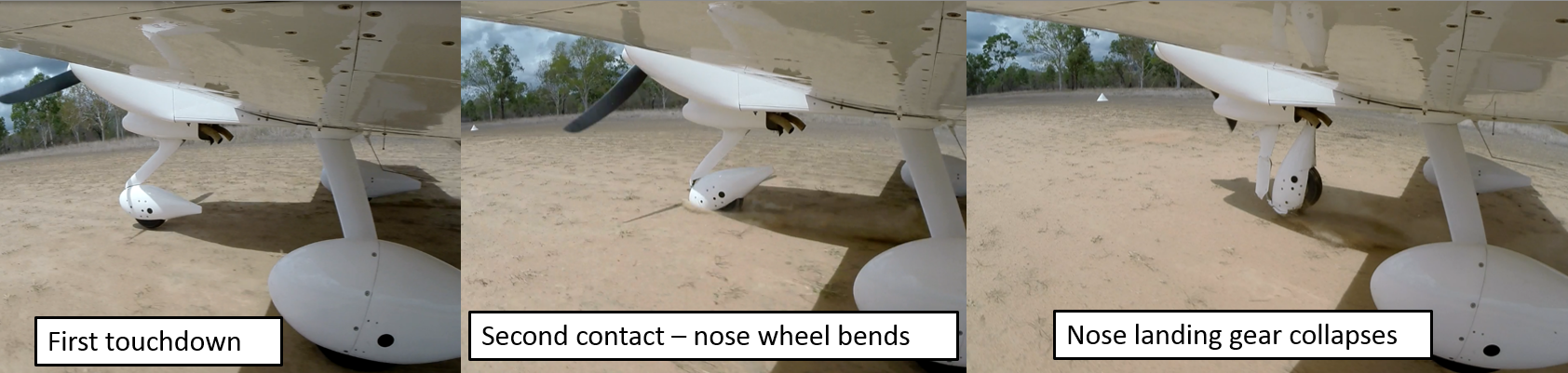
Occurrence summary

Investigation number 346-MO-2018-011
Occurrence date 18/06/2018
Location Berth 113, Port Kembla,
State New South Wales
Report release date 11/05/2021
Report status Final
Investigation level Systemic
Investigation type Occurrence Investigation
Investigation status Completed
Mode of transport Marine
Marine occurrence category Fire
Occurrence class Accident
Highest injury level None

Ship details

Name Iron Chieftain
IMO number 9047740
Ship type Cargo
Flag Australia
Manager CSL Australia
Departure point Ardrossan, South Australia
Destination Port Kembla, New South Wales

De-icing boot failure involving Saab 340, VH-ZLH, Esperance Airport, Western Australia, on 26 May 2018

Final Report

Report release date: 26/10/2018

What happened

On 26 May 2018, at about 0647 Western Standard Time (WST)[1], a SAAB 340B, VH-ZLH, operated by Regional Express Pty Ltd, was taxiing at Esperance Airport, Western Australia (WA). The aircraft was on a scheduled passenger flight to Perth, WA, with three crew members and 32 passengers on board.

While taxiing, the first officer (FO) conducted an ice protection test and received a Master Caution. The crew observed that the STAB BOOT IND light[2] was not illuminating and the Ice Protection Master Caution light[3] on the Central Warning Panel (CWP) was on. The crew noted that the TIMER light[4] did not illuminate during the test as expected. The crew conducted a lamp test and concluded that the TIMER light was functioning correctly.

Before entering the runway, the crew conducted their failure management procedure and went through the Quick Reference Handbook Checklist (QRH); ‘Boot remains inflated and boot indication light remains on or off’. In addition, the flight crew checked the Minimum Equipment List (MEL) to ensure there were no operational requirements that would ground the aircraft.

The Captain and the FO discussed the warnings and their observations that:

  • no visible defects were detected during the daily walk-around check
  • the TIMER light was working, but did not illuminate in conjunction with the STAB light
  • the warnings received did not follow any of the scenarios in the QRH
  • the MEL permitted dispatch outside of known or forecast icing conditions
  • the forecast freezing level was 7,500 ft and if necessary, the flight to Perth could be conducted as low as 4,000 ft.

Following their discussion, the flight crew concluded that the warnings were most likely the result of a faulty sensor and there was no risk to the safety of the flight. Subsequently, they elected to proceed with the flight as scheduled and the flight was conducted without further incident.

During the post-flight walk-around, the FO observed that the right-hand stabiliser boot had a tear approximately six inches (150 mm) in length (Figure 1). The de-icing boot was replaced in accordance with the aircraft maintenance manual before the aircraft was returned to service. There were no other faults found with the de-icing system.

Figure 1: Photo of the damaged de-icing boot

Figure 1: Photo of the damaged de-icing boot

Source: Aircraft operator annotated by the ATSB

De-icing boot system

The wing, vertical and horizontal stabiliser de-icing systems consist of inflatable boots, located on the leading edges of the vertical and horizontal stabiliser and the wing. The boots are inflated using precooled engine bleed air, controlled by a pressure regulator and supply valve. De-icing occurs when accumulated ice is cracked by rapid inflation of the boots. A timer control unit regulates the boot inflation cycles.

The crew can monitor inflation of the de-icing boots by observing the boot indication lights, located on the overhead panel. A fault light illuminates if a fault is detected in either the operation of the valves or the boots. If a boot remains inflated after normal operation of the system, the fault light will also illuminate.

A ruptured or torn stabiliser boot can be indicated by a series of cautions:

  • the ‘STAB light’ will not illuminate, indicating that the respective boot is not pressurised; and
  • the ‘Timer light’ will illuminate, indicating either that a boot is not pressurised or the activated timer has given a ‘no inflation’ signal; and
  • the ‘Ice protection master caution’ on the CWP light will flash, advising the flight crew of a fault within the ice protection system.

All of the cautions need to be present to indicate a ruptured or torn boot.

Airworthiness directive

Airworthiness directive (AD) AD 2017-0144 was released in August 2017, superseding AD 2015‑0129. The AD addressed the issue of rupturing of the horizontal stabiliser de-icing boots in flight which, in some reported events, had formed a large open scoop. The AD indicated that the condition, if left unrepaired, could lead to loss of the de-icing function and severe vibrations, possibly resulting in reduced control of the aeroplane.

To address this potentially unsafe condition, the following measures were stipulated:

  • a recommendation to select ‘Flaps 0’ for landing in the event of a suspected rupture of the de-icing boot on the horizontal stabiliser
  • inspection of de-icing boots as per Service Bulletin (SB) 340-30-094
  • repeated inspections at a maximum interval of 400 flight hours of the horizontal stabiliser de-icing boots
  • replacement of the left and right horizontal stabiliser de-icing boots with improved double stitched boots within 18 months of the release of AD 2017-0144, as per SB 340-30-095.

Inspections

The operator’s inspection procedures followed the requirements defined in AD 2017-0144. The Flight Crew Operating Manual (FCOM) outlined the visual inspection requirements for the de-icing boots during the daily, post-flight and crew change inspections. The FCOM contained a requirement to inspect the de-icing boots for surface damage such as abrasions, cracking, foreign object damage, loose repair patches and tears. The flight crew were responsible for documenting identified defects on the aircraft maintenance log, which was then provided to the engineering team for assessment.

The flight crew reported that they had flown VH-ZLH into Esperance the evening before the incident. The de-icing boots had remained operational during that flight. The FO did not identify any defects on the de-icing boots during the post flight walk-around.

The morning of the incident, the FO conducted the daily walk-around in accordance with the FCOM procedures. The FO carried out the aircraft inspection at dawn, in overcast and low-light conditions. Due to the light conditions, the inspection was conducted with the aid of a torch. The flight crew indicated that discontinuities in the de-icing boot surface are usually readily identified using torch light.

The horizontal stabiliser is located approximately 4 m from the ground with the top surface of the de-icing boot sweeping back over the horizontal stabiliser to be parallel to the ground. The flight crew indicated that a visual inspection of all surfaces of the boot is possible from the ground, however, it can be more difficult to see the uppermost surface. The tear in this occurrence was located on the lower surface of the stabiliser boot (Figure 1), which is an easily inspected location from the ground.

Continuation of flight with defects

For any crack, slit or tear in the boot, a temporary or permanent repair patch must be applied before the aircraft can be returned to service.

There were five MELs that allowed for operation of the aircraft with partially or wholly inoperative (but not torn) de‑icing boot system. One MEL had an associated pilot‑in‑command (PIC) maintenance inspection and all of the MELs permitted dispatch of the aircraft provided the flight crew did not operate in known or forecast icing conditions[5].

Flight crew comments

As a result of this occurrence, the flight crew of VH-ZLH indicated they had learned that when faced with ambiguous situations, it is important to take precautions and take the time to consider all the options. If the situation does not make sense, go back to the bay and confirm that everything is as it should be before you take off.

Safety analysis

On examination by the engineering team, the only fault found within the de-icing system was a torn de-icing boot. It was therefore likely that the cockpit warning lights were indicative of that defect, despite the fact that the unlit TIMER light was not consistent with a torn boot as described in the QRH. The TIMER light not illuminating during testing was likely to have been a system anomaly and there was, in fact, a defect present in the de-icing boot that either went undetected during visual inspections or ruptured during the pre-flight test.

The TIMER light not illuminating during the de-icing system testing was not a known issue to either the operator or the manufacturer. The operator’s engineering team tested the TIMER light after repairing the de-icing boot and found it to be serviceable.

The FO did not observe any defects in the surface of the de-icing boots during the walk-around inspections, either the evening before or on the morning of the incident. During the post-flight walk-around however, the FO identified the tear without difficulty. It was therefore likely that if there was a pre-flight tear, it was small in nature, allowing it to go undetected. That being the case, aerodynamic loading on the horizontal stabiliser during the flight would have resulted in the defect increasing to the size that was readily identified post-flight.

Prior to departing, the flight crew assessed the criteria in QRH and the MEL (section 30-10-5, Boot indication lights), to ensure the aircraft was safe to depart. Under MEL 30-10-5, ‘all [indication lights] may be inoperative provided the aircraft is not operated in known or forecast icing conditions’. That MEL did not require any PIC maintenance. Based on the assumption the abnormal indications were due to a faulty sensor and knowing that the scheduled flight could be conducted below the forecast freezing level, the flight crew felt satisfied that there was no risk to the safety of the flight to continue as scheduled. That assessment, while understandable, included a likely incorrect assumption regarding the defect in the de‑icing system that led to the flight being conducted with a torn de‑icing boot.

The flight crew reported that they did not experience any in-flight controllability issues or abnormal vibrations during the flight to indicate that there was a torn de-icing boot. While a torn boot is not guaranteed to result in controllability issues, without any inflight indications there was no reason for the crew to suspect a torn boot and conduct a ‘Flaps 0’ landing as per the AD recommendation.

Findings

These findings should not be read as apportioning blame or liability to any particular organisation or individual.

  • It was likely that the crew conducted a flight with a small defect in the aircraft’s horizontal stabiliser de-icing boot, which increased to a readily detectable size during the flight.
  • The timer light for the de-icing system did not illuminate, giving the flight crew indications that were inconsistent with a torn de-icing boot. The reason for the unlit timer light could not be determined.
  • The flight crew managed the risk of airframe icing prior to continuing with the flight.

Safety action

Aircraft operator

As a result of this occurrence, the aircraft operator advised the ATSB that they had taken the following safety actions:

  • provided additional training on the de-icing systems and associated MELs to the flight crew
  • discussed the potential occurrence of a torn de-icing boot with no associated TIMER light with the manufacturer
  • all five de-icing boot MELs have been amended to include PIC maintenance visual inspections.

Safety message

This incident highlights that there is the potential for anomalies to occur in the operation of warning systems. In the event that fault indications are ambiguous and there is the possibility of affecting the safety of the flight, it is important to take the necessary conservative precautions to resolve the issue prior to conducting the flight.

Purpose of safety investigations

The objective of a safety investigation is to enhance transport safety. This is done through:

  • identifying safety issues and facilitating safety action to address those issues
  • providing information about occurrences and their associated safety factors to facilitate learning within the transport industry.

It is not a function of the ATSB to apportion blame or provide a means for determining liability. At the same time, an investigation report must include factual material of sufficient weight to support the analysis and findings. At all times the ATSB endeavours to balance the use of material that could imply adverse comment with the need to properly explain what happened, and why, in a fair and unbiased manner. The ATSB does not investigate for the purpose of taking administrative, regulatory or criminal action.

Terminology

An explanation of terminology used in ATSB investigation reports is available here. This includes terms such as occurrence, contributing factor, other factor that increased risk, and safety issue.

Publishing information 

Released in accordance with section 25 of the Transport Safety Investigation Act 2003

Published by: Australian Transport Safety Bureau

© Commonwealth of Australia 2018

image_5.png

Ownership of intellectual property rights in this publication

Unless otherwise noted, copyright (and any other intellectual property rights, if any) in this report publication is owned by the Commonwealth of Australia.

Creative Commons licence

With the exception of the Coat of Arms, ATSB logo, and photos and graphics in which a third party holds copyright, this publication is licensed under a Creative Commons Attribution 3.0 Australia licence.

Creative Commons Attribution 3.0 Australia Licence is a standard form licence agreement that allows you to copy, distribute, transmit and adapt this publication provided that you attribute the work.

The ATSB’s preference is that you attribute this publication (and any material sourced from it) using the following wording: Source: Australian Transport Safety Bureau

Copyright in material obtained from other agencies, private individuals or organisations, belongs to those agencies, individuals or organisations. Where you wish to use their material, you will need to contact them directly.
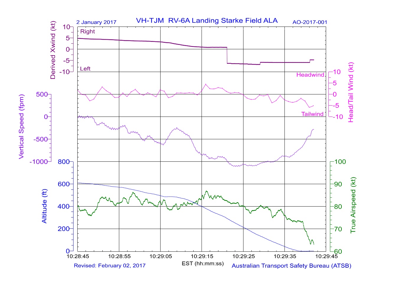
__________

  1. Western Standard Time: Coordinated Universal Time (UTC) + 8 hours
  2. The STAB light (green) illuminates when the horizontal stabilizer de-icing boot is pressurised.
  3. The Ice Protection Master Caution light flashes whenever a caution light associated with the ice protection system illuminates.
  4. The Timer light (amber) will illuminate in a number of scenarios, including if (1) no pressure is sensed downstream of the valve sequenced for opening within four seconds; (2) the activated timer gives no inflation signal.
  5. Icing conditions existed when the outside air temperature on the ground and for takeoff, or static air temperature in flight, was 5°C or below, and visible moisture in any form (clouds, fog, rain, snow, sleet or ice crystals) was present.

Occurrence summary

Investigation number AO-2018-045
Occurrence date 26/05/2018
Location Esperance Airport
State Western Australia
Report release date 26/10/2018
Report status Final
Investigation level Short
Investigation type Occurrence Investigation
Investigation status Completed
Mode of transport Aviation
Aviation occurrence category Icing
Occurrence class Incident
Highest injury level None

Aircraft details

Manufacturer Saab Aircraft Co.
Model 340B
Registration VH-ZLH
Serial number 340B-376
Aircraft operator Regional Express (REX)
Sector Turboprop
Operation type Air Transport Low Capacity
Departure point Esperance Airport, Western Australia
Destination Perth Airport, Western Australia
Damage Nil

Engine failure and forced landing of Beech Aircraft 76, VH-BDS, 49 km north-west of Cessnock Airport, New South Wales, on 1 June 2018

Final report

Report release date: 15/01/2019

What happened

On the evening of 1 June 2018, a twin-engine Beech Aircraft 76 (Duchess), registered VH-BDS, departed Coonamble Airport, New South Wales (NSW) with a pilot and two passengers on board. The aircraft was conducting a private flight to Cessnock Airport, NSW.

Prior to departure, the pilot reviewed the fuel quantity and checked the fuel for contamination. The aircraft had about 190 L on board (anticipated fuel use for the flight was 107 L). The aircraft had no known maintenance issues.

The pilot did not provide a safety briefing to the passengers. As he had not loaded headsets, he provided them earmuffs (not connected to the aircraft intercom) for hearing protection. The pilot occupied the front left seat with the passengers seated in the front right and rear right seats.

At about 1730 Eastern Standard Time (EST),[1] 8 minutes before last light,[2] the aircraft departed Coonamble and climbed to a cruising altitude of 7,500 ft in visual meteorological conditions.[3]

At about 1816, the pilot slightly reduced power and began descending the aircraft for Cessnock. At about 1821, he felt the aircraft yaw toward the right and observed the right engine indications showing a loss of power.

The pilot immediately commenced the engine failure checklist, which included selecting engine mixtures to full rich, increasing propeller RPM for both engines and advancing the throttles. He then confirmed the landing gear and flaps were retracted. The pilot also considered carburettor icing as a reason for the power loss and selected carburettor heat ‘on’ and ‘off’ (see the section titled Carburettor icing). The engine did not respond so he then conducted the engine failure checklist again. He also selected the fuel to cross-feed from the left fuel tank.

As the right engine did not respond, the pilot elected to secure the failed engine and configure the aircraft for single-engine flight. When securing the engine, the pilot moved the mixture to idle cut‑off, the propeller control to the feather position (see Propeller Feathering section) and the throttle to idle. He reported that he did not confirm that the right propeller had actually feathered. After securing the failed engine, the pilot did not attempt to unfeather the propeller, or restart the failed engine.

In order to maintain altitude, the pilot focussed on targeting the single-engine best rate of climb speed. He also ensured that airspeed did not reduce and affect aircraft controllability. The pilot observed that in order to maintain the required speed, the aircraft could not maintain altitude and continued to descend. In order to arrest the descent, the pilot increased power on the left engine to maximum but the aircraft continued descending.

The pilot considered diverting to Scone Airport but due to the proximity of housing near that airport, and his familiarity with Cessnock Airport, he decided to continue to Cessnock.

As the aircraft descended thorough about 5,500 ft, the pilot calculated that the descent rate would not allow the aircraft to clear high terrain between its position and Cessnock. At 1827, he declared MAYDAY[4] and advised air traffic control that he did not believe the aircraft could reach Cessnock.

At about 1830, the pilot elected to conduct a forced landing. At that time, the aircraft was positioned above the Ravensworth Mines. The pilot was familiar with the location and knew that flat areas, clear of vegetation, were located next to the mines.

While it was about 40 minutes after last light, enough daylight remained for the pilot to select a generally suitable landing area. He then selected a clear area and configured the aircraft for landing with the landing gear retracted.

With no intercom-connected headsets to communicate with the passengers, the pilot did not attempt to warn them and focused on flying the aircraft. The front seat passenger later reported that he was not aware of the impending forced landing.

The aircraft touched down in a grassy field on the underside of the fuselage and slid over a slope. The pilot yawed the aircraft sideways in an attempt to slow down but it continued over the slope before coming to rest (Figure 1). The pilot and passengers then evacuated the aircraft using the left cabin door; they were not injured but the aircraft was substantially damaged.

Figure 1: VH-BDS at the accident site

Figure 1: VH-BDS at the accident site. Source: Pilot

Source: Pilot

Engine and propeller examination

Photographs and video footage of the aircraft taken immediately after the accident showed the right propeller in the fine pitch position and not the expected feathered position (Figure 2). The engineer who recovered the aircraft reported that fuel was present in both fuel tanks and both engine carburettors.

The ATSB did not conduct an inspection of the propeller feathering system or engine.

Figure 2: Right engine after the accident showing the propeller

Figure 2: Right engine after the accident showing the propeller

Source: YouTube

Meteorological conditions

The weather forecast for the cruise and descent segments of the flight indicated broken cloud at altitudes between 5,000 ft and 8,000 ft, with an expected freezing level[5] of 7,000 ft. The pilot reported that the weather was better than forecast with cloud above the selected cruising level, and that he was able to maintain visual conditions throughout the flight.

The dewpoint[6] recorded at the Bureau of Meteorology’s Singleton, NSW, weather station (35 km southeast of the accident site) at 1820 (approximate engine failure time) was 3.9 °C.

Carburettor icing

Induction icing, often referred to as carburettor icing, is the accumulation of ice within the induction system of an engine fitted with a carburettor. This ice forms as the decreasing air pressure and introduction of fuel reduces the temperature within the system. The temperature may reduce sufficiently for moisture within the air to freeze and accumulate. This build-up of ice restricts airflow to the engine, leading to a reduction in engine performance and possible engine failure. Environmental conditions influence the likelihood of carburettor ice forming (see the Civil Aviation Safety Authority (CASA) Carburettor icing probability chart - shown in Figure 3).

At the time of the engine failure, the aircraft was descending through, and just below, the forecast freezing level. The forecast and observed cloud level, along with analysis of the recorded weather observations, indicated that the aircraft was operating in an atmosphere of high relative humidity.

The carburettor icing probability chart shows that the aircraft was descending in conditions of serious carburettor icing at descent power (Figure 3).

Figure 3: Carburettor icing probability chart

Figure 3: Carburettor icing probability chart. Source: CASA annotated by ATSB

Source: CASA annotated by ATSB

The Duchess is equipped with a carburettor heat system which, when selected ‘on’, allows heated air to enter the engine induction system to reduce the likelihood of carburettor icing.

The descent checklist in the aircraft’s operating handbook provided the following guidance on the use of carburettor heat.

Carburettor heat – FULL ON or FULL OFF, AS REQUIRED

Once selected ‘on’, the carburettor heat should remain on until normal engine power is restored. If ice has already accumulated, engine performance may deteriorate further as the ice melts before engine performance returns to normal. This may take up to 30 seconds. The pilot reported that he applied carburettor heat as part of troubleshooting following the right engine power loss. However, he also stated that he may not have applied it for long enough.

The engine manufacturer, Lycoming, issued a service instruction, No. 1148C Use of Carburettor Heat Control, that applied to all its engines fitted with float-type carburettors, including VH-BDS. The service instruction also noted that the possibility of induction icing at full throttle, was very remote (may be dependent on the individual engine installation).

Propeller feathering

The Duchess is equipped with full-feathering, two-bladed propellers. When an engine is shut down in-flight and the associated propeller control is moved to the feather position, the propeller blades rotate to an edge-on angle to the airflow to minimise drag. A propeller that is not feathered after an engine failure can produce sufficient drag to prevent the aircraft maintaining altitude.

Given the aircraft’s weight and ambient conditions at the time of the engine failure, the aircraft’s operating handbook indicated the aircraft should have been capable of maintaining altitude with the propeller of the failed engine feathered.

Safety analysis

At about 1820, the aircraft was descending in conditions that were conducive to serious carburettor icing at the selected engine power without carburettor heat applied. Those operating conditions, in combination with the described nature of the power loss, supported a conclusion that the right engine was affected by carburettor icing that progressed to engine failure. The described performance of the left engine when full throttle was applied, however, indicated that it was unaffected by carburettor icing despite operating in the same environmental conditions, and at a similar power level. The significant difference in the behaviour of the two engines support the possibility that the power loss in the right engine may have been due to some other unidentified source.

The pilot recalled that after the engine failure, he conducted the propeller feathering actions, but did not confirm that the propeller had feathered. He did not attempt to unfeather the propeller or restart the engine after this time. Post-accident photographs and video show that the propeller was not feathered at the time of the forced landing. Additionally, the inability of the aircraft to maintain altitude was considered to be due to the significant drag associated with the unfeathered propeller. As the aircraft and its systems were not examined, a fault that may have prevented selection of the feathered position could not be ruled out.

As the aircraft descended, the pilot calculated that the aircraft would not safely clear high ground between its position and the airport. The pilot therefore elected to conduct a forced landing with the landing gear retracted. The forced landing resulted in substantial damage to the aircraft.

Findings

These findings should not be read as apportioning blame or liability to any particular organisation or individual.

  • During descent, the right engine of VH-BDS failed, possibly due to carburettor icing.
  • After the right engine failed, the propeller was not feathered, or did not feather. The increased drag of the unfeathered propeller prevented the aircraft from maintaining altitude.
  • The inability to maintain altitude led the pilot to conduct a forced landing, which resulted in substantial damage to the aircraft.

Safety message

This accident highlights the importance of ensuring carburettor heat is used to prevent carburettor ice accumulating and leading to engine failure. If carburettor icing is encountered, or suspected, carburettor heat must be applied fully, and for sufficient time, to melt any accumulated ice. While that occurs, the performance of the engine may temporarily deteriorate further. The Flight Safety Australia article Ice Blocked provides useful guidance for managing carburettor icing.

Additionally, this occurrence illustrates the importance of correctly configuring a multi‑engine aircraft following an engine power loss. On this occasion, the increased drag associated with the unfeathered propeller resulted in a risky forced landing.

While all occupants evacuated the aircraft uninjured, the passengers had not received a pre-flight safety briefing nor were they aware of the impending forced landing. The likelihood of injury during a landing with landing gear retracted, on unfamiliar terrain and at night, is high. Therefore, safety briefings before flight and, where possible, prior to an emergency landing are essential in preparing passengers for the landing and subsequent evacuation.

Purpose of safety investigations

The objective of a safety investigation is to enhance transport safety. This is done through:

  • identifying safety issues and facilitating safety action to address those issues
  • providing information about occurrences and their associated safety factors to facilitate learning within the transport industry.

It is not a function of the ATSB to apportion blame or provide a means for determining liability. At the same time, an investigation report must include factual material of sufficient weight to support the analysis and findings. At all times the ATSB endeavours to balance the use of material that could imply adverse comment with the need to properly explain what happened, and why, in a fair and unbiased manner. The ATSB does not investigate for the purpose of taking administrative, regulatory or criminal action.

Terminology

An explanation of terminology used in ATSB investigation reports is available here. This includes terms such as occurrence, contributing factor, other factor that increased risk, and safety issue.

Publishing information 

Released in accordance with section 25 of the Transport Safety Investigation Act 2003

Published by: Australian Transport Safety Bureau

© Commonwealth of Australia 2019

image_5.png

Ownership of intellectual property rights in this publication

Unless otherwise noted, copyright (and any other intellectual property rights, if any) in this report publication is owned by the Commonwealth of Australia.

Creative Commons licence

With the exception of the Coat of Arms, ATSB logo, and photos and graphics in which a third party holds copyright, this publication is licensed under a Creative Commons Attribution 3.0 Australia licence.

Creative Commons Attribution 3.0 Australia Licence is a standard form licence agreement that allows you to copy, distribute, transmit and adapt this publication provided that you attribute the work.

The ATSB’s preference is that you attribute this publication (and any material sourced from it) using the following wording: Source: Australian Transport Safety Bureau

Copyright in material obtained from other agencies, private individuals or organisations, belongs to those agencies, individuals or organisations. Where you wish to use their material, you will need to contact them directly.

__________

  1. Eastern Standard Time (EST): Coordinated Universal Time (UTC) + 10 hours.
  2. Last light: the time when the centre of the sun is at an angle of 6° below the horizon following sunset. At this time, large objects are not definable but may be seen and the brightest stars are visible under clear atmospheric conditions. Last light can also be referred to as the end of evening civil twilight.
  3. Visual Meteorological Conditions (VMC): an aviation flight category in which visual flight rules (VFR) flight is permitted – that is, conditions in which pilots have sufficient visibility to fly the aircraft while maintaining visual separation from terrain and other aircraft.
  4. MAYDAY: an internationally recognised radio call announcing a distress condition where an aircraft or its occupants are being threatened by serious and/or imminent danger and the flight crew require immediate assistance.
  5. Freezing level is the altitude, for a specific location, at which the temperature has reduced to zero degrees Celsius.
  6. Dewpoint: the temperature at which water vapour in the air starts to condense as the air cools. It is used, among other things, to monitor the risk of aircraft carburettor icing or the likelihood of fog.

Occurrence summary

Investigation number AO-2018-047
Occurrence date 01/06/2018
Location 49 km north-west of Cessnock Airport
State New South Wales
Report release date 15/01/2019
Report status Final
Investigation level Short
Investigation type Occurrence Investigation
Investigation status Completed
Mode of transport Aviation
Aviation occurrence category Engine failure or malfunction
Occurrence class Accident
Highest injury level None

Aircraft details

Manufacturer Beech Aircraft Corp
Model 76 (Duchess)
Registration VH-BDS
Serial number ME-64
Aircraft operator Masterflight
Sector Piston
Operation type Private
Departure point Coonamble Airport, New South Wales
Destination Cessnock Airport, New South Wales
Damage Substantial

Engine vibrations and in-flight shutdown involving Airbus A330, VH-QPI, near Sydney Airport, New South Wales, on 1 June 2018

Final report

Report release date: 28/08/2020

Safety summary

What happened

On 1 June 2018, a Qantas Airways Limited Airbus A330 aircraft, registered VH-QPI (QPI), was operating a scheduled passenger flight from Sydney, New South Wales to Bangkok, Thailand. On board were 13 crewmembers and 297 passengers.

Shortly after take-off, a ‘pop’ sound was heard, followed by light airframe vibration and a reduction in the rotational speed of the right engine. A cockpit advisory message relating to the right engine’s vibration level was also displayed to the crew.

The flight crew discontinued the climb and consulted the ‘High Engine Vibration’ checklist, which directed them to reduce the right engine’s thrust to idle. With the reduction in thrust, the vibration on the right engine reduced but remained relatively high. To prevent further engine damage the flight crew decided to shut the engine down. With the engine shut down, the airframe vibration ceased.

Following an uneventful descent and return to Sydney Airport, an overweight landing with one engine inoperative was conducted.

Initial inspection by engineering staff revealed visible damage to the right engine low-pressure turbine, and engine debris generated impact damage to the aircraft’s wing flap lower surfaces and body fairings. The engine was removed and sent to the operator’s overhaul facility for detailed examination and repair.

What the ATSB found

Technical examination identified that the effects of oxidation and deterioration of the protective coating of the low‑pressure turbine stage 4 nozzle guide vane segments, led to intergranular oxidation, crack development and loss of an aerofoil from the No. 5 segment. The liberated aerofoil impacted downstream rotating components, resulting in a loss of turbine blade material, rotor imbalance and subsequent airframe vibration.

What’s been done as a result

In response to the loss of the aerofoil from the No. 5 nozzle guide vane segment, the operator initiated a borescope inspection program to identify segments that exhibited evidence of cracking. Affected engines were removed from service. The operator also specified that at engine overhaul, all nozzle guide vane segments that had cracks were to be replaced, and that only new (rather than overhauled) segments were to be installed.

The engine manufacturer made a change to the type of protective coating used on the nozzle guide vane segments to reduce oxidation. Service instructions were issued in mid‑2019 to implement the coating replacement.

Safety message

This incident illustrates that, despite the high reliability of modern turbine engines, flight crews can still be faced with malfunctions that require their combined judgement and expertise to safely manage the situation.


The occurrence

What happened

On 1 June 2018, a Qantas Airways Limited Airbus A330 aircraft, registered VH-QPI (QPI), was operating a scheduled passenger flight from Sydney, New South Wales to Bangkok, Thailand. On board were 13 crewmembers and 297 passengers. The flight crew consisted of the aircraft captain who was the pilot flying (PF), the first officer as the pilot monitoring (PM) and a second officer.[1]

QPI departed Sydney at 1219 Eastern Standard Time.[2] As the engine thrust was being reduced from the take‑off setting, the PM heard a ‘pop’ sound and the flight crew recalled receiving a flight deck advisory message, followed by light airframe vibration. A reduction of about 5 per cent in N1[3] revolutions per minute of the right (No. 2) engine was also noticed. The advisory message from the aircraft’s electronic centralised aircraft monitor (ECAM) indicated that the No. 2 engine’s vibration level had reached the maximum recordable level of 10 units. A later review of quick access recorder[4] data showed that the ECAM message was generated at 1220:25 as the aircraft climbed through an altitude of 1,696 ft.

The PF reported that, despite the right engine vibration and reduction in N1, no yawing[5] was present. The aircraft was configured with the undercarriage retracted, and autopilot engaged. As the aircraft gained altitude, the PF retracted the wing flaps and leading-edge slats. The flight crew then responded to the advisory message and referred to the aircraft’s quick reference handbook, which directed them to the 'High Engine Vibration’ checklist.

By 1224:22, the flight crew had discontinued the climb and were maintaining an altitude of 7,000 ft in order to complete the ’High Engine Vibration’ checklist. The PF reported that in accordance with the checklist, the No. 2 engine’s thrust lever was reduced to idle, and the No. 1 (left) engine set to maximum continuous thrust.

With the No. 2 engine at idle, the vibration level reduced to 6.5 units. However, the advisory message remained displayed as the threshold to remove the advisory was 5.7 units. The flight crew considered this level of vibration to be excessive and discussed shutting down the No. 2 engine to prevent further damage. No additional alerts or advisory messages from the ECAM that related to engine parameters were presented to the flight crew for the remainder of the flight. Given the ‘pop’ sound heard immediately prior to the onset of vibration, the ‘Engine Stall’ checklist was actioned. At 1231:47, about 12 minutes after take-off, the PF shut down the No. 2 engine.

With the No. 2 engine shut down, the airframe vibration ceased, and a holding pattern over Richmond, New South Wales was initiated. While holding, the flight crew communicated with air traffic control, appraised company representatives of the event, and briefed the cabin crew and passengers on the situation. The decision was made to return to Sydney and perform an overweight landing. The aircraft was not equipped with a fuel dump system and company procedures required that, when an aircraft was damaged, an overweight landing was to be performed to allow the aircraft to land as soon as practicable.

The flight crew referred to the ‘Overweight Landing’ checklist and discussed how they would conduct a single-engine approach and utilise the aircraft’s auto-land system as procedurally required. At 1307, after about half an hour of holding, a descent into Sydney was commenced. The PF reported that the descent was initially unstable, however between 1,000 and 500 ft above ground level, a stable approach was established. At 1317, QPI touched down at Sydney Airport on runway 16R[6]. It was taxied clear of the runway and inspected by airport fire services. On receiving clearance from the fire warden, the aircraft was taxied to the terminal and shutdown at 1319.

An initial inspection by engineering staff revealed visible damage to the No. 2 engine low-pressure turbine stages four and five. It also revealed that engine debris had caused impact damage to the lower surfaces of the aircraft’s right-wing flaps and body fairings. The engine was subsequently removed and shipped to the engine manufacturer’s overhaul facility in Taiwan for detailed examination and repair.

Engine description and examination

QPI was fitted with two General Electric Company CF6-80E1 engines, which are dual-rotor, axial‑flow, high by-pass, turbo fan engines. They are capable of delivering in excess of 58,000 pounds of static thrust. A 2-stage high-pressure turbine drives the 14-stage high-pressure compressor (Figure 1). The integrated fan and low-pressure compressor is driven by a 5-stage, low-pressure turbine.

Figure 1: Profile of General Electric CF6-80 engine showing layout of rotating assemblies and position of stage four nozzle guide vane assembly

Figure 1: Profile of General Electric CF6-80 engine showing layout of rotating assemblies and position of stage four nozzle guide vane assembly.
Source: Supplied by operator and annotated by the ATSB

Source: Supplied by operator and annotated by the ATSB

Stationary nozzle guide vanes are fitted ahead of each turbine wheel. Gasses coming from the combustion chamber pass through the nozzle guide vanes, which, due to their convergent shape, accelerate the airflow and drive the turbine at high rotational speed.

The No. 2 engine from QPI was disassembled and examined at the engine manufacture’s repair facility. Examination of the engine’s low-pressure turbine stages found that aerofoil No. 6 from the No. 5 segment of the stage four nozzle guide vane (NGV) was missing (Figures 2 and 3). The liberated aerofoil caused downstream damage to the stage four and five low-pressure turbine and the stage five NGV segments. Both turbine stages sustained loss of blade material consistent with impacts from the aerofoil and other liberated fragments. Additionally, while the low-pressure turbine case outer wall was perforated and showed signs of bulging, there was no loss of containment of the fragments via the outer case wall. No damage was found upstream of the stage four NGV assembly.

Figure 2: Low-pressure turbine stage four NGV assembly with segment No. 5 showing loss of aerofoil

Figure 2: Low-pressure turbine stage four NGV assembly with segment No. 5 showing loss of aerofoil.
Source: Supplied by the operator and annotated by the ATSB

Source: Supplied by the operator and annotated by the ATSB

Figure 3: Segment No. 5 showing loss of aerofoil No. 6 and fracture area detail

Figure 3: Segment No. 5 showing loss of aerofoil No. 6 and fracture area detail.
Source: Supplied by the operator and annotated by the ATSB

Source: Supplied by the operator and annotated by the ATSB

Detailed examination of the stage four NGV assembly showed that another three segments exhibited cracks through the entire chord width of various aerofoils. The engine manufacturer identified that oxidation and deterioration of the aerofoil’s chromide protective coating had occurred due to engine operating temperatures, stress and time. The deterioration led to the formation of intergranular oxidation in the NGV aerofoil material. As intergranular oxidation levels increased, cracks formed on the NGV leading edges, resulting in eventual failure of the No. 6 aerofoil.

The engine manufacturer also identified that the highest intensity of intergranular oxidation indications was concentrated in the leading edge of aerofoil No. 6, the highest stressed location in segment No. 5 of the stage four, low-pressure turbine, nozzle guide vane assembly.

Additional examination by the manufacturer identified the presence of intergranular oxidation on a number of new NGV segments at their first overhaul shop visit (first run parts), but with less severity than that found on multiple-run parts.

History of stage four NGV aerofoil failures

A review of past occurrences identified that low-pressure turbine stage four NGV aerofoil liberations on General Electric CF6-80E1 engines have occurred on 17 occasions since 2006. The operator experienced seven of those occurrences and was the only operator of CF6 engines to have initiated a consequent engine shutdown in flight.

The engine manufacturer initially assessed that the most likely cause of the failures was associated with movement of the NGV segments relative to each other. This was due to low‑pressure turbine case rail wear, resulting in increased stress at the leading edge of aerofoil No. 6. In response, service bulletin CF6-80E1 SB 72-0545 was issued in August 2016, introducing an anti‑wear shim to eliminate undesirable nozzle movement.

The manufacturer later recognised that while the anti-wear shim addressed the effects of static stresses and the potential for high cycle fatigue[7] cracking of the NGV segments, it did not prevent intergranular oxidation. The progression of intergranular oxidation was subsequently identified as an additional failure mode for aerofoil liberation. This occurrence was the first liberation in the Qantas fleet, following implementation of the anti-wear shim.

Protective coatings on engine hot section components

To protect against erosion and corrosion, engine manufacturers utilise protective coatings to increase the durability and in-service performance of highly stressed parts. For example, in the fan and compressor areas, erosion-resistant coatings are used to minimise blade wear, and corrosion-resistant coatings are applied to surfaces of turbine blades and nozzle guide vanes.[8]

Oxidation of hot section parts

Oxidation is a form of corrosion in aircraft turbine engines[9] that involves the chemical reaction of oxygen, in the engine core gas stream, with the surface coating or base metal of the part. This chemical reaction creates oxide molecules as it consumes the coating or base metal. The oxides generally build up as an oxide surface film, but can also transition to an intergranular mode, penetrating below the protective coating on the surface and into the base material. Over time, oxidation will consume these materials and in certain cases, cause premature failure of the part.

Thermally induced fatigue can also affect the integrity of the protective surface coating, brought on by repeated application of thermally induced stresses due to rapid and non-uniform heating and cooling cycles during engine power changes.[10] These thermal and mechanical stresses may result in cracking of the surface coating or base metal. Breakdown of the surface coating allows the gas stream to impinge on the base metal and accelerate the overall oxidation process leading to part failure.

Action by the manufacturer and operator

In response to the aerofoil liberation in this occurrence, the engine manufacturer investigated changing the type of protective coating of the NGV segments from chromide to vapour-phased aluminide. The vapour-phased aluminide coating, in use on stage 3 NGVs, has lower instances of intergranular oxidation, and an absence of NGV material deterioration. SB 72-575 was issued in July 2019 to implement the coating replacement.

The engine manufacturer also assessed that the operator’s stage four NGVs had higher levels of deterioration when compared to NGVs from other operators. They attributed this to engine thrust settings, reporting that the operator’s aircraft spent relatively more time at high thrust, operated at heavier weights, and spent more time in the take-off and climb segments. The manufacturer concluded that the operator’s engine duty cycle likely exposed the low-pressure turbine components to higher temperatures and stress.

The operator made several changes with respect to treatment of the low-pressure turbine stage four NGV that included:

  • replacing all NGV segments that exhibited cracking of the aerofoil leading edge
  • introducing a requirement that only new segments were to be installed during overhaul (no multiple run segments)
  • introducing a borescope[11] inspection program targeting the low-pressure turbine, stage four NGV assembly. The borescope inspection subsequently identified five engines with aerofoil cracking that warranted engine removal.
  • revising the CF6 engine removal plan to reduce the time in service for those engines identified as at-risk of aerofoil liberation.

In-flight engine vibration management

The captain considered that the ‘High Engine Vibration’ checklist lacked sufficient guidance to address high residual engine vibration, which led the operator to seek clarification from the aircraft manufacturer. The aircraft manufacturer advised that high engine vibration alone did not require an engine shutdown, and crews had the discretion to monitor the engine for other symptoms and to continue operation. However, the manufacturer also advised that the flight crews could consider shutting an engine down if the vibration was considered excessive.

Following review, both the aircraft manufacturer and the operator concluded that sufficient information was available for crews to respond appropriately in an abnormal or emergency situation.

Safety analysis

Gas turbine engine, nozzle guide vanes (NGV) and turbine assemblies are subject to high mechanical loading and temperatures in a corrosive and erosive environment. Detailed technical examination identified that, following oxidation and deterioration of the protective coating on the stage four NGV, No. 5 segment, inter-granular oxidation developed in the base material of the aerofoils. This resulted in cracking of the highly stressed leading edge of the No. 6 aerofoil and its subsequent fracture and liberation.

The lack of damage ahead of the stage four NGV assembly indicated that the liberated aerofoil was the initial event that led to the engine damage. As the aerofoil continued aft in the gas stream, the stage four and stage five low-pressure turbines and the stage five NGV were damaged. The loss of turbine blade material caused a rotor imbalance that was felt as airframe vibration. The airframe vibration was still present following the power lever reduction to idle. Due to the level of residual vibration, the flight crew decided to shut the engine down in flight and return to the departure airport.

Findings

These findings should not be read as apportioning blame or liability to any particular organisation or individual.

  • Oxidation and deterioration of the stage four No. 5 nozzle guide vane segment protective coating resulted in the development of intergranular oxidation in the parent material of the No. 6 aerofoil. This led to crack development, fracture and liberation of the aerofoil.
  • The loss of the aerofoil led to downstream turbine rotor damage with significant loss of blade material and engine vibration. Due to the vibration, and in consideration of the potential for further engine damage, the flight crew decided to shut the engine down in flight and return to the departure airport.

Safety action

Following this occurrence, the engine manufacturer changed the protective coating on the NVG segments from chromide to vapour-phased aluminide, citing better resistance to oxidation effects.

The operator also worked proactively by ensuring stage four, low-pressure turbine NGV segments that exhibited cracking of the aerofoil leading edge were removed from service, and that only new, not overhauled segments were fitted to the operator’s engines. The operator also introduced a borescope inspection program that was successful in identifying other engines with aerofoil cracking and removed the affected engines from service.

Purpose of safety investigations

The objective of a safety investigation is to enhance transport safety. This is done through:

  • identifying safety issues and facilitating safety action to address those issues
  • providing information about occurrences and their associated safety factors to facilitate learning within the transport industry.

It is not a function of the ATSB to apportion blame or provide a means for determining liability. At the same time, an investigation report must include factual material of sufficient weight to support the analysis and findings. At all times the ATSB endeavours to balance the use of material that could imply adverse comment with the need to properly explain what happened, and why, in a fair and unbiased manner. The ATSB does not investigate for the purpose of taking administrative, regulatory or criminal action.

Terminology

An explanation of terminology used in ATSB investigation reports is available here. This includes terms such as occurrence, contributing factor, other factor that increased risk, and safety issue.

Publishing information 

Released in accordance with section 25 of the Transport Safety Investigation Act 2003

Published by: Australian Transport Safety Bureau

© Commonwealth of Australia 2020

image_5.png

Ownership of intellectual property rights in this publication

Unless otherwise noted, copyright (and any other intellectual property rights, if any) in this report publication is owned by the Commonwealth of Australia.

Creative Commons licence

With the exception of the Coat of Arms, ATSB logo, and photos and graphics in which a third party holds copyright, this publication is licensed under a Creative Commons Attribution 3.0 Australia licence.

Creative Commons Attribution 3.0 Australia Licence is a standard form licence agreement that allows you to copy, distribute, transmit and adapt this publication provided that you attribute the work.

The ATSB’s preference is that you attribute this publication (and any material sourced from it) using the following wording: Source: Australian Transport Safety Bureau

Copyright in material obtained from other agencies, private individuals or organisations, belongs to those agencies, individuals or organisations. Where you wish to use their material, you will need to contact them directly.
__________

  1. Pilot Flying (PF) and Pilot Monitoring (PM): procedurally assigned roles with specifically assigned duties at specific stages of a flight. The PF does most of the flying, except in defined circumstances; such as planning for descent, approach and landing. The PM carries out support duties and monitors the PF’s actions and the aircraft’s flight path.
  2. Eastern Standard Time (EST): Coordinated Universal Time (UTC) + 10 hours.
  3. N1 - The rotational speed of the low pressure compressor of a gas turbine engine
  4. Quick Access Recorder (QAR) is an airborne flight recorder designed to provide access to raw flight data, through means such as USB or cellular network connections and/or the use of memory cards.
  5. Yawing: the motion of an aircraft about its normal, or vertical axis
  6. Runway number: the number represents the magnetic heading of the runway. The runway identification may include L, R or C as required for left, right or centre
  7. High cycle fatigue is typically characterised by low-amplitude, high-frequency elastic deflections. An example would be an aerofoil subject to repeated bending
  8. G.W. Meetham, (1986), Use of protective coatings in aero gas turbine engines, Materials Science and Technology, Vol 2, No.3, p.290-294.
  9. AC 33-11, (2014), F.A.A. Advisory Circular, U.S Department of Transportation. www.faa.gov
  10. AC 33-11, (2014), F.A.A. Advisory Circular, U.S Department of Transportation. www.faa.gov
  11. Flexible optical periscope, usually incorporating lighting, capable of being inserted into narrow apertures to inspect interior of machinery

Occurrence summary

Investigation number AO-2018-046
Occurrence date 01/06/2018
Location Near Sydney Airport
State New South Wales
Report release date 28/08/2020
Report status Final
Investigation level Short
Investigation type Occurrence Investigation
Investigation status Completed
Mode of transport Aviation
Aviation occurrence category Engine failure or malfunction
Occurrence class Incident
Highest injury level None

Aircraft details

Manufacturer Airbus
Model A330-303
Registration VH-QPI
Serial number 0705
Aircraft operator Qantas Airways
Sector Jet
Operation type Air Transport High Capacity
Departure point Sydney Airport, New South Wales
Destination Bangkok, Thailand
Damage Minor

Fatality in the elevator trunk on board OOCL Kuala Lumpur, 8.5 nautical miles south-east of Port Botany, New South Wales, on 3 June 2018

Final report

Report release date: 03/06/2020

Safety summary

What happened

On 3 June 2018, OOCL Kuala Lumpur’s electro-technical officer (ETO) was testing the ship’s personnel elevator after completing mechanical repairs. While driving the elevator from the cage top, the ETO became trapped between the moving cage and the bulkhead, and was fatally injured.

What the ATSB found

The ATSB investigation found that the ETO was last seen alone, on top of the elevator cage, in the prescribed safe zone with the elevator control in ‘MANUAL’. The exact circumstances explaining how and why the ETO then came to be trapped while the elevator moved between floors could not be determined. For the accident to have occurred, however, the ETO had to have moved from the safe zone, the elevator control had to have been changed from ‘MANUAL’ to ‘AUTO’ and the elevator called.

The investigation also found that safety barriers prescribed in the electrical work permit were not put in place before the work commenced. All ship’s crew were not warned against using the elevator as there had been no warning announcement and there were no warning signs posted at all elevator access doors. This allowed an elevator call to be made while the work was underway. Aspects of the supervision and communications throughout the task were ineffective, which meant that opportunities to stop or alter the method of work were missed.

What's been done as a result

Following this accident the ship’s management company instigated an education programme throughout the company and fleet which addressed its safe work practices, permit to work system, risk assessment, and elevator maintenance. The company safety management system was also amended to more clearly define and detail elevator maintenance responsibilities, processes and procedures.

Elevator maintenance and risk identification training has been provided to all shipboard and shore‑based technical staff. This training will be ongoing and required prior to joining a ship equipped with an elevator. In addition to this, all fleet elevators have been assessed to ensure they meet current elevator cage top control station standards for functions and access. A process for modification, if necessary, has also been implemented.

Safety message

Elevator accidents continue to occur around the world and result in about one fatality per year. Many of these accidents involved the failure to apply existing safety management procedures and/or identified safety barriers that have proven effective in reducing the risks associated with elevator maintenance. These include procedures related to communications, supervision and machinery isolation/lockout. Furthermore, the injured person was often working alone and riding the elevator cage. For any task that is performed on multiple occasions without any adverse consequence, there is the potential for an individual’s perception of risk (or expectancy of a problem) to decrease. This makes it all the more important to always follow documented procedures and safe working practices, even when the operation is considered safe.

It is imperative that close and careful supervision is maintained for any elevator testing and tasks. Supervisory oversight provides an opportunity for experienced, senior technical staff to scrutinise and assess the plans and intentions of those completing the task. This provides an external check and safety barrier before, and during, the work.


The occurrence

During the afternoon and evening of 2 June 2018, the 280 m, 5,888 TEU[1] fully cellular container ship OOCL Kuala Lumpur (Figure 1) was stopped and drifting about 20 NM[2] south-east of Port Botany, New South Wales. Weather had deteriorated with winds in excess of 40 knots, and the ship’s arrival time into Port Botany had been pushed back because of disruptions to port operations. The officer of the watch (OOW) recorded in the ship’s bridge log that the ship was rolling easily to moderately in about 30 knot winds from the south and 4 to 5 metre seas from the south-east. The main engine was on short notice and the ship’s engineers maintained watches.

There had been problems with a refrigerated cargo container not maintaining temperature and from about 1800[3] the electro-technical officer (ETO) and fitter had been on deck attending to the container. At about 2145, the ETO contacted the chief engineer to update him on the work and seek advice. Together they attended the container and by 2230 the repair was complete. They returned to the ship’s accommodation and completed paperwork recording the work, some of which was passed to the master for forwarding to shore management.

Figure 1: OOCL Kuala Lumpur

Figure 1: OOCL Kuala Lumpur.
Source: Owen Foley, Shipspotting.com

Source: Owen Foley, Shipspotting.com

Just before 0400 on 3 June, the second engineer[4] left his cabin to go to the engine room to commence his engineering watch and found the elevator to be inoperative. It was stopped on the third deck, the lowest level of its travel. It was usual to position the elevator at this level and lock it out when there was a fault with it or rough weather meant it was advisable not to use it. During the watch handover from the third engineer, the second engineer was informed that the lift was faulty. He decided he would discuss the fault and its repair during the scheduled morning toolbox meeting.

In Port Botany, pilotage operations resumed at 0700 on 3 June and OOCL Kuala Lumpur’s master was notified that pilot boarding time was 1000 that morning. At 0800, the OOW began preparing for standby and manoeuvring.

At about the same time, the master and chief engineer were making their way to breakfast. They called the elevator so as to go to the mess room several decks below. The elevator did not respond to the call so they used the stairs. In the mess room they met the ETO and discussed the unserviceable elevator. The ETO advised that he was aware of the fault—the elevator cage doors were not closing because the drive chain sprocket had come adrift and would require refitting. He stated that he would make preparations to repair the fault and discuss with the chief engineer after breakfast.

Elevator maintenance

The fourth engineer had taken the engineering watch at 0800 and was preparing the machinery for manoeuvring. In the engine control room (ECR), the daily work toolbox discussion was held, led by the second engineer. Also present were the chief, fourth and fifth engineers, the fitter and the ETO. During this meeting, among other tasks, the elevator fault was discussed. The ETO said he knew of and understood the fault and would complete the repair with the fitter. He then went about completing the required paperwork, including an electrical work permit (EWP) and a hazard identification and risk assessment form.

The chief engineer authorised the EWP at 0820. The requirements of the task were discussed and the ETO showed the chief engineer the chain drive sprocket and explained the repair. They discussed how the work was to be completed, agreeing that the ETO would isolate the elevator and access the elevator cage top (Figure 2) through the engine room second deck elevator entrance door, and the fitter would complete the repair. The ETO undertook to notify the chief engineer when the repair work was complete and testing would proceed. The ETO and fitter went to do the work and the chief engineer turned his attention to the imminent main engine movements.

Figure 2: Elevator cage top from entrance door (forward)

Figure 2: Elevator cage top from entrance door (forward).
Source: Singapore Transport Safety Investigation Bureau; Worksafe Victoria and ATSB

Source: Singapore Transport Safety Investigation Bureau; Worksafe Victoria and ATSB

The EWP required that warning notices were placed on all decks and elevator doors, and that a public address announcement was made informing all crew members that the elevator was out of service and was not to be used. During the ATSB investigation, no evidence was provided to show that these precautions were put in place. The master and the OOW were aware that the work would take place but were not informed that it was underway.

At 0836, the main engine was tested ahead and astern, followed by steering gear checks. Passage to the pilot boarding ground (7.5 NM to the north-west) resumed at 0845. By 0900, the ship had a speed of just over 8 knots and was on a northerly heading. Winds were south-westerly at about 20 knots, with seas about 2.5 m from the south-east. The weather and movement of the ship in the following sea were not considered sufficiently hazardous to prevent the elevator work from continuing.

For the elevator work, the ETO isolated the electrical power supply in the elevator machinery room, returned to the engine room and opened the second deck elevator access door. The elevator cage top was about 1 m above the second deck and this provided relatively easy access to the cage top and the cage door drive mechanism which was to be repaired. The ETO activated the local emergency stop and set the control switch from ‘AUTO’ to ‘MANUAL’ on the cage top operating panel (see the section titled Elevator in Context).

The fitter then went about the repair. A replacement key was fabricated for the chain drive sprocket and together these were fitted in place on the drive shaft and the chain fitted. The repair took about 10 minutes. The ETO satisfied himself that the repair was complete and that the elevator could be tested before being brought back into service.

At about 0915, the ETO returned to the ECR to speak with the chief engineer. The chief engineer recalled that the ETO advised that he intended to restore electrical power and test the elevator from inside the elevator cage. This would entail driving the cage up and down between floors and ensuring that the cage doors operated correctly and consistently at each level.

Elevator testing

The ETO went to the elevator machinery room and de-isolated the machinery. He then returned to the second deck elevator landing and gave instructions to the fitter to close the door behind him. He then climbed onto the top of the elevator cage. The fitter last saw the ETO standing at the back of the cage, atop the elevator cage emergency escape door and behind the operating panel, facing the fitter. He recalled that the emergency stop button was depressed and the elevator control selector switch was in ‘MANUAL’. As instructed, the fitter closed the door.

Soon thereafter, the fitter heard the lift operate, noticed the up and down indicating lamps activate briefly and the landing door handle move. This was followed by impact noises (thuds) and continuous clicking. In response to the unusual sounds, he attempted to open the access door. However, the landing door interlock mechanism was now engaged and he was unable to open it.

At 0930, in the ECR, the chief engineer decided to check on the progress of the elevator work and went into the engine room. He went to the elevator landing and saw the fitter attempting to open the door. The fitter explained about the noises he had heard and that he was concerned. The chief engineer then attempted to open the door. After some effort the door opened. Inside, he could see that the upper section of the door frame and the door closer were damaged.

The chief engineer looked into the elevator shaft and saw the ETO hanging, unresponsive, head-down, from the bottom of the elevator cage, about half a metre above the doorway. He was caught between the cage and the forward bulkhead.

Accident response

The chief engineer hurried to the ECR to raise the alarm and summon help. The fourth engineer called the bridge and asked that the elevator shaft emergency escape door (on the wheelhouse top) be opened as this would activate the escape door micro-switch and prevent movement of the elevator.

At 0936, they activated a manual call point which triggered the general alarm and alerted all crew to the unfolding emergency. The chief engineer reported to the master and at 0937 the master contacted Sydney vessel traffic service (VTS) seeking urgent medical assistance. VTS contacted the Ambulance Service of New South Wales for assistance and also went about making arrangements to get paramedics to the ship. The harbour master, container terminal management, and other authorities were also notified.

On board, the cage was stopped midway between the second and upper decks. Many of the ship’s crew had mustered at the upper deck elevator entrance door and it was opened to allow access to the top of the cage. The chief mate, fourth engineer and fitter entered the lift trunking and climbed down onto the cage. They activated the emergency stop, opened the cage escape door and entered the cage. The cage sliding doors were closed, with one panel showing signs of damage. The ETO could not be seen and they went about removing one of the door panels to gain access to him.

Meanwhile, ashore, soon after being notified, a VTS officer went to the adjacent pilot office and informed the duty pilot of the accident. The duty pilot was in the office performing administrative duties (such as taking bookings and making pilot allocations) to assist the rostered pilot and was not required to pilot ships during this time. However, the rostered pilot was in the midst of guiding a ship out of port and had been scheduled to transfer from that ship to OOCL Kuala Lumpur at 1000 to bring it into port. Once notified of the accident and the need to get OOCL Kuala Lumpur into port for medical assistance, the duty pilot quickly prepared to attend the ship and conduct the pilotage. He gathered his things, proceeded to the wharf and boarded the waiting pilot launch. At 0944 the pilot boat left the wharf.

At 1015, the pilot boat was alongside OOCL Kuala Lumpur and the duty pilot boarded the ship. Once on board and on the bridge he obtained an update of the emergency and notified VTS. At this stage the ETO was still trapped. Discussions were held regarding the most suitable option for boarding medical staff. The heavy weather restricted access for a helicopter and also limited the suitable locations for personnel to board from a boat. The decision was taken to bring the ship in as far as the swing basin off Brotherson Dock,[5] create a lee, and have the medical staff board from the pilot launch. The duty pilot took the con[6] while the master and OOW were busy with communications and on board happenings.

The pilot boat departed OOCL Kuala Lumpur, proceeded to the outbound ship and embarked the rostered pilot at 1026. After discussions between the two pilots, it was agreed that the rostered pilot would return to port in the pilot boat. There he would assist the embarkation of an emergency response team (paramedics and rescue personnel) and return to OOCL Kuala Lumpur with them.

At 1033, two harbour tugs were approaching the ship as it was passing Henry Head at a speed of 10.3 knots. Discussions between the two pilots and VTS had agreed to also use a third tug which was available and at 1035 this tug departed the tug den in Brotherson Dock.

At about this time, the ETO was freed and taken into the elevator cage. The cage was manually moved to the upper deck where the ETO was moved to the ship’s hospital. At 1042, the first tug was made fast centre lead aft while the second tug approached to tie-up on the port shoulder.

Ashore, emergency services personnel including paramedics were assembled. They boarded the pilot launch and at 1049 departed. Meanwhile, the second tug had been made fast on OOCL Kuala Lumpur’s port shoulder and the third tug was alongside. At this time, the duty pilot guided the ship in toward Brotherson dock, washed off speed, and commenced swinging the bow to port to bring the ship round with the starboard side towards the intended berth. At about 1050, as the ship swung round, the pilot launch came alongside and the emergency services personnel and the rostered pilot boarded.

Once on board, at about 1054, the paramedics were directed to the ETO and the rostered pilot proceeded to the bridge. At 1100, the pilot launch departed the ship as it was manoeuvred into dock. At 1118, the first line was ashore.

The paramedics provided what assistance they could but at 1135 the ETO was declared deceased. OOCL Kuala Lumpur was all fast alongside Brotherson Dock 7 at 1148.

Post-accident

Authorities boarded the ship at Port Botany and commenced investigation of the accident. Cargo operations commenced at 1518,

At 0118 on 6 June, OOCL Kuala Lumpur departed Port Botany bound for Melbourne, Victoria. The elevator remained out of service. On 8 June, while alongside in Melbourne, an inspection of the elevator cage top electrical and control equipment was completed by the Principal Engineer of Worksafe Victoria. Close visual and physical inspection of the cage top operating panel buttons did not reveal any faults or indicate that the buttons may have malfunctioned.

From Melbourne, the ship continued its voyage until arrival into Singapore on 23 June. During this port call, the vessel manager, Synergy Marine, had arranged for the elevator to be serviced and brought back into use by the elevator manufacturer. Marine Safety Investigators from the Singapore Transport Safety Investigation Bureau attended and reported their observations of the elevator to the ATSB.

Damaged components were repaired and refitted to the elevator cage and the second deck landing door. The elevator was recommissioned after verification of operation in ‘MANUAL’ and ‘AUTO’ modes. An annual safety inspection was completed, a certificate issued and the elevator declared in good working order. No operational malfunctions were reported during inspection, repair and testing of the elevator.

__________

  1. TEU – Twenty-foot Equivalent Unit, a standard shipping container. The nominal size of container ships in TEU refers to the number of standard containers that it can carry.
  2. A nautical mile of 1,852 m.
  3. All times in this report are local time, Eastern Standard Time – UTC + 10 hours
  4. OOCL Kuala Lumpur’s engineering personnel consisted of chief, second, third and fourth engineers, electro-technical officer, cadet (fifth) engineer, a fitter and three motormen.
  5. OOCL Kuala Lumpur was originally scheduled to berth at number 7 Brotherson Dock.
  6. Conduct of the ship’s passage means directing the navigation and movement of the ship.

Context

OOCL Kuala Lumpur

At the time of the accident, OOCL Kuala Lumpur was registered in Singapore, owned by Grace Ocean (Singapore), managed by Synergy Marine (Singapore) and classed with ClassNK (Nippon Kaiji Kyokai).

OOCL Kuala Lumpur had a complement of 23 Indian nationals, including 3 trainees and a supernumerary. All were qualified for the positions which they held.

The master joined the ship as chief mate in January 2018 and was promoted to master after one voyage, about 2 months before the accident. OOCL Kuala Lumpur was his first command. He held a Deck Officer Class 1 (Master) certificate of competency from Singapore (obtained in 2016) and had worked with Synergy Marine for 9 years.

The chief engineer held a Singapore Class 1 Marine Engineer’s certificate of competency obtained in 2017 after earlier completing a Bachelor of Engineering (Mechanical) in India. This was his first ship as chief engineer and his third time on board OOCL Kuala Lumpur; previous trips had been as second engineer. He joined the ship about 4 months prior to the accident and had worked for Synergy Marine for 6 years.

The electro-technical officer (ETO) first went to sea in 2013 and had worked with Synergy Marine since 2014 as a trainee and then as a qualified electrical officer. In 2018 he obtained an Indian certificate of competency as electro-technical officer and joined OOCL Kuala Lumpur in this capacity in February 2018. All the ETO’s sea service had been on container ships.

Safety management system

General

Elevator maintenance was considered by Synergy Marine as hazardous and thus required close attention to ensure a safe system of work. The Synergy Marine safety management system (SMS) included procedures, guidance and forms relevant to completion of unplanned elevator maintenance such as being undertaken on 3 June. In particular, the system included hazard identification and risk assessment and permit to work (PtW) documents.

Health and safety manual

The Synergy Marine Health and Safety Manual included a chapter on Permit to Work. One section of this chapter was devoted to Elevator Maintenance. The information provided included descriptions and illustrations of the hazards involved. Prominent in these pages were the dangers of being trapped by the moving elevator car, electrocution and falling from height. This information was repeated in the opening pages of the Electrical Work Permit book.

Hazard identification and risk assessment

Hazard identification and a risk assessment were required for new or unfamiliar tasks. The form consisted of two pages, and could be expanded as needed. Activity steps were listed and a table identified the hazard, consequence, control and recovery measures in place for each step. The risk for each step was then assessed and residual risk determined.

Forms completed for recent elevator maintenance were all similar in content, with each identified hazard having its review date updated to that of the form completion (Appendix A). In all, seven hazards and control measures were identified. Of these, the hazard of ‘sudden uncontrolled movement’ had control measures of:

  • ensure the local emergency stop button is activated
  • isolate and lock out the main breaker
  • tag out.

The likelihood of this event was adjudged remote and the residual risk very low. The highest residual risk level for any of the identified activity steps was assessed as ‘medium’ and no activity step included any additional control measures to reduce the level of risk.

Electrical work permit

The Synergy Marine Electrical Work Permit (EWP) system included permit books, each of which contained guidance and permit forms. Opening pages (17 in all) of each book contained guidance on the use of the permit to work system for electrical work, including examples. Of the guidance pages, nine pages were devoted to ‘Elevator Maintenance’. This section repeated the information provided in the Health and Safety Manual and further included a table of ‘Risk Assessment Considerations for Elevator Maintenance’. This table identified risks for different elevator related maintenance areas.

The remainder of the book contained blank EWP forms for use. The EWP form comprised two pages divided into general administrative detail and a line item list of ‘Additional Precautions’ to be completed (Appendix B). The administrative information included things such as description of the work, isolations details and permit authorities.

The ‘Additional Precautions’ section included 35 line items specific to the task being undertaken. Of these, 11 items related to all electrical jobs regardless of task content and 7 were related to high voltage (more than 650 V) tasks. The remaining 17 line items were to be completed specifically for elevator jobs, including 6 line items for ‘Additional checks when working on top of cage’.

All electrical jobs required:

  • a risk assessment to be carried out or an existing risk assessment to be reviewed
  • isolations or precautions to be in place to prevent accidental operation of the equipment
  • that communications were tested
  • a tool box meeting to be completed.

The significant portion of the EWP book and form devoted to elevator work (more than half of the risk mitigation line items to be checked) indicated that Synergy Marine considered this work to be of high inherent (residual) risk. The EWP form elevator-specific check items highlighted risk barriers to be in place for any work on the elevator (see the section titled Elevator work precautions, below).

Elevator

OOCL Kuala Lumpur is fitted with an Ushio Reinetsu, single wrap, traction geared type elevator rated to carry 6 persons or 500 kg. The elevator operates within a hoistway 39 m in height servicing 8 levels from the third deck (engine room) to the navigation bridge deck level (Figure 3).

The operation of the elevator, including all associated safety interlocks, is controlled by a micro‑processor based programmable controller. This system contained no stored memory capacity. Therefore, disruptions to the control logic due to operation of protection devices or power loss resulted in reset of the system logic. That is, all call requests outstanding at the time of the interruption were reset and not stored.

The elevator machinery and control unit are located in the elevator machinery room located on E deck, 2 decks below the navigation bridge and about 25 m above the third deck level. When there is no electrical power supply to the elevator, the elevator cage can be raised or lowered by fitting a provided hand-wheel to the electric drive motor. When the traction machine brake is released, the hand-wheel can be turned in either direction to move the elevator car up or down.

Figure 3: Elevator hoistway arrangement and location of accident

Figure 3: Elevator hoistway arrangement and location of accident.
Source: Kowa Marine Service and ATSB

Source: Kowa Marine Service and ATSB

Latched push button ‘EMERGENCY STOP’ switches are fitted inside and on top of the cage. When activated, all elevator motion ceases and an emergency stop indicator lamp on the control panel in the elevator machinery room is illuminated. When the switches are reset, the elevator control system reactivates.

The elevator installation has two escape doors—in the cage top and from the elevator hoistway (on the navigation bridge top). These doors have micro‑switches fitted which detect when they are opened. Once operated, the escape door switch circuit requires manual reset in the elevator machinery room. The elevator cage will remain in its current location and will not operate until the escape door is closed and the circuit has been reset.

Micro-switches are also fitted to the cage and landing doors. Although the cage door is motorised and driven via a chain and sprocket, the landing doors are conventionally hinged and manually operated. In order to prevent access to the open lift shaft, the landing door also has an interlock mechanism that only permits it to be opened when the elevator is adjacent to the landing.

Operation

Normal (automatic) operation

Under normal operating conditions, the elevator will respond automatically to floor and cage operating panel floor call request inputs. Should any of the protection devices activate (emergency stop or door open) or there is a loss of power (blackout), the cage will stop moving and the call request queue is reset. The elevator cage will remain stationary until power is restored, or the protection device is reset, and a new floor request order is received.

Manual operation

The elevator can be operated in ‘MANUAL’ mode from the operating panel on top of the elevator cage. In ‘MANUAL’ mode, all operating signals come from the cage-top operating panel. This panel contains six control buttons (Figure 2):

  • ‘AUTO’—‘MANUAL’ rotary switch
  • latching ‘EMERGENCY STOP’ button
  • four ‘push and hold to run’ buttons:
    • ‘CAGE UP’
    • ‘CAGE DOWN’
    • ‘DOOR OPEN’
    • ‘DOOR CLOSE’.

Manual operation of the cage doors requires the emergency interlocks (emergency stops and escape doors) to be reset. To manually drive the cage up or down using the push buttons requires that the interlocks are reset and that the cage and landing doors are all closed.

If power is lost, an emergency stop is activated, or a door opens, the elevator stops and remains in its current location. When the power is restored, the emergency stop reset and all doors closed, control reverts to the push buttons. Any calls for the elevator from floor panels or the cage internal panel have no effect—the calls do not queue and are not stored by the control system logic.

If control is changed from ‘MANUAL’ to ‘AUTO’ the system remains in its current state, with the cage stopped, until a call request is made. The system will then respond and move the cage to the requested deck.

Maintenance

Based on the elevator manufacturer’s guidance, OOCL Kuala Lumpur’s planned maintenance system included regular monthly, 3-monthly and annual checks.

The monthly maintenance routine included checks of equipment which was located in the elevator hoistway and outside the elevator cage. This included checks of the wire rope, the cage and counterweight guides, and the guide rail lubrication.

The 3-monthly checks included the monthly checks plus more comprehensive inspections of the entire elevator system, including in the hoistway and outside the cage. The annual check included the monthly and 3-monthly items plus additional component securing and system control checks.

It was usual that these maintenance routines included driving the elevator from the cage top.

Maintenance records showed that four routine elevator tasks (one 3-monthly and three monthly checks) had been completed since the ETO joined the vessel. Evidence was provided to show that risk assessments had been completed for at least the three most recent tasks, including the 3-monthly check. Crew members testified to having assisted the ETO to complete recent elevator checks during which the ETO operated the elevator, in ‘MANUAL’ mode, from the cage top.

Elevator maintenance by shore-based service companies

Records showed that OOCL Kuala Lumpur’s elevator had undergone inspection and repair by shore-based elevator repair companies in July and September 2016 and October 2017. These services included operational tests of the elevator, including all safety devices.

Elevator work precautions

Elevator maintenance presents risks to those completing the work. Work within the elevator hoistway and on the cage top is particularly hazardous and guidance is provided to increase awareness of the risks and advise suitable mitigators to put in place.

Elevator operating manual

The elevator manufacturer’s operation manual provided a section on cautions for inspection or maintenance. General guidance included advice to:

  • use a work permit
  • post warning signs at each entrance door
  • ensure alarms are operable before commencing work
  • not work alone
  • ensure good communications.

The operating manual then provided specific advice for work on the cage top. This advice included:

  • ‘AUTO’—‘MANUAL’ switch to be in the ‘MANUAL’ position
  • ‘EMERGENCY STOP’ to be engaged
  • manually operate the elevator after releasing the emergency stop.

Electrical work permit

The precautions listed in the Synergy Marine electrical work permit (EWP) expanded upon those in the operating manual. In addition to the EWP requirements for all electrical jobs, specific requirements for elevator maintenance included:

  • the officer of the watch, on the bridge, was to be informed
  • an announcement was to be made on the public address system
  • notices were to be placed on all decks and doors indicating the elevator was out of service
  • communications between the elevator machine room and the top of cage were to have been tested
  • an assisting person was to be nominated and was to remain in eye contact at all times
  • all alarms and trips were to be tested prior to maintenance
  • the work was to be supervised by a senior engineering officer.

Additional checks for when working on top of the cage included:

  • the power was to be isolated
  • the top of the cage was to be accessed by the elevator cage escape hatch only
  • elevator control was to be changed from ‘AUTO’ to ‘MANUAL’
  • the cage top ‘EMERGENCY STOP’ switch was to be activated
  • the ‘EMERGENCY STOP’ was to be released only when required to operate the elevator
  • persons were to stand in the ‘Safe Zone’ at all times (atop the closed elevator cage escape hatch (Figure 2)).

Once maintenance was completed, the power to the elevator was to be isolated and the escape hatch opened before changing control from ‘MANUAL’ to ‘AUTO’ and exiting the cage top. Opening the hatch required the escape reset to be pushed in the elevator machinery room. The control system would then power-up and the elevator return to normal operation.

The EWP precautions ensured that control of the elevator remained with the person on top of the cage and until they were clear. This ensured that the elevator would not move without their knowledge and direction.

Industry guidance

The United Kingdom Maritime and Coastguard Agency (MCA) publication Code of safe working practices for merchant seafarers (COSWP) is a widely referenced nautical publication which provides best practice guidance for improving health and safety on board ships. In respect to the maintenance and testing of elevators, COSWP advised that:

  • the work is to be completed by competent persons only, with practical and theoretical knowledge, experience and understanding of the plant being worked on
  • appropriate isolations must be in place
  • a risk assessment is required—safe work procedures are to be drawn up and followed
  • no person should work alone
  • appropriate signage must be prominently displayed
  • barriers must be in place to protect open doorways.

COSWP mentioned that the most important single factor in minimising risk of accidents was the avoidance of misunderstandings between personnel.

Further, the British Standard Code of practice for safe working on lifts (BS 7255:2012) provides useful guidance on safe practices when working in and around elevators. This includes advice in relation to accessing and exiting the elevator cage top.

Additionally, more targeted and specific operational guidance can be sought from elevator service organisations which provide services to the ship and company. This complements advice available from the manufacturer of the specific elevator installation in use on board.

Inspections and approvals

Post-accident inspections

Inspections of the elevator, associated equipment and machinery and the ship were completed by the ATSB and other authorities in the immediate aftermath of the accident. Subsequently, prior to recommissioning of the elevator in Singapore on 23 June, additional inspections by elevator experts, including the manufacturer, were completed. No evidence of faulty control equipment or operation was found during any of the inspections.

Flag – Singapore

The flag Administration advised that they do not have any specific regulatory requirements related to ship elevators. However Singapore advised that, under the ISM Code, the shipping company is responsible to ensure that any equipment and installation on board is inspected and maintained in good working condition. That is, the company is responsible to ensure the elevator is maintained as per the manufacturer’s requirements and is covered under the ship’s planned maintenance system (PMS) and, therefore, is maintained and safe for use.

The vessel was inspected by flag[7] twice during the preceding five years with only one observation, related to the operation of tank valves.

In addition to this, the vessel was inspected by Port State Control (PSC)[8] regularly during the preceding five years with no deficiencies found which related to elevator inspection and maintenance.

Classification – ClassNK (Nippon Kaiji Kyokai)

A classification society is a non-governmental organization that establishes and maintains technical standards for the construction and operation of ships and offshore structures. Classification is to verify the strength, integrity, function and reliability of a ship’s structure and systems in order to maintain essential services on board. Classification societies aim to achieve this through the development and application of their own rules and by verifying compliance with international and/or national statutory regulations on behalf of flag Administrations.

OOCL Kuala Lumpur’s classification society, ClassNK, advised the ATSB that there were no international rules or regulations relating to ship elevators. However, some Administrations issue their own rules for elevators. ClassNK also advised that registration of shipboard installations with a classification society is at the owner’s request and it is not mandatory to register installations such as an elevator. It is then the owner’s responsibility to maintain the ship’s elevator in accordance with the manufacturer’s instructions. If an elevator is registered with ClassNK, it will be included in the ship’s register of equipment and machinery and subjected to periodic survey.

OOCL Kuala Lumpur’s elevator was not registered with ClassNK as a surveyable item.

Previous elevator accidents

Elevator accidents continue to occur around the world and result in about one fatality per year. The ATSB last conducted such an investigation in 2007.[9] Since that time, more than 10 fatal ship elevator accidents have been reported internationally.[10]

Many of these accidents involved the failure to apply existing safety management procedures and/or identified safety barriers that have proven effective in reducing the risks associated with elevator maintenance. These include procedures related to communications, supervision and machinery isolation/lockout. Furthermore, the injured person was often working alone and riding the elevator cage.

__________

  1. Flag State Inspections (FSI) are used by flag States to ensure satisfactory standards are being maintained on board vessels flying their flag.
  2. Port State Control (PSC) is an internationally agreed programme for the inspection of foreign ships in other national ports. If a ship is found to have deficiencies, it may be detained until the issue is resolved.
  3. ATSB marine occurrence investigation report number 235, Crew member fatality on board British Mallard, 27 January 2007—available at www.atsb.gov.au/marine/
  4. See IMO website for further information—https://gisis.imo.org/Public/

Safety analysis

Introduction

On 3 June 2018, OOCL Kuala Lumpur’s electro-technical officer (ETO) was conducting testing of the ship’s personnel elevator after completion of mechanical repairs. While on top of the cage, the ETO became trapped between the moving cage and the bulkhead, and was fatally injured.

OOCL Kuala Lumpur’s safety management system (SMS) required that detailed planning and preparation, including multiple safety checks and barriers, were implemented prior to conducting elevator maintenance. This included the need to complete a risk assessment, an electrical work permit and a toolbox meeting before commencing the work. The ETO was the most appropriate person on board to complete this task as he had electrical qualifications and previous experience working on the elevator.

This analysis will examine the circumstances around how the ETO became trapped and will include a review of the guidance and procedural preparations and assessment of the elevator maintenance task.

The accident

After completion of mechanical repairs, the ETO notified the chief engineer of his intention to test the elevator. He then returned to the second deck elevator landing to provide a final brief to the fitter. The elevator cage top was positioned at a convenient access height above the second deck level (about 1 m) and a similar distance below the top plate of the landing door frame.

At this stage, the elevator control was isolated via the safety interlocks provided by the landing door being open, the cage top emergency stop being activated, and the control switch set to ‘MANUAL’. In this position, it was possible to de‑activate the emergency stop and manually operate the cage door using the control panel pushbuttons, without the need to drive the elevator up and down or climb on top of the cage.

However, the ETO was last observed on top of the elevator cage, standing in the safe zone, looking forward, with the elevator control in ‘MANUAL’ and the cage top emergency stop engaged. When the fitter closed the second deck elevator landing door, the door open interlock was reset and full elevator control reverted to the cage top operating box if the emergency stop was de‑activated. In this position, at this time, control of the elevator resided with the ETO.

From here, it was possible for the ETO to safely observe the operation of the elevator and sliding doors. The sliding door cams and position-sensing micro‑switches were visible and he could manually open and close the doors using the push-and-hold door buttons on the control box. With all doors closed and all interlocks reset, he was also able to drive the elevator up and down using the push-and-hold buttons on the control box. The buttons only worked while depressed and as soon as released, all motion stopped.

After the accident, the ETO was found on the forward side of the elevator, toward the port side, in an inverted position. The top plate of the second deck landing door frame was found damaged and bent upwards with the door position micro‑switch dislocated and the door closer damaged (Figure 4). This indicated, that, at some stage after the second deck elevator access door was closed, the ETO moved away from the cage top safe zone to a position that exposed him to a crush hazard beyond the side of the cage. It was not possible to determine the reason for this re‑positioning.

The elevator travelled several metres vertically from its original location until the cage bottom was about 0.5 m above the second deck doorway top plate. The push-and-hold design of the manual control buttons meant that if the ETO had been driving the cage manually, it should have stopped once he was struck and his finger was removed from the button.

Figure 4: Accident location and damage to second deck elevator landing door frame

Figure 4: Accident location and damage to second deck elevator landing door frame.
Source: Synergy Marine, Worksafe Victoria and ATSB

Source: Synergy Marine, Worksafe Victoria and ATSB

Inspections and tests completed after the accident, including those by the elevator manufacturer during repair and recommissioning, found no fault with the elevator control system and equipment, in ‘AUTO’ or ‘MANUAL’. Therefore, for the cage to have continued for some distance from where the ETO was struck, the control must have been in ‘AUTO’ and the elevator movement was the result of a floor call request. It is likely that the elevator stopped when one of the door sensing micro‑switches was dislocated and indicated to the control system that a door had opened.

As the specific actions of the ETO on top of the elevator cage were not witnessed or communicated, it was not possible to determine why automatic control of the elevator was selected contrary to maintenance requirements.

Safety barrier implementation

This accident highlights that safety measures identified on the Electrical Work Permit (EWP) and in the risk assessment should be taken at all times. If not, any person conducting elevator maintenance, especially on the cage top, is exposed to significant risk. The elevator must remain under the control of the person(s) on top of the cage at all times, up to and until they have safely exited the cage top and the hoistway.

Warning signs and announcements

The EWP form included a list of checks to be filled for maintenance on elevators in addition to those for all electrical work. The first two items on this list were:

  • notify the bridge and have a public address announcement made
  • place notices for elevator maintenance on all decks and doors.

For the work to be completed on 3 June, these prominent risk barriers were annotated as being in place but the evidence showed that they were not. Amongst other evidence, when ATSB investigators attended the ship on 4 June, warning notices were not universally in place. Furthermore, interview testimony was that although the bridge team were aware that elevator maintenance would be undertaken, they had not been notified that it had started or when the work would be completed. Consequently, no public address announcement in respect to the elevator was made. No explanation for this could be determined.

Systems of safe work rely upon adherence to notices and announcements to ensure the effectiveness of the safety net placed around a task. Although announcements and warning signs are not sufficient safeguards alone, they are important in making persons whose actions may affect the safety of a task aware that this task is taking place.

Had these barriers been put in place, the likelihood of an inadvertent request for the elevator, and subsequent unexpected movement, would have been much reduced.

Supervision and other electrical work permit precautions

In addition to the warning announcement and notices mentioned above, the EWP also listed other precautions several of which were either not in place or not completely implemented. This included:

  • A senior engineering person was to be identified to supervise the work. This would have allowed third party technical scrutiny of the work plan and provided an opportunity to change the way in which the task was to be completed.
  • An attendant person was to be nominated and was directed to remain in eye contact with the person conducting the task. This meant a second person would observe the worker and might therefore be able to warn of dangers or impulsive actions.
  • Entry to, and exit from, the cage top was to be via the elevator cage escape hatch only, with the hatch being opened before control was changed from ‘MANUAL’ to ‘AUTO’. This would have ensured that persons were clear of the cage top before control was changed to ‘AUTO’ and power was restored to the elevator.

Prior to commencing the work, the chief engineer had discussed the job with the ETO during the morning, been present during the tool box meeting, had approved the daily work plan and the risk assessment, accepted the EWP role of supervising engineer, and had authorised and signed the permit. Subsequently, from his station in the machinery control room he would have been aware that no warning announcement was made. Furthermore, the worksite was only a short distance away, on the same deck, and the chief engineer could have readily determined if all permit conditions were in place. At this time, the work could have been stopped and the entire process and plan been re-assessed.

Later, the ETO correctly notified the chief engineer that he was going to test the elevator, after the repair had been completed. At this time, the intentions of the ETO and the details of what he was planning to do should have been clearly conveyed to and understood by the chief engineer. However, in testimony, the chief engineer stated that they discussed the testing but he did not expect that the ETO would do so by driving the elevator from the cage top.

As a consequence, opportunities were missed—initially to correct errors in not following the EWP requirements and then for final scrutiny and advice—which may have altered the actions taken or the intentions of the ETO to test the elevator. Had the EWP barriers been fully implemented and this level of oversight provided, the task might not have progressed to the point of testing which involved the ETO driving the elevator from the cage top.

Considerations

Although the exact motivation and actions of the ETO could not be determined, several possible influences were present at the time. Port calls are busy times for the ship’s personnel and there would be limited time available for the ETO to complete maintenance other than that related to the cargo and cargo operations. Possible motivations for completing the elevator maintenance at this time include logistical and time considerations, such as:

  • the elevator is an important part of the ship’s equipment and would be heavily utilised during the port stay
  • the ship was to receive a harbour pilot on board at 1000 that morning—this was a busy time for engineering staff and, for the ETO to be ready for manoeuvring, meant that the repair would need to be completed before this time
  • the pilot boarding point was through a gunport door at the second deck level, into the engine room; it was then 8 decks to the navigation bridge, a climb of about 30 m—having the elevator available would be beneficial and reflect positively on the ship
  • the repair was straightforward and only required about 10 minutes to complete—that is, the short time available was considered sufficient to complete the job
  • the ETO was familiar with the machinery and had completed several maintenance tasks, including driving the elevator from the cage top, since joining the ship
  • placing and removing notices on all decks and doors may take longer than the task itself.

Although these considerations are acknowledged, this accident illustrates the importance of following documented procedures and safe working practices. Working from the top of an elevator cage is recognised as being high risk and all identified precautions should be followed and put in place for all elevator maintenance.

For any task that is performed on multiple occasions without any adverse consequence, there is the potential for an individual’s perception of risk (or expectancy of a problem) to decrease. The individual can become more confident doing the task, and in some cases incorrectly perceive the situation is under control. Although there was insufficient evidence to determine if an incorrect perception of risk contributed to this accident, it is important to always follow documented procedures and safe working practices, even when the operation is considered safe.

Findings

From the evidence available, the following findings are made with respect to the fatality which occurred on board the container ship OOCL Kuala Lumpur about 8.5 NM south-east of Port Botany, New South Wales on 3 June 2018. These findings should not be read as apportioning blame or liability to any particular organisation or individual.

Contributing factors

  • While riding atop the elevator cage, the electro-technical officer (ETO) became trapped between the moving cage and the bulkhead, and was fatally injured. The reasons the ETO was in this position and became trapped could not be determined.
  • After the second deck door was closed, the elevator control must have been set to ‘AUTO’, the cage top emergency stop must have been released and the ETO moved to a position that exposed him to a crush hazard.
  • Crew members were not informed that the elevator work was being conducted and warning signs were not in place indicating the elevator was out of service. This allowed an elevator call request to be made while the work was underway and the ETO was on the cage top.
  • Other safety management system procedural requirements, in particular supervision and communications, were not fully complied with. Had the procedures been followed, it is likely that the work would have been stopped and the plans modified. This would then have reduced the risks to which the workers were exposed.

Safety actions

Whether or not the ATSB identifies safety issues in the course of an investigation, relevant organisations may proactively initiate safety action in order to reduce their safety risk. The ATSB has been advised of the following proactive safety action in response to this occurrence.

Synergy Marine—ship manager

Synergy Marine (manager of OOCL Kuala Lumpur) notified the ATSB that the following proactive safety actions had been taken.

  • A company audit into the understanding and use of the permit to work (PTW) system was conducted on board OOCL Kuala Lumpur. Compliance was checked and training in the PTW system was provided.
  • An extensive programme of education, training and review of elevator‑related processes and procedures was widely implemented within the company and fleet. This included a company-wide co-ordinated ‘Safety Stand Down’ (suspend work and meet) discussion of the accident, targeted management and elevator technical and maintenance personnel training and distribution of safety alerts and circulars.
  • The company safety management system was amended to
    • require shore management approval prior to any maintenance which involves working outside the elevator cage
    • include increased detail regarding elevator maintenance hazards
    • outline elevator maintenance personnel responsibilities
    • describe safety requirements for elevator maintenance
    • provide detail specific to working safely on top of the elevator cage including procedures for accessing and exiting the cage top (referencing standard BS 7255:2012 Code of practice for safe working on lifts).
  • All company vessel elevators (existing and new) were assessed for compliance with British and European standards for car top control stations and safe entry and exit. A programme of modification has been implemented to ensure non-compliant elevators meet the standards.

Additional details

Ship details

Name:OOCL Kuala Lumpur
IMO number:9367176
Call sign:9V7671
Flag:Singapore
Classification society:ClassNK (Nippon Kaiji Kyokai)
Ship type:Fully cellular container ship
Builder:Imabari – Koyo Dockyard, Mihahara, Japan
Year built:2007
Owner(s):Grace Ocean, Singapore
Manager:Synergy Marine, Singapore
Gross tonnage:68,904.47
Deadweight (summer):66,940 t – 5,888 TEU including 586 refrigerated
Summer draught:14.021 m
Length overall:280.54 m
Moulded breadth:40.00 m
Moulded depth:24.00 m
Main engine(s):Mitsui MAN B&W 10K98MC (Mk VI)
Total power:57,200 kW at 94 rpm
Speed:25.00 knots
Damage:Elevator taken out of service

Sources and submissions

Sources of information

The sources of information during the investigation included:

  • the master and crew of OOCL Kuala Lumpur
  • the Port Authority of New South Wales
  • Synergy Marine
  • Ushio Reinetsu (elevator manufacturer)
  • ClassNK
  • the Australian Maritime Safety Authority
  • Maritime and Port Authority of Singapore (MPA)
  • Transport Safety Investigation Bureau (TSIB), Ministry of Transport, Singapore
  • Worksafe Victoria.

References

Maritime and Coastguard Agency (MCA) 2018, Code of Safe Working Practices for Merchant Seafarers, MCA, Southampton, UK. Available at www.gov.uk/transport/maritime-safety

Schager, B 2008, Human Error in the Maritime Industry, Vinnova and Bengt Schager, Halmstad, Sweden.

Submissions

Under Part 4, Division 2 (Investigation Reports), Section 26 of the Transport Safety Investigation Act 2003 (the Act), the ATSB may provide a draft report, on a confidential basis, to any person whom the ATSB considers appropriate. Section 26 (1) (a) of the Act allows a person receiving a draft report to make submissions to the ATSB about the draft report.

A draft of this report was provided to the master, chief engineer and involved crew members of OOCL Kuala Lumpur; Synergy Marine, Maritime and Port Authority of Singapore, Transport Safety Investigation Bureau (TSIB), Ministry of Transport, Singapore, the Australian Maritime Safety Authority and the Port Authority of New South Wales.

Submissions were received from Synergy Marine, Maritime and Port Authority of Singapore, Transport Safety Investigation Bureau (TSIB), Ministry of Transport, Singapore, the Australian Maritime Safety Authority and the Port Authority of New South Wales. The submissions were reviewed and, where considered appropriate, the text of the report was amended accordingly.

Appendices

Appendix A – Hazard identification and risk assessment form for elevator maintenance on 3 June 2018

Page 1
Appendix A – Hazard identification and risk assessment form for elevator maintenance on 3 June 2018. Page 1.
Hazard identification and risk assessment form page 2:
Appendix A – Hazard identification and risk assessment form for elevator maintenance on 3 June 2018. Page 2.

Appendix B – Synergy Group Electrical work permit

Page 1:
Appendix B – Synergy Group Electrical work permit. Page 1.
Synergy Group Electrical work permit page 2:
Appendix B – Synergy Group Electrical work permit. Page 2.


Purpose of safety investigations & publishing information

Purpose of safety investigations

The objective of a safety investigation is to enhance transport safety. This is done through:

  • identifying safety issues and facilitating safety action to address those issues
  • providing information about occurrences and their associated safety factors to facilitate learning within the transport industry.

It is not a function of the ATSB to apportion blame or provide a means for determining liability. At the same time, an investigation report must include factual material of sufficient weight to support the analysis and findings. At all times the ATSB endeavours to balance the use of material that could imply adverse comment with the need to properly explain what happened, and why, in a fair and unbiased manner. The ATSB does not investigate for the purpose of taking administrative, regulatory or criminal action.

Terminology

An explanation of terminology used in ATSB investigation reports is available here. This includes terms such as occurrence, contributing factor, other factor that increased risk, and safety issue.

Publishing information 

Released in accordance with section 25 of the Transport Safety Investigation Act 2003

Published by: Australian Transport Safety Bureau

© Commonwealth of Australia 2020

image_3.png

Ownership of intellectual property rights in this publication

Unless otherwise noted, copyright (and any other intellectual property rights, if any) in this report publication is owned by the Commonwealth of Australia.

Creative Commons licence

With the exception of the Coat of Arms, ATSB logo, and photos and graphics in which a third party holds copyright, this publication is licensed under a Creative Commons Attribution 3.0 Australia licence.

Creative Commons Attribution 3.0 Australia Licence is a standard form licence agreement that allows you to copy, distribute, transmit and adapt this publication provided that you attribute the work.

The ATSB’s preference is that you attribute this publication (and any material sourced from it) using the following wording: Source: Australian Transport Safety Bureau

Copyright in material obtained from other agencies, private individuals or organisations, belongs to those agencies, individuals or organisations. Where you wish to use their material, you will need to contact them directly.
Occurrence summary

Investigation number 345-MO-2018-009
Occurrence date 03/06/2018
Location 8.5 nautical miles south-east of Port Botany
State New South Wales
Report release date 03/06/2020
Report status Final
Investigation level Defined
Investigation type Occurrence Investigation
Investigation status Completed
Mode of transport Marine
Marine occurrence category Fatality
Occurrence class Accident
Highest injury level Fatal

Ship details

Name OOCL Kuala Lumpur
IMO number 9367176
Ship type Fully cellular container ship
Flag Singapore
Manager Synergy Marine, Singapore
Departure point Fremantle, Western Australia
Destination Sydney, New South Wales

Taxiing proximity event involving Airbus A321, VH-VWQ and Boeing 737, VH-VZB, Melbourne Airport, Victoria, on 30 April 2018

Final report

Report release date: 06/06/2019

What happened

On the morning of 30 April 2018, the surface movement controller (SMC) at Melbourne Airport, Victoria was conducting on-the-job training of a trainee air traffic controller. Runways 27 and 34 were in use, with aircraft landing on runway 27 and departing from either runway 27 or runway 34 (Figure 1).

Figure 1: Melbourne Airport apron, taxiways and runways

Figure 1: Melbourne Airport apron, taxiways and runways

Source: Airservices modified by ATSB

At about 0923 Eastern Standard Time,[1] after the trainee had been in the surface movement control position for nearly 2 hours, the SMC took over in preparation for handing over the position to another controller. At that time, an Airbus A321-231 aircraft, registered VH-VWQ (VWQ) and operating Jetstar flight 730 from Launceston, Tasmania, landed on runway 27 and exited onto taxiway N and then E (Figure 1). After landing, the flight crew of VWQ contacted the SMC, who instructed them to hold short of runway 34.

At about the same time, a Boeing 737-838 aircraft, registered VH-VZB (VZB) and operating Qantas flight 610 from Melbourne to Brisbane, Queensland, had been pushed back from bay C8.

About 3 minutes after VWQ landed, it was still holding awaiting clearance to cross runway 34. Meanwhile, the flight crew of VZB requested clearance to taxi to holding point J of runway 34 for take-off. The SMC cleared VZB to ‘taxi via TANGO [T] and hold short of [taxiway] ALPHA [A]’ (Figure 2).

Figure 2: Airport diagram showing aircraft tracks

Figure 2: Airport diagram showing aircraft tracks

Source: Airservices Australia modified by ATSB

At 0927:43, the SMC cleared VWQ to ‘cross runway 34, taxi via ALPHA [A], hold short of JULIET [J],’ which was four intersections beyond taxiway T. As VZB was required to hold short of taxiway A, at that time, VWQ had right of way through the intersection of taxiways A and T.

Twenty seconds later (at 0928:03), the SMC commenced handover of the surface movement control position. He pressed the handover record button and selected the speaker on so the relieving controller (and the trainee) could hear all transmissions on the Ground frequency. The SMC then proceeded through the handover checklist. When ‘Traffic’ was the next item on the checklist, the controller said they would ‘work through this traffic as we go’. The relieving controller did not take over the position at that time.

At 0928:39, the SMC cleared VZB to continue via A to holding point K of runway 34.

As VWQ taxied along taxiway A and approached the intersection with taxiway T, the captain, seated in the left seat, sighted VZB approaching the intersection from the left (on taxiway T). The captain of VWQ assessed that the flight crew of VZB had not seen VWQ and that if both aircraft continued at their current speed, they might collide at the intersection. In response, he took control of the aircraft from the first officer (the operating pilot) and braked heavily.

At the same time, the flight crew of another aircraft requested clearance. The SMC responded to that request, and by the time he finished that transmission, the captain of VWQ had braked. The SMC, on looking out the window, had also seen the potential conflict and instructed the flight crew of VWQ to ‘give way to Qantas [VZB]’. When the captain of VWQ responded that the instruction was late, the SMC acknowledged the oversight.

Meanwhile, VZB continued through the intersection, taxied to holding point K for runway 34 and subsequently departed. The flight crew of VZB had not been aware of any potential conflict.

VWQ continued to taxi first to J then onwards to the bay (at 0931:06).

At 0935:25, 7 minutes after commencing the handover, the SMC returned to the checklist item of Traffic, completed the handover, and the oncoming SMC accepted handover of the position.

Electronic flight strips (Flight Data Elements)

It is possible to note a clearance limit on the flight strip (such as VZB being instructed to hold short of taxiway A). However, the SMC advised that controllers generally do not do this because the time it takes to do so makes it counterproductive to issuing fast, dynamic clearances.

A technique that controllers do use to remind themselves that a clearance limit has been issued and further instructions are required is to ‘cock’ the flight strip (Figure 3). This involves leaving the strip offset to the right side of the bay. The controller moves it to the left (‘uncocked’) when a clearance has been issued where no further instructions are required. The SMC advised that he used that technique.

This technique provides a visual trigger to remind controllers that there is an outstanding action. However, an uncocked strip when no clearance limit has been issued would not provide that cue, or alert to the potential for a proximity event.

Figure 3: Examples of flight strips cocked and uncocked

Figure 3: Examples of flight strips cocked and uncocked

Source: Airservices Australia

Handover

It was standard procedure for a controller to hand over their position either at the end of a shift or to take a break, in this case after being in the position for 2 hours. The handover requires a division of attention between controlling traffic and communicating with the relieving controller. Along with a division of their attention, the controller’s workload increases as they pass required information to the relieving controller.

In preparation for handing over to the oncoming controller, the SMC had taken over from the trainee in actively controlling the traffic about 5 minutes prior to commencing the handover. He commented that the traffic was not necessarily sequenced the way he would have done it if he had been actively controlling and that he had taken over in order to get the traffic in a state that he considered ready to hand over.

Strategies used to mitigate the risks of the increase in workload and of divided attention at handover include the use of a checklist to ensure all vital information is passed on, and delaying the handover until there is a suitable lull in the traffic.

The controller used a checklist and started the handover, which was then delayed due to the volume of traffic. The controller commented that there is an element of distraction in having another person watching them while controlling, and having the transmissions audible on the speaker.

Previous handover occurrences

The ATSB has been notified of 13 occurrences since 2008 where the handover was identified as an influencing factor. A review of these occurrences indicated that the handover increases workload and requires a division of attention from actively controlling. The handover therefore increases the potential for errors.

Taxiway works

Melbourne Airport was conducting planned works as part of the airport’s taxiway maintenance program. The works were not directly related to the clearances issued to the two aircraft involved in this occurrence. However, the controller was planning and managing other aircraft around the taxiway closures. This reduced the efficiency of controlling taxiing aircraft, thereby increasing the controller’s workload.

Flight crew actions

Airservices Australia Aeronautical Information Publication En Route section 1.1-9 2.3.3.5 stated that the ‘separation of aircraft taxiing on the manoeuvring area is a joint pilot and controller responsibility.’

Safety analysis

Controller workload

Workload reflects ‘the interaction between a specific individual and the demands imposed by a particular task.’[2]

In this occurrence, several factors increased the controller’s task demands and therefore his workload:

  • a high volume of traffic associated with the morning peak period
  • having recently taken over from the trainee in actively controlling the traffic
  • ongoing taxiway works.

Additionally, and according to the European Organisation for the Safety of Air Navigation (2006),[3] handover increases workload demands and distraction, which increases the risk of errors.[4]

After commencing the handover, the controller forgot that he had issued VWQ clearance to taxi through intersection A/T, thinking that he had instructed the crew to hold short of T. Situations of high workload are likely to reduce memory performance.[5]

When the controller then cleared VZB through the same intersection, a potential conflict resulted. His workload and distraction associated with the handover probably contributed to the delay in detecting the conflict. When the conflict was detected, other radio transmissions delayed the controller instructing the flight crew of VWQ to give way to VZB until after avoiding action had already been taken.

Managing workload during handover

Workload experienced by a controller at a given time is subjective and it is difficult to assess the increase in workload that can be managed before the error rate increases. Therefore, it is important to implement strategies to reduce the risk and potential consequences of errors due to high workload. A widely accepted strategy to reduce that risk is delaying the handover until a suitable lull in the traffic.

In this occurrence, there had been 5 minutes of almost continuous radio communications then a 30-second lull before the controller started the handover. After completing some of the checklist items, the controller then delayed detailing the traffic to the relieving controller. Had the handover been delayed until a longer lull could be expected, it may have reduced the risk of error. However, without any prompt to record taxiing instructions, the controller was still reliant on remembering the issued clearance limits.

Findings

This finding should not be read as apportioning blame or liability to any particular organisation or individual.

  • The surface movement controller’s workload during handover probably contributed to him forgetting the taxiing instruction he had issued to VH-VWQ. Consequently, he issued a conflicting taxiing instruction to VH-VZB that resulted in a proximity event between the aircraft at an intersection.

Safety message

This occurrence highlights that increased workload and distraction can reduce performance and increase errors. In the air traffic control context, using tools/practices that reduce reliance on memory and delaying handover until lulls in activity can mitigate these effects.

The timely action taken by the captain of VH-VWQ to avoid a collision also demonstrates the importance of flight crew alertness while taxiing.

Purpose of safety investigations

The objective of a safety investigation is to enhance transport safety. This is done through:

  • identifying safety issues and facilitating safety action to address those issues
  • providing information about occurrences and their associated safety factors to facilitate learning within the transport industry.

It is not a function of the ATSB to apportion blame or provide a means for determining liability. At the same time, an investigation report must include factual material of sufficient weight to support the analysis and findings. At all times the ATSB endeavours to balance the use of material that could imply adverse comment with the need to properly explain what happened, and why, in a fair and unbiased manner. The ATSB does not investigate for the purpose of taking administrative, regulatory or criminal action.

Terminology

An explanation of terminology used in ATSB investigation reports is available here. This includes terms such as occurrence, contributing factor, other factor that increased risk, and safety issue.

Publishing information 

Released in accordance with section 25 of the Transport Safety Investigation Act 2003

Published by: Australian Transport Safety Bureau

© Commonwealth of Australia 2019

image_5.png

Ownership of intellectual property rights in this publication

Unless otherwise noted, copyright (and any other intellectual property rights, if any) in this report publication is owned by the Commonwealth of Australia.

Creative Commons licence

With the exception of the Coat of Arms, ATSB logo, and photos and graphics in which a third party holds copyright, this publication is licensed under a Creative Commons Attribution 3.0 Australia licence.

Creative Commons Attribution 3.0 Australia Licence is a standard form licence agreement that allows you to copy, distribute, transmit and adapt this publication provided that you attribute the work.

The ATSB’s preference is that you attribute this publication (and any material sourced from it) using the following wording: Source: Australian Transport Safety Bureau

Copyright in material obtained from other agencies, private individuals or organisations, belongs to those agencies, individuals or organisations. Where you wish to use their material, you will need to contact them directly.
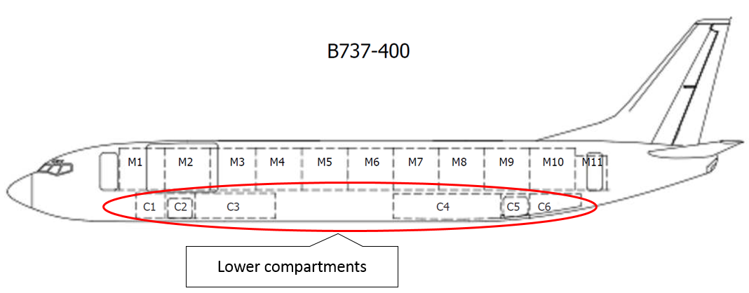
__________

  1. Eastern Standard Time (EST): Coordinated Universal Time (UTC) + 10 hours.
  2. Orlady H.W. & Orlady L.M. 1999, Human Factors in Multi-Crew Flight Operations, Ashgate Publishing Ltd, Hants, England.
  3. European Organisation for the Safety of Air Navigation 2006, Study Report on Selected Safety Issues for Staffing ATC Operations.
  4. Loukopoulos, L.D., Dismukes, R.K. & Barshi, I 2009, ‘The Perils of Multitasking’, Aerosafety World, August 2009, pp. 18-23.
  5. Van Benthem, K.D., Herdman, C.M., Tolton, R.G., & LeFevre, J.A. (2015), ‘Prospective memory failures in aviation: Effects of cue salience, workload, and individual differences.’ Aerospace Medicine and Human Performance, 86(4), pp. 366-373.

Occurrence summary

Investigation number AO-2018-040
Occurrence date 30/04/2018
Location Melbourne Airport
State Victoria
Report release date 06/06/2019
Report status Final
Investigation level Short
Investigation type Occurrence Investigation
Investigation status Completed
Mode of transport Aviation
Aviation occurrence category ANSP operational error
Occurrence class Serious Incident
Highest injury level None

Aircraft details

Manufacturer Airbus
Model A321-231
Registration VH-VWQ
Serial number 7384
Aircraft operator Jetstar Airways
Sector Jet
Operation type Air Transport High Capacity
Departure point Launceston Airport, Victoria
Destination Melbourne Airport, Victoria
Damage Nil

Aircraft details

Manufacturer The Boeing Company
Model 737-838
Registration VH-VZB
Serial number 34196
Aircraft operator Qantas Airways
Sector Jet
Operation type Air Transport High Capacity
Departure point Melbourne Airport, Victoria
Destination Brisbane Airport, Queensland
Damage Nil

Loss of containers overboard involving YM Efficiency, 16 NM east-south-east of Newcastle, New South Wales, on 1 June 2018

Final report

Report release date: 13/02/2020

Safety summary

What happened

At about 0035 on 1 June 2018, YM Efficiency was en route to Sydney, steaming slowly into strong gale force winds and very rough seas off Newcastle when it suddenly rolled heavily. As a result, 81 containers were lost overboard and a further 62 were damaged. The ship also sustained structural damage to its lashing bridges, superstructure and accommodation ladder. The ship spent a further 5 days at sea before berthing in Sydney on 6 June.

At the time of publication, searches including remote underwater surveys had identified 66 containers with a few washed ashore or close offshore. Five containers have been removed with 15 containers yet to be found. The accident resulted in substantial debris washing ashore on New South Wales beaches.

What the ATSB found

The ATSB determined that the loss of containers overboard occurred because forces generated during the sudden, heavy rolling placed excessive stresses on containers stowed aft of the ship’s accommodation. This resulted in the structural failure of containers and components of the lashing system, leading to the loss of containers. All potential causes for the sudden rolling were investigated but there was insufficient evidence to establish a definitive reason for the rolling.

The ATSB found that the weights and distribution of containers in the affected bays were such that calculated forces exceeded allowable force limits as defined in the ship’s Cargo Securing Manual (CSM). The investigation also identified that the stowage arrangement was not checked for compliance with the CSM’s calculated lashing force limitations during the cargo planning process ashore. This left sole responsibility for compliance with these requirements with the ship’s officers, with limited options to resolve deficiencies at a late stage in the process without unduly impacting operations. Further, the officers did not use the ship’s loading computer system and its lashing calculation program to check if the stowage arrangement complied as they probably did not have an adequate understanding of the system.

What's been done as a result

The ship’s managers, Yang Ming, now require checks of lashing forces during the initial cargo stowage planning stage ashore. Shore planners will receive regular training in the principles of cargo loading and securing, container stowage, and the dangerous goods functionality of the computer automated stowage planning software. Further, a stowage planning examination has been introduced for trainee stowage planners.

A review of loading computer systems in use across the Yang Ming fleet resulted in the adoption of class-specified, route-specific container stowage standards for part of the fleet. YM Efficiency and the other ships of the same size and type have been equipped with class-approved container stowage planning software systems, with the same software replicated ashore.

In addition, periodic training in the use of the ship’s loading computer system will be delivered to the responsible ship’s officers. Cargo procedures were also reviewed to ensure that the requirement for lashing forces checks to be conducted, both ashore and on board, was captured.

Safety message

The safe carriage of containers at sea depends on loading, stowing and securing them in compliance with the ship’s CSM. Checking stowage plans for compliance with the CSM requirements is increasingly achieved through loading computer systems. Notwithstanding the efficiency of computerised systems, the scale and pace of modern container ship operations puts significant pressure on ships officers to check and amend or approve proposed stowage plans at a late stage.

In that context, the planning process ashore offers the best opportunity to take all practical measures to ensure that the proposed stowage plan presented to ships officers complies with the CSM and is as safe as reasonably practicable.

Weather forecasting, routing and good navigational practices in adverse weather all play a part in minimising the risk of injuries to crew and damage to ship, cargo and environment. However, safe and effective container stowage planning remains the primary control measure in managing the risks involved in carrying containers by sea.


The occurrence

What happened

On 13 May 2018, the 4,250 TEU[1] container ship YM Efficiency sailed from Kaohsiung, Taiwan, bound for Sydney, New South Wales (NSW) (Figure 1). The ship was partly loaded, carrying 2,249 cargo containers (3,307 TEU)[2] with a forward draught of 10.5 m and an aft draught of 12.5 m. The ship’s schedule required it to arrive off Sydney at 0200 Eastern Standard Time[3] on 31 May.

Figure 1: YM Efficiency

Figure 1: Aerial view of YM Efficiency showing disruption to containers.

Source: ATSB

During the passage south, the ship maintained an average speed of about 10 knots[4] and received daily weather forecasts and routing advice from a commercial weather routing service.

On the afternoon of 28 May, YM Efficiency received instructions from the ship’s agent in Sydney to amend its arrival time to 1200 on 1 June 2018. In response, the master reduced the ship’s main engine speed to ‘slow ahead’ or 35 revolutions per minute (RPM) and the ship’s speed reduced to an average of about 8 knots.

On the afternoon of 29 May, the ship was off Brisbane, Queensland and by this time, the ship had also started receiving weather forecast information broadcast by Australia’s Bureau of Meteorology (BoM).

By 0930 on 30 May, YM Efficiency was off the coast of NSW, about 32 nautical miles[5] (miles) to the north‑east of Coffs Harbour. Weather forecasts received by the crew predicted steadily increasing winds and seas into the next day. The forecast estimated 4-5 m seas and swell along the NSW coast. In preparation for the expected adverse weather, the chief mate carried out checks in accordance with the ship’s heavy weather checklist. This included a check to ensure container lashings on deck were secure. The checks were completed by about 1130. By 1200, the ship was off Coffs Harbour and the weather (recorded in the ship’s logbook) was west-south-westerly winds at force 4[6] (between 11 and 16 knots) with 3 m seas and a 2 m swell.

At 1605, the BoM issued coastal waters forecasts for the Macquarie, Hunter and Sydney coastal regions of NSW. The forecasts included gale warnings for the next day, 31 May. The forecasts warned of 3 m seas and swell, increasing to 4 m by the evening. Other BoM forecasts, including marine wind warnings and high seas weather warnings, also warned of the developing adverse weather.

By 1900, YM Efficiency was off Port Macquarie and the weather had deteriorated. Consistent with the forecast conditions, it was recorded as being cloudy with force 8 (between 34 and 40 knots) west‑south‑westerly winds, 6 m seas and a 5 m swell.

By 0800 the next morning, 31 May, the ship was about 32 miles east-north-east of Port Stephens. The weather was recorded as being cloudy with west-south-westerly winds at force 8 (between 34 and 40 knots) with 7 m seas and a 5 m swell. The ship’s main engine speed remained at 35 RPM, with the ship making good about 6 knots. At about 0830, a second heavy weather checklist was completed, with the container lashings checked again. At about 1000, the ship received a weather forecast as part of the weather routing service and shortly after, BoM broadcast a coastal waters forecast. Both forecasts were consistent in predicting continuing adverse weather into the evening of 31 May.

The accident

At about 1314 on 31 May, the agent informed YM Efficiency’s master that the required arrival time had been postponed a further 8 hours to 2000 on 1 June. At about 1400, when the ship was about 84 miles from Sydney, the master stopped the main engine and began drifting about 30 miles east of Newcastle in order to adjust the ship’s arrival time (Figure 2). The weather at the time was recorded as being overcast with west‑south‑westerly winds at force 8 (between 34 and 40 knots) with 6 m seas and a 5 m swell. The ship’s officers recalled that, when the ship was drifting, there was little rolling or pitching.

The main engine was re-started for brief periods over the next few hours to maintain some control over the ship’s drift. The rough weather continued into the evening with the wind recorded as west-south-westerly and strengthening to force 9 (between 41 and 47 knots) at 2200.

At about the same time, the ship’s master completed his night orders, which instructed the officer of the watch (OOW) to continue monitoring weather forecasts and the observed weather conditions. The orders required the OOW to test the main engine and other navigational equipment by 2330 before calling the master in preparation to resume the passage.

Figure 2: Section of navigational chart Aus 489 showing YM Efficiency's track

Figure 2: Section of navigational chart Aus 489 showing YM Efficiency's track.
Source: Australian Hydrographic Office, annotated by the ATSB

Source: Australian Hydrographic Office, annotated by the ATSB

At about 2300, the chief engineer and duty engineer (fourth engineer) went down to man the engine room and prepare to start the main engine. Shortly before 2330, the third mate tested the engine and navigational equipment and then called the master. At about 2330, with the master on the navigation bridge (bridge), the engine was started, with the engine speed again set at ‘slow ahead’, and the passage to Sydney was resumed. The engineers left the engine room and returned to their cabins.

Shortly before midnight, having satisfied himself that the ship was on an appropriate heading, the master retired to his cabin. The master’s night orders instructed the officers to maintain 35 RPM and to use the rudder to keep the ship’s bow into the prevailing conditions to avoid a situation where the weather was on its beam.

The third mate maintained the steering in manual mode until about 2353 when he switched to autopilot with a set heading[7] of 211°. At midnight, the third mate handed over the watch to the second mate. The weather at midnight was recorded as being overcast with west-south-westerly winds at force 9 (between 41 and 47 knots) with 6 m seas and a 5 m swell.

The second mate reverted to manual steering before switching back to autopilot at about 0013 on 1 June with a set heading of 210°. The ship continued to make comfortable progress (little rolling or pitching) in the prevailing conditions at a speed of about 3 to 4 knots.

Shortly after 0034, in a position about 16 miles east-south-east of Newcastle, the ship experienced a period of sudden rolling for between 60 and 90 seconds. During this period, the ship rolled quickly and heavily at least three times. The ship’s master, who was in his cabin, recalled what he believed to be a wave crashing against the ship’s side immediately before the rolling began.

According to the master and second mate, the rolling reached angles of up to 30º to port and starboard. Almost immediately after the rolling commenced, several engine room alarms sounded. In response to the rolling, the second mate changed the steering from autopilot to manual. The second mate reported hearing loud noises on deck and suspected that there had been some container damage. He turned on the ship’s deck lights and observed that a number of containers had been damaged and possibly lost overboard from the bays aft of the accommodation. Shortly after, the main engine unexpectedly shut down, with the RPM gradually reducing to zero.

By about 0036, the rolling had subsided and the master had arrived on the bridge. The chief, second and fourth engineers went to the engine room to attend to the alarms. The second mate phoned the chief mate and alerted him to the situation. The master took over conduct of the ship’s navigation and instructed the chief mate to carry out a damage assessment.

Post-accident events

Following completion of a damage assessment at about 0040, the chief mate reported several containers damaged and lost overboard from bays 52 and 56, just aft of the accommodation.

At about 0045, the engine was successfully started and the bridge engine telegraph[8] set to ‘dead slow ahead’. Almost immediately however, the engine was stopped again following identification of a cracked outlet oil pipe on the control oil pump. The engineers immediately began repairs to the control oil pump. Meanwhile, the ship continued to drift in the gale force winds and seas. The master and mates reported that there was no significant rolling or pitching, and conditions on board were comfortable.

At about 0117, Newcastle vessel traffic information centre (VTIC) broadcast a safety call on very high frequency (VHF) radio channel 16.[9] The associated safety message was broadcast on VHF channel 09 and consisted of a gale warning for the Hunter coastal region and weather forecast information for 1 June. The message also advised all ships drifting off Newcastle to remain more than 10 miles away from the nearest coast. YM Efficiency’s VHF radios were monitoring both of these channels.

At about 0130, the master reported the incident to the company by satellite phone. At about 0200, repairs to the control oil pump were completed. The main engine was then returned to service but was not started. By this time, the ship had settled on a heading of about 290° with the prevailing wind and seas on its port beam. The master continued to attend to internal company incident reporting and other work as the ship drifted in a northerly direction at about 2.8 knots.

At about 0229, YM Efficiency’s second mate broadcast a message on VHF channel 16. The broadcast advised that containers had been lost overboard and provided the ship’s name and the position where the containers had been lost. Two minutes later, at about 0231, the second mate broadcast another message on VHF channel 16 addressed to all stations repeating the information in the previous broadcast. This broadcast was acknowledged by another ship in the vicinity. There was no response from Newcastle VTIC or any other coast radio station.

At about 0251, Newcastle VTIC called YM Efficiency on VHF channel 09 and advised that ships drifting off Newcastle were to stay more than 10 miles from the nearest coast. At that time, YM Efficiency was 9.8 miles off the coast. The second mate acknowledged the call and advised VTIC that the ship would start its engine and move. There was no reference to the loss of containers by either party during that radio exchange. At about 0252, the main engine was started and the ship resumed the passage.

Later that morning, during daylight, the ship’s crew carried out a detailed damage assessment and attempted to stabilise the damaged and collapsed containers on deck. The damage and container loss was limited to bays 52 and 56, aft of the accommodation (Figure 3). Other damage on deck included the accommodation ladder, superstructure and lashing bridges. The crew were able to confirm that no containers carrying dangerous goods had been damaged or lost overboard.

Figure 3: Damaged containers in bays 52 and 56

Figure 3: Damaged containers in bays 52 and 56.
Source: ATSB

Source: ATSB

At about 1153, the master notified the agent in Sydney of the incident and submitted an Australian Maritime Safety Authority (AMSA) incident notification form. The agent forwarded this AMSA incident notification to the Port Authority of NSW vessel traffic service in Sydney, who in turn forwarded the notification to AMSA and Roads and Maritime Services, NSW (RMS). Subsequently, AMSA disseminated the notification and updates to others, including the ATSB. Other action initiated by AMSA included drift modelling of the lost containers and promulgating maritime safety information to alert shipping to the hazards posed by the lost and drifting containers.

At about 1440, DP World Australia[10] advised the ship’s operator (Yang Ming – see the section titled YM Efficiency) that, given the potential berthing issues and scheduling delays associated with the sustained damage, YM Efficiency would not be accepted at the Port Botany terminal as originally planned. The ship then continued to steam off the coast while waiting for decisions to be taken ashore regarding its berthing.

The adverse weather conditions persisted for several days as the ship continued steaming off the south coast of NSW. However, none of the damaged or displaced containers on deck were lost overboard.

On 4 June, DP World Australia agreed to berth YM Efficiency at the Port Botany terminal early on 6 June. At about 1030 on 5 June, AMSA issued a direction to the harbour master under the Protection of the Sea (Powers of Intervention) Act 1981, directing that a suitable berth be provided to YM Efficiency by 0800 on 6 June. An AMSA direction was also issued to the ship’s owners and master directing that they make appropriate arrangements to berth the ship.

At about 0715 on 6 June, harbour pilots boarded YM Efficiency about one mile east of the Port Botany pilot boarding ground. By about 0936, the ship was securely berthed.

Over the course of the following days, representatives of many stakeholders attended YM Efficiency, including ATSB investigators, AMSA surveyors, and surveyors from the ship’s flag State. The ship was detained by AMSA following a Port State control (PSC) inspection.

On 11 June, the first damaged container was discharged from the ship and by 21 June, all remaining damaged containers had been discharged. In total 81 containers were lost overboard from bays 52 and 56 and a further 62 containers on board had varying degrees of damage.

Following the completion of corrective actions required by the PSC inspection, AMSA released the ship from detention and YM Efficiency departed Sydney for Melbourne at about 2130 on 22 June.

Clean-up and response

In the days following the container loss, AMSA along with RMS, continued to work with the ship’s owners and insurers to detect, identify and track the lost containers and their contents on the NSW coast. In accordance with NSW[11] and Commonwealth[12] marine environmental emergency management arrangements, RMS was designated the Combat Agency[13] and assumed responsibility for responding to the incident in NSW waters. While RMS took overall charge of the response to the beached containers and debris within affected NSW waters and coastal areas, AMSA assumed responsibility for the detection of lost containers and other vessel related issues.

More than 1,000 cubic metres of incident-related debris was recovered and disposed of from affected beaches and inshore areas on the NSW coast (Figure 4). Debris from container contents was largely limited to areas of the coast in the vicinity of Port Stephens, with some debris found further north near Coffs Harbour.

Figure 4: Contents of lost containers washed ashore

Figure 4: Contents of lost containers washed ashore.
Source: Roads and Maritime Services, NSW, modified by the ATSB

Source: Roads and Maritime Services, NSW, modified by the ATSB

Detection and recovery efforts

On 22 June 2018, a hydrographic survey vessel engaged by YM Efficiency’s insurers began conducting a sub-sea search for the lost containers. The survey vessel identified a number of probable containers and associated debris on the sea floor. AMSA published the positions of the located containers and debris and issued updated notices to mariners warning of their location.

AMSA received at least three reports of trawlers hooking-up on containers or other material lost from YM Efficiency, which represented a risk to local fisheries and industry.

On 3 December, AMSA-contracted remotely operated underwater vehicles began an assessment of the lost containers. Several containers were identified and imaged at various locations off the NSW coast. The imagery allowed an assessment by salvage experts of the environmental risks and recovery prospects for the identified containers and debris. As of 6 May, a total area of about 578.3 square km had been searched with at least 54 of the lost containers identified. Four containers were found washed up ashore or in waters close offshore.

  1. Twenty-foot Equivalent Unit, a standard shipping container. The nominal size of ships in TEU refers to the number of standard containers that it can carry.
  2. As stated in the ship’s bay plans for the voyage. In addition, the ship carried four 20-foot lashing gear storage units.
  3. Eastern Standard Time (EST): Coordinated Universal Time (UTC) + 10 hours.
  4. One knot, or one nautical mile per hour, equals 1.852 kilometres per hour.
  5. A nautical mile of 1,852 m.
  6. The Beaufort scale of wind force, developed in 1805 by Admiral Sir Francis Beaufort, enables sailors to estimate wind speeds through visual observations of sea states.
  7. All ship’s headings in this report are in degrees by gyrocompass with negligible error.
  8. An engine telegraph on a ship’s bridge is a device used to transfer orders for changes in engine speed or direction from the bridge to the engine room.
  9. VHF channel 16 (156.800 MHz) is the international distress, safety and calling frequency.
  10. DP World Australia, operator of the Port Botany container terminal where YM Efficiency was originally scheduled to berth.
  11. NSW State Emergency Management Plan (EMPLAN).
  12. National Plan for Maritime Environmental Emergencies.
  13. A Combat Agency is the agency identified in the State Emergency Management Plan as the agency primarily responsible for controlling the response to a particular emergency.

Context

YM Efficiency

The container ship YM Efficiency was built in January 2009, one of five vessels built by the Taiwan Shipbuilding Corporation (formerly known as the China Shipbuilding Corporation). At the time of the accident, the ship was owned by All Oceans Transportation, Liberia. The ship was managed and operated by Yang Ming Marine Transport Corporation (Yang Ming), Taiwan and classed with the American Bureau of Shipping (ABS).

The ship’s propulsion was provided by a Sulzer 7RT-Flex96C engine driving a single, fixed-pitch propeller, giving it a service speed of about 24.8 knots. The ship’s manoeuvring speed (normally used when navigating in ports and harbours) ranged from about 6.5 knots at ‘dead slow ahead’ to about 17 knots at ‘full ahead’.

The bridge was equipped with the necessary navigational equipment required by SOLAS[14] for a ship of its size. The equipment included a Japan Radio Corporation JCY 1800 voyage data recorder (VDR).[15]

The ship was on a regular service between ports in China, Taiwan and Australia. The service’s southbound schedule included port calls at Ningbo, Shanghai and Shekou in China, followed by Kaohsiung, Taiwan before calling at Sydney, Melbourne and Brisbane, in that order.

YM Efficiency had a crew of 23 Chinese and Taiwanese nationals. The ship’s master was a Taiwanese national with about 18 years of seagoing experience. He held a Taiwanese and a Liberian master’s certificate of competency. This was his fifth ship as master and his first time on YM Efficiency, which he had joined about 6 months before the accident.

The chief mate was a Chinese national with about 25 years of seagoing experience. He held a Chinese chief mate’s certificate of competency and a Liberian endorsement for his certificate of competency. He had about 8 years’ experience as chief mate, all of it with Yang Ming on container ships. The chief mate had joined the ship about 6 months before the accident.

The second mate, the officer of the watch (OOW) at the time of the container loss, was also a Chinese national. He held a Chinese certificate of competency for a watch keeping officer and a Liberian endorsement for his certificate of competency. He had about 8 years’ seagoing experience, most of it with Yang Ming.

The master and chief mate had also been on board YM Efficiency in January 2018, when about 15 containers and ship’s structures sustained substantial damage in adverse weather off the Queensland coast en route to Sydney.

Safety management system

YM Efficiency held a valid safety management certificate[16] issued by DNV GL (Det Norske Veritas – Germanischer Lloyd), on behalf of the ship’s flag State, Liberia, and operated under a documented safety management system (SMS). The SMS consisted of several manuals covering key aspects of the ship’s operations such as navigation safety, deck operations, shipboard management, environment protection, emergency management and engineering.

The deck manual and the shipboard management manual contained operating procedures and checklists related to container cargo operations. The SMS placed the responsibility for cargo operations on the chief mate, assisted by the master. In particular, the SMS required the completion of a container stowage checklist for every port call, which included various checks pertaining to the safe carriage of containers on board, and ship stability.

YM Efficiency’s stability condition upon departure from Kaohsiung satisfied the International Maritime Organization’s (IMO) intact stability criteria. Yang Ming procedures required ships of YM Efficiency’s size to have a metacentric height (GM)[17] of at least 0.70 m. The ship’s fluid metacentric height or GM (fluid)[18] on departure Kaohsiung, and at the time of the accident, was 1.09 m.

The navigation safety manual and the shipboard management manual included the general principles and requirements for navigation. They also included procedures and checklists concerning passage planning, weather routing and navigation in heavy weather.

The relevant SMS procedure encouraged the master to make prudent use of the weather routing service. However, the procedure stated that this did not exempt the master from the responsibility of ensuring navigational safety and from collecting and analysing weather information independently. The master was also required to observe current and forecast weather and alter course and speed, if necessary, to avoid adverse weather, which could cause harm to the ship or crew. The procedure clarified that navigational decisions when adverse weather was encountered were at the master’s discretion.

The SMS also contained a checklist (Appendix A) for use when the ship was expected to navigate in heavy weather or tropical cyclones. Procedures required the checklist to be completed prior to the ship encountering heavy weather or tropical storms to ensure precautions against foreseeable hazards of the weather were taken.

Weather

Weather routing advice

YM Efficiency’s passage plan from Kaohsiung to Port Botany was planned and executed based on weather and routing advice provided by Weather News Incorporated (WNI), a commercial weather routing service.

WNI used company-specific weather safety thresholds when providing routing advice to Yang Ming ships. The WNI procedure indicated that the advice would aim to maintain the shortest distance between two ports except when certain weather conditions were encountered. The procedure required WNI to consider speed adjustments when wave heights were expected to exceed 4 m and route diversions when wave heights exceeded 6 m. When wave heights were expected to exceed 8 m, the procedure required routing advice to consider seeking shelter or drifting to avoid encountering adverse weather.

Based on the original required arrival time off the Port Botany container terminal at Sydney of 0200 on 31 May, WNI routing advice positioned YM Efficiency to track west of the forecast adverse weather and enter port before the weather worsened. On 29 May, the master informed WNI of a revised required arrival time of 1200 on 1 June with a resulting 34-hour delay in the schedule.

On 30 May, WNI acknowledged the delay in the schedule and assessed that, based on the new schedule and current forecast, the ship would not enter port before adverse weather developed. The WNI forecast predicted south-south-westerly winds increasing from force 5 (between 17 and 21 knots) to force 6 (between 22 and 27 knots) and force 7 (between 28 and 33 knots) as the ship proceeded further south. The forecast predicted significant wave heights of up to 4 m and advised the master to expect 4‑5 m seas and swell. The routing advice to the master was to adjust the ship’s course and speed for safety, based on actual weather conditions. The forecast and routing advice was supplemented by a phone call from WNI to confirm the master had received the warning of impending adverse weather. The master acknowledged the warning and advised that he intended to drift in a position closer to Sydney to adjust the ship’s time of arrival to align with the delayed berthing schedule.

After the accident, WNI conducted a review into the significant decisions and actions taken leading up to the master’s decision to drift. The review report stated that the master’s intention to drift was acknowledged by WNI based on the following reasoning:

  • the vessel was already close offshore on the east Australian coast
  • adverse weather was expected along the east Australian coast and an immediate stoppage might not have provided better conditions than drifting closer to Sydney
  • there were no possible routing options that would keep the vessel clear of the developing conditions while also maintaining the required arrival time at Sydney
  • the master was aware of WNI’s forecast of adverse weather when he made his decision to drift
  • the expected significant wave height in the forecast did not exceed the safety threshold for this type of ship.
Weather encountered

The ATSB obtained and analysed weather forecast and observation data from several sources. These included VDR data, bridge logbooks and interviews with YM Efficiency’s crew, bridge logbooks from other ships in the vicinity[19] and available forecast data. The ship’s weather forecast information came primarily from WNI and the Australian Bureau of Meteorology (BoM).[20]

31 May

The prevailing weather on the afternoon of 31 May, when the ship was drifting, as recorded in YM Efficiency’s bridge logbook, was west-south-westerly winds at force 8 (between 34 and 40 knots), 6 m seas and a 5 m swell. These conditions were reasonably consistent with the BoM coastal waters forecast, broadcast at 1018, 1605, 1902 and 2200 that day. The forecast warned of a complex low-pressure system moving east over the Tasman Sea; it predicted south-westerly winds between 30 and 40 knots, 4 m seas and a southerly 3 m swell. As the evening progressed, the weather deteriorated with the wind recorded as increasing to force 9 (between 41 and 47 knots) at about 2200.

Table 1 summarises the weather forecast information for 2200 on 31 May that was available to the master.

Table 1: Weather forecast information

SourceWind directionWind speedSeasSwell
BoM forecastSW30‑40 knots4 m4 m (S)
WNI forecastSSW28‑33 knots2 m2 m (SSE)

At 2200, the master noted a south-westerly to south-south-westerly wind and a southerly swell in his night orders, which was consistent with the forecast. At about 2330, after resuming the passage, the master turned the ship to a heading of 211°, consistent with his instructions to the OOW in the night orders to keep the wind and swell on the ship’s bow.

1 June

Table 2 summarises the observed weather data at about midnight on 31 May (0001 on 1 June), as extracted from the bridge log books on board YM Efficiency and two other ships off Newcastle at that time (Attikos and Anangel Destiny).

Table 2: Recorded weather observations

SourceWind directionWind speedSeasSwell
YM EfficiencyWSW41‑47 knots6 m5 m (S)
AttikosSW41‑47 knots7 m4 m (SW)
Anangel DestinySSW48‑55 knots6 m5 m (S)
Wave data

Recorded wave data was obtained from the Port Authority of NSW and Manly Hydraulics Laboratory (MHL)[21]. The Port Authority’s wave rider buoys were located off Newcastle, about 16 miles west-north-west of the position where the containers were lost. The MHL buoys were located at Crowdy Head, about 84 miles north-east of that position, and at Sydney, about 65 miles south-west of the position.

The Port Authority’s buoys and MHL buoys collected significant wave height (Hsig),[22] maximum wave height (Hmax),[23] and wave direction[24] at 10-minute and 1-hour intervals, respectively. In addition, the buoys recorded wave periods associated with, the peak of the wave energy spectrum (Tp) and the average of zero up-crossing wave periods (Tz).

Table 3 details the recorded wave data at about midnight on 31 May (0001 on 1 June) for the MHL buoys and at about 0030 on 1 June for the Newcastle buoys.

Table 3: Recorded wave data on 1 June 2018

SourceTimeHsigHmaxWave directionTp
MHL Crowdy Head00014.8 m7.3 m181°12.14 s
MHL Sydney00014.2 m8.5 m187°10.83 s
Newcastle outer buoy00304.6 m7.4 m157°12.12 s
 00404.7 m7.4 m151°12.96 s
Newcastle inner buoy00304.7 m7.6 m166°12.36 s
 00404.8 m7.6 m168°12.35 s
Heavy weather checks

The heavy weather checklist was completed on the morning of 30 May, and then again on 31 May. Some of the relevant items included in the checklist are summarised below.

  • Have the protection boxes of plug sockets for reefer containers been firmly closed and put under protection?
  • Have container lashings on deck been secured?
  • Has course and speed been adjusted as necessary?
  • Are weather reports being received and monitored?
  • Are meteorological elements being observed and entered into the ship’s log?

The container loss

On the afternoon of 31 May, YM Efficiency was to the east of Newcastle, about 84 miles from Sydney. Prompted by the agent’s advice of a further delay to the schedule, the master assessed the situation and decided to stop and drift off Newcastle. He determined that the weather further south was worse than at the ship’s location, and that its stability condition (adjusted for arrival at Sydney) was acceptable for drifting.

Navigation in adverse weather

YM Efficiency began drifting off Newcastle at about 1400 on 1 June. The ship drifted until about 2330 that day, excluding brief periods when the main engine was used. Forecast and observed weather data for this period shows that the winds and seas were predominantly from the south-west with the swell from a direction between south-south-east and south. The weather steadily deteriorated into the evening with winds increasing to force 9 (between 41 and 47 knots) with 6 m seas and a 5 m swell being recorded at 2200.

The evidence shows that, except for the periods when the main engine was operating, the ship predominantly remained on a west-north-westerly heading. This is consistent with the expected behaviour of a container ship in that condition settling beam-on to prevailing winds and seas when drifting. While the ship lay with the weather on the beam, the master and mates recalled that there was no significant rolling or pitching.

Drifting beam-on in heavy seas leaves a ship vulnerable to the risk of synchronous rolling (see the section titled Cause of the rolling). That condition can impose stresses on the ship’s structure and cargo such as containers and securing devices, thereby increasing the risk of cargo shifting. Cargo shift can result in damage and in the ship assuming a potentially dangerous stability condition. Cumulative stresses exerted on containers and lashings due to heavy rolling can ultimately result in the failure of the container structure and lashing equipment.

Sudden heavy rolling

At about 2330 on 31 May, YM Efficiency’s passage to Sydney was resumed with the ship making comfortable progress, at slow speed, with little rolling or pitching. Shortly after 0034 on 1 June, the ship rolled heavily, with containers being damaged and lost overboard, followed by the main engine shutdown. Interviews with the ship’s officers indicated that the rolling was sudden.

The second mate reported that the ship rolled about four times, that is two times to either side, and that the rolling was quick. He estimated that the rolling reached angles of up to 30° to either side. The second mate also indicated that it was likely that the ship rolled to port first but that the subsequent roll to starboard was larger. The master stated that the ship was struck by a wave, that it rolled heavily three times to angles of up to 30° and that the rolling lasted about a minute. The main engine alarms and subsequent shutdown also occurred during this period of rolling.

Analysis of VDR data, including audio data, indicated the following sequence of events (Table 4).

Table 4: Sequence of events

Time on 1 June 2018Event
0034:28Estimated start of rolling
0034:50Engineering alarms began to sound
0035:00Rolling intensified
0035:12Estimated start of container loss overboard
0035:28Steering changed from autopilot to manual
0035:38Main engine shutdown and RPM reduces to zero
0036:00Estimated end of container loss overboard
0036:45Rolling subsided

Source: ATSB analysis of YM Efficiency’s VDR data

The master and second mate reported that the rolling subsided shortly after the container loss. Weather conditions after the accident remained rough and the ship settled on a north-westerly heading, drifting beam‑on to the prevailing weather but with no significant rolling or pitching reported.

Main engine shutdown

Engine room alarms sounded on YM Efficiency’s bridge soon after the rolling commenced. Alarm log data shows that the first alarms were cascade tank and expansion tank low-level alarms. Almost immediately afterwards, the main engine slowdown and shutdown pre-warning alarms sounded, followed by the main engine shut down and RPM gradually reducing to zero. The shutdown was accompanied by main bearing and piston lubricating oil low pressure alarms.

In the course of re-starting the main engine, both main engine control oil pumps were unserviceable for different reasons. As a result, the ship was left without propulsion until one of the pumps could be returned to service. Repairs continued until 0200 when the main engine was made available for use again. However, although the engine was available, the master decided to continue drifting.

At about 0252, Newcastle vessel traffic information centre (VTIC) called YM Efficiency with a reminder that ships were to stay greater than 10 miles from the coast when drifting, and that the ship was now 9.8 miles from the coast. Immediately after, the engine was started and the ship’s passage was resumed.

Potential causes for the rolling

YM Efficiency’s dynamic roll or pitch acceleration data was not recorded on board nor was there any requirement to record such data. As such, estimates of the ship’s rolling and movement were based on other evidence. The ship’s bridge was equipped with an analogue inclinometer,[25] which displayed the angle of the ship from the vertical, and registered the maximum angles reached to either side (Figure 5). Examination of the inclinometer after the ship berthed in Sydney indicated that the ship rolled to a maximum of about 29° to starboard and about 28° to port, which was consistent with the officers’ accounts of the accident. However, it was impossible to confirm if these roll angles were reached on the night of the accident.

Figure 5: Inclinometer

Figure 5: Inclinometer. Note semi-fixed indicators show the maximum roll encountered.
Source: ATSB

Note semi-fixed indicators show the maximum roll encountered.
Source: ATSB

The roll response of a ship in seas is determined primarily by wave-induced rolling moments,[26] the natural roll period of the ship[27] and the wave period.[28]

The roll period is largely dependent on the ship’s GM. A ship with a relatively large GM will require larger moments to incline and, when inclined, will return to the upright more quickly. Consequently, the roll period is relatively short and the ship may roll quickly and violently. A ship in such a condition is referred to as ‘stiff’. A ship with a relatively small GM will be much easier to incline and the roll period may be comparatively long. A ship in such a condition is ‘tender’.

At the time of the container loss, the ship’s stability condition had been adjusted in preparation for arrival at Sydney. The ship had been appropriately ballasted to bring it into alignment with the planned arrival stability condition, with draughts of 10.3 m forward and 12.6 m aft, and a planned arrival GM of 1.09 m. The ship’s planned arrival condition also complied with the IMO intact stability criteria.

The ship’s roll period (calculated by the loading computer system) was 20.1 s, which was consistent with the ATSB’s calculated value of about 20 s. This is generally considered an acceptable roll period resulting in a roll behaviour that is associated with neither a stiff nor a tender condition.

Extreme roll behaviour can also result from resonance, which is the phenomenon of a ship building up extreme rolling amplitudes by the addition of roll excitation loads. This can result in ‘normal’ synchronous rolling and ‘non-linear’ parametric rolling. Consistent with the master’s recollection, the ATSB also considered the possibility that the rolling was due to an abnormal or ‘rogue’ wave.

Abnormal waves

The master stated his belief that, immediately before the accident, a large, ‘freak wave’, struck YM Efficiency and initiated the heavy rolling.

Abnormal waves, sometimes referred to as ‘rogue waves’, are very large waves that can occur at sea. Abnormal waves may occur anywhere in the world where appropriate conditions arise. A well-documented example was the 26 m wave that struck the Draupner oil platform off the coast of Norway in January 1995.

Where seas and/or swell are reinforced by waves of another wave system or where seas are influenced by a combination of two or more weather systems acting together, abnormal waves may be expected. Certain circumstances such as refractive focussing due to bathymetry or currents (where waves become distorted by meeting shoal water or a strong opposing tidal stream or current) can contribute to larger waves occurring.[29] For example, under certain conditions off the coast of South Africa, sea and swell waves moving against the Agulhas Current are known to generate abnormal waves up to 25 m high.

Research indicates that waves encountering opposing currents can become significantly amplified and steeper, potentially breaking violently.[30] This allows for the possibility that seas and swell associated with southerly winds, acting in opposition to the East Australian Current, may contribute to a steepening of waves and the occurrence of significantly larger waves.

The BoM describes ‘rogue waves’ as waves greater than twice the total wave height. Statistical distribution estimates that about one in every 2,000 or 3,000 waves will be approximately twice the total wave height. For the most part, recorded maximum wave heights obtained from buoys off Newcastle and from MHL buoys did not exceed heights greater than twice the recorded significant wave heights. However, it should be noted that the recorded wave data was only sampled at 10 minute and 1 hour intervals so the resolution of the data was insufficient to categorically rule out a larger wave event. The ATSB reviewed weather conditions recorded in the logbooks of ships in the vicinity at the time of the container loss, but found no evidence of an unusual wave event.

Therefore, while the possibility that YM Efficiency encountered abnormal waves cannot be ruled out, there is insufficient evidence to conclude that this was the case.

Synchronous rolling

Synchronous rolling occurs when the ship’s roll period coincides with the encounter wave period.[31] This can result in the excitation of large roll motions as each roll is boosted by the waves and a condition of synchronous rolling is setup. Ships are more prone to such rolling when the seas are abeam. At the time of the heavy rolling, YM Efficiency was making way under power on a heading of about 210°. Analysis of the recorded wave data indicated peak wave directions as being from south-south-east and south respectively. This meant that the ship was manoeuvring with the seas largely on the port bow (not in beam seas) reducing the likelihood of synchronous rolling.

Additionally, the wave encounter period at the time of the accident, calculated based on the ship’s heading and speed and on recorded wave data, was 11–12 s compared to the ship’s calculated roll period of about 20 s. Therefore, it is highly unlikely that synchronous rolling was the cause of the heavy rolling.

Parametric rolling

Parametric rolling is a phenomenon, which can quickly generate large roll angles coupled with significant pitching motions. Parametric rolling can be defined as the spontaneous rolling motion of the ship that occurs as a result of dynamic instability associated with variation of the ship’s stability due to the changing immersed shape of the ship’s hull when wave crests pass it.

Various theoretical studies, observations, model tests and analysis of similar incidents and accidents indicate that parametric rolling can potentially occur when the following conditions are satisfied:

  • the ship is navigating in head seas or following seas
  • the natural period of roll is equal to approximately twice the wave encounter period
  • the wave length[32] is of the order of the ship’s length (that is, between 0.8 and two times the ship’s length between perpendiculars)
  • roll damping is low (for example, due to low ship’s speed).

Based on the weather conditions at the time of the accident and YM Efficiency’s heading, it is almost certain that the ship was in head seas at a speed of about 3 knots. Calculations using recorded wave data and, the ship’s heading and speed data, provided a probable calculated wave length of between 229 m and 262 m (the ship’s length between perpendiculars was 256.5 m). The probable wave encounter period was calculated to be 11–12 s. When compared to the ship’s calculated roll period of about 20 s, the wave encounter period does not appear to satisfy the related condition required for parametric rolling. While calculations show that some criteria required for parametric rolling may have been satisfied, there was insufficient evidence to conclude that parametric rolling was a contributing factor.

WNI roll-risk prediction program

WNI provided a ship’s master and officers with a program[33] to estimate the risk of heavy rolling for a calculated ship’s position based on forecast weather and user-entered details of the ship’s dimensions, stability, heading and speed. Although available on board YM Efficiency, there was no evidence that this program was used in the time leading up to the accident.

After the accident, WNI analysed the risk of heavy rolling based on the ship’s positions and forecast data for 0100 on 1 June. The program’s calculations indicated that there was no risk of heavy rolling due to parametric or synchronous rolling at that time.

Summary

Stability parameters that influenced the roll behaviour of YM Efficiency, such as its GM and roll period were acceptable and did not indicate that the ship was in a ‘stiff’ or ‘tender’ condition. While the possibility of an abnormal wave cannot be ruled out, there was insufficient evidence to conclude that such a phenomenon contributed to the heavy rolling.

At the time of the accident, the ship was oriented with its bow into the prevailing weather and was not in what would be considered ‘beam seas’. The ship’s calculated roll period was also not within the range that would be expected for synchronous rolling to occur. While there were certain conditions that were conducive to parametric rolling, the existence of other associated conditions could not be established. Further, the WNI roll-risk prediction program analysis indicated no risk of heavy rolling due to synchronous or parametric rolling. Therefore, a definitive cause for the heavy rolling could not be determined.

Carriage of containers

YM Efficiency was designed exclusively for the carriage of containers as cargo. Containers were carried in spaces called ‘bays’, both on deck and under deck in cargo holds. The ship’s bays were numbered from bay 01 forward to bay 60 aft, with bay numbers 52 to 60 located aft of the accommodation (see Appendix B for more detail). The SOLAS regulations required that cargo, including containers be loaded, stowed and secured on board the ship so as to prevent, as far as is practicable, damage or hazard to the ship and its crew and the loss of cargo overboard.

Container units

Containers are standardised cargo units usually manufactured to a standard specified by the International Standards Organisation. They are usually either 20 or 40 feet in length although other sizes are also used. Their width is standard at 8 feet while their height varies. Most containers normally have a height of 8 feet and 6 inches. A ‘high cube’ container is a standard container that is 9 feet and 6 inches high.

In general, a container’s structure is composed of a framework with corrugated steel walls and four corner posts. The corner posts support the container’s weight and that of containers loaded above it. The corner posts are provided with corner castings at their upper and lower ends, which are also used to attach container securing fittings (twistlocks and lashing bars).

The position of a container on board a ship is defined by means of a six-digit number. The first two numbers indicated the bay in which the container is located, the next two indicated the row and the last two numbers indicate the tier (see Appendix B for more detail).

Forces on containers

Containers are stowed and secured with suitable securing arrangements so as to withstand the forces imposed on them while being transported by sea. The motions of a ship in a seaway (Figure 6) give rise to accelerations and consequently, forces. The magnitude of these accelerations, and resultant forces, will depend upon the dimensions of the ship, its GM and the wind and sea conditions being experienced.

Figure 6: Motions of a ship in a seaway

Figure 6: Motions of a ship in a seaway.
Source: MacGregor Container Securing Systems product catalogue, modified by the ATSB

Source: MacGregor Container Securing Systems product catalogue, modified by the ATSB

When considering the forces acting on the container frames and the securing system, the following static and dynamic forces need to be taken into account:

  • static gravity forces
  • dynamic, inertial forces generated by accelerations due to roll, pitch and heave motions of the ship
  • wind forces
  • forces imposed by the securing arrangements
  • wave impact forces from seas.

Each force can be resolved into components acting both parallel to and perpendicular to the stack of containers (Figure 7). The resultant force acting on the container is the vector summation of the individual directional components of all forces acting at a given instant. The securing system was to be designed based on the most severe combination of static and dynamic forces as specified by classification societies, such that resultant forces on containers and securing devices remained within allowable limits.

Figure 7: Forces on a container in a seaway

Figure 7: Forces on a container in a seaway.
Source: MacGregor Container Securing Systems product catalogue, modified by the ATSB

Source: MacGregor Container Securing Systems product catalogue, modified by the ATSB

The resultant forces acting on an individual container and its securing system can be broadly classified into the following:

  • racking force
  • lifting force
  • corner post load.

Racking force (Figure 8, left) is a transverse or longitudinal force applied to the container parallel to the deck. When the ship is rolling heavily, the weight of containers in upper tiers can set up racking forces in the frame of the lowest containers. The larger the vessel’s roll, the greater the resultant racking force. Pitching sets up racking forces acting longitudinally, which are generally less than the transverse equivalent set up by rolling.

Lifting force (Figure 8, centre) is a vertical tension force or separation force. It usually occurs when the ship is rolling and results in a tipping movement of the container stack. If the lifting force is excessive, it can break or pull securing devices out of corner castings or separate corner castings from the containers themselves.

Corner post load (Figure 8, right) is a vertical compression force applied to the four container corner posts. Dynamic loadings resulting from the ship rolling can increase compression forces resulting in a failure of the container’s corner posts.

Other forces on a container include lashing forces resulting from the application of securing gear and pressure loads at the bottom of the container.

Figure 8: Resultant forces acting on containers

Figure 8: Resultant forces acting on containers.
Source: UK P&I Club, modified and annotated by the ATSB.

Source: UK P&I Club, modified and annotated by the ATSB.

Accelerations and forces acting on a stack of containers are calculated based on assumed maximum values of ship motion such as roll, pitch and heave. Forces on containers within a stack are affected by all these motions to some extent but generally, the angle of roll is the most critical. Water resistance to pitching is greater than rolling meaning ships generally roll to greater angles than they pitch. Rolling gives rise to transverse accelerations that impose racking stresses, compression forces and generates a tipping moment on the container stack.

The calculations of forces acting on containers and securings are based on a theoretical maximum angle of roll (defined by the classification society) that the ship is not expected to exceed but in practice sometimes can (as in this case). Further, calculations are based on the assumption that all containers are in good condition.

In YM Efficiency’s case, a roll angle of 25.1° was assumed as the maximum single amplitude of roll to determine the most severe combination of forces expected at sea. Therefore, the ship’s stowage and securing system was designed to withstand the expected forces, including those associated with this maximum roll, in combination with other forces. The ship’s stowage and securing system was also designed based on a maximum operational GM value of 1.61 m.

A ship’s cargo stowage arrangement and securing system is designed to ensure that the forces generated at sea remain within certain defined, allowable limits and that the container stow remain intact. Details of these maximum allowable limits of forces, stowage arrangements and container securing systems including lashing patterns and details of lashing gear are provided to the ship in its cargo securing manual (CSM).

YM Efficiency’s container stowage and securing arrangement was designed so that forces remained within the CSM‑specified maximum allowable limits (for 40-foot containers) shown in Table 5.[34]

Table 5: Allowable limits of forces acting on containers and securing systems

Racking force150 kN
Lifting force250 kN
Corner post load848 kN

Source: YM Efficiency’s Cargo Securing Manual

Container stowage and securing

In accordance with SOLAS regulations, all cargoes, other than solid and liquid bulk cargoes, need to be loaded, stowed and secured in accordance with a CSM approved by the ship’s administration. This requirement also applies to containers carried by ships.

YM Efficiency’s CSM

YM Efficiency’s CSM was compiled by All Set Marine Lashing,[35] the manufacturer of the ship’s cargo securing gear and approved by the ship’s classification society, ABS, on behalf of the flag State. The cargo stowage and securing arrangements in the manual were calculated based on Lloyd’s Register[36] rules for the classification of ships and verified against those rules by ABS. Significantly though, class approval of the CSM examined only the manual’s compliance with the format and content required by the Code of Safe Practice for Cargo Stowage and Securing (CSS Code).[37] The approval did not include the acceptability of particular cargo stowage and securing arrangements.

General guidance on stowage and securing

The CSM required the master to ensure that containers on board YM Efficiency were at all times stowed and secured in a safe and efficient manner, based on prevailing conditions and the principles of safe stowage. The manual provided general information on cargo stowage, securing and evaluation of forces acting on containers, including that:

  • forces are generally composed of components acting relative to the longitudinal, transverse and vertical axes of the ship
  • forces are to be absorbed by suitable arrangements for stowage and securing to prevent cargo shifting
  • the most severe forces can be expected in the furthest forward, the furthest aft and highest stowage position on each side of the ship
  • the transverse forces exerted increase directly with the GM of the ship
  • cargo should be distributed such that the ship’s GM, wherever practical, remains within an acceptable upper limit to minimize the forces acting on the cargo
  • in addition to the forces referred to above, cargo carried on deck may be subject to forces arising from the effects of wind and seas
  • improper ship handling (course or speed) may create adverse forces acting on the ship and cargo
  • the magnitude of these forces may be estimated by using the appropriate calculation methods described in the manual
  • the maximum quantity of tiers stated in this manual should not be exceeded because the loading of the securing system would be increased.

In addition to general guidance on cargo securing and documenting rules upon which the stowage and securing system was designed, the manual provided information on the ship’s specific container stowage and securing arrangements.

Container securing system

YM Efficiency’s securing system was designed so that, when complied with in conjunction with the required stowage arrangement, resultant forces on the container securing devices would not exceed the allowable working loads of the equipment. The CSM described the ship’s container securing arrangement (lashing arrangement) and container securing equipment (lashing equipment) including the minimum acceptable safe working load (SWL)[38] and minimum breaking load (MBL)[39] for each item of lashing equipment. The manual also included details of the actual equipment in use on board the ship, including their SWL and MBL.

The ship’s lashing arrangement required the lashing of containers in specific patterns, depending on the container’s size and location. The CSM specified a standard container securing arrangement or an alternative container securing arrangement.[40] On board YM Efficiency, the alternative container securing arrangement was in use. The equipment used to secure containers on deck included twistlocks, lashing bars and turnbuckles.

Twistlocks were used to secure containers stowed on deck to the hatch cover or deck and to secure containers to one another vertically in a stack. On board YM Efficiency, two variants of semi-automatic twistlocks were used, depending on whether they were being used on the deck/hatch cover or between containers (Figure 9). The SWL and MBL of these twistlocks was 250 kN and 500 kN, respectively (a safety factor of two).

Figure 9: Twistlock types used in different locations in container stacks

Figure 9: Twistlock types used in different locations in container stacks.
Source: YM Efficiency’s CSM and MacGregor, modified and annotated by the ATSB

Source: YM Efficiency’s CSM and MacGregor, modified and annotated by the ATSB

Lashing bars were used to secure containers and tension lashings in combination with turnbuckles. Turnbuckles were anchored to lashing eyes on the ship’s deck, hatch coaming or lashing bridge, depending on the location on board. Lashing bars (Figure 10) came in three variants: short, long and vertical.[41] Lashing bars and turnbuckles had a SWL of 250 kN and a MBL of 500 kN (a safety factor of two).

Figure 10: Lashing bar and turnbuckle arrangements

Figure 10: Lashing bar and turnbuckle arrangements.
Source: YM Efficiency’s Cargo Securing Manual, modified and annotated by the ATSB

Source: YM Efficiency’s Cargo Securing Manual, modified and annotated by the ATSB

Condition of securing equipment

The ATSB onsite investigation examined the lashing equipment in use on the ship. They were found to be in generally good condition and appeared to be well maintained, with little corrosion or wear evident.

The examination also found a number of broken twistlocks and parts of twistlocks scattered in the vicinity of bays 52 and 56, and attached to damaged containers. Some of these containers from toppled stacks lay on their sides, but remained securely fastened to each other with twistlocks despite being in precarious positions and enduring rough weather over several days following the accident (Figure 11). Many bent or deformed lashing bars and turnbuckles attached to damaged containers or loose on deck were also found.

The ATSB also obtained records relating to the shipboard inspection and maintenance of the lashing equipment. These records showed that the lashing equipment was inspected regularly, with the last inspection performed in March 2018, about 2 months before the accident. Sub-standard lashing equipment was removed from use and repaired or discarded. The ship held ample stocks of new lashing equipment for use as spares.

Based on the examination of the ship’s lashing equipment, inspection of maintenance records and the fact that many containers remained securely restrained in the rough weather following the accident, the condition of the lashing gear was considered to have been satisfactory. As such, the condition of the lashing equipment was not considered to have contributed to the loss of containers.

Figure 11: Dislodged containers six days after the accident

Figure 11: Dislodged containers six days after the accident.
Source: ATSB

Source: ATSB

Cargo operations in Kaohsiung

YM Efficiency’s cargo operations in Kaohsiung involved the discharge of two containers and the loading of 881 containers in several bays, including bay numbers 52 and 56. Loading operations involved the loading of containers of various types including standard 20-foot and 40-foot containers, 40-foot ‘high cube’ containers, refrigerated containers and containers carrying dangerous goods.

Bay 52 stowage arrangement

Bay 52 was located immediately aft of the ship’s accommodation. The bay had no under-deck cargo loading space and containers were loaded directly onto the main deck. The bay comprised 13 rows and was empty on arrival at Kaohsiung.

The middle three rows (rows 00, 01 and 02 of bays 51 and 53) were loaded with empty, 20-foot refrigerated containers to a height of eight tiers. The remaining 10 rows were used to load seventy-six 40-foot ‘high cube’ containers to a height of eight tiers with the exception of the outboard row on either side where only six tiers were loaded (see Appendix C for more detail). The outboard rows did not begin at deck level but were set on support pedestals beginning at a height equivalent to the second tier.

Of the seventy-six 40-foot ‘high cube’ containers in bay 52, more than three-quarters were lost overboard (29 from the port side and 31 from the starboard side). The remaining 40-foot ‘high cube’ containers all sustained varying degrees of damage (Figure 12). None of the 20-foot containers were lost overboard although one was damaged.

Figure 12: Bay 52 plan showing lost and damaged containers

Figure 12: Bay 52 plan showing lost and damaged containers.
Source: Yang Ming, modified and annotated by the ATSB

Source: ATSB

Bay 56 stowage arrangement

Bay 56 was located immediately aft of bay 52. The bay had a cargo hold under deck and therefore, containers in this bay were loaded on top of the hatch covers. The bay comprised 13 rows and was partially loaded on arrival at Kaohsiung. The cargo already on board comprised thirty-one 40-foot ‘high cube’ containers and four 40-foot standard containers loaded in Shanghai in the middle seven rows to a height of five tiers. The under-deck space was also fully loaded on arrival at Kaohsiung.

Cargo operations in Kaohsiung involved loading three additional tiers of 40-foot ‘high cube’ containers in the middle seven rows. In addition, two tiers of 20-foot containers were loaded in the outer three rows on either side of bays 55 and 57 (see Appendix D for more detail).

Of the fifty-six 40-foot containers in bay 56, over a third (21 containers) were lost overboard. Almost all the remaining 40-foot containers sustained some degree of damage (Figure 13). None of the 20-foot containers was lost overboard although seven were damaged.

Figure 13: Bay 56 plan showing lost and damaged containers

Figure 13: Bay 56 plan showing lost and damaged containers.
Source: Yang Ming, modified and annotated by the ATSB

Source: Yang Ming, modified and annotated by the ATSB

Cargo securing

The lashing of containers in Kaohsiung was performed by stevedores supervised by the ship’s crew. The chief mate confirmed that the container lashings were inspected by the crew prior to departure from Kaohsiung, and found to be satisfactory. This check was also noted in the container stowage checklist completed for Kaohsiung. The chief mate also reported that lashings were checked and tensioned as required, during actioning of the heavy weather checklist prior to the accident.

The loss and damage to numerous containers and their lashings in bays 52 and 56 made it impossible to verify the original lashing arrangement in those bays. However, the lashing arrangement in other bays were generally consistent with the CSM. Additional lashings found in some bays in excess of those required by the CSM were probably applied post-accident to prevent further loss.

Container weights

In accordance with SOLAS regulations, a verified gross mass[42] needs to be declared for all packaged containers loaded on board a ship. This regulation was adopted to increase maritime safety and reduce the dangers to cargo, containers, ships and persons resulting from the incorrect declaration of container weights.

The ATSB’s analysis of container weights in the affected bays found that, for the most part, the measured containers weights were consistent with the declared weights in the manifest with a few minor exceptions.

Container mass-distribution arrangements

The CSM contained information covering the stowage of containers on deck and in cargo holds. A general arrangement bay plan laid out how containers of different standard sizes could be loaded. In addition, mass‑distribution arrangements provided an overview for each bay of maximum stack weights and the permitted vertical distribution of weights in stacks.

The mass-distribution arrangement represented an example stowage arrangement that demonstrated the ship’s cargo-carrying capacity with calculated forces on containers and lashings at their maximum. Loading in conformance with the applicable mass-distribution arrangement was one way of complying with the allowable force limitation requirements of the CSM. Stowage arrangements that did not strictly conform to the mass‑distribution arrangements in the CSM could be acceptable provided it could be established that calculated forces did not exceed allowable limits.

Mass-distribution arrangements were provided for two values of GM (1.00 m and 1.61 m). For each GM value, depending on the size of the containers loaded, the manual provided a maximum stack weight for each stack of containers and a vertical weight distribution showing maximum container weights for each individual container slot in the stack (Figure 14).

Figure 14: Bay 52 and 56 mass-distribution arrangements for 1.61 m GM

Figure 14: Bay 52 and 56 mass-distribution arrangements for 1.61 m GM.
Source: YM Efficiency’s Cargo Securing Manual, modified and annotated by the ATSB

Source: YM Efficiency’s Cargo Securing Manual, modified and annotated by the ATSB

Maximum container weights and stack weights were specified in the mass-distribution arrangement taking into consideration the effect the weights and their distribution would have on the calculated forces acting on the system. Conformance with the mass-distribution arrangements was based on the underlying principle that container weights should not exceed the maximum weight provided for each individual container slot and that stack weights should not exceed the maximum stack weight.

The mass-distribution arrangements specified in the CSM were vertically stratified (that is, individual container weights progressively reduced with stack height). This accorded with the widely recognised principle of avoiding the loading of heavy containers over light ones, which was reflected in the manual as follows:

It is a general principle that no heavy containers shall be stowed on top of light containers. In practice, this principle can to some extend [sic] be deviated from, when stack weights are not fully utilised.

There was no clarification in the manual about the extent to which the principle concerning avoiding ‘heavy over light’ loading could be deviated from. As with the mass-distribution arrangement, alternate stowage arrangements that deviated from the ‘no heavy over light’ rule could still be acceptable provided calculated forces were assessed to be within allowable limits. In practice however, it was unlikely that a stowage arrangement that significantly deviated from the ‘no heavy over light’ principle or from the manual’s mass‑distribution arrangement would still comply with the calculated force limitations of the manual.

Conformance with mass-distribution arrangements

As discussed, the ship’s GM is a key factor influencing the forces acting on containers and their securing system while the ship is at sea.

Since there was no mass-distribution arrangement in the CSM specific to YM Efficiency’s GM of 1.09 m on departure from Kaohsiung, the arrangement for the next higher GM (1.61 m) was applicable. The stowage arrangement in bays 52 and 56 were compared to this mass-distribution arrangement for 40-foot ‘high cube’ containers. This comparison revealed a number of significant deviations from the CSM.

Deviations from the applicable mass-distribution arrangement as observed in the bay 52 stowage arrangement included (Figure 15):

  • loading of 40-foot ‘high cube’ containers exceeded the 7-tier limit specified (loaded to a height of 8 tiers)
  • all stacks of 40-foot ‘high cube’ containers exceeded the maximum stack weights specified
  • many container weights exceeded the weights specified for individual slots
  • many instances of heavy containers above lighter ones, contrary to principles of vertical distribution.

Figure 15: Bay 52 stowage comparison

Figure 15: Bay 52 stowage comparison.
Figure shows the mass-distribution arrangement for bay 52 for 40-foot ‘high cube’ containers and a 1.61 m GM (left) compared to the ship’s actual stowage arrangement on departure from Kaohsiung (right). Container and stack weights in excess of those defined in the mass-distribution arrangement are highlighted in red.
Source: Yang Ming, modified and annotated by the ATSB

Figure shows the mass-distribution arrangement for bay 52 for 40-foot ‘high cube’ containers and a 1.61 m GM (left) compared to the ship’s actual stowage arrangement on departure from Kaohsiung (right). Container and stack weights in excess of those defined in the mass-distribution arrangement are highlighted in red.
Source: Yang Ming, modified and annotated by the ATSB

Deviations from the applicable mass-distribution arrangement as observed in the bay 56 stowage arrangement included (Figure 16):

  • loading of 40-foot ‘high cube’ containers exceeded the 7-tier limit specified (loaded to a height of 8 tiers)
  • many container weights exceeded the weights specified for individual slots
  • many instances of heavy containers above lighter ones, contrary to principles of vertical distribution.

Figure 16: Bay 56 stowage comparison

Figure 16: Bay 56 stowage comparison.
Figure shows the mass-distribution arrangement for bay 56 for 40-foot ‘high cube’ containers and a 1.61-m GM (left) compared to the ship’s actual stowage arrangement on departure Kaohsiung (right). Container and stack weights in excess of those defined in the mass-distribution arrangement are highlighted in red.
Source: Yang Ming, modified and annotated by the ATSB

Figure shows the mass-distribution arrangement for bay 56 for 40-foot ‘high cube’ containers and a 1.61-m GM (left) compared to the ship’s actual stowage arrangement on departure Kaohsiung (right). Container and stack weights in excess of those defined in the mass-distribution arrangement are highlighted in red.
Source: Yang Ming, modified and annotated by the ATSB

The Australian Maritime Safety Authority (AMSA) advised that, following the previous container damage on board YM Efficiency in January 2018, its inspection identified a number of container mass and distribution irregularities. These irregularities were concentrated in the forward bays where the damage occurred.

Compliance with the mass-distribution arrangements in the CSM offered a simple, if tedious, means of planning a stowage arrangement that minimised the risk of calculated forces exceeding allowable limits. However, in practice, cargo-planning and stowage operations were conducted using a loading computer system rather than by planning in strict conformance with the mass-distribution arrangements. This was because the scale, complexity and pace of modern container ship operations means that efficient cargo stowage and planning without the use of an on board loading computer system are highly impractical if not impossible. The use of a loading computer system involved direct calculation of the resultant forces acting upon the containers and lashing systems. This approach allowed the user to confirm that calculated forces did not exceed the maximum allowable limits of forces defined in the CSM.

Loading computer system

Aids used on board ships to assist with stability and cargo planning include loading instruments, on-board stability computers and loading computer systems.

A loading instrument provides a means to easily and quickly ascertain that the still‑water bending moments, shear forces, and, where applicable, still-water torsional moments and lateral loads (wind pressure force) at specified points along the ship’s length will not exceed the specified values in any load or ballast condition. ABS requirements for YM Efficiency included carriage of an approved ‘loading instrument’.

An on-board stability computer is an instrument to ascertain that stability requirements specified for the ship in the stability booklet are met in any loaded or ballast condition. There was no class requirement for the ship to be equipped with an on-board stability computer.

A loading computer system incorporates the functions of a loading instrument and an on-board stability computer. In addition, a loading computer system may also incorporate a container or cargo loading module and a lashing calculation program. There was no class requirement for the ship to be equipped with a loading computer system.

Nevertheless, YM Efficiency was equipped with a loading computer system capable of performing the functions of a loading instrument and on-board stability computer, in addition to container stowage planning and lashing calculation capabilities.

The ship’s loading computer system was approved by ABS. However, the approval only covered the longitudinal strength and certain other stability-related aspects of the ‘loading instrument’ component of the system. There was no class approval or, requirement for class approval for the cargo-planning and stowage components of the loading computer system.

ABS Container Securing System certification

Class (ABS) offered an optional container securing systems certification. This involved class survey of the ship’s entire CSM, cargo securing equipment and loading computer system. However, YM Efficiency did not hold this certification nor was it required to. Nevertheless, the ABS Guide for Certification of Container Securing Systems contained useful information on container stowage arrangements, the securing of containers and the use of the CSM.

The key points from the guidance document were that:

  • container stack weights are limited by the strength of the hull structure and the securing system
  • permissible stack weights for each GM shall be applicable for all operating conditions with a lower GM
  • the higher GM shall be selected to represent a near upper bound on all possible operating conditions because it represents an upper bound on the loads that are not to be exceeded
  • weather effects increase the loading into the containers and lashing components
  • stacks located at the ends of the vessel experience the highest accelerations
  • outboard stacks experience higher accelerations than inboard stacks
  • raising portions of the stack by using taller containers in lower tiers will increase acceleration loads on the stack and reduce the permissible weights
  • forces into the lashing system and containers are reduced when the stack is vertically stratified, with the heaviest containers located in the lower tiers
  • container lashing calculation software is used to calculate and verify that the container securing arrangements comply with the applicable strength requirements and acceptance criteria
  • the container weight limits given by the computer lashing program are to be strictly followed in practice.

YM Efficiency’s loading computer system

YM Efficiency’s loading computer system—‘TSB Supercargo’—was designed by Total Soft Bank. The system allowed the user to perform a range of functions and checks associated with the safe stowage, loading and carriage of containers.

In particular, the system’s lashing calculation program allowed the user to calculate, for a given container stowage arrangement, the resultant forces acting upon containers and the securing system based on the class-defined assumptions for the worst combination of dynamic and static forces expected at sea. The use of a loading computer system allowed for increased flexibility in container stowage and carriage. Stowage arrangements could be assessed and accepted even if they deviated from the mass-distribution arrangement in the manual, provided the lashing calculation program was used to check that calculated forces were within allowable limits. This also made it possible for a heavy container to be accepted for loading over a light container, provided the calculated forces were found to be within allowable limits.

Operation of the TSB Supercargo

Checks of the proposed container stowage arrangements using the TSB Supercargo required an electronic file containing the stowage plan to be loaded into the system and then checked for compliance against various requirements such as the design stack weight check and lashing calculation check. In addition, the system could also be used to check the stowage plan for compliance with the International Maritime Dangerous Goods Code (IMDG Code)[43] requirements.

Design stack weight check

The ship’s design stack weight was a maximum limiting value based solely upon the strength of the ship’s deck, fittings and hatch covers. This value was different from the maximum stack weight in the mass‑distribution arrangement, which considered the effect of container weights on the calculated forces acting on containers and lashings.

The maximum design stack weight was 80 t for a stack of 20-foot containers and 110 t for a stack of 40-foot containers.

TSB Supercargo could be used to check the stowage arrangement against the ship’s design stack weight to ensure that the ship’s deck and hatch structures were not overloaded. If a container stack exceeded the design stack weight, the program indicated this by displaying the exceedance in red above the relevant stack. YM Efficiency’s chief mate stated that this check was performed with no exceedances detected. ATSB analysis confirmed that there were no design stack weight exceedances.

IMDG compliance check

The carriage of dangerous goods by sea has to be conducted in accordance with the IMDG Code. The Code classifies dangerous goods (DG) into nine classes. A key aspect of safe cargo stowage related to the carriage of dangerous goods involved the segregation of containers carrying dangerous cargo from other containers carrying incompatible classes of dangerous cargo. Containers carrying certain classes of dangerous cargo also had to be segregated from refrigerated cargo containers. A check to ensure that this was carried out was marked as completed in the chief mate’s container stowage checklist for the port call at Kaohsiung.

Checks of YM Efficiency’s container stowage arrangement after the occurrence, using the ship’s loading computer system, identified 10 unresolved IMDG segregation conflicts. These conflicts involved DG containers being stowed in proximity to other non-compatible DG containers or refrigerated containers without the separation required by the Code.

Lashing forces calculation check

The lashing forces calculation check assessed the container stowage arrangement against the maximum values for lashing forces described in the CSM. Setup for the check involved selecting appropriate values for the strength and flexibility parameters of the lashing equipment, the lashing pattern in use, limits of forces and other parameters. Alternatively, default values based on generic DNV GL container stowage and securing rules[44] and, minimum acceptable equipment SWL and MBL values from the ship’s CSM could be used. DNV GL default values for the allowable limits of calculated lashing forces were largely identical to those defined by ABS in YM Efficiency’s CSM. The program calculated the maximum forces expected to be generated on containers and securing systems based on the assumed worst combination of static and dynamic forces as defined in the CSM.

TSB Supercargo did not specifically provide an indication if container stacks exceeded the stack weights provided in the container mass-distribution arrangement (which could be less than the maximum design stack weight). Nor did it alert the user if individual container weights exceeded the maximum weights for individual slots or if the maximum number of tiers were exceeded. Instead, the program calculated the effect of container weights and their distribution, on the forces acting on the containers and their securing system.

The program indicated these calculated forces either as a percentage of the maximum allowable force or as units of force (kN). In both cases, an exceedance of the maximum allowable value of the lashing force would be indicated in red, allowing the operator to readily identify the container stacks where changes needed to be made to reduce the calculated forces to acceptable values.

Analysis of the stowage arrangement

After the accident, lashing calculation checks were performed by the ship’s manager, Yang Ming, on YM Efficiency’s container stowage arrangement as presented to the ship in Kaohsiung. The checks were performed using the same TSB Supercargo software program as was in use on board the ship. The check was performed using the program’s default values. The stowage plan, container weights and other underlying parameters, such as limits of forces, were verified by the ATSB. The outcome of the checks showed that calculated forces in a number of stacks in bays 52 and 56 exceeded allowable limits of lashing forces as indicated by the highlighted figures in red (Figure 17, see Appendix E for a larger version).

Further checks by Yang Ming at the ATSB’s request, involving minor variations to lashing force parameters, lashing equipment characteristics and vessel speed did not provide significantly different results.

Figure 17: Outcome of lashing forces calculation check (actual values)

Figure 17: Outcome of lashing forces calculation check (actual values). An indicative image primarily showing the lashing forces calculation check for bays 52 and 56 with results displayed in kN. Values of lashing forces in excess of the maximum allowable forces are displayed in a red font (highlighted by the ATSB).
Source: Yang Ming, modified and annotated by the ATSB

An indicative image primarily showing the lashing forces calculation check for bays 52 and 56 with results displayed in kN. Values of lashing forces in excess of the maximum allowable forces are displayed in a red font (highlighted by the ATSB).
Source: Yang Ming, modified and annotated by the ATSB

Figure 18 (and Appendix F) detail the outcome of the same lashing check expressed as a percentage of the maximum allowable forces. Calculated forces that exceeded 100 per cent of the allowable value are indicated by figures in red.

Figure 18: Outcome of lashing forces calculation check (percentage)

Figure 18: Outcome of lashing forces calculation check (percentage). An indicative image primarily showing the lashing forces calculation check for bays 52 and 56 with results displayed as a percentage of the maximum allowable forces. Values of lashing forces in excess of the maximum allowable forces are displayed in a red font.
Source: Yang Ming, modified by the ATSB

An indicative image primarily showing the lashing forces calculation check for bays 52 and 56 with results displayed as a percentage of the maximum allowable forces. Values of lashing forces in excess of the maximum allowable forces are displayed in a red font.
Source: Yang Ming, modified by the ATSB

In addition, there were a few other instances (in bay 48 located immediately forward of the accommodation) where calculated forces exceeded allowable values. However, no containers were lost or damaged in this bay. Lashing forces in all other bays were within the allowable limits.

Lashing calculation check of bay 52

A lashing calculation check of YM Efficiency’s container stowage arrangement showed that calculated forces in at least 10 locations in bay 52 exceeded the allowable limits of various forces (Figure 19).

For example, for the container in position 520382, calculations show lifting force at 237 per cent (about 592 kN) of the allowable force of 250 kN. This indicates a lifting force in excess of the 500 kN MBL of the twistlocks. Similarly, calculated load on the container corner posts were at 147 per cent of the allowable compressive corner post load of 848 kN.

Figure 19: Bay 52 plan showing calculated force exceedances

Figure 19: Bay 52 plan showing calculated force exceedances.
Source: Yang Ming, modified and annotated by the ATSB

Source: Yang Ming, modified and annotated by the ATSB

Lashing calculation check of bay 56

A lashing calculation check of YM Efficiency’s container stowage arrangement showed that calculated forces in at least eight locations in bay 56 exceeded the allowable limits of various forces (Figure 20).

For example, for the container in position 560682, calculated lifting force was at 262 per cent (655 kN) of the allowable lifting force of 250 kN and in excess of the 500 kN MBL of the twistlocks. Similarly, calculated load on the container corner posts were at 152 per cent of the allowable compressive corner post load of 848 kN.

Figure 20: Bay 56 plan showing calculated force exceedances

Figure 20: Bay 56 plan showing calculated force exceedances.
Source: Yang Ming, modified and annotated by the ATSB

Source: Yang Ming, modified and annotated by the ATSB

Effect of forces

Significant exceedance of the compressive corner post load would typically be expected to manifest as a collapse of the container’s corner post/s (Figure 21). This can result in the stack becoming unstable and collapsing to either side, thereby placing forces on adjoining stacks or structures. Racking force exceedances typically manifested as a deformation or distortion of the container box structure. There was no safety factor applied to the maximum design corner post load (848 kN) and maximum racking force (150 kN) values for the container structure.

Figure 21: Image showing container corner post collapse

Figure 21: Image showing container corner post collapse. Source: ATSB

Source: ATSB

Exceedance of the lifting forces could result in excessive and potentially destructive stresses on container corner sockets, twistlocks, turnbuckles and lashing rods (Figure 22). The destructive failure of one or more twistlocks leaves the container and those above it partially or completely unsecured. This can result in the loss or uncontrolled movement of the container leading to a collapse or toppling of the stack. This can also place stresses on adjoining stacks that were not allowed for in the design of the lashing system.

It is important to note that, for the container loss to have occurred, it was not necessary for every single instance of a force exceedance to have manifested as a failure of the container or lashing device. Any one structural failure of a container and/or lashing or, a combination of such failures could have given rise to the sequence of events that resulted in the loss of containers overboard.

Figure 22: Examples of lifting force exceedances

Figure 22: Examples of lifting force exceedances. Source: ATSB

Source: ATSB

Conduct of the lashing forces calculation check

The chief mate stated that he did not perform a lashing forces calculation check of the proposed container stowage plan in Kaohsiung. The master believed that he would be consulted by the chief mate if there were any difficulties or issues with the cargo plan. He also stated that he considered the chief mate to be an experienced and capable officer. The fact that he was not called upon for assistance led to the master assuming that the cargo plan had been approved without any significant unresolved issues.

Training and knowledge

The chief mate and master both stated that they were unfamiliar with the set-up and use of the lashing forces calculation check using TSB Supercargo’s lashing calculation program. The unresolved IMDG segregation conflicts in the cargo plan suggested that there might also have been an inadequate understanding of other aspects of the loading computer system.

There was no evidence of training in the use of TSB Supercargo being provided to ship’s officers prior to the accident (training was provided to the chief mate and master after the accident). Junior officers were usually trained in the use of the system and its checks while on the job, by senior officers. While newly promoted chief mates were usually supervised on board by the master until confident in the conduct of the checks, YM Efficiency’s chief mate was an experienced officer with many years’ experience as a chief mate on container ships.

Cargo-planning process

YM Efficiency berthed at Kaohsiung at 1448 in the afternoon of 31 May and sailed shortly before midnight that same day. During this approximately 9-hour port stay, the ship loaded 881 containers and discharged two containers. This time also included the checks and approval of the proposed cargo plan and checking of container lashings by the ship’s crew.

Container ship operations generally involve certain key phases involving responsible individuals both ashore and on board the ship. Yang Ming’s container planning and operations process could be divided into activities during the following three location-based phases:

  • stowage planning centre
  • port container terminal
  • shipboard.
Stowage planning centre

The Yang Ming stowage planning centre is located in Keelung, Taiwan. The centre was staffed with cargo planners who were trained and employed by Yang Ming. Cargo planners were primarily ex-seafarers or graduates of maritime colleges (with little seagoing experience). The SMS required that cargo stowage, stability and draught calculations be performed ashore in advance of cargo operations on board the ship.

The loading port agency accepted container bookings from shippers and forwarded the forecast cargo details to the stowage planning centre (identified as the ‘centre planning office’ in the shipboard SMS). These planners organised the ship’s final container bookings forecast and prepared a draft stowage plan with loading instructions. The preparation of the draft stowage plan took into account a number of factors, including the cargo to be unloaded, the ship’s expected stability condition, its schedule and order of discharge ports, forecast container bookings and special cargo requirements. This stowage plan did not include final container weights for the containers expected to be loaded nor could it account for any containers that arrived at the terminal late or that did not arrive at all. The stowage plan and associated loading instructions were then sent to the container terminal (in this case, Kaohsiung).

The shore planners used a version of computer automated stowage planning software (commonly known as ‘CASP’) that did not include the lashing forces calculation program. Hence, there was no lashing forces calculation check of the proposed container stowage plan performed at the shore planning stage. As a result, a stowage arrangement with significant weight and distribution irregularities was submitted to the terminal for YM Efficiency’s cargo operations.

As part of the investigation, the ATSB reviewed the current practices of other major container ship operators. This research identified that planning processes have the means of incorporating lashing forces calculation checks into the shore planning process. Further, a number of those operators considered the conduct of these checks ashore as an integral part of the shore planning process. They advised that consideration of lashing forces were taken into account from the very outset in order to reduce the risk of an unsafe stowage plan being presented to the ship.

Port container terminal

As is common in the marine industry, the planners at the Kaohsiung container terminal were employed by the terminal, not by Yang Ming. Their responsibilities were largely restricted to the operational aspects of the ship’s port call including the discharge and loading of containers. The terminal planner finalised the stowage plan by entering the verified weights of containers as they arrived at the load port. The plan was also adjusted for any planned containers that were late or that did not arrive at the load port. The loading and unloading sequence for the ship’s port call was then planned, taking into account Yang Ming’s loading instructions.

Yang Ming stated that a (design) stack weight check was performed before the plan was presented to the ship but not a lashing calculation check. The stowage planning software used at the terminal did not include the lashing forces calculation program and the conduct of a lashing forces check was not part of the terminal planning process.

The stowage plan was then presented to the ship as an electronic file for final checking and approval.

Shipboard

The electronic file containing the proposed stowage plan was presented to the ship upon arrival in port or shortly before. The ship’s responsible officer (the chief mate) was then expected to check the plan against a number of specified criteria such as IMDG compatibility, acceptability of container weight and distribution and stack weight checks, before approving the plan for actioning. Any identified irregularities were to be rectified or were to be referred ashore for assistance.

Yang Ming stated that the electronic file containing the planned stowage arrangement and container details was provided to YM Efficiency for approval by email about 2 hours prior to its arrival at Kaohsiung. The proposed plan was also provided to the chief mate by the terminal planner after the ship berthed.

The ship’s passage from the previous port, Shekou, was estimated to have taken about 18 hours with the ship embarking the harbour pilot for Kaohsiung at about 1400 on 13 May. The chief mate, who was the ship’s responsible cargo officer, also performed the duties of the OOW on the 0400-0800 and 1600-2000 bridge watches. Records of hours of rest for 13 May show that the chief mate was resting between 1200 and 1400 before attending to the port call at Kaohsiung. This meant that there was limited opportunity for him to check the proposed cargo plan received by email before the ship berthed.

The electronic file containing the proposed stowage plan was received from the terminal planner at about 1515 (about 30 minutes after the ship berthed). The SMS required the chief mate to check the proposed plan using the loading computer system and, if there was any irregularity, that the chief mate immediately request a rectification. A rectification could potentially involve re-positioning or cancellation of the containers involved. These checks and any associated amendments had to be conducted after the ship berthed with cargo operations imminent. While the SMS expected the ship’s officers to seek shore assistance if necessary, shore planners did not have the software capability to perform lashing force calculations. This meant that the punctual start, and the efficient conduct, of cargo operations depended on the chief mate’s ability to check, rectify and verify the proposed cargo plan in a timely and effective manner.

Container stowage checklist

A summary of the checks required under the ship’s SMS was provided in the form of a container stowage checklist (Appendix G). The completed checklist for the ship’s call at Kaohsiung on 13 May noted that, among others, the following checks of the proposed stowage arrangement were performed by the chief mate:

  • dangerous cargo list received and verified
  • dangerous cargo stowage in compliance with the IMDG Code, local requirements and Yang Ming policy
  • calculated GM, longitudinal strength and bridge visibility in compliance with safety condition
  • each stack weight below deck strength limitation (design stack weight)
  • vertical weight distribution in compliance with lashing system recommendation.

The checklist also recorded the ship’s maximum shear forces (44 per cent), maximum bending moments (69 per cent) and GM (1.09 m).

The chief mate recalled checking that the design stack weight was not exceeded and that planned container locations were suitable for the containers to be loaded including for refrigerated containers and containers carrying dangerous goods. The chief mate also checked that the ship’s stability parameters met the IMO criteria and that bending moments and shear forces were within acceptable limits. However, a check of calculated lashing forces, which would have identified the vertical weight distribution irregularities in the proposed stowage arrangement, was not performed.

The chief mate subsequently approved the stowage and loading plan without requesting any changes. The checklist noted that the final, verified bay plan was received at about 1545 and that cargo operations commenced at 1600.

The absence of a lashing forces check during the planning process ashore meant that an inherently unsafe container stowage arrangement was presented to the ship for approval. The omission of the shipboard lashing forces check removed the last opportunity to identify the safety implications of the proposed stowage arrangement. Consequently, the ship was loaded in accordance with the unsafe stowage arrangement.

Rectification of identified issues

On board YM Efficiency, rectification of issues identified during the shipboard check depended on action by the responsible ship’s officers.

Rectification of calculated lashing force exceedances generally involved relocation of containers such that calculated forces were reduced to acceptable levels. This might involve the redistribution of container (weights) within the stack, within the bay or elsewhere on the ship. If the redistribution of containers failed to address the issue, the implementation of additional mitigating measures might be considered, such as reducing the ship’s GM through ballasting. As a last resort, a container may be cancelled for carriage.

The redistribution of containers would essentially need to be done by the chief mate on a ‘trial and error’ basis until the check showed that calculated forces fell within allowable limits. TSB Supercargo did not have the capability to offer solutions to identified lashing force calculation exceedances. However, an effective starting point would possibly have involved repositioning containers to eliminate situations where significantly heavier containers were loaded over lighter ones.

In bay 52, this would have been relatively straightforward, given that the bay was empty on arrival in Kaohsiung. The order of loading containers could have been changed to ensure that heavier containers were loaded at the bottom, with containers designated for loading in the bay swapped with other bays if necessary.

However, in bay 56, the first five tiers of containers had been loaded in Shanghai and were already on board on arrival at Kaohsiung (Appendix H). The stowage plan proposed the loading of three additional tiers above the Shanghai cargo. With a few exceptions, almost all the Kaohsiung containers were heavier than those from Shanghai in the tiers immediately below them. The rectification of this situation would have involved either relocating the heavy containers to a different bay or the discharge of the relevant Shanghai containers, loading of the heavier Kaohsiung containers and then reloading the Shanghai containers on top. The latter method, involved the undesirable ‘double-handling’ of containers.

Rectification of irregularities related to the weight and distribution of containers in a proposed stow would almost inevitably involve the redistribution of containers within or across the ship’s bays. The redistribution of cargo would also potentially introduce additional conflicts related to lashing forces, stability, IMO visibility rules, IMDG segregation rules and port discharge schedules. These conflicts would have to be resolved and the plan re-checked before execution.

Depending on the planned sequence of operations, this rectification may be able to take place while other cargo operations get underway. However, as operations progress, there would be increasingly limited options available to the chief mate that would allow the redistribution of containers without over-stowing cargo and affecting work already completed or underway. Further, additional shore gantry crane ‘moves’ associated with the redistribution of cargo would incur additional costs.

The alternative was to delay or suspend cargo operations while modifications were made to the plan and those changes re‑checked and approved. Delays to a ship’s operations in port would have knock-on effects on sailing and berthing schedules, waiting times, container storage and warehousing, and potentially introduce delays to the container transport chain ashore. In an environment where speed of operations is of critical concern, any delays would likely attract considerable commercial penalties.

In summary, the costs, disruption and delays to operations associated with making substantial modifications to the cargo plan at the last minute places unrealistic expectations on the ship’s officers. Under such circumstances, it is unlikely that the chief mate would have the necessary influence to delay or suspend operations while pursuing increasingly limited options for the modification of the cargo plan.

Incident reporting and communications

Reporting procedures in the YM Efficiency’s SMS required the master to notify the company’s marine department in the event of an incident. The master informed the company of this incident via satellite telephone at about 0130 on 1 June, about 1 hour after the containers were lost overboard. The procedures also instructed the master to comply with all relevant international requirements in relation to the incident.

AMSA reporting requirements

Australian legislation requires that all foreign and Australian vessels involved in a marine incident in Australian waters report the incident to the Australian Maritime Safety Authority (AMSA). The responsibility to report an incident, including loss of a cargo from a ship, is that of its owner and master.[45] The reporting involves a two-step process, which consisted of an incident alert and a subsequent incident report with more detail.

In the event of an incident in Australian waters, an incident alert needs to be submitted as soon as ‘reasonably practicable’. Marine Order 1[46] clarified this by requiring the incident alert to be submitted within 4 hours of the incident. The incident alert is to be submitted by completing an incident alert form[47] online or by downloading the form, completing it and emailing it to AMSA. Following the submission of the incident alert, vessels are required to submit a more detailed incident report[48] within 72 hours.

YM Efficiency was in coastal waters, about 14 miles from land when the loss of containers occurred. The main engine shutdown and prevailing weather meant that the disabled ship, as well as the lost containers, subsequently drifted into territorial waters. YM Efficiency’s incident alert, in the form of an AMSA form 18 sent by email using satellite services, was not submitted until about 1153 on 1 June, nearly 12 hours after the incident. The incident alert was submitted to the ship’s local agent who notified port authorities. Subsequently, AMSA’s Joint Rescue Coordination Centre and state authorities (Roads and Maritime Services) were notified of the incident.

By 1330, the Joint Rescue Coordination Centre had begun deploying air surveillance assets. Shortly after, AMSA began drift modelling[49] to predict where the containers were likely to be washed ashore. Maritime safety information broadcasts to warn shipping of the lost containers were also initiated by about 1500. By the late afternoon, there were reports of two containers drifting off Port Stephens. The State authorities implemented state spill contingency plans and liaised with local fire and rescue services to respond to reports of containers that washed ashore.

In the days following the accident, coast radio stations including Newcastle VTIC and Marine Rescue NSW bases assisted with the dissemination of maritime safety information concerning the lost containers.

Safety communications

Safety communications are those communications used to convey important navigational or meteorological warnings. Safety communications have priority over all communications except distress and urgency communications.

Safety communications can be transmitted either using terrestrial systems such as very high frequency radio (VHF) or using satellite-based systems. In a terrestrial system, safety communications consist of a safety announcement using digital selective calling (DSC) followed by a safety call and safety message using radiotelephony or other means.

The safety call comprises the initial voice or text procedure, including the safety signal, prior to the transmission the safety message. The safety message indicates that the calling station has an important navigational or meteorological warning to transmit. International and Australian regulations placed a responsibility on the ship’s master to inform all vessels in the vicinity of any serious danger to navigation by transmitting a safety signal and message.[50]

When a safety message is transmitted via radiotelephony, the preceding safety signal comprises the word ‘SECURITE’ spoken three times. This is followed by the identity of stations to whom the message is addressed and the transmitting station’s identity. Safety messages from ships to other stations in the vicinity are usually addressed to all stations.

YM Efficiency’s safety message transmissions

At about 0229 and 0231, the YM Efficiency’s second mate (the OOW) broadcast two radiotelephony calls on VHF channel 16. These calls were not preceded by a digital selective calling safety announcement or by a safety call with the spoken word ‘SECURITE’. Further, the ship’s broadcasts did not follow the form required of emergency radiotelephony voice procedures. The two radiotelephony calls, however, were broadcast addressed to all stations, stated the ship’s name, that containers were lost overboard and the position where the containers were lost.

As the calls were broadcast on VHF radio, they had a limited range (generally, within line of sight). Stations within range of the broadcast and capable of receiving the message would have included other ships in the vicinity (there were several), Newcastle VTIC, volunteer marine rescue bases, and any other stations monitoring channel 16. Of these, some stations had a responsibility to listen for distress and emergency communications.

National Coast Radio Network

As part of its SOLAS obligations, Australia provides a satellite and high frequency (HF) radio communications service that forms part of the global maritime distress safety system (GMDSS).[51] The Australian GMDSS‑network does not provide voice watchkeeping on the distress radiotelephony frequencies.

The National Coast Radio Network was established in July 2002 to replace the Commonwealth Coastal Radio Network. Each jurisdiction monitored the relevant VHF and HF distress and calling frequencies and broadcast relevant navigation warnings and maritime safety information.

In NSW, marine radio services were provided by Kordia (a specialist telecommunications company), the port corporations of three NSW ports[52] and Marine Rescue NSW.

Newcastle VTIC

Newcastle Port Corporation was one of the three port corporations that formed part of the National Coast Radio Network. The primary role of Newcastle VTIC was the planning, booking and coordination of ship movements for the port of Newcastle. However, as part of the National Coast Radio Network, Newcastle VTIC provided part of the VHF component of the network and monitored VHF channel 16 for distress and emergency communications at all times (primarily from domestic and recreational vessels rather than from seagoing merchant ships).

A review of Newcastle VTIC’s archived audio data for 1 June confirmed that YM Efficiency’s broadcasts on channel 16 were recorded. However, there was no evidence to indicate that the VTIC operator/s heard, documented, acknowledged or took any action in response to the broadcasts. The earliest awareness of the accident was shortly after 0700, when reports of a container loss from YM Efficiency were heard on local public radio broadcasts by the Australian Broadcasting Corporation (ABC).

Marine Rescue NSW

Volunteer rescue organisations are located throughout Australia with a focus primarily on promoting safety and carrying out local rescues. As such, volunteer marine rescue radio operators normally only responded to calls directly addressed to them. Nevertheless, in NSW, part of the State’s marine radio services were provided by volunteer marine rescue bases.

Archived electronic audio recordings obtained from the Port Stephens marine rescue base confirmed that YM Efficiency’s VHF broadcasts were recorded there. However, as with Newcastle VTIC, there were no documented log entries either in the Port Stephens base log or in the Marine Rescue NSW state-wide log, and there was no awareness of the accident. The earliest that Marine Rescue NSW personnel gained an awareness of the container loss was at about 0647, when contacted by the ABC.

Similar occurrences

Over the past few decades, flag administrations and agencies with a responsibility to investigate safety occurrences have investigated several container loss and container damage events. Some common recurring, contributory factors identified in these investigations include stack weight exceedances, excessive compression and racking forces, and shortcomings in the shore planning process. Another factor that was common to a number of these investigations was the difficulty encountered in conclusively determining an external cause for the ship’s motion or movement that contributed to the incident.

Svendborg Maersk

On 14 February 2014, the 8,160 TEU, 347 m Denmark-registered container ship Svendborg Maersk lost 517 containers overboard with a further 250 containers damaged. The incident occurred when the ship suddenly rolled to extreme angles on two occasions while the ship was on passage in the Atlantic Ocean off Ushant, France.

Denmark’s Maritime Accident Investigation Board investigation report—Svendborg Maersk – Heavy weather damage on 14 February 2014, identified that, on two separate occasions, Svendborg Maersk encountered extremities in an adverse weather situation, causing heavy rolling. The investigation was unable to establish whether the extreme rolling motions of the ship were caused by parametric resonance or single waves that were different from the predominant wave pattern.

Pacific Adventurer

On 11 March 2009, the 1,123 TEU, 185 m Hong Kong-registered multi-purpose container ship Pacific Adventurer lost 31 containers overboard off Cape Moreton, Queensland, Australia. The containers were lost when the ship rolled violently while on passage to Brisbane. At the time, the ship was being subjected to the effects of tropical cyclone Hamish. Two of the ship’s fuel oil tanks were holed as the containers went overboard, resulting in 270 t of fuel oil leaking into the sea, polluting 38 miles of the coastline.

The ATSB transport safety investigation report MO-2009-002 identified that Pacific Adventurer probably experienced synchronous or resonant rolling in the time leading up to the loss of containers, brought about by the ship’s natural roll period matching the encounter period of the waves.

Annabella

In February 2007, the 868 TEU, 134.4 m-long, United Kingdom (UK)-registered container ship Annabella sustained a collapse of cargo containers stowed in a cargo hold. The incident occurred in the Baltic Sea in adverse weather, while the ship was on passage from Antwerp, Belgium to Helsinki, Finland. Three of the collapsed containers contained hazardous cargo and the ship was redirected to port of Kotka where emergency services and specialist contractors attended and safely unloaded the hazardous containers.

The UK’s Marine Accident Investigation Branch (MAIB) investigation Report No. 21/2007 concluded that the collapse of cargo containers occurred as a result of compression and racking forces acting on the lower containers of the stack. Maximum allowable stack weights had been exceeded and lashing bars had not been applied to the containers as required. Class approval of the loading computer system did not include the container and lashing modules, which contributed to a programming error not being detected. In addition, the report identified that the master did not report the accident to the coastal state authorities as soon as possible, potentially delaying timely and effective support from shore authorities.

The MAIB also found that the pace of modern container operations is such that it is very difficult for ship’s staff to maintain control of the loading plan.

P&O Nedlloyd Genoa

On 27 January 2006, the 2,902 TEU, 210.1 m-long, UK-registered container ship P&O Nedlloyd Genoa lost 27 containers overboard in the Atlantic Ocean while on passage from Le Havre, France to Newark, United States. The incident occurred when the ship was struck by a steep-sided swell wave during a series of large rolls initiated by large swell waves. In addition to the loss of containers overboard, the ship also sustained a collapse of 28 containers.

The UK’s MAIB investigated the incident and published Report No. 20/2006. The investigation could not determine the cause of the accident with any certainty. Sea conditions did not appear to have been steady enough to induce parametric rolling and the ship’s natural roll period appeared to have been just outside the limits for parametric rolling.

The report concluded that the stowage plan in the affected bay exceeded the maximum stack weight limit in the outboard row and disregarded the principle of ‘no heavy over lights’ loading. Errors in the stowage plan were not identified by the company’s planning staff, the terminal or the ship’s chief mate.

Dutch Navigator

In April 2001, the 99 m-long, Netherlands-registered general cargo ship Dutch Navigator encountered poor weather that resulted in a shift of nine cargo container units in the foremost bay of cargo hold. The incident occurred while on passage from Bilbao, Spain to Avonmouth, UK. Two of the nine units were tank containers containing incompatible dangerous goods, with one of these tank containers significantly damaged with a leak.

The UK’s MAIB investigated the incident and published Report No. 37/2002. The investigation concluded that container stack masses in bay 01 of the hold were substantially in excess of the recommendations of the ship’s CSM and that the stowage of tank containers in the hold did not comply with the IMDG Code. Calculated racking loads on the container frames in the lower tier of bay 01 were substantially in excess of design limits and were considered to be a major factor in the failure of the stow.

__________

  1. International Maritime Organization, 2014, The International Convention for the Safety of Life at Sea (SOLAS) 1974 as amended, IMO, London.
  2. A voyage data recorder is designed to collect and store data from various shipboard systems in compliance with SOLAS requirements.
  3. A safety management certificate is issued to a ship to signify that the company and shipboard management operate in accordance with the approved SMS.
  4. Metacentric height is one of the critical measurements of a ship’s stability. It is usually referred to as ‘GM’, the term used for it in the equation used to calculate metacentric height.
  5. GM (fluid) – a reduced GM after the free surface correction is applied to the calculated GM (GM (solid)). All ship’s GM values in this report are GM (fluid) values, with free surface effect accounted for, unless stated otherwise.
  6. Automatic identification system data indicated that there were at least eight other ships drifting or steaming at slow speed in the vicinity of YM Efficiency in the early hours of 1 June 2018.
  7. All BoM coastal waters forecasts warned mariners that wind gusts could be 40 per cent stronger than averages in the forecast and that maximum wave height could be up to twice the height.
  8. Manly Hydraulics Laboratory (MHL) is a business unit within the New South Wales government’s Department of Finance, Services and Innovation. MHL’s capability includes the collection of offshore wave data.
  9. Significant wave height (Hsig) is traditionally defined as being the average height of the highest one-third of the waves experienced over time. It is also referred to as ‘total wave height’. About 14 per cent or one in every seven waves will be higher than the significant wave height.
  10. Maximum wave height (Hmax) can be up to twice the significant wave height.
  11. The direction from which ocean waves approach a location generally represented by the direction which corresponds to the peak period of the energy spectrum.
  12. Inclinometer: A device used to measure the angle of a ship’s list or heel.
  13. The moment of a force is a measure of the turning effect of a force about a point.
  14. The natural roll period of a ship is the time taken by the ship to roll from one side to the other and back again to the initial position.
  15. The time taken for consecutive wave crests or wave troughs to pass a given point.
  16. United Kingdom Hydrographic Office, 2016, The Mariner’s Handbook (NP 100), UKHO, Taunton.
  17. Toffoli et al, 2015, Rogue waves in opposing currents: An experimental study on deterministic and stochastic wave trains. Cambridge University Press.
  18. The time interval between the passage of two successive wave crests relative to a shipborne observer. Wave encounter periods were calculated using the recorded wave period associated with the peak of the wave energy spectrum (Tp).
  19. The distance between consecutive wave crests or wave troughs. Wave length was calculated using the recorded wave period associated with the peak of the wave energy spectrum (Tp).
  20. Captain’s Dynamic Operation System for Counter planning and Analysis (DOSCA).
  21. One kilonewton (kN) is equivalent to about 0.10 tonne-force. For example, 150 kN is equal to about 15 tonne-force.
  22. In 2005, All Set Marine Lashing was acquired by MacGregor.
  23. Lloyd’s Register (LR) is a classification society similar to ABS and DNV GL. Each classification society has different standards and defines different maximum limits for the forces acting on a container and for the maximum roll angle to be used in calculations.
  24. International Maritime Organization, 2014, Code of Safe Practice for Cargo Stowage and Securing, IMO, London.
  25. The safe working load (SWL), sometimes referred to as maximum securing load (MSL), is the allowable load capacity for a device used to secure a container. The maximum resultant load upon a component is not to exceed the SWL.
  26. The minimum breaking load (MBL), also referred to as minimum breaking strength (MBS) or design breaking load, is the minimum expected load at which a fitting will fail, as determined by a test of a representative sample. The MBL divided by an appropriate safety factor provides the SWL.
  27. The standard container securing arrangement restricted tier heights but could be implemented with less lashing equipment. The alternative container securing arrangement allowed greater tier height but required the use of additional lashing equipment.
  28. Under the alternative container securing arrangement, vertical lashing bars were used on the outboard stacks when the stack height exceeded seven tiers.
  29. The verified gross mass (VGM) of a container is obtained either by weighing the loaded container or by weighing the contents of a container (including dunnage and bracing) and adding this to the tare weight of the container.
  30. The International Maritime Dangerous Goods Code (IMDG Code) is a uniform, international code for the safe transport of dangerous goods by sea. The Code covers aspects such as the marking, packaging, stowage and segregation of dangerous goods during transport.
  31. DNV GL, 2013, Rules I - Ship Technology, Part 1 - Seagoing ships, Chapter 20 - Stowage and lashing of containers.
  32. Sections 185 and 186 of the Navigation Act 2012 (Cth).
  33. Marine orders are legal instruments made by AMSA pursuant to powers under Commonwealth legislation. They are also described as regulatory instruments or legislative regulations.
  34. Incident alert form 18, available at www.amsa.gov.au
  35. Incident alert form 19, available at www.amsa.gov.au
  36. Drift modelling was facilitated by the deployment of self-locating datum marker buoys designed to measure surface ocean currents.
  37. Section 187 of the Navigation Act 2012 (Cth).
  38. Australia holds sea area A3.
  39. The port corporations of Sydney, Newcastle and Port Kembla.

Safety analysis

At about 0035 on 1 June 2018, YM Efficiency was en route to Sydney, steaming at about 3–4 knots into strong gale force winds and very rough seas off Newcastle when it suddenly rolled heavily (nearly 30° to either side). As a result, a number of container stacks on deck collapsed or toppled with 81 containers lost overboard and 62 others damaged. Soon after the container stacks began collapsing, the ship’s main engine shut down.

As the ship drifted without propulsion, no further containers were lost overboard. After some delays, the main engine was restarted and the passage resumed. The ship arrived off Sydney later that day but no berth in the port was made available. Consequently, the ship remained at sea in persisting bad weather until it berthed at the Port Botany container terminal in Sydney on 6 June. Fortuitously, none of the damaged containers on board were lost during that extended period. Meanwhile, debris from the lost containers that had not sunk continued washing up ashore.

Early in the ATSB investigation, it became evident that the sudden, heavy rolling directly resulted in the collapse of the container stacks, and the loss of propulsion immediately afterwards. Therefore, all potential causes for the rolling were explored. While the possibility of an abnormal wave could not be ruled out, there was insufficient evidence to conclude that this was the case. Similarly, the rolling could not be attributed to parametric rolling because there was insufficient evidence to definitively conclude that the conditions conducive to allow this behaviour were present. YM Efficiency had not been in beam seas, the ship’s calculated roll period was outside the range expected for synchronous rolling and other relevant stability parameters were not abnormal or unusual. Therefore, no definitive reason/s for the sudden rolling could be established.

However, the investigation identified a number of contributing and other safety factors under the following broad areas:

  • container stowage and securing
  • cargo planning and checking
  • navigation in adverse weather
  • incident reporting and communications.

Container stowage and securing

As with most container ships, YM Efficiency had a Cargo Securing Manual (CSM) and a loading computer system to assist its master and crew with the safe carriage of containers. These tools provided all that was necessary from a mandatory and practical standpoint to plan and safely carry cargo. Together, they were a primary risk control – a control that was easier to manage, and much more predictable, than the weather.

Cargo Securing Manual

The CSM mandates how containers are stowed and secured to ensure that forces acting on the containers and their lashings do not exceed defined safe limits for carriage. A number of factors influence these forces, including container weight and location, stack height, and stability characteristics, such as metacentric height (GM) and roll period. The weight of containers and their vertical distribution in a stack are critical factors. The CSM provided mass-distribution arrangements to avoid stowage arrangements exceeding safe force limits.

YM Efficiency’s stowage arrangements in bays 52 and 56 (to which the collapsing container stacks were confined) did not conform to the applicable mass-distribution requirements. There were significant deviations, particularly with respect to container weights and stack weights, tier heights, and other inconsistencies, as summarised below:

  • the stowage arrangement exceeded the 7-tier limit specified (loaded to a height of 8 tiers)
  • many stacks of 40-foot ‘high cube’ containers exceeded the maximum stack weights specified
  • many container weights exceeded the weights specified for individual slots
  • there were many instances of heavy containers above lighter ones, contrary to principles of vertical distribution.

The type and extent of these deviations introduced a high level of risk, which was realised when the ship rolled heavily. While the stowage arrangements were not planned by direct reference to the mass-distribution arrangements, the exceedances of weights and tier heights directly influenced the lashing forces acting on the container stacks and lashings.

In practice, lashing forces in the proposed stowage arrangements were to be calculated and assessed for compliance with the requirements of the CSM using the loading computer system. Use of the loading computer system offered a flexible and efficient way to ensure compliance with the CSM.

Loading computer system

YM Efficiency’s loading computer system included a lashing calculation program that allowed for a direct check of the forces acting on containers and lashings. Analysis of the stowage arrangement (based on default values similar to those in YM Efficiency’s CSM) showed that calculated forces exceeded maximum allowable values at several locations in bays 52 and 56. Specifically, calculated values for lifting force, compressive force on corner post loads and racking forces exceeded allowable limits as follows:

In bay 52, there were;

  • 10 instances of lifting force exceeding the maximum (including four exceeding 200 per cent)
  • four instances of corner post load exceeding the maximum (including two exceeding 140 per cent)
  • two instances of racking forces exceeding the maximum.

In bay 56, there were;

  • eight instances of lifting force exceeding the maximum (including four exceeding 200 per cent)
  • four instances of corner post load exceeding the maximum (including two exceeding 150 per cent)
  • two instances of racking forces exceeding the maximum.

The lashing force exceedances determined by the ship’s lashing calculation program were a direct result of the weights and distribution of containers in the bays. By contrast, calculated lashing forces in other bays were generally compliant with the CSM (with minor exceptions in bay 48) and almost no container damage or loss occurred there.

Resultant forces were calculated in the CSM for the most severe combination of forces expected, based on certain theoretical extreme values for aspects of the ship’s motion such as roll, pitch and heave. This meant that when the ship encountered conditions that approached or exceeded those theoretical values, it became increasingly likely that the calculated resultant forces would be physically realised. For example, the angle to which the ship rolled (nearly 30°) exceeded the theoretical angle of roll (25.1°) used in the calculations. Therefore, it was almost certain that forces generated during the rolling approached or exceeded the forces determined by the lashing calculation program.

The heavy rolling gave rise to accelerations, which in turn generated excessive forces in the container stacks. This placed stresses and loads on containers and lashings that were in excess of the strengths and minimum breaking loads for which they were designed, resulting in their structural failure. It was not necessary for every identified calculated force exceedance to be realised – any single exceedance or combination of exceedances could have initiated the failure sequence. The ensuing collapse and toppling of container stacks led directly to the loss of containers overboard.

Use of the loading computer system

The lashing forces calculation check was an important risk control measure to ensure that proposed container stowage arrangements complied with the requirements of the CSM. Yang Ming’s cargo planning process ashore did not incorporate a lashing forces check (see the section titled Cargo planning). Therefore, the shipboard check was the final, and only, opportunity to check the proposed stowage plan before it was implemented on the ship.

Yang Ming procedures required that proposed container stowage plans be checked on board the ship for safety and compliance with the CSM. Any irregularities identified in the stowage arrangement were to be rectified to the master’s satisfaction before the ship sailed. In practice, proposed container stowage plans should have been checked using the loading computer system and its built-in lashing calculation program.

The checklist for cargo operations at Kaohsiung indicated that a number of checks required by the ship’s procedures were performed and found satisfactory. However, YM Efficiency’s proposed container stowage plan was not checked using the lashing calculation program at Kaohsiung.

The checklist also noted that the proposed stowage plan was checked for compliance with the IMDG Code. However, the ten unresolved dangerous goods segregation conflicts identified during the investigation indicated that some checks might have been omitted or incorrectly performed.

YM Efficiency’s chief mate and master stated that they were not familiar with the set-up or use of the lashing calculation program. Evidence of other omitted or improperly performed checks suggested that this might have extended to broader aspects of the loading computer system as well. The lashing calculation program formed part of the functionality of the loading computer system (although the carriage of a loading computer system was not a requirement for the ship). The safe stowage and loading of the ship depended on the responsible officers being able to effectively operate the system, run the required checks, interpret the outcome of those checks and take the necessary action. Apart from on-the-job training and mentoring, there was no evidence to indicate that the officers had been trained in the use of the loading computer system or the lashing calculation program.

In summary, the ship’s master and chief mate did not check the proposed container stowage plan using the lashing calculation program because they probably did not have an adequate understanding of the system and its checks. This meant that a stowage arrangement with significant weight and distribution irregularities was approved for execution. When eventually subject to the sudden, heavy rolling, these irregularities gave rise to excessive forces, which culminated in the loss of containers overboard.

Cargo planning and checking

The cargo planning process ashore offered a realistic and ideal opportunity to ensure that proposed container stowage plans complied with YM Efficiency’s CSM. However, the organisation and structure of Yang Ming’s shore operations did not include certain important safety checks. In particular, the lashing forces check was not part of any stage of the shore planning process. According to Yang Ming, it was impossible to perform the lashing forces check ashore as they could not account for container weights, containers that arrived late or that did not arrive at the terminal. Further, the version of computer automated stowage planning software used by the shore planners did not have the software required to perform these checks.

However, current industry practice indicates that the importance of conducting CSM-related checks at an early stage is well understood and the ability to perform these checks ashore during the shore planning stage exists. In fact, integration of the lashing forces checks into the shore planning process is standard practice for a number of major container ship managers.

The absence of the lashing forces calculation check in Yang Ming’s shore planning process meant that weight and distribution irregularities in the proposed stowage plan were not identified during that stage of the planning. Consequently, an inherently unsafe stowage arrangement was presented to YM Efficiency, and compliance with the CSM requirements relied entirely on shipboard checks of the stowage arrangement at an unnecessarily late stage. While the ship’s loading computer system had the software to perform the lashing forces calculation and other checks, such as compliance with the IMDG Code, its master and crew faced other limitations.

Shipboard checks in practice occur at a late stage in the planning process when the ship is berthed with cargo operations imminent. Loading and discharge operations at container terminals are expected to be conducted quickly, efficiently and with minimum disruption to the planned sequence. The identification of multiple, serious irregularities in a proposed stowage plan would require the suspension or delay of cargo operations until the deficiencies are rectified. These delays will almost certainly have flow-on effects to the ship’s schedule, berthing schedules of other ships and port operations, which all incur a commercial cost. Such practical considerations place unrealistic expectations on ship’s officers in terms of identifying and resolving irregularities in the stowage plan, at the last minute, without unduly affecting cargo operations.

These impediments, together with a lack of loading system knowledge detailed previously, affected the ability of YM Efficiency’s master and chief mate to perform the necessary checks, interpret their outcome, understand the implications and then decide on appropriate action to address the matter.

Therefore, while shipboard checks are a necessary step in cargo planning and stowage and serve to assure the master that the proposed plan is safe and compliant, they should not be the only checks as was the case with Yang Ming’s cargo planning process. In YM Efficiency’s case, this resulted in the chief mate approving the non-compliant and unsafe proposed container stowage plan without properly checking it.

Navigation in adverse weather

A ship that is stopped generally tends to lie beam-on to the wind and seas. In a rough sea, the ship is likely to roll and, depending on the severity of the weather and the ship’s stability, may roll heavily. This can impose stresses on cargo and ship’s structures resulting in damage. The shifting of cargo can also lead to a sudden adverse change in the ship’s stability with the potential for capsizing. Drifting beam-on in rough seas also leaves the ship vulnerable to synchronous rolling.

On the afternoon of 31 May, YM Efficiency’s master decided to drift without propulsion in increasingly adverse weather conditions. The ship was subject to the effects of gale force winds between force 8 (between 34 and 40 knots) and force 9 winds (between 41 and 47 knots), 6 m seas and a 5 m swell. Analysis showed that YM Efficiency generally settled beam-on to the prevailing weather when drifting.

After the loss of containers, the ship was disabled as its main engine had shut down. In these circumstances, it was unavoidable that the ship would drift in the prevailing weather. The loss of propulsion and disablement of the ship, especially in adverse weather, is generally considered a serious situation with potential for grave danger. However, once the main engine was returned to service at about 0200, no attempt was made to start the engine to restore propulsion and regain control of the ship. The master decided to continue drifting until 0252 when the main engine was started and passage resumed, probably prompted by advice of the requirement for ships to remain 10 miles offshore.

The decision to drift on 31 May left the ship open to the possibility of synchronous rolling. Heavy rolling on a container ship can impose severe compression, racking and lifting forces. This can loosen lashings and place stresses on containers, weakening components of the system. After the accident, with collapsed stacks and loose containers on deck, it was even more imperative that control of the ship was regained to avoid any further damage and container loss.

The initial decision to drift in adverse weather by the master was in response to a delay in the ship’s required time off arrival at Sydney. He assessed that the ship’s GM afforded adequate stability and recalled that the ship’s motion while drifting during the afternoon was comfortable with little pitching or rolling. After the accident, the master once again described conditions on board as being comfortable with little need for concern. The second mate’s recollections concurred with the master’s account.

There was insufficient evidence to establish if the decision to drift on 31 May contributed to the loss of containers overboard. There was also no evidence that the decision to continue drifting after the main engine was returned to service resulted in any adverse consequences. Nevertheless, the decision to drift in what was unarguably adverse weather increased the risk of damage to the ship and cargo, and was inconsistent with the accepted practice of good seamanship.

Incident reporting and communications

The loss of containers overboard from YM Efficiency was a marine incident that required reporting to the coast state authorities, in this case the Australian Maritime Safety Authority (AMSA). An incident alert was required within four hours of the incident and a subsequent incident report within 72 hours.

The requirement for an incident alert was primarily to enable authorities to mobilise resources to:

  • respond to the incident
  • implement contingency plans
  • notify relevant personnel and organisations
  • manage risk from potential consequences.

AMSA also had a responsibility to initiate promulgation of maritime safety information to those who might be affected by the lost containers.

While the master reported the incident to the ship’s managers soon after the incident, the incident alert notification to AMSA was not made until about 11 hours after the containers were lost overboard. This delayed the authorities’ response to the incident. Specifically, response actions such as drift modelling and aerial surveillance of the ship and lost containers were not initiated until more than 12 hours after the incident. Promulgation of maritime safety information for affected waters was also delayed until about 1500 (over 14 hours after the incident).

About 2 hours after the incident, YM Efficiency broadcast two messages to warn nearby vessels of the loss of containers overboard. The messages were broadcast in English, on the appropriate distress and calling frequency (VHF channel 16). The messages were addressed to all stations and contained the necessary information required to convey the details and seriousness of the incident to any listening station. However, these broadcasts did not follow the form required of emergency radiotelephony voice procedures, were not announced by a digital selective calling announcement and the calls did not include the appropriate safety message designator ‘SECURITE’.

Coast radio stations on the Australian coast received the messages broadcast by YM Efficiency. However, operators at these stations remained unaware of the incident until several hours later when they were alerted to it by a news broadcast. It is acknowledged that the primary purpose of these coast radio stations was the localised provision of services relating to port operations or the rendering of safety services to small recreational and domestic commercial vessels. In addition, the absence of appropriate message designators and the greater amount of general radio traffic off major ports may have affected the coast radio station operators’ ability to discern YM Efficiency’s message. The use of the appropriate ‘SECURITE’ message designator and digital selective calling announcements may have better alerted operators to the broadcast.

Therefore, while the ship did make two broadcasts intended to alert radio stations in the area to the accident, they were not picked up by coast radio stations and an early opportunity to alert authorities was lost. Such early awareness would have allowed the appropriate State and Commonwealth authorities to respond to the incident in a timely manner, regardless of the delay in the master reporting the incident to AMSA via the agent.

Findings

From the evidence available, the following findings are made with respect to the loss of 81 containers overboard from YM Efficiency, 16 NM east‑south‑east of Newcastle, New South Wales on 1 June 2018. These findings should not be read as apportioning blame or liability to any particular organisation or individual.

Safety issues, or system problems, are highlighted in bold to emphasise their importance. A safety issue is an event or condition that increases safety risk and (a) can reasonably be regarded as having the potential to adversely affect the safety of future operations, and (b) is a characteristic of an organisation or a system, rather than a characteristic of a specific individual, or characteristic of an operating environment at a specific point in time.

Contributing factors

  • YM Efficiency suddenly rolled heavily while steaming slowly in adverse weather. That movement generated forces which placed excessive stresses on the container stows in bays 52 and 56, resulting in the structural failure of a number of containers and components of their securing systems, and the subsequent loss of containers overboard.
  • The weights and distribution of containers in bays 52 and 56 were such that calculated resultant forces on containers and securing systems exceeded the allowable force limits specified in the ship’s Cargo Securing Manual.
  • The ship's master and chief mate did not check that the proposed container stowage plan complied with the requirements of the Cargo Securing Manual probably because neither had an adequate understanding of the loading computer system.
  • The ship’s manager’s (Yang Ming) cargo-planning process ashore did not ensure that the proposed container stowage plan complied with the stowage and lashing forces requirements of the ship's Cargo Securing Manual. Consequently, compliance with these requirements relied entirely on shipboard checks, made at a late stage, with limited options available for amendments without unduly impacting commercial operations. [Safety issue]

Other factors that increased risk

  • The decision to drift in severe weather despite the main engine being available, was inconsistent with the practice of good seamanship, and increased the risk of damage to the ship and cargo.
  • The ship’s radio broadcasts, intended to alert stations to the loss of containers, were transmitted on the distress and calling frequency but did not include the appropriate message designator, ‘SECURITE’ and were not preceded by a digital selective calling announcement. Coast radio stations that received the broadcasts did not acknowledge or respond to them, which meant that an early opportunity to alert Australian authorities to the incident was lost.
  • The loss of containers overboard was not reported to Australian authorities within the required 4 hours following the incident, significantly delaying the response to ensure the safety of navigation and the environment.

Other findings

  • YM Efficiency's main engine shut down soon after the container loss started, and therefore was not a contributing factor.

Safety issues and actions

The safety issue identified during this investigation is listed in the Findings and Safety issues and actions sections of this report. The Australian Transport Safety Bureau (ATSB) expects that all safety issues identified by the investigation should be addressed by the relevant organisation(s). In addressing those issues, the ATSB prefers to encourage relevant organisation(s) to proactively initiate safety action, rather than to issue formal safety recommendations or safety advisory notices.

Depending on the level of risk of the safety issue, the extent of corrective action taken by the relevant organisation, or the desirability of directing a broad safety message to the marine industry, the ATSB may issue safety recommendations or safety advisory notices as part of the final report.

All of the directly involved parties were provided with a draft report and invited to provide submissions. As part of that process, each organisation was asked to communicate what safety actions, if any, they had carried out or were planning to carry out in relation to each safety issue relevant to their organisation.

The initial public version of these safety issues and actions are provided separately on the ATSB website to facilitate monitoring by interested parties. Where relevant the safety issues and actions will be updated on the ATSB website as information comes to hand.

Shore planning

Safety issue number: MO-2018-008-SI-01

Safety issue description: The ship’s manager’s (Yang Ming) cargo-planning process ashore did not ensure that the proposed container stowage plan complied with the stowage and lashing forces requirements of the ship's Cargo Securing Manual. Consequently, compliance with these requirements relied entirely on shipboard checks, made at a late stage, with limited options available for amendments without unduly impacting commercial operations.

Additional safety action

Whether or not the ATSB identifies safety issues in the course of an investigation, relevant organisations may proactively initiate safety action in order to reduce their safety risk. The ATSB has been advised of the following proactive safety action in response to this occurrence.

Yang Ming

Yang Ming advised the ATSB of the following safety action taken following the loss of containers overboard from YM Efficiency:

  • a review of cargo operations procedures to ensure that verification of compliance with vertical weight distribution arrangements is performed
  • cargo operations procedures have been updated to reflect the requirement for ship’s officers to verify lashing forces
  • periodic familiarisation and shore-based training for all officers on compliance with the Cargo Securing Manual
  • review and amendment to navigation procedures which now require the master to report and seek advice from shore management when the ship is expected to encounter waves greater than 4 m
  • an emergency procedure for containers lost at sea has been included in the emergency procedures manual and includes a requirement for such incidents to be reported to the relevant parties using the standard reporting format
  • a directive issued to the Yang Ming fleet reminding that all deck officers need to be familiar with the on board container stowage planning and lashing software, and the cargo securing manual.


Ship details – YM Efficiency

Name:YM Efficiency
IMO number:9353280
Call sign:A8OS5
Flag:Liberia
Classification society:American Bureau of Shipping
Departure:Kaohsiung, Taiwan
Destination:Sydney, Australia
Ship type:Container ship
Builder:Taiwan Shipbuilding Corporation
Year built:2009
Owner(s):All Oceans Transportation
Manager:Yang Ming Marine Transport Corporation
Gross tonnage:42,741
Deadweight (summer):52,773 t
Summer draught:12.535 m
Length overall:268.80 m
Moulded breadth:32.20 m
Moulded depth:19.10 m
Main engine(s):Sulzer 7RT-flex96C
Total power:54,460 BHP
Speed:24.8 knots
Damage:Eighty-one containers lost overboard, 62 containers damaged, significant damage to ship’s accommodation ladder, superstructure and cargo structures

Appendices

Appendix A – Navigation in heavy weather or in tropical storm areas checklist

Appendix A: Navigation in heavy weather or in tropical storm areas checklist.
Source: Yang Ming, modified by the ATSB

Source: Yang Ming, modified by the ATSB

Appendix B – Description of container positions on board

The position of a container on board a ship was given by means of a six-digit number (Figure 23). The first two digits indicated the bay number where the container was located. An odd number indicated that the bay was suitable for 20-foot containers while an even number meant that it was suitable for 40-foot containers.

Figure 23: Bay/Row/Tier container location numbering system

Appendix B: Bay/Row/Tier container location numbering system. 
Source: Yang Ming, modified and annotated by the ATSB

Source: Yang Ming, modified and annotated by the ATSB

The next two digits gave the container’s athwartships position by means of a row number. YM Efficiency’s bays varied between 9 and 13 rows each. The middle row in each bay was designated as row ‘00’. Rows to starboard were designated odd numbers beginning with row ‘01’ immediately to starboard of the middle row and progressing outboard. Similarly, rows to port were designated even numbers beginning with row ‘02’ immediately to port of the middle row and progressing outboard.

The last two digits denoted the container’s tier number indicating its vertical position. The first tier on deck was designated ‘tier 82’, the next higher one ‘tier 84’ and so on.

Appendix C – Bay 52 container stowage arrangement

Appendix C: Bay 52 container stowage arrangement.
Source: Yang Ming, modified and annotated by the ATSB

Source: Yang Ming, modified and annotated by the ATSB

Appendix D – Bay 56 container stowage arrangement

Appendix D – Bay 56 container stowage arrangement.
Source: Yang Ming, modified and annotated by the ATSB

Source: Yang Ming, modified and annotated by the ATSB

Appendix E – Results of lashing force calculations (Force)

Figure 17: Outcome of lashing forces calculation check (actual values). An indicative image primarily showing the lashing forces calculation check for bays 52 and 56 with results displayed in kN. Values of lashing forces in excess of the maximum allowable forces are displayed in a red font (highlighted by the ATSB).
Source: Yang Ming, modified and annotated by the ATSB

Source: Yang Ming, modified and annotated by the ATSB

Appendix F – Results of lashing force calculations (Percentage)

Figure 18: Outcome of lashing forces calculation check (percentage). An indicative image primarily showing the lashing forces calculation check for bays 52 and 56 with results displayed as a percentage of the maximum allowable forces. Values of lashing forces in excess of the maximum allowable forces are displayed in a red font.
Source: Yang Ming, modified by the ATSB

Source: Yang Ming, modified and annotated by the ATSB

Appendix G – Checklist of container stowage operation

Appendix G: Results of lashing force calculations (Force).
Checklist for cargo operations during YM Efficiency’s port call at Kaohsiung on 13 May 2018.
Source: Yang Ming, modified by the ATSB

Checklist for cargo operations during YM Efficiency’s port call at Kaohsiung on 13 May 2018.
Source: Yang Ming, modified by the ATSB

Appendix H – Bay 56 cargo disposition by port of loading

Appendix H: Bay 56 cargo disposition by port of loading.
Source: Yang Ming, modified and annotated by the ATSB

Source: Yang Ming, modified and annotated by the ATSB

Sources and submissions

Sources of information

The sources of information during the investigation included:

  • American Bureau of Shipping (ABS)
  • Anangel Destiny
  • Attikos
  • Australian Maritime Safety Authority (AMSA)
  • MacGregor
  • Manly Hydraulics Laboratory
  • Marine Rescue New South Wales
  • the Port Authority of New South Wales
  • Roads and Maritime Services (RMS)
  • Total Soft Bank (TSB)
  • Weather News Incorporated (WNI)
  • the ship’s manager—Yang Ming Marine Transport Corporation
  • YM Efficiency’s master and crew.

References

Graham Danton, 1996, The theory and practice of seamanship, 11th Edition, Routledge, London.

International Maritime Organization, 2007, MSC.1/Circ.1228—Revised guidance to the Master for avoiding dangerous situations in adverse weather and sea conditions, IMO, London.

International Maritime Organization, 2014, Code of Safe Practice for Cargo Stowage and Securing, IMO, London.

International Maritime Organization, 2014, MSC.1/Circ.1353/Rev.1—Revised guidelines for the preparation of the Cargo Securing Manual, IMO, London.

International Maritime Organization, 2014, The International Convention for the Safety of Life at Sea (SOLAS) 1974 as amended, IMO, London.

Lloyd’s Register and The Standard P&I Club, A master’s guide to container securing, 2nd Edition.

National Geospatial Intelligence Agency, 2018, Sailing Directions, East Africa and the Sothern Indian Ocean (Pub. 171), NGA, Springfield.

UK P&I Club, 2004, Container lashing and stowage.

United Kingdom Hydrographic Office, 2016, The Mariner’s Handbook (NP 100), UKHO, Taunton.

Submissions

Under Part 4, Division 2 (Investigation Reports), Section 26 of the Transport Safety Investigation Act 2003 (the Act), the Australian Transport Safety Bureau (ATSB) may provide a draft report, on a confidential basis, to any person whom the ATSB considers appropriate. Section 26 (1) (a) of the Act allows a person receiving a draft report to make submissions to the ATSB about the draft report.

A draft of this report was provided to Yang Ming, the ship’s master, chief mate, second mate and chief engineer, AMSA, MacGregor, ABS, Marine Rescue NSW, Port Authority NSW, RMS, TSB and the Liberian Registry.

Submissions were received from Yang Ming, AMSA, MacGregor, MR NSW and PA NSW. The submissions were reviewed and where considered appropriate, the text of the draft report was amended accordingly.

Purpose of safety investigations & publishing information

Purpose of safety investigations

The objective of a safety investigation is to enhance transport safety. This is done through:

  • identifying safety issues and facilitating safety action to address those issues
  • providing information about occurrences and their associated safety factors to facilitate learning within the transport industry.

It is not a function of the ATSB to apportion blame or provide a means for determining liability. At the same time, an investigation report must include factual material of sufficient weight to support the analysis and findings. At all times the ATSB endeavours to balance the use of material that could imply adverse comment with the need to properly explain what happened, and why, in a fair and unbiased manner. The ATSB does not investigate for the purpose of taking administrative, regulatory or criminal action.

Terminology

An explanation of terminology used in ATSB investigation reports is available here. This includes terms such as occurrence, contributing factor, other factor that increased risk, and safety issue.

Publishing information 

Released in accordance with section 25 of the Transport Safety Investigation Act 2003

Published by: Australian Transport Safety Bureau

© Commonwealth of Australia 2020

image_2.png

Ownership of intellectual property rights in this publication

Unless otherwise noted, copyright (and any other intellectual property rights, if any) in this report publication is owned by the Commonwealth of Australia.

Creative Commons licence

With the exception of the Coat of Arms, ATSB logo, and photos and graphics in which a third party holds copyright, this publication is licensed under a Creative Commons Attribution 3.0 Australia licence.

Creative Commons Attribution 3.0 Australia Licence is a standard form licence agreement that allows you to copy, distribute, transmit and adapt this publication provided that you attribute the work.

The ATSB’s preference is that you attribute this publication (and any material sourced from it) using the following wording: Source: Australian Transport Safety Bureau

Copyright in material obtained from other agencies, private individuals or organisations, belongs to those agencies, individuals or organisations. Where you wish to use their material, you will need to contact them directly.
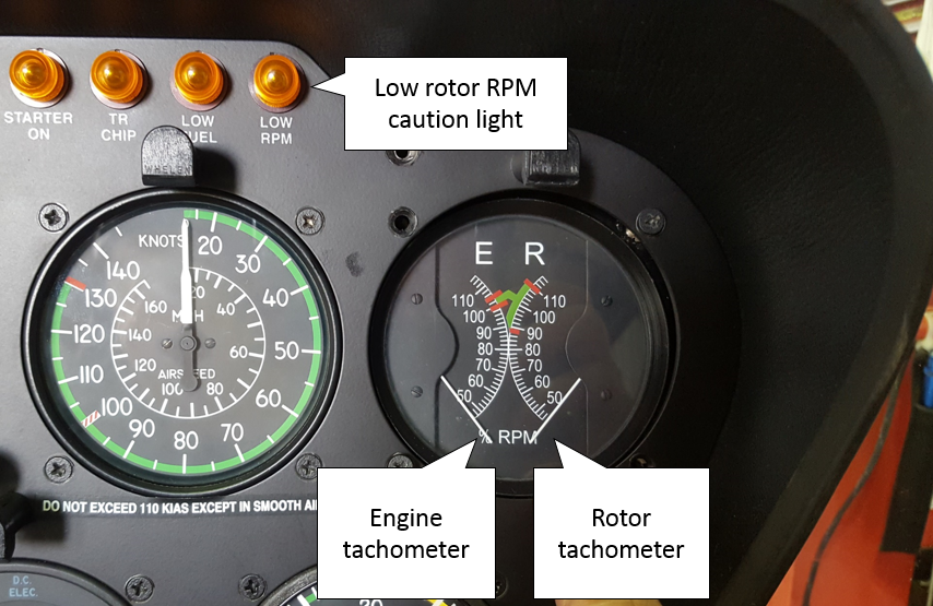
Preliminary report

Report release date: 24/07/2018

This preliminary report details factual information established in the investigation’s early evidence collection phase and has been prepared to provide timely information to the industry and public. Preliminary reports contain no analysis or findings, which will be detailed in the investigation’s final report. The information contained in this preliminary report is released in accordance with section 25 of the Transport Safety Investigation Act 2003.

Sequence of events

On 1 June 2018, at about 0035 Eastern Standard Time,[1] the Liberian-flagged container ship YM Efficiency (Figure 1) lost 81 containers overboard in gale-force weather conditions. At the time of the container loss, the ship was about 16 NM east-south-east of Newcastle, New South Wales (NSW). The occurrence also resulted in damage to a further 62 containers and structural damage to the ship’s gangway, superstructure and lashing bridges. The ship was on a regular service, calling at ports in China, Taiwan and Australia.

Figure 1: YM Efficiency entering Port Botany, NSW on 6 June 2018

Figure 1: YM Efficiency entering Port Botany, NSW on 6 June 2018. Source: ATSB

Source: ATSB

YM Efficiency

YM Efficiency is a 268.8 m-long, 4,250 TEU[2] container ship, registered in Monrovia, Liberia. The ship was owned by All Oceans Transportation, Liberia and operated by Yang Ming Marine Transport, Taiwan. At the time of the incident, the ship was classed with the American Bureau of Shipping.

Loading in Taiwan

On the afternoon of 13 May 2018, YM Efficiency berthed at the port of Kaohsiung, Taiwan. About an hour after berthing, the loading of containers on board the ship commenced and just before midnight, cargo operations were completed. Shortly after, YM Efficiency departed Kaohsiung for Port Botany, NSW, Australia, with a maximum draft of about 12.6 m aft. On departure, the ship’s passage was executed to achieve an expected time of arrival at the pilot station off Port Botany at midday on 1 June 2018.

Passage to Australia

During the passage south, the ship’s crew received regular weather forecasts and advice to assist voyage planning, as part of a commercial weather routing service. By the afternoon of 29 May, the ship was off the coast of Brisbane, Queensland making good an average speed of about 9 knots. By this time, the ship’s crew had also begun to receive weather data broadcast by Australia’s Bureau of Meteorology (BoM).

By 0930 on 30 May, YM Efficiency was off the coast of NSW, about 32 NM to the north-east of Coffs Harbour. Weather forecast information received on board predicted steadily increasing winds and seas into the next day. Between 0930 and 1130 that morning, in preparation for the expected heavy weather, the chief officer was charged with carrying out checks in accordance with the ship’s heavy weather checklist. This included a check to ensure that container lashings on deck were secure, which was subsequently completed. By 1200, the ship was off Coffs Harbour with the weather recorded in the ship’s logbook as being west-south-westerly winds at force four[3] (between 11 and 16 knots) with 3 m seas and 2 m swells.

At 1605 on 30 May, BoM issued coastal waters forecasts for the Macquarie and Hunter coasts of NSW. Both forecasts included gale warnings for the next day, 31 May, caused by a low-pressure system moving east over the Tasman Sea for the next few days.

By 1900 on 30 May, YM Efficiency was off Port Macquarie and the weather had deteriorated. The weather was recorded as being cloudy with west-south-westerly winds at force eight (between 34 and 40 knots) with 6 m seas and 5 m swells.

By 0800 the next morning, 31 May, the ship was about 32 NM east-north-east of Port Stephens. The weather was recorded as being cloudy with west-south-westerly winds at force eight (between 34 and 40 knots) with 7 m seas and 5 m swells. The ship’s main engine speed was set at 35 revolutions per minute (rpm), the equivalent of ‘slow ahead’. At about 0830, a second heavy weather checklist was completed, with the container lashings checked once again.

The incident

At about 1300 on 31 May, the ship received information that the pilot boarding time for the ship’s call at Port Botany had been delayed by 8 hours to 2000 on 1 June. At about 1400, the ship’s main engine was stopped and the ship commenced drifting off the NSW coast, about 30 NM east of Newcastle (Figure 2). The weather at the time was recorded as being overcast with west-south-westerly winds at force eight (between 34 and 40 knots) with 6 m seas and 5 m swells.

Figure 2: Section of navigational chart Aus 489 showing YM Efficiency's track

Figure 2: Section of navigational chart Aus 489 showing YM Efficiency's track. Source: Australian Hydrographic Service, modified by the ATSB


Source: Australian Hydrographic Service, annotated by the ATSB

The ship’s main engine was re-started for brief periods over the next few hours to maintain some control over the ship’s drift. The rough weather continued into the evening with the wind recorded as having increased to force nine (between 41 and 47 knots) at 2200.

At about 2330, the ship’s main engine was started with the engine speed set to 35 rpm and the ship’s head was slowly brought around to the south-west to resume the passage to Port Botany. At midnight, the third officer handed over the navigation watch to the second officer. By this time, the ship was on a heading of about 210° with a speed of about 4.3 knots. The weather at midnight was recorded as being overcast with west-south-westerly winds at force nine (between 41 and 47 knots) with 6 m seas and 5 m swells.

At about 0034 on 1 June, in a position about 16 NM east-south-east of Newcastle, the ship experienced a period of quick, heavy rolling for about 60 to 90 seconds. The rolling was estimated by the ship’s master as having reached angles of up to 30º to port and starboard. Shortly after the start of the rolling, several engineering alarms sounded and the main engine shut down with the rpm reducing to zero. The second officer reported hearing loud noises on deck and suspected that there had been some cargo damage. He turned on the ship’s deck lights and observed that containers had been damaged and possibly lost overboard from the bays aft of the accommodation.

By about 0036, the rolling had reduced and the ship’s motion had calmed. By this time, the master had arrived on the bridge and the chief engineer and second engineer had proceeded down to the engine room to assist the duty engineer with the main engine shutdown.

The master took over the navigation of the vessel and instructed the chief officer to conduct a damage assessment. At about 0040, the chief officer reported several containers damaged or lost overboard from bays 52 and 56, just aft of the accommodation (Figure 3).

Figure 3: Damaged containers on bay 52 and bay 56 on board YM Efficiency

Figure 3: Damaged containers on bay 52 and bay 56 on board YM Efficiency. Source: ATSB

Source: ATSB

At about 0045, the main engine was successfully re-started and the engine telegraph[4] on the bridge was placed at ‘dead slow ahead’ and then, almost immediately, placed at ‘stop’ again. The ship continued to drift in the gale force winds and seas until about 0252, when the main engine was started and the ship resumed passage for Port Botany.

In the morning, the ship’s crew conducted more detailed damage assessments and attempted to stabilise the damaged and collapsed containers on deck. The container loss and damage was found to be limited to bays 52 and 56. The container loss was reported to the Australian Maritime Safety Authority (AMSA) who coordinated notifications to other involved stakeholders. AMSA also commenced modelling the drift of the lost containers and initiated safety broadcasts to warn shipping in the area of the hazard posed by the lost containers.

Over the next few days, AMSA, along with Roads and Maritime Services, NSW, continued to work with the ship’s owners and insurers to detect, identify and track containers and their contents on the NSW coast. Although there were a considerable number of damaged containers still on board the ship, no further containers were lost overboard after the container loss event on 1 June. The ship sustained damage to the gangway, superstructure and lashing bridges.

YM Efficiency eventually berthed in Port Botany at about 0936 on 6 June. Over the course of the following days, personnel representing several different stakeholders attended the ship including investigators from the ATSB, AMSA surveyors and the ship’s flag state - Liberia.

On 11 June, the first damaged container was discharged from the ship and by 21 June, all remaining damaged containers had been discharged. YM Efficiency departed Port Botany for Melbourne at about 2130 on 22 June.

Ongoing investigation

The investigation is continuing. The ATSB will follow any location and salvage efforts to identify any further evidence should it become available.

The investigation will include the following:

  • analysis of the ship’s container stow and lashing arrangement
  • analysis of the ship’s stability condition
  • actions of the ship’s officers and crew following the incident
  • analysis of weather conditions at the time of the incident.

The information contained in this preliminary report is released in accordance with section 25 of the Transport Safety Investigation Act 2003 and is derived from the initial investigation of the occurrence. Readers are cautioned that new evidence will become available as the investigation progresses that will enhance the ATSB's understanding of the accident as outlined in this report. As such, no analysis or findings are included in this update.

Purpose of safety investigations

The objective of a safety investigation is to enhance transport safety. This is done through:

  • identifying safety issues and facilitating safety action to address those issues
  • providing information about occurrences and their associated safety factors to facilitate learning within the transport industry.

It is not a function of the ATSB to apportion blame or provide a means for determining liability. At the same time, an investigation report must include factual material of sufficient weight to support the analysis and findings. At all times the ATSB endeavours to balance the use of material that could imply adverse comment with the need to properly explain what happened, and why, in a fair and unbiased manner. The ATSB does not investigate for the purpose of taking administrative, regulatory or criminal action.

Terminology

An explanation of terminology used in ATSB investigation reports is available here. This includes terms such as occurrence, contributing factor, other factor that increased risk, and safety issue.

Publishing information 

Released in accordance with section 25 of the Transport Safety Investigation Act 2003

Published by: Australian Transport Safety Bureau

© Commonwealth of Australia 2018

image_2.png

Ownership of intellectual property rights in this publication

Unless otherwise noted, copyright (and any other intellectual property rights, if any) in this report publication is owned by the Commonwealth of Australia.

Creative Commons licence

With the exception of the Coat of Arms, ATSB logo, and photos and graphics in which a third party holds copyright, this publication is licensed under a Creative Commons Attribution 3.0 Australia licence.

Creative Commons Attribution 3.0 Australia Licence is a standard form licence agreement that allows you to copy, distribute, transmit and adapt this publication provided that you attribute the work.

The ATSB’s preference is that you attribute this publication (and any material sourced from it) using the following wording: Source: Australian Transport Safety Bureau

Copyright in material obtained from other agencies, private individuals or organisations, belongs to those agencies, individuals or organisations. Where you wish to use their material, you will need to contact them directly.
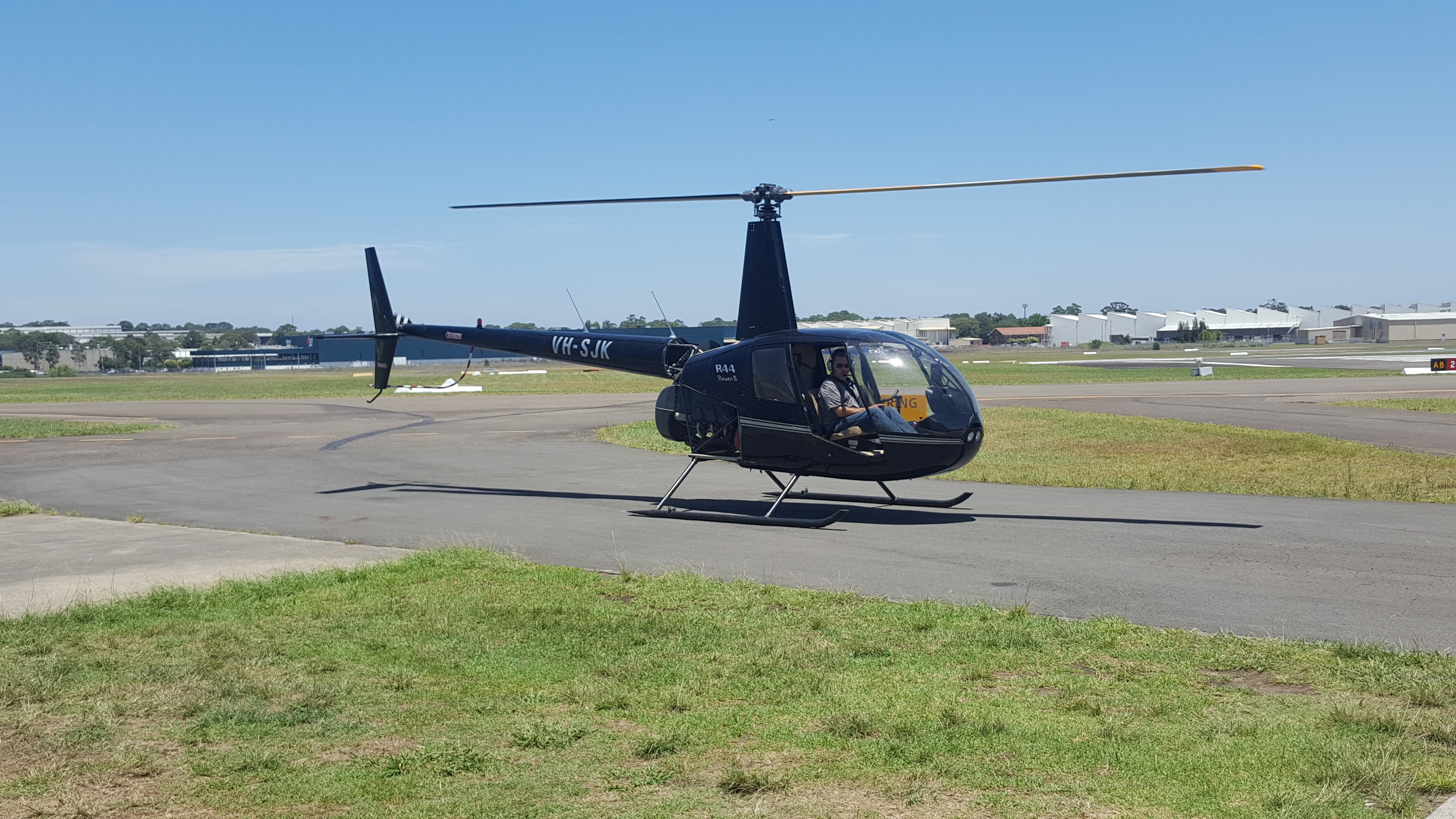
  1. Eastern Standard Time (EST): Coordinated Universal Time (UTC) + 10 hours.
  2. Twenty-foot Equivalent Unit, a standard shipping container. The nominal size of ships in TEU refers to the number of standard containers that it can carry.
  3. The Beaufort scale of wind force, developed in 1805 by Admiral Sir Francis Beaufort, enables sailors to estimate wind speeds through visual observations of sea states.
  4. An engine telegraph on a ship’s bridge is a device used to transfer orders for changes in engine speed or direction from the bridge to the engine room.

Occurrence summary

Investigation number 344-MO-2018-008
Occurrence date 01/06/2018
Location 16 NM east-south-east of Newcastle
State New South Wales
Report release date 13/02/2020
Report status Final
Investigation level Defined
Investigation type Occurrence Investigation
Investigation status Completed
Mode of transport Marine
Marine occurrence category Cargo shift
Occurrence class Accident
Highest injury level None

Ship details

Name YM Efficiency
IMO number 9353280
Ship type Cargo
Flag Liberia
Classification society American Bureau of Shipping
Owner All Oceans Transportation
Manager Yang Ming Marine Transport Corporation
Departure point Kaohsiung, Taiwan
Destination Port Botany, Sydney, New South Wales

Incorrect configuration for landing involving Airbus A320, VH-VQK, Ballina/Byron Gateway Airport, New South Wales, on 18 May 2018

Final report

Report release date: 10/12/2019

Safety summary

What happened

On the morning of 18 May 2018, an Airbus A320 aircraft, registered VH-VQK, was being operated on a regular public transport flight by Jetstar Airways. The flight departed from Sydney, New South Wales for Ballina/Byron Gateway Airport, New South Wales.

The flight crew conducted a go-around on the first approach at Ballina because the aircraft’s flight path did not meet the operator’s stabilised approach criteria. On the second approach, at about 700 ft radio altitude, a master warning was triggered because the landing gear had not been selected DOWN. The flight crew conducted a second go-around and landed without further incident on the third approach.

What the ATSB found

The flight crew did not follow the operator’s standard procedures during the first go-around and subsequent visual circuit at 1,500 ft. In particular, the flaps remained at Flaps 3 rather than Flaps 1 during the visual circuit. This created a series of distractions leading to a non-standard aircraft configuration for a visual circuit. Limited use of available aircraft automation added to the flight crew’s workload.

During the downwind leg following the first go-around, the flight crew did not select the landing gear DOWN as they had commenced the configuration sequence for landing at the Flaps 3 setting. Furthermore, the flight crew incorrectly actioned the landing checklist, which prevented the incorrect configuration for landing being identified and corrected.

Safety message

Unexpected events during approach and landing phases can substantially increase what is often a high workload period. Adherence to standard operating procedures and correctly monitoring the aircraft and approach parameters provides assurance that a visual approach can be safely completed. The selection of inappropriate auto-flight modes, unexpected developments, or any confusion about roles or procedures can contribute to decisions and actions that increase the safety risk to the aircraft and its passengers.

The ATSB SafetyWatch highlights the broad safety concerns that come out of our investigation findings and from the occurrence data reported to us by industry. Handling of approach to land is one of these priorities.


The occurrence

First approach

On the morning of 18 May 2018, an Airbus A320 aircraft, registered VH-VQK, was being operated on a regular public transport flight by Jetstar Airways. The flight departed from Sydney, New South Wales for Ballina/Byron Gateway Airport, New South Wales. The captain was the pilot monitoring (PM) and the first officer (FO) was the pilot flying (PF).[1]

During the flight, the flight crew discussed and planned their arrival into Ballina. The forecast weather conditions were good with clear visibility and light winds. The FO suggested that they conduct a visual approach. Given that the conditions were good and the captain could see the airport from 50 NM the captain agreed. The FO then programmed the Flight Management Guidance System for the descent and arrival and carried out an approach briefing for a visual approach to runway 24. The FO recalled that he briefed the initial actions for a go-around, however, the flight crew did not discuss subsequent actions including the visual circuit[2] procedure.

At 1042 Eastern Standard Time,[3] the flight crew commenced descent during which they broadcast the required radio calls for their arrival on the common traffic advisory frequency (CTAF). During this period they became aware of a helicopter conducting right circuits at the airport.

Descending through about 2,100 ft the FO disconnected the autopilot and manually flew the aircraft. During manoeuvring to join a left base, the aircraft’s airspeed and altitude were both higher than a normal approach profile. The captain recognised the problem and recalled thinking that a go-around would be required, but due to the circuit traffic he wanted the aircraft established on final approach before commencing the go-around procedure.

The FO continued the approach and targeted a vertical speed of 1,000 ft/min descent and commenced a turn onto the final approach. Recorded flight data showed a peak vertical speed of about 1,300 ft/min at about 730 ft, and the aircraft still well above the desired vertical profile. Still turning onto the final approach the FO observed three white fly-down lights on the visual approach slope indicator system (VASIS).[4]

First go-around

At 500 ft above ground level (AGL) the aircraft automatically generated a callout of ‘five hundred’ and the captain commanded a go-around by calling out ‘not stable’. The FO commenced the go-around procedure (Figure 1).

Recorded flight data showed the aircraft was about 450 ft AGL when the go-around commenced. With take-off/go-around (TOGA) thrust set and Flaps 3 selected, the aircraft approached the circuit altitude of 1,500 ft about 10 seconds later.

As the FO levelled the aircraft it accelerated quickly toward the Flaps 3 limit speed (185 kt). The FO called for the approach phase[5] to be activated, which would have reduced the autothrust’s target speed from green dot speed[6] to 139 kt, and the captain went to action this request.

However, due to the aircraft’s acceleration, the FO believed the autothrust system would not prevent a flap overspeed prior to the approach phase becoming active. Consequently, he retarded both thrust levers to IDLE. This action disengaged the autothrust and generated an Electronic Centralised Aircraft Monitoring (ECAM) caution message (AUTO FLT A/THR OFF).

The captain heard the associated aural master caution chime, scanned the instruments and observed the aircraft’s pitch attitude being 10° nose up with Flaps 3 and idle thrust. He immediately commanded the FO to place both thrust levers back into the climb detent and re-engage the autothrust system. The FO subsequently reported that he had already commenced these actions at that time.

Figure 1: Flight path of VH-VQK during incident flight

Figure 1_6.jpg

Source: Google Earth annotated by ATSB.

Circuit for second approach

The FO commenced a left turn to conduct a standard left circuit for runway 24, however, the captain instructed the FO to conduct a right circuit. The captain later recalled his decision to conduct a non-standard right circuit was predicated on a number of reasons, but mainly due to the helicopter conducting right circuits and the noise sensitive area over the Ballina township to the south-east of runway 24 (Figure 1).

During the turn onto the downwind leg of the circuit, the FO offered the PF duties to the captain. The captain took control of the aircraft and the FO reverted to PM duties. The captain continued to fly the aircraft manually with the autopilot off and the autothrust engaged.

During the downwind leg, the captain recalled observing on his navigation display that the aircraft was positioned too close to the runway. Recorded flight data indicated the aircraft was about 1.2 NM abeam the runway rather than the captain’s desired 2.0 NM spacing. The captain turned left to widen the circuit spacing.

The flight crew completed the after take-off checklist. The captain noted that the flaps were set to Flaps 3 rather than the normal Flaps 1 configuration for a visual circuit, and he instructed the FO to let the flaps remain at that setting as he wanted to prioritise safely flying the aircraft in the circuit area.

As the captain commenced the turn onto the base leg, he scanned the ECAM upper display and observed the flaps were still set at Flaps 3. He commanded Flaps FULL, which the FO selected.

Both the captain and the FO stated they completed the landing checklist at about 950 ft AGL, which included the ECAM landing memo, and continued the approach.

At about 700 ft radio altitude (RA), a master warning for L/G GEAR NOT DOWN was triggered because the landing gear had not been selected DOWN. Recorded flight data showed that about 4 seconds after the master warning, the landing gear was selected DOWN. A further 2 seconds later the captain selected the thrust levers to TOGA and commenced a second go-around. The aircraft’s lowest recorded height was about 670 ft AGL.

Second go-around

The flight crew reconfigured the aircraft to gear UP and Flaps 1, as per the go-around procedure. The captain elected to continue manually flying the aircraft and conducted a second non-standard right circuit.

At about this time, the pilot of a Cessna 172 inbound from the north made radio calls advising aircraft at Ballina of his intention to join the (left) circuit for landing. The captain of the A320 provided instructions to the Cessna 172 pilot over the radio to confirm separation between the two aircraft.

On the downwind circuit leg for the third approach, the A320’s traffic collision avoidance system (TCAS) generated a traffic advisory (TA). The flight crew had remained in visual contact with the Cessna 172 and estimated its position to be about 2.0 NM to the north and about 800 ft above them. No further actions were required from either flight crew in relation to the TCAS TA.

On the third approach the flight crew configured the aircraft in accordance with the operator’s visual circuit procedures and actioned the landing checklist, including the landing memo items from the checklist. The aircraft landed on runway 24 without further incident.

__________

  1. Pilot Flying (PF) and Pilot Monitoring (PM): procedurally assigned roles with specifically assigned duties at specific stages of a flight. The PF does most of the flying, except in defined circumstances; such as planning for descent, approach and landing. The PM carries out support duties and monitors the PF’s actions and aircraft flight path.
  2. Circuit: a specified pattern flown by aircraft when taking off or landing while maintaining visual contact with the airfield. Typically rectangular in shape and include pattern legs; upwind, crosswind, downwind, base and final.
  3. Eastern Standard Time (EST) was Coordinated Universal Time (UTC) + 10 hours.
  4. VASIS: a visual approach slope indicating system that uses high intensity lighting to assist pilots identify the correct glide path to the runway. The system for runway 24 at Ballina was an AT-VASIS, and three white lights indicated the aircraft was too high.
  5. Approach phase is a function of the Flight Management Guidance System. When activated it automatically commands slower aircraft speeds during an approach and will appropriately reduce airspeed to the respective flap manoeuvring speed as configuration is changed for landing.
  6. Green dot speed is the operational speed in the clean configuration and gives an estimate of the speed for best lift-to-drag ratio.

Context

Flight crew information

The captain held an Air Transport Pilot (Aeroplane) Licence, a multi-engine command instrument rating and a Class 1 Aviation Medical Certificate. He had over 11,000 hours flying experience, of which over 3,000 hours were on the A320/A321. The captain was a check pilot for the operator; however, this flight was rostered as a normal line flight, with no check or training functions scheduled.

The first officer (FO) held a Commercial Pilot (Aeroplane) Licence and was appropriately qualified for the flight. He had about 1,600 hours flying experience, of which about 1,400 hours were on the A320/A321.

Both flight crew signed on for duty at Sydney Airport at 0510 and operated a flight from Sydney to the Gold Coast then return to Sydney. The flight to Ballina/Byron Gateway was their third flight of the day. Both flight crew reported that they had a reasonable amount and quality of sleep the night before and did not feel tired at the time of the occurrence. The captain had conducted flights the previous day and the FO had conducted flights on the two previous days, and neither reported any problems with their sleep prior to those days’ flights.

Both the captain and the FO had operated into Ballina on many previous occasions. The FO advised that this was only the third or fourth time he had operated into Ballina as pilot flying.

Go-around procedure

The operator’s procedures stated the pilot flying (PF) must conduct an immediate go-around if the pilot monitoring (PM) called ‘500 not stable’. The operator’s go-around procedure (based on the aircraft manufacturer’s procedure) detailed a sequence of actions that the PF and PM were required to perform, as summarised in Figure 2.

For most go-arounds, once the aircraft reached the nominated thrust reduction altitude, the procedure required the thrust levers to be placed into the climb detent by the PF. This action would activate the autothrust system.

In SPEED mode, the autothrust adjusts the thrust in order to acquire and hold a speed target and does not allow speed excursions beyond the maximum speed for each flap configuration. The flaps are not automatically retracted from the Flaps 3 configuration.[7] As the aircraft accelerates, the flight crew would need to retract flaps to the required position. The operator’s procedure when conducting a visual circuit following a go-around was normally to re-configure the aircraft to the Flaps 1 position.

Figure 2: Airbus A320 go-around profile

Figure 2: Airbus A320 go-around profile. Source: Airbus.

Source: Airbus.

Visual circuit procedure

The operator’s Flight Crew Operating Manual contained procedures for flying a visual circuit. The procedure detailed a visual circuit be flown at 1,500 ft AGL with Flaps 1. Prior to turning onto the base leg of the circuit, the flight crew should normally select Flaps 2, select landing gear DOWN and arm the spoilers. On the base leg, the flight crew should normally select Flaps 3 followed by Flaps FULL (if required). Flight crews would then perform the landing checklist.

ECAM landing memo

The Airbus A320 Electronic Centralised Aircraft Monitor (ECAM) presents data to flight crew on two displays: the Engine/Warning Display (E/WD) and the System Display (SD). Data presented includes:

  • primary engine indications, fuel quantity, landing gear, flap and slat position
  • warning and caution alerts, or memos
  • synoptic diagrams of aircraft systems, and status messages.

Memos are displayed on the lower section of the E/WD, and they list functions or systems that are temporarily used for normal operations. The display uses colour codes, which indicate to flight crew the importance of the indication. Green indicates the item is operating normally, and blue indicates there are actions to be carried out.

The landing memo is displayed when the aircraft is in the approach phase below 2,000 ft. However, after a go-around the system logic requires the aircraft climb above 2,200 ft radio altitude (RA) in order for the landing memo to reset. If the aircraft conducts a circuit lower than 2,200 ft the landing memo will not be displayed on the E/WD until 800 ft RA on the next approach.

Figure 3: Airbus A320 flight deck and E/WD landing memo

Figure 3: Airbus A320 flight deck and E/WD landing memo. Source: Airbus modified by ATSB.

Source: Airbus modified by ATSB.

Landing checklist

As part of the operator’s stabilised approach criteria the landing checklist was required to be completed prior to 1,000 ft AGL. The checklist included an item for ECAM MEMO. When actioning that item the captain and FO were required to independently look at the ECAM MEMO on the E/WD, confirm that there was no blue text and, on observing that, announce ‘landing, no blue’ in response to the checklist item.

In the case of the landing memo not being displayed on the E/WD (as in the event of a go-around and visual circuit below 2,200 ft), the flight crew were required to read, check and announce the landing memo items listed on the checklist below the item ECAM MEMO.

Figure 4: Jetstar A320 landing checklist

Figure 4: Jetstar A320 landing checklist. Source: Jetstar.

Source: Jetstar.

__________

  1. The only automatic flap retraction that can take place is from Flaps 1+F to Flaps 1.

Safety analysis

Introduction

Incidents such as the incorrect configuration of an air transport aircraft for landing are rarely the result of a single action or identifiable event. Instead, a number of factors combine to result in an unintended outcome; which in this case was the conduct of the second approach to Ballina/Byron Gateway Airport without the landing gear selected DOWN.

Although the incident was highly undesirable, it should be noted that the aircraft’s warning system effectively alerted the flight crew to the problem, and the crew responded promptly to the warning and initiated a second go-around.

Conduct of the first go-around

Due to the unstable approach on the first attempt to land, the flight crew appropriately performed a go-around.

An all engines go-around is a very dynamic procedure with high accelerations created by the application of take-off/go-around (TOGA) thrust. When performed at a low aircraft weight with low altitude level off, such as a 1,500 ft circuit height, it can be a demanding manoeuvre. It requires flight crews to perform a significant number of actions in a short period of time with all of them related to important changes of attitude, thrust, flight path, landing gear and flap configuration and flight modes. The actions need to be performed in the correct order, with a high level of coordination between the crew.[8]

The initial actions of the first go-around manoeuvre, up until reaching the thrust reduction altitude, were performed correctly. However, instead of retracting the flaps on schedule to Flaps 1, the first officer (FO) called for the approach mode to be activated first in an attempt to reduce the aircraft’s acceleration. Concerned about a potential flap overspeed, the FO then retarded the thrust levers past the climb detent to IDLE. This action de-activated the autothrust system and its protections, which limit thrust to help prevent overspeeds. With Flaps 3 still set and about 10° nose-up pitch attitude, the aircraft performance deteriorated, requiring intervention by the captain.

Visual circuit

In this incident, several distractions caused the flight crew to deviate from the operator’s normal visual circuit procedures at Ballina. The FO was anticipating a left circuit to be flown in accordance with the published procedure for runway 24. However, the captain commanded a non-standard right circuit for various reasons, which he had not previously advised the FO during the approach briefing or the subsequent approach.

As the aircraft was being turned onto downwind the flight crew were presented with further distractions including the handover of flying duties to the captain and then correcting the lateral flight path spacing in the circuit. The captain continued to manually fly the aircraft, which added to his workload. Accordingly, the captain elected to concentrate on flying the aircraft and have the FO conduct the required checklists and radio calls. As the captain prioritised tasks he chose to remain at Flaps 3, which was permissible and safe, but not the operator’s standard configuration for a visual circuit which was Flaps 1.

Landing configuration

Linking an aircraft’s normal procedures with an identifiable phase of flight is designed to assist a flight crew’s procedural recall. During most approaches, a flight crew will follow the same sequence for configuring flaps, landing gear and spoilers and conducting the landing checklist.

The operator’s sequence of configuring the aircraft for landing required the landing gear to be selected DOWN prior to the selection of Flaps 3. As the captain turned on to the final approach during the second approach, he scanned the flight instruments, observed Flaps 3 already set and instinctively commanded Flaps FULL, which was the normal sequence from Flaps 3. The FO selected Flaps FULL but then also turned his attention to monitoring the aircraft’s flight path. As such, neither of the flight crew were aware that the landing gear had not been selected DOWN.

Landing checklist

The flight crew flew the second visual circuit at about 1,500 ft. Therefore, the Electronic Centralised Aircraft Monitor (ECAM) landing memo logic was not reset after the go-around. When the flight crew performed the landing checklist on the second approach, with the aircraft at about 950 ft, the landing memo would not have been displayed on the Engine/Warning Display.

The absence of the landing memo should have prompted the flight crew to perform the items of the landing checklist as a ‘read-and-do’ checklist. Had they read the required actions from the checklist, both the captain and FO would have been required to independently check and announce that the landing gear was down. This method should have effectively ‘trapped’ their error.

When the landing memo did appear at 800 ft, both of the flight crew were situationally focused on intercepting the final approach path and performing radio calls. Neither the captain nor the FO recalled seeing the landing memo appear on the E/WD; which would have had the landing gear item in blue text. Both the captain and FO were subsequently alerted to the incorrect configuration for landing by a master warning message triggered at about 700 ft.

It would be ideal if the aircraft’s systems were designed such that the landing memo became available during the 1,500 ft visual circuit. However, system design is often a matter of compromise and there is also a need to minimise unnecessary complexity. Airbus set a minimum height of 2,200 ft to prevent spurious display of the landing memo during take-off and to prevent display flickering during an approach.

The exact reasons why both crew did not notice the absence of the landing memo when completing the landing checklist are unclear. However, a combination of workload and expectancy are often involved in such errors (Wickens and McCarley, 2008).[9] In this case, the flight crew probably expected the memo to be there, given that it is normally present at that phase of flight. In addition, the absence of something that should be present is often more difficult to detect than the presence of something that should not be there (for example, Thomas and Wickens, 2006).[10]

Overall, this occurrence reinforces the importance of using normal procedures, and minimising and managing the effects of workload during critical phases of flight.

__________

  1. Further discussion on the challenges of all-engine go-arounds in modern aircraft is provided in the ATSB investigation report AO-2012-116, Flap overspeed and altitude exceedance during go-around, Airbus A321, VH-VWY, Cairns Airport, Queensland, 3 September 2012. See also Bureau d’Enquêtes et d’Analyses pour la sécurité de l’aviation civile (BEA) 2013, Study on aeroplane state awareness during go-around. Available from www.bea.aero.
  2. Wickens, CD & McCarley, JS 2008, Applied attention theory, CRC Press Boca Raton, FL.
  3. Thomas, LC & Wickens, CD 2006, ‘Effects of battlefield display frames of reference on navigational tasks, spatial judgements, and change detection’, Ergonomics, vol.49, pp.1154-1173.

Findings

These findings should not be read as apportioning blame or liability to any particular organisation or individual.

  • During the first go-around, the flight crew did not fully complete the standard go-around procedure, resulting in the aircraft’s flaps remaining at Flaps 3 rather than Flaps 1 during the subsequent visual circuit at 1,500 ft.
  • During the downwind leg following the first go-around, the flight crew did not select the landing gear DOWN, as they had commenced the configuration sequence for landing at the Flaps 3 setting.
  • The flight crew did not identify that, because the aircraft had not climbed through 2,200 ft, the landing memo had not been reset and was not displayed.
  • Following both go-arounds, the captain elected to conduct non-standard right circuits. This increased the potential for traffic conflicts with other aircraft, and flight crew workload managing such conflicts.

Safety action

Whether or not the ATSB identifies safety issues in the course of an investigation, relevant organisations may proactively initiate safety action in order to reduce their safety risk. The ATSB has been advised of the following proactive safety action in response to this occurrence.

Jetstar Airways

As a result of this occurrence, Jetstar Airways has advised the ATSB that both flight crew members attended debriefings with flight operations management and were provided with specific simulator and line flying training related to the occurrence.

Purpose of safety investigations & publishing information

Purpose of safety investigations

The objective of a safety investigation is to enhance transport safety. This is done through: 

  • identifying safety issues and facilitating safety action to address those issues
  • providing information about occurrences and their associated safety factors to facilitate learning within the transport industry.

It is not a function of the ATSB to apportion blame or provide a means for determining liability. At the same time, an investigation report must include factual material of sufficient weight to support the analysis and findings. At all times the ATSB endeavours to balance the use of material that could imply adverse comment with the need to properly explain what happened, and why, in a fair and unbiased manner. The ATSB does not investigate for the purpose of taking administrative, regulatory or criminal action.

Terminology

An explanation of terminology used in ATSB investigation reports is available here. This includes terms such as occurrence, contributing factor, other factor that increased risk, and safety issue.

Publishing information

Released in accordance with section 25 of the Transport Safety Investigation Act 2003

Published by: Australian Transport Safety Bureau

© Commonwealth of Australia 2019

image_5.png

Ownership of intellectual property rights in this publication

Unless otherwise noted, copyright (and any other intellectual property rights, if any) in this report publication is owned by the Commonwealth of Australia.

Creative Commons licence

With the exception of the Coat of Arms, ATSB logo, and photos and graphics in which a third party holds copyright, this publication is licensed under a Creative Commons Attribution 3.0 Australia licence.

Creative Commons Attribution 3.0 Australia Licence is a standard form licence agreement that allows you to copy, distribute, transmit and adapt this publication provided that you attribute the work.

The ATSB’s preference is that you attribute this publication (and any material sourced from it) using the following wording: Source: Australian Transport Safety Bureau

Copyright in material obtained from other agencies, private individuals or organisations, belongs to those agencies, individuals or organisations. Where you wish to use their material, you will need to contact them directly.
Occurrence summary

Investigation number AO-2018-042
Occurrence date 18/05/2018
Location Near Ballina/Byron Gateway Airport
State New South Wales
Report release date 10/12/2019
Report status Final
Investigation level Short
Investigation type Occurrence Investigation
Investigation status Completed
Mode of transport Aviation
Aviation occurrence category Incorrect configuration
Occurrence class Incident
Highest injury level None

Aircraft details

Manufacturer Airbus
Model A320-232
Registration VH-VQK
Serial number 2651
Aircraft operator Jetstar Airways
Sector Jet
Operation type Air Transport High Capacity
Departure point Sydney Airport, New South Wales
Destination Ballina/Byron Gateway Airport, New South Wales
Damage Nil

Loss of control in flight involving Leonardo Helicopters AW139, VH-YHF, near Adelaide River mouth, 38 km east-north-east of Darwin, Northern Territory, on 13 May 2018

Final report

Report release date: 16/04/2020

Safety summary

What happened

At 2000 Central Standard Time on 13 May 2018, the crew of a Leonardo Helicopters AW139, registered VH-YHF, departed Darwin, Northern Territory, to search for an active emergency position-indicating radio beacon (EPIRB). The crew flew under night visual flight rules with support of a night vision imaging system.

During an approach to a potential EPIRB target, smoke from nearby bushfires affected visibility and the helicopter developed an uncommanded high rate of descent. The Aircrew Officer, in the rear of the helicopter, called ‘Climb! Climb! Climb!’, and the pilot regained control with a rehearsed recovery drill. During the recovery procedure, the power demand exceeded airframe limitations. This exceedance went undetected, and the helicopter was flown on a second sortie that same evening.

What the ATSB found

The pilot entered instrument meteorological conditions during approach, and lost control of vertical speed. The helicopter descended to 31 ft above ground level during the event. Reversion to standard patter and practiced drills allowed the crew to recover the situation and avert an accident.

Two layers of protection available to the crew of the helicopter were not used. Flight instruments were not referred to in the incident approach, and a crewmember trained to support the pilot in monitoring the approach was required to be in the rear of the aircraft.

A main gearbox over-torque of 159.5 per cent occurred during the recovery. The crew could not determine the magnitude of the potential over-torque after the event. Subsequently the aircraft remained in service in a condition of uncertain airworthiness.

What has been done as a result

CareFlight has established three main controls aiming to prevent reoccurrence:

  • Stabilised Approach Criteria was written into standard operating procedures, requiring an immediate go-around if the aircraft leaves a prescribed range of approach parameters.
  • Controlled flight into terrain (CFIT) avoidance training was incorporated into the ground-based training syllabus.
  • Improved advice on use of auto hover functions was written into aircraft handling standard operating procedures. This included a requirement that the function was not to be engaged while the helicopter was descending.

Safety message

Pilots must be aware of the human factors hazards associated with loss of visual references. Pilots can protect themselves by maintaining the use of instrument scans in approaches at night, and making use of monitoring by trained and available crewmembers.

Flight planning should include assessment of the risk of a degraded visual environment. Operators should document their minimum acceptable levels of illumination and levels of tolerable risk. Where the risk exists, predetermined responses should be readily available.

Instrument flight rules (IFR) pilots in IFR-rated aircraft should prioritise use of inadvertent instrument meteorological conditions drills and pre-planned exit routes over recovery of visual meteorological conditions.

Flight crew and engineering teams should not rely solely on indicators, or absence of indicators, to determine airworthiness. If there is any reason to suspect exceedance of aircraft limits, operators should run diagnostics to determine the airworthiness of the aircraft beyond doubt.

People have a responsibility to aid their own rescue. Up-to-date registration of an EPRIB, and correct use of an EBIRB and other signalling equipment, simplifies a rescue of people in need. Australian Maritime Safety Authority guidelines exist to help people prepare for onshore and offshore remote area travel.


The occurrence

Incident flight

On the evening of 13 May 2018 at 1943 Central Standard Time,[1] the Rescue Coordination Centre (RCC) tasked the crew of a Leonardo Helicopters AW139, registered VH-YHF, to locate an active emergency position-indicating radio beacon[2] (EPIRB) 38 km north-east of Darwin Airport, Northern Territory. The EPIRB had been activated within the vicinity of a waterway called Salt Water Arm (Figure 1).

Figure 1: Map showing Darwin take-off point, search area, and location of incident event

Figure 1: Map showing Darwin take-off point, search area, and location of incident event. 
Source: Google Earth annotated by the ATSB

Source: Google Earth annotated by the ATSB

The area was popular with recreational anglers, so the crew of VH-YHF anticipated responding to a boating event. They also determined that such a response would likely require use of the aircraft’s winch.

The crew configured the aircraft with the pilot on night vision goggles[3] (NVG) in the front right seat, the aircrew officer (ACO) with NVG in the rear cabin by the right hand door, and the flight nurse in the rear cabin without NVG. Lighting within the cockpit and cabin was NVG-compatible. Two steerable searchlights mounted to the front, one steerable searchlight mounted to the right side of the aircraft, a handheld light operated by the ACO, and LED light bars at the front and rear of the helicopter supported the Night Vision Imaging System[4] (NVIS).

At about 2000, the crew departed Darwin Airport with good visibility. At that time, a five-metre tide was receding from Salt Water Arm. There was little illumination as the moon had set at 1653, and the sun had set at 1830. There was limited celestial light available through the gaps in the clouds which were forecast as scattered[5] cumulus and stratocumulus clouds at 2,000 ft, with cloud tops to 10,000 ft. Smoke from outlying grass fires drifted across the search area below 7,000 ft, reducing visibility to 4 km in places. The crew could not easily detect the smoke due to low illumination.

As the crew descended into the search area and commenced the search, smoke became evident as the task progressed. The ACO described visibility as 5 km but dropping in and out due to large amounts of smoke. These conditions are common for the region, and recent check flights for the crew had been conducted in similar conditions.

During the flight, the beam of the search light would reflect off smoke and ash. Backscatter from the beam was affecting visibility, reducing NVG image quality, and reducing peripheral vision. As a result, the beam required frequent adjustment. The ACO contacted the RCC and advised that limited visibility may hamper the operation.

The helicopter was fitted with direction-finding equipment (DF) which enabled the crew to locate the source of a 121.5 MHz beacon signal, such as the EPIRB. The crew found that readings from the DF were erratic and unreliable. This added a level of complexity to the operation, making it difficult to locate the beacon. As a result, the crew conducted a visual search for potential targets from a safe working height of above 800 ft above ground level (AGL).

While the use of NVG allowed the crew to detect targets, the image quality was not high enough to verify the targets from this safe working height. The crew had to fly the aircraft down to 400 ft AGL to verify whether their target was one requiring rescue. The crew flew the descent to the target visually, using searchlights to ensure the approach and departure paths were clear of obstacles. The intent was to decrease rate of descent and airspeed before activating auto-hover (HOV) mode at 400 ft AGL.

At 2110:30, the crew commenced an approach from the north to a point of interest in Salt Water Arm. The pilot reported visibility on approach to the target as good to the north-west, and dark to the north and east. During this approach, the pilot lost visual references. At 2110:40, the pilot activated HOV mode. At this time, the helicopter had already developed an undesired high rate of descent (Figure 2).

Figure 2: Flight path of VH-YHF during the event

Figure 2: Flight path of VH-YHF during the event.
Source: Leonardo interpretation of data from the Flight Data Recorder, annotated by ATSB

Source: Leonardo interpretation of data from the Flight Data Recorder, annotated by ATSB

At the point of activation of HOV mode, the aircraft was at 430 ft, pitched 19.7 degrees nose-up, and descending at over 1,300 ft/min with a ground speed of 14 kt. The autopilot increased collective[6] pitch to 48 per cent to arrest the rate of descent.

Due to the lighting installed on the aircraft, and prioritisation of peripheral vision, the ACO could see the ground below and advised the pilot of a high rate of descent. The ACO provided advice twice more to the pilot before transitioning to an emergency call of ‘Climb! Climb! Climb!’ The pilot was by now receiving clear visual cues and detected a rapid rate of closure with the ground.

At 2140:46, at a height of 280 ft with a rate of descent of 1,630 ft/min, in a reversion to drilled emergency procedures, the pilot overrode aircraft automatics and used forward cyclic[7] and collective to reverse the rate of descent. The pilot directed his attention to the attitude indicator and the picture outside. The pilot increased collective pitch to 77 per cent. At this point, the rate of descent increased to 1,952 ft/min, indicative of onset of vortex ring state[8].

Maintaining forward cyclic, the pilot was aware of engine temperature limits and made a small reduction in collective to avoid exceeding the limits, before increasing collective again to 84 per cent.

At 2140:50, a yellow caution light illuminated and a crew alert system (CAS) message appeared on the display. Occupied with the recovery procedure, the pilot flew solely through the outside picture and the attitude indicator. The aircraft descended to a height of 31 ft AGL before attaining a positive rate of climb. As the pilot’s recovery manoeuvre ceased and control inputs returned to normal, the warning self-extinguished at 2140:57. The pilot noticed the warning, but could not read it before it extinguished.

It is likely that any further delay in conduct of the recovery drill would have led to an impact with terrain.

Return to base

The crew advised the RCC that they would end the flight and return to base. The crew landed the helicopter back at base at 2158. The pilot found that ash had accumulated on the fuselage of the helicopter, confirming flight through streams of smoke. During the flight through smoke, visibility was reduced below the visual minima.

A crew debrief took place and it was thought that a main gearbox overtorque could have occurred. There is no capacity in the aircraft for the crew to check for overtorque without the presence of an aircraft maintenance engineer (engineer). As a precaution, and as per Operations Manual requirements, the crew called a duty engineer to explain the situation and seek advice.

The duty engineer asked the crew to check the CAS system for messages. If an overtorque occurred, a white status message saying ‘maintenance’ would be present. This would signal a requirement to download and analyse data from the aircraft’s central maintenance computer (CMC).

The pilot estimated the extent of a potential overtorque to be within operational limits. The crew did not detect a maintenance message. With this information, the duty engineer advised that no maintenance activity was required.

Subsequent mission flight

Prior to the mission’s second flight, the crew thoroughly discussed the event. They developed a different strategy for the search to prevent reoccurrence, including the use of topography over the DF.

At 2254, the crew departed for the second flight to locate the source of the EPIRB transmission. The crew flew the arms of the river system at 1,000 ft using the autopilot, with the pilot flying with reference to instruments, and the ACO visually searching from the back.

The EPIRB was successfully located and noted to be in the bottom of a 14 ft metal-hulled recreational fishing boat. The boat carried two people and was in total darkness. As the vessel was unlit, the ACO could see the EPIRB flashing in the bottom of the boat. The position of the EPIRB had most likely resulted in the sporadic readout of the DF.

The helicopter crew directed a nearby Northern Territory Water Police vessel to the scene. The Water Police were then able to assist.

Detection of main gearbox overtorque

The following day, the crew related the experience to an engineer in the hangar and requested a download of the CMC data to check for potential issues. An overtorque of the main gearbox is recorded when a torque limit is exceeded. The limits for all engines operative are 110 per cent for five minutes, or 121 per cent for 5 seconds.

The engineer downloaded and analysed the data. An overtorque in excess of 125 per cent requires grounding of the aircraft, and analysis of the data by the engine and airframe manufacturers. He found that a main gearbox overtorque to 159.5 per cent had occurred during the first flight. The extent of the overtorque was such that the helicopter should not have been flown until the engine and airframe manufacturers declared the helicopter serviceable.

The engineer grounded the helicopter and sent data to the manufacturers of the engines and airframe for analysis. This meant that the crew had departed for their second flight of the previous evening in an aircraft of uncertain airworthiness.

Five days later, the engine manufacturer confirmed that the engines were undamaged and suitable for service. The helicopter manufacturer advised that the helicopter’s main gearbox was serviceable and required inspection of oil for metal contamination at 50 flight-hour intervals. The engineers carried out the necessary actions, and subsequently returned the helicopter to service.

__________

  1. Central Standard Time (CST): Coordinated Universal Time (UTC) + 9.5 hours.
  2. EPIRB: Emergency Position-Indicating Radio Beacon. A distress beacon which, when activated, broadcasts a 406 MHz signal to a network of satellites, and a 121.5 MHz signal for homing in on by search and rescue assets.
  3. Night Vision Goggles (NVG): A helmet mounted binocular device that intensifies ambient light, providing flight crew with improved vision at night.
  4. Night Vision Imaging System (NVIS): a system of internal and external lighting, combined with night vision goggles, which provides enhanced vision to crew for operation at night.
  5. Scattered clouds cover between three eights and one half of the visible sky.
  6. Collective: a primary helicopter flight control that simultaneously affects the pitch of all blades of a lifting rotor. Collective input is the main control for vertical velocity.
  7. Cyclic: a primary helicopter flight control that is similar to an aircraft control column. Cyclic input tilts the main rotor disc, varying the attitude of the helicopter and hence the lateral direction.
  8. Vortex Ring State: an undesirable state of powered flight where the helicopter settles in its own downwash.

Context

Personnel

Pilot

The pilot had over thirty-seven years’ experience in flying helicopters. He held an Airline Transport Pilot Licence (Helicopter) and instrument rating (Helicopter), authorising him to conduct night visual flight rules[9] (NVFR) and instrument flight rules[10] (IFR) operations as pilot. The pilot had gained experience around the world in military helicopter operations, onshore and offshore resource support, mountain flying, search and rescue, and ambulance helicopter operations. He held a current Class 1 Aviation Medical Certificate.

Table 1: Pilot’s rotary-wing hours accumulated

Total Time Rotary Wing9,800
Instrument Flight327.5
Night Flight833.0
AW139724.9

Source: Pilot

The pilot had more than 100 hours’ experience in command with night vision imaging systems (NVIS) and held a grade 1 NVIS rating. The operator’s training and checking system evaluated the pilot as level 2 night vision goggles (NVG).

The pilot achieved currency with an NVIS proficiency check on 9 May 2018. Notes on file advised the pilot to seek practice opportunities in order to consolidate skills for future upgrade to a level 1 NVG pilot. The report also noted that a lack of opportunity to practice was preventing the pilot from making best use of the aircraft’s automated systems.

The pilot’s roster pattern was week-on, week-off, performing 24-hour standby while rostered on. The most recent pattern started on 09 May 2018. In the 4 days prior to the incident, the pilot had accumulated 27.3 hours of duty and 5.8 hours of flight time. Within the Operator’s Fatigue Risk Management System[11] (FRMS), scores of 75 or less were considered consistent with safe working practices. The pilot’s score was 51. He reported feeling well and alert.

Aircrew Officer

The Aircrew Officer (ACO) had 23 years’ experience in crewing Search and Rescue (SAR) and Emergency Medical Services (EMS) helicopters as winch operator and down the wire rescue crewmember. He also held a Commercial Pilot Licence (Helicopter). His total experience in crewing helicopters was over 3,500 hours.

The ACO was NVIS and winch current, having undergone currency and proficiency flights on 10 and 12 May 2018. The Operator’s AW139 crewmembers all completed a pilot’s ground school course for the AW139. The ACO was trained and competent in front seat support and rear cabin activities. The ACO was rated as a Level 1 NVG crewmember within the operator’s system. He had over ten years’ NVIS experience, and he was part of a team that first integrated NVIS into company operations.

The ACO worked on a week-on, week-off, 24-hour standby roster. The ACO reported feeling well and rested at the time of the incident. The ACO’s score of 32 in the Operator’s FRMS supported this.

Flight Nurse

The Flight Nurse (FN) was a medical crewmember responsible for patient care, and not expected to be involved in the operation of the aircraft in flight.

Flight crew configuration

Exemption to operate with crewmember in rear cabin

The Civil Aviation Safety Authority (CASA) provided the Operator with an exemption to Supplement 60 of the AW139 rotorcraft flight manual. The exemption allowed the ACO to operate from the rear cabin of the aircraft during flight below 300ft and for landing at unimproved sites.

The Operator provided a risk analysis for landing at unprepared helicopter landing sites (HLS) under NVG to CASA in support of the exemption. For the descent and final approach phases, the identified risks were concerned with unintentional interference from the ground, obstacles, and loose objects. The helicopter manufacturer had no technical objection to the exemption on the provision that, amongst other things, the crewmember focussed on ensuring identification of obstacles.

Focussing on flight below 300 ft, the risk analysis provided for the initial exemption did not consider risks in the approach phase of flight relating to monitoring and the need for a single pilot to transition from outside goggle vision to instruments to supported peripheral vision. This exemption was later rendered unnecessary by an amendment to Supplement 60 in revision 22 of the AW139 rotorcraft flight manual on 19 October 2017. The manufacturer stated that they addressed risks during transition phase in the initial NVIS certification of the aircraft.

Climb-through

The Operator listed the responsibilities of an ACO in their operations manual as:

Under direction of the pilot assist with the operation of all aircraft equipment and systems during the conduct of VFR, NVG and IFR operations;

and

… operate the winch, dispatch, and recovery of personnel and assist the pilot in maintaining clearance from obstacles by lookout and reporting over the intercom.

Company ACOs could not carry out all of their duties from one location in the aircraft. The ACO had to climb between the front and back as operational requirements demanded. CASA’s position was that they supported the role of the ACO in the front left seat and did not support the transfer of the ACO from the front to rear of the cabin and vice versa in flight. CASA preferred operators to land for the ACO transfer through the aircraft to take place.

When responding to an emergency, the ACO would ordinarily begin the flight in the front and assist the pilot, then climb through to the rear to operate the winch as required. When an ACO used the climb-through, the company required the crew to file a report for data collection and analysis of the procedure.

On this flight, with no available landing sites on scene, and a short flight to the search area with anticipated use of the winch, the ACO began the flight in the back of the helicopter.

Aircraft information

General

Leonardo Helicopter’s AW139 is a medium-sized twin-engine helicopter powered by two Pratt & Whitney PT6C-67C engines (Figure 3). Each engine is capable of producing take-off power of 1,252 kW. Each engine produces enough power for the aircraft to climb in the event of one of the engines failing. The main gearbox’s maximum limit for power from both engines is 1,641 kW. Therefore, overtorque of the transmission can occur when a pilot demands excessive engine power with both engines operative.

VH-YHF

AW139 serial number 31108 was registered in Australia on 18 February 2008 as VH-YHF, and at the time of the occurrence had flown 3,423 hours. The helicopter was certified and maintained for IFR and NVIS operations.

The helicopter’s autopilot was a 4-axis system with enhanced 3-cue flight director (FD). The FD is capable of controlling the helicopter’s movement in the pitch, roll, yaw, and vertical axis. The installed version of the FD had auto-hover functionality (HOV) mode, yet did not offer SAR modes that can mark, return, and transition down to a selected target.

Figure 3: AW139 helicopter VH-YHF

Figure 3: AW139 helicopter VH-YHF.
Source: Careflight

Source: Careflight

Auto-hover

HOV mode incorporates two systems to hold the aircraft at a point in space selected by the pilot. The first system controls the pitch and roll of the aircraft to maintain a zero ground speed in all directions. The second uses the barometric altitude or the radio altimeter[12] (RADALT) information and control of height to maintain the altitude selected by the pilot.

Aside from the panel-mounted autopilot controller, the pilot can activate both systems with the centre of the pitch/roll beep trim selector switch on the cyclic (Figure 4). With the airspeed below 75 kt, ground speed below 60 kt and altitude between 15 ft and 2,000 ft above ground level the system can be engaged. Engaging the system instructs the autopilot to make control inputs to bring the aircraft to a hover at the height showing on the RADALT at the time the pilot presses the switch. There was no vertical speed limit to engage HOV mode. The manufacturer did not intend for HOV mode to be engaged with a high vertical speed, though it did not preclude a pilot from doing so.

If engaged with a high vertical speed, the system would show as engaged and the autopilot would make adjustments necessary to attain the height designated by the pilot. This would induce a magnitude of overshoot relative to the vertical speed at time of engagement. A difference between the reference height and actual height would trigger a warning once large enough. For example, at a reference height of 500 ft, a message ‘HTLM’ appears on the PFD and ‘ALTITUDE, ALTITUDE’ sounds when the actual height passes below 430 ft.

Figure 4: Exemplar AW139 Cyclic and PFD showing HOV Mode engaged

Figure 4: Exemplar AW139 Cyclic and PFD showing HOV Mode engaged.
Source: Leonardo Helicopters, annotated by the ATSB

Source: Leonardo Helicopters, annotated by the ATSB

Crew Alert System

The primary flight display (PFD) and the multi-function flight display (MFD) present instrumentation to the pilot (Figure 5). The PFD displays FD modes selected, and their status. The MFD displays engine and aircraft system data and the crew alert system (CAS). The CAS displays messages pertaining to the operation and condition of the aircraft to the crew for information and action.

Figure 5: Exemplar AW139 cockpit displays

Figure 5: Exemplar AW139 cockpit displays.
Source: Leonardo Helicopters file photo, annotated by the ATSB

Source: Leonardo Helicopters file photo, annotated by the ATSB

The CAS messages appear in order of priority. Red warnings appear at the top of the list, next are yellow caution messages, third are green advisory messages, and fourth are white status messages. The final line in the list is white text stating ‘END.’ Each page shows twelve lines and crew can scroll through pages. When scrolling, red warnings cannot be hidden and remain at the top of the list on each page.

A warning or caution message will show with a coloured background until acknowledged. Once acknowledged, it appears as coloured text on a black background. Some messages such as “XMSN OVTQ” (main transmission overtorque) will disappear when the condition causing them has passed. White status messages will only show on the ground with weight on wheels (Figure 6).

The “MAINTENANCE” message is significant because following exceedance of a limit such as torque, it will illuminate after landing. The presence of the “MAINTENANCE” message is a cue to an aircraft maintenance engineer (engineer) to investigate and rectify the cause of the message before cancelling the message.

Figure 6: Exemplar caution light and maintenance message on CAS

Figure 6: Exemplar caution light and maintenance message on CAS.
Source: Leonardo Helicopters, annotated by the ATSB.

Source: Leonardo Helicopters, annotated by the ATSB.

Night vision imaging system

To improve vision during night operations, the helicopter crew utilised an NVIS. The operator was experienced in application of these technologies. They trained their own crews and offered NVIS training to other operators.

The operator’s NVIS comprises:

  • AN/AVS-9 green phosphor Night Vision Goggles (NVG)
  • NVG-compatible cockpit lighting
  • NVG-compatible cabin lighting
  • 2 x 450 W incandescent forward facing steerable search lights
  • 1 x 450 W incandescent steerable search light by winch
  • White flood lights at the front and back of the aircraft.

The operator mandated the use of NVIS for all visual flight rules (VFR) flights at night.

Goggle position

The human eye carries two sets of light-sensitive receptors: rods and cones. The cones are packed into the fovea, the central part of the retina responsible for focal vision. The rods populate the area of the retina used for peripheral vision. The way in which information from the focal regions and information from the peripheral regions is processed differs significantly (Miller & Tredici, 1992).

Peripheral vision is processed automatically and quickly. Humans utilise peripheral information to orientate themselves within their environment without even noticing. Focal vision requires conscious processing, which happens slowly and takes up cognitive resources (RTCA, 2001). The information delivered to the user through NVG is largely within the focal region. The cognitive resources required take away from other tasks requiring focal vision, such as interpretation of instruments (Salazar et al, 2003).

NVG offer a field of view (FOV) of 40° vertically and horizontally, much narrower than the 200° horizontally and 120° vertically most humans experience (Morawiec and others, 2007). Goggles are normally adjusted to a point where the central image is sharp, and the edge of the picture is slightly blurred yet becomes sharp when focussed upon. This puts the eyepiece approximately 25 mm from the eye.

This operator advised that they extend the NVG further away from the eye again. This reduces the FOV by a couple of degrees and increases the amount of peripheral vision available. This, in combination with copious white light, provides for increased peripheral vision when looking around the goggles below 400 ft in the obstacle environment.

This provides benefit in spatial orientation in low-level hover operations. The effect will be lost if peripheral cues become unreliable and obscure the target, such as happens with backscatter from obscurants like smoke.

White light

The use of white light is fundamental to this operator’s NVIS usage strategy. NVG-friendly[13] searchlights do not help in obstacle clearance as the NVG do not detect the light reflected by obstacles in the vicinity. White light (detectable by NVG) is amplified by the goggles and provides a clear image of where obstacles are. The crew moves the lights in a ‘scan and pause’ pattern with a wide swath either side of the planned approach and departure paths looking for obstacles.

The combination of peripheral vision and white light likely aided the ACO in his assessment of rate of closure and enabled his timely use of emergency phase Crew Resource Management (CRM).

NVIS approach procedure

Overhead the HLS or point of interest, the pilot marks the target on the GPS. The pilot then flies a circuit at 1,000 ft to set up an approach to the spot. Since the visual acuity afforded by the goggles does not provide ground cover detail until a height of 400 ft, the pilot must use instruments to monitor the progress of the aircraft, as per normal night flight procedures. The company operations manual highlights three critical instruments for the initial stage of the approach:

  • attitude indicator, to avoid incorrect attitude adversely affecting airspeed and rate of descent
  • vertical speed indicator, to make up for the reduced visual cues for rate of descent
  • radio altimeter, to incorporate a visual and audible warning that is set at 400 ft as a defence against unexpected rates of terrain closure

The pilot manually flies to a datum point of 400 ft above ground level (AGL) to attain the visual acuity required to identify the target. It is common to come to a hover at 400 ft to complete the reconnaissance and crew brief. The pilot can select HOV mode to pause. If there is a need to descend to winching height, the crew scans the approach and departure paths with searchlights using a ‘stop, scan, move’ process.

Once clear, the crew agrees to continue and the pilot eases the aircraft forward and down with the autopilot. ACO and pilot will work together to bring the aircraft to the best hover reference.

Meteorological information

During the shift, the pilot monitored weather reports and weather forecasts from sources at Darwin and surrounding airports, and the Bureau of Meteorology (BoM). The Aerodrome Forecast (TAF) for Darwin airport, valid for the duration of the flight, forecast wind as 6 kt from the south‑east, visibility of 10 km or greater, nil significant weather, and nil significant cloud below 5,000 ft. The aerodrome report matched the forecast precisely with the exception of showing wind to be 5 kt.

The BoM issued a Graphical Area Forecast (GAF) at 1332 Central Standard Time (CST), which carried a validity from 2030 CST for six hours. The planned operation was within area B2, and the operations were close to the boundary with B1. The GAF forecast scattered cloud with base 2,000 ft and tops to 10,000 ft in the area of B1. The forecast for the area B2 was visibility over 10 km reducing to 5,000 m with isolated areas of smoke below 7,000 ft. The crew reported that some of the conditions associated with B1 existed in their area of operation.

At 1923 CST, BoM published a new GAF. The new GAF showed visibility of 10 km reducing to 4,000 m with isolated areas of smoke below 7,000 ft in B2. Pilots utilising NVG must maintain visibility of 5,000 m at or above 500 ft above terrain or obstacles (Civil Aviation Order 82.6). In areas of smoke, visibility could be expected to be below that required for VFR flight at night.

Environmental conditions

On the night of the incident, there was very little celestial illumination. The moon had set at 1653 CST, and the sun had set at 1830 CST. The only light was starlight. Clouds obscured much of the starlight available.

Grass fires had been burning to the southeast of the region for several days. Smoke from the outlying grass fires drifted across the search area below 7,000 ft, reducing visibility in places. The operations manual mentioned smoke as a common cause of loss of visual reference, and pilots were required to memorise loss of visual reference drills.

The crew reported that these conditions had prevailed for a week. Training notes from a flight three days prior described similar conditions. The report stated:

…this flight was conducted on an especially difficult NT typical night – no moon, very low illumination, and smoke contamination.

Where operationally viable, the crew flew the helicopter above the smoke inversion, which they reported to be at around 1,000 ft.

Risk management of deteriorating weather and loss of visual references

The operator’s risk management profile recognised the risk of deteriorating weather and loss of visual references during a SAR operation. Among the potential consequences was loss of control leading to an aircraft accident. The management of the risk included controls for prevention of an occurrence, and for recovery should the event occur.

Prevention controls

Documented controls for the prevention of loss of visual references were:

  • Training and checking, to ensure that crews have relevant experience of similar conditions, all crew know how to assist in the approach and landing phase, and that procedures are being correctly followed.
  • Maintenance of good CRM, to ensure effective mission management and decision making aboard the aircraft.
  • Keeping the ACO current to assist the pilot with management of the flight.
Recovery controls

Recovery controls covered four aspects of operation:

  • Equipment fit, ensuring that the aircraft is appropriately equipped and has a functioning RADALT and Attitude Indicator.
  • Sound knowledge of procedures and limits for visual illusions and inadvertent instrument meteorological conditions (IIMC).
  • Crew preparedness: Use of simulator training to ensure crews have exposure to implementing correct technique in recovery procedures.
  • Crew Resource Management: Ensuring unambiguous and timely communication in situations requiring urgent action.

Beacon activation

Activating an emergency position-indicating radio beacon (EPIRB) begins a distress signal transmission on the 406 MHz frequency, which is detected by satellites. The transmission contains a code that identifies the registered owner of the EPIRB in a database. The Rescue Coordination Centre (RCC) can use the registration details to source information on the activation of the beacon, and contact the owner or a nominated emergency contact.

In this case, the EPIRB belonged to a Queensland-registered vessel, which was sold some time before without re-registration of the EPIRB. As a result, the RCC had no current contact details or information for the current owner of the EPIRB.

EPIRBs in Australia also transmit on the 121.5 MHz frequency. Search and Rescue Assets carry direction-finding (DF) equipment to home in on 121.5 MHz signals. When the beacon is correctly deployed, the DF shows the crew the direction the signal is coming from.

Similar occurrences

AO-2007-028

On 22 July 2007, the crew of a Bell 412 were searching for the source of an EPIRB transmission. The pilot was IFR-rated and the aircraft IFR-equipped. The crew were operating on a dark night with searchlights without NVG. There was smoke from active bushfires in the area.

During the approach, the pilot lost visual references due to the haze from smoke and dust in the atmosphere. The helicopter entered a high rate of descent. The aircrew officer called ‘zero airspeed.’ The pilot initiated recovery actions and the main gearbox was over-torqued in the recovery.

There was a landing site available and the pilot continued the approach from 200 ft AGL and inspected the helicopter after landing. The Bell 412 had a physical indicator that clearly indicated to the crew that overtorque had occurred.

AO-2009-077

In December 2009, the crew of a Bell 206L was conducting aerial work on a fire ground. The pilot was not IFR-rated and helicopter was not IFR-equipped. On take-off, the helicopter entered low cloud. The pilot lost control and the aircraft collided with the ground; the pilot was seriously injured and the passenger was fatally injured. There was no option for the pilot to conduct an IIMC drill to stabilise the aircraft and attain a safe profile.

AO-2016-160

On 21 October 2016, the crew of a BK 117-C2 were returning to base from carrying out an EMS mission. The pilot was IFR-rated and the aircraft was IFR-equipped. The flight was conducted under NVFR with NVIS. Conditions were marginal, and on departure, the helicopter entered low cloud.

The ACO declared loss of visibility on take-off. The pilot had poor visibility ahead yet could see well to the right. The pilot thought visibility would improve as they passed ground lighting that was reflecting in raindrops on the canopy.

The visibility did not improve, and the pilot slowed the aircraft to maintain visual meteorological conditions. The low-speed manoeuvre resulted in an undesired aircraft state and a terrain awareness warning activated. The pilot conducted an IIMC drill, restabilised control, and continued the flight before landing safely.

Aeromedical flights in the United States

In an analysis of aeromedical flights in the US, Aherne and others (2016) found that between 1995 and 2013, the US aeromedical industry had 32 fatal accidents resulting in 100 deaths. These flights were all single-pilot operations at night. All flights were operated under VFR, and two thirds of the fatal accidents occurred in instrument meteorological conditions (IMC).

__________

  1. Night Visual flight rules (NVFR): a set of regulations that permit a pilot to operate an aircraft only in weather conditions generally clear enough to allow the pilot to see where the aircraft is going, at night.
  2. Instrument flight rules (IFR): a set of regulations that permit the pilot to operate an aircraft to operate in instrument meteorological conditions (IMC), which have much lower weather minimums than visual flight rules (VFR). Procedures and training are significantly more complex as a pilot must demonstrate competency in IMC conditions while controlling the aircraft solely by reference to instruments. IFR-capable aircraft have greater equipment and maintenance requirements.
  3. Fatigue Risk Management System (FRMS): defined by ICAO as "a data-driven means of continuously monitoring and maintaining fatigue related safety risks, based upon scientific principles and knowledge as well as operational experience that aims to ensure relevant personnel are performing at adequate levels of alertness".
  4. Radio Altimeter: a device that detects phase shift between a transmitted and a reflected radio signal, to calculate the height of the aircraft from terrain directly below it. Also known as Radar Altimeter.
  5. NVG-friendly: a light system that excludes frequencies detected by the NVG. The intent is for a light to be available for crews that does not dazzle the NVG wearer.

Safety analysis

Introduction

During an approach to a potential search and rescue target, smoke from nearby bushfires affected the visibility for the flight crew. The helicopter developed an uncommanded high rate of descent, and the aircrew officer in the rear alerted the pilot, at which point a recovery was enacted. The recovery manoeuvre resulted in an airframe limitation exceedance, which went undetected for the subsequent flight.

This analysis will examine the operator’s risk management, degraded visual environments, single pilot operations, and airframe limitation exceedance management.

Operator’s risk controls

On this occasion, prevention controls failed and recovery controls worked to save the aircraft and crew. There were, however, gaps in the implementation of all of the documented controls:

  • Training and checking achieved the aim of creating relevant experience, yet an identified limited practice opportunity reduced efficacy.
  • Crew resource management (CRM) lapsed in a missed announcement of loss of visual references. CRM was, however, restored to good effect in recovery.
  • The aircrew officer (ACO) was trained yet not positioned to assist the pilot in managing the approach.

There were no preventative controls that helped crews to define limits of visibility beyond the description of visual flight rules (VFR) minima.

The operations manual stated:

Illumination levels are significantly affected by moon position and strength, cloud presence, and cultural lighting and during NVG operations; illumination levels have a profound effect on the ability of the NVG to clearly discern terrain at distance. Visibility is also affected by the usual day time issues of dust, snow, moisture, bushfire smoke and other atmospheric obscurants.

However, the operations manual offered no guidelines on interpretation of factors affecting visibility or definition of acceptable limits. This meant the crew had to interpret marginal conditions during operations and decide if the minima were sufficient. This meant that the organisation did not set its own tolerance for risk in this regard.

During the event, CRM, the well-rehearsed recovery drill, and use of the attitude indicator were all vital in recovering control of the aircraft. The documented and implemented recovery controls worked as intended.

Contribution of night vision imaging system

Studies have shown that night vision goggles’ (NVG) performance can lead pilots to revert to a daytime model of operation (Rash, 2010), leading them to overlook the threats and complexities of operating with NVG. The operator’s operations manual clearly reminded crew that NVG does not turn night into day, and that the use of NVG carries limitations and risk.

Low-contrast Terrain

The search area was an area of low-contrast terrain for night vision imaging systems (NVIS) operations. This meant that elements of the terrain reflected similar amounts of celestial light, creating a low-quality image in the NVG. This lack of detail reduced visual cues. The reduction in visual cues most likely led to difficulty in perceiving the aircraft’s attitude and estimation of terrain clearance (Parush et al., 2011).

Obscurants

Airborne particles affect the image that NVG produce. The cues that would normally be relied upon for loss of visual meteorological conditions (VMC)[14] may not be present. Operating unaided, light sources begin to disappear as obscurants increase. Under NVG, as obscurants reduce the light energy reaching the goggles, NVG will continue to amplify the light signal, disguising the worsening visibility (see CAAP 174-01 11). There will be steady reduction in image quality outside of the bright spots as signal to noise ratio reduces. Scintillation[15] in the image will occur.

Sighting pinpoints of bright light over long distances does not mean that visibility is in excess of 5 km. Visibility must be measured by the distance detail can be seen on the ground. If a pilot using NVG can see lights but no ground detail, they may be in or very close to instrument meteorological conditions (IMC).[16] An early decision to use a recovery drill if visual references are lost is also vital to ensure entry into IMC does not develop into a loss of control or controlled flight into terrain.

Degraded visual environment

Conditions of degrading visibility create ambiguity. This ambiguity can stall decision-making, as two contextually different situations are faced (Orasanu and others, 2001). Either the approach continues and the target is assessed, or the approach is aborted and the mission is delayed.

Pilots rely on appropriate visual cues to assess quickly and accurately the aircraft’s current and future situation. Darkness, even while utilising a NVIS, reduces availability of these cues. No one is immune to these phenomena and strict adherence to an instrument scan on night approach is the primary protection available.

Pilots tend to underestimate the likelihood of loss of control and overestimate their ability to continue to control the aircraft if visual references are lost (Wiggins and others, 2012). The cues for IMC are an absence of those for VMC. The search area for cues to resolve the ambiguity is external to the aircraft, and as such, attention can be drawn outside (Summerfield & Egner, 2009).

Humans also often incorrectly believe that changes will be easy to detect in their environment. Unless someone observes a change while it is taking place, there is a good chance it will not be picked up (Wickens & McCarley, 2008). While searching outside for cues, changes on instruments can be missed. These missed changes can lead a pilot to believe that their knowledge of their position and trajectory in space is accurate. This belief leads to a reduction in the search for new information or information to the contrary (Wickens & McCarley, 2008).

Above 400 ft, the approach should be predominantly made with reference to instruments (see CAAP 174-01 D.3). The pilot was primarily using goggle vision and looking outside. The narrow field of view of the NVG’s requires a demanding and deliberate scan pattern to integrate the outside with instruments. As the pilot slowed to below 45 kt with reducing visual cues, the picture outside was not giving enough information to manage the closure rate of the aircraft. This resulted in a loss of the ability to recognise, with any accuracy, the aircraft’s position and trajectory.

Single-pilot operation

Monitoring is a fundamental tool to boost threat and error management (Flight Safety Foundation, 2014). Furthermore, inadequate monitoring is related to a high number of approach and landing accidents. While there is a clear benefit to multi-crew operations, there is no requirement for multi-crew in Australian search and rescue (SAR), and emergency medical services (EMS). SAR/EMS Operators in Australia tend to perform reduced crew flight operations, whereby extra crewmembers are called upon only for periods of vulnerability.

Crew in the back of an AW139 cannot hear alarms from the cockpit. The 400 ft warning from the Radio Altimeter (RADALT) and the 150 ft warning from the aircraft are only available to front seat crew. The aircraft descended through 400 ft at 1,430 ft/min. The pilot resumed manual control at the time of the emergency climb call as the aircraft passed through 280 ft, 3.5 seconds later.

Had there been a second person in the cockpit monitoring the approach, their first indication of a loss of visual reference, if not announced by the pilot, would most likely be an unusual combination of attitude and vertical speed. The aircraft had developed an unusually high 900 ft/min rate of descent 12 seconds before passing through 400 ft. This information may take a monitoring Aircrew Officer (ACO) a second or two to process. Once processed, however, the aircrew officer (ACO) is in a position to call for a go-around, and to provide accurate information to the pilot regarding the aircraft state much sooner in the sequence.

While facing a high risk of encountering a degraded visual environment, the requirement to have the ACO in the rear cabin for winch operations degraded the crew’s defences against loss of control. The addition of another trained crewmember would be an ideal risk control for operations in potentially degraded visual environments.

Caution and maintenance messages

There is no option for the crew to review caution messages once the message has self‑cleared, or to interrogate the system to discover the extent of any exceedance. As the main transmission torque limit exceedance message (XMSN OVTQ) was missed because it appeared during a time of high workload in flight, the crew could not know of the nature and extent of the exceedance without the support of an aircraft maintenance engineer (engineer).

The crew and the engineer who downloaded the data the following day reported that no maintenance message was detected on the crew alert system (CAS). Analysis of the central maintenance computer (CMC) log showed that eight minutes before the incident flight, a maintenance message activated for 41 seconds. A maintenance message again illuminated four minutes after landing for 31 seconds until shutdown.

The crew reported that the maintenance message was overly generic and related to a host of issues, ranging from critical to inconsequential. The only way to determine the meaning of the message was for an engineer to access the CMC through a laptop. Given the remote locations and 24‑hour nature of operations, engineer access was often impractical, and some telephone diagnosis had to take place.

Additionally, a software update had previously caused issues by instructing the aircraft that equipment it did not have was fitted. As a result, numerous maintenance messages related to the failure of the non-existent equipment were seen. This nuisance message issue was resolved 6 months prior to the event.

These nuisance alerts and generic nature of the message could combine to dilute the significance of the maintenance message and reduce the likelihood that crews would seek out and respond to genuine alerts.

Automatic hover mode use

The autopilot’s automatic hover (HOV) mode fitted to the helicopter could be engaged while the helicopter had a high rate of descent. If this system was not explicitly understood, the pilot may believe that HOV mode had adequate control of the aircraft upon activation. It would display as engaged even though it could be subject to a considerable overshoot, outside of the system’s capacity to recover before impact with terrain. At the height engaged, the mismatch between reference height and actual radar height would have triggered a PFD message ‘HTLM’ and an aural callout of ‘ALTITUDE, ALTITUDE’ after about 2.5 s, as the aircraft passed through a point between 39 ft and 70 ft below the reference height. The pilot input came 4.2 s after engagement of automatic hover. Without the correct mental model of HOV mode operation, time taken to interpret autopilot performance may have delayed manual recovery actions.

Beacon registration and placement

When the vessel was located, the crew saw the emergency position-indicating radio beacon (EPIRB) laying in the bottom of the boat and not deployed as per Australian Maritime Safety Authority guidance. This resulted in a scattered signal and created inaccuracies in the operation of the Direction Finder (DF). The crew could not resolve the direction of the beacon.

The lack of accurate registration details and sporadic output of the DF caused distraction to the crew and increased their time to find the target. The result for the crew was that they were required to identify a number of targets and make approaches to them for visual identification. This increased the complexity and time taken to complete the operation.

Figure 7: Correct EPIRB placement following activation

Figure 7: Correct EPIRB placement following activation.
Source: Australian Maritime Safety Authority

Source: Australian Maritime Safety Authority
__________

  1. Visual Meteorological Conditions (VMC): an aviation flight category in which visual flight rules (VFR) flight is permitted – that is, conditions in which pilots have sufficient visibility to fly the aircraft while maintaining visual separation from terrain and other aircraft.
  2. Scintillation: rapid changes in brightness at random points which to the viewer looks like a sparkling effect across the image.
  3. Instrument meteorological conditions (IMC): weather conditions that require pilots to fly primarily by reference to instruments, and therefore under Instrument Flight Rules (IFR), rather than by outside visual reference. Typically, this means flying in cloud or limited visibility.

Findings

From the evidence available, the following findings are made with respect to the loss of control of a Leonardo Helicopters AW139, registered VH-YHF, on 13 May 2018, and the subsequent release of the aircraft without a required inspection. These findings should not be read as apportioning blame or liability to any particular organisation or individual.

Contributing factors

  • During the search for a transmitting beacon, the helicopter crew planned to approach to a hover near a target. However, low celestial illumination and drifting smoke created a high risk of encountering a degraded visual environment. This resulted in a loss of visual references on approach.
  • During the approach to hover in a degraded visual environment, searching outside for visual cues drew the pilot’s attention away from the flight instruments. This resulted in flight instruments not being referenced when they were needed.
  • The required position of the aircrew officer in the rear of the helicopter prior to descent negated the benefit of having a trained and competent crewmember to assist the pilot, resulting in a degraded monitoring capability in the approach to hover.
  • While on approach in a degraded visual environment, without the protections of flight instrument use or monitoring, the helicopter entered an uncommanded, undetected high rate of descent, resulting in a transmission overtorque during recovery.

Other factors that increased risk

  • Auto hover had no design limit on vertical speed for engagement, which permitted overshoot following engagement with high rate of descent.
  • As the aircrew could not confirm the existence of an exceedance, and a maintenance message was not detected on the Crew Alert System, the aircraft was operated despite requiring an inspection.

Other findings

  • Application of good Crew Resource Management and practiced recovery techniques supported the crew in restoring control.
  • The emergency position-indicating radio beacon was not registered to the current owner, and was incorrectly placed in the boat. The placement scattered the beacon's signal, leading to loss of accuracy in direction-finding equipment. As a result, mission complexity and time taken to rescue were increased.

Sources and submissions

Sources of information

The sources of information during the investigation included:

  • the pilot and crew
  • Careflight
  • Aviation Specialities Unlimited
  • the Bureau of Meteorology
  • Airservices Australia
  • Leonardo Helicopters
  • the Civil Aviation Safety Authority.

References

Aherne BB and others, 2016, Pilot Domain Task Experience in Night Fatal Helicopter Emergency Medical Service Accidents, Aerospace Medicine and Human Performance. 87(6). 550-556.

Arthur W and others, 1998, Factors That Influence Skill Decay and Retention: A Quantitative Review and Analysis, Human Performance. 11(1), 57-101.

Australian Transport Safety Bureau, 2004, ASR B2004/0152, Night Vision Goggles in Civil Helicopter Operations

Bailey RE and others, 2017, An Assessment of Reduced Crew and Single Pilot Operations in Commercial Transport Aircraft Operations, 2017 IEE/AIAA 36th Digital Avionics Systems Conference, St Petersburg

Biggs AT and others, 2015, Examining perceptual and conceptual set biases in multiple-target visual search, Atten Percept Psychophys. 77. 844-855.

Civil Aviation Authority, 2013, CAP 739, Flight Data Monitoring

Civil Aviation Safety Authority, 2017, CAAP 174-01 v2.1, Night vision imaging – helicopters

Dismukes RK & Berman B, 2010, Checklists and Monitoring in the Cockpit: Why Crucial Defenses Sometimes Fail, National Aeronautics and Space Administration, Moffett Field

Ersting J & King P, 1995, Aviation Medicine, 2nd ed., Butterworth-Heinemann Ltd, Oxford.

Flight Safety Foundation, 2014, A Practical Guide for Improving Flight Path Monitoring, Washington.

Flight Safety Foundation, 2018, Position Paper: Pilot training and competency, Alexandria.

Miller RE & Tredici TJ, 1992, Night Vision Manual for the Flight Surgeon, Armstrong Laboratory, AL-SR-1991-0002

Morawiec G, Niall KK & Scullion K, 2007, Distance estimation to flashes in a simulated night vision environment, Defence R&D Canada, TR 2007-143

Orasanu J & Martin L, (1998). Errors in aviation decision making: A factor in accidents and incidents. In Proceedings of the Workshop on Human Error, Safety, and Systems Development. 100-107.

Orasanu J, Martin L & Davison J, (2001). Cognitive and contextual factors in aviation accidents, in Salas E and Klein G (Eds.) Linking expertise and naturalistic decision making, Lawrence Erlbaum Mahwah NJ. 209–226.

Parush A, Gauthier M, Arseneau L & Tang D, (2011). ‘The Human Factors of Night Vision Goggles Perceptual, Cognitive, and Physical Factors’, Reviews of Human Factors and Ergonomics. 7. 238-279.

Previc FH & Ercoline WR, 2004, Spatial Disorientation in Aviation, American Institute of Aeronautics and Astronautics, Inc., Reston.

Rash CE, 2010, ‘Lighting Up the Night’, Aero Safety World. August 2010. 14-18.

Robson D, Night Flight, 2008, Aviation Theory Centre, Cheltenham.

RTCA 2001, Concept of Operations: Night vision imaging systems for civil operators, RCTA/DO-268, RTCA, Washington, D.C.

Salazar G and others, 2003, Civilian use of night vision goggles, Aviation Space and Environmental Medicine. 74. 79-84.

Summerfield C & Enger T, 2009, Expectation (and attention) in visual cognition, Trends in Cognitive Sciences. 13(9). 403-409.

Wickens CD & McCarley JS, 2008, Applied Attention Theory, CRC Press, Boca Raton

Wiggins MW and others, 2012, ‘Characteristics of pilots who report deliberate versus inadvertent visual flight into instrument meteorological conditions’, Safety Science. 50(3). 472-477.

Wiggins MW and others, 2014, ‘Cue-utilisation typologies and pilots’ pre-flight and in-flight weather decision-making’, Safety Science. 65. 118-124.

Submissions

Under Part 4, Division 2 (Investigation Reports), Section 26 of the Transport Safety Investigation Act 2003 (the Act), the Australian Transport Safety Bureau (ATSB) may provide a draft report, on a confidential basis, to any person whom the ATSB considers appropriate. Section 26 (1) (a) of the Act allows a person receiving a draft report to make submissions to the ATSB about the draft report.

A draft of this report was provided to the Civil Aviation Safety Authority, the Bureau of Meteorology, Leonardo Helicopters, the crew of VH-YHF, engineers for VH-VHF, and Careflight.

Submissions were received from the Civil Aviation Safety Authority, the Bureau of Meteorology, Leonardo Helicopters, the crew of VH-YHF and Careflight. The submissions were reviewed and, where considered appropriate, the text of the report was amended accordingly.

Appendix A: Flight data

Figure 8: Incident flight data

Figure 8: Incident flight data.
Source: Operator / Leonardo Helicopters, annotated by the ATSB

Source: Operator / Leonardo Helicopters, annotated by the ATSB

Figure 9: Incident flight data

Figure 9: Incident flight data.
Source: Operator / Leonardo Helicopters, annotated by the ATSB

Source: Operator / Leonardo Helicopters, annotated by the ATSB

Purpose of safety investigations & publishing information

Purpose of safety investigations

The objective of a safety investigation is to enhance transport safety. This is done through:

  • identifying safety issues and facilitating safety action to address those issues
  • providing information about occurrences and their associated safety factors to facilitate learning within the transport industry.

It is not a function of the ATSB to apportion blame or provide a means for determining liability. At the same time, an investigation report must include factual material of sufficient weight to support the analysis and findings. At all times the ATSB endeavours to balance the use of material that could imply adverse comment with the need to properly explain what happened, and why, in a fair and unbiased manner. The ATSB does not investigate for the purpose of taking administrative, regulatory or criminal action.

Terminology

An explanation of terminology used in ATSB investigation reports is available here. This includes terms such as occurrence, contributing factor, other factor that increased risk, and safety issue.

Publishing information 

Released in accordance with section 25 of the Transport Safety Investigation Act 2003

Published by: Australian Transport Safety Bureau

© Commonwealth of Australia 2020

image_5.png

Ownership of intellectual property rights in this publication

Unless otherwise noted, copyright (and any other intellectual property rights, if any) in this report publication is owned by the Commonwealth of Australia.

Creative Commons licence

With the exception of the Coat of Arms, ATSB logo, and photos and graphics in which a third party holds copyright, this publication is licensed under a Creative Commons Attribution 3.0 Australia licence.

Creative Commons Attribution 3.0 Australia Licence is a standard form licence agreement that allows you to copy, distribute, transmit and adapt this publication provided that you attribute the work.

The ATSB’s preference is that you attribute this publication (and any material sourced from it) using the following wording: Source: Australian Transport Safety Bureau

Copyright in material obtained from other agencies, private individuals or organisations, belongs to those agencies, individuals or organisations. Where you wish to use their material, you will need to contact them directly.
Occurrence summary

Investigation number AO-2018-039
Occurrence date 13/05/2018
Location 38 km east-north-east of Darwin
State Northern Territory
Report release date 16/04/2020
Report status Final
Investigation level Defined
Investigation type Occurrence Investigation
Investigation status Completed
Mode of transport Aviation
Aviation occurrence category Loss of control
Occurrence class Serious Incident
Highest injury level None

Aircraft details

Manufacturer Leonardo Helicopters
Model AW139
Registration VH-YHF
Serial number 31108
Aircraft operator Careflight
Sector Helicopter
Operation type Aerial Work
Departure point Darwin, Northern Territory
Destination Darwin, Northern Territory
Damage Nil