On 12 February 2017, a Boeing 747-47UF (freighter) aircraft, registered N416MC, operating from Honolulu, Hawaii, conducted an approach to Sydney Airport, New South Wales. On board the aircraft were two flight crew. The captain was the pilot monitoring (PM) and the first officer was the pilot flying (PF).[1]
The aircraft was cleared by the approach controller for the runway 16R instrument landing system (ILS) approach.[2] The autopilot was engaged[3] and the modes for localiser and approach (glideslope) were armed[4] while the aircraft was flown at 2,200 ft on a heading of 200° to intercept the 16R ILS. The aircraft captured[5] the localiser and the PF turned it left onto the 16R final approach course, while maintaining 2,200 ft, in order to intercept the glideslope from below.
Shortly after the turn onto the final approach, the PF called ‘glideslope captured’ and the aircraft started to descend. However, the PM’s primary flight display[6] was still showing the aircraft below the glideslope. The PM crosschecked the PF’s display and noticed the glideslope was captured, then checked their own display and noticed there was a failure flag displayed for the glideslope. The PM again crosschecked the PF’s display, noticed there was a failure flag for the PF’s glideslope, and instructed the PF to disconnect the autopilot and stop the descent.
As the aircraft descended through 2,100 ft, the approach controller requested confirmation that they were established on the glideslope. The PM responded that they had an interruption on glideslope and would maintain altitude until they could re-intercept. During the response, a minimum safe altitude warning (MSAW) alert appeared on the approach controller’s radar for N416MC at an altitude of 1,800 ft. The approach controller immediately issued the instruction ‘go-around, you are well below the glide-path, go-around’. The PM immediately acknowledged the instruction, and the flight crew initiated the missed approach procedure.
The lowest point on the approach was 1,559 ft from flight data (1,600 ft on radar) at about 8.0 NM (14.8 km) from runway 16R (Figure 1). This resulted in the aircraft descending about 1,000 ft below the nominal 3° glideslope at the time of the incident. The aircraft was flown on the second approach with autopilot engaged. The localiser and glideslope captured and tracked the ILS with no anomalies detected.
Figure 1: Minimum safe altitude warning for N416MC
Source: Airservices, annotated by the ATSB
ILS signal interference
Disturbances to ILS localiser and glideslope courses are caused by fixed structures, such as buildings (static distortion), and moving vehicles or aircraft (dynamic distortion). The total ILS course distortion is determined by the root square summation of static and dynamic distortion, and this is used to define critical areas[7] near each localiser and glideslope antenna (Figure 2).
Figure 2: Runway 16R glideslope antenna and critical area hold point
Source: Google earth, annotated by the ATSB
The critical areas are protected for low visibility approaches. This is when the cloud ceiling is at or below 600 ft, or the visibility is 2000 m or less. In which case, no aircraft or vehicle is permitted to enter the critical areas when an arriving aircraft is within the outer marker, or 4 NM from the threshold if there is no outer marker.
At the time N416MC intercepted the runway 16R localiser, a Boeing 787 was holding on taxiway A1, within the runway 16R glideslope critical area (Figure 3). However, the weather conditions did not require air traffic control to activate the ILS critical area, and N416MC was instructed to go‑around before reaching the outer marker.[8]
Figure 3: Infringement of the 16R glideslope critical area
Source: Airservices, annotated by the ATSB
Receiver characteristics
A moving receiver passing through a distorted ILS signal will produce a guidance error. The error produced will vary depending on the receiver characteristics, its antenna characteristics and the speed of the vehicle carrying the receiver as it passes through the distorted signal.
Similar incidents
Glideslope signal disturbances
On 17 March 2017, a Boeing 747-400 attempted to intercept the runway 16R ILS in instrument meteorological conditions using the autopilot for a coupled approach.[9] When the glideslope was captured, the indications began to oscillate, and the autopilot chased the indications. A high rate of descent developed and a ‘low on profile’ call was made on the flight deck to stop the descent. The descent was stopped at about 1,500 ft, about 7 NM (13 km) from the threshold of runway 16R. An Airbus A380 was lined up for departure on runway 16R from taxiway A1 when the Boeing 747 was about 8 NM (14.8 km) from the threshold of runway 16R.
On 23 March 2017, a Boeing 747-400 attempted to intercept the runway 16R ILS in instrument meteorological conditions using the autopilot for a coupled approach. Approaching 2,000 ft, the glideslope on the captain’s primary flight display disappeared, followed by the glideslope on the first officer’s primary flight display. The aircraft pitched nose down with an associated increased rate of descent. The captain disengaged the autopilot and stopped the descent at about 1,500 ft and 8 NM (14.8 km) on final for 16R. A minimum safety altitude alert activated, and the approach controller instructed the flight crew to conduct a missed approach. An Airbus A380 was holding on taxiway A1 at the time of the incident. A second approach was flown using the autopilot without incident. There were no aircraft in the glideslope critical area during the second approach.
Localiser signal disturbance
On 27 August 2015, a Boeing 787-800 attempted to conduct an autoland[10] to runway 34L at Sydney Airport in visual meteorological conditions. The aircraft experienced a disturbance to the localiser signal at about 100 ft and the flight crew immediately disconnected the autopilot to complete the landing. The flight crew were aware the ILS critical area was not required to be protected at the time and had not notified air traffic control they were conducting an autoland. They were aware that disturbances to the ILS signals were possible and were prepared to intervene. An Airbus A330 departed directly in front of the 34L localiser antenna at the time of the incident.
Manufacturer comments
Boeing, the aircraft manufacturer, reported that they have no reason to believe that the 747 would behave any differently to their other aircraft types. The same antenna system is installed on the 757, 767 and 777. However, there are some differences in the antenna locations. The 747 and 777 receiver antennas are located on the main landing gear doors, while the 757 and 767 antennas are located in the nose of the aircraft. The glideslope incidents might relate to a varying signal strength, rather than a distorted beam.
Aeronautical Information Publication
If a pilot advises air traffic control that an ‘autoland’ or ‘coupled approach’ is to be flown, then air traffic control will either report ‘ILS critical area not protected’ or ‘LVP[11] in force’ if the critical area is protected.[12]
Airservices Australia comments
Airservices Australia, the air traffic services provider, reported that disturbance of the glideslope signal is less for aircraft at the taxiway A holding point (holding point for glideslope critical area) than it is for the same aircraft at the holding point on taxiway A1. Airservices Australia conducted a computer simulation which indicated that an Airbus A380 aircraft stationary at holding point A1 is unlikely to have caused the large ILS signal disturbance observed in this incident.
The simulations and radar recordings indicated the observed disturbance in each case occurred after the holding aircraft was provided with its line up clearance and while taxiing between the holding point and the runway. In this respect, there will always be significant interference to approaching aircraft outside 4 NM regardless of whether the holding point on taxiway A or A1 is used at the same time as runway 16R is used for arrivals.
Safety analysis
N416MC intercepted the final approach, and the autopilot captured the ILS localiser and glideslope at the same time as a Boeing 787 (B787) was holding on taxiway A1, which lies within the critical area for the runway 16R glideslope. The presence of the 787 in the critical area likely resulted in N416MC receiving either a distorted glideslope beam or a beam of varying signal strength. This required flight crew intervention following a glideslope failure indication, which was detected by the captain crosschecking the two primary flight displays. At the time of the incident, the glideslope critical area was not required to be protected, in accordance with the manual of air traffic services.
ATSB comment
It has been previously noted by regulators and manufacturers, that it is common practice for operators to conduct coupled approaches and autoland to satisfy maintenance, training or reliability program requirements. These approaches may be conducted in weather conditions which do not require protection of the ILS signal. There have been incidents reported in which the autopilot has responded to disturbances in the ILS signal when the aircraft was close to landing. Airservices Australia advise that ILS signals may be disturbed with the consequential effect on autoland performance when weather conditions do not require protection of the ILS critical area.
For more information on ILS signal distortion and determination of protected areas following the introduction of the Airbus A380 see Assessment of ILS protection areas impact on large aircraft operations.
Findings
These findings should not be read as apportioning blame or liability to any particular organisation or individual.
The descent below the nominal 3° approach glideslope was probably the result of the aircraft auto-pilot capturing a distorted glideslope beam.
The glideslope beam was probably distorted due to the presence of a Boeing 787 in the glideslope critical area, which was not required to be protected in the weather conditions which prevailed at the time of the incident.
Safety message
This incident highlights the importance of crosschecks on the flight deck and between air traffic control and the flight crew. After detecting unexpected indications on the flight deck, the flight crew intervened to stop the descent, which was then followed by an instruction from air traffic control to initiate a go-around.
The aircraft manufacturer and regulators have recommended that flight crew remain vigilant for ILS disturbances with resulting unexpected flight control movements and be prepared to immediately disconnect the autopilot, particularly during autoland operations.
Decisions regarding whether to conduct an investigation, and the scope of an investigation, are based on many factors, including the level of safety benefit likely to be obtained from an investigation. For this occurrence, a limited-scope, fact-gathering investigation was conducted in order to produce a short summary report, and allow for greater industry awareness of potential safety issues and possible safety actions.
Publishing information
Released in accordance with section 25 of the Transport Safety Investigation Act 2003
Ownership of intellectual property rights in this publication
Unless otherwise noted, copyright (and any other intellectual property rights, if any) in this report publication is owned by the Commonwealth of Australia.
Creative Commons licence
With the exception of the Coat of Arms, ATSB logo, and photos and graphics in which a third party holds copyright, this publication is licensed under a Creative Commons Attribution 3.0 Australia licence.
Creative Commons Attribution 3.0 Australia Licence is a standard form licence agreement that allows you to copy, distribute, transmit and adapt this publication provided that you attribute the work.
The ATSB’s preference is that you attribute this publication (and any material sourced from it) using the following wording: Source: Australian Transport Safety Bureau
Copyright in material obtained from other agencies, private individuals or organisations, belongs to those agencies, individuals or organisations. Where you wish to use their material, you will need to contact them directly.
On the morning of 21 February 2017, the pilot of a Beechcraft B200 King Air aircraft, registered VH-ZCR was conducting a charter passenger flight from Essendon Airport, Victoria to King Island, Tasmania with four passengers on board.
The aircraft’s take-off roll was longer than expected and a yaw to the left was observed after rotation. The aircraft’s track began diverging to the left of the runway centreline before rotation and the divergence increased as the flight progressed. The aircraft entered a shallow climb followed by a substantial left sideslip with minimal roll. The aircraft then began to descend and the pilot transmitted a Mayday call. The aircraft subsequently collided with a building in the Bulla Road Precinct Retail Outlet Centre of Essendon Airport.
The aircraft was destroyed by the impact and post-impact fire, and all on board were fatally injured. The building was severely damaged and two people on the ground received minor injuries.
What the ATSB found
The ATSB found that the pilot did not detect that the aircraft’s rudder trim was in the full nose-left position prior to take-off. The position of the rudder trim resulted in a loss of directional control and had a significant impact on the aircraft’s climb performance in the latter part of the flight.
At the time of the accident, the operator did not have an appropriate flight check system in place for VH-ZCR. Although this did not contribute to this accident, it increased the risk of incorrect checklists being used, incorrect application of the aircraft's checklists, and checks related to supplemental equipment not being performed.
The aircraft’s cockpit voice recorder did not record the accident flight due to a tripped ‘impact switch’, which was not reset prior to the accident flight. This deprived the investigation of potentially valuable recorded information.
The ATSB determined that the aircraft was operated above its maximum take-off weight on the accident flight. This was not considered to have influenced the accident.
The ATSB also found that the presence of the building struck by the aircraft did not increase the severity of the consequences of this accident. In the absence of that building, the aircraft’s flight path would probably have resulted in an uncontrolled collision with a busy freeway, with the potential for increased ground casualties.
Although not contributing to this accident, the ATSB identified that two other buildings within the retail precinct exceeded the airport’s obstacle limitation surfaces. While those exceedances had been approved by the Civil Aviation Safety Authority, the ATSB identified several issues relating to the building approval process for the precinct.
What's been done as a result
It is beyond the scope of this investigation to consider in detail the issues identified with the Bulla Road Precinct building approval processes. These issues will be addressed in the current ATSB Safety Issues investigation The approval process for the Bulla Road Precinct Retail Outlet CentreAI-2018-010.
Safety message
Cockpit checklists are an essential tool for overcoming limitations with pilot memory, and ensuring that action items are completed in sequence and without omission. The improper or non-use of checklists has been cited as a factor in some aircraft accidents. Research has shown that this may occur for varying reasons and that experienced pilots are not immune to checklist errors. This accident highlights the critical importance of appropriately actioning and completing checklists.
This accident also emphasises the importance of having flight check systems in place that are applicable to specific aircraft in their current modification status. In addition, it emphasises:
the value of cockpit voice recorders
the significance of ensuring aircraft weight and balance limitations are not exceeded
the challenges associated with decision-making in critical stages of a flight such as the take-off ground roll.
Beechcraft B200 King Air aircraft, registered VH-ZCR immediately prior to collision with a building in the Bulla Road Precinct
Source: Supplied
Summary video
The occurrence
On 21 February 2017, the pilot of a Beechcraft B200 King Air aircraft, registered VH-ZCR (ZCR), and operated by Corporate & Leisure Aviation, was conducting a charter passenger flight from Essendon Airport,[1] Victoria to King Island, Tasmania. There were four passengers on board.
ZCR had been removed from a hangar and parked on the apron the previous afternoon in preparation for the flight (Figure 1). The pilot was first seen on the apron at about 0706 Eastern Daylight-saving Time.[2] Closed-circuit television (CCTV)[3] recorded the pilot walking around the aircraft and entering the cabin, consistent with conducting a pre-flight inspection of the aircraft.
Figure 1: Aircraft taxi and flight track from Airservices Australia ADS-B data
Source: Google, annotated by the ATSB
At about 0712, the pilot entered ZCR’s maintenance provider’s hangar. A member of staff working in the hangar reported that the pilot had a conversation with him that was unrelated to the accident flight. The pilot exited the hangar about 0715 and had a conversation with another member of staff who reported that their conversation was also unrelated to the accident flight.
The pilot then returned to ZCR, and over the next 4 minutes he was observed walking around the aircraft. The pilot went into the cabin and re-appeared with an undistinguishable item. The pilot then walked around the aircraft one more time before re-entering the cabin and closing the air stair cabin door. At about 0729, the right engine was started and, shortly after, the left engine was started.
Airservices Australia (Airservices) audio recordings indicated that, at 0736, the pilot requested a clearance from Essendon air traffic control (ATC) to reposition ZCR to the southern end of the passenger terminal. ATC provided the clearance and the pilot commenced taxiing to the terminal.
At the terminal, ZCR was refueled and the pilot was observed on CCTV to walk around the aircraft, stopping at the left and right engines[4] before entering the cabin. The pilot was then observed to leave the aircraft and wait for the passengers at the terminal. The passengers arrived at the terminal at 0841 and were escorted by the pilot directly to the aircraft. At 0849, the left engine was started and, shortly after, the right engine was started.
At 0853, the pilot requested a taxi clearance for King Island, with five persons onboard, under the instrument flight rules.[5] ATC instructed the pilot to taxi to holding point 'TANGO' for runway 17,[6] and provided an airways clearance for the aircraft to King Island with a visual departure. The pilot read back the clearance.
Airservices Automatic Dependent Surveillance Broadcast (ADS-B)[7] data[8] (refer to section titled Air traffic services information - AutomaticDependent Surveillance Broadcast data) indicated that, at 0854, ZCR was taxied from the terminal directly to the holding point. The aircraft did not enter the designated engine run-up bay positioned near holding point TANGO. At 0855, while holding at TANGO, the pilot requested a transponder code. The controller replied that he did not have one to issue yet. Two minutes later the pilot contacted ATC and stated that he was ready and waiting for a transponder code. The controller responded with the transponder code and a clearance to line-up on runway 17. At 0858, ATC cleared ZCR for take-off on runway 17 with departure instructions to turn right onto a heading of 200°. The pilot read back the instruction and commenced the take-off roll.
The aircraft’s take-off roll along runway 17 was longer than expected. Witnesses familiar with the aircraft type observed a noticeable yaw[9] to the left after the aircraft became airborne. The aircraft entered a relatively shallow climb and the landing gear remained down. The shallow climb was followed by a substantial left sideslip[10], while maintaining a roll[11] attitude of less than 10° to the left. Airservices ADS-B data indicated the aircraft reached a maximum height of approximately 160 ft above ground level while tracking in an arc to the left of the runway centreline (Figure 1). The aircraft’s track began diverging to the left of the runway centreline before rotation and the divergence increased as the flight progressed.
Following the sustained left sideslip, the aircraft began to descend and at 0858:48 the pilot transmitted on the Essendon Tower frequency repeating the word ‘MAYDAY’[12] seven times in rapid succession. Approximately 10 seconds after the aircraft became airborne, and 2 seconds after the transmission was completed, the aircraft collided with the roof of a building in the Essendon Airport Bulla Road Precinct - Retail Outlet Centre (outlet centre), coming to rest in a loading area at the rear of the building.
CCTV footage from a camera positioned at the rear of the building showed the final part of the accident sequence with post-impact fire evident; about 2 minutes later, first responders arrived on-site. At about 0905 and 0908 respectively, Victoria Police and the Metropolitan Fire Brigade arrived.
The pilot and passengers were fatally injured, and the aircraft was destroyed. There was significant structural, fire and water damage to the building. Additionally, two people on the ground received minor injuries and a number of parked vehicles were damaged.
The pilot held a Commercial Pilot (Aeroplane) Licence, issued in September 1994, and attained his rating to operate the B200 aircraft in September 2004. He held a valid Class 1 Aviation Medical Certificate issued by the Civil Aviation Safety Authority (CASA) with a requirement to wear distance vision correction.
The pilot’s logbook showed a total flying experience of 7,681 hours to the last recorded flight on 18 February 2017. In the previous 90 days, the pilot had flown 66 hours and in the previous 30 days, he had flown 16 hours. He had a total of 73 hours in VH-ZCR (ZCR) and last flew the aircraft on 3 January 2017. Other records supplied by the operator indicated the pilot had accrued more than 2,400 hours in B200 aircraft.
Proficiency checks and flight reviews
The pilot had last completed a multi-engine flight review on 7 October 2016, valid to 31 October 2017 in ZCR. Records supplied by the operator also showed that the pilot had satisfactorily completed a Civil Aviation Order 20.11 emergency procedures proficiency check on 10 March 2016, valid until 9 March 2017.
The Civil Aviation Regulations 1988 regulation 224(A)(3)(d) stated that a pilot in command who was 65 years of age or older must successfully complete an instrument proficiency check (IPC) or flight review in an aircraft of the same category or an approved flight simulator for the category of aircraft, within 6 months before the date of a flight. The pilot, who was 67 years old at the time of the accident, last completed an IPC on 7 October 2016, about 4 months prior to the accident.
Following an incident[13] involving the pilot at Mount Hotham, Victoria on 3 September 2015, the pilot accepted CASA’s suggestion to undergo an IPC with a CASA flight operations inspector. That check flight was conducted on 19 October 2015. The pilot did not pass this IPC and it was recommended that the pilot conduct simulator training. There was no record in the pilot’s logbook to indicate that simulator training had been conducted, however, the pilot subsequently passed the IPC with the same CASA flight operations inspector on 3 November 2015.
CASA records stated that, other than the two IPC’s conducted with the CASA flight operations inspectors, the majority of the pilot’s flight tests and proficiency checks, including both instrument rating and Civil Aviation order 20.11 checks, were conducted by the same CASA Approved Testing Officer.
In response to the Mount Hotham incident, CASA compiled an audit report in January 2016. In that report, it was also commented that the pilot would benefit from ongoing training opportunities in a B200 simulator. The report indicated the simulator would have provided:
…an opportunity for non-jeopardy training in a variety of areas not possible in the aircraft. The use of a simulator assists in the development and maintenance of decision-making, situational awareness and practical skills, as well as exposing the pilot to real time scenarios and associated flight management practices.
The ATSB was unable to find any evidence to indicate that the pilot attended a B200 simulator after January 2016, however, CASA did not mandate that the pilot conduct the simulator training.
72-hour history
The pilot’s logbook showed the pilot conducted a flight from King Island to Essendon on 18 February 2017. He was reported to have then had two days away from flying duties. The pilot was also an air operator’s certificate (AOC) holder and, as such, was required to manage a business, including ensuring regulatory compliance. It is not known how much time the pilot spent managing his aircraft charter business during his two days away from flying duties.
The pilot was reported to normally go to bed between 2030 and 2100, or earlier if an early flight was scheduled for the next day. Evidence from Airservices indicated that the pilot’s National Aeronautical Information Processing System (NAIPS) user account was accessed at 2356 on the evening of 20 February 2017, to obtain aerodrome forecasts and Notice(s) to Airmen (NOTAM)[14] for Essendon, Victoria and King Island, Tasmania.
The same NAIPS account was accessed again on the morning of the accident, between 0456 and 0458, to obtain aerodrome forecasts and NOTAM for Essendon, King Island, Launceston, and Devonport, Tasmania. The pilot reportedly woke around this time, had breakfast and a beverage before leaving home for the drive to Essendon Airport. Traffic dependent, this drive was estimated to be between 1 hour 15 minutes and 2 hours.
On the above information, it was considered that the pilot had a sleep window of approximately 8 hours, but had a period of wakefulness during the night, when he briefly checked NAIPS. It is not known how long the period of wakefulness was and therefore not possible to assess the potential for it to have resulted in acute fatigue. Fatigue is a function of both sleep obtained and time awake however, and the pilot had been awake for about 4 hours at the time of the accident. That period of wakefulness is unlikely to have aggravated any feelings of fatigue associated with the previous night’s rest period.
The ATSB was also provided with varying accounts of factors that may have increased the pilot’s level of longer‑term fatigue, however, there was insufficient evidence to determine whether fatigue was a contributing factor to this accident.
Aircraft information
ZCR was a twin-engine turboprop aircraft with retractable landing gear, a pressurised cabin and a T-tail horizontal stabiliser (Figure 2). The aircraft was manufactured in the United States by the Raytheon Aircraft Company in 1996 and was issued with serial number BB-1544. At the time of the accident, Textron Aviation Inc. was the Type Certificate holder[15] for the aircraft. Textron Aviation Inc. branded the aircraft as a Beechcraft B200. The aircraft was imported into Australia and registered as ZCR on 9 October 2014.
After arriving in Australia, ZCR was reconfigured with a corporate-style interior and a passenger cabin seating capacity of seven. The aircraft was operated in the charter category. It had accumulated 6,997 flight hours prior to the accident flight.
Figure 2: Beechcraft B200 King Air, VH-ZCR
Source: Courtesy of FlightAware (flightaware.com)
Aircraft records
ZCR had a current Certificate of Registration and Airworthiness. The aircraft’s current maintenance release was destroyed in the accident. A copy of that maintenance release, at issue, was provided to the ATSB by ZCR’s maintainer. The maintenance release was due to expire on 16 December 2017 or upon 7,188 hours total time-in-service, whichever came first. The maintenance release also indicated that ZCR was equipped to be operated under the IFR and in the charter operational category.
Part 1 of the aircraft’s Logbook Statement specified the aircraft was to be maintained in accordance with aircraft manufacturer’s maintenance schedule and applicable Airworthiness Directives. A review of the maintenance documentation did not reveal any anomalies that may have contributed to the accident.
The following summarises the maintenance and activities conducted in ZCR leading up the accident:
16 December 2016 - major maintenance and rectifications were completed. A subsequent post-maintenance check flight was conducted with the accident pilot and a licenced aircraft maintenance engineer.
28 December 2016 - all the main landing gear tyres were replaced.
3 January 2017 - a flight was conducted by the accident pilot and a co-pilot. This was the last flight captured on the aircraft’s cockpit voice recorder.
12-13 January 2017 - the pilot who flew the aircraft reported experiencing a landing gear malfunction.
31 January 2017 - the landing gear power pack and the emergency locator transmitter battery were replaced. This was the last maintenance recorded in the aircraft’s records.
5 February 2017 - the aircraft operated for 6 hours without any reported defects and did not fly again until the accident flight on 21 February 2017.
20 February 2017 - the aircraft was towed out of a hangar adjacent to the maintenance provider and parked on the tarmac.
The ATSB did not identify any maintenance having been performed between 5 February and the accident flight on 21 February.
Operating speeds
The following information details the operating speeds and limitations applicable to ZCR (Table 1).
Table 1: Summary of operating speeds
Aircraft systems information
Flight control overview
The B200 aircraft is fitted with conventional flight controls connected to the aircraft’s primary flight control surfaces. The primary flight controls consist of the rudder, elevators and ailerons, which control the aircraft about the yaw, pitch and roll axes respectively (Figure 3).
The pilot controls an aircraft by manipulating the control wheel and rudder pedals, which deflect the ailerons, elevators and rudder. Deflection of an aircraft’s primary flight control surfaces changes the aerodynamic shape and therefore the amount of lift generated by the associated part of each wing, vertical stabiliser or horizontal stabiliser. These local variations in lift result in changes to the aircraft attitude and consequently flight path.
Any deflection of the primary flight control surfaces into the adjacent airflow produces aerodynamic forces on the surface and corresponding loads on the control wheel or rudder pedals. The magnitude of the aerodynamic force is principally related to the amount of flight control surface deflection, airspeed, and trim tab deflection.
On the B200 aircraft, adjustable trim tabs are attached to the trailing edge of the primary flight controls. These tabs are used to ‘trim’ or counteract the aerodynamic forces felt by the pilot on the control wheel or rudder pedals. During flight, deflection of an aircraft’s trim tab produces an aerodynamic force on the aft part of the associated primary surface. The tabs have the capacity, when adjusted in the opposite direction to the deflection of the primary surface, to modify the aerodynamic force on the surface and correspondingly, reduce the load felt by the pilot on the control wheel or rudder pedals. The effectiveness of a trim tab is principally related to the amount of deflection and the aircraft’s airspeed.
Figure 3: Position of the elevator, aileron and rudder trims on a B200 aircraft and the pitch, roll and yaw axes
Source: ATSB
Trim tab positions were adjusted on ZCR by rotating trim wheels, located on the centre pedestal (Figure 4). Moving the trim wheels transmitted rotary motion to screw jack actuators that positioned each tab. A position indicator for each trim tab was integrated with the respective trim control wheel.
Figure 4: Position of the elevator trim wheel, aileron trim wheel and rudder trim wheel on the centre pedestal of a B200 aircraft
Source: Australasian Jet Pty Ltd, annotated by the ATSB
Rudder trim
The rudder trim was manually controlled using a trim wheel located on the right side of the centre pedestal (Figure 5). Cables extend rearward from the wheel, through the airframe, to the rudder trim tab actuator. Rotating the wheel to the left moved the trim tab to the right, which in turn moved the rudder to the left, resulting in nose-left movement about the aircraft’s yaw axis. Rotating the wheel to the right results in yaw to the right. Operation of the rudder trim control showed that three turns through about 180 degrees were required in order to achieve full deflection either side of neutral.
Figure 5: Rudder trim indicator in the full nose-left, neutral and nose-right positions
Source: ATSB
Rudder boost system
The aircraft was fitted with a rudder boost system that aided the pilot in maintaining directional control in the event of an engine failure. Two pneumatic-boost servos were incorporated into the rudder system, which actuated the rudder control cables. This assisted the pilot by reducing the required rudder pedal force. The rudder boost system is controlled by a toggle switch on the centre pedestal, below the rudder trim wheel labelled RUDDER BOOST – OFF. The switch is to be turned on before flight.
Autopilot control
The aircraft was fitted with a three-axis autopilot and flight director system. The autopilot used a combination of sensors, electrical servos, guidance displays, mode selectors and flight control computers. These systems provide either full autopilot control of the aircraft, with simultaneous flight director monitoring or manual control in response to flight director steering commands.
The autopilot uses electric servos which are connected directly to the primary aileron, elevator and rudder control cables and to the elevator trim system. The autopilot is not connected to the aileron or rudder trim systems. The elevator trim system had an additional electric servo to control pitch trim independently of the autopilot utilising trim switches on the control wheel.
A component of the autopilot which affects aircraft yaw though the rudder system is called the yaw damper. The yaw damper can be operated independently to the rest of the autopilot system. Its function is to assist the pilot in maintaining directional control, and to increase passenger ride comfort. While the system could be used at any altitude and was required above flight level[16] 170, it should be deactivated for take-off and landing. The yaw damper is actuated through the rudder autopilot servo, which is connected directly to the rudder cables and has no connection to the rudder trim cables.
Flap system description
The aircraft had four flaps, one inboard, and one outboard per wing. The flaps are normally in the fully retracted position. They are extended to slow the aircraft and allow it to land at a lower airspeed. They can also be used to aid short field take-off performance in the APPROACH position. The flaps were operated using a sliding selector positioned on the centre pedestal. Flap travel was registered on an indicator above the pedestal, the indicator represents flap position in a percentage. There were three detents in the selector assembly that correspond with:
UP or 0%, representing fully retracted, 0⁰ of travel
APPROACH or 40%, representing 14⁰ of flap down travel
DOWN or 100%, representing full extension, 35⁰ of flap down travel.
The flaps cannot be stopped in-between any of the three positions. If an asymmetric flap condition is detected, power to the electric flap motor is disconnected.
Flight control locks
While parked, the flight and engine controls were mechanically locked by a U-shaped clamp and two pins (Figure 6). The pins lock the control wheel and rudder pedals and the U-shaped collar fits around the engine control levers to prevent movement when the lock is installed. The rudder pin locked the nose wheel steering in the neutral position, making normal ground manoeuvring impossible. The control wheel lock prevents movement of the elevators and ailerons making it unlikely the aircraft could be rotated on take-off. The control lock components were connected together by chain and were to be removed prior to towing the aircraft. The control lock mechanism shown below was consistent with the description of the lock used in ZCR.
Figure 6: Example of the control lock, fitted to a B200 aircraft
Source: Textron Aviation Inc., annotated by the ATSB
Engine controls
The B200 propulsion system is operated using three sets of controls located in the engine controls section of the centre pedestal (Figure 7):
Power levers control engine power from the idle position through to take-off power. When the power levers are lifted and pulled aft over a gate, they control propeller reverse thrust for slowing the aircraft after landing and for taxi operations.
Propeller levers control propeller revolutions per minute (RPM). The propellers can be feathered by moving the levers past detents and back to the full aft position.
Condition levers are used to select high or low idle and to shut the engines down.
Friction locks
Four friction locks were located on the engine control quadrant. One each for the left and right power levers, one for the propeller levers and one for the condition levers (Figure 7). When rotated in an anti-clockwise direction, the propulsion systems controls moved freely. When rotated in a clockwise direction, the levers progressively become resistant to movement, preventing the levers from moving out of position.
Figure 7: Engine control pedestal showing power levers, propeller levers, condition levers and friction locks
Source: Textron Aviation Inc., annotated by the ATSB
Power lever roll back (creep)
Throughout the investigation, the ATSB spoke with numerous B200 pilots who highlighted the importance of ensuring power lever frictions were adequately tightened prior to take-off. In their experience, if inadequate power lever friction was set, the power levers could ‘creep’ back from the full-power position when the pilot removed their hand from the levers after take-off.
If power lever movement is not noticed, the aircraft may not climb and accelerate normally, and rudder force may be required to keep the aircraft straight. In addition, the auto-feather system will be disarmed if either power lever moves back past the ‘90% engine’ speed position (refer to section titled Autofeather system below).
Autofeather system
ZCR was equipped with an auto feathering system, which provided a means for automatically feathering the propellers in the event of an engine failure. Feathering reduces drag by increasing the angle of the propeller blades until they are parallel with the aircraft’s line of flight.
Airport information
Essendon Airport is located about 8 km to the south-east of Melbourne Airport. It provided facilities and services for international and domestic corporate aircraft, aircraft maintenance, airfreight, and aircraft charter. It was also the base for emergency services fixed-wing aircraft and helicopters for police, air ambulance and firefighting aircraft operations.
It has two runways aligned 17/35 and 08/26 (Figure 8). Runway 17/35 was the runway-in-use at the time of the accident and was 1,504 m in length, with a 0.9 per cent slope down to the south. Runway 08/26 was 1,921 m in length. Three windsocks were positioned around the airport, one of which was located adjacent to the northern end of runway 17/35.
Airservices provided air traffic services to the flight crew of aircraft operating at Essendon and in the surrounding airspace. At the time of the accident, the pilot of ZCR was communicating with Essendon Tower.
The Airservices publication En Route Supplement Australia (the ERSA) indicated that a bird hazard existed at the airport. A helicopter pilot who had landed shortly before the accident could not recall observing any bird activity in the area. Similarly, a pilot positioned on the eastern side of runway 17/35, who observed ZCR take off, reported that he did not observe birds in the vicinity off the aircraft during take-off and climb.
Figure 8: Essendon Airport and the location of the ATC tower, windsocks, and proximity of the Bulla Road Precinct
ZCR collided with a building constructed on the south-eastern corner of Essendon Airport (Figure 8). This building was one of four, collectively known as the Bulla Road Precinct – Retail Outlet Centre (outlet centre), proposed by the airport lessee in 2003, approved by the Federal Government in 2004, and completed in 2005.
The ERSA, a component of the Aeronautical Information Publication, publishes information about an airport’s infrastructure and, in particular, runway data and airspace obstructions that may affect operations at the airport. The airport data for Essendon included seven obstacles that breached the airport’s obstacle limitation surfaces (OLS). Four of those obstacles infringed the runway 26 transitional surface component of the OLS and were associated with two buildings within the outlet centre that were not struck by the aircraft. CASA accepted the breaches in 2015 after the airport operator applied lighting and colour to the obstacles to mitigate their risk to aircraft operations.
The OLS are a series of surfaces that set the height limits of objects around an airport. The transitional surface is a component of the OLS that is immediately adjacent to the runway area. The runway area includes the runway itself and an adjacent area that is required to be graded and clear of all obstacles. The intent of the OLS is to provide airspace around an airport that is kept as free as possible from obstacles so as to permit the intended aircraft operations at the airport to be conducted safely, as well as to prevent the airport from becoming unusable as a result of growth of obstacles around it. The airport operator is responsible for establishing an applicable OLS. The surfaces of the OLS are based on a complex set of criteria that include whether the runway is used for departures and/or landings, and the types of approaches attached to that runway.
At the request of the investigation, the airport operator produced an OLS based on runway 17/35 only, and mapped the outlet centre obstacles in relation to this particular OLS. That data identified that the listed obstacles did not penetrate the OLS for runway 17/35. The airport operator also identified a further three obstacles that were not listed in the ERSA as breaching the OLS. They were not listed as they were considered minor breaches of the OLS. These obstacles related to light poles in the area of the outlet centre. The aircraft did not collide with any of the obstacles that breached the OLS.
Meteorological information
The automatic terminal information service (ATIS) information current at the time of the aircraft’s departure indicated that runway 17 was being used for departures and runway 26 for arrivals. The wind was reported as 340° at 5 kt, all tailwind on runway 17, the conditions were CAVOK,[17] and the temperature was 12 °C. Subsequent ATIS information issued after the accident indicated the airport was closed, due to the accident, and the wind was variable[18] at 5 kt.
The Bureau of Meteorology provided the ATSB with one-minute interval data recorded by the Essendon automatic weather station. At 0859, the wind was 322° at 4 kt gusting to 5 kt, which would have resulted in about a 4 kt tailwind on runway 17. The temperature was 14 °C.
The Essendon air traffic controllers indicated that, on the morning of the accident, the windsocks were showing nil wind but the anemometer[19] was indicating winds up to 5 kt. Consequently, using the least favourable scenario, the controllers stipulated on the ATIS that the wind speed was 5 kt, which was the maximum allowable tailwind on the nominated runway-in-use. The controllers also reported that, when the anemometer reading was less than about 7-8 kt, the readings became unreliable due to the siting of the anemometer. The automatic weather station was positioned on the eastern side of runway 17/35. The wind anemometer was located about 10 m south-east of the station.
On 14 September 2017, the Bureau of Meteorology advised the ATSB that the anemometer had been in the same position since 2003. Since the accident, however, a potential issue with the anemometer siting had been raised, which they were investigating.
Two witnesses, both of whom were pilots familiar with the B200 aircraft type, were positioned on the eastern side of runway 17/35 at the time of ZCR’s departure. They recalled that the wind was ‘fairly calm’ and there was no adverse weather present at the time. Images of the smoke plume and video footage of the windsock adjacent to the northern end of runway 17/35 taken shortly after the accident also showed that the wind at ground level was negligible (Figure 9 and Figure 10).
Overall, the wind conditions around the time of the accident were likely to have been calm. However, it could not be ruled out that the wind conditions ranged to a maximum of 5 kt tailwind on runway 17, which was within the aircraft’s limitations.
Figure 9: Photographs of the smoke plume that provided an indication of the wind conditions
Source: Alex Poole (left) and David Bell (right)
Figure 10: Indications of wind from the windsock located adjacent to the northern end of runway 17/35
Source: Victoria Police
Air traffic services information
Flight plan
The pilot’s flight plan submitted to Airservices specified a scheduled departure time of 0830 from Essendon and a total estimated elapsed time of 36 minutes to King Island. The plan also indicated that the flight was a ‘non-scheduled air service’ to be conducted under the instrument flight rules, and there was to be five persons on board.
MAYDAY call
The MAYDAY call broadcast by the pilot of ZCR shortly after take-off was reviewed by the ATSB. No additional information regarding the nature of the emergency was identified. In addition, the ATSB’s assessment of the pilot’s speech characteristics was unable to provide any further information.
Automatic Dependent Surveillance Broadcast data
Automatic Dependent Surveillance Broadcast (ADS-B) data was obtained from Airservices. The ADS-B data was transmitted from the aircraft multiple times per second using the aircraft’s mode‑S transponder.[20] ADS-B parameters include latitude, longitude, groundspeed, track angle, vertical speed and pressure altitude. With the exception of pressure altitude, these parameters were sourced from the aircraft’s GPS. Pressure altitude information was sourced from ZCR’s static system.[21]
The ADS-B pressure altitude data was considered more accurate than the GPS vertical rate data. Following the observed sideslip in the latter part of the flight, however, the pressure data was no longer considered reliable. This was due to the local airflow effects near the static ports induced by the substantial sideslip (refer to section titled Aircraft flight path profile).
The following information was derived from the ADS-B data:
ZCR performed a rolling take-off after turning onto runway 17 from holding point TANGO.
ZCR reached the rotation speed of 94 kt at about 730 m from the threshold of runway 17. The aircraft’s derived acceleration was refined using CCTV footage.
ZCR became airborne about 1,015 m from the threshold of runway 17. The aircraft’s rotation point was confirmed using CCTV footage.
The aircraft began to deviate to the left of the runway centre-line between ADS-B data points A and B (Figure 11). The rate of deviation was initially constant but then increased as the flight progressed (Figure 12).
ZCR became airborne at a groundspeed of about 111 kt.
Using the rate of change in ADS-B pressure altitude data, ZCR’s initial rate of climb was about 1,100 ± 200 feet per minute.
ZCR stopped accelerating about 5 seconds after becoming airborne.
The maximum groundspeed recorded for the flight was 116 kt.
ZCR reached a height, above ground level (AGL), of no more than 160 feet.
The MAYDAY call was initiated about 7 seconds after ZCR became airborne. At this time, ZCR’s airspeed was decreasing, the vertical speed was changing from a climb to a descent and the track was deviating to the left at an increasing rate.
The final ADS-B data point was recorded at 0858:52, about 10 seconds after the aircraft became airborne and about half a second before the collision with the outlet centre building.
Figure 11: ADS-B data showing initiation of ZCR’s divergence from the runway centreline between points A and B
Source: Google, annotated by the ATSB
Figure 12: ADS-B data points showing ZCR’s increasing divergence from the runway centreline as the flight progresses
Source: Google, annotated by the ATSB
Witness observations
A number of witnesses were interviewed by the ATSB and Victoria Police. The following provides a description of the observations by the key witnesses and a combined summary of the other witnesses interviewed.
Key witnesses
Pilots on the eastern side of runway 17
Two B200 pilots were positioned on the eastern side of runway 17, in line with the air traffic control tower (Figure 13). Both witnesses observed the aircraft taxiing past the control tower toward the runway 17 threshold. The witnesses were unable to observe the beginning of the take-off roll; they could, however, hear the aircraft’s engines, which they reported as sounding normal. Shortly after commencing the take-off roll, the aircraft came into view. The witnesses were expecting the aircraft to become airborne around their position, however ZCR continued along the runway. They commented that it appeared that the aircraft became airborne near the runway intersection or about two‑thirds along the runway, which was considered an unusually long take-off roll.
Figure 13: Image showing the key witness positions relative to ZCR’s track
Source: Google, annotated by the ATSB
One of the witnesses reported observing the aircraft in a shallow climb after it became airborne. Immediately after, or possibly several aircraft lengths after, a left turn was observed. The turn was described as a ‘flat’, yawing or skidding turn rather than a rolling turn, with possibly 5-10° angle of bank, at a ‘very slow’ speed. The aircraft then appeared to be at right angles to the runway, heading in an easterly direction. The aircraft was observed climbing no higher than about 100 ft AGL, before descending. The witness stated that he then lost sight of the aircraft behind the buildings. Overall, the witness believed there was something wrong when the aircraft was on the ground as well as when it was airborne.
The other witness reported that, after it became airborne, the aircraft immediately yawed left, similar to that experienced with a strong crosswind. He further reported the aircraft did not climb and the aircraft’s attitude was about 5° nose-up, which was less than half of what he would normally expect. He reported the aircraft’s wings were level and it continued yawing left and climbed to no more than 100-150 ft AGL. The witness then observed the aircraft stop climbing and adopt an almost level attitude, which coincided with the left yaw increasing. The witness stated the aircraft was going ‘extremely slow’ and was almost ‘floating’. The aircraft descended and then disappeared behind the buildings.
Both witnesses reported that the landing gear had remained extended. They further stated that there were no unusual sounds heard during the take-off, such as the propellers trying to stay ‘on speed’, sounds associated with the propellers feathering or changing pitch, and no compressor stall sounds. The aircraft sounded normal.
Refuelling operator
A local refuelling operator had stopped his truck adjacent to runway 17, facing south, to take a phone call. While on the phone, the operator observed ZCR shortly after becoming airborne. The aircraft was at about 30-40 ft AGL and climbing in what he believed to be a normal take-off configuration.
When the aircraft was about over the runway intersection, he saw the aircraft yaw ‘savagely’ left, but stay relatively ‘flat’; the aircraft did not bank. He did not observe any corrections to the yaw. The aircraft climbed to no more than 100-200 ft before it began to descend rapidly. He lost sight of the aircraft as it descended behind the outlet centre buildings.
As the operator remained in his truck with the engine running, he was unable to hear any sounds associated with ZCR. The landing gear was reported to have remained extended.
Air traffic controllers
One of the Essendon Tower air traffic controllers observed ZCR’s take-off roll and reported that the aircraft accelerated as expected and appeared normal. The aircraft appeared to rotate at the correct position. He did not hear any unusual noises from the aircraft as it went past the tower.
After this, the air traffic controller moved his attention to other work-related activities. Shortly after, the controller heard a MAYDAY call, which he recognised as being from ZCR. He was expecting the pilot to continue the MAYDAY call and provide further details. At the same time, he looked at the aircraft and noted that the aircraft was facing east instead of south. The aircraft was in a ‘flat’ orientation and appeared to be travelling ‘very slowly’ compared with what he would expect. The nose then dipped and the aircraft disappeared behind the outlet centre buildings. The controller advised the Melbourne departures controller of the accident, instructed an airport safety vehicle to attend the accident site, and dealt with other aircraft traffic.
Another air traffic controller in the Essendon Tower first sighted ZCR when it was airborne and near the runway intersection, at about 50-100 ft AGL. That controller reported that the aircraft was low, but there was nothing untoward at that time. After hearing the MAYDAY call, the controller observed the aircraft facing east in a nearly level attitude and moving slowly. The aircraft climbed to an estimated 200 ft before descending and disappearing behind the outlet centre buildings.
Helicopter pilot
At the time of the accident, a helicopter pilot had just landed and was positioned on the southern apron, facing in an easterly direction, and preparing to shut down. The pilot saw ZCR shortly after it became airborne and reported that it appeared normal. At that time, he could see the right side of the aircraft. However, when ZCR was around the runway intersection, the aircraft started to yaw left, which the pilot stated was unusual. He was now looking more directly behind the aircraft. He reported the aircraft was possibly rolling left, but only by about 5-10°. The aircraft climbed to about 100-200 ft AGL, before it started to descend. It disappeared behind the outlet centre buildings and seconds later, the pilot saw smoke rising from where the aircraft had disappeared from view. As the helicopter was still running, the pilot was unable to identify any sounds associated with ZCR.
Crane operator
A crane operator was working directly opposite the accident site, on the other side of the Tullamarine Freeway (Figure 14). The crane was facing in a north-westerly direction and the operator had an unobstructed view of Essendon Airport out his right window. The distance between the ground and the operator’s eye level in the cabin was about 24 m.
Figure 14: Position of the crane relative to the accident site, with the crane inset
Source: Victoria Police, annotated by the ATSB
The operator reported hearing the sound of an aircraft’s engines, which sounded loud and in close proximity. The engines appeared to be operating normally and there were no indications of ‘misfiring or distress’. Having been alerted by the sound, the operator looked out the right window and saw the aircraft at about 25-35 m above the ground. Referring to (Figure 15), the aircraft’s initial position was close to being in-line with the hook of the crane at the accident site and the airport building in the background. The operator identified the aircraft as a twin-engine, low‑winged, turboprop aircraft.
The aircraft was described as moving or sliding towards him, but not facing him. The aircraft’s nose was about 10-15° to the left of his position and about 10° or ‘slightly down’. The operator had a view of the right side of the aircraft and believed that the right engine was operating. He was unable to comment if the left engine was also operating or recall if the landing gear was extended.
After this, the aircraft descended to the right over the billboard second from the right. The aircraft yawed further left, possibly an angle of 30-40°, before momentarily disappearing behind the billboard on the far right. The aircraft impacted the roof and parapet wall, and flames ensued immediately after. The aircraft continued moving forward and came to rest in the loading area at the rear of the building.
Figure 15: View of the accident site from the crane operator’s right cabin window
Source: ATSB
General witness observations
Multiple witnesses were interviewed by the ATSB and Victoria Police. These witness observations may have been influenced by the varied physical locations, environmental conditions, and the short time frame within which the accident occurred.
Although there were several inconsistencies, the majority of the witnesses reported that the aircraft was relatively flat with wings level or in a slight bank. They described the aircraft as moving sideways, ‘drifting’ or ‘crabbing’ like in a crosswind or yawing, and that it was low. One witness, who was a pilot, saw the aircraft shortly after becoming airborne. He observed it conduct a 5-10° left bank and veer left, as if ‘full rudder was being applied’. He described the aircraft as initially heading about 150°, but finished facing to the east, with wings level and the landing gear remaining extended.
With regard to the engine sounds, there was some variation in observations between the witnesses. The majority, however, including one familiar with the B200 aircraft, reported that the engine sound was loud and constant.
Aircraft flight path profile
Following witness observations of a significant left yaw, the ATSB attempted to define the aircraft’s sideslip and roll angles at different points along the flight path using video footage from CCTV and a vehicle dashboard camera. Still images were extracted from the CCTV and dashboard camera footage, and the location of the aircraft was determined using ADS-B data at points A through G (Figure 16). ZCR’s track was determined at each point using ADS-B data.
Figure 16: ZCR’s track, location of the cameras and location of ZCR in each analysed image
Source: Google, annotated by the ATSB
The aircraft’s heading was determined at each point by relating the distance between the landing gear wheels to an angular displacement. The height of the aircraft’s tail was measured in pixels to provide a datum for pixel size (Figure 17).
Figure 17: Example of method for estimating sideslip angle, image is from level 1 main apron camera
Left image (a) shows the use of objects in the image to determine the location of the aircraft.
Right image (b) demonstrates measurement of the height of the tail and distance between the left wheel (LW), right wheel (RW) and the nose wheel (NW).
Note: in Figure (a) the smoke has been overlayed on the image to give an approximate location of the accident site in relation to the aircraft.
Source: Essendon Airport, annotated by the ATSB
At points E and F, the aircraft was too far away from the camera to use this method. For these two points, an estimated heading was determined graphically by aligning a scaled diagram of the aircraft with the CCTV image (Figure 18).
Figure 18: Example of graphical method for estimating sideslip angle
Source: Essendon Airport, annotated by the ATSB
The angular difference between the aircraft heading and the aircraft track gives the sideslip angle. The methods used to determine the aircraft’s sideslip angle at each point and the probable accuracy are summarised in (Table 2).
Roll was calculated using the following two methods:
The relative height of each wheel was measured and then related to an angular displacement on the aircraft’s roll axis. This method was used for the Bulla Road dashboard camera.
Drawing lines on the still image that were representative of the wing angle and the height difference in the wheels, then determining the aircraft’s rotation by measuring the angular difference between the representative line and a known level surface in the image.
The methods used to estimate ZCR’s sideslip and roll contained the following assumptions and potential errors:
It was assumed that the aircraft was far enough away from the camera that perspective did not introduce significant error.
The tail was assumed to be in a perpendicular plane to the camera and therefore the viewed height of the tail was its actual height.
There were potential errors in measuring distances and heights in pixels, these errors were cumulative.
The error in the calculations varied depending on ZCR’s distance from the camera, picture quality and viewing angle of the aircraft. The more accurate sideslip angles were about ± 5o, with the least accurate calculation about ± 20o.
The images were examined to determine the amount of distortion from the lens, in particular fisheye distortion. The outlet centre camera had substantial fisheye distortion and therefore some analysis, roll angle in particular, was limited (Figure 19). The ‘Level 1 main apron’ camera appeared to have minimal distortion, despite having a wide-angle lens (Figure 20).
Figure 19: Outlet centre camera 83 still used for analysis, showing significant fisheye distortion in the image
Horizontal green line in inset image represents the distance between the main landing gear and the vertical green line represents the height of the tail as a reference. Source: Essendon Direct Factory Outlet, annotated by the ATSB
Figure 20: Time-lapse image of the aircraft flight path taken from the Essendon Airport Level 1 main apron camera
CCTV frame rate 30 images/minute, screenshots were taken every 2 seconds. Source: Essendon Airport, annotated by the ATSB
Figure 21: Bulla Road dashboard camera footage with zoomed inset depicting measurements used for sideslip and roll calculations
Source: Supplied
In summary, the results below demonstrate a substantial left sideslip between points D and G with minimal left roll. These results were consistent with witness observations and analysis of the accident site roof impact marks.
Table 2: Results of sideslip study
Identifier
Camera location
Aircraft Track (T)
Left sideslip angle and tolerance
Aircraft roll to the left
Comments/limitations
A
Lvl1 main apron (Figure 20)
176°
2° ± 5°
N/A
Aircraft probably still on runway so unlikely to have any sideslip.
B
Outlet centre camera 83 (Figure 19)
170°
5° ± 10°
N/A
Image contained significant fisheye.
C
Lvl1 main apron
160 - 165°
0 ± 10°
4-6°
The estimated location of the aircraft meant the aircraft track could vary by 5°.
D
Lvl1 main apron
155 - 160°
35° ± 15°
6-9°
A graphical method was used to determine the sideslip angle.
A sideslip of 35° is very high so is more likely to be at the lower end of the error band rather than the upper.
E
Lvl1 main apron
142°
50° ± 20°
Too far away to determine
A graphical method was used to determine the sideslip angle. The distance and the viewing angle reduced accuracy.
A sideslip of 50° is extremely high so is more likely to be at the lower end of the error band.
F
Lvl1 main apron
130°
25o ± 10°
Too far away to determine
A graphical method was used to determine the sideslip angle. The distance and the viewing angle reduced accuracy.
G
Bulla Rd (Figure 21)
115°
25° ± 5°
6°
Correlation of ADS-B data and sideslip information
Sideslip information was correlated with Airservices ADS-B data to determine the relationship between the aircraft’s sideslip and performance. This comparison found that the reduction in ZCR’s airspeed, identified by the ADS-B data, correlated with the onset of the sideslip. This was most likely due to the increase in drag from the sideslip (Figure 22).
Similarly, the aircraft’s climb performance also reduced at the same time as the onset of the sideslip. As the ADS-B barometric data was considered unreliable while the aircraft was in a substantial sideslip, a time-lapse image was produced to provide an indicative depiction of the aircraft’s vertical flight path (Figure 23). The substantial sideslip was first observed at point 6 in Figure 23, at this point the image shows the aircraft transitioning from a climb to a descent.
Figure 22: Comparison of groundspeed and sideslip angle against time measured from the beginning of the take-off roll
Source: ATSB
Figure 23: Time-lapse CCTV image of the ZCR’s flight path, with images taken every second
Source: Linfox, annotated by the ATSB
Recorded information
Cockpit voice recorder
ZCR was fitted with a cockpit voice recorder (CVR) as required by Civil Aviation Order 20.18. The aircraft was not fitted with a flight data recorder, nor was it required to be by Australian regulations.
CVR systems provide a record of flight crew conversations. In addition, the CVR can provide a record of the cockpit audio environment, including sounds relating to engine/propeller operation, aural alerts, operation of switches and levers, activation of the landing gear, and the weather such as rain or hail.
The CVR control unit, located in the cockpit, allows a pilot to test the serviceability of the CVR system. The power supply for the CVR unit was fitted with an ‘impact switch’ designed to stop the recorder and prevent any erasure feature from functioning when deceleration forces similar to those expected in an accident are sensed.
ZCR was fitted with a Fairchild model A100S CVR in June 1996, at about the time the aircraft entered service. The fire-damaged CVR was removed from the wreckage and transported to the ATSB’s technical facilities in Canberra for examination. The CVR was successfully downloaded, however, no audio from the accident flight was recorded. The recovered audio related to a previous flight on 3 January 2017. This recording began at the expected time prior to engine start. The recording stopped, however, at about the time the aircraft landed at the arrival aerodrome. The post-landing taxi and engine shutdowns were not recorded. It was likely that the ‘impact switch’ was activated during the landing and power was removed from the CVR.
CVR serviceability checks and maintenance
An applicable CASA airworthiness directive relating to the CVR, AD/REC/1, (www.casa.gov.au) was carried out by ZCR’s maintenance provider in December 2016. The maintenance action included replacing the ‘impact switch’. No defects were logged following the conduct of the inspection.
CVR system operating instructions
Following a CVR installation in an aircraft, supplemental material related to the operation of the CVR must be attached to the Pilots Operating Handbook (POH) or approved Airplane Flight Manual (AFM). A copy of the Raytheon Aircraft Company Beechcraft Super King Air B200/B200C AFM supplement was provided by the aircraft manufacturer. That supplement indicated that a self‑test must be successfully accomplished prior to flight. This was to be achieved following the procedure below (Figure 24). Due to fire damage to the aircraft, the ATSB could not determine if the AFM contained this supplement. (For further information on checklists refer to section titled Organisational information – Flight Check System).
Figure 24: Supplemental procedure for testing CVR serviceability
Source: Aircraft manufacturer
A pilot who regularly flew ZCR was aware that it was fitted with a CVR and he would test the system as described above. He could not recall, however, if there was a specific checklist item for this. He also commented that other B200 aircraft he had operated were not fitted with CVRs. Similarly, another pilot who was aware of the CVR was using another company’s checklist and could not recall if there was a checklist item regarding the CVR. That pilot also stated that he did not operate the CVR in ZCR. A CASA-authorised testing officer who had flown ZCR stated that he had used the checklist in the aircraft, but was not aware that it was fitted with a CVR, suggesting the CVR checklist items were not included in ZCR’s checklist.
It is unknown if the accident pilot was aware that ZCR was fitted with a CVR and the requirement to conduct the self-test prior to flight. Of note, the pilot previously flew another B200 aircraft, which was not fitted with a CVR.
Dashboard camera audio frequency analysis
A witness driving on the Tullamarine Freeway provided dashboard camera footage of the accident to the ATSB. The footage featured a sound consistent with an aircraft passing nearby immediately prior to the collision with the outlet centre.
Frequency analysis determined that the aircraft’s engine power was at a high level, loud enough to drown out background noises such as car, road and airflow noise. Only one propeller frequency was present, meaning that either both propellers were at similar RPM or only one propeller was operating at the identified frequency and the other propeller was not detected in the frequency analysis. While the ATSB could not establish if one or both engines were operating at a high level, the analysis determined that the propeller RPM(s) were at the nominal take-off setting of 2,000 RPM.
Wreckage and impact information
Accident site
The aircraft intially contacted the roof of a building in the outlet centre adjacent to the southern end of runway 17 (Figure 25). A search of the runway and surrounding area did not identify any items related to ZCR. In addition, there was no evidence of a bird strike under the aircraft’s flight path or at the accident site.
After colliding with the building’s roof and parapet wall, the aircraft came to rest in a loading zone at the rear of the building. A post-impact fuel-fed fire severely damaged the wreckage and initiated a fire in the building.
Figure 25: Accident site overview
Source: Metropolitan Fire Brigade (Melbourne), annotated by the ATSB
Impact mark analysis
Marks from the landing gear and slash marks from the left propeller’s blades were identified on the building’s roof. These marks were used to determine the aircraft’s initial impact attitude by aligning a scaled diagram of a B200 aircraft with an image of the marks (Figure 26).
Figure 26: Outlet centre roof impact damage with scaled aircraft aligned with impact marks
Note: Landing gear wheels are offset to the right and apparent wingspan is reduced to allow for a slight left bank. Source: Metropolitan Fire Brigade (Melbourne), annotated by the ATSB
Analysis of the roof impact marks indicated that:
the aircraft had a heading angle of about 86 ⁰ (T)
the ground track was about 114 ⁰ (T)
the aircraft was at a sideslip angle of about 28⁰ left of track
the aircraft was slightly left-wing and nose-low with a shallow angle of descent at the initial roof impact
after the initial impact, the aircraft rotated left on its vertical axis until the fuselage was about parallel with the rear parapet wall of the building.
Propeller slash marks
Nine propeller slash marks were located in the building’s roof (Figure 27). Analysis of those slash marks indicated that they had been created by the left propeller blades cutting through roofing material while rotating.
Figure 27: Left propeller slash marks in roofing material with tape measure showing distance between cuts
Source: ATSB
The last 2 seconds of ADS-B data indicated ZCR’s ground speed was about 108 kt. Allowing for potential aircraft deceleration due to the nose landing gear colliding with the roof, prior to the left propeller blades making contact, the left propeller RPM was calculated as being consistent with ZCR’s nominal take-off setting of 2,000 RPM. This was consistent with the estimated propeller RPM established from the dashboard camera audio frequency analysis (refer to section titled Recorded information -Dashboard camera audio frequency analysis).
An estimate of ZCR’s sideslip angle was also obtained by measuring the angle between the flight path and the slash marks, corrected for aircraft speed and propeller RPM. Using this method, the angle of sideslip at impact was calculated as being about 29° to the left. The results of this method to calculate sideslip at impact was consistent with the impact mark analysis above.
Other damage
After the initial impact, the aircraft collided with a concrete parapet wall before coming to rest in the building’s rear loading area. There was significant structural damage to the building, and the retail business operating in that section of the building incurred significant fire and water damage. Several vehicles parked at the rear of the building were also damaged or destroyed.
Aircraft wreckage
The majority of the aircraft was damaged or destroyed as a result of the collision with the building and subsequent fire. The damage precluded a complete examination of many components and systems (Figure 28). All major parts of the aircraft were accounted for at the accident site. On-site examination of the wreckage did not identify any pre-impact faults with the aircraft that could have contributed to the accident.
Figure 28: Main wreckage
Source: ATSB
The outboard right-wing sections, main landing gear lower sections, both engines, and both propellers separated from the aircraft during the accident sequence and were located at the accident site. The nose gear oleo and wheel assembly came to rest on the Tullamarine Freeway, about 65 m from the main wreckage, in the direction of the flight.
Tyre marks on the building’s roof and damage to the main and nose landing gear assemblies indicated that the landing gear was down during the accident sequence. Dashboard camera footage of the aircraft just prior to impact, along with witness observations, further supported the landing gear being in the down position.
Rudder
The majority of the vertical stabiliser was destroyed by fire (Figure 29). The rudder flight control surface was still attached to what remained of the vertical stabiliser. The rudder control cables, bell cranks, and push-pull tubes were inspected from the cockpit through to the tail with no pre‑impact faults identified.
Figure 29: Remains of the vertical stabilizer on its left side showing position of rudder and trim actuator
Source: ATSB
Rudder trim
The left rudder trim cable had failed at a position towards the rear of the fuselage. Inspection of the cable fracture revealed necking-type failure of individual strands within the cable. That, and the way the cable was splayed, were indicative of an overstress fracture, likely as a result of the collision (Figure 30).
Figure 30: Schematic of rudder trim system showing the approximate cable fracture point (left) and a picture of the left rudder trim cable fracture (right)
Source: Textron Aviation Inc. and ATSB
The rudder trim actuator screw jack was extended 43 mm when measured from the actuator body to the center of the rod end, which equated to the rudder trim being in the full nose-left position. Due to the significant yaw observed by witnesses, the rudder actuator was removed from the wreckage for further detailed examination. This examination determined that the rudder trim tab actuator was likely in the full nose-left position at impact (refer to section titled Appendix B – Rudder trim tab actuator examination).
Abrasion marks and compression damage were present on the right side of the empennage, rudder, and rudder trim tab, indicating that the area had come in contact with a hard flat abrasive surface (Figure 31). Abrasion on the rudder trim tab trailing edge was significantly greater than the corresponding abrasion on the rudder trailing edge, shown in Detail A (Figure 32 and Figure 33). The abrasion damage indicated that the rudder trim tab was positioned to the right of the rudder surface during the impact sequence. The angular displacement of the rudder trim tab could not be determined from the abrasion marks, however the displacement indicated that the rudder trim was in a nose-left position at impact.
Figure 31: Empennage and rudder viewed from the right showing abrasion damage
Source: ATSB
Figure 32: Rudder and rudder trim showing abrasion damage
Source: ATSB
Figure 33: Detail A. Close-up of abrasion damage to rudder and upper surface of rudder trim trailing edge
Source: ATSB
Analysis of the roof impact marks and CCTV footage showed that the aircraft had contacted the concrete parapet wall on the right side of the empennage before exiting the roof of the building. It was likely that the impact with the wall caused the abrasion damage to the empennage and rudder.
Rudder boost system
The rudder boost control system was destroyed by fire, however, sections of the rudder boost actuators were located within ZCR’s empennage. No anomalies were identified in the remaining sections of the actuators.
Elevator trim
Both the left and right elevator trim actuators were found in a position that equated to a full nose‑up trim position. Witnesses, CCTV and ADS-B evidence either opposed or did not support ZCR having full nose-up trim at take-off. It is possible that the elevator trim was moved to this position by the pilot in an attempt to control the aircraft’s flight path or the trim may have moved as a result of impact forces. The ATSB determined however, that it was unlikely that the elevator trim was in the full nose-up position at take-off and did not examine the trim tab actuators any further in order to confirm their position at impact.
Flap system
The left inboard and outboard flap control surfaces were destroyed by fire. The right inboard and outboard flaps had separated from the aircraft and broken into numerous sections during the impact sequence.
All four flap actuators were identified in the wreckage. The left inboard and outboard actuator outer bodies had been fire-damaged, however, their internal shafts and attachment points were present.
Initial on-site examination of the aircraft wreckage indicated the flaps were extended approximately 10°. More detailed analysis of the left inboard and outboard actuators, however, found they were likely in the fully retracted, UP position, when the aircraft collided with the building. An accurate assessment of the right-wing flap positions was not possible due to impact and fire damage.
Flight control locks
Remnants of the flight control locks including the locking pin for the control column, some chain and the ‘remove before flight’ warning sign were located to the rear of the co-pilot seat in the cockpit. In addition, the area surrounding the rudder locking pin receptacle was searched and the pin was not located.
Cockpit instruments and switches
Due to significant fire damage, the cockpit switch positions, instrument settings and cockpit trim indicator positions could not be determined. The available cockpit instruments were inspected and none retained any useful information.
Engine controls
An inspection of the remaining sections of the engine control pedestal and engine control linkages was performed from the cockpit through to the engines. There was significant disruption to the engine controls due to fire and impact damage. For that reason, continuity of the engine controls could not be fully established. No pre-impact defects, however, were identified in the remaining control sections.
The position of the power levers, condition levers, propeller levers and corresponding friction control knobs could not be accurately determined due to the extent of the damage.
The propeller control system was inspected in detail. The control system had fractured in overload in several locations due to propeller and engine separation during the accident sequence. There were no pre-impact defects identified within the propeller control system.
Engines
The left engine had separated from the aircraft and broken into three sections: the accessory drive with the compressor inlet, the compressor and turbine modules, and a forward section of the reduction gearbox which remained attached to the propeller (Figure 34). The engine had sustained significant impact and fire damage. An external inspection did not identify any pre‑impact defects.
Figure 34: Right engine assembly, shown upside down and viewed from its left side
Left propeller with attached forward section of reduction gearbox not shown. Source: ATSB
The right engine had detached from the aircraft and separated into two sections at the reduction gearbox. It sustained significant impact and fire damage (Figure 35). An external inspection of the engine was conducted with no pre-impact defects identified.
The engines were removed from the accident site and taken to a secure facility for further examination.
Figure 35: Right engine assembly, shown upside down and viewed from its left side
Right propeller with attached forward section of reduction gearbox not shown. Source: ATSB
Engine examinations
Both engines were retained by the ATSB for further examination in order to determine:
if there were any defects present which could have contributed to the accident
the engine power outputs at impact.
The PT6A-42 engine utilises a two-stage power turbine to drive the propeller shaft via a reduction gearbox (RGB) that is located at the front of the engine. The propeller shaft transmits torque from the engine’s reduction gearbox to the propeller.
The detailed engine examinations found
no defects that were likely to have prevented normal operation of the engines
there was similar evidence of rotation in both engines
both propeller shafts had fractured at a similar position and the fracture surfaces appeared similar
the left engine’s reduction gearbox planetary gears had indentations and tooth bending.
An accident investigator from the engine manufacturer, Pratt & Whitney Canada, travelled to Australia to assist with the examinations. The engine manufacturer’s report concluded that both engines were producing similar power at impact.
The reduction gearboxes were retained for further examination at the ATSB laboratories in Canberra (refer to section titled Appendix A - Reduction gearbox and propeller shaft assembly examinations).
Both engines’ fuel control units, fuel pumps, propeller governors, overspeed governors and torque limiter units were sent to the engine manufacturer for testing, where possible, followed by disassembly and inspection under the supervision of the Transportation Safety Board of Canada. The examinations did not identify any pre-impact faults that would have prevented normal engine operation.
Propellers
The left propeller was connected to a section of the reduction gearbox that had separated from the engine. The connected section housed the overspeed governor and propeller governor with its reversing lever and control linkage still attached. Inspection of those components and remaining controls did not identify any pre-impact issues.
All four blades remained attached to the propeller assembly (Figure 36). The propeller assembly was heavily sooted and charred, with heat damage to the de-ice boots and wiring. Three of the blades had portions of the tips fractured. All blades exhibited varying amounts of chordwise rotational scoring and leading edge gouging.
The propeller cut through roofing material and the supporting structure during the impact sequence, demonstrating significant rotational energy (Figure 37).
Figure 36: Left propeller viewed from the rear, showing blade-tip fractures, blade gouges and blade bending
Source: ATSB
Figure 37: Left propeller cuts through roof structure
Source: ATSB
The right propeller remained connected to a section of the reduction gearbox section that had separated from the engine. The propeller was located on the roof of the building.
The damage to the right propeller was similar to the left propeller but with less apparent heat damage (Figure 38). All four blades remained attached to the propeller assembly. All blades exhibited varying amounts of chord-wise rotational scoring and leading edge gouging.
Both propellers were retained for further examination by the ATSB.
Figure 38: Front view of the right propeller showing bending, chordwise twisting, and leading edge gouging of the propeller blades
Source: ATSB
Propeller examinations
Both propellers were examined in order to determine the level of power being produced by each engine at impact. An accident investigator from Hartzell Propeller travelled to Australia to assist with the subsequent propeller examination at an approved facility.
The propellers were four-blade Hartzell constant speed propellers Model HC-D4N-3A with D9383K blades installed on the aircraft under Raisbeck Engineering Supplemental Type Certificate SA2698NM. They had a feathering and reverse pitch capability.
Oil pressure from the propeller governor is used to reduce the blades’ pitch angles. A feathering spring and blade counterweight forces are used to move the blades to the high pitch/feather direction in the absence of governor oil pressure. The propeller utilises an aluminium hub with aluminium blades. Rotation is clockwise as viewed from the rear.
Both the left and right propellers exhibited similar damage consistent with high power output at impact. There were no discrepancies noted on either propeller that would have prevented or degraded normal operation prior to the impact. Blade and internal impact damage indicated both propellers impacted at positive blade angles of attack. At an estimated impact speed of 108 kt with the propellers at 2,000 RPM, preload plate impact marks suggest a geometric blade angle that was approximately equal to the engines take-off power of 850 horsepower.
Medical and pathological information
The pilot held a Class 1 Aviation Medical Certificate that was valid until 20 May 2017. The pilot was required to wear distance vision correction and have available reading correction while exercising the privileges of his licence.
The pilot’s CASA medical records indicated that he was diagnosed with Type 2 diabetes in 2007. At the time of the accident, the pilot was reportedly on multiple oral medications to manage his diabetes and was considered to have met the CASA requirements for maintaining his medical certificate. The records also showed that, as part of the pilot’s annual medical requirements, an echocardiogram was performed in 2016, which revealed an abnormal mitral valve. This was repaired in July of that year, with a post-operative follow-up identifying nil issues. CASA subsequently reviewed the pilot’s medical history and he was advised on 4 February 2017 that he could continue exercising the privileges of his licence, but should cease flying if there was a change in his treatment or condition.
The pilot’s post-mortem examination established that the pilot succumbed to injuries sustained during the impact sequence. Mild to moderate coronary artery atherosclerosis[22] was noted, along with signs of mitral valve annuloplasty.[23] There was no evidence, however, of any significant natural disease which may have caused or contributed to the accident. Further, the toxicology results did not identify any substance that could have impaired the pilot’s performance or that were not noted in the pilot’s CASA medical records. While post-mortem results for the passengers were not provided to the ATSB at the time of writing, given the injuries sustained by the pilot and the results of his post-mortem, the accident was not survivable.
The pilot’s family described him as being fit for his age and indicated that he regularly exercised.
Organisational information
Corporate & Leisure Aviation
Corporate & Leisure Aviation was solely operated by the accident pilot. The pilot generally flew the B200 aircraft and Piper Chieftains on charter flights, golf and fishing trips, and some corporate flights. A pilot who had previously worked with the accident pilot reported that he was a ‘one-man show’ and that he did not have many ‘outside influences’ or much checking. The accident flight was booked by a specialty golf tour company who had used Corporate & Leisure Aviation on several previous occasions.
Air operator’s certificate
A CASA AOC was re-issued to the accident pilot (certificate holder) on 17 July 2014, valid until 31 July 2017.[24] The AOC schedule stipulated that the certificate holder was approved to conduct charter operations within Australian territory and was authorised to operate several Australian-registered aircraft types and models, including the B200 aircraft.
The accident pilot was approved as the AOC holder’s Chief Pilot on 17 February 1999. A CASA review following the accident found that the AOC holder had no outstanding non-compliance notices (NCNs) or safety alerts.
CASA surveillance and non-compliance notices
A review of CASA records found they had conducted surveillance on the pilot’s AOC on 43 occasions since initial issue. On 5 November 2015, CASA conducted an audit of the AOC, and identified 11 findings, of which nine were NCNs. Of significance to this investigation was:
NCN 713808: The operator did not have a flight check system approval, which was required for the B200 aircraft.
Flight Check System
A flight check system (FCS) is the combination of a specified operator’s activities, processes and documentation that together provide a system for the safe conduct of flight operations in a specified aircraft. Civil Aviation Regulations 1998 (CAR), regulation 232 Flight check system stated that:
The operator of an aircraft shall establish a flight check system for each type of aircraft, setting out the procedure to be followed by the pilot in command and other flight crew members prior to and on take-off, in flight, on landing and in emergency situations.
A flight check system shall be subject to the prior approval of CASA, and CASA may at any time require the system to be revised in such manner as CASA specifies.
The pilot in command must ensure that the check lists of the procedures are carried in the aircraft and are located where they will be available instantly to the crew member concerned.
CASA further define an aircraft checklist and checklist procedure as:
Aircraft checklist is: The physical presentation of an efficient sequence of checks used to verify that the correct aircraft configuration has been established in specified phases of flight.
Checklist procedure for an aircraft is: The process by which the checks and the checklist are implemented efficiently and effectively.
CASA exempts some operators of the requirement to have a CASA-approved FCS, but they are not exempt from the requirement to establish and use a FCS (EX38/2004). With regard to the accident pilot’s AOC, the only aircraft required to have a CASA-approved FCS was ZCR.
In the case of commercial operations, the operator must ensure that the FCS is outlined in their operations manual. Also, if the information, procedures or instructions are contained in the AFM, then the operator must ensure that the operations manual refers to that AFM.
Non-Compliance Notice 713808
CASA records showed that NCN 713808 was issued to Corporate & Leisure Aviation (the operator) on 3 February 2016 and required an acceptable response to CASA within 30 days. CASA worked with the operator to achieve compliance and in December 2016, they received an updated operations manual with a section addressing checklist requirements for the B200 aircraft. Appendix B0-1 to the operations manual stated that, for ZCR:
The currently approved CASA check lists for both Normal and Emergency Procedures will be used at all times. Copies of checklists are readily accessible to pilots in the cockpit of all company Aircraft, and a copy is also available in the company reference library. Checklists are in a tabbed booklet format suitable for use on the pilot’s knee, and include tabbed emergency procedures at the back for easy access. The currently approved CASA checklist is the manufacturer’s checklist P/N 101‐590010‐157E issued July 1996.
CASA indicated this was an acceptable means of compliance and closed NCN 713808 on 20 December 2016 in their internal tracking system. The operator was not formally advised that the NCN had been closed, and a CAR 232 approval was not issued at this time. CASA correspondence with the operator indicated that they intended to inspect the checklist in the aircraft prior to the approval being issued, however, this did not occur before the accident flight.
The ATSB sought further clarification from CASA regarding the acquittal of NCN 713808 and were advised that a CAR 232 approval had been issued to the operator in 2006, however, the FOI who issued NCN 713808 was not aware of this approval. This approval referenced checklist part number 101-590010-157E.
ZCR checklists
The aircraft manufacturer advised the ATSB that the checklist, referenced by part number 101‑590010-157E, in the CASA CAR 232 approval and the operators manual was the incorrect checklist for ZCR. The manufacturer further advised that that they had no record of a quick reference checklist being purchased for ZCR; it was possible, however, that the operator obtained a checklist from another source.
Due to fire damage to ZCR, the ATSB could not determine which checklist was in the aircraft. The aircraft manufacturer provided a copy of the checklist referenced in the operations manual, a copy of the correct checklist by serial number for ZCR, 101-590010-309F, and a copy of a POH applicable to ZCR. The manufacturer advised that the checklists were unlikely to contain checks related to modifications to the aircraft such as the CVR. The three checklist sources were compared and it was found that, in regard to the rudder trim and weight and balance items, the checklists were identical. None of the checklists contained CVR checks.
A summary of checklist items required to be performed before take-off, related to the rudder trim and the aircraft’s weight and balance is below (Table 3). When followed, the checklists required the position of the rudder trim be checked five times and the weight and balance of the aircraft be checked once before take-off.
Table 3: Checklist item summary
Checklist
Rudder trim
Weight and Balance
PREFLIGHT INSPECTION
Trim Tabs - SET TO “0” UNITS & Rudder, Rudder Tab… - CHECK
-
BEFORE ENGINE STARTING
…Rudder trim controls - SET
Weight and C.G. - CHECKED
ENGINE STARTING
-
-
BEFORE TAXI
-
-
BEFORE TAKEOFF (RUNUP)
Trim Tabs - CONFIRM SET
-
BEFORE TAKEOFF (FINAL ITEMS)
Trim - CONFIRM SET
-
Operational information
Yaw damper and rudder boost operation
The ATSB was unable to determine whether the yaw damper was engaged on the accident flight or when the pilot normally engaged the yaw damper (refer to section titled Aircraft wreckage – Cockpit instruments and switches). There was no evidence found to support a rudder boost malfunction (refer to section titled Aircraft wreckage – Rudder boost system inspection).
Both systems could be disconnected by the pilot and the aircraft manufacturer advised that the pilot should have easily been able to overcome forces generated by the rudder boost and yaw damper systems.
B250 flight simulator
In order to determine the effects of full left rudder trim on take-off and climb performance, a flight was performed in a King Air 250 Level D flight training simulator[25]. The simulator performance was similar, though not identical to ZCR. The accident weather, airport location and maximum take-off weight were used to make the flight conditions as similar as possible to the accident flight. The pilot who performed the flight commented that:
The yaw on take-off was manageable but at the limit of any normal control input. Should have rejected the take-off. After take-off the aircraft was manageable but challenging up to about 140 knots at which time because of aerodynamic flow around the rudder it became uncontrollable. Your leg will give out and then you will lose control. It would take an exceptional human to fly the aircraft for any length of time in this condition. The exercise was repeated 3 times with the same result each time. Bear in mind I had knowledge of the event before performing the take-offs.
The pilot also stated that it could be possible for a pilot to misinterpret the yaw as being caused by an engine power loss rather than from a mis-set rudder trim.
Sideslip effects on performance
An increase in an aircraft’s sideslip angle will decrease aerodynamic efficiency and aircraft performance. It was not possible to quantify the effects on ZCR without flight testing or complex engineering modelling. Both these options were outside the scope of the investigation and this information was not held by the aircraft manufacturer.
A sideslip will affect aircraft performance in a number of ways, including by:
reducing thrust, due to the change in propeller inflow angles
increasing form drag[26] as a greater surface area of the aircraft is facing the relative airflow (Figure 39 and Figure 40)
reducing the amount of wing available to produce lift, due to the fuselage and engine cowls blanking airflow to portions of the wing (Figure 41)
creating a rolling moment (in the case of a nose-left yaw it will create a left wing-down rolling moment).
Opposite aileron input would have been required to keep the wings level during the observed sideslip in this event. This aileron input will have the effect of further increasing drag on the aircraft.
Figure 39: Image of exemplar aircraft taken directly front on showing the profile facing into the relative airflow
Source: ATSB
Figure 40: Image of exemplar aircraft taken at an angle of 30o showing the increase in engine cowl fuselage and vertical tail surface that would be exposed to the relative airflow with a sideslip of 30o
Source: ATSB
Figure 41: Diagram showing sections of the wing that will be blanked by a 30o yaw angle excluding the effect of the propeller wash
Note: As a result of the propeller wash straightening out the airflow over sections of the wings, they will not receive as much blanking as is depicted in the diagram. Source: ATSB
Take-off weight estimations
A copy of the passenger/cargo manifest and load sheet for the accident flight, that was required to be left at the aircraft’s departure airport, was not located. Consequently, the ATSB estimated ZCR’s weight and balance based on a combination of known and estimated weights of the pilot, passengers, baggage, and fuel on board. From this, it was estimated that ZCR’s weight at the beginning of the flight was about 240 kg above the aircraft’s maximum take-off weight of 5,670 kg.
The occupant seating positions were established from information provided by Victoria Police. This information indicated the front right or co-pilot seating position was unoccupied. ZCR’s balance charts did not allow a centre of gravity[27] position to be determined for an aircraft above its maximum take-off weight. The charts were extrapolated, however, and assuming the forward and aft centre of gravity limits remained linear at higher weights, ZCR was determined to probably be within the forward and aft centre of gravity limits.
While the golf tour organiser provided their clients with limitations on baggage weights, they reported that the pilot had previously used scales to weigh bags. The organiser indicated, however, that they were not aware of any further checks conducted by the pilot. CCTV footage of the passengers arriving at the airport did not show their bags being weighed. The ATSB was unable to confirm if the pilot had verified the aircraft’s weight and balance prior to departing.
Take-off performance estimations
The ATSB estimated the ground roll distance and climb performance expected for ZCR on the day of the accident. The following conditions were used to establish these estimates:[28]
The pilot was reported to use ‘APPROACH flap’ for take-off. However, as the flaps were found in the UP position and this setting was recommended by the aircraft manufacturer for this take‑off, ‘flaps UP’ was used for the estimates.
The ATSB’s take-off weight estimate (refer to section titled Operational information - Take-off weight estimations).
While a review of the meteorological information identified that the wind conditions could have ranged from 0 kt to no more than a 5 kt tailwind. The worst-case scenario of a 5 kt tail wind was used.
The figures were manually extracted from the performance charts contained in Section V – Performance of the Raisbeck Engineering B200 POH and AFM supplement (85‑116). As the charts did not account for take-off weights greater than the maximum take-off weight, these figures were extrapolated. The resultant figures should not be considered as absolute, but rather as an estimate due to charting errors and extrapolation.
Based on the worst-case scenario of the higher take-off weight and a 5 kt tailwind, the ground roll should have been about 594 m.[29] This was only 5 per cent more than the distance calculated for ZCR at its maximum take-off weight, however the actual ground roll estimated by the ATSB from ADS-B data and CCTV footage was 71 per cent longer (refer to section titled Air traffic services information – Automatic Dependent Surveillance Broadcast data). These calculations demonstrate that the higher take-off weight alone did not result in the delayed take-off.
With regard to ZCR’s climb performance, the expected best rate of climb performance with both engines operating and the landing gear retracted was estimated as 2,360 feet per minute. Textron Aviation Inc. advised the ATSB that the climb penalty for having the landing gear extended was 630 feet per minute. Consequently, ZCR’s expected climb performance should have been about 1,730 feet per minute. These figures assume that maximum continuous power was set on both engines and the two-engine best rate of climb speed of 121 kt was maintained.
The aircraft manufacturer also provided the ATSB with the aircraft’s expected take-off performance. While some of the variables used to establish these figures differed from that used by the ATSB, most likely as the most up-to-date information was not available at that time, a broad comparison of the results showed that they were reasonably consistent.
Fuel-related information
At 0743 on the morning of the accident, a refuelling agent received a telephone request from the pilot for fuel to be uplifted into ZCR. Between 0750 and 0806, a total of 705 L of JetA1 was uplifted to the main tanks and a total of 401 L was uplifted to the auxiliary tanks. The ATSB determined that after refuelling the main tanks were likely full and the auxiliary tanks contained 401 L.
A complete daily check of the fuel quality was conducted at 0550 and 1210. That check established that the fuel from the fuel truck was ‘clear bright’ in appearance, and there was nil water or sediment present. An additional check was conducted soon after the accident, at 1000, which did not identify any contamination.
There were no reports of aircraft having refuelled at Essendon experiencing fuel-related issues around the time of the accident flight.
Pre-flight inspections and before take-off checks
Cockpit checklists are an essential tool for overcoming limitations of pilot memory, and ensuring that action items are completed in sequence and without omission. According to Degani & Wiener (1990):
The major function of the flight deck checklist is to ensure that the crew will properly configure the airplane for any given segment of flight. It forms the basis of procedural standardization in the cockpit.
Nagano (1975), cited in Degani & Wiener (1990), also stated that another objective of an effective checklist was to promote a positive attitude to the use of checklists. This relied on the checklist not only being ‘well grounded’ in the current operating environment, but also the checklist user understanding the importance of the checklist rather than regarding it as a nuisance task.
Checklist devices have evolved over the years and range from paper to electronic formats. The paper checklist is commonly used and consists of a list of items written on paper card. One of the key disadvantages of the paper checklist is that there is no mechanism for pilots to distinguish between checklist items that have been completed and those that have not. Further, pilots, in particular experienced pilots, may be tempted to memorise the checklist to avoid the burden of reading it from the card (Degani & Wiener, 1990). Irrespective of the device employed, generally, there are two distinct checklist methods:
Challenge-response: Flight-phase related actions are performed by the pilot from memory and the checklist is then used to verify that critical items have been correctly performed. For multi‑crew operations, this may involve the pilot monitoring reading the item to be checked and the pilot flying confirming the status or configuration of that item (Hawkins, 1993).
Read-and-do: A method for leading and directing the pilot in configuring the aircraft using as a ‘step-by-step, cookbook approach’. For multi-crew, this may involve one pilot calling for an item, and the other pilot setting that item and verbalising its status (Degani & Wiener, 1990).
With regard to the use of checklists in this accident, the pilot’s operations manual stated that:
The Pilot in Command shall ensure that the aircraft checklist is carried out in detail for every flight – this includes private, aerial work and charter operations. The method of carrying out the checklist shall be “Read and Do” or “Do and Check” for all flights.
PREFLIGHT INSPECTION checklist
As the accident flight was the first flight of the day, all items on the PREFLIGHT INSPECTION checklist [30] had to be completed. CCTV footage captured ZCR parked outside near the maintenance provider’s hangar on the morning of the accident. The pilot was observed arriving at ZCR and walking around the aircraft and entering the cabin. This suggested that the pilot was conducting a pre-flight inspection. The specific details of that inspection could not be determined, however, due to the aircraft’s distance from the camera.
The PREFLIGHT INSPECTION checklist included setting the trim tabs in the cockpit to ‘0’ units then visually checking the rudder and rudder tab when conducting the external walk-around (Figure 42). An example of a B200 checklist used by an Australian operator called for a ‘function check’ of the manual trim system to be performed, which included the rudder trim. A previous employee of this operator indicated that the function check for the rudder trim involved moving the trim wheel from full left to full right deflection and then back to the centre position. Any subsequent checks of the trim were to confirm that they were correctly set. Another pilot who had operated ZCR also indicated that he would exercise the limits of the trim systems during the pre-flight inspection. The ATSB was unable to determine the accident pilot’s practices with regard to checking the trim positions during the pre-flight inspection.
Figure 42: B200 rudder with rudder trim tab set to the full nose-left position
Images taken while standing at the rear of the aircraft. Source: ATSB
BEFORE ENGINE STARTING and BEFORE TAXI checklists
The BEFORE ENGINE STARTING checklist included;
confirming the rudder trim controls were set
checking the aircraft’s weight and centre of gravity
checking that the flight control locks were removed
checking the rudder boost and elevator trim switches were ON.
The BEFORE TAXI checklist included checking and setting the flaps, and checking the flight controls for freedom of movement and proper direction of travel.
BEFORE TAKEOFF (RUNUP) checklist
Similar to the PREFLIGHT INSPECTION checklist, all items on the BEFORE TAKEOFF (RUNUP) checklist were to be completed for the accident flight. Items on this checklist included;
checking the autopilot and yaw damper
checking the electric elevator trim
confirming the trims tabs were set
checking and testing the functionality of the primary governors, overspeed governors and rudder boost system
checking and arming the autofeather system.
Some of these checks required the aircraft’s engines to be increased to a relatively high power setting to test a number of systems. Consequently, the checks would typically be performed away from any persons and other aircraft.
A number of experienced B200 pilots were consulted regarding the conduct of these checks. Some of these pilots reported that the checks should be performed when the aircraft was stationary, such as in the designated run-up bay. While others indicated that the checks could be done while taxiing or at the holding point. Similarly, the Essendon Tower controllers also stated that they have observed pilots of turboprop aircraft utilise both options. They further commented that it was not unusual for pilots to taxi directly to the holding point and report ready for take-off, without entering the run-up bay.
The CCTV footage of ZCR parked outside showed the left engine being started, followed by the right engine 1 minute later. About 2 minutes after this, the taxi toward the passenger terminal was commenced. A person positioned in an adjacent hangar provided no indications that the BEFORE TAKEOFF (RUNUP) checks were conducted at this time. Similarly, there was no indication from the ATC audio recordings that the pilot had requested a clearance to conduct run-ups either on the apron or in the designated run-up bay. Further, the ADS-B data did not show the aircraft stopping at any stage while taxiing to the terminal or, later, the holding point, which would have been consistent with conducting stationary engine run-ups. A pilot who also observed ZCR taxiing to the holding point, stated that he did not hear any run-ups, but had also considered that they may have been completed prior to that time.
BEFORE TAKEOFF (FINAL ITEMS) checklist
The BEFORE TAKEOFF (FINAL ITEMS) checklist included confirming the autofeather was armed, and the trims and flaps were set as required.
TAKEOFF checklist
After take-off, the TAKEOFF checklist called for the landing gear to be retracted when a positive rate of climb was established and then for the flaps to be raised when at a minimum speed of 121 kt (indicated airspeed). The accident pilot had previously advised the ATSB that it was his standard practice for take‑off to use ‘one stage of flap because it gets me off the ground quicker’. The last recorded flight on the cockpit voice recorder and the pilot’s CASA-Approved Testing Officer also confirmed that he used flap for take-off.
Checklist discipline
When discussing the importance of checklists, Hawkins (1993) stated that:
It is widely accepted that the proper, disciplined use of cockpit checklists is an essential element in flight safety. This reflects the view of the aircraft manufacturer, regulatory agencies, pilot bodies and airlines. It is a concept long accepted in civil aviation…In spite of this general agreement on the significance of the checklist to flight safety, lack of proper checklist discipline remains a major issue.
In previous correspondence between the accident pilot and the ATSB when discussing checklists, the pilot stated that:
…You don’t get complacent as a pilot but you get into a routine. The same as your pre-take-off checks, you get a routine and you don’t need to use a checklist because you are doing it every day, you are flying it every day… I take-off with one stage of flap because it gets me of the ground quicker. And I never change my routine...
Given the above comments previously made by the pilot, the ATSB received information from numerous persons who flew with the pilot in order to establish his use of checklists. A summary of their comments is below:
An engineer who flew with the accident pilot on a post maintenance check flight reported that the pilot elected not to conduct the BEFORE TAKEOFF (RUNUP) checks as they had already been done earlier in the day. The engineer also commented that they took off with the pressurisation system incorrectly set and during the flight he noticed that the right wing locker was open. Reportedly, the pilot did not refer to a checklist throughout the flight.
A previous passenger reported that the pilot did not close the main cabin door until he was prompted by that passenger just prior to take-off. The cabin door is required to be checked in the BEFORE ENGINE STARTING checklist. Further, when the door is open, a red DOOR UNLOCKED warning light will illuminate on the annunciator panel in the cockpit to alert the pilot.
Another pilot reported having a conversation with the accident pilot about the use of checklists when hiring a B200 aircraft. When confirming if there was a checklist in the aircraft, the accident pilot indicated that he did not believe in checklists. He further commented that he felt comfortable with flying the aircraft and did not believe the checklist was necessary. However, the ATSB was unable to establish if the accident pilot was indicating that he would use his own checklist or would rely on memory to perform the checklist items.
The accident pilot’s CASA-approved testing officer advised that the pilot would use a checklist the majority of the time, though he could not recall if the pilot used the aircraft’s checklist or his own.
Another pilot who flew with the accident pilot on occasion indicated that he had observed the pilot using the checklist that was approved in his operations manual at that time.
A pilot (co-pilot) who flew with the accident pilot (captain) on the last flight recorded on ZCR’s cockpit voice recorder also stated that they had used a checklist. A review of that recording also showed the captain and co-pilot appeared to be using the ‘challenge and response’ checklist methodology. The co-pilot read the item to be checked and the captain confirmed the status of the item.
During the conduct of the pilot’s instrument proficiency checks in October and November 2015, the CASA flight operations inspector noted that the pilot was using a laminated checklist with what appeared to contain the abbreviated normal procedures.
While there was variable evidence showing the pilot’s checklist discipline, the ATSB was unable to establish if he was using a checklist on the accident flight or if he relied on memory to action checklist items.
Why checklists are not completed
Checklists are an essential defence against pilot errors, however, this can sometimes fail. Various research studies have provided insights as to why checklist procedures may not always be completed, including:
Attitude: Hawkins (1993) highlighted that, ‘probably the greatest enemy of error-free, disciplined checklist use is attitude – a lack of motivation…to use the checklist in the way it should be used’.
Distractions and interruptions: Distractions and interruptions can result in a disruption to the sequential flow of the checklist. This not only means that the pilot will have to memorise the location of that disruption, but it may also lead to a checklist error or omission (Degani & Wiener, 1990).
Expectation and perception: Degani & Wiener (1990) found that, when the same task is performed repetitively, such as a checklist, the process becomes automatic. The user will create a mental model of that task, and with experience, this model will become more rigid, leading to faster information processing and the ability to divide one’s attention. While this will ultimately reduce the user’s workload, this model may adjust or even override ‘seeing what one is used to seeing’. In the study conducted by Degani & Wiener (1990), many of the pilots interviewed commented that they had seen a checklist item in the improper status, but perceived it to be in the correct status. For example, the flaps were set at zero, but the pilot perceived them to be at the 5° position as this was what they were expecting to see.
Time pressures: The speed of performing the checklist may affect the accuracy of the check. For example, if a pilot scans the item to be checked quickly due to time pressures, the accuracy of the pilot’s perception will degrade and the possibility of error will increase (Degani & Wiener, 1990).
A study was conducted by Dismukes & Berman (2010) to explore why checklists (and monitoring) sometimes fail to catch errors and equipment malfunctions. One of the study’s authors conducted 60 observation flights from the cockpit jumpseat of three airlines. These observations identified 899 deviations, of which 22 per cent were related to checklist use. Checklist deviations were mainly associated with the pre-taxi, taxi-out, descent and approach phases of flight. The identified deviations were categorised into six types and the results are presented below and in Figure 43:
Flow-check performed as read-do: Normal checklist procedures generally require pilots to check and/or set the items in a sequence or flow. After completing this flow, the checklist is performed to confirm that the critical items have been correctly actioned. However, if the flow is not performed and only the checklist is completed, items not on the checklist will be omitted.
Responding without looking: The authors described two situations when this may occur. The first is when a pilot responds from memory of having recently set or checked that item as part of the flow. Basically, the current situation may be confused with the previous situation. Secondly, a pilot may look directly at the item to be checked, but perceive it to be in the correct position when it is not. A pilot may respond without looking due to habit or when under time pressures.
Checklist item omitted, performed incorrectly, or performed incompletely: The pilot’s response is incorrectly worded, one or more elements of a multi-item response are omitted or combined into a single response, or the checklist is not verbalised completely. The research found that, while in some cases the checklist item was deferred and later forgotten, in other instances the checklist was interrupted by external influences and an item was disregarded. In contrast, on many occasions an item was omitted when no external disruption occurred.
Poor timing of checklist: The checklist is conducted at the wrong time or at a time that interfered with higher priority tasks, or it was self-initiated at the incorrect time.
Checklist performed from memory: Similar to that identified by Degani & Wiener (1990), when a pilot has completed a checklist many times, performance becomes mainly automatic, fast and fluid, and requires minimal cognitive effort. Forcing oneself to read each checklist item may be awkward, effortful and time-consuming. Therefore, pilots may be inclined to perform the checklist from memory rather than from the physical checklist.
Failure to initiate checklists: Failing to initiate a checklist may be the result of distractions, other competing demands on the pilot’s attention, or due to circumstances forcing procedures to be performed out of sequence.
Source: Dismukes & Berman (2010), modified by the ATSB
The authors also evaluated the consequence of just more than half of the flights observed. Of these, 89 per cent had no discernible outcome other than a minor reduction in the effectiveness of defences. However, 9 per cent resulted in an undesired aircraft state. These included mis‑configuration of an aircraft system from failing to set a switch correctly during a flow. Some of these items were on checklists and were missed in both the flow and checklist. This shows that experienced pilots are not immune to checklist deviations.
Related occurrences
A review of the ATSB’s occurrence database and the United States’ National Transportation Safety Board’s (NTSB) online database identified three potentially similar accidents that involved an aircraft taking off with the rudder trim not correctly set.
Australian occurrence
Loss of control, 7km west-south-west of Tamworth Airport, New South Wales, on 7 March 2005, VH-FIN (ATSB investigation 200501000)
At about 1326 Eastern Daylight-saving Time on 7 March 2005, the pilot of a Cessna Aircraft Company 310R, registered VH-FIN, took off from runway 30 Right at Tamworth Airport, for Scone, New South Wales. Approximately 1 minute after becoming airborne, the pilot reported flight control difficulties. At about 1329, the aircraft impacted the ground in a cleared paddock about 7 km west-south-west of the airport. The pilot was fatally injured and the aircraft was destroyed by the impact forces and post-impact fire.
Examination of the aircraft's mechanical flight control systems, autopilot and electric trim system did not reveal any evidence of pre-impact malfunction. Those results, however, were inconclusive due to the extensive impact and fire damage.
A periodic maintenance inspection carried out in the days before the flight resulted in the rudder trim tab being set at the full right position and possibly aileron and elevator trim tabs being set at non-neutral positions prior to the flight. There were indications that the pilot was rushed and probably overlooked the rudder and aileron trim tab settings prior to takeoff. The aircraft flight path reported by witnesses was found to be consistent with the effect of abnormal rudder and/or aileron trim tab settings.
United States occurrences
Loss of control in-flight, Hayward, California, 16 September 2009, B200N726CB, (NTSB accident number WPR09LA451)
The aircraft had just undergone routine maintenance and this was planned to be the first flight after the inspection. During the initial climb, the pilot observed that the aircraft was drifting to the left. The pilot attempted to counteract the drift by application of right aileron and right rudder, but the aircraft continued to the left. The pilot reported that, despite having both hands on the control yoke, he could not maintain directional control and the aircraft collided into a building. The aircraft subsequently came to rest on railroad tracks adjacent to the airport perimeter.
A post-accident examination revealed that the elevator trim wheel was located in the 9-degree NOSE-UP position; normal take-off range setting is between 2 and 3 degrees NOSE-UP. The rudder trim control knob was found in the full left position and the right propeller lever was found about one-half inch forward of the FEATHER position; these control inputs both resulted in the airplane yawing to the left.
The pilot did not adequately follow the aircraft manufacturer's checklist during the pre-flight, taxi, and before take-off, which resulted in the aircraft not being configured correctly for take-off. This incorrect configuration led to the loss of directional control immediately after rotation. A post‑accident examination of the airframe, engines, and propellers revealed no anomalies that would have precluded normal operation. The pilot was the only person on-board and he was uninjured.
Runway excursion, Oneida, Tennessee, 25 September 2014, Beech C90, N211PC (NTSB accident number ERA14CA458)
According to the pilot's written statement, he departed runway 05 and the airplane veered ‘sharply’ to the right. The pilot assumed a failure of the right engine and turned to initiate a landing on runway 23. Seconds after the aircraft touched down it began to veer to the left. The pilot applied power to the left engine and right rudder, but the aircraft departed the left side of the runway, the right main and nose landing gear collapsed and the aircraft came to rest resulting in substantial damage to the right wing. The pilot reported that he had failed to configure the rudder trim prior to take-off and that there were no pre-impact mechanical malfunctions or anomalies that would have precluded normal operation. The pilot was the only person on-board and he was uninjured.
After a delayed lift-off from runway 17, VH-ZCR (ZCR), was observed in a substantial sideslip to the left. Control of the aircraft could not be maintained, and shortly after, it collided with the roof of a building in the Essendon Airport, Bulla Road Precinct - Retail Outlet Centre (outlet centre).
The ATSB established that the pilot was appropriately qualified to perform the flight. The ATSB did not find any evidence of pilot incapacitation or a mechanical fault with the aircraft that contributed to the accident. Further, it was unlikely that the weather conditions influenced the development of the accident.
This analysis will examine the possible reasons for the left sideslip and its consequence on aircraft control and performance. It will also discuss the serviceability of the cockpit voice recorder (CVR), the aircraft’s take-off weight, and the operator’s flight check system. The proximity of the outlet centre to Essendon Airport will also be analysed.
The occurrence
Ground roll, flight path and aircraft attitude
Automatic Dependent Surveillance Broadcast (ADS-B) data and closed-circuit television (CCTV) footage revealed ZCR reached the required rotation speed of 94 kt when about 730 meters from the threshold of runway 17. The aircraft then remained on the ground for an additional 285 meters and rotated at 111 kt. The data also showed that, at some point between 470 m and 920 m from the threshold, ZCR’s ground track began to veer left from the runway centreline.
At rotation, a witness familiar with the aircraft type observed a yaw to the left followed by a relatively shallow climb. The ATSB’s analysis of ZCR’s flight path profile and the impact sequence found that, the aircraft had minimal sideslip for the initial climb followed by substantial sideslip for the later part of the flight and at impact. The analysis also found there was minimal left roll, not exceeding 10° for the duration of the flight.
Aircraft performance
ZCR’s actual take-off roll, to the required rotation speed of 94 kt, was about 136 m longer than the ATSB’s estimated distance of 594 m. However, the estimated distance did not account for the rolling take-off conducted by the pilot or possible drag penalties resulting from the mis-set rudder trim. Considering these factors, it was likely that ZCR accelerated as expected, with both engines producing take-off power, to 94 kt.
The ADS-B data indicated that ZCR reached a maximum height of no more than 160 ft. The ADS‑B barometric altitude data became unreliable following the onset of the sideslip at 125 ft, however, CCTV footage and Global Positioning System rate data indicated ZCR maintained a brief and shallow climb after this point. The initial climb rate was broadly consistent with the expected performance of the aircraft with the landing gear down, allowing for a minor out of balance condition, not maintaining the best rate of climb airspeed and tolerances in the data. Following the onset of the sideslip, ZCR began a descent followed by the collision with the outlet centre building.
The data also showed an increased divergence from the runway centreline when airborne and a reduction in aircraft acceleration, rate of climb, and airspeed following the commencement of the sideslip. This was consistent with the theoretical effects of a substantial left sideslip on ZCR’s performance.
Engine power
Asymmetric engine power can result in a yawing moment in a twin-engine aircraft. As a substantial sideslip was observed by witnesses and later confirmed through CCTV footage analysis, the possibility of a left engine power reduction was considered.
A reduction in left engine power would have exacerbated the left yaw, however, this was discounted as the key witnesses reported that the engine/s sounded normal and the ATSB’s dashboard camera audio frequency analysis detected no change in engine sound. In addition, engine and propeller impact evidence support the left engine producing take-off power at impact.
There was no evidence to indicate that the left yaw was the result of an asymmetric engine power condition.
Rudder
Given the substantial left sideslip and no evidence of an asymmetric engine power condition, the ATSB considered various inputs to the rudder system that could induce the sideslip. These included:
the yaw damper system
the rudder boost system
manipulation of the rudder pedals by the pilot
rudder trim position.
There was no evidence to support a yaw damper or rudder boost malfunction. In addition, the aircraft manufacturer advised that these systems could be physically overpowered by the pilot or the respective systems turned off. Application of left rudder by the pilot was also considered unlikely as there was no evidence to support, or plausible reason identified to account for the pilot applying left rudder and maintaining this input until impact.
The on-site and post on-site examinations of the aircraft found that the rudder trim was in the full nose-left position at the time of impact. This was consistent with the substantial sideslip at impact, derived from the roof collision marks. As the ATSB established that ZCR’s engines were capable of normal operation and were operating at similar settings, there was no apparent reason identified, such as an asymmetric power condition that would have required the use of full rudder trim by the pilot.
A malfunction of the rudder trim system resulting in a full nose-left setting was also considered unlikely, as the rudder trim control system is manually operated by the pilot. The system has no connection to the autopilot/yaw damper or electric trim systems.
As it was unlikely that the pilot had set full nose-left trim during or after take-off, the rudder trim was probably mis-set in the full nose-left position prior to take-off.
Mis-set rudder trim
Some previous occurrences have shown that a mis-set trim situation has occurred as a result of maintenance performed on the aircraft immediately prior to the flight. It was considered unlikely in this occurrence, however, as maintenance had not been performed on ZCR since 5 February 2017 and the aircraft had flown in the intervening time.
While the ATSB could not exclude the possibility that the rudder trim had been manipulated by unknown persons prior to the accident flight, the aircraft had been stored in a secure hangar until the previous afternoon. After this, ZCR was parked outside the hangar within the confines of the airport. Consequently, the ATSB considered actions performed by the pilot prior to take-off.
Prior to take-off, there were several opportunities in the pre-flight inspection and before take-off checklists for the pilot to set and confirm the position of the rudder trim. A review of the CCTV footage showed the pilot moving in and around ZCR when parked outside the hangar, consistent with performing a pre-flight inspection. The pre-flight inspection required the rudder trim to be set in the cockpit and the external trim tab to be visually inspected. The ATSB was unable to determine if the rudder trim was in full nose-left prior to the pilot arriving at the aircraft or if the pilot inadvertently left the trim in that position. In any case, the visual inspection of the rudder trim tab was an opportunity to identify the mis-set trim. From the footage, it could not be established if the PRE-FLIGHT INSPECTION checklist was followed completely.
Further, a review of the witness observations, ADS-B data and air traffic control audio recordings found no evidence to suggest that the BEFORE TAKEOFF (RUNUP) checks had been completed by the pilot. However, the ATSB could not discount that they were done while parked at the passenger terminal or during taxi.
The pilot’s practices with regard to setting and confirming the position of the rudder trim, such as performing a function check, could not be established. Further, while there was some evidence to indicate that the pilot may have relied on memory to perform checks rather than reference physical checklists or that he did not always complete checklists, it was unknown if this practice was applied on the accident flight.
Previous findings by Dismukes et al (2007) cited in Dismukes & Berman (2010) have found that accidents very rarely occur due to one single error but rather, from the convergence of task demands, coincidental events, organisational factors and human factors. As research has shown, a diverse range of factors can lead to checklist deviations such as distractions, interruptions, time pressures, expectations, and relying on memory. While the ATSB was unable to establish why the rudder trim on ZCR was in the full nose-left position, a distraction or interruption may have influenced the pilot’s check actions. Despite this, however, there were several opportunities in the pre-flight and before take-off checklists to check and correct the trim position.
Of note, the on-site examination of ZCR also found the flaps in the UP position, though it was the pilot’s normal practice to use APPROACH flaps for take-off. It could not be discounted that the flaps were retracted after take-off, but unlikely given the short time frame from take-off to the accident, and the pilot’s likely focus of attention on attempting to control the aircraft with the mis‑set trim condition. However, the ATSB was unable to establish if the pilot had purposely elected not to use flaps for take-off in this case or if this item was possibly missed or forgotten when performing his checks.
Loss of control
As the aircraft’s airspeed increased during the take-off roll, and airflow over the control surfaces increased, the rudder trim would have become more effective. It is likely this would have resulted in an increasing tendency for the aircraft to veer or yaw to the left. This would have required the pilot to apply right rudder pedal input to maintain the runway centreline using the nose wheel steering. The divergence left of centreline observed on the ADS-B data could support the rudder trim having an influence on ZCR’s heading during the take-off roll.
As previously established, ZCR accelerated as expected to the rotation speed of 94 kt. The aircraft was not rotated at this point, however, but rather at 111 kt and 1,015 m along the runway. For the B200 aircraft, the rotation speed is also the take-off decision speed, by which time any decision to reject a take-off must be made. For example, if an engine failure occurs at or below this speed, the take-off should be rejected. Above this speed, however, the take-off must be continued unless the pilot believes the aircraft will not fly.
It was possible that the pilot expected, either through training or previous experience, that the most likely reason for a yaw on the take-off roll was due to asymmetric engine power rather than a mis-set trim. This would not have been reflected on the cockpit instruments, however, as the engines were likely to have been operating normally. This conflicting information could have confused or distracted the pilot resulting in a delay in rotating while troubleshooting. Diagnosing an unknown issue during a critical phase of flight would have been challenging. As the aircraft approached 111 kt, the pilot may have considered that there was insufficient runway remaining to safely reject the take-off without the risk of a runway overrun. There was insufficient evidence to determine why the pilot delayed rotation from 94 kt to 111 kt or why the take-off was not rejected. This accident highlights the decision-making challenges during critical stages of flight, especially when faced with a novel or unusual problem.
After take-off, it was likely that the pilot was applying right rudder pedal in an attempt to compensate for the yaw induced by the mis-set rudder trim. The mis-set trim would have had a stronger influence on the aircraft’s heading once airborne due to the loss of directional control provided by ZCR’s nose wheel steering. While the ATSB was unable to quantify the rudder pedal forces required to overcome the mis-set rudder trim, when tested in a B250 class-D simulator, the forces could only be countered by the pilot for a short period of time. The pilot who flew the simulator commented that he was able to offset the rudder force ‘until his leg gave out’. This happened on three consecutive attempts.
Given the simulator results, once the pilot of ZCR was no longer able to counteract the rudder forces, the yaw resulting from the mis-set trim likely had a significant effect on the aircraft’s climb performance and controllability. The ATSB’s analysis of the ADS-B data and CCTV footage found a clear correlation between ZCR yawing and a reduction in performance. ZCR’s performance degraded to the point at which control could not be maintained and the aircraft subsequently collided with the outlet centre.
The adverse effect on performance and control of a mis-set rudder trim during take-off has also been shown in previous similar occurrences. While these occurrences varied, they all resulted in significant control difficulties and a loss of performance. This was consistent with the results of the B250 simulator flights, where each flight resulted in a loss of control.
Cockpit voice recorder
The ATSB publication Black box flight recorders highlights the benefits of aircraft flight recorders such as the CVR as an invaluable tool in identifying the factors behind an accident. The CVR not only records the pilot’s voice, it creates a record of the total audio environment in the cockpit area.
Checking the serviceability of the CVR is required before the first flight of the day. ZCR’s CVR did not record the accident flight as a result of the impact switch tripping on a previous flight in January 2017. Consequently, ZCR was operated on multiple flights by several pilots in the intervening period with the CVR unserviceable. The ATSB could not determine why the impact switch was not reset, however, it was likely that the checklist being used in ZCR did not alert the pilots to the requirement to check the CVR. While this had no influence on the accident, ZCR’s CVR being inoperable resulted in a potentially valuable source of information not being available to the investigation.
Aircraft take-off weight
The ATSB estimated ZCR’s maximum take-off weight was exceeded by 240 kilograms. The corresponding ground roll distance for this weight was only 5 per cent more than that calculated for the maximum take-off weight. Similarly, ZCR’s climb performance would have reduced only slightly with the additional weight. Further, while ZCR was estimated to be within the forward and aft centre of gravity limits, the ATSB was unable to determine if the overweight condition affected the pilot’s ability to control the left yaw.
ZCR’s actual take-off roll was significantly more, and its climb performance was significantly less, than performance calculations estimated. Therefore, the overweight condition alone did not result in the longer take-off roll and reduced climb performance.
The ATSB was unable to establish if the pilot had verified the aircraft’s weight and balance prior to departing. However, ZCR’s overweight condition was unlikely to have contributed to the likelihood of the accident occurring or to the severity of the outcome of the accident.
Flight Check System
In late 2015, the Civil Aviation Safety Authority (CASA) had identified that the operator did not have an approved flight check system for ZCR. CASA subsequently issued the operator with a non-compliance notice. In late 2016, CASA closed the notice on the basis that the checklist requirements stipulated in the operator’s amended operations manual met the requirements of a flight check system. However, the checklists to be used in ZCR had not been sighted by CASA at that time and the aircraft manufacturer advised the ATSB that the checklist nominated in the operations manual was not applicable to ZCR. In addition, the nominated checklist did not contain checks for supplemental equipment such as the CVR. Incorporating checks for supplemental equipment in a consolidated and easy‑to‑access cockpit checklist is a key requirement for a flight check system.
Consequently, at the time of the accident, the operator did not have an appropriate flight check system in place for ZCR. The ATSB sought further information from CASA regarding the acquittal of NCN 713808 and was advised that a Civil Aviation Regulation 232 approval was issued to the operator in 2006, however, the checklist part number nominated in the approval was not applicable to ZCR and did not contain required checks for supplemental equipment.
B200 checklists reviewed by the ASTB all included identical checks for setting and confirming trim positions. While the ATSB was unable to establish what checklist was being used by the pilot, an appropriate flight check system was unlikely to have varied the checks related to ZCR’s rudder trim. Therefore, it is unlikely that the inappropriate flight check system influenced the accident. It may, however, have been a missed opportunity to ensure the CVR was operational and would have ensured any other checks required as a result of any modifications to ZCR were included in the checklists used by the pilot.
Bulla Road Precinct – Retail Outlet Centre approval process
Although there were exceedances identified with the Essendon Airport overall obstacle limitation surfaces (OLS), ZCR did not collide with the sections of the outlet centre which breached the OLS. In addition, the outlet centre did not impinge on the required obstacle clearance zones for a departure from runway 17.
It was unlikely that the outlet centre had an influence on the severity of the accident. In the absence of the Retail Outlet Centre buildings, the aircraft’s trajectory would likely have resulted in the aircraft colliding with the Tullamarine freeway, east of the Bulla Road overpass. Dashboard camera footage provided to the ATSB indicated that there was a significant amount of traffic on the Tullamarine Freeway at the time, with potential for casualties on the ground.
The reasons for the OLS breaches were complex and related to the airport operator’s obligation to establish an OLS in accordance with applicable standards and CASA advice to, and oversight of, the airport operator. It is beyond the scope of this investigation to adequately examine the issues found with the outlet centre building approval processes. Consequently, the ATSB has initiated a separate investigation, AI-2018-010. That investigation will examine the building approval process from an aviation safety perspective, including any airspace issues associated with the development, to determine the transport safety impact of the development on aviation operations at Essendon Airport.
Findings
From the evidence available, the following findings are made with respect to the collision with terrain involving Beechcraft B200 King Air, registered VH-ZCR that occurred at Essendon Airport, Victoria on 21 February 2017. These findings should not be read as apportioning blame or liability to any particular organisation or individual.
Contributing factors
The aircraft's rudder trim was likely in the full nose-left position at the commencement of the take-off.
The aircraft's full nose-left rudder trim setting was not detected by the pilot prior to take-off.
Following a longer than expected ground roll, the pilot took-off with full left rudder trim selected. This configuration adversely affected the aircraft's climb performance and controllability, resulting in a collision with terrain.
Other factors that increased risk
The flight check system approval process did not identify that the incorrect checklist was nominated in the operator’s procedures manual and it did not ensure the required checks, related to the use of the cockpit voice recorder, were incorporated.
The aircraft's cockpit voice recorder did not record the accident flight, resulting in a valuable source of safety related information not being available.
The aircraft's maximum take-off weight was likely exceeded by about 240 kilograms.
Two of the four buildings within the Bulla Road Precinct Retail Outlet Centre exceeded the obstacle limitation surface (OLS) for Essendon Airport, however, the OLS for the departure runway was not infringed and VH-ZCR did not collide with those buildings.
Other findings
The presence of the building struck by the aircraft was unlikely to have increased the severity of the outcome of this accident.
Both of the aircraft’s engines were likely to have been producing high power at impact.
General details
Pilot details
Licence details:
Commercial Pilot (Aeroplane) licence
Ratings:
Multi-engine aeroplane class and instrument ratings
Endorsements:
Manual propeller pitch control, pressurisation system, retractable undercarriage and gas turbine engine; B200 endorsement issued on 8 September 2004
Medical certificate:
Valid and current Class 1
Aeronautical experience:
7,681.8 hours flying experience
Last flight review:
7 October 2016
Aircraft details
Manufacturer and model:
Beechcraft King Air B200
Year of manufacture:
1996
Registration:
VH-ZCR
Serial number:
BB-1544
Total Time In Service
6,996.7 flight hours as of 5 February 2017
Type of operation:
Charter (passenger)
Certificate of registration:
16 Dec 2013 issue date
Certificate of airworthiness:
9 Oct 2014 issue date
Maintenance release:
A 133390
Time since last maintenance:
6 flight hours
Persons on board:
Crew – 1
Passengers – 4
Injuries:
Crew – 1 (fatal)
Passengers – 4 (fatal)
Damage:
Destroyed
Left engine information
Manufacturer:
Pratt & Whitney Canada
Model:
PT6A-42
Type:
Turboprop
Serial number:
PCE- 93132
Time since overhaul:
497.7 flight hours, fitted on 11 Dec 2012
Total time in service:
13,175.3 flight hours
Right engine information
Manufacturer:
Pratt & Whitney Canada
Model:
PT6A-42
Type:
Turboprop
Serial number:
PCE-93904
Time since overhaul:
499.8 flight hours, fitted on 10 Oct 2012
Total time in service:
8,829.8 flight hours
Left propeller information
Manufacturer:
Hartzell
Model:
HC-D4N-3A
Type:
Constant speed, full feathering & reversing
Serial number:
FY-3552
Total time in service:
509.3 flight hours
Right propeller information
Manufacturer:
Hartzell
Model:
HC-D4N-3A
Type:
Constant speed, full feathering and reversing
Serial number:
FY-3554
Total time in service:
501.5 flight hours
Appendices
Appendix A – Reduction gearbox and propeller shaft assembly examinations
On-site examination determined that both engines were rotating at impact and there were no signs of pre-impact failure. During that examination, the propeller shaft fracture surfaces and reduction gear boxes (RGB)s were examined and it was determined that further detailed inspection at the ATSB laboratories might be able to assist in determining the relative power output of each engine at impact.
Propeller shafts
Visual examination of the propeller shafts from the left and right engines revealed that they had fractured at almost identical locations (Figure 44, Figure 45 and Figure 46). The fracture features from both shafts were also near-identical in appearance. Both were inclined at 900 to the shaft axis with a smooth and regular surface texture. A high-magnification examination of the fracture surfaces was completed using a scanning electron microscope (SEM), which confirmed the presence of ductile tearing from overstress associated with the accident sequence. No evidence of pre-existing defects that might have contributed to the propeller shaft fractures were identified. The fracture surfaces were consistent with torsional loads being the dominant load case that led to the failure of the shafts, rather than bending loads from ground impact.
Figure 44: Pratt & Whitney Canada PT6A-42 engine showing the general layout of the RGB in relation to the location of the propeller shaft fracture
Source: Pratt & Whitney Canada, annotated by the ATSB
Figure 45: Left and right propeller shaft fractures
Source: ATSB
Figure 46: Fractured portion of the propeller shaft from the left and right engines
Note the almost identical planar fracture surfaces. Source: ATSB
The ATSB determined that with little difference between the shaft fractures, and torsion being the dominant load case for both shafts, it was unlikely that there was a significant power difference between the two engines at impact. Further, features identified on the fracture surfaces were characteristic of significant torsional loading at the time of impact.
Reduction gearbox examination
A two-stage sun and planetary gear assembly is contained within the reduction assembly to reduce the engine rpm at maximum continuous power from 38,100 rpm at the gas-generator down to 2,000 rpm at the propeller shaft.
Tooth damage was observed on the stage-2 planetary gears from the left RGB. Three of the five gears from the stage-2 carrier displayed similar levels of tooth damage (Figure 47). Indentations and tooth bending along the planet gear tooth profile suggests significant torsional loads were transmitted into the gearbox at the time of the accident.
Scoring was present on the stage-2 carrier housing end surfaces for both the left and right engines. The scoring was the result of rotational contact between the housing and the respective carrier bearing and its bolts. Such damage is indicative of significant RPM at the time of impact.
Figure 47: Left engine RGB stage-2 planetary tooth deformation
Source: ATSB
Appendix B – Rudder trim tab actuator examination
On-site examination of the aircraft wreckage found the rudder trim tab actuator was in the full nose-left position. The actuator was examined at the ATSB laboratories in order to determine its position at impact.
Rudder trim tab actuator operation
The range of movement of the rudder trim tab is 15 degrees either side of neutral. Adjusting the trim wheel position moves the left and right cables, which in turn either extends or retracts the actuator through its range of movement (Figure 48). Tension on the right cable translates the cable forward along the actuator barrel and retracts the actuator. Conversely, tension on the left cable translates the cable rearward along the barrel and extends the actuator (Figure 49).
When the actuator is fully retracted, the rudder trim tab is at 15 degrees to the right, corresponding to an aircraft nose-left yaw. When the actuator is fully extended, the trim tab is at 15 degrees to the left, corresponding to a nose-right yaw. (Refer to the ‘Aircraft systems information’ section of this report for more details on aircraft flight controls).
Figure 48: Schematic of the B200 rudder trim actuator
Source: Beechcraft, annotated by ATSB
Figure 49: Rudder trim actuator showing the cable position along the barrel
Left image shows the actuator fully retracted and set to full nose-left position, right image shows the actuator fully extended and set to full nose-right. Source: ATSB
Initial observations
The actuator had sustained significant heat damage from the post-accident fire (Figure 50). The rod end was retracted and the guide was noted to be in the full nose-left position, and the cable was in the forward position on the drum. Measurements established that the rod end extended 43mm from the end of the housing, which correlated to a rudder trim tab deflection of approximately 15-degrees to the right. The left cable had fractured forward of the actuator. Right cable damage included kinking and wire strand fracture where it entered the actuator housings.
Figure 50: General view of the rudder trim actuator, as received from the accident site
Source: ATSB
Disassembly
Prior to disassembly, a radiographic examination of the actuator was conducted under the supervision of the ATSB. The examination enabled further understanding of the internal structure of the actuator assembly. No internal anomalies were identified.
In order to examine the internal components of the actuator with minimal disturbance to any potential witness marks that had been created during the accident sequence, the housing was sectioned between the guide and the cable drum. Once sectioned, the drum and cable were removed from the housing (Figure 51).
Figure 51: Disassembled and sectioned rudder trim actuator
Source: ATSB
Examination
Following disassembly, the components were examined using a binocular microscope. Abrasion damage was identified within the housing at the location where the right cable exited the housing, as found at the accident site. The cable was kinked and several individual wires had been overstressed, likely from contact with the housing. The location of the abrasion damage was consistent with the final wrap of cable about the drum (Figure 52 and Figure 53).
Figure 52: Actuator housing showing the location of the abrasion damage
Sliding contact from the right cable (left image) produced abrasion damage within the housing (right image). Source: ATSB
Figure 53: Abrasion damage to the housing attributed to sliding contact from the right cable
Source: ATSB
In order to further characterise the damage, the actuator housing was examined at high magnification using a SEM. The examination confirmed that the damage was consistent with abrasion from sliding contact with the cable (Figure 54 and Figure 55). No additional damage or features were observed on the actuator drum housing to indicate the actuator was in any position, other than fully retracted at the time of the accident.
Cable damage supports both the left and right cables being under high tension as a result of impact forces. In addition, the lack of any additional abrasion damage to the housing from cable contact indicates that the cable had not spooled through the actuator drum during the accident sequence.
Figure 54: High magnification SEM image of the abrasion damage
Source: ATSB
Figure 55: Higher magnification SEM image of the abrasion damage
The red lines highlight the abrasion and scoring resulting from sliding contact between the trim cable and the actuator housing. Source: ATSB
Sources and submissions
Sources of information
The sources of information during the investigation included:
Textron Aviation Inc.
Pratt & Whitney Canada
Hartzell Propeller
the Bureau of Meteorology
the Civil Aviation Safety Authority
Airservices Australia
Victoria Police
the Victorian Institute of Forensic Medicine
the Metropolitan Fire Brigade
a number of witnesses
Corporate & Leisure Aviation records
numerous B200 pilots
Essendon Fields Airport
Bulla Road Precinct Retail Outlet Centre
References
CASA (2015), A review of the case for change: Scientific support for CAO 48.1 Instrument 2013. CASA SMS & HF Section – Fatigue Management Standard Division.
Degani, A. & Wiener, E.L. (1990). Human Factors of Flight-Deck Checklists: The Normal Checklist (NASA Contractor Report 177549). Washington, DC: National Aeronautics and Space Administration.
CASA Air Operator’s Certificate Handbook Volume 2 – Flying Operations (February 2018 Version 2.1).
Civil Aviation Regulations 1998 (Cth), Volume 3, regulation 232 - Flight check system (Austl.).Dismukes, K.R. & Berman, B. (2010). Checklists and Monitoring in the Cockpit: Why Crucial Defenses Sometimes Fail (NASA TM 2010-216396). Washington, DC: National Aeronautics and Space Administration.
Hawkins, F.H. (1993). Human factors in flight (2nd Ed.) Aldershot, England: Ashgate Publishing.
House of Representatives Standing Committee on Communication, Transport and the Arts, (1999), Beyond the Midnight Oil: Managing Fatigue in Transport.
Submissions
Under Part 4, Division 2 (Investigation Reports), Section 26 of the Transport Safety Investigation Act 2003 (the Act), the Australian Transport Safety Bureau (ATSB) may provide a draft report, on a confidential basis, to any person whom the ATSB considers appropriate. Section 26 (1) (a) of the Act allows a person receiving a draft report to make submissions to the ATSB about the draft report.
A draft of this report was provided to the aircraft owner and maintainer, Textron Aviation Inc., Pratt & Whitney Canada, Hartzell Propeller, the Bureau of Meteorology, the Civil Aviation Safety Authority, the Department of Infrastructure, Regional Development and Cities, Essendon Fields Airport, Bulla Road Precinct Retail Outlet Centre, the Victorian Institute of Forensic Medicine, the Transport Safety Board of Canada, the US National Transportation Safety Board and the US Federal Aviation Authority.
Submissions were received from the aircraft owner and maintainer, Textron Aviation Inc., Pratt & Whitney Canada, Hartzell Propeller, the Civil Aviation Safety Authority and Essendon Fields Airport. The submissions were reviewed and where considered appropriate, the text of the report was amended accordingly.
Purpose of safety investigations
The objective of a safety investigation is to enhance transport safety. This is done through:
identifying safety issues and facilitating safety action to address those issues
providing information about occurrences and their associated safety factors to facilitate learning within the transport industry.
It is not a function of the ATSB to apportion blame or provide a means for determining liability. At the same time, an investigation report must include factual material of sufficient weight to support the analysis and findings. At all times the ATSB endeavours to balance the use of material that could imply adverse comment with the need to properly explain what happened, and why, in a fair and unbiased manner. The ATSB does not investigate for the purpose of taking administrative, regulatory or criminal action.
Terminology
An explanation of terminology used in ATSB investigation reports is available here. This includes terms such as occurrence, contributing factor, other factor that increased risk, and safety issue.
Publishing information
Released in accordance with section 25 of the Transport Safety Investigation Act 2003
Ownership of intellectual property rights in this publication
Unless otherwise noted, copyright (and any other intellectual property rights, if any) in this report publication is owned by the Commonwealth of Australia.
Creative Commons licence
With the exception of the Coat of Arms, ATSB logo, and photos and graphics in which a third party holds copyright, this publication is licensed under a Creative Commons Attribution 3.0 Australia licence.
Creative Commons Attribution 3.0 Australia Licence is a standard form licence agreement that allows you to copy, distribute, transmit and adapt this publication provided that you attribute the work.
The ATSB’s preference is that you attribute this publication (and any material sourced from it) using the following wording: Source: Australian Transport Safety Bureau
Copyright in material obtained from other agencies, private individuals or organisations, belongs to those agencies, individuals or organisations. Where you wish to use their material, you will need to contact them directly.
Preliminary report
Report release date: 29/03/2017
This preliminary report details factual information established in the investigation’s early evidence collection phase and has been prepared to provide timely information to the industry and public. Preliminary reports contain no analysis or findings, which will be detailed in the investigation’s final report. The information contained in this preliminary report is released in accordance with section 25 of the Transport Safety Investigation Act 2003.
The occurrence
On 21 February 2017, the pilot of a Beechcraft King Air B200, registered VH-ZCR, was conducting a flight from Essendon Airport, Victoria to King Island, Tasmania. On board were the pilot and four passengers. The weather was fine with a recorded wind speed of 5 kt (9 km/h) from the north‑north‑west and a temperature of 12 °C.
Witnesses familiar with the aircraft type reported that the take-off roll along runway 17[1] was longer than normal. After becoming airborne, the aircraft was observed to yaw[2] left. The aircraft performed a shallow climbing left turn while maintaining a relatively level pitch[3] and roll[4] attitude. Airservices Australia Automatic Dependent Surveillance Broadcast (ADS-B) data[5] indicated the aircraft reached a maximum height of approximately 160 ft above ground level while tracking in an arc to the left of the runway centreline (Figure 1). The aircraft subsequently collided with a building in the Essendon Airport retail precinct.
The pilot and passengers were fatally injured, and the aircraft destroyed. Additionally, a number of people on the ground received minor injuries.
Figure 1: Aircraft track from Airservices Australia ADS-B data. All heights above ground level
Source: Google earth, modified by the ATSB
Wreckage and impact information
The aircraft collided with the roof of the building and associated concrete parapet before coming to rest in the building’s rear car park (Figures 2 and 3). Examination of the significantly fire- and impact‑damaged wreckage determined that, at impact the:
aircraft was configured with 10° of flap
landing gear was in the extended and locked position.
Examination of the building roof showed evidence of propeller slash marks and nose and main gear tyre marks (Figure 3). Those marks were consistent with the aircraft having significant left yaw and a slight left roll at initial impact.
Figure 2: Accident site overview
Source: Metropolitan Fire Brigade (Melbourne), modified by the ATSB
On-site examination of the wreckage did not identify any pre-existing faults with the aircraft that could have contributed to the accident.
The left and right engines separated from their mounts during the impact sequence. Both engines had varying degrees of fire and impact damage. The engines were removed from the accident site to a secure facility where they were disassembled and inspected by the ATSB with assistance from the engine manufacturer. That examination found that the cores of both engines were rotating and that there was no evidence of pre-impact failure of either engine’s internal components. However, a number of engine components were retained for further examination and testing.
The propellers separated from the engines during the impact sequence. Both propellers exhibited evidence of rotation and have been retained by the ATSB for detailed examination. The ATSB also retained several airframe components, documents and electronic devices for further examination.
Figure 3: Accident site building roof overview
Source: Metropolitan Fire Brigade (Melbourne), modified by the ATSB
Recorded information
Cockpit voice recorder
A Fairchild model A100S cockpit voice recorder (CVR), part number S100-0080-00 and serial number 01211, was fitted to the aircraft. This model of recorder uses solid-state memory to record cockpit audio and has a recording duration of 30 minutes. CVRs are designed on an ‘endless loop’ principle, where the oldest audio is continuously overwritten by the most recent audio. Apart from pilot speech and radio transmissions, CVRs can record control movements (for example flap and gear levers), switch activations, aural warnings and background sounds such as propeller and engine noise.
The aircraft’s fire‑damaged CVR was recovered from the accident site and transported to the ATSB’s technical facility in Canberra, Australian Capital Territory on 23 February 2017 for examination and download (Figure 4).
Figure 4: Comparison of an undamaged Fairchild model A100S CVR (top) with the CVR from VH-ZCR (bottom)
Source: ATSB
The CVR from VH-ZCR was disassembled and the memory board was removed from inside the crash-protected memory module. The memory board was undamaged (Figure 5).
Figure 5: Memory board (removed from inside the crash-protected module)
Source: ATSB
The CVR was successfully downloaded however, no audio from the accident flight was recorded. All the recovered audio was from a previous flight on 3 January 2017. The ATSB is examining the reasons for the failure of the CVR to operate on the accident flight.
Air traffic control audio
Examination of the recorded air traffic control radio calls for Essendon Tower on 21 February 2017 revealed that, shortly after take-off, the pilot broadcast a MAYDAY call.[6] The pilot repeated the word ‘MAYDAY’ seven times within that transmission. No additional information regarding the nature of the emergency was broadcast.
Further investigation
The investigation is continuing and will include:
examination of both propellers to determine the blade angles at impact, their pre-impact condition and to assess the impact damage
further examination of a number of retained engine and airframe components
further interviews with a number of witnesses and involved parties
further analysis of numerous witness reports
review of the aircraft’s maintenance and operational records
review of the meteorological conditions at the time
review of the approval process for the building that was struck by the aircraft
analysis of aircraft performance and other operational factors
review of the pilot’s medical and flying history
review of the operating processes and approvals
determining the reasons for the failure of the CVR to record during the accident flight
further analysis of recorded information, including: - Automatic Dependent Surveillance Broadcast data - dash camera and other video footage provided by witnesses - closed-circuit television video footage - air traffic control audio recordings.
Identification of safety issues
Should any significant safety issues be identified during the course of the investigation, the ATSB will immediately bring those issues to the attention of the relevant authorities or organisations. This will allow those parties to develop safety action to address the safety issues. Details of such safety issues, and any safety action in response, will be published on the ATSB website at www.atsb.gov.au.
_________ The information contained in this update is released in accordance with section 25 of the Transport Safety Investigation Act 2003 and is derived from the initial investigation of the occurrence. Readers are cautioned that new evidence will become available as the investigation progresses that will enhance the ATSB's understanding of the accident as outlined in this update. As such, no analysis or findings are included in this update.
Purpose of safety investigations
The objective of a safety investigation is to enhance transport safety. This is done through:
identifying safety issues and facilitating safety action to address those issues
providing information about occurrences and their associated safety factors to facilitate learning within the transport industry.
It is not a function of the ATSB to apportion blame or provide a means for determining liability. At the same time, an investigation report must include factual material of sufficient weight to support the analysis and findings. At all times the ATSB endeavours to balance the use of material that could imply adverse comment with the need to properly explain what happened, and why, in a fair and unbiased manner. The ATSB does not investigate for the purpose of taking administrative, regulatory or criminal action.
Terminology
An explanation of terminology used in ATSB investigation reports is available here. This includes terms such as occurrence, contributing factor, other factor that increased risk, and safety issue.
Publishing information
Released in accordance with section 25 of the Transport Safety Investigation Act 2003
Ownership of intellectual property rights in this publication
Unless otherwise noted, copyright (and any other intellectual property rights, if any) in this report publication is owned by the Commonwealth of Australia.
Creative Commons licence
With the exception of the Coat of Arms, ATSB logo, and photos and graphics in which a third party holds copyright, this publication is licensed under a Creative Commons Attribution 3.0 Australia licence.
Creative Commons Attribution 3.0 Australia Licence is a standard form licence agreement that allows you to copy, distribute, transmit and adapt this publication provided that you attribute the work.
The ATSB’s preference is that you attribute this publication (and any material sourced from it) using the following wording: Source: Australian Transport Safety Bureau
Copyright in material obtained from other agencies, private individuals or organisations, belongs to those agencies, individuals or organisations. Where you wish to use their material, you will need to contact them directly.
On 9 February 2017, the passenger cruise ship Norwegian Star departed Melbourne, Australia, on a scheduled cruise to Dunedin, New Zealand. There were 2,113 passengers and 1,017 crew on board. On departure, the starboard propulsion unit was operational following its recent repair, and the port propulsion unit was under repair following its failure on 24 January. This meant that the ship was operating only with the starboard propulsor.
At about 0134 on 10 February, Norwegian Star was about 22 NM south-west of Cape Liptrap, Victoria, Australia, when the starboard propulsion unit failed. Propulsion could not be restored and tugs were deployed from Melbourne to tow the ship back to Melbourne. The ship arrived back without further incident at about midnight on 11 February.
What the ATSB found
The ATSB found that Norwegian Star lost function of its starboard propulsion as a result of the failure of the recently repaired starboard exciter. The configuration of the exciter unit had been modified as part of its repair, and the unit failed as a result of an error in the design of the modification. Insufficient clearance had been provided to allow for movement and thermal expansion of components during the unit’s operation. This error was not detected during the design, installation and trialling of the modified exciter unit.
The need for the repair of the starboard exciter unit had followed its failure on 11 December 2016. The failure of the unit in its original (as-built) configuration, and the subsequent failure of the original port exciter unit on 24 January, were both probably due to a breakdown in electrical insulation. Processes for the monitoring of exciter unit condition were ineffective in detecting deterioration prior to unit failure.
The ship operator’s decision to sail from Melbourne with only the starboard propulsion unit did not breach any regulatory requirement and was based on confidence in the reliability of the repaired starboard unit. While the repaired exciter was of proven design concept, the detailed design specific to this propulsion system application had not previously been used in-service.
What's been done as a result
The ATSB has issued recommendations to the ship operator Norwegian Cruise Line Holdings and the equipment manufacturer ABB Industry Oy to review the processes for monitoring the condition of brushless exciter units in Azipod installations, considering the mechanism of failure of the port and starboard brushless exciter units on Norwegian Star.
Safety message
Operation of newly designed equipment without redundancy increases operational risks. Equipment manufacturers and ship operators must apply extra diligence when designing, installing and operating modified equipment, especially safety critical equipment.
The passenger cruise ship Norwegian Star
The occurrence
Norwegian Star
Norwegian Star was scheduled to cruise South-East Asia towards the end of 2016, moving to the Oceania region in January 2017, and then cruising East Asia from March 2017.
The Norwegian Star was fitted with two electric driven, podded propulsion units[1] (Azipod)[2] giving it a maximum speed of about 25 knots.[3]
Prior to arriving in Melbourne
On 11 December 2016, Norwegian Star (cover photo) was preparing to depart Singapore when the starboard propulsion unit circuit breaker tripped, with the alarm panel indicating an ‘overcurrent earth failure’. Inspection of the exciter unit for the starboard propulsion motor found evidence of flashover marks on the stator winding.
Repair of this exciter unit to its existing configuration would require the ship to be taken out of service. Instead, it was decided to modify the starboard exciter unit from the brushless system to a slipring and brush system. This modification and repair could be done without taking the ship out of service.
While the starboard exciter unit was being repaired, Norwegian Star was capable of operating with one propulsion unit but at a reduced maximum speed of between 13 and 16 knots. The ship’s schedule was amended to allow for the reduced speed and approvals were granted by relevant authorities for the ship to continue in service.
Repair was ongoing whilst the ship continued a program of cruises between Singapore and Hong Kong using its port Azipod. The installation of the modified starboard exciter unit was completed on 14 January 2017 and tested at full load between 14 and 20 January. The starboard Azipod was tested and passed by the Classification Society[4] on 20 January 2017 in Singapore.
On 22 January 2017, Norwegian Star resumed normal operations with both propulsion units operational, departing Singapore for Darwin, Australia, stopping in Indonesia. Then, on 24 January 2017, the port Azipod exciter unit failed. The failure of the port unit appeared similar to that of the starboard unit in December and would also require repair.
The ship was now operating solely with the modified starboard propulsion unit and arrived in Darwin on 29 January 2017. The ship departed Darwin and called at Cairns and Sydney before arriving in Melbourne on 8 February 2017. In Melbourne, technicians from the Azipod manufacturer were on board to repair the port exciter unit using the same modification as had been made to the starboard unit. This repair had not been completed when the ship departed Melbourne.
The incident
Norwegian Star departed Melbourne on the evening of 9 February 2017 bound for Dunedin, New Zealand with 2,113 passengers and 1,017 crew. The ship exited Port Phillip Heads (the Heads) at 2118[5] and at 2133 dropped off the pilot and proceeded into Bass Strait (Figure 1).
At 0134 on 10 February 2017, Norwegian Star was about 22 NM south-west of Cape Liptrap[6] (on the south coast of Victoria) when the starboard propulsion unit failed. Inspection found arcing and pitting damage on the outer slipring of the modified exciter unit, and propulsion could not be restored.
Norwegian Star was disabled and drifting in an approximately north-north-easterly direction in about 75 m depth of water. The wind at that time was from the south-east at about 5 knots, the sea condition was slight and the swell about one metre from the south-west. The current was negligible. The ship’s bow thrusters were used to manoeuvre the ship’s head into the wind, reducing the rate of drift to about one knot.
The recovery
The owners and relevant shore authorities were informed and arrangements made to deploy tugs to tow the ship back to Melbourne. The Australian Maritime Safety Authority (AMSA) coordinated the recovery operation.
Drift modelling predicted that the earliest the ship might run aground was at about 0630 on 11 February near Cape Liptrap. The ship made contingency arrangements to anchor when the depth of water reduced to 50 m at which point the ship would be about 5 NM from the nearest land.
At about 1957 on 10 February, the tug Hastings (50 tonnes bollard pull, 473 gross tonnage) arrived and at about 2048 the tow line was connected. At 2121 Hastings commenced towing Norwegian Star towards Port Phillip Heads at a speed of about 4.5 knots. The tug Tom Tough (46 tonnes bollard pull, 396 gross tonnage) arrived at 2212 and accompanied the tow.
At about 1107 on 11 February 2017, Tom Tough was made fast to the stern and the speed of the tow reduced. At about 1338 Norwegian Star arrived at the pilot boarding ground and two pilots boarded the ship.
Norwegian Star entered Port Phillip Heads at about 1506, at a speed of about 4 knots. The tide was at slack water. At 1528, a third tug, Svitzer Marysville (68 tonnes bollard pull, 250 gross tonnage), was made fast on the port quarter to assist with manoeuvring the ship. The tow then continued in Port Phillip Bay without incident and the ship was berthed at Station Pier at about 2358.
Resumption of cruise operations
The ship remained in Melbourne while both the port and starboard exciter units were repaired, incorporating modifications to the slipring and brush exciter.
Both propulsion units were commissioned and after a series of sea trials within Port Phillip Bay, detention notices were revoked by Port State Control, permitting the ship to resume its voyage. Norwegian Star departed Melbourne for New Zealand on 14 February.
Figure 1: The track of Norwegian Star from Port Phillip Bay until its loss of propulsion, and its drift before being towed back to Melbourne
Source: Australian Hydrographic Office ENC Charts AU 439144 and 439145 [Inset: Google Map of Australia], with annotations by Chief Investigator, Transport Safety
At the time of the incident, Norwegian Star was owned and operated by Norwegian Cruise Line Holdings Ltd (NCLH), headquartered in Miami, Florida, United States of America. The company began operations in 1966 under the name Norwegian Caribbean Line and in 1987 changed to its current name. NCLH operated a fleet of 15 passenger ships and provided passenger cruises throughout the world.
Norwegian Star
Norwegian Star was built in November 2001 at the Meyer Werft shipyard in Papenburg, Germany. It was built in accordance with the DNV[7] Rules for Ships, and complied with the requirements of SOLAS[8] for structural design, navigational equipment and machinery installations. The ship was registered in the Bahamas and classed[9] with DNV GL.[10]
Norwegian Star has a gross tonnage of 91,740, an overall length of 294.13 m, maximum breadth of 38.10 m and a summer draft of 8.60 m. Electric power, including for ship propulsion, was supplied by four diesel generators providing a total output of 58,800 kW.
The propulsion system consisted of two[11] independent electric-driven 5-bladed ABB V02300 Azipods. Each unit delivered 19,500 kW of propulsion power at 137 rpm for a maximum ship speed of about 25 knots. The ship was also fitted with three bow thrusters, having a total output of 7,080 kW.
The ship’s certification was current and all crew were appropriately qualified for the positions they held.
Propulsion
NCLH fleet installations
Ten of the 15 ships in the NCLH fleet were fitted with Azipod propulsion systems, with Norwegian Star having the fleet’s oldest Azipod installation.
Azipod
Norwegian Star was fitted with two Azipods, mounted port and starboard near the stern. The ship could be propelled using either Azipod or both combined. Each Azipod was independent of the other’s operation, and complied with SOLAS and classification society requirements for propulsion and steering. At sea, the propulsion units were normally operated concurrently.
Azipod propulsion is a gearless, steerable propulsion system with the electric motor installed in a submerged pod beneath the ship’s hull. The Azipod can be rotated through 360 degrees, removing the need for a rudder. On the Norwegian Star, propellers were fixed pitch mounted face forward, in a pulling configuration (Figure 2).
Figure 2: Azipod installation
Source: ABB Industry Oy with annotations by Chief Investigator, Transport Safety
Within the submerged pod, key components included the propulsion motor and the exciter unit (Figure 3).
Figure 3: Arrangement of components within the Azipod
Source: ABB Industry Oy with annotations by Chief Investigator, Transport Safety
Propulsion motor and excitation
The propulsion motors were of synchronous[12] type mounted on the same shaft as the propeller. The propeller speed was controlled by varying the motor speed. This was achieved by varying frequency of the motor stator supply. To ensure the motor operated at maximum efficiency, the rotor magnetic field was also varied with the motor speed. A much smaller AC generator (exciter) of 135 kW was mounted co-axially adjacent to the motor, and this provided the field excitation for the synchronous motor through a rotating rectifier (Figure 3). The exciter was brushless, and varying the exciter stator voltage provided control of its rotor voltage and hence the excitation for the motor’s magnetic field. Varying excitation provided the opportunity to optimise the efficiency of the synchronous motor. The advantages of a separate machine providing brushless excitation included reduced maintenance and lower power requirements for motor field control.
Azipod inspection and maintenance
Shipboard maintenance of Azipod equipment was generally carried out when the ship was in port due to restrictions accessing the pod during ship operation.
The ship’s crew undertook a series of regular checks, testing and maintenance of the propulsion systems. These tasks included monitoring bearing vibration, metal scanning of bearing lubrication oil, analysis of oil for water contamination, propeller and thrust bearing filter checks and checking of Azipod electrical and automation systems. Bearing lubrication oil filters were changed every six months. The recorded shipboard maintenance also indicates a fortnightly check of the propulsion system logs and a monthly switchover of the exciter encoder switch.
Due to the specialist nature of the propulsion equipment, part of the inspection and maintenance was undertaken by the equipment manufacturer, ABB Industry Oy (ABB). Insulation resistance of the exciter units was measured at 12 monthly intervals at the same time as the main propulsion motors. Between 26 and 30 August 2016, exciter units were inspected and insulation resistance tested, without any defects or deficiencies identified. During these inspections it was also noted that pod interiors were clean and dry. ABB also conducted acoustic emission measurements of slew bearings, borescope inspections and vibration analysis of Azipod shaft line bearings. All readings were within design limits.
The ship inspection records did not identify any deficiencies or defects with the Azipod units in the lead up to the starboard exciter failure on 11 December 2016. NCLH also reported that the exciters were classed as ‘ship’s life’ and had not been subjected to any major maintenance work since their installation.
Conversion from brushless to slipring exciter
Modification
When the brushless starboard exciter unit failed on 11 December 2016, NCLH (in consultation with ABB) decided to repair the unit by modifying it from a brushless system to a slipring unit with brushes. The modification to a slipring unit involved the installation of two concentrically mounted sliprings on the existing exciter rotor, and diode bridge assemblies, carbon brush assembly and dust removal unit mounted on the stator hub assembly (Figure 4). The effect of the modification was to bypass the defective exciter and supply the field of the synchronous motor directly from a new external variable DC supply.
Figure 4: Modified starboard exciter unit with sliprings and brushes
Source: ABB Industry Oy with annotations by Chief Investigator, Transport Safety
Justification for modification
Repair of the exciter unit to the modified design could be achieved with the ship remaining in service, whereas repairing the unit to its original brushless configuration would require the Norwegian Star to be removed from service.
ABB had already undertaken preparatory, ship non-specific, design work for the modification should it be required. As a result, the design modification could be quickly rolled out for ship-specific implementation. This type of modification had not previously been used on an Azipod, but had been fitted to Fixipod[13] type propulsion systems.
Preparatory design
ABB commenced a project for emergency exciter modification for Azipods on 8 September 2016, and this was completed on 2 December 2016. ABB reported that at that time there was no target ship for installation.
Design modification for Norwegian Star
For application on Norwegian Star following the failure of the starboard unit, the pre-approved generic modification drawings were updated specific to Norwegian Star and approved for installation on 23 December 2016.
ABB had documented processes for design, review and approval of technical documentation. The modification was signed-off in line with these procedural steps.
ABB advised that the configuration could be used for an unlimited period of time, although maintenance would be more demanding. Because of this higher maintenance, ABB had recommended reinstalling the original brushless arrangement at the ship’s next dry docking.
DNV GL
The Classification Society
DNV GL is an international accredited classification society headquartered in Oslo, Norway. It was created in 2013 from a merger between Det Norske Veritas (Norway) and Germanischer Lloyd (Germany).
DNV GL rules are independent standards that consist of technical and procedural requirements adopted by the Society as the basis for classification of ships and offshore structures. Classification is a service which comprises the development and maintenance of Rules, and the verification of compliance with the Rules throughout a vessel’s life. A certificate of classification is issued to confirm compliance with the Society's Rules as applicable at the time of survey.
Permission to sail with one propulsion unit
Following first failure
After the first (starboard) Azipod failure on Norwegian Star in December 2016, NCLH provided DNV GL with documentation (prepared by ABB) confirming that the ship had full manoeuvrability with only the port propulsion unit operating, and a reduced maximum speed.
DNV GL satisfied themselves that the port Azipod was fully functional in accordance with SOLAS and Class requirements and permission was granted to operate with one propulsion unit. In conjunction with this approval, DNV GL imposed a Condition of Class for the starboard Azipod to be returned to operational status by 31 January 2017.
Following second failure
When the port Azipod subsequently failed in January, DNV GL were satisfied that the modified starboard Azipod was capable of providing full manoeuvrability to Norwegian Star. Permission for Norwegian Star to continue operating with just the starboard Azipod was granted and a Condition of Class was again imposed, to have the port exciter unit operational by 31 March 2017.
Exciter unit modification
DNV GL advised that they were required to be informed of the modification to the exciter unit, and performance was to be verified by testing after installation.
Accordingly, NCLH provided DNV GL with the exciter modification drawings and the performance of the modified unit would be tested. DNV GL was satisfied with the manufacturer’s assurances that the modifications were a proven and used method to excite a motor. The earlier imposed Condition of Class (following the starboard unit failure in December) was removed after the modified starboard Azipod was tested at full load.
Bahamas Maritime Authority
The Bahamas Maritime Authority (BMA) is an agency that registers ships under the Bahamas Ship Register. The function of the Authority is to enforce ship safety requirements to ensure that ships under the Bahamian flag comply with international standards as prescribed by the International Maritime Organisation (IMO). Over 50 million Gross Tonnes of shipping flies the Bahamas flag.
The BMA had no objection to Norwegian Star operating with one Azipod while the other was being repaired, provided that the ship could manoeuvre and go astern utilising one Azipod only and subject to the special conditions outlined by DNV GL.
Port State Control
Port State Control (PSC) is an internationally agreed regime for the inspection of foreign ships in other national ports. The remit of these officers is to investigate compliance with the requirements of international conventions of the IMO (for example, SOLAS). Inspections can involve checking that the ship is manned and operated in compliance with applicable international law, and verifying the competency of the ship's master and officers, and the ship's condition and equipment. PSC has the authority to detain a ship until it is satisfied that the ship is in a seaworthy condition and complies with the requirements of the applicable international conventions.
PSC inspections at Singapore and Hong Kong did not record any deficiencies against Norwegian Star sailing with only one operational propulsion unit, other than PSC Hong Kong advising that DNV GL should inform the Flag State.
The Australian Maritime Safety Authority (AMSA) is responsible for PSC in Australia. Norwegian Star was inspected by AMSA on 6 February when it berthed in Sydney. AMSA did not find anything to suggest the ship was unseaworthy. It was noted that the ship could maintain a speed of at least 12 knots with one propulsion unit running and maintain safe steering and navigation. AMSA was satisfied that a Condition of Class was issued to rectify the failed port propulsion unit by the end of March 2017 and that the Flag State had no objection to Norwegian Star operating with one Azipod.
AMSA conducted another PSC inspection when the ship berthed in Melbourne on 9 February. Six minor deficiencies were noted, one of which was that the voyage plan did not document that operating on one Azipod affected ship speed. All six deficiencies were rectified to the satisfaction of AMSA prior to the ship’s departure on 9 February.
When Norwegian Star was towed back to Melbourne, AMSA issued a Detention Notice on the ship. The Notice was revoked once both Azipods had again been repaired and had passed sea trials.
Inspection of the starboard and port exciter units after their first-time failures (on 11 December 2016 and 24 January 2017 respectively) found evidence of flashover marks on the stator windings in both units (Figure 5), suggesting a similar cause of the flashover and failure.
Figure 5: Flashover damage from the port and starboard exciter units
Source: NCLH with annotations by Chief Investigator, Transport Safety
There are a number of factors that can lead to flashover, including insulation breakdown and insulation damage as a result of bearing failure. Post-incident inspection by Norwegian Cruise Line Holdings Ltd (NCLH) found no evidence of bearing failure and therefore this has been discounted as a possible failure mechanism.
A reduction in the effectiveness of the electrical insulation on stator or rotor windings can result from age, heat, moisture, accumulation of dust and dirt or component stress due to excessive voltage. The auxiliary systems installed on Norwegian Star to mitigate the risk of insulation deterioration included ventilation, cooling, space heating and dust extractor systems. They were reportedly operating satisfactorily and routine inspections did not identify any deficiencies with the equipment. Therefore, there was no evidence to indicate that a defect in these auxiliary systems contributed to the exciter unit failures.
Following the flashover incidents on Norwegian Star, NCLH inspected the exciter units on other Azipod installations within their fleet and found surface cracks on the stator insulation on several units. ABB Industry Oy (ABB)expressed the view that these cracks were only in the surface lacquer and so should not compromise electrical insulation.
NCLH advised that further examination of the failed components cannot take place until removal of the units during ship dry docking. Closer examination of the units at that time may provide additional information on the failure mechanism. However, at the time of reporting neither NCLH nor the equipment manufacturer (ABB) has identified the mechanism of failure of the brushless units.
Based on the evidence available, deterioration of the insulation material remains the most probable cause of the failures of the brushless exciter units. Norwegian Star’s Azipods were the oldest in the fleet and had the highest running hours. Age, heat, moisture and contamination are all possible factors that may have contributed to this deterioration.
Monitoring of insulation resistance
Norwegian Star’s planned maintenance system included periodic inspection, testing and maintenance of the Azipod and its auxiliary systems by the ship’s crew and the equipment manufacturer. The manufacturer’s maintenance instructions for the exciter units included the annual measurement of the insulation resistance of the exciter rotor and the stator (500 V DC megger).[14] The most recent annual assessment of the exciter insulation was in August 2016 with results indicating satisfactory insulation.
Notwithstanding this insulation monitoring regime, both Azipod exciter units experienced a flashover failure that was probably the result of a breakdown in electrical insulation. The regime for monitoring exciter condition was therefore ineffective for exciter units of this type, age, running hours and operating environment.
Check of port unit following failure of starboard unit
After the starboard exciter unit failure on 11 December, Norwegian Star remained in port for two days while a suitable repair was arranged and Flag State and classification society permission to sail with one Azipod was obtained. It was reported that neither the ship’s engineers nor the manufacturer’s representatives could ascertain the cause of the flashover immediately after its failure, and an investigation was commenced by ABB.
NCLH reported that the port exciter was inspected by the on-board staff after the failure of the starboard exciter unit. However, no insulation resistance measurements were taken of this unit at the time of the inspection and so an opportunity to identify possible deterioration in insulation was lost. This decision may have been influenced by the expectation of high reliability of these units based on previous experience.
Modified exciter unit
Failure mechanism
On 10 February 2017 while Norwegian Star was transiting Bass Strait, the modified exciter unit installed on the starboard propulsion unit failed, rendering the ship without propulsion. Pitting on the outer slipring was observed (Figure 6). Brush holders were also damaged (Figure 7).
Figure 6: Arcing damage on the outer slipring
Source: ABB Industry Oy with annotations by Chief Investigator, Transport Safety
Figure 7: Arcing damage to brush holders
Source: ABB Industry Oy with annotations by Chief Investigator, Transport Safety
Detailed examination and assessment by ABB found that the damage to and failure of the unit was the result of insufficient clearance between the brush holder and sliprings. It was identified that axial movement and thermal expansion of components was more than had been allowed for in the design.
Design error
It was identified by ABB that there was an error made in the design of the modified exciter unit that was not identified during the design review process. Clearance between the brush holders and the sliprings was less than required to accommodate the axial movement and thermal expansion of components.
Process
ABB advised that a slipring type unit had not been used with the Azipod configuration before, but had been used on their Fixipod propulsion units.
A project to design a modification to their Azipod exciter units was initiated in September 2016. The material developed during this project was used as the basis for the ship-specific application on Norwegian Star. ABB did not provide the reasons for initiating this project.
ABB’s internal quality management system provided for the processing of technical documents through several stages including design, review and approval. Documents received from ABB indicate that they complied with their quality management system. However, the error in the clearance between sliprings and brush holders was not identified during the review and approval stages of the design development.
Post-installation testing and monitoring
ABB’s maintenance instructions for the modified slipring and brush exciter unit specified fortnightly visual inspections that included:
cleaning of carbon dust and other contaminants
ensuring that the carbon brushes were free to move within their holders
measuring brush wear.
The modified starboard exciter was inspected on 29 January 2018 and again on 05 February 2018. During inspections, surface grooving, carbon dust and an oil film forming a ‘carbon grease’ were observed on the sliprings. Actions were initiated to improve dust extraction, but the cause of the grooving was not investigated further. It is probable that the grooving was the result of contact between brush holder and slipring, and an indicator of the inadequate clearance provided in the design.
Classification society approval
DNV GL’s design and installation approval processes for conversions, modifications or alterations of equipment on ships is governed by internal policies and processes that are developed to align with international statutory regulations, conventions and codes. The DNV GL rules specified that some modifications were subject to classification society approval and others were not subject to such approval. Modifications not normally subject to approval but considered to affect safety or main functions were to be considered case-by-case.
DNV GL advised that the design of an excitation system was not subject to any separate requirements, approval or certification and was covered under the certification of the complete electrical machine. The classification society was to be informed of any intended modifications.
Consistent with these provisions, when the brushless starboard exciter failed and the decision was made to replace it with the slipring type, NCLH provided DNV GL the design and installation drawings developed by ABB. DNV GL was satisfied with the design, installation and tests conducted on the modified system.
Permission to sail with one propulsion unit
Continued passenger voyages on one Azipod
Following first failure
Each Azipod on Norwegian Star complied with SOLAS regulations for ship propulsion (manoeuvring and stopping) and steering. Therefore, when the starboard Azipod failed (for the first time), NCLH applied for, and was permitted to sail Norwegian Star with just the port Azipod operational, while the starboard exciter unit was being repaired. The decision to sail with one operational Azipod was probably influenced by past reliability of the port Azipod.
Following second failure
The starboard Azipod was tested after the modification and a trialling and monitoring regime established that satisfied the ship’s classification society. Regulatory authorities also did not object to proceeding with a single propulsion unit that complied with SOLAS requirements. The decision to proceed was therefore consistent with class and regulatory requirements.
The decisions by NCLH and other parties was on the basis that the alternative excitation system was a proven and used method to excite a motor. Whereas the design concept was proven, the detailed design for the Norwegian Star application was not proven in-service. In hindsight, the decision to proceed with normal cruise operations after the second failure, using a single operational pod with a modified exciter installation of unproven operational service was not prudent.
Safe Return to Port regulations
In December 2006, the International Maritime Organisation (IMO) adopted the Safe Return to Port (SRtP) regulations, to place more emphasis on the ability of a ship to safely return to port unsupported after a fire or flooding casualty and for improved survivability in the event of such a casualty. The regulations cover all systems deemed necessary to ensure a safe voyage back to port following a casualty, including propulsion and steering.
The SRtP regulations became mandatory (for new ships) in July 2010 and apply to passenger ships having a length of 120 m or more, or having three or more vertical fire zones. The regulations do not apply to Norwegian Star as it was built prior to 2010.
The application of the regulations into the future will potentially improve passenger ship machinery and system redundancy and ‘get home’ capability. On the matter of whether a post-2010 SRtP compliant ship would be permitted to depart port with compromised propulsive redundancy, DNV GL advised that it is in dialogue with the key passenger ship Flag States and ship owners to establish a common approach. The approach would likely include consideration of the impact of any loss in capability on SRtP compliance, the operational situation (such as the planned route and weather conditions) and countermeasures that may be taken to reduce the operational risk.
From the evidence available, the following findings are made with respect to the loss of propulsion of the passenger cruise ship Norwegian Star that occurred in Bass Strait, about 22 NM south-west of Cape Liptrap on 10 February 2017. These findings should not be read as apportioning blame or liability to any particular organisation or individual.
Safety issues, or system problems, are highlighted in bold to emphasise their importance. A safety issue is an event or condition that increases safety risk and (a) can reasonably be regarded as having the potential to adversely affect the safety of future operations, and (b) is a characteristic of an organisation or a system, rather than a characteristic of a specific individual, or characteristic of an operating environment at a specific point in time.
Contributing factors
The processes for monitoring the condition of the brushless exciter units’electrical insulation were ineffective in detecting deterioration prior to unit failure. [Safety Issue]
The brushless exciter unit for the starboard Azipod failed on 11 December 2016. The electrical flashover was probably the result of a deterioration in the electrical insulation between the exciter components.
The inspection of the port unit, following the flashover failure of the starboard exciter unit, did not include insulation testing of the exciter stator.
The brushless exciter unit for the port Azipod failed on 24 January 2017. The cause of the failure was similar to that of the starboard unit that failed on 11 December 2016.
There was an error made in the design of the modified exciter unit used in the repair of the starboard propulsion unit. Clearance between the brush holders and the sliprings was less than required.
The cause of grooving found on the sliprings of the modified starboard exciter unit was not explored nor remedied prior to the failure of the unit. The slipring grooving was probably a precursor event to the unit’s failure.
The ship operator decided to continue with passenger voyages using a single propulsion unit with a modified exciter unit that had limited operational service.
The modified exciter unit failed on 10 February 2017 resulting in Norwegian Star being adrift in Bass Strait.
Safety issues and actions
The safety issues identified during this investigation are listed in the Findings and Safety issues and actions sections of this report. The Australian Transport Safety Bureau (ATSB) expects that all safety issues identified by the investigation should be addressed by the relevant organisation(s). In addressing those issues, the ATSB prefers to encourage relevant organisation(s) to proactively initiate safety action, rather than to issue formal safety recommendations or safety advisory notices.
Depending on the level of risk of the safety issue, the extent of corrective action taken by the relevant organisation, or the desirability of directing a broad safety message to the marine industry, the ATSB may issue safety recommendations or safety advisory notices as part of the final report.
Processes for the monitoring of the exciter unit insulation resistance
Safety issue description: The processes for monitoring the condition of the brushless exciter units’ electrical insulation were ineffective in detecting deterioration prior to unit failure.
Sources and submissions
Sources of information
Investigators from the Chief Investigator, Transport Safety (Victoria) under delegation from the Australian Transport Safety Bureau attended Norwegian Star on 14 February 2017 while the ship was in Melbourne, Victoria, and again on 22 February 2017 while the ship was in Sydney, New South Wales.
The sources of information during the investigation included:
Ship owners, Norwegian Cruise Line Holdings Ltd (NCLH)
Azipod manufacturer, ABB Industry Oy (ABB)
Classification Society, DNV GL
Flag State, The Bahamas Maritime Authority (BMA)
Port State Control, Australian Maritime Safety Authority (AMSA)
Victorian Ports Corporation Melbourne (VPCM).
References
International Maritime Organisation, 2014, The International Convention for the Safety of Life at Sea (SOLAS), 1974, as amended, IMO, London.
International Association of Classification Societies, 2015, Classification Societies – what, why and how?, IACS, London.
Det Norske Veritas, 1997, DNV Rules for Classification of Ships January 1997, Pt.4 Ch.2 Sec.8 Thrusters, Det Norske Veritas, Norway.
Det Norske Veritas, 2003, Rules for Classification of Ships Newbuildings January 2003, Det Norske Veritas, Norway.
Submissions
Under Part 4, Division 2 (Investigation Reports), Section 26 of the Transport Safety Investigation Act 2003 (the Act), the Australian Transport Safety Bureau (ATSB) may provide a draft report, on a confidential basis, to any person whom the ATSB considers appropriate. Section 26 (1) (a) of the Act allows a person receiving a draft report to make submissions to the ATSB about the draft report.
A draft of this report was provided to:
NCLH
ABB
DNV GL
BMA
AMSA
Transport Safety Victoria (TSV)
VPCM
Port Phillip Sea Pilots (PPSP)
Submissions were received from NCLH, ABB, DNV GL, BMA, AMSA and TSV. The submissions from those parties were reviewed and where considered appropriate, the text of the draft report was amended accordingly.
Purpose of safety investigations
The objective of a safety investigation is to enhance transport safety. This is done through:
identifying safety issues and facilitating safety action to address those issues
providing information about occurrences and their associated safety factors to facilitate learning within the transport industry.
It is not a function of the ATSB to apportion blame or provide a means for determining liability. At the same time, an investigation report must include factual material of sufficient weight to support the analysis and findings. At all times the ATSB endeavours to balance the use of material that could imply adverse comment with the need to properly explain what happened, and why, in a fair and unbiased manner. The ATSB does not investigate for the purpose of taking administrative, regulatory or criminal action.
Terminology
An explanation of terminology used in ATSB investigation reports is available here. This includes terms such as occurrence, contributing factor, other factor that increased risk, and safety issue.
Publishing information
Released in accordance with section 25 of the Transport Safety Investigation Act 2003
Ownership of intellectual property rights in this publication
Unless otherwise noted, copyright (and any other intellectual property rights, if any) in this report publication is owned by the Commonwealth of Australia.
Creative Commons licence
With the exception of the Coat of Arms, ATSB logo, and photos and graphics in which a third party holds copyright, this publication is licensed under a Creative Commons Attribution 3.0 Australia licence.
Creative Commons Attribution 3.0 Australia Licence is a standard form licence agreement that allows you to copy, distribute, transmit and adapt this publication provided that you attribute the work.
The ATSB’s preference is that you attribute this publication (and any material sourced from it) using the following wording: Source: Australian Transport Safety Bureau
Copyright in material obtained from other agencies, private individuals or organisations, belongs to those agencies, individuals or organisations. Where you wish to use their material, you will need to contact them directly.
Preliminary report
Report release date: 27/04/2017
The information contained in this Preliminary report is released in accordance with section 25 of the Transport Safety Investigation Act 2003 and is derived from the initial investigation of the occurrence. Readers are cautioned that new evidence will become available as the investigation progresses that will enhance the ATSB's understanding of the occurrence as outlined in this Preliminary report. As such, no analysis or findings are included in this report.
What happened
On 9 February 2017, the passenger cruise ship Norwegian Star departed Melbourne, Australia, on a scheduled cruise to Dunedin, New Zealand. There were 2113 passengers and 1017 crew on board. On departure, the starboard propulsion unit (Azipod[1]) was operational and the port Azipod was under repair.
At about 0134 on 10 February, the vessel was about 18 nautical miles south-west of Cape Liptrap, Victoria, when the starboard Azipod failed. Propulsion power could not be restored and two tugs were deployed from Melbourne to tow Norwegian Star back to Melbourne. The vessel arrived back without further incident at about midnight on 11 February 2017.
What the ATSB has found so far
Based on the preliminary information, the ATSB found that the Norwegian Star experienced three separate propulsion unit failures over a period of about nine weeks. In each case, the field exciter unit for the main propulsion motor failed. The first two failures (the starboard unit in December and the port unit in January) involved a breakdown of electrical insulation and the third failure (on 10 February 2017) related to a modification made to the starboard Azipod exciter unit during its earlier repair.
Norwegian Star is a passenger cruise ship built in November 2001 and registered in the Bahamas. The vessel is owned and operated by Norwegian Cruise Line Holdings (NCL) Ltd, Miami, and is engaged in round-the-world cruises, predominantly cruising the northern hemisphere ports during the northern summer season and the southern hemisphere ports during the southern summer season.
Figure 1: Norwegian Star
Source: Norwegian Cruise Line Holdings Ltd
The vessel was scheduled to cruise south-east Asia towards the end of 2016, moving to the Oceania region (Australia, New Zealand and Pacific Islands) in January 2017, then far-east Asia in March 2017.
Norwegian Star was built with two electric-driven Azipod[2] propulsion units, manufactured by ABB Industry Oy (ABB), Finland. Each Azipod was constructed with a brushless type exciter unit (see Context).
On 11 December 2016, the vessel was preparing to depart Singapore when the starboard Azipod power breaker tripped and the alarm panel indicated an ‘overcurrent earth failure’. Inspection of the unit confirmed that one of the exciter windings was earthed with visible electrical flashover marks.
Replacement of the brushless type exciter unit could only be achieved if the vessel was taken out of operation. However, the units could be modified from brushless to slip ring (and brush) type with the vessel still in operation. Norwegian Star was capable of operating with one propulsion unit, giving it full manoeuvrability but at a reduced speed of between 13 to 16 knots.[3]
The vessel’s schedule was amended to allow for the reduced propulsion speed. Repair to the starboard Azipod exciter unit continued whilst Norwegian Star cruised the south-east Asia ports between Singapore and Hong Kong. The modified exciter unit was commissioned on 14 January 2017 and tested at full load on 20 January 2017.
Norwegian Star resumed its cruise schedule with both propulsion units operational, departing Singapore on 22 January 2017 for Darwin, Australia, via the Pacific islands. On 24 January 2017, the exciter unit of the port Azipod failed. It was noted that the failure of the port unit was similar to that of the starboard unit. The vessel was now operating solely with the modified starboard propulsion unit.
The vessel called at Bali, Darwin, Cairns and Sydney before arriving in Melbourne on 8 February 2017. ABB technicians were on board to repair the port propulsion by modifying the port exciter unit to slip ring design (similar to the starboard unit). NorwegianStar departed Melbourne on the evening of 9 February 2017 bound for Dunedin, New Zealand. There were 2113 passengers and 1017 crew on board.
The vessel exited Port Phillip Heads (the Heads) at about 2118[4] and at about 2133 dropped off the pilot and commenced its voyage across Bass Strait towards Dunedin. At about 0134 on 10 February 2017, Norwegian Star was about 18 nautical miles south-west of Cape Liptrap (on the south coast of Victoria) when the starboard propulsion unit failed.
Inspection of the modified exciter unit found arcing marks on the outer slip ring, indicating that the brush holders had come into contact with the slip ring.
Norwegian Star was disabled and drifting in an approximately north-north-easterly direction in about 75 metres depth of water. The wind at that time was from the SE at about 5 knots, the sea condition was slight and the swell about one metre. It was partly cloudy and the visibility was good. The current was negligible. The master used the vessel’s bow thrusters to manoeuvre the ship’s head into the wind and reduce the drift from about four knots to about one knot.
The owners and relevant shore authorities were informed and arrangements were made to deploy two tugs to tow the vessel back to Melbourne. At about 1957 the same day, the tug Hastings arrived and at about 2048 the tow line was connected. At 2121 tug Hastings commenced towing Norwegian Star at a controlled speed of about 4.5 knots. The tug Tom Tough arrived at 2212 and followed the tug and tow towards Melbourne.
At about 1107 on 11 February 2017, tug Tom Tough was made fast to the starboard quarter to assist Norwegian Star manoeuvre through the Heads. At about 1338 Norwegian Star arrived at Port Phillip Heads and a pilot boarded the vessel. The vessel entered Port Phillip Bay through the Heads at 1506 and at 1528 a third tug, Marysville, was made fast on the port quarter to assist with the berthing. The vessel berthed at Station Pier at about 2358 without further incident.
Both Azipod units were repaired in Melbourne with further modifications to the slip ring exciter units. On 14 February 2017 both propulsion units were commissioned and Norwegian Star resumed its voyage to New Zealand.
Figure 2: Pictorial of Norwegian Star’s track and drift before being towed back to Melbourne
Norwegian Star is a 294 m long passenger cruise ship built in November 2001 at the Meyer Werft shipyard in Papenburg, Germany. It is owned and operated by Norwegian Cruise Line Holdings (NCL) Ltd, Miami. The vessel is registered in Bahamas and classed with Det Norske Veritas Germanischer Lloyd (DNV GL).
The crew were appropriately qualified for the positions they held and the vessel’s classification certificates were current.
Norwegian Star was built to comply with the requirements of SOLAS (the International Convention for the Safety of Life at Sea 1974, as amended) and the DNV[5] rules for ships (July 1997 edition). The propulsion system of Norwegian Star consisted of two independent ABB V02300 Azipods, each unit producing 19,500 kW of propulsion power at 137 RPM for a maximum ship speed of about 25 knots. Each propulsion unit complied with the class requirements with respect to steering and propulsion.
Norwegian Cruise Line
Norwegian Cruise Line Holdings Ltd. (NCL) is headquartered in Miami, Florida. The company began operations in 1966 under the name Norwegian Caribbean Line and in 1987 changed to its current name. NCL operates as a cruise company, providing cruise itineraries ranging from 1 to 180-days calling on worldwide locations.
At the time of the incident, NCL operated a fleet of 15 passenger vessels worldwide. Ten of those vessels were fitted with the ABB brushless Azipod propulsion systems and Norwegian Star was the oldest in that fleet.
Azipod propulsion system
Azipod propulsion is a gearless steerable propulsion system where the electric drive motor is in a submerged pod under the ship hull. The propeller is a fixed pitch type mounted directly on the motor shaft. The Azipod can rotate 360 degrees, replacing the need for a separate rudder. On the Norwegian Star, the Azipod propellers face forward in a pulling configuration.
Speed and rotational direction control of the propulsion motors is achieved by a frequency converter (cycloconvertor[6]), which consists of selectors, power supply contactors and the control electronics for the main propulsion motor circuits.
Figure 3: Azipod unit
Source: ABB Industry Oy with annotations by Chief Investigator, Transport Safety
Propulsion motor and excitation units
The propulsion motors were of the synchronous type. Synchronous motors require DC current to be supplied to its rotor windings in order to create the excitation for a constant magnetic flux, develop torque and therefore induce rotation. The DC current was supplied to the rotor of the propulsion motor from an exciter unit[7] mounted on the same shaft as the main rotor. There are two methods to provide excitation for field windings, either by sliprings and brushes or by using a brushless excitation machine.
In its original configuration, this propulsion system used the brushless exciter system. The AC generated in the exciter rotor was converted to DC via a rotating diode rectifier unit and supplied to the propulsion rotor. The rectifier is connected to the rotor in the propulsion motor via cables attached to the shaft.
Figure 4: Schematic drawing of motor mechanical and electrical components
Source: ABB Industry Oy with annotations by Chief Investigator, Transport Safety
Conversion from brushless to slip ring
When the brushless starboard exciter unit failed on 11 December 2016, the operating company decided to initiate emergency measures to repair the unit by carrying out a modification of instituting a slipring system with brushes. This decision was made to avoid decommissioning the vessel to carry out permanent repairs to the brushless system.
The modification to a slip ring unit with brushes consisted of the installation of a slip ring assembly, diode bridge assembly, carbon brush assembly and dust removal unit mounted on the existing exciter rotor and stator hub assembly. The transformers for each phase were mounted in the cycloconvertor room and cabling installed from the transformers to the slip ring unit in the pod.
There are two slip rings of the face type located concentrically, mounted on the original exciter rotor. The carbon brush unit and the rectifier unit are mounted with supporting brackets on the original exciter stator frame.
Figure 5: Modified slip ring design exciter unit
Source: ABB Industry Oy with annotations by Chief Investigator, Transport Safety
Investigators from the Chief Investigator, Transport Safety (Victoria) under delegation from the Australian Transport Safety Bureau attended Norwegian Star on 14 February 2017 while the ship was in Melbourne, Victoria, and again on 22 February 2017 while the ship was in Sydney, New South Wales.
The sources of information during the investigation included:
Vessel owners, Norwegian Cruise Line Holdings Ltd
Equipment manufacturer, ABB Oy
Classification Society, Det Norske Veritas Germanischer Lloyd
Australian Maritime Safety Authority
Victorian Ports Corporation (Melbourne).
Investigation direction
The investigation is ongoing and will focus on:
the failures of the propulsion units
vessel operation with one propulsion unit
modifications to the propulsion systems.
Purpose of safety investigations
The objective of a safety investigation is to enhance transport safety. This is done through:
identifying safety issues and facilitating safety action to address those issues
providing information about occurrences and their associated safety factors to facilitate learning within the transport industry.
It is not a function of the ATSB to apportion blame or provide a means for determining liability. At the same time, an investigation report must include factual material of sufficient weight to support the analysis and findings. At all times the ATSB endeavours to balance the use of material that could imply adverse comment with the need to properly explain what happened, and why, in a fair and unbiased manner. The ATSB does not investigate for the purpose of taking administrative, regulatory or criminal action.
Terminology
An explanation of terminology used in ATSB investigation reports is available here. This includes terms such as occurrence, contributing factor, other factor that increased risk, and safety issue.
Publishing information
Released in accordance with section 25 of the Transport Safety Investigation Act 2003
Ownership of intellectual property rights in this publication
Unless otherwise noted, copyright (and any other intellectual property rights, if any) in this report publication is owned by the Commonwealth of Australia.
Creative Commons licence
With the exception of the Coat of Arms, ATSB logo, and photos and graphics in which a third party holds copyright, this publication is licensed under a Creative Commons Attribution 3.0 Australia licence.
Creative Commons Attribution 3.0 Australia Licence is a standard form licence agreement that allows you to copy, distribute, transmit and adapt this publication provided that you attribute the work.
The ATSB’s preference is that you attribute this publication (and any material sourced from it) using the following wording: Source: Australian Transport Safety Bureau
Copyright in material obtained from other agencies, private individuals or organisations, belongs to those agencies, individuals or organisations. Where you wish to use their material, you will need to contact them directly.
On 5 February 2017, at about 1639 Eastern Standard Time (EST), a Bell 407 helicopter, registered VH‑VHU (VHU), departed from Cairns Airport, Queensland, on a local scenic charter flight (visual flight rules), tracking towards Green Island (Figure 1). On board were the pilot and six passengers.
Figure 1: Extract of Cairns visual terminal chart showing the Marlin CTAF shaded in green, Green Island and Cape Grafton
Source: Airservices Australia – annotated by ATSB
At that time, a Piper PA-31-350 aircraft, registered VH-FDQ (FDQ), was also conducting a scenic charter flight in the area. At about 1640, the pilot of FDQ contacted the Cairns approach controller and requested clearance to enter the Cairns controlled airspace. The pilot advised that they were at 10 NM and at 1,000 ft and requested to return via either east of Cape Grafton or False Cape.[1] The controller acknowledged FDQ and confirmed that the pilot intended to remain outside controlled airspace and track to Cape Grafton. The pilot confirmed that they would complete an orbit at Green Island and then track to Cape Grafton at 1,000 ft (Figure 1). At about 1641, the approach controller suggested if available that the pilot of FDQ climb to 1,500 ft, as there were multiple helicopters in the area on climb to 1,000 ft (the same altitude as FDQ). Although outside controlled airspace, the controller provided traffic as a helicopter (not VHU) was already at 1,000 ft and about 2 NM W of FDQ. The pilot of FDQ responded that they would climb to 1,500 ft.
At about 1643, the tower controller notified VHU that they were approaching the control boundary and that control services were terminated. The pilot of VHU changed their radio from Cairns Tower to the Marlin common traffic advisory frequency (CTAF),[2] and broadcast that they were at the zone boundary and would track direct to Green Island climbing from 500 ft to 1,000 ft. The pilot did not receive a response and commenced the climb.
About 30 seconds later, the approach controller cleared the pilot of FDQ (then orbiting at Green Island) to track to Cairns via a left base circuit leg for runway 15 at 1,500 ft (Figure 2).
Figure 2: Location of VHU when changed to the Marlin CTAF and approximate location of FDQ when commenced tracking direct to Cairns
Source: Airservices Web Trak, modified by the ATSB
As VHU approached 900 ft on climb, the pilot indicated that their attention was inside the cockpit to ensure they did not climb above 1,000 ft and to set up the helicopter in the cruise. When the pilot subsequently scanned outside, they sighted an aircraft rapidly approaching[3] in the opposite direction (FDQ). The pilot of VHU conducted a rapid descent to increase the separation with FDQ and estimated that the vertical separation between the two aircraft was between 100 to 150 ft. [4] Radar data indicated that the minimum separation between the two aircraft was 400 ft vertically and 500 m horizontally.
Both aircraft subsequently landed without further incident.
Communications
At the time of the incident, the pilot of VHU had Marlin CTAF selected and was flying in an area where the Cairns Approach frequency should be monitored. At the same time, FDQ was on Cairns Approach frequency and flying in an area where the Marlin CTAF should be monitored.
The pilot of VHU commented that they were not aware of the pilot of FDQ’s intentions and did not expect to see an aircraft approaching rapidly in the opposite direction.
The pilot of VHU also commented that although the helicopter was fitted with two radios, they only selected and monitored one frequency at a time, to ensure that communications were not over-transmitted in a very busy airspace. For this flight, the frequency after leaving the Cairns control zone boundary and before the Marlin CTAF boundary was the Cairns Approach frequency.
The operator of FDQ indicated that they also have two radios and maintain an active listening watch on two frequencies.
The operator of VHU commented that immediately outside the Cairns control zone boundary pilots may not be monitoring a common frequency and therefore may not be aware of traffic advisory calls. As such, the operator of VHU believes there can be an elevated risk of a collision, particularly during times of high traffic.
Scenic flight routes
The operator of VHU commented that this incident occurred at one of the busiest times of the year for scenic flights by helicopters and fixed wing aircraft from Cairns to the Great Barrier Reef. The pilot of VHU reported that it would not be uncommon at this time of year to have eight to ten aircraft in the area conducting scenic flights at any one time. To ensure separation they usually fly a set route at a similar altitude and adjust their airspeed so that they follow each other.
At the time of this incident, the Civil Aviation Safety Authority (CASA) was liaising with Airservices and local charter operators to review procedures for possible flight corridors and altitudes to help maintain aircraft separation.
In the interim, on 10 January 2017, the operator of VHU sent an email to the chief pilots of other scenic flight operators with a suggested route for scenic flights (Figure 3). They reported that all helicopter operators agreed to fly in a counter-clockwise direction and that this had decreased the incidence of near collisions between helicopters.
Figure 3: Suggested route for scenic flights
Source: Helicopter operator– annotated by ATSB
Similar incidents
A search of the ATSB database identified one other occurrence in the 2 months before this incident that involved a near collision in the Marlin CTAF. A Cessna 172 was tracking in the Marlin CTAF from Upolu Cay Reef (Figure 1) to False Cape at 1,000 ft. The pilot of an Airbus Helicopters AS350 (AS350) had entered the Marlin CTAF tracking outbound, and broadcast on the Marlin CTAF their intention to track to Green Island and did not receive any response. The AS350 was on climb, passing about 750 ft, when the pilot reported that they had to take evasive action to avoid a collision with the Cessna 172.
In a submission to a draft of this report, CASA provided information about two other relevant near miss incidents, which had not been reported to the ATSB.
Findings
These findings should not be read as apportioning blame or liability to any particular organisation or individual.
VHU and FDQ were on reciprocal tracks, near the control zone boundary, and the pilots were communicating on different radio frequencies at the time of the separation issue. Neither pilot was aware of the other aircraft prior to the incident.
There are no published routes and procedures for scenic flights in the Cairns/Great Barrier Reef area. FDQ was operating contra to the inbound direction used by the helicopter operator, but in accordance with their air traffic control clearance, and still outside controlled airspace at the time of the incident.
Safety action
Whether or not the ATSB identifies safety issues in the course of an investigation, relevant organisations may proactively initiate safety action in order to reduce their safety risk. The ATSB has been advised of the following proactive safety action in response to this occurrence.
Civil Aviation Safety Authority
As a result of this occurrence, the Civil Aviation Safety Authority has advised the ATSB that they are taking the following safety actions:
CASA are engaged with Airservices and the local operators to find a workable safety outcome to the aircraft separation issues.
Safety message
This incident highlights the importance of effective risk analysis by operators. An effective risk analysis of the scenic routes would probably have highlighted the potential for opposite-direction traffic. This may have led to risk management strategies such as implementation of vertical separation planning.
A search for other traffic is eight times more effective when a radio is used in combination with a visual lookout than when no radio is used. In areas outside controlled airspace, it is the pilot’s responsibility to maintain separation with other aircraft. For this, it is important that pilots use both alerted and un-alerted see-and-avoid principles.
ATSB research has found that accidents and incidents are not always reported to the ATSB when they should be. It is possible that other occurrences related to this incident have not been reported to the ATSB.
While we use a notification to determine whether to investigate an occurrence, looked at as a whole, notifications also provides a bigger picture of aviation safety trends and patterns.
Decisions regarding whether to conduct an investigation, and the scope of an investigation, are based on many factors, including the level of safety benefit likely to be obtained from an investigation. For this occurrence, a limited-scope, fact-gathering investigation was conducted in order to produce a short summary report, and allow for greater industry awareness of potential safety issues and possible safety actions.
Publishing information
Released in accordance with section 25 of the Transport Safety Investigation Act 2003
Ownership of intellectual property rights in this publication
Unless otherwise noted, copyright (and any other intellectual property rights, if any) in this report publication is owned by the Commonwealth of Australia.
Creative Commons licence
With the exception of the Coat of Arms, ATSB logo, and photos and graphics in which a third party holds copyright, this publication is licensed under a Creative Commons Attribution 3.0 Australia licence.
Creative Commons Attribution 3.0 Australia Licence is a standard form licence agreement that allows you to copy, distribute, transmit and adapt this publication provided that you attribute the work.
The ATSB’s preference is that you attribute this publication (and any material sourced from it) using the following wording: Source: Australian Transport Safety Bureau
Copyright in material obtained from other agencies, private individuals or organisations, belongs to those agencies, individuals or organisations. Where you wish to use their material, you will need to contact them directly.
On 3 February 2017, a Network Aviation Fokker F28 Mk 0100, registered VH-NHV (NHV), conducted a scheduled passenger flight from Perth to Kalgoorlie, Western Australia (WA). On board the aircraft were two flight crew, three cabin crew and 17 passengers.
The service to Kalgoorlie was originally scheduled in another company F28, registered VH-NHQ (NHQ). However, a fault occurred in NHQ after the aircraft was pushed back from the terminal for departure. The fault resulted in the aircraft returning to the terminal and the operator replacing NHQ with NHV for the service to Kalgoorlie.
The flight crew moved to NHV to start their pre-flight duties and took the certified load instruction sheet (LIS) for NHQ with them. After the flight crew boarded NHV, they received the customer management summary and passenger manifest with the registration NHQ. The crew identified the incorrect registration and rejected the paperwork. Subsequently a person, whom the captain believed was the loading supervisor for the ramp team loading the aircraft, entered the flight deck and inspected what the captain believed was the new LIS, again with the registration NHQ.[1] The captain asked this person if NHV was to be loaded as per NHQ and the response they[2] received satisfied them that that was the case. The captain then pen amended their LIS from NHQ to NHV.
The F28 has two cargo compartments forward of the wing, compartments A and B, and two compartments aft of the wing, compartments E and F. The flight to Kalgoorlie was planned to be loaded with 197 kg of freight and 272 kg of baggage (469 kg in total), distributed between compartments A and B.
The aircraft departed from Perth and landed at Kalgoorlie without incident. However, when the cargo compartments were opened after arrival at Kalgoorlie, there was no load on board the aircraft and the cargo nets were undone. The load was subsequently found to be on board NHQ in Perth, which had been towed into the operator’s hangar for maintenance.
Load instruction sheet
Both of the aircraft involved in this incident, NHQ and NHV, were classified as Group-A F28 aircraft, therefore the same LIS instructions applied to both aircraft for weight and balance purposes. When NHQ developed a fault, the maintenance watch staff in the operations control centre[3] identified NHV as the alternative aircraft for the Kalgoorlie service. The operator’s terminal staff produced an amended LIS for NHV and sent a copy of the LIS to their contracted ground handling service provider. The LIS was marked as edition 1, but should have been marked as edition 2. However, post-incident, the ground handling service provider reported to the operator that they did not receive a copy of the LIS for registration NHV.
The normal process for the LIS is, once it is certified by the loading supervisor that the aircraft is loaded in accordance with the LIS and all cargo compartments inspected, it is passed from the loading supervisor to the flight crew. The incident LIS was certified for NHQ, which the captain amended to NHV after consultation with a person whom they believed was from the loading team. Pen amendments were a permitted practice at the time of the incident. The captain believed it was the correct LIS, but with the incorrect registration.
The LIS was also used by the operator themselves to prepare the offload instruction report for the destination airport. To prepare the offload report, the operator’s ramp personnel would normally contact the contracted ground handling staff to retrieve the details from the final LIS.[4] However, in the absence of a loading team, they could also check the LIS that was on the flight deck.
Management of changes within ground services
The conduit for information within the ground handling service provider is their movement control (MOCO). For ramp loading activities, MOCO contacts the ground resource allocator/coordinator who allocates the ramp loading tasks. Tasks are related to flight numbers and the task for loading flight number 1608 (NHQ) was completed prior to the aircraft change to NHV. Any further loading tasks related to this flight number, were required to be manually generated.
The LIS amended to NHV, sent (faxed) from the operator to their ground handling service provider had edition 1 for flight number 1608, as did the previous LIS for NHQ. The ground handling service provider reported to the operator, after the incident, that they did not receive an LIS for the registration NHV and therefore no team was allocated the task to transfer the freight and baggage from NHQ to NHV.
Weight and balance
The operator reported that the F28 has a ‘very aft’ empty weight centre-of-gravity due to the location of the engines near the tail of the aircraft. However, the majority of the passengers (16 from 17) were seated in the forward rows and therefore the aircraft did not exceed weight and balance limits on the incident flight.
Previous incidents
On the 26 January 2017, the operator experienced an incident in which paperwork with errors were delivered to the flight crew (AO-2017-018). Incorrect cargo weight data was entered by the flight crew, but there was no reported effect on the handling of the aircraft.
Safety analysis
Following the unserviceability of NHQ, the operator re-allocated the Perth to Kalgoorlie service to NHV. The operator’s contracted ground handling service provider was responsible for loading the aircraft in accordance with the operator’s LIS.
The operator verbally notified their ground handling services provider of the unserviceability, but not of the replacement registration. The ground handling service provider allocated tasks with reference to the flight number and the task for flight number 1608 had been completed in their system. The replacement registration was identified on the amended LIS, but the LIS inadvertently indicated that it was edition 1.
It is probable that a team was not allocated to the task of transferring baggage and freight from NHQ to NHV because the LIS sent to the ground handling service provider, marked as edition 1, was for a task recorded as already completed.
The operator was responsible for producing the offload instruction for the destination. It is therefore possible that the person who entered the flight deck of NHV, while the flight crew were preparing for flight, was there only for the purpose of confirming the offload figures from the LIS because they could not make contact with the loading supervisor. The captain was a relatively new employee and had no prior experience of this practice. Consequently, they misunderstood the role of this person and the reason for their inspection of the LIS. The captain then pen amended the aircraft registration on the LIS from NHQ to NHV under the assumption that the LIS was actually for NHV. This was a permitted practice at the time, which resulted in the flight crew believing they had a certified LIS for the loading of NHV.
Findings
These findings should not be read as apportioning blame or liability to any particular organisation or individual.
After NHQ became unserviceable, the operator sent the ground handling service provider a new load instruction sheet for NHV with the same flight number and edition as NHQ.
NHV was not loaded because no team was allocated to the task of transferring the freight and baggage from NHQ to NHV.
The policy of permitting flight crew to pen amend the load instruction sheet resulted in the aircraft departing with the flight crew believing they had a load instruction sheet certified for the loading of NHQ.
Safety action
Whether or not the ATSB identifies safety issues in the course of an investigation, relevant organisations may proactively initiate safety action in order to reduce their safety risk. The ATSB has been advised of the following proactive safety action in response to this occurrence.
Operator
As a result of this occurrence, the aircraft operator has advised the ATSB that they are taking the following safety action:
Advisory bulletin
The operator issued an advisory bulletin to their staff, to communicate the aircraft loading system requirements, including the interface requirements between departments for aircraft dispatch. Note 3 of the bulletin states that ‘after a significant change, such as an aircraft change, a new LIS will be issued with an updated edition number, previous editions should be placed so as not to be referenced in error.’
Decisions regarding whether to conduct an investigation, and the scope of an investigation, are based on many factors, including the level of safety benefit likely to be obtained from an investigation. For this occurrence, a limited-scope, fact-gathering investigation was conducted in order to produce a short summary report, and allow for greater industry awareness of potential safety issues and possible safety actions.
Publishing information
Released in accordance with section 25 of the Transport Safety Investigation Act 2003
Ownership of intellectual property rights in this publication
Unless otherwise noted, copyright (and any other intellectual property rights, if any) in this report publication is owned by the Commonwealth of Australia.
Creative Commons licence
With the exception of the Coat of Arms, ATSB logo, and photos and graphics in which a third party holds copyright, this publication is licensed under a Creative Commons Attribution 3.0 Australia licence.
Creative Commons Attribution 3.0 Australia Licence is a standard form licence agreement that allows you to copy, distribute, transmit and adapt this publication provided that you attribute the work.
The ATSB’s preference is that you attribute this publication (and any material sourced from it) using the following wording: Source: Australian Transport Safety Bureau
Copyright in material obtained from other agencies, private individuals or organisations, belongs to those agencies, individuals or organisations. Where you wish to use their material, you will need to contact them directly.
On 6 February 2017 at around 0730 Australian Eastern Daylight-saving Time (AEDT), the pilot of a Cessna 210 aircraft, registered VH-HZE, departed Mildura Airport, Victoria, for Broken Hill Airport, New South Wales (NSW), to conduct a private business flight under visual flight rules.[1]
The pilot had been to the airport the previous afternoon to prepare the aircraft, which included filling the two fuel tanks.
After arriving in Broken Hill an hour after departure, the pilot was joined by two work colleagues. From Broken Hill, they flew for 40 minutes to Katalpa Station, NSW, to visit clients. After Katalpa, they flew 30 minutes to Pine View Station, NSW, to visit other clients. From Pine View Station, the pilot flew 45 minutes back to Broken Hill to drop off their two work colleagues. After departing Broken Hill, the pilot tuned the radio to Mildura aerodrome weather information service (AWIS) to check the weather. The weather was cloudy, but suitable for a visual approach.
Approximately 70 NM (130 km) from Mildura, the pilot listened to the AWIS again. The AWIS advised that there was broken[2] cloud at Mildura at 4,000 ft and visibility was 10 km.
Passing 12 NM (22 km) on approach to Mildura, the pilot made a broadcast to advise that they were approaching the airport. The pilot reported that during the approach, the AWIS indicated that the cloud base was varying between 1,000 ft and 3,000 ft. Therefore, the pilot decided to approach Mildura overhead to observe the conditions.
Approaching the airport, the pilot noticed the weather was overcast over the airport, but clear on the northern side of the Murray River.
The pilot manoeuvred the aircraft initially to the east and then to the north of Mildura for about 20 minutes before they set up for a straight-in approach for runway 18. Once established on the approach, they started descending. They were about to make a broadcast that they were joining a straight-in approach to runway 18 when the engine stopped. The pilot then made a MAYDAY[3] call to Melbourne Centre.
The pilot had been flying the aircraft with the fuel tank selector set to both tanks. They cycled the selector to the right tank and switched on the auxiliary fuel pump, but there was no response from the engine. The pilot noticed that their fuel flow computer was indicating 90 L of fuel remaining when the engine failed.
The pilot decided not to attempt to land on the runway as they would have had to fly over a populated area and instead identified Amaroo Road as suitable for a forced landing. On approach, they noticed there were powerlines on both sides of the road and changed their landing site to a nearby paddock.
The pilot landed the aircraft in the paddock and collided with a fence during the ground roll. Once the aircraft had stopped, the pilot selected the master switch to off and exited the aircraft uninjured. The aircraft was substantially damaged (Figure 1).
Figure 1: Damage to HZE
Source: Pilot
Pilot comments
The pilot provided the following comments:
At most, the trip would take 4 to 4.5 hours, so fuel was not expected to be an issue.
The fuel selector was selected to both tanks.
There were no abnormal engine indications or sounds from the engine to indicate that the engine was about to fail.
Fuel management
The pilot reported they filled the tanks with around 197 L the evening before. This was consistent with the amount of fuel they believed was used from the last flight, around 200 L. Overall, after refuelling, the total amount of useable fuel on board should have been 435 L. Their planned fuel flow was about 75 L per hour. Therefore, their planned endurance with full fuel tanks was just under six hours. The pilot recorded they were flying for four hours and 15 minutes before the engine failed.
The pilot reported that the aircraft was parked with the left wing low at the fuel point and when they refuelled the fuel tanks in the wings, so they might have stopped before the tanks were full. However, the pilot reported that the fuel gauges indicated the tanks were about full. The pilot advised that they visually checked the fuel levels the next morning but did not use a dipstick. The fuel caps are on the wing tips which makes visually checking the fuel level difficult.
The aircraft was installed with a fuel flow computer known as an EDM 930 (also known as a JPI). The fuel flow computer tracks the fuel flow to the engine to calculate fuel remaining. The pilot must enter the fuel on board the aircraft at the start of the flight, as the computer does not take fuel measurements from the fuel tanks.
After the engine is started, there is a prompt on the computer to enter whether any fuel was added to the aircraft. If no fuel is added to the tank, the user can exit the screen, otherwise they can choose ‘next’ to select ‘yes’ if fuel was added which automatically resets to a quantity of 435 L.
Upon approach, the fuel gauge indicated the left tank was near empty, but the right was half full.
The Cessna fuel system is designed so fuel can be drawn from either the right tank or the left tank or from both tanks at the same time. The pilot advised that they normally flew with the fuel selector on both tanks. They advised that during the cruise at 4,000 ft, they had leaned the fuel mixture.
After the accident, an inspection was conducted which found the left fuel tank was empty and the right tank had 25 L of fuel remaining, half of which was useable. The Cessna 210 manual states that if the aircraft is flown out-of-balance when fuel tanks contents are one quarter full or less, then the fuel tank outlets can uncover, causing fuel starvation and engine stoppage. The fuel selector was selected on ‘right tank’, but the pilot had advised that this was selected after the engine had failed.
Weather
The Bureau of Meteorology provided a weather report with the aerodrome forecasts.
The amended aerodrome forecast (TAF)[4] which was valid at the time of the accident was broken clouds at 1,500 ft, with rain and visibility was greater than 10 km. It also forecast intermittent periods of broken cloud at 600 ft with visibility of 5,000 m with rain. These conditions were still suitable for a visual flight.
Previous occurrences
A search of the ATSB’s database found 12 occurrences in 2016 where fuel starvation led to an engine failure. Two examples are:
On 18 April 2016, a Lancair ES aircraft took off from an airstrip near Mansfield, Vic. and was climbing to about 500 ft when the engine lost power (ATSB investigation AO-2016-037[5]). The pilot established the aircraft in a glide and conducted a forced landing. The maintenance personnel assessed the reason for the power loss was fuel starvation as the aircraft was parked on an incline prior to taxi and fuel may have drained away.
On 12 August 2016, the pilot of a Cessna 172 was conducting powerline inspections near White Cliffs, NSW (ATSB occurrence 201602162). After finishing checking a powerline, the engine lost power and the pilot conducted a forced landing. The engineering inspection revealed the engine failed due to a lack of useable fuel in the left fuel tank.
Safety analysis
The pilot thought the aircraft had been filled to the maximum fuel level because they had considered how much the fuel was used the previous flight, which was 200 L, and the tanks did not appear to take more fuel at 197 L. The ground where the aircraft was refuelled was on an incline which meant the aircraft had its left wing down, so the left tank may have appeared full before it actually was, as the refuelling points are on the end of the wing. The aircraft was parked on level ground overnight, to ensure fuel did not leak out through the breather. The following morning, the fuel was checked visually in the tank, but not physically by using a dipstick. Therefore, it is uncertain whether the aircraft was filled with the maximum fuel level.
The pilot was using the fuel flow computer for fuel usage monitoring, however, it does not provide a direct reading of fuel contents from the fuel tanks, only fuel flow. The fuel remaining is calculated by the computer by subtracting the fuel consumed in-flight from the fuel manually entered by the pilot at the start of the flight. Only the fuel gauges provide the pilot with an indication of the actual amount of fuel left on board.
While circling Mildura Airport attempting to find a break in the clouds to land, the pilot conducted numerous turns with both fuel tanks were selected. However, as the left tank was likely to be empty at that time, it is probable the right fuel tank outlet was uncovered during the manoeuvring, resulting in fuel starvation and subsequent engine failure.
Given the fuel burn rate and the remaining usable fuel on board, the aircraft had about 10 minutes of flying time remaining before complete fuel exhaustion.
Findings
These findings should not be read as apportioning blame or liability to any particular organisation or individual.
The engine failed due to fuel starvation when the limited amount of fuel remaining in only one of the two tanks became unusable during manoeuvring.
Prior to departure, the aircraft’s fuel tanks were probably not full. However, the pilot selected full fuel tanks on the fuel flow computer and therefore the fuel flow computer provided the pilot with a higher reading of fuel on board than what was actually on board.
Safety message
The investigation is a reminder of the importance of monitoring fuel levels prior to – and during – the flight. When monitoring the fuel levels, it is important to note the limitations of flight instruments. The ATSB has published a report Avoidable Accidents No. 5 - Starved and exhausted: Fuel management aviation accidents which outlines strategies in fuel management.
Decisions regarding whether to conduct an investigation, and the scope of an investigation, are based on many factors, including the level of safety benefit likely to be obtained from an investigation. For this occurrence, a limited-scope, fact-gathering investigation was conducted in order to produce a short summary report, and allow for greater industry awareness of potential safety issues and possible safety actions.
Publishing information
Released in accordance with section 25 of the Transport Safety Investigation Act 2003
Ownership of intellectual property rights in this publication
Unless otherwise noted, copyright (and any other intellectual property rights, if any) in this report publication is owned by the Commonwealth of Australia.
Creative Commons licence
With the exception of the Coat of Arms, ATSB logo, and photos and graphics in which a third party holds copyright, this publication is licensed under a Creative Commons Attribution 3.0 Australia licence.
Creative Commons Attribution 3.0 Australia Licence is a standard form licence agreement that allows you to copy, distribute, transmit and adapt this publication provided that you attribute the work.
The ATSB’s preference is that you attribute this publication (and any material sourced from it) using the following wording: Source: Australian Transport Safety Bureau
Copyright in material obtained from other agencies, private individuals or organisations, belongs to those agencies, individuals or organisations. Where you wish to use their material, you will need to contact them directly.
On 26 January 2017, a Network Aviation Fokker F28, registered VH-NHZ (NHZ), conducted a flight from Perth Airport, Western Australia (WA), to Newman Airport, WA. On board the flight were two flight crew, three cabin crew and 31 passengers.
The aircraft was initially pushed back from the parking bay at about 1600 Western Standard Time (WST), for the Perth-Newman-Perth service. However, another company aircraft, scheduled to operate the Perth-Karratha-Perth service, became unserviceable and the company elected to return NHZ to the gate and reschedule NHZ to operate a Perth-Newman-Karratha-Perth service. This required the flight crew to re-plan the flight while ground staff transferred passengers and baggage from the unserviceable aircraft to NHZ. In addition to the transfer of passengers and baggage from the Perth-Karratha service, there were 30 bags, which had been offloaded from another Perth-Karratha service due to weight restrictions, which were planned to be loaded on board NHZ for the rescheduled service.
During the flight planning process, the flight crew were presented with an amended load instruction sheet (LIS) and two customer management (CM) summaries. The LIS indicated the number of bags to be loaded and the distribution of the load between the baggage compartments. The CM summaries were produced by the passenger check-in system and provided the total passenger number and distribution of passengers, along with the total number of bags and their weight.
The LIS indicated there were 28 bags to be loaded in compartment A and 30 bags to be loaded in compartment B, for a total of 58 bags. The first CM summary, annotated as ‘Acceptance not finalised’, indicated there were 34 passengers with 30 bags at a total weight for the bags of 388 kg. The second (final) CM summary indicated there were 31 passengers with 28 bags at a total weight for the bags of 365 kg.
The flight crew entered 58 bags with a total weight of 388 kg (correct number of bags, but 365 kg less than the actual weight) and 31 passengers (the correct number of passengers) into their electronic load sheet for departure. The flight departed Perth and landed at Newman without incident. After arrival at Newman, the ground staff informed the flight crew that the actual baggage weight appeared to be greater than what they expected. The Newman ground staff weighed the baggage, which was found to be 755 kg (planned load 388 + 365 = 753). The flight crew worked with the Newman ground staff to resolve the discrepancy and the flight continued to Karratha and Perth without further incident.
Check-in system
According to the operator, there was some difficulty getting the paperwork to the flight crew when the flight was re-scheduled to include the Karratha service. At the time the decision was made to amalgamate the services, the check-in system had recorded that the services to both Newman and Karratha had departed. The first CM summary, annotated ‘Acceptance not finalised’ with boarding time 1725, was delivered to the flight crew by the gate staff for the purpose of planning their flight. When the flight closed, the final CM summary with boarding time 1820 was generated from check-in and then delivered to the flight crew with the passenger manifest. The flight crew then crosschecked the final CM summary with the figures entered into the electronic load sheet (see electronic load sheet) and the completed LIS.
Each CM summary delivered to the flight crew supersedes any previous CM summary. The second CM summary was the final CM summary and had the correct number of passengers. However, both CM summaries had incorrect baggage data. The operator considered it possible that the attempt to amalgamate the services, which were both recorded as departed in the check-in system, resulted in incorrect baggage data on the final CM summary. The final CM summary had the correct number of passengers and their baggage, but did not take into account the extra bags, which had been off-loaded from the earlier flight.
Electronic load sheet
The flight crew had electronic flight bags (iPads), which were used to produce the electronic load sheet from the data provided from the LIS and CM summary.[1] The electronic load sheet was produced with the total number of bags in accordance with the LIS, the baggage weight of 388 kg in accordance with the first CM summary marked ‘Acceptance not finalised’ and the number and distribution of passengers in accordance with the final CM summary.
Flight crew comments
The captain reported that they performed a crosscheck of the paperwork and that they commented to the first officer that they needed to be extra careful due to the number of changes that were occurring during the process of re-planning the flight.
Safety analysis
During the flight planning process, the crew received several items of paperwork for the re-schedule of the service to include Karratha. It is likely that the first CM summary contained the 30 bags offloaded from an earlier flight. The final CM summary received by the flight crew contained incorrect information on the total number and weight of bags loaded in the aircraft, but was in accordance with the passengers’ checked-in baggage.
It is likely that when entering the information into the electronic load sheet, the crew entered the baggage weight from the CM summary annotated ‘Acceptance not finalised’ during the planning stage. It is likely that the crosscheck of baggage weight entered into the electronic load sheet from the first CM summary (388 kg) with a final CM summary (365 kg) resulted in an incorrect assumption that the planned baggage weight was acceptable in the mind of the captain.
While the LIS has the total number of bags and their distribution between the cargo compartments, it does not include the weight of baggage. Hence, the LIS may be used for entering and crosschecking baggage numbers, but it cannot be used for entering or crosschecking baggage weight. It is probable that the flight crew did not crosscheck the total number of bags on the LIS against the final CM summary.
Findings
These findings should not be read as apportioning blame or liability to any particular organisation or individual.
The final CM summary provided to the flight crew contained incorrect baggage data, which was possibly the result of an attempt to amalgamate two services already recorded in the check-in system as departed, and did not include the extra baggage, which was previously offloaded from an earlier Perth-Karratha service.
It is probable that when completing the electronic load sheet, the flight crew entered the total number of bags from the LIS and the baggage weight from the CM summary annotated ‘Acceptance not finalised’. This weight was probably checked against the final CM summary and considered acceptable in the mind of the flight crew.
The total number of bags on the LIS was probably not crosschecked with the final CM summary, resulting in the crew not detecting the error and the aircraft departing with the incorrect weight and balance calculations.
Safety action
Whether or not the ATSB identifies safety issues in the course of an investigation, relevant organisations may proactively initiate safety action in order to reduce their safety risk. The ATSB has been advised of the following proactive safety action in response to this occurrence.
Operator
As a result of this occurrence, the aircraft operator has advised the ATSB that they are taking the following safety action:
Advisory bulletin
The operator issued an advisory bulletin to communicate to their staff the aircraft loading system requirements, including the interface requirements between departments for aircraft dispatch. This includes the point that the baggage crosscheck is the final CM summary number of bags versus number of bags on the LIS.
Decisions regarding whether to conduct an investigation, and the scope of an investigation, are based on many factors, including the level of safety benefit likely to be obtained from an investigation. For this occurrence, a limited-scope, fact-gathering investigation was conducted in order to produce a short summary report, and allow for greater industry awareness of potential safety issues and possible safety actions.
Publishing information
Released in accordance with section 25 of the Transport Safety Investigation Act 2003
Ownership of intellectual property rights in this publication
Unless otherwise noted, copyright (and any other intellectual property rights, if any) in this report publication is owned by the Commonwealth of Australia.
Creative Commons licence
With the exception of the Coat of Arms, ATSB logo, and photos and graphics in which a third party holds copyright, this publication is licensed under a Creative Commons Attribution 3.0 Australia licence.
Creative Commons Attribution 3.0 Australia Licence is a standard form licence agreement that allows you to copy, distribute, transmit and adapt this publication provided that you attribute the work.
The ATSB’s preference is that you attribute this publication (and any material sourced from it) using the following wording: Source: Australian Transport Safety Bureau
Copyright in material obtained from other agencies, private individuals or organisations, belongs to those agencies, individuals or organisations. Where you wish to use their material, you will need to contact them directly.
On 25 January 2017, a Jetstar Airways Airbus A320-232, registered VH-VGJ (VGJ), taxied for a scheduled passenger transport flight from Newcastle (Williamtown) Airport, New South Wales, to Brisbane Airport, Queensland. There were six crewmembers and 165 passengers on board the aircraft. The captain was the pilot monitoring and the first officer was the pilot flying.[1]
The aircraft parked at bay 4 at the Newcastle Airport terminal for passenger disembarkation and boarding (Figure 1). Bay 4 was a ‘pushback’ bay, which means that when the aircraft is ready for departure, the aircraft is pushed backwards from the parking bay by a tug under the supervision of a dispatcher. Another operator’s aircraft was parked on bay 5, to the left of VGJ. Bay 5 was a ‘power-out’ bay which means that on departure, aircraft taxi from the bay under their own power by turning sharply away from the terminal.
At about 1836 Eastern Daylight-savings Time (EDT), the crew of VGJ received a clearance from the surface movement controller to pushback, which placed VGJ to the right rear quarter of the aircraft parked on bay 5, and facing towards taxiway H (Figure 1). The dispatcher was walking beside the aircraft and was connected to the nose of VGJ by a headset for communications with the flight crew. The flight crew started the engines during the pushback in accordance with standard procedures. After the pushback was completed, the flight crew set the brakes, the tug disconnected and the dispatcher removed the nose wheel steering pin. [2] The flight crew then started their ‘after start flows’ (see: After start flows). After the tug disconnected from VGJ, the tug driver moved it to a position adjacent to the left wingtip of VGJ, facing towards the aircraft on bay 5.
At about 1838, the crew of the aircraft on bay 5 requested a clearance to taxi for departure. The surface movement controller questioned whether the aircraft could taxi to taxiway J and avoid VGJ.[3] The flight crew responded that they could. At this stage, the flight crew on board VGJ interrupted their ‘after start flows’ to monitor the other aircraft. The captain, seated in the left seat of VGJ, did not believe there was sufficient clearance for the other aircraft to turn around for taxiway J without a collision. The aircraft started to taxi from bay 5 in a right power-out turn, but stopped within a few metres.
When the tug driver observed the aircraft on bay 5 move towards them,[4] they moved the tug away from VGJ over to the terminal side of the apron, near bay 4, to remain clear of the other aircraft. Meanwhile the dispatcher assisting the aircraft on bay 5, had also moved from bay 5 towards bay 4 in order to monitor and signal wingtip clearance for the left wing of the aircraft conducting the power-out from bay 5.
Figure 1: Newcastle Airport apron
Source: Google earth, annotated by ATSB
Radio communications continued between air traffic control and the aircraft departing from bay 5, until it was confirmed that the aircraft would wait for VGJ before taxiing any further. The captain of VGJ, who was looking out the left window of the flight deck towards the bay 5 aircraft and the terminal, sighted their tug and a dispatcher near bay 4. They assumed that the dispatcher near bay 4 was their dispatcher, who had disconnected from their aircraft while they were monitoring the bay 5 aircraft movements and radio communications. At about 1840, the flight crew on board VGJ requested and received a clearance to taxi for runway 12 via taxiway H. The flight crew selected their taxi lights on, released the brakes and increased power.
The dispatcher for VGJ was still connected to the aircraft nose with their headset and waiting for their clearance from the flight crew to disconnect. They observed the taxi lights for VGJ illuminate, then they heard the engine noise increase, and then the aircraft started to taxi. They immediately disconnected their headset from the aircraft and moved clear to the left of the aircraft towards the terminal with the headset and the nose wheel steering pin. Once the dispatcher was clear of the aircraft, they turned around to display the nose wheel steering pin to the flight crew, but the captain was not looking towards them.
After start flows
On completion of starting both engines, the flight crew conduct their ‘after start flows’, which are memory item checks split between the pilot flying and pilot monitoring (Figure 2). The second-to-last item for the pilot flying is the announcement to the dispatcher that they are clear to disconnect. After the dispatcher disconnects their headset from the aircraft, they walk clear of the aircraft and provide a ‘thumbs-up’ signal to the flight crew while holding up the nose wheel steering pin for the flight crew to sight. During the ‘after start flows’, the attention of the flight crew on board VGJ was diverted to the radio communications between the aircraft parked on bay 5 and the surface movement controller.
Figure 2: After start flows
Source: Operator
The last item on the ‘after start flows’ is for the flight crew to complete the challenge and response ‘after start checklist’, which is as follows:
ANTI ICE…AS RQRD
ECAM STATUS…CHECKED
PITCH TRIM…SET
RUDDER TRIM…ZERO
DISP CLRNCE…SIGHTED
The last item on the ‘after start checklist’ is confirmation that the dispatcher was sighted clear of the aircraft. The left seat or right seat pilot reports to the other pilot ‘dispatch clearance sighted’. In this serious incident, the terminal was on the left side of VGJ and therefore it was expected that the captain, in the left seat, would sight the dispatcher. The captain reported remembering sighting a dispatcher, but could not recall what was communicated on the flight deck between the flight crewmembers.
On completion of the ‘after start checklist’, the flight crew request taxi clearance and turn on the taxi light.
Tug movements
After the tug disconnected from the aircraft, the tug driver moved the tug clear of the aircraft and initially waited for the dispatcher near the left wingtip. The tug normally waited beside the aircraft to offer the dispatcher a lift and because the nose wheel steering pin is stowed in the tug when removed from the aircraft. However, when the bay 5 aircraft started to move, the tug moved from the left wingtip to the terminal building near parking bay 4.
Safety analysis
After VGJ was pushed-back from bay 4 and the flight crew had started their ‘after start flows’, their attention was diverted to a potential risk of collision associated with the taxi instructions and movement of an aircraft parked on bay 5. Following confirmation between the conflict aircraft and surface movement control that they would wait for VGJ, the captain of VGJ misidentified the dispatcher for the bay 5 aircraft as their own dispatcher. At this time, the tug, which would normally wait beside the departing aircraft for the dispatcher, had moved away from VGJ towards the terminal to avoid a conflict with the bay 5 aircraft. Therefore, the dispatcher sighted by the captain, was next to the tug used for the pushback of VGJ. This potentially provided an association between the tug and the dispatcher in the mind of the captain, who assumed the dispatcher had removed the nose wheel steering pin and moved away from the aircraft. The diversion of the flight crew’s attention away from their ‘after start flows’ probably resulted in the pilot flying not completing their memory items. This was not detected in the ‘after start checklist’ because the captain had misidentified the dispatcher for the bay 5 aircraft as the dispatcher for VGJ. Consequently, the dispatcher connected to VGJ was not cleared to disconnect prior to VGJ starting to taxi.
Findings
These findings should not be read as apportioning blame or liability to any particular organisation or individual.
The flight crew on board VGJ were distracted during their ‘after start flows’ by the radio communications between an aircraft parked on bay 5 and surface movement control, and the subsequent movement of that aircraft which had a potential risk of collision with VGJ.
The captain on board VGJ misidentified the dispatcher for the bay 5 aircraft as their own dispatcher, which resulted in VGJ starting to taxi without clearing the dispatcher to disconnect.
Safety message
Following this serious incident the captain reported that their most important lesson was distraction management. They considered either slowing down the ‘after start flows’ or re-starting the ‘flows’, before the ‘after start checklist’, as the most practical risk mitigation strategies.
Decisions regarding whether to conduct an investigation, and the scope of an investigation, are based on many factors, including the level of safety benefit likely to be obtained from an investigation. For this occurrence, a limited-scope, fact-gathering investigation was conducted in order to produce a short summary report, and allow for greater industry awareness of potential safety issues and possible safety actions.
Publishing information
Released in accordance with section 25 of the Transport Safety Investigation Act 2003
Ownership of intellectual property rights in this publication
Unless otherwise noted, copyright (and any other intellectual property rights, if any) in this report publication is owned by the Commonwealth of Australia.
Creative Commons licence
With the exception of the Coat of Arms, ATSB logo, and photos and graphics in which a third party holds copyright, this publication is licensed under a Creative Commons Attribution 3.0 Australia licence.
Creative Commons Attribution 3.0 Australia Licence is a standard form licence agreement that allows you to copy, distribute, transmit and adapt this publication provided that you attribute the work.
The ATSB’s preference is that you attribute this publication (and any material sourced from it) using the following wording: Source: Australian Transport Safety Bureau
Copyright in material obtained from other agencies, private individuals or organisations, belongs to those agencies, individuals or organisations. Where you wish to use their material, you will need to contact them directly.
During the afternoon of 29 January 2017, the deck crewmembers of Shanghai Spirit were conducting painting and routine touch-up work in the cargo holds. They used a mobile scaffold tower to access areas of bulkhead about 6 to 9 m above the hold bottom. Two crewmembers conducted the work from the upper tiers of the scaffold tower and remained unsecured on it when it was moved.
To access the full length of the hold bulkhead, the work required repositioning the scaffold tower on multiple occasions. After the work on the aft bulkhead was completed, it was decided to paint the hopper tank edge. As the scaffold tower was moved with the unsecured crewmembers, it became unbalanced and toppled forward onto the deck.
The two crewmembers on the scaffold tower were seriously injured in the fall and were evacuated to a hospital ashore for treatment.
What the ATSB found
The ATSB found that, contrary to established procedures, two crewmembers remained on the unsecured scaffold tower in preparation for repositioning, rendering it top-heavy and unstable. Consequently, when moved it toppled and fell. Additionally, neither crewmember on the scaffold tower utilised the required safety harness and associated safety lines which would have prevented them falling when climbing or working on the tower.
Finally, the afternoon work in hold number four was not supervised by an officer as required by company procedure and in contrast to the morning activity. The absence of formal supervision, in combination with a desire to expedite the task in difficult working conditions, probably led to the crewmembers remaining unsecured on the scaffolding as it was repositioned.
What's been done as a result
The scaffolding equipment operating instructions and maintenance manuals/guidelines have been included in the company’s safety management system. Further, there is now a requirement for monthly and quarterly inspection of the equipment.
The use of scaffolding is now specifically classed as ‘working at heights’ and is therefore subject to all planning and precautionary measures such as risk assessment, working aloft permits and precautions.
Personnel Protective Equipment training and awareness has been reviewed and enhanced. Additionally, new crewmembers will be subject to pre-joining training that now includes the use of scaffolding.
Safety message
This accident highlights the importance of adhering to procedures that assure safety as well as the value of effective supervision. Owners, operators and crewmembers are reminded to plan and undertake risk assessments for assigned tasks in order to identify any shortcomings in procedures and required risk-mitigation measures.
The occurrence
At 0824 Eastern Standard Time[1] on 27 January 2017, the 140 m geared bulk carrier[2]Shanghai Spirit (Figure 1), anchored in Keppel Bay, about 15 nautical miles[3] north-east of Port Alma, Queensland. The ship had just completed a voyage from Subic Bay, Philippines with a cargo of containers, and was expected to berth at Port Alma during the morning of 30 January 2017.
Figure 1: Shanghai Spirit alongside at Port Alma
Source: ATSB
While at anchor, the ship’s crewmembers went about routine duties including berthing preparations, repairs and maintenance. The following day, Saturday, was Chinese New Year and the ship’s crewmembers maintained only essential duties, opting to work on the Sunday.
On Sunday 29 January, during the chief mate’s morning watch, he discussed the day’s work with the master. This included painting and routine touch-up work in cargo holds (hold) number one and number four. Shortly after 0800, the chief mate briefed the bosun about the day’s work. He instructed the bosun to prepare mooring lines for the next day’s berthing, and then complete routine paint work in the holds. This required crewmembers to work from the ship’s portable, modular scaffold tower.
At about 0830, a work group consisting of the chief mate, the bosun, two able seamen (AB2 and AB3), the ordinary seaman (OS), and the deck cadet (cadet), commenced work in number one hold. They gathered the necessary equipment on the tank top in the hold. This included the ship’s scaffold tower, spray painting apparatus, harnesses and safety and securing lines. Their task was to touch up and paint sections of the hold’s aft bulkhead and topside tank, about 6 to 9 m above the tank top.
The crewmembers assembled five sections of scaffolding to allow access to an area of the bulkhead up to about 9 m above the tank top. The scaffold tower was secured by two guy ropes that had been run up out of the hold, and secured on deck. The chief mate, as the supervisor, oversaw the work from the tank top, and the bosun and AB3 painted from the scaffold tower. Both crewmembers wore safety harnesses with the safety lines leading up on to, and secured on the ship’s deck. The remaining crewmembers (AB2, OS and cadet) assisted with the paint preparations, moving equipment, and handling of the security and safety lines.
As each area of work was completed, the scaffold tower needed to be repositioned to access the next area. To do this, the bosun and AB3’s safety lines were released and they climbed down from the scaffold tower. Then the scaffold tower securing lines were released and the scaffold tower was repositioned and resecured. The bosun and AB3 then climbed up the scaffold tower, and with their safety lines resecured, recommenced work.
This process was followed throughout the morning. By 1130, the touch-up work in hold number one had been completed. The scaffold tower was disassembled and, along with the other equipment, moved to hold number four ready for work there after lunch.
At midday, the bridge watch duty changed over and the 1200-1600 bridge team consisting of the second mate assisted by AB2 commenced duty on the bridge. AB1 replaced AB2 in the deck work crew. The chief mate did not return to the deck in the afternoon as he rested in preparation for taking the bridge watch at 1600.
At about 1300, the team now consisting of the bosun, AB1, AB3, the cadet and the OS, went to hold number four. The scaffold tower was assembled (Figure 2) and the associated equipment prepared. As before, the bosun and AB3 painted from the scaffold tower and the remaining crewmembers (AB1, OS and cadet) assisted. The task commenced in the port aft corner of the hold.
Figure 2: Hold number four showing scaffold tower moves from port to starboard and positions of crewmembers on the tower viewed from forward
Source: ATSB
A similar work sequence of operation to that in hold number one was followed. However, when the scaffold tower was moved, the bosun decided that he and AB3 would not climb down. Instead, they remained on the scaffold tower as the OS and cadet repositioned it. Additionally, and in contrast with the morning’s activity, neither the bosun or AB3 wore safety harnesses and safety lines were not used.
The work progressed from port to starboard across the aft of the hold. The tower was moved in that direction, in line with the major axis of the scaffold tower footprint, about five times.
At the completion of the fifth move, the crewmembers were in position to finish the touch up of the aft bulkhead. The bosun was on tier five of the scaffold tower, about 8 m above the deck and AB3 was one tier below, facing aft, about 6 m above the deck.
After they had completed the work on the aft bulkhead, the bosun then decided to touch up the hopper tank edge (Figure 3). He instructed the OS and cadet to move the scaffold tower forward adjacent to the hopper tank edge, so they could reach the topside tank surface above.
Figure 3: Hold number four showing position of scaffold tower, crewmembers at completion of work and direction of next movement
Source: ATSB
The AB3 was aware the tower would be moved, and busied himself with clearing the equipment around him and lowering it to the tank top. Toward the middle of the hold, on the tank top, AB1 readied the equipment for the move. The cadet and OS released the tower securing lines and climbed down into the hold to move the scaffold tower.
At about 1410, the cadet and OS were in position either side of the base of the scaffold tower. They grasped the scaffold tower legs, released the wheel brakes and started to push the structure forward. The scaffold tower moved about 0.5 m when, without warning, it toppled forward to the deck, taking with it the bosun and AB3.
On hitting the tank top, the scaffold tower came apart and the bosun and AB3 were entangled in the components. AB1, the OS, and the cadet, hurried to assist the injured men.
The master was in his cabin at the time and heard loud noises coming from hold number four. He was unsure of the sound and went outside to investigate. On deck, he saw the scaffold structure and crewmembers on the tank top and he realised that an accident had occurred. He radioed the second officer on the bridge and directed that a public address announcement be made for all available crewmembers to go to the hold. He then went down into the hold to determine the details of the incident and the extent of any injuries.
The bosun and AB3 lay where they had landed on the tank top deck and were given assistance and first aid. The master then went to the bridge and commenced notifying his company’s Designated Person Ashore and the shipping agent.
At 1448, the agent and then, at 1449, the master, contacted Gladstone vessel traffic service (VTS) and notified them of the accident and requested assistance. The duty VTS officer then notified the Queensland Ambulance Service, the Gladstone Regional Harbour Master, and the Australian Joint Rescue Co-ordination Centre of the incident and the master’s request for assistance.
At 1504, emergency services were notified of the incident and tasked a rescue helicopter to retrieve the injured crewmembers. At the time of the tasking, the rescue helicopter was deployed on another mission, but was re-tasked to this job. The helicopter returned to base in Rockhampton where it was refuelled and reconfigured for winch and stretcher retrieval. The duty paramedic was briefed and, at 1558 the helicopter departed the base.
On board Shanghai Spirit, the injured men were moved to the main deck in preparation for their helicopter evacuation. At about 1700, the bosun, who had received more serious injuries, was winched to the helicopter and taken to Rockhampton Hospital. After refuelling, the helicopter returned to the ship at about 1830, retrieved AB3, and flew him to the hospital.
The bosun received multiple injuries to his pelvis, chest and arm. He remained in the hospital for 19 days before being repatriated. The AB3 sustained a fractured sternum and back injury. He remained in the hospital for 8 days before being repatriated.
At the time of the incident, Shanghai Spirit was registered in Hong Kong, classed with Nippon Kaiji Kyokai (NKK), and managed by Asia Maritime Pacific (AMP), Shanghai. It was on a regular service between ports in China, Japan and Australia, and frequently called at Port Alma.
The ship had a Chinese crew of 21. The master had 17 years of seagoing experience and held a Chinese master’s certificate of competency. He had sailed as master for 5 years and had been with AMP for the last 5 years. This was his second time on Shanghai Spirit, which he had joined about 2 months before the incident.
The chief mate had 19 years of seagoing experience and held a Chinese master’s certificate of competency. He had sailed on bulk carriers prior to joining AMP. This was his first time on Shanghai Spirit, which he had joined about 8 months before the incident.
The bosun and able seaman (AB) each had 12 years of seagoing experience on bulk carriers and general cargo ships. This was their first time with AMP and on Shanghai Spirit, which they had joined about 8 months before the accident.
AB1 had 11 years of seagoing experience on bulk carriers and general cargo ships. This was his first time with AMP and on Shanghai Spirit, which he had joined about 8 months before the incident.
The ordinary seaman (OS) had 18 months of seagoing experience. This was his second time with AMP and on Shanghai Spirit, and he had joined about 2 months before the incident.
The deck cadet had 8 months of seagoing experience and this was his first assignment on a ship.
Shipboard procedures
Safety management system
In compliance with requirements of International Safety Management (ISM) Code,[4] AMP had developed and implemented a Safety Management System (SMS) on board its ships. The stated intent of this system, amongst others, was ‘to ensure safety at sea, prevention of human injury or loss of life, and avoidance of damage to the environment, in particular to the marine environment and property…’.
The shipboard management and operation procedures provided general guidance for safe work on board. To ensure effective implementation of the SMS, all personnel, ashore and on board the ship, were directed to strictly obey the rules and regulations defined in the SMS documentation.
However, on 29 January the requirements of the SMS were not met. Crewmembers completing the task did not follow, nor complete required procedures, forms, or other documents.
During interview, crewmembers stated that a risk assessment and working aloft checklist had been completed for this work. Copies of these documents were provided to ATSB investigators on request. However, evidence collected from other sources suggested that the documentation may have been completed after the accident.
For example:
a Port State Control inspection conducted on 31 January 2017 could find no risk assessment or ‘working aloft’ checklist for this task
the ship’s crew could not supply copies of previous risk assessments and checklists for use of the scaffolding
the ship’s risk assessment file contained no risk assessments for scaffold use during the previous 18 months, despite the equipment having been used at least three times in the 6 months before this incident.
In addition to this, the master’s incident report to AMP identified that the risk assessment and working aloft procedures were not followed. That assessment was supported by AMP shore management. Additionally, the company issued a fleet circular in which failures to implement company procedures for risk assessment, for identification and planning of shipboard operations and for working aloft were identified as contributory factors in the accident.
Working aloft
Shanghai Spirit’s SMS contained procedures for key operations such as working aloft. The SMS classified working aloft as a special operation (when a dangerous situation exists) and required that ‘all mandatory international and national regulations’ be complied with. Notably, that the crewmembers be qualified for the task and that a risk assessment and maintenance plan be undertaken for that task using a defined process.
According to the ship’s SMS, such tasks as working aloft needed an ‘on the spot’ work assessment to determine the active risk and any preventative measures necessary to reduce that risk. Further, the work should be planned, crewmembers briefed, the checklist completed, and the operation be continuously supervised by an officer in charge of the work. Company requirements for working aloft required that special attention be paid to supervision and inspection of the work. The working aloft special instruction required the chief mate to be in charge and inspect the site for safe working. Further, the duty officer was required to be in attendance at the work site and supervise while the work was being completed.
Task sequencing
The task of painting and touching up hold surfaces was conducted during the morning and afternoon of 29 January. When interviewed, the master, chief mate and involved crewmembers confirmed the agreed task sequence was as follows:
scaffold tower assembled in position at the port aft corner of the hold
ladder frame pinned together, platforms in place on each tier, with wheel brakes engaged
OS and cadet go up onto the deck, run the scaffold guy ropes over the hatch coaming and secure them to strong points on deck
bosun and AB3 ascend the scaffold tower
safety harness lines run up to deck and secured by OS and cadet
work commenced.
As each area of work was completed, the scaffold tower required repositioning to access the next area.
The repositioning process to be followed was:
equipment secured on, or lowered from, the scaffold tower
OS and cadet release the safety harness securing lines
bosun and AB3 descend from the scaffold tower
OS and cadet release the scaffold tower securing lines
OS and cadet return to the hold bottom to assist with the movement of the scaffold tower as required
wheel brakes released and the structure repositioned
once repositioned, the process was reversed before work recommenced.
Code of safe working practice
According to the UK Code of Safe Working Practices for Merchant Seafarers, 2015 (COSWP),[5] the equipment should be of approved design and be rigged by competent persons in a recognised and/or recommended configuration to provide a safe working platform. The use of scaffolding is classed as ‘working at heights’ and therefore should be subject to planning and precautionary measures such as risk assessment and working aloft permits and precautions.
The ship carried a copy of COSWP that provided guidance for working at heights, with scaffolding, and provided reference to further information in the UK marine guidance notice (MGN 410M+F),[6] including but not limited to:
Personnel working aloft should wear a safety harness with a lifeline or other arresting device at all times.
If it is a mobile structure, it should be securely fixed to ensure that it cannot inadvertently move while in use.
The scaffolding shall be assembled and positioned to ensure its stability.
Wheeled scaffolding shall be prevented by appropriate devices from moving accidentally during work at height.
No seafarer is to be carried on any mobile work equipment unless it is designed for that purpose.
Subsequent to the incident, the ship’s managers provided an operating manual which detailed the steps for constructing a similar scaffold tower. Of note, the document detailed the correct assembly of the (similar) scaffold, personal safety information (safety belt, non-slip shoes, and safety helmet), and the requirement that all personnel are to disembark the scaffold during relocation.
Scaffolding
General information
The term ‘scaffold’ means any temporary structure, fixed, suspended or mobile, and its supporting components, which is used for supporting workers and materials, and which is not a lifting appliance. Mobile scaffolding is regularly used by ships’ crew to conduct maintenance of normally inaccessible (high) areas on board. Such equipment is particularly useful for hold maintenance such as chipping and painting of upper surfaces.
On board equipment
The mobile scaffolding equipment in use on board Shanghai Spirit was made of steel and was similar to other common types of mobile scaffold towers designed for use on stable, level surfaces. It was constructed of modular tiers placed one atop the next via inserts in each vertical leg. Each tier was 0.9 m wide, 1.8 m long and 1.8 m high. With five tiers fitted, the scaffolding had a height of 9.2 m. A single, half-width (400 mm wide) work platform was positioned on the lower cross bar of each tier with two in place on the uppermost (fifth tier) level (Figure 4).
Figure 4: Scaffold construction components and dimensions
Source: ATSB
At the base of the scaffold, rubber-tracked swivel wheels were fitted at each corner and allowed the structure to be moved (rolled) easily from position to position. These wheels could be locked to prevent unintended movement.
On board inspection of scaffolding equipment
Inspection of Shanghai Spirit’s scaffolding equipment (Figure 5) identified that it had no manufacturer’s identification plate, and all components showed signs of regular use, wear, damage, and some repairs.
The following defects were found during an on board inspection:
ladder frame stub piece connections without securing pins
loose and bent cross bracing
cross brace locking pins loose allowing travel up to with 40 mm
swivel wheels stub piece connections without securing pins
corroded platform hooks
inoperative swivel wheel brakes on three of the four wheels
deficient frame ladder welds.
Figure 5: Condition of the scaffold tower
Source: ATSB
Scaffolding documentation
The scaffolding equipment used on board should be supported by suitable documentation such as operating and maintenance manuals, guidelines and training materials. The equipment should, only be used by competent, trained personnel and should be regularly inspected and maintained. Documents specific to the scaffold tower onboard were not identified during the investigation. Some additional documents, including test certificates, were subsequently provided by the company. However, these documents were found to be for mobile scaffolding equipment of a different design and not for that in use on the ship at the time of the accident. The scaffolding certificate showed the equipment was last tested in 2013, and had been on board for about 4 years.
Related occurrences
The ATSB has investigated similar occurrences on board ships at anchor in 2003 and 2009.
Pacific Wisdom was a 1992-built geared bulk carrier with five cargo holds. The ship’s holds were serviced by four cranes. On 5 September 2003, the ship arrived at Albany and anchored in the outer harbour. As it was due to load wheat, the ship’s crew started preparing the holds for cargo loading. This involved washing each hold and scraping and touching up the interior paintwork ready for the grain cargo.
The ship’s crew used a mobile scaffold tower to access the areas around top of the hold and under the main deck. The work progressed over the next few days, working from forward to aft in the holds.
On 7 September 2003, after moving the scaffold tower to the aft end of a hold, two crew members climbed the scaffold tower to resume their work. However, as soon as they had climbed onto the platform at the top of the scaffold tower, the entire tower fell towards the aft bulkhead. The two men fell about 12 m to the tank top resulting in the death of one crew member and serious injuries to the other.
The following findings from that accident are particularly relevant to this occurrence:
The base of the scaffolding was too narrow for the assembled height, making the scaffolding inherently unstable.
Guy ropes were not secured, and the castors were not locked prior to the men going back up the tower.
The two men had not secured their safety harnesses to the ship’s structure.
It is probable that some combination of ship movement in the seaway and the distribution of weights at the working platform level were factors in the fall of the scaffolding.
In an attempt to hasten the work in hand, both company procedures and normal seaman-like practices were not followed.
Serious injury on board United Treasure off Port Kembla, New South Wales on 7 July 2009 (266-MO-2009-005)
United Treasure was a 2006-built gearless bulk carrier with 7 cargo holds. On 23 June 2009, the ship anchored off Port Kembla, Australia, waiting for a berth to load coal. Expecting many days at anchor waiting for a berth, the master thought it would be a good opportunity to paint the empty cargo holds.
On 24 June, work started in number four hold. Scaffolding was used to access higher areas in number four hold. The scaffold tower was moved in the hold and its height adjusted as required.
By 4 July, work had been completed in holds number four, three and two and had progressed to number one hold. However, the weather conditions deteriorated and work was suspended for several days due to the moderate to heavy rolling and pitching.
On 7 July, the weather had abated slightly and the ship’s master instructed the crewmembers to progress number one hold. After the crew members had assembled the scaffold tower, they started to heave up the painting equipment. However, the ship rolled and the scaffold tower swayed. Shortly after, the scaffold tower toppled to port and crewmembers fell with it to the tank top, 8 m below. Both men sustained compound fractures and were evacuated from the ship by helicopter and taken to hospital.
The following findings from that accident are also relevant to this accident:
The mobile scaffold tower was not secured to the ship’s structure and it toppled over when United Treasure rolled and the seamen began lifting equipment up from the tank top.
The seamen were secured to the tower instead of a strong point on the ship’s structure using a safety harness with a fall arrestor.
Locking the tower’s wheels and using safety belts indicates that some risks were identified but not effectively securing the tower suggests an assumption that it would not topple over. The inadequate and/or ineffective precautions taken indicate that an appropriate risk assessment was not carried out.
United Treasure’s permit to work aloft system had not been effectively implemented on board the ship.
The tower was not assembled as designed. The outriggers and intermediate planks, both key components, were missing and the work platform guard rails were not used. The manufacturer’s instructions were also missing, and no attempt was made to obtain them, a parts list or the missing parts.
Throughout 29 January 2017, deck crewmembers on Shanghai Spirit were conducting painting and routine touch-up work in the cargo holds, utilising a mobile scaffold tower. The contrast between how this activity was conducted in the morning compared to the afternoon highlights the key element of this accident. That is, contrary to company procedures, accepted practice and industry guidance, the two crewmembers remained unsecured on the scaffolding while it was repositioned within the hold.
It was reported that the occurrence day was hot (32° C) and the worksite was uncomfortable, in an open hold with poor natural ventilation. As a result, the decision to remain on the scaffold tower was probably motivated by a desire to expedite completion of a task being conducted in difficult working conditions.
That decision to remain on the scaffolding however, led to it being top-heavy and unstable when the supporting lines were not secured. Scaffold repositioning for the majority of the previous work was port to starboard in the direction of the scaffold’s longest base dimension. That direction of movement provided sufficient stability to protect against overbalance and toppling, compared to when it was moved in the fore-aft direction along the narrowest base dimension, in order to reach the hopper tank edge.
Consequently, when the unsecured scaffolding and occupants were moved towards the hopper tank edge it toppled and fell.
Use of safety equipment
During the morning in hold number one, the crewmembers operating from the scaffold tower donned safety harnesses however safety lines were not attached before the crewmembers climbed or descended the structure. Instead, the lines were passed down and connected to the harnesses once the crewmembers were at their working positions. Therefore, if the crewmembers had fallen from the scaffold during ascent or descent, their fall could not have been arrested.
During the afternoon task neither crewmember utilised the available safety harnesses or lines so they were not protected in the event of a fall while climbing the scaffold or when they were at their working positions. If the harnesses and the associated safety lines had been in use when the scaffolding fell the two crewmembers may have still have been seriously injured as their safety lines may have become fouled in the collapsing scaffold.
Task supervision
During the afternoon’s work there was no appointed supervising ship’s officers so, by default, the most senior crewmember was deemed to be responsible for the conduct of the task. However, that individual was one of the two crewmembers working from the scaffold tower who did not come down during its repositioning, despite being required to do so. As these same crewmembers had also worked from the tower in the morning and climbed down during each repositioning, the ATSB concluded that they were both familiar with the requirement to climb down from the scaffolding before it was moved. In that context, the decision to remain on the scaffolding during the afternoon repositioning was probably influenced by the lack of formal supervision, as well as the desire to expedite the task detailed above.
Working from a scaffold tower is ‘work at height’, and research conducted by the UK Health and Safety Executive shows that falls from height usually occur as a result of poor management control rather than because of equipment failure. The success of shipboard tasks such as hold maintenance relies heavily on the actions, behaviours and relationships of the people involved in the task. This accident highlights the importance of adhering to procedures that assure safety as well as the value of effective supervision.
Scaffolding condition
Examination of the scaffold tower following the accident identified a number of defects relating to damaged, loose, corroded and unserviceable components.
While these defects would undoubtedly have reduced the tower’s rigidity and stability, it was successfully repositioned during the morning activities, and the majority of the afternoon task with the crewmembers on it, without toppling. That indicated that, despite these flaws, it was sufficiently stable during those moves. Therefore, while the identified defects may have contributed to the accident when it was moved towards the hopper tank edge, the lack of stability associated with movement of the tower in the fore-aft direction along the narrowest base dimension with crewmembers on it, may alone have resulted in it falling.
While it could not be determined whether the condition of the scaffold tower contributed to this accident, for equipment to be suitable for use on board a ship, it must not only be in good condition and fit for purpose, but should comply with relevant standards and be suitable for the work which is to be carried out.[7]
Shipboard procedures and documentation
The on board guidance for scaffold use consisted of an ‘operation manual’ page. While this document proved to be for equipment of different design to that being used on Shanghai Spirit, it did contain the following relevant safety precautions:
workers on the scaffolding should wear protective equipment including a safety helmet and safety harness (belt)
the scaffolding should not be moved with persons on it.
These precautions, if adhered to, would probably have prevented the accident from occurring. In that regard, the fact that the operations manual page referred to a different equipment design did not in itself contribute to the accident.
Shanghai Spirit’s scaffolding equipment was not supported by suitable documentation, and therefore did not ensure guidance for the correct methods and level of maintenance, tracking of maintenance and repair history, or provide training and familiarisation guidance. Had this supporting information been available, it would most likely have provided an opportunity for guidance relating to rectification of the identifed damage and wear, and sound methods for its safe operational use.
The ship carried the UK Code of Safe Working Practices for Merchant Seafarers, 2015 (COSWP). This document contains best practice guidance for improving health and safety on board ship. Chapter 17 referred to Work at Height including a specific section and annex on scaffolding. This chapter outlined guidance for such things as scaffold plans, ensuring tower stability, preventing accidental movement, fall prevention and appropriate and specific scaffold/rigging training.
Furthermore, the COSWP section on carrying seafarers on mobile work equipment stated that ‘No seafarer is to be carried on any mobile work equipment unless it is designed for that purpose’. If the guidance contained in the scaffold operation manual page, and/or COSWP had been heeded, the accident and resulting crewmember injuries would not have occurred.
The appropriate methods of attaching safety lines should have been considered, and the lines attached to the crewmembers before they climbed the tower and this practice followed in the afternoon.
From the evidence available, the following findings are made with respect to the fall from height and serious injury of two crewmembers aboard Shanghai Spirit during a maintenance task, while at anchor 15 nautical miles north‑east of Port Alma, Queensland on 29 January 2017. These findings should not be read as apportioning blame or liability to any particular organisation or individual.
Safety issues, or system problems, are highlighted in bold to emphasise their importance. A safety issue is an event or condition that increases safety risk and (a) can reasonably be regarded as having the potential to adversely affect the safety of future operations, and (b) is a characteristic of an organisation or a system, rather than a characteristic of a specific individual, or characteristic of an operating environment at a specific point in time.
Contributing factors
Contrary to established procedures, two crewmembers remained on the unsecured scaffold tower in preparation for repositioning, rendering it top‑heavy and unstable. Consequently, when moved it toppled and fell.
The afternoon work in hold number four was not supervised by an officer as required by company procedure and in contrast to the morning activity. The absence of formal supervision, in combination with a desire to expedite the task in difficult working conditions, probably led to the crewmembers remaining unsecured on the scaffolding as it was repositioned.
Other factors that increased risk
The assembly and condition of the scaffold tower had several defects, which exacerbated the unstable state of the structure.
Guidelines for the provision, care and use of the scaffold tower, was not supported by suitable on-board documentation. The only documentation was for mobile scaffolding equipment of a different design, and not for that in use on the ship. [Safety issue]
Neither crewmember on the scaffold tower utilised the required safety harness and associated safety lines which would have prevented them falling when climbing or working on the tower.
Safety issues and actions
The safety issues identified during this investigation are listed in the Findings and Safety issues and actions sections of this report. The Australian Transport Safety Bureau (ATSB) expects that all safety issues identified by the investigation should be addressed by the relevant organisation(s). In addressing those issues, the ATSB prefers to encourage relevant organisation(s) to initiate safety action proactively, rather than to issue formal safety recommendations or safety advisory notices.
All of the directly involved parties were provided with a draft report and invited to provide submissions. As part of that process, each organisation was asked to communicate what safety actions, if any, they had carried out or were planning to carry out in relation to each safety issue relevant to their organisation.
The initial public version of these safety issues and actions are repeated separately on the ATSB website to facilitate monitoring by interested parties. Where relevant the safety issues and actions will be updated on the ATSB website as information comes to hand.
Guidelines for the provision, care and use of shipboard equipment were not supported by suitable documentation. The only documentation was for mobile scaffolding equipment of different design and not for that in use on the ship.
Additional safety action
Following this accident, the ATSB was advised the following addition safety action has been taken:
The use of scaffolding is now specifically classed as ‘working at heights’ and is therefore subject to all planning and precautionary measures such as risk assessment, working aloft permits and precautions.
Personnel Protective Equipment training and awareness has been reviewed and enhanced. Additionally, new crewmembers will be subject to pre-joining training that now includes the use of scaffolding.
General details
Ship details
Name:
Shanghai Spirit
IMO number:
9326328
Call sign:
VRD04
Flag:
Hong Kong, the People’s Republic of China
Classification society:
ClassNK
Ship type:
Geared bulk carrier
Builder:
Yamanishi Co, Ishinomaki, Japan
Year built:
2005
Owner(s):
Shanghai Spirit Shipping Ltd
Manager:
Asia Maritime Pacific (Shanghai)
Gross tonnage:
11,751
Deadweight (summer):
18,829 t
Summer draught:
8.44 m
Length overall:
139.92 m
Moulded breadth:
25.00 m
Moulded depth:
11.50 m
Main engine(s):
Makita – Mitsui MAN B&W 7S35MC (Mk 7)
Total power:
5,180 kW, 173 rpm
Speed:
13.0 knots
Sources and submissions
Sources of information
The sources of information during the investigation included:
the master and involved crewmembers of Shanghai Spirit, including the injured persons
Asia Maritime Pacific (Shanghai)
the Australian Maritime Safety Authority
the Capricorn Helicopter Rescue Service
Maritime Safety Queensland
the Marine Department, Hong Kong, the People’s Republic of China.
Rolfe ST, Barsom JM 1977, Fracture and fatigue control in structures, applications of fracture mechanics, Prentice-Hall New Jersey, pp. 414-440.
Submissions
Under Part 4, Division 2 (Investigation Reports), Section 26 of the Transport Safety Investigation Act 2003 (the Act), the Australian Transport Safety Bureau (ATSB) may provide a draft report, on a confidential basis, to any person whom the ATSB considers appropriate. Section 26 (1) (a) of the Act allows a person receiving a draft report to make submissions to the ATSB about the draft report.
A draft of this report was provided to Asia Maritime Pacific (Shanghai), the Australian Maritime Safety Authority, Maritime Safety Queensland, the Marine Department of Hong Kong and the master, chief mate, bosun and AB3 on board Shanghai Spirit.
Submissions were received from Asia Maritime Pacific (Shanghai), the Australian Maritime Safety Authority and Maritime Safety Queensland. The submissions were reviewed and where considered appropriate, the text of the report was amended accordingly.
Purpose of safety investigations
The objective of a safety investigation is to enhance transport safety. This is done through:
identifying safety issues and facilitating safety action to address those issues
providing information about occurrences and their associated safety factors to facilitate learning within the transport industry.
It is not a function of the ATSB to apportion blame or provide a means for determining liability. At the same time, an investigation report must include factual material of sufficient weight to support the analysis and findings. At all times the ATSB endeavours to balance the use of material that could imply adverse comment with the need to properly explain what happened, and why, in a fair and unbiased manner. The ATSB does not investigate for the purpose of taking administrative, regulatory or criminal action.
Terminology
An explanation of terminology used in ATSB investigation reports is available here. This includes terms such as occurrence, contributing factor, other factor that increased risk, and safety issue.
Publishing information
Released in accordance with section 25 of the Transport Safety Investigation Act 2003
Ownership of intellectual property rights in this publication
Unless otherwise noted, copyright (and any other intellectual property rights, if any) in this report publication is owned by the Commonwealth of Australia.
Creative Commons licence
With the exception of the Coat of Arms, ATSB logo, and photos and graphics in which a third party holds copyright, this publication is licensed under a Creative Commons Attribution 3.0 Australia licence.
Creative Commons Attribution 3.0 Australia Licence is a standard form licence agreement that allows you to copy, distribute, transmit and adapt this publication provided that you attribute the work.
The ATSB’s preference is that you attribute this publication (and any material sourced from it) using the following wording: Source: Australian Transport Safety Bureau
Copyright in material obtained from other agencies, private individuals or organisations, belongs to those agencies, individuals or organisations. Where you wish to use their material, you will need to contact them directly.
On 13 December 2016, a Virgin Australia Boeing 737-800 aircraft, registered VH-VUF, was being prepared to operate flight VA 1393 from Adelaide, South Australia to Brisbane, Queensland.
At 0927 Central Standard Time (CST), the graphical load instruction report (GLIR) was sent to the ramp staff allocated to load the aircraft. Virgin Australia used an electronic load control system (LCS), which was accessed by the leading hand on a mobile tablet device to organise the loading of the aircraft.
The GLIR indicated the Brisbane bound bags and all cargo (seafood and four dogs) were to be loaded in the forward compartment (section 21), and the bags which would be transferred to connecting flights and the priority Brisbane bags were to be loaded in the aft compartment (section 31) (Figure 1).
Figure 1: Compartments of a Boeing 737-800
Source: Operator (modified by the ATSB)
While loading the aircraft, a member of the loading staff advised the leading hand that the Brisbane bags would not fit into the compartment with the cargo unless they were placed on top of the dog crates. If the bags were placed on the crates, the loading staff thought the dogs may not have enough oxygen to breathe. To resolve this issue, the leading hand used the LCS to move 55 bags into section 31, and saved the changes in the system. When the changes were made, the ‘Move Mode’ and the ‘Ramp Clear Mode’ buttons on the tablet’s screen greyed out and the load control status changed to ‘LL’.[1] The loading staff proceeded to load these bags in section 31. When the leading hand refreshed the device after the bags had been moved, the status returned to normal and the leading hand presumed the changes had been accepted.
At about 0938, the load controller in Brisbane noticed an approval request in the LCS (for the load to be redistributed). This request was for 55 bags (equal to 870 kg) to be moved from section 21 to section 31. The LCS will allow the leading hand/load supervisor to move up to 500 kg of freight provided the centre of gravity moment does not change by more than 5 index units[2] without the approval of the load controller only if the resultant centre of gravity remains within operational limits. However, as this amount exceeded the limits, the change needed to be approved by the load controller. Two indications were generated by the LCS for the leading hand indicating the system was locked and the take-off index was exceeded (greying out of the ‘Ramp Clear Mode’ and ‘Move Mode’, and the load control status change to LL).
A high priority message was also shown on the load controller’s screen stating the take-off index had exceeded the aft limit by 4.8 index units. This meant the aircraft was no longer within the required centre of gravity limits. In response, the LCS was locked for 7 minutes while the load controller calculated the required changes to the load and approved the changes in the LCS.
The load controller calculated that moving 40 bags from section 31 of the aircraft back to section 21, or moving a number of passengers forward, would be enough to return the aircraft to balance.
Because the leading hand was using the mobile application, the load controller thought they had a direct line of communication with the leading hand so they used the in-built messaging system to send a message. The message the load controller wrote was the request to move the bags was denied and the solution was to move passengers or to put 40 bags in section 21. The load controller received no response from the leading hand and amended the LCS. The flight information was then unlocked so the ground crew could continue to update the LCS. The leading hand did not receive these messages and they subsequently finalised the flight, without making any changes or checking the LCS, and the final documents were released by the LCS automatically. This indicated the changes had been accepted and the aircraft had been loaded correctly.
After the aircraft had departed, the leading hand was re-checking the paperwork and saw the bags had been moved in the LCS back to section 21 by load control. The leading hand then spoke to the airport movement co-ordinator (AMCO). The AMCO attempted to contact the aircraft by radio, but received no response.
The AMCO then contacted the load controller to explain what had happened. The load controller determined the aircraft was out of balance by 4.8 index units past the aft limit for take-off and the flight crew should be advised 40 bags (equal to 626 kg) were in section 31, not section 21.
To return the aircraft to balance, the load controller advised the AMCO that three passengers would have to move forward from zone D to zone B. When the flight crew rang for the departure call, the AMCO passed on this information, however, when asked to confirm they had received this information, there was no response. Flight dispatch then contacted the flight crew via satellite phone and confirmed the flight crew had received this information. The flight crew contacted the cabin supervisor with the request to move three passengers forward. There were no control issues during flight.
Loading procedures
Virgin’s airport airside operations manual included the following steps in regard to loading aircraft:
Loading aircraft
The load supervisor/leading hand/delegate confirms the final load is loaded in accordance with the final loadsheet and this is reflected in the loading report (LDR).
Live animals loading/unloading
All ramp staff are responsible for monitoring and protecting the welfare of live animals.
Baggage and/or cargo must not be loaded on top of cages and ventilation holes on the cages must not be covered.
Load control system
Subscribe to flight
Before a flight is selected to work on, the user must first subscribe and add themselves to it. This is needed to ensure any messages regarding the flight are received and it also adds the users contact details.
Identifying compartment overloads
Compartments will only display in red on the LCS, if the leading hand/AMCO/delegate makes a change to the deadload[3] that exceeds the compartment weight or volume.
Deadload change ramp tolerance
Changes can be made to a flight’s deadload on the LCS without having to verbally communicate with load control. The change to the deadload weight for a Boeing 737, in the operator’s system, is limited to 500kg when the change to the centre of gravity moment is no more than 5 index units and the resultant centre of gravity remains within operational limits.
Changes that are made outside these tolerances will need to be approved by load control. The notification is sent automatically to load control for their approval.
If load control denies the change request, e.g. out of balance, then a phone call will be made to the port to advise. If the change is approved, the leading hand/AMCO/delegate will see this approval by viewing the load control flight status.
As a result, if changes are required above the pre-determined tolerances, the leading hand/AMCO/delegate should contact the load controller for the flight by either phone or by using the message screen.
Out of balance
Virgin’s load control standard operating procedures included the following steps in regard to solving out of balance situations:
Contact the leading hand/delegate with the requirements advising what deadload and in which compartment it needs to be moved to.
The leading hand/delegate is responsible for ensuring the deadload is redistributed as advised and updated in the mobile application to reflect the changes.
Operator report
The operator conducted an internal investigation with the following findings:
If the aircraft is out of trim, overweight or the move exceeds the pre-set tolerance (500kg and/or five index units) allowable for a ramp agent the change, as long as it is acceptable, may be approved by the load controller. Any change requiring load control acceptance, is indicated by the ‘Move Mode’ and ‘Ramp Clear Mode’ buttons becoming ‘greyed out’ and not being accessible. In addition to this, the load control status at the top of the screen changes to ‘LL’ (Load Control Closed-Approve Distribution required). The leading hand recalled being unsure of what the load control status meant.
The load controller used the flight management loading system to move the 40 bags to compartment 21. The screen on the mobile application was refreshed a short time later with the ‘Move Mode’ and ‘Ramp Clear Mode’ button becoming active, indicated by the buttons having a green border and text. The leading hand believed the ‘Move Mode’ and ‘Ramp Clear Mode’ buttons had become active after the refresh of the screen as a result of their original change.
The visual aids incorporated into the flight management mobile application alone are not effective in preventing a configuration misalignment.
Load controller comments
The load controller provided the following comments:
They thought using the messaging system was the best way to communicate with the leading hand given they had just made the change in the system and thought they had a direct line of communication via the messaging system.
The GLIR is automatically generated by the system.
Leading hand comments
The leading hand provided the following comments:
Making changes to the load plan is considered a last resort and only if necessary. This is emphasised given this incident.
Once the changes were made in the LCS, they assumed the changes were accepted and did not double check the figures accurately. Cross checking the LDR and the actual load is part of the procedure.
There have been instances in the past where the load plan has not been practical, but it can be difficult to predict because they do not always know about the size of the bags, for example.
AMCO comments
The AMCO provided the following comments:
To receive messages within the system, you must add and subscribe to the flight you are currently loading. Because the leading hand was not subscribed to the flight, they did not receive the messages.
It is possible to enter into flights within the system without subscribing as it is not a compulsory screen. It is also possible to enter flights without realising you have not subscribed.
The load controller advised based on the fuel usage, the aircraft would be in trim for landing.
Previous occurrences:
A search of the ATSB database of previous loading related occurrences involving incorrect load or weight on the aircraft were detected, particularly when procedures were not followed during the process and discrepancies were not identified in the load sheet:
Loading related event, Bali, Indonesia, 26 May 2014 (ATSB investigation AO-2014-110).[4] A Boeing 737 aircraft was being loaded at Bali Airport for a flight to Melbourne, Victoria. Due to the time restrictions, the ground staff were unable to load all of the bags for the flight before aircraft had to be prepared for departure. The load controller assessed a total of 93 bags had been loaded and the flight documents produced were using that figure. About 30 minutes after the aircraft departed Bali, the ground handler advised network operations and load control the final baggage numbers were incorrect. The total number of bags loaded onto the aircraft was 189 instead of 93, which an estimated additional weight of about 1,600 kg. Prior to loading, the ground crew were under time pressure due to the flight already being delayed, breakdown of a baggage belt, scheduled closure of the runway, and impending airport curfew.
Loading event, Sydney Airport, New South Wales, 8 September 2016 (ATSB investigation AO-2016-119).[5] An Airbus A320 was being loaded at Sydney for a flight to Brisbane, Queensland. The leading hand received the deadload weight statement (DWS) and checked the containers. The third container number (1483) did not match the number listed on the DWS (4183), nor the container card (4183). The leading hand assumed the freight handler had inadvertently transposed the numbers incorrectly and amended the card and DWS with 1483 and continued loading. When the aircraft was unloaded in Brisbane, it was found that the incorrect container (1483) was delivered and was nearly 650kg heavier than container 4183. The loading procedure if the DWS is incorrect is the container must not be loaded onto the aircraft. The leading hand noted the short turnaround time and the flight was the last one of the day led to procedures being bypassed.
Safety analysis
The first step for users in the LCS is to subscribe and add themselves to the flight. This is undertaken to ensure the messages are received by people within the network, such as AMCOs, load controllers, freighters, and leading hands. This is not a compulsory page in the LCS and can be skipped when opening a particular flight. The leading hand had not subscribed to the system, meaning they did not receive the messages from the load controller about the aircraft being out of trim due to the movement of baggage from section 21 back to section 31.
When the baggage from section 21 was moved to section 31 by the leading hand in the LCS, the system locked. This was indicated on the LCS display by the buttons being greyed out and the load control status at the top of the screen changing to ‘LL’. This did not provide clear indications that the load distribution change needed acceptance by the load controller before proceeding with loading the aircraft. The leading hand was not sure what the load control status meant. Furthermore, as the system returned to open when they reset the system they did not realise that changes had been made in the LCS.
The load controller received an error message in the system because the number of bags moved by the leading hand meant that the aircraft was out of balance. The load controller attempted to contact the leading hand via the messaging system but was unaware the leading hand was not subscribed to the system so the messages were not received.
The operator had two procedures for load control to notify the leading hand that changes have been made in the LCS. The 'deadload change ramp tolerance’ in the standard operating procedures for the flight management mobile application required that load control make a phone call to advise the leading hand or the AMCO that they had denied a change request through the LCS. The second procedure, which is in the controlling document used by load control, for ‘out of balance operations’ required that load control communicated the requirements to the leading hand (which was normally done through the messaging system within the LCS). In this incident, the load controller used the messaging system which was not effective as the leading hand was not subscribed to the system.
Once the loading is completed, it is the leading hand’s responsibility to confirm that the LDR reflects how the aircraft has been loaded. Although the leading hand did check, they did not detect the error until after the aircraft had departed.
Findings
These findings should not be read as apportioning blame or liability to any particular organisation or individual.
The leading hand was not subscribed to the load control system, meaning they did not receive the messages from load control about the aircraft being out of trim and subsequent change to the load distribution.
Although the load control system locked after the leading hand made changes to the load distribution, it did not provide sufficient feedback to the leading hand to indicate that the changes needed to be accepted by the load controller before proceeding.
Although the controlling document for load controller noted that contacting the leading hand was required due to an out of balance situation, another document regarding the loading system specified a phone call was to be made.
The leading hand did not accurately cross check that the aircraft was loaded in accordance with the LDR.
Whether or not the ATSB identifies safety issues in the course of an investigation, relevant organisations may proactively initiate safety action in order to reduce their safety risk. The ATSB has been advised of the following proactive safety action in response to this occurrence.
Operator
As a result of this occurrence, the aircraft operator has advised the ATSB they are taking the following safety actions:
Safety bulletin: subscribing to flights
The operator has issued a safety bulletin for leading hands to subscribe to the flight management system.
Due to recent occurrences throughout the network, it has highlighted the requirement to ensure leading hands subscribe to flights which they are assigned to, in the Flight Manager Program.
Subscribing to a flight attaches your contact details to the flight.
This will allow messages to be sent between you and load control. Once subscribed to a flight you will receive a conformation pop up message. You can subscribe to more than one flight at a time.
Safety bulletin: changes to deadload
The operator has also issued a safety bulletin about making changes to deadload:
It is very important that changes made to the planned deadload remain at a minimum, and they must only be made if deemed absolutely necessary – i.e. if there are concerns with the safety of the flight or there is restricted volume in the aircraft hold.
If changes are required above the pre-determined Deadload Change Ramp Tolerances, the Leading Hand/AMCO/Delegate should contact the Load Controller for the flight by using the message screen in the Ramp Application, or if this is not possible, by phone. It is important to read and acknowledge all messages received from the Load Controller.
System functionality
New system functionality is being introduced where a leading hand allocates him/herself to a flight and therefore no one else has access.
Safety message
This incident highlights the importance following procedures and communication have during the loading process. Communication when there is an error is particularly important to ensure all team members share the same understanding of the error and the correction. The ATSB report: Aircraft loading occurrences - July 2003 to June 2010 identified loadsheet errors as contributing to these occurrences.
Decisions regarding whether to conduct an investigation, and the scope of an investigation, are based on many factors, including the level of safety benefit likely to be obtained from an investigation. For this occurrence, a limited-scope, fact-gathering investigation was conducted in order to produce a short summary report, and allow for greater industry awareness of potential safety issues and possible safety actions.
Publishing information
Released in accordance with section 25 of the Transport Safety Investigation Act 2003
Ownership of intellectual property rights in this publication
Unless otherwise noted, copyright (and any other intellectual property rights, if any) in this report publication is owned by the Commonwealth of Australia.
Creative Commons licence
With the exception of the Coat of Arms, ATSB logo, and photos and graphics in which a third party holds copyright, this publication is licensed under a Creative Commons Attribution 3.0 Australia licence.
Creative Commons Attribution 3.0 Australia Licence is a standard form licence agreement that allows you to copy, distribute, transmit and adapt this publication provided that you attribute the work.
The ATSB’s preference is that you attribute this publication (and any material sourced from it) using the following wording: Source: Australian Transport Safety Bureau
Copyright in material obtained from other agencies, private individuals or organisations, belongs to those agencies, individuals or organisations. Where you wish to use their material, you will need to contact them directly.


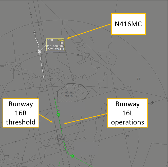
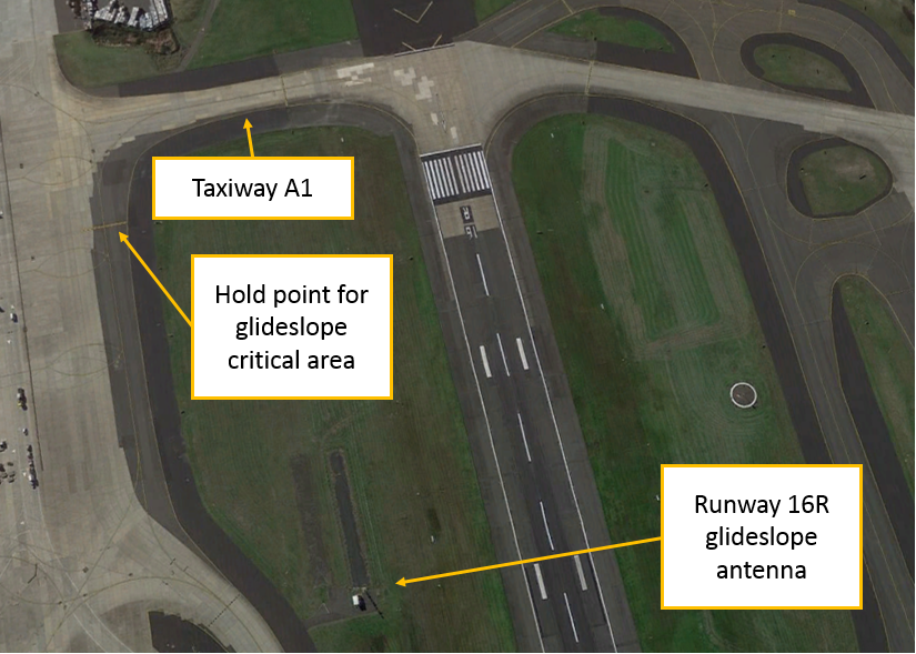
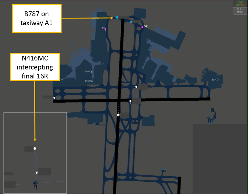

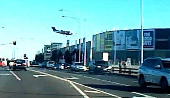
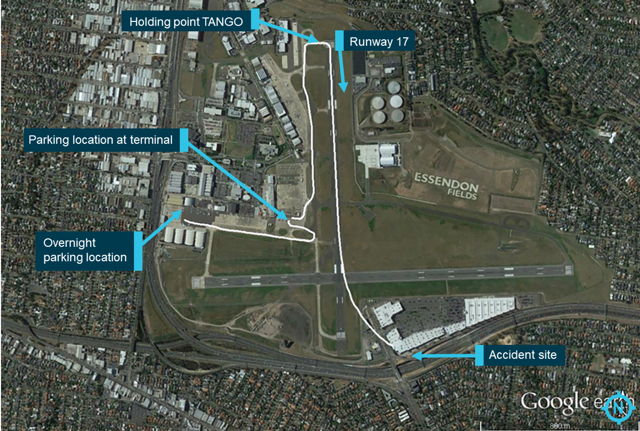
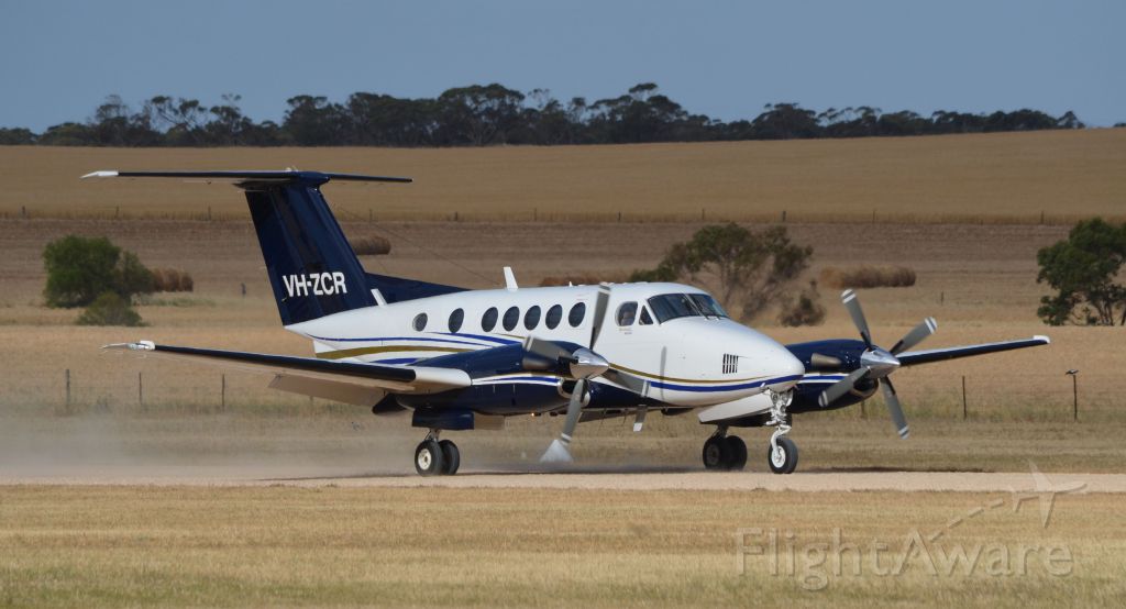
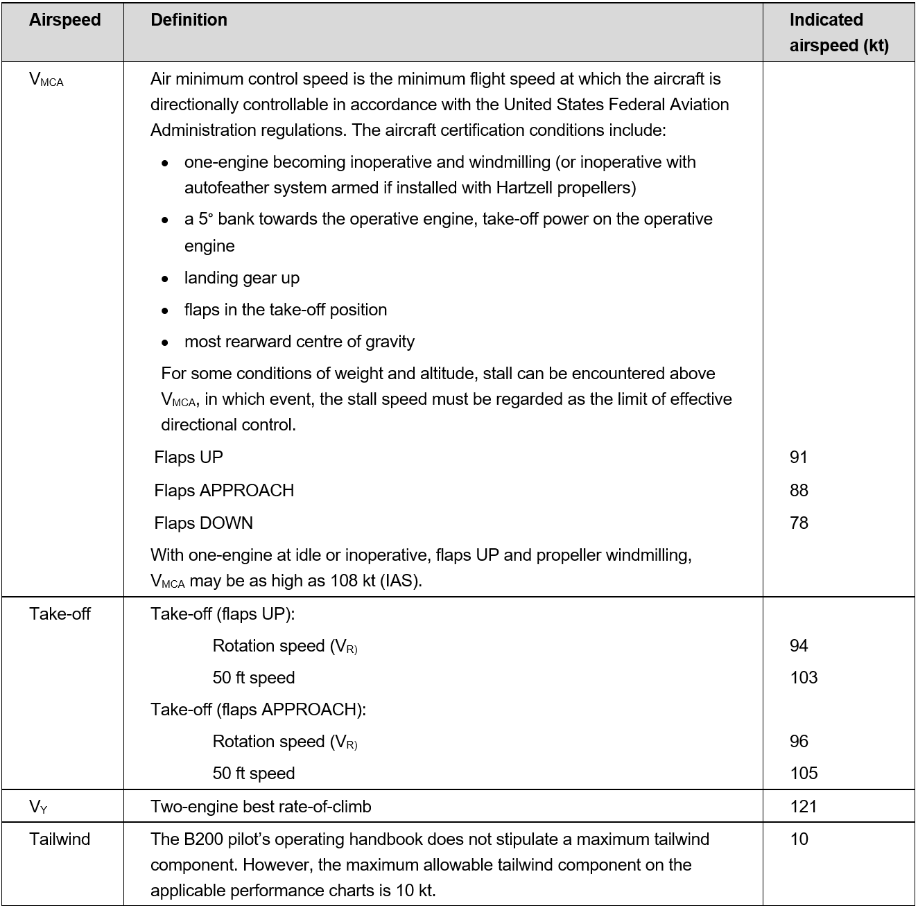
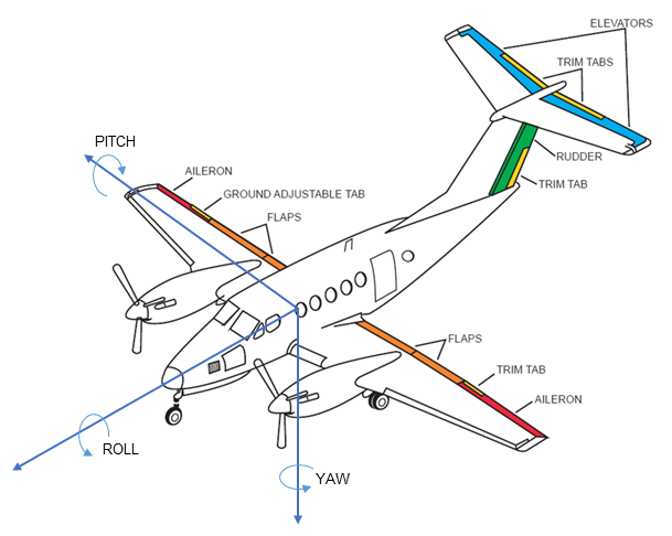
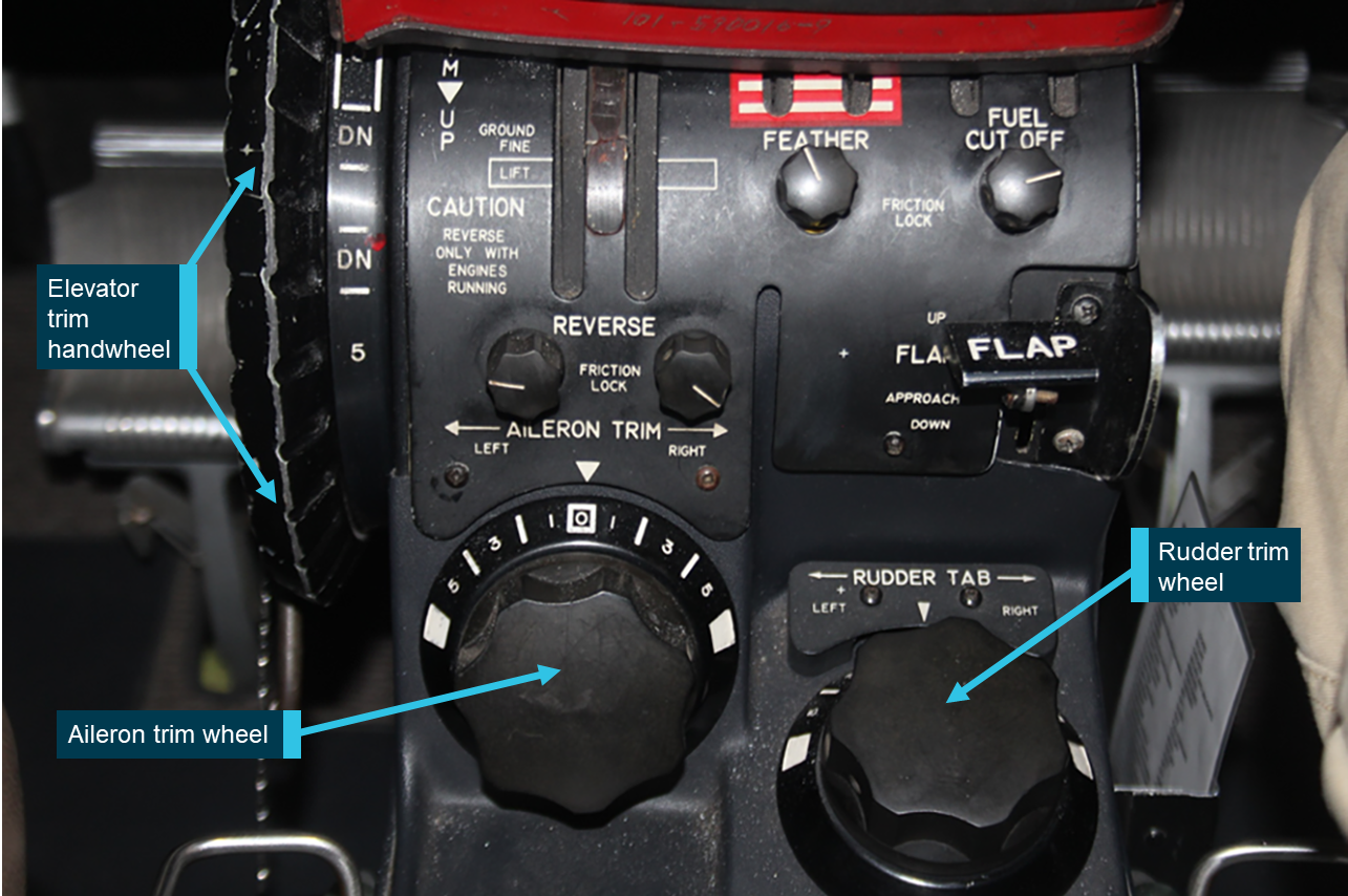
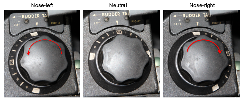
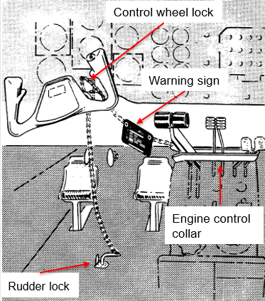
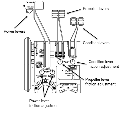
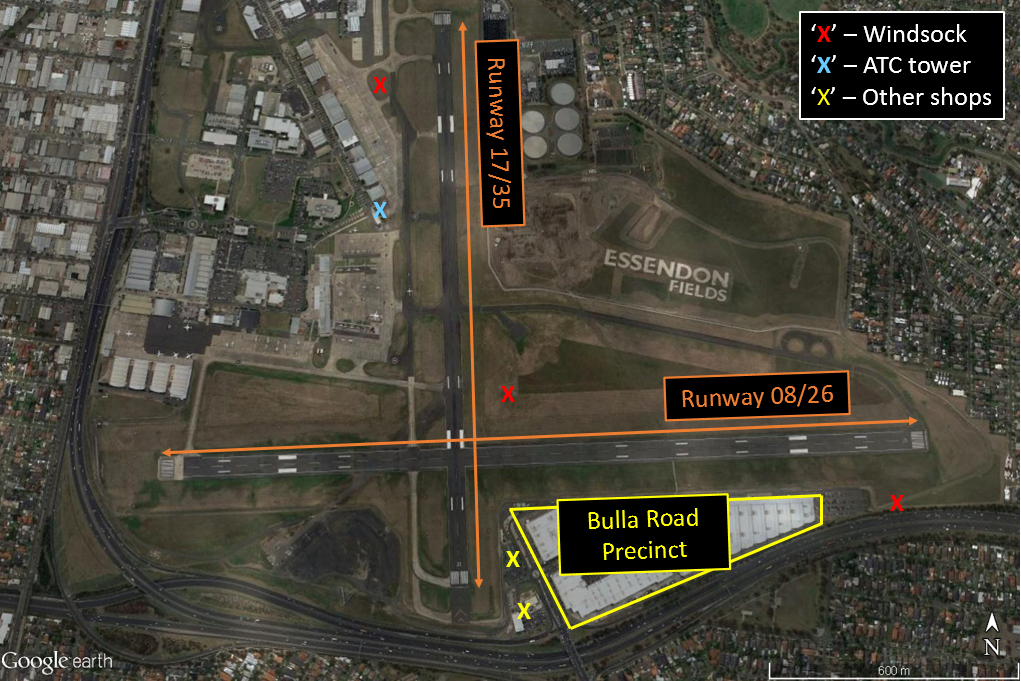
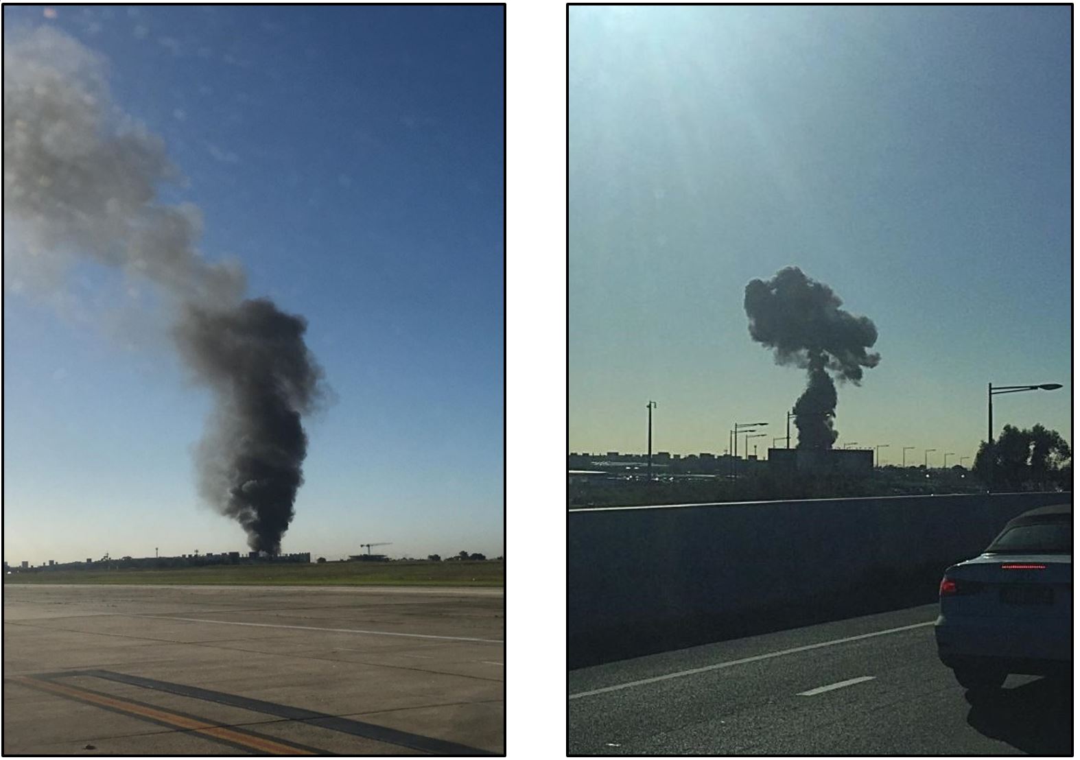
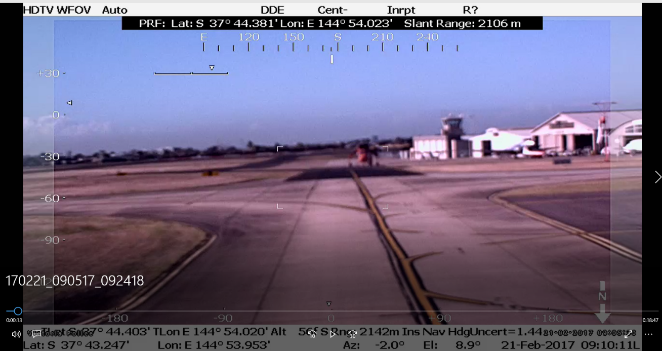
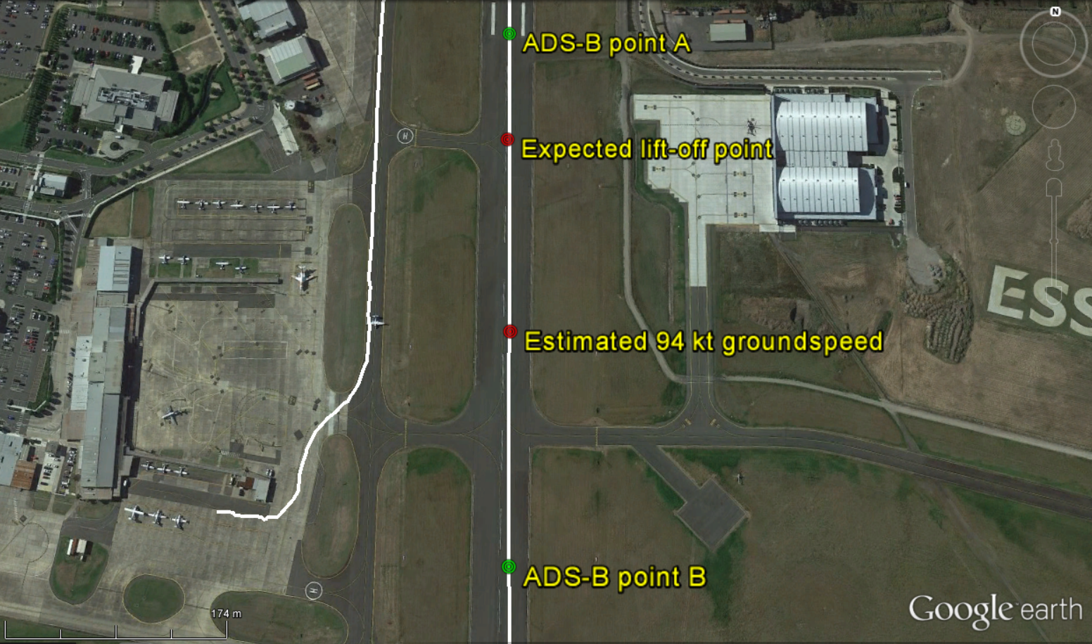
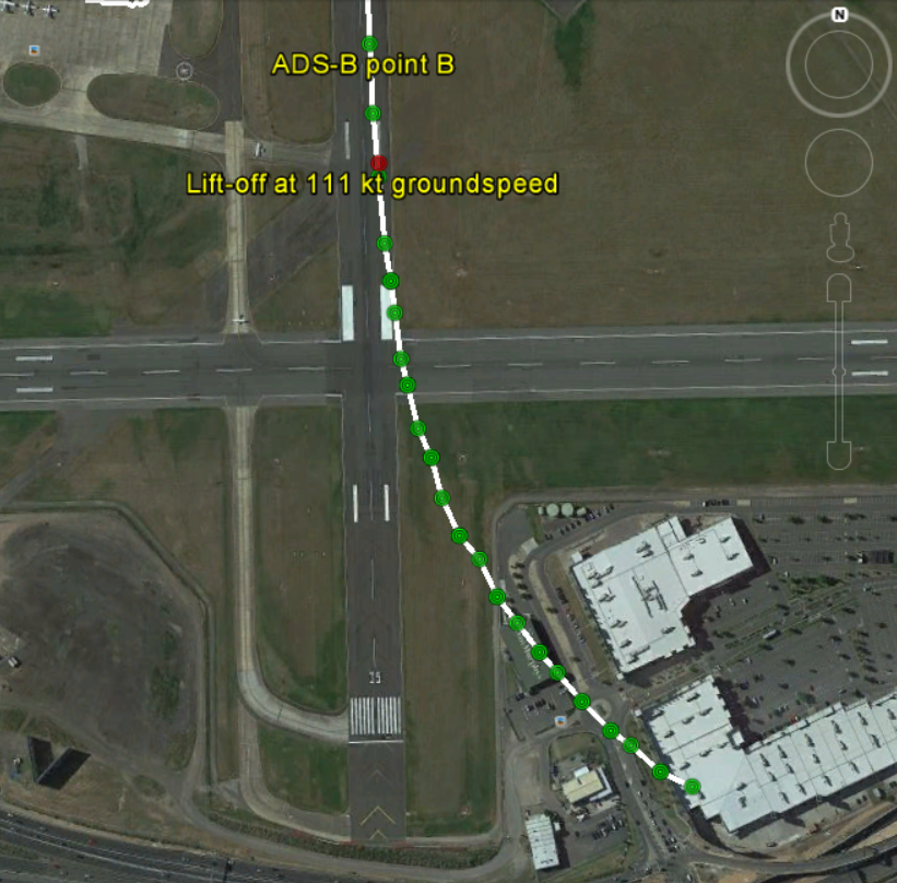
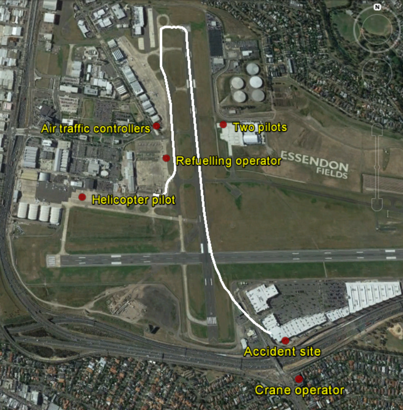
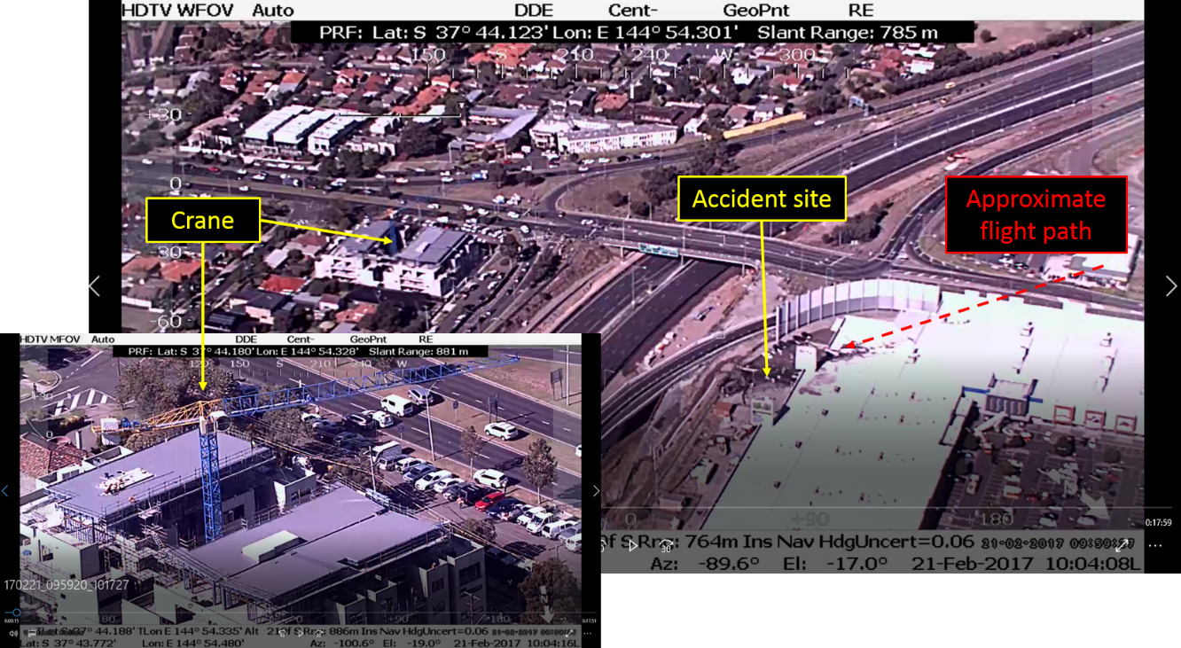
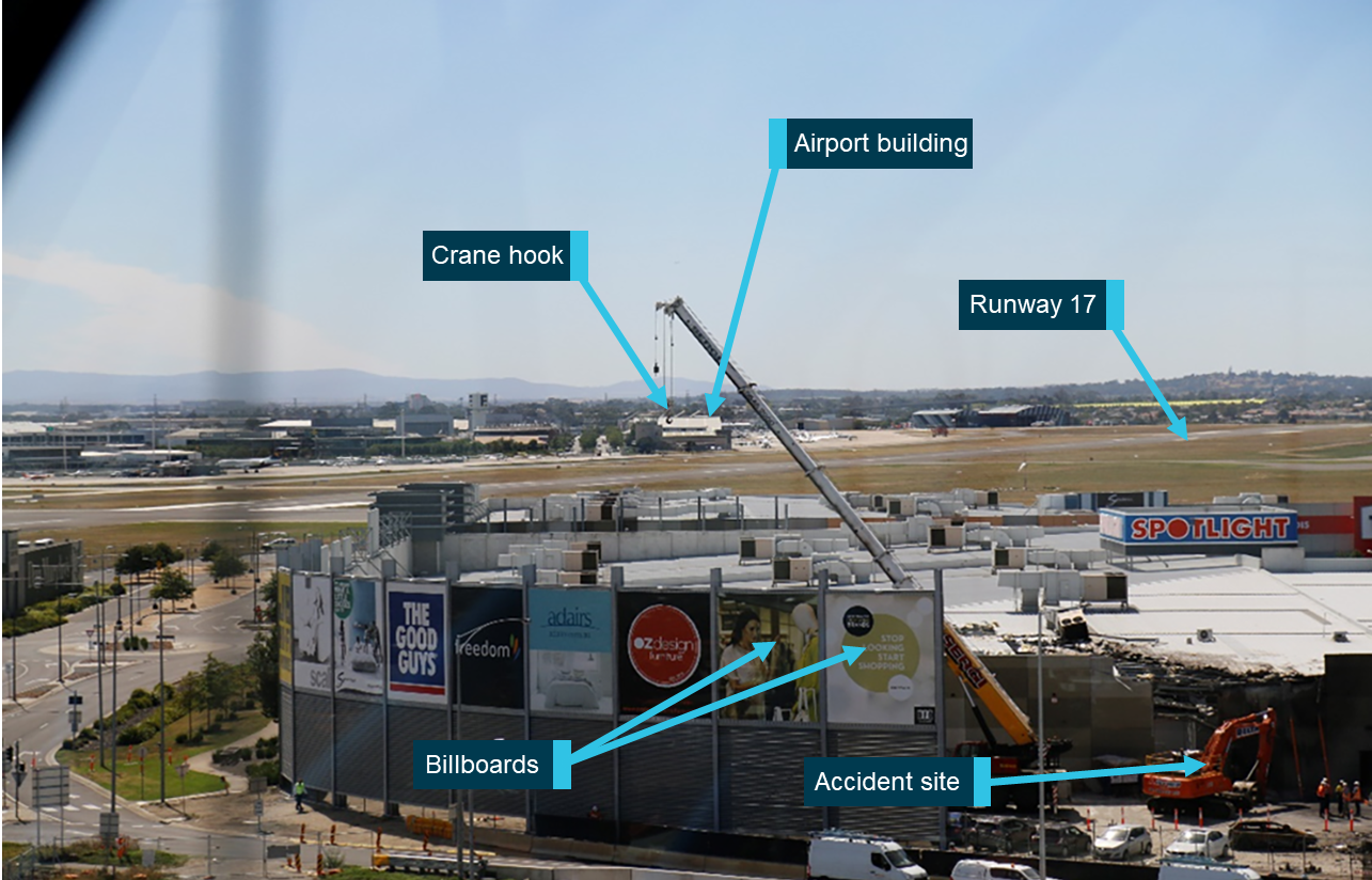
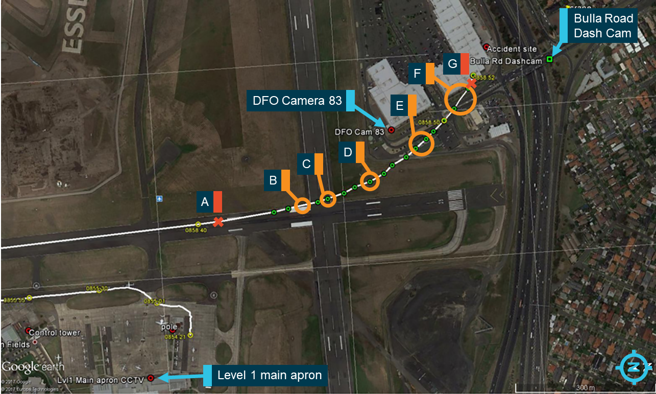
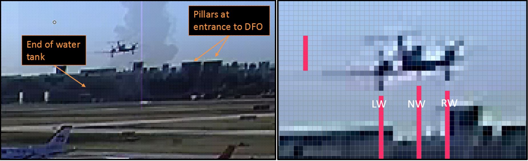
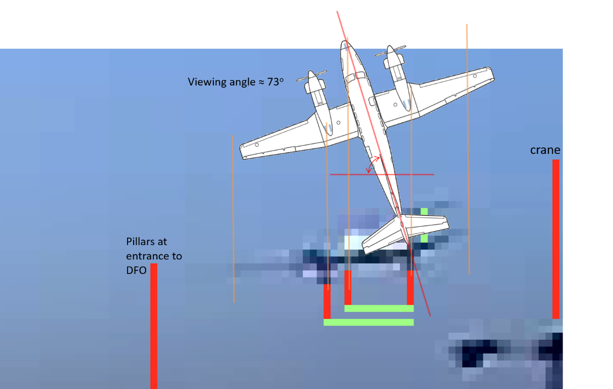
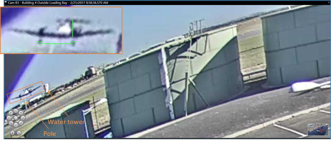
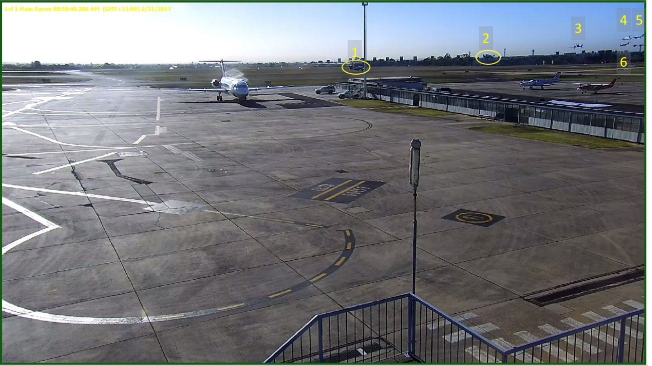
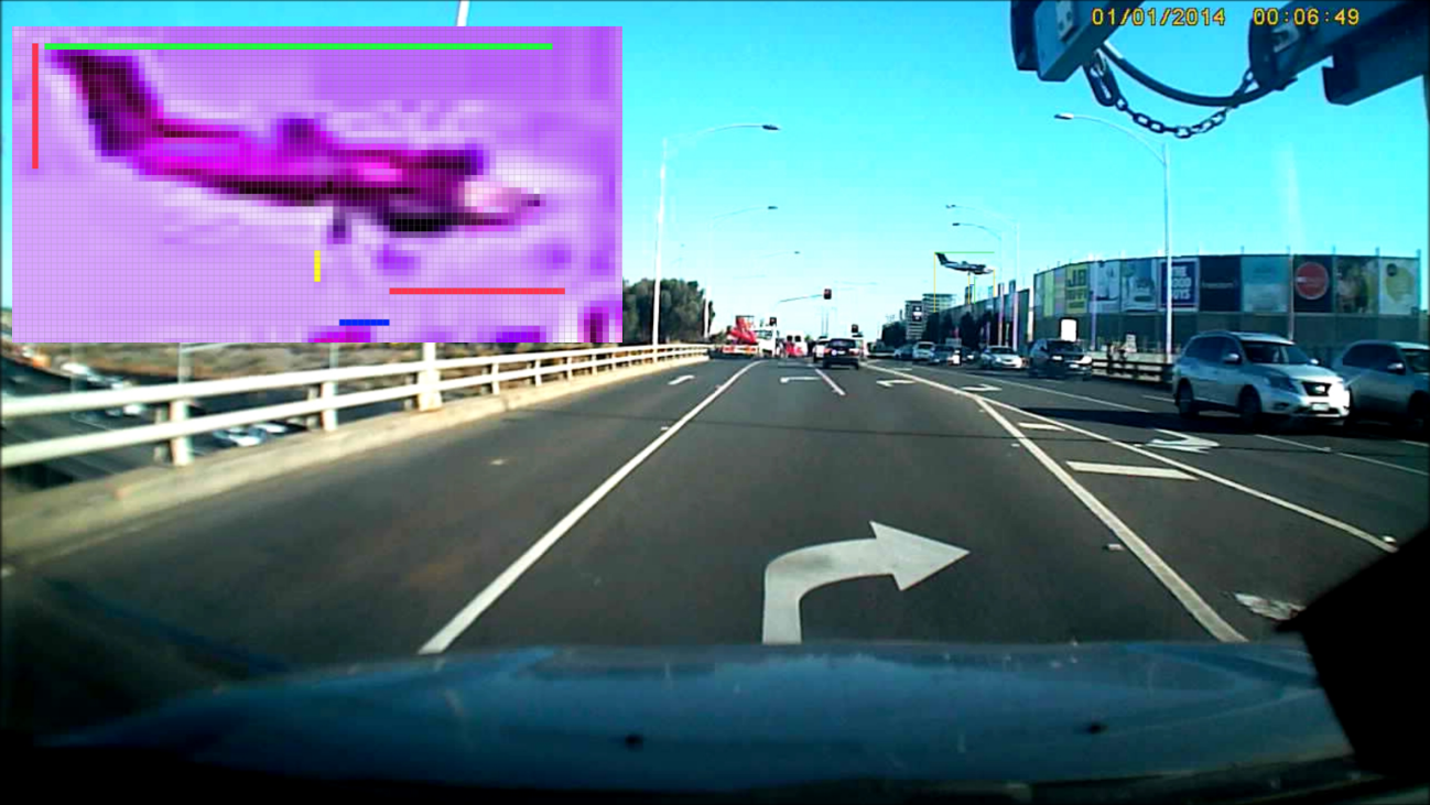
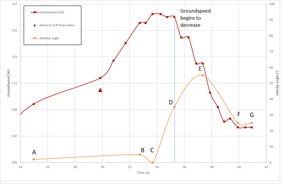
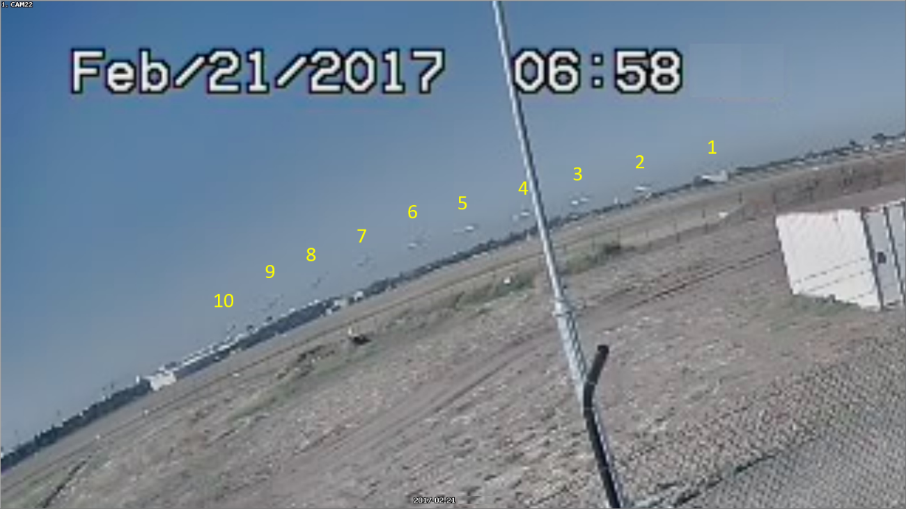
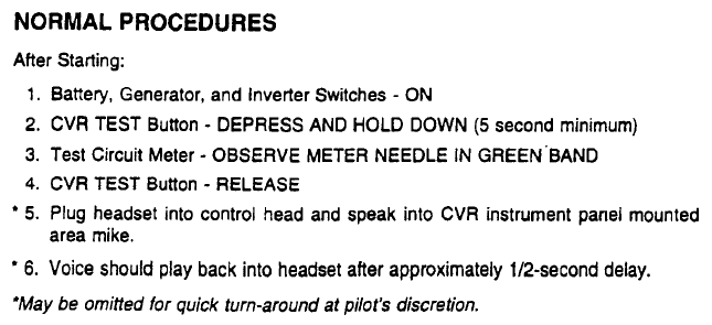
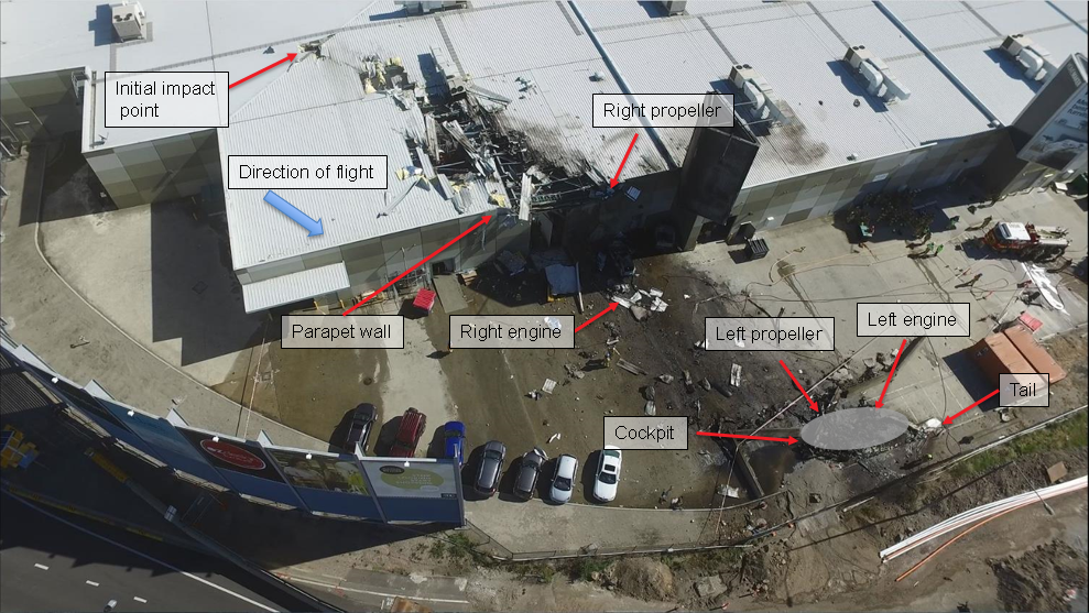
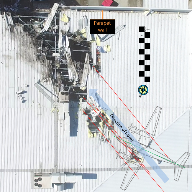
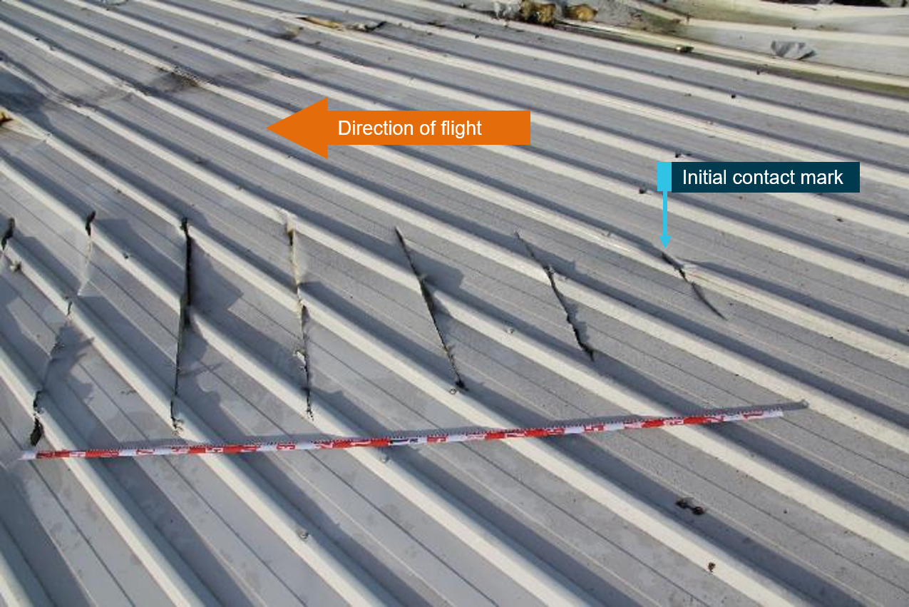
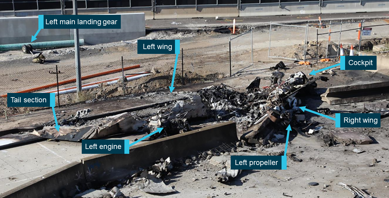
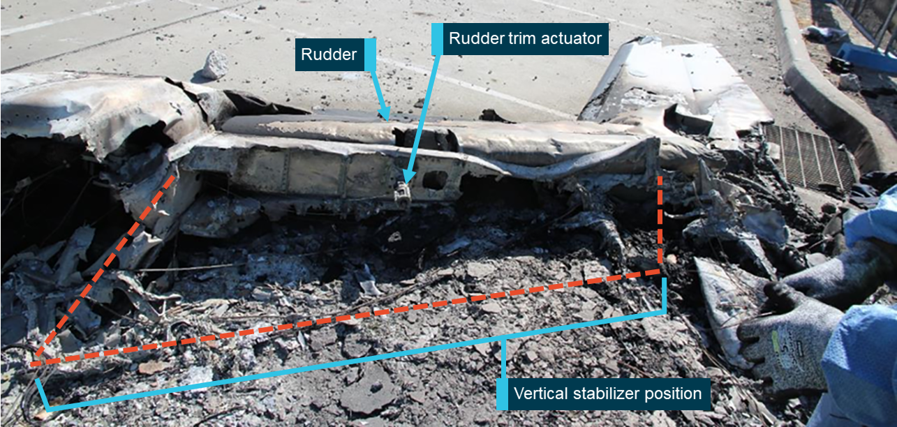
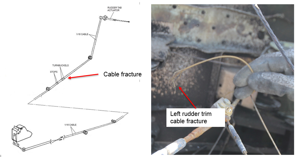
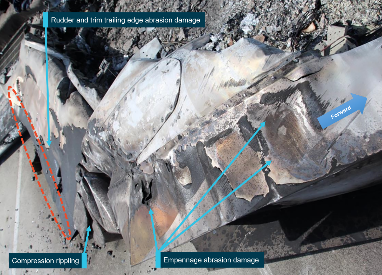
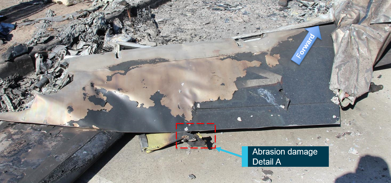
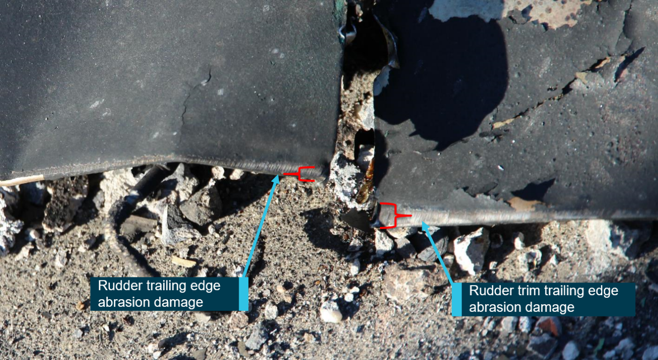
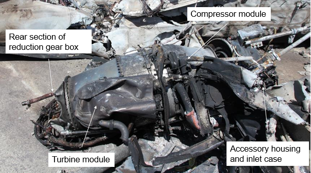
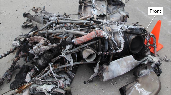
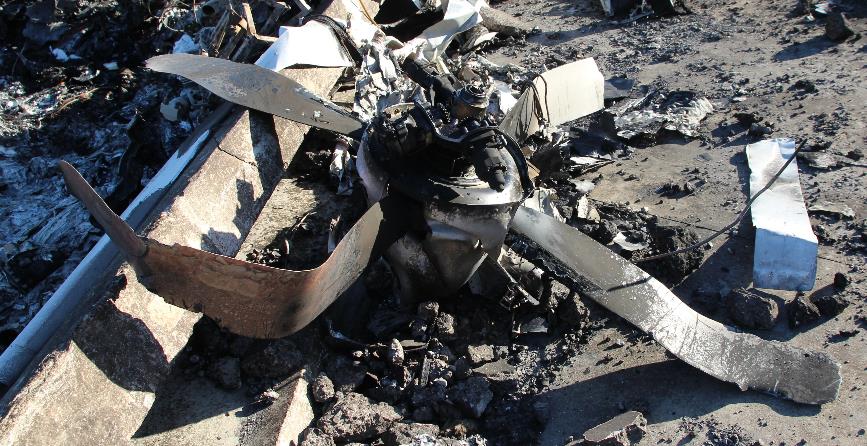
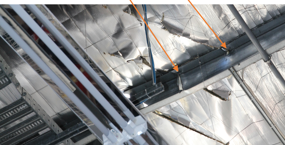
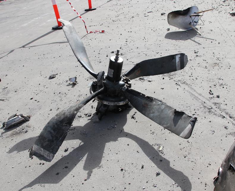
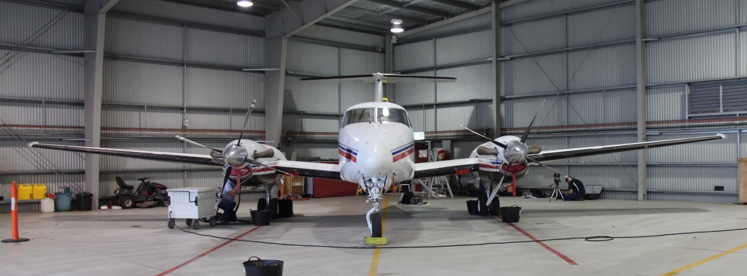
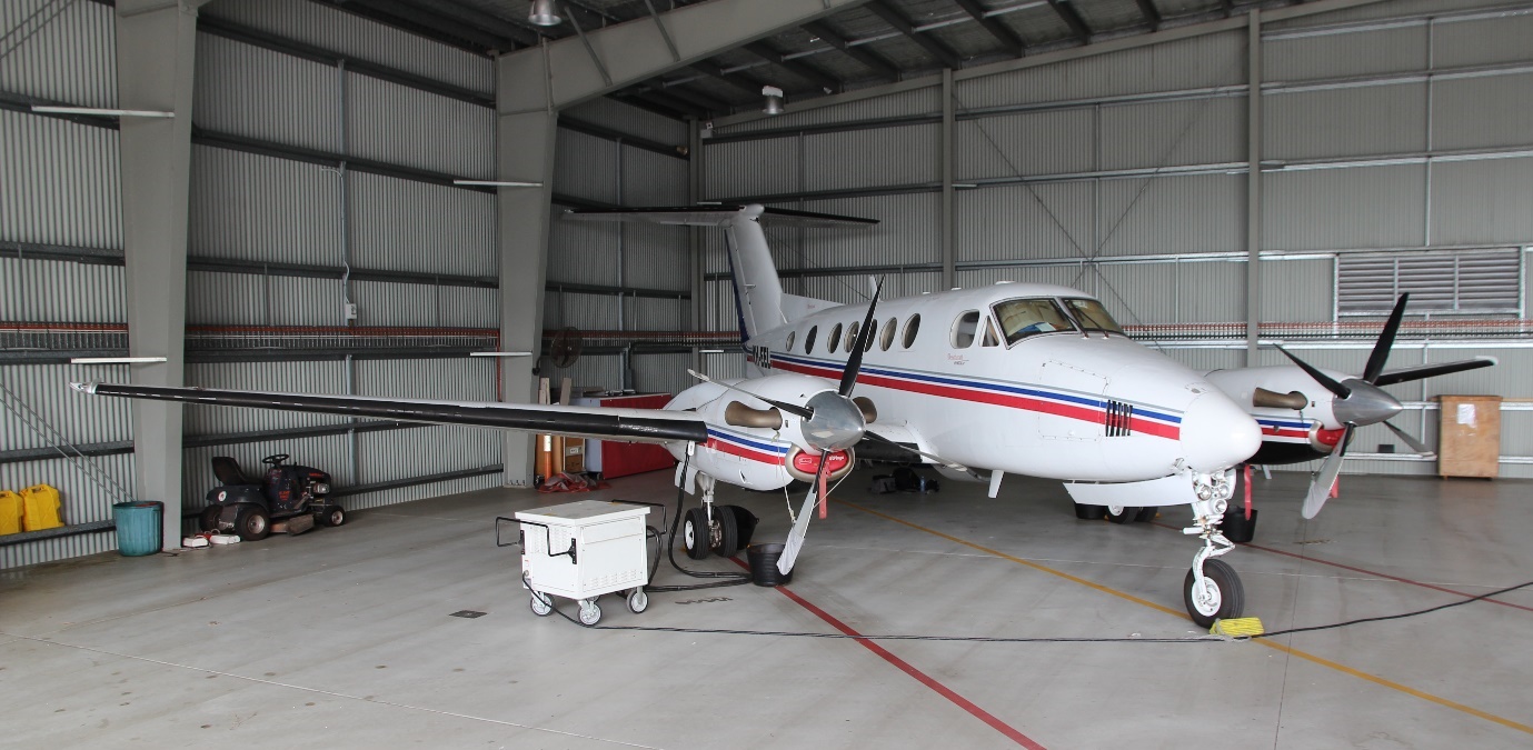
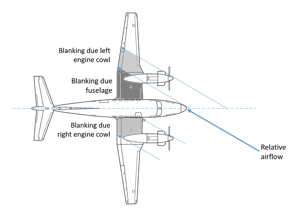
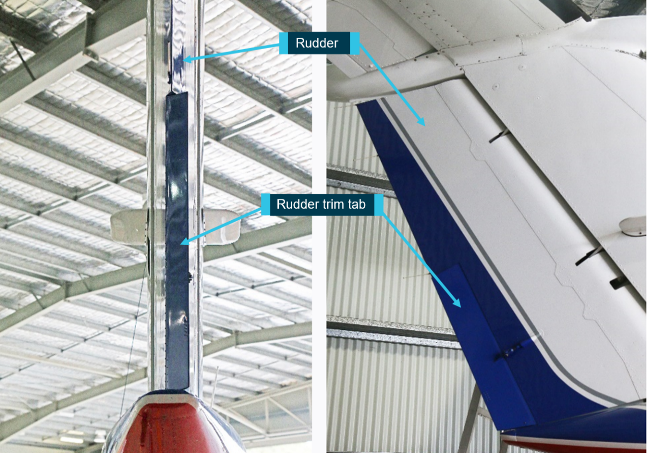
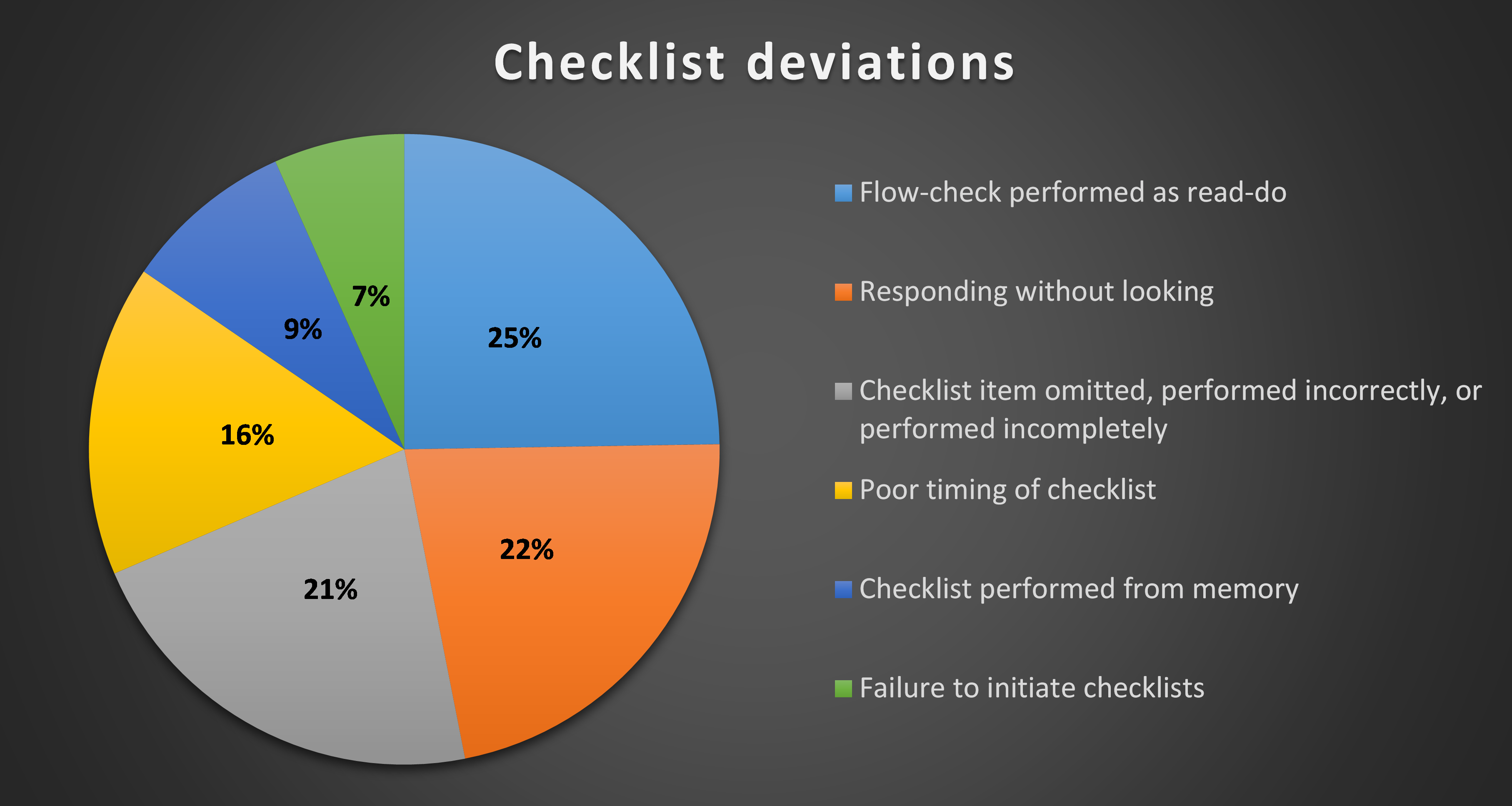
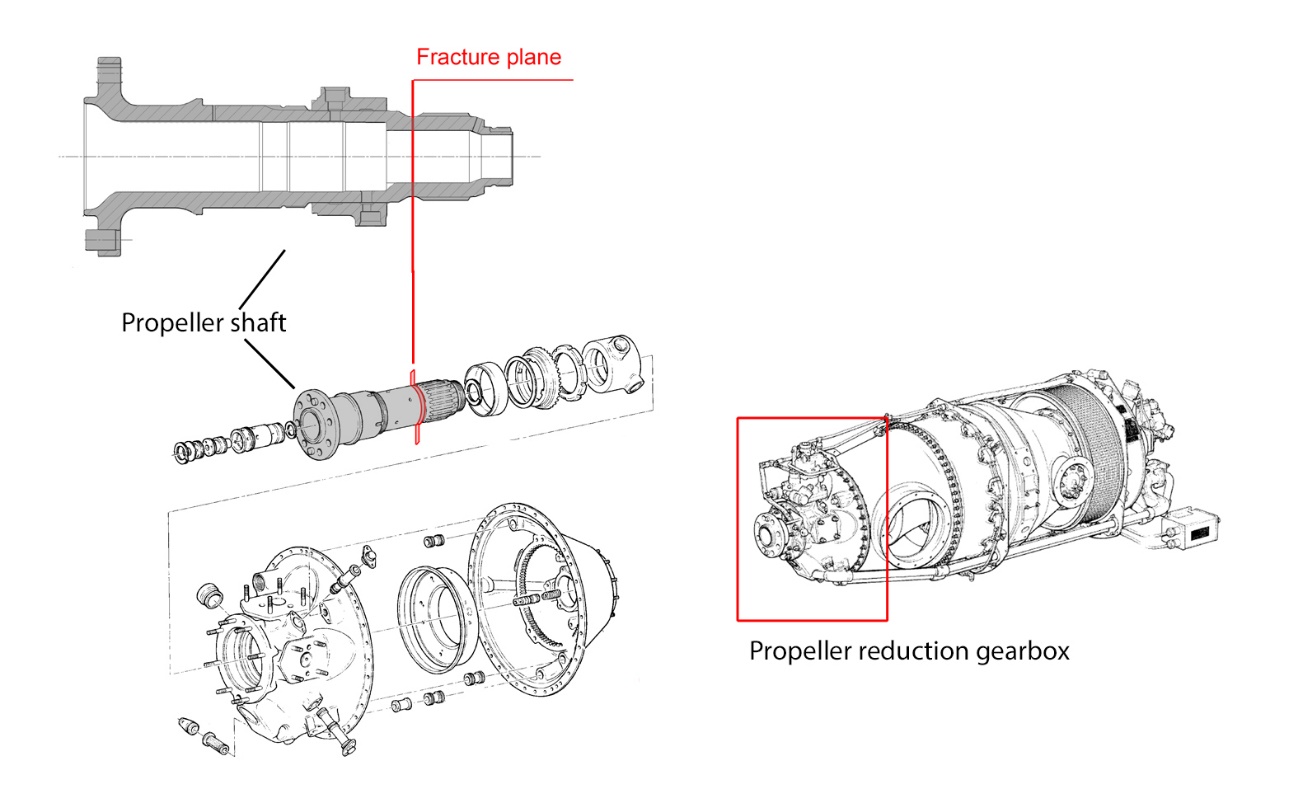
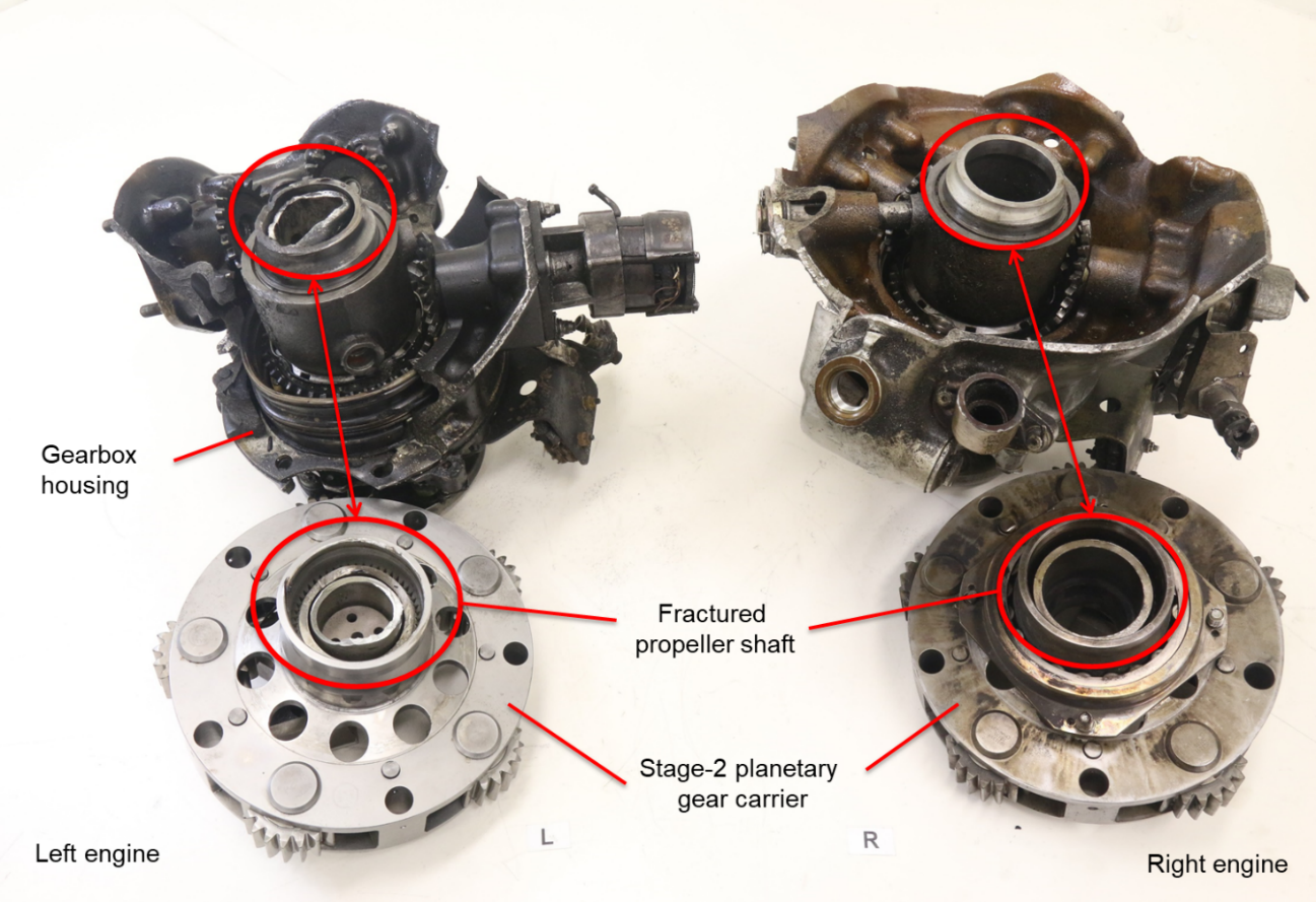
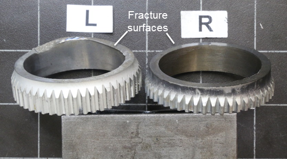
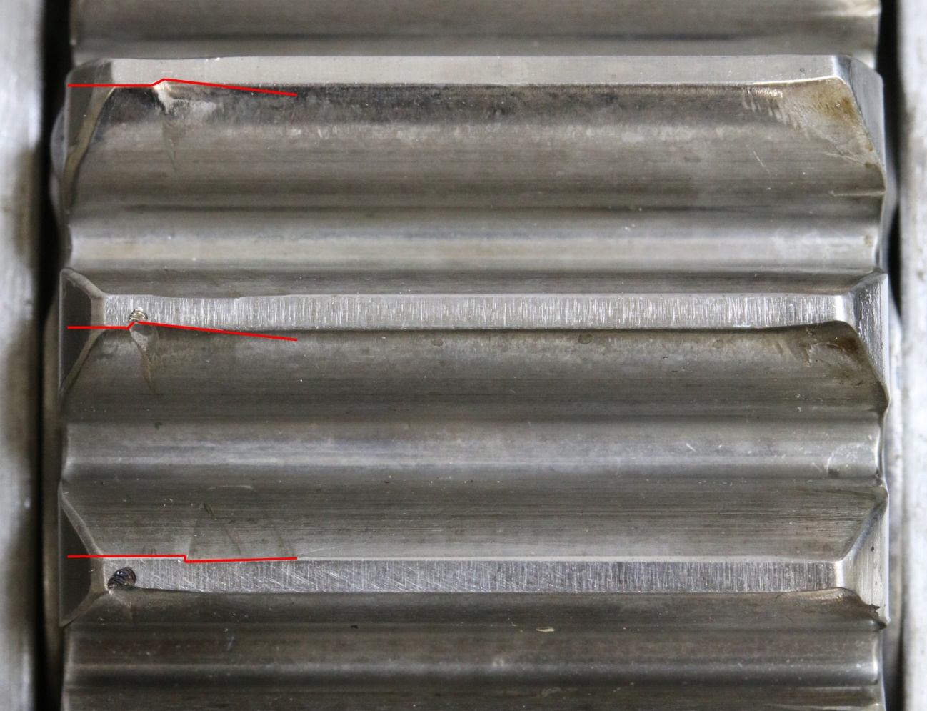
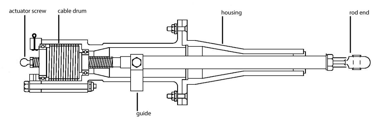
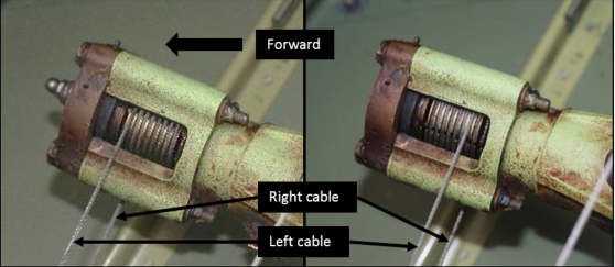
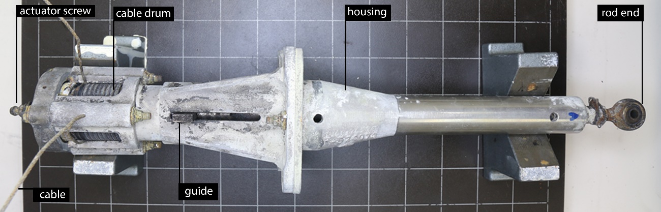
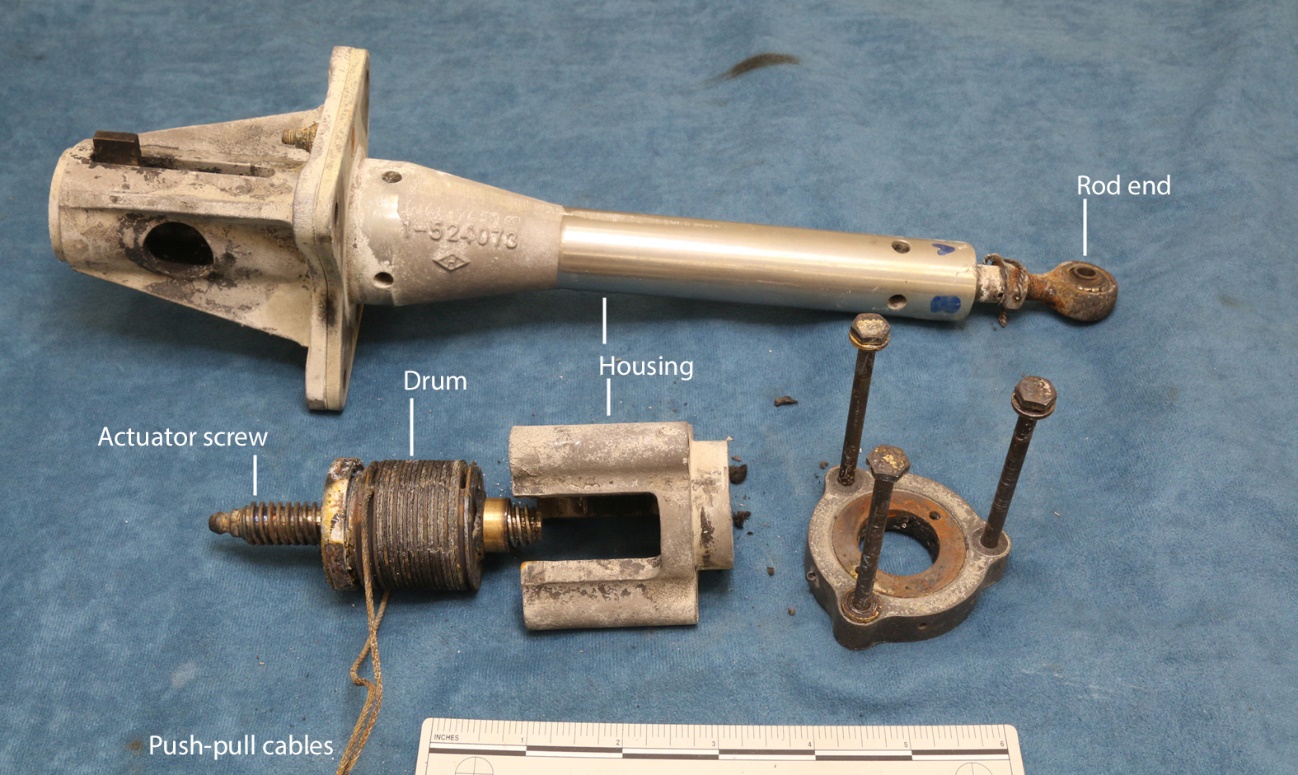
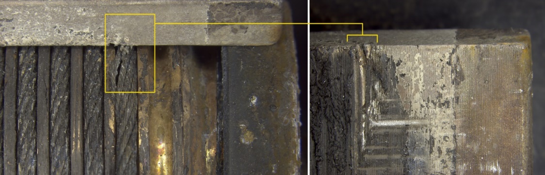
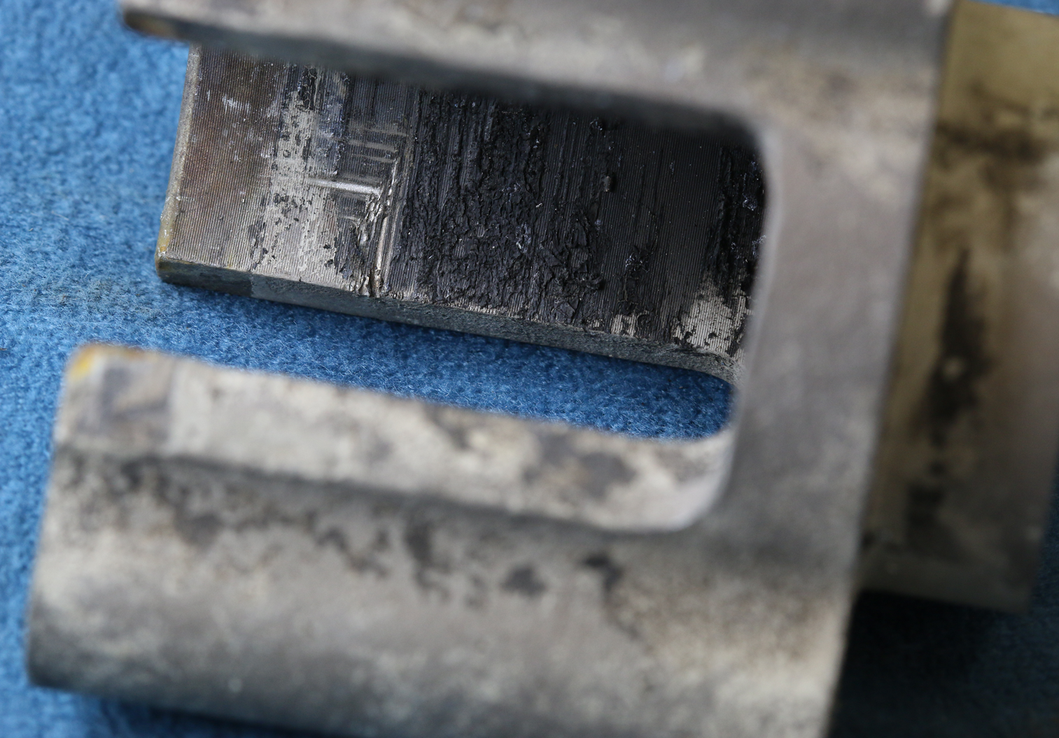
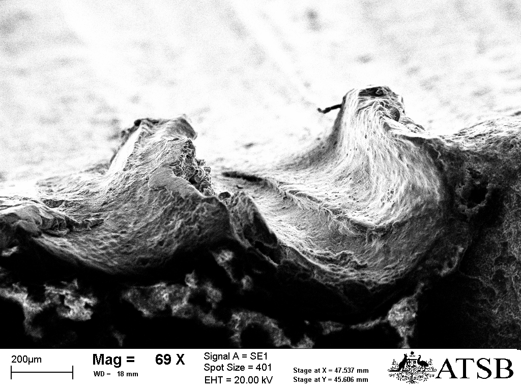
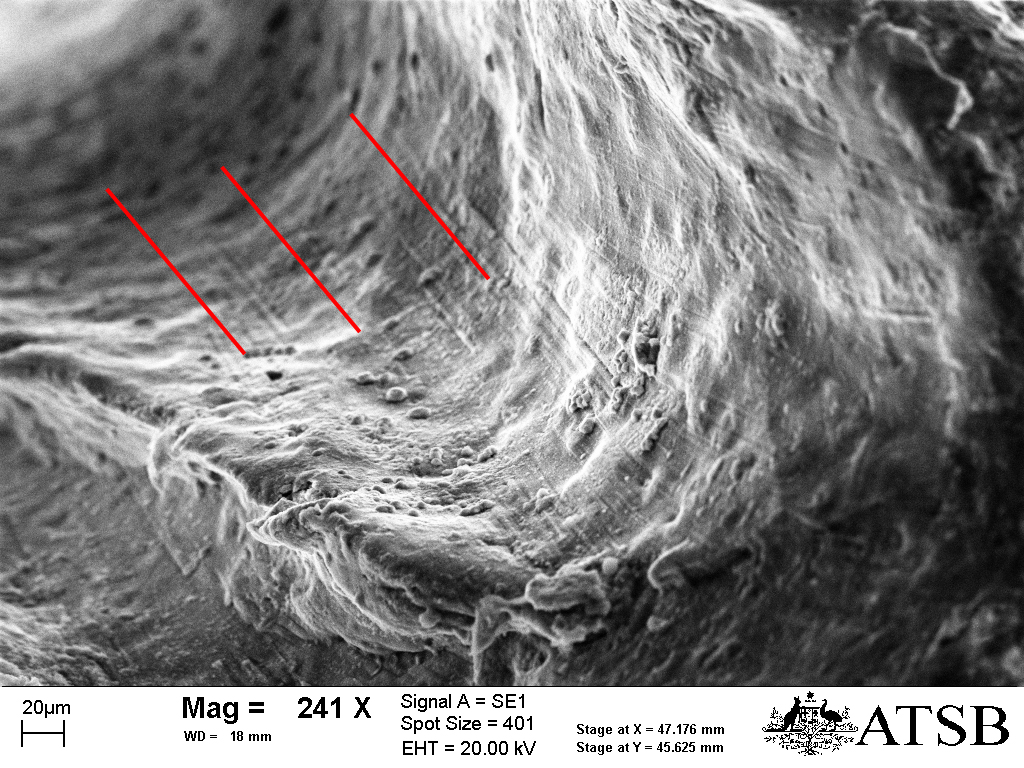
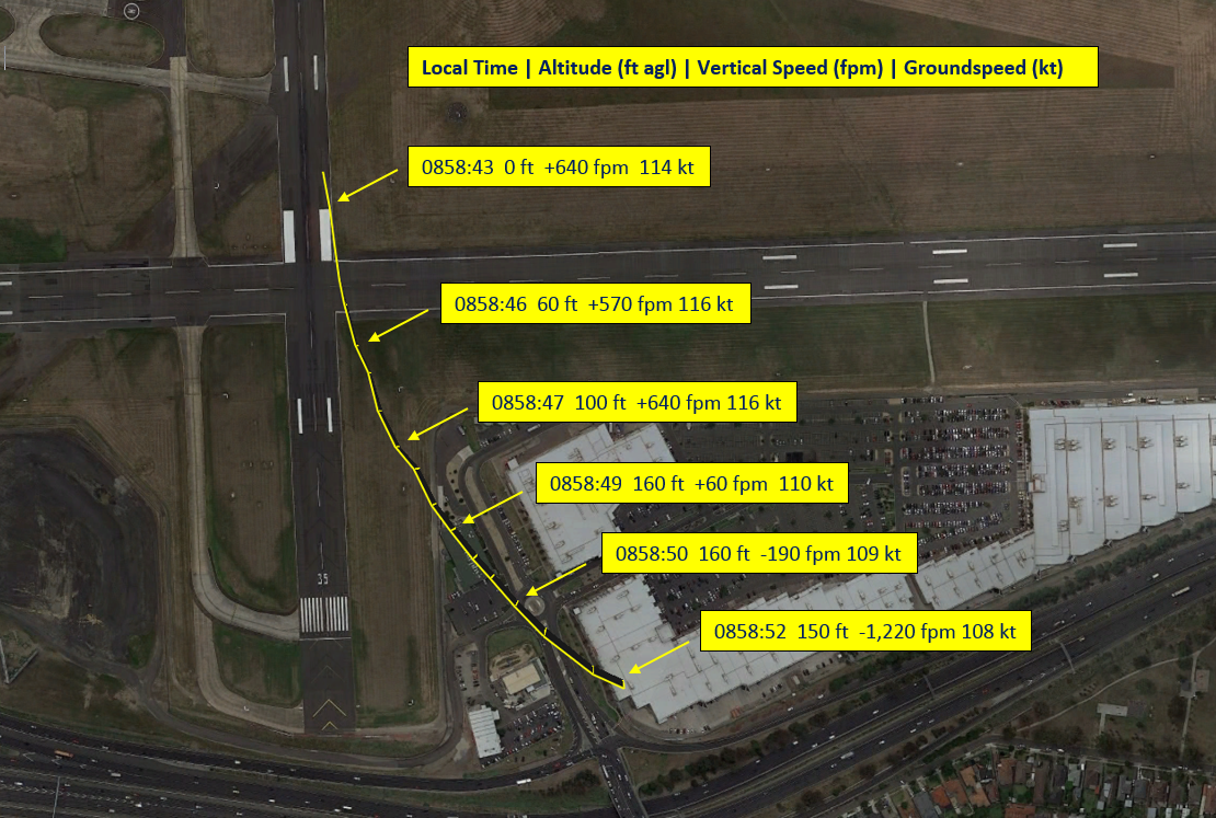
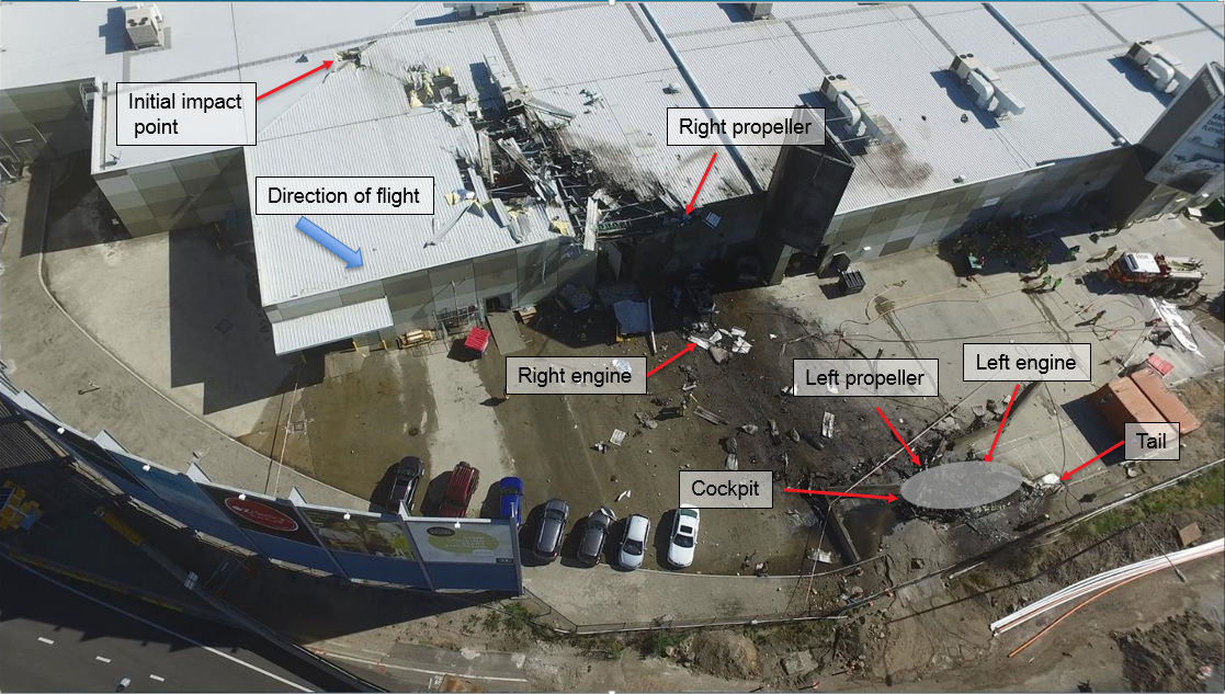
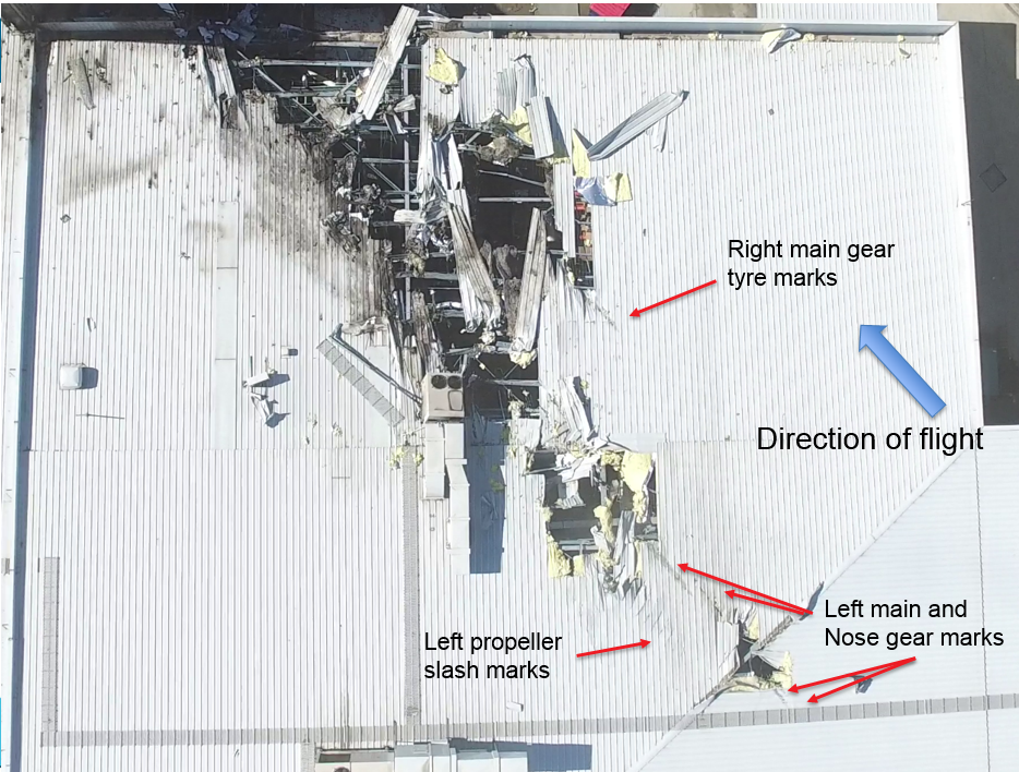
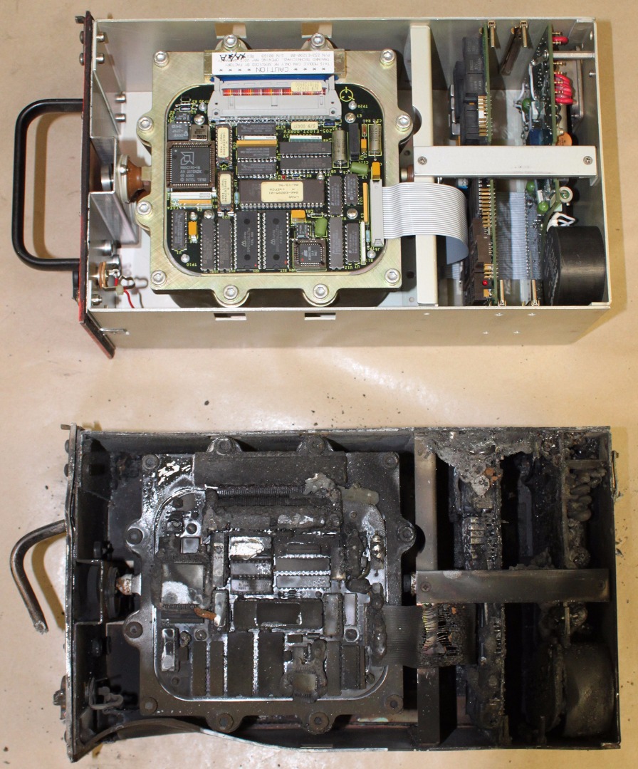

![Figure 1: The track of Norwegian Star from Port Phillip Bay until its loss
of propulsion, and its drift before being towed back to Melbourne. Source: Australian Hydrographic Office ENC Charts AU 439144 and 439145 [Inset: Google Map of Australia], with annotations by Chief Investigator, Transport Safety](/sites/default/files/media/5774319/mo2017003_picture-5.jpeg)