On 8 February 2018, a Kavanagh B-350 hot-air balloon, registration VH-EUA, operated by Go Wild Ballooning, departed Glenburn, Victoria for a scenic charter flight with a pilot and 15 passengers on board. About 45 minutes into the flight, over the Yarra Valley, the balloon experienced a sudden wind change with associated turbulence. The pilot decided to land immediately rather than continue over rising and heavily vegetated terrain. The resulting landing was hard and fast and 11 passengers were injured, with four of them receiving serious injuries.
What the ATSB found
The ATSB found that information about the sudden wind change was not available to the pilot prior to the flight. In particular, the most recent local balloon forecast (provided in a recorded telephone message) was inadvertently not publicly available, and other forecast information available to the pilot did not accurately state the timing of the wind change. The ATSB identified a safety issue with the procedure used by the Bureau of Meteorology to confirm the local weather forecast for balloon operators in the Melbourne area was correctly uploaded and therefore available.
Although some passengers were provided with a safety briefing prior to boarding the balloon, the operator’s normal safety briefing for passengers post boarding was not conducted. In addition, the briefing prior to boarding was not effective in ensuring all passengers understood the required landing position to use in the event of an emergency landing. The ATSB identified a safety issue with the operator’s risk controls for ensuring safety briefings were conducted, and that passengers understood the briefing and the availability and content of its safety information cards.
What's been done as a result
The Bureau of Meteorology has commissioned a new system and modified its procedures for providing local weather briefings to balloon operators in the Melbourne area. This new recording system automatically uploads the recording to the automated telephone service.
The operator has implemented a procedure that all passengers are required to demonstrate the landing position after boarding the aircraft. In addition, the operator has implemented procedures for all pilots to share wind and weather conditions to optimise safe and suitable launch sites in addition to conducting more regular checks of nearby aerodrome weather information.
Safety message
Pilots are reminded that good command judgement is required for all operations when actual weather conditions do not appear as forecast.
In relation to the emergency descent and landing, this accident highlights the importance of operators briefing balloon passengers about what to do in an emergency and the landing position. Proper preparation for landing is shown to reduce the likelihood and severity of injury, and operators should ensure that passengers understand the instructions provided. It is recommended that all passengers should board the basket and practice the position they should adopt for landing. This allows the operator to determine any misunderstanding prior to flight.
It is also recommended that safety information cards, with diagrams, be readily available to help communicate important safety information, particularly to people from a non-English speaking background.
The occurrence
On the morning of 8 February 2018, a Kavanagh B-350 hot-air balloon, registration VH-EUA, operated as a scenic charter flight by Go Wild Ballooning. The flight, with one pilot and 15 passengers, was to depart from Glenburn, north of the Yarra Valley, Victoria.
During the night before the flight, the pilot checked the Bureau of Meteorology (BoM) weather forecast and on the morning of 8 February, he checked the automated phone briefing service to ascertain the suitability of the weather for the flight.
The pilot, ground crew and passengers met early at Chateau Yering Hotel, near Yarra Glen. The ground crew launched a pilot balloon (piball)[1] to measure surface and upper-level winds. Based on the observations of the direction and speed of the piball, the pilot decided to take-off from a northerly launch site at Glenburn (Figure 1). Given the available forecasts and observations, the pilot’s intention was to land back at Chateau Yering.
Figure 1: VH-EUA’s approximate intended track (red) and actual flight path (yellow)
Source: Background image Google Earth; annotated by ATSB.
The passengers, pilot, ground crew and balloon travelled by vehicles to the launch site. Prior to take-off, the ground crew inflated another piball and they observed similar conditions to those from the previous piball.
A ground crew member conducted a safety briefing with the passengers, and the pilot discussed the proposed flight with a number of other balloon pilots before preparing the balloon for launch.
At 0617 Eastern Daylight-saving Time,[2] VH-EUA lifted off in clear conditions with a light northerly wind. Three other balloons, all operated by a different operator, lifted off from the same location shortly after.[3]
Soon after take-off, the pilot of VH-EUA received a phone call from the chief pilot of another balloon operator, who was in Melbourne city at the time. The pilot was advised that unexpected weather conditions had been experienced in the city and that a south-westerly wind may affect his operations. The pilot considered this information and decided to continue the flight, immediately towards Chateau Yering, due to a lack of suitable landing areas at that time.
At 0657, as the balloon approached the Yarra Valley, the pilot began to descend for landing.
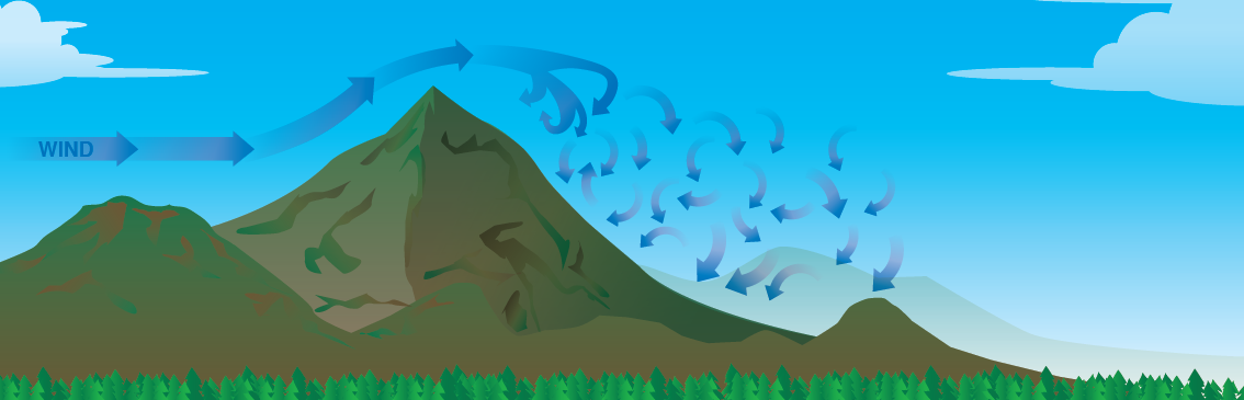
At 0703, when about 630 ft above ground level (AGL), the balloon encountered significant turbulence. There was also a significant change in the wind direction and speed, and the balloon started tracking about 90° to the left of its previous track (Figure 2).
Figure 2: VH-EUA actual flight path, showing change in track due to wind
Source: Background image Google Earth; annotated by ATSB.
Due to the turbulence associated with the wind change, the balloon initially increased altitude by 78 ft to 708 ft AGL (1,037 ft above mean sea level). Because of the turbulence, hot air inside the balloon canopy was forced out, reducing buoyancy and the balloon began to descend.
The pilot was aware of a number of obstacles in the area such as powerlines and rising, wooded terrain further along the direction of travel. He decided to conduct an emergency landing in a nearby paddock after identifying what he thought was mist on a nearby dam.
In the final stages of the flight (Figure 3), the balloon descended at about 600 ft/minute and accelerated to over a 16 kt[4] groundspeed. Prior to impact, the pilot applied the burner, which reduced the descent rate to some extent. The pilot instructed the passengers to adopt the emergency landing position, but some passengers were initially confused about what to do.
Figure 3: VH-EUA final descent profile
Source: Still image taken from witness video with ATSB annotations.
On approaching the ground, the pilot turned the burners off and opened the vent at the top of the balloon to deflate the balloon envelope. The basket landed hard, and the deflating balloon envelope began to act like a sail. The basket then dragged for 48 m, and then became airborne for another 56 m. After a secondary hard landing, it tipped over and dragged for another 7 m before coming to rest on its side (Figure 4). The pilot isolated the gas and began to check on the passengers.
Four passengers received serious injuries and seven received minor injuries. All of the serious injuries involved some form of spinal injury, three of which required hospitalisation. The balloon’s basket sustained minor damage.
Figure 4: VH-EUA final resting position
Source: Victorian Police with annotations by ATSB to show passenger compartments, hand holds and passenger position for landing.
The graphical area forecast relevant to the intended flight indicated no significant cloud, visibility or other weather. The grid point wind and temperature (GPWT) forecast indicated northerly winds at lower levels (2,000 ft and below) of about 10 kt.[5] The upper winds would begin to back[6] through to a westerly direction and increase in strength to more than 20 kt. The forecast also indicated that, as the day progressed, the expected winds would ease progressively at lower altitudes and then begin to back to the west.
The Bureau of Meteorology (BoM) provided local weather briefings for balloon operators in the Melbourne area. These briefings contained site-specific weather services and gave more detailed local weather information than area forecasts. The briefings covered the Melbourne city, inner and outer suburbs and Yarra Valley areas and were provided as recorded telephone messages.
Two briefings were provided for each morning. The first briefing was recorded on the previous afternoon and normally had a short summary of the next morning’s weather forecast. The second briefing was recorded in the early hours of the morning of the day of validity and provided a more comprehensive forecast based on up-to-date details.
For 8 February 2018:
The first briefing was recorded at 1600 on 7 February and it indicated weak surface winds for the time of the flight, increasing to easterly winds at 15 kt at 1,500 ft.
The second briefing, recorded at 0230 on 8 February, indicated wind at lower levels (2,000 ft) in the Yarra Valley would be from the north at 10 kt, but expected to change direction to the south at 10 kt by about 0900.
BoM reported that although the second briefing for 8 February was recorded in the early hours of the morning, a procedural error by a meteorologist prevented its uploading to the automated phone system. As a result, the briefing that was available to balloonists in the early hours of 8 February 2018 was the previous afternoon’s recorded briefing. In addition, BoM advised that there was no procedure in place to check that the new briefing had been updated correctly.
The ground crew launched piballs at the intended landing and take-off sites to ascertain the suitability of the weather for the operation. Their observations of these indicators were mostly consistent with the area forecast.
Following the 8 February 2018 accident, BoM provided analysis of Doppler[7] wind imagery and the Coldstream, Victoria weather sensors. The analysis showed development of moderate westerly winds coinciding with the arrival of a low-pressure trough at the balloon accident site at about the time of the accident.
The pilot had significant operational experience in balloon operations in the local area. He stated that it was not uncommon to utilise lower level katabatic[8] wind conditions to operate the balloon down the Yarra Valley. He reported that he had only ever encountered this type of unexpected weather change during flight once before in 15 years of operating in the area.
Passenger safety briefing
The operator’s procedures required passengers to have a safety briefing before take-off, with the passengers in the basket. The pilot was responsible for conducting the briefing, but could delegate the task to a ground crew member. The briefing was required to explain and demonstrate the position to adopt during landings and emergencies. The landing position required passengers to bend their knees slightly, hold on to the rope handholds (Figure 4), rest their back against the padding and face away from the landing direction.
According to the procedure, the person conducting the briefing was also required to ask passengers whether they understood the briefing, with particular attention given to non-English speaking passengers. There was no specific requirement for passengers to physically demonstrate the landing position to show that they had understood the briefing.
A ground crew member stated that they typically provided passengers with two briefings: one before the passengers entered the basket and one after they had entered the basket. He advised that two passenger briefings took place on the morning of 8 February. However, several passengers recalled only one briefing, which was provided by the ground crew member before passengers entered the basket and included information about the landing position and the inside of the basket. Some of these passengers also recalled being told there would be another briefing after they entered the basket, but this second briefing did not occur.
The operator reported that all passengers were present at the briefing. However, two passengers, who assisted with setting up the balloon, did not recall receiving any safety briefing.
On board the balloon were two passengers who could not speak English. Those passengers recalled having the initial briefing provided by the ground crew member, which was translated by a family member who had accompanied them to the launch site. Although the flight manifest identified these two passengers as non-English speaking, the pilot later reported that his understanding was that all passengers on board understood English.
The operator’s procedures required the pilot to provide an additional briefing towards the end of a flight, with the content depending on the prevailing conditions. For a fast or hard landing, this involved:
repeating the instructions for the landing position, and asking passengers to indicate that they understood
advising passengers to take up the landing position, and checking they were in the correct position
instructing passengers to hold on tightly until advised that it was safe to relax their grip.
On this occasion, the pilot reported that he did not provide a detailed in-flight briefing to the passengers after he had made the decision to land as soon as possible, however, he did instruct passengers to adopt the landing position.
Some passengers reported that when instructed by the pilot to adopt the landing position, there was confusion about what position to adopt and the direction to face, with some passengers kneeling, sitting and/or facing the direction of travel. The non-English speaking passengers advised that they did not understand the pilot’s instruction and copied the actions of other passengers. The pilot attempted to correct the passengers’ landing positions, however, not all passengers were in the correct position on impact.
Civil Aviation Order 20.11 (Emergency and life saving equipment and passenger control in emergencies) required that passenger safety information cards be available to passengers on any charter flight with a seating capacity greater than six. It stated that the cards must be carried in a convenient location and detail the passenger brace position for an emergency landing.
The operator had developed safety information cards. Ground crew reported that these were kept in the balloon support vehicle and were only retrieved and used to assist passenger understanding by exception rather than as a normal routine. The operator reported that the safety information cards were also kept in the pilot’s compartment of the balloon basket. The cards were not provided to any of the passengers on the day of the accident.
Civil Aviation Advisory Publication (CAAP) 253-2(0) (Passenger safety information: Guidelines on content and standard of safety information to be provided to passengers by aircraft operators) provided generic guidance on passenger safety briefings and safety information cards for all types of aircraft. It recommended that safety information cards contain non-complex pictorial representations to assist operators in explaining instructions about what to do in an emergency.
The operator’s cards were available in nine languages, but only the English cards provided pictures showing the required landing position.
Other occurrences
A search of the ATSB occurrence database found that in the 10 years to April 2018 there were 47 balloon hard landings or collisions with terrain in Australia. Only some of these occurrences were investigated by the ATSB. One of these occurrences, a hard landing in 2014, involved some non-English speaking passengers not understanding or following the pilot’s instructions to adopt the landing position.[9]
During the flight on the morning of 8 February 2018, the balloon encountered a wind change that substantially altered the direction and speed of the balloon and subjected the occupants to moderate turbulence. The pilot assessed the direction of the balloon after the wind change and concluded that future forced landing options may be further limited if he did not land immediately. Continuation of the flight may have posed increased risk to occupants, and he decided to accept a hard landing in order to lower future risk to passengers. The pilot’s decision to land immediately after the sudden wind change was in accordance with the operator’s operations manual.
Information about the wind change was not available to the pilot prior to the flight. The Grid Point Wind and Temperature (GPWT) chart, which provides wind information, did not capture localised information on the wind change below 2000 ft due to the nature of the product. Although the Bureau of Meteorology (BoM) had identified the potential for a wind change in the Melbourne area during the morning, this information was unavailable to balloon pilots in the relevant local weather briefing area, due to an individual error in the upload of the information to the publicly available phone briefing system.[10]
The error in uploading the local weather briefing meant that the pilot (and other balloon pilots) were not able to use this localised (and in this case more accurate) weather information to re-assess his pre-flight planning or to plan around the expected south-westerly wind change. BoM indicated there was no procedure in place to ensure the recorded briefing was correctly uploaded, which would minimise the risk of such errors.
Soon after take-off, the pilot was advised of a possible wind direction and strength change in-flight. However, at the time he could not identify a suitable landing area in the immediate vicinity of the balloon. He decided to continue the flight and proceeded to the intended landing area as quickly as possible. There appeared to be subsequent landing opportunities in the open fields in the valley prior to the wind change arriving (Figure 2). It may have been prudent to have considered landing earlier, but such a decision would have been complicated by the uncertainty regarding the nature and timing of any wind change.
Prior passenger preparation for a balloon landing, including an emergency, is shown to reduce the likelihood and severity of injury. As such, passengers need to be briefed on the position to adopt when landing during the pre-flight safety briefing and be reminded of it just prior to landing. On this occasion, there were inconsistent accounts about what safety briefing information was provided to the passengers prior to the flight. The operator reported that all passengers attended the briefing, and the ground crew member recalled that he had provided the operator’s normal safety briefings to the passengers, including briefings before and after the passengers boarded the balloon. However, the consistent and independent recollection of the passengers was that the only briefing occurred prior to the passengers boarding, and not all passengers were present at the time.
The period prior to take-off in any aviation operation involves high workload and distractions, and there is a potential for key tasks to be inadvertently omitted. The operator’s procedures did not have a formal check process between the pilot and ground crew member to minimise the risk of such errors and ensure the full safety briefing was provided.
Overall, it appears likely that the passengers were not provided with a safety briefing after they had boarded the balloon. In addition, the briefing that was conducted prior to the passengers boarding was not effective in ensuring that all passengers understood the required procedures for a landing position. Not being in the correct position during the initial hard landing probably contributed to the occurrence or severity of at least some of the passenger injuries.
To ensure that safety briefings are effective, a balloon operator should ensure that passengers understand the information provided. The operator’s procedures required that passengers be asked to indicate whether they understood the safety briefing. To ensure passengers know what to do, it is recommended that all passengers should board the basket and simultaneously practice the position they should adopt on landing.[11] This better enables the operator to determine any misunderstanding prior to flight.
In addition to passenger briefings, safety information cards are a readily accessible method of providing normal and emergency procedures to passengers to enhance safety. Storage of these cards in an area not readily accessible to passengers increases the risk of passengers not fully understanding important information, especially in preparation for an emergency landing. Such cards can be even more effective if they include pictorial representations of the required actions, particularly for non-English speaking passengers. In this case, the safety briefing cards were not made available to passengers, removing another opportunity to overcome any limitations with the provision of the safety briefing.
The Civil Aviation Safety Authority (CASA) issued the Civil Aviation Advisory Publication (CAAP) 253-2(0) in 2004 to provide guidance on the provision of safety information to passengers (oral and written). Although the information is still relevant, it contains only generic guidance material applicable to all aircraft types. Given the unique nature of balloon operations, and the increase in balloon charter operations in recent years, production of specific guidance material about recommended practices for briefing of balloon passengers would be beneficial. Towards this end, the Civil Aviation Safety Authority has recently published a bulletin that provides additional guidance for passenger briefings for balloon operations (see Additional safety action). It also recently commenced a process of public consultation for a revision of CAAP 253-2(0).
From the evidence available, the following findings are made with respect to the hard landing involving the balloon, registered VH-EUA, that occurred 6 km east-north-east of Yarra Glen, 8 February 2018. These findings should not be read as apportioning blame or liability to any particular organisation or individual.
Safety issues, or system problems, are highlighted in bold to emphasise their importance. A safety issue is an event or condition that increases safety risk and (a) can reasonably be regarded as having the potential to adversely affect the safety of future operations, and (b) is a characteristic of an organisation or a system, rather than a characteristic of a specific individual, or characteristic of an operating environment at a specific point in time.
Contributing factors
During the flight, the balloon encountered a wind change that substantially altered the direction and speed of the balloon and subjected the occupants to moderate turbulence.
The most recent local balloon forecast was inadvertently not made publicly available, and other forecast information available to the pilot did not accurately state the timing of the wind change.
The Bureau of Meteorology did not have a procedure to ensure that a recording of the local weather forecast for balloon operations in the Melbourne area was correctly uploaded and accessible to balloon pilots. [Safety issue]
The pre-flight safety briefing provided to the passengers was ineffective in ensuring that all passengers understood the required landing position to use in the event of an emergency landing.
Although the operator had procedures for conducting a verbal safety briefing prior to flight and had safety briefing cards available, its risk controls did not provide assurance that all passengers would understand the required procedures for emergency landings. More specifically:
safety briefing cards were not routinely made available to passengers prior to or during flight
safety briefing cards for non-English speaking passengers did not include diagrams to help communicate important information
the procedure for safety briefings did not require passengers to physically demonstrate that they understood the required landing position
the procedure for safety briefings did not require the pilot and ground crew to crosscheck that a safety briefing had been conducted prior to departure. [Safety issue]
Other findings
Following the sudden wind change, the pilot decided to land immediately rather than continue flight over rising and heavily vegetated terrain. Given the existing situation, this decision meant that a hard and fast landing was likely to occur.
Safety issues and actions
The safety issues identified during this investigation are listed in the Findings and Safety issues and actions sections of this report. The Australian Transport Safety Bureau (ATSB) expects that all safety issues identified by the investigation should be addressed by the relevant organisation(s). In addressing those issues, the ATSB prefers to encourage relevant organisation(s) to proactively initiate safety action, rather than to issue formal safety recommendations or safety advisory notices.
All of the directly involved parties were provided with a draft report and invited to provide submissions. As part of that process, each organisation was asked to communicate what safety actions, if any, they had carried out or were planning to carry out in relation to each safety issue relevant to their organisation.
Descriptions of each safety issue, and any associated safety recommendations, are detailed below. Click the link to read the full safety issue description, including the issue status and any safety action/s taken. Safety issues and actions are updated on this website when safety issue owners provide further information concerning the implementation of safety action.
Safety issue description: The Bureau of Meteorology did not have a procedure to ensure that a recording of the local weather forecast for balloon operations in the Melbourne area was correctly uploaded and accessible to balloon pilots.
Safety issue description: Although the operator had procedures for conducting a verbal safety briefing prior to flight and had safety briefing cards available, its risk controls did not provide assurance that all passengers would understand the required procedures for emergency landings. More specifically:
safety briefing cards were not routinely made available to passengers prior to or during flight
safety briefing cards for non-English speaking passengers did not include diagrams to help communicate important information
the procedure for safety briefings did not require passengers to physically demonstrate that they understood the required landing position
the procedure for safety briefings did not require the pilot and ground crew to crosscheck that a safety briefing had been conducted prior to departure.
Additional safety action
Whether or not the ATSB identifies safety issues in the course of an investigation, relevant organisations may proactively initiate safety action in order to reduce their safety risk. The ATSB has been advised of the following proactive safety action in response to this occurrence.
Go Wild Ballooning Pty Ltd has advised the ATSB that, in relation to operational procedures, it had taken the following safety actions:
all pilots share information on winds, weather tendencies and optimising safe and suitable launch sites before each flight
checks of nearby aerodrome weather information are conducted on a more regular basis.
On 10 October 2018, the Civil Aviation Safety Authority (CASA) issued ‘Cabin safety bulletin 12 - General aviation passenger briefings’.[1] The purpose of the bulletin was to ‘…provide guidance on how to conduct a briefing to increase passenger situational awareness and enhance any response to an emergency or abnormal event within the passenger-carrying environment’.
The bulletin provided guidance for small aeroplanes, helicopters and hot air balloons. For balloons, the bulletin included the following information:
Pre-flight briefing
▸ Passengers must follow pilot-in-command instructions.
▸ When and how to enter and exit the basket.
▸ No smoking in or around the balloon.
▸ Precautions relating to the inflation fan.
▸ Precautions relating to the hot phase of inflating the balloon.
▸ Restricted access areas in the launch area.
▸ Details of the landing position appropriate to the balloon design type and that this position must be adopted for all landings on hearing the cue ‘landing positions’.
▸ A practice adoption of the landing position by all passengers to demonstrate their understanding.
▸ An explanation that on landing the basket may remain upright or may tip onto the side and although this may not happen it is quite normal.
▸ A reminder to remain in the basket in any event until instructed to disembark.
▸ An instruction to:
▸ flex the knees on touch down
▸ where to hold on
▸ stow cameras and personal items before landing
▸ ensure that nothing can be outside the basket including hair, clothing or limbs can be outside the basket.
Pre-landing briefing
On approach to landing, the pilot-in-command should make a pre-landing announcement reminding passengers that:
▸ cameras and loose personal items must be stowed
▸ on the command ‘landing positions’ all passenger must assume the position previously practiced
▸ all persons must remain on board until instructed to disembark
▸ if the landing is anticipated to be fast or hard, a reminder of the knee flex position and to hold on firmly.
The oral briefing may be supplemented with:
▸ assistance from ground support personnel to ensure all passengers have [demonstrated] the landing position
▸ repetition of the oral briefing by a translator
▸ use of placards and signage using text and/or pictograms and international symbols that illustrate the landing position and other requirements…
In addition to the bulletin, on 19 October 2018 CASA released a revised draft of CAAP 253-02 for public consultation, with particular reference to the carriage of passengers on balloon flights.
The sources of information during the investigation included the:
pilot and ground crew member
operator (Go Wild Ballooning Pty Ltd)
passengers
witnesses to the landing (including a video recording)
Bureau of Meteorology (BoM)
Victorian Police.
Submissions
Under Part 4, Division 2 (Investigation Reports), Section 26 of the Transport Safety Investigation Act 2003 (the Act), the Australian Transport Safety Bureau (ATSB) may provide a draft report, on a confidential basis, to any person whom the ATSB considers appropriate. Section 26 (1) (a) of the Act allows a person receiving a draft report to make submissions to the ATSB about the draft report.
A draft of this report was provided to the pilot, ground crew member, the operator, BoM and the Civil Aviation Safety Authority (CASA).
Submissions were received from the operator, BoM and CASA. The submissions were reviewed and, where considered appropriate, the text of the report was amended accordingly.
Purpose of safety investigations & publishing information
Purpose of safety investigations
The objective of a safety investigation is to enhance transport safety. This is done through:
identifying safety issues and facilitating safety action to address those issues
providing information about occurrences and their associated safety factors to facilitate learning within the transport industry.
It is not a function of the ATSB to apportion blame or provide a means for determining liability. At the same time, an investigation report must include factual material of sufficient weight to support the analysis and findings. At all times the ATSB endeavours to balance the use of material that could imply adverse comment with the need to properly explain what happened, and why, in a fair and unbiased manner. The ATSB does not investigate for the purpose of taking administrative, regulatory or criminal action.
Terminology
An explanation of terminology used in ATSB investigation reports is available here. This includes terms such as occurrence, contributing factor, other factor that increased risk, and safety issue.
Publishing information
Released in accordance with section 25 of the Transport Safety Investigation Act 2003
Ownership of intellectual property rights in this publication
Unless otherwise noted, copyright (and any other intellectual property rights, if any) in this report publication is owned by the Commonwealth of Australia.
Creative Commons licence
With the exception of the Coat of Arms, ATSB logo, and photos and graphics in which a third party holds copyright, this publication is licensed under a Creative Commons Attribution 3.0 Australia licence.
Creative Commons Attribution 3.0 Australia Licence is a standard form licence agreement that allows you to copy, distribute, transmit and adapt this publication provided that you attribute the work.
The ATSB’s preference is that you attribute this publication (and any material sourced from it) using the following wording: Source: Australian Transport Safety Bureau
Copyright in material obtained from other agencies, private individuals or organisations, belongs to those agencies, individuals or organisations. Where you wish to use their material, you will need to contact them directly.
On 5 February 2018, a Boeing 757 freighter aircraft, registered VH-TCA, operated by Tasman Cargo Airlines Pty. Ltd., departed from Auckland International Airport, New Zealand for Sydney International Airport, Australia.
Passing through an altitude of 6,000 ft, the left hydraulic system quantity warning message displayed. The crew actioned the Quick Reference Handbook (QRH) checklist and obtained clearance from Air Traffic control (ATC) to level out at 8,000 ft, in a holding pattern to the north‑west of Auckland Airport.
Shortly after commencing the holding pattern, the crew received further warning messages regarding both the left and right hydraulic systems. Following the appropriate actions in the QRH checklists, the crew shut down both systems. The crew made a PAN call to ATC with a request for an immediate return to Auckland. The flaps and landing gear were extended using the alternative systems and the aircraft landed without further incident.
What the ATSB found
The ATSB identified that the dual hydraulic failure was the result of a number of sequential failures in the hydraulic system. The initial failure was a ruptured left main landing gear flex hose, which resulted in a loss of the left hydraulic system pressure. Subsequently, the power transfer unit (PTU) pressure switch did not operate as intended, following depletion of the hydraulic fluid from the left system. This resulted in overheating and failure of the right hydraulic system. The pressure switch was the subject of a 2010 non-mandatory service bulletin which, if implemented, would likely have prevented the failure of the right system.
What's been done as a result
Following the occurrence, the operator conducted preventative maintenance on the aircraft, replacing all of the main landing gear flex hoses as well as updating the PTU pressure switch to conform to the published service bulletin. In addition, the operator revised the aircraft maintenance plan to introduce improved inspections and a time‑limited life on the flex hoses.
Safety message
This occurrence highlights that although some service bulletins are not deemed to be safety critical, they can still have an impact on aircraft reliability. While operators are required to implement all airworthiness directives, the ATSB recommended that operators familiarise themselves with non-mandatory service bulletins and consider the potential impacts of delaying implementation.
Boeing recommends that operators perform periodic inspection of hose assemblies paying particular attention to the high-risk areas of the landing gear area, the engine/pylon areas and the tail/empennage area. Hose assemblies can be difficult to inspect in-situ due to access constraints and the limitations of visual inspection of the multi-layered construction of the hose. As a result, some operators have chosen to introduce a hose replacement schedule, based on flight time in service or a calendar period, in addition to periodic in-situ inspections.
Picture of the ruptured hydraulic flex hose
Source: ATSB
The occurrence
On 5 February 2018, at about 0652 Universal Coordinated Time (UTC), a Boeing 757 freighter aircraft, registered VH-TCA, operated by Tasman Cargo Airlines Pty. Ltd., departed from Auckland International Airport, New Zealand for Sydney International Airport, Australia.
Passing through an altitude of 6,000 ft, the flight crew received a left hydraulic quantity warning message. The crew actioned the Quick Reference Handbook (QRH) checklist and obtained clearance from Air Traffic control (ATC) to level out at 8,000 ft, in a holding pattern to the north‑west of Auckland Airport.
Shortly after entering the holding pattern, the left hydraulic system lost pressure as the hydraulic fluid quantity reduced to zero. The crew received a left hydraulic system pressure warning and followed the QRH checklist, which required switching off the left hydraulic engine driven pump and electric pump.
A few minutes later, the crew received a right hydraulic system, engine driven pump overheat message. In response, the crew actioned the QRH and turned off the right engine driven pump. Shortly after, the crew received a right-hand system pressure warning. The crew actioned the corresponding QRH checklist and shut down the right electric motor driven hydraulic pump, resulting in a loss of both the left and right hydraulic systems.
At about 0710, the flight crew declared a PAN[1] and requested both an immediate return to Auckland and for emergency services to be put on standby. The crew received clearance from ATC to commence their approach to runway 23L. The flight crew extended the flaps and landing gear using the alternative systems, and the aircraft touched down at approximately 0735. The flight crew brought the aircraft to a halt at the anticipated location using the manual braking system.
There was no damage to the aircraft and no injuries sustained as a result of the occurrence.
After the occurrence, the operator conducted an examination of the aircraft and discovered that the left main landing gear (MLG) downlock actuator retract flexible (flex) hose was ruptured. No faults were detected during an operational check of the right system and the power transfer unit (PTU) (see the section titled Boeing 757 Hydraulic System). The required components were replaced as per the aircraft maintenance manual (AMM) and the aircraft was returned to service.
In March 2018, following discussion of the occurrence with the aircraft manufacturer, the operator replaced the PTU pressure switch and the right, reservoir standpipe selector valve and sent them to the switch manufacturer for further examination.
The Boeing 757 aircraft was acquired by the operator in 2013. Before being introduced onto their Air Operator’s Certificate, all maintenance records were uploaded to the maintenance management system and assessed. The audit of the maintenance records was conducted by the operator and was used to verify that all airworthiness directives and mandatory service bulletins (SBs) had been carried out by the previous operator. The records indicated that, although it was not mandated, SB 757-29-0056 (see the section titled Service bulletins) had been incorporated in 2002 to replace the flex line hoses and the PTU pressure switch.
Maintenance and inspection
The flexible hose components were maintained in accordance with the aircraft manufacturer’s requirements and were replaced on-condition[2].
The operator conducted daily inspections on the aircraft. The daily inspection procedures outlined a number of required checks, including a visual inspection of the right and left MLG assembly to check for wear and leaks. Prior to the occurrence flight, there were no defects identified relating to the MLG assembly.
The details of the relevant components installed on the aircraft at the time of the occurrence are listed in Table 1 below.
Table 1: Components installed on VH-TCA on 5 February 2018
Component
Date/ reason replaced
Part Number/ year manufactured
Left MLG downlock actuator retract flex hose
Post-June 2016/ unknown
271N6119-2 / 2011
Right MLG downlock actuator extend flex hose
June 2011 / aircraft configuration change
271N6119-1 / 2011
February 2018 / ruptured
271N6119-1
PTU pressure switch
May 2002 / SB-757-29-0056
Serial number: Y02905A / 2000
Boeing 757 hydraulic system
The aircraft is equipped with three independent hydraulic systems; left, right and centre. The services operated by each system, or combination of systems, are shown in Figure 1. Flight control system components are distributed so that any one hydraulic system can provide adequate aircraft controllability. An additional layer of redundancy is provided such that after a loss of the left and right hydraulic systems, the flaps, slats, landing gear and speedbrakes all have alternative mechanisms for control.
Each of the left and right systems has two pumps, an engine driven pump (EDP), which is the main system pump, and an electric motor driven pump (ACMP). The pumps are supplied with hydraulic fluid from a reservoir, pressurised by the bleed air system. Each of the reservoirs has two supply outlets: one outlet is connected to a standpipe inside the reservoir, to retain reserve fluid at the bottom of the reservoir. The second (reserve outlet) draws fluid from the bottom of the reservoir.
The left system reserve fluid is maintained for use by the power transfer unit (PTU) in the event of a left system hydraulic leak. The right reserve fluid was maintained for use by the reserve brakes in the event of a right system leak.
The ‘standpipe selector valve’ controls which outlet is used. Operation of the right ‘standpipe selector valve’ to the reserve fluid triggers the right ACMP valve to divert the hydraulic pressure to the reserve brakes only.
Power Transfer Unit
The PTU is a hydraulic motor pump which transfers hydraulic power from the right system to the left system (Figure 2). The PTU is automatically activated when the left EDP pressure is low. When activated, the PTU supplemented the left ACMP to operate the following:
flaps and slats
landing gear
nose wheel steering
If the PTU fails to develop pressure in the left system (as expected following the loss of left system fluid), the pressure switch for the PTU senses the lack of system pressure and shuts down the PTU. If the pressure switch is inoperative, the right hydraulic system fluid will begin to heat, as it drives the PTU motor under a no-load condition, due to a lack of left system fluid. Eventually, the right hydraulic system fluid will heat to the point where the temperature switch in the right EDP actuates, causing the right EDP overheat light to illuminate in the flight deck.
Figure 1: The 757 hydraulic system – services controlled by each system
Source: ATSB
Figure 2: The 757 hydraulic system – power transfer unit operation
Source: ATSB
Service bulletins
The following non-mandatory service bulletins were relevant to this occurrence.
SB 757-29-0056 recommended the installation of part number (P/N) 271N6119-X downlock actuator hoses and P/N 211C223-521 PTU pressure switches following six reported incidents of dual hydraulic system loss on the Boeing 757. The sequence of events in each case was the depletion of left hydraulic system fluid through a ruptured MLG downlock hose, followed by overheating of the right system. The overheat was due to malfunction of the PTU control pressure switch that allowed the PTU to run continuously in a dry condition.
Boeing Service Letter SL 757-FTD-29-01001 was issued in March 2001 to recommend implementation of the SB at the next convenient maintenance opportunity. This SB was carried out on VH‑TCA prior to the occurrence.
Boeing noted that operators had reported some failures of the P/N 271N6119-X downlock actuator hoses since implementation of this SB.
2010 – PTU pressure switch SB 29-09-05-02
After entering service, the PTU Pressure Switch (P/N 211C223-521) experienced failures due to moisture ingression into the switch. The moisture contamination caused corrosion and leakage paths past the receptacle O-ring seal, which led to erroneous indications and eventual switch failure. The switch supplier issued SB 29-09-05-02 in 2010 to recommend replacement of the receptacle O-ring and application of sealant between the receptacle and housing. Modified switches were marked with the letter ‘C’ at the end of the serial number. The recommended action was to be performed at the next suitable planned maintenance period.
Boeing Service Letter 737-SL-29-069-C was issued to operators in May 2010. The service letter provided background information to SB 29-09-05-02 and a recommendation for either the incorporation of the design changes on an attrition basis or retrofit of the improved pressure switches to affected aircraft in the operator’s fleet. This SB had not been performed on VH‑TCA.
Component examinations
Hydraulic flex hose
The construction of the hydraulic flex hose consists of three layers; an internal rubber tube, housed in a braided metal hose[3] and covered with a rubber sleeve (Figure 3).
The following observations were made during the analysis of the hose assembly:
the chemical composition of the braid material fell within the required specifications
the direction of the failed wires indicated that the braided hose failed under burst pressure
the location of the rupture was not coincident with the maximum bend location on the hose, indicating the failure was not due to bending fatigue
corrosion was limited to the rupture location, indicating that it was likely the wires corroded after the rupture (Figure 4)
there was some evidence of ductile overstress on the individual wire filaments, but significant corrosion on the fracture surfaces made determination of the failure mode impossible
no wear, cuts, abrasion or pinching on any of the layers of the hose was evident
there was no evidence of manufacturing anomalies or kinking/twisting of the hose to indicate improper installation.
Figure 3: Hydraulic flex hose construction
Source: ATSB
Figure 4: Scanning electron microscope images of the ruptured area on the left hose
Source: Aircraft manufacturer, annotated by the ATSB
PTU pressure switch
The examination of the PTU pressure switch revealed that the electrical switch contacts were stuck in the ‘normally open’ state due to an excessive amount of contamination on and around the electrical switch button. The contamination prevented the switch from returning to the ‘normally closed’ (unpressurised) condition. The visual appearance of the contamination was consistent with corrosion, as identified in the 2010 SB (SB 29-09-05-02).
Visual examination revealed a large amount foreign object debris (FOD) throughout the entire unit. Indications were that the FOD entered the unit past the O-ring seal between the receptacle and the unit housing (Figure 5).
Standpipe valve selector
The right reservoir standpipe selector valve was tested and found to be leaking, but functional. The teardown analysis revealed that the electrical connector was corroded, there was damage to the rotor valve and all seals were worn.
Figure 5: PTU pressure switch installed on VH-TCA
Source: Switch manufacturer, annotated by the ATSB
Related occurrences
In addition to the failures discussed under SB 757-29-0056, Boeing has received reports of four hydraulic hose failures over the past five years. The root cause of each of these failures was not determined, however Boeing identified that they have previously seen hose failure due to high cycle fatigue, physical damage as a result of improper installation and corrosion of the metal braids.
VH-TCA, 1 February 2018
At about 2000 Australian Eastern daylight‑saving Time (UTC + 11 hours), on 1 February 2018, VH-TCA was on approach into Sydney, Australia. As the flight crew extended the landing gear, they received a ‘gear disagree’ and observed that the light for extension of the right MLG did not illuminate. The crew communicated with ATC and conducted a go-around. On the second approach, the flight crew followed the QRH and extended the gear using the alternate system. The main landing gear extended successfully and the aircraft landed without further incident.
An engineering inspection revealed that the right MLG, downlock extend hydraulic flex hose had ruptured. The engineering team replaced the ruptured hose, tested the system in accordance with the AMM and released the aircraft back into service. Detailed examination of the right hose identified similar failure characteristics to those found on the left hydraulic flex hose associated with the 5 February 2018 occurrence.
Aircraft manufacturer’s comments
Boeing advised that the current flex hose assembly, introduced into service via the 2001 SB, is a more robust design and has helped reduce hose failures. Failures, however, do still occur.
Boeing recommends that operators perform periodic inspection of hose assemblies, paying particular attention to the high-risk areas of the landing gear area, the engine/pylon areas and the tail/empennage area. Operators are encouraged to schedule replacing the subject hoses at designated intervals, based on in-service experience. Boeing does not have any concerns with the noted failure of the subject hose nor is there any further action planned.
The sequence of events leading to the dual hydraulic system failure commenced with rupture of the left main landing gear downlock actuator retract flex hose under pressure (during landing gear retraction). This resulted in the depletion of the hydraulic fluid in the left side and, subsequently, low pressure in the left system. The exact mechanism of the rupture could not be determined due to extensive corrosion on the fracture surfaces. However the hose did not exhibit any physical damage that would have made the hose more susceptible to failure.
After the crew shut down the left system, the right hydraulic system overheated due to the power transfer unit (PTU) pressure switch being stuck in the open position and the associated pump running continuously without hydraulic fluid in the left hydraulic system. These events were consistent with the failure sequence reported in the 2001 and 2010 service bulletins. The non-mandatory 2010 service bulletin to modify the susceptible PTU switch had not been actioned, which probably resulted in the failure of the pressure switch due to contamination/corrosion.
After the crew shut down the right engine driven pump (EDP), the right hydraulic system was pressurised by the right electric motor driven pump (ACMP) only. The pressure output of the ACMP is lower than the pressure output of the EDP. It is therefore likely that the right system pressure warning annunciated while there was still adequate hydraulic fluid quantity in the right system, because the ACMP output was not sufficient to meet the right hand hydraulic system requirements and simultaneously operate the PTU motor under a no-load condition.
The aircraft was leased by the operator after the publication of the non-mandatory 2010 service bulletin. The audit conducted of the aircraft maintenance records during the aircraft transfer process only pertained to mandatory service bulletins and airworthiness directives. The operator was therefore unaware of the 2010 SB on the pressure switches until discussion of this occurrence with the manufacturer. System testing of the aircraft in maintenance after the occurrence did not identify the issue with the pressure switch. This highlights that an understanding of the impact of all aircraft non-mandatory service bulletins can increase the reliability of aircraft and reduce the time spent troubleshooting maintenance issues.
The flight crew took appropriate action in response to the warning messages received. They followed each of the QRH checklists as required and completed the prescribed actions. The design of the 757 hydraulic system ensures that any one hydraulic system can independently provide adequate aircraft controllability. The QRH clearly notes the alternative mechanisms for activating critical aircraft controls should they become inoperative because of a failure in the main system. After shutting down the left and right hydraulic systems, the flight crew was able to maintain full control of the aircraft by using the alternative mechanisms to activate the critical in‑flight and landing systems. This highlights the redundancies inherent in the 757 hydraulic system design and why the service bulletins contained recommended, rather than mandatory, actions.
Given that the failure of the occurrence left hydraulic hose occurred within 5 days of a right hydraulic hose failure on the same aircraft, the ATSB considered whether the events were related. Under normal operations, the hydraulic system was designed to act as three independent systems. Despite being manufactured in the same batch, the right hose was installed five years before the left, resulting in the hoses failing at a significantly different number of flight cycles. As the hoses were installed on different sides of the aircraft and no common link could be identified as the cause of failure, it is likely that the events on 1 February and 5 February 2018 were isolated and independent.
Findings
From the evidence available, the following findings are made with respect to the hydraulic system failure involving a Boeing 757, registered VH-TCA that occurred near Auckland International Airport, New Zealand on 5 February 2018. These findings should not be read as apportioning blame or liability to any particular organisation or individual.
Contributing factors
During initial climb, the left main landing gear downlock actuator retract hose ruptured, resulting in the failure of the left hydraulic system. The cause of the rupture could not be determined.
After the loss of the left hydraulic system, corrosion inside the power transfer unit (PTU) pressure switch resulted in an overrun of the PTU system and subsequent overheat failure of the right hydraulic system.
Other findings
Following the failure of the left and right hydraulic systems, full controllability of the aircraft was maintained through the use of alternative systems.
No connection was found between the hydraulic hose failures that occurred on 1 February and 5 February 2018.
Safety issues and actions
Additional safety action
Whether or not the ATSB identifies safety issues in the course of an investigation, relevant organisations may proactively initiate safety action in order to reduce their safety risk. The ATSB has been advised of the following proactive safety action in response to this occurrence.
Tasman Cargo Airlines
Tasman Cargo Airlines Pty. Ltd. advised the ATSB of the following safety actions taken as a result of this occurrence:
Nose landing gear and main landing gear hydraulic flex hoses were all replaced.
The 2010 SB for the power transfer unit pressure switch was incorporated.
A 6-year soft life on all main landing gear flex hoses (replacement of hoses after 6 years rather than just on condition replacement) was introduced.
An investigation was conducted with Boeing to understand the cause of the electric motor driven pump control valve closure. As a result, Boeing made recommendations for maintenance checks and component replacements, which were incorporated by the operator.
The crew resource management proficiency training program was updated to include a dual hydraulic failure event.
Since this occurrence the operator has transitioned to a 767 cargo aircraft, in lieu of the 757, which has a similar hydraulic system. The operator has proposed implementation of the soft life on the flex hoses in the 767 aircraft maintenance plan and improved zonal inspections.
Sources and submissions
Sources of information
The sources of information during the investigation included the:
flight crew
aircraft operator
aircraft manufacturer (Boeing)
United States Federal Aviation Administration.
Submissions
Under Part 4, Division 2 (Investigation Reports), Section 26 of the Transport Safety Investigation Act 2003 (the Act), the ATSB may provide a draft report, on a confidential basis, to any person whom the ATSB considers appropriate. Section 26 (1) (a) of the Act allows a person receiving a draft report to make submissions to the ATSB about the draft report.
A draft of this report was provided to the flight crew, aircraft operator and manufacturer, the Civil Aviation Safety Authority and the United States National Transportation Safety Board.
Submissions were received from the aircraft operator and manufacturer and the flight crew. The submissions were reviewed and where considered appropriate, the text of the report was amended accordingly.
Purpose of safety investigations & publishing information
Purpose of safety investigations
The objective of a safety investigation is to enhance transport safety. This is done through:
identifying safety issues and facilitating safety action to address those issues
providing information about occurrences and their associated safety factors to facilitate learning within the transport industry.
It is not a function of the ATSB to apportion blame or provide a means for determining liability. At the same time, an investigation report must include factual material of sufficient weight to support the analysis and findings. At all times the ATSB endeavours to balance the use of material that could imply adverse comment with the need to properly explain what happened, and why, in a fair and unbiased manner. The ATSB does not investigate for the purpose of taking administrative, regulatory or criminal action.
Terminology
An explanation of terminology used in ATSB investigation reports is available here. This includes terms such as occurrence, contributing factor, other factor that increased risk, and safety issue.
Publishing information
Released in accordance with section 25 of the Transport Safety Investigation Act 2003
Ownership of intellectual property rights in this publication
Unless otherwise noted, copyright (and any other intellectual property rights, if any) in this report publication is owned by the Commonwealth of Australia.
Creative Commons licence
With the exception of the Coat of Arms, ATSB logo, and photos and graphics in which a third party holds copyright, this publication is licensed under a Creative Commons Attribution 3.0 Australia licence.
Creative Commons Attribution 3.0 Australia Licence is a standard form licence agreement that allows you to copy, distribute, transmit and adapt this publication provided that you attribute the work.
The ATSB’s preference is that you attribute this publication (and any material sourced from it) using the following wording: Source: Australian Transport Safety Bureau
Copyright in material obtained from other agencies, private individuals or organisations, belongs to those agencies, individuals or organisations. Where you wish to use their material, you will need to contact them directly.
On 31 January 2018, a Cessna U206G, registered VH-WZX, was operated by Bush Pilots Australia for a charter passenger scenic flight from Apollo Bay Airfield, Victoria. The scenic flight was over the Twelve Apostles Marine National Park, Victoria, and return to Apollo Bay. There were a pilot and five passengers on board.
At about 1515 Eastern Daylight-saving Time (EDT), the flight returned to Apollo Bay. The pilot observed the windsock indicating the wind direction as varying between a south-westerly and a south-easterly and elected to use runway 27 for landing, as this provided an uphill slope.
Runway 27 was a 740 m long and 6 m wide sealed runway. A grass fly-over area adjoined the sealed runway along its northern edge (Figure 1). The runway had an overall uphill slope of 2 per cent, however, the slope was not constant along the runway. The first half of the runway had little gradient. About halfway along the runway, the slope increased, before increasing further over about the final quarter of the runway. The runway ended on the upslope of a hill. About 35 m from the end of the runway, the airfield boundary was defined by a wire fence. Beyond the fence, the slope gradient reduced over clear ground for about 80 m until reaching the top of the hill. The ground then descended into a valley.
Figure 1: Western end of runway 27
The figure shows the western end of runway 27. The sealed runway and grass fly-over area along with the fence and impacted tree are annotated. Source: Operator, annotated by ATSB
The pilot assessed the wind strength to be about 5–10 kt with gusts up to 15 kt and anticipated a left crosswind during the landing. The pilot conducted a normal approach and positioned the aircraft on the final approach leg at a speed of about 70 kt, with full flap selected.
The aircraft touched down in the normal touch down zone and bounced. The aircraft floated, and the pilot used a slight increase in power to stabilise the aircraft to complete the landing. The aircraft continued to float along the runway and drifted right, over the adjacent grass fly-over area, and a passenger reported that the aircraft bounced a second time. With about one quarter of the runway remaining, the aircraft touched down on the grass and again bounced.
Assessing that insufficient runway length remained to complete the landing, the pilot elected to conduct a go-around (Figure 2). The pilot applied full power and recalled the aircraft nose pitched up to a high attitude. The pilot observed that the aircraft did not climb away from the rising ground as expected, and as the aircraft passed the end of the runway at low height, he retracted the flaps one stage to 20 degrees in an attempt to improve climb performance. The aircraft did not climb sufficiently to clear the airfield boundary fence and the left undercarriage leg struck the fence, sustaining minor damage, including fracturing the brake line.
Figure 2: Overview of the attempted landing and go-around
The figure shows an overview of runway 27, approximate locations of significant events during the incident landing and go-around are annotated. Source: Google earth, annotated by ATSB
After striking the fence, the aircraft continued flying. The upslope on the hill reduced and then the ground started to descend into a valley. The pilot advised that the climb performance degraded and he elected to retract the flaps a further stage to 10 degrees. The flap retraction resulted in a significant loss of lift and the aircraft descended. The pilot identified trees in front of the aircraft and banked the aircraft right to turn away from a larger group of trees. While turning, the right wingtip struck the canopy of a single tree positioned about 225 m beyond the end of runway 27.
After impacting the tree, the aircraft accelerated over the descending terrain and then began to climb. The pilot then completed a left circuit for runway 27 and landed without further incident.
No persons were injured during the incident and the aircraft sustained minor damage to the left main landing gear and right wing (Figure 3).
Figure 3: Damage to VH-WZX
The figure shows the damage to the right wing (left) and left main undercarriage (right).
Source: Operator, annotated by ATSB
Aircraft loading
The aircraft was fitted with five passenger seats and had a maximum take-off weight of 1,633 kg.
The incident flight was one of two similar flights booked on the day by a group of nine passengers, five women and four men. The operator and a passenger both commented that the average weight of the men was notably heavier than the women. The pilot elected to load the four men along with one woman on the first flight, leaving the remaining four women for the second flight.
Prior to the first flight, the pilot fuelled the aircraft to a total of 180 L and anticipated using 40 L (29 kg) of fuel on each flight. He did not plan to refuel the aircraft after the first flight.
The pilot calculated the weight and balance for the incident flight using the actual weights of the occupants and determined the aircraft to be within weight and balance limits with a take-off weight of 1,622 kg.
The incident flight departed with a combination of a heavier passenger load and higher fuel load than that planned for the second flight.
Aircraft information
The Cessna U206G aircraft flight manual provides a target speed range of 65 kt to 75 kt for landing.
The manual also contained the following guidance for conducting a go-around:
In a balked landing (go-around) climb, the wing flap setting should be reduced to 20 degrees immediately after full power is applied. After all obstacles are cleared and a safe altitude and airspeed[1] are obtained, the wing flaps should be retracted.
Pilot comments
The pilot of the aircraft provided the following comments:
The target speed for the approach was 70 kt, however, the pilot could not recall the speed of the aircraft during the late stages of the approach and at the commencement of the flare.
The floating after the initial touchdown and bounce may have been caused by a wind change or excessive speed.
After the second bounce, he did consider attempting to stop the aircraft, but assessed that insufficient runway remained and elected to go-around.
Operator comment
The operator of the aircraft provided the following comments:
While the flight was within weight and balance limits, the passenger load should have been distributed more evenly across the two flights. This would have increased available aircraft performance and operational margins.
The manufacturer’s target speed of 80 kt for flap retraction during a go-around could only be achieved with a light aircraft weight.
Safety analysis
After the initial bounce and the aircraft’s right-drift off the sealed runway, the pilot did not commence a go-around. The aircraft continued to float over the grass fly-over area until, with about a quarter of the runway remaining, the aircraft again bounced before the pilot elected to go‑around.
After commencing the go-around, the pilot did not immediately follow the go-around procedure to retract the flaps to the 20-degree positon as directed by the aeroplane flight manual. It is likely this, combined with the upslope of the runway and the heavy load of the aircraft, prevented the aircraft from climbing sufficiently to clear the airfield boundary fence.
After the aircraft struck the fence, the pilot did not follow the correct go-around procedure and raised the flaps to 10 degrees before allowing the aircraft speed to increase and ensuring all obstacles had been cleared. The flap retraction resulted in a loss of lift which led to the aircraft descending and impacting the canopy of a tree 225 m beyond the airfield boundary fence.
Findings
These findings should not be read as apportioning blame or liability to any particular organisation or individual.
The go-around commenced late during the landing and the pilot did not immediately follow the go-around procedure. These factors, combined with the heavy aircraft weight and rising terrain, reduced obstacle clearance and the aircraft struck the airfield boundary fence.
After the aircraft struck the fence, the go-around procedure was not followed and the flaps were retracted to the 10-degree setting. Following the flap retraction, the aircraft descended and struck the canopy of a tree.
Safety action
Whether or not the ATSB identifies safety issues in the course of an investigation, relevant organisations may proactively initiate safety action in order to reduce their safety risk. The ATSB has been advised of the following proactive safety action in response to this occurrence.
Aircraft operator
As a result of this occurrence, the aircraft operator has advised the ATSB that they are taking the following safety actions:
Change to procedure
For scenic flights requiring runway 27 at Apollo Bay for departure or arrival, the maximum take-off weight has been restricted to 1,563 kg.
Safety message
This incident underlines the importance of electing to commence a go-around early when the approach and landing deviate from the plan and a safe landing cannot be assured.
The recovery from floating is dependent upon the amount of floating and the effect of any crosswind, as well as the amount of runway remaining. Since prolonged floating utilizes considerable runway length, it must be avoided especially on short runways or in strong crosswinds. If a landing cannot be made on the first third of the runway, or the airplane drifts sideways, execute a go-around.
The Civil Aviation Authority of New Zealand publication: Mountain Flying provides further guidance for pilots operating into airfields where runway slope and surrounding terrain are significant considerations:
Always have a clearly defined decision point where you can go-around if you are not happy that a safe landing is achievable.
Also highlighted is the importance of following the correct procedure once a go-around has been commenced. Following the correct procedure is critical in ensuring that the aircraft can achieve maximum climb performance and obstacle clearance.
Chapter eight of the Airplane Flying Handbook provides the following guidance for managing the aircraft’s configuration during the go-around.
After the descent has been stopped, the landing flaps are partially retracted or placed in the take-off position as recommended by the manufacturer. Caution must be used in retracting the flaps. Depending on the airplane’s altitude and airspeed, it is wise to retract the flaps intermittently in small increments to allow time for the airplane to accelerate progressively as they are being raised. A sudden and complete retraction of the flaps could cause a loss of lift resulting in the airplane settling into the ground.
Purpose of safety investigations
The objective of a safety investigation is to enhance transport safety. This is done through:
identifying safety issues and facilitating safety action to address those issues
providing information about occurrences and their associated safety factors to facilitate learning within the transport industry.
It is not a function of the ATSB to apportion blame or provide a means for determining liability. At the same time, an investigation report must include factual material of sufficient weight to support the analysis and findings. At all times the ATSB endeavours to balance the use of material that could imply adverse comment with the need to properly explain what happened, and why, in a fair and unbiased manner. The ATSB does not investigate for the purpose of taking administrative, regulatory or criminal action.
Terminology
An explanation of terminology used in ATSB investigation reports is available here. This includes terms such as occurrence, contributing factor, other factor that increased risk, and safety issue.
Publishing information
Released in accordance with section 25 of the Transport Safety Investigation Act 2003
Ownership of intellectual property rights in this publication
Unless otherwise noted, copyright (and any other intellectual property rights, if any) in this report publication is owned by the Commonwealth of Australia.
Creative Commons licence
With the exception of the Coat of Arms, ATSB logo, and photos and graphics in which a third party holds copyright, this publication is licensed under a Creative Commons Attribution 3.0 Australia licence.
Creative Commons Attribution 3.0 Australia Licence is a standard form licence agreement that allows you to copy, distribute, transmit and adapt this publication provided that you attribute the work.
The ATSB’s preference is that you attribute this publication (and any material sourced from it) using the following wording: Source: Australian Transport Safety Bureau
Copyright in material obtained from other agencies, private individuals or organisations, belongs to those agencies, individuals or organisations. Where you wish to use their material, you will need to contact them directly.
Essendon Airport was a Commonwealth Government owned and operated airport when it was established in the 1920s. In 2001, it was leased to a private operator, Essendon Airport Pty Ltd (EAPL) and later became Essendon Fields Airport. Over its history, there have been changes to the aerodrome standards that specified the design of surfaces around runways that managed the location and height of buildings. There were changes applied to the dimensions of those surfaces at the airport. In addition, land was developed around the runways, with the primary development being the Bulla Road Precinct (Direct Factory Outlet centre) in 2005 outlined in red in Figure ES1 below.
Figure ES1: Essendon Fields Airport, March 2021
Source: Google Earth, annotated by the ATSB
The surfaces required by the aerodrome standards the investigation was concerned with were the runway strip and the obstacle limitation surfaces (OLS). The International Civil Aviation Organization (ICAO) published international standards and recommended practices for the establishment of these surfaces. Australian aerodrome standards, administered by the Civil Aviation Safety Authority (CASA), are derived from these international standards.
The runway strip was an area of land around the paved runway, which generally prohibited fixed structures (the blue outline for runway 08/26 in Figure ES1). The width of the runway strip, which was a focus in this investigation, provided protection to reduce the risk of damage to aircraft veering off the runway or flying over it during take-off and landing. There was a graded portion that provided the primary protection for veer-off. Runways allowing for an instrument approach[1] provided for an extended ‘fly-over’ area either side of the graded portion.
The OLS were imaginary surfaces associated with the runway, which identified the lower limits of the aerodrome airspace above which objects become obstacles (Figure ES2). An obstacle (or proposed obstacle) was referred to CASA for a risk assessment to determine whether to prohibit or allow the obstacle, but with risk mitigators such as lighting and notification to pilots.
The OLS discussed in this report are the approach and transitional surfaces relevant to runways used for the approach to land (Figure ES3). Together they provided protection from obstacles to aircraft experiencing a lateral deviation during a visual approach or the visual segment of an instrument approach. This included protection during a missed approach or go-around.
Figure ES3: The primary surfaces considered in this investigation
Source: ATSB
Changes in the 1970s
Runway 08/26 at the airport was used by aircraft conducting precision approaches[2] with an instrument landing system (ILS)[3] from the runway 26 end. Between 1970 and 1971, international and domestic air services were transferred from Essendon Airport to the new Tullamarine Airport (known today as Melbourne Airport). With reference to the aerodrome standards applicable at the time, which had different requirements for precision approach runways without international operations, the width of the runway 08/26 strip (outlined in blue in ES1) was narrowed from 300 m to 180 m. The OLS were also brought closer in towards the runway. The effect of this was that buildings could be placed higher and closer to the runway without a requirement for an assessment of risk.
2000s and development of the Bulla Road Precinct
In 2001, prior to the airport being leased, the part of the OLS for runway 26, called the approach surface, was widened so that the inner edge associated with the end of the runway strip increased from 180 m to 300 m. This was consistent with the aerodrome standards in effect at the time and administered by CASA, which no longer distinguished design requirements based on whether there were international operations using the runway. For a precision approach runway, the design requirements were based on the code of aircraft for which the aerodrome operator had declared the facilities available. Runway 26 at Essendon Fields Airport was declared as a code 4 precision approach runway.[4] It should be noted, however, that due to an operational weight limitation under aircraft noise regulations, the runway was unlikely to have been used by the larger code 4 aircraft.
The dimensions of the runway strip and the other parts of the OLS were also determined by the code categorisation of the runway. The aerodrome standards required a 300 m wide runway strip for a code 4 precision approach runway. However, the aerodrome operator continued to publish a 180 m strip width. There was no documentation from 2001 available to the investigation from EAPL or CASA explaining the basis for the decision to do this from that time.
When EAPL took over the lease of the airport they sought approval for a master plan for the airport and then a major development plan to develop the Bulla Road Precinct. The plans were required by the Airports Act 1996 which applied to federally leased airports and was administered by the then Department of Transport and Regional Services (the Department).[5] It was during that process that questions arose about the requirements in the standards for part of the OLS called the transitional surface. The transitional surface splayed upwards and outwards from the side of the runway strip and the side of the approach surface. In relation to runway 26, if it was based off the 300 m inner edge of the approach surface and the requirements for a standard runway strip width (300 m), the buildings for the proposed development would have infringed the transitional surface and required an assessment for risk. If it was based off the 180 m strip width, the building would not infringe the surface. The diagram below (Figure ES4) illustrates the position of part of the transitional surface for a 180 m strip width (left) and a 300 m strip width (right).
Figure ES4: Transitional surface for a 180 m runway strip width (left) and a 300 m strip width (right)
Source: Google Earth, modified by the ATSB
In 2003, a CASA officer provided EAPL with a letter stating that the transitional surface could be based off the 180 m published runway strip. EAPL prepared the major development plan for the Bulla Road Precinct on this basis. Normally CASA would comment on a draft of the plan after it had been submitted to the Department but did not do so in this instance. The Bulla Road Precinct was subsequently developed in 2005 with EAPL advising that it did not infringe the transitional surface. On this basis, EAPL did not seek approval for it from the Secretary of the Department under Part 12 of the Airports Act and regulations which, for federally leased airports, required assessments for intrusions into prescribed airspace. Prescribed airspace included airspace above the OLS. The Part 12 approval process was separate from the major development plan process.
Civil Aviation Safety Authority audits in 2012 and 2014
In 2012, and then again in 2014, CASA made audit findings that the 180 m runway 08/26 strip width was not compliant with the aerodrome standards applicable at that time, which required a 300 m strip width. The basis of the findings was that there was no record on how the 180 m runway strip had originated, nor were there records as to the previous standard under which that measurement was authorised and could be maintained. (In submissions in response to drafts of this report CASA advised that these should have been issued as administrative non-compliances). In response to the findings, EAPL submitted safety cases to CASA with assessments of risk for the Bulla Road Precinct development and maintaining the 180 m runway strip width and associated transitional surface. CASA determined there were inadequacies with the risk assessments.
Changes in 2015
However, while there were inadequacies with the risk assessments, CASA considered there was enough information to promulgate CASA instrument 153/15. This instrument required EAPL to publish the strip width as 300 m, consistent with the strip width requirements in the aerodrome standards in 2015. The instrument approved obstacles, including the Bulla Road Precinct development, on the published 300 m runway strip. The instrument also required risk mitigators for the obstacles being marking and lighting of the buildings and notification of their presence in the Aeronautical Information Publication (En Route Supplement Australia).
2019 grandfathering to 1970s standards
In March 2019, EAPL notified all aircraft operators and tenants of the airport of the intent to return the publication of the runway 08/26 runway strip width to 180 m. This was to be achieved by ‘grandfathering’ the strip width dimension against the requirements of the standards that existed in the early 1970s. Grandfathering permitted a deviation from the current standards provided compliance was maintained against the previous standards being grandfathered to, with documentation in the aerodrome operator’s operating manual. An assessment of risk was not required.[6]
CASA accepted that the conditions for grandfathering of the runway strip width had been met. In May 2019, CASA repealed instrument 153/15. The November 2019 edition of the En Route Supplement Australia stated the runway 08/26 strip width was 180 m, and reference to the previously reported obstacles was removed. EAPL had also indicated that they grandfathered the transitional surface, returning it to the position on the left of Figure ES4. The buildings no longer intruded through that part of the OLS.
While EAPL stated they had grandfathered the runway strip and the transitional surface, they did not grandfather the runway 26 approach surface inner edge. That dimension remained 300 m consistent with compliance with the current aerodrome standards.
Assessment of risk
Prior to completing the actions associated with grandfathering, EAPL prepared a safety assessment in the form of a safety case. EAPL produced the safety case in accordance with its own safety management system stating its basis was that changes to aerodrome standards over time required a 300 m strip width while runway 08/26 had been operating for decades with a 180 m runway strip width. The basis for the safety case was a ‘non-compliance with a changed regulatory standard’.
CASA was not informed that the safety case had been produced and CASA did not enquire about one, noting the grandfathering provisions did not require a risk assessment. However, the safety case did state that it was available for scrutiny by CASA if required.
The safety case assessed risks to aircraft operations managed by the runway strip width and the transitional surface. This included the risk of aircraft veering off the runway during take-off or landing, and the risk of a collision in an instrument missed approach.
The safety case took into account the weight limitation that restricted the type of aircraft operating at Essendon Fields Airport, and reviewed accident and incident data for those aircraft. The safety case also referred to the landing minima[7] ensuring aircraft were clear of obstacles for an instrument missed approach. However, lateral deviation data on approach below the landing minima was not included in the safety case. An aerodrome consultant engaged by the ATSB indicated that this data would be relevant but challenging for an aerodrome operator to obtain and assess. The weight limitation and landing minima were factors that CASA also referenced in statements made about the runway being safe for the operations at Essendon Fields Airport. Based on the safety case, EAPL concluded that reverting to a 180 m wide runway strip for runway 08/26 provided an acceptable risk rating that was tolerable in accordance with its safety management system.
During the period of this investigation, ICAO had established a taskforce to review the OLS. The taskforce reviewed approach trajectory data below 500 ft on instrument runways in the United States. The data, encompassing lateral deviations at the threshold and during a missed approach, suggested that ‘obstacle free surfaces’ could be established with the dimensions of the inner edge of the approach surface reduced and the transitional surfaces brought in closer to the runway. Potentially, the inner edge of the approach surface could be 155 m for an aircraft like the Fokker F100 for which runway 26 was available.[8] At the time this report was published ICAO had written to contracting States to propose changes to the international standards with adoption to be in 2028.
There was also a responsibility on pilots and aircraft operators to make decisions about the safety of a runway. Both EAPL and CASA were of the view that all the information required for pilots to decide on the suitability of runway 08/26 was readily available, with information on the 180 m runway strip width and aerodrome reference code (code 4) published in the En Route Supplement Australia. However, CASA also published an advisory circular stating that notification of the design criteria for facilities was relevant to pilot and aircraft operators making decisions. There was no information about the design criteria for the 180 m runway strip width from the Aerodrome Engineering Instructions (the standard the runway was grandfathered against) and neither was there any requirement to publish these details.
What the ATSB found
Transitional surface under Australian and international standards
The ATSB found that there could be differences in the wording and interpretation of the international standards and the Australian aerodrome standards. This included the alignment of the inner edge of the approach surface with the runway strip width and the structure of the transitional surface. CASA advised the ATSB that they should be aligned. However, CASA also stated there was no specific requirement for this in the Australian standards. If the dimension of the runway strip width was less than the inner edge of the approach surface, the part of the transitional surface alongside the strip would become misaligned with the part alongside the approach surface, as shown in Figure ES5 (left).
In contrast, the ICAO Secretariat provided the ATSB with an interpretation of the international standards advising that, irrespective of the reasons to reduce the runway strip width, a reduction should not dictate or change the provisions related to the OLS. The Secretariat’s interpretation of the ICAO standards was that the lower edge of the transitional surface was governed by the dimension of the inner edge of the approach surface, which had the same width as that of a standard runway strip. However, it was observed by the ATSB that this would create an unexplained space between the side of the published runway strip with its reduced dimensions and the lower edge of the transitional surface (Figure ES5right).
Figure ES5: Transitional surface with a runway strip width less than the current standard
Source: ATSB
Neither ICAO or CASA published guidance in support of their stated expectations for interpretating the standards as described above. However, ICAO noted that there was an opportunity to consider guidance with work that was occurring by the taskforce on reviewing the standards for the OLS.
2005 publication of the 180 m strip width
CASA advised the ATSB in the course of this investigation in 2019 that the runway 08/26 strip width should have been subject to administrative grandfathering, documenting the basis for the 180 m strip width to the aerodrome standards from the 1970s when newer standards came into effect in 1987. The ATSB found that, since 1972, successive aerodrome operators had published a 180 m strip width for runway 08/26. However, in 2005, when the Bulla Road Precinct was developed, it was unlikely that the aerodrome standards against which the strip width was based had been adequately determined to assure compliance against those standards.
By comparison, the OLS for runway 26 were likely being maintained in accordance with the standards applicable in 2005. Consistent with those standards, the approach surface had a 300 m inner edge as required for a code 4 precision approach runway. The transitional surfaces were being maintained in accordance with the interpretation of the standards given by the CASA officer in 2003 that allowed for the misalignment of the surface as described above.
Application of the Airports Act
Aerodrome operators applied the Australian aerodrome standards to establish the OLS. However, the Airports Act and Australian Airports (Protection of Airspace) Regulations referenced international standards published by ICAO for establishing the OLS for determining prescribed airspace. Noting the advice of ICAO Secretariat, the ATSB found that these standards may be applied differently with respect to the structure of the transitional surface. It was understood though that the provisions of the Airports Act and Regulations for building control around federally leased airports operated in addition to, and not instead of the safety standards administered by CASA.
With respect to the absence of CASA’s comment on the major development plan for the Bulla Road Precinct, the ATSB found that, in 2004, the Department of Transport and Regional Services did not have an agreed assurance framework with CASA for assessing the safety information in draft major development plans. This increased the risk of plans being approved with incorrect dimensions for runway facilities and obstacle limitation surfaces.
However, the ATSB found that the absence of any comment from CASA was unlikely to have affected the outcome of the planning process. Further, the finding about assurance processes was from a point in time in 2004. The finding did not reflect assurance processes that the Department and CASA state have been in place since and that were confirmed in correspondence in 2019.
2019 grandfathering
CASA maintained that the runway 08/26 strip width was appropriately ’grandfathered’ when a version of the Australian aerodrome standards, the Manual of Standards Part 139 - Aerodromes, came into effect in 2003. CASA’s view was that the strip width had been in compliance with the older standards from the 1970s when Essendon became a domestic airport and that it had remained in compliance.
Similarly, EAPL maintained that the runway width had not been changed since the 1970s (during Government ownership and since privatisation in 2001) and was still 180 m, and the original standards applied. EAPL further stated steps taken in April 2019, amending the aerodrome manual and seeking revocation of the instrument 153/15, was done with the approval of CASA. EAPL advised that CASA accepted the grandfathering in 2019 and has continued to accept the grandfathering in subsequent aerodrome certification approval and audit processes.
However, the ATSB established that, in 2019, there was uncertainty with how the grandfathering provisions of the Manual of Standards Part 139 could be applied to a runway strip width that had been published as compliant with the current standards when instrument 153/15 was enacted. Further, there was ambiguity in the older standards being applied with respect to non-scheduled international operations conducting precision approaches. It was unclear how CASA had addressed these matters when they accepted the grandfathering and the publication of the 180 m strip width.
The ATSB also noted that the transitional surface had not been grandfathered to the 1970s standards. As the approach surface retained its 300 m inner edge, the transitional surface was being maintained in accordance with the interpretation of the current standards that allowed for the misalignment of the surface.
The Manual of Standards Part 139 did not require submission of a safety case to CASA for them to consider when accepting the grandfathering. However, although CASA did not expect it, a safety case was prepared by EAPL in accordance with its safety management system. The ATSB found that greater safety assurance could have been provided for the changes in 2019 for runway 08/26 by CASA’s consideration of the safety case.
It was understood that a regulator would not, as a matter of course, review an aerodrome operator’s safety assessment done in accordance with its safety management system. However, this finding was made in the context of the acceptance of grandfathering in this case not being a normal application of the grandfathering standards. EAPL had produced 2 safety cases previously, which had been reviewed by CASA with some criticism. Further, the application of the grandfathering provisions in these circumstances resulted in changes related to the strip width and OLS, which did not normally occur with the acceptance of grandfathering.
Assessment of risk
CASA’s position was that a risk assessment was not required for the 180 m runway 08/26 strip width and associated change to the transitional surface based on the risk being accepted with the application of the grandfathering provisions in 2019. The ATSB found that the policy permitting grandfathering, conservative aerodrome design principles, the graded portion of the runway strip, aircraft weight limitations, and the raised landing minima were mitigating factors for maintaining the runway 08/26 strip width less than that required by the aerodrome standards in 2019 and location of the associated transitional surfaces. However, while not preventing the acceptance of risk, the risk assessments previously undertaken by EAPL and statements made about safety by CASA regarding these changes did not consider all the relevant risk information.
This finding was made with reference to the consideration of accident and incident data being restricted to a limited number of aircraft types for which runway 26 was used. The ICAO taskforce review of lateral deviation data informed this investigation but would not have been available at the time grandfathering took place in 2019. The investigation commented further on matters concerning building-induced windshear and turbulence, identifying objects for the purpose of determining the landing minima, and publication of information to pilots. While commenting on these matters and making a finding that not all relevant risk information had been considered, there was no finding that EAPL had been non-compliant with the applicable standards.
However, the ATSB did find there was limited guidance from ICAO and CASA on risk considerations for the OLS around the runway strip protecting aircraft during the approach to land. There was an opportunity to provide greater clarity on the application of the surfaces through the work of the ICAO OLS taskforce and the proposed revisions to the aerodrome standards.
What has been done as a result
As a result of this investigation, in February 2020, the then Department of Infrastructure, Transport, Regional Development and Communications advised the ATSB that they had exchanged letters with CASA to confirm ongoing arrangements for CASA’s review of airport planning documentation. The Department did not believe there was uncertainty around the designation of prescribed airspace with respect to references to international standards in the Airports (Protection of Airspace) Regulations. However, the Department did note that the regulations were due to sunset on 1 April 2025 and were being reviewed. The Department indicated that they would consider whether there was any need to clarify the regulations.
Unrelated to this investigation, an ICAO taskforce had been reviewing the international standards and recommended practices for establishing the OLS. At the time of publication of this report, ICAO had written to contracting States to propose changes with adoption for 2028. The ICAO Secretariat advised that, ICAO does not see an obvious gap or safety issue related to the existing provisions for the transitional surface and runway strip. However, ICAO is in the process of conducting a holistic review of OLS provisions. Review of guidance material to facilitate OLS implementation is also being carried out. This ongoing work could assist States in avoiding any possible misinterpretation of the aerodrome standards and facilitate effective implementation.
During the course of the investigation, action was taken to ‘grandfather’ the runway 08/26 strip width to the standards EAPL and CASA advised was the basis for the 180 m strip width. Both EAPL and CASA have maintained that there was an acceptable level of safety and that information was appropriately published for pilots and aircraft operators to make their own decisions about the use of the runway. The ATSB has discussed these views in the report without undertaking a separate assessment of risk, which was outside the scope of this investigation and not the responsibility of the ATSB.
Safety message
The control of obstacles (such as buildings) in the vicinity of aerodromes is a matter of interest for many stakeholders. They include pilots and aircraft operators, aerodrome operators, local councils and communities, the aviation regulator and air traffic service provider and other Commonwealth and State government agencies. Obstacle restriction areas and the OLS are intended to be used to ensure the safety of aircraft when those aircraft are manoeuvring on the ground, taking off, landing or flying in the vicinity of the aerodrome. This investigation highlights the complex nature of airport planning and aerodrome safeguarding with the many factors that need to be considered to ensure an acceptable level of safety.
Aerodrome planning and aerodrome safeguarding can be further complicated when applying aerodrome standards with changing design criteria over a long historical period, as was the case at Essendon Fields Airport. It is even more challenging when there are incomplete records, limited guidance on how design criteria relates to risk, and changing interpretations of standards. These factors affect the confidence stakeholders have in the assurance being provided that the standards and the manner in which they are being applied provide an acceptable level of safety. It is important that relevant information and expertise is available to support the decision-making process.
The investigation further emphasised the need for robust assurance frameworks to be in place between government agencies that have complementary regulatory responsibilities for aerodrome safety under different legislation. Without such assurance frameworks there is an increased risk of decisions being made using incorrect information with potential adverse effects on safety.
1. Background and scope
Background
In February 2017, a Beechcraft B200 King Air aircraft impacted a building in the Bulla Road Precinct after taking off from Essendon Fields Airport, Victoria on runway 17. This was the subject of ATSB investigation (AO-2017-024). The location of the buildings was not contributory to the accident and it was unlikely that they had an influence on the severity of the accident. However, it was during the course of the investigation that the ATSB noted that buildings in the Bulla Road Precinct breached obstacle limitation surfaces (OLS) for runway 08/26 (as declared between 2015 and 2019).
Scope
The ATSB commenced this investigation into the building approval process for the Bulla Road Precinct. It was during the course of this investigation that the ATSB obtained evidence of historical uncertainty with respect to compliance against the aerodrome standards for the dimensions of the runway strip surfaces for runway 08/26 and 17/35. The dimensions of the runway strip could affect the location of the OLS and the need to subject developments to an assessment. The Bulla Road Precinct development was affected by the location of the OLS for runway 08/26. While there was also historical uncertainty with respect to compliances for runway 17/35, an analysis of the aerodrome operator’s compliance with aerodrome standards for that runway was out of scope for this investigation.
Drafts of this report were released to directly involved parties in 2018, 2019 and 2022 for review. Around the time the 2019 draft was released, the ATSB became aware that the aerodrome operator had sought to ‘grandfather’ the runway strip and part of the OLS for runway 08/26 to the requirements of historical aerodrome standards from the 1970s. As there had been uncertainty around the standards the aerodrome operator was obliged to comply with, the ATSB broadened this investigation to include the grandfathering.
At the same time, based on the varying views of the directly involved parties on the subject matter presented in previous versions of the draft report, the ATSB recognised the need to obtain additional evidential material and undertake further analysis. The investigation has involved historically complex material with the application of Australian and international aerodrome design standards dating back to before the 1970s. The International Civil Aviation Organization, which develops the international standards from which the Australian standards are derived, has established a taskforce to review and propose revisions to the OLS. The taskforce has said that the purpose of some of the surfaces is unclear and that they no longer reflect the performance characteristics of modern aircraft. It has taken the investigation time to overcome the challenges of limited information available from historical periods to support the analysis.
After the release of the 2019 draft report, which focussed on the building approval process for the Bulla Road Precinct, stakeholders sought an explanation from the ATSB of the consequences of any compliance matters with the current standards. Other than in the case of effective grandfathering, it is the aerodrome operator that is responsible for assessing risk when there is a departure from the design requirements in the aerodrome standards. This will be done in the context of advice and guidance received from the aviation regulator. Undertaking the risk assessment was not the responsibility of the ATSB and was outside the scope of this investigation. This investigation reviewed statements and assessments of risk made by the regulator and aerodrome operator about the safe operation of runway 26 to determine whether they had adequately encompassed all the relevant risk information for the runway strip and OLS.
Report outline
The nature of airport[9] planning and airspace protection around airports is a complex topic. The complexity is heightened by the long history of events and changes to aerodrome standards relevant to this investigation at Essendon Fields Airport. To achieve the above scope and account for this complexity, the report has been structured into chapters based on key topics as follows. Chapters include the factual evidence and information required to understand the safety analysis; the safety analysis, which provides the arguments that lead to the findings identified during the investigation; and the relevant findings for that chapter.
Chapter 1 provides the background and scope.
Chapter 2 provides a timeline of the key events that had occurred since the establishment of Essendon Fields Airport, which will be discussed in further detail throughout the report.
Chapter 3 details the history of Essendon Fields Airport since it was established in 1919, the nature of operations, runway facilities, aircraft weight restrictions, and basic information regarding the Bulla Road Precinct.
Chapter 4 explains the legislative framework and key concepts frequently referenced throughout the report. This includes a description of the applicable legislation and standards, aerodrome design, runway strip composition and width, and the airspace surfaces protecting aircraft operations around airports.
Chapter 5 summarises the changes to the published dimensions of the runway 08/26 strip width and associated OLS at Essendon Fields Airport since 1960 as well as changes to the landing minima.
Chapter 6 explores the historical uncertainty around the applicable standards and dimensions of the runway 08/26 strip width and location of the OLS transitional surface. This context is the lead up to the approvals of the Essendon Fields Airport master plan and major development plan for the Bulla Road Precinct outside the runway 08/26 runway strip width published as 180 m.
Chapter 7 addresses the uncertainty in the Airports (Protection of Airspace) Regulations 1996 for determining ‘prescribed airspace’ and examines the legislative assurance framework applicable for the approval and construction of buildings around airports under the Airports Act 1996 and regulations.
Chapter 8 details the process leading up to the enactment of a legislative instrument for runway 08/26 relating to the approval of the Bulla Road Precinct buildings on a runway strip that the Civil Aviation Safety Authority required to be published with a 300 m width. This chapter also examines Essendon Airport Pty Ltd’s use of grandfathering provisions (with Civil Aviation Safety Authority’s acceptance) to return to a published 180 m runway strip width and locate part of the transitional surface against that width.
Chapter 9 reviews the risks associated with the protections provided by the runway strip and transitional surfaces. The focus of the review is the extent to which relevant information was taken into account for informing the risk assessments and statements about risk.
2. Timeline of key events
Table 1 provides a summary of the key events that occurred from the establishment of Essendon Fields Airport until 2019. These events provide context for the discussions in the following chapters.
Table 1: Timeline of key events
Date
Event
1921
Essendon Airport was established as a Commonwealth owned and operated airport.
1950s
Essendon Airport (later known as Essendon Fields Airport) was officially designated as an international airport.
1970-1971
Domestic regular public transport and international flights transferred from Essendon to Tullamarine (Melbourne Airport). The runway 08/26 strip width was reduced from 300 m to 180 m.
2001
The inner edge of the runway 26 approach surface (part of the obstacle limitation surfaces) was changed from 180 m to 300 m.
2001 – 2002
The Commonwealth owned company holding the airport lease was acquired by Edgelear Pty Ltd. In 2002, the company holding the lease became Essendon Airport Pty Ltd (EAPL).
2003
The EAPL airport master plan was approved, which included a proposal for a retail centre at the Bulla Road Precinct, alongside runway 08/26.
The Civil Aviation Safety Authority (CASA) provided advice to EAPL indicating that the part of the transitional surface (another part of the obstacle limitation surface) alongside the runway 08/26 strip was based on the published 180 m strip width (while the inner edge of the approach surface had to be 300 m for runway 26). This information was used by EAPL in their major development plan for the Bulla Road Precinct.
2004
The major development plan was approved by the Minister for Transport and Regional Services. The Bulla Road Precinct was located proximate to runway 08/26 to avoid infringing a transitional surface and strip width based on 180 m.
2005
Construction of the retail centre commenced. A significant part of the development was completed and opened to the public in October 2005.
2012
A routine CASA surveillance audit identified that the dimensions of the runway 08/26 strip width and associated transitional surface had not demonstrated compliance with the aerodrome standards for the runway strip width.
2013
EAPL submitted a safety case to CASA seeking an exemption to the aerodrome standards, which was later withdrawn by EAPL.
2014
Another CASA audit resulted in a non-compliance notice being issued to EAPL against the unresolved issue with the runway strip width and transitional surface. CASA indicated that either, the runway had to be compliant with the aerodrome standard; or EAPL were to apply for an exemption; or downgrade the classification of the runway; or ‘grandfather’ the runway against historical aerodrome standards.
CASA issued instrument 153/15 to EAPL. This required runway 08/26 to have a published strip width of 300 m, and any obstacles that penetrated the obstacle limitation surfaces to be illuminated and notified in the En Route Supplement Australia for pilot/aircraft operator awareness. With the 300 m strip width, the northern portions of buildings from the retail centre infringed the transitional surface and were now considered obstacles.
EAPL complied with the instrument, and the dimensions of the published runway strip width and transitional surface were consistent with the aerodrome standards applicable at that time.
2019
EAPL stated in their aerodrome manual that the runway 08/26 strip width had been grandfathered against the Airport Engineering Instructions (1970). The width was returned to 180 m and the part of the transitional surface alongside the strip was moved inwards with this change. The inner edge of the approach surface for runway 26 remained at 300 m.
CASA accepted the grandfathering and revoked instrument 153/15. With the 180 m strip width, the retail centre no longer infringed the transitional surface. The lighting and notification requirements were subsequently removed.
3. Essendon Fields Airport and the Bulla Road Precinct
Essendon Fields Airport
History
Located about 10 km to the north-north-west of Melbourne City, Essendon Airport was established in 1919. In 1921, it became a Commonwealth owned and operated airport. From the early 1950s, it was officially designated as an international airport and remained the primary airport for Melbourne up until the early 1970s.
Between 1970 to 1971, international and domestic air services for Melbourne were transferred to the airport at Tullamarine (known today as Melbourne Airport). Essendon’s role changed to a general aviation airport. Essendon Airport continued to maintain its navigation aids, and instrument approach and departure procedures to allow aircraft to operate safely by day and night, and in all weather conditions.
In September 2001, Edgelear Pty Ltd acquired the Commonwealth owned corporation (Essendon Airport Ltd) that held the lease for the airport. The corporation was converted into a private company, Essendon Airport Pty Ltd (EAPL). The licence to operate the airport was transferred to EAPL in June 2002. The operator later changed the airport name to Essendon Fields Airport.
Nature of operations
Operations at the airport had evolved to include regular passenger transport operations, charter (domestic and international) and tourist flights, airfreight, and aircraft maintenance. It was also the base for emergency services fixed-wing aircraft and helicopters for police, air ambulance, and firefighting aircraft operations. For context, in 2021, there were 46,920 aircraft movements recorded at the airport by Airservices Australia. Of this, about 56% were aircraft with a maximum take‑off weight less than 7,000 kg, 30% were helicopters, and 13% were aircraft with maximum take-off weight over 7,000 kg.[10] Weight restrictions at the airport are discussed below.
Runway facilities
In its current configuration, the airport had a north-south runway, designated as 17/35, and an east-west runway, designated as 08/26 (Figure 1). Runway 08/26 was 1,921 m long and 45 m wide. Runway 17/35 was 1,503 m long and 45 m wide.
An instrument landing system (ILS)[11] approach aid to runway 26 was commissioned prior to international and domestic operations being moved from the airport in the early 1970s. An ILS provided pilots with both vertical and horizontal guidance flying an instrument approach procedure[12] to enable a safe landing during instrument meteorological conditions.[13] The ILS was still operational at the time of publication of this report. Under the aerodrome standards, runway 26 was required to be classified as a precision approach (Category I) runway[14] until 2020. Changes to the standards, in effect in 2020, meant that the runway could be classified as a non-precision approach runway (EAPL confirmed that it had adopted this classification for runway 26).[15] While the ILS was still available for use as precision instrument approach aid, the change in classification of the runway was a result of the advent of new navigation technologies and definitional changes associated with the height of the landing minima (the height at which a pilot needed to make a decision to continue the approach with visual references to the runway). The concepts and changes to definitions in the standards affecting instrument approaches are discussed in Chapter 4.
Weight restrictions
The Air Navigation (Essendon Fields Airport) Regulations 2018 operated to manage noise emissions at the airport, rather than safety. Specifically, the objective of the regulations was to ‘minimise the impact of aircraft noise on the community surrounding Essendon Fields Airport through the imposition of a curfew between 11pm and 6 am and restrictions on certain aircraft operations at all times’. There was a general maximum take-off weight limitation of 45,000 kg with some aircraft being able to operate up to 50,000 kg. The 2018 regulations replaced an earlier set of regulations from 2001, providing the 50,000 kg weight increase to accommodate newer, but larger high performance business jets using the airport, such as the Bombardier Global 8000 and Gulfstream G650 aircraft. EAPL published the weight limitation in the En Route Supplement Australia.
The Bulla Road Precinct
Development of the Bulla Road Precinct, which contained a retail shopping centre, was commenced in 2005 and was located on 16.5 hectares in the south-east corner of Essendon Fields Airport (Figure 1). It was adjacent to the intersection of Bulla Road and the Tullamarine Freeway, and to the south-east of the intersection of runways 08/26 and 17/35.
Figure 1: Essendon Fields Airport, March 2021
Source: Google Earth, annotated by the ATSB
4. Key concepts
Introduction
The following is a summary of the key concepts frequently referenced throughout the report. This includes knowledge of the international and domestic framework for specifying aerodrome design requirements, the various ground and airspace surfaces used to protect aircraft around airports, and runway categories, composition and dimensions.
Applicable legislation and standards
Aerodrome standards
The International Civil Aviation Organization (ICAO) promulgates standards and recommended practices, which countries contracting (referred herein as contracting States) to the Convention on International Civil Aviation (Chicago Convention) are expected to follow. Annex 14 to the Chicago Convention (ICAO Annex 14) contained standards and recommended practices for aerodrome design and operations.
Subject to any differences that Australia may have lodged with ICAO, these design requirements have primarily been incorporated into regulations and standards made under Australia’s Civil Aviation Act 1988 (Civil Aviation Act), which was administered by the Civil Aviation Safety Authority (CASA). As of 2020, design requirements were incorporated into the Part 139 (Aerodromes) Manual of Standards 2019 (Part 139 MOS 2019) made under the Civil Aviation Safety Regulations 1998. Prior to the Part 139 MOS 2019, the requirements were incorporated into the following standards relevant to the time periods referenced in this report:
the Manual of Standards Part 139 – Aerodromes (MOS Part 139) (effective 2003–2020)
the Rules and Practices for Aerodromes (RPAs) (effective 1987–2003)
the Airport Engineering Instructions (APEIs) (effective prior to RPAs estimated 1960s–1987).
The design requirements in the standards included those for the runway facilities and surfaces for the protection of airspace. The surfaces for the protection of airspace were the obstacle limitations surfaces (OLS). However, obstacle protection for aircraft was also a required consideration in instrument approach procedure design, as established under Part 173 of the Civil Aviation Safety Regulations and ICAO Procedures for Air Navigation Services – Aircraft Operations (PANS-OPS). These concepts are explained further below.
Airports Act and regulations
Separate to the requirements of the Civil Aviation Act, federally leased airports like Essendon Fields Airport, were subject to the planning requirements under the Airports Act 1996 (Airports Act).[16] These requirements were in place to, among other objectives, promote the efficient and economic development and operation of airports. Essendon Airport Pty Ltd (EAPL) was required under the Airports Act to have an airport master plan (addressing future land uses, types of permitted development, and noise and environmental impacts) approved by the Minister responsible for the Act. For a major airport development such as the Bulla Road Precinct, they were required to have an approved major development plan. The planning documentation for the airport and the Bulla Road Precinct development considered in this investigation was submitted for approval between 2002 and 2004 to the then Minister for Transport and Regional Services.
In addition, Part 12 of the Airports Act, together with the Airports (Protection of Airspace) Regulations 1996, established a framework for the protection of airspace at, and around federally leased airports. This was achieved through the declaration of certain airspace to be ‘prescribed airspace’ and seeking to limit activities that affected that airspace (controlled activities). These terms were defined as:
Prescribed airspace: Airspace that was to be protected where it was in the interests of the safety, efficiency, or regularity of existing or future air transport operations into, or out of an airport. This related to the airspace above any part of either an OLS or PANS-OPS surface for the airport or any other airspace established in a declaration under regulation 5 relating to the airport.
Controlled activities: Activities that resulted in intrusions into prescribed airspace, such as the construction of buildings or other structures, required approval from the Secretary of the Department under the Act and regulations. The regulations established the system under which an application to conduct controlled activities was assessed and either approved or refused.
Risk controls for identifying and managing intrusions into the airspace above the OLS and PANS‑OPS surfaces were also contained in the regulations and aerodrome standards made under the Civil Aviation Act. However, for federally leased airports, Part 12 of the Airports Act (and the regulations) was the primary legislation through which approvals were sought to construct buildings impacting prescribed airspace encompassing OLS and PANS-OPS. Decisions were made considering the interests of the safety, efficiency, or regularity of existing or future air transport operations into or out of the airport.
Aerodrome design
Aerodrome reference code
In the 8th edition of ICAO Annex 14 (1983), ICAO adopted the use of an aerodrome reference code (ARC) system using aircraft data to design airports. The ARC was used in the Australian RPAs, MOS Part 139 and the more recent Part 139 MOS 2019.
The ARC included a code number and letter, which was used to ensure the aerodrome facilities were suitable for the aircraft that were intending to operate at the aerodrome (International Civil Aviation Organization, 2018a). The code linked the aerodrome design criteria for the runway, runway facilities, and the OLS to the operational and physical characteristics of an aircraft type. The aerodrome operator was required to nominate the design criteria for each facility so that pilots and aircraft operators could make informed decisions about the use of the facility.
The code number was related to the aircraft’s performance characteristics (aeroplane reference field length for take-off)[17] and the letter referred to the aircraft’s dimensions (wingspan and the outer main gear wheel span) (International Civil Aviation Organization, 2018a). The Part 139 MOS 2019 separated out the wingspan and outer main gear wheel span elements of the code. The most significant element of the code that is discussed in this investigation is the code number, which ranged from ‘1’ to ‘4’, where larger aircraft would be a code ‘4’.[18] This code applied to the design requirements for the runway facilities (including the runway and runway strip) and the OLS.
Runway 08/26 at Essendon Fields Airport was categorised by the aerodrome operator as a code 4 runway.
Aerodrome design under the Airport Engineering Instructions (APEIs)
The APEIs, which preceded the RPAs, did not use the ARC to design runway facilities and the OLS. Rather, the runway strip width and parts of the OLS were designed taking into account (among other factors), aircraft weight, whether the runway was a precision approach, and the likelihood of international operations. The presence of international operations was a consideration for compliance with the design requirements set out in the ICAO standards.
From an international law perspective, countries were only bound by the Chicago Convention and Annexes where there was an international connection. Annex 14 applicability provisions covered aerodromes in public use in accordance with the requirements of Article 15 of the Convention. Article 15 related to use of public airports by aircraft from other contracting States.
Instrument approach runways
A runway's strip width and associated OLS dimensions were determined by whether or not the runway has an instrument approach attached, and if so, the type of instrument approach. Due to accuracy limitations associated with various instrument approach navigation aids, as well as flight operations limitations, strip widths were wider for a runway with an instrument approach, consistent with the aerodrome reference code designation for the runway. The OLS around the runway strip had broader dimensions as well, based on the code designation and it being an instrument approach.
Instrument approach runways were classified as a precision approach runway or non-precision approach runway. Under MOS Part 139, precision approach runways were largely distinguished based on the availability of an instrument landing system (ILS) (which provided 3D vertical and lateral guidance). Non-precision approach runways were classified based on the availability of other accepted directional guidance, which may have only been for the lateral movement of the aircraft.
Advances in technology and the advent of performance-based navigation[19] led to changes in classifications for instrument approach procedures and runways. Considerations were centred around the accuracy of 3D navigation guidance, decision height, and runway visibility requirements with the approach procedure being flown. An ILS is still a precision approach aid. Under the new Part 139 MOS 2019, a runway providing an ILS, which has supporting infrastructure, and a decision height below 250 ft, could be classified as a precision approach runway. If the decision height was 250 ft or more, then the runway would be classified as a non‑precision approach runway, as was the case for runway 26 at Essendon Fields Airport under the newer standards.
Runway strip composition
The runway strip was a rectangular surface area that surrounded the runway. It was part of the obstacle restriction area that also included the runway end safety areas, clearways, and taxiway strips. Objects, except for approved visual and navigational aids, were prohibited from being located within the obstacle restriction area without specific approval from CASA (Civil Aviation Safety Authority, 2019).
The purpose of the runway strip was to provide protection for an aircraft during runway operations, such as during a take-off or landing. This was intended to reduce the risk of damage to aircraft running off the runway (runway excursion),[20] and provide protection from obstacles for an aircraft overflying the runway at low-level, such as during a rejected landing (missed approach, go-around or balked landing) (International Civil Aviation Organization, 2018a).
When a runway was served by an instrument approach (non-precision[21] and precision approaches), the strip requirements included a graded area[22] around the runway and associated stopways[23] (if applicable), and a flyover area for managing these risks. A non-instrument runway only required the graded portion.
Figure 2: Runway strip composition
Source: Civil Aviation Safety Authority (2019a)
The design element that was the focus of this investigation was the runway strip width (including the graded area and the flyover area). ICAO Doc 9981, Procedures for Air Navigation Services – Aerodromes, stated that ‘particularly, the graded portion of the runway strip is provided to minimize the damage to an aeroplane in the event of a ‘veer-off’ during a landing or take-off operation’ (International Civil Aviation Organization, 2020d). Under MOS Part 139 and the latter Part 139 MOS 2019, the graded portion of the strip width was required to be not less than 150 m for an instrument approach runway such as runway 26 at Essendon Fields Airport.
Table 2 below sets out the requirements under the different historical standards for determining the overall strip width (graded portion and flyover) for a runway where aircraft conducted instrument approaches using the ILS.
Table 2: Runway strip width dimensions as required by the aerodrome standards
Under the RPAs, MOS Part 139, Part 139 MOS 2019 and ICAO Annex 14, practicability considerations could be taken into account when considering whether the full dimensions of the strip width could be maintained. This is discussed further below (refer to section titled Runway strip width less than the current standard and effect on the transitional surface). It is also discussed in other chapters, along with the various means for an accepted non-compliance with the standards outlined in Table 5, with respect to how the standards were applied for runway 08/26 at Essendon Fields Airport.
Safeguarding airports
Obstructions in the vicinity of airports have the potential to create safety hazards for an aircraft and its occupants. The Australian Federal Government has provided background material on the risks to aircraft presented by obstacles (National Airport Safeguarding Advisory Group, 2012):
Intrusions into operational airspace affect airport operations. The operational efficiency of safe operations at airports is affected by geographical features such as surrounding hills and artificial structures and activities such as those [that cause turbulence or the emission of steam, other gas, smoke, dust or other particular matter]. Tall structures and other activities that intrude into operational airspace have the potential to lower safety levels of aviation operations at airports. If these activities are not regulated, the aviation safety regulator may have to mitigate risk by placing restrictions on operations at affected airports.
Two sets of protective imaginary surfaces have been established to manage the risks associated with obstacles in operational airspace. These are the OLS and PANS‑OPS surfaces.
Obstacle limitation surfaces
Purpose of the surfaces
The CASA aerodrome standards defining the different surfaces of the OLS are adapted from the standards and recommended practices in ICAO Annex 14. The OLS are a series of conceptual (imaginary) surfaces associated with each runway at an aerodrome, which identify the lower limits of the aerodrome airspace above which objects become obstacles and must be assessed as hazards to aircraft operations. The various OLS surfaces could extend out to 15 km from the aerodrome. Figure 3 below shows a typical OLS configuration.
According to ICAO, the broad purpose of the OLS was to (International Civil Aviation Organization, 1983):
…define the volume of airspace that should be kept free from obstacles in order to minimise the dangers presented by obstacles to an aircraft, either during an entirely visual approach or during the visual segment of an instrument approach.
…should be kept free of obstacles to aircraft operations being conducted under VFR [visual flight rules] or during the visual stages of IFR [instrument flight rules] operations.
For pilots operating under instrument flight rules,[25] the PANS-OPS surfaces (described below) provided obstacle clearance protection during the final approach segment of an instrument approach procedure down to the decision height/landing minima (that is, the height at which the pilot must have adequate visual reference to continue the descent to landing). Below the landing minima, in the visual segment of the approach, obstacle clearance protection was provided by the OLS.[26] The aerodrome operator had the responsibility for establishing the OLS for a runway in accordance with the standards.
Part 12 of the Airports Act regime (for federally leased airports) and the CASA aerodrome standards did not place an absolute prohibition on obstacle intrusions into the OLS. Rather, they required referral to CASA for an assessment of the objects as intrusions and their effect on the safety of aircraft operations.
For this investigation, due to the proximity of the Bulla Road Precinct buildings, the OLS components immediately adjacent to the runway were most relevant. In particular, the approach and transitional surfaces, which have been subject to published changes in their dimensions on runway 08/26. Figure 4 shows the runway strip in green, surrounded by the approach (white), transitional (blue) and take-off (white) obstacle limitations surfaces.
Figure 4: Runway strip width and the connected obstacle limitation surfaces[27]
Source: ATSB
Key terms relating to the OLS affected by changes to runway 08/26 at Essendon Fields Airport are shown in Figure 5 below.
Figure 5: Key terms used in the report
Source: ATSB
How the approach and transitional surfaces work together
The approach surface and the transitional surface are shown in Figure 4 and Figure 5 above. The approach surface is shown as inclined planes extending upward and outward from the end of the runway strip. The transitional surface is shown as planes extending upward and outward from the sides of the approach surface and runway strip. The dimensions of the inner edge of the approach surface and runway strip width can affect the location of the lower edges of the transitional surface.
Following the 38th ICAO Assembly[28] in 2013, ICAO established the Obstacle Limitation Surface Task Force (OLSTF)[29] to review the effectiveness of the OLS in providing protection to aircraft (At the time of publication, ICAO had submitted proposals developed by the OLSTF to contracting States for consideration). One of their tasks was to advise on the purpose of the existing surfaces and the role they played in managing risk to aircraft operations.
In a discussion paper presented to the OLSTF members, historical material was reviewed, which demonstrated the approach and transitional surfaces were meant to work together to provide protection to aircraft from obstacles (International Civil Aviation Organization, 2020b). ICAO Doc 9137 – Airport Services Manual (International Civil Aviation Organization, 1983) explained the surfaces worked together to define:
… the volume of airspace that should be kept free from obstacles to protect an aeroplane in the final phase of the approach‑to‑land manoeuvre. Their slopes and dimensions will vary with the aerodrome reference code and whether the runway is used for visual, non-precision or precision approaches.
The OLSTF reviewed earlier versions of ICAO Annex 14 (4th, 5th and 6th editions) where the intent of the transitional surface was described as:
The transitional surface establishes the heights above which it may be necessary to take one or more of the following actions: restrict the creation of new obstructions; remove objects or mark objects in order to ensure a satisfactory level of safety and regularity for aircraft flying at low altitude and displaced from the runway centre line in the approach, or missed approach phases.
Noting the above 2 quotes, the OLSTF indicated that, together:
…the approach and transitional surfaces aim at protecting approaches and missed approaches; they should guarantee that an aircraft is safe both in the approach to land and in the missed approach manoeuvres.
Along with the approach surface, the transitional surface should provide protection for any lateral (from the runway centreline) and/or vertical (height above the threshold) deviations of the aircraft as the pilot is approaching the runway (below the landing minima) attempting to land. When an aircraft that is flying over the runway strip deviated laterally from the centreline during landing or a missed approach, the approach surface no longer provided obstacle protection. Rather, the runway strip and the transitional surface running alongside the runway strip provided this protection.
CASA did not provide any specific guidance on the purpose of the transitional surface. However, they confirmed in correspondence with the ATSB in 2020 that the surface was:
…one component of the Obstacle Limitation Surfaces (OLS) that provides protection to visual flight rules aircraft or aircraft flying the visual segment of an instrument flight procedure from obstacles. Any proposed structures that may infringe the OLS must be assessed for the potential to create a risk to the safety of aircraft operations.
Construction of the approach surface
Extracts from the MOS (both MOS Part 139 (2003) and Part 139 MOS 2019) definition of the approach surface relevant to the discussion in this investigation are:
The approach surface is an inclined plane, or combination of planes, which originate from the inner edge associated with each runway threshold, with two sides originating at the ends of the inner edge.
The inner edge associated with each runway threshold has a specified length, and is located horizontally and perpendicular to the runway centreline, at a specified distance before the threshold.
The two sides diverge uniformly at a specified rate from the extended centreline of the runway.
The dimensions for the inner edge of the approach surface required by the various standards were consistent with the requirements for the dimensions of the runway strip width. The dimensions relevant to the discussion in this report on the classification of runway 26 at Essendon Fields Airport are shown in Table 3.
Table 3: Approach surface inner edge dimensions
Construction of the transitional surface
Table 4 provides a summary of the definitions for the transitional surface across the varying standards. The definitions do not provide a specific dimension to locate the lower edge of the transitional surface. Rather, they work by referencing the approach surface and runway strip.
ATSB observation
The ATSB noted a key difference between the international (ICAO Annex 14) and Australian definitions of the transitional surface. For ICAO, the location of the transitional surface alongside the approach surface and the runway strip was to be referenced to the inner edge of the approach surface (which had a defined dimension). This was replicated in the Australian APEIs. However, in the RPAs, MOS Part 139 and Part 139 MOS 2019, the inner edge of the approach surface was not mentioned. Rather, this Australian definition created separate planes for the transitional surface with one originating from the side of the approach surface and the other originating from the side of the runway strip.
Alignment of the surfaces
As shown in Table 2 and Table 3 the strip width dimensions were the same as the inner edge of the approach surface for the designated aerodrome reference code under the RPAs, MOS and ICAO Annex 14. This provided for alignment between the surfaces, including the transitional surface, which was defined by reference to the strip width and the approach surface. The alignment with a standard construction of the surfaces, using the aerodrome reference code requirements, is shown in Figure 5.
When interpreting the Australian standards (in the RPAs, MOS Part 139 and Part 139 MOS 2019), CASA advised the ATSB in November 2019 that the transitional surface was based on the actual runway strip width (published by the aerodrome operator) and the inner edge of the approach surface, and that the inner edge was to be consistent with the strip width. This view was reiterated by CASA in December 2020, where they stated to the ATSB that the runway strip width and inner edge of the approach surface must be identical to establish the transitional surface. These views were inconsistent with earlier advice given by CASA to the ATSB in 2018 that said:
It could be interpreted that the current and former MOS did not and does not take account into consideration instances where the approach surface inner edge and the overall runway strip are not consistent on a case by case basis.
On 8 November 2022, in response to this draft report, CASA advised the ATSB that:
…the transitional surface and the inner edge of the approach surface must be consistent with the actual RWS [runway strip] width.
However, there is currently no explicit requirement in Australia’s standards that the transitional surfaces and approach inner edges are connected.
In September 2020, the ICAO Secretariat[30] provided the ATSB with a view on the alignment of the surfaces in ICAO Annex 14. They advised that the OLS were specified in a manner that allowed the surfaces to be ‘connected geometrically’. Noting that the transitional surface extended down the side of the approach surface and then along the length of the runway strip, parallel to the runway centreline, ICAO indicated that:
…it can be said that the location of the lower boundary [edge] of a transitional surface is governed by the dimension of the inner edge of the approach surface, which has the same dimension as that of a standard runway strip.
ATSB observation
The approach and transitional surfaces worked together to provide obstacle protection to aircraft in the final stages of the approach to land and during a missed approach. The ICAO Secretariat advised that this would be achieved using their interpretation of the standard in ICAO Annex 14 with the surfaces aligned by the inner edge of the approach surface. Advice provided by CASA acknowledged the Australian standards may allow for misalignment on a case-by-case basis. However, they have also advised that the transitional surfaces and inner edge of the approach surface must be consistent with the actual (published) runway strip width.
Runway strip width less than the current standard and effect on the transitional surface
As mentioned in Table 2, the Australian and international aerodrome standards specified the required runway strip width dimensions for a precision approach/non-precision approach runway. In some instances, if an aerodrome operator believed the aerodrome could not accommodate a full strip width, the operator may have sought to publish a strip width less than the standard if it was not practicable to provide for a full strip width. Alternatively, an aerodrome operator may have applied an older standard with less strip width requirements under grandfathering provisions. The capacity for an aerodrome operator to maintain a strip width less than the current standards in Australia is discussed in Chapters 6 and 8 with respect to the configuration of the runway strip and associated OLS for runway 08/26.
To understand whether the transitional surface would be affected by a reduction in the runway strip width, the ATSB sought advice from CASA and ICAO. In 2020, CASA indicated that, in accordance with the Australian standard, the transitional surface would ‘automatically’ move inwards when the runway strip width was reduced (the reduced strip width being the ‘actual strip width’ published by the aerodrome operator). On 8 November 2022, in response to a draft of this report, CASA further advised that the inner edge of the approach surface must have the same dimensions as the strip width although they indicated that an aerodrome operator may choose to adopt more conservative dimensions for the approach surface. As noted above, CASA had also stated there was no explicit requirement that the transitional surfaces and inner edge of the approach surface were connected.
The ICAO Secretariat’s advice to the ATSB noted that in ICAO Annex 14, the lower edge of the transitional surface was governed by the dimension of the inner edge of the approach surface, which had the same width as that of a standard runway strip and stated:
OLS are imaginary surfaces and not physical ones. When the strip width is reduced, the lower/grounded boundary [lower edge] of the transitional surface should be an imaginary line along the length of a standard strip parallel to the runway centreline.
Irrespective of the reasons to reduce the runway strip width, a reduction of runway strip should not dictate or change the provisions related to OLS.
The ICAO Secretariat’s view was that the intended location of the lower edge of the transitional surface was from the inner edge of the approach surface along what a standard runway strip should be (based on the standard), not what was published as the actual runway strip width.
On 8 November 2022, in response to this draft report, CASA advised the ATSB that they consider the actions ICAO took to reduce the runway strip width in the ICAO Annex 14 standards in 2018 (see Table 2) showed that the ICAO position was the same as CASA’s. That is, the inner edge of the approach surface and the transitional surface must be the same as the runway strip width. CASA noted that ICAO had also reduced the inner edge of the approach surface in the standards to the same dimensions as the revised runway strip width (see Table 3). Consequently, the location of the transitional surfaces, which were referenced to the strip width and the inner edge of the approach surface (see Table 4), changed.
Chapter 9 discusses the ICAO amendments further.
ATSB observation
The actions taken by ICAO in 2018 were changes to the dimensions in the standards. By contrast, in 2020, the ICAO Secretariat’s advice to the ATSB was about the application of the standards as they were drafted.
The ATSB notes that, under ICAO Annex 14 the dimensions of the inner edge of the approach surface were determined by the aerodrome reference code applied to the runway and not by the dimensions of the runway strip width. This was similarly the case in the Australian standards for the RPAs, MOS Part 139 and Part 139 MOS 2019.
Figure 6 shows the effect on the transitional surface when the runway strip width at an airport’s runway was less than that in the standards, while the dimension of the inner edge of the approach surface remained consistent with the standards (whether in compliance with the standards or by choice of the aerodrome operator). The left picture represents the effect based on the CASA interpretation of the Australian standards where the lower edge of part of the transitional surface moved inwards with the reduced strip width (the actual published runway strip width). The right picture depicts the ICAO Secretariat’s interpretation of ICAO Annex 14 where the lower edge was based on the inner edge of the approach surface and running parallel to the runway along a line consistent with the dimensions of the runway strip in the standard.
Figure 6: Transitional surface with a runway strip width less than the current standard
Source: ATSB
The ATSB was not aware of any published guidance to support the interpretations of ICAO and CASA of their respective standards for the purpose of meeting expectations about alignment of surfaces. On 12 October 2022, in response to a draft of this report, the ICAO Secretariat advised:
ICAO does not see an obvious gap or safety issue related to the existing provisions on transitional surface and runway strip. However, ICAO is in the process of a holistic review of OLS provisions. Review of guidance material to facilitate OLS implementation is also being carried out. The existing ICAO provisions on transitional surface and runway strip are clear. However, further guidance could be considered, as part of the above ongoing work to assist States in avoiding any possible misinterpretation and in facilitating the effective implementation of the relevant ICAO provisions.
The ATSB noted that, in the future, the OLSTF has proposed to remove the link between the OLS and the runway strip (see Chapter 9).
ATSB observation
Under the RPAs, MOS Part 139 and Part 139 MOS 2019, CASA interpreted the standard so that the lower edge of the transitional surface alongside the runway strip moved inwards when the strip width was reduced to less than that required by the standards. The part of the transitional surface alongside the approach surface would no longer be aligned if the dimension of the inner edge of the approach surface remained unchanged. CASA noted there was no explicit requirement in the Australian standards for alignment.
ICAO’s interpretation of the ICAO Annex 14 standard would ensure the transitional surface did not move when the runway strip width was reduced. However, it was observed that this would create an unexplained space between the side of the published runway strip with its reduced dimensions and the lower edge of the transitional surface.
Neither ICAO nor CASA published guidance in support of their stated expectations for interpretating the standards. However, ICAO noted that there was an opportunity to consider guidance with work on reviewing the OLS.
Changes to the alignment of the transitional surface for runway 26 with variations in the published runway strip width and inner edge of the approach surface are discussed in subsequent chapters. Application of both the Australian standards and the international standards are also considered.
Procedures for Air Navigation Services – Aircraft Operations (PANS‑OPS) surfaces
The PANS-OPS surfaces[31] were used to ensure that the required obstacle separation was achieved in the design of instrument approach procedures. The surfaces were generally above the OLS and were designed to safeguard an aircraft from collision with obstacles when the pilot was flying solely by instruments, in conditions of poor visibility (Department of Infrastructure, Transport, Regional Development and Communications, 2019). Various components of these surfaces were used to establish the ‘lowest possible operating minima for instrument flight procedure’ (International Civil Aviation Organization, 2020a). For precision approaches, such as the runway 26 instrument landing system approach at Essendon Fields Airport, these surfaces were complex.
Determining instrument approach landing minima for runway 26
Only an instrument flight procedure designer certified in accordance with Part 173 of the Civil Aviation Safety Regulations could design an instrument approach procedure for use at an aerodrome (certified designers include Airservices Australia and others). Figure 7 shows the basic structure of an ILS instrument approach, which was a type of precision approach and was in use for runway 26 at Essendon Fields Airport.
Figure 7: ILS missed approach
Source: Skybrary, modified by the ATSB
When conducting the ILS instrument approach towards the runway, the pilot follows the horizontal approach path provided by the localiser transmitter and descends along the vertical path provided by the glide slope transmitter to the decision altitude/height (DA/H) or landing minima (Figure 7). At the DA/H, if the pilot does not have the required visual cues necessary to continue the approach to land, a missed approach must be initiated. The decision altitude (DA) is referenced to mean sea level while the decision height (DH) is referenced to the runway threshold elevation.
The obstacle clearance altitude/height (OCA/H) is the lowest point at which a missed approach shall be initiated to ensure compliance with obstacle clearance criteria. That altitude/height was determined through identifying obstacles within specific airspace around the final approach path, the runway, and a specific segment of the missed approach path. When the highest obstacle was established, a margin for height loss to transition from an approach descent profile to a missed approach climbing profile is added, with the result being the OCA/H. A predetermined clearance margin is then added to the OCA/H, which establishes the approach’s DA/H.
Commencing a missed approach at, or above the OCA/H ensured that (International Civil Aviation Organization, 1983):
…even if the pilot has no outside visual reference to the ground at any point, the aeroplane will pass safely above all potentially dangerous obstacles. The pilot may descend below the OCA/H only if he [sic] has visually confirmed that the aeroplane is correctly aligned with the runway and that there are sufficient visual cues to continue the approach. The pilot is permitted to discontinue the approach at any point below the OCA/H, e.g. if the required visual reference ceases to be available. Such a late missed approach is called balked landing.
Should the pilot continue the approach to land from the DA/H, which was known as the visual segment of the instrument approach, obstacle clearance was partly assured by a PANS-OPS surface known as the visual segment surface. Further protection from obstacles was also provided by the ICAO Annex 14 OLS and related obstacle limitation and marking/lighting requirements. The relationship between the PANS‑OPS and OLS was described as (International Civil Aviation Organization, 1983):
…it must be stressed that a runway protected only by the obstacle limitation surfaces of Annex 14 will not necessarily allow the achievement of the lowest possible operational minima if it does not, at the same time, satisfy the provisions of the PANS-OPS. Consequently, consideration needs to be given to objects which penetrate the PANS-OPS surfaces, regardless of whether or not they penetrate an Annex 14 obstacle limitation surface, and such obstacles may result in an operational penalty.
Basic ILS surfaces
There were several methods for determining the OCA/H for an ILS based precision approach procedure, which involved progressively increasing the degree of sophistication in the treatment and accountability of obstacles (International Civil Aviation Organization, 2020c). The most sophisticated was the collision risk model, which was a computer program that established the numerical risk that could be compared to a target level of safety for aircraft operating to a specified OCA/H height (International Civil Aviation Organization, 2020c). Airservices Australia indicated this model was used at Essendon Fields Airport. All the methods relied on an assessment of obstacle data. This included data that came from consideration of obstacles that penetrated the ‘basic ILS surfaces’. Essentially, these surfaces provided a simple form of obstacle protection for ILS operations.
These surfaces were determined in accordance with ICAO Doc 8168-OPS/611 Volume II (Procedures for Air Navigation Services – Construction of the Visual and Instrument Flight Procedures).[32] The surfaces corresponded to a subset of the OLS defined in ICAO Annex 14 (rather than the Australian aerodrome standards) for a code 3 or 4 precision approach runway. This included a component of the approach surface, runway strip, missed approach surface, and the extended transitional surface along the side of the approach and missed approach surfaces up to a height of 300 m above the threshold (International Civil Aviation Organization, 2020c). Penetrations of these surfaces, as well as consideration of obstacle density, could result in adjustments to the OCA/H (International Civil Aviation Organization, 2020c).
Effect of a reduced runway strip width on basic ILS surfaces
As discussed above, according to CASA’s interpretation of the Australian aerodrome standards, the OLS transitional surface would move in towards the runway with a runway strip width less than the standard. However, while the basic ILS transitional surface (see Figure 8) was based on an extension of the OLS transitional surface, the basic ILS transitional surface would not move with a change in the actual runway strip width. This was due to the basic ILS transitional surfaces using the dimension prescribed for a code 3/4 precision approach runway OLS in ICAO Annex 14 (where the transitional surface was static) rather than the Australian aerodrome standards. When the OLS transitional surface was moved using the Australian aerodrome standards, this created a gap between the basic ILS transitional surface and the relocated OLS transitional surface, as shown in Figure 8.
Figure 8: Effect on the OLS and basic ILS transitional surfaces with a reduced runway strip width (not to scale)
Source: ATSB
Monitoring obstacles and structures around aerodromes
For a runway with an instrument approach, the aerodrome operator was required to establish procedures to monitor for obstacles in relation to the OLS and the instrument procedures. While the aerodrome operator’s monitoring obligations for the OLS were consistent across iterations of the Civil Aviation Safety Regulations 1998 and accompanying standards, the requirements for monitoring PANS-OPS surfaces (including the basic ILS) associated with the instrument procedures changed in the level of direction provided.
For a precision approach runway, under the regulations and MOS Part 139, the aerodrome operator was required to monitor any object that may penetrate the applicable OLS.[33] Under MOS Part 139 there were additional requirements for monitoring PANS-OPS surfaces for a non‑precision approach runway.
The procedure designer was required to provide the aerodrome operator with ‘diagrams and obstacle data sufficient to enable the aerodrome operator to fulfil obligations to report and monitor obstacles in the vicinity of an aerodrome as required under the regulations’.[34] Noting that for a precision approach runway the emphasis was on the aerodrome operator monitoring the OLS, there was no guidance for where changes to the OLS created a gap between the OLS transitional surface and the corresponding basic ILS surfaces.
The monitoring requirements with respect to precision approach and non-precision approach runways were clearer under the Part 139 MOS 2019 and regulations.[35] There was a specific direction for the aerodrome operator to monitor for infringements into the OLS and ‘surfaces associated with any published terminal instrument flight procedures at the aerodrome (as defined by PANS-OPS)’.[36] There was an existing requirement in the regulations for the aerodrome operator to include procedures in the aerodrome manual to monitor for building developments within the horizontal limits of the OLS, and for new objects or developments in any other area nominated by the instrument procedure designer.[37]
ATSB observation
The basic ILS surfaces were based on the standard dimensions of the runway strip and the OLS in ICAO Annex 14. They were not determined by the dimensions in the Australian aerodrome standards or what an aerodrome operator published as the actual runway strip and OLS. Therefore, changes to the runway strip and/or OLS could result in a gap between the transitional surfaces components of the PANS-OPS basic ILS surfaces and the OLS surfaces. There was therefore the potential for penetrations of the transitional surface component of the PANS-OPS basic ILS surfaces to not be identified due to the obstacle monitoring requirements in the Australian aerodrome standards only applying to the OLS established in accordance with those standards.
Acceptance of non-compliance with the aerodrome standards
As detailed above, aerodrome design requirements, including the dimensions of runway facilities and the OLS, were governed by the Australian aerodrome standards. If an aerodrome operator could not comply with these standards, there were different means by which CASA could accept the operation of a non-compliant facility or OLS. These are set out in Table 5 below with reference to the RPAs, MOS Part 139 and Part 139 MOS 2019, which were relevant to the period for this investigation. Appendix A contains extracts of the standards referenced.
Table 5: Means for accepting non-compliance with a standard
Non-compliance acceptance
Standards
Description
Grandfathering
RPAs
MOS Part 139
Part 139 MOS 2019
A grandfathering provision allowed an aerodrome facility and/or OLS associated with the runway to remain compliant with the standards that preceded the current standard. An aerodrome operator could continue to comply with a historical rule or standard until the facility and/or OLS was replaced or upgraded.
Under the RPAs, the grandfathering provision stated that there was no requirement for an aerodrome operator to apply RPA standards retroactively to an existing facility where such an application would involve significant cost. The ATSB could not determine from the wording of the RPAs whether a concession was required from CASA to grandfather an aerodrome facility.
In contrast, under MOS Part 139 and Part 139 MOS 2019, there was no comparable requirement to consider cost or the equivalent of a concession such as an exemption. Grandfathering was achieved by the aerodrome operator identifying in the aerodrome manual the provisions of the historical standards it was applying to the facility and/or OLS. The aerodrome operator had to document a date by which the facility/OLS would become compliant.
Concession
RPAs
An aerodrome operator could apply to obtain a concession from CASA for a non‑compliance with a standard. CASA could impose restrictions to ensure an equivalent overall level of safety to what was originally expected was achieved.
Exemption
MOS Part 139
Part 139 MOS 2019
An aerodrome operator could apply to CASA for an exemption for a non‑compliance with a standard. The application for an exemption had to meet the requirements in Subpart 11.F of the Civil Aviation Safety Regulations 1998.
The applicant had to detail any aircraft, aeronautical product, or kind of operation that would be affected by the exemption; the reasons why the exemption was necessary; and how they proposed to ensure that an acceptable level of safety would be provided when operating in accordance with the exemption. When assessing an exemption, CASA ‘must regard the preservation of a level of aviation safety that is at least acceptable as paramount’.
Exemptions ceased within 3 years. They could only be reissued if there was a change in circumstances that prevented compliance within the timeframe.
Authorisation
RPAs
MOS Part 139
Part 139 MOS 2019
Some provisions within the standards provided CASA with the ability to authorise an aerodrome operator to conduct a task or operation in a specified way. CASA would consider whether there was an adverse effect on aviation safety and could impose conditions on the operator in the interests of safety and regularity of aircraft operations.
Authorisations were not broadly available for operating non-compliant runway facilities and OLS. They were available for specific operating conditions such as authorising the presence of an obstacle on the runway strip.
Approval
Part 139 MOS 2019
Part 139 MOS 2019 introduced the ability for CASA to provide an approval for non-compliance with a standard. The aerodrome operator had to satisfy CASA that an approval would not have any adverse effect on aviation safety. Approvals could be time limited or enduring.
The provision to obtain an approval was not available under the former MOS Part 139 or the RPAs (although approvals could be obtained for specific things like obstacles in the obstacle restriction area). However, a concession under the RPAs was not necessarily time limited, which meant a similar outcome to an approval could be achieved.
Practicability
RPAs
MOS Part 139
Part 139 MOS 2019
Some provisions in the standards included practicability considerations for not meeting the standard. These are discussed in detail in Chapter 6 with respect to the runway strip width and the need to also obtain a concession/exemption.
ATSB observation
There were differing conditions attached to the varying means for accepting an aerodrome operator’s non-compliance with a standard. All the means for obtaining acceptance, apart from grandfathering, required consideration of the safety effect by the regulator. Grandfathering was permitted by the standards without a formal requirement to seek approval from the regulator with consideration of the safety effect.
Finding
ATSB finding
The wording of the International Civil Aviation Organization (ICAO) Annex 14 and the Australian standards for the transitional surfaces was not clear on how they should be applied when the runway strip width (as permitted) was less than the standard. Both standards worked in practice where the strip width and associated OLS met the standard dimensions. However, the wording of the respective standards was open to different interpretations for addressing the misalignment between the runway strip width and the inner edge of the approach surface. Neither ICAO or the Civil Aviation Safety Authority provided guidance in support of their respective interpretations.
5. Summary of changes at Essendon Fields Airport
Introduction
The published dimensions of the runway 08/26 strip width and the associated obstacle limitation surfaces (OLS) at Essendon Fields Airport have changed over time. Table 6 below shows these changes along with the aerodrome reference code applicable at the time. The summary information in the table is derived from evidence detailed in Appendix B.
Table 6: Documented runway strip width, inner edge of the approach surface (for runway 26 only), and transitional surface dimensions for runway 08/26
Year
Aerodrome reference code
Runway strip width (m)
Approach inner edge (m)
Transitional surface (m)[1]
Source
1960
N/A
~300
Unknown
Unknown
Aerodrome landing chart
1972
N/A
180
180
90
Clearance surfaces chart
2000
4
180
180
Not stated
OLS survey, published data
2001
4
180
300
Unconfirmed
OLS survey, published data, Essendon Airport Ltd aerodrome manual
2003
4
180
300
90
OLS survey, Essendon Airport Proprietary Limited aerodrome manual, En Route Supplement Australia
2015
4
300
300
150
Civil Aviation Safety Authority, En Route Supplement Australia
As detailed in Chapter 4, the Airport Engineering Instructions (APEI) applied during the period 1960 to 1972 with different strip width requirements for aircraft engaged in international operations conducting precision approaches. The change to the runway strip width from 300 m to 180 m, between 1960 and 1972, occurred when international operations were transferred from Essendon Airport to Tullamarine Airport (refer to section titled History in Chapter 3). The inner edge of the approach surface and the transitional surfaces were aligned around a 180 m runway strip width.
Changes 2000 to 2003
A 2001 version of Essendon Airport Limited’s aerodrome manual stated that the Rules and Practices for Aerodromes (RPAs) and the International Civil Aviation Organization Annex 14 were the applicable aerodrome standards for determining facilities (such as the runway strip) and the OLS. There was no mention of the APEIs.
Runway 26 was declared to be a code 4 runway. The runway strip width for runway 08/26 was published as 180 m. However, there was no explanation in the manual as to how that dimension was being maintained. The requirement in the RPAs for a code 4 runway was a 300 m strip (unless a lesser strip width was accepted as per the requirements in the standards discussed in Chapter 6).
In 2001, the inner edge of the approach surface for runway 26 was changed from 180 m to 300 m through a survey of the OLS. The change was made with Essendon Airport Limited and the Civil Aviation Safety Authority (CASA) noting a 300 m inner edge was required in the RPAs for a code 4 precision approach runway.
There was no data available to the investigation to determine if any changes had been made in 2001 to the location of the transitional surfaces. The 2001 OLS survey diagram did not include the transitional surface. A later diagram in 2003 showed the lower edges of the transitional surfaces placed either side of the 180 m strip width. The other parts of the transitional surfaces were along the sides of the approach surface for runway 26 with a 300 m inner edge.
The runway strip width’s compliance with the aerodrome standards and the construct of the transitional surface during this period is discussed in Chapter 6.
Changes in 2015
In 2015, CASA promulgated instrument 153/15 (refer to section titled CASA instrument 153/15 in Chapter 8) The instrument required Essendon Airport Proprietary Limited (EAPL) to declare a 300 m runway strip width to make runway 08/26 compliant with the then applicable Manual of Standards Part 139 – Aerodromes (MOS Part 139). The location of the lower edge of the transitional surface alongside the runway strip width moved out with the change in dimension. The inner edge of the approach surface for runway 26 remained at 300 m.
Changes in 2019
In 2019, EAPL used ‘grandfathering’ provisions in the MOS Part 139 (refer to Chapter 8). They grandfathered the runway strip width and the transitional surface against the APEIs and changed the strip width back to 180 m. EAPL also moved the location of the transitional surface back in towards the runway against the reduced strip width. The inner edge of the approach surface for runway 26 remained unchanged at 300 m. CASA accepted EAPL’s use of the grandfathering provisions and subsequently revoked instrument 153/15.
Changes to the landing minima
The ATSB sought advice from Airservices Australia in 2018 about adjustments to the landing minima. The decision altitude/height (DA/H) for a missed approach for an aircraft conducting an instrument landing system (ILS) approach on runway 26 had been raised above 200 ft (referenced to the runway threshold elevation) prior to proposals for the development of the Bulla Road Precinct. In 2003, the published ILS decision altitude (DA) and decision height (DH) was 490 ft and 251 ft respectively.
Between 2005 and 2008, the DA/DH was adjusted to accommodate the Eureka Tower building located at Southbank in Melbourne’s city centre. Airservices Australia advised that the location of this building required a greater than normal climb rate during the first segment of the missed approach. An ILS chart dated June 2006 identified that, if an aircraft could achieve this higher climb rate, the DA/DH were 590 ft and 351 ft respectively, otherwise they were 640 ft and 401 ft. The chart also identified that, when an actual aerodrome QNH[38] from an approved source was used,[39] the DA/DH stated on the chart could be reduced by 100 ft. If used, this would result in a DA/DH of 490 ft and 251 ft for the greater climb rate missed approach, or 540 ft and 301 ft otherwise.
From around 2008, following confirmation of the height of the Eureka Tower, the DA/DH were restored to the previous values of 590 ft and 351 ft. The chart dated 5 November 2020 indicated the DA was the same but the DH was 350 ft.
6. Bulla Road Precinct approval
Introduction
Leading up to the approvals of the Essendon Fields Airport master plan (2003) and major development plan for the Bulla Road Precinct (2004), varying views had been expressed on the requirements for the runway 08/26 strip width and the associated transitional surfaces. This was relevant to the planning documents, as their dimensions and location determined how high and how close to the runway buildings and other structures could be established.
This chapter explores the historical uncertainty around the dimensions of the runway strip width and location of the transitional surface. This is then used to establish what assurance there was that the 08/26 runway strip width and obstacle limitation surfaces (OLS) complied with the applicable aerodrome standards when planning approval was obtained for the development and the buildings were constructed.
Licensing and certification status of Essendon Fields Airport
On 3 May 2003, the new Manual of Standards Part 139 - Aerodromes (MOS Part 139) of the Civil Aviation Safety Regulations 1998 came into effect. These regulations replaced the regulatory framework for aerodromes under former Part 9 of the Civil Aviation Regulations 1988. The status of the operator of Essendon Fields Airport, either as ‘licensed’ under Part 9 of the old regulations or ‘certificated’ under Part 139 of the new regulations, determined what aerodrome standards they were obliged to comply with. Table 7 sets out the aerodrome operator’s status and what standards were applicable from 1998 to the application of MOS Part 139, supported by reference to the regulations and standards detailed in Appendix A.
Table 7: Licence/certification status of Essendon Fields Airport
Time period
Licence/certificate holder
Status
Aerodrome standard
2 July 1998–20 June 2002
Essendon Airport Limited
Licenced
Rules and Practices for Aerodromes (RPAs)
21 June 2002–2 May 2003
Essendon Airport Proprietary Limited
Licenced
RPAs
3 May 2003 –18 May 2005
Essendon Airport Pty Ltd (EAPL)
Transitional licence (refer below)
MOS Part 139 or the RPAs for the runway movement area (including runway strip) and OLS
19 May 2005–
EAPL
Certificated
MOS Part 139
The requirements of the new MOS Part 139 were applicable from May 2003 subject to transitional provisions for Part 139 of the Civil Aviation Safety Regulations. As Essendon Airport Pty Ltd (EAPL) did not apply for a certificate under the new regulations, they were taken to have a transitional licence. As a transitional licence holder, EAPL was treated as if they were certificated under the new regulations (refer to Appendix A for the applicable transitional provisions). However, while they held a transitional licence, they were not required to meet the standards in the MOS for the declaration of dimensions of facilities in the movement area (including the runway strip width) and the OLS, provided they met the requirements of Rules and Practices for Aerodromes (RPAs).
ATSB observation
During the period 3 May 2003 to 18 May 2005, EAPL had a transitional aerodrome licence and could continue to comply with the RPAs for the dimensions of the runway strip width and OLS. If they did not comply, EAPL had to meet the requirements of the new MOS Part 139.
Standards for the runway strip width, the approach surface, and transitional surfaces
Chapter 4 detailed the requirements in the aerodrome standards for determining the dimensions of the runway strip width (Table 2) and the inner edge of the approach surface (Table 3) for a code 4 precision approach runway. Under the RPAs and the MOS Part 139 (applicable for the period considered in this chapter) both surfaces were required to be 300 m. The requirements for locating the transitional surfaces in connection with the strip width and the approach surface were set out in Table 4. Under the RPAs and the MOS Part 139, the lower edge of the transitional surfaces originated from the side of the runway strip (the overall strip) and the side of the approach surface.
To maintain the runway strip or the OLS with dimensions less than the standards current at the time, an aerodrome operator was generally required to have done one of the following:
grandfathered to the requirements of an earlier standard[40]
complied with the practicability requirements for a lesser strip width (which could include a concession/exemption)
otherwise obtained a concession/exemption from CASA.
Table 5 summarised these means for maintaining non-compliance with the RPAs and the MOS Part 139.
Reducing the strip width on practicability grounds
Both the RPAs and early versions of MOS Part 139 allowed for reductions of the runway strip width down to 150 m where it was not practicable to maintain a full strip width and subject to adjustments to the landing minima. There was no guidance accompanying the RPAs or early versions of MOS Part 139 that explained how to interpret the term ‘practicable’.
The term practicable in the Australian aerodrome standards is derived from a similar provision for the runway strip width in the international standards. The Secretariat for the International Civil Aviation Organization (ICAO) provided the ATSB with advice that the phrase ‘wherever practicable’, with reference to providing the full strip width required by the standards in ICAO Annex 14, was first introduced in 1958 to provide countries with reasonable discretion in applying the standard. The Secretariat gave the example of it being used where there was difficulty (such as from physical constraints) applying the standard to an aerodrome that was built before 1958. The Secretariat stated that contracting States were expected to interpret the provision in good faith.
There was some ambiguity as to whether an aerodrome operator was required to obtain a concession from CASA under the RPAs if the strip width was to be reduced on practicability grounds. As stated in Table 5, obtaining a concession would have meant that CASA would have considered whether an equivalent level of safety could be maintained with the concession. The alternative interpretation was that the aerodrome operator could determine whether it was practicable to maintain a full strip width in accordance with the standard without seeking a concession from CASA.
The RPAs contained both standards (mandatory requirements) and recommended practices. Concessions were only required against the standards. The RPAs advised that:
Standards are phrased in the text as direct requirements, i.e. “is to” or “are to”. Recommended practices are phrased as discretionary matters, i.e. “should” or “may”.
The provisions in the RPAs used mandatory language in the section setting the dimensions for the strip width and discretionary language for reducing the strip width on practicability grounds:
7.17.6. A precision approach runway is to be centrally located within a runway strip consisting of a graded portion and a fly-over area such that the overall runway strip width is as shown in table 7-9
Table 7-9: Runway Strip Width for Precision Approach Runways
Aerodrome facility reference code
Overall strip width
1,2
3,4
150 m
300 m
7.17.7. Where it is not practicable to provide the full runway strip width, a lesser graded only strip width not less than 90m for code 1 and 2 and 150m for code 3 and 4 respectively may be provided subject to landing minima adjustments.
The MOS Part 139 stated that a safety case (that is, a risk assessment) was required for the strip width to be reduced on practicability grounds. Further, it was clear that an exemption (Table 5) from CASA was also required. The wording of the exemption provision in MOS Part 139 stated that standards that included phrases such as ‘if practicable’ still required an exemption if aerodrome operators were to take ‘advantage of the non-practicability of full compliance’. The provision detailing the requirements for obtaining a concession under the RPAs did not include the same clarifying statement.
Grandfathering
Table 5 of Chapter 4 provided a summary of the requirements for grandfathering. Further details of the grandfathering provisions in the RPAs and the MOS Part 139, applicable at the time the master plan and Bulla Road Precinct major development plans were being developed and approved, are provided below.
RPAs
1.6. It should be noted that there was no requirement for an aerodrome operator to apply RPA standards retroactively to an existing facility where such an application would involve a significant cost. However, the standards are to be applied to all new facilities and to every case of a major upgrade of an aerodrome facility. The aerodrome operator is to seek from CASA a written concession to cover the interim period prior to the existing facility being upgraded to meet the new standards, and details of the concession are to be noted in the aerodrome manual.
MOS Part 139
2.1.2.1 Standards are subject to change from time to time. In general, unless specifically directed by CASA, subject to Paragraph 2.1.2.3, existing aerodrome facilities do not need to be immediately modified in accordance with the new standards until the facility is replaced or upgraded to accommodate a more demanding aircraft.
2.1.2.2 Unless otherwise directed by CASA, an existing facility that does not meet the standard specified in this Manual must continue to comply with the standard that was applicable to it.
2.1.2.3 At a certified aerodrome, an existing aerodrome facility that does not comply with this MOS must be identified and recorded in the Aerodrome Manual, described in Chapter 3 must include the date or period when that facility was first introduced or last upgraded and an indication from the aerodrome operator of a plan or timescale to bring the facility in compliance with the MOS. As part of CASA audit, evidence to demonstrate efforts to implement plan or timescale may be required.
The Civil Aviation Safety Authority (CASA) advised the ATSB in 2019 that they considered the runway 08/26 strip width should have been subject to ‘administrative’ grandfathering against the Airport Engineering Instructions (APEIs) in 1987 when the Rules and Practices for Aerodromes (RPAs) came into effect. CASA considered that grandfathering would have documented the operator’s compliance with the APEIs forming the basis on which the operator declared a strip width of 180 m. There was no evidence available to the investigation of grandfathering prior to the approvals of the master plan and major development plan. During this period, CASA, EAPL and the Department of Transport and Regional Services (the Department) were seeking to determine compliance under the standards applicable at the time.
2003 Essendon Fields Airport master plan
As noted in Chapter 2, federally leased airports were required to have in place a master plan under the Airports Act 1996. After taking over the lease of Essendon Fields Airport, EAPL commenced preparations for developing the master plan. The plan, which detailed EAPL’s direction for the future development of the airport, included references to the Bulla Road Precinct. It also mentioned reducing the dimensions of the runway 08/26 strip width and changing the location of the associated OLS.
Discussions about reducing the runway 08/26 strip width
In 2002, discussions were held between representatives of EAPL and CASA regarding EAPL’s intention to reduce the runway 08/26 strip width and change the OLS. As such, on 11 June 2002, Airbiz (an aviation consultancy) wrote to CASA on behalf of EAPL with the following:
As discussed, as part of the Draft Preliminary Master Plan being prepared in accordance with the Airport’s Act 1996, it is the intention to reduce the strip width on Runway 08/26 to 150m and promulgate the Obstacle Limitation Surfaces (OLS) based from this width. It is also the wish of the airport owner for Airservices Australia to maintain an operating ILS [instrument landing system] on this runway, irrespective of the revised OLS.
Your preliminary advice was that CASA’s position is that under existing rules and practices (RPA’s) one cannot operate an ILS off a 150m strip unless there is a practical reason (i.e., physical or technical) preventing it. You advised that a precision approach procedure requires protection from a 300m strip for a code 4 runway. Runway 08/26 at Essendon Airport is code 4 runway.
You further advised that a request for approval for other reasons (eg, commercial reasons) represents a precedent which would need to be considered in Canberra. You invited me to write formally to CASA so that you may co-ordinate input from various relevant CASA departments as well as Airservices and DOTARS [the Department] to prepare a considered response.
This letter therefore represents a formal request by Airbiz, on behalf of the Essendon Airport owner – Essendon Airport Pty Ltd, seeking feedback on the proposal to reduce the 08/26 runway strip to 150m. In particular, we request your opinion as to whether Airservices Australia can continue to operate the ILS (albeit with a raised “Decision Height”) on a code 4 runway with the OLS protection promulgated from this 150m strip…
Following discussions with the Department and Airservices Australia, CASA wrote back to EAPL via Airbiz on 18 June 2002:
I refer to your letter of 11 June 2002 outlining the proposal to reduce the existing Runway Strip (RWS) width from 300 to 150 metres wide and to base the origin of the Obstacle Limitation Surfaces (OLS) on the reduced RWS width.
Runway (RWY) 08/26 is a Code 4, Precision Approach Category I RWY. Both the Rules and Practices for Aerodromes (RPA) and the International Standards and Recommended Practices for Aerodromes (Annex 14) mandate that a 300 metre wide RWS is the origin for the 1:7 side transitional surfaces.
The CASA role is to regulate and secure compliance with the Australian aviation standards. Currently, at 300 metres width, RWS 08/26 meets the RPA standard. An exemption would be required for a RWS reduction from 300 to 150 metres. Generally, exemptions are only issued when there has been a change in the standard and the existing facility no longer meets the new standard. This is not so in the current proposal.
An application for an exemption must be supported by a safety case. The safety case will need to address the following:
(a) why a need to change the status quo;
(b) measures to provide equivalent level of safety;
(c) what impact a new reduced OLS will have on the Instrument Landing System facility and how it may affect Melbourne Airport;
(d) as the RWS reduction will reduce the efficiency of the RWY, documentary evidence that all stakeholders (Airservices Australia; Department of Transport and Regional Services; aircraft operators; aircraft maintenance organisations; and any other Federal, State and Local Governments, etc.) have been consulted, and are supportive of, and at least not opposed to the proposal; and
(e) if its intended to allow buildings and other development to be located closer to the RWY, measures to enforce obstacle marking, lighting and other activities that may create a hazard to aircraft navigation…
EAPL did not seek an exemption from CASA prior to submitting the draft master plan to the Department. However, in September 2002, EAPL provided CASA with a copy of the plan, which included the proposal to reduce the runway strip width. On 21 November 2002, CASA wrote back to EAPL directing them to the previous correspondence sent via Airbiz on 18 June 2002.
Submission of the draft master plan
EAPL submitted the draft master plan to the Department on 27 December 2002, which included the following advice about the proposed reduction of the runway strip width:
Essendon Airport Pty Ltd is presently proposing a 150 m strip width for runway 08-26. This does not involve any change to the length or width of the pavement surface, only the width of the grassed area either side of the runway and the points from which the Obstacle Limitation Surface is calculated.
In further statements in the plan, EAPL said ‘this was subject to resolution with CASA’. There were also inconsistent references to the current dimensions that the strip width was being reduced from. In one section, EAPL referred to the reduction to 150 m allowing ‘an extra 75 m of room for development to occur close to the runway centreline’. To achieve this, the original strip width would have had to be 300 m. Similarly, in the ‘Executive Summary’, EAPL stated that the reduction was from a 300 m strip width. However, another section referred to reducing the strip width from 180 m to 150 m.
On 31 January 2003, the Department provided EAPL with its initial assessment of the plan. The Department questioned the need to reduce the strip width and asked whether a safety case had been assessed by CASA. Following a meeting between the parties on 4 March 2003, EAPL wrote to the Department on 6 March to clarify their proposal to reduce the runway strip width, advising:
Essendon Airport comprises two runways, a north-south (17/35) and east-west (08/26). Both runways have 45 metre bitumen surfaces, although the calculated width of runway 17/35 is 150 metres whilst 08/26 is 180 metres.
Essendon’s 08/26 is an Instrument Landings System (ILS) approach runway. The OLS calculation is taken from 150 metres from the runway’s centreline.
We understand these arrangements have been in place for decades, dating back to when Essendon was Melbourne’s gateway domestic and international airport.
In essence, EAPL seeks to retain the runway’s physical characteristics, but adopt a 150 metre runway width and calculate the OLS from the edge of this runway width.
This configuration would enable the development of an increased, commercially viable building envelope within the Bulla Precinct, whilst retaining the operational status quo of the runway for aircraft operators.
Earlier, on 17 January 2003, the Department wrote to CASA seeking their views on the plan. The Department noted CASA’s previous comments to EAPL, dated 18 June 2002. CASA responded to the Department on 14 March 2003 stating:
Provision of aviation facilities is a matter for the aerodrome operator. However, CASA would need to be satisfied that, for the type and level of aircraft operations at the aerodrome, the aviation facilities provided are appropriate and are in accordance with specified standards.
CASA would expect to be consulted before any changes envisaged in the draft Master Plan are implemented by the airport operator.
Approval of the master plan
The ATSB’s review of the CASA files for Essendon Fields Airport identified that there was likely further engagement with EAPL about CASA’s views on the proposal to reduce the runway strip width. This occurred at the time the master plan was sent to the Minister for Transport and Regional Services (the Minister) for approval. On 26 March 2003, a senior CASA officer obtained a briefing from other CASA officers about the previous correspondence between CASA and EAPL. The officer was advised in the briefing:
It is true that at a number of aerodromes equipped with ILS, due to terrain constraints, precision approach operations have been sanctioned where the runway strip widths are less than 300 m. This is allowed for in the standard and the reduced safety margin is recognised and sometimes compensated in the approach procedure. It should however be noted that this is a limitation imposed by site constraints. This is not the case for runway 08/26 therefore, it would be difficult to justify a reduction in the required standard especially for economic development reasons. This notwithstanding, the runway strip width may be reduced to 150 m if the ILS was decommissioned and replaced by a non-precision approach such as GPS.
Accordingly, before any action is taken to actually reduce the runway strip width to 150 m, CASA needs to be assured that appliable standards will not be breached, or a proper safety assessment is made for any non-compliance situation.
There was no evidence on the available files to show if any further advice was provided by CASA to either the Minister’s office or the Department. The Minister’s office was working to approve the master plan on 27 March 2003. On that same day, EAPL wrote to the Minister advising:
A provision of this draft Master Plan was a proposal to reduce the 08/26 runway strip width (for OLS calculation purposes) from 300 metres to 150 metres. This proposal’s intent was to seek a more suitable land envelope for the development of the Bulla Road Precinct.
…EAPL is now aware that this proposal has not yet attracted the support of the Civil Aviation Safety Authority.
Accordingly, having reconsidered this matter and the process we undertook during the public consultation period to specifically address this issue, we have decided to withdraw the concept of reducing the runway strip width (for OLS calculation purposes) from 300 metres to 150 metres.
On 27 March 2003, the Minister approved the master plan with any references to reducing the runway strip width omitted. At the same time, EAPL published a 180 m runway strip width in the March 2003 version of the En Route Supplement Australia.
The applicable aerodrome standards at the time required a strip width of 300 m for runway 08/26. Although EAPL, CASA and the Department were discussing the reduction of the runway strip width from 300 m to 150 m, there was no available evidence, which showed that EAPL had published a 300 m strip width. Rather, the 2001 aerodrome manual and 2003 En Route Supplement Australia indicated the strip width was 180 m.
In correspondence about the draft master plan, EAPL referred to reducing the runway strip width from 300 m for ‘OLS purposes’. Potentially, as set out in their 6 March 2003 letter to the Department, EAPL were seeking to differentiate the runway strip requirements from the OLS requirements. They published a 180 m runway strip width but believed they still had to locate the OLS transitional surface 150 m either side of the runway centreline.
Chapter 4 outlines ICAO’s view on how the standard for the transitional surface was constructed. ICAO’s view was that the location of the transitional surfaces was still determined by what the standard said the dimensions of runway strip width should be, which coincided with the width of the inner edge of the approach surface, and not what the published strip width was. This was consistent with EAPLs interpretation above that they would still require the ‘support of CASA’ to locate the transitional surface from a strip width less than 300 m despite the published runway strip already being less than that at 180 m. It was also consistent with CASA’s 2002 advice that a 300 m strip width was the origin for the transitional surface.
2004 major development plan for the Bulla Road Precinct
Following the approval of the master plan, EAPL continued to progress arrangements for the development of the Bulla Road Precinct. In accordance with the Airports Act, they were required to submit a major development plan for the precinct to obtain approval from the Minister. The plan needed to include information about the location of the buildings relative to the runways and the OLS.
Continued discussions regarding the runway strip width and transitional surface
After the master plan was approved, incomplete records of exchanges (detailed below) between EAPL and CASA showed that the organisations were still seeking to resolve the dimensions required for the runway 08/26 strip width and the location of the associated OLS.
2003 aerodrome inspection
In 2013, EAPL submitted a safety case to CASA, which included information indicating that an aerodrome inspection had been conducted at Essendon in 2003. EAPL stated:
During an aerodrome inspection in 2003, it was noted that certain structures associated with commercial development on the southern edge of Runway 26 penetrated the associated transitional surfaces of the OLS. As a result of this, the airport operator sought confirmation from CASA that the airport had correctly interpreted the regulatory standards, as detailed in the CASA Manual of Standards Part 139 (MOS 139).
There was no record on the CASA files of the aerodrome inspection report from 2003 that showed the penetration of the OLS. On 8 November 2022, in response to this draft report, CASA advised that it was unaware of any infringements of the OLS identified during an aerodrome inspection in 2003.
Essendon Airport Pty Ltd internal email
Records were obtained from EAPL and CASA covering the exchange on the applicability of MOS Part 139 and the required dimensions for the runway 08/26 strip width and associated OLS (below). The CASA files did not contain any further exchanges with EAPL on this matter. EAPL provided the following internal email dated 23 September 2003, where an EAPL office holder advised:
I’ve had some further correspondence with CASA this afternoon…
Following these discussions, CASA has agreed (verbally) to accept a 1-7 transitional surface from a 180 metre strip width, not the 300 metre Inner Edge [approach surface].
This will give us an additional 60 metres of depth across the 600 metre (or so) frontage. Importantly, this will not require any changes to the Master Plan because our runway width is already 180 metres. It is simply changing the past technical argument. There has been varying views even within CASA on this so we have 100% secure reason not to put in a variation to the Master Plan.
My view is that we can start development on 180 metres – without any approvals – as it is based off the existing specifications – but we have successfully argued a different interpretation…
This should open up about 36,000 square metres of new land for development.
Essendon Airport Pty Ltd request for clarification of the aerodrome standards
It was evident that there were follow-up meetings between EAPL and CASA on the issue. Subsequently, on 1 October 2003, EAPL wrote to CASA seeking clarification on their interpretation of MOS Part 139. They noted that EAPL had previously applied to CASA and the Department to reduce the dimensions of both the runway 08/26 strip width and runway 26 approach surface inner edge. Referring to recent discussions with CASA, EAPL indicated that they now deemed ‘these changes to be unnecessary’. Therefore, they intended to ‘work within the airport’s existing conditions’. EAPL sought confirmation from CASA that the following was the agreed understanding:
Essendon Airport’s Runway 26 has an Approach Surface Inner Edge of 300 metres. This must be protected and maintained;
Essendon Airport’s 08/26 Runway has a published Strip Width of 180 metres. The Transitional Surface of the OLS is measured from the edge of this Strip Width, being 90 metres from the centreline. From this point, the Transitional Surfaces slopes upwards and outwards at a rate of 1‑7, to a height of 45 metres.
We are confident that this interpretation is correct but would appreciate your confirmation of these details.
Civil Aviation Safety Authority advice to Essendon Airport Pty Ltd
On 2 October 2003, CASA responded to EAPL’s written request to confirm the applicability of the MOS Part 139 requirements for runway 08/26. The letter stated:
Thank you for meeting with us on 30 September 2003 and your letter of 1 October 2003 in regard to confirmation of standards applicable to Essendon Airport.
I can certainly confirm that your interpretations are correct, viz:
The approach [surface of the] OLS for Runway 26, a precision approach runway, must be based on an inner edge of 300m. Essendon Airport needs to have a monitoring program, which includes arrangements with relevant planning authorities, to ensure that any object that may infringe the OLS is brought to CASA’s attention.
As stated in MOS section 7.3.2.6, the lower edge of the transitional surface originated from the side of the runway strip along the runway, and from the side of the approach surface for the portion of the approach that is below the inner horizontal surface [see Figure 3]. In the case of Runway 08/26, the portion of the transitional surface along the runway is based on the published runway strip width of 180m.
As discussed in our meeting of 30 September 2003, you still need to monitor the airspace between the actual transitional surface and the transitional surface if the runway strip width is 300m. Information of any new obstacle in this area should be notified to Airservices Australia’s Procedure Design Section to ensure that the published decision height of the ILS procedure is not compromised.
Figure 9 is a graphical representation of the dimensions and location of the runway 08/26 strip width and transitional surface as detailed in CASA’s advice (left) and that normally required by the aerodrome standards (right). On the left, the transitional surface ran alongside the reduced runway strip width of 180 m and then ‘stepped up’ to accommodate an approach surface for runway 26 with a 300 m inner edge. On the right, the transitional surface was based on a 300 m inner edge and strip width, as per the standards.
Figure 9: Depiction of variation in the runway 08/26 strip width and transitional surface
Source: ATSB
On 8 November 2022, in response to this draft report, CASA stated that the advice provided by a CASA officer in the October 2003 letter regarding the 300 m dimension for the inner edge of the approach surface was incorrect.
After the master plan was approved, there were further discussions between EAPL and CASA regarding the location of the lower edge of the transitional surface, alongside the runway strip. That was, whether it was to be based on the dimensions of the approach surface inner edge (and the standard runway strip width) or the published runway strip width. In the October 2003 letter, CASA advised EAPL that the lower edge was based on the published strip width of 180 m, while the portion alongside the approach surface (for runway 26) was to be based on 300 m. This essentially separated the transitional surface into 2 portions, which were not aligned.
By advising EAPL to also continue to monitor a transitional surface based off a 300 m strip width, and report penetrations to Airservices Australia, the CASA officer appeared to have awareness the reduced strip width could affect obstacle monitoring with the basic ILS surfaces, which included the basic ILS transitional surface. As set out in Chapter 4, penetrations of the basic ILS surfaces were taken into account by the Airservices Australia instrument approach procedure designer in determining the landing minima. Chapter 9 discusses the risk with moving the OLS transitional surface and its effect on the obstacle monitoring requirements for the basic ILS transitional surface.
2003 obstacle limitation surfaces
On 16 October 2003, EAPL created an OLS diagram for Essendon Fields Airport depicted in Figure 10 below around a runway 08/26 strip width of 180 m and a 300 m inner edge for the runway 26 approach surface. The transitional surface was alongside the runway strip, stepping up (represented by the blue lines) to then run alongside the approach surface.
Source: Essendon Airport Pty Ltd, annotated by the ATSB
Submission and approval of the draft major development plan
On 12 December 2003, EAPL submitted the draft major development plan for the Bulla Road Precinct to the Department for comment and then to the Minister on 19 August 2004. The plan used the dimensions above consistent with the understanding EAPL presented to CASA on 1 October 2003. The Bulla Road Precinct development was placed proximate to the side of runway 08/26 without breaching the transitional surface.
Below (Figure 11) is an extract from the major development plan showing the runway centreline, the runway strip and location of the transitional surface. The section drawing (‘S04’) identified the height of the transitional surface at the building line,[43] which was 128 m from the runway centreline. EAPL provided a statement in the plan that, at this point, the buildings did not penetrate the transitional surface.
Figure 11: Bulla Road Precinct section drawing in the major development plan
Source: Essendon Airport Pty Ltd, annotated by the ATSB
The major development plan was approved by the Minister on 16 December 2004. The relevant building permits were obtained under the Airports (Building Control) Regulations 1996 between January and May 2005. A significant part of the construction was completed and opened to the public in October 2005. Further development of the precinct continued after this time.
ATSB observation
With a runway 08/26 strip width of 180 m and approach inner edge of 300 m (for runway 26), as detailed in the OLS diagram and per the CASA 2 October 2003 advice, the buildings associated with the Bulla Road Precinct did not infringe the respective transitional surface. These dimensions were used for the basis of the major development plan.
Subsequent positions on compliance with the standards
Chapter 8 documents a period from 2012 when questions were raised through CASA audits about compliance with the aerodrome standards for the runway 08/26 strip width and OLS. Since that time, CASA and EAPL have expressed varying views on compliance with the aerodrome standards during the master plan and major development plan processes and the construction of the Bulla Road Precinct development. Evidence showing the progression of these views is set out below.
Civil Aviation Safety Authority’s position on compliance
2015 recommendation form
Chapter 8 details CASA’s implementation in 2015 of instrument 153/15, which approved obstacles within a 300 m wide runway strip and required EAPL to declare the strip width as 300 m. The CASA recommendation form that led to issuing the instrument, stated that:
Runway 26 at Essendon Aerodrome is serviced by an Instrument Landing System and thus is a precision approach runway. Its status as a precision approach runway has hence remained unchanged since 1971. The ICAO Annex 14 standards require a 300 metre strip width to be provided for a Code 3 or Code 4 precision approach runway.
In 2003, Essendon Aerodrome wrote to CASA requesting clarification of the runway strip width requirements for Runway 08/26. [A CASA officer] from Aerodrome Standards responded via letter and stated that a transitional surface based upon a published 180 wide strip was acceptable. No mention was made of the actual strip standard published under the ‘Rules and Practices for Aerodromes’ which was in place at the time and the Manual of Standards Part 139 – Aerodromes.
The advice in CASA’s letter of 2 October 2003 was not supported by an official legal instrument. As such, it was subsequently assessed by the Legal Services Division as having no legal validity.
A separate assessment from the Aerodromes team has also concluded that the advice provided from [the officer] was incomplete and incorrect as it only referenced the Obstacle Limitation Surface based on published information and not the required standard for the actual strip.
Upon the transition of Essendon Aerodrome to a Certified Aerodrome in 2005, the compliant strip width was not reinstated as part of this process. The Direct Factory Outlet (DFO) building [Bulla Road Precinct] was constructed at the aerodrome post Certification and was opened in October 2005.
Correspondence with professional associations
In response to correspondence from the Australian Federation of Airline Pilots and Civil Air[44] about the runway 08/26 strip width (in November 2017), CASA indicated that the width was compliant with the standards in 1970 and with MOS Part 139. CASA stated:
The 180m strip width was consistent with the aerodrome standards that applied at the time Essendon became a domestic airport following the opening of Melbourne (Tullamarine) Airport (circa early 1970s). It was also consistent with the Manual of Standards for Part 139 of the Civil Aviation Safety Regulations 1998 (MOS Part 139) until November 2014, subject to landing minima adjustments. As you are aware, a landing minima penalty applies on the runway 26 instrument landing system procedure (Attachment E). Accordingly, based on the 180m wide runway strip and associated Obstacle Limitation Surface (OLS) in 2004, the DFO complex did not infringe the OLS.
The November 2014 version of MOS Part 139 removed the provision for lesser strip widths to be provided subject to landing minima adjustments.[45] Subsequently, the strip width for runway 08/26 was published with a 300m strip width which resulted in established buildings infringing the OLS.
Response to ATSB questions
In August 2018, after the commencement of this investigation, CASA responded to several questions from the ATSB, which included advice about how to interpret the CASA letter from 2 October 2003 and EAPL’s compliance at that time:
The aerodrome was compliant with the RPA until they transitioned to become certified in 2007.[46] Under the RPA, and subject to grandfathering provisions in the MOS, the aerodrome operator appropriately published the 180m wide runway strip, which had been the case since the international aircraft operations ceased at Essendon Airport in the 1970s.
…the ability of an operator to choose what was ‘practical’ changed with the introduction of the MOS. Unlike the RPA where Operators themselves could choose what they considered practical, under the current MOS Part 139, operators have to seek an exemption where they deemed compliance was not practical…
ATSB draft report consultation
In response to consultation on the first draft of this report, CASA advised in November 2018 that:
The RPA permitted the runway strip to be reduced to not less than 150 m, subject to practicability and minima adjustment. Hence there was no need to grandfather the runway strip in the RPA.
…the runway strip prior to the introduction of the MOS could be not less than 150 m. This situation remained until the aerodrome was certified under the CASR 1998.
The only time the runway strip width should have been addressed was during the certification of the aerodrome.
In response to consultation on the second draft of this report, CASA stated in November 2019 that:
On further review, CASA considers that the absence of grandfathering is an administrative issue which does not impact the safety of aviation at Essendon given that there has been no practical change to the nature or limitation on operations at Essendon using the published 180-metre runway strip (RWS).
Essendon Airport has had a published 180-metre RWS [runway strip] since 1972. This RWS was accepted by the relevant authority as consistent with the relevant standards that applied at that time. As a consequence of your review of the history of the approval process, it is CASA’s view that the runway strip width of 180-metres should have been subject to administrative grandfathering in 1987 when the Rules and Practices for Aerodromes (RPA) were introduced.
Furthermore, it is CASA’s view that the transitional surface is based on the actual RWS and the inner edge of the approach surface which must be consistent with the RWS width. Consequently, the retail outlet centre (ROC) did not require any approvals under the applicable legislation from either CASA or the Department of Infrastructure, Regional Development and Cities as the design did not infringe the runway strip or transitional surface. In the absence of any infringement, CASA was not required to conduct a safety assessment of the ROC proposal.
Essendon Airport Pty Ltd’s position on compliance with the standards
2013 safety case
The EAPL 2013 safety case (refer to section titled Essendon Airport Pty Ltd safety cases) discussed the October 2003 CASA letter after mentioning that they had sought clarification on the application of the standards when a 2003 aerodrome inspection identified penetrations of the transitional surface. The letter responded to EAPL’s request for confirmation that they could maintain a 180 m runway 08/26 strip width, associated transitional surface, and 300 m approach surface inner edge for runway 26 under MOS Part 139. In the safety case, EAPL stated:
The response from CASA stated that Essendon Airport’s interpretation of the standards was correct. However, it stopped short of providing a clear understanding as to whether CASA agreed that the current strip dimensions were acceptable, or whether an exemption was required to maintain precision approaches on Runway 26.
2019 ATSB draft report consultation
In response to consultation on the ATSB’s second draft report in June 2019, EAPL provided its views on the requirements of the RPAs for determining the runway strip width. When discussing the strip width compliance at the time the major development plan was approved in 2004, EAPL stated that:
On 16 December 2004 the 180m wide runway strip was compliant with the standards that applied to Essendon Airport at the time.
The RPA [Rules and Practices for Aerodromes] applied to Essendon Airport until 2003.
From May 2003 until May 2005 Essendon Airport was taken to comply with the MoS provided it complied with any requirements or standards for the physical characteristics of the movement area of an aerodrome that were set out in the RPA.
The MOS applied to Essendon Airport in full from May 2005 when Essendon Airport became certified.
In follow-up correspondence to the ATSB in late 2019, for determining the runway strip width, EAPL’s view was that RPAs standard 7.17.7 was an exception to the requirement in 7.17.6 to have a 300 m runway strip width for a code 3 or 4 precision approach runway. Specifically, EAPL stated:
Nothing in 7.17.7 says that the aerodrome operator must have a concession granted in order to be compliant with the requirements of that clause. 7.17.7 says:
“where it is not practicable to provide the full runway strip width, a lesser graded only strip width not less than… 150 m for code 3 and 4… may be provided subject to landing minima adjustments.
There is no qualification in the clause that requires the aerodrome operator to do anything else other than meet the minimum (150m) standard where it was not practicable to do so.
A different way of saying this is that the aerodrome operator was able to comply with 7.17.7 by providing a runway strip of at least 150m because it was impracticable to meet the standard in 7.17.6, and therefore, because it met the test within the clause, no concession was required.
Meeting practicability considerations
EAPL advised the ATSB in December 2018, that the following was taken into account for meeting practicability considerations in the standards for having a runway strip width less than 300 m:
Bearing in mind the cost and time required to upgrade a runway facility, the fact that the Runway was compliant with the prior APEIs would suggest that it was not practicable for the runway strip to be extended to 300 m, when its 180 m was in fact one fifth wider than the minimum requirement allowed under the RPA.
In June 2019 they further advised:
The 08/26 runway strip width complied with RPA 7.17.7. It was not practical to provide the full runway strip width because part of the full runway strip width would have been outside the airport site boundary on land owned by third parties.
From the information available to the ATSB, there was no evidence provided about the cost and time to upgrade the runway strip width to determine whether it was impracticable. The ATSB noted that the land owned by third parties only encroached about 10-20 m into the north-east corner of a 300 m strip width. Figure 12 shows the land (blue) and approximate position of a 180 m (orange) and 300 m (yellow) runway strip width in 2003 (when the master plan was approved).
Figure 12: Approximate location of land owned by third parties
Source: Google Earth, annotated by the ATSB
2022 ATSB draft report consultation
In response to consultation on the third draft of this report, EAPL advised the ATSB on 8 November 2022 that the section in the report on the varying positions on compliance with the standards:
…does not accurately record that EAPL sought confirmation from CASA on the compliance status [the 2003 letter from a CASA officer] and acted in accordance with CASA’s guidance on the same.
With respect to the absence of any evidence of a concession being obtained under the RPAs, EAPL advised:
It is important context that it appears no record that any concession was sought. There are two possible reasons for this:
1. Either a concession was sought, and granted, but the records were not duly transferred; or
2. A concession was not required as the aerodrome operator and CASA agreed that the standard of RPA 7.17.7 applied.
EAPL provided an alternative position to the need to have met practicability requirements:
There was no requirement in the MOS Part 139 (2003) for the runway to meet the practicability requirements, as the runway was an existing facility. Under the quoted extracts from that version of the MOS Part 139, no modification was required unless specifically directed by CASA or upgrading the runway to a more demanding aircraft. Neither such trigger occurred. An existing facility was only required to continue to comply with the standard that was applicable to it. That standard was the standard when it was constructed, i.e., the APEIs, which it continued to comply with.
A lack of clarity around whether, in the interim when the RPAs were the prevailing standards, a concession was required or the facility ought to have been grandfathered, does not change the requirement under the MOS Part 139.
EAPL further stated:
By virtue of the issuance of an aerodrome certificate to EAPL by CASA [May 2005], based on the aerodrome manual contents and the facilities physical characteristics, including the condition and published information regarding the runway strip width, it was reasonable for EAPL to take confidence that they were indeed compliant at the time of issue and at the time of the construction of the Bulla Road Precinct.
Safety analysis and findings
Runway 08/26 strip width
Establishing the runway strip width and applicable standards
The Essendon Fields Airport master plan and major development plan for the Bulla Road Precinct were approved by the Minister in March 2003 and December 2004 respectively. While the master plan was unclear about the dimensions of the actual strip width for runway 08/26, EAPL had been in discussions with CASA and the Department about the possibility of reducing the strip width from 300 m to 150 m (possibly for the purpose of calculating the dimensions of the OLS only). The major development plan used a 180 m strip width and located the transitional surfaces alongside the strip. This was consistent with the dimensions in the aerodrome manual, OLS diagrams, and En Route Supplement Australia. Likewise, CASA had previously stated that the width had been 180 m since 1972.
At the time the major development plan was approved, EAPL had a transitional licence under MOS Part 139, which meant the requirements of the RPAs for determining the dimensions of runway strip width and the OLS (including the transitional surface) could continue to be applied. If the requirements of the RPAs were not met, the aerodrome operator had to meet the requirements of MOS Part 139.
Requirements for a runway strip width less than 300 m
From 2003, EAPL used the advice letter they received from a CASA officer in that year for determining the OLS around a 180 m published runway strip. However, the advice did not state the basis (aerodrome standard) on which the 180 m strip width was recognised, which was also acknowledged by EAPL in their 2013 safety case.
As runway 08/26 was a code 4 precision approach runway, to maintain a strip width less than 300 m under the RPAs and MOS Part 139 the runway strip facility needed to have done either one of the following:
be grandfathered against an earlier standard permitting a lesser strip width
meet the practicability requirements for a lesser strip width (which could include concession/exemption)
otherwise comply with a concession/exemption granted by CASA.
Concession/exemption
There was no evidence that an aerodrome operator (whether EAPL or previous owners) had obtained a concession from CASA under the RPAs for maintaining a strip width less than 300 m or an exemption under the MOS Part 139. The possibility, as raised by EAPL, of a concession being granted under the RPAs in the past with records not being transferred is noted. However, in the absence of any record the parties needed to assure compliance against a standard.
Meeting practicability requirements
Prior to 2019, CASA advanced a position that under the RPAs the strip width could be reduced to 150 m subject to practicability and landing minima adjustments, and that there was no need to grandfather. To address the content of previous drafts of this report, EAPL has continued to make submissions about compliance with the provisions in the RPAs for reducing the strip width on practicability grounds. The ATSB has considered these positions as an alternative to grandfathering (addressed below) for maintaining compliance during the period 2002 to 2005.
Under the RPAs it was unclear to the ATSB whether an aerodrome operator needed to obtain a concession to apply the practicability provision and maintain a strip width less than the standard. It was EAPL’s view that a concession was not required. This was also consistent with CASA’s 2018 advice to the ATSB, which stated that operators themselves could choose what they considered practical.
As such, the ATSB considered whether the practicability grounds could have been relied upon to maintain a 180 m strip width. It was noted that there were no standards or guidance available defining the practicability criteria in the RPAs. Therefore, the ATSB took into account the views CASA officers offered at the time for interpreting the provision.
In 2002 correspondence between EAPL and CASA, it was apparent that CASA’s then view was that practicability considerations were limited to physical and technical reasons for reducing the strip width. This was consistent with the position the ICAO Secretariat gave on the equivalent Annex 14 standard. In 2019 submissions to the ATSB, EAPL stated that it was not practicable to have maintained a 300 m runway strip width as the strip would have encroached onto privately owned land. However, this would have only been by 10–20 m. On the basis of EAPL’s argument, it was likely that only a slight reduction in the strip width from 300 m would have been required to satisfy the practicability provision instead of a significant decrease to 180 m.
In addition to the above, EAPL had cited commercial reasons for having a reduced strip width, which the 2002 EAPL (Airbiz) and CASA correspondence indicated that CASA would not have accepted as a ‘practicability’ consideration. In 2018, EAPL advised the ATSB that it would not have been practicable to have had a 300 m strip width due to the cost and time required to update the facility. However, no evidence was provided to support the cost considerations. Further, rather than demonstrating cost was the concern, EAPL correspondence with the Department and Minister during the master plan approval process, and an internal EAPL email in September 2003, showed their concern was to increase the available land for development.
The CASA internal briefing at the time the Minister was asked to approve the master plan in March 2003 advised that it would be difficult to justify a reduction of the strip width for runway 08/26 ‘especially for economic development reasons’. There was no evidence to indicate that EAPL had further advanced the economic development case with CASA and resolved its compliance with the RPAs on this basis.
The provisions under MOS Part 139 for maintaining a strip width less than the standard on practicability grounds were similar to those in RPAs. However, under MOS Part 139 it was clear that an exemption was required and the aerodrome operator had to submit a safety case. There was no evidence that an exemption was obtained or a safety case submitted, applying the practicability criteria under MOS Part 139.
Grandfathering
There was no evidence available to the ATSB that Essendon Airport Limited or EAPL had sought to rely on the provisions in either the RPAs or MOS Part 139 to grandfather the reduced runway 08/26 strip width against the APEIs. Further, there was no information recorded in the aerodrome manual that met the requirements with reference to standards in the APEIs. Instead, the 2001 aerodrome manual stated that the RPAs and ICAO Annex 14 were to be used to determine the movement area around the runway, which included the runway strip. In addition, correspondence between CASA, the Department, and EAPL during the period 2002 to 2005 did not mention the APEIs. Rather, these organisations discussed application of either the RPAs or MOS Part 139 to determine the dimensions of the strip width.
CASA’s view in submissions to the ATSB from 2019 was that runway 08/26 should have been subject to administrative grandfathering when the RPAs came into existence in 1987. CASA’s position was that it was an administrative matter to do with recording the grandfathering in the aerodrome manual and that compliance for a 180 m strip width had otherwise been maintained with the APEIs. The ATSB was uncertain that grandfathering under the RPAs was purely an administrative matter. The provisions also included references to obtaining concessions from CASA and giving consideration to the costs of complying with the RPAs.
In EAPL’s 2022 submissions on the draft report, EAPL provided the view that a lack of clarity under the RPAs for grandfathering did not change their ability to apply the grandfathering provisions under MOS Part 139 from 2003. EAPL indicated that, under MOS Part 139, runway 08/26 was an ‘existing facility’ and that compliance could be maintained with the APEIs unless CASA directed a modification or there was an upgrade to allow for more demanding aircraft. There was no evidence of these occurring between 1972 and the development of the Bulla Road Precinct.
The ATSB noted that the application of the grandfathering provisions was subject to recording information in the aerodrome manual about the non-compliance with MOS Part 139 and plans to bring the facility into compliance. There was no evidence available to the investigation that this was recorded in the aerodrome manual. As CASA and EAPL were discussing compliance with MOS Part 139 in 2003, it was very unlikely the APEIs had been identified at the time as the applicable standards. Identification of the standards was significant, as it was necessary to demonstrate ongoing compliance with those provisions for the purpose of grandfathering under MOS Part 139.
Summary
The wording of the aerodrome standards for grandfathering or otherwise maintaining a strip width less than 300 m for a code 4 precision approach runway was open to different interpretations. While acknowledging the positions of CASA and EAPL, the ATSB was unable to determine with certainty that the basis for establishing a 180 m strip width for runway 08/26 during the planning processes or construction of the Bulla Road Precinct development had been resolved.
The standards on which the 180 m runway strip was based when the Bulla Road Precinct was developed in 2005 were not clearly determined. Neither EAPL or CASA had identified the APEIs in correspondence prior to this time. Further, there was insufficient evidence to show the application of the practicability criteria had been resolved with CASA for a 180 m runway strip under the RPAs or MOS Part 139. There was also no evidence of a concession granted by CASA under the RPAs or an exemption issued under MOS Part 139.
EAPL reportedly relied on the advice provided in the October 2003 letter from CASA for determining the approach and transitional surfaces around the strip width. However, while this advice acknowledged the 180 m published strip width, it did not advise which standards were the basis for maintaining this dimension.
ATSB finding
Since 1972, successive aerodrome operators had published a 180 m strip width for runway 08/26. However, in 2005, when the Bulla Road Precinct was developed, it was unlikely that the aerodrome standards against which the strip width was based had been adequately determined to assure compliance against those standards.
Variation in transitional surface design
Under the RPAs and MOS Part 139, the aerodrome reference code design principles (as discussed in Chapter 4) were used to determine the dimensions of the runway strip width and the OLS. These principles worked with the intention that parts of the OLS, being the inner edge of the approach surface, and the lower edge of the transitional surface alongside the runway strip, would be aligned. This alignment ensured obstacle protection to aircraft in the final stages of the approach to land and during the missed approach. ICAO, and more recently CASA in 2019, indicated the expectation was these surfaces should be aligned.
At the time the draft master plan was submitted for approval in late 2002, there was no survey information available showing the location of the transitional surface for runway 26. Subsequent correspondence from EAPL to the Minister indicated an understanding that the transitional surface was to be located 150 m either side of the runway centreline, as if based on a standard 300 m runway strip width (or/and the 300 m approach surface inner edge). However, following the CASA October 2003 letter, the 2003 OLS diagram (Figure 10) and major development plan located the lower edge of part of the transitional surface alongside the published 180 m runway strip width. The other part of the transitional surface was located alongside the approach surface with a 300 m inner edge, which had been established in 2001. This resulted in the misalignment as shown in Figure 10.
However, this misalignment was consistent with the interpretation presented in the CASA 2003 letter where the definition in the Australian aerodrome standards allowed the lower edge of part of the transitional surface to be based off the published 180 m runway strip width. As noted above, this letter did not establish the basis for the 180 m strip width.
ATSB finding
In 2005, the transitional surfaces were likely being maintained in accordance with the standards applicable at the time, which were interpreted to allow part of the transitional surface to be located alongside the approach surface and the other part alongside the published runway strip. With the different dimensions of the inner edge of the approach surface and runway strip, the transitional surfaces were misaligned.
7. Assurance framework for airport planning
Introduction
Chapter 6 detailed the correspondence between Essendon Airport Pty Ltd (EAPL), the Department of Transport and Regional Services (the Department) and the Civil Aviation Safety Authority (CASA) on the 2003 draft master plan for Essendon Fields Airport and the 2004 draft major development plan for the Bulla Road Precinct. It was established that the aerodrome standards against which the dimensions of the runway 08/26 strip width were based had not been adequately determined to assure compliance with the standard. The transitional surfaces for runway 26 were established in accordance with advice provided in the CASA 2003 letter to EAPL interpreting the definition in the Manual of Standards Part 139 – Aerodromes (MOS Part 139).
This chapter examines the effectiveness of the assurance processes and framework for checking the safety content of airport planning documentation created for the purposes of the Airports Act 1996. It also addresses the uncertainty in the Airports (Protection of Airspace) Regulations for determining ‘prescribed airspace’. This uncertainty arises as prescribed airspace under the regulations was to be determined using the International Civil Aviation Organization’s (ICAO) standards in Annex 14 (Aerodromes) to the Convention on International Civil Aviation (ICAO Annex 14) rather than MOS Part 139.
Determining prescribed airspace
Airports (Protection of Airspace) Regulations 1996
Chapter 4 discussed the requirements under Part 12 of the Airports Act and the Airports (Protection of Airspace) Regulations 1996 for the protection of prescribed airspace at federally leased airports. Prescribed airspace was established around an airport in the interests of the safety, efficiency or regularity of existing or future air transport operations. Controlled activities, such as the construction of buildings that would intrude into prescribed airspace, required approval of the Secretary of the Department. This approval was required separately from the Minister’s approval for draft master plans and major development plans that may reference the construction of those buildings.
The Secretary’s approval was dependent on advice required to be provided from CASA. If CASA had advised that the controlled activity would have an unacceptable effect on the safety of existing or future air transport into or out of the aerodrome concerned, the Secretary could not approve that activity.[47]
Prescribed airspace included airspace above the OLS that was to be protected and determined in accordance with ICAO Annex 14. The regulations did not define the OLS by reference to the requirements set out in the standards administered by CASA, such as MOS Part 139 or the earlier Rules and Practices for Aerodromes. Guidance continued to be provided by the Department of Infrastructure, Transport, Regional Development and Cities on its website (at the time of publication of this report) that airport operators were to provide a signed statement that the OLS had been prepared in accordance with Annex 14.
Prescribed airspace also included Procedures for Air Navigation – Aircraft Operations (PANS‑OPS) surfaces. These were established in accordance with ICAO Doc 8168 OPS – 611, Procedures for Air Navigation Services - Aircraft Operations. The standards administered by CASA referenced the same ICAO document for establishing the PANS-OPS surfaces. It was noted that under the Airport (Protection of Airspace) Regulations, long term penetrations of a PANS-OPS surface could not be approved.
ATSB observation
The ATSB noted that PANS-OPS surfaces could include surfaces like the basic ILS transitional surface discussed in Chapter 4. Under ICAO Doc 8168, intrusions into these surfaces were not prohibited but they could result in the obstacle clearance altitude/height (OCA/H) being raised.
As discussed in Chapter 4, a gap could be created between the OLS and the basic ILS transitional surfaces when the OLS transitional surface was moved in towards the runway with a reduced strip width. This meant that, while an obstacle might not penetrate the OLS transitional surface it could still penetrate the basic ILS transitional surface. Noting that under ICAO Doc 9168 any intrusions of the basic ILS surfaces would be used in assessing the OCA/H to provide obstacle clearance, the investigation did not pursue this anomaly further in relation to approvals under the Airports Act. Further, procedure designers would likely use more sophisticated methods to determine the OCA/H and instrument procedures.
No approval sought under Part 12 of the Airports Act
On the basis of the OLS information put forward in the approved major development plan for the Bulla Road Precinct, EAPL did not seek further approval under Part 12 of the Act. As shown in Figure 11 (from the major development plan), the height of the buildings did not penetrate through the transitional surfaces (established in accordance with the CASA 2003 letter interpreting MOS Part 139). In the plan, EAPL stated that an application for approval of the building under Part 12 was not applicable, advising ‘no changes to airspace protection’.
Difference in transitional surface definitions
As discussed in Chapter 44, the definition in MOS Part 139 for the transitional surface connected to the side of the runway strip and the side of the approach surface. The definition did not reference the inner edge of the approach surface. These standards were interpreted by CASA to allow the part of the transitional surface alongside the runway strip to move in towards the runway centreline with a reduced strip width.
In contrast, ICAO Annex 14 connected the transitional surface with the inner edge of the approach surface as well as the side of the approach surface and the side of the runway strip. The ICAO Secretariat emphasised the connection with the inner edge of the approach surface when they provided an interpretation of the ICAO Annex 14 standards that kept the location of the transitional surface fixed with that connection. On that basis, the transitional surface did not move when the published runway strip width was less than the standard.[48]
2007 prescribed airspace review of Essendon Fields Airport
In January 2007, EAPL engaged a consultant to review the prescribed airspace for Essendon Fields Airport. The consultant’s final report recognised that ICAO Annex 14 and MOS Part 139 could result in different constructions of the OLS. Specifically, the consultant stated that, they had used MOS Part 139 rather than ICAO Annex 14:
In this instance the Australian OLS standard specified in the CASA Manual of Standards, Section 139 has been adopted in preference to ICAO Annex 14 since these are considered a more realistic and appropriate definition of airspace requirements in the Australian context. CASA advised a number of key differences between ICAO and Australian standards as recently as June 1998. DOTARS [the Department of Transports and Regional Services] should be requested to formally endorse the use of the revised Australian standard for the purposes of regulation 4 of the Airports (Airspace Protection) Regulations. This has been formally agreed by CASA.
Of note, the report indicated that the use of MOS Part 139 was agreed with CASA and recommended approval be sought from the Department of Transport and Regional Services (which was responsible for administering the Airports Act and regulations). There was no evidence available to the ATSB showing whether the Department was consulted at that time.
Views on the application of standards under the Airports (Protection of Airspace) Regulations
CASA has provided varying views on the effective difference between the Australian standards and ICAO Annex 14 for locating the transitional surface. In 2019, CASA advised the ATSB:
Essendon Airport is a Leased Federal Aerodrome and is subject to legislation other than the CASR [Civil Aviation Safety Regulations] 1998. The assessment of the buildings including a review of the requirements of the Airports (Protection of Airspace) Regulations 1996. Regulation 4 (Ascertainment of OLS and PANS-OPS surfaces) in clause (1) required that ‘an OLS for an airport is a surface ascertained in accordance with the procedures in Annex 14 to the Chicago Convention’.
Informal advice from Department of Infrastructure, Regional Development and Cities was CASA only needed to consider the standards relevant in the CASR [Civil Aviation Safety Regulations] 1998 and the MOS [Manual of Standards Part 139 - Aerodromes]. It was noted nothing in the Airports (Protection of Airspace) Regulations 1996 permits a variation to the standards applicable in Annex 14 to the Chicago Convention.
In later correspondence in 2019, CASA provided advice to the ATSB that:
There is no substantial difference in the development or construct of the transitional surface as described in the Annex [Annex 14] and the MOS.
In the case of Essendon Airport, the legitimate width of the runway strip as published is 180 m in width. The width of the inner edge of the approach surface for runway 26 was 300 m in width. From an Annex 14 perspective it could be argued it was not possible for the inconsistency between the inner edge of the approach surface and the runway strip.
In 2020, when responding to follow-up questions from the ATSB, CASA again advised that there was no difference between ICAO Annex 14 and MOS Part 139 definitions for the transitional surface. CASA indicated that the runway strip width standard was 300 m, if practicable, and the transitional surface commenced from the end of the strip.
In 2022 submissions on a draft of this report, CASA took the view that the ICAO Secretariat’s interpretation of the Annex 14 standard was incorrect and that under Annex 14 the transitional surface would move inward with the published strip width. These comments have been addressed in Chapter 4.
The Department of Infrastructure, Regional Development and Cities (the Department), advised the ATSB in 2018 that:
Our practice is that the Department administers the APAR [Airports (Protection of Airspace) Regulations] on the basis that the OLS should be ascertained in accordance with Annex 14 as it applies in Australia (i.e. incorporating any notified differences that are formalised in MOS Part 139).
In 2020, the Department provided comments to the ATSB on an earlier draft of this report. With respect to the discussion on whether there was a difference between the Australian standards and ICAO Annex 14 for defining the transitional surface, the Department referenced the view provided by CASA that there was no substantial difference between the standards.
On 8 November 2022, in response to this draft report, the Department advised that:
The requirements for an obstacle limitation surfaces (OLS) are established through the Civil Aviation Safety Regulations 1998 – Part 139 (Aerodromes) Manual of Standards (MOS), not the Airports (Protection of Airspace) Regulations 1996 (APARs).
The first MOS was published in September 2004. Regarding differences between ICAO Standards prescribed in the APARs and the Australian standards prescribed in the MOS, the 2004 version advised: Notwithstanding the above, where there is a difference between a standard prescribed in the ICAO standards and one in the MOS, the MOS standard shall prevail.
Part 12, section 190 of the Airports Act also specifies: This Part [in relation to Protection of Airspace around airports] has effect in addition to, and not instead of, regulations under the Civil Aviation Act 1988.
This means requirements in Part 12 of the Airports Act and in the APARs do not replace the relevant requirements in the Civil Aviation Act and the associated Civil Aviation Safety Regulations 1998 through which the MOS is established. In referring to the procedures in Annex 14 to the Chicago Convention for ascertaining an OLS, the APARs are complementing, not replacing the requirements in Part 139 of the CASRs and the associated MOS. Regardless, the MOS standards would prevail if there was a difference to the ICAO standards. Therefore, the assertion that there is uncertainty or ambiguity of which standard should apply when establishing an OLS is incorrect.
In 2022, in response to a draft of this report, EAPL advised that, although they considered ambiguity in the regulatory environment to be a matter for the Department and CASA:
Ambiguity between the airport planning and development approval regulations and the Civil Aviation Safety Regulations (CASRs) is not relevant to safety. Safety will always be governed by the CASRs and any deficiencies in protection which may result from the prescribing of airspace in accordance with the Australian standards rather than the ICAO ones will ultimately manifest in operational (efficiency, regularity) restrictions rather than a reduction in safety.
Assurance requirements for draft master plan and major development plan safety information
As detailed in Chapter 4, federally leased airports were required to have master plans and major development plans. There was no requirement in the legislation for the Minister of the Department administering the legislation to enquire into the information included in a draft master plan or major development plan. However, in approving or rejecting a plan, the Minister was required to consider the needs of civil aviation users and ‘the views of the Civil Aviation Safety Authority and Airservices Australia, in so far as they relate to safety aspects and operational aspects of the plan’.
This was further emphasised by the Department during consultation on an earlier draft of this report. Specifically, they stated that, ‘As the safety regulator, CASA is able to independently verify aerodrome information and provide advice it considers relevant to the Minister’s consideration of draft MDPs [Major Development Plans]’. Aside from asking for their advice, there was no obligation for CASA and Airservices Australia to provide any feedback on the draft plans under the Airports Act.
The Department had established practices to review and assess the information in order to recommend to the Minister whether a plan should be approved. This included the Department writing to government agencies with regulatory responsibilities in relation to the proposals in the plans. Further, the Department had developed assessment tools for addressing the content of plans in accordance with the requirements set out in section 71 and section 91 of the Airports Act 1996 (the Airports Act). For a draft major development plan, this included the aerodrome operator advising whether approvals were needed from the Secretary of the Department under Part 12 of the Airports Act.
Application of assurance processes to the 2003 and 2004 plans
2003 master plan
In the draft master plan, EAPL had originally proposed to reduce the runway 08/26 strip width from 300 m to 150 m ‘for OLS [obstacle limitation surfaces] calculation purposes’. The Department completed an assessment of the plan using the assessment tools mentioned above. With respect to changes to the OLS (including the transitional surface), the Department noted the reduced OLS was subject to EAPL receiving ‘favourable consideration from CASA and Airservices Australia’.
Following exchanges between the Department and CASA on the plan, EAPL withdrew the proposal to reduce the runway strip width for OLS calculation purposes. The exchanges included references to the requirements of both MOS Part 139 and ICAO Annex 14. The Department had followed their processes, seeking responses from CASA to clarify whether EAPL had included the correct information in the plan for determining the runway strip width and OLS.
2004 major development plan
In the draft major development plan, EAPL stated that they had consulted CASA on the location of the runway 08/26 transitional surface. They further indicated that aviation safety standards required the buildings to be below the transitional surface and confirmed that this was the case with the Bulla Road Precinct (as shown in Figure 11). As previously discussed, EAPL located the runway 08/26 transitional surface based on a 180 m strip width (rather than the 300 m strip width required by the aerodrome standards).
On 27 August 2004, the Department wrote to CASA providing them the ‘opportunity to comment’ on the safety and operational aspects of the draft major development plan in accordance with the requirements of the Airports Act. The Department sent a follow-up letter to CASA on 29 October 2004, again seeking their advice on the safety and operational aspects of the draft plan. That letter also stated that, if ‘CASA does not wish to provide a comment, advice of this would also be appreciated’. Neither of the letters sent to CASA referenced the issues with defining the OLS for runway 08/26, which had arisen during the approval process for the master plan. A similar letter was also sent to Airservices Australia, who subsequently provided a response on 24 September 2004.
On 16 December 2004, CASA sent a letter to the Department in response to their requests seeking comments on the draft major development plan for the Bulla Road Precinct. The letter stated that:
As there are numerous civil aviation safety requirements imposed upon airport operations, many of which are technical in nature or which are dependent upon numerous factors, CASA has determined that the Authority can no longer provide substantive comment on draft Master or master plans. Invariably, draft master plans do not contain sufficient detail to determine compliance with civil aviation safety requirements.
…gathering the information required for the Authority’s assessment of whether every item in a draft master plan will be compliant with civil aviation safety requirements would be time-consuming and expensive, and inconsistent with the purpose of the Master Plan in any case.
…CASA does not provide ‘no objection’ responses to draft airport master plans, as such a response is apt to be construed by the airport operator as an approval by CASA of the plan. Based on the position outlined above, CASA is not able to provide substantial comments on the Essendon Airport major development plan. CASA notes however that the airport is obliged to comply with the relevant Civil Aviation Regulations.
The Department had completed an assessment of the draft major development plan using their assessment tools. The Department concluded that the plan was consistent with the 2003 master plan. They had also noted that EAPL had included information stating that approval under Part 12 of the Airports Act was not required.
Consequently, the Department recommended that the Minister approve the draft major development plan, which was given on 16 December 2004 (the same day CASA had provided the Department with its letter above). However, noting the absence of comment from CASA, a condition included in the Minister’s approval was that:
Essendon Airport Pty Ltd (EAPL) must consult the Civil Aviation Safety Authority (CASA) during the construction of the proposed development, and comply with any safety requirements specified by the agency. Additionally, EAPL must advise my department of any changes to the approved major development plan arising from the need to comply with CASA standards.
The records available to the ATSB showed that, after partial construction of the Bulla Road Precinct development in October 2005, the Department followed up with EAPL on 9 November 2005 on their compliance with the condition. On 10 November 2005, EAPL responded to say the condition was ‘completed and adhered to’. This advice did not contain any further detail or evidence of compliance. Despite this, there were no records available to indicate that consultation between EAPL and CASA had occurred.[49]
The Department and Civil Aviation Safety Authority views
The Department provided its views to the ATSB on the matters outlined above during discussions on earlier drafts of this report. They advised that expertise for providing safety advice on draft master plans and major development plans was not within the Department’s remit. Rather, this advice came from CASA and Airservices Australia as the safety specialists. Specifically, in February 2020, the Department noted that:
…the Act specifies the Minister must make a decision to approve an MDP [Major Development Plan] with regard to the views of the Civil Aviation Safety Authority (CASA) and Airservices Australia (Airservices) in so far as they relate to safety aspects and operational aspects of the MDP. CASA’s and Airservices’ views are sought on all MDPs. This input is provided to the Minister to support his decision and conditions can also be included in the decision to ensure CASA and Airservices have an ongoing role in the MDP where needed.
If follows that CASA, as the aviation safety regulator, is best placed to determine the appropriate level and form of safety assessment to undertake so the appropriate safety advice can be provided to the Minister to inform their decision.
The Department acknowledges the views of CASA were not included in the Bulla Road Precinct MDP submitted to the Minister for consideration in 2004.
With respect to the absence of advice from CASA on the 2004 draft major development plan, the Department advised that they had mitigated this by imposing the condition for EAPL to consult CASA during the construction of the Bulla Road Precinct.
In 2014, a CASA officer reviewed the history of the Bulla Road Precinct development. In that review, the officer noted the absence of comment by CASA on the 2004 draft major development plan. However, the officer stated that, if CASA had reviewed the plan, they may have considered the information regarding the OLS to have been correct based on the CASA 2 October 2003 letter to EAPL. The content of that letter, detailed in Chapter 6, indicated that the portion of the transitional surface alongside the runway 08/26 strip at Essendon Fields Airport could be based off a 180 m strip width under MOS Part 139.
On 8 November 2022, in response to this draft report, CASA advised that:
Section 94 of the Airports Act 1996 states that the Minister must have regard to the views of CASA in considering whether to approve a major development plan (MDP). It is correct CASA is not required to comment, and does not always need to.
CASA is provided exposure drafts of MDPs to provide comment and following the preliminary draft MDP process, the Department formally seeks comment from CASA to fulfil the requirements of s.94 of the Airports Act 1996.
CASA routinely provides robust comment to the Department under the Airports Act 1996.
Confirmation of assurance framework
Following receipt of previous drafts of this report, the then Department of Infrastructure, Transport, Cities and Regional Development wrote to CASA in 2019 to seek:
…written confirmation of CASA’s ongoing commitment to provide authoritative and timely safety and operational advice to the Department on all federal Airport draft Mast [Master] Plans and MDPs [Major Development Plans].
In response, CASA advised that they had a dedicated airspace development team that was responsible for managing all requests related to draft master plans and major development plans. They advised that:
The team has established processes to ensure each request from the Department of Infrastructure, Transport, Cities and Regional Development (the Department) is processed with the expected timeframe to avoid delays…
On 8 November 2022, in response to this draft report, the Department advised:
…the seeking and receiving of this advice is a well-established process the department and CASA (and Airservices Australia) have been following for many years. The exchange of letters in 2019 between the department and CASA simply confirmed this process.
The Minister for Infrastructure, Transport and Regional Development also included in his Statement of Expectations for CASA from 15 July 2019 to 30 June 2021, an expectation that CASA:
Provide authoritative and timely advice to me and my Department on other airport developments, to assist me in complying with the statutory requirements of the Airports Act 1996, and regulations made under it.
The Minister’s Statement of Expectations for 31 January 2022 to June 2023 included a similar expectation for CASA relevant to the matters raised in this chapter:
Provide regulatory oversight for major aerodrome infrastructure projects, including significant new runway projects, as well as providing authoritative and timely advice to me and the Department on matters related to leased federal airport developments.
Safety analysis and finding
Establishing protective surfaces for prescribed airspace
The Airports (Protection of Airspace) Regulations referred to ICAO Annex 14 rather than MOS Part 139 for establishing the OLS and PANS-OPS surfaces for ‘prescribed airspace’ at federally leased airports. Although CASA indicated that the Department had informally advised that MOS Part 139 could be used to determine the OLS, the Department reaffirmed in public guidance issued to aerodrome operators that Annex 14 was to be used.
As previously established, the transitional surface was defined somewhat differently in ICAO Annex 14 and MOS Part 139. It was open to interpretation that the location of the transitional surface moved inwards with a reduced runway strip width under MOS Part 139, while not moving under ICAO Annex 14 (as per the interpretation provided by the ICAO Secretariat in 2020).
If the ICAO Annex 14 definition of the transitional surfaced had been used for runway 26, the transitional surface would have remained connected to the 300 m inner edge of the approach surface and 300 m strip width specified in the standard. In which case, the buildings would have intruded through the OLS. This would have resulted in the need to seek approval for the buildings under Part 12 of the Airports Act and the Airports (Protection of Airspace) Regulations. However, as the major development plan for the Bulla Road Precinct had the transitional surfaces for runway 26 based off the published runway strip width of 180 m, an approval was not sought.
EAPL stated that safety with respect to determining the OLS would be governed by the Civil Aviation Safety Regulations (and the aerodrome standards under those regulations). The Department considered the Airports Act and Airports (Protection of Airspace) Regulations and MOS Part 139 as being complimentary. However, if there was a difference between these, the Department stated MOS Part 139 would prevail over the ICAO standards.
The Airports Act and regulations were used for building control around federally leased airports and were expressed to have a safety objective. The Department may consider MOS Part 139 standards for the OLS to be acceptable for the purposes of the Airports Act and regulations with respect to building control. However, it was ICAO Annex 14 that was referenced in the regulations and public guidance issued by the Department for the purpose of determining the OLS to protect airspace around federally leased airports. Consequently, the use of different standards under the Airports regulations made it uncertain whether federally leased airports relying on an application of the standards in MOS Part 139 (or historical standards) were correctly determining prescribed airspace for the purpose of building control under the Airports Act.
ATSB finding
Aerodrome operators used the Australian aerodrome standards to establish the obstacle limitation surfaces. For the purpose of building control around federally leased aerodromes, the Australian Airports (Protection of Airspace) Regulations referenced the international aerodrome standards. These standards may be applied differently with respect to the structure of the transitional surface.
No agreed assurance framework
There was a requirement under the Airports Act for the approving Minister (and Department administering the Act) to seek advice from CASA and Airservices Australia about the safety and operational aspects of the plans, although they were not obliged to provide this advice. The Department sought CASA and Airservices Australia advice on both the 2003 draft master plan for Essendon Fields Airport and the 2004 draft major development plan for the Bulla Road Precinct development. Consistent with the Act, the correspondence from the Department to CASA on the planning documentation did not require CASA and Airservices Australia to provide advice. Although it was noted that Airservices Australia had provided responses to both requests.
When CASA did not respond to the first letter sent by the Department on the major development plan, the second letter only expressed concern that CASA at least advise if they did not wish to provide comment. CASA replied on the same day the Minister approved the plan, indicating they would not be providing comments on this, and future plans. This response demonstrated that the Department did not have an agreed assurance framework with CASA to ensure they would provide advice on the safety content of the plans in the absence of a legislative requirement.
Importance of assuring information in the plans
The lack of an agreed assurance framework was despite the Department’s reliance on advice from CASA from a safety perspective. In this case, the need for advice on the draft major development plan was likely elevated given the Department had previously questioned if the dimensions of the runway 08/26 strip width and location of the OLS were correct during the draft master plan process. The Department did not appear to have raised the historical context when asking CASA for advice on the draft major development plan.
As previously established in Chapter 6, at the time the master development plan was approved, it was unlikely that the aerodrome standards against which the runway 08/26 strip width were based had been adequately determined to assure compliance. Further, there was no evidence that a view from CASA had been expressed on the location of the transitional surfaces for runway 26 under Annex 14. Information about the location of the OLS transitional surface was important for determining whether any part of the Bulla Road Precinct development would breach the aerodrome’s prescribed airspace. A proposed development that breached prescribed airspace required a separate approval by the Secretary of the Department under Part 12 of the Airports Act and regulations.
Effect of condition for Essendon Airport Pty Ltd to consult with the Civil Aviation Safety Authority
While the major development plan was approved by the Minister without CASA’s advice, a condition was imposed on EAPL to consult with CASA during the construction of the Bulla Road Precinct development. However, this was unlikely to have been an effective mitigator in the absence of CASA’s advice. The Department followed up with EAPL on compliance with the condition after part of the development had been completed. Despite EAPL indicating that this condition had been completed, there were no records to show that any consultation with CASA had taken place. Therefore, having regard to the timing, if there was incorrect information in the major development plan, it was too late to question EAPL about the need to obtain an approval for the building under Part 12 of the Airports Act.
Influence of the Civil Aviation Safety Authority October 2003 letter
As noted by the CASA review in 2014, if CASA had reviewed the draft major development plan, they may have considered the information correct based on their October 2003 letter to EAPL. Further, although CASA officers had previously discussed the need to comply with ICAO Annex 14, there was no evidence as to how they would have interpreted the transitional surface provisions in the Annex in parallel to the advice provided in MOS Part 139. Therefore, the absence of a CASA review in this case may not have made a difference to EAPL’s advice in the major development plan that there were ‘no changes to airspace protection’.
Increased risk of no agreed assurance framework
The lack of advice from CASA on the 2004 major development plan may not have affected the prescribed airspace for Essendon Fields Airport. However, the fact that CASA could decline to provide advice to the Department on airport plans demonstrated the lack of an agreed assurance framework. This increased the risk of draft major development plans being approved with incorrect safety information about the OLS. In turn, in around 2004, this increased the risk of objects or structures not being assessed under Part 12 of the Airports Act on an incorrect declaration that the proposed object or structure did not intrude through prescribed airspace. However, this did not reflect assurance processes that the Department and CASA state have been in place since and that were confirmed in correspondence in 2019.
ATSB finding
In 2004, the Department of Transport and Regional Services did not have an agreed assurance framework with the Civil Aviation Safety Authority for assessing the safety information in draft major development plans. This increased the risk of plans being approved with incorrect dimensions for runway facilities and obstacle limitation surfaces.
The Civil Aviation Safety Authority (CASA), through audits in 2012 and 2014, raised compliance issues with the runway 08/26 strip width and transitional surfaces. Subsequently, in 2015, CASA issued an instrument approving obstacles on a 300 m strip width and requiring Essendon Airport Pty Ltd (EAPL) to publish the strip width as 300 m. Then in 2019, EAPL relied on grandfathering provisions in the Manual of Standards Part 139 (MOS Part 139) to reduce the published strip width to 180 m. CASA revoked the instrument referencing the 300 m strip width. This chapter reviews compliance with the standards with the decisions taken during that period.
Regulatory means for addressing non-compliance
Runway strip width and obstacle limitation surfaces
As previously shown in Table 5, the means through which a non-compliance with MOS Part 139 for facilities (such as the runway strip) or the obstacle limitation surfaces (OLS) could be addressed was by either:
grandfathering to an older standard with which the facility/OLS was compliant (see below Grandfathering requirements under Manual of Standards Part 139)
obtaining a 3-year exemption from CASA after demonstrating how an acceptable level of safety (presenting a safety case) could be achieved with the exemption.[50]
During the period under consideration in this chapter, under MOS Part 139, if grandfathering was not available an exemption was required to maintain a strip width less than the standard current at the time. The MOS Part 139 further emphasised that ‘if an aerodrome operator wishes to provide a lesser runway strip width to that specified in the standards, the aerodrome operator must provide CASA with a safety case justifying why it is impracticable to meet the standard. The safety case must include documentary evidence that all relevant stakeholders have been consulted’.
There was no provision in MOS Part 139 for issuing an enduring approval for a non-compliant runway strip or OLS. The capacity for CASA to provide approvals for non-compliant facilities without a time limitation was only made possible later under Part 139 (Aerodromes) Manual of Standards 2019 (Part 139 MOS 2019 - in effect in 2020).
Objects on a runway strip
Runway strips had to be free of fixed objects, other than visual aids on the graded portion of the runway strip. Any fixed objects elsewhere on the runway strip had to be of a low mass and frangibly mounted.[51] Further, no part of the fly-over area (area of strip outside the graded portion), or any object on it, must project through a plane:
(a) that starts along each outer side of the graded area; and
(b) has an upward slope of away from the graded area of more than 5%.[52]
Section 7.1.2.1 of the MOS Part 139 stated:
Objects, except for approved visual and navigational aids, must not be located with the obstacle restriction area without the specific approval of CASA.
The obstacle restriction area was defined to include the runway strips, runway end safety areas, clearways and taxiway strips. Although obstacles on the runway strip were generally prohibited, specific approval could be obtained from CASA under section 7.1.2.1.
Safety cases
Where a safety case was required, such as for seeking an exemption, the aerodrome operator was to provide CASA with an understanding of the current situation, what areas would be affected by the deviation from the standard, the relevant stakeholders involved or affected, when the applicant could comply with the regulations, and how the proposed deviation was likely to impact aircraft operations. In addition, the applicant was to provide a copy of their safety assessment, including the detailed risk assessment. Ultimately, the purpose of the safety case was to demonstrate to CASA that the proposed deviation would provide an acceptable level of safety (Civil Aviation Safety Authority, 2020a).
Safety assessment
In order to understand the expectations for assessing risks for maintaining aerodrome facilities less than the standard, the ATSB had regard to CASA advisory circular AC 139.A-04 v1.0 (Civil Aviation Safety Authority, 2020a), Applying for aerodrome authorisations, exemptions and approvals.[53] The advisory circular provided guidance to aerodrome operators on applying for an authorisation, exemption, or an approval under Part 139 MOS 2019. The guidance extended to the considerations for a safety assessment as part of a safety case.
When detailing the safety assessment process, the circular stated that:
Understanding the risks to the safe operation of aircraft at, to and from the aerodrome, is the basis for the development of appropriate and effective risk mitigation measures that might be needed to ensure safe aerodrome operations.
A safety assessment must demonstrate how a safe environment is provided for the intended operation of aircraft in-flight, manoeuvring on the aerodrome and when parked on the apron. The CASA advisory circular noted items that could be considered for the assessment depending on the reason for seeking the authorisation, exemption or approval including, but not limited to (Civil Aviation Safety Authority, 2020a):
aerodrome layout
the types of aircraft intended to operate at the aerodrome, including their dimensions relevant to the assessment, such as the aerodrome reference code, and their performance characteristics
instrument flight procedures
obstacles and hazardous activities at, or in the vicinity of the aerodrome
planned construction or maintenance works at, or in the vicinity of the aerodrome
any local or regional hazardous meteorological conditions such as windshear.
Safety management system
There were broader expectations for an aerodrome operator to undertake risk assessments in accordance with their safety management system (refer to advisory circular AC 139-16(1) Safety management systems for aerodromes(Civil Aviation Safety Authority, 2013). This was consistent with ICAO’s guidance in ICAO Doc 9981 – Aerodromes, which stated that (International Civil Aviation Organization, 2020):
A safety assessment is an element of the risk management process of an SMS [safety management system] that is used to assess safety concerns arising from, inter alia, deviations from standards and applicable regulations, identified changes at an aerodrome…, or when any other safety concerns arise.
Note. – Changes on an aerodrome could include changes to procedures, equipment, infrastructures, safety works, special operations, regulations, organization, etc.
EAPL had established a safety management system for Essendon Fields Airport.
Civil Aviation Safety Authority surveillance
Surveillance 2005 to 2012
In February 2005, when EAPL was seeking certification for Essendon Fields Airport, CASA conducted an audit of the airport. At the time, the aerodrome manual was found to require substantial revision for it to be in compliance with that required of a certified aerodrome. EAPL subsequently submitted a revised aerodrome manual to CASA for approval. This was assessed as being compliant with the regulations and standards, and accepted by CASA.
Part of CASA’s process included the completion of a checklist. Included within that checklist was a requirement to check that the physical characteristics of the aerodrome (including the runway strip) were compliant with MOS Part 139. These were marked as acceptable.
A 2007 CASA audit also included a checklist for verifying aerodrome data against MOS Part 139. This aerodrome data covered both the physical characteristics of the aerodrome and the OLS. Both items were marked as acceptable.
CASA completed 2 further audits prior to 2012. There were no compliance issues noted with the runway strip or the OLS.
ATSB observation
Following the letter provided by CASA in 2003 that was used by EAPL to form the view that they could retain a 180 m runway strip for runway 08/26, there were further opportunities for the regulator to address the standards against which the strip width was based to assure compliance.
2012 audit
On 21-22 November 2012, CASA conducted an on-site surveillance audit of EAPL to assess aspects relating to aerodrome management, the aerodrome environment, inspection and reporting, and airside control. The audit concluded that, overall, EAPL had operated in accordance with the regulations and standards, however, several observations[54] were made. In particular, observation ‘720 147’ concerned the lack of identification of the standards against which the runway 08/26 strip width was compliant with. Specifically, the audit report noted that:
Notwithstanding previous CASA advice [the 2 October 2003 letter], MOS Part 139 paragraph 2.1.2.2 requires (that) an aerodrome facility must comply with the standard applicable to it. Audit Observation 720 147 advises that unless the historic standard that preceded MOS Part 139 can be identified [‘grandfathering’], MOS Part 139 is deemed to apply. In the latter case, a request can be made to CASA to draft a legislative instrument of exemption. Any such request will need to be supported by a suitable safety case...
In March 2019, CASA advised the ATSB that the 2012 audit observation was raised as a result of a ‘mismatch’ between the information contained in the EAPL aerodrome manual and the existing aerodrome infrastructure. The purpose of the observation was to provide EAPL with the ‘opportunity to analyse the identified deficiency through their Safety Management System (SMS) and update their manual accordingly’. However, EAPL chose not to ‘grandfather’ the runway and runway strip at that time.
2014 audit
On 19-20 February 2014, CASA conducted another on-site surveillance audit and issued EAPL with non-compliance notices. Those most relevant were:
Runway 26, which was a code 4 precision approach runway, did not have a 300 m wide strip as required by the standards (notice ‘708937’).
Runway 17/35, which was a code 3 non-precision approach runway, did not have a 300 m wide strip as required (although beyond the scope of this investigation).
The OLS dimensions in the EAPL aerodrome manual were not consistent with the standards.
In follow up correspondence to the ATSB in March 2019, CASA reiterated that notice 708937 was issued as runway 08/26 did not have a strip width of 300 m and continued to be published as 180 m. They emphasised that ‘the Aerodrome Manual did not include necessary information to ‘grandfather’ the runway strip, notwithstanding safety observation 720 147 raised the previous year’.
On 8 November 2022, in response to a draft of this report, CASA emphasised they now consider that the non-compliance notice was incorrectly issued in 2014. CASA said it should have been issued as an administrative non-compliance to EAPL for not having documented information in the aerodrome manual about the standards the runway strip and OLS complied with.
Essendon Airport Pty Ltd safety cases
2013 safety case
In response to the CASA 2012 audit observation about the lack of identification of the standard with which the runway strip width complied, EAPL provided a safety case in late 2013 to support a request for an exemption from MOS Part 139. In the safety case, EAPL indicated that the exemption would continue to permit runway 08/26 to operate as a code 4 precision approach runway. The safety case addressed the history of the strip width dimensions and stated that:
the airport provided facilities and services for international and domestic corporate aircraft, aircraft maintenance, air freight, charter and emergency air service providers
runway 26 had been operating with a strip width of 180 m since 2003 (it was earlier than 2003, see Chapter 5)
while the strip width did not provide the full width of the flyover area, the strip met the physical requirements stipulated by the regulations
it would be impractical to provide a 300 m runway strip width
both the Australian and international aerodrome standards allowed for a reduced runway strip width subject to adjustments to the landing minima (note: ICAO Annex 14 did not have a reference to landing minima adjustments)
the landing minima for runway 26 had been previously adjusted to take into account obstacles (see Chapter 5)
an obstacle monitoring program was already in place to determine and report on any changes to the obstacle environment that may reduce the effectiveness of any risk mitigators.
When describing their position at the time, EAPL stated that they had continued to operate with a reduced runway strip width safely. However, referencing the 2 October 2003 CASA letter (see Chapter 6), which acknowledged the 180 m strip width, they noted that:
…this arrangement is supported by CASA correspondence rather than an official exemption to the applicable regulations. The current operating ‘arrangement’ is not supported by any regulatory head of power and provides little surety to the airport operator to develop its business model into the future. As such the situation requires addressing.
The ‘arrangement’ between CASA and Essendon Airport has been in place and working successfully since 2003.
After submitting the safety case, EAPL instructed CASA to cease processing the application for the exemption.
2014 safety case
In July 2014, EAPL submitted a second safety case to CASA in response to the non-compliance notice (708937) issued regarding the dimensions of the runway 26 strip width. The objective again was to obtain an exemption to the standard requiring a 300 m width. EAPL sought to demonstrate that a 300 m runway strip width was not practicable, nor necessary, based on risk principles; and that the existing 180 m width should have been maintained.
Obstacles and structures
When discussing the obstacles and structures adjacent to runway 26, the safety case stated that the direct factory outlet (DFO) buildings within the Bulla Road Precinct was the only relevant structure. Specifically, EAPL noted that:
The DFO building has been constructed specifically to comply with transitional OLS [transitional surface] from a 180 metre wide runway strip for runway 26.
For the current 180 metre wide runway strip, the entire DFO building is below the transitional OLS but would be within the lateral dimensions of any 300 metre wide runway strip.
Reducing the runway width
The safety case discussed the option of reducing the existing runway 08/26 width of 45 m to 30 m. This would have downgraded the runway classification to a code 3 precision approach runway. When taking into consideration the weight restrictions at Essendon (under the Air Navigation Essendon Air Navigation (Essendon Fields Airport) Regulations 2001) EAPL said:
The practical effect of aircraft curfew and maximum take-off weight restrictions is that the largest aircraft that have, and are likely to operate from Essendon Airport are those with a combined reference code of 3C.
Irrespective, MOS Part 139 also required a code 3 precision approach runway to have a strip width of 300 m. Therefore, EAPL did not consider this to be a viable option.
Consequence of increasing the runway strip width to 300 m
The DFO building, which was considered a ‘significant structure’, was located about 128 m south of the runway 08/26 centreline and was built based on a runway strip width of 180 m. The northern edge of the building was about 22 m within a 300 m runway strip. EAPL indicated that, if a 300 m strip width was mandated, this building had to be demolished.
Conclusions
In summarising their analysis, EAPL concluded the following:
A reduction in the strip width had been previously approved when Melbourne Airport was commissioned in 1971. This was formally accepted by CASA in 2003.
There was a considerable margin between the surveyed obstacles and the decision height (landing minima) for the runway 26 instrument landing system approach.
Multiple types of failures that could affect directional control of an aircraft and result in a lateral deviation from the runway centreline were assessed against the purpose of the runway strip as defined in the MOS, using ICAO risk assessment processes. These included the probability of:
an accident
the failure of a critical engine during take-off
landing gear failures
and descending to the height of obstacles during a missed approach.
EAPL concluded that, in all these scenarios, maintaining a strip width of 180 m provided an ‘acceptable’ risk rating that was considered ‘tolerable’.[55] The largest aircraft that were currently using the airport (the Bombardier Global Express, Fokker F100, Gulfstream G IV) were used for this assessment.
The range of aircraft types that required a runway strip width of 300 m ranged from the Jetstream 41 (code 3C) to the extreme of an Airbus A380 (code 4F), with maximum take-off weights of 10,433 kg and 560,000 kg respectively. However, the code 3C aircraft types that used Essendon with the restriction of 45,000 kg were 8% of the weight of an Airbus A380. Therefore:
Based on risk principles, if an A380 requires a runway strip width of 300 metres to operate safely, logic dictates that an aircraft with only 8% of that mass could operate just as safely with significantly less runway strip width.
There were no documented lateral runway excursion accidents at Essendon in the past 44 years (1970 to 2014). However, over the same period, there were 3 major accidents involving small twin piston‑engine aircraft (code 1A) that had departed Essendon, but collided with terrain outside the airport’s boundaries. These aircraft required a runway strip width of 90 m for a non‑precision approach runway.
The total number of fixed-wing aircraft movements was forecast to decrease by 10% in the period to 2033. However, fixed-wing movements above 20,000 kg were expected to increase from 1,791 movements in 2014 to 3,391 in 2033.
The 3 types of larger code C aircraft using Essendon (Bombardier Global Express, Fokker F100 and Gulfstream IV) would account for the greatest proportion of fixed-wing movements by 2033.
An analysis of records for these aircraft identified that the likelihood of any type of accident occurring was ‘one possible accident for in excess of 400,000 flight hours’.[56]
Reducing the runway 26 width (paved portion) to 30 m to be a code 3 was impractical, costly and provided no safety benefit.
Increasing the runway strip width to 300 m was impractical based on the existence of the DFO buildings, which would have required major changes to infrastructure, would have negatively impacted aviation activity at the airport, and provided no safety benefit.
Civil Aviation Safety Authority assessment of the safety cases
Preliminary review
In September 2014, a CASA aerodrome inspector conducted a review of the 2013 and 2014 runway 08/26 safety cases provided by EAPL and concluded the following:
Current and projected aircraft movements: More movements of code 3 aircraft involving a maximum take-off weight above 22,000 kg (EAPL said 20,000 kg) equated to a higher likelihood of an incident involving these aircraft occurring.
Runway centreline deviation analysis: The centreline deviation information was incomplete as it only considered take-off and not landing. The safety case did not also consider the absence of a flyover [as part of the runway strip] and how this would have affected aircraft with compromised performance or in high crosswind conditions. The runway centreline deviation for take-off did not provide ‘complete evidence that a reduced runway strip is safe’.
Further, the inspector was also of the view that the risk of a runway excursion involving code 3 or 4 aircraft was ‘foreseeable’. The officer’s own analysis identified several examples of runway excursion events worldwide involving the type of aircraft that operated regularly at Essendon Fields Airport identified by EAPL in their assessment. The inspector considered the Airbus A380 comparison was ‘superfluous’ as these aircraft did not operate at Essendon and had different approach/take-off speeds to those aircraft using the airport.
Risk assessments: There were deficiencies in the application of the risk management methodology, where a higher consequence level should have been used in some cases, escalating the risk rating from ‘acceptable’ to ‘review’. The inspector recommended that EAPL reconsider their risk assessment to ensure that it accurately reflected potential consequences.
Accident history: EAPL’s justification for reducing the runway strip width was largely based on having ‘no accidents to date’ involving the narrow strip width. However, international risk management practices recommended that safety could not be ‘justified’ on the basis that an event had yet to occur. Therefore, the inspector indicated that this did not justify a reduction from the standard and that EAPL could not ignore that such an accident was possible in the future.
The inspector recommended to a CASA manager that EAPL should reconsider the assessment of risk to ensure it was an accurate reflection of the potential consequence. However, notwithstanding what the aerodrome inspector considered ‘flaws’ in the EAPL safety case, the inspector believed CASA had sufficient evidence to accept the risk of a 180 m non‑compliant strip width. This was subject to the review for an exemption being completed and appropriate conditions being met by EAPL.
Recommendation for approving the buildings on a 300 m wide runway strip
In August 2015, a CASA aerodrome inspector submitted a recommendation to senior management to address the matter of what had been identified at the time as the non-compliant runway 08/26 strip width. The recommendation was to issue an instrument to require EAPL to reinstate a compliant 300 m strip width while approving the existing obstacles (buildings) that infringed the transitional surface and runway strip, subject to conditions. The submission provided the following information in support:
The DFO building infringed both the 300 m runway strip width and the OLS (transitional surface) required by MOS Part 139 and ICAO Annex 14. Based on a non-compliant strip width of 180 m, the buildings remained ‘just clear’ of the transitional surface.
EAPL had provided evidence that it was not possible to have a compliant runway strip width due to the existing development, which infringed the 300 m.
Grandfathering was not a desired outcome as EAPL were unwilling to document a date to become compliant with the current standards [required under MOS Part 139 – see Table 5 and below].
Airservices Australia had reviewed the proposal for the reduced 180 m runway strip width and had no objections as the landing minima had been adjusted [the minima was still 590 ft above mean sea level or 351 ft above the landing threshold height – see Chapter 5].
The CASA Airways and Aerodrome Branch had reviewed the EAPL proposal and believed that safe operations could be conducted subject to reinstating a compliant 300 m runway strip width with an approval of the obstacles. The recommendation further stated that this:
…will result in Essendon Airport meeting the requirements of Annex 14 and the MOS. Furthermore, the compliance with Annex 14 will assist in the aerodrome operator’s compliance with the Airports Protection of Airspace Regulations.
When discussing the impact of the current state at Essendon Fields Airport, the inspector noted that the aerodrome operator had been non-compliant since certification. The inspector further considered the 2 October 2003 CASA advice provided to EAPL was not consistent with ICAO Annex 14 and the MOS, and:
[With the 180 m strip width] The aerodrome operator is currently free to further infringe upon the compliant strip area [300 m]. This could further increase their safety risk in the event of an incident, accident or other adverse aircraft operation occurring at the aerodrome.
Therefore, a recommendation was made to issue an instrument as an approval for the buildings on a 300 m runway strip width.
CASA instrument 153/15
Enactment of the instrument
On 17 November 2015, in accordance with 7.1.2.1 of MOS Part 139, CASA issued instrument 153/15, Approval – obstacles at Essendon Aerodrome, to EAPL, based on the information provided in the safety cases. This instrument recognised a 300 m strip width for runway 08/26. The northern portions of the DFO buildings (5 buildings) within the Bulla Road Precinct became obstacles that infringed the runway strip and intruded the OLS, specifically, the transitional surface (Figure 13).
Figure 13: Representation of the buildings infringing the runway strip and transitional surface with a 300 m width (150 m from the runway centreline)
Source: Google Earth, annotated by the ATSB
The instrument contained an approval for these obstacles under the following conditions, requiring EAPL to:
publish the overall runway 08/26 strip width as 300 m
ensure that information relating to the approved obstacles was published in the En Route Supplement Australia
ensure the obstacles were illuminated with a low intensity steady red light at night
apart from the obstacles identified in the instrument, no further developments or obstacles could infringe the obstacle restriction area (that is, the runway strip) or transitional surfaces based on the 300 m strip width.
In compliance with the instrument, EAPL published the runway 08/26 strip width as 300 m in December 2015 and the obstacles were listed in the May 2016 edition of the En Route Supplement Australia. The buildings were also lit in accordance with the requirement.
ATSB observation
In 2015, EAPL published a 300 m strip width for runway 08/26 in response to a direction from CASA that approved obstacles on a runway strip with the width dimensions required by the standards at that time. The transitional surface was aligned with the published 300 m strip width and the 300 m inner edge for the approach surface.
Civil Aviation Safety Authority advice on the instrument
With the issue of instrument 153/15, CASA had elected not to provide an exemption for a 180 m runway 08/26 strip width. In response to questions from the ATSB in 2019 regarding the approach taken, CASA advised:
At the time CASA chose not to provide an instrument of exemption as it was considered the aerodrome operator had the ability to ‘grandfather’ the runway strip width…
At the time it was determined that as the runway strip width had not been appropriately ‘grandfathered’ in the manual, the aerodrome operator needed to therefore comply with the current standard, to which the then existing obstacles were located within the obstacle restriction area of Runway 08/26.
On 8 November 2022, in response to a draft of this report, CASA advised:
Had the non-compliance been identified appropriately as a failure to document the status of the runway strip width in the aerodrome manual, the more appropriate remedial action of amending the aerodrome manual would likely have been identified.
…
At the outset, seeking an exemption was both unnecessary and not the preferred option of EAPL. Exemptions were only valid for three years and EAP wanted an enduring approval.
…
Instead of seeking an exemption or grandfathering, EAPL wanted the NCN [non-compliance notice] for RWY 08/26 to be acquitted on the basis of its safety case.
However, CASA did not consider this possible but was conscious of the need for a way forward.
Under the circumstances, CASA issued an instrument imposing a 300m RWS width and obstacle lighting.
CASA also noted that, at the time, EAPL had not been able to identify the standard applicable to the 180 m runway strip width. EAPL did not identify this until after reviewing an earlier draft of this investigation report.
Notification of intent to grandfather
On 15 March 2019, EAPL notified all operators and tenants at the airport of an intention to publish the runway 08/26 strip width as 180 m. The notice stated that this would return the runway strip width to what it had been previously from 1972 to 2015, and that this would not reduce safety at the airport. Further, the 5 buildings that were classified as obstacles under the previously published 300 m strip width, as required by instrument 153/15, would no longer be obstacles. These changes were to occur prior to 2 April 2019.
EAPL proposed to publish a 180 m runway strip width and relocate the part of the transitional surfaces alongside the runway strip by ‘grandfathering’ to the Airport Engineering Instructions (APEIs) (in place until 1987). EAPL did not seek to grandfather the runway 26 approach surface inner edge, which remained at 300 m. On 2 April 2019, EAPL officially advised CASA that they intended to grandfather the runway 08/26 strip width (and transitional surface), effective immediately, and requested revocation of instrument 153/15. EAPL provided CASA with evidence in their aerodrome manual, which they believed demonstrated they had met the grandfathering requirements in MOS Part 139, applicable in 2019.
Grandfathering requirements under Manual of Standards Part 139
Grandfathering against historical standards was permitted under section 2.1.2.3 of MOS Part 139 (applicable in 2019), which stated:
The operator of a certified aerodrome is not required to modify an existing aerodrome facility (a non‑compliant facility) so that it complies with this MOS until the facility is replaced or upgraded. However, until it is replaced or upgraded, details of the non-compliant facility must be recorded in the Aerodrome Manual, including:
(a) identification of the facility; and
(b) the date or period when the facility was first introduced or last upgraded (as the case may be); and
(c) a description of, or documented evidence of, the standard with which the facility complies, including a supporting reference to the version and date of the MOS, RPA [Rules and Practices for Aerodromes], AEI [Airways Engineering Instructions], APEI [Airport Engineering Instructions], API [Airport Instructions] or other aerodrome facility standard embodying the standard with which the facility complies; and
(d) details of the plans and timescale for replacing or upgrading the facility so that it complies with this MOS.
An aerodrome facility was defined as:
Any of the following at an aerodrome, or in or on something at an aerodrome, for which standards are provided by the MOS: surfaces; infrastructure; structures; buildings; installations; stations; systems; equipment; earthing points; cables; lighting; signage; markings.
The term ‘surfaces’ was not defined further in MOS Part 139, but it was understood by the ATSB by reference to the grandfathering actions taken by EAPL to include the runway strip as well as the OLS. The Part 139 MOS 2019, which came into effect in 2020 (after EAPL ‘grandfathered’), defined an aerodrome facility differently. It did not use the term surfaces. A facility was limited to something physical like a runway. However, the grandfathering provisions also said that the associated OLS could be grandfathered with the facility.
An upgrade for an aerodrome facility was defined as:
1. Any change to, or improvement of, the facility that allows it to do 1 or more of the following
(a) accommodate the parking, holding, movement or operation of larger or heavier aircraft, or aircraft modified to carry more passengers or freight;
(b) accommodate the parking, holding, movement or operation of more aircraft;
(c) be used by aircraft flying under changed approach conditions, for example, a change:
(i) from non-instrument to non-precision instrument; or
(ii) from non-precision instrument to precision instrument; or
(iii) from precision category I to category II or III;
(d) accommodate aircraft take-offs and aerodrome surface movements in RVR conditions of less than 550 m.
2. The replacement of any aerodrome facility that does not comply with the standards for the facility in this MOS.
Note: The upgrade of a particular non-compliant aerodrome facility is the trigger for that particular non-compliant facility to be brought into compliance with the relevant MOS standards. Since the timing and budgeting of an upgrade is usually under the aerodrome operator’s control, so too is the timing of works necessary to bring the non-compliant facility into compliance with the MOS.
The terms ‘replaced’ and ‘replacement’ were not defined in relation to a facility with respect to a change that would limit the use of grandfathering provisions.
Guidance on grandfathering
The ATSB did not identify any additional guidance in support of the grandfathering provisions in MOS Part 139 applicable at the time. The latter Part 139 MOS 2019 that came into effect in 2020 was accompanied by advisory circular AC 139.A-03 v1.0, Application of aerodrome standards(Civil Aviation Safety Authority, 2019b), which provided advice on the use of the grandfathering provisions under those standards.
No requirement for a safety case
There was no requirement in either MOS Part 139 or Part 139 MOS 2019 for the aerodrome operator to provide a safety case with a safety assessment to grandfather an aerodrome facility against the requirements of a historical standard.
Essendon Fields Airport aerodrome manual
In their 2 April 2019 correspondence, EAPL provided the CASA officer with an extract of their aerodrome manual that sought to provide the information for the purpose of grandfathering in accordance with the requirements of MOS Part 139.
Identification of the facility
EAPL continued to declare runway 08/26 as a code 4 runway with runway 26 being served by a precision approach. The strip width was identified as the facility being grandfathered along with the lower edge of the transitional surface. EAPL did not seek to grandfather the inner edge of the approach surface for runway 26.
History of the facility
EAPL set out a history for the runway 08/26 strip width consistent with the known information included in Table 6 of this report. EAPL acknowledged that the published width had been changed from 180 m to 300 m in 2015 (when CASA issued instrument 153/15 and the runway strip facility became compliant with MOS Part 139). They stated that the inner edge of the approach surface for runway 26 had been changed from 180 m to 300 m in 2003 (rather than 2001 as documented in Table 6).
The standard with which the facility complied
EAPL referenced the APEIs dated April 1970 as the standard to which the runway strip width and transitional surface complied. Table 2 in this report includes the requirements for the dimensions of the runway strip width under the APEIs. Table 4 defines the requirements for locating the transitional surface under the APEIs.
The extracts from the APEIs for the runway strip width and transitional surface included in the Essendon Fields Airport aerodrome manual are provided below (Figure 14 and Figure 15). They contained text that was ‘struck out’ as well as hand annotations, which was how smaller amendments were made at the time.
EAPL indicated the runway 08/26 strip width met the requirements of section 8.3.4 in Figure 14, which was 500 ft with an additional 50 ft either side for a total of 600 ft or about 180 m. EAPL further indicated the transitional surfaces met the requirements of section 13.5.1(ii) in Figure 15, which relied on an approach surface inner edge of 600 ft or about 180 m.
Figure 14: Runway strip width requirements in the APEIs Volume II, Part 4
Source: Essendon Airport Pty Ltd
Figure 15: Transitional surface requirements in the APEIs Volume II, Part 4
Source: Essendon Airport Pty Ltd
Interpretation and application of standards to runway 26
The aerodrome manual did not include additional parts of the standards that may have been required to understand the application of, and interpret the sections extracted, such as a definitions section. Similarly, the aerodrome manual did not include extracts of any orders or regulations that provided for the promulgation of the instructions, which may have aided in their interpretation to determine compliance.
Precision approach
An incomplete copy of the APEIs that the ATSB obtained contained a definition for precision approach runway, which was ‘a runway served by I.L.S. or G.C.A approach aids and intended for use in conditions of poor visibility or low cloud base’. Runway 26 was served by an instrument landing system approach aid prior to the 1970s and one was in use when EAPL sought to grandfather in 2019.
International operations
As noted in Chapter 4 the presence of international operations was a consideration for compliance with the aerodrome design requirements set out in the ICAO Annex 14. The terms ‘international aeroplane operations’ and ‘international precision approach’ used in the standards for the runway strip width and transitional surface extracted above were not defined in the version of the APEIs available to the ATSB. One section of the standards provided for the functional classification of aerodrome (that is, international airport, customs airport, domestic airport, training airport). However, none of these were referenced for defining the runway strip physical characteristics or the OLS in the APEIs.
The ATSB did not have copies of the regulations or orders in effect at the time that may have provided clarification. However, the ATSB noted that, the term ‘international operations’ generally referred to ‘an operation that involves departure from a point outside Australia, or arrival at a point outside Australia’.
At the time of publication of this report, Essendon Fields Airport was not listed as a designated international airport on the Department of Infrastructure, Transport, Regional Development, Communications and the Arts website. However, while not listed, aircraft operators could conduct non-scheduled international flights to the airport subject to meeting exemption criteria and/or seeking prior approvals in accordance with the Air Navigation Act 1920.
In 2021, Airservices Australia provided the ATSB with data dating back to 2013, which showed that aircraft engaged in international operations had been using Essendon Fields Airport with some regularity.[57] However, there was no evidence available to suggest that there were scheduled international operations after 1971-72. Therefore, the international flights were most likely private/business and charter operations.
On 28 November 2022, in response to a draft of this report, EAPL stated that varying definitions of ‘international’ have been included in standards subsequent to the APEIs. For the purpose of the Part 139 MOS 2019 (in effect 2020) they stated the relevant definition for ‘international’ in relation to the application of grandfathering with respect to an ‘upgrade’ was a change ‘which enables the aerodrome to accommodate aircraft on scheduled international operations’.
Timeframe to replace or upgrade the facility
EAPL stated that the proposed timescale for compliance with the current standards was 1 July 2097, and that there was no intention to upgrade the runway strip width until that time.
Revocation of CASA instrument 153/15
In response to EAPL’s request to have instrument 153/15 revoked, CASA internal email correspondence (dated 2 April 2019) indicated that this could be done by the appropriate delegate subject to receiving the required background information. A senior CASA officer involved in the decision initially advised they did not have sufficient information to understand the reasoning for the revocation. They also indicated that a ‘standard form recommendation’ (a formal CASA internal process for documenting evidence and considering options for decisions) was not required. In response, a CASA aerodrome officer provided a 1-page email explaining:
In 2005, buildings were constructed relative to the then existing published runway strip width of 180 m for runway 08/26, and relative to the transitional surface based on an approach surface inner edge of 180 m (i.e. 90 m either side of the runway centreline).
The CASA officer then briefly detailed the history of the non-compliance notices (refer to section titled Civil Aviation Safety Authority surveillance) and the issue of instrument 153/15 before stating:
Essendon Fields Airport Pty Ltd (EAPL) has satisfactorily demonstrated that they have now appropriately grandfathered the overall runway strip of Runway 08/26 in their manual, and the information has been appropriately submitted to the Aeronautical Information Publication for entry into the next version of the En Route Supplement Australia.
There was no information provided in the correspondence explaining how they thought EAPL had appropriately grandfathered against the aerodrome standards. The requirements of the APEIs for the runway strip width and the transitional surface were not addressed. Further, the limited brief did not detail the earlier CASA analysis of the EAPL safety cases or the full reasons in the recommendation for implementing instrument 153/15.
In the correspondence, the CASA officer had further stated:
…the need for the CASA instrument [153/15] is no longer necessary as the obstacles cited in the instrument are outside of the 180m overall runway strip and associated obstacle limitation surfaces.
Subsequently, on 7 May 2019, CASA revoked instrument 153/15. This included removal of the conditions put in place by CASA, such as lighting of obstacles, the declaration of obstacles in the En Route Supplement Australia, and preventing future obstacles that infringed a 300 m runway strip width and associated transitional surface.
ATSB observation
In contrast to what was stated in the CASA internal correspondence, the inner edge of the runway 26 approach surface was not 180 m in 2005. It was 300 m and was unchanged by EAPL when they grandfathered the runway 08/26 strip width and transitional surface.
2019 safety case
Prior to EAPL publishing a 180 m strip width for runway 08/26, EAPL developed a safety case in February 2019 for the purpose of their safety management system. On 8 November 2022, in response to a draft of this report, EAPL stated:
EAPL was not at the time of the grandfathering required to undertake an assessment of risk as part of the grandfathering process.
Despite this fact, EAPL did undertake an assessment of risk on its own initiative and in accordance with its risk management processes set out in EAPL’s Safety Management System (SMS) (as approved by CASA and published by EAPL) in advance of the application of the grandfathered standards in 2019.[58]
In the safety case EAPL stated:
The safety concern that required production of this safety case is that changes to aerodrome standards over time now require a 300 m wide runway strip for a runway with a classification of runway 08/26 (Code 4 precision approach runway). As detailed above, runway 08/26 has operated for decades with a 180 m wide runway strip.
Thus the safety concern is not related to a specific identified hazard, but rather a non-compliance with a changed regulatory standard.
In the conclusion, EAPL stated that the safety case will be available for scrutiny by CASA if required. Noting that there was no requirement for an aerodrome operator to submit a safety case to apply the grandfathering provisions in MOS Part 139, the safety case was not submitted to CASA with the documentation supplied on 2 April 2019. Therefore, it was not considered as part of CASA’s acceptance of EAPL’s use of the grandfathering provisions and the revocation of instrument 153/15.
In May 2023, the ATSB sought confirmation as to whether CASA had been made aware of the existence of the safety case. CASA advised that they did not have a copy. EAPL also advised that its records showed that CASA was not made aware of the safety case. EAPL stated:
The safety consequences of the decision to grandfather were and are EAPL’s responsibility. The safety case is part of the process by which EAPL ensured that the safety consequences of its decision to grandfather were appropriately assessed and considered. EAPL had already notified CASA of the decision to grandfather and consulted with CASA about that decision.
EAPL reiterated the statement in the safety case that a copy would be provided to CASA if requested.
On 8 November 2022, in response to a draft of this report, CASA maintained that:
By definition, since the standard of the day was identified and grandfathered, risk assessment was not necessary. The risk associated with aerodrome facilities has been considered as part of the continued policy of permitting previously compliant facilities to apply the standards that existed at the time they were constructed/last upgraded.
The EAPL 2019 safety case and assessment of risk is discussed in Chapter 9.
Publication of changes
On 1 April 2019, EAPL issued a Notice to Airmen[59] (published by Airservices Australia) with advice that the runway 08/26 strip width was 180 m and that the En Route Supplement Australia was to be amended to reflect this. It was noted by the ATSB that the notice was issued before instrument 153/15 had been revoked by CASA.
In February 2019, EAPL had also conducted a survey of the OLS adjacent to a 180 m runway strip, producing a new diagram for the OLS (Figure 16). The survey identified that the strip width was narrower than the inner edge of the runway 26 approach surface. This resulted in the transitional surface becoming misaligned, with part of the surface based off a 180 m runway strip width and the other part based off the side of the approach surface with a 300 m inner edge. Both the OLS and PANS-OPS survey diagrams were published on EAPL’s website for the purpose of identifying the airport’s prescribed airspace under Part 12 of the Airports Act 1996 and Airports (Protection of Airspace) Regulations 1996.
In the June 2022 version of the En Route Supplement Australia, EAPL advised pilots and aircraft operators that runway 08/26 was a code 4 runway with a strip width of 180 m. There was no information about the grandfathering or the design of the approach and transitional surfaces for runway 26, nor were these details required to be published. As the Bulla Road Precinct buildings did not intrude through the transitional surface with the reduced strip width, the information designating the buildings as obstacles was removed.
Civil Aviation Safety Authority’s comments
Grandfathering
In November 2019, CASA provided comments in response to a previous version of the ATSB’s draft report. In this, they indicated that the absence of grandfathering was an administrative issue, which did not impact safety at the airport as there had been no ‘practical change to the nature or limitation on operations at Essendon’ with the 180 m runway strip width. CASA’s view was that this had been the published dimensions of the runway strip width since 1972, which was accepted by the relevant authority as complying with the applicable aerodrome standards at that time.
Further, CASA reported that the 180 m runway strip width should have been subject to grandfathering when the Rules and Practices for Aerodromes were introduced in 1987 (replacing the APEIs). However, they considered the appropriate grandfathering arrangements had been implemented by Essendon to retain the 180 m strip width. CASA also stated that the transitional surface was based on the actual runway strip width and inner edge of the approach surface, which must be consistent.
CASA was also provided with information from the ATSB in 2020 that questioned whether EAPL had correctly used the grandfathering provisions in MOS Part 139 after the published runway strip width was reduced to 180 m in stated compliance with requirements of the APEIs. CASA responded indicating that they had conducted a comprehensive review of the available information and relevant regulations from 1971. From this, they established that Essendon had complied with the APEIs when the instrument landing system was commissioned in 1968 (EAPL stated it was commissioned in 1953) and applied a 300 m runway strip width. However, the width appeared to have been reduced to 180 m in 1971, when Essendon ceased international operations. CASA again stated that the runway strip width and inner edge of the approach surface had to be identical to establish the transitional surface.
Overall, CASA concluded that there did not appear to be any evidence of compliance issues with the runway strip width. However, they indicated that, when they submitted the comments that they were continuing to review this aspect.
In 2022, the International Federation of Airline Pilots’ Associations (IFALPA) corresponded with CASA on the runway 08/26 compliance issues. CASA advised IFALPA that, while they would consider new and different information, CASA considered that runway 08/26 was compliant with the Australian standards.
On 8 November 2022, in response to a draft of this report, CASA advised the ATSB that:
On review, CASA assesses that Essendon Airport was in compliance with the contemporary legislation when it became a domestic airport over 50 years ago, it was in compliance prior to the accident precipitating this investigation [2017] and it has been in compliance since the time of the accident.
…
…on the evidence available, CASA maintains that the facility was appropriately “grandfathered” when the former MOS was made [2003].
On this basis, an assessment of risk was not required.
The minimum RWS width requirement is 150m and this is exceeded on RWY 08/26 with its RWS of 180m.
…
CASA’s position is that the administrative grandfathering relating to the Runway Strip by EAPL’s January 2019 amendment of the Aerodrome Manual was correct and entirely consistent with the applicable standards.
…
CASA’s position is that grandfathering was permitted once the standard to which the 180 m runway strip width was identified.
…
The ATSB’s draft report notes that in 2015, EAPL published a 300 m strip width in response to CASA instrument 153/15. It does not follow that grandfathering ceases if temporal compliance is achieved.
CASA did not explain further how grandfathering was still available after a ‘temporal compliance’.
Airports Act and regulations
With respect to the effect of the changes on compliance with the Airport (Protection of Airspace) Regulations 1996 for defining prescribed airspace, CASA stated in the 8 November 2022 submission that:
There was no infringement of prescribed airspace under the Airports (Protection of Airspace) Regulations 1996 at Essendon.
ATSB observation
When CASA directed EAPL to publish a 300 m strip width for runway 08/26 and base the transitional surfaces on that 300 m strip width, a CASA officer considered that this would result in compliance with the MOS Part 139 and ICAO Annex 14. They said further that it would assist with compliance with the Airports (Protection of Airspace) Regulations. The CASA officers considering the grandfathering material provided by EAPL in 2019 did not comment on compliance with ICAO Annex 14 and the Airports (Protection of Airspace) Regulations.
Chapter 7 provided the following finding with respect to the identification of prescribed airspace:
Aerodrome operators used the Australian aerodrome standards to establish the obstacle limitation surfaces. For the purpose of building control around federally leased aerodromes, the Australian Airports (Protection of Airspace) Regulations referenced the international aerodrome standards. These standards may be applied differently with respect to the structure of the transitional surface.
Essendon Airport Pty Ltd’s comments on grandfathering
On 28 November, in response to a draft of this report, EAPL advised:
…
The MOS provided that an operator of a certified aerodrome (such as the Airport) “is not required to modify an existing aerodrome facility (a non-compliant facility) so that it complies with this MOS until the facility is replaced or upgraded”.
This means that EAPL did not have to upgrade the aerodrome facility (including the relevant runway strip width and associated surfaces), or undertake any further action, in line with the MOS (i.e EAPL could maintain the infrastructure to the same standard it was in the 1970s) until the aerodrome facility was replaced or upgraded.
The relevant airstrip had never been changed since the 1970s (during Government ownership and since privatisation in 2001) and was still 180m, and the original standards applied.
The published information regarding the aerodrome facility changed for a period from 2015, pursuant to Instrument 153/15. However, this did not make the airport compliant with current standards - it was simply a (revocable) permission by CASA (pursuant to MOS section 7.1.2.1) to operate with some obstacles on certain conditions.
The applicable standards (the APEIS) were published by the airport to the satisfaction of CASA and included in Amendment No: 25.2 to the Aerodrome Manual.
As stated above, the Instrument did not make the airport compliant with MOS standards, It simply allowed the airport to operate while certain obstacles existed provided it complied with certain conditions.
…
The step taken in April 2019 (under the prior MOS), amending the aerodrome manual and seeking revocation of the Instrument, was only done with the approval of CASA. Importantly, this was all again formally approved and ratified by CASA in the subsequent airport certification (aerodrome manual) process under the new MOS [MOS Part 139 2019]. EAPL further asserts that this amendment to the aerodrome manual also resulted in enhanced safety to airport users as the manual then reflected the actual strip width.
…
CASA not only accepted the "grandfathering" in 2019 but has continued to approve the grandfathering in subsequent airport approval and audit processes.
EAPL further advised:
Runway 26 had not become compliant as a result of the Instrument itself, as there were obstacles in the obstacle restriction area, which necessitated the CASA instrument 153/15. The issuing of the Instrument does not affect the compliance of the Runway, rather it required the publication of prescribed information.
Safety analysis and findings
Grandfathering in 2019
The 2012 and 2014 CASA audits identified that the published dimension of 180 m for the runway 08/26 strip width and associated transitional surface were not compliant with the current aerodrome standard, MOS Part 139, which required 300 m for a code 4 precision approach runway. EAPL had not applied grandfathering provisions or obtained an exemption. As such, CASA issued instrument 153/15, which approved certain objects (buildings) as part of the Bulla Road Precinct development as obstacles in the obstacle restriction area for a 300 m runway strip width.
However, since 2019, CASA has maintained that what had occurred was an administrative matter and that the instrument had not been necessary as the strip width had previously been grandfathered to the APEIs (1970) but not appropriately documented in the aerodrome manual. Although, the ATSB noted that, when the audits occurred and the instrument was issued, there was no information provided to indicate that the APEIs had been identified as the standard the 180 m strip width complied with. Further, CASA advised that, at the time, EAPL did not want to grandfather as they did not want to identify a time for compliance with MOS Part 139 and did not want to proceed with an exemption due to the 3-year limit. This was more than an administrative matter. Without reference to the applicable standard, it was uncertain how CASA could assure compliance, including any operational limitations that might be specified for the 180 m strip width in those standards.
Subsequent to the above, in early 2019, EAPL advised CASA that they had grandfathered the runway strip width and transitional surfaces to the APEIs. EAPL changed the published strip width back to 180 m and moved the parts of the transitional surface alongside the runway strip with this change. The part of the transitional surface that remained alongside the runway 26 approach surface was based on the 300 m inner edge.
Application of the MOS Part 139 grandfathering provisions
The grandfathering provisions under MOS Part 139 were for an existing ‘non-compliant’ facility. In reference to EAPL’s publication of a 300 m strip width in 2015, CASA advised that it did not follow that grandfathering ceased if ‘temporal compliance’ was achieved. CASA did not explain further how the standards could allow an aerodrome operator to become compliant and then subsequently rely on grandfathering.
EAPL advised that the runway strip had not become compliant with MOS Part 139 as the physical characteristics of the strip had not changed with the presence of obstacles. While the obstacles themselves may have been non-compliant on a 300 m strip width (that is, the buildings were not of low mass and frangibly mounted and projected through the gradient limitation for the flyover area), CASA, through instrument 153/15, had issued approvals for the obstacles in the obstacle restriction area. This indicated that CASA proceeded on the basis the obstacle restriction area was comprised of a runway strip with a 300 m width as required by MOS Part 139.
EAPL further stated that the runway strip had not been ‘replaced’ or ‘upgraded’. These terms were used in the grandfathering provisions to indicate when a facility had to become compliant with the current standards and could no longer be grandfathered. The ATSB had nil evidence to show there was an upgrade as specified in paragraph 1 of the MOS Part 139 definition. With respect to the term ‘replaced’, there was no definition to assist with interpreting this term to understand when a facility was considered ‘replaced’. The ATSB noted that there was no requirement for markers to identify the boundaries of the full strip width (only the graded portion), which might have shown a physical replacement. However, in response to instrument 153/15, EAPL published information referring to a 300 m strip width instead of a 180 m strip width.
Compliance with APEIs
In the copy of the APEIs supplied for the purpose of grandfathering, a 180 m strip width could be interpreted to be applied where there were international aeroplane operations, other than those using the precision approach aids. The Airservices Australia data showed that international flights had been using Essendon Fields Airport in 2019. As the airport had not been listed as a designated international airport, they would not have been scheduled international flights. Further, the regulated weight limitation had been increased in 2018 to allow larger high‑performance business jets to use the airport. Therefore, it was not unreasonable to consider that some non-scheduled international flights, particularly those involving more sophisticated aircraft, would have utilised the runway 26 instrument landing system.
The APEI’s required a strip width of about 300 m for ‘international aeroplane operations’ conducting precision approaches. The term ‘international aeroplane operations’ was not defined in the version of the APEIs available to the ATSB. EAPL noted that varying definitions of the term ‘international’ had been included in aerodrome standards subsequent to the APEIs and that an ‘upgrade’ for the purpose of considering the grandfathering provisions in the newer Part 139 MOS 2019 referred to scheduled international operations. There was no evidence that scheduled international operations had occurred at any time since the runway 08/26 strip width was reduced from 300 m to 180 m in the early 1970s. However, the wording in the APEIs was still unclear for the purpose of assuring compliance with the standard with the non-scheduled international flights conducting precision approaches in 2019.
Summary
The ATSB review raised matters which required further clarification on how to interpret and apply the MOS Part 139 grandfathering provisions after a 300 m runway strip width had been published for runway 08/26. The matters raised above were not clearly addressed on the available evidence when CASA accepted EAPL’s use of the grandfathering provisions in 2019. Any uncertainty with compliance with the APEIs with the presence of international operations was also not discussed.
ATSB finding
In 2019, the grandfathering provisions of the Manual of Standards Part 139 made it uncertain how the provisions could be applied to a runway strip width that had been published as compliant with those standards. Further, there was ambiguity in the older standards being applied with respect to non-scheduled international operations. It was unclear how the regulator had addressed these matters when they accepted grandfathering and the publication of the 180 m strip width.
Safety cases not required for grandfathering
Previously, EAPL had prepared 2 safety cases to address the 2012 and 2014 CASA audit findings regarding compliance of the runway 08/26 strip width with MOS Part 139. CASA had reviewed these safety cases and made comments concerning their adequacy. These safety cases were used by CASA in its review of risk prior to issuing instrument 153/15.
In early 2019, prior to applying the grandfathering provisions, EAPL had completed another safety case acknowledging changes to the aerodrome standards, requiring a 300 m strip width, which was different to the standards they were relying on for a 180 m runway 08/26 strip width. When advising CASA of the intent to grandfather in April 2019, EAPL provided an extract of the amended aerodrome manual, but did not submit the safety case as supporting documentation. However, they were not required to under MOS Part 139, nor did CASA have an expectation that EAPL would submit a safety case. EAPL undertook their assessment in accordance with their own safety management system.
CASA later advised the ATSB that ‘administrative grandfathering’ was ‘correct and entirely consistent with the applicable standards’. While CASA may have accepted EAPL’s use of the grandfathering provisions as an administrative matter, the circumstances were different to the expected application of the provisions where information relating to the compliance of the facilities had not changed.
Normally, grandfathering did not involve a previous history of safety cases being presented to, and assessed by the regulator with respect to the risks of a runway strip and the OLS not complying with the current standard. Further, grandfathering did not normally involve the regulator having previously mandated the publication of information consistent with compliance with the current standard and requiring the implementation of risk mitigators such as the lighting and notification of buildings as obstacles.
Further, the published information for the runway 08/26 strip width was reduced from 300 m to 180 m and part of the transitional surface was relocated alongside the reduced strip width. The approach surface inner edge did not change (the CASA officer accepting the grandfathering incorrectly referenced an approach surface inner edge of 180 m). CASA characterised this as the operator choosing to apply a more conservative standard than the 180 m inner approach surface edge in the APEIs (see Chapter 4). However, in the case of runway 26, the approach surface inner edge had been 300 m in compliance with the requirements for a code 4 precision/non-precision approach runway since 2001. The effect of the reduced published runway strip width was to relocate the part of the transitional surface running alongside the strip, resulting in a misalignment with the part running along the side of the approach surface.
The transitional surfaces were being applied as they were since 2003 in accordance with the definition in MOS Part 139. The application of an older standard to the strip width changed the structure of the OLS, which was being defined in accordance with the current standards applicable to the runway’s code 4 designation.
Where grandfathering was not available, a safety case was required to be considered by CASA for an aerodrome operator to provide a lesser strip width than the current standard, which should have assessed any risks associated with the runway strip as well as the associated OLS. While grandfathering was accepted in 2019 and a safety case was not required, the circumstances were not a normal application of the provisions as they affected changes related to the strip width and OLS.
In 2019, EAPL did produce a safety case. In this circumstance, an assurance of safety could have been enhanced by CASA having access to, and considering, the safety case in the context of previous risk assessments that CASA had assessed when implementing instrument 153/15.
ATSB finding
The Manual of Standards Part 139 did not require submission of a safety case to the Civil Aviation Safety Authority to consider for acceptance of grandfathering. However, a safety case was prepared by Essendon Airport Pty Ltd, completed in accordance with its safety management system. As this was not a standard application of the grandfathering provisions, greater safety assurance could have been provided for the changes in 2019 for runway 08/26 by the regulator’s consideration of that safety case.
9. Assessment of risk
Introduction
This chapter reviews the risks associated with the protections provided by the runway strip and transitional surfaces. The focus of the review is the extent to which relevant information was considered in the risk assessments in the Essendon Airport Pty Ltd (EAPL) 2019 safety case and statements about risk made by EAPL and CASA for the 180 m runway 08/26 strip width. The chapter also examines the factors that contextualise the risks being assessed. This includes the operational limitations at Essendon Fields Airport and ongoing work at an international level to revise the standards for the obstacle limitation surfaces (OLS).
The ATSB has not conducted a risk assessment for operations at Essendon Fields Airport. This was not the responsibility of the ATSB and outside the scope of this investigation.
Background considerations to assessment of risk
Chapter 8 covered the application of grandfathering provisions in 2019 to the runway strip width for runway 08/26 at Essendon Fields Airport. The published strip width was reduced from 300 m to 180 m, applying the Aerodrome Engineering Instructions (APEIs) from the early 1970s. Consistent with the definition for the transitional surface in the Manual of Standards Part 139 – Aerodromes (MOS Part 139) the part of the transitional surface running alongside the strip was relocated. The other part of the transitional surface alongside the approach surface was based on a 300 m inner edge.
The MOS Part 139 did not require an aerodrome operator to produce a safety case to be reviewed by CASA for accepting the application of grandfathering provisions. Nonetheless, a safety case was produced by Essendon Airport Pty Ltd (EAPL) in 2019 for its own assessment of having a strip width less than the 300 m standard in MOS Part 139 under its safety management system. Further, statements were made by CASA about the safety of the runway with the changes in the published dimensions.
Civil Aviation Safety Authority comments
As discussed in Chapter 8, CASA advised the ATSB that since runway 08/26 was grandfathered, a risk assessment was not necessary. Risk associated with the facilities had been considered as part of the continued policy of permitting previously compliant facilities to apply the standards that existed at the time they were last constructed/upgraded.
In 2022, CASA advised the International Federation of Airline Pilots that there were ‘no safety or compliance issues that would render Essendon Airport as critically deficient’. In addition, CASA stated their expectation that pilots will make their own decision on whether to use the runway as configured based on all the available information.
Essendon Airport Pty Ltd comments
Chapter 8 addressed the production of the safety case by EAPL in 2019. EAPL had advised the ATSB that the safety case was produced on its own initiative and in accordance with its safety management system. In the safety case, it was stated that the concern that required its production was that the standards had changed to require a 300 m strip width for a code 4 precision approach runway. Runway 08/26 had operated for decades with a 180 m strip width.
The safety case further stated:
The purpose of the safety case is to demonstrate that a 180 metre wide runway strip provides an operational environment that manages risks for all fixed wing aircraft permitted to operate at YMEN [Essendon Fields Airport] to a level that is as low as reasonably practicable.
The safety case considered stakeholder feedback on the proposal to revert to the published 180 m strip width. It considered risks associated with the runway strip width dimensions and location of the transitional surface in the context of its safety management system, and risk appetite and tolerance.[60] EAPL concluded that:
…reverting to a 180 m wide runway strip for runway 08/26 provides an Acceptable risk rating that is Tolerable in accordance with EAPL SMS risk management procedures that have been accepted by CASA.
Additionally, EAPL believes that a reasonable person would conclude that over 40 years of safe operations with a 180 m wide runway strip supports this conclusion.
Overview of risks to be assessed
The general expectations for a safety assessment as part of a safety case are documented and have been previously discussed in Chapter 8. Guidance was provided by the International Civil Aviation Organization (ICAO) in ICAO Doc 9981, Procedures for Air Navigation Services - Aerodromes (International Civil Aviation Organization, 2020d) for safety assessments and advice was provided for the objectives of the physical characteristics of the aerodrome, including the runway strip. Guidance was given for the consideration of hazards and objects on the runway strip. ICAO Doc 9137 – Airport Services Manual, Part 6 Control of Obstacles (International Civil Aviation Organization, 1983), provided guidance for managing obstacles and background to the OLS. However, specific guidance was not provided for all the individual surfaces and the hazards with an explanation for their dimensions (see Chapter 4, noting the historical review undertaken by the ICAO Obstacle Limitation Surface Taskforce to clarify the safety objectives of the transitional surface).
On 8 November 2022, in response to a draft of this report, CASA stated that ‘the aviation industry and aerodrome operators in particular have a demonstrated understanding of the function of the OLS’. On 12 October 2022, the ICAO Secretariat advised:
The report, in a few places, seeks guidance to assist States in deviating from Standards. It is not practicable to provide guidance on how to apply deviations to a published Standard. In the case of transitional surface and runway strip width, they are Standards in Annex 14, Vol I. It is expected that States comply with these Standards.
Despite the above comments, it is reasonable to expect that, if there are going to be variations from the standards, that the risks the surfaces managed are considered as part of any assessment. For the runway strip width and transitional surface, these risks, particularly with respect to protection from obstacles, included the below (as discussed in Chapter 4):
The runway strip, as part of the obstacle restriction area, provided protection:
to reduce the risk of damage to aircraft running off a runway (veer-off); and
protecting aircraft flying over it during take-off or landing.
The transitional surfaces (with the approach surface) provided protection from obstacles to aircraft during the final phase of the approach-to-land manoeuvre experiencing a lateral deviation during a visual approach or the visual segment of an instrument approach. This included protection during a missed approach.
The importance of these surfaces as risk mitigators protecting aircraft operations around the approach to land, landing, and take-off phase of flight is exemplified by the prevalence of accidents around the runway. In its 2022 Annual Safety Report, the International Air Transport Association examined accident data for commercial aircraft[61] with a maximum take-off weight above 5,700 kg, between 2005‑2022. Of the 1,365 accidents identified, about half (53%) occurred during the landing phase.[62] A much smaller proportion occurred while on approach,[63] during a go‑around,[64] and take-off/rejected take-off,[65],[66] accounting for 8%, 2% and 10% respectively (International Air Transport Association, 2022).
Further context for the risks associated with aircraft operations protected by the runway strip width and transitional surface (in connection with the approach surface) are explained under the relevant headings below. Consideration is given to objects being placed higher and closer to the runway with the strip width for runway 26 being less than the standard for a code 4 precision/non-precision approach runway.
Critical aircraft type
As discussed in Chapter 8, a key factor in any risk assessment will be the critical aircraft types that use the runway. These aircraft are the most demanding for the relevant elements of the physical infrastructure and the facilities for which the aerodrome is intended.
Although runway 08/26 was a code 4 runway, the Air Navigation (Essendon Fields Airport) Regulations 2018 placed a 50,000 kg maximum take-off weight (MTOW) limit to regulate noise at the airport. The weight limitation meant that it was unavailable for larger code 4 aircraft. In their 2019 safety case, EAPL stated that the largest aircraft that have, and are likely to operate from the airport, are those with a combined reference code (number and letter) of 4C such as the Global Express (note in the table below the Global Express were referenced as 3C but some had a field length requirement that could classify them as a 4C aircraft).
As previously stated in Chapter 4, the code number applied to the field length required for take‑off at the aircraft’s MTOW. The letter referenced the wingspan and the outer main gear wheel span. The latter Part 139 MOS 2019 separated the outer main gear wheel span element from the code letter.
Table 8 below is extracted information from a table produced in the 2019 safety case of code C aircraft that EAPL said currently used Essendon Fields Airport as well as CASA’s advice on the critical aircraft for the aerodrome.
Table 8: Details of typical critical aircraft for Essendon Fields Airport
In their November 2019 submissions to the ATSB, CASA stated that:
Regulatory limitations to the size of aircraft permitted to use the aerodrome ensures the ROC [retail outlet centre – Bulla Road Precinct development] does not generate a risk to aviation safety now or in the future.
Runway veer-offs
Overview of risk
According to ICAO, runway excursions continue to be a high priority due to the frequency of these types of events. While most of these events are survivable, the fatality risk remains significant (Future Airport, 2018). Recent research also reviewed worldwide events from 1996 to 2019, and found that about 52% of accidents occurred near the runway. Of this, about 41% were runway excursions, which were evenly distributed between veer‑offs and overruns. Most of these occurred during the landing phase of flight (Di Mascio, Cosciotti, Fusco, & Moretti, 2020).
ICAO Doc 9981 (International Civil Aviation Organization, 2020d) stated:
Particularly, the graded portion of the runway strip is provided to minimize the damage to an aeroplane in the event of a veer-off during a landing or take-off operation. It is for this reason that objects should be located away from this portion of the runway strip unless they are needed for air navigation purposes and are frangibly mounted.
The mandated graded portion for a code 3 or 4 precision/non-precision approach runway was 75 m from the runway centreline (150 m) to provide protection for a veer-off event with the wheels coming to the edge of this portion. The wing extending beyond the graded portion was an additional factor that needed to be considered for veer-off protection provided by the overall strip width (International Civil Aviation Organization, 2017).
ICAO Annex 14 also provided guidance for consideration of an extended graded portion for a code 3 or 4 precision approach runway. The guidance stated that it may be desirable to have a graded portion extending 105 m out from the centreline, except that the distance is gradually reduced to 75 m from the centreline at both ends of the strip, for a length of 150 m from the runway end. The guidance was given using information on aircraft running off runways (International Civil Aviation Organization, 2018a).
With reference to the guidance, it was noted that runway 26 was classified as a precision approach runway in 2019. However, changes to the standards meant that runway 26 was classified as a non-precision approach runway at the time of publication of this report (see Chapters 3 and 4).
The risk of veer-off was highlighted in the ATSB’s research report into runway excursions (AR‑2008-018 Part 2):
Runway strips are a key recovery risk control when runway excursions do occur, especially for veer‑offs. They consist of a fully graded area surrounding the runway at both ends and beyond the side of the runway. The aim of this area is to reduce the risk of damage to aircraft running off the ends or sides of the runway.
Fortunately, Australia has not experienced a runway excursion accident of the severity of those seen overseas. However, given the proximity of Australia’s major airports to urban residential and industrial areas, Australia is not immune.
In ICAO Doc 9981, ICAO further stated that:
The lateral runway excursion hazard is clearly linked to specific aeroplane characteristics, performance/handling qualities and controllability in response to such events as aeroplane mechanical failures, pavement contamination and crosswind conditions. This type of hazard comes under the category for which risk assessment is mainly based on the flight crew/aeroplane performance and handling qualities. Certified limitations for the specific aeroplane is one of the key factors to be considered in order to ensure that this hazard is under control.
Essendon Airport Pty Ltd safety case and comments
The 2019 EAPL safety case referenced the airworthiness standards for the aircraft they considered to be the critical aircraft types operating at the airport (see Table 8). EAPL noted:
The take-off scenario is considered the most critical by certification authorities because the potential for lateral deviation and control problems is greatest with an operating engine set to take-off power on one side and a failed engine with low or zero power on the other side of the aircraft. Such a scenario is not present during landing operations since the power on an operating engine(s) is close to that of a failed engine.
EAPL considered the minimum control speeds for an aircraft and noted that the most critical situation involving lateral deviation was a take-off emergency (for example, the failure of an engine at low speed) and that it ‘must not result in the aircraft moving laterally more than 9.1 m’. EAPL stated that this applied for lateral deviations on the ground and in the air while the aircraft was over the runway and the associated strip.
In addition to considering the airworthiness standards, EAPL considered risks with respect to:
failure of a single tyre
failure of both tyres and landing gear leg
failures of both tyres on main landing gear leg
structural failure of the main landing gear leg
structural failure of nose gear leg
failure of nose wheel steering system
pilot incapacitation.
Further, EAPL analysed accident records for the airport and more broadly for the 3 aircraft listed in their critical aircraft type (see Table 8) as well as for the smaller Saab 340. EAPL concluded that ‘these records show that lateral excursions are not common over time for the aircraft types above but when they have occurred, the excursion has been contained well within the limits of a 180 m runway strip’. The safety case concluded that analysis of all the possible types of failure that could affect directional control of an aircraft resulting in a lateral excursion gave an acceptable risk rating that was tolerable.
In CASA’s review of a safety case EAPL submitted in 2014 (see Chapter 8), a CASA officer detailed 2 occurrences at airports in other countries considered relevant for a risk assessment of veer-off events on runway 26 at Essendon Fields Airport:
A Bombardier BD-700-1A11 (Global Express) aircraft that sheered its landing gear during landing and veered-off the runway before coming to rest outside the graded portion of the runway strip, about 65 m from the centreline. A swale drain[69] and earth berms appeared to have arrested much of the aircraft’s energy, otherwise it may have travelled into houses.
A Fokker 100 aircraft that was landing when the right main landing gear failed. The aircraft veered-off the right side of the runway, coming to rest at least 90 m from the centreline.
Comparing these accidents to the conditions at Essendon Fields Airport, the officer assessed that:
…The grade between Runway 26 and the DFO building consists of a constant down slope. Whilst meeting the standards, this grade does not provide any upslope to arrest the energy of an aircraft departing the runway. The distance the aircraft travelled in the Iran [Fokker 100] accident would have exceeded the strip environs.
The ATSB notes that the Global Express accident was referenced in the 2019 EAPL safety case. However, factors such as the swale drain and earth berms preventing it travelling further than 65 m from the runway centreline were not discussed. The Fokker 100 incident was not referenced.
On 28 November 2022, in response to a draft of this report, EAPL referenced their 2019 safety case and further stated:
The width of the graded portion of the runway strip provided the protection for runway excursions (veer-offs). The width of the graded portion of the runway strip met the requirements for the minimum graded runway strip width of 150 m for a Code 4 instrument runway.
Civil Aviation Safety Authority comments
On 8 November 2022, in response to a draft of this report, CASA stated that the minimum requirement for the graded portion of the runway strip was 150 m. CASA further noted that there have been veer‑offs up to 500 m, but this did not show the need for larger strip widths. CASA advised that they considered the evidence showed an acceptable level of risk for the type of aircraft operating at Essendon Fields Airport.
Changes to the strip width standards
In a 2017 State letter proposing changes to the standards in ICAO Annex 14, ICAO explained to contracting States that the existing aerodrome design specifications based on the aerodrome reference code were overly conservative (International Civil Aviation Organization, 2017). With respect to the runway strip width, the letter stated the:
Current strip width is not designed based on modern aeroplane performance or safety objectives according to historical evidence [such as the extent of runway veer off events].
For code 3 and 4 precision/non-precision approach runways, ICAO proposed reducing the strip width from 300 m to 280 m. ICAO considered a series of runway veer-off studies stating there was:
… a sharp reduction in veer-off events within a distance of 100 m from the runway centreline, and a much smaller decrease between 100 m and 150 m from the centreline. Only a few extreme cases can be found exceeding 150 m from the runway centreline.
For code 3 and 4 precision/non-precision approach runways, ICAO used the guidance for the graded portion of the strip width for a precision approach runway extending 105 m from the runway centreline. ICAO accounted for the wing of larger code 4F aircraft extending beyond the graded portion. The 280 m strip width was derived from these considerations.
The changes for the overall strip width dimensions were adopted in subsequent editions of ICAO Annex 14 and in Part 139 MOS 2019 (see Table 2 in Chapter 4). The standards for the graded portion (75 m from the runway centreline) did not change. ICAO also continued to provide guidance for consideration of an extended graded portion out to 105 m from the centreline for code 3 or 4 precision approach runway.
Deviations on approach to land
With respect to the risks to aircraft airborne in proximity to the runway, the investigation focussed on the approach to land rather than take-off. This was due to the dimensions of the runway strip width under consideration being determined by the status of runway 26 as a precision/non‑precision approach runway rather than as a take-off runway. Further, the transitional surface is associated with the OLS approach surface, not the take-off surface.
As explained in Chapter 44, the landing minima was the lowest height at which a pilot in instrument flight conditions could be assured of obstacle clearance without having sighted and aligned with the runway. This provided pilots operating under instrument flight rules with assurance that obstacle free airspace will be provided by PANS-OPS if they needed to conduct a missed approach at or above the landing minima (that is, the decision height). The OLS and related notification, marking and lighting requirements for objects penetrating the OLS provided protection below the minima when pilots had visual confirmation they were correctly aligned with the runway and protected from obstacles.
Lateral deviations below the landing minima
As discussed in Chapter 4, along with the runway strip (flyover area), the approach and transitional surfaces provided aircraft with protection from obstacles in the event of a lateral deviation from the runway centreline during a visual approach or the visual segment of an instrument approach below the landing minima. Protection provided by the full width of the surfaces likely included an aircraft with compromised performance, such as with an engine inoperative, high crosswind, pilot handling error, or during a rejected landing (missed approach, go-around, or balked landing).
The findings and conclusions of the 2013 international Go-around Safety Forum (Skybrary, 2013) recognised that a go-around (an occurrence in which the aircraft discontinues the approach to land such as a missed approach) is a normal phase of flight and pilots should be encouraged to conduct this manoeuvre when the conditions necessitate such. However, this ‘does not mean that there are no safety issues associated with it’. From the research quoted by the forum, the majority of the accidents (over the last 10 years) occurred during the approach, landing and go-around flight phases, with 1 in 10 go‑around reports resulting in a ‘potentially hazardous go-around outcome’. Notably, it was also emphasised that the height at which a go‑around was initiated presented different challenges and risks.
The Flight Safety Foundation completed a study (Go-Around and Decision-Making and Execution Project) in 2017, which examined more than 1,500 go-around events involving jet aircraft worldwide. The study found that a go-around was conducted once every 340 approaches. Of these, about 40% were initiated below 500 ft, 15% below 200 ft, and 7% below 50 ft (Flight Safety Foundation, 2017). The ATSB noted that a go-around at 200 ft would be below the landing minima at its lowest for a category I precision approach runway (as defined in 2019).
The United States Federal Aviation Administration (United States Federal Aviation Administration, 2017) also noted that:
It is imperative to recognize that any delay in making a decision to execute the Missed Approach Procedure at the DA/DH or MDA [minimum descent altitude]/Missed Approach Point will put the aircrew at risk of impacting any obstructions that may be penetrating the visual obstacle clearance.[70]
International Civil Aviation Organization review of obstacle limitation surfaces
ICAO hosted an ‘OLS symposium’ at the end of 2021 to discuss the work of the Obstacle Limitation Surface Taskforce (OLSTF), which had been reviewing the OLS. Changes were proposed on the basis that the OLS had origins in the 1950s and ‘no longer reflect the performance characteristics of modern aircraft and air navigation systems whose evolution has enabled a significant decrease of aircraft deviation’ from the intended flight path. The OLSTF was concerned that using the aerodrome reference code meant the OLS dimensions were established independently of the operational use of the runway (International Civil Aviation Organization, 2020a). At the OLS symposium in 2021, the OLSTF noted that they had been reviewing the OLS dimensions and advised ‘the taskforce sees the need to provide clarity on the application of these surfaces’.
Consistent with the discussion at the symposium, ICAO issued a letter to contracting States in May 2023 (International Civil Aviation Organization, 2023) proposing 2 new sets of surfaces to replace the OLS:
The obstacle free surfaces (OFS) would provide a volume of airspace necessary for safe and accessible operations near the runway and in the vicinity of the aerodrome. As such, the volume of airspace would be kept free from obstacles, except for existing obstacles and terrain that would have been assessed earlier.
The obstacle evaluation surfaces (OES) would provide the volume of airspace where obstacles could impact the operations intended for the aerodrome. States would then evaluate their impact and decide whether obstacles were acceptable, after adequate mitigation measures. They would act as triggering surfaces used when determining whether obstacles are acceptable for safe and regular operations. Surfaces were proposed to protect instrument approach procedures.
The OLSTF also proposed to disconnect the OLS from the runway strip. Further, for the purposes of defining the parameters of these surfaces related to the approach runway, it was proposed to categorise aircraft based on the indicated airspeed when over the runway threshold and wingspan rather than the aerodrome reference code number. As noted above, the aerodrome reference code number was based on the field length for aircraft taking-off. However, the indicated airspeed was used by the PANS-OPS approach procedure designer when calculating airspace and obstacle clearance requirements for the aircraft approach (Skybrary, 2023). The aircraft wingspan was relevant to considering how wide an aircraft extended when deviating laterally from the runway centreline.
Part of the work of the OLSTF included a review of the approach trajectory data below 500 ft on instrument runways in the United States. The taskforce stated that the data encompassing lateral deviations at the threshold, and during a missed approach forward of the threshold, suggested that the dimensions of the inner edge of the approach surface could be reduced and the transitional surfaces brought in closer to the runway. A member of the OLSTF advised the ATSB that the data set covered approximately 135, 000 trajectories and likely included go‑arounds and balked landings. It could have also included cases of engine failure based on the amount of data reviewed.
In their 28 November 2022 submissions on a draft of this report, CASA advised that using the Fokker F100 aircraft as the critical aircraft type for runway 26 at Essendon Fields Airport (considering airspeed and wingspan), the OFS approach surface inner edge would be 155 m. A member of the OLSTF and an aerodrome safeguarding consultant confirmed that the Fokker F100 would fit within the categorisation for aircraft requiring the OFS with these dimensions.
The ATSB noted that the OES surface for a precision approach using an instrument landing system (ILS) would be consistent with the basic ILS surfaces. While an ICAO contracting State could vary the dimensions of the OES based on the operations at a particular aerodrome, it was proposed that there would be an OES approach surface with a 300 m inner edge and the lower edges of the transitional surface would be determined by this dimension.
At the time of publication of this report the ICAO proposals were under consideration by contracting States. Any proposals adopted would not be applicable until 2028.
Essendon Airport Pty Ltd safety case and comments
EAPL’s 2019 safety case considered the risk of a collision in an instrument missed approach on runway 26. The safety case stated:
The runway 26 ILS approach has a Decision Height (DH) of 251 feet above the runway 26 threshold. Pilots must make a decision to land or conduct a missed approach by the DH. In the event of a decision to conduct a missed approach at the DH, an aircraft may descend by up to 50 feet below the DH, although most pilot training and testing require the pilot to initiate a missed approach by the DH with the aircraft not descending below that height. Instrument rating testing of pilots and the inherent accuracy of air data computers that provide altitude information to the pilot mean that any breach of this requirement is assessed as extremely improbable.
EAPL also reviewed surveyed obstacles and the distance between them and the decision height concluding ‘there is clearly considerable margin’. Consequently, EAPL rated the risk as acceptable. However, EAPL also considered it appropriate to monitor aircraft incident reports provided by Airservices Australia and aircraft operators for missed approach altitude breaches. The ATSB engaged an aerodrome safeguarding consultant who advised that:
To evaluate risks in the visual phase of an approach-to-land manoeuvre, ideally trajectories are considered to enable statistical analysis of aircraft behaviour and lateral deviation. Adequate data for such analysis, however, is often not available. Although other assessment methods and criteria exist for the assessment of obstacles, especially in the pre-threshold environment (area related to the approach surface), statistical analysis of trajectories is considered preferable to justify a reduction of OLS dimensions in the near runway environment.
On 28 November 2022, in response to a draft of this report outlining risk considerations for changes after 2019, EAPL stated it was not clear why crosswind would be a specific issue [for a lateral deviation] when the Airservices Australia runway nomination criteria required runway 17/35 to be nominated as the runway for use if the crosswind on runway 08/26 exceeded 20 kt.
Civil Aviation Safety Authority comments
On 8 November 2022, in response to a draft of this report, CASA stated that it was unaware of a single instance where a transitional surface protected an aircraft with compromised performance to the extent that it was flying over a transitional surface. As noted above, CASA also referenced the work of the OLSTF stating that ‘it proposes a reduction of the inner edge of the approach surface to 155 m at airports catering to Essendon RWY 08/26 type operations’.
Landing minima as a risk mitigator
As discussed in Chapter 6, both the Rules and Practices for Aerodromes and MOS Part 139 standards included a provision for adjusting (raising) the landing minima (decision altitude/height) of a code 4 precision approach runway such as runway 08/26 when it was not practicable to provide the full runway strip width. In their 2013 safety case to CASA, EAPL discussed having raised the runway 26 landing minima (decision height) in 2003:
As a result of the penetrations of the southern [OLS] transitional surfaces of Runway 26 noted in 2003,[71] and in accordance with CASA’s direction to monitor and report obstacles accordingly, the Essendon Airport Runway 26 ILS [instrument landing system] approach decision height (DH) was raised by the magnitude of the penetration. This resulted in an amendment to the RWY 26 ILS procedure’s DH to 590 feet AMSL [above mean sea level], positioning the approaching aircraft at 351 feet above the Runway 26 landing threshold.[72]
The raising of the RWY 26 ILS approach decision height ensures that aircraft utilizing the instrument approach procedure are adequately protected from collision with an obstacle and satisfied compliance to the Procedures for Air Navigation Services – Aircraft Operations (PANSOPS) criteria. Furthermore, the identification, reporting and subsequent amending of approach procedures illustrated the airport operator’s robust system and overall desire for maintaining continued regulatory compliance with regard to the reduced runway strip dimensions.
Landing minima adjustments have been implemented for Runway 26 approaches to take account of the obstacle environment, thus completely mitigating the requirement for a full 300m wide runway strip…
The above comments were also mentioned by CASA in 2019, where they stated to the ATSB that the ‘approach minima had not changed since 2003’. The aerodrome approach charts that the ATSB obtained showed that this was the case from at least 2005 (see Chapter 5).
The ATSB noted the decision height of 351 ft (251 ft with the QNH applied) was higher than the 200 ft minimum required for a precision approach category I runway as stated in MOS Part 139 (definition for an instrument approach runway in MOS Part 139 in 2019 prior to changes in runway classification: see Chapter 4). In 2018, Airservices Australia confirmed to the ATSB that the Bulla Road Precinct development had no impact on the landing minima for runway 08/26 (as it had already been raised). They also advised that, from the most recent obstacle surveys available, no further changes to the minima were required.
In October 2020 correspondence with the ATSB, CASA referenced the raised decision height for a missed approach as a risk mitigator for the strip width less than the standard, noting that increasing the minima ensured aircraft were above any obstacle while operating in instrument meteorological conditions. This was further reiterated in CASA’s 8 November 2022 submission to the ATSB (see Chapter 5 for references to the decision height). Likewise, EAPL considered the raised decision height to be one of the risk mitigators and that sufficient obstacle clearance was provided by the existing minima.
Obligation to assess risks associated with obstacles
Assessment of obstacles
Chapter 4 discussed the restrictions on obstacles around aerodromes with reference to the runway strip, OLS and PANS-OPS surfaces. Intrusions on the runway strip were generally prohibited although CASA could issue an approval as they did with instrument 153/15. As discussed in Chapters 4 and 7, Part 12 of the Airports Act 1996 and the Airports (Protection of Airspace) Regulations 1996 were used to facilitate the assessment of intrusions into the OLS and PANS-OPS airspace at federally leased airports. The requirements applied in addition to the regulations and standards administered by CASA.
Monitoring and assessment requirements existed under the Civil Aviation Safety Regulations and MOS Part 139 (and Part 139 MOS 2019) for the OLS. Obstacles penetrating through the OLS were to be referred to CASA to determine if they would be a hazard to aircraft operations. CASA could direct that the obstacles be marked and/or illuminated. For PANS-OPS, the flight procedure designer was to be advised of an actual or proposed intrusion into this airspace.
The Civil Aviation Safety Regulations provided CASA with the power to issue a direction about a matter affecting the safe navigation and operation of aircraft. CASA could use this power to limit operations at an aerodrome to manage any identified hazard.[73] The regulations also provided for an identified hazard to be published in the Aeronautical Information Package [En Route Supplement Australia] or notice to airmen.[74]
Runway 26 published runway strip width and obstacle limitation surfaces
Chapter 8 explained the changes to the published runway strip width and the transitional surfaces for runway 26 when the grandfathering provisions of MOS Part 139 were applied and accepted. This resulted in buildings in the Bulla Road Precinct no longer being notified as obstacles and requirements for marking and lighting being removed. Further, additional objects could be placed higher and closer to the runway with a 180 m strip width rather than a 300 m strip width.
Essendon Airport Pty Ltd safety case and comments
The EAPL 2019 safety case acknowledged ‘amendment of the runway strip width to 180 m defines the datum for the OLS Transitional Surface as at any other certified aerodrome’. EAPL considered that the control of potential future obstacles was a matter for future planning controls including the airport master planning process under the Airports Act. EAPL further stated that monitoring and reporting of obstacles was a business as usual issue in accordance with any requirements stipulated by CASA.
Civil Aviation Safety Authority comments
On 8 November 2022, in response to a draft of this report, CASA stated that they agreed with the position that buildings could be placed higher and closer to the runway without the need for an assessment. Based on this, CASA indicated that this should have led the ATSB to the conclusion that the Bulla Road Precinct had no transport safety impact on aviation operations at the airport.
Building-induced windshear and turbulence
Background
Historical ICAO documents indicated that one purpose of the transitional surface was to protect aircraft during crosswind operations (International Civil Aviation Organization, 2020a) when a lateral deviation from the runway centreline may occur. Building-induced windshear and turbulence (BIWT) was not identified as one of the original protections provided by the transitional surface, but its occurrence can be associated with a crosswind.[75] Building generated windshear is changes in wind speed and/or direction between 2 points, while building generated turbulence is rapid irregular changes in wind speed and/or direction at fixed points (National Airport Safeguarding Advisory Group, 2018a). According to research conducted by the Netherlands National Aerospace Laboratory, aircraft were most vulnerable to the effects of disturbed wind velocity profiles during the final stages of an approach to land, especially below 200 ft (Nieuwpoort, Gooden & de Prins, 2010).
Figure 17 is a representation of how a building can affect the localised wind downwind of that structure. The diagram on the left shows the wind being diverted around and over a building causing the localised wind to vary. The diagram on the right shows the turbulence created by a barrier an equivalent distance of up to 15 times the height of the object that created the disturbance (ATSB investigation AO‑2010-008).
Figure 17: Graphic representation of building-induced windshear and turbulence
The risk presented to aircraft operations around the runway environment by BIWT was examined by the ATSB in investigation AO-2010-008. This investigation looked at the brief loss of control experienced by the pilot of a Grumman Traveller AA-5 aircraft during late final approach to runway 12 at Canberra Airport, Australian Capital Territory, in 2010. The combination of wind direction and speed, and the location of buildings within the vicinity of the runway resulted in the aircraft experiencing severe turbulence when at about 150 ft above ground level. This resulted in the aircraft banking sharply, but the pilot regained control and landed safety.
The investigation determined that 2 buildings[76] were constructed north of the runway 12 threshold at a height and position that could generate turbulence affecting the approach, threshold and touchdown areas of the runway under some wind conditions. It was also noted that the En Route Supplement Australia alerted pilots to the possibility of severe turbulence during touchdown on runway 25 in strong westerly winds. However, there was no such alert to affected pilots about the possible risk on runway 12.
Figure 18: Aerial view of runway 12 and the adjacent buildings
The reference to ATSB investigation AO-2010-008 is provided as an example of the need to be aware of the risks of BIWT. It is not indicative of any BIWT risk at Essendon Fields Airport.
National Airports Safeguarding Framework
In the 2008 National Aviation Policy Green Paper, the formation of a National Airports Safeguarding Advisory Group[77] was initially proposed and subsequently included in the 2009 White Paper. Around 2012, the advisory group developed the National Airports Safeguarding Framework (NASF), which provided guidance on the planning requirements for developments that affect aircraft operations. The framework applied to all Australian airports and included building activity around airports that may penetrate operational airspace and/or affect navigational procedures for aircraft. However, they were not mandatory and did not have any retrospective application to buildings constructed before they were introduced.
The guidelines stated that any proposed structure, which penetrated a specified ‘trigger area’ located around the runway ends should be assessed for its potential to create BIWT (National Airport Safeguarding Advisory Group, 2018a). The trigger area was located by reference to the runway threshold and centreline (Figure 19).
Figure 19: Building induced windshear turbulence runway trigger area
Source: National Aerodrome Safeguarding Framework – Guideline B
Risk was mitigated within the trigger area by reference to a height limitation. This limitation was defined by a 1:35 surface extending perpendicular from the runway centreline. In other words, the distance from the runway centreline to the closest point of the building should be more than 35 times the height (above runway level) of the building. The guidelines advised that the 1:35 surface was used to rule out buildings that ‘clearly do not propose a risk’. They further stated, ‘the 1:35 surface is very conservative and any building that does not penetrate the surface is not expected to create unsafe wind effects’.
Bulla Road Precinct development location within the trigger area
Figure 20 below shows the dimensions of the trigger area (inset) compared with runway 08/26 at Essendon Fields Airport (main). This shows that part of the Bulla Road Precinct development was within the trigger area.[78]
Figure 20: Assessment trigger area (red shading) around runways (inset) and partially around runway 08/26 (main) for comparison
Source: Department of Infrastructure, Transport, Regional Development and Communications, annotated by the ATSB
In correspondence with the ATSB in 2020, EAPL acknowledged that some parts of the buildings penetrated the 1:35 surface with reference to the height of the buildings and distance from the runway. EAPL stated that the buildings had not been subject to a BIWT assessment, noting that the guidelines were introduced in 2012 and not intended to be applied retrospectively.
2003 Airservices Australia’s comments
During the public exhibition of the 2003 Essendon Fields Airport draft master plan, which included the proposal for the development of the Bulla Road Precinct, Airservices Australia submitted the following to the then Department of Transport and Regional Services:
With regards to building infrastructure adjacent to the runways, we suggest they be assessed for potential turbulence generated by the structures in strong winds. The Draft Master Plan limits the infrastructure assessment to obstacle impediment of the Obstacle Limitation Surface (OLS).
This suggestion was not restated by Airservices Australia in their submission on the 2004 draft major development plan for the Bulla Road Precinct.
Essendon Airports Pty Ltd safety case and comments
EAPL’s 2019 safety case considered wind turbulence, stating:
CASR 139.350 and provisions in Part 139 MOS requires the operator of a certified aerodrome to monitor the airspace around the aerodrome for obstacles and their effect on aircraft operations. Consequently, the potential for new obstacles to present a wind turbulence problem is a BAU [business as usual] issue for the aerodrome operator.
EAPL has assessed there are no hazards associated with wind turbulence from potential future obstacles that require a risk assessment specifically as a result of a reduced runway strip width.
Civil Aviation Safety Authority comments
On 8 November 2022, in response to a draft of this report, CASA stated:
CASA notes that during wind conditions that would generate BIWT issues of concern, the preferred runway will be RWY 17. CASA also notes that the prevailing wind climate at Essendon generally favours operations on RWY 17/35 and not RWY 08/26.
CASA also noted the NASF guidelines came into effect 10 years after the major development plan process for the Bulla Road Precinct. They stated that:
There was no requirement from the department as the regulator for retroactive BIWT assessment of buildings.
Obstacle monitoring for PANS-OPS
Chapter 4 set out the requirements for aerodrome operators to monitor obstacles under the Australian aerodrome standards for the purpose of assessing them as hazards to aircraft operations. The presence of obstacles may be considered when determining the landing minima and establishing instrument approach procedures. As noted in Chapter 4, the requirements for obstacle monitoring in MOS Part 139 centred around the OLS. The latter regulations and Part 139 MOS 2019 were specific with respect to the obligations of the aerodrome operator to monitor both the OLS and PANS-OPS surfaces regardless of whether a runway was a precision or non-precision approach runway.
In their 2013 safety case to CASA (refer to Chapter 8), EAPL acknowledged the October 2003 letter from CASA and stated:
It should be noted that the current arrangement in place at Essendon Airport to monitor and report obstacles within a 180 m strip width and a 300 m approach inner edge is not supported by the guidance material contained in the MOS.
Noting that it had been unclear in the past what the obstacle monitoring requirements were when there was a gap between the OLS transitional surface and the corresponding PANS-OPS basic ILS transitional surface, the ATSB asked Airservices Australia in 2021 how the monitoring requirements should be addressed. Airservices Australia advised:
The proper solution is in having a clear obstacle surveying and reporting specification for aerodromes with precision runways, which will be linked to PANS-OPS protection areas and not to the OLS only.
CASA did not consider that there was an issue that required addressing. On 8 November 2022, in response to a draft of this report, CASA stated:
Under the aerodrome manual requirements, in previous and current legislation, the aerodrome operator is/was required to establish procedures to monitor obstacles for infringements of PANS-OPS and to report them to the procedure designer. The procedure designer is responsible for ensuring the MOC [Minimum Obstacle Clearance] criteria are met when designing and maintaining TIFPs [Terminal Instrument Flight Procedure]. The procedure designer cannot rely on the aerodrome operator to ensure the absence of infringements.
The ATSB addressed CASA’s position with Airservices Australia in further correspondence in 2023. Airservices Australia supplied the ATSB with diagrams that it provided to the aerodrome operator for the purpose of the aerodrome operator fulfilling its obligations with respect to protecting instrument flight procedure areas. Airservices Australia noted that the diagrams did not provide detail in close proximity to the aerodrome that are protected by the OLS.
PANS-OPS obstacle monitoring for runway 08/26 at Essendon Fields Airport
On 28 November 2022, in response to a draft of this report, EAPL stated the following with respect to the ATSB observation that ‘there was the potential for penetrations of the PANS-OPS basic ILS surfaces not be identified with the gap between the OLS transitional surface and the basic ILS transitional surface’ (see Chapter 4):
As the surfaces in question are entirely over airport property, this potential is considered highly limited in case of EAPL due to the processes of due diligence and planning associated with on-airport development.
In comments provided to the ATSB by Airservices Australia on 18 May 2023, Airservices Australia confirmed:
In relation to DFO [within the Bulla Road Precinct] and CRM [collision risk model], the highest points related to the DFO building are already included in the obstacle list used in CRM for ILS RWY 26.
As discussed in Chapter 4, the collision risk model was a computer program that established the numerical risk, which could be compared to the target level of safety for aircraft operating to a specified OCA/H height.
Pilots to determine suitability of aerodromes
In response to a previous draft version of this investigation report, CASA indicated that ‘Aircraft operators and pilots need to assess the suitability of the aerodrome for their intended operations based on published information’. This was consistent with former regulation 92 of the Civil Aviation Regulations 1988 and currently in section 91.410 of the Civil Aviation Safety Regulations 1998, which placed the onus on pilots and aircraft operators to determine the suitability of an aerodrome or other place for take‑off or landing.
Advisory circular 139.A-03 v 1.0 (2020), Application of aerodrome standards (Civil Aviation Safety Authority, 2019b) noted the responsibility of the aerodrome operator to nominate the design criteria for each facility so that aircraft operators could make informed decisions about the use of the facility. Among other sources, pilots and aircraft operators relied on information published by aerodrome operators in the En Route Supplement Australia about the runway and obstacles in the vicinity. Relevant information included the aerodrome reference code for the runway, the strip width, and obstacles penetrating the OLS.
Chapter 8 noted that, when the grandfathering provisions were applied to runway 08/26 in 2019 the published information still designated the runway as a code 4 runway. However, the strip width reverted to 180 m and the buildings in the Bulla Road Precinct development were no longer identified as obstacles. Information was not published about the location of parts of the OLS and the misalignment of the transitional surfaces. However, MOS Part 139 did not require this information to be published.
Essendon Airport Pty Ltd comments
On 28 November 2022, in response to a draft of this report, EAPL stated:
All the information required for pilots to establish spatial awareness of the obstacle free (and by exception, potentially obstacle-infringed) airspace in the approach, around the runway and in the take-off, is published in the AIP [En Route Supplement Australia] (its purpose is to provide all essential information for operators and users).
In this respect we note that the AIP does not include the width of the inner edge of the approach surface, nor the ICAO or CASA standard for the width of the approach surface obstacle protection to be expected (only the slope).
…
The published information related to the smaller of the respective dimensions and so was conservative in managing risk (deviations in the approach were protected to a greater degree than pilots would assume from reading the AIP).
Civil Aviation Safety Authority comments
On 8 November 2022, in response to a draft of this report CASA stated:
Pilots correctly expect that the RWS and OLS meet accepted standards.
…
All relevant information is available to pilots.
…
No risk assessment was required from pilots and aircraft operators regarding the RWS.
Delinking of aerodrome design as an operational limitation in Australia
In 2012, CASA’s policy regarding runway width limitations was ‘rationalised’ in accordance with the intent of ICAO Annex 14. ICAO had stated that the standards and recommended practices prescribing the physical characteristics of the aerodrome (such as the runway strip) and OLS for an aerodrome were not intended to limit or regulate the operation of an aircraft (International Civil Aviation Organization, 2018a). The CASA policy was to ‘delink the aerodrome design standards from the operational requirements of aeroplanes’.
As stated in CASA Civil Aviation Advisory Publication (CAAP) 235A-1(0), Minimum Runway Width – for aeroplanes engaged in RPT [regular public transport] and charter operations with a maximum take-off weight greater than 5700 kg (Civil Aviation Safety Authority, 2014), it was necessary to clarify that Part 139 MOS was not intended to limit or regulate operations from, and into aerodromes. The CAAP provided guidance to pilots and aircraft operators/owners for a performance-based assessment of aircraft operational capability on runways narrower[79] than that provided by using the aerodrome reference code (ARC) system.
The CAAP clarified that strip width requirements were also not to be applied as operational limitations. However, the CAAP stated the expectation of the aerodrome operator to provide for the OLS and runway strip width in accordance with the requirements of the ARC for the identification of obstacles and management of risk:
The Obstacle Limitation Surface (OLS) requirements are based on runway Code Number which is a function of runway length requirements, not runway width. The OLS is an aerodrome operator responsibility dependent on the runway length equivalent Code number. Aeroplane operators and pilots may need to take into account specific obstacles, as published, in accordance with specific take-off and landing performance requirements. Aeroplane operating limitations for instrument approach obstacle clearance is based on Aircraft Approach Category which is a function of approach speeds.
Strip width requirements in Part 139 MOS are not applied as aeroplane operational limitations. It is expected that the aerodrome design meets the requirements of the particular ARC. The runway to which an aeroplane is permitted to operate is expected to have the strip width applicable to the ARC permitted in accordance with Part 139 MOS. The aerodrome operator may limit certain aeroplanes if it is necessary to do so.
The En Route Supplement Australia also emphasised to pilots and aircraft operators that the ARC number was not intended to limit aircraft operations at an aerodrome. Pilots and aircraft operators were to ensure that the published aerodrome information met the requirements of their operations.
Safety analysis and findings
Expectations for assessment of risk
When grandfathered, the changes to return the 08/26 runway strip width to 180 m and relocate the part of the transitional surface alongside the strip, while leaving the approach surface inner edge at 300 m, reinstated the design characteristics that had been in place in 2003. Chapter 8 acknowledged that application of the grandfathering provisions in MOS Part 139 did not require the operator to assess the risk of applying an older standard to an aerodrome facility such as a runway strip and its OLS. However, an aerodrome operator’s safety management system provided an expectation that risk would be assessed where there were deviations from the aerodrome standards. Consequently, prior to EAPL applying the MOS Part 139 grandfathering provisions, they assessed the risk of maintaining the runway 08/26 strip width at 180 m, less than the 300 m in MOS Part 139 for a code 4 precision approach runway. EAPL also considered the location of the transitional surface for runway 26 with a 180 m runway strip.
CASA stated that any risk had been considered as part of the continued policy of allowing grandfathering. However, additional statements were made about how safety was assured with operating conditions at Essendon Fields Airport. These included the aircraft weight limitation, the raised decision height for runway 26, and their observation that pilots will make their own decision on whether to use the runway on all the available information.
While the ATSB did not conduct a separate risk assessment, the ATSB has, however, sought to determine whether the statements and assessments of risk made by the aerodrome operator and the regulator were adequately informed by the information relevant to the risks the runway strip and OLS managed.
Runway veer-offs
Research has shown that a large proportion of accidents occur during the landing phase of flight and of the runway excursions, about half are veer-off events. The width of the runway strip, particularly the graded portion, provided protection for an aircraft that veered off the runway. Both CASA and EAPL referenced the graded portion of the runway 08/26 strip being maintained to the required 75 m from the runway centreline as evidence of adequate veer-off protection. However, while not mandatory, there was ICAO guidance for extending this out to 105 m for code 3 and 4 precision/non-precision approach runways. ICAO emphasised that the graded portion of the runway strip provided protection for aircraft should they veer-off from the runway with the potential for the wheels to come to the edge of this portion. However, this did not exclude consideration of the risk of a veer-off extending beyond the graded portion when there was a proposal to maintain the overall strip width less than the standard.
EAPL had assessed the risk of a veer-off for the 3 critical aircraft types using runway 08/26, noting the weight limitation of 50,000 kg. These were the Bombardier Global Express, British Aerospace 146-300 and Gulfstream G IV aircraft. For this, EAPL considered mechanical failures and pilot incapacitation, but did not address other factors such as human performance (outside the expectations for an engine failure), crosswind conditions or pavement contamination as identified in ICAO Doc 9981. Although EAPL later noted that runway 17/35 would be the preferred runway if unfavourable crosswind conditions were experienced on runway 08/26.
Consistent with ICAO guidance, EAPL also considered the certification requirements for the 3 critical aircraft types, determining that an engine failure during take-off was the most critical situation that could result in a lateral deviation. With this, EAPL concluded that the deviation should be contained within 9.1 m laterally of the runway centreline. EAPL’s review of accident data for these, and the Saab 340 aircraft, concluded that veer-offs were rare, but were generally contained well within a 180 m strip width. Similarly, ICAO noted a sharp reduction in veer-off events within 100 m from the runway centreline.
When reviewing EAPL’s 2014 safety case, CASA noted a veer-off occurrence involving a Fokker 100, which was an aircraft type that had used Essendon Fields Airport. At the time, CASA stated that this accident showed the potential for aircraft using runway 08/26 to be involved in a veer-off event that exceeded the boundaries of the 180 m strip width. This example was not included in EAPL’s 2019 safety case. In 2014, CASA had also noted a veer-off accident involving a Global Express aircraft that went about 65 m from the centreline, exceeding the graded portion of the strip. This was included in the 2019 EAPL safety case. While CASA noted (in 2014) that the swale drain and earth berms at the airport may have arrested the aircraft's energy, these safety features were not discussed in the 2019 EAPL safety case in the context of risk controls at Essendon Fields Airport.
The identification of veer-off events like that involving the Fokker 100 and Global Express aircraft did not prevent an assessment being made that the veer-off risk with maintaining a 180 m strip width was acceptable. However, this information is relevant for considering the risks the runway strip width and transitional surface managed when maintaining an overall strip width less than that required by the aerodrome standards.
Deviations in-flight during landing
Lateral deviations above the landing minima
Any risk to aircraft operating above the landing minima in PANS-OPS airspace created by existing objects or future developments had likely been addressed by the raised landing minima. Airservices Australia had previously considered proposals for a 180 m strip width and had no objections based on the raised minima keeping aircraft clear of obstacles while in PANS-OPS airspace.
Lateral deviations below the minima
The runway strip, including the flyover area, provided protection to aircraft flying over the runway and in the vicinity of the runway. The transitional surfaces, splaying from the side of the approach surface and the runway strip extended the obstacle protection for aircraft during a visual approach or visual segment of the instrument approach below the landing minima. The parts of the transitional surfaces alongside the runway 26 strip were determined by its 180 m width while the parts alongside the approach surface were determined by its 300 m inner edge.
EAPL took the view in the 2019 safety case that the landing minima for runway 26 provided adequate obstacle clearance for an aircraft flying instrument approach procedures and conducting a missed approach at the decision height. However, research by the Go-Around Safety Forum showed that go-arounds (missed approaches) do occur below the landing minima, which may present different challenges and risks with compromised obstacle clearances. As such, the risk of lateral deviations below the minima should also be assessed.
EAPL stated that they would monitor aircraft incident reports from Airservices Australia and aircraft operators for missed approach altitude breaches. However, the 2019 safety case did not incorporate a review of any data for airborne lateral deviations below the minima for the type of aircraft using runway 26.
The ICAO OLSTF deemed it necessary to review data to determine the extent of lateral deviations within the airspace protected by the transitional surfaces before proposing that the surfaces could be moved closer to the runway for certain aircraft types based on indicated airspeed at the threshold and wingspan. The type of review undertaken by the ICAO OLSTF was necessary to accurately inform its assessment of risk. However, it was noted from the advice of the aerodrome consultant engaged by the ATSB that, although an assessment of such data would best inform an aerodrome operator’s safety case, it would be challenging for them to access this data.
With respect to the work of the OLSTF, their review led to proposals for a narrower approach surface inner edge of 155 m for runways accommodating aircraft like the Fokker F100. Both CASA and the aerodrome consultant engaged by the ATSB had judged this aircraft type to fit within the aircraft categorisation that would apply this dimension based on airspeed over the threshold and wingspan. If applied, this would result in a transitional surface, which would be connected to the approach surface inner edge but not the runway strip, located closer to the runway. CASA referenced the ICAO OLSTF analysis for the purpose of their advice that the 180 m runway strip and associated OLS for runway 26 was safe. While the work of the ICAO OLSTF was indicative of changes that could be implemented with an acceptable level of safety with OLS closer to the runway for certain categories of aircraft, at the time this report was published the proposals were still subject to consultation with States.
In addition, it should be noted that the ICAO OLSTF’s proposals were not limited to the obstacle free surfaces. The OLSTF had proposed a set of obstacle evaluation surfaces establishing a volume of airspace where obstacles trigger an aeronautical study. This would include surfaces similar to the PANS-OPS basic ILS surfaces protecting an instrument approach using an ILS. It was proposed to have an approach surface with an inner edge of 300 m and an associated transitional surface. These surfaces would not be prohibitive of obstacles, but the obstacles penetrating them would need to be assessed for their effect on the instrument approach procedure with consideration given to such actions as raising the landing minima. This is also relevant to the discussion on obstacle assessments below.
Guidance on risks managed by the obstacle limitation surfaces
EAPL’s safety cases were seeking to demonstrate that a strip width less than the current standard of 300 m was safe. The dimensions of the strip width affected the location of the transitional surface and the protections that it afforded. An aerodrome operator needed to have a good understanding of the risks managed by the different surfaces to undertake an assessment of deviations from the standard. CASA was of the view that the aviation industry and aerodrome operators had a demonstrated understanding of the function of the OLS.
The safety cases showed that EAPL understood the purpose of the OLS to protect aircraft from obstacles. However, they may have been supported by more detailed guidance. The OLSTF has stated that there was a need to provide greater clarity on the application of the surfaces, recommending new surfaces to be established having regard to the indicated airspeed at the threshold and wingspan of the critical aircraft types using the runway. These factors were considered more relevant to identifying the risk of a lateral deviation for aircraft during the approach than the factors determining the OLS by use of the aerodrome reference code number.
The ICAO Secretariat advised the ATSB that it was not practicable to provide guidance on how to provide deviations to a published standard. However, they did provide guidance on the considerations for assessing risks with aircraft operations at aerodrome facilities including the runway strip width in ICAO Doc 9981. They further acknowledged there is ongoing work to review the OLS provisions and guidance material, and that additional guidance could be considered. Such guidance may not only inform contracting States and aerodrome operators in circumstances where there are deviations from the standards, but also with obstacle assessments when an object penetrates the OLS. Noting the work already done by ICAO through the OLSTF, there was opportunity for CASA to consider supplementing its guidance prior to the promulgation of any new standards by ICAO in 2028.
Obstacle assessment
With the change in published runway strip width from 300 m to 180 m and relocation of part of the transitional surface in 2019, the buildings in the Bulla Road Precinct development were no longer identified as obstacles. This also meant that other buildings and structures could be placed higher and closer to the runway in the future without being referred to CASA as obstacles for a hazard assessment. Both EAPL and CASA had regard to the historical publication of the 180 m strip width for accepting this outcome. Further, EAPL’s view was that any such future development would still form part of the airport planning process under the Airports Act. For the purpose of the Airports Act, any new developments around the aerodrome would be considered in the airport master plan and major development plans. Although objects to the side of the runway that did not penetrate the transitional surface from a 180 m strip width would not be assessed for the purposes of Part 12 of the Act (if the transitional surface was constructed on the basis of the MOS Part 139 definition).
More generally, the risk around changes to the surfaces triggering an obstacle assessment is contextualised by consideration of the risks discussed above of maintaining the dimensions of the surfaces less than what was prescribed by MOS Part 139. However, the BIWT risks associated with obstacles requires further attention noting that BIWT is a risk with buildings placed beyond the areas protected by the OLS.
Building-induced windshear and turbulence
The NASF guidelines for BIWT, developed in 2012, defined a trigger area for a risk assessment of buildings around an aerodrome. EAPL’s 2019 safety case noted the monitoring requirements for the OLS around the runway and stated that the potential for new obstacles to present a wind turbulence problem was a business-as-usual issue. Although not mentioned in the safety case, by 2019, the NASF guidelines were in place. The guidelines provided trigger areas extending beyond the OLS and the aerodrome. Application of these guidelines would ensure that buildings associated with future developments were adequately assessed for BIWT.
The guidelines, however, were not retrospective. The buildings within the Bulla Road Precinct development were within the trigger area specified by the guidelines and EAPL advised that some of them penetrated the 1:35 surface. However, EAPL indicated that the buildings had not been subject to assessment, and they were under no obligation to conduct an assessment retrospectively.
The location of the OLS could affect whether an object was subject to a hazard assessment that included BIWT. Airservices Australia identified the transitional surface as a risk control for this purpose when the 2003 airport master plan was subject to consultation. At that time, they had recommended that the buildings be subject to an assessment although they did not penetrate the transitional surface.
EAPL and CASA both advised that, where a crosswind on runway 08/26 was more than 20 kt, the preferred runway for use would be runway 17/35. The ATSB acknowledges that using another runway could be considered a risk control for BIWT, although this may limit operations in weather conditions where an ILS approach to runway 26 was required. However, and while the 1:35 surface in the NASF guidelines was a conservative threshold, an assessment of any BIWT effects associated with the presence of the buildings that penetrated the surface would further enhance the understanding and management of any potential risks.
PANS-OPS
Chapter 4 acknowledged the potential for a gap to be created between the OLS transitional surface and the PANS-OPS basic ILS transitional with a reduced runway strip width. The Part 139 MOS 2019 clarified the obligation on an aerodrome operator to monitor both the OLS and transitional surfaces. However, correspondence between the ATSB and Airservices Australia indicated that there was still the potential for misinterpretation of the obstacle monitoring obligations where there was a gap between the OLS and the basic ILS transitional surfaces. This view was formed having regard to the limited detail that Airservices Australia indicated instrument flight procedure designers provide aerodrome operators for surfaces around the runway, where there was normally reliance on the OLS for obstacle detection and reporting.
There is evidence of confusion around the expectations for monitoring and reporting in these circumstances extending back to the letter that was provided by a CASA officer in 2003 to EAPL. This letter advised EAPL to monitor the part of the transitional surface alongside the approach surface (based on a 300 m inner edge) and notify CASA of any infringements. They were also instructed to monitor the airspace between the transitional surface alongside the published strip width of 180 m and the transitional surface for a 300 m runway strip width, and report intrusions to Airservices Australia.
The ATSB did not have any evidence to indicate that the gap between the OLS and basic ILS transitional surfaces was a particular concern at Essendon Fields Airport for runway 08/26. EAPL had emphasised that due-diligence and planning would mean that any potential for a problem at the airport would be limited. Further, Airservices Australia had advised that the highest points of the buildings in the Bulla Road Precinct development were included in the collision risk model used for determining the obstacle clearance altitude/height for the runway 26 ILS approach procedure.
While there may not be an issue for runway 08/26, the comments from Airservices Australia demonstrated a need for clearer guidance on the expectations for aerodrome operators monitoring and reporting intrusions of the basic ILS transitional surface when the OLS transitional surface was closer to the runway than that required by the standards. This may be addressed in the future by the adoption of obstacle evaluation surfaces to ensure instrument procedures are safe and accessible for intended operations. These would be in addition to the obstacle free surfaces that would likely be closer to the runway.
Pilot assessment of risk
To make informed decisions about the suitability of a particular aerodrome for landing, pilots and aircraft operators utilised information about the runway and obstacle intrusions as published by aerodrome operators. From 2019, the En Route Supplement Australia indicated that runway 08/26 was a code 4 runway with a strip width of 180 m. EAPL’s view was that the information about the dimensions of the runway strip was sufficient for pilots to establish awareness of the obstacle free airspace in the approach and around the runway. EAPL also noted that the 180 m strip width was less than the 300 m inner edge for the approach surface. As the dimension of the inner edge of the approach surface was not published, EAPL believed that deviations during the approach were protected to a greater degree than what pilots would assume from the information provided in the En Route Supplement Australia.
The ATSB acknowledges that published information about the strip width is indicative of the obstacle free space as part of the obstacle restriction area. While not being aware of the OLS, a pilot or aircraft operator having knowledge of the function of the strip width could assume that obstacles could be placed outside that protected area. Nonetheless, while aerodrome design was not intended to impose operational limitations, the CASA advisory circular emphasised the need for aerodrome operators to nominate the design criteria for each facility so that pilots and aircraft operators could make informed decisions. The En Route Supplement Australia only advised that the runway was a code 4 runway. There was no information about the design criteria for the 180 m runway strip width from the Aerodrome Engineering Instructions and neither was there any requirement to publish these details.
Pilots and aircraft operators would not necessarily know the basis on which risk was assessed and accepted by the aerodrome operator and regulator for the 180 m wide runway strip for the code 4 runway. An aircraft operator may consider this information relevant to making an informed decision about the use of the facility.
Summary
CASA’s position was that a risk assessment was not required for the 180 m runway 08/26 strip width and associated change to the transitional surface based on the risk being accepted with the application of the grandfathering provisions in 2019. They further indicated that safety was assured through risk mitigators such as weight limitations and the raised landing minima.
However, it was unlikely that all the relevant risk information was considered when EAPL completed its 2019 safety case for the changes to the strip width and transitional surface. For example, the minimum graded portion of the strip width was provided for the veer-off risk. However, the veer-off assessment did not include all accident and incident data for the critical aircraft types that could use the runway. Further, consideration was only given to a missed approach being performed at or above the landing minima. While it was acknowledged that it would be difficult for an aerodrome operator to obtain data, the assessment did not include information about lateral deviations below the minima. CASA’s most recent comments referenced the work of the OLSTF, which had assessed data on lateral deviations on the approach to land. These assessments indicated standards that may be adopted in the future, which may show an acceptable level of safety with the published dimensions of the runway 08/26 strip width. However, this information was not available at the time grandfathering of runway 08/26 was accepted in 2019.
There were other considerations in the overall assessment of risk with the changes to published information and the presence of the buildings in the Bulla Road Precinct. Although not required, and recognising it was a very conservative threshold, the buildings that breached the 1:35 surface had not been subject to a BIWT assessment. With respect to an obstacle assessment for PANS-OPS, any issues with the gap between the basic ILS and OLS transitional surfaces were unlikely to have affected Essendon Fields Airport. However, it was identified that better guidance could assist aerodrome operators with fulfilling their monitoring and reporting obligations when there was a gap between the surfaces.
In addition, while there was a responsibility on pilots and aircraft operators to make decisions about the safety of the runway, for runway 08/26 they were not provided all the relevant information to assess risk. It was reasonable that pilots and aircraft operators may consider information about the design criteria used for the runway strip width relevant to making an informed decision about using the facility. This was on the basis that the design criteria on which it was based was different to the aerodrome reference code design criteria nominated for the runway.
ATSB finding
The policy permitting grandfathering, conservative aerodrome design principles, the graded portion of the runway strip, aircraft weight limitations, and the raised landing minima were mitigating factors for maintaining the runway 08/26 strip width less than that required by aerodrome standards in 2019 and location of the associated transitional surfaces. However, while not preventing the acceptance of risk, the risk assessment undertaken by the aerodrome operator and statements made about safety by the regulator for these changes did not consider all the relevant risk information.
ATSB finding
There was limited guidance from the International Civil Aviation Organization and the Civil Aviation Safety Authority on risk considerations for the obstacle limitation surfaces around the runway strip protecting aircraft during the approach to land. There is an opportunity to provide greater clarity on the application of the surfaces through the work of the International Civil Aviation Organization’s Obstacle Limitation Surface Taskforce.
Findings
ATSB investigation report findings focus on safety factors (that is, events and conditions that increase risk). Safety factors include ‘contributing factors’ and ‘other factors that increased risk’ (that is, factors that did not meet the definition of a contributing factor for this occurrence but were still considered important to include in the report for the purpose of increasing awareness and enhancing safety). In addition, ‘other findings’ may be included to provide important information about topics other than safety factors.
Safety issues are highlighted in bold to emphasise their importance. A safety issue is a safety factor that (a) can reasonably be regarded as having the potential to adversely affect the safety of future operations, and (b) is a characteristic of an organisation or a system, rather than a characteristic of a specific individual, or characteristic of an operating environment at a specific point in time.
These findings should not be read as apportioning blame or liability to any particular organisation or individual.
From the evidence available, the following findings are made with respect to the aerodrome design changes and Bulla Road Precinct development at Essendon Fields Airports.
The wording of the International Civil Aviation Organization (ICAO) Annex 14 and the Australian standards for the transitional surfaces was not clear on how they should be applied when the runway strip width (as permitted) was less than the standard. Both standards worked in practice where the strip width and associated OLS met the standard dimensions. However, the wording of the respective standards was open to different interpretations for addressing the misalignment between the runway strip width and the inner edge of the approach surface. Neither ICAO or the Civil Aviation Safety Authority provided guidance in support of their respective interpretations.
Since 1972, successive aerodrome operators had published a 180 m strip width for runway 08/26. However, in 2005, when the Bulla Road Precinct was developed, it was unlikely that the aerodrome standards against which the strip width was based had been adequately determined to assure compliance against those standards.
In 2005, the transitional surfaces were likely being maintained in accordance with the standards applicable at the time, which were interpreted to allow part of the transitional surface to be located along the side of the approach surface and the other part along the side of the published runway strip. With the different dimensions of the inner edge of the approach surface and runway strip, the transitional surfaces were misaligned.
Aerodrome operators used the Australian aerodrome standards to establish the obstacle limitation surfaces. For the purpose of building control around federally leased aerodromes, the Australian Airports (Protection of Airspace) Regulations referenced the international aerodrome standards. These standards may be applied differently with respect to the structure of the transitional surface.
In 2004, the Department of Transport and Regional Services did not have an agreed assurance framework with the Civil Aviation Safety Authority for assessing the safety information in draft major development plans. This increased the risk of plans being approved with incorrect dimensions for runway facilities and obstacle limitation surfaces. (Safety issue)
In 2019, the grandfathering provisions of the Manual of Standards Part 139 made it uncertain how the provisions could be applied to a runway strip width that had been published as compliant with those standards. Further, there was ambiguity in the older standards being applied with respect to non-scheduled international operations. It was unclear how the regulator had addressed these matters when they accepted grandfathering and the publication of the 180 m strip width.
The Manual of Standards Part 139 did not require submission of a safety case to the Civil Aviation Safety Authority to consider for acceptance of grandfathering. However, a safety case was prepared by Essendon Airport Pty Ltd, completed in accordance with its safety management system. As this was not a standard application of the grandfathering provisions, greater safety assurance could have been provided for the changes in 2019 for runway 08/26 by the regulator’s consideration of that safety case.
The policy permitting grandfathering, conservative aerodrome design principles, the graded portion of the runway strip, aircraft weight limitations, and the raised landing minima were mitigating factors for maintaining the runway 08/26 strip width less than that required by aerodrome standards in 2019 and location of the associated transitional surfaces. However, while not preventing the acceptance of risk, the risk assessment undertaken by the aerodrome operator and statements made about safety by the regulator for these changes did not consider all the relevant risk information.
There was limited guidance from the International Civil Aviation Organization and the Civil Aviation Safety Authority on risk considerations for the obstacle limitation surfaces around the runway strip protecting aircraft during the approach to land. There is an opportunity to provide greater clarity on the application of the surfaces through the work of the International Civil Aviation Organization’s Obstacle Limitation Surface Taskforce.
Safety issues and actions
Central to the ATSB’s investigation of transport safety matters is the early identification of safety issues. The ATSB expects relevant organisations will address all safety issues an investigation identifies.
Depending on the level of risk of a safety issue, the extent of corrective action taken by the relevant organisation(s), or the desirability of directing a broad safety message to the aviation industry, the ATSB may issue a formal safety recommendation or safety advisory notice as part of the final report.
All of the directly involved parties are invited to provide submissions to this draft report. As part of that process, each organisation is asked to communicate what safety actions, if any, they have carried out or are planning to carry out in relation to each safety issue relevant to their organisation.
The initial public version of these safety issues and actions will be provided separately on the ATSB website on release of the final investigation report, to facilitate monitoring by interested parties. Where relevant, the safety issues and actions will be updated on the ATSB website after the release of the final report as further information about safety action comes to hand.
Assurance framework
Safety issue description
In 2004, the Department of Transport and Regional Services did not have an agreed assurance framework with the Civil Aviation Safety Authority for assessing the safety information in draft major development plans. This increased the risk of plans being approved with incorrect dimensions for runway facilities and obstacle limitation surfaces.
Issue number:
AI-2018-010-SI-04
Issue owner:
Department of Infrastructure, Transport, Regional Development, Communications and the Arts
Transport function:
Aviation: Airports
Current issue status:
Closed - Adequately addressed
Issue status justification:
The safety issue was raised for a point in time in 2004 and not reflective of contemporary practices. The ATSB is satisfied that the arrangement established by the Department will ensure that advice on the safety and operational aspects of an airport draft major development plan will be provided by the Civil Aviation Safety Authority and Airservices Australia. This will reduce the potential for plans being approved with incorrect safety information affecting whether approvals are required under Part 12 of the Airports Act for buildings around an aerodrome.
Proactive safety action taken by the Department of Infrastructure, Transport, Regional Development, Communications and the Arts
Action number:
AI-2018-010-PSA-53
Action organisation:
Department of Infrastructure, Transport, Regional Development and Communications
Action status:
Closed
As a result of this investigation, the Department of Infrastructure, Transport, Regional Development and Communications advised the ATSB on 13 February 2020, that the following safety action had been taken:
The Airports Act 1996 (the Act) establishes the requirements for the Minister’s decision on Master Plans and Major Development Plans (MDPs) to have regard to the views of the Civil Aviation Safety Authority (CASA) and Airservices Australia (Airservices) in so far as they relate to safety aspects and operational aspects of the plan (specifically ss. 81(3)(d) and 94(3)(e) respectively).
The Department acknowledges the views of CASA were not included in the Bulla Road Precinct MDP submitted to the Minister for consideration in 2004. However, the Department’s method of mitigating risk from not receiving the CASA advice within the statutory timeframe was to recommend a condition be imposed on the development. This condition required Essendon Airport Pty Ltd ‘to consult with CASA during the construction of the proposed development and comply with any safety requirements specified by that agency’.
The Department’s MDP process now includes an arrangement with CASA and Airservices for seeking advice on safety in accordance with the requirements under the Act. A specific format for receiving these views in the assessment of MDPs is not prescribed in the Act. This ensures advice from CASA and Airservices is in a format that is flexible and fit for purpose.
The Department has received confirmation from CASA and Airservices of their ongoing commitment to provide safety and operational advice on Master Plans and MDPs. The Department will continue to work closely with CASA and Airservices to ensure the existing approach remains fit for purpose.
Sources and submissions
Sources of information
The sources of information during the investigation included the:
Essendon Airport Pty Ltd
Civil Aviation Safety Authority
Department of Infrastructure, Transport, Regional Development, Communications and the Arts
Civil Aviation Safety Authority. (2013). Advisory circular AC 139-16(1): Safety management systems for aerodromes. Retrieved from CASA website.
Civil Aviation Safety Authority. (2014). Civil Aviation Advisory Publication 235A-1(0)): Minimum Runway Width-for aeroplane engaged in RPT and charter operations with a maximum take-off weight greater than 5700 kg. Canberra: Civil Aviation Safety Authority.
Civil Aviation Safety Authority. (2019a). Part 139 (Aerodromes)Manual of Standards 2019. Canberra: Civil Aviation Safety Authority.
International Civil Aviation Organization. (1951). Annex 14 (Aerodromes) to the Convention on International Civil Aviation (1st ed.). Montreal, Canada: International Civil Aviation Organization.
International Civil Aviation Organization. (1983). Airport Services Manual (Doc 9137-AN/898): Part 6 Control of Obstacles (2nd ed.). Montreal, Canada: International Civil Aviation Organization.
International Civil Aviation Organization. (1987). ICAO Circular 186-AN/122 Windshear. Montreal, Canada: International Civil Aviation Organization.
International Civil Aviation Organization. (2013). Need for review of Annex 14 obstacle limitation surface criteria (A38-WP/143). Montreal, Canada: International Civil Aviation Organization.
International Civil Aviation Organization. (2018a). Annex 14: Aerodromes (Volume 1 - Aerodrome Design and Operations). Montreal, Canada: International Civil Aviation Organization.
International Civil Aviation Organization. (2018b). Annex 6 to the Convention on International Civil Aviation. Operation of Aircraft - Part 1 - International Commercial Air Transport - Aeroplanes (11th ed.). Montreal, Canada: International Civil Aviation Organization.
International Civil Aviation Organization. (2018c). Safety Management Manual (Doc 9859) (4th ed.). Montreal, Canada: International Civil Aviation Organization.
International Civil Aviation Organization. (2020b). Design of the applicable transitional OFS. Montreal, Canada: International Civil Aviation Organization.
International Civil Aviation Organization. (2020c). Procedures for Air Navigation Services – Aircraft Operations (Doc 8168): Volume II – Construction of Visual and Instrument Flight Procedures (7th ed.). Montreal, Canada: International Civil Aviation Organization.
International Civil Aviation Organization. (2020d). Procedures for Air Navigation Services – Aerodromes (Doc 9981) (3rd ed.). Montreal, Canada: International Civil Aviation Organization.
International Civil Aviation Organization. (2023). Proposal for the amendment of Annex 14, Volume I and PANS-Aerodromes (Doc 9981) relating to aerodrome design and operations. State letter AN 4/1,1,58-23/33 dated 30 May 2023. Montreal, Canada: International Civil Aviation Organization.
Under section 26 of the Transport Safety Investigation Act 2003, the ATSB may provide a draft report, on a confidential basis, to any person whom the ATSB considers appropriate. That section allows a person receiving a draft report to make submissions to the ATSB about the draft report.
A draft of this report was provided to the following directly involved parties:
Essendon Airport Pty Ltd
Civil Aviation Safety Authority
Department of Infrastructure, Transport, Regional Development, Communications and the Arts
International Civil Aviation Organization
Airservices Australia.
Submissions were received from:
Essendon Airport Pty Ltd
Civil Aviation Safety Authority
Department of Infrastructure, Transport, Regional Development, Communications and the Arts
International Civil Aviation Organization
Airservices Australia.
The submissions were reviewed and, where considered appropriate, the text of the report was amended accordingly.
Glossary
APEIs
Airport Engineering Instructions
ARC
Aerodrome reference code
BIWT
Building-induced windshear and turbulence
CASA
Civil Aviation Safety Authority
DA/H
Decision altitude/height.
The Department
Department of Transport and Regional Services
Department of Infrastructure, Transport, Regional Development and Local Government
Department of Infrastructure, Regional Development and Cities
Department of Infrastructure, Transport, Cities and Regional Development
Department of Infrastructure, Transport, Regional Development and Communications
Department of Infrastructure, Transport, Regional Development, Communications and the Arts
DFO
Direct factory outlet
EAPL
Essendon Airport Pty Ltd
ICAO
International Civil Aviation Organization
IFR
Instrument flight rules
ILS
Instrument landing system
IMC
Instrument meteorological conditions. See chapters 3 and 4
Instrument Approach Procedure
See chapters 3 and 4
MOS
Manual of Standards
MTOW
Maximum take-off weight
NASF
National Airports Safeguarding Framework
OCA/H
Obstacle clearance altitude/height
OFS
Obstacle free surfaces
OES
Obstacle evaluation surfaces
OLS
Obstacle limitation surface
OLSTF
Obstacle Limitation Surface Task Force
PANS-OPS
Procedures for Air Navigation Services – Aircraft Operations
Published runway strip width
The runway strip width published in the Aeronautical Information Publication, maintained by Airservices Australia
ROC
Retail outlet centre
RPAs
Rules and Practices for Aerodromes
RWS
Runway strip
RWY
Runway
‘Standard’ runway strip width
The runway strip width stipulated in the aerodrome standards
VFR
Visual flight rules
Appendices
Appendix A – Extracts from standards and regulations
Aerodrome standards 1960s to 1970s
Table 9: Extracts from Annex 14 (Aerodromes) to the Convention on International Civil Aviation (5th edition 1969)
Airport Engineering Instructions (amended text 1966-1973)
Table 10: Extracts from the Airport Engineering Instructions (amended text 1966-1973)
Note: The Airport Engineering Instructions were amended by replacing pages in the hard copy document or by hand annotations. The extracts are reproduced as they existed in the standards.
Runway strip width
Volume II – Part 4 – Section 8
Approach surface
Volume II – Part 4 – Section 13
Transitional surface
Volume II – Part 4 – Section 13
Aerodrome standards late 1990s to early 2000s
Table 11: Extracts from (Annex 14) Vol 1 to the Convention on International Civil Aviation (3rd edition 1999)
Table 12: Extracts from the Rules and Practices for Aerodromes (2002)
Table 13: Extracts from the Manual of Standards Part 139 - Aerodromes (2003)
Grandfathering
Chapter 2
2.1.2.1 Standards are subject to change from time to time. In general, unless specifically directed by CASA, subject to Paragraph 2.1.2.3, existing aerodrome facilities do not need to be immediately modified in accordance with the new standards until the facility is replaced or upgraded to accommodate a more demanding aircraft.
2.1.2.2 Unless otherwise directed by CASA, an existing facility that does not meet the standard specified in this Manual must continue to comply with the standard that was applicable to it.
2.1.2.3 At a certified aerodrome, an existing aerodrome facility that does not comply with this MOS must be identified and recorded in the Aerodrome Manual, described in Chapter 3 must include the date or period when that facility was first introduced or last upgraded and an indication from the aerodrome operator of a plan or timescale to bring the facility in compliance with the MOS. As part of CASA audit, evidence to demonstrate efforts to implement the plan or timescale may be required.
2.1.2.4 This MOS applies to a new facility that is brought into operation, and to an existing facility that is being replaced or improved. Subject to agreement by the relevant CASA office, changes to an existing facility of a minor or partial nature may be exempted.
Exemptions to standards
Chapter 2
2.1.3.1 An exemption granted to an existing facility continues to apply until its expiry date.
2.1.3.2 Application for new exemptions must be supported, in writing, by cogent reasons including, where appropriate, an indication of when compliance with the current standards can be expected.
2.1.3.3 Those standards which include phrases such as “if practicable”, “where physically practicable”, etc., still require an exemption to standards when aerodrome operators wish to take advantage of the non-practicability of full compliance.
2.1.3.4 Exemptions to standards, granted to an aerodrome, must be recorded in the Aerodrome Manual. The Manual must contain details of the exemption, reason for the granting, any resultant limitations imposed, and similar relevant information.
The standards were made subject to the requirements for obtaining an exemption from the regulations under Subpart 11F of the Civil Aviation Safety Regulations 1998. Subpart 11F was introduced into the regulations into 2004.
Regulation 11.170(3) required that in making its decision, CASA must regard the preservation of a level of aviation safety that is at least acceptable as paramount.
Originally, under regulation 11.230, exemptions could not be granted for longer than two years. This was later amended to three years.
Runway strip width
Chapter 6
6.2.18.3 In the case of a precision approach runway, the width of the runway strip, including the fly-over area, must not be less than that given in Table 6.2.7
Table 6.2-7: Runway strip width for precision approach runways
6.2.18.4 If an aerodrome operator wishes to provide a lesser runway strip width to that specified in the standards, the aerodrome operator must provide CASA with a safety case justifying why it is impracticable to meet the standard. The safety case must include documentary evidence that all relevant stakeholders have been consulted.
Obstacle restriction and limitation
Chapter 7
7.1.2.1 Objects, except for approved visual and navigational aids, must not be located within the obstacle restriction area of the aerodrome without the specific approval of CASA.
7.1.3.1 An aerodrome operator must establish the OLS applicable to the aerodrome.
Procedures for an aerodrome operator to deal with an obstacle
Chapter 7
7.1.4.1 The aerodrome operator must monitor the OLS applicable to the aerodrome and report to CASA any infringement or potential infringement of the OLS.
Monitoring of obstacles associated with instrument runways
Chapter 7
7.1.7.1 For a precision approach runway, the aerodrome operator must monitor any object that may penetrate the applicable OLS.
There was no requirement to separately monitor the PANS-OPS surfaces for a precision approach runway. However, 7.1.7.2 required PANS-OPS surfaces to be monitored for non-precision approach runways.
Approach surface
Chapter 7
7.3.2.5 (a) The approach surface is an inclined plane or combination of planes which originate from the inner edge associated with each runway threshold, with two sides originating at the ends of the inner edge
(b) the inner edge associated with each runway threshold has a specified length, and is located horizontally and perpendicularly to the runway centreline, at a specified distance before the threshold.
…
Table 7.1-1 – Approach runways
Transitional surface
Chapter 7
7.3.2.6 (a) The transitional surface comprises inclined planes which originate at the lower edge from the side of the runway strip (the overall strip), and the side of the approach surface which is below the inner horizontal surface, and finishes where the upper edge is located in the plane of the inner horizontal surface.
…
Note: For the purpose of drawing the transitional surface, the lower edge of the transitional surface along the runway strip may be drawn as a straight line joining the corresponding ends of the approach surfaces at each end of the runway strip. However, when assessing whether an object may penetrate the transitional surface, the standard of the transitional surface applies.
Civil Aviation Safety Regulations 1998 – transitional provisions for aerodrome licensing and certification (adoption of Part 139)
Part 139 of the Civil Aviation Safety Regulations 1998 came into effect 2 May 2003. Subpart 202.FY covering the transitional provisions for the regulations came into effect on 23 April 2003.
Table 14: Extracts from the transitional provisions for Part 139 of the Civil Aviation Safety Regulations 1998
Aerodrome standards early 2020s
Table 15: Extracts from Annex 14 (Aerodromes) Vol I to the Convention on International Civil Aviation (eighth edition 2018)
Width of runway strips
Chapter 3
3.4.3 A strip including a precision approach runway shall, wherever practicable, extend laterally to a distance of at least:
- 140 m where the code number is 3 or 4; and
- 70 m where the code number is 1 or 2;
on each side of the centre line of the runway and its extended centre line throughout the length of the strip.
Approach surface inner edge
Chapter 4
4.2.16 The heights and slopes of the surfaces [Obstacle Limitation Surfaces] shall not be greater than, and their other dimensions not less than, those specified in Table 4-1.
Table 4-1
The length of the inner edge for a precision approach category I, code 3 or 4 runway was 280 m.
Transitional surface
Chapter 4
4.1.13 Description – Transitional surface. A complex surface along the side of the strip and part of the side of the approach surface, that slopes upwards and outwards to the inner horizontal surface.
4.1.14 Characteristics. – the limits of a transitional surface shall comprise:
(a) A lower edge beginning at the intersection of the side of the approach surface with the inner horizontal surface and extending down the side of the approach surface to the inner edge of the approach surface and from there along the length of the strip parallel to the runway centreline: and
(b) An upper edge located in the plane of the inner horizontal surface.
Table 16: Extracts from the Part 139 (Aerodromes) Manual of Standards 2019 (2020)
Grandfathering
Chapter 2
2.0.4 The standards in the MOS for an aerodrome facility and the obstacle limitation surfaces of a runway (the OLS) do not apply to a grandfathered facility of the same kind if the grandfathered facility:
(a) complies, and continues to comply, with the standards which applied to the aerodrome facility and the OLS immediately before the commencement of this MOS, as if they continued in force (the grandfathered rules); and
(b) is not:
(i) replaced; or
(ii) upgraded: and
(c) is maintained in accordance with the requirements of this MOS for the same kind of facility.
Approval
Chapter 2
2.06
(1) CASA may approve in writing that an operator is not required to meet a standard specified in this MOS.
(2) An approval under subsection (1) must specify the provisions which the approval applies, and may be 1 or more of the following:
(a) time-limited or open-ended as to its duration;
(b) made subject to conditions.
(3) For subsection (1), CASA may grant an approval if the aerodrome operator:
(a) applies in writing for an approval; and
(b) identifies each of the relevant standards, by reference to the specific provision in the MOS, which it is proposed will not be met, and explains why it will not be met; and
(c) states the length of the period during which each relevant standard will not be met; and
(d) sets out in an accompanying safety assessment:
(i) the effect on aerodrome and aviation safety of not meeting each of the relevant standards; and
(ii) either:
(A) The measures proposed to mitigate those effects; or
(B) The measures proposed to achieve the same safety outcome as the relevant standards in the MOS would achieve; and
(e) satisfies CASA that the approval will not have any adverse effect on aviation safety.
Exemptions
The Part 139 (Aerodromes) Manual of Standards 2019 did not include a reference to granting exemptions. However, Subpart 11F of the Civil Aviation Safety Regulations still applied so that an aerodrome operator could seek an exemption from compliance with the regulations. This could include regulations in Part 139 requiring compliance with standards.
Runway strip width
Chapter 6
6.2.18.3 In the case of a precision approach runway, the width of the runway strip, including the fly-over area, must not be less than that given in Table 6.2.7
Table 6.2-7: Runway strip width for precision approach runways
6.2.18.4 If an aerodrome operator wishes to provide a lesser runway strip width to that specified in the standards, the aerodrome operator must provide CASA with a safety case justifying why it is impracticable to meet the standard. The safety case must include documentary evidence that all relevant stakeholders have been consulted.
Obstacle restriction and limitation
Chapter 7
7.01
(1) Both of the following must be monitored and maintained free from obstacles in accordance with this MOS:
(a) the airspace around the aerodrome;
(b) the manoeuvring area of an aerodrome [including the runway strip].
7.02
(1) Objects or structures, other than approved visual and navigational aids, must not be constructed or erected within the obstacle restriction area of an aerodrome without the written approval of CASA.
7.03
(1) An aerodrome operator must establish and monitor the obstacle limitation surfaces (OLS) applicable to the aerodrome.
…
(4) As far as possible the aerodrome operator must ensure that the OLS within the aerodrome boundary is maintained clear of obstacles.
Approach surface
Chapter 7
7.3.2.5 (a) The approach surface is an inclined plane or combination of planes which originate from the inner edge associated with each runway threshold, with two sides originating at the ends of the inner edge
(b) the inner edge associated with each runway threshold has a specified length, and is located horizontally and perpendicularly to the runway centreline, at a specified distance before the threshold.
…
Table 7.1-1 – Approach runways
Transitional surface
Chapter 7
7.3.2.6 (a) The transitional surface comprises inclined planes which originate at the lower edge from the side of the runway strip (the overall strip), and the side of the approach surface which is below the inner horizontal surface, and finishes where the upper edge is located in the plane of the inner horizontal surface.
…
Note: For the purpose of drawing the transitional surface, the lower edge of the transitional surface along the runway strip may be drawn as a straight line joining the corresponding ends of the approach surfaces at each end of the runway strip. However, when assessing whether an object may penetrate the transitional surface, the standard of the transitional surface applies.
Dealing with obstacles in the OLS
Chapter 7
7.18
(1) An aerodrome operator must:
(a) monitor the OLS for the aerodrome; and
(b) report to CASA, in writing, any infringement, or potential infringement, of the OLS.
Monitoring obstacles associated with instrument runways
(1) An aerodrome operator must monitor any object or structure that may infringe the aerodrome’s OLS and PANS-OPS airspace associated with instrument approach procedures
(2) An aerodrome operator must:
(a) Establish procedures to monitor:
(i) the OLS; and
(ii) such obstacles, associated with the aerodrome terminal instrument flight procedures, as are determined by the instrument flight procedure designer to be critical obstacles; and
(iii) include the procedures in the aerodrome manual.
(3) The aerodrome operator must inform the designer of a terminal instrument flight procedure at the aerodrome of the following:
(a) any change in the status of an existing critical obstacle;
(b) any proposed development that is to be higher than the critical obstacles within the area depicted by the designer;
(c) any new object or structure that is higher than the critical obstacles within the area depicted by the designer.
Critical obstacle means the obstacle within the take-off climb area, or within the approach area, or within both areas, which subtends the greatest vertical angle when measured from the inner edge of the take-off climb surface and/or approach surface.
Civil Aviation Safety Regulations 1998 – transitional provisions for aerodrome licensing and certification
Part 139 of the Civil Aviation Safety Regulations 1998 came into effect 2 May 2003. Subpart 202.FY covering the transitional provisions for the regulations came into effect on 23 April 2003.
Table 17: Extracts from the transitional provisions for Part 139 of the Civil Aviation Safety Regulations 1998
Aerodrome Licences issued under the Civil Aviation Regulations 1988
Subpart 202.FY Transitional Provisions for Part 139 (Aerodromes)
202.701 An Aerodrome licence in force under Part 9 of the old regulations [Civil Aviation Regulations 1988] immediately before the commencement of this regulation continues in force after that commencement as if it were an aerodrome certificate granted under regulation 139.050.
A licence that continued in force under regulation 202.701 was a transitional aerodrome licence.
Previous aerodrome manuals and standards for aerodromes
Subpart 202.FY Transitional Provisions for Part 139 (Aerodromes)
202.704
(2) This regulation applies to the operator of an aerodrome if the operator holds a transitional aerodrome licence for the aerodrome.
…
(4) The operator is taken to comply with regulation 139.165 if the operator complies with any requirements or standards for the physical characteristics of the movement area [includes the runway strip width] of an aerodrome that:
(c) are set out or referred to in the Rules and Practices for Aerodromes; and
(d) applied to the operator in respect of the aerodrome immediately before the commencement of this regulation.
…
(7) The operator is taken to comply with regulation 139.355 if the operator complies with any requirements and standards for the establishment of obstacle limitation surfaces [includes the approach and transitional surfaces] for an aerodrome that:
(c) are set out or referred to in the Rules and Practices for Aerodromes; and
(d) applied to the operator in respect of the aerodrome immediately before the commencement of this regulation.
Physical characteristics of the movement area
Part 139
139.165
The operator of a certified aerodrome must ensure that the physical characteristics of the movement area comply with the standards set out in the Manual of Standards.
Establishment of the obstacle limitation surfaces
Part 139
139.355
An aerodrome operator must ensure that the obstacle limitation surfaces are established for the aerodrome in accordance with the standards set out in the Manual of Standards.
Appendix B – Evidence of declared dimensions for the runway 08/26 strip width, runway 26 approach surface, and transitional surfaces
Table 6 in Chapter 5 summarised changes to the declarations of runway 08/26 at Essendon Fields Airport for the runway strip width, inner edge of the runway 26 approach surface, and the transitional surface between 1960 and 2019. The table is reproduced below.
Year
Aerodrome reference code
Runway strip width (m)
Approach inner edge (m)
Transitional surface (m)[1]
Source
1960
N/A
~300
Unknown
Unknown
Aerodrome landing chart
1972
N/A
180
180
90
Clearance surfaces chart
2000
4
180
180
Not stated
OLS survey, published data
2001
4
180
300
Unconfirmed
OLS survey, published data, Essendon Airport Ltd aerodrome manual
2003
4
180
300
90
OLS survey, Essendon Airport Proprietary Limited aerodrome manual, En Route Supplement Australia
2015
4
300
300
150
Civil Aviation Safety Authority, En Route Supplement Australia
The changes in the tables were discussed in Chapter 5 with reference to evidence contained in this Appendix.
Changes between 1960 and 1972
Year
Aerodrome reference code
Runway strip width (m)
Approach inner edge (m)
Transitional surface (m)[1]
Source
1960
N/A
~300
Unknown
Unknown
Aerodrome landing chart
1972
N/A
180
180
90
Clearance surfaces chart
The change in dimensions for the runway strip width between 1960 and 1972 coincided with the commissioning of Tullamarine Airport as the international airport for Melbourne. When Essendon Airport was Melbourne International Airport, an approach landing chart from 1960 showed a 300 m runway strip width for runway 08/26.
Around the time international operations ceased at Essendon, a 1972 clearance surfaces chart showed a 180 m strip width. The inner edge of the approach surface appeared to match the strip width, and the transitional surfaces originated at the ends of the inner edge and followed the length of the runway strip.
Note: The approach surface and transitional surfaces were part of the ‘Clearance Surfaces’ under the former Airport Engineering Instructions. Measurements are displayed in ft. The 600 ft strip width converts to 180 m.
Source: Aviation Museum Essendon
The 1972 revised 180 m strip width and associated obstacle limitation surfaces matched the requirements in the Airport Engineering Instructions (APEIs). The APEIs were the standards that preceded the Rules and Practices for Aerodromes (RPAs). The APEIs contained different requirements for the runway strip and associated obstacle limitation surfaces (OLS) depending on whether the runway was likely to have international operations conducting precision approaches.
Changes between 2000 and 2001
Year
Aerodrome reference code
Runway strip width (m)
Approach inner edge (m)
Transitional surface (m)[1]
Source
2000
4
180
180
Not stated
OLS survey, published data
2001
4
180
300
Unconfirmed
OLS survey, published data, Essendon Airport Ltd aerodrome manual
An OLS survey undertaken in November 2000 identified a 180 m runway strip width and inner edge of the approach surface for runway 26 on the basis that the runway was an instrument non‑precision approach runway. There was no survey data for the transitional surface.
Figure 22: Extract from OLS survey for runway 26, November 2000
Source: Civil Aviation Safety Authority
A subsequent OLS survey in February 2001 identified a 300 m inner edge of the approach surface for runway 26 on the basis that the runway was an instrument-precision approach runway. Again, there was no survey data for the transitional surface.
Figure 23: Extract from OLS survey for runway 26, February 2001
Source: Civil Aviation Safety Authority
An internal Civil Aviation Safety Authority email in February 2001 responding to the new survey referred to the then applicable RPAs as the source of the requirements for determining the gradient of the approach surface. A 10.6% gradient had been adopted for the first section of the gradient instead of 2%. The change to 2% was due to additional obstacles infringing the surface.
A copy of a safety inspection for Essendon Airport Limited in April 2001 acknowledged the change in dimensions used for the inner edge of the runway 26 approach surface and change in gradient.
There was no evidence available to the investigation that showed a similar change to the runway strip width. An Aerodrome Operations Manual for Essendon Airport dated February 2001 listed the runway strip width as 180 m. Section 5 of the manual referenced the Rules and Practices for Aerodromes and International Civil Aviation Organization Annex 14 as the source of the standards for determining facilities (such as the runway strip) and the obstacle limitation surfaces (OLS).
2003 dimensions
Year
Aerodrome reference code
Runway strip width (m)
Approach inner edge (m)
Transitional surface (m)[1]
Source
2003
4
180
300
90
OLS survey, Essendon Airport Proprietary Limited aerodrome manual, En Route Supplement Australia
A March 2003 copy of the En Route Supplement Australia, published a 180 m runway strip width for runway 08/26 at Essendon Fields Airport. On 27 March 2003, the Minister for Transport and Regional Services approved the master plan for Essendon Fields Airport. The references to the runway strip in the master plan were unclear on the dimensions for the strip and the location of the transitional surfaces (see Chapter 6).
An OLS diagram of Essendon Fields Airport dated 16 October 2003 showed that runway 26 was surveyed with a 300 m inner edge of the approach surface and a 180 m runway strip width. The location of the transitional surface was not described, but it was shown on the chart. One part of the transitional surface appeared to extend outwards from the side of the approach surface with a 300 m inner edge. Another part of the transitional surface appeared to extend outwards from the side of the runway strip with a 180 m width. The part alongside the runway strip width appeared to ‘step-up’ to meet the approach surface and provide congruity between the 2 parts. The survey data and chart for the transitional surfaces are reproduced below.
Figure 24: Essendon Fields Airport OLS survey data, October 2003
Source: Essendon Fields Airport Pty Ltd
Figure 25: Essendon Fields Airport OLS diagram with transitional surfaces, October 2003 (see also Figure 10)
Source: Essendon Fields Airport Pty Ltd
Consistent with the survey data above, the major development plan for the Bulla Road Precinct, which was approved by the Minister in December 2004, used a 180 m strip width with the part of the transitional surface alongside the strip located 90 m from the runway centreline. A figure from the major development plan using these dimensions is reproduced below.
Figure 26: Extract from the 2004 major development plan for the Bulla Road Precinct (see also Figure 11)
Note: Figure 8 from page 13 of the 2004 major development plan.
Source: Essendon Fields Airport Pty Ltd
Changes between 2015 and 2019
Year
Aerodrome reference code
Runway strip width (m)
Approach inner edge (m)
Transitional surface (m)[1]
Source
2015
4
300
300
150
Civil Aviation Safety Authority, En Route Supplement Australia
The evidence for these changes is set out in chapter 8.
Australian Transport Safety Bureau
About the ATSB
The ATSB is an independent Commonwealth Government statutory agency. It is governed by a Commission and is entirely separate from transport regulators, policy makers and service providers.
The ATSB’s purpose is to improve the safety of, and public confidence in, aviation, rail and marine transport through:
independent investigation of transport accidents and other safety occurrences
safety data recording, analysis and research
fostering safety awareness, knowledge and action.
The ATSB is responsible for investigating accidents and other transport safety matters involving civil aviation, marine and rail operations in Australia, as well as participating in overseas investigations involving Australian-registered aircraft and ships. It prioritises investigations that have the potential to deliver the greatest public benefit through improvements to transport safety.
The ATSB performs its functions in accordance with the provisions of the Transport Safety Investigation Act 2003 and Regulations and, where applicable, international agreements.
Purpose of safety investigations
The objective of a safety investigation is to enhance transport safety. This is done through:
identifying safety issues and facilitating safety action to address those issues
providing information about occurrences and their associated safety factors to facilitate learning within the transport industry.
It is not a function of the ATSB to apportion blame or provide a means for determining liability. At the same time, an investigation report must include factual material of sufficient weight to support the analysis and findings. At all times the ATSB endeavours to balance the use of material that could imply adverse comment with the need to properly explain what happened, and why, in a fair and unbiased manner. The ATSB does not investigate for the purpose of taking administrative, regulatory or criminal action.
Terminology
An explanation of terminology used in ATSB investigation reports is available on the ATSB website. This includes terms such as occurrence, contributing factor, other factor that increased risk, and safety issue.
[1] An instrument approach operation describes the operation of an aircraft with reference to navigation guidance information. The operation must be in accordance with an authorised instrument approach procedure. An instrument approach procedure was a series of predetermined manoeuvres by reference to flight instruments with specified protection from obstacles from the initial approach fix or, where applicable, from the beginning of a defined arrival route to a point from which a landing can be completed thereafter, if a landing is not completed, to a position at which holding or en route obstacle clearance criteria apply (Civil Aviation Safety Authority, 2019).
[2] At the time, an instrument approach procedure based on navigation systems designed for 3-dimensional instrument approach operations, using both lateral and vertical navigation guidance (International Civil Aviation Organization, 2018b). Changes to terminology are discussed in the body of the report.
[3] A precision instrument approach system, which normally consists of the following electronic components: very high frequency localiser and marker beacons, and an ultra-high frequency glideslope.
[4] Code numbers ranged from 1 to 4 based on the take-off runway length requirements of the aircraft at maximum take-off weight. Code 4 aircraft ranged from smaller aircraft such as McDonnell Douglas DC9-30 to the more common Airbus A320-200 and Boeing B737. At the higher end of the category was an Airbus A380.
[5] Now the Department of Infrastructure, Transport, Regional Development, Communications and the Arts.
[6] Copies of parts of the earlier standards from the 1970s had been obtained by EAPL in the process of the ATSB conducting this investigation.
[7] The height at which the pilot flying instrument approach procedures must have adequate visual reference to continue the descent to landing.
[8] Other ‘obstacle evaluation surfaces’ were proposed for instrument approach runways that would have an approach surface with a 300 m inner edge and a transitional surface based from this dimension. Penetrations of these surfaces would trigger an assessment to consider such things as whether the landing minima needed to be raised to maintain clearance from obstacles for the instrument approach.
[9] The terms ‘airport’ and ‘aerodrome’ are used interchangeably throughout the report.
[10] Airservices Australia airport movement data is only recorded during hours of tower operation. Therefore, ‘actual movements at non H24 locations may be higher than published’ (Airservices Australia, 2022). There were no movements for aircraft with a maximum take-off weight over 136,000 kg.
[11] A precision instrument approach system, which normally consists of the following electronic components: very high frequency localiser and marker beacons, and an ultra-high frequency glideslope.
[12] A series of predetermined manoeuvres by reference to flight instruments with specified protection from obstacles from the initial approach fix or, where applicable, from the beginning of a defined arrival route to a point from which a landing can be completed thereafter, if a landing is not completed, to a position at which holding or en route obstacle clearance criteria apply (Civil Aviation Safety Authority, 2019).
[13] Instrument meteorological conditions: weather conditions that require pilots to fly primarily by reference to instruments, and therefore under instrument flight rules, rather than by outside visual reference. Typically, this means flying in cloud or limited visibility.
[14] Prior to 2020, for a precision approach category I runway such as runway 26 was, a runway intended for the operation of aircraft using instrument approach procedures (see footnote 12) served by ILS and visual aids intended for operations with a decision height (see footnote 16) not lower than 200 ft and either a visibility not less than 800 m, or a runway visual range not less than 550 m. Runway visual range referred to the range over which the pilot of an aircraft on the centreline of a runway can see the runway surface markings, or the lights delineating the runway or identifying its centreline (Civil Aviation Safety Authority, 2003).
[15] As defined in standards from 2020, a non-precision approach runway was a runway intended for the operation of aircraft using instrument approach procedures served by visual aids and non-visual aids, intended for landing operations following an instrument approach with a minimum descent height or decision height at or above 250 ft in runway visibility of not less than 1,000 m (Civil Aviation Safety Authority, 2019a).
[16] The versions of the Airports Act considered in the context of this investigation were those in force between 2003 and 2004 when approval was sought by EAPL for an airport master Plan (2003) and a major development plan for the Bulla Road Precinct (2004).
[17] The minimum field length required for take-off at the maximum certificated take-off weight, sea level, standard atmospheric conditions, still air and zero runway slope, as shown in the aeroplane flight manual or equivalent data from the manufacturer. Field length means balanced field length, if applicable, or take-off distance in other cases.
[18] Code 4 aircraft ranged from the lightest being the McDonnell Douglas DC9-30 to the more common Airbus A320-200 and Boeing B737. At the higher end of the category was an Airbus A380.
[19] The performance-based navigation concept specifies that aircraft navigation system performance requirements be defined in terms of accuracy, integrity, continuity, availability and functionality required to achieve a navigation application. The navigation application identifies the navigation requirements for an air traffic service route and instrument procedures used by pilots and air traffic controllers. The navigation application is dependent on the navigation aid infrastructure (Civil Aviation Safety Authority, 2021b).
[20] Runway excursion: when an aircraft runs off the end of the runway (overrun) or the side of the runway (veer-off).
[21] A non-precision approach is a 2-dimensional instrument approach, which utilises lateral navigation guidance only (International Civil Aviation Organization, 2018b).
[22] Graded areas must be relatively flat, free from pooling water and generally be able to minimise hazards arising from differences in the load-bearing capacity of aircraft which the runway is intended to serve, in the event of an aircraft running off the runway (Civil Aviation Safety Authority, 2019a).
[23] Stopway is a defined rectangular area on the ground at the end of the take-off run available prepared as a suitable area in which an aircraft can be stopped in the case of an abandoned take-off (Civil Aviation Safety Authority, 2019a).
[24] The National Airports Safeguarding Framework provided guidance on planning requirements for developments that affected aviation operations, such as building activity around airports that may penetrate operational airspace. The framework was developed by the National Airports Safeguarding Advisory Group and published by the Department.
[25] Instrument flight rules (IFR): a set of regulations that permit the pilot to operate an aircraft in instrument meteorological conditions (IMC), which have much lower weather minimums than visual flight rules (VFR). Procedures and training are significantly more complex as a pilot must demonstrate competency in IMC conditions while controlling the aircraft solely by reference to instruments. IFR-capable aircraft have greater equipment and maintenance requirements.
[26] Note, an additional PANS-OPS surface, the visual segment surface, protected aircraft from obstacles prior to landing, while the pilot transitioned from flying on instruments to using the visual references available at the aerodrome.
[27] The diagram is not an accurate representation of all surfaces. For a precisions/non-precision approach runway the inner edge for the take-off surface will be less than the width of the runway strip, which is determined by the runway approach category.
[28] The Assembly is comprised of all contracting States of ICAO and meets not less than once in 3 years.
[29] The taskforce was established by the ICAO Secretariat in 2014 and its first meeting was in 2015. The taskforce consisted of international experts from civil aviation authorities, air navigation service providers, aerodrome operators, regulators, professional aviation associations and aviation consultants.
[30] The ICAO Secretariat is the administration within ICAO supporting the interactions of member (contracting) states, researching and advising on air transport policy and standardisation of innovations in air transport.
[31] Part 173 of the Civil Aviation Safety Regulations 1998 required the instrument flight procedures comprising the PANS‑OPS to be designed in accordance with appliable standards set out in ICAO Doc 8168 (PANS-OPS) Procedures for Air Navigation Service – Construction of Visual and Instrument Flight Procedures.
[32] The MOS Part 139, Part 139 MOS and the Airports (Protection of Airspace) Regulations 1996 stated that the PANS‑OPS surfaces were to be determined in accordance with ICAO Doc 8168.
[35] Civil Aviation Safety Regulation 139.090 – in force F2020C00793.
[36] Part 139 MOS subsection 11.06 Obstacle control.
[37] Civil Aviation Safety Regulation 139.095 (a)(ii) Appendix 1 (l) – in force F2020C00596.
[38] QNH: the altimeter barometric pressure subscale setting used to indicate the height above mean sea level.
[39] Airservices Australia Aeronautical Information Publication, ENR 1.5 – Holding, approach and departure procedures, section 5 - Application of aerodrome meteorological minima, subsection 5.3 - QNH Sources.
[40] As shown in Table 5, the ATSB could not determine whether a concession was required under the RPAs for grandfathering. Under the MOS Part 139 it was clear that an exemption was not required.
[41] On 8 November 2022, in response to a draft of this report, EAPL submitted that the ATSB’s observation was speculation and irrelevant as to what EAPL may or may not have believed about where the transitional surfaces were required to be located.
[42] On 8 November 2022, in response to a draft of this report, CASA submitted that the ATSB’s observation was speculation based on incorrect advice given at the time by the CASA officer.
[43] Building line: The minimum distance a building or structure must be set back from a boundary.
[44] The Australian Federation of Air Pilots was an industrial organisation and professional association for commercial pilots in Australia. Civil Air was the association advocating for the professional, technical and industrial needs of Australian air traffic controllers and air traffic control support.
[45] The reference to landing minima adjustments was removed from the standards at this time. However, removal of the reference did not prevent a procedure designer from raising the minima where the strip width was reduced.
[46] EAPL obtained certification in May 2005 and their certificate was reissued in 2007.
[47] See also ATSB report AI-2013-102 Building approval process for structures in the vicinity of Australian airports. That investigation found that the approval process under the Regulations used a prescriptive approach to safety by requiring CASA to make an ‘acceptable’ or ‘unacceptable’ declaration and that this was contrary to a safety management risk‑based approach.
[48] When the 2003 master plan for Essendon Fields Airport and the 2004 major development plan for the Bulla Road Precinct were approved, Australia had not lodged a difference with ICAO for a variation to the ICAO Annex 14 definition for the transitional surface. At the time of publishing this report, Australia had still not lodged a difference. Rather, Australia had advised ICAO that the ICAO Annex 14 standard had been adopted through the Part 139 MOS 2019 (current at the time of the report’s publication).
[49] There were no records made available to the investigation that demonstrated that this occurred. There were no records on the CASA files, but it should be noted that these files did not document all interactions with the aerodrome operator at that time.
[50] MOS Part 139 during the period under consideration was clear that an exemption was required if a provision mentioned practicability considerations for complying with a standard.
[53] Although AC 139.A-04 v1.0 accompanied Part 139 MOS 2019, the expectations for a safety assessment summarised from the circular were congruous with generally understood expectations for safety assessments articulated before the advisory circular’s publication. Versions of International Civil Aviation Organization Doc 9981, Procedures for Air Navigation Services – Aerodromes (International Civil Aviation Organization, 2020), stated similar expectations. Earlier guidance around safety cases for aerodrome operators in AC 139-16(1) Safety management systems for aerodromes (Civil Aviation Safety Authority, 2013) referred to AC 172-02(0) Guidelines for preparing safety cases covering CASR Part 172 Services (Air Traffic Service Providers) (Civil Aviation Safety Authority, 2005). This guidance was general in nature. Chapter 6 set out correspondence between CASA, EAPL and the Department of Transport and Regional Services when it was proposed in 2002 that EAPL would need to seek an exemption for a reduced runway strip width. The correspondence indicated similar factors to be considered for a safety assessment to those contained in the 2020 AC 139.A-04. As the AC came into effect in 2020 just after the changes to the published strip width and OLS dimensions at Essendon Fields Airport, it was considered the advisory circular provided an appropriate summary of the expectations for a safety assessment.
[54] Audit observation draws attention to latent conditions or minor deficiencies in a system that could not be attributed to a current legislative requirement. The intention was to raise awareness with a view to avoiding problems in the future.
[55] Safety risks are conceptually assessed as ‘acceptable’, ‘tolerable’ or ‘intolerable’. A safety risk can be tolerable based on the safety risk mitigation, but may require management decision to accept the risk. A safety risk classified as ‘acceptable’ is considered ‘acceptable as is’ and no further safety risk mitigation is required (International Civil Aviation Organization, 2018c).
[56] The ATSB noted that flight hours were not the appropriate measure for risk in this context. The aerodrome operator should have used the number of landings.
[57] There was further evidence to indicate that international operations were occurring before this time. The CASA files available to the investigation showed a letter from the Department of Transport and Regional Development (the Department) in 2001, which stated that Essendon Airport ‘is currently regularly used by small aircraft as the origin or destination of flights between Australia and points overseas’. The files also showed that, in 2005, the Department and CASA were discussing EAPL’s safety management system requirements to have a temporary designation for an international operation.
[58] EAPL did seek to provide the ATSB with a copy of the 2019 safety case prior to the ATSB issuing a draft of this report in 2022 to directly involved parties for comment. The ATSB omitted to realise that it had not been received in correspondence. The 2019 safety case was subsequently taken into account in the final report.
[59] Notice to Airmen: A notice distributed by means of telecommunication containing information concerning the establishment, condition or change in any aeronautical facility, service, procedure or hazard, the timely knowledge of which is essential to personnel concerned with flight operations https://www.organisationalresilience.gov.au/.
[60] The ATSB has not sought to determine the adequacy of the consultation or the criteria for assigning values for determining risk tolerance and acceptability.
[61] Executive jet operations, training, and maintenance/test flights were excluded.
[62] IATA: the landing phase begins when the aircraft is in the landing configuration and the crew is dedicated to touch down on a specific runway; it ends when the speed permits the aircraft to be manoeuvred by means of taxi for arrival at a parking area. It may also end by the crew initiating a go-around phase.
[63] IATA: the approach phase begins when the crew initiates changes in aircraft configuration and/or speeds enabling aircraft to manoeuvre to land on a specific runway; it ends when the aircraft is in the landing configuration and the crew is dedicated to land on a specific runway. It may also end by the crew initiating a ‘go-around’ phase.
[64] IATA: the go-around phase begins when the crew aborts the descent to the planned landing runway during the approach phase; it ends after the speed and configuration are established at a defined manoeuvring altitude or to continue the climb for the purpose of cruise.
[65] IATA: the take-off phase begins when the crew increases the engine thrust for take-off; it ends when an initial climb is established or the crew initiates a rejected take-off phase.
[66] IATA: the rejected take-off phase begins when the crew reduces engine thrust to stop the aircraft before the end of the take-off phase; it ends when the aircraft is taxied off the runway for a taxi-in phase or when the aircraft is stopped and engines shutdown.
[67] The Fokker F100 may not have regularly used Essendon Fields Airport. However, it has done so and would not be restricted from landing on runway 08/26.
[68] A search for this aircraft type indicated that there were a number of references to it being a code 3C. However, ICAO Doc 9157, Aerodrome Design Manual (International Civil Aviation Organization, 2020) listed the Fokker F100 in a table as a code 4C aircraft. An aerodrome safeguarding consultant engaged by the ATSB advised the reference code tables need to be updated.
[69] A swale drain is a broad, shallow ditch that can be lined with grass, vegetation, or rocks.
[70] This term in the United States refers to the equivalent of the obstacle limitation surfaces.
[71] As noted in Chapter 6 the ATSB did not have evidence of the penetrations of the transitional surface in 2003. However, in 2005 the Bulla Road Precinct development would have infringed a transitional surface based off a 300 m strip width. Despite acknowledging the 180 m strip width for runway 08/26, CASA in 2003 had told EAPL to still monitor a transitional surface based off a 300 m strip width and report obstacles to Airservices Australia.
[72] The ATSB noted that the correspondence appeared to incorrectly use the term ‘decision height’. In the context to which EAPL were referencing the minima at AMSL, they were likely to have meant ‘decision altitude’.
[73] CASA has limited power under the Civil Aviation Regulations 1988 to require removal of an object or part of an object that infringes surfaces, defined by that regulation, at an aerodrome open to public use by aircraft engaged in international air navigation or air navigation within a Territory.
[74] A notice to airmen: A notice distributed by means of telecommunication containing information concerning the establishment, condition or change in any aeronautical facility, service, procedure or hazard, the timely knowledge of which is essential to personnel concerned with flight operations.
[75] Low level windshear associated with buildings around the runway was a known concern. ICAO published Circular 186-AN/122 in 1987 addressing the known risks (International Civil Aviation Organization, 1987).
[76] On 8 November 2022, in response to this draft report, CASA noted that the buildings at Canberra Airport were ‘significantly taller’ than those for the Bulla Road Precinct.
[77] The group comprised of Commonwealth, State and Territory Government planning and transport officials, the Australian Government Department of Defence, CASA, Airservices Australia and the Australian Local Government Association.
[78] The ATSB was of the understanding that changes to the runway strip width or movement of the transitional surface would not affect the application of these guidelines.
[79] Narrow runway: A runway with a width less than the ICAO minimum width for the aeroplane, in accordance with the ARC system.
Occurrence summary
Investigation number
AI-2018-010
Occurrence date
25/01/2018
Location
Essendon Fields Airport, Bulla Road Precinct Retail Outlet Centre
On 26 January 2018, a Cessna Citation 560 aircraft, registration VH-PSU, was conducting a business flight from Brisbane to Townsville, Queensland. VH-PSU was operated by the State of Queensland, Public Safety Business Agency, with two flight crew and six passengers.
While passing through flight level (FL) 320[1], a loud noise was heard from the rear of the aircraft, along with the smell of smoke. The flight crew made a PAN PAN[2] call to air traffic control (ATC) and requested an emergency descent and return to Brisbane. The aircraft returned to Brisbane for an emergency landing and landed without incident.
An examination of the Pratt & Whitney Canada JT15D-5D engine, using borescope inspection, revealed the low pressure (LP) compressor (boost) rotor had lost an aerofoil and sustained some damage.
Operator’s investigation
Passing through FL320 on climb, the flight crew experienced (both heard and felt) a series of bangs from the rear of the aircraft. The pilot monitoring[3] (PM) immediately saw and smelt a slight mist of ‘acrid’ smoke in the cockpit. The PM donned his oxygen mask, immediately made a PAN PAN call to ATC and requested an immediate return to Brisbane and emergency descent. An immediate examination of engine and other system parameters indicated no other abnormalities. The pilot flying (PF) commenced the descent and turn back in accordance with ATC instruction, however, as he did not sense any smoke he did not immediately don his oxygen mask. This was a decision made so that he could maintain communications with ATC. Once satisfied that any immediate communications were carried out, he donned his mask and both crew kept their masks on until an altitude of 10,000 ft above mean sea level was reached. The PF elected not to deploy the passenger oxygen masks as there was no indication of smoke subsequent to that first noticed by the PM.
During the descent, the crew discussed the options of landing at Bundaberg or Sunshine Coast airports, but they were discounted in favour of Brisbane.
It was likely that the reduction in power necessitated by the emergency descent eliminated the smell and visual evidence of the smoke. However, the PM reported a very brief re-occurrence of the odour when power was reapplied upon gear extension at commencement of the approach into Brisbane.
Interviews with the crew after the occurrence revealed some inconsistencies in their recollections of the event, including what actions were immediately taken by whom. The inconsistencies had no direct impact on the safe outcome of the flight.
Examination of the aircraft in Brisbane revealed that the cause of the loud bangs was the failure of one of the aerofoils of the integrally bladed LP compressor (boost) stage rotor, which then exited the engine via the usual gas flow. Small globules of molten metal were found in the exhaust.
The engine was removed from the aircraft and sent to the owner[4] for initial disassembly. The relevant sections of the LP compressor were forwarded to the manufacturer in Canada for further examination and determination of the blade failure mechanism.
Engine owner’s report
Disassembly of the engine cold section (by the owner) revealed one aerofoil from the boost stage rotor (part number (PN) 3070232-01, serial number (SN) A0010EHB) had liberated and was found wedged in the trailing edge of the front inner LP compressor stator. The integrated disk did not have any impact damage in the area of the fracture. There was also no missing material upstream from the boost rotor other than the damage on the trailing edges of the LP compressor front inner stator. This indicated that the fracture was not initiated by impact damage, either foreign or domestic.
Secondary damage due to the aerofoil liberation was relatively extensive downstream of the LP compressor.
Manufacturer’s report
A general view of the boost rotor as received by the manufacturer can be seen in Figure 1. The aerofoils were arbitrarily numbered, beginning with number 1 at the fractured aerofoil. Figure 2 shows the damage on the aerofoils around the fractured one (nicks on the aerofoils are shown with arrows). Nicks, dents and deformation along the leading edge of all the aerofoils was observed, as well as rubbing and deformation along their tips. Dimensional analysis was performed on aerofoils 1, 2, 13, 25, 38 and 50. The aerofoil break edges were within requirements but the trailing edge root radius were all below minimum requirements.
Nicks, plastic deformation and foreign surface contamination were visible on the other aerofoils; they were likely the result of the release of the fractured aerofoil. The composition of the contamination on aerofoil 2 was consistent with projections of abradable coating, likely due to the rubbing that followed the aerofoil release.
Figure 1: Upstream view of the low-pressure compressor boost rotor
Source: Pratt & Whitney Canada
Figure 2: Boost rotor showing missing aerofoil and surrounding damage
Source: Pratt & Whitney Canada
The (Figure 2, number 1) aerofoil fracture surface showed river marks (Figure 3, dashed arrows) and beach marks (Figure 3, arrowed), consistent with fatigue cracking. The markings indicated that the fatigue likely initiated at the trailing edge area along the pressure side and progressed towards the leading edge. The exact location of the fatigue origin could not be determined since the rubbing of the mating surface damaged the area. No anomalies were observed near the origin.
Figure 3: Magnified view of the aerofoil fracture surface
Aerofoil fracture surface showed crack progression lines from the trailing edge (white dashed arrows) along with beach marks (yellow arrows) which were indicative of a fatigue failure mechanism. Source: Pratt & Whitney Canada
The manufacturer then examined the fracture surface using a scanning electron microscope. Observations included river lines, and striations, which indicated local crack propagation direction. The final fracture area exhibited a dimpled fracture surface typical of tensile overstress. No material anomalies were identified.
A cross-section examination of the fractured aerofoil was performed; the microstructure conformed to specifications and there was no evidence of material anomaly.
The manufacturer’s report concluded that the aerofoil fractured as a result of fatigue cracking progressing from the trailing edge, pressure side towards the leading edge. The exact origin of the fatigue crack could not be determined, and no evidence of damage or material anomaly was found near the suspected origin area. The deviation observed at the trailing edge root radius (below dimensional requirements) was not believed to be a contributing factor to the crack initiation.
History of the component
The engine (SN JC0580), including the LP compressor (boost) rotor (PN 3070232-01), was manufactured in October 2001. It had completed 3,126.6 flight hours since new and 3,122 flight cycles since new. The engine was installed on the left side of VH-PSU on 25 October 2017 and had completed 27.2 flight hours since that time.
The maintenance manual did not contain any periodic inspections for the boost rotor, however, there was a requirement to inspect both the impeller and the boost rotor before a hot section inspection (recommended every 1,750 hours). No other maintenance was required to be performed on the rotor until overhaul, at 3,500 hours’ time in service.
Engine SN JC0580 had undergone a hot section inspection in January 2009, and was not due for overhaul for another 373.4 hours’ time in service. There were no other maintenance entries where the boost rotor was accessed.
Between 1997 and 1999, the manufacturer reported they had investigated a number of events involving boost rotor aerofoil distress. The rotors had developed cracks, which had initiated at the trailing edge, at approximately 3,000 hours or less of operation. Several of the events were attributed to impact/mechanical damage or manufacturing deviations, while the others were fatigue cracks with no obvious signs of defects/damage. The location of the crack along the trailing edge was not always the same (varying heights above the platform). As a result of these events, Service Bulletin, SB 7569 Turbofan Engine, Low Compressor Rotor – Replacement/Modification Of, was introduced in November of 1999. The service bulletin introduced a new or reworked LP compressor rotor with a ‘cut-back’ at the trailing edge, which was designed to reduce the dynamic stresses. The entire rotor was to be removed and replaced with the new or modified rotor.
Several years after the rework was introduced, the manufacturer reported that some events occurred with the post SB 7569 rotors. Their investigation found that restoration of the trailing edge profile was not consistent following the machining cutback. This had the potential of leaving sharp edges, which in turn generated a stress riser. As a result, in 2004, service bulletin SB 7595 Turbofan Engine – Low Compressor Rotor – Replacement/Modification Of, was issued. This SB introduced a honing process to ensure a consistent aerofoil trailing edge profile.
Boost rotor SN A0010EHB was manufactured with the new design (post-SB 7569), and had been reworked in January 2009 to incorporate the honing process specified by SB 7595.
The manufacturer reported that they had received notification of five boost rotor distress events (including this event involving SN A0010EHB), since the introduction of SB 7595. The manufacturer investigated all these events, and in each case, failures were contained (that is, no liberated debris) and did not cause in-flight shutdowns. However, the ability to achieve full commanded thrust was compromised. For two events, it was determined that the rotor aerofoil fractured due to mechanical damage on the leading edge, and the other two events were similar to this one.
Safety analysis
The bangs and smoke experienced by the flight crew of VH-PSU were a result of a failure of a single aerofoil on the low-pressure compressor (boost) rotor. The aerofoil fractured as a result of a fatigue crack, which had initiated at the trailing edge on the pressure side, and progressed towards the leading edge until final fracture occurred. The exact origin of the fatigue crack could not be determined.
The boost rotor on JT15D-5D engines had a history of aerofoil distress, and a number of actions had previously been taken to address the issue. However, as a result of some additional events (including this one), the engine manufacturer commenced further work aimed at better understanding the distress mechanism.
Findings
These findings should not be read as apportioning blame or liability to any particular organisation or individual.
A single aerofoil on the low-pressure compressor (boost) rotor failed as a result of high-cycle fatigue cracking. A loud bang observed by the flight crew prompted a precautionary descent and return to the departure aerodrome.
Safety action
Whether or not the ATSB identifies safety issues in the course of an investigation, relevant organisations may proactively initiate safety action in order to reduce their safety risk. The ATSB has been advised of the following proactive safety action in response to this occurrence.
Pratt & Whitney Canada
As a result of this occurrence, the engine manufacturer advised the ATSB that they are taking the following safety actions:
Proactive safety action
The Pratt & Whitney Canada engineering specialists formed a group to review the complete history of the boost rotor and boost rotor distress. An initial meeting was held to establish the data that would be required to assess what further activities (if any) would be performed. The data included fleet demographics (configuration of fleet with respect to boost rotor), boost rotor events, and when event rotors were modified to the various service bulletins.
The next meeting was scheduled for mid-September 2018 and the ATSB will update this report if any new information is received.
Public Safety Business Agency – Queensland Government Air
As a result of this occurrence, the operator advised the ATSB that they are taking the following safety actions:
Proactive safety action
The operator introduced a number of new training packages for flight crew including:
crew resource management for all pilots
line oriented flight training with reinforcement of the multi-crew coordination
a future line operations safety audit program.
Although some of this training was programmed, it was expedited following a review of the occurrence involving VH-PSU. The first tranche of crew resource management training was conducted prior to publication of this report.
Safety message
Operators and maintainers of Pratt & Whitney Canada JT15D-5D engines are alerted to the potential for aerofoil distress within the low-pressure compressor (boost) rotor. It is possible that, if not detected and addressed, this could lead to blade cracking and fracture. However, service experience has shown only three aerofoil distress and failure events since service bulletin SB 7595 was issued in 2004.
While blade separation will cause engine malfunctions, potentially leading to an inability to achieve full commanded thrust, the associated risks to the safety of continued flight are minor. Failures are very likely to be contained (that is, no liberated debris) and procedures for managing engine malfunctions are detailed and effective as shown in this occurrence.
Purpose of safety investigations
The objective of a safety investigation is to enhance transport safety. This is done through:
identifying safety issues and facilitating safety action to address those issues
providing information about occurrences and their associated safety factors to facilitate learning within the transport industry.
It is not a function of the ATSB to apportion blame or provide a means for determining liability. At the same time, an investigation report must include factual material of sufficient weight to support the analysis and findings. At all times the ATSB endeavours to balance the use of material that could imply adverse comment with the need to properly explain what happened, and why, in a fair and unbiased manner. The ATSB does not investigate for the purpose of taking administrative, regulatory or criminal action.
Terminology
An explanation of terminology used in ATSB investigation reports is available here. This includes terms such as occurrence, contributing factor, other factor that increased risk, and safety issue.
Publishing information
Released in accordance with section 25 of the Transport Safety Investigation Act 2003
Ownership of intellectual property rights in this publication
Unless otherwise noted, copyright (and any other intellectual property rights, if any) in this report publication is owned by the Commonwealth of Australia.
Creative Commons licence
With the exception of the Coat of Arms, ATSB logo, and photos and graphics in which a third party holds copyright, this publication is licensed under a Creative Commons Attribution 3.0 Australia licence.
Creative Commons Attribution 3.0 Australia Licence is a standard form licence agreement that allows you to copy, distribute, transmit and adapt this publication provided that you attribute the work.
The ATSB’s preference is that you attribute this publication (and any material sourced from it) using the following wording: Source: Australian Transport Safety Bureau
Copyright in material obtained from other agencies, private individuals or organisations, belongs to those agencies, individuals or organisations. Where you wish to use their material, you will need to contact them directly.
On 17 January 2018, at about 1700 New Zealand Daylight Time,[1] a Boeing 737‑800, registered VH-YIR and operated by Virgin Australia Airlines (Virgin), prepared to depart Auckland, New Zealand. The aircraft was operating scheduled passenger flight VA91 to Rarotonga, Cook Islands, with two flight crew, four cabin crewmembers and 135 passengers on board. Runway 05 right was in use and the wind direction and strength was from 040° true at 25 knots gusting to 38 knots. The captain was the pilot flying (PF) and the first officer was the pilot monitoring (PM).[2]
The flight crew prepared the take-off performance calculations and determined the take-off limit weight to be 76.7 t with an actual take-off weight of 75.0 t. The flight crew elected to use the 24,000 pound thrust rating for the reported weather conditions.
At about 1715, the PF commenced the take-off. During the take-off, the PF maintained a small amount of left aileron input for the crosswind. The aircraft accelerated to V1[3] and the automated V1 announcement sounded, shortly followed by the PM making the ‘rotate’ call at the rotation speed of 149 knots. During rotation, the PF felt a slight side-to-side movement of the aircraft’s tail, which he corrected with minor rudder input, and observed some fluctuation of the airspeed. The PF did not recall the PM announcing any variation in airspeed during the rotation. Just before the aircraft became airborne, the PF noticed the nose-up attitude of the aircraft was slightly higher than the target 8° pitch angle. The PM also recognised this and called out that the pitch attitude was high. As the main wheels left the ground, the flight crew felt a bump from the rear of the aircraft.
After the initial climb, the flight crew discussed the sequence of events and concluded that their observations were most likely the result of a tailstrike. The captain handed control of the aircraft to the first officer and called the cabin supervisor to verify their suspicion. The cabin crewmembers reported that there had been a very loud noise from the rear of the aircraft during take-off.
The captain then contacted air traffic control (ATC), informed them of the suspected tailstrike, requested a runway inspection and asked for the tower’s observations of the take-off.
The flight crew elected to stop the climb at 12,000 ft. Shortly after stopping the climb, ATC confirmed that the tower had not observed any abnormalities, and the runway inspection had identified no debris or damage to the runway.
The captain then called the Virgin ground operations duty manager to report the situation and seek input on whether an overweight landing be conducted or to continue a holding pattern to burn off fuel prior to return to Auckland. Subsequently, the captain elected to return to Auckland for an overweight landing. He then updated the cabin crew and made a passenger announcement advising of the intention to return to Auckland.
The aircraft returned to the airport where an overweight landing was conducted without further incident.
After shut-down, the captain monitored the off-loading of the bags and freight. The captain found that there were 10 fewer bags in the forward compartment of the cargo hold than detailed on the load sheet.
No persons were injured and the aircraft sustained minor damage in the incident.
Engineering inspection
An engineering inspection confirmed that the aircraft had sustained a tailstrike during the take-off. The damage was limited to a scratch on the tailskid shoe that was found to be within the allowable limits. An overweight landing check was completed and the aircraft was determined to be serviceable.
Recorded flight data
Analysis of flight data from the aircraft’s digital flight data recorder indicated the rotation occurred in gusty conditions with aircraft speed reducing during rotation. The data showed:
a reduction in airspeed of 7 knots (Figure 1), followed by a stagnation in airspeed (the groundspeed continued to increase over this period, indicating the change in airspeed was a result of the variation in headwind component, which reduced by up to 11 knots during rotation)
at lift-off, the pitch attitude of the aircraft was 10.55°
maximum pitch rate during the rotation was 3.5° per second
the average pitch rate during rotation was 2.4° per second
the aircraft was slow to lift-off the runway (6 seconds from the point of initial rotation).
Figure 1: VH-YIR take-off data
Source: ATSB
Flight crew training manual and Boeing guidelines
The operator’s 737 Flight Crew Training Manual provided the following guidance:
With a consistent rotation technique, where the pilot uses approximately equal control forces and similar visual cues, lift-off attitude is achieved in approximately 3 to 4 seconds.
A rotation rate of 2 to 3° per second is required to ensure adequate tail clearance is achieved on take-off.
At flaps 5 setting, the target attitude to achieve a 51 cm tail clearance to the runway is 8°.
Under gusty wind and strong crosswind conditions, do not rotate early or use a higher-than-normal rotation rate in an attempt to clear the ground and reduce the gust effect because this reduces the tail clearance margins (tail clearance).
The PM makes callouts based on instrument indications or observations for the appropriate condition. The PM should monitor engine instruments and airspeed indications during the take-off roll and announce any abnormalities.
Guidelines that relate to Boeing aircraft show that the following factors contribute to reduced tail clearance:
lateral control deflection
activation of flight spoilers, which reduces the amount of lift on the aircraft
average pitch rate above 2.5° per second
maximum pitch rate in excess of 4° per second.
Pilot’s comments
The captain stated that the runway in use had slowly rising terrain along the departure path, which created the visual illusion that the pitch attitude of the aircraft was lower than it actually was. He advised that this delayed his appreciation that the aircraft was approaching the pitch attitude where a tailstrike could occur.
The captain stated that during his initial training with the operator in 2012, a training captain had advised that he needed to increase the rotation rate on take-off. The captain advised that, because of this tail-strike, he has reduced his take-off rotation rate to ensure it is within the manufacturer’s recommended limits of 2 to 3° per second.
The captain also advised that, due to the crosswind conditions, significant control wheel input was required to keep the wings level. Even so, the aircraft became airborne with the right wing slightly lower than the left. The captain noted that in strong crosswind conditions, flight crews are required to make a quick decision on the compromise between keeping wings level and avoiding raising a spoiler, which has a corresponding loss of performance.
Operator’s comments
With respect to take-offs in strong crosswind conditions, the operator made the following comments:
The correct technique is as described below in the Boeing Flight Crew Training Manual:
Limit control wheel input to that required to keep the wings level. Use of excessive control wheel increases spoiler deployment, which has the effect of reducing tail clearance. All of these factors provide maximum energy to accelerate through gusts while maintaining tail clearance margins at lift-off.
In a swept wing jet aircraft additional momentary aileron input is often required after lift-off to maintain wings level until the control wheel can be neutralised and the aircraft direction controlled with rudder.
Training on crosswind take-offs is provided to pilots during each simulator session. The simulation is frequently conducted on a 30 m runway, which is more difficult than normal operations on a 45 m runway. Both take-off and landing simulations are conducted at maximum crosswind. Check and training captains assess that the correct procedures are used for the manoeuvres.
Crosswind technique is further reinforced during the supervised line training components of both intake and command upgrade training.
Safety analysis
Analysis of the flight data determined that, during rotation, as the aircraft continued to accelerate, a reduction in headwind resulted in an initial drop and then stagnation in airspeed until just after lift-off. The airspeed variations were reportedly not identified and called out by the PM, as required in the flight crew training manual. Stagnation in airspeed at rotation had a similar effect to that of rotating too early: reduced lift and an extended the take-off roll, as confirmed by the flight data. The continued rotation with the main landing gear remaining on the runway then resulted in a reduced tail clearance.
The flight crew training manual indicated that the recommended rate of rotation on take-off to achieve sufficient tail clearance is 2 to 3° per second, with a lift-off target attitude of 8°. The maintenance of take-off and initial climb performance is dependent on rotation at the correct airspeed and rate to the target attitude. Boeing data indicated that average rotation rates above 2.5° per second to 10° pitch attitude, impact tail clearance. Analysis of the flight data showed that the aircraft was rotating at an average of 2.4° per second up to lift‑off, at a pitch attitude of 10.55°. While the average rotation rate was towards the upper end of the recommended limit, it was not likely to have reduced the available tail clearance. Similarly, the maximum rotation rate of 3.5° was not considered to have contributed to the tailstrike.
Boeing data indicates that lateral control inputs can significantly reduce tail clearance on take-off. The small amount of left aileron input maintained during take-off to compensate for the crosswind was not considered to be sufficient to impact lift and consequently reduce tail clearance.
The minor discrepancy between the actual loading of the cargo hold and the load sheet was not significant and did not contribute to the tailstrike.
Following the occurrence event, the flight crew were proactive in gathering information from all available sources, which enabled them to make a complete assessment of the situation. They were decisive in their actions and kept cabin crew, passengers, ATC and ground staff up to date with clear communications.
Findings
This finding should not be read as apportioning blame or liability to any particular organisation or individual.
A decrease in the headwind component reduced the airspeed during rotation and extended the time required for VH-YIR to leave the runway, resulting in a reduced tail clearance and subsequent tailstrike.
Safety message
External factors can change flight conditions rapidly. How the crew plans for and mitigates threats can make the difference between an uneventful take-off or landing and one that results in a tailstrike. Boeing guidance shows that airspeed loss, lateral control deflection and a greater than average pitch rate can all contribute to reduced tail clearance. The risk of a tailstrike can be mitigated by using recommended take-off techniques. The Boeing Aero-magazine article Tail strikes: Prevention contains a number of useful recommendations on tailstrike prevention, which include stressing the importance of:
The role of the pilot monitoring to actively monitor and identify airspeed stagnation during the rotation phase to take-off target pitch attitude.
In gusty conditions, momentarily delay rotation to ensure that the aircraft starts rotation at an average speed above the rotate speed.
Adherence to the recommended average all-engine take-off rotation rate of 2 to 3° per second.
Following this tailstrike event, the flight crew made good use of resources and were proactive in assessing and resolving the situation. A safe outcome was achieved through the crew’s use of effective communication and by following practiced failure management procedures.
Purpose of safety investigations
The objective of a safety investigation is to enhance transport safety. This is done through:
identifying safety issues and facilitating safety action to address those issues
providing information about occurrences and their associated safety factors to facilitate learning within the transport industry.
It is not a function of the ATSB to apportion blame or provide a means for determining liability. At the same time, an investigation report must include factual material of sufficient weight to support the analysis and findings. At all times the ATSB endeavours to balance the use of material that could imply adverse comment with the need to properly explain what happened, and why, in a fair and unbiased manner. The ATSB does not investigate for the purpose of taking administrative, regulatory or criminal action.
Terminology
An explanation of terminology used in ATSB investigation reports is available here. This includes terms such as occurrence, contributing factor, other factor that increased risk, and safety issue.
Publishing information
Released in accordance with section 25 of the Transport Safety Investigation Act 2003
Ownership of intellectual property rights in this publication
Unless otherwise noted, copyright (and any other intellectual property rights, if any) in this report publication is owned by the Commonwealth of Australia.
Creative Commons licence
With the exception of the Coat of Arms, ATSB logo, and photos and graphics in which a third party holds copyright, this publication is licensed under a Creative Commons Attribution 3.0 Australia licence.
Creative Commons Attribution 3.0 Australia Licence is a standard form licence agreement that allows you to copy, distribute, transmit and adapt this publication provided that you attribute the work.
The ATSB’s preference is that you attribute this publication (and any material sourced from it) using the following wording: Source: Australian Transport Safety Bureau
Copyright in material obtained from other agencies, private individuals or organisations, belongs to those agencies, individuals or organisations. Where you wish to use their material, you will need to contact them directly.
At 1347 on 24 January 2018, loaded Aurizon coal train EF01 encountered a track buckle at Duaringa, on Aurizon Network’s Blackwater System between Emerald and Rockhampton, Queensland. The buckle resulted in 17 wagons in the train consist derailing, damaging 502 m of track on the down line and 54 m of track on the adjacent up line, with rails, sleepers and overhead line equipment requiring replacement. Thirteen coal wagons were extensively damaged and not expected to be repaired. There were no injuries.
What the ATSB found
The ATSB found the track buckle had formed on a falling 1 in 50 grade at the point of the track where ballast cleaning and track stabilisation work had been completed less than 12 hours earlier. The ballast cleaning operational plan did not consider compressive stress in the continuous welded rail as a risk at this location.
The compressive stress, steep grade, proximity to a turnout and high ambient temperature meant the track structure had a limited capacity to constrain lateral forces. While the ballast cleaning, track resurfacing and dynamic track stabilisation work met Aurizon Network’s civil engineering track standards, negative operational outcomes were not anticipated when a risk assessment was done for the site.
What has been done as a result
While work was conducted to re-open the Blackwater System, de-stressing was performed on the down line on the approach to the point of derailment, and on the up line on both sides of the turnout adjacent to the point of derailment.
Aurizon Network has changed its procedures to ensure a temporary speed restriction is applied to all work sites on which ballast undercutting has been performed. The restriction is to remain in place until rail adjustment or stress testing has been completed and it has been determined that the rail stresses are within accepted limits. In addition, sites with a high risk of compressive rail stress will be identified and added to the site hazard map before conducting ballast cleaning.
Safety message
The incident highlights the importance of developing, maintaining and consulting a network hazard register to identify locations at risk of buckling, and producing site-specific risk assessments that consider rail stress when planning track disturbing maintenance work.
The incident also demonstrates that effective rail stress management is dependent on a knowledge of the rail stress free temperature and the identification of any variations from that stress free temperature.
The occurrence
At 1110[1] on 23 January 2018, Aurizon Network’s Plasser RM900 High Output Ballast Cleaning Machine began undercutting work along a straight section of the down line[2] between Duaringa and Aroona, Queensland (Qld) from 103.130 km[3] to 102.800 km. The work was part of planned track maintenance on Aurizon Network’s Blackwater System between Emerald and Rockhampton.
Without dismantling the track, the ballast cleaning machine undercut the ballast bed with a moving chain beneath the rails and sleepers, removed contaminated and degraded ballast, screened it to eliminate contaminants and replaced the screened ballast under the track.
Work concluded at 1505, at a point just before the 11 A/B turnout[4] at the eastern end of Duaringa yard. Plasser 09-2X Continuous Action Tamping machine MMA505 then tamped[5] and aligned the track, and performed dynamic track stabilisation,[6] completing its first pass through the work site at 1730.
Three loaded coal trains subsequently passed over the re-opened down line. MMA505 began its second and final pass through the work site at 0200 on 24 January, tamping, re-aligning and stabilising the track. Another eight loaded coal trains passed over the down line between 0248 and 1332.
At 1345 on 24 January, the loaded coal train EF01 passed signal DA14 at the western end of Duaringa, rolling at 66 km/h. It was the twelfth loaded coal train to pass over the down line since ballast undercutting and dynamic track stabilisation had been completed.
As the train began to descend the 1 in 50 grade[7] the driver applied and progressively increased the dynamic brake.[8] When the train passed signal DA16 at the eastern end of Duaringa at 57 km/h, the lead locomotive’s dynamic brake controller was set at B8.
On the steep falling grade, the driver supplemented the dynamic brake with a brake pipe reduction of 100 kPa and increased the dynamic brake to its maximum setting at B10. At this point, the driver noticed a track buckle forming ahead of the train, just before the 11 A/B turnout on the down line.
At 1347, train EF01 negotiated the track buckle at 53 km/h, throwing the lead locomotive and wagons from side to side, as they passed over it. The driver placed the automatic brake handle in the full service position and made an emergency radio call, warning other trains in the vicinity that the train may have derailed.
Looking back from the locomotive, the second driver reported that several wagons appeared to be off the line. The driver placed the automatic brake handle in the emergency position at 48 km/h, reducing the train’s brake pipe pressure to 0 kPa at an emergency rate and fully applying the brakes.
Line voltage was lost, indicating that the 25kV AC overhead line equipment had been damaged, and at 1348, the train came to a halt; 65 seconds after the lead locomotive had passed over the track buckle (Figure 1).
Figure 1: Position of train EF01 after the derailment, and area of ballast undercutting on the Duaringa to Aroona down line
Source: Google Earth annotated by ATSB
Wagon 12 on the train, the first to derail, travelled for 502 m in a derailed state before the train stopped. Wagon 20 had also derailed and wagon 24 appeared to have derailed and then re-railed. Flange marks found on the head of the rail showed the leading wheelset of the leading bogie of wagon 12 had climbed over the rail at the 102.782 km mark—identified as the initial point of derailment.
Examination of the wagons behind the lead locomotive after the derailment, including those that had not derailed, showed their auto-couplers and drawbars had experienced movement from side to side well beyond their normal range of operation, consistent with running through a short ’S’ shaped track buckle at considerable speed.
Strike marks to the sides, wear plates and upper surfaces of the draw gear housings became more pronounced further back in the train consist. This indicates that the amplitude of the track buckle had increased as the train ran through it. The first light contact was noted on the auto-couplers between the wagons 4 and 5 and significant strike marks were identified on the four auto-couplers and drawbars between wagons 6, 7, 8, 9 and 10. Severe strike marks found on the auto-coupler and draft gear housings between wagons 10 and 11 showed the track buckle had developed into a full ’S’ shape by the time they passed over it.
The 13 wagons in positions 33 to 45 were completely derailed. Eleven were on their sides, spread across the up and down lines at the eastern end of Duaringa, over the 11 A/B and 11 C/D turnouts and along the northern side of the track (Figures 2 and 3).
Figure 2: Derailed wagons 33 to 46 on the Duaringa to Aroona down line
Source: Aurizon annotated by ATSB
Two derailed wagons remained upright, but off the track. The leading bogie of wagon 46 had derailed, but its trailing bogie remained on the track. The rail vehicles behind the partially derailed wagon, including six loaded wagons, the mid-train remote locomotive, another 50 loaded wagons and the end-of-train remote locomotive, remained on the track.
Figure 3: Looking back towards the point of derailment over the damaged 11 A/B turnout.
Source: ATSB
There were no injuries. Of the 17 wagons that derailed, 13 were extensively damaged and not expected to be repaired. In addition, 502 m of track on the down line and 54 m of track on the adjacent up line was damaged, with rails, sleepers and overhead line equipment requiring replacement.
Aurizon train EF01 was operating from Boonal Balloon, 9 km east of Blackwater, to the R G Tanna coal terminal at the Port of Gladstone, Queensland. It had been loaded with coking coal at Boonal Balloon, with 102 coal wagons and an estimated gross mass of 11,004 tonnes. The 1,722 m train included lead locomotive 3804, 52 wagons, mid-train locomotive 3813, another 50 wagons and end-of-train locomotive 3808.
Stress free temperature
In the past, rail track was laid with short lengths of jointed rail up to 25 m long, which expanded and contracted with the rise and fall of the ambient temperature. Today, most main line rail track is laid with continuous welded rail, which is less expensive to maintain and has a longer lifespan than jointed rail, but expands and contracts significantly with variations in temperature.
When the state of the rail is neither in tension nor in compression, it is at its stress free temperature. Over weeks, months or years, the stress free temperature of a specific track section may be reduced if it is subject to rail creep (see Rail creep below), lateral shift, track disturbing work (such as re-ballasting) or an extended period of hot weather. As the stress free temperature is lowered, the compressive forces present in the rail increase and the track section may become vulnerable to buckling.
Continuous welded rail that has been disturbed is returned to the required stress free temperature by restressing. Rail anchors and fasteners are removed, and if the rail is in tension it is cut and a new section of rail is added. If the rail is in compression it is cut and a section of rail is removed.
Rail creep
Rail creep is the longitudinal movement or migration of rail in one direction, due to temperature changes, train operations, maintenance activities or inherent rail stresses from manufacture or construction. It occurs when thermal and train dynamic forces exceed the longitudinal resistance provided by the rail anchors and resilient fasteners that secure rails to the sleepers.
Compressive rail stress may accumulate over time as a direct result of creep, at the bottom of descending grades where heavy train braking occurs and in track sections adjacent to fixed points such as level crossings, bridges and turnouts.
Rail creep can be monitored by marking datum points on a fixed structure (such as an overhead line equipment mast) and the rail adjacent to that structure, and comparing that initial position with its position several weeks or months later. Movement of the datum point on the rail away from its initial position indicates that creep has occurred.
Environmental conditions
The closest Bureau of Meteorology weather station to the derailment site was located at Blackwater, about 85 km west of Duaringa. On the day of the derailment, the maximum temperature recorded at Blackwater was 37.0 °C. There was no rainfall recorded in the 24-hours preceding the derailment.
At the time of the derailment (1347), the weather was fine and hot. The minimum overnight temperature was 22.8 °C, and for the week preceding the derailment, the weather was dry and hot with every day exceeding 34 °C.
A maximum rail temperature of 43 °C was recorded while the ballast cleaning work was conducted between 1110 and 1505 on 23 January 2018. The next day at 1600, more than 2 hours after the derailment, the rail temperature was 48 °C and the ambient temperature at the derailment site was 34 °C.
Preparation for ballast cleaning work
Under the Rail Safety National Law (Queensland), part 3 Regulation of rail safety, sections 99 and 100, a safety management system must provide risk management systems and procedures for eliminating, reducing, identifying and assessing risks, and a register of risks.
A site survey was conducted on 10 November 2017, more than 2 months before the ballast cleaning work began. Workers from the ballast cleaning and drainage team located overhead line equipment cables, bond wires and stay wires, signage, drains and old signal mast bases that would impede the operation of the ballast cleaning machine, and assessed the ballast profile, prepared a site hazard map, identified waterways near the work site and made provision for the disposal of waste.
The presence of rail stress at the work site was not considered, and the maintenance superintendent responsible for this track section was not asked to provide the ballast cleaning team with information on any rail stress issues or track buckle history at the work site.
Hazard location register
Aurizon’s Civil Engineering Track Standards – Track Stability CETS 10 stipulated that hazard locations on the rail network must be recorded in its Hazard Location Register. The rail infrastructure manager is required to identify locations where track instability had been recorded previously, where monitoring had demonstrated that the potential for instability exists, and where there were increased longitudinal forces and other destabilising factors that reduce the lateral resistance or strength of the track.
The track stability standard noted that hazards may exist at locations where the stress free rail temperature is unknown, at the bottom of descending grades, near fixed structures such as turnouts, and where track disturbing work has been conducted.
Track instability had not been recorded previously on the down line at the eastern end of Duaringa yard and the track section did not appear in Aurizon’s Hazard Location Register.
Other track misalignment occurrences
The ATSB has investigated nine previous derailments attributed to track misalignment or buckle events, including:
RO-2015-025 – Derailment of iron ore train ND575 near Tom Price, Western Australia, 15 December 2015
RO-2014-003 – Derailment of grain train 9130 at Emu, Victoria, 12 February 2014
RO-2013-006 – Derailment of train 3MC1 near Locksley, Victoria, 12 February 2013
RO-2013-002 – Derailment of intermodal train 3PS6 at Yunta, South Australia, 17 January 2013
RO-2010-015 – Derailment of train 1MP5 at Goddards, Western Australia, 28 December 2010
RO-2009-004 – Derailment of freight train 6MB2 at Tottenham, Victoria, 30 January 2009
RO-2008-012 – Derailment of train 3DA2 near Katherine, Northern Territory, 4 November 2008
2006001 – Derailment of freight train 3AB6 at Yerong Creek, New South Wales, 4 January 2006
2005002 - Derailment of train 6MP4 at Koolyanobbing, Western Australia and train 6SP5 at Booraan, Western Australia, 30 January 2005 (two different events on the same day).
Although these occurrences involved a variety of track owners and rail operators, and were unique in their details, there are some common factors. These factors should be considered in mitigating the risk of derailment from track buckling events. For example:
Trains travelling along a track, particularly in one direction, can result in a redistribution of longitudinal rail stresses along the track. Fixed points, such as level crossings, turnouts, or bridge structures, can further compound the risk of longitudinal rail stress redistribution, resulting in increased track-buckling risk. Signals located on falling grades may also contribute to rail creep, as rolling stock braking and wheel/rail forces induce additional longitudinal rail stress.
During hot weather, the effects of track disturbing works require prudent management.
Ballast quality and profile is essential for providing resistance against lateral track movement.
To assist maintenance workers in determining the potential risk of track buckling events, effective creep monitoring points should be considered, particularly at high-risk areas such as curves, and near fixed points, such as railway crossings, turnouts and bridge structures.
Track owners should consider heat speed restriction strategies during periods of high ambient temperature to reduce the risk of track buckling and derailments.
Management and quality assurance processes need to be robust to ensure that track work is conducted in accordance with prescribed standards.
Safety analysis
Introduction
The completed ballast cleaning, track resurfacing and dynamic track stabilisation work conducted on the down line at Duaringa complied with Aurizon Network’s Civil Engineering Track Standards. In addition, there was no evidence to suggest that train handling or a rolling stock defect caused the derailment. Consequently, the investigation focused on the management of track stability and rail stress.
Track buckle and derailment
On sections of track laid with continuous welded rail, track buckles usually form when high ambient temperatures, excessive compressive forces, track disturbing work and train dynamics compromise the stability of the track structure.
At Duaringa, these factors acted together upon the short section of track between the end point of the ballast undercutting work (102.800 km) and the fixed point associated with the 11 A/B turnout (102.693 km). A track buckle was seen by the driver to begin to form as loaded coal train EF01 approached (Figure 4).
Figure 4: Track buckle, point of derailment and last derailed wagon (46 in consist)
Source: ATSB
As the train passed over it, the amplitude of the buckle increased. The lead locomotive and first 11 wagons ran over the track buckle without derailing before the wheels of wagon 12 were unable to steer through it. The right-hand wheel of the leading wheelset of the leading bogie climbed over the head of the rail and derailed at 102.782 km.
The buckle developed laterally and assumed a full ’S’ shape. Wagons 33 to 45 were subject to extreme lateral forces as they passed over it and derailed completely.
Risk assessment
The conditions at this location were conducive to the accumulation of compressive rail stress and the track buckled less than 12 hours after dynamic track stabilisation work had been completed. Those conditions (temperature and falling grade ending at a fixed point) presented operational hazards that, if identified, could have been planned for and mitigated. It is likely that the rail was in a compressive state[9] before ballast cleaning work began.
The risk assessment conducted for the maintenance activities considered a range of factors. However, it did not consider any risks to the operation of trains.
If compressive rail stress had been identified as a hazard at the site, it is likely that arrangements would have been made to impose a temporary speed restriction on the track section on completion of the ballast cleaning work. A temporary speed restriction would have reduced the risk of a train derailment.
Hazard location register
Track instability had not been recorded previously on the down line at the eastern end of Duaringa yard and the track section did not appear in Aurizon’s Hazard Location Register. In the Ballast Cleaning Operational plan, compressive rail stress was not considered a hazard at this location, and it was not included on the site hazard map. Stress testing was not conducted before the ballast cleaning work began, and it was not performed after the work had been completed.
It seems likely that the Hazard Location Register was primarily a record of occurrences, rather than a resource used proactively during planning for work, comparing and analysing locations on the network with similar characteristics and identifying common hazards.
After the work on the down line at Duaringa had been completed, the site was not treated as a hazard location. Dynamic track stabilisation partially restored the track’s stability after the ballast cleaning work, but it was the only remedial measure applied to the track.
Indicators of rail stress
Aurizon’s track stability manual advised that track prone to rail creep problems included track adjacent to fixed structures such as turnouts, areas with steep grades and areas where high braking occurs. This is consistent with the area where the track buckle developed just before the Duaringa 11 A/B turnout on a falling 1 in 50 grade.
Rail creep markers and rail stress monitors had been trialled on Aurizon’s Central Queensland coal network at Edungalba (approximately 20 km east of Duaringa) between 2010 and 2012, but they had not been installed at Duaringa. Aurizon engineering staff advised the ATSB that there was no history of track buckling at the eastern end of Duaringa yard and the track section was not regarded as high-risk for track buckling.
Aurizon engineering personnel involved in conducting the ballast cleaning work advised that the stress free temperature[10] of the down line rail at the eastern end of Duaringa yard was not known.
From the evidence available, the following findings are made with respect to the derailment of Aurizon coal train EF01 between Duaringa and Aroona on 24 January 2018. These findings should not be read as apportioning blame or liability to any particular organisation or individual.
Safety issues, or system problems, are highlighted in bold to emphasise their importance. A safety issue is an event or condition that increases safety risk and (a) can reasonably be regarded as having the potential to adversely affect the safety of future operations, and (b) is a characteristic of an organisation or a system, rather than a characteristic of a specific individual, or characteristic of an operating environment at a specific point in time.
Contributing factors
A track buckle formed on the down line at the eastern end of Duaringa yard due to the combined effect of a high ambient temperature, excessive compressive rail stress, recent track disturbing ballast cleaning work and dynamic uplift from an approaching train. The magnitude of the buckle was sufficient to derail the train as it passed over it.
The risk assessment conducted before ballast cleaning work began on the down line between Duaringa and Aroona addressed immediately observable hazards, but it did not consider compressive rail stress to be a hazard at this location.
When planning track disturbing work, Aurizon’s normal practice was to use its Hazard Location Register as a record of past occurrences at a specific location. Aurizon did not use the Hazard Location Register as a resource to consider the situational characteristics of a location that may increase risk, such as continuous welded rail, track gradient and proximity to fixed points such as turnouts or level crossings. [Safety issue]
A variety of techniques to indicate and record rail stress at specific locations are available, however Aurizon had not used any of these techniques in some locations with elevated risk of rail stress, such as tangent track on steep grades. As a result, Aurizon could not readily determine the presence or absence of compressive rail stress at these locations.[Safety issue]
Safety issues and actions
The safety issues identified during this investigation are listed in the Findings and Safety issues and actions sections of this report. The Australian Transport Safety Bureau (ATSB) expects that all safety issues identified by the investigation should be addressed by the relevant organisation(s). In addressing those issues, the ATSB prefers to encourage relevant organisation(s) to proactively initiate safety action, rather than to issue formal safety recommendations or safety advisory notices.
Depending on the level of risk of the safety issue, the extent of corrective action taken by the relevant organisation, or the desirability of directing a broad safety message to the [aviation, marine, rail - as applicable] industry, the ATSB may issue safety recommendations or safety advisory notices as part of the final report.
Safety issue description: When planning track disturbing work, Aurizon’s normal practice was to use its Hazard Location Register as a record of past occurrences at a specific location. Aurizon did not use the Hazard Location Register as a resource to consider the situational characteristics of a location that may increase risk, such as continuous welded rail, track gradient and proximity to fixed points such as turnouts or level crossings.
Safety issue description: A variety of techniques to indicate and record rail stress at specific locations are available, however, Aurizon had not used any of these techniques in some locations with elevated risk of rail stress, such as tangent track on steep grades. As a result, Aurizon could not readily determine the presence or absence of compressive rail stress at these locations.
Additional safety action
Whether or not the ATSB identifies safety issues in the course of an investigation, relevant organisations may proactively initiate safety action in order to reduce their safety risk. The ATSB has been advised of the following proactive safety action in response to this occurrence.
During the investigation, Aurizon advised that it had taken the following safety actions:
The Duaringa-Aroona down line (on the approach to the point of derailment) and the Aroona-Duaringa up line (adjacent to the point of derailment, on both sides of the 11 C/D turnout) were de-stressed to relieve any remaining compressive forces.
Sites on which ballast undercutting work has been performed had a temporary speed restriction (TSR) of 40 km/h applied. The restriction was required to remain in place until rail adjustment or stress testing had been completed and the rail stresses were confirmed as being within acceptable limits.
In addition, Aurizon advised that it was also implementing the following additional actions such as:
Review the planning, prestart and handback processes for works involving heavy machinery, mechanised production or large ballast removal works and include a process for the identification of track buckle risks and appropriate controls.
Review and align SAF/STD/0075/CIV/NET Hot Weather Precautions for Track Stability, SAF/STD/0077/CIV/NET Module 10 – Track Stability and the Track Stability Manual (AZN NA MAN 12 6170 005) to establish clear guidelines for instances in which ballast is removed or renewed, and the actions taken to protect the track asset from the risk of a stress-related derailment.
Discuss with Network Operations the risks associated with completing work in hot weather and the management of rail stress.
Review and amend the current checklist, used to hand back completed work sites, to cover all aspects of track-related disturbance work in hot weather.
Develop a program to train, certify and guide those workers handing track assets back into service, taking into consideration minor and major works, light and heavy axle load tracks and appropriate levels of qualification.
Develop and implement a local process to improve communication between the superintendents responsible for works and maintenance.
Consider fitting outward-facing video recording equipment to locomotives.
Sources and submissions
Sources of information
The sources of information during the investigation included:
Aurizon
Personnel involved in planning and conducting the ballast cleaning work.
Submissions
Under Part 4, Division 2 (Investigation Reports), Section 26 of the Transport Safety Investigation Act 2003 (the Act), the Australian Transport Safety Bureau (ATSB) may provide a draft report, on a confidential basis, to any person whom the ATSB considers appropriate. Section 26 (1) (a) of the Act allows a person receiving a draft report to make submissions to the ATSB about the draft report.
A draft of this report was provided to Aurizon, key personnel involved in planning the work and the Office of National Rail Safety Regulator (ONRSR).
Submissions were received from ONRSR and Aurizon. The submissions were reviewed and where considered appropriate, the text of the report was amended accordingly.
Purpose of safety investigations & publishing information
Purpose of safety investigations
The objective of a safety investigation is to enhance transport safety. This is done through:
identifying safety issues and facilitating safety action to address those issues
providing information about occurrences and their associated safety factors to facilitate learning within the transport industry.
It is not a function of the ATSB to apportion blame or provide a means for determining liability. At the same time, an investigation report must include factual material of sufficient weight to support the analysis and findings. At all times the ATSB endeavours to balance the use of material that could imply adverse comment with the need to properly explain what happened, and why, in a fair and unbiased manner. The ATSB does not investigate for the purpose of taking administrative, regulatory or criminal action.
Terminology
An explanation of terminology used in ATSB investigation reports is available here. This includes terms such as occurrence, contributing factor, other factor that increased risk, and safety issue.
Publishing information
Released in accordance with section 25 of the Transport Safety Investigation Act 2003
Ownership of intellectual property rights in this publication
Unless otherwise noted, copyright (and any other intellectual property rights, if any) in this report publication is owned by the Commonwealth of Australia.
Creative Commons licence
With the exception of the Coat of Arms, ATSB logo, and photos and graphics in which a third party holds copyright, this publication is licensed under a Creative Commons Attribution 3.0 Australia licence.
Creative Commons Attribution 3.0 Australia Licence is a standard form licence agreement that allows you to copy, distribute, transmit and adapt this publication provided that you attribute the work.
The ATSB’s preference is that you attribute this publication (and any material sourced from it) using the following wording: Source: Australian Transport Safety Bureau
Copyright in material obtained from other agencies, private individuals or organisations, belongs to those agencies, individuals or organisations. Where you wish to use their material, you will need to contact them directly.
On 23 January 2018, at about 0015 Eastern Daylight-saving Time,[1] the fishing vessel Saxon Onward (Figure 1) collided with the container ship Beijing Bridge (cover) about 3 nautical miles (NM) south-east of Gabo Island, Victoria. Saxon Onward was bound for Eden, New South Wales while Beijing Bridge was en route to Melbourne, Victoria from Taiwan.
Figure 1: Saxon Onward, alongside in Hobart, Tasmania, 2010
Source: Theo Van Loon
At about 2030 on the evening of 22 January 2018, the 294 m container ship Beijing Bridge was about 29 NM off the southern coast of New South Wales bound for Melbourne with arrival expected late the next evening. The ship’s master had retired to his cabin for the night and the third officer was the officer of the watch (OOW) and sole lookout on the navigational bridge (bridge). The ship was on autopilot maintaining a heading[2] of about 206º with a speed of about 17 knots. The night was clear with good visibility and the seas calm, with a south-westerly wind at about 5-10 knots and little swell.
Meanwhile, Saxon Onward, a 32 m long trawler, was northbound for the port of Eden to discharge its catch having completed a few days fishing off the coast of Tasmania. The trawler was on autopilot maintaining a heading of about 038º with a speed of about 8.5 knots.[3] At about 2200, the skipper handed over the watch to the 2200-2400 watchkeeper. The fishing vessel Rubicon, also bound for Eden, was on a parallel course about 3 NM away on the starboard bow, slowly being overtaken by Saxon Onward.
Sometime between 2320 and 2330, Saxon Onward’s watchkeeper sighted the masthead lights and green sidelight of an approaching ship (Beijing Bridge) on the starboard bow. The ship was also detected on radar but was not acquired for tracking at that time.
Shortly after, at about 2335, with the ship on a heading of 209º, Beijing Bridge’s OOW sighted two approaching vessels (Saxon Onward and Rubicon) on the starboard bow. The two vessels were also detected and subsequently acquired on the ship’s radar by the OOW. By about 2352, the two fishing vessels were about 10 NM from Beijing Bridge. The OOW continued to monitor the two vessels, both visually and by radar, while making small adjustments to the heading to maintain the ship on the planned track.
At about 2356 (Figure 2), with Beijing Bridge now on a heading of 216º, the OOW commenced a course alteration to starboard about 3.2 NM in advance of a planned course alteration position (waypoint). Over the next 10 minutes, the OOW made a succession of small heading alterations that took the ship further to starboard, away from the planned track.
Figure 2: Section of navigational chart Aus 395 showing times of key events
Source: Australian Hydrographic Service, modified by the ATSB
Meanwhile, at about midnight, Saxon Onward’s 2400-0200 watchkeeper made his way to the vessel’s wheelhouse to take over the watch. The previous watchkeeper stayed on for a few minutes to handover before retiring to his cabin. After taking over the watch, the 2400-0200 watchkeeper immediately acquired Beijing Bridge on the radar and noted that the approaching ship on the starboard bow was about 6.5 NM away on a south-westerly course with a speed of about 17.5 knots. He also noted that Rubicon was now about 1.5 to 2 NM away on the starboard beam.
At about 0005 on 23 January, with Beijing Bridge about 4 NM away, Saxon Onward’s watchkeeper left the wheelhouse and walked the short distance to the trawler’s bow to better assess the situation. He sighted Beijing Bridge fine on the starboard bow with the ship’s two masthead lights (nearly in a line), green sidelight and deck lights visible. He then returned to the wheelhouse and continued to monitor the approaching ship visually and by radar while maintaining Saxon Onward’s course and speed.
By about 0008, Beijing Bridge was steady on the new course with a heading of 241º and was about 0.75 NM to starboard of the ship’s planned track with Saxon Onward fine on the ship’s port bow. About a minute later, the OOW[4] altered the ship’s heading to port with the intention of passing between the two trawlers and increasing the distance at which Saxon Onward’s closest point of approach (CPA)[5] would occur. The ship eventually settled on a heading of 228º at about 0012 with Saxon Onward, now on the ship’s starboard bow.
Shortly after, Saxon Onward’s watchkeeper commenced a rapid turn to starboard at a distance of about 1 NM from Beijing Bridge.
In response, Beijing Bridge’s OOW altered the ship’s heading to port from 228º to 225º and flashed the ship’s Aldis lamp[6] at Saxon Onward followed by a long blast on the ship’s whistle. Woken by the whistle, the ship’s master called the OOW on the bridge telephone to find out what was happening and was told that he was needed on the bridge. The OOW then continued to sound long blasts on the ship’s whistle. At about 0014, the OOW changed the steering over from autopilot to hand steering and placed the wheel hard to port.
A few seconds later, the master arrived on the ship’s bridge and saw the lights of the trawler, on the starboard side, rapidly closing on the ship. He also immediately ordered ‘hand steering’ and ‘hard to port’ and confirmed that the ship was beginning to turn to port. The master ordered the OOW to continue blowing the whistle and then went out on to the starboard bridge wing.
Meanwhile, on Saxon Onward, the watchkeeper realised that the trawler was in danger and shouted to alert the skipper and crew. At about 0015, as the skipper arrived in the wheelhouse, Saxon Onward collided with Beijing Bridge (Figure 3). The trawler’s port bow impacted the ship’s starboard side in the region of cargo hold number 3, about 94 m aft of the ship’s bow. As the trawler then scraped down the ship’s side, the skipper stopped the engine and the crew mustered in the wheelhouse. The trawler heeled over sharply to starboard and took on some water before it righted itself, passed the ship’s stern and drifted away to the north-east.
Beijing Bridge continued turning to port with a corresponding reduction in speed. The master then ordered ‘hard to starboard’ and shortly after, ‘stop engine’. At about 0017, the master called Saxon Onward on the radio and requested a damage report. At about the same time, Rubicon passed clear to port of Beijing Bridge at a distance of about 0.5 NM and continued its passage to Eden.
In the following minutes, as Saxon Onward’s crew inspected the trawler for damage, the skipper advised Beijing Bridge of the trawler’s name and that they did not require assistance. Beijing Bridge’s master then made contact with their company superintendent and designated person ashore to brief them on the situation and obtain advice. He also ordered a damage assessment of the ship and initiated the save procedure for the ship’s voyage data recorder (VDR).[7]
Figure 3: Section showing detail of collision
Source: ATSB (using electronically recorded data)
At about 0035, after seeking advice from the company superintendent and designated person ashore, Beijing Bridge’s master made two attempts to contact Saxon Onward on the radio with no response received. Shortly after, Beijing Bridge’s main engine was restarted and the ship’s heading was gradually altered to resume its original course. At about 0039, analysis of VDR data from Beijing Bridge shows that Saxon Onward turned around and began slowly to make its way back towards Beijing Bridge. A few minutes later, the trawler’s skipper broadcast a call on the radio with no response received. As Beijing Bridge resumed its south-westerly course, Saxon Onward increased speed in an attempt to catch-up with Beijing Bridge. However, at about 0047, with Beijing Bridge steadily increasing speed and moving away, Saxon Onward also turned back onto a north-easterly course and resumed its passage to Eden.
Beijing Bridge berthed at Melbourne later that night and was attended by Australian Maritime Safety Authority (AMSA) surveyors the next day (24 January). The ship sustained minor damage, including indentations to the hull and scratch marks down most of the ship’s starboard side (Figure 4). Beijing Bridge was detained while the authorities conducted inspections and collected evidence before being released to continue its voyage on 25 January.
Figure 4: Beijing Bridge showing surface damage to the hull on the starboard side
Source: Australian Maritime Safety Authority (AMSA)
Saxon Onward arrived safely in Eden at about 0600, six hours after the collision and was attended by AMSA later that afternoon. The trawler sustained substantial damage to the port bow (Figure 5), structural cracks and displacement of the port side A-frame arm and structural damage to deck fittings. The trawler also lost a net overboard and sustained seawater damage to an auxiliary engine, a generator and to cabin fittings.
Figure 5: Saxon Onward, alongside in Eden
Source: Australian Maritime Safety Authority (AMSA)
Beijing Bridge
Beijing Bridge’s master joined the ship in November 2017 and held a Bulgarian master’s certificate of competency with at least 14 years’ experience in the rank of master. The third officer joined the ship in July 2017 and held a Philippines watchkeeping deck officer’s certificate of competency with at least 8 years’ experience as an OOW.
The ship was fitted with the required navigational equipment including electronic chart display and information systems, radar with automatic radar plotting aid capability, automatic identification system (AIS),[8] VDR and radio equipment as required by SOLAS.[9]
Lookout
International regulations and Beijing Bridge’s company procedures both specified that the OOW could be the sole lookout on the bridge only during daylight hours. However, there was no lookout posted on the bridge during the 2000-2400 watch, at the time of the collision and for several weeks preceding. The ship’s master had the 2000-2400 lookout re-assigned to day work duties in an effort to direct more manpower towards maintenance and repair activities. Repairs of the ship had been ongoing since it had re-entered service in July 2017 after being laid-up for 18 months. Safety and maintenance related deficiencies had been identified by an AMSA inspection during the ship’s port call at Melbourne in September 2017 resulting in the ship being detained and issued with two prohibition notices. AMSA inspections during subsequent port calls at Melbourne in November and December also resulted in the issuance of prohibition, improvement or direction notices to the ship.
Following the collision, AMSA detained the vessel in Melbourne based on several identified deficiencies such as the lack of a bridge lookout on the 2000-2400 watch. The nature of the identified deficiencies indicated that the ship’s safety management system (SMS) as implemented, did not ensure compliance with procedures for critical shipboard operations such as navigational watchkeeping. The AMSA report of inspection also noted that the ship’s last internal audit in September 2017 identified similar SMS related deficiencies indicating ineffective internal audit processes.
Collision avoidance
Beijing Bridge’s company procedures and master’s standing orders required early and effective action be taken to avoid collision, in accordance with the International Regulations for Preventing Collisions at Sea, 1972, as amended, (COLREGs). The procedures and standing orders specified that course alterations were to be clear and made in sufficient time so as to leave no doubt as to the ship’s intentions. The procedures and standing orders also required the action to result in the ship keeping a minimum CPA of at least 1 NM from other vessels. If the OOW’s action did not have the desired effect and the minimum CPA could not be maintained, the master was to be called.
Saxon Onward
Saxon Onward’s skipper held a skipper’s certificate of competency with about 33 years’ experience in the fishing industry. The 2400-0200 watchkeeper had recently obtained his deck watchkeeper’s certificate of competency and had about 4 years’ experience in the fishing industry.
The trawler was equipped with the required navigational equipment for a vessel of its class including radar with automatic radar plotting aid capability, chart plotter, echo sounder and radio equipment. The trawler was not equipped with, nor was it required to be equipped with AIS or VDR.
Collision Regulations
The International Regulations for Preventing Collisions at Sea, 1972, as amended (COLREGs) provide internationally agreed rules to prevent collisions and generally apply to all vessels at sea. The COLREGs lay out requirements for every vessel to maintain a lookout, to take action to avoid collision in accordance with the rules and to exhibit specific lights (navigation lights) from sunset to sunrise.
Beijing Bridge and Saxon Onward both exhibited the navigation lights required by the COLREGs for power-driven vessels of their size. In addition, both vessels also had some of their deck lights on.
The COLREGs also provide rules detailing the actions required of vessels in specific situations involving risk of collision such as head-on situations, crossing situations and overtaking situations. Rule-14 requires vessels meeting in a head-on situation involving risk of collision to each alter their course to starboard. The rule also makes it clear that in the event a vessel is in any doubt as to whether a head-on situation exists, they are to assume that it does and act accordingly.
The rules also state that any action to avoid collision should, among other things, be positive, be large enough to be apparent to an observing vessel (while avoiding a succession of small course and/or speed alterations) and be made in ample time. More specifically, the rules require that any alteration of course to avoid a close quarters situation should be made in good time, be substantial and not result in another close-quarters situation.
Finally, Rule-2 of the COLREGs allows that in special circumstances, it may be necessary for vessels to deviate from these rules in order to avoid immediate danger.
Safety analysis
While Beijing Bridge was on its planned track, the traffic situation was relatively benign with neither Saxon Onward nor Rubicon posing a risk of collision. Beijing Bridge’s officer of the watch (OOW) then commenced a course alteration to starboard more than 3 NM in advance of the planned waypoint in the vicinity of Gabo Island, Victoria. The OOW, believing it was safe to do so, commenced the course alteration early to effect a ‘short-cut’ and indicated that it was common practice for him to do so. While it is not unusual for ships to make minor departures from the passage plan, in this instance, the decision to alter course in advance of the planned waypoint resulted in a close quarters situation with risk of collision developing with Saxon Onward.
Beijing Bridge's company procedures and master's standing orders required early and effective action be taken to avoid collision in accordance with the COLREGs. They also specified that course alterations were to leave no doubt as to the ship's intentions. Shortly before the collision, at a range of about 3 NM from Saxon Onward, Beijing Bridge’s OOW carried out a 13° course alteration to port in an attempt to increase the distance at which Saxon Onward’s closest point of approach (CPA) would occur. This action was based on the OOW’s assumption that Saxon Onward would cross the ship’s bow from port to starboard and pass clear down the ship’s starboard side. However, this action failed to resolve the close quarters situation and would have resulted in a CPA that was less than the minimum distance required by the procedures. The action also increased the risk of a collision in the event Saxon Onward decided to take action in accordance with the COLREGs, as subsequently occurred. Further action, taken in response to Saxon Onward’s course alteration to starboard, including the final turn to port, was not effective in avoiding the collision either. Furthermore, the master was not called during the developing situation and was only alerted to the impending collision by the ship’s whistle. Consequently, he arrived on the bridge too late to affect the outcome of the situation.
Saxon Onward’s 2400-0200 watchkeeper had acquired Beijing Bridge on radar and then continued to monitor the situation, including Beijing Bridge’s succession of course alterations, both visually and by radar. The watchkeeper then assessed the trawler and the ship to be in a head on situation with risk of collision. In response, and in accordance with the COLREGs, the watchkeeper then initiated a bold alteration of course to starboard. However, this action, taken at the relatively close range of about 1 NM, was too late to have a positive effect on the situation and resulted in the collision.
On board Beijing Bridge, the re-assignment of the bridge lookout to day work duties left the OOW as the sole lookout on the bridge during the hours of darkness of the 2000-2400 watch on the night of the collision and for several weeks preceding. This was in contravention of the company’s procedures and international regulations. While in this case, the absence of the bridge lookout did not affect the OOW’s ability to detect Saxon Onward, it increased the risk of vessels going undetected over a period of several weeks prior to the collision.
Findings
These findings should not be read as apportioning blame or liability to any particular organisation or individual.
Beijing Bridge's planned alteration of course, to starboard, executed in advance of the passage plan waypoint, placed the ship in a developing close quarters situation involving risk of collision with Saxon Onward.
Beijing Bridge's subsequent alteration of course was neither substantial nor made in good time and was inconsistent with the master's standing orders, company procedures and the International Regulations for Preventing Collisions at Sea, 1972, as amended, (COLREGs). The action failed to remove the ship from the existing close quarters situation and increased the risk of a collision.
Saxon Onward's alteration of course to starboard was made in response to the head-on situation that the watchkeeper assessed the vessel to be in. The alteration, while substantial, was not made in sufficient time to have a positive effect on the situation and resulted in the collision.
Beijing Bridge's officer of the watch was the sole lookout on the bridge during the 2000‑2400 watch on the night of the collision and for several weeks preceding the collision. The absence of the bridge lookout during hours of darkness increased risk and was in contravention of company procedures and international regulations.
Safety action
Whether or not the ATSB identifies safety issues in the course of an investigation, relevant organisations may proactively initiate safety action in order to reduce their safety risk. The ATSB has been advised of the following proactive safety action in response to this occurrence.
V.Ships (Germany)
As a result of this occurrence, Beijing Bridge’s management company, V.Ships (Germany), have advised the ATSB that they have taken the following safety actions:
Circular letter
V.Ships (Germany) issued a circular requiring all managed ships to hold a safety meeting at the earliest opportunity to discuss the collision and its lessons. The circular required the ship’s masters and bridge watchkeeping personnel to review compliance with the COLREGs and the ship’s SMS with particular emphasis on the following:
statutory requirement to have a lookout on the bridge during hours of darkness and restricted visibility
calling the master in good time
safe speed and the use of main engines to avoid collision
areas of likely concentrations of fishing vessels to be taken into consideration during passage planning.
The company also mandated that passage plan tracks were to be laid at least 10 NM from the shoreline where possible.
Saxon Onward
As a result of this occurrence, Saxon Onward’s master has advised the ATSB that they have taken the following safety actions:
Watchkeeping
The master has implemented a policy of maintaining two watchkeepers on duty in the wheelhouse when transiting through high traffic density areas.
Automatic identification system (AIS)
The vessel has installed AIS equipment and has since reported an improvement in traffic awareness. The system enables AIS-equipped vessels and shore based AIS stations to send and/or receive identification and navigation information that can be displayed on a chart plotter, compatible radar or a standalone display unit. This provides the watchkeeper with an additional means of making a full appraisal of the situation and of the risk of collision.
Safety message
The ATSB continues to see collisions between small vessels and trading ships on the Australian coast with at least 65 such collisions reported and 39 investigated since 1990. Safety investigations into several of these collisions have shown that taking early and effective avoiding action and the keeping of a proper lookout in accordance with the COLREGs could have prevented most of these collisions.
Planned course alterations at waypoints should be risk assessed taking into account the traffic situation and movement of vessels in the vicinity. Course alterations at waypoints should be conducted so as to minimise the risk of the alteration generating close quarters situations or risk of collision. While an alteration of course, for whatever purpose, may be logical to an officer on their own ship, the action may be confusing and open to interpretation by observing vessels.
The safety of fishermen and people in small boats continues to be a concern in terms of safety at sea. When fishing in waters off the Australian coast, fishing vessels regularly encounter large trading ships carrying a variety of cargoes to and from Australian ports. When these vessels collide, a fishing vessel, being smaller than a ship, will almost always come off worse after a collision, often with potentially serious consequences to the lives of those onboard. The ATSB has published safety bulletins, Safety Bulletin 01 - Ships and Fishing vessels and Safety Bulletin 05 - Fisherman and Safety Awareness at Sea, aimed at highlighting the risks faced by fishing vessels and raising awareness of the common contributory factors present in these collisions.
Ship details
Name:
Beijing Bridge
IMO number:
9292230
Call sign:
H8FE
Flag:
Panama
Classification society:
Korean Register of Shipping
Ship type:
Container ship
Builder:
Hyundai Heavy Industries Company – Ulsan, Republic of Korea
Year built:
2005
Owner(s):
Beijing Bridge S.A, Republic of Panama
Manager:
V.Ships, Germany
Gross tonnage:
54,519
Deadweight (summer):
65,038 t (4,738 TEU)
Summer draught:
13.5 m
Length overall:
294.12 m
Moulded breadth:
32.2 m
Moulded depth:
21.8 m
Main engine(s):
Hyundai MAN B&W 8K98MC-C MK6
Total power:
29,413 kW
Speed:
21.5 knots
Damage:
Minor damage to starboard side shell plating
Ship details
Name:
Saxon Onward
IMO number:
5314987
Call sign:
VJT5748
Flag:
Australia
Classification society:
N.A.
Ship type:
Fishing vessel - Trawler
Builder:
Grimsby, United Kingdom
Year built:
1960
Owner(s):
Seafood Specialists, New South Wales, Australia
Manager:
Voyager Seafoods, New South Wales, Australia
Gross tonnage:
209.8
Length overall:
32.16 m
Moulded breadth:
7.03 m
Moulded depth:
3.81 m
Main engine(s):
Cummins K-38
Total power:
464 kW
Speed:
11 knots
Damage:
Structural damage to port bow, A-frame, deck fittings and water damage to cabins and generator.
Purpose of safety investigations
The objective of a safety investigation is to enhance transport safety. This is done through:
identifying safety issues and facilitating safety action to address those issues
providing information about occurrences and their associated safety factors to facilitate learning within the transport industry.
It is not a function of the ATSB to apportion blame or provide a means for determining liability. At the same time, an investigation report must include factual material of sufficient weight to support the analysis and findings. At all times the ATSB endeavours to balance the use of material that could imply adverse comment with the need to properly explain what happened, and why, in a fair and unbiased manner. The ATSB does not investigate for the purpose of taking administrative, regulatory or criminal action.
Terminology
An explanation of terminology used in ATSB investigation reports is available here. This includes terms such as occurrence, contributing factor, other factor that increased risk, and safety issue.
Publishing information
Released in accordance with section 25 of the Transport Safety Investigation Act 2003
Ownership of intellectual property rights in this publication
Unless otherwise noted, copyright (and any other intellectual property rights, if any) in this report publication is owned by the Commonwealth of Australia.
Creative Commons licence
With the exception of the Coat of Arms, ATSB logo, and photos and graphics in which a third party holds copyright, this publication is licensed under a Creative Commons Attribution 3.0 Australia licence.
Creative Commons Attribution 3.0 Australia Licence is a standard form licence agreement that allows you to copy, distribute, transmit and adapt this publication provided that you attribute the work.
The ATSB’s preference is that you attribute this publication (and any material sourced from it) using the following wording: Source: Australian Transport Safety Bureau
Copyright in material obtained from other agencies, private individuals or organisations, belongs to those agencies, individuals or organisations. Where you wish to use their material, you will need to contact them directly.
On 22 January 2018, a Sydney Trains passenger train (A42) failed to stop as intended at the Richmond Station platform, and collided with the buffer stop at the end of the platform at a speed of about 26 km/h. There were 26 people on board the train (including the driver and a guard). Sixteen people were injured and treated at the scene, some with serious injuries.
What the ATSB found
The ATSB’s investigation found that the driver of A42 did not slow the train at a crucial time when approaching the buffer stop at the end of Platform 2 at Richmond Station. A number of possibilities for the driver’s inaction were examined during the course of the investigation, these included: the driver blacking out, the driver experiencing a microsleep due to fatigue impairment, or the driver being distracted / inattentive. The investigation was unable to conclusively determine what caused the driver to have no control system input for 22 seconds shortly before impact.
The ATSB concluded that the buffer stop withstood the impact of the collision and prevented the train from crossing onto a main road. It further concluded that the two hydro-pneumatic rams on the front of the buffer stop did not perform as designed, due to non-alignment with the crash energy management system on the front of the Waratah train, and Sydney Trains’ risk-management procedures did not rectify deficiencies in the buffer stop design at Richmond before the incident. The crash energy management system on A42 reduced the impact force of the collision but not all components performed as designed.
What's been done as a result
The buffer stops for Platforms 1 and 2 at Richmond were redesigned. The new buffer stops are compliant with the NSW buffer stop standard. The NSW Asset Standards Authority (ASA) has reviewed and updated their buffer stop standard.
Other measures which may have prevented the collision, such as the installation of an intermediate train stops and automatic train protection, were not present at the time of the incident. Intermediate train stops, previously identified and recommended as a risk control, have been installed at Richmond since the incident. Automatic train protection which, if installed on A42, may have prevented the incident, was still in trial stage at the time of the incident. Transport for New South Wales (TfNSW) have scheduled automatic train protection to be operational on most Sydney Trains electric rolling stock by May 2021.
Computer modelling and analysis of the crash performance of the A-set and its crash energy management system has been undertaken. This will provide better understanding for future rolling stock specification and design.
Safety message
Rail operators should ensure that multi-layered defences are in place against over-speeding. This should include infrastructure design, rolling stock design and train crew health management. They need to ensure that identified risk controls are implemented, and that these control measures are effective in their performance.
The occurrence
Events prior to collision
The crew of the accident train, run 150-E, consisted of a driver and guard who had commenced duty in the early hours of 22 January 2018. The driver signed on at the Blacktown Depot at 0312[1] to commence his shift. He was due to finish at 1111. At the start of his shift, he first prepared a train in the Blacktown siding and then operated run 149-B from Blacktown at 0515, arriving at Richmond at 0552. Afterwards, he operated a return service to Blacktown arriving at 0645, and then travelled as a passenger on this same train to Central Station, arriving at 0729. The driver commenced a break until 0806 when he relieved another driver and operated run 286-D to Blacktown, arriving at 0843. The driver then had a meal break, walking into the main street of Blacktown to purchase and consume some food. He returned to the station, waiting on Platform 2 for run 150-E to arrive. Run 150-E had departed Central Station at 0834 and was due to arrive at Blacktown at 0917 where a crew changeover occurred (Figure 1).
Figure 1: Location Map
This map shows the path of run 150-E from Central to Richmond Station and the major railway lines in the Sydney metropolitan area.
Source: Geoscience Australia, modified by the ATSB
The train arrived at 0917, as per the timetable. The outgoing driver verbally provided information about the state of the train. There were no faults reported by the outgoing driver. The driver took his seated position in carriage (car) 1, closed his cabin door, then received a ‘proceed’ bell signal from the guard. The train departed 2 minutes late, but was on schedule by the time it reached Clarendon, eight stations later.
The guard of the accident train had signed on at Richmond Station at 0243 and worked two Richmond to Blacktown return services and then a Blacktown to Schofields service before returning to Blacktown Station at 0851. The guard waited at the city end of Platform 2 for run 150‑E to arrive. He did not speak to the driver while waiting for the train, nor at any time throughout the trip to Richmond. The guard received a handover from the outgoing guard and took his position in the compartment at the rear of the train, car 8.
After departing Blacktown Station at 0920, the train made eight stops before arriving at the last station before Richmond, East Richmond at 0950:10. The driver said the train was operating normally throughout the journey and that, up to this point, he was feeling fine and had no indication of any problem with his health. A tabular summary of the journey from Blacktown to Richmond is shown in Table 1.
Table 1: Tabular summary of journey of 150-E, Blacktown Station to Richmond Station
Station
Timetable
Max speed in section
Time of door opening
Time of door closing
Time driver powered on
Blacktown
0917- 0918
0919:27.4
0920:05.6
0920:09.9
92 km/h
Marayong
0920
0922:47.1
0923:01.5
0923:02.5
83 km/h
Quakers Hill
0924
0925:41.9
0926:00.0
0926:02.5
107 km/h
Schofields
0926 - 0927
0928:38.1
0928:56.2
0928:57.5
99 km/h
Riverstone
0930 - 0932
0932:07.1
0933:03.0
0933:06.4
91 km/h
Vineyard
0937
0937:11.6
0937:27.0
0937:28.4
100 km/h
Mulgrave
0940
0940:45.1
0940:57.4
0940:58.5
78 km/h
Windsor
0944
0944:07.6
0944:31.0
0944:33.0
85 km/h
Clarendon
0947 – 0948
0946:53.4
0947:07.4
0947:08.4
92 km/h
East Richmond
0951
0950:10.6
0950:25.0
0950:27.0
52 km/h
Richmond
0952
0951:46
Source: Sydney Trains
The maximum speed was exceeded, momentarily, on two occasions. Between Mulgrave and Windsor, the maximum allowable track speed is 75 km/h and the train reached a speed of 78 km/h for a short period of 4.7 seconds. Between East Richmond and Richmond, the maximum allowable track speed is 50 km/h and the train reached a speed of 52 km/h for a brief period of 1.9 seconds.
Run 150-E departed East Richmond approximately 30 seconds ahead of timetable at 0950:27. The driver received a ‘proceed’ bell signal from the guard and, using the power/brake handle, increased power demand to 85% at 0950:29 (maximum power is 90%). This power level was maintained for 19.5 seconds until the train had reached a speed of 48 km/h. The driver then reduced power demand to 50% at 0950:48.5.
At 0950:48.9, the driver operated the train’s town horn for 260 milliseconds on approach to the Bourke St level crossing. Due to the slight downhill track gradient of 1:77, the train increased speed to 52 km/h. The driver said that he could see the caution signal ahead and Richmond Platform 2 in the distance. He said he was aiming for a smooth stop before the buffer at Richmond Station (Figure 2).
Figure 2: Richmond Station and train path of 150-E
Source: Google maps with annotations by ATSB
At 0951:06.1, the driver applied the power/brake control handle from 50% to brake (39%) just above the minimum brake demand level. The train was travelling at 52 km/h and the distance to the buffer stop was 270 m.
Somewhere past the home signal RD5, which displayed a green over red (caution) indication, but sometime after the action of applying the brake, the driver reported that he ‘felt dark, dizzy and powerless, and that my body had no control over me. I felt complete black, dark. I don’t know what happened to me after that.’ According to event recorder analysis from other similar trains, drivers usually make a number of brake applications during this time, which change the rate of deceleration.
The distance from the end of East Richmond platform to the start of Richmond platform is approximately 506 m; run 150-E took 46 s to travel this distance. As the train approached Richmond Station, the guard, who was preparing to finish his shift, had packed his bag and was standing near the door on the platform side of the train. He said he was looking at the internal CCTV screen as the train entered the platform. This screen displays multiple views from various cameras located in the passenger areas and on the train’s exterior.
Meanwhile, the passengers inside the train were preparing to disembark at this end-of-the-line stop. Many had left their seat and were making their way to, or were already in, the vestibule area near the doors. There was no announcement of the impending collision and the passengers had no warning that the train was about to collide with the buffer stop. There were 24 passengers and two crew members on board the train at the time of the collision. The majority of the passengers were in the front half of the train. There were seven passengers in car 1 and seven in car 2, two passengers in car 3, five passengers in car 4, two passengers in car 5 and one passenger in car 6.
The collision
At 0951:15.6, the leading car of A42 passed the Sydney-end of Platform 2 at Richmond Station at a speed of 47 km/h. The train was timetabled to arrive at 0952. A42, under the effect of electro-dynamic braking with brake cylinder pressure at zero, was decelerating slowly (~0.2 m/s2) as it travelled the approximate 168 m-length of Richmond Station.
The driver stated that when he regained his senses he reacted by applying the emergency brake. At 0951:28.1, the power / brake control handle was moved to the maximum brake position. There had been no control system input by the driver since 0951:06.1, 22 seconds before. The train’s speed at this point was 36 km/h and the distance to the buffer stop was 27 m.
It was approximately a car length before the buffer stop that the guard realised there was a problem. This would have given him less than 2 seconds to activate the emergency brake, which meant that even if it was activated, the train would have still collided with the buffer stop. There were no early clues to alert the guard that there was a problem with the driver. The train had entered the platform at a normal approach speed and the train was decelerating slightly. In this situation, the investigation determined that there was insufficient time for the guard to react by applying the emergency brake in his compartment.
At 0951:29.5, the driver moved the power/brake control handle to emergency. The train’s speed at this point was 34 km/h and the distance to the buffer stop was 17 m.
The first indication of the impact with the buffer stop is at 0951.31.1, when the Emergency Door Release Terminal Door Seal was recorded as having opened. This is the emergency door at the front of the train, which opens to the driver’s compartment. The train’s speed at impact was 26 km/h. The buffer stop stopped the progress of A42 and the impact sent a high deceleration shock pulse down the train.
After the impact with the buffer stop, the front of the train came to rest approximately 3 m from the buffer stop and the rear carriages recoiled further due to the partial recovery of the energy absorption elements that are distributed throughout the train. The impact caused all cars to concertina together, with some wheels lifting from the track. A post-incident inspection found, on the rear wheelset of the rear bogie on the third position car one wheel suspended above the rail, the other wheel derailed and all wheels of the rear bogie (No.1 end) on the fifth position car derailed.
There was damage to the front of the train, particularly the head of the Sharfenberg coupler (No.2 end of motor driving carriage D6342), the lower section of the front nose cone and the undercarriage. There was significant damage to the interconnecting areas between cars, the associated door systems and the coupling systems between cars. There was no visible damage to the interior of the driver’s cab or to the internal passenger saloon areas. The emergency door at the front of the train had become ajar during of the collision. The exterior stainless steel skin of the carriages, apart from the areas between carriages, sustained no visible damage.[2] All carriage windows and exterior doors were undamaged. The exterior doors and opening systems were all functioning following the collision.
The collision caused substantial damage to the end-of-track buffer stop with a significant transverse crack opening at the corner of the base and the upright. The two hydro-pneumatic rams positioned on the front of the buffer stop also sustained damage (Figure 3).
Figure 3: Platform 2 buffer stop and front of A42
This figure shows the post-collision damage to the buffer stop on Platform 2 and the front of A42.
Source: ATSB
The guard was standing near the closed exterior door of the rear driver’s / guard’s compartment as the train entered the station. He said he was watching the train’s CCTV surveillance screen. He became aware that the train braking was not slowing the train as it usually would. At the same time as he was thinking to apply the brake himself, the driver applied the power/brake handle to full brake application. The guard was thrown forward into the handrail on the leading bulkhead. The guard said he fell to the floor and had trouble breathing due to sustaining cracked ribs.
Post-collision events
By 0951:38, the train had come to a complete stop. CCTV showed the guard at the open door of his compartment who then opened the passenger doors a few seconds later. The guard stumbled out onto the platform and crouched on his haunches clutching his ribs. He returned to his compartment and emerged later.
The driver stated that he was dazed but conscious following the collision. He remained in the lead driver’s compartment until 0952:25, when he emerged to walk around the platform and then returned to the cab. When interviewed, he stated ‘I was very shocked, disorientated and traumatised. I was trying to recollect and compose myself … but I was in so much pain’. He sustained injuries to his arm, hip and head. His injuries were mainly on the right-hand side of his body.
The triple zero emergency line first received a call about the incident at 0952:52. At 0953:40, the station manager called the Rail Management Centre to inform them of the accident and request assistance. The station manager was on the platform, next to the buffer stop, at the time of the collision. All three branches of emergency services attended this event. NSW Ambulance were first to arrive on scene at 1002. Shortly afterwards, a NSW Police inspector assumed command of the site.
At 0953:44, the driver called the Rail Management Centre and informed them that his train had struck the buffer stop. He gave a coherent account of the situation. A relieving guard who had been waiting on the platform checked to ensure that the driver did not require immediate treatment and then left to help injured passengers.
Richmond Station staff and other Sydney Trains employees who were already on the platform were first to attend to the injured passengers and train crew. Some passengers emerged from the train after the train doors were opened by the guard. Others, too injured to move, were stretchered out by emergency services.
A total of 16 persons were injured as a result of the collision. Many were assessed and received treatment in Richmond Park, across the road from the station. Five persons were assessed as requiring immediate transfer to hospital. NSW Ambulance confirmed that 15 persons were transported to hospital for further treatment and assessment. The driver and guard were breath tested by police, both returned a negative result.
At 1045, the driver, after being treated for his injuries, was interviewed by NSW Police. Later he was transported to Blacktown hospital for observation and drug and alcohol testing. The results were negative.
Site examination, recovery and repair
At 1145, once emergency services had completed evacuation of the injured, the ATSB formally took control of the site from NSW Police for the purpose of conducting safety investigations. The ATSB then inspected the train, the track, and the adjacent infrastructure including the buffer stop.
On 24 January 2018, the ATSB took possession of the event recorders and digital video recorders from the train while it was still at Richmond Station. Sydney Trains successfully relocated the cars to the storage siding where further assessment and temporary repairs of the cars occurred.
The train remained at Richmond until 2 February 2018 when the three rear cars (D6442, N5442, N5642) were coupled to a locomotive and hauled to the Downer[3] maintenance facility at Cardiff, Newcastle, New South Wales, approximately 150 km by rail from Richmond. Two more cars (T6642, T6542) were moved on 14 February 2018. The remaining 3 cars (D6342, N5342, N5542) were moved on 21 February 2018.
The initial response, recovery and transfer of A42 to Cardiff were coordinated between all parties including Downer, Sydney Trains and Transport for New South Wales. Sydney Trains is the operator of the train, Downer is the maintainer of the train, and TfNSW through the Asset Standards Authority sets standards for rolling stock and infrastructure.
At Cardiff, a number of non-intrusive inspections took place in which the damage to A42 was photographed and documented. Downer engineering specialists assessed the options for repair. All major components were removed and individually assessed for damage. Comprehensive testing and commissioning was undertaken by Downer with support from Sydney Trains.
A42 recommenced revenue service on 28 March 2019 following a 14-month repair effort. The total repair cost for A42 was approximately $4.8 million.
Richmond is a suburb of Sydney, located approximately 52 km northwest of the CBD. Richmond Station is a terminating station located 60.761 km by rail from Central Station. Behind the buffer stop was a pedestrian ramp, an overhead catenary stanchion, a pedestrian footpath and a four-lane road (Market St) (Figure 4).
Figure 4: Richmond Station
This figure shows the street entrance to Richmond Station and the location of A42 post-collision in proximity with the pedestrian footpath on Market Street.
Source: ATSB
Organisation
Sydney Trains is the operator of rail services across metropolitan Sydney, operating passenger services in an area bordered by Berowra, Emu Plains, Macarthur, Richmond and Waterfall. It controls train movements on its network using signal control complexes and the Rail Management Centre. The Richmond rail line has passenger services at about 30-minute intervals during the peak period.
Sydney Trains started train operations as a legal entity on 1 July 2013 and was accredited as both a rail operator and infrastructure manager under the Rail Safety National Law (NSW) No. 82a. It inherited a number of staff, documents, systems, assets, responsibilities and duties from the previous operator, RailCorp. RailCorp, as an entity, remains the owner of real property, rail infrastructure and rolling stock, but its functions as operator and maintainer of metropolitan and interurban rail passenger services were transferred to Sydney Trains and another government agency, NSW TrainLink, for regional services.
Environmental information
At 0900, on the day of the accident, the temperature was recorded at Richmond as 23.1°C. The overnight minimum temperature was 16.3°C. The nearest Bureau of Meteorology automatic weather station (AWS) was located at RAAF Base Richmond, about 3 km east of Richmond Station.
The previous four days all recorded a maximum temperature over 35°C and the temperature on the day of the accident eventually reached 42°C (five hours after the accident).
Sunrise on the day of the incident was at 0539 and it was a fine morning. The sun was behind and on the right-hand side of the train. The position of the sun was determined not to have affected the driver’s visibility.
There had been no rain recorded at Richmond Station in the 11 days prior to the incident.
Train crew
The train crew were both Sydney Trains employees. The driver was based at the Blacktown depot while the guard was based at the Richmond depot. Both lived in nearby suburbs and drove to work with less than 20 minutes’ travel time to work.
The driver was an experienced driver who started as a guard in 2005 and progressed to become a metropolitan train driver in 2007. He had been as passed as medically fit in February 2014 and was not due to be reassessed until 2019. He was familiar with the route and had been qualified to drive Waratah sets since 2013.
The guard was an experienced guard, having started as a guard in 1985 and became a trainer guard in 2003. He was familiar with the route, being based at Richmond for 20 years, and had been qualified on Waratah sets since 2014.
Train information
The train involved in the incident was called a Waratah train, also known as an A-set. Each 8-car Waratah set has a designated number, all beginning with the letter A. The train involved in the incident was A42. Sydney Trains operate the A-sets which are leased to Sydney Trains by Reliance Rail Pty Ltd under a Rolling Stock Manufacture Contract with Reliance Rail, a Downer/Hitachi Joint Venture was responsible for the design, manufacture and commissioning of the Waratah trains and train simulators. Under a Through Life Support Contract with Reliance Rail, Downer is responsible for the through life support of the Waratah trains, the Auburn maintenance centre and train simulators (Figure 5).
There are 78 A-sets in total, all are maintained at Auburn, in western Sydney. These trains first entered service on the NSW rail network in 2011, and the final set was delivered in May 2014. A42 came into service in May 2013.
A42 was a double-deck electric multiple-unit train, consisting of an eight-car set. It had a driving car at each end, two motor cars located next to each driving car, and two trailing cars in the centre of the train (Figures 6 and 7).
Figure 6: A42 at Richmond Station post-collision
Source: ATSB
Figure 7: Waratah A-set car types
Source: Sydney Trains with annotations by ATSB
An eight-car Waratah set has a seated-passenger capacity of 896. The train width is 3035 mm, the height is 4410 mm, and each car is approximately 20 m in length. The total length of the train is approximately 163 m. It has a tare mass of approximately 407 t, a gross mass of 558 t. The Waratah was designed to be able to be operated at 130 km/h, although its maximum speed is restricted to 115 km/h. The train has a regenerative braking system with blended electro-pneumatic wheel-mounted disc brakes. The bodies of the cars are stainless steel with composite train ends.
The previous 30-day train examination was conducted on 27 December 2017 and the train was deemed fit for service. The train preparation certificate for A42 issued by Downer at the Auburn Maintenance Facility on 22 January 2018 stated the train was functioning as designed, and found the train fit for service.
Track and infrastructure information
The track structure between East Richmond and Richmond consisted of 60 kg/m rail fastened to concrete sleepers with a bed of rock ballast. The track approaching Richmond Station had a falling gradient of 1:77 from about the RD 5 signal to just past the start of Platform 1, where the track grade transitioned to 1:660 into the buffer stop.
Track inspections showed no evidence of obvious track defects or misalignments. The track geometry measurements carried out before and after the collision found the track to be within tolerances and of sound alignment.
Richmond Station is the terminal stop on the Blacktown to Richmond single bi-directional line. This standard gauge railway line was opened in 1864. It is a branch line of the Main Western line. This electrified line is predominantly used by passenger trains and is a single track for much of its length. The line is duplicated at multiple positions along the track. Passing loops also exist at various stations, allowing for trains to pass.
Train movements on the Richmond line are controlled by Sydney Trains under network rule NSY 500 Rail Vehicle Detection system. This system of safeworking prescribes the rules used in axle counter territory and continuously track-circuited territory on the network. Train movements on the metropolitan network, including the Richmond line, are authorised by a Train Controller from the Rail Management Centre in Sydney. These movements are controlled in conjunction with local signal control rooms. At the time of the incident, the movements for Richmond were controlled by the Area Controller located in the Blacktown signal box. Both the Rail Management Centre and the Blacktown Signal Box are now in the Rail Operations Centre at Green Square.
Richmond Station consists of an island platform, incorporating Platform 1 and 2, which has an effective length of approximately 168 m[4]. A dead-end line runs on each side of this island platform. A third dead-end siding line (The Up[5] storage siding) is used to stable trains for storage purposes. All three lines were terminated with an identical buffer stop involved in the incident.
The single line from East Richmond Station to Richmond Station curves to the right for 160 m before straightening after the Moray Street pedestrian crossing. Once past this crossing, the line diverges into three separate lines to Platform 1, Platform 2 and the Up storage siding line. There is a clear line of sight to the buffer stop for Platform 2. The buffer stop also had a functioning light signal, which displayed a red light, centrally located on top of the buffer stop (Figure 8).
Figure 8: Platform 2 buffer stop of Richmond Station
This diagram shows the post-collision damage to the buffer stop on Platform 2, details at Richmond Station, and the light signal attached to the buffer stop.
Source: ATSB
A signal, RD5, and an interlocking set of points permits trains to travel straight ahead along the Platform 2 line, as was the case the morning of the incident, or to be diverted onto one of the other two lines.
The permissible posted speed for trains travelling in the section from East Richmond Station to Richmond Station is 50 km/h. At the time of the accident, there were no temporary speed restrictions in place in the section from East Richmond to Richmond.
The three buffer stops at Richmond Station were all of the same energy-absorbing design. Sydney Trains indicated that the buffer stops were installed in the early 1990s. They all had bodies constructed from steel-reinforced concrete with two oleo-type 15 MMO-2000-0104 hydro-pneumatic rams bolted to the face of the buffer stop. These rams were designed to assist in absorbing the energy of a collision with a train.
This type of buffer stop was a minority type on the Sydney Trains network, with the majority being of a fixed timber design. A high percentage of critical locations utilise energy-absorbing designs.
The last examination done on the Richmond Platform 2 buffer stop was by Sydney Trains on 2 April 2017. The buffer stop examination report did not list any defects or make any comment about its condition. The next scheduled examination was on 16 November 2020.
The overall dimensions of the L-shaped buffer stop was 6.45 m long, 3.5 m wide and 4.1 m high. The end stop portion of the buffer stop was steel-reinforced concrete, protruding 1.6 m vertically from the ground. The majority of the mass of the buffer stop was below ground level. The engineering approval drawing for the buffer stops at Richmond Station was dated 26 February 1991.
The hydro-pneumatic rams had a metal tag affixed to the end plate dated 3 September 1991 (Figure 9). These rams extend approximately 1.1 m from the face, with a hollow tubular area cast into the concrete behind the rams so that under impact they can collapse into this tube.
Figure 9: Buffer stops, Platform 1 and Up storage siding, Richmond Station
This diagram shows the buffer stops at Richmond Station on the Up storage siding line (right) and Platform 1 line (left), the insert shows the identification tags on one buffer stop.
Source: ATSB
Rail head and train wheel inspection
Leading up to the platform and under the train, the rail head was inspected for evidence of contaminants such as woody or leaf material, oils, grease, corrosion products, metals and other particles. The railhead appeared to have no significant degree of contaminants present.
There have been previous buffer stop collisions where contaminants have caused poor adhesion at the contact point between the train’s wheels and the railhead. The investigation determined this was not the case at Richmond.
Previous incidents
There have been a number of serious incidents involving passenger trains colliding with buffer stops, both in Australia and overseas.
The most significant recent Australian incident occurred on 31 January 2013, where a passenger train, T852, failed to stop at the Cleveland Station platform, in Brisbane, Queensland. The train collided with the buffer stop, the platform, and the station building at a speed of 31 km/h. A number of people were treated for minor injuries and transported to hospital for further examination.
The ATSB’s investigation into the Brisbane accident found that local environmental conditions had resulted in the formation of a contaminant substance on the rail running surface. This caused poor adhesion at the contact point between the train’s wheels and the rail head. The braking effectiveness of train T842 was reduced as a result of reduced adhesion and the train was unable to stop before hitting the buffer stop. It was found that Queensland Rail’s risk management processes prior to the accident had not adequately assessed, recorded, managed and communicated the risks associated with operating trains on their network under low adhesion conditions.[6]
Later that year, on 16 September 2013, an eight-car V-set interurban passenger train collided at low speed with a buffer stop at Platform 10, Sydney Terminal. As the driver approached the buffer stop at the end of the platform, he misjudged the brake application. This brought his train to a stand just prior to the buffer stop. The driver then engaged power and increased the train speed to 10 km/h. Due to the close proximity of the buffer stop and the driver’s application of the slower-acting automatic air brakes, the train collided with the buffer stop. There were no injuries to the passengers or the driver. An investigation found that the contributing factors to the collision was train management by the driver and electro pneumatic (EP) braking abnormalities. These abnormalities were experienced earlier on the trip and prompted the driver to switch off EP braking and run under the conventional air brake system.
On 6 December 2016, Sydney Trains’ passenger service 625H collided with the buffer stop at the end of No.2 Platform at Cronulla when terminating. The Tangara train pushed the friction-type buffer stop back approximately 2 m. There were no injuries to the train crew or passengers on board the train. The investigation found that low adhesion caused by wet weather and rail lubricator grease contributed to the train not stopping as the driver expected.
Other buffer stop collisions have occurred at Sydney Terminal on 27 October 2017, 22 December 2017, and 18 February 2018. These three collisions all occurred at low speed with drivers misjudging the approach to the end of the platform. No injuries occurred and minor to nil damage was reported as a result of these incidents.
Overseas, in the US, two significant buffer stop incidents occurred: one in 2016 and one in 2017. On 29 September 2016, at Hoboken, New Jersey, an accident on the New Jersey Transit railroad killed one person, injured 110, and resulted in major damage to the station. On 4 January 2017, an accident on the Long Island Rail Road at the Atlantic Terminal in Brooklyn, New York, injured 108 people. Both accidents involved passenger trains that struck buffer stops and crashed into stations. The US National Transportation Safety Board (NTSB) investigation determined that the major contributory factor in both accidents was driver fatigue resulting from undiagnosed severe obstructive sleep apnea.[7]
On Monday 22 January 2018, train A42 approached Richmond Station with a train crew comprising a driver and a guard and with 24 passengers on board. The train entered the platform under the posted speed limit of 50 km/h but did not slow as expected and collided with the buffer at an estimated speed of 26 km/h. The evidence obtained from the train’s event recorders confirm that the driver did not have any input to the controls for the period of 22 seconds from 0951:06 to 0951:28.
The buffer stop collision was the result of a lack of braking input by the driver as the train approached the buffer stop on Platform 2 at Richmond Station. The analysis section of this report explores the human factors surrounding the driver’s performance and likely reasons for his lack of braking input.
The buffer stop withstood the impact of the collision and prevented the train from continuing into the street. The two hydro-pneumatic rams positioned on the front of the buffer stop were not aligned with any structural element on the front of the train, this meant they had little or no effect in the absorption of energy from the collision.
Other elements discussed in the analysis section include:
driver safety systems
buffer stops
crashworthiness and crash energy management systems (CEMS)
emergency response management
management of safety risks.
The following elements were excluded from further analysis:
the train’s braking and control system
track adhesion and track-related issues
signalling and train control issues
the actions of the guard.
Driver issues
There is a risk with the operation of any vehicle that the operator may perform in a sub-optimal way. On passenger trains, there are many procedural and engineering defences put in place to mitigate this risk. These defences include: training, rostering, vigilance devices, operator enable (deadman) systems, train stop/trip gear systems, and the guard. The introduction of technology such as Automatic Train Protection in future will provide an additional defence.
The driver of A42 was interviewed by the ATSB on two occasions and was questioned closely about the events of that day, his previous shifts, and any aspect that may have potentially affected his behaviour on the day of the collision. The driver stated that he was feeling well and everything was normal leading up to, and during, the shift. He said he was well-rested, had slept well before his shift, had eaten normally, was hydrated and was feeling comfortable in the cab of the train. The driver had just had a break at Blacktown station less than an hour before the incident.
The driver was certified as medically fit in accordance with the National Standard for Health Assessment of Rail Safety Workers (Health Assessment). Under this standard, rail safety workers such as the driver must have a valid certificate of fitness to perform rail safety work. The driver last had his category 1 medical assessment in February 2014. He was passed as ‘Fit for Duty – unconditional’. This certificate was valid until April 2019. In addition to this compulsory medical, the driver said he had a voluntary annual medical check with his local general practitioner. At the initial ATSB interview in February 2018, the driver stated that he was a person in good health, using no medication, with no previous history of blackouts or sleep disorders.
The health assessment standard covers a wide range of medical conditions that may impact on safe working performance. It seeks to provide guidance to support consistent assessment and decision-making. It is reviewed approximately every 5 years to ensure the medical criteria are up to date with the latest knowledge and research. The areas of interest to this investigation are contained in part 18 of the standard – ‘Conditions causing sudden incapacity or loss or situational awareness’. The following are the sub-headings for this part:
The investigation considered the following were the most likely reason for the driver’s lack of input to the braking controls as he approached the buffer stop:
the driver experienced a blackout
the driver had a microsleep due to fatigue impairment
the driver was inattentive or distracted.
Due to the lack of any CCTV inside the cab, the investigation could not conclusively determine what happened to the driver. The following is an analysis of the likely reason for the lack of braking input by the driver as the train approached the buffer stop.
Blackout due to an undiagnosed medical condition
A blackout is described as an unpredictable, spontaneous loss of consciousness. The National Standard for Health Assessment of Rail Safety Workers states that ‘blackouts or pre-syncope may indicate an underlying medical condition (e.g. seizures, diabetes, cardiovascular condition, a sleep disorder)’.[11] It is possible that the blackout was related to the obstructive sleep apnea that the driver was diagnosed with after the incident. As described previously, the medical testing conducted on the driver after the event found no abnormalities with the driver’s cardiological or neurological condition.
One type of blackout is termed ‘syncope’. This temporary loss of consciousness is usually related to insufficient blood flow to the brain. It is commonly referred to as fainting or passing out. It often occurs when blood pressure is too low and the heart does not pump enough oxygen to the brain.
‘Fainting is a common problem, accounting for 3% of emergency room visits and 6% of hospital admissions. It can happen in otherwise healthy people. A person may feel faint and lightheaded (pre-syncope) or lose consciousness (syncope).’[12]
The driver’s original description of the event leading up to the collision was similar to that which can occur with low blood pressure. In the crucial time approaching the station the driver stated that he ‘felt dark, dizzy and powerless, and that my body had no control over me. I felt complete black, dark. I don’t know what happened to me after that.’ He also said that when he regained his senses he saw the buffer stop about one car-length away, and applied the brakes to maximum.
It is considered possible that the driver experienced a pre-syncope or syncopal episode. It is reported that up to 50% of the population will lose consciousness at some point in their life due to a syncopal episode.[13] Sydney Trains agrees with an independent medical assessment that, considering all of the medical information, the most likely diagnosis was a blackout of undetermined cause.
Microsleep due to fatigue impairment
In the context of human performance, fatigue is a physical and psychological condition primarily caused by prolonged wakefulness and/or insufficient or disturbed sleep.[14] Fatigue can have a range of influences on performance, such as decreased short-term memory, slowed reaction time, decreased work efficiency, reduced motivational drive, increased variability in work performance, and increased errors of omission.[15] Transport accident investigation agencies have identified fatigue impairment as a contributory factor in many accidents and incidents.
Extensive medical tests, including neurological and cardiology tests, were conducted on the driver following the incident. One test detected a problem. A sleep test (a home polysomnography sleep study) conducted in July 2018 led to the driver being diagnosed with moderate obstructive sleep apnea. This was followed by an in-clinic test on 8 October 2018 that showed mild obstructive sleep apnea and a maintenance of wakefulness (MWT) test conducted on 9 October 2018 that was normal, with no suggestion of sleepiness. He was advised by his medical practitioner to use a continuous positive airway pressure (CPAP) machine. In December 2018, the driver reported that since using the CPAP machine, his overall feeling of well-being had improved. He was unable to say if he was feeling more alert although he had not resumed train-driving duties.
Research has shown that sleep apnea increases the accident rate in motor vehicle drivers between two and seven times due to sleepiness and/or due to altered blood gases and hypoxia affecting mental function.[16] Obstructive sleep apnea involves repetitive obstruction to the upper airway during sleep. Throughout the sleep period, the breathing of a person can stop from a few seconds to over a minute. These episodes, which can occur many times during the night, are known as apneas. The person can be unaware that it has happened during the night but will frequently wake feeling tired. An increase in sleepiness can result from obstructive sleep apnea.[17]
It is possible that the driver was fatigued and experienced a microsleep. A microsleep is a very short period of sleep when the brain disengages from the environment and slips uncontrollably into light non-REM sleep.[18] Microsleeps have been shown to correlate with periods of low performance and they occur most frequently during conditions of fatigue.[19] It is possible the driver experienced a microsleep due to an increased level of fatigue due to a combination of obstructive sleep apnea, a cumulative lack of sleep, and an early morning shift start.
Even though the driver stated that he felt normal on the day of the incident, research has shown that patients with sleep disorders may not be aware of an impending sleep episode[20] and that there may be a lack of realisation by a sleep-deprived person as to how fatigued they actually are.[21] This driver had not reported any clinical features of sleep apnea prior to the incident and had no high-risk factors, such as a body mass index greater than 40, which would trigger a referral for a sleep study.
Sydney Trains, like other Australian rail operators, is not required to automatically send all employees in safety-sensitive positions for a sleep study. The National Health Standards for Health Assessment of Rail Safety Workers specifies certain criteria for sleep study referral and the driver of A42 did not meet these criteria. [22]
Another factor that increased the likelihood of a microsleep was that the driver had been awake since 0215, more than 7 ½ hours prior to the time of the incident. It has been reported that both feelings of fatigue and the occurrence of microsleeps increase as duty time progress.[23] The National Transport Commission recognises that the duration of a duty period is a contributor to fatigue-impaired work performance. [24] Early morning shifts are associated with high levels of fatigue and this can affect performance for the duration of the shift.[25] Also, some research has shown that shifts ending around the time of this accident show an increase in mental tiredness for train drivers.[26]
The driver was rostered to have 3 days off (Friday, Saturday and Sunday) before the incident day, Monday. Instead, he was phoned on Friday by the roster clerk and asked to work an overtime shift the next day, Saturday. He said he worked from 1500 to 2300 on Saturday and went to bed at 0200 in the early hours of Sunday morning. He awoke at 0830, having slept approximately 6 ½ hours.
The driver said he was used to early morning shifts and he would rather have not worked the afternoon/evening shift on Saturday. This change in shift meant that he changed his sleeping pattern from going to bed in the late evening (2130-2200) for the previous 5 days, to going to bed in the early hours of Sunday morning.
On Sunday, instead of resting at home and taking the opportunity for an afternoon nap, the driver went shopping with his family from approximately 1300-1630. Originally, the driver thought that he had napped that afternoon but an analysis of mobile phone records showed otherwise. The driver went to sleep Sunday evening at 2000 and set an alarm for 0215. The driver had the opportunity for approximately 6 hours sleep the night before the accident, and 6 ½ hours sleep in the previous 24-hour period. Research has shown that limiting sleep to six hours or less over successive nights can result in a deficit in performance[27] and that sleep of only six continuous hours is associated with an elevated likelihood of a fatigue-related incident.[28] It is suggested that the average amount of sleep required per 24-hour period for most people is approximately 8 hours.
There were two opportunities for the driver to increase his sleep hours. Firstly, after he completed his Saturday shift at 2300 when he did not go to bed until 0200. It is accepted that often people need a period of time to wind down after work before going to bed, but the 3 hours taken this evening may have been detrimental. Secondly, during the day on Sunday, he did not take the opportunity to have an afternoon nap as he was in the habit of doing. Prophylactic napping has been shown to be beneficial in supplementing sleep time and reducing the effects of fatigue.[29]
Rostering
Sydney Trains’ rostering, fatigue-management and health policies were examined to determine if they contributed to the incident. The investigation found that while Sydney Trains had policies and systems in place to ensure that drivers were fit for duty and rostered in a manner to manage their fatigue levels, there were some inconsistencies with the rostering of this driver and Sydney Trains’ operating procedure for managing shift work and rostering.
Sydney Trains’ operating procedure was to ‘make sure there are adequate breaks between shift cycles. Days off should be a minimum of two consecutive days’. Prior to the incident the driver had worked 5 consecutive days and then had a break of one day, worked another day, then had a one day break.
Another rostering principle inconsistent with the driver’s roster was that start times should be consistent and move in a forward rotation. This driver had start times that moved from a regular morning start (0600-0700), to a single overtime shift that started at 1500, then to a very early morning start of 0312.
Sydney Trains’ management systems provide guidance for management and employees to ensure there is an awareness of countermeasures in this area. The procedures are detailed and cover eventualities such as shift changes.
Sydney Trains use a bio-mathematical fatigue modelling program known as the Fatigue Audit Interdyne (FAID) to assess the suitability of the roster for managing fatigue risk. Bio-mathematical models attempt to predict the effects of different working patterns on subsequent job performance, with regard to the scientific relationships between work hours, sleep and performance.[30] The FAID score predicts the risk of fatigue associated with the opportunities provided by the organisation for an individual to obtain restorative sleep.[31] Guidance suggests that scores between 80 and 100 have a high fatigue likelihood. The FAID score for the driver on the day of the incident was 51. Other bio-mathematical scores were also calculated for the driver’s shift. These also indicated that the driver was in the low range for being at risk of fatigue. However, any bio-mathematical model cannot account for the hours of sleep actually achieved by individuals, nor for the quality of that sleep.
Driver distraction / inattention
Driver distraction and inattention are major contributing factors in accidents. While there are many differing definitions for distraction and inattention, for the purposes of this investigation the following definitions will apply:
‘Distraction: a diversion of attention from the driving task that is compelled by an activity or event inside the vehicle.’[32] External events outside the vehicle can also provide a distraction.
‘Inattention: insufficient or no attention to activities critical for safe driving.’[33]
It may be possible to be inattentive even where there is no distracting event.
The driver said that he was not distracted by any radio calls or external events and was paying attention as he approached Richmond Station. He said that he had driven into this station on hundreds of occasions and knew that the approach to the buffer stop was a critical time to apply the brakes in order to come to a smooth stop. He said that he was not using his mobile phone, and the phone records confirm that no messages or calls were made or received in the time leading up to the event. There was no one else in the cabin with the driver.
There is no evidence of distraction to the driver and in the absence of any in-cab CCTV footage, the investigation could only rely on the testimony of the driver and the recorded actions on the event recorder. On all occasions, from his initial conversations with the replacement guard, the train guard, and the police, to his formal interviews, the driver’s recollection was consistent: that he did not know what happened to him but experienced some kind of blackout.
Previous driving behaviour
The driver’s operation of the train and the performance of the train were analysed for the duration of the journey from Blacktown to Richmond. The driver’s actions were found to be generally in line with the performance standards set down by Sydney Trains. The only area of concern was the previously described over-speeding events where the driver exceeded the maximum speed for the section of track on two occasions. These infractions were for a few kilometres per hour above the limit for a few seconds.
The driver’s train driving history was examined for any previous similar incidents since commencing driving trains. Since starting as a driver in November 2007, there were eight recorded incidents where the driver has either failed to stop at a station, overshot the platform or passed a signal at stop. A variety of reasons are recorded for these lapses: distracted, misjudged, lost situational awareness and lost concentration. On each occasion, Sydney Trains has counselled or coached the driver to be more vigilant and to maintain situational awareness. Sydney Trains was unable to say if this was an above-or below-average error rate for drivers. This investigation made no determination on the driver’s recorded error rate but includes it in the report for completeness.
Driver safety systems
Rail operators use a range of measures to reduce the risk of driver error. This section will focus on the technology-based devices that may have prevented or mitigated the effects of this collision. These devices include:
a vigilance control system
an operator enable system
a train stop and trip gear system
an automatic train protection system.
The first three measures were already in use on the Sydney Trains network and on A42 at the time of the collision at Richmond. The last measure, automatic train protection, was not in use on the network at the time of the collision.
ASA have published a standard for train (driver) safety systems.[34] This standard applies to Sydney Trains and rolling stock operating on the Sydney metropolitan rail network. The standard covers onboard safety systems that protect train safety in the event of a failure in the manual functions of train operation, such as the driver becoming incapacitated approaching a buffer stop. Another ASA specification for passenger rolling stock driver safety systems provides greater detail for the application of these systems.[35]
Vigilance control system
This system supports driver alertness and is in place to ensure the driver is maintaining vigilance at the controls. The standard for train (driver) safety systems defines a vigilance control system as a ‘system that will react by bringing a vehicle or train to a stand if an acknowledgment input is not received within a specified time increment. On conventional vehicles with an automatic brake, the vigilance system will bring the train to a stand by directly venting the brake pipe to atmosphere’.[36]
All Sydney Trains passenger trains have onboard task-linked vigilance devices which are set up to warn the driver and apply an automatic brake application if there is no acknowledgement by the driver in the vigilance time cycle. The acknowledgement tasks include: pressing the vigilance button, applying the horn, operating the windscreen wiper, operating the power/brake control handle, operating the headlights/fog lights and also depressing the operator enable pedal. For each of these tasks there are parameters applied to the detection. For example, if the control input for the vigilance is the headlights or the foglights, it can only be used for one reset of the cycle then another type of input must be used.
The vigilance system is operational only at the active end of the train, so is only available for the driver and not the guard. It commences operation only when the power/brake control handle is moved out of the isolate position and when either the brake cylinder pressure is below 75% full service brake cylinder pressure or the speed is greater than 5 km/h.
The vigilance system has a 30-second cycle; if the driver does not perform one of the tasks within the cycle then the vigilance penalty sequence begins. Firstly, a warning light flashes on the control board in front of the driver and on the vigilance button itself, the driver is required to acknowledge the visible warning within 5 seconds or the sequence will progress to the next stage. Then, during the next 5-second period, a bell also sounds and the driver is required to acknowledge within the 5-second period or the sequence will progress to the automatic brake application. If no action is taken by the driver, an automatic brake application is initiated which cannot be released until 3 seconds after the train comes to a stand.[37] Following this, within the next 30 seconds, the driver can release the automatic brake by pressing the vigilance button. In the event of the driver failing to press the vigilance button within 30 seconds of the reset indicator, a distress message will be sent via the train’s radio to train control and the train’s park brakes will be applied (Figure 10).
Figure 10: Vigilance control system timing sequence
This figure shows the timing sequence of the train’s vigilance system.
Source: ASA Passenger rolling stock driver safety system, modified by ATSB
Following the incident, the vigilance system on A42 was tested by a Sydney Trains brake engineer. This test was witnessed by ATSB investigators. The vigilance control system cycles were timed and tested and performed as designed. All elements of the vigilance control system were operational and the event recorder showed that the driver was using the system throughout the journey from Blacktown that day.
The critical time that the driver was inactive on approach to the buffer stop was approximately 22 seconds. The investigation determined that this period of inactivity by the driver, with a possible loss of consciousness, occurred between a 30-second vigilance cycle.
Operator enable system
Another driver safety system is the operator enable system. Its main function is to detect that the driver is at the controls while the train is operating. An advance design on what in the past was known as a ‘deadman’ system which refers to its purpose of braking the train if the driver became incapacitated or deceased. The standard for train (driver) safety systems defines an operator enable system as ‘a device that applies emergency brakes and disables traction power if a continuous control input required of the driver or operator is interrupted or not detected’.[38]
The Special Commission of Inquiry’s report into the Waterfall train derailment in 2003 discussed the deadman system. It found that: ‘in New South Wales, prior to the Tangara, there were no electric trains with a deadman foot pedal device. The then-existing electric train fleet had a single deadman feature on the power / brake handle that required downward pressure to be applied to maintain it in the set position.[39] The current operator enable systems have advanced to a more sophisticated level than those used in the past and are designed to minimise circumventions.
The functional and performance requirements for operator enable systems installed on passenger trains in New South Wales are outlined in an ASA specification.[40] These specifications require that while a driver is driving a train, in either the sitting or standing position, the automatic brake application be suppressed by an operator enable pedal (OEP) operated in the normal operating range (or in vigilance acknowledge range), or by the rotation of an operator enable handle (OEH) (Figure 11).
Figure 11: Driver safety systems
This figure shows the location of the driver safety systems on A42. The insert shows the power / brake handle and the twist grip which acts as part of the operator enable system.
Source: ATSB
The operator enable system on Waratah trains consists of both an OEP and an OEH. The presence of both handle and pedal allows drivers to alternate between arm and leg muscle groups and give drivers the option to stand while driving.
The OEP is also used as the driver’s footrest. The height of the pedal and surround can be raised or lowered by the driver. The angle of the surround is approximately 28° from horizontal which slopes towards the driver. The pedal has a normal operating position range of approximately 26° to 30° from horizontal.
In order to enable traction and release the brakes, either the OEP must be depressed or the OEH power / brake handle twist grip turned approximately 20° clockwise. The power / brake handle needs to be in the forward or reverse position for this to operate. To operate the OEH a force of 8 N (± 10 N) is required. The force specification is such that the force required to be applied shall not cause injury or discomfort taking into account the shift length the drivers are required to operate.
There are three main stages to the OEP (Figure 12):
Released range: here the pedal is in the fully released position where no force is applied.
Normal operating range: the driver depresses the pedal into this range which activates the system and suppresses the automatic brake application. The force required to depress the pedal from the released range to the normal operating range is 50 N (±10 N). In order to hold the pedal in-line with the surround a force of less than 80 N is required. (This equates to a mass of approximately 8 kg).
Vigilance acknowledgement range: when the driver further depresses the pedal it links to the vigilance control system, vigilance is acknowledged and the automatic brake application suppression is maintained. The force required to depress the pedal from the normal to vigilance acknowledge range is 120 N (± 10 N). If the pedal is held in this range for more than three seconds, a second stage vigilance activation will occur and give an audible warning. This mean the driver has 5 seconds to acknowledge using the vigilance button before an automatic brake application occurs.
After East Richmond, the system did not detect a change in the driver’s application of the operator enable system. It is likely that once the driver applied the power/brake control handle to brake (39%) at 0951:06.1, he did not need to use the OEH and simply maintained pressure on the OEP. About 30 m before the train impacted the buffer stop, at 0951:28.5, the OEP indicated an increased force being applied to the pedal; this remained high until after the collision. It is likely at this point that as the driver of A42 realised the train was about to collide with the buffer stop, he braced himself for impact by increasing his leg force on the OEP.
Figure 12: Operator enable pedal operating ranges
This figure shows the side view of the main operating positions of the operator enable pedal on A42.
Source: ASA Passenger rolling stock driver safety system, modified by ATSB
Research has shown that it is possible to be in a semi-conscious state and still perform simple tasks. An investigation into a rail collision between two coal trains at Beresfield, New South Wales in 1997, discussed the issue of a driver not responding to signals. The report highlighted research into Automatic Behaviour Syndrome. The discussion of this syndrome may also explain the actions of the driver at Richmond.
‘There are various forms of sleep on the sleep-wakefulness continuum, ranging from a state of drowsiness (stage 1 sleep) as a person transitions from wakefulness to sleep, through to deep sleep. Generally, a person woken from stage 1 sleep will not be aware that they have been asleep. Stage 1 sleep can occur as ‘microsleeps’, or may involve longer episodes of lowered alertness, referred to as Automatic Behaviour Syndrome (ABS). The Transportation Safety Board of Canada defines Automatic Behaviour Syndrome as:
‘A state of fatigue in which we are essentially sleeping with our eyes open. While able to perform simple or familiar tasks, we are unable to respond quickly to more critical tasks and situations. In sleep lab studies, participants experiencing ABS show brain waves characteristic of sleep’.
The potential for vehicle drivers to ‘sleep with the eyes open’ was referred to as long ago as 1929 (Miles W. Scientific American June 1929, pp. 489-492). Recent scientific studies have confirmed that fatigued drivers can continue to drive while being asleep with the eyes open (Horne and Reyner 1998). In a US study, truck drivers were monitored for signs of sleep while driving normal deliveries on US public roads. Electroencephalogram (EEG) readings indicated that some drivers were continuing to drive while in stage 1 sleep for periods of up to 20 seconds (Mitler 1998).’ [41]
Tests conducted following the incident confirmed that A42’s operator enable system, both the OEP and OEH, was functioning. The driver continued to operate the operator enable system possibly due to automatic behaviour where he was still able to maintain with the required force on the OEP in the normal operating range.
Train stop systems
A train stop system involves a trip cock on the vehicle and a trip arm located trackside which, when engaged, directly initiates an emergency brake application (Figure 13).[42] In NSW, train stop systems are fitted to multiple-unit passenger trains operating on the electrified lines.
Figure 13: Signal train stop system
This figure shows the trip arm next to signal RD5 at Richmond (left) and the trip cock on A42 (right).
Source: ATSB
There are three main categories of train stops:
Fixed train stops: at terminal platforms these operate as a permanent upright lever arm which trigger the emergency brake when struck by a train’s trip cock.
Signal train stops: located adjacent to a signal, the lever arm elevates when the signal is at stop and returns horizontal when the signal clears.
Intermediate train stops: located at a determined distance from a known location where a reduction of speed is required. A speed detection device controls the lever arm so that if the train speed is not reduced to the required level before reaching a predetermined point, the lever arm remains raised.
The ASA standard for train (driver) safety systems defines the purpose of train stops and trip gear: ‘to intervene and stop a train or vehicle fitted with trip gear if it fails to stop for a signal at stop (red signal aspect). When the train stop arm engages the trip cock, the associated valve directly vents the train or vehicle brake pipe to atmosphere, initiating the removal of (a cut in) traction power and an automatic (emergency) brake application on all vehicles within the train. The train stop is used at signals in conjunction with a red signal aspect and in areas where train speed is required to be externally controlled.’ [43]
The operating standard for rolling stock states that multiple unit passenger trains operating within the Sydney metropolitan rail network shall be fitted with trip gear equipment.[44] All Sydney Trains passenger trains are fitted with trip gear at the front of the train.
In 2005, an external engineering consultancy was commissioned by RailCorp[45] to investigate and review overrun protection in the Sydney greater metropolitan area. RailCorp had identified 35 terminal track locations that could involve passenger trains in overrun incidents.
The 2005 report investigated and reviewed what overrun protection was in place and what options were available, and made recommendations to reduce risk. Richmond Station was one of these locations and, amongst other recommendations; the report recommended that intermediate train stops be installed at Richmond Platform 2. The report stated:
‘the worst case scenario at this platform would be the brakes failing and the train impacting the buffer stop at a probable worst case speed of 40 km/h, …the current buffer would be overloaded and not survive impact.’
The report stated that one of the options to reduce risk at Richmond Platform 2 was ‘to install two intermediate train stops, rated at 15 km/h and 8 km/h.[46] The completed report was provided to RailCorp and there is documentation which suggests that a risk workshop was held by RailCorp on 8 April 2005. There is no record of any actions being undertaken as a result of this workshop and it appears that the recommendations pertaining to Richmond were not acted upon.
In 2008, the same external engineering consultancy was commissioned by RailCorp to review the previous 2005 report and to assess the performance of overrun protection specifically at two stations: Richmond and Carlingford. The review found that a risk assessment model was applied to each station and ‘Richmond Platform 2 was rated as highest risk of injury and fatality due to train overrun’.[47] The report stated: ‘the worst case scenario at this platform would be the brakes failing and the train impacting the buffer stop at a probable worst case speed of 25 km/h, the current advertised approach speed. The current buffer would be overloaded and not survive impact.’ The report recommended that one of the options to reduce risk at Richmond Platform 2 was ‘to install two intermediate train stops, rated at 25 km/h and 15 km/h.[48]
Sydney Trains provided these reports to this investigation. It appears that the details and safety recommendations from these reports were not included as part of Sydney Trains' program for asset improvement. The actions to improve the risk profile by installing intermediate train stops at Richmond and Carlingford were not implemented before the collision.
Following the collision, Sydney Trains has reviewed the signal system at Richmond and implemented a signal control upgrade utilising two intermediate train stops and one fixed train stop to reduce the risk of a train overshooting the platform at Richmond Station. The installation occurred in April 2019, 15 months after the collision. This train stop would trigger a brake application if a train speed exceeds 25 km/h approaching the train stop.
On the day of the collision, at signal RD5, the approximate speed of A42 was 47 km/h. The shortcoming of an intermediate train stop is that it is still possible for a driver to increase speed once past the signal and also for the driver to become incapacitated past the train stop. Another system to control train speed, Automatic Train Protection, was planned to be implemented at the time of the Richmond collision.
Automatic train protection system
The Automatic Train Protection system (ATP) is a system that monitors the train’s speed against the trackside target speed. It alerts the driver of a braking requirement and automatically applies train brakes if its speed significantly exceeds line speed parameters. It consists of on-train and trackside equipment that act independently of drivers and signallers (Figure 14).
Figure 14: Automatic Train Protection
This figure shows the functionality of the ATP system as the train approaches a buffer stop.
Source: Transport for NSW
The implementation of ATP on the Sydney passenger rail network was one of the recommendations of the Special Commission of Inquiry’s report into the Waterfall train derailment in 2003. It recommended that: ‘RailCorp should progressively implement, within a reasonable time, level 2 automatic train protection. Level 2 ATP systems provide automatic enforcement (slowing/braking) of authority (speed/location) if a train is behaving in an unauthorised way.’[49]
The ATP project was first commenced by RailCorp in 2006 and was progressed until June 2012 when responsibility for the delivery of the project was transferred to TfNSW.
All recommendations from the Special Commission of Inquiry were tracked, initially by the NSW rail regulator, the Independent Transport Safety Regulator (ITSR), and since 10 March 2017, the national rail regulator, the Office of National Rail Safety Regulator (ONRSR). ONRSR reports publically on open recommendations.
The report into the implementation of the NSW government’s response, published in April 2018, provided a comprehensive update of the progress of the installation of ATP (Table 2). It stated: ‘With the exception of the Tangara fleet, the forecast completion date for the delivery of TfNSW’s ATP project is December 2020 and full deployment is expected in May 2021 with the anticipated completion of the Tangara fleet upgrade’.[50]
Table 2: Forecast completion dates for Automatic Train Protection
Source: ONRSR
The installation of ATP on Waratah (A-sets), if installed at the time of the buffer stop collision, would likely have prevented the train colliding with the buffer stop at Richmond. The system would have detected that the train was approaching the buffer stop at unauthorised speed and applied the train’s brakes automatically.
In-cab audio and video recording
The cause of the driver being unresponsive at the controls for a period of time leading up to the collision may have been resolved if the driver’s cab was fitted with an inward-facing camera recording the driver’s actions. The video may have shown what the driver was doing and his state of consciousness leading up to the collision. The presence of a camera would not have prevented the collision, but would have assisted in the post-incident analysis. An audio recording, synchronised with the camera, may have provided additional information about the driver’s actions, and possible alarms or sounds inside the cab. Having audio and video recording allows investigators to eliminate, early in the investigation, potential contributory factors such as mobile phone-use or other distraction-type events.
Waratah trains are fitted with 64 internal and 34 external cameras (including 16 cameras on each side plus one camera at each end). Only one of the end cameras faces forward (at any time) with the other rearward. They both record. The guard cannot select to view the images from the end of set cameras. At approximately 250 m prior to the station, the guard’s surveillance screens automatically switch to display external side camera views to display entry into the platform. The forward-facing cameras have proved especially useful for investigators in determining what has happened during events such as: derailments, SPADs, level crossing incidents and collisions. Forward-facing video of the buffer stop collision was available and proved useful in analysing the event.
There is no current requirement for rail operators to fit inward-facing cameras or voice-recording devices in driver’s cabs. In NSW, there is rail safety compliance code for data loggers which sets out minimum requirements for data loggers fitted in rolling stock.[51] While it does not specify inward-facing cameras, it does mention that operators may consider cab-based forward-looking video recording. Many rail operators have already fitted, of their own volition, forward-looking video cameras.
A precedent for in-cab recording of drivers exists in the NSW bus transport environment where inward-facing cameras and audio-recording microphones are installed to record driver’s actions. Metropolitan bus operators are required under the Passenger Transport Regulation 2017 to ensure each bus in the fleet is fitted with an approved security camera system.[52] The requirement is that, along with other cameras, a camera is installed in the driver’s cabin and is directed towards the driver, including one microphone in the vicinity of the driver. These requirements are specified under Transport for NSW bus procurement contracts. Protections against use for unauthorised purposes exist in the regulation. The use of these recordings has proved invaluable in determining the cause of many accidents, particularly driver incapacitation incidents, and has played an important role in improving operational safety.
In the USA, the NTSB have long advocated the use of recording devices inside locomotive cabs as an aid in accident investigations and for use by transportation management in efficiency testing and performance monitoring programs. Their initial recommendation for voice recorders came as a result of their investigation of a 1996 accident between a Maryland Rail Commuter train and an Amtrak train near Silver Spring Maryland. There were 11 fatalities including three operating crew.[53]
The NTSB have reiterated and enhanced this recommendation in numerous accident investigations since. In 2010, the NTSB, in a safety recommendation report, made a recommendation to the Federal Railroad Administration (FRA) to require the installation, in all controlling locomotive cabs and cab car operating compartments, of inward- and outward-facing audio and video recorders capable of providing recordings to verify train crew actions and train operating conditions.[54] In 2015, US federal legislation[55], required inward- and outward-facing cameras on all passenger locomotives (when leading). According to the FRA, most larger freight operations and a few passenger operations have already installed inward-facing cameras in anticipation of regulation.
In 2013, the Transportation Safety Board of Canada (TSB) recommended ‘The Department of Transport require all controlling locomotives in main line operations be equipped with in-cab video.’[56] Since that time, the TSB have continued collaborative efforts to move the issue forward, and in May 2017, legislation was introduced in the Canadian House of Commons to mandate locomotive voice and video recording (LVVR) in locomotive cabs. Transport Canada has been conducting pre-consultation and drafting of its new regulations relating to the introduction of LVVR.
The following table shows recent Australian rail investigations where in-cab audio and video recording of the driver, if available, would likely have assisted in determining the actions of the train crew and would likely have provided an accurate record of the events in the driver’s cab (Table 3).
Table 3: Australian rail incidents where in-cab audio and video recording may have assisted the investigation
Location
Date
Title and brief summary
Hurlstone Park, NSW
30 Jan 2013
Multiple SPAD by freight train 9837 – train crew, both possibly asleep, passed two signals at stop while track workers were on the track ahead.
Kilbride, NSW
22 May 2014
Near hit with detrained passengers on track at Kilbride - the crew of V938 detrained passengers onto the track without having arranged the required train protection.
Mt Druitt, NSW
12 Mar 2015
Wrong running direction involving passenger train 165-S – a driver drove an empty cars passenger train in the wrong direction for 761 m.
Hornsby, NSW
17 Dec 2015
SPAD and derailment of empty Tangara service 109D – driver was distracted by another driver in the cab and passed two signals.
Muswellbrook, NSW
2 Dec 2016
Disabled Xplorer passenger service NP23. Driver reacted to fire alarm from auxiliary engine and over 200 passengers stranded on board train.
Unanderra, NSW
22 Apr 2017
Runaway of grain train 8960 – a fully loaded grain train ranaway down Illawarra mountain reaching a speed of 107 km/h.
Petrie, Qld
12 Oct 2017
SPAD by train 2552 – a driver, driving an empty suburban passenger train, passed a signal at stop and did not recall acknowledging the onboard Automatic Warning System.
Bowen Hills, Qld
10 Jan 2018
Signal ME45 passed at danger resulting in a near-miss between suburban passenger trains TP43 and TR50. The driver was unaware of the SPAD occurrence and continued to operate the train as if the signal was not displaying a stop indication.
Wagga Wagga, NSW
1 Mar 2019
Pacific National grain train 5KC3 passed a series of signals at danger. The train came to a halt approximately 3 km from train 5BM9 which was travelling in the down direction on the same line.
In many investigations, having in-cab audio and video recordings from the driver’s cab would have provided unequivocal primary evidence to assist in determining the contributory factors to an incident.
It would be beneficial if the relevant Australian agencies would commence the process of consultation with key stakeholders regarding a requirement for Australian rail operators to install in-cab audio and video recorders in driver’s compartments.
Buffer stop issues
Buffer stops are infrastructure items at the end of rail tracks or sidings which are used to prevent rolling stock from running off the end of the track or colliding with adjacent structures. In the event of a train colliding with the buffer stop, another main function is to reduce the impact forces transmitted through the rolling stock in order to minimise injury to train crew and passengers and to minimise damage to the rolling stock itself.
Energy-absorbing and fixed buffer stops are the two most common types used by railways in Australia. The purpose of an energy-absorbing buffer stop is to progressively transform a train’s energy into heat through friction elements that move together with the buffer stop frame along the track or through the displacement of hydraulic rams or springs. Fixed buffer stops generally consist of a frame or block rigidly fixed to the rails or in the ground. A rigid buffer stop has a limited ability to dissipate a train’s kinetic energy and is generally only effective in low-speed collisions (10 km/h or below).
The ASA buffer stop standard specifies that the energy-absorbing buffer stops may be of the following types:
Friction – used where there is sufficient distance for the friction shoes to slide along the rails (Figure 15)
Hydraulic – dissipate energy where hydraulic rams slow the train (Figure 16)
Combination of friction and hydraulic – initial impact taken by the hydraulic rams with residual energy transferred to the buffer frame (Figure 17).[57]
Figure 15: Friction buffer stop
This shows an energy- absorbing friction buffer stop. It has sliding friction shoes, anti-climbers and a coupler-compatible arrangement at the front.
Source: TfNSW with annotations by ATSB
Figure 16: Hydraulic buffer stop
This figure shows an energy-absorbing hydraulic buffer stop. It has hydraulic rams, a buffer beam and a coupler-compatible arrangement at the front.
Source: TfNSW with annotations by ATSB
Figure 17: Combination hydraulic and friction buffer stop
This figure shows an energy-absorbing combination of hydraulic and friction buffer stop. It has friction shoes designed to stop or slow the train upon impact. The front of the buffer stop has a hydraulic arm with a rubber face coupling arrangement.
Source: TfNSW with annotations by ATSB
The buffer stop at the end of Platform 2 at Richmond Station (the Richmond buffer stop) did not absorb the energy of the collision with A42 as was expected. The reason is that the hydro-pneumatic rams on the buffer stop were not aligned with the crash energy management system at the front of the Waratah train. Instead of the rams aligning with a solid surface and absorbing energy, they penetrated the cavity on either side of the automatic coupler at the front of the train and were bent downward and inward. The buffer was designed for rolling stock operating at the time of installation such as the K-set, introduced into service 1981-85. These were not operating on the Richmond line at the time of the accident.
As a result of these energy-absorbing rams not performing as intended, the force of the collision was instead transferred to the crash energy-management system of the train and the concrete body of the buffer stop. The front of the coupler collided with the vertical face of the reinforced concrete end stop of the buffer stop. This activated the crash energy management system associated with the coupler which features gas-filled chambers and crash tubes. It should be emphasised that, ideally, the rams on the buffer stop act in conjunction with the train’s crash energy management system to absorb impact energy (Figure 18).
Figure 18: Richmond buffer stop and front CEMS of A42
This figure shows the plan view and side view of the Richmond buffer stop and the front of train CEMS of A42 just before contact.
Source: Downer with annotations by ATSB
The buffer stop at Richmond has an energy capacity of 896 kJ which represents approximately 8% of the total collision energy associated with an impact speed of 26 km/h. This type of buffer is suited for low-speed collisions of approximately 10 km/h.
The latest buffer stops installed on the Sydney metropolitan rail network are compliant with the current ASA buffer stop standard. The current ASA buffer stop standard states that buffer stops should be designed to suit the range of couplers on the rolling stock operating on that track.[58] The energy-absorbing aspect of the Richmond buffer stop was not compatible with this Waratah train which operated regularly on the Richmond line and had done so for more than 5 years. The Richmond buffer stop was not compatible with most other Sydney Trains rolling stock.
As discussed earlier, an external engineering consultancy was commissioned by RailCorp in 2005 and 2008 to review the effectiveness of overrun protection.
The 2005 report investigated and reviewed what overrun protection was in place in the Sydney greater metropolitan area. It made recommendations to reduce the risk of overrun in 35 locations. Richmond was one of these locations and the report recommended the installation of a friction-type buffer stop, as well as extending the platform length by 1 m.
The 2008 report focussed only on the two identified high-risk locations, Richmond and Carlingford. It reported that the existing buffer arrangements at Richmond would not survive an impact of a 500 t train with an approach speed of 26 km/h or above.[59] This assessment was incorrect, as was demonstrated in the collision with the buffer stop on 22 January 2018. The collision showed that in fact the buffer stop would stop a 500 t train at 26 km/h (despite the energy-absorbing arms not performing as designed). The train was successfully stopped, and then recoiled approximately 3 m. The buffer stop survived largely intact and was moved approximately 12 mm backward.
The 2008 report recommended a number of improved buffer stop options for Richmond platform 2. Like the 2005 report, one option recommended was the installation of a friction-type buffer stop and the extension of the platform by 1 m. Another option recommended was the installation of a combination hydraulic and friction buffer stop. As stated previously, there was no evidence provided to indicate that RailCorp acted upon any of the recommendations regarding overrun protection at Richmond or Carlingford stations, nor could any reasons be provided for the inaction.
Neither the 2005 or the 2008 report mentioned the potential ineffectiveness of the hydro-pneumatic rams on the Richmond buffer stop. Also, the reports did not discuss the compatibility of the buffer stops with the crash energy management systems on the newer rolling stock. At the time the reports were written, both the T-set (Tangara) and M-set (Millennium) trains, which are fitted with the Scharfenberg coupler and a form of crash energy management system, were in operation.
Design of the replacement buffer stop at Richmond
Following the collision, Sydney Trains assessed the damage to the buffer stop at Richmond Platform 2 and conducted an internal investigation. They also convened meetings with internal and external stakeholders, including the ASA and the original engineering manufacturer of the hydraulic rams. After considering a range of options, Sydney Trains decided to demolish the existing Richmond buffer stop and replace it with a redesigned buffer stop that is compliant with the ASA buffer stop standard (Figures 19 and 20). This design may be used for replacement of other buffer stops on similarly highly length-constrained passenger terminating site on the Sydney metropolitan rail network.
Due to the proximity of a major road, Market St, situated behind Richmond Station, it was determined that it was not feasible to extend the length of the track past the platform. This restricted the type of energy-absorbing buffer stop that could be installed at the western end of Richmond Platforms 1 and 2 to a hydraulic buffer stop. The extension of the platform to the east was also problematic due to the track and infrastructure configuration. This means there was not the requisite activation length[60] for a friction buffer stop or a combination hydraulic and friction buffer stop at Richmond Platforms 1 and 2.
The replacement buffer stop design includes a buffer beam design where the dimensions are adjusted to suit the rolling stock operating in that area. The design complies with the standard which states that the buffer face should be designed for the automatic coupler (Sharfenberg type 10) but should also be capable of stopping a train fitted with an automatic (AAR 10A) interlocking coupler. The buffers also incorporate anti-climber contact areas to reduce the risk of a train overriding the buffer stop upon collision at a speed above the design speed.
Figure 19: Redesigned buffer stop
This diagram shows the design for an energy-absorbing hydraulic buffer stop that was the basis for the replacement buffer stop at Richmond.
Source: Sydney Trains with annotations by ATSB
Figure 20: Redesigned buffer stop for Waratah and Millennium trains
This elevation drawing shows the differences in design of the front buffer beam for the Waratah and Millennium trains.
Source: Sydney Trains
Risk assessment of buffer stops
Sydney Trains indicated that there were a total of 167 buffers stops in the Sydney metropolitan network. According to a network-wide review of buffer stops undertaken by Sydney Trains, following the incident, none of buffer stops, at the time of the collision, met the ASA buffer stop standard Specification ASA T HR TR 25000 ST V1.0, 10 July 2017. The majority of these are at the end of sidings and stabling yards where passengers would not be expected to be on board the service. For example, at Richmond, only two of the three buffer stops are at the end of a regular passenger line. The other line, the Up storage siding, has no platform for passenger access.
The most safety-critical buffer stops are positioned where approaching trains have passengers on board. These are typically at the end of a regular passenger line, examples of which are at Carlingford, Cronulla, Richmond and at Sydney Terminal (Central). An additional function of many of these buffer stops is that they prevent the train from running off the track and entering another environment.
The Carlingford buffer stop, when inspected in March 2019 (14 months after the Richmond collision), still had the standard Department of Railways NSW, Way and Works Branch, 1963-designed timber fixed buffer stop bolted to the track (Figure 21). Reviewing the effectiveness of this buffer stop, the 2008 report calculated that timber buffer stops are unable to resist a force of 1000 kN and would break away. The report stated that ‘the current fixed timber buffer stop would not be able to arrest any train effectively at any speed.’[61]
Figure 21: Fixed buffer stop at Carlingford station
This figure shows the buffer stop at the end of the line at Carlingford station on the Sydney rail network.
Source: ATSB
Following the collision, Sydney Trains conducted an end-of-line risk prioritisation of the safety-critical buffer stops on its network. The review rated 23 buffer stops with a category 1 level hazard rating and a further 15 with a ranking range from 2 to 5. The following four locations achieved a top prioritisation for mitigation measures to be put in place: Central Platform 9, Richmond Platform 2, Macarthur turn-back road, and Carlingford.
The buffer stops at Richmond Platforms 1 and 2 have been redesigned and are scheduled for replacement in 2020. The buffer stop at Richmond Up storage siding line will retain the old design buffer stop as this line is not used for passenger services.
Sydney Trains have notified this ATSB investigation that no planned upgrades to the Carlingford line will be undertaken. This line will be relinquished from Sydney Trains’ control from the end of 2019. A proposed light rail service is planned to operate in this rail corridor.
Crashworthiness and crash energy management
The aim of designing for crashworthiness is to mitigate the consequences of collisions in a controlled manner and to reduce the risk of injury to the occupants.[62] The British and European standard for crashworthiness requirements for railway vehicle bodies states that it is impractical to design for all possible crash scenarios. Therefore, the design collision scenarios chosen represent the most common collision situations and those that might result in most casualties.
These are:
A front-end impact between two identical train units
A front-end impact with a different type of rail vehicle
Train unit front impact with a large road vehicle on a level crossing
Train unit impact into low obstacle (e.g. car on a level crossing, animal, rubbish).
The general principles are:
Reduce the risk of overriding
Absorb collision energy in a controlled manner
Maintain survival space and structural integrity of the occupied areas
Limit the deceleration
Reduce the risk of derailment.
The crashworthiness requirements for the Waratah were specified in a RailCorp specification,[63] and no dynamic modelling of buffer impact scenarios was conducted during the design phase of the Waratah contract.
T-sets (Tangara) introduced into service between 1988 -1995 have a lower level crash energy management systems (CEMS), incorporating anti-telescoping columns designed to withstand a static end load of 700 kN. CEMS is not present on earlier model rolling stock such as the S-sets, K-sets or C-sets.
A feature of newer Sydney Trains passenger rolling stock is the presence of a CEMS. This feature is present on M-sets (Millennium) and A-sets (Waratah), however, the newer A-sets can accommodate a significant increase in energy absorption capacity in CEMS over the M-Sets. Although not explicitly specified in any standard, the M-set was the first to use anti-climbers between carriages. The design energy absorption capacity on the leading car is 3.215 MJ at 50 km/h which exceeds the British Standard Railway Group requirement of 1 MJ.[64] The collision energy of the train at this impact was calculated as approximately 10 MJ.
The design of the A-set enhances the crashworthiness performance by limiting vertical and lateral movement and has crush zones at the end of each car. The crush zones of unoccupied areas are intended to collapse in a controlled progressive manner, which assists to keep the cars in-line. The A-set CEMS was not designed to interface with the buffer stop arrangement installed at Platform 2 Richmond Station.
An ASA standard exists for the structural integrity and crashworthiness of passenger rolling stock. This standard covers the minimum requirements that passenger rolling stock shall meet over its design life. [65] It adopts the requirements from national and international standards including European standard EN 15227: 2008.
The Australian Rail Industry Safety and Standards Board have developed an Australian Standard (AS 7521:2017) which includes a section on collision energy management. It states that the rolling stock collision energy management strategy shall be supplied by the rolling stock designer. This strategy shall include the design of the interior elements and how they integrate with the exterior crashworthiness.[66]
Crashworthiness design for A-set
In 2009, on behalf of Downer, a specialist consulting firm called Delta Rail undertook a theoretical review of the crashworthiness risk of the A-set fleet as part of the public-private partnership (PPP) acquisition process. The review was to compare the crashworthiness design of the train against a train built to UK Railway Group Standard GM/RT2100 Issue 3. It stated that the collision management system was optimised for collisions between similar trains and was supported by a range of modelling and simulation. It covered the risk for collision with a buffer stop and stated:
‘In the event of a buffer stop collision, the train’s energy management system will provide some degree of mitigation, however, the level of protection will depend on the effectiveness of the contact and engagement between the coupler, anti-climbers and the buffer stop, together with the energy absorbing properties of the buffer stop. Some buffer stop types have very little likelihood of utilising the energy absorption capacity of the coupler because the coupler head cannot be restrained laterally under longitudinal loading, or is too low to contact the buffer stop, or there is no contact face in the region of the coupler. If the coupler does slip laterally on the buffer stop face, there may be considerable damage to the vehicle in the coupler pocket area without corresponding benefit in terms of controlled energy absorption.
‘However, the PPP train will be no different in this respect from a GM/RT2100-compliant train. The remaining cars in rear of the leading car will retain the benefit of the energy management system. In the UK, Railway Group Standards GC/RT5033 and GC/RC5633 recommend that if the rolling stock on a route is to be changed, there should be a review of buffer stops by the infrastructure owner, and a risk assessment methodology is provided. It is therefore recommended that closure of this risk should be formally transferred to Railcorp.’[67]
This recommendation that the review of buffer stops be undertaken if the rolling stock on the route is changed was not completed by RailCorp.
The Waratah Train crashworthiness performance was verified with respect to the requirements specified in the Train Performance Specification. This included:
Dynamic impact testing on the couplers (both automatic and semipermanent couplers) [68]
Verification testing on car end structure, vertical end crash barriers columns and anti-climbers[69]
Design mass estimation and centre of gravity locations [70]
VAMPIRE[71] simulations of the static twist test [72]
Finite element analysis of energy-absorbing crash boxes [73]
It should be noted that verification of the A-set crashworthiness capabilities is based upon numerical simulations in conjunction with physical testing of the energy absorption elements. There was no physical testing of the overall set. The crash simulations are mathematical studies of the expected behaviour of the rail vehicles’ response in various collision scenarios under particular conditions, the actual performance of the train in a real world collision may differ.
CEMS features on A-set
As stated previously, the presence of a CEMS is a feature of the A-sets. The following are the key design elements of the A-set’s crashworthiness methodology:
The couplers consist of couplers at the end of the terminal cars and semi-permanent couplers between cars on an 8-car set. The coupler system is a standard design and the coupler head is fitted with a Scharfenberg (Voith) 10 coupler. The couplers incorporate both regenerative and non-regenerative energy-absorbing devices in the form of a gas-hydraulic ram (for elastic deformation) and a deformation tube (for plastic deformation). The gas hydraulic ram absorbs energy at varying amounts depending on the speed of collision. It reduces deceleration and recoil and also delays the point of structural deformation. It is designed to absorb the energy of an 18km/h symmetric collision without activating the deformation tubes.
The deformation tubes, if activated, consist of a mandrel which is forced into a tube of a slightly smaller diameter. This interference fit means that the mandrel deforms the tube and increases the tube diameter as it passes along the tube. The plastic deformation dissipates energy from the collision. Each tube is designed to arrest the design force at specified locations along the train set. It also withstands vertical loading which may assist in prevention of overriding.
On the end-of-train couplers there is up to 250kJ elastic deformation energy and 700kJ of plastic deformation energy-absorption capacity. On the semi-permanent couplers there is up to 480kJ elastic deformation energy and 1350kJ of plastic deformation energy-absorption capacity.
Two crash boxes, one on each side of the car, are located at both ends of all cars of the train. The crash boxes use a sacrificial deformation zone of an aluminium honeycomb core with a piston and ram arrangement (Figure 22). This absorbs a higher speed collision energy at a constant force level.
Figure 22: CEMS elements on leading end of A-set driving (or terminal) car
This figure shows the parts of the crash energy management system on the driving car of an A-set.
Source: Downer with annotations by ATSB
Located on the front of the crash box rams are devices called anti-climbers (Figure 23). Anti-climbers consist of horizontal rib-like arrangements which are aligned to mesh with a coinciding anti-climber on the adjacent car (or buffer stop). The aim of the anti-climbers is to prevent vehicle overriding in the event of a collision impact and reduce the risk of telescoping of car bodies.
Figure 23: CEMS parts on intercar end of A-set driving car
This figure shows the parts of the crash energy management system on the intercar end of the driving car of an A-set.
Source: Downer with annotations by ATSB
Two collision pillars (posts) are also fitted to both ends of all cars (Figure 23). These provide additional strengthening to the end wall of the car to protect occupants. At the cab end of the train they terminate at window sill-height but otherwise extend from floor to ceiling height.
There are also a number of improvements to the A-set design that improved its strength and crashworthiness capability. These include:
The behaviour of any train during a collision is dependent upon many factors including the track geometry (straight or curved), how the colliding cars interact, the coupling between cars, and the crush performance of the cars. If overriding of cars occurs, this can cause shearing or crushing of the lower car with the consequent serious risk to passengers. Another negative interaction caused by a collision can be lateral deflection in which the coupled cars form an accordion pattern when viewed from above. This escape from the track envelope creates additional risk, such as collision with a train on an adjacent track. An effective crash energy-management system will limit the vertical and lateral motions of the cars and lead to a controlled collapse of crush zones. Research has shown that this is effective in assisting to keep cars in line. A controlled deformation and collapse of designated sections also reduces the deceleration on passengers and crew.
The crash energy management system on an A-set is optimised to minimise force levels. The crash response sequence of the CEM is designed to be progressive in nature, with the initial contactor deforming first, followed by the next structural component, and progressively along the train. Each section should exhibit sufficient resistance so that the plastic deformation of the previous section can dissipate energy.
It is anticipated that the leading car (Car 1) would be the first contact point of most collisions. In this case the following sequence should occur:
At the front of Car 1, the coupler engages, pushing back the gas-hydraulic ram for a stroke of 125 mm. Then, at the end of the stroke of the ram, the force build-up causes the deformation tube to activate for a 300 mm stroke.
At the front of Car 1, on each side of the coupler, the anti-climbers engage (minimising vertical movement to prevent intrusion into the passenger area) and the crash boxes on each side are activated for a stroke of 750 mm.
Between Car 1 and Car 2, the semi-permanent coupler gas-hydraulic buffer engages for a stroke of 125 mm. Then, at the end of the stroke of the ram, the force build-up causes the deformation tube to activate for a 125 mm stroke.
Between Car 1 and Car 2, on each side of the coupler, the anti-climbers engage with each other and the crash boxes on each side are activated for a stroke of 300 mm in conjunction with the remaining stroke of the deformation tube.
The between-cars energy transfer by the semi-permanent couplers and the crash boxes is repeated for the rest of the cars progressively along the train.
A42 damage description following collision
The initial observation of the train revealed that damage was mainly confined to the front of the train and the areas between the cars. The body of the cars and interior passenger areas showed little visible damage or deformation. Predictably, the further from the impact zone, the lesser damage level.
More comprehensive and intrusive inspections of the train and its components were carried out in the months following the collision. These inspections found that the front of the train, car D6342, sustained damage to the coupler, anti-climbers, the emergency door, the tread plate, the cab canopy, the GRP panels, wiring and piping. The intercar areas between all cars sustained some damage; this included couplers, anti-climbers, crash boxes, gangways, door panels and electrical connecting cables. Various cars sustained damage to their end walls and collision pillars. A more detailed summary of damage is shown in Table 4.
Damaged gangway, severely damaged and bent coupler, damaged intercar jumper cables, damaged GRP and end wall structure, anti-climber engagement, coupler indented into draft gear pocket.
Intercar 2
Damaged gangway, severely damaged and bent coupler, damaged intercar jumper cables, damaged GRP and end wall structure, damage to 1500V DC junction box, N5542 intercar door jammed.
Intercar 3
Damaged gangway, severely damaged coupler and drift ring fractured, N5542 sitting atop T6542 anti-climbers, damaged intercar jumper cables, T6542 intercar door jammed.
Intercar 4
Damaged gangway, damaged coupler, damaged gangway GRP and end panel.
Intercar 5
Damaged gangway, damaged coupler, damaged gangway GRP and end panel.
Intercar 6
Damaged coupler, gangway roof collapsed.
Intercar 7
Gangway roof collapsed.
Source: Downer
Performance of A42 CEMS
The CEMS on Waratah passenger train A42 reduced the impact force of the collision but did not perform optimally. It did not perform as the design or modelling predicted. It should be noted that collision energy was reduced by the presence and performance of a CEMS, which likely lessened the injury level of passengers. The type of collision with a buffer stop, like the Richmond buffer stop, was not one of the scenarios specified in the original train performance specification.[75]
Downer evaluated the impact speed from a number of data sources and concluded that the impact speed was in the range of 26 km/h ± 2 km/h. A small variation in velocity has a significant effect on the impact energy. For instance, the impact speed at 28 km/hr has a kinetic energy of 12 MJ while the impact speed of 24 km/hr has a kinetic energy of 9 MJ.
According to calculations by Downer, a simulation of the Richmond collision predicted that 7.5 MJ (or approximately 70%) of the collision energy would be absorbed by the CEMS. The remainder of the energy would be absorbed by the eight-car body structure.[76] It was estimated that 4.5 MJ (or approximately 40%) of collision energy was actually absorbed by the CEMS during the Richmond collision. There were inconsistencies between predicted and actual behaviour of the CEMS:
The predicted forces and decelerations experienced by the cars were significantly greater than the design load cases.
There was inconsistency between simulation results and post-collision observations where the actual structural damage is considered to be minor with no failure at equipment mounts.
There were significant portions of unaccounted energy.[77]
The rapid deceleration of A42 on impact caused pitching on the suspension in relation to the car’s centre of gravity, because the CEMS did not activate properly and fully activate, due to the incompatibility between the CEMS and the Richmond buffer stop. A meeting, attended by representatives from Downer, Sydney Trains and TfNSW, discussing A42’s performance recorded:
‘The vehicle pitching meant that coupler angular displacement exceeded the 8-degree service limit, inducing significant bending in the shanks and in some cases preventing the couplers from fully stroking.
The induced bending of the coupler shanks is quite likely the reason why some of the intermediate couplers collapse tubes did not activate.
Vehicle pitching of approximately 308 mm relative vertical displacement on some vehicle ends resulted in the anti-climbers being vertically misaligned between the car ends.’[78]
Following the incident at Richmond, Downer, in consultation with Sydney Trains and TfNSW, have commissioned a third party to 3D model the collision. The results of this 3D modelling were inconclusive and Downer have completed their own linear modelling.
Downer conducted a comprehensive examination of the performance of each component of the CEMS. The table below lists the CEMS components for the eight cars, the calculated load absorption level (for estimated speed impact of 26 km/h), their maximum stroke displacement and the actual Richmond stroke displacement (Table 5).
Table 5: CEMS components and force level, maximum stroke displacement and actual Richmond stroke displacement
LOCATION
COMPONENT
FORCE (kN)
MAX STROKE (mm)
RICHMOND STROKE (mm)
LEAD END
Coupler (Gas Hydraulic)
2325
125
124
Coupler (Deformation tube)
2325
300
115
Crash boxes
2600
800
Left 0, Right 50
INTERCAR 1
Coupler (Gas Hydraulic)
2250
250
247
Coupler (Deformation tube)
2250
2250
300
300
215
39
Crash boxes
600
300
Left 168, Right 175
INTERCAR 2
Coupler (Gas Hydraulic)
2125
250
250
Coupler (Deformation tube)
2125
2125
300
300
0-3
41
Crash boxes
550
300
Left 194, Right 38
INTERCAR 3
Coupler (Gas Hydraulic)
1950
250
248
Coupler (Deformation tube)
1950
300
300
Crash boxes
2425
300
Left 4, Right 1
INTERCAR 4
Coupler (Gas Hydraulic)
1800
250
250
Coupler (Deformation tube)
1800
300
300
Crash boxes
1950
300
Left 10, Right 4
INTERCAR 5
Coupler (Gas Hydraulic)
1950
250
247
Coupler (Deformation tube)
1950
300
115
Crash boxes
2425
300
Left 0, Right 0
INTERCAR 6
Coupler (Gas Hydraulic)
2125
250
249
Coupler (Deformation tube)
2125
2125
300
300
0
9
Crash boxes
550
300
Left 0, Right 0
INTERCAR 7
Coupler (Gas Hydraulic)
2250
250
223
Coupler (Deformation tube)
2250
2250
300
300
0
8
Crash boxes
600
300
Left 0, Right 0
Source: Downer
A few examples of the performance of A42’s CEMS are shown below.
The front edge of both anti-climbers contacted the buffer tube flange on the face of the concrete buffer stop (Figures 25 and 26). The driver’s side crash box activated and deformed rearwards by 50 mm; this damaged the fibreglass canopy and floor. The guard’s side crash box did not activate despite the anti-climber also contacting the buffer tube flange (Figure 27). The maximum stroke for the crash box rams behind the anti-climber was 800 mm. It is possible the edge contact transferred angular force to the anti-climber, this did not allow the ram to slide and deform as designed.
Figure 25: Position of anti-climbers on leading car
This figure shows position of the anti-climbers on the leading car of A42 and the edge which contacted the buffer tube flange.
Source: ATSB
Figure 26: Damage from impact with anti-climbers
This figure shows the damage to the buffer stop tube flange (Right side) following contact with A42’s RHS anti-climber (Left side) and the corresponding damage to the RHS anti-climber edge.
Source: ATSB
Figure 27: Crash box ram from left side of A42 leading car
This figure shows the crash box ram being removed from A42. This ram did not activate during the collision as the contact area on the anti-climbers was at the side of the crash box on the radius of the outside corner of the anti-climber teeth. The anti-climber teeth fractured or sustained plastic flow under the extreme contact pressure and lost the force on the front of the crash box.
Source: Downer with annotations by ATSB
The semi-permanent coupler between the first and second cars (Figure 28), and that between the second and third cars were bent and damaged. The vertical angular movement of the semi-permanent coupler is limited to 8 degrees (by design). This vertical limit was exceeded by the excessive pitching due to the CEMS not properly activating. The other four semi-permanent couplers also sustained damage. The anti-climbers between the third and fourth cars did not engage and instead one anti-climber damaged the 1500V DC junction box on the other car (Figure 29). The only semi-permanent coupler not to sustain damage was the semi-permanent coupler between the seventh and eighth cars.
Figure 28: Bent semi-permanent coupler
This figure shows the bent coupler between the first and second cars (D6342 and N5342) and also the contact witness marks on the anti-climbers.
Source: ATSB
Figure 29: Anti-climber into junction box
This figure shows the No. 1 end of motor car N5542 overriding the No. 1 end of trailer car T6542, between the third and fourth cars. The anti-climber has damaged the 1500V DC junction box.
Source: ATSB
The bending of the couplers between the first two car interfaces, and the derailment of all wheels of a bogie (Figure 30), is indicative of vertical pitching that occurred because of the forces being transferred along the train not in a line of action close to the centreline through the couplers. This affected the alignment of the anti-climbers, which reduced their effectiveness in containing vertical movement (Figure 31).
Figure 30: Derailed wheels
This figure shows the derailed wheels on the bogie on the No.1 end of the fifth car (T6642) (non-platform side).Source: ATSB
Figure 31: Normal configuration of anti-climbers
This figure shows the anti-climbers in their normal configuration between the seventh car (N5442) and the eighth car (D6442).
Source: ATSB
The existence of CEMS on A-sets meant that the force experienced by the passengers was less than if they had been on another, older type of Sydney Trains rolling stock. It was estimated that the CEMS absorbed approximately 40% of the collision energy. The train bodyshell showed no gross deformation and the seating fixtures and handrails all remained intact. All exterior passenger doors remained closed and windows unbroken. The passenger and crew blunt trauma injuries were likely caused by secondary impact with interior fittings or surfaces. None of the fittings contributed excessively to the injury toll. The impact inertia feature of the seats performed as designed, where the moveable seats locked under the impulsive collision force. Potential injury-causing mechanisms such as crushing, ejection, penetration or burns did not occur.
Emergency response management
The notification of the incident to Triple Zero and the Rail Management Centre occurred within two minutes following the collision. Within ten minutes, NSW Fire & Rescue, NSW Police and NSW Ambulance were on site. At 1004, eleven minutes later, NSW Police took control of the site. During this time, paramedics, Sydney Trains staff and uninjured passengers assisted in evacuation and provided first aid to injured persons.
In accordance with his training, the station duty manager performed the notification task by placing a call to network control. Following the collision, the station customer service staff and other Sydney Trains employees present provided ongoing relevant information, directed and controlled the events on-site until the arrival of emergency services personnel.
The incident occurred at a staffed suburban station close to major facilities, which meant that staff were already on hand and the location did not present difficulties in terms of emergency services accessing the site. Triage of injured persons was conducted promptly and all services performed well in the stressful environment of the accident site. Open access to the accident site was required, especially during the initial evacuation and treatment period. Afterwards, a police demarcation tape and security personnel on Platform 2 kept the site partially secure from contamination by non-involved persons. The investigation determined that the emergency response at Richmond was effective.
An examination of Sydney Trains emergency management documents found that Sydney Trains have detailed emergency management guidance for staff involved in responding to major emergencies such as occurred at Richmond. Prior to the incident, the station duty manager at Richmond had completed training in responding to a workplace emergencies, fire incidents and evacuation of a station.
According to Sydney Trains, since 2014 up to the time of the incident, they had conducted 38 evacuation exercises at various stations across the Sydney Trains network. These exercises involved conducting live evacuation drills with the objective of testing Sydney Trains' capability in responding to and managing incidents on stations across the Sydney Trains network.
The evacuation exercises were conducted across the network and at times involved over a hundred individuals at a time, mostly in conjunction with emergency services. The scenario in each of these exercises was similar and usually involved a bomb threat, utilising the fire management system, manipulating points and hand signalling at failed signals.
Other exercises conducted at regular intervals included:
NSW Fire & Rescue train lift and rescue exercises
Bushfire preparation
Counter-terrorism exercises with Australian Defence Forces
Bridge, train and tunnel evacuation
Train and track familiarisation.
In addition, a local station desktop exercise was conducted at Richmond Station in October 2018 as part of the monthly station team briefing. The desktop exercise scenario related to a station power failure. No emergency preparedness exercise, desktop or otherwise, could be identified that included a passenger train collision with another train or a collision with a buffer stop.
Organisational risk management
Sydney Trains manages operational risks through a safety management system that comprises 20 elements. These elements include: safety responsibilities, asset lifecycle management, and engineering and operational standards. This system contains a series of interconnected documents that describe what must be done to manage safety, who is responsible, and how certain tasks must be done. The element of ‘Manage Operational Safety Risk’ describes a cascading series of risk documents that identify and assess operational risks, assign control, monitor, and review the implementation of the controls.
Identified in the Sydney Trains safety risk register was the hazard of a passenger train overshooting a designated stop point at a station. The incapacitation of a rail vehicle driver was also identified as one of the potential causes of a passenger train overshooting a designated stop point at a station. Six causes for this incapacitation were listed: ill health, influence of drugs and/or alcohol, stress, fatigue, distraction and confusion. The relevant preventative controls for a rail vehicle driver incapacitation, and the status at the time of the incident, were given as:
Automatic train protection (not operational at the time of the collision).
Driver safety system (installed on A42 but did not detect the driver’s incapacitation).
Rail safety worker health assessment program.
The relevant mitigative controls for a rail vehicle driver incapacitation, relevant to the Richmond incident, were given as:
Buffer stop design satisfies integrity requirements for absorbing an impact.
Crashworthiness design of passenger train.
Intermediate train stop (recommended for Richmond but was installed only after the collision).
The buffer stop at Richmond did not absorb the impact as expected.
Sydney Trains, like all rail transport operators, is required to ensure, so far as is reasonably practicable, the safety of its railway operations.[79] So far as is reasonably practicable, Sydney Trains should have ensured the buffer stop at Richmond was designed, constructed, and maintained to appropriate standards that ensured safety on the day of the collision.
Sydney Trains responded in regards to whether the buffer stop at Richmond was suited to purpose and able to function as designed for the newer types of electric passenger rolling stock (such as the Waratah) at the time of the collision: ‘Sydney Trains owns a large number of legacy equipment, which it acquired as part of the network infrastructure. The process of assessing this legacy equipment against present standards has been occurring on a priority-based system, due to the large number of items that require such an assessment. The buffer stop type at Richmond has not undergone the assessment process.’
The buffer stop at Richmond was one of 23 buffer stops identified as a high priority during an end-of-line risk prioritisation. The site had previously been identified as a high priority for additional safety measures in reports commissioned by RailCorp in 2005 and 2008. The integrated safety management system and the risk evaluation process, since the commencement of Sydney Trains in 2013, had not verified that the Richmond buffer stop was compatible with the rolling stock running on the Richmond line.
Once controls are in place, verification must be undertaken to ensure that the controls are effective at mitigating the risks to an acceptable level. A cohesive approach to risk management needs to ensure that no gaps exist in the verification of the control of safety risks.
Downer conducted risk assessments for a variety of scenarios including a collision between two trains or with buffer stop, due to adverse weather conditions (low adhesion) and inadequate crashworthiness of train. The controls for these identified risks included:
VAMPIRE software used to address the crashworthiness requirements to verify the structural integrity of the design.
Checks that the centre of gravity of the completed car was as low as reasonably practicable.
A trade-off study on crashworthiness taking account of deformation tubes, gangway length, crumple zones and repair zones to confirm that an optimum crashworthiness design was achieved.
All crashworthiness/assembly type testing was completed before the cars were manufactured, in order to eliminate any issues for train testing and commissioning.
Ensured that checks for satisfactory condition of energy absorption components of the coupler and those incorporated in the car body structure.
Reviewed the adequacy of crashworthiness design against the following prescriptive requirements:
Structure to not fail by horizontal shearing between the car body shell and headstocks during the process of collapse.
Not collapse in a way which might initiate overriding and/or telescoping of cars or derailment of cars.
Be constructed as to mitigate the possibility of injury to occupants and other persons from such causes as detachment of components from, or deformation of, the car body structure and the formation of sharp or jagged fracture edges.
From the evidence available, the following findings are made with respect to the collision of Waratah passenger train, A42, with the buffer stop that occurred on number 2 platform at Richmond Station, New South Wales on 22 January 2018.These findings should not be read as apportioning blame or liability to any particular organisation or individual.
A safety issue is an event or condition that increases safety risk and (a) can reasonably be regarded as having the potential to adversely affect the safety of future operations, and (b) is a characteristic of an organisation or a system, rather than a characteristic of a specific individual, or characteristic of an operating environment at a specific point in time.
Contributing factors
The driver of A42 did not brake at a crucial time as the train approached the buffer stop at the end of Platform 2 at Richmond Station. There was a 22-second period where no inputs were made to the train’s control system.
It is possible that the driver of A42 experienced a loss of consciousness during this 22-second period as the train approached the buffer stop. A number of possibilities during the course of the investigation were examined, these included: the driver blacking out, the driver experiencing a microsleep due to fatigue impairment, or the driver being distracted / inattentive. It could not be conclusively determined what occurred during this period.
Other factors that increased risk
When A42 collided with buffer stop at Richmond Station No. 2 platform, the reinforced concrete end stop of the buffer stop withstood the impact of the collision and prevented the train from crossing into a pedestrian and main road precinct. The two hydro-pneumatic rams on the front of the buffer stop did not perform their intended function. They were not aligned with the front of the Waratah train and instead of absorbing energy from the collision, they penetrated the cavity either side of the front-of-train coupler.(Safety issue)
The crash energy management system on the Waratah passenger train A42 reduced the impact force of the collision but not all components performed as designed.The performance of the crash energy management system was significantly limited by the buffer stop at Richmond being incompatible with the front of the Waratah train. (Safety issue)
Sydney Trains’ risk management procedures did not sufficiently mitigate risk to the safe operation of trains in circumstances when there were deficiencies in the buffer stop design at Richmond and at other locations.(Safety issue)
Sydney Trains’ risk management procedures did not sufficiently mitigate risk to the safe operation of trains in circumstances where the presence of anintermediate train stop at Richmond may have reduced the risk of trains approaching the station at excessive speed. (Safety issue)
The rostering of the driver in the days leading up to the incident was inconsistent with Sydney Trains' rostering procedures. (Safety issue)
Other findings
The train's vigilance control system did not activate in the period where the driver experienced a possible loss of consciousness. The vigilance control system cycles were timed and tested and performed as designed.
The operator enable system continued to be operated by the driver, despite the driver experiencing a possible loss of consciousness.
The passenger areas on the Waratah passenger train A42 remained intact and free from deformation following the collision with the buffer stop.
The driver was certified as medically fit to drive the train, in accordance with category A of the National Standard for Health Assessment of Rail Safety Workers, and had passed all previous medical assessments. Following the incident, he was subjected to further medical tests which could not identify any health issue apart from being diagnosed 8 months after the incident with moderate obstructive sleep apnea.
The investigation determined that there was insufficient time for the guard to react and apply the emergency brakes. There were no clues for the guard that there was anything amiss until approximately 2 seconds before the collision. The train had entered the platform at a speed that was normal and the train was decelerating slightly under the influence of the electro-dynamic braking system.
There was no fault found with the train's braking and control system.
It was determined that the emergency response at Richmond was effective.
The introduction of ATP will significantly control the risk of overrun incidents using engineering controls to supervise the train speed and enforce braking when necessary.
The absence of inward facing in-cab audio and video recording meant that the investigation was unable to verify the driver’s actions as the train approached the buffer stop at the end of Platform 2 at Richmond Station. It would be beneficial if in-cab audio and video recorders were installed in driver's compartments.
Safety issues and actions
The safety issues identified during this investigation are listed in the Findings and Safety issues and actions sections of this report. The Australian Transport Safety Bureau (ATSB) expects that all safety issues identified by the investigation should be addressed by the relevant organisation(s). In addressing those issues, the ATSB prefers to encourage relevant organisation(s) to proactively initiate safety action, rather than to issue formal safety recommendations or safety advisory notices.
Depending on the level of risk of the safety issue, the extent of corrective action taken by the relevant organisation, or the desirability of directing a broad safety message to the rail industry, the ATSB may issue safety recommendations or safety advisory notices as part of the final report.
Descriptions of each safety issue, and any associated safety recommendations, are detailed below. Click the link to read the full safety issue description, including the issue status and any safety action/s taken. Safety issues and actions are updated on this website when safety issue owners provide further information concerning the implementation of safety action.
Crash energy management system did not perform as designed
Safety issue description: The crash energy management system on the Waratah passenger train A42 reduced the impact force of the collision but not all components performed as designed. The performance of the crash energy management system was significantly limited by the buffer stop at Richmond being incompatible with the front of the Waratah train.
Safety issue description: When A42 collided with buffer stop at Richmond station No. 2 platform, the reinforced concrete end stop of the buffer stop withstood the impact of the collision and prevented the train from crossing into a pedestrian and main road precinct. The two hydro-pneumatic rams on the front of the buffer stop did not perform their intended function. They were not aligned with the front of the Waratah train and instead of absorbing energy from the collision, they penetrated the cavity either side of the front-of-train coupler.
Management of risk associated with buffer stop deficiencies
Safety issue description: Sydney Trains’ risk management procedures did not sufficiently mitigate risk to the safe operation of trains in circumstances when there were deficiencies in the buffer stop design at Richmond and at other locations.
Management of risk associated with intermediate train stop installation
Safety issue description: Sydney Trains’ risk management procedures did not sufficiently mitigate risk to the safe operation of trains in circumstances where the presence of an intermediate train stop at Richmond may have reduced the risk of trains approaching the station at excessive speed.
Rostering of the driver inconsistent with rostering principles
Safety issue description: The rostering of the driver in the days leading up to the incident was inconsistent with Sydney Trains' rostering principles.
Safety recommendation description: The Australian Transport Safety Bureau recommends that Sydney Trains take safety action to ensure that existing procedures regarding adequate rest breaks between shift cycles and start time rotations are reinforced to safeguard against fatigue impairment of train crew.
Safety actions implemented
A number of organisations have advised the ATSB that, in response to this incident, the following proactive safety actions have been implemented:
Sydney Trains
Richmond Station
A temporary speed restriction of 20 km/h, from East Richmond (60.200 km) to the buffer stops was put in place after the incident. Circuitry alterations were implemented so that the train stop on RD5 would provide a speed check at that point. Buffer stop redesign measures have been completed to meet compliance with the NSW Asset Standards Authority (ASA) buffer stop standard.[8]
The new Platform 1 buffer concrete block was installed in April 2019. The Platform 2 buffer concrete block is planned for installation in January 2020. The buffers are planned for installation in February 2020.
Sydney Trains has completed a signalling upgrade at Richmond, including intermediate train stops to control the approach speed. Planning has commenced for a platform extension at Richmond. Construction is expected to be completed in 2020.
Other locations and network-wide recommendations
The remaining high-risk category locations (Central Platform 9, Macarthur, Carlingford) were assessed and speed reductions have been introduced in the short term to reduce the level of risk at these locations. Further control measures including intermediate train stops are being evaluated for installation at Macarthur and Central Platform 9 as part of the annual works program for 2019-2020. No further risk mitigation measures have been implemented at Carlingford due to the imminent closure of this line in January 2020.
Sydney Trains’ Asset Management Division has incorporated a program to assess and where appropriate upgrade buffer stops in its Annual Works Program, utilising the Buffer Stop Risk Index Prioritisation modelling for implementation sequence. Liaised with ASA to improve the process for issuing new infrastructure and rolling stock standards, adding a process where, through stakeholder consultation and risk assessment, existing equipment and its interfaces to the new standard/strategies are reviewed.
Sydney Trains have created a centralised database for equipment concession against the issued ASA standards.
Downer
Downer have undertaken investigations into the performance of the A-set in the Richmond incident. They have also completed mathematical crash modelling to provide better understanding of the Richmond collision with respect to the design’s ability to manage crash energy levels.
Transport for NSW
A network-wide Automatic Train Protection project is underway. This, among other features, will provide speed control for electric passenger trains approaching buffer stops.
The ASA reviewed their buffer stop standard and updated it with a technical note[9] to include the following amendments:
An explanation of the speed-related risk criteria to be considered during the buffer stop design stage.
Amendments to the maximum allowable deceleration rate for lighter weight rolling stock while complying with the allowable impact force requirements.
Amended maximum allowable impact force requirements that the newer generation trains can withstand with minimal damage or injury.
Glossary
Anti-climbers – plates attached to the leading and intercar ends of the train to prevent overriding in a collision.
Asset Standards Authority (ASA) – the ASA, as part of Transport for NSW, is the network design and standards authority for NSW transport assets. The ASA’s functions encompass all transport modes alongside organisational management systems, safety systems and environmental policy.
Automatic Train Protection (ATP) – a system which supervises train speed and target speed, alerts the driver of the braking requirement, and enforces braking when necessary. The system may be intermittent, semi- continuous or continuous according to its track-to-train transmission updating characteristics.
Buffer stop – mass concrete block or energy-absorbing device to stop train overrun – usually located at the end of the line (terminating station, sidings or train servicing facility roads).
Buffer stop rams – energy-absorbing hydraulic devices positioned on a buffer stop to contact with train impact point.
Coupler – the mechanism for joining two rail vehicles together.
Crash boxes – box fitted to the leading and intercar ends of the train to absorb energy in the event of a collision. (The anti-climber plate is attached to the face of the crash box.)
Crash emergency management system (CEMS) – a system integrated into a vehicle body design for controlling the energy absorbed, deceleration and structural deformation during crashes, in particular collisions.
Crashworthiness – ability to mitigate the consequences of a collision in a controlled manner and reduce the risk of injury to the occupants.
Fixed Train Stop – a device for applying train brakes if the driver exceeds the limit of authority; either at a red signal or dead end stopping point, by the means of a lever on the train striking a trackside arm.
Intermediate train stops – mechanical trackside arms, spaced intermediately on approach to a risk point, and designed to apply the emergency train brakes if the speed of the train exceeds the safe stopping speed as measured by the signal timing of the train speed in the section.
Operator Enable System (OES) – a device that applies emergency brakes and disables traction power if a continuous control input required of the driver or operator is interrupted or not detected. On conventional vehicles with an automatic brake, the emergency brake is achieved by directly venting the brake pipe to atmosphere.
Overriding – an undesirable outcome of a train collision when the end of a train car lifts vertically relative to the adjoining car.
Overrun – where a train passes a designated stopping point such as a platform or signal.
Train stop and trip gear system – a system involving a trip valve on the train or vehicle and a trip arm located track side which when engaged, directly vents the brake pipe on the train or vehicle to atmosphere. The train stop is used at signals in conjunction with a red aspect and in areas where train speed is required to be externally controlled.
Vigilance control system – a system that will react by bringing a vehicle or train to a stand if an acknowledgment input is not received within a specified time increment. On conventional vehicles with an automatic brake, this is achieved by directly venting the brake pipe to atmosphere.
Sources and submissions
Sources of information
The sources of information during the investigation included:
Downer
NSW Police
NSW Ambulance
The Office of the National Rail Safety Regulator
Sydney Trains
Train crew of A42
Transport for NSW – Asset Standards Authority
The Transportation Safety Board of Canada
The National Transportation Safety Board (USA)
The Federal Railroad Administration (USA).
References
Australian Transport Safety Bureau. Rail investigation report (2013). RO-2013-005, Collision of passenger train T842 with station platform at Cleveland, Queensland. Published 20 December 2013.
Australian Standard (2018). AS 7521:2018 Interior crashworthiness.
Battelle Memorial Institute (1998). An Overview of the scientific literature concerning fatigue, sleep, and the circadian cycle. Report prepared for the Office of the Chief Scientific and Technical Advisor for Human Factors, United States Federal Aviation Administration.
British Standard (2010). BS EN 15227:2008 +A1:2010 – Railway applications - Crashworthiness requirements for railway vehicle bodies.
Dawson D., Noy YI, Harma M, Akerstedt T, Belenky G. (2011). Modelling fatigue and the use of fatigue models in work settings. Accident Analysis and Prevention. Vol 43.
Desai AV, Ellis E, Wheatley JR, Grunstein RR. (2003). Medical Journal of Australia. Vol. 178. Fatal distraction: a case series of fatal fall-asleep road accidents and their medicolegal outcome.
Downer (2009). Static Twist Test Simulation, CEC00594 – CN01, 23 April 2009.
Downer (2009). Engineering Report – FEA of energy absorbing crash boxes, 15 May 2009.
Downer (2010). Rolling Stock PPP Sets – Mass Estimation, CEC00523, 8July 2010.
Downer (2010). Dynamic Crash Test, PAU817-012, 15 July 2010.
Downer (2011). Engineering test report, CTR00710-001, 5 November 2011.
Downer (2011). PPP Trains crashworthiness risk Review Delta Rail Report - Body crashworthiness risk assessment 2009 p.14. 8 November 2011.
Downer (2019). Meeting minutes 21 January 2019.
Downer (2019). CEC00903 Engineering calculation vehicle deceleration, 8 February 2019.
Federal Government of the United States (2015). Fixing America's Surface Transportation Act – Public Law. 114th Congress Public Law 94, 2015, Sec. 11411.
Folkard S, Robertson KA, Spenser MB (2006). The development of a fatigue / risk index for shiftworkers.
McInerney, PA. (2004). Interim Report of the Special Commission of Inquiry’s report into the Waterfall rail accident.
National Transport Commission (2008). National Rail Safety Guideline. Management of Fatigue in Rail Safety Workers.
National Transport Commission (2017). National Standard for Health Assessment of Rail Safety Workers. p.72.
National Transportation Safety Board (2019). Most Wanted List of TransportationSafety Improvements 2019-2020. www.ntsb.gov/mostwanted
National Transportation Safety Board (2017). Special Investigation Report, End-of-track collisions at Terminal Stations Hoboken, New Jersey, 29 September, 2016 and Atlantic Terminal, Brooklyn, New York, 4 January 2017. NTSB/SIR-18/01.
New South Wales Passenger Transport Regulation 2017 cl. 82.
New South Wales Department of Transport. Independent Inquiry Report, Coal Train Collision, Beresfield, NSW, 23 October 1997.
Office of the National Rail Safety Regulator (2011). Rail Safety Compliance Code – Data Loggers. Section 4.
Office of the National Rail Safety Regulator (2018). Implementation of the NSW Government’s response to the Final Report of the Special Commission of Inquiry’s report into the Waterfall rail accident.
Office of the National Rail Safety Regulator Asset management guideline s52 (1).
Pack A, Pack AM, Rodgman E, Cucchiara A, Dinges DF, Schwab CW. Accident Analysis and Prevention. Vol. 26. (1995). Characteristics of crashes attributed to the driver having fallen asleep.
Rail Industry Safety and Standards Board (2010). Glossary of Rail Terminology.
RailCorp Rolling Stock PPP – Double Deck Trains Train Performance Specification v21, 22 December 2015.
Regan MA, Strayer DL. (2014). Towards an understanding of driver inattention: taxonomy and theory. Journal of the Association for the Advancement of Automotive Medicine.
Senders JW. (2013). Driver distraction and inattention: a queueing theory approach. Driver distraction and inattention. Advances in Research and Countermeasures. Ashgate.
Sinclair Knight Merz (SKM) (2005). Report on existing overrun protection at terminal tracks and proposals for upgrades.
Sinclair Knight Merz (SKM) (2008). Buffer stops at Richmond and Carlingford.
Stichting Elilpesie Instellingen Nederland (SEIN) (2019). The blackout checklist.
Stutts JC, Wilkins JW, Osberg JS, Vaughn. (2003). Driver Risk Factors for Sleep-related Crashes, Accident Analysis and Prevention.
Sydney Trains / Downer, Brakes RTM00001-100B. p.61 (Undated).
Transport for New South Wales – Asset Standards Authority (2017). Standard T MU RS 01000 ST Structural integrity and crashworthiness of passenger rolling stock.
Transport for New South Wales – Asset Standards Authority (2017). Standard T HR TR 25000 ST Buffer Stops, Version 1.0, Issued: 10 July 2017.
Transport for New South Wales – Asset Standards Authority. Standard RSU 100 Series – Minimum Operating Standards for Rolling Stock – General Interface Requirements 7.5.1.
Transport for New South Wales – Asset Standards Authority (2016). Train (Driver) Safety System, T HR RS 00840 ST, v2.0, issued 4 November 2016.
Transport for New South Wales (2018). TOC Waiver TW 203-629, Locomotive Hauling of Waratah cars from set A42. Issued 1 February 2018.
Transportation Safety Board of Canada (2014). Guide to investigating sleep-related fatigue.
Transportation Safety Board of Canada (2013). TSB Recommendation R13-02.
UK Rail Safety and Standards Board (2004). Human Factors study of fatigue and shift work. Appendix 1: Working patterns of train drivers: implications for fatigue and safety.
US National Transportation Safety Board (1997). Safety Recommendation RAR-97/02 from Collision and Derailment of Maryland Rail Commuter MARC Train 286 and National Railroad Passenger Corporation Amtrak Train 29 Near Silver Spring, Maryland, on February 16, 1996.
US National Transportation Safety Board (2010). NTSB Safety Recommendation R-10-001.
WedMD - Brain and nervous system – Understanding fainting www.webmd.com (accessed 1 December 2018).
Submissions
Under Part 4, Division 2 (Investigation Reports), Section 26 of the Transport Safety Investigation Act 2003 (the Act), the Australian Transport Safety Bureau (ATSB) may provide a draft report, on a confidential basis, to any person whom the ATSB considers appropriate. Section 26 (1) (a) of the Act allows a person receiving a draft report to make submissions to the ATSB about the draft report.
A draft of this report was provided to Downer, the Office of National Rail Safety Regulator, Sydney Trains, Transport for NSW and the train crew of A42.
Submissions were received from Downer, the Office of National Rail Safety Regulator, Sydney Trains, and Transport for NSW. The submissions were reviewed and where considered appropriate, the text of the draft report was amended accordingly.
Purpose of safety investigations & publishing information
Purpose of safety investigations
The objective of a safety investigation is to enhance transport safety. This is done through:
identifying safety issues and facilitating safety action to address those issues
providing information about occurrences and their associated safety factors to facilitate learning within the transport industry.
It is not a function of the ATSB to apportion blame or provide a means for determining liability. At the same time, an investigation report must include factual material of sufficient weight to support the analysis and findings. At all times the ATSB endeavours to balance the use of material that could imply adverse comment with the need to properly explain what happened, and why, in a fair and unbiased manner. The ATSB does not investigate for the purpose of taking administrative, regulatory or criminal action.
Terminology
An explanation of terminology used in ATSB investigation reports is available here. This includes terms such as occurrence, contributing factor, other factor that increased risk, and safety issue.
Publishing information
Released in accordance with section 25 of the Transport Safety Investigation Act 2003
Ownership of intellectual property rights in this publication
Unless otherwise noted, copyright (and any other intellectual property rights, if any) in this report publication is owned by the Commonwealth of Australia.
Creative Commons licence
With the exception of the Coat of Arms, ATSB logo, and photos and graphics in which a third party holds copyright, this publication is licensed under a Creative Commons Attribution 3.0 Australia licence.
Creative Commons Attribution 3.0 Australia Licence is a standard form licence agreement that allows you to copy, distribute, transmit and adapt this publication provided that you attribute the work.
The ATSB’s preference is that you attribute this publication (and any material sourced from it) using the following wording: Source: Australian Transport Safety Bureau
Copyright in material obtained from other agencies, private individuals or organisations, belongs to those agencies, individuals or organisations. Where you wish to use their material, you will need to contact them directly.
Preliminary report
Report release date: 08/03/2018
This preliminary report details factual information established in the investigation’s early evidence collection phase and has been prepared to provide timely information to the industry and public. Preliminary reports contain no analysis or findings, which will be detailed in the investigation’s final report. The information contained in this preliminary report is released in accordance with section 25 of the Transport Safety Investigation Act 2003.
Sequence of events
On 22 January 2018, at about 0834[1] Eastern Daylight-saving Time,[2] a Sydney Trains passenger train, A42, crewed by a driver and guard, departed Central Station (Central) on run 150-E to Richmond Station, New South Wales.
The train stopped at 19 stations on its way from Central to Richmond Station. Richmond Station was the train’s final stop for the run, located 60.680 km by rail from Central (Figure 1). The stop before Richmond Station was East Richmond Station, located 60.000 km by rail from Central (Figure 2).
The train was running about one minute ahead of schedule when it stopped at East Richmond Station at 0950:10. It departed the station at 0950:29. The train then travelled the approximate 506 m between stations, taking 46 s at an average speed of 40 km/h. The leading carriage (car) entered the Sydney-end of Platform 2 at Richmond Station at 0951:15. It was scheduled to arrive at 0952.
The train travelled the 169 metre length of Richmond Station at an estimated average speed of 35 km/h. The train subsequently collided with the end-of-line buffer stop at the country end of Platform 2 at 0951:32. After the impact with the buffer stop, the train recoiled backwards approximately 3 m before coming to a complete stop at 0951:37.
The impact caused all cars to concertina together, with some lifting from the normal position. A post-incident inspection found the rear wheelset of the rear bogie on the third position car had raised above the rail and all wheels of the rear bogie on the fifth position car derailed. There was damage to the front of the train, the interconnecting areas and coupling systems between cars. The passenger saloon areas appeared to have sustained minimal damage.
There were 24 passengers on board the train at the time of the collision. As the train entered Richmond Station, some of the passengers on board rose from their seats in anticipation of getting off at this final stop. The passengers were unprepared for the impact, and many of the resulting injuries were consistent with them not holding onto handrails or fixtures. There was no announcement or warning before the collision.
The first call to 000 was recorded as being received at 0952:52. A total of 16 people were treated at the scene by NSW Ambulance. All injured persons were from the train; no persons on the platform were injured as a consequence of the incident. The driver, seated in the front driver’s compartment at the time of collision, sustained minor injuries and received first aid before being tested for drugs and alcohol. The guard, who was standing at the door of the driver’s compartment at the rear of the train, sustained facial and chest injuries. Another Sydney Trains employee was injured; a cleaner who was travelling in the passenger area of one of the cars. NSW Ambulance treated him at the scene. In total, fifteen persons were transported to hospital for treatment; this included some passengers with suspected fractures.
Figure 1: Train journey path from Central to Richmond Station
Source: Sydney Trains, modified by the ATSB
Figure 2: Site diagram, East Richmond Station to Richmond Station train path
Source: ATSB
Train crew information
The driver was based at the Blacktown depot while the guard was based at the Richmond depot. Both lived in nearby suburbs and both had less than 20 minutes travel time to work.
The driver was experienced, starting as a metropolitan train driver in 2007. He was familiar with the route, fully qualified and had been passed as medically fit.
The guard was also experienced, having started as a guard in 2006. He was familiar with the route, qualified and had also been passed as medically fit.
Train information
The train was a double-deck electric multiple unit train, consisting of an eight-car Waratah set, designated as A42. It was operated by Sydney Trains. It had a driving car at each end (Figures 3 and 4), two motor cars located next to each driving car, and two trailing cars in the centre of the train. Waratah trains first entered service on the NSW rail network in 2011, and the final set was delivered in May 2014. This set came into service in May 2013.
The Waratah sets are leased by Sydney Trains from Reliance Rail Pty Ltd. EDI Rail PPP Maintenance Pty Ltd maintains the Waratah fleet of trains on behalf of Reliance Rail. The 626 Waratah cars are maintained at Auburn, in western Sydney.
The train has a seated-passenger capacity of 896. The train width is 3035 mm, height 4410 mm and each car is approximately 20 m in length. The total length of the train is approximately 160 m. It has a tare mass of approximately 402 t, a gross mass of 558 t, and a maximum operating speed of 130 km/h. The train has a regenerative braking system with blended electro-pneumatic wheel-mounted disc brakes. The bodies of the cars are stainless steel.
Figure 3: A-set driving car
Source: Sydney Trains
Figure 4: Sydney trains Waratah train, A42, at Richmond Station post-collision
Source: ATSB
Track and infrastructure information
Richmond Station is the terminal stop on the Blacktown to Richmond single bi-directional line. This standard gauge railway line was opened in 1864, it is a branch line of the Main Western line. This electrified line is predominantly used by passenger trains and is a single track for much of its length. The line is duplicated at multiple positions along the track. Passing loops also exist at various stations, allowing for trains to pass.
Train movements on the Richmond line are controlled by Sydney Trains under network rule NSY 500 Rail Vehicle Detection system. This system of safeworking prescribes the rules used in axle counter territory and continuously track-circuited territory on the network. Train movements on the metropolitan network, including the Richmond line, are directed from the Rail Management Centre in Sydney. These movements are controlled in conjunction with local signal control rooms.
Richmond Station consists of an island platform with two dead-end lines on either side (Figure 2). A third dead-end siding line (The Up storage siding) is used to stable trains for storage purposes. All three lines have a buffer stop at the country end to prevent trains overshooting onto the busy four-lane road, East Market Street.
The line from East Richmond Station to Richmond Station curves to the right for 160 m before straightening after the Moray street pedestrian crossing. Once past this crossing there is a clear line of slight to the end-of-line buffer stop for Platform 2. A signal, RD5, and an interlocking set of points permits trains to travel straight ahead along the Platform 2 line, as was the case on 22 January 2018, or be diverted onto one of the other two lines.
Once past signal RD5, there were no train stops or derailing devices (catch points) for trains travelling in the Down direction[3] into the platforms at Richmond Station. In the Up direction, for trains leaving Richmond Station, there are intermediate train stops and catch points for each of the three lines merging into the single line to East Richmond Station.
The permissible posted speed for trains travelling in the section from East Richmond Station to Richmond Station is 50 km/h. At the time of the accident, there were no temporary speed restrictions in place in the section from East Richmond to Richmond stations.
The end-of-line buffer stops at Richmond Station all have a light signal indicator light, which display a red light, centrally located on top (Figure 5). The light signal indicator light on the Platform 2 buffer stop was operational at the time of the collision. This was observed from the forward-facing CCTV camera downloaded from the train’s digital video recorders after the accident.
The buffer stops at Richmond Station were constructed from steel-reinforced concrete with two hydraulic arms that are designed to dissipate the energy of a collision (Figure 5 and 6).
Figure 5: Post-collision damage to the Platform 2 buffer stop of Richmond Station
Source: ATSB
Figure 6: Buffer stops, Platform 1 and Up storage siding, Richmond Station
Source: ATSB
Environmental information
The nearest Bureau of Meteorology automatic weather station (AWS) was located at Royal Australian Air Force Base Richmond, about 3 km east of Richmond Station. At 0900 on the day of the accident, the Richmond AWS recorded the temperature as 23.1°C. The overnight minimum temperature was 16.3°C.
The previous four days all recorded a maximum temperature over 35°C and the temperature on the day of the accident eventually reached 42°C (five hours after the accident).
Sunrise was at 0539 and it was a fine morning. The train was travelling in a west-north-west direction and the sun was behind and on the right-hand side of the train. The altitude of the sun was 44° and its position was determined not to have affected the driver’s visibility.
There had been no rain recorded at Richmond Station in the 11 days prior to the incident.
Site examination and recovery
Once emergency services had completed evacuation of the injured, the ATSB formally took control of the site and investigators from the ATSB examined the train, the track and the adjacent infrastructure including the buffer stop. At 1510, the ATSB issued a protection order specifying that the train not be interfered with except by those involved in recovery operations (Figure 7). That evening and on the following day, Sydney Trains unsuccessfully attempted to move the train from its position alongside Platform 2 to the Up storage siding on the other side of Richmond station. Sydney Trains did subsequently successfully relocate the cars to the Up storage siding alongside Richmond Station where further assessment and temporary repairs of the cars occurred to allow Sydney Trains to safely move the cars to the Downer EDI Rail maintenance facility at Cardiff in the Hunter Valley of NSW for further assessment and (if required) repair.
On 24 January 2018, the ATSB took possession of the event recorders and digital video recorders from the train while it was still at Richmond Station. Following a final inspection, at 1500, the ATSB revoked the protection order.
The train remained at Richmond Stationuntil 3 February 2018 when the three rear cars were coupled to a locomotive and hauled to the Downer EDI maintenance facility at Cardiff. Two more cars were moved on 14 February 2018 and the remaining three cars moved on 21 February 2018. A ‘train operating condition’ (TOC) waiver was issued by the NSW Asset Standards Authority on 1 February 2018, specifying a number of conditions to allow this movement to occur.[4]
Figure 7: Recovery operation at Richmond Station post-collision
Source: ATSB
Initial examination of A42 and Richmond Station indicated the following:
all cars of the train were intact
no evidence of contaminants was found on the rail running surface
event recorders and digital video recorders were intact and operational
the driver’s and guard’s compartments were clean and clear of any objects, with no personal effects present
the driver’s windscreen was free from cracking and provided adequate visibility
the driver’s front emergency access door was in the partially open position (post collision)
the passenger saloon areas sustained minimal damage
there was damage to the front of the train, the interconnecting areas and coupling systems between cars
the buffer stop and hydraulic arms sustained collision damage
the surrounding station structure, paths and wall showed minor cracking as a result of the impact of the collision
station CCTV cameras were functioning at Richmond Station and at other stations along the route.
The event recorders and digital video recorders have been retained by the ATSB for further examination and analysis.
Sydney Trains safety action
Whether or not the ATSB identifies safety issues in the course of an investigation, relevant organisations may proactively initiate safety action in order to reduce their safety risk. Sydney Trains has advised the ATSB that, in response to this incident, the following proactive safety actions have been implemented:
A 20 km/h temporary speed restriction is in place on the approach to Richmond Station until a permanent 25 km/h speed restriction can be applied.
The train stop located with signal RD5 has been modified to trigger a brake application if train speed exceeds 25 km/h.
Ongoing investigation
The ATSB investigation is continuing and will include consideration of the following:
train, track and infrastructure examinations
collision sequence
obtaining and evaluating event recorder, signalling and CCTV information
train maintenance history
train crashworthiness including override prevention performance
train brake performance
train vigilance, deadman and warning systems
train operations including signalling
train communications
train crew qualifications, experience and medical information
train crew performance
train crew rostering
track and infrastructure condition
performance of buffer stop
automatic train control measures
operator policies and procedures
environmental influences
emergency response
similar occurrences in Australia and internationally.
Acknowledgements
The ATSB acknowledges the support of the New South Wales (NSW) Police Force, NSW Ambulance, Sydney Trains and EDI Rail PPP Maintenance Pty Ltd.
___________________ The information contained in this preliminary report is released in accordance with section 25 of the Transport Safety Investigation Act 2003 and is derived from the initial investigation of the occurrence. Readers are cautioned that new evidence will become available as the investigation progresses that will enhance the ATSB's understanding of the accident as outlined in this report. As such, no analysis or findings are included in this update.
Purpose of safety investigations
The objective of a safety investigation is to enhance transport safety. This is done through:
identifying safety issues and facilitating safety action to address those issues
providing information about occurrences and their associated safety factors to facilitate learning within the transport industry.
It is not a function of the ATSB to apportion blame or provide a means for determining liability. At the same time, an investigation report must include factual material of sufficient weight to support the analysis and findings. At all times the ATSB endeavours to balance the use of material that could imply adverse comment with the need to properly explain what happened, and why, in a fair and unbiased manner. The ATSB does not investigate for the purpose of taking administrative, regulatory or criminal action.
Terminology
An explanation of terminology used in ATSB investigation reports is available here. This includes terms such as occurrence, contributing factor, other factor that increased risk, and safety issue.
Publishing information
Released in accordance with section 25 of the Transport Safety Investigation Act 2003
Ownership of intellectual property rights in this publication
Unless otherwise noted, copyright (and any other intellectual property rights, if any) in this report publication is owned by the Commonwealth of Australia.
Creative Commons licence
With the exception of the Coat of Arms, ATSB logo, and photos and graphics in which a third party holds copyright, this publication is licensed under a Creative Commons Attribution 3.0 Australia licence.
Creative Commons Attribution 3.0 Australia Licence is a standard form licence agreement that allows you to copy, distribute, transmit and adapt this publication provided that you attribute the work.
The ATSB’s preference is that you attribute this publication (and any material sourced from it) using the following wording: Source: Australian Transport Safety Bureau
Copyright in material obtained from other agencies, private individuals or organisations, belongs to those agencies, individuals or organisations. Where you wish to use their material, you will need to contact them directly.
At about 1250 Eastern Daylight Time on 21 January 2018, a Schleicher ASH-25E (AMT Jet) experimental powered glider, registered VH-GOA (GOA), was launched from the Bathurst Soaring Club facilities (Piper’s Field) New South Wales. The experienced pilot intended to conduct a cross-country flight, and was the sole occupant.
Eight minutes into the flight, the glider had climbed to about 2,200 ft in a thermal. Shortly after, it abruptly started to descend and track back towards the airfield. Witnesses saw smoke or liquid trailing from the glider and flames in the area behind the cockpit.
At about 1300, when at about 1,100 ft AGL, the pilot jettisoned the front-seat canopy but did not exit the glider. Fire engulfed more of the rapidly descending aircraft’s fuselage before it collided with the ground in a nose-down attitude. The pilot was fatally injured, and the aircraft was destroyed.
What the ATSB found
The glider caught fire in-flight, with flames seen near the engine housing. However, due to the severe post‑impact fire damage, the ignition source of the fire could not be determined. The pilot was probably attempting to return the burning glider to the airfield when it departed controlled flight and collided with terrain. The loss of control was probably due to the effects of fire incapacitating the pilot and/or affecting the aircraft’s flight controls.
The ATSB found that the pilot had the necessary equipment to make an emergency egress from the glider to escape the effects of the fire. He jettisoned the glider's canopy but possibly due to incapacitation, did not exit.
Finally, the glider’s cockpit and engine housing were not separated by a firewall. That resulted in limited containment of smoke and fire, and reduced the available time to make an emergency exit.
What’s been done as a result
Following the occurrence, the Gliding Federation of Australia published an Airworthiness Directive and Airworthiness Advice Notice, both entitled Engine Compartment Fire Containment and Retardation, which provide guidance regarding fire safety. The Airworthiness Directive requires all powered glider operators to inspect and repair fire retardant paint, fit ‘in case of engine fire’ cockpit placards, and ensure there is no flammable material on the cockpit side of any firewalls.
Safety message
Although not an airworthiness requirement, pilots of powered experimental gliders are strongly encouraged to install fire protection between themselves and the engine housing. The ability to exit a glider relies on avoiding incapacitation that can happen quickly in the event of in-flight fires.
The occurrence
At about 1250 Eastern Daylight‑saving Time[1] on 21 January 2018, a Schleicher ASH-25E (AMT Jet) experimental powered glider, registered VH-GOA (GOA), launched from the Bathurst Soaring Club’s facility at Piper’s Field, New South Wales (Figure 1). The glider was launched by an aero‑tow aircraft from runway 21 with the pilot as the sole occupant. The purpose of the flight was for GOA and another glider to conduct a cross-country flight. The other glider launched about 5 minutes before GOA.
Figure 1: Bathurst Soaring Club facilities at Piper’s Field
Source: Bathurst Soaring Club, with permission, modified by ATSB
Witnesses at the airfield reported that, after departing, (Figure 2, item 1), GOA tracked out for about 1.5 NM. The pilot released from the aero-tow aircraft at 800 ft above ground level (AGL)[2] (Figure 2, item 2), made a radio call on the Soaring Club frequency that he had disengaged from the aero-tow. On-board GPS position and altitude information showed that by 1258:58 GOA had climbed to 2,205 ft AGL in a thermal situated to the south of the airfield. The glider then abruptly departed the thermal and started to descend and track back towards the northern end of the airfield (Figure 2, item 3).
Witnesses reported seeing something trailing from GOA, which they thought was smoke or a liquid, while the glider was in a steep nose-down attitude. They then saw flames emanating from the top and bottom of the airframe, behind the cockpit (Figure 3). The pilot jettisoned the front seat canopy at 1259:52, at a height of about 1,100 ft AGL (Figure 2, item 4), but despite wearing a parachute, he did not exit the glider.
Figure 2: Aircraft track as recorded by the on-board GPS and as recalled by witnesses
Source: GPS data overlaid on Google earth, annotated by ATSB
Figure 3: Photograph of GOA after the front canopy was jettisoned
Source: Witness photograph, modified by ATSB.
At this stage, GOA was seen maintaining a steep nose-down attitude and high speed with a bank angle of about 15°. Witnesses also recalled that there did not appear to be any discernible control inputs after the canopy was jettisoned and by the time the glider descended to about 500 ft AGL, more of the fuselage was engulfed in fire. At about this time, at least one of them called emergency services.
The soaring club’s closed-circuit television camera recorded that the glider banked left just prior to impact (Figure 4). A witness similarly reported that the glider’s left wing tip impacted the ground first, before it came to rest in an inverted position. The wreckage continued to burn after impact, and a fire spread to the surrounding grass.
Some witnesses moved to the accident site with handheld fire extinguishers to control the fire. About 10 minutes later, fire services arrived on the scene and extinguished the fire before it spread to neighbouring properties.
The pilot received fatal injuries and the aircraft was destroyed.
The pilot held a valid Glider Pilot Certificate issued by the Gliding Federation of Australia (GFA) in October 2017. He also held a Private Pilot (Aeroplane) License that was issued in July 1977. In addition to holding all necessary qualifications for gliding operations, his endorsements included:
carriage of private passengers
cross-country/touring (self-launching sailplane)
low level finish
self-launching sailplane.
At the time of the occurrence, the pilot had accrued between 8,000 and 11,000 hours of gliding experience over more than 2,000 flights. The pilot also held a maintenance authority to conduct specific powered glider and airframe maintenance.
The pilot held a valid medical Certificate of Fitness issued by a Medical Practitioner as required by GFA. The criteria for issuing a Certificate of Fitness were based on the medical standards that Austroads set for issuing a driver’s license medical certificate for a private motor vehicle. He had previously held a class 2 aviation medical certificate, which expired in 2012.
Evidence to assess the likelihood of the pilot experiencing fatigue was gathered, including available information on sleep obtained, any factors potentially affecting his ability to maintain adequate alertness during the flight, and other aspects that affects sleep opportunity. However, there was insufficient evidence to ascertain whether the pilot was likely to have been experiencing a level of fatigue known to affect performance.
Aircraft information
The Alexander Schleicher ASH-25E is a two-seat, mid-wing, powered sailplane with camber changing flaps, t-tail unit, retractable landing gear, and provision for water ballast. The aircraft also has a retractable engine pylon that accommodates a Rotax 275 engine, designed for self‑sustaining flight. The engine pylon extension/retraction mechanism was powered by a 12 V lead-acid battery. The glider had front and rear canopies, each of which could be separately jettisoned in-flight by the pilot.
The major construction materials for the ASH-25E airframe included carbon fibre-reinforced polymer rebar in the wings and winglets, carbon and aramid fibres in the fuselage, hard foam sandwich in the fin, wings and control surfaces, and fibreglass in the winglets. The flight control cables were steel ropes, the long push rods were aluminium alloy, and the shorter push rods were steel.
VH-GOA was manufactured in Germany in 1988. In 2010, the pilot removed the Rotax engine and propeller and replaced them with two diesel‑fuelled Titan AMT gas turbine engines. Two 25 L collapsible fuel cells were installed into the wing root to supply the replacement engines. Information about the design standards, the cockpit and canopy, the engines, fire protection and maintenance is summarised below.
Design and airworthiness
Following the engine modification, the glider was re-classified as experimental, and listed as an ASH-25E (AMT Jet). This re‑classification meant there was no regulatory requirement for GOA to comply with existing design standards.
A special Certificate of Airworthiness (CoA) was issued in 2014 under the Civil Aviation Safety Regulations (CASR) Part 21.191 (i) Private Operation of a Prototype Aircraft for the purposes of research and development, showing compliance with regulations, exhibition and air racing. Under the CoA, the glider was expressly limited to using the jet engines for ‘sustainer flight’[3] only. Once the glider was listed as an experimental aircraft, the aircraft could be modified, but operated under the GFA under Civil Aviation Orders (CAO) 95.4 Power-assisted sailplanes, powered sailplanes and sailplanes.
The Gliding Federation of Australia published the Manual of Standard Procedures (MOSP) Volume 3 Airworthiness Procedures and, under Section 2.6 Experimental Certificate, it outlined that:
Flying in an aircraft under an [Experimental Certificate] is entirely on the basis of voluntary acceptance of risk by the persons who elect to do so [and that person] should ensure they have sufficient knowledge to understand the nature of the risk...GFA promotes innovation and some member’s desire to build, modify and service their own aircraft.
EC’s may only be issued in accordance with CASR Part 21.191 to 21.195B. All ECs will clearly list the terms and limitations applicable to the allowed flight(s)…
Cockpit and canopy
The cockpit of GOA contained two seats, one behind the other. The pilot operated the glider from the front seat on solo flights. In addition to the standard instruments, installed equipment included two engine control unit (ECU) displays, a rear-facing camera (to see the engines when operating) and an ‘LxNav’ flight recorder.
A placarded canopy jettison release handle was positioned on the top right side of the instrument panel (Figure 5).
Figure 5: View from front seat in GOA’s cockpit
Source: Flight Manual, amended by the ATSB
Engine start system
The two vertically-aligned Titan AMT Netherlands gas turbine engines were installed on the existing dual-sided pylon. The Titan was constructed from a single radial compressor and an axial flow turbine stage (Figure 6). Fuel attachments on the front cowl of the engine, with Teflon tubing and push-in Polytetrafluoroethylene (PFTE) fittings were used. The engines were housed in the engine bay when not in use, and were raised as part of the one-switch start sequence.
The Titan engines’ fuelling and operating speed were controlled by the two electronic control units (ECUs), which also regulated performance, and were each powered by a lithium polymer battery. The ECU displays were fitted inside the cockpit (Figure 5). The engines’ ignition system was designed in a manner to prevent start-up when the pylon was lowered. In the event of an emergency, the flight manual recommended lowering the pylon, which would cause the fuel flow to stop immediately.
The ignition system for the engines comprised a disposable propane gas bottle installed in the engine bay. The specially developed ASH-25J Flight Manual for GOA contained further information on the propane system:
A disposable canister of propane connects to two solenoid operated valves which are controlled by the ECU. These valves are open only during the start up phase. PFAN tubing is used to carry the propane gas...Since the valves are open only during the start phase of the engine, the risk of gas release through ruptured hoses is minimised.
The engines were started sequentially. An electric starter would spin up the turbine, a glow plug activated, and propane was then fed into the engine. If the propane ignited successfully, the EGT would start to increase and the fuel pump would switch on. The solenoid valve to the propane was then closed.
Figure 6: Images of the engines fitted to GOA
Source: ASH-215J Flight Manual
The ATSB conducted a bench test on the fuel system plumbing, constructed from plastic tubing to confirm the product was fire-resistant. The test results showed that the tubing had high temperature resistance and did not support combustion.
ECU batteries
A dedicated rechargeable lithium polymer (LiPo) battery powered each engine’s running circuit. The batteries were situated at the rear of the cockpit along with the other ECU components, the lead‑acid battery, fuel lines, and other electrical leads and components (Item B in Figure 7). The fuel lines from the wing fuel cells were situated next to the batteries.
Thermal runaway describes an accelerating process whereby increased temperature releases energy that in turn further increases temperature. If defective, or handled improperly, some rechargeable batteries with sealed cells can explode during thermal runaway. The ASH-25J Flight Manual noted that ‘LiPo batteries are potentially dangerous’, and that it was important to ensure that they were protected from mechanical forces and the effects of heat due to their ‘high energy density’. The GFA investigation report for this occurrence stated that:
[LiPo batteries] can undergo thermal runaway…due to overcharge, over-discharge, over-temp, short circuit, mechanical damage…
Witnesses reported seeing the pilot removing the LiPo batteries after a flight the day before, and recharging them.
Fire protection
Sealed firewalls reduce the spread of fire and prevent the leakage of flammable substances, like propane gas or diesel, reaching the cockpit.
When lowered, the engines were accommodated within the fuselage tail boom (Figure 7, item A). Regarding the aircraft design, Schleicher confirmed that the ‘ASH-25E was not [originally] equipped with a forward firewall’ and it appeared that during the subsequent modification, one was not added. Schleicher also confirmed that ‘the factory-made engine compartment was primed with a fire protection paint’.
Between the engine housing and the shelf in the cockpit, there was an unobstructed opening through to the timber particle shelf (Figure 7, item B and C). In their investigation report, GFA stated that ‘it is likely that when the two stroke engine removal [was done], the electronic shroud cover and carbon fibre electronics bay were removed from the aircraft and not refitted.’ An inspection of the images of the particle shelf, and remnants of fuel lines, indicated that there did not appear to be any heat protective sleeves used.
Figure 7: Engine housing and cockpit (A. Engines – rear view, B. Cockpit area – rear view, C. Area between engine housing and particle shelf)
Source: Gliding Federation of Australia, with permission
The European Aviation Safety Agency (EASA) Certification Specification CS-22 Sailplanes and Powered Sailplanes (introduced in 2003) set design specifications applicable to the manufacturing of Schleicher gliders. Under Power-Plant Fire Protection, it outlined that:
The engine must be isolated from the rest of the sailplane by a firewall, shroud or equivalent means.
The firewall or shroud must be constructed so that no hazardous quantity of liquid, gas or flame can pass from the engine compartment to other parts of the sailplane…The firewall and shroud must be fireproof...
The materials accepted as fireproof included stainless steel (0.38 mm thick), mild steel sheet (0.5 mm thick), and/or steel or copper-based alloy firewall fittings.
The CASR 1988 Part 22 Airworthiness standards for sailplanes and powered sailplanes stated that the standards set out in EASA CS-22 were in force. The engineering report to support the experimental CoA stated that there was little risk of fire in the engine bay, as the engines were only able to operate in a raised configuration. That report did not document any specific consideration of compliance with the firewall requirements outlined in CS-22, although due to its experimental classification there was no regulatory requirement to comply.
Aircraft maintenance
General information
The special CoA stipulated that glider maintenance was to be conducted in accordance with the manufacturer’s recommendations, the requirements of the GFA Manual of Standard Procedures (MOSP) 3 and the Maintenance Manual ASH 25-J Turbo Engine Project. A review of the aircraft’s maintenance documentation indicated that there was no history of issues associated with the fuel system, batteries or engines.
Pre-flight maintenance issues
On the day before the occurrence, the pilot was observed performing ground testing on the glider’s engines. A video was also taken of the tests. Significant observations included:
fuel pouring out of the lower engine on lowering (Figure 8, item A)
significant engine flaming (Figure 8, item B)
white smoke billowing from the lower engine (Figure 8, item C)
After shutting down the engines, the pilot was heard on the video commenting that the exhaust gas temperature (EGT) read 906C. The maintenance manual for the engines listed an EGT of 700 C as normal. Following the engine testing, the pilot took a passenger for a flight. The passenger reported that the pilot did not start the engines during the flight. After landing, the passenger helped the pilot with further engine testing.
The ATSB considered how the recorded fuel leak from the lower engine may have occurred, and consulted with gliding experts and the manufacturer. They advised that there may have been a leak within the fuel lines, or at the connection point between the PFTE tubing and the engine cowling. It was the manufacturers’ opinion that this can occur when the lines are roughly cut (for example using pliers).
It was evident from the video taken that the radial compressor on the lower engine was not rotating. Therefore, another possible source of the leak may have been the way the fuel flow was initiated. The system was designed to engage the fuel pump only when the engine speed reached a certain level. Therefore, it should not have been possible for fuel to flow while the compressor was not rotating.
Figure 8: Photographs from engine testing
Source: witness, with permission
Operational information
The ASH-25E flight manual listed operating limitations, including a ‘never exceed speed’ (VNE) of 151 kt. The normal operating speed range for the glider was between 52‑97 kt.
Pre-flight checks
According to the ASH-25J flight manual, a pre-flight inspection of the engines was required, including raising the engine pylon, inspecting all hoses for leaks, all electrical cables and connections for integrity, and checking the security of restraining wires and the engine bay floor for leaks. The GFA Inspector’s handbook for powered sailplanes stated that a daily walk-around was required, which included an inspection of the battery installation, instruments and radio, oxygen bottle and systems and powerplant, and a ‘check [that] there are no fuel or oil leaks’.
Witnesses, and others who knew the pilot, reported that he would often perform an engine run prior to departure, but they did not see him do so on the day of the occurrence.
In-flight engine use
In order to deploy and operate one or both of the engines in-flight, the pilot needed to:
turn on the key switch
activate the master circuit breaker
move the engine pylon switch forward and wait till it had raised (which the pilot could see via a rear-facing camera) then, after seeing START CLEARANCE on the ECU,
move one or both of the engine control switches forward to START/RUN and then open up the throttle once the ECU displayed STARTED UP.
The ASH-25J Maintenance Manual outlined that the engine’s pylon circuit was powered from the glider’s 12V battery, and triggered the START CLEARANCE on the ECU, without which the engines could not be started.
Stopping the engines in flight was achieved by selection of a POWER DOWN switch. In an emergency, selection of the STOP/OFF position or movement of the pylon switch rearwards would instantly stop the fuel.
Recorded data
The ATSB recovered data from a flight recorder unit that the pilot had fitted to the canopy of GOA. The device was a LxNav Nano flight recorder, which is a 66-channel GPS receiver, altimeter and effective noise level sensor. The standard recording rate is once per second, and the unit was configured to automatically start recording once movement above 1 m/s was detected.
Medical and pathology
Post-mortem/toxicology reports and consultation with aviation medical experts identified that:
With regard to possible smoke inhalation, examination results ‘suggest that the deceased may not have had the chance to inhale the smoke related to the fire’.
The pilot suffered from advanced stage coronary artery disease at the time of the occurrence but there was insufficient evidence to determine if that may have influenced the development of the accident.
Survivability
Egress assist cushion
The pilot had designed his own egress assistance cushion to allow an easier in‑flight exit from the glider, particularly if the occupants needed to egress in the case of a mid-air collision. It consisted of two hermetically-sealed carbon dioxide cartridges from commercially-available life jackets that fed the gas through to an inflatable bag via a manifold and flexible hose (Figure 9). Using it required both hands – one to steady the pouch, and the other to manipulate a lanyard.
In the case of an emergency that required abandoning the aircraft, the pilot would jettison the canopy first, undo the seat harness, open the flap of the pouch to reveal a lanyard attached to the actuators, and then pull the lanyard to activate the flow of gas.
Due to the extent of fire damage, it could not be determined whether the pilot deployed the egress assistance cushion.
Figure 9: The components of the egress assist cushion
Source: ATSB
Pilot parachute
Glider pilots typically wear a parachute to exit a glider in an emergency. The passenger that the pilot had taken flying the day before recalled that they both wore a parachute, and the egress assistance cushions (described above) were in both the front and rear seats on the glider. Images from the wreckage indicated the pilot was wearing a parachute.
The most common minimum deployment height of parachutes typically worn by glider pilots was 500 ft AGL.
Site and wreckage
Wreckage location
The aircraft wreckage was located in a large burnt patch of grass on the property of Bathurst Soaring Club, about 445 m away from the threshold of airstrip runway 03. The wreckage trail was spread across about 125 m. Ground scars and evidence from the wreckage indicated that GOA impacted the ground in a nose-down, left wing configuration in a northerly direction, then rolled or tumbled after the initial impact and came to rest inverted. It was determined that the impact sequence was likely not survivable. The in-flight fire continued and spread to the surrounding area (Figure 10).
The shattered components of the canopy, as well as the GPS unit and flight recorder, were found on private property adjacent to Piper’s Field, about 440 m away from the fuselage.
Figure 10: Location of the wreckage on the Bathurst Soaring Club property
Source: ATSB
On-site examination
On-site examination of the severely fire‑ and impact-damaged fuselage, wings (Figure 11) and engines did not identify any obvious pre-existing faults that could have contributed to the accident. The wings, although destroyed in the post-impact fire, had all carbon fibre structures accounted for. The flap position at time of impact could not be determined. The engine pylon appeared to have been lowered at the time. A propane canister was found, but damage from the fire meant that it was not possible to determine whether it had contained any gas. The landing gear mechanism was found in the extended position, suggesting it had been lowered prior to the impact. The pilot was located within the wreckage around the area of the cockpit, although it could not be determined if he was secured in his seat.
A small number of components were retained for further examination and testing. The shattered components of the canopy’s Perspex were also examined. There was evidence of smoke residue on some of the shards (Figure 12) on the internal side of the canopy. There was also some residue on the forward third on the external side of the canopy’s ‘clearview’ hatch. These indicated that there was some smoke inside the cockpit, and it had passed through that hatch.
Figure 11: Wreckage of VH-GOA
Source: NSW Police
Figure 12: Canopy in-situ (in a field adjacent to the Bathurst Soaring Club)
Source: ATSB
Related occurrences
The pilot and the same glider were involved in a previous occurrence reported to GFA. On that occasion, during the launch of the glider, the pilot ‘noticed abnormal engine readings and saw flames coming from the jet engine via the monitor.’ In response, the pilot shut down and then lowered the engine and continued the flight.
Other related occurrences
In 2007, GFA completed its investigation into an occurrence involving a Stemme model powered glider S-10, registration VH-ZVT involved in in-flight fire, which resulted in two fatalities. The investigation identified that at some stage before impact, the pilot jettisoned the canopy. The GFA also determined that the complex nature of the fuel systems on board, and the use of fuel lines that were not fireproof, would have allowed any leaking fuel to come into contact with engine‑related heat sources.
The United States National Transport Safety Board investigated an accident involving a Stemme S10-VT in Wisconsin on 14 July 2001. The pilot took off using the engine in its self‑launching capacity. Shortly after, the engine began running rough and smoke entered the cockpit. The pilot shut down the engine, initiated an emergency landing and exited the glider. Within five minutes of the engine failure, the aircraft was engulfed in flames. The fire originated in or around the engine compartment. Following that occurrence, it was recommended that certification standards require the evaluation of the engine compartment such that liquids, smoke and gases cannot pass freely between it and the cockpit, and for extinguishing systems be installed.
In 2017, the Air Accident Investigation Branch in the United Kingdom issued a special bulletin relating to a battery fire on board an HPH Glasflugel 304 eS powered sailplane. It was determined that there was insufficient warning to the pilot of a fire in the front electric sustainer (FES) battery compartment, and that fires behind the pilot are difficult to see. This reduced the time available for a pilot to make a decision about abandoning the aircraft by parachute. One of the recommendations was for the European Aviation Safety Agency to require manufacturers to install a FES warning system in all powered sailplanes to alert the pilot to fire or smoke.
From the available information, in-flight flames were first seen near the engine housing, at the rear of the cockpit. Therefore, the ATSB considered potential ignition sources associated with the engines and the lithium polymer (LiPo) batteries.
Engine‑related ignition source
Normal operation of the engines only provided an ignition source during the start sequence or when operating. The design of the engine systems prevented the engines from starting while lowered and stowed. Specifically, the START CLEARANCE on the ECU was not displayed until the pylon was fully raised, and an interlock prevented engine start in the lowered position. While a malfunction that bypassed these mechanisms could not be ruled out, it was considered unlikely that the start sequence initiated while the engines were housed inside the fuselage.
The pilot had experienced an in-flight engine fire on VH‑GOA (GOA) in the past, and had reportedly lowered the engine into the housing to extinguish it. While it was therefore likely that he would have performed the same action if faced with another in‑flight fire, the ATSB could not find any supporting evidence that the pilot attempted to start the engines in flight. Specifically:
The pilot did not run the engines on the ground before the occurrence flight. Given his reported past practice, this indicated that he was not intending to use them.
Witnesses reported that they did not hear the distinctive sound of the engines either before or after the departure of GOA. It was also not possible to discern from the witness photos whether the engines were raised.
The rate of climb that GOA achieved in the thermal was possible without the engines.
The engines were likely lowered at the time of the impact (although it was not possible to determine what their position was at all times during the flight).
The ATSB was therefore unable to determine if the source of the fire was related to an attempt (successful or not) to raise and start the engines. However, given the recorded engine operation the previous day - fuel leakage and excessive flaming, similar in-flight behaviour during the accident flight could have resulted in an airborne fire. Additionally, as propane ignites at lower temperature than the diesel fuel, a propane leak could also have plausibly ignited.
Prior to the installation of the jet engines in 2010, the ASH-25E had a forward shroud and fire protection paint within the engine housing, but it appears the shroud was removed with the original engine. Based on several sources of evidence, there was no effective fire protection between the engine housing and the cockpit on GOA.
Thermal runaway
The pilot had charged the batteries on the evening before the occurrence. If a battery experienced thermal runaway, the resulting heat would be sufficient to ignite any diesel or propane nearby, as well as causing the fuselage to combust. However, due to the intense post‑impact fire, the battery was not identifiable within the wreckage, so it was not possible to assess the likelihood that it was the source of ignition.
Summary
The investigation found that the in-flight fire probably started near the aircraft’s engine housing. However, the extent of fire damage precluded identification of the specific ignition source.
Despite that, the circumstances of this accident (and previous occurrences) clearly illustrate the importance of having a sealed firewall to prevent, or at least delay, the effects of fire reaching the cockpit area. In that context, the ATSB recommends that any modifications to powered gliders are conducted with reference to the European Aviation Safety Agency Certification Specification CS‑22 Sailplanes and Powered Sailplanes.
Loss of control and collision with terrain
After disengaging from the aero tow aircraft, the glider started to climb in a thermal. The other glider that departed a few minutes before GOA climbed to about 10,000 ft in the same thermal, indicating that it would likely have supported the continuation of a positive climb for GOA. Therefore, when the pilot of GOA broke off from the thermal, this was probably a result of identifying the fire behind the cockpit. The glider then tracked back towards the direction of the airfield.
The subsequent high rate of descent indicated that the pilot probably deployed the glider’s air brakes to expedite the descent. The glider passed by the threshold of runway 21 when in the continuous nose-down, left-bank attitude, a configuration that could indicate the pilot was no longer in control. It collided with terrain in this same configuration at a relatively high speed.
The ATSB assessed that the control loss was probably due to the effects of fire incapacitating the pilot and/or affecting control of the glider.
It is possible that the pilot became incapacitated, for the following reasons:
exposure to smoke, fumes or fire (there was evidence that smoke entered the cockpit)
a medical event, possibly linked to the stress of the in‑flight fire and/or his coronary heart disease
the canopy or associated airflow may have impacted the pilot as it was jettisoned.
Based on the available evidence, the ATSB was not able to determine whether the pilot became incapacitated prior to the impact with terrain. However, as discussed further below, the apparent partial completion of the egress sequence could support that conclusion.
Images of GOA just prior to impact indicated that the glider was structurally intact prior to impact however, it is possible that the flight control cables and/or pushrods were damaged by the in‑flight fire. Due to the severity of the post-impact fire, it was not possible to ascertain if the flight controls were fire‑damaged before the ground impact.
Glider egress
The ATSB established that the pilot was wearing a parachute, which probably had a minimum deployment height of 500 ft, and that he was probably sitting on his egress assist cushion. He therefore had the necessary equipment to be able to exit the glider.
The time between the pilot breaking off from the thermal and then jettisoning the canopy was about 54 seconds, and it appeared as though the glider was under control. However, witnesses reported the fire visibly became more intense over that time. There was smoke residue on the inside of the canopy, which indicated that the pilot was exposed to at least one incapacitating factor before jettisoning the canopy. Fire smoke contains a mixture of narcotic and irritant gases, and incapacitation results from exposure to this combination, where ‘incapacitation’ encompasses a range of possible conditions, including unconsciousness, severe physical distress, or inability to determine how to escape (Gann, 2004).
Jettisoning the canopy required the pilot to pull a handle in the cockpit. This indicated that he was not incapacitated up to that moment. However, it is possible that after jettisoning the canopy, the pilot was not able to exit due to incapacitation. Alternatively, he may have assessed that he was now too low to exit the aircraft, or made a conscious decision to land the glider.
Findings
From the evidence available, the following findings are made with respect to the collision with terrain on the experimental ASH-25E glider, registered VH-GOA that occurred 13 km west‑north‑west of Bathurst Airport (Piper’s Field) on 21 January 2018. These findings should not be read as apportioning blame or liability to any particular organisation or individual.
Contributing factors
Shortly after launch, an in-flight fire commenced near the engine housing. The ignition source of the fire could not be determined due to severe post-impact fire damage.
The pilot was probably attempting to return the burning glider to the airfield when it departed controlled flight and collided with terrain.
The pilot had the necessary equipment to make an emergency exit from the glider and escape the effects of the fire. He jettisoned the glider's canopy but possibly due to incapacitation, did not exit.
Other factors that increased risk
The glider's cockpit and engine housing were not separated by a firewall. This limited containment of the in-flight fire, resulting in greater exposure of the pilot to fire/smoke and reduced egress time.
Safety action
Whether or not the ATSB identifies safety issues in the course of an investigation, relevant organisations may proactively initiate safety action in order to reduce their safety risk. The ATSB has been advised of the following proactive safety action in response to this occurrence.
The Gliding Federation of Australia
As a result of this occurrence, and others throughout the gliding and recreational aviation sectors, GFA advised the ATSB that on 11 March 2019, GFA published an Airworthiness Advice Notice (AAN), and on 15 March 2019 published an Airworthiness Directive (AD), both entitled Engine Fire Containment and Retardation. The affected aircraft types included all self-launching and power‑assisted sailplanes, including those fitted with jet engines.
The AAN stated that:
…many instances have been found of potential fire hazards in the form of fuel leaks, oil leaks and deficient exhaust systems. Instances found of fires starting, then self-exhausting. Adding to the mix are some powered sailplane types that may not fully meet the fire protection standards…’
The AAN outlined the fire protection standards from EASA publication CS-22 (summarised in the Context section of this report), the engine installations of key concern (including the ‘fully buried’ engine such as GOAs), and the risks of defects in any fire retarding paint. Intumescent paint was suggested for use, which is ‘a paint cover which, when heated, expands [to shelter] the material it is covering, from heat and combustion...’ Glider pilots were also encouraged to consider the effects of airflow on fire propagation, and used a diagram of the ASH 25E (Figure 13). Lastly, the AAN covered pilot actions in the case of an engine fire, with the key advice being to shut off the fuel supply and contain the fire.
Figure 13: ASH 25E diagram displaying pressure, airflow in and out of the airframe
Source: Gliding Federation of Australia
The AD provided pilots with inspection guidelines and procedures to meet a minimum standard for fire containment and retardant. Before 30 June 2019, all glider operators and inspectors needed to complete a Form 2 inspection, inspect the condition of fire retardant paint, determine the configuration of the firewall(s), and provide the Inspection Schedule to GFA. By 30 November 2019, all paint deficiencies were required to be rectified. All subsequent inspections then needed to include a paint inspection, and also an assurance that no flammable material is attached to the cockpit side of the firewall. If the glider cannot be fitted with a firewall, a ‘strong case for non compliance’ must be made to GFA.
Sources and submissions
Sources of information
The sources of information during the investigation included:
Alexander Schleicher
the AMT Netherlands
Bathurst Soaring Club and its members
the Civil Aviation Safety Authority
the Gliding Federation of Australia and members of the gliding community
New South Wales Police
Witnesses and neighbours of the Soaring Club.
References
AAIB, Special Bulletin S3/2017 on HPH Glasflugel 304 eS, G-GSGS, 25 September 2017, Air Accidents Investigation Branch United Kingdom
CASA, CASR Part 22 – Airworthiness standards for sailplanes and powered sailplanes, Civil Aviation Safety Authority
EASA 2003, Certification Specification CS-22 – Sailplanes and Powered Sailplanes, European Union Aviation Safety Agency
NTSB, Docket CHI01LA216, accident involving a Stemme S10-VT in Wisconsin on 14 July 2001, National Transport Safety Board
Submissions
Under Part 4, Division 2 (Investigation Reports), Section 26 of the Transport Safety Investigation Act 2003 (the Act), the Australian Transport Safety Bureau (ATSB) may provide a draft report, on a confidential basis, to any person whom the ATSB considers appropriate. Section 26 (1) (a) of the Act allows a person receiving a draft report to make submissions to the ATSB about the draft report.
A draft of this report was provided to the Gliding Federation of Australia and the Civil Aviation Safety Authority.
Submissions were received from the Gliding Federation of Australia and the Civil Aviation Safety Authority. The submissions were reviewed and, where considered appropriate, the report was amended accordingly.
Purpose of safety investigations & publishing information
Purpose of safety investigations
The objective of a safety investigation is to enhance transport safety. This is done through:
identifying safety issues and facilitating safety action to address those issues
providing information about occurrences and their associated safety factors to facilitate learning within the transport industry.
It is not a function of the ATSB to apportion blame or provide a means for determining liability. At the same time, an investigation report must include factual material of sufficient weight to support the analysis and findings. At all times the ATSB endeavours to balance the use of material that could imply adverse comment with the need to properly explain what happened, and why, in a fair and unbiased manner. The ATSB does not investigate for the purpose of taking administrative, regulatory or criminal action.
Terminology
An explanation of terminology used in ATSB investigation reports is available here. This includes terms such as occurrence, contributing factor, other factor that increased risk, and safety issue.
Publishing information
Released in accordance with section 25 of the Transport Safety Investigation Act 2003
Ownership of intellectual property rights in this publication
Unless otherwise noted, copyright (and any other intellectual property rights, if any) in this report publication is owned by the Commonwealth of Australia.
Creative Commons licence
With the exception of the Coat of Arms, ATSB logo, and photos and graphics in which a third party holds copyright, this publication is licensed under a Creative Commons Attribution 3.0 Australia licence.
Creative Commons Attribution 3.0 Australia Licence is a standard form licence agreement that allows you to copy, distribute, transmit and adapt this publication provided that you attribute the work.
The ATSB’s preference is that you attribute this publication (and any material sourced from it) using the following wording: Source: Australian Transport Safety Bureau
Copyright in material obtained from other agencies, private individuals or organisations, belongs to those agencies, individuals or organisations. Where you wish to use their material, you will need to contact them directly.
Occurrence summary
Investigation number
AO-2018-009
Occurrence date
21/01/2018
Location
Pipers Field, 13 km west-north-west of Bathurst Airport