On 7 December 2016, a Boeing 737-8FE aircraft, registered VH-YFT (YFT) was parked on bay 3 (Figure 1) at Hobart Airport, Tasmania, as the crew prepared to conduct Virgin Australia flight VA1531 to Sydney, New South Wales. The flight crew consisted of a captain and first officer, and a check captain seated in the jump seat between them.
Figure 1: Hobart Airport – aerodrome diagram
Source: Airservices Australia annotated by ATSB
At about 0945 Eastern Daylight-saving Time (EDT), another Virgin Australia Boeing 737-8FE aircraft, registered VH-VUP (VUP), landed at Hobart Airport and parked on bay 2, adjacent to and north of YFT. The bays required that the aircraft departs using a power-out taxi[1], as there were no tug facilities available at Hobart Airport.
By 0950, the flight crew of YFT had received the final load sheet[2] electronically via the aircraft communications addressing and reporting system (ACARS). Due to an issue with printing a copy of the load sheet on the ACARS printer, the crew requested, and received, a paper copy of the load sheet from the dispatcher.[3] This issue caused a slight delay in pre-flight preparations. After starting the engines, the captain gave the dispatcher the instruction to disconnect their headset from the aircraft, which the dispatcher did, then exchanged thumbs up to indicate all was clear. The dispatcher then walked to the left wingtip of the parked aircraft (VUP) and stood with their arms out and thumbs up to indicate YFT was clear of obstacles, particularly the wingtip of VUP.
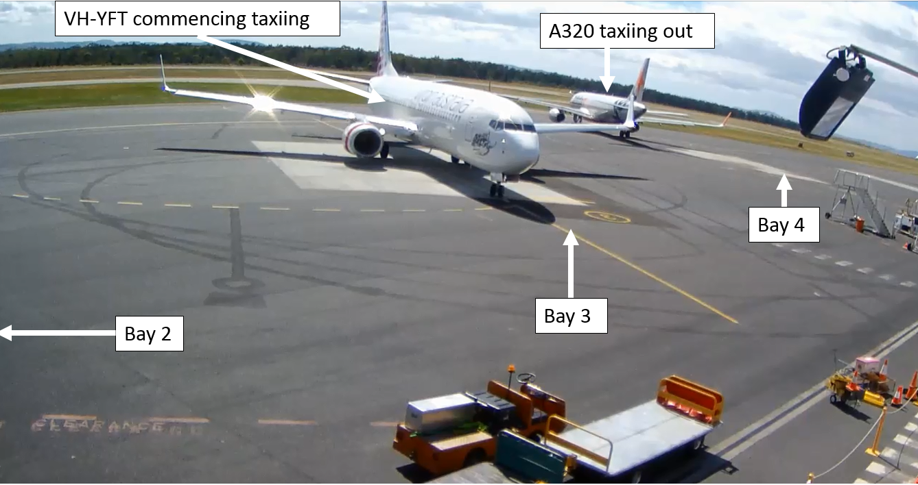
At 1012:12, the first officer of YFT contacted the Hobart surface movement controller (SMC) on Ground frequency and requested a clearance to taxi. The SMC then instructed the crew of an Airbus A320 aircraft that had commenced taxiing from bay 4, to vacate the apron area via taxiway H (Figure 2).
Figure 2: YFT starts taxiing from bay 3 at Hobart Airport
Source: Airport operator annotated by ATSB
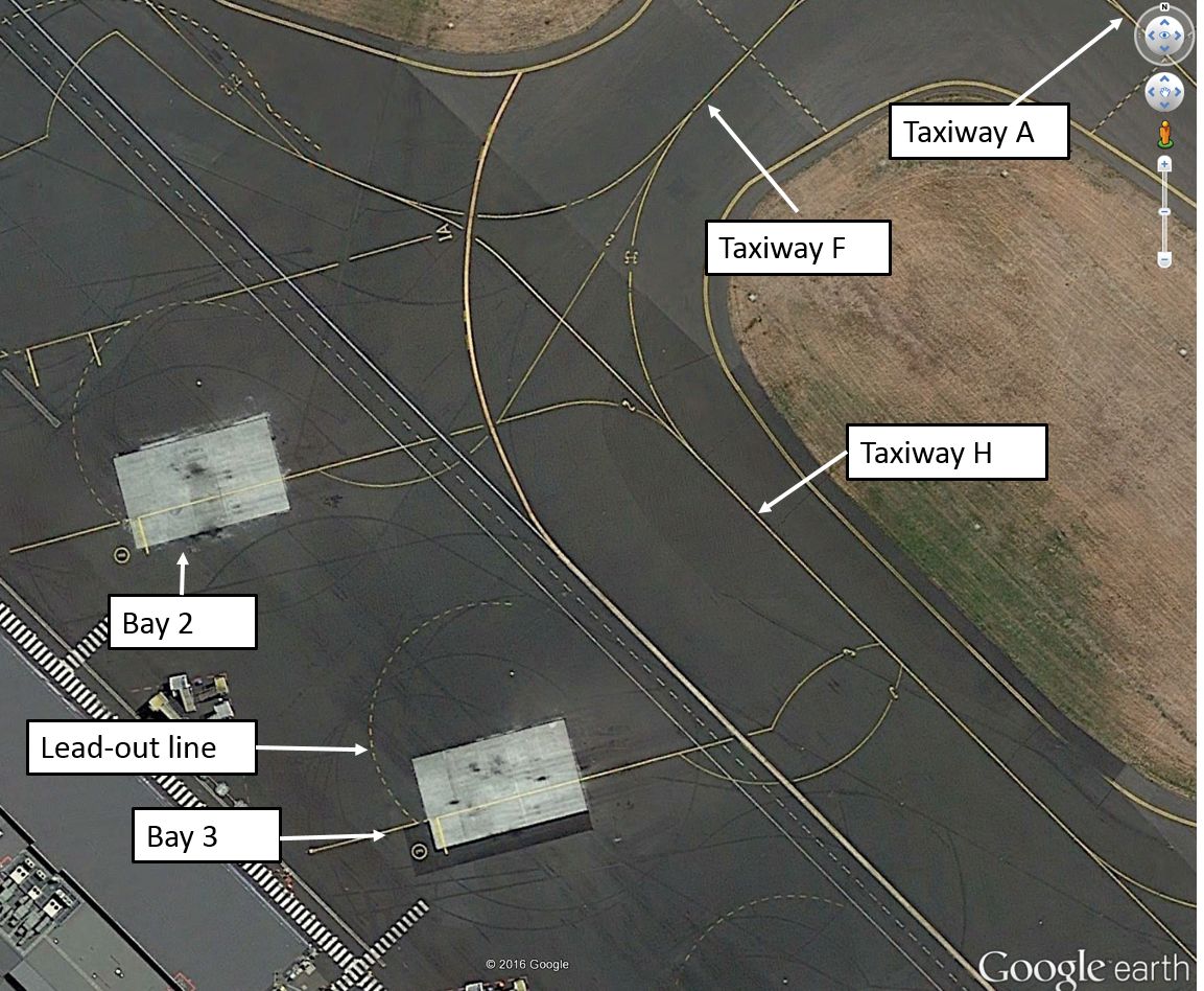
The SMC then advised the crew of YFT that the A320 on their ‘left hand side’ was taxiing out via H and that they were to follow that aircraft via H (and D) to holding point D for runway 30. The first officer read back ‘follow Jetstar A320 behind, behind him via hotel holding point delta runway 30’. At about 1013, the captain commenced turning the aircraft to the right, out of the bay, with the nose wheels just inside the marked lead-out line (Figure 3).
Figure 3: Hobart apron area showing the lead-out line on bay 3
Source: Google earth annotated by ATSB
At that time, another A320 aircraft had landed and was taxiing in towards the parking bays from the north. During the initial turn out of the parking position, the captain became aware of the inbound A320 on taxiway A and became uncertain as to which A320 the controller had instructed them to follow, and whether the inbound A320 would taxi past them via taxiway F. The first officer had also seen the A320 taxiing down A towards F and pointed it out to the captain.
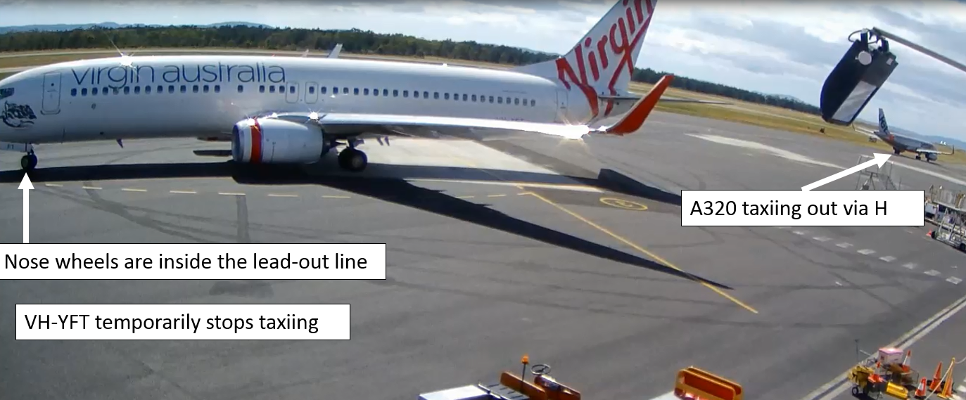
The captain elected to stop the aircraft and clarify their taxi clearance. YFT stopped part way through the turn, about 90° from its parked position (Figure 4). At that time, the nose wheels were inside the lead-out line, and the aircraft was pointing towards the left wingtip of VUP.
Figure 4: YFT stopped taxiing during the turn out of bay 3
Source: Airport operator annotated by ATSB
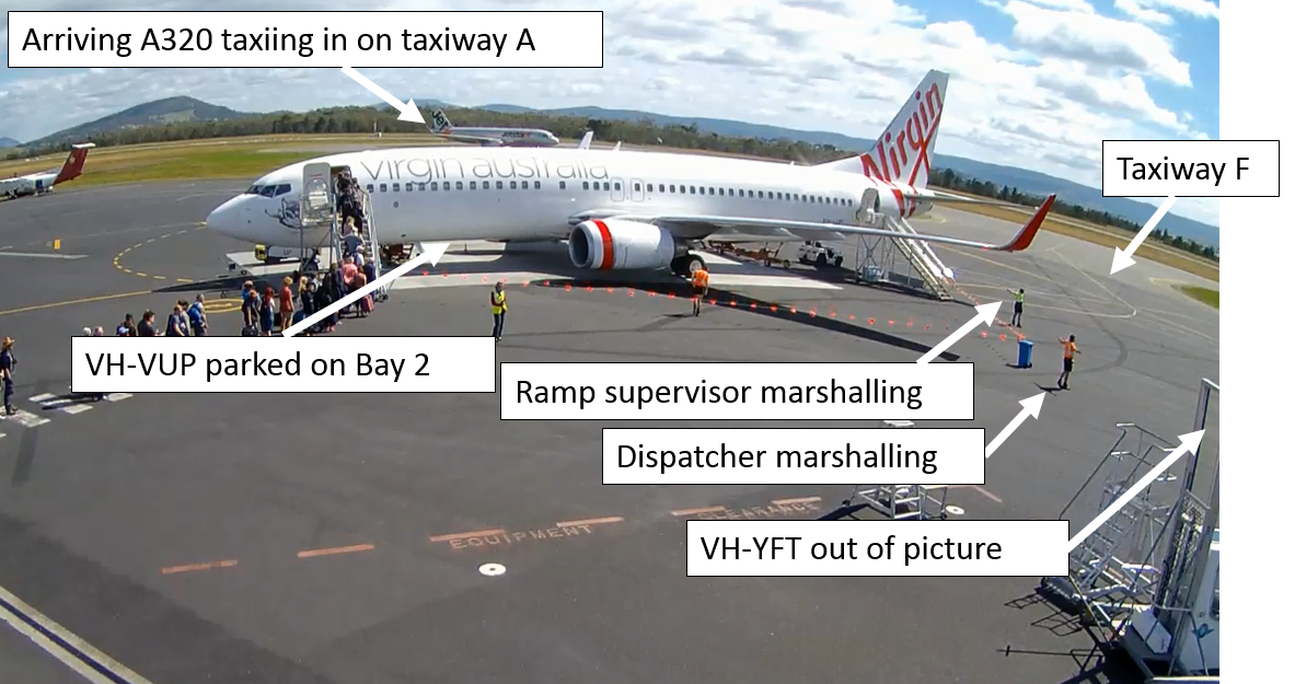
The ramp supervisor[4] was at the far side of the parked aircraft (VUP) preparing it for departure, when YFT stopped. The ramp supervisor saw that YFT had stopped during the turn out, which was unusual, therefore moved to a position near the dispatcher, who was at the left wingtip of VUP, to where they could communicate with the flight crew if required and have line of sight to check for wingtip clearance between the two aircraft (Figure 5).
Figure 5: VUP parked on bay 2 with ground crew marshalling and A320 inbound
Source: Airport operator annotated by ATSB
When YFT had stopped, the flight crew noticed that they had inadvertently omitted to write the automatic terminal information service (ATIS)[5] reference letter on their take-off data card. The first officer switched their radio to the appropriate frequency to listen to the ATIS, while the captain temporarily took over responsibility for communications with air traffic control (ATC) on Ground frequency.
At 1014:00, after seeing YFT stop during the turn, the SMC instructed the crew of YFT to ‘continue to taxi via taxiway H, you are number one to inbound traffic and the other traffic is well clear’. About 20 seconds later, after confirming the clearance with the captain (and switching the radio back from the ATIS to the Ground frequency), the first officer acknowledged the clearance with the call sign ‘Velocity 1531’.
By the time the first officer acknowledged the clearance, the captain had recommenced taxiing, while watching the A320 on taxiway A to make sure that it was going to hold its position. After stopping, the captain removed their hand from the tiller, which caused the nose wheels of YFT to centre. Therefore, the aircraft moved forwards in a near straight line for about 2 seconds and crossed the lead-out line, before the right turn resumed.
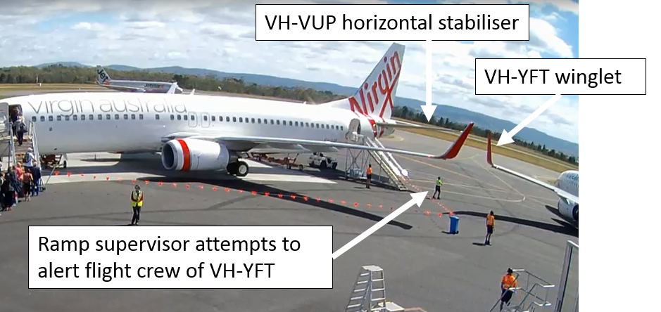
As the aircraft recommenced taxiing, the dispatcher initially observed the wingtips of the two aircraft clear each other. However, as YFT then tracked towards the tail of the parked aircraft as it started to turn, the ramp supervisor assessed that a collision between the left wingtip of YFT and left horizontal stabiliser of VUP was imminent. The ramp supervisor commented that they then lowered their arms towards a crossed position to show that clearance between the two aircraft was reducing,[6] and attempted (unsuccessfully) to make eye contact with the flight crew (Figure 6).
Figure 6: Collision imminent
Source: Airport operator annotated by ATSB
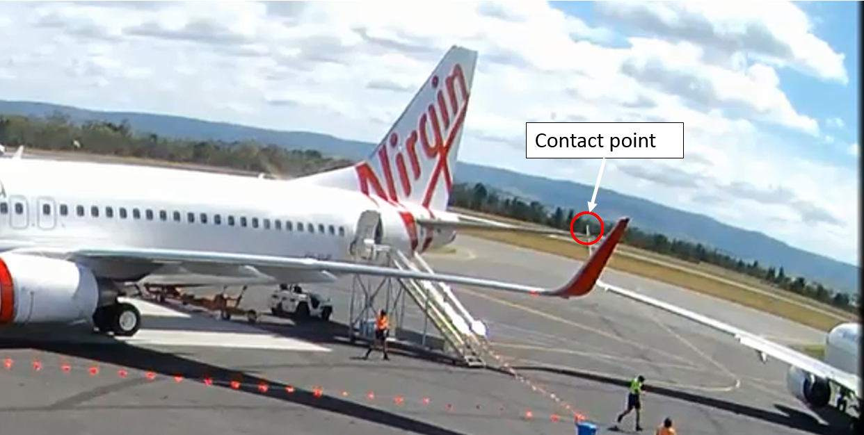
About 30 seconds after recommencing the taxi, as YFT continued to turn, the left wingtip collided with the horizontal stabiliser (tailplane) of VUP (Figure 7).
Figure 7: Contact between YFT left winglet and VUP left horizontal stabiliser
Source: Airport operator annotated by ATSB
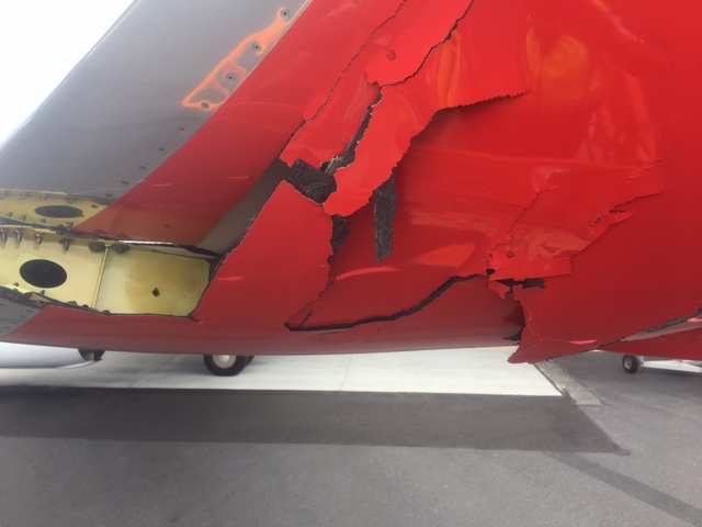
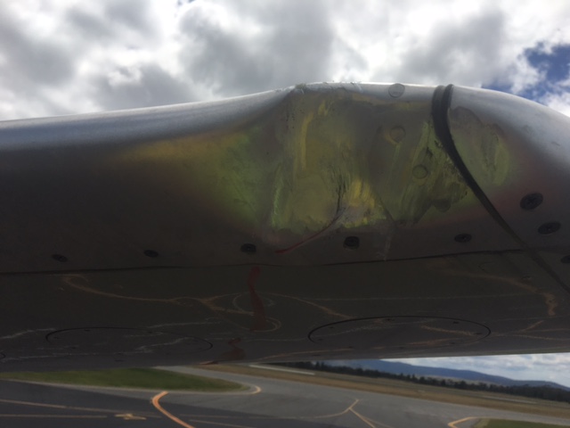
The winglet of YFT was damaged (Figure 8) as was the horizontal stabiliser of VUP (Figure 9). No one was injured.
Figure 8: Damage to YFT left winglet
Source: Aircraft operator
Figure 9: Damage to VUP left horizontal stabiliser
Source: Aircraft operator
Safety analysis
Parking bays
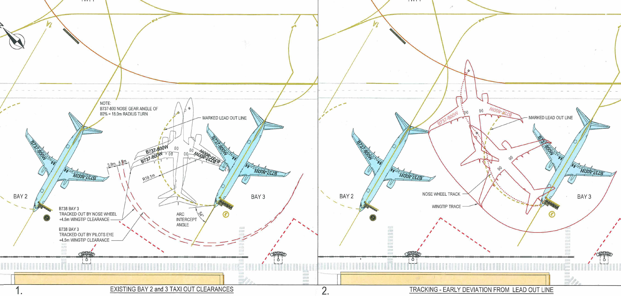
The Hobart Airport operator reported that the bays were surveyed regularly to ensure they met the required standards. The airport operator constructed a schematic diagram of the aircraft’s taxi path from the CCTV footage and the aircraft dimensions on the surveyed apron markings (Figure 10).
The flight crew commented that the design standard for the parking bays meant that they were far too close to be comfortably safe to conduct a power-out taxi when there is an aircraft in the adjacent bay. Furthermore, a bit more spacing between the bays may prevent a similar incident occurring. The captain also commented that consideration of operational acceptability criteria, in addition to technical design specifications, prior to the commissioning of any parking bay and its associated taxi guidance line would facilitate required changes to the bay and mitigate additional threats peculiar to the local environment.
The captain commented that the (power-out) bays in Hobart are not aligned at right angles to taxiway H. This tends to give a false sense of being clear of adjacent aircraft once the cockpit is well past the aircraft and heading towards taxiway H, as the wingtips are so far behind the flight deck and outside the normal viewing arc of the pilots.
Figure 10: Airport survey markings showing B737 aircraft taxi track with nose wheel on lead-out line (left) and approximate incident taxi path (right)
Source: Airport operator
Position of VUP
VUP was parked with the nose wheels approximately 450 mm aft of the stop mark on bay 2, and the main landing gear was offset longitudinally (relative to the aircraft’s heading on the bay) about 380 mm left of the bay centreline. These were well within allowed tolerances and the aircraft was assessed by ground crew to be parked in the correct position. The crew of VUP had been guided to the parking position by ground marshals.
However, the position of VUP’s tail slightly left of centreline and aft (measured after the accident), reduced the available clearance between the two aircraft.
Turning geometry
When the aircraft stopped, the nose wheels straightened, and the aircraft subsequently taxied outside the marked turning circle.
When the captain releases the tiller on a Boeing 737 aircraft[7] during taxi, it will tend to centre the nose-wheel steering and straighten the nose wheels. When the aircraft then starts to move, the captain cannot immediately turn the nose-wheel steering before the aircraft moves without considerable use of thrust and excessive load on the nose landing gear. As the aircraft starts to move forwards, the captain turns the tiller in the desired direction and the nose wheels will start to turn the aircraft.
When YFT stopped, the nose wheels were inside the lead-out line. If the nose wheels track on (or inside) the lead-out line, the wingtip will clear a correctly parked aircraft on the adjacent bay, but it is necessary to keep a continuous turn going. The check captain commented that if you stop the aircraft, particularly if it is heavy, a significant amount of thrust is required to then keep the aircraft on the line. The captain commented that they used caution with the thrust setting because of passengers boarding the aircraft on the adjacent bay. The check captain also stated that there was not a lot of manoeuvring room with ‘power-out’ bays. There is a risk that the aircraft has to go straight ahead for 2-3 m to get the turn going again and there is no allowance made for that in the geometry of the bay.
The captain commented that there is an inherent error in determining where the nose wheel is tracking in relation to a taxi guidance line, in the Boeing 737, during turns. The nose wheel is behind and laterally offset from the captain’s seating position. As such, its position in relation to the line can only be estimated. On power-out bays, flight crew cannot see the position of the aircraft on the lead-out line at any time.
After stopping, the captain could no longer see the lead-out line, which was then beneath and behind the cockpit. The aircraft taxied forward across the lead-out for about 1–2 seconds then turned to the right towards the H taxiway line. There was no marked line connecting the lead-out line with taxiway H.
Ground crew interpretation of taxi track
When the aircraft stopped, the dispatcher noticed that the nose wheels were inside the line, which was normally an indication that the aircraft would stay well clear of an aircraft parked on bay 2. The aircraft then proceeded for about 2 seconds at an angle that was not normal, and both the ramp supervisor and the dispatcher thought the aircraft may have been heading towards taxiway A via the exit (F) behind bay 2 rather than continuing to turn to the right and along the normal path onto taxiway H.
The dispatcher reported that they were not initially concerned about the aircraft’s track, because a bit of momentum was needed to turn the aircraft and get moving. When the wingtip of YFT taxied clear of the wingtip of VUP where the dispatcher was standing, they assumed the aircraft would continue turning and exit the bay, but instead it kept going towards the parked aircraft, which they commented was very unusual.
Communication between ground crew and flight crew
In accordance with normal procedures, the dispatcher unplugged their radio connection to the flight crew before the aircraft commenced taxiing.
The dispatcher commented that they were unsure as to why the aircraft had stopped during the turn, but assumed it was because the flight crew were communicating with ATC. The ground crew radios are not on the ATC frequency and therefore they cannot hear transmissions between ATC and flight crew.
When the aircraft stopped, the ramp supervisor moved to where they could see if the flight crew flashed the nose-wheel lights to indicate a reconnect (of ground-air crew radio communications) was required, but they did not. There were also no hand signals from the flight crew to indicate they needed to reconnect. The ramp supervisor is the only person in the ground crew with a ground-to-air licenced, hand-held radio, so they wanted to get into position to communicate with the flight crew if they requested a reconnect.
As the aircraft continued its turn off the bay, YFT’s wingtip clearance was decreasing due to its proximity to the tailplane of VUP, although it had safely cleared the wingtip of VUP. The dispatcher was then no longer in sight of the flight crew. The ramp supervisor was unable to make eye contact with the captain (seated in the left seat) and commented that the captain appeared to be looking directly forwards.
The ramp supervisor commented that they lowered their arms towards a crossed position to indicate reducing clearance, but that action was not apparent on the CCTV footage of the accident. The check captain commented that lowering of the arms to the crossed position as stated by the ramp supervisor was not shown in the operator’s manual as a procedure to show reduced wing tip clearance.
According to the manual, the correct signal for requiring the aircraft to stop was ‘arms repeatedly crossed above head (the rapidity of the arm movement should be related to the urgency of the stop (i.e. the faster the movement, the quicker the stop)’.
The captain commented that they had seen the thumbs up from the wing walker at the wingtip of the parked aircraft (the dispatcher) and the wing walker near the tailplane of the parked aircraft (the ramp supervisor). They were the only signals the captain sighted and assumed therefore that they were clear of the parked aircraft. If there was any doubt about their clearance from the parked aircraft, they would contact ground staff via radio on their company operations frequency and request assistance, but they did not have any doubt. They had received the all clear signal from the ground crew and thought that they were clear of the parked aircraft and safe to continue.
The captain commented that it would be better to have verbal communication with the marshallers all the way out of the parking bay to have immediate communication if the clearance is insufficient. A verbal warning would be an immediate trigger to stop.
Training
The check captain commented that they consider the turning bays at Hobart to be tight. When training new captains, they always encourage them to ensure that they apply sufficient tiller during the turn out, and that sufficient thrust is applied to keep the aircraft turning. In addition, they suggest using the technique of using slightly more thrust on the outside engine to assist in keeping the aircraft turning.
The check captain also stated that there was no standard procedure in the company for training captains to taxi the aircraft. Training captains instil the importance of using a minimum radius turn out of the bay, appropriate power application and tiller technique, and instruct how to go about requesting assistance with marshaller guidance. Captains are instructed on the visual (hand) signals and where there is any doubt about clearance, to rely on the marshaller and keep a good lookout. If unsure of the clearance from any obstacle, they should stop, but in a turn, it is also important to keep the turn going – if you do stop you potentially have a problem.
When taxiing out of a power-out bay, they try to turn inside the lead-out line to ensure adequate clearance.
Role of ground crew
The operator commented that at the time of the incident, although provision of ‘wing-walkers’ was included in the ground handling contract between the aircraft operator and ground handling provider at Hobart Airport, the ground personnel were not specifically trained in wing walking. The dispatcher and ramp supervisor had proactively positioned themselves at the wingtip and horizontal stabiliser of VUP to assist the flight crew in maintaining clearance between the two aircraft. Wing walking or marshalling was normal procedure for the ground crew at Hobart Airport and both ground crewmembers had substantial experience in doing so.
Once the wingtip of YFT had passed the wingtip of VUP, the dispatcher’s responsibility was over because the next marshaller (ramp supervisor) was in line and the dispatcher was then out of line of sight of the flight deck. There was not usually a marshaller positioned beyond the wingtip.
The dispatcher commented that normally once the aircraft was clear from that position on the wingtip, the dispatcher would give a salute or wave to the captain and they would acknowledge with a wave, but that did not happen on this occasion. The dispatcher commented that the captain appeared to be looking straight ahead towards the exit, or they may have been focused on the marshaller ahead (the ramp supervisor).
Attention and time pressure
The captain initially got the thumbs up from the dispatcher and the ramp supervisor. Immediately before the collision, the captain’s attention was on the inbound A320, and they did not see any indication from the ground crew of reducing clearance with VUP (nor was there any evidence of such on the CCTV footage).
The captain commented that during the turn out, their attention was divided between the wing walker, watching where the aircraft was going, listening to ATC, communicating with the first officer, maintaining situational awareness and being aware of other traffic in the area.
The captain also commented that they[8] had to rise at 0345 to commute to Sydney Airport for the flight and had not slept particularly well as the flight was a line check. There was some pressure to perform well having a check captain in the jump seat. However, the captain felt fit to operate the flight and did not feel tired.
While waiting for the final load sheet to come out on the aircraft communications addressing and reporting system (ACARS), they had a problem with the ACARS printer and had to unjam it as the scheduled departure time was approaching. They requested a hard copy of the load sheet from the dispatcher but were also able to get the printer fixed and printed the load sheet from the ACARS. This caused them a slight delay and they were ready to go about 2 minutes late (scheduled departure was 1010 and they released brakes at 1013). This created some time pressure.
Clearance and traffic disposition
The presence of two A320s led the captain to doubt their taxi clearance after they started taxiing. The operator commented that the first officer’s read back of the taxi clearance, where they stated the A320 ‘behind’ rather than to their left, may also have affected the captain’s perception of which of the two A320s they were to follow. Once the aircraft started to turn, the captain could not see the A320 taxiing out (via H) but was concerned about the one inbound. The captain wanted to confirm that the inbound aircraft was going to stop.
Normally the captain would clarify the clearance with the first officer, but the first officer was listening to the ATIS at the time.
Findings
These findings should not be read as apportioning blame or liability to any particular organisation or individual.
When the captain became aware of the incoming A320, they became uncertain of their clearance and stopped the aircraft to clarify.
The aircraft taxied outside the marked lead-out line after stopping and without the application of sufficiently increased thrust or tiller input this resulted in insufficient clearance from the parked aircraft. The captain was unable to see the aircraft’s position relative to the lead-out line after stopping and the line did not continue to intersect the taxiway ahead of the aircraft.
The bays were marked according to the standards, but the standards probably did not allow sufficient margin for non-normal situations, such as stopping during the turn.
There was no documented procedure for either flight or ground crew to follow in the case of an aircraft stopping during the turn or crossing the lead-out line.
The operator did not have a standard training syllabus or assessment criteria for teaching captains to taxi the aircraft.
There was no direct means of verbal communication between ground marshallers and the flight deck once the aircraft started taxiing, although the crew could contact the movement coordinator if required.
Wing walkers should remain in sight of the flight crew, but the captain did not see the ramp supervisor signal to indicate reducing clearance between the two aircraft. The captain’s attention was to the incoming A320.
Safety action
Whether or not the ATSB identifies safety issues in the course of an investigation, relevant organisations may proactively initiate safety action in order to reduce their safety risk. The ATSB has been advised of the following safety action in response to this occurrence.
Aircraft operator
As a result of this occurrence, the aircraft operator has advised the ATSB that they are taking the following safety actions:
Flight crew operational notice
The aircraft operator issued a flight crew operational notice (FCON)[9] which stated that:
When taxiing out of power-out bay, crew shall ensure the aircraft maintains the apron lead-out line until:
the end of the lead-out line; or
the lead-out line joins a taxiway centreline.
This may involve an exit turn of more than 180 degrees to assure clearance from adjoining bays.
Should the aircraft be stopped before completion of the entire turn to exit the apron, caution should be made when re-initiating movement to ensure the above requirements are maintained.
If at any time aircraft clearance cannot be assured, the aircraft should cease taxiing and request assistance.
Training and checking notice
The aircraft operator also issued a training and checking notice (TCN) that stated ‘All Check Captains and Training Captains are requested to ensure that wingtip geometry, turn markings, turn procedures and hazards are well understood by flight crew during line training and recurrent line checks’.
Flight crew information bulletin
The aircraft operator published a flight crew information bulletin (FCIB) for educational and standardisation purposes titled Wingtip Clearance Hazard and applicable to Boeing 737 aircraft. The FCIB included information about taxiing in accordance with lead-out lines, appropriate use of ground crew, images of Hobart and other airports used by the operator, and wing and tail turning geometry for the aircraft.
The FCIB stated:
In summary, it is recommended that taxi guidance lines be adhered to, whenever practical. Continued vigilance should be employed by crews in the monitoring of obstacles during ground manoeuvring.
If there is any doubt whatsoever regarding wingtip clearance, STOP and seek guidance.
Safety message
This incident highlights the importance of aircraft operators conducting a thorough risk assessment where ground movement is confined, particularly movements involving congested power-out bays. Effective risk assessments ensure that hazards are clearly identified and well understood, and that the associated risks are appropriately managed.
To manage clearance in congested areas, communication tools between ground and flight crew should be used where possible when ground crew are providing marshalling or wing walking assistance. Hand signals rely on constant visual contact, which cannot be guaranteed. Appropriate training of ground crew regarding the use of standard hand signals is required to ensure mutual understanding and communication between flight and ground crew.
Where possible, airport authorities should consider additional margins to accommodate unusual or irregular circumstances during taxiing.
Decisions regarding whether to conduct an investigation, and the scope of an investigation, are based on many factors, including the level of safety benefit likely to be obtained from an investigation. For this occurrence, a limited-scope, fact-gathering investigation was conducted in order to produce a short summary report, and allow for greater industry awareness of potential safety issues and possible safety actions.
Publishing information
Released in accordance with section 25 of the Transport Safety Investigation Act 2003
Ownership of intellectual property rights in this publication
Unless otherwise noted, copyright (and any other intellectual property rights, if any) in this report publication is owned by the Commonwealth of Australia.
Creative Commons licence
With the exception of the Coat of Arms, ATSB logo, and photos and graphics in which a third party holds copyright, this publication is licensed under a Creative Commons Attribution 3.0 Australia licence.
Creative Commons Attribution 3.0 Australia Licence is a standard form licence agreement that allows you to copy, distribute, transmit and adapt this publication provided that you attribute the work.
The ATSB’s preference is that you attribute this publication (and any material sourced from it) using the following wording: Source: Australian Transport Safety Bureau
Copyright in material obtained from other agencies, private individuals or organisations, belongs to those agencies, individuals or organisations. Where you wish to use their material, you will need to contact them directly.
On 25 November 2016, an Airborne Edge XT-912 microlight, registered 34-8401, collided with terrain at Hadlow, Queensland. Both of the aircraft’s occupants were fatally injured.
The Coroner investigated this occurrence and requested technical assistance from the ATSB, with respect to analysis of CCTV footage and examination of structural components from the accident aircraft. To facilitate this support, on 12 December 2016 the ATSB initiated an external investigation under the provisions of the Transport Safety Investigation Act 2003.
The ATSB completed its technical assistance at the end of April 2017. Any enquiries in relation to the investigation should be directed to the Central Queensland Coroner’s office.
___________ The information contained in this web update is released in accordance with section 25 of the Transport Safety Investigation Act 2003.
On 6 December 2016, with thunderstorm activity in the area, a Boeing 737-800 aircraft operated by Virgin Australia on a scheduled passenger flight from Melbourne, Victoria was on approach to runway 29 at Darwin Airport, Northern Territory. The flight crew established and maintained clear visual reference to the runway and surrounds until they encountered heavy rain shortly before reaching the runway threshold. Under the influence of a light but increasing crosswind, the aircraft drifted right without the flight crew being able to discern the extent of the drift.
The aircraft landed 21 m to the right of the runway centreline and, shortly after touchdown, the right landing gear departed the sealed surface of the runway, destroying six runway lights before the aircraft returned to the runway. The aircraft incurred minor damage from ground debris and there were no injuries.
What the ATSB found
A relatively small increase in crosswind resulted in a significant deviation from the runway centreline at a critical time during final approach. The absence of adequate visual cues influenced the flight crew’s ability to detect and correct the deviation.
International guidelines recommend, but do not mandate, the use of centreline lighting on wider runways. In recent years, two runway veer-offs have occurred at runway 29 at Darwin, which is the only runway in Australia that is wider than 50 m and not equipped with centreline lighting. No similar occurrence has happened at any other of the busier airports in Australia, where the runways are either narrower, or are a similar width but with centreline lighting.
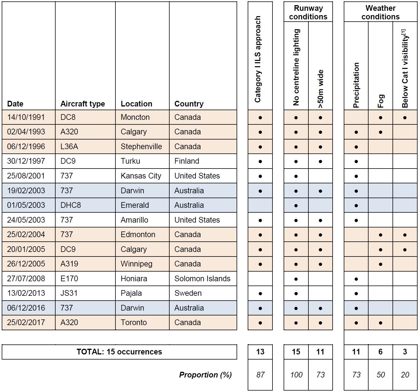
A study of relevant occurrences world-wide found that the likelihood of a runway veer-off on landing increases significantly when using a runway that is wider than 50 m and does not have centreline lighting. This is likely due to limitations in the visual cues available in such circumstances.
There was no advisory information about this hazard in the operator’s manuals or in the aerodrome information provided to operators by Darwin Airport.
The ATSB also found limitations in the weather information provided to the flight crew while on approach to land.
What's been done as a result
The aircraft operator and airport operator initiated a number of safety actions as a result of the occurrence, including providing flight crews with information about the specific risks of approaches to Darwin Airport at night in conditions with reduced visibility.
The ATSB has issued a safety recommendation to the International Civil Aviation Organization and Darwin Airport to consider measures to reduce the safety risk identified in this report relating to wide runways without centreline lighting.
Safety message
Approaches in darkness and poor weather can be challenging. Centreline lighting greatly assists flight crews align the aircraft with the runway but many runways, including most in Australia, are not equipped with it. A wide runway without centreline lighting, such as that in Darwin, poses a particular challenge. Pilots and operators who are aware of any circumstances that are different to what is usually encountered and account for it in their planning are more likely to avoid being ‘caught out’ at a critical time.
The occurrence
Overview
On 6 December 2016, a Boeing 737-800 aircraft, registered VH-VUI and operated by Virgin Australia, was used for a scheduled passenger flight from Melbourne, Victoria to Darwin, Northern Territory. During the final approach to runway 29 at Darwin at night, the aircraft entered very heavy rain. The aircraft landed 21 m to the right of the runway centreline and, shortly after, the right main landing gear departed the sealed surface of the runway. Runway 29 was 60 m wide, which was 15 m wider than almost all the other runways used by air transport aircraft in Australia.
Flight planning
Prior to departing Melbourne, the flight crew reviewed relevant meteorological information for the flight including the latest aerodrome forecast (TAF) for Darwin, which was issued at 1400 Central Standard Time[1] and valid from 1530. The forecast conditions for their arrival time were good, with wind 300° at 5 kt, visibility at least 10,000 m and few cloud[2] at 2,000 ft.
There were no weather-related or other requirements for the flight crew to nominate alternate fuel or holding fuel for the flight. However, the captain ordered 1,500 kg more fuel than the minimum required for the flight (including the required reserves) due to the possibility that adverse weather conditions could develop.
Take-off and cruise
The aircraft was scheduled to depart Melbourne at 1825 (1955 AEDT) and actually departed at 1842. The captain was pilot flying (PF) and the first officer was the pilot monitoring (PM).[3]
During the flight, the flight crew obtained weather updates, which initially indicated that the weather conditions at Darwin remained good and were consistent with the forecast. A new TAF issued at 2053 and valid from 2130 was the same as the 1400 forecast.
At 2207, with the flight about 1 hour from landing, the Bureau of Meteorology (BoM) issued an amended TAF for Darwin. The amended TAF included a TEMPO,[4] which indicated that between 2230 and 0030 there could be periods of up to 1 hour with wind of variable direction at 20 kt gusting to 35 kt, visibility 4,000 m in showers of rain, and cloud broken at 1,500 ft.
Darwin air traffic control was required to pass on the availability of amended TAFs for the airport in accordance with the Manual of Air Traffic Services. The Darwin approach controller advised the Brisbane Centre en route controller of the amended TAF, and the Brisbane controller broadcast the TAF’s availability and key details at 2211. The flight crew interpreted the forecast weather as ‘thunderstorm material’ and noted that the TEMPO period covered their expected arrival time.
At 2212, the Brisbane controller who broadcast the availability of the 2207 amended TAF handed over duties to another controller. The incoming controller was advised that the amended TAF had been broadcast to all aircraft.
At 2218, the Brisbane controller issued the flight crew with a standard instrument arrival clearance to runway 29.
At 2223, the flight crew listened to the automatic terminal information service (ATIS) for Darwin Airport, which indicated the conditions were wind 300° at 8 kt, visibility at least 10,000 m, rain showers and scattered cloud[5] at 2,000 ft.
At 2224, the flight crew commenced the approach briefing. The briefing covered all the standard items, including the approach minima (290 ft elevation or 209 ft above the runway elevation and 800 m visibility) and the missed approach procedure for the runway 29[6] instrument landing system (ILS) approach procedure.
The flight crew selected an approach speed of 143 kt (reference landing speed plus 5 kt) and autobrake setting 2. They noted that the weather conditions were well above the minima at this stage, but if required they had sufficient fuel to conduct four missed approaches or hold for at least an hour.
At 2230, a SPECI[7] was issued for Darwin, which indicated that there had been a change in the actual weather conditions and that thunderstorms with rain were likely to be present. Subsequent SPECIs issued from 2247 indicated conditions were deteriorating. The flight crew did not obtain or receive these weather reports, but were aware of the developing situation. From 2232, they could see lightning in the distance and soon after, they could see rain cells on the aircraft’s weather radar.
At 2237, when VH-VUI was about 25 minutes from Darwin, BoM issued a second amended TAF for Darwin. The change to the previous (2207) amended TAF was that during the TEMPO period there was now thunderstorms with rain and visibility could be 2,000 m. For reasons that could not be established, the Darwin approach controller did not advise the Brisbane controller of the availability of the second amended TAF. Therefore, the Brisbane controller did not broadcast the 2237 amended TAF’s availability or details.
The operator’s flight following staff attempted to check that VH-VUI’s flight crew knew of the 2237 amended TAF via HF radio. Due to poor radio reception, the flight crew could not hear the message clearly but discerned that the call was about an amended TAF, and advised that they were aware of it. However, the call was about the 2237 TAF and not the 2207 amended TAF that the Brisbane controller had earlier broadcast. The flight following staff contacted Brisbane air traffic control at about 2247, and asked whether the flight crew had ‘the amended TAF for Darwin’. The controller advised that they did.
Descent and approach
At 2241, the flight crew commenced descent from flight level (FL) 380.[8] Shortly afterwards, they could discern a rain cell on the weather radar and discussed the extra fuel they had on board, and that they did not want to fly under or through any thunderstorms.
At 2249, the Brisbane controller handed over control of VH-VUI to the Darwin approach controller. The first officer contacted the approach controller and stated they were descending through FL 120 and had received (ATIS) information ‘Delta’. The approach controller advised the flight crew to expect the runway 29 ILS approach. He also advised that (ATIS) information ‘Foxtrot’ was current, and he provided the differences between ‘Delta’ and ‘Foxtrot’, which included that the wind was now 220° at 20 kt. The approach controller also advised that this wind information was only an estimate, because the airport anemometer was now unserviceable.
The flight crew discussed the situation, noting that the wind would be a predominant crosswind for the landing. They also discussed the weather around the airport and what impact it may have for their arrival on several occasions throughout the rest of the descent. The captain asked the first officer to add 10 kt to the landing reference speed to help alleviate the effect of wind gusts or changes, resulting in a selected approach speed of 148 kt.
At 2252, the approach controller provided the crew with another wind update, advising the wind speed to be 20 to 35 kt and that the crosswind for landing could be up to 20 kt. About a minute later the approach controller made an all stations broadcast, advising the runway was wet and the visibility at the airport was reducing to 5,000 m in rain.
At 2255, the flight crew requested approval to track direct to the initial approach fix (LAPAR) to avoid some of the weather, and the controller approved the request.
At 2256, when passing 5,000 ft, the flight crew began a further discussion about the airport weather. Their comments recorded on the cockpit voice recorder indicated they could see lightning ahead, and were using weather radar to determine the position of rain cells. They agreed a rain cell to the north-east of the airport would not impact the approach. In a later interview, the captain reported that it appeared as though they would easily land before the rain arrived. They began discussing the potential impact of another rain cell south-west of the airport but were interrupted by other priority tasks and did not conclude this discussion.
The flight crew selected flaps 5 at 2258 and the first officer advised Darwin tower that they were approaching LAPAR. The tower controller advised rain was now directly over the airport and the visibility was reducing to about 3,000 m. At around the same time, the flight crew selected flaps 15.
The tower controller also advised the flight crew of the settings of the high intensity approach lighting (stage three) and the high intensity runway lighting (stage five) and requested the flight crew advise if changes to the settings were necessary. The first officer asked if there was any update on the wind information, and the tower controller stated that the wind estimate remained the same as previously advised by the approach controller, and they were trying to get additional information. The first officer acknowledged the reply, and noted they now had the runway lights in sight.
At about 2259, the aircraft descended through the lowest level of the cloud base from about 2,500 ft. The crew later reported that they could see the runway and airport surrounds. They saw a rain shower at the airport, towards the far end of runway 29.
The crew again discussed the weather conditions and they discussed their options in the event a missed approach was required, and agreed they would divert to the right rather than straight ahead as published on the missed approach track (286°). The captain requested the first officer be ready to use the aircraft windscreen wipers.
At 2300, the aircraft descended through 2,000 ft at about 150 kt and the flight crew selected flap 30. The Darwin tower controller updated the wind information based on data obtained from a second, test anemometer located to the south of the runway 29 threshold that the wind was 290° at 16 kt, gusting to 22 kt. The first officer acknowledged the information and advised that if a missed approach was conducted the crew planned to turn to a heading of around 320° to ‘avoid the storm on the other side of the field.’
At 2301, the flight crew commenced the landing checklist, and the captain asked the first officer for his opinion on the situation. The first officer noted the approach was stable, the missed approach altitude was set and it was apparent they would be able to land. They could see the runway lights clearly, and although there was rain ahead, it looked like it was some distance down the runway.
Final approach and landing
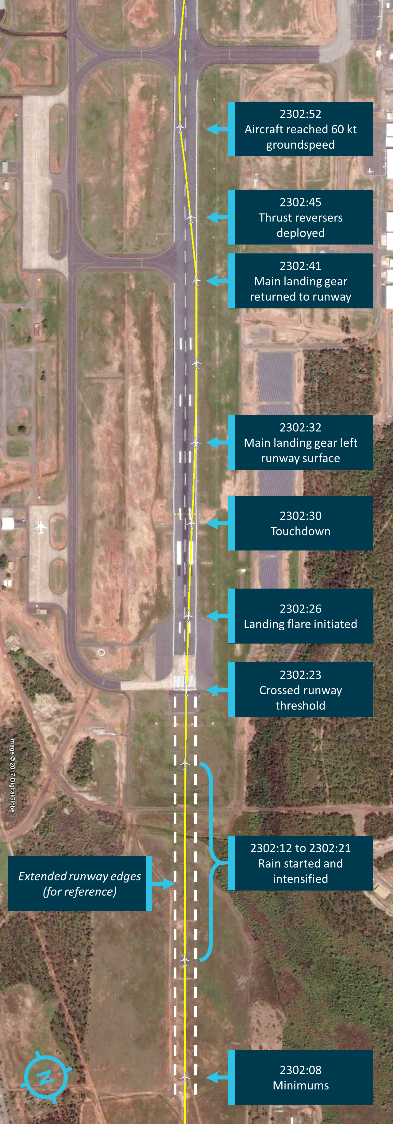
The events during the final approach and landing are summarised in Table 1, including the time, airspeed and radio height (or height above ground) from 500 ft. Figure 1 also shows the aircraft’s lateral displacement from the runway centreline.
Table 1: Summary of events during final approach and landing
The captain asked the first officer to turn the wipers on using the fast setting, which was actioned.
2302:01
153 kt CAS
267 ft
The captain disengaged the autopilot. At this point, the aircraft was on the glidepath, on track and close to the extended runway centreline. The first officer advised that the wind was 280° and up to 25 kt.
2302:07
148 kt CAS
207 ft
The aircraft passed through the decision height for the ILS approach, and the aircraft’s automated ‘minimums’ annunciation occurred. The captain stated they would try to land. The first officer acknowledged and stated the wind was steady.
2302:12
148 kt CAS
179 ft
The aircraft entered rain, which intensified over the next few seconds.
2302:18
152 kt CAS
131 ft
The crossbars of the approach lights would no longer have been visible to the crew under the aircraft’s nose. The crosswind dropped from about 4 kt to 1 kt for 2 seconds, and then began a slow increase
2302:21
151 kt CAS, 133 kt GS
98 ft
The automated ‘100 feet’ annunciation occurred. The runway threshold lights would have no longer been visible to the crew under the aircraft’s nose. Later analysis indicated that, at about this time, there was an increase in the average crosswind from 3 kt to 6 kt, and the aircraft started drifting to the right of the extended runway centreline.
2302:23
152 kt CAS, 134 kt GS
50 ft
The aircraft crossed the runway threshold, about 3 m to the right of the runway centreline and drifting about 3° to the right. The automated ‘50 feet’ annunciation occurred.
2302:25
134 kt GS
35 ft
The captain initiated the landing flare.[10] The aircraft was about 11 m to the right of the runway centreline.
2302:30
135 kt GS
0 ft
The aircraft touched down wings level within the touchdown zone, 440 m from the threshold, about 21 m to the right of the centreline and drifting about 3° to the right.
2302:31
133 kt GS
0 ft
The aircraft’s nose gear touched down.
2302:33
126 kt GS
0 ft
The right main landing gear departed the sealed surface of the runway about 235 m after touchdown, 675 m from the runway threshold at about 126 kt groundspeed. The gear’s maximum distance from the runway edge was around 1.5 m.
23:02:41
92 kt GS
0 ft
The right main landing gear returned to the sealed runway surface at a groundspeed of about 92 kt, after having been off the sealed surface for about 394 m.
23:02:45
78 kt GS
0 ft
The captain deployed the thrust reversers.
23:02:52
60 kt GS
0 ft
The aircraft reached 60 kt groundspeed.
The approach was stable at 500 ft, and the captain disconnected the autopilot at about 270 ft. The wind was gusty, requiring constant correction, and the crosswind varied between 0 kt and 5 kt from the aircraft’s left. At the decision height (about 210 ft) the flight crew were still visual and decided to proceed with the landing. Soon after, at about 180 ft, the aircraft entered heavy rain. The crew later reported that they had expected to land well before encountering the rain.
The air traffic controllers in the Darwin tower reported that they could see the aircraft’s lights (including the logo light on the near side) throughout the final approach and landing from the tower, about 1.8 km north-west of the runway threshold.
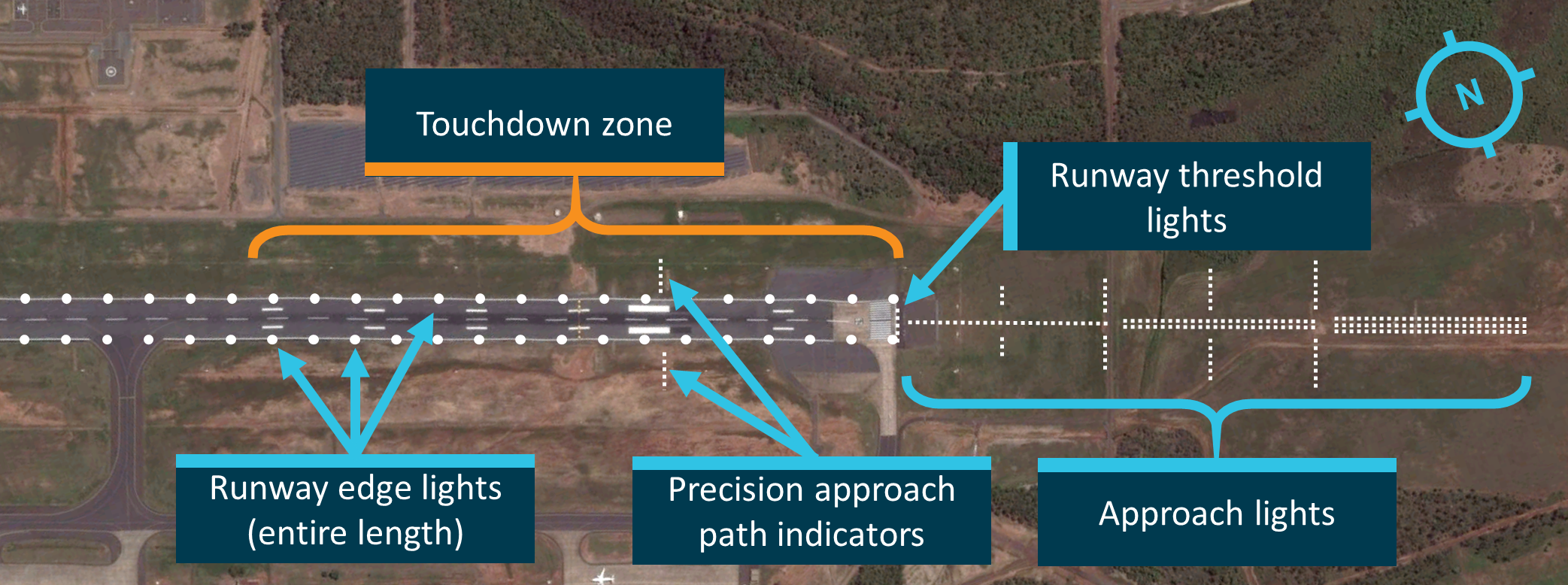
From about 100 ft, the flight crew would not have been able to see the approach lights or runway threshold lights below the aircraft’s nose (see Aerodrome information). In addition, the crew later described the rain from this point as a ‘heavy deluge’. Their vision of the runway and the surrounding airport environment was obscured. Only the runway edge lights and precision approach path indicators remained visible, and they became blurred and no longer sharp and distinct, particularly between each pass of the windscreen wipers. The crew reported that they felt at the time that the visibility remained sufficient to complete the landing.
At about 100 ft (2302:21), the aircraft started to drift to the right of the runway centreline, and this deviation increased until the aircraft landed 8 seconds later (2302:29). Other than the lateral deviation, all other aspects of the final approach and landing were normal.
The aircraft touched down within the touchdown zone, about 21 m to the right of the centreline. The maximum recorded vertical acceleration was 1.74 g, within the normal range for landing, and there was no evidence that the aircraft bounced.
When the captain lowered the aircraft’s nose he realised the aircraft had landed ‘well right’ of the centreline but with the obscured visibility he could not readily ascertain how far. He later recalled trying to steer the aircraft towards the centre of the runway but being very wary of oversteering and losing control on the wet runway.
At 2302:33, 4 seconds after landing, the right main landing gear departed the right side of the runway. The captain recalled hearing a repeated, light thudding noise. He asked the first officer if they had hit the runway lights and the first officer responded that that they were just missing the lights. The aircraft’s nose was oriented to the left of the direction of travel, placing the flight crew and nose gear over the sealed surface and inside the painted runway edge markings. The first officer later reported feeling a shudder, as though the wheels were skidding. Both flight crew recalled that the physical sensation and noise were not as strong as they would have expected from the wheels departing the runway.
Figure 1: Final approach and landing roll of VH-VUI
Image shows the aircraft’s path crossing the runway threshold near the centreline and deviating to the right edge of the runway before returning.
Source: ATSB / Google Earth
Taxi and disembarkation
The flight crew taxied to the bay and stopped short at 2309, remaining there until the weather eased enough for safe groundwork and disembarkation. During this time, the crew discussed the approach and landing. The captain asked whether the first officer was sure the aircraft had stayed on the runway, and the first officer reiterated that he was sure they had.
At 2322, the ground marshaller installed the wheel chocks and the passengers soon started disembarking. At 2329, one of the flight crew also disembarked and inspected the aircraft. He observed the aircraft damage and immediately realised they had departed the sealed surface of the runway on landing. After returning to the aircraft, the flight crew reported the incident to the operator and air traffic control at 2331.
The airport operator inspected the runway and identified that at least four runway lights were inoperable, but at the time saw no debris other than grass on the runway. The flight crew of the next arriving flight was advised of the situation and elected to continue, landing at 2336. Subsequent inspections found debris from the runway lights on the runway surface.
Damage and injuries
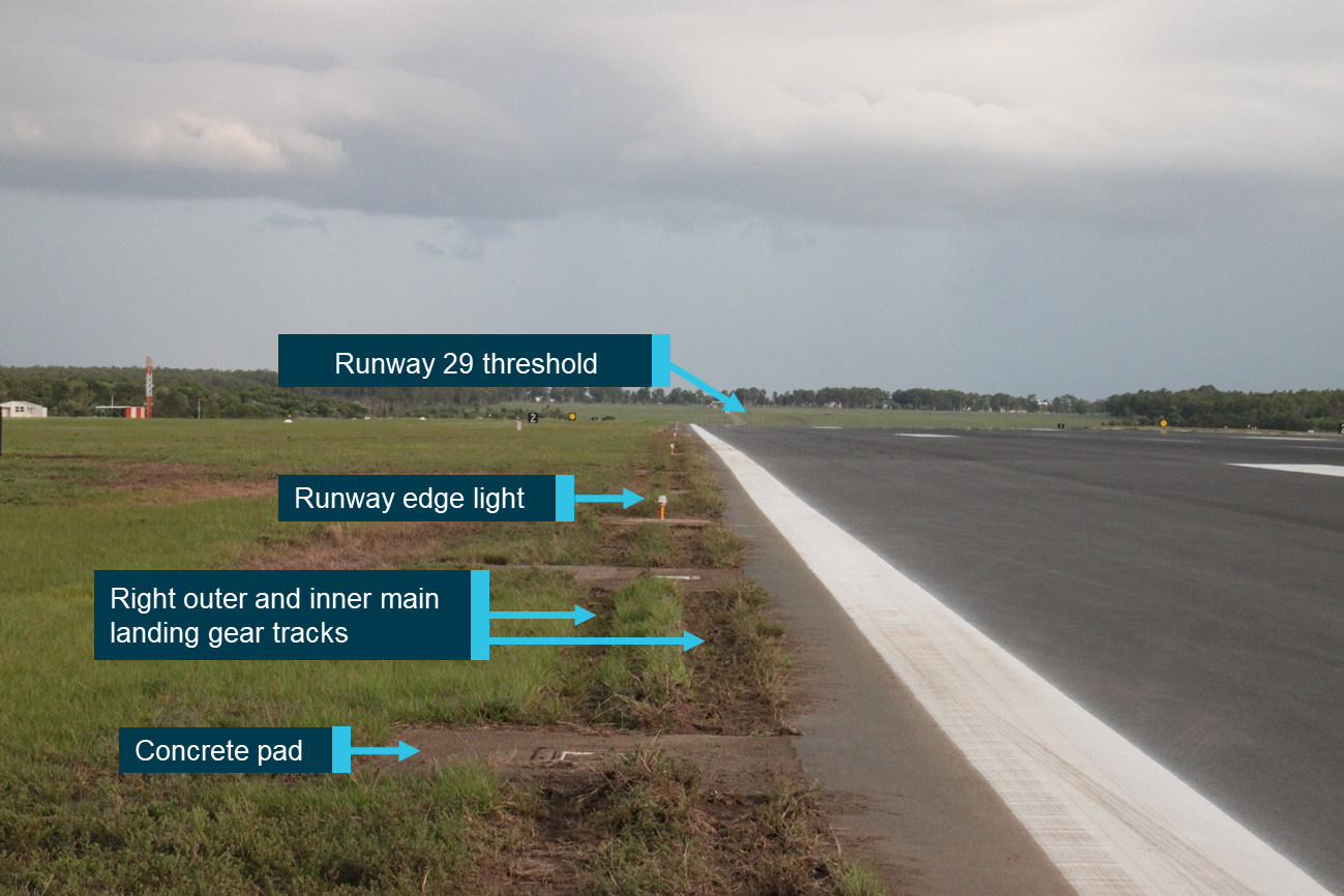
Six runway edge lights were hit and destroyed as the landing gear impacted concrete pads located just off the runway edge (Figure 2). Debris from the lights and ground impacted the aircraft and littered the edge of the runway surface.
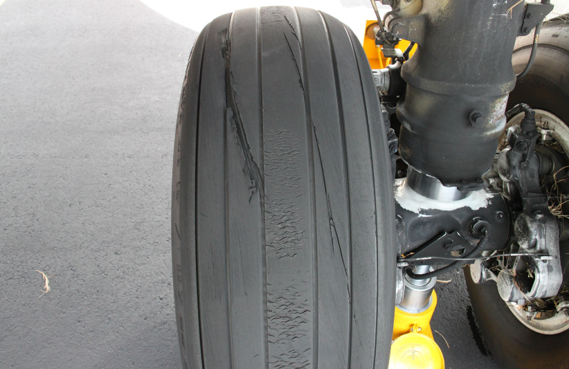
The right main gear tyres sustained deep cuts during the impacts with the runway edge lights and concrete pads (Figure 3).
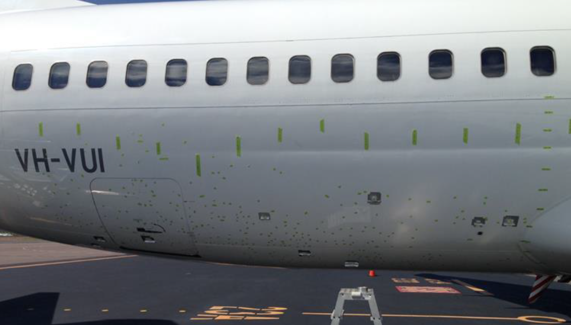
Debris impacted the aircraft resulting in minor damage to areas of the right aft fuselage and right horizontal stabiliser (Figure 4). A large quantity of grass accumulated in the vicinity of the right wheel well, landing gear and wing flaps.
There were no injuries.
Figure 2: Wheel tracks where VH-VUI departed the runway 29 sealed surface and destroyed runway edge lights[11]
Image shows the tracks from the right main landing gear through grass and over concrete pads near the runway edge. Photo facing the opposite direction to the landing. Source: ATSB
Figure 3: VH-VUI tyre damage
Image shows cut damage to the right main landing gear outboard tyre. The chevrons in the centre of the tread are normal. Source: ATSB
Figure 4: VH-VUI fuselage damage, marked with green tape
Image shows the locations of skin damage to the right side of the aircraft fuselage marked with short sections of tape on the underside of the fuselage. Longer sections of tape mark the locations of longitudinal and vertical fuselage reference lines. Source: Virgin Australia
At the time of the occurrence, the captain had a total of 22,559 hours flight time with 9,206 hours on Boeing 737 variants. The first officer had a total of 7,000 hours flight time with 3,500 hours on 737 variants. Both flight crew were appropriately qualified to conduct the flight.
The flight crew’s last night landing was conducted together the previous night, and each had conducted several night landings into various Australian airports in the previous month. The captain’s last flight into Darwin Airport was five and a half months previous, and the first officer’s most recent landing there was 16 months previous. Both were night landings. The captain reported having flown to Darwin many times before.
The first officer reported not having encountered rain conditions like those on approach during the occurrence flight before. The captain recalled having seen such conditions only once before, about 30 years prior, during a flight into Darwin that resulted in a hard landing.
Both flight crew were based in Melbourne. They had no duty on 3 and 4 December 2016. On 5 December, they both flew as passengers to Canberra in the afternoon, and then conducted a series of flights, ending their duty time at about 2300 AEDT.[12]
On 6 December, they signed on for duty at Canberra Airport at 1600 AEDT. They then operated a flight from Canberra to Melbourne, before beginning preparations for the Melbourne to Darwin flight. They had both been on duty for 8.5 hours at the time of the occurrence.
The captain reported getting about 6 hours sleep the night before the occurrence and normal sleep in the nights before. The first officer reported getting a normal amount of sleep the night before the occurrence, and the nights before that. Both crew reported being a little tired at the time of the occurrence. However, there was insufficient evidence to suggest that the flight crew were operating at a fatigue level known to affect performance, and both had sufficient sleep opportunity in the nights prior to the occurrence.
Aircraft information
VH-VUI, a Boeing 737-800 aircraft, was manufactured in 2006. No problems with the serviceability of any relevant aircraft systems were reported or identified. The aircraft was fitted with the appropriate equipment for category I, II, and III ILS approaches and was capable of autoland at suitably equipped airports.[13] The aircraft was not fitted (nor required to be fitted) with an aircraft communications addressing and reporting system (ACARS) to receive data messages.
Boeing 737-800 aircraft (as well as the 600, 700 and 900 series 737s) were certified for operation with windscreen wipers and without any other rain removal system. The aircraft was not fitted with a rain repellent fluid dispensing system, which had been fitted to earlier versions of the 737. This system was no longer in use because of environmental concerns about the fluid available at the time.
Additional visual enhancements available for 737-800 windscreens include a hydrophobic coating. The aircraft manufacturer stated these coatings were an enhancement to the wiper system but were not required for safe operation of the aircraft. It stated that the service life of hydrophobic coatings varied significantly from operator to operator due to the operating environment, particularly in terms of how often windscreen wipers were used and the areas where particulates such as dust were encountered on flights.
The operator reported that 43 of its 79 Boeing 737 aircraft had a hydrophobic coating applied at the time of aircraft production. However, regular maintenance of the coatings was not required by the operator’s system of maintenance, and the coatings had not been routinely replaced in service. The windscreen of VH-HUI was delivered to the operator in 2013 with a new hydrophobic coating.
The aircraft was fitted with anti-skid wheel brakes. Post-occurrence inspections found no evidence of rubber reversion hydroplaning (which leaves distinctive marks on the runway and tyres); however, other types of hydroplaning leave no direct evidence. The touchdown point could not be identified, suggesting that some initial hydroplaning may have occurred. There were black particles in the runway surface that indicated a transfer of rubber from the aircraft’s tyres continuously along the aircraft’s path from near where the aircraft touched down, consistent with some degree of traction.
Meteorological information
Weather observations
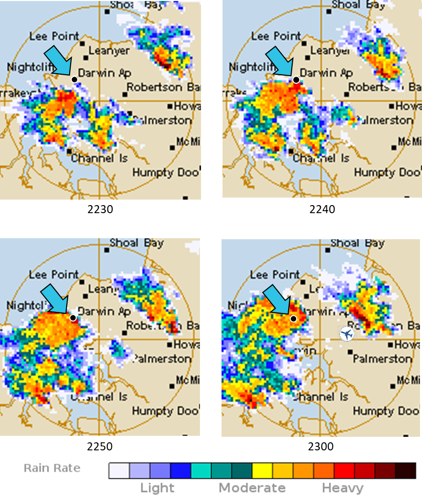
The approach and landing were conducted in darkness. Weather radar data provided by the Bureau of Meteorology (BoM) showed two areas of rain near and over Darwin Airport on the night of the occurrence (Figure 5).
Table 2 summarises meteorological information from routine weather reports (METARs) and special weather reports (SPECIs) during the period from 2100 local time. As indicated in the table, visibility started decreasing at about 2247, and it decreased to 2,000 m at 2257. There was heavy rainfall recorded by a rain gauge near the runway 29 threshold at Darwin Airport after 2247, peaking at about 24 mm/hour for a period of several minutes around the time the aircraft landed.
A 2300 observation from the test anemometer at Darwin Airport (see Weather information services) recorded a westerly surface wind of 16 kt. The Darwin tower controller reported the windsock nearest the runway 29 threshold indicated a relatively steady wind but as with windsocks in general, it was not responsive to short gusts.
Closed-circuit security video showed rain at the terminal (2 km north-west of the runway 29 threshold) starting and increasing from about 2250, and becoming heavy by 2302. Over this period, the video showed four brief, bright flashes consistent with lightning strikes.
Recorded lightning strike data showed significant activity in the area. In the 5 minutes before VH‑VUI landed (at 2302), there were several lightning strikes within 5 NM of the airport and two within 5 NM of the aircraft. Some of these may not have been visible to the flight crew due to them potentially being obscured by cloud.
Figure 5: Ground-based radar images showing rainfall near Darwin Airport (blue arrow) during the approach, with the aircraft’s position at 2300 indicated by an aircraft symbol
Image shows heavy rain approaching Darwin Airport from the south-east over a period of 30 minutes, and arriving at the airport while VH‑VUI approached. The tan circle has a 20 km (10.8 NM) radius. Note that the picture displayed on the aircraft’s weather radar would not be the same. Source: Bureau of Meteorology, modified by ATSB
Table 2: Darwin METAR and SPECI summary
Time
Wind direction (° M)
Wind speed (kt)
Visibility
Precipitation
2100
290
7
> 10 km
None
2130
320
10
> 10 km
Light rain
2200
310
9
> 10 km
Showers in the vicinity
2230
250 (variable)
7
> 10 km
Light thunderstorm and rain
2247
230
9
7 km
Moderate thunderstorm and rain
2257
290
16
2 km
Heavy thunderstorm and rain
2300
290
15
2 km
Heavy thunderstorm and rain
2312
320
11
5 km
Light thunderstorm and rain
2330
310
7
> 10 km
Showers in the vicinity
0000
340
4
> 10 km
Showers in the vicinity
0030
340
2
> 10 km
None
Weather information services
BoM was responsible for the provision of aerodrome forecasts and weather reports at Darwin Airport. An aerodrome forecast (TAF) was issued every 6 hours with a validity period of either 24 or 30 hours from defined commencement times. When significant variations from the mean conditions, of a temporary nature, were expected to occur within the forecast period they were indicated by the use of the term TEMPO in the forecast.
Aerodrome weather reports were generated by an automatic weather station with manual input from approved weather observers. Routine reports (METAR) were issued every 30 minutes. Special reports (SPECI) were triggered by a significant change in a set of parameters, including wind, visibility and cloud.
In Australia, air traffic control (ATC) was required to pass on TAF and amended TAF information to flight crews that were within an hour of their destination. ATC was not required to pass on SPECI reports if those reports were available through a local broadcast service such as the Aerodrome Weather Information Service (AWIS) available at Darwin.
Availability of wind information
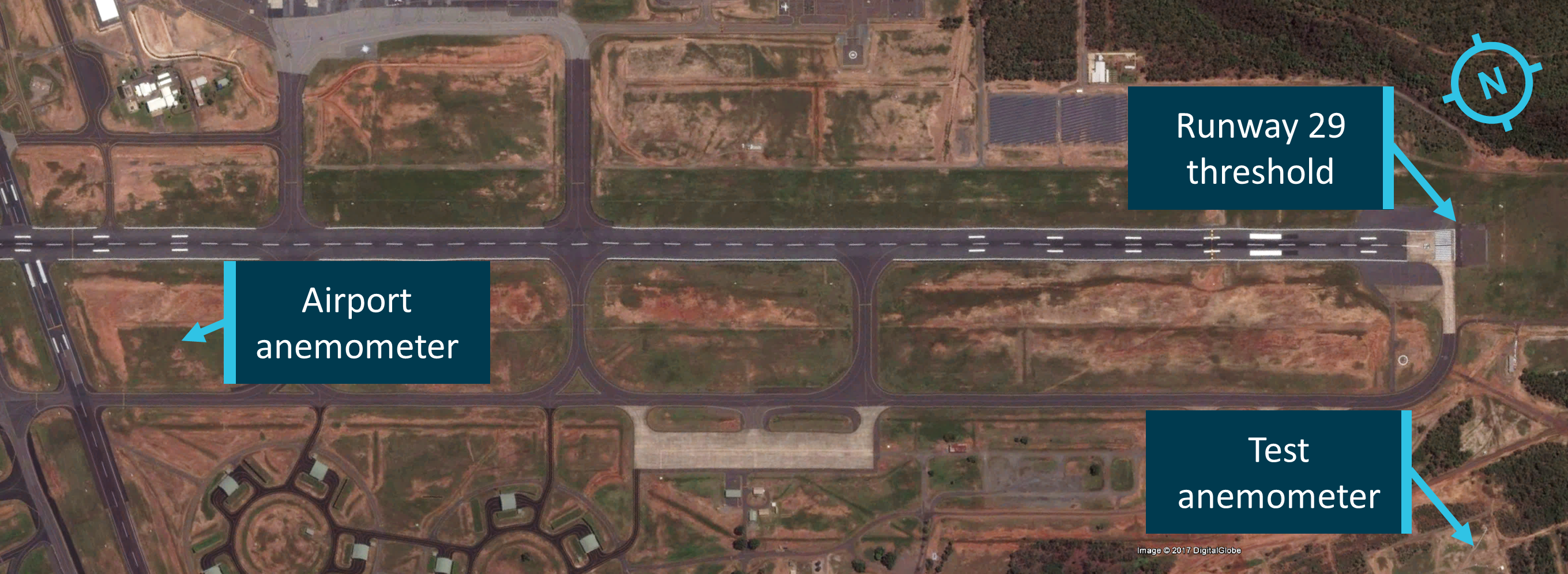
The Darwin control tower was equipped with displays that showed the wind direction and speed sourced from the airport anemometer via the BoM Observations office. This anemometer was located near the centre of the airport, about 2.4 km west of the runway 29 threshold (Figure 6).
Figure 6: Location of anemometers at Darwin Airport
Image shows the primary anemometer’s location near the centre of the airport and the second (test) anemometer near the runway 29 threshold. Source: ATSB / Google Earth
Due to a failure attributed to a lightning strike,[14] the airport anemometer was unserviceable at the time of the occurrence and no wind information was being displayed in the control tower. Darwin tower controllers obtained wind information from windsocks located at the airport, and through BoM observers via telephone for information from a second, test anemometer about 550 m south of the runway 29 threshold. Wind data from this anemometer was relayed to the tower controllers by a trained BoM observer.
BoM reported that the last performance checks on the test anemometer were conducted in June 2014. BoM was unable to verify the integrity of the anemometer’s wind data but stated that it was a standard installation using the same type of anemometer as the airport anemometer, and BoM considered the wind information to be a reasonable indication of local conditions. Performance checks before and after the occurrence showed the test anemometer to be operating within specifications. There may be some difference in wind speed and direction readings between the two sites due to local variations, and obstructions near the secondary site.
According to fault records, the primary anemometer was unavailable or exhibited faults on 32 occasions from February 2013 to December 2016, including 21 occasions in the wet season (November to April). The median time to repair was about 2.5 hours and the average was 14.5 hours. On four occasions, the repair took longer than 24 hours.
BoM advised that its anemometers were installed and maintained to meet International Civil Aviation Organization (ICAO) Annex 3 standards and recommended practices. For anemometers at Australian airports, there was no minimum availability[15] requirement and no requirement to have a secondary anemometer.
Landing visibility criteria
Civil Aviation Regulation (CAR) 257(4) stated that an aircraft may not land if any element of the meteorological minima was below that published for the operation. The published ceiling minimum (and decision height)[16] for an ILS category I approach to Darwin was 200 ft, and the visibility minimum was 800 m.
CAR 176A(2) stated that:
In determining visibility, the pilot in command of an aircraft must take into account the meteorological conditions, sunglare and any other condition that may limit his or her effective vision through the windscreen of the cockpit of the aircraft.
CAR 257 noted that determinations about the meteorological minima for landing must be published in the Aeronautical Information Publication (AIP). The AIP (ENR 1.5, paragraph 4.11) stated that conditions were below the minima when ‘the total amount of cloud below the ceiling minimum specified is continuously greater than SCT’ [scattered], or ‘the visibility is continuously below the visibility specified’.
Flight data recording
The aircraft manufacturer performed kinematic analysis of the recorded flight data, which provides a more accurate representation of wind than the raw recorded data.
With the autopilot engaged, the aircraft accurately maintained the glideslope and localiser during the approach. To maintain the steady approach in turbulence, constant corrections were required including control wheel (yoke) deflections up to 20°. The captain maintained runway alignment after disengaging the autopilot at 2302:01 until almost at the threshold.
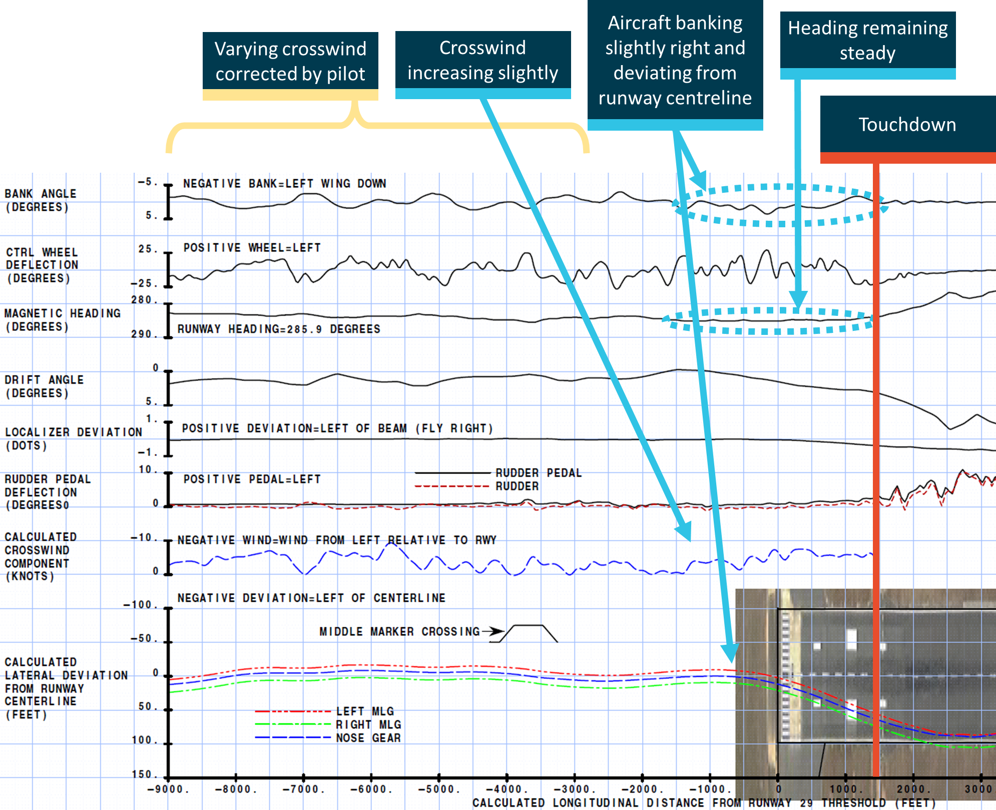
The kinematic analysis indicated that in the few seconds before crossing the threshold (2303:23), the crosswind varied but it was not significantly more than it had been previously (Figure 7). However, in a gradually increasing crosswind from about 140 ft, about 5 seconds before crossing the threshold, the aircraft banked slightly right and began drifting right, without correction. A combination of momentum and continuing crosswind meant that the drift to the right continued until touchdown.
Figure 7: Recorded data showing the aircraft’s drift from centreline. The runway width is exaggerated and the markings are different to those at the time of the occurrence.
Source: Boeing, annotated by ATSB
Aerodrome information
General information
Darwin Airport consists of both civil and military facilities and is classified as a joint-user aerodrome. The civilian airport operator is Darwin International Airport. Responsibilities between the Department of Defence and Darwin International Airport are defined in a joint-user deed. The runway infrastructure is the responsibility of the Department of Defence.
Runway information
Runway 29 was 3,354 m long and 60 m wide, and the centre 45 m was grooved to aid water displacement and had a retractable arrestor cable in the touchdown zone for military use. The runway was equipped with an instrument landing system (ILS) that allowed for precision approaches in operations to category I minima (without autoland).
The runway had white markings along the centreline, an aim point starting 342 m from the threshold, and five touchdown zone markings from the threshold to 900 m. The runway had high intensity approach lights, runway threshold lights, and runway edge lights spaced at 60 m intervals.[17] There were also precision approach path indicator lights each side of the aim point (Figure 8).
Figure 8: General arrangement of runway lighting at Darwin Airport runway 29
Light locations are approximate, and actual light colours are not represented. Source: ATSB / Google Earth
Runway 11/29 at Darwin was significantly wider than most others in Australia (see Related occurrences in Australia), resulting in the visual cues and runway perspective being different to those normally available to complete a landing. The runway was not equipped with centreline or touchdown zone[18] lights.
There were two distinct crests that could obstruct distant portions of the runway and some edge lights when viewed very close to touchdown. ATSB analysis of topographic survey data indicated that runway 29 met relevant standards for slope and variation.
The Civil Aviation Safety Authority (CASA) outlined Australian requirements for aerodromes in Civil Aviation Safety Regulation (CASR) 139 and the associated Manual of Standards (MOS) for CASR Part 139. Testing conducted in 2016 and 2017 found that the ungrooved runway edge on the northern side of runway 11/29 at Darwin did not meet the surface texture or friction requirements of the MOS.
Runway design standards and guidance
The International Civil Aviation Organization (ICAO) specifies standards and recommended practices (SARPS) for international aviation operations in a series of Annexes. ICAO Annex 14 (Aerodromes, Volume 1 Aerodrome Design and Operations, 7th edition July 2016) stated that runway centreline lights and touchdown zone lights shall be provided for runways with a category II or III[19] precision approach. It also stated:
5.3.12.2 Recommendation— Runway centre line lights should be provided on a precision approach runway category I, particularly when the runway is used by aircraft with high landing speeds or where the width between the runway edge lights is greater than 50 m.
Annex 14 had included the same or similar recommendation since 1966. There was no recommendation for touchdown zone lights for category I runways.
ICAO also published other guidance about aerodrome lighting. For example, ICAO document 9157 (Aerodrome Design Manual, Part 4 Visual Aids) stated:
The function of the centre line lighting is to provide the pilot with lateral guidance during the flare and landing ground roll or during a take-off. In normal circumstances, a pilot can maintain the track of the aircraft within approximately 1 to 2 m of the runway centre line with the aid of this lighting cue. The guidance information from the centreline is more sensitive than that provided from the pilot’s assessment of the degree of asymmetry between the runway edge lighting. In low visibility conditions, the use of the centre line is also the best means of providing an adequate segment of lighting for the pilot to use. The greater distances involved in viewing the runway edge lighting together with the need for the pilot to look immediately ahead of the aircraft during the ground roll also contribute to the requirements for a well-lit runway centre line.
Another section of the manual stated:
…Some of the most difficult tasks when flying an aircraft visually are judging the approach to a runway and the subsequent landing manoeuvre. During the approach, not only must the speed be carefully controlled, but continuous simultaneous corrections in all three dimensions are necessary in order to follow the correct flight path.
…There are two reasons why approach and runway lighting systems are provided with patterns that emphasize the centre line. One obvious reason is that the ideal landing position is along the centre of the runway. The other is that the fovea of the eye, the region of sharp vision, is only about 1.5 degrees in width…
Studies have shown that the average time required for a pilot to switch from outside visual cues to instruments and back to outside cues is about 2.5 seconds. Since high performance aircraft will travel at least 150 m in this time period, it is apparent that in so far as possible the visual aids should provide the utmost in guidance and information, enabling the pilot to proceed without the necessity of cross-checking the instruments…
Consistent with Annex 14, the MOS for CASR Part 139 required centreline and touchdown zone lighting for runways with category II or II approaches and recommended centreline lighting for category I runways with a width of more than 50 m.
Simulation of visual cues provided by runway lights
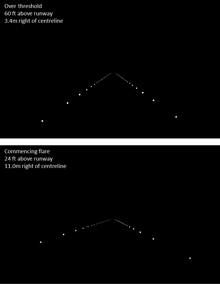
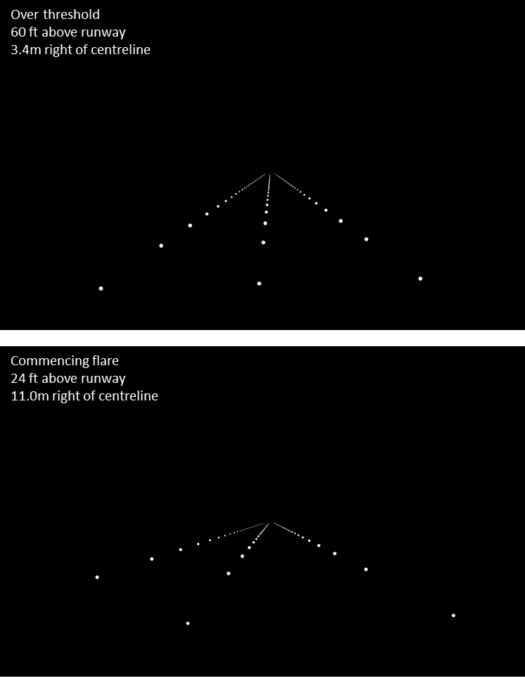
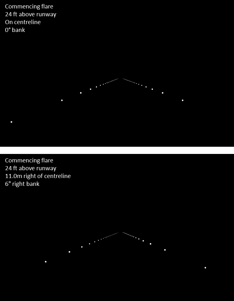
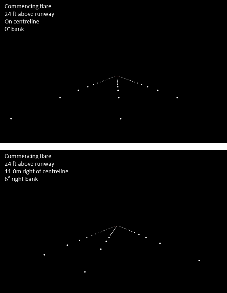
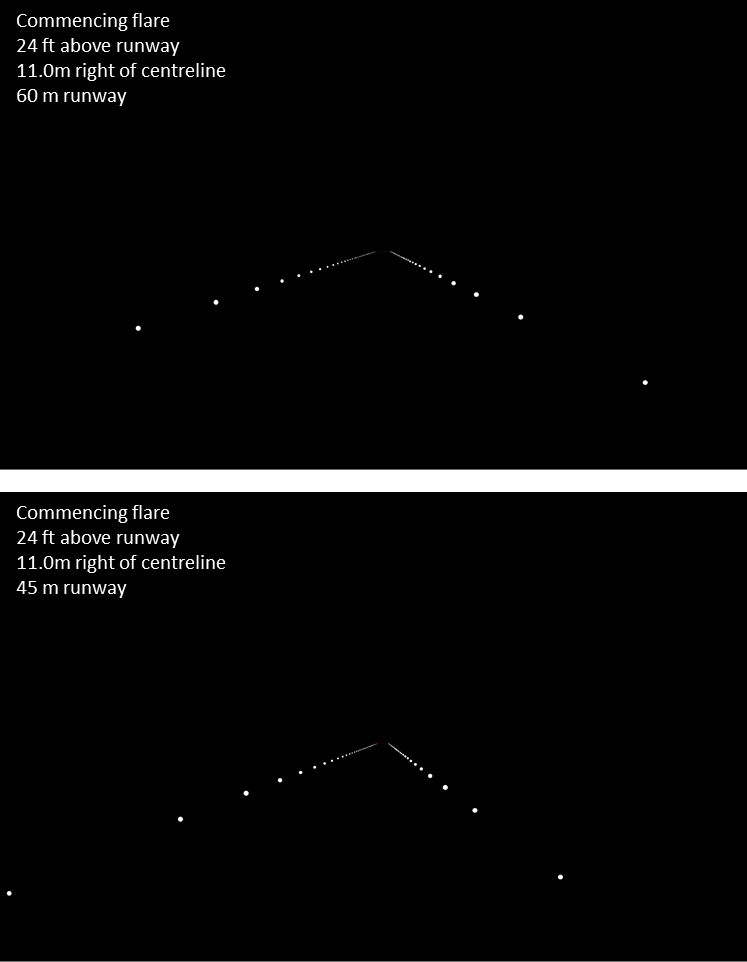
The ATSB examined the relative effectiveness of the visual cues provided by runway edge lights on late final approach at Darwin during the 6 December 2016 occurrence flight compared with other situations.
Visual images were created to simulate a captain’s view of runway lights when on approach to a runway. These simulations were based on a highly simplified model of the cues that would normally be available to flight crews. For example, they did not include visual cues available from approach lighting, runway texture or surrounding areas, and did not account for the effects of rain and windshield wipers on the visual appearance of the runway edge lights. They also did not account for the effects of aircraft movement and associated visual cues such as optic flow. Nevertheless, they provided some indication of the relative ability to identify a lateral deviation from the runway centreline during the later stages of the final approach.
The simulations indicated:
A significant deviation from the runway centreline (11 m lateral displacement at 24 ft above the ground) appears much easier to detect on a 60 m wide runway if runway centreline lights are provided.
A significant deviation from the runway centreline is more difficult to detect on a 60 m wide runway without centreline lighting compared to a 45 m wide runway without centreline lighting.
It may be difficult to distinguish being on centreline and wings level from being off centreline with a slight bank in the direction of the closest row of edge lights. However, the deviation from the centreline is much easier to detect when runway centreline lights are present.
Further details of the simulation method and simulation images are provided in Appendix A.
En route supplement information
CASR 139 required an aerodrome operator to ensure there was adequate particulars about the aerodrome published in the En Route Supplement Australia (ERSA).[20] The types of information required included telephone numbers, runway specifications, lighting, visual aids, available ground services, special procedures and local precautions.
The MOS for Part 139 provided more details regarding the types of information to be included in the ERSA. This included the width and lighting information for each runway and ‘important cautionary or administrative information relating to the use of the aerodrome’. The ‘Additional information’ section of the ERSA for the aerodrome was also required to include ‘significant local data’, such as animal or bird hazards or areas to avoid overflying.
The ERSA information for many Australian aerodromes includes some types of hazards in the ‘Additional information’ section, such as birds, weather balloon launches, or the likelihood of turbulence on approach to particular runways. Specific guidance with regard to visual issues on approach was uncommon. One example was the ERSA entry for Mackay Airport, which stated that in conditions of light mist or fog, high intensity floodlighting adjacent to the final approach to a runway could ‘cause distraction’. A small number of entries cautioned that nearby roads or other objects may be mistaken for a runway.
The ERSA information for Darwin stated there was a possibility of windshear or turbulence on short final approach for all runways and bird hazards. No advisory information was provided about the potential for visual illusions or potential problems with visual guidance during landing associated with the runway width, lack of centreline lighting or touchdown zone lighting, or the crests in the runway.
Operator information
Approach to land near storms
The Virgin Australia flight crew operations manual stated:
In the interests of safety, prevention of aircraft damage, and passenger comfort, avoiding thunderstorms is of paramount importance.
- Visually avoid thunderstorm cells, or radar returns, including those with prominent 'hooks', 'scallops' or 'fingers' which indicate severe hail and signify strong vertical shear
- Avoid flying under anvils
- Avoidance shall be upwind of the weather, where possible
- Do not attempt to overfly a thunderstorm…
In terms of the descent and approach to land, the manual also stated:
Fly the aircraft clear of thunderstorms either by holding or adopting an alternative approach track. The circuit and approach to land should not be closer than 5 nm to an approaching storm at any time.
A note in the relevant section stated:
During take-off and landing, storms that have passed may be approached closer than 5 nm, as the rear of storms is considered to be comparatively inactive.
Transition to manual flight
In relation to flight path management, the operations manual stated that the auto flight system (AFS) on an aircraft ‘should be used to enhance operational capability, improve safety and reduce workload’. In addition:
Flight crew should use available AFS to the fullest extent that meets operational requirements considering the current flight conditions.
The manual also stated that the autopilot should be engaged:
… On all Instrument approaches, when cloud is within 500 ft of the minima or when the reported visibility is less than required visibility +2000 m…
In a section discussing the flare and touchdown, the operator’s flight crew training manual for the 737 stated:
When a manual landing is planned from an approach with the autopilot connected, the transition to manual flight should be planned early enough to allow the pilot time to establish airplane control before beginning the flare. The PF should consider disengaging the autopilot and disconnecting the autothrottle 1 to 2 nm before the threshold, or approximately 300 to 600 feet above field elevation.
Guidance for Darwin Airport
An examination of the Virgin Australia’s flight operational quality assurance data suggested off-centreline landings were very rare, including at Darwin.
Virgin Australia used aeronautical charts that were provided by a third party (Jeppesen), and also published its own supplementary port information when there was a need to provide additional information to flight crews. The supplementary port information for Darwin Airport included a caution for flight crew about turbulence and windshear on short final, and bird hazards. There was no specific guidance for other weather conditions, runway characteristics, or local lighting.
The ATSB reviewed the supplementary guidance for Darwin Airport provided by two other major Australian airlines. Following a veer-off runway excursion at Darwin in 2003 (see Related occurrences in Australia), one operator introduced additional guidance to flight crews for approaches to Darwin, including notes about runway surface, slope, width, lighting, and ambient light. The guidance stated:
CAUTION:
Be aware of the possibility of loss of visual cues when landing on RWY 29 at night, particularly in conditions of reduced visibility.
Contributing factors include:
- Runway surface condition;
- Runway slope;
- Runway width of 60 m;
- No centreline lighting;
- No touchdown zone lighting;
- Lack of surrounding ambient light, particularly approaching the flare, i.e. black hole effect.
It is recommended that approach and landings at night onto RWY 29 auto-coupled to the ILS for as long as possible, commensurate with the limitations. Crew must exercise vigilance and if any doubt exists as to the safe continuation of the approach, a Missed Approach must be executed.
The second operator, which had an association with the first operator, provided similar guidance to its flight crews.
Related occurrences
Previous studies of runway excursions
A study by the ATSB (2009) examined 141 runway excursions involving commercial jet aircraft during 1998–2007. About 40 per cent were veer-offs[21] on take-off or landing. Weather was a significant factor in many of the occurrences. The ATSB report stated:
Appropriate lighting of the runway centreline and edges has the potential to provide pilots with better spatial awareness at night or in poor visibility conditions, and may reduce the likelihood of veer-offs.
A Flight Safety Foundation (FSF) study (2009) examined 548 runway excursions, including 230 veer-offs on landing. This study also highlighted the significant effect of weather. The FSF report stated:
The frequent presence of runway contaminants in runway excursions strongly implies that they…are a significant risk factor, along with weather conditions such as rain, crosswinds, gusting winds, and low visibility.
The FSF found that runway excursions on landing were closely associated with rain, snow and wind. Importantly, about half of all landing veer-off occurrences in crosswinds or gusty, turbulent winds, followed a stabilised approach.
In July 2015, Airbus published an article titled ‘Lateral runway excursions upon landing: a growing safety concern?’ It stated that an increasing proportion of accidents were runway excursions (including both veer-offs and overruns) and that, unlike other accident types, the rate of runway excursion accidents had not changed significantly in 20 years. It also noted that generally the consequences of an overrun were more severe than a veer-off, but the reported number of veer-offs had increased in recent years. It examined 25 reported veer-offs involving Airbus aircraft and, acknowledging limitations of the data, stated:
Three main environmental factors came out of the analysis:
- Runway state, wet or contaminated
- Turbulences or cross-wind
- Visibility deterioration
Most (19) of the 25 occurrences involved at least two of these environmental factors. Twelve were associated with a deterioration in visibility, 12 involved turbulence or crosswind, and four involved both. All but two of the 12 occurrences that were associated with poor visibility involved a deviation prior to touchdown.
Related occurrences in Australia
Search criteria for related veer-off occurrences
The ATSB reviewed its occurrence database for any veer-off occurrence in Australia from 1997 to 2017 that involved:
an air transport aircraft
a loss of runway centreline alignment prior to and at touchdown
no notable problems with the serviceability of relevant aircraft equipment, runway lighting or the runway surface that significantly contributed to the veer-off
no significant problems with the stability of the approach in terms of height or airspeed.
In addition to the 6 December 2016 occurrence involving VH-VUI, two other relevant occurrences were identified: a 2003 occurrence at Darwin and a 2003 occurrence at Emerald, Queensland.
2003 veer-off at Darwin
On 19 February 2003, a Boeing 737 veered off runway 29 at Darwin while landing at night and in conditions of rain and reduced visibility.[22]
At the approach minima (about 210 ft), the flight crew were still visual and decided to proceed with the landing. About 2 to 3 seconds later, the captain disengaged the autopilot. At that time, the aircraft was established on the localiser and glideslope. About 7 seconds after the autopilot was disengaged (and 13 seconds prior to touchdown), the aircraft started deviating right. At about this time, the approach lighting was no longer in the flight crew's view. The captain considered that there was sufficient visual reference to complete the landing but did not detect the aircraft's increasing lateral displacement from the runway centreline.
The aircraft touched down close to the right edge of the runway about 520 m from the threshold. The right main gear ran off the runway 590 m from the threshold and the left main gear ran off 760 m from the threshold. All wheels had returned to the runway about 1,300 m from the threshold.
The ATSB investigation found that the flight crew may have encountered an abnormal situation where few reliable visual cues were available for determining the aircraft's position relative to the centreline of the runway. The investigation report highlighted the potential for visual illusions during a night approach to runway 29 at Darwin Airport, noting the wider than normal runway, the absence of centreline lighting and the weather conditions.
As a result of the occurrence, the operator provided flight crews with more specific information for Darwin Airport.
2003 veer-off at Emerald
On 1 May 2003, while landing in a storm at night, a DHC-8-200 veered partially off runway 24 at Emerald Airport, Queensland.[23]
The flight crew were conducting a non-precision approach. As the captain flared the aircraft for landing, the crew lost virtually all external visual reference when the aircraft encountered very heavy rain. The runway was 45 m wide and did not have centreline lighting.
The Emerald occurrence was different to the 2003 and 2016 occurrences at Darwin because it involved sudden, near zero visibility at the time of the flare. In contrast, although the two occurrences at Darwin involved a significant loss of visual references, the deviations commenced slightly earlier in the approach and the runway edge lights were still visible.
Other notable occurrences at Darwin Airport
Although not veer-off occurrences, there were two other notable occurrences at Darwin Airport:
A 2002 runway overrun involving a 737 occurred at night in clear weather.[24] The investigation report stated that the ‘operational environment was conducive to visual illusions, such as the black hole effect, during the approach and landing’. The overrun followed an unstable approach and, at the time, the runway had a displaced threshold.
A 2008 hard landing involving a Boeing 717 at night.[25] The investigation report stated ‘the degraded visual information during the landing may have increased the difficulty of judging the aircraft’s rate of closure with the runway and the required flare’. The report also included the following two safety factors (neither of which was classified as contributing to the occurrence):
The aircraft operator's Route Manual did not include all relevant information on the potential for visual illusions during a night approach to runway 29 at Darwin Airport that would have improved the awareness of flight crews.
The lack of runway centreline lighting reduced the available visual cues during the latter stages of the approach and landing to runway 29 at Darwin Airport.
As a result of the occurrence, the operator updated its route manual to provide more specific information for each aerodrome, including Darwin.
Further analysis
In summary, including the 6 December 2016 occurrence involving VH-VUI, there were three veer-off occurrences matching the selected criteria in Australia between 1997 and 2016. All were on runways without centreline lighting, and two were on Darwin’s runway 29.
Darwin runway 11/29 was the only runway in Australia that was 60 m wide and had no centreline lighting. The only other runway in Australia that was 60 m wide was runway 16/34 at Melbourne Airport, which had centreline lighting. All of the other runways in Australia that had centreline lighting were 45 m wide: runways 01/19 at Brisbane, runway 27 at Melbourne, and runways 16L, 16R, 34L and 34R at Sydney.[26]
As previously stated, Darwin runway 29 could host category I ILS approaches. Compared with category I ILS approaches, category II/III ILS approaches permit lower decision heights and landings in reduced visibility. Among other things, category II/III approaches require runway centreline lighting (or touchdown zone lighting in the case of special authorisation category II approaches). At the time of the occurrence, category III ILS approaches were only available at Melbourne Airport and category II ILS approaches only at Brisbane, Melbourne, and Sydney airports.[27]
To evaluate against exposure rates, the ATSB examined traffic, runway, and weather information for the 10 busiest airports in Australia, including Darwin (Table 3). Emerald Airport is also included in the table. As indicated in the table, Darwin experiences the most storm activity and the heaviest rainfall, but hosts only a small proportion of traffic (2 per cent of the top 10 airports).
Table 3: Information for the 10 busiest airports in Australia, and Emerald Airport
Approximate number of lightning strikes per km2 per year[30]
Approximate number of days with >25 mm rainfall per year
≤50 m
>50 m
≤50m
>50m
Busiest airports
Sydney
158,810
4
0
2
0
5 – 10
10 – 15
Melbourne
118,006
3
0
1
2
1 – 5
5 – 10
Brisbane
95,716
2
0
2
0
10 – 15
5 – 10
Perth
47,253
2
0
2
0
1 – 2
5 – 10
Adelaide
39,523
4
0
0
0
0.5 – 2
0 – 2
Cairns
24,654
2
0
0
0
5 – 10
20 – 30
Gold Coast
21,246
2
0
0
0
10 – 15
15 – 20
Canberra
18,591
4
0
0
0
5 – 10
5 – 10
Darwin
13,949
2
2
0
0
15 – 20
20 – 30
Townsville
12,806
4
0
0
0
5 – 10
10 – 15
Other airports
Emerald
4,992
2
0
0
0
5 – 10
5 – 10
In summary, Darwin had the only runway that was 60 m wide without centreline lighting, and it hosted less than 2 per cent of the total traffic of the 10 busiest airports. It is very unlikely that the only two veer-off occurrences that took place at these 10 airports should have occurred on this runway. Although another occurrence took place at Emerald, the extreme loss of visual references during the flare in that occurrence was very likely a more significant factor than the runway width or runway lighting.
Related veer-off occurrences in Canada
During the investigation, the ATSB identified that some veer-offs associated with runway misalignment during final approach had occurred in Canada. It also identified that Canada had a higher proportion of runways that were 60 m wide compared to other countries. Accordingly, the investigation examined the number and characteristics of veer-off occurrences in Canada.
The Transportation Safety Board (TSB) of Canada provided the results of a search of its database for potentially similar occurrences during the period 1997 to 2017. The ATSB reviewed this data and associated investigation reports to identify relevant occurrences, using the same criteria as listed above for occurrences in Australia. Occurrences were only considered if a final investigation report was available. During this process, some additional occurrences from the period 1991 to 1996 were identified.
In total, seven veer-off occurrences were identified that met the relevant criteria. All seven veer-off occurrences in Canada occurred at night on 60 m wide runways with no centreline lighting. In each case, there were some weather-related factors reducing visibility.
One occurrence was somewhat different to the others. It involved a Learjet, with the flight crew hand-flying a category I ILS approach. The crew attempted a missed approach after the aircraft touched down off the runway. The aircraft subsequently impacted terrain in an inverted attitude, and the two flight crew (the only occupants) were fatally injured.
All six of the other Canadian occurrences had similar characteristics to the two at Darwin:
All six involved the flight crew of a high-capacity air transport aircraft conducting a category I ILS approach at night.
Five involved a deviation from the centreline that occurred soon after the autopilot was disconnected just prior to landing (at heights ranging from 65 to 115 ft above the ground). In the other case, the approach was hand-flown.
All resulted in destroyed runway lights and/or signs, and most had some aircraft damage. None resulted in any injuries.
In addition to those seven occurrences, there were some other notable occurrences:
Two other potentially related veer-off occurrences were identified, but because they were not investigated by the TSB the full nature of the events and their circumstances could not be determined. One involved a DC9 at Calgary in 1998 and the other an A320 at Ottawa in 2017. Both occurred at night on 60 m wide runways with no centreline lighting.
A 1997 occurrence at Fredericton involved a Canadair CL600 at night during a category I ILS approach. When the aircraft was about 35 ft above the ground, the captain was aware that they were left of the centreline but was not sure how far down the runway they were. Recognising that they were not in a position to land safely, he ordered the first officer to go around. During the go around, the aircraft stalled and then struck the runway, and subsequently it struck a tree, resulting in nine serious injuries. The accident occurred on a 60 m wide runway with no centreline lighting.
A 2014 veer off occurrence at Montréal involved an Airbus A320 during the day during a category I ILS approach. The runway lights were out of service at the time. Other characteristics of the occurrence were similar to the related occurrences discussed above. It occurred on a 60 m wide runway.
In summary, all seven veer-off occurrences in Canada involving centreline misalignment during final approach occurred on 60 m wide runways without centreline lighting. Some other potentially related occurrences also involved this type of runway, but no potentially related occurrences were identified on other types of runways in Canada.
Canada’s civil air navigation service provider, Nav Canada, provided landing statistics for 115 of the busiest airports in Canada in 2017. Table 4 shows the percentage of landings at runways with and without centreline lighting, and at runways that are wider than 50 m compared with narrower runways. Data is only included for aircraft with a maximum take-off weight of more than 7,000 kg. Although this data was not presented separately for night versus day operations, and it is only for 2017, it was considered to provide a reasonable approximation of the proportion of operations occurring on different types of runways during the relevant period.
Table 4: Aircraft landing statistics in Canada
Width < or = 50 m
Width > 50 m
Total
Centreline lighting
4 %
39 %
43 %
No centreline lighting
26 %
31 %
57 %
Total
30 %
70 %
100 %
As indicated in the table, about 31 per cent of landings occurred at wider runways with no runway centreline lighting. It is statistically very unlikely that seven veer-off occurrences in 20 years with similar characteristics took place on these types of runways without any having occurred on the narrower runways, or on wider runways with centreline lighting.
In its most recent investigation report into a veer-off occurrence, the TSB stated:[31]
…On runways without centreline lighting, as the distance between runway edge lights increases, it becomes more difficult to judge lateral movement solely by assessing the degree of asymmetry between the runway edge lights—especially when the aircraft is close to the ground and the flight crew’s attention is focused directly ahead of them.
The TSB has investigated a number of lateral runway excursions that occurred on runways without centreline lighting. If the distance between runway edge lights is greater than 50 m and runways are not equipped with centreline lighting, there is a risk that visual cues will be insufficient for flight crews to detect lateral drift soon enough to prevent an excursion, while operating aircraft at night during periods of reduced visibility.
Related veer-off occurrences in other countries
The ATSB also searched for potentially related veer-off occurrences in other countries using internet search tools, reviewing the United States National Transportation Safety Board (NTSB) aviation database of accidents and selected incidents and reviewing relevant research reports. The search covered the period 1997 to 2017, and occurrences were only included if they met the same criteria as used for the Australian and Canadian occurrences, and a final investigation report was available. The search was not comprehensive, and it is likely that there were many more occurrences during this period.
Overall, five additional veer-off occurrences involving runway misalignment during final approach were identified. Two occurred in the United States, and one each in Finland, Sweden and the Solomon Islands. The basic details of these additional occurrences are provided in Table 5 (in blue shading).
All five occurrences occurred at night, during instrument approaches in conditions with reduced visibility to runways without centreline lighting. None of the occurrences resulted in serious injuries. Two of the occurrences occurred on 60 m wide runways, and three on 45 m wide runways. One of the three occurrences involving 45 m wide runways occurred during a non-precision approach in very heavy rain (Honiara, 2008), like the Emerald occurrence.
Summary of related occurrences
In summary, 15 related occurrences were identified in Australia, Canada and other countries. Basic details of these occurrences are summarised in Table 5, with the Australian occurrences highlighted in red and Canadian occurrences highlighted in blue.
With regard to all 15 occurrences:
All occurred at night.
All occurred at runways without centreline lighting.
Most (11) occurred at runways that were wider than 50 m.
Most (13) occurrences involved a category I ILS approach. The other two occurrences (Honiara 2008 and Emerald 2003) were during non-precision approaches and involved runways narrower than 50 m.
All occurred in conditions of reduced visibility (in terms of rain, fog and/or snow), with most also involving wet runways (reducing the visible texture of the runway) or snow-covered runways.
Three occurrences were in visibility conditions reported to be below the permissible minimum for an ICAO-standard category I ILS approach and landing (800 m ground visibility or 550 m runway visual range; the same distances are used in Australia). Canada applied different rules.
Most (13) occurrences involved high capacity air transport aircraft (with a capacity exceeding 38 seats). The exceptions were at Emerald in 2003, involving a low capacity air transport aircraft, and the business jet at Stephenville, Canada in 1996.
Other than the DHC-8 turboprop aircraft at Emerald, all involved turbofan (jet) aircraft.
A review of global runway databases indicated that about 30 per cent of runways[32] are wider than 50 m, which is a much lower proportion than the number of relevant occurrences at such runways. In addition, the busiest runways tend to be equipped with centreline lighting. Although statistics regarding the number of movements to different types of runways was not obtained for all of the relevant countries, it is likely that there are significantly fewer landings on runways that are 60 m wide without centreline lighting than others. Subsequently, there appears to be a disproportionately high number of related occurrences at those runways, even in Canada where more runways are 60 m wide.
Table 5: Veer-off occurrences involving runway misalignment during final approach
[1] Reported conditions less than 800 m ground visibility or 550m runway visual range.
Previous ATSB recommendations
In 2004, during the investigation into the 2003 veer-off at Darwin, the ATSB advised Darwin International Airport that it was considering making a recommendation for the installation of runway centreline lighting. On 31 December 2004, Darwin International Airport advised:
A standard runway centerline system would be prohibitively expensive and is not currently a standard for our runway category.
As a result of the investigation into the 2003 veer-off occurrence, the ATSB made a recommendation on 4 March 2005:[33]
The Australian Transport Safety Bureau recommends that the Department of Defence (airport infrastructure owner) and Darwin International Airport Pty Ltd (civilian facilities operator) consider installation of centreline lighting and touchdown zone lighting, consistent with CASA recommended practices on runways wider than 50 m.
No formal response was received at the time, and the recommendation was classified as ‘Closed – Partially accepted’ based on further correspondence with the Department of Defence.
Following the release of the ATSB’s report into the 2008 hard landing at Darwin involving a Boeing 717, published in May 2010), the ATSB sought further response from the Department of Defence. On 7 July 2011, the Department of Defence responded:
Air Force has reviewed the [AO-2008-007] report, and has consulted with Darwin International Airport [DIA] on the issue of runway centreline lighting. Initial cost estimates for installation are approximately $3M, however additional costs may ensue with a potential upgrade to the lighting equipment rooms and repairs due to incompatibility of arrestor hook equipped military aircraft with centreline lighting.
The Air Force position is as follows:
a. Existing approach lighting at Darwin is appropriate for a Cat I [category I instrument landing system] precision approach runway.
b. Installation, upgrade and maintenance costs do not represent value for money.
c. The installation of runway centreline lighting is not imperative and will not be pursued (DIA are in agreement).
d. The option of reverting the runway lighting to 45m width would be costly and viewed as a low priority infrastructure change.
The ATSB reclassified the issue as ‘Closed – Not accepted’.
During the landing on runway 29 at Darwin at night, the aircraft touched down 21 m to the right of the runway centreline while tracking about 3° to the right. Apart from the sudden degradation of visibility, other aspects of the landing (in terms of the aircraft’s configuration, airspeed, distance down the runway and descent rate) were normal. Soon after touching down, the right main gear departed the sealed surface.
The runway excursion (veer-off) was due to the aircraft deviating from the runway centreline during the final stages of the final approach. There were no aircraft serviceability issues. The crosswind was not sudden or strong enough to be significant under most circumstances.
This analysis will firstly discuss the reasons for the aircraft’s deviation from the centreline. It will then discuss a range of other safety factors identified during the investigation.
Visual cues during final approach
After transitioning from autopilot to manual flight control, a flight crew needs to manage the aircraft’s airspeed, flight path (lateral and vertical), and three-dimensional attitude, and the crew must then initiate the flare at the correct height for landing. Misjudging any of these can result in a hard landing, veer-off or overrun. The landing task becomes additionally challenging when the aircraft is constantly moving in gusty, turbulent conditions. In reduced visibility, the pilot has less information to assess the aircraft’s behaviour and respond appropriately.
During a normal landing at night, a flight crew has a range of visual cues to help judge the lateral position of the aircraft:
Approach lighting gives effective cues for the key elements needed for runway alignment, and is required (where practicable) for category I ILS approaches such as to runway 29 at Darwin airport. However, from about 100 ft height to touchdown, approach lighting is no longer visible under the aircraft’s nose. Similarly, runway threshold lighting is also no longer visible.
Runway centreline markings and other surface textual cues on or near the runway can provide some useful information in appropriate ambient lighting. However, such cues may not be visible on a night approach to a wet runway when there is little or no ambient lighting available.
Runway edge lights are visible to the flight crew in most weather conditions when landing (and crews are required to conduct a missed approach if they are not visible). The relative angle and degree of asymmetry of the two rows of lights can provide useful cues in many situations. However, the salience of lights can be reduced to some extent due to environmental factors, such as rain and water on the aircraft’s windscreen.
Runway centreline lighting and touchdown zone lighting can provide very useful visual cues. However, they were not available at Darwin and they are only available at a small proportion of runways, generally those associated with a Category II/III ILS approach.
In summary, the main visual cues the flight crew of VH-VUI had in the last few seconds prior to touchdown (from 100 ft above ground level) were the runway edge lights. It was during this period that the aircraft started and then continued to deviate from the runway centreline.
It appears that the aircraft started drifting right under the influence of an increasing (although light) crosswind, and a small amount of right bank. However, deviations occur during manual control for a number of reasons, and the important aspect in this case is that the deviation was not detected and corrected. The deviation occurred in turbulent conditions, which required continuous corrections to the aircraft’s attitude and flight path, and there were insufficient external visual cues during this high workload period for the flight crew to effectively detect the deviation and make appropriate adjustments. The available evidence did not indicate fatigue, medical issues or distraction affected the flight crew’s performance.
A significant factor reducing the effectiveness of the visual cues in this case was the wider than normal width of the runway (60 m compared to the much more common 45 m), and the corresponding increased distance between the two rows of runway edge lights. As indicated by simple graphical representations (see Appendix A), it is more difficult to detect a deviation when approaching a wider runway compared to a narrower runway. By the time a deviation is identified on a wider runway, the momentum of the lateral movement may be such that the deviation is difficult to correct prior to touchdown.
More importantly, the rate of veer-off occurrences due to misalignment during late final approach is much higher at 60 m wide runways than 45 m wide runways. All of these occurrences have taken place at night in situations where rain or other environmental factors reduced other visual cues.
This problem has been recognised for a long time, with the International Civil Aviation Organization (ICAO) and regulatory authorities recommending the use of centreline lighting on runways wider than 50 m that are used for Category I ILS approaches.
Following a similar occurrence at Darwin in 2003, the ATSB made a specific recommendation that the Department of Defence and Darwin International Airport consider installing runway centreline lighting and touchdown zone lighting on its wide runways. The relevant parties advised that they did not consider any changes cost-effective.
The ATSB understands there is significant expense and logistical difficulties associated with installing centreline lighting. However, without it, there is a realistic prospect of further veer-off or related occurrences at Darwin or any other airport that has a wider runway without centreline lighting.
The 2016 occurrence involving VH-VUI at Darwin resulted in damage to six runway edge lights and minor damage to the aircraft. Most of the other veer-off occurrences due to misalignment during final approach have resulted in a similar level of damage. However, with this type of occurrence, there is the potential for more serious consequences such as undercarriage collapse, veering into other aircraft or vehicles on the ground, or a mishandled go-around with the aircraft near the ground and the engines at low power resulting in a collision with terrain. The ATSB previously found that 2 out of 48 landing veer-off accidents over a 10-year period were fatal, resulting in 93 fatalities (ATSB 2009).
Advisory material regarding hazards at airports
If a hazard such as ineffective visual cues for landing in some situations cannot be effectively mitigated by redesign, then a less desirable though beneficial option is to ensure appropriate advisory information is provided to flight crews.
At the time of the occurrence, the aircraft operator had limited guidance for flight crews approaching Darwin Airport to consider the increased risk arising from the combination of a wide runway and the absence of centreline lighting. This meant that crews were less likely to consider the risk when deciding whether to continue an approach, and potentially less prepared for the potential for undetected deviation away from the centreline on late final approach.
Both flight crew had operated to Darwin before. However, they had not done so recently, with the captain’s last flight there over 5 months before and the first officer 16 months before. As a result, neither crewmember had recent familiarity with the visual cues present on the approach, and would probably have studied any available information on hazards that was provided. Although reviewing such information would have reduced the potential risk during an approach, the extent to which it would have affected the flight crew’s decision-making or performance in this situation was difficult to determine.
The ATSB has previously identified that other operators did not provide advisory information about visual cues on approach to runway 29 at Darwin. The Boeing 737 operator involved in the 2003 veer-off occurrence did not have relevant advisory information at that time (although it introduced such information following the occurrence). Similarly, the Boeing 717 operator involved in a hard landing occurrence at Darwin in 2008 also did not have relevant advisory information for its flight crews.
The guidance that operators provide to flight crews is primarily based on the En Route Supplement Australia (ERSA). However, this document also did not provide advisory information about visual cues on approach to runway 29 at Darwin. Including relevant information in the ERSA would help ensure that all air transport operators (including international operators) conducting flights to Darwin adequately consider the potential problems associated with visual cues at night.
Provision of weather information
At the time of planning the flight, aerodrome forecast (TAF) indicated fine conditions at Darwin for the expected landing time. At 2207 Central Standard Time, with the aircraft about 1 hour from landing, an amended TAF was issued, which indicated deteriorating conditions.
The Brisbane en route controller broadcast the availability of the 2207 amended TAF. However, the flight crew were not made aware of a subsequent amended TAF, issued at 2237, which indicated a further deterioration in conditions (although the conditions were still above the landing minima).
Between the two amended TAFs, there was a handover from one Brisbane en route controller to another. When the incoming controller was queried at the time by the operator’s flight following staff as to whether the crew had received ‘the amended TAF’, the controller replied that they had. However, the Darwin approach controller had not made the Brisbane en route controller aware of the updated TAF as was done with the previous update.
Not advising the flight crew of the second amended TAF is unlikely to have influenced the flight crews’ decision to continue the approach. The wind information was the same as the first amended TAF. In addition, the crew interpreted the first amended TAF as being indicative of ‘thunderstorm material’. Within a few minutes of the second amended TAF being issued, the flight crew could also see thunderstorm activity ahead visually and with the aircraft’s weather radar. Furthermore, they were obtaining observation reports through Darwin tower, which are more relevant than forecasts when near the destination airport.
Provision of wind information
While the aircraft was on descent, the airport’s primary anemometer failed due to a lighting strike. Consequently, the Darwin approach and tower controllers were unable to provide the flight crew with real-time wind information from that anemometer during the approach and landing.
After recognising the problem, the controllers were able to obtain information by telephone from a meteorological observer with access to information from a second (test) anemometer, and through observations of the airport’s windsocks. However, the second anemometer’s integrity was unconfirmed and it could not be read in real time. In addition, the information available from windsocks was subject to interpretation. As a result, the wind information that the controllers could provide to flight crews was degraded.
Decision to continue approach and landing
The approach and landing occurred during a period of deteriorating weather conditions, which were observed by the flight crew directly and on the weather radar display, and was indicated to them by frequent updates about the conditions provided by controllers. The operator’s policies recommended that flight crews not approach within 5 NM of an approaching thunderstorm. However, this was not a strict requirement, and the decision was left to each flight crew’s judgement.
Previous research and safety investigation reports have identified that it is not unusual for flight crews to approach or penetrate thunderstorms when landing. For example, Rhoda and Pawlak (1999) reviewed radar data in the Dallas–Fort Worth airspace in the United States. They identified most (about two thirds) of the encounters with storms resulted in penetrations. The proportion of penetrations was lower as the intensity of the storms increased. However, the proportion of penetrations increased with the storm’s proximity to the airport. It also increased when flight crews were following another aircraft, flying after dark, or if they were behind schedule by more than 15 minutes.
In a recent investigation report associated with a flight crew landing close to the edge of a 60 m wide runway during daytime and in the presence of a storm, the Transportation Safety Board of Canada (TSB) noted that other flight crews had also decided to land in proximity of the storm.[34] The TSB also stated:
The hazards generated by thunderstorms are well known in the aviation industry. Crews who fly near a thunderstorm can expect to encounter the following conditions: erratic wind and gusts, squalls (violent wind blasts), turbulence, extremely violent rain, low visibility, hail, and lightning. Furthermore, there is no correlation between the appearance of a thunderstorm and the intensity of its events…
Since [the operator] relies on the experience of its crews to determine the trajectory of the flight in the presence of thunderstorms in the vicinity of airports, the margin of safety varies from flight to flight, depending on the crew…This occurrence is an excellent example of the sudden and simultaneous appearance of hazards associated with thunderstorms at a critical point during landing. This occurrence highlights the unpredictability of thunderstorms and the necessity to maintain a safe distance during the critical stages of flight.
Research has shown that many aviation accidents involve a ‘plan continuation bias’ or ‘plan continuation error’ associated with situations involving dynamically changing risk and pilots underestimating the risk level. That is, a flight crew decides to continue with the original plan of action despite the presence of cues or information that suggests changing the course of action would be the safer option (Orasanu and others 2001). Other researchers have noted that previous encounters with a situation (such as approaching near a storm) without negative consequences may reinforce such behaviour or enable flight crews to reduce their perception of the association risks (Dismukes and others 2007).
In this case, the flight crew could see lightning ahead and, during the later part of the descent, closely monitored the location of rain cells in the vicinity of the airport using the aircraft’s weather radar.
The flight crew regularly discussed the situation and their planned actions. This including obtaining additional information at times, as well as planning to vary their missed approach path (if required) in order to avoid the worst of the weather. The flight crew arrived at the decision height in conditions better than the minimum requirements for visibility and crosswind.
Soon after the aircraft descended through the decision height, it encountered very heavy rain. After this point the visibility deteriorated, and although it was not possible to reliably determine whether the visibility was below the minimum of 800 m, the aircraft’s logo light could be seen from the tower 1.8 km away. The crew could still see the runway edge lights, although they were very blurred between windscreen wiper passes, and considered that they had sufficient visual cues available for landing. Overall, the flight crew’s interpretation of the information available to them gave no compelling reason to initiate a missed approach, and they did not detect the deviation from centreline until after touchdown.
It was not possible to establish the extent to which the flight crew considered the risk of a loss of visibility before it occurred. Furthermore, the weather reports deteriorated gradually during the descent and approach and each incremental change in risk was probably not fully appreciated by the flight crew.
The crew’s decision to continue the approach after entering heavy rain would usually not result in an adverse outcome. However, the combination of a wider runway and relatively limited visual cues available at Darwin increases the potential for adverse consequences.
As with the flight crews in many previous occurrences, the flight crew may not have fully appreciated the increased risk arising from the limited visual cues presented during an approach to a wider runway without centreline lighting. A flight crew that is informed about the potential risk associated with a sudden reduction in visibility close to landing, particularly at airports with 60 m wide runways and no centreline lighting, should have greater readiness to perceive and respond to it.
Recovery actions after touchdown
When the aircraft touched down the flight crew were aware they had landed to the right of the centreline but did not fully comprehend the extent of the deviation and the rate of drift. The captain applied corrective control inputs but, by the time the situation was apparent, was unable to prevent the right main landing gear departing the sealed surface of the runway.
The amount of corrective control input applied by the captain was influenced by the potential to lose control on the wet runway, in combination with the advice from the first officer who thought that the aircraft was clear of the runway lights.
The captain delayed the application of reverse thrust after landing until the aircraft was established on the runway. This action probably helped prevent further excursion off the runway.
Given the extent of the deviation from the runway centreline at touchdown, and the time required to assess the situation, it was very likely the excursion would have happened regardless of the available traction. Traction was probably reduced to some extent after touchdown, and it may have slightly delayed the subsequent recovery back onto the runway. The ATSB notes that the outer 7.5 m of the runway was not grooved, and did not meet the relevant surface texture or friction requirements. Although not contributing factors to this occurrence, such problems could degrade aircraft control in future situations where an aircraft has significantly deviated from the runway centreline.
Post-landing actions
After the landing the crew were unsure whether the aircraft had left the runway. The flight crew discussed whether they had hit the runway lights. Based on the first officer’s perception of the situation, they thought that they had not.
There was no opportunity for ground crews to examine the aircraft and confirm a potential veer-off until the storm had cleared, but there remained a risk that following aircraft could be affected by debris on the runway, and having fewer runway lights available.
This occurrence indicates that it is important to be conservative after a potential veer-off occurrence. A timely report of the possibility that a veer-off had occurred, even if there was doubt, would have provided the airport operator and air traffic control with a better opportunity to ensure the runway was serviceable for other aircraft.
From the evidence available, the following findings are made with respect to the runway excursion (veer-off) involving Boeing 737-800, registered VH-VUI, which occurred at Darwin Airport on 6 December 2016. These findings should not be read as apportioning blame or liability to any particular organisation or individual.
Safety issues, or system problems, are highlighted in bold to emphasise their importance. A safety issue is an event or condition that increases safety risk and (a) can reasonably be regarded as having the potential to adversely affect the safety of future operations, and (b) is a characteristic of an organisation or a system, rather than a characteristic of a specific individual, or characteristic of an operating environment at a specific point in time.
Contributing factors
After passing the decision height for the approach, the aircraft drifted under the influence of a slight crosswind and landed 21 m to the right of the runway centreline.
Due to heavy rain, darkness and limited visual cues, the flight crew did not detect the aircraft’s deviation from the runway centreline prior to landing.
The absence of centreline lighting and the 60m width of runway 11/29 at Darwin result in very limited visual cues for maintaining runway alignment during night landings in reduced visibility. [Safety issue]
Other factors that increased risk
Category I runways that are wider than 50 m and without centreline lighting are over-represented in veer-off occurrences involving transport category aircraft landing in low visibility conditions. The installation of centreline lighting on wider category I runways is recommended but not mandated by the International Civil Aviation Organization Annex 14. [Safety issue]
Virgin Australia did not have formal guidance for flight crews regarding the limited visual cues for maintaining alignment to runway 11/29 at Darwin during night landings in reduced visibility.[Safety issue]
The En Route Supplement Australia (ERSA) did not have formal guidance for flight crews regarding the limited visual cues for maintaining alignment to runway 11/29 at Darwin during night landings in reduced visibility.[Safety issue]
While the aircraft was on descent, the airport’s primary anemometer failed due to a lightning strike. Although there were windsocks and a second, test anemometer at the airport, the reliability and timeliness of the wind information that the controllers could provide to flight crews was temporarily degraded.
Although air traffic services broadcast details of an amended aerodrome forecast (TAF) for Darwin issued at 2207, the flight crew were not made aware of a subsequent amended TAF issued at 2237. However, the flight crew were provided with multiple updates of current weather conditions prior to landing at 2302.
Because they were unsure what had occurred, the flight crew did not report the possibility of a runway excursion to air traffic control until 29 minutes after it occurred. This delayed the response by the airport operator and air traffic control to ensure that the runway was safe for subsequent operations.
Safety issues and actions
The safety issues identified during this investigation are listed in the Findings and Safety issues and actions sections of this report. The Australian Transport Safety Bureau (ATSB) expects that all safety issues identified by the investigation should be addressed by the relevant organisation(s). In addressing those issues, the ATSB prefers to encourage relevant organisation(s) to proactively initiate safety action, rather than to issue formal safety recommendations or safety advisory notices.
Depending on the level of risk of the safety issue, the extent of corrective action taken by the relevant organisation, or the desirability of directing a broad safety message to the aviation industry, the ATSB may issue safety recommendations or safety advisory notices as part of the final report.
Standards for installation of runway centreline lighting on wider runways
Safety issue owner: International Civil Aviation Organization
Operation affected: Aviation: Airports
Who it affects: Operators using runways wider than 50 m without centreline lighting
Safety issue description:
Category I runways that are wider than 50 m and without centreline lighting are over-represented in veer-off occurrences involving transport category aircraft landing in low visibility conditions. The installation of centreline lighting on wider category I runways is recommended but not mandated by the International Civil Aviation Organization Annex 14.
Status of the safety issue
Issue status: Safety action pending
ATSB safety recommendation to the International Civil Aviation Organization
The Australian Transport Safety Bureau recommends that the International Civil Aviation Organization review the effectiveness of Annex 14, recommendation 5.3.12.2 (for the installation of runway centreline lighting on Category I runways that are wider than 50 m), given that Category I runways that are wider than 50 m and without centreline lighting are over-represented in veer-off occurrences involving transport category aircraft landing in low visibility conditions.
Limited visual cues for approach at Darwin runway 11/29
Who it affects: Pilots operating into Darwin airport
Safety issue description:
The absence of centreline lighting and the 60-m width of runway 11/29 at Darwin result in very limited visual cues for maintaining runway alignment during night landings in reduced visibility.
Status of the safety issue
Issue status: Safety action pending
Response by Darwin International Airport and Defence Flight Safety Bureau
On 18 September 2017, Darwin International Airport (DIA) advised:
The Department of Defence position in 2011 was as follows and DIA is not aware of any change to that:
a. Existing approach lighting at Darwin is appropriate for a Cat 1 precision approach runway.
b. Installation, upgrade and maintenance costs do not represent value for money.
c. The installation of runway centreline lighting is not imperative and will not be pursued (DIA are in agreement).
d. The option of reverting the runway lighting to 45m width would be costly and viewed as a low priority infrastructure change.
In previous correspondence Defence did indicate a concern for potential damage to tail hook equipped aircraft.
Under the terms of the Joint User Agreement, Defence is responsible for airfield pavements and lighting and is considering resurfacing of Runway 11/29 in about 2022. Replacement of runway lighting may occur as part of that project. Provision of centreline lighting could be considered at that time.
On 25 January 2019, DIA advised:
Darwin Airport is a Joint User aerodrome with the Department of Defence. As previously advised, and under the terms of the joint User Deed, the Department of Defence is responsible for forward planning of pavement overlays and upgrading or replacement of airfield lighting.
DIA will continue to consult with Defence on whether lighting upgrades, including centreline lighting could be considered for future works. A planning meeting is proposed for March 2019.
On 8 February 2019, the Defence Flight Safety Bureau advised:
The lack of centre line lighting at Darwin has been an ongoing issue for some time. Under the Joint User Deed, Defence and DIA are required to work together on any infrastructure matters. To date, Defence and DIA have been in agreement that runway centreline lighting is not supported for reasons that include upfront capital cost, ongoing maintenance issues and consideration of the potential effects of runway centreline lighting on aircraft taking the arrestor cables.
On 26 March 2019, DIA advised:
Northern Territory Airports (NTAP) and Defence met on Wednesday 13th March in Canberra to discuss maintenance, projects and operational matters associated with the Joint User Area at Darwin International Airport / RAAF [Royal Australian Air Force] Darwin. A topic of tabled discussion was Airfield Ground Lighting (including a session on Runway Centreline Lighting) for RWY 11/29. Both NTAP and Defence agreed that the use of Hook Arrestor Cable System on RWY 11/29 prevented the safe introduction of CASA MOS139 compliant Runway Centreline Lighting since the risk of FOD [foreign object debris] caused via damage to Runway Centreline Lights by the Hook Arrestor Cable was of significant concern. It was however tabled that both Runway Centreline Lighting and reducing the runway width from 60m to 45m would be re-considered in future major project design briefs.
ATSB comment
After a similar occurrence in 2003, the ATSB issued a recommendation that the Department of Defence (airport infrastructure owner) and Darwin International Airport (civilian facilities operator) consider the installation of centreline lighting and touchdown zone lighting on runway 29. The ATSB later reclassified the issue as ‘Closed – Not accepted’.
In response to safety issue AO-2016-166-SI-04, Darwin International Airport has undertaken safety action enhancing the en route supplement guidance to flight crews, which will help flight crews conducting operations into Darwin to more effectively plan for and respond to a partial loss of visual cues during approach. However, this action is not a completely effective way of addressing the risk: crew preparedness can reduce the likelihood of, but not prevent, an undetected loss of adequate visual cues.
The ATSB acknowledges the practical limitations of installing and maintaining runway centreline lighting, and notes that DIA have also stated that the feasibility will be reconsidered in future major project design briefs. The ATSB continues to encourage additional safety action by DIA and Defence, and has released the following safety recommendation.
ATSB safety recommendation to Darwin International Airport
The Australian Transport Safety Bureau recommends that Darwin International Airport address the risk of very limited visual cues for maintaining runway alignment during night landings in reduced visibility that arise from the combination of the absence of centreline lighting and the 60-m width of runway 11/29 at Darwin.
Who it affects: Virgin Australia Airlines flight crews operating into Darwin airport
Safety issue description:
Virgin Australia did not have formal guidance for flight crews regarding the limited visual cues for maintaining alignment to runway 11/29 at Darwin during night landings in reduced visibility.
Status of the safety issue
Issue status: Adequately addressed
Justification: The operator’s action, in conjunction with other safety actions, should provide crews with adequate guidance to enable them to assess risk and prepare for approaches in low visibility conditions at Darwin Airport.
Safety action taken: On 20 January 2017, the operator introduced additional guidance to flight crews for approach to Darwin airport, including notes about runway surface, slope, width, lighting, and ambient light.
Who it affects: Pilots operating into Darwin airport
Safety issue description:
The En Route Supplement Australia (ERSA) did not have formal guidance for flight crews regarding the limited visual cues for maintaining alignment to runway 11/29 at Darwin during night landings in reduced visibility.
Status of the safety issue
Issue status: Adequately addressed
Justification: The additional information provided in the ERSA should improve the risk awareness and decision-making of flight crews during low visibility approaches to Darwin airport.
Safety action taken: On 28 January 2019, Darwin International Airport initiated amendments to the ERSA entry for Darwin Airport. These amendments were introduced into the 23 May 2019 issue of the ERSA, and stated:
Under Additional information: ‘During low visibility conditions pilots of ACFT landing RWY 29 HN may experience loss of visual references due RWY WID 60 with no CL or TDZ LGT.’
Under Aerodrome and approach lighting: ‘RWY 11/29 CL and TDZ LGT not provided.’
Additional safety action
Whether or not the ATSB identifies safety issues in the course of an investigation, relevant organisations may proactively initiate safety action in order to reduce their safety risk. The ATSB has been advised of the following proactive safety action in response to this occurrence.
Virgin Australia Airlines
On 5 May 2017, Virgin Australia advised ATSB of the following additional safety actions:
initiated specific training to pilots for loss of visibility in heavy rain
investigated enhancements to simulator modelling of degraded visibility at low level
reviewed risk profiles for each airport including Darwin
commenced a program to investigate the potential to install hydrophobic windshield coatings on its 737 fleet
initiated a review of callouts for loss of visibility
reviewed the use of autopilot in poor weather.
Darwin International Airport
On 25 September 2018, Darwin International Airport (DIA) initiated the following amendment to the ERSA entry under Physical characteristics: ‘Central 45M grooved SFC of 7.5M outer ungrooved sections BLW MNM friction LVL when wet. 91M concrete ends RWY 11 and RWY 29 ungrooved.’
DIA also advised that the runway is due to be resurfaced in about 2022, and the airport and Department of Defence will be considering having the entire width of the runway grooved at that time.
Royal Australian Air Force Darwin
On 8 February 2019, the Defence Flight Safety Bureau advised that Royal Australian Air Force Darwin ‘will continue to investigate serviceability of MET [meteorological] instruments.’
Sources and submissions
Sources of information
The sources of information during the investigation included the:
aircraft’s flight data and cockpit voice recordings
air traffic control recorded audio
Bureau of Meteorology
Department of Defence
Airservices Australia
Bureau of Infrastructure, Transport and Regional Economics
Boeing
Virgin Australia Airlines
flight crew
Transportation Safety Board (Canada).
References
Airbus S.A.S. (2015). Lateral runway excursions upon landing: a growing safety concern?. In Safety First #20.
Australian Transport Safety Bureau (2009). Runway excursions. Part 1: a worldwide review of commercial jet aircraft runway excursion. ATSB transport safety report No. AR-2008-018(1).
Flight Safety Foundation (2009). Reducing the risk of runway excursions.
International Civil Aviation Organization (2004). Aerodrome Design Manual. Part 4: Visual Aids. Document 9157, 4th ed.
Orasanu J, Martin L & Davison J (2001). Cognitive and contextual factors in aviation accidents, in E Salas and G Klein (Eds.) Linking expertise and naturalistic decision making, Lawrence Erlbaum Mahwah NJ, pp. 209–226.
Rhoda, DA & Pawlak, ML (1999). An assessment of thunderstorm penetrations and deviations by commercial aircraft in the terminal area. Massachusetts Institute of Technology, Lincoln Laboratory, Project Report NASA/A-2.
Submissions
Under Part 4, Division 2 (Investigation Reports), Section 26 of the Transport Safety Investigation Act 2003 (the Act), the Australian Transport Safety Bureau (ATSB) may provide a draft report, on a confidential basis, to any person whom the ATSB considers appropriate. Section 26 (1) (a) of the Act allows a person receiving a draft report to make submissions to the ATSB about the draft report.
A draft of this report was provided to the:
flight crew
Virgin Australia Airlines
Airservices Australia
Bureau of Meteorology (BoM)
Darwin International Airport
Defence Flight Safety Bureau (DFSB)
Civil Aviation Safety Authority (CASA)
International Civil Aviation Organization (ICAO).
Submissions were received from the:
captain
Virgin Australia Airlines
Airservices Australia
BoM
Darwin International Airport
DFSB
CASA.
The submissions were reviewed and, where considered appropriate, the text of the report was amended accordingly.
Appendices
Appendix A – Simulation of visual cues provided by runway lights
The ATSB examined the relative effectiveness of the visual cues provided by runway edge lights at Darwin during the 6 December 2016 occurrence flight compared with other situations.
This examination involved the use of simple simulations based on a model with the following characteristics:
Static images were developed with white dots representing the position of runway lights on a black background.
The arrangement of the dots in each image was based on the relative location of each light from an observer in a fixed position corresponding to an aircraft’s flight path on final approach. Some fixed positions used the approximate lateral position of the aircraft during the occurrence flight over the threshold (3.4 m right of centreline) and when the flare was initiated (11.0 m right of centreline). The aircraft height was adjusted
The model assumed the observer was in the captain’s seat on the aircraft, 1 m to the left of the longitudinal axis of the aircraft and accounted for the approximate eye height above the aircraft’s nominal position. The model used a level runway.
The size of the dots varied in proportion to distance away from the observer’s position.
Visual cues from the runway texture, sky or surrounding areas were not modelled. Factors such as precipitation and other effects on visibility, windscreen effects and other influences on the brightness of the lights were not modelled. The simulations also did not account for the effects of aircraft movement and associated visual cues such as optic flow.
Figure A1 illustrates the pattern of runway edge lights visible to a pilot on approach to a 60 m wide runway. The top image shows the pattern at 60 ft, with the aircraft about 3.4 m right of centreline, and the bottom image shows the pattern at 24 ft, with the aircraft about 11 m right of centreline. The elapsed time between each view in a normal landing would be about 4 seconds. The deviation from the centreline in the top image is almost undetectable, and in the bottom image it is inconspicuous. In a high workload environment, with degraded visibility and from a constantly moving aircraft, the deviation from centreline may not be detected until it is too late to correct.
Figure A2 shows the same two situations as Figure A1, but with centreline lighting added. The aircraft’s slight deviation from centreline at 60 ft (top image) is more apparent than without the centreline (top image of Figure A1), and the deviation at 24 ft (bottom image) is easily discernible.
Figure A3 shows the potential influence of aircraft bank when only runway edge lights are visible. The top image shows the pattern of runway lights when the aircraft is on centreline at 24 ft, and the bottom image shows the pattern when the aircraft is at the same height but 11 m right of centreline with a 6° right bank. The two images look very similar. Therefore, when an aircraft is off centreline, a small bank in the direction of the nearest row of edge lights may make the aircraft appear closer to the centreline than it is.
Figure A4 shows the same two situations as Figure A3, with centreline lighting added. The deviation from the centreline in the bottom image is obvious.
Figure A5 compares a 60 m wide runway without centreline lighting (top) with a 45 m wide runway without centreline lighting (bottom). In both cases, the aircraft is 24 ft above the ground, 11.0 m right of centreline. The relative asymmetry of the two rows of lights is much easier to detect for the 45 m runway than the 60 m wide runway.
Figure A1: Simulated misaligned approach without centreline lighting
Source: ATSB
Figure A2: Simulated misaligned approach with centreline lighting
Source: ATSB
Figure A3: Simulated approaches without centreline lighting showing on centreline with wings level (top) compared to a misaligned approach with 6° right roll (bottom)
Source: ATSB
Figure A4: Simulated approaches with centreline lighting showing on centreline with wings level (top) compared to a misaligned approach with 6° right bank (bottom)
Source: ATSB
Figure A5: Simulated approaches to runways of different widths, without centreline lighting
Source: ATSB
Purpose of safety investigations
The objective of a safety investigation is to enhance transport safety. This is done through:
identifying safety issues and facilitating safety action to address those issues
providing information about occurrences and their associated safety factors to facilitate learning within the transport industry.
It is not a function of the ATSB to apportion blame or provide a means for determining liability. At the same time, an investigation report must include factual material of sufficient weight to support the analysis and findings. At all times the ATSB endeavours to balance the use of material that could imply adverse comment with the need to properly explain what happened, and why, in a fair and unbiased manner. The ATSB does not investigate for the purpose of taking administrative, regulatory or criminal action.
Terminology
An explanation of terminology used in ATSB investigation reports is available here. This includes terms such as occurrence, contributing factor, other factor that increased risk, and safety issue.
Publishing information
Released in accordance with section 25 of the Transport Safety Investigation Act 2003
Ownership of intellectual property rights in this publication
Unless otherwise noted, copyright (and any other intellectual property rights, if any) in this report publication is owned by the Commonwealth of Australia.
Creative Commons licence
With the exception of the Coat of Arms, ATSB logo, and photos and graphics in which a third party holds copyright, this publication is licensed under a Creative Commons Attribution 3.0 Australia licence.
Creative Commons Attribution 3.0 Australia Licence is a standard form licence agreement that allows you to copy, distribute, transmit and adapt this publication provided that you attribute the work.
The ATSB’s preference is that you attribute this publication (and any material sourced from it) using the following wording: Source: Australian Transport Safety Bureau
Copyright in material obtained from other agencies, private individuals or organisations, belongs to those agencies, individuals or organisations. Where you wish to use their material, you will need to contact them directly.
On 26 November 2016, at about 0908 Eastern Standard Time (EST), a Bombardier DHC-8-402 aircraft, registered VH-QOV (QOV), operating scheduled passenger flight QF2320 from Brisbane, commenced descent to Bundaberg Airport, Queensland (Qld). At about the same time, a Eurocopter MBB-BK 117 helicopter, registered VH-EHQ (EHQ) was being prepared to depart Bundaberg. The crew of EHQ had been tasked to conduct a visual flight rules (VFR) flight to search for potential wreckage from a trawler missing off the Qld coast.
Bundaberg is a non-controlled airport with a common traffic advisory frequency (CTAF). A CTAF is a designated frequency on which pilots make positional broadcasts when operating in the vicinity of a non-controlled aerodrome. Bundaberg is also equipped with an aerodrome frequency response unit (AFRU) with a pilot activated light (PAL) option. When a pilot transmits on the correct frequency, the AFRU will provide an automatic response, either ‘Bundaberg CTAF’ (if the frequency has not been used in the previous five minutes) or a beep-back. At night, or at other times of low natural light levels, transmitting three one second pulses, one second apart, on the frequency will activate the runway lighting and the transmission will change to the aerodrome name and CTAF with either ‘runway lights on’ or ‘no runway lights’. At other times, this action will activate the precision approach path indicator (PAPI).
At 0912, three one second pulses were broadcast on the Bundaberg CTAF. This resulted in the AFRU correctly responding automatically, ‘Bundaberg Aerodrome no runway lighting’. Two seconds later a single one second pulse was also broadcast on the CTAF. The next recorded CTAF broadcasts were those made by the flight crew of QOV while on approach to Bundaberg. Broadcasts were made at 27 NM, 10 NM and 5 NM and on each occasion the flight crew received the AFRU beep-back. No responses from other aircraft were heard.
While QOV was on final approach to Bundaberg, EHQ taxied for departure from a position to the east of runway 32. The helicopter taxied a short distance, took off and once airborne commenced a left turn tracking initially towards Hervey Bay.
During EHQ’s departure, the flight crew of QOV received a traffic advisory (TA)[1] from their aircraft’s traffic alert and collision avoidance system (TCAS).[2] On receipt of the TA, the flight crew of QOV attempted to sight the traffic causing the alert. After a few seconds, they identified a helicopter, later determined to be EHQ, in their 2 o’clock[3] position around 1.5 NM, and around 1,000 ft below their aircraft. The helicopter was clear of their projected flight path and accordingly the flight crew continued the approach, landing without further incident.
After landing, the flight crew of QOV made two broadcasts on the CTAF to identify the helicopter. These were unsuccessful and they requested, on area frequency, if air traffic control knew the identity of the helicopter. The pilot of EHQ heard this exchange and subsequently identified themselves also advising they had not heard the earlier broadcasts made by the flight crew of QOV.
Pilot comment VH-EHQ
The pilot of EHQ provided the following comments:
The flight was routine, preparations for the flight were not rushed with normal pre-departure checks conducted. They recalled completing normal communication checks including ensuring all frequencies were set correctly and at appropriate volumes. They also recalled hearing an aircraft broadcast on the air traffic control area frequency, and a response from the AFRU when the PAPI was activated. They did not hear any other broadcasts made by the flight crew of QOV.
Normally, when departing from a location similar to the one they did on the day of the incident, the pilot advised they would make a taxi call and a call departing on the CTAF. They recalled making these calls but could not recall if an AFRU response was received.
During the left turn after departure, the crew of EHQ sighted QOV on final approach, clear of their projected flight path.
After departure, they heard the flight crew of QOV on area frequency attempting to determine the identity of the helicopter. They identified themselves and subsequently checked their communications set up, with nothing abnormal found.
Captain’s comment VH-QOV
The Captain of QOV provided the following comments:
They had made all of the necessary CTAF broadcasts, receiving the AFRU response, and did not receive any broadcasts made by EHQ.
They were surprised upon receipt of the TA, but had quickly visually identified the traffic and confirmed it was not on a conflicting flight path.
Safety Analysis
The ATSB reviewed all available recordings from air traffic control and the Bundaberg CTAF. All broadcasts made by the flight crew of QOV and the AFRU responses were recorded. There were no identifiable recordings of broadcasts made by the pilot of EHQ. The ATSB was not able to determine why the broadcasts reportedly made by the pilot of EHQ were not transmitted on the CTAF or why the crew were not able to hear the broadcasts made by the flight crew of QOV. It is probable that the pilot did not correctly configure and operate the helicopter’s communications system.
Findings
These findings should not be read as apportioning blame or liability to any particular organisation or individual.
It is probable the pilot of EHQ did not correctly configure and operate the helicopter’s communications system for CTAF operations while departing Bundaberg airport and they did not detect the error.
Safety action
As a result of this occurrence, the pilot of EHQ has advised they now transmit on the CTAF and activate the lighting to confirm they have the correct radio frequency and volumes selected.
Safety message
The ATSB SafetyWatch highlights the broad safety concerns that come out of our investigation findings and from the occurrence data reported to us by industry.
One such concern is Safety around non-controlled aerodromes, which highlights that it is difficult for pilots to detect another aircraft through visual observation alone. The ATSB has identified that insufficient communication between pilots operating in the same area is the most common cause of safety incidents near non-controlled aerodromes.
This incident highlights the fundamental importance of effective communication, particularly during operations at a non-controlled aerodrome. The Civil Aviation Safety Authority (CASA) has produced several publications and resources that provide important safety advice related to operations in the vicinity of non-controlled aerodromes. Relevant guidance and explanatory material provided by CASA includes the following:
Decisions regarding whether to conduct an investigation, and the scope of an investigation, are based on many factors, including the level of safety benefit likely to be obtained from an investigation. For this occurrence, a limited-scope, fact-gathering investigation was conducted in order to produce a short summary report, and allow for greater industry awareness of potential safety issues and possible safety actions.
Publishing information
Released in accordance with section 25 of the Transport Safety Investigation Act 2003
Ownership of intellectual property rights in this publication
Unless otherwise noted, copyright (and any other intellectual property rights, if any) in this report publication is owned by the Commonwealth of Australia.
Creative Commons licence
With the exception of the Coat of Arms, ATSB logo, and photos and graphics in which a third party holds copyright, this publication is licensed under a Creative Commons Attribution 3.0 Australia licence.
Creative Commons Attribution 3.0 Australia Licence is a standard form licence agreement that allows you to copy, distribute, transmit and adapt this publication provided that you attribute the work.
The ATSB’s preference is that you attribute this publication (and any material sourced from it) using the following wording: Source: Australian Transport Safety Bureau
Copyright in material obtained from other agencies, private individuals or organisations, belongs to those agencies, individuals or organisations. Where you wish to use their material, you will need to contact them directly.
On 28 November 2016, at about 1656 Coordinated Universal Time (UTC),[1] a China Eastern Airlines Airbus A330-243, registered B-5821, operating flight MU-777, departed Kunming, China, for Sydney, New South Wales. On board were 14 crew and 213 passengers.
As the aircraft approached Sydney, the flight crew commenced descent from flight level (FL) 370.[2] The flight crew advised the cabin crew of the descent and illuminated the seatbelt signs. The cabin crew manager announced to the passengers that the aircraft was on descent to Sydney and that as the seatbelt sign had been illuminated they needed to fasten their seatbelts. The cabin crew proceeded to check that passengers had their seatbelts fastened, starting from the front rows and moving towards the back of the cabin.
During descent, the flight crew diverted 5 NM from the flight route due to thunderstorms. Once clear of weather, they received instructions to descend via waypoint[3] BOREE.
At 0248 UTC at FL 230, about ten minutes after the seatbelt sign had been illuminated, the aircraft experienced a severe turbulence event which lasted about 30 seconds. The flight crew commenced the turbulence checklist as per the quick reference handbook (QRH), starting with ‘ignition on’, but as the turbulence had stopped, the rest of checklist was not completed. They checked the flight instruments and engine indications, which were normal, so the flight was continued to Sydney.
Prior to the event, the cabin crew manager was at the back of the cabin checking seatbelts and observed four passengers without a seatbelt, one of whom was standing and reaching for their baggage. During the turbulence event, the cabin crew manager struck their back on a seat armrest. A cabin crewmember in front of the cabin crew manager fell to the ground. Two of the passengers without seatbelts struck their head on the ceiling. After the event, all cabin crewmembers returned to their seats.
After landing, at around 0314 UTC, a cabin crewmember informed the flight crew that there were eleven people who were injured, including three cabin crew. The aircraft sustained minor damage to the interior cabin above row 42, 64, 65, and 68 (Figure 1).
Figure 1: Damage to cabin (row 42, and 68 passenger service unit)
Source: Operator (annotated by the ATSB)
Captain’s comments
The captain provided the following comments:
On approach to Sydney, the crew did not receive any reports regarding turbulence. They did observe other aircraft divert to avoid the thunderstorms.
Once they completed the diversion around the thunderstorms, there was no further weather on the radar.
During the descent, there was some cloud scattered, but no dangerous weather, because they had diverted from the thunderstorms 5–8 minutes earlier.
The turbulence they experienced was different to any turbulence they experienced before, as it was very short, but very strong.
As the turbulence event was very short, they did not report it to ATC.
During the turbulence, there was little change in airspeed or rate of descent.
The flight crew did not realise that there were any issues within the cabin until after landing. Normally, they would be notified by the cabin crew if there were injuries.
The flight crew did not make any announcement to passengers, nor cabin crew about the turbulence, as they did not have any warning.
Cabin crew manager comments
The cabin crew manager provided the following comments:
The seatbelt sign had been switched on about 10 minutes before the turbulence.
The cabin crew were preparing the aircraft for landing, and ensuring that passengers had their seatbelts on, when the turbulence event occurred.
The cabin crew did not notify the captain until after landing as the cabin crew manager was injured and they were aware the flight crew were preparing for landing.
The cabin crew had to keep encouraging passengers to fasten their seatbelts during the flight.
Flight data
The aircraft manufacturer provided the ATSB with a report of the data extracted from the digital flight data recorder (DFDR). The data shows that when the aircraft encountered the turbulence, the vertical G[4] loadings varied between -0.20 G and 1.8 G and the lateral G loadings varied between -0.07 G and 0.12 G (Figure 2). The calculated longitudinal wind varied between around 15 kt tailwind and 5 kt headwind and the lateral wind varied between 20 kt right and 5 kt left. The vertical wind reached a maximum of about 3,100 feet per minute updraft (Figure 3). During the turbulence, the autopilot stayed engaged and the load factors experienced during the turbulence did not exceed the limits of the aircraft.
The rapid changes to wind speed and direction confirm the aircraft encountered turbulence conditions.
Figure 2: G Loadings during turbulence
Source: Airbus
Figure 3: Wind variation during turbulence
Source: Airbus
Bureau of Meteorology report
The Bureau of Meteorology (BoM) provided the ATSB with a report detailing the weather at the time of the incident, including conditions, the weather forecast, warnings, and satellite and radar imagery.
The report showed that there were light winds between 20 to 30 kt from FL180 to FL450. There was no significant weather at the time of the turbulence.
It is likely that the turbulence encountered was the result of developing thunderstorms in the area.
Clear air turbulence
Clear air turbulence (CAT) is defined as sudden severe turbulence occurring in cloudless regions that causes violent buffeting of aircraft.
CAT can be serious, because it is not shown on weather radar, meaning it is difficult for pilots, air traffic controllers, and weather forecasters to detect. It can also occur when no clouds are visible. It is common at high altitudes, especially in the vicinity of jetstreams.
Previous occurrences
A search of the ATSB database found the following occurrences where aircraft encountered clear air turbulence resulting in injuries on board:
On 27 October 2000, a Boeing 747 encountered clear air turbulence en route from Sydney to Osaka, Japan (ATSB investigation 200005031). Although the weather forecast indicated thunderstorms within 110 NM of the flight route there was no turbulence forecast. When the CAT stuck, the seatbelt sign was not illuminated, and people were moving about the cabin. Two passengers sustained broken ankles.
On 10 May 2013, a Bombardier DHC-8 encountered clear air turbulence about 49 NM north of Townsville, Queensland (ATSB investigation AO-2013-084). The turbulence lasted about 10 seconds. The crew did not observe any cloud and the weather radar did not show any significant weather for the entire flight. Two cabin crew members who were standing at the time sustained head injuries, one of whom was knocked unconscious. Two flight crew sustained minor injuries when objects were thrown around the flight deck.
Safety analysis
The aircraft encountered unforecast CAT about ten minutes after the seatbelt sign had been illuminated for the descent into Sydney. The cabin crew were preparing the cabin for landing. A number of passengers and members of the cabin crew, towards the back of the aircraft, who were not wearing seatbelts, were injured during the CAT event. They sustained head, neck, hand, back, and abdominal injuries.
Finding
This finding should not be read as apportioning blame or liability to any particular organisation or individual.
The aircraft encountered CAT. The cabin crew and passengers who were injured during the turbulence did not have seatbelts fastened, despite the seatbelt sign being switched on.
Safety message
A clear air turbulence encounter can be a surprising experience for both crew and passengers. A safety bulletin published by the ATSB Staying safe against in-flight turbulence, noted that almost all turbulence injuries involved people who are not properly seated and do not have their seatbelt fastened. This incident is a timely reminder of the importance of having the seatbelt fasted when the seatbelt sign is switched on and to pay attention to instructions given by the cabin crew, so that injuries during a turbulence encounter can be minimised.
Decisions regarding whether to conduct an investigation, and the scope of an investigation, are based on many factors, including the level of safety benefit likely to be obtained from an investigation. For this occurrence, a limited-scope, fact-gathering investigation was conducted in order to produce a short summary report, and allow for greater industry awareness of potential safety issues and possible safety actions.
Publishing information
Released in accordance with section 25 of the Transport Safety Investigation Act 2003
Ownership of intellectual property rights in this publication
Unless otherwise noted, copyright (and any other intellectual property rights, if any) in this report publication is owned by the Commonwealth of Australia.
Creative Commons licence
With the exception of the Coat of Arms, ATSB logo, and photos and graphics in which a third party holds copyright, this publication is licensed under a Creative Commons Attribution 3.0 Australia licence.
Creative Commons Attribution 3.0 Australia Licence is a standard form licence agreement that allows you to copy, distribute, transmit and adapt this publication provided that you attribute the work.
The ATSB’s preference is that you attribute this publication (and any material sourced from it) using the following wording: Source: Australian Transport Safety Bureau
Copyright in material obtained from other agencies, private individuals or organisations, belongs to those agencies, individuals or organisations. Where you wish to use their material, you will need to contact them directly.
On the evening of 21 October 2016, a Eurocopter BK 117 C-2 helicopter, registered VH-SYB, departed Crookwell Medical helicopter landing site, New South Wales. The crew were returning to their home base at Orange, New South Wales, after conducting an emergency medical service (EMS) task. The flight was conducted as a night visual imaging system (NVIS) operation under night visual flight rules (NVFR), with the pilot and aircrew member (ACM) both wearing night vision goggles (NVG).
Shortly after take-off, the helicopter unexpectedly encountered low cloud, and the pilot initiated the operator’s inadvertent entry into instrument meteorological conditions (IMC) procedure. As the momentum of the helicopter’s climb reduced, the pilot lowered the helicopter’s nose to regain airspeed, but she inadvertently over corrected the pitch angle to 15° nose-down, as well as allowing a slight roll to the left. The resulting unusual attitude triggered a caution alert from the helicopter’s enhanced ground proximity warning system.
What the ATSB found
The ATSB found that the pilot had undertaken relevant recent training in inadvertent IMC recovery, and the pitch over correction was probably (at least in part) associated with the surprising nature of the event. In addition, during a high workload situation, the pilot was probably distracted by the reflection of the helicopter’s red anti-collision light reflecting off nearby cloud while wearing NVG.
In response to the distraction, the pilot asked the ACM to switch the light off. However, the ACM was not familiar (or required to be familiar) with the operation of the light switch, and inadvertently switched on the strobe light, which exposed the pilot to bright white light reflecting off cloud while wearing NVG. Exactly when the strobe light was switched on, and whether it contributed to the unusual attitude, could not be determined.
Earlier that evening, the pilot had diverted to Crookwell during a flight from Canberra to Orange due to the presence of thunderstorms and reduced visibility en route. The flight from Canberra to Orange was conducted under NVFR with NVIS, when the use of instrument flight rules (IFR) was practical and involved less risk. The ATSB identified that although the operator’s policies stated that EMS flights should be conducted under IFR where practical, this policy was not reinforced in the manual that covered NVIS operations. An IFR departure was not available for the take-off from Crookwell.
What’s been done as a result
As a result of this occurrence, the helicopter operator undertook several proactive safety actions, including clarifying its flight planning policy on IFR and NVIS operations and enhancing its training and advisory materials. The operator is also assessing the potential fitment of flight data monitoring equipment to all of its fleet.
Safety message
Although NVIS/NVG can significantly improve the quality and quantity of visual information available to pilots at night, the use of such devices also involves risk in some situations. This occurrence highlights the importance of ensuring that operators and pilots have robust processes for deciding when to conduct NVIS operations. It also serves as an example of the limitations and risks of NVIS operations when there are external light sources or reflections, and highlights the benefit of having a predetermined strategy for responding to degraded visibility conditions.
The occurrence
Overview
On the evening of 21 October 2016, a Eurocopter BK 117 C-2 helicopter, registered VH-SYB and operated by CHC Helicopter Australia, departed Crookwell Medical helicopter landing site, New South Wales (NSW). The crew were returning to their home base at Orange, NSW, after conducting an emergency medical service (EMS) task. The flight was conducted as a night visual imaging system (NVIS[1]) operation under night visual flight rules (NVFR), with the pilot and aircrew member both wearing night vision goggles (NVG).
Shortly after take-off the helicopter unexpectedly encountered low cloud. During the recovery from inadvertent instrument meteorological conditions[2] (IMC), the helicopter entered an unusual attitude, which triggered an enhanced ground proximity warning system (EGPWS) alert.
Previous flights to Young and Canberra
Earlier that day, at about 1627 Eastern Daylight-saving Time (EDT), the rostered crew accepted a task to transport a patient from Young, NSW to Canberra Hospital, Australian Capital Territory. The rostered day shift crew consisted of a pilot and aircrew member (ACM) and the medical team consisted of a doctor and a paramedic.
As the day shift pilot was completing the flight planning, the night shift pilot arrived at the operator’s base at Orange. Following a discussion, the night shift pilot agreed to take the task. The day shift pilot briefed the night shift pilot on the helicopter, personnel, forecast weather and flight plan.
The area forecast (ARFOR) for area 21 (which included Orange, Young and Canberra)[3] available at that time was valid from 1600 to 0400. For flights between Orange, Young and Canberra, the forecast included:
scattered showers and isolated thunderstorms north of Young, with isolated showers in other areas after 2000
rain developing after 2200
broken[4] stratus cloud from 2,000-5,000 ft above mean sea level (AMSL) after 2000 and broken cloud in precipitation[5]
visibilities of 2,000 m in thunderstorms, 3,000 m in rain, and 4,000 m in showers.
The flights from Orange to Young and Young to Canberra were expected to be completed well before to 2000. The aerodrome forecasts (TAFs) for Young and Canberra for the relevant period indicated the potential for showers but did not indicate any notable problems with visibility or low cloud.
The helicopter departed Orange at 1650 and landed at Young at 1728. While on the ground at Young, the pilot checked for updated weather information using the OzRunways[6] program on a tablet computer[7] provided by the operator. At that time the 1600 ARFOR was still valid, and the TAF for Canberra was effectively the same.
After the doctor and paramedic boarded the patient, the helicopter departed Young at 1818 and landed at Canberra Hospital at 1855. After the doctor, paramedic and patient disembarked at the hospital, the pilot and ACM departed Canberra Hospital to position to the operator’s base near Canberra Airport to refuel the helicopter. The helicopter landed at the base at 1918.
The flights between Orange, Young, Canberra Hospital and the operator’s Canberra base (Figure 1) were planned and conducted under day visual flight rules (VFR) in visual meteorological conditions.[8] No weather-related difficulties were reported to have occurred during those flights.
Figure 1: VH-SYB’s approximate flight path for outbound flights from Orange to Canberra (in blue) and return flights (in yellow), including diversion flight paths (yellow dots)
Source: Google maps annotated by ATSB
Preparation for the return flight from Canberra to Orange
During the late afternoon, the Bureau of Meteorology (BoM) issued a significant meteorological information (SIGMET)[9] valid from 1850 to 2150. It provided information about thunderstorms in a squall line with hail north-west of Orange moving in an east, south-easterly direction at 35 kt.
An updated ARFOR for area 21, valid from 1900 to 1000, indicated some changes in the forecast weather conditions along the planned route from Canberra to Orange. Key details included:
frequent thunderstorms in a squall line
isolated thunderstorms with possible hail and scattered showers north of Young, with isolated showers in other areas
rain developing
broken stratus cloud from 2,000-5,000 ft AMSL after 2000 and broken cloud in precipitation
visibilities of 2,000 m in thunderstorms, 3,000 m in rain, and 4,000 m in showers.
BoM subsequently issued an amended ARFOR valid from 1925 to 1000, which provided essentially the same information as the 1900 ARFOR.
An amended TAF for Orange was issued at 1729, but this forecast was basically the same as the previous (1200) forecast, indicating showers from 2000 and the potential for thunderstorms from 1900. The forecast also required the pilot to provide for a suitable alternate aerodrome when flight planning.[10]
While at the operator’s Canberra base, the pilot planned the return flight to Orange. She recalled that she checked for updated weather information using the OzRunways program on the tablet computer, and the ARFOR information she saw on the computer was unchanged from that which she saw prior to departing Young. The pilot reported that she was not aware of the updated 1900 ARFOR or the amended 1925 ARFOR, and did not recall any statement about frequent thunderstorms in a squall line. She noted that, had she seen that statement, she would not have departed Canberra.
The pilot planned the return flight to Orange under NVFR as an NVIS operation. She reported that conducting the flight under NVFR rather than instrument flight rules (IFR) as it provided more diversion options along the planned route.[11] The pilot uploaded the maximum fuel possible to cover inflight contingencies, and this included sufficient fuel to conduct an approach at Orange and, if required, divert to a suitable alternate aerodrome such as Bathurst.
At 1947, the helicopter departed from the operator’s Canberra base to Canberra Hospital to pick up the doctor and paramedic, landing at the hospital at 1953. While on the ground at the hospital, the paramedic viewed BoM weather radar information on his tablet computer and noted there was a line of thunderstorms extending from Moree (north of Orange) to Young. At about this time, the ACM received a text message from another ACM at Orange that stated there was a storm overhead Orange at that time.
The paramedic expressed concern about the situation and suggested they stay in Canberra, and the ACM agreed. The pilot recalled noting that the storms forecast for later that day appeared to have arrived earlier than expected, and that they would probably have passed through Orange by the time they arrived. She also believed the storms could be traversed safely.
The pilot advised the ACM and medical team that she had checked the weather forecast and, even after reviewing the BoM weather radar information, was happy to proceed with the flight to Orange. After a more detailed explanation of the flight planning from the pilot, including the en route alternatives and planning for contingencies, further discussion took place and the ACM and medical team agreed to conduct the flight.
Return flight from Canberra and diversion to Crookwell
The helicopter departed Canberra Hospital at 2010 for the return flight to Orange, with both the pilot and ACM wearing NVG. Shortly after departure, the pilot asked the paramedic if he still had any concerns. The paramedic recalled stating that he did, however, he would discuss it in the debrief at the end of the flight. The ACM subsequently reported to the ATSB that she also was not entirely comfortable conducting the flight due to the storms but did not voice those concerns again at this time.
While en route, the pilot and ACM continually assessed the movement of storms using the helicopter’s weather radar and ground-based weather radar using a tablet computer. The paramedic used his tablet computer to view the BoM weather radar information.
Approximately 20 NM north-west of Crookwell the pilot determined that the weather conditions were no longer suitable for continuing the flight due to closing gaps between the storms and reduced visibility ahead. After some discussion between the pilot, ACM and paramedic regarding suitable diversion sites, it was decided to divert to the Crookwell Medical helicopter landing site (HLS) (Figure 1).
At about 2100, the pilot conducted a visual approach (using NVG) to the Crookwell Medical HLS. After landing, the pilot, ACM and medical team went inside a rural fire service building to wait until the approaching storm cells passed.
Preparation for the flight from Crookwell to Orange
The pilot reported that, while on the ground at Crookwell, there was some rain but no storms passed directly overhead. The pilot monitored the weather situation using the OzRunways program and ground-based weather radar. The paramedic viewed the BoM weather radar information on his tablet computer.
The pilot later recalled that, again, the latest ARFOR displayed on the operator’s tablet computer was unchanged from that which she obtained prior to departing Young. She reported that she obtained the latest weather observations for Orange (including temperature and dew point) and Bathurst, and both indicated appropriate conditions.[12] No recorded weather observations were available at Crookwell.
After being on the ground for some time at Crookwell, the pilot noted that the storms appeared to have passed through. She went outside to check the weather conditions, and she conducted a visual scan and then a second scan with NVG to assess the conditions. She recalled seeing lightning flashes in the distance, which lit up the local area, showing no cloud, a small amount of rain and no haze.
During initial discussions about departing Crookwell, the paramedic stated that he was not comfortable that the storms had passed so did not think they should depart. After waiting a short period and having further discussions, the pilot, ACM and medical team agreed and planned for a departure under NVFR using NVIS at about 2240. The pilot, ACM and paramedic recalled that, when walking out to the helicopter, there was light rain but no lightning or other indication of thunderstorms or low cloud observed nearby.
Departure from Crookwell
Both the pilot and the ACM were wearing NVG for the departure from Crookwell. The pilot conducted a standard, hand-flown back-up take-off procedure to a decision point of approximately 120 ft. She then transitioned the helicopter to a forward climbing profile, increasing airspeed towards the take-off safety speed[13] (45 kt) with a positive rate of climb.
The ACM recalled that, during the initial part of the take-off, she had poor visibility due to a combination of effects from the helicopter’s searchlight and rain on the windscreen. She stated to the pilot that she had poor visibility, which the pilot noted.
The pilot recalled that the building floodlights and rain limited her vision ahead, but she had good visibility on the right-hand side, which she stated to the ACM. The pilot expected the visibility problems ahead would improve as the helicopter moved away from the building lights and the rain streamed off the windscreen with increased forward speed. Accordingly, she continued the departure.
The pilot reported that when the helicopter reached the take-off safety speed, she adjusted the helicopter attitude but the searchlight reflecting off the rain limited her forward visibility. She adjusted the searchlight down and to the right so she could see the ground more clearly, but the forward visibility did not improve enough for her to be comfortable with continuing the flight in that configuration. She then adjusted the helicopter’s attitude to slow the helicopter and help maintain visibility with the ground.
From this point, there was a rapid series of events. The pilot recalled that a flash of the anti-collision light reflecting off cloud alerted her to the presence of low cloud above. She immediately assessed that returning to land was no longer an option and called ‘inadvertent IMC’ while initiating the operator’s inadvertent IMC recovery procedure. She transitioned to flying on instruments, and commenced a rapid, vertical climb at maximum power, announcing that she was climbing to the other occupants. With the next flash of the anti-collision light, they had entered cloud.
In an attempt to reduce the distracting effect of the anti-collision light, the pilot asked the ACM to turn the light off. The ACM removed her NVG, took a few seconds to locate the switch and, not realising the switch had three positions, inadvertently moved the anti-collision/strobe light switch from the ACOL (anti-collision light) position to the ON (anti-collision and strobe light) position. This changed the reflected light from red to bright white, which the pilot subsequently reported had a blinding effect on her vision while wearing NVG. The pilot again asked the ACM to turn the light off, which the ACM then actioned.
The pilot recalled that, during this period, the momentum of the helicopter’s climb was decreasing and the airspeed was reducing, so she lowered the helicopter’s nose to increase the airspeed. She recalled that she intended to lower the pitch angle by 5° but inadvertently overcorrected to about 15° nose-down, as well as inadvertently allowing a slight roll to the left. She also noted that during this period, the flashing of the reflected external lights had been distracting, and her transition to effective instrument scanning had not been ‘tidy’.
Very soon after the helicopter entered the unusual attitude, the enhanced ground proximity warning system (EGPWS) provided an aural ‘caution terrain’ alert. The pilot called ‘climbing, climbing, climbing’ and commenced unusual attitude recovery actions (in accordance with the operator’s procedure) by adjusting the helicopter’s attitude to wings-level and initiating a climb, with the helicopter still at full power. She recalled that the transition from the unusual attitude to the recovery attitude was conducted promptly and smoothly.
The ACM recalled that, following the EGPWS alert, she looked out the front windscreen and saw terrain. She also called out ‘climb, climb, climb’. During the climb, she noted that the airspeed had reduced close to 20 kt and stated the airspeed was low to the pilot. The pilot replied that she was happy to accept low airspeed at that stage in order to clear the terrain. Soon after, she adjusted the pitch attitude to increase airspeed.
Although the ACM’s recollection of many of the events during this period was similar to that of the pilot (above), there were some notable differences. More specifically:
When the pilot slowed the helicopter down to maintain visual reference with the ground, the ACM recalled the helicopter also descended. However, the pilot did not recall any descent at that time.
During the initial climb as part of the inadvertent IMC recovery, the ACM recalled that the pilot asked her to turn on the helicopter’s weather radar, which resulted in the ACM looking inside the helicopter. The pilot could not recall asking the ACM to turn on the weather radar until later (see Continuation to Orange and diversion to Bathurst).
The ACM recalled that while she was looking inside the helicopter, she observed the vertical speed indicator (VSI) indicating a rate of descent of about 3,000 ft/minute, and it was at this time the EGPWS alert occurred. The pilot recalled seeing a figure of about 100 ft/minute at the time of the EGPWS alert (see also Helicopter performance).
The ACM recalled that the pilot first asked her to turn off the anti-collision light during the climb after the unusual attitude event and EGPWS alert occurred. The pilot and the paramedic both recalled that the initial request to turn off the anti-collision light occurred during the earlier climb as part of the inadvertent IMC recovery (and before the unusual attitude event). The initial statements made by the pilot and paramedic soon after the occurrence also indicated that the inadvertent selection of the strobe light on occurred before the unusual attitude event. However, the pilot subsequently could not recall whether the strobe light was selected on before or after the unusual attitude event.
The pilot estimated that the unusual attitude event occurred between 200 and 400 ft above ground level (AGL). The ACM estimated that it occurred at about 500 ft AGL, and that she believed the helicopter could not have descended below 200 ft AGL as she did not recall the altitude alerter (normally set at 200 ft AGL during a departure) annunciating.
Continuation to Orange and diversion to Bathurst
Following the unusual attitude recovery, the pilot engaged the autopilot as soon as possible (after the helicopter reached the required minimum airspeed limitation) and continued climbing at best rate of climb towards the area’s lowest safe altitude for IFR flight (6,100 ft). She recalled asking the ACM to turn on the weather radar at this time, and she asked the ACM to change the destination on the helicopter’s GPS to Orange and obtain the latest weather information for Orange. The pilot contacted air traffic control (ATC) at 2246 and advised they had inadvertently entered IMC and requested to change flight rules from NVFR to IFR. ATC approved the request.
While tracking to Orange, the crew obtained weather reports that indicated the weather conditions at Orange were unsuitable for landing due to low cloud (with overcast cloud at 400 ft), whereas the weather at Bathurst was suitable. The pilot confirmed there was sufficient fuel to conduct an instrument approach at Orange and then divert to Bathurst, and elected to proceed to Orange.
When the helicopter was closer to Orange, the crew obtained further weather reports, which indicated the conditions at the airport had not improved (still overcast at 400 ft) but the conditions at Bathurst were still suitable.[14] Consequently, at 2311 the pilot requested clearance from ATC to divert to Bathurst, which was provided. The pilot diverted to Bathurst, conducted an instrument approach and landed at Bathurst Airport at 2331.
The pilot held an Air Transport Pilot (Helicopter) Licence and Command Instrument Rating. This permitted her to conduct night visual flight rules (NVFR) and instrument flight rules (IFR) flights. She had a total aeronautical experience of about 5,065 hours including 602 hours on BK 117 helicopters. Her last command instrument proficiency check was conducted on 25 May 2016. Her last recurrent proficiency check (base and line check) was conducted on 27 May 2016.
The pilot was qualified for night vision imaging system (NVIS) flight and had last completed an NVIS proficiency check flight on 9 August 2016. This check included conducting recovery from inadvertent instrument meteorological conditions (IMC) exercises while wearing night vision goggles (NVG). No problems were noted on this proficiency check, or her other recent proficiency checks.
The pilot had conducted about 770 hours of night flying including about 300 hours on NVIS. She met the recency requirements to conduct both NVIS flights and IFR flights.
The pilot had a valid Class 1 Aviation Medical Certificate, and she stated that she had no health-related issues.
The pilot’s roster pattern included 2 days standby at work (0730-1730), 2 nights standby at work (1730-0730) and 4 days off. She was rostered on standby at work from 1730 to 0730 the previous night, but had not been required to conduct any flight tasks. On the day of the occurrence, the pilot’s rostered period commenced at 1730. She arrived at work early, for no particular reason, at about 1600. She stated that she did not feel tired prior to or during the occurrence flight.
The pilot reported that she had no specific pressure or reason to return to Orange that night. However, she felt a responsibility to complete the mission and to return the helicopter back to home base if possible and safe to do so, thereby allowing further emergency medical service (EMS) or search and rescue (SAR) tasking from the Orange base (see Operator information).
Aircrew member information
The aircrew member (ACM) had about 859 hours total experience, which included about 465 hours on the BK 117 C-2. She was qualified, met the recency requirements to conduct NVIS operations sitting in a control seat, and had last completed an NVIS capability check flight on 31 May 2016. She had been trained and assessed to provide assistance to pilots in deteriorating visibility conditions and in-flight recovery procedures.
In addition to their role as part of a rescue crew, an ACM’s role during EMS flights could include performing tasks at the request of and under the direct supervision of the pilot. These tasks could include operating the weather radar, radios, the GPS and the searchlight and, if required, calling normal and emergency checklists and monitoring responses.
The operator reported that initial training courses for an ACM provided a general overview of helicopter systems. However, ACMs were not specifically trained in the use of helicopter exterior light switches (such as the anti-collision/strobe light switch), and were not expected to operate such switches during flight. The ACM on the occurrence flight reported that she had not been asked to operate the anti-collision/strobe light switch during flight before.
The pilot reported that she was aware that some other ACMs she had flown with had operated the switch before. However, the pilot had not often flown with this ACM as they were normally on different rosters.
The ACM had the same type of roster pattern as the pilot. She was rostered on standby at work from 0730 to 1730 on the day of the occurrence. Although she had conducted some duty tasks during the day at the Orange base, she also had rest periods to manage potential fatigue. The ACM’s duty time associated with the patient transfer task commenced at the time of the tasking call. As a result, the delayed return flight did not exceed her maximum duty time limit of 14 hours.
The ACM recalled that, while on the ground at Crookwell, she felt tired, so she closed her eyes and rested for a period. The pilot recalled asking the ACM, prior to departing Crookwell, whether she was fit to continue the flight and the ACM agreed. However, in hindsight the ACM recalled that she was fatigued at that time as it had been a long day, and she should have stated she was fatigued and not able to complete the flight.
Aircraft information
General information
The BK 117 C-2 is a medium-sized, single main rotor and tail rotor helicopter with skid-type landing gear. It was fitted with two Turbomeca Arriel 1E2 turbine engines.
VH-SYB was manufactured in 2008. It was equipped for EMS operations and complied with the requirements of Civil Aviation Order (CAO) 82.6 (Night vision imaging system – helicopters). The model of NVG used during the occurrence flight were ITT M949 aviator night vision imaging system 9.
The helicopter was approved for single-pilot operations by day and night under VFR and IFR and was equipped with an autopilot, radio altimeter and weather radar. The helicopter could also be flown with two pilots, with both front seats fitted with appropriate flight controls and displays.
The helicopter was fitted with a Honeywell Mark XXI enhanced ground proximity warning system (EGPWS). The EGPWS was a terrain awareness and warning system (TAWS) designed for helicopters, with additional features. The EGPWS alert described by the occupants was a caution alert rather than a warning alert.
The helicopter did not have a flight data recorder fitted, nor was a recorder required under Civil Aviation Order 20.18 (Aircraft equipment – basic operational requirements).
Anti-collision/strobe light switch
The helicopter’s exterior lighting included navigation (position), anti-collision and strobe lights. The anti-collision light was a red, flashing light, mounted at the top of the vertical fin. It was normally required to be selected as ‘on’ any time the aircraft’s engines were operating. The strobe light was a white flashing light, located near the anti-collision light.
The anti-collision and strobe lights were operated by a toggle switch, located on the overhead panel above the pilot’s seat. The switch had three positions (Figure 2):
OFF
ACOL, which operated the helicopter’s red anti-collision light only
ON, which operated the red anti-collision light and white strobe light.
Flight control display system – Primary flight display
VH-SYB was fitted with a three-screen flight control display system, which included two independent primary flight displays (PFD). Each PFD (Figure 3) provided a pilot with primary flight data including attitude, altitude, airspeed and vertical speed.
The altimeter provided pilots with information as to their height above mean sea level. It was located on the right side of the PFD. In VH-SYB, the barometric corrected altitude was displayed with a numerical value every 100 ft and graduated markers every 20 ft.
The vertical speed indicator (VSI) provided pilots with information as to the helicopter’s rate of climb or descent. It was located immediately to the left of the altimeter and had a digital value and an analog indicator.
The analog indicator’s scale was from -2,000 ft/minute to +2,000 ft/minute with a graduated mark at every 500 ft. The digital indication was displayed as a value between -9,900 ft/minute and +9,900 ft/minute and it provided pilots a rate of climb or descent information even if the analog information was out of range. The displayed figure was in 100 ft/minute units (for example, ’3‘ equalled 300 ft/minute).
The BK 117 C-2 flight manual noted a limitation of the accuracy of the VSI, which stated:
Vertical speed indication may be unreliable in gusty conditions and at airspeeds around 30 kt during fast transition from hover flight into steep descent and from level flight to hover during rapid pull up’s.
Figure 3: VH-SYB’s primary flight display
Source: CHC.
Helicopter performance
As noted in Departure from Crookwell, the ACM recalled seeing the VSI indicate a rate of descent of 3,000 ft/minute at the time of the EGPWS alert. She also recalled seeing a rate of climb of 2,900 ft/minute during the initial unusual attitude recovery. The ACM stated she read these figures from the digital VSI display.
The helicopter had an all engines operating rate of climb of less than 2,200 ft/minute with gross weights above 3,000 kg (the approximate helicopter weight at the time of the occurrence). This maximum rate of climb would be lower if the helicopter had a low airspeed.
A rate of climb of 2,900 ft/minute would be beyond the performance capability of the helicopter, particularly given the low airspeed at the time. In addition, it is unlikely that a helicopter could transition from such a significant rate of descent to a significant rate of climb in a short period of time. Furthermore, the pilot, ACM and paramedic all stated that they did not experience any significant sensory feeling of acceleration forces acting on their bodies that would normally be associated with a helicopter rapidly recovering from a 3,000 ft/minute rate of descent to a 2,900 ft/minute rate of climb in a short period of time. The pilot also advised that the rate of climb and rate of descent figures recalled by the ACM were unrealistic.
The elevation of the Crookwell Medical helicopter landing site (HLS) was 2,840 ft. Therefore, indicated altitudes during the occurrence would have been slightly higher than 2,800 ft. Given the proximity of the altimeter to the VSI on the PFD, it is possible that the values recalled by the ACM during this high workload period may have been read from the altimeter rather than the VSI.
Meteorological information
Details of relevant forecasts and weather reports are provided in The occurrence. Based on the available information, the reported weather observations en route and at Orange were consistent with the issued forecasts.
The operator used tablet computers as an electronic flight bag (EFB) to assist pilots with various flight operations tasks, including obtaining weather information. The pilot had received training by the operator in the use of the EFB in accordance with the operator’s procedures. The crew had two operator-provided tablet computers on board the helicopter to provide redundancy.
Records from the National Aeronautical Information Processing System[15] indicated that weather information was accessed while the helicopter was on the ground in Young, Canberra and Crookwell. However, such records did not provide information about what forecasts or other weather information was accessed. The pilot reported that she used the EFB OzRunways program during the afternoon prior to the occurrence flight in the same way that she had always used it, and on no other occasions had she had a problem obtaining the latest weather information.
OzRunways advised that its program did not automatically download weather information from the Bureau of Meteorology. To obtain weather information, a pilot had to initiate a request. The OzRunways program presented users with the time of request and period of validity for the received area forecast. Received information was only stored for a maximum of 60 minutes, after which that information was no longer displayed. This feature mitigated the risk that a pilot would reference outdated weather information.
OzRunways advised the ATSB that it had not received any previous reports of a pilot not receiving updated weather information when using its program.
Helicopter landing site information
Crookwell Medical HLS (Figure 4), located to the northern side of the Crookwell Township, and was operated by the Crookwell Rural Fire Service (RFS). The HLS had no published IFR arrival or departure procedures. Its elevation was 2,840 ft and no weather information was available for the site. The concrete helipad was not equipped with standard pad lighting, although general floodlighting was available for night operations upon request to an RFS duty officer. Fuel and rest facilities were available, but there was no sleeping accommodation.
Figure 4: Crookwell Medical helicopter landing site
Source: OzRunways annotated by ATSB
Night vision imaging systems
Under visual meteorological conditions (VMC), NVIS/NVG amplify the amount of light reflected from the terrain. In most conditions and with proper implementation, NVIS/NVG provide pilots with a significant increase in the quantity and quality of visual information compared with unaided night vision. They allow a pilot to see the horizon, objects, terrain and weather more easily. Furthermore, they assist the pilot to maintain spatial orientation, to avoid hazards such as inadvertent entry into IMC, and to visually navigate.
Despite the advantages associated with NVIS/NVG, their application has limitations. Compared with optimal day vision, they are monochromatic, have a limited field of view, and a lower visual acuity. In addition, the quality of the NVG image is variable depending on the operating environment, and NVIS/NVG do not provide adequate imagery under all lighting, scene contrast, and atmospheric conditions. For example, the quality of an NVG image can vary depending on the amount of celestial illumination, the intensity of direct bright light, weather conditions, and the height above the surface and speed of the helicopter.
NVGs are not designed to be used for flight under IFR, however, it is possible to ‘see through’ areas of light moisture when using NVGs which increases the risk of inadvertently entering IMC.
CAO 82.6 (Night vision imaging system – helicopters) provided direction to NVIS operators of matters to be included in their operations manuals, including equipment standards, ongoing maintenance requirements, operating procedures and flight crew capability. Operators considering NVIS operations were required under CAO 82.6 to carry out a risk assessment prior to the commencement of operations or training with these devices.
The operator was approved by the Civil Aviation Safety Authority to conduct NVIS operations in accordance with CAO 82.6. The operator’s training and checking system ensured NVIS qualified pilots and ACMs maintained ongoing competency for NVIS flights.
Civil Aviation Advisory Publication (CAAP) 174-1(1) (Night vision googles – helicopters)[16] provided guidance to operators and pilots for the conduct of helicopter aerial work operations using NVIS. It discussed general information on NVIS and its capabilities, and limitations including environmental considerations as well as information on known human factors and physiological limitations.
Operator information
Flight planning policy
The operator provided its flight planning policies and procedures in multiple manuals. The Operations Manual Part A (OMA General/Basic Procedures) contained the operator’s VFR/IFR policy, which stated:
The Company policy is to conduct passenger carrying flights under the IFR. Other operations described in the OMF [EMS and SAR] and the OMG [external load and similar special operations] can be performed under the IFR or the VFR, but where practical IFR procedures are to be used.
However, a departure may be flown under the VFR to a predetermined changeover point, and IFR may be cancelled before landing when the commander has visual reference to the terrain (VFR then applies)…
The OMA defined a passenger as ‘any person other than an operating crew member carried on-board an aircraft.’
The Operations Manual Part F (OMF) contained the operator’s policies and procedures for EMS and search and rescue (SAR) operations. It stated a SAR/EMS crew normally consisted of a pilot (commander), ACM (or winch operator), rescue crewman (if a crew member was intended to be lowered by the winch) and other optional crew members required for the task (such as medical personnel).
The OMF further stated that EMS/SAR flights could be planned as IFR or VFR (as long as relevant limitations were met). In addition, it stated that NVIS operations under the VFR were permitted for specific types of flights, including EMS flights and positioning flights for EMS flights. There was no specific statement regarding the planning of return flights after a patient had been transported to a hospital.[17]
In terms of flight planning for NVIS operations under the NVFR, the OMF stated:
no cloud was permitted up to 1,000 ft AGL within a 2 NM corridor either side of the planned track if the aircraft was IFR capable and the crew were IFR qualified (otherwise no cloud was permitted up to 2,000 ft)
minimum visibility of 5,000 m.
The pilot interpreted the operator’s flight planning policies to mean the return flight from Canberra to Orange could be conducted under NVFR using NVIS, as the flight was still being conducted as part of an EMS mission; returning the helicopter and crew back to the base to enable their use for future tasking. The ACM reported that in her experience most, but not all, return flights were conducted under the IFR. The operator noted that its policy was for IFR to be used wherever practical for such flights. It also advised that, following the occurrence, it identified that this policy had not been applied consistently across all of its EMS/SAR bases.
The OMF stated that all NVIS flights were only permitted to be conducted in an IFR serviceable helicopter and crewed by an IFR rated and current crew (unless approved by the manager of flight operations). It also stated that one NVIS-qualified pilot was required for NVIS flights with an en route height at more than 1,000 ft AGL. For other flights, a second NVIS-qualified crew member was required (either a pilot or ACM) to assist the pilot.
Risk management of inadvertent entry into instrument metrological conditions
The OMF stated that pilots were to conduct a risk assessment for all NVIS operations as part of the pre-flight planning and briefing process. To reduce the risk of possible loss of control or controlled flight into terrain when encountering inadvertent IMC, pilots were required to include actions for inadvertent IMC in their departure and approach briefs.
The OMF included a list of specific NVIS hazards and relevant treatments (or risk controls) required by the operator and the crew to eliminate or reduce the risk to an acceptable level. The list of hazards included several related to inadvertent entry into IMC.
With regard to procedures for inadvertent entry to IMC, the operator’s OMA stated:
Loss of visual references can occur suddenly and with little warning in marginal weather conditions. Pilots should contingency plan regarding how to recover from inadvertent IMC... Consideration should be given to the elements of the missed approach briefing on an IFR approach as preparation.
An instinctive reflex to 'go back', descend rapidly or turn sharply to regain visual clues can be hazardous and may add to disorientation, possibly accompanied by loss of control and / or unintentional contact with terrain.
If the pilot has lost visual cues:
a. Follow the procedure… [for] Recovery from unusual attitude, ensuring that a heading is selected clear of known obstacles / terrain
b. Once safe flight is achieved, formulate a new plan
Inadvertent entry into IMC is a dangerous condition, and the immediate safety of the aircraft shall then take precedence over any rules relating to IFR flight plans, clearances, or normal rules for transition from VFR to IFR.
The OMF provided further details relating to loss of visual reference when using NVIS:
Despite careful preparation, the potential for inadvertent IMC penetration always exists. It is important that crews are able to recognise subtle changes to the NVIS image that occur prior to entry into instrument meteorological conditions. A loss of visual reference when conducting NVIS operations may be caused by a reduction in light levels that occur when moisture or haze is in the atmosphere. Visual reference may also be lost when terrain or obstacles obstruct the illumination from the moon or stars. Further, any build-up of moisture such as precipitation, mist, fog or cloud along with haze, smoke and dust may also lead to a loss of visual reference.
In areas where there is little lighting from built up areas, cloud cover will significantly reduce NVIS performance. Under cloud cover there is an increased likelihood of increased moisture that in the reduced light levels may go undetected until a total loss of visual reference has occurred…
When flying below LSALT the PF shall immediately apply climb power, obtain VTOSS or VY[18] as appropriate and climb to the minimum safe altitude. Depending on the situation prior to the loss of visual reference, manoeuvring over a safe area while climbing may assist in avoiding terrain, however that this will lead to a reduction in climb performance.
In the event of loss of visual reference the PF [pilot flying] shall announce "Losing visual reference – commencing IMC (intentions)".
Use of helicopter external lighting
CAAP 174-1(1) stated that exterior lighting such as an anti-collision lights and searchlights may have adverse effects on NVG. Light reflections off cloud or rain may interfere with NVG performance as the unit cannot adjust well to flickering or intermittent bright light. This causes rapid changes in the NVG image, which may be distracting and disorienting for the pilot.
Prior to NVIS operations, an operator was required to ensure that a helicopter’s exterior (and interior) lights were compatible with its NVG and met relevant standards. CAO 82.6 also stated that an NVIS operator was exempt from the requirements for using external aircraft lighting if complying with the CAO was at variance with the external lighting requirements.
The operator’s procedures stated that the use of NVIS to detect traffic was inconsistent, and that exterior lighting should be used as much as possible. The procedures also stated that:
If the helicopter's exterior lighting adversely affects NVIS performance, the commander must:
a. If he is satisfied there is no risk of collision with another aircraft: Turn off the exterior lighting, or
b. If he is satisfied there is such a risk: Immediately cease NVIS operations.
Goggle and de-goggle procedures
The OMF stated that time was required for each crew member to transition from aided flight (with NVG) to unaided flight (without NVG). It further stated that the crew was ‘not to goggle-up or de-goggle while in the hover’, and, where possible, the helicopter was to be at a safe height (generally above 1,000 ft AGL) before transitioning from (or to) NVGs. Crew members were required to transition one at a time (at the pilot’s direction), with each crew member clearly announcing when they had transitioned.
Crew resource management
The operator’s training and checking system included crew resource management (CRM) training. Pilots and ACMs were required to complete initial CRM training prior to commencing unsupervised line flying. Recurrent CRM training and assessment was then conducted annually. In addition to recurrent training, pilots and ACMs underwent in-depth CRM training during aircraft conversion and (for pilots) command upgrades.
The operator’s CRM program had a training matrix to ensure the structured delivery of major topics was achieved at least every 3 years. Human factors, threat and error management, decision making, leadership, team behaviour and communication and co-ordination inside and outside the cockpit were topics contained in the matrix. The pilot and ACM had both undertaken the operator’s CRM training program.
As previously noted, the operator had a risk management policy and procedure for all crew members involved in NVIS operations to follow prior to conducting such operations. The policy stated:
…all crew members involved in NVIS operations shall participate in the risk management of those operations. NVIS risk management involves recognition of those hazards that NVIS use may create and identifying and applying treatments to eliminate or reduce the risk to an acceptable level…
During operations, whether inflight or during the pre-flight process, crew members who believe that the planned or current NVIS operation is not in accordance with the operations manual or that risks exist that are not covered by the operations manual shall bring them to the attention of the pilot in command.
This policy was referred to by crew members as ‘All to say go, one to say no’ when referring to the decision to conduct a flight.
The flight from the Crookwell Medical helicopter landing site (HLS) to Orange was planned as a night vision imaging system (NVIS) operation under night visual flight rules (NVFR) with the pilot and aircrew member (ACM) both using night vision googles (NVG). During the take-off, the helicopter entered cloud, and soon after the helicopter entered an unusual attitude.
As far as could be determined, the unusual attitude occurred and was recovered more than 200 ft above ground level. Nevertheless, it triggered an enhanced ground proximity warning system (EGPWS) terrain alert, and an unusual attitude at a relatively low height and low airspeed has the potential to result in serious consequences.
This analysis first discusses flight-planning aspects, both in terms of the return flight from Canberra to Orange, which diverted to Crookwell, and then from Crookwell, as well as related crew resource management (CRM) aspects. It then discusses factors potentially associated with the unusual attitude, including the operation of the helicopter’s external lighting in cloud.
Flight planning aspects
Flight planning aspects prior to departing Canberra
When the pilot was on the ground in Canberra planning the flight from Canberra to Orange, there had been a significant meteorological information (SIGMET) issued, indicating thunderstorms in a squall line with hail. In addition, the current area forecast (ARFOR), valid from 1925, stated there were frequent thunderstorms in a squall line, as well as isolated thunderstorms with hail. The pilot reported that she checked the weather information using the operator’s tablet computer, but did not see the SIGMET or a statement in the ARFOR about frequent thunderstorms in a squall line. Instead, she recalled that the information in the ARFOR was the same as she had seen prior to departing Orange (which was issued at 1600 and included isolated thunderstorms).
Based on the available information, it appears likely that the latest ARFOR was available each time the pilot accessed weather information on the tablet computer. The time between the access at Young and Canberra was longer than the 60-minute time that the OzRunways program stored previously received information. The reason why the pilot did not notice the SIGMET or the updated ARFOR while on the ground at Canberra (or subsequently at Crookwell) could not be determined.
In addition to thunderstorms, the ARFORs issued at 1600, 1900 and 1925 all indicated broken cloud from 2,000-5,000 ft above mean sea level (AMSL), broken cloud in precipitation and scattered showers. The forecast for Orange also indicated there was showers, scattered cloud at 500 ft above ground level (AGL) and a TEMPO associated with reduced visibility, low cloud and thunderstorms with rain. Overall, these forecasts indicated there was a reasonable potential for encountering cloud and/or reduced visibility during the flight.
The pilot believed that, based on reviewing weather radar information, the forecast storms had passed through the area earlier than expected. She believed that conducting the flight under NVFR with NVIS offered more diversion options along the planned route, and she had ensured that there was sufficient fuel to arrive at Orange and then divert to a suitable aerodrome.
Pilots flying under visual flight rules (VFR) use visual information to avoid weather, obstacles and terrain, and to maintain control of an aircraft’s orientation. The amount of external visual information available to a pilot is significantly degraded during night operations. Although the use of NVIS normally increases the amount of visual cues available, this improvement is limited, particularly when there is a significant amount of cloud and/or precipitation. Overall, conducting the flight under instrument flight rules (IFR) was both possible and practical, and would have minimised the potential risk relative to doing the flight under NVFR.
The pilot reported that she felt no specific pressure to conduct the return flight to Orange, but believed there was an obligation to complete the mission by returning the helicopter to its home base to allow possible further emergency medical service (EMS)/search and rescue (SAR) tasking. However, conducting the flight under IFR would have provided a similar potential for reaching Orange, even though the flight may have had to divert further from the planned flight path.
The pilot also believed that under the operator’s flight planning policy, NVFR with NVIS was a permitted flight planning option for EMS positioning flights. Although the operator’s operations manual (Part A) clearly stated that IFR was to be used ‘where practical’ for all EMS/SAR flights, the procedures for EMS/SAR flights (in Part F) did not reinforce that policy or state a clear preference for when NVFR with NVIS versus IFR should be used. This created potential ambiguity regarding when VFR with NVIS could be used, and the available evidence indicates that other pilots also had not fully understood the operator’s intended policy.
If the flight from Canberra was conducted under the IFR, it is still likely that the pilot would have had to divert during the flight, due to thunderstorms along the planned flight path, with the most likely option being a return to Canberra. However, the decisions prior to departing Canberra were not considered to be contributing factors to the unusual attitude and EGPWS alert that occurred when departing Crookwell. Departures at night from locations such as Crookwell were well within the normal range of operations conducted by the operator.
Flight planning aspects prior to departing Crookwell
Crookwell Medical HLS was not equipped with a published instrument flight rules (IFR) departure procedure and there were no recorded weather observations available. Therefore, when planning the NVFR departure, the pilot had to rely on a visual assessment of the immediate weather conditions in conjunction with the ARFOR and recorded observations for Orange.
Although the thunderstorm hazard had passed, other hazards potentially remained so the pilot assessed the local weather conditions using a visual scan. She also conducted a second scan of the area using NVG. Although light rain was observed, the pilot’s scans of the local area did not detect any potentially associated low cloud.
The decision about whether to depart Crookwell was not straightforward, as departure under the IFR was not available and it was difficult to get detailed information about the weather conditions. In addition, if the crew and medical personnel remained at Crookwell, there were limited rest facilities available, and the helicopter would have been unavailable for further tasking.
Ultimately, the pilot obtained all the information that was available, and based on this information determined the local weather conditions were compliant with the requirements for a NVFR with NVIS departure. The ACM and paramedic’s recollections of the weather conditions at Crookwell were consistent with the pilot’s assessment, and they did not report having any concerns with the conditions prior to departure.
Crew resource management
The effective use of CRM and/or threat and error management will minimise risk in abnormal and emergency situations through identifying and discussing threats and hazards, ensuring all crew have the same understanding of the situation, involving all crew in key decisions and minimising workload.
To ensure CRM will be effective, pilots, ACMs and medical teams need appropriate training and guidance. The operator provided CRM training as well as a documented risk management policy and procedure for all crew members involved in NVIS operations that incorporated CRM aspects.
Prior to departing Canberra, the ACM and paramedic had significant reservations about the approaching line of thunderstorms, and they stated their concerns to the pilot. The pilot briefed the ACM and medical team about the weather conditions, advised she had uploaded sufficient fuel for en route diversions and holding, and that they had multiple diversion options on the route. The pilot had experience flying operations in thunderstorm conditions. It is likely that her confidence flying in similar weather conditions moderated the ACM’s and paramedic’s reservations, and led to them agreeing to conduct the flight even though they both still had concerns. However, with a more forceful relay of concern from either the ACM or medical team, it is likely the pilot would have decided to remain in Canberra.
Prior to departing from Crookwell, the paramedic initially stated to the pilot that he was not comfortable with departing as he was not confident the storms had passed, and the departure was delayed until all the parties were comfortable that the storms had passed. This was an effective use of the operator’s policy, which was described by crew members as ‘All to say go, one to say no’ when referring to the decision to conduct a flight.
The ACM subsequently reported that, in hindsight she was fatigued prior to the flight from Crookwell and should have stated to the pilot that she was fatigued. Based on the available information, it is difficult to make a conclusion about the extent to which the ACM was fatigued, and the extent to which her perception may have been affected by subsequent events.
Undesired attitude and recovery
Avoidance of instrument meteorological conditions (IMC) is more problematic at night because it is difficult to distinguish clear air from cloud in darkness. As a result, loss of already limited visual references can occur suddenly and with little warning in marginal weather conditions. Two main risks associated with flying in limited visibility are:
spatial disorientation,[19] leading to loss of control of an aircraft and an uncontrolled flight into terrain
inability to see and avoid obstacles while remaining under control, potentially leading to controlled flight into terrain.
As VH-SYB was not fitted with a flight data recorder it was not possible to determine the exact sequence of events or flight path of the helicopter during the departure from Crookwell. Based on the available evidence, the helicopter reached the decision point (120 ft) and the pilot transitioned the helicopter to a forward climbing profile, increasing airspeed towards the take-off safety speed (45 kt) with a positive rate of climb.
Shortly after this time, the weather conditions unexpectedly deteriorated and the pilot was unable to continue flight by visual reference using NVG. Soon after, the pilot identified that the helicopter was about to enter cloud, and she promptly commenced the operator’s inadvertent IMC recovery procedure, which involved a rapid, vertical climb at maximum power.
As the momentum of the helicopter’s climb deceased, the pilot intended to lower the pitch angle by 5° but she recalled that she inadvertently overcorrected to about 15° nose-down, as well as inadvertently allowing a slight roll to the left. This subsequently led to the helicopter entering an undesired attitude at low level, which resulted in the EGPWS alert. The pilot effectively identified the undesired attitude and successfully recovered the helicopter to normal flight by following the operator’s unusual attitude recovery procedures. The descent rate during the unusual attitude event could not be reliably determined.
In terms of the reasons for the unusual attitude, there was no known problems with the helicopter’s serviceability and there was no windshear or other environmental factors that directly affected the helicopter’s flight path. The unusual attitude appeared to result from the pilot’s overcorrection of the pitch attitude during her transition from visual flight (with her vision mainly focussed on external visual cues) to instrument flight (focussed mainly on the helicopter’s flight instruments), but the control difficulties did not appear to be related to pilot fatigue, medical or physiological problems. Other potential explanations involved instrument flying proficiency, expectancy and the distraction and other effects of the helicopter’s external lighting when the pilot was using NVG while flying in cloud (see next section).
The pilot met relevant recency requirements for IFR flight, and had conducted an IFR proficiency check 4 months prior to the occurrence and another proficiency check including inadvertent IMC recovery procedures 2 months prior to the occurrence. Research has shown that helicopter pilots with an instrument rating and recent experience are more successful in dealing with an unexpected entry into IMC than pilots who are not rated or do not have recent experience. Nevertheless, they may still encounter difficulties.
For example, one study found that commercial helicopter pilots who did not meet relevant instrument rating proficiency requirements were significantly more likely to lose control (67 per cent) than pilots who did meet the requirements (15 per cent) when unexpectedly entering IMC (Wuerz and O’Neal 1997). Another study showed that instrument-rated helicopter pilots’ performance (including control of pitch and bank) was significantly better in visual metrological conditions (VMC) than after they inadvertently entered IMC, and their performance in dealing with inadvertent entry to IMC in subsequent trials improved with recent practice (Crognale and Krebs 2011).
Other research has shown that airline pilots who are provided with unexpected emergency situations in a simulator do not manage these situations as well as when the emergencies are expected, with increased variability in pilot performance. This effect has been shown to occur with emergencies such as upset recoveries (Landman and others 2017) and stalls (Casner and others 2013), and it occurs with pilots who have successfully managed the same types of emergencies successfully many times before.
Overall, the pilot’s difficulty with controlling the helicopter’s pitch on this occasion was probably (at least in part) associated with the surprising or unexpected nature of the event. No problems were identified with the amount or recency of the proficiency checking undertaken by the pilot in the period prior to the occurrence.
Operation of helicopter’s external lighting
Workload refers to the interaction between an individual and the demands associated with the tasks they are performing. It varies as a function of the number and complexity of task demands and the capacity of the individual to meet those demands. High workload leads to a reduction in the number of information sources an individual will search, and the frequency or amount of time these sources are checked (Staal 2004). It can result in an individual’s performance on some tasks degrading, tasks being performed with simpler or less comprehensive strategies, or tasks being shed completely (Wickens and Hollands 2000).
When using NVG, helicopter external lighting can have various effects on a pilot’s vision and/or attention if the helicopter is near or in cloud. In this case, the helicopter’s red anti-collision light was selected as ‘on’ on prior to departing Crookwell, consistent with the operator’s normal procedures for night operations. The pilot reported that the reflection off cloud of the red flashing anti-collision light was distracting. Accordingly, she wanted the light switched off.
During the inadvertent IMC recovery, the pilot would have been experiencing a high workload and required both hands to control the helicopter. This prevented her capacity to de-goggle and manipulate the light switch. Therefore, it is understandable that the pilot instructed the ACM manipulate the light switching in this situation. However, the operator’s ACMs were not trained or expected by the operator to perform this cockpit function. Accordingly, when under higher workload, it is not surprising that the ACM inadvertently positioned the anti-collision light to the anti-collision and strobe light position. This resulted in a much brighter, white flashing light reflecting off the cloud, and the pilot reported that this had a significant, ‘blinding’ effect on her vision when using NVG.
In addition to impaired vision, exposure to an intense bright light could potentially lead to a range of other short-term performance effects when using NVG, including surprise and potentially a ‘startle’ response. It is therefore critically important to minimise the risk of pilots using NVGs to be exposed to such light, particularly during a critical stage of flight. The sudden onset of the bright light from the strobe light reflecting off cloud would certainly provide a viable explanation for the pilot’s difficulty managing the helicopter’s pitch attitude during the recovery from inadvertent IMC.
However, the extent to which the helicopter’s external lighting contributed to the pilot’s control of the helicopter was difficult to determine due to the inconsistency in the recall of the sequence of events by the pilot, ACM and paramedic. The recollection of the pilot and paramedic was that the pilot asked the ACM to switch off the anti-collision light prior to the unusual attitude event, whereas the ACM recalled that the unusual attitude event occurred first. A person’s memory about a sequence of events during a serious incident or accident can be affected by a range of factors, including the person’s workload, the complexity of the events, the pace at which the events occur and interference from other sequences of events that may occur before and after the sequence of interest. Even if many of the events are recalled, the memory of the sequence in which they occurred may not be accurate (Davis 2001).
Based on the available evidence, the ATSB concluded that the description provided by the pilot and paramedic was viable and more likely to be correct. Nevertheless, although the pilot probably asked the ACM to switch the anti-collision light off prior to the unusual attitude, this action would have taken some time to action and it is unclear whether the ACM inadvertently selected the strobe light on prior to the unusual attitude. Nevertheless, the flashing of the red anti-collision light off cloud, and the process of asking the ACM to select the light off and the ACM commencing this task, provided some level of distraction during a critical time, and probably influenced the pilot’s ability to effectively transition to instrument flight.
If a pre take-off risk assessment identified a realistic potential for entering cloud, then it would be reasonable to expect that the pilot would not undertake a flight using NVG. Alternatively, if some potential risk was identified, then the pilot had the authority to select the external helicopter lights off prior to departure (assuming there is no identified collision risk with other aircraft).
Once the pilot had encountered the unexpected situation, it would have been ideal if the pilot had been able to have the anti-collision light selected as ‘off’ reliably and quickly. However, the ATSB understands that it would not be a reasonable expectation for an operator to ensure that a non-pilot had received training and proficiency checking for such tasks so that they could successfully operate them in a high workload or emergency situation. In addition, there is also the associated risk of either of a front seat occupant de-goggling at a low altitude in such a situation.
It is difficult to estimate the extent of the distraction the anti-collision light provided on this occasion, however the effect would have been minimised if the pilot’s vision was focussed on the helicopter’s flight instruments. Recovery from inadvertent entry into IMC at low altitude is an emergency procedure, and therefore it would generally be appropriate for a pilot to focus on ensuring the helicopter was recovered to a safe height and flight path prior to dealing with distractions wherever possible.
From the evidence available, the following findings are made with respect to the terrain awareness warning system alert involving Eurocopter BK 117 C-2, registered VH-SYB, near Crookwell, New South Wales on 21 October 2016. These findings should not be read as apportioning blame or liability to any particular organisation or individual.
Contributing factors
During the night visual flight rules take-off from Crookwell, the helicopter entered unexpected low cloud.
The helicopter’s anti-collision light reflecting against nearby cloud distracted the pilot while she was using night vision goggles.
When responding to the inadvertent entry into instrument meteorological conditions, the pilot over-controlled the helicopter nose down. The resulting unusual attitude at low altitude triggered the enhanced ground proximity warning system to provide a caution alert.
Other factors that increased risk
Although the pilot had checked weather information for updates prior to departing Canberra, she did not identify significant changes in updated area forecasts pertaining to the planned route from Canberra to Orange. The reason the changes were not identified could not be determined.
The flight from Canberra to Orange was planned to be conducted under night visual flight rules with the use of night vision goggles, when the use of instrument flight rules was practical and involved less risk, given the forecast and actual weather conditions.
Although CHC Helicopter Australia’s operations manual stated that emergency medical service flights should be conducted under instrument flight rules (IFR) ‘where practical’, its procedures for night visual flight rules (NVFR) operations using night vision goggles did not clearly state when IFR rather than NVFR should be used. [Safety issue]
The aircrew member and paramedic had significant concerns regarding the expected weather conditions for the flight from Canberra to Orange, but these concerns were not effectively communicated to, and/or resolved with, the pilot prior to them agreeing to depart Canberra.
Due to the distraction of the red anti-collision light reflecting off cloud soon after take-off from Crookwell, and high workload, the pilot requested the aircrew member (ACM) to turn off the light. The operation of the light switch was not part of the ACM’s defined and trained duties, therefore creating potential for the task to not be conducted accurately or promptly.
The aircrew member inadvertently positioned the anti-collision / strobe light switch to the anti-collision and strobe lights position, which resulted in the pilot being exposed to bright white light (reflecting off cloud) while using night vision goggles.
Safety issues and actions
The safety issues identified during this investigation are listed in the Findings and Safety issues and actions sections of this report. The Australian Transport Safety Bureau (ATSB) expects that all safety issues identified by the investigation should be addressed by the relevant organisation(s). In addressing those issues, the ATSB prefers to encourage relevant organisation(s) to proactively initiate safety action, rather than to issue formal safety recommendations or safety advisory notices.
All of the directly involved parties were provided with a draft report and invited to provide submissions. As part of that process, each organisation was asked to communicate what safety actions, if any, they had carried out or were planning to carry out in relation to each safety issue relevant to their organisation.
The initial public version of these safety issues and actions are repeated separately on the ATSB website to facilitate monitoring by interested parties. Where relevant the safety issues and actions will be updated on the ATSB website as information comes to hand.
Policies and procedures for planning IFR and NVIS flights
Safety issue description: Although CHC Helicopter Australia’s operations manual stated that emergency medical service flights should be conducted under instrument flight rules (IFR) ‘where practical’, its procedures for night visual flight rules (NVFR) operations using night vision goggles did not clearly state when IFR rather than NVFR should be used.
Additional safety action
Whether or not the ATSB identifies safety issues in the course of an investigation, relevant organisations may proactively initiate safety action in order to reduce their safety risk. The ATSB has been advised of the following safety action in response to this occurrence.
CHC Helicopter Australia
As a result of this occurrence, the helicopter operator advised the ATSB it had undertaken the following safety actions:
integrated its incident investigation and associated learnings into its crew resource management training package
conducted a review of its simulator training program to ensure inadvertent instrument meteorological conditions (IMC) and unusual attitude procedures were adequately covered
developed an accident prevention publication regarding inadvertent IMC scenarios
conducted a review to assess the safety benefit associated with fitment of flight data monitoring equipment for those aircraft within the fleet that did not have it.
Sources and submissions
Sources of information
The sources of information during the investigation included:
the pilot and crew
CHC Helicopter Australia
New South Wales Health Emergency and Aeromedical Services
OzRunways Pty Ltd
Bureau of Meteorology
Airservices Australia.
References
Casner, SM Geven, RW & Williams, RT 2013, ‘The effectiveness of airline pilot training for abnormal events’, Human Factors: The Journal of the Human Factors and Ergonomics Society, vol. 55, pp.477-485.
Crognale, MA & Krebs, WK 2011, ‘Performance of helicopter pilots during inadvertent flight into instrument meteorological conditions’, The International Journal of Aviation Psychology, vol. 21, pp. 235-253.
Davis, D 2001, ‘Foibles of witness memory for traumatic / high profile events’, Journal of Air Law and Commerce, Vol. 66, pp. 1421-1549.
Landman, A Groen, EL van Passen, MM Bronkhorts, AW & Mulder, M 2017, ‘The influence of surprise on upset recovery performance in airline pilots’, The International Journal of Aerospace Psychology, vol. 27, pp. 2-14.
Wuerz, RC & O’Neal, R 1997, ‘Role of pilot instrument proficiency in the safety of helicopter emergency medical services’, Academic Emergency Medicine, vol. 4, pp. 972-975.
Submissions
Under Part 4, Division 2 (Investigation Reports), Section 26 of the Transport Safety Investigation Act 2003 (the Act), the Australian Transport Safety Bureau (ATSB) may provide a draft report, on a confidential basis, to any person whom the ATSB considers appropriate. Section 26 (1) (a) of the Act allows a person receiving a draft report to make submissions to the ATSB about the draft report.
A draft of this report was provided to the operator, pilot, aircrew member (ACM) and medical team on VH-SYB, NSW Health Emergency and Aeromedical Services, OzRunways and the Civil Aviation Safety Authority (CASA).
Submissions were received from CASA, the ACM, the paramedic and OzRunways. The submissions were reviewed and, where considered appropriate, the text of the report was amended accordingly.
An amended draft report was sent to the operator, pilot, ACM and medical team on VH-SYB, NSW Health Emergency and Aeromedical Services, OzRunways and CASA.
Submissions were received from the operator and the ACM. The submissions were reviewed and, where considered appropriate, the text of the report was amended accordingly.
Purpose of safety investigations
The objective of a safety investigation is to enhance transport safety. This is done through:
identifying safety issues and facilitating safety action to address those issues
providing information about occurrences and their associated safety factors to facilitate learning within the transport industry.
It is not a function of the ATSB to apportion blame or provide a means for determining liability. At the same time, an investigation report must include factual material of sufficient weight to support the analysis and findings. At all times the ATSB endeavours to balance the use of material that could imply adverse comment with the need to properly explain what happened, and why, in a fair and unbiased manner. The ATSB does not investigate for the purpose of taking administrative, regulatory or criminal action.
Terminology
An explanation of terminology used in ATSB investigation reports is available here. This includes terms such as occurrence, contributing factor, other factor that increased risk, and safety issue.
Publishing information
Released in accordance with section 25 of the Transport Safety Investigation Act 2003
Ownership of intellectual property rights in this publication
Unless otherwise noted, copyright (and any other intellectual property rights, if any) in this report publication is owned by the Commonwealth of Australia.
Creative Commons licence
With the exception of the Coat of Arms, ATSB logo, and photos and graphics in which a third party holds copyright, this publication is licensed under a Creative Commons Attribution 3.0 Australia licence.
Creative Commons Attribution 3.0 Australia Licence is a standard form licence agreement that allows you to copy, distribute, transmit and adapt this publication provided that you attribute the work.
The ATSB’s preference is that you attribute this publication (and any material sourced from it) using the following wording: Source: Australian Transport Safety Bureau
Copyright in material obtained from other agencies, private individuals or organisations, belongs to those agencies, individuals or organisations. Where you wish to use their material, you will need to contact them directly.
Occurrence summary
Investigation number
AO-2016-160
Occurrence date
21/10/2016
Location
Crookwell Medical (HLS)
State
New South Wales
Report release date
06/11/2018
Report status
Final
Investigation level
Defined
Investigation type
Occurrence Investigation
Investigation status
Completed
Mode of transport
Aviation
Aviation occurrence category
E/GPWS warning
Occurrence class
Incident
Highest injury level
None
Aircraft details
Manufacturer
Eurocopter
Model
BK 117 C-2
Registration
VH-SYB
Serial number
9203
Aircraft operator
Lloyd Helicopters trading as CHC Helicopter Australia
On 10 November 2016, a Sikorsky S-92A helicopter, registered VH-ZUQ (ZUQ), was scheduled to fly from Broome Airport, WA, to an offshore facility. The flight crew consisted of a pilot flying (PF) in the right crew seat, and pilot monitoring (PM) in the left crew seat[1]. The PM was undergoing conversion training on the S-92A.
During the start procedure, the flight crew reported feeling abnormal vibrations in the airframe. The crew believed this might have been the result of a crosswind or recent maintenance work performed on the aircraft, and the PF attempted to minimise it by adjusting the cyclic control.
At approximately 1215 Western Standard Time (WST), a member of the ground crew showed the pilots an anti-flap stop that had broken off the main rotor head. Figure 1 shows the recovered anti-flap stop and securing hardware. Figure 2 shows the anti-flap stop attached to the main rotor hub. The helicopter was subsequently shut down. Further inspection revealed that two anti-flap stops had been sheared off the main rotor head during start-up. One of the stops landed next to the aircraft, while the other struck one of the main rotor blades and narrowly missed a member of the ground crew. It was recovered 45 metres from the aircraft.
Figure 1: Anti-flap stop and securing hardware
Source: Operator
Figure 2: Anti-flap stop secured to the main rotor hub
Source: Operator
The damage to the anti-flap stops was found to have been the result of the PM not lowering the collective control lever at the appropriate time during the engine start. The raised collective resulted in the blades lifting upward, placing abnormal stresses on the anti-flap stops (which are designed to limit upward movement of the blades). This behaviour resulted in the vibrations experienced by the crew.
Events leading up to the broken anti-flap stops
The flight crew had flown together on each of the three days leading up to the serious incident. In all three flights, the pilots were acting in the opposite roles compared with the incident flight. The PM on the day of the incident had never flown an S-92 in that role before.
On the day of the serious incident, the crew arrived approximately two hours before the scheduled take-off. This was in accordance with base instructions that required at least 90 minutes for flight planning and pre-flight inspections. However, the PM was required to make a phone call to the company’s flight operations department and the crew were then involved in a discussion regarding the PM’s further training requirements.
The flight crew were also required to ‘shadow plan’[2] and perform the pre-flight inspection on a second aircraft, to ensure the flight could proceed in the event that ZUQ was unable to fly. According to the operator’s daily flying roster, the base pilot-in-command (PIC) was originally rostered on to be part of the backup crew. However, client obligations on the base prevented the PIC from being available in the event of the backup crew being required. The PF and PM were not aware of this prior to arriving that day, so they had not given themselves additional time to prepare a second aircraft before departure.
Prior to departure, the PF was tasked with pre-flight inspections of ZUQ as well as the backup aircraft, but they were delayed as maintenance activities were still being conducted on ZUQ. In addition, flight data from ZUQ’s previous flight had not yet been downloaded and analysed, further delaying the PF.
Flight crew comments
Both the PF and PM felt time pressure compounding from the morning’s events. Given that, in accordance with the base rules, 90 minutes is required to prepare for a single flight and considering the number of distractions and delays encountered that morning, the crew felt that more time was required to adequately plan and prepare for both flights. As a result of feeling rushed and to ensure that they were fully prepared for the flight, they completed a second threat and error review, rechecked the flight plan together, rechecked the helicopter’s technical log and walked to the helicopter together.
The flight crew perceived a significant amount of pressure from the operator’s client for this flight. They believed that this client, more than any other they were aware of, required flights to adhere to strict schedules.
Engine start procedures
For engine starts with the rotor brake off, as were normally performed by this operator, the collective must be lowered as part of the start sequence. According to the operator’s standard operating procedures, the PF starts the number 1 engine first, and brings the throttle to idle. When the rotational speed of the main rotor is over 20%, and the hydraulic pressure reaches an appropriate level, the procedures state that the collective is to be moved to the full down position. The PF then starts the number 2 engine.
The S-92A was the only helicopter in the operator’s fleet that required the collective to be lowered as part of the start sequence. It was also the only helicopter where responsibility for controls was split between the two pilots. The operator’s procedures did not designate the task of lowering the collective to either the PM or PF. However, the operator’s parent company uses procedures that specifically assign the role to the PM. Despite not being contained in the operator’s procedures, both pilots understood that it was the role of the PM to lower the collective during engine start and this had been briefed prior to the engine start.
Operator’s investigation
Immediately after the serious incident, the operator commenced its own safety investigation. It identified that the PM had not lowered the collective at the appropriate time during the start procedure. A number of factors were identified. Some of these are listed below:
Within the operator’s fleet, the requirement that the PM, rather than the PF, lower the collective is unique to the S-92A.
During the S-92A start procedure, there is no documented requirement for a call out and challenged response between the flight crew to ensure the collective is lowered.
The PM had been serving as PF for the last three flights the crew carried out together.
Safety analysis
Almost immediately after they arrived at work in the morning, the flight crew began experiencing steadily increasing time pressure. The crew had more work than expected which resulted in less time in which to plan their flight. This pressure was great enough that the flight crew discussed it prior to the flight.
On the incident flight, the PM was flying for their first time in that particular role on a S-92A. This meant that the PM had never been tasked with lowering the collective on a S-92A during start-up. This was the first helicopter that the PM had flown where the responsibility for controls (collective, cyclic and anti-torque pedals) was split between the two pilots. In addition, there were no other helicopters in the operator’s fleet in which the collective must be lowered during the start-up procedure. The PM’s lack of experience in this particular role may have contributed to the collective not being lowered at the appropriate time.
The operator’s standard operating procedures required the collective to be lowered during the start-up procedure. However, there was no requirement on either pilot to “call out” in order to check/verify the collective position. If a call out had been required by the procedures, it is possible that the PF would have noticed it had not been lowered and the incident might have been avoided.
There was no division of labour specified between the PF and PM in the operator’s documentation. In this particular instance, both the PF and PM were aware of their responsibilities prior to start-up, so this likely did not contribute to the incident. However, this ambiguity in the operator’s procedure has the potential to cause similar problems in future.
Findings
These findings should not be read as apportioning blame or liability on any organisation or individual.
A series of events resulted in the flight crew having more tasks to complete than originally planned, and less time in which to complete them. This resulted in time pressure on the crew.
The PM's unfamiliarity with the unique starting procedures in the S-92A compared with other helicopters contributed to the collective not being lowered in time.
The operator's standard operating procedures did not require any call outs for the lowering of the collective, which probably contributed to the collective not being lowered in time.
With regard to start-up, the operator's standard operating procedures do not provide an explicit division of tasks between the PF and PM.
Safety action
Whether or not the ATSB identifies safety issues in the course of an investigation, relevant organisations may proactively initiate safety action in order to reduce their safety risk. The ATSB has been advised of the following proactive safety action in response to this occurrence.
The Operator
The operator’s investigation into this incident produced 17 recommendations, some of which include:
a review of S-92A start procedures, addressing as a minimum:
flight crew division of duties with specific regard for the collective control lever
standardised calls relating to the position of the collective control lever
the use of the rotor brake for the start procedure[3]
changes to the engine start procedures, the section on lowering the collective is currently written in a ’Note’, this will be changed to a ‘Caution’ to highlight its importance to flight crew
a review of the policy and procedures used for shadow planning be undertaken, addressing as a minimum all hazards and risks associated with shadow planning inclusive of whether flight crew undergoing training should be exposed to the requirement.
Safety message
This incident is an example of what can occur when pressure associated with on-time departures is compounded with the absence of clear operating procedures. It is important that pilots have detailed and specific instructions on which to fall back when they feel pressure beginning to build.
Decisions regarding whether to conduct an investigation, and the scope of an investigation, are based on many factors, including the level of safety benefit likely to be obtained from an investigation. For this occurrence, a limited-scope, fact-gathering investigation was conducted in order to produce a short summary report, and allow for greater industry awareness of potential safety issues and possible safety actions.
Publishing information
Released in accordance with section 25 of the Transport Safety Investigation Act 2003
Ownership of intellectual property rights in this publication
Unless otherwise noted, copyright (and any other intellectual property rights, if any) in this report publication is owned by the Commonwealth of Australia.
Creative Commons licence
With the exception of the Coat of Arms, ATSB logo, and photos and graphics in which a third party holds copyright, this publication is licensed under a Creative Commons Attribution 3.0 Australia licence.
Creative Commons Attribution 3.0 Australia Licence is a standard form licence agreement that allows you to copy, distribute, transmit and adapt this publication provided that you attribute the work.
The ATSB’s preference is that you attribute this publication (and any material sourced from it) using the following wording: Source: Australian Transport Safety Bureau
Copyright in material obtained from other agencies, private individuals or organisations, belongs to those agencies, individuals or organisations. Where you wish to use their material, you will need to contact them directly.
On 21 November 2016, at about 0730 Eastern Daylight-saving Time (EDT), a Bell 206B helicopter, registered VH-CHO, took off from a property about 30 km south of Bathurst, New South Wales. The pilot was conducting an aerial inspection of the property, with the farm manager on board as a passenger.
After overflying a flat area on high ground, the pilot raised the collective[1] and turned the helicopter to follow down-sloping terrain. At about 75 ft above ground level and an airspeed of about 40 kt, the pilot and passenger heard and felt a bang. The pilot looked outside to see if there was any obvious damage to the spray booms on the helicopter and in the back seat to see whether anything had fallen onto the floor, and assessed that the helicopter was too high to have collided with anything outside.
The pilot initially decided to land as soon as possible in order to check the helicopter to determine the cause of the bang, and started to slow it down. As the airspeed decreased, the helicopter started to yaw rapidly to the right and the pilot, unable to arrest the rotation with left anti-torque pedal, realised they had lost tail rotor authority. The pilot immediately rolled the throttle to the ground idle detent and as the helicopter stopped yawing, lowered the collective. The pilot saw that the rotor rpm had dropped to about 80 per cent and prepared for a hard landing. The pilot cushioned the landing by pulling back on the cyclic,[2] but the helicopter landed heavily. The belly tank (for spraying) absorbed some of the impact of the landing. The spray booms (fitted to the aircraft for spraying operations) probably helped prevent the helicopter rolling over.
The electronic locator beacon activated on impact. The pilot and passenger sustained minor injuries and the helicopter was substantially damaged (Figure 1).
Figure 1: Accident site showing damage to VH-CHO
Source: Aircraft operator
Post-accident inspection
The tail rotor driveshaft had fractured at the No. 2 bearing (Figure 2).
The tail rotor blades were undamaged in the impact, which indicated that they were probably not rotating when the helicopter collided with the ground. There were scrapes inside the tail rotor driveshaft cowling, which indicates that the shaft was probably rotating when it fractured.
There was no evidence of oil leakage, overheating, or vibration of the tail rotor driveshaft system.
Figure 2: Fractured tail rotor driveshaft
Source: Aircraft engineer
Maintenance history
The helicopter had serial number 714, and was fitted with a long tail rotor driveshaft. The manufacturer required the single long driveshaft to be replaced with a segmented shaft in serial numbers 1252 and above.
The helicopter was fitted with a data augmentation monitoring system, which did not show any abnormalities.
The tail rotor bearings were ‘on condition’ items, that is, were required to be replaced if worn on inspection. The driveshaft was inspected every 1,200 hours and was in good condition apart from the fracture after the accident.
On 18 August 2016, the No. 1 and No. 3 tail rotor driveshaft bearings and tail rotor gearbox were replaced. On 29 September 2016, the No. 1 tail rotor bearing and bearing hanger were replaced. Post-accident inspection did not reveal any abnormalities.
Manufacturer comments
The helicopter manufacturer (Bell Helicopter) reported that the single long tail rotor driveshaft (P/N 206-040-330-001) was replaced with the segmented shafts in Bell 206B helicopters about 45 years ago. At serial number 1252, all Bell 206B helicopters and follow-on Bell 206B3 helicopters were equipped with segmented shafts. The change was made for ease of maintenance in replacing hanger bearings. In addition, if a segmented shaft was damaged, only it would have to be replaced and not the entire long shaft. The long shaft is still procurable through Bell Helicopter. The manufacturer reported that the long tail rotor driveshaft has not been a safety concern with no recent failures recalled.
Manufacturer investigation
The helicopter manufacturer inspected the tail rotor driveshaft and found that it fractured as a result of fatigue cracking. The origin of the fatigue was associated with an area of corrosion pitting, intergranular corrosion and associated cracking on the outside surface of the driveshaft tube, around both sides of the second hanger bearing inner ring location. The driveshaft was otherwise found to comply with the manufacturer’s requirements.
Pilot comments
The pilot provided the following comments:
When the pilot heard the bang, the helicopter was at a very high-power setting with the blades highly pitched. Although the pilot rolled the throttle off, it took a couple of seconds before the yawing stopped, then they put the collective down and by that time the rotor rpm had dropped.
There were about 30 gallons (114 litres) of fuel on board and the helicopter was loaded well within weight and balance limitations.
The temperature was 18.5 °C, the wind light and variable, and the elevation about 3,200 ft above mean sea level. The conditions were well within the performance limitations of the helicopter.
If the pilot had been able to get into a position where they could do a run-on landing, there may not have been any damage.
The pilot did not know the tail rotor authority was lost until it was too late to do anything other than land immediately.
Safety analysis
The pilot and passenger heard a bang, which was probably the tail rotor driveshaft failing in flight, as indicated by the scraping inside the tail rotor driveshaft cowling. This resulted in a loss of authority of the tail rotor, and the lack of tail rotor blade damage suggests the blades were (near) stationary at the time of ground impact. The manufacturer’s examination found that the driveshaft tube fractured as a result of fatigue cracking that was associated with an area of corrosion pitting on the outside surface of tube, adjacent to the location of the second hanger bearing. The pilot slowed the helicopter to make an approach to land and check out the cause of the bang, which caused the helicopter to start yawing to the right. The pilot then realised they had lost tail rotor authority, rolled off the throttle to stop the yaw, and as the rotor rpm had dropped they were then committed to an immediate landing.
Findings
These findings should not be read as apportioning blame or liability to any particular organisation or individual.
The tail rotor driveshaft tube fractured as a result of fatigue cracking that likely originated from corrosion pitting on its outside surface. This resulted in a loss of tail rotor authority.
The helicopter was low and slow when tail rotor authority was lost, limiting the time available for the pilot to assess the circumstances and manage the forced landing.
Safety message
This incident highlights the importance of robust and current training in emergency procedures. Being able to identify a problem and react quickly can reduce the severity of damage and injuries.
About this report
Decisions regarding whether to conduct an investigation, and the scope of an investigation, are based on many factors, including the level of safety benefit likely to be obtained from an investigation. For this occurrence, a limited-scope, fact-gathering investigation was conducted in order to produce a short summary report, and allow for greater industry awareness of potential safety issues and possible safety actions.
Publishing information
Released in accordance with section 25 of the Transport Safety Investigation Act 2003
Ownership of intellectual property rights in this publication
Unless otherwise noted, copyright (and any other intellectual property rights, if any) in this report publication is owned by the Commonwealth of Australia.
Creative Commons licence
With the exception of the Coat of Arms, ATSB logo, and photos and graphics in which a third party holds copyright, this publication is licensed under a Creative Commons Attribution 3.0 Australia licence.
Creative Commons Attribution 3.0 Australia Licence is a standard form licence agreement that allows you to copy, distribute, transmit and adapt this publication provided that you attribute the work.
The ATSB’s preference is that you attribute this publication (and any material sourced from it) using the following wording: Source: Australian Transport Safety Bureau
Copyright in material obtained from other agencies, private individuals or organisations, belongs to those agencies, individuals or organisations. Where you wish to use their material, you will need to contact them directly.
On 18 November 2016, a Robinson R44 helicopter, registered VH-HHZ, was operating to support fire-fighting personnel near Sleisbeck, Northern Territory.
At about 1600 Central Standard Time (CST), the pilot conducted an approach to a landing site they had already landed at twice that day. The landing site was a flat rocky surface, but one side had a slight downwards slope. The pilot confirmed the wind direction from smoke nearby and approached the landing site into wind. As the pilot lowered the collective[1] and the helicopter’s skids touched down, the helicopter started to slide to the right. The pilot attempted to correct the sideways movement, but the main rotor blade struck a rock, and the helicopter started vibrating. The pilot rolled off the throttle and applied right pedal, but the helicopter rotated to the left and the horizontal stabiliser struck a rock. The helicopter sustained substantial damage (Figure 1). The pilot and two passengers were not injured.
Figure 1: Accident site showing damage to VH-HHZ
Source: Helicopter operator
Findings
These findings should not be read as apportioning blame or liability to any particular organisation or individual.
The helicopter landed on a portion of rock, which had a slight downwards slope. The actions taken by the pilot, when the helicopter started to slide, did not prevent the main rotor blades and the horizontal stabiliser from striking a rock.
Safety action
Whether or not the ATSB identifies safety issues in the course of an investigation, relevant organisations may proactively initiate safety action in order to reduce their safety risk. The ATSB has been advised of the following safety action in response to this occurrence.
Helicopter operator
As a result of this occurrence, the helicopter operator has advised the ATSB that they are taking the following safety actions:
The company issued a notice to flight crew emphasising the importance of conducting a thorough aerial assessment before committing to landing at any remote location including confined areas.
The company also reminded pilots that in hot humid conditions, fatigue can occur a lot sooner that during the cooler months. They should make every effort to remain hydrated and inform the chief pilot immediately if they feel adversely affected.
Safety message
Civil Aviation Advisory Publication 92-2(2), Guidelines for the establishment and operation of onshore Helicopter Landing Sites, sets out factors that may be used to assess the suitability of a site for helicopters to land and take off. The guidelines include the recommendation that helicopter operators conduct thorough risk and hazard assessments for a basic helicopter landing site and implement controls to manage identified hazards.
Decisions regarding whether to conduct an investigation, and the scope of an investigation, are based on many factors, including the level of safety benefit likely to be obtained from an investigation. For this occurrence, a limited-scope, fact-gathering investigation was conducted in order to produce a short summary report, and allow for greater industry awareness of potential safety issues and possible safety actions.
Publishing information
Released in accordance with section 25 of the Transport Safety Investigation Act 2003
Ownership of intellectual property rights in this publication
Unless otherwise noted, copyright (and any other intellectual property rights, if any) in this report publication is owned by the Commonwealth of Australia.
Creative Commons licence
With the exception of the Coat of Arms, ATSB logo, and photos and graphics in which a third party holds copyright, this publication is licensed under a Creative Commons Attribution 3.0 Australia licence.
Creative Commons Attribution 3.0 Australia Licence is a standard form licence agreement that allows you to copy, distribute, transmit and adapt this publication provided that you attribute the work.
The ATSB’s preference is that you attribute this publication (and any material sourced from it) using the following wording: Source: Australian Transport Safety Bureau
Copyright in material obtained from other agencies, private individuals or organisations, belongs to those agencies, individuals or organisations. Where you wish to use their material, you will need to contact them directly.
On 21 November 2016 at about 0730 Eastern Daylight‑saving Time, the pilot of an Air Tractor Inc. AT-802A, registered VH-NIA, was conducting aerial spraying activities from Trangie airfield near Narromine, New South Wales. The planned activities included spraying a small area of crop on a property about 30 km west of Narromine. The crop spraying was a continuation of the previous day’s activities that had been discontinued due to the weather becoming unsuitable for spraying conditions.
The property owner reported observing the aircraft arrive and that the pilot appeared to be experienced in the way he was manoeuvring the aircraft while spraying the crop. The property owner assumed that the pilot had completed spraying the crop as, after about 30 minutes, the aircraft departed in the direction of Trangie airfield.
At about 0810, witnesses briefly observed the aircraft to be in a nose-down attitude before impacting the ground, resulting in an intense fuel‑fed fire. The accident site was located about 5 km from the spray area. The pilot was fatally injured, and the aircraft was destroyed.
What the ATSB found
The ATSB found that the aircraft departed controlled flight, from which the pilot was unable to recover, leading to the collision with terrain. Based on the available evidence, it was not possible to determine the reasons for the loss of control.
The ATSB identified a number of observed incidents or potentially unsafe aircraft operations involving the accident pilot that were not reported to the operator’s chief pilot. This decreased the opportunity for the operator to identify and address risks that could affect the safety of operations.
What's been done as a result
The operator advised that meetings with staff have been beneficial in highlighting the importance of reporting incidents and accidents despite any concerns about an employee’s seniority or role in the company. Additionally, induction processes and documented safety reporting procedures have been reinforced.
Safety message
Operators must ensure that all personnel have an understanding of the importance of timely reporting of events that increase safety risk. A good safety reporting culture can assist operators with monitoring trends, identifying operational issues, and providing a timely response to reduce risk within the operating environment.
Air Tractor AT-802A, VH-NIA
Source: Jayden Laing
The occurrence
On 21 November 2016, the pilot of an Air Tractor Inc. AT-802A, registered VH-NIA (NIA), was preparing to conduct aerial crop spraying activities from Trangie airfield near Narromine, New South Wales. The planned crop spraying was a continuation of the previous day’s spraying activities that were conducted on a property about 30 km west of Narromine (Figure 1). The previous day’s spraying had not been completed because of deteriorating weather conditions.
The operations manager recalled meeting the pilot at Trangie airfield at 0630 Eastern Daylight‑saving Time[1] where about 1890 L of chemical solution was loaded into the aircraft’s hopper. The operations manager reported that the pilot considered this adequate to complete the job as there was only a small spray area remaining. A loader reported that the aircraft’s fuel tanks were likely to have been full before take-off as they were routinely filled at the end of each day’s flying.
The property owner reported observing the aircraft arrive and commence spraying the remaining paddocks at about 0730. He reported that, judging by the way the aircraft was manoeuvred while spraying the crop, the pilot appeared to be experienced and there did not appear to be any difficulties with the operation of the aircraft. The property owner observed the aircraft leave the spray area after about 30 minutes. They assumed that the pilot had completed the spraying, as the aircraft was flying in the direction of Trangie.
Figure 1: Accident location
Source: Google Earth, modified by the ATSB
At about 0800, a contractor driving away from the property witnessed the pilot spraying alongside Doonside airstrip (Figure 2), which was bordered by a crop thought to have been sprayed on the previous day. The contractor reported observing the aircraft flying beside the airstrip with some up and down movements, before the spray stopped and the aircraft commenced a climb and continued north.
A farmer located between the airstrip and a short distance (2 km) from the accident site reported seeing the aircraft fly overhead at an altitude ‘that was quite high for an agricultural aircraft’. The farmer estimated the aircraft to have been at about 150 ft (45 m). Although the farmer could not clearly hear the aircraft because of machinery noise, the aircraft flew overhead in a level attitude and appeared to be in normal, controlled flight.
Figure 2: Location of witnesses and approximate flight path
Source: Google Earth, modified by the ATSB
At about 0810, witnesses driving along a nearby road observed the aircraft above a tree line in a steep, almost vertical, nose-down attitude. Some witnesses reported the aircraft also having a slow, right to left roll, as it quickly descended. The aircraft was destroyed by the impact and a subsequent post-impact fire. The pilot was fatally injured.
Personnel
Pilot
The pilot was appropriately qualified for the flight, holding a Commercial Pilot Licence with Aeroplane and Helicopter category ratings, an Aerial Application Rating (Aeroplane and Helicopter) and a Low-Level Rating. The pilot also held an Aerobatic endorsement. The pilot’s most recent logbook recorded a total aeronautical experience in excess of 23,967 hours, with the majority of these hours accumulated conducting agricultural flying activities.
The pilot was endorsed on the Air Tractor Inc. AT-802 (AT-802). The most recent logbook, which commenced in 2011, did not record any hours in this aircraft type. The operator records show that the pilot advised of having accrued about 1,500 hours of flying experience on the AT-802 and 700 hours on the Air Tractor Inc. AT-502/504 (AT-502). Further, the operator had employed the pilot to fly the AT-502/AT-802 on a casual basis over many years and considered him to be a highly experienced and proficient agricultural pilot.
The operator reported that proficiency checks were normally conducted yearly with the company pilots. An additional proficiency check was not required as the pilot’s logbook recorded that a proficiency check had been conducted by another operator on the 30 August 2016 flying an AT-502. The operator that conducted the pilot’s last proficiency check recorded that the pilot had no difficulty operating the AT-502.
The pilot held a valid class 1 medical certificate. Highlighted in the medical records was a pre‑existing medical condition that was medically managed through a CASA-approved medical officer. There was good evidence that the pilot was taking the prescribed medication used to manage the condition. Reports by work colleagues, friends, and relatives indicated that the pilot appeared well on the morning and in the days leading up to the accident.
Operations
The operator was approved to conduct aerial spraying activities in accordance with an air operators certificate issued by CASA.The air operators certificate authorised the operator to engage in aerial work operations, and the requirements of Civil Aviation Order 82.0 and Civil Aviation Safety Regulations Part 137 were applicable. The operator had not implemented, nor was it required to implement, a safety management system.
In accordance with the requirements of their air operators certificate, the operator was required to provide an operations manual for the use and guidance of their personnel. In the performance of their duties, personnel were required to comply with all instructions in the operations manual.The operations manual included a requirement for company personnel to report accidents and incidents. This included the reporting of any occurrence associated with the operation of the aircraft that affects, or had the potential to affect the safety of the operation. To assist with the management of accident and incidents reported to the supervisor, the operator used a software database. Completed reports were to be forwarded to the chief pilot for investigation and follow up corrective action as considered necessary.
Incidents and accidents
During the investigation, it was identified that the pilot in command of the accident flight had been involved in a number of operational events in the six days leading up to the accident flight. These events all occurred while the pilot in command was performing his flying duties in the AT‑802.
Most of the identified operational events had the potential to compromise safety, and met the operator’s definition of an incident included in the company operations manual. The events observed by company personnel included:
A runway excursion during landing that required the aircraft to be towed from the runway edge drain
A subsequent landing incident that resulted in the aircraft deviating from the centreline with the pilot regaining control prior to the aircraft again departing the runway
An airborne event that involved a tight/aggressive 180-degree turn that, according to a witness who was also a pilot, resulted in a possible stall with the pilot recovering control at a very low altitude
A downwind take-off approaching maximum take-off weight, which resulted in the aircraft narrowly missing trees at the departure end of the runway
During a spray run, the aircraft’s right wing spray equipment was damaged due to contacting the crop being sprayed. The pilot was reported to have removed the vegetation from the spray equipment, conducted a repair, and recommenced spraying operations.
The ATSB requested all of the operator’s accident and incident reports recorded in the company’s safety database in the 12 months prior to the VH-NIA accident. There was one unrelated incident report recorded in the database.
Despite being a company requirement, none of the incidents detailed above were reported to the chief pilot or management. Witnesses to the incidents had either discussed the events with other pilots, or were intending to discuss these matters with management at the first available opportunity. In the absence of incident reports associated with these events, there was no ability for the operator to undertake an investigation and subsequently determine if corrective action was required.
Spraying activities
The operator’s fleet primarily consisted of AT-502 and AT-802 aircraft. It was reported by the operator that each aircraft would have a specific pilot allocated to each aircraft.The recent spraying season, however, had been busy and the operator employed additional experienced pilots on a casual basis. The use of casual pilots allowed the permanent pilots the opportunity to rest and have a break from flying activities, in preparation for the next aerial spraying and fire season.
Loaders supported pilots conducting aerial spraying and were generally located at an airfield central to spraying operations. Primarily, the loaders were responsible for refilling the aircraft’s spray tank (hopper) and refuelling the aircraft. A loading truck was used to refuel the aircraft in addition to mixing and transferring chemicals into the aircraft’s hopper.
The spraying operation on the day before the accident required a loader to be at the Doonside airstrip (Figure 2), and the accident pilot to reposition NIA from Trangie airfield, to load the first quantity of chemicals. Spraying commenced at about 0730, and a number of loads were applied during the morning’s operations. The loader reported that the pilot uplifted a full hopper of about 3,000 L of chemical mix, and that each load took about 30 minutes to spray.
The loader reported that during the morning, the pilot advised the spraying conditions had deteriorated and a remaining load would need to be applied the following day. The pilot subsequently completed the spray activities and returned to Trangie airfield at about 1030. In accordance with the reported standard company practice, the loader completely filled the aircraft’s fuel tanks after returning with the loading truck to Trangie airfield.
Meteorological information
On-site evidence, and data recorded at a nearby agricultural recording weather station indicated a 9 kt (16 km/h) wind from the north-east, and a temperature of 26 °C at about the time of the accident.
Aircraft information
The Air Tractor Inc. AT-802A aircraft was of tail wheel, fixed landing gear design. The aircraft was powered by a Pratt & Whitney Canada PT6A-67A turboprop engine and was purpose-built for use in aerial agricultural applications and fire control operations.
VH-NIA was manufactured in 2003, and had a current special certificate of airworthiness, certificate of registration, and maintenance release. The last maintenance inspection was conducted about two weeks and 50 flight hours prior to the accident. The maintenance release was identified at the accident site, and indicated that the aircraft had a total time in service of 2812.9 flight hours before the accident flight. There were no outstanding maintenance requirements or defect endorsements entered on the maintenance release. Examination of the aircraft’s maintenance documentation did not identify any issues that would have been detrimental to the operation of the aircraft.
Site and wreckage
Site examination
The accident site was located adjacent to a road on cleared flat farmland, about 33 km west of Narromine, NSW. The wreckage trail was about 70 m long, towards the south-west. The initial ground impact marks were from the upper part of the vertical stabiliser, left and right wings, upper cockpit area, engine and propeller (Figure 3). Those marks and items such as navigation lights, tail and cockpit components indicated that the aircraft impacted with terrain inverted, with the left wing striking the ground first, oriented on the right side of the wreckage trail.
Figure 3: Accident site, showing ground impact marks and the main wreckage in the background
Source: ATSB
Wreckage examination
A post-impact fuel-fed fire began during the accident sequence and consumed the majority of the aircraft wreckage. Figure 4 shows the remaining sections of the main wreckage, which were inverted. The level of disruption and fire damage significantly reduced the amount of evidence available to be examined.
Figure 4: Main wreckage inverted with the nose (engine and propeller) in the foreground
Source: ATSB
Inspection of the remaining wreckage indicated that:
there was no evidence of impact with trees, powerlines, or birds
all of the aircraft’s main structural components were in the immediate area of the accident site
the main support structure had no identified pre-impact defects
the left wing had bending damage to the main and rear spars that was greater than that observed on the right wing structure, indicating that the left wing most likely struck the ground first
the vertical stabiliser had separated from the empennage due to downward and back bending forces, which was a further indication of an inverted impact with terrain
sections of the upper cockpit area, vertical stabiliser, and wing secondary structure had separated from the fuselage.
The aircraft’s approximate angle of entry was calculated using the position of aircraft components and angled crush damage to the tail section of the aircraft (Figure 5). The aircraft most likely impacted the ground inverted, at an angle of about 30-40° nose down.
Figure 5: Side view of an AT-802 aircraft with superimposed tail and rudder showing angled crush damage
Source: Air Tractor Inc., modified by the ATSB
Flight controls
Examination of the flight control surfaces, control cables and push rods did not identify any pre-impact defects. The fire damaged flap actuator was located within the wreckage, and its attachment points were destroyed by fire. A measurement was taken on the threaded portion of the actuator to ascertain flap position. That measurement indicated that the flaps were in the fully extended position at the time of impact with terrain. Based on the trim actuator and trim control surface positions, the trim position was calculated as being almost fully nose up. Given the wreckage disruption and trim cable disconnection from the actuator, the trim position prior to impact could not be confirmed.
Engine
An external examination of the engine did not identify any pre-impact defects (Figure 6). The engine first stage compressor was inspected through the inlet and the second stage power turbine through the exhaust outlet. No pre-impact defects that would indicate an internal failure were identified.
Figure 6: Engine and propeller assembly
Source: ATSB
The engine reduction gearbox was removed from the accident site for further examination of the engine to propeller drive components, in an area of what appeared to be overload failure (Figure 7).
Figure 7: Reduction gearbox drive section viewed from the rear with three of the ten fracture points arrowed
Source: ATSB
Detailed examination of the drive components showed that:
the fractures observed were overstress, due to high torsional loads
the direction of overstress failure was consistent with a sudden propeller stoppage while the engine was driving the propeller (Figure 8).
The engine manufacturer confirmed that the damage observed in the drive components was indicative of the engine producing power at the time of impact.
Figure 8: Reduction gearbox drive section showing fracture points, damage to bearing sleeves and an illustration showing direction of failure.
Source: ATSB and P&WC, modified by the ATSB
Propeller
The propeller was inspected on-site. Two of the five blades had been liberated from the hub and were located in the vicinity of the first impact point. The propeller was removed from the accident site, disassembled and examined at a propeller overhaul facility, under the supervision of the ATSB. The examination revealed that:
the internal components of the propeller hub did not have any pre-impact defects
only one blade did not have its pitch link broken at impact. Its pitch angle was calculated to be 43 degrees, which was reported by the propeller overhaul facility staff as being in the cruise power pitch range
all other blades either had broken pitch linkages or were liberated from the hub, which precluded an accurate measurement of their positions
two of the propeller blades showed signs of either double bending (forward at the tip and rearward through the mid-section) or bending in the opposite direction to rotation. That indicated that the engine was driving the propeller on impact with terrain.
Recorded data
The aircraft was not fitted with a flight data or cockpit voice recorder, nor was it required to be according to Australian regulations.
The aircraft was equipped with a satellite-based Global Positioning System (GPS) SATLOC AirStar system (SATLOC) to provide guidance for aerial spraying operations. The system also recorded position and spray information. Unfortunately, the data logging card that stores the recorded information was destroyed by the post-impact fire.
Wreckage inspection summary
Although there were no pre-impact defects identified during the wreckage examination, the possibility of an in-flight mechanical failure could not be discounted due to the level of disruption and fire damage.
Examination of the aircraft and accident site concluded that the aircraft impacted terrain in an inverted and uncontrolled state. The ATSB considered several scenarios that might explain why the aircraft departed from controlled flight after the pilot had appeared to have completed all low-level spraying activities.
There was no evidence of any mechanical defect or failure within the aircraft or engine that may have contributed to the accident.The level of impact and fire damage, however precluded a detailed examination of all of the aircraft systems. Therefore, a mechanical failure could not be discounted.
A review of the probable environmental conditions indicated that it was unlikely that the weather had an adverse effect on the operation of the aircraft. In addition, there was no evidence of a birdstrike or wirestrike.
A review of the pilot’s recent AT-802 flying experience and incidents prior to the accident indicated that the pilot was not as proficient flying the AT-802 as the AT-502. Although both aircraft are similar, the flying characteristics of the AT-802 are different. The manual tail wheel lock mechanism, increased weight, increased inertia, and reported slower manoeuvring characteristics would all require some degree of pilot adaptation. These differences may not have been fully appreciated by the pilot, and were likely manifested in the way the aircraft was flown on previous flights. Despite this, the pilot conducted the morning’s planned spraying activities successfully, with nearby witnesses reporting that this was done with no apparent difficulty.
After completing the planned spraying and a spray run along a paddock near the Doonside airstrip, the pilot climbed the aircraft to a higher altitude and flew away from the spray area. A farmer located close to the accident site reported the pilot appeared to be in control of the aircraft, and was maintaining level flight moments before the accident.
No conclusive evidence was available to determine how the aircraft went from what appeared to be controlled, level flight, at a reasonable altitude above terrain, to an apparent loss of control and a steep nose down attitude prior to impact with terrain.
Incident reporting
Despite the operator implementing a safety reporting system, the ATSB became aware that a number of incidents and concerns by pilots and loaders about the accident pilot were not reported to the operator using the prescribed procedure.
The inclusion of reporting requirements in the operations manual was intended to assist the operator and management personnel to manage safety outcomes. Company personnel were made aware of these requirements through an induction program, however the investigation noted that in relation to events concerning the accident pilot, these requirements were not followed.
While it could not be established if that affected the outcome in this accident, the accurate and timely reporting of incidents and accidents is essential for organisations to be able to manage safety outcomes. Such reports from operational personnel directly involved in operational activities enable management to take action as necessary to manage risk.
The establishment of a reporting system is only one aspect of effective safety reporting within an organisation. It establishes the platform which enables reporting to occur, but does not provide assurance that personnel will comply with the requirements. Effective reporting systems require integration into the broader management systems of an organisation.
As such, the reporting system of the operator was not effective on its own in ensuring that hazards or perceived risks that existed in the operational environment were reported to management. It is probable that the effectiveness of the established reporting system was decreased by a lack of a systemic approach to its management. As it is possible that concerns held by some operating personnel of the pilot’s flying were perceived by them as being unduly critical, they may not have reported out of a sense of fairness to the pilot. A focus on the need to report, despite common obstacles such as time, distance from the office and ease of reporting, along with stated management support for this process will help to ensure it is followed.
While the lack of reporting of safety events represented a missed opportunity to improve safety outcomes, given the unknown reason for the accident and limited time between the events and the accident, it is not possible to determine if better reporting would have prevented this accident.
Findings
From the evidence available, the following findings are made with respect to the departure from controlled flight and collision with terrain of Air Tractor Inc. AT-802A, registered VH-NIA, that occurred 33 km west of Narromine, New South Wales, on 21 November 2016. These findings should not be read as apportioning blame or liability to any particular organisation or individual.
Safety issues, or system problems, are highlighted in bold to emphasise their importance. A safety issue is an event or condition that increases safety risk and (a) can reasonably be regarded as having the potential to adversely affect the safety of future operations, and (b) is a characteristic of an organisation or a system, rather than a characteristic of a specific individual, or characteristic of an operating environment at a specific point in time.
Contributing factors
Shortly after departing the spray area, and for reasons that could not be determined, a loss of control occurred from which the pilot was unable to recover before impacting terrain.
Other factors that increased risk
Several aircraft incidents involving the accident pilot were not reported to the operator’s management as per the documented procedure. This limited the operator’s awareness of potential operational risks.
The operator's documented procedure for company personnel to report accidents and incidents was in itself not sufficient to ensure that occurrences that had affected, or had the potential to affect safety, were reported to management. This decreased the opportunity for the operator to identify potential operational risks and take appropriate action to minimise them[Safety issue].
Safety issues and actions
The safety issue identified during this investigation is listed in the Findings and Safety issues and actions sections of this report. The Australian Transport Safety Bureau (ATSB) expects that all safety issues identified by the investigation should be addressed by the relevant organisation(s). In addressing those issues, the ATSB prefers to encourage relevant organisation(s) to proactively initiate safety action, rather than to issue formal safety recommendations or safety advisory notices.
All of the directly involved parties were provided with a draft report and invited to provide submissions. As part of that process, each organisation was asked to communicate what safety actions, if any, they had carried out or were planning to carry out in relation to each safety issue relevant to their organisation.
Descriptions of each safety issue, and any associated safety recommendations, are detailed below. Click the link to read the full safety issue description, including the issue status and any safety action/s taken. Safety issues and actions are updated on this website when safety issue owners provide further information concerning the implementation of safety action.
The operator's documented procedure for company personnel to report accidents and incidents was in itself not sufficient to ensure that occurrences that had affected, or had the potential to affect safety, were reported to management. This decreased the opportunity for the operator to identify potential operational risks and take appropriate action to minimise them.
Sources and submissions
Sources of information
The sources of information during the investigation included the:
operator
maintenance provider
witnesses
engine manufacturer
aircraft manufacturer
Civil Aviation Safety Authority (CASA).
Submissions
Under Part 4, Division 2 (Investigation Reports), Section 26 of the Transport Safety Investigation Act 2003 (the Act), the Australian Transport Safety Bureau (ATSB) may provide a draft report, on a confidential basis, to any person whom the ATSB considers appropriate. Section 26 (1) (a) of the Act allows a person receiving a draft report to make submissions to the ATSB about the draft report.
A draft of this report was provided to the aircraft and engine manufacturer, Rebel Ag, the maintenance provider, National Transportation Safety Board, Transportation Safety Board of Canada and the CASA.
A submission was received from CASA. The submission was reviewed and where considered appropriate, the text of the report was amended accordingly.
Purpose of safety investigations
The objective of a safety investigation is to enhance transport safety. This is done through:
identifying safety issues and facilitating safety action to address those issues
providing information about occurrences and their associated safety factors to facilitate learning within the transport industry.
It is not a function of the ATSB to apportion blame or provide a means for determining liability. At the same time, an investigation report must include factual material of sufficient weight to support the analysis and findings. At all times the ATSB endeavours to balance the use of material that could imply adverse comment with the need to properly explain what happened, and why, in a fair and unbiased manner. The ATSB does not investigate for the purpose of taking administrative, regulatory or criminal action.
Terminology
An explanation of terminology used in ATSB investigation reports is available here. This includes terms such as occurrence, contributing factor, other factor that increased risk, and safety issue.
Publishing information
Released in accordance with section 25 of the Transport Safety Investigation Act 2003
Ownership of intellectual property rights in this publication
Unless otherwise noted, copyright (and any other intellectual property rights, if any) in this report publication is owned by the Commonwealth of Australia.
Creative Commons licence
With the exception of the Coat of Arms, ATSB logo, and photos and graphics in which a third party holds copyright, this publication is licensed under a Creative Commons Attribution 3.0 Australia licence.
Creative Commons Attribution 3.0 Australia Licence is a standard form licence agreement that allows you to copy, distribute, transmit and adapt this publication provided that you attribute the work.
The ATSB’s preference is that you attribute this publication (and any material sourced from it) using the following wording: Source: Australian Transport Safety Bureau
Copyright in material obtained from other agencies, private individuals or organisations, belongs to those agencies, individuals or organisations. Where you wish to use their material, you will need to contact them directly.