Loss of control and collision with terrain involving DJI Inspire 2, remotely piloted aircraft, Darling Harbour, Sydney, New South Wales, on 15 January 2021

Final report

Report release date: 23/06/2022

Safety summary

What happened

On the morning of 15 January 2021, a DJI Inspire 2 remotely piloted aircraft (RPA) was being used for aerial photography and videography above Cockle Bay in Darling Harbour, Sydney. A short time after take-off the RPA unexpectedly accelerated away from the pilot. The pilot attempted to control the RPA and arrest its movement however, the aircraft was unresponsive to control inputs. The aircraft continued to accelerate to its maximum speed while flying away from the operator and towards nearby buildings. A short time later the RPA struck, and shattered, the window of a hotel adjacent to Darling Harbour. An occupant of the hotel received minor injuries from flying glass and the RPA was destroyed.

What the ATSB found

The ATSB found that shortly after take-off for the second flight of the day, the compass on the RPA failed due to electromagnetic interference. This resulted in the aircraft becoming unresponsive to control inputs leading to the collision with a building. Although not triggered in this occurrence, the failure of the compass also disabled the Failsafe return to home function. Thus, the failure of the compass had the two-fold effect of rendering the aircraft uncontrollable while simultaneously disabling the failsafe designed to prevent a fly away occurrence. 

Although not contributory to this occurrence, the ATSB also found the pilot did not follow the operator’s emergency procedures or comply with the regulators operational permissions to fly in restricted airspace.

What has been done as a result

Following a review of this occurrence, the manufacturer updated the user manuals of a number of products, including the Inspire 2. These changes provide additional guidance to users regarding the use of the fully manual attitude flight mode in the event of compass interference.

Safety message

While the reliability of Remotely Piloted Aircraft (RPA’s) is generally high, they are not infallible. Occurrences reported to the ATSB indicate that RPA fly-away occurrences are not rare. It is therefore important that pilots ensure they are familiar with and well drilled in emergency procedures, as well as being proficient in flying in all flight modes. In the case of an RPA fly‑away, whether it be due to a compass failure or loss of signal, there may only be a few seconds in which a pilot can take avoiding action. In the event of a compass failure, switching to the fully manual attitude flight mode may assist regaining control of the RPAS. Whereas, following a loss of signal to the RPA, the last remaining risk control to prevent a fly away are built-in design features such as the Failsafe Return to Home.

Remote pilots are also reminded that adhering to operational guidelines and limitations remains important for ensuring the safe operation of RPAs. This is particularly true in populated areas, where risks are potentially elevated. Adhering to the limitations and guidance provided by the regulator will ensure these risks remain as low as reasonably practicable.


The occurrence

On the morning of 15 January 2021, the pilot of a DJI Inspire 2 remotely piloted aircraft (RPA) arrived at Darling Harbour, New South Wales (Figure 1) for the commencement of aerial work operations. The operator had been contracted to conduct aerial photography and videography in the Cockle Bay area within Darling Harbour.

Figure 1: Accident location

ao-2021-001-pic-1.jpg

Source: Google Earth, annotated by ATSB

After being advised by the client that the subject was ready, the pilot set-up the RPA on the Cockle Bay marina (Figure 2) and conducted pre-flight checks. Pre-flight checks included checking for software updates, ensuring that GPS satellites were acquired, and checking the home point was set to the take-off location. It was reported that the first flight of the day commenced at about 1030 Eastern Daylight‑save Time[1] and lasted about 20 minutes.

Photographs and video of the subject were captured, and the RPA returned for an uneventful landing. The client advised that there would be an hour before the subject would be ready again, so the RPA was packed away. After receiving advice from the client advised that the subject would shorty be ready for photography, the RPA was once again set up. Fully‑charged batteries were installed, and the pre-flight checks were again conducted.

Figure 2: Area of operations

ao-2021-001-pic-2.jpg

Source: Google Earth, annotated by ATSB

The second flight for the day was reported to have commenced at about 1145. The pilot reported taking-off the RPA and climbing to about 10 m. During this time the RPA’s retractable legs were raised. The pilot recalled pitching the RPA towards the subject and within about 5 m of travel the RPA had pitched over to about 30°‑ 40° and accelerated quickly. The pilot realised the behaviour of the RPA was abnormal and attempted to control the RPAS and stop it pitching however the control inputs from the pilot had no effect on the RPA and it continued to accelerate in the same direction.

The pilot reported that when the RPA was about 30 m away the screen on the transmitter froze then subsequently went black. As the RPA continued to fly away the pilot lost sight of it. Having realised the RPA had flown away, the pilot made phone calls to report the matter to the operator’s chief pilot and chief executive officer. The pilot then initiated a search for the RPA and was subsequently notified by the company’s chief pilot that the aircraft had collided with a hotel on the far (western) side of Darling Drive. The pilot proceeded to the hotel to brief hotel staff and New South Wales Police Force officers, before returning to Darling Harbour to complete the job using a back-up RPA.

__________

  1. Eastern Daylight saving Time (EDT): Coordinated Universal Time (UTC) + 11 hrs.

Context

Aircraft details

General details

The Remotely piloted Aircraft (RPA) was a SZ Da-Jiang Innovations (DJI) Technology Co Ltd Inspire 2 (Figure 3).

Figure 3: DJI Inspire 2, shown in landing configuration

ao-2021-001-pic-3.jpg

Source: DJI

The Inspire 2 is part of DJI’s professional product line and is designed for aerial photography and cinematography. The aircraft is a quadcopter measuring 42.7 cm in length, 31.7 cm in height and 42.5 cm in width (without propellers). The aircraft is constructed with a magnesium aluminium composite shell and carbon fibre arms holding the motors and landing struts. During flight these arms are raised to allow unobstructed viewing from the camera suspended by the gimbal below the aircraft. With both batteries and all four propellers (but without the gimbal or camera) the Inspire 2 weights 3.44 kg and it has a maximum take-off weight is 4.25 kg. The Inspire 2 has a maximum flight time of between 23 and 27 minutes, depending on the payload, and has a maximum speed of 94 km/h.

Flight sensors

The inspire 2 was fitted with a Vision System and Infrared[2] Sensing System. The Vision System consisted of two forward facing optical sensors and two downward facing ultrasonic sensors. The Infrared Sensing System comprised two upwards facing infrared sensors. These systems were utilised in certain flight modes (see the Flight modes section) for positioning and obstacle avoidance. The Assisted Braking from Obstacle Sensing function used these sensors to actively aerodynamically brake when obstacles were detected around the aircraft. However, this function was only effective at aircraft speeds up to 50 km/h.

Flight modes

The Inspire 2 could be flown in three different flight modes, P-mode (Positioning), A-mode (Attitude), and S-mode (Sport).

P-mode was the most automated of the three modes. In this mode the Global Positioning System (GPS), as well as the anti-collision sensors, were used to assist stability and navigation. This mode also made use of the aircraft’s failsafe features (detailed in the following section).

S-mode maximised the aircraft’s agility and speed while still using GPS for positioning. In this mode a number of the aircraft’s safety features, such as the forward and downward vision systems, were disabled. As a result, the ability for the aircraft to sense and avoid obstacles was not available in S-mode.

A-mode was effectively a fully manual mode that could be used when neither the GPS nor the Vision System were available. In this mode the aircraft could not position or auto brake and, due to the lack of GPS positioning, the aircraft’s position was also affected by wind. The manual stated that the aircraft would switch into A-mode in the following two instances:

Passive: When there is weak GPS signal or when the compass experienced interference where the Vision System is unavailable.

Active: Users toggle the flight mode switch to A-mode.

The pilot reported normally using P-mode, including on the day of the occurrence.  

Return to Home function

The Inspire 2 had three types of return to home (RTH) functions that could return the aircraft back to the last recorded home point; Smart RTH, Low Battery RTH and Failsafe RTH.

  • Smart RTH could be activated by either using the RTH button on the remote controller or taping the RTH button in the DJI GO 4 application.
  • Low battery RTH would be automatically activated when the batteries are depleted to a point that may affect the safe return of the aircraft.
  • The Failsafe RTH was designed to automatically return the aircraft to its home point in the event of a loss of controller signal. For this feature to work the home point was required to be set and the compass functioning normally. If these conditions were met, the Failsafe RTH would activate if the controller signal was lost for more than 3 seconds.
Compass

The Inspire 2 was fitted with a single magnetic field sensor compass. The compass fed data to the Internal Measurement Unit (IMU), which was used for flight control.

Wreckage and accident site information

The aircraft struck a window of a hotel on the western side of Darling Drive. The impact site was approximately 330 m from the take-off location. The impact of the aircraft shattered the window, causing an ingress of glass into the room however, the aircraft did not penetrate the window.

The sole occupant of the room sustained minor injuries from the flying glass and the aircraft was destroyed, coming to rest on a balcony below the window. The glass used in the window was 10.38 mm bronze‑laminated glass, compliant with Australian Standard 1288.

Meteorological information

The pilot reported that the weather on the day was fine for RPA flying. That assessment was consistent with Bureau of Meteorology observations which, at 0900, indicated that the temperature was 21.9 °C with 80 per cent relative humidity and no rain. The wind speed was observed at Fort Denison (3 km north‑east of Darling Harbour) at 15 km/h from the south-south-west.

Additional information

Recorded flight data

Flight data logs were recovered from the RPA transmitter by the operator and supplied to the ATSB. Flight data logs were also recovered from a Secure Digital (SD) card mounted on-board the aircraft. Data from the penultimate flight (Figure 4) showed that the aircraft commenced the flight at 1048 from the Cockle Bay Marina and climbed to about 24 m above ground level (AGL).

Figure 4: Recorded flight data for the penultimate flight

ao-2021-001-pic-4.jpg

Source: Google Earth, annotated by ATSB

The aircraft was then manoeuvred within Cockle Bay before rising to 70 m (230 ft) AGL at the northern end of the bay. The aircraft was then flown over shore to a position above the Harbourside shopping mall before descending for landing at the take-off location. The flight time for the first flight was just over 17 minutes.

Data recorded from the incident flight is shown in Figure 5. Data recovered from the controller (shown in green in Figure 5) showed the aircraft taking off at 1140, again from the Cockle Bay Marina and initially climbing to about 20 m AGL.

Figure 5: Recorded flight data of the incident flight

ao-2021-001-pic-5.jpg

Source: Google Earth, annotated by ATSB

The aircraft then proceeded in a westerly direction towards the centre of Cockle Bay. Within about 8 seconds of take-off, and having only traversed about 5 m, the aircraft’s pitch increased to about 24° nose down and the aircraft quickly accelerated. The direction, altitude and pitch remained largely consistent as the aircraft continued to accelerate westward.

The last data point recorded by the controller was 184 m from the take-off location, as the aircraft approached the western side of Cockle Bay. At this point the aircraft was at 26 m AGL and travelling at its maximum speed of 94 km/h.

Data recovered from the aircraft (shown in red in Figure 5) is consistent with the controller data with regard to heading and speed. The slight off-set in altitude data is likely due to one data set using GPS altitude and the other using barometric altitude. The RPA data shows the aircraft continuing at its maximum speed at a relatively stable heading and altitude for another 150 m until it impacted a building on the western side of Darling Drive.

Operational information

Restricted airspace operations

The area of operation was classified as a restricted area by the Civil Aviation Safety Authority (restricted area R405A). Sub regulation 101.065 (3) of the Civil Aviation Safety Regulations (CASR) 1998, required that the controlling authority must provide a written statement to an RPA operator of the conditions of entry to a restricted area. The operator applied for this permit, and one was provided by CASA. Some of the conditions of the permit were:

  • the radius of operation was to be within a 30-metre radius of a vessel at the location as shown in Figure 6
  • operations were to be between the surface and 90 feet above surface level (ASL)
  • operations were not permitted within 30 metres of the shoreline of Cockle Bay and not within 30 metres of, or over, any vessel not directly associated with the RPA operation, or in such a way that the master of a vessel had to take avoiding action.

Figure 6: Operational restrictions for operations within restricted area R405A.

ao-2021-001-pic-6.jpg

Source: Operator

Additionally, the permit did not exempt the RPA operator from the general conditions applicable to all RPA operators, that an RPA must not be operated:

  • beyond visual line-of-sight
  • over a populous area
  • within 30 metres of any person not directly associated with the RPA operation.
Emergency procedures

The operator’s operational procedures document provided guidance for actions to take in the event of a flyaway or visual loss of an RPA.

Fly Away or Visual Loss of RPA - Where an RPA is experiencing loss of control or is visually lost, all attempts shall be made to regain control or initiate the Return To Home procedure. Should these attempts fail perform a combined stick movement to shut-down the motors with due regard for the location of the RPA so as not to increase the risk of collision with persons or property. The Controller will shout warning to people or use radio where necessary. The shut-down timing is crucial to control the RPA termination point within a safe area before the aircraft has the possibility to fly beyond the area of operation into areas over people/property etc. In the event of an uncontrolled Fly Away, the RPA will be deemed unserviceable pending inspection by the Maintenance Controller.

The pilot made a number of attempts to control the RPA through use of the control sticks, without effect. However, they had no recollection of using the Smart return to home function or the emergency engine shutdown procedure.

Related occurrences

A review of the ATSB’s aviation occurrence database revealed that in the 4 years between 2017 and 2020, 1,165 occurrences have been reported to the ATSB involving an RPA aircraft type. In this time, 94 occurrences were classified as a Data link (UAS) occurrence type. The ATSB Occurrence type coding manual described this occurrence type as:

The partial or complete loss of transmission and/or reception of digital information from an unmanned aerial system.

55 (59 %) of the 94 Data link occurrences involved a DJI aircraft. However, it should be noted that DJI are the market leader for RPAS and, as such, they represent a significant proportion of RPAS flying in Australia. Outcomes for these occurrences varied, depending on whether the aircraft crashed immediately, flew away, or auto-landed (either on land or in water).

  • 43 of the 55 (78 %) were associated with a collision with terrain, while another two involved a ditching and seven resulted in missing aircraft.
  • 42 of the 55 (76 %) were classified as an accident, with the remainder classified as an incident
  • Nealy all of the 55 data link occurrences resulted in some level of damage to the aircraft, with 29 (53 %) of the 55 occurrences resulting in the aircraft being lost or destroyed. Another 12 occurrences resulting in substantial damage and 10 with minor damage.
  • Of the 55 DJI aircraft involved in a Data link occurrence, 32 of the RPA’s were in the Phantom product line, with 13 in the Matrice, 6 Mavic and 4 Inspire.

These aircraft varied in size between about 0.75 kg and 9 kg, with maximum speeds between about 65 and 94 km/h. The user manuals for all these aircraft types described the Failsafe Return to Home Function.

__________

  1. The part of the electromagnetic spectrum contiguous to the red end of the visible spectrum, comprising radiation of greater wavelength than that of red light.

Safety analysis

Loss of control

Shortly after take-off for the second planned flight from the Darling Harbour area on 15 January 2021, the pilot reported that the Inspire 2 remotely piloted aircraft (RPA) initiated an uncommanded pitch‑down and acceleration. The aircraft remained unresponsive to control inputs as it continued to accelerate westwards, towards the Harbourside shopping mall.

Before the aircraft left Cockle Bay the screen on the pilot’s transmitter that showed the camera image froze and then went black. Flight data recovered from the transmitter showed that about 8 seconds into the flight, the pitch of the aircraft increased significantly, followed shortly by an increase in speed. The aircraft continued to accelerate to its maximum speed of 94 km/h before recording of the flight data ceased 184 m from the take-off location.

Controller signal

The manufacturer advised that the data transmission system for the Inspire 2 had two independent channels, one for data upload and one for data download. Therefore, it was possible for one signal to be lost while maintaining the other. Analysis of the flight data log undertaken by the manufacturer showed a number of control inputs made by the pilot were received by the RPAS for the duration of the entire flight. Thus, the manufacturer advised that the upload signal (from the controller to the RPAS) was maintained for the entire flight.

Despite these control inputs being received by the RPAS, the flight data in Figure 5 shows that the aircraft did not appear to respond to these inputs, as it continued at roughly the same heading, speed and altitude until it collided with the building.  

Compass failure

Analysis undertaken by the manufacture indicated that at the time the aircraft took-off the compass was functioning normally. However, about a second after take-off the compass was subjected to strong magnetic interference. From this point the compass started sending spurious information to the internal measurement unit (IMU). A short time later the IMU accelerometer measurements became unstable leading to the loss of directional control. 

Failsafe Return to Home

The Inspire 2 had a Failsafe Return to Home (RTH) function, which was designed to prevent a flyaway occurrence in the event of a loss of controller signal. The user manual described three prerequisites for this feature to function properly. Specifically, the:

  • home point must be set
  • compass must be functioning
  • controller loss of signal must exist for more than three seconds.

In this occurrence the pilot had no control authority over the aircraft, and the signal download link ceased. Despite this, the signal upload link was maintained and therefore the failsafe RTH was not triggered. Additionally, about 1 second after take-off when the compass failed, the failsafe RTH was rendered inoperable as it relies on a functioning compass.

Flight modes

The Inspire 2 manual stated that the aircraft would switch to A-Mode if the compass suffered from interference, but only when the Vison System was unavailable. In this occurrence, despite the compass failure, the Vision System remained available, and therefore the flight mode was not automatically switched to A-Mode. As A-Mode does not rely on the compass or GPS, the manufacturer advised that if the flight mode was switched to A-mode, control of the aircraft could have been regained. 

Operational requirements

Permissions provided by the Civil Aviation Safety Authority to fly an RPA in restricted area R405A came with a number of operational restrictions. These included:

  • operating in an area 30 m in radius within Cockle Bay
  • operating between the surface and 90 ft (27.4 m)
  • operating within 30 m of the shoreline of Cockle Bay.

Other general conditions applicable to all RPA operators included not flying over a populous area and not flying within 30 m of any person not directly associated with the RPA operation. Flight data recovered from the transmitter showed the pilot exceeded a number of these limitations by flying up to 70 m (230 ft) as well as flying over the Cockle Bay shoreline and over the Harbourside shopping mall.

Emergency procedures

The operator’s emergency procedures in the event of a fly away recommended attempting to regain control of the RPA or initiating a RTH. If these failed, the recommendation was to initiate an emergency motor shutdown.

Although the pilot made a number of attempts to control the RPA through use of the control sticks, the pilot did not recall using the Smart RTH feature or the emergency engine shutdown procedure. However, given that the compass had failed the Smart RTH would not have worked anyway. Additionally, given that the pilot had no control authority over the aircraft, it is unclear whether the emergency motor shutdown commands would have been acted on by the RPA.

Findings

ATSB investigation report findings focus on safety factors (that is, events and conditions that increase risk). Safety factors include ‘contributing factors’ and ‘other factors that increased risk’ (that is, factors that did not meet the definition of a contributing factor for this occurrence but were still considered important to include in the report for the purpose of increasing awareness and enhancing safety). In addition ‘other findings’ may be included to provide important information about topics other than safety factors. 

Safety issues are highlighted in bold to emphasise their importance. A safety issue is a safety factor that (a) can reasonably be regarded as having the potential to adversely affect the safety of future operations, and (b) is a characteristic of an organisation or a system, rather than a characteristic of a specific individual, or characteristic of an operating environment at a specific point in time.

These findings should not be read as apportioning blame or liability to any particular organisation or individual.

From the evidence available, the following findings are made with respect to the Loss of control and collision with terrain, Inspire 2 (PRA), Darling Harbour New South Wales, on 15 January 2021.

Contributing factors

  • Shortly after take-off the compass failed rendering the aircraft uncontrollable, disabling the Return to Home function and resulting in the collision with a building.

Other factors that increased risk

  • The pilot in command did not follow the emergency procedures outlined in the operations manual and did not comply with the operating limitations outlined in the Civil Aviation Safety Authority approval.

Glossary

AGL                 Above ground level

CASA               Civil Aviation Safety Authority

CASR               Civil Aviation Safety Regulations

DJI                   Da-Jiang Innovations

GPS                 Global Positioning System

RPA                 Remotely Piloted Aircraft

RPAS               Remotely Piloted Aircraft System

RTH                 Return to Home

SD                   Secure Digital

Safety action

Safety action not associated with an identified safety issue

Whether or not the ATSB identifies safety issues in the course of an investigation, relevant organisations may proactively initiate safety action in order to reduce their safety risk. The ATSB has been advised of the following proactive safety action in response to this occurrence.

Additional safety action by SZ Da-Jiang Innovations (DJI) Technology Co Ltd

The manufacturer has advised that they have updated the user manuals of a number of products, including the Inspire 2. These changes provide additional guidance to users regarding the use of the fully manual attitude flight mode in the event of compass interference.

Sources and submissions

Sources of information

The sources of information during the investigation included the:

  • pilot of the accident flight
  • Sky Monkey Pty. Ltd.
  • Civil Aviation Safety Authority
  • New South Wales Police Force
  • SZ Da-Jiang Innovations (DJI) Technology Co Ltd
  • Bureau of Meteorology
  • recorded data from the RPAS.

References

Civil Aviation Safety Authority (CASA), Civil Aviation Safety Regulation (CASR) 1998 Part 101

Sky Monkey Operations manual, operational procedures and safe work method statement.

DJI Inspire 2 user manual

Submissions

Under section 26 of the Transport Safety Investigation Act 2003, the ATSB may provide a draft report, on a confidential basis, to any person whom the ATSB considers appropriate. That section allows a person receiving a draft report to make submissions to the ATSB about the draft report.

A draft of this report was provided to the following directly involved parties:

  • Civil Aviation Safety Authority
  • Sky Monkey Pty. Ltd
  • the pilot of the accident flight
  • SZ Da-Jiang Innovations (DJI) Technology Co Ltd
  • Australian Federal Police

Submissions were received from:

  • Civil Aviation Safety Authority
  • Sky Monkey Pty. Ltd
  • SZ Da-Jiang Innovations (DJI) Technology Co Ltd
  • Australian Federal Police.

The submissions were reviewed and where considered appropriate, the text of the report was amended accordingly.

Purpose of safety investigations & publishing information

Purpose of safety investigations

The objective of a safety investigation is to enhance transport safety. This is done through:

  • identifying safety issues and facilitating safety action to address those issues
  • providing information about occurrences and their associated safety factors to facilitate learning within the transport industry.

It is not a function of the ATSB to apportion blame or provide a means for determining liability. At the same time, an investigation report must include factual material of sufficient weight to support the analysis and findings. At all times the ATSB endeavours to balance the use of material that could imply adverse comment with the need to properly explain what happened, and why, in a fair and unbiased manner. The ATSB does not investigate for the purpose of taking administrative, regulatory or criminal action.

Terminology

An explanation of terminology used in ATSB investigation reports is available here. This includes terms such as occurrence, contributing factor, other factor that increased risk, and safety issue.

Publishing information 

Released in accordance with section 25 of the Transport Safety Investigation Act 2003

Published by: Australian Transport Safety Bureau

© Commonwealth of Australia 2022

image_5.png

Ownership of intellectual property rights in this publication

Unless otherwise noted, copyright (and any other intellectual property rights, if any) in this report publication is owned by the Commonwealth of Australia.

Creative Commons licence

With the exception of the Coat of Arms, ATSB logo, and photos and graphics in which a third party holds copyright, this publication is licensed under a Creative Commons Attribution 3.0 Australia licence.

Creative Commons Attribution 3.0 Australia Licence is a standard form licence agreement that allows you to copy, distribute, transmit and adapt this publication provided that you attribute the work.

The ATSB’s preference is that you attribute this publication (and any material sourced from it) using the following wording: Source: Australian Transport Safety Bureau

Copyright in material obtained from other agencies, private individuals or organisations, belongs to those agencies, individuals or organisations. Where you wish to use their material, you will need to contact them directly.

Occurrence summary

Investigation number AO-2021-001
Occurrence date 15/01/2021
Location Darling Harbour
State New South Wales
Report release date 23/06/2022
Report status Final
Investigation level Defined
Investigation type Occurrence Investigation
Investigation status Completed
Mode of transport Aviation
Aviation occurrence category Collision with terrain
Occurrence class Accident
Highest injury level None

Aircraft details

Model Inspire 2
Registration 09YDFAL0040942
Serial number 09YDFAL0040942
Aircraft operator Sky Monkey Pty Ltd
Sector Remotely piloted aircraft
Operation type Aerial Work
Departure point Darling Harbour, New South Wales
Destination Darling Harbour, New South Wales
Damage Destroyed

Partial power loss and collision with terrain involving Dynaero MCR-01 VLA, VH-SIP, near Serpentine Airfield, Western Australia, on 28 December 2020

Final report

Report release date: 08/03/2023

Executive summary

What happened

On 28 December 2020, at about 1438 local time, a Dynaero MCR-01 VLA, registered VH-SIP, departed Serpentine Airfield, Western Australia, to conduct a post-maintenance check flight. At about 300 ft above ground level, the engine began to run rough, however continued to operate. The pilot commenced a turn to the left, and the aircraft appeared to decelerate in a nose-high attitude without gaining height. Shortly after, the aircraft was observed to aerodynamically stall, pitch nose-down, and impact terrain. The pilot, who was the sole occupant, was fatally injured, and the aircraft was destroyed.

What the ATSB found

The ATSB found that multiple tasks in the aircraft’s return to service after a significant period of inactivity were not adequately carried out, and that the left carburettor of the aircraft’s engine was missing a component and contained a significant amount of contamination. This likely resulted in over-fuelling of the carburettor at a low power setting, and likely produced subsequent engine rough running at high power settings.

The pilot was unfamiliar with the aircraft and engine type, which increased the risk of not being able to adequately manage an inflight emergency. During the partial power loss on take-off, the pilot turned the aircraft in a likely attempt to land on another runway, when the aircraft stalled.

The ATSB found that the pilot had probably consumed a significant amount of alcohol the night before the accident, which increased the risk of post-alcohol impairment.

Safety message

Ongoing maintenance of an aircraft’s fuel system is essential to ensure fault-free operation of its engine. In particular, the reliability of carburettors is dependent on their condition, and by following the manufacturer’s maintenance requirements and service bulletins.

The ATSB encourages pilots to review and practice the conduct of a pre-take off safety brief before each flight, and highlights the importance of preparedness for possible emergencies on take-off leading to an off-airfield landing. The ATSB further encourages pilots to review the recommended partial power loss procedure in the aircraft pilot operating handbook if available, and cautions against turning back towards the runway unless in controlled situations where sufficient altitude exists. Further information can be found in the ATSB booklet, Avoidable Accidents No.3: Managing partial power loss after take-off in single engine aircraft AR-2010-055.

Pilots transferring from one type of aircraft to another are reminded that there is as much risk in moving to lower performance aircraft, as there is moving to higher performance aircraft. The ATSB encourages pilots to manage this transition using a risk-based approach such as Federal Aviation Administration (FAA) advisory circular AC90-109A – Transition to Unfamiliar Aircraft (U.S. Department of Transportation Federal Aviation Administration, 2015).

This accident is also a reminder that blood-alcohol can persist the day after significant alcohol consumption, and the residual effects of alcohol may impair performance, especially in demanding and time critical situations.


The occurrence

Overview

On 28 December 2020, at about 1438 local time, a Dynaero MCR-01 VLA, registered VH-SIP, departed Serpentine aircraft landing area (ALA), Western Australia, to conduct a post-maintenance check flight. At about 300 ft above ground level, the engine began to run rough, however continued to operate. Shortly after, the aircraft was observed to aerodynamically stall,[1] pitch nose-down, and impact terrain. The pilot, who was the sole occupant, was fatally injured, and the aircraft was destroyed.

Aircraft return to service

Post-maintenance flight checks

On 27 December 2020, the new owner and a flight instructor were a conducting post-maintenance check flight of VH-SIP at Serpentine ALA, after undergoing maintenance after an extended period of inactivity (see Return to service tasks). As they departed from runway 05[2] on climb, at about 200–300 ft above ground level (AGL), the engine lost power and began to run rough. The instructor, who was the pilot in command, reported that they lowered the nose and reduced power, which cleared the rough running and allowed the aircraft to continue flight. There was sufficient power available to continue a reduced climb and conduct a circuit back onto runway 05.

The instructor recalled they then initiated a missed approach on short final approach to runway 05 and commenced a full power climb. While the aircraft engine power initially responded, rough running was again experienced at about 200–300 ft AGL. The instructor again reduced power, cleared the rough running, and conducted a slow climb before making a final landing back on runway 09. Both occupants identified the smell of fuel in the cockpit at the time.

The instructor, the new owner and several other people including the pilot of the accident flight (pilot) assisted a licenced aircraft maintenance engineer (LAME) with troubleshooting the engine rough running that afternoon. Numerous engine-runs were conducted on the ground with multiple witnesses stating that they were able to replicate the rough running and partial power loss during the static full power tests on the ground, both with and without the electric fuel pump assistance. The owner stated that the engine seemed to run smoother with the electric fuel pump on, however engine coughing and rough running was replicated on all of the full power runs to varying degrees. Other witnesses recalled the engine stopping when the throttle was reduced after the engine runs, one capturing the stoppage on video.

Engine troubleshooting

To try and diagnose the problem, basic fuel system troubleshooting was conducted by another LAME on behalf of the original LAME, who was no longer at the airfield. This included the draining and cleaning of the fuel filter on direction of the original LAME by phone. A witness described the contaminants within the fuel drain sample and filter as a significant amount of ‘brown gunk’. The engine troubleshooting continued until early evening, when the aircraft was then hangered for the night with the original LAME scheduled to conduct troubleshooting on the aircraft the next day.

The owner and instructor made the decision to return back to Queensland without the aircraft and have the aircraft ferried over when the rectification work was completed. The pilot, who was known to the LAME, volunteered to ferry VH-SIP from Serpentine to Queensland after working with the LAME to correct the engine problem. The owner accepted the offer before departing Serpentine Airfield back to Perth.

Evening activities

That evening, the local aero club held a dinner at the airfield (see social function). Witnesses confirmed that the pilot attended the event, retiring to their accommodation at about 0200 the following morning.

Accident flight

On 28 December 2020, the pilot and LAME met at the airfield at about 1100. The LAME did not recall the pilot was any different to usual, however did remark that the pilot was consuming significant amounts of water. The pilot assisted the LAME with the running of the engine and mentioned that they had never flown an aircraft as small or light before and had not operated a Rotax engine previously. Subsequently, the LAME explained the absence of a mixture control, use of ignition systems and the operation of the electric inflight adjustable propeller.

The LAME removed the aircraft cowls and inspected the engine compartment for a fuel leak before replacing a newly installed mechanical engine driven fuel pump with the old pump to test positive fuel flow without any blockages as part of the troubleshooting sequence. The LAME identified that the fuel flow increased with the activation of the electric fuel pump.

The pilot conducted a troubleshooting check flight in VH-SIP at about 1415, with the support of a number of ground crew including several LAMEs. On return from the first flight, the pilot reported that the engine was not developing full power (5,500 RPM),[3] and was not able to produce much greater than 4,000 RPM. The LAME provided an additional brief to the pilot on the use of the automatic propeller system and requested further ground runs of the engine.

At about 1438, the pilot conducted a further post-maintenance troubleshooting flight from runway 09 (Figure 1). The LAME stated that they expected the aircraft operation to be a high-speed ground run. At about 300 ft AGL, witnesses described audible changes in the aircraft engine noise, and observed a noticeable change in aircraft performance. They observed the aircraft visibly slow and begin a left turn. Further change in the engine noise was heard before the aircraft was described to commence another left turn towards runway 23. At about 200 ft AGL, witnesses described the left turn beginning to tighten and the aircraft visibly slowing with a nose-high attitude. At about 150 ft AGL, the aircraft’s left wing dropped and the aircraft entered a steep rotating descent to the left. The pilot was unable to recover control of the aircraft before it impacted with terrain.

Figure 1: Aircraft’s flight path and accident site location

Figure 1: Aircraft’s flight path and accident site location

Source: Google Earth, modified by the ATSB

Context

Pilot information

Licencing

The pilot held an air transport (Aeroplane) pilot licence. This licence was for single and multi-engine aircraft, with endorsements for tailwheel aircraft, manual propeller pitch change, gas turbine engines, pressurisation and for aircraft with retractable undercarriage.

Aeronautical experience

General experience

The pilot’s logbook showed a total flying experience of 5,999.8 hours, up to the last recorded flight on 31 November 2019, when the pilot ceased airline flying with a carrier in the US, before moving back to Australia.

Aircraft specific experience

The majority of the pilot’s total flight time was conducted in multi-engine, piston and turbine aircraft operations. However, since the pilot’s return to Australia, they had conducted a tailwheel design feature endorsement, an aeroplane flight review, and a number of private flights of the local aeroclub aircraft based at Serpentine ALA.

Although the pilot had considerable experience, a review of the pilot’s logbook records found that they had not previously flown Rotax-powered aircraft or the Dynaero MCR-01 VLA.

Medical

The pilot held a valid class 1 and class 2 medical certificate, with the last examination conducted on 23 January 2020. The pilot’s class 2 medical was valid until 23 January 2022 and included restrictions requiring the wearing of distance vision correction and additionally, that reading correction must also be available whilst exercising the privileges of the licence.

Recent history

The night before the accident, a number of airfield members met for an informal social dinner at the clubhouse facilities. It was reported that a number of people attended the dinner, and that alcohol was consumed as part of the social event. Witnesses reported seeing the pilot drinking alcohol during the dinner, 1 witness recalled that the pilot engaged in a ‘fairly heavy’ drinking session consuming a significant quantity of alcohol. The witness recalled the pilot being in a good state of mind, being exceptionally chatty and, later on, recalled them stating that the pilot was ‘really drunk’.

The social function ended at about 0130 on the morning of the accident. Another witness recalled seeing the pilot shortly before driving home from the airport at about 0147, but did not believe that the pilot was significantly impaired by alcohol at that time. The pilot’s quantity and quality of sleep could not be determined.

Post-mortem and toxicology

A post-mortem indicated that the cause of death was due to multiple injuries that were sustained as a result of the collision with terrain. Toxicology indicated low levels of carbon monoxide, consistent within normal levels, and did not detect any common drugs. Toxicology did not detect levels of alcohol within either blood or urine samples.

Aircraft information

General

The Dynaero MCR-01 VLA is a low-wing, high performance, experimental amateur-built aircraft. It was supplied in kit form and VH-SIP was constructed for the education and recreation of the previous owner. The Dynaero MCR-01 VLA was promoted as suitable for cross-country flying, with an airspeed range from 56 to 200 kt. It could be operated between +3.8 g and -1.5 g,[4] however aerobatic flight and intentional spinning of the aircraft were prohibited.

Airworthiness and maintenance history

The aircraft was constructed from a kit and had a special certificate of airworthiness issued on 15 May 2003, and was first flown on 22 May 2003. The aircraft was powered by a horizontally opposed, 4-cylinder, dual carburettor, Rotax 912 ULS-FR, that was manufactured in May 2002.

On 6 November 2003, the canopy of VH-SIP shattered while the aircraft was in flight. This led to a loss of control and the aircraft entering a spin at altitude. After recovering controlled flight, the pilot conducted a forced landing into a paddock, which resulted in significant damage to the aircraft. VH-SIP was repaired over a period of about 18 months, and during this time, the carburettors were removed, cleaned and refitted. The aircraft was returned to service in April 2005.

Among other work carried out on the aircraft, the logbook recorded that, in September 2006, the carburettors were again cleaned and refitted. The aircraft did not fly between November 2009 and November 2013 (4 years). In August 2013, the original owner conducted maintenance on the aircraft for the last time. The aircraft was flown on 4 occasions in 2014, and then was inactive for over 5 years.

On 13 January 2019 the aircraft logbook indicated that work had been conducted on the fuel system and carburettors of VH-SIP, including a new fuel drain valve, removal and cleaning of the carburettors, the installation of new idle jets, O rings and new carburettor float bowl gaskets. Oil and oil filter replacements were also carried out, and the fuel system was flushed with 10 L of aviation gasoline (AVGAS) before being ground run.

In 2020, the aircraft was offered for sale. A pre-purchase inspection was undertaken on 22 May 2020 by a Recreational Aviation Australia Level 2 maintenance engineer on behalf of a prospective buyer. The engineer did not consider the aircraft to be in an airworthy condition due to contaminants in the carburettors, unactioned carburettor float service bulletins, and the mandatory rubber component replacement requirements had not been carried out. Subsequently, the condition of the aircraft was reported to the prospective buyer and the sale did not proceed.

The licenced aircraft maintenance engineer (LAME) at Serpentine ALA was contacted by another prospective buyer in early December 2020 to conduct a pre-purchase inspection before the aircraft was due to be auctioned. The LAME advised the prospective owner that they considered the aircraft to be in good condition, however it would require an annual inspection. Several days later the LAME was contacted by the buyer and advised of the successful acquisition of the aircraft and requested that the LAME carry out the work required to issue a maintenance release. The last entry in the aircraft maintenance log was on 27 December 2020, the day prior to the accident. It showed the most recent work conducted by the LAME.

Engine preservation and return to service

Preservation and storage requirements apply to aircraft engines fitted to an aircraft, as well as uninstalled engines. The Rotax operator’s manual had preservation and storage requirements for long out-of-service periods that were required to be repeated every year the engine was inactive. This included inhibiting the engine both internally and externally and covering all of the engine’s openings to protect it from dirt and humidity. The line maintenance manual limited the storage period for engines to 24 months, and if this period had been exceeded, the engine required overhaul.

The engine manufacturer had an aircraft engine return to service schedule for Rotax 912 engines after a prolonged period or during preservation. These requirements included conducting the normal 100-hour inspection before flight if the engine has been preserved for greater than 12 months.

Return to service tasks

At the request of the new owner, the LAME performed the return to service over a period of several days. The LAME recalled that, during this work, the floats were removed from the carburettor bowls and weighed for discrepancies, refitted, and a carburettor balance was conducted. The LAME also recalled conducting a fuel calibration by draining and replacing the fuel at set increments to ascertain if the fuel quantity markings were correct. Additional work carried out included a periodic inspection, instrument and systems checks, a compression test, engine idle adjustment, and engine ground runs.

Logbook entries detailed that the airframe was inspected in accordance with the Dynaero schedule and considered airworthy along with entries stating:

  • the propeller was inspected and found to have nil defects evident
  • the engine was inspected in accordance with the BRP-Rotax 912 maintenance manual and CASA AD/ENG/4 with nil defects evident
  • service bulletins for the flaps, main landing gear attach, trim tab attach, and canopy attach were carried out
  • pitot-static leak tests
  • engine-driven fuel pump was replaced
  • the 5-year carburettor rubber part and coolant hose replacement was carried out in addition to fitting a new fuel pump and spark plugs.

A maintenance release was issued by the LAME on 27 December 2020 at an aircraft time in service of 439.3 hours. There were 3 endorsements on the maintenance release:

  • an engine oil and filter change at 489.3 hours
  • a periodic inspection by 539.3 hours or 26 December 2021
  • the oil and fuel hoses to be changed by February 2021.

The LAME recalled that the oil and fuel hose replacement entry had been added because the required parts were not available to be sourced and therefore could not be fitted during the aircraft’s return to service.

The other required parts were supplied by the engine importer directly to the LAME in mid-December 2020. Some of these parts were replaced during the return to service, however a few unused parts in their original packaging were found in the aircraft at the accident site.

After the aircraft was returned to service, it underwent a number of other maintenance troubleshooting checks the day prior to, and the morning of the accident. These checks included the removal and replacement of key parts, such as the refitting the original time-expired engine‑driven fuel pump for troubleshooting purposes, however these changes were not documented.

The pilot also conducted several ground runs along runway 09 before becoming airborne and conducting a circuit.

Fuel

The aircraft operated on AVGAS and had the capacity to carry 79 L of usable fuel, in one 80 L main tank. The aircraft was reportedly refuelled prior to the proposed departure from Serpentine ALA the day before the accident, and the new owner estimated that about 60-65 L would have been on board at the time of the accident. ATSB investigators confirmed a strong smell of fuel at the accident site.

Weight and balance

Weight and balance information retrieved from the accident site indicated the aircraft had an empty weight of 261 kg and a maximum take-off weight of 490 kg. The difference left about 229 kg of useable payload for the pilot and fuel. Weight and balance calculations placed the centre of gravity towards the forward limit of the envelope, and within limits.

Amateur-built aircraft

Pilots and passengers of experimental aircraft in Australia accept the risk that the aircraft may not meet the same airworthiness safety standards as certified aircraft, and operate these aircraft on the basis of informed participation.[5] Most amateur-built aircraft are constructed in Australia for the owners education and leisure, however in time many are sold to other private operators.

Operating limitations

Aircraft operating limitations were contained within the aircraft flight manual and the relevant stall airspeed limitations are detailed in Table 1.

Table 1: Stall speeds at 400 kg maximum take-off weight

Bank angle0° flaps,[6] power off, knots indicated airspeed (KIAS)10° flaps, power off, KIAS25° flaps, power off, KIAS
585144
30º625347
60º817262

The flight manual also described the recommended glide speed of the Dynaero MCR‑01 VLA of 70 KIAS with a 13.4:1 glide ratio,[7] indicating that the Dynaero MCR-01 VLA has a higher glide speed compared to many other low inertia aircraft in a similar weight category.

Aerodynamic stall speeds considerably increase beyond a 30° angle of bank turn (Table 1). Pilots should be aware these of characteristics during emergency manoeuvring.

The Dynaero MCR-01 VLA flight manual indicates the emergency procedure for an engine failure after take-off (Figure 2). Specifically mentioned, for engine failures immediately after take-off, is not to attempt a 180° turn to return to the runway.

Figure 2: Engine failure on take-off procedure

Figure 2: Engine failure on take-off procedure

Source: Dynaero MCR-01 VLA flight manual

Meteorological information

Bureau of Meteorology graphical area forecast for the Serpentine local area indicated that at the time of the accident, that visibility was greater than 10 km with nil significant weather issues. However, moderate turbulence was expected below 10,000 ft over land in thermals and dust devils.

At about the time of the accident, Jandakot Airport, about 30 km to the north of Serpentine, recorded an easterly wind of about 13 kt with visibility greater than 10 km and no significant cloud or weather.

Witnesses at the airfield described the weather as a ‘belting easterly’ and similar to the previous day with hot, dry and windy conditions.

Wreckage information

Site and wreckage examination

The accident site was located in relatively flat and open farmland (Figure 3), about 200 m east of the threshold of runway 23 at Serpentine ALA. The ATSB conducted an examination of the site and wreckage and identified:

  • ground impact marks indicated that the aircraft had impacted terrain nose-down, upright and with left rotation
  • flaps were in the retracted position.

No pre-impact defects were identified with flight controls or aircraft structure. The fuel tank, located between the cockpit and engine compartment, had ruptured and a quantity of fuel had leaked into the soil. There was no pre- or post-accident fire.

A damaged GPS device, instrumentation including a fuel flow indicator, the engine, propeller, and fuel lines, were recovered from the accident site for further technical examination by the ATSB.

Figure 3: Accident site

Accident site

Source: ATSB

Engine examination

The engine was disassembled and examined at a Civil Aviation Safety Authority (CASA) approved engine overhaul facility under the supervision of the ATSB. Apart from impact damage, the main engine components were generally in good condition.

Testing and dis-assembly of the carburettors and fuel system identified:

  • the left carburettor was missing a clip that attached the float needle valve to the float hinge bracket
  • corrosion was identified in both carburettor bowls and on both sets of carburettor floats
  • significant corrosion deposits were found on the float needle valve, seat and on the valve tip
  • carburettor floats were the incorrect type
  • the right carburettor float guide pin was bent, causing float contact with side of carburettor bowl
  • fuel line internals were perished and brittle with splitting at the securing end.

Further details relating to the engine teardown can be found in Appendix B – Engine examination.

Partial power loss

Partial power loss on take-off

The ATSB booklet, Avoidable Accidents No.3: Managing partial power loss after take-off in single engine aircraft (AR-2010-055) (Australian Transport Safety Bureau, 2013), describes partial engine power loss as a situation when the engine provides less power than commanded by the pilot, but more power than idle thrust:

This kind of power loss is more complex than a complete failure, and it can be much harder to stay ahead of the aircraft. The pilot is thrust into a situation where the engine is still providing some power; however, the power may be unreliable, and the reliability may be difficult to assess. As a result, pilots are uncertain about the capabilities of their aircraft, and what their options are.

Partial engine power loss can range from providing very little power to almost full power, with varying levels of reliability of the remaining engine power. When faced with a partial power loss, pilots should not try to diagnose the engine problems at the expense of maintaining aircraft control.

On take-off, once the aircraft climbs to a point where it does not have enough runway to land straight ahead, but is not high enough to safely return to the aerodrome for a landing, it has reached a ’no return’ to the runway decision point (Figure 4). From this point, until the aircraft climbs to a height allowing safe return to the runway, the pilot is faced with conducting a forced landing beyond the prepared surface of the airfield. Decisions made by the pilot in command can be critical to the safety of flight at this point. 

Figure 4: No return decision point

Figure 4: No return decision point

Source: Google Earth, modified by the ATSB

In the event of any emergency during critical phases of flight, such as below 200 ft above ground level (AGL) on take-off in a single engine aircraft without runway remaining, pilots should focus on the priorities of:

  • Aviate: maintain glide speed and assess whether the aircraft is maintaining, gaining or losing height to gauge aircraft performance
  • Navigate: fly the aircraft to make a landing, if height and power are limited, then an into wind landing, 30° left or right of the centreline is a safer option
  • Communicate: Mayday call as appropriate.
Pre-take-off safety brief

The pre-take-off safety brief is a verbal and mentally prepared response, through the pre-visualisation of an emergency on take-off and is generally conducted once all engine run-ups are complete and prior to entering the runway. The brief mentally prepares a pilot with pre-programmed responses to possible unexpected events during this critical phase of flight when decision making time is short.

These anticipated actions in response to certain stimuli, assist pilots in making better decisions in accepting emergency circumstances and safely managing emergencies, especially when an off-airfield landing may be the safest option.

The briefing should include the pilot in command’s intentions in the event of an engine related problem during the take-off roll and after take-off, both with runway remaining and without. This formulates pre-existing mental models of possible actions should an emergency arise. 

A pre-take off safety brief should include:

  • consideration of the runway in use, it’s length, surface, boundary fencing and possible forced landing areas beyond the runway, including terrain and obstacles
  • wind direction and strength, which will indicate the safest into wind turning options to safely maintain airspeed and provide a lower groundspeed in case of a forced landing beyond the airfield boundary
  • consideration of required height and direction of turn, to conduct a turn back to the runway

The ATSB Avoidable Accidents booklet provides sound guidance to pilots on this subject and concludes that:

Generally speaking, if you self-brief your plan of action just before flight, you have more chance of ‘staying ahead’ of the aircraft and being able to concentrate on flying.

The turn back

The turn back is described as the conduct of an emergency manoeuvre to reverse the direction back towards the take-off runway, to either conduct a landing on the reciprocal runway or to land at another runway at the original departure point.

During this critical time, the pilot must assess four main considerations for the safe conduct of a turnback:

  • Is the height sufficient to safely turn the aircraft back to the runway?
  • Is there remaining power available to continue to climb or maintain height?
  • Can a safe airspeed be maintained during the turn, taking into account the increased stall Speed associated with an increased angle of bank to prevent aerodynamic stall?
  • assuming that the engine may fail at any time, is the remaining power reliable?

The ATSB Avoidable Accidents booklet noted:

A turnback requires accurate flying during a period of high stress to prevent a stall and possibly a spin occurring. If an aerodynamic stall and or spin occurs, given that these circumstances are likely to be at low level, there is little likelihood of a successful recovery.

There are many scenarios where it might be considered inappropriate to conduct a turnback. For example, consideration should be given to additional hazards such as other aircraft, obstacles, an unfavourable wind component, increased stall risk during a low-level turn and surrounding terrain.

Pilot decision making during partial power loss

The ATSB Avoidable Accidents booklet also detailed influences on decision making affecting pilots:

The course of action chosen following such a partial power loss after take-off can be strongly influenced by the fact that the engine is still providing some power, but this power may be unreliable. As the pilot, you may also have a strong desire to return the aircraft to the runway to avoid aircraft damage associated with a forced landing on an unprepared surface.

Based on an analysis of partial power loss accidents after takeoff, the booklet further noted that pilot decision making is also influenced by the amount of power loss experienced. In situations where power loss is substantial, pilots are more likely to recognise this as being close to a complete loss of power and typically conduct a forced landing outside of the runway environment. However, if the remaining power is sufficient to continue climb, albeit at a reduced rate, pilots were able to take advantage of increased options, such as a continuing a circuit or conducting a turn back towards the runway.

However, the ATSB identified a period between these 2 areas that represented a region of heightened uncertainty (Figure 5). In this region, excess power was not available to climb but there was sufficient power to prevent appreciable descent, resulting in a period of flight uncertainty where the aircraft may not be able to maintain height without bleeding off airspeed, eventually resulting in the aircraft slowing to maintain or gain height and increasing the risk of aerodynamic stall.

Figure 5: Region of heightened uncertainty during partial power failures on take-off

Figure 5: Region of heightened uncertainty during partial power failures on take-off

Source: ATSB

The ATSB identified that 8 out of 9 partial power loss accidents resulting in fatal injuries occurred with mid-range power loss. Inconsistent power or engine surging from high to low RPM present complex problems to the pilot. Inability to maintain height with partial power loss usually leads to aircraft stall and loss of control, mostly resulting in collision with terrain.

Transition to unfamiliar aircraft

General competency

In order for a pilot to operate a different aircraft type already covered by their licence category and class rating, they need only be satisfied that they are competent under Civil Aviation Safety Regulation (CASR) 1998.

CASR 61.385 Limitations on exercise of privileges of pilot licences – general competency requirement stated:

(1) The holder of a pilot licence is authorised to exercise the privileges of the licence in an aircraft only if the holder is competent in operating the aircraft to the standards mentioned in the Part 61 Manual of Standards for the class or type to which the aircraft belongs, including in all of the following areas:

(a) operating the aircraft’s navigation and operating systems;

(b) conducting all normal, abnormal and emergency flight procedures for the aircraft;

(c) applying operating limitations;

(d) weight and balance requirements;

(e) applying aircraft performance data, including take-off and landing performance data, for the aircraft.

Guidance on transition

While no definitive Australian guidance provided advice on the transition of pilots to unfamiliar aircraft, the Federal Aviation Administration (FAA) advisory circular AC90-109A – Transition to Unfamiliar Aircraft (U.S. Department of Transportation Federal Aviation Administration, 2015) is a widely recognised and utilised publication providing a sound basis to consider the hazards of transitioning to unfamiliar types of aircraft, whether certified or experimental.

The AC recognises the importance of providing guidance to pilots transitioning between aircraft types, or to experimental aircraft with differing design features to high performance and complex aircraft. It recommends that pilots’ should develop a training strategy (Figure 6) for mitigating the risks of operation of an unfamiliar aircraft type.

The FAA AC recommend that:

Prior to flying an unfamiliar airplane, all pilots should review the hazards and risks outlined in this AC, and complete the training recommended before operating the airplane. Accident data has shown that there is as much risk in “moving down” in performance as “moving up.” For example, consider a pilot who has substantial experience in high-performance corporate, airline, or military airplanes. The knowledge and skills used to safely fly at high speeds, high altitudes, and over long flights will, by themselves, not prepare the pilot for the challenges of a low-inertia, high-drag airplane.

Figure 6: FAA recommended airplane transition training approach

Figure 6: FAA recommended airplane transition training approach

Source: FAA AC90-109A

The guidance recommends firstly that pilots should consider undertaking flight training with a qualified flying instructor in the proposed transition aircraft, the same make and model or an aircraft that exhibits the same design features or characteristics of the transition type. If instruction is unavailable, seek another experienced pilot to conduct a familiarisation flight; however, if unwilling, at least discuss the differences and expected characteristics of the transition aircraft.

The guidance further recommended that pilots take a risk management approach to formally identify the hazards and mitigate any known or elevated risks identified.

These may include:

  • specific type training in the transition aircraft or similar type/design features
  • safety equipment such as helmets, fire extinguishers or parachute
  • condition, maintenance and history of the transition aircraft
  • review of aircraft operating limitations
  • plan transition flights to conservatively build up manoeuvres and aircraft experience
  • conducting initial flights in benign weather conditions

Fitness for flight

Regulatory requirements

CASA identifies that any amount of alcohol in your body may affect a pilot’s fitness to safely operate an aircraft.

Subparagraphs 91.520(2)(b)(i), (ii) and subregulation 91.520(5) of CASR outlines a crew member for a flight (pilot) commits an offence if they consume alcohol at any time during the period of 8 hours ending when the flight begins, or if a test of a body sample of the crew member to determine the level of alcohol in the sample was taken at the time of carrying out the duty (and) the test reveals that the permitted level for alcohol (within the meaning of Part 99) is exceeded.

Part 99 of CASR defines –

permitted level means:

  • (a)    for a testable drug—a level of the drug specified in subregulation (2A) for the purposes of this paragraph; and
  • (b)   for alcohol—a level of alcohol of less than 0.02 grams of alcohol in 210 litres of breath.


This means pilots should give considerable and reasonable thought to the amount and rate of alcohol consumption in order to determine if residual alcohol levels may affect cognitive functions, such as decision making, reduced attention and physical ability during the intended flight.

Post alcohol impairment

Post-alcohol impairment (PAI) has been defined as performance impairment after alcohol is no longer detectable. While the performance decrement of pilots under the influence of alcohol is well known and documented, the effect of post-alcohol impairment, commonly known as a ‘hangover’, is less tangible.

Although pilots must not operate an aircraft within 8 hours of the consumption of alcohol, a pilot’s ability to make normal and emergency decisions may be impaired even after the blood alcohol concentration (BAC) has returned to zero.

Research conducted for the ATSB (Newman, 2004) into alcohol and human performance highlighted that:

In simple terms, alcohol impairs human performance…

It has detrimental effects on cognitive functions and psychomotor abilities. Risk taking behaviour may result, and a full appreciation of the consequences of a planned action may not be possible… Adverse effects can also persist the day after alcohol ingestion, with reductions in alertness, concentration and vestibule-ocular function, and increases in anxiety all being reported…

Alcohol has been shown to impair registration, recall, and organisation of information, leading to increased reaction times and/or a greater number of errors…

…performance has also been found to suffer most when an unexpected or unanticipated event occurs.

A study found that 14 hours after alcohol ingestion leading to a BAC of at least 0.10%, pilots performed much worse at a flight simulator task at a time when their BAC had returned to 0 (Yesavage & Leirer, 1986). Pilot performance was measured and found worse on almost every level, with detriments to precision and accuracy being highlighted. It was also found that pilots were not able to accurately judge their own degree of impairment and concluded that such performance effects would still be measurable sometime after 14 hours.

The ATSB study (Newman, 2004) also found that:

The alcohol-induced impairment of cognitive performance becomes more evident when the nature of the flying task becomes more complex and demanding, such as in an emergency situation. A pilot suffering from the effects of post-alcohol impairment may not handle such a high-workload emergency appropriately, due to reduced attention, a slower rate of information processing, increased reaction time, and poor decision-making. All of these could ultimately result in an accident.

Safety analysis

Introduction

On 28 December 2020, the pilot of a Dynaero MCR-01 VLA, registered VH-SIP, was conducting post-maintenance troubleshooting check flights at Serpentine Airfield, Western Australia. While at about 300 ft above ground level (AGL), on the second flight for the day, the engine began to run rough. Shortly after, and while most likely attempting to return to the airfield, the aircraft’s left wing was observed to drop, the nose pitched down, rotate to the left, and impact terrain.

This analysis will explore airworthiness considerations pertaining to VH-SIP, its return to service, the pilot’s experience on the aircraft type and its effect on emergency management, and the effects of post-alcohol impairment.

Return to airfield and stall

A partial power loss occurred at about 300 ft AGL on take-off from runway 09. Although alternative ‘off-runway’ landing areas were available, the pilot elected to continue flight while manoeuvring the aircraft towards the eastern end of runway 15. 

Manoeuvring an aircraft to return to the airport during critical periods of the initial climb, with inconsistent and unreliable power output, significantly increases risk.

With a combination of turning downwind, marginal power and performance, potentially an attempt to maintain altitude, probably led to the aircraft decelerating. During a further left turn towards runway 15, this decrease in airspeed likely resulted in the left-wing stall at about 200 ft AGL, that did not afford the pilot an opportunity to successfully recover.

Airworthiness of VH-SIP

Return to service

VH-SIP had 3 periods of inactivity, about 18 months, 4 years, then 5 years. There was no record in the logbooks for VH-SIP to indicate its engine had been preserved, however the logbook states the carburettors were cleaned on 3 occasions, with the most recent being in January 2019.

The requirement to replace time-limited components every 5 years was partially carried out. Some of the fuel lines that were not replaced were found to be in poor condition when examined at the overhaul facility after the accident. However, it could not be determined if this contributed to the engine rough running prior to, and on the day of the accident.

Engine defects and partial power loss

The preliminary examination of the engine at the accident site, and the subsequent engine examination at an overhaul facility did not identify any pre-impact mechanical defects. However, both carburettors were found to contain contamination, most likely forming during the aircraft’s extended periods of inactivity.

This contamination that was not rectified prior to the aircraft being released for service, or during the subsequent troubleshooting of the engine rough running. Additionally, there was no record of the fuel system being inspected and cleaned in accordance with the manufacturer’s requirements when carburettor contamination has been identified.

The flooding that was observed during multiple tests of the left carburettor, was the result of significant contamination on its float needle valve and seat. Given the amount of contamination, the left carburettor was likely flooding prior to the accident, and as carburettor flooding is known to result in fuel odour, would have been the likely source of the reported fuel smell.

It’s possible the contamination in both carburettors, along with the absence of the clip that attached the float needle valve to the float hinge bracket, resulted in the rough running of the engine at high power settings.

Ongoing maintenance of an aircraft’s fuel system is essential to ensure fault-free operation of its engine. In particular, the reliability of carburettors is dependent on their condition, and by following the manufacturers maintenance requirements and service bulletins.

Unfamiliarity with aircraft type

Although experienced in passenger transport operations and heavier multi-engine aircraft, the pilot was not as experienced in flying lighter general aviation aircraft, with even less experience in very light, low inertia aircraft such as the Dynaero MCR-01 VLA.

The safe conduct of post maintenance flights and troubleshooting of aircraft systems requires pilot familiarity and experience in the aircraft type, its design features and its normal and emergency operating parameters.

Although appropriately licenced, the pilot had never flown a Dynaero MCR-01 VLA previously and had limited experience with low inertia aircraft, as well as the engine and the propeller type fitted to VH-SIP.

The conduct of a post maintenance flight with limited pilot experience and knowledge in the aircraft and its systems, increased the likelihood that the pilot would be unable to effectively manage any in-flight emergency.

Post alcohol impairment

Post-alcohol impairment is of particular importance in aviation. While regulations require a minimum time between drinking and flying, there is considerable evidence that pilot performance may be impaired for much longer periods. Post-alcohol impairment can increase the potential for spatial disorientation for up to 48 hours. While a pilot may be legally able to fly eight hours after drinking, the residual effects of alcohol may seriously impair their performance when they need it most, such as during an emergency.

Witness accounts of reported alcohol consumption the night before the accident, increased the likelihood that the pilot would have been experiencing some level of post alcohol impairment that may have contributed to reduced cognitive function which could have affected the pilot’s decision making during the partial power loss after take-off.

Findings

ATSB investigation report findings focus on safety factors (that is, events and conditions that increase risk). Safety factors include ‘contributing factors’ and ‘other factors that increased risk’ (that is, factors that did not meet the definition of a contributing factor for this occurrence but were still considered important to include in the report for the purpose of increasing awareness and enhancing safety). In addition, ‘other findings’ may be included to provide important information about topics other than safety factors. 

These findings should not be read as apportioning blame or liability to any particular organisation or individual.

From the evidence available, the following findings are made with respect to the partial power loss and collision with terrain involving, Dynaero MCR-01 VLA, VH-SIP near Serpentine Airfield, Western Australia, on 28 December 2020.

Contributing factors

  • Shortly after take-off, the engine experienced a partial power loss. The pilot turned the aircraft to the left most likely in an attempt to return for landing.
  • At about 200 ft above ground level, with low airspeed and no flap selected, the left wing aerodynamically stalled. This resulted in the aircraft entering into an upright spin, at an altitude that limited an effective recovery.
  • Multiple tasks in the aircraft’s return to service after a significant period of inactivity were not carried out adequately before the aircraft was released to service.
  • The left carburettor contained contamination that likely resulted in flooding at low power, and rough running at high power settings.
  • The pilot did not adequately manage the risk of transitioning to an unfamiliar aircraft type, further increasing the risk of not being able to adequately manage in-flight emergencies during post maintenance flights.

Other factors that increased risk

  • The pilot had probably consumed a significant amount of alcohol the night before the accident, which increased the risk of post-alcohol impairment.

Glossary

AGL                  Above ground level

ALA                  Aircraft Landing Area

ATSB                Australian Transport Safety Bureau

AVGAS             Aviation gasoline

BAC                 Blood alcohol concentration

CASA               Civil Aviation Safety Authority

FAA                  Federal Aviation Administration

GPS                 Global positioning system

KIAS                 Indicated airspeed

LAME               Licenced aircraft maintenance engineer

PAI                   Post alcohol impairment

RPM                 Revolutions per minute

VFR                  Visual flight rules.

Sources and submissions

Sources of information

The sources of information during the investigation included the:

  • witnesses that operated the aircraft the day before the accident flight
  • Civil Aviation Safety Authority
  • Western Australian Police Service
  • aircraft manufacturer
  • engine manufacturer
  • maintenance organisation
  • Airservices Australia
  • Bureau of Meteorology
  • accident witnesses
  • video footage of VH-SIP the day before the accident flight and other photographs and videos.

References

Australian Transport Safety Bureau. (2013). Avoidable Accidents No. 3 Managing partial power loss after takeoff in single-engine aircraft. Canberra: Australian Transport Safety Bureau.

Newman, D. G. (2004). Alcohol and Human Performance from an Aviation Perspective: A Review. Canberra: Australian Transport Safety Bureau.

U.S. Department of Transportation Federal Aviation Administration. (2015, July 06). AC 90-109A Transition to Unfamiliar Aircraft. Washington DC: U.S. Department of Transportation Federal Aviation Administration.

Yesavage, J. A., & Leirer, V. O. (1986). Hangover effects on pilots 14 hours after alcohol ingestion: a preliminary report. American Journal of Psychiatry, 1546-1550.

Submissions

Under section 26 of the Transport Safety Investigation Act 2003, the ATSB may provide a draft report, on a confidential basis, to any person whom the ATSB considers appropriate. That section allows a person receiving a draft report to make submissions to the ATSB about the draft report.

A draft of this report was provided to the following directly involved parties:

  • Civil Aviation Safety Authority
  • the Bureau d'Enquêtes et d'Analyses pour la sécurité de l'aviation civile
  • engine manufacturer
  • a LAME witness
  • the aircraft owner
  • maintenance organisation.

Submissions were received from:

  • Civil Aviation Safety Authority
  • A LAME witness.
  • the Bureau d'Enquêtes et d'Analyses pour la sécurité de l'aviation civile

The submissions were reviewed and, where considered appropriate, the text of the report was amended accordingly.

Appendices

Appendix A – Sequence of events

Sequence of events

Source: ATSB
 

Appendix B – Engine examination

The engine was disassembled and examined at a Civil Aviation Safety Authority (CASA) approved engine overhaul facility under the supervision of the ATSB.

Some impact damage was identified; however, the main engine components were found generally in working order.

Review of the engine systems found that the left carburettor was missing a clip that attached the float needle valve to the float hinge bracket (Figure B 1 and Figure B 2). During multiple tests under controlled conditions, the left carburettor flooded[8] repeatably. It was later determined that this was likely due to the presence of significant amounts of corrosion on the float needle valve, its seat, and a deposit on the on the valve tip (Figure B 3).

Figure B 1: Carburettor components

Figure B 1: Carburettor components

Source: BRP-Rotax, modified by the ATSB

Additionally, both carburettor float bowls were contaminated. The floats fitted to both carburettors were the original type (Figure B 4), which were required to be replaced as part of a mandatory service bulletin. Pre-service bulletin floats could lose buoyancy and increase the likelihood of carburettor flooding, also characterised by the presence of fuel odour. 

The float bowl of the right carburettor was also contaminated, and one of the float guide pins was bent, causing a float to contact the side of the bowl.

A number of fuel lines were destructively inspected. The internal surfaces in some fuel lines were perished and had become brittle, compromising the security of their end fittings. Some of the fire sleeves covering the fuel lines had marks where securing clamps had previously been removed.

Figure B 2: VH-SIP left carburettor condition

Figure B 2: VH-SIP left carburettor condition

Source: ATSB

Figure B 3: VH-SIP left carburettor float needle valve and seat

Figure B 3: VH-SIP left carburettor float needle valve and seat

Source: ATSB

Figure B 4: Left carburettor float condition

Figure B 4: Left carburettor float condition

Source: ATSB, BRP-Rotax, modified by the ATSB

Carburettor contamination

ATSB technical analysis found that the contamination on the left carburettor float needle valve showed that it was corrosion, and the deposit on the valve tip was a carbon-based material. The contamination in the bowls of both carburettors was considered a likely corrosion by-product from the bowls.

The engine manufacturer advised the ATSB that faultless function of the engine could not be guaranteed if contaminants were found in the carburettor bowls. Corrosion on the float needle valve, and the absence of the clip that attaches the float needle valve to the float hinge bracket further increased the risk that the engine would not satisfactorily perform. The engine manufacturer also advised that the deposit on the left carburettor float needle valve could cause flooding and engine rough running at low power settings.

Service bulletins from the manufacturer recommended that if any contamination was found within the carburettor bowl, that the entire fuel system must be inspected and cleaned.

Purpose of safety investigations

The objective of a safety investigation is to enhance transport safety. This is done through:

  • identifying safety issues and facilitating safety action to address those issues
  • providing information about occurrences and their associated safety factors to facilitate learning within the transport industry.

It is not a function of the ATSB to apportion blame or provide a means for determining liability. At the same time, an investigation report must include factual material of sufficient weight to support the analysis and findings. At all times the ATSB endeavours to balance the use of material that could imply adverse comment with the need to properly explain what happened, and why, in a fair and unbiased manner. The ATSB does not investigate for the purpose of taking administrative, regulatory or criminal action.

Terminology

An explanation of terminology used in ATSB investigation reports is available here. This includes terms such as occurrence, contributing factor, other factor that increased risk, and safety issue.

Publishing information 

Released in accordance with section 25 of the Transport Safety Investigation Act 2003

Published by: Australian Transport Safety Bureau

© Commonwealth of Australia 2023

image_5.png

Ownership of intellectual property rights in this publication

Unless otherwise noted, copyright (and any other intellectual property rights, if any) in this report publication is owned by the Commonwealth of Australia.

Creative Commons licence

With the exception of the Coat of Arms, ATSB logo, and photos and graphics in which a third party holds copyright, this publication is licensed under a Creative Commons Attribution 3.0 Australia licence.

Creative Commons Attribution 3.0 Australia Licence is a standard form licence agreement that allows you to copy, distribute, transmit and adapt this publication provided that you attribute the work.

The ATSB’s preference is that you attribute this publication (and any material sourced from it) using the following wording: Source: Australian Transport Safety Bureau

Copyright in material obtained from other agencies, private individuals or organisations, belongs to those agencies, individuals or organisations. Where you wish to use their material, you will need to contact them directly.
[1]     Aerodynamic stall: occurs when airflow separates from the wing’s upper surface and becomes turbulent. A stall occurs at high angles of attack, typically 16˚ to 18˚, and results in reduced lift.

[2]     Runway number: the number represents the magnetic heading of the runway.

[3]     Engine revolutions per minute.

[4]     G load: the nominal value for acceleration. In flight, g load represents the combined effects of flight manoeuvring loads and turbulence and can have a positive or negative value.

[5]     Informed participation relies on the premise that before you take part or pay for an activity that you are fully aware of the potential risks and consequences.

[6]     Inboard trailing edge wing sections controlled by the pilot that protrude into the airflow to produce lift and drag, commonly used during take-off, landing and slow flight.

[7]     The glide ratio of an aircraft is the distance of forward travel divided by the altitude lost in that distance.

[8]     Overfilling the float chamber of carburettor.

Preliminary report

Report release date: 08/03/2023

This preliminary report details factual information established in the investigation’s early evidence collection phase and has been prepared to provide timely information to the industry and public. Preliminary reports contain no analysis or findings, which will be detailed in the investigation’s final report. The information contained in this preliminary report is released in accordance with section 25 of the Transport Safety Investigation Act 2003.

The occurrence

On 28 December 2020, at about 1438 Western Standard Time,[1]a Dynaero MCR-01, registered VH-SIP, departed Serpentine Aerodrome, Western Australia, to conduct a check flight after maintenance (Figure 1). The pilot was the sole occupant on board.

The pilot had conducted one previous check flight in VH-SIP earlier that afternoon, and was conducting the post-maintenance checks with a number of ground crew, including licensed aircraft maintenance engineers.

Witnesses reported that, on the second flight from runway 09,[2]audible changes in the aircraft engine noise, and a noticeable change in aircraft performance at about 300 ft above ground level. They observed the aircraft slow and begin a left turn. Further change in the engine noise were heard before VH-SIP was observed to continue the left turn. Shortly after, the left wing dropped, and the aircraft entered a steep, nose-down rotating descent. The pilot was unable to recover control of the aircraft before impacting terrain.

Figure 1: Flight path derived from witness reports and accident site location

Figure 1: Flight path derived from witness reports and accident site location

Source: Google Earth, annotated by the ATSB

The witnesses at the aerodrome were able to quickly get to the accident site to render assistance, however the pilot had sustained fatal injuries. The aircraft was destroyed.

Site and wreckage examination

The accident site was located in relatively flat and open farmland (Figure 2), about 200 m east of the threshold of runway 23 at Serpentine aerodrome. The ATSB conducted an examination of the site and wreckage, and identified that the:

  • ground impact marks indicated that the aircraft had impacted terrain nose-down, upright, rotating to the left
  • flaps were in the retracted position.

No pre-impact defects were identified with flight controls or aircraft structure. The aircraft’s single fuel tank had ruptured and a quantity of fuel had leaked into the soil. There was no fire.

Several items were recovered from the site for further examination, including:

  • a damaged GPS unit
  • various instruments
  • fuel system components including the fuel flow indicator
  • the engine
  • the propeller.

Figure 2: Accident site

Figure 2: Accident site

Source: ATSB

Further investigation

Electronic instrumentation will be examined at the ATSB’s technical facility in Canberra. The engine and propeller will be examined under ATSB direction by manufacturer representatives.

The investigation is continuing and will include:

  • interviews with witnesses involved with the accident and operations the previous day
  • analysis of the downloaded data from the fuel flow meter and other electronic devices
  • examination of the recovered components
  • review of the pilot’s qualifications, experience and medical history
  • assessment of the aircraft’s flight performance characteristics
  • examination of aircraft maintenance and operational records.

Purpose of safety investigations

The objective of a safety investigation is to enhance transport safety. This is done through:

  • identifying safety issues and facilitating safety action to address those issues
  • providing information about occurrences and their associated safety factors to facilitate learning within the transport industry.

It is not a function of the ATSB to apportion blame or provide a means for determining liability. At the same time, an investigation report must include factual material of sufficient weight to support the analysis and findings. At all times the ATSB endeavours to balance the use of material that could imply adverse comment with the need to properly explain what happened, and why, in a fair and unbiased manner. The ATSB does not investigate for the purpose of taking administrative, regulatory or criminal action.

Terminology

An explanation of terminology used in ATSB investigation reports is available here. This includes terms such as occurrence, contributing factor, other factor that increased risk, and safety issue.

Publishing information 

Released in accordance with section 25 of the Transport Safety Investigation Act 2003

Published by: Australian Transport Safety Bureau

© Commonwealth of Australia 2021

image_5.png

Ownership of intellectual property rights in this publication

Unless otherwise noted, copyright (and any other intellectual property rights, if any) in this report publication is owned by the Commonwealth of Australia.

Creative Commons licence

With the exception of the Coat of Arms, ATSB logo, and photos and graphics in which a third party holds copyright, this publication is licensed under a Creative Commons Attribution 3.0 Australia licence.

Creative Commons Attribution 3.0 Australia Licence is a standard form licence agreement that allows you to copy, distribute, transmit and adapt this publication provided that you attribute the work.

The ATSB’s preference is that you attribute this publication (and any material sourced from it) using the following wording: Source: Australian Transport Safety Bureau

Copyright in material obtained from other agencies, private individuals or organisations, belongs to those agencies, individuals or organisations. Where you wish to use their material, you will need to contact them directly.
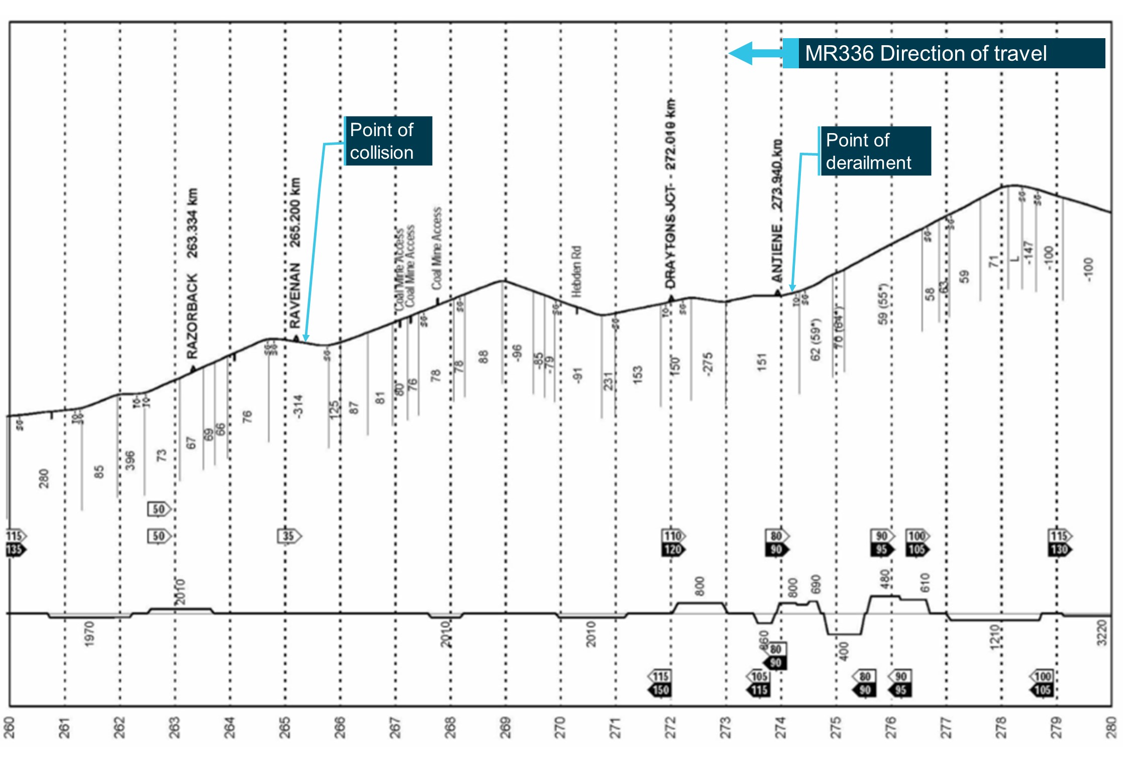
__________

  1. Western Standard Time (WST): Coordinated Universal Time (UTC) + 8 hours.
  2. Runway number: the number represents the magnetic heading of the runway.

Occurrence summary

Investigation number AO-2020-065
Occurrence date 28/12/2020
Location Serpentine Airfield
State Western Australia
Report release date 08/03/2023
Report status Final
Investigation level Defined
Investigation type Occurrence Investigation
Investigation status Completed
Mode of transport Aviation
Aviation occurrence category Collision with terrain
Occurrence class Accident
Highest injury level Fatal

Aircraft details

Manufacturer Amateur Built Aircraft
Model DYN-AERO MCR01VLA
Registration VH-SIP
Serial number 225
Sector Piston
Operation type General Aviation
Departure point Serpentine Airfield, Western Australia
Destination Serpentine Airfield, Western Australia
Damage Destroyed

Safeworking irregularity and near miss with crew of train 5936, at Hawkesbury River, New South Wales, on 8 January 2021

Final report

Report release date: 19/12/2022

This investigation was conducted under the Transport Safety Investigation Act 2003 (Commonwealth) by the Office of Transport Safety Investigations (NSW Government) on behalf of the ATSB in accordance with the Collaboration Agreement. Released in accordance with section 25 of the Transport Safety Investigation Act 2003.

Safety summary

What happened

At approximately 0407 on 8 January 2021, freight train 5936, travelling in the up direction (towards Sydney) failed as a result of wheel slip, on the steep Cowan bank inside Boronia tunnel No. 3. To keep the up main line clear the train crew were directed by Sydney Trains network control to propel1the train backwards into Hawkesbury River up refuge siding.

Network rules for propelling trains require crew to direct the movement from the rear of the train via radio communication with the driver. Due to the terrain, the assistant driver and a trainee were required to walk to the rear of the train on the adjacent down main line, as there was no alternate pathway beside the track. To protect these workers from passing trains, the driver of 5936 requested track protection from the Sydney Trains signaller. This protection was provided in the form of rail signals placed to stop to prevent a train from entering the section of track where the workers were walking.

On arrival at the rear of the train the two workers and the driver of 5936 proceeded to propel the train back towards Hawkesbury River up refuge siding in accordance with procedures, with the two workers walking in advance of the train on the adjacent down main line. During the propelling movement the workers observed the lights of an oncoming train on the down main line on which they were walking. The two workers told the driver of 5936 to stop the propelling movement and the train was brought to a stand. The workers jumped clear of the oncoming train onto the adjacent cess area, with one of the workers suffering an injury. A passenger train, 247B, passed the workers, travelling around train 5936 in the up direction towards Sydney on the down main line.

The driver of 5936 contacted the Sydney Trains signaller and requested an explanation about why a train had been permitted to run on the down main while there was meant to be a signal block in place to protect the workers.

The Sydney Trains signaller told the driver the signal block had been removed once the propelling movement started, due to the signaller mistakenly thinking the workers were clear of the down main line. The incident was not reported at the time by the Sydney Trains signaller. The incident was reported by the driver of 5936 to their control centre, but it was not acted on at the time. The incident came to notice when the trainee worker reported an injury resulting from jumping out of the way of train 247B.

What the ATSB found

The Sydney Trains signaller and the driver of train 5936 did not observe the requirements of the relevant Train Working Network Rules and Procedures for protecting workers on track with in-service rail traffic, specifically rule NTR 432, Protecting activities associated with in-service rail traffic and associated procedure NPR 750. The Sydney Trains signaller and the driver of train 5936 did not observe the relevant safety critical communications requirements during the application and removal of the protection. The Sydney Trains signaller placed blocks on the signals manually as if protecting an emergency situation or Condition Affecting the Network and did not use the electronic forms as required under NTR 432 and NPR 750. The Sydney Trains signaller removed the signal block protection without confirmation from the driver of train 5936 that the workers were clear of the danger zone as required by NTR 432 and NPR 750.

The Sydney Trains signaller did not understand the details of the tasks required for propelling movements, was not familiar with the terrain, and assumed the workers were clear of the down main line once the propelling movement had commenced. Sydney Trains signaller safeworking refresher training, which may have identified a knowledge gap or non-compliance with procedures, has not been in place since 2009.

The application of signal blocks was not compliant with NTR 432 and NPR 750. Sydney Trains assurance and audit processes for signal box management did not detect the non-conformances. The signaller did not report the incident as per General Rule NGE 234, Responsibilities of Signallers. Cowan bank is a known problem area for failed freight trains. Rail lubricators were overactive and delivering too much lubricant to the rail surface, contributing to the likelihood of a train becoming disabled. Lack of breathing apparatus in train 5936 meant the driver was exposed to diesel fumes in Boronia tunnel 3 for a considerable time while organising and performing the propelling movement.

What has been done as a result

Sydney Trains delivered the following actions following the occurrence:

  • Issued two Safe Tracks alerts to reinforce the requirements of Network Rule NTR 432, Protecting activities associated with in-service rail traffic, and related procedure NPR 750.
  • Issued an Operating Instruction 02/2022 to staff who manage this type of incident that deals specifically with propelling movements on Cowan Bank.
  • Adjusted the rail lubricators on Cowan Bank to provide optimum balance between lubrication of the rails while still permitting the train to retain traction on the rail surface.
  • Reintroduced Safety Refresher Training for signallers.
  • Delivered to all signallers an e-learning course on the use of NTR 432.
  • Use of NTR432 will be added to Signaller Competency assurance scenarios and the next annual round of Safety Refresher Training commencing during 2023.
  • Line managers have been required to focus safety engagements, undertaken with signallers, on ensuring signaller understanding of NTR 432. If non conformances are identified remedial coaching/training will be undertaken with the signaller.
  • From 18 November 2022 all Signallers have been instructed to report each use of NTR432 to their line manager and line managers have been instructed to submit an audio compliance request for all reported uses of NTR432 for a compliance review.
  • A communications cue card on use of NTR 432 for Signallers and Rail traffic crew was developed and distributed and is published on the RailSafe website.
  • A review of the network hazard of instance of worker in path of rail vehicle (protecting activities associated with in service rail traffic) is currently being undertaken.

Transport for NSW delivered the following action following the occurrence:

  • Assisted Sydney Trains through the provision of project support and vendor engagement for the design and development of safety refresher training.

Safety message

To provide confidence that rules and procedures are being followed and that they are effective in managing relevant risks, rail operator assurance processes need to detect non-conformances.

Training and competence management regimes for rail safety workers need to provide relevant and meaningful content, such as scenario-based training, and site based network familiarisation, to allow workers to perform safely and effectively.


The occurrence

Overview

At approximately 0407 on 8 January 2021, Pacific National (PN) freight train 5936, travelling in the up direction (towards Sydney) failed as a result of wheelslip inside Boronia tunnel No. 3 while travelling on the steep grade on Cowan bank. Following discussion between the Signaller Hornsby North (SHN) located in the Homebush Control Centre (HCC) and the Train Service Delivery Manager Central Coast (TSDMCC) located in the Rail Operations Centre (ROC), the train crew were directed to propel the train backwards into the Hawkesbury River Up Refuge siding in order to keep the up main line clear.

Two members of the train crew, the assistant driver and a trainee assistant driver were required under the network rules for propelling trains to walk back along the length of the train to the last vehicle in order to direct the propelling movement. Because of the terrain and lack of a safe place beside the track the two workers needed to walk on the adjacent down main line. In order to protect these workers, the driver of 5936 requested protection from the SHN. This protection was provided in the form of rail signals placed to stop to prevent a train from entering the area.

While the workers made their way to the rear of the train, the driver of 5936 reported at interview that they were suffering the ill effects of diesel exhaust inhalation as the leading locomotive was inside Boronia tunnel No. 3 and exhaust fumes had built up in the tunnel and entered the cab. There was no breathing apparatus available to the driver on board to assist with managing this situation.

Once the two workers were in position at the rear of the train, the driver of 5936 confirmed with the SHN that the route was set for the movement and proceeded to propel the train backwards, under the direction of the two workers, towards Hawkesbury River Up Refuge siding. As the two workers were walking in advance of the train on the adjacent down main line, they observed the lights of an oncoming train. The two workers told the driver of 5936 to stop the propelling movement and the train was brought to a stand. The workers jumped clear of the down main onto the adjacent cess area, with one of the workers suffering an injury.

A passenger train, 247B, passed the workers on the down main, travelling in the up direction around train 5936. The driver of 5936 contacted the SHN and requested an explanation from the signaller about why a train had been permitted to run on the down main while there was meant to be a signal block in place to protect the workers.

The SHN told the driver the signal block had been removed once the propelling movement started, mistakenly thinking the workers were clear of the down main line. The signaller was not familiar with either the propelling procedure or the network terrain and was not aware that the workers were still walking adjacent to and in front of the propelling freight train, as they are required to do under the Sydney Trains Network Rules. The incident was not reported at the time by the SHN. The incident was reported by the driver of 5936 to their control centre, but it was not acted upon at the time. The incident came to notice when the trainee worker reported an injury resulting from jumping out of the way of train 247B.

Context

Train information

Train 5936 consist

Train 5936 was a Pacific National freight train hauling grain from Moree Wheat Silo to Bomaderry. It consisted of four 82 class diesel electric locomotives (8214, 8213, 8244, 8232) hauling a consist of 52 loaded wheat hopper wagons (25 x NGKF wagons and 27 x NGPF wagons).

The train length was 831.6 m and the mass was 4134 t.

Figure 1: 82 class Pacific National locomotive

Figure 1: 82 class Pacific National locomotive

Source: Pacific National 

Train 5936 journey

Train 5936 departed Moree Wheat Silo on Thursday 7 January 2021 at 1230. There was a crew change at Morandoo at 0030 on Friday 8 January 2021. The incoming crew consisted of a driver, an assistant driver and a trainee assistant driver.

Train 247B

247B was an eight car OSCar NSW TrainLink passenger service operating from Newcastle to Central.

Train crew information 5936

Driver

The driver was an employee of Pacific National with 21 years and four months experience. The driver possessed the requisite qualifications to operate the type of train and to operate over the route. They were trained in protection arrangements for in-service rail traffic in 2016.

Assistant driver

The assistant driver was an employee of RailTrain, a rail labour hire company with a contract with Pacific National, with four months experience. The assistant driver possessed the qualifications to be a second person but did not possess the requisite qualifications to operate the type of train over the route. The assistant driver was trained in protection arrangements for in-service rail traffic in September 2020.

Trainee assistant driver

The trainee assistant driver was an employee of RailTrain with three weeks experience. The trainee assistant driver did not possess the requisite qualifications to be a second person or operate the type of train over the route. The trainee assistant driver was trained in protection arrangements for in-service rail traffic in December 2020.

Signaller information

The SHN advised they were first qualified in signalling in 2002, however Sydney Trains could not locate any signaller training records for this worker until 2007. The SHN had worked at a variety of signal boxes and control centres including Penrith, Springwood, Auburn, Katoomba, Blacktown, and a number of control panels in the Homebush Control Centre.

Signaller performance

Between 2015 and 2021 the SHN had received coaching, counselling or retraining, post incident on 18 separate occasions. These incidents included:

  • Faulty manipulation of signalling equipment that resulted in delays
  • Misrouting of trains
  • Incorrect setting of train route
  • Delays in setting of routes.

The most serious incident involved an occurrence at Penrith where the SHN had allowed a freight train to enter a section that was subject to Block Working. Block Working is an operational method where rail traffic is not permitted to enter a section until previous rail traffic is reported as clear of the block ahead. In this case it was a set of track machines that do not operate signalling track circuits like a train. To secure their safety, these machines operate under Block Working conditions.

Allowing a following train to enter the section without ensuring the track machines were clear of the block ahead ran the risk of a collision.

Signaller training

The SHN held all the necessary safeworking qualifications to operate the Hornsby North panel at HCC. Sydney Trains manages the safeworking certification and qualifications arrangements for rail safety workers through two standards, the Network Rules and Network Procedures Certification Standard, and the Network Rules and Network Procedures Training Standard.

Each standard contains a matrix of information. The Certification Standard details those competencies applicable to each role and assigns a code to that role. The code is then expanded upon in the Training Standard that details the specific Rules and Procedures applicable to that role, and what must be contained in the training package for that role.

The code for a signaller is C105, Control Rail Traffic Movements level 1. For the code C105, a training package must contain instruction in 51 Network Rules, 39 Network procedures and how to complete 10 different Network Forms. The training package for signallers includes the Train Working Network Rules for propelling trains, NTR 424, and protecting activities associated with in-service rail traffic, NTR 432.

Each Rule, Procedure and associated forms may have several individual requirements, so the knowledge requirement for a signaller runs into several hundred individual steps, processes and tasks.

In addition to the Network Rules and Network Procedures, Sydney Trains has other operating requirements known as Operator Specific Procedures, Special Instructions and General Orders. The signaller role training requirements in these procedures, instructions and orders are not captured by the Network Rules and Network Procedures training process.

A signaller must have current knowledge and competency in a large array of rules, procedures, instructions, and orders to perform safely and efficiently.

Localised training and assessment

Each signal control panel in the Sydney Trains network has its own Localised Training and Assessment (LTA) process. The LTA for Hornsby North panel does not include scenario-based training to deal with a failed train on Cowan Bank, despite it being a common occurrence, nor any network familiarisation training to ensure that signallers can visualise the network they are managing.

Network Control

Rail Operations Centre (ROC)

Sydney Trains has a centralised control room called the Rail Operations Centre (ROC) where a number of functions are co-located. The functions include train control and supervision, incident management, customer information, security and infrastructure control. Working within the ROC are Train Service Delivery Managers (TSDM) and Network Incident Managers (NIM) who work with signallers, train crew and others to manage train operations, work on track and other functions.

Train Service Delivery Manager (TSDM)

TSDM is the Sydney Trains business term used for what is referred to in the Sydney Trains Network Rules and Procedures as the Network Controller. TSDM are responsible for train running, planned possessions and planned work on track authorities. There are five TSDM areas, Central Coast, North, Main, Illawarra, and South West.

The TSDM principally involved in this incident was the TSDM Central Coast. The TSDM Central Coast is described as the TSDMCC in this report.

ATSB observation

The role description for the TSDM does not have mandatory requirements for rail safeworking or train operations qualifications or experience. These are listed as desirable criteria. However, the TSDMCC was responsible for train running, and safeworking decisions such as the train movement to Hawkesbury River Up Refuge.

Figure 2 Rail Operations Centre (ROC) control room

Figure 2 Rail Operations Centre (ROC) control room

Source: Sydney Trains

Signal box operations

Sydney Trains has a number of small signal boxes and larger control centres in the network where signallers control the trackside signals to give proceed authorities[1] for trains to operate. Signallers also provide protection for workers doing maintenance and other activities, such as train crew attending to their train while in service.

Signallers do this by putting signals to stop and applying blocking facilities[2] to prevent them from being cleared, thereby excluding trains from entering the area where work is occurring. There are several Network Rules and Procedures that govern this activity.

Assurance and oversight of signallers is undertaken by Signal Box Operations (SBO), who provide line management functions and ensure operational requirements are delivered safely and in accordance with the relevant rules, procedures and standards. This assurance activity can take the form of:

  • review of recorded audio to check compliance with communications protocols and application of rules and procedures
  • review of applicable forms and documents to ensure that details have been completed as required
  • review of similar incident types to check on outcomes and application of standard requirements.

SBO is an operating section of the Sydney Trains Customer Operations Branch. SBO is responsible for managing all signallers and signal boxes in the network.

Location

Sydney Trains network – Cowan Bank

Cowan Bank is a steep and curving section of track that runs from Hawkesbury River up to Cowan station, a distance of approximately 9 km. The section consists of the Up and Down Main lines, features four tunnels and the signalling system is rail vehicle detection bi-directional.

Trains travelling in the up direction towards Sydney from Hawkesbury River encounter steep rising gradients as much as 1:37. A rising gradient refers to the graded rate of ascent. A 1:37 rising gradient means that for every 37 m travelled, the track rises 1 m.

The bi-directional signalling system means trains can operate in either direction on either track as there are signals provided to control movements in both directions. This type of signalling is a feature in areas on the network where there are steep grades and trains have a greater risk of being unable to continue due to mechanical faults, or as in the case with 5936, excessive wheel slip.

The rail line winds through a narrow corridor and access and space is limited. The line in the section from Hawkesbury River to Cowan station is formed of many cuttings made into the hillside to house the rail tracks.

Figure 3: Entry to Boronia Tunnel No. 3 in the up direction

Figure 2 Rail Operations Centre (ROC) control room

Source: Sydney Trains

Hawkesbury River Up Refuge siding

The Hawkesbury River Up Refuge siding is located within the Hawkesbury River yard. The yard consists of the Up and Down Main lines, the Up Refuge siding, No. 1 and 2 sidings and various points and signals to permit trains to operate. The Up Refuge siding has a stowing capacity of 877 m including the use of No. 2 siding.

Figure 4: Diagram of Hawkesbury River

Diagram of Hawkesbury River

Rail lubricators

Rail lubricators are engineering devices designed to deliver rail lubrication to the wheel-rail interface to reduce wear and wheel squeal noise. Three rail lubricators were installed and active on the Up Main track between Hawkesbury River and Cowan at the time of the incident.

Delivery of excessive lubricant to the rail can induce wheel slip in a train, leading to a lack of adhesion between the rail and the wheel face and the train being unable to continue.

Rail safety systems and rules and application

Protecting activities for in service rail traffic

Sydney Trains describes their Train Working (NTR) Rules as prescribing the Network requirements for operating trains and track vehicles, including the maintenance of train integrity, and management of equipment defects by Operators, Train Crews and Track Vehicle Crews. Train Working Network Procedures (NPR) describe how particular actions are to be done to apply the Network Rules.

Sydney Trains has specific Train Working Network Rules (NTR) and Procedures (NPR) for protecting people when attending to trains which are in service on the network. The Network Rule is NTR 432 Protecting activities associated with in-service rail traffic and the associated Network Procedure is NPR 750.

The rule and procedure cover situations including where train crew leave their cab to get down on the track and conduct repairs or undertake other activities.

The activities that are undertaken by workers and subject to this form of protection include minor repairs to rolling stock, re-coupling burst air hoses, removing minor obstructions from the track and conducting roll by inspections.

This Train Working rule for protecting people when attending to trains in service and the associated procedure were introduced in 2016, after the SHN had received their foundation training and qualifications, to provide a greater level of prescription about how these on track activities were managed. Previously these activities were managed under the Work on Track (NWT) suite of rules using Absolute Signal Blocking rule NWT 308.

According to RailSafe, Work on Track (NWT) rules prescribe the Network requirements for undertaking activities in the rail corridor and mandate the ways to plan for and achieve the separation of rail traffic from people working on or about track. Principally aimed at maintenance and infrastructure repair, not in-traffic protection.

The new rule and procedure under Train Working (NTR) rules provided a level of assurance for both the signaller applying the protection and the in-traffic worker seeking the protection by compelling the parties to give and receive assurances about the location of the work and the type of work being done. It has similar assurances to the work on track requirements for other tasks like maintenance and infrastructure repair.

NTR 432 operational requirements

NTR 432, Protecting activities associated with in-service rail traffic, has very explicit instructions about what information must be exchanged between the Qualified Worker requesting the protection and the signaller.

Requesting protection

When requesting the protection of activities associated with in-service rail traffic, the Qualified Worker must:

  • Provide the train number or track vehicle number
  • Identify the lines on which the protection is required
  • Nominate the activity location as being:
    • between any two stations
    • completely within a nominated dead-end siding, or
    • completely within the limits of a platform.
Absolute Signal Blocking (ASB)

ASB is a network rule for working on track, Work on Track NWT 308, Absolute Signal Blocking. It works on the principle of rail signals being set to stop with blocking facilities applied to exclude rail traffic from the work area. Within the rule there are several options to provide protection, including:

  • Having two controlled absolute signals set to stop with blocking facilities applied or
  • Having one controlled absolute signal set to stop with blocking facilities applied and
  • Removing an ESML/EOL key, or
  • Securing points to prevent access, or
  • There being an easily reached safe place available and providing a lookout.

In the case of protecting workers under NTR 432 and NPR 750 Protecting activities associated with in-service rail traffic, while signals are used to protect workers, similar to using ASB, the protection itself is not ASB, as the assurances and requirements are different to ASB and are contained in separate train working rules and procedures, NTR 432 and NPR 750. It is a subtle but important distinction.

ATRICS overview

ATRICS stands for Advanced Train Running and Information Control System, a bespoke system developed in-house by Sydney Trains. ATRICS is a computer-based control system that interfaces with signalling assets to control and monitor their status. It also has an interface with the timetable to automatically set routes for rail traffic.

A signaller will oversee rail traffic operating through the control area of each signalling panel, however in normal circumstances, ATRICS will set routes based on the timetable inputs. The signaller intervenes to control signals manually when there is a need, such as protecting work on track.

The signal control panel the SHN was operating was an ATRICS controlled panel within Homebush Control Centre.

Applying and removing blocks to signals

When a signaller applies blocks to signals on an ATRICS control panel, there are two methods to do so. Manually placing blocks on signals is done directly by the signaller in response to an incident or another circumstance such as a Condition Affecting the Network, where there may be a potential obstruction to the track or other hazard. In this circumstance, the signaller can place and remove signal blocks with no other intervention.

However, when placing signals to stop and placing blocks to protect work on track or workers attending to in-service trains, there are very specific requirements in the rules and procedures about how this is done.

According to NTR 432, Protecting activities associated with in-service rail traffic, the signaller must use an electronic Absolute Signal Blocking (ASB) form to record the application of the signal protection. The extract of the rule is below:

The Signaller must:

  • Use a system-generated ASB form, or if that is unavailable, an NRF 018 Absolute Signal Blocking (ASB) form to record the protection details
  • Issue a unique protection number to the Qualified Worker requesting the protection.

When using the system-generated ASB form, ATRICS generates a unique code which is associated with the protection and is provided to the worker who has requested the protection. This code is used when ending the protection as an identifier of the correct protection.

NTR 432 requires the use of a system generated form, if it is available, to record the details of the protection. This form is the same as used when applying protection for ASB.

Figure 5: ASB form on ATRICS workstation

 ASB form on ATRICS workstation

Propelling trains

Propelling trains under the network rule NTR 424, Propelling rail traffic, can be a dangerous activity, as a worker or workers may be walking in front of a moving train, and as the driver is not at the end of the movement in the direction of travel, they do not have visibility of the worker(s). There is no procedure that accompanies the network rule to identify and manage risks associated with this activity, unlike other activities that are governed by a rule and a procedure.

Network Communications

NGE 204 is the network General Rule (NGE) applicable to communications. NGE 204 says, in part:

Communication in the Network must be:

  • Clear, brief and unambiguous
  • Relevant to the task at hand
  • Agreed to its meaning before being acted upon.
Communication between the SHN and the driver 5936

The driver of 5936 did not specifically request protection under NTR 432, Protecting activities associated with in-service rail traffic. They requested that a block be put on the signals, and that is what the signaller did. Neither party followed the requirements of NTR 432 in particular the required safety critical communication exchange. The transcript of the recorded audio between the SHN and the driver of 5936 at the time protection was requested is below.

SHN: OK um do you need any protection there for that?

Driver 5936: Yes, if he’s gotta walk on the ah on the opposite track, we definitely need protection. A block for the whole way over.

HNAC: Righto then …ok so …. I’m just putting some blocks on there now….. Just stand by while I do that.

DR5936: Roger that over.

HNAC: Righto I’ve done that there now, so um, I haven’t, so nothing can come up….on that line for ya there so, when you’re ready to walk back and get into position you’re able to do that for me now please.

DR5936: Roger that my mate will walk back now ah so his got the blocks, so his gotta walk back another 832 metres and then get ahead of me. Bit of a way. And then I will proceed down as safely as I can possibly can over.

HNAC: ok thank you for that driver.

Neither party to this conversation specifically mentioned protection being required under NTR 432, which is the relevant rule in this circumstance. All they refer to is “blocks”.

The driver of 5936 did not specify where and for how long the two crew members would be required to walk on the Down Main line while the propelling movement was taking place.

Fatigue management

The SHN was subject to the Sydney Trains rostering and fatigue management arrangements contained in the procedure Managing Shift Work and Rostering procedure, SMS-08-OP-3128 V1.2.

The Pacific National train crew were subject to fatigue management requirements that were derived from their labour management system. No issues of concern were discovered with the fatigue management requirements for the train crew.

The Sydney Trains rostering and fatigue procedure included eight rostering principles to be observed in order to reduce or manage the cumulative effects of fatigue. These eight rostering principles, and a description of these principles, are reproduced below from the Sydney Trains procedure:

PrincipleDescription
AcclimatisationWorkers new to shift work and those returning after an extended period of annual or sick leave should not be rostered on night work or an early morning start for their first shift. When on leave, human circadian rhythms quickly re-establish a pattern of sleeping at night and being active during the day. Returning to night or early morning starts may be difficult, a bit like ‘Mondayitis’.
Shift lengthThe length of a shift should not exceed 12 hours including overtime, especially if it involves a night shift. Human performance declines significantly when people have been working for 12 hours or more, especially where work is done at night or in the early morning.
Total hours workedAim for no more than 48 hours per week including overtime, which can be averaged across the roster cycle. The risk of fatigue increases towards the end of a week/roster cycle. This is because a sleep debt has accumulated. Limiting the number of hours worked in a week or roster cycle, provides time off to recover and repay the sleep debt.
Limit night shifts and early morning starts

Aim for no more than:

  • four consecutive shifts where 12 hour shifts are worked
  • five consecutive shifts where 10 hour shifts are worked
  • six consecutive shifts where 8 hour shifts are worked.

Working a series of night/early morning shifts disrupts circadian rhythms and leads to accumulation of a sleep debt.

Break during a shiftSchedule frequent breaks especially during a night shift or if the work involves sustained mental or physical activity, if local arrangements allow. Breaks during a shift provide workers with an opportunity to rehydrate and get a short rest. Breaks during a shift may be rostered or managed informally, depending on local arrangements and the nature of the work.
Break between shiftsAim for at least 12 hours from the end of a shift and the start of the next shift. Industrial agreements may allow for less than 12 hours, however, to reduce the risk of fatigue, a minimum of 12 hours break is needed. Breaks between shifts need to allow enough time for recovery and sleep. Night shifts may need longer breaks between shifts. This is because workers will need to sleep during the day when it is difficult to get good quality sleep
Breaks between cycles

Make sure there are adequate breaks between shift cycles. For example:

  • Two days off in a 7 day shift cycle
  • Four days off in a 14 day shift cycle
  • Eight days off in a 28 day shift cycle.

Days off should be a minimum of two consecutive days. Evidence indicates shift workers need at least two consecutive nights sleep per week to enable them to report to work feeling refreshed.

Shift cycles

Schedule consistent start times where possible, or if rotating rosters are used, shift start times should move in a forward rotation i.e. morning-afternoon-night.

Consistent start times can help shift workers get into a routine. Where rotating rosters are used, there is evidence that a forward rotating roster allows shift workers to delay sleep and wake up later. This is easier to do than going to sleep earlier or waking up earlier.

The planned, or master, roster and shifts the SHN actually worked for the period from 28 December 2020 to 8 January 2021 is included in the table below.

Date

Planned shift

times

Actual shift

times

Hours

worked

Time until

next shifts

28 December 2020Rostered off   
29 December 2020Rostered off   
30 December 2020Rostered off   
31 December 20202200 - 06002200 - 0600824
1 January 2021Rostered off   
2 January 20210600 - 14000600 - 1400816
3 January 20210600 - 14000600 - 1400832
4 January 20212200 - 06002200 - 0600816
5 January 20212200 - 06002200 - 0600816
6 January 20212200 - 06002200 - 0600816
7 January 2021 (incident 0405 8 Jan)2200 - 06002200 - 0600816
8 January 20212200 - 0600Off roster  

Environmental conditions

The Bureau of Meteorology (BOM) Terry Hills weather station (located approximately 12.0 km from Cowan Station) recorded a minimum temperature of 15.4˚C and maximum temperature of 20.6˚C. The weather station also recorded 2 millimetres of rain on the date of the incident. The track was wet and slippery and the driver of 5936 reported these conditions added to the degree of difficulty in conducting the propelling movement of a train in excess of 4000 t down a steep gradient. However, while the conditions made the propelling movement difficult, it did not contribute to the incident itself.

Breathing apparatus and welfare of the train driver

Train 5936 was stopped in Boronia tunnel no. 3 for over thirty minutes before the propelling movement commenced. The driver reported at interview suffering health effects from exposure to diesel fumes while stopped in the tunnel. Unlike their coal fleet, Pacific National bulk trains carrying products such as grain do not carry breathing apparatus as part of their standard on board kit.

Reporting incidents

NGE 234, Responsibilities of Signallers is the network rule applicable to the responsibilities of signallers and contains a requirement relating to reporting incidents. Specifically stating, Signallers must:

…..promptly report breaches of Network Rules and Network Procedures to the controlling officer and the Network Controller.

Related occurrences

On 2 March 2022 at 0121, Pacific National freight train CA80 failed on the Down main line at Wondabyne, NSW in the Sydney Trains network. The recovery process for this train, as determined by the Sydney Trains Network Incident Manager, involved attaching a following freight train, 1423, to the rear of CA80 and pushing it out of the section to Gosford.

A member of the crew of CA80 was on the track and attached the air hoses of 1423 to CA80. No protection was provided to this worker and as a result, a passenger train, 282L, passed by on the adjacent Up Main line as the worker was walking back to the crew cab of CA80. This worker had to take evasive action and move off the track to avoid being struck by 282L.

No protection was provided to this worker using the required network rules and procedures, NTR 432 Protecting activities associated with in-service rail traffic and related procedure NPR 750.

At approximately 0030 on 21 August 2019, freight train 4WM2 operated by Pacific National stopped at signal W26U near Waterfall, NSW. The train crew consisting of driver A and B were directed by the Waterfall Signaller at 0200 to remarshal the train. The train could not continue and was required to return to Coalcliff to clear the main line.

Remarshalling the train required one of the drivers to enter the danger zone to apply hand brakes on the wagons. Driver A requested safeworking protection from the Waterfall Signaller before entering the danger zone without incident.

The locomotives were detached and operated to Waterfall, before travelling to Helensburgh and returning to the stabled wagons near Waterfall.

On arrival at the stabled wagons, driver B requested safeworking protection again from the Waterfall Signaller. Driver B entered the danger zone to release the hand brakes from the stabled wagons. At about 0417, driver A signalled (hand signals and red marker lights) to the driver of an approaching passenger train (404A) to stop. The train was travelling on the adjacent track towards driver B in the danger zone and the driver of 404A made an emergency brake application to stop the train. The train stopped before arriving at the location of driver B and there were no physical injuries.

The safeworking network rule and procedure for protecting activities associated with in-service rail traffic, NTR 432 and NPR 750, were not used effectively to ensure workers were protected from rail traffic. The requests for protection were informal and did not detail the required activities or protection. Both drivers of 4WM2 unknowingly entered the danger zone without appropriate protection and were at risk of being struck by rail traffic.
 

Safety analysis

Introduction

Pacific National train 5936 failed inside Boronia tunnel No. 3 on Cowan Bank in the up direction as a result of wheel slip from excessive lubricant and was unable to lift its load up the grade. The driver of 5936 reported the train failure to the SHN. The SHN reported the incident to the Sydney Trains TSDMCC and their decision on how to manage the incident involved propelling the train backwards down Cowan bank and into the Hawkesbury River Up Refuge siding to clear the main line.

To undertake the propelling movement, a qualified worker needed to be located at the rear of the train, to supervise the movement backwards down the Cowan Bank. This was a standard requirement in the Sydney Trains Network rules for propelling trains. Under the rule, if there is not a designated safe place on the rear of the train, the worker must walk in advance of the movement in a safe place. Where the worker walks, depends on a few conditions, like the terrain, the availability of a safe place and the layout of the rail environment.

Train 5936 had three people in the driver’s cab, the driver, an assistant driver and a trainee assistant driver. The driver of 5936 intended to send the assistant driver and the trainee assistant driver to the back of the train to supervise the movement.

The driver of 5936 requested protection from the SHN in the form of signals put to stop and blocked on the Down Main line. This prevented trains from entering the area where the two workers needed to walk to reach the rear of 5936. Once confirmed, the assistant driver from 5936 and the trainee driver exited the driver’s cab and walked on the adjacent Down Main line to the rear of the train.

Once the two crew members were in place at the rear of the train, the driver advised the SHN that the propelling movement was about to commence and asked the SHN to confirm that the route was clear back to the Hawkesbury River Up refuge siding. The two workers continued to walk on the Down Main line adjacent to the rear of 5936, as there was no other safe place to walk.

As the propelling movement continued, the two crew members observed the lights of a train travelling towards them in the up direction on the Down Main line. The two crew members alerted the driver of 5936 of the presence of the oncoming train and to stop the movement, then they jumped clear of the Down Main into the Down Cess area.

Cowan Bank terrain and operational features

Cowan bank is known to have some challenging operational features. For example, access on the up side of Cowan Bank is problematic for a worker needing to walk along the rail line as the corridor is often butted up against the rock face of cuttings and there is no safe place.

To give a worker a continuous safe place to walk while supervising a propelling movement, a safe place is created on the adjacent track by applying protection in the form of setting rail signals to stop and blocking them to stop rail traffic entering the affected area.

Trains failing to make the steep grade on Cowan Bank is a regular occurrence and there are two main options to deal with the situation. In some cases, a rescue engine is brought in from Gosford or elsewhere north of the incident location to push the train up the grade.

The alternative is to propel the train back down the grade into the Hawkesbury River Up Refuge siding. This option can only work if the train is a suitable length to fit into the siding, which has a capacity of 877 m. 5936 was 831.6 m and therefore suitable to fit safely inside the siding, so the decision was made by the TSDMCC to propel the train back towards Hawkesbury River.

Rail lubrication on Cowan Bank

There were three operational rail lubrication devices installed on Cowan Bank to service the Up Main between Hawkesbury River Yard and the Cowan Station. Sydney Trains engineers had assessed that the rail lubricators should have similar settings as those used in the Blue Mountains in order to deliver optimal lubrication. These adjustments were made in February 2021.

Sydney Trains conducted an engineering review post incident into these devices and determined that excess lubrication contributed to the wheelslip. This led to the train becoming disabled and unable to continue up the Cowan Bank. This resulted in the need to propel the train backwards to the Hawkesbury River Up refuge siding.

Sydney Trains determined post incident and in response to a spate of similar events where freight trains were unable to lift their load due to loss of traction from excess lubricant on the wheel-rail interface that further adjustments were necessary to ensure the amount of lubrication provided did not adversely affect wheel adhesion to the rail head, particularly for loaded freight trains.

The decision to propel 5936 and run passenger trains using bi- directional signalling

Discussion between SHN and TSDMCC

When the SHN and TSDMCC became aware of the inability of 5936 to lift its load up the Cowan Bank, a discussion took place to determine what to do with the train. The discussion canvassed the option of using a rescue engine to assist, however, given the time and location, it was considered unlikely to result in a timely outcome. The TSDMCC determined that the best course of action was to propel 5936 backwards down Cowan Bank into the Hawkesbury River Up Refuge siding.

The TSDMCC checked reference documents to ensure the Up Refuge siding was long enough to contain 5936, and once confirmed, gave the instruction to SHN to direct the driver of 5936 to propel back into the siding.

The TSDMCC and SHN also discussed the need to run any AM peak passenger services via the Down Main using the bi-directional signalling. This discussion indicated there was a concurrent plan developing not only to remove 5936 from the main lines but also to facilitate the continued operation of passenger services in the up direction for the AM peak.

Implication of the decision to propel 5936

The TSDMCC and SHN knew that workers would have to walk to the back of the train to manage the propelling movement. The recorded audio indicated there was a suggestion that a passing train could be used to transport the workers via the Down Main, but there was no train due in that direction for nearly an hour so that was dismissed.

Both the TSDMCC and the SHN knew there would be a worker or workers out of the train and on the track at some point to facilitate and manage the propelling movement.

What the propelling decision meant to the driver of 5936

The degree of difficulty in making this manoeuvre was considerable. The driver had to slowly reverse a train of over 4000 t and nearly 900 m long down a steep gradient, in the dark and in the rain. The train also had to negotiate tunnels, and in the case of 5936, the leading locomotive was still within Boronia tunnel No. 3. The driver reported at interview suffering ill health effects from diesel exhaust whilst being stopped in the tunnel.

Recorded audio of exchanges between the SHN and the driver of 5936 indicated numerous calls were made during the movement, which likely disrupted the concentration of the driver during what was a high cognitive load due to a difficult manoeuvre under complicated circumstances. Other recorded audio of exchanges between the SHN and the TSDMCC indicated there was particular focus on continuation of passenger train services, especially in the up direction for the AM peak.

Protecting workers attending to in-service rail traffic

Compliance with the requirements of NTR 432 and NPR 750

In the case of the workers involved in propelling 5936, the driver needed to nominate the activity location as being between two points. This did not occur. They also did not describe that two workers would be walking all the way behind and adjacent to the train as it propelled backwards towards Hawkesbury River yard, past the station and into the Up Refuge Siding.

NTR 432 also stated that the signaller must:

  • Use a system-generated ASB form, or if that is unavailable, an NRF 018 Absolute Signal Blocking (ASB) form to record the protection details
  • Issue a unique protection number to the Qualified Worker requesting the protection.

The SHN did neither of these things in this circumstance.

Sydney Trains internal safety investigation into this incident found evidence that similar events of managing failed freight trains where the requirements of NTR 432 and NPR 750 were not applied. Recent ATSB investigations listed in the Related Occurrences section of this report also found this error in practice.

Suitability of NTR 432 to protect workers

NTR 432 is a Train Working rule about protecting workers while on the track, however it is not included in the suite of other rules devoted to the same purpose, specifically Work on Track (NWT).

NTR 432 is designed to protect people on the track when attending to their train while it is in service however is included in the suite of rules devoted to train working. This suite contains rules more specific to the operation and use of the train, rather than the protection of workers and includes rules such as:

  • NTR 400 Protecting rail traffic,
  • NTR 402 Inspecting trains,
  • NTR 404 Using brakes
  • NTR 406 Using lights.

The Work on Track (the NWT) series of rules, is more specific to protecting workers and includes rules such as:

  • NWT 300 Planning work in the rail corridor
  • NWT 302 Local Possession Authority
  • NWT 304 Track Occupancy Authority
  • NWT 306 Track Work Authority
  • NWT 308 Absolute Signal Blocking.

NTR 432 appears out of place in the suite of train working rules given it is a rule devoted to protecting workers who are on the track performing rail safety work. In this case, the workers were attending to a train while it was in service however required protection while doing so because they were on the track. However, NTR 432 is not included in the Work on Track suite of rules which are devoted to protecting workers while on the track.

Evidence from the Sydney Trains investigation report into the incident indicated that rule NTR 432 was not applied in other cases where it should have been. It is possible that NTR 432 was not applied correctly because rail safety workers were not familiar enough with it as a rule to be followed while working on track. As rule NTR 432 is contained in a suite of rules devoted to train operations, and not within the suite devoted to protecting people while on track (the NWT suite). It is possible that its importance and application may not be understood by rail safety workers.

Suitability of NTR 432 to manage propelling movements

NTR 432 Protecting activities associated with in-service rail traffic includes a number of requirements which must be met through satisfying the assurances contained within the rule. One of the assurances relates to the mobility of the rolling stock and reads:

Unless conducting a roll by inspection, the Qualified Worker must make sure that the associated rail traffic will not be moved until the activity is completed.

If the intention of NTR 432 was to protect workers attending to in service rail traffic, then this rule may not be suitable for use during a propelling movement. NTR 432 contains a prohibition on rolling stock movement, except when conducting a roll by inspection. That being the case, there are no approved measures available under the current set of rules to protect workers supervising a propelling movement.

Signaller operational assurance

The Sydney Trains investigation examined the assurance regime for signallers relating to the application of the requirements of NTR 432 and NPR 750 - Protecting activities associated with in-service rail traffic. The investigation found that the SBO group did not undertake assurance activity related to the correct application of relevant rules and procedures for protecting workers attending to in-service rail traffic.

The investigation identified other similar incidents that were also not managed in accordance with the requirements of NTR 432. Examples of where the requirements of NTR 432 and NPR 750 were not applied are listed in the Related Occurrences section of this report.

ATRICS and the application of signal protection

Applying and removing blocks to signals

The SHN did not apply blocks to the protecting signals in accordance with NTR 432 and NPR 750 and did not use the ATRICS generated form to record the placement of the protection. The SHN applied the blocks to the protecting signals manually and removed them without the authority of the person requesting the protection, the driver of 5936.

Communication between the SHN and the driver 5936

The driver of 5936 did not specifically request protection under NTR 432. They requested that a block be put on the signals, and that is what the signaller did. Neither party followed the requirements of NTR 432 or observed the assurances. The transcript of the recorded audio between the SHN and the driver of 5936 at the time protection was requested is below.

SHN: OK um do you need any protection there for that?

Driver 5936: Yes, if he’s gotta walk on the ah on the opposite track, we definitely need protection. A block for the whole way over.

HNAC: Righto then …ok so …. I’m just putting some blocks on there now….. Just stand by while I do that.

DR5936: Roger that over.

HNAC: Righto I’ve done that there now, so um, I haven’t, so nothing can come up….on that line for ya there so, when you’re ready to walk back and get into position you’re able to do that for me now please.

DR5936: Roger that my mate will walk back now ah so his got the blocks, so his gotta walk back another 832 metres and then get ahead of me. Bit of a way. And then I will proceed down as safely as I can possibly can over.

HNAC: ok thank you for that driver.

Neither party to this conversation specifically mentioned protection being required under NTR 432, which is the relevant rule in this circumstance. All they refer to is “blocks”.

The driver of 5936 did not specify where and for how long the two crew members would be required to walk on the Down Main line while the propelling movement was taking place.

Signaller training, performance, and competence management

Signaller knowledge of propelling trains

The SHN did not understand the requirements of NTR 424 - Propelling Trains. At interview, the SHN expressed a lack of knowledge about the activities of the workers on the ground directing the propelling movement. Specifically, the SHN did not understand that the two workers directing the propelling movement were still walking in front of, and adjacent to, train 5936 when it was propelled down Cowan Bank.

The SHN expressed some surprise that the workers were in that position and assumed they were riding on the freight rolling stock once the propelling movement started. The practice of riding on moving freight rolling stock has been prohibited since 2004.

Once the propelling movement started, the SHN removed the blocks on the protecting signals and allowed train 247B to run in the Up direction on the Down Main through use of the bi-directional signalling system.

During the conversation with the driver of 5936 after the near miss incident with 247B, it was apparent that the signaller was not aware that the workers were still on the protected track walking in front of the propelling movement.

Driver 5936 Yes Hornsby ah my ah mate down the back just said you just put a train up on the down around us over.

HNAC Yeah that’s correct.

Driver 5936 Ah I thought we had a block on over

HNAC Yeah that’s when you actually, when you weren’t moving, when you were actually on the (pauses) when you walking back over.

Driver 5936 He’s still walking back. He’s gotta walk me back to get into the siding over HNAC OK (speaks under their breath) well you’ve moved back.

Driver 5936 Yes ‘cause he was on the down calling me back, that’s the only safe place for him to stand over.

HNAC (12 seconds of silence and clears his throat) OK that trains trains gone and there are no other trains on the down. I have got blocks on on um up at Cowan (silence for a few seconds) just stand-by.

Driver 5936 Roger.

HNAC Yes so you’re right to proceed there driver um keep proceeding I’ve got the um all the routes and the signals set for you to go into the Refuge Loop there at Hawkesbury River driver. Thank you driver.

Driver 5936 5936 out.

HNAC (groans) Hornsby North Panel out.

Driver 5936 Roger that, we have everything set so there is nothing definitely going to come either way towards us now over.

HNAC That is correct driver.

Driver 5936 Roger so I can my mate to ah get back on the down in a safe place. HNAC That is correct.

Driver 5936 Roger that well we start again over.

This conversation, after the near miss happened, resulted in the incorrect re-application of protection required by NTR 432. The SHN reapplied the blocks manually with communication assurances not observed as required by the rules and procedures. The conversation revealed that the SHN did not understand the workers positioning during the propelling movement and had made an assumption that the signal blocks could be safely removed, without confirmation from the driver as required.

Safety Refresher Training

At interview, the SHN advised that the job of a signaller involves the use of many rules and procedures, and that signallers are expected to be current and competent with all these requirements all of the time. The SHN specifically stated that he did not know the workers were walking in front of train 5936 during the propelling movement because he was not familiar with the requirements of NTR 424 Propelling Trains, even though it was a mandatory requirement for signallers to know this rule.

The SHN also advised that they had not attended any refresher, or scenario-based training for several years. The SHN advised that the only safeworking training they received, other than initial training, was when there were rule changes, as there was in the case of the introduction of NTR 432 in 2016. A briefing session was provided to explain the new rule and procedure. The SHN advised that when they had enquired about receiving refresher training, their management’s response was they could not be released because of operational requirements.

The Sydney Trains investigation report into this incident identified that its Customer Operations Branch had not delivered any safety refresher training for signallers since 2009. Other rail safety workers such as Protection Officers on the other hand received a form of refresher training and competency assessment which included periodic recertification in safeworking rules and procedures along with formal assessment.

Following its investigation report finding, Sydney Trains advised that a pilot of a revised refresher training program for signallers was commenced in April 2021.

Network familiarisation

Signallers control the operation of signals, points and other infrastructure in a defined geographical area. What the signaller sees and understands of the network is what is represented on their signal display panel, which is a schematic array and does not depict the geography or topography or other features of the network.

The SHN advised at interview that they had never been to Hawkesbury River Yard or seen the Cowan Bank, or any other part of the network they had controlled during their career. Signallers are not provided the opportunity to visit their area of operation to make them familiar with the area of the network that they controlled. The mental model that the SHN reported they had of Cowan Bank did not include key features such as the steep grade, the winding rail corridor and the lack of safe places and access.

A review undertaken as part of this investigation of the Sydney Trains competence management system for signallers revealed that network familiarisation or route knowledge was not a feature of the initial or ongoing training requirements for signallers.

Sydney Trains commenced a trial program of network familiarisation for protection officers in December 2020 designed to provide awareness and knowledge of the layout and risks in the network, to help workers perform more safely and efficiently, but at the time of writing it was not being rolled out to signallers.

Signaller fatigue

The incident happened around 0430, which is a known time of the window of circadian low, or the time of maximum sleepiness, for most people.

Two of the eight rostering principles were not met in relation to the roster of SHN in the eight days leading up to the incident. The two principles, and the nature of the departure from these principles, are outlined below. The acronym HNAC stands for Hornsby North Area Controller, and is the term used by Sydney Trains to describe the signaller operating the Hornby North panel.

Rostering principleDeparture from principle during this incident
4. Limit night shifts and early morning startsThe HNAC was rostered for two consecutive early morning shifts on 2- 3 Jan 2021 and six consecutive night shifts on 4-9 Jan 2021
7. Breaks between cyclesThe HNAC had single days off on 28 Dec 2020, 30 Dec 2020, and 1 Jan 2021—each time after a night shift before commencing the consecutive shifts leading up to the day of the incident.

An extract of the Sydney Trains Investigation report into this incident relating to fatigue is reproduced below:

Rostering Principle #4: Limit night shifts and early morning starts. Aim for no more than six consecutive shifts where 8-hour shifts are worked. ‘

The Hornsby North Area Controller (HNAC) was rostered for two consecutive early morning shifts on 2- 3 Jan 2021 and six consecutive night shifts on 4-9 Jan 2021. While the incident occurred at the sixth consecutive shift (where HNAC signed in on 7 Jan 2021 at 10pm) and was just at the limit of this rostering principle, the increase in the FAID score over this period had reached 93 by this shift. 

Although this FAID score had not reached the business unit threshold of 100, it was on the upper limits of approaching the threshold. Furthermore, it is difficult for humans to adjust from the two extremes of an early morning shift to a night shift without the opportunity to have an adequate break in between to prepare and adjust to the sleep impacts of night shift.

Rostering Principle #7: Breaks between cycles. Make sure there are adequate breaks between shift cycles. Days off should be a minimum of two consecutive days.

The HNAC had single days off on 28 Dec 2020, 30 Dec 2020, and 1 Jan 2021—each time after a night shift before commencing the consecutive shifts leading up to the day of the incident. Having less than 48 hours between shift cycles, especially after completing night shifts, does not provide an individual with enough opportunity to have restorative sleep to recover from any sleep debt that has accumulated from working night shifts. With the HNAC working single night shifts between these single days off, it is likely that the HNAC had accumulated an amount of sleep debt from only having the opportunity for restorative sleep during daytime, which is not as restorative as obtaining sleep during night time. The HNAC then commenced the sequence of consecutive early morning and night shifts, which would have further contributed to additional sleep debt leading up to the day of the incident.

According to the Managing Shift Work and Rostering procedure, when departures from these rostering principles occur, line managers must intervene and put in place measures to try and correct the situation. There was no intervention by the Sydney Trains line manager for SHN to adjust or amend the roster.

Sydney Trains acknowledged in their internal investigation report into this incident that the requirements for the procedure Managing Shift Work and Rostering were not being followed. Sydney Trains adopted a recommendation from their internal report as follows:

Review the business unit Fatigue Risk Management System / processes to ensure that there is an ability for the business unit to identify the fatigue risk associated with different rostering patterns and to detect adherence to rostering principles with mitigating fatigue risk controls to be implemented for these instances.

The issue of departures from the Managing Shift Work and Rostering procedure, and the subsequent lack of managerial intervention, have been raised previously in the ATSB investigation RO-2019-18 Westmead.

Signaller rest regime

At interview, the SHN stated that they were well rested for the shift prior to the incident. SHN recounted how they had an effective rest regime at home when working night shift and had obtained sufficient rest, had slept as usual from about 0730 to 1530, and felt fit and able to carry out their shift.

It is unknown whether the amount of sleep was sufficient to allow for recovery from the five consecutive shifts. It is possible that the SHN was affected by the cumulative effects of fatigue given the deviations from two rostering principles leading up to the day of the incident. However, the evidence is not definitive, and it is not possible to ascribe fatigue as a contributing factor with sufficient certainty.

Breathing apparatus and welfare of the train driver

Train 5936 came to a stand inside Boronia No. 3 tunnel and was there for around 30 minutes before the propelling movement commenced. According to the driver’s statement, the lead locomotive exited Boronia tunnel around 0441, therefore the driver was exposed to diesel fumes for around 35 minutes. The driver reported in their statement at interview that they were starting to feel unwell and had trouble seeing as their eyes had started to weep.

This physical discomfort existed while the driver undertook the difficult manoeuvre of propelling the train down the Cowan Bank.

Pacific National did not supply breathing apparatus or other mitigation measures to crews on its bulk trains, despite these trains operating through tunnels. Breathing apparatus was provided on locomotives that service the coal network in the Hunter Valley, as there were some long tunnels. The network manager specified that trains operating there must carry and use breathing apparatus in the case of train failure or some other mishap.

Safe Work Australia produces guidance on managing exposure to diesel fumes. The guidance says, in part:

Short-term (Acute) effects

Short term exposure to high concentrations of diesel exhaust can irritate the eyes, nose, throat and lungs and cause light-headedness, coughing, phlegm and nausea. Very high levels of diesel exhaust exposure can lead to asphyxiation from carbon monoxide poisoning.

The driver of 5936 reported feeling effects that were consistent with short-term effects of high concentration exposure to diesel exhaust listed above. The Safe Work Australia guidance does not provide any detail on the timeframes that these effects are likely to lead to more serious effects such as asphyxiation from carbon monoxide poisoning, as this would be subject to a range of factors, such as the health of the individual, the environment and ventilation and other factors.

However, based on the evidence of the driver, they indicated they were affected by diesel fumes, as they were on a disabled train in a tunnel for an extended period and were experiencing physical discomfort.

Once the two other crew members left the cabin to walk to the end of the train to supervise the propelling movement, the driver was alone. The Safe Work Australia guidance says that extended exposure to very high levels of diesel exhaust can lead to asphyxiation. If this were to happen while undertaking a propelling movement with a 4000 t freight train then there would be a risk of the movement becoming out of control.

While the effect of diesel exhaust on the driver did not directly contribute to this incident, it is a factor of increased risk in that it may have contributed to loss of control of the train in other circumstances.

Incident reporting

The SHN did not report the safeworking breach or the incident to the TSDMCC or anyone else. Signallers have clear accountabilities to report incidents in Network Rule NGE 234 - Responsibilities of Signallers.

Signallers must:

  • Promptly report breaches of Network Rules and Network procedures to the controlling officer and the Network Controller.

The recorded audio of the conversation between SHN and the driver of 5936 clearly identified that a safeworking breach and a safety incident had occurred, i.e., the signals had been cleared without the authority of the driver and consequently, two workers had to jump clear of the track to avoid being struck by a train.

The incident was not reported until some days later when the trainee assistant driver reported an injury to Pacific National as a result of having jumped off the track. Pacific National then reported the incident to Sydney Trains who were then able to trace the events back to the original incident.

Findings

ATSB investigation report findings focus on safety factors (that is, events and conditions that increase risk). Safety factors include ‘contributing factors’ and ‘other factors that increased risk’ (that is, factors that did not meet the definition of a contributing factor for this occurrence but were still considered important to include in the report for the purpose of increasing awareness and enhancing safety). In addition ‘other findings’ may be included to provide important information about topics other than safety factors.

Safety issues are highlighted in bold to emphasise their importance. A safety issue is a safety factor that (a) can reasonably be regarded as having the potential to adversely affect the safety of future operations, and (b) is a characteristic of an organisation or a system, rather than a characteristic of a specific individual, or characteristic of an operating environment at a specific point in time.

These findings should not be read as apportioning blame or liability to any particular organisation or individual.

From the evidence available, the following findings are made with respect to the near miss with train crew from train 5936 at Hawkesbury River on 8 January 2021.

Contributing factors

  • The signaller did not apply or remove blocks to the protecting signals in accordance with NTR 432, Protecting activities associated with in-service rail traffic and NPR 750 and did not use the ATRICS generated form to record the placement of the protection.
  • Sydney Trains’ internal safety investigation identified similar incidents i.e., where a freight train failed, that were not managed in accordance with the requirements of NTR 432, Protecting activities associated with in-service rail traffic. Recent ATSB investigations also identified examples where the requirements of NTR 432 and NPR 750 were not adequately applied.  (Safety issue)
  • Sydney Trains’ assurance and audit processes for signal box management did not routinely detect non-conformances with NTR 432, Protecting activities associated with in-service rail traffic.  (Safety issue)
  • Sydney Trains’ signaller refresher training, to keep signallers’ skills and knowledge up to date, had not been in place since 2009. (Safety issue)
  • The driver of 5936 and signaller did not comply with the requirements of NGE 204, Network Communication as communications were casual, ambiguous, and unclear so did not conform to prescribed protocols.
  • The Signaller Hornsby North did not understand that under the requirements of NTR 424, Propelling rail traffic, the worker(s) on track were walking next to or in front of the movement to direct the train.
  • The Signaller Hornsby North did not receive advice from the driver to clear the protecting signals and remove the protection and did not receive confirmation that workers were clear of the danger zone as per the requirements of NPR 750.

Other factors that increased risk

  • The Signaller Hornsby North did not report the incident as per NGE 234, Responsibilities of Signallers.
  • Sydney Trains signallers were not provided with network or route familiarisation training for the area they controlled.
  • Cowan Bank was a known problem area for failed freight trains however there were no local established procedures for managing such incidents in that area.
  • Rail lubricators were overactive and delivered too much lubricant to the rail surface, which contributed to the likelihood of a train becoming disabled.
  • Lack of breathing apparatus in train 5936 meant the driver was exposed to potentially dangerous levels of diesel fumes because they were in Boronia tunnel No. 3 for over 30 minutes while organising and performing the propelling movement.
  • Network rule NTR 432, Protecting activities associated with in-service rail traffic was designed to protect workers while on the track but is not included in the suite of rules devoted to this purpose.
  • Network rule NTR 432, Protecting activities associated with in-service rail traffic was not suitable to protect workers on track supervising a propelling movement as the rule prohibited the movement of rail traffic except for conducting a roll by inspection.
  • Network rule NTR 424, Propelling rail traffic, does not cover protection arrangements for workers and there is no specific supporting procedure to provide guidance in how to do that.

Safety issues and actions 

Central to the ATSB’s investigation of transport safety matters is the early identification of safety issues. The ATSB expects relevant organisations will address all safety issues an investigation identifies.

Depending on the level of risk of a safety issue, the extent of corrective action taken by the relevant organisation(s), or the desirability of directing a broad safety message to the rail industry, the ATSB may issue a formal safety recommendation or safety advisory notice as part of the final report.

All of the directly involved parties are invited to provide submissions to this draft report. As part of that process, each organisation is asked to communicate what safety actions, if any, they have carried out or are planning to carry out in relation to each safety issue relevant to their organisation.

Descriptions of each safety issue, and any associated safety recommendations, are detailed below. Click the link to read the full safety issue description, including the issue status and any safety action/s taken. Safety issues and actions are updated on this website when safety issue owners provide further information concerning the implementation of safety action.

Requirements of NTR 432 and NPR 750 not applied

Safety issue number: RO-2021-SI-01 

Safety issue description: Sydney Trains internal safety investigation identified similar incidents i.e., where a freight train failed, that were not managed in accordance with the requirements of NTR 432, Protecting activities associated with in-service rail traffic. Recent ATSB investigations also identified examples where the requirements of NTR 432 and NPR 750 were not adequately applied.

Assurance and audit process

Safety issue number: RO-2021-002-SI-02

Safety issue descriptionSydney Trains assurance and audit processes for signal box management did not routinely detect non-conformances with NTR 432.

Signaller refresher training

Safety issue number: RO-2021-002-SI-03

Safety issue description: Sydney Trains Signaller refresher training, to keep signallers’ skills and knowledge up to date, has not been in place since 2009.

Glossary

ASBAbsolute Signal Blocking
ATRICSAdvanced Train Running and Information Control System.
CANCondition Affecting the Network
ESMLEmergency switch machine lock
EOLEmergency Operations Lock
FAIDFatigue Audit Interdyne
HCCHomebush Control Centre
LTALocalised Training and Assessment
NGENetwork Rules General
NIMNetwork Incident Managers
NPRNetwork Procedures
NTRNetwork Rules Train Working
POProtection Officer
PNPacific National
ROCRail Operations Centre
SHN/HNACSignaller Hornsby North
TSDMCCTrain Service Delivery Manager Central Coast
TSDMTrain Service Delivery Managers

Sources and submissions

Sources of information

The sources of information during the investigation included the:

  • Sydney Trains Systemic investigation report
  • Sydney Trains recorded audio from Homebush Control Centre and the Rail Operations Centre
  • Rostering data for the Sydney Trains signaller
  • Sydney Trains Network Rules and Procedures
  • Pacific National investigation report
  • Interviews with the Sydney Trains signaller and Pacific National train driver

Submissions

Under section 26 of the Transport Safety Investigation Act 2003, the ATSB may provide a draft report, on a confidential basis, to any person whom the ATSB considers appropriate. That section allows a person receiving a draft report to make submissions to the ATSB about the draft report.

A draft of this report was provided to the following directly involved parties:

  • Sydney Trains
  • Transport for NSW
  • Pacific National
  • The Office of the National Rail Safety Regulator

Any submissions from those parties will be reviewed and, where considered appropriate, the text of the draft report will be amended accordingly.

Submissions were received from:

  • Sydney Trains
  • Transport for NSW
  • Pacific National
  • The Office of the National Rail Safety Regulator

The submissions were reviewed and, where considered appropriate, the text of the report was amended accordingly.

Purpose of safety investigations

The objective of a safety investigation is to enhance transport safety. This is done through:

  • identifying safety issues and facilitating safety action to address those issues
  • providing information about occurrences and their associated safety factors to facilitate learning within the transport industry.

It is not a function of the ATSB to apportion blame or provide a means for determining liability. At the same time, an investigation report must include factual material of sufficient weight to support the analysis and findings. At all times the ATSB endeavours to balance the use of material that could imply adverse comment with the need to properly explain what happened, and why, in a fair and unbiased manner. The ATSB does not investigate for the purpose of taking administrative, regulatory or criminal action.

Terminology

An explanation of terminology used in ATSB investigation reports is available here. This includes terms such as occurrence, contributing factor, other factor that increased risk, and safety issue.

Publishing information

Released in accordance with section 25 of the Transport Safety Investigation Act 2003

Published by: Australian Transport Safety Bureau

© Commonwealth of Australia 2022

image_5.png

Ownership of intellectual property rights in this publication

Unless otherwise noted, copyright (and any other intellectual property rights, if any) in this report publication is owned by the Commonwealth of Australia.

Creative Commons licence

With the exception of the Coat of Arms, ATSB logo, and photos and graphics in which a third party holds copyright, this publication is licensed under a Creative Commons Attribution 3.0 Australia licence.

Creative Commons Attribution 3.0 Australia Licence is a standard form licence agreement that allows you to copy, distribute, transmit and adapt this publication provided that you attribute the work.

The ATSB’s preference is that you attribute this publication (and any material sourced from it) using the following wording: Source: Australian Transport Safety Bureau

Copyright in material obtained from other agencies, private individuals or organisations, belongs to those agencies, individuals or organisations. Where you wish to use their material, you will need to contact them directly.
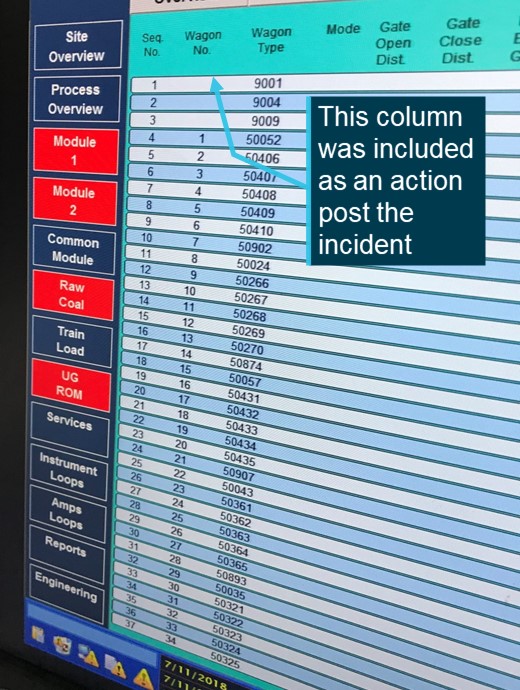
[1] A propelling movement is a rail movement where the train is travelling in the reverse direction, with the locomotives pushing the train rather than hauling it.

[2] A proceed authority is defined in the RailSafe Glossary as: An Authority that allows rail traffic to enter and occupy a portion of line and proceed in the forward direction.

[3] Blocking facilities are defined in the RailSafe Glossary as: A facility or device used by a Qualified Worker to prevent either the unintended issue of an Occupancy Authority, or the operation of points or signalling equipment

Occurrence summary

Investigation number RO-2021-002
Occurrence date 08/01/2021
Location Hawkesbury River
State New South Wales
Report release date 16/12/2022
Report status Final
Investigation level Defined
Investigation type Occurrence Investigation
Investigation status Completed
Mode of transport Rail
Rail occurrence category Safe Working Irregularity/Breach
Occurrence class Incident
Highest injury level Minor

Train details

Train operator Pacific National
Train number 5936
Type of operation Freight
Rail vehicle sector Freight
Departure point Moree, New South Wales
Destination Port Kembla, New South Wales
Train damage Nil

Train details

Train operator NSW Trains
Train number 247B
Type of operation Passenger
Departure point Gosford, New South Wales
Destination Central, New South Wales
Train damage Nil

Rolling stock irregularity on train 3YN2, near Kiacatoo, New South Wales, on 6 January 2021

Final report

Report release date: 28/06/2021

Safety summary

What happened

On 6 January 2021, loaded Pacific National freight train 3YN2 was operating between Broken Hill and Newcastle, New South Wales. Just before 0914, a contractor working near the rail line, noticed a wagon on train 3YN2 was dragging on the rail. This was reported to representatives from the rail infrastructure manager and the crew of 3YN2 were directed to stop their train. The train stopped between Euabalong West and Kiacatoo with a crack found through the underframe of the 32nd wagon. The air tank was resting on the rail and it was later found that three level crossings had been struck by the wagon. There was superficial damage at the level crossings and no reported injuries.

What the ATSB found

Train 3YN2 departed Broken Hill with an existing crack in the underframe of wagon NDHX14836G. This crack progressed during the journey with the underframe of the wagon striking three level crossings. The underframe of NDHX14836G likely fractured due to a fatigue crack at a weld on the lower edge of the sill. This defect was likely detectable for a period of time prior to the occurrence. The train had undergone the required maintenance inspections however these were not sufficient to identify the cracking at a location of known risk prior to the structural failure.

What has been done as a result

Following the occurrence Pacific National released a rolling stock safety notice detailing the failure and requiring an inspection of all affected wagons within the class wagon.

Pacific National advised the following actions have been planned to prevent recurrence:

  • Develop a lifecycle asset management strategy for affected class of wagons (NDHX/ICX) with a butt weld.
  • Complete a risk assessment to assess the limitations of NDHX wagons and requirements for ongoing use.
  • Review the wagon maintenance manual associated with the inspection of the wagon underframe to include details for ICX class wagons.
  • Review and adjust the current non-destructive strategy applied across Pacific National’s fleet of wagons.

Safety message

The incident highlights the importance of managing ageing assets to ensure continued safe operation through the lifecycle of the asset. Rolling stock operators should ensure that their maintenance and inspection regimes effectively monitor and detect conditions that might escalate and contribute to accidents.


The investigation

Decisions regarding whether to conduct an investigation, and the scope of an investigation, are based on many factors, including the level of safety benefit likely to be obtained from an investigation. For this occurrence, a limited-scope investigation was conducted in order to produce a short investigation report, and allow for greater industry awareness of findings that affect safety and potential learning opportunities.

The occurrence

On 5 January 2021, two Pacific National (PN) train drivers (crew 1 and crew 2) were assigned to shunt and attach 17 wagons from within the CBH Resources - Rasp Mine at Broken Hill to the rear of freight train 3YN2. 

During the shunting movement, a roll-by inspection[1] was performed by crew 1. Between 1905[2]  and 2020, crew 1 completed a general examination (GX) of the 17 wagons. The inspection was completed without incident and a brake certificate was issued.

On 6 January 2021, train 3YN2 departed Broken Hill bound for Newcastle, New South Wales. The train consisted of three locomotives and 44 wagons with a total length of 977 m. The train departed Broken Hill at 0149 and a roll-by inspection was performed from both sides by crew 1 and crew 2 without incident.

Just before 0914, a contractor working near the rail line noticed a broken wagon on 3YN2 was dragging on the rail. This was reported to a track worker located at Parkes, who passed the message on to the network controller at Junee. At 0915, the network controller contacted the crew of train 3YN2 and directed them to stop and inspect their train.

The crew stopped to inspect the train between Euabalong West and Kiacatoo. The crew identified that the wagon frame on the 32nd wagon (NDHX14836G) had failed and the air tank was resting on the rail near 583.900 km[3] (Figure 1 and Figure 2). The wagon was loaded with two containers carrying zinc (Zn) concentrate at the time which remained secured to the wagon.

Inspection post incident identified superficial scrape marks on the rail and at three level crossings between 595.518 km and 583.900 km. There was no reported damage to the sleepers or rail fasteners from the failed wagon. There were no reported injuries.

Figure 1: Path of 3YN2

Figure 1: Path of 3YN2

Source: Geoscience Australia, modified and annotated by OTSI

Figure 2: Rolling stock irregularity  

Figure 2: Rolling stock irregularity

Wagon NDHX14836G shown with centre of the wagon sagging under the load of the 20 ft containers. Inset image shows the fracture in the underframe and an air tank resting on the rail. 

Source: Pacific National, modified and annotated by OTSI

Context

Wagon

Wagon NDHX14836G was designated as a sleeper carrying wagon with a tare mass of 20 t and a maximum capacity of 60 t. Previously the wagon was designated NQHX (container flat wagon)[4] before it was converted to a sleeper carrying wagon in 2009. In 2010 this modification was reverted and the wagon returned to original use, however, this was not communicated effectively to the various rail infrastructure managers.  

The wagon was manufactured as an ICX class wagon with the centre sill forming the load bearing structure (Figure 3). This class of wagon was manufactured from approximately 1968 onwards and PN had a total of 136 ICX class wagons in operation at the time of the incident (Table 1).

Figure 3: ICX class wagon underframe and cracking locations

Figure 3: ICX class wagon underframe and cracking locations

A side and top down view of the wagon and underframe structure. The centre sill runs the length of the wagon and supports the load.

Source: Pacific National, modified and annotated by OTSI

Table 1: ICX class

Wagon codeWagon TypeQuantityComment
NDHXSleeper carrying wagon36Previously NQHX container wagon
NQHXContainer76Previously NQIX container wagon
NQIXContainer24 

Historically, cracking had been detected on some ICX class wagons at butt welds along the centre sill lower flange at a change in material thickness (Figure 3). Repair procedures had been developed with doubler plates[5] fitted if cracking was detected.[6] The location of the previous cracking was along the centre sill but not at the location of the fracture on NDHX14836G.

Maintenance

Wagon NDHX14386G was under a unit train maintenance (UTM) regime requiring the wagon to be inspected every 56 days (maximum 7-day tolerance) in accordance with the Wagon Maintenance Manual (WMM 01-01 and WMM 01-18).

Additionally, the wagon required inspection at intervals of 150,000, 450,000 and 900,000 km. Both the 56 day on train inspection and kilometre-based inspection referred to the same work instruction for the inspection of the underframe (Underframes, Body Work and Load Supports WMM 04-02).

The most recent maintenance records are shown in Table 2. The wagon had operated for 51 days since the last 56 day on train inspection and was not overdue at the time of the occurrence.

Table 2: Maintenance history

DateInspection typeComments
07/07/202056 day on train maintenanceCompleted 70 days between previous inspection
24/09/202056 day on train maintenanceCompleted 79 days between previous inspection
16/11/202056 day on train maintenanceCompleted 53 days between previous inspection

Train examination

Prior to departure the 17 wagons underwent a GX as required by the Train Inspection Manual (TIM 01-03). The examination was limited to the major components of the wagon but included checking the wagon body for structural damage. The GX was performed by crew 1 who held the required qualifications and had three years’ experience. There were no defects noted with wagon NDHX14836G.

Crew 2 who assisted with the roll-by inspection, held the appropriate qualifications and had approximately eight years’ experience.

Loading

The containers were loaded on to the 17 wagons at CBH Resources - Rasp Mine. The train consist and records for container mass indicated all wagons were within the permitted loading limits (60 t).

Loading records indicated wagon NDHX14836G was loaded with two 20 ft concentrate containers with a total mass of 59.54 t. Post occurrence the mass of the containers were weighed at 59.9 t,[7] closely matching the loading records.

Similar occurrences

ATSB investigation (RO-2018-009)

On 21 April 2018, Pacific National intermodal freight train 6MP4 derailed near Glenalta, South Australia. It was found that there was a pre-existing structural crack on platform 2 of wagon RRYY01X that had not been identified during multiple train examinations and maintenance inspections. A combination of the pre-existing structural crack, in-train forces (compression and tension) and tight curves on a descending grade likely resulted in the derailment. A contributing factor and safety issue of this occurrence was:

Pacific National’s inspection processes did not identify key structural points for inspection on RRYY class wagons, including the susceptibility to cracking in the junction between container loading outriggers, pull rod boxed opening, and the bottom centre sill sections. This reduced the likelihood of cracks being detected. (Safety issue)

This wagon was of a different design and class to NDHX14836G, although, both were operated and maintained by Pacific National. The same work instruction was also utilised for the inspection of the underframes of RRYY and NDHX (ICX) class wagons (WMM 04-02). This inspection procedure was revised as part of the safety action to address the safety issue.

OTSI investigation (04588)

On 5 December 2012, crew performing a roll-by inspection of a SQYD wagon near Gulgong, New South Wales, detected a wagon sagging in the middle and almost dragging on the ground. The wagon struck and damaged the road surface on several level crossings before it was detected.

It was found that the underframe of wagon SQYD0060G failed at a transverse butt weld at the mid-point of the centre sill. The failure was the result of poor weld design, welding practices/techniques and inadequate non-destructive testing at the time of the weld.

The SQYD wagon was similar in design to the ICX class wagon but the two wagon classes were at different ends of the asset lifecycle. The SQYD wagons entered service in the 12 months prior to the occurrence while ICX class wagons were approaching end of life.

Safety analysis

Train 3YN2 travelled approximately 530 km before wagon NDHX14836G struck a level crossing at 595.518 km.  The wagon struck two more level crossings before the train was stopped at 583.900 km. The actions of the contractor reporting the defect prevented the escalation of this occurrence.

The wagon was found with a fracture extending across the bottom flange (underside) and up both vertical plates (web) at the mid-point of the centre sill. The lower portion of the fracture face was damaged by ballast strikes, particularly on the trailing edge (in the direction of travel) of the fracture.

Assessment of the fracture indicated that the fracture was at the mid-point of the centre sill transverse weld. A backing bar[8] was present along the length of the weld although there was no obvious weld penetration. Oxidation was visible on the lower section of both vertical plates and the fracture face was worn (Figure 4). The presence of both oxidation and wear is consistent with fatigue cracking however there were no beach marks[9] observed in this region. The remaining fracture face was free from oxidation and likely progressed quickly.

Figure 4: Wagon NDHX14836G fracture

Figure 4: Wagon NDHX14836G fracture

Photograph shows the left and right sides of the centre sill.

Source: Pacific National and OTSI, annotations by OTSI

Train 3YN2 underwent the required maintenance inspection prior to departing Broken Hill on 6 January 2021. These inspections did not detect the existing fracture on the frame of NDHX14836G.

The GX inspection scope was limited although the partial fracture would likely have been visible during close inspection of the centre sill vertical plates (web). The investigation was unable to determine when the frame was partially fractured, the oxidation indicates a fracture was almost certainly present during numerous GX and roll-by inspections.

Maintenance records (Table 2) showed two of the three most recent 56 day on inspections (UTM) were completed in exceedance of the 7-day tolerance. The UTM maintenance plan was associated with the rake[10] of wagons rather than individual wagon. If a wagon was moved from the rake it could have operated in exceedance of the maintenance plan, increasing the likelihood of a rolling stock irregularity progressing without detection.

Wagon maintenance manual WMM-04-02 provided guidance for the inspection of various wagon classes although did not specifically detail inspections of NQHX (NDHX) wagons. The guidance for inspecting the underframe was general and did not highlight the location of cracking as found on NDHX14836G. Additionally, there was no requirement for more detailed inspections of ageing assets.

The design and construction of the ICX class wagons varied with some wagons having a centre sill transverse weld at the mid-point on the lower edge of the sill. Design drawing provided as part of the investigation did not indicate the presence of the weld or provide details for the original weld specification. A weld at this location of high stress increases the risk of fatigue cracking and presented different risk profiles within the same wagon class.

Non-destructive testing consisting of magnetic particle inspection (MPI) was only required if a crack was visually detected. Without more advanced non-destructive testing, a crack would need to propagate to be visibly detectable on the surface before it may be addressed.

Findings

ATSB investigation report findings focus on safety factors (that is, events and conditions that increase risk). Safety factors include ‘contributing factors’ and ‘other factors that increased risk’ (that is, factors that did not meet the definition of a contributing factor for this occurrence but were still considered important to include in the report for the purpose of increasing awareness and enhancing safety). In addition ‘other findings’ may be included to provide important information about topics other than safety factors. 

These findings should not be read as apportioning blame or liability to any particular organisation or individual.

From the evidence available, the following findings are made with respect to the rolling stock irregularity involving freight train 3YN2.  

Contributing factors

  • 3YN2 departed Broken Hill with an undetected crack on wagon NHDX14836G; the crack progressed and the wagon sagged under the load striking three level crossings.
  • The centre sill of wagon NDHX14386G likely fractured due to fatigue cracking initiating at a transverse weld on the lower edge of the sill.
  • Pacific National's maintenance and inspection regime was not sufficient to identify cracking at a location of known risk before the structural failure of wagon NDHX14836G.

Safety actions

Whether or not the ATSB identifies safety issues in the course of an investigation, relevant organisations may proactively initiate safety action in order to reduce their safety risk. The ATSB has been advised of the following proactive safety action in response to this occurrence.

Pacific National

Maintenance and inspection

On the day of the occurrence, Pacific National issued a Rolling Stock Notice (RSN E 21-002) requiring an underframe crack inspection on NDHX, NQHX and NQIX wagons. The visual inspection required:

  • checking if there was a butt weld at the midpoint of centre sill
  • checking for cracks on the underside of the centre sill at the location of the butt weld
  • checking the vertical web plate for the presence of crack propagation
  • confirming the presence of doubler plates and any cracking associated with the doubler plates.

A total of 134 wagons were inspected as of 21 January 2021 with no cracks identified at the centre sill. The last wagon was inspected on 27 May 2021 with no cracks identified. Wagon NDHX14836G was to be scrapped, reducing Pacific National’s number of ICX class wagons to a total of 135.

Pacific National advised that they have completed a risk assessment to determine the NDHX wagon limitations and ongoing monitoring program requirements and plans for ongoing use. The following actions are also planned in relation to this occurrence:

  • Broken Hill maintenance depot to conduct a risk assessment associated with the inspection of underframe of ICX class wagons during time based and kilometre based inspections.
  • Review facilities available at Broken Hill to provide maintenance personnel easier access to complete underframe inspections.
  • Develop a lifecycle management strategy for NDHX/ICX wagon classes with a butt welds.
  • Develop an asset management strategy for the identification and implementation of the appropriate wagon lifecycle strategies.
  • Review wagon maintenance manual WMM 04-02 to include details for ICX class wagons.
  • Review and adjust the current non-destructive strategy applied across Pacific National’s fleet of wagons.
Compliance with maintenance standards

In relation to the management of trains under unit train maintenance (UTM) strategies, a Rolling Stock Notice (RSN E 21-003) was issued on 18 January 2021. The notice advised of the transition from unit train maintenance (UTM) at the rake level (group of wagons) to the individual wagon level. This notice was distributed to asset management and maintenance personnel and detailed actions to be taken. This change was to ensure that wagons receive the correct inspection when required. Pacific National's maintenance management system was updated to reflect these changes and wagons with overdue maintenance activities were identified and prioritised for inspection.

Sources and submissions

Sources of information

The sources of information during the investigation included the:

  • Australian Rail Track Corporation
  • Pacific National.

References

Pacific National (2015), Train Inspection Manual, General Train Inspection Procedure, TIM 01-03_05, 14 December 2015

Pacific National (2017), Wagon Maintenance Manual, Maintenance of Freight Wagons, WMM 01-01_05, 26 June 2017

Pacific National (2020), Wagon Maintenance Manual, UTM/ Block/ OK Spare/PM Inspection, WMM 01-18_07, 21 October 2020

Pacific National (2020), Wagon Maintenance Manual, Underframes, Body work and Load Supports, WMM 04-02_05, 1 July 2020

Rail Industry Safety and Standards Board (2021), Glossary of Terms. Accessed at: www.rissb.com.au/glossary/

Submissions

Under section 26 of the Transport Safety Investigation Act 2003, the ATSB may provide a draft report, on a confidential basis, to any person whom the ATSB considers appropriate. That section allows a person receiving a draft report to make submissions to the ATSB about the draft report.

A draft of this report was provided to the following directly involved parties:

  • Australian Rail Track Corporation
  • Office of the National Rail Safety Regulator
  • Pacific National
  • Transport for NSW.

Submissions were received from:

  • Australian Rail Track Corporation
  • Office of the National Rail Safety Regulator
  • Pacific National.

The submissions were reviewed and, where considered appropriate, the text of the report was amended accordingly.

Purpose of safety investigations

The objective of a safety investigation is to enhance transport safety. This is done through:

  • identifying safety issues and facilitating safety action to address those issues
  • providing information about occurrences and their associated safety factors to facilitate learning within the transport industry.

It is not a function of the ATSB to apportion blame or provide a means for determining liability. At the same time, an investigation report must include factual material of sufficient weight to support the analysis and findings. At all times the ATSB endeavours to balance the use of material that could imply adverse comment with the need to properly explain what happened, and why, in a fair and unbiased manner. The ATSB does not investigate for the purpose of taking administrative, regulatory or criminal action.

Terminology

An explanation of terminology used in ATSB investigation reports is available here. This includes terms such as occurrence, contributing factor, other factor that increased risk, and safety issue.

Publishing information

Released in accordance with section 25 of the Transport Safety Investigation Act 2003

Published by: Australian Transport Safety Bureau

© Commonwealth of Australia 2021

image_5.png

Ownership of intellectual property rights in this publication

Unless otherwise noted, copyright (and any other intellectual property rights, if any) in this report publication is owned by the Commonwealth of Australia.

Creative Commons licence

With the exception of the Coat of Arms, ATSB logo, and photos and graphics in which a third party holds copyright, this publication is licensed under a Creative Commons Attribution 3.0 Australia licence.

Creative Commons Attribution 3.0 Australia Licence is a standard form licence agreement that allows you to copy, distribute, transmit and adapt this publication provided that you attribute the work.

The ATSB’s preference is that you attribute this publication (and any material sourced from it) using the following wording: Source: Australian Transport Safety Bureau

Copyright in material obtained from other agencies, private individuals or organisations, belongs to those agencies, individuals or organisations. Where you wish to use their material, you will need to contact them directly.
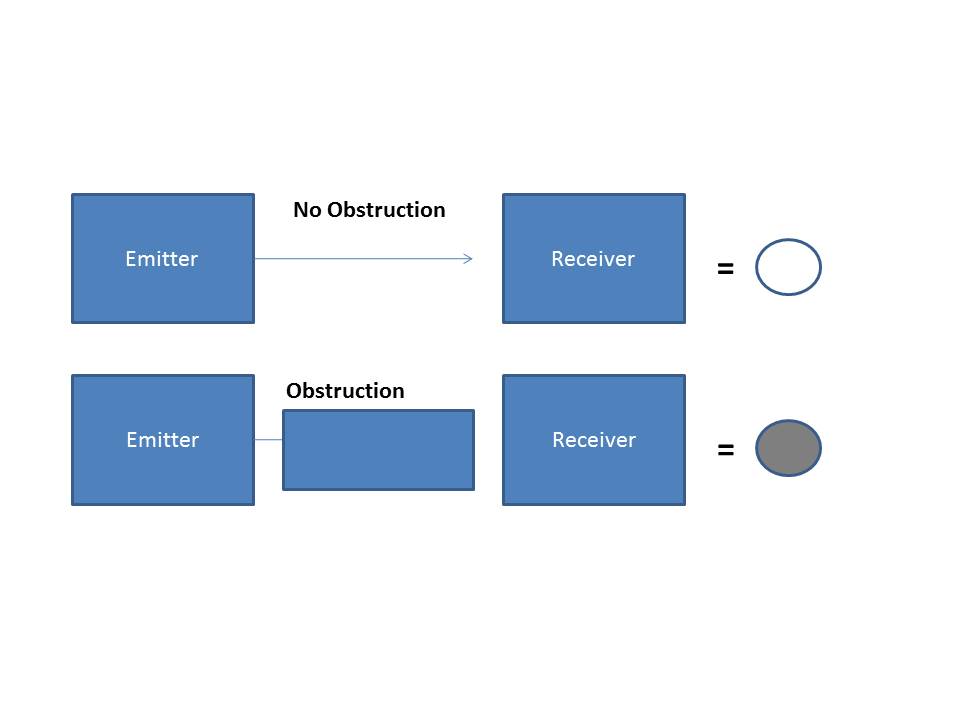
__________

  1. Roll-by inspections are a visual inspection of moving rail traffic to identify equipment, loading security or other defects or failure.
  2. Times shown in 24-hour time as Australian Eastern Daylight Time (AEDT).
  3. The kilometre distance is measured from Platform 1, Central Station, Sydney, New South Wales.
  4. A flat wagon specially equipped with approved securing devices for the transport of freight containers. The wagon may have a full width deck, with or without apertures, or be of skeletal construction.
  5. A doubler plate is a section of steel that is welded to a larger section as part of a repair or to provide additional strength.
  6. Between 1985 and 2004 two work instructions were released for the inspection and repair of centre sill fractures.
  7. Containers were checked using a scale on the forklift utilised for unloading and unloading the containers post occurrence.
  8. A backing bar is a piece of material positioned at the root of a weld to support molten weld material allowing for complete weld penetration.
  9. Beach mark refers to markings on the fracture surface associated with fatigue cracking. Typically, the progression of a fatigue crack will leave concentric rings on the fracture surface that radiate from the point of origin.
  10.  Rake refers to vehicles, usually not formed as a train, moved as a unit during shunting and marshalling. In this case the 17 wagons formed the rake for the unit train maintenance purposes.

Occurrence summary

Investigation number RO-2021-001
Occurrence date 06/01/2021
Location Kiacatoo
State New South Wales
Report release date 28/06/2021
Report status Final
Investigation level Short
Investigation type Occurrence Investigation
Investigation status Completed
Mode of transport Rail
Rail occurrence category Rolling Stock Irregularity
Occurrence class Incident
Highest injury level None

Train details

Train operator Pacific National
Train number 3YN2
Type of operation Freight train
Rail vehicle sector Freight
Departure point Broken Hill, New South Wales
Destination Newcastle, New South Wales
Train damage Substantial

Loss of control and collision with terrain involving Robinson R44 II, VH-HOB, near Clare, South Australia, on 22 December 2020

Final report

Report release date: 08/12/2022

Executive summary

What happened

On 22 December 2020, the pilot of a Robinson R44 II helicopter was conducting aerial agricultural spray operations on a property about 13 km south-east of Clare Valley Aerodrome, South Australia. After completing numerous spraying runs throughout the morning, the pilot started a gentle descending turn to the landing site to replenish with chemical product when a loud bang emanated from the rear of the helicopter. The pilot reported that the helicopter descended rapidly, and the flight controls appeared to be jammed. The helicopter collided heavily with the loading vehicle, coming to rest on its side. The pilot and ground crewman were uninjured, and the helicopter was substantially damaged.  

What the ATSB found

The ATSB found that the forward yoke of the helicopter’s clutch shaft had failed due to an undetected fatigue crack that originated from an indent in one of the arms of the yoke. This resulted in loss of drive to the main and tail rotor systems. The unrestrained clutch shaft caused the displacement of the hydraulic reservoir and the loss of fluid. The loss of hydraulic fluid removed hydraulic power assistance to the flight control servos leading to increased control stick forces to operate the helicopter.

The pilot experienced difficulties in controlling the helicopter and executed an emergency descent from a low height without hydraulic power assistance and no tail rotor control. The pilot was presented with a compound emergency for which no training had been provided and for which they had no prior experience.

The ATSB found that the helicopter manufacturer’s maintenance instructions requiring verification that no cracks, corrosion or fretting were present on the yoke, lacked specific instructions on the method to be employed. The visual inspection that was employed increased the risk that a crack in the yoke arm may not be detected.

What has been done as a result

The helicopter manufacturer, the Robinson Helicopter Company, introduced new maintenance inspection requirements for the clutch shaft forward yoke at the 2,200/2,400-hourly inspection for the R44 helicopter. This included replacement of yokes of earlier revision status (A through G) and for later revision (H and subsequent), the option of replacement, or a more detailed examination that included a magnetic particle inspection. This update was included in the R44 maintenance manual in August 2022. The manufacturer also changed the paint colour of the yokes at the forward flex coupling from dark grey to white. This was to enhance the visibility of fretting dust during inspections, in the event of loose hardware.

Following the accident, the ATSB issued a Safety Advisory Notice, AO-2020-064-SAN-014 advising operators of R44 helicopters that based on the preliminary finding of fatigue cracking, to look for the presence of corrosion, fretting or cracking, which may not be visually obvious during all inspections of the clutch shaft yoke.

The Civil Aviation Safety Authority issued an Airworthiness Bulletin, AWB 63-010 advising industry of the failure of the yoke based on the ATSB investigation preliminary finding. It advised pilots and maintenance personnel to exercise vigilance for any signs of deterioration in the helicopter drive train components. This was further supported by the release of similar bulletins by the European Union Aviation Safety Agency and the US Federal Aviation Administration.

Safety message

This occurrence highlighted how non-life limited components such as a drive train yoke may still develop defects and fail in-flight. Aircraft owners and maintenance personnel are reminded of the importance of applying inspection and maintenance criteria specified in the aircraft manufacturer’s publications. Should maintenance information be lacking or unclear, the manufacturer or authorised representative should be contacted for appropriate, additional information.

The occurrence also serves as a reminder to pilots and maintenance personnel that when conducting inspections to be prepared for the unexpected, and to remain vigilant for defects in parts with an established history of reliability.


The occurrence

On the morning of 22 December 2020, the pilot of a Robinson Helicopter Company R44 II, registered VH-HOB, prepared the helicopter for aerial agricultural spray operations to be conducted on a property located about 13 km to the south-east of Clare Valley Aerodrome, South Australia. The pilot completed the daily inspection and departed the Clare Valley hangar at 0652 Central Daylight-saving Time[1] for the short flight to the loading zone, from where operations would be based.

The pilot arrived at the loading zone at 0700 and departed at 0702 with the property owner on board to conduct a short survey flight of the area to be sprayed, returning to the loading zone at 0708. Following the arrival of the ground crewman, the helicopter was loaded with chemical product, and at 0728 the pilot departed and conducted a series of spraying runs.

Numerous spraying runs were completed during the morning between 0728 and 0920 with the pilot returning to the loading zone periodically to replenish with chemical product and to refuel the helicopter. The pilot reported that the operation proceeded smoothly, and the long spray runs with minimal obstacles made for ideal spraying conditions. 

During the final descent to the loading zone at about 0926, the pilot momentarily increased altitude to gain a better view of a light shower approaching from the south-west, and to assess its potential impact on further spraying operations. The pilot slowed the helicopter, and once satisfied that the shower did not pose a threat, started a gentle, right descending turn at 0926:20 towards the ground loading vehicle with the intent to land alongside as on previous occasions (Figure 1).

Figure 1: VH-HOB flight path showing return to loading zone and descent and inset providing accident location

VH-HOB flight path showing return to loading zone and descent and inset providing accident location

Source: Google and DGPS data, annotated by the ATSB

About 10 seconds into the turn, at 0926:30, a loud bang from the rear of the helicopter was heard, followed by vibrations from the rotor systems. The ground crewman recalled looking up and seeing that the tail rotor had stopped turning. The pilot reported that the cockpit flight controls appeared to have jammed and of not being able to move the tail rotor pedals. The helicopter’s rate of descent increased to 550 ft/min and as reported by the pilot, its movement towards the ground loading vehicle was generally unaffected by the pilot’s attempts at control inputs. The helicopter’s flight path continued until its landing gear impacted the vehicle’s roof, which resulted in it rolling onto its right side and colliding with terrain at 0926:46.

The pilot was not injured in the collision and was assisted from the helicopter wreckage by the ground crewman. There was no post-impact fire, and the helicopter was substantially damaged.

Context

Pilot information

The pilot of VH-HOB held a Commercial Pilot Licence (Helicopter) and a Private Pilot Licence (Aeroplane), both issued in March 2015. The pilot held class ratings included single engine helicopters and helicopter low-level rating. From 2017, the pilot also held an aerial application rating for helicopter operations.

The pilot completed an aerial application proficiency check for single engine helicopters and a night Visual Flight Rules (Helicopter) flight review for Robinson R44 helicopters on 23 July 2020. Both were valid until 31 July 2021.

The pilot held a Class 2 Aviation Medical Certificate issued by the Civil Aviation Safety Authority (CASA), without medical restrictions, which was valid until 23 January 2023.   

The pilot’s logbook indicated that at the time of the accident, the pilot had a total flying experience of about 6,521 hours. Of these, about 1,337 hours were in the Robinson R44 helicopter and 1,018 hours conducting aerial application work. The pilot had flown about 105 hours on type in the previous 90 days, and about 54 hours on type in the previous 30 days.

Aircraft information

VH-HOB was a Robinson Helicopter Company R44 II helicopter that was manufactured in the United States in 2005 with serial number 10801. It was first registered in Australia in 2005.

The R44 II is a single-engine, light utility and training helicopter with a semi-rigid, two-bladed main rotor, a two‑bladed tail rotor and skid type landing gear. It had an enclosed cabin with two rows of side‑by‑side seating for a pilot and three passengers.

The helicopter was powered by a Textron Lycoming IO-540-AE1A5, 6-cylinder, fuel-injected piston engine and was fitted with hydraulic servo-actuators providing hydraulic power assistance to the main rotor, flight control system.

VH-HOB was configured for aerial application work that included a belly-mounted storage tank and laterally mounted spray booms for chemical product dispersal.

The helicopter’s current maintenance release was issued on 20 October 2020, about 92 flight hours prior to the accident. It was valid for 12 months or 100 hours, whichever occurred sooner. At the time of the accident, VH-HOB had accumulated about 4,579 hours, total time-in-service. There were no open defects recorded on the maintenance release and no outstanding or overdue maintenance was noted.

Maintenance records also showed that about 188 flight hours prior to the accident, at an aircraft time-in-service of 4,391.0 hours, an airframe 2,200-hour/12-year inspection was completed.

Meteorological information

The forecast meteorological conditions for Clare Valley Aerodrome (13 km north-west of the accident site) area, indicated winds from the south-south-west at 19 kt and a temperature of 12 ⁰C. Visibility was forecast to be greater than 5 km with isolated showers of rain and broken cloud above 1,200 ft.

The METAR[2] for Clare Valley township issued at 0930 recorded wind from the south-west at 7 kt and a temperature of 14 ⁰C. This was consistent with witness in the accident area who reported that some cloud was present with isolated showers to the south.

Wreckage information

The ATSB did not attend the accident site and based assessment of the helicopter on imagery and reports supplied by the operator, maintenance personnel, interview records and witness account.

The helicopter presented as relatively intact with the tailboom broken aft of its forward mount point. The operator’s examination identified that one of the arms of the clutch shaft forward yoke had fractured resulting in loss of drive to the main and tail rotor systems. The tubular steel structure surrounding the shaft was damaged by the rotation of the unrestrained clutch shaft. The hydraulic reservoir was also found displaced from its mounting base and was located within the wreckage (Figure 2).

Figure 2: VH-HOB following the collision with inset showing clutch shaft with upper drive sheaves and displaced hydraulic reservoir

VH-HOB following the collision with inset showing clutch shaft with upper drive sheaves and displaced hydraulic reservoir

Source: Supplied, annotated by the ATSB

Following the accident, attending maintenance personnel reported they conducted a functional check of the flight control system and found the cyclic[3] and collective[4] controls had full and free movement. However, one of the tail rotor control tubes exhibited bending damage that was likely the result of contact with the unrestrained clutch shaft.

Both the pilot and the ground crewman reported that the engine stopped operating shortly before the collision. Images showed that a cutting action of the unrestrained clutch shaft forward yoke (see R44 rotor drive system below) penetrated the engine upper firewall and damaged the engine fuel system flow divider located on the engine below. The yoke perforated the flow divider top housing, which likely interrupted fuel flow to the engine, resulting in engine stoppage.

Both of the fuel tanks were found intact and there was little external distortion of the auxiliary tank following the impact with the ground.

At interview, the ground crewman commented that the helicopter was observed to approach at a low rate of descent, and had it not struck the vehicle, the landing would likely have resulted in significantly less damage to the helicopter.

R44 rotor drive system

The clutch shaft forward yoke assembly is part of the R44 rotor drive system. The R44 pilot’s operating handbook provided the following description of the main and tail rotor drive system and is illustrated in Figure 3.

A vee-belt sheave is bolted directly to the engine output shaft. Vee-belts transmit power to the upper sheave which has an overrunning clutch contained in its hub. The inner shaft of the clutch transmits power forward to the main rotor and aft to the tail rotor. Flexible couplings are located at the main gearbox input and at each end of the long tail rotor drive shaft.

Figure 3: R44 drive train with inset showing clutch shaft forward yoke and flex plate providing input power to the main and tail rotor gearboxes

R44 drive train with inset showing clutch shaft forward yoke and flex plate providing input power to the main and tail rotor gearboxes

Source: Robinson Helicopter Company R44 maintenance manual, annotated by the ATSB

Images provided by maintenance personnel showed that during the accident sequence, the vee‑belts had dislodged from the upper sheave.

A manual, cable operated rotor brake was mounted on the aft end of the main gearbox and when applied via the pull handle in the cabin ceiling, friction pads of the braking mechanism would contact the main gearbox input yoke to stop the rotor system. Images showed that the actuating cable was displaced from its guide pulley and was disconnected from the braking mechanism (Figure 4).

Figure 4: Rotor brake mechanism minus actuating cable attached and trapped wire material around the main gearbox input yoke shaft

Rotor brake mechanism minus actuating cable attached and trapped wire material around the main gearbox input yoke shaft

Source: Maintenance organisation, annotated by the ATSB

The action of separating the cable from the braking mechanism likely caused the rotor brake to be momentarily actuated, and while considered minimal, may have affected the speed of the main rotor system.

R44 II hydraulic system

The R44 II hydraulic system consists of a pump mounted to the main rotor gearbox, a servo at each of the control tubes connecting the cockpit controls to the swashplate, a reservoir assembly, hydraulic fluid and interconnecting flexible hoses (Figure 5). Should a loss of hydraulic pressure occur, the servos contain an irreversible feature to reduce main rotor feedback forces to the pilot’s controls. However, in the absence of hydraulic pressure, the manufacturer advised that the cyclic control system is harder to move in the fore-and-aft and lateral planes, while the collective control can be easily lowered, but becomes harder to raise.

Following the accident, the hydraulic system was provided to the ATSB for further examination. Without hydraulic pressure applied, examination of each servo showed that the irreversible feature was functional. The forces required to move each servo were noted to be slightly higher in comparison to new servos but were considered acceptable.  

The hydraulic reservoir had separated from the hydraulic manifold mounted to the tubular frame likely from the clutch shaft striking the manifold (mounting location circled, Figure 5). This resulted in significant loss of hydraulic fluid. The ATSB’s examination of the hydraulic reservoir revealed multiple impact marks attributed to striking, or being struck repeatedly by a rotating component, likely the main gearbox input yoke.

Figure 5: Hydraulic system and main gearbox installation from VH-HOB

Hydraulic system and main gearbox installation from VH-HOB

Source: Maintenance organisation, annotated by ATSB

Yoke examination

The clutch shaft with the fractured yoke arm, the forward flex plate and the attaching hardware were provided to the ATSB for detailed examination (Figure 6). A portion of the flex plate that remained connected to the yoke and the separated section of the arm was also provided for examination.             

The yoke presented with one arm intact, to which a portion of the forward flex plate and its attaching hardware were present. The opposite arm had fractured at the bolt hole that secured the arm to flex plate.

The surfaces of the yoke presented with scoring marks and indentations to the painted surfaces. Mechanical impact damage and gouging was also present with smearing damage to the arm fracture surfaces obscuring some of the original fracture features.

Figure 6: Fractured forward yoke arm with inset showing clutch shaft assembly and flex plate

Fractured forward yoke arm with inset showing clutch shaft assembly and flex plate

Source: ATSB

A detailed visual inspection of the yoke arms using an optical microscope and a magnetic particle inspection of the yoke surfaces and bolt hole regions, did not identify additional cracks.

Red-coloured corrosion products were observed on the forward face of the yoke where it contacted the bonded stainless-steel washer from of the forward flex plate (Figure 7). Fretting damage was present on the aft face that was in contact with the attaching hardware. Microscopic examination of the red-coloured product identified it to have been produced from general corrosion/oxidation of the underlying steel surface. There were no indications of pitting corrosion.

Figure 7: Fractured yoke arm and separated section front and rear surface condition

Fractured yoke arm and separated section front and rear surface condition

Source: ATSB

Visual examination of the fracture surfaces on either side of the bolt hole showed evidence of fatigue fracture. The fracture surface showed concentric beach marks indicative of a progressive crack mechanism, which radiated outwards from the likely origin at the inner bolt hole surface on the front face of the yoke (Figure 8). The fatigue crack had propagated from the front to the aft face, and initially obscured from view by the presence of the attaching hardware.

Crack propagation continued across a substantial portion of the cross section (about 98% of fracture # 1 and about 80% of fracture #2), with a visible portion on the rear face of about 6 mm before final overstress fracture and separation occurred. 

Figure 8: Separated yoke tip with fracture features identified

Separated yoke tip with fracture features identified

Source: ATSB

A scanning electron microscope (SEM) was used to further qualify the fracture surfaces at high magnifications. The SEM examination confirmed:

  • many hundreds of crack progression bands were observed, which indicated crack growth occurred as a result of high-cycle fatigue[5]
  • surface damage (an indent) approximately 0.10 mm in depth at the fatigue crack origin of fracture #1 had likely influenced the initiation of cracking within the yoke arm at the point of fracture
  • a clear boundary on the fracture surface existed between the region of corrosion and the region that was not corroded (Figure 9).

Figure 9: Fracture surface of separated section showing corrosion boundary with inset showing crack surface discoloration

Fracture surface of separated section showing corrosion boundary with inset showing crack surface discoloration

Source: ATSB

Metallurgical, chemical and dimensional analysis established that the yoke conformed to the manufacturer’s specification for material type, hardness, and physical dimensions.

Overall corrosion protection had been specified by the manufacturer that was for the yoke to be cadmium-plated, primed and then painted. These corrosion protection schemes were confirmed during metallurgical examination of the yoke.

Manufacturer’s clutch shaft forward yoke inspections

The manufacturer’s instructions for continuing airworthiness of the clutch shaft forward yoke (part number C907) were contained in the Robinson R44 II pilot’s operating handbook (POH) and the aircraft maintenance manual. The following was noted:

  • At each daily or pre-flight inspection, the yoke flanges[6] (yoke arms) were to be checked. No cracks were permitted.
  • At each 100-hour or annual airframe inspection, the yoke was to be checked for condition and to verify no cracks, corrosion or fretting was present. The yoke was also to be checked for security and operating clearance.
  • At each 2,200-hour inspection, a 100-hour or annual inspection is also conducted, and the yoke was to be checked for condition. Additionally, the aircraft maintenance manual provided a list of components that were to be replaced with new or overhauled exchanged parts when they had accumulated 2,200/2,400-hours time‑in‑service. There was no requirement for the yoke to be replaced with a new or overhauled part once those hours had accumulated.

Other than for unscheduled maintenance, the yoke was only separated from the forward flex plate (see Figure 3 insert) when parts were replaced at their assigned 2,200/2,400-hour service interval. The yoke was treated as an ‘on-condition’ item and was not assigned an operating time‑in‑service, fatigue, or calendar life-limit.

Maintenance personnel reported that when installed, the yoke can be viewed on a daily inspection via an access panel located on the right side of the helicopter. During the 100-hour or annual inspection, the yoke can also be inspected from above when the upper panel between the fuel tanks was removed. It was noted that cracking on the front face of the yoke arm would not be visible during these inspections as there was no requirement to remove the yoke from the flex plate.

The aircraft maintenance manual specified a range of examination methods for the detection of defects and identified specific parts that warranted examination above that provided by visual inspection means. Higher levels of examination for nominated parts included the use of a suitably powered magnifying glass, and fluorescent penetrant and magnetic particle inspection processes. However, the yoke was not included in the nominated parts list.

Maintenance practices

The pilot reported that on the day of the accident, a pre-flight inspection was completed, and no defects were noted. Maintenance personnel also reported that no defects associated with the forward yoke were noted during the 100-hour inspection that was conducted 92 hours prior to the accident.

During the most recent 2,200-hour inspection, the helicopter’s main rotor gearbox was refitted, and the three flex plates of the rotor system drive train were replaced with new items.

Records showed that the engine-to-gearbox clutch shaft assembly had been replaced about 701 hours prior to the 2,200-hour inspection with the forward yoke transferred to the replacement shaft. This may have provided another opportunity for detailed inspection of all yoke surfaces.

Maintenance personnel involved in the 2,200-hour inspection reported that at the time of replacing the flex plates, following separation from the forward flex plate, the yoke surfaces were visually examined for defects and the yoke was determined to be serviceable.

The manufacturer advised that yokes were commonly removed from service due to the presence of corrosion or fretting damage, but not due to cracks. When forward yokes were returned to the manufacturer as part of the clutch shaft for overhaul, the surface finish was removed, and a magnetic particle inspection for defects would be completed prior to release to service.

Helicopter emergency procedures

Hydraulic system normal and emergency procedures

The R44 II POH advised pilots that for training purposes, a hydraulic system failure may be simulated by switching the hydraulic system off by using the cyclic-mounted hydraulic switch. With hydraulics switched off, controlling the helicopter in a hover may be difficult due to control system feedback forces.

The handbook also advised pilots to expect control stiffness and feedback when conducting hydraulic systems checks or pre-take off control checks with the hydraulic system switched off.

The handbook described the symptoms for a hydraulic system failure as indicated by heavy or stiff cyclic and collective controls, and loss of hydraulic fluid may cause intermittent and/or vibrating feedback in the controls. Should that occur, the POH stated that control of the helicopter would be normal except for the increase in stick forces. Additionally, if hydraulic power was not restored after verifying that the hydraulic switch is in the ‘ON’ position, the pilot is to switch hydraulics to ‘OFF’ and to land as soon as practical.

Engine power loss or loss of tail rotor function

In the event of an engine or drive system failure, the POH advised pilots to immediately lower the collective lever and enter autorotation[7] while observing airspeed requirements. Pilots were also instructed to enter an autorotation if loss of tail rotor thrust in forward flight occurs.

An autorotation is typically conducted at a specified forward airspeed and rotor RPM at which a power-off glide is most efficient. Autorotation airspeed and RPM is different for each helicopter type and is characterised as a controlled descent. The flight controls are used to manoeuvre the helicopter during the autorotation, through to completion of the landing sequence.

Although the tail rotor is used to counteract the yawing effect of the main rotor at low speed, a loss of tail rotor control or drive to the tail rotor, is manageable provided adequate airspeed is maintained, as directional stability is provided by the helicopter’s vertical and/or dorsal fin.

Pilots are trained to perform autorotational descents, and autorotational capability is a certification requirement for helicopters.

At interview, the pilot reported that simulated engine failures, tail rotor system malfunctions and hydraulic failures were practised during training and flight reviews. However, they were trained and assessed as independent emergencies and were never conducted simultaneously as a compound emergency.

Recorded data

VH-HOB was not equipped with a flight data or cockpit voice recorder, nor was it required to be. Differential GPS[8] flight path data from the on-board SatLoc Bantam[9] aerial application tracking device was provided to the ATSB.

Speed and position data from the SatLoc device was used in the analysis of the helicopter’s movements in the final 3 minutes of flight (Table 1).

Table 1: Key events involving VH-HOB during the final minutes of flight with approximate values of flight behaviour

TimeVH-HOB movementsHeight above ground level (ft)Ground speed (kt)Rate of descent (ROD) (fpm)

Rate of track change

(⁰ per minute)

0924:06Pilot returning to loading zone, slows prior climbing flight from about 160 to 40 fpm.25019  
0924:08Pilot commences descent to loading zone 2060 
0925:44Bottom of descent62210 
0925:46Pilot initiates a climb, rate of climb about 60 fpm6420  
0926:18Approaching top of climb, pilot slows rate of climb to about 20 fpm1245  
0926:20Helicopter on descent122560 
0926:28Bang heard (estimated time of noise)1044200475
0926:30Descent945335416
0926:36Descent – maximum ROD438550207
0926:38Descent3010413232
0926:40Descent1810314133
0926:42Descent101123674
0926:44Descent51016011
0926:46Helicopter collides with vehicle/terrain 9160 

From 09:26:40 to collision at 09:26:46, the aircraft track varied by about 4 degrees. In the last two seconds of flight, the track varied by less than one degree, and aligned the helicopter’s movement with the position of the stationary ground vehicle (Figure 10).

Figure 10: VH-HOB flight path showing landing approach with momentary climb and descent towards ground vehicle

VH-HOB flight path showing landing approach with momentary climb and descent towards ground vehicle

Source: Google, annotated by the ATSB

Related occurrences

This accident involving the clutch shaft forward yoke (part number C907) was the first occurrence to be investigated by the ATSB that involved an in-flight failure of a yoke on a helicopter model in the Robinson range.

Robinson advised of no other reports of fatigue cracks associated with forward yokes. Searches of the CASA, the US Federal Aviation Administration (FAA) and New Zealand Civil Aviation Authority (CAA) Service Difficulty Report databases did not reveal other documented cases of fatigue related cracking.

There was one similar R44 occurrence, involving loss of drive to the main and tail rotor due to weld failure of the forward yoke. The incident occurred during cruise flight in which the pilot heard a bang and experienced a loss of tail rotor effectiveness due to the failure of a weld joint in the forward yoke.

As a result of this incident, an airworthiness directive was issued by the FAA in August 1999 (FAA Priority Letter Airworthiness Directive AD 99-17-17), requiring the replacement of certain yoke assemblies in R44 helicopters before further flight. The manufacturer identified manufacturing lots associated with the failed yoke and retired the affected yokes from service. If uncorrected, the FAA advised that the condition could result in failure of the yoke assembly, loss of main and tail rotor drive, and subsequent loss of control of the helicopter. In October 1999, CASA issued AD/R44/13 in support of FAA action.

Safety analysis

The collision with terrain involving Robinson R44 II VH-HOB, about 13 km south-east of Clare Valley Aerodrome, South Australia, was the result of the loss of drive to the main and tail rotor systems due to fracture of the clutch shaft forward yoke. This analysis will focus on the failure of the yoke, the emergency descent, and the subsequent collision with terrain. The analysis will also consider maintenance information for the continued airworthiness of the yoke and management of in-flight emergencies.

Yoke failure and separation

The yoke failed as a result of fatigue crack propagation that initiated on the forward face of the yoke arm coincident with the bolt hole. On one side, the crack had initiated from a mechanical surface defect. The fatigue cracking was assessed to have propagated slowly as evidenced by the many hundreds of crack progression bands, with failure of the yoke arm occurring when minimal intact cross-sectional area remained. 

A distinctly corroded region was identified on the forward-most surface of the yoke. A similarly corroded/stained region was identified on the fracture surface. The corroded regions were underneath where the bonded washer from the forward flex plate would normally be clamped. The varying nature of the corrosion within the fatigue crack and the demarcation between the various regions suggested that the crack had existed during an overhaul cycle of the component.

Following the fracture of the yoke, the clutch shaft became disconnected from the main gearbox creating misalignment of the upper and lower sheaves and displacement of the vee-belts. This resulted in a loss of drive from the engine to both the main and tail rotor systems. The loss of drive committed the pilot to find a suitable place to land the helicopter while conducting an emergency descent without tail rotor control.  

Yoke inspections

The manufacturer’s in-service requirements for yoke serviceability specified that the yoke be inspected for cracks, fretting or corrosion at specific intervals that included the daily inspection, at scheduled time in service intervals and during the 2,200-hour inspection.

The drive train was inspected on the morning of the accident flight and at the previous scheduled inspection, and no defects were found. However, with the yoke connected to the forward flex plate, there was no opportunity to visually detect the crack on the forward face during the daily and 100-hour inspections. Once the crack had progressed to the rear surface of the yoke arm, it would have been difficult to see, given that the crack was estimated to be about 6 mm in length, and the area would have needed to have been sufficiently clean.

The only opportunity for detecting a crack initiating on the front face of the yoke would be when all yoke surfaces were exposed and not obscured by the presence of the flex plate and attaching hardware. This would be at the 2,200‑hour inspections, or at unscheduled clutch shaft or flex plate removal. The last time the yoke was separated from the forward flex plate was at the recent 2,200-hour inspection, about two months and 188 flight hours prior to the accident.

The presence of corrosion deposits in part of the cracked region indicated that the crack was likely present at that inspection. Once the yoke arm was re-installed, the forward face was obscured by the flex plate and the crack would not have been visible during the subsequent routine inspections.

Maintenance instructions for critical item

The forward yoke was not assigned a service life by the manufacturer so its continuation in service was dependent on it meeting specific inspection criteria to determine on-going serviceability. The maintenance instructions for continued airworthiness specified that the yoke be inspected for condition, and maintenance personnel were required to verify that no cracks, corrosion or fretting was present. No specific method on how to accomplish this was provided in the manufacturer’s documentation, and as such, a visual inspection would be acceptable.

Defects related to corrosion and fretting damage are likely detected by the un-aided eye, but crack identification may be not as obvious. At the 2,200-hour inspection, the yoke was separated from the forward flex plate and the visual inspection method that was used to detect cracks that existed on the helicopter’s forward yoke, was unsuccessful.

The methods used to verify the absence of cracks varied between this maintenance organisation and the aircraft manufacturer. When yokes were returned to the manufacturer as part of the clutch shaft assembly, the yokes were subject to magnetic particle inspection, which would have a greater chance of identifying a crack than visual inspection alone. This suggested that the inspection instruction was open to interpretation and was not consistently applied.

On this occasion, the failure of the yoke led to a loss of drive to both the main and tail rotor systems. The failure of this critical item further resulted in a secondary failure of the hydraulic system under the action of the unrestrained clutch shaft. This presented the pilot with a compound emergency resulting in an emergency descent and subsequent collision with the ground vehicle and terrain.

The reliability of the yoke and lack of history of removal from service due to cracking, likely influenced the use of visual inspection methods and reduced the expectation for a crack to be present. However, that further reduced the probability of detecting the crack when all the yoke surfaces are available for inspection.

Helicopter control

The pilot reported that when the yoke fractured the helicopter was configured for a gentle descent and turn towards the loading vehicle. However, the consequential failures that followed the failure of the yoke, which included a loss of tail rotor drive, resulted in degraded directional control. The pilot also reported that the cyclic and collective controls felt like they were jammed.

The significant bending of the tail rotor pitch control tube following impact by the intermediate flex coupling/clutch shaft aft yoke, likely restricted the movement of the tail rotor pedals, adding to the sense of difficulty in controlling the helicopter.

Post-accident examination of the collective and cyclic control systems found that they moved freely within their travel range. The loss of hydraulic power assistance would have increased the cyclic and collective feedback forces required by the pilot to control the helicopter. An unexpected increase in the control forces while flying with a normal relaxed grip on the cyclic and collective might have led the pilot to perceive the controls were jammed.

The multiple impact marks that presented on the hydraulic reservoir body indicated that the reservoir had become dislodged in flight rather than when the helicopter collided with terrain. The ATSB considered the possibility that the displaced hydraulic reservoir impeded the movement of the hydraulic servos or their control system, or that in the attempt to position the helicopter away from the ground vehicle, the flight controls were moved to their mechanical stops, which prevented further movement. However, based on the evidence available, neither of these possibilities could be confirmed.

The pilot’s usual practice was to land beside the loading vehicle to enable replenishment of chemical product and had configured the helicopter accordingly. Analysis of the flight path following the initial turn towards the ground support vehicle, revealed that the helicopter’s rate of descent repeatedly changed, as did the rate of turn as it approached the vehicle. This suggested that the helicopter was likely responding to some pilot control inputs and therefore some control of the helicopter was likely available. However, it was insufficient for the pilot to avoid a collision with the loading vehicle.

Multiple emergencies

The pilot reported that during their initial training and subsequent flight reviews, there was a requirement to demonstrate competency in performing autorotational descents and flying and landing the helicopter without hydraulic power assistance. However, there was no requirement to conduct compound major emergencies, such as the loss of tail rotor control coupled with a loss of hydraulic power assistance.

The hydraulic pump is driven by the helicopter’s main gearbox, so the hydraulic system is expected to continue providing hydraulic power during autorotation training. Consequently, this accident presented the pilot with a scenario for which they had no prior experience. It also occurred at a low height and low forward speed, which provided the pilot with very little time to diagnose the situation and manage the emergency landing.

Findings

ATSB investigation report findings focus on safety factors (that is, events and conditions that increase risk). Safety factors include ‘contributing factors’ and ‘other factors that increased risk’ (that is, factors that did not meet the definition of a contributing factor for this occurrence but were still considered important to include in the report for the purpose of increasing awareness and enhancing safety). In addition, ‘other findings’ may be included to provide important information about topics other than safety factors. 

Safety issues are highlighted in bold to emphasise their importance. A safety issue is a safety factor that (a) can reasonably be regarded as having the potential to adversely affect the safety of future operations, and (b) is a characteristic of an organisation or a system, rather than a characteristic of a specific individual, or characteristic of an operating environment at a specific point in time.

These findings should not be read as apportioning blame or liability to any particular organisation or individual.

From the evidence available, the following findings are made with respect to the loss of control and collision with terrain involving Robinson R44, VH-HOB, near Clare, South Australia, on 22 December 2020.

Contributing factors

  • Fatigue cracks in the clutch shaft forward yoke progressed until the yoke fractured during operation, which led to a loss of drive to the main rotor system that necessitated an emergency descent.
  • During the emergency descent from a height of about 100 feet, the pilot experienced difficulties in controlling the helicopter and was unable to avoid colliding with the ground vehicle, which increased the severity of the collision with terrain.
  • Although it was very likely that a crack was present when the clutch shaft yoke was last disassembled from the forward flex plate, it was not detected during inspection. Once assembled, the crack, which had formed on the forward face of the yoke arm, was obscured by the presence of the flex plate.
  • Although the helicopter manufacturer’s instructions for continuation in service for the clutch shaft forward yoke specified that the condition of the yoke was to be inspected to verify that no cracks, corrosion, or fretting was present, it did not provide specific instructions for the method to be employed. The visual inspection that was employed increased the risk that a crack in that area may not be detected [Safety issue].

Other (key) finding

  • The emergency descent was performed without hydraulic power assistance to the main rotor control systems and without drive to the tail rotor. That required the pilot to manage simultaneous emergencies that were not concurrently presented during training sessions and for which they had no prior experience.

Safety issues and actions

Central to the ATSB’s investigation of transport safety matters is the early identification of safety issues. The ATSB expects relevant organisations will address all safety issues an investigation identifies.

Depending on the level of risk of a safety issue, the extent of corrective action taken by the relevant organisation(s), or the desirability of directing a broad safety message to the aviation industry, the ATSB may issue a formal safety recommendation or safety advisory notice as part of the final report.

All of the directly involved parties are invited to provide submissions to this draft report. As part of that process, each organisation is asked to communicate what safety actions, if any, they have carried out or are planning to carry out in relation to each safety issue relevant to their organisation.

Descriptions of each safety issue, and any associated safety recommendations, are detailed below. Click the link to read the full safety issue description, including the issue status and any safety action/s taken. Safety issues and actions are updated on this website when safety issue owners provide further information concerning the implementation of safety action.

Critical item

Safety issue number: AO-2020-064-S1-01

Safety issue description: Although the helicopter manufacturer’s instructions for continuation in service for the clutch shaft forward yoke specified that the condition of the yoke was to be inspected to verify that no cracks, corrosion, or fretting was present, it did not provide specific instructions for the method to be employed. The visual inspection that was employed increased the risk that a crack in that area may not be detected.

Safety action not associated with an identified safety issue

Whether or not the ATSB identifies safety issues in the course of an investigation, relevant organisations may proactively initiate safety action in order to reduce their safety risk. All of the directly involved parties are invited to provide submissions to this draft report. As part of that process, each organisation is asked to communicate what safety actions, if any, they have carried out to reduce the risk associated with this type of occurrences in the future. The ATSB has so far been advised of the following proactive safety action in response to this occurrence
Safety advisory notice to operators of R44 helicopters

The ATSB advises operators of R44 helicopters to note the preliminary finding of this accident and to look for the presence of corrosion, fretting or cracking, which may not be visually obvious, during all inspections of the clutch shaft yoke. Any identified defects should be notified to both the ATSB and the Civil Aviation Safety Authority.

Additional safety action taken by CASA

CASA issued Airworthiness Bulletin AWB 63-010 Issue 1 to inform owners, registered operators, maintenance organisations and Licensed Aircraft Maintenance Engineers of a failure in a Robinson R44 drive train component (the yoke) that was found by the ATSB during investigation AO-2020-064 and that the ATSB has issued a Safety Notice AO-2020-064-SAN-014 to highlight the component failure.

A revision to the AWB (Issue 2) was issued by the CASA on 23 September 2021. Further to original references that signs of loose fasteners, corrosion or discolouration warrant further investigation, Issue 2 advised that further investigation may require the use of specialised inspection methods such as non-destructive testing (NDT). The manufacturer's maintenance data should be consulted and if lacking sufficient detail for the required inspection or method/s, then the manufacturer is to be contacted for the appropriate inspection data, or if a specialised inspection is required, then the inspection data will need to be generated and approved under civil aviation legislation. Further, any specialised inspections will need to be conducted using approved data by an appropriately authorised person.

Additional safety action taken by European Union Aviation Safety Agency (EASA)

Following the release of CASA AWB 63-010 Issue 1 dated 21 June 2021, EASA issued Safety Information Bulletin No. 2021-13 on 29 June 2021 advising owners and operators that EASA concurs with the AWB's recommendations and to ensure that owners and operators are aware of the recommendations.

Additional safety action taken by Federal Aviation Administration (FAA)

Following receipt of a report of a failed C907 yoke in the R44 main rotor drive system, the FAA issued a Special Airworthiness Information Bulletin (SAIB: AIR-22-08) to remind owners and operators of any Robinson R44 rotorcraft of the importance of adhering to existing inspection procedures in the applicable operating handbooks and maintenance manuals.

The SAIB advised of the presence of a fatigue crack near the bolt hole of the arm of the C907 yoke, and that an initial metallurgical examination found corrosion products and fretting damage on the surface near the fatigue crack. The yoke failure may have been caused by corrosion and/or improper hardware torque. Further, inadequate inspection and maintenance of all driveshaft yokes may result in undetected wear and/or corrosion that could lead to yoke failure and loss of main and tail rotor drive.

The FAA recommended that owners and operators of R22 and R44 series rotorcraft follow Robinson's published pre-flight inspection and periodic maintenance criteria regarding main and tail rotor driveshaft yokes in order to prevent future failures.

Glossary

FAA                  Federal Aviation Administration

CAA                 Civil Aviation Authority

GPS                 Global Positioning System

METAR             Meteorological Terminal Air Report

POH                 Pilot Operating Handbook

RHC                 Robinson Helicopter Company

SAN                 Safety Advisory Notice

SDR                 Service Difficulty Report

TAF                  Terminal Aerodrome Forecast

Sources and submissions

Sources of information

The sources of information during the investigation included the:

  • accident witnesses
  • aircraft manufacturer
  • Bureau of Meteorology
  • Civil Aviation Safety Authority
  • maintenance organisations for VH-HOB
  • County Helicopters Pty Ltd
  • photographs and videos taken on the day of the accident
  • pilot of the accident flight
  • recorded data from the DGPS unit on the aircraft.

References

Federal Aviation Administration (2019), Helicopter Flying Handbook, U.S. Department of Transportation, FAA-H-8083-21B

Under section 26 of the Transport Safety Investigation Act 2003, the ATSB may provide a draft report, on a confidential basis, to any person whom the ATSB considers appropriate. That section allows a person receiving a draft report to make submissions to the ATSB about the draft report.

A draft of this report was provided to the following directly involved parties:

  • aircraft manufacturer
  • Civil Aviation Safety Authority
  • County Helicopters Pty Ltd
  • pilot of the accident flight
  • maintenance organisations for VH-HOB.


Submissions were received from:

  • aircraft manufacturer
  • Civil Aviation Safety Authority

The submissions were reviewed and, where considered appropriate, the text of the report was amended accordingly.

Purpose of safety investigations

The objective of a safety investigation is to enhance transport safety. This is done through:

  • identifying safety issues and facilitating safety action to address those issues
  • providing information about occurrences and their associated safety factors to facilitate learning within the transport industry.

It is not a function of the ATSB to apportion blame or provide a means for determining liability. At the same time, an investigation report must include factual material of sufficient weight to support the analysis and findings. At all times the ATSB endeavours to balance the use of material that could imply adverse comment with the need to properly explain what happened, and why, in a fair and unbiased manner. The ATSB does not investigate for the purpose of taking administrative, regulatory or criminal action.

Terminology

An explanation of terminology used in ATSB investigation reports is available here. This includes terms such as occurrence, contributing factor, other factor that increased risk, and safety issue.

Publishing information 

Released in accordance with section 25 of the Transport Safety Investigation Act 2003

Published by: Australian Transport Safety Bureau

© Commonwealth of Australia 2022

image_5.png

Ownership of intellectual property rights in this publication

Unless otherwise noted, copyright (and any other intellectual property rights, if any) in this report publication is owned by the Commonwealth of Australia.

Creative Commons licence

With the exception of the Coat of Arms, ATSB logo, and photos and graphics in which a third party holds copyright, this publication is licensed under a Creative Commons Attribution 3.0 Australia licence.

Creative Commons Attribution 3.0 Australia Licence is a standard form licence agreement that allows you to copy, distribute, transmit and adapt this publication provided that you attribute the work.

The ATSB’s preference is that you attribute this publication (and any material sourced from it) using the following wording: Source: Australian Transport Safety Bureau

Copyright in material obtained from other agencies, private individuals or organisations, belongs to those agencies, individuals or organisations. Where you wish to use their material, you will need to contact them directly.
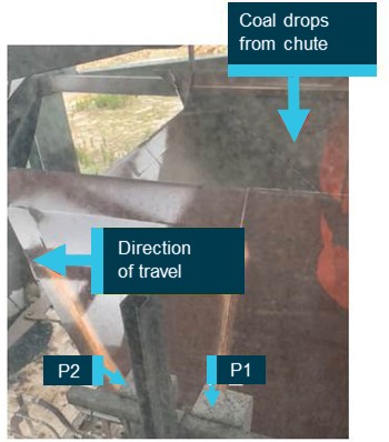
[1]     Central Daylight Time (CDT): Coordinated Universal Time (UTC) +10.5 hours

[2]     METAR: a routine aerodrome weather report issued at routine times, hourly or half-hourly

[3]     Cyclic: a primary helicopter flight control that is similar to an aircraft control column. Cyclic input tilts the main rotor disc, varying the attitude of the helicopter and hence the lateral direction.

[4]     Collective: a primary helicopter flight control that simultaneously affects the pitch of all blades of a lifting rotor. Collective input is the main control for vertical velocity.

[5]     Failure mechanism associated with high frequency vibration, flexing or rotation of machinery, typically at a rate of many times per second.

[6]     Yoke flanges or arms: interchangeable terms used by the manufacturer to describe the connecting surfaces of the yoke

[7]     Autorotation, also known as an autorotational descent, is a power off manoeuvre in which the engine is disengaged from the main rotor system and the rotor blades are driven solely by the upward flow of air through the main rotor.

[8]     Differential GPS: an enhancement to global navigation satellite system (GNSS) systems. A differential GPS base station broadcasts a correction signal that allows differential GPS devices to provide sub-metre positional accuracy relative to the base. If the position of the base is precisely known, this allows for high absolute positional accuracy.

[9]     SatLoc Bantam: a proprietary aerial application guidance system utilising differential GPS signals.

Occurrence summary

Investigation number AO-2020-064
Occurrence date 22/12/2020
Location Clare Valley (ALA), 135° T 13Km
State South Australia
Report release date 08/12/2022
Report status Final
Investigation level Defined
Investigation type Occurrence Investigation
Investigation status Completed
Mode of transport Aviation
Aviation occurrence category Collision with terrain
Occurrence class Accident
Highest injury level None

Aircraft details

Manufacturer Robinson Helicopter Co
Model R44 II
Registration VH-HOB
Serial number 10801
Aircraft operator COUNTY HELICOPTERS
Sector Helicopter
Operation type Aerial Work
Departure point Clare Valley, South Australia
Destination Clare Valley, South Australia
Damage Substantial

Derailment of freight train 9281, near Charters Towers, Queensland, on 30 December 2020

Final report

Report release date: 09/08/2022

Executive summary

What happened

On 30 December 2020, Aurizon fertiliser freight train 9281, was travelling from Phosphate Hill to Townsville Jetty, Queensland. A short time, after commencing the downhill grade from 119 km towards Sellheim, train 9281 derailed while traversing over a culvert.

What the ATSB found

The investigation found that a series of rainfall events on the 29 December 2020, which included a heavy rain event between 1510 and 1615, compromised the drainage system at the 118.131 km. Water over-topped the track prior to the arrival and subsequent derailment of train 9281.

The corrugated metal pipe, that was an element of the drainage system at the 118.131 km, likely had rainwater throughput restricted. This was restriction was possibly due to sinking, debris from the upstream side blocking the corrugated metal pipe, or collapse of the corrugated metal pipe due to exceeding its service life, or a combination of the three, resulting in the rainwater pooling.

Extensive rainwater pooling resulting in over-topping of the track at the location of the corrugated metal pipe very likely undermined the track infrastructure, such that it could not support the weight of the rolling stock.

What has been done as a result

Following the derailment, Queensland Rail upgraded the culvert with three 900 mm corrugated metal pipes, which significantly improved drainage in the area. Queensland Rail is also considering actions around engineering studies, resilience works, and alternative and predictive weather monitoring.

Safety message

Rail infrastructure managers should ensure their drainage systems are fit for purpose, are clear, open, and in serviceable condition. This will minimise the risk of system inundation and track over‑topping.


The occurrence

Train 9261/9281 was a loaded fertiliser train, operated by Aurizon, travelling from Phosphate Hill to Townsville Jetty on the Mount Isa line in Queensland. The train departed Phosphate Hill as train number 9261 on 28 December 2020, before being renumbered 9281 from Hughenden on 29 December 2020. Both the drivers of train 9281 commenced work in Hughenden at 1815 Eastern Standard Time[1]on 29 December 2020.

On 29 December, at about 1830, while travelling from Hughenden to Charters Towers, the rail traffic crew of train 9281 were asked by the network control officer to report on the weather conditions. The rail traffic crew reported they had not observed any flooding or adverse conditions on the journey. Prior to the passage of train 9281 from Charters Towers, there were 2 periods of rainfall recorded near the site of the derailment, one in the afternoon, and another in the evening.

On 30 December 2020, at 0016, train 9281 was travelling from Charters Towers towards Sellheim (Figure 1). A short time after commencing the downhill grade from 119 km towards Sellheim, 11 wagons, not including the locomotives and first wagon, derailed while traversing a culvert.[2] As a result of the derailment, fertiliser was spilt into the waterway and towards a dam on a local property.

Figure 1: Location of the derailment

Figure 1: Location of the derailment

Source: Geoscience Australia, annotated by the ATSB

Context

Train

The train consisted of 2 locomotives, a 2800 class (2826) leading and a 4000 class (4046) trailing. The train was hauling 35 VFMQ class hopper wagons. The train was 562 m in length and had a trailing mass of 2,754 t and was crewed by 2 rail traffic crew, consisting of a tutor driver and a driver under route tuition.

Washout of track infrastructure

Evidence collected by Queensland Rail at the site of the derailment indicated it was the result of a washout of the track infrastructure. The washout was on the downstream beside a culvert and uncovered an old concrete abutment within the foundation (Figure 2).

Figure 2: Washout location

Figure 2: Washout location

Source: Queensland Rail, annotated by the ATSB

Weather

The Mount Isa line from Mount Isa to Richmond, which is to the west of Charters Towers, is heavily impacted by adverse weather events during the monsoon season, which can close the line for periods of time. The closures allow water to dissipate from the rail corridor and inspection to be undertaken to ensure the line is fit for service. Areas east of Richmond, towards Townsville, are less impacted by adverse weather events. Queensland rail’s washout records have been kept since 1971 with no occurrence of washout or flooding recorded at the derailment site.

The northern Australian monsoon season generally lasts from December to March. The north Australian wet season encompasses the monsoon months but can extend several months on either side.[3]

The Bureau of Meteorology (BoM) forecast for Charters Towers on Tuesday, 29 December 2020, issued at 0455:[4]

Cloudy. Very high (95%) chance of showers, tending to rain. A thunderstorm likely with possible heavy falls. Light winds becoming north-easterly 15 to 20 km/h in the middle of the day then becoming light in the early afternoon.

The BoM record of total rainfall for 29 December 2020, indicated that near the site of the derailment, the intensity of rainfall from a series of rain events was in the range of 25–50 mm over the 24-hour period. (Figure 3).

Figure 3: 29 December 2020 Rainfall Total

Figure 3: 29 December 2020 Rainfall Total

Source: Bureau of Meteorology, annotated by the ATSB

The BoM weather station at Charters Towers, located about 8.5 km from the derailment site, recorded 33.2 mm of rain between 1500 on 28 December and 1500 on 29 December. A further 26.8 mm was recorded between 1500 on 29 December and 0900 on 30 December.

Weather radar data recorded a series of rainfall events at the derailment site in the 24 hours preceding the accident. They were during the periods 0105–0305 (light rainfall), 1310–1635 (moderate to heavy rainfall) and 1930–2210 (light rainfall) (Figure 4).

Figure 4: Weather radar rainfall intensity at derailment site over 24 hours

Figure 4: Weather radar rainfall intensity at derailment site over 24 hours

Source: The Weather Chaser, annotated by the ATSB

Queensland Rail weather monitoring systems for the region provided no alarms for flooding, significant rainfall or closed-circuit television camera images, which might have prompted a change in the operational status of the line.

The owner of a property, located about 800 m to the north of the derailment site, recorded about 84 mm of rain. The owner was in Charters Towers at the time, and was notified by their partner, who was at the property, at about 1520 on 29 December, that there was heavy rainfall. The owner stated that it was heavy rain (storm) that was isolated in a small area. The owner had last checked the rain gauge in the morning and noted the 84 mm after returning to the property from Charters Towers at about 1700.

The ATSB noted that there was a period of consistent moderate to heavy rainfall at the derailment site from about 1510­-1615. The 1600 weather radar data depicted a heavy rainfall event over the accident site, which passed between the weather stations at Charters Towers and Mingela (Figure 5).

Figure 5: Weather radar rainfall intensity at derailment site

Figure 5: Weather radar rainfall intensity at derailment site

Source: The Weather Chaser, annotated by the ATSB

A rainfall of 84 mm from 1510–1615 equates to 78 mm/h rainfall intensity.

The BoM Design rainfall data system 2016 provides design rainfall data based on intensity‑frequency-duration, and includes average recurrence intervals, which refer to how often a particular level of rainfall intensity can be expected to occur in years and probabilities. The BoM intensity-frequency-duration data for the derailment location near Charters Towers can be seen in Figure 6.

The 78 mm/h observed was greater than a once in 20-year event (71.9 mm/h), but less than 50‑year event (83.5 mm/h) for the Charters Towers weather station.[5]

Figure 6: Bureau of Meteorology intensity-frequency-duration chart for Charters Towers

Figure 6: Bureau of Meteorology intensity-frequency-duration chart for Charters Towers

Source: Bureau of Meteorology, http://www.bom.gov.au/water/designRainfalls/revised-ifd/ accessed on 16 May 2022.

Drainage system

Drainage systems are designed to allow flow of water from known water courses under the track infrastructure, through a corrugated metal pipe (CMP) or other free-flow system, without adversely affecting the formation, ballast, sleepers, and rail. The drainage system located at the 118.130 km chainage was of a cross drainage design (Figure 7) with water flowing from a catchment area into longitudinal drains and progressing through a single CMP under the track infrastructure. The CMP was about 3 m below the rail head height (Figure 8).

Figure 7: External and local catchments, including cross drainage

Figure 7: External and local catchments, including cross drainage

Source: Rail Industry Safety and Standards Board, AS 7637 Hydrology and Hydraulics, Version 1.0, 2014

Figure 8: Drainage system

Figure 8: Drainage system

Source: Queensland Rail, annotated by the ATSB

Catchment area

The catchment area for the drainage system was about 200 m south of the rail corridor. Water flows from the catchment in a northerly direction, through the drainage system under the track infrastructure, and continues into a dam located about 800 m north of the drainage system, and about 180 m east of the home of the property owner.

The catchment area, south of the derailment site, as provided by Queensland Rail in their preliminary hydraulic assessment,[6] was about 30 ha (300,000 square metres, Figure 9 dotted red line). Within a 30-ha catchment area, this would have produced about 23,400 m3/h, or 6.5 m3/s (based on 78 mm/h).[7]

Figure 9: Drainage catchment system

Drainage catchment system

Source: Google Earth, annotated by Aurizon and the ATSB

Construction of the culvert

Construction history

A 6 m single span timber bridge was built at the time or soon after original construction of the railway, circa 1882. At a construction date that was unknown by Queensland Rail, a 1.8 m long by 1.4 m high concrete floodway was constructed to replace the timber structure. Sometime between 1965 and 1980, a 1,050 mm CMP was installed at the location to replace the previous concrete floodway. Queensland Rail stated that it was likely constructed in the mid-1970’s.

Corrugated metal pipe

The rainwater from the catchment area was directed to a drainage system, which included a single 1,050 mm diameter by 8 m long CMP, which was of free-flow discharge and designed to be self-cleaning. The water then continued to flow north towards the dam and Gladstone Creek.

Based on the preliminary hydraulic assessment undertaken by Queensland Rail, the design flow rates of the CMP in the drainage system were between about 8 m3/s for a 50-year event and 9.5 m3/s for a 100-year event.

Corrugated metal pipe service life

Queensland Rail reported that the design life and the planned service life of CMPs was 50 years. Evidence provided showed the design life was determined for all CMPs, without consideration of local factors that could reduce the service life.

Service life of a CMP could be affected by pH soil levels, electrolysis and material/fluid passing through pipe, zinc or other coatings, wall thickness and method of installation.

Australian Standard AS/NZS 2041:1998 Appendix C provided guidance on factors that could affect service life assessment, such as:

  • pH and resistivity of backfill
  • aggressive backfill conditions
  • atmospheric corrosion of exposed surfaces
  • perforation of metal.

The service life of a CMP could be reasonably predicted based on the environmental conditions discussed above.

CMPs are galvanised using a zinc coating to prevent corrosion. The corrosion resistance provided by the zinc coating is in direct proportion to the coating's thickness. Current galvanising, in accordance with AS/NZS 2041.1:2011, is Z600 (600 g/m2 minimum zinc coating mass). Discussions with a manufacturer of CMP’s determined that, mid 1970’s, the CMP probably had galvanised at a Z250 coating[8](250 g/m2 minimum zinc coating mass).

The studies conducted in the United States show that corrugated steel pipe has a life expectancy of 10 years to about 35 years before perforation of the metal occurs.[9] Combined with the wall thickness, dynamic loads and infrastructure foundations, and backfill soils, the service life of a CMP may be less than the planned design life of the drainage system in its entirety.

Installation

The process for installation of CMPs from the mid-1970s to present day has evolved. There were no Australian rail industry standards in the 1970s for their installation. The Australian rail industry currently use AS/NZS 2041: Buried Corrugated Metal Structures and AS/NZS 2041.2: Buried Corrugated Metal Structures – Part 2: Installation.

During the installation of the new culvert, between 1965 and 1980, which, according to Queensland Rail, was likely in the mid-1970s, a concrete abutment that was part of the old concrete floodway structure, was not removed. Interviews with the Queensland Rail structures planners found that they were unaware that the concrete abutment was in-situ until it was exposed by the washaway and derailment. They noted that the location of the concrete abutment could have inhibited the compaction of the foundation and created a weakened area of earthworks.

Weather effect on corrugated metal pipes

With the cyclic dry-wet weather that occurs across the north of Australia, stressors from the passage of rolling stock would apply different dynamic loads to the drainage system and foundation. During dry weather, the foundation is hardened, and stressors from the dynamic loads would be applied across the foundation with minimal stressors applied to the barrel of the CMP.[10]

During wet soaking weather, as occurred during December 2020, the foundation becomes more malleable, and with the softening of the soils around the CMP, the stressors would be applied more to the barrel of the CMP as rolling stock traversed over the track. For CMP’s to withstand significant fill loads[11] and heavy repetitive dynamic loads, an effective soil-structure interaction is necessary. This composite behaviour uses the compressive strength of the culvert wall, with the compressive or bearing strength of the well-compacted soil surrounding the structure. As loads are applied to the culvert, the flexible structure attempts to deflect, with the vertical diameter decreasing and the horizontal diameter increasing.[12]

Corrugated metal pipes may fail due to rolling stock inducing buckling or crushing of the CMP.  Factors such as overloading, corrosion of the CMP, soil loss from behind the CMP wall, and softening of the soil due to increased moisture content, the soil being washed away from around the CMP during wet periods and aging can contribute to a CMP failure. The soil can also be lost due to over-topping, loss of headwalls, as well as loss of soil through perforations in the culvert, or a combination of those elements.

Structures and track inspection

The Queensland Rail structures’ planners undertake detailed inspections of bridges, culverts, and associated drainage systems. Queensland Rail had 2 structures’ planners who usually undertook these inspections on the Townsville to Mount Isa and Phosphate Hill lines, which were conducted in accordance with the Queensland Rail Civil Engineering Structures Standard (CESS).[13] The structures’ planners usually inspected about 370 drainage systems per fortnight. On average, the structures planners inspect about 8 drains per hour. Drainage systems with multiple CMP cells, or more defects, took longer to inspect. The planners had undertaken enterprise[14] training with Queensland Rail and were deemed competent to undertake the tasks.

Detailed inspections

The CESS specified scheduled inspections, including that the Rail Infrastructure Manager shall determine the inspection interval for a structure based on the condition of the structure, the rate of deterioration, and local environmental factors. However, it also specified the intervals between scheduled inspections shall not exceed the maximum intervals specified. The CESS specified that ground level inspections of corrugated and sheet steel pipes, drains and arches were to be conducted at a maximum interval of 2 years.

In addition to the maximum interval, it also stated that:

The Rail Infrastructure Manager is to determine the interval according to the condition of the structure and the prevalence of damp silt and permanent water in the culvert throughout the year and an annual visual inspection just before the start of the wet season to check if the waterway is clear.

A detailed inspection in accordance with Appendix 1J of the CESS[15] was undertaken between the 111.224 km and the 129.534 km in July 2019. Sections of the CESS have requirements for inspection of drainage systems, including inspection for corrosion of CMPs.

Between 30 March and 29 April 2020, the CMP at the 118.130 km to 118.131 km was identified as scouring and sinking, which was the location of the derailment. A corrective work order further noted that the gabion baskets on the right side were rolling off the CMP. The CMP was also noted as scoured and sinking on the right side, which was clarified by Queensland Rail as the downstream side of the CMP.

The sinking of the CMP would restrict the outflows of any rainwater that would be diverted to the culvert from the local catchment area. If the CMP was restricted, the design flows would be reduced, and rainwater would pool if input flow from the catchment exceeded the output flow. The report of sinking on the northern side indicated that the CMP was sinking on the downstream side, which suggested that the siltage would be at a greater depth at the outlet.

The work order stated the gabions were to be removed and replaced with two 4 m by 1 m by 1 m gabion baskets. This work was given a low priority of 26 weeks, which was in accordance with the CESS. The work order was closed at the time of the derailment, which indicated that the work had been completed. While the replacement of the gabion baskets would alleviate the scouring around the formation, they would not address the sinking of the CMP.

Cleaning and clearing of culverts

Queensland Rail had undertaken cleaning and clearing of their culverts about December 2020 in accordance with CESS Appendix 1J. Their records indicated that culverts were cleaned and the work order was closed on 6 December 2020. There were no dates in their records for individual culverts.

The cleaning and clearing should remove any debris and other objects from the upstream side of the culvert, preventing the foreign material from entering the CMP when rainwater from the catchment area flowed towards the culvert. The area cleaned was restricted to the rail corridor on the upstream side for as far as the structures planner decided was adequate to prevent debris from entering the drainage system. Any material from outside of the rail corridor could still be deposited into the culvert and the CMP during rain events that had enough volume and force to move the debris. If debris entered the CMP, it could become lodged and restrict the flow of water, resulting in a dam-like effect and subsequent pooling of water on the upstream side.

Pooling of rainwater at the culvert and scouring of infrastructure

Photographs provided by Queensland Rail show that there was debris located on the ballast shoulder on the upstream and downstream side of the track and between the rails, which indicated over-topping of the track infrastructure at that location (Figure 10). Water over-topping of the rail would likely create a waterfall effect and scouring on the downstream side of the track infrastructure (Figure 11). The waterfall effect could also cause the gabion baskets on the downstream side to slide over the exit of the CMP, thereby further restricting the outflows from the CMP.

Figure 10: Evidence of debris on ballast shoulder and between rails

Figure 10: Evidence of debris on ballast shoulder and between rails

Source: Aurizon, annotated by the ATSB

Figure 11: Evidence of scouring on the downstream (outlet) side

Figure 11: Evidence of scouring on the downstream (outlet) side

Source: Queensland Rail, annotated by the ATSB

Operational information

Track inspection

Queensland Rail managed the railway where the derailment occurred, with the movement of rail traffic controlled from the Queensland Rail Network Control Centre located at Townsville. The section between Charters Towers and Sellheim was inspected by a Queensland Rail road-rail vehicle at about 1000 on 29 December 2020. The track was certified as fit for service. Aurizon ballast train OCB3 travelled across the section from Charters Towers to Sellheim about 1220 on 29 December 2020 and reported no issues.

Event recorder data

The analysis of the event recorder from diesel electric locomotive 2826 was undertaken by the ATSB and found at 00:20:25 (event recorder time, incident time about 00:16) the equalising reservoir (ER) and brake pipe (BP) pressure simultaneously begin to decrease. This was a likely indication that the initial brake application was driver induced as the ER is generally a good proxy for driver BP request.

Track speed at the 118 km was posted as 60 km/h, however, there was a speed restriction of 50 km/h on the section. The approach speed of train 9281 at the derailment point was, based on recorded data, about 38 km/h. The driver applied the brakes at about 37 km/h, following the derailment, and the train travelled a further 137 m before coming to a complete stop.

Operations

During the travel from Hughenden to Charters Towers, the rail traffic crew were requested by the network control officer to observe weather and effects on the rail infrastructure. The rail traffic crew relayed information to the network control officer at several locations on the travel, with no areas of concern observed.

There were no anomalies identified with the train speed, handling, rolling stock condition, or operational performance preceding the derailment.

Queensland Rail’s management of operations in response to the wet weather event was generally in accordance with their existing policies and procedures.

Safety analysis

On 30 December 2020, Aurizon fertiliser freight train 9281, derailed while traversing a culvert to the east of Charters Towers, Queensland. There was no evidence to suggest that any medical or physiological factors affected the driver’s performance leading up to or during the incident, or that the driver’s actions or health contributed to the derailment. This analysis will discuss the localised weather event, over-topping, and undermining of the track infrastructure.

Localised weather event

The ATSB reviewed several sources of evidence for the rainfall on the afternoon of 29 December. A property owner reported that 84 mm was recorded at the property. The phone call to the property owner at 1520 about the heavy rain indicated that rainfall in the vicinity of the derailment site had started earlier than 1520. Weather radar imagery at 1600 (Figure 5) depicted heavy rainfall over the derailment site from a cell that passed between the 2 nearest weather stations of Charters Towers to the west and Mingela to the east. The weather radar time series charts captured moderate to heavy rainfall over the derailment site in the period 1510 to 1615. As this was consistent with the time the property owner received the phone call reporting heavy rain at the property, this was the likely period over which the heaviest rainfall occurred on the afternoon of 29 December.

The weather radar rain rate intensity marker timeseries is a qualitative indicator only, and therefore the actual rainfall in the vicinity of the derailment could not be determined from weather radar imagery. The rainfall at the weather stations of Charters Towers and Mingela were not considered to be reliable indicators for the derailment site as the weather radar imagery depicted a heavy rain cell pass between these stations and over the top of the site. Therefore, the 84 mm of rain reported by the property owner, over a 65-minute period, was the best measurement available.

Corrugated metal pipe failure

Cleaning and clearing inspections of CMP in the area of the derailment was completed on 6 December 2020, which likely included the incident CMP. Therefore, it was likely that the CMP was open and clear at the time of the incident.

Using the period 1510-1615 as the worst-case scenario for the entire 84 mm of rainfall in the gauge, produced an average rainfall intensity of 78 mm/h. Within a 30-ha catchment area, this would have produced about 23,400 m3/h, or 6.5 m3/s, which was less than the CMP design flow rate (of between 8 m3/s and 9.5 m3/s). As such, the drainage system should have been able to manage this flow of rainwater, through an unrestricted CMP.

The inside of the CMP was not photographed or inspected at the derailment site, and no other evidence was provided to verify the condition of the pipe post-derailment. Therefore, while the age of the CMP combined with the wet conditions suggested the possibility of a collapse, it could not be confirmed if a collapse had occurred or if the CMP had become obstructed by debris. However, the maintenance records for the CMP indicated it had been reported as sinking on the northern side (downstream side) and that no rectification work was performed prior to the derailment. Imagery from the upstream end of the CMP post-derailment also indicated a high level of silt build‑up around the inlet (upstream side).

While the amount of sinkage and build-up of silt pre-derailment could not be determined, it would nevertheless have reduced the CMP flow rate to below the design rate. It was therefore likely that the combination of a localised heavy rainfall event and restricted flow through the CMP resulted in the rainwater over-topping the track infrastructure.

Track infrastructure undermined

Prior to the localised heavy rain fall from 1510 on 29 December, the track was twice seen to be serviceable (road-rail track inspection and previous train). However, after the derailment of train 9281, debris in the middle of the track indicated the formation was over-topped by rainwater. This must have occurred in the afternoon of 29 December, after the passage of ballast train OCB3. Extensive pooling resulted in over-topping, very likely resulted in the undermining of the track infrastructure and the subsequent derailment.

Findings

ATSB investigation report findings focus on safety factors (that is, events and conditions that increase risk). Safety factors include ‘contributing factors’ and ‘other factors that increased risk’ (that is, factors that did not meet the definition of a contributing factor for this occurrence but were still considered important to include in the report for the purpose of increasing awareness and enhancing safety). In addition ‘other findings’ may be included to provide important information about topics other than safety factors. 

These findings should not be read as apportioning blame or liability to any particular organisation or individual.

From the evidence available, the following findings are made with respect to the derailment of freight train 9281 on 30 December 2020.

Contributing factors

  • A series of rainfall events on the 29 December 2020, which included a heavy rain event between 1510 and 1615, compromised the drainage system at the 118.131 km and water over-topped the track prior to the arrival and subsequent derailment of train 9281.
  • The corrugated metal pipe, that was an element of the drainage system at the 118.131 km, likely had rainwater throughput restricted due to sinking, debris from the upstream side blocking the corrugated metal pipe, or collapse of the corrugated metal pipe due to exceeding its service life, or a combination of the 3, resulting in the rainwater pooling.
  • Extensive rainwater pooling resulting in over-topping of the track at the location of the corrugated metal pipe very likely undermined the track infrastructure, such that it could not support the weight of the rolling stock.

Safety actions

Whether or not the ATSB identifies safety issues in the course of an investigation, relevant organisations may proactively initiate safety action in order to reduce their safety risk. All of the directly involved parties are invited to provide submissions to this draft report. As part of that process, each organisation is asked to communicate what safety actions, if any, they have carried out to reduce the risk associated with this type of occurrences in the future. The ATSB has so far been advised of the following proactive safety action in response to this occurrence.

Safety action by Queensland Rail

Following the derailment, Queensland Rail have completed the following proactive safety actions:

  • Upgraded the culvert with three 900 mm corrugated metal pipes, which significantly improved drainage in the area.
  • Engaged a contractor to conduct a hydrology study to include the derailment area from Stuart, through Hughenden to Cloncurry, Mount Isa and Flynn to Phosphate hill. This package of works has now been completed.
  • Commenced implementation of infrastructure reliance works that will form part of the outcome of the hydrology study. Notwithstanding significant works already completed as part of the last hydrology study including bridge strengthening in a number of locations.
  • Identified a further 44 sites for new and upgraded weather monitoring equipment. A business case to request capital expenditure has been progressed. Approval has been given to implement a monitoring system that is currently under trial in the far north. This system provides a level of predictive information based on set points. It collates the data from all current available weather monitoring devices not currently utilised by Queensland Rail e.g. registered farmer rain gauges and also the Bureau of Meteorology. The system then notifies Queensland Rail via text that a specific set point has been hit.
  • The condition affecting the network procedure has been reviewed and included the traffic light process to inform the broader business as to how Queensland Rail will be treating the event and train operators’ obligations.
  • Implementation of an additional engineering study into flooding to cover previously unassessed areas of Mount Isa Line to include review of engineering basis for bridges and culverts.
  • Implementation of infrastructure resilience works.
  • Review of alternative weather monitoring technology and consideration of installation of additional weather monitoring stations.

Sources and submissions

Sources of information

The sources of information during the investigation included the:

  • Queensland Rail
  • Rail traffic crew of 9281
  • Bureau of Meteorology.

References

Ezzeldin I & El Naggar H 2022, ‘Numerical Modelling of Induced Stresses in Buried Corrugated Metal Structures Due to Compaction Efforts’, Transportation Geotechnics (100706), vol. 32.

Haviland JE, Bellair PJ & Morrell VD n.d., Durability of Corrugated Metal Culverts, Bureau of Physical Research, New York State Department of Transportation.

Rail Industry Safety and Standards Board 2014, Hydrology and Hydraulics, Version 1.0, AS 7637:2014.

Standards Australia 2011, Buried Corrugated Metal Structures Part 1: Design methods, Australian/New Zealand Standard AS/NZS 2041.1-2011.

Standards Australia 1998, Buried Corrugated Metal Structures, Australian/New Zealand Standard AS/NZS 2041:1998.

Wysokowski A 2021, Impact of Live Load on Changes of Backfill Properties of Buried Flexible Steel Railway Structure, Retrieved from https://doi.org/10.1007/s40515-021-00204-4.

Submissions

Under section 26 of the Transport Safety Investigation Act 2003, the ATSB may provide a draft report, on a confidential basis, to any person whom the ATSB considers appropriate. That section allows a person receiving a draft report to make submissions to the ATSB about the draft report.

A draft of this report was provided to the following directly involved parties:

  • Aurizon
  • rail traffic crew of 9281
  • Queensland Rail
  • Office of the National Rail Safety Regulator.

Submissions were received from:

  • Aurizon
  • Queensland Rail
  • Office of the National Rail Safety Regulator.

The submissions were reviewed and, where considered appropriate, the text of the report was amended accordingly.

Purpose of safety investigations

The objective of a safety investigation is to enhance transport safety. This is done through:

  • identifying safety issues and facilitating safety action to address those issues
  • providing information about occurrences and their associated safety factors to facilitate learning within the transport industry.

It is not a function of the ATSB to apportion blame or provide a means for determining liability. At the same time, an investigation report must include factual material of sufficient weight to support the analysis and findings. At all times the ATSB endeavours to balance the use of material that could imply adverse comment with the need to properly explain what happened, and why, in a fair and unbiased manner. The ATSB does not investigate for the purpose of taking administrative, regulatory or criminal action.

Terminology

An explanation of terminology used in ATSB investigation reports is available here. This includes terms such as occurrence, contributing factor, other factor that increased risk, and safety issue.

Publishing information

Released in accordance with section 25 of the Transport Safety Investigation Act 2003

Published by: Australian Transport Safety Bureau

© Commonwealth of Australia 2022

image_5.png

Ownership of intellectual property rights in this publication

Unless otherwise noted, copyright (and any other intellectual property rights, if any) in this report publication is owned by the Commonwealth of Australia.

Creative Commons licence

With the exception of the Coat of Arms, ATSB logo, and photos and graphics in which a third party holds copyright, this publication is licensed under a Creative Commons Attribution 3.0 Australia licence.

Creative Commons Attribution 3.0 Australia Licence is a standard form licence agreement that allows you to copy, distribute, transmit and adapt this publication provided that you attribute the work.

The ATSB’s preference is that you attribute this publication (and any material sourced from it) using the following wording: Source: Australian Transport Safety Bureau

Copyright in material obtained from other agencies, private individuals or organisations, belongs to those agencies, individuals or organisations. Where you wish to use their material, you will need to contact them directly.
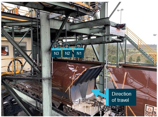
__________

  1.  Eastern Standard Time (CST): Coordinated Universal Time (UTC) + 10 hours.
  2.  A load bearing structure that supports the track, which conveys water under the railway or providing access for property owners, but not a bridge structure.
  3.  Reference - http://www.bom.gov.au/climate/glossary/monsoon.shtml
  4.  Bureau of Meteorology, Severe Thunderstorm Warnings issued for Northern Goldfields and Upper Flinders, 29 December 2020.
  5.  The Queensland Rail internal investigation report concluded that between 2130 and midnight on 29 December, approximately 84 mm of rain in a 40-minute period had fallen from an undetected localised rain event. Queensland rail advised this was based on discussion with the landowner. The hydraulic assessment undertaken by Queensland Rail determined the rainfall intensity was about 126 mm/h (based on 84 mm in 40 minutes), which exceeded the average rainfall intensity for a 100-year event. The ATSB notes that both the time of the rainfall, and the duration, differ from evidence provided to the ATSB by the Bureau of Meteorology and the landowner.
  6.  Preliminary Hydraulic Assessment – Culvert, Mount Isa Line at 118.13 km.
  7.  As noted in footnote 5, the Queensland Rail internal investigation report concluded rainfall at 126 mm/h based on a discussion with the landowner. This would have produced 37,800 m3/h, or 10.5 m3/s.
  8.  CMP Manufacturing Pty Ltd.
  9.  New Jersey Department of Transportation, Bureau of Research, Corrugated Steel Culvert Pipe Deterioration, Final Report, August 2009.
  10.  Wysokowski, A. Impact of Live Load on Changes of Backfill Properties of Buried Flexible Steel Railway Structure. Transp. Infrastruct. Geotech. (2021). https://doi.org/10.1007/s40515-021-00204-4.
  11.  An essential element of composite soil-structure pipe and/or culvert systems is the backfilling process, where compaction efforts are applied to newly placed soil layers surrounding flexible CMPs.
  12.  Queensland Transport and Main Roads, November 2015, Criteria for Inspection, Life Extension and Rehabilitation of Circular Corrugated Metal Culverts, Rev 2, p14
  13.  Queensland Rail, Civil Engineering Structures Standard, MD-10-586, version 6.0, dated 8 June 2020
  14.  Training provided internally by an organisation that is not aligned to Australian Industry and Skills Committee accredited training products.
  15.  Queensland Rail, Civil Engineering Structures Standard, MD-10-586, version 6.0, dated 8 June 2020, p34

Occurrence summary

Investigation number RO-2020-023
Occurrence date 30/12/2020
Location 9 km east of Charters Towers
State Queensland
Report release date 09/08/2022
Report status Final
Investigation level Short
Investigation type Occurrence Investigation
Investigation status Completed
Mode of transport Rail
Rail occurrence category Derailment
Occurrence class Accident
Highest injury level None

Train details

Train operator Aurizon
Train number 9281
Type of operation Fertiliser
Rail vehicle sector Freight
Departure point Hughenden, Queensland
Destination Townsville Jetty, Queensland
Train damage Substantial

Runaway and derailment of loaded grain train 3966, Dombarton, New South Wales, on 15 December 2020

Final report

Report release date: 24/01/2024

Office of Transport Safety Investigations logo

This investigation was conducted under the Transport Safety Investigation Act 2003 (Commonwealth) by the Office of Transport Safety Investigations (NSW) on behalf of the ATSB in accordance with the Collaboration Agreement. Released in accordance with section 25 of the Transport Safety Investigation Act 2003.

Safety summary

What happened

On Tuesday, 15 December 2020 at 0454, the crew of Qube loaded grain train 3966, consisting of 41 wagons and two CM class locomotives, reported a runaway on the descent of the Moss Vale to Unanderra rail line. The train reached speeds up to 100 km/h on a 30 km/h section of track before it derailed and separated at two points between Dombarton and Farmborough Heights, New South Wales (NSW). Shortly after, the train crew advised they had brought the two locomotives and the remaining two wagons to a stand at Farmborough Heights. The train crew were not physically injured.

What the ATSB found

The investigation identified that ineffective braking caused by several factors contributed to the runaway. The ineffective application of train braking systems was influenced by a heavily loaded train with some overloaded wagons, wagons with variable net brake ratio (NBR), reduced brake cylinder pressure through the train, and train handling and locomotive dynamic braking affected by low track adhesion conditions.

The weight of the train was near, but likely not over, the maximum allowable tonnage limit specified by the Australian Rail Track Corporation (ARTC)’s Train Operating Conditions (TOC) Waiver 16002. It was likely, however, that several individual wagons across the train consist were over the allowable limit for a single wagon.

Measurements of NBR at different times and on different wagons returned varying results ranging from 10.7% to 19.5%. The minimum required NBR for these wagons, specified by Australian Standards was 13%. While modifications were made to improve braking performance on the wagons, the NBR on some wagons continued to change over time. The wagon type test met the NBR requirement when introduced into service and met NBR requirements when tested post modifications, however there was no requirement for regular testing of NBR, which may have identified the changes in NBR.

The mix of wagons with variable NBRs and variability in loading likely reduced braking effort on some of the wagons during the steep descent along the rail line.

During the occurrence, the second automatic brake application made by the driver was made before the brake pipe had fully recharged. This resulted in a reduced amount of available brake cylinder pressure and lessened braking effort on the trailing wagons.

The driver's operation of the train and braking actions did not always conform to the operator (Qube)’s instructions, and it is likely some of the driver’s decisions on the morning of the accident were affected by fatigue.

Once control was lost, the driver elected not to use the emergency brake because they believed, in accordance with Qube’s procedures, that the locomotive braking would have been diminished. This in turn lessened the opportunity to regain control of the train.

Qube’s operational procedure for train management between Moss Vale and Inner Harbour did not consider locomotive configurations that maintained locomotive dynamic braking during emergency applications. This increased the risk of train drivers not applying the emergency brake during a runaway event. This assumption was also found to be embedded within other rolling stock operators’ procedures with similarly configured locomotives in NSW.

The conditions on the rail line from Summit Tank to Farmborough Heights on the morning of the incident included wet rail and track contaminant that likely contributed to low track adhesion and also reduced dynamic braking effort by the locomotives. The wheel slip/slide protection system worked as designed to maximise traction through the use of auto sanding to increase friction and derated the dynamic braking effort through the wheels to match the lower adhesion conditions.

Several rail flange lubricators, which provided lubrication to the down and up rail, were less than the 500 m minimum separation requirement specified in ARTC’s engineering practices manual RC2411. A review of these to ensure consistency with the engineering practice and to minimise the risk of excess track lubrication on a steep gradient was warranted.

Finally, the brake pipe charging flow indicator on CM class locomotives only provided a numerical display without any corresponding audio or visual warning system to alert the driver of its status. This limited the ability of the driver to detect derailment or train separation events and, as in this incident, effectively monitor recharge of main reservoir air into the brake pipe to ensure it was fully charged before making another brake application.

What has been done as a result

During the investigation, a Safety Advisory Notice was issued by the Office of Transport Safety Investigations (OTSI) in collaboration with the ATSB to the rail industry to raise awareness of variable locomotive braking system configurations on locomotives across Australia. Qube and other affected rollingstock operators took immediate actions to review their locomotive configurations, to ensure their locomotive drivers had a clear understanding of the braking systems on the locomotives they were operating.

A forum was chaired by the Office of the National Rail Safety Regulator (ONRSR) in March 2023 with Rail Infrastructure Managers (RIMs) and Rollingstock Operators (RSOs) that operated on the Moss Vale to Unanderra rail line. This provided an opportunity to discuss and communicate the risks of operating on the rail line and how to manage them to mitigate runaway events.

The two RIMs, Sydney Trains and ARTC conducted a review and alignment of Transport for NSW (TfNSW) TOC Manual Illawarra operations and the ARTC Route Access Standard - Section Page D52 Moss Vale - Unanderra. The focus of the review was on providing interoperable train configuration and operating conditions between the two RIM interfaces. Additionally, conditions for managing degraded dynamic brakes and hauling dead attached locomotives were developed. All changes were held in consultation with RSOs, ARTC operations and Network Control stakeholders.

In consultation with TfNSW, ARTC developed joint assessment criterion for Unanderra Trial train configurations, operating conditions, and implementation plans. The RSO will be required to submit supporting documentation as part of a variation to existing approved train configurations.

ARTC has updated NBRs for vehicle classes following physical testing and has worked with others in the rail industry to promote NBR testing as part of preventive maintenance.

Safety message

The rail line between Summit Tank and Unanderra is one of the steepest sections of rail line in NSW. To prevent runaway occurrences on this rail line, operators must regularly review the effectiveness of their risk controls and proactively manage conditions that present greater risk of runaway.

RSOs should ensure their trains have sufficient braking, are loaded within safe load limits and are operated in accordance with their procedures.

RSOs and RIMs should ensure that risk assessments identify critical operational requirements to safely run trains down such steep sections of track. They should also ensure that there is sufficient error tolerance to enable control of trains on sections of rail line that present increased risks from long and steep descents.

RSOs should review the locomotive specifications and test those locomotives under their control to understand how the braking systems are configured and the associated error tolerance. RSOs must communicate this information through their organisation’s procedures and training material to ensure train crew have knowledge of and competence in operating locomotive braking systems, including emergency braking in the event of a runaway.

The use of two-pipe wagon braking systems significantly reduces the recharge times for the brake pipe after a brake application, but the starting air pressure of a wagon’s auxiliary reservoir remains a critical consideration. For example, low auxiliary reservoir starting pressure at the beginning of an automatic brake application reduces the response of a wagon’s supplementary reservoir, resulting in lower wagon brake cylinder pressure and therefore less effective braking effort.

Finally, while a ‘full service’ automatic brake application typically provides the maximum pneumatic braking force available on a train, in the unique circumstance of a train with low auxiliary reservoir starting pressure, lowering the brake pipe pressure further through the application of the emergency brake, will result in an increase in the available braking force. However, this increased braking force will remain less than that which would have been available in full service had the auxiliary reservoir been fully charged at the time of the brake application.


The occurrence

Overview

On 14 December 2020, at approximately 1815 Eastern Standard Time (EST),[1] Qube loaded grain train 3966 departed Temora, New South Wales (NSW) bound for Inner Harbour Port Kembla, NSW. The train travelled through the night and in the early hours of 15 December 2020 commenced the descent on the Moss Vale to Unanderra rail line. Between Summit Tank and Farmborough Heights, the train ran away,[2] derailed and separated at two locations. The 29th to 41st wagons derailed and separated at approximately 93.730 km from Sydney’s Central Station. Then the 3rd to the 28th wagons derailed and separated at approximately 93.220 km, before the locomotives and two remaining wagons came to a stop at Farmborough Heights (Figure 1).

Figure 1: Section of Moss Vale to Unanderra rail line between Summit Tank and Farmborough Heights

Figure 1: Section of Moss Vale to Unanderra rail line between Summit Tank and Farmborough Heights

 
This image shows where the train stopped prior to descending the mountain, the points of derailment and where the train stopped. The inset is the track gradient diagram with corresponding stop points and derailments.
Source: Google Earth and QUBE, annotated by OTSI

Start of shift

On 14 December 2020, the train crew, consisting of a driver and driver’s assistant, signed on at 2000 at the Junee depot for an 11-hour shift. They were scheduled to start at 1430 but were laid back[3] to 2000. They travelled to Cootamundra and relieved the train crew on service 3966 at approximately 2110. They were rostered to work the train from Cootamundra to Port Kembla. The driver operated the train, for the near seven-hour journey, reporting at interview that the journey was uneventful with the train operating predictably to the start of the descent at Summit Tank.  

Start of the descent (~107.5 km)

On 15 December 2020, at approximately 0415, the driver made an automatic brake[4] application (about 70 kPa reduction) and brought train 3966 to a stop at the level crossing just after Summit Tank (see A in Figure 2), as required by Qube’s operational procedure. Once stopped, the driver applied the independent brake.[5]

After a stop of approximately four minutes, the driver released the independent brake and with the automatic (train) brake still applied, powered the locomotives to commence movement against the still applied train brakes.

This stop and start process conducted by the driver at Summit Tank differed to Qube’s operational procedure, which stated that the train should be stopped using a 100 kPa brake pipe reduction (refer to Brake release rollaway time test for further information).

The driver then maintained the automatic brake at a 70 kPa brake pipe reduction and graduated the dynamic brake[6] to manage the speed of the train. This form of brake management was known as ‘balanced braking’.[7] The driver descended the rail line between Summit Tank and the No.2 Tunnel using this method of braking control.

Figure 2: Sequence of events

Figure 2: Sequence of events


This image shows the sequence of events leading up to the loss of control and derailments.
Source: QUBE, annotated by OTSI

No.2 Tunnel (~102.5.0 km) to No.1 Tunnel (~99.0 km)

At 0436 the train entered No.2 Tunnel travelling at 24 km/h. The driver applied full dynamic brake and released the automatic brake (see B in Figure 2).

Releasing the automatic brake allowed the brake pipe to fully recharge[8] after about 50 seconds. The train slowed to approximately 6 km/h at this time (see C in Figure 2).

The driver then reduced the dynamic brake. Over the next minute, the train speed increased to about 15 km/h.

The driver applied the dynamic brake in full again (see D in Figure 2), then approximately 30 seconds later, with the train travelling at 17 km/h, the driver made a ‘minimum service’[9] automatic brake application (see E in Figure 2).

The train continued to increase speed over the next 30 seconds, with auto sanding[10] occurring three times as the train approached 18 km/h. The train then started to slow slightly over the next 45 seconds and auto sanding occurred another three times.

Over the next 2.5 minutes, without any further input from the driver, the train began to increase speed again. Auto sanding occurred 12 times, as the train speed reached 24 km/h. The driver increased the automatic brake application to about an 80 kPa brake pipe pressure reduction and the train started to slow (see F in Figure 2).

The frequent auto sanding on the descent from Summit Tank, in misty and wet weather conditions, indicated the locomotives' wheel slip/slide protection systems were working as designed to maintain dynamic braking under the adhesion conditions. The driver stated at interview that there were no wheel slip indications received on the locomotive to indicate reduced wheel-rail adhesion, and so they felt the dynamic brake was working effectively.[11]

The train speed reduced over the next 2.5 minutes to about 16 km/h, and auto sanding occurred 11 times. With the dynamic brake fully applied and the auto brake at 80 kPa reduction, the train speed continued to decrease over the next 2.25 minutes to 4 km/h, during which auto sanding occurred another four times (see G in Figure 2).

As the train slowed, the driver released the automatic brake and maintained the dynamic brake in full applied mode. The driver then managed the train speed using serial/cycling braking,[12] as per Qube work instruction WI-540 (Moss Vale to Inner Harbour Train Management). The braking instruction stated that if train speed could not be managed using a 75 kPa reduction and altering the dynamic braking to maintain speed, then the serial/cycle braking method must be used.

At 0448, at about 99.673 km,[13] with the train travelling at 15 km/h, the driver applied a minimum service brake application (see H in Figure 2). The automatic brake handle had been in the release position and charging for 43 seconds since the brakes were last applied.

Although the brake pipe pressure at the locomotive had, by this stage, recharged to 489 kPa on the cab gauge, the brake pipe charging flow indicator was still registering an air flow of 934 litres per minute. This meant that the brake pipe had not yet fully recharged throughout the length of the train (refer to Brake pipe charging flow indicator for further information). In interview, the driver recalled observing the flow meter indicating air flow of 934 litres per minute and judged the train brake pipe to be charged to about 90–95%.

The minimum reduction in brake pipe pressure did not appear to slow the train as the speed increased to 21 km/h over the following 14 seconds. The driver reduced the brake pipe by a further 14 kPa (425 kPa) but the speed continued to increase. The dynamic brake remained in the fully applied position and auto sanding was triggered regularly.

As the train’s speed reached the track section speed limit of 30 km/h, the driver reduced the brake pipe pressure by a further 7 kPa (418 kPa) and the train entered No.1 Tunnel.

No.1 Tunnel (~99.0) to Farmborough Heights (~92.0)

In interview the driver indicated that it was at this point they felt the train was behaving ‘unpredictably’, compared to its responsiveness to the two previous brake applications between Summit Tank and No.1 tunnel.

While in No.1 tunnel, the driver increased the automatic brake application, reducing the brake pipe pressure by a further 14 kPa (404 kPa). The train’s speed continued to increase to 32 km/h, just over the track speed limit of 30 km/h. The train passed through the tunnel and auto sanding was triggered eight times.

At 0450, at about 98.5 km, the driver increased the brake application again, reducing the brake pipe by another 7 kPa (397 kPa). The train was travelling at 34 km/h when the driver commented to the driver’s assistant, ‘I’m on the edge’. Auto sanding occurred two times.

Thirty seconds later, the driver increased the brake application. This reduced the brake pipe pressure by another 7 kPa, to 390 kPa. The train speed remained 34 km/h. Auto sanding occurred three times.

At this time, the head of the train was at about 98.2 km, entering a relatively straight section of track. The rear of the train was still passing through a series of 200 m curve radius left and right‑hand turns.

At about 98.0 km, the driver made another brake application (383 kPa). The train remained at 34 km/h.

As the head of the train reached 97.5 km, the speed increased from 34 km/h to 37 km/h over a 20 second period. At this point, the locomotives entered a 200m right hand curve with the full length of the trailing load on straight track behind it. This would have resulted in reduced dynamic locomotive braking and zero curve resistance on the wagons, which likely contributed to the acceleration. Although the driver made a further brake application (376 kPa), the train continued to increase speed over the next 15 seconds.

At 0453, at about 97.1 km, with the train speed at 42 km/h, the driver applied the automatic brake to ‘full service’[14] (see I in Figure 2). The train continued to increase speed up to 45 km/h over the next 20 seconds. The driver was heard on the in-cab recorder to say, ‘we’re not going to stop’, and then contacted Network Control. Over the next 90 seconds the speed increased to over 60 km/h.

The driver said to Network Control, ‘Can you guarantee me the road there at Unanderra, I’m having trouble stopping this train’. The network controller called Wollongong Panel and requested the rail line to be cleared at Unanderra and Wollongong Panel confirmed it would be done.

At 0455, the network controller called the driver of 3966 and confirmed the scale of the emergency. The driver said, ‘…I’m doing about 70 [km/h] and I’ve got it in full service, I don’t want to put it in emergency[15] because I’ll drop my dyno [dynamic brake] out.’ The network controller said, ‘so fairly dire then is it?’. The driver replied, ‘yeah I’m doing about 80 [km/h] now’.

The network controller kept the driver on the line while they called Wollongong Panel to confirm that the rail line was clear at Unanderra. Wollongong Panel confirmed it was, then the network controller asked the driver for an update. There was no response from the driver.

At 0456, the driver fully applied the independent brake with no apparent effect on reducing the speed of the train. The train was travelling at about 85 km/h, at track position 94.159 km. At this time wheel slide was recorded on the locomotives.

Seconds later, as the train passed the Dombarton distant signal WG1042U at 93.810 km, it went into a left-hand 200 m radius curve in the direction of travel, reaching a peak speed of about 100 km/h. The train was 70 km/h over the track speed limit of 30km/h. At this time, the 29th wagon and trailing wagons derailed and separated from the front part of the train (see J in Figure 2).

At 0457, with the front of the train at 93.100 km and travelling at about 98 km/h, the 3rd wagon up to the 28th wagon derailed and separated from the front part of the train. The train was on a right‑hand 200 m radius curve in the direction of travel (see K in Figure 2).

The train had started to slow after the first separation and at 0458, the two locomotives and remaining two wagons came to a stop at 92.040 km (see L in Figure 2).

As the train came to a stop, the driver advised Network Control ‘I’m at Farmborough Heights and all of a sudden it decided to grab [train started to slow]’.

Post occurrence

With the train immobile, the driver’s assistant stepped off the lead locomotive to check the rest of the train and secure it. They reported back to the driver, via radio, that there were only two wagons attached to the two locomotives.

The driver conveyed this information to Network Control and the Qube Control Centre shortly after.

Recovery teams and emergency services were arranged to attend the site. Inspection of the rail track and rolling stock commenced at approximately 0700 and at 1140 recovery operations commenced.

The locomotives and two attached wagons were inspected by Qube and Chicago Freight Car Leasing Australia (CFLCA, the owner) before being transferred to Port Kembla.

At Port Kembla, the wagons were emptied, and grain weighed to confirm the weight of the remaining two wagons. The tonnage in the wagons was within load limits.

Context

Incident Location

The runaway and derailment occurred between Summit Tank and Farmborough Heights on the Moss Vale to Unanderra rail line, near Dombarton, New South Wales (NSW). Dombarton is on the Illawarra Escarpment approximately 97 rail km south of Sydney Central Station. The train journey started in Temora and the train crew took control of the train at Jindalee (Cootamundra) (Figure 3).

Figure 3: Path of 3966

Figure 3: Path of 3966


The orange line represents the rail route of 3966 from Temora to where it stopped at Farmborough Heights. Other key locations are identified. 
Source: Google Maps, annotated by OTSI

Moss Vale to Unanderra rail line

The Moss Vale to Unanderra rail line is a 57 km section of track connecting the Main South rail line with the Illawarra rail line. The 20 kilometres of track between Summit Tank and Unanderra traverses down the Illawarra escarpment through multiple curves varying in radius between 185 m and 2020 m, transitions and straights. The grade[16] is primarily 1 in 30, other than small sections through No.2 tunnel and Farmborough Heights where the grades are 1 in 120 and 1 in 105 respectively (Figure 1). It is a single-track rail line at Summit Tank, mostly tree lined (Figure 4) and passes through two tunnels and a Rock Fall Shelter before reaching Dombarton where the rail line becomes double-track.

Figure 4: Front of train footage of track

Figure 4: Front of train footage of track

Taken from 3966 front of train camera between 104.000 km and prior to entering No.2 tunnel. Tree foliage lines the track.

Source: Qube

The rail line then remains double-track winding through more tree lined areas before reaching Farmborough Heights. At this location, the grade eases to 1 in 105 then changes back to 1 in 30 grade, winding down through more tree lined areas to Unanderra (see Figure 1 inset for track gradient).

Weather information

There were two Bureau of Meteorology weather stations in proximity to the occurrence: Moss Vale in the Southern Highlands, located at the top of the Illawarra escarpment, and Albion Park in the Illawarra region, located close to the bottom of the escarpment. The site of the incident was between these two locations.

The weather pattern recorded at both weather stations was similar. Recorded weather data logged light rain and moderate winds on the Moss Vale to Unanderra rail line (Table 1). In interview, the driver recalled the weather conditions on departure from Summit Tank to be that of ‘very misty rain’. The data logger also indicated the windscreen wipers of locomotive 3316 were activated between Tunnel 2 and Tunnel 1.

Table 1: Weather recorded at Moss Vale and Albion Park

Place/DateTemperatureRainfallWinds
Moss Vale/14 Dec 2013.4 – 19.12.6 mmENE up to 41 km/h
Moss Vale/15 Dec 2014.6 – 23.64.4 mmNE up to 39 km/h
Albion Park/14 Dec 2016.8 – 24.34.0 mmNE up to 30 km/h
Albion Park/15 Dec 2018.6 – 25.33.2 mmNE up to 33 km/h

Source: Bureau of Meteorology

Rail Transport Operators

Qube Holdings

Qube Holdings was a logistics and infrastructure company that provides import and export logistics services across Australia. Its rail logistics division, Qube Logistics (Rail) Pty Ltd (Qube), was accredited by the Office of the National Rail Safety Regulator (ONRSR) as a Rail Infrastructure Manager (RIM) and Rollingstock Operator (RSO) on the 20 January 2013, in the states of NSW, South Australia, Victoria, Western Australia and Queensland.

Qube was the RSO responsible for the operation of grain train 3966.

CFCL Australia Pty Ltd

Chicago Freight Car leasing Australia (CFCLA) was the owner and lessor of the locomotives and wagons. They were accredited as a RSO by ONRSR on 20 January 2013 and were primarily a locomotive and rollingstock leasing company providing assets to other RSOs in the Australian rail industry.

In January 2020, CFCLA was acquired by Anchorage Capital Partners and the company was rebranded as Rail First Asset Management in 2021.

Australian Rail Track Corporation

The Australian Rail Track Corporation (ARTC) manages and maintains approximately 8500 km of rail network across five states in Australia.

In NSW, ARTC leases the mainline interstate corridors from the NSW Government (Figure 5). ARTC is responsible for managing and maintaining these rail corridors in accordance with their accredited system standards.

Figure 5: ARTC leased rail network from NSW Government

Figure 5: ARTC leased rail network from NSW Government


Dark lines are the corridors managed and maintained by ARTC. The route of 3966 was between Cootamundra and PT (Port) Kembla
Source: ARTC

ARTC was accredited by ONRSR as a RIM and RSO on 20 January 2013 in the states of South Australia, New South Wales, Victoria, Western Australia and Queensland.

ARTC was the RIM responsible for the management and maintenance of the section of track between Summit Tank and Farmborough Heights on the rail line between Moss Vale and Unanderra. Slightly further down the rail line from Farmborough Heights, at 91.080 km, is the interface between ARTC and Sydney Trains rail networks. Above rail operators that use the Moss Vale to Unanderra rail line are required to operate their trains in accordance with the train operating conditions[17] of both RIMs.

Train Crew

The train crew consisted of a driver and driver’s assistant. Both were employed by Qube.

Driver

The driver started working for Qube in September 2012. They were qualified as a locomotive driver for 23 years.

Before working with Qube, the driver had operated train services on the Moss Vale to Unanderra rail line with another freight operator.

The driver was assessed and deemed competent to operate services on the Moss Vale to Unanderra line by Qube. The driver operated five other services on that line in the week prior to the incident train service on the 15 December 2020.

During post incident interview with the driver, they said (of the incident train, 3966) they had taken a mental note of the train weight and got a feel for the train as they operated the train from Cootamundra, but did not calculate the train’s tonnes per operated brake (TOB) as required in their procedure.

The driver’s sleep-wake activity in the days prior to the incident was also established (Table 2). The previous train service operated by the driver was an empty grain service from Port Kembla to Cootamundra that departed at 1315 on 13 December 2020. The driver completed this shift at approximately 0100 on 14 December 2020.

At interview, the driver indicated that they were not feeling fatigued at the time of the incident.

The front of train recordings also captured the time when the train passes Robertson station, near the start of the descent of the Illawarra Mountain. The driver was heard yawning, and shortly after the driver’s assistant starts a discussion about the use of ‘No Doz’[18] to keep you awake. The driver indicated they were not aware of the tablets.

Qube calculated the driver’s FAID[19] score at the time of the incident to be 82.99. Scores between 80 to 100 represented high fatigue likelihood.

Table 2: Driver sleep-wake diary
 

Table 2: Driver sleep-wake diary

This is the driver’s account of fatigue related factors and activities in the week leading up to the incident. Actual work hours from Qube 
Source: OTSI

According to Qube training records, the driver had current qualifications required to operate train services on the Moss Vale to Unanderra rail line. The relevant qualifications included:

  • Level 5 – Driver Trainer[20]
  • Driver competency against Work Instruction WI-540 (Train Management Moss Vale to Inner Harbour [Port Kembla]) was assessed as part of FM-781 (Train Driver Route Assessment Checklist). It was conducted on 28 and 29 November 2020. Competency was current.
  • Rail Safety Worker medical last completed 28 July 2017, valid until 28 July 2022
  • FM-780 (Train Operations Performance Checklist) last completed 11 February 2020, valid until 11 February 2023, and
  • Qualified in CM locomotive operations on 11 April 2014 and competency was current.
Driver’s Assistant

The Driver’s Assistant started working for Qube in September 2020. They were qualified as a driver’s assistant and had no previous rail experience, prior to working for Qube.

According to Qube training records, the driver’s assistant had current qualifications required to assist train services on the Moss Vale to Unanderra rail line. Their relevant qualifications included:

  • Level 2 – Second Person[21]
  • Deemed competent to operate as an assistant under work instruction WI-540 (Train Management Moss Vale to Inner Harbour [Port Kembla], sign-off dated 9 October 2020 on Acknowledgement of Safety Critical Documents pro-forma. Competency was current, and
  • Rail Safety Worker medical last completed 7 September 2020, valid until 7 September 2025.

Post incident interviews with the driver’s assistant established their sleep-wake activity in the days prior to the incident (see Table 3).

Qube calculated the driver’s assistant FAID score at the time of the incident to be 79.41.

Table 3: Driver’s Assistant sleep-wake diary

Table 3: Driver’s Assistant sleep-wake diary


This is the driver’s assistant’s account of fatigue related factors and activities in the week leading up to the incident. Actual work hours from Qube. 
Source:  OTSI

Observation

The train crew was working within the special fatigue management program requirements of the Rail Safety National Law National Regulations 2012. However, in high risk operations where train crew are required to descend long steep gradients, an operator’s fatigue management program should consider the additional demand this places on train drivers.

Prior train services

ARTC provided information from ICE train radio[22] data to establish the volume of rail traffic that had descended the Moss Vale to Unanderra rail line in the months leading up to the incident. The data set included the average train speed of all train operators travelling in the Up direction (downhill) between Summit Tank and Unanderra.

Between 1 September 2020 and 15 December 2020 there were 412 services. Each coloured line on Figure 6 represents an RSO and the average speed of their combined services.

ARTC also noted that there had not been any reports of Condition Affecting the Network (CAN)[23] from the drivers of these services specifically related to lack of adhesion. Further, there had not been any reports of CANs from services travelling in the down direction (Uphill) related to lack of adhesion or loss of traction.

Generally, a train travelling up a hill requires a higher coefficient of friction at the wheel rail interface for the wheels to maintain traction (before the wheels start to slip). The same train, coming down the same hill can maintain adhesion (before the wheels start to slide) at a lower coefficient of friction.

Figure 6: Average train speed all RSOs 1 September 2020 to 15 December 2020

Figure 6: Average train speed all RSOs 1 September 2020 to 15 December 2020

Each coloured line represents a RSO and the average speed of all their train services that travelled down the mountain. The red dotted line indicates the speed limit in that section of track.

Source: ARTC

Track inspection and measurements

Transport safety investigators inspected the track on the day of the incident. The track area inspected extended from the stop point of the two locomotives and two wagons (approximately 92.000 km) up to 600 m prior to the first derailment site (approximately 94.300 km).

Observations of the track leading up to the first derailment site and the second derailment site were documented and photographs taken (Figures 7, 8 and 9). Initial assessment of the track condition was noted as not having any obvious defects that could be expected to increase the risk of derailment. Track measurements were taken by ARTC post incident. Superelevation[24] measurements were compared against design superelevation and short twist and long twist[25] were calculated.

The track leading up to the first derailment site, 93.810 km to 93.714 km was measured. ARTC had identified a point of first derailment at 93.710 km. The results of the track measurements at this location showed no exceedances of short or long twist.

Figure 7: Rail line leading to first derailment site

Figure 7: Rail line leading to first derailment site


Facing Up direction (towards Unanderra and down the mountain)

Source: OTSI

Figure 8: Rail line between first derailment site and Signal WG1042U

Figure 8: Rail line between first derailment site and Signal WG1042U


Facing Down direction (towards Moss Vale and up the mountain)

Source: OTSI

Figure 9: Signal WG1042U to second derailment site

Figure 9: Signal WG1042U to second derailment site


Facing Up direction (towards Unanderra and down the mountain)

Source:  OTSI

Qube also contracted an engineering group to inspect the track post incident, who identified evidence of a derailment point, for the second derailment, at 93.220 km. However, the associated wagon and wheelset that made the markings could not be conclusively determined.

ARTC also took measurements of the rail track before and after the second derailment site. There were no exceedances of short or long twist found.

A contaminant was observed on the head of the rail lines across the area of track that was inspected. The contamination was more prominent in areas with more tree foliage. There was evidence of wheels rolling over and skidding through the contaminant at 94.000 km (Figure 10 and Figure 11).

Figure 10: Track contaminant at 94.000 km

Figure 10: Track contaminant at 94.000 km

Figure 11: Close up of track contaminant at 94.000 km

Figure 11: Close up of track contaminant at 94.000 km

Pictures of the contaminant in Figures 10 and 11 were taken approximately 300 m prior to the first derailment, evidence of wheels rolling over and skidding through the contaminant 
Source: OTSI

Investigators collected a sample of the track contaminant from the rail head, near the site of the second derailment (93.150 km), for testing at the ATSB laboratories.

The ATSB testing indicated the substance was leaf matter. There appeared to be a secondary substance which was described as balled up and highly compressed (dark and greasy) in appearance which was probably from the leaves but could not be ruled out as coming from another source.

Track maintenance

The preceding six months’ maintenance history for the Unanderra to Moss Vale rail line was reviewed. ARTC had undertaken inspections of the running line between 91.080 km (the ARTC rail network boundary with Sydney Trains Rail Network) and 150.600 km (Moss Vale Junction).

Inspections undertaken included track geometry, rail wear, front of train inspection, rail lubrication and rail lubrication devices.

The frequency of these inspections was specified in ETE-00-03 (Civil Technical Maintenance Plan (CTMP)) and ARTC records indicated these inspections had been completed as required.

However, the requested maintenance history records did not account for a rail lubrication device located at 97.030 km (Figure 12). This lubricator was located close to the Landmark and Dombarton (Figure 1 inset).

Following draft report feedback, ARTC produced a listing of all rail flange lubricators which included a rail flange lubricator at 97.030 km. ARTC also stated that this rail flange lubricator serviced trains travelling on the down (uphill) (Figure 12). No additional maintenance records were provided with the revised list.

Figure 12: Rail flange lubrication device at 97.030 km and grease plume

Figure 12: Rail flange lubrication device at 97.030 km and grease plume


Facing Up direction (towards Unanderra and down the mountain) device (left) and close up (right), this section of track was bi-directional

Source: Qube

General inspection of rail flange lubrication over this section of the rail line was last conducted between 96.893 km and 150.600 km on 14 June 2020, approximately six months prior to the incident.

The inspection intervals for rail flange lubricators were specified as once every 365 days. All rail flange lubrication devices listed in the maintenance records provided, from the ARTC boundary to Moss Vale Junction were inspected and deemed compliant on 30 August 2020, approximately 3.5 months prior to the incident.

The closest rail flange lubrication device to the one located at 97.030 km to have had a recorded general inspection was at 95.580 km on 30 August 2020.

Track Standards

ARTC’s Engineering Practices Manual, Civil Engineering, RC 2411 (Guidelines for Trackside Lubrication) stated on page 4:

Under very severe grade conditions (more than about 1:50 in either braking or climbing direction), lubricators on the Up and Down rails should not be positioned any closer than 0.5km of each other.

Approximately 1.2 km before the first derailment site, two rail flange lubricators providing lubrication for the down rail line (uphill) were located at 94.26 km and 94.30 km, 40 metres apart, the rail flange lubricator at 94.30 km was not listed on ARTC’s maintenance history records (see Figure 13).

Additionally, two rail flange lubricators listed in ARTC’s maintenance history records at 94.958 km and 94.535 km were less than the required 500 m separation stipulated in RC 2411.

Figure 13: Rail lubrication devices leading to left hand curve and site of first derailment

Figure 13: Rail lubrication devices leading to left hand curve and site of first derailment


Facing Down direction (towards Moss Vale and up the mountain).

Source: OTSI

ARTC CoP (Code of Practice Rail) section 1.2.6.4 Performance Requirements stated:

Rail lubrication systems should be designed to meet the following performance requirements:
• The friction coefficient on the gauge face of outer rails on curves should be < 0.25
• The friction coefficient on the top of rail contact surfaces of both rails should be > 0.3 (> 0.40 preferred) and > 0.40 on grades steeper than 1 in 50
• A lower friction level may be acceptable on the contact surface in the immediate area of the lubricator (within 50 m)
• It is also desirable that the difference in the running surface friction coefficients between the high and low rails should be < 0.15.
Sufficient rail lubricant shall be applied to the gauge face of the outer rail of curves, so that rail wear and flanging noise are minimised. Note: The friction testing should be carried out with a tribometer[26] and cover at least 100 m in each track section to be assessed.

ARTC was requested to provide results of any friction testing undertaken on the Moss Vale to Unanderra rail line between Summit Tank Service Crossing (100.222 km) and Dombarton Down Signal WG1043 (92.222km), in the period from 1 January 2017 to 31 December 2021. They did not provide any results from friction testing conducted, in the requested period and stated in feedback that the Code of Practice does not require on-going coefficient of friction measurements.

ARTC noted:

The monitoring of rail friction levels is deliberately not mandated as the risks associated, firstly, could not be effectively managed through a process (not practical or achievable within the variation of the friction over vast track length and rapid change factors). Secondly, are not related to any high risk which has been identified as justifying monitoring as a SFAIRP control.
The nature of steel wheel on steel rail is such that the friction coefficient will vary significantly according to various factors including the nature of the steel in the rail and the wheel, temperature and presence of materials such as water (rain), grease, oil, sand and vegetative material such as leaf debris. The reality is that the friction coefficient on any railway changes significantly and vary significantly between the 2 rail lines that run parallel to each other only 4 feet apart. It is impossible in such circumstances for ARTC to be attempting to prescribe a level of friction coefficient, and ARTC has not sought to do so.
The purpose of (the CoP) is to provide guidance in rail management, not to prescribe criteria for operating conditions that are actually beyond the control of ARTC.
ARTC does not warrant, and RSOs should not expect, any particular level of friction coefficient, or for the friction coefficient to be above or below any specified level. What ARTC does embrace, and for the benefit of RSOs, is to manage the Network in a manner that safely reduces the wear on rail and wheels, including the use of rail lubrication devices at appropriate locations, where ARTC seeks to reduce the friction coefficient.

On 3 June 2021, 6 months post the incident, friction tests were conducted by Monash Institute of Railway Technology, commissioned by Qube. The testing was conducted between 97.580km (500 m before Dombarton in the direction of travel) and 95.461km (1.5 km after Dombarton in the direction of travel). The tests were undertaken using a push tribometer as required in the ARTC Code of Practice.

All tribometer measurements were performed under dry conditions and were conducted at four separate sites. The results are in Table 4.

Table 4: Tribometer measurements

SiteTribometer test/ Grease pot locationFriction coefficient top of rail (range)Friction coefficient top of rail (average)
197.4km to 97.2km

Up rail – 0.17 to 0.22

Down rail – 0.17 to 0.35

0.2

0.26

297.11km to 97.078km

Up rail – 0.24 to 0.37

Down rail – 0.19 to 0.24

0.32

0.2

 Lubricator @ 97.03km (Down rail)  
397.03km to 96.925km

Up rail – 0.3 to 0.4

Down rail – 0.26 to 0.37

0.36

0.32

4

95.77km to 95.461km


Up rail – 0.16 to 0.29

Down rail – 0.2 to 0.33

0.23

0.26

 Lubricator @ 95.58km (Up rail)  


Observation

Across the four sites tested relevant to this incident, the friction coefficient on the top of the up and down rails was lower than the design standard of 0.4 for grades steeper than 1 in 50. Also of note the friction coefficient in some locations under dry conditions was lower than the design standard of 0.3 for all other gradients.

Rollingstock

The rollingstock was supplied to Qube by CFCLA under a lease agreement. The locomotives were maintained by CFCLA under its agreement with Qube. The wagons were primarily maintained by a contracted rollingstock maintainer to CFCLA and Qube in line with the lease agreement.

The rollingstock involved in the incident included:

  • 2 CM Class Locomotives, CM3316 and CM3304
  • 39 CGSY bottom dump grain hopper wagons
  • 2 CGDY bottom dump grain hopper wagons.

The length of the train was 679.3 m.

CM class locomotives

The CM class locomotives were manufactured in 2012-13. They had a 22 t axle load and maximum gross power of 3300 hp (2460 kW). They were fitted with a Wabtec Fastbrake braking system and dynamic brake. They were also fitted with the Q-Tron QES-III locomotive control system that would provide an adhesion control function. The functional requirements for the adhesion control function as specified in Schedule 3 (Technical Specifications of MP33 Locomotive for CFCLA Rail JV) were:

If poor wheel-to-rail adhesion persists, causing the horsepower of the locomotive to fall below a set percentage of the rated value, or a synchronous slip is detected, sand shall automatically be applied.
A train lined wheel slip indication shall be included.

The Locomotive Information Pack for the CM class locomotives[27] provided the operating conditions which included;

Maximum tractive effort – 414 kN, and continuous tractive effort – 363 kN, at a speed of 16 km/h

Peak dynamic braking effort – 244.6 kN, at a speed of 23.3 km/h.  

The locomotive design fully provisioned mass at rail was 132 tonnes. The locomotive can carry 10000 litres of diesel fuel which would weigh 8500 kilograms and the weight of other provisions such as lube oil, water and sand, approximately 1 tonne. Therefore, the dry weight of the locomotive would be approximately 122.5 tonne.

Grain hopper wagons

There were two types of grain hopper wagons, making up the train consist of the grain train 3966. Thirty-nine wagons were CGSY type, brought into service on the NSW rail network in 2015. The other two wagons were CGDY type, brought into service on the NSW rail network in 2013. The grain hopper wagons were manufactured by China International Marine Containers Group Australia (CIMC), for CFCLA.

Before any rail vehicle was permitted to operate on a rail network, they were required to comply with the minimum operating standards of the rail network owner. The measurement of brake block forces was one of several vehicle compatibility tests conducted to ensure the vehicle complied with the minimum operating standards for rollingstock. Tests were conducted on one of every type of vehicle, prior to that type of vehicle operating on the rail network. This is known as the Type Test.

The average measured brake block force was used to calculate the net brake ratio (NBR). NBR is the sum of the measured forces applied by the brake blocks onto the wheels divided by the weight of the vehicle and is determined for both tare and gross (loaded) vehicle mass. For a loaded vehicle the minimum NBR specified by AS7510.2:2014 was 13% with a brake cylinder pressure of 350 kPa, for vehicles fitted with high friction composite brake blocks. ARTC’s standard WOS 01.400 also recommended an NBR of 13% in order to provide effective braking without skidding wheels. The brake blocks fitted to the CGSY and CGDY wagons were FIP HA30 high friction brake blocks.

The results of the type tests for the CGSY and CGDY wagons were provided by CFCLA. A brake block force test conducted on 13 September 2015, on wagon CGSY 4519A, achieved an NBR of 14.23% for the loaded vehicle. A brake force test conducted on CGDY 4027, on 14 September 2013, achieved an NBR of 15.79%.

Both wagon types had CIMC 120AK brake componentry, a two-pipe train braking system. The two pipes being a brake pipe and main reservoir. This system allowed for an improved recharge time of the brake pipe pressure and greater control of the train braking performance (see Means of operation – wagons).

Two-pipe braking systems on grain wagons was a requirement in ARTC’s Route Access Standard for the Moss Vale to Unanderra rail line, where the trailing tonnes was greater than 2400 t, as with 3966.

Inspection and maintenance of the brake blocks and brake adjustments were primarily completed by a contracted rollingstock maintainer, consistent with the lease agreement.

History of CGSY wagons

After delivery of the CGSY wagons into service, issues with the braking performance of the wagons were identified. CFCLA had investigated the issue and concluded the braking performance was unsatisfactory. As a result, CFCLA required the brake rigging ratio to be increased to improve the braking performance.

To achieve this, slack adjuster pivot holes were re-drilled in the brake lever (Figure 14).  

Following this modification to the brake lever, CFCLA found that the braking performance of the wagons had not improved and advised the original engineering manufacturer (OEM) CIMC that they had undertaken modifications to the brake lever ratio to improve brake performance which was not successful and requested advice from CIMC on a possible fix. The detail of the modifications made by CFCLA was not provided to CIMC.

Observation

The configuration and change management processes employed to manage this modification to the wagons was not effective.

CIMC’s review of the wagon’s design identified an error in the brake rigging system, in the setup of the control rod on the slack adjuster. The control rod on the slack adjuster had been fixed to the wagon structure. This did not permit the slack adjuster to perform its primary function of reducing the slack in the brake system. This resulted in the brake cylinder piston travel increasing as brake blocks wear, with an eventual reduction in brake block forces on the wheels.

CIMC revised the design to incorporate a control lever.

Figure 14: Revised slack adjuster pivot holes

Figure 14: Revised slack adjuster pivot holes

Source: Wayne Clift Consulting

When the revised control lever design was fitted by CFCLA to a trial wagon, they found there was no change to the operation of the brakes. The slack adjuster was still unable to reduce the slack in the brake rigging.

In March 2017, an independent subject matter expert (SME) was engaged by CIMC, to assess and determine the root cause of the braking issue on the CGSY wagons.

Conclusions and recommendations from the SME were as follows:

4. CONCLUSIONS
4.1. The issues relating to the slack adjuster operation were resultant from:
4.1.1. Change to the brake lever ratio by CFCLA not concisely reported back to the Chinese manufacturer.
Advising the manufacturer of the changes made to the brake lever ratio, would have ensured the proposed control lever would have had corrected dimension to accommodate.
4.1.2. Lack of brake rigging setup and slack adjuster operation training.
4.2. Once the correct setup geometry was established the slack adjuster performed as per specification.
4.3. The Brake Cylinder Stroke as specified appears excessive.
4.4. The change to the brake ratio initiated by CFCLA will deliver high NBR% bordering on excessive.
5. RECOMMENDATIONS
5.1. Brake force tests be undertaken with rigging as modified by CFCLA to confirm NBR% for loaded and empty conditions once first wagon is modified with correct control lever. No other wagons should be modified until this is confirmed.
5.2. Dependent upon outcome of 5.1 all wagons to be fitted with control levers.
5.3. Brake Cylinder travels be set to achieve either 85mm (Rigging Ratio of 6.45) or 70mm (Rigging Ratio of 5.07)
5.4. A training course be considered for staff to ensure competency in the principles of brake rigging and slack adjuster operation.
5.5. Critical changes made to the wagon should be reported back to the OEM to ensure continuity.

On 20 April 2017, the same SME was engaged by CFCLA to conduct the first article compliance inspection and testing sign-off and to provide a report on the revised control lever design. The SME conducted testing on CGSY 4542H and found and recommended the following:

The Control Lever design requires modification to the clevis opening from the current 76mm to 100mm to permit fitment over the existing D Shackle. The brake pin length will need to be extended to suit.
The arrangement drawing requires more detail on location of the control lever fulcrum bracket as per the appended report detail.
The revised control lever pin hole position and fulcrum bracket location is compliant with industry standards and now permits the slack adjuster to operate correctly.
Due to the use of Resilient Chevron pads between the wheelset and bogie frame, block clearance is compromised due to the compression of this pad during loaded brake applications.
- Hence the proposed BC Stroke of 85mm has been amended to 130mm nominally to ensure a minimum block clearance of 9 – 10mm.
- This stroke setting also permits removal of a new brake shoe without having to lengthen the slack adjuster manually.
The operation of the Slack adjuster was observed and found to be fully compliant with industry practice. The slack adjuster was observed to return the brake cylinder stroke to nominal setting within 3 full-service brake applications.
Brake force testing was conducted in accordance with industry practice and results were compliant with ASA requirements, NBR – 15%
CGSY wagons fitted with the modified slack adjuster control lever in accordance with the findings of this report will provide regulated brake cylinder stroke consistently, irrespective of brake block wear.

On 22 April 2017, a train consisting of 40 CGSY wagons was involved in a runaway down the Illawarra Mountain (see Related Occurrences).

On 18 May 2017, as a result of the runaway on 22 April 2017, the NBR was tested on CGSY 4502V and found to be 13.9%. This wagon was the 38th wagon in the train consist and was randomly chosen for testing.

On 10 July 2017, the CGSY wagons were returned to CFCLA and taken to Goulburn for care and maintenance. During this time, the CGSY wagons were modified with the slack adjuster control lever. They were returned to service on 3 April 2018, to service other bulk grain contracts.

On 16 November 2020, the CGSY wagons recommenced operation on the Moss Vale to Unanderra rail line. Qube provided information to confirm the wagons had received a 28 day periodical maintenance on 5 November 2020 and assurance FX exam brake tests had been conducted post return of the wagons to Qube.

The wagons completed 12 journeys on the Moss Vale to Unanderra rail corridor, including a trip two days prior to this incident journey on 15December 2020.

Train weight

There were several sources of data providing varying values of the weight of the train.

The load out tonnes[28] from Temora BFB[29] was 2703.9 t in 40 wagons + 1 empty wagon. This equated to a trailing tonnage of (39 x 23.2 t + 2 x 22.7 t + 2703.9 t) = 3654.1 t.

The train driver’s hand-written train consist stated the trailing tonnage was 3690 t. However, each loaded wagon was noted as 90 t which equated to a trailing tonnage of (40 x 90 t + 22.7 t) = 3622.7 t.

Qube’s computer printed train consist, provided when requested for copies of the train consist, had loaded wagons weighing 89 t each which equated to a trailing tonnage of (40 x 89 t + 1 x 22.7 t) = 3582.7 t.

The train consist provided to ARTC, from Qube, had a declared weight of the train of 3198 t, which included a declared weight of the locomotives at 123 t each. The trailing tonnage, according to this train consist, was (41 x 72 t) = 2952 t. The 41st wagon was indicating it was loaded which was incorrect. This declared weight was significantly lower (by 456.1 t) than the weight of the train calculated on the Temora BFB load out tonnes. This was a 12.5% difference.

The two remaining wagons from the derailment were taken to Port Kembla for unloading and weighing. CGSY 4516T and 4518Y total grain weight was 134.385 t, as observed on the belt weigh system at Port Kembla. The average weight for each wagon was therefore (67.2 t + 23.2 t) = 90.4 t.

Using this figure to estimate the trailing tonnage equated to (40 x 90.4 t + 22.7 t) = 3638.7 t.

This weight was greater than the declared weight to ARTC, the driver’s hand-written train consist and Qube’s computer printed train consist, but less than the trailing weight calculated using the load out tonnes from Temora BFB and below the maximum allowable trailing weight (3680 t) as per ARTC TOC Waiver 16002[30].

It was noted that the train journey required 3966 to traverse the TfNSW rail network[31]. As per the TfNSW TOC Manual (TS TOC.2.2020 Issue 2 v19.0 2 September 2020), the load tones for freight trains travelling on the rail line from 91.080 km to Unanderra was a maximum of 3300 t for locomotives of class L3, as the CM locomotives were. Based on this, the train weight was greater than the allowable tonnage (on the TfNSW rail network) on all records of the train weight, other than the train consist provided by Qube to ARTC and TfNSW, which had a declared weight of 3198 t.

The trailing load was also measured by ARTC’s Exeter wayside detector at 0248 hrs, 15 December 2020. The wayside detector calculates a weight in motion and uses specific locomotive classes as weight references to conduct an automatic calibration at every pass of one of the reference locomotives. ARTC stated the wayside was not a certified weighbridge but achieved a +/- 3% accuracy.

It was noted that the weight of the locomotives provided by the wayside detector were within 1% of the calculated weight of the locomotives, accounting for indicative fuel levels in the locomotives (taken from the data logger) and their tare weight.

It was also noted the wayside detector recorded the last wagon in the consist CGDY 4026 at 27.67 t, approximately 4.5 t higher than its documented tare weight. ARTC provided data from the wayside of the previous two tare weights taken of CGDY 4026, which indicated the tare weight as 25.53 t on 5 December 2020, and 26.0 t on 21 October 2020. The tare weights of other CGDY wagons taken by the wayside monitor on 21 October 2020 indicated the average tare weight of the CGDY wagons was 27.5 t.

These readings indicated the tare weight of the CGDY class wagon was not the documented 22.7 t as registered with the infrastructure manager.

The total trailing weight measured was 3748.5 t. With consideration of the +/-3% accuracy, the train was between 3636.045 t and 3860.95 t (Figure 15). This indicated the train may have been running heavier than allowable tonnage limit of 3680 t.

There was also variability in wagon weights of approximately 7%, ranging from 90.65 t to 96.44 t. The wayside data indicated 20 of the 41 wagons were over the allowable loaded wagon weight limit of 92 t.

Figure 15: Exeter wayside detector read out

Figure 15: Exeter wayside detector read out

Source: ARTC

While it could not be established with 100% certainty what the trailing weight of the train was, the total load out tonnes from Temora BFB plus the tare weight of the wagons was considered most representative as all other sources were only estimates of the grain weight in the wagons.

ARTC’s wayside detector at Exeter was considered an indicative source of weight in each wagon, which highlighted a 7% degree of variability in the amount of grain loaded in each wagon across the train consist. It also highlighted specific wagons were likely overloaded.

These combined indicated the weight of the train was near maximum allowable tonnage and probably under the 3680 t limit for the train. However, it was likely a number of these wagons were over the allowable limit for a single wagon and there was variation in loading across the train consist.

Observation

Inaccurate reporting of train weights presents an increased risk to operations, particularly when trains are operating heavier than expected.

Rollingstock inspections

Prior inspections

The most recent wagon periodical maintenance (28 day) inspection was conducted in Goulburn by a contracted wagon maintainer and signed off for release back into service on 25 November 2020, 20 days prior to the incident.

Post-incident inspections

Transport safety investigators’ observations of the rollingstock on the day of the incident included the portion of the train which had not derailed, the locomotives and two wagons (Figure 16), and both sites where rollingstock had derailed.

Figure 16: Stop point of runaway train 3966

Figure 16: Stop point of runaway train 3966

Source: OTSI

On arrival at the locomotives and two wagons it was observed that the coupler knuckle was closed and locked on the back of the second wagon CGSY 04518Y and that both main reservoir (MR) and brake pipe (BP) isolation cocks were closed. It was later confirmed that the driver’s assistant had isolated the cocks post derailment to stop air leaking from the main reservoir and brake pipe.

The locomotives were shut down because noise from the running engines was disturbing nearby residents. Isolation cocks for the locomotive’s bogies and brake equipment appeared to be in the correct orientation when inspected.

The wheels on the remaining connected wagons showed some signs of heat (see Figure 17). There were no visual signs of flat spots on the wheels. This was later confirmed when the rolling stock was tested on 17 December 2020, prior to moving to Port Kembla to unload the wagons. Sand was also evident on the rail head located under the wagons and locomotives.

Figure 17: Back of 2nd wagon CGSY 04518Y

Figure 17: Back of 2nd wagon CGSY 04518Y


Source: OTSI

The brake shoes were in contact with the wheels across both locomotives and wagons. The contact patch of the brake shoes was not aligned with the wheel diameter on some wagons (Figure 18).

Figure 18: Side of 1st wagon CGSY 04516T brake shoe

Figure 18: Side of 1st wagon CGSY 04516T brake shoe


Source: OTSI

On 17 December 2020, two days after the incident, testing on the rollingstock that had not derailed was conducted, to ensure the braking systems were operating to standard. The wagons were tested for brake pipe leakage rate (5 kPa/min) and given a brake holding test (13 mins). These were within specified limits.

The lead locomotive CM3316 had a functional brake test conducted by CFCLA and was given a Locomotive Ready to Go Certificate prior to the locomotives and two wagons being driven down to Port Kembla to unload and weigh the grain.

The trailing locomotive CM3304 brake function test was not conducted post incident. The locomotive event logger data for CM3304 indicated the control system acted as designed, with the air brake system and dynamic brake system performance recorded.

Net braking ratio tests

The NBR is the ratio of the sum of the measured actual brake block forces in kilograms divided by the total vehicle mass, in kilograms, at rail.

Qube conducted NBR tests on the two remaining CGSY wagons (4516T and 4518Y) that did not derail in the incident. The testing was conducted at Junee on 9 February 2021 by a qualified rollingstock engineer, under the observation of representatives from CFCLA.

The NBR test results were:

  • CGSY 4516T was 12.45%
  • CGSY 4518Y was 10.7%.

These results did not meet the minimum design standard net braking ratio for vehicles fitted with high friction composition brake blocks. Noting that the standard applied to new vehicles only and there was no requirement to test NBR on an ongoing basis.

The RISSB Standard AS 7510.2: 2014 Braking Systems – Part 2 – Hauled Rolling Stock stated:

The automatic air brake of a vehicle fitted with high friction composition brake blocks shall be designed to achieve a Net Braking Ratio of 13% to 16% with a Brake Cylinder pressure of 350kPa.

As per ARTC’s WOS 01.400 Freight Vehicle Specific Interface Requirements Issue 1.0 Dec 2005, the NBR for vehicles fitted with high friction brake blocks, fully loaded, recommended 13% to provide effective braking without skidding wheels.

Transport for NSW RSU 400 Series – Minimum Operating Standards for Rolling Stock – Freight Vehicle Specific Interface Requirements V2.0, issued 24 August 2017 required 16% NBR to be used as a minimum for all new rollingstock and provided the conditions when the net braking ratio was lower than 16% but higher than 13% (for existing rollingstock):

Figures less than 16%, down to 13% net brake ratio as a minimum, may be accepted; however the wagons will require a dynamic brake test in the loaded condition in a comparable consist to confirm that the train consisting of these wagons is able to stop within the brake performance curves applicable for the operating corridor.

As mentioned in Grain hopper wagons, the type test for the CGSY wagons was found to be greater than 13% but lower than 16%. The type test conducted on CGSY 4519A confirmed the NBR for the wagon was 14.23%.

It was understood by CFCLA at the time that the requirement for all new bulk commodity type wagons became effective as of 1 January 2018. The CGSY wagon type was published in the ASA Train Operating Conditions (TOC) Manual version 11.0 on 15 December 2017 with unrestricted operating conditions.

The two NBR tests on the remaining wagons could not statistically be considered representative of the entire consist. However, the NBR on a freight wagon should not be significantly different to other wagons of the same design assuming they are all built to the same drawings. The CGSY wagons had varying measured NBRs from 19.5% down to 10.7%, as seen from the various tests conducted on different CGSY wagons over their service life.

Post this incident on 15 December 2020, there remained five CGSY wagons in the fleet.

As noted in Net braking ratio tests, the NBR tests conducted on 9 February 2021 returned 12.45% and 10.7%.

The other three CGSY wagons not involved in the incident were tested on the 12 May 2021 and results were, CGSY 4542H – 12%; CGSY 4503H – 19.5%; CGSY 4513P – 14.5%.

It was noted that CGSY 4542H was modified by the SME to improve its brake performance. The NBR of this wagon when tested on 20 April 2017, post modifications, was 15.0% (see History of CGSY wagons).

Wagon brake pipe continuity

The ‘brake pipe’ is critical to the functionality of a train’s braking system. This pipe, which runs along the length of the train, provides the means through changes in air pressure to effect application and release of the train’s brakes (see Means of operation – wagons). A disruption in the continuity of this pipe, such as a brake pipe tap closed between wagons, will result in less wagons providing braking force.

To ensure brake pipe continuity and the correct functionality of a train’s brakes throughout the consist, the brake system is tested prior to commencement of a train’s journey. For the accident train, these tests were performed the previous day, with one wagon (of the 41 attached to the train) identified as having its brake components isolated.

In addition, Qube undertook a comparison of the time taken to recharge the brake pipe on the day of the accident (15 December 2020), against that of the train’s previous journey on 12 December 2020.

Qube found that there was no appreciable difference in the time taken to recharge the brake pipe between the two services, supporting the brake pipe was fully connected and continuous throughout the train consist on the day of the accident.

Contact patch of brake blocks

It was observed in the post incident inspection that some of the brake blocks on the wagons were not in contact with the wheel on the leading edge of the brake block. Qube also found this during their inspections and considered the gap at the outer edge of the brake blocks a contributor to lowered coefficient of friction[32] at the brake block/wheel interface. The reduced contact area between block and wheel also results in higher heat in the block contact area, which increases the risk of brake fade.

The manufacturer of the brake blocks had conducted tests of the high friction brake blocks in 2017. The testing indicated that brake block friction generally reduced as speed increased; and when the brake blocks were wet. Additionally, brake blocks were more susceptible to reduced friction with the wheel when the block had a gap at the leading edge of the brake block.

Of the 41 wagons attached to the accident train, the two remaining upright wagons with brakes applied were observable and found with gaps at the outer edge of the brake block.

There was evidence of a heat stripe (blue discolouration on metal occurs at approximately 300 degrees Celsius) on the left rear wheel of wagon CGSY 04518Y (see Figure 17). This indicated the contact patch from the brake block to the wheel was not consistent and evenly applied across the wheel. The corresponding right wheel did not show signs of heat build-up (no blue discolouration) to the same extent as found on the left wheel.

The wheels on CGSY 04516T and on the Locomotives showed very little signs of heat (no blue discolouration was present).

Train braking system

General description

There are three braking systems fitted to the CM class locomotive in addition to the parking brake. These comprise of two types of air operated (pneumatic) brake, that is, the automatic and independent, and an electrical dynamic brake. The use of each of the three braking systems is dependent on the circumstance during which braking effort is required.

Automatic brake

Introduction

The ‘automatic brake’ controls the brakes on the entire train, including the wagons and locomotive/s. Central to this system is the brake pipe, which runs along the length of the train. Changes to air pressure within the brake pipe regulate the application and release of the train’s brakes. When fully charged (that is, brakes released), the brake pipe pressure is about 500 kPa. Reduction of this pressure by the driver results in application of the train’s brakes.

Driver controls

The driver regulates the pressure within the brake pipe through operation of the automatic brake handle (see Figure 19). The brake handle positions on the CM class locomotive are:

  1. Release – brake pipe charging or charged up to 500 kPa, which releases any automatic brake applied to the locomotive/s and wagons.
  2. Minimum service – reduces the brake pipe pressure to 450 kPa which initiates a minimum application of the brakes on the locomotive/s and wagons.
  3. Service zone – a graduated reduction of the brake pipe pressure from 450 kPa to 350 kPa, which correspondingly increases the braking forces at a graduated rate.
  4. Full service – reduces the brake pipe pressure to 350 kPa which fully applies the brakes on the locomotive/s and wagons.
  5. Suppression – reduces the brake pipe pressure to 350 kPa for the purposes of penalty brake[33] suppression and reset.
  6. Handle off – reduces the brake pipe pressure to 0 kPa. This handle position configures the locomotive such that it cannot be used for initiating braking commands.
  7. Emergency – rapidly reduces the brake pipe pressure to 0 kPa which quickly provides a full service brake application to the locomotive and wagons (see Means of operation – wagons).

Figure 19: Automatic and independent brake handles

Figure 19: Automatic and independent brake handles


Source: OTSI

Means of operation – wagons

In addition to the brake pipe, each CGDY and CGSY wagon was fitted with a pneumatic control valve, auxiliary reservoir, relay valve, supplementary reservoir and brake cylinders. The control valve responded to changes in pressure within the brake pipe. On sensing a reduction in brake pipe air pressure, the control valve would reduce the auxiliary reservoir air pressure by an equal amount. This auxiliary reservoir air would supply reference (signal) air to a relay valve, in-turn permitting air from the supplementary reservoir (continuously supplied by main reservoir air from the locomotive)[34] to enter the brake cylinder. A piston within the brake cylinder would then push the brake blocks against the wagon wheels, causing friction and slowing of the train (see Figure 20).

Figure 20: Wagon airbrake application process

Figure 20: Wagon airbrake application process


The image is a simplified representation of an airbrake application on a wagon. The control and relay valves consist of rubber diaphragms, springs and ports that respond to air pressure differences to perform their functions.
Source: OTSI

In effect, on two-pipe trains (as with the CGDY and CGSY wagons) the pressure in the brake cylinder is directly proportional to the air pressure reduction in the auxiliary reservoir. Maximum braking effort is achieved when brake pipe pressure is reduced to 350 kPa, known as a ‘full service’ brake application. At this point the brake pipe, auxiliary reservoir and brake cylinder pressures equalise with each other at about 350 kPa. Therefore, further reductions in brake pipe pressure do not result in increased braking effort. Table 5 provides an overview of braking system pressures in response to various brake pipe pressures.

Table 5: Automatic brake pressure equalisations for a 500 kPa brake pipe[35]

Automatic brake handle positionBrake pipe     (kPa)Auxiliary reservoir (kPa)Brake cylinder (kPa) 
Release5005000 
Minimum service450450[1]118[2] 
Service zone (example pressure)400400[1]235[2] 
Full service350350[3]350[2] 
Emergency0350[4]350 

[1] Auxiliary reservoir equalises with the brake pipe.
[2] Brake cylinder pressure equates to about 235% of the pressure loss in the auxiliary reservoir.
[3] Auxiliary reservoir equalises with both the brake pipe and brake cylinder.
[4] Auxiliary reservoir equalises with the brake cylinder, preventing further equalisation with the brake pipe.

In a similar manner to the wagons, a reduction in brake pipe pressure also applies the brakes on the hauling locomotives. For a CM class locomotive, the maximum automatic brake applied locomotive brake cylinder pressure attainable is also 350 kPa.  

Once the required speed reduction has taken effect, the driver places the automatic brake handle in the ‘release’ position which restores the brake pipe pressure to 500 kPa. On sensing an increase in brake pipe air pressure, the control valve allows air from the brake pipe to recharge the auxiliary reservoir to 500 kPa.[36] In addition, brake cylinder air pressure is vented to atmosphere allowing a spring within the brake cylinder to force the piston to retract, thereby removing the friction force of the brake blocks from the wagon wheels (see Figure 21).

Figure 21: Wagon airbrake release process

Figure 21: Wagon airbrake release process


The image is a simplified representation of an airbrake release on a wagon. The control and relay valves consist of rubber diaphragms, springs and ports that respond to air pressure differences to perform their functions.
Source: OTSI

With brake pipe operated pneumatic braking systems, the brakes on the train do not apply simultaneously. As brake pipe pressure is vented from the lead locomotive, the brakes on the leading wagon apply first, followed sequentially by the other wagons towards the rear of the train.

Similarly, when a train’s automatic brakes are released (actioned by the lead locomotive), there is a delay in the entire train’s brake pipe (and auxiliary reservoirs) recharging, particularly towards the rear of the train. A review of the incident train’s data logger indicated that it took about 26 seconds for the brake pipe to fully recharge after a minimum service (50 kPa brake pipe reduction) application. For a 70 kPa reduction in brake pipe pressure, this increased to over 50 seconds for a full recharge. That is, the greater the brake pipe pressure reduction, the longer it took to fully recharge the brake pipe and auxiliary reservoirs back to 500 kPa along the entire length of the train in readiness for another brake application.

Brake pipe charging flow indicator

During an automatic brake release, main reservoir air, produced by the main compressor on the locomotives, recharges the brake pipe to 500 kPa. Although brake pipe pressure is restored relatively quickly at the front of the train, this does not accurately reflect brake pipe pressure along the length of the train. To assist the driver in determining whether the brake pipe is fully recharged in readiness for another brake application, a brake pipe charging flow indicator is provided.

Due to the sensitivity of the brake pipe charging flow indicator, it is possible to detect small losses in brake pipe pressure. This is particularly useful in alerting the driver to a derailment or train separation[37] event towards the rear of the train, whereas the brake pipe pressure on the locomotive may indicate little or no pressure loss.

On the CM class locomotive, the brake pipe charging flow indicator is on a computer display unit (CDU) on the driver’s control station. The indicator consists of a numeric value of main reservoir to brake pipe air flow expressed in litres per minute. It is located at the bottom of a bank of similar numeric displays including the brake pipe, main reservoir and locomotive brake cylinder pressures (see Figure 22). There is no accompanying visual annunciator tile or audible alarm to draw the driver’s attention to the activation of the brake pipe charging flow indicator.

Figure 22: Driver’s computer display unit

Figure 22: Driver’s computer display unit

Source: OTSI

Running out of air

As depicted in Table 5, a full service application of brake cylinder pressure (350 kPa) is achieved when the driver reduces the brake pipe pressure to 350 kPa. However, this is dependent on the auxiliary reservoirs on each wagon being fully charged to 500 kPa at the time the brake application is made.

Where the brake pipe has not been given a sufficient opportunity after an automatic brake application to recharge the brake pipe across the entire length of the train prior to the reapplication of the automatic brake, it will result in a lower auxiliary reservoir starting pressure, particularly on wagons at the rear of the train. As a result, there is a reduced pressure drop in the auxiliary reservoir when equalising with the brake pipe on the subsequent brake application. In response, the relay valve and supplementary reservoir provide less pressurised air to the brake cylinders, resulting in a reduced braking force than would be achieved if the auxiliary reservoir starting pressure is 500 kPa. Table 6 provides an example of this reduced brake cylinder pressure where an auxiliary reservoir has recharged to only 450 kPa prior to the reapplication of the automatic brake.

Table 6: Brake pressure equalisations from 450 kPa auxiliary reservoir starting pressure[38]

Brake pipe     (kPa)Auxiliary reservoir (kPa)Brake cylinder (kPa) 
~500450[1]0 
450450[2]0 
425425[3]59[4] 
400400[3]118[4] 
350350[3]235[4] 

[1] Note: Braking system still in release mode, with the brake pipe in the process of recharging the auxiliary reservoirs.
[2] Auxiliary reservoir remains equalised with the brake pipe, no brake cylinder pressure effected.
[3] Auxiliary reservoir equalises with the brake pipe.
[4] Brake cylinder pressure equates to about 235% of the pressure loss in the auxiliary reservoir.

In this example, the maximum achievable brake cylinder pressure in full service is about 235 kPa, where the auxiliary reservoir starting pressure is 450 kPa. This is one-third less than the 350 kPa brake cylinder pressure in full service where the auxiliary reservoir starting pressure is fully recharged to 500 kPa (refer Table 5).

This phenomenon of reduced available braking force due to low starting auxiliary reservoir pressure is termed ‘running out of air’. In summary, the lower the starting pressure of the auxiliary reservoir at commencement of an automatic brake application, the lower the braking force available.

Partial braking force recovery when running out of air

As explained in Means of operation wagons, the maximum braking effort achievable is a full service brake application, due to the concurrent equalisation of the brake pipe, auxiliary reservoir and brake cylinder pressures. That is, further reductions in brake pipe pressure below 350 kPa do not result in increased braking effort. The only exception is when the train’s braking system is running out of air.

In this unique scenario a further reduction in brake pipe pressure will result in increased brake cylinder pressure. By lowering the auxiliary reservoir pressure below 350 kPa, it is possible to force an equalisation of the brake cylinder pressure at a higher rate than is by then achievable in full service. For example, as discussed in Running out of air, where an auxiliary reservoir is only recharged to 450 kPa prior to the reapplication of the automatic brake, the maximum brake cylinder pressure available in full service will be about 235 kPa. However, by reducing the brake pipe pressure further, an equalisation between the auxiliary reservoir and brake cylinder pressures will occur at about 314 kPa (see Table 7).

As described in Driver controls, it is not possible for the driver to graduate the brake pipe below 350kPa, for example, to 314 kPa as noted above. The next available command after full service is either ‘handle off’ or ‘emergency’, both of which result in 0 kPa brake pipe pressure, at a service (controlled) rate for the former and at a rapid rate for the latter.

Table 7 summarises various scenarios of reduced auxiliary reservoir starting pressures. This is then compared to the maximum brake cylinder pressures available in full service, versus the maximum brake cylinder pressures available with the brake pipe pressure reduced to 0 kPa.

Table 7: Approximate maximum brake cylinder pressures from auxiliary reservoir starting pressure[39], [40]

Auxiliary reservoir starting pressure (kPa)Maximum achievable brake cylinder pressure (kPa)[2] in ‘full service’[3]Maximum achievable brake cylinder pressure (kPa)[2] with brake pipe at 0 kPa 
500[1]350350 
490329343 
480306336 
470282329 
460259321 
450235314 
440212307 
430188300 
420165293 
410141286 
400118278 
39094271 
38071264 
37047257 
36024250 
3500243 

[1] Fully charged auxiliary reservoir, with expected starting pressure during normal operations.
[2] Brake cylinder pressure equates to about 235% of the pressure loss in the auxiliary reservoir.
[3] Brake pipe reduced to 350 kPa.

Importantly, despite the ability to increase available brake cylinder pressure with the brake pipe reduced to 0 kPa in instances of running out of air, it is not possible to again obtain the maximum braking force available as would be provided by full service with a fully charged auxiliary reservoir starting pressure.

Observation

While ordinarily a ‘full service’ automatic brake application provides the maximum pneumatic braking force available on a train, in the unique circumstance of a train ‘running out of air’, a lower brake pipe pressure results in an increase in the available braking force. However, this increased braking force would still be less than that available in full service had the auxiliary reservoir been fully charged at the time of the automatic brake application.

This option was available to the driver.

Independent brake

The ‘independent brake’ applies pneumatic brakes to the locomotive/s only, independently of any trailing wagons. It is operated by the driver using the independent brake handle on the driver’s control station (see Figure 19). On the CM class locomotive, it has two positions: ‘release’ and ‘apply’, with an intermediate graduated service zone. The independent brake can be graduated in both application and release. In the fully applied position, the locomotive brake cylinder pressure is about 500 kPa.

Dynamic brake

The electrical dynamic brake is designed to reduce locomotive fuel usage and wear on wagon componentry as occurs with pneumatically operated friction brakes. It provides a supplementary means of train-speed control that complements the train’s pneumatic automatic brake.

When dynamic brake is selected, it alters the locomotive’s traction motor fields from a tractive power to a generator configuration. The subsequent power generated by the rotating locomotive wheels is fed to resistor grids and dissipated as heat, resulting in a retarding force. This retarding force is limited to the locomotive wheelsets only, rather than dispersed across the entire train. Increasing or decreasing the amount of electrical resistance varies the braking effort on the rotating locomotive wheels.

On the CM class locomotive, the dynamic brake is selected by the driver moving the throttle/dynamic brake handle on the driver’s control station into the dynamic braking zone (see Figure 23).

Figure 23: Dynamic brake / throttle handle

Figure 23: Dynamic brake / throttle handle


Source: OTSI

Automatic brake relationship with dynamic brake

As described in Means of operation – wagons, when the automatic brake is applied air pressure develops in the locomotive’s brake cylinders. Simultaneous application of both the dynamic brake and locomotive brake cylinder pressure can result in potential wheel lock-up and wheel slide. To prevent this, a dynamic brake inhibit (DBI) function[41] is supplied as part of the Fastbrake air brake system. The DBI automatically releases any automatic brake applied locomotive brake cylinder pressure whilst dynamic brake is in use. Independent brake applied locomotive brake cylinder pressure is not affected by the DBI.[42]

The Fastbrake system provides the option for the owner/operator to specify during the locomotive design the activation of the dynamic brake knockout (DKO) function during an emergency brake application. When activated, the DKO causes the locomotive’s dynamic brake to disengage, and the automatic brake applied locomotive brake cylinder pressure to be restored. Wabtec advised, that where the optional DKO function is not fitted, the dynamic brake is retained during an emergency brake application, resulting in extra available braking effort.

CM class locomotive braking systems

General

Braking system specifications for the CM class locomotives was contained in Schedule 3 (Technical specifications of MP33 locomotive for CFCLA Rail JV).

Information (page 12) included:

   Wabtec Fastbrake system shall be provided.
Cut-off brake pipe charging in the event of an emergency application for any source and will provide:
• Instantaneous power knockdown.
• Instantaneous brake pipe charging cut-off.
• Continuous DB until the independent brake is applied to 100kPa (15 psi), then DB knockdown [DKO] occurs.[43]
 
CM class locomotive dynamic brake

As discussed in Dynamic brake, Wabtec manual 31394P (FASTBRAKE Operations and Maintenance MPI-CFCLA Locomotives) allowed for a DKO option, specifically:

If the Dynamic Brake is applied when the emergency brake application occurs, it is optional to have the Dynamic Brake CUT-OUT immediately via the Dynamic Brake Knock Off (DKO) or maintained and employed at the operator’s discretion.

Neither this manual or the driver’s manual[44] for the CM class locomotive stipulated if the DKO function was active or omitted for the CM class locomotive. Wabtec Australia advised that the Wabtec manual included the statement (set out above) as the owner/operator of the locomotive could determine and specify the way they wanted this feature to work.

Subsequent testing found that the CM class locomotive DKO option was not active, resulting in the retention of the dynamic brake during emergency automatic brake applications.

While not related to the incident, additional testing by OTSI also found that retention of the dynamic brake during an emergency brake application resulted in the automatic brake applied locomotive brake cylinder pressure being suppressed by the DBI on the CM class locomotive. This meant that when travelling as a light engine[45] the stopping distance could increase in the event of an emergency, if:

  • dynamic brake was engaged
  • the automatic brake was placed in the emergency position
  • the independent brake was not applied.

While Wabtec addressed this issue in earlier brake system designs by stipulating that ‘during independent, emergency, or penalty brake applications, the dynamic brake interlock magnet [DBI] MUST NOT restrict the flow of air to the [locomotive] brake cylinders’,[46] Wabtec Fastbrake did not. Rather, the Fastbrake manual (31394P) stated that during an emergency brake application the:

…(DBI) function will release the locomotive’s brake cylinder pressure developed from the [automatic brake] emergency brake application.

In recognition of the possibility of increased stopping distances on light engines, 31394P advised that in the event of an emergency:

  • firstly, the independent brake was to be fully applied
  • secondly, the automatic brake was to be applied to the emergency position.

This critical instruction was not replicated in the driver’s manual for the CM class locomotive.

CM class locomotive power cut-out switch

The power cut-out switch (PCS) activates in circumstances of low brake pipe pressure, for example, if the driver selects ‘handle off’ or ‘emergency’. Once activated, it automatically removes tractive effort from the traction motors and returns the locomotive to idle. The purpose of this is to prevent locomotive traction power working against the train’s brakes in the event of an emergency brake application.

The CM class locomotive was fitted with this function, as stated in the operator’s manual (MP33C Locomotives MP33C Units CM3301 – CM3316), page 2-29:

If emergency braking is activated while the throttle / DB handle is in one of the power notches (1-8), the pneumatic control switch (PCS)[47] opens automatically to cut power to the traction motors. …

Similar information was contained in the driver training materials supplied by Wabtec to CFCLA on handover of the CM class locomotive. For the CM class locomotive, the PCS activated at pressures below ~280 kPa.

Historically, the PCS and DKO were both contained on the same electrical circuit, whereby at low brake pipe pressures both locomotive traction power and dynamic brake would disengage.

However, the electrical circuit configuration allowed for the separation of the two functions. Static testing by OTSI on a CM class locomotive found that:

  • An ‘emergency’ automatic brake application during dynamic braking resulted in a PCS, but dynamic brake stayed engaged.
  • A ‘handle out’ automatic brake application during dynamic braking resulted in a PCS, but dynamic brake stayed engaged.

Qube later repeated these tests on a moving locomotive with the same results.

Operational procedures

Qube had a documented work instruction for operations on the Moss Vale to Unanderra rail line. WI-540 (Moss Vale to Inner Harbour [Port Kembla] Train Management).

Requirements in WI-540 included a calculation of the tonnes per operative brake (TOB) and a requirement to record a brake release rollaway time at Summit Tank. These actions were in the instruction to ensure train crew were aware of key train handling characteristics, to assist train management.

Tonnes per operative brake

TOB is calculated by dividing the gross weight of the train (3966 was 3922.1 t) by the number of wagons with operable brakes. The 14th wagon CGSY4539Q had been identified on the train inspector’s certificate for 3966 as having non-operative air brakes. Therefore, the number of wagons with operable brakes was 40. For 3966, the TOB was 98.

WI-540 also specified the TOB for grain trains could vary in value up to 100. Train crews were required to calculate the TOB to determine braking effort required on down grades. Grain trains with a TOB that exceeded 80 generally required higher brake cylinder pressures to bring the train to a stop or control the train speed. Drivers needed to be mindful of this when operating trains down steep grades.

Brake release rollaway time test

The brake release rollaway time test was required to be performed to give the driver an appreciation of the brake release and recharge times of the automatic brake. The train was required to be stopped using a 100 kPa brake pipe reduction. Once stopped, the driver would release the automatic brake and the train crew recorded the time it took for the train to start moving without the application of traction power. If the train moved following the 100 kPa reduction in less than 45 seconds, extra care was required to ensure sufficient recharge of the automatic brake after a stop was made, before continuing down the grade. Further information to clarify what ‘extra care’ meant was not detailed in the work instruction, but this may have been appropriate due to the subjective nature of the term ‘extra care’.

Serial/Cycle Braking

WI-540 specified serial/cycle braking, where the dynamic brake is fully applied and the air brake graduated to control the speed of the train, as the preferred method if the TOB was less than 80 and only two locomotives were provided for dynamic braking. The procedure for serial/cycle braking was:

  • When speed reached 15 km/h, apply automatic brake to minimum reduction.
  • Apply further reduction in brake pipe pressure to ensure train speed is not increasing on the grade, do not exceed 100 kPa reduction if possible. The dynamic brake must be left in full applied position.
  • If train speed increased towards 30 km/h, make a heavier brake pipe pressure reduction or stop the train.
  • The train must be brought to a stop using the fourth consecutive brake application cycle.
Balance Braking

WI-540 specified balance braking, where the dynamic brake is graduated, as the preferred braking method if the TOB was more than 80 and two or more locomotives are provided for dynamic brake purposes. The procedure for balance braking was:

  • When speed reached 15 km/h, apply automatic brake to minimum reduction.
  • Check if weight of the train can be balanced on the grade, maintaining about 25 km/h.
  • If train speed increased, reduce brake pipe pressure to 425 kPa. If speed then balanced, maintain control using the dynamic brake.
  • If weight and speed could not be balanced using 75 kPa brake pipe pressure reduction and full dynamic brake, serial / cycle braking was to be used.

Additional instructions were provided in section 10 which required the train crew to stop the train and apply the locomotive independent brakes if at any time the brake pipe pressure needed to exceed 100kPa to control the train speed.

Section 13 of WI-540 re-iterated the requirements from the ARTC RAS General Information 10.6:

Where braking problems occur on descending steep grades, the train crew shall advise the Network Controller and:
• Stop the train
• Rectify the problem
• Advise the Network Controller before continuing

In an emergency situation, Section 14 of WI-540 provided the Emergency Train Management Procedures which stated:

If in the event the train operation transition from standard train management to emergency train management, the following steps are to be completed:
• The automatic brake valve handle is to be placed into the full service position do not place the handle into the emergency position
• The dynamic brake handle is to be placed into the full position
• The independent brake must be manipulated so that the brake pressure does not exceed 100 kPa (the dynamic brake interlocking will activate at 105 kPa and the train will suffer a loss of dynamic brake capability)
• Operate the locomotive sands
• Train crew are to initiate an emergency call utilising the ICE Radio and communicate the current situation to the NCO
 

Related occurrences

El Zorro Transport, 7 February 2011

Loaded grain train 3996, travelling to Inner Harbour, Port Kembla, ran away as it descended the rail line between Summit Tank and Unanderra. The driver was unable to control the speed of the train towards the end of the descent. The 2988 t train was 691 m in length.

The investigation found that the driver did not test their air brakes at any stage after leaving Moss Vale although this was common practice. Several other RSO’s driving procedures included the requirement for a driver to stop in the vicinity of 107.000 km and make a 100 kPa automatic brake application. After coming to a stand and only after all pressures had equalised, was the driver to release the independent brakes on the locomotive and then release the automatic brake. As soon as the brakes were released, the driver was to note the elapsed time in seconds before the train began rolling. This gave the driver an understanding of the recharge rate for the brake pipe and the timing of the release of the exhaust chokes on the wagons.

Between Summit Tank and the point at which 3996 came to a stand, the driver made several brake application and releases. Only on two of these occasions did the brake pipe air pressure return to full pressure (500 kPa). Also, successive brake applications were greater than the preceding application, indicating the driver was having trouble controlling the train as it increased speed due to ‘running out of air’.

Qube Logistics, 22 April 2017

Loaded grain train 8960, travelling from Bogan Gate to Inner Harbour, Port Kembla, ran away as it descended the rail line between Summit Tank and Unanderra. After passing Dombarton, the driver realised he had lost control of the train. At 1248, the driver contacted the ARTC network controller who, in conjunction with Sydney Trains’ train controller, cleared a pathway for 8960.

The maximum allowable speed for the Dombarton to Unanderra line was 30 km/h; however, the train reached a maximum speed of 107 km/h. At 1255, the train stopped, assisted by a shallower gradient near Unanderra station. There were no injuries or damage because of the incident.

The investigation found that as train 8960 was operated down the rail line between Summit Tank and Unanderra, the train management actions by the driver did not conform to Qube’s train handling procedures. After passing Summit Tank, the driver made ten brake applications and releases and in doing so did not allow the train’s automatic brake system to fully recharge. This resulted in a loss of necessary braking capability to be able to control the train’s speed on the steep continuous descent. The incident was further compounded when the driver’s actions (applying the independent brake) caused the locomotive’s dynamic braking system to be rendered inoperative, further reducing control of the train.

The braking system of 8960 was operating within specification and wagons were loaded below the maximum allowable payload (3680 t). However, the train was loaded by approximately 10% more than that recorded on the train’s consist record. It is probable that the additional mass placed an extra load on the braking system and affected the handling characteristics of the train.

Safety analysis

The loss of control leading to the runaway of the train was influenced by several factors. The primary contributing factors included wagons with variable net brake ratio (NBR), reduced brake cylinder pressure, a heavy train with some overloaded wagons, and dynamic braking affected by low adhesion conditions. Several individual actions by the driver that were inconsistent with the requirements in the work instruction contributed to the loss of control. These are discussed in more detail below.

Operation and braking did not control the train

WI-540 work instruction required the train’s tonne per operative brake to be calculated prior to descending the Illawarra Mountain. Qube’s internal report documented that this was not performed in this occurrence. The tonnes per operative brake (TOB) of the train was 98. A TOB that exceeded 80 generally required higher brake cylinder pressures to bring the train to a stop or control the train speed. Drivers needed to be mindful of this when operating trains down steep grades.

WI-540 also required the driver stop using a 100kPa reduction and check the brake release and recharge time at Summit Tank. The driver did not do this and stated in Qube’s internal investigation that they had made a mental note of the train rollaway time and got a feel for the train brake during operation of the train. According to the data logger, the driver stopped the train using a 69 kPa reduction and did not release the brakes. This led to the driver dragging the train to commence descent down the mountain.

Without conducting this test, the driver was not aware if the train brakes would release in under 45 seconds, which would be an indicator for the driver to use extra care to ensure brakes were recharged after an automatic brake application. The absence of this brake test meant the driver was unable to confirm the effectiveness of the braking system, before commencing descent.

WI-540 also stated ‘The brake pipe air flow must indicate a fully charged or almost fully charged brake pipe before second and subsequent brake applications are initiated’. The data logger record shows that a second serial braking application was initiated with 934 lpm flow of air into the brake pipe, indicating a significant flow of air was still filling the brake pipe so it was not yet fully charged.

It was also noted, this instruction presented a challenge to a driver having regard for the small margins for error. Adding 'almost' is not quantifiable and so leaves the driver to make difficult decisions, with little margin for error, on when to apply brakes.

For high risk operations in particular, steep gradient management, drivers must constantly weigh the demand to reduce the fast-accelerating speed against the demand to delay application so that the brake pipe can charge.

WI-540 further required the train to be stopped in the event of a greater than 100 kPa brake pipe reduction or when speed exceeded 30 km/h. During the second serial / cycle braking (final brake application sequence), the data logger record indicated no attempt to stop the train when the speed exceeded 30 km/h. After 42 km/h was reached, the driver applied a full-service brake application. Just prior to this, at 0422:55 a 103 kPa equalising reservoir reduction while travelling at 35 km/h was reached, but full service was still not applied.

At 38 km/h the driver increased the brake pipe reduction to about 120 kPa. The driver increased this to about 135 kPa at 41 km/h and finally to a ‘full service’ application (150 kPa brake pipe reduction) at 42 km/h. The driver applied the maximum braking effort which they believed to be achievable. However, once the train had reached 42 km/h, control of the train was lost.

The train remained in this braking configuration until it reached a speed of 85 km/h, at which time the driver applied the independent brake. The train did not immediately slow as a result of this brake application and continued to increase speed until the rear portion of the train, from the 29th wagon derailed as it rounded a 200 m left-hand radius curve, at a speed of 100 km/h. The 3rd to the 28th wagons then derailed seconds later as the train rounded a right-hand 200 m radius curve at a speed of 98 km/h. The locomotives and remaining two wagons then slowed significantly, stopping about one kilometre later.

Appreciation of brake recharge time

According to work instruction WI-540 (Moss Vale to Inner Harbour Train Management), Qube drivers were required to calculate the train’s tonne per operative brake (TOB) prior to descending the Illawarra Mountain to estimate braking effectiveness. The TOB calculated for 3966 was 98, which was at the upper limit of 80−100 for grain trains. This meant that the train was almost at braking capacity limits for the long descending grade from Summit Tank to Unanderra. However, Qube found that the driver did not conduct this calculation prior to the descent.

To further assist drivers in judging the braking characteristics of their train consist, WI-540 required drivers to perform a running brake test enroute (that is, without stopping the train) and a rollaway time check at Summit Tank at the top of the grade. In the 45 minutes prior to arrival at Summit Tank, the driver made 15 running automatic brake applications and releases. In interview, the driver advised that at that stage the train appeared to brake normally.

For the rollaway time check, drivers were required to stop their train at Summit Tank using a 100 kPa brake pipe reduction and verify the amount of time it took for the train to commence rolling once the automatic brake was released. In addition to gauging the release time for the automatic brake, the stop and brake release at Summit Tank provided the driver with an indication of the brake pipe recharge time after a large service brake reduction.

This was one of the most critical checks conducted by train drivers prior to descending the mountain as it provided an indication of how much time it would take for the train’s brakes to recharge following a significant brake application (100 kPa).

Although the driver stopped the train on arrival at Summit Tank, they did so with a 70 kPa brake pipe reduction, 30 kPa less than that required by the instruction. Further, once stopped, the driver applied traction power against the still applied automatic brake and commenced the descent, rather than releasing and assessing the brake release, and recharge time as per the instruction.

While the driver stated he had gained an appreciation of how the train was handling along the journey, not conducting this brake stop and release rate test, may have deprived the driver of some critical information, that was, the recharge time of the train’s brake pipe following a significant brake application.

Discussions with other train drivers who have descended the same route over many years indicated the stop and check of the recharge time was an important step before descending the mountain because the recharge time on trains can vary.

Reduced dynamic braking

The driver made the first of the cycle braking applications with full dynamic brake at about 17 km/h. Sand operated automatically to assist in increasing the adhesion of the locomotive wheels under the heavy dynamic braking.  

Wheel slip and slide occurs when adhesion between the wheel and rail interface is low.[48] The automatic sanding function on a locomotive occurs to improve or increase adhesion during braking. It also improves traction when locomotives are powering. In this case, frequent auto sanding occurred which was indicative that reduced or low friction impacted the ability of the locomotive’s dynamic brakes to effectively provide optimal braking force.

Based on the CM class locomotive specifications, the mass of the locomotive and the maximum dynamic braking force, to achieve the maximum dynamic braking force the required coefficient of friction at the wheel rail interface was 0.18. The top of rail friction measurements taken approximately 6 months after the event, in dry conditions indicated the coefficient of friction was in the range of 0.2 to 0.36. It is likely that at the time of the train’s descent, when the rail line was wet and featured significant leaf matter contamination that the coefficient of friction on the top of rail was lower than the locomotive required.

The dynamic brake was less effective under the low adhesion conditions than it would have been under higher adhesion conditions. The wheel slip/slide protection system, worked to maintain traction by use of auto sanding to increase friction and derating the dynamic braking effort through the wheels (as evidenced in the data logger, as dynamic brake power lowered sanding was initiated)

As the train’s speed increased, the driver increased the brake pipe reduction to 83 kPa which was initially effective in slowing the train. With additional braking effort applied to the 40 wagons with operable brakes, the train driver was able to successfully reduce the train’s speed. As discussed in Rollingstock adhesion requirements the friction level required by loaded freight wagons for braking was not compromised under the prevailing track conditions.

Wagons with variable net brake ratio

Measurements of NBR on various CGSY wagons ranged from 10.7% to 19.5%, which was a significant variation in NBR for a wagon type. These wagons were required by Australian Standards to achieve an NBR of 13% to 16% with a brake cylinder pressure of 350 kPa. ARTC recommended an NBR of 13% in order to provide effective braking without skidding wheels.

When these wagons were placed into service in September 2015, the type test, which was the industry standard requirement was met, with 14.23% NBR.

As stated in History of CGSY wagons, a design error that affected the braking performance on the CGSY wagons was identified shortly after their introduction into service. Although a few interventions were made to rectify the braking system, uncertainty remained as to the effectiveness of the modifications.

Evidence supported a degree of variability in the braking system in the CGSY fleet with varying results from NBR tests conducted on different wagons over time:

• 13September 2015, wagon CGSY 4519A was tested (type test) and achieved an NBR of 14.23%
• 20April 2017 wagon CGSY 4542H was tested (post modifications) and achieved an NBR of 15%
• 18 May 2017 wagon CGSY 4502V was tested (post incident) and achieved an NBR of 13.99%
• 9February 2021 the two wagons that remained attached to the incident train, CGSY 4516T and CGSY 4518Y were tested and achieved NBRs of 12.45% and 10.7% respectively.

On 12 May 2021, three CGSY wagons that were not involved in this incident were tested and achieved the following NBR results:

• CGSY 4542H – 12%;
• CGSY 4503H – 19.5%;
• CGSY 4513P – 14.5%.

As CGSY 4542H did not meet the AS requirements for braking while in a loaded condition, Chicago Freight Car Leasing Australia (CFCLA) cleaned and greased the brake rigging and repeated the brake test on the 20 May 2021. This resulted in the wagon returning an NBR of 15.8%.

On 9 July 2021, after consultation of the AAR standard S401, which prevented the addition of grease on brake rigging for testing, CGSY 4542H brake rigging was cleaned and all evidence of grease removed. The NBR test was then repeated several times in the loaded and empty conditions. The NBR in the loaded condition was found to have an average of 13.85%.

CGSY 4542H

This wagon was of particular interest, as modifications and tests could be observed over its life cycle.

Based on the wagon type test conducted in September 2015, it’s NBR should have remained in the vicinity of 14.23%

The wagon’s slack adjuster pivot holes were re-drilled on its brake levers by CFCLA. It had a CIMC revised control lever design fitted by CFCLA. It was further modified by CFCLA in accordance with the recommendations from the SME.

In April 2017, the SME tested the wagon and made some minor adjustments before determining that the slack adjuster on the wagon was fully compliant with industry practice and brake force testing showed the wagon had an NBR of 15%.

While this wagon was not involved in the runaway of train 8960 that occurred on 22 April 2017, nor was it involved in this runaway of train 3966, it was brake tested on 12 May 2021 and achieved an NBR of 12%.

Following the cleaning and greasing of its brake rigging by CFCLA, a re-test on the 20 May 2021 achieved an NBR of 15.8%.

Then on the 9 July 2021, with removal of the grease and being tested multiple times, it achieved an average NBR of 13.85%.

The modifications and testing on this wagon indicated its braking performance varied over its life cycle. After modifications to improve the brake performance, it did fade over time to drop below the standard requirements. With interventions, such as cleaning and greasing, which were not permitted by Engineering standards (EPR 005), the NBR was raised above requirements and were proven to remain above requirements once the greasing of the brake rigging was rectified.

Reduced brake cylinder air pressure

At 0448 travelling at 15 km/h, and consistent with WI-540, the driver reapplied the automatic brake in ‘minimum service’ and then increased the brake pipe reduction to 70 kPa. However, as noted by the driver in interview, the brake pipe had not yet fully recharged.

The brake pipe at the locomotive was registering 489 kPa and the brake pipe charging flow indicator was still registering a rate of recharge of 934 litres per minute.

This second cycle braking automatic brake application was made before the brake pipe had fully recharged after the release of the first cycle braking brake application. This resulted in a reduced amount of available brake cylinder pressure to the driver for that and subsequent brake pipe reductions, and a lessened braking effort on the 40 trailing wagons with operational air brakes.

As a result, the train continued to increase speed with this 70 kPa brake pipe reduction.

For the driver, this was likely considered an appropriate brake pipe reduction to slow the train. However, as discussed in Running out of air, when the brake pipe has not been given a sufficient opportunity to recharge across the entire length of the train prior to the reapplication of the automatic brake, it will result in a lower auxiliary reservoir starting pressure, particularly on wagons at the rear of the train. As a result, there is a reduced pressure drop in the auxiliary reservoir when equalising with the brake pipe on the subsequent brake application. In response, the relay valve and supplementary reservoir provide less pressurised air to the brake cylinders, resulting in a reduced braking force than would be achieved if the auxiliary reservoir starting pressure was 500 kPa.

As the driver experienced nil effect from the brake application, they continued to reduce brake pipe pressure incrementally against a faster moving train which required greater braking force than was being applied, to stop. Each incremental brake application made by the driver at this time was against a gradually increasing speed of train, with increasing momentum requiring an even greater braking force to slow or stop the train.

Heavy train with some overloaded wagons

The weight of the train was near maximum allowable tonnage and probably under the 3680 t limit. Notwithstanding, it was likely a number of these wagons were over the allowable limit for a single wagon.

As detailed in Train weight, the wagons had been loaded inconsistently with some wagons being heavier than others. While the overall weight of the train consist was likely under the allowable weight limit for grain trains, it was apparent there were some wagons that were overloaded.

With a train near peak weight, there would be less scope for error with train handling and maintaining appropriate speed when descending the 1 in 30 grade on the Illawarra Mountain. Minor over speeds result in much greater downhill force for the train braking system to retard.

With individual wagons overloaded, the dynamics of these wagons is also affected impacting the ability of the wagon to operate as designed.

It is likely the driver expected he was operating a heavy train as the handwritten tonnage on the train consist was 3690 t. This should have been a trigger that the train was overloaded, even though the addition of the nominated individual wagon weights of 90 t each equated to 3622.7 t.

At interview the driver said they took a mental note of the weight of the train even though they had not calculated the tonnes per operative brake.

While the driver said they were aware of the train being heavy, it did not appear to change their method of operating the train on the descent.

Train driver decisions affected by fatigue

Fatigue research has shown that increasing fatigue is typically associated with an increasing likelihood of error.

There were factors which may have increased the driver’s level of fatigue and consequently influenced their decision-making and handling of the train. Factors considered included prior sleep, wakefulness, hours of service and task demand.

Prior sleep

It is reasonably well established in the literature that sleep loss reduces the duration that a person can sustain alertness.[49] In a working environment (such as train driving) that requires the driver to remain vigilant and alert for several hours during the day and night, it is essential that drivers have enough sleep in the 24 and 48 hours prior to work to maximise opportunity for sustained alertness.

The sleep-wake history established during interview with the driver indicated they had slept 12 hours in the previous 48 hours, with 3 of the sleep hours being in the previous 24 hours leading up to the time of incident. These 3 hours consisted of the last 2 hours in regular sleep time (0500 to 0700) and 1 hour in the afternoon (1500) prior to commencing work.

The driver’s block of sleep in the early hours of 14 December was 6 hours (0100 to 0700). The recommended sleep time for adults in the National Sleep Foundation Guidelines is 7-9 hours.[50]

The driver had also worked the night shift on the previous night (17:00 12th December to 06:00 13th December) and had only 5 hours of sleep in the day (07:00 to 12:00). Including the first 4 hours of the driver’s sleep block on the 14th December, the driver had 9 hours sleep for that 24‑hour period.

It is likely that the 12 hours of sleep in the previous 48 hours created a sleep debt[51]. The typical sleep hours of the driver were 8 hours in a 24-hour cycle.

It is likely a sleep debt contributed to the driver’s level of fatigue.

Wakefulness

The time of the occurrence suggests the driver’s level of alertness may have been influenced by the natural circadian rhythm or sleep-wake cycle.[52] Humans have a natural circadian rhythm which governs sleeping and waking. In the early hours of the morning (0300 to 0500), the body is driven to sleep and hence is not as alert as it would be later in the morning when the sun has risen.

Due to the time of day leading up to the occurrence, it was likely the sleep-wake cycle contributed to the driver’s level of fatigue.

Hours of service

Leading up to the day of the incident, the driver was rostered and had worked an 11-hour night shift, had a 6-hour break, then an 11-hour afternoon shift, then a 20-hour break and was 10 hours into an 11-hour night shift when the incident happened.

The roster for the driver on the 14th December was planned to commence at 14:30, however, due to late running services the driver was informed approximately 2 hours prior to commencement that the shift was laid back to commence at 20:00.

The original roster was assessed by Qube and found to have a FAID score of 82.99. Scores between 80 to 100 represent a high fatigue likelihood. As this score was based on the driver’s rostered hours, it is an indicator the rostered working hours likely to contributed to fatigue. Additionally, the layback of the start time on the 14th December would only have exacerbated the driver’s level of fatigue.

Task demand

The driver commenced driving duties from Cootamundra and remained at the controls for the entire time leading up to the incident. This meant they were on the task of driving for approximately seven hours before starting the descent.

The second person was unable to relive the driver as they were not qualified to drive the route.

According to the train crew, they did not stop on the journey from Cootamundra, except for a momentary stop at Moss Vale to pick up a crew pass. This stop did not allow enough time for the driver to have a reasonable break from driving duties.

The time the driver spent driving the train without a significant break to relieve him from the task demand of driving the train likely contributed to the driver’s level of fatigue.

Considering each of these factors, it was likely the driver’s ability to make decisions at the time of driving the train between Summit Tank and Farmborough Heights was affected by fatigue. This was supported in review of the driver’s actions and from in-cab recordings described below.

While the driver made increasingly heavier automatic brake applications in response to increases in speed, these decisions were delayed. According to WI-540, the balance point at which efforts should have been made to stop the train and fully recharge the braking system was when the brake pipe pressure reduction exceeded 100 kPa or, the speed of the train approached 30 km/h. The driver did not exceed a 100 kPa brake pipe pressure reduction until the train was travelling at 38 km/h (about 25% over speed). The driver also delayed the use of a ‘full service’ brake application with full dynamic braking (the maximum braking effort they believed to be achievable), until 42 km/h.

Operational decisions made by the driver on the morning of the incident, such as delaying the full service brake application until after the train was travelling above 30 km/h, may have been affected by fatigue.

The driver was an experienced shift worker and had descended that section of track on previous occasions and at similar times of the morning, At interview, the driver indicated they were not feeling fatigued at the time of the incident.

The physiological effects of fatigue result from hours of wakefulness and high cognitive task demands. Individuals are not always aware of the impacts or effects and the momentary lapses in concentration which may occur as a result.

The fact that the driver indicated at interview that he was not fatigued is not necessarily reliable given the high levels of stress and high cognitive workload he would have experienced at the time and in the early hours of the morning.

Driver did not apply the emergency brake

Dynamic braking in an emergency

In interview, the driver advised that during the second cycle braking application after leaving Summit Tank the train began behaving ‘unpredictably’. That is, it was not slowing as expected based on the previous braking sequences.

Once the driver identified that control of the train had been lost, the driver advised the network control officer. During an update of the emergency to the network control officer, the driver stated ‘…I don’t want to put it in emergency because I’ll drop my dyno [dynamic brake] out’. The driver explained that as the automatic brake was already in the ‘full service’ position, they believed no further braking effort would be available in the ‘emergency’ position. Further, the driver believed that if the automatic brake was placed in the emergency position, the locomotive’s dynamic brake would disengage, thereby reducing braking capacity and worsening the runaway situation.

The driver’s actions were supported by Qube’s work instruction WI-540 (Moss Vale to Inner Harbour Train Management), which in part, stated that in the event of an emergency:

…the automatic brake valve handle is to be placed into the full-service position do not place the handle into the emergency position.

This was due to Qube’s similar understanding that the loss of dynamic brake with no increase in wagon braking effort would result if the automatic brake was placed in the emergency position.

However, testing by OTSI found that on the CM class locomotive the dynamic brake remained engaged and functional when the automatic brake was placed in emergency.

Low auxiliary reservoir starting pressure

In relation to the automatic brake on the day of the accident, analysis of the data logger of 3966 found that:

  • On average, the brake pipe took 10 seconds to reduce to a commanded ‘minimum service’ brake pipe reduction (50 kPa).
  • The second cycle braking sequence commenced before the brake pipe had fully recharged from the first cycle braking sequence. Specifically, at the time of the brake application, the brake pipe charging flow indicator indicated a rate of recharge of 934 litres per minute and the brake pipe pressure at the locomotive was 489 kPa, rather than 500 kPa.
  • The brake pipe took 3 seconds, rather than 10 from a full brake pipe, to reduce to the commanded ‘minimum service’ brake pipe reduction (50 kPa) for the second cycle braking sequence.

During a brake pipe recharge the brake pipe air pressure throughout the length of a train varied, with the rear of the train lower in pressure than the front. Further, as it was recharged by the brake pipe, auxiliary reservoir pressure would lag the brake pipe pressure. As such, the brake pipe pressure reading at the front of the train was an unreliable indicator of auxiliary reservoir pressure, which was markedly lower (particularly at the rear of a train).

The low starting level and rapid drop in brake pipe pressure at the commencement of the second cycle braking sequence, indicated that the auxiliary reservoirs on 3966 were not fully recharged to 500 kPa. Given the rapid attainment of the minimum service brake pipe reduction at commencement of the second cycle braking sequence, it was highly likely that the true brake pipe pressure (and therefore auxiliary reservoirs), particularly towards the rear of the train, was closer to about 450 kPa.

On two-pipe wagons such as the CGSY and CGDY, brake cylinder pressure was provided by a supplementary reservoir which was supplied continuously with main reservoir air pressure. This meant that provided main reservoir air supply was available, the brake cylinders could always be supplied with air pressure. However, this was reliant on a reference (signal) air supply from the auxiliary reservoir acting on the relay valve, which enabled supplementary reservoir air to enter the brake cylinders. So, unless air pressure from the auxiliary reservoir was available to activate the relay valve, the supplementary reservoir could not apply a wagon’s brake.

In normal braking circumstances, a full service automatic brake application would result in a concurrent equalisation of the brake pipe, auxiliary reservoir and brake cylinders (via the relay valve) at about 350 kPa. So, reducing the brake pipe further would not increase braking effort. However, in instances of low auxiliary reservoir starting pressure, the equalisation of the brake pipe with auxiliary reservoir in full service would result in a lower brake cylinder pressure. Specifically, for an auxiliary reservoir starting pressure of 450 kPa, the maximum brake cylinder pressure achievable in full service was substantially lower at approximately 235 kPa. This is consistent with the driver’s observation that the brakes were not as effective as they had been during the previous brake application sequences since leaving Summit Tank.

However, in the unique circumstance of a low auxiliary reservoir starting pressure as was in this incident, it was possible to force an equalisation of the brake cylinder pressure at a higher rate than was by then achievable in full service. Where the auxiliary reservoir starting pressure was for example, 450 kPa, through further reduction of the brake pipe pressure to zero, an equalisation between the auxiliary reservoir and brake cylinder pressures would occur at about 314 kPa, thereby resulting in an increase in wagon braking effort. As it was not possible for the driver to graduate the brake pipe below 350 kPa, this would have required the driver to select either the ‘handle off’ or ‘emergency’ automatic brake positions, both of which would result in 0 kPa brake pipe pressure.

The effect of this increased brake cylinder pressure would have been apparent across the 40 wagons with operating air brakes on the day of the accident, particularly where low rail adhesion was causing a reduction of the dynamic braking effort on the two lead locomotives. Without an indication in the form of an in-cabin warning light and/or alarm the driver lacked awareness of the situation. Although it cannot be said with certainty that the train could have been stopped with this increased braking effort, it is more likely than not that a lower speed could have at the very least been maintained. Particularly if the emergency automatic brake application had been made early during the incident sequence and at a lower speed. That is, at the time the train was found to be exceeding the speed limit and not responding as expected to braking commands.

Operational procedure and training discouraged use of emergency brakes

Work instruction WI-540 (Moss Vale to Inner Harbour Train Management) provided specific instructions to be followed in an emergency, including the requirement to place the brake handle into full service, not emergency.

The driver had been trained to respond to a loss of control down the Moss Vale to Unanderra rail line in accordance with the work instruction as recently as two weeks prior to the incident. During that training, the driver completed a route assessment of the Moss Vale to Inner Harbour rail line with one of Qube’s trainer assessors and was assessed as competent, including against the requirements of WI-540.

As discussed earlier in the analysis, in a situation where maximum braking from a full service application was not achievable due to less than full auxiliary reservoir starting pressure, the greatest braking power available would have come from reducing the brake pipe to 0 kPa. On the CM class locomotive, this would have resulted in a combination of full train air braking plus electrical dynamic braking from the locomotives.

In summary, Qube’s operational procedure for train management between Moss Vale and Inner Harbour did not account for locomotive configurations that maintained dynamic brakes during emergency brake applications. This meant that a driver who lost control while descending the Illawarra Mountain was highly unlikely to use the emergency brakes. The use of the emergency brake in conjunction with the dynamic brake in this accident may have acted to slow or at least better control the speed of the train, thereby reducing the risk of derailment.

Train operators unaware of locomotive specifications

It was evident from the RSO’s procedures that there were assumptions about the functionality of the dynamic brake, based on historical locomotive brake configurations and standards. That was, that dynamic brake functionality would be lost if the automatic brake handle was placed into the emergency position. This assumption was incorrect.

Wabtec, the manufacturer of the locomotive including its braking system, had stated in their Operations and Maintenance Manual for the CM class locomotives that the dynamic brake could be configured to remain active or to cut out in the event of low brake pipe pressure, but did not specify how the CM class was configured.

The technical specification provided to CFCLA and Qube was silent on whether the dynamic brake remained active after emergency automatic brake applications.

Post incident testing found the dynamic did in fact remain active with an emergency automatic brake application and Wabtec later advised, through the course of the investigation, that the dynamic brake cut out function had not been implemented on the CM locomotive class.

The Wabtec-developed driver training presentation also did not specifically mention that the dynamic brake would remain active when an emergency brake application was made. Conversely, there was no mention of the dynamic brake cutting out when an emergency brake application was made, so the assumption could be made that the dynamic brake would remain active, which is how the locomotive was configured.

Review of the locomotive handover information from the manufacturer to the owner (CFCLA) and the operator (Qube), did not provide a clear understanding as to what the dynamic brake would do when the emergency brake was applied. Given the significant change in functionality from what was historically understood by the RSO to be common practice, it was reasonable to expect that the details of the dynamic brake function would have been clearly articulated as part of the handover.

However, in the handover of the CM class locomotives, it was apparent that incorrect assumptions were made by the owner and operator about the dynamic brake and how it operated. These incorrect assumptions flowed into their procedures and training materials and so onto their drivers.

Other locomotives with functional changes

Similar functional changes on locomotives were identified more broadly across industry that were unknown to other operators. Dynamic brake functionality was found to be inconsistent across locomotives with electronic braking systems. While some locomotives would disengage the dynamic brake when an emergency brake application was made, this was not the case across all locomotive types.

This inconsistency in dynamic brake functionality coupled with this being unknown by many operators was considered significant as it reduced the ability of drivers to appropriately manage their trains.

As a result, the OTSI in collaboration with the ATSB published a Safety Advisory Notice about this safety issue (see Appendix A – Safety Advisory Notice).

Factors affecting rail adhesion

Wet rail

The weather conditions reported by the Bureau of Meteorology indicated there was moderate wind and light rain on the escarpment in the hours leading up to and at the time of the incident. These conditions likely increased the presence of water and leaf litter on the head of the rail.

At interview the driver stated there was ‘very misty rain’ when they started the descent between Summit Tank and Unanderra. The train data logger supported this statement, indicating the windscreen wipers activated between Tunnel 2 and Tunnel 1 for a duration over 6 minutes.

The United Kingdom’s Rail Safety Standards Board’s (RSSB) 2016 study[53] to model and quantify the influence of water on wheel rail adhesion coefficients found that light drizzle conditions had the greatest effect on reducing the adhesion coefficient. In these scenario’s friction values could get as low as 0.05, with light quantities of water that would mix with wear debris or surface rust to form a lubricating paste.[54]

Track contaminant

The effect of leaf matter in reducing the wheel rail adhesion coefficient on rail lines is a known issue[55] and was found in a previous ATSB investigation.[56] Trees drop leaves onto the rail track which are then crushed when rollingstock passes over the leaf littered rail head. This plant matter contributes to reduced wheel rail adhesion coefficients.

The wheel rail adhesion coefficient has been found to be lower than 0.05 under severe rail contamination such as dampened leaf contamination.[57]

Front of train footage from the night of the accident showed trees lining the rail corridor from Summit Tank through to Farmborough Heights. Leaf matter was present on various parts of the rail line and was observed on the rail line at the derailment sites during the post incident inspections.

The weather conditions leading up to the 15 December 2020 had been wet and windy likely causing leaves to fall from the trees onto the rail track.

During the post incident track inspections, the contaminant observed on the head of the rail lines was more prominent in areas where the tree foliage was denser and dissipated as the trees cleared. The condition of the rail line closer to the top of the escarpment near Summit Tank was not observed during the site inspection, however it was considered likely the condition of the rail line at that time would have been similar to that observed at the derailment sites. The front of train footage (see Figure 3) indicated the density of tree foliage to be similar.

The sample of the contaminant tested was found to be primarily leaf matter. Leaf matter on rail head is a known contaminant that reduces adhesion of the wheel rail interface.

Rollingstock adhesion requirements

To help understand whether the condition of the rail line effected braking of the train, braking adhesion requirements were provided by ARTC.

For a loaded wagon, under the assumptions the NBR was 13% and the brake block coefficient of friction was 0.3, the required friction level = 0.039, or 3.9% required braking adhesion.

For the CM class locomotive, given the max dynamic braking power was 230 kN, the required friction level = 0.18, or 18% required braking adhesion. Other factors considered which would have influenced adhesion between the rollingstock and the top of rail includes:

1)  on long freight trains the adhesion improves back along the train as wheels successively clean and dry the rail - so the average adhesion for train 3966 was likely higher than the referenced single-wheel adhesion.

2)  tread-braked wheels, such as on train 3966, are cleaned and dried by the brake block, which aids maintenance of higher adhesion between wheel and rail. It is noted the referenced report RO-2013-005 was a passenger train with disk-braked wheels.

Considering these values and factors, it is likely the dynamic braking on the CM class locomotives was affected by the conditions on the rail line. This was evidenced by the frequent automatic sanding and dynamic brake power derating seen on the data logger of CM3316.

However, the wagons braking capacity should not have been affected by the conditions as the required braking adhesion levels of loaded freight wagons is significantly lower (at 3.9%) than the dry adhesion levels found on the rail line when measured on the 3 June 2021 (lowest at 20%). Additionally, the braked train wheels would have been successively cleaning and drying the rail line as they ran over making it even less likely the wagon wheels were affected by water and contaminant.

In summary, the conditions on the rail line from Summit Tank to Farmborough Heights on the morning of the incident presented a mix of factors including wet rail and track contaminant that likely increased the risk of reduced adhesion at the wheel-rail interface. This reduced adhesion likely affected the locomotive dynamic braking power but not so much as to affect the braking of the freight wagons.

Management of rail friction

Friction at the wheel-rail interface is the bond linking the tangential and normal forces that varies depending on vehicle speed, vehicle weight, contact patch and other material characteristics.[58]

Managing the coefficient of friction at the interface of the top of rail and the wheel is important for predictable operation of the train’s acceleration and braking systems.

While ARTC specified the design friction coefficients in their Code of Practice, these requirements were for design only. In the operational system, the friction coefficient can vary significantly as a result of various factors, including the nature of the steel in the rail and wheels, temperature and presence of materials such as, water, grease, oil, sand and vegetative material.

It is reasonable to consider the friction coefficient on the top of rail could change between two trains running along the same rail line if water and leaf matter were introduced, such as from a localised storm occurring in between the two trains passing a given location. The introduction of water (rain) and leaf matter on the top of rail could reduce the coefficient of friction at the wheel rail interface.

For this reason, a regular testing and monitoring program, even if conducted monthly is unlikely to provide assurance of the top of rail friction remaining at the value measured on the day.

For the descent of the Moss Vale to Unanderra rail line, the risk of a train running away has been realised on a few occasions. For this incident, it was likely a number of factors contributed to the eventual loss of control and runaway of the train. The top of rail friction was only one element that affected the performance of the train.

In this regard, when known factors present which increase the risk of reducing top of rail friction levels, such as, localised rain and wind events, it would be reasonable to afford some level of warning to train drivers that the line may present added risk and should be taken with extra care. There are existing processes in place, such as reporting of conditions affecting the network (CAN), that once reported by a train driver, warnings to other train drivers are made. However, this control mechanism relies on the first train driver being exposed to the risk without any warning.

Rail flange lubricators and track lubrication

ARTC maintenance records indicated the rail lubrication devices on the rail line between Summit Tank and Unanderra had been serviced in accordance with standards and the general inspection of rail lubrication conducted on 14 June 2020 did not identify any issues with the spread of rail grease from the lubricators.

Approximately six months after the incident, observations made by Qube of a rail track lubricator at Dombarton (97.030 km, in between No.1 Tunnel and the first point of derailment), showed a grease plume extending from the rail track lubricator, indicative of the lubricant being picked up and flung from the wheels and deposited in the surrounding area, including on the top of the rail head.

It was noted that the location of this rail track lubricator did not coincide with any of the rail lubrication devices listed in ARTC’s maintenance history records and therefore could not be reconciled as to when its last general inspection was completed. It was not the only unlisted rail flange lubricator in the section as another at 94.30 km could not be reconciled with the maintenance history records. This rail flange lubricator was in very close proximity to the listed rail flange lubricator at 94.26 km. Visual inspection of these lubricators indicated both were operational.

These rail flange lubricators providing lubrication to the down rail, at 94.30 kms and 94.26 kms, were less than the 500 m minimum separation requirement specified in ARTC’s engineering practices manual RC2411. Another two listed rail flange lubricators located at 94.95 kms and 94.53 kms, servicing the up rail were also less the 500 m minimum separation requirement.

Although the number and positioning of these rail flange lubricators was possibly intended for the strategic delivery of flange lubrication, a review of these to ensure consistency with the engineering practice and minimise the risk of excess track lubrication on a steep gradient was warranted.

Monitoring air flow

Maximum brake cylinder pressure on wagons is reliant on auxiliary reservoirs being fully charged (500 kPa) before a brake application is made. The brake pipe charging flow indicator instrumentation is available to the driver to help determine when the brake pipe, and therefore the auxiliary reservoirs are fully recharged after a brake release.

Although the brake pipe gauge in the driver’s cabin may indicate a 500 kPa at the locomotive, where the brake pipe charging flow rate is above zero litres per minute, it is indicative of an incomplete brake pipe recharge throughout the train, particularly toward the back of the train. That is, main reservoir air is flowing into the brake pipe and auxiliary reservoirs. Whilst this is occurring, they are not fully charged and hence, it is not possible to reach maximum brake cylinder pressure if a brake application was made.

Knowing if and when main reservoir air was flowing into the brake system is important to the driver because it enables them to understand the condition (i.e. whether fully charged) of the brake pipe and auxiliary reservoir pressures across the entire train.

At interview, the driver recalled observing the brake pipe charging flow indicator and the brake pipe pressure gauge and judged the brake pipe to be about 90-95% recharged. The data logger recorded that the brake pipe pressure gauge was reading 489 kPa (that is, close to full pressure of 500 kPa) however, the brake pipe charging flow indicator was still registering a significant air flow of 934 litres per minute. This indicated that the train’s brake pipe and auxiliary reservoirs were still charging and not yet fully recharged.

The driver’s judgement of the brake pipe being 90-95% recharged was likely in relation to the brake pipe pressure gauge reading 489 kPa. Further, there was limited guidance for drivers of the significance of flow indicator gauge readings, in particular the level of recharge these were quantifying. For example, in this instance, 934 litres per minute, and what that indicated in relation to the physical state of recharge of the auxiliary reservoirs and the brake pipe across the train.

The brake pipe pressure and brake pipe charging flow indicator consisted of small numerical digital displays situated in the top left-hand corner of the driver’s HMI screen. In the case of the latter, the display did not provide an obvious or distinct representation of the critical values that could be easily understood or quantified by the driver. For example, at maximum recharge (more than 3000 litres per minute), the value remained the same colour (green) as it did when recharge was almost complete (low litres per minute value). In addition, no audible indication was associated with the recharge. That is, there were no indications, apart from a small numerical display, to alert the driver that main reservoir air flow to recharge the brake pipe was occurring or continuing.

Amongst the other tasks conducted while driving a train, a driver may only make a momentary glance at the gauges. As a result, it is possible a driver could miss the importance of the value the brake pipe charging flow indicator was providing where no further alert stimulus was provided.

In contrast, it was noted during the investigation that on some locomotives fitted with an identical braking system to the CM class locomotive, an audible alarm was provided in conjunction with a red flashing tile when high air flow from the main reservoir to the brake pipe was detected. This assisted in proactively drawing a driver’s attention to the state and condition of the brake pipe charging flow indicator. This assisted in the driver’s ability to detect uncommanded brake pipe pressure loss (for example, derailment) and monitor when the train’s brake pipe and auxiliary reservoirs were fully charged in preparation for an automatic brake application.

Communication of design changes

Prior to the design error in the CGSY wagons being identified by the CIMC, CFCLA considered the braking force on the wagons as not performing as required. CFCLA concluded the brake rigging ratio needed to be increased to improve the braking performance.

To achieve this, slack adjuster pivot holes were re-drilled in the brake lever. CIMC were advised that CFCLA were undertaking these modifications to the brake lever ratio, but the detail of the dimensional changes was not provided to CIMC.

Without the specifics of the design changes to the brake lever ratio, CIMC developed a design fault repair, that being a revised control lever, which when installed made no change to the operation of the brakes with the slack adjuster still unable to reduce the slack in the brake rigging.

Wayne Clift Consulting was engaged by CIMC to determine the root cause of the braking system performance.

The consultant found that changes had been made to the wagons braking system by CFCLA that had not been passed back to CIMC which resulted in the modified design failing to correct the issue.

CFCLA accepted the report from Wayne Clift Consulting and later engaged the consultant to complete the compliance and inspection report of the first modified wagons, in accordance with the Consultants recommendations.

The original change made to the brake levers by CFCLA were instigated without full consultation with the OEM, so the OEM was unaware of the details when they developed a repair. It is unclear whether CFCLA followed a systematic change management process when making the design changes to the brake levers.

Generally, any changes to equipment should be assessed and undertaken following a sound change management process. The rail industry in Australia has standards for management of change, such as AS7472:2018 Railway operations – Management of change.[59]

The standard describes the requirements to be applied by all rail organisations to ensure that safety risks associated with changes to railway operations, assets, or systems are identified and eliminated or reduced so far as is reasonably practicable.

Amongst other requirements in the standard, an integral step in the change process is to consult and communicate with relevant stakeholders. Prior to CFCLA making changes to the design of the braking system, consultation with the OEM (CIMC) would likely have assured a better outcome as input from the designer would have identified the design fault sooner and any ensuing changes would have considered this. However, CIMC was eventually informed of the changes made by CFLCA but the details of the changes, that is, the dimensions of the drilled holes from the original, were not provided, leaving CIMC to design a fault repair without full knowledge of the brake lever configuration.

Only through review of the fault by a contracted rollingstock specialist was the issue identified and further modifications made to address the issue.

CFCLA made changes to the CGSY wagons to improve the brake performance. While CIMC was informed of the changes, the details of the change were not provided which resulted in a design fault repair developed by the OEM being ineffective.

Findings

ATSB investigation report findings focus on safety factors (that is, events and conditions that increase risk). Safety factors include ‘contributing factors’ and ‘other factors that increased risk’ (that is, factors that did not meet the definition of a contributing factor for this occurrence but were still considered important to include in the report for the purpose of increasing awareness and enhancing safety). In addition, ‘other findings’ may be included to provide important information about topics other than safety factors. 

Safety issues are highlighted in bold to emphasise their importance. A safety issue is a safety factor that (a) can reasonably be regarded as having the potential to adversely affect the safety of future operations, and (b) is a characteristic of an organisation or a system, rather than a characteristic of a specific individual, or characteristic of an operating environment at a specific point in time.

These findings should not be read as apportioning blame or liability to any particular organisation or individual.

From the evidence available, the following findings are made with respect to the runaway and derailment of loaded grain train 3966 near Dombarton, NSW, on 15 December 2020.

Contributing Factors

  • The weight of the train was near, but likely not over, the maximum allowable tonnage limit specified by the Australian Rail Track Corporation (ARTC)’s Train Operating Conditions (TOC) Waiver 16002. It was likely however that several individual wagons across the train consist were over the allowable limit for a single wagon.
  • The second automatic brake application was made before the brake pipe had fully recharged. This resulted in a reduced amount of available brake cylinder pressure to the driver for that and subsequent brake pipe reductions, and a lessened braking effort on the 40 trailing wagons with operational air brakes.
  • The train driver did not effectively manage the train’s speed or comply with operator prescribed braking, which resulted in the last cycle braking sequence not adequately controlling the train’s speed, leading to the runaway.
  • Some of the driver’s decisions on the morning of the accident were likely affected by fatigue.
  • Once control was lost, the driver did not select the emergency brake position based on the mistaken understanding that the dynamic brake would cut out when the emergency brake was applied. This resulted in less available braking effort, reducing the ability to control the speed of the train.
  • Qube’s operational procedure for train management between Moss Vale and Inner Harbour did not account for locomotive configurations that maintained locomotive dynamic braking during emergency applications. This increased the risk of the train driver not using the emergency brake during a runaway event. (Safety issue)
  • The conditions on the rail line from Summit Tank to Farmborough Heights on the morning of the incident presented a mix of factors including wet rail and track contaminant that likely contributed to a reduced dynamic braking effort by the locomotives.
  • Measurements of net brake ratio (NBR) at different times and on different wagons returned varying results ranging from 10.7% to 19.5%. While various modifications were made in order to improve braking performance on the wagons, the NBR on some wagons continued to change over time.

Other factors that increased risk

  • The wagon type test met the NBR requirement when introduced into service and met NBR requirements when tested post modifications, however there was no requirement for regular testing of net brake ratio, which may have identified the changes in NBR.
  • The assumptions regarding locomotive configurations that cut-out locomotive dynamic braking during emergency applications was found embedded in other rollingstock operator’s procedures with similarly configured locomotives in NSW. (Safety issue)
  • Several rail flange lubricators, which provided lubrication to the down and up rail were less than the 500 m minimum separation requirement specified in ARTC’s engineering practices manual RC2411. A review of these to ensure consistency with the engineering practice and to minimise the risk of excess track lubrication on a steep gradient was warranted.
  • The brake pipe charging flow indicator on CM class locomotives only provided a numerical display without any corresponding audio or visual warning system to alert the driver. This limited the ability for the driver to detect derailment or train separation events, and in this incident, effectively monitor recharge of main reservoir air to the brake pipe.
  • CFCLA made changes to the CGSY wagons to improve the brake performance. While CIMC (the Original Equipment Manufacturer) was informed of the changes, the details of the change were not provided which resulted in a design fault repair developed by the OEM that was ineffective.

Safety issues and actions

Central to the ATSB’s investigation of transport safety matters is the early identification of safety issues. The ATSB expects relevant organisations will address all safety issues an investigation identifies.

Depending on the level of risk of a safety issue, the extent of corrective action taken by the relevant organisation(s), or the desirability of directing a broad safety message to the rail industry, the ATSB may issue a formal safety recommendation or safety advisory notice as part of the final report.

Descriptions of each safety issue, and any associated safety recommendations, are detailed below. Click the link to read the full safety issue description, including the issue status and any safety action/s taken. Safety issues and actions are updated on this website when safety issue owners provide further information concerning the implementation of safety action.

Train Operators unaware of locomotive specifications

Safety issue number: RO-2020-022-SI-03

Safety issue description: The assumptions regarding locomotive configurations that cut-out locomotive dynamic braking during emergency applications was found embedded in other rollingstock operator’s procedures with similarly configured locomotives in NSW.

Safety advisory notice to Rail Transport Operators: The ATSB advises that all Rollingstock Operators (RSO) should review the specifications and test the locomotives under their control to understand how the braking systems are configured. RSO’s must communicate this knowledge through the organisation’s procedures and training material to ensure train crew knowledge and competence in operating locomotive braking systems.

Operational procedure and training discouraged use of emergency brakes

Safety issue number: RO-2020-022-SI-04

Safety issue description: Qube’s operational procedure for train management between Moss Vale and Inner Harbour did not account for locomotive configurations that maintained locomotive dynamic braking during emergency applications. This increased the risk of the train driver avoiding the use of the emergency brake during a runaway event.

Sources and submissions

Sources of information

The sources of information during the investigation included the:

  • Train crew of 3966
  • Qube Logistics (Rail) Pty Ltd
  • Australian Rail Track Corporation
  • Office of the National Rail Safety Regulator
  • Wabtec Australia
  • Railfirst, formerly Chicago Freight Car Leasing Australia (CFCLA)

References

A survey of Wheel/Rail Friction, Federal Railroad Administration, Sept 2017

Dorrian et al How much is left in your “sleep tank”? Proof of concept for a simple model for sleep history feedback, Accident Analysis and Prevention, 2019, 126, pp 177-183

El-Tayeb N M and Liew K W Effect of water spray on friction and wear behaviour of non-commercial and commercial brake pad materials, Journal of Materials and Processing Technology, 2008, 208(1); 135-144

Gunay et al - An investigation on braking systems used in railway vehicles - Engineering Science and Technology 23 2020 421-431

OTSI Investigation Report 04505 (2011) Uncontrolled movement of El Zorro grain service 3996 Unanderra 7 February 2011

Managing low adhesion, 6th Ed, January 2018 – Adhesion Working Group Modelling and quantifying the influence of water on wheel/rail adhesion levels – Phase 2 report, conducted for RSSB by University of Sheffield, L Buckley-Johnstone, University of Sheffield, R Lewis, University of Sheffield, K Six, Virtual Vehicle, G Trummer, Virtual Vehicle, 2016

National Sleep Foundation's sleep time duration recommendations: methodology and results summary - PubMed (nih.gov)

Qiu C and Lambert R, Measurement of rail friction and contamination, Monash Institute of Railway Technology, July 2021

Sanding Systems | (railsystem.net)

Saville Neil, Braking Systems Trains 27 October 2017 - Engineers Australia

RO-2013-005 Collision of passenger train T842 with station platform Cleveland, QLD, 31 January 2013

RISSB Standards

Van Dongen, H.P.A., Rogers, N.L. & Dinges, D.F. Sleep debt: Theoretical and empirical issues. Sleep Biol. Rhythms 1, 5–13 (2003). https://doi.org/10.1046/j.1446-9235.2003.00006.xWheel/rail adhesion — the overriding influence of water - ScienceDirect

Yuan et al, A review on the Application of Friction Models in Wheel-Rail Adhesion Calculation, Urban Rail Transit, 2021, 7, pp1-11

--------------------------------------------------------------

Submissions

Under section 26 of the Transport Safety Investigation Act 2003, the ATSB may provide a draft report, on a confidential basis, to any person whom the ATSB considers appropriate. That section allows a person receiving a draft report to make submissions to the ATSB about the draft report.

A draft of this report was provided to the following directly involved parties:

  • Qube
  • ARTC
  • Wabtec
  • Railfirst
  • Office of the National Rail Safety Regulator
  • Monash Institute of Railway Technology
  • Train driver
  • Assistant train driver


Submissions were received from:

  • Qube
  • ARTC
  • Wabtec
  • Railfirst
  • Office of the National Rail Safety Regulator
  • Monash Institute of Railway Technology

The submissions were reviewed and, where considered appropriate, the text of the report was amended accordingly.

Appendices

Appendix A – Safety Advisory Notice

Appendix A – Safety Advisory Notice

Purpose of safety investigations

The objective of a safety investigation is to enhance transport safety. This is done through:

  • identifying safety issues and facilitating safety action to address those issues
  • providing information about occurrences and their associated safety factors to facilitate learning within the transport industry.

It is not a function of the ATSB to apportion blame or provide a means for determining liability. At the same time, an investigation report must include factual material of sufficient weight to support the analysis and findings. At all times the ATSB endeavours to balance the use of material that could imply adverse comment with the need to properly explain what happened, and why, in a fair and unbiased manner. The ATSB does not investigate for the purpose of taking administrative, regulatory or criminal action.

Terminology

An explanation of terminology used in ATSB investigation reports is available here. This includes terms such as occurrence, contributing factor, other factor that increased risk, and safety issue.

Publishing information

Released in accordance with section 25 of the Transport Safety Investigation Act 2003

Published by: Australian Transport Safety Bureau

© Commonwealth of Australia 2024

image_5.png

Ownership of intellectual property rights in this publication

Unless otherwise noted, copyright (and any other intellectual property rights, if any) in this report publication is owned by the Commonwealth of Australia.

Creative Commons licence

With the exception of the Coat of Arms, ATSB logo, and photos and graphics in which a third party holds copyright, this publication is licensed under a Creative Commons Attribution 3.0 Australia licence.

Creative Commons Attribution 3.0 Australia Licence is a standard form licence agreement that allows you to copy, distribute, transmit and adapt this publication provided that you attribute the work.

The ATSB’s preference is that you attribute this publication (and any material sourced from it) using the following wording: Source: Australian Transport Safety Bureau

Copyright in material obtained from other agencies, private individuals or organisations, belongs to those agencies, individuals or organisations. Where you wish to use their material, you will need to contact them directly.
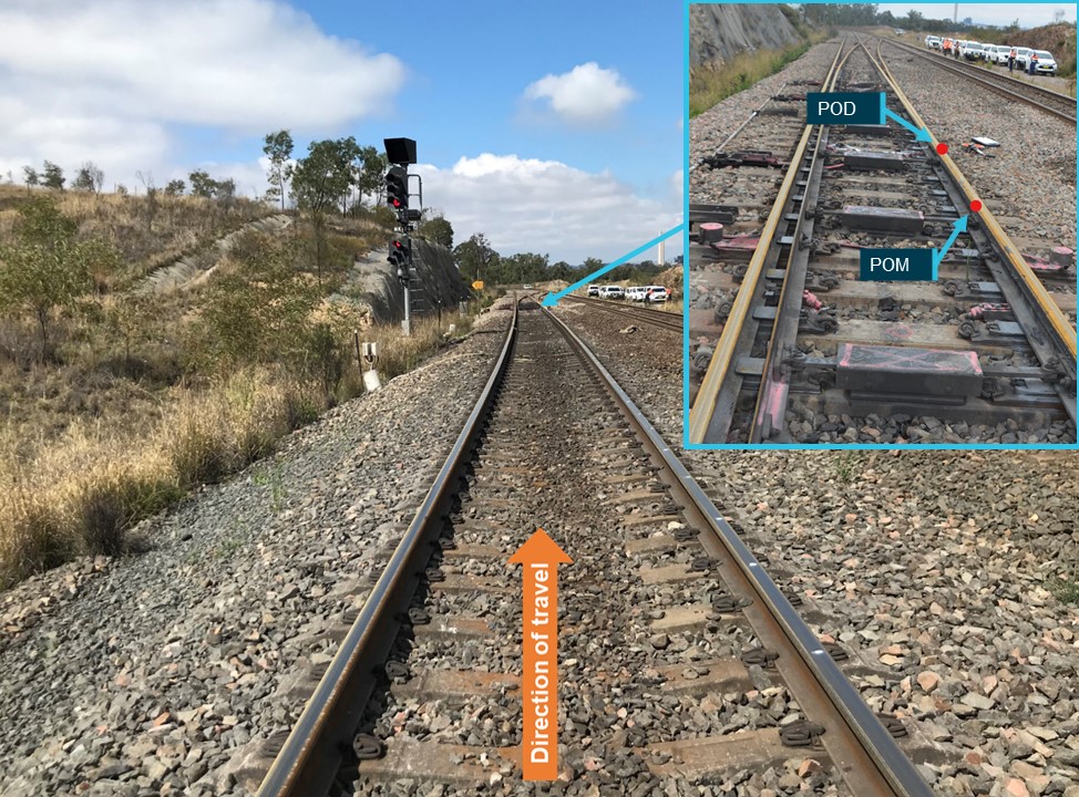
[1]  EST: Coordinated Universal Time (UTC) + 10 hours.

[2] A runaway train includes unintended rolling stock movement and instances of loss of control of a train.

[3] Train crew can have their start time changed to suit operational needs, to be ‘laid back’ is to start at a later time from rostered start time.

[4] The automatic brake is used as the main mechanism for slowing and stopping the train (both locomotive/s and wagons) full details are provided in Train Braking System.

[5] The independent brake is the air actuated friction braking mechanism on the locomotives only. See Independent brake.

[6] The dynamic brake is a braking mechanism of the locomotives only. It is supplementary and designed to reduce the wear and heat generated by the friction braking mechanisms. Refer to Dynamic brake.

[7] Balanced braking is a method of train speed control where an automatic brake application is maintained, while the dynamic brake is manipulated to control speed.

[8] A fully recharged brake pipe has approximately 500 kPa.

[9] A minimum service brake application is a reduction of the brake pipe by 50 kPa to 450 kPa.

[10] Sanding is the release of sand from the locomotive onto the head of the rail in front of the drive wheels. It improves traction at the interface of wheel and rail head. Auto sanding is the automatic release of sand when the system detects the wheel creep (micro slip or slide) at the interface with the rail.

[11] Where the wheel slip/slide was manageable by the locomotive systems, automatic sanding would occur without an indication to the driver.

[12] Serial/cycling braking is a method of train speed control where the dynamic brake is fully applied and the application and release of the automatic brake controls the speed.

[13] Distances measured from Central Station, Sydney (0.000 km).

[14] A ‘full service’ automatic brake application reduces the brake pipe pressure to 350kPa.

[15] An emergency automatic brake application reduces the brake pipe pressure to 0 kPa. Refer to Automatic brake for further information.

[16] 1 in 30 grade means that for every 30 metres of distance travelled, the track descends 1 metre. This grade can also be referred to as a percentage which for 1 in 30 the grade is 3.33%

[17] The train operating conditions are detailed in the infrastructure manager’s TOC Manuals and Waivers.

[18] No-Doz is a caffeine tablet readily available at pharmacies and supermarkets that is marketed to help relieve mental fatigue and drowsiness.

[19] The Fatigue Audit InterDyne (FAID) is a computerised bio-mathematical model, developed by Interdynamics Pty Ltd. The score is the University of South Australia's Centre for Sleep Research Fatigue Management Index (FMI). The FMI is a measure of fatigue risk arising from reduced sleep opportunity expected to be induced by working a particular pattern of work. This score is primarily used in industry to assist rostering. It does not calculate actual impairment.

[20] This competency was developed by Qube for their trainers of train drivers.

[21] This competency was developed by Qube for their driver’s assistants.

[22] ICE (In-cab Communications Equipment) train radio is the digital train radio system used on the ARTC network.

[23] A Condition Affecting the Network is any condition that can or do affect the safety of rail operations in the rail network, they must be reported promptly to the Network Control Officer responsible for the affected portions of track.

[24] Superelevation is the vertical distance between the inside and outside rails, typically measured in millimetres. Excessive difference between actual and design superelevation is one of many factors that can increase likelihood of derailment.

[25] Twist is the difference in level between the two rails, measured over a defined length. Short Twist – 2 metres, Long Twist – 14 metres. Twist can affect wheel-load and vehicle dynamics and is one of many factors that can increase likelihood of derailment.

[26] Tribometer or tribotester is a generic name for a device which is used to simulate and measure friction and wear at the interface between surfaces in a relative motion under controlled conditions.

[27] The locomotive information pack is submitted by the rollingstock owner to the rail network owner prior to its approval on the network and provides all technical and operational specifications of the locomotive.

[28] The load out tonnes is the total weight of the grain loaded into the grain hopper wagons.

[29] BFB is the Brabin, Firman and Block families partnership – BFB Pty Ltd delivering freight, grain, fertiliser and fuel services. Based in Temora, the grain loading terminal is located at Temora West. In 2023, BFB Pty Ltd merged to become AltoraAg

[30] A TOC waiver is a published variation to the train operating conditions manual.

[31] The TfNSW rail network started at 91.080 km to Unanderra, where it joined the South Coast rail line which was also part of the TfNSW rail network.

[32] The coefficient of friction is a measure of the frictional force (or resistance) between one object moving over another.

[33] The penalty brake resulted in an automatic reduction of the brake pipe to 0 kPa. This occurred after vigilance and detonator signal detection timeouts, and locomotive overspeed.

[34] Where a wagon is fitted with a main reservoir pipe to supply the supplementary reservoir, in addition to a brake pipe, the braking system is termed ‘two-pipe’.

[35] Based on information on general airbrake principles supplied by Wabtec Australia.

[36] The CGDY and CGSY wagons were fitted with a supplementary reservoir which was recharged by the main reservoir, not the brake pipe. Removing reliance on the brake pipe recharging all aspects of the train’s braking system resulted in reduced brake pipe recharge and brake release times.

[37] Train separation: where the rear of the train detached from the front of the train, either through coupler failure or uncommanded uncoupling.

[38] Based on information on general airbrake principles supplied by Wabtec Australia.

[39] Note: these pressures are an approximation. The exact pressures would be influenced by the number and diameter of the brake cylinders, diameter of the brake cylinder piston and, length and diameter of the pipework from the supplementary reservoir to the brake cylinder/s.

[40] Based on information on general airbrake principles supplied by Wabtec Australia.

[41] The DBI function was known on earlier locomotives as a ‘dynamic brake interlock’.

[42] OTSI found that the CM class locomotive manual stated that the independent brake was released by the DBI. Testing by OTSI confirmed this does not occur.

[43] Wabtec advised this configuration has not been implemented on the CM class locomotive.

[44] developed by MotivePower Inc. - a subsidiary of Wabtec USA, the locomotive builder

[45] Light engine: one or more locomotives coupled without wagons attached.

[46] Wabco 1988, “26-L” locomotive air brake equipment and devices. American Standard Incorporated, Pennsylvania.

[47] Also referred to within the manual as the ‘power cutout switch’.

[48] Managing low adhesion 2018; Braking systems 2017

[49] Dawson and McCulloch, 2005, Managing Fatigue: It’s about sleep.

[51] Van Dongen et al, 2003, Sleep debt: Theoretical and empirical issues. Sleep debt may be defined as the cumulative hours of sleep loss with respect to a subject-specific daily need for sleep.

[52] Circadian Rhythms first scientific observation in 1729 by Jean-Jaques d’Ortous de Mairan, they are a 24 hour internal cycle that regulates body functions such as sleep and wake times.

[53] Modelling and quantifying the influence of water on wheel/rail adhesion levels – Phase 2 report, conducted for RSSB by University of Sheffield, L Buckley-Johnstone, University of Sheffield, R Lewis, University of Sheffield, K Six, Virtual Vehicle, G Trummer, Virtual Vehicle, 2016

[55] A survey of Wheel/Rail Friction, Federal Railroad Administration, Sept 2017

[56] RO-2013-005 Collision of passenger train T842 with station platform Cleveland, QLD, 31 January 2013

[57] Managing Low Adhesion, AWG Manual, 6th Edition, Jan 2018

[58] Yuan et al 2021

[59] AS 7472 Railway operations – Management of change was prepared by Rail Industry Safety and Standards Board (RISSB) Development Group consisting of representatives from the Australian Rail Industry.

Occurrence summary

Investigation number RO-2020-022
Occurrence date 15/12/2020
Location Dombarton
State New South Wales
Report release date 24/01/2024
Report status Final
Investigation level Defined
Investigation type Occurrence Investigation
Investigation status Completed
Mode of transport Rail
Rail occurrence category Derailment
Occurrence class Accident
Highest injury level None

Train details

Train operator QUBE Logistics
Train number 3966
Type of operation Grain Train
Rail vehicle sector Freight
Departure point Temora, New South Wales
Destination Inner Harbour Port Kembla, New South Wales
Train damage Destroyed

Assistance to the Hong Kong Marine Accident Investigation Section (MAIS) investigation into the crew fatality onboard Luzon Strait while at anchor off Bunbury, Western Australia, on 11 December 2020

Final

On 11 December 2020, a crew member (from Shandong, China) on Luzon Strait fell into the cargo hold and sustained fatal injuries. The Hong Kong Marine Department, Marine Accident Investigation Section (MAIS), is investigating the accident.

At the request of MAIS, the ATSB assisted with the collection of information relevant to the investigation. To protect any information supplied by MAIS to the ATSB, and the ATSB's investigative work to assist MAIS, the ATSB initiated an investigation under the Transport Safety Investigation Act 2003. The ATSB has now concluded its involvement in the investigation.

The Hong Kong Marine Department, Marine Accident Investigation Section is responsible for and will administer the release of the final investigation report into this accident. Any enquires relating to the investigation should be directed to the Hong Kong Marine Department at mdenquiry@mardep.gov.hk.

Occurrence summary

Investigation number ME-2020-003
Occurrence date 11/12/2020
Location Bunbury anchorage
State Western Australia
Report release date 11/05/2021
Report status Final
Investigation type External Investigation
Investigation phase Final report: Dissemination
Investigation status Completed
Mode of transport Marine
Marine occurrence category Fatality
Occurrence class Accident
Highest injury level Fatal

Ship details

Name Luzon Strait
IMO number 9317793
Ship type Bulk Carrier
Flag Hong Kong
Manager Pacific Basin Shipping (HK) Limited
Departure point Singapore
Destination Bunbury, Western Australia

Level crossing irregularity involving freight train 1MP9, at Torrens Road, Ovingham, South Australia, on 7 December 2020

Final report

Report release date: 05/03/2025

Investigation summary

What happened

On 7 December 2020, at about 1155 local time, SCT Logistics train 1MP9 was travelling on the Australian Rail Track Corporation (ARTC) network through Adelaide, South Australia en route to the SCT Logistics Penfield freight facility. 

As the train traversed a slight left curve in the southern approach to the Torrens Road level crossing the driver saw that road traffic was still passing over the crossing about 90 m ahead, and that the level crossing warning equipment had not operated for the approach of the train. The driver initiated an emergency brake application before continuously sounding the locomotive horn, warning road traffic of the train’s approach. Shortly after, the locomotive entered the level crossing and continued to travel a further 260 m before stopping. The trailing freight wagons from the train stopped on the level crossing and blocked the passage of road traffic. There was no collision with road traffic or injury to any person.

What the ATSB found

The ATSB found that, earlier that day members of a subcontracted signal team working on the adjacent Adelaide metropolitan passenger rail network (AMPRN) had undertaken temporary wiring alterations to the control circuits of 2 level crossings to facilitate track tamping work. A late change to the scope of track work required the signal team to undertake additional work to alter the control circuits at another level crossing located at Torrens Road. This scope change placed an increased work demand with short notice on the signal team to implement the pre-approved Torrens Road inspection and test plan procedure. The procedure required the installation of 3 temporary jumper wires, 2 of which were superfluous. The inclusion of avoidable wiring placed an unnecessary task demand on the signal team during the wiring installation stage.

Following the installation stage, the signal team tested the temporary wiring for compliance to the inspection and test plan. The methodology adopted by the signal team did not ensure independence between the installation and testing tasks. This resulted in a wiring error not being corrected and remaining in the Torrens Road level crossing control circuit as a latent condition that could affect the correct operation of the level crossing warning equipment.

The uncorrected wiring error, combined with another signalling system condition that later presented on the AMPRN, resulted in the control input from the ARTC network signalling system not activating the Torrens Road level crossing warning equipment for train 1MP9 as it approached the crossing. 

The ATSB established that the inspection and test plan that was used by the signal team did not include effective test procedures to verify and validate the safety integrity of the level crossing control circuits following the installation of the temporary wiring alterations. The South Australian Public Transport Authority reviewed and approved a package of level crossing inspection and test plans developed by their principal contractor, Acciona, which did not specify any requirement to test the altered wiring following installation. The effectiveness of any testing undertaken to control risk and assure the safety integrity of the rail infrastructure for trains operating on the ARTC network relied solely on the methodology adopted by the subcontracted signal team on the day.

What has been done as a result

Following the incident, Acciona undertook a risk assessment of the level crossing alteration works in consultation with the project stakeholders. New controls associated with works were incorporated into an updated construction work method statement that was subsequently submitted to the South Australian Public Transport Authority for approval. The controls addressed requirements for additional function testing activity and the potential for road closures where wiring alterations were required to facilitate track tamping work.

In December 2020, the Office of the National Rail Safety Regulator (ONRSR) published a notice to rail transport operators highlighting several incidents of the non-operation of level crossings on live lines due to incorrect isolation, and recommended operators ensure the completion of the key tasks specified in the notice.

The Rail Commissioner amended work instructions related to the temporary decommissioning and jumpering of signalling systems. Additionally, the Rail Commissioner worked with the contractor managing the AMPRN to develop improved procedures and forms for use in the temporary alteration of signalling systems.

The ARTC, although not directly involved in the installation of the jumpers at the Torrens Road level crossing, also reviewed and updated several ARTC engineering standards related to the modification of control circuitry of level crossings that were shared between operators. 

Safety message

The correct operation of the active warning equipment installed at level crossings forms the primary engineered risk control for the management of safety at the road-rail interface. A failure of the level crossing warning equipment to operate on the approach of a train introduces significant risk of a collision that may result in fatalities or serious injury to road users, train passengers and crew. 

Any installation or alteration of a signalling system introduces a potential risk to the safety of rail operations that may arise from a design or installation error. To manage the risk, signal designs typically underwent an independent review and approval process and the installed or altered signalling systems were then subjected to various levels of testing, dependent on the complexity of the system change. At a basic level these tests typically involved the certification of the system through the independent verification of the installed wiring followed by the validation of the systems control functions to ensure the safety of rail operations was maintained. 

It is essential that rail transport operators and rail safety workers plan, document, and implement effective testing systems and auditable practices to ensure that new or altered safety‑critical railway infrastructure is rigorously verified and validated to assure the safety integrity of the infrastructure being placed into service.


The occurrence

Overview of the track work

On 2 December 2020, Acciona[1] commenced a program of track work[2] on the South Australian Public Transport Authority (SAPTA) Adelaide metropolitan rail network (AMPRN) as part of the Gawler rail electrification project (GREP). The Acciona worksite was located on the Gawler up line[3] between the 2.7 km mark[4] at North Adelaide Station and the 8.5 km mark at Grand Junction Road, located north of Islington Station (Figure 1 ,detailing the stations within the work area). The Australian Rail Track Corporation (ARTC) interstate rail line ran parallel to the AMPRN through the worksite and was protected by the AMPRN level crossing warning equipment at each road crossing location.

Figure 1: Acciona Gawler rail electrification project worksite

Figure 1: Acciona Gawler rail electrification project worksite

Source: NationalMap, Australian Government, annotated by the ATSB

To facilitate the track tamping work, rail safety workers[5] from Rail Industry Constructions undertook electrical work on the AMPRN signalling system under a subcontract to Acciona. The electrical work involved the removal of track circuit[6] connections from the rails and if required, the installation of temporary jumper wiring to the control circuit of a level crossing that would be affected by the removal.

The Gawler up and down rail lines were closed to scheduled passenger services and the jumper wiring was to prevent the unintended operation of the level crossing flashing lights, gongs and boom barriers due to the track work on the AMPRN. On completion of the track work each day, the signalling system was reinstated to the original state.

The ARTC interstate rail line was open to train services and normal operation of the level crossing warning equipment was to be maintained for a train travelling on that line.

Prior to the arrival of train 1MP9

4 December 2020

On the morning of 4 December 2020, the Rail Industry Constructions rail safety workers comprised a tester in charge (TIC), a signal electrician and 2 trade assistants (signal team). The team attended the daily Acciona pre-work briefing where the TIC spoke with the Acciona possession protection officer (PPO) and other Acciona project representatives to determine the scope of the team’s work for that day. The agreed work involved the removal of connections from the rails and alterations to the Pym Street and Belford Avenue level crossing control circuits.

Following the briefing, the TIC and signal electrician travelled to the Islington relay room, located around 500 m north of the Islington station, and used the pre-approved inspection and test plans (ITPs) to install and test the alterations to the 2 level crossings. On completion of this work, they moved from the relay room to the rail track where, in conjunction with the remainder of the signal team, they removed the required connections from the rails in preparation for the track work to commence. 

At the end of the track work for that day, the signal team reinstated the connections and tested the track circuits. The TIC and signal electrician then went to the Islington relay room to remove the jumpers from the 2 level crossing control circuits before testing the correct operation of the associated warning equipment, as per the respective ITP. 

7 December 2020

On 7 December 2020, at about 0630 local time, the signal team attended the routine Acciona pre-work briefing. The scope of the work for the day was to again remove connections from the rails and alter the Pym Street and Belford Avenue level crossing control circuits. The TIC recalled that during the pre-work brief, the Acciona work group supervisor asked them to remove as many of the connections from the rails that they could toward the Dudley Park station.

The TIC and signal electrician travelled to the Islington relay room to alter the control circuits for the 2 level crossings. At about 0805, the TIC and signal electrician completed work and moved to the track to remove the connections from the rails between the Islington and Dudley Park stations, as they had done on the previous days. 

At about 1020, the signal team completed that work. Shortly after, the work group supervisor asked the TIC if they would also undertake alterations to the Torrens Road level crossing control circuit and remove additional connections from the rails, so that work could continue past Dudley Park station towards Torrens Road.

Although this work was not planned during the pre-work briefing, the TIC stated they felt an obligation to comply with the request and undertake the additional tasks, so the work group could recover from previous delays in their schedule. The TIC felt the signal team was under constant pressure to complete tasks and there was not an understanding from the tamping workgroup of the time needed to undertake the signal works. The TIC stated they agreed to the request on the proviso that the track work up to Dudley Park station be completed so that the signal team could start to reinstate the connections to the rails in preparation for testing the correct operation of the track circuit. 

At about 1032, the TIC telephoned the Acciona PPO to tell them that the track work was progressing well, and the work group would likely reach the Torrens Road level crossing later that day. The TIC also told the PPO they had agreed with the supervisor of the work group to expand the signal team’s scope of work to include the alteration of the Torrens Road level crossing control circuit. The TIC reached agreement with the PPO that they would first undertake the alteration of Torrens Road control circuit, before meeting with them to provide a completed infrastructure booking advice form (IBA).[7]

At about 1045, the TIC told the signal electrician of the change to the scope of work and that they would now install jumpers at Torrens Road, before returning to remove the additional track connections between Dudley Park and Ovingham stations. Shortly after, the TIC and signal electrician arrived at the Torrens Road level crossing and accessed the location case that housed the level crossing control circuit. 

The TIC and signal electrician positioned themselves at the front (Figure 2) and rear (Figure 3) of the location case (Loc 472) respectively to begin installation of the jumpers. The TIC kept the ITP, as was their usual practice, and called instructions to the signal electrician on where to connect the ends of each jumper wire. The ITP circuit diagram required 3 jumper wires to be installed. The TIC marked off the installation of each corresponding connection on the ITP as the work progressed. 

The rear view of location case 472 shows the temporary jumper wiring (red). The installation method for the jumper wiring was intended and meant to make temporary wiring conspicuous from other wiring installed at that location. 

Figure 2: Torrens Road location case (Loc 472) front view

Figure 2: Torrens Road location case (Loc 472) front view

Note: Location case 472 showing signalling control equipment, image modified by ATSB to annotate and remove graffiti tags from exterior of location case. Source: Acciona, annotated by the ATSB

Figure 3: Torrens Road location case (Loc 472) rear view

Figure 3: Torrens Road location case (Loc 472) rear view

Source: Acciona, annotated by the ATSB

Following the installation of all the jumpers, the TIC operated the test switch[8] to check the correct operation of the level crossing warning equipment. The warning equipment functioned as the TIC expected. 

The TIC and signal electrician then left the Torrens Road level crossing location. The TIC went to meet the PPO to complete the IBA. The signal electrician went to the track and met with the 2 trades assistants in readiness to remove the electrical connections from the rails. 

At about 1120, the TIC and PPO completed the IBA for the work to the Torrens Road level crossing. Shortly after, the TIC contacted the signal electrician by telephone informing them that the IBA was complete, and they could commence removal of the connections from the rails.

During this work, connections to 572C track located between the Dudley Park and Ovingham stations were removed. The removal of the track connections caused an associated relay in the level crossing control circuit for the Torrens Road level crossing to also de-energise. 

Arrival of train 1MP9 at Torrens Road level crossing

At about 1155, SCT Logistics train 1MP9, travelling on the ARTC rail line, occupied the Torrens Road level crossing southern approach circuit. The ARTC signalling system detected the train and sent a control input to the AMPRN Torrens Road level crossing control circuit to activate the warning equipment. The warning equipment did not activate in response to the ARTC control input. The train, travelling at a speed of 44 km/h continued to approach the Torrens Road level crossing. 

At about 1156, as the train rounded a slight left curve about 90 m before the Torrens Road level crossing, the driver saw that road traffic was still crossing in front of the train and that the warning equipment had not activated. The driver immediately moved the automatic brake handle to the emergency position to apply maximum braking. About 45 m from the crossing the driver started to continuously sound the locomotive horn to warn road traffic of the train’s approach.

Train 1MP9 continued to brake, entered and travelled through the level crossing, narrowly missing a number of road vehicles before the lead locomotive stopped at the 5.25 km mark,[9] about 260 m north of the level crossing. Trailing freight wagons from 1MP9 blocked the Hawker Street and Torrens Road level crossings for the passage of road traffic.

Response to Torrens Road level crossing irregularity

At about 1158, the driver of 1MP9 made an emergency radio call to the ARTC network control officer (NCO) notifying the Torrens Road crossing warning equipment had failed to operate for their train and that there were several near misses with road vehicles as the locomotive passed over the level crossing.[10] The NCO instructed the train crew to remain in situ and wait for the arrival of support personnel to manage safety at the site (Figure 4).

Shortly after the incident, representatives from SAPTA, ARTC, Acciona, the Office of the National Rail Safety Regulator and South Australian Police attended the site. SAPTA representatives coordinated the onsite response, gathered evidence, and commenced an internal investigation. 

Rail vehicles from 1MP9 continued to block the Hawker Street and Torrens Road level crossing until about 1505, when, following agreement with SAPTA representatives, the ARTC NCO issued an authority to the train crew to continue their journey to the SCT Logistics Penfield rail freight centre.

Figure 4: Train 1MP9 at Torrens Road level crossing

Figure 4: Train 1MP9 at Torrens Road level crossing

Note: Level crossing south-eastern road approach. Source: Rail Commissioner

Context

Personnel information

Train crew

At the time of the incident, train 1MP9 was crewed by 2 drivers. Both drivers held route competencies that were current for the track section travelled. The health assessments of each driver were current, and they had both met the standard prescribed by the National standard for health assessment of rail safety workers without restriction. 

Signal team 

The Rail Industry Construction (RIC) signal team comprised the tester in charge (TIC), a signal electrician and 2 trades assistants. The TIC and signal electrician were rail safety workers, assessed to have the required competencies to undertake the rail safety work on the Adelaide metropolitan passenger rail network (AMPRN) signalling system. The statement of competency record for the TIC and signal electrician identified they had around 55 and 45 years of experience respectively undertaking rail safety work on signalling infrastructure. The experience included previous engagements and the successful completion of similar tasks on both the AMPRN and Australian Rail Track Corporation (ARTC) network signalling infrastructure.

The trades assistants were supervised by the TIC or signal electrician and were not qualified to undertake unsupervised rail safety work on the signalling equipment. Neither trades assistant was directly involved with work to implement the Torrens Road inspection and test plan (ITP).

The signal electrician and TIC underwent health assessments as per the requirements of the National standard for health assessment of rail safety worker as a rail safety worker category 1 and 3 respectively. Although there were anomalies with the TIC’s health assessment category and currency, there was no evidence the TIC or signal electrician health assessment categorisation or any physiological condition present at that time influenced the incident at Torrens Road.

In the week prior, the TIC and signal electrician worked between 8.5 and 12 hours each day on the Gawler rail electrification project (GREP) undertaking the signalling alterations to facilitate the track tamping works (see Appendix A – Fatigue risk management program). These hours were generally consistent with the Acciona fatigue management guidelines (10 to 12 hours per day up to a maximum cumulative total of 60 hours per week).

The Acciona Alliance rail safety management plan outlined the procedures put in place to satisfy the accreditation requirements of the Rail Commissioner[11] (RComm). In particular, the competency, health and fitness, and fatigue management programs applicable to the GREP rail safety workers of Acciona, and subcontractor RIC. For additional information related to each program see Appendix A – GREP safety management system procedures.

Train information

SCT Logistics train 1MP9 comprised locomotives CF4430, CF4410 and CSR002 hauling 46 rail vehicles. The train was 1,773 m in length and had a gross mass of 4,561 tonnes. The train was travelling from Dooen, Victoria to the SCT Logistics Penfield rail freight centre near Adelaide, South Australia. 

Railway infrastructure

The Australian Rail Track Corporation

The ARTC interstate rail line at Torrens Road consisted of a single standard gauge (1,435 mm) rail track. The track was constructed using continuously welded rails secured to concrete sleepers by resilient fasteners and supported on crushed rock ballast.

The signalling system enabled the bi-directional operation of rail traffic. The system incorporated level crossing controls that functioned independently from the signalling system on the adjacent AMPRN. Rail traffic approaching Torrens Road level crossing on the ARTC rail line triggered a level crossing control, which then provided an input to the AMPRN signalling system to activate the level crossing warning equipment, and the road traffic light signals.

South Australian Public Transport Authority 

The AMPRN at Torrens Road consisted of 2 broad gauge (1,600 mm) rail tracks. The tracks were constructed using continuously welded rails secured to concrete sleepers by resilient fasteners and supported on crushed rock ballast.

The Torrens Road level crossing was located on an arterial road near the north-western fringe of the Adelaide central business district. The rail track infrastructure of the AMPRN and ARTC network ran in parallel at that location (Figure 5). 

The configuration of the signalling system for the AMPRN enabled passenger rail traffic to principally travel in either an up or down direction[12] on the respective track. The Torrens Road level crossing control equipment could be configured locally[13] to enable the automatic operation of the warning equipment to facilitate single line bi-directional working (with limited functionality). Prior to the implementation of single line bi-directional working, an alternative method of safe working was required for the management of rail vehicle movements.

All rail tracks were protected by flashing lights, gongs and half boom barriers mounted to mast assemblies. In addition, several mast assemblies were equipped with 3 aspect road traffic light signals. The traffic light signals interfaced with the railway level crossing control system and other road traffic light signals at an adjacent road traffic signalled intersection, located about 100 m to the south-east. The traffic light signals controlled the flow of road traffic to prevent queuing of road vehicles across the rail tracks at the Torrens Road level crossing.

The Torrens Road flashing lights, gongs, half boom barriers, and the associated trackside signalling and communication systems were operated and maintained by the South Australian Passenger Transport Authority (SAPTA) under the rail safety accreditation of the RComm.

Figure 5: Road and rail track layout at Torrens Road level crossing

Figure 5: Road and rail track layout at Torrens Road level crossing

Source: Google Earth, annotated by the ATSB

Gawler rail electrification project

Overview

The GREP works were managed by the South Australian Department of Infrastructure - Transport project delivery (TPD) and undertaken under the RComm rail safety accreditation. The RComm, SAPTA and TPD were all departments or bodies under the South Australian Department for Infrastructure and Transport (Figure 6). Relevant SAPTA safety management system standards, procedures and work instructions for the AMPRN signalling and communications systems were adopted by TPD to manage the GREP works.

Figure 6: AMPRN rail network and GREP project organisation structure

Figure 6: AMPRN rail network and GREP project organisation structure

Source: ATSB

The TPD delivered the GREP works through the principal contractor, Acciona, managing the project alliance safety management plan. Acciona initially engaged subcontractor RIC to undertake works associated with the provision of electrical conduits and pits for the project. Acciona later varied the subcontract with RIC to include the provision of qualified rail safety workers to undertake project work as directed by Acciona. Specifically, the alteration and testing of parts of the level crossing control circuitry, and removal and reinstatement of connections to the rails in the areas affected by the GREP track works. The operation of rail maintenance and construction vehicles used in conjunction with the GREP work site was under the Acciona rail safety accreditation as a rolling stock operator. Acciona was not accredited in South Australia as a rail infrastructure manager (RIM).

The roles, responsibilities, authorities, accountabilities and general safety duties applicable to the various parties involved in the contractual arrangements to deliver a rail project, such as the GREP, were outlined in the Rail Safety National Law – South Australia Act 2012 (RSNL) and associated guideline documents published by the Office of the National Rail Safety Regulator and the Rail Industry Safety and Standards Board.

The RSNL incorporated the principles of shared responsibility and accountability in contractual arrangements and highlighted that the management of rail safety was the shared responsibility of everyone involved in undertaking the required rail safety work. The degree to which a person was accountable for rail safety was dependent on the nature of the risk their activities might pose to rail safety. The management of risks associated with railway operations was therefore predominantly the responsibility of the person best able to control them. 

Additional information related to the RSNL and guidelines for contracting arrangements are contained under Appendix B – Contracting in the rail industry.

Procedures for temporary signalling system alterations

To manage potential risks to rail operations when undertaking temporary wiring alterations to the level crossing control circuits, RIC developed documentation that defined the project scope and responsibilities, work method statements, and the ITP specific to each level crossing location.

Level crossing inspection and test plan approval procedure

On 23 September 2020, representatives of Acciona, TPD and RIC met to establish the procedure that Acciona would follow to submit the draft ITPs, which included the level crossing control circuit schematic drawings to TPD for approval. 

The agreed procedure (Figure 7) required Acciona to submit the draft ITPs for all the affected level crossing locations as a single package. TPD was then to forward the package to SAPTA for review and final approval. Once approved, SAPTA would endorse a network access authority application (NAA) to allow the RIC rail safety workers (the signal team) access to the AMPRN to commence work onsite.

Figure 7: Inspection and test plan approval flowchart

Figure 7: Inspection and test plan approval flowchart

Source: Acciona

During the meeting, TPD identified that the work to isolate (decommission) level crossing functionality was ‘specialised works’ and that the SAPTA procedures for installing temporary wiring, testing, and commissioning activities were to be followed by the signal team. 

Although this requirement was identified during the meeting, neither TPD nor SAPTA provided Acciona or RIC with a copy of the SAPTA work instruction WI-AM-SP-1234 Signalling system temporary decommissioning and jumpering or the SAPTA forms FO-AM-SE-1226 Inspection and test plan template and FO-EM-SE-1226 - Amendment log for their reference or use in the development of the GREP signalling procedures for the specialised works specific to the level crossings (see SAPTA signalling system temporary decommissioning and jumpering work instruction).

To develop the draft ITPs, RIC adapted a SAPTA ITP document sourced from a project RIC had previously undertaken for TPD on the AMPRN. The formatting of the ITP document was generally consistent with the SAPTA form FO-EM-SE-1226 and included sections related to the:

  • document and version control
  • plan approval and the allocation of roles and authority to implement the plan
  • master test plan listing in sequential order the equipment and a description of the required task to be undertaken
  • certification by the TIC of the tasks and related testing activity that were complete.

RIC representatives also prepared 2 copies of the relevant control circuit diagrams for each level crossing installation. One copy showed the jumpers (marked up in red) to illustrate the required termination point of each wire in the control circuit. The second copy showed the jumpers (marked up in green) to illustrate the wires that must be removed following completion of the track work for that day. A fresh copy of the ITP and circuit diagram package was produced for each occasion where modification of a level crossing control circuit was necessary.

On 25 September 2020, the RIC representatives[14] who had either produced, checked or approved content, signed off on version 1 of the draft ITP for each of the level crossing installations the GREP track work program would affect. Acciona subsequently submitted copies of the draft ITPs by email as a single package to TPD for forwarding to SAPTA for review and final approval, as per the ‘one review gate process’ in the approval flowchart. 

Signalling work scope procedure

On 15 October 2020, RIC developed the GREP Tamping project signalling methodology document to describe the scope of work for the project, the network access arrangements and the division of responsibilities between Acciona, RIC and SAPTA for managing the affected signalling infrastructure. 

The document specified that RIC would provide suitably competent staff (the signal team), and that prior to the commencement of any site activity, these staff would attend the daily Acciona and PPO pre-work briefings. During the pre-work briefings, RIC staff, in this case the TIC, was required to notify SAPTA maintenance staff and the PPO of the proposed location of work and the tasks to be performed that day. The document also specified that under no circumstances was the signal team to undertake any signalling work until the TIC had an Infrastructure booking advice (IBA) in place with the PPO (see Procedure for implementing an infrastructure booking advice.).

After implementation of the IBA, the scope of work specified the signal team was responsible for:

The disconnection of equipment and installation of temporary bridging [jumpers] to ensure that the level crossings remain working for ARTC trains will be carried out as per the approved ITP’s and recorded in the ITP’s.

On 20 October 2020, the TPD signal site manager approved the content of the signalling methodology document, which specified the signal team was to carry out the instructions contained in the approved ITP. The methodology document also specified that track circuit maintenance record cards and the ITP documents must be completed as each piece of signalling infrastructure was tested and certified and that photographic records were taken of the locations before commencement and on completion of works. 

While the review and approval process for the tamping project signalling methodology document was ongoing, the ITPs referenced in the document were still in draft format, having been forwarded by TPD to SAPTA for review and approval the day prior to the finalisation of the methodology document. 

Approval of draft inspection and test plans

On 22 October 2020, SAPTA responded to TPD requiring amendments to several ITPs that were identified to contain errors.[15] The review found no error or omission in the Torrens Road ITP document or circuit diagrams.

On 26 October 2020, Acciona resubmitted the corrected ITP packages.

On 30 October 2020, the SAPTA again responded highlighting 3 of the packages[16] still contained errors and required Acciona to correct and resubmit. SAPTA advised Acciona that the NAA for the track work would be withheld until the identified errors were corrected and the affected packages resubmitted for approval.

SAPTA communicated the outcome from the review process via a series of emails through TPD to Acciona. There was no record in the emails or respective electronic copies of the ITPs that SAPTA was satisfied the proposed testing arrangements managed risk, were consistent with the requirements of the SAPTA work instruction Signalling system temporary decommissioning and jumpering or that SAPTA had approved (certified) each ITP for use on the AMPRN. However, SAPTA did approve the NAA for the signal team to access the AMPRN and undertake the specialised work on the signalling system in accordance with the ITPs.

Although there were a series of amendments that occurred to some of the ITP documents to correct details related to the termination point of the jumpers, the document control version number and date recorded in the electronic copy of the respective documents remained as version 1 of 25 September 2020. 

RIC subsequently provided the TIC with hard copies of the packages for each level crossing installation affected by the GREP. The package for each level crossing installation comprised a document describing the required plan for completing the inspection and test tasks and 2 copies of the circuit diagram marked up in red and green. None of the packages included a copy of the SAPTA forms FO-EM-SP-312 Signal circuit jumpering decommissioning or FO-EM-SP-313 Amendment log. Dependent on the planned track tamping work for that day, the TIC was then required to select and implement the relevant ITP. 

The hard copy of the ITP documents subsequently issued by RIC for the TIC to implement, contained no record to identify the documents were the final version approved by SAPTA for use on the AMPRN. The TIC later reflected that the practice of issuing ITP documents without records of final certification by the RIM (in this case SAPTA) was unusual, but appeared normal for that particular operator.

Construction work method statement – track works

On 6 November 2020, Acciona released an updated version of the construction work method statement (CWMS) for the tamping and regulating track works on the AMPRN. The CWMS described the resources, processes and methodologies Acciona would use to undertake the track work on the Gawler rail line. The CWMS was developed to identify and control any risk that may arise during the works and document how these would be addressed.

The CWMS recorded that Acciona assumed the policies and procedures within the Acciona management systems were compliant with the requirements of the RComm rail safety accreditation. However, Acciona noted that, although the works were undertaken under the accreditation of the RComm it did not absolve Acciona from its responsibilities under the RSNL.

The CWMS detailed the planned scope of works and arrangements that included the identification of resource requirements, risk assessments, work health and safety, methodology procedures, and inspection and test plans to undertake the tamping and regulating work on the AMPRN. There was no consideration in the CWMS of the subcontracted work to RIC associated with the removal/reinstatement of connections to the rails or modification to the level crossing control circuity.

Although the engagement of RIC to undertake alterations to the signalling system was not specifically identified in the CWMS, the documentation developed by RIC for the identification of resource requirements, risk assessments, work health and safety, methodology procedures, and ITPs were generally consistent with the practice detailed in the CWMS. 

Procedure for the installation of the temporary wiring

On 16 November 2020, RIC submitted a safe work method statement (SWMS)[17] to Acciona detailing how the connection, installation, termination and test and commission tasks were to be performed on the AMPRN signalling infrastructure. The SWMS outlined the worker competencies, site supervision arrangements and associated reference documents (NAA forms, approved tamping project signalling methodology and ITPs) necessary to undertake the work.

The SWMS listed the various steps involved in performing each task, identified the hazards and risk assessed the related controls. The resulting residual risk rating for the various steps was assessed as being either medium or low, dependent on the task. However, the overall risk assessment for the SWMS determined the work activity was high risk.

The potential hazards and associated controls were primarily focused on managing work health and safety implications and not the operational hazards and risk to rail safety that may arise from the modification of vital signalling control systems. 

The SWMS did not address the requirements of the SAPTA work instruction Signalling system temporary decommissioning and jumpering, particularly in relation to managing the potential risk to rail safety for the adjacent ARTC network. There was no record Acciona, TPD, SAPTA or RComm had reviewed and approved the use of the SWMS document for the GREP works.

Procedure for implementing an infrastructure booking advice.

The TPD provided Acciona with a copy of the SAPTA AMPRN Train rules and procedures Volume 4 - Work on track rules and procedures. The document contained instructions to rail safety workers on the requirements and procedures to compile an infrastructure booking advice (IBA) form. The IBA must be used wherever infrastructure was:

  • permanently installed or commissioned
  • permanently decommissioned or removed
  • temporarily removed from service
  • returned to service following temporary removal from service.

The procedure provided various options to complete the IBA, one of which allowed the operations controller and rail safety worker to jointly compile the IBA. This allowed completion where the parties were remote from each other. If the rail infrastructure work was within a work site under the control of a PPO, a copy of the IBA was to be provided to the PPO before any equipment was either ‘booked out’ or ‘booked into’ service.

In this instance, the Gawler rail line was closed to rail traffic for the GREP track work and the worksite was under the control of a PPO. Under this arrangement the requirements of the AMPRN train rules were reflected in the GREP Tamping project - signalling methodology procedure, which required the TIC on arrival to contact the PPO and advise of the location of works and tasks to be undertaken. It also specified that no work be commenced unless the TIC had an IBA in place with the PPO. There was no mention in the methodology procedure of a requirement to provide a copy of the completed IBA to the PPO.

The IBA completed following the alterations to the Torrens Road level crossing control circuit recorded that the level crossing warning equipment would be operational by the test switch only for the AMPRN lines (indicating both up and down). This statement was only partially correct since the temporary control circuit modifications, detailed in the ITP, bridged control functions on the AMPRN up line but retained the down line control function. 

The purpose of the IBA document was to communicate and record the intended status of critical rail infrastructure or equipment to the operations controller or PPO controlling the movement of rail traffic, which may be affected by the proposed infrastructure changes. 

The IBA process, as applied to the GREP, considered only the infrastructure and equipment alterations that were planned to be affected by the work, in this instance the AMPRN Gawler rail line level crossing up direction approach. As the ARTC network was not intended to be affected or removed from service, there was no requirement stipulated in the IBA for the TIC or PPO to notify the ARTC network operations controller and advise that an alteration was made to the control circuitry of the level crossing protections shared by the 2 networks.

SAPTA signalling system temporary decommissioning and jumpering work instruction

The SAPTA work instruction Signalling system temporary decommissioning and jumpering specified the processes a qualified SAPTA employee must undertake to temporarily decommission signalling system infrastructure on the AMPRN. Decommissioning included the installation of circuit jumpering and the removal of track circuit connections, the same type of specialised work that SAPTA identified was to be undertaken by RIC for the GREP.

The SAPTA work instruction specified the roles and responsibilities of a SAPTA employee (rail safety worker) undertaking the specialised work as:

  • Qualified employees are responsible for ensuring signalling assets are decommissioned using the process below. Qualified employees performing temporary decommissioning and jumpering shall ensure another qualified employee is available on site to verify correct installation of jumpers. Qualified employees shall ensure all documentation associated with temporary decommissioning and jumpering contains complete and accurate information.
  • Where temporary jumpering affects adjacent railway (i.e. ARTC), personnel shall ensure the rail transport operator has been made aware of the work being undertaken. Where signalling functions on adjacent lines are required to remain active (i.e. level crossings isolated for AMPRN line but should operate for ARTC movements), the correct operation of those functions shall be verified by the qualified employee performing the decommissioning/jumpering.

Additionally, the instruction detailed the processes a qualified employee was to follow when undertaking either unplanned or planned decommissioning work. Unplanned or ‘emergency work’ covered situations where it was not possible to develop and use a pre-approved ITP, due to the unpredictable nature of the work and the resultant time constraints in responding to the particular emergency. 

In such cases, the qualified employee was to first consult with the operations controller for that particular location to inform them of the signalling infrastructure affected. The qualified employee was then to record any decommissioning or reinstatement work undertaken on the signalling system infrastructure form FO-EM-SP-312 Signal circuit jumpering decommissioning (Figure 8). The qualified employee was required to include detail for the:

  • identification of the qualified employee actioning the work including their qualification
  • identification of the qualified employee verifying the work including their qualification
  • notification to the operations controller of that area and the identification of the equipment to be decommissioned
  • description of the proposed task (that is, detailing the circuit functions jumpered and track leads removed)
  • verification by another qualified employee.

Figure 8: Example form – SAPTA signal circuit jumpering decommissioning 

Figure 8: Example form – SAPTA signal circuit jumpering decommissioning

Source: South Australian Public Transport Authority

For occasions where the decommissioning works were able to be planned, the work instruction required the:

  • correlation of affected signalling circuits prior to the ITP development (to ensure accuracy of the control circuit drawings)
  • preparation and certification of an ITP by a qualified employee that recorded any decommissioning or reinstatement work to be undertaken on the signalling system infrastructure
  • independent review to check and certify the ITP prior to issue
  • inclusion of the form FO-EM-SP-312 Signal circuit jumpering decommissioning
  • TIC or qualified employee responsible for executing the plan to take receipt of the ITP
  • decommissioning work to be actioned in accordance with the approved ITP for that project or works
  • amendment (if required) to the ITP be recorded on form FO-EM-SP-313 Amendment log. Any amendment was to be independently verified.

For planned works, the work instruction required both the development of an ITP form and the inclusion of form FO-EM-SP-313. The format of the ITP and FO-EM-SP-313 form templates included duplicated information related to the required tasks and records to be kept. The work instruction did not specify how the template forms were to be used together when planning work in advance.

In summary, SAPTA required a qualified employee (rail safety worker) undertaking either unplanned or planned decommissioning work to ensure that: 

  • another qualified employee was available onsite to verify the correct installation of jumpers 
  • all documentation associated with temporary decommissioning and jumpering contained complete and accurate information
  • the correct operation of those functions was verified [validated] by the qualified employee performing the decommissioning/jumpering
  • where signalling functions on adjacent lines were required to remain active (that is, level crossings isolated for the AMPRN line but should operate for ARTC movements), the correct operation of those functions was to be verified by the qualified employee performing the decommissioning/jumpering.

Industry standards for signalling testing and commissioning plans

Overview

The Rail Industry Safety and Standards Board published standards AS-7717-2016 Signal testing and commissioning and AS-7716-2017-Signal testing process. These standards were to provide rail transport operators,[18] such as the RComm, with a common framework to plan and execute the inspection, testing and commissioning activity for new and altered signalling infrastructure on their respective networks. 

Signal testing and commissioning

Standard AS-7717-2016 defined the range of inspection and test activities necessary for a rail transport operator to certify the safety of the new or modified signalling system before placing it into service. These included the testing activity required following minor works, such as alterations for the installation and removal of temporary jumper wiring to level crossing control circuits. 

Such alterations were to be tested in accordance with the standard considering the type, extent, and risk associated with the particular alterations being made. The nature of the testing and commissioning activities could vary dependent on requirements determined by the accredited rail infrastructure manger,[19] which for the AMPRN and associated GREP works was also the RComm.

The standard stipulated the railway organisation and its management structure together with the planning process and staff competence were each critically important to ensure the railway signalling systems were safe for the operation of trains. The requirements for the planning process included elements such as:

  • the production of formal documentation of the required activities and tasks
  • the allocation of responsibilities and the personal competencies required to undertake the tasks
  • the independence required for people’s involvement among the different parts of the work
  • the documentation to be used for the testing and commissioning plans.

The overall objective was the development of a detailed ITP, which documented the processes, work activities, and the controls implemented to achieve the requirements of the standard, using an agreed format. 

For the GREP works, the subcontractor, RIC, identified and undertook the development of the ITPs for each level crossing installation. These plans were then forwarded through Acciona and TPD to SAPTA for approval.

Identification of interfaces outside the commissioning boundaries

Standard AS-7717-2016 also required that before inspection and testing activities commenced at sites containing signalling equipment that was in use, the RIM was to be informed of the extent and program of work. Additionally, consideration should also be given to elements outside of the defined boundaries of the commissioning area. 

For the GREP level crossing works, the TPD and SAPTA were aware of the extent of the works, and inspection and testing activity through the approval of the GREP Tamping Project Signalling Methodology document and the coordination activities through the TPD onsite project manager. 

Interfaces outside the GREP boundaries were managed through the rail-to-rail interface agreement[20] between SAPTA and ARTC. The agreement managed the identified risks to safety that may arise from railway operations carried out by either operator (SAPTA or ARTC) that would affect the other at the shared road-rail interfaces. The agreement included the interface at the Torrens Road level crossing.

The agreement required each operator to provide advance notice to the other, prior to commencing any works likely to materially affect the other operator’s rail network. To address this requirement, Acciona, via TPD, provided ARTC advance notice of the proposed GREP work in the format of a draft train notice.

On 1 December 2020, ARTC published train notice TN2925 advising train crew operating on the ARTC network that tamping works were to be undertaken on the adjacent AMPRN. The notice contained the following information:

  • The GREP project will be undertaking tamping and regulating works on the Gawler line between 2.7km to 8.5km (AMPRN km) on both the up and the down track. The works will have no impact on ARTC line and there will be no potential to foul ARTC.
  • As part of the works some ballast will be placed inside the corridor North of Ovingham Railway station using the access gate on the ARTC side (at least 3m away from the tracks) and a loader will be intermittently at the stockpile area to load trucks with ballast under TOA [track occupancy authority] between trains.
  • The Qualified Rail Safety Worker will be required to take out adjacent line protection TOA [track occupancy authority] ATP [as traffic permits] when operating the Ballast Regulator Side Wing Plough on the Down Main Line.
  • The works will have no impact on ARTC Network Services or Operations.
  • The Qualified Rail Safety Worker will ensure that communications are made with the Network Controller prior & post work.

The notice indicated that the proposed tamping works would have no impact on the ARTC network nor the potential to obstruct traffic operating on that line.[21] Neither the notice, nor other communication between Acciona, TPD or SAPTA and ARTC identified that temporary alterations would occur to the level crossing control circuity of the shared level crossings in the work area between North Adelaide and Islington, encompassing Torrens Road. 

Requirement for independence of persons undertaking testing activity

The planning and implementation of an effective inspection and test regime was a critical element to reduce risk to rail safety associated with undertaking works on vital signalling control equipment. This required the development of ITPs that must include sufficient tasks to support the verification[22] and validation[23] of any new or altered safety‑related signalling system. The standard required:

These verification and validation processes shall be performed at an appropriate level of independence from the construction and implementation process to be verified and validated. The degree and nature of this independence shall be determined by taking into account at least the following factors:

(a) The risk of errors being perpetuated during the verification and validation process due to there being too close an association between the persons performing the verification and validation and those involved in the construction and implementation process.

(b) The risk imposed on the existing system both by the introduction of the system to be verified and validated and by faults or inconsistencies in that system.

The TIC and signal electrician worked together in undertaking both the installation of the temporary jumper wiring and the verification and validation testing of the level crossing control circuitry. Although, in this instance there was close association between the persons performing the work, the standard allowed this arrangement through placing a higher weighting on competence of organisations rather than independence provided: 

…where independence cannot be achieved other controls should be considered to assure any additional risk due to a lack of independence is controlled. If it is not possible to achieve independence, then approval shall be given by the RIM [rail infrastructure manger] of the alternative control measures that will be used to control the additional risk due to the lack of available competent independent resources

Other than reviewing the draft ITPs, there was no record of SAPTA assessing the competencies of the rail safety workers undertaking the signalling work. Further, there were no alternative control measures implemented to manage the risk due to the limited availability of other competent independent resources to undertake an independent inspection and test activity.

Signal testing process

The second standard, AS 7716-2017 signal testing process, provided greater detail of the types of testing methods and procedures that may be used when commissioning typical signalling apparatus and systems. Emphasis was again placed on the importance of maintaining independence between the performance of the installation and testing activities. Although the standard described the minimum requirements for undertaking inspection and testing activities, it did not diminish the obligation of the verification, validation and test personnel to decide what should be tested and how it should be tested respectively. 

The types of testing methods and procedures were grouped under post‑installation testing, which was to independently verify the new or altered work was built in accordance with the design documentation (in this case the circuit diagram) and secondly, the function testing and validation phase, which proved the new or altered work performed as designed.

Installation testing verified the system was built in accordance with the design required testing include the following:

  • detailed circuit testing
  • cables testing
  • apparatus testing.

System testing and validation included the following:

  • [design] function testing
  • testing to control tables[24]
  • aspect sequence[25] testing
  • [design] principles testing.[26]

For the GREP level crossing works, RIC provided the TIC with a pre-approved suite of ITPs to specify the tasks they were required to perform to install/remove temporary jumpers, and for the testing and validation of the altered control circuit to ensure the level crossing warning equipment functioned as the design intended. 

Torrens Road inspection and test plan

Overview

The Torrens Road ITP document specified the processes approved by the RIM that RIC (TIC and signal electrician) would undertake for the planned temporary decommissioning of critical signalling system infrastructure (see Appendix C – Torrens Road inspection and test plan). The ITP was divided into 3 sections that contained the:

  • details for the document version control, plan approval signatures and allocated responsibilities to undertake defined roles
  • verification tasks to ensure the sign-off acceptance for the allocated responsibilities and confirmation of safe working and IBA arrangements
  • master test certificate tasks to confirm safe working arrangements and the specifications for the sequence of installation and inspection and test activities the TIC was required to coordinate and sign off as completed.
Plan implementation

The verification section of the Torrens Road ITP document required the TIC to ensure documents were attached and details of allocated responsibility completed. The section also required the TIC to confirm that safe working procedures were in place and to ‘take out’ an IBA before commencing work. The latter, in compliance with SAPTA rules, would include direct communication between the TIC and operations controller prior to the commencement of any work to alter signalling infrastructure.

On this occasion, the worksite was under the control of a PPO and there was no direct contact between the TIC and operations controller. The TIC and PPO, however, did not follow either the signalling methodology or IBA procedures, which required the completion of an IBA form prior to the commencement of work. The TIC and PPO instead agreed verbally to complete the jumper installation, before meeting later that morning to complete the IBA. Although the TIC had undertaken several actions to address the various safe working, IBA, and other tasks in the verification section, those tasks were not signed off in the plan document as complete. 

Temporary jumper wiring installation 

The plan detailed the series of tasks to be coordinated by the TIC that related to the temporary jumper installation (Figure 9). 

Figure 9: Master test certificate, section 2 page 1 of the Torrens Road inspection and test plan

Figure 9: Master test certificate, section 2 page 1 of the Torrens Road inspection and test plan

Note: Extract of the SAPTA‑approved ITP specifying the required tasks and records to evidence completion of that task. Source: South Australian Passenger Transport Authority, annotated by the ATSB

The ‘jumper install’ section of the plan contained a description of where to terminate each jumper wire and an associated field for the TIC to record the identification number of the jumper together with details of the date, time, and the tester who certified that task was completed. Although the tasks to install the 3 jumpers in the level crossing control circuit were actioned by the TIC, no entry was recorded in the plan to specify the jumper identification number or to certify that task was completed.

The task descriptions in the plan document for the installation of the jumpers (highlighted in red font) reflected the circuit diagram (marked up in red). The circuit diagram showed 3 jumpers positioned in the level crossing control circuit to bypass functions that could be affected by the track tamping works (Figure 10).

Temporary jumper wire ‘A’ bypassed the control function that incorporated the up-direction AMPRN track circuits to the level crossing that were to be disconnected to facilitate the track work. The jumper wires ‘B’ and ‘C’ bypassed control functions associated with the automatic operation of the level crossing warning equipment when configured for single line bi-directional working. 

The TIC stated that, on reflection, only one temporary jumper wire was required. The other 2 jumpers (marked ‘B’ and ‘C’ in Figure 10) were superfluous[27] as they bypassed the single line working function, which was not planned to be in use on 7 December 2020. The single line working function would only be used where single line bi-directional working was instigated under an alternative method of safe working arrangement. This was not the case on 7 December 2020. 

Figure 10: Extract of the SAPTA‑approved Torrens Road inspection and test plan showing approved temporary wiring configuration

Figure 10: Extract of the SAPTA‑approved Torrens Road inspection and test plan showing approved temporary wiring configuration

Note: Extract of circuit diagram showing the SAPTA‑approved location for the 3 temporary jumper wires. Source: South Australian Passenger Transport Authority, annotated by the ATSB.

The TIC used the circuit diagram when calling instructions to the signal electrician on where to connect the ends of each jumper to the respective relay bases. The signal electrician did not have a copy of the diagram. 

The relay base contained a matrix of termination points arranged in columns marked ‘A’ to ‘D’. The terminations in the ‘D’ column were located on the right side of the relay base. Each column then contained 8 rows of terminations. The base was embossed with markings that corresponded to the relative position of the termination in the matrix, for example ‘D1’ to ‘D8’. Each could connect up to a maximum of 2 wires. In addition to the embossed markings, each wire connected to a respective termination point that was fitted with a numbered colour‑coded sleeve. The colour of the sleeve was dependent on the column, for example, wires in the ‘D’ row were yellow. The sleeves were not fixed to the wire and could be moved along the wire to enable the rail safety worker to view the identification number of the wire if required.

During the installation of the temporary jumper (RIC01*11) between the function 47 1TR - B5 and 47 UpJR ‑ D7 (marked ‘Temporary jumper ‘B’’ in Figure 10), the probe from one end of the jumper was inadvertently placed into 47 UpJR - D6. This was located directly above the intended termination point (47 UpJR ‑ D7) detailed in the ITP and positioned on the bottom row of the relays in the equipment rack (Figure 11). 

Figure 11: Rear of Torrens Road location case showing 47 UpJR control relay

Figure 11: Rear of Torrens Road location case showing 47 UpJR control relay

Source: South Australian Passenger Transport Authority, annotated by the ATSB

One end of another jumper was installed to a termination (47 XSR R1) other than that identified in the approved circuit diagram. This was intentional and made under the instruction of the TIC. This amendment was undertaken as access to the nominated termination was impeded due to its physical location in the equipment rack and congestion from the existing wiring. This amendment did not change the intended functionality of the jumper or level crossing control circuit. The TIC subsequently illustrated the amended wiring on the circuit diagram. However, no corresponding amendment record was completed in the plan document to ensure correlation between the plan and circuit diagram.

The unintentional installation of a jumper probe into the 47 UpJR - D6 terminal and intentional termination of a jumper probe into the 47 XSR R1 termination meant the jumper wiring was configured as illustrated in Figure 12. This was inconsistent with the description in the approved plan document and detail shown on the amended circuit diagram.

Figure 12: Extract of the Torrens Road level crossing control circuit showing temporary jumper wires in the ‘as installed’ configuration

Figure 12: Extract of the Torrens Road level crossing control circuit showing temporary jumper wires in the ‘as installed’ configuration

Note: Configuration of the temporary jumper wiring recorded by SAPTA during the post-incident onsite investigation. Source: South Australian Department for Infrastructure and Transport, annotated by the ATSB

Temporary jumper wiring testing

Verification

Following the temporary jumper install, there were no post‑installation testing tasks included in the ITP to specify the tests that the TIC was to coordinate to ensure correctness. Such tests were typically required to ensure the ‘as installed’ wiring conformed to the circuit diagram and that the required control functions would still operate the level crossing warning equipment as designed. In this case, the operation of the level crossing warning equipment for trains approaching on the ARTC network.

In the absence of any instruction from SAPTA to specify the testing or methodology required for recording test results, the TIC used their typical method for recording verification testing and marked up the circuit diagram with details to record the installation of each jumper together with its identification number (Figure 13). 

Figure 13: Extract from the Torrens Road inspection and test plan marked up with testing annotations and amended jumper wiring configuration

Figure 13: Extract from the Torrens Road inspection and test plan marked up with testing annotations and amended jumper wiring configuration

Note: Extract of the circuit diagram showing the location of the temporary jumper wiring and TIC testing notations as completed on 7 November 2020. Signatures removed to de-identify the involved parties. Source: South Australian Passenger Transport Authority, annotated by the ATSB

The TIC recorded each test activity using a system of symbols to signify the installation and verification of the jumper wire in accordance with the approved circuit diagram. The markings indicated the TIC had certified the completion of a wire count[28] and continuity test[29] for each of the installed jumpers. The TIC also used an asterisk to denote that one end of a jumper was no longer connected at the terminal originally approved.

When marking up the circuit diagram, the TIC did not undertake an independent visual inspection to verify the correct installation of the jumper wiring. The TIC acknowledged that they should have undertaken an independent visual check, but instead had relied on the information provided by the signal electrician, due to their significant experience in undertaking work on signalling systems. The TIC stated that there were limited resources in the signal team and no other member had the qualification required to undertake independent testing. The TIC stated that there was therefore a tendency not to check the work undertaken as rigorously as would be the case for a team member with less experience.

The methodology used by the TIC to verify the ‘as installed’ wiring against the control circuit diagram did not detect the error made in the termination of the jumper wire RIC01*11 into the 47 UpJR - D6 terminal (instead of 47 UpJR – D7) or the transposition of the unique identification numbers for 2 of the jumper wires. 

The TIC stated that the ITP (plan document) was not identified as a commissioning work instruction and, in their mind, it appeared only as a reference document to ensure the circuit diagrams were attached, the PPO was informed and the IBA had been completed. The TIC also noted the level of documentation provided to support their work was minimal in comparison to their experience when undertaking similar tasks with other rail organisations. The TIC stated the information in the ITP document basically reflected information related to the jumper installation and removal that was contained in the circuit diagrams. It did not appear to them as a typical work instruction forming part of a commissioning plan.

Validation

Following the completion of the verification tests, the TIC operated the level crossing test switch (Figure 13) located in an enclosure on the AMPRN location case to validate the correct operation of the level crossing circuit (and warning equipment). The level crossing warning equipment operated as the TIC expected. The TIC recalled that there was no mention in the ITP of testing the functionality of the ARTC level crossing, and that the only validation test specified was the operation of the test switch, following the removal of the temporary jumpers. 

The test of the ARTC approach function required either the operation of the test switch on the ARTC signalling system control box or the interruption by other means of the ARTC approach control function relayed to the AMPRN signalling system. The TIC stated that, in hindsight, when testing the functionality of the level crossing warning equipment, the ARTC test switch should have also been operated to validate the correct operation of that function.

Although the TIC undertook tests to validate the correct operation of the level crossing equipment, the tests did not identify the wiring error. In this instance, another relay function in the control circuit needed to change state for the error to become apparent by the operation of the ARTC test switch or approach control function. 

There was no record on the circuit diagram or plan document to indicate any testing of a control function had occurred (including by the operation of the test switch). The TIC signed off the ITP circuit diagram to certify the temporary jumper installation was completed, and the level crossing warning equipment functioned as expected.

In preparation for the track tamping work to commence, the signal team disconnected connections for the 572C track that caused a 572C T1P relay to de-energise. The change in state of this relay closed contacts A7 and A8. An alternative connection from the control circuit power supply was applied to the 47 XSR function via the incorrectly installed jumper wire RIC01*11 (Figure 14). The false feed subsequently maintained the 47 XSR function in an energised state (level crossing warning equipment inactive), regardless of the configuration of another AMPRN or ARTC control input in the circuit. The level crossing warning equipment would now not operate for train 1MP9 approaching Torrens Road on the ARTC network, or any other AMPRN or ARTC train approaching the level crossing.

Figure 14: Extract of the Torrens Road level crossing control circuit showing the path of false feed 

Figure 14: Extract of the Torrens Road level crossing control circuit showing the path of false feed

Note: Red dashed line shows the path of the false feed applied to the Torrens Road level crossing control relay, after 572C T1P relay was de-energised. Source: South Australian Department for Infrastructure and Transport, annotated by the ATSB

Removal

The ITP document also specified tasks related to the ‘jumper removal’, which was to occur following the completion of the track work for that day. The work at Torrens Road had not progressed to a stage where these tasks needed to be actioned.

Associated with the tasks for jumper removal, additional tasks were included for the TIC to action. This included a test for the operation of the level crossing warning equipment with the test switch, to ensure the level crossing operated correctly, before advising the operations controller (in this case PPO) the works were complete. 

The installation or removal of the jumper wiring did not affect the test switch. Operating the test switch only confirmed that the warning equipment would function using the switch. It did not confirm that a train approaching the Torrens Road level crossing on either the AMPRN or ARTC network would activate the warning equipment in the same way.

Summary

In summary, the extent of the testing requirements specified in the Torrens Road ITP following the jumper installation work were consistent with those developed for each of the other level crossings affected by the GREP track works that day (Bedford Road and Pym Street). None of the approved ITPs specified a requirement to:

  • verify the temporary jumpers were per the plan description and circuit diagram
  • validate the level crossing warning equipment would operate as intended with the temporary jumper wiring, particularly the continued operation of the level crossing warning equipment for trains approaching on the ARTC network.

Additionally, after completing the installation and testing phase, the scope of work for the signalling team on the day included the removal and reinstatement of several track circuit connections that were associated with the AMPRN up approach to the Torrens Road and other level crossings. In the absence of the use of form FO-EM-SP-312Signal circuit jumpering decommissioning, there was no provision made in the ITP documentation for the TIC to record the signal team’s actions associated with the removal, reinstatement or testing of the affected track circuit connections. Although there was no requirement in the ITP documentation, the GREP signalling methodology document specified the track maintenance record card for the affected track circuit must be completed as the equipment was tested and certified. These documents were distributed at various trackside location cases and were separate from the ITP document package developed to record the specialised rail safety work undertaken by the signal team for the GREP.

SAPTA post-incident onsite investigation

An onsite examination by SAPTA found: 

  • The ITP used by RIC was not located in the location case as required by SAPTA procedures.
  • The ITP document, when provided, was not completed.
  • A comparison of the temporary wiring modifications against the ITP circuit diagrams identified the 3 temporary jumper wires were not installed in accordance with the details recorded in the approved circuit diagram.
  • One end of a temporary jumper wire was terminated to the wrong point in the circuit.
  • The incorrectly terminated temporary jumper wire subsequently provided a circuit, which falsely energised a relay that would have otherwise been de-energised during correct operation of the level crossing. This was determined as the reason for the level crossing warning equipment not activating for the approach of 1MP9 on the adjacent ARTC network.

Safety analysis

Introduction

On 7 December 2020, Specialised Container Transport train 1MP9 was travelling on the Australian Rail Track Corporation (ARTC) network through Adelaide in South Australia. As the train approached the Torrens Road level crossing, the driver saw that road traffic was still passing over the crossing, and that the level crossing warning equipment had not operated for the approach of the train. The driver initiated an emergency brake application before sounding the locomotive horn to alert any road traffic of the train’s approach. Shortly after, the train traversed the level crossing and continued a further 260 m before stopping. 

This analysis will discuss the pre-planned tasks the signal team was required to undertake at short notice. It will then examine the limitations in the methodology adopted by members of the signal team during the installation and subsequent testing to certify the temporary wiring alterations and to ensure the level crossing warning equipment operated correctly. 

Further, limitations in the development and approval processes for the inspection and test plans, and the associated procedures used to manage the specialised safety‑critical work to alter signalling infrastructure, such as the control circuits for level crossings, will also be considered.

Work plan change

On the morning of the incident, the signal team recommenced the planned work activity in support of the tamping works as was agreed during the pre-work briefing for that day. The signal team was familiar with the work as it was repeating an activity to alter the Pym Street and Belford Avenue level crossing control circuits, which it had successfully undertaken over the previous few days. 

The control circuits for these 2 crossings were co-located in the Islington relay room situated at the northern end of the track worksite. This meant the tester in charge (TIC) and signal electrician could sequentially complete the tasks described in the respective inspection and test plans (ITPs) before relocating to the track area to commence the work associated with the removal of electrical connections to the rails. On completion of the track tamping works, the signal team would then reinstate and test the equipment before placing it back into service and signing off. The signal team was typically working 11.5 to 12 hour shifts each day to complete this scope of work involving the 2 level crossings and their associated track circuits.

The TIC had felt the signal team was under constant work pressure from the tamping workgroup to complete its work and that there was not an understanding of the time needed to undertake the signal works both before and after the track works were completed. The signal electrician reflected similar observations to that of the TIC and added that their workload at the commencement of that day was reasonable, but this had increased due to repair of damage to electrical connections caused by the tamping machine earlier that day.

However, the decision to add the third level crossing (at Torrens Road) at short notice and additional track circuit connections within the 12-hour workday requirement and allocated track possession timeframe placed further demands on the signal team. In addition, these tasks were not located near the Islington relay room like the previous works and were instead located toward the opposite end of the worksite. The TIC and signal electrician reported that they were cognisant that this work needed to be progressed as expeditiously as possible, to not further delay the track machine workgroup schedule in continuing its work toward Torrens Road, which had experienced previous delays. To save time, the TIC modified their usual approach to the infrastructure booking advice process (as part of the signalling method procedure), by making arrangements with the possession protection officer by telephone rather than meeting together to complete the advice form. This was likely to reduce the need to travel within the worksite before commencing work to modify the level crossing circuitry. 

Work pressure is defined as degree to which employees feel under pressure to complete work, amount of time to plan and carry out work, and balance of workload (Glendon and Stanton, 2000). Employees who perceive that they are under pressure to increase production may deviate from safety rules that impede their progress, or perform tasks with less care, increasing the likelihood of errors. There is evidence for a link between work demands and accident involvement, where the higher the perception of work demands, the more accidents that occur (Clarke, 2006). Time pressure has also been found to degrade performance, such as task or load shedding, and a trading of accuracy for speed (Staal, 2004).

Together, this indicated that the signal team was experiencing actual or perceived work pressure with the addition of the Torrens Road level crossing, which influenced the deviation from adhering to the requirements outlined in the standard signalling methodology procedure. 

Contributing factor

A late change to the planned scope of track tamping work on the day of the incident placed additional work demand with short notice on the signal team to implement the Torrens Road inspection and test plan.

Inspection and test plan – wiring

The ITP reviewed and approved by South Australian Public Transport Authority (SAPTA) required the TIC and signal electrician to install 3 temporary jumper wires to isolate the Adelaide metropolitan passenger rail network (AMPRN) up approach at the Torrens Road level crossing. Post-incident, both the TIC and signal electrician stated the installation could have been simpler, as the circuit alterations to facilitate the track work required the installation of only one of the jumpers, instead of 3.

During the installation of the jumpers, one of the superfluous jumpers was inadvertently installed to an incorrect point in the control circuit. Further, the installation of the second jumper required the TIC to undertake an amendment to the termination point to allow for simpler installation, increasing the complexity of the task. These 2 conditions could have been averted by the identification and removal of unnecessary jumpers from the Torrens Road ITP during the various stages of the review and approval process.

SAPTA required Acciona to submit the draft ITPs for their final review and approval prior to the commencement of work on the AMPRN. While the SAPTA review identified various drafting errors in some of the ITPs (excluding Torrens Road), there was no comment from SAPTA in relation to the inclusion of superfluous wiring. The inclusion of superfluous jumpers was common across the approved ITPs for the level crossings that were altered by the signal team during the track work earlier on that day and over the preceding days. 

On 7 December 2020, each of the Bedford Avenue, Pym Street and Torrens Road ITPs required the signal team to install temporary wiring that bridged the single line working switches. The inclusion of superfluous wiring in the approved ITPs placed an unnecessary task demand on the signal electrician and TIC when performing work associated with the modification and testing of safety‑critical signalling infrastructure. The approved inspection and test plan for the Torrens Road level crossing control circuit included 2 superfluous temporary jumper wires. The inclusion of superfluous wiring both increased complexity of the task and placed unnecessary work demand on the signal electrician and tester in charge to implement the plan.

Contributing factor

The inspection and test plan for the Torrens Road level crossing control circuit included 2 superfluous temporary jumper wires. The inclusion of superfluous wiring both increased complexity of the task and placed unnecessary work demand on the signal electrician and tester in charge to implement the plan.

Temporary jumper wiring installation

After accessing the Torrens Road location case, the TIC and signal electrician positioned themselves on opposite sides of the equipment rack. During the installation, the TIC likely called out to the signal electrician to install the probe of a jumper into terminal D7 of the 47 UpJR. 

The signal electrician did not have a copy of the circuit diagram to reference or cross‑check during the installation process for the jumpers and therefore relied on recalling the verbal instructions provided by the TIC. The signal electrician could however seek clarification from the TIC if they were unsure of the instruction or connection point that was provided. The 47 UpJR control relay was located in the bottom row of the relays installed in the equipment rack (Figure 11).

Together, it was possible that the increased time pressure, method for the installation of the temporary jumper wiring, and familiarity of the task from preceding work all combined to influence the unintentional installation of 47 UpJR into node D6, which was immediately above D7. This meant the jumper installed was not consistent with the approved ITP document and control circuit drawing and introduced a latent condition for the incorrect operation of the level crossing warning equipment.

Contributing factor

The signal electrician inadvertently installed one end of a superfluous temporary jumper wire to an incorrect terminal within the control circuit of the Torrens Road level crossing warning equipment. The installation error meant the jumper was not consistent with the approved control circuit.

Verification of signalling works

The Gawler rail electrification project (GREP) Tamping project signalling methodology procedure for planned work required the TIC to undertake and record their work in accordance with the content of the SAPTA‑approved ITP. However, none of the ITPs or other documentation developed for the GREP level crossing work specified a requirement for the TIC to undertake and record an independent verification of the correct installation of temporary jumper wiring. Although the verification task was not specified in the ITPs, the TIC (and signal electrician) had previous experience in commissioning signal system alterations and were cognisant of the need to undertake a verification inspection for the correct installation of the jumpers. 

The independent verification of a control circuit alteration could be satisfied by a variety of arrangements dependent on the availability of suitably qualified resources. At a minimum level, independent verification would require the wiring installation work undertaken by one rail safety worker to be verified (inspected and certified) as correct by another rail safety worker, who held an equivalent or higher competency and was not directly involved with the initial wiring installation work. 

For the work at Torrens Road (and other level crossing installations affected by the GREP work) the qualified resources of the signal team comprised 2 rail safety workers, the signal electrician and TIC. To satisfy the minimum level of independence would typically require the signal electrician to have access to a circuit diagram (construction copy) to carry out and record the installation or removal of each jumper independently from involvement of the TIC. On completion, the TIC, referencing the ITP documentation would then verify and certify the correct installation of the jumpers independently from involvement of the signal electrician.

The methodology adopted by the TIC during the installation of the wiring, where they retained the circuit diagram and called the termination node to the signal electrician before marking the respective wire as installed, essentially combined the installation and verification tasks into a single step. Consequently, there was no independent verification of the installed wiring. This resulted in the wiring error not being detected and remaining in the circuit as a latent condition.

The approach adopted by the signal team was likely influenced by the close working association it had established through the repeated implementation of the ITPs to alter the level crossing control circuits, as well as the completion of other tasks undertaken to facilitate the tack tamping works. The signal electrician and TIC repeatedly completed these specialised works successfully under time pressure over a number of preceding days and likely developed a level of trust in each other’s ability to competently complete the alteration work without error or omission. 

The Rail Industry Safety and Standards Board standard required the planning and implementation of an effective inspection and test regime to reduce risk to rail safety. To achieve this, the standard required the verification and validation process that forms the inspection and test regime to be undertaken with independence between the construction (installation) and testing (commissioning) process. The standard, however, allowed for situations where the independence could not be achieved. In that instance, other controls should be considered and approved by the rail infrastructure manager to control the additional risk. 

Contributing factor

The methodology adopted by the signal team when implementing the Torrens Road inspection and test plan did not ensure independence between the installation and verification tasks. This resulted in the wiring error not being corrected and remaining in the Torrens Road control circuit, potentially affecting the correct operation of the level crossing warning equipment.

Tamping preparation works

After completion of the temporary wiring alterations, the TIC and signal electrician concluded the jumpers were installed correctly and that the warning equipment would continue to function as intended. The signal team then left the Torrens Road level crossing. Following approval from the TIC, the signal electrician and trades assistants then commenced work to remove the required track circuit electrical connections from the rails so the track work could continue.

The removal of the track connections should have had no effect on the correct operation of the Torrens Road level crossing warning equipment. That is, the altered level crossing control circuit would not operate the warning equipment due to the removal of the track circuit connections on the AMPRN, but would still operate either by the use of the test switch or for the passage of a train on the adjacent ARTC network.

In this instance, due to the earlier undetected error in the installation of one of the jumpers, the removal of the track circuit connections for the 572C track resulted in a change of state of the 572C T1P function in the level crossing control circuit. This condition, together with the wiring error, resulted in a wiring connection that provided alternative connection from the control circuit power supply to the 47 XSR control relay. This now prevented the correct operation of the level crossing control circuit and warning equipment. 

This condition was not present at the time the TIC and signal electrician tested (validated) the correct operation of the level crossing warning equipment by using the level crossing test switch. Therefore, the TIC and signal electrician, having left the Torrens Road level crossing after completing the installation and test tasks, would not have been aware the level crossing would now not operate either by the selection of the test switch or the passage of a train on the adjacent ARTC network. 

As the alternative connection condition was not present during the time the TIC undertook the validation testing, the detection and correction of the wiring error was therefore solely reliant on the effectiveness of the verification testing that was undertaken following the installation of the temporary jumper wiring.

Other factor that increased risk

The inspection and test methodology used by the signal team to validate the operation of the level crossing warning equipment via the operation of the Adelaide Metropolitan Passenger Rail Network level crossing test switch did not prove the Australian Rail Track Corporation level crossing control function would operate the warning equipment.

Inspection and test plan – testing

For the GREP level crossing works, Rail Industry Constructions (RIC) developed a package of ITP documents through copying the format of ITPs that RIC had used for projects previously undertaken on the AMPRN signalling system. Other than stipulating the ITPs were to be submitted for approval, SAPTA provided no specification or guidance to define the minimum content that RIC was to follow during the drafting and later application of the ITP documents.

The ITPs subsequently developed by RIC reflected the content of various pre-populated fields that described generalised tasks to confirm details of plan references, responsibilities and authorities, safe working, and communication arrangements. A sequence of tasks was added to the master test certificate section that reflected information contained in the circuit diagrams for the temporary jumper wiring installation or removal tasks. RIC only specified a test of the signalling system integrity (by operation of the test switch) would occur after the removal of the jumpers. 

The RISSB signalling testing process standards described the types of testing and methods for testing typical signalling apparatus and systems that form part of a signalling system. A key objective of a test activity was to provide assurance the new or altered signalling system conformed with defined functional requirements, such as maintaining the operation of level crossing warning equipment for trains operating on the ARTC network. The ITP provided a template to document the equipment to be altered, and the planned sequence of tasks including an effective auditable process for the verification and validation of the safety integrity of the altered signalling system to meet the defined functional requirements. 

The ITPs subsequently developed by RIC for the GREP level crossing control circuit alterations were tailored toward a checklist addressing administrative tasks. Therefore, the ITPs did not include sufficient detail to form an effective and auditable test procedure to verify and validate the safety integrity of level crossing control circuits following the installation of the temporary jumper wiring.

Other factor that increased risk

Rail Industry Constructions developed a package of inspection and test plans that did not include effective and auditable test procedures to verify and validate the safety integrity of level crossing control circuits following the installation of the temporary jumper wiring.

Inspection and test plan checking/approval process – testing

On 25 September 2020, RIC representatives endorsed the draft ITPs for each level crossing location that would be affected by the GREP track tamping work. The ITPs were subsequently submitted to SAPTA for review and approval to verify that the specifications contained in the ITPs were appropriate for application on the AMPRN. 

The review identified errors in several of the ITPs, which SAPTA returned to RIC for correction. The errors related to an inconsistency between the task description in the plan document and the related marked up circuit diagram. SAPTA identified no errors in the positioning of the various temporary jumper wires as marked-up on the control circuit diagrams.

In reviewing the proposed wiring alterations, SAPTA did not provide any feedback to RIC on the inclusion of the superfluous jumpers to inhibit control functions that were not necessary to achieve the objective. That is, to prevent the unnecessary operation of the level crossing warning equipment during the track work. The SAPTA acceptance of the extra wiring alterations both unnecessarily increased the workload on the signal team and introduced a potential risk to safety that may arise from an undetected error during the installation works.

A SAPTA‑qualified employee undertaking similar works must undertake the planned temporary decommissioning of signalling system infrastructure in accordance with the SAPTA work instruction Signalling system temporary decommissioning and jumpering. The instruction required the qualified employee implement a pre-approved ITP for the works. The work instruction emphasised to the SAPTA‑qualified employee their responsibility to ensure there was independence in the verification testing of the installed wiring. Additionally, where there were adjacent rail lines, the employee was to validate the correct operation of the signalling functions on that line to ensure they remained active following the completion of the alteration work. In this instance, the level crossing control functions were isolated for AMPRN but were to continue operating for trains on the adjacent ARTC network. 

A key objective of the SAPTA review and approval process was to ensure the ITP procedures developed by subcontractors (RIC) for implementation by the signal team on the AMPRN were, at a minimum, consistent with SAPTA procedures and/or included methods that provided improved risk control. The SAPTA review did not identify the omission of specific inspection and test tasks to ensure there was independent verification that the jumpering was correctly installed, and that the ARTC control function to operate the level crossing warning equipment for a train approaching on the ARTC network was validated. Consequently, the effectiveness of the tests to control risk and assure the safety integrity of the rail infrastructure for trains operating on the ARTC network relied solely on the methodology adopted by a subcontracted signal team on the day.

Other factor that increased risk

The South Australian Passenger Transport Authority approved a package of inspection and test plan procedures that did not specify any requirement for testing to verify and validate the safety integrity of the altered level crossing control circuits. The effectiveness of inspection and test plan process to control risk and provide assurance the signalling system functioned safety for trains operating on the Australian Rail Track Corporation network relied solely on the methodology adopted by the subcontracted signal team. (Safety issue)

Validation of signalling works

The Rail Industry Safety and Standards Board standard for signal testing processes required the TIC to complete tests to verify the installed wiring alteration conformed to the control circuit diagrams and then confirm that the requirements of the alteration were fulfilled. In this instance, the requirements, although not specified in the ITP, were the correct operation of the level crossing warning equipment via the manual operation of the AMPRN test switch and the automatic operation for a train approaching the Torrens Road level crossing on the ARTC network.

The TIC stated that, on completion of the jumper installation, they did validate the correct operation of the level crossing warning equipment via the manual operation of the AMPRN test switch. Although the level crossing warning equipment did function as the TIC expected, this was not an effective inspection and test method to prove the ARTC approach control function would operate the warning equipment. While the test proved the AMPRN test switch function operated the level crossing warning equipment it did not prove the ARTC control function would similarly operate the warning equipment. 

To prove the ARTC control function required the TIC to manually select the ARTC test switch (located on a separate ARTC location case) or interrupt by other means the ARTC approach control function relayed from the ARTC to the AMPRN signalling system. The validation testing conducted in this manner by the TIC would, in this instance, not identify the incorrect installation of the jumper unless a further condition related to the 572C T1P function was present at the time the validation testing occurred.

Other finding

The later disconnection of electrical connections to the rails on the Adelaide metropolitan passenger rail network caused a false feed to the level crossing control relay via the incorrectly installed temporary jumper wire. This false feed prevented the correct operation of the level crossing warning equipment for a train approaching on the Australian Rail Track Corporation network.

Findings

ATSB investigation report findings focus on safety factors (that is, events and conditions that increase risk). Safety factors include ‘contributing factors’ and ‘other factors that increased risk’ (that is, factors that did not meet the definition of a contributing factor for this occurrence but were still considered important to include in the report for the purpose of increasing awareness and enhancing safety). In addition ‘other findings’ may be included to provide important information about topics other than safety factors. 

Safety issues are highlighted in bold to emphasise their importance. A safety issue is a safety factor that (a) can reasonably be regarded as having the potential to adversely affect the safety of future operations, and (b) is a characteristic of an organisation or a system, rather than a characteristic of a specific individual, or characteristic of an operating environment at a specific point in time.

These findings should not be read as apportioning blame or liability to any particular organisation or individual.

From the evidence available, the following findings are made with respect to the level crossing irregularity involving freight train 1MP9 that occurred on 7 December 2020 at Torrens Road level crossing, Ovingham, South Australia.

Contributing factors

  • A late change to the planned scope of track tamping work on the day of the incident placed additional work demand with short notice on the signal team to implement the Torrens Road inspection and test plan.
  • The inspection and test plan for the Torrens Road level crossing control circuit included 2 superfluous temporary jumper wires. The inclusion of superfluous wiring both increased complexity of the task and placed unnecessary work demand on the signal electrician and tester in charge to implement the plan.
  • The signal electrician inadvertently installed one end of a superfluous temporary jumper wire to an incorrect terminal within the control circuit of the Torrens Road level crossing warning equipment. The installation error meant the jumper was not consistent with the approved control circuit.
  • The methodology adopted by the signal team when implementing the Torrens Road inspection and test plan did not ensure independence between the installation and verification tasks. This resulted in the wiring error not being corrected and remaining in the Torrens Road control circuit, potentially affecting the correct operation of the level crossing warning equipment.

Other factors that increased risk

  • The inspection and test methodology used by the signal team to validate the operation of the level crossing warning equipment via the operation of the Adelaide Metropolitan Passenger Rail Network level crossing test switch did not prove the Australian Rail Track Corporation level crossing control function would operate the warning equipment.
  • Rail Industry Constructions developed a package of inspection and test plans that did not include effective and auditable test procedures to verify and validate the safety integrity of level crossing control circuits following the installation of the temporary jumper wiring.
  • The South Australian Passenger Transport Authority approved a package of inspection and test plan procedures that did not specify any requirement for testing to verify and validate the safety integrity of the altered level crossing control circuits. The effectiveness of inspection and test plan process to control risk and provide assurance the signalling system functioned safety for trains operating on the Australian Rail Track Corporation network relied solely on the methodology adopted by the subcontracted signal team. (Safety issue)

Other findings

  • The later disconnection of electrical connections to the rails on the Adelaide metropolitan passenger rail network caused a false feed to the level crossing control relay via the incorrectly installed temporary jumper wire. This false feed prevented the correct operation of the level crossing warning equipment for a train approaching on the Australian Rail Track Corporation network.

Safety issues and actions

Central to the ATSB’s investigation of transport safety matters is the early identification of safety issues. The ATSB expects relevant organisations will address all safety issues an investigation identifies. 

Depending on the level of risk of a safety issue, the extent of corrective action taken by the relevant organisation(s), or the desirability of directing a broad safety message to the rail industry, the ATSB may issue a formal safety recommendation or safety advisory notice as part of the final report.

All of the directly involved parties were provided with a draft report and invited to provide submissions. As part of that process, each organisation was asked to communicate what safety actions, if any, they had carried out or were planning to carry out in relation to each safety issue relevant to their organisation. 

Descriptions of each safety issue, and any associated safety recommendations, are detailed below. Click the link to read the full safety issue description, including the issue status and any safety action/s taken. Safety issues and actions are updated on this website when safety issue owners provide further information concerning the implementation of safety action.

Inspection and test plan checking/approval process - testing

Safety issue number: RO-2020-021-SI-03 

Safety issue description: The South Australian Passenger Transport Authority approved a package of inspection and test plan procedures that did not specify any requirement for tests to verify and validate the safety integrity of the altered level crossing control circuits. The effectiveness of inspection and test plan procedure to control risk and provide assurance the signalling system functioned safety for trains operating on the ARTC network relied solely on the methodology adopted by the subcontracted signal team on the day.

Safety action not associated with an identified safety issue
Whether or not the ATSB identifies safety issues in the course of an investigation, relevant organisations may proactively initiate safety action in order to reduce their safety risk. The ATSB has been advised of the following proactive safety action in response to this occurrence.

Additional safety action by Acciona

Following the incident, Acciona undertook corrective action to:

  • Update the methodology to increase the level of controls for the activity. This may include additional function testing and road closures when jumpering-out was required for tamping/regulating.
  • Investigate the modification of level crossing control circuits to allow isolation of the level crossing without the installation of temporary jumper wiring. This action was considered a long-term solution to be considered by the South Australian Department for Infrastructure and Transport.

A complete risk assessment has been undertaken in consultation with Omada Rail Systems and the project team. The controls that came out from the risk assessment have been discussed with both Australian Rail Track Corporation and South Australian Department of Infrastructure - Transport project delivery in formal meetings and have been accepted by them.

Additional safety action by the Office of the National Rail Safety Regulator

On 16 December 2020, the Office of the National Rail Safety Regulator (ONRSR) published a Notice to Rail Transport Operators - Safety alert RSA-2020-001 in relation to several incidents of non-operation of level crossings on live lines due to incorrect isolation. 

Each identified case (including Torrens Road) involved level crossings with multiple lines with more than one rail infrastructure manager and required the partial isolation of the crossing for some lines while leaving adjacent lines operational. However, the crossings were mistakenly isolated for the operational lines and workers were unaware of the mistake until the passage of trains through the unprotected crossing. ONRSR noted there was a significant risk to rail safety and reminded rail transport operators to ensure the completion of the key tasks outlined in the alert.

Additional safety action by the Australian Rail Track Corporation:

The ARTC undertook the following safety action related to several ARTC engineering standards in response to the level crossing incident at Torrens Road:

1) Reviewed and updated standard ESC-21-01 – Inspection and Testing of Signalling – Roles, Responsibilities and Authorities (Updated and published Sep 2021)

  • Clarified the roles and responsibilities for inspection and testing including TIC (Tester in Charge) responsibilities for shared level crossings.

2) Reviewed and updated standard ESM-24-01 - Bridging and false feeding signalling circuits. (Updated and published in Nov 2021)

  • Reviewed and updated requirements for bridging and false feeding signalling circuits and included a separate section for bridging on the shared level crossings

3) Reviewed and updated standard ESD-03-01 Level Crossing Design (Updated and published in Oct 2022)

  • Aligned with AS Standard AS7658 and guidance for shared level crossings.

Glossary

AMPRNAdelaide metropolitan passenger rail network. Comprised 132 km of broad-gauge railway track between Seaford, Gawler, Outer Harbor, Belair, Grange and Tonsley.
ARAAustralasian Railway Association
ARTCAustralian Rail Track Corporation
CWMSConstruction work method statement
GREPGawler rail electrification project
IBAInfrastructure booking advice
ITPInspection and test plan
KDAKeolis Downer Adelaide
NAANetwork access application
NCOARTC network control officer
ONRSRThe Office of the National Rail Safety Regulator 
PPOPossession protection officer 
RCommRail Commissioner, A body corporate established under the South Australia Rail Commissioner Act 2009
RICRail Industry Constructions
RIMRail infrastructure manager
RSMPRail safety management plan
RSNLRail safety national law 
RISSBRail Industry Safety and Standards Board
RTORail transport operator
SAPTASouth Australian Public Transport Authority
SOCStatement of competency
SWMSSafe work method statement
TICTester in charge
TPDSouth Australian Department of Infrastructure - Transport project delivery

Sources and submissions

Sources of information

The sources of information during the investigation included:

  • South Australian Public Transport Authority
  • Acciona
  • Australian Rail Track Corporation
  • SCT Logistics
  • Rail Industry Constructions
  • the train crew
  • the tester in charge and signal electrician
  • recorded data from 1MP9. 

References

Battelle Memorial Institute. (1998). An overview of the scientific literature concerning fatigue, sleep, and the circadian cycle. Report prepared for the Office of the Chief Scientific and Technical Advisor for Human Factors, United States Federal Aviation Administration.

Clarke, S. (1999). Perceptions of organizational safety: implications of the development of safety culture. Journal of Organizational Behaviour, 20, 185-198.

Glendon, A.I. & Stanton, N.A. (2000). Perspectives on safety culture. Safety Science, 34, 193‑214.

National Transport Commission. (2017). National standard for health assessment of rail safety workers. https://www.ntc.gov.au/codes-and-guidelines/national-standard-health-assessment-rail-safety-workers

Office National Rail Safety Regulator. (2020). General safety duties under RSNL – ‘Upstream’ duty holders. https://nraspricms01.blob.core.windows.net/assets/documents/Factsheet/Review-Placeholder-website.pdf

Office National Rail Safety Regulator. (2020). ONRSR Guideline - Identifying rail safety work under the RSNL (version 2.0). https://www.onrsr.com.au/publications/fact-sheets-guidelines-and-policies/guidelines

Office of the Rail Safety Regulator. (2020). Notice to Rail Transport Operators – Safety Alert Rail Safety Alert No. RSA-2020-001.  https://nraspricms01.blob.core.windows.net/assets/documents/Safety_Alerts/Safety-Alert-Isolation-of-level-crossings-on-adjacent-lines-December-20202-1.pdf

Rail Safety National Law (South Australia) Act 2012. https://www.onrsr.com.au/publications/rail-safety-national-law-related-legislation

Rail Industry Safety and Standards Board. (2017). Contracting in the rail industry (version 1). https://www.rissb.com.au/products/guideline-contracting-in-the-rail-industry/

Rail Industry Safety and Standards Board. (2017). Australian Standard AS-7716-2017 - Signal testing process (version 1). https://www.rissb.com.au/products/as-7716-signalling-testing-process/#:~:text=The%20main%20purpose%20of%20this,systems%2C%20in%20Australian%20railway%20corridors.

Rail Industry Safety and Standards Board. (2016). Australian Standard AS-7717-2016 - Signal testing and commissioning (version 1). https://www.rissb.com.au/products/as-7717-signal-testing-commissioning/

Staal, M.A. (2004). Stress, cognition, and human performance: a literature review and conceptual framework. Moffett Field: The National Aeronautics and Space Administration.

Submissions

Under section 26 of the Transport Safety Investigation Act 2003, the ATSB may provide a draft report, on a confidential basis, to any person whom the ATSB considers appropriate. That section allows a person receiving a draft report to make submissions to the ATSB about the draft report. 

A draft of this report was provided to the following directly involved parties:

  • Acciona
  • Australian Rail Track Corporation
  • South Australian Public Transport Authority
  • Office of the National Rail Safety Regulator
  • Rail Industry Constructions
  • SCT Logistics
  • the signal team
  • the train crew.

Submissions were received from:

  • Acciona
  • Australian Rail Track Corporation
  • South Australian Public Transport Authority
  • Office of the National Rail Safety Regulator.

Appendices

Appendix A – GREP safety management system procedures

Acciona competency management program

The Acciona procedure LLE1002 Attachment 2 – Training of rail workers required all employees and subcontractors accessing the Adelaide metropolitan passenger rail network (AMPRN) rail corridor to have a basic level of competency, such as track safety awareness. Acciona managed this competency together with other task‑related competencies, such as safe working and track vehicle operation through the requirements of the contractor and rail industry worker cards. 

For specialist engineering competencies, such as those associated with signal installation and testing, the Acciona procedure allowed the recognition of another accredited rail operator’s statement of competency (SOC) as evidence the worker was competent. This recognition was dependent on whether the details of the engineering work undertaken were related to the required Gawler rail electrification project (GREP) tasks, and if the SOC was still current. 

GREP signalling team statement of competency

Acciona recognised the Australian Rail Track Corporation (ARTC) SOC and associated work experience log as evidence of the competencies attained by the tester in charge (TIC) and signal electrician. The respective SOCs detailed their current employer, work role, ARTC certified competencies, health assessment status and the inductions completed. Each SOC was current, with an expiry date of May 2024 and December 2022 for the TIC and signal electrician respectively.

The SOCs specifically related to ARTC’s assessment of their competence and compliance with the ARTC network standards, procedures, practices and instructions when undertaking related rail safety work on that organisation’s network. ARTC stipulated that the SOC assessment was not transferrable for use on another rail network without further review and assessment by the rail transport operator (RTO) responsible for that network, in this instance the RComm.

The SOC document included a requirement for the individual to maintain a work experience log in accordance with the ARTC competency standards, and to make that record available for any future competency review. The work experience log was a critical element in ARTC establishing the ongoing experience of signalling staff through demonstration that the person had moved from the training level to a level that permitted the independent performance of signalling tasks. The log recorded details in chronological order of the various projects undertaken, timeframes, the specific tasks performed, equipment types worked on and the supervisor’s assessments of the individual’s performance in undertaking that work. 

The log for the TIC recorded a range of projects undertaken on various rail networks throughout Australia including the AMPRN. Project entries recorded the TIC had worked on AMPRN projects since October 2010. The work typically involved coordination of the installation, testing and commissioning of modifications to signalling control circuity and interlocking systems. The Rail Industry Constructions (RIC) supervisor’s observations of the TIC’s work level standard performing those tasks was recorded as excellent, completed on time and to schedule, and that all documentation was completed to the applicable standards. 

The latest project entry for the TIC undertaking signalling work on the AMPRN was the performance of signal support activities during September and November 2020 for track tamping works in the Adelaide yard area. There was no entry against this project recording the supervisor’s observation of the TIC’s work level standard.

The log for the signal electrician similarly recorded a range of projects undertaken on the ARTC and AMPRN networks. Project entries recorded the signal electrician had worked on AMPRN projects since September 2016. The latest project entry for the signal electrician undertaking work on the AMPRN was December 2020 during which the signal electrician undertook the following project tasks associated with the GREP level crossing works:

  • analysis of designed plans
  • bridge [jumper] out level crossings
  • removing track leads and install
  • certifying track circuits.

The RIC supervisor’s observation of the signal electricians work level standard for those tasks was recorded as excellent, completed on time and to schedule.

Both the TIC and signal electrician’s SOCs included the caveat the assessment was not transferrable to another rail network without further review and assessment by the RTO responsible for that network. Although there was no evidence provided of any review or assessment by RComm, SAPTA or South Australian Department of Infrastructure – Transport project delivery (TPD) prior to the commencement of the GREP works, the work experience logs contained evidence the TIC and signal electrician were assessed as having competently undertaken similar installation and testing tasks for other projects on the AMPRN signalling system.

SAPTA investigation – post‑incident competency assessment

The SAPTA internal investigation report into the incident at Torrens Road on 7 December 2020 identified that between July 2017 and January 2020, 3 incidents occurred involving the RIC rail safety workers (TIC and signal electrician) when undertaking signalling project works. The report noted that as a result, SAPTA notified RIC that the competencies held by the workers enabling them to work on the AMPRN were to be suspended, pending re-assessment by SAPTA.

The SAPTA report further noted there was no evidence of a formal response from RIC to the notification or that information of the suspension was communicated by SAPTA to TPD, as the project manager for the GREP. At the date of the Torrens Road incident, the RIC staff involved were not listed in the SAPTA/TPD signalling engineering statement of competency folder and had not completed the competency re-assessment process to permit work on the AMPRN, as SAPTA had required.

The competency status for the RIC rail safety workers was inconsistent between Acciona (assessed as competent) and the SAPTA (requiring re-assessment). The ATSB noted the work experience records available to Acciona indicated the signal electrician and TIC were assessed to have competently undertaken project work including similar installation and testing tasks on the AMPRN signalling infrastructure between July 2017 and January 2020. The records contained no notation related to the incidents identified in the SAPTA investigation report.

Acciona health and fitness management program

The Acciona Alliance work health and safety management plan referred to the National Standard for Health Assessment of Rail Safety Workers as a key guideline relevant to the management of worker health and safety during construction activity. The standard set out the health assessment criteria, including the frequency applicable to rail safety workers in each of the 4 defined categories. The 4 categories were based on the level of risk associated with the rail safety workers role. Categories 1 and 2 applied to safety critical work/workers and categories 3 and 4 to non-safety critical work/workers.

The Acciona Rail safety management plan - Rail operations management plan and LLE1001 Attachment 3, Medical standards and rail safety workers specified Acciona rail safety workers were to hold a health assessment category that was dependent on the role/task that worker was to perform. Acciona additionally required all workers to hold an Australasian Railway Association (ARA) rail industry worker card. The ARA rail industry worker card held rail compliance information related to the individual worker, including health assessment category held.

The ARA process required the rail industry worker’s employer to maintain the worker’s details, job roles, competencies, and health assessment information within the ARA system. This information was then available for a project administrator to access and assess against the criteria for the role the rail industry worker was to undertake for that project. 

For the GREP, the card provided Acciona project administration a source of information to verify the worker’s suitability for the intended role. The Acciona procedure for subcontractors specified the health category required for each rail safety worker role for the GREP (Table 1). The table did not include the roles of TIC, signal electrician or trade assistant that were performed by the subcontracted RIC rail safety workers. The absence of a specific rail safety worker role for the TIC and signal electrician indicated they were assessed as a construction worker, requiring a Category 3 health assessment to undertake rail safety work on the signalling system. 

Table 1: GREP Rail industry worker health requirements

Rail safety worker roleHealth assessment category

Track vehicle operator, including linesman

Protection officers

Track machine operator

Road rail vehicle operator

Category 1
Plant operators (excavator, backhoe, crane, elevated work platform)Category 2

Construction worker

Track labourer

Category 3

Rail Commissioner health and fitness management program

The RComm procedures used a rail safety worker checklist to determine the health assessment category applicable to a SAPTA rail safety worker who undertook work on the AMPRN infrastructure or rolling stock. The checklist determined firstly if the work activities were rail safety work and secondly defined the minimum health assessment category level applicable to that rail safety worker. 

The RComm assessment for the position of signal maintenance fitter (signal electrician) undertaking work on rail infrastructure identified the following work activities:

  • Signalling (and signalling operations), receiving or relaying communications or any other activity which is capable of controlling or affecting the movement of rolling stock.
  • Maintaining, repairing, modifying, monitoring, inspecting or testing – rolling stock or rail infrastructure.
  • Work on or about rail infrastructure in relation to the design, construction, repair, modification maintenance, monitoring, upgrading, inspection or testing of rail infrastructure or associated works or equipment, including checking that the rail infrastructure is working properly before being used (excluding persons engaged in office-based design work).
  • Installation or maintenance of – telecommunications system relating to or used in connection with rail infrastructure or the means of supplying electricity directly to rail infrastructure or to any rolling stock using rail infrastructure or to telecommunications systems.
  • Work involving certification as to the safety of rail infrastructure or rolling stock or any part of a component of rail infrastructure or rolling stock.
  • Work involving the development, management or monitoring of safe working systems for railways.

Undertaking any of the above work activities identified the signal maintenance fitter (signal electrician) as a rail safety worker.

The second stage of the assessment applied a series of tests to determine if the worker was a safety‑critical worker and the category of health assessment applicable (Figure 15). The RComm assessment identified the position of signal maintenance fitter as a safety‑critical worker who required a category 1 health assessment. 

The activities undertaken by the TIC were generally the same as those of the signal maintenance fitter described above. SAPTA did not have a rail safety worker checklist specifically for the position of TIC and advised it assessed all rail safety workers under training work on the AMPRN signalling infrastructure as safety critical workers, requiring a category 1 health assessment. 

Figure 15: Rail safety worker health category assessment flowchart

Figure 15: Rail safety worker health category assessment flowchart

Source: Rail Commissioner

Acciona/RIC signalling team health assessments

Although the required health assessment category for the project role of TIC or signal electrician was not specified in Acciona procedures, the signal electrician held a current health assessment for a rail safety worker category 1 (safety‑critical worker) with no restrictions and the TIC had held a rail safety worker category 3 (non-safety‑critical worker) assessment with no restrictions. 

However, the category 3 assessment for the TIC expired on 31 August 2020, around 3 months prior to the incident at Torrens Road. The TIC later advised the ATSB they had renewed their category 3 health assessment on 5 February 2021, with no restrictions.

The work on the AMPRN signalling system undertaken by the TIC and signal electrician as part of the GREP works was safety‑critical work and if undertaken by a RComm/SAPTA rail safety worker would require a category 1 health assessment for both the TIC and signal electrician. There was no evidence that the RComm, SAPTA or TPD reviewed the suitability of the health assessments of the RIC rail safety workers (particularly the TIC), as applied by Acciona for the GREP works, to determine if the RComm requirements/expectation for rail safety workers undertaking safety‑critical work on the AMRRN were satisfied. 

Fatigue risk management program

Fatigue can have a range of influences on performance, such as decreased short-term memory, slowed reaction time, decreased work efficiency, reduced motivational drive, increased variability in work performance, and increased errors of omission (Battelle Memorial Institute, 1998). Due to these negative effects on cognitive performance, fatigue is a factor that increases the risk of transport accidents.

The Acciona procedure LLE617 Fitness health and hygiene described the process for managing fatigue and mental health. The procedure applied to direct employees and subcontractors. The procedure involved establishing project rules for the hours of work, arrangements for providing suitable welfare facilities, and the identification and risk assessment of tasks where fatigue could lead to mistakes that could result in the fatal injury of any person. Controls to manage fatigue related risk were then included in the safe work method statement for the associated task.

The Acciona project rules stipulated the maximum hours of work must not exceed the normal shift hours of 10–12 hours maximum per day, up to a cumulative total of 60 hours per week. The procedure allowed for working extended hours in situations where the type of work, track possession length or other circumstances, such as emergency works may arise. In such cases the requirement to work extended hours was to be approved and the guidelines described in the procedure applied to manage the hours worked.

RIC signal team

The signal team’s work hours were not determined from a set roster pattern but were governed by the requirements of the project’s daily schedule or the progress of a particular task on that day. The team typically commenced work onsite at around 0600 and worked to the completion of the tasks commenced that day. 

In the week prior to the incident, the TIC and signal electrician recorded workdays of between 8.5 and 12 hours each day undertaking the signalling alterations to facilitate the track tamping works (Table 2). On one occasion, the signal electrician exceeded the 12-hour daily limit by 30 minutes. The reason for this or whether approval was sought/granted to work the extra time could not be established. 

Table 2: Signal team hours of work


DateTester in charge (hours include a 30-minute lunch break) Signal electrician (hours include a 30-minute lunch break)
23 November 2020LeaveLeave
24 November 20200730 – 1630, 9 hours0700 – 1700, 10 hours
25 November 20200700 – 1630, 9.5 hours0700 – 1730, 10.5 hours
26 November 20200700 – 1530, 8.5 hours0700 – 1600, 9 hours
27 November 20200700 – 1530, 8.5 hours0700 – 1600, 9 hours
28 November 20200700 – 1530, 8.5 hours0600 – 1430, 8.5 hours
29 November 20200700 – 1530, 8.5 hours0700 – 1530, 8.5 hours
30 November 20200700 – 1530, 8.5 hours0700 – 1630, 9.5 hours
1 December 2020Leave0700 – 1700, 10 hours
2 December 20200600 – 1800, 12 hours0600 – 1830, 12.5 hours
3 December 20200600 – 1930, 11.5 hours[1]0600 – 1930, 11.5 hours[1]
4 December 20200600 – 1800, 12 hours0600 – 1800, 12 hours
5 December 20200600 – 1730, 11.5 hoursOFF
6 December 20204 hoursOFF
7 December 20200600 – 1800, 12 hours0600 – 1830, 12.5 hours
  1. Although start and finish times reflect a duration of 11.5 hours, total hours were recorded in the respective timesheets as 13 hours.

The signal electrician had worked 11 days consecutively before taking the 2 days off over the weekend prior to the incident. On commencing work on the day of the incident, the signal electrician self-rated their fatigue level as 4 out of 7 (a little tired, and not at their peak).[30] The signal electrician felt that they tended to be like that after a while on the big jobs. 

The TIC had worked on each of 5 days prior to the incident. On 6 December 2020, the TIC undertook office-based work preparing plans and tools required for the coming week’s work. The TIC recalled obtaining poor sleep quality over the 3 nights of the weekend prior to the incident. On commencing work on the day of the incident, the TIC self-rated their fatigue level as 3 out of 7 (Okay, somewhat fresh). 

Both the TIC and signal electrician stated they were aware of the need to individually manage fatigue levels, but also felt obliged to work toward meeting the project targets. Neither the TIC nor signal electrician had been provided with site‑specific training in the policies or procedures related to the management of fatigue during the GREP works.

Appendix B – Contracting in the rail industry

ONRSR guidelines

The Office of the National Rail Safety Regulator (ONRSR) published a range of fact sheets, guidelines and policies to provide the rail industry with key information on specific rail safety issues and legislative, regulatory and technical matters associated with the administration by ONRSR. These documents included information to duty holders about their duties and related obligations under the Rail Safety National Law (RSNL) when undertaking major projects involving contractor management.

The fact sheet General safety duties under the Rail Safety National Law – ‘upstream’ duty holders emphasised the RSNL embedded the principles of shared responsibility across a range of entities, including rail transport operators, rail safety workers and other persons such as designers, manufacturers and suppliers. ONRSR categorised some entities as ‘upstream’ as there would be greater scope for those entities to remove foreseeable hazards than a ‘downstream’ duty holder. 

ONRSR noted upstream duty holders generally did not require accreditation for the activities they undertook. However, they still had a responsibility (general safety duty) to ensure they undertook their activities safely and in a way that did not affect the safety of the railway operations, themselves or others. The level and nature of the responsibility was dependent on the nature of the risks, and the capacity of the duty holder to control, eliminate or mitigate those risks. 

RISSB guideline contracting in the rail industry

To supplement the ONRSR publications the Rail Industry Safety and Standards Board published the Accreditation and safety management systems guideline – contracting in the rail industry. The purpose of the guideline was to assist rail transport operators in understanding their responsibilities under the RSNL for engaging contractors to carry out rail operations and for contractors to gain an understanding of what is expected of them when they were engaged to carry out rail operations and specific rail safety work.

The guideline reflected the RSNL and ONRSR fact sheet in highlighting the principle of shared responsibility and accountability (general safety duty) to effectively manage rail safety when engaged in rail safety work, such as the design, commissioning or modification of rail infrastructure. 

The guideline also noted the RSNL takes the principle of shared responsibility and strengthens its application by prescribing that:

  • a duty under this Law cannot be transferred to another person
  • a person can have more than one duty under this Law by being in more than one class of duty holder
  • more than one person can concurrently have the same duty under this Law and each duty holder must comply with that duty to the standard required by this Law even if another duty holder has the same duty.

GREP arrangements

The South Australian Department for Infrastructure and Transport (DIT) encompassed the Rail Commissioner (RComm), the South Australian Passenger Transport Authority (SAPTA) and Transport project delivery (TPD). The RComm was the accredited rail infrastructure manager and rolling stock operator for the AMPRN. SAPTA managed the provision of passenger rolling stock operations and maintenance, train control functions and railway infrastructure maintenance under the RComm accreditation. The TPD, with a degree of involvement by SAPTA, managed the delivery of projects for the AMPRN, also under the RComm accreditation. 

The TPD was the contract principal for the GREP that was undertaken by principal contractor Acciona in accordance with the Gawler rail electrification project alliance rail safety management plan (RSMP). The RSMP detailed how the alliance would meet the accreditation requirements of the RComm and general safety duties under the RSNL:

The purpose of the Rail Safety Management Plan is to describe the approach the Alliance will take (with the Constructor NOP [Acciona] being the Principal contractor), with WSP and Siemens [subcontractors] to manage the Gawler Rail Electrification Project Alliance. This Rail Safety Management Plan is focused on how the Project will comply with the safety requirements when carrying out railway activities, including survey, design, construction, commissioning, use, inspection, installation, modification, maintenance, repair, cleaning, decommissioning of rail infrastructure and the operation of rollingstock on the Adelaide Metropolitan Passenger Rail Network (AMPRN).

The Rail Safety Management Plan identifies how the Alliance delivery will meet the Rail Commissioner’s Rail Accreditation Requirements as a Rail Transport Operator. This is essential in order that the Rail Commissioner can fulfil its obligations under Rail Safety National Law and Regulations. The Principal will be relying upon the professed expertise of the Constructor NOP in Rail Safety to fulfil the Rail Commissioner’s obligations pursuant to the Rail Safety National Law.

The RSMP later detailed the arrangements for rail safety management:

In all cases the Rail Commissioner’s accreditation systems and processes will apply unless granted a waiver by the Rail Commissioner’s representative/s. The Rail Commissioner’s engineering standards, for the most part, reflect Australian Standards and Rail Industry Safety Standards Board (RISSB) documentation. As a contractor working under the Rail Commissioner’s accreditation, the Alliance will construct and carry out activities and reporting to the higher level whilst ensuring the Rail Commissioner’s accreditation is met.

The SAPTA final investigation report found that TPD and Acciona did not:

…have effective processes in place to provide assurance that the rail safety obligations of the Rail Commissioner's accreditation were being met by contractors and sub-contractors.

The statements in the alliance RSMP, SAPTA investigation and ONRSR fact sheet imply the RComm was a ‘downstream’ duty holder. The remaining entities, SAPTA, TPD, Acciona, RIC and the rail safety workers of the signal maintenance team were then upstream duty holders sharing responsibility for the rail safety duties associated with the development of safety management system procedures, work instructions and plans and approval processes to manage the specialised rail safety work required to alter the level crossings (including Torrens Road) as part of the GREP works.

Appendix C – Torrens Road inspection and test plan

Appendix C – Torrens Road inspection and test plan

Source: South Australian Public Transport Authority, image modified by the ATSB to deidentify signatories

Appendix C – Torrens Road inspection and test plan

Source: South Australian Passenger Transport Authority

Appendix C – Torrens Road inspection and test plan

Source: South Australian Passenger Transport Authority

Appendix C – Torrens Road inspection and test plan

Source: South Australian Passenger Transport Authority

Appendix C – Torrens Road inspection and test plan

Source: South Australian Passenger Transport Authority

Appendix C – Torrens Road inspection and test plan

Source: South Australian Passenger Transport Authority

Purpose of safety investigations

The objective of a safety investigation is to enhance transport safety. This is done through: 

  • identifying safety issues and facilitating safety action to address those issues
  • providing information about occurrences and their associated safety factors to facilitate learning within the transport industry.

It is not a function of the ATSB to apportion blame or provide a means for determining liability. At the same time, an investigation report must include factual material of sufficient weight to support the analysis and findings. At all times the ATSB endeavours to balance the use of material that could imply adverse comment with the need to properly explain what happened, and why, in a fair and unbiased manner. The ATSB does not investigate for the purpose of taking administrative, regulatory or criminal action.

Terminology

An explanation of terminology used in ATSB investigation reports is available here. This includes terms such as occurrence, contributing factor, other factor that increased risk, and safety issue.

Publishing information

Released in accordance with section 25 of the Transport Safety Investigation Act 2003

Published by: Australian Transport Safety Bureau

© Commonwealth of Australia 2025

Title: Creative Commons BY - Description: Creative Commons BY


Ownership of intellectual property rights in this publication

Unless otherwise noted, copyright (and any other intellectual property rights, if any) in this report publication is owned by the Commonwealth of Australia.

Creative Commons licence

With the exception of the Commonwealth Coat of Arms, ATSB logo, and photos and graphics in which a third party holds copyright, this report is licensed under a Creative Commons Attribution 4.0 International licence.

The CC BY 4.0 licence enables you to distribute, remix, adapt, and build upon our material in any medium or format, so long as attribution is given to the Australian Transport Safety Bureau. 

Copyright in material obtained from other agencies, private individuals or organisations, belongs to those agencies, individuals or organisations. Where you wish to use their material, you will need to contact them directly.
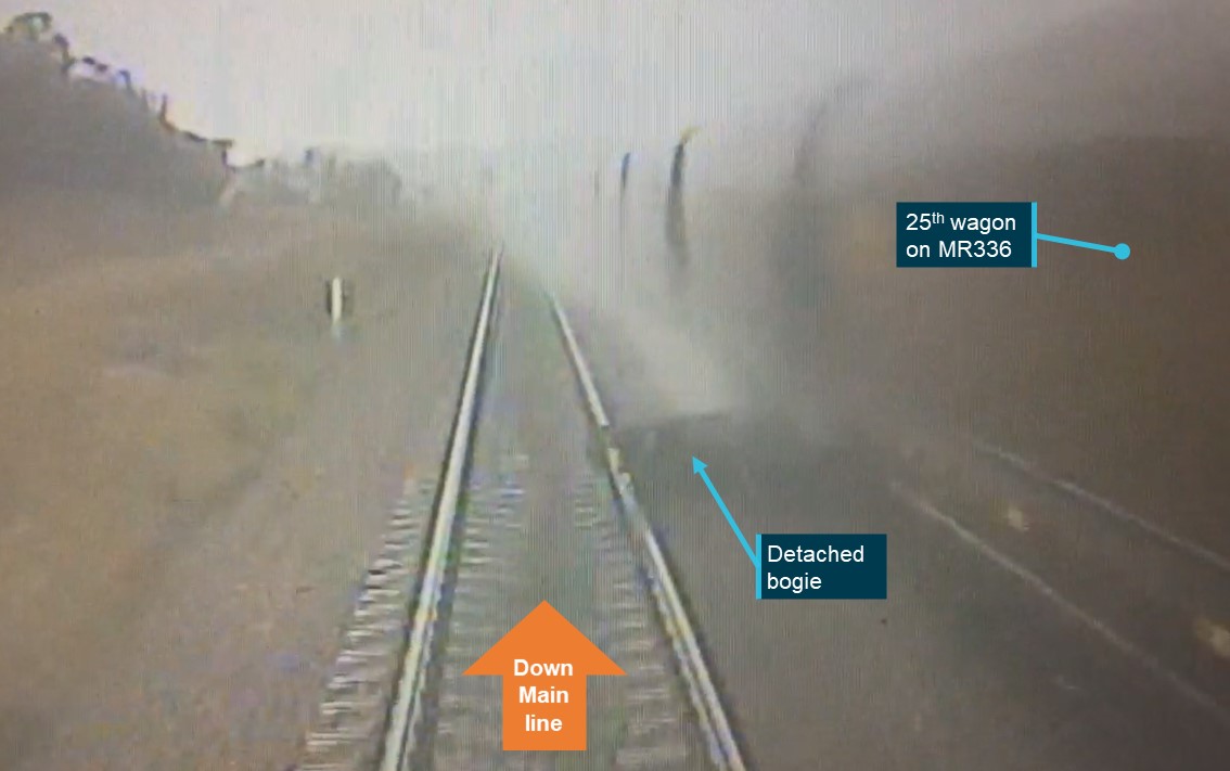
[1]      Acciona was the principal contractor for the railway infrastructure works.

[2]      Work involved the operation of track tamping and ballast regulator machines to adjust the track alignment and reshape the ballast formation.

[3]      Rolling stock movements on the up-rail line travel toward the Adelaide Railway Station.

[4]      AMPRN track km marks measured from the 0 km mark at the Adelaide Railway Station.

[5]      A competent worker who has carried out, is carrying out, or is about to carry out, rail safety work defined in the Rail Safety National Law.

[6]      An electric circuit where current is carried through the rails and used to detect the presence of trains. Track circuits are used in the operation and control of points and signalling equipment.

[7]      The IBA formally recorded that the AMPRN operations controller, or in this case the PPO in charge of the worksite, were notified and agreed to the modification of the nominated equipment prior to work being undertaken

[8]      Control switch located in cabinet attached to the location case used primarily to operate the level crossing warning during maintenance work.

[9]      ARTC track km marks at Torrens Road are measured from the 0 km mark at the Keswick rail passenger terminal.

[10]    ARTC network control officer monitors do not display approach track circuit or level crossing status information for Hawker Street or Torrens Road level crossings.

[11]    At the time of the incident, the Rail Commissioner was the accredited rail transport operator (rail infrastructure manager and rolling stock operator) for the AMPRN under the Rail Safety National Law (South Australia) Act 2012. See Organisational information section below detailing the contractual relationships associated with the GREP.

[12]    Up direction toward Adelaide, down direction away from Adelaide and toward Gawler Central.

[13]    Through the operation of a single line working function located within level crossing control circuit.

[14]    This included the signal electrician who endorsed the review phase of the ITP approval process. The TIC was not involved in the production, review or approval phases of the ITP documentation.

[15]    Errors were generally inconsistencies between the task description in the plan document and the marked-up circuit diagrams.

[16]    Level crossings at Hawker Street, Pym Street and Park Terrace.

[17]    SWMS RIC-031, Acciona – Signal support, Cable termination and Testing of signal infrastructure, version 3.

[18]    A rail transport operator (RTO) can be a rail infrastructure manager (RIM) or a rolling stock operator (RSO) or a person who is both a RIM and RSO.

[19]    In relation to the infrastructure of a railway, means the person who has effective management and control of the rail infrastructure.

[20]    Rail-rail interface agreement, RComm and ARTC.

[21]    The ARTC notice identified the GREP work area related to the Mile End to Crystal Brook route between the 3.8 km and 10.291 km marks on the ARTC network.

[22]    Testing and evaluation of a product to assure compliance with its specification or other requirements.

[23]    Confirmation that the particular requirements for a specific intended use are fulfilled.

[24]    Control table: A part of the signalling system specification that defines the detail of the signalling controls for each signalling function.

[25]    Aspect sequence testing verifies that only the correct aspect and route indication are displayed to the train driver.

[26]    Principles testing shall be carried out to validate that the controls embodied in the system conform to signalling principles, performance specifications and site-specific operating requirements and the railway layout signalling plan.

[27]    The inclusion of superfluous jumper wiring was common across all approved ITPs for the level crossing modification.

[28]    Completion of a visual examination against the wiring diagram to confirm the termination contains the correct number of wires. Denoted on the circuit diagram by a small stroke across the wire next to the termination. 

[29]    Completion of examination for conductor continuity between wire termination points. Denoted by a small tick adjacent to the wire.

[30]    The Samn-Perelli scale for self‑evaluating fatigue ranges from 1 (fully alert) to 7 (completely exhausted). A rating of 4 indicates ‘a little tired; less than fresh’.

Occurrence summary

Investigation number RO-2020-021
Occurrence date 07/12/2020
Location Ovingham
State South Australia
Report release date 05/03/2025
Report status Final
Investigation level Defined
Investigation type Occurrence Investigation
Investigation status Completed
Mode of transport Rail
Rail occurrence category Level Crossing
Occurrence class Incident
Highest injury level None

Train details

Train operator SCT Logistics
Train number 1MP9
Type of operation Freight service
Rail vehicle sector Freight
Departure point Dooen, Victoria
Destination Penfield, South Australia
Train damage Nil

Level crossing irregularities involving freight train 3PM7, Werribee, Victoria, on 4 December 2020

Final report

Report release date: 16/08/2024

Executive summary

What happened

At about 0825 (local time) on 4 December 2020, Pacific National (PN) freight train 3PM7 was passing through Werribee, about 32 km from Melbourne. The train was travelling from Perth (Western Australia) to Melbourne (Victoria) on the Australian Rail Track Corporation (ARTC) standard gauge network. 

When the train approached the level crossing at Werribee Street, the crossing’s protection equipment did not operate. However, road traffic signals that were linked to rail systems did operate to stop road vehicles. The train continued through Werribee Station with its crew under the impression that road traffic at Werribee Street had been appropriately stopped.

The next level crossing encountered by train 3PM7 was at Cherry Street which was located about 940 m east of the Werribee Street level crossing. When the train approached the level crossing, the crossing’s protection equipment also did not operate, and the train’s crew observed road vehicles crossing ahead. In response, the crew made an emergency brake application and sounded the horn. The train entered the crossing travelling at approximately 48 km/h, with motor vehicles clearing the crossing less than 2 s before the train’s arrival. 

What the ATSB found

The non-operation of the level crossing equipment occurred during signalling works associated with the removal of the level crossings at Werribee and Cherry Streets by the Western Program Alliance (WPA). Metro Trains Melbourne (MTM) was the accredited infrastructure manager for the level crossings and a member of WPA. 

With a track occupation scheduled to run from 29 November to 7 December, the broad gauge lines were closed to rail traffic while signalling circuits were being rewired, tested and commissioned. During these broad gauge works, the standard gauge line was to continue to operate normally. To facilitate the operation of the 2 level crossings for the standard gauge traffic, required control circuits were isolated from broad gauge systems being modified.

It was found that the failure of the Werribee Street and Cherry Street level crossings was due to the isolation arrangements being disrupted. This occurred at about 0800 on the morning of the incident (4 December) when function testers replaced 2 fuses that had been disconnected as part of the isolation arrangement. The testers were not familiar with the isolation arrangement. Reinstatement of fuses was not unusual in their role of function testing completed circuits.

Relevant events prior to 4 December included:

  • The isolation design was changed on 27 November and involved the powering down of the Werribee relay room. The isolation arrangements also required the removal of 2 fuses and the installation of temporary (jumper) wires to facilitate a false power feed to the Werribee Street and Cherry Street crossing control circuits. 
  • When installing the isolation arrangements on the night of 29–30 November, the fuses to be removed and secured were instead folded out with one end remaining in the fuse holder. This made the fuses vulnerable to reinstatement.
  • Power to the Werribee relay room was returned on 2 December with temporary jumper wires for the isolation retained. In this condition, reinstatement of the fuses would result in the level crossing circuits being energised and prevent operation of the level crossing equipment.

There were several safety factors identified with regard the late change to the isolation arrangements. Critically, the changed level crossing isolation arrangements were not reflected in planning and program documentation, nor effectively disseminated to all those potentially affected by the change. An earlier internal audit of this project also identified instances of scope changes not being documented.

The ATSB also found that:

  • Road traffic management was an available risk control that was not used for normal standard gauge rail traffic during testing. 
  • There were opportunities for the updated isolation design to incorporate additional risk controls to reduce the likelihood of premature replacement of removed fuses.
  • Although approved by MTM, the isolation and reinstatement plans were not reviewed in accordance with MTM design approval processes. 

Other identified safety issues requiring consideration are:

  • MTM standards and procedures did not specifically address requirements associated with fuse removal and securement in safety critical scenarios. 
  • Contrary to the requirements of relevant standards and procedures, there was probably no independent check of the installed isolation arrangements. An earlier internal audit of this project also identified instances of testers in charge checking their own work.

What has been done as a result

The Western Program Alliance and Alliance member Metro Trains Melbourne (MTM) have taken several safety actions that should address identified safety issues in testing and commissioning practices and assurance. Safety actions include the update of assurance frameworks and associated procedures, and awareness initiatives. 

As an active participant of Victoria’s Signalling Strategy Taskforce (SST), MTM is contributing to the development of consistent signalling practices and enhanced competency frameworks. The work of the SST has the potential to provide an industry-wide framework for, and contribute to, addressing safety issues like those identified in this investigation.

Safety message

This occurrence highlights the importance of considering the implications of late design changes, updating plans and programs, and ensuring all affected parties have a clear understanding of the implications for their work activities. This is particularly the case in complex projects that involve consortia, contractors, sub-contractors, and the responsible rail infrastructure manager.


The occurrence

Overview

At about 0825 (local time) on 4 December 2020, Pacific National freight train 3PM7 operating on the Australian Rail Track Corporation (ARTC) standard gauge network was travelling through Werribee towards Melbourne.[1] The train was to pass through level crossings at Werribee Street and Cherry Street which were located either side of Werribee Railway Station (Figure 1). For the passage of train 3PM7, the level crossing protection equipment at both Werribee and Cherry Street level crossings did not activate. 

Figure 1: Location of Werribee Street and Cherry Street level crossings

Figure 1: Location of Werribee Street and Cherry Street level crossings

Source: eWay Electronic Melway Street Directory – 2017 Edition, annotated by the Office Chief Investigator (OCI)

Events prior to the non-operation of level crossing protection

Level crossing removal 

As part of the Level Crossing Removal Project (LXRP) for Melbourne, works had commenced to remove the Werribee and Cherry Street level crossings which serviced standard and broad gauge rail traffic.[2] The Werribee Street crossing was to be replaced with a rail flyover, and the Cherry Street level crossing was to be closed and a road overpass constructed to its east.

The LXRP in Werribee was being delivered by the Western Program Alliance (WPA) which included the network operator Metro Trains Melbourne (MTM). MTM was also the responsible rail infrastructure manager for the operation of the 2 level crossings. Several contractors and subcontractors were involved in signalling works associated with this removal project.

By November 2020, progress on infrastructure works meant that broad gauge tracks were only operational east of and up to Werribee Railway Station. This meant that only the standard gauge track was operational through the Werribee Street level crossing (west of the station) whereas both standard gauge and broad gauge tracks remained operational at Cherry Street.

Signalling works from 29 November 2020

Modification of the signalling systems at Werribee included extensive re-wiring of circuits in the Werribee relay room and their testing. The works, testing and commissioning were scheduled to take place from 29 November to 7 December. For this period, trains would not operate on the broad gauge lines,[3] while the single standard gauge track would remain operational. The level crossings at Werribee Street and Cherry Street were to remain operational for standard gauge rail traffic only. 

The Testing and Commissioning Plan (TCP) for the 29 November to 7 December works was finalised as issued for construction (IFC) on 4 November. The TCP provided the methodology for level crossing isolation. 

Subsequently, there was a change to the isolation strategy and an alternative isolation plan developed which included the powering down of the Werribee relay room. This change was made after the risk of circuits being undesirably energised in the relay room during the re-wiring works was identified. The new isolation arrangements were prepared by signalling contractor Active Railway Signalling (ARS) and isolation and reinstatement plans approved by MTM on 27 November. 

The alternative isolation arrangements involved the cutting of the power supply to the relay room while providing an alternative power supply, referred to as a ‘false feed’, to circuits required for the operation of level crossing equipment for the passage of standard gauge traffic. The TCP was not updated to reflect the new isolation arrangements. 

Implementation of isolation

On the night of 29 November, the Werribee relay room was powered down[4] and the temporary circuit configuration installed. Fuses 9C2 and 9C4 were disconnected by them being rotated through 90° (Figure 2) and temporary jumper wires were installed (Figure 3). In total there were 4 jumper wires installed in the Werribee relay room, and 3 in location cases near the level crossings.

Figure 2: The probable state of fuses removed on the night of 29 November

Figure 2: The probable state of fuses removed on the night of 29 November

Source: MTM, taken on the morning of 4 December prior to the incident, annotated by OCI

Figure 3: One of the jumper wires installed in the Werribee relay room on 29 November

Figure 3: One of the jumper wires installed in the Werribee relay room on 29 November

The jumper wire shown in this figure was identified as ‘number 2’. Personal details on the wire label have been redacted.

Source: MTM, taken on 4 December 2020, annotated by OCI. 

Reinstatement of power to the Werribee relay room

The changeover[5] of circuits in the Werribee relay room was noted in the commissioning log[6] as complete and ready for testers on the morning of 2 December. The entry for the completion of the changeover was not annotated with a time, however, log entries either side were made at 0500 and 0700 suggesting that the changeover completion was between these times. It was reported that power to the relay room was also restored on the morning of 2 December, although this was not recorded in the logs. 

The temporary isolation arrangements put in place on 29 November to facilitate the operation of level crossing equipment for standard gauge trains were not removed when the power was restored to the relay room following the changeover of circuits. The temporary jumper wires and disconnected fuses 9C2 and 9C4 remained as they were.

Signalling circuit function testing in the Werribee relay room

Signalling circuit function testing commenced in the Werribee relay room on 2 December and continued during the (12-hour) day shifts and (12-hour) night shifts between 2 and 4 December. The teams undertaking testing were independent of, and not involved with, the isolation installed on the night of 29 November. At the commencement of function testing, the program was behind schedule and the commissioning was unlikely to be completed by 7 December. 

On 4 December, the day shift test team commenced at 0700. Soon after, a standard gauge train 5AM5 travelled through Werribee and the level crossing protection at both Cherry and Werribee Streets operated normally. 

The function tests involved the replacement of fuses as required to complete circuits for testing. This was normal practice. At about 0800 and following discussions with others in the project regarding the need to progress the testing of all circuits, the lead tester instructed one of the team to reinstate fuses 9C2 and 9C4 (Figure 4). The testers were not aware that several temporary jumper wires had been installed as part of the level crossing isolation arrangements. 

Figure 4: Fuses 9C2 and 9C4 replaced in Werribee relay room

Figure 4: Fuses 9C2 and 9C4 replaced in Werribee relay room

Source: MTM, taken on 4 December after the incident, annotated by OCI

With the jumper wires still in place, control relays remained energised when the fuses were replaced, inhibiting the operation of the level crossing equipment at both Werribee and Cherry Street level crossings.[7] 

The passage of train 3PM7 through Werribee

Passage through Werribee Street level crossing

At about 0825 on 4 December, train 3PM7 approached the Werribee Street level crossing travelling at about 50 km/h. The train was detected by rail control systems, but the level crossing equipment did not operate. However, road traffic signals on Werribee Street, which were interfaced with the train detection system, did operate and stopped road traffic. 

The crew of train 3PM7 reported sighting traffic management staff at the Werribee Street level crossing and acknowledged their presence by an application of the train horn. Although the traffic management staff were present, they were not actively engaged in managing traffic at that time.

Passage through Cherry Street level crossing

Shortly after, train 3PM7 approached the Cherry Street level crossing travelling at about 52 km/h. The train crew observed that road vehicles were crossing, and that the crossing protection had not activated. In response, the crew made an emergency brake application and sounded the train horn several times. The train entered the crossing travelling at about 48 km/h. The lead locomotive came to a stand about 200 m past the crossing.

CCTV equipment installed at Werribee Railway Station showed motor vehicles crossing on Cherry Street ahead of train 3PM7 (Figure 5). It is estimated that the cars probably cleared the path of the train less than 2 s before the train occupied the crossing (Figure 6).

Figure 5: CCTV images showing road vehicles on Cherry Street as train approaches

Figure 5: CCTV images showing road vehicles on Cherry Street as train approaches

Source: MTM, annotated by OCI

Figure 6: CCTV image showing the locomotive entering the level crossing

Figure 6: CCTV image showing the locomotive entering the level crossing

Source: MTM, annotated by OCI

Post incident management

In immediate response to the incident, the level crossings were secured with traffic management and (after being notified) ARTC train control applied a signal block to prevent standard gauge rail traffic from entering the section. 

On inspection within the Werribee relay room, an MTM infrastructure team identified that fuses in positions 9C2 and 9C4 had been reinstated with temporary jumper wires still in place. The fuses were removed and secured, the crossing systems tested and the ARTC signal block removed later on 4 December to allow the resumption of standard gauge services. 

For the remainder of the works, level crossing keepers[8] were put in place at the Werribee Street and Cherry Street level crossings to ensure level crossing operations. 

Context

The train and actions by crew

Train 3PM7 was a Perth to Melbourne intermodal freight service operated by Pacific National (PN) on the Australian Rail Track Corporation (ARTC) standard gauge network. The train consisted of 2 locomotives and 26 wagons, was approximately 1.4 km long, and had a crew of 2. 

Approaching the Werribee Street level crossing, the crew were controlling train speed at about 50 km/h and within the 60 km/h permitted speed. The horn was sounded about 400 m from the Werribee Street crossing and near the crossing to acknowledge track workers.

Records indicate that approaching the Cherry Street level crossing, the train was travelling at a speed of about 52 km/h, still within the permitted speed. Then, in response to the crew detecting cars on the crossing, an emergency brake application was made by the crew when the train was about 150 m from the crossing. The speed of the train commenced to slow and entered the level crossing travelling at about 48 km/h. Records indicate the train horn was sounded by the crew several times on the approach to the Cherry Street level crossing in response to road vehicles continuing to cross. 

There was no evidence to suggest that train handling contributed to this event.

Infrastructure

Location

The Werribee Street and Cherry Street level crossings were on the Werribee line of the Melbourne metropolitan rail network and located either side of Werribee Railway Station which was about 32 rail-km from Southern Cross Station in Melbourne (Figure 7). Rail lines through the location included 2 broad gauge lines and a parallel single bi-directional standard gauge line.[9]

Figure 7: Location of Werribee Railway Station to the west of Melbourne

Figure 7: Location of Werribee Railway Station to the west of Melbourne

Not all railway stations on the Werribee line are shown in this figure.

Source: Department of Transport, annotated by OCI

Infrastructure management

Metro Trains Melbourne (MTM) was the rail infrastructure manager (RIM) of the broad gauge lines through Werribee and ARTC was the RIM of the standard gauge line. MTM was the responsible RIM for the level crossing equipment and control systems for the Werribee and Cherry Street level crossings.

Werribee Street Level crossing

The Werribee Street level crossing was located about 680 m on the down side (away from Melbourne) of Werribee Railway Station.[10]The road crossing was equipped with active protection that included flashing lights, audible warning (bells) and half-boom barriers, and an active pedestrian crossing was to its east. The railway crossing systems were also interfaced with traffic control systems (traffic signals) to assist the management of road traffic through the level crossing.

At the time of the occurrence, the rail flyover that would replace the level crossing had been constructed and new broad gauge tracks had been installed. Standard gauge traffic was still operating through the level crossing (Figure 8).

Figure 8: Aerial view of Werribee Street level crossing and rail flyover in December 2020

Figure 8: Aerial view of Werribee Street level crossing and rail flyover in December 2020

Source: nearmap on 12 December 2020, annotated by OCI

Cherry Street level crossing

The Cherry Street level crossing was located about 215 m10 on the up side (towards Melbourne) of Werribee Railway Station. The road crossing was equipped with active protection that included flashing lights, audible warning (bells) and half-boom barriers (cover photo). Unlike the arrangements at Werribee Street, there were no road traffic lights (interfaced with the railway systems) installed for road vehicles approaching the Cherry Street level crossing.

On the day of the occurrence, the layout of the Cherry Street level crossing included 2 broad gauge lines and a single bi-directional standard gauge line crossing Cherry Street (Figure 9).

Figure 9: Aerial view of Cherry Street level crossing in December 2020

Figure 9: Aerial view of Cherry Street level crossing in December 2020

Source: nearmap on 12 December 2020, annotated by OCI

Level crossing control

Both crossings were within the Werribee signal interlocking area. The operation of the active protection for the 2 level crossings involved train detection and signal interlocking functions.[11] Control circuitry was in trackside location cases (at each crossing) and the Werribee relay room located on the Werribee Railway Station platform (Figure 10).

Figure 10: Aerial view of Werribee Railway Station and relay room

Figure 10: Aerial view of Werribee Railway Station and relay room

Source: nearmap on 12 December 2020, annotated by OCI

Systems were designed so that energised control relays prevented the activation of level crossing equipment. Following the detection of an approaching train, the relays would be de-energised, activating the protection equipment. This design configuration was failsafe in that a loss of power to the control system would result in relays becoming de-energised and level crossing protection systems activating. 

A Rail Interface Control Unit (RICU) was also installed at the Werribee Street level crossing to manage the interface functions between the railway crossing system and road traffic control system. The RICU was operational at the time of the incident and on detection of the approaching train by the rail systems, nearby road traffic signals were triggered to stop traffic. This arrangement was not in place at Cherry Street.

Level crossing removal project

Administration

In 2015 the Victorian State government established the Level Crossing Removal Authority (LXRA), an administrative office within the then Department of Economic Development, Jobs, Transport and Resources (DEDJTR). LXRA was responsible for the Level Crossing Removal Project (LXRP). In 2019, administrative responsibility associated with the LXRP was transferred to the Major Transport Infrastructure Authority (MTIA), an administrative office within the Department of Transport (DoT). MTIA used an alliance contracting model and grouped level crossing sites for contracting to program alliances.

Western Program Alliance (WPA)

WPA was one of the 4 alliances established by MTIA to deliver the LXRP. The alliance comprised McConnell Dowell as the principal contractor, Arup and Mott Macdonald as design partners, and Metro Trains Melbourne (MTM) as the rail infrastructure manager. In February 2020, WPA was contracted to remove level crossings at Old Geelong Road in Hoppers Crossing, and Cherry Street and Werribee Street in Werribee.

Stage 3 works at Werribee

To facilitate the removal of the level crossings at Werribee, the infrastructure changes were delivered in 4 main stages. The signalling cabling assets were confirmed during the first stage. Stage 2 comprised civil and structural enabling works, the removal of decommissioned equipment to the west of Werribee station, and interlocking changes. Stage 3 included the commissioning of the broad gauge flyover west of Werribee Station, the installation and commissioning of a new axle counter[12] configuration and the reconfiguration of the Werribee relay signal interlocking. Broad gauge train movements west of Werribee were scheduled to return after testing and commissioning of the new system.

John Holland Group (JHG) and Active Railway Signalling (ARS) were subcontracted to undertake the signalling works associated with stage 3 of the project. Traffic Diversions Group (TDG) was contracted to implement the road traffic management plan. 

Metro Trains Melbourne (MTM)

As the accredited RIM,[13] MTM was responsible for ensuring that the design, construction, and commissioning of rail infrastructure was carried out in a way that ensured safety of railway operations. MTM was also listed as being responsible for signalling design within the WPA design and engineering management plan (WPA 2020d).

Works commencing 29 November 2020 

Background

In mid-2020, Werribee Railway Station became a terminus for broad gauge trains, allowing construction works to the west of the station. Construction, testing and certification works from September to December would bring the new broad gauge signalling layout, which incorporated the elevated section (the rail flyover) over Werribee Street, into service. 

Activities scheduled between 29 November to 7 December included extensive re-wiring of broad gauge circuits in the Werribee relay room, and testing and commissioning works. To enable these works, the project implemented a track occupation[14] and broad gauge trains were terminated at Laverton, about 10 km to the east of Werribee. This meant there would be no broad gauge traffic in Werribee during the occupation from 29 November to 7 December. 

The bi-directional standard gauge line through Werribee was not part of the occupation and remained operational. It was planned that the level crossings at Werribee Street and Cherry Street were to be operational for standard gauge rail traffic for the duration of the broad gauge track occupation.

WPA management plans and guides

WPA produced a commissioning management plan (WPA 2020b) which described the framework for the pre-commissioning and commissioning activities. The WPA also developed a works guide (WPA 2020e) which, along with other track and civil works, described the high-level signalling tasks to be undertaken. It also stipulated that working shifts were to be back-to-back 12-hour shifts from 1900 on 29 November to 0700 on 7 December. 

Test and commissioning plan

The Alliance produced a test and commissioning plan (TCP) (WPA 2020c) for the works to be undertaken between 29 November and 7 December. The plan was approved by the project’s management and issued for construction (IFC) on 4 November. The purpose of the document was to ensure that required testing and commissioning activities were identified and planned. The TCP outlined the structure of the test and commissioning team (Appendix A) which included the following key personnel:

  • The Tester in Charge (TIC): The TIC was an ARS employee. They were scheduled to work the 0700 to 1900 day shifts. They prepared the TCP issued on 4 November and were responsible for the satisfactory completion of system testing and commissioning requirements in readiness for service.  
  • The Shift Tester in Charge, also referred to as the Alternate Tester in Charge (ATIC): The ATIC was contracted from HJW Signalling Services Pty Ltd and was scheduled to work the 1900 to 0700 night shifts. They oversaw testing and commissioning activities during the night shifts. 
  • Testers and test assistants: Testers were contracted workers from Lineside Signalling, Dragon Rail and ARS. They were responsible for testing the function of circuits.
  • The Principles Tester (PT): The PT was employed by MTM and was responsible for confirming that the newly installed system operated in accordance with the relevant signalling principles and safeworking rules and regulations. 

Consistent with the MTM standard for testing and commissioning of safety related railway signalling systems (MTM 2018a), the TCP stated that management and testers involved in the works should attend a pre-commissioning briefing. An invitation to a signalling pre-commissioning meeting (with draft TCP attached) was issued by WPA on 22 October 2020 and the meeting was held on 12 November. ARTC was included in the distribution of the TCP. The briefing was not attended by several personnel either because they did not receive the invitation or they chose not to attend. This briefing was held prior to the changes made to the level crossing isolation arrangements.

Level crossing isolation design changes

Isolation plan specified in TCP issued for construction

The testing and commissioning methodology section of the TCP issued for construction (IFC) on 4 November advised that the ARTC standard gauge line would remain operational. The TCP referred to a drawing for the isolation of Cherry Street level crossing which specified an isolation methodology consistent with that used for previous stages of the project. This isolation design did not require powering down of the relay room, did not specify the removal of any fuses, and required 1 temporary jumper wire. Testing work instructions in the TCP were also consistent with these arrangements.

Isolation design changes

About 3 weeks after the finalisation of the TCP, the decision was made to power down the Werribee relay room for the re-wiring works due to concerns that circuits may be undesirably energised during the works. As a result, an updated isolation arrangement was required.

On 25 November, the TIC instructed the ARS design team to develop a temporary feed arrangement for the isolation of the Cherry Street and Werribee Street level crossings. An alternative supply, referred to as a ‘false feed’, would power the control circuits required for the operation of level crossing equipment for the passage of standard gauge traffic. 

The design was completed by ARS on 27 November. A simplified representation of the design concept for the Cherry Street level crossing isolation and power feed is shown in Figure 11.

Figure 11: Simplified representation of isolation for the Cherry Street level crossing

Figure 11: Simplified representation of isolation for the Cherry Street level crossing

Image shows a simplified representation of the level crossing circuits for Cherry Street level crossing. Temporary jumper wire number 1 was put in place to bypass the broad gauge approach and signal interlocking circuits for Cherry Street level crossing. Temporary jumper wire number 2 was put in place to accommodate the planned shutdown of the relay room power supply.

Source: ATSB and OCI.

Temporary jumper wires were installed to isolate the broad gauge train detection circuits from the level crossing control circuits (label 1). During the planned shutdown of power to the relay room, the temporary jumper wire also allowed an alternative power supply (from the level crossing location case) via the control relay in the relay room to the repeater relay at the location case (label 2). The temporary modification required the removal of the power supply to the relay room by the removal of a fuse (label 3) and opening the relay room power supply circuit breaker (label 4).[15]

The isolation plan included instructions to switch circuit breakers off and provided details of temporary wiring changes and fuse removal. Construction notes on the isolation drawings included the instructions ‘install temporary purple jumper wire with green tape in the vicinity of the end of the wire’ and ‘fuses to be removed and secured’ in relation to fuse bay locations 9C2 and 9C4 (Figure 12). 

Figure 12: Construction note extract from isolation plan

Figure 12: Construction note extract from isolation plan

Source: ARS, extract by OCI

A second set of drawings (reinstatement plan) contained instructions for the reinstatement of power to the relay room. The drawings included instructions for circuit breakers to be switched back on, fuses to be reinstalled, and temporary jumper wires to be removed. 

Approval of design changes

In accordance with the requirements of its safety management system, MTM had developed an engineering management system framework (MTM 2019a), a design assurance procedure (MTM 2019b) and a signalling design technical review procedure (MTM 2017). The signalling design technical review procedure defined requirements and responsibilities of contractors and required that design documents applicable to works on MTM signalling infrastructure be submitted to MTM for technical review. Any signalling equipment that was required to be isolated, false fed[16] or removed during project work was to be checked and verified by the contractor and details provided to the MTM Engineering Design Review Group (EDRG) for review.[17] 

The revised isolation arrangements were sent by ARS to MTM for review and approval at 1838 on 27 November. Confirmation of approval by the MTM representative of WPA was sent to the contractor an hour later. This design was not issued to the MTM EDRG for review.

Management of the isolation design change

Procedures, guidelines and management plans

The MTM Design Assurance Procedure (MTM 2019b) applied to all MTM’s infrastructure and projects. This procedure defined a design change as a change occurring post-IFC and described the structure of a Design and Engineering Management Plan (DEMP) or Design Management Plan used to detail how the design change would be managed.

The TCP (section 6.5) noted that the process for the issue of design modifications may alter depending on project and contractors’ internal processes and the process being used for each project should be recorded within the design management plan.

The WPA Design and Engineering Management Plan existed as two documents, one referred to works at Werribee (WPA 2020d), the other was a program wide plan (WPA 2019). The purpose of a design change notification (DCN) referenced in the program wide plan was to provide stakeholders with a summary of the scope of a design change made to IFC documentation. The plan stated that a DCN resulting from a design change and the design change register (DCR) would be issued to the Level Crossing Review Group (LXRG) which would review the DCN. The program wide plan also stated that all temporary work that had the potential to impact train operations and/or have safety implications were required to be reviewed by the MTM LXRG. 

Dissemination and notification of isolation design change

DCNs were recorded in the DCR for the LXRP at Werribee. Between 20 August 2020 and 4 December 2020, 19 DCNs were recorded in the register, for all infrastructure types. However, the change to the isolation arrangements in the relay room approved on 27 November was not included in the DCR and the TCP was not reissued following the change to the isolation arrangements. There was no record of communication with the LXRG concerning the design change for isolation of the level crossing.

Design changes made following the occurrence

Following the non-operation of the level crossing equipment on 4 December 2020, a design modification was made to the isolation arrangements. The design modification, dated 14 December,[18] included the addition of construction note #3 which required the wires connecting the temporary jumpers to the fuse holder to be removed, sleeved and secured (Figure 13). This modification strengthened the arrangement in that reinsertion of the fuses (alone) would not complete the electrical circuit. 

Figure 13: Extract from design modification drawing, post incident

Figure 13: Extract from design modification drawing, post incident

Source: ARS, extract by OCI

Implementation of isolation arrangements

Werribee relay room environment

At the time of the isolation, access restrictions associated with the COVID-19 pandemic were in place. The WPA Pandemic and Readiness response plan (WPA 2020a) required all buildings on site to have signage at the entry point displaying the maximum capacity for each building in accordance with a 4 m2 per person rule. This applied to the Werribee relay room and probably limited free access to the room during isolation activities.

At the time of the isolation, there were several technicians from the John Holland Group inside the room undertaking electrical work. The ATIC was also present at the relay room.

Installation of isolation arrangements on 29 November 

The commissioning log recorded that the broad gauge track occupation started at 2100 on 29 November. The MTM level crossing disarrangement form showed that, as planned, the Werribee Street level crossing for broad gauge services was confirmed non-operational at 2220, and the Cherry Street broad gauge crossing non-operational at 2348. These times were consistent with entries in the commissioning log. The log also recorded that the Werribee relay room power was isolated at 0135 on 30 November 2020.

The isolation drawings and construction notes[19] required certain circuit breakers to be switched off, temporary jumper wires to be installed, other wires to be disconnected and sleeved and select fuses to be removed and secured. Based on available evidence, fuses 9C2 and 9C4 were not completely removed but were instead folded out (turned 90 degrees) with one end remaining in the holder. No specific instructions existed in the MTM specification for signalling supply, construction, and installation (MTM 2018b) on the method of securing a fuse bay to reduce the risk of premature reinstatement.[20]

The purple temporary jumper wires were installed broadly in accordance with the isolation drawings, excepting for the colour of identifying labels. White tape was used to label the wires instead of green as specified in the isolation drawings. The labels identified the designated number of the temporary jumper wire (in accordance with the isolation drawing) and the name of the installer as being the ATIC. The ATIC also annotated the isolation drawings, marking off the installation of each jumper wire and the removal of fuses. The ATIC had also added the annotation of ‘tested ok’ and signed the work instruction as having checked the work. 

Several temporary jumper wire installations were recorded on the isolation drawings and in the test strap register which were inconsistent with the identification of the installer on jumper wire labels.[21] An ARS testing assistant, a cadet railway signalling engineer[22] under the supervision of the ATIC, signed the test strap register and the isolation drawing as the installer of the temporary jumper wires in the Werribee relay room when they had only installed the jumper wire at the Cherry Street location case. 

Level crossing event during isolation

At about 2320 on 29 November during the application of the isolation, a freight train on the standard gauge line crossed the Cherry Street level crossing without activating the level crossing protection equipment. Traffic control was requested to stop road vehicles passing through the level crossing shortly before the train arrived. It was reported by the ATIC that this event may have distracted those involved in the isolation activities.

Testing

MTM engineering standards for testing and commissioning

The standard for testing and commissioning of safety related railway signalling systems (VRIOG 2008) was initially developed through the collaboration of members of the Victorian Rail Industry Operators’ Group[23] (VRIOG) and was adopted by the MTM as part of its engineering standard for testing and commissioning of safety related railway signalling systems (MTM 2018a). The practices specified in the standard applied to the testing and commissioning phases of new and modified railway signalling systems. 

The standard stated that the objective of the testing and commissioning of new or modified signalling systems, including where disconnected wiring may be reconnected, was to ensure that, before the systems were used for the control of train operations, the systems were to satisfy all specified requirements, safe working standards and any application‑specific requirements. 

Other sections of the standard pertinent to this investigation included:

  • IndependenceThe standard specified the independence required of persons involved across different parts of the work.
  • Pre-commissioning meeting – The standard required a pre-commissioning meeting to be held where key personnel involved in the commissioning works were briefed and a project scope, work sites and responsibilities were identified, and a test plan provided. This meeting was required to be separate from any occupation/safeworking or other discipline‑specific meeting associated with the project.
  • Testing strategy – The standard required that a written statement of the proposed testing methodology be prepared, along with proposed layout and anticipated testing content in consultation with other involved parties at an early stage of the project. The standard required that the statement was kept up to date throughout the project development. Amongst other items, the testing strategy was to include:
    • creation of a preliminary testing program that included personnel resources 
    • a program of suitable and achievable work packages for individual testers to undertake any training needs
    • the limits of the testing, including responsibilities, interfaces (equipment interfaces, area interfaces, project interfaces), and stage work requirements 
    • identification of hazards, risks and control measures 
    • train operation and safe working arrangements.
  • Operational requirements – The standard stated that if train running was unavoidable, any testing that was going to disrupt the train running should be carefully planned and completed in the time available. All hazards during testing and commissioning were required to be identified and appropriate contingency plans put in place. 
  • Testing procedures – These were to provide details of the tests that were required to be carried out and included:
    • insulation resistance tests[24]
    • continuity tests[25]
    • wire counts[26]
    • null counts[27]
    • strap and function tests[28]

The standard provided instruction on the installation and removal of wires and advised that new wires should be stripped and crimped, continuity tested and then insulated and secured. The standard stated testing should not commence until all yellowed wires had been disconnected and removed. Yellowed wires were those wires that the design requires to be removed during a signalling changeover and are marked in yellow on the circuit diagram.

Other relevant standards

The Rail Industry Safety and Standards Board (RISSB) Australian Standard for signal testing and commissioning, AS 7717 (Standards Australia 2016), stated that:

… before certification function testing is commenced, testers shall ensure that circuit wiring testing is complete, that the circuit wiring is secured against interference, and that the approved final circuit wiring diagrams are correctly certified as bell continuity tested, wire counted, and insulation tested. 

Testing specified in the TCP

The testing regime outlined in the TCP described tests ‘broadly in the required sequence to be completed and some activities may be completed in parallel with others.’[29] In order of activity, these were:

  • insulation (megger) testing 
  • continuity (bell) testing
  • wire / null count testing
  • strap and function testing
  • through testing.

Although the testing summary in the body of the TCP was consistent with AS 7717 and the MTM engineering standard, with the wire and null count testing listed for completion prior to strap and function testing, the detailed testing program differed. The detailed program in document WPA‑program v22 for 29/11-07/12 Occupation scheduled the strap and function testing before the wire and null counts (Figure 14). 

Figure 14: Extract from ‘WPA-program v22 for 29/11-07/12 occupation’ 

Figure 14: Extract from ‘WPA-program v22 for 29/11-07/12 occupation’

Source: ARS, annotated by OCI.

Implementation of testing from 2 December

Restoration of power to the relay room on 2 December

A detailed occupation program (WPA 2020g) was issued on 27 November which indicated that testing in the Werribee relay room was scheduled to start on the morning of 30 November. However, owing to a delay, the Werribee relay room was not available to testers until the morning of 2 December. Entry 38 (of that morning) in the commissioning log recorded that the Werribee relay room changeover was completed and included the comment ‘ready for testers’. Although no specific time was recorded against this entry in the log, evidence suggests it was probably made between 0500 and 0700. 

Power was restored to the relay room on the morning of 2 December to allow function testing although there was no record of this activity in the commissioning log. When power was restored to the relay room, it is very likely that technicians did not refer to the reinstatement plans. Isolation arrangements remained in place. Fuses 9C2 and 9C4 remained disconnected and a total of 7 temporary jumper wires remained in place, 4 in the relay room, one in the Cherry Street level crossing location case, and 2 in the Werribee Street level crossing location case.

Function testing

The commissioning log recorded that function testing in the relay room was conducted later on 2 December and continued into 3 December, during day and night shifts. Testing was undertaken by teams independent of those involved in the isolation of the relay room. 

Function testers reported ‘finding wires in the wrong spots’. The TCP required that wire and null count testing occur prior to the strap and function testing. Had testing occurred in the order required of the TCP it is probable that incorrectly positioned wires would have been identified and repositioned prior to the strap and function testing.

Testing of signalling circuits in the Werribee relay room required that fuses be restored to their normal positions. The function tester leading the testing team that started work on the morning of 4 December instructed one of their team members to reinstate the fuses. This was reported to have occurred following discussions between project team members where it was decided that all fuses should be reinstated. This was probably intended to expedite function testing due to testing and commissioning being behind schedule. 

As the temporary jumper wires used for the isolation were still in place, the reinstatement of the fuses and power being restored to the relay room meant the crossing control relays for both the Werribee Street and Cherry Street level crossings were inadvertently permanently powered.

Testing with redundant wiring and bare ends

The MTM standard for signalling installation (MTM 2018b) required that decommissioned signalling wiring should be removed immediately or should have its ends cut off, sleeved, tagged, and shall be removed prior to final testing and commissioning of any new works. The Australian Standard for Signalling testing process (Standards Australia 2017), though not mandatory, also stated that testing should not commence until all wires for removal have been disconnected and removed.

On 3 July 2020, the WPA submitted a request for information to MTM asking whether a standard waiver would be required from July to December 2020 to tag, cut, and sleeve redundant circuit ends while Werribee was being configured as a terminal station. MTM confirmed that a waiver was not required for the temporary retention of redundant equipment and that WPA’s proposal to remove all redundant equipment and wiring during the 29 November to 7 December occupation was acceptable. The project did not request a waiver nor had permission been given to conduct testing while bare ends were present on redundant wiring in the Werribee relay room.

For the December testing and commissioning activities, the TCP (section 6.5) referenced the need to remove redundant wiring from the Werribee relay room. Wires requiring removal were to be identified with yellow tape. The TCP stated that testing should not commence until all yellow wires[30] and equipment had been fully disconnected and permanently removed. However, the TCP also stated that yellow wires could remain subject to the approval of the MTM Head of Engineering Signalling and if the redundant wiring was not removed, it should be made safe using blind crimps[31] or terminated. 

On 2 December, the principles tester (after attending the Werribee relay room) contacted the TIC by email, stating that principles testing[32] could not be started while there were wires with bare ends present which produced a risk of stray wires causing energisation of circuits. The principles tester advised that ‘unrecovered redundant wiring needed to be removed, and if not they needed to be made safe’. The commissioning log recorded that sleeving of wires to protect bare ends was not completed until 1400 on 3 December. The redundant wires were made safe prior to the level crossing occurrence on 4 December.

The timings recorded in the commissioning log, along with interview evidence indicates that function testing was conducted while bare ends were present. This was contrary to the TCP and continuation of function testing while redundant wiring was being made safe was probably influenced by schedule pressures. 

Road traffic management

Applicable documents

Requirements and strategies for the management of road traffic risks were mentioned in several standards, guidelines and project documents. The following is a summary of those references:

  • MTM standard for testing and commissioning (MTM 2018a) stated that all hazards during testing and commissioning were required to be identified and appropriate contingency plans put in place. 
  • The Level Crossing Removal Project – Western Program Alliance Works Guide (WPA 2020e) stated that traffic management personnel would be in place between 29 November 2020 and 7 December 2020 at level crossings, including Werribee Street and Cherry Street, for ‘monitoring the traffic ….’
  • The WPA Works Guide (WPA 2020e) also contained a section titled ‘Road Closures/Traffic Management’. For the period between the night shift of 29 November and the night shift of 1 December, the Works Guide required traffic management at Cherry Street to ‘Stop all lanes intermittently to allow Hi-Rail Access’.[33]For the period between the day shift of 3 December and the night shift of 6 December, the guide required traffic management at Cherry Street to ‘Stop traffic over level crossing intermittently to allow for principles testing & test trains’.[34]
  • The TCP did not mandate traffic management outside of the times that test trains were planned. The occupation notice (MTM 2020a) attached to the works guide that captured the area of the Cherry Street level crossing gave no specific instructions for the protection of level crossings.
  • The original isolation drawings issued for construction but subsequently superseded included a requirement for ‘crossing to be protected by traffic management and safe working at all times’. This requirement was removed from the revised isolation drawings that were approved on 27 November.
  • A daily train notice was issued for the standard gauge which advised of works adjacent to the ARTC rail corridor. This notice was included in the works guide (WPA 2020e), the purpose of which was to outline the details of the broad gauge track occupation for 29 November to 7 December. The daily train notice did not make reference to traffic protection or operation of the level crossings for the ARTC standard gauge line. 
Implementation

The provision of traffic management at Werribee Street and Cherry Street was subcontracted to Traffic Diversions Group (TDG). A traffic guidance scheme produced by TDG (TDG 2020) for the occupation showed the provision of traffic controller staff at both crossing locations, for both directions of traffic. 

Traffic management staff are reported to have been available at level crossings if needed for broad gauge movements but were not actively managing traffic for normal standard gauge rail traffic. Level crossing protection was expected to operate normally for standard gauge trains.

Interview evidence indicates there were differences in opinion amongst project personnel on implementation of road traffic management and a lack of clarity on managing the risks during testing. ARTC, the RIM for the standard gauge track, was not consulted by WPA or MTM in the implementation of traffic management as a risk control during testing.

MTM audit of the project in October 2020

Audit of signalling testing and commissioning works

MTM was responsible for ensuring the safety of railway operations during projects for which MTM was the accredited RIM. As part of its assurance program, MTM conducted an internal audit of testing and commissioning (T&C) activities on the Werribee project in October 2020 due to the number of incidents associated with T&C works performed in the field.[35]

The audit report (MTM 2020c) was published by MTM on 20 November 2020. The purpose of the audit was to determine the extent of MTM’s conformity with the requirements of the signalling works in TCPs. This project was selected as an audit subject as MTM had identified several new projects which were to be delivered by the Western Program Alliance (of which MTM was a member). Findings (and corrective actions as applicable) relevant to this investigation included:

  • Evidence provided by the project team was not sufficient to demonstrate that changes in scope during testing and commissioning works were evaluated ‘by the relevant people’[36] to determine potential consequences. In addition, it was found that scope change details were not formally recorded in the commissioning log. The finding was categorised high priority and agreed corrective action[37] (by 23 December) required TIC to ensure that any changes in scope were clearly identified, assessed and documented, and the potential consequences documented. Assuring conformity of changes with current standards was also identified in agreed corrective action. 
  • There were instances of a TIC certifying their own work at a commissioning in August 2020. The finding was categorised as medium priority and an agreed corrective action date of 15 December was specified.
  • Some staff were not attending pre-commissioning meetings. No specific corrective action specified for this finding. 

The audit recommended communication of the findings to all project managers, signalling project managers, testers in charge and principles testers to share learnings from the audit and to prevent recurrence of similar findings in future works. The TIC at the time of the incident in December 2020 was included in the audit report dissemination list. 

Previous similar occurrence

Level crossing irregularity North Geelong, Victoria in 2019

The most recent example of a level crossing irregularity during infrastructure project works in Victoria involved the standard gauge passenger train 3MA8 at North Geelong, Victoria, on 8 January 2019 (ATSB 2020). The protection equipment did not activate for the passage of the train through the Thompson Road level crossing. In preparation for stage 1 track work, only the broad and dual gauge[38] tracks at the Thompson Road level crossing were to be isolated. The level crossing protections for the adjacent standard-gauge track were to remain active until stage 2 works at a later date. However, the signalling tester, having been provided with the isolation drawings for stages 1 and 2 as a single pack by the TIC, mistakenly isolated the level crossing for stage 2 work, in addition to stage 1. 

VicTrack, through their contractor UGL Engineering Limited, did not provide the TIC or signalling testers with specific instructions detailing the scope of work to be conducted at each stage of the project, but rather, only provided packaged isolation drawings for the entire project. The absence of these specific instructions increased the risk of the works being incorrectly implemented.

Safety analysis

Introduction

For the passage of train 3PM7 through Werribee on the morning of 4 December 2020, the level crossing equipment at Werribee Street and Cherry Street did not operate to stop road traffic. This led to a near-collision between train 3PM7 and road vehicles at the Cherry Street level crossing. The analysis discusses:

  • The non-operation of the level crossing equipment
  • Installation of isolation arrangements on 29 November
  • The reinstatement of power and testing from 2 December
  • Isolation design change processes and communication
  • Testing protocols
  • Traffic management.

The non-operation of level crossing equipment

In preparation for works on broad gauge systems, temporary isolation arrangements were established on the night of 29 November to facilitate the operation of the Werribee Street and Cherry Street level crossings for standard gauge rail traffic. The isolation included the cutting of power to the Werribee relay room, the removal of fuses 9C2 and 9C4, the disconnection of wires and the addition of temporary jumper wires in the relay room and in location cases near the level crossings. Implementation of the plans was successful in achieving activation of level crossing equipment for standard gauge traffic while works were undertaken on the broad gauge systems.

Following the completion of circuit changeover works on 2 December, power was restored to the Werribee relay room in preparation for testing. The temporary isolation arrangements that had been installed to facilitate level crossing operation for standard gauge trains, including the temporary jumper wires, remained in place.

When the fuses at positions 9C2 and 9C4 were reinserted by the testing team on the morning of 4 December with the temporary wiring still in position, operation of level crossing protection equipment at Werribee Street and Cherry Street was inhibited by the unintended permanent powering of the crossing control relays. Testers were not aware of the isolation arrangements and that their action would affect the operation of the level crossings.

Installation of isolation arrangements on 29 November

Removal of fuses 9C2 and 9C4

The isolation installation was not fully consistent with the isolation plans. Fuses were not removed and secured as described in construction notes. When implementing the temporary isolation arrangements on the night of 29 November, one end of each of the fuses in positions 9C2 and 9C4 were turned out from their holders rather than being removed and secured as described in design drawings. Although this achieved the objective of disconnecting the circuits, it left the circuits vulnerable to re-connection.

The practice of turning a fuse outward in its holder (to facilitate its disconnection) without implementing other control measures carries risk, in this instance a safety critical risk. MTM guidelines were not specific regarding the work practices required of the removal of fuses in safety critical scenarios and the application of risk controls either through more robust design and/or more robust practices to secure fuses and block fuse holders. 

Jumper wire labels

Construction notes on the isolation drawings provided the following instruction: ‘install temporary purple jumper wire with green tape in the vicinity of the end of the wire’. However, white tape was used as labelling on the jumper wires rather than the green as specified. This was a deviation from the isolation plans, although unlikely to have been noticed by testers who were not familiar with the isolation plan drawings.

Independent check of isolation arrangements

The principle of independent inspection and testing of new and altered work, including the design and/or installation of a vital circuit, requires that no person undertakes and then certifies their own work when that work produces a safety critical outcome.[39] 

It is likely that the ATIC undertook parts of the isolation works and then verified that those same works had been completed in accordance with the isolation plans. This absence of independent checking of some works was consistent with the findings of the MTM audit of this project 2 months earlier which found instances of TICs certifying their own work.

Also, documentation recording the name of the person who had installed the temporary jumper wires in the Werribee relay room was signed (as installed) by a person who was not physically present in the relay room and had not installed the wires. This was probably to ensure documentation met the independence requirements. 

Other factors

Other factors that may have influenced the installation and checking of isolation arrangements that night were considered, including project resourcing, access restrictions due to the COVID-19 pandemic, the presence of several other workers in the relay room, the passage of a standard gauge train at about 2320 during isolation implementation, and fatigue of involved personnel. Although one or more of these factors may have impacted isolation activities, there was insufficient evidence to conclude that any of these factors had significantly influenced the installation.

Project pressures to complete the testing and commissioning within the window of the track occupation probably did heighten the potential for error, particularly in the context of late changes to the isolation arrangements and limited dissemination of information on the changes to potentially affected parties. 

Reinstatement of power on 2 December 

Broad gauge works in the Werribee relay room were considered ready for testing on the morning of 2 December and power was restored to the relay room that morning. The arrangements specified in the isolation plans, including the positioning of jumper wires, were retained.

The investigation did not identify any evidence that the reinstatement plan was consulted by technicians when power was restored. The plan addressed the restoration of power to the relay room and the removal of the temporary isolation arrangements. 

There was also no provision in the reinstatement plans for the isolation (that included powering down of the relay room) to be replaced with a simplified isolation when power was restored to the relay room. It is probable that the reinstatement sequence, which included restoration of power for testing, was not fully considered in the design or the programming of testing and commissioning activities from 2 December to completion.

Isolation change processes and communication

Change to design

To facilitate powering down of the Werribee relay room while maintaining level crossing operation for standard gauge traffic, the TIC requested the ARS design team to develop a new isolation design. Isolation and reinstatement plans were developed, and the isolation plan implemented. The design achieved the desired function although it was vulnerable to the replacement of fuses with jumper wires still in position.

On the isolation plan, construction notes stated that fuses in fuse bays 9C2 and 9C4 were to be ‘removed and secured’. The risk associated with inadvertent reinsertion of fuses could have been reduced with more explicit construction notes pertaining to the labelling and protection of fuse bays, and/or the disconnection and sleeving of fuse holder terminal wires. A design modification made to the isolation plans after the event on 4 December specified disconnection of the terminal wires. 

Design change approval

The signalling design technical review procedure contained specific requirements in relation to isolations and false feeds. Project works requiring any signalling equipment to be isolated, false fed or removed required an isolation/re-instatement design package which was required to be checked, verified by the contractor, and issued to the MTM Engineering Design Review Group (EDRG) for review. The isolation and reinstatement plans approved by MTM on 27 November 2020 were not reviewed by the EDRG or the MTM Level Crossing Review Group (LXRG). Review may have led to more robust plans.

Documenting change

Test and Commissioning Plan

Standard AS 7717 (Standards Australia 2016) recognised that on occasion, there may be a need to vary from the Test and Commissioning Plan (TCP). The standard stated that the TCP should ‘remain flexible enough to allow changes in direction when problems arise’ and ‘should be kept up to date throughout the project development’.

The change to the isolation strategy was made after the TCP was issued for construction on 4 November 2020, and before the occupation that commenced on 29 November. The TCP was not updated and reissued to reflect the change to the isolation arrangements and did not detail any planned strategy for the return of power to the relay room, a partial implementation of the reinstatement plan. The risk that the design change would impact signal testing was not documented by the TIC and was probably not assessed.

Registration of change

The change to the isolation arrangements in the relay room was not included in the register of design change notifications (DCN). Inclusion of project changes in the register was important for ensuring the change was captured by MTM’s scope of accreditation and providing additional opportunities for MTM to monitor the change. 

Incorporating change into program and work instructions

Excepting for the design drawing package, the change was not incorporated into program documentation. The reinstatement plan had been developed by ARS but the implementation schedule was not clearly documented in the work program and there was no evidence of consideration of how the reinstatement plan would practically be implemented when power was to be restored to the relay room for testing. An MTM audit of this project 2 months earlier also found instances of changes in scope not being assessed and documented.

The TCP did not contain instruction regarding the reinstatement of power to the relay room. The TCP lacked the relevant instruction because the IFC version was released on 4 November before the need to power down and repower the relay room had been realised.

Communicating change

Several key staff including the testing team working in the Werribee relay room on 4 December were not aware of the change to the isolation strategy and the temporary configuration. 

Along with the change not being included in the register of DCNs, an initial change impact assessment was not undertaken. There was no record that interface with stakeholders who would be impacted by the change, such as testers, had been considered.

Pre-commissioning briefings

Several key personnel did not attend the pre-commissioning meeting held on 12 November, either by choice or because they did not receive an invitation. Although this had no impact on this event, the importance of attendance of critical staff at briefings is reflected in the MTM engineering standard for testing and commissioning of safety related railway signalling systems (MTM 2018a) and was a requirement of the TCP. Key staff not attending pre-commissioning meetings was also a finding of the internal MTM audit report released on 20 November, shortly before the incident.

Testing protocols

Context

Function testing commenced on the morning of 2 December and involved teams on day and night shifts. Testers were independent of installation works, had not been involved in the installation of isolation arrangements and were not briefed on the isolation design which differed from recent crossing removal projects undertaken by WPA. The leader of the testing team on the morning of 4 December was not aware of the isolation configuration implemented during the works and stated that the temporary purple jumper wires installed during the isolation were in addition to other purple wires installed in the relay room.

Reinstatement of fuses was required for function testing, and it was therefore not uncommon for testers to reinstate turned fuses. Practices amongst testers were reported to vary, some taking a systematic circuit-by-circuit approach to restoring circuits, others a batched approached. On 4 December and following conversations with a member of the project team, testers reinstated fuses (9C2 and 9C4) which had been turned out as part of the isolation design. The reinstatement of fuses was not considered unusual practice for testers although this team was influenced by the advice of others within the project, and probably by pressures associated with the testing and commissioning being behind schedule.

Order of testing

Signal testing comprised the following 3 main elements, each of which should be undertaken by independent teams: 

  • verification, during which installed relays and wiring are visually compared to the detailed design documents. This ensures circuits do not include any contact, terminal, or wires not shown in the circuit diagram. This is generally satisfied by conducting a ‘continuity test’, a ‘wire count’ and a ‘null count’ test.
  • functional testing, undertaken by functional testers, during which the electrical operation of installed relays and wiring is checked against the detailed design documents. 
  • principles testing, undertaken by principles testers using their knowledge of signalling principles.

The testing summary included within the main body of the TCP was consistent with this process and the MTM engineering standard for testing and commissioning of safety related railway signalling systems (MTM 2018a) which required circuit tests to be undertaken before the functionality of the signalling was tested.

Programmed and implemented testing varied from this approach. The function testing was conducted prior to the verification element being completed. Probably because the verification had not been completed, the testing team reported ‘finding wires in the wrong spots’ when they commenced function testing. The likelihood of wires being found incorrectly installed during function testing would probably have been reduced if the wire and null count testing had been concluded before strap and function testing. Undertaking function testing prior to verifying that the installed circuits were consistent with the drawings also increased the risk of an unintentional false feed being applied to affect working circuits. This risk was not directly associated with the non‑operation of the level crossings in this instance.

Redundant wiring and bare ends

Although the installation of the new signalling had been completed by the morning of 2 December, the removal of redundant wiring had not, and wiring with bare ends presenting a hazard was not reported as resolved until 1400 on 3 December. Function testing was conducted in the Werribee relay room while there were bare ends present. This was in contradiction to MTM’s procedures and Australian Standards for signal testing and increased the risk of erroneous signal testing results. This risk was not associated with the non-operation of the level crossings in this instance.

Traffic management as risk control

The isolation design drawings issued with the IFC version of the TCP on 4 November contained the instruction ‘Crossing to be protected by traffic management and safe working at all times’. However, this instruction was not present on the isolation drawings that were approved on 27 November. During testing, traffic management was limited to the protection of road rail vehicle movements on the broad gauge tracks as part of occupation works, and to mitigate circumstances where traffic might be caught queueing over the crossing. Traffic management was also to be used for test trains on the broad gauge lines.

The commissioning works for the level crossing removal project took place adjacent to the operational standard gauge railway managed by ARTC. Level crossing activation control equipment was located in the same relay room where signal function testing was being undertaken, and the risk of this testing affecting the safety of the operating railway was not sufficiently controlled. Traffic management for the passage of standard gauge rail traffic was an available, but unused, risk control during testing and commissioning activities. ARTC was not consulted on the use of traffic management as a risk control.

After the 4 December wrong side failure, level crossing keepers who could activate level crossing operation in the instance of a system failure were posted to the level crossings for the remainder of the testing and commissioning activities. 

Findings

ATSB investigation report findings focus on safety factors (that is, events and conditions that increase risk). Safety factors include ‘contributing factors’ and ‘other factors that increased risk’ (that is, factors that did not meet the definition of a contributing factor for this occurrence but were still considered important to include in the report for the purpose of increasing awareness and enhancing safety). In addition ‘other findings’ may be included to provide important information about topics other than safety factors. 

Safety issues are highlighted in bold to emphasise their importance. A safety issue is a safety factor that (a) can reasonably be regarded as having the potential to adversely affect the safety of future operations, and (b) is a characteristic of an organisation or a system, rather than a characteristic of a specific individual, or characteristic of an operating environment at a specific point in time.

These findings should not be read as apportioning blame or liability to any particular organisation or individual.

From the evidence available, the following findings are made with respect to level crossing irregularities involving freight train 3PM7 at Werribee, Victoria on 4 December 2020.

Contributing factors

  • Changed level crossing isolation arrangements were not effectively reflected in program documentation, nor effectively disseminated to all those potentially affected. An earlier internal audit of the project also identified instances of scope changes not being documented. (Safety issue)
  • When installing isolation arrangements on the night of 29–30 November, fuses to be removed and secured were instead probably folded out with one end remaining in the fuse holder. This made the fuses vulnerable to inadvertent reinstatement.
  • Power to the Werribee relay room was returned on 2 December with temporary jumper wires for the isolation retained. There was no evidence of reference being made by technicians to the reinstatement plan and the vulnerability of the isolation arrangements was probably not appreciated.
  • Fuses disconnected for the isolation were reinstated by testers on the morning of 4 December with the temporary wiring for the isolation still in position. With circuits in this configuration, operation of the level crossing equipment at Werribee and Cherry Streets was inhibited.

Other factors that increased risk

Isolation and reinstatement
  • Metro Trains Melbourne standards and procedures did not specifically address requirements associated with fuse removal and securement in safety critical scenarios. (Safety issue) 
  • There was probably no independent check of the isolation arrangements installed on the night of 29 November. An earlier internal audit of the project also identified instances of testers in charge checking their own work. (Safety issue) 
The change to isolation design
  • There were opportunities for the updated isolation design to incorporate additional risk controls to reduce the likelihood of inadvertent replacement of removed fuses.
  • Although approved by MTM, the isolation and reinstatement plans that included false feed arrangements were not reviewed in accordance with MTM design approval processes. 
  • The change to the isolation design was not documented with a design change notification.
Other risk controls
  • Road traffic management was an available risk control but not used during function testing. This became more critical following the reinstatement of power to the Werribee relay room. 
  • Testing did not follow the order identified in the MTM engineering standard and the body of the Test and Commissioning Plan.
  • Contrary to standards and procedure, function testing was conducted while there were signalling wire bare ends present on redundant wiring in the Werribee relay room. 
  • Several staff critical to the testing program did not attend the pre-commissioning meeting for the testing and commissioning activities between 29 November and 7 December. An earlier internal audit of the project identified previous instances of this practice.

Other findings

  • Records for the installation of temporary jumper wires in the relay room were signed-off as being completed by a worker who did not undertake the installation. 

Safety issues and actions

Central to the ATSB’s investigation of transport safety matters is the early identification of safety issues. The ATSB expects relevant organisations will address all safety issues an investigation identifies.

All directly involved parties were provided with the draft report and invited to provide submissions. As part of that process, each organisation was asked to communicate what safety actions, if any, they had carried out or were planning to carry out in relation to each safety issue relevant to their organisation.

Descriptions of each safety issue, and any associated safety recommendations, are detailed below. Click the link to read the full safety issue description, including the issue status and any safety action/s taken. Safety issues and actions are updated on this website when safety issue owners provide further information concerning the implementation of safety action.

Change management

Safety issue number: RO-2020-020-SI-01

Safety issue description: Changed level crossing isolation arrangements were not effectively reflected in program documentation, nor effectively disseminated to all those potentially affected. An earlier internal audit of the project also identified instances of scope changes not being documented.

Guidelines for fuse removal

Safety issue number: RO-2020-020-SI-02

Safety issue description: Metro Trains Melbourne standards and procedures did not specifically address requirements associated with fuse removal and securement in safety critical scenarios. 

Independent checking of works

Safety issue number: RO-2020-020-SI-03

Safety issue description: There was probably no independent check of the isolation arrangements installed on the night of 29 November. An earlier internal audit of the project also reported instances of testers in charge checking their own work. 

Additional safety actions

Proactive safety action taken by the Australian Rail Track Corporation

Safety actions taken by the Australian Rail Track Corporation (ARTC) in response to this level crossing irregularity and a similar irregularity in Adelaide on 7 December 2020 include:

  • Executive engagement with adjoining rail infrastructure managers on interim risk control measures at the shared active level crossings
  • Updates to ARTC’s standard for bridging or false feeding signalling circuits including the ARTC requirement for bridging on the shared active level crossings
  • The introduction of additional protocols for shared rail corridors and improvements to the rail/rail interface agreement with Metro Trains Melbourne, including communications.

Other relevant safety initiatives

Victoria’s Signalling Strategy Taskforce

The Signalling Strategy Taskforce (SST) was established in June 2021 as a specialist advisory group of the Office of the Director General within Victoria’s Major Transport Infrastructure Authority (MTIA). The MTIA was replaced by the Victorian Infrastructure Delivery Authority (VIDA) in April 2024.

The SST was established to address systemic issues affecting the efficient and effective delivery of signalling works required to support Victoria’s rail projects. VIDA advised that an objective of the SST is to identify and implement changes to practices, processes and methods of engagement to address key vulnerabilities identified as impacting signalling project delivery.

The SST is focused on delivering improvements in several areas of signalling planning, support and delivery. Of relevance to the circumstances of this occurrence are:

  • The development of a uniform, objectively assessed, signalling competency attainment and recognition system, particularly in the areas of signalling design, testing and commissioning, that supports skills development and portability, including alignment with other national and internationally recognised schemes.
  • The updating and unifying of Victoria’s railway signalling standards and related guidance material to prepare for and support the application of modern signalling and signalling control systems, as well as to reduce ambiguity and uncertainty.
ATSB comment

The successful implementation of the activities of the SST within VIDA should provide a framework for, and contribute to, addressing the safety issues identified in this investigation.

Glossary

ASAustralian Standard
ARSActive Railway Signalling
ARTCAustralian Rail Track Corporation
ATICAlternate Tester In Charge
CCTVClosed-circuit television
CSFGRCherry Street Level Crossing Control Relay
DCNDesign Change Notification
DCRDesign Change Register
DEDJTRDepartment of Economic Development, Jobs, Transport and Resources
DoTDepartment of Transport
EDRGEngineering Design Review Group
IFCIssued For Construction
JHGJohn Holland Group
LXRALevel Crossing Removal Authority
LXRGLevel Crossing Review Group
LXRPLevel Crossing Removal Project
MTIAMajor Transport Infrastructure Authority
MTMMetro Trains Melbourne
ONRSRThe Office of the National Rail Safety Regulator
PNPacific National
RFIRequest For Information
RIMRail Infrastructure Manager 
RTORail Transport Operator
RISSBRail Industry Safety and Standards Board
SMS Safety Management System
TCPTest and Commissioning Plan
TDGTraffic Diversions Group
TICTester In Charge
TWITesting Work Instruction
UPSUninterruptable Power Supply
VRIOGVictorian Rail Industry Operators’ Group
WPAWestern Programme Alliance

Sources and submissions

Sources of information 

The sources of information during the investigation included:

  • Metro Trains Melbourne
  • Western Program Alliance
  • Active Railway Signalling
  • Pacific National
  • CCTV footage from Werribee

References

ATSB (Australian Transport Safety Bureau) (2020) Rail Occurrence Investigation Report RO‑2019-002 Level crossing irregularity involving passenger train 3MA8, North Geelong, Victoria, on 8 January 2019, Australia.

MTM (Metro Trains Melbourne) (2017) Signalling Design Technical Review Procedure, L1‑CHE‑PRO-035 -Version 2.

MTM (Metro Trains Melbourne) (2018a) Testing and commissioning of safety related railway signalling systems - engineering standard L1-CHE-STD-073, version 1.

MTM (Metro Trains Melbourne) (2018b) MTM L1-CHE-STD-070, Specification for signalling supply, construction and installation, version 1.

MTM (Metro Trains Melbourne) (2019a) Engineering Management System Framework, L1_CHE‑MAN-001 –Version 1.

MTM (Metro Trains Melbourne) (2019b) Design Assurance Procedure, 
L1-CHE-PRO-045–Version 1.

MTM (Metro Trains Melbourne) (2020a) Absolute Occupation Notice, 2101/2020.

MTM (Metro Trains Melbourne) (2020c) Internal Audit Independent Inspection Report, Western Program Alliance (WPA), Testing & Commissioning Compliance (WPA), 2 & 7 October 2020.

Standards Australia (2016) Signal testing and commissioning (AS 7717-2016), Rail Industry Safety and Standards Board (RISSB).

Standards Australia (2017) Signalling testing process (AS7716:2017), Rail Industry Safety and Standards Board (RISSB).

VRIOG (Victorian Rail Industry Operators’ Group) (2008) Testing and commissioning of safety related railway signalling systems, 012.5 revision A Issue Date: 11/12/2008.

WPA (Western Program Alliance) (2019) Design and engineering management plan WSP‑000‑WPA-PLN-XPN-0019.

WPA (Western Program Alliance) (2020a) Pandemic and readiness response plan, 2792‑0000‑OHS-PLN-0003.

WPA (Western Program Alliance) (2020b) Commissioning management plan, WPS‑000‑WPA‑PLN-XPM-0003, revision 5

WPA (Western Program Alliance) (2020c) Test and commissioning plan, 
WSP-050-C-WPA-PLN-09- WER-GSG-0003 Revision: 0 (IFC).

WPA (Western Program Alliance) (2020d) Design and engineering management plan, WSP‑030‑WPA-PLN-XPM-0019, revision 3. 

WPA (Western Program Alliance) (2020e) Works guide, LXRP-WPA-WES: 29 Nov to 7 Dec 2020.

WPA (Western Program Alliance) (2020g) Occupation plan WPA-WES DEC OCCO, version 22, date of issue 26/11/2020

Appendices

Appendix A – Organisation structure as specified in TCP

Organisation structure as specified in TCP

Source: WPA project TCP adapted by OCI

Purpose of safety investigations

The objective of a safety investigation is to enhance transport safety. This is done through: 

  • identifying safety issues and facilitating safety action to address those issues
  • providing information about occurrences and their associated safety factors to facilitate learning within the transport industry.

It is not a function of the ATSB to apportion blame or provide a means for determining liability. At the same time, an investigation report must include factual material of sufficient weight to support the analysis and findings. At all times the ATSB endeavours to balance the use of material that could imply adverse comment with the need to properly explain what happened, and why, in a fair and unbiased manner. The ATSB does not investigate for the purpose of taking administrative, regulatory or criminal action.

Terminology

An explanation of terminology used in ATSB investigation reports is available here. This includes terms such as occurrence, contributing factor, other factor that increased risk, and safety issue.

Publishing information

Released in accordance with section 25 of the Transport Safety Investigation Act 2003

Published by: Australian Transport Safety Bureau

© Commonwealth of Australia 2024

Title: Creative Commons BY - Description: Creative Commons BY

Ownership of intellectual property rights in this publication

Unless otherwise noted, copyright (and any other intellectual property rights, if any) in this report publication is owned by the Commonwealth of Australia.

Creative Commons licence

With the exception of the Coat of Arms, ATSB logo, and photos and graphics in which a third party holds copyright, this publication is licensed under a Creative Commons Attribution 3.0 Australia licence.

Creative Commons Attribution 3.0 Australia Licence is a standard form licence agreement that allows you to copy, distribute, transmit and adapt this publication provided that you attribute the work.

The ATSB’s preference is that you attribute this publication (and any material sourced from it) using the following wording: Source: Australian Transport Safety Bureau

Copyright in material obtained from other agencies, private individuals or organisations, belongs to those agencies, individuals or organisations. Where you wish to use their material, you will need to contact them directly.
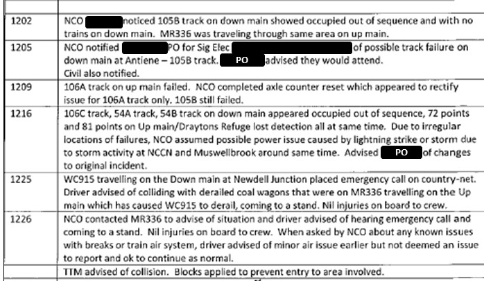
[1]     The standard gauge (1435 mm) network was predominantly used by interstate rail traffic.

[2]     The broad gauge (1600 mm) network was used by Melbourne metropolitan and Victorian regional train services.

[3]     The broad gauge lines would be temporarily removed from service by applying a track occupation.

[4]     Circuit breakers were ‘turned off’ and an Uninterruptable Power Supply (UPS) also disconnected.

[5]     Changeover is where vital signalling equipment and/or circuits are altered or renewed. The works were extensive.

[6]     A Commissioning Log is log of key events or issues encountered by the commissioning team during commissioning of the works and will include pre-start briefs, shift changes and testing issues. The Commissioning Log is managed by the TIC.

[7]     The level crossing protection would normally be activated by the level crossing control relay being de-energised. 

[8]     Rail worker positioned at a level crossing to activate crossing equipment if required for the passage of rail traffic.

[9]     The standard gauge line was on the north side of the broad gauge lines.

[10] Distance from the mid-point of the Werribee Street Railway Station.

[11]    A system composed of signalling apparatus that prevents conflicting movements by only allowing trains to receive authority to proceed when routes have been set, locked and detected in safe combinations.

[12]    Equipment used to detect the presence of rail vehicles by counting the number of axles entering or leaving a location. 

[13]    Accredited by the Office of the National Rail Safety Regulator.

[14]    Occupancy of a portion of rail track (an occupation) is allowed once a formal notice to occupy the track has been issued by the relevant rail authority. An occupation is usually issued to allow maintenance or other works on the rail track. Rail traffic is usually suspended, modified or restricted.
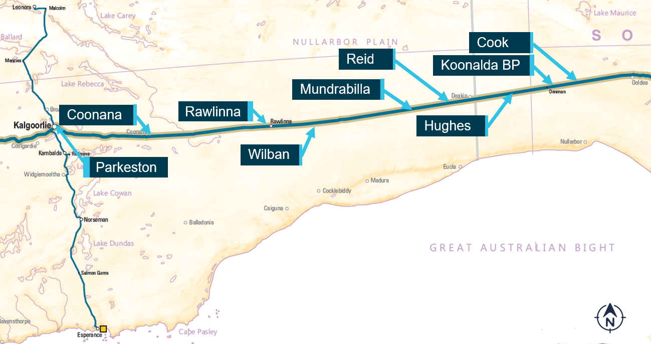
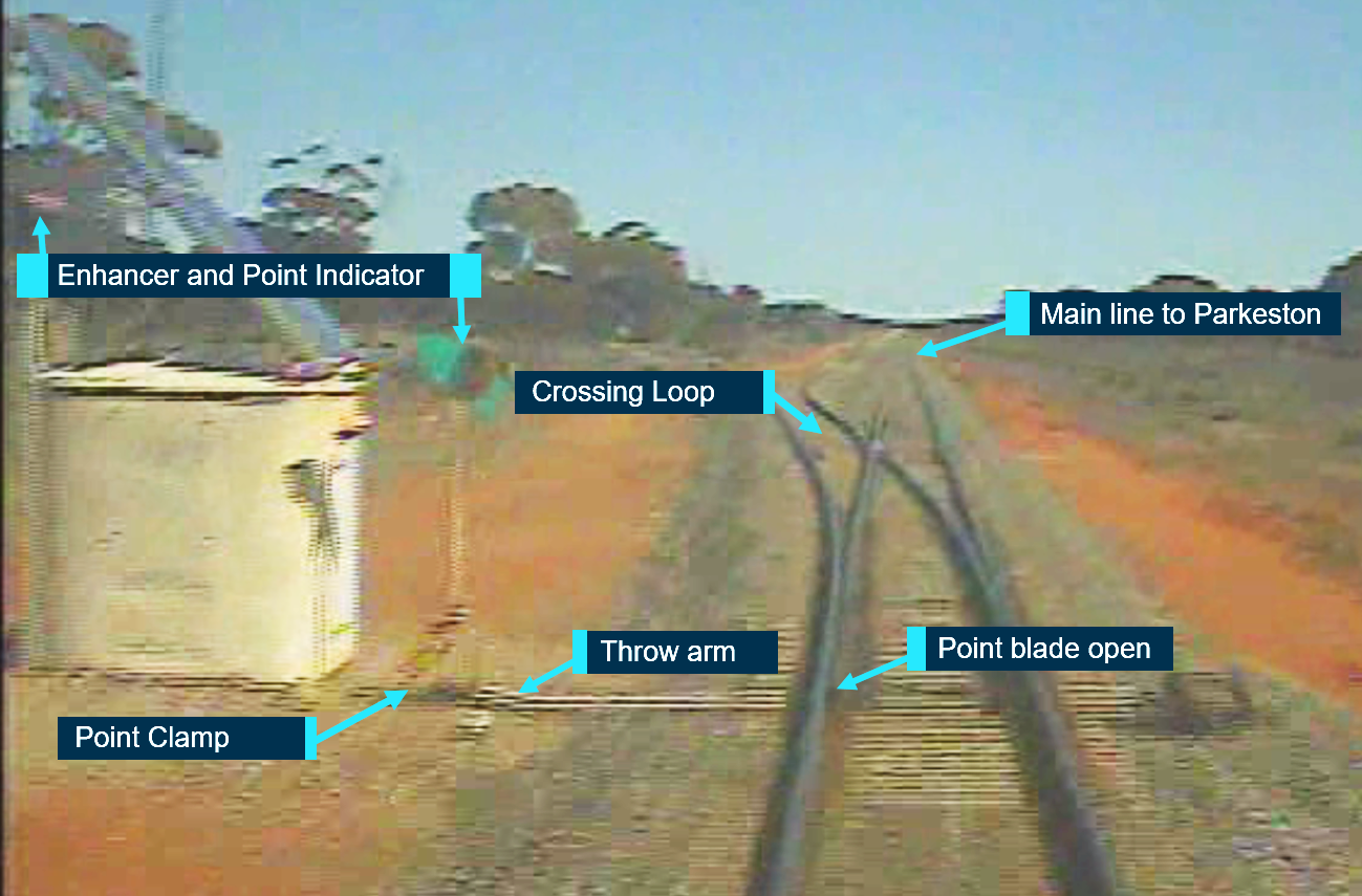
[15]    Disconnection of an Uninterruptable Power Supply (UPS) that supplied power to the relay room was also required, which is not shown in Figure 11.

[16]    A circuit that is energised from a source alternative to its design, for example through an intended temporary bridging arrangement, or by a current/voltage unintentionally fed into a circuit.

[17]    Clause 13, MTM (2017) Signalling design technical review procedure, L1-CHE-PRO-035-Version 2.

[18]    Additional controls were also put in place between 4 December 2020 and 14 December 2020 to prevent a repetition of the occurrence at Cherry Street level crossing.

[19]    Construction notes are instructions for implementation made by the signal designer when the drawings are produced.

[20]    The MTM specification for signalling supply, construction, and installation referenced AS/NZS 3000: Wiring Rules, which in turn referenced AS/NZS 4836 (2001): Safe working on or near low-voltage and extra-low voltage electrical installations and equipment.

[21]    The TCP stated that ‘all test straps and simulation equipment for testing shall be uniquely numbered and recorded on a test strap/equipment register.’ Further, the TCP stated that ‘temporary wiring and/or false feeds shall be recorded on the test copy and in the temporary jumper register.’ For the Werribee commissioning, a test strap register was used to record both test straps and temporary wiring. The signature space on the test copy stated ‘TEMPORARY JUMPER INSTALLED BY…’

[22]    The railway engineering cadetship, an LXRP initiative, is a 3-year program initiative offering a pathway into the railway industry. 

[23]    VRIOG members consisted of VicTrack, V/Line Pty Ltd, MTM, Yarra Trams and the Department of Transport (Vic).

[24]      In signalling installations where safety integrity is dependent upon the insulation between individual circuits, insulation tests on multicore and power cables are required to be made after their permanent installation and termination has been completed..

[25]    A test to confirm wire continuity between the two terminals.

[26]    A visual inspection to verify that the correct number of wires are connected at each termination point in accordance with the circuit diagrams and/or wiring diagrams and that the wire identification sleeves correspond with its termination position number.

[27]    A null count is a visual inspection of all relay bases, fuses, links and terminations against the documentation sheets to ensure there is no surplus wiring to that specified.

[28]    Test to determine that the circuit function is correctly energised/de-energised by the electrical “strapping” of the control device if the control device is not available to be electrically power operated. (eg “strap” front/back relay contacts, remove/replace fuses, links etc).

[29]    Page 37 of the test and commissioning plan.

[30]    A ‘yellow wire’ refers to a redundant wire that was identified with yellow tape and was to be removed.

[31]    A termination made by inserting the stripped end of a stranded wire into a portion of the connector, which is then mechanically deformed by compressing (crimping) it tightly around the wire.

[32]    The process for confirming that the installed system operates in accordance with the required signalling principles and safeworking rules and regulations. The Principles Tester confirms the integrity of the interlocking design by trying to defeat it, attempting to set up conflicting conditions, checking that all operational conditions that should be able to be simultaneously set up can be.

[33]    A Hi-Rail is a road rail vehicle which can operate on rail tracks and a conventional road.

[34]    A train used to test the operation of signalling equipment. Test trains were only planned to operate on the broad gauge. 

[35]    An IFC Signalling Test and Commissioning Plan for the Werribee Street level crossing removal was used for the audit.

[36]    The relevant people were not defined in the audit report.

[37]    The MTM audit report advised that corrective actions had been ‘discussed and agreed with relevant control owners and validated by relevant management for implementation’.

[38]    Dual gauge track has 3 rails to accommodate both broad gauge and standard gauge rolling stock.

[39]    This principle was stated in AS 7717 – 2016 section 2.15 and in the TCP, section‑1.3.2.

Occurrence summary

Investigation number RO-2020-020
Occurrence date 04/12/2020
Location Cherry Street, Werribee
State Victoria
Report release date 16/08/2024
Report status Final
Investigation level Systemic
Investigation type Occurrence Investigation
Investigation status Completed
Mode of transport Rail
Rail occurrence category Level Crossing
Occurrence class Incident
Highest injury level None

Train details

Train operator Pacific National
Train number 3PM7
Type of operation Freight service
Rail vehicle sector Freight
Departure point Perth, Western Australia
Destination Melbourne, Victoria
Train damage Nil