On 11 October 2018 a Qantas Airways Boeing 737-800, registered VH-VZD (VZD) was inbound to Brisbane, Queensland from Melbourne, Victoria on a scheduled passenger flight. Another Boeing 737-800 also on a scheduled passenger flight, operated by Virgin Australia Airlines and registered VH-YFW (YFW), departed Brisbane, Queensland for Proserpine, Queensland. The two aircraft were on reciprocal tracks in the Amberley Queensland airspace when a loss of separation occurred. The aircraft inbound to Brisbane, VZD, was being controlled on the Royal Australian Air Force (RAAF) Amberley (military) air traffic control (ATC) frequency and the aircraft outbound from Brisbane, YFW, was being controlled on a Brisbane (civil) ATC frequency.
What the ATSB found
RAAF Amberley and Brisbane ATC operated non-linked air traffic management systems, which did not share a common display. Between ATC jurisdictions without linked systems information was shared using manual coordination between ATC elements.
The departing aircraft from Brisbane (YFW) entered Amberley airspace without a hand‑off from Brisbane ATC and without instructions to the crew to change to the Amberley frequency. This resulted in YFW monitoring an incorrect frequency on entry to Amberley airspace and Amberley ATC initially unable to communicate with the flight crew.
The Brisbane departures air traffic controller did not hand‑off the departing aircraft YFW until after it had entered Amberley airspace. In addition, just prior to this incident, Brisbane terminal control unit did not advise Amberley ATC of a change in configuration to the terminal control unit consoles. This led to Amberley ATC contacting the incorrect console position at Brisbane ATC once the departing aircraft had entered Amberley airspace, and delayed the opportunity for Amberley ATC to resolve the impending conflict.
Once appropriate communication with Amberley and Brisbane ATC was established, the outbound aircraft was transferred to the Amberley frequency, and the aircraft were initially diverted away from each other, before being re-established on their respective tracks.
What’s been done as a result
Following the occurrence both RAAF Amberley and Brisbane ATC have taken corrective actions to improve communication and coordination between the two units. This has included deploying a dedicated communications pathway between Amberley approach and the Brisbane Departures South air traffic control positions, and implementing an airspace release that controls the risk that short notice deviations present across the non-linked systems.
Safety message
This incident highlights the importance of clear communication and coordination between air traffic controllers operating in different, yet immediately adjacent airspace. Air traffic controllers need to maintain a clear understanding of responsibility for separation assurance, especially when operating without a shared traffic picture. This incident also illustrates the effectiveness of the conflict resolution training received by air traffic controllers in loss of separation events.
The occurrence
What happened
On 11 October 2018 at about 1413 Eastern Standard Time (EST),[1] there was a loss of vertical and lateral separation standards in military airspace near the Royal Australian Air Force (RAAF) Amberley aerodrome, Queensland, involving two Boeing 737-800 aircraft. Prior to the loss of separation the two aircraft were operating in the same airspace but on different frequencies, with one aircraft controlled by RAAF Amberley (military) air traffic control (ATC) and the other by Brisbane (civil) ATC.
Sequence leading to the incident
At 1406 a Qantas Boeing 737-800, registered VH-VZD (VZD), operating as QF618 on a scheduled passenger flight from Melbourne, Victoria to Brisbane, Queensland, was on descent to Brisbane Airport and passing through RAAF Amberley airspace, which was controlled by military ATC. Weather warnings were in place for Brisbane and Amberley airports as a frontal weather system, including thunderstorms, was approaching from the west and moving east. About that time, a Virgin Australia Airlines Boeing 737-800 aircraft, registered VH-YFW (YFW) operating as VA1117 on a scheduled passenger flight, departed Brisbane Airport from runway 19 on an initial heading of 195, and turned right onto a heading of 230 and was on climb to flight level (FL)[2] 180. Due to the convective weather in the area, YFW was unable to use a procedural standard instrument departure, and was flying assigned radar headings provided by ATC. The flight crew advised the Brisbane departures controller that they were unable to make any further turns to the right at that time due to the convective weather.
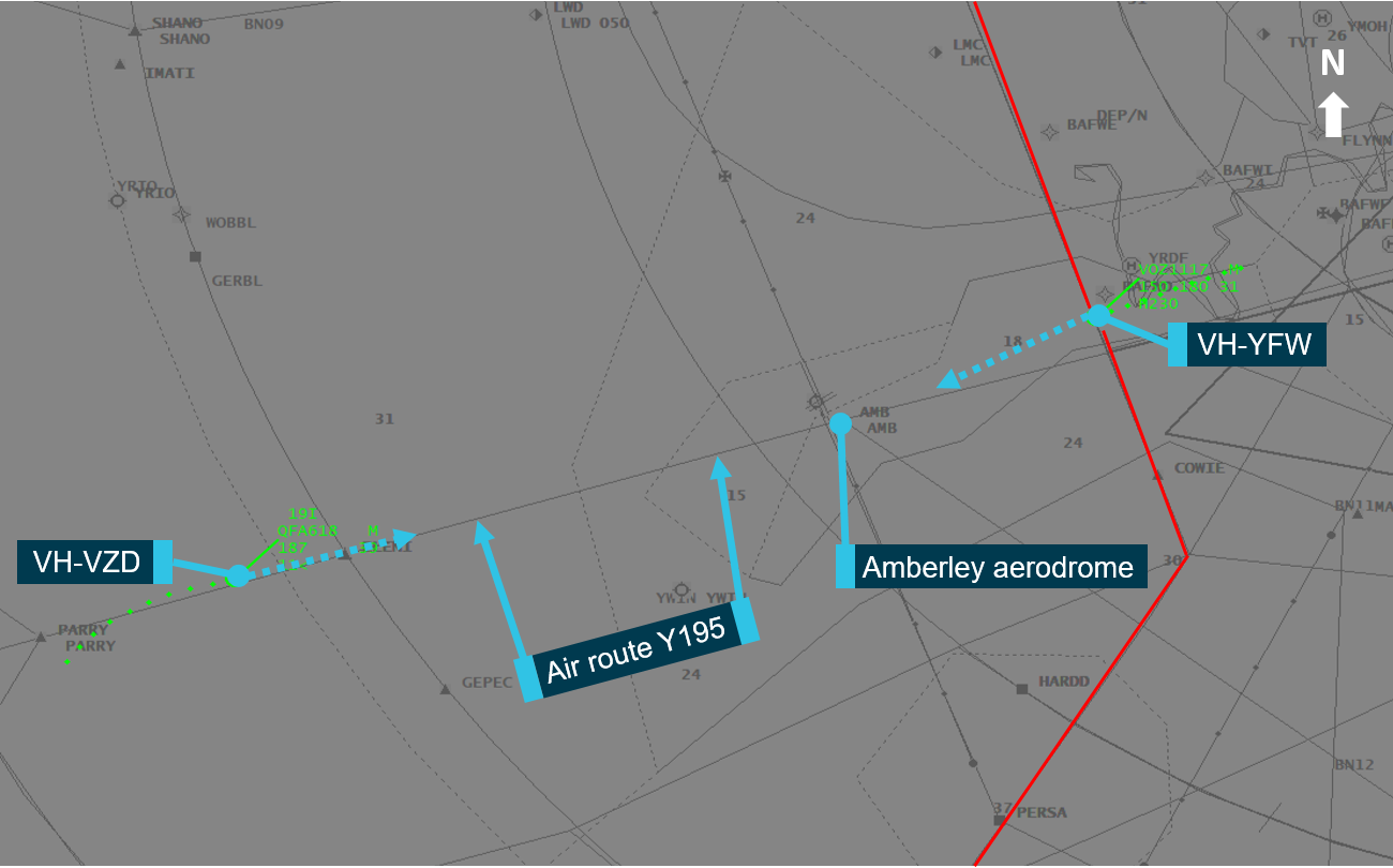
At 1410, as YFW was approaching Amberley airspace, the Brisbane departures controller provided the RAAF Amberley approach controller with an identification on the aircraft, as required by the procedures in the Manual of Air Traffic Services (MATS): Supplementary South East Queensland.[3] At this time, the Amberley approach controller advised the Brisbane departures controller of the inbound aircraft on air route Y195 (Figure 1). The Brisbane departures controller replied that YFW would be turning right soon. The Brisbane departures controller then asked the flight crew of YFW to advise when they could turn right (north). The flight crew advised they would like to stay on heading 230 for an additional 70 to 80 NM due to the weather. It was around this time that YFW entered Amberley airspace (Figure 1), while still communicating with the Brisbane departures controller.
At this time, RAAF Amberley approach was being controlled by a trainee approach controller under supervision of a training supervisor.
At 1411:56, the Amberley approach controller attempted to contact the Brisbane departures south controller regarding the inbound aircraft VZD but was advised that they were speaking to the incorrect controller due to an earlier Brisbane terminal airspace configuration change (see Brisbane airspace configuration). The Amberley training officer took over from the trainee controller in the Amberley approach position, and about 17 seconds later established contact with the Brisbane departures controller, advising them of the inbound aircraft (VZD). The Brisbane departures controller questioned the assigned altitude of VZD raising concern over the potential conflict with YFW, which was now within Amberley airspace. At this point, the two aircraft were still on different radio frequencies, with VZD on the Amberley approach frequency, and YFW on the Brisbane departures frequency.
Figure 1: Position and direction of the two aircraft when VH-YFW entered Amberley airspace at 1411:44. The red line indicates the boundary between Brisbane airspace (right) and Amberley (left) airspace. Air route Y195 was assigned to VH-VZD.
Source: Airservices Australia – modified by the ATSB
At 1412:20, the Brisbane departures controller advised the Amberley approach controller that YFW would contact them for separation, and at 1412:29 instructed the flight crew of YFW to contact Amberley approach. Around this time, the Brisbane ATC display presented a short term conflict alert (STCA) to the Brisbane departures controller. At about the same time the Amberley approach controller issued a safety alert[4] to VZD and instructed the crew to turn left (north). Upon contact with YFW at 1413:10, the Amberley approach controller issued a safety alert and instructed them to turn to left (south). After both aircraft had turned and separation recovery actions were complete, VZD resumed its descent into Brisbane and YFW continued its flight to Proserpine.
Both aircraft were fitted with a traffic collision avoidance system[5] (TCAS) which would have assisted in providing separation instructions to the flight crew in the event ATC were unable to resolve the situation.
Airspace information
The red line in Figure 1 shows the delineation between Brisbane and Amberley airspace. The local coordination procedures between Brisbane and Amberley ATC are described in the MATS: Supplementary South East Queensland. This document included the following:
the hand-off of (aircraft) must be initiated prior to 5 NM (9.26 km) of the boundary
when runway 19 is in use, the standard assignable level is FL 130 for aircraft on approach to Brisbane on the air route Y195, through Amberley airspace
Brisbane Terminal Control Unit (TCU) are to advise Amberley of any changes to the position of Brisbane departures south. This includes if it is merged with Brisbane approach south or Brisbane departures north.
Brisbane and Amberley ATC used different air traffic management systems to control their airspace. These systems were not linked and did not display the same information, so the Amberley controllers did not get details of aircraft which were not entering their airspace as the details were not entered by their planning function. The Brisbane controllers were required to contact the Amberley controllers to provide them an aircraft’s identification and basic details if the aircraft was approaching the boundary between Brisbane and Amberley airspace.
Aircraft hand-off
ATC recordings and interviews identified that the Brisbane departures controller originally intended to turn the departing aircraft, YFW, to the north avoiding Amberley airspace. Amberley controllers stated that YFW came further into their airspace than they were expecting, as they were expecting it to turn north based on communications with the Brisbane departures controller. The Brisbane departures controller reported that several previous aircraft had ‘accepted’ turns to the north-northwest.
The Amberley approach controller had not received a hand‑off of YFW when it entered Amberley airspace. The hand-off of YFW occurred after the impending conflict with the inbound aircraft (VZD) was identified by the Brisbane departures controller. The Brisbane departures controller reported that they had expected Amberley to assure separation between the aircraft by assigning VZD to maintain FL 190, however 5 minutes before YFW entered Amberley airspace VZD had been instructed by the Amberley approach controller to descend to FL 130.
Brisbane airspace configuration
Prior to the occurrence, and due to the World Parachuting Championships at Runaway Bay (about 65 km south-south-east of Brisbane Airport), the airspace sectors for the Brisbane TCU were not in the usual configuration. Due to the proximity of the inbound and outbound tracks of aircraft around the parachute operations, one controller was controlling all departures and approaches in the southern area. Due to the weather front approaching, the parachuting championships were put on hold prior to the incident.
About 5 minutes prior to the incident, at about 1407, the Brisbane airspace was returned to a more standard configuration, being that the departures controller controlled all departures to the south and north. The Brisbane approach south controller was controlling all aircraft approaching from the south. It was reported that this change, back to the more standard configuration was not communicated to Amberley ATC.
Amberley to Brisbane communication
Amberley approach and Brisbane TCU controllers used three tele-communication lines. These included direct lines to the following sectors: Brisbane approach north, Brisbane approach south and Brisbane departures north. There was no direct line to Brisbane departures south. Brisbane TCU used combinations of sectors whereby the sector of Brisbane departures south was always combined with one of the other sectors. In accordance with agreed procedures, Brisbane TCU was required to notify Amberley when the position of Brisbane departures south changed.
The Amberley controllers stated that they were not aware that Brisbane departures positions had been combined until they contacted the incorrect controller. The Airservices internal investigation stated that the Brisbane TCU did not advise Amberley of the change of configuration. There was approximately 4 minutes and 30 seconds from the time Brisbane departures was combined and the Amberley approach controller contacting the incorrect Brisbane controller.
Workload
The presence of the rapidly moving weather front, including thunderstorms, around Brisbane meant that many aircraft were unable to operate on standard instrument departures. This resulted in an increase in coordination requirements for the air traffic controllers. The Brisbane departures controller had continuous communications with multiple aircraft for approximately 6 minutes prior to the loss of separation.
Separation
Once the two aircraft were operating on the same frequency, they were instructed to deviate from their flight path away from each other by the Amberley approach controller. The two aircraft passed each other and had a loss of separation,[6] where the required separation was 3 NM horizontally or 1,000 ft vertically, and the minimum recorded distances were 2.1 NM and 650 ft.
Safety analysis
The Brisbane departures controller intended to turn the departing aircraft YFW to the north, avoiding Amberley airspace. When YFW did not accept turns to the north, it was unlikely the situation was effectively reassessed by the Brisbane departures controller resulting in YFW entering Amberley airspace without a hand-off. The presence of the rapidly moving weather front likely increased the workload for the Brisbane departures controller due to the increase in aircraft coordination requirements, and this may have influenced the delay in the hand-off of YFW to the Amberley approach controller.
When YFW entered Amberley airspace without a hand-off from the Brisbane departures controller it was operating on a different frequency to Amberley approach and other aircraft in Amberley airspace. This resulted in the Amberley approach controller being unable to effectively manage the multiple aircraft, specifically YFW, in their airspace and therefore reduced their ability to maintain separation standards.
Amberley ATC were not expecting YFW to enter their airspace due to the Brisbane departures controller stating the aircraft would be turning north soon, which was consistent with their actions for several previous departing aircraft. This, combined with the aircraft operating on a different frequency to Amberley approach, resulted in a delay in the Amberley approach controller being able to resolve the impending conflict. The Brisbane departures controller was expecting the Amberley approach controller to assure separation between the two aircraft, but was unaware that VZD was already on descent and therefore in conflict with YFW.
Due to the World Parachuting Championships, the Brisbane Terminal Control Unit (TCU) were not operating in a standard configuration on the day of the occurrence. When the TCU reverted back to a more standard configuration this was not communicated to Amberley ATC as per the agreed procedure. Consequently, this led to a delay in the Amberley approach controller being able to contact the Brisbane departures south controller due to the incorrect position being contacted. Further, this resulted in a delay in the aircraft being transferred to the Amberley approach controller to effect recovery of the compromised separation scenario. The time from configuration change to the Amberley approach controller contacting the incorrect Brisbane position (4 minutes and 30 seconds) suggests that there was an opportunity for Brisbane TCU to advise Amberley ATC of the new configuration prior to the Amberley approach controller requiring contact with the Brisbane departures south controller.
The Amberley approach controller contacting the incorrect controller resulted in a reduction of potential recovery time of 17 seconds before the correct Brisbane controller was reached. Calculations based on the estimated ground speed of both aircraft obtained from Airservices indicate that this 17-second delay led to a reduction in the lateral separation of the two aircraft by approximately 6 km (3.24 NM). This delay in communication between Amberley and Brisbane ATC reduced the amount of time available to recover the impending loss of separation while the aircraft were closing on reciprocal tracks in opposite directions. If this configuration change was immediately relayed to Amberley ATC, it would have allowed the Amberley approach controller more time to resolve the impending conflict between the two aircraft, and separation requirements may have been maintained.
Findings
These findings should not be read as apportioning blame or liability to any particular organisation or individual.
The departing aircraft was not expected to enter Amberley airspace but did so without hand‑off of control from the Brisbane departures controller, resulting in the aircraft operating on a different frequency to the Amberley approach controller and the other aircraft operating in Amberley airspace.
The Brisbane departures controller did not hand‑off the departing aircraft until after it had entered Amberley airspace due to the original intention to turn the aircraft north prior to the airspace boundary.
The Brisbane Terminal Control Unit did not advise Amberley of the changed terminal control unit configuration. This led to Amberley approach contacting the incorrect Brisbane controller once the departing aircraft had entered Amberley airspace, and delayed the opportunity for Amberley approach to resolve the impending conflict.
Safety action
Whether or not the ATSB identifies safety issues in the course of an investigation, relevant organisations may proactively initiate safety action in order to reduce their safety risk. The ATSB has been advised of the following proactive safety action in response to this occurrence.
Airservices Australia
As a result of this occurrence, Airservices Australia (civil air traffic control) advised the ATSB that they are taking the following safety actions:
Implementing airspace releases that control the risk that short notice deviations present across the non-linked systems.
Deployed dedicated communication lines between Amberley ATC and Brisbane departures south.
Royal Australian Air Force (RAAF)
As a result of this occurrence, RAAF (military) air traffic control has advised the ATSB that they have taken the following safety actions:
A communications line to Brisbane departures south has been established and commenced operational use.
The relevant parties are working together to implement a solution to ensure separation assurance between Brisbane departing aircraft and Amberley traffic during weather diversions.
Amberley have submitted a documentation change to Airservices Australia to extend the weather colour coding to include the Brisbane TCU/Amberley approach interface.
Purpose of safety investigations
The objective of a safety investigation is to enhance transport safety. This is done through:
identifying safety issues and facilitating safety action to address those issues
providing information about occurrences and their associated safety factors to facilitate learning within the transport industry.
It is not a function of the ATSB to apportion blame or provide a means for determining liability. At the same time, an investigation report must include factual material of sufficient weight to support the analysis and findings. At all times the ATSB endeavours to balance the use of material that could imply adverse comment with the need to properly explain what happened, and why, in a fair and unbiased manner. The ATSB does not investigate for the purpose of taking administrative, regulatory or criminal action.
Terminology
An explanation of terminology used in ATSB investigation reports is available here. This includes terms such as occurrence, contributing factor, other factor that increased risk, and safety issue.
Publishing information
Released in accordance with section 25 of the Transport Safety Investigation Act 2003
Ownership of intellectual property rights in this publication
Unless otherwise noted, copyright (and any other intellectual property rights, if any) in this report publication is owned by the Commonwealth of Australia.
Creative Commons licence
With the exception of the Coat of Arms, ATSB logo, and photos and graphics in which a third party holds copyright, this publication is licensed under a Creative Commons Attribution 3.0 Australia licence.
Creative Commons Attribution 3.0 Australia Licence is a standard form licence agreement that allows you to copy, distribute, transmit and adapt this publication provided that you attribute the work.
The ATSB’s preference is that you attribute this publication (and any material sourced from it) using the following wording: Source: Australian Transport Safety Bureau
Copyright in material obtained from other agencies, private individuals or organisations, belongs to those agencies, individuals or organisations. Where you wish to use their material, you will need to contact them directly.
On 5 October 2018, a BRM Aero Bristell light sport aircraft (LSA), registered VH-YVX, departed Moorabbin Airport, Victoria, with a pilot and passenger on board. The purpose of the flight was a navigation exercise in support of the pilot’s commercial pilot training requirements. Following an overfly of the intended waypoint at Stawell Airport, the aircraft was observed by witnesses to conduct a number of aerobatic‑type manoeuvres before control was lost. The pilot was unable to recover control of the aircraft before it impacted terrain. The occupants sustained significant injuries and the aircraft was destroyed.
What the ATSB found
The ATSB determined that, contrary to the aircraft’s limitations and the pilot’s qualifications, aerobatic manoeuvres were conducted during the flight, and immediately prior to the loss of control. The aircraft experienced an accelerated aerodynamic stall and entered into an upright, fully‑developed spin. Although the pilot did not consistently apply the manufacturer’s recommended spin recovery technique, recovery from a fully‑developed spin may not have been possible in the aircraft type.
The avionics system fitted to the accident aircraft had data storage capability and also backup storage capability by way of a secure digital (SD) card which could be fitted to the avionics system. An SD card was not fitted as standard equipment when Bristell aircraft were delivered to operators from new. Further, the operator was not aware of the additional memory card storage capability and had not installed SD cards in any of their Bristell fleet.
What's been done as a result
Following a number of fatal spin‑related accidents involving BRM Aero Bristell aircraft in Australia and overseas, the Civil Aviation Safety Authority (CASA) reviewed the flight test data supplied by the aircraft manufacturer against the ASTM standard for which the manufacturer self‑certifies compliance. CASA found that there was not enough information in the initial and follow-up test data to provide them with assurance that the aircraft type meets the required standards for spin recovery. At the time of writing the final investigation report, the manufacturer and CASA were still in discussion.
The operator conducted a fleet-wide installation of SD cards to all aircraft capable of storing data.
Safety message
Aerobatic flight should not be undertaken by pilots who have not been adequately trained, as it requires specialist techniques and methods to maintain control of the aircraft during significant manoeuvring. Further, aircraft manufacturers that prohibit aerobatics in certain aircraft types do so because the aircraft has not been designed and/or tested to ensure these manoeuvres can be conducted safely. This accident clearly demonstrates the catastrophic consequences when the hazards of aerobatic flight are not managed.
Aircraft data recording systems can be a readily accessible tool for both flying training, maintenance and safety investigation. Aircraft owners should make themselves aware of the data recording capability of their aircraft and ensure that the systems are fully functioning and backing up information.
The occurrence
What happened
On 5 October 2018, at about 1220 Eastern Daylight‑saving Time,[1] a Bristell light sport aircraft, registered VH-YVX, departed Moorabbin Airport, Victoria, with a pilot and passenger on board. The purpose of the flight was a navigation exercise in support of the pilot’s commercial pilot training requirements. The passenger held a student pilot licence, however their aviation medical certificate was not current. Photographs taken during the flight indicated that the passenger operated the aircraft for brief periods, but the ATSB assessed that this did not contribute to the development of the accident.
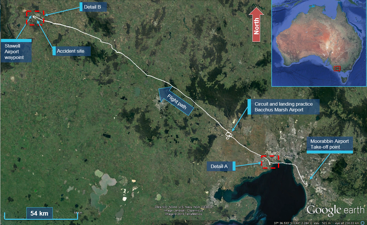
Automatic Dependence Surveillance Broadcast and on-board flight and GPS data recorded the aircraft position and attitude throughout the flight (see the section titled Recorded information). The data showed the take-off and flight over the northern part of Port Phillip Bay, followed by the commencement of significant manoeuvring overhead a built-up area to the west of Melbourne (Figures 1 and 2).
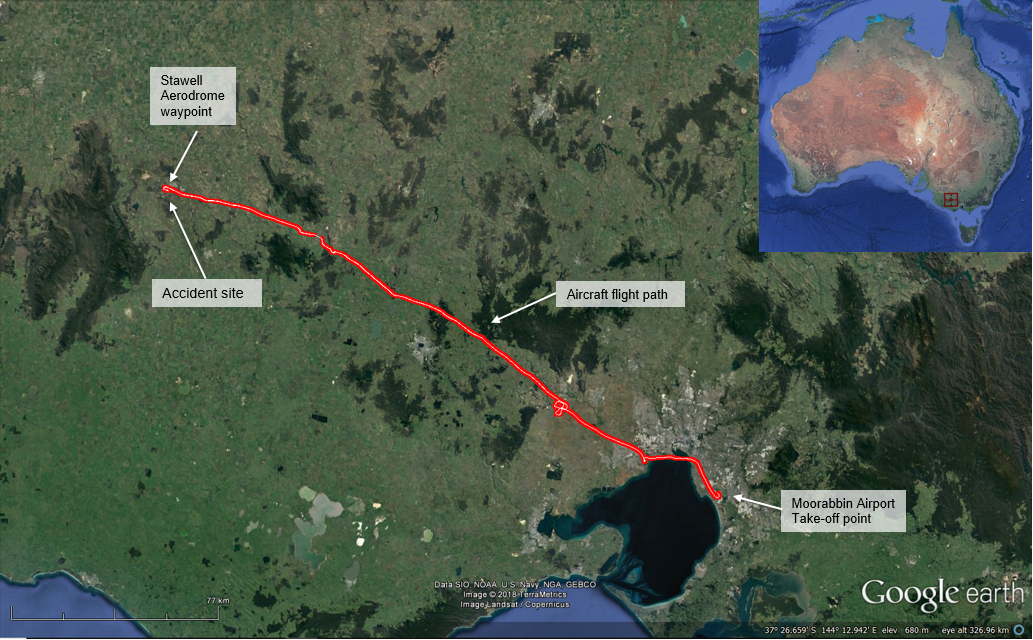
Figure 1: Aircraft’s flight path and accident site location
Source: Google Earth, modified by the ATSB
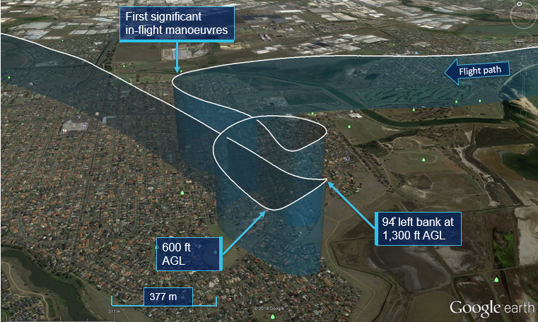
Figure 1 details the flight path of the aircraft in the area labelled as ‘Detail A’ in Figure 1. The data showed that the pilot conducted significant manoeuvres including steep climbs, descents and turns in excess of 90° angle of bank over a built-up area and at heights between 600‑1,300 ft above ground level (AGL).
In discussing that segment of the flight, the pilot stated that a 360° turn was conducted over the house of someone the pilot knew in the area. The pilot did not recall conducting any aerobatics or significant manoeuvring at that time.
Figure 2: Detail A – Recorded data of the aircraft flight path over a built-up area
Source: Google Earth, modified by the ATSB
The aircraft then continued to Bacchus Marsh Airport where the pilot conducted a circuit followed by a touch-and-go landing. The aircraft then continued in a north‑west direction until overhead Stawell Airport (Figure 3).
At about 1240, three witnesses at Stawell Airport observed the aircraft overfly the airport before commencing a 180°turn back towards the south‑east. Following that turn, the aircraft was observed to commence a number of significant manoeuvres including steep climbs and turns described as aerobatic in nature. The aircraft was then observed to abruptly enter a flat spin (see the section titled Spins and spin recovery) and descend out of view.
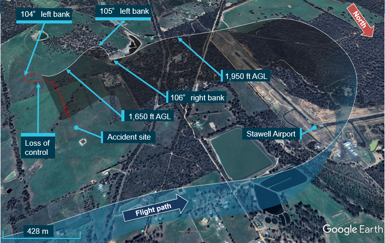
Analysis of the recorded data identified that, after passing overhead the airport, manoeuvres far in excess of the aircraft’s performance limitations were conducted. Based on the magnitude of the recorded pitch and roll values, the manoeuvres were classified as aerobatic. Further data analysis established that while the aircraft was pitching and rolling out from a diving left steep turn, it experienced an accelerated aerodynamic stall[2] while rolling at an indicated airspeed of about 93 kt. The aircraft subsequently flick-rolled and entered a fully developed upright spin at an altitude of about 1,650 ft AGL. The aircraft maintained the spinning descent until it impacted terrain.
The pilot stated that, immediately prior to the accident, a turn of no more than 50° angle of bank was conducted in the process of lining up for a practice circuit and landing at Stawell Airport when ‘the back end of the aircraft slid out’ and control was lost. The pilot also stated that the accident occurred prior to reaching the airport.
When provided with detail of the recorded flight data and other accounts, the pilot was unable to reconcile the difference between their recollection of the event and that of the witnesses and the recorded data. Figure 3 shows the aircraft track, manoeuvring and spin. The red portion of the flight track is the point at which the GPS lost signal and position data was no longer recorded. This was likely due to a combination of the aircraft’s rapid movements and the GPS antenna position. From that point onwards, position data was calculated using groundspeed, bearing and barometric altitude data.
Figure 3: Detail B – Aircraft operation in the vicinity of Stawell Airport
Source: Google Earth, modified by the ATSB
A witness at Stawell Airport notified emergency services about the accident. Two other witnesses at the airport used an aircraft to locate the accident site and guided the emergency services to the location by flying overhead. The pilot and passenger sustained serious injuries and were airlifted to hospital. The aircraft was destroyed.
The pilot attained a Private Pilot Licence (Aeroplane) on 13 August 2018 and had about 160 hours of flying experience. At the time of the accident the pilot was undergoing training for the issue of a Commercial Pilot Licence (Aeroplane) qualification. The pilot was not trained or endorsed to conduct aerobatics.
Medical information
The pilot held a current Class 1 Aviation Medical Certificate with a requirement to conduct additional assessments as directed by the Civil Aviation Safety Authority. The pilot confirmed being well-rested on the day of the flight, with no medical issues.
Stall and spin recovery training
According to the pilot’s instructor, the pilot had been taught theoretical and practical stall recovery techniques, including recovery from an incipient spin. The pilot’s training records indicated that the pilot had demonstrated the correct incipient spin recovery technique to their instructor and flight examiner on several occasions.
Aircraft information
General
The BRM Aero Bristell is a light sport aircraft (LSA). It is an all-metal, low-wing monoplane of semi-monocoque construction with side-by-side seating and dual flight controls. It is driven by a 4-cylinder, 4-stroke, normally aspirated piston engine, driving a composite three-blade constant-speed propeller. It has a maximum all up weight of 600 kg (Figure 4).
Figure 4: Exemplar BRM Aero Bristell LSA aircraft
Source: Aircraft operator with permission
VH-YVX Airworthiness and maintenance
BRM Aero Bristell LSA serial number 284 was manufactured in 2017 and registered in Australia as VH-YVX.
At the time of the accident, the aircraft was:
operating on a special Certificate of Airworthiness in the light sport aircraft (LSA) category
approved for private operations/flight training
maintained in accordance with the manufacturer’s maintenance schedule
operating under a current maintenance release with no outstanding defects or maintenance. It indicated that the aircraft had about 928 flight hours since new.
Approved aircraft manoeuvres
The aircraft operating instructions (AOI) section 2.9 had approved manoeuvres listed as follows:
• Steep turns not exceeding 60° bank
• Lazy eights
•Chandelles
• Stalls (except whip stalls).
The section also had the following warning:
Aerobatics and intentional spins are prohibited.
The same warning is also included as a placard on the cockpit instrument panel (Figure 5).
Figure 5: Depiction of placard attached to the instrument panel
Source: Bristell LSA operating instructions
Section 2.10 of the AOI identified the maximum manoeuvring load factors as +4.0 to -2.0 G.
Integrated instrument and avionics system
The aircraft was fitted with a Garmin G3X avionics system, which was an integrated flight instrumentation, position, navigation and communication system.
Recorded flight data
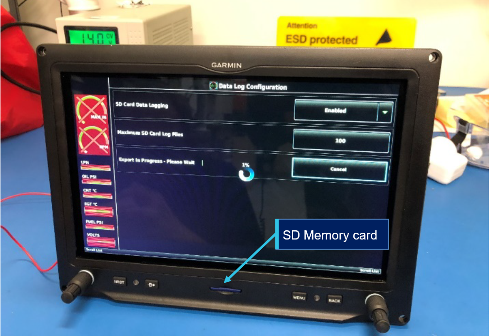
The G3X unit had a flight data logging feature which automatically stored flight and engine data to its memory module. A secure digital (SD) card can also be fitted as a backup memory storage that can be easily removed from the aircraft so that the flight data can be downloaded for operational and maintenance monitoring purposes. A data file was created each time the system was powered on with an SD card inserted, or each time an SD card was inserted after power on.
A 2 GB SD card can store over 1,000 hours of flight data or up to 1,000 files (whichever comes first). The SD card is normally located in a receptacle on the right upper face of the unit. However, an SD card was not provided with the aircraft when it was first supplied from the manufacturer. It was therefore at the owner’s discretion if they wished to utilise the recording feature. No SD card was installed at the time of the accident.
Stall warning and angle of attack display
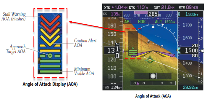
When the angle of attack (AOA) system identifies an exceedance in the calibrated caution alert threshold, an intermittent audible warning will be heard. The tone will increase in frequency until it reaches the AOA stall warning threshold, at which point the audible warning will change from intermittent to continuous.
In conjunction with the audible warning, the AOA system will display a change from a solid green to yellow in the caution level. It flashes from yellow to red when it reaches the stall warning threshold (Figure 6).
Figure 6: Angle of attack on the primary flight display
Source: Garmin G3X Pilot’s Guide, modified by the ATSB
Regulatory definition and requirements for aerobatic flight
Definition of aerobatic flight
Civil Aviation Safety Regulations 1998 (CASR) Dictionary, Part 1 Definitions defined aerobatic manoeuvres as those that involve:
(a) bank angles that are greater than 60˚; or
(b) pitch angles that are greater than 45˚, or are otherwise abnormal to the aircraft type; or
(c) abrupt changes of speed, direction, angle of bank or angle of pitch.
Regulatory requirements for aerobatic flight
To conduct aerobatic manoeuvres, pilots are required to have an aerobatics flight activity endorsement entered on their pilot’s licence. To obtain this endorsement, a pilot is required to have received training and demonstrated competency in all the course units mentioned in CASR Part 61 Manual ofStandards. That training includes recovery from unusual attitudes and spins.
CASR 61.065 prohibits the conduct of any activity for which the licence holder is not authorised. In addition, CASR subpart 61.S Flight activity endorsements stated the requirements for aerobatic endorsements. These included an initial aerobatic endorsement that would authorise the pilot to conduct aerobatic manoeuvres in an aeroplane above 3,000 ft above ground level (AGL). Subsequent endorsements were necessary for aerobatic activities at lower altitudes.
information and guidance on safety issues related to aerobatic flight, including in respect of the aircraft, pilot and regulations
an explanation of spin recovery techniques
advice on the importance of ensuring sufficient height to recover from an aerobatic manoeuvre by 3,000 ft AGL (or the lower limit of the pilot’s approval).
In particular, section 7.3.2 of the CAAP stated:
It is highly probable that the consequence of an error or failure during low-level aerobatics will be fatal to the participants.
Aerobatics are not permitted over populous areas or public gatherings without the written permission of CASA.
Spins and spin recovery
Overview
An aerodynamic spin is a sustained spiral descent in which one or both an aircraft’s wings are in a stalled condition,[3] with the outside wing producing more lift and less drag than the other wing. The associated forces sustain the rotation and keep the aircraft in the spin. A spinning aircraft will descend more slowly than one in a vertical or spiral dive and it will have a lower airspeed, which may oscillate. The pitch angle can also vary considerably from significant pitch down to a relatively flat attitude.
Intentional spins are normally entered from a stall in straight and level flight, via the application of full back elevator and full rudder in the intended direction of rotation at the moment of the stall. The circumstances of a spin entry during aerobatic manoeuvring can be very different. If for example, aerobatic manoeuvres are incorrectly conducted, an unintentional consequence can be a flick roll[4] and entry into a spin.
Incipient spin
When entering a spin, an aircraft motion through the air is irregular at first. This is a transition phase from the stall and is known as incipient spin. Though the nature of the incipient spin is heavily dependent on the aircraft type and the manner of entry, recovery may be more rapid and require less control input in this stage compared with recovery from a developed spin.
Developed Spin
After a number of rotations and depending on the aircraft loading, type and control inputs, an aircraft in an incipient spin may settle into a regular rotating descent known as a developed spin. A developed spin is typified by reduced oscillations when compared to an incipient spin and the axis of rotation becomes vertical. The spin may steepen (nose down) or flatten (nose more horizontal) as it continues.
Recovery from an unintentional spin
The BRM Aero Bristell LSA AOI, section 3.7 described the recovery from unintentional spins as follows:
There is no[t] an uncontrollable tendency of the airplane to enter into a spin provided the normal piloting techniques are used.
Unintentional spin recovery technique:
1. Throttle - idle
2. Lateral control - ailerons neutralized
3. Rudder pedals - full opposite rudder
4. Rudder pedals - neutralize rudder immediately when rotation stops
5. Longitudinal control - neutralize or push forward and recover dive.
Spinning ceases only when opposing forces and moments overcome auto-rotation. Since yaw coupled with roll powers the spin, the pilot must forcibly uncouple them by applying the recommended spin recovery technique. Due to rotational inertia, spin recovery is not instantaneous. It may take several turns of the applied technique before recovery control forces finally overcome the spin stabilising forces and rotational inertia. Spins are only recoverable when the cumulative effects of the interacting variables favour recovery and there is enough altitude and therefore time to recover. Generally speaking, recovery from an incipient spin will take less time than a recovery from a fully developed spin. It is therefore vital that the correct recovery technique is implemented as soon as possible.
Pilot and passenger recollection of the attempted spin recovery
The pilot stated that the aircraft did not provide him with an aural or visual warning of an impending stall leading up to or during the accident sequence. When asked about the recovery technique following entry into a spin, the pilot confirmed that full opposite rudder was not maintained. Rather, the pilot initially applied opposite rudder to the spin and then reversed the control and noted that the spin rate increased. The pilot then moved the rudder back to the full opposite rudder position.
Analysis of the recorded data showed that the engine power was only slightly reduced following entry into the spin. Power was reapplied and then reduced to idle about 14 seconds after the spin commenced.
The passenger did not have a full recollection of the event but recalled the plane going pitch-up to a vertical position and then one rotation. The passenger remembered then saying ‘opposite rudder power down’ to the pilot before passing out prior to impact.
Although the passenger did not recall an audible warning when interviewed by the ATSB, they did mention hearing a beeping sound when discussing the event with their family a short time after the accident.
Light sport aircraft certification standards for spin recovery
Aircraft in the LSA category are certified to the ASTM International[5] standards. The certification process is conducted and self-certified for compliance by the manufacturer themselves, rather than by the regulating aviation authority from the state of manufacture. The LSA process relies on the manufacturer declaring that the aircraft meets all the construction and flight requirements of the LSA standards identified by them in the statement of compliance.
Aircraft certification standards for spin testing
ASTM F2245 standard specification for design and performance of light sport aeroplanes, section 4.5.9 states:
4.5.9 Spinning:
4.5.9.1 For airplanes placarded “no intentional spins,” the airplane must be able to recover from a one turn spin or a 3-s[econd] spin, whichever takes longer, in not more than one additional turn, with the controls used in the manner normally used for recovery.
In some aircraft not approved for spinning, recovery may not be possible if the spin progresses to the developed stage.
The standard has various requirements, for example the light sport aircraft category for non-aerobatic aircraft requires the aircraft manufacturer to prove the aircraft type can recover from a one-turn spin.
CASA assessment of BRM Aero Bristell LSA spin testing
The LSA category relies solely on the aircraft manufacturer declaring that each individual aircraft meets/complies with the standard(s) that they have indicated within the statement of compliance. Each individual aircraft must have its own statement of compliance issued and signed by the aircraft manufacturer that the particular aircraft meets the identified standards. Manufacturers are not required to submit test data, or show compliance to those standards, to CASA or any other regulator.
Following a number of fatal accidents involving Bristell aircraft entering into and not recovering from spins in Australia and overseas, CASA assessed the Bristell LSA self-certification testing documentation against the ASTM certification test standards.
CASA found that there was insufficient information in the initial test data to provide assurance that the aircraft type met the ASTM standards for spin recovery. As a result, CASA requested more certification testing data from the manufacturer. The manufacturer conducted further certification flight tests in the Bristell LSA and provided that data, including video recordings of each flight sequence to CASA. CASA’s assessment of the new flight-testing data and further information supplied by the manufacturer was that it still did not confirm that the aircraft met the required ASTM standard for spin recovery.
Post-accident CASA guidance on spin avoidance
Due to an increase in spin‑related accidents across a broad range of light aircraft types in the training environment, CASA produced guidance material in the form of an advisory circular (AC) 61-16 v1.0 titled Spin avoidance and stall recovery training. The AC highlights:
…the risks associated with advanced stalling training when conducted in aircraft that are not certified for intentional spinning. It clarifies the difference between wing drop at the stall and the incipient phase of a spin and provides background for the interpretation of aircraft flight manual manoeuvre limitations with respect to spinning. It also provides guidance on acceptable methods of training and testing stalls with a wing drop and spin avoidance.
The AC provides detailed guidance for pilots, flight instructors, flight examiners and flight training organisations. The AC states that:
The key messages in this AC that are critical for the safe conduct of advanced stalling and spinning exercises, and that all pilots instructors, operators and flight examiners should be aware of are:
• A spin must not be induced in aircraft not certified or approved for intentional spinning
• A spin must not be induced without the pilot in command holding a spinning flight activity endorsement
• Aircraft flight manual limitations and any special procedures before conducting any exercise which may result in a spin
• The need to comply with aeroplane centre of gravity limits
• Wing drop at the stall for the purposes of spin avoidance training must not be induced by application of pro-spin rudder and the induction of a spin
• Training in spin avoidance must include the recognition of symptoms associated with slow flight and approach to the stall through to recovery from stall with a wing drop
• Recognise and manage changes in aircraft energy state
• Spin avoidance training where a wing may drop at the stall should be undertaken through scenario-based in-flight manoeuvres:
- Approach configuration descending turns (base to final turn)
- Go-around from approach configuration (significant change in trim state)
- Climbing turns in departure configuration (trim changes during flap retraction and turns)
- Engine failure after take-off (potential out of trim condition)
- Turns in slow flight.
Site and wreckage examination
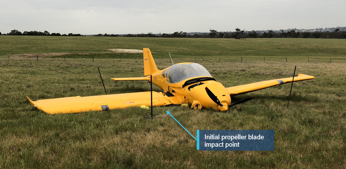
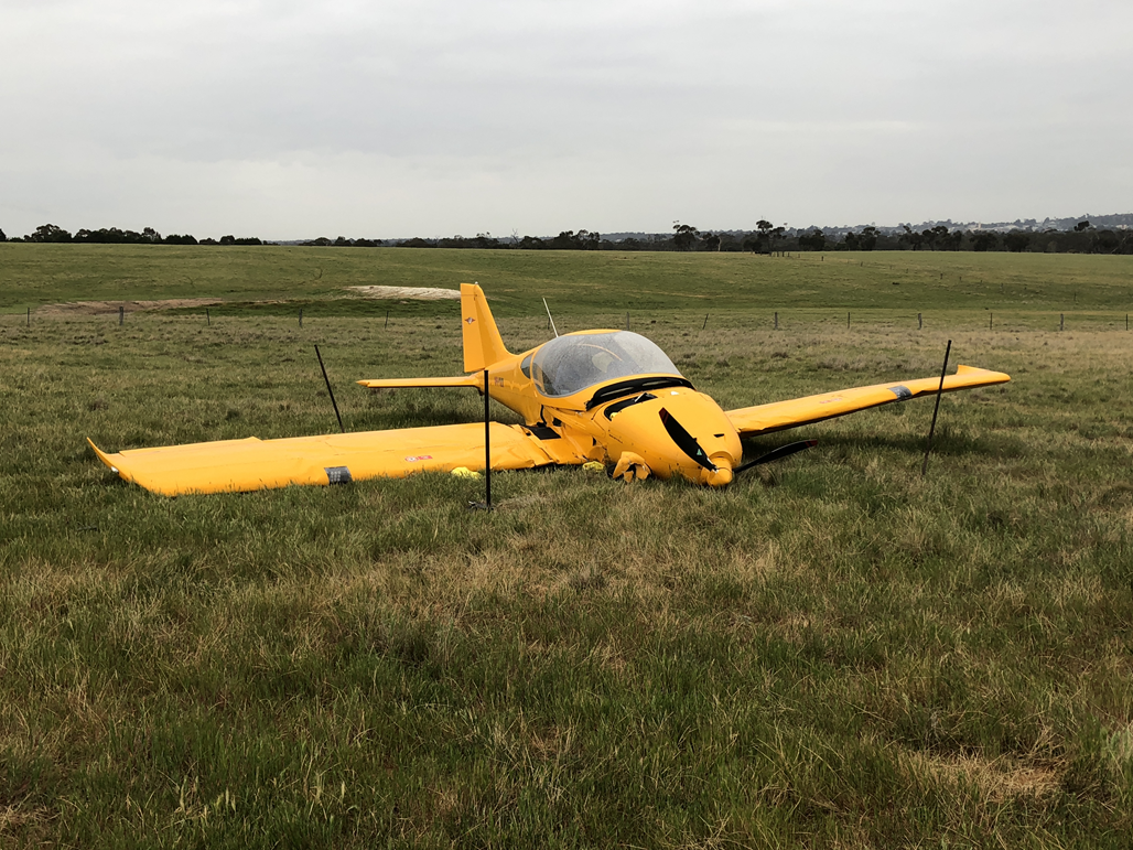
The ATSB conducted an examination of the accident site and wreckage (Figure 7). The examination identified that:
the aircraft was located in relatively flat and open farmland, about 1.7 km south‑east of Stawell Airport
ground impact marks indicated that the aircraft had impacted terrain in a relatively flat, upright, counterclockwise spin
the flaps were in the retracted position
there was evidence of a significant amount of fuel at the accident site and the airframe fuel filter bowl was full of fuel and free of contaminants
the propeller blades showed rotation damage consistent with engine operation at a low power setting at impact
elevator trim was in a neutral position
no pre-impact defects were identified with the flight controls or aircraft structure
all aircraft components were accounted for at the accident site.
A Garmin G3X (G3X) panel‑mounted avionics unit was removed from the aircraft for detailed examination at the ATSB’s technical facility in Canberra.
Figure 7: Aircraft accident site
Source: ATSB
Recorded information
G3X avionics system flight data download
The ATSB inspected the G3X unit and identified that it was visually undamaged. There was no SD card fitted to the unit. On return to Canberra, the unit was powered up with an SD card fitted (Figure 8). Data files associated with the accident flight were successfully downloaded from the memory module to the card.
Figure 8: G3X avionics unit being downloaded, showing memory card position
Source: ATSB
Flight data summary
The downloaded data recorded 86 parameters for the duration of the accident flight, from the initial taxi until impact with terrain. The flight data indicated that the aircraft and engine were operating normally throughout the flight with no anomalies identified within the data or aircraft operating systems.
Position verification
The GPS position was verified to be accurate within 2 metres by utilising the aircraft’s:
track on the parking bay, taxi ways and runway at Moorabbin Airport
track during the touch-and-go on the runway at Bacchus Marsh Airport
final position at the accident site.
Significant aircraft manoeuvres
The data recorded that at about 1230, while the aircraft was overhead the built‑up area shown in Figure 2, it was operated significantly outside of its allowable flight envelope. This included banking to 94° while manoeuvring between 600‑1,300 ft above a populated area.
At 1319, the recording captured a 91° roll to the left followed by a pitch down to 40°. The data also recorded a climbing right turn to 91° angle of bank at 1323, followed by a pitch down to 38° then a rolling left pull out turn. Whilst pulling out, the instrumentation system recorded a peak normal acceleration of 4.4 G. That loading exceeded the aircraft’s positive load limit of 4 G.
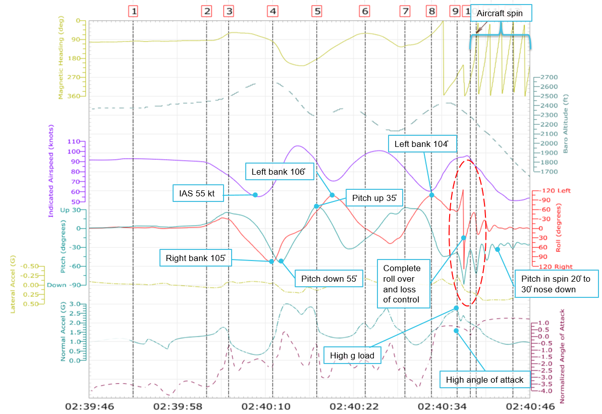
From 1340, there was significant variation in the magnitude of pitch, roll and load factor, consistent with additional aerobatic manoeuvring during the final minute of the flight (Figure 9).
At 1340:36, while the aircraft was operating at:
about 90 kt indicated airspeed
a pitch-down angle of about 50°
high angle of attack and positive load factor
it abruptly pitched down to 90° and rolled significantly to the left. That behaviour was consistent with the aircraft experiencing an accelerated aerodynamic stall.[6]
Subsequent variation in the recorded parameters indicated that the aircraft then entered a counter-clockwise upright spin at a rotation rate of about one full turn every 1.5 seconds and a vertical descent rate of over 3,000 ft/min at the time of impact.
The engine power level remained at a constant high setting prior to the spin entry.
Figure 9: Last 60 seconds of recorded flight data parameters prior to the accident
Source: ATSB
Weight and balance information
The aircraft weight was calculated as being about 17 kg over the maximum allowable limit at take‑off from Moorabbin Airport, but within the balance limits. However, the aircraft was within the weight and balance limits at the time of the accident, when the weight was adjusted for 1 hour 20 minutes of fuel consumption.
Previous accidents
BRM Aero Bristell registered 24-7954, Clyde North, Victoria
This accident was investigated by Recreational Aviation Australia. The accident investigation report is not a publically available document.
On 3 August 2017, during a training flight, a student pilot was conducting stall recovery training under supervision of an instructor at an altitude of 3,500 ft AGL. Following entry into the stall, the right wing dropped and, despite the correct instructed actions, the student pilot mishandled the stall recovery by applying opposite aileron. Although this is an intuitive response to raise the wing, it exacerbated the stall and the aircraft entered a spin.
The instructor took over control of the aircraft from the student and initiated the correct spin recovery technique using ailerons neutral and opposite rudder. Despite having 3,000 ft remaining, the instructor was unable to regain control of the aircraft before it impacted the terrain. The student pilot was fatally injured, and the instructor sustained serious injuries.
On 14 June 2019, during a flight with two occupants, recorded data showed that the engine power was reduced as the aircraft maintained about 3,200 ft with reducing airspeed. The aircraft then rapidly lost height and impacted the ground about 30 seconds later. The aircraft was destroyed and the two occupants were fatally injured.
The on-site examination indicated that the aircraft impacted the ground at a high vertical rate, in a nearly level attitude, whilst rotating anticlockwise about the yaw axis.
At the time of writing the accident was still under investigation by the Irish Aircraft Accident Investigation Unit.[7]
Examination of the aircraft and recorded flight data identified that there were no mechanical defects that contributed to the accident. Further, a review of the meteorological conditions as described by witnesses and the pilot indicated that weather was not a factor.
Evaluation of the flight data also established that the pilot engaged in aerobatic manoeuvres during the course of the flight, including just prior to the loss of control in the vicinity of Stawell Airport. This analysis will discuss the development of the accident in that context.
Aerobatic limitations
The Bristell light sport aircraft (LSA) operating instructions prohibit excessive angles of bank, aerobatics and intentional spins. This was clearly defined and the information relating to spin avoidance was also presented by way of a placard in the cockpit.
Civil aviation regulations stipulate the types of manoeuvres that are considered to be aerobatic. It also sets out the pilot training and endorsements requirements before aerobatics are to be conducted. The framework provided by these rules ensures that this hazardous activity can be performed with an acceptable level of safety.
When interviewed, the pilot demonstrated an awareness of the aircraft limitations and the requirements relating to aerobatics. Further, the pilot did not have any training or endorsements in aerobatics and did not apply for or receive permission from CASA to undertake aerobatics over a populous area. Despite that, manoeuvres meeting the definition of aerobatics were carried out during the accident flight in the form of abrupt changes in flight parameters and excessive bank and pitch.
Aerobatic manoeuvring and loss of control
Aerobatics were first conducted above a built-up area at 600‑1,300 ft above ground level (AGL), and with a maximum bank angle of 94°. Had an unrecoverable loss of control occurred over such a populated area, in addition to the likely fatality of the occupants, there was a significantly increased risk of injuries or fatalities to people on the ground.
Additional aerobatics were conducted mid-flight between Bacchus Marsh and Stawell airports, with one exceeding the aircraft’s flight load limitations. The aircraft was then observed by witnesses to overfly Stawell Airport before again commencing significant pitch and bank manoeuvres. During one of these manoeuvres, the aircraft experienced an accelerated aerodynamic stall and entered into an upright spin at an altitude of about 1,650 ft AGL. This progressed into a fully developed spin that continued until the aircraft impacted terrain.
Due to the accelerated nature of the spin entry and the already nose-down and banked attitude, the entry to the spin would probably have been abrupt and disorientating. The pilot reported not maintaining the correct spin recovery technique with respect to rudder input. Despite that, as discussed further below, even with immediate and sustained application of spin recovery control inputs, recovery from the spin may not have been possible.
The pilot’s account of the aircraft manoeuvring during the flight, including immediately before the loss of control, did not align with either the flight data or the witness statements. The passenger only recalled fragments of information about the flight and did not recall what happened before the aircraft entered the spin.
The ATSB assessed that the recorded flight data was accurate. It clearly indicated that the aircraft was operated significantly beyond the allowable limits of both the aircraft and the pilot’s qualifications, with catastrophic consequences.
Aircraft spin certification and characteristics
Non‑aerobatic aircraft in the LSA category, such as the Bristell LSA, are certified to the ASTM International standards. As such, the aircraft is required to demonstrate the ability to recover from a one‑turn or 3‑second spin, whichever was longer, in not more than one additional turn. Recovery from a multiple-turn, fully developed spin is not required to be demonstrated.
As a consequence, there is no assurance that, even if the normal spin recovery technique was applied, that recovery from a fully developed spin is possible in the Bristell LSA aircraft.
In response to a number of fatal accidents involving Bristell aircraft entering and not recovering from spins in Australia and overseas, the Civil Aviation Safety Authority (CASA) assessed the Bristell LSA type certification testing documentation against the ASTM certification test standards. CASA found that there was insufficient information in the initial flight test data to provide assurance that the aircraft type met the ASTM standards for spin recovery. As a result, CASA requested more certification testing data from the manufacturer. The manufacturer conducted further certification flight tests in the Bristell LSA and provided that data, including video recordings of each flight sequence to CASA. CASA’s assessment of the new flight-testing data and other information provided after that point still did not confirm that the aircraft met the required ASTM standard for spin recovery. At the time of writing, CASA and the manufacturer were still in discussion.
In the context of this accident, as the aircraft was operated significantly outside its operating limitations, it was not possible to identify if a safety issue surrounding aircraft spin and recovery characteristics of the Bristell LSA exists.
Avionics memory and data use
There are many advantages to having recording devices installed in aircraft. These include the use of downloaded data to monitor:
student pilot performance
third party aircraft usage
engine health trends and aircraft limitation exceedances.
They also provide a significant source of evidence during the investigation of aircraft accidents.
The avionics system fitted to the accident aircraft had data storage capability and also backup storage capability by way of a secure digital (SD) card which could be fitted to the avionics system. An SD card was not fitted as standard equipment when Bristell aircraft were delivered to operators from new. Further, the operator was not aware of the additional memory card storage capability and had not installed SD cards in of their Bristell fleet. As a result, had the avionics unit memory module been damaged, then important recorded data associated with this accident could have been destroyed.
The ATSB encourages operators and owners of aircraft to, wherever possible, use on board recording capability to capture the available data parameters.
Findings
From the evidence available, the following findings are made with respect to the loss of control and collision with terrain involving a Bristell LSA aircraft, registered VH-YVX, in Stawell Victoria on 5 October 2018. These findings should not be read as apportioning blame or liability to any particular organisation or individual.
Contributing factors
While conducting aerobatics, the aircraft experienced an accelerated aerodynamic stall and entered into an upright spin that continued until impacted terrain.
The pilot conducted aerobatic manoeuvres without aerobatic training, in an aircraft which prohibited such manoeuvres.
Other factors that increased risk
During the accident flight, the pilot conducted aerobatics at low altitude over a built-up area in contravention to safe practices and the regulations. Had an unrecoverable loss of control occurred there was a significantly increased risk of injuries or fatalities to people on the ground.
A regulatory review of the aircraft type’s self-certification flight test data and documentation by the Civil Aviation Safety Authority (ongoing at the time of writing) did not provide assurance that the aircraft type met the required standard for spin recovery.
Other findings
The aircraft's avionics system, while capable of storing data, was not fitted with a memory card. The memory card serves as a back-up for stored data, which can be a readily accessible tool for both flying training and safety investigation.
Safety issues and actions
Proactive safety action
Whether or not the ATSB identifies safety issues in the course of an investigation, relevant organisations may proactively initiate safety action in order to reduce their safety risk. The ATSB has been advised of the following proactive safety action in response to this occurrence.
Civil Aviation Safety Authority
During the investigation, the ATSB became aware that the Civil Aviation Safety Authority (CASA) was reviewing the BRM Aero Bristell LSA aircraft certification testing against the ASTM standards. At the time of writing, there was insufficient information available to assure CASA that the Bristell LSA aircraft met the required standard for spin recovery. Consequently, CASA has requested further information from the aircraft manufacturer.
The operator
The operator conducted a fleet-wide installation of SD cards to all aircraft capable of storing data.
General details
Pilot details
Licence details:
Private Pilot Licence (Aeroplane), issued 13 August 2018
Endorsements:
Manual Propeller Pitch Control
Ratings:
Single engine aeroplane
Medical certificate:
Class 1 and 2, valid to 19 October 2018
Aeronautical experience:
about 160 flight hours
Sources and submissions
Sources of information
The sources of information during the investigation included:
the pilot and passenger
witnesses and first responders to the accident
the aircraft operator and manufacturer
Civil Aviation Safety Authority
Airservices Australia
Victoria Police.
Submissions
Under Part 4, Division 2 (Investigation Reports), Section 26 of the Transport Safety Investigation Act 2003 (the Act), the ATSB may provide a draft report, on a confidential basis, to any person whom the ATSB considers appropriate. Section 26 (1) (a) of the Act allows a person receiving a draft report to make submissions to the ATSB about the draft report.
A draft of this report was provided to the pilot and passenger, the aircraft operator and manufacturer and the Civil Aviation Safety Authority.
Submissions were received from the pilot and passenger, the aircraft operator and manufacturer and the Civil Aviation Safety Authority. The submissions were reviewed and, where considered appropriate, the text of the report was amended accordingly.
Purpose of safety investigations
The objective of a safety investigation is to enhance transport safety. This is done through:
identifying safety issues and facilitating safety action to address those issues
providing information about occurrences and their associated safety factors to facilitate learning within the transport industry.
It is not a function of the ATSB to apportion blame or provide a means for determining liability. At the same time, an investigation report must include factual material of sufficient weight to support the analysis and findings. At all times the ATSB endeavours to balance the use of material that could imply adverse comment with the need to properly explain what happened, and why, in a fair and unbiased manner. The ATSB does not investigate for the purpose of taking administrative, regulatory or criminal action.
Terminology
An explanation of terminology used in ATSB investigation reports is available here. This includes terms such as occurrence, contributing factor, other factor that increased risk, and safety issue.
Publishing information
Released in accordance with section 25 of the Transport Safety Investigation Act 2003
Ownership of intellectual property rights in this publication
Unless otherwise noted, copyright (and any other intellectual property rights, if any) in this report publication is owned by the Commonwealth of Australia.
Creative Commons licence
With the exception of the Coat of Arms, ATSB logo, and photos and graphics in which a third party holds copyright, this publication is licensed under a Creative Commons Attribution 3.0 Australia licence.
Creative Commons Attribution 3.0 Australia Licence is a standard form licence agreement that allows you to copy, distribute, transmit and adapt this publication provided that you attribute the work.
The ATSB’s preference is that you attribute this publication (and any material sourced from it) using the following wording: Source: Australian Transport Safety Bureau
Copyright in material obtained from other agencies, private individuals or organisations, belongs to those agencies, individuals or organisations. Where you wish to use their material, you will need to contact them directly.
Preliminary report
Report release date: 21/11/2018
This preliminary report details factual information established in the investigation’s early evidence collection phase and has been prepared to provide timely information to the industry and public. Preliminary reports contain no analysis or findings, which will be detailed in the investigation’s final report. The information contained in this preliminary report is released in accordance with section 25 of the Transport Safety Investigation Act 2003.
What happened
On 5 October 2018, at about 1120 Eastern Daylight‑saving Time,[1] a Bristell Light Sport Aircraft, registered VH-YVX, departed Moorabbin Airport, Victoria, with a pilot and passenger onboard. The purpose of the flight was a navigation exercise in support of the pilot’s commercial pilot training requirements. The passenger held a student pilot licence, but his aviation medical certificate was not current.
At about 1240, following an overfly of the intended waypoint at Stawell Airport, the aircraft was observed by witnesses to conduct a 180° turn towards the east at about 1,500 ft above ground level (Figure 1). Following the turn the aircraft was observed to commence a number of manoeuvres before entering a spin. The pilot was unable to recover control of the aircraft before it impacted terrain.
Figure 1: Aircraft’s flight path and accident site location
Source: Google earth, with Airservices surveillance radar data. Modified by the ATSB
A witness at the aerodrome notified emergency services about the accident. Two other witnesses at the aerodrome utilised an aircraft to locate the accident site and guided the emergency services to its location. The pilot and passenger sustained significant injuries and were airlifted to hospital. The aircraft was destroyed.
Site and wreckage examination
The ATSB conducted an examination of the accident site and wreckage (Figure 2). This examination identified that the:
aircraft was located in relatively flat and open farmland, which was about 1.7 km south‑east of Stawell Airport
ground impact marks indicated that the aircraft had impacted terrain in a relatively flat, upright, counter clockwise spin
flaps were in the retracted position
elevator trim was in a neutral position.
No pre-impact defects were identified with the flight controls or aircraft structure.
A panel‑mounted avionics unit was removed from the aircraft and taken to the ATSB’s technical facility in Canberra for examination. The stored information was successfully downloaded and included numerous flight and engine parameters recorded during the accident flight.
Figure 2: Accident site of Bristell Light Sport Aircraft, registered VH-YVX
Source: ATSB
Ongoing investigation
The investigation is continuing and will include:
interviews with parties involved in the accident
analysis of the downloaded data from the avionics unit and other electronic devices
examination of the pilot’s qualifications, experience and medical history
assessment of the aircraft’s flight performance characteristics
examination of aircraft maintenance and operational records
examination of the training organisation records and procedures.
___________________
The information contained in this preliminary report is released in accordance with section 25 of the Transport Safety Investigation Act 2003 and is derived from the initial investigation of the occurrence. Readers are cautioned that new evidence will become available as the investigation progresses that will enhance the ATSB's understanding of the accident as outlined in this update. As such, no analysis or findings are included in this update.
Purpose of safety investigations
The objective of a safety investigation is to enhance transport safety. This is done through:
identifying safety issues and facilitating safety action to address those issues
providing information about occurrences and their associated safety factors to facilitate learning within the transport industry.
It is not a function of the ATSB to apportion blame or provide a means for determining liability. At the same time, an investigation report must include factual material of sufficient weight to support the analysis and findings. At all times the ATSB endeavours to balance the use of material that could imply adverse comment with the need to properly explain what happened, and why, in a fair and unbiased manner. The ATSB does not investigate for the purpose of taking administrative, regulatory or criminal action.
Terminology
An explanation of terminology used in ATSB investigation reports is available here. This includes terms such as occurrence, contributing factor, other factor that increased risk, and safety issue.
Publishing information
Released in accordance with section 25 of the Transport Safety Investigation Act 2003
Ownership of intellectual property rights in this publication
Unless otherwise noted, copyright (and any other intellectual property rights, if any) in this report publication is owned by the Commonwealth of Australia.
Creative Commons licence
With the exception of the Coat of Arms, ATSB logo, and photos and graphics in which a third party holds copyright, this publication is licensed under a Creative Commons Attribution 3.0 Australia licence.
Creative Commons Attribution 3.0 Australia Licence is a standard form licence agreement that allows you to copy, distribute, transmit and adapt this publication provided that you attribute the work.
The ATSB’s preference is that you attribute this publication (and any material sourced from it) using the following wording: Source: Australian Transport Safety Bureau
Copyright in material obtained from other agencies, private individuals or organisations, belongs to those agencies, individuals or organisations. Where you wish to use their material, you will need to contact them directly.
On 29 September 2018, a Jetstar Airways Airbus A320 aircraft, registered VH-VFK, was operating a scheduled passenger flight from Sydney, New South Wales to Melbourne, Victoria. While preparing for the flight and having difficulties with the electronic system used for calculating take-off performance figures, the flight crew reverted to the back-up procedure of manual calculations.
Shortly after take-off, the maximum flap extended speed was exceeded. As the aircraft climbed through 2,800 ft, the flight crew retracted the landing gear after realising it was still extended, resulting in a landing gear retraction overspeed.
What the ATSB found
In completing the manual calculations for take-off performance, the flight crew inadvertently calculated speeds that were higher than required for the actual aircraft weight and environmental conditions. The incorrect take-off speeds were not identified by independent verification and cross-checking.
During the first segment of the take-off climb period, at maximum engine power settings, the aircraft pitch rate was below the recommended 3° per second, resulting in a higher acceleration rate than anticipated. Due to the incorrect calculated speeds, the aircraft rotated with a margin of only 16 kt to the flap extended limit speed. Five seconds after rotation, the flap extended overspeed event occurred.
The aircraft did not rotate to the correct pitch attitude and the pilot monitoring did not alert the pilot flying of this. However, he called ‘speed, speed’ in an attempt to assist the pilot flying manage the airspeed, to which the pilot flying reduced the engine power in response, rather than increasing the aircraft pitch. The action of reducing the engine power was taken when the aircraft was below the safe altitude above ground.
The landing gear would normally be retracted by the flight crew as soon as the aircraft had a positive rate of climb. In this case, the crew did not retract the landing gear when required. Climbing through 2,800 ft, they identified that the landing gear was still extended while troubleshooting the source of a buffeting noise. They then immediately selected the gear to ‘UP’ without first checking the aircraft speed, resulting in a landing gear retraction overspeed event.
What's been done as a result
Jetstar Airways advised that they undertook several actions to prevent a similar occurrence in the future. A safety summary of the incident was distributed to the wider pilot community, focusing on the importance of having the latest Flysmart software database version on their Electronic Flight Bag. It also highlighted the importance of considering reasonability and accuracy checks, consulting company procedure manuals in the event of Electronic Flight Bag issues, and conducting a normal rotation followed by reference to the Speed Reference System.
Safety message
This incident highlights the importance of independent validation and cross-check by the flight crew, in particular for performance speeds and aircraft weight.
The Airbus magazine Safety First #18 reports on potential problems with using incorrect reference speeds. This highlights the design and operational considerations underlying recommendations that Airbus has issued to flight crews.
The occurrence
On 29 September 2018, the flight crew of an Airbus A320 aircraft, registered VH-VFX and operated by Jetstar Airways, prepared to conduct a scheduled passenger flight from Sydney, New South Wales to Melbourne, Victoria. The flight crew had recently completed their third sector for that day in a different aircraft and were required to change aircraft for this flight, which had a scheduled departure time of 2200 Eastern Standard Time (EST).[1]
Take-off performance calculations – Electronic Flight Bag
The first officer, who was the designated pilot monitoring (PM)[2] for this flight, boarded VH-VFX in advance of the captain who was the pilot flying (PF) to begin flight preparations so as to minimise any delay. Jetstar had issued each pilot with their own electronic flight bag (EFB), an electronic information management device that helps the flight crew perform flight management tasks more easily and efficiently. The EFB enables the flight crew to access up-to-date information and contains applications to automate other functions, such as performance take-off calculations. Neither flight crew updated their EFBs before the first flight of the day, as required by Jetstar Airways.
The PM updated his EFB’s Flysmart[3] database shortly before the occurrence flight. When the PF arrived on the flight deck, he and the PM continued their preparations for departure. Both the PF and the PM used their respective EFBs to calculate the take-off performance data. The PF entered the data from his EFB into the flight management system (FMS)[4] performance take-off page. When the PM cross-checked the performance data displayed on his EFB with the information that the PF had entered into the FMS, he identified that the data was inconsistent. The PM and the PF then conducted a series of checks to troubleshoot the problem. During the flight crew’s attempt to identify the discrepancy, they found that the PF had an older software version of the EFB database on his device. The flight crew assessed that the out-of-date database was possibly related to the performance data discrepancy.
The PF attempted to update the database on his EFB, however, the device screen continuously displayed the ‘busy’ symbol and, at that time, the update was unsuccessful. The flight crew then attempted to use the spare EFB[5] on the aircraft. This had an outdated version of the software database.[6] The PF attempted to update the spare EFB. This update was also unsuccessful. Both the spare EFB and the PF’s EFB were effectively inoperative, continuously displaying the ‘busy’ symbol.
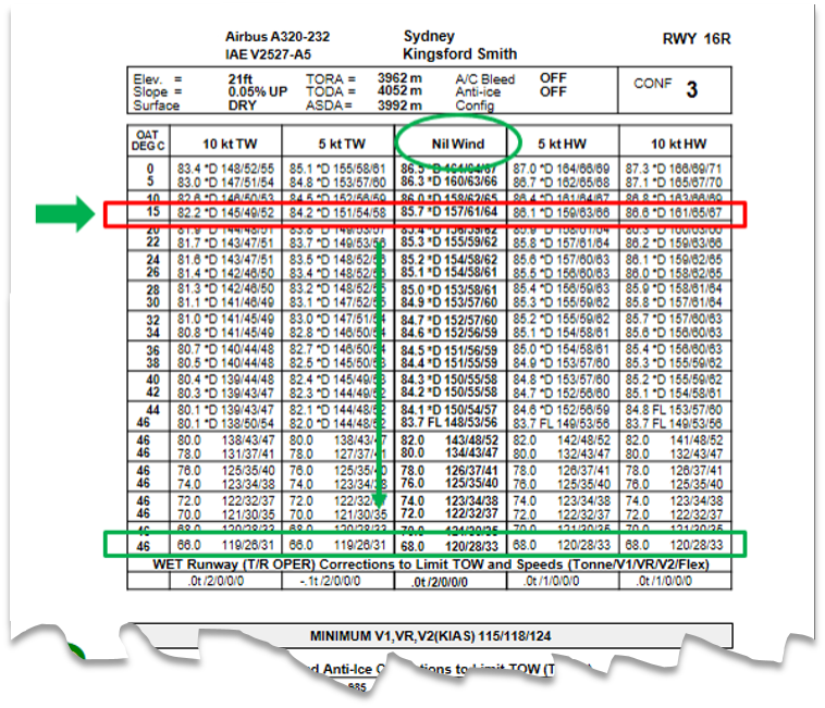
The flight crew resorted to the back-up procedure in which performance speeds were derived from manual calculations. The manual calculations involved reading the performance speeds off the regulated take-off weight (RTOW)[7] tables.
The PM recalled that he performed the calculations and that the PF agreed with the results, but the PM did not recall the PF independently performing that task. However, the PF’s recollection was that he did independently check the performance speed calculations that the PM had achieved. The flight crew agreed on the following performance speeds that were entered into the flight management system:
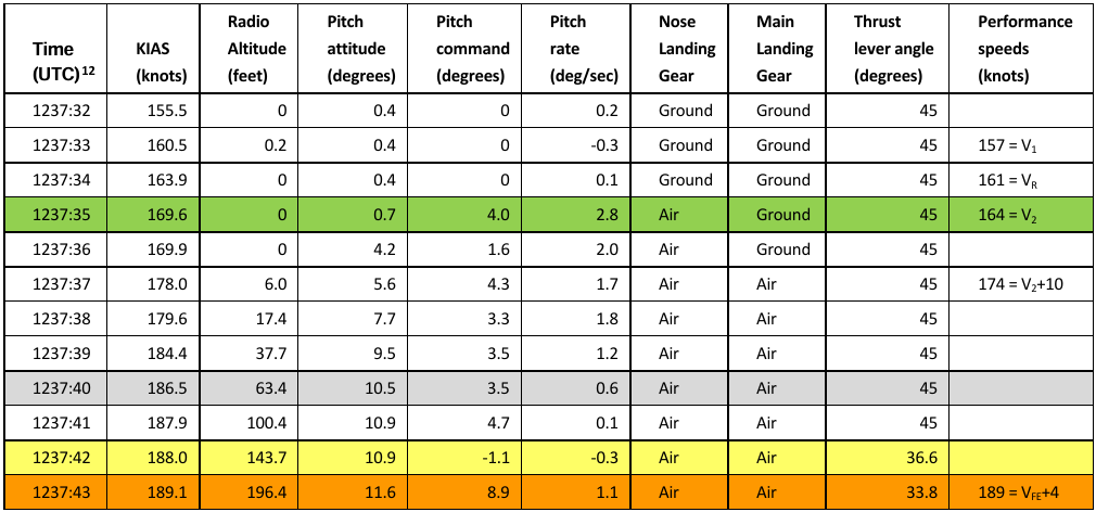
The flight crew commenced the take-off at 2237 EST (1237 UTC), using the manually-calculated performance data and take-off/go-around (TOGA)[11] thrust. Table 1 shows the quick access recorder (QAR) data at one second intervals, including indicated airspeed (KIAS), aircraft pitch attitude, pitch rate and the pitch and thrust commands by the pilot flying. Aircraft data times below are in UTC. QAR data showed the aircraft rotated at 169 kt with an initial pitch rate of 2.8⁰/sec. After rotation, the pitch rate remained under the desired 3⁰/sec (see Speed Reference System), reducing across the next 7 seconds before increasing.
The green highlighted line shows the rotation. The shadedline shows the flap overspeed. The yellow highlighted line shows when the thrust was reduced. The orange highlighted line shows when the master warning has been triggered.
Source: Quick access recorder (QAR) data provided by Jetstar and tabulated by ATSB.
In the normal procedure, following take-off, the PM would call ‘positive climb’ and the PF would call ‘gear up.’ In this case, neither of the calls were heard by the other flight crew member, although they were both reported as having been made.
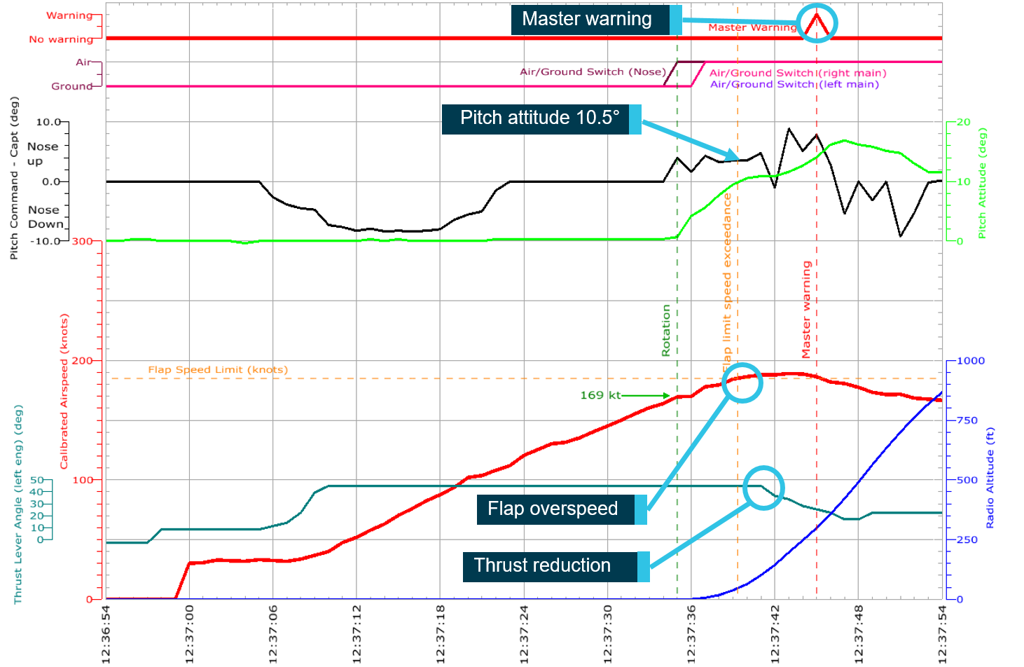
The PM reported then calling ‘speed, speed’, indicating that the aircraft was nearly at maximum speed for the flap extension configuration. The aircraft exceeded the flap extended limit speed 5 seconds after rotation (Table 1 and Figure 1).[13] By this time, at 1237:40 UTC, the aircraft was about 63 ft above ground level (AGL) and had a pitch attitude of 10.5° (green graph in Figure 1).
The overspeed warning was triggered when the airspeed exceeded the maximum flap extended speed (VFE[14]) by more than 4 kt. This occurred at a time between 1237:42 and 1237:43 UTC (the yellow and orange lines in Table 1). Airbus advised that the aircraft was at 180 ft radio altitude (AGL) at that time. The overspeed warning was displayed on the electronic centralised aircraft monitor, in addition to an aural warning and the master warning light.
Figure 1: Quick access recorder data graph showing take-off period
This graph shows when the master warning was recorded in the QAR data.
Source: Jetstar Airways quick access recorder data – graphed by ATSB
The PF retarded the thrust levers from the TOGA position 2 seconds after the flap overspeed, while the aircraft was at 144 ft AGL, which was below the thrust reduction altitude of 800 ft. After a further 7 seconds, the PF increased the thrust by advancing the thrust levers to the climb detent. The PF then retracted the flaps from position 3 to position 1.[15] The autopilot was engaged in climb mode and the aircraft continued climb with subsequent retraction of the flaps from position 1 to 0.[16]
Landing gear retraction overspeed
The take-off standard operating procedure was to retract the landing gear as soon as a positive climb rate was established. Shortly after completely retracting the flaps, the flight crew reported that they heard a ‘buffeting noise’. They commenced trouble-shooting the source of this sound and they identified that the aircraft’s auxiliary power unit (APU) was still on and delivering bleed air to the air-conditioning packs (as required when take-off performance speeds are calculated using the RTOW tables). Thinking that this may have been causing the buffeting noise, they turned the bleed air off, as per the standard operating procedures. This did not resolve the buffeting noise. The flight crew then realised the landing gear was still extended. The PF immediately called ‘gear up’ and the PM responded by retracting the landing gear immediately. The airspeed was then 250 kt,[17] which was above the maximum landing gear retraction speed of 220 kt.
The flight crew discussed the occurrence and, having no known adverse indications, decided to continue the flight to Melbourne.
The operator’s procedures required the flight crew to verify the Flysmart software database version on their electronic flight bag (EFB), and update it if required prior to their first flight of the day. On this occasion, neither flight crew member updated their Flysmart software prior to their first flight of the day despite an updated version being available. Included in the updated version was the removal of an obstacle relevant to the departure runway. However, Jetstar Airways later reported that the two software versions should have produced identical take-off performance results for this flight. Different performance data could result from a discrepancy in manually entered parameters. For example, if the incorrect aircraft registration was entered into Flysmart, different performance data would likely result.
The standard operating procedures, which the flight crew were required to complete as part of the preparation of the aircraft, included steps for starting the EFB and using it to calculate the take-off performance data. Subsequently, the flight crew were required to complete the flight management and guidance system preparation, which included entering the take-off data from the EFB into the flight management system’s performance take-off page and completing a cross-check of that data.
For dispatch, the EFB’s AIB Take-off application[18] had to be present and functioning on two EFBs (which could include the spare EFB) unless backup provisions were satisfied. The backup provisions, as detailed in the Jetstar A320 Company Procedures Manual, were ‘manual take-off charts available and/or independent calculations on one device.’ Since the flight crew did not have the AIB Take-off application functioning on two EFBs, they chose to use the manual take-off tables. However, in accordance with the backup provisions, they could also have completed independent calculations on the one functioning device.
Manual calculation for performance values
The manual take-off charts (regulated take-off weight (RTOW) tables) served as a backup method for calculation of the performance speeds when Flysmart was not available. The tables and the instructions for using them were contained in the Jetstar A320/A321 Performance Manual. The instructions spanned three pages and the tables were contained in a separate appendix. The manual was stored electronically on the EFBs and the flight crew accessed it on the PM’s EFB.
To use the manual tables (extract shown in Figure 2), the flight crew had to select the row corresponding to the outside air temperature, in this case 15⁰ (shown by the green arrow). They then had to select the column corresponding to the wind, in this case ‘nil wind’ (shown by the green circle). The point where they intersect is the maximum RTOW for these conditions, which was 85.7 t (shown by the red box). The take-off reference speeds used by the crew corresponded to this row.
The next step in the procedure was to move down the wind column to the row with the weight that was nearest to, but greater than the actual take-off weight (TOW) of 64.5t. The instruction to move down the ‘wind column’ appears at the top of the second page of the instructions. In this case, that weight was 68 t. According to this method, 68 t corresponded to the performance speeds of V1 = 120 kt, VR = 128 kt, V2 = 133 kt (shown by the green box).
After the event, the pilot monitoring (PM) stated that, in hindsight, he did not complete the process and move down the wind column until the actual TOW was less than the RTOW, as required by the procedure.
Training to use the tables was included as part of the operator’s initial ground school and line training. Both flight crewmembers had received this training. However, as the EFBs had been very reliable, it was rarely necessary to use the tables. Additionally, there was no recurrent training or practice with the tables.
Prior to the introduction of Flysmart in 2014, the procedures and charts were the normal method of calculation for the take-off performance speeds. The pilot flying (PF) commenced with Jetstar in 2006, so had prior, although not recent, experience with the charts. The PM stated that before commencing with Jetstar 18 months ago, he had used similar charts for calculating performance speeds for a different aircraft type. Those charts, however, did not require the user to use the aircraft weight to go down the wind column.
The operator’s procedures explaining how to use the tables also stated that normally the PM will calculate and record the performance data. The PF will only enter the performance data into the multifunction control display unit (MCDU) once they have checked and confirmed the calculated data is correct. If the PF identifies an error in the PM’s calculations, they may recalculate the recorded data. In any case, both the PF and the PM must agree on any data before entry into the MCDU, which they did in this instance. However, as described above, there was different recollection among the two crewmembers about whether the PF independently checked the speed calculations.
Both the PF and the PM explained that their resulting take-off reference speeds were ‘on the faster side’ but that this was consistent with what they were expecting, because using the charts required using TOGA thrust.
Figure 2: Regulated take-off weight table
The header of the table shows the aircraft type and variant, the airport location and runway to which the table applies. The sub-header gives more details about the airport and the configuration required. The main body of the table contains data provided for various temperature and wind combinations. The data corresponding to the ambient temperature (to the left) and the wind component (above) are RTOW in tonnes/ Performance Limit Code/Take-off speeds (V1, VR and V2).(Note: 100 must be added to VR and V2.).The performance limit code of *D is an obstacle limit weight. The lower sections of the table show corrections required for such things as wet runway, QNH corrections. They were not required in this case.
Source: Jetstar Airways – annotated by ATSB
Speed Reference System
The take-off procedure prescribed in the Jetstar A320/A321 Flight Crew Operating Manual (FCOM) stated:
At VR, initiate the rotation to achieve a continuous rotation with a rate of about 3°/s, towards a pitch attitude of 15°.
The FCOM further stated ‘After lift-off, follow the [speed reference system] SRS[19] pitch command bar.’ The speed reference system (SRS) shows a pitch line on the primary flight display (PFD). After rotation, the PF is required to bring the aircraft symbol on the PFD up to this line by rotating the aircraft at about 3°/s. While the pitch line is above the aircraft symbol, the PF is required to continue with a smooth rotation rate until the aircraft symbol intercepts the pitch line. From then on, the PF should aim to adjust the pitch only as necessary to keep the aircraft symbol on the pitch bar.
This guidance provided by the SRS helps the PF to maintain speed and pitch within defined parameters. With normal engine configuration, the SRS commands a target speed of V2 + 10 kt and contains speed protection limiting the target speed to V2 + 15 kt. In this case, the calculated V2 was 164 kt, giving a target speed of 174 kt. This speed was achieved less than 2 seconds after rotation. Using the correct weight for the manual calculations would have given a V2 of 133 kt, hence a target speed of 143 kt.
In addition to providing the correct pitch to maintain the target speed, the SRS pitch command bar also provides attitude protection to reduce the aircraft nose-up effect during take-off (limited to 18°) and flight path angle protection that ensures a minimum vertical speed of 120 ft/minute.
Airbus conducted a simulation using the data obtained from the Quick Assess Recorder (QAR), but modifying the pitch input to target a 3°/s pitch rate. From this they were able to conclude in this case the airspeed would have remained below 180 kt and that a 3°/s pitch rate would have prevented the flap overspeed. Airbus further advised that the SRS would likely have been indicating a pitch guidance lower than the maximum 18º. This was evidenced by the speed decrease of 3 kt/s when the pitch attitude reached 17º in response to the PF’s pitch-up input.
Thrust management
The Jetstar A320/A321 Performance Manual required the crew to use TOGA thrust when performance speeds calculated from the RTOW tables were used for take-off. TOGA thrust is the take-off/go-around throttle position that provides maximum power. For most take-offs, maximum power is not necessary and the aircraft can take off using less thrust than the engines are capable of producing, which reduces engine wear. This is implemented by assuming that the temperature for performance speed calculations is higher than actual outside air temperature. The ‘assumed temperature’ gives the required thrust for the available runway length.
The PF reported that TOGA take-offs were only used about two to three times a year and the PM said that he had never experienced TOGA thrust setting with the flaps in configuration three. The limit speed for flaps extended has a specific value for each flap setting—the higher the configuration of the flaps, the lower the limit speed.
The take-off procedure prescribed in the Flight Crew Operating Manual (FCOM) dictated that the thrust levers were to remain in the take-off configuration until the thrust reduction altitude was reached. A minimum thrust reduction altitude ensures that the aircraft has reached a safe height above the ground before reducing thrust.
The PM called ‘speed, speed’ to alert the PF to the impending flap overspeed event.
The flight crew did not have the same database versions on their electronic flight bags (EFB). The standard operating procedures required the version to be checked at sign-on each day. Had this been completed the databases on the flight crew’s EFBs would have been the same and the current database. Although the operator reported that the discrepancy should not have made a difference to the performance results obtained for this flight, had both databases been up to date, it is more likely the crew would have considered the source of the discrepancy between the two EFBs was related to something else, such as a data entry, and resolved the discrepancy.
Manual calculations of performance speeds
Instead of using the one serviceable EFB, the crew reverted to the manual take-off charts to calculate the performance speeds, a procedure rarely practiced by the crew. When using the manual performance tables to derive take-off speeds, it was unlikely the flight crew completed the full procedure for the manual calculation. The instruction to move down the ‘wind column’ appears at the top of the second page of instructions. It was likely that this step, and subsequent steps, were overlooked, resulting in performance speeds for the maximum regulated take-off weight (RTOW) being used.
The ATSB could not establish whether both of the flight crew independently made the same calculation error or if the results were not independently validated by the pilot flying (PF). Either way, the error by the pilot monitoring (PM) was not detected by the PF.
Rotation and flap overspeed
The actual rotation speed of 169 kt was only 16 kt below the maximum flap extended speed (185 kt), 41 kt closer than the correct rotation speed would have been. The PF rotated the aircraft at a rate significantly below the recommended rate of 3°/s. This resulted in the aircraft attitude reaching 10.5° pitch-up, instead of 15°, 5 seconds after rotation when the maximum flap extended speed was exceeded. The pitch attitude reached 15°; 11 seconds after rotation.
It is likely that the SRS was indicating guidance to the PF to increase the pitch, which, had the PF followed, would have reduced the aircraft acceleration. According to the simulation conducted by Airbus, if a 3°/s pitch rate had been achieved, the flap overspeed would not have occurred.
The PM did not bring to the attention of the PF the incorrect pitch attitude at take-off. Had the PM called ‘pitch’ it may have prompted the PF to increase the pitch. Jetstar stated this call was not specifically published, like many calls a PM would need to make to identify an incorrect control input.
Thrust management
When the PM called ‘speed, speed’, the PF reduced the engine power in response, as opposed to increasing the aircraft pitch. The thrust reduction occurred below the thrust reduction altitude and therefore had the potential to affect safety of the flight.
Landing gear retraction overspeed event
The retraction of the landing gear was not performed when positive climb was achieved. While troubleshooting a buffeting sound, the PF found that the landing gear was still extended and called ‘gear up’. The PM immediately retracted the landing gear without checking the aircraft’s actual airspeed relative to the maximum landing gear retraction speed. This resulted in an overspeed event when the landing gear was retracted beyond the maximum landing retraction speed. The correct procedure was to reduce the aircraft’s speed below the maximum landing gear speed before retracting the landing gear. There is no aircraft warning associated with this event.
Findings
These findings should not be read as apportioning blame or liability to any particular organisation or individual.
The flight crew did not follow standard operating procedures to verify and update Flysmart database during sign on for the day.
When using manual calculations to obtain performance speeds, the flight crew made an error which was not detected by independent validation. This resulted in a calculated rotation speed based on an aircraft weight significantly heavier than the actual take-off weight.
The rotation rate commanded by the pilot flying was too low to prevent a flap overspeed, given the incorrect performance speeds and use of maximum take-off thrust.
In an attempt to manage the airspeed, the pilot flying reduced the thrust from the take-off setting, rather than increasing the pitch, but the aircraft was below the safe altitude above the ground to do so.
The landing gear was not retracted at the normal phase of the take-off. When the flight crew identified that the landing gear was still extended, they retracted it immediately, even though the aircraft was above the maximum landing gear retraction speed.
Safety action
The ATSB has been advised of the following proactive safety action in response to this occurrence.
Jetstar issued an internal safety summary to all flight crew outlining the occurrence and the learning outcomes from the incident. These included reminders to:
have the correct databases at the start of their duty and perform a verbal cross-check of the databases to ensure compliance
consider performance figures for reasonability and accuracy
carefully and methodically follow any available reference instructions, particularly when an ‘out of the ordinary’ circumstance arises
consult the Company Procedures manual in the event of electronic flight bag issues
conduct a normal rotation followed by reference to the speed reference system, in particular if it is noted that the aircraft is carrying a lot of energy.
Submissions
Under Part 4, Division 2 (Investigation Reports), Section 26 of the Transport Safety Investigation Act 2003 (the Act), the Australian Transport Safety Bureau (ATSB) may provide a draft report, on a confidential basis, to any person whom the ATSB considers appropriate. Section 26 (1) (a) of the Act allows a person receiving a draft report to make submissions to the ATSB about the draft report.
A draft of this report was provided to the flight crew and Jetstar Airways.
Submissions were received from flight crew and Jetstar Airways. The submissions were reviewed and, where considered appropriate, the text of the report was amended accordingly.
Purpose of safety investigations
The objective of a safety investigation is to enhance transport safety. This is done through:
identifying safety issues and facilitating safety action to address those issues
providing information about occurrences and their associated safety factors to facilitate learning within the transport industry.
It is not a function of the ATSB to apportion blame or provide a means for determining liability. At the same time, an investigation report must include factual material of sufficient weight to support the analysis and findings. At all times the ATSB endeavours to balance the use of material that could imply adverse comment with the need to properly explain what happened, and why, in a fair and unbiased manner. The ATSB does not investigate for the purpose of taking administrative, regulatory or criminal action.
Terminology
An explanation of terminology used in ATSB investigation reports is available here. This includes terms such as occurrence, contributing factor, other factor that increased risk, and safety issue.
Publishing information
Released in accordance with section 25 of the Transport Safety Investigation Act 2003
Ownership of intellectual property rights in this publication
Unless otherwise noted, copyright (and any other intellectual property rights, if any) in this report publication is owned by the Commonwealth of Australia.
Creative Commons licence
With the exception of the Coat of Arms, ATSB logo, and photos and graphics in which a third party holds copyright, this publication is licensed under a Creative Commons Attribution 3.0 Australia licence.
Creative Commons Attribution 3.0 Australia Licence is a standard form licence agreement that allows you to copy, distribute, transmit and adapt this publication provided that you attribute the work.
The ATSB’s preference is that you attribute this publication (and any material sourced from it) using the following wording: Source: Australian Transport Safety Bureau
Copyright in material obtained from other agencies, private individuals or organisations, belongs to those agencies, individuals or organisations. Where you wish to use their material, you will need to contact them directly.
The pilot of a Cessna 208B aircraft, registered VH-FAY (FAY), was contracted by the aircraft operator to ferry FAY from Jandakot Airport, Western Australia to Mississippi, United States. On the morning of 27 September 2018 local time, the aircraft departed Saipan International Airport, Northern Mariana Islands, for a planned flight to New Chitose Airport, Hokkaido, Japan. After climbing for about an hour, the aircraft levelled off at flight level (FL) 220.
After 2 hours 20 minutes flight time, the pilot contacted Tokyo Radio flight information service at the first mandatory reporting position. The aircraft passed the next reporting point at the same altitude, 1 hour 20 minutes later, but the pilot did not contact Tokyo Radio as expected. Tokyo Radio made repeated attempts to communicate with the pilot, without success. Having received no communications from the pilot for 4.5 hours, two Japan Air Self‑Defense Force (JASDF) aircraft intercepted FAY. The pilot did not manoeuvre the aircraft in response, in accordance with international intercept protocols.
After about 30 minutes, the JASDF pilots observed FAY descend into cloud. The aircraft descended rapidly and disappeared from radar less than 2 minutes later. Within 2 hours, search and rescue personnel located the aircraft’s rear passenger door. No other aircraft parts were located and the pilot was not found.
What the ATSB found
While the aircraft was in the cruise on autopilot, the pilot almost certainly became incapacitated and did not recover. About 5 hours after the last position report, without pilot intervention to select fuel tanks, the aircraft’s engine stopped, likely due to fuel starvation. This resulted in the aircraft entering an uncontrolled descent into the ocean.
The cause of incapacitation could not be determined. While a medical event could not be ruled out, the pilot was operating alone in an unpressurised aircraft at 22,000 ft and probably using an unsuitable oxygen system, which increased the risk of experiencing hypoxia and being unable to recover.
What's been done as a result
The aircraft operator amended their operations manual to include additional guidance for international ferry flights. They also created an oxygen use guide and a specific risk assessment for positioning (ferry) flights.
Safety message
Operating unpressurised aircraft above 10,000 ft requires careful oxygen management and planning. Where an increased risk of hypoxia exists, good risk management practices should be used for flight planning. Because the effects of hypoxia can be insidious, training in recognition of early symptoms of hypoxia can increase the time available to react, descend and resolve any issues. The Flight Safety Australia (2014) article Do not go gentle: the harsh facts of hypoxia provides further information, including anecdotal experiences of hypoxia.
VH-FAY with full survey equipment installed
Source: Sid Mitchell, Aviation Spotters Online
The occurrence
What happened
The pilot of a Cessna 208B aircraft, registered VH-FAY (FAY), was contracted to ferry the aircraft from Jandakot Airport, Western Australia (WA), to Greenwood, Mississippi in the United States (US). The pilot planned to fly via the ‘North Pacific Route’ (Figure 1).
At 0146 Coordinated Universal Time (UTC)[1] on 15 September 2018, the aircraft took off from Jandakot Airport, WA, and landed in Alice Springs, Northern Territory at 0743. After landing, the pilot advised the aircraft operator that the aircraft had a standby alternator fault indication. In response, two company licenced aircraft maintenance engineers went to Alice Springs and changed the alternator control unit, which fixed the problem.
Late the next morning, the aircraft departed Alice Springs for Weipa, Queensland, where the pilot refuelled the aircraft and stayed overnight.
On the morning of 17 September, the pilot conducted a 1-hour flight to Horn Island, Queensland. About an hour later, the aircraft departed Horn Island with the planned destination of Guam, Micronesia. While en route, the pilot sent a message to the aircraft operator advising that he would not land in Guam, but would continue another 218 km (118 NM) to Saipan, Northern Mariana Islands. At 1003, the aircraft landed at Saipan International Airport.
The next morning, the pilot refuelled the aircraft and detected damage to the propeller anti-ice boot. The aircraft was delayed for more than a week while a company engineer travelled to Saipan and replaced the anti-ice boot.
Figure 1: North Pacific Route
Source: Aircraft operator – annotated by ATSB
At 2300 UTC on 26 September, the aircraft departed Saipan, bound for New Chitose Airport, Hokkaido, Japan. Once airborne, the pilot sent a message from his Garmin device, indicating that the weather was clear and that he had an expected flight time of 9.5 hours.
About an hour after departure, the aircraft levelled out at flight level (FL) 220.[2] Once in the cruise, the pilot sent a message that he was at 22,000 feet, had a tailwind and the weather was clear. This was followed by a message at 0010 that he was at FL 220, with a true airspeed[3] of 167 kt and fuel flow of 288 lb/hr (163 L/hr).
At 0121, while overhead reporting point TEGOD (Figure 2), the pilot contacted Tokyo Radio flight information service[4] on HF radio. The pilot was next due to report when the aircraft reached reporting point SAGOP, which the pilot estimated would occur at 0244. GPS recorded track showed that the aircraft passed SAGOP at 0241, but the pilot did not contact Tokyo Radio as expected. At 0249, Tokyo Radio made several attempts to communicate with the pilot on two different HF frequencies, but did not receive a response. Tokyo Radio made further attempts to contact the pilot between 0249 and 0251, and at 0341, 0351 and 0405.
Figure 2: VH-FAY GPS recorded track
Source: Aircraft operator, Google Earth – annotated by ATSB
About 4.5 hours after the pilot’s last communication, two Japan Air Self-Defense Force (JASDF) aircraft intercepted FAY. The pilot did not respond to the intercept in accordance with international intercept protocols, either by rocking the aircraft wings or turning, and the aircraft continued to track at FL 220 on its planned flight route. The JASDF pilots were unable to see into the cockpit to determine whether the pilot was in his seat or whether there was any indication that he was incapacitated. The JASDF pilots flew around FAY for about 30 minutes, until the aircraft descended into cloud.
At 0626 UTC, the aircraft’s GPS tracker stopped reporting, with the last recorded position at FL 220, about 100 km off the Japanese coast and 589 km (318 NM) short of the destination airport. Radar data showed that the aircraft descended rapidly from this point and collided with water approximately 2 minutes later. The Japanese authorities launched a search and rescue mission and, within 2 hours, searchers found the aircraft’s rear passenger door (Figure 3). The search continued until the next day, when a typhoon passed through the area and the search was suspended for two days. After resuming, the search continued until 27 October with no further parts of the aircraft found. The pilot was not located.
According to information provided by the aircraft operator, the pilot had accrued over 13,600 hours of aeronautical experience and had conducted more than 200 ferry flights for various companies. The pilot held a valid US First Class Medical Certificate issued on 19 March 2018, with the restriction of vision correction. The 66 year-old pilot was reported by acquaintances to be a non-smoker, in good health for his age, and there was no evidence of any underlying medical conditions. In the nights before FAY departed from Saipan, the pilot had reportedly not slept well, but there was insufficient evidence to determine whether he could have been experiencing a level of fatigue that would affect performance.
The pilot was a Norwegian/American dual citizen with a United States (US) Airline Transport Pilot Licence issued in January 2018. For the ferry flight, a Certificate of Validation was issued by the Civil Aviation Safety Authority (CASA) on 14 September 2018 for a Commercial Pilot Licence (Aeroplane). This included the conditions that the flight ‘must be conducted in accordance with [the aircraft operator’s] operations manual and CASA legislative requirements pertaining to the flight planned route.’ In January 2018, the pilot had ferried another Cessna 208B aircraft, VH-FHY (FHY) from Canada to Perth, WA.
Aircraft information
VH-FAY (FAY) was a Cessna Aircraft Company C208B aircraft manufactured in the US in 2001. At that time, the aircraft was issued with a Certificate of Airworthiness and an associated Airplane Flight Manual.[5]
The aircraft was fitted with a Honeywell TPE331-12JR engine and a Hartzell Propeller Inc. HC-B4TN-5QL/LT10891NK (De-ice) propeller under a Supplemental Type Certificate (STC). Also under an STC, the aircraft had been fitted with an improved landing gear axle. This increased the maximum landing weight from 3,856 to 4,082 kg and the maximum take-off weight (MTOW) from 3,969 to 4,110 kg. Flight Manual Supplements (FMS) to the Airplane Flight Manual had been issued for each of these modifications.
FAY was fitted with a Garmin GTN 750 GPS. Among other options, the aircraft’s autopilot could be selected to ‘Altitude hold’, and lateral navigation mode could be selected to capture a GPS programmed flight plan.
The aircraft’s last Maintenance Release[6] was issued on 7 September 2018 following completion of extensive maintenance in preparation for overseas operations. It was valid for 14 months or 230 hours. At issue, the aircraft had 9,269.8 hours total time in service and was approved in the aerial work category and for flight under the instrument flight rules (IFR).[7]
On the morning of 27 September, prior to departure from Saipan, the aircraft had a total of 9291.7 hours in service.
Survey equipment
The aircraft was usually used for aerial survey work and had been fitted with an electromagnetic (EM) loop system under an Engineering Order[8] (EO) and an associated FMS had been issued. The system consisted of a copper cable loop suspended around the aircraft and supported by nose, wingtip and tail stingers with a transmitter mounted in the cabin. A receiver (bird) could be towed behind the aircraft on a cable, extended and retracted using a winch. The cable, bird and its cradle, and wingtip stingers had been removed in preparation for the ferry, and the tail stinger had been shortened but was still fitted to the aircraft. EM equipment in the cabin had also been removed, except for some fixed cables.
As the equipment was fitted under an EO, the aircraft had a Special Certificate of Airworthiness (CoA) that limited aircraft operation to the restricted category, for the purpose of aerial surveying.
The FMS for the EM loop limited the aircraft to a maximum operating airspeed of 161 kt and a maximum operating altitude of 20,000 ft, however, most of the equipment had been removed from the aircraft for the ferry. The design holder of the EM loop system advised the ATSB that exceeding the altitude limit had no safety implications in that configuration.
Although the aircraft was permitted to operate in IFR conditions, flight into known icing conditions was prohibited.
Ferry fuel tank and special flight permit
An aircraft that is not operated in accordance with its Type Certificate (and approved Supplementary Type Certificates) is not permitted to operate in foreign countries without a Special Flight Permit (SFP) and the approval of all countries the aircraft flies over or into.
For the ferry, FAY had been fitted with a ferry fuel tank under an engineering order with an associated FMS. The ferry fuel tank fitment meant that the aircraft no longer met the design requirements for the aircraft. Therefore, the aircraft was required to operate under an SFP. An SFP was issued on 6 September 2018 by a person authorised by CASA to issue SFPs, but not to issue overweight approvals.
The aircraft Type Certificate Data Sheet (TCDS) stated that the aircraft was structurally satisfactory for ferry flight up to 130 per cent of the TCDS MTOW (which equates to 11,375 lb or 5,160 kg). However, without overweight approval, the aircraft was required to be operated not above the STC MTOW of 9,062 lb (4,110 kg). The ferry tank FMS stated that ‘the ferry tank may only be able to be partially filled to stay within the aircraft 9062 lbs MTOW.’
Weight and balance
The load sheet indicated that on departure from Saipan, the aircraft’s take-off weight was 4,430 kg and it was loaded within the centre of gravity and structural limits.
Journey logs
The pilot completed journey logs for each flight sector, which included a daily inspection certification, take-off, landing and flight times, and fuel information. The pilot had also recorded engine condition trend monitoring information including the exhaust gas temperature (EGT) and RPM percentage. These are depicted in Table 1.
Table 1: Trend exhaust gas temperature (EGT) and engine RPM
Date
EGT (°C)
RPM (%)
15 September
657
100.5
16 September
658
100.4
17 September
658
100.2
Source: Aircraft operator
Operating the engine at 100.2 to 100.9 per cent was within the normal continuous engine speed allowable range. The FMS for the engine specified the maximum EGT as 650 °C. The engine manufacturer advised that operating at an average EGT of 658 °C relative to 650 °C increased fuel flow by about 5 lb (2.8 L) per hour under the conditions of the accident flight. The aircraft operator’s head of airworthiness and maintenance control advised that no inspection was needed for the recorded temperature exceedances, which could be avoided if the pilot reduced RPM to 100 per cent.
The journey logs were sent to the operator each day, however they were not reviewed during the ferry flight.
Communications
Radio equipment
The aircraft was fitted with the following equipment:
two VHF radios
one HF radio
a Spidertracks GPS connected via a switch on the instrument panel to a hot bus straight to the aircraft battery, so it would continue to operate in case of electrical failure
one Artex G406-4 emergency locator transmitter fitted with a G shock and remote panel switch
a satellite phone was installed in the aircraft, docked and with Bluetooth connection
four personal locator beacons (MT410G) and one Kannad marine sport emergency position indicating radio beacon were on board, all of which needed to be manually activated.
The pilot had a Garmin inReach system from which he could send and receive messages, navigate and track flights and ‘if necessary, trigger an SOS to get emergency help from a 24/7 global monitoring via the 100% global Iridium® satellite network.’
Push to talk
When the company licenced aircraft maintenance engineer (LAME) arrived in Saipan, the pilot advised him that the pilot-side push-to-talk (PTT) button had only been working intermittently and reported that he had been using the co-pilot-side PTT. The LAME cleaned and tested the button, which the pilot then verified was transmitting correctly.
Recorded data
GPS data
The on-board Spidertracks and Garmin GPS devices recorded the aircraft’s position and geometric altitude at 2-minute intervals. The recorded altitude of all sectors flown from Jandakot Airport to the last recorded position is shown in Figure 4. About half of the first leg, from Jandakot to Alice Springs, was flown at FL 210 before descending to FL 130, which was also the cruise altitude on the following sector to Weipa. On the flight from Horn Island to Saipan, having conducted a climb to FL 200, the pilot then made a descent over Papua New Guinea, possibly to avoid weather near Mount Hagen, before climbing and then maintaining FL 200.
The geometric altitude for the occurrence flight from Saipan showed a gradual descent from top of climb at 23,412 ft to the last recorded position at 22,770 ft. This was consistent with the aircraft flying into reducing temperature and barometric pressure. The corresponding radar data recorded pressure altitude at intervals of about 10 seconds and showed a constant altitude at 22,000 ft AMSL.
The pilot sent several messages from the Garmin device after departing Saipan and before the aircraft reached reporting point TEGOD. The last position recorded by the Spidertracks and Garmin devices was at 0626 UTC at FL 220. The aircraft took less than 2 minutes to descend from FL 220 to the ocean and there were no GPS recorded points below that altitude.
Figure 4: Geometric altitude of all flight sectors
Source: Spidertracks analysed by ATSB
Radar and ADS-B data
Japanese air traffic services recorded mode C radar and automatic dependant surveillance broadcast (ADS-B) data from FAY. Secondary surveillance radar (SSR) returns depend on an aircraft transponder’s reply to an interrogation from the ground. In response to a mode C interrogation, the aircraft transmits an encoded return with the aircraft’s selected SSR code and pressure altitude.
Radar data recorded the aircraft’s position (in X and Y coordinates) from the ground radar site and pressure altitude (referenced to 1013 hPa and quantised to the nearest 100 ft) at approximately 10-second intervals. ADS-B data transmitted from FAY’s GPS included the aircraft’s altitude within about 25 ft.
The aircraft was recorded by radar at 22,000 ft at 0627:36 and there were five valid radar returns after that. The data showed that the aircraft descended from 22,000 to the last recorded position of about 11,500 ft in 62 seconds, with an increasing descent rate of up to 22,000 and 23,000 ft/min. That descent rate was less than the dive speed (VD)[9] for the aircraft (250 kt calibrated airspeed), which corresponded to a vertical descent rate of about 25,300 ft/min.
Recorded audio transmissions
The ATSB obtained recorded audio of the pilot’s transmissions on HF radio to Tokyo Radio and VHF transmissions while tracking across Australia. Comparative analysis of these was carried out with the aim of determining whether the pilot was likely to have been using a nasal cannula and/or affected by hypoxia in the final transmission. Indicators of hypoxia include timing of microphone keying, voice onset time and fundamental frequency range of the pilot’s voice, but these could not be measured due to the noise in the HF channels. The pilot’s communications with Tokyo Radio at TEGOD included some hesitation and a misstated time, but the tempo of the pilot’s next transmission appeared normal and he corrected the time error. The ATSB was unable to make any conclusions based on the recorded audio.
Fuel
The aircraft was fitted with left- and right-wing tanks, which held a combined total of 1,257 L (2,225 lb) of usable fuel. The ferry tank held 924 L (1,635 lb) of usable fuel. The ferry tank was fitted under an engineering order with an associated FMS.
Based on the journey log and fuel dockets, the aircraft ferry and wing tanks were filled in Saipan on 18 September. Although the pilot had taxied the aircraft for maintenance, the fuel was likely close to full on departure. The LAME in Saipan had seen the pilot conduct a pre-flight fuel sample drain from the aircraft and check for contaminants, on the morning prior to departure.
There was no published fuel flow data for flight at FL 220, but the pilot reported an in-flight fuel consumption rate of 163 L/hr (288 lb/hr), which would have been relatively constant for the 6.4 hours in cruise. The aircraft took about 1 hour from taxi to reaching top of climb at 22,000 ft. The operations manual specified a planned fuel burn rate of 450 lb/hr in the climb and the design holder for the engineering orders estimated a taxi and climb fuel consumption of 353 lb. Given the pilot had previously started the aircraft and taxied for maintenance, an estimated fuel consumption for the taxi and climb was 400 lb. Based on these figures, the estimated total fuel used at the last recorded position was 1,241 L (2,196 lb), which was approximately the combined volume of the wing tanks.
Fuel transfer and imbalance
The fuel transfer protocol detailed in the ferry tank FMS was to conduct the take-off and climb to altitude using both aircraft main fuel tanks and, when established in the cruise, turn the left-wing tank selector to off, as fuel in the ferry tank could only be transferred to the right-wing tank. Two electric ferry tank pumps could be selected with different flow rates – 440 lb/hr (low) and 600 lb/hr (high). There was no gauge to indicate fuel quantity remaining in the ferry tank, and the pilot was required to monitor the fuel quantity of the right-wing tank to ensure fuel was transferring as planned and that fuel was not venting overboard.
The FMS specified 200 lb as the maximum permitted fuel imbalance between the left and right tanks. When more severe sideslip is maintained (due to imbalance), the unusable fuel quantity increases. In this occurrence, if the left tank selector was set to off at the top of climb and the right tank was used until empty, it was possible to have a 900 lb imbalance.
In August 1998, the Cessna Aircraft Company conducted flight tests at the request of the US National Transportation Safety Board to determine controllability of the Cessna 208B at various airspeed and lateral fuel imbalance combinations. A Cessna 208B aircraft was flown to a maximum 600 lb imbalance, at airspeeds between 70 and 120 kt at flap settings of 0° and 20°. The maximum control wheel deflection attained was about 28°, of the maximum available 55° control wheel deflection. Control deflection versus lateral imbalance curves were derived from the test. The ATSB extrapolated the data and found that for a 900 lb imbalance, at the aircraft’s likely airspeed, this equated to a control wheel deflection of +14°-17° and right aileron travel of +5-7°.
The aircraft manufacturer (now Textron Aviation) advised the ATSB that the autopilot servo was capable of driving the ailerons to the travel limits of 25° +4°/-0° up and 16° +1°/-0° down in the hangar. This indicated that if the aircraft had a fuel imbalance of 900 lb, there was adequate aileron control to maintain level flight at the aircraft’s likely airspeed, however the autopilot force required to maintain this was not assessed. Photos from the JASDF of FAY in the final 30 minutes of the flight did not show any visible aileron deflection.
Weather
During the last 30 minutes of the flight, the aircraft was observed to be situated between two layers of cloud. The weather conditions that the aircraft likely encountered at FL 220 included strong south-westerly winds averaging about 50 kt, temperature about -15 °C and moderate turbulence. Moderate icing and light rain were present in cloud.
Supplemental oxygen
Because of reduced atmospheric pressure, operation of unpressurised aircraft in Australia above 10,000 ft requires supplemental oxygen.
Flight crew oxygen requirements
Australian Civil Aviation Order (CAO) 20.4 – Provision and use of oxygen and protective breathing equipment, stated:
A flight crew member who is on flight deck duty in an unpressurised aircraft must be provided with, and continuously use, supplemental oxygen at all times during which an aircraft flies above 10 000 feet altitude.
CAO 108.26 – System specification – oxygen systems included that portable oxygen units may be used to meet the crew or passenger breathing requirements and that:
…flight crew members may use nasal cannula manufactured under the name “Oxymizer”, subject to the following conditions… (b) the flight crew members must use the nasal cannula only during private, aerial work, or charter, operations; (c) the aircraft must not operate above 18 000 feet altitude.
Further, it stated that ‘Dispensing units provided in an aircraft operating above flight level 180 must be designed to cover the nose and mouth.’
Aircraft oxygen system
The aircraft was fitted with a 13-port oxygen system with a 3.312 cubic metre (116.95 cubic foot) capacity oxygen cylinder located in the fuselage tail cone. The cylinder had been tested and maintained in accordance with requirements, was within its 15-year life limit and had been filled with aviator breathing oxygen (ABO) prior to the aircraft’s departure from Jandakot.
Oxygen from the cylinder was first reduced to 70 PSI by a pressure regulator and then by two altitude-compensating regulators located between the pressure regulator and oxygen supply lines, which automatically varied the flow of oxygen to the masks with changes in altitude. A remote shut-off valve in the overhead console was used to shut off the supply of oxygen to the system when not in use. A cylinder pressure gauge was located on the overhead console above the pilot’s (and copilot’s) seat.
A microphone-equipped Cessna mask with a vinyl plastic hose and flow indicator was stored under the pilot’s seat. It was observed to be in its packaging (unused) when the aircraft was in Saipan.
On-demand system
The pilot had a battery-operated Mountain High (MH) Pulse-Demand™ Electronic Delivery System (EDS) O2D1 (single-person) model (Figure 5). The EDS unit supplied a measured pulse of oxygen at the beginning of each inhalation and was oxygen-compensating (increasing flow with altitude). The unit had audible and illuminating flow fault and apnoea alarms. A representative from Mountain High advised that although the ceiling of the MH EDS is 25,000 ft, at 22,000 ft it is at the maximum flow rate requirement for oxygen.
Figure 5: Mountain High Pulse-Demand Electronic Delivery System O2D1
Source: Mountain High
Cannula
The pilot preferred to use a nasal cannula for oxygen delivery and he intended to use it for the ferry flight. This was consistent with the supplied oxygen mask being unused before departing Saipan, despite two previous sectors above 18,000 ft. The pilot had also sent a message on the previous sector, indicating that he was using the cannula at 19,000 ft.
The ATSB could not establish the cannula model used for the ferry, however the MH EDS manual stated ‘Use only the supplied MH EDS cannula, as other cannulas may not work properly with the EDS.’ The standard MH nasal cannula (Figure 6) differed from the Oxymizer specified in CAO 108.26, which had a reservoir that stored oxygen during the exhalation then added it to the delivery during inhalation to increase oxygenation. Mountain High advised that the risks of wearing a cannula are:
it is ineffective if the pilot has nasal congestion, is eating, talking or mouth-breathing
it can come away from the nose, which would also trigger the apnoea alert.
Figure 6: Mountain High nasal cannula
Source: Mountain High
In-line regulator
The EDS was required to be operated with an oxygen inlet pressure between 16 and 20 PSI, which could be achieved with an in-line regulator (Figure 7). The MH EDS manual indicated that the flow of oxygen would be unnecessarily high between 20-30 PSI. The manual also included the warning that higher pressure ‘will not only compromise the performance of the EDS, but is likely to damage the internal breathing sensor, rendering your EDS unit inoperable.’ MH advised that pressures above 30 PSI would cause the valve to open up and result in the EDS working like a constant flow system. In this situation, the apnoea alert would sound out constantly until the oxygen supply was nearly depleted.
The pilot did not have an in-line regulator for the flight. At altitudes above 17,000 ft, the aircraft’s system provided oxygen at 21.55 ± 2.5 PSI, which was higher than the EDS inlet pressure range. At 20,000 ft, this increased 24.45 ± 2.5 PSI. There was no data for the output pressure at 22,000 ft.
Figure 7: In-line regulator to connect EDS to aircraft oxygen outlet
Source: Mountain High
Mountain High aluminium cylinders
In his briefing before the aircraft departed Jandakot, the chief pilot understood that the pilot intended to plug his EDS directly into the aircraft system without an in-line regulator and was concerned about its effectiveness. Therefore, to ensure the pilot had an independent oxygen supply, the operator provided two MH aluminium (AL682) cylinders fitted with MH regulators, each of which had a maximum volume of 0.68 cubic metres (24.1 cubic feet) and a ‘typical volume’ of 0.63 cubic metres (22.1 cubic feet). The cylinders were filled with ABO and secured behind the copilot’s seat, which the pilot could reach if he slid his seat backwards.
Flight above FL 180
The MH EDS manual advised that pilots operating above 18,000 ft should have a supplementary oxygen cylinder gauge and an emergency backup oxygen system. The manual also provided full cylinder duration figures up to its ceiling of 25,000 ft and cylinder duration graphs from which to calculate usable oxygen for altitudes up to 18,000 ft.
The FAA pilot safety brochure Oxygen equipment: Use in General Aviation Operations stated that the use of cannulas was restricted by US Federal Aviation Regulations to 18,000 ft ‘because of the risk of reducing oxygen-blood saturation levels if one breathes through the mouth or talks too much.’
The aircraft operator’s operations manual approved the use of the MH EDS O2D2 and MH standard aviation nasal cannula up to FL 180, above which pilots were required to use a constant flow mask.
Pulse oximeter
To aid in identifying the symptoms of hypoxia, the pilot had a pulse oximeter, which showed blood oxygen saturation levels based on reading from the finger. On a previous flight the pilot was observed only to use the oximeter intermittently.
The US Federal Aviation Administration (FAA) cautions against relying on pulse oximeters as the sole indicator of hypoxia because by the time the oxygen saturation levels fall, it may result in a level of hypoxia sufficient to cause impairment. Further, the haemoglobin oxygen saturation in blood passing through the finger may not reflect oxygen available to the brain.
Pilot’s oxygen usage
An oxygen management plan from the pilot was not provided to the operator, however there were three sources of oxygen available to the pilot – the aircraft oxygen system and two aluminium cylinders, which were all filled prior to departure from Jandakot. It was not known which source the pilot used and when, but only one cylinder remained behind the copilot’s seat prior to the aircraft departing Saipan. This suggests the pilot had used one cylinder during the flights to Saipan. The pilot had not refilled the aircraft or portable oxygen cylinders since commencing the ferry.
The ATSB estimated whether the pilot had sufficient oxygen to complete the sector. This was based on the time at various altitudes flown for all sectors up to the last recorded aircraft position, and the expected endurance of the available oxygen, filled to typical pressures, according to the manufacturer’s documentation. The estimation was also based on using the available equipment as follows:
oxygen was used at all altitudes above 10,000 ft
the nasal cannula was used with the MH cylinders at all flight levels
the aircraft system was used with a mask or cannula, with or without the EDS.
The pilot’s actual equipment usage may have varied from these assumptions and it is acknowledged that oxygen usage can vary significantly between individuals, especially with on‑demand systems. However, it represented realistic usage scenarios and approximate endurance for the available oxygen. Even when conditions of highest usage were considered, there should have been several hours of oxygen remaining at the completion of the sector to Japan.
Hypoxia
Hypoxia is the absence of an adequate supply of oxygen to the tissues. Hypobaric hypoxia is the most common form in aviation and is associated with breathing air at low barometric pressure. A deficiency in alveolar oxygen exchange due to low oxygen tension (partial pressure) of inspired air leads to inadequate oxygen supply to the blood and reduced oxygen available to the tissues.
Hypoxia can be prevented by pressurising the aircraft cabin or by breathing supplemental oxygen. However, hypoxia can still occur in unpressurised aircraft if, for example, the supply equipment fails and/or does not provide an adequate concentration of oxygen or if the supply is not managed appropriately. In an aviation context, acute hypobaric hypoxia is the ‘most serious single physiological hazard during flight at altitude.’ [10]
Signs and symptoms of hypobaric hypoxia include:
darkening and restriction of the visual field and loss of peripheral vision
increased heart rate, hyperventilation and light-headedness
syncope (fainting/unconsciousness, pallor, sweating, nausea and vomiting)
cyanosis (bluish colouration of the skin, nail beds and mucous membranes)
impairment of mental performance and neuromuscular control, slowed reaction time
muscular spasms.
From 15,000 to 20,000 ft ‘there is a loss of critical judgment and willpower…the subject is usually unaware of any deterioration in performance or indeed of the presence of hypoxia; it is this that makes the condition such a potentially dangerous hazard in aviation.’ Above 20,000 ft these symptoms and signs become more pronounced. Involuntary jerks of the arms, loss of consciousness and convulsions occur, and after several minutes, death.
Physical activity, cold, illness and certain drugs increase the onset speed and severity of hypoxia.
US FAA Advisory Circular AC_61-107B Aircraft operations at altitudes above 25,000 feet mean sea level or Mach numbers greater than .75 indicated that while the signs of hypoxia can be detected in an individual by an observer, signs are not a very effective tool for hypoxic individuals to use to recognize hypoxia in themselves. The circular carried the following warning:
A common misconception among pilots is that it is easy to recognize the symptoms of hypoxia and to take corrective action before becoming seriously impaired. While this concept may be appealing in theory, it is both misleading and dangerous for crewmembers.
Above this altitude, complete incapacitation can occur with little or no warning. All senses fail, and a pilot will become unconscious within a very short period of time. No stimuli such as the radio will be able to help a pilot suffering from hypoxia, especially [rapid onset] fulminant hypoxia, above 5,500 meters (18,000 feet).
A less common form of hypoxia in an aviation context is anaemic hypoxia, caused by carbon monoxide poisoning. This is most commonly associated with piston engine aircraft, in drawing air for cabin heating over a damaged or defective exhaust system. Turbine engines produce up to two orders of magnitude lower carbon monoxide emissions than piston engines and utilise compressor bleed air as opposed to an exhaust heat exchanger. In addition, in 1984, the US National Transportation Safety Board investigated the possible effect of engine oil bleed air contamination on pilot incapacitation, from Garrett TPE 331 engines. It was concluded that such contamination was not likely to occur.
Time of useful consciousness
The FAA circular referenced above (AC_61-107B) defined the time of useful consciousness (TUC) as ‘the period of time from interruption of the oxygen supply, or exposure to an oxygen-poor environment, to the time when an individual is no longer capable of taking proper corrective and protective action.’ There are significant variations in TUC between individuals, and it does not mean that everyone will be capable of performing complex tasks in a challenging environment for the duration.
The circular included a graph showing decreasing TUC with increasing altitude (Figure 8). At 22,000 ft, the TUC was 10 minutes, or 5-6 minutes following rapid decompression. However, it goes on to caution that slow decompression is as dangerous as, or more dangerous than, a rapid decompression, as the resultant hypoxia may be unrecognized by the pilot. The circular also carried the warning: ‘The TUC does not mean the onset of unconsciousness. Impaired performance may be immediate.’
Figure 8: Times of useful consciousness versus altitude
Source: FAA AC 61-107B
Pilot exposure and training for high altitude flying
There was evidence from previous flights that the pilot had some exposure to operating at higher altitudes. The pilot also held a valid US type rating for a Bombardier Challenger aircraft which had a service ceiling above FL 250. Under US Code of Federal Regulations Part 61.31 (g), this required completion of ground theory training including the effects, symptoms and causes of hypoxia and any other high-altitude sickness. The pilot had completed theoretical hypoxia awareness training and reported being aware of his own initial signs of hypoxia.
Altitude-induced decompression sickness
Flying unpressurised aircraft above 18,000 ft can not only induce hypoxia, but also result in altitude-induced decompression sickness (DCS). This is the formation of nitrogen bubbles in different areas of the body due to exposure to reduced barometric pressure. According to the FAA pilot safety brochure on decompression sickness, in most cases of DCS, the bubbles form in the joints, but in 10-15 per cent of cases, neurological manifestations occur. These can include similar symptoms to hypoxia such as confusion, seizures and unconsciousness.
While most cases occur at or above 25,000 ft, the risk of DCS increases with exposure to altitudes above 18,000 ft.
Oversight of the ferry flight
The aircraft operator’s Air Operator Certificate (AOC) was for aerial work and as such, it was not a regulatory requirement to have a formal safety management system. Despite this, the aircraft operator had implemented a health, safety and environmental operating management system (HSE-OMS) that applied to their aviation activities, most of which were low-level survey operations.
FAY was routinely ferried to new surveying locations with its specialised equipment installed. Although ferry flights were classed as private operations, they were normally carried out by company pilots, operating under the AOC. The flights were conducted in accordance with the standard operating procedures and the chief pilot was responsible for operational matters affecting the safety of flying operations. However, following the successful ferry of FHY from Canada to Western Australia by the contract pilot 6 months earlier, the operator elected to re‑engage the contract pilot to ferry FAY to the US.
Risk assessment for the ferry flight
The operator initially conducted a gap analysis to identify any changes that had occurred since the ferry of FHY. It identified several actions, including the need to audit the pilot’s qualifications, conduct a familiarisation flight and briefing on the aircraft and fitments, and for flight monitoring by company staff.
At the planning stage of the FAY ferry, the primary concerns of the operator were around managing:
long sectors over water – fatigue, lack of alternate landing areas and distance from search and rescue assistance
single-pilot operation – the operator required their own ferry flights to be conducted with two crewmembers, but the contracted ferry pilot preferred to operate alone
routing – including consideration of security in countries to be overflown.
In accordance with the HSE-OMS, the operator then conducted a risk assessment for the ferry flight. The operator’s risk matrix guidelines included:
The Risk Matrix must be used with good judgment, applying the following recommendations:
- Make use of the experience of several people, with a broad range of experience and backgrounds.
- Within the defined context, the relevant hazards should be identified and documented in the hazard libraries.
- For an identified hazard, the potential consequences (severity) are determined first. A hazard can have a consequence in several categories…
- Risk must be assessed in the context of an activity as hazards manifest themselves differently in different environments or conditions…
The aviation manager reported that he had done the risk assessment based on what the company had experienced in previous ferries and general risk assessment from their operations. The quality assurance manager and flight operations administrator were involved in the assessment process. He also obtained input from the company’s aviation specialist in Canada, who had been involved with the risk assessment for the previous ferry (of FHY). The assessment report was then provided through to their HSE manager.
The HSE manager commented that normally they would get flight operations personnel involved; he, the chief pilot, the aviation manager, a ferry pilot, and a couple of other pilots would form a team. However, the HSE manager had been on vacation during the ferry risk assessment and had not been involved in the process.
The risk assessment identified 32 hazards including one relating to hypoxia:
Unconscious pilot due to oxygen starvation [resulting in] uncontrolled flight into terrain.
It was initially rated as moderate and assessed as unlikely to occur. The nominated control to reduce risk was that there was an oxygen system fitted to the aircraft, with no resultant change to the risk rating (or likelihood). Consideration of specific operational or technical factors that could contribute to hypoxia were not included in the risk assessment. Nor was any form of pilot incapacitation other than hypoxia.
Nearly half of the identified hazards nominated the pilot’s experience (having conducted over 200 ferry flights, including multiple recent Pacific crossings) as one of, or the only risk control. The assessment did not detail whether the pilot had considered the hazards or associated risks, or how he proposed to mitigate them. However, the day before FAY departed Jandakot, the ferry pilot reviewed the risk assessment in conjunction with the operator and suggested additional risks, including road transport, ‘poor decision making due client pressure,’ and access to food and medical support. The chief pilot and a senior company pilot later outlined to the ATSB that they assessed the pilot as being ‘quite organised and competent’, albeit with a clear preference for doing things his own way.
Aircraft operator and pilot agreement
The contract between the pilot and aircraft operator for the ferry detailed the responsibilities of each party, and stipulated how the aircraft was to be operated, including the requirement to adhere to standard operating procedures as specified in the operations manual.
The ‘International Operations’ section of the operations manual included requirements for approvals, permits and documentation associated with travelling to foreign countries as well as flight planning, flight following and emergency equipment. In the agreement between the aircraft operator and the contract pilot, most of these responsibilities had been assigned to the pilot to manage. Of significance, the section stated that ‘In general, the Chief Pilot will manage an overseas operation. Close liaison between the aircrew and the Chief Pilot or their delegate is essential.’
The chief pilot had commenced with the operator on 28 August 2018, two weeks before FAY departed Jandakot on the ferry flight. The chief pilot had previously conducted ferry flights for a different operator, but was inexperienced on the C208 aircraft type. Additionally, because the ferry was assigned to a contract pilot, the chief pilot reported having been informed that he was not required to have involvement in the conduct of the operation, other than briefing the ferry pilot prior to departure.
Along with the risks inherent to the type of operation, the aircraft operator had considered the additional threats posed by financial incentive to complete the ferry as expeditiously and cost-effectively as possible. To this end, the contract included that the pilot would be paid for any days delayed on the ground to reduce pressure to continue the flight in adverse conditions. The pilot was responsible for fuel, oil and other en-route costs such as accommodation and food.
Pre-flight briefing and familiarisation flight
The day before the ferry flight departed from Jandakot, the pilot completed an aircraft familiarisation flight with a senior company pilot experienced in ferry flights, and a briefing with the chief pilot. The familiarisation flight focused on aircraft handling and use of the ferry tank fuel. The chief pilot’s briefing was primarily about the aircraft’s minimum equipment list and safety equipment. These measures had been identified in the gap analysis but not included in the risk assessment.
When the chief pilot briefed the ferry pilot, he was concerned about the pilot’s intention to connect his EDS unit to the aircraft oxygen system without the requisite regulator. To address the concern, he provided the pilot with the two portable oxygen cylinders that were appropriate for use with the pilot’s equipment. The risk assessment did not include the pilot’s oxygen management plan and further risk assessment was not done to assess the effect of the additional oxygen sources.
Flight following
The gap analysis indicated that company operations staff would be responsible for flight following. As required by the contract, the pilot sent the flight plan and journey logs to the operator each day, however they were not reviewed by the operator until after the aircraft disappeared from radar. The logs showed the pilot consistently operated the aircraft engine above the exhaust gas temperature (EGT) limit of 650 °C. Additionally, on the first sector to Alice Springs, the aircraft was flown at 21,000 ft and the final sector from Saipan was at 22,000 ft. Operations staff did not contact the pilot about exceeding the 20,000 ft limit.
Flight plan
The flight plan that the aircraft operator obtained, which was submitted for the planned flight from Saipan to New Chitose Airport, showed the flight planned altitude as FL 250, total estimated elapsed time of 10 hours and 15 minutes and (fuel) endurance of 9 hours and 30 minutes. The discrepancy with the planned flight time exceeding the endurance may have been a transposition error by the pilot, however neither this, the lack of alternates, nor the planned altitude in excess of the 20,000 ft limit was identified or amended prior to departure.
The flight plan obtained by Japan Civil Aviation Bureau was sent from Honolulu at 0507 UTC on 26 September, before the aircraft departed Saipan. That flight plan had a planned cruising level of FL 220 and a total estimated elapsed time of 8 hours and 53 minutes.
Summary of operational oversight
The aircraft operator had processes in place to identify and manage the risks associated with the ferry flight. This included conducting a gap analysis and risk assessment, familiarisation flight and pre-flight briefing, which identified the potential issue with pilot’s intended use of the oxygen system.
The operator also relied on the pilot’s extensive ferry experience to bring level of safety to the ferry flight. However, many of the risk controls relied solely on the pilot’s experience and did not provide any detail on the steps the pilot had taken to manage those risks. The flight also took place outside of the company’s standard procedures and without the normal level of oversight from operations personnel, both of which could have provided an additional opportunity to identify and manage the hazards associated with the ferry flight.
Previous occurrences
ATSB research publication Pilot Incapacitation – Analysis of medical conditions affecting pilots involved in accidents and incidents (2007), reviewed occurrences recorded by the ATSB from 1 January 1975 to 31 March 2006. It identified three cases of hypoxia, which was 3 per cent of the medical/incapacitation events. One of those was a Beech Super King Air aircraft (VH-SKC) near Burketown, Queensland on 4 September 2000. The ATSB investigation report (200003771) assessed that the incapacitation of the pilot and seven passengers was probably due to hypobaric hypoxia due to operating at high cabin altitude and not receiving supplemental oxygen. The report also identified that all the fatal accidents where medical conditions or incapacitation occurred were single-pilot operations where there was no second pilot on board who could assume control of the aircraft and prevent an accident.
The ATSB investigated an incapacitation event involving a Raytheon Aircraft Super King Air 200, VH-OYA, which occurred on 21 June 1999 (199902928). As the aircraft climbed through 10,400 ft, the pilot inadvertently selected the ‘bleed air off’, which prevented the aircraft from pressurising. As the aircraft reached the planned cruising altitude of FL 250, the aircraft deviated from the assigned track and the pilot was observed repeatedly attempting to program the GPS. Shortly afterwards, the pilot lost consciousness. The passenger in the co‑pilot seat took control of the aircraft and conducted an emergency descent, during which the pilot regained consciousness. The investigation findings included that hypobaric training did not provide an effective defence to ensure the pilot (or passengers) would identify the onset of hypoxia.
ATSB investigation AO-2014-134: Flight crew incapacitation involving a Reims F406, VH-EYQ near Emerald Airport, Qld on 1 August 2014. The pilot and navigator were planning to conduct a survey operation at FL 240. The aircraft was unpressurised but fitted with an oxygen system. Having selected the oxygen supply on and donned oxygen masks, passing about FL 180, the pilot noticed the blood saturation level reporting on his oxygen pulse meter was 77 per cent instead of above 90 per cent. In a hypoxic state, the pilot worked to rectify a problem with his oxygen system connection with assistance from the navigator and air traffic control. In this case, the pilot subsequently commented that his hypoxia awareness training had aided his appreciation of his symptoms and effects of hypoxia.
On 23 September 2012, a Metro 3 aircraft, VH-SEF, failed to pressurise on climb (ATSB investigation AO-2012-127). Passing FL 140, the captain started to feel the effects of hypoxia, donned an oxygen mask, and the first officer took over flying the aircraft and conducted an emergency descent to 10,000 ft.
After departing Saipan and climbing for about an hour, the aircraft levelled off at flight level (FL) 220. An hour later, the pilot made a mandatory position report on HF radio and then no subsequent communications. About 5 hours after the position report, while maintaining FL 220 and the flight planned route, the aircraft descended to the ocean. No wreckage other than a part of the aircraft door was recovered and the pilot was not found, limiting the evidence available.
The analysis will consider reasons for the pilot’s lack of any further communication and the aircraft’s subsequent descent. The investigation identified some operational factors that increased the pilot’s risk of experiencing hypoxia. These factors are explored in detail below.
Pilot incapacitation
The absence of any communication by the pilot after reporting at position TEGOD was almost certainly a result of pilot incapacitation. He did not make any further mandatory position reports, or respond to repeated attempts by Tokyo Radio to communicate on HF radio. The pilot had several alternative means of communication available in case of HF radio failure or failure of the aircraft’s electrical system. He would have been able to communicate using one of those means if not incapacitated, as demonstrated by having successfully sent messages from his standalone Garmin device prior to reaching TEGOD.
Additionally, the pilot did not respond in accordance with international intercept protocols, either by rocking the aircraft wings or turning, when intercepted by two Japan Air Self-Defence Force (JASDF) aircraft. The JASDF pilots were unable to see into the cockpit to confirm whether the pilot of VH-FAY was visibly incapacitated.
No evidence was available from which to determine the cause of incapacitation. The two most likely mechanisms for incapacitation were due to the pilot experiencing a medical event or hypoxia. Although the pilot had a valid medical certificate and was reportedly in good health, a medical event could not be ruled out. Similarly, the pilot’s last communications with Tokyo Radio were not of adequate sound quality to determine whether the pilot was affected by hypoxia at that time. In any case, there was ample time after TEGOD for the pilot to experience hypoxia and be unable to recover at the cruise altitude, before the aircraft reached the next reporting point.
With the pilot incapacitated, the aircraft continued on autopilot. The aircraft’s track and altitude were consistent with the flight director selected to hold flight level (FL) 220 and to follow the GPS programmed track.
Fuel starvation and uncontrolled descent
About 5 hours after the pilot’s last transmission, the JASDF aircraft radar showed FAY start to descend at an increasing rate, which was indicative of engine power loss. In the absence of pilot intervention, the power loss would have resulted from either engine failure or fuel starvation. An engine failure could not be ruled out, however this would had to have occurred in addition to pilot incapacitation, and the likelihood of both these events occurring in the same flight was considered to be low. The engine power loss was therefore considered more likely to have resulted from fuel starvation.
The estimated fuel used at the commencement of the descent was significantly less than the total fuel carried. However, as the pilot almost certainly became incapacitated relatively early in the flight, he would therefore not have been able to manually alter the fuel state after that point. It was possible to have starved the engine of fuel around the descent point by switching to the right tank and using some or all of the ferry tank (and venting some). However, this would have resulted in a fuel imbalance that was not evident in photos of the aircraft taken shortly before its descent. Given that the estimated fuel used was approximately equal to the usable fuel in the wing tanks, it was more likely that the wing tanks were selected for the duration and this usable fuel was exhausted, leaving the ferry tank full.
The aircraft’s last computed descent rate was below the dive speed for the aircraft, and was therefore indicative of an uncontrolled descent, rather than an in-flight breakup. There was no recorded data of the aircraft’s collision with the water, however the descent profile and wreckage indicated that the collision with water was not survivable.
Increased risk of experiencing hypoxia
In exploring the potential reasons for pilot incapacitation, there were several operational factors identified that increased the pilot’s risk of experiencing hypoxia and being unable to recover.
The pilot elected to fly solo at FL 220 where, without adequate oxygen supply, the time of useful consciousness (TUC) was in the order of 5-6 minutes. This was limited compared to FL 180, for example, where the TUC was two to three times longer.
The pilot had undertaken a hypoxia awareness course and reportedly knew the initial symptoms that presented in himself, which would aid in identifying and mitigating against the risk of hypoxia. However, particularly above FL 180, impairment and incapacitation can occur quickly, with little or no warning, rendering a person unable to take action to recover. The pilot also had a pulse oximeter to monitor blood oxygen saturation, but had been observed on a previous flight to use it intermittently rather than continuously. Given the limited TUC, had the pilot followed a similar regime on this flight, it may have resulted in insufficient time to alert the pilot to decreasing saturation levels. The pilot elected not to have a second pilot on board, as offered by the operator, which would have provided an additional risk control in assisting to identify the signs of hypoxia in each other and enable recovery action, as illustrated by previous occurrences. This would be especially pertinent at altitudes where there is limited TUC.
There was adequate oxygen on board for the flight, however the pilot was probably using a nasal cannula connected to the pilot’s electronic pulse-demand system (EDS) at all flight levels, as indicated by the fact that the Cessna mask was unused by the time the aircraft was in Saipan, despite having flown above FL180. This increased the risk of reduced oxygen-blood saturation levels.
The pilot had also indicated his intention to connect the EDS to the aircraft system without the in-line regulator that was required to ensure the EDS operated within its limits. At FL 220, this had the potential for the pilot to receive inadequate oxygen supply or for the EDS to be rendered inoperative, resulting in higher oxygen consumption than anticipated. However, it is noted that the pilot had the Cessna mask available which, if used with the aircraft system, would have mitigated this risk.
Findings
From the evidence available, the following findings are made with respect to the uncontrolled flight into water involving a Cessna Aircraft Company 208B, registered VH-FAY, that occurred 260 km north-east of Narita International Airport, Japan, on 27 September 2018. These findings should not be read as apportioning blame or liability to any particular organisation or individual.
Contributing factors
During the cruise between Saipan and New Chitose, the pilot very likely became incapacitated and could no longer operate the aircraft.
The aircraft’s engine most likely stopped due to fuel starvation from pilot inaction, which resulted in the aircraft entering an uncontrolled descent into the ocean.
Other factors that increased risk
The pilot was operating alone in the unpressurised aircraft at 22,000 ft and probably not using the oxygen system appropriately, which increased the risk of experiencing hypoxia and being unable to recover.
Safety actions
Whether or not the ATSB identifies safety issues in the course of an investigation, relevant organisations may proactively initiate safety action in order to reduce their safety risk. The ATSB has been advised of the following proactive safety action in response to this occurrence.
Aircraft operator
As a result of this occurrence, the aircraft operator has advised the ATSB that they are taking the following safety actions:
Risk assessment and standard procedures
The aircraft operator reviewed their risk assessment processes and the standard operating procedures for conduct of ferry flights. As a result, they amended the guidance for international ferry operations in their operations manual including: maximum sector length, fuel planning, mandating two-crew operations, oxygen planning, management and training, operating altitude limitations, and use of contract pilots.
Oxygen use guide
The aircraft operator also created an oxygen use guide and a specific risk assessment for positioning (ferry) flights.
Sources and submissions
Sources of information
The sources of information during the investigation included the:
Aircraft operator and maintainer
Aircraft engineer and design holder
Japan Transport Safety Board
Civil Aviation Safety Authority
Bureau of Meteorology
Honeywell
Textron Aviation
United States National Transportation Safety Board.
References
Campbell RD, Bagshaw M 2002, Human performance and limitations in aviation, Blackwell Science Ltd.
Gradwell DP, Rainford DJ 2006, Ernsting’s aviation medicine, Edward Arnold (Publishers) Ltd London, Chapter 3.
Newman, DG 2004, Flying fast jets: Human factors and performance limitations, CRC Pres LLC.
Submissions
Under Part 4, Division 2 (Investigation Reports), Section 26 of the Transport Safety Investigation Act 2003 (the Act), the ATSB may provide a draft report, on a confidential basis, to any person whom the ATSB considers appropriate. Section 26 (1) (a) of the Act allows a person receiving a draft report to make submissions to the ATSB about the draft report.
A draft of this report was provided to the aircraft operator, aircraft maintainer, aircraft insurance assessor, Civil Aviation Safety Authority, Japan Transport Safety Board, US National Transportation Safety Board, Textron Aviation, Honeywell, Thomson Design and Mountain High.
Submissions were received from the Japan Transport Safety Board, Honeywell, aircraft insurance assessor, aircraft operator, Thomson Design and Mountain High. The submissions were reviewed and, where considered appropriate, the text of the report was amended accordingly.
Purpose of safety investigations
The objective of a safety investigation is to enhance transport safety. This is done through:
identifying safety issues and facilitating safety action to address those issues
providing information about occurrences and their associated safety factors to facilitate learning within the transport industry.
It is not a function of the ATSB to apportion blame or provide a means for determining liability. At the same time, an investigation report must include factual material of sufficient weight to support the analysis and findings. At all times the ATSB endeavours to balance the use of material that could imply adverse comment with the need to properly explain what happened, and why, in a fair and unbiased manner. The ATSB does not investigate for the purpose of taking administrative, regulatory or criminal action.
Terminology
An explanation of terminology used in ATSB investigation reports is available here. This includes terms such as occurrence, contributing factor, other factor that increased risk, and safety issue.
Publishing information
Released in accordance with section 25 of the Transport Safety Investigation Act 2003
Ownership of intellectual property rights in this publication
Unless otherwise noted, copyright (and any other intellectual property rights, if any) in this report publication is owned by the Commonwealth of Australia.
Creative Commons licence
With the exception of the Coat of Arms, ATSB logo, and photos and graphics in which a third party holds copyright, this publication is licensed under a Creative Commons Attribution 3.0 Australia licence.
Creative Commons Attribution 3.0 Australia Licence is a standard form licence agreement that allows you to copy, distribute, transmit and adapt this publication provided that you attribute the work.
The ATSB’s preference is that you attribute this publication (and any material sourced from it) using the following wording: Source: Australian Transport Safety Bureau
Copyright in material obtained from other agencies, private individuals or organisations, belongs to those agencies, individuals or organisations. Where you wish to use their material, you will need to contact them directly.
On 2 September 2018, a Sydney Trains workgroup conducting a track inspection had to move to a safe location beside the track as a NSW Trains’ passenger train, W532, approached. The incident occurred in a worksite protected by a Track Work Authority, in a section of track between Blackheath and Medlow Bath stations on the Main West line.
The maintenance work group began working on a section of line that passenger train W532 was travelling in. The work group were informed that the section was protected. The driver of W532 travelling on the Up[1] main line sounded the horn when he saw workers on the tracks 40 to 60 metres ahead of the train. The work group, evacuated to a safe place beside the Up main line. The workers had cleared the tracks approximately three to four seconds before W532 passed their location.
There were no injuries to people or damage to property.
What the ATSB found
The Australian Transport Safety Bureau found that safety critical communication lacked confirmation between the signaller at Mount Victoria (SMV) and the protection officer[2] (PO) for the work group.
The PO became distracted during the establishment of worksite protection while he was attempting to conduct multiple tasks. The PO was communicating with the SMV, his work group and also the hand signaller at Mount Victoria (HSMV). This resulted in him overlooking information regarding the presence of a passenger train within the limits of the worksite and directing his work group to commence work on track.
What’s been done as a result
As a result of this incident and other recent safe working incidents, Sydney Trains launched the safety initiative “Safety Together: It Starts With Me”. The initiative focussed on ensuring all employees had an adequate understanding of the protection in place prior to the commencement of their work.
Safety message
Rail operators should remind rail safety workers of the importance of effective communications. All safety critical messages should be repeated by the receiver to confirm the detail of the message. If the sender is unsure that the receiver has understood the message, then the sender should challenge the receiver to repeat the message. This confirmation is especially important with regard to providing detail of train movements in the vicinity of the worksite.
On 2 September 2018, Sydney Trains had pre-scheduled track maintenance work (Welded Track Stability Inspection)[3] for both the Up and Down Main West lines between Mount Victoria and Katoomba (see Figure 1).
To facilitate the work, at 0600[4] the PO briefed the work group and deployed hand signallers, one to Mt Victoria station, the second to Katoomba station. The PO then arranged a Track Work Authority[5] (TWA) with the signaller, Katoomba for the Down line at 0714. At 0720, the PO contacted the SMV to establish the TWA on the Up line, however this could not occur, as there was a train in the section at that time. While the PO waited for the train to clear the section, he conducted a final worksite protection pre-work briefing for the work group.
Following the briefing, the PO then arranged a TWA with the SMV on the Up line at 0756. Both of the TWAs were authorised by the train controller on the Southwest Panel prior to the workers entering the rail corridor.
Figure 1: Location of the Mt Victoria to Katoomba track section.
Source: Geoscience Australia, annotated by the ATSB
Passenger train W532, an 8-car intercity train known as a V set, was scheduled to depart Mt Victoria station on the Up line at 0802. The PO informed the SMV that he would allow W532 to depart prior to establishing protection. At 0758, the PO radioed the HSMV and communicated the plan to allow W532 to depart prior to implementing the protection. The planned protection consisted of the HSMV clipping and locking 41 points, combined with the SMV blocking signal 78.6 (126.599 km).[6]
At 0802, passenger train W532 departed Mt Victoria on the Up line. At approximately 0803 the HSMV informed the SMV that W532 had passed his location. The SMV then informed the HSMV that he placed the signals to stop and applied a block[7]. The HSMV clipped and locked 41 points, then called the PO on the two way radio informing him that protection was in place and W532 was in the section.
At approximately 0804, the PO received a call from the SMV who communicated the train-running times for the day. This conversation included the information that W532 was currently in the section.
At approximately 0807, the PO advised the work group supervisor that both Up and Down TWA were in place and that both tracks were protected. The PO advised the work group they could commence work and the work group moved on to the tracks.
At 0809, W532 departed Blackheath station (120.622km) on the Up main line towards Sydney. A short while later, the driver of W532 observed a work group on the tracks as the train exited a left hand curve in a cutting between 119.614 km and 119.650 km (see Figures 2 and 3).
Figure 2: Location detail
Source: Sydney Trains, annotated by the ATSB
Figure 3: Line of sight between train and workgroup obscured by cutting
At 0811, the driver of W532 rounded the left hand turn and sounded the train’s horn when he sighted workers on both the Up and Down lines in front of the train. The driver did not apply the brakes and continued on his route as scheduled without reporting the incident. At approximately the same time the PO, who was located closer to the train, ran towards the work group shouting a warning that a train was approaching.
The workers on the Up line, realising that W532 was approaching, moved to a safe location beside the tracks (see Figure 4). The workers on the Down line waited for W532 to pass before joining the rest of the work group at the safe location.
Figure 4: Driver’s view of the incident site
Source: Sydney Trains, annotated by the ATSB
W532 passed the worksite approximately 3-4 seconds after the workers on the Up main cleared the track and continued on its journey to Sydney. The work group reported no injuries.
The Worksite Supervisor stopped the work and reported the incident to ICON[8] and the PO fulfilled the TWAs on both the Up and Down Main lines. The workgroup then returned to the Lawson network base where they met with the incident rail commander who conducted preliminary interviews and arranged post incident drug and alcohol testing. The results of the testing were negative.
Network rules and procedures
When planning work in a rail corridor, it is a PO’s responsibility to ensure that all work in the danger zone is carried out according to network rules and procedures. The PO must also ensure that work is planned in accordance with NWT 300 Planning work in the Rail Corridor.
NWT 306 Track Work Authority
In order to carry out track work under a TWA, a PO must ensure that the TWA is authorised by the network controller. Prior to a network controller issuing a TWA, they must be satisfied that the PO has complied with network rule NWT 306. NWT 306 prescribes items that must be completed before authorising, issuing and using a TWA. The PO must liaise with the signaller responsible for the section about protection arrangements. The PO must ensure that the workers and worksite are protected against the unauthorised entry of rail traffic.
Before workers can enter a worksite, they must be briefed by the PO about the worksite and planned protection. The briefing must identify safe places, safety measures, the extent of the protected area and any changes to the protection. The PO must also ensure that protection is in place prior to any work commencing.
For the duration of the TWA, the PO must manage rail traffic between the limits of the TWA. The PO does this by establishing and maintaining effective communication with local signal boxes and with inner and outer hand signallers.
NPR 702 Using a Track Work Authority
NPR 702 prescribes the process for obtaining, authorising and establishing a TWA. It also specifies how to manage rail traffic movements through the worksite.
It requires the signaller provide the PO with train running information. Further, the signaller must identify the last rail traffic to enter the worksite and ensure the PO knows its location. The PO is required to confirm understanding of this information.
NPR 702 contains a warning that states:
Workers must be in safe places before rail traffic is allowed to approach beyond the inner Hand signaller or pass through the limits of worksites.
NGE 204 Network communication
NGE 204 prescribes rules for spoken and written communication on the Sydney Trains Network. The general principles of which are that all communication must be brief, clear, relevant to the task at hand and agreed to its meaning before being acted upon. The receiver must confirm the content of a message by repeating the message back to the sender when the communication is about a work on track authority.
NGE 204 contains a warning:
Qualified Workers must not assume that a receiver has understood a message before the receiver confirms that the message has been understood.
The Protection Officer
At the time of the incident, the PO had over five years’ experience as a protection officer. The PO was qualified and worked as a level 2 for almost 5 years and had held his level 3 qualification since February 2018. The level 3 qualification additionally allowed him to implement a TWA and manage rail traffic through worksites.
The PO had worked on the Blue Mountains section of the network for approximately 12 months. Six of these months he had worked as a qualified level 3 PO.
A number of safety factors lead to the work group entering the danger zone at the same time as passenger service W532. These factors were found to be related to the implementation of rules and procedures, and serve as a reminder for rail operators and rail safety workers to ensure effective communications when working on the rail network.
Missed W532 in the Section
At the time the PO delivered the final worksite protection briefing and participated in the worksite supervisor’s pre-work briefing, trains W530 and VP02 passed through the worksite. When VP02 exited the worksite, at approximately 0750, the SMV communicated with the train controller and had the TWA on the Up Main authorised at 0756. W532 was scheduled to depart Mt Victoria six minutes later at 0802.
Due to the proximity of W532s scheduled departure, the PO instructed the HSMV to allow W532 to depart Mt Victoria before applying protection. At 0802, W532 departed Mt Victoria station and protection (signal block and clip lock on 41 points) was established. The HSMV then called the PO, at 0803, on the two-way radio and informed him that protection was established and that W532 was in the section.
At 0804, shortly following the radio call, the SMV called the PO to relay expected train schedule times on the Up Main line that day. During this conversation, the SMV informed the PO that W532 was in the section. The PO recorded the up coming train schedule times on the PO log but notably made no record of W532 being in the section (see Figure 5).
Figure 5: Train running schedule from Protection Officer Log
Source: Sydney Trains: annotated by the ATSB
At 0807, after receiving and recording the train running schedule the PO informed the work group that protection was established and they could commence work.
The work group moved on to both the Up and Down lines at the agreed location (119.650 km) to commence work. W532 rounded the cutting and approached the work group shortly after at 0811.
At post interview, the PO said that he missed the fact that W532 was in the section.
Network Communication
ATSB reviewed the voice recordings between the PO and SMV during the establishment of the TWA. It was found that the communication of important safety information was informal, conversational and lacked confirmation to ensure messages were understood.
Specifically at 0804, during the communication between the SMV and the PO, train running information was being provided to the PO informing him that W532 was in the section at that time. The PO responded with ‘yep’.
The PO did not repeat back the train running information or that W532 was in the section to confirm his understanding. Additionally, the SMV did not challenge the lack of confirmation by the PO, thus missing an opportunity to confirm that the message was understood.
The lack of confirmation of the message, most likely allowed the PO to overlook the fact that W532 was in the section. This oversight led to the PO instructing the work group to enter the rail corridor with a train in the section.
Management of tasks
The process of implementing worksite protection requires the PO to undertake a number of tasks and consider various factors to ensure the success of the worksite protection plan.
At the time of the incident, the PO was managing a number of tasks that each demanded his attention:
His prime responsibility, according to NWT 300 Planning work in the Rail Corridor, was to ensure the safety of the worksite and the workers.
He was responsible for managing the movement of rail traffic through the worksite to ensure the safety of his work team prior to allowing work to begin in the danger zone.
He was updating paperwork relevant to the protection officer’s diary and log.
He was communicating with the SMV by mobile phone receiving safety critical information relevant to the worksite protection on the Up Main line.
He was communicating with the HSMV regarding current rail traffic and status of protection.
Research has shown that attempting to carry out multiple tasks at the same time results in distraction, slower task performance and an increase in errors. [9] Baddeley (1986) argues that individuals have a limited pool of working memory resources available to conduct tasks. When an individual attempts to manage multiple tasks, the divided attention draws from the limited pool and results in a reduction of resources to devote to any one task.
Research by Wickens (1992) proposed that an individual’s short term sensory resource is of limited capacity and if overwhelmed by competing stimuli, can become depleted resulting in poor responses or slips of attention.
Staal (2004), argued that this reduction in attentional resources when attempting the management of multiple tasks, ’results in degraded performance on either the primary or secondary task.’
Further Staal argues that:
In such cases when the recall or recognition of information is required, this division often results in a decreased capacity to recall or recognize information.
It is likely that the PO became distracted and missed the information about W532 being in the section, as he attempted to manage the multiple tasks and the high workload.
In establishing the TWA, the PO followed the basic principles of network rules 300 and 306. However, safety critical communication when implementing protection on the Up Main line lacked the feedback and confirmation as required by NGE 204. This lack of confirmation combined with attempts to concurrently carry out multiple tasks led to the PO overlooking that W532 was already in the section when he instructed his work group to commence work.
ATSB comment
When establishing worksite protection, the principles of network communication require communication to be clear, brief, unambiguous, relevant and agreed to its meaning before being acted upon. Clear communication is critical to maintaining safety on the rail network.
These findings should not be read as apportioning blame or liability to any particular organisation or individual.
The PO cleared the work group to enter the danger zone and commence work when passenger service W532 was in section.
The verbal communications between the PO and the SMV lacked the feedback and confirmation required in network communications.
The PO was working through multiple tasks when implementing the TWA on the Up main line which distracted him from understanding safety critical train schedule information.
Safety action
The ATSB has been advised of the following proactive safety action in response to this occurrence.
Sydney Trains
As a result of this occurrence, Sydney Trains has taken the following safety actions:
Safety Initiative
As a result, of this incident and other recent safe working incidents, the safety initiative “Safety Together: It Starts With Me” was launched. The initiative focusses on ensuring all employees have an adequate understanding of the protection in place prior to the commencement of their work.
References
A.D. Baddeley (1986). Working memory, Oxford, England: Oxford University Press.
Sidney W. A. Dekker (2002). The re-invention of human error, Sweden: Lund University School of Aviation.
Anjum Naweed (2013) Psychological factors for driver distraction and inattention in the Australian and New Zealand rail industry, Accident Analysis and Prevention, 60(pp. 193-204).
J. Reason (1990). Human error. New York: Cambridge.
Mark A. Staal (2004). Stress, Cognition, and Human Performance: A Literature Review and Conceptual Framework, Moffett Field, California: Ames Research Center.
David L. Strayer, Jason M. Watson, and Frank A. Drews (2011). Cognitive Distraction While Multitasking in the Automobile, The Psychology of Learning and Motivation, Vol. 54, Burlington: Academic Press.
C.D.Wickens (1992). Engineering Psychology and Human Performance, New York: Harper Collins.
Purpose of safety investigations
The objective of a safety investigation is to enhance transport safety. This is done through:
identifying safety issues and facilitating safety action to address those issues
providing information about occurrences and their associated safety factors to facilitate learning within the transport industry.
It is not a function of the ATSB to apportion blame or provide a means for determining liability. At the same time, an investigation report must include factual material of sufficient weight to support the analysis and findings. At all times the ATSB endeavours to balance the use of material that could imply adverse comment with the need to properly explain what happened, and why, in a fair and unbiased manner. The ATSB does not investigate for the purpose of taking administrative, regulatory or criminal action.
Terminology
An explanation of terminology used in ATSB investigation reports is available here. This includes terms such as occurrence, contributing factor, other factor that increased risk, and safety issue.
Publishing information
Released in accordance with section 25 of the Transport Safety Investigation Act 2003
Ownership of intellectual property rights in this publication
Unless otherwise noted, copyright (and any other intellectual property rights, if any) in this report publication is owned by the Commonwealth of Australia.
Creative Commons licence
With the exception of the Coat of Arms, ATSB logo, and photos and graphics in which a third party holds copyright, this publication is licensed under a Creative Commons Attribution 3.0 Australia licence.
Creative Commons Attribution 3.0 Australia Licence is a standard form licence agreement that allows you to copy, distribute, transmit and adapt this publication provided that you attribute the work.
The ATSB’s preference is that you attribute this publication (and any material sourced from it) using the following wording: Source: Australian Transport Safety Bureau
Copyright in material obtained from other agencies, private individuals or organisations, belongs to those agencies, individuals or organisations. Where you wish to use their material, you will need to contact them directly.
A coal train MR336 departed for Newcastle after being loaded with coal from Moolarben loading terminal. On route the 25th wagon in the train consist derailed at Antiene and then subsequently collided with another coal train WC915 as it passed in the opposing direction at Ravenan. The collision resulted in the locomotives on WC915 being damaged and derailed and several wagons from both trains were also damaged and derailed.
What the ATSB found
A loading sensor malfunctioned during the loading sequence which stopped coal from being loaded into the 25th wagon. The train loading operator (TLO) was pre-occupied when control alarms sounded and missed viewing the wagon pass under the loading bin. The TLO could not confirm if the wagon was loaded or not in the low light conditions, so instigated a verification check. The TLO unknowingly provided misleading information to check the 28th wagon, rather than the 28th vehicle in the sequence. The empty 25th wagon was not detected by the loading terminal before MR336 departed onto the rail network.
An empty wagon positioned between two loaded wagons was allowed onto the rail network and this known risk materialised in a derailment of the empty wagon. The derailed state of the wagon on MR336 caused the collision with WC915.
The controls for managing loading irregularities, were operational in the Moolarben loading system however, it is likely, the reliability of the alarms to indicate a loading irregularity in the loading system contributed to the TLO questioning their accuracy.
What has been done as a result
Moolarben loading terminal corrected the malfunctioning sensor and implemented more detailed verification processes of the train load out summary. They reviewed their risk assessment for train loading and implemented a number of actions resulting from this review process. The details of these actions is presented in this report.
Safety message
Empty or light loaded wagons positioned between loaded wagons running on the rail network is a known risk that can have severe consequences. Coal loading terminals and rolling stock operators should review their processes to prevent this known risk from materialising.
The occurrence
Train loading
At 0356 on 26 September 2018, coal train MR336 arrived at Moolarben coal loading terminal to load coal and return to Newcastle, New South Wales.
Shortly after, the train driver of MR336 moved the train up to the loading bin in readiness to commence loading. At 0417, loading coal into the wagons of MR336 commenced.
At 0445, the TLO was alerted to a ‘wagon empty detected’ alarm from the loading system.
When this alarm sounded, the TLO was pre-occupied and could not confirm if the wagon was loaded by viewing it as it passed under the loading bin. The TLO then waited for the weighbridge readings for wagons 28 and 29. The TLO received a ‘wagon empty alert’ from the weighbridge but was unable to visually verify if these wagons were empty as the wagons had moved beyond the lit loading area.
Shortly after, the TLO called the Coal Handling Preparation Plant (CHPP) Supervisor to check wagon 28. The CHPP Supervisor confirmed he would check the wagon. The TLO then continued to load the train with the train driver communicating through a combination of telemetry[1] and radio calls.
The CHPP Supervisor and a technician drove up to the front of the loading train then proceeded to count back from the 1st wagon. When they reached the 28th wagon, they checked wagons 27, 28 and 29 and confirmed that all three wagons were loaded.
The TLO continued to load the train, with another three loading interruptions occurring before it was completed at 0645.
Shortly after, the TLO contacted the train driver by radio to advise loading was complete. MR336 then departed the loading terminal on its path to Newcastle where it would unload.
Derailment
MR336 travelled approximately 160 km after departing Moolarben loading terminal before the train derailed on the up main line[2] at Antiene. The leading wheelset of the trailing bogie of the 25th wagon mounted the rail at kilometre mark 274.396 km.[3] The wheelset dropped off the rail in a derailed state at kilometre mark 274.394 km.
Shortly after derailing, a wheelset ejected from its bogie and came to rest at 271.684 kms. The train continued to travel in a derailed state for approximately nine kilometres.
Figure 1: Location of ejected wheelset
Source: ARTC
Collision
As MR336 reached Ravenan, another coal train, WC915 travelling in the opposite direction approached on the down main line.
The second person in WC915 was alerted to something dragging along-side MR336. As WC915 got closer, the second person shouted to the train driver of WC915 to apply full emergency brakes. The train driver applied the emergency brakes as the second person got on the radio to tell the train driver of MR336 to stop immediately.
The trailing bogie on the 25th wagon on MR336 was dragging across the down track fouling the down main line. The lead locomotive of WC915 collided with the dragging bogie that had been partly dislodged from the wagon earlier. The collision between the lead locomotive of WC915 and the dragging bogie caused the wagon it was attached to (25th) and the seven following wagons on MR336 to derail and incur damage to varying degrees.
The 25th, 26th and 27th wagons tipped on their side away from the down main line. The 25th wagon was found without coal.
The locomotives and two wagons on WC915 were derailed and damaged as a result of the collision.
Track infrastructure underneath the derailed rollingstock was damaged and approximately nine kilometres of track and infrastructure between Antiene and Ravenan was damaged to varying degree by the dragging bogie on MR336.
There were no injuries to the train drivers from either train.
Figure 2: Curve and gradient diagram indicating point of derailment and point of collision
Source: ARTC annotated by OTSI
Incident response
The train crew on WC915 contacted Network Control and their organisation’s operations control to inform them of the incident. They checked their locomotives for any fluid loss and confirmed with their operations control that the locomotives were intact.
The rail infrastructure manager sent crews to isolate the site and make it safe. Information was communicated to relevant organisations as required and post incident investigations commenced that afternoon.
Spanning over 450 km the Hunter Valley Coal Chain is made up of coal producers (or mines), rail haulage providers, the Australian Rail Track Corporation (ARTC), three export terminals, port managers and the Hunter Valley Coal Chain Coordinator. Collectively the Hunter Valley Coal Chain facilitates more than 20,000 train trips and the loading of 1,600 vessels annually in order to export more than 80 different types of thermal and coking coal to destinations around the world.
The trains involved in this incident were coal trains.
Australian Rail Track Corporation
The ARTC is the rail infrastructure manager for mainline rail in the Hunter Valley. ARTC was accredited by the Office of the National Rail Safety Regulator (ONRSR) to manage the Hunter Valley rail network.
As the accredited organisation, ARTC is responsible for maintaining the condition of the rail infrastructure to relevant standards and for providing network control for the movements of rollingstock over the network.
The rail track where the derailment and subsequent collision occurred was under the management of the ARTC. The system of safeworking was rail vehicle detection using axle counters to detect the presence of rail traffic in a block section.
Moolarben Coal Complex
The Moolarben Coal Complex is located approximately 40 kilometres north of Mudgee in the Western Coalfields of New South Wales.
Moolarben Coal Operations Pty Ltd (MCO) is the operator of the Moolarben Coal Complex on behalf of the Moolarben Joint Venture (Moolarben Coal Mines Pty Ltd, Yancoal Moolarben Pty Ltd and a consortium of Korean power companies). MCO, Moolarben Coal Mines Pty Ltd and Yancoal Moolarben are wholly owned subsidiaries of Yancoal Australia Limited.
Operating 24 hours a day, the Moolarben Coal Complex comprises four approved open cut mining areas, three approved underground mining areas and other mining related infrastructure (including coal processing and transport facilities).
Moolarben loading terminal
The Moolarben loading terminal is a loading facility built for loading coal trains and forms a significant part of the transport facilities of the Moolarben Coal Complex.
Coal loading process
Train information sent to TLO
Prior to the arrival of the coal train at the loading terminal, the rolling stock operator was responsible for sending Moolarben information relating to train loading. The information which was sent includes but is not limited to wagon and locomotive; type, number, position in consist and loading restrictions (i.e. if some wagons are to remain empty or partially filled).
Information uploading
As the train approaches the loading terminal, the TLO uploads the information provided in preparation to load the train. The data is uploaded into the train load point supervisory control and data acquisition system (SCADA). This system monitors the progress of a train and through the use of algorithms loads the train at a speed and rate so as to optimise the volume of coal loaded on each train against certain customer requirements.
Train movement into loading terminal
Once the information is uploaded by the TLO, the TLO provides the train driver a verbal authority to proceed through the loading terminal via 2-way radio. The TLO also advises the train driver to maintain a speed which was advised to be around 0.7-0.8 km/h. Beyond the initial verbal communication, the train speed is communicated from the TLO to the train via the train speed indicator (TSI) panel in the locomotive cabin. The speed of the train is monitored by sensors at the loading terminal and warns the TLO of any over speed or under speed.
Train loading display screen
Prior to the occurrence (wagon not being loaded), the train loading display screen did not display the wagon number column.
Figure 3: Train loading display screen
Source: OTSI
There was no clear delineation between the ‘wagon’ position in the train consist and the ‘vehicle’ position in the train consist. That is, vehicle position was the physical count of all vehicles (wagons and/or locos) starting from the first vehicle (in the direction of travel) of the train consist. Whereas wagon position was the physical count from the first wagon in the train consist, not including any locomotives. To be clear, if there were 3 locomotives on the front of a head end powered train, wagon number 25 was the same as vehicle 28. The requirement to distinguish between locomotives and wagons was a recent change as a result of Moolarben’s investigation into this occurrence.
Train loading
Moolarben’s coal loading terminal has a semi-automated coal loading system that uses a number of sensors for wagon detection to start and stop coal loading. The coal loading system is overseen by the TLO. The TLO would normally be seated in the loading cabin which was situated above the wagons so coal loading into the wagons could be easily observed.
How the sensors work
The sensors are known as photo electric (PE) sensors. The sensors work by emitting and receiving electromagnetic radiation. If there is an obstruction, the receiver cannot detect the emitted radiation and hence knows there is an obstruction. If the receiver can receive the emitted radiation, the system knows that there is no obstruction.
Figure 4: PE Sensor operation
Source: OTSI
The sensors involved in coal loading were P1, P2, N1, N2, N3 and N3A.
Sensors P1 and P2
Sensors P1 and P2 initiate the loading of coal from the coal bin above the wagons. The coal bin has a capacity of 1000 t and it is continuously monitored and filled by conveyor belts during a typical train loading operation. A typical 93 x 120 t train will carry approximately 9021 t of coal.
The sensors detect a gap between the front of the wagon to be loaded and the rear of the wagon which had just been loaded. Once the front of the wagon to be loaded obstructs P1 and P2, there is a delay and the system instructs the bin gates to open to commence loading.
Figure 5: Sensor P1 and P2 instructing system to drop coal
Source: OTSI
Coal loading then continues as the train progresses at 0.7 to 0.8 km/h.
Sensors N1, N2, N3 and N3A
Sensors N1, N2, N3 and N3A work to instruct the system to stop loading coal. As a gap emerges at N1, it warns the system that it is approaching the end of the wagon and begins to slow the loading of coal. Once a gap emerges at N2, the system instructs the loading to stop completely and by the time there is a gap at N3, the system should have stopped loading coal.
It was advised by Moolarben representatives that a redundant sensor N3A also existed at the time of the occurrence which was used to confirm what the N3 sensor was detecting. This redundant sensor has since been removed.
Figure 6: N1, N2 and N3 sensors
Source: OTSI
Post wagon loading
After the wagons are loaded, they enter a weigh bridge approximately three wagon lengths from the loading terminal in the direction of travel. The weigh bridge measures the weight of the wagons to confirm the wagon has been loaded within tolerances. This weigh data is used as feedback to the SCADA system so as to load more or less coal in the remaining wagons based upon a number of parameters including the speed of the train, the time the load bin chute is open for, etc).
It was advised that if the wagons fall below or above a threshold weight, an alarm is activated to alert the TLO. In this scenario, the wagon may be reversed to load more coal or adjusted to reduce the amount of coal within it.
Safety Interface Agreements
A safety interface agreement is a written agreement for managing the risks to safety at interfaces.
The Rail Safety National Law (RSNL) requires that rail transport operators (i.e. rail infrastructure managers and rolling stock operators) and road managers must enter into interface agreements to manage the risks to safety at interfaces.
Pacific National Pty Ltd and Moolarben Coal Operations Pty Ltd entered into a safety interface agreement between the two parties from the 14 March 2016.
In part 31.2 of the safety interface agreement;
Moolarben Coal Operations Pty limited is responsible for train (wagon) loading operations to ensure wagons are loaded safely and evenly without causing damage to Pacific national property and notification to Pacific National of any wagon loading irregularity, including overloading, underloading (wagons to be loaded within maximum and minimum gross load limit) empty or part loaded wagons, coal spillages, and will ensure wagon loading is carried out, so far as reasonably practicable, as detailed in Pacific National Procedure NSWC005 – Coal Train Loading Process.
Safety analysis
Introduction
A number of potential contributing factors were considered in this investigation, including the condition and maintenance history of the rolling stock and the rail infrastructure.
Rolling stock maintenance history was provided by the rollingstock operators and the investigation concluded maintenance did not contribute to the incident. Post incident inspections of the damaged wagons, draw gear, bogies and wheelsets found the damage to be consistent with the derailment and collision and therefore unlikely any pre-existing condition in the rollingstock contributed to the incident.
Track measurements (top, gauge and twist)[4] were taken of the Up Main line from the point of mount (274.396 km)[5] to 100 m in the down direction. Track measurements were also taken up to 25 m after the point of mount in the up direction The track measurements were all within the ARTC’s track geometry standards. Maintenance data for the section of track was provided by the ARTC and the investigation concluded track maintenance and the condition of the track did not contribute to the incident.
The focus of the analysis is on the conditions that led to the derailment of the 25th wagon in the train consist and the awareness of this risk in the industry.
Wagon empty and undetected
There were a number of controls in place at the Moolarben loading terminal to detect when a wagon had not been loaded as required. At the time, Moolarben loading terminal was in process of commissioning various parts of the loading system so that it could be a fully automated loading process without the need for intervention by a TLO.
The loading system was set up with sensors to detect wagons and automatically load each wagon as it passed underneath the coal loading chute. As loading progressed on the morning of the incident, there was a fault in the system which stopped coal from being loaded into the 25th wagon. Moolarben’s post incident analysis of the loading system found the stop loading sensor N3A had malfunctioned. Moolarben loading terminal decommissioned the N3A sensor shortly after.
When loading faults such as this occurred there was the ‘wagon empty detected’ alarm which formed part of the check system that was being commissioned and would form part of the system for automatic loading. In the commissioning phase, this alarm had false triggered on a number of occasions and the confidence level of the TLO in the alarm was not high.
The wagon empty detected alarm sounded as required but was reliant on an action from the TLO to intervene and check that the alarm was indicating an actual event and then set the train back so the wagon could be loaded if required.
At the time the alarm sounded, the TLO was pre-occupied with other non-work related activity which kept his attention long enough to miss being able to confirm if the wagon had been loaded by viewing it as it passed under the loading bin.
When the TLO eventually returned his attention to the train loading, he attempted to confirm whether there was coal in the wagon, however the wagon had moved beyond the lit loading area and in the low light of pre sunrise the TLO could not visually confirm whether there was coal in the wagon or not. The TLO was aware the wagon would be passing over the weighbridge which was also fitted with an alarm for detecting empty wagons.
When the weighbridge alarm sounded indicating there was an empty wagon, the TLO waited for the next wagon to go over the weighbridge to confirm whether the weighbridge was reading correctly. When the following wagon passed over without sounding the weighbridge alarm, the TLO contacted the CHPP Supervisor to check the wagon.
Prior to the incident the train loading display screen for the TLO only had the Seq. No. column. When the TLO contacted the CHPP Supervisor to check the wagon, the TLO called the wagon – wagon 28, when it was in fact the 25th wagon, as there were 3 locomotives at the front of the train.
The CHPP Supervisor and a technician drove up to the position of the 28th wagon by counting back from the first wagon after the locomotives. They checked the 27th, 28th and 29th wagons to confirm all were loaded. As the 25th wagon (28th vehicle in the sequence) was the unloaded wagon, it was missed by this check.
The CHPP Supervisor confirmed the 28th wagon was loaded and the TLO continued to load the train.
‘Less than safely loaded’ wagons
In June 2010, the Independent Transport Safety and Reliability Regulator (ITSRR), the then rail safety regulator in New South Wales, released a rail industry safety notice (RISN No.32) on the ‘Operation of less than safely loaded wagons’.
The safety notice was published following instances of one or more wagons in a coal train consist being left unloaded or lightly loaded and positioned between loaded wagons at a coal loading point on a railway balloon loop off the main line.
The safety notice was directed to coal loading operators and rolling stock operators who were responsible for loading coal into wagons of a coal train to a safe level.
In the 20 months leading to the release of the safety notice, a freight operator in NSW had experienced three incidents most likely attributed to an empty or lightly loaded vehicle entering service undetected post loading, within the train consist. In each case, the empty or lightly loaded wagon had been positioned between two fully loaded wagons resulting in the trailing in-train longitudinal forces either lifting the wagon off its bogie(s), lifting the wagon and bogie(s) off the rail or, the precursor, the forces creating a diminished wheel loading on wheelsets of the affected wagon, which heightens the risk of derailment.
On each of the above occasions, the wagon was retained in the train consist by the solid drawbar connection which prevented the train consist from uncoupling, however, two of the incidents resulted in derailments.
As a result ITSRR provided some key points to consider which included:
Rolling stock operators to check that suitable and sufficient information has been provided to the loading points regarding appropriate wagon loading configurations (ie. less than safely loaded thresholds) for safe operations.
Existing controls for the majority of coal loading facilities are predominantly procedural based ie. reliance on the competency and fitness for duty (ie. drug and alcohol, fatigue management, etc) of their coal load personnel and their vulnerability to human error (or performance variability).
Attention of coal load personnel can also be subject to distraction from other train management, mining and stockpile duties.
A number of incidents of less than safely loaded wagons have either gone undetected and/or the train crew involved have not been informed prior to completion of the loading activity.
Refer to Appendix A for the full rail industry safety notice.
In July 2019, the ONRSR released a safety message titled; ‘Unsafe Loading of Coal Wagons’. It was an updated safety message with the same safety related content released in response to this occurrence.
Refer to Appendix B for the full safety message.
Derailment
The train travelled approximately 160 km without incident. As the train approached Antiene, it is likely a combination of train handling (train braking was being applied), track geometry (a falling grade of 1:59 and a left hand 690m curve radius[6] into a turnout on tangent track), and the trailing in-train longitudinal forces lifting the 25th wagon and its trailing bogie resulting in the leading wheelset of the trailing bogie mounting the rail at kilometre mark 274.396 km. The wheelset then dismounted the rail in a derailed state at kilometre mark 274.394 km.
The 25th wagon was positioned between two loaded wagons, the front of the wagon was coupled to the 24th wagon and was attached to the 26th wagon by the solid drawbar connection.
Figure 7: Point of Mount (POM) and Point of Dismount (POD) – Antiene Up direction
Source: OTSI
Following the derailment the leading wheelset of the trailing bogie was ejected from the bogie and left on the track at kilometre mark 271.684 km. As the driver remained unaware of the derailment, the train continued with the bogie dragging on the down rail of the up main line within the six foot and foul of the down main line.
Figure 8: WC915 front locomotive footage just prior to collision
Source: Aurizon annotated by OTSI
The derailed wagon and dragging bogie caused damage to multiple parts of the rail infrastructure network. As the train travelled in a derailed state, the NCO received information that may have alerted the NCO to a possible problem however it was received and interpreted in the following manner (see Table 1).
Table 1: NCO log of incident events
Source: ARTC annotated by OTSI to de-identify parties
The responses by the NCO to the track failures as they occurred are likely standard responses taken by any NCO when faced with track irregularities.
At 1202 when the NCO was alerted to an irregularity on the down main line, the NCO’s response was to make contact with the signals team and request they investigate a possible track failure.
This is an immediate action taken by the NCO that attends to a potential problem and would allow the NCO to continue working on other issues while waiting for further information.
When the second track failure occurred at 1209, the NCO’s response was to reset the axle counters which appeared to rectify the situation, although the original track failure remained. The NCO had already taken action on the original track failure and it is reasonable to see he would continue to wait to hear back from the signal team.
At 1216 when there were multiple track failures, the NCO assumed a possible power issue caused by lightning strike or storm which was occurring further north on the rail network and therefore took action by advising the signals team of these other failures.
Between this time and the emergency call made by the crew on WC915, the NCO had an opportunity to make contact with the train crew on MR336 if he suspected there was a problem. Had the NCO made the enquiry, it is likely the crew of MR336 would not have been able to provide any other information that would help the NCO identify the source of the problem.
As at 1225 when the NCO heard the emergency call from WC915, the NCO made contact with the driver of MR336 and made enquiries. MR336 had come to a stand and the crew reported they were not injured. They were also not aware of any issue other than a minor air issue which they deemed not a problem.
It is possible the air issue was a leak in the trains pneumatic braking system[7] as a result of the derailed 25th wagon however such a situation where air is being lost but not significantly so as to automatically apply the brakes, the train crew would remain unaware of there being a problem with the train.
Management of known risk
The risk associated with releasing an empty or lightly loaded wagon positioned between a loaded wagon onto the rail network was known by the rollingstock operator and the loading terminal. The requirement to load wagons safely and evenly was detailed in the safety interface agreement between the two parties.
Moolarben loading terminal had a number of controls in place to ensure wagons were loaded in accordance with the rollingstock operator’s procedure for loading coal trains. This indicated both parties understood the risk and reasonable mitigating controls had been implemented to prevent the risk from arising.
A summary of the risk controls that were ineffective which lead to the unwanted event of an empty wagon positioned between loaded wagons is depicted below (see Figure 9).
Figure 9: Bow tie risk diagram depicting ineffective risk controls in this incident
Source: OTSI
The layers of control (defences) in place failed to prevent and detect the loading irregularity. As a result, the loading terminal reviewed its risk assessment and controls to confirm the systems level of effectiveness. The outcomes from the review included implementation of additional controls, such as extra lighting on the outbound side of the loading chute, two independent mechanisms for detection of empty wagons and a process of verification of the train load out summary between the TLO and the Control Room Operators to ensure each train is loaded within required specification prior to advising the train operator that loading is complete.
ATSB investigation report findings focus on safety factors (that is, events and conditions that increase risk). Safety factors include ‘contributing factors’ and ‘other factors that increased risk’ (that is, factors that did not meet the definition of a contributing factor for this occurrence but were still considered important to include in the report for the purpose of increasing awareness and enhancing safety). In addition ‘other findings’ may be included to provide important information about topics other than safety factors.
These findings should not be read as apportioning blame or liability to any particular organisation or individual.
From the evidence available, the following findings are made with respect to the derailment of MR336 at Antiene and subsequent collision between MR336 and WC915 at Ravenan New South Wales on 26 September 2018.
Contributing factors
An empty wagon positioned between two loaded wagons on MR336 was allowed onto the network and this known risk materialised in a derailment of the empty wagon.
The derailed state of MR336 caused the collision with WC915.
Sensor N3A malfunctioned during the loading sequence which stopped coal from being loaded into the 25th wagon.
The TLO was pre-occupied when control alarms sounded and missed viewing the wagon passing under the loading bin.
The TLO instigated a verification check however the TLO unknowingly provided misleading information to check the 28th wagon, rather than the 28th vehicle in the sequence.
The 25th wagon in the train consist was not loaded and was not detected by the loading terminal.
Other factors that increased risk
It is likely, the reliability of the alarms to indicate a loading irregularity in the loading system contributed to the TLO questioning their accuracy.
The TLO could not see if the wagon was loaded or not in the low light of pre sunrise when the wagon had already passed through the loading area.
Safety action
Central to the ATSB’s investigation of transport safety matters is the early identification of safety issues. The ATSB expects relevant organisations will address all safety issues an investigation identifies.
Depending on the level of risk of a safety issue, the extent of corrective action taken by the relevant organisation(s), or the desirability of directing a broad safety message to the rail industry, the ATSB may issue a formal safety recommendation or safety advisory notice as part of the final report.
All of the directly involved parties were provided with a draft report and invited to provide submissions. As part of that process, each organisation was asked to communicate what safety actions, if any, they had carried out or were planning to carry out in relation to each safety issue relevant to their organisation.
The initial public version of these safety issues and actions are provided separately on the ATSB website, to facilitate monitoring by interested parties. Where relevant, the safety issues and actions will be updated on the ATSB website as further information about safety action comes to hand.
Safety action not associated with an identified safety issue
Whether or not the ATSB identifies safety issues in the course of an investigation, relevant organisations may proactively initiate safety action in order to reduce their safety risk. The ATSB has been advised of the following proactive safety action in response to this occurrence.
Moolarben loading terminal
Following the occurrence Moolarben conducted an internal investigation and developed a number of safety actions in their corrective action plan. During the DIP process Moolarben provided an update on the status of the actions listed below.
Malfunctioning Sensors
Sensor N3A was determined to be faulty and for this reason has been removed from service.
Empty wagon detection sensors have been re-commissioned and are functional.
Verification of train load out summary
Communicate requirement for verification of train load out summary at end of loading by both the TLO and Control Room Operators to ensure train is loaded within required specification prior to advising train operator that loading is complete. Completed.
Review risk assessment for additional train loading requirements
Review of the train load out risk assessment has been completed. Outcomes of this review included the following items;
Train loading sequence stop and alarms raised if wagon overloaded, underloaded or empty.
Empty wagon detection via two independent methods, being radar profiling and weighbridge.
Sequence number, wagon number and unique wagon identifier to appear on train summary page.
Improve lighting on outbound side of train load out.
Use of radar for train speed detection.
Increased monitoring of weighbridge performance.
Enable recording of train load out CCTV cameras.
Install scraper blade for removal of coal from the top of a wagon if an overload occurs.
Upgrade and reprogram the train loading control system to incorporate all of the above requirements.
Complete change management for additional train loading requirements
Complete Change Management for additional train loading functionality requirements as identified by the risk assessment review. The additional requirements listed above have been implemented since the incident occurred.
Review and update train loading manual and training package
Review and update train loading manual and training package including additional train loading functionality requirements and actions to be taken if a wagon is outside of acceptable loading specifications. Completed.
Sources and submissions
Sources of information
The sources of information during the investigation included the:
Moolarben
Australian Rail Track Corporation
Aurizon
Pacific National
Office of the National Rail Safety Regulator (ONRSR)
Interviews with directly involved parties
Video footage of the incident and other photographs and videos taken on the day of the incident and in the days after
References
ARTC curve and gradient
ITSRR
Safety interface agreement
Rail Safety National Law (RSNL)
Submissions
Under section 26 of the Transport Safety Investigation Act 2003, the ATSB may provide a draft report, on a confidential basis, to any person whom the ATSB considers appropriate. That section allows a person receiving a draft report to make submissions to the ATSB about the draft report.
A draft of this report was provided to the following directly involved parties:
Moolarben
Australian Rail Track Corporation
Aurizon
Pacific National
ONRSR
Transport for NSW
Submissions were received from:
Moolarben
Australian Rail Track Corporation
Pacific National
Transport for NSW
ONRSR
The submissions were reviewed and, where considered appropriate, the text of the report was amended accordingly.
General details
Train 1 details
Track operator:
Australian Rail Track Corporation
Train operator:
Pacific National
Train number:
MR336
Type of operation:
Freight
Consist:
Coal
Departure:
Moolarben loading terminal
Destination:
Newcastle
Persons on board:
Crew – 2
Passengers – N/A
Injuries:
Crew – 0
Passengers – N/A
Damage:
Substantial [7 wagons damaged] and nine kilometres of track
Train 2 details
Train operator:
Aurizon
Train number:
WC915
Type of operation:
Freight
Consist:
Coal (empty)
Departure:
Newcastle
Destination:
Werris Creek
Persons on board:
Crew – 2
Passengers – N/A
Injuries:
Crew – 2 (minor)
Passengers – N/A
Damage:
Substantial [2 locomotives and 2 wagons damaged]
Appendices
Appendix A – Rail Industry Safety Notice (RISN No. 32)
Appendix B – Safety Message: Unsafe Loading of Coal Wagons
This safety message is directed to coal loading operators and any other rolling stock operators responsible for loading coal into wagons.
Recently a coal train consist at a coal loading point on a railway balloon loop off the main line in New South Wales was allowed to depart with an unloaded wagon. The unloaded wagon subsequently derailed on the main line whilst the train was braking to negotiate a curve.
The empty wagon had been sandwiched between two fully loaded wagons resulting in the trailing in-train longitudinal forces either; lifting the wagon off one of its bogies, lifting the wagon and one of its bogies off the rail or, as a precursor, the forces created a diminished wheel loading on wheelsets of the affected wagon - subsequently heightening the risk of derailment.
Further the wagon was retained in the train consist by a solid drawbar connection which prevented uncoupling and resulted in a derailment. One bogie dislodged from the centre casting and rotated under the vehicle before fouling the adjacent track. The derailed bogie was subsequently struck by another coal train traveling on the adjacent track causing that train to derail.
In view of the above, it is imperative that the actual load in each wagon is ascertained at the loading points prior to the consist entering a rail transport operator’s network.
Points to consider
Rolling stock operators should check that suitable and sufficient information has been provided to the loading points regarding appropriate wagon loading configurations (i.e. less than safely loaded thresholds) for safe operations.
Existing controls for the majority of coal loading facilities are predominantly procedural based i.e. reliance on the competency and fitness for duty (i.e. drug and alcohol, fatigue management, etc.) of their coal load personnel and their vulnerability to human error (or performance variability).
Attention of coal loading personnel can also be subject to distraction from other train management, mining and stockpile duties.
The following actions should be taken by rail transport operators
ONRSR requires coal loading operators and rolling stock operators to carry out their respective railway operations in relation to loading coal into wagons of a coal train in a safe manner, to do so in a way that does not threaten safety. Coal loading operators and rolling stock operators should:
Review the risks associated with operations and loading of coal trains, in particular ensuring correct and known loading configurations are met for the subsequent movement of the train away from the coal loading facility.
In the context of this safety message review the current standards, procedures, rules and control measures including safety interface agreements to ensure:
clear delineation of roles and responsibilities;
Ongoing effectiveness of existing controls; and
Opportunities to implement additional controls including engineering controls such as ultrasonic load profile detectors, track based load cells, etc.)
The objective of a safety investigation is to enhance transport safety. This is done through:
identifying safety issues and facilitating safety action to address those issues
providing information about occurrences and their associated safety factors to facilitate learning within the transport industry.
It is not a function of the ATSB to apportion blame or provide a means for determining liability. At the same time, an investigation report must include factual material of sufficient weight to support the analysis and findings. At all times the ATSB endeavours to balance the use of material that could imply adverse comment with the need to properly explain what happened, and why, in a fair and unbiased manner. The ATSB does not investigate for the purpose of taking administrative, regulatory or criminal action.
Terminology
An explanation of terminology used in ATSB investigation reports is available here. This includes terms such as occurrence, contributing factor, other factor that increased risk, and safety issue.
Publishing information
Released in accordance with section 25 of the Transport Safety Investigation Act 2003
Ownership of intellectual property rights in this publication
Unless otherwise noted, copyright (and any other intellectual property rights, if any) in this report publication is owned by the Commonwealth of Australia.
Creative Commons licence
With the exception of the Coat of Arms, ATSB logo, and photos and graphics in which a third party holds copyright, this publication is licensed under a Creative Commons Attribution 3.0 Australia licence.
Creative Commons Attribution 3.0 Australia Licence is a standard form licence agreement that allows you to copy, distribute, transmit and adapt this publication provided that you attribute the work.
The ATSB’s preference is that you attribute this publication (and any material sourced from it) using the following wording: Source: Australian Transport Safety Bureau
Copyright in material obtained from other agencies, private individuals or organisations, belongs to those agencies, individuals or organisations. Where you wish to use their material, you will need to contact them directly.
On 21 September 2018, overnight track maintenance works being conducted in the Colac area had necessitated the isolation of the protection equipment at eight level crossings. On completion of the track work, equipment was to be reinstated and the operation of crossing protection equipment tested.
With the completion of the maintenance work, the track was returned to service and train services resumed on the morning of 22 September. However, the driver of a train transiting the area noticed that the level crossing protection equipment at the Hart Street level crossing was not operating. He stopped his train but was unable to prevent it from occupying the crossing. There was no road traffic at the time.
What the ATSB found
The ATSB found that V/Line did not have a documented detailed process for inhibiting and then reinstating level crossing protection equipment. The Signal Maintenance Technician (SMT) undertaking these activities partially restored the Hart Street level crossing equipment before attending to other tasks. He subsequently forgot to return to that crossing to complete its reinstatement and testing, and the track was returned to service with the protection at the Hart Street crossing not operational.
It was also concluded that, for the scope of works on this night, the allocation of a non-rail electrician to support the SMT was very likely of less assistance to the SMT than had a rail-qualified technician been provided.
What has been done as a result
V/Line has developed new procedures related to the task of inhibiting and reinstating level crossing equipment and conducted training for relevant employees in these procedures.
In addition, V/Line has reviewed its resourcing of complex and time critical tasks involving inhibiting and reinstating level crossing equipment.
Safety message
When isolating safety equipment, it is important to have formal procedures that require the recording of the equipment’s isolation, reinstatement and testing, in order to validate that restoration work is completed before rail services resume.
The occurrence
On the night of 21 September 2018, overnight track maintenance works were being conducted in the Colac area. To enable these works, an ‘absolute occupation’[1] applied overnight between Warncoort Loop and Camperdown (Figure 1).
Figure 1: Location diagram
Source: Melways (used with permission). Annotated by Chief Investigator, Transport Safety (Vic).
Due to the likelihood of these works causing damage to track assets, the active protection equipment at eight railway level crossings (RLXs) were required to be placed out-of-service[2] and the associated electrical connections disconnected and cables removed clear of the track.
Level crossing inhibition
A Signal Maintenance Technician (SMT) was engaged to inhibit and later reinstate the crossing protection equipment. To complete the inhibiting task for each crossing, it was necessary to isolate control equipment at the crossing, and to travel to the extremities of the level crossing approach circuits to disconnect cabling.
For the five crossings closest to Colac Railway Station, the SMT initially requested the issue of five Permits To Foul the Line (PTFL)[3] together (№’s 1-5) issued between 2216 and 2226 (Figure 2). This was so he could quickly isolate the protection equipment at these proximal crossings and remove their track connections to allow the track works to proceed.
The SMT then received a call to attend the Colac-Ballarat Road RLX (about 6 km by road from Colac Railway Station). He drove to the location, obtained PTFLs 8 and 9 (issued between 2239 and 2241) for the Colac-Ballarat Road and the nearby Flaxmill Road crossings, and completed the inhibition of these two crossings.
Returning to Colac, the technician completed the inhibition activity on the five RLXs nearby to Colac Station.
Figure 2: Diagram showing the area of works on 21 September, including RLXs
Source: Chief Investigator, Transport Safety (Vic)
Receiving advice of rapid progress, the SMT requested PTFL10 (issued at 0126), then drove to and inhibited the Deans Creek Road RLX (approximately 3.5 km by road from Colac Railway Station).
All eight level crossings were now inhibited.
Level crossing reinstatement
Knowing the Tamper & Regulator Gang had completed work at the Colac-Ballarat Road and Flaxmill Road RLX locations, the SMT returned there (a total distance of about 11 km by road to attend both RLXs), reinstated the in-track equipment, and surveyed[4] the two crossings. PTFLs 8 and 9 (for these crossings) were not returned at that point but were returned later, during the call to the Track Force Protection Coordinator (TFPC) in which PTFL 2 was also returned.
Moving to the Church Street RLX (a further 2.5 km of travel) the SMT reinstated its on-track equipment, surveyed it, and returned PTFL 2 (together with PTFL 8 and 9) between 0518 and 0519. Following this, he reinstated the equipment for the Queen Street RLX (1 km distant by road) and surveyed it as well. However, he could not return the PTFL at this time as the track machines were returning to the Colac yard and were occupying the crossing for a period.
The SMT then reinstated the in-track equipment for Hart Street (1.5 km distant) and went to the location case (the level crossing equipment control box) intending to return the control equipment to operation. However, due to overlapping track circuits[5] not yet being reconnected, the full restoration of the Hart Street crossing protection was not completed at that point in time. The technician then went to undertake other tasks, and subsequently did not return to Hart Street to complete its reinstatement.
By this time, the Tie Renewal Gang had completed their work and returned to the Colac yard, and the SMT commenced to reinstate in-track equipment and survey the remaining RLXs at Deans Creek Road, Cants Road and Armstrong Street.
The SMT then called the TFPC and returned the remaining five PTFLs between 0625 and 0626, including that for Hart Street. He believed he had been to each RLX, reinstated and tested each, and confirmed this belief with the assisting electrician. With this, the SMT considered his work for the shift completed.
At the completion of the night’s work, the track occupation was cancelled by the TFPC. This enabled the recommencement of train services between Melbourne and Warrnambool.
The first train to transit the area was a Warrnambool-to-Melbourne service. Its driver did not report any fault with the RLX. The second service was running from Melbourne to Warrnambool and had departed Colac Railway Station at about 0930. Its locomotive driver noticed that the flashing lights for the Hart Street level crossing were not operating. He made an Emergency brake application but was unable to prevent the locomotive from occupying the crossing. There was no road traffic at the time. The locomotive driver inspected the rail head and train consist wheels for contamination, identifying no issues, and the service was permitted to continue.
Subsequent inspection of the Hart Street RLX active protection revealed that the level crossing protection had not operated because it was still inhibited. __________
The track and associated infrastructure, including the level crossing protection systems, is owned by the Victorian Rail Track Corporation (VicTrack) and managed by V/Line Corporation (V/Line). V/Line is responsible for track and signalling maintenance.
The maintenance work on 21-22 September was part of a tie[6] renewal project, being carried out by V/Line between September and December 2018, to replace sleepers on the Melbourne-to-Warrnambool line.
Resourcing
This project was the first to be undertaken since the inception of a new method for allocating staff to track maintenance projects. The resourcing and support function of projects such as this became the direct responsibility of the corporate Project Delivery team. Previously, local[7] signal maintenance technicians supported projects within their area. From the time of this project, there was greater scope to draw technicians from other regions.
At the commencement of these works, maintenance technicians were not readily available (due to the effects of insufficient staff numbers and annual leave requirements). Thus, for signal maintenance technical support, the Warrnambool tie renewal project required that a technician be drawn from other assignments. The Signal Maintenance Technician (SMT) allocated to support this project was based in Ballarat.
The track maintenance work groups
There were four separate work groups operating within the track occupation:
The Electrical Assets group; a Signal Maintenance Technician and assistant, responsible for removing on-track equipment and for functionally inhibiting any active Railway Level Crossing (RLX) protection prior to the works, and for reinstating it following completion.
The Tie Discharge Gang; engaged in unloading and laying out the new sleepers. They worked ahead of the Tie Renewal Gang.
The Tie Renewal Gang; consisting of more than 40 personnel and about 12 on-track machines to insert the replacement sleepers
The Tamper & Regulator Gang; followed the Tie Renewal Gang with personnel and on-track machinery to restore the track and ballast state in preparation for the resumption of rail traffic.
Supervisor of the four workgroups
The overall on-site workgroup supervisor for the area under the Absolute Occupation was a V/Line Assistant Track Maintenance Supervisor. He had about 30 years’ rail experience.
Signal Maintenance Technician
Qualification and experience
The maintenance technician on this shift was a qualified electrician and Signal Maintenance Technician with around 4.5 years’ experience in the rail industry. He had been involved in V/Line projects since May 2018.
Technician’s roster and sleep
On the Monday prior to the incident, the SMT worked a 10-hour dayshift, then had 26.5 hours off duty. Commencing 1900 on the Tuesday evening, he was then rostered on for 12-hour night-shifts. He worked these night-shifts on the Tuesday, Wednesday and Thursday nights with 12 hours off duty, and reportedly about 6 hours’ sleep, between each shift. He was rostered to work another 12-hour shift on the night of the incident.
The incident occurred overnight between Friday and Saturday. The SMT reported going to bed at around 0630 on the Friday morning following his previous shift, and achieving about 6 hours’ sleep. He commenced work at Wendouree (Ballarat) at about 1930 that evening and drove to Colac to commence his support work. He completed activities on site at about 0630 the following morning, before driving back home.
The work
In the week prior to the incident, the SMT had become aware that signals technical support was required for this tie renewal project and had agreed to be tasked for the project. Work for the project commenced on 4 September and was progressing west.
The level crossing inhibition task required:
the isolation of the RLX active protection by using temporary jumper wires to connect certain system component terminals within the equipment location cases adjacent to each RLX (Figure 3)
the disconnection of signal and track circuit bonding wires from the rails at each RLX
the detachment and removal of any between-rails equipment.
Figure 3: Position of a typical RLX location case (Hart St, Colac)
Source: Chief Investigator, Transport Safety (Vic)
Following completion of work, these actions were reversed, with the addition of a test (survey) at each crossing to confirm its functionality.
V/Line did not have a formal, written procedure describing or defining this sequence of actions. SMTs learnt the processes associated with inhibition and reinstatement through on-the-job training.
Support resources
The SMT had commenced his role on the project working solo but, having become aware of the scope-of-works for the Friday-night shift, requested assistance for that shift.
The SMT was informed that no qualified rail technical assistance was available, but that an assisting electrician from a contract electrical company would be supplied. The contract electrician had no previous rail-based experience but held a Track Safety Awareness qualification and was to work under the technician’s direct supervision.
Supporting documentation
The overlap of adjacent track circuits and unfamiliarity with the location presented a challenge to the SMT. The As-In-Service plans[8] for the RLXs in this region had not been updated since their track-circuited approaches had been extended from 1,000 to 1,300 m about a year earlier. Lacking an up-to-date diagram of arrangement, the SMT was required to inspect the length of each track-circuited section to identify the location of connected equipment.
Worksite Protection
Overall protection
The worksite protection for the four groups was managed by a Track Force Protection Coordinator (TFPC). Their role included establishing the Absolute Occupation Order, and arranging its cancellation at the completion of works. The TFPC held such an Order for the Warncoort Loop-to-Camperdown section (issued at 2209 on 21 September 2018) with Worksite Protection recorded as being in place at 2214. This TFPC was also authorised to issue Permits To Foul the Line (PTFLs).
Signalling workgroup supervisor
The SMT functioned as the ‘Workgroup Supervisor’[9] for his workgroup. He was authorised to have on-site management of an individual or group of people working under the cover of an Absolute Occupation. He was also authorised to seek and hold PTFLs.
Permit To Foul the Line (PTFL)
A PTFL is a paper instrument designed to convey and record the granting of permission to occupy the track between defined geographical limits during the existence of an Absolute Occupation. Relevant portions of the process are described here.
Where the active protection equipment at a railway level crossing (RLX) is to be disconnected (or ‘inhibited’) or its functionality restricted, the workgroup supervisor, who, for this particular task must also be qualified as a signal maintenance technician, must first obtain a PTFL. Work at the location of the RLX cannot commence until the PTFL has been issued.
An SMT may hold multiple PTFLs for the disconnection of active level crossing protection equipment and must be in possession of a separate PTFL for each RLX during the time the active protection equipment is out-of-use at that crossing. The PTFL remains in place until normal operation of the active protection equipment has been restored.
The PTFL must only be issued or cancelled by the TFPC who (at the time) is holding the Absolute Occupation. When a workgroup, including that of an SMT, has completed their work, and all staff, machinery and equipment is clear of the line, the workgroup supervisor must ‘return’ the PTFL to the TFPC by completing the relevant section of the form. The TFPC then cancels the PTFL. This process can be by radio communication.
Toward the end of a busy night shift, the Signal Maintenance Technician (SMT) and his assistant had proceeded to Hart Street to complete reinstating its crossing protection. Track equipment was reconnected, but the reinstatement process for Hart Street was not finalised at that point in time because of a requirement to reinstate track circuit cabling. The SMT and his assistant then attended to other tasks, and forgot to return to the Hart Street level crossing to complete its reinstatement, and test its functionality.
Workload
The rate-of-progress achieved by other workgroups during the evening meant there was competition for the SMT’s attention to have level crossings isolated or reinstated as the works progressed. To satisfy the requirements of the other work groups, the SMT was engaged in considerable to-and-fro travel throughout the work area.
Fatigue
Regularly sleeping for reduced hours can affect human performance. In one study, people reporting more than 7.5 hours of sleep had significantly less probability of falling asleep than those reporting sleep durations of less than 6 hours 45 minutes.[10] Other studies have confirmed that chronic sleep restriction to fewer than 6 hours per night has been shown to impair performance and to increase the tendency to involuntarily fall asleep.[11]
In this instance, the SMT reported that he had had around 6 hours sleep the day before this shift. The technician had switched to a night-shift roster on the Tuesday, and this was his fourth 12-hour night shift. Following the shift change, and as a result of the low sleep hours in the preceding days, it is likely that the technician’s cognitive performance was less than if he’d been well rested.
Process control
SMTs learnt the process for inhibiting and reinstating active railway level crossing (RLX) installations through on-the-job observation. They did not have the benefit of any prescribed procedure for this activity. Thus, there was no formal process available to the SMT by which the individual tasks associated with the isolation or removal of active level crossing equipment could be recorded and then be available to ensure correct and complete reinstatement.
The SMT was handling multiple Permit to Foul the Line (PTFLs) (that was permitted). However, rather than returning each permit individually at the completion of reinstatement of each RLX, the SMT in some cases delayed and then grouped their return. This included the PTFL for the Hart Street crossing, that was returned, away from the Hart Street site, at the end of the SMT’s work. This method of handling the PTFLs removed another potential defence against error.
Project resourcing
The SMT assigned to the project assessed that he would require (and he requested) assistance for Friday’s overnight shift. However, V/Line could not provide a rail technician due to a lack of staffing availability, and provided instead, an electrician who was only able to carry out tasks under direct supervision. As a result, the SMT did not have the benefit of a rail-qualified associate with whom he could divide the task of inhibiting the eight level crossings. Nor was the SMT able to potentially benefit from cross-checking by a rail-experienced colleague.
Given the scope of works to be undertaken by the SMT on this night, he would have benefited from the support of an appropriately qualified rail technician.
Out-of-date ‘As-In-Service’ plans for rail level crossings
System diagrams depicting the arrangement of equipment unique to each level crossing and its associated track circuitry were held within the Public Transport Victoria (PTV)[12] Drawing Management System. Maintaining their currency was the responsibility of V/Line. However, the on-site documentation was not up-to-date. Track circuit distances had changed over the prior year, and this information had not been transferred to the As-In-Service diagrams of the RLXs.
As a result, the SMT expended valuable time in having to identify each RLX circuit without the assistance of accurate documentation.
Previous investigation
In a previous investigation[13] into a ‘short ring incident’ incident at a Colac RLX, the Chief Investigator, Transport Safety (Vic), found that: ‘As-In-Service drawings were found to be inconsistent with the actual site configuration’ and that ‘site working documents for field maintenance staff did not fully reflect the actual system configuration.’
From the evidence available, the following findings are made with respect to the non-operation of railway level crossing protection that occurred in Colac, Victoria on 22 September 2018. These findings should not be read as apportioning blame or liability to any particular organisation or individual.
Safety issues, or system problems, are highlighted in bold to emphasise their importance. A safety issue is an event or condition that increases safety risk and (a) can reasonably be regarded as having the potential to adversely affect the safety of future operations, and (b) is a characteristic of an organisation or a system, rather than a characteristic of a specific individual, or characteristic of an operating environment at a specific point in time.
Contributing factors
The Signal Maintenance Technician (SMT) forgot to complete the restoration of the Hart St level crossing.
V/Line did not have a documented detailed process for inhibiting and reinstating level crossing protection equipment. [Safety Issue]
Other factor that increased risk
For the scope of works on this night, the allocation of a non-rail electrician to support the SMT was very likely of less assistance to the SMT than had a rail-qualified technician been provided.
Other finding
V/Line had not maintained up-to-date the system diagrams depicting the arrangement of equipment at each level crossing.
Safety issues and actions
Depending on the risk level of the safety issue, the extent of corrective action taken by the relevant organisation, or the desirability of directing a broad safety message to rail industry, the Australian Transport Safety Bureau (ATSB) may issue safety recommendations or safety advisory notices as part of the final report.
The initial public version of these safety issues and actions are repeated separately on the ATSB website to facilitate monitoring by interested parties. Where relevant the safety issues and actions will be updated on the ATSB website as information comes to hand.
Safety issue description: V/Line did not have a documented detailed process for inhibiting and reinstating level crossing protection equipment.
Additional safety action
Whether or not the ATSB identifies safety issues in the course of an investigation, relevant organisations may proactively initiate safety action in order to reduce their safety risk. The ATSB has been advised of the following proactive safety action in response to this occurrence.
V/Line has reviewed its resourcing levels for complex and time critical tasks involving inhibiting and reinstating level crossing equipment.
Sources and submissions
Sources of information
The sources of information during the investigation included:
V/Line
References
Level Crossing Short Warning Time, Freight Train 9251, Queen Street Colac, 9 July 2008, Chief Investigator, Transport Safety (Vic), Rail Safety Investigation Report No 2008/06, pp 35-36.
Submissions
Under Part 4, Division 2 (Investigation Reports), Section 26 of the Transport Safety Investigation Act 2003 (the Act), the Australian Transport Safety Bureau (ATSB) may provide a draft report, on a confidential basis, to any person whom the ATSB considers appropriate. Section 26 (1) (a) of the Act allows a person receiving a draft report to make submissions to the ATSB about the draft report.
A draft of this report was provided to V/Line, the employees concerned and relevant agencies. Submissions were reviewed and where considered appropriate, the text of the draft report was amended accordingly.
Purpose of safety investigations
The objective of a safety investigation is to enhance transport safety. This is done through:
identifying safety issues and facilitating safety action to address those issues
providing information about occurrences and their associated safety factors to facilitate learning within the transport industry.
It is not a function of the ATSB to apportion blame or provide a means for determining liability. At the same time, an investigation report must include factual material of sufficient weight to support the analysis and findings. At all times the ATSB endeavours to balance the use of material that could imply adverse comment with the need to properly explain what happened, and why, in a fair and unbiased manner. The ATSB does not investigate for the purpose of taking administrative, regulatory or criminal action.
Terminology
An explanation of terminology used in ATSB investigation reports is available here. This includes terms such as occurrence, contributing factor, other factor that increased risk, and safety issue.
Publishing information
Released in accordance with section 25 of the Transport Safety Investigation Act 2003
Ownership of intellectual property rights in this publication
Unless otherwise noted, copyright (and any other intellectual property rights, if any) in this report publication is owned by the Commonwealth of Australia.
Creative Commons licence
With the exception of the Coat of Arms, ATSB logo, and photos and graphics in which a third party holds copyright, this publication is licensed under a Creative Commons Attribution 3.0 Australia licence.
Creative Commons Attribution 3.0 Australia Licence is a standard form licence agreement that allows you to copy, distribute, transmit and adapt this publication provided that you attribute the work.
The ATSB’s preference is that you attribute this publication (and any material sourced from it) using the following wording: Source: Australian Transport Safety Bureau
Copyright in material obtained from other agencies, private individuals or organisations, belongs to those agencies, individuals or organisations. Where you wish to use their material, you will need to contact them directly.
On 20 September 2018, at about 1620 Eastern Standard Time[1], an Airbus A320, VH‑VGZ, operated by Jetstar departed Brisbane Airport, Queensland, on a scheduled passenger flight to Sydney, New South Wales, with six crewmembers and 178 passengers on board.
During the landing roll, the flight crew selected both engines to ‘reverse thrust’ and received an Electronic Centralised Aircraft Monitor (ECAM) ‘reverse fault’. The captain called, ‘no reverse’ and the first officer completed the landing utilising normal braking. The flight crew taxied the aircraft off the runway at the planned exit. The captain later recalled that, during the pre-flight checks, he had not observed any indications on the engine cowls, in the cockpit or on the technical log to show that the thrust reversers were de-activated.
There was no damage to the aircraft, or injuries sustained during the incident.
Engineering inspection
Following the incident, an engineering inspection revealed that the thrust reversers were in the de‑activated position; with the minimum equipment list (MEL) lockout pin installed (Figure 1). The lockout pins were removed from each of the engines, thrust reversers were tested and found to be serviceable, and the aircraft was returned to service.
Figure 1: MEL lockout pin installed in thrust reverser hydraulic control unit (HCU)
Source: Operator, annotated by the ATSB
Maintenance prior to the incident flight;
On 17 September 2018, VH-VGZ arrived at the Qantas maintenance facility in Brisbane, Queensland. The aircraft was scheduled for a three-day maintenance check and was due to return to service at 2040 on 20 September 2018.
Two days into the maintenance, the engineers identified that the horizontal stabiliser actuator required replacing, which added half a day of work to the schedule. To recover the lost time, a team was organised to begin work at 0400 the following day. At about 0600 on 20 September 2018, the actuator replacement was completed and the team proceeded to finalise the remaining scheduled maintenance tasks.
At about 0840, a licenced aircraft maintenance engineer (LAME) completed and certified the task card for a required thrust reverser functional check. Based on the system test of the thrust reversers, but contrary to the required procedure, he also completed the certification for the same check on the ‘hangar release’ task card.
The check coordinator (CC) instructed the engineering team to return all equipment to the tool crib, so that he could complete signoffs on the work packages. Two hours later, the CC received a call from Jetstar to inform him that the aircraft departure time had been brought forward to 1620. The CC assessed the request based on outstanding workload, certification and resource requirements and accepted the reschedule. The CC communicated the new schedule to the engineering team. To avoid a shift handover during the final maintenance signoffs, the CC instructed the engineers to complete the maintenance by the end of first shift at 1500. Due to the compressed schedule, many of the engineers worked through their lunch breaks to ensure they could complete the maintenance on time.
After completion of the engine ground run checks, the engineers discussed the remaining maintenance items on the ‘hangar release’ task card (Figure 3), giving consideration to the limited time remaining. The engineers noted that:
the thrust reverser functional check was not a requirement in the aircraft maintenance manual (AMM) following the engine leak check
the functional check on the hangar release card had already been signed concurrently with the thrust reverser functional check completed earlier that morning.
On that basis, and with consideration to the remaining time, the engineers decided that they did not need to repeat the functional check on the thrust reversers after completing the engine leak checks. That was contrary to the requirements associated with releasing the aircraft back to service (see the section titled Maintenance procedures).
Shortly after, the engineers pushed the aircraft out of the hangar to complete the final checks, which included the engine leak checks. The AMM engine leak check procedure required the left and right engine thrust reversers to be de‑activated. The de-activation procedure specified the use of warning notices in the cockpit and a lockout pin with a red warning flag attached (Figure 2). The AMM lockout pin was located in the tool crib. Checking out the AMM lockout pin from the tool crib would have resulted in delays to the closure of the work package as that could only be done when all tools were checked back in. The MEL lockout pin, which was functionally the same but did not have a warning flag attached, was located inside the engine cowling. In an effort to keep to schedule, the engineers decided to use the MEL lockout pin as a substitute. The engineers did not put additional warning notices in the cockpit for thrust reverser de-activation as they considered the ‘maintenance in progress’ notice to satisfy the AMM requirement.
The installed MEL lockout pins were not identified following completion of the engine leak check procedure. Consequently, both engine cowlings were closed with the lockout pins in place and the thrust reversers inoperative.
Figure 2: Lockout pin with warning flag
Source: Operator
At about 1240, 3 hours and 40 minutes prior to the incident flight, the final paperwork was completed and the engineers released VH-VGZ to service.
Maintenance procedures
A typical work order for any maintenance check contained a number of ad hoc task cards that were required to be completed and certified to record the work done. During aircraft maintenance checks, ‘non-routine’ task cards could be raised by the engineers to complete defect rectification or other work resulting after carrying out inspection tasks of the check’s work pack and/or technical log defects.
The ad hoc task card for the hangar release check, contained a note regarding the importance of completing all post-maintenance checks as standalone tasks; and provided an order of jobs to be completed sequentially (Figure 3).
Figure 3: Operator’s task card for A320 hangar release check
Source: Operator, annotated by the ATSB
Engineers’ comments
The maintenance engineers provided the following comments after the incident:
During the final maintenance tasks, some of the engineers reported feeling tired as a result of a combination of factors including:
early start times
skipped meal breaks
circumstances outside work, which had limited their ability to get quality sleep the previous evening.
Each of the engineers felt a sense of responsibility and pressure to provide on-time performance to the customer.
The schedule compression and increased pressure for on-time performance influenced their decision to use the MEL lockout pin, as it would not delay the completion of the maintenance paperwork.
At the start of the maintenance check, the engineers placed a generic ‘maintenance in progress’ warning notice over the controls in the cockpit. The generic warning notice was considered by some of the engineers to concurrently satisfy the requirement in the individual AMM tasks to place specific warning notices over the controls.
Qantas’ comments
Following an internal review of the incident, Qantas provided the following comments:
The individuals involved in this occurrence were all working in compliance with the maintenance organisations’ approved fatigue management framework.
The awareness of following the AMM safety precautions steps, such as placing specific warning notices over the controls, at the Brisbane base was not as robust as it should be.
Safety analysis
Following non‑operation of the thrust reversers during the landing roll, an engineering check revealed that the MEL lockout pins were installed in the hydraulic control units (HCU) resulting in deactivation of the thrust reverser system. The pins were installed as part of required maintenance action and unintentionally not removed prior to flight.
Although the AMM procedure did not require a functional check of the thrust reversers following reactivation, the operator’s task card did. The task card was a supplemental procedure to the AMM and it was a requirement that a licenced engineer sign and certify that each step was completed. The task card specifically noted the importance of conducting the post‑maintenance checks as stand-alone tasks. Contrary to the written procedure, the engineers did not follow the task card sequentially and signed off the operational check based on testing that they had completed earlier in the day. While that action was probably motivated by the desire to expedite the aircraft’s return to service, if the engineers had completed the functional check in sequence, they would have discovered that the thrust reverser was still de-activated.
Although the required operational check of the thrust reverser would have prevented this incident, other maintenance actions hampered detection of the HCU lockout. Thrust reverser de-activation required the use of a lockout pin with a red flag attached to provide a visual indication that the HCU was de-activated. The MEL lockout pin that was actually fitted was designed for in service use and was much less visually obvious than the pin used during maintenance.
The replacement of the horizontal stabiliser actuator and change to the revenue flight departure time had a compounding effect on the maintenance schedule. The engineering team probably felt pressure to expedite the maintenance, working through meal breaks in an effort to achieve this. The engineers stated that they felt pressured to return all tools to the tooling crib so that the CC could complete the paperwork, and that this was an influential factor in their decision to use the MEL lockout pin.
The AMM thrust reverser de-activation procedure also required the use of specific warning labels in the cockpit, stating that ‘thrust reverser HCU is de-activated’. However, it was reportedly common practice to only use a generic maintenance warning notice. That action, in combination with use of the MEL lockout pins, removed opportunities to identify the status of the thrust reverser system during the final inspection, and before the aircraft was returned to service.
Findings
These findings should not be read as apportioning blame or liability to any particular organisation or individual.
Deviation from the required maintenance procedures resulted in the aircraft being returned to service with the thrust reverser system inadvertently deactivated.
Operational pressure to expedite the maintenance probably influenced the engineers’ decision to deviate from the written procedures.
Safety action
Whether or not the ATSB identifies safety issues in the course of an investigation, relevant organisations may proactively initiate safety action in order to reduce their safety risk. The ATSB has been advised of the following proactive safety action in response to this occurrence.
Qantas Engineering
As a result of this occurrence, the maintainer has advised the ATSB that the following safety actions were taken:
A Quality Alert was issued, with a requirement for all Brisbane‑based maintenance staff to read and sign. The Quality Alert reminded engineers to ‘always use the lockout pins issued from the tool crib unless a MEL is required to be applied to the aircraft.’
The occurrence was discussed with all Jetstar’s aircraft-certifying staff, including the effect of perceived time pressures and the importance of documentation and compliance.
A review of the process of previous lockout pin management in Brisbane was conducted to rule out a systemic problem with lockout pin management.
All A320 thrust reverser lockout pins were inspected to confirm they were correctly identified and flagged.
An A320 de-activation board, containing the correct A320 lockout tooling, has been constructed. The trolley will sit next to the aircraft during maintenance visits for ease of access.
Safety message
Operational pressures are a reality of the aircraft industry, with aircraft delays having a substantial cost impact to operators. Such time and production pressures have the potential to influence safe work practices. It is imperative in the aircraft maintenance industry that, at all levels of an organisation, employees feel empowered to stop a process when they observe procedural violations or foresee that an error is likely to occur.
This incident serves as a reminder that a failure to follow procedures, such as functional checks, can result in unintended consequences. Functional checks are the last line of defence in maintenance work and can identify a range or errors that may have occurred during the job completion process. The extra few minutes taken to complete a functional check could detect an unsafe situation.
The United States Federal Aviation Authority has conducted research into the topic of ‘failure to follow procedures’. A number of useful articles and training tools can be found on their website, including:
Recognising that there was no identified fatigue-related contribution to this occurrence, some of the engineers noted that they were feeling tired while completing the final maintenance checks.
The ATSB SafetyWatch report, Fatigue, provides information on how to recognise if fatigue may be affecting your performance.
The ATSB SafetyWatch highlights the broad safety concerns that come out of our investigation findings and from the occurrence data reported to us by industry.
About this report
Decisions regarding whether to conduct an investigation, and the scope of an investigation, are based on many factors, including the level of safety benefit likely to be obtained from an investigation. For this occurrence, a limited-scope, fact-gathering investigation was conducted in order to produce a short summary report, and allow for greater industry awareness of potential safety issues and possible safety actions.
Publishing information
Released in accordance with section 25 of the Transport Safety Investigation Act 2003
Ownership of intellectual property rights in this publication
Unless otherwise noted, copyright (and any other intellectual property rights, if any) in this report publication is owned by the Commonwealth of Australia.
Creative Commons licence
With the exception of the Coat of Arms, ATSB logo, and photos and graphics in which a third party holds copyright, this publication is licensed under a Creative Commons Attribution 3.0 Australia licence.
Creative Commons Attribution 3.0 Australia Licence is a standard form licence agreement that allows you to copy, distribute, transmit and adapt this publication provided that you attribute the work.
The ATSB’s preference is that you attribute this publication (and any material sourced from it) using the following wording: Source: Australian Transport Safety Bureau
Copyright in material obtained from other agencies, private individuals or organisations, belongs to those agencies, individuals or organisations. Where you wish to use their material, you will need to contact them directly.
Section 21 (2) of the Transport Safety Investigation Act 2003 (TSI Act) empowers the Australian Transport Safety Bureau (ATSB) to discontinue an investigation into a transport safety matter at any time. Section 21 (3) of the TSI Act requires the ATSB to publish a statement setting out the reasons for discontinuing an investigation.
On 4 September 2018, the ATSB commenced an investigation into high engine vibrations involving Avro RJ100, VH-NJY, on a flight from Prominent Hill, South Australia, to Port Augusta, South Australia on 30 August 2018. The Bureau of Meteorology had issued a significant meteorological information (SIGMET) for severe turbulence and icing along the aircraft’s planned flight path. The flight crew were aware of this SIGMET and later recalled it to be consistent with the actual conditions encountered in flight.
When cruising at FL 250[1] in instrument meteorological conditions, an engine vibration caution was annunciated on the master warning panel (MWP). The flight crew identified the number 4 engine was indicating 1.8 units of vibration (more than the specified maximum of 1.2 units). About this time the flight crew observed ice build-up on the windscreen. They commenced the applicable checklist actions, and the fault message cleared before the checklist was completed.
The MWP then indicated a second engine vibration caution, and the crew identified that the number 2 engine was indicating 2.1 units of vibration. They performed the applicable checklist actions for the number 2 engine, and the fault annunciation cleared. The flight crew then descended the aircraft to FL 190, where the outside air temperature was higher, to prevent further icing. In consultation with the operator, the flight crew elected to divert to Adelaide rather than continue the flight to Port Augusta. No further excessive engine vibrations were encountered.
The ATSB obtained additional information from the flight crew that identified that the crew had selected the engine anti-ice system on prior to the occurrence. This and other airframe anti-ice systems were reported to be functioning normally. The ATSB also obtained data from the aircraft’s flight data recorder for the flight.
The ATSB reviewed the available information relating to this occurrence as well as information from its database associated with any similar previous occurrences involving the same aircraft type. Based on this review, the ATSB considered it was very unlikely that further investigation would identify any systemic safety issues. Consequently, the ATSB has discontinued this investigation.
___________
[1] Flight level: at altitudes above 10,000 ft in Australia, an aircraft’s height above mean sea level is referred to as a flight level (FL). FL 250 equates to 25,000 ft.
On 14 August 2018, a Virgin Australia Regional Airlines (VARA) A320, registered VH-FNP, was prepared for a scheduled passenger flight from Perth Airport, Western Australia, to Christmas Island. Landing gear ground locks (LGGL) were fitted to the landing gear of FNP during the preparation, and were not removed prior to pushback. A ground handler removed the locking pins from the LGGL, but did not remove the associated sleeves.
As the aircraft was pushed back, taxied and took off from Perth Airport, the LGGL sleeves fell from the landing gear, onto a taxiway and Runway 21. The remainder of the flight was uneventful and FNP landed safely at Christmas Island.
What the ATSB found
The ATSB found that a lack of documentation relating to installing and removing LGGL from VARA A320s, and an ineffective handover of responsibilities between two engineers, contributed to the engineers not detecting that the LGGL remained installed during the preparation for flight.
Although the flight crew aircraft exterior walk-around check identified the LGGL, this was at a time when the flight crew did not have access to the flight deck due to maintenance work on the flight deck. The disrupted pre-flight sequence for the flight crew contributed to the flight crew later not identifying that the LGGL were missing from the stowage compartment on-board.
There was no procedure for making maintenance log entries when LGGL were installed and removed. A maintenance log entry relating to LGGL would have provided another opportunity for both the flight crew and the on-board engineer to become aware that the LGGL had not been removed and stored on-board before flight.
Rather than inform an engineer or pilot as per procedures, the pushback driver removed the LGGL pins from the landing gear sleeves before pushback. This decision was affected by time pressure and prior experience removing pins from another aircraft type. However, as the lanyards attaching the pins to the sleeves was missing and the pushback driver did not understand the LGGL locking mechanism, he removed the pins and not the sleeves.
What's been done as a result
VARA introduced procedures requiring an authorised person to sign an Aircraft Readiness Log to certify that LGGL had been removed prior to flight. If the aircraft has been towed after the initial check, the check must be performed again. Towing procedures also now require the approved brake rider to ensure that LGGL have been removed after a positional tow.
VARA have also issued a notice to flight crews instructing them to use a standardised method for stowing LGGL pins and sleeves. A separate notice reminds ground handlers they should not remove pins themselves.
Safety message
This investigation highlights how a number of relatively small errors and/or omissions, associated with separate functional areas, can combine to potentially affect flight safety. In this case, the identification and rectification of any one factor would probably have significantly reduced the likelihood of the occurrence developing.
While all persons working in and around aircraft have specific roles, they also have a responsibility to notify the operating crew about any concerns they may have with the aircraft. It is imperative that any concerns are assessed and rectified by appropriately qualified personnel before flight.
The occurrence
What happened
On 14 August 2018, Virgin Australia Regional Airlines (VARA) was operating an Airbus A320-231 (A320), registered VH-FNP (FNP), on a scheduled passenger flight from Perth, Western Australia to Christmas Island. The scheduled departure time was 1305 local time.
Aircraft tow to departure bay
To prepare for departure, ground handling personnel towed FNP from the domestic apron to its departure bay at the international terminal. In preparation for this tow, a VARA Aircraft Maintenance Organisation (AMO) engineer (the apron engineer) fitted landing gear ground locks (LGGL)[1] to the landing gear of FNP. The apron engineer then performed the aircraft brake operator (ABO)[2] duty, as FNP was towed onto its departure bay at 1117.
At 1121, the apron engineer left FNP, as he had been instructed to supervise the refuelling of another aircraft. The apron engineer anticipated that he would return after the other aircraft had been refuelled, at which time he planned to supervise the refuel of FNP and remove the LGGL.
During this time, VARA engineers were working in the cockpit of FNP to rectify a defect with a navigational display. Another engineer who was travelling with FNP to Christmas Island (on-board engineer), was assisting with the rectification work. When the apron engineer left FNP, he anticipated that it might sit for some time due to the rectification work, possibly resulting in the aircraft being unserviceable for the planned flight.
Pre-flight walk-around
The flight crew for FNP comprised the captain, first officer (FO), and an augmenting crewmember.[3] For the first sector (to Christmas Island), the captain would be pilot flying (PF) and the FO would be pilot monitoring (PM).
The flight crew arrived at the aircraft about one hour before the scheduled departure time. The crew were unable to access the cockpit to conduct their pre-flight procedures because of the rectification work. An engineer advised the captain it would take about 30 minutes to complete the works, so the crew waited in the passenger cabin.
The captain tasked the augmenting crewmember with conducting the exterior walk-around, which he commenced at about 1202. During the walk-around, the augmenting crewmember observed that the LGGL were still fitted. He considered removing the LGGL but determined he could not do so safely.
After completing the walk-around, the augmenting crewmember returned to the cabin, and reported to the captain that the LGGL remained installed. The captain acknowledged this, and anticipated that the normal departure procedures would lead to the removal of the LGGL prior to flight.
Refuelling
As the departure time approached, the apron engineer identified that he would be unable to return to FNP in time to supervise the refuel. Consequently, he phoned the on-board engineer and asked that he take over the remaining engineering duties for FNP, including supervising the refuelling.
At 1217, 48 minutes before the scheduled departure time, the on-board engineer left the flight deck of FNP. When the on-board engineer arrived at the refuelling console (on the fuselage under the wing), the refueller was already at FNP and had been waiting for some time. The on-board engineer recalled that the task of supervising the refuelling had been given relatively late in the pre-departure schedule for FNP.
From 1217 to 1245, the on-board engineer supervised the refuel, then returned to the flight deck.
Pre-flight cockpit preparation
The flight crew gained access to the cockpit about 30 minutes prior to the scheduled departure time. This was about 30 minutes after the augmenting crewmember had advised the captain that the LGGL were still installed.
The captain and the FO commenced their pre-flight procedures and checklists, performing allocated tasks as PF and PM respectively. These procedures started about 30 minutes later than normal, relative to the scheduled departure time.
Pushback and dispatch
At about 1247, the pushback driver and the dispatcher, employed by the ground handling agent Swissport, were in a pushback tug vehicle in front of FNP. The ground handlers had finished loading baggage onto the aircraft and were waiting for passengers to board before commencing pushback (using the tug vehicle) and dispatch duties.
While waiting in the pushback vehicle, the pushback driver saw pins and associated flags attached to the landing gear of FNP, which he considered unusual. The pushback driver made multiple attempts to radio the aircraft movements co-ordinator (AMCO) over a period of about 10 minutes, in order to request an engineer to inspect the pins. The pushback driver was unable to contact the AMCO.
At about 1258, seven minutes prior to the scheduled departure time, the pushback driver removed the LGGL pins from the landing gears, but unknowingly left the associated locking sleeves in place. The pushback driver placed the pins in the pushback vehicle.
Shortly after, the pushback driver went into the cockpit to have the load sheet signed by the flight crew. The dispatcher communicated with the crew via a headset plugged into the aircraft, to confirm all doors and panels were secured and that the aircraft was clear to push back. Neither ground handler mentioned the LGGL to the crew.
As FNP was pushed back, at about 1328, one of the LGGL sleeves fell unnoticed from the aircraft onto the taxiway. As FNP took off at 1339, a second sleeve fell from the aircraft onto Runway 21.
Identification of foreign object debris
In the two hours following the departure of FNP, there were a number of reported observations of foreign object debris (FOD) on Perth Airport runways and taxiways.
At 1414, the crew of an arriving aircraft contacted air traffic control to report sighting FOD on Runway 21. A Perth Airport operations officer inspected the runway, but was unable to detect the FOD.
At 1420, another arriving aircraft reported observing FOD at the northern end of Runway 21. A second operations officer located one of the LGGL sleeves adjacent to the Runway 21 precision approach path indicator.
At 1510, the second LGGL sleeve was located in the taxi line behind bay 153/154.
Approach to Christmas Island
On descent into Christmas Island, the flight crew of FNP received a satellite phone call from VARA flight management, who advised of the discovery of LGGL parts at Perth Airport and asked that the flight crew check the flight deck stowage compartment for LGGL pins and sleeves. The flight crew identified that the LGGL parts were missing from the stowage compartment.
Considering the LGGL were unaccounted for, the flight crew identified there was a risk the landing gear was potentially damaged. The flight crew modified their approach plan so that the landing gear was lowered earlier, which gave the flight crew additional time to respond to any abnormal indications.
The approach and landing into Christmas Island was uneventful. The landing gear operated normally and there were no other indications of abnormalities.
Upon landing at Christmas Island, the flight crew notified the on-board engineer that the LGGL had not been stowed on-board FNP. The on-board engineer conducted a visual inspection of the landing gear and underside, and observing no damage, certified that FNP was serviceable.
The planned flight to Christmas Island was part of an Indian Ocean Territory (IOT) service, which VARA operated twice a week. On the day of the occurrence, the service departed from Perth to Christmas Island, before continuing to Cocos Islands then returning to Perth.
Augmented crew
Due to the duty time length for the IOT service, VARA operated the occurrence flight with an augmented crew. The augmenting crewmember on-board FNP was a training Captain who was qualified to perform the roles of both the first officer (FO) and captain.
The augmenting crewmember did not have any specified duties in the pre-flight sequence. However, it was common practice for augmenting crewmembers to conduct the exterior walk-around. The IOT service contained several additional requirements in terms of the pre-departure workload for the flight crew, so delegating the walk-around to the augmenting crew reduced the load on the pilot monitoring.
A320 Landing Gear Ground Locks (LGGL)
Landing gear ground locks are used to ensure physical down-locking of landing gear during towing operations when hydraulic power supply is not available. The LGGL for Airbus A320 aircraft comprise locking sleeves that fit around the landing gear, preventing the collapse or retraction of that gear, and pins that hold the sleeves in place. There are two types of LGGL used on A320s, those which secure the landing gear strut and those which secure the landing gear door actuating cylinder. The LGGLs installed on FNP were landing gear strut lock sleeves.
Figure 1 illustrates the design of the LGGL, whereas Figure 2 shows the LGGL used on FNP.
In normal operations, the LGGL would be removed from the aircraft prior to flight and stored in the flight deck stowage compartment.
Figure 1: Schematics showing design of LGGL strut locks
Source: Airbus, amended by ATSB
Figure 2: LGGL pins, flags and sleeves installed on VH-FNP
Source: VARA
As shown in Figure 1 and Figure 2, the LGGL have several design features to make them conspicuous. The LGGL sleeves are painted red and the pins have high-visibility flags attached.
Under normal conditions, a wire lanyard secures the LGGL sleeves to the pins, preventing separation of the two components. The lanyards were missing for both sets of LGGL on VH-FNP (FNP), a condition that had not been reported prior to the occurrence. The operator conducted a check across their fleet and missing lanyards were also found on two other aircraft.
VARA AMO procedures for using LGGL
The ATSB reviewed the systems and procedures in place to manage the installation and removal of LGGL from VARA A320 aircraft during and after a positional tow.[4]
VARA Approved Maintenance Program A320 (AMP)
This manual provided a detailed description of maintenance procedures for VARA A320 aircraft, and was applicable to VARA Aircraft Maintenance Organisation (AMO) personnel. The AMP did not provide procedures for towing. There were no procedures relating to installing or removing LGGL following a procedural tow.
A320 Aircraft Maintenance Manual (AMM)
This manual described the maintenance procedures for the A320 as specified by Airbus. The AMM stated that safety devices (LGGL) were to be installed on landing gear prior to towing. The AMM did not describe steps for removing LGGL after completing a tow.
Virgin Group Operations Manual: Airport Airside Operations Manual (AAOM)
The AAOM provided instructions for towing Airbus A330 and Boeing 737 type aircraft. The instructions specified the requirement to install and remove LGGL, and that the Aircraft Brake Operator (ABO) riding on the aircraft during the tow was responsible for doing this task for these aircraft types.
The AAOM did not describe towing procedures for A320s, nor the responsibilities of the ABO for this aircraft type. The only mention of landing gear pins on A320s in the AAOM was in the section on aircraft dispatch procedures for A320s and Fokker 100 aircraft. These procedures stated that removal of landing gear pins was the responsibility of the flight crew and engineering.
VARA line maintenance procedures (LMP)
The LMP in effect at the time of the occurrence (dated 11 September 2017), noted that towing should be conducted in accordance with the AMM. Limited other guidance was provided in these procedures and there was no documentation for installing or removing pins as part of towing procedures. The section titled ‘Removal of locking and safety devices’ was empty, denoted as ‘Reserved’.
The previous version of the LMP (dated 9 September 2016) provided a summary description of the tasks involved in towing aircraft, but did not document a step for removing LGGL after a tow was completed. The section titled ‘Removal of Locking Devices’ stated:
The captain was responsible for ensuring all locks prior to flight, and must confirm with the first officer that lock pins had been removed and stowed on board the aircraft.
Authorised aircraft maintenance engineers must remove locks and stow them on the aircraft.
The dispatcher would provide an additional check during the pre-dispatch walk-around to ensure all locks had been removed.
Procedures as understood by engineers
The ATSB found that there were no specific procedures for removing LGGL from A320s after a positional tow. Consequently, the ATSB examined the engineers’ understanding of the process for installing and removing LGGL.
At interview, the on-board engineer said that the normal sequence after towing an aircraft onto the departure bay was for the engineer to remove the LGGL and stow them on board the aircraft. The on-board engineer indicated it was not normal practice to leave the LGGL on aircraft.
The apron engineer said it was approved practice for engineers to leave pins in place after towing an aircraft, particularly if the aircraft was likely to sit for a while or may be unserviceable and towed off the bay. In such circumstances, engineers would leave the LGGL installed after performing the tow and only remove the LGGL when they returned to supervise the refuel.
Recent changes to pre-flight engineering duties
In the months preceding the occurrence, changes to the responsibility for performing pre-flight dispatch duties for VARA aircraft affected the procedures used by engineers.
Prior to the change, VARA AMO engineers were responsible for dispatch. The process included a walk-around safety check, including a check of the landing gear prior to the departure of each aircraft. Engineers involved in this occurrence said that any LGGL left installed through the preparation of the aircraft would be removed at this point.
On 21 May 2018, Swissport (then Aerocare) took responsibility for dispatch duties. AMO engineers advised that they continued to conduct informal walk-arounds after dispatch duties transferred to Swissport, although there was no requirement to do so. The on-board engineer advised that he did not perform a walk-around after supervising the refuel of FNP because he perceived that he was running late and there was no requirement to perform a walk-around.
Handover of VARA AMO Engineering Duties
For this incident, the handover of engineering duties for FNP was conducted orally (via mobile phone). The two VARA AMO engineers recalled that they could clearly hear the other. However, their recollections of the handover content differed:
The apron engineer recalled that he advised the on-board engineer that FNP was on the bay and needed to be refuelled. The apron engineer also recalled that he advised that the pins (meaning LGGL) were still installed on FNP.
The on-board engineer recalled that the request was to perform the refuel only and that he was not told that the pins remained on FNP.
The apron engineer recalled he perceived the handover had been effective at the time. Neither engineer recalled confirming their understanding of the remaining tasks following the handover.
The VARA AMO did not have documented procedures or training relating to the handover process between engineers.
Flight crew pre-flight procedures and checklists
Formal procedures and checklists are essential for overcoming the limits of pilot memory, and ensuring that actions are completed in sequence and without omission. According to Degani and Wiener (1990):
The major function of the flight deck checklist is to ensure that the crew will properly configure the airplane for any given segment of flight. It forms the basis of procedural standardisation in the cockpit
The pre-flight procedures and responsibilities for VARA A320 flight crews were described in the Flight Crew Operating Manual A320 (FCOM) and the A320 Quick Reference Handbook (QRH)
Preliminary cockpit preparation
The flight crew perform the preliminary cockpit preparation procedure prior to all flights. The procedure included checking that the three landing gear pins and pitot tube covers were on board and stowed. The QRH assigns this duty to the pilot monitoring (PM).
The FO and the captain indicated that the normal sequence was to check the stowage compartment during the process of exiting the cockpit to conduct the exterior walk-around checks. The stowage compartment on-board FNP was located in such a way that it was difficult to check the LGGL while seated in the flight seat.
The ATSB noted that the check of the stowage compartment was not necessarily dependent on the walk-around, although the crew perceived the tasks were normally performed together.
Exterior walk-around
The exterior walk-around was part of the normal duties for the PM and occurred immediately after the preliminary cockpit preparation procedures. The exterior walk-around comprises a sequential check of the exterior of the aircraft, including checking that the nose, left main, and right main landing gear safety pins have been removed.
The VARA Flight Operations Policies and Procedures Manual (FOPPM) was applicable to all aircraft operated by VARA. The FOPPM described additional procedures applicable where LGGL remain fitted during the exterior walk-around. In these circumstances, the FOPPM stated that the captain must:
Direct that the LGGL are removed prior to taxiing.
Confirm the LGGL have been removed by the display of the locks/pins by an authorised person from an appropriate position on the ground.
Acknowledge (in the form of a ‘thumb up’ sign) indicating he/she is satisfied that all locking devices have been removed. (The first officer can also perform this acknowledgement).
The augmenting crewmember performed the exterior walk-around for FNP according to procedure, before returning to the aircraft and telling the captain that he had observed the LGGL were still installed. The augmenting crewmember conducted this walkaround while the remaining flight crew were waiting in the passenger cabin. However, there is no evidence that the captain subsequently directed or confirmed the removal of the LGGL as documented in the FOPPM.
Before start checklist
The Before start checklist is part of the Normal checklist and is called after cockpit preparation is completed. The VARA A320 Normal checklist was designed such that all actions should be completed from memory prior to the flight crew calling for and performing the Normal checklist, reading from a laminated card. The VARA FOPPM stated:
The normal checklist is the most effective method of identifying procedural omissions and is the last line of defence in preventing an undesired aircraft state.
The Normal checklist is a challenge-response type checklist. The pilot flying (PF) was responsible for calling for the checklist, while the PM was responsible for reading checklist items. The PF was then responsible for checking the relevant system, before responding to the PM. For the ‘Cockpit Prep is completed’ checklist item, both the PM and PF are responsible for confirming the status of the aircraft.
The Before start checklist was designed to be performed in two parts, with the parts separated by a line. The crew had to perform checks of seven aircraft systems before pushback, then four further system checks after pushback. The first two items on the checklist were:
Cockpit Prep is completed
Gear Pins and Covers are removed
The captain reported that although he was aware the flight crew did perform the Before start checklist, he did not have a specific memory of this checklist from the occurrence flight. The FO did not report any details about the Before start checklist either. Consequently, the ATSB could not verify the specific actions of the flight crew in conducting this checklist. It is not unusual for individuals to have difficulties recalling a particular iteration of a highly-practiced task, and no inference is made regarding the captain’s difficulty remembering the Before start checklist for this flight.
Procedural tasks and errors
Procedures and checklists are important defences against equipment failures and other adverse events, and the failure to perform them properly can have severe consequences for flight safety.[5] Nonetheless, research has found that checklist deviations occur relatively frequently, relative to other forms of deviation from operating procedures. Such deviations include missed checklist items, procedures performed at inappropriate stages of flight, verbal response to checklist items without actually sighting the item, and performing flow-check procedures as read-do (Dismukes and Berman, 2010).
A substantial body of research has investigated conditions associated with checklist and procedural deviations in the context of aviation. In particular, research on prospective memory errors in aviation has identified a number of task situations that increase prospective memory demands and may increase the likelihood of error.
Episodic tasks
In situations where pilots are required to remember to perform an action at a later time, prospective memory is negatively affected when that action is not usually performed. In the context of flight operations, the time between forming an intention and the window of opportunity to act, is often filled with other tasks and demands that will divert a pilot’s attention away from what they need to remember to do. In such circumstances, pilots often forget to perform the delayed task.
The flight crew of FNP were required to delay their usual checks, including checking the on-board stowage compartment and acting on the report from the augmenting crewmember, until they were able to access the flight deck. The captain reported that by the time he was able to access the cockpit, other information had ‘got in front’ of the augmenting crewmember’s report.
Interruptions
Interruptions during the pre-flight sequence can significantly affect flows and checks. Line observation research showed that flight crews experience frequent and unpredictable interruptions during pre-flights, which takes their attention from allocated tasks (Loukopoulos, Dismukes and Barshi, 2001). This research also showed that because interruptions mean pilots were required to form and defer intentions, this increased the likelihood of error.
During the pre-flight preparations for this flight, the crew experienced several interruptions. The captain recalled there were inaccuracies in the maintenance log and loading documentation, and that he needed to attend to this and re-check the documentation prior to certifying the airworthiness of FNP. Moreover, the pre-flight sequence involves a high level of workload for the flight crew, with many competing requirements. In the context of the preparation of FNP, there were other tasks and demands the flight crew attended to after gaining access to the flight deck.
Loss of normal cues and routines
As normal procedures are highly structured, and flight crews conduct these procedures over many hundreds of flights, the procedures become highly habitual over time. Along these lines, Dismukes (2008) reports that pilots often develop significant cue-behaviour associations for routine tasks. Importantly, Dismukes notes that when the prompting cue for those tasks is removed, pilots are more likely to forget to perform the task.
In this occurrence, the normal sequence for the PM pre-flight tasks was in a sequence involving standing up for the intention to leave the cockpit for the walk-around. With practice, the actions associated with standing and doing the walk-around probably developed cue-behaviour associations with other tasks in particular checking the cockpit stowage compartment.
Methods for ensuring procedures and checklists are completed
Formal safety systems and individual strategies can be used to prevent checklist deviations, to help ensure procedures and checklists are performed appropriately.
In terms of formal systems, the operator provided training to support the ability of flight crews to manage distraction and disruption, and assessed flight crew competence on those skills. In particular, pilots received threat and error management classroom training, and were assessed on these skills as part of cyclical simulator training. The classroom training included education for pilots on the effects of distractions and interruptions, and advised crews to manage distraction using a range of techniques, including re-starting interrupted checklists, and using memory aids. The flight crew for FNP had all received passing assessments for threat and error management skills in their most recent simulator assessments, prior to the incident.
The flight crew of FNP recalled a number of strategies, which they normally used while conducting procedural tasks and checklists. The main strategy was to use materials available within the cockpit to create a visual reminder of an outstanding or otherwise required action. For example, the captain described using the pull-down cockpit compass to remind him that further action was required. The FO reported turning the Quick Reference Handbook manual from portrait to landscape orientation to provide a similar reminder. The flight crew also reported using the take-off data cards to create written reminders.
However, these strategies rely on access to the cockpit. In this case, the flight crew’s normal process was disrupted due to delayed access to the cockpit, so their normal strategies were unavailable.
Maintenance log requirements for LGGL
The maintenance log records the details of maintenance activities performed on an aircraft, in order to meet regulatory requirements relating to issuing certificates of release to service. When a maintenance activity is performed, engineers make a maintenance log entry to record the details of that activity, as well as a second entry to certify that the activity is completed.
VARA Continuing Airworthiness Management Organisation (CAMO) procedures did not define installing and removing LGGL as a maintenance activity, so there was no requirement to record these activities in the maintenance log.
Use of maintenance log by flight crews
As part of the preliminary cockpit procedure, the captain reviews documentation, including the maintenance log, to determine the airworthiness of the aircraft. In this way, the maintenance log provides a means of ensuring safety-critical maintenance information is communicated effectively between the flight crew and the engineers.
The captain reported that during the preparation of FNP, he checked the documentation associated with the serviceability of the aircraft, including the maintenance log. However, the log did not contain an entry regarding the LGGL as an entry was not required by the procedures.
Use of maintenance log by engineers
The maintenance log also functions as a means for engineers to determine the maintenance status of an aircraft. The log is relatively unambiguous regarding maintenance activities that are yet to be certified as completed.
In the pre-flight sequence for the occurrence flight, the on-board engineer used the maintenance log to record the stowage of the engineer’s flyaway kit on-board FNP. The maintenance log did not record any activities related to fitting and removing the LGGL, nor was there any requirement to record these activities.
Previous occurrence
On 12 April 2016, a VARA Fokker 100 aircraft departed from Perth Airport with landing gear pins (equivalent to LGGL) attached. The pins had been fitted so that the aircraft could be towed prior to the flight, but had not been removed. The aircraft was required to conduct an air turn-back, and safely landed at Perth Airport.
An internal investigation by the operator found that the captain had conducted an external inspection and identified the pins. However, the captain had regarded removing pins as an engineering function and assumed that they would be removed prior to departure. An engineer had conducted a pre-dispatch walk-around inspection, but had not detected or removed the pins.
The operator subsequently recommended that the VARA CAMO consider making the installation and removal of gear pins an action that requires a maintenance log entry. This would require engineers to sign when pins were installed, and sign-off when they were removed. After a review, the operator introduced an Aircraft Readiness Log, which would perform the same function as described above. The log was introduced on 8 October 2018. The recommended actions had not yet been implemented at the time of the A320 incident on 14 August 2018.
Ground handling context
Ground handler background information
The pushback driver was trained for both the pushback and dispatcher roles for A320 aircraft. On the day of the occurrence, the pushback driver was performing the role of leading hand on an IOT flight for the first time without supervision. Being new to this role, he felt additional pressure to ensure he did everything correctly. The pushback driver also felt pressure to get the aircraft out on time, because he did not want delays to affect his subsequent flights that day.
Prior to this occurrence, the pushback driver had removed pins from Boeing 737 aircraft. The pushback driver described this as being done to assist the engineers, and as having occurred under the supervision of the engineers. The pushback driver recalled that the 737 has pins in a similar position to the LGGL on the A320. He also thought the A320 LGGL were equivalent to pins on a 737 and was not aware that the A320 LGGL had a sleeve. The on-board engineer also recalled instances of ground handlers assisting engineers by removing pins from aircraft.
The dispatcher was trained for the dispatcher duties on A320 aircraft, although was new to the role. When the ground handlers considered removing the LGGL from FNP, the dispatcher deferred to the judgement of the pushback driver.
Ground handler procedures and training
A320 procedures for ground handlers require the dispatcher to perform a walk-around check prior to departure. The procedures also instructed ground handlers to ‘be aware’ of landing gear pins, and indicated that the dispatcher should check that landing gear pins have been removed during the walk-around. The procedures stated that any abnormalities (such as unexpected pins) must be reported to the pilot in command immediately after the walk-around.
The training material for the dispatcher role described a similar procedure to the above. The training materials stated the dispatcher should report anomalies to the captain and/or an engineer.
The ground handler training did not show or describe the LGGL specifically. There was no indication in any training material relating to what the LGGL were, or how they function.
Pushback driver understanding and usual practices
At interview, the pushback driver noted he had been taught that if he saw anything unusual or unexpected on an aircraft, he should ‘tell somebody, either a supervisor or the AMCO, try to get an engineer’. The pushback driver reported he had been taught this during initial training, and could not recall any further reinforcement of this procedure.
The pushback driver reported that, in the context of responding to unusual observations during aircraft preparation, he would normally try to contact the AMCO, to get an engineer. The pushback driver reported this occurred very infrequently, noting that the last time he had cause to contact an engineer about an unusual observation was six months prior to this occurrence.
Factors affecting non-communication with flight crew
The decision to remove the LGGL pins and not contact the flight crew was contrary to procedures and training. The pushback driver reported that he did not consider contacting the flight crew. There were several opportunities for both the pushback driver and the dispatcher to communicate with the crew throughout the pre-flight sequence, and there was no technical barrier to this communication.
The ATSB considered whether a high power gradient between the ground handlers and the flight crew contributed to the non-communication. Pilots have substantially more aviation knowledge and more status in the context of the operation, and this is can lead to a high power gradient between them and the ground handlers. Research has shown that individuals are less likely to raise concerns with individuals they perceive to have significantly more power than they do.
Communication between the ground and the plots is a regular requirement of the ground handler roles, as part of dispatch and receipt duties. The pushback driver reported that he felt ‘fine’ talking to the crew, although he indicated his preference was to communicate with engineers. The pushback driver stated that when he entered the cockpit to deliver the loading information, the LGGL did not seem important and that his main concern was getting the aircraft out. This implies the pushback driver did not mention the LGGL due to a perception of importance, rather than reluctance due to power gradient.
In terms of safety systems which may reduce the problematic effects of power gradients, non-technical skills training completed by the flight crew included content which described the impacts of very high power gradients, specifically the importance of creating an atmosphere where others feel safe to communicate concerns. The flight crew had all received passing assessments for communication skills for the non-technical skills components of their most recent simulator assessments, prior to the incident.
Although a high-power gradient may have existed, there was insufficient evidence to determine that this influenced the non-communication between the crew and the ground handlers.
The handover of pre-flight engineering duties between the VARA Aircraft Maintenance Organisation (AMO) engineers did not effectively transfer the responsibility to remove landing gear ground locks (LGGL) from VH-FNP (FNP).
Handing over duties from one person to another has been found to be associated with increased risk of error and accidents (Parke and Kanki, 2008). The main risk associated with handover is that critical task information is lost. There are two primary mechanisms of possible information loss during a handover: critical information may be omitted, or it may not be correctly received.
The ATSB was not able to establish exactly what was said during the handover, or how it was said. The on-board engineer reported that following the handover, he did not know the LGGL remained on FNP. The two engineers reported different accounts of the handover, further supporting the absence of effective communication. It is likely that one or both form(s) of information loss occurred.
The risk of information loss during handover is influenced by the mode and methods used to conduct handover. Research has shown that oral-only handovers are associated with much higher levels of error, when compared to handovers that supplement oral methods, such as using note-taking or printed information .
Although oral-only handover is associated with greater information loss, effective communication and listening methods can moderate this. These include closed loop communication, where both the sender and receiver actively confirm that the message was transmitted as intended. Research suggests that this is effective at ensuring team members maintain shared awareness, even in complex environments (Bearman, Paletz, Orasanu and Thomas, 2010).
The ATSB did not identify any training or other materials which supported the use of effective communication skills in this context. It is possible that the use of oral-only handovers, and the absence of training or other supports for these handovers, increased the risk of information loss.
Because the handover was not effective, the on-board engineer had no expectation that the LGGL pins may have been in place on FNP when he supervised the refuel. It is likely that this contributed to the on-board engineer actions which resulted in him not detecting the LGGL pins.
Towing procedures not documented
There were no procedures specifying when or how LGGL were to be removed from VARA A320s after positional tows. Procedures which did specify these requirements did not apply to A320s.
Reason (1997) describes how the absence of appropriate formal procedures produces the conditions for the development of work-arounds and other informal practices. Where no formal procedures exist, individuals will tend to improvise and develop procedures based on their own understanding. Such improvisation is associated with high levels of error.
Procedures also facilitate a shared understanding of how and when tasks are done. Research has shown that successful team performance requires that team members develop shared mental models for the job and the task, which relate to how the task is performed, in terms of what procedures are involved. Appropriate, accessible written procedures facilitate the development of this shared understanding between team members.
Although the importance of procedures may seem abstract, these concepts were illustrated in the occurrence. The absence of appropriate procedures for removing LGGL meant that the engineers did not have an appropriate reference for how that task should be performed, and instead used their own informal procedures.
The engineers had different understandings of the task of removing LGGL from A320s. The apron engineer stated that it was accepted practice for LGGL to be left installed on aircraft after positional towing. In contrast, the on-board engineer reported that normal practice was to remove LGGL from the aircraft after a tow.
The absence of a procedure for removing LGGL contributed to the absence of shared understanding between the engineers regarding the removal of LGGL from FNP. This contributed to the LGGL remaining in place throughout the preparation of FNP.
Expectancy affected detection of LGGL
The on-board engineer had opportunity to sight the LGGL after leaving the cockpit and walking to the refuelling panel. It is likely that if the on-board engineer observed the LGGL, he would have removed them appropriately and placed them in on-board stowage compartment. The ATSB determined that the LGGL were likely to have been highly conspicuous, and there were no indications that fatigue or visual obstruction were contributory. However, the on-board engineer reported that he did not expect to see the pins when he supervised the refuel.
Research shows that expectation affects attention and perception, influencing what people detect and whether they attend to information (Wickens and McCarley, 2008). As identified in the phenomena of inattentional blindness, people can fail to detect even highly salient targets when they are not expecting to see them (Simons, 2000).
It is likely that the on-board engineer’s low level of expectancy that the LGGL would be installed on FNP reduced the likelihood he would to detect the LGGL.
Flight crew disrupted in pre-flight procedures
The flight crew of FNP omitted several checks and actions that would normally have detected that the LGGL had not been stowed on-board the aircraft as required. These were:
The captain did not perform the required actions after the augmenting crewmember advised the LGGL remained on FNP during the exterior walk-around.
The first officer (FO) did not check the landing gear stowage compartment.
Neither the captain nor the FO identified that the LGGL were not stowed on-board during the Before start checklist. It is likely that these items were not performed, or that the crew responded to the checklist items without visually inspecting the associated systems.
It is unlikely that role confusion associated with the delegation of the walk-around contributed to the omission of the cockpit stowage check by the FO.
The flight crew were delayed in accessing the flight deck. Consequently, the captain needed to remember that the LGGL had been observed during the walk-around, but could not act on this information for around 30 minutes. The captain did not implement any alternative reminder and relied on his memory to remember to perform a future action. After the crew gained access to the flight deck, they had other demands associated with the pre-flight. It is likely that the delay adversely affected the captain’s ability to remember to act on the LGGL information.
The delay also meant that the crew did not have access to the usual reminders they would employ as a method to ensure checks were performed, as these methods relied on access to the cockpit.
Because the walk-around task was delegated to the augmenting crewmember, the FO varied his normal sequence of pre-flight checks. When the FO entered the cockpit, and sat in the flight seat to conduct his pre-flight checks, there was no requirement to leave his seat because the augmenting crewmember had already performed the walk-around. The sequence of events he normally relied upon to check the stowage compartment was not necessary, so there was no cue for him to check the stowage compartment and this step was missed. In general, it is preferable to manage delays and interruptions by ensuring that procedures are performed in their usual sequence. Where there are known barriers to completing procedures, it may be preferable to delay commencing those procedures until the barriers are removed.
As summarised, the normal pre-flight sequence for the flight crew was disrupted due to maintenance work on the flight deck and delegation of the exterior walk-around check. This contributed to the flight crew not identifying that the LGGL were missing from the stowage compartment on-board FNP.
No maintenance log requirement for LGGL
Installing and removing LGGL was not defined as a maintenance activity. Consequently, there was no requirement for VARA AMO engineers to make maintenance log entries for these tasks. This meant that when the captain reviewed the log during the preliminary cockpit preparation procedure, there was no indication that the LGGL remained fitted to the aircraft and not stowed on-board the aircraft.
In the absence of maintenance log entries, the flight crew relied on visual checks during the pre-flight procedures to check. The context in which these checks occur, being the pre-flight sequence, can be characterised as typically involving a high level of workload, with frequent interruptions and distractions. As illustrated in this occurrence (and in the research literature), such conditions increase the likelihood of flight crews omitting pre-flight checks (Loukopoulos, Dismukes and Barshi, 2001).
This absence of LGGL maintenance log requirements also affected the ability of the on-board engineer to identify that the LGGL remained on FNP. This meant that engineers relied on oral-only methods to communicate the status of this task. As there was no requirement for VARA engineers to conduct a walk-around, there were limited other opportunities for the on-board engineer to notice that the LGGL had not been removed prior to flight.
It is likely that a maintenance log entry relating to LGGL would have provided another opportunity for the flight crew and the engineer to become aware that the LGGL had not been removed and stored on-board FNP before flight.
Pushback driver decision to remove LGGL pins
The pushback driver recognised that the LGGL pins and associated flags needed to be removed before flight. Although it was outside of his procedures, the pushback driver decided to remove the LGGL pins from the landing gear of FNP, but inadvertently did not remove the LGGL sleeves from the landing gear. Because the pins were removed prior to the dispatcher walk-around check, there was no opportunity for the dispatcher to identify the LGGL during that check. Neither the pushback driver nor the dispatcher advised the flight crew that the LGGL had been detected and/or removed. These decisions and the result was influenced by the following.
Time pressure
Research has shown that when individuals make decisions under pressure, they tend to sample less information overall (Wright, 1974), and perceptions of time pressure can reduce decision-making and judgement performance (DeDonno and Demaree, 2008). Time pressure is also associated with the use of less-analytical decision-making.
After attempting to contact the AMCO for around 10 minutes the pushback driver perceived pressure to ‘get the aircraft out’. This perceived pressure was partly due to the pushback driver wanting to perform well as a new leading hand on IOT flights. The ATSB established that there was no pressure explicitly placed on the pushback driver to expedite tasks during the preparation of FNP. It is likely that perceived time pressure influenced his decision to remove the pins from FNP.
Pushback driver’s experience removing pins from Boeing 737s
When the pushback driver perceived the pins on FNP, he recognised this as being similar to prior experiences of removing pins from 737 aircraft. The pushback driver perceived that he would be able to remove the pins FNP, and that this action was required to prepare FNP for flight.
Pushback driver’s lack of understanding of LGGL mechanism
Although the pushback driver correctly recognised the pins needed to be removed before flight (as indicated by the flags), he did not realise the sleeves also needed to be removed. The ATSB noted that the role of a ground handler is limited in scope and responsibility. There was no requirement for a global understanding for aircraft systems or equipment, including the LGGL. Conducting a procedure outside of his responsibility therefore greatly increased risk as his actions were then reliant on an understanding of a system he had not been trained in (Rasmussen, 1983).
Missing lanyards
As the wire lanyard was missing for both sets of LGGL, there was no physical defence to ensure the sleeves could not be left on the aircraft without the locking pins in place. While a last line of defence, such a simple mechanism would have been an effective protection against an occurrence such as this.
Findings
From the evidence available, the following findings are made with respect to the aircraft preparation event involving A320, VH-FNP (FNP) at Perth Airport, Western Australia on 14 August 2018. These findings should not be read as apportioning blame or liability to any particular organisation or individual.
Contributing factors
The handover of pre-flight engineering duties between engineers did not effectively communicate the requirement to remove landing gear ground locks (LGGL), contributing to the on-board engineer having no expectation of any further requirement to perform additional checks or tasks relating to the exterior of the aircraft.
There was no formal documentation regarding when LGGL pins should be removed following a positional tow. The absence of a formal process contributed to the LGGL remaining in place throughout the preparation of FNP, and the on-board engineer having no expectation that the LGGL were still installed when he supervised the refuel.
The normal pre-flight sequence for the flight crew was disrupted due to maintenance work on the flight deck and delegation of the exterior walk-around check. This contributed to the flight crew not identifying that the LGGL were missing from the stowage compartment on-board FNP.
The operator did not have a procedure for making maintenance log entries when LGGL were installed and removed. The maintenance log entry relating to LGGL would have provided another opportunity for the flight crew and the engineer to become aware that the LGGL had not been removed and stored on-board FNP before flight.
Rather than inform an engineer or pilot as per procedures, the pushback driver removed the LGGL pins from the landing gear sleeves before pushback. However, as the lanyards attaching the pins to the sleeves was missing and the pushback driver did not understand the LGGL locking mechanism, he removed the pins and not the sleeves.
Safety issues and actions
The safety issues identified during this investigation are listed in the Findings and Safety issues and actions sections of this report. The Australian Transport Safety Bureau (ATSB) expects that all safety issues identified by the investigation should be addressed by the relevant organisation(s). In addressing those issues, the ATSB prefers to encourage relevant organisation(s) to proactively initiate safety action, rather than to issue formal safety recommendations or safety advisory notices.
Depending on the level of risk of the safety issue, the extent of corrective action taken by the relevant organisation, or the desirability of directing a broad safety message to the aviation industry, the ATSB may issue safety recommendations or safety advisory notices as part of the final report.
Additional safety action
Whether or not the ATSB identifies safety issues in the course of an investigation, relevant organisations may proactively initiate safety action in order to reduce their safety risk. The ATSB has been advised of the following proactive safety actions in response to this occurrence.
Responding to a previous occurrence involving gear pins (LGGL) not being removed prior to flight, VARA reviewed existing procedures and industry practice. VARA introduced an Aircraft Readiness Log and associated procedures, which meant that an authorised person must sign a log entry whenever LGGL pins were installed and removed, to certify that LGGL have been removed prior to flight. If the aircraft has been towed after the initial check, the check must be performed again. This procedure was communicated to involved parties within VARA, the VARA Approved Maintenance Organisation and VARA Continuous Airworthiness Maintenance Organisation, as well as other affected parties, on 5 December 2018.
The memo issued on 5 December 2018 also updated towing duties for procedural towing. The memo specified that it is the responsibility of the approved brake rider (Aircraft Brake Operator) to ensure that the LGGL are installed before towing, and removed after towing is completed. The memo also specified that the Aircraft Brake Operator document the actions in the Aircraft Readiness Log.
VARA issued a notice to flight crews in April 2019 which instructed them to use a standardised method of stowing LGGL pins and sleeves in the stowage compartment. Flight crews were instructed to stow the LGGL such that the flag ends were partially exposed, to assist with easier identification during the pre-flight inspection.
VARA also issued a ‘Safety Alert’ message to all ground handlers after the incident. This message emphasised that ground handlers should not remove LGGL pins, and instructed them to notify either the pilot-in-command or maintenance personnel if they were to observe gear pins installed during their walkaround or prior to an imminent pushback. The message also showed photographs of A320 and Fokker F100 landing gear with pins installed and removed.
Sources and submissions
Sources of information
The sources of information during the investigation included the:
flight crew
engineers
ground handling personnel
aircraft operator.
References
Bearman, C., Paletz, S. B., Orasanu, J., & Thomas, M. J. (2010). The breakdown of coordinated decision making in distributed systems. Human factors, 52(2), 173-188.
Bhabra, G., Mackeith, S., Monteiro, P., & Pothier, D. D. (2007). An experimental comparison of handover methods. The Annals of The Royal Surgical College England, 298-300.
DeDonno, M. A., & Demaree, H. A. (2008). Perceived time pressure and the Iowa Gambling Task. Judgment and Decision making, 3(8), 636.
Degani, A., & Wiener, E. L. (1990). The human factors of flight deck checklists: The normal checklist (NASA Contractor Report 177549). Moffett Field, CA: NASA Ames Research Centre.
Dismukes, R. K. (2008). Prospective memory in aviation and everyday settings. Prospective memory: Cognitive, neuroscience, developmental, and applied perspectives. NASA Ames Research Centre.
Dismukes, R. K., & Berman, B. (2010). Checklists and Monitoring in the Cockpit: Why Crucial Defenses Sometimes Fail. Moffett Field, CA: NASA Ames Research Centre.
Loukopoulos, L. D., Dismukes, R. K., & Barshi, I. (2001). Cockpit interruptions and distractions: A line observation study. In Proceedings of the 11th international symposium on aviation psychology (pp. 1-6). Ohio State University Press Columbus, OH.
Mathieu, J. E., Goodwin, G. F., Heffner, T. S., Salas, E., & Cannon-Bowers, J. A. (2000). The influence of shared mental models on team process and performance. Journal of Applied Psychology, 85(2), 273-283.
Parke, B., & Kanki, B. G. (2008). Best practices in shift turnovers: Implications for reducing aviation maintenance turnover errors as revealed in ASRS reports. The International Journal of Aviation Psychology, 18(1), 72-85.
Reason, J. (1997). Managing the Risks of Organisational Accidents. Routledge.
Simons, D. J. (2000). Attentional capture and inattentional blindness. Trends in cognitive sciences, 4(4), 147-155.
Wickens, C. D., & McCarley, J. S. (2008). Applied Attention Theory. Boca Raton: Taylor & Francis Group.
Wright, P. (1974). The harassed decision maker: Time pressures, distractions, and the use of evidence. Journal of applied psychology, 59(5), 555.
Submissions
Under Part 4, Division 2 (Investigation Reports), Section 26 of the Transport Safety Investigation Act 2003 (the Act), the Australian Transport Safety Bureau (ATSB) may provide a draft report, on a confidential basis, to any person whom the ATSB considers appropriate. Section 26 (1) (a) of the Act allows a person receiving a draft report to make submissions to the ATSB about the draft report.
A draft of this report was provided to Virgin Australia Regional Airlines, Swissport, CASA, the captain, first officer, augmenting crewmember and onboard engineer on board VH-FNP, the apron engineer and the pushback driver.
Submissions were received from Virgin Australia Regional Airlines and Swissport. The submissions were reviewed and where considered appropriate, the text of the report was amended accordingly.
Purpose of safety investigations
The objective of a safety investigation is to enhance transport safety. This is done through:
identifying safety issues and facilitating safety action to address those issues
providing information about occurrences and their associated safety factors to facilitate learning within the transport industry.
It is not a function of the ATSB to apportion blame or provide a means for determining liability. At the same time, an investigation report must include factual material of sufficient weight to support the analysis and findings. At all times the ATSB endeavours to balance the use of material that could imply adverse comment with the need to properly explain what happened, and why, in a fair and unbiased manner. The ATSB does not investigate for the purpose of taking administrative, regulatory or criminal action.
Terminology
An explanation of terminology used in ATSB investigation reports is available here. This includes terms such as occurrence, contributing factor, other factor that increased risk, and safety issue.
Publishing information
Released in accordance with section 25 of the Transport Safety Investigation Act 2003
Ownership of intellectual property rights in this publication
Unless otherwise noted, copyright (and any other intellectual property rights, if any) in this report publication is owned by the Commonwealth of Australia.
Creative Commons licence
With the exception of the Coat of Arms, ATSB logo, and photos and graphics in which a third party holds copyright, this publication is licensed under a Creative Commons Attribution 3.0 Australia licence.
Creative Commons Attribution 3.0 Australia Licence is a standard form licence agreement that allows you to copy, distribute, transmit and adapt this publication provided that you attribute the work.
The ATSB’s preference is that you attribute this publication (and any material sourced from it) using the following wording: Source: Australian Transport Safety Bureau
Copyright in material obtained from other agencies, private individuals or organisations, belongs to those agencies, individuals or organisations. Where you wish to use their material, you will need to contact them directly.