Collision between coal trains MB526 and AH378, Kooragang, New South Wales, on 29 July 2020

Final report

Report release date: 04/04/2022

otsi_logo.jpg

This investigation was conducted under the Transport Safety Investigation Act 2003 (Commonwealth) by the Office of Transport Safety Investigations (NSW) on behalf of the ATSB in accordance with the Collaboration Agreement. Released in accordance with section 25 of the Transport Safety Investigation Act 2003.

Safety summary

What happened

On 29 July 2020 at 0508, a loaded Pacific National (PN) coal train MB526 collided with the rear of a One Rail Australia (ORA) coal train AH378. MB526 was routed behind AH378 on number 3 arrival road in Kooragang Coal Terminal. At the time of impact, MB526 was moving at approximately 16 km/h. AH378 was stationary due to technical issues that occurred while it was unloading coal.

The collision resulted in significant damage to the rail infrastructure and the derailment of the last two wagons of AH378 and the leading locomotive of MB526. The derailed locomotive and wagons also came into contact with two adjacent stationary trains, BC346 and HV274. These trains sustained minor damage. The driver of the derailed locomotive experienced minor injuries.

What the ATSB found

While AH378 was unloading at Kooragang Island Coal Terminal, several penalty brake applications, associated with a fault in its electronic pneumatic brake system, disabled the train bringing it to a standstill. The crew investigated the faults using a series of technical exercises, which then caused the End of Train (EOT) light on AH378 to be extinguished. The disablement of AH378 constituted a Condition Affecting the Network (CAN) but the crew did not report it to the Kooragang Network Controller as they were required to do. As the Kooragang Network Controller was unaware that AH378 was disabled on number 3 arrival road, they set a signal for MB526 which allowed it to proceed, with caution along number 3 arrival road. When the crew of MB526 saw the shunt proceed signal combined with information they had received earlier, they were expecting any train ahead to be operating farther along the track and illuminated with an EOT light.

The terminal area where the accident occurred was poorly lit by artificial trackside lighting and the absence of the EOT light on AH378 reduced its conspicuity. Light produced by an overhead gantry, above the accident site, may also have caused disabling glare for the drivers of train MB526. In combination, these factors reduced the likelihood that the drivers of MB526 would have seen train AH378 in time to prevent a collision.

The crew’s expectations combined with glare from a nearby overhead signal gantry concealed the presence of AH378 until it was too late to avoid a collision.

What has been done as a result

On 1 August 2020, PN issued notices that informed drivers that on receiving a shunt proceed signal within Kooragang Coal Terminal, they must not exceed 8 km/h and should also proceed as if the line ahead is already occupied.

ORA added programmed monitoring of EOT lights into its asset management plan. ORA also circulated safety information (Notice to Drivers -HV-0046) to their drivers which reminded them of the requirement to communicate all conditions affecting the network to network control.

The Australian Rail Track Corporation (ARTC) provided advice to rail operators to clarify, the operation of trains with defective EOT lights. ARTC also updated information contained in the Rail Access Standard general information.

Safety message

This accident highlights the importance of train crews communicating conditions affecting the network to network control. It also emphasises the need for train crews operating in areas of restricted visibility to be prepared to stop short of any obstruction on the track.


Decisions regarding whether to conduct an investigation, and the scope of an investigation, are based on many factors, including the level of safety benefit likely to be obtained from an investigation. For this occurrence, a limited-scope investigation was conducted in order to produce a short investigation report, and allow for greater industry awareness of findings that affect safety and potential learning opportunities.

The occurrence

On 29 July 2020, PN was operating freight train MB526 between Maules Creek and Kooragang Coal Terminal, New South Wales (NSW). Ahead of MB526 was the ORA-operated coal train AH378.

At approximately 0305[1], AH378 entered 3 arrival road in Kooragang Coal Terminal making its way towards number 3 dump station.

At approximately 0325, MB526 departed Branxton Station (215.540 km) in the Up[2] direction with two crew on board, comprising the driver and second person. The two crew had just taken over the train at Branxton and had been informed by the departing crew, that a train was somewhere ahead of MB526 with an extinguished EOT light (referring to, but not identifying, HV274).

At 0352, MB526 approached Lochinvar Station (202.600 km) and made a 35 % brake application. The crew identified no issues with the brakes at the time. At approximately the same time, AH378 commenced discharging at number 3 dump station (177.288 km[3]). The journey of MB526 is illustrated in Figure 1.

Figure 1: Incident location and path of MB526

Figure 1: Incident location and path of MB526

Source: Geoscience annotated by OTSI

While unloading, AH378 experienced several Electronically Controlled Pneumatic (ECP) brake penalties[4] and eventually came to a stand at 0410. The crew of AH378 called for technical assistance from ORA rolling stock maintainers to rectify the situation. AH378 was stationary as the crew and maintainers diagnosed the cause of the ECP penalties.

At approximately 0427, PN coal train HV274 (proceeding under Block Working, due to an extinguished EOT light), entered arrival road 1 and came to a stop a short time later, approximately 45 m before number 1 dump station (177.310 km).

At 0433, the MB526 second crew member called the PN Kooragang team leader on the phone. The team leader advised MB526 that they would be tipping at dump station 3 and that AH378 was ahead of them with approximately half a load to tip.

At 0434, the Australian Rail Track Corporation (ARTC) Kooragang Network Controller, set signal K23 (175.384 km) to a ‘shunt proceed’ aspect. The controller was unaware of the technical difficulties AH378 was experiencing when this occurred.

At 0451, MB526 entered Kooragang yard limits (170.047 km) and proceeded along a route with clear signals. The crew of MB526 were carrying out several observational duties as they passed the series of signals that authorised MB526 to continue towards number 3 dump station.

At 0457, the AH378 crew ended ECP[5] in an effort to rectify the brake penalties on AH378. It is likely the crew were unaware, that ending the ECP also extinguished the EOT light. The unlit rear of AH378 was located at approximately 176.165 km. The crew of AH378 did not inform the Kooragang Network Controller of this action.

At 0503 MB526 passed signal K17 (174.982 km), which was set at caution, the train was travelling at approximately 18 km/h with the headlights set to Bright to improve visibility in an area of the yard with little or no trackside lighting. At 0503:36, the crew confirmed that points 107 and 111 (175.177 km) were correctly set. After the driver confirmed that they were not on the same arrival road as BC246 (arrival road 4), the driver set the train speed to 15 km/h.

At 0506:07, MB526 entered arrival road 3 and approached signal K23 (175.384 km), the crew confirmed the signal was set to a calling on aspect, meaning they could proceed past the signal. MB526 passed K23 signal in throttle notch 2 at approximately 9 km/h, slowly accelerating to approximately 18 km/h as it later passed the 176.096 km mark. Shortly after passing K23 (0506:15), the crew identified the rear of the earlier reported unlit train (HV274) on arrival road 1 and discussed challenges with seeing an unlit wagon in the dark. During this discussion, MB526’s headlight, was switched to Dim mode then switched off (175.495 km). The headlight remained off while the crew continued the conversation until 0506:50 when the headlight was turned back on to Dim mode (175.609 km). MB526’s loco data logger shows the train had travelled for approximately 35 seconds and 114 m with the lights off.

When the lights were turned on, unbeknownst to the crew, MB526 was approximately 550 m from the unlit rear of AH378, travelling at 13 km/h and accelerating.

At 0508:47, the driver of MB526 made an emergency brake application after the assistant driver shouted a warning when they saw the unlit rear wagon of AH378 appear close ahead, out of the darkness.

At 0508:49, MB526 collided with the rear wagon of AH378 on arrival road 3 at Kooragang Coal Terminal, between signals K23 and K31 and came to a stop at approximately at 176.160 km (Figure 2).

Figure 2: Kooragang Island with approximate location of trains at time of incident

Figure 2: Kooragang Island with approximate location of trains at time of incident

Source: OTSI, modified and annotated by OTSI

As a result of the collision, MB526’s lead locomotive (9211) derailed to the left, impacting and derailing a wagon of ORA coal train BC246 on arrival road 4. The wagon (PHWH0214S) remained upright and coupled to the remainder of BC246. AH378’s rear two wagons (PHEH01514D and PHEH01513R), derailed to the right and struck PN coal train HV274, derailing a wagon (NHRH50410Q), this wagon remained upright and coupled to HV274 (Figure 3).

Figure 3: Collision site

Figure 3: Collision site

Source: OTSI, modified and annotated by OTSI

The incident also resulted in damage to approximately 70 m of rail and concrete sleepers on number 2 and 3 arrival roads.

Context

Train crew

MB526 was operated by two crew: a driver and an assistant driver. Both crew were appropriately qualified. Neither driver was originally rostered to work the morning of the accident. At around 2000 on 28 July, a PN rostering clerk called each driver and requested they undertake a shift starting 0015 on 29 July. There was a 90-minute stand-up/call time for this shift, meaning the drivers would be called at 2245. The start time for the drivers’ shift was subsequently pushed back to 0215 and the drivers were called at around 1215.

The driver and assistant driver, both advised the PN internal safety investigation they went to sleep immediately after accepting the job and achieved a reasonable quality sleep. Based on the available information, the drivers probably each achieved around 4 hours sleep prior to commencing their shift.

Both drivers reported having a sleep-in on the day prior to the accident, and neither reported feeling fatigued at the time of the accident. Considering that the accident did not occur at a time of day typically associated with the nadir of circadian alertness, and that the development of the accident was not indicative of fatigue-related performance problems, the ATSB did not identify fatigue as a contributory safety factor.

Environmental conditions and visibility

On the morning of the accident, the sun rose at 0645, with astronomical twilight starting at 0521. It was not raining at the time of the accident, but rain had fallen overnight, and the ground was wet. Environmental conditions at the time of the accident were dark.

The area where the accident occurred was not lit by artificial trackside lighting except for the overhead gantry signal lights. As MB526 travelled along arrival road 3, the two stationary trains on the adjacent arrival roads 1 and 4 created a corridor and may have blocked ambient light. During interview, the drivers of MB526 recalled that conditions on arrival road 3 were very dark.

MB526 was equipped with a front-facing video camera and the ATSB reviewed footage of the approach along arrival road 3. The video (as captured in Figure 4) showed that conditions were dark, and that after the train drivers extinguished the headlights, nothing was visible outside apart from distant artificial lighting.

Figure 4: Video onboard MB526 three seconds apart, showing outside visibility with headlights on Bright mode (upper), Dim mode (middle) and off (lower)

Figure 4: Video onboard MB526 three seconds apart, showing outside visibility with headlights on Bright mode (upper), Dim mode (middle) and off (lower)

Source: Pacific National

The rear of train AH378 was 110 m before the overhead gantry signal K31, in MB526’s direction of travel. Video footage from MB526 showed that as the train approached the gantry, the gantry lights appeared to produce a halo of light which occluded the surrounding area. The rear of train AH378 only became visible in the video footage a few seconds prior to impact. The drivers of train MB526 did not mention any problems associated with the overhead gantry but did recall that AH378 appeared to “come out of nowhere” (Figure 5).

Figure 5: MB526 front of train CCTV frames over 7 seconds

Figure 5: MB526 front of train CCTV frames over 7 seconds

Source: Pacific National annotated by OTSI

The ATSB investigation did not examine the visibility of trains at the Kooragang freight terminal including around the overhead gantry and relied on the information provided by the drivers and the CCTV footage. While CCTV footage indicated the gantry may have produced glare, the appearance of glare is different in recorded video compared to as seen by the human eye.

The driver also recalled that because the PN Kooragang team leader had advised the crew of MB526 earlier in their journey that the train ahead was dumping at dump station 3 and was halfway through dumping their load, they expected this to be completed and the train to have moved off by the time they arrived at that section of track. Because of this, the driver was not expecting a train to be positioned underneath the gantry and their gaze was focussed further down the track.

Train information

MB526 consisted of three 92 class locomotives and 82 ECP loaded coal hopper wagons. The three 92 class locomotives were arranged with 9211 in the lead, 9203 second and 9207 in the third position. The drivers were operating the train from locomotive 9211.

The 92 class locomotives were 22 m in length and weighed 139 tonnes. They had two 350W headlights and two 100W ditch lights at either end. The locomotives had a crew of two, the driver and assistant driver. The train crew were appropriately qualified.

The 82 wagons were of the NHEH class, which weighed (empty) approximately 22 t each, were arranged in packs of four which had a combined capacity of 432 cubic metres of coal. MB526 was approximately 1325 m in length and the 82 wagons had a combined loaded weight of 9840 t.

AH378 consisted of three XRN class locomotives and 96 PHEH/PHYH coal hopper wagons. The train length was 1478 m, with a total mass of 11348 t. The train was equipped with ECP braking and an extinguished EOT light.

Headlights

The lead locomotive of MB526 had two 350W headlights and two 100W ditch lights. The headlights could be operated in two brightness settings: Bright and Dim. The light switch panel in the locomotive enabled the train driver to turn the headlights on and off and select the brightness setting.

The driver said that after they passed the unlit rear of train HV274, they extinguished their headlights to demonstrate to the assistant driver the difficulties of seeing an unlit train in the dark conditions. At interview the driver said that it was often easier to see an EOT light with the headlights on Dim mode. The driver said that Dim mode offered reduced reflections from adjacent wagons in dark conditions, which allowed the earlier identification of an EOT light.

The front-facing video from MB526 showed the driver turned the headlights to Dim mode before turning the headlights off after passing HV274. When the headlights were turned to Dim mode, visibility ahead of the train was significantly reduced.

ECP and EOT

Electronically controlled pneumatic braking system is an electrically controlled system that applies or releases the service brake on each wagon simultaneously at the driver’s command. The system connects from the locomotives to each wagon both electrically and pneumatically. The simultaneous application of braking force on each wagon improves braking performance and assists in train handling.

The system includes a failsafe feature that automatically applies the brakes if the electrical connection between the wagons be broken or the air supply lost.

The ECP cable also provides power to the train EOT light (Figure 6), if the ECP fails or is turned off, the EOT light extinguishes. The EOT light on the rear wagon of AH378 was extinguished at the time of the accident. The last wagon on AH378 also had reflective discs to assist with visibility in lowlight conditions.

The driver of MB526 said that as they were proceeding along arrival road 3, they were looking for an EOT light to locate the train ahead. Having seen the unlit rear of train HV274, the driver assumed this was the train they had previously been advised was operating without an EOT light, and did not think there would be another train ahead that was also operating without an EOT light.

Figure 6: EOT marker light and impact point

Figure 6: EOT marker light and impact point

Source: OTSI

Network procedures related to the ‘shunt proceed’ signal

ANSG 606 Responding to Signals and Signs prescribes the rules for responding to signal indications and signs on the ARTC network. It contains a description of how to interpret and respond to track signals which inform train drivers and qualified workers about the status of the line ahead.

The shunt proceed signal authorised the train driver to pass the signal at restricted speed[6], with the knowledge that another train was occupying the next section. The procedure for responding to a shunting signal included a warning for the driver (Figure 7).

Figure 7: ANSG606 warning to drivers

Figure 7: ANSG606 warning to drivers

Source: ARTC

This rule required a driver to travel at a speed that allowed the train to stop within the visible section of the line, short of any obstruction. On a bright sunlit day with unlimited visibility a higher speed could be considered appropriate ‘restricted speed’, as long as the train could stop short of an obstruction. In low light conditions obstructions appear much closer to the front of the train and a lower speed would be appropriate, considering the weight of the train and its effect on stopping distance.

At interview, the driver of MB526 said that because they had received a shunt proceed signal, they did not expect to see a train without a lit EOT light ahead.

Related occurrence

On 26 June 2012, a loaded coal train (Unit 3 BG146) collided with another loaded coal train (Unit 9 BS288) that was discharging at number 2 dump station. The incident occurred very close to the location of the 29 July 2020 incident.

Following the 2012 incident PN issued a Local Safety Notice (LSN No: CH23/12) to train crews. The safety notice described the incident and reminded train crews of the controls already in place to minimise the likelihood of a train collision. These included the PN route knowledge pack for Kooragang Coal Terminal which specified a 15 km/h speed limit for the section where the incident occurred. The safety notice also included a reminder that the Terminal was operated under Yard Working Conditions and that caution signals required the slowing of trains to ensure that the train can be stopped clear of any obstacles that may be on the track.

On 26 September 2012, PN issued a Divisional Safety Notice (DSN 15/12) which superseded the Local Safety Notice. DSN 15/12 imposed a speed limit of 10 km/h on PN trains from signal K13 (174.180 km) until they reached a brick building (adjacent to the position of the July 2020 collision location at 176.160 km). From the point adjacent to the brick building to the dump stations a speed of 5 km/h was imposed (Figure 8). This speed limit was less than the posted 25 km/h ARTC limit.

Figure 8: Kooragang reduced speed limit issued by PN in 2012

Figure 8: Kooragang reduced speed limit issued by PN in 2012

Source: PN annotated by OTSI

The PN self-imposed speed limit was discontinued before the time of the July 2020 accident.

ARTC NSW Network Rules and Procedures

Rail movements within the confines of the Kooragang Coal Terminal are subject to a series of network rules and procedures defined by the ARTC. These rules and procedures include instructions for train operators utilising the ARTC NSW network in general and Kooragang specifically.

ANGE 206 Reporting and Responding to a Condition Affecting the Network (CAN), prescribes rules for reporting and responding to unsafe conditions affecting or potentially affecting the ARTC network. This rule mandates that any conditions that can or do affect safe rail operations in the ARTC network must be reported promptly to the Network Control Officer and the appropriate response be implemented.

ANSG 606 Responding to Signals and Signs, prescribes the rules for responding to indications and signs in the ARTC network. It contains a description of how to interpret and respond to track signals which inform train drivers and other qualified workers about the status of the line ahead.

ANSG 608 Passing Signals at Stop, prescribes the rules for passing signals at stop in the ARTC network. This rule provides instruction requiring a driver to communicate with a Network Controller before passing a signal at stop on the wider ARTC NSW network.

ANTR 400 Protecting Trains, prescribes rules for protecting trains in the ARTC NSW network.

ANTR 404 Using Brakes, prescribes rules for using train brakes safely in the ARTC network. This procedure includes a requirement to notify a Network Controller if a train is suffering an abnormality of defect with the brakes.

ANTR 406 Using Train Lights, prescribes rules for using train lights for indication and warning on the ARTC network. It includes a requirement for trains to have at least one white marker at the front and at least one approved red tail light or approved end of train marker at the rear of the last vehicle. The EOT light must be lit in low visibility conditions. This rule also includes a requirement for a Network Controller to arrange for the train to operate as a block train if the EOT is unlit at night. The rule also requires the illumination of a train’s headlights on full at all-times on the ARTC network unless required to be dimmed. The headlights must be dimmed when approaching an opposing train, when hand signals are displayed, when approaching workers near the track and during shunting.

ANTR 416 Disabled Trains, prescribes rules for dealing with disabled trains in the ARTC network. The rule includes requirements for a disabled train’s crew to report to the Network Controller the nature of the failure and to take steps to protect the train.

ANTR 418 Yard limits, prescribes rules for the safe movement of rail traffic within yards in the ARTC NSW network.

ANTR 420 Shunting and marshalling, prescribes rules for making safe shunting movements in the ARTC NSW network.

ANPR 722 Manual Block Working, prescribes rules to prevent rail traffic entries into occupied blocks of track.

ANSY512 Manual Block Working, prescribes the rules for manually maintaining blocks between rail traffic movements in the ARTC NSW network.

Safety analysis

Communication of Condition Affecting the Network

On the morning of 29 July 2020, the driver of AH378 responded to a series of ECP penalties by contacting maintenance personnel to assist with the fault diagnosis of the brake system. During the fault diagnosis of this system, the crew of AH378 did not report the disablement of the train to the ARTC Kooragang Network Controller as required by network rules including ANGE 206 Condition Affecting the Network (CAN) and ANTR 416 Disabled Trains.

At 0457 when the ECP was ended and the EOT light extinguished, the requirements for managing trains under ANTR406 (Block Working) were not implemented. This occurred because earlier at 0434, the Kooragang Network Controller had not been informed that, and did not notice on their display, AH378 was disabled at the dump station. As a result, they set signal K23 to shunt proceed instead of setting to stop and using block working. The shunt proceed signal allowed MB526 to enter the same section of track towards the already disabled AH378.

While MB526 was approaching the rear of AH378 on arrival road 3, the Kooragang Network Controller was involved in carrying out block working of train HV274, which was operating with an unlit EOT light on arrival road 1. The block working involved an increased workload for the 

Kooragang Network Controller. It is likely that the controller, communicating with HV274 and concentrating on ensuring that the correct signals were set to protect the train, did not notice that AH378 was stationary.

Had the Network Controller been informed of or realised that a CAN existed it is unlikely, based on the requirements of block working, that they would have authorised MB526 to enter the section with AH378.

Visibility and headlight use

As the crew of train Pacific National train MB526 travelled along Kooragang terminal approach road 3, their vision of the track ahead was limited by the dark conditions outside. The approach road was unlit by trackside lighting and two other trains occupied the adjacent approach roads 1 and 4, blocking other trackside light sources.

Ahead of train MB526 was train AH378, immediately ahead of the overhead gantry displaying signal K31. Bright lights can sometimes cause visual problems due to extra light being scattered within the eye onto the retina, thereby reducing contrast of the retinal image.[7] Where this causes some loss of visual capability, this is described as ‘disability glare’. Footage from the forward-facing video recorded from MB526 showed that the gantry lights appeared very bright, which may have caused disability glare for the drivers and impaired their vision of the track (and train) ahead.

Without trackside lighting, the ability of the crew of MB526 to see AH378 was dependent on the light produced by either train. Due to maintenance actions, the end of train marker light at the rear of train AH378 was unlit, greatly reducing the conspicuity of the train to oncoming vehicles.

The crew of MB526 turned off their headlights for around 35 seconds as they traversed the dark approach road, before activating the headlights in Dim mode when they were around 550 m prior to the rear of train AH378. The selection of Dim mode met the requirements of ARTC Network Rule ANTR 406, headlights must be dimmed where shunting is taking place.

In Dim mode, the headlights cast much less light, reducing the opportunity of the drivers to identify objects ahead of the train. However, it was not possible to determine whether the use of Dim mode contributed to the late detection of the rear of train AH378, due to the uncertain impact of glare from the overhead gantry. Further, it is noted that the crew were expecting the rear of any trains ahead to be lit and considered that Dim mode might help with detecting lit objects.

In summary, the drivers of train MB526 were operating in a very dark environment, driving towards an unlit obstacle. These visual conditions were very challenging and reduced the likelihood the drivers would see train AH378 in time to prevent a collision.

Train crew expectancy

Prior to entering the section of track occupied by train AH378, the crew of train MB526 received a shunt proceed signal which meant the track ahead may be occupied but implied there was no CAN on the proceeding track such as a disabled train. The crew had received no information that a train was stationary and disabled without an EOT light, ahead of the overhead gantry, in the area possibly obscured by light glare.

At the beginning of their journey, the crew had been informed there was another train operating ahead of them without an EOT light. When the crew sighted train HV246, they assumed that this was the train about which they had been forewarned. Later in their journey, the crew had been informed that a train ahead was halfway through dumping. Based on this information, the drivers expected any proceeding train to be farther down the track, well beyond the gantry.

These preceding events shaped the drivers’ expectations for the route ahead, and where they were looking. The crew were focussed on the section of track farther along the approach road, past the curve, and were looking for an illuminated EOT light. The drivers’ low expectancy of a train in that section of track, and low expectancy of an unilluminated train reduced the likelihood that they would notice train AH378 in time to prevent a collision.

When interviewed the crew said, that confirming the location of the train with the unlit EOT (HV274) that they had been warned about and the absence of any EOT light in front led them to relax, as the situation appeared as they expected. The driver expected the train ahead was around the corner and was preparing to slow MB526 as they passed the next signal before they reached the turn (Figure 11).

Figure 11: Bend in Kooragang arrival roads

Figure 11: Bend in Kooragang arrival roads

Source: OTSI

Findings

ATSB investigation report findings focus on safety factors (that is, events and conditions that increase risk). Safety factors include ‘contributing factors’ and ‘other factors that increased risk’ (that is, factors that did not meet the definition of a contributing factor for this occurrence but were still considered important to include in the report for the purpose of increasing awareness and enhancing safety). In addition ‘other findings’ may be included to provide important information about topics other than safety factors. 

These findings should not be read as apportioning blame or liability to any organisation or individual.

From the evidence available, the following findings were made with respect to the collision between coal trains MB526 and AH378 in Kooragang, NSW on 29 July 2020.

Contributing factors

  • Kooragang terminal approach road 3 was unlit by trackside artificial lighting and was very dark. The conspicuity of the stationary train AH378 was reduced by the absence of an illuminated end of train marker. The light produced by an overhead gantry may have caused disabling glare for the drivers of train MB526. In combination, these factors reduced the likelihood that the drivers of MB526 would have seen train AH378 in time to prevent a collision.
  • The crew of AH378 did not report the disablement of the train to the network control officer as required under the network rules, ANGE206 Condition Affecting the Network, ANTR 404 Using brakes and ANTR 416 Disabled trains.
  • The Kooragang Network Controller did not know or had not noticed that AH378 was disabled at the dump station. As a result, they set signal K23 to shunt proceed instead of setting it to stop and using block working.
  • The shunt proceed signal authorised the crew of MB526 onto the section of track occupied by AH378. Based on this and information received earlier in the journey, the crew of MB526 expected any train ahead to be operating farther along the track and that it would be illuminated with end of train lights. The crew’s low expectation of the unlit train AH378 immediately before the gantry, reduced the likelihood they would have detected the train in time to prevent collision.

Other factors that increased risk

  • The driver of train MB526 deactivated the train headlights while operating along an unlit section of track. This greatly increased the risk of collision with an undetected obstacle.
  • The start time initially allocated by PN rostering to the drivers of train MB526 provided a rest opportunity of 2 hours and 15 minutes. This is significantly below the time normally required to achieve sufficient restorative rest. Had the drivers woken at 2245 as planned, they would have experienced an acute sleep debt and an unacceptable risk of fatigue.

Safety actions

Whether or not the ATSB identifies safety issues in the course of an investigation, relevant organisations may proactively initiate safety action in order to reduce their safety risk. All of the directly involved parties are invited to provide submissions to this draft report. As part of that process, each organisation is asked to communicate what safety actions, if any, they have carried out to reduce the risk associated with this type of occurrences in the future. The ATSB has so far been advised of the following proactive safety action in response to this occurrence.

Safety action by Pacific National

On 1 August 2020, PN issued Local Safety Notice 20-71 Responding to Shunt Proceed Indications. This notice reminded drivers that when they receive a shunt proceed signal, they must proceed as if the line ahead is already occupied and at a maximum of 8 km/h.

The 8 km/h speed limit was implemented for operations at Kooragang Coal Terminal (from signal K5 at 172.830 km) and Port Waratah Terminal (from signal PW2 at 164.945 km).

PN participated in regular meetings with the ARTC to discuss concerns raised from the incident.

Safety action by One Rail Australia

ORA instigated a review of their asset management plan to include programmed monitoring of EOT lights. On 28 August 2020, ORA also circulated safety information (Notice to Drivers -HV-0046) to all their drivers. This notice reminded drivers of the requirement to communicate with network control all conditions affecting the network. The notice also informed train crew that when ECP is ended the EOT light extinguishes. ORA provided copies of network rules ANGE232 Responsibilities of Rail Traffic Crews and ARTC Network Rule ANTR416 Disabled Trains with the notice to drivers.

ORA also participated in regular meeting with the ARTC to discuss concerns raised from the incident.

Safety action by Australian Rail Track Corporation

The ARTC provided clarification advice to rail operators, regarding the operation of trains with defective EOT lights. This advice was in the form of two notices (SAFE Notice and Standing Notice).

The ARTC also updated the information contained in the Rail Access Standard (general information). ARTC plans to undertake a review of the Kooragang Operations Protocol and to conduct a risk assessment to ensure the risk of collision is effectively managed and controlled during operations.

The ARTC met with rail operators to improve safe operations on their network.

Sources and submissions

Sources of information

The sources of information during the investigation included the:

  • Australian Rail Track Corporation
  • One Rail Australia
  • Pacific National
  • Sydney Trains

Submissions

Under section 26 of the Transport Safety Investigation Act 2003, the ATSB may provide a draft report, on a confidential basis, to any person whom the ATSB considers appropriate. That section allows a person receiving a draft report to make submissions to the ATSB about the draft report.

A draft of this report was provided to the following directly involved parties:

  • Australian Rail Track Corporation
  • Office of the National Rail Safety Regulator
  • Pacific National

Submissions were received from:

  • Australian Rail Track Corporation
  • Office of the National Rail Safety Regulator
  • One Rail Australia
  • Pacific National

The submissions were reviewed and, where considered appropriate, the text of the report was amended accordingly.

Purpose of safety investigations

The objective of a safety investigation is to enhance transport safety. This is done through:

  • identifying safety issues and facilitating safety action to address those issues
  • providing information about occurrences and their associated safety factors to facilitate learning within the transport industry.

It is not a function of the ATSB to apportion blame or provide a means for determining liability. At the same time, an investigation report must include factual material of sufficient weight to support the analysis and findings. At all times the ATSB endeavours to balance the use of material that could imply adverse comment with the need to properly explain what happened, and why, in a fair and unbiased manner. The ATSB does not investigate for the purpose of taking administrative, regulatory or criminal action.

Terminology

An explanation of terminology used in ATSB investigation reports is available here. This includes terms such as occurrence, contributing factor, other factor that increased risk, and safety issue.

Publishing information

Released in accordance with section 25 of the Transport Safety Investigation Act 2003

Published by: Australian Transport Safety Bureau

© Commonwealth of Australia 2022

image_5.png

Ownership of intellectual property rights in this publication

Unless otherwise noted, copyright (and any other intellectual property rights, if any) in this report publication is owned by the Commonwealth of Australia.

Creative Commons licence

With the exception of the Coat of Arms, ATSB logo, and photos and graphics in which a third party holds copyright, this publication is licensed under a Creative Commons Attribution 3.0 Australia licence.

Creative Commons Attribution 3.0 Australia Licence is a standard form licence agreement that allows you to copy, distribute, transmit and adapt this publication provided that you attribute the work.

The ATSB’s preference is that you attribute this publication (and any material sourced from it) using the following wording: Source: Australian Transport Safety Bureau

Copyright in material obtained from other agencies, private individuals or organisations, belongs to those agencies, individuals or organisations. Where you wish to use their material, you will need to contact them directly.

__________

  1.  Times in this report are in 24-hour Australian Eastern Standard Time (AEST).
  2.  In NSW, trains travelling towards Sydney travel in the up direction, trains travelling away from Sydney are travelling in the down direction.
  3.  Kilometre mark in NSW is the distance a section of rail is from Platform 1 Central Station, Sydney, NSW.
  4.  A penalty occurs when the ECP brake system detects a fault and then automatically applies the brakes.
  5.  For an explanation of ECP see page 8. Ending ECP refers to the shutting down of the ECP system.
  6.  Restricted Speed is a speed that allows rail traffic to stop short of an obstruction within the distance of clear line that is visible ahead.
  7.  Davoudian N, Raynham P, Barrett E. Disability glare: A study in simulated road lighting conditions. Lighting Research & Technology. 2014 Dec;46(6):695-705.

Occurrence summary

Investigation number RO-2020-013
Occurrence date 29/07/2020
Location Kooragang Island
State New South Wales
Report release date 04/04/2022
Report status Final
Investigation level Short
Investigation type Occurrence Investigation
Investigation status Completed
Mode of transport Rail
Rail occurrence category Collision
Occurrence class Accident
Highest injury level Minor

Train details

Train operator Pacific National
Train number MB526
Type of operation Freight
Rail vehicle sector Freight
Departure point Whitehaven Coal, Maules Creek, New South Wales
Destination Kooragan Coal Terminal, New South Wales
Train damage Substantial

Train details

Train operator One Rail
Train number AH378
Type of operation Freight
Rail vehicle sector Freight
Departure point Ashton Coal Project, Camberwell, New South Wales
Destination Kooragang Coal Terminal, New South Wales
Train damage Substantial

Rotor drive system failure and collision with terrain involving a Robinson R22, VH-YMU, 44 km south of McArthur River Mine Airport, Northern Territory, on 16 August 2020

Final report

Report release date: 04/04/2023

Executive summary

What happened

On 16 August 2020, a Robinson R22 Beta II helicopter, registered VH-YMU, was mustering cattle on a property about 44 km south of McArthur River Mine Airport, Northern Territory. The helicopter was operated by ENJAY Services, and the pilot was the sole occupant.

While hovering at a height of about 60 ft, the helicopter experienced a sudden loss of rotor drive. The helicopter rapidly lost height and collided with terrain. The pilot sustained serious injuries and the helicopter was substantially damaged.

What the ATSB found

The ATSB found evidence of fatigue cracking in the fanwheel outer support ring and in the welded region of 2 vanes of the fanwheel assembly. These fatigue cracks probably weakened the fanwheel structure sufficiently to result in in-flight break‑up of the fanwheel.

During this investigation, it was also found that there had been other instances where cracking had been identified in the welded regions of fanwheels. However, a search of the CASA Defect Report Service for R22 and R44 models identified only a single reported occurrence in 2013 for vane weld cracking.

The imbalance caused by the fanwheel break-up, likely led to the forward drive belt migrating from the drive sheaves. The remaining rear drive belt likely failed under the load exerted on it, when the helicopter impacted the ground, and the downward motion of the engine overloaded the drive belt to failure.

Due to the helicopter being in a 60 ft hover at the time of the drive belt failure, the pilot had limited options to respond to the emergency, resulting in a heavy landing and serious injuries to the pilot.

It was also identified that the details for the emergency locator transmitter had not been updated after the helicopter had been recently purchased by the operator. This led to a delay in the Joint Rescue Coordination Centre (JRCC) being able to confirm the accident. Fortunately, prompt assistance was provided to the pilot by other personnel involved in the muster.

Safety message

Cracking of Robinson fanwheels in the vane weldment, has been identified to occur in a limited number of the R22 fleet, however this was the first instance where the cracking had progressed sufficiently to permit an in-flight failure to occur. The circumstances of this accident are an important reminder for pilots and maintainers to pay particular attention to the installation, maintenance, and ongoing inspection of critical components of the Robinson R22 (and R44 – being a similar system) helicopter drive system.

The non-reporting of defects prevents the sharing of knowledge to the wider aviation community and identification of emerging issues. Defect reporting allows CASA to create a database, which is used to identify trends in design and maintenance reliability of aircraft systems and components and is a publicly accessible service. Defect reporting benefits the aviation industry such that data may be utilised to develop or review an Airworthiness Directive or Airworthiness Bulletin, which leads to long term improvement in design, manufacturing, and maintenance standards.


The investigation

Decisions regarding whether to conduct an investigation, and the scope of an investigation, are based on many factors, including the level of safety benefit likely to be obtained from an investigation. For this occurrence, a limited-scope investigation was conducted in order to produce a short investigation report and allow for greater industry awareness of findings that affect safety and potential learning opportunities.

The occurrence

On 16 August 2020, a Robinson R22 Beta II helicopter, registered VH-YMU (YMU) and operated by ENJAY Services, was being utilised for cattle mustering operations on McArthur River Station, about 44 km south‑west of the McArthur River Mine Airport, Northern Territory. At about 0700 local time, the pilot departed to begin the mustering operation. At about 0730, another pilot operating a Robinson R44 joined the mustering activities. Both then worked together to move the cattle into the yards.

Sometime later, both helicopters flew to a fuel point. A hot fuel[1] was performed to quickly return to the cattle. The R44 pilot assisted the other pilot by refuelling YMU. During the refuel, the R44 pilot reportedly noticed a drive belt misalignment on YMU. During a discussion, the pilot of YMU commented that drive belt engagement[2] on previous starts had been normal and that the clutch warning light in the cockpit had not flickered[3] during the previous flight. Both pilots considered that the misalignment did not warrant shutting down the helicopter for further investigation and decided to complete an inspection of the drive system at the conclusion of the day’s mustering.

Both helicopters returned to the mustering task and at about 1140, YMU was moving cattle toward the stockyard at low level in a valley. The pilot of the R44 was manoeuvring about 100 ft higher and about 200 m away to the left of YMU, looking for other cattle and observing YMU muster the cattle.

While YMU was being hovered at about 60 ft above ground level, the R44 pilot saw a large plume of blue smoke at the rear of YMU and, recognising a problem, quickly alerted the pilot of YMU by radio. The R44 pilot then observed fragments burst from the cooling shroud area at the rear of the helicopter before YMU rapidly descended and impacted terrain (Figure 1 and Figure 2).

Figure 1: Damage to cooling fanwheel and missing shroud

Figure 1: Damage to cooling fanwheel and missing shroud

Source: ATSB and Operator, annotated by the ATSB

The pilot of YMU reported hearing a loud bang and loss of main rotor drive propulsion and recalled that there was limited time to react due to the low-level operations at the time. The pilot sustained serious back injuries and was heavily winded from the impact, however, was able to exit the helicopter unassisted. A station hand mustering on the ground, witnessed the accident and rendered first aid to the pilot.

Figure 2: VH-YMU accident site

Figure 2: VH-YMU accident site

Source: Operator

Following the accident, the R44 pilot immediately diverted to pick up the station manager who was a short distance from the accident site, but unaware of the accident as they were on the other side of a hill with the main cattle herd. The R44 pilot returned to the accident site with the manager and first aid equipment. The pilot of YMU was transported in the R44 to the McArthur River Mine medical facility, and subsequently evacuated by aeroplane to Darwin.

The emergency locator transmitter activated during impact. The signal was detected by the Joint Rescue Coordination Centre (JRCC) in Canberra at 1209 Eastern Standard Time,[4] who then contacted the registered owner. However, due to a change of ownership, the registration details of YMU were not updated, which led to a delay in the accident confirmation and rescue effort by the JRCC.

Context

Pilot information

The pilot of VH-YMU (YMU) held a valid Commercial Pilot Licence (Helicopter) issued in May 2019, and a current Class 1 Aviation Medical Certificate. They held approvals for low-level operations and mustering and had about 300 hours flight time in helicopter mustering operations. They had worked for the operator for about 18 months.

Helicopter information

The Robinson R22 (R22) is a 2‑seat, single‑engine helicopter predominately used for pilot training, private use and in utility roles. It is primarily all‑metal construction with a 2-blade main and tail rotor system and is powered by a 4-cylinder Lycoming piston engine. YMU was manufactured in the United States in 2012 and registered in Australia in the same year. YMU changed ownership in February 2020, when it was acquired by the operator.

A routine 100-hour service was conducted about 42 hours prior to the accident, on 13 July 2020. Additional work also performed, included an adjustment of the engine height and sheave alignment. This involved shimming the engine due to engine mounts sagging. The shimming procedure raised the engine to obtain optimal alignment in the sheaves. The rotor drive belts were last replaced at 2,850.2 hours, about 275 hours prior to the accident. The maintenance release indicated that YMU had accumulated 3,125.2 hours in service on the morning of the accident.

Rotor drive system

The rotor drive system on the R22 helicopter uses two reinforced rubber drive belts. The drive belts are double-banded and fitted to multi-grooved sheaves. The upper sheave is mounted on a free‑wheel clutch shaft that drives the main rotor gearbox and the tail rotor driveshaft. The lower sheave is attached directly to the engine crankshaft.

The upper sheave is moved relative to the lower sheave by means of an electric clutch actuator, thereby controlling the tension on the drive belts. This allows the engine to be started unloaded (drive belts slack) without the drag of the rotor system, and then tensioned to allow engine power to be transmitted to the rotor drive (Figure 3).

Figure 3: Diagram of the Robinson R22 rotor drive system

Figure 3: Diagram of the Robinson R22 rotor drive system

Source: Robinson Helicopter Company, annotated by the ATSB

Robinson Helicopter Company (RHC) stated in the pilot’s operating handbook that, after engaging the clutch actuator switch, the rotors should be turning within 5 seconds. RHC Safety Notice SN‑33 also stated that if the rotors turned during the start sequence, or the time was greater than 5 seconds, it indicated that the rotor drive belts adjustment was not correct. In both scenarios, maintenance action was required to rectify the problem.

The actuator may also operate momentarily during flight as the drive belts warm up or stretch slightly. A warning light illuminates on the instrument panel to indicate any movement of the actuator and a flicker of the light during operation is considered normal. On the day of the accident, the pilot did not recall any abnormal actuator operation for the engagement of the drive belts or of a light illuminating prior to the accident.

Fanwheel

The fanwheel utilised on the R22 is a commercial product, modified by RHC. Its purpose is to direct cooling air onto the engine. The fanwheel is constructed of steel, comprising 8 cooling vanes which are welded to the rear plate (on the engine side) and a support ring at the outer side. The assembly mounts onto the fan shaft, aft of the lower sheave, and is enclosed in a fibreglass cooling shroud.

There have been several reported cases of fanwheel cracking at the bolt holes at the central hub attaching hardware on the rear plate. The fanwheel on YMU did not have any evidence of cracking from these locations. A search of the CASA Defect Reporting Service did not reveal any reports of fatigue cracking or structural failures from the vane welds of Robinson R22 (or R44) fanwheels, despite evidence of several other fanwheels being removed from service due to cracking in the welded areas. Photos of these fanwheels were provided to the ATSB during this investigation. The manufacturer also stated that fanwheels containing cracks in the vane welds had been returned to the factory.

Although there was knowledge in the Robinson community (from maintainers and operators) that cracking does occur in the welded regions of fanwheel vanes, there has been no defect reports submitted to CASA which would raise awareness of this issue. Defect reporting is an essential of aircraft operation and maintenance and the requirement is covered in Part 4B of the Civil Aviation Regulations and Advisory Circular AC 20-06v1.1.

Robinson reported to the ATSB that about 2% of R22 (and 3% of R44) fanwheels returned to Robinson fail inspection due to fatigue cracking at the vane welds. These fanwheels are removed from service and scrapped. The rejected fanwheels were identified by Robinson as having been in service for at least 2 overhauls (at least 4,400 hours, time in service).

Robinson have changed the maintenance manual requirement, which now states that fanwheels are to be replaced at the 2,200-hour inspection.[5] These are supplied as a new or factory overhauled item and are part of the 2,200-hour overhaul kit supplied by Robinson. The fanwheel that was installed on YMU had been replaced at the 2,200-hour inspection and had accumulated about 1,000 hours since installation.

The R22 maintenance manual states that a dynamic balance must be performed each time the fanwheel is fitted to the helicopter. This ensures the balance is maintained within acceptable limits to prevent damage to the fanwheel and the helicopter drivetrain. The most recent fanwheel balance on YMU had been carried out 204.5 hours prior to the accident.

Sheave alignment

In accordance with RHC maintenance requirements, sheave alignment was to be checked each 100 flight hours or 12-month period, and any time that the drive belts were replaced. The specific procedures were outlined in the R22 maintenance manual. The engine height, clutch shaft angle and throttle correlation rigging was also checked to ensure all elements of the drive system were in alignment. RHC released Service Letter SL-35 in 1990 highlighting the importance of ensuring that sheave alignment is maintained within acceptable limits. This was released to highlight the correct tooling and procedure to be used when carrying out sheave alignment.   

The Civil Aviation Safety Authority (CASA) released Airworthiness Bulletin AWB 63-006 in 2009, which emphasised the need to adhere to all current RHC data. It noted that engine height and sheave alignment was a critical element of the drive system. RHC testing identified that most drive belt failures are caused by misalignment of the drive belts on the sheaves.

Damage to the helicopter

A post-accident inspection of the helicopter was completed by the operator and the R44 pilot at the accident site the following day. The operator reported that the:

  • forward drive belt was displaced forward from its normal operating position on the sheaves, and was tangled around the lower sheave and ring gear, and the upper sheave on the clutch shaft
  • rear drive belt had split and was laying on the ground under the helicopter
  • clutch actuator and engine cooling shroud had broken free from the rear of the engine
  • tail rotor control bell crank had fractured, and a segment was in the tail boom
  • metal cooling fanwheel was damaged, with 2 vane segments found away from the main wreckage.

Additionally, the skid landing gear was splayed outward, and the pilot seat base had collapsed mainly on the right rear side. The forward tail rotor drive flex coupling was significantly damaged, most likely due to contact from the failing fanwheel or the tail cone attachment lower frame. The tail rotor blades had fractured, and the lower vertical stabiliser was bent to the left. Both main rotor blades had minor impact damage, most likely due to contact with the surrounding trees.

Operator-supplied images of the collapsed pilot seat structure of YMU also showed several items stored under the seat. While not evident that the equipment had filled the area, large amounts of equipment stored under the seat can lead to occupant injuries in the event of an accident, as the collapsible space may be compromised. In the case of this accident, there was sufficient collapsible space to prevent further injury to the pilot during the impact sequence.

Component examination

The drive belt set, fanwheel, tail rotor blades, clutch actuator and drive sheaves were examined at the ATSB’s technical facilities in Canberra (Appendix). The ATSB’s examination found that the forward drive belt had disengaged and become entangled in the rotating drive train components and the rear drive belt had stretched before failing in overload. The upper and lower sheaves had significant rubber deposits on the forward surfaces due to drive belt skidding. No indication of abnormal wear or damage was identified on the painted surfaces within the sheave grooves from a drive belt anomaly.

Measurements showed that the clutch actuator had not extended to is full travel limit. Additionally, the actuator had sustained impact damage and had fractured in overstress from its mount location.

The metallurgical examination of the fanwheel identified evidence of pre-existing fatigue cracks in the welded region of 2 vanes, and in the outer support ring structure. Two segments of fanwheel had liberated from the assembly. One segment had 1 vane with evidence of severe metal-to-metal contact during the rotation of the fanwheel, and a black witness mark, which was most likely rubber transfer due to contact with the drive belt/s. The other was a segment of 2 vanes with wood fibres entrapped in the structure.

The fibreglass cooling shroud showed evidence of slice and penetration damage and had been separated from the rear of the engine in flight. This damage was most likely a result of fanwheel segments separating from the cooling fan while the fanwheel was rotating.

Both tail rotor blades had fractured at the root with evidence of rotation at the time of impact.

Emergency locator transmitter

The helicopter was equipped with a Kannard 406 AF emergency locator transmitter (ELT). Impact forces automatically activated the ELT, which then transmitted a signal on the 406 MHz frequency. This transmission contains digital information, including a unique identifier, enabling the search and rescue authority to contact the registered owner of the beacon to determine whether the activation was a false alarm or genuine. At the time of writing, the 406 MHz ELT was required to be registered with the Australian Maritime Safety Authority.

The signal relating to this accident was received by the Joint Rescue Coordination Centre (JRCC) in Canberra, who then attempted to contact the registered owner. They advised that the aircraft had been sold and that the details had not been updated since the change of ownership in February 2020. After being provided contact details for the new owner, JRCC then attempted unsuccessfully to contact them. As such, the JRCC was unable to confirm the validity of the ELT activation.

JRCC then contacted the Northern Territory Police. The police point of contact in the area was, coincidentally, the R44 pilot who was able to confirm the accident occurrence to the police about one hour after the ELT was first detected. The aircraft operator switched the ELT off on the following day when they attended the site. While not affecting the response to this accident, more generally it is important that contact details of the registered owner are up to date to ensure a timely search and rescue.

Low-level operations

A successful forced landing following a complete drive train failure requires a sufficient combination of height (potential energy) and airspeed (kinetic energy). A description of sufficient available energy following a sudden loss of power is provided in the height/velocity (H/V) diagram (Figure 4). While most mustering operations take place at a height and airspeed suitable for forced landings, there is occasional need to operate within the shaded avoid area of the H/V diagram.

When operating within the shaded area, pilots are exposed to the risk of a high energy impact in the event of a sudden loss of power to the rotor system. However, in practice this risk must be balanced with other risks associated with low‑level operation such as obstacle collision (e.g., trees and wires) and brown out from dust. There is also the consideration of being able to complete a task efficiently. At the time of rotor drive belt failure, the pilot of VH-YMU was operating inside the avoid area of the H/V diagram.

Figure 4: Robinson R22 height/velocity diagram

Figure 4: Robinson R22 height/velocity diagram

Source: Robinson Helicopter Company (annotated by the ATSB)

Hot fuelling

While there was no procedure for hot fuelling in the operators Operations Manual as required in Civil Aviation Order 20.10[6] (which was in force at the time of the accident), it is common in aerial mustering operations. In a single person operation, to hot fuel the aircraft, the pilot must leave the controls. This increases the risk of loss of control of the helicopter and has resulted in aircraft unintentionally becoming airborne, leading to injury of bystanders and damage to the helicopter. The Robinson R22 pilot’s operating handbook (POH) cautions against leaving flight controls unattended. Additionally, friction locks have been stated by CASA as unsuitable for use to secure unattended controls.

CAO 20.10 required hot fuelling be carried out safely and must have regard to the helicopter flight manual. Cautions written in a POH are binding requirements under Civil Aviation Safety Regulation (CASR) 138.210. This was also the case under subregulation 138 (1) of the Civil Aviation Regulations 1988. The Robinson POH caution would have prevented hot fuelling without the pilot on board the rotorcraft.

In addition, piston engine fuel possesses a higher flammability than turbine fuels, which can also contribute to a potential fire risk during hot fuelling operations, particularly when the fuel tanks are located above the engine.

Information relating to hot fuelling of an aircraft is contained in CASR 91.500 and 91.505 and the CASR Part 91 Plain English Guide. Further guidance can be found in the Visual Flight Rules Guide.

Safety analysis

Rotor drive system failure

Fanwheel failure

It could not be determined why the fanwheel assembly began to break up during the flight, mainly due to the limited amount of cracking evident within the fanwheel structure itself. The presence of fatigue cracking in the welded regions from the fanwheel vanes and on the outer support ring, were considered a pre-existing defect. There was no metallurgical evidence of continuous/intermittent crack growth from that region of damage to indicate that a period of progressive crack growth had occurred to the extent that the structural integrity of the fanwheel should have been affected.

Drive belt failure

Examination of the drive belts and photographs provided to the ATSB by the operator, established that the forward drive belt dislodged and moved forward, entangling in the rotating components of the engine and rotor drive. This was further supported by the witness account from the pilot of the R44, who observed smoke from the rear of VH-YMU moments before the accident. The forward drive belt showed signs of being heated and abraded by frictional contact with the upper sheave and clutch shaft. It is likely that the remaining rear drive belt failed in tensile overstress from the downward motion of the engine during the ground collision. This is supported by the short time from fanwheel failure to ground impact and the inability of the clutch actuator to have travelled to its full extension to cause the drive belt to fail through overstretching.

As the circumference and cross-sectional profile of the forward belt were consistent with a new Revision‑Z belt, dislodgement due to a belt defect was considered unlikely. The examination of the upper and lower sheaves showed that the sheave grooves did not exhibit any abnormal wear or damage to the painted surfaces, which also supported positive belt engagement.

Summary

The partial fragmentation of the fanwheel during flight resulted in a sudden load imbalance on the rotor drive system. Fragments from the fanwheel had evidence of contacting the rotor system drive belt/s, however it could not be determined if this affected the forward drive belt’s engagement. The more probable scenario was that the mass imbalance that resulted from the fanwheel fragmentation, probably led to the forward drive belt being disengaged from the drive sheaves. The subsequent load placed on the rear drive belt from the engine weight at ground impact likely led to it failing in overload.

Low-level operations

Mustering operations involve manoeuvring at low-level and at varying airspeeds. Such operations increase the risk associated with a loss of engine power. In this accident, the operational requirement to operate at about 60 ft above ground level did not allow sufficient time for the pilot to react to the drive belt failure or provide sufficient aircraft energy for an autorotation to cushion the landing.

The high hover provided limited opportunity to conduct a safe forced landing, however the pilot, with the remaining energy in the rotor system, was able to manoeuvre to a clear area and land the helicopter in an upright attitude, lessening the injuries sustained.

Emergency locator transmitter

Activation of the emergency locator transmitter (ELT) on impact and transmission of the 406 MHz signal was detected by the Joint Rescue Coordination Centre, although incorrect contact details delayed confirmation of the accident.

Fortunately, this accident was reacted to quickly, due to the mustering being performed by 2 helicopters operating in close proximity and nearby ground crew. In a circumstance where an aircraft may be operating alone, any delayed search and rescue (SAR) response has the potential to be a critical factor in occupant survival.

ELT registration is entered onto a database that is always accessible to SAR authorities. Up to date contact information is vital in deploying SAR resources and medical assistance effectively when an activation is detected.

Defect reporting

There is reportedly an awareness within operators of Robinson helicopters that cracking can occur at the welded regions of the cooling fanwheel, however this is not reflected in the CASA Defect Reporting Service data. Reporting of in-service defects, whether identified during operation or maintenance, must be reported to CASA via the online defect reporting service. This ensures a database can be maintained to assist in identifying reliability of aircraft components and systems which benefits the wider aviation community.

Additionally, feedback provided to the manufacturer permits awareness of defects to be identified and investigated, and system improvements to occur should it be required. This ensures that aircraft component reliability and safety are maintained at optimum levels.

Findings

ATSB investigation report findings focus on safety factors (that is, events and conditions that increase risk). Safety factors include ‘contributing factors’ and ‘other factors that increased risk’ (that is, factors that did not meet the definition of a contributing factor for this occurrence but were still considered important to include in the report for the purpose of increasing awareness and enhancing safety). In addition ‘other findings’ may be included to provide important information about topics other than safety factors. 

These findings should not be read as apportioning blame or liability to any particular organisation or individual.

From the evidence available, the following findings are made with respect to the rotor drive system failure and collision with terrain, involving a Robinson R22 Beta II, VH-YMU, 44 km south of McArthur River Mine Airport, Northern Territory on 16 August 2020.

Contributing factors

  • It is likely that fatigue cracks in the vane welds and outer support ring of the fanwheel reduced its structural integrity, leading to an in-flight fracture and release of fanwheel segments.
  • The forward drive belt migrated from the rotor system drive sheaves, probably due to the resulting drivetrain imbalance from the fanwheel failure. The loads exerted on the rear belt due to movement of the engine weight during impact likely led to its subsequent failure.
  • While operating at low-level during mustering operations, the pilot had limited opportunity to arrest the descent before impacting terrain once rotor drive was lost.

Other factors that increased risk

  • The helicopter had recently changed ownership, but the emergency locator transmitter registration had not been transferred to the new owner. This delayed confirmation of the accident by the Joint Rescue Coordination Centre.
  • The apparent non-reporting of defects associated with the cooling fanwheel increased the risk that any associated safety issue would not be identified.

Sources and submissions

Sources of information

The sources of information during the investigation included the:

  • pilot of VH-YMU
  • operator/chief pilot
  • maintenance organisation for VH-YMU
  • accident witness
  • Robinson Helicopter Company
  • Australian Maritime Safety Authority
  • Civil Aviation Safety Authority.

References

Australian Government 2013, AI-2009-038, Reliability of the Robinson R22 helicopter belt drive system, Australian Transport Safety Bureau, Canberra, ACT, viewed 8 November 2021, <Reliability of the Robinson R22 helicopter belt drive system (atsb.gov.au)>.

Australian Maritime Safety Authority [current], Beacons and MMSI Register, accessed 14 February 2023, <Public - Home - 406MHz Distress Beacon and MMSI Register (amsa.gov.au)>.

Civil Aviation Safety Authority Briefing 2020 Flight Safety Australia -The challenge for aerial mustering [Online video] Available at: https://www.youtube.com/watch?v=hiViOeqZO_o Accessed:[4 Nov 2021]

Civil Aviation Safety Authority 2015, Sector Risk Profile for the aerial mustering sector, accessed 8 November 2021, < Sector Risk Profile for the aerial mustering sector (casa.gov.au)>.

Civil Aviation Safety Authority 2021, CASR Part 91, General Operating and Flight Rules, Plain English Guide, accessed 14 February 2023. < Part 91 plain English guide version 2.0 (casa.gov.au)>.

Civil Aviation Safety Authority 2021, Part 4B of CAR Defect reporting, accessed 14 February 2023, < Part 4B of CAR Defect reporting | Civil Aviation Safety Authority (casa.gov.au)>.
Civil Aviation Safety Authority 2022, Advisory Circular AC 20-06 v1.1, accessed 14 February 2023, < AC 20-06 v1.1 - Defect reporting (casa.gov.au)>.

Robinson Helicopter Corporation 2020, R22 Pilot’s Operating Handbook, section 4, p.4-7 and section 10, p.27.

Robinson Helicopter Corporation 2020, R22 Pilot’s Operating Handbook, section 5, p.5-11.

Robinson Helicopter Corporation 2018, R22 Maintenance Manual, chapter 7, pp.7.20-7.22.

Submissions

Under section 26 of the Transport Safety Investigation Act 2003, the ATSB may provide a draft report, on a confidential basis, to any person whom the ATSB considers appropriate. That section allows a person receiving a draft report to make submissions to the ATSB about the draft report.

An initial draft of this report was provided to the following directly involved parties:

  • the pilot of VH-YMU
  • the pilot of the R44
  • the operator
  • the maintenance provider
  • Robinson Helicopter Company
  • the Civil Aviation Safety Authority.

Submissions on that draft were received from the:

  • operator
  • maintenance provider
  • Robinson Helicopter Company
  • Civil Aviation Safety Authority.

The submissions were reviewed and resulted in significant change to the initial draft report. As such, this second draft report was provided to the above directly involved parties. Submissions on the second draft report were received from the:

  • operator
  • Robinson Helicopter Company
  • the Civil Aviation Safety Authority.

The submissions were reviewed and, where considered appropriate, the text of the report was amended accordingly.

Appendix

Component examination

The helicopter wreckage was transported to a maintenance facility where sections of the helicopter drive system were subsequently removed and sent to the ATSB’s technical facilities in Canberra for detailed examination.

Drive belts

That examination identified that the drive belts fitted to YMU were part number A190-2, Revision‑Z, and had been in service for about 275 hours. The examination and review of the on‑site imagery identified that during operation, the forward drive belt had dislodged and shifted out of position from the upper and lower sheaves.

The forward drive belt had sustained consequential damage from contact with the rotating drive system components, as evidenced by abraded rubber deposits on the forward face of the upper sheave and on the clutch shaft. Measurement of the rear drive belt identified that it had a 25 mm greater overall circumference than the forward drive belt, indicating that the rear drive belt had stretched during the ground impact and then failed in tensile overstress (Figure 5). The circumference of the forward drive belt was consistent with that of a new Revision‑Z belt and the cross-sectional profile of both belts did not show any evidence of excessive wear.

Figure 5: Drive belt damage

Figure 5: Drive belt damage

Source: ATSB

Measurement of the clutch actuator identified that it had not reached its full extension, indicating that the period from complete drive train failure to ground impact was likely to have been rapid. No abnormal wear to the paint within the sheave grooves had occurred. Some localised chipping of the aluminised coating had occurred, however that damage was likely produced during the accident sequence.

Tail rotor blades

Examination of the tail rotor blades showed that each had fractured in a uniform, almost identical manner, close to the blade attachment to the hub. Bending and deformation of the skin surfaces surrounding the fracture points was against the direction of rotation. This indicated that the tail rotor had been rotating at the time of the failure, most likely while being driven by the residual rotational force of the rotor system.

Fanwheel

Examination of the fanwheel identified that it had sustained significant disruption with 3 of the cooling vanes and associated rear support ring separated from the main structure. The liberated sections of fanwheel were comprised of a single vane ring and another comprising two vane rings. The fanwheel had sustained overall deformation, off axis bending with twisting and buckling evident throughout the structure. Notably, one of the liberated vane segments displayed considerable sliding contact damage.

The ATSBs metallurgical examination identified the presence of discrete pre-existing fatigue cracks on the fracture surfaces of the fanwheel where the cooling vanes had been welded. The formation of corrosion product on some of those crack surfaces indicated that those fatigue cracks had been present for a significant period. The fanwheel fracture surfaces, beyond the regions of fatigue, showed evidence of gross tearing that was consistent with overstress of the structure.

A detailed examination of the fanwheel fracture surfaces identified regions of fatigue cracking located on the weldment of the fan vanes. These were located at the rear of one vane (Region 5) and forward of the next vane (Region 3), where the vane was welded to the fanwheel rear plate. The fatigue cracks were measured at approximately 8 and 12 mm, respectively. The vane section containing the 12 mm crack had separated from the fanwheel along with another vane and displayed rapid ductile tensile tearing of the fracture surface (Figure 6).

Figure 6: Fanwheel fatigue cracking

Figure 6: Fanwheel fatigue cracking

Source: ATSB

The vane support ring also had an area of fatigue cracking (Region 4) measuring approximately 45 mm. There was a degree of corrosion formation on the surfaces that suggested the cracking had been there for a significant period. There was insufficient metallurgical evidence on the fracture surfaces of the vane support ring to conclude definitively whether this region was damaged by fatigue that then could have led to a structural weakening of the fanwheel.

When considering the hypothesis for an in-flight break-up of the fanwheel to have occurred, ATSB’s examination of the single vane that had released from the fanwheel showed extensive rotational contact and scoring damage from metal-to-metal contact. That damage conflicted with the metallurgical evidence and was an indicator of a potential in-flight release and subsequent contact of that part with nearby rotating drivetrain componentry.

The larger segment of the fanwheel that had also released (containing the two vanes) was extensively deformed and contained entrapped wood fibres that was consistent with that portion striking a tree. There was an absence of wood fibres on all other parts of the fanwheel. It is likely that this section of fanwheel contacted a tree after it had broken from the fanwheel, prior to ground impact (Figure 7).

Figure 7: Fragmented cooling fanwheel and liberated fragments: a vane section sustained severe metal-to-metal contact and a lager section contained entrapped wood fibres

Figure 7: Fragmented cooling fanwheel and liberated fragments: a vane section sustained severe metal-to-metal contact and a lager section contained entrapped wood fibres

Source: ATSB

Purpose of safety investigations

The objective of a safety investigation is to enhance transport safety. This is done through:

  • identifying safety issues and facilitating safety action to address those issues
  • providing information about occurrences and their associated safety factors to facilitate learning within the transport industry.

It is not a function of the ATSB to apportion blame or provide a means for determining liability. At the same time, an investigation report must include factual material of sufficient weight to support the analysis and findings. At all times the ATSB endeavours to balance the use of material that could imply adverse comment with the need to properly explain what happened, and why, in a fair and unbiased manner. The ATSB does not investigate for the purpose of taking administrative, regulatory or criminal action.

Terminology

An explanation of terminology used in ATSB investigation reports is available here. This includes terms such as occurrence, contributing factor, other factor that increased risk, and safety issue.

Publishing information 

Released in accordance with section 25 of the Transport Safety Investigation Act 2003

Published by: Australian Transport Safety Bureau

© Commonwealth of Australia 2023

image_5.png

Ownership of intellectual property rights in this publication

Unless otherwise noted, copyright (and any other intellectual property rights, if any) in this report publication is owned by the Commonwealth of Australia.

Creative Commons licence

With the exception of the Coat of Arms, ATSB logo, and photos and graphics in which a third party holds copyright, this publication is licensed under a Creative Commons Attribution 3.0 Australia licence.

Creative Commons Attribution 3.0 Australia Licence is a standard form licence agreement that allows you to copy, distribute, transmit and adapt this publication provided that you attribute the work.

The ATSB’s preference is that you attribute this publication (and any material sourced from it) using the following wording: Source: Australian Transport Safety Bureau

Copyright in material obtained from other agencies, private individuals or organisations, belongs to those agencies, individuals or organisations. Where you wish to use their material, you will need to contact them directly.

[1]     Hot fuelling means the refuelling of a helicopter with its engine or engines running.

[2]     After engagement of the clutch actuator, the pilot must ensure the rotors turn within 5 seconds, ensuring correct system adjustment and drive belt stretch is not excessive.

[3]     The presence of the clutch light flickering indicates the clutch is moving to take up drive belt looseness in operation.

[4]     Eastern Standard Time: Coordinated Universal Time (UTC) + 10 hours.

[5]     The overhaul of the complete helicopter is carried out each 2,200 hours or 12 years, time-in-service of the helicopter.

[6]     Legislation for hot fuelling changed on 2 December 2021, now covered under Civil Aviation Safety Regulation CASR 138.300.

Occurrence summary

Investigation number AO-2020-043
Occurrence date 16/08/2020
Location 44 km south of McArthur River Mine Airport
State Northern Territory
Report release date 04/04/2023
Report status Final
Investigation level Short
Investigation type Occurrence Investigation
Investigation status Completed
Mode of transport Aviation
Aviation occurrence category Collision with terrain
Occurrence class Accident
Highest injury level Serious

Aircraft details

Manufacturer Robinson Helicopter Co
Model R22 Beta
Registration VH-YMU
Serial number 4560
Aircraft operator Enjay Services Pty Ltd
Sector Helicopter
Operation type Part 138 Aerial work operations
Departure point McArthur River Station, Northern Territory
Destination McArthur River Station, Northern Territory
Damage Substantial

Depressurisation involving a Fokker 100, VH-NHC, 167 km south-south-east of Geraldton Airport, Western Australia, on 10 August 2020

Final report

Report release date: 22/01/2021

Safety summary

What happened

On the morning of 10 August 2020, a Fokker F28 Mk 0100 (Fokker 100), registered VH-NHC and operated by Network Aviation, on behalf of QantasLink, departed Perth Airport, bound for Geraldton, Western Australia. While in the cruise, at about 26,000 ft, the flight crew received an excessive cabin altitude warning, with no associated faults identified. The flight crew donned their oxygen masks and initiated an emergency descent. The oxygen masks in the cabin were manually deployed by the flight crew. Once the aircraft levelled out at about 9,000 ft, the flight crew advised that oxygen was no longer required. The flight crew then continued to Geraldton for an uneventful landing.

Fokker F100 VH-NHC.

Fokker F100 VH-NHC pictured landing.

Source: Clayton Ferguson

What the ATSB found

An insulation blanket had become wedged in one of the two air outflow valves, preventing modulation of the aircraft’s cabin pressure. In addition, it was established that the insulation blanket had not been correctly secured to the structure, which allowed it to migrate into the outflow valve.

While the manufacturer's instructions for maintenance inspections detailed that insulation blankets could be removed 'as necessary', they did not reference the insulation blanket installation procedure. In addition, it was identified that the insulation blankets were likely not correctly installed prior to being moved for structural inspections. A combination of these two conditions resulted in the insulation blankets not being secured to the structure following maintenance.

What has been done as a result

A fleet-wide inspection by Network Aviation identified that only one of their 17 aircraft had the insulation blankets correctly installed. As a result, they have commenced a fleet-wide program to systematically replace insulation blankets with new items, ensuring correct installation as per the manufacturer’s instructions.

The type certificate holder advised they would amend the relevant maintenance documentation to clarify the insulation blanket manufacture, removal, inspection and installation procedures. In addition, where movement or removal of insulation blankets was required for certain tasks, the job instruction card would reference the insulation blanket installation procedures.

Finally, the maintenance organisation issued a ‘Maintenance Notice’ highlighting the importance of securing the insulation blankets in accordance with the manufacturer’s instructions. This notice was also included as part of the maintenance inspection finalisation paperwork.

The ATSB also alerted the other Australia operators of Fokker 100 aircraft to this occurrence, and in response, they conducted fleet inspections.

Safety message

When performing safety‑critical tasks like aircraft maintenance, it is very important that procedures are clear and consistent across all documentation in order to avoid misinterpretation and error, such as occurred in this incident.

Further, industry best practice recommends that, when removing a part or component, to not assume it had been correctly installed previously. In all cases, the relevant maintenance documentation should be referred to, ensuring the part or component is being installed to the current specifications.


The occurrence

On 10 August 2020, a Fokker 28 Mk 0100 (Fokker 100), registered VH‑NHC (NHC) was being operated by Network Aviation on behalf QantasLink as scheduled flight QF1618 from Perth to Geraldton, Western Australia. On board were five crew and 57 passengers. For this flight, the captain was the pilot flying (PF) and the first officer was the pilot monitoring (PM).[1]

The pre-flight crew briefing identified the possibility of encountering rain showers and turbulence en route, requiring intermittent illumination of the seat belt signs. The flight crew also discussed the option to conduct an area navigation (RNAV) approach into Geraldton. The flight departed at 0717 Western Standard Time,[2] which was about 5 minutes behind schedule due to a period of heavy rain delaying the boarding of passengers.

Following a normal departure and climb, with a slight diversion to avoid weather, NHC levelled at flight level 260.[3] At 0738, after about 8 minutes in the cruise, the flight crew received a master warning alert consisting of a red light and a triple-chime. At the same time, an ‘excessive cabin altitude’ warning and associated emergency procedure displayed on the multi-function display unit (MFDU). The excessive cabin altitude emergency procedure for the flight crew required them to:

  • fit oxygen masks
  • establish flight crew communication
  • descend.

The flight crew donned their oxygen masks, established effective communication with each other and then, at 0739, commenced the procedure for an emergency descent.

The cabin supervisor observed the seat belt sign illuminate and, believing it may be indicating possible turbulence, instructed the other cabin crew to secure the galley. At about this time, one of the cabin crew reported hearing an unusual sound from the flight deck. The cabin supervisor identified the sound as consistent with the flight crew using oxygen masks and directed the cabin crew to prepare for possible decompression procedures. One cabin crew member went to the rear of the aircraft and one remained at the forward station, with the cabin supervisor. The cabin crew then secured themselves in their seats. Shortly after, the flight crew conducted a cabin announcement (PA) ‘attention cabin crew, descent, descent, descent’.

After about 30-60 seconds, when the cabin oxygen masks did not deploy as was expected, the cabin supervisor contacted the flight crew to inform them of the situation. The flight crew reported looking at the cabin altitude indication, and noted it was increasing but had not yet reached the altitude where the masks would automatically deploy. In order to minimise communication with the cabin, during a period of high workload, they elected to manually deploy the oxygen masks.

Once the masks had deployed, the cabin crew commenced their aircraft decompression procedure whereby they direct the passengers to ‘fit oxygen and tighten seat belts’. The forward cabin crew member reported that, when they pulled on the lanyard to initiate the oxygen flow, one of the masks separated and fell to the floor. They fitted the remaining two masks however, they believed there was no oxygen flow. During this time, the flight crew conducted a PAN PAN call[4] and continued with their emergency descent procedure.

At 0743 the excessive cabin altitude warning extinguished and the flight crew levelled NHC out at an altitude of about 9,000 ft. The PM made a PA to the cabin that oxygen was no longer required. Due to their proximity and desire to avoid a return flight at low level through showers and possible turbulence, the flight crew elected to continue to Geraldton. A short time later, the PF made a PA and advised the cabin the reason for the emergency descent and that they would be continuing to Geraldton. The cabin crew checked the passengers for any injuries, or the need for further oxygen, and then prepared the cabin for landing.

The aircraft landed at Geraldton at 0804, followed by a normal taxi and shutdown. Prior to disembarking the aircraft, the PF stood at the front of the cabin, further detailed the event and offered that passengers could approach any flight, cabin or ground crew if they had any questions or concerns. There were no injuries to crew or passengers.

Post-flight maintenance

A post-flight maintenance inspection identified that an insulation blanket had become wedged in the secondary (air) outflow valve, affecting pressurisation (Figure 1).

Figure 1: Insulation blanket caught in the outflow valve

Figure 1: Insulation blanket caught in the outflow valve

Source: Network Aviation, annotated by ATSB

  1. Pilot flying (PF) and pilot monitoring (PM) are procedurally assigned roles with specifically assigned duties at specific stages of a flight. The PF does most of the flying, except in defined circumstances; such as planning for descent, approach and landing. The PM carries out support duties and monitors the PF’s actions and aircraft flight path.
  2. Western Standard Time (WST): Coordinated Universal Time (UTC) + 8 hours.
  3. Flight level: at altitudes above 10,000 ft in Australia, an aircraft’s height above mean sea level is referred to as a flight level (FL). FL 260 equates to 26,000 ft.
  4. PAN PAN: an internationally recognised radio call announcing an urgency condition which concerns the safety of an aircraft or its occupants but where the flight crew does not require immediate assistance.

Context

Pressurisation system

The cabin altitude (pressure) indications are located in the flight deck, in an overhead panel (Figure 2). Cabin altitude is regulated by the primary and secondary outflow valves, which are located at the pressure bulkhead at the rear of the forward cargo compartment. The secondary outflow valve is located alongside the primary outflow valve. The valves operated together to control cabin altitude, in either automatic or manual mode. For this flight, the cabin altitude would have been at about 4,000 ft, for the corresponding cruise altitude of FL 260. An excessive cabin altitude warning activates at 10,000 ft.

Figure 2: Cabin altitude indicator

Figure 2: Cabin altitude indicator

Source: Network Aviation, annotated by ATSB

The ingested insulation blanket prevented the modulation of one of the outflow valves, affecting cabin pressure control. This resulted in a gradual cabin altitude increase, until the flight crew were alerted, once the cabin altitude had exceeded 10,000 ft.

A review of the flight data for this flight identified the time and aircraft altitude when the excessive cabin altitude warning activated and deactivated however, the recorded flight data did not include any cabin altitude parameters. Therefore, the maximum cabin altitude (pressure) could not be determined.

Oxygen system

The oxygen system in the Fokker 28 Mk 0100 (Fokker 100) consists of three sub‑systems. The flight crew oxygen system was available when required and was a standalone system of storage and distribution, which supplied oxygen for up to three crew. The portable oxygen system, which consisted of a cylinder and mask, was located near the forward cabin crew station. It was typically administered by cabin crew and was available to anyone on board. The primary oxygen system was a ‘fixed drop-down’ system and provided oxygen to the passengers and cabin crew.

There were drop-down systems located above every seat group, in the toilets and above the cabin crew seats. Each location consisted of a chemical oxygen generator, supplying the drop-down masks. A spare mask was available at each location. That is, three masks were available above each dual-seat group, each cabin crew station and in the toilets. Four masks were available for each 3-bay seat group. The forward cabin crew system also had a ‘pull’ lanyard extension, to enable the seated cabin crew to reach the masks, as the unit was not directly overhead (Figure 3).

The chemical oxygen generator consisted of a sodium chlorate core, along with some other trace elements. Application of heat, via the firing mechanism, initiated a chemical reaction that resulted in the production of oxygen. Once the chemical reaction has been commenced, it could not be stopped and oxygen supply generally lasted 10-20 minutes. This allowed sufficient time for the aircraft to descend to an altitude where oxygen was no longer required, typically at, or below, 10,000 ft.

In the Fokker 100, the drop-down masks deploy automatically in the event of the cabin altitude exceeding 14,000 ±500 ft. The flight crew can also manually deploy the drop-down masks at any point. Network’s procedures for flight above FL 250 provided flight crew discretion of cabin oxygen deployment between 10-14,000 ft cabin altitude.

Whether automatically or manually deployed, the drop-down overhead panel will open, and the masks will partly drop, being held up by lanyards. When any mask is pulled toward the individual, the lanyard pulls a safety pin at the firing mechanism, initiating the oxygen generation. The bag may or may not inflate, depending on the individual’s breathing rate. However, an in‑line green indicator, located in the tube of each mask, confirms the flow of oxygen.

Figure 3: Cabin oxygen system

Figure 3: Cabin oxygen system

Source: Network Aviation, annotated by ATSB

When asked how they assessed that the forward cabin crew oxygen system was not working, the cabin supervisor advised:

  • they could not feel any airflow
  • the mask did not inflate
  • they could not hear any airflow.[5]

Post-occurrence maintenance included replacement of oxygen generators where passengers had been located and refitting of the system on unoccupied seats, where the generator had not been activated. Network’s maintenance department advised that the forward crew oxygen generator had been activated, evidenced by the configuration of the firing mechanism and colour-change of the chemical indicator dots (Figure 4).[6]

Figure 4: Oxygen generator firing pin and activated forward cabin crew generator

Figure 4: Oxygen generator firing pin and activated forward cabin crew generator

Source: Network, annotated by ATSB

With regard to the detached oxygen mask, Network advised it was not able to determine if the mask had separated due to it being pulled, or if it had not been connected at last maintenance. Irrespective of the detached mask, Network also advised that oxygen should have flowed to the remaining masks in that unit. Further, the cabin crew had the option to use any spare passenger masks.

Explosive, or rapid, decompressions (a rate greater than 7,000 ft/min) are very rare. The majority of decompression events are ‘gradual’, stemming from issues such as leaking door seals, incorrect system mode selection by flight crew and mechanical-related problems. In many cases, the oxygen system is not required.

AR-2008-075-1 Staying safe during an aircraft depressurisation (passenger information bulletin) and AR-2008-075-2 Aircraft depressurisation (cabin crew information bulletin) were published by the ATSB to provide comprehensive information regarding depressurisation and oxygen system use.

Insulation blanket information

The insulation blankets installed on the Fokker F100 are made from glass fibre with a foil outer covering. They are located throughout the fuselage and provide thermal insulation[7] and acoustic damping. Reinforcement strips are fitted on the underside, to prevent sagging of the insulation blanket against the aircraft skin, where moisture may become trapped. The insulation blankets are fixed to the airframe structure via plastic ties (Figure 5 and Figure 6). The aircraft maintenance manual (AMM) tasks 25-53-00-000-814A Remove the insulation blanket assemblies and 25‑53‑00‑400‑814-A Install the blanket assemblies, provided detailed information on removal, inspection and installation of the insulation blankets.

Insulation blankets were available from the manufacturer, with each being assigned a part number, to suit each location. Alternatively, Service Letter 293 (SL 293) permitted local manufacture, detailing manufacture process and installation procedures. SL 293 advised that the insulation blankets were to be installed in accordance with ‘AMM Task 25-28-00-400-814A and/or with double-sided tape’ (of a defined specification). SL 293 did not reference the requirement for the reinforcement strips.

Figure 5: Insulation blanket location and installation

Figure 5: Insulation blanket location and installation

Source: Network Aviation, annotated by ATSB

Figure 6: Typical insulation blanket installation using the plastic ties

Figure 6: Typical insulation blanket installation using the plastic ties

Source: Network Aviation, annotated by ATSB

Maintenance procedures

NHC had recently undergone heavy maintenance at Fokker Services Asia (FSA), in Singapore.[8] The aircraft returned to line on 28 July 2020 and had flown 12 sectors at the time of the occurrence. The heavy maintenance check included internal zonal inspection of the forward cargo compartment (job instruction card (JIC) 062110-00-01) and visual inspection of specific structural locations nearby, and including, the outflow valve area (JIC 533005-00-01). Both JICs advised that linings and sound proofing[9] was to be ‘removed as required’ to gain access to the inspection locations.

Post-occurrence actions

On 11 August 2020, the flight crew of another Network Fokker 100, reported a slower than expected rate of cabin altitude (pressure) reduction during descent. When the engineers gained access to the outflow valve area, they noted the insulation blanket had migrated and was covering the secondary outflow valve, with parts of the blanket ‘starting to migrate toward the valve opening’. Troubleshooting identified the defect was associated with the outflow valve, which was replaced however, the event also identified another insulation blanket that was incorrectly secured.

On 12 August 2020, following the identification of the incorrectly installed insulation blankets on two aircraft, Network initiated a fleet-wide inspection of insulation blankets located in the area of the primary and secondary outflow valves. The inspection identified that only 1 of their 17 aircraft had the insulation blankets correctly installed, with two aircraft having no insulation blankets fitted. Another aircraft was undergoing heavy maintenance at FSA and already had the insulation blankets removed, so its status could not be determined.

Due to unavailability of the plastic ties and replacement insulation blankets, Network received approval from Fokker Services to temporarily install the blankets under the outflow valves with a defined double-sided tape. These blankets were to be inspected fortnightly, until the replacement blankets and plastic ties were available.

Following notification of the issue from Network, FSA conducted an investigation into how the insulations blankets came to be installed without the required plastic ties. They identified that the JICs for the zonal inspections did not reference the associated AMM tasks for removal, inspection and installation of the insulation blankets.

Flight and cabin crew communications

A sterile flight deck environment incorporates procedures for safety critical phases of flight, such as take‑off and landing, when non-essential activities and communications are not permitted. While it is primarily focused on communication between flight crew members, it also applies to cabin crew contact with the flight deck. In this occurrence, the depressurisation did not occur during a sterile flight deck period.

Network’s emergency procedures manual stated that, communication of safety-related information in an emergency should be ‘clear, concise and direct’.

The flight crew reported that, after the ‘descent’ cabin announcement (PA), they would not expect to hear from the cabin until after the ‘oxygen no longer required’ PA. The cabin supervisor advised that the cabin crew procedure was to instruct the passengers to fit oxygen and tighten seat belts, once the masks had deployed. In addition, cabin crew were trained to contact the flight deck if the oxygen had not deployed after 3 minutes following the descent announcement. The cabin crew reported that, as they did not have any cabin altitude information and the masks had not deployed as anticipated, they elected to contact the flight crew to inform them of the situation.

Previous occurrences

A search of the Civil Aviation Safety Authority (CASA) Service Difficulty Report and ATSB databases, between 1 January 2000 and 1 October 2020, did not identify any occurrences of an insulation blanket being ingested in an outflow valve of a Fokker 100. A search of the ATSB database identified an insulation blanket-associated depressurisation occurrence involving a Boeing 737, in 2018. The cargo flight, with three persons on board, identified the pressurisation issue on climb. The crew donned oxygen and conducted an emergency descent. The aircraft then returned to the departure airport and for a normal landing.

  1. Following the occurrence, the rear cabin crew reportedly advised they knew their mask was working as they could ‘hear’ the oxygen flowing.
  2. Heat is generated during the oxygen generation chemical reaction, which will change the indicator dots from white to black.
  3. Thermal insulation includes preventing the cargo area and components of the aircraft, such as the water system, from freezing during flight.
  4. Fokker Services Asia is part of Fokker Services, which is the current Type Certificate Holder for this aircraft type.
  5. The terms soundproofing and insulation blankets are interchangeable for this aircraft type.

Safety analysis

Introduction

During cruise, the flight crew were alerted to increasing cabin altitude and subsequently initiated an emergency descent, to an altitude of about 9,000 ft, as per their procedures. The crew then elected to continue to their destination, avoiding a low altitude return flight in poor weather, and conducted a normal landing. Post-occurrence inspection identified that an insulation blanket had been ingested into one of the outflow valves, affecting the aircraft’s ability to maintain cabin altitude (pressure).

This analysis will discuss the maintenance procedures and practices that resulted in the insulation blanket not being correctly secured to the aircraft structure and the communication between the cabin and flight crew.

Maintenance procedures

The aircraft had recently undergone heavy maintenance checks, which included zonal structural inspections. The job instruction cards (JICs) detailed the requirements for the structural inspections and advised that the insulation blankets could be ‘removed as necessary’ but there was no reference to the aircraft maintenance manual insulation blanket removal and installation procedures.

From the available information, it was not possible to determine how long the insulation blankets had been unsecured. However, based on the maintenance history, they are unlikely to have been installed correctly when the aircraft returned to service following the most recent heavy maintenance checks.

The majority of the aircraft’s insulation blankets are located behind panels and covers where, movement in the event of not being correctly installed, is generally hindered. In contrast, the insulation blankets located in the same area as the outflow valves, are subject to the varying rates of airflow required to modulate cabin pressure and, if not correctly secured, are free to migrate.

Service Letter 293 did not identify the need for reinforcement strips during manufacture and had offered double-sided tape as an alternative way of securing the insulation blankets to the aircraft structure. While not directly linked with this occurrence, the inconsistency between the service letter and the AMM increased the risk of incorrect installation of insulation blankets. Further, insulation blankets without the reinforcement strips not only allowed them to sag, and come in contact with the aircraft skin, but the increased flexibility meant they were more likely to be ingested into an outflow valve.

In this occurrence, it could not be determined if the insulation blanket was original from the factory or locally manufactured, as per the service letter. Whichever the case, it was apparent that the insulation blanket had not been correctly secured, highlighting the importance of consistency across documentation, to reduce the risk of misinterpretation.

Industry best practice recommends that, when removing a part or component, to not presume it had been correctly installed previously. In all cases, the relevant maintenance documentation should be referred to, ensuring the part or component is being installed to the current specifications.

Flight and cabin crew communication

With the introduction of reinforced cockpit doors, it has been recognised that this has had the effect of introducing an additional psychological barrier between flight crew and cabin crew. There has been a history of misunderstanding and hesitancy by cabin crew of informing flight crew of critical and sometimes life-threatening situations occurring in or external to the cabin of the aircraft.[10]

In this occurrence, the action of the cabin supervisor to question a possible safety issue was in line with industry expectations and procedures. While they may have queried the lack of oxygen masks sooner than as per their training, it was still in line with safety best practice. Further, there was no requirement by the flight crew to respond if they were in a critical stage of flight.

  1. FAA AC 120-48A ‘Communication and Coordination Between Flight Crewmembers and Flight Attendants’, dated 27 January 2020.

Findings

ATSB investigation report findings focus on safety factors (that is, events and conditions that increase risk). Safety factors include ‘contributing factors’ and ‘other factors that increased risk’ (that is, factors that did not meet the definition of a contributing factor for this occurrence but were still considered important to include in the report for the purpose of increasing awareness and enhancing safety). In addition, ‘other findings’ may be included to provide important information about topics other than safety factors. 

Safety issues are highlighted in bold to emphasise their importance. A safety issue is a safety factor that (a) can reasonably be regarded as having the potential to adversely affect the safety of future operations, and (b) is a characteristic of an organisation or a system, rather than a characteristic of a specific individual, or characteristic of an operating environment at a specific point in time.

These findings should not be read as apportioning blame or liability to any particular organisation or individual.

From the evidence available, the following findings are made with respect to the depressurisation and emergency descent involving a Fokker 100, registered VH-NHC, 167 km south‑south‑east of Geraldton Airport, Western Australia, on 10 August 2020.

Contributing factors

  • While the manufacturer's instructions for the zonal inspections detailed that installation blankets could be removed 'as necessary', they did not reference the insulation blanket installation procedure. This resulted in insulation blankets not being secured to the structure. [Safety issue]
  • An insulation blanket became wedged in the secondary outflow valve, affecting aircraft pressurisation and resulting in the requirement for an emergency descent.

Other factors that increased risk

  • The instructions for local manufacture and installation of insulation blankets were not consistent with the aircraft maintenance manual procedures, which increased the risk of migration and ingestion into an outflow valve.

Other findings

  • The cabin supervisor had no way to determine that the cabin altitude had not yet passed the threshold for oxygen mask deployment. Therefore, their action in choosing to contact the flight deck during the emergency descent, to inform the flight crew that the masks had not deployed, was consistent with safety best practice.

Sources and submissions

Sources of information

The sources of information during the investigation included the:

  • Flight crew and cabin supervisor
  • Network Aviation
  • Civil Aviation Safety Authority
  • Fokker Services
  • Fokker Services Asia

References

Australian Transport Safety Bureau 2008, Staying safe during an aircraft depressurisation, Safety publication AR-2008-075(1).

Australian Transport Safety Bureau 2008, Aircraft depressurisation, Safety publication AR‑2008‑075(1).

Submissions

Under section 26 of the Transport Safety Investigation Act 2003, the ATSB may provide a draft report, on a confidential basis, to any person whom the ATSB considers appropriate. That section allows a person receiving a draft report to make submissions to the ATSB about the draft report.

A draft of this report was provided to the flight crew and cabin supervisor, Network Aviation, Civil Aviation Safety Authority, Fokker Services, Fokker Services Asia, Onderzoekbaad (Dutch Safety Board) and the Transport Safety Investigation Bureau of Singapore.

Submissions were received from:

  • Network Aviation
  • Civil Aviation Safety Authority
  • Fokker Services
  • Transport Safety Investigation Bureau of Singapore.

The submissions were reviewed and, where considered appropriate, the text of the report was amended accordingly.

Safety issues and actions

Central to the ATSB’s investigation of transport safety matters is the early identification of safety issues. The ATSB expects relevant organisations will address all safety issues an investigation identifies.

Depending on the level of risk of a safety issue, the extent of corrective action taken by the relevant organisation(s), or the desirability of directing a broad safety message to the aviation industry, the ATSB may issue a formal safety recommendation or safety advisory notice as part of the final report.

All of the directly involved parties are invited to provide submissions to this draft report. As part of that process, each organisation is asked to communicate what safety actions, if any, they have carried out or are planning to carry out in relation to each safety issue relevant to their organisation.

Descriptions of each safety issue, and any associated safety recommendations, are detailed below. Click the link to read the full safety issue description, including the issue status and any safety action/s taken. Safety issues and actions are updated on this website when safety issue owners provide further information concerning the implementation of safety action.

Maintenance Publications

Safety issue number: AO-2020-041-SI-01

Safety issue description: While the manufacturer's instructions for the zonal inspections detailed that installation blankets could be removed 'as necessary', they did not reference the insulation blanket installation procedure. This resulted in insulation blankets not being secured to the structure.

Purpose of safety investigations & publishing information

Purpose of safety investigations

The objective of a safety investigation is to enhance transport safety. This is done through:

  • identifying safety issues and facilitating safety action to address those issues
  • providing information about occurrences and their associated safety factors to facilitate learning within the transport industry.

It is not a function of the ATSB to apportion blame or provide a means for determining liability. At the same time, an investigation report must include factual material of sufficient weight to support the analysis and findings. At all times the ATSB endeavours to balance the use of material that could imply adverse comment with the need to properly explain what happened, and why, in a fair and unbiased manner. The ATSB does not investigate for the purpose of taking administrative, regulatory or criminal action.

Terminology

An explanation of terminology used in ATSB investigation reports is available here. This includes terms such as occurrence, contributing factor, other factor that increased risk, and safety issue.

Publishing information 

Released in accordance with section 25 of the Transport Safety Investigation Act 2003

Published by: Australian Transport Safety Bureau

© Commonwealth of Australia 2021

image_5.png

Ownership of intellectual property rights in this publication

Unless otherwise noted, copyright (and any other intellectual property rights, if any) in this report publication is owned by the Commonwealth of Australia.

Creative Commons licence

With the exception of the Coat of Arms, ATSB logo, and photos and graphics in which a third party holds copyright, this publication is licensed under a Creative Commons Attribution 3.0 Australia licence.

Creative Commons Attribution 3.0 Australia Licence is a standard form licence agreement that allows you to copy, distribute, transmit and adapt this publication provided that you attribute the work.

The ATSB’s preference is that you attribute this publication (and any material sourced from it) using the following wording: Source: Australian Transport Safety Bureau

Copyright in material obtained from other agencies, private individuals or organisations, belongs to those agencies, individuals or organisations. Where you wish to use their material, you will need to contact them directly.

Occurrence summary

Investigation number AO-2020-041
Occurrence date 10/08/2020
Location 167 km south-south-east of Geraldton Airport
State Western Australia
Report release date 12/02/2021
Report status Final
Investigation level Defined
Investigation type Occurrence Investigation
Investigation status Completed
Mode of transport Aviation
Aviation occurrence category Air/pressurisation
Occurrence class Incident
Highest injury level None

Aircraft details

Manufacturer Fokker B.V.
Model F28 MK 0100
Registration VH-NHC
Serial number 11481
Aircraft operator Network Aviation
Sector Jet
Operation type Air Transport High Capacity
Departure point Perth Airport, Western Australia
Destination Geraldton Airport, Western Australia
Damage Nil

Safeworking irregularity involving train 9261, Sellheim Station, Mount Isa Line, Queensland, on 28 July 2020

Final report

Report release date: 25/08/2021

Safety summary

What happened

On 28 July 2020, the driver of Aurizon train 9261 told the Queensland Rail (QR) network control officer (NCO) the train was approaching its limit of authority at Sellheim Station, where it would stop to cross road-rail vehicle ZH42 travelling in the opposite direction. As 9261 entered the station, the driver triggered a counter in the locomotive cab to measure the distance travelled. The driver then stopped 9261 next to a trackside information sign that displayed the text ‘Stop at this point unless holding DTC (direct traffic control) Authority to Mingela’. The driver determined the train to be complete and in-clear of the track section to the rear and supplied a release code to the NCO.

The NCO confirmed the location of train 9261 and issued an authority for ZH42 to continue onto the track section that 9261 had reportedly vacated. Shortly after, the driver of ZH42 advised the NCO that the rear wagons of train 9621 were not in-clear and estimated that two and a half wagon lengths were occupying the track section ahead.

What the ATSB found

QR had installed the information signs at Sellheim Station in 2015 as a measure to address noise complaints from members of the public living near the station. The signs were located 940 m past the block limit boards (BLBs), whereas the maximum train length permitted was 1,009 m, and drivers were not advised of the distance from the signs to the BLBs. When installing the information signs, QR personnel did not complete a formal infrastructure change approval process or risk assessment to consider the potential operational implications of the signs.

The driver of 9261 used the information sign location as a reference point for stopping rather than cross-checking the in-cab counter readout against the train comparison length. Subsequently, the driver erroneously provided the NCO with a release code for the Charters Towers to Sellheim section block.

QR’s DTC system provided limited functionality for an NCO to verify the physical availability of a released section block prior to issuing an authority to the opposing rail traffic. This placed increased reliance on a second (opposing) train crew checking the other train to detect the occupied section block in sufficient time to avoid a collision.

What has been done as a result

Queensland Rail (QR) undertook a risk assessment of the information signs at Sellheim Station and subsequently moved the signs to the 110.109 km point, approximately 134 m east of the first location. The revised location provided about 1,060 m between BLBs and the associated information signs. QR also started a program of works to find locations on the Mount Isa Line and other lines where inconsistencies existed between the trackside infrastructure and the information contained in route maps, signalling arrangement diagrams and the DTC software.

Safety message

Given the limitations of DTC, rail traffic crew of the first traffic to stop at a directional travel station to undertake a cross or pass with other rail traffic must ensure their traffic is complete and in-clear before releasing the section block to the NCO.

In addition, rail infrastructure managers should carefully consider the potential for information signs to be misinterpreted by rail traffic crew, particularly if such signs contain the word ‘Stop’.  This occurrence also highlights the importance of rail infrastructure managers conducting appropriate change management and risk assessment processes when introducing changes to their infrastructure.


The occurrence

Prior to arriving at Sellheim

On 28 July 2020, an Aurizon rail traffic crew (driver and co-driver) took control of train 9261 at Hughenden on the Queensland Rail (QR) Mount Isa Line to travel toward Stuart (near Townsville) in Queensland (Figure 1). After leaving Hughenden at about 0354,[1] the crew travelled in an easterly direction toward Charters Towers under a series of direct traffic control (DTC) authorities issued by the QR network control officer (NCO).

Figure 1: Referenced locations on the Mount Isa Line 

Referenced locations on the Mount Isa Line

Source: Queensland Rail, annotated by the ATSB

At about 0900, as train 9261 approached Charters Towers, the rail traffic crew received their next authority from the NCO to leave Charters Towers and travel through to the block limit board (BLB) SM23 at Sellheim Station.

Shortly after, the driver of a road-rail vehicle ZH42, travelling in a westerly direction from Mingela toward Sellheim (Figure 1), contacted the NCO to advise of a driver change and to confirm the current authority to travel to BLB SM16 at Sellheim Station, where ZH42 would stop for the cross with train 9261. The NCO confirmed the authority and informed the driver of ZH42 that 9261 would likely be the first to arrive at Sellheim.

At about 0930, the driver of 9261 told the NCO they were approaching the limit of authority at Sellheim. The NCO was aware there had been an earlier issue with the correct operation of the western end trailable points, so asked the driver to check the train’s position on approach. Shortly after, the driver responded, confirming that the trailable facing points functioned correctly for the train movement.

Arrival at Sellheim

The driver recalled that, as the lead locomotive of 9261 passed BLB SM18 and entered the down track[2] at Sellheim, they triggered the counter in the cab to measure the distance the locomotive then travelled. The driver stopped 9261 at a point next to an information sign erected adjacent to the down track.

The driver later recalled being aware that the train was 997 m long and the in-cab counter was reading 940 m.[3]However, they stated that the significance of the counter’s indication did not register with them at the time.

The co-driver later recalled observing the driver start the in-cab counter when they entered Sellheim and also observed the driver check the counter prior to providing the release code to the 

NCO. However, the co-driver did not observe the counter as it was on the driver’s side of the cab, and it was not normal practice for the driver to read out the value from the in-cab counter.

At about 0936, the driver of 9261 provided the NCO with a release code for the section block between Charters Towers and Sellheim Station (to the rear of 9261). After receiving the release code, the NCO responded by communicating an understanding that the train was intact and in-clear[4] at BLB SM18 in the down road at Sellheim (Figure 2). The driver of 9261 confirmed the NCO’s understanding and inquired about how long it would be before the cross with ZH42 could occur.

Figure 2: Sellheim Station and location of 9261 and ZH42

Seilheim Station and location of 9261 and ZH42

Location of BLBs and signs is indicative only (not drawn to scale).

Source: Queensland Rail, annotated by the ATSB

At 0945, the NCO contacted the driver of ZH42 to determine the vehicle’s location. The driver advised that ZH42 had passed the eastern end approach board to Sellheim Station and they would supply a release code to the NCO shortly. The NCO decided to issue an extension of the DTC authority for ZH42 that would allow the vehicle to travel through Sellheim Station without stopping and continue to Charters Towers.[5]

At about 0949, the crew of 9261 contacted the NCO asking when their next authority would be available. Shortly after, the NCO again contacted the driver of ZH42 to request a release code for the Mingela to Sellheim section. The driver of ZH42 advised the release code was available but that they were stationary at BLB SM16 as the rear of train 9261 was not in-clear. The driver of ZH42 estimated that two and a half wagon lengths (at the rear of 9261) were occupying the block section ahead (Figure 3).

Figure 3: Rear wagons of train 9261

Figure 3: Rear wagons of train 9261

Image taken after train 9621 moved approximately one wagon length. Rear wagons of 9261 were still foul of BLB SM18.
Source: Queensland Rail, annotated by the ATSB

At about 0950, the NCO radioed an instruction to the crew of 9261 to not move their train, but the NCO did not receive any acknowledgement of this instruction. At about this time, the driver of 9621, who had overheard the earlier communications between the driver of ZH42 and the NCO, had begun moving the train forward to clear the block section to the rear. Shortly after, the driver of 9261 contacted the NCO by mobile phone, advising they had moved forward to clear the block section and to further discuss the circumstances of the occurrence.

Following a discussion between the driver of 9261 and the NCO about moving the train forward,[6] the driver confirmed that the lead locomotive initially stopped at the information sign. The driver also advised that the length of the train was 997 m[7]and the in-cab counter had recorded 940 m. The driver indicated to network control a belief that the train should have bunched sufficiently during braking to clear the section block to the rear as the driver had recently undertaken a cross at Sellheim when driving a similar type of train of similar length with no issue.

The NCO then began addressing the DTC authorities, issuing a restraining authority[8] to the driver of ZH42 and seeking the release of the Mingela to Sellheim section block to recover from the occurrence and allow 9261 to proceed.

__________

  1.  All time references in this report are in local time (Eastern Standard Time).
  2.  Rail traffic on the Mount Isa line travelling in the down direction are travelling towards Townsville.
  3.  The counter displayed 94. Distance travelled was measured as a multiple of 10 m.
  4.  In-clear: occurs when rail traffic on a bidirectional single line, in other than remote controlled signalling territory, is brought to a stand at a station to allow other rail traffic to cross or pass.
  5.  The speed of rail traffic departing from a turnout curve and trailing through the points was restricted to a maximum of 25 km/h until traffic had cleared the points. a>
  6.  Neither the driver or co-driver of 9261 recalled hearing the instruction from the NCO not to move the train.
  7.  The driver quoted the documented effective train length. Effective train length adds an allowance for train slack and a handling safety factor to the documented static train length.
  8.  Restraint authority: used when it is necessary to stop and hold rail traffic at a designated signal, BLB or location.

Context

Rail vehicle information

Train 9261

Aurizon train 9261 had a static length of 968.4 m that equated to a comparison[9]  length of 997.1 m. The train included locomotives 2805 and 4049 and 66 freight wagons[10]for a gross mass of 3,705 t.

Train 9261 supplied a freight service between Phosphate Hill and Stuart (near Townsville). Although normally crewed by a single driver, in this case 9261 was crewed by two drivers, as the automatic train protection system on locomotive 2805 was unserviceable at that time.

Road rail vehicle ZH42

Queensland Rail (QR) maintenance road-rail vehicle ZH42 had a driver and two other persons on board. Vehicle ZH42 was on-tracked at Stuart for the purpose of undertaking a track inspection patrol between Stuart and Pentland (Figure 1) as well as the re-certification of category 3[11] driver qualifications for the driver and another rail safety worker on board at the time.

Train 9261 rail traffic crew information

The driver and co-driver on 9261 held current assessments as fit for duty per the requirements of the National standard of health assessment for rail safety workers. The crew also held current assessments for route accreditation for the Stuart to Hughenden section of track. Following the occurrence, Aurizon arranged screening tests for the presence of an illicit drug or alcohol, which returned a negative result for both the driver and co-driver.

Both drivers had over 25 years driving experience and they were both experienced in conducting driver-only operations and operating as a two-driver crew. Both drivers had many years’ experience operating on the Mount Isa Line.

On this occasion, the driver operated the train for the first quarter of the trip, then the co-driver operated the train for the second quarter. The driver took over again at Mungunburra (119 km prior to Sellheim).

The driver and co-driver were based at Townsville. Table 1 shows the driver’s hours of work for the week leading up to the occurrence. They stayed overnight at operator-provided accommodation at Hughenden and commenced duty at 0340 on the morning of the occurrence, following a 12.5-hour rest period.

Table 1: Actual duty times for the driver over previous week

DateWork activityDuty startDuty endDuty timeTime free (of duty)
21 Jul 2020Off duty    
22 Jul 2020Townsville–Cairns210006309.5 hours9.0 hours
23 Jul 2020Cairns–Townville1530013010.0 hours> 24 hours
24 Jul 2020Off duty    
25 Jul 2020Local150421566.9 hours> 24 hours
26 Jul 2020Off duty    
27 Jul 2020Townsville–Hughenden061515108.9 hours12.5 hours
28 Jul 2020Hughenden–Townville (planned)0340145611.3 hours 

The driver recalled having a wake-up call at 0250 on 28 July. They also recalled going to bed at about 2030 the previous evening and obtaining about 5 hours sleep of reasonable or normal quality. The driver considered themself as being a night-time person and feeling ‘a bit tired’ due to the early start. They could not recall the amount of sleep they had the previous night but regarding it as being beneficial for achieving sufficient sleep. The driver estimated normally getting about 8 hours sleep a night when not working.

The co-driver worked the same shifts on 27–28 July, worked a short shift during the day on 26 July, and had the previous 2 days off duty. The co-driver recalled getting at least 6–7 hours sleep during the night prior to the occurrence and feeling fine at the time of the occurrence.

The drivers stated that the quality of the accommodation at Hughenden was suitable. The driver reported that there were no distractions present, either externally or in the locomotive cab, when they entered Sellheim.

Queensland Rail infrastructure information

Information signs

QR used signage to convey the following types of information to rail traffic crew:[4]

  • information or advice
  • safety critical instructions
  • system of safeworking or area of control.

The background colour of a sign indicated the purpose of the sign to rail traffic crew, as follows:

  • red, indicated ‘Stop’
  • yellow, conveyed ‘Warning’
  • white, conveyed information or advice.

To address noise complaints from residents (see Infrastructure change management processes), on 30 November 2015[12] QR installed information signs on the up and down track at the 110.243 km point, away from the limit of authority at block limit boards (BLBs) SM23 and SM25 (Figure 2). The signage displayed the text ‘Stop at this point unless holding DTC Authority to Mingela’ on a white background (Figure 4). The format of the sign (white background) conveyed to drivers that the text was for information or advice. Although the sign displayed the word ‘stop’, it was not meant to be interpreted by rail traffic crews as a stop board.

Figure 4: Information sign at Sellheim Station

Figure 4: Information sign at Sellheim Station

Train depicted is not 9261.

Source: Queensland Rail, annotated by the ATSB

The actual track length available between the up and down starting BLBs[13]at Sellheim Station was 1,240 m. When rail traffic crew stopped the locomotive of their train at the nominated point, the track length between the information sign and BLB SM16 or SM18 to the rear reduced to approximately 940 m, effectively shortening the track length on which a train could be stopped and be clear of the section to the rear.

When the signs were installed, train notice TN15-09327 was issued. The notice advised of the kilometre mark where the signs were installed and the wording of the sign, and it also stated that the signage was ‘…erected to stop all trains at nominated point clear of local residence unless RTC have DTC authority to Mingela’. It did not specify the distance between the signs and the BLBs 16/18.

The information signs were not located on driver route maps, network maps or the location specific instructions in QR’s general appendix (MD-14-36).

QR advised that information signs were used throughout its network. QR also advised that, as far as could be determined, no other information signs, similar to the ones at Sellheim providing advice to stop, had been installed at other locations on the Mount Isa Line.

Maximum train length

According to its Mount Isa System Information Pack, QR derived the maximum train length for operation on the Mount Isa Line from:

  • infrastructure restrictions for crossing/passing other trains
  • requirements for braking performance of the train
  • capacity of the route
  • draw gear capacity
  • train handling
  • requirements for road/pedestrian access across the track

The maximum train length allowed on the Mount Isa Line was 1,009 m. This length only applied west of Stuart as other limitations/restrictions applied between Stuart and Townsville jetty. Reduced lengths also applied on other lines in the network, such as the North Coast Line.

Variations of train length (greater than the maximum train length allowed) for a particular train configuration were possible west of Stuart, however changes needed ratification as part of access agreement negotiations with QR. At Sellheim Station, the default maximum allowed train length (1,009 m) on the Mount Isa Line west of Stuart exceeded the agreed 940 m track length available between BLB SM18 or SM16 and the location of the respective information signs.

Infrastructure change management process

After receiving complaints from residents at Sellheim about noise from idling trains, in 2014 QR moved the siding at the station.

Following further complaints in July 2015, representatives of QR, Aurizon and another rolling stock operator agreed (during an onsite meeting) that trains waiting for an authority to proceed to Mingela may be stopped at a nominated location away from the limit of authority at BLBs SM23 or SM25, and that an information sign could be installed at that location.

QR personnel advised the ATSB that the distance of 940 m was selected in consultation with Aurizon and the other rolling stock operator because at that time Aurizon had a maximum train length of 925 m. The other operator was operating trains up to the maximum permitted train length.

Prior to installing the signs, QR advised the other parties that the proposed change would need to undertake an information change request process.

QR procedure MD-11-157 (Infrastructure change management) outlined QR’s processes for requesting a change to track or structures infrastructure owned by QR or infrastructure or processes that interfaced with QR track or structures infrastructure. Infrastructure changes could be assessed using a standard process or a short process. A short process could be used if the proposed change did not require significant design, track modification, signalling modification or overhead line equipment modifications.

Conducting the short process required that a detailed risk assessment be conducted in accordance with QR standard MD-11-1338 (Risk management), the complexity be reviewed to determine if a safety management plan was required, and an infrastructure change approval form be completed.

The risk assessment component of the ‘short’ change process used the QR template ‘Simple safety risk assessment tool’ (MD-11-7056). The template was to be used in conjunction with the QR document Risk assessment criteria (MD-13-561), which detailed the consequence and likelihood matrix used in determining the anticipated risk exposure.

The tool and associated guidance material assisted attendees through the safety risk assessment process and enabled the recording of contextual information about the proposed change, the objective of the change, and a description of the identified risks associated with that change. For each identified risk the tool stepped attendees through processes to analyse the hazard and determine the organisation’s exposure, establish appropriate treatments (controls) and record the expected residual risk following application of the treatments.

QR located documentation for an information change process relating to the movement of the siding in 2014, but could not locate any documentation to indicate that the information change request process or a detailed risk assessment was conducted for the installation of the information signs.

Subsequent changes and events

In 2016 Aurizon increased its train lengths, with the longest service having a comparison length of about 1,005 m (within the 1,009 m maximum train length allowed on the Mount Isa Line). When this change occurred, the potential problem with the location of the information signs at Sellheim was not identified. QR personnel advised that this was an oversight, and related to the fact that the sign was not identified when considering that change (given the sign was not a signal or BLB and did not appear on any driver route maps or network maps).

On 1 November 2019, QR sent an email to Aurizon informing receipt of further public complaints about noise from trains stopped at the eastern end of Sellheim Station. QR summarised the work undertaken to mitigate the complaints, including the installation of the information signs. The email noted the signs’ placement was to allow eastbound rail traffic to be in-clear at the western end and requested Aurizon reinforce this issue with its rail traffic crews.

Aurizon forwarded the QR email internally to team leaders and asked them to remind drivers to follow the ‘direction’ and stop at the information sign. Additionally, Aurizon asked team leaders to report any circumstances that did not allow its drivers to follow the instruction. There was no record of any issue raised in response.

There was no record of Aurizon raising an issue with QR in relation to rail traffic crew working a train exceeding 940 m responding to the information sign at Sellheim, and managing a cross with opposing rail traffic.

Safeworking requirements

Direct traffic control territory safeworking arrangements

The QR safeworking system of direct traffic control (DTC) used on the Mount Isa Line operated on the principle of absolute block working, which provided that only one rail traffic movement would be authorised on any one block (section of track) at any one time. The NCO issuing a DTC authority up to a nominated BLB effectively transferred ownership of the affected block(s) from the NCO to rail traffic crew. After exiting a block, the rail traffic crew could transfer ownership back to the NCO with the provision of a release code.

The transfer of block ownership was primarily through numerical codes communicated verbally between the NCO and rail traffic crew. In addition, the DTC system software supplied an oversight function when generating and validating the codes. It compared the GPS location of the locomotive against the selected block(s) to be released, and those that would remain in the authority when the release was finalised. This occurred through a combination of functionality in the DTC driver workstation equipment in the locomotive cab and the controller workstation equipment in the network control centre.

The driver workstation calculated whether the current locomotive GPS location was within the block(s) that would remain in the authority after the release and, if not, triggered an alarm requiring confirmation of the release. The driver workstation did not hold information on the train length, so it could not prove the location of the rear vehicle of the train when calculating the release.

On receipt of the release code from the rail traffic crew, the NCO selected the rail traffic and entered the code into the control workstation. The control workstation calculated whether the current GPS location was within the blocks that would remain in the authority after the release and, if not, displayed a prompt requiring confirmation of the release. The control workstation did hold information on the train length and used this information to confirm that the length of the train would fit within the blocks still in the authority.

QR standard MD-10-113 (Direct traffic control manual) summarised the limitations of the system. It stated that, although the DTC system design created and validated authorities for issue by the NCO, it could not:

  • detect if blocks that were currently occupied, or to be occupied, were released by the rail traffic crew or by the NCO
  • detect if a block that was available to the NCO was physically unavailable for traffic for any reason such as a track defect.
Procedure for crossing rail traffic at a DTC station

For a cross at a directional travel station,[14]such as Sellheim Station, the NCO relied on the rail traffic crew stopped at the location to confirm their train was complete and in-clear of the section block to the rear (that is, for train 9261, the Charters Towers to Sellheim section block).

Following receipt of confirmation and the release code from the rail traffic crew, the NCO could then issue the next electronic authority or extend an existing authority for the opposing rail traffic to proceed and occupy the vacated block (that is, for road-rail vehicle ZH42, the Sellheim to Charters Towers section block).

To facilitate this, the DTC manual required rail traffic crew of the first rail traffic arriving at the station to:

- check the points indicator is in the normal position

- if necessary, stop the rail traffic clear of the points and reset them to the correct position

- enter the station, on the road indicated on the DTC Authority, at a maximum speed 25 km/h

- stop the rail traffic within the clearance point boards[15]

- make sure the rail traffic is complete

- report to Network Control Officer the rail traffic is in clear and complete and release unoccupied blocks

- check the points, and if necessary, correctly set them for the opposing rail traffic

The opposing rail traffic crew arriving at the station were to:

- check the opposing rail traffic is clear and complete

- tell the opposing rail traffic crew their rail traffic is clear and complete, or otherwise

- obtain an Authority to proceed[16]

- proceed in accordance with the Authority

- release unoccupied blocks when clear and complete

The DTC manual also stated that, when approaching a station or when passing other rail traffic, a rail traffic crew should travel at controlled speed. The QR standard MD-10-107 (General operational safety manual) defined controlled speed as ‘…a speed that allows rail traffic to stop short of an obstruction within half the distance of clear line that is visible ahead’.

Procedure for checking in-clear and complete

MD-10-107 required that when rail traffic was stopped at a station in single line bidirectional territory (such as the Mount Isa Line) to cross other rail traffic, its crew must check the rail traffic was complete and in-clear by:

- verbal confirmation of another who can see the rear of train signals, or

- visually determining the correct rail vehicle is at the rear of the rail traffic, or

- the correct number of rail vehicles are on the rail traffic, or

- carrying out a brake pipe leakage test

Note: A rail traffic driver may assume the rail traffic is complete if the Brake Pipe Leakage Test is successful.

- make sure the rail traffic is in clear by comparing the length of the rail traffic with the capacity of the main line or loop

- if rail traffic is not in clear, tell Network Control Officer and rail traffic crew of opposing rail traffic

- protect the rail traffic, if necessary

For an unattended station such as Sellheim, the crew of the first rail traffic to arrive could satisfy the requirements by conducting a brake pipe leakage test and comparing the train length to the available track length in the station (if stopping at the limit of authority) or the distance travelled by the locomotive after entering the station. The crew of the second rail traffic to arrive could satisfy the requirement for checking in-clear and complete through receipt of verbal confirmation from the crew of the first rail traffic that they had sighted the rear of train signals on the second rail traffic after it had entered the station.

If the crew of the second rail traffic to arrive found the first rail traffic not to be in-clear of the track ahead, the crew were to:

- stop clear of other rail traffic

- tell rail traffic crew of other rail traffic their rail traffic is not in clear

The crew of the first rail traffic to arrive were then to pull in-clear of the opposing track, if possible.

If the second crew found the first rail traffic to arrive was not complete, they were to tell the other crew and notify the NCO. The second crew were not to proceed until authorised by the NCO.

Aurizon rolling stock operator information

Aurizon rail traffic crew working the Mount Isa Line were required to follow the applicable safeworking rules published by QR for DTC working, as well as other instructions implemented by Aurizon. To manage a cross with opposing rail traffic, the Aurizon crew of the first train to arrive were to undertake several tasks, including:

  • stopping the rail traffic within the clearance point boards, or in the case of 9261 at Sellheim within the information sign and BLB (SM16/SM18)
  • making sure the rail traffic was complete
  • reporting to the NCO that the rail traffic was in-clear and complete.

Aurizon advised that no discrete procedures, or work/local operating instructions, were provided to drivers to explicitly address the unique requirement for stopping a down direction train at the Sellheim Station information signs.  

Drivers stopping a train at a BLB for the limit of authority or, in the case of 9261 on 28 July 2020, the information sign, were essentially required to perform the same sequence of tasks. These involved:

  • the correct operation of the locomotive in-cab counter
  • the choice of static or comparison train length for use in conjunction with the in-cab counter
  • deciding if the train was in-clear
  • cross-checking the train was in-clear and complete before releasing a section block.

Aurizon advised that drivers received training in the above tasks as part of the traction competency, route knowledge and verification of competence training provided to rail traffic crew during the initial driver training and reaccreditation of competency processes.

Aurizon advised that Sellheim was infrequently used to perform crosses. It also stated that its trains on the Mount Isa Line varied in length from 620 m to 1,005 m.

The driver of train 9261 reported that they may have performed crosses at Sellheim on about 15 previous occasions, but could not recall how many they had done since the maximum train length had been extended. As noted in the occurrence, the driver indicated they had done a cross recently at Sellheim and on that occasion they had encountered no problem when stopping at the information sign. The driver stated that they always stopped at the relevant stop boards and never had a problem doing so, so had assumed on this occasion that stopping at this sign would have meant their train was in-clear. The co-driver could not recall conducting a cross at Sellheim since the Aurizon maximum train length had been extended.

__________

Safety analysis

Introduction

Train 9621 and road-rail vehicle ZH42 were undertaking a cross in single line bidirectional territory at Sellheim Station. Train 9621 arrived first, and the driver stopped the train at the information sign advising drivers to stop, which was located 940 m passed the block limit board (BLB) 18 and 300 m prior to BLB 23. This resulted in the train, with a length of 997 m, still occupying the previous block.

The driver of 9261 released the previous block (rear of BLB 18) to the network control officer (NCO), who then extended the authority of ZH42 to enter that occupied block.

A rail vehicle receiving authority to enter an occupied block obviously increases the risk of a collision. In this case, the last line of defence was the requirement for the rail traffic crew of ZH42 to travel at controlled speed (that is, be able to stop within half the distance of the line of sight ahead). The crew complied with the requirement and stopped prior to reaching the rear of 9621.

Information sign location and design

The Queensland Rail (QR) train notice TN15-09327 identified the 110.243 km point as the nominated position of the information signs at Sellheim, but it did not specify the measurement of track length available for standing a train between each sign and its respective BLB (SM18 or SM16). Additionally, neither the signs nor other trackside monument displayed a measurement to inform rail traffic crew of the available track length from the signs to the BLBs. The published track length to stand a train at Sellheim Station was 1,240 m, however the positioning of the information sign left an available track length of around 940 m for a train stopped at that point.

The instruction to stop a train at the information sign was not safeworking related; rather it was intended to convey advice to rail traffic crew to avoid further noise complaints from the public. It was therefore not compulsory for rail traffic crew to stop at that point, meaning a driver could choose to pass the sign by a distance sufficient to ensure the rear of their train was in-clear, while still stopping short of the respective limit of authority at BLB SM23 or SM25.

Nevertheless, a driver choosing to travel past the information sign and closer to the limit of authority could have been exposed to criticism should receipt of further public noise complaints occur. In addition, the language in the train notice (‘stop all trains’) and a subsequent reminder email from Aurizon management to its train crews (referring to a ‘direction’ to stop) conveyed a stronger intent than purely advisory information.

With rolling stock operators working trains of varying length up to the maximum permitted train length on the Mount Isa Line of 1,009 m, rail traffic crew of some down direction trains would have had insufficient standing room to accommodate their entire train length if they stopped at the information sign. This would result in the section block to the rear remaining occupied, placing increased reliance on the rail traffic crew's implementation of procedural controls to identify whether the rear of the train was in-clear prior to providing the section block release to the NCO.

QR installed the information sign at Sellheim in 2015. This was the only location on the Mount Isa Line that displayed advice for rail traffic crew to stop short of the limit of authority. There was no earlier report where the incorrect provision of a release code at this location resulted in the crew of an opposing train finding a rail vehicle fouling the track section ahead. However, the ATSB notes that Aurizon had only been operating trains up to the maximum length at that location for 4 years.

Change management and risk assessment processes

To undertake an infrastructure change, such as installing the information signs at Sellheim, QR personnel were required to conduct an infrastructure change approval process. Given the nature of the change, only a ‘short’ change process was required; nevertheless, this still required a risk assessment and other evaluations.

There was no evidence to indicate that the formal change management process or risk assessment was conducted prior to installing the sign. It is apparent that QR personnel consulted with rolling stock operators when making the change, and considered Aurizon’s maximum train length at that time as part of that process. However, a formal risk assessment should have involved relevant personnel in a process to identify risks associated with the change, identify the causes and consequences of the risk, identify and evaluate the existing controls to minimise risk, and determine of any additional treatments were required to minimise risk.

It is difficult to conclude using hindsight whether a formal risk assessment would have identified the potential problems with the signs’ design and/or location. It is possible that the relevant personnel may have considered that the Aurizon maximum train length at that time and the existing controls in place for managing DTC working would have been sufficient. However, it is also possible that a formal risk assessment would have considered the potential operational implications of the sign, noted that the other operator was using trains longer than 940 m, and concluded that the signs did not provide sufficient information regarding their location relative to the BLBs. 

Aurizon changed its maximum train length after the signs were installed, which increased the opportunity for rail traffic crews to make errors and therefore the risk associated with the signs’ design and placement. Unfortunately however, there was no obvious mechanism for this change to trigger a review of the location of the signs.

In summary, although there was consultation between QR personnel and rolling stock operators prior to the installation of the information signs at Sellheim, QR personnel did not complete a formal infrastructure change approval process or risk assessment to record their consideration of the potential operational implications of the signs. This resulted in a missed opportunity to identify the limitations with the location and design of the information signs.

Section block release

QR procedures required rail traffic crew undertaking a cross with opposing rail traffic to make sure their train was in clear by comparing the length of their train with the length of the main line or loop. As trains run on the Mount Isa line were generally less than the maximum train length,[18] a rail traffic crew stopping the locomotive at the limit of authority BLB would likely be in-clear.

However, a rail traffic crew of a down direction train using the information sign at Sellheim Station as the stopping point would need to check the train’s length against the distance the locomotive travelled after passing the respective BLB (SM18 or SM16), to determine if the rear of the train was in-clear. If the distance travelled was insufficient for the train length, the rear vehicle(s) would still occupy the section block to the rear and the driver could therefore not supply a release code to the NCO. This would likely result in a delay in undertaking the cross, as the opposing rail traffic could not receive an extension to their authority and would need to stop at their limit of authority.

The static and comparison train lengths of 9261 were about 968 m and 997 m respectively. Depending on the extent of bunching/stretching of the train, its overall length could have been between 28 to 57 m longer than the standing distance available between BLB SM18 and the associated information sign. Although Aurizon did not publish any procedures or work instructions specifically addressing the use of the in-cab counter to determine a train was in-clear when stopping at the Sellheim Station information signs, the use of the tool for this type of application was common practice for the drivers operating trains on the Mount Isa Line.

For the cross between train 9261 and rail vehicle ZH42, the driver of 9261 used the information sign location as a reference for the locomotive stopping point rather than consciously cross-checking the in-cab counter readout against the train comparison length to determine if the locomotive had travelled sufficient distance for the rear of the train to be in-clear. Although the driver was aware of the train static and comparison lengths and the readout on the in-cab counter, these separate sources of information were not assimilated when undertaking the task of determining whether the train was in-clear. Subsequently, the driver erroneously provided the NCO with a release code for the Charters Towers to Sellheim section block.

The driver’s decision to supply a release code was likely based on their recent experience working a similar train where no issue had arisen during a cross when stopped at the sign, and the driver’s assumption that always stopping at the relevant stop board (or in this case an information stop sign) would ensure the train would be in-clear.

The ATSB also considered other potential reasons for the driver’s error on this occasion. There was no evidence of any notable distraction during the task. It is possible that the driver was experiencing a level of fatigue associated with the early start (with a wake-up call at 0250) and only 5 hours sleep the previous night. However, given the length of time awake, the time of day of the occurrence, and the fact that the driver had only been operating the train for a short period (after a period acting as co-driver), there was insufficient evidence to conclude the existence of a significant level of fatigue at the time of the occurrence. 

On this occasion, the driver was accompanied by a co-driver. However, the co-driver was not actively involved in cross-checking the train length with the information from the in-cab counter, nor did this appear to be normal practice when a train was crewed by two drivers. Although a second driver would not always be present for the operator’s operations at Sellheim Station, it provided an opportunity on this occasion for ensuring safety-critical actions were monitored and checked. The ATSB has previously noted the important role that effective teamwork can play in transport operations.[19] Having the driver verbally call out relevant information during activities such as a cross, and having the co-driver confirm that information, would help reduce the risk associated with an individual driver’s error.

DTC traffic control system

The procedures for direct traffic control (DTC) safeworking required the crew of the first rail traffic arriving at the station to enter at 25 km/h and, after stopping, make sure their rail traffic was complete and in-clear before providing a release code to the NCO. For the second rail traffic to arrive, the procedure typically required the crew to enter at 25 km/h, stop and check the opposing rail traffic was in-clear before obtaining the next authority from the NCO. As in this instance, an error by the first rail traffic crew in providing a release code when the rear of their rail traffic was not in-clear, would usually be identified by the second rail traffic crew prior to them obtaining their next authority from the NCO.

To facilitate traffic flow, the DTC safeworking system made provision for the NCO in receipt of the release code to extend the authority issued to the second crew, prior to their arrival at the station. This would allow the second rail vehicle to pass through the station without stopping, though the procedures still required the crew to check the opposing rail traffic was in-clear and complete before doing so.

It was noted that the DTC workstations did not have functionality to trigger an alarm for the NCO if the rear of the first rail traffic was not clear. This meant an error by one rail traffic crew in providing a release code when their rail vehicle was not in-clear increased reliance on the second (opposing) rail traffic crew checking the other vehicle to detect the occupied section block in sufficient time to avoid a collision.

Although restricting the speed of the second rail vehicle to 25 km/h reduced the risk, it did not eliminate the risk. In situations arising from adverse environmental conditions or track alignment, the rail traffic crew might not sight the vehicle(s) of the opposing train in sufficient time to avoid a collision. For example, on 27 February 2018 at Oonoomurra on the Mount Isa Line, a westbound train collided with the wagons on the rear of the opposing train that were foul of the track.

In summary, the QR direct traffic control (DTC) system supplied limited functionality for the NCO to verify the physical availability of a released section block prior to issuing an authority to an opposing rail traffic crew. This limitation increased reliance on the crews of both rail vehicles correctly applying the procedure for crossing rail traffic at a DTC station. Accordingly, future technological developments to the DTC system (and similar systems) to ensure that NCOs are provided with information when trains are not in-clear would further reduce risk.

__________

  1.  Trains greater than the maximum train length may be operated on agreement with QR. In such cases other procedures applied when undertaking a cross or pass at a directional travel station.
  2.  For example, see ATSB investigation RO-2018-007, Collision with floodwater involving freight train 6792, Little Banyan Creek, Queensland, on 7 March 2018.

Findings

ATSB investigation report findings focus on safety factors (that is, events and conditions that increase risk). Safety factors include ‘contributing factors’ and ‘other factors that increased risk’ (that is, factors that did not meet the definition of a contributing factor for this occurrence but were still considered important to include in the report for the purpose of increasing awareness and enhancing safety). In addition ‘other findings’ may be included to provide important information about topics other than safety factors. 

These findings should not be read as apportioning blame or liability to any particular organisation or individual.

From the evidence available, the following findings are made with respect to the safeworking irregularity (and subsequent rail vehicle receiving authority to enter an occupied block) involving train 9261 at Sellheim station, Mount Isa Line, Queensland, on 28 July 2020.

Contributing factors

  • Queensland Rail installed information signs advising rail traffic crew to stop at a point 940 m past a block limit board (BLB) at Sellheim Station, a location where the maximum train length (for normal operations) was 1,009 m, without advising drivers of the distance from the sign to the BLB. This placed increased reliance on rail traffic crew of down direction trains stopping at the sign to effectively implement procedural controls to identify whether the rear of their train was in-clear.
  • The driver of 9261 used the information sign location as a reference for the locomotive stopping point rather than cross-checking the in-cab counter readout against the train comparison length to determine if the locomotive had travelled sufficient distance for the rear of the train to be in-clear. Subsequently, the driver erroneously provided the network control officer with a release code for the Charters Towers to Sellheim section block when their train was not in-clear.
  • The Queensland Rail direct traffic control system provided limited functionality for a network control officer to verify the physical availability of a released section block prior to issuing an authority. This placed increased reliance on a second (opposing) train crew checking the stationary train to detect the occupied section block in sufficient time to avoid a collision.

Other factors that increased risk

  • When installing the information signs at Sellheim, Queensland Rail personnel did not complete a formal infrastructure change approval process or risk assessment to consider the potential operational implications of the signs.

Safety actions

Safety action not associated with an identified safety issue

Whether or not the ATSB identifies safety issues in the course of an investigation, relevant organisations may proactively initiate safety action in order to reduce their safety risk. The ATSB has been advised of the following proactive safety action in response to this occurrence.
Additional safety action by Queensland Rail

Following the occurrence involving train 9261, Queensland Rail (QR) reviewed the nominated location of the information signs. QR undertook a risk assessment in conjunction with its infrastructure change management procedure, subsequently moving the signs to the 110.109 km point, approximately 134 m east of the first location. The revised location provided about 1,060 m between BLB SM18 or SM16 and the associated information sign. QR notified rolling stock operators of the changed location via train notice TN20-09749.

Additionally, QR started a program of works to find locations on the Mount Isa Line and other lines where inconsistencies existed between the trackside infrastructure and the information contained in route maps, signalling arrangement diagrams and the DTC software.

Additional safety action by Aurizon

Following the occurrence involving train 9261, Aurizon created a ‘safety share’ surrounding the incident as part of toolbox meetings with its Stuart operations staff to emphasise actions to prevent a recurrence. Actions nominated included checking the counter reading. In July 2021, Aurizon advised that it was continuing to deliver train handling coaching (including the use of counters) to its train crew through toolbox talks.

Aurizon also commenced a review to identify other instruction boards and practices on loops and sidings which may cause full length trains to be foul of the previous section when stopped. In addition Aurizon, advised it would investigate a potential requirement for rail traffic crew and/or ground staff to cross call counter distances and train wire length to mitigate the risk of remaining foul of rear signals/authorities and the prevention of roll back SPADs when performing crosses or stopping in loops. 

Glossary

BLB                 Block limit board. Sign used in direct traffic control (DTC) territory to define the limit of a particular block section.

DTC                 Direct traffic control. DTC is an absolute block safeworking system used to control the movement of trains in non-signalled territory.

NCO                Network control officer

ONRSR           The Office of the National Rail Safety Regulator

QR                   Queensland Rail

Sources and submissions

Sources of information

The sources of information during the investigation included the:

  • Aurizon
  • Queensland Rail
  • the network control officer
  • the rail traffic crew of train 9261 and road-rail vehicle ZH42
  • recorded data from the Townsville network control centre and train 9261’s event recorder.

References

National Standard health assessment for rail safety workers 2017, National Transport Commission.

Queensland Rail Rules and Procedures, MD-12-189, QR 6007 Signs-General, V6.0, 26 August 2019.

Queensland Rail Observance of Signals Manual, MD-10-109, v3.0, s2.7, v5.1, 10 August 2020.

Queensland Rail Mount Isa system information pack, v3.1, 20 February 2017.

Queensland Rail Infrastructure Change Management Procedure, MD-11-1157, v3.0, 30 July 2020

Queensland Rail SEMS Standard, Direct Traffic Control Manual, v3.1, 28 October 2019, Module DT-1 General, s1.6 Computer operations.

Queensland Rail SEMS Standard, General operational safety manual, MD-10-107, v5.0, 10 May 2019, Module GS-2, s2.9 Rail traffic in clear and complete.

Queensland Rail Train notice TN15-09327, 27 November 2015, General information: Signalling arrangements – Sellheim Yard, 30 November 2015.

Queensland Rail Simple Safety Risk Assessment Tool, MD-11-7056, v3.0.

Submissions

Under section 26 of the Transport Safety Investigation Act 2003, the ATSB may provide a draft report, on a confidential basis, to any person whom the ATSB considers appropriate. That section allows a person receiving a draft report to make submissions to the ATSB about the draft report.

A draft of this report was provided to the following directly involved parties:

  • Aurizon
  • Queensland Rail
  • the rail traffic crew of rail vehicle 9261
  • the Office of the National Rail Safety Regulator.

Submissions were received from:

  • Aurizon
  • Queensland Rail
  • The Office of the National Rail Safety Regulator

The submissions were reviewed and, where considered appropriate, the text of the report was amended accordingly.

Purpose of safety investigations & publishing information

Purpose of safety investigations

The objective of a safety investigation is to enhance transport safety. This is done through:

  • identifying safety issues and facilitating safety action to address those issues
  • providing information about occurrences and their associated safety factors to facilitate learning within the transport industry.

It is not a function of the ATSB to apportion blame or provide a means for determining liability. At the same time, an investigation report must include factual material of sufficient weight to support the analysis and findings. At all times the ATSB endeavours to balance the use of material that could imply adverse comment with the need to properly explain what happened, and why, in a fair and unbiased manner. The ATSB does not investigate for the purpose of taking administrative, regulatory or criminal action.

Terminology

An explanation of terminology used in ATSB investigation reports is available here. This includes terms such as occurrence, contributing factor, other factor that increased risk, and safety issue.

Publishing information 

Released in accordance with section 25 of the Transport Safety Investigation Act 2003

Published by: Australian Transport Safety Bureau

© Commonwealth of Australia 2021

image_5.png

Ownership of intellectual property rights in this publication

Unless otherwise noted, copyright (and any other intellectual property rights, if any) in this report publication is owned by the Commonwealth of Australia.

Creative Commons licence

With the exception of the Coat of Arms, ATSB logo, and photos and graphics in which a third party holds copyright, this publication is licensed under a Creative Commons Attribution 3.0 Australia licence.

Creative Commons Attribution 3.0 Australia Licence is a standard form licence agreement that allows you to copy, distribute, transmit and adapt this publication provided that you attribute the work.

The ATSB’s preference is that you attribute this publication (and any material sourced from it) using the following wording: Source: Australian Transport Safety Bureau

Copyright in material obtained from other agencies, private individuals or organisations, belongs to those agencies, individuals or organisations. Where you wish to use their material, you will need to contact them directly.

Occurrence summary

Investigation number RO-2020-014
Occurrence date 28/07/2020
Location Sellheim Station, 18 km east of Charters Towers, Mount Isa Line
State Queensland
Report release date 25/08/2021
Report status Final
Investigation level Defined
Investigation type Occurrence Investigation
Investigation status Completed
Mode of transport Rail
Rail occurrence category Safe Working Irregularity/Breach
Occurrence class Incident
Highest injury level None

Train details

Train operator Aurizon
Train number 9261
Type of operation Bulk
Rail vehicle sector Freight
Train damage Nil

Train details

Train operator Queensland Rail
Train number ZH42
Type of operation Track Maintenance
Train damage Nil

Loss of control and near collision with terrain, Leonardo Helicopters AW139, VH-TJO, 25 km east of Goulburn Airport, New South Wales, on 24 July 2020

Final report

Report release date: 08/04/2022

Safety summary

What happened

On 24 July 2020, the crew of a Leonardo Helicopters AW139, registered VH-TJO, departed Shellharbour Airport, near Wollongong, New South Wales, with four crew onboard (including a single pilot and aircrew officer). The flight was conducted under the night visual flight rules, with the assistance of night vision goggles, to recover two bushwalkers from the Bungonia National Park, New South Wales.

On arrival at the search and rescue location the helicopter was descended to approximately 240 ft above ground level and reduced speed. The aircraft was then tracked over high ground past the edge of an escarpment, where the terrain dropped away to the valley floor.

During this time an uncommanded, and increasing, rate of descent and lateral drift developed. This was identified by the aircrew officer, with corrective instructions provided to the pilot. During the recovery, the engine power output exceeded airframe limitations, rendering the helicopter temporarily unserviceable.

What the ATSB found

The ATSB identified that the pilot's likely fixation on locating the bushwalkers resulted in them not maintaining an effective scan on the cockpit instruments and outside visual references. This resulted in the loss of hover reference and development of an unintended descent and lateral drift.

In response to the loss of reference, the pilot unsuccessfully attempted to engage the helicopter’s auto hover rather than commence an overshoot. A subsequent focus on selecting the automated mode further delayed the resumption of the scan and recognition of the increasing descent rate.

During the event, air to ground communications between the onboard paramedic and ground party hindered communications between the pilot and aircrew officer.

It was also identified that the external aircraft white lighting was inadequate to clearly illuminate the area below and to the side of the aircraft. This delayed the identification and recovery from the unsafe aircraft state.

Finally, the pilot did not announce losing hover reference, delaying the aircrew officer’s awareness of the developing situation and support to the pilot. As a result, it was estimated the aircraft came within 20 ft of terrain before the descent and drift were arrested.

What has been done as a result

Following this incident, Helicorp Pty Ltd, trading as Toll Helicopters, made several changes to their procedures and equipment aiming to prevent reoccurrence:

  • Aircraft external lighting to be upgraded to include a dedicated high-powered search light.
  • Sterile cockpit procedures specific to emergency medical services flights, as well as a specific procedure in the event of a loss of hover references have been amended in the company operations manual.
  • Additional human factors training with a focus on spatial disorientation, confirmation bias and communication techniques for all flight and medical crew.
  • Pre-flight operational risk assessment approval process introduced specifically for all complex night vision imaging system winch activities.

Safety message

Operations at night in low light conditions can be challenging to even the most experienced crews. Low light conditions reduce available visual cues for maintaining aircraft position and undesired aircraft states can develop rapidly. To mitigate these risks, crews conducting night operations in such conditions should maintain adequate references, taking into account equipment limitations such as external lighting, and maintain an effective scan to ensure continual awareness of the position and movement of the helicopter.

This incident also illustrates the importance of an appropriate response if an undesired aircraft state occurs.


The occurrence

At 2000 Eastern Standard Time[1] on 24 July 2020, a Wollongong‑based emergency helicopter crew commenced their shift at Shellharbour Airport, New South Wales. The on-call crew consisted of the pilot, an aircrew officer (ACO), a paramedic and a doctor.

The first task of the night was to conduct a patient transfer from Bowral to Sydney, in a Leonardo Helicopters AW139, registered VH-TJO. The crew were unable to complete the task due to fog in the vicinity of Bowral so the aircraft returned to base. At approximately 2145, as VH-TJO was being reconfigured post flight, the crew received notification of another task. A pre-flight risk assessment was conducted by the crew and conditions were assessed as suitable for the flight.

This task was to locate, and extract, two bushwalkers from the Bungonia National Park, New South Wales, who were lost and showing signs of dehydration, exhaustion and exposure to the elements. Initial details on the bushwalkers’ conditions were limited, however, when it was suspected one was unresponsive, the helicopter was tasked. The two bushwalkers had separated in an attempt to gain mobile phone reception and raise the alarm, though they remained in the same search area.

The crew had been passed a position of the bushwalkers’ approximate location and were also notified that each of them had a source of white light. The location of the bushwalkers was in the low ground off the edge of an escarpment. The crew conducted a pre‑flight briefing, noting it would be an unlit scene with the moon at less than 20 per cent illumination.

The crew configured the aircraft, with the pilot on night vision goggles[2] (NVG) in the front right seat and the ACO on NVGs in the rear cabin adjacent to the right door. The paramedic and doctor were also in the rear cabin with the paramedic on NVGs. Lighting in the cockpit and cabin was NVG‑compatible, with two steerable landing lights and a handheld light operated by the ACO that supported the night vision imaging system[3].

VH-TJO departed the Wollongong base at 2234, transited to the site and arrived over the search area at about 2255 (Figure 1).

Figure 1 - Flight path from Wollongong base to search area and return

pic1-ao-2020-038.png

Source: Google Earth, annotated by the ATSB

On arrival at the search location the pilot disengaged all the helicopter’s flight director modes (see the section titled VH-TJO) and manually descended the helicopter overhead the escarpment to approximately 240 ft above ground level (AGL). The pilot also reduced the aircraft’s ground speed below 40 kt. They also selected a predominantly northerly approach direction for the initial search, as this provided an assessed headwind component based on the northerly winds experienced during the transit to the location. This approach direction resulted in the helicopter overflying high ground, off the edge of the escarpment and over the valley in the vicinity of the two bushwalkers.

Once below 240 ft, the pilot turned on the right moveable landing light and the crew attempted to identify several features of the area. The crew intended to track the helicopter past a New South Wales National Parks and Wildlife Service helipad then onto the bushwalkers’ location (Figure 2). However, the crew were unable to identify this helipad, but positively identified the area where the rescue services were set up on the ground, as well as Adams Lookout due to vehicle and personnel lights on the ground (Figure 2). This lookout had been mentioned during police communications with the crew in reference to the bushwalkers’ location, which was reported to be near the lookout but in the lower ground off the edge of the escarpment.

Figure 2 - Flight path of helicopter on approach to the incident location

pic2-ao-2020-038.png

Source: Google Earth, annotated by the ATSB

At 2257 while the aircraft was still over the escarpment, the ground party made an initial radio call to the paramedic in the helicopter (Figure 3). The paramedic responded to the ground party and two-way communication commenced, discussing the bushwalkers. This communication continued throughout the incident.

The helicopter continued forward, at approximately 15 kt ground speed, 84 per cent torque, and with a 9° nose‑up attitude, past the edge of the escarpment. At this stage the pilot was flying with visual reference to the lookout, which was on a spur of high ground to their right. The terrain below the aircraft dropped away into the valley beyond the range of the landing light, however the spur of high ground to the right remained visible. The pilot described the perspective as looking ‘into the black abyss that was … the valley floor.’

At 2258:02 recorded flight data (see the section titled Recorded data) indicated that the nose of the helicopter was raised to approximately 16° nose‑up while engine power was reduced to approximately 78 per cent. The data also recorded a rate of descent increasing past 160 ft/min (Figure 3). The ACO stated that he felt the aircraft had come to a high hover at that point.

Figure 3 - Flight path leading up to incident with time stamps

pic3-ao-2020-038.png

Source: Google Earth, annotated by the ATSB

At 2258:07 the rate of descent increased above 500 ft/min as the aircraft passed a radio altimeter[4] (RADALT) height of 304 ft AGL.

At 2258:11 power increased to 91 per cent, however the rate of descent continued to increase, passing 608 ft/min. In addition, a drift to the right commenced.

At 2258:13 both the ACO and the pilot verbalised that they could see a white light source at the bottom of the valley. The light source was in the vicinity of the described location for bushwalker 1.

With the bushwalker sighted, the pilot then looked right in the direction of the lookout and identified that the terrain was no longer visible. The pilot did not verbalise they had lost sight of the lookout.

During that time, the ACO observed the light source of bushwalker 1 disappear behind the nose of the aircraft, however, did not verbalise this to the pilot, or question the apparent movement of the helicopter, due to the ongoing radio communications between the paramedic and the ground party. 

As a result of losing sight of the terrain, the pilot selected the helicopter’s auto-hover function. However, it did not engage, as indicated by the lack of a confirmatory auditory tone. Consequently, the pilot looked inside the cockpit and visually confirmed that the auto hover had not engaged. The pilot then attempted to troubleshoot the failure.

During this time the ACO’s scan moved between the bushwalker’s light and the ridgeline to the right of the aircraft. The aircrew officer identified that the ridgeline was starting to disappear up through their goggles, indicating that the helicopter was descending, and did a quick scan up and down to confirm this.

Air to ground communications continued between the paramedic and the ground party during this time period.

At 2258:15 the ACO called ‘descending, descending’ over the intercom, to which there was no verbal acknowledgement from the pilot. At this point the power was approximately 88 per cent with a rate of descent of 768 ft/min descending through 246 ft AGL.

At 2258:17 the rate of descent reached a maximum of 896 ft/min. Power then increased by 10 per cent and the rate of descent reduced, but the descent and aircraft’s right drift continued.

At 2258:18 the ACO called ‘no further right no further right,’ however the pilot later reported that they only heard part of the transmission. Specifically, the pilot advised only hearing the words ‘right’, which did not align with their situational awareness of the terrain being to the right and so did not make a control input. At that time the rate of descent was approximately 768 ft/min passing through 199 ft AGL.

At 2258:20 Aircrewman called ‘left, left, left, move left.’ The rate of descent was approximately 544 ft/min, passing 159 ft AGL. The pilot responded with a left bank and increased power.

At 2258:23 the rate of descent reached zero and a climb was commenced. The minimum recorded RADALT height was 97 ft AGL. However, due to the positioning of the RADALT antenna towards the nose of the helicopter, and the steep terrain rising behind the tail of the helicopter, this value does not indicate the closest point of terrain to the aircraft. The ACO estimated that the aircraft came within about 20 ft of the terrain to the right of the helicopter.

At 2258:24 the paramedic became aware of the descent and questioned the crew about it.

At 2258:49 the helicopter was established in a steady hover at approximately 285 ft AGL, and the hover mode engaged without issue.

During the recovery the pilot recalled seeing red on the power index, however, they did not recall an exact figure. A red figure on the power index indicated an over torque condition, however there was no visible record of the magnitude of the over torque once the power was reduced. 

The crew conducted three orbits of the area whilst debriefing the incident and decided to end the mission and return to base noting the likely power exceedance. The requirement to return to base was communicated via radio to all relevant authorities involved in the search.

Once back at the base, the aircraft was assessed by maintenance personnel and removed from service due to a torque exceedance.

__________

  1. Eastern Standard Time (EST): Coordinated Universal Time (UTC) + 10 hours.
  2. Night Vision Goggles (NVG): A helmet mounted binocular device that intensifies ambient light, providing flight crew with improved vision at night.
  3. Night Vision Imaging System (NVIS): a system of internal and external lighting, combined with night vision goggles, which provides enhanced vision to crew for operation at night. See the section titled Night vision imaging system for further detail.
  4. Radio altimeter (also known as a radar altimeter): a device that detects phase shift between a transmitted and a reflected radio signal, to calculate the height of the aircraft from terrain directly below it.

Context

Personnel

Pilot

The pilot had over 20 years of experience flying helicopters, including military aircraft, and held an Airline Transport Pilot (Helicopter) Licence that was issued on 27 August 2017.

The pilot’s logbook showed a total flying experience of 4,676 hours and 322.8 hours using NVGs to the last recorded flight on 24 July 2020. The pilot’s total flying experience on the Leonardo Helicopters AW139 was 735.9 hours. In the previous 90 days, they had flown 45.3 hours on type, and in the previous 30 days the pilot had flown 13.1 hours on type.

The pilot held a valid instrument rating with an expiry date of 28 February 2021. They also held a valid night VFR rating, with an expiry date of 31 July 2021 and a low-level rating, valid until 10 October 2021.

The pilot held a Class 1 aviation medical certificate valid to 19 August 2021 and a Class 2 valid until 2022, with nil restrictions noted.

Aircrew Officer

The Aircrew Officer (ACO) had over 14 years experience crewing helicopters and over 11 years crewing search and rescue (SAR) and emergency medical services (EMS) helicopters. Their total crewing experience was over 2,600 hours.

The ACO was night vision imaging system (NVIS) (see the section titled Night vision imaging system) and winch current, having undergone an NVIS currency check and crewman line check in the previous 12 months.

The operator’s AW139 ACOs all completed a pilot’s ground school course for the aircraft type. The ACO was trained and competent in front seat cockpit duties and rear cabin activities. The ACO was rated as a Level 1 NVG crewmember within the operator’s system. The ACO had over 10 years NVIS experience and was part of the team that first integrated NVIS operations into the New South Wales Ambulance contract with another operator.  

Paramedic and Doctor

The paramedic role included rescue crew officer duties, down‑the‑wire duties and inter-hospital operations. The paramedic and doctor had both undergone the operator‑required Aeromedical Resource Management course, however they were not expected to be involved in the operation of the aircraft.

Aircraft information

General

Leonardo Helicopter’s AW139 is a medium-sized, twin-engine helicopter powered by two Pratt & Whitney PT6C-67C engines. The combined maximum power output of both engines is greater than the main gearbox’s allowable power limit. Therefore, over torque of the transmission can occur when a pilot demands excessive engine power with both engines operative.

VH-TJO

AW 139 serial number 31740 was registered in Australia on 17 August 2017 as VH-TJO, and at the time of the occurrence had flown 1,887.3 hours. The helicopter was certified and maintained for IFR and NVIS operations.

The helicopter was fitted with a 4-axis enhanced flight director (FD) capable of controlling the helicopter’s movement in the pitch, roll, yaw, and vertical axis. The installed version of the FD had additional functions including Hover (HOV) mode and Transition Up (TU) mode.

Auto-hover

HOV mode incorporated two systems to hold the aircraft at a point in space selected by the pilot. The first system controlled the pitch and roll of the aircraft to maintain a zero-ground speed in all directions. The second used the barometric altitude or RADALT information to maintain the altitude or height above ground selected by the pilot.

Aside from the panel-mounted autopilot controller, the pilot could activate both hover systems with the centre of the pitch/roll beep trim selector switch on the cyclic, known as the fifth position of the switch The system could be engaged when the airspeed was below 75 kt, the ground speed below 60 kt and when an operating height was between 15­­–2,000 ft above ground level. Engaging the system instructed the autopilot to make control inputs to bring the aircraft to a hover at the height shown on the RADALT at the time the pilot selected the mode.

The helicopter manufacturer advised that there was no vertical speed limit to engage HOV mode. Though the manufacturer did not intend for HOV mode to be engaged with a high vertical speed, it did not preclude a pilot from doing so. If engaged with a high vertical speed, the system would show as engaged and the autopilot would make adjustments as necessary to attain the height designated by the pilot. If there was a rate of climb or descent present at the time of engagement, this would induce a magnitude of overshoot whilst the system gradually reduced the vertical speed to zero at the selected RADALT height.

Flight crew configuration

Civil Aviation Order 82.6 was in force at the time of this incident and stated that the minimum crew for NVIS operations must not be less than the highest requirement for NVFR, or IFR, specified in either:

  • the aircraft’s flight manual
  • the operator’s operations manual acceptable to CASA
  • Australian civil aviation legislation, including this Order, that applied to the aircraft.

Flight crew configuration for EMS helicopter operations was in accordance with the approved rotorcraft manual.

Supplement 24 of the AW139 rotorcraft manual detailed the minimum flight crew required for night visual flight rules operations as one pilot, unless otherwise required by operating rules.

Supplement 60 of the AW139 rotorcraft flight manual detailed the minimum flight crew required for night vision goggle operations and was to be read in addition to supplement 24 for EMS operations. This supplement allowed for the minimum flight crew to be a single pilot and an additional NVG‑equipped crew member during take-off and landing on unimproved sites to assist with obstacle identification and clearance.

Communications

The communications system onboard the aircraft included five separate radios and the internal communications system (ICS). The ICS consists of five ICS audio control panels. The pilot, ACO and paramedic were all connected to separate ICS panels during the flight. Each ICS panel was set independently of the others, with radio channel selection, channel isolation and volume adjustable at each panel.

During the incident neither the pilot nor ACO had chosen to isolate themselves from the ongoing communication between the paramedic and the ground party on the government radio network (GRN) channel. The pilot stated that they did not isolate the GRN because it was the only radio in use at the time and the ACO stated it was a normal time for the paramedic to be communicating on the GRN and the crew considered the search to be a low workload phase of flight.

When transmitting on any radio, the intercom was muted for that user. In the case of this incident, when the paramedic was transmitting on the GRN, the ACO’s emergency calls over the intercom during the incident would have been muted for the paramedic. It is also possible that the paramedic had prioritised the volume of the GRN over the ICS and other radio channels.

Night vision imaging system

To improve vision during night operations, the helicopter crew utilised a night vision imaging system (NVIS). The operator was experienced in the application of this technology and trained their own crews and offered NVIS training to other operators.

The operator’s NVIS comprised:

  • AN/AVS-9 green phosphor Night Vision Goggles (NVG)
  • NVG-compatible cockpit and cabin lighting
  • ACO‑controlled steerable winch and handheld light
  • two pilot‑steerable white landing lights on the underside of the aircraft.

External white lighting

The use of white light was fundamental to the operator’s NVIS usage strategy. VH-TJO was fitted with the standard external AW139 lighting detailed above. The winch light pointed directly downward from the aircraft to illuminate the winch site, with illumination supplemented by the ACO’s handheld light. Low level operations (search and rescue/hover/winching) were conducted by the operator using a combination of references viewed both with and without the NVGs.

The pilot described the landing light as not having a significant range and being ineffective at the height the aircraft was operating at when the incident commenced. 

Several other operators conducting similar night search and rescue, hover and winching operations, had modified their aircraft to include high‑powered search lights and additional external aircraft white lighting.

Meteorological information

Forecast weather conditions

The flight from Wollongong to the search area and return occurred within the Graphical Area Forecast[5] New South Wales – East (GAF NSW-E). Within the GAF NSW-E there were two subdivisions affecting the flight. The section of the flight to and from Wollongong to the search area was located in subdivision A, and the search portion of the flight was located in subdivision A2. The GAF NSW-E was valid from 2100 to 0300 on 25 July 2020, with forecast conditions including:

  • average conditions of greater than 10 km visibility, with broken[6] stratus cloud 2,000 to 3,000 ft above mean sea level (AMSL) in A2
  • 500 m visibility in isolated fog over the land with associated broken stratus 100 – 1,000 ft AMSL.

The Grid Point Wind and Temperature forecasts did not have wind information for 1,000 or 2,000 ft altitudes. The 5,000 ft altitude wind was forecast to be 4 kt from 040°.

Goulburn Airport observations

The Bureau of Meteorology provided the ATSB with METAR[7] data from Goulburn Airport at the time of the accident. Goulburn Airport was located 26 km to the west of the incident location and was the closest airfield with recorded meteorological observations. For the duration of the flight automatic recordings of weather conditions at Goulburn included wind speeds of less than 2 kt, greater than 10 km visibility and nil cloud detected.

Witnesses

The pilot and crewman of VH-TJO stated that before departure from Wollongong they were given an appreciation of the weather in the search area by the police officers on the ground who reported clear skies with no fog and no cloud. The pilot stated that they encountered those described weather conditions on arrival at the search area. The pilot also noted that it was very dark, with no moon and little cultural lighting in the area.

The pilot described the winds during transit to be approximately 10 – 20 kt from the north and at ground level at Nowra and Wollongong the wind was negligible.

Recorded data

VH-TJO was equipped with a Penny & Giles Aerospace Limited Model D51615-142 solid-state Multi-Purpose Flight Recorder (MPFR). The MPFR recorded up to 600 flight parameters and audio on four separate audio channels. The recorded audio tracks related to pilot, co-pilot and cabin intercommunication system, as well as the cockpit area for the last 120 minutes.

The audio data was not recovered from the MPFR for this incident. However, the recorded flight data information and time stamps from the MPFR have been used for analysis and throughout the report.

The MPFR data was sent to the manufacturer for download and analysis. Leonardo Helicopters produced an analysis report which stated that, while the status of the push buttons to engage HOV mode were not recorded, there was no temporary HOV mode activation before the event. This would have been indicated by the ground speed velocity references being set to zero knots if the HOV mode was successfully engaged.

Leonardo Helicopters also noted that before the event all flight parameters were valid and within the limits for HOV mode engagement. The proper functioning of the system was confirmed when, after the event, the crew were able to successfully activate the HOV mode. It could not be established why the HOV mode did not engage when the pilot first attempted to engage the system.

Also onboard the aircraft was an additional video and audio recording system specifically introduced by the operator as part of the aeromedical fit out for the AW139. It consisted of three cameras, two of which were in the cabin and one fitted to the right-side fuselage below floor level focused downward on the winch site.

The rest of the system consisted of a power control module, an audio mixer and interfaces with the existing aircraft audio panels. Video and audio files were recovered from this system. Audio was recorded from several inputs, however the separate inputs were combined and recorded into one audio file. This file recorded all channels at a nominal volume and was not specific to the settings the crew had on their individual ICS boxes.

Operational information

Operator flight manual

Sterile cockpit procedure

At the time of the incident company procedures for helicopter operations during critical phases of flight included a section for sterile cockpit procedures. Part of these procedures allowed for conversation during sterile cockpit environment when it was specific to the phase of flight concerned.

The Toll fitted audio recording system was used to confirm the focus of the air to ground communications during the incident and confirmed that the paramedic and ground party were focused on locating the bushwalkers, which directly related to the current phase of flight.

Lost visual references procedure

The operator’s procedures included guidance for actions in the event of inadvertent instrument meteorological conditions, loss of visual reference such as brownout or white out and attitude upset situations.

Recovery procedures from loss of visual references are designed to minimise the likelihood of an aircraft striking obstacles. The procedure was to be initiated by any crewmember that lost visual references calling ‘lost reference’ immediately. The pilot flying was then to commence a restricted visibility take-off profile, using the available visual and instrument attitude and rate of movement cues.

In discussing this procedure with the pilot after the incident, the pilot indicated that in this incident their first reaction was to go for the HOV mode. However, they also stated that, in hindsight, they should have conducted an overshoot.

Related Occurrence

AO-2018-039

On the evening of 13 May 2018, the crew of a Leonardo Helicopters AW139, registered VH-YHF, departed Darwin, Northern Territory, to search for an activated emergency position-indicating radio beacon (EPIRB). The crew flew under night visual flight rules with support of an NVIS.

During an approach to a potential EPIRB target, the pilot lost visual references and engaged HOV mode with a high rate of descent. Due to the additional lighting installed on the aircraft, the ACO could see the ground below and provided corrective actions to the pilot. The pilot regained control with a rehearsed emergency recovery drill. During the recovery procedure, the applied engine power exceeded the airframe limitations.

__________

  1. Graphical Area Forecast (GAF) provides information on weather, cloud, visibility, icing, turbulence and freezing level in a graphical layout with supporting text. These are produced for 10 areas across Australia, broadly State-based.
  2. Broken cloud cover indicates that more than half to almost all of the sky is covered with cloud
  3. METAR: A meteorological report for an aerodrome issued at a routine time (half hourly) when conditions are better than specified thresholds.

Safety analysis

The occurrence

During the visual search phase of the flight an unidentified rate of descent and lateral drift commenced. This was likely due to the pilot’s scan focusing largely outside the cockpit in search of the bushwalkers rather than on the cockpit instruments and the ridgeline to the right of the helicopter.

Detection of the uncommanded movement was hampered by limitations with the aircraft’s external lighting. Specifically, at the operating height the external aircraft white lighting was inadequate to illuminate the terrain below the aircraft, resulting in the pilot not identifying the developing rate of descent while searching for the bushwalkers. While the pilot had been using a terrain reference to the right of the aircraft during the initial part of the search, no other terrain was illuminated by the landing lights.

After the pilot and ACO visually identified the bushwalker, the pilot looked back to the three o’clock for the hover reference, but it was no longer in the pilot’s field of view. This was a result of the helicopter’s continued forward movement while the crew were focused on locating the bushwalkers. As the external aircraft lighting did not illuminate the terrain below the aircraft the pilot had no other visual hover references. As a result, the pilot attempted to engage the automated hover mode rather that commence an overshoot. Had the pilot commenced an overshoot when visual references were lost, the severity of this incident would probably have been reduced.

When the auto hover failed to engage the pilot focused their attention on trying to rectify the issue. During this time the rate of descent increased, and drift continued unnoticed until recognised and announced by the ACO.

Communications

The pilot did not announce losing references during this incident. Had this been verbalised to the crew, the ACO would have focused their attention solely on assisting the pilot to maintain aircraft position. This likely would have resulted in the rate of descent being identified earlier and reduced the recovery time. That said, given how close the helicopter came to the terrain during the recovery manoeuvre, the ACO’s detection and response to the situation probably prevented the helicopter colliding with terrain.

Throughout the incident there was continual communications between the onboard paramedic and the ground crew. Despite that, neither the pilot or ACO isolated the air to ground radio channel. This was primarily because all other radios were quiet, and the crew did not feel they were in a high workload phase of flight.

When the ACO identified the light source of bushwalker 1 disappear behind the nose of the aircraft, this was likely their first identification of the helicopter developing the drift and descent which led to the unsafe aircraft state. However, due to the ongoing communications between the paramedic and ground party the ACO did not verbalise this to the pilot and confirm the pilot’s intentions. Had there been no other communications at the time, the ACO would have verbalised the observed movement and it is likely that the pilot would have responded and recovered the descent and drift sooner than otherwise occurred.

The sterile cockpit company procedures at the time did not prevent the paramedic speaking to the ground party during this phase of flight. While it could not be established exactly why the pilot did not clearly hear all communications from the crewman, the continual air to ground communications may have hindered the communication between the pilot and the ACO once the undesired aircraft state had developed, possibly delaying the recovery further.

Findings

ATSB investigation report findings focus on safety factors (that is, events and conditions that increase risk). Safety factors include ‘contributing factors’ and ‘other factors that increased risk’ (that is, factors that did not meet the definition of a contributing factor for this occurrence but were still considered important to include in the report for the purpose of increasing awareness and enhancing safety). In addition, ‘other findings’ may be included to provide important information about topics other than safety factors. 

Safety issues are highlighted in bold to emphasise their importance. A safety issue is a safety factor that (a) can reasonably be regarded as having the potential to adversely affect the safety of future operations, and (b) is a characteristic of an organisation or a system, rather than a characteristic of a specific individual, or characteristic of an operating environment at a specific point in time.

These findings should not be read as apportioning blame or liability to any particular organisation or individual.

From the evidence available, the following findings are made with respect to the near collision with terrain, VH-TJO, that occurred 26 km east of Goulburn Airport on 24 July 2020.

Contributing factors

  • It is likely that the pilot's fixation on locating the bushwalkers resulted in them not maintaining an effective scan. This resulted in the loss of hover reference and development of an unintended descent and lateral drift.
  • During the incident, air to ground communications between the paramedic and ground party hindered communications between the pilot and aircrew officer. This inhibited the aircrew officer's ability to verify with the pilot whether the observed initial movement was intentional, preventing recovery from the initial drift and descent.
  • In response to the loss of hover reference, the pilot unsuccessfully attempted to engage auto hover rather than commence an overshoot. Subsequent focus on selecting the automated mode further delayed the resumption of the scan and recognition of the increasing descent rate.
  • The external aircraft white lighting was inadequate to effectively illuminate the area below and to the side of the aircraft. This delayed the identification and recovery from the unsafe aircraft state. (Safety issue)
  • The pilot did not announce losing hover reference, delaying the aircrew officer’s awareness of the developing situation and support to the pilot. As a result, it was estimated the aircraft came within 20 ft of terrain before the descent and drift were arrested.

Other findings

  • The aircrew officer's detection of the undesired aircraft state and response probably prevented the helicopter colliding with terrain.

Safety issues and actions

Central to the ATSB’s investigation of transport safety matters is the early identification of safety issues. The ATSB expects relevant organisations will address all safety issues an investigation identifies.

Depending on the level of risk of a safety issue, the extent of corrective action taken by the relevant organisation(s), or the desirability of directing a broad safety message to the aviation industry, the ATSB may issue a formal safety recommendation or safety advisory notice as part of the final report.

All of the directly involved parties are invited to provide submissions to this draft report. As part of that process, each organisation is asked to communicate what safety actions, if any, they have carried out or are planning to carry out in relation to each safety issue relevant to their organisation.

Descriptions of each safety issue, and any associated safety recommendations, are detailed below. Click the link to read the full safety issue description, including the issue status and any safety action/s taken. Safety issues and actions are updated on this website when safety issue owners provide further information concerning the implementation of safety action.

External aircraft white lighting

Safety Issue number: AO-2020-038-SI-01

Safety issue description: The external aircraft white lighting was inadequate to illuminate the terrain below and to the side of the aircraft at the required operating height., This delayed the identification and recovery from the unsafe aircraft state resulting in the pilot not identifying the developing rate of descent during the incident, delaying the recovery from the descent.

Whether or not the ATSB identifies safety issues in the course of an investigation, relevant organisations may proactively initiate safety action in order to reduce their safety risk. The ATSB has been advised of the following proactive safety action in response to this occurrence.
Additional safety action by Helicorp Pty Ltd

Helicorp Pty Ltd advised they have taken the following proactive safety action in response to this occurrence:

  • Sterile cockpit procedures have been amended and specifically introduced into the helicopter emergency medical services volume of the company operations manual. The procedures include a minimum height and speed above which the aircraft needs to be for general discussions between the crew to occur and for when air to ground radio communications are permitted. In addition, prior approval should be sought before the paramedic transmits on role radios. If the PIC approves the transmission, flight crew are to isolate role radios.
  • A new procedure has been introduced into the operations manual clarifying that hovering is a visual manoeuvre that requires adequate references to maintain position. It also details the actions required if, upon termination of an approach, adequate hover references are not available.
  • Additional human factors training with a focus on spatial disorientation, confirmation bias and communication techniques, including silent cockpit adherence has been introduced for all flight crew and medical crew.
  • Pre-flight Operational Risk Assessment process has been amended to include a specific mission oversight approval process for all NVIS complex winch activities.
  • Additional NVIS training program was introduced, including initial complex winch training. Additional NVIS winching flights were also added after a subsequent occurrence.
  • Additional procedures for the use of auto-hover were introduced.

Glossary

ACO                 Aircrew officer  

AGL                 Above ground level

CASA               Civil Aviation Safety Authority

EMS                 Emergency medical services

EST                  Eastern standard time

FD                   Flight director

GAF                 Graphical area forecast

GRN                Government radio network

HOV                 Hover mode

ICS                  Internal communications system

MPFR              Multi-purpose flight recorder

NVG                 Night vision goggles

NVIS                Night vision imaging system

RADALT           Radio altimeter

SAR                 Search and rescue

Sources and submissions

Sources of information

The sources of information during the investigation included:

  • the helicopter crew
  • Helicorp Pty Ltd
  • Civil Aviation Safety Authority
  • Leonardo Helicopters
  • video footage of the incident flight from internal cameras
  • recorded data from the multi-purpose flight recorder onboard the aircraft
  • Bureau of Meteorology

Submissions

Under section 26 of the Transport Safety Investigation Act 2003, the ATSB may provide a draft report, on a confidential basis, to any person whom the ATSB considers appropriate. That section allows a person receiving a draft report to make submissions to the ATSB about the draft report.

A draft of this report was provided to the following directly involved parties:

  • the helicopter crew
  • Helicorp Pty Ltd
  • Civil Aviation Safety Authority
  • Leonardo Helicopters
  • Bureau of Meteorology

Submissions were received from:

  • the helicopter pilot
  • Helicorp Pty Ltd
  • Civil Aviation Safety Authority

The submissions were reviewed and, where considered appropriate, the text of the report was amended accordingly.

Purpose of safety investigations & publishing information

Purpose of safety investigations

The objective of a safety investigation is to enhance transport safety. This is done through:

  • identifying safety issues and facilitating safety action to address those issues
  • providing information about occurrences and their associated safety factors to facilitate learning within the transport industry.

It is not a function of the ATSB to apportion blame or provide a means for determining liability. At the same time, an investigation report must include factual material of sufficient weight to support the analysis and findings. At all times the ATSB endeavours to balance the use of material that could imply adverse comment with the need to properly explain what happened, and why, in a fair and unbiased manner. The ATSB does not investigate for the purpose of taking administrative, regulatory or criminal action.

Terminology

An explanation of terminology used in ATSB investigation reports is available here. This includes terms such as occurrence, contributing factor, other factor that increased risk, and safety issue.

Publishing information 

Released in accordance with section 25 of the Transport Safety Investigation Act 2003

Published by: Australian Transport Safety Bureau

© Commonwealth of Australia 2022

image_5.png

Ownership of intellectual property rights in this publication

Unless otherwise noted, copyright (and any other intellectual property rights, if any) in this report publication is owned by the Commonwealth of Australia.

Creative Commons licence

With the exception of the Coat of Arms, ATSB logo, and photos and graphics in which a third party holds copyright, this publication is licensed under a Creative Commons Attribution 3.0 Australia licence.

Creative Commons Attribution 3.0 Australia Licence is a standard form licence agreement that allows you to copy, distribute, transmit and adapt this publication provided that you attribute the work.

The ATSB’s preference is that you attribute this publication (and any material sourced from it) using the following wording: Source: Australian Transport Safety Bureau

Copyright in material obtained from other agencies, private individuals or organisations, belongs to those agencies, individuals or organisations. Where you wish to use their material, you will need to contact them directly.

Occurrence summary

Investigation number AO-2020-038
Occurrence date 23/07/2020
Location 26 km east of Goulburn Airport (Bungonia National Park)
State New South Wales
Report release date 08/04/2022
Report status Final
Investigation level Defined
Investigation type Occurrence Investigation
Investigation status Completed
Mode of transport Aviation
Aviation occurrence category Near collision
Occurrence class Serious Incident
Highest injury level None

Aircraft details

Manufacturer Leonardo Helicopters
Model AW139
Registration VH-TJO
Serial number 31740
Aircraft operator Helicorp Pty. Ltd.
Sector Helicopter
Operation type Aerial Work
Departure point Wollongong Airport, New South Wales
Destination Wollongong Airport, New South Wales
Damage Nil

Accredited representative to the Papua New Guinea Accident Investigation Commission investigation into a collision with terrain, involving Cessna 402C, registered VH-TSI, near Papa Lealea, Central Province, Papua New Guinea, on 26 July 2020

Summary

On 26 July 2020, a Cessna 402C, registered VH-TSI, collided with terrain during a rejected take-off from an uncommissioned airfield near Papa-Lealea, about 16 NM north-west of Port Moresby, Papua New Guinea. The aircraft was substantially damaged and the pilot (the only occupant) sustained minor injuries.

The Papua New Guinea Accident Investigation Commission (AIC) investigated the accident. During its investigation, the AIC requested assistance from the Australian Transport Safety Bureau (ATSB).

To facilitate this work, the ATSB initiated an external investigation under the provisions of the Transport Safety Investigation Act 2003.

On 31 December 2020, the AIC released the final investigation report into this accident. Accordingly, the ATSB has concluded its involvement in the investigation.

Any enquires relating to the investigation should be directed to the Papua New Guinea Accident Investigation Commission at www.aic.gov.pg.

Occurrence summary

Investigation number AE-2020-039
Occurrence date 26/07/2020
Location Papa Lealea, Central Province, Papua New Guinea
State International
Report release date 06/01/2021
Report status Final
Investigation type External Investigation
Investigation phase Final report: Dissemination
Investigation status Completed
Mode of transport Aviation
Aviation occurrence category Collision with terrain
Occurrence class Accident

Aircraft details

Manufacturer Cessna Aircraft Company
Model 402C
Registration VH-TSI
Serial number 402C0492
Sector Piston
Operation type Unknown
Damage Substantial

Wirestrike and collision with terrain involving Robinson R44, VH-HNF, 69 km south-east of Hay Airport (Steam Plains), New South Wales, on 31 July 2020

Final report

Report release date: 04/03/2022

Safety summary

What happened

On 31 July 2020, the pilot of a Robinson R44 Raven I helicopter, registered VH-HNF and operated by Riverina Helicopters, was conducting aerial weed spraying at Steam Plains, 69 km south-east of Hay Airport, New South Wales.

During the fifth spray load of the morning, the pilot turned the spray off and conducted a climb to clear a stand of trees. At 1057 Eastern Standard Time, as the helicopter descended to continue spraying, the top of the left skid struck a powerline that crossed the flight path.

The helicopter entered uncontrolled flight and collided with terrain about 120 m beyond where it struck the wire, resulting in fatal injuries to the pilot. The helicopter was substantially damaged.

What the ATSB found

The ATSB found that the pilot knew the wire existed and overflew a small section of the target area earlier that morning but did not conduct an aerial inspection to identify hazards and verify the location of the powerline on the accident flight. Without the aerial hazard check, the pilot was reliant on seeing the wire during the flight but was unable to do so in time to avoid the wirestrike.

The pilot's injuries were consistent with flailing due to the left-side impact, but it could not be determined whether the pilot slipped out of, or was not wearing, the shoulder sash portion of the 3-point harness.

Although the pilot was wearing a helmet, it did not attenuate the impact to survivable levels. Either the impact forces exceeded the helmet design specifications, or the helmet was not fitted, worn or maintained correctly.

The pilot was not effectively managing severe obstructive sleep apnoea, which has been shown can cause impairments in cognitive functions including attention and short-term memory and increased the risk of the pilot suffering the effects of fatigue. It could not be determined whether the pilot was experiencing any impairments associated with the condition. The condition had also not been disclosed to the Civil Aviation Safety Authority, which prevented oversight of any ongoing safety risk associated with the condition.

What has been done as a result

The ATSB has released a safety advisory notice to strongly encourage pilots conducting low-level operations to wear a flight helmet, ensuring that it is:

  • fit for purpose
  • custom fitted to the pilot’s head
  • properly secured by using the chin strap
  • maintained in accordance with the manufacturer’s instructions.

Safety message

The risk of wirestrike in low-level operations is well-documented. Uncontrolled flight often follows a wirestrike, which increases the risk of serious and fatal injuries. For pilots conducting low-level operations, pre-flight identification of hazards is essential. As more up-to-date mapping and powerlines data is made available, and more wires carry visible markers, pilots have improved access to tools for planning and strike prevention. The ATSB encourages landowners who engage pilots to conduct aerial application operations to mark powerlines that may pose a hazard.  

However, only by conducting an aerial inspection at a safe height, can the pilot be assured of the location of hazards.

Although planning for hazard avoidance is key, pilot limitations remain, including the ability to see a wire or obstacle, attention, memory and distraction. In these situations, survivability features including 4-point pilot seat restraints and flight helmets, significantly improve survivability of helicopter accidents and should be used. It is also important to remember that a helmet will only meet its design specifications if it is fitted properly, worn correctly and maintained in accordance with manufacturer’s instructions.

Common symptoms of obstructive sleep apnoea (OSA) include snoring, excessive daytime sleepiness and poor concentration. It can also have complex and significant physiological, neurological, cognitive and psychological impacts, and increases the risk of accidents. The Civil Aviation Safety Authority’s Obstructive sleep apnoea and aviation safety fact sheet advises pilots who have symptoms of OSA or suspect they may have it, to see a general practitioner. A diagnosis of OSA must be reviewed by a Designated Aviation Medical Examiner.

Summary video


The occurrence

What happened

On 31 July 2020, the pilot of a Robinson R44 Raven I helicopter, registered VH-HNF and operated by Riverina Helicopters, was preparing to conduct aerial weed spraying along a perimeter fence and adjacent track at Steam Plains Station, 69 km south-east of Hay Airport, New South Wales.

At 0911 Eastern Standard Time,[1] the pilot ferried the helicopter from the station airstrip to the loading site, where the loading truck was positioned. The Riverina Helicopters’ chief pilot was performing the role of loader for the day, transferring chemical from the truck into the helicopter’s spray tank.

Prior to loading the helicopter with chemical for the first load, the loader briefed with the pilot. The briefing included a review of the day’s task, the map of the property and hazards associated with the operation. The identified hazards included a 19.1 kV single wire earth return powerline, which crossed the perimeter fence line once in the target area. The powerline had been identified as a hazard and highlighted on the pilot’s map during initial planning with the station manager 2 days prior.

After loading at 0931, recorded GPS data indicated the pilot flew the helicopter to the property boundary to spray the track adjacent to the fence line, operating 2.5 to 5 m above the ground, before returning to the loader. The pilot sprayed four loads over a 76-minute period and departed with the fifth load at 1047 (Figure 1).

The GPS data showed that the pilot flew the helicopter to the fence line and began spraying the fifth load. About 370 m before reaching the position where the previously-identified powerline crossed the fence, the pilot turned the spray off and manoeuvred the helicopter to climb over an area of trees 12 to 15 m high. At the end of the treed area, the helicopter descended, likely to recommence spraying. During the descent, the helicopter struck the powerline. The electricity provider reported that the fault to the powerline occurred at 1057. This was consistent with the time of the last recorded GPS position of the helicopter, about 300 m prior to the powerline.

The helicopter subsequently collided with terrain about 120 m beyond the powerline, resulting in fatal injuries to the pilot. The helicopter sustained substantial damage.

Post-accident actions

At 1140, the loader contacted the station manager and reported the helicopter overdue from the last load. Aware that the helicopter was operating in the vicinity of the powerline, the station manager drove to the accident site, advised the loader of the accident, and called emergency services. The station manager advised the emergency services call operator that the powerline was coiled over the fence and the helicopter, and requested the power be switched off as a priority. From a distance, the station manager assessed that the pilot was breathing but unconscious.

The emergency services operator advised Essential Energy and the system controller isolated that section of the electrical network. Field workers were dispatched to check power to the area had been effectively isolated and to ensure it was safe prior to first responders accessing the site.

Police and ambulance crews arrived on the scene and about 1 hour later, the Essential Energy workers arrived and tested the wires to verify they were not live. The pilot was then extricated from the helicopter and airlifted to hospital, where they remained on life support until the morning of 3 August.

Figure 1: VH-HNF flight path for fifth spray load

Figure 1: VH-HNF flight path for fifth spray load

Source: Google Earth and GPS data, annotated by the ATSB

__________

  1.  Eastern Standard Time (EST): Coordinated Universal Time (UTC) + 10 hours.

Context

Pilot information

Qualifications and experience

The pilot held a Commercial Pilot Licence (Helicopter) and a Private Pilot Licence (Aeroplane) issued under Civil Aviation Safety Regulations Part 61 on 10 February 2015, granted on the basis of Civil Aviation Regulations Part 5 licences issued in 2010. The pilot held the following helicopter ratings: single engine class, aerial application, low level, sling and aerial mustering.

The pilot’s Class 1 Medical Certificate was valid to 27 August 2020. At the pilot’s last medical examination with a Civil Aviation Safety Authority (CASA) Designated Aviation Medical Examiner in August 2019, no issues were raised by the pilot or apparent to the doctor. Following issue of the medical certificate, there was no further communication between CASA and the pilot.   

The pilot was inducted into Riverina Helicopters in July 2015 with about 2,000 hours of aeronautical experience, 1,600 of which was in Robinson R22, and 30 was in R44 helicopters.

The pilot’s Aerial Application Association of Australia (AAAA) Spraysafe accreditation was current and in June 2019, the pilot had successfully completed the association’s Crew resource management, hazards and human factors course. In August 2019, the pilot had completed an annual CASA flight review/proficiency check.

On 27 May 2020, the chief pilot of Riverina Helicopters conducted an (annual) agricultural pilot and air work proficiency check and assessed the pilot ‘competent to carry out Agricultural and Aerial Work operations for Riverina Helicopters’. According to the pilot’s logbook, as of that date the pilot had accrued 3,730.3 hours of aeronautical experience and there were no further entries. 

72-hour history

On 29 July, the pilot had left Griffith at about 0700 and driven the loading truck 1.5 hours to the Steam Plains property. That day, the pilot had been performing the loader duties (not flying) from 1138 to 1715. The pilot and chief pilot had stayed in accommodation at the property for the next 2 nights, going to sleep at about 2130 each night.

On 30 July, the pilot woke up at 0700 and conducted the daily inspection on the helicopter. The pilot started the helicopter at 0917 and commenced spraying operations at 0925 on the neighbouring property, finishing there at 1413. The loader then relocated the vehicle, and the pilot ferried the helicopter to Steam Plains, commencing spraying operations there at 1501. The pilot finished the day’s work and shut down the helicopter at 1743.

On the morning of the accident flight, the chief pilot reported that they had woken up at about 0700 and there had been no hurry in getting started as there was dew and they had to wait for the vegetation to dry before spraying.

Obstructive sleep apnoea

On 23 January 2020, the pilot attended a sleep clinic and completed a sleep study. On referral, the pilot had a STOP-Bang score[2] hat indicated a high risk of obstructive sleep apnoea (OSA) and an Epworth Sleepiness Scale[3] score in the higher normal range for daytime sleepiness. At that time, the pilot’s only reported symptom was loud snoring. The resulting polysomnography report identified fragmented sleep with oxygen saturation reducing to a minimum of 81 per cent. The diagnosis was severe OSA, with accompanying moderate oxygen desaturations.

The diagnosis of OSA is made when repetitive pauses in breathing occur during sleep, last at least 10 seconds, and occur due to the airway collapsing. These pauses reduce blood oxygen levels and lead to awakening or shifting into a lighter sleep.

The severity of OSA is based on the number of partial or complete pauses in breathing per hour. Severe OSA is defined as more than 30 events per hour. The pilot recorded 42.5 events per hour on average during the study. In response, the reviewing specialist recommended an urgent trial of a continuous positive airway pressure (CPAP) machine. A CPAP machine provides pressurised air, which opens the airway to ensure adequate delivery of oxygen. However, it does not cure OSA and compliance is a known limitation with CPAP treatment (Caldwell 2006).

CASA’s Obstructive sleep apnoea and aviation safety fact sheet stated that a CPAP should be used at least 5 hours per night for 6 nights per week and ‘must be used during the sleep period just prior to flight’. CASA may issue or reissue medical certification where compliance and effectiveness of CPAP treatment can be used to demonstrate control of OSA.

The ATSB obtained a detailed compliance report of sleep data automatically uploaded from the pilot’s CPAP machine. Between 21 February and 16 July 2020, the pilot had used the CPAP machine for at least 4 hours on 71 per cent of nights. The pilot’s CPAP usage had been frequent in March and April, then decreased. The CPAP had not been used between 8 and 15 July and the last recorded use was 16 July, 15 days prior to the occurrence flight. The pilot had not taken the CPAP machine to the accommodation at Steam Plains.

The effects of sleep apnoea on aviation outlined in the CASA fact sheet included reduced attention and concentration, and degraded cognition.

Fatigue risk

The US Federal Aviation Administration (FAA) pilot safety brochure Fatigue in aviation stated that typically fatigue ‘occurs with someone who does not get sufficient sleep over a prolonged period of time (as with sleep apnoea, jet lag, or shift work) or someone who is involved in ongoing physical or mental activity with insufficient rest’. It further stated:

Any fatigued person will exhibit the same problems: sleepiness, difficulty concentrating, apathy, feeling of isolation, annoyance, increased reaction time to stimulus, slowing of higher-level mental functioning, decreased vigilance, memory problems, task fixation, and increased errors while performing tasks.

Research has also found that sleep deprivation can impair decision making and increase risk-taking behaviour to avoid additional effort (Shingedecker and Holding 1974 as cited in Battelle Memorial Institute 1998; Harrison and Horne 2000; Killgore and others 2006). If a person has 20 or more apnoeas per hour, both health and daytime alertness will suffer (Caldwell 2006). When present, excessive daytime sleepiness is inversely correlated with vigilance, but not all people with OSA display excessive daytime sleepiness (Seda and Han 2020).

Circadian rhythms are the body’s internal clock that regulates the sleep-wake cycle and repeats roughly every 24 hours. An individual’s alertness, sleep tendency and human error have been shown to follow this 24-hour pattern (CASA 2016). According to the International Civil Aviation Organization’s Fatigue management guide for airline operators (ICAO 2015), there are two times of peak sleepiness within 24-hour cycle. The main peak is in the early morning between 0300-0500 known as the window of circadian low, another smaller peak is around 1500-1700 known as the afternoon nap window. During the afternoon nap window, someone who has had restricted or disturbed sleep can find it harder to stay awake.

Other factors that can increase the fatigue risk level include early shift start times (before 0600), when regular breaks have not been taken, and when shifts are longer than 8 hours (CASA 2012). Twenty per cent of accidents where fatigue was attributed were in the 10th or more hour of duty (Goode 2003).

Effects of sleep apnoea

Sleep apnoea can have significant physiological, neurological, cognitive and psychological impacts, and can affect multiple cognitive domains (Seda and Han, 2020). Several studies have shown that OSA has an adverse effect on inductive and deductive reasoning, attention, vigilance, learning, and memory (Lal and others 2012). These impairments are measurable in neurological and cognitive assessments, but they may not be readily evident during flying operations or medical examinations. Deficits in neurocognitive functioning have been shown to occur with a high frequency in OSA sufferers, but the exact prevalence is unknown.

Investigation findings regarding sleep apnoea

A search of the US National Transportation Safety Board database revealed 29 aviation accidents between 1997 and 2019 with ‘sleep apnea’ included in the analysis text, with 9 accidents where it was concluded that OSA had some contribution.

There were 8 accidents in which a pilot had OSA, and the OSA itself or in combination with other diseases and medications contributed to the accident. A further accident involved a fuel truck driver with OSA who fell asleep, and the truck collided with an aircraft.

In one investigation there was no evidence that the pilot suffered sleep apnoea, in another it was unlikely that the pilot’s effectively treated OSA contributed to the accident. For the other 17, the pilot either had, or was at risk of, OSA but it could not be determined whether the pilot was suffering from any effects of OSA and/or whether these contributed to the accident.

The Transportation Safety Board of Canada published a list of all their investigations with fatigue‑related findings from 1990 to 2018. One of 34 aviation occurrences where fatigue was listed as a causal or contributory factor or a source of risk, mentioned OSA. Following diagnosis of OSA and initial effective CPAP treatment, the pilot subsequently rarely used CPAP therapy. The investigation found that although the pilot was therefore at risk of fatigue, there was no indication that fatigue contributed to the occurrence.   

One ATSB investigation report into a fatal accident involving a collision with terrain during landing practice in a solo training flight (AO-2016-112) identified that the pilot had ‘a history of health and chronic pain issues including sleep apnoea’. The investigation found that:

Fatigue and level of experience likely affected the pilot's ability to respond to the demands required to correct the aircraft's departure from controlled flight during the landing attempt and subsequent go‑around.

Post-mortem and toxicology results

The post-mortem report documented multiple impact-related injuries, including spinal fractures, with the cause of death identified as severe traumatic head injury. This was as a result of diffuse cerebral injuries, while only relatively superficial contact injuries to the head were noted. These included bruising consistent with a left-side impact to the head. There was also bruising consistent with the pilot being restrained during the accident by the lap belt, but not from the accompanying shoulder sash.

The only substance identified in toxicological examination was almost certainly administered by emergency/hospital personnel.  

Aircraft information

VH-HNF was a Robinson Helicopter Company R44 Raven I helicopter, powered by a six-cylinder Lycoming O-540-F1B5 engine, manufactured in 2018 and first registered in Australia in April 2018.

The helicopter’s current maintenance release was issued on 21 January 2020 and was valid for 12 months or 100 hours, whichever occurred sooner. A 50-hourly inspection had been conducted on 26 March 2020, at 353.8 hours, and no defects were recorded on the maintenance release. Prior to the commencement of flying on 31 July 2020, the aircraft had accrued 388.5 hours total time in service.

The helicopter was fitted with a Helipod III Agricultural Spray System, which included a single fibreglass belly tank attached to the landing gear and a spray boom and nozzle arrangement located towards the front of the helicopter. Pilot control of the system was via a cyclic-mounted switch. For the system fitted, the maximum chemical tank load was 285 L or 285 kg. With the Helipod system installed, the helicopter was to be operated in the Restricted category and in accordance with a special certificate of airworthiness.

The exact quantity of fuel and chemical on board at the time of the accident was unable to be determined. However, the helicopter would have been within the weight and balance limitations through the range of empty to full fuel and spray tanks.

The R44 helicopter was not fitted with wirestrike protection. The most common aircraft-mounted wirestrike protection systems (WSPS) are passive and comprise deflectors to guide a struck wire to a fixed wire cutter consisting of sharpened blades. They are designed to reduce the likelihood of adverse outcomes resulting from a wirestrike, including entanglement, damage to flight controls, the airframe and injuries to occupants. To be effective, the system relies on the wire entering the cutter with sufficient force and at a suitable angle to cut it.  ATSB research report Wire-strike accidents in general aviation: Data analysis 1994 to 2004 stated that smaller rotary-wing aircraft including Robinson (R22 and R44) helicopters ‘generally have no structural hard points to fit a WSPS and are generally too light and, in many instances, travel too slowly for WSPS to be effective’.

Meteorological information

Witness reports indicated the weather was fine and sunny with calm to mild winds. Bureau of Meteorology observations at 1100, from the nearest recorded weather stations, indicated the temperature was between 10 °C and 12 °C and the wind 0 to 4 kt.

Site and wreckage examination

Powerline

The 19.1 kV single wire earth return powerline spanned 305 m and was supported by two power poles, one located 144 m north-west and the other 161 m south-east of the fence. It crossed the fence line at a gate. Between the poles, the wire drooped parabolically from about 10 m at the pole to 6 m mid span when new but had likely stretched due to its age and was therefore about 5 m above the ground mid span, where it was struck. The wire was pulled off several poles and broken in two places.

The powerline was not marked and was not required to be, according to Australian Standards 3891.1 and 3891.2.[4] Following a wirestrike of a powerline owned by Essential Energy, field workers assess the risk of another strike. If it is considered likely, at least one aerial marker (Figure 2) is fitted to the wire. It was assessed at the time that a subsequent wirestrike was unlikely to occur due to the remoteness of the location and because the helicopter was spraying weeds along the perimeter fence rather than crop spraying. As a result, no markers were fitted to the wire when it was restrung or subsequently.

Figure 2: Example of a wire aerial marker

Figure 2: Example of a wire aerial marker

Source: Balmoral Engineering

Accident site

The accident site was in flat, open farmland, about 7 km north-east of the loading vehicle. The main fuselage was located about 120 m beyond the powerline, in the direction of travel.

Wire abrasion marks were evident down the front of the forward left strut and along the top of the left skid, ending with a distinct friction mark near the tip of the skid (Figure 3). The powerline remained entangled in the wreckage.

Examination of the ground scars, damage and distribution of the wreckage indicated:

  • the main rotor had impacted the tail boom during the accident sequence, resulting in loss of control of the helicopter
  • the helicopter collided with the ground on its left side in a nose-down attitude of about 30°
  • the main rotor blade and landing gear dug into the ground, resulting in the helicopter bouncing, rotating about 180°, and coming to rest on the right side.

Figure 3: Wire marks on VH-HNF’s left skid

Figure 3: Wire marks on VH-HNF’s left skid

Source: ATSB

The ATSB examined the helicopter and did not identify any evidence of in-flight breakup, birdstrike, or pre-existing defects that may have contributed to the wirestrike. Consistent with normal agricultural operations, the pilot door was not fitted at the time of the accident. Significant structural deformation of the helicopter’s left front quarter and seat was consistent with a heavy impact on that side, to the extent that there was no occupiable space for the front left seat. On the right (pilot’s) side, there was crushing of the seat lower box section (as designed, to absorb vertical impact loads) and some right-side roof deformation, associated with the left-front impact. Although compromised, occupiable space on the right side of the fuselage remained.

There were no issues identified with the flight controls, and examination of the engine found no anomalies that would have affected the engine’s performance. Evidence that the main rotor was being driven under power included that one of the main rotor blades showed significant chordwise bending and, from the other blade, a section of blade tip, measuring 850 mm and weighing 5.3 kg had fractured as a result of ground impact and was thrown approximately 300 m from the accident site.

The loader had recorded uplift of 40 L of Avgas prior to the start of the fifth load. A large quantity of fuel remained in the left fuel tank, and testing indicated no evidence of water or contaminants. There was no post-impact fire.

The chemical holding tank had been compromised and no visible herbicide remained, but a strong odour indicated that a quantity had leaked and soaked into the ground where the aircraft had come to rest. The pilot-controlled spray switch was in the on position.

Operational information

Helicopter operator

Riverina Rotor Work, trading as Riverina Helicopters, was the registered owner and operator of VH-HNF. Riverina Helicopters held a CASA-issued Air Operator’s Certificate to conduct aerial work and aircraft charter operations. Of relevance to this occurrence, the Riverina Helicopters Operations Manual included:

Specialised operations [including aerial spraying]

Protective helmets shall be worn for all specialised operations.

Low level operations

Before descending to conduct low level operations, the pilot in command shall conduct a reconnaissance of the area and identify the hazards noted from the study of the charts and to make a note of other hazards not indicated on the charts.

Agricultural operations – helicopters

The Company shall be responsible for supplying pilots with up-to-date maps and charts of the various treatment areas, clearly displaying all hazards associated with those areas. However, prior to the commencement of operations, the pilot in command shall become familiar with the task by personal inspection and briefing by drawing a ‘field map’ of each area to be treated. Pilots should be aware that any locally supplied information is often incorrect but it does at least provide a guide and can be verified during aerial inspection of the area. A copy of the applicable field map(s) should be taken by the pilot on each sortie…agricultural pilots are required to carry out a preliminary aerial inspection of the area to be treated including the adjacent manoeuvring areas in all directions, paying particular attention to the location of obstructions including those, if any, outside the actual treatment area.

In addition, the operator’s Management System procedure – Conduct an application, included that:

The pilot will conduct a pre-application aerial inspection of the target ensuring that they have confirmed the following with their work order:

iii.   Power Lines, Towers, Aerials, moisture probes & other obstacles are located and identified.

Steam Plains task

The station manager had previously engaged Riverina Helicopters for aerial work in 2010, 2012, 2016 and March 2020. Commencing on 29 July 2020, the station manager had contracted Riverina Helicopters to spray weeds along the fence and adjacent track at Steam Plains and a neighbouring property as a firebreak. The pilot conducted the same task during the 2016 engagement.

Pre-flight planning

On the morning of 29 July (day 1 of the 3-day task), the chief pilot was delayed leaving Griffith in the helicopter due to fog. The pilot drove the loading truck and the station manager reported that it arrived at about 0800. The station manager met the pilot at the truck and gave the pilot a briefing of the task. This briefing included discussing the chemicals that would be used for spraying, the application rate of the chemicals, areas to be sprayed, flight path and hazards. The station manager provided the pilot with maps of Steam Plains and the adjacent property. The maps had been provided to the property owner on purchase in 2008, at which time the property owner had assessed by ground vehicle that the markings on the maps appeared to be correct. 

The spray application path had been drawn on the map in red marker pen by the station manager. Using the map, the station manager briefed the pilot about the location of crops, stock and people working in the area. The pilot used a blue pen to over-mark the powerlines (Figure 4). When the chief pilot arrived later that morning, the pilot passed on the details from the briefing, including the powerlines.

The station manager met with the pilot and chief pilot on the morning of 31 July, at about 0650. They discussed the day’s plan including reviewing the map. Before commencing operations, the pilot and chief pilot briefed on the day’s operation again, including the task, map and powerline location.

Prior to the fifth (accident) load, the pilot fuelled the helicopter and discussed with the chief pilot the shape of the boundary fence to be sprayed on the next sortie and the location of the powerline.

Figure 4: Map of Steam Plains Station showing spray path (red) and powerline (blue)

Source: ATSB  The ATSB examined the helicopter and did not identify any evidence of in-flight breakup, birdstrike, or pre-existing defects that may have contributed to the wirestrike. Consistent with normal agricultural operations, the pilot door was not fitted at the time of the accident. Significant structural deformation of the helicopter’s left front quarter and seat was consistent with a heavy impact on that side, to the extent that there was no occupiable space for the front left seat. On the right (p

Source: Station owner, marked by the station manager and pilot, and annotated by the ATSB

Mapped powerline location

Figure 5 shows a comparison between the powerline marked on the pilot’s map and its actual location taken from Essential Energy’s Look-up-and-live app. On the pilot’s map (left image), the powerline is depicted close to the fence corner and beyond the (marked) gate. The powerline’s actual location was exactly overhead the gate and about 300 m further west of the fence corner than depicted on the pilot’s map.

In addition to the commentary in the Riverina Helicopters Operations Manual about the possibility of incorrect locally-supplied information, training also emphasised possible inaccuracies. The instructor who conducted the pilot’s annual flight review and proficiency check in 2019 commented that pilots are trained to expect that planning information may be inaccurate, and reinforced the importance of verifying it by conducting an aerial inspection.

Figure 5: Map location compared with actual powerline location

Figure 5: Map location compared with actual powerline location

Source: Helicopter operator, Google earth and Essential Energy, annotated by the ATSB

Spraying procedures

The AAAA Aerial Application Pilots Manual (AAAA 2011:166) advised that:

all application pilots should be trained to carry out an extra “wind and wires” check before commencing each run, to refresh short-term memory and refocus on any wires.

When spraying a crop or paddock, hazards in the whole area are identified before spraying and the hazards then generally remain fixed. However, the operator reported that, to retain identified hazards in working memory when spraying along a fence line on a large property, a pilot may conduct an aerial reconnaissance of a section of the target spray path before spraying that section, then repeat as the helicopter progresses along the fence line. 

In addition, the AAAA Aerial Application Pilots Manual (AAAA 2011:151) stated:

Recollection of precise locations of power lines based on the [application management plan] AMP and a confirming aerial survey is critical to safe application. High situational awareness and an accurate mental map of the treatment area must remain front of mind for the pilot throughout the application…The aerial inspection is the last chance for the pilot to build defences and manage risk.

Aerial inspection and GPS data

Two GPS systems recorded data from the helicopter for the accident flight: Spidertracks and TracMap. Spidertracks data was recorded at 2-minute intervals. The TracMap GPS data associated with the spraying system included speed, altitude and whether the spray system was on or off. Due to buffering from incomplete shutdown associated with the collision, the last TracMap data that was recorded was above the trees with the spray off, before the helicopter descended and about 300 m before it struck the wire.

The TracMap data was compared for the 3 days of the task.

On the first day, the chief pilot reported conducting short inspection flights in the target area ahead, then spraying that section with a good understanding of the hazards present. This was evident in the GPS data for the day, where most tracks were flown twice – once 50 to 100 ft higher with the spray off, then from a lower height with the spray on. Where the intended spray path was along or across a powerline, the helicopter tracked to the wire with the spray off before descending and commencing spraying.

On the day prior to the accident, the pilot was operating on the property neighbouring Steam Plains and the chief pilot was performing loader duties. The GPS data showed that on that day, the helicopter had overflown a powerline several times, including before descending to spray along the wire and perpendicular to it. This was consistent with what the chief pilot observed when the helicopter was operating in sight of the loading truck – short inspection flights conducted before spraying.

On the accident day, the GPS data showed only one small segment of the southern perimeter was flown twice – at the end of the first and start of the second loads. There was no further duplication of any of the tracks and no aerial inspection conducted. The helicopter had not overflown the powerline before the wirestrike.

Previous wirestrike

In 2018, the pilot was operating a helicopter that struck a powerline during spraying operations. The pilot conducted an aerial inspection prior to commencing the task and was aware of the powerline. However, a moisture probe that stood above the crop canopy momentarily distracted the pilot’s awareness of the powerline.

The day after that occurrence, the chief pilot had a debrief with the pilot and recalled discussing the sequence of events leading up to the accident, the wirestrike and the post-accident period. A subsequent follow-up discussion with the pilot included techniques to remain situationally aware and understanding the danger of distraction. Following the accident, the pilot completed an AAAA course in cockpit resource management and wire awareness, and a Robinson Helicopter Safety course.

Survivability aspects

The following section is largely based on a report provided by The Royal Australian Air Force Institute of Aviation Medicine. The report included advice regarding the use of helmets and restraints in helicopter accidents and their role in reducing the risk of fatal injuries in an otherwise survivable accident, as well as analysis specific to this accident. 

Survivability and injuries

The FAA report Analysis of rotorcraft crash dynamics for development of improved crashworthiness design criteria (Coltman and others 1985) defined a survivable accident as one in which the acceleration forces were within the limits of human tolerance and sufficient occupiable space remained for well-restrained occupants. Accidents in which impact injuries of the head or upper torso resulted from striking a surface, and could have been prevented by proper restraint, were deemed potentially survivable.

Injuries from aircraft accidents arise from three distinct sources:

  • excessive acceleration forces (internal injuries)
  • direct trauma from contact with hard surfaces
  • exposure to environmental factors such as fire, smoke, water, and chemicals.
Acceleration forces

Significant research has been conducted into human tolerance of impact forces. Survivable velocity/acceleration envelopes have been determined based on analyses of helicopter accidents, including the injuries sustained by occupants, and the vertical, longitudinal and lateral impact forces (Coltman and others 1989, Coltman and others 1985). A large proportion of the studied US civilian helicopter wirestrike accidents (1974–1978) were classified as non-survivable due to the uncontrolled flight that followed the strike, and 65 per cent of the wirestrike accidents resulted in serious or fatal injuries.

Due to the compound forces on the helicopter (VH-HNF) when it impacted the ground, including a vertical component that resulted in seat crushing (as designed), lateral impact on the left front side and rotational forces, the ATSB was unable to accurately determine the velocities in each plane, to assess whether the acceleration forces were survivable.   

Trauma injuries

In US Army helicopter accidents from 1979 to 1985, trauma injuries from striking the aircraft structure occurred at least five times more frequently than acceleration injuries (Shanahan and Shanahan 1989). The potential for trauma injuries can be reduced by using restraint systems that decrease the area the body can move around in. That is, by reducing the ‘flail zone’ or ‘strike envelope’.

Restraints

The Australian Civil Aviation Safety Order 20.16.3 required at least one pilot crew member to wear a seat belt or safety harness at all times during flight. Civil Aviation Safety Regulation Part 137.225 required fitment of a 4-point harness to fixed-wing aeroplanes operating in the Restricted category – for example, when fitted with ‘role equipment’ such as a spray system – however, this requirement did not apply to helicopters operating in the Restricted category. CASA advised that a proposal to amend Part 137 to include Rotorcraft was expected to commence by the end of 2022. Civil Aviation Safety Regulations Part 90.105 required helicopters to be fitted with a safety harness that ‘must consist of a lap belt and at least 1 shoulder strap’ (3-point harness). Figure 6 illustrates 2-, 3-, 4- and 5-point harnesses.

Figure 6: Aviation restraint types

Figure 6: Aviation restraint types

Source: Aircraft Crash Survival Design Guide, US Army Aeromedical Research Laboratory, annotated by the ATSB

The US Federal Aviation Regulation 137.31 for helicopters conducting aerial application was consistent with Australian regulations in requiring a minimum of a lap belt and shoulder harness for pilots. Some operators have higher standards to reflect their risk associated with their type of operation. For example, the US Department of the Interior, responsible for a large fleet of aircraft conducting land-management-related tasks, required the use of a 4-point restraint (with an inertia reel) for front seat occupants of helicopters. Military standards in the US and Australia mandate the use of a 5-point harness,[5] due to the risks associated with their requirement to fly at low altitudes, in close proximity to obstacles and hazards.  

Upper torso restraints serve two purposes: to reduce upper body flailing and subsequent contact with aircraft structures and strike hazards, and to distribute acceleration forces across a larger body area to reduce local transmission of force. Although the shoulder sash of a 3-point harness (the design basis for the common seat belt in cars) provides restraint in a forward direction, it provides lateral restraint in only one direction. If the occupant moves in a lateral or diagonal direction away from the shoulder restraint, it is possible to slip out of the shoulder sash.

The limited aviation research for occupants in 3-point restraint systems subjected to oblique impact forces, indicates a risk of head and abdominal injuries from deceleration forces (Snyder and others 1969). Automotive accident research indicates the potential for greater flailing in oblique (60°) impacts compared to completely lateral (90°) impacts due to torso rotation and reduced engagement of the shoulder (Forman and others 2013). Therefore, if deceleration forces have large lateral or oblique components on the opposite side of the 3-point harness, there would likely be reduced protection provided to the upper torso and head in that direction. In a helicopter accident, crash deceleration forces on the occupant may be from multiple directions as the helicopter impacts the ground and rotates.

The front seats of VH-HNF were fitted with 3-point harnesses. The pilot’s shoulder sash was installed to cover the right shoulder. After the initial front-left impact, the helicopter rotated and came to rest on its right side. The pilot was found in the right seat, with the lap belt still attached across the waist, but the pilot’s upper body was outside the right side of the cabin, in front of (unrestrained by) the shoulder sash. The seat and seat belt were intact. This suggests the pilot may not have been wearing the shoulder sash at the time of the accident. Alternatively, the pilot may have slipped out of it during the uncontrolled flight following the wirestrike or during the crash sequence. In the latter case, the pilot would also have had to slip back underneath the sash to end up in front of it. The operator reported that the company pilots always wore the fitted restraint and specifically that they had observed this pilot to always wear the restraint correctly. However, it could not be determined whether the pilot was wearing the shoulder sash at the time of the accident.

A comparison between the flail zone for an occupant wearing a lap belt only (2-point harness) and a 4-point harness is depicted in Figure 7. These images show that the maximum head strike distance is reduced to 50 per cent with the 4-point restraint. Reducing the flail zone significantly reduces injury risk by reducing the number of objects that could cause strike injuries. In particular, this reduces the risk of potentially fatal head injuries, which was the most common cause of death in aircraft accidents (Crowley and others 1992).

Figure 7: Lap belt only (2-point harness) and 4-point harness flail zone

Figure 7: Lap belt only (2-point harness) and 4-point harness flail zone

Source: Aircraft Crash Survival Design Guide, US Army Aeromedical Research Laboratory, annotated by the ATSB

Flight helmets

Benefits and requirements

Helicopter accident investigations conducted by the US Army in the 1980s determined that aircrew lives were being lost to head injury in otherwise survivable accidents (where the deceleration forces were within human tolerance). The outcome of this was the introduction and ongoing development of helmet standards. In an analysis of ‘severe accidents’, it was determined that occupants not wearing a helmet were significantly more likely to sustain severe and fatal head injuries (Crowley and others 1992). This finding was also consistent in civilian flying studies (Taneja and Wiegmann 2003). The introduction of protective helmets into military aviation has significantly reduced the incidence of head injury (Lewis 2006).

The Civil Aviation Safety Regulations did not require pilots to wear flight helmets. However, it was often mandated by aircraft operators for pilots engaged in aerial work, and necessary to meet federal- and state-legislated workplace, health and safety requirements. The AAAA code of conduct required a commitment to wear suitable personal protection equipment including a flight helmet. The pilot of VH-HNF was a member of AAAA and the company operations manual required a flight helmet to be worn.   

Standards

Helmets are designed primarily to provide impact protection – attenuating force and distributing it over a larger surface area – and penetration resistance. Helmets primarily consist of a composite shell that encases an ‘impact cap’, made from a layer of rigid foam that crushes on impact, and an inner liner/padding for fitment and additional energy absorption. The helmet should also include support for the retention system (including chin strap), visor(s) and communication equipment, as well as noise attenuation. The helmet must be retained on the head following an impact to protect against injury in subsequent impact/s.

There are specific standards for each of these domains and many commercially available helmets for civilian helicopter operators meet these to varying degrees. There was no Australian Standard for flight helmets, however helmet manufacturers used relevant standards that included the US Department of the Interior (DOI)/US Forest Service (USFS) Aviation Helmet Standard, US Military Standard and the European Standard (EN-966) Helmets for Airborne Sports.

The pilot of VH-HNF wore a MSA LH250 helmet (Figure 8). The manufacturer’s brochure indicated that the helmet was for pilots/flight crew of helicopters, transport and training aircraft without ejection seats. The helmet was reported to meet or exceed: 

  • impact resistance to US Air Force (USAF) MIL-DTL-87174A, DOI/USFS Aviation Helmet Standard
  • penetration resistance to USAF MIL-DTL-87174A EN-966, DOI/USFS Aviation Helmet Standard
  • retention to EN-966:2012 and EN-966:2006, DOI/USFS Aviation Helmet Standard.

The US military standards had different requirements for helmets used in helicopters and aeroplanes. Helicopter and aeroplane helmets were required to be impact tested at five sites (front, rear, left and right sides, crown), but helicopter helmets also required impact testing at two additional sites: the left and right ear cups. The MIL-DTL-87174A standard described helmet performance for use in fixed wing aircraft (aeroplanes) and therefore helmets qualified to that standard may not provide adequate protection for helicopter occupants.  

Figure 8: MSA LH250 helmet

Figure 8: MSA LH250 helmet

Source: Flight Helmets Australia

To meet the specifications a helmet is designed for, it must be fitted correctly, worn properly and maintained in accordance with the manufacturer’s requirements. The manufacturer of the pilot’s MSA LH250 helmet advised wearers of the following.

- To provide sufficient protection, the helmet must be fitted and adjusted to the head size of its wearer.

- The helmet is made in such a way that any energy received during an impact is absorbed by the destruction of or partial damage to the shell and impact cap; even if this damage is not immediately apparent, replacement of the whole helmet is recommended after a major impact.

- The helmet must be inspected for damage after obvious or suspected impact, or where routine maintenance reveals indications that suggest impact damage may have occurred. Helmet users are responsible for reporting known or suspected damage to helmets and to arrange further assessment, including if the helmet had sustained any impact in a previous accident. If the helmet has sustained a major impact, it should be replaced even if damage is not apparent.

Fitment and maintenance

The pilot purchased the helmet new in 2010. The shell was within its 15-year warranty period at the time of the accident. The pilot had purchased a new chin strap and edge roll (padding) in 2015, and earcup pieces and edge roll in 2017. There was no evidence of the helmet having been serviced by the distributor from which it was purchased.

The LH250 helmet comes in two shell sizes, which can be personalised with pads to fit the wearer’s head. The manufacturer advised that the pads degrade over time and should be replaced to ensure optimum fit. The fit of the helmet was not able to be assessed in this instance. The helmet was fitted with a chin strap and locking buckle, which met US DOI and US Military standards. The chin strap was noted by the ATSB to be worn and frayed (Figure 9). This was indicative of the chin strap being worn securely fastened over a long time.

The pilot had very likely been wearing the same helmet during a helicopter accident in 2018, in which the pilot sustained facial injuries. It could not be determined whether the helmet sustained an impact in that accident, or whether any subsequent inspection or maintenance was conducted, although it was confirmed that the helmet had not been sent to the distributor from which it was purchased. 

Figure 9: Helmet chin strap

Figure 9: Helmet chin strap

Source: ATSB

Effectiveness

The helmet was found at the accident site, on the ground on the left side of the helicopter, the opposite side to the final resting position of the helicopter on its right side and the pilot in the right seat. The helmet sustained extensive structural damage, with significant cracking of the shell on the top and on the left side. The structure around the left ear and visor attachment was crushed and there was a dent in the shell above the left eye. Most of the outer visor and track had broken off from the right side, and there was paint transfer and scrape marks on the top of the helmet.

The chin strap was found undone with dirt lodged in the clasp. The chin strap fastened on the right-hand side of the helmet (Figure 10). The post-mortem report did not identify chin injuries to indicate that the helmet had been forcibly removed with the chin strap properly adjusted and secured. However, any such injuries may have been obscured by facial hair. Post-accident testing of the helmet by the ATSB found it was possible to undo the clasp with a relatively small ‘bump’ applied to the clasp. As the clasp was on the right side, this force needed to be applied opposite the (left) side of the initial impact. Although there was no evidence of damage to the clasp or scuff marks near the latch to indicate contact, the damage to the right side of the helmet was consistent with a secondary impact on that side. There was also no documented history of this latch coming undone in accidents.   

Figure 10: Helmet clasp and buckle

Figure 10: Helmet clasp and buckle

Source: ATSB

Risk of injuries

The ATSB considered whether wearing a helmet may increase the risk of cervical spine injury, given those sustained by the pilot in this accident. The Royal Australian Air Force Institute of Aviation Medicine indicated that there was limited data on this specific risk from helicopter accidents, however the considerable data from motorcycle and all-terrain vehicle accidents demonstrated clear benefits for helmet use in reducing head injury and no difference in regard to neck injuries.

Wirestrikes

Visibility of wires and poles

Powerlines, particularly unmarked wires, may be impossible to see due to the size of the wire, camouflage with the background and limitations of the eye.

Imagery taken from the ATSB’s remotely piloted aircraft (RPA), while following the helicopter’s estimated flight path at about the same time on a subsequent day, found that the wire would have been extremely difficult to see (Figure 11 and Figure 12).

Figure 11: RPA image 50–75 m prior to the powerline showing the accident location, taken at 1028 on 4 August 2020, with powerline highlighted

Figure 11: RPA image 50–75 m prior to the powerline showing the accident location, taken at 1028 on 4 August 2020, with powerline highlighted

Source: ATSB

Figure 12: RPA image 50–75 m prior to the powerline showing the accident location, taken at 1028 on 4 August 2020, noting powerline visibility

Figure 12: RPA image 50–75 m prior to the powerline showing the accident location, taken at 1028 on 4 August 2020, noting powerline visibility

Source: ATSB

During agricultural operations, pilots must retain the position of a powerline in their memory and are taught to use other visual indications of the presence of a wire, such as a group of trees, power pole, building or feature. The AAAA Aerial Application Pilot’s Manual (AAAA 2011:151) stated:

…the background to the wires – trees, hills etc. – may often provide a poor contrast. Poles may be concealed by intervening obstacles or by being located so far towards the periphery of the pilot’s visual field that they are not noticed.

Figure 13 shows the two closest power poles located either side of the helicopter’s flight path. From ATSB RPA footage taken along the estimated flight path, at times, both poles were obscured by trees and lacked contrast and texture variation from their background (Figure 14 and Figure 15). The two power poles should have been visible within the pilot’s peripheral vision, however it is likely that the pilot’s visual acuity was affected by contrast sensitivity, resulting in the pilot being unable to discriminate the poles from their background. Additionally, based on the powerline’s location on the pilot’s map, the pilot may not have been looking for cues at that time.  

Figure 13: Power poles either side of flight path

Figure 13: Power poles either side of flight path

Source: lookupandlive app annotated by the ATSB

Figure 14: RPA footage of reconstructed flight path showing location of poles left and right of track from about 160 and 350 m respectively

Source: lookupandlive app annotated by the ATSB Figure 14: RPA footage of reconstructed flight path showing location of poles left and right of track from about 160 and 350 m respectively

Source: ATSB

Figure 15: RPA footage of reconstructed flight path showing right pole from about 240 m

Figure 15: RPA footage of reconstructed flight path showing right pole from about 240 m

Source: ATSB

Similar occurrences

Research conducted for the ATSB publication Wirestrikes involving known wires: A manageable aerial agriculture hazard found that there were 180 wirestrike accidents in the ATSB database for the period between 2001 and 2010. During that period, 55 wirestrikes involved helicopters, 30 of which resulted in an accident and 25 were serious incidents. Of the 55 helicopter wirestrikes, 20 occurred during aerial agricultural operations. Particularly relevant to this accident, the report reminded pilots to:

  • have an up-to-date and detailed map with powerlines and other hazards clearly marked
  • obtain network maps from the power company if available
  • not rely solely on maps and pre-flight briefing
  • always conduct an aerial reconnaissance to confirm wire locations and detect other hazards.

For the 10-year period from 2010 to 2020, there were 67 wirestrikes involving helicopters recorded in the ATSB occurrence database, 54 of which were conducting aerial work – 30 of which were during aerial agricultural operations. Of the aerial work occurrences, 23 were classified as accidents and 9 resulted in serious or fatal injuries to the occupants.  

__________

  1.  The STOP-Bang questionnaire assesses a candidate’s risk of obstructive sleep apnoea.
  2. The Epworth Sleepiness Scale is a self-administered questionnaire with 8 questions. Respondents are asked to rate, on a 4-point scale (0-3), their usual chances of dozing off or falling asleep while engaged in eight different activities
  3.  Australian Standards AS 3891.1 Permanent marking of overhead cables and their supporting structures for other than planned low level flying, and AS 3891.2 Marking of overhead cables for planned low level flying operations, addressed the requirements for marking overhead cables, including powerlines.
  4.  A 5-point harness is a 4-point harness with an additional crotch strap that prevents ‘submarining’, in which the occupant slides down under the lap belt.

Safety analysis

Introduction

The pilot had been employed by the operator since 2015 and was experienced, trained and qualified to conduct the spraying operation. After being involved in a wirestrike 2 years earlier, the pilot underwent additional training and checking with no issues identified.

The weather on the accident day was sunny with mild temperatures and very light winds. After a delayed start because of dew, the pilot had been flying for less than 2 hours, during which time the helicopter had landed five times to reload with chemical and fuel. The pilot appeared in good health and there was no indication of any performance issues with the helicopter.  

Aerial inspection and hazard identification

Due to a lack of contrast between the wire and the vegetation as the pilot looked down from the helicopter towards the fence line below and with no markers fitted to the wire, it would have been very difficult for the pilot to visually detect the powerline with sufficient time to avoid the wirestrike.

Had the pilot been relying on the powerline’s location depicted on the map, the helicopter would have encountered the wire earlier than expected. Therefore, the remaining defence available to the pilot would have been visual cues along the spray path. In this case, the power poles would likely have been visible, had the pilot been looking for them either side of the flight path. However, as the helicopter approached the wire, the poles would have been difficult to detect in the pilot’s peripheral view, if looking straight ahead.

It was clear that the pilot was aware of the powerline from pre-flight planning, and the chief pilot reported having discussed the powerline with the pilot on multiple occasions, including while loading the helicopter prior to the last take-off. However, despite being aware of the wire, and for reasons that were not determined, the pilot had not completed an aerial hazard inspection of the spray path, other than overflying a small section of the southern perimeter at the start of the second load. Doing so would have provided a clearer mental model of the wire’s exact location and better equipped the pilot to avoid it.

Pilot restraint

The helicopter was fitted with a 3-point harness, consisting of a lap belt and shoulder sash. The pilot’s torso had not been effectively restrained by the shoulder sash as evidenced by:

  • the pilot’s head injury and damage to the helmet indicating a left-side impact
  • the pilot was found secured in the lap belt but positioned out (and in front) of the shoulder sash
  • an absence of bruising caused by the shoulder sash.

Based on the pilot’s final position in front of the shoulder sash, it was possible that the shoulder sash had not been worn at the time of the wirestrike, although the operator had always observed the pilot to wear it correctly. A right-seat shoulder sash is designed to restrict movement in the forward and right diagonal directions. Its effectiveness for restraint is likely to be significantly reduced with movement to the left. With the initial force sending the pilot leftwards, it is possible that the pilot came out of the sash. If so, the resultant flail zone would have been similar to wearing a 2-point harness (lap-belt only). Either way, not being restrained by the shoulder sash significantly increased the risk of strike injuries and injuries due to the pilot not being retained within the occupiable space.

Had the pilot been wearing a 4- or 5-point harness, which provide lateral stability to the upper torso in both directions, the risk of strike injuries, particularly to the head, would have been reduced. Additionally, the risk of deceleration injuries would also have reduced due to the decrease in relative impact forces for an occupant with the upper torso restrained.

Helmet effectiveness

The damage to the helmet and superficial contact injuries including bruising to the pilot’s left cheek, in the absence of skull and facial fractures, indicated that during the initial impact with terrain, the pilot was wearing the helmet and it had protected the head from significant blunt force trauma. Following the initial impact, the helmet completely came off the pilot’s head, increasing the risk of injury from subsequent impacts, and potentially reducing its effectiveness in attenuating the initial impact forces.

The chin strap was found intact and attached to the helmet but undone. It could not be determined whether the chin strap came undone during the accident sequence or was not secured at the time. Although the primary impact was on the left side of the helmet, there was also some damage to the right side of the helmet and visor and the chin strap clasp was on the right side. However, there was no visible damage to, or in the vicinity of, the clasp. Although the ATSB found that the clasp could come undone with a direct ‘bump’ force applied to it, there were no witness marks to indicate the clasp was opened from being caught on something during the impact sequence or directly impacted or bumped. The poor condition of the chin strap may also have resulted in it being uncomfortable to wear secured under the chin. Its poor condition was, however, consistent with the pilot having regularly worn it secured in the past.

It was very likely that the same helmet had been worn in an accident 2 years prior, and the helmet’s effectiveness would have been reduced had it sustained damage during that occurrence. There was no evidence to indicate that was the case, however there was also no evidence that the helmet had been inspected or serviced following that accident. An inspection would have provided an opportunity to identify any damage or items requiring maintenance to ensure that the helmet was continuing to function in accordance with its design specifications.

In any event, the diffuse brain injuries sustained by the pilot indicate the helmet did not attenuate the acceleration forces to the brain to a survivable level. It was not possible to determine if the impact forces exceeded the helmet’s specifications and/or whether the helmet’s effectiveness was compromised by any of the above considerations. However, it is important for pilots to remember that to be fully effective, a helmet must be fitted properly, worn correctly and maintained in accordance with manufacturer instructions.

Obstructive sleep apnoea

Following diagnosis of severe obstructive sleep apnoea (OSA) in February 2020, the pilot had initially managed the condition using a continuous positive airway pressure (CPAP) machine. However, over time, there had been reduced compliance with the treatment, and the CPAP machine had not been used for 2 weeks prior to the accident.

There was no evidence of the pilot having consulted a general practitioner or specialist physician since the diagnosis. This was a missed opportunity for a professional to ensure the CPAP machine’s efficacy in the pilot’s sleep quality. The pilot had also not reported the condition to a Civil Aviation Safety Authority designated aviation medical examiner, which prevented oversight of any ongoing safety risk associated with the condition.

Untreated, the pilot’s condition increased the risk of experiencing the effects of fatigue. However, the pilot had not reported excessive daytime sleepiness at the time of diagnosis. The pilot also had not stayed up late or awoken early and had been operating the helicopter for only about 1.5 hours that morning. Further, the time of day at which the accident occurred, 1057, was not a period of increased risk of fatigue based on the pilot’s reported sleep/wake times.

Even in the absence of fatigue, untreated severe OSA can cause inattention and impaired cognitive function and is linked with several other conditions. However, there is no evidence that cognitive impairment affects everyone with OSA or that the severity of OSA predicts its impact (or associated risks). Therefore, although the pilot was at an increased risk of cognitive impairment due to not using the CPAP to treat the severe OSA in the 2 weeks before the accident, it could not be concluded that the pilot was affected by this at the time of the accident.

Further, the ATSB assessed whether the pilot’s actions may have been indications that the pilot was experiencing the possible effects of OSA. It was possible that cognitive impairment led to the pilot inadvertently omitting the inspection, however, while the pilot had conducted an inspection the previous day, it could not be determined why the pilot did not do so on the accident day. Having briefed about the location of the wire in pre-flight planning and again immediately prior to the accident load, impaired memory and inattention may have affected the pilot’s recollection of the location of the wire and ability to identify it. However, it was equally possible that the pilot recalled the wire hazard but simply did not see the wire or poles. Additionally, numerous wirestrike accidents have occurred in the absence of OSA, in which the pilot was aware of the wire and/or where a hazard inspection was not conducted (ATSB 2006, 2014). 

There is limited evidence of aircraft accidents in Australia and the US in which OSA was a contributing factor. This is at least in part because it is extremely difficult for investigators to assess what a pilot’s cognitive state was at the time of an occurrence.

Findings

ATSB investigation report findings focus on safety factors (that is, events and conditions that increase risk). Safety factors include ‘contributing factors’ and ‘other factors that increased risk’ (that is, factors that did not meet the definition of a contributing factor for this occurrence but were still considered important to include in the report for the purpose of increasing awareness and enhancing safety). In addition, ‘other findings’ may be included to provide important information about topics other than safety factors. 

Safety issues are highlighted in bold to emphasise their importance. A safety issue is a safety factor that (a) can reasonably be regarded as having the potential to adversely affect the safety of future operations, and (b) is a characteristic of an organisation or a system, rather than a characteristic of a specific individual, or characteristic of an operating environment at a specific point in time.

These findings should not be read as apportioning blame or liability to any particular organisation or individual.

From the evidence available, the following findings are made with respect to the wirestrike and collision with terrain involving a Robinson R44 helicopter, registered VH-HNF, at Steam Plains, New South Wales, on 31 July 2020.

Contributing factors

  • The pilot did not conduct an aerial inspection to verify the location of hazards including the powerline identified during pre-flight planning. As the wire was very difficult to see, the pilot was unable to see and avoid the wire before the helicopter struck it.
  • The pilot's injuries were consistent with flailing due to the left-side impact, but it could not be determined whether the pilot was not wearing, or slipped out of, the shoulder sash portion of the 3-point harness.

Other factors that increased risk

  • The pilot was not effectively managing severe obstructive sleep apnoea, which had not been disclosed to the Civil Aviation Safety Authority. This prevented its oversight of any ongoing safety risk associated with the condition.

Other findings

  • The pilot’s helmet did not attenuate the impact to survivable levels. Either the impact forces exceeded the helmet design specifications, or the helmet was not fitted, worn or maintained correctly.
  • Untreated severe obstructive sleep apnoea can increase the risk of fatigue and impairment of neurological and cognitive functions which can include impaired memory, vigilance and decision-making.

Safety actions

Safety advisory notice to helicopter pilots and operators

SAN number:AO-2020-040-SAN-01 

The Australian Transport Safety Bureau strongly encourages pilots conducting low-level operations to wear a flight helmet, ensuring that it is:

  • fit for purpose
  • custom fitted to the pilot’s head
  • properly secured by using the chin strap
  • maintained in accordance with the manufacturer’s recommendations.

Sources and submissions

Sources of information

The sources of information during the investigation included the:

  • Aerial Application Association of Australia
  • Bureau of Meteorology
  • Civil Aviation Safety Authority
  • New South Wales Police Force
  • helicopter maintainer
  • helicopter operator and chief pilot of Riverina Helicopters
  • recorded data from the GPS units on the helicopter
  • Royal Australian Air Force Institute of Aviation Medicine
  • Steam Plains Station owner and manager.

References

AAAA (Aerial Application Association of Australia) (2011) Aerial Application Pilots Manual, 3rd edn, Canberra.

ATSB (Australian Transport Safety Bureau) (2014) ‘Avoidable Accidents No. 2, Wirestrikes involving known wires: A manageable aerial agriculture hazard, Research report AR‑2011‑028, ATSB, Australian Government.

ATSB (Australian Transport Safety Bureau) (2006)Wire-strike accidents in general aviation: Data analysis 1994 to 2004’, Research and Analysis Report B2005/0055, ATSB. Australian Government.

Battelle Memorial Institute (1998) An Overview of the scientific literature concerning fatigue, sleep, and the circadian cycle, prepared for the Office of the Chief Scientific and Technical Advisor for Human Factors, United States Federal Aviation Administration.

Caldwell JL (2006) ‘Physiology of sleep and wakefulness, sleep disorders, and the effects on aircrew’, in Gradwell DP and Rainford DJ (eds) Ernsting’s Aviation Medicine, 5th edn, CRC Press, London, United Kingdom.

CASA (Civil Aviation Safety Authority) (2016) Fatigue – the rules have changed. CASA, Australian Government, accessed 22 August 2021. (also see: Plain English guide for fatigue management rules | Civil Aviation Safety Authority)
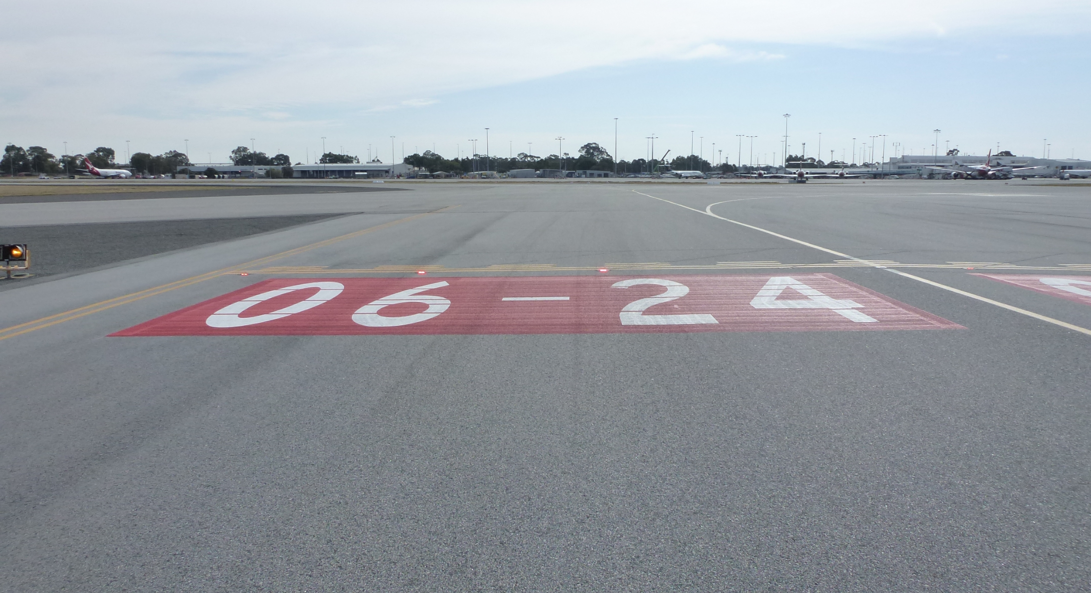
CASA (Civil Aviation Safety Authority) (2012) Fatigue Management Strategies for Aviation Workers: A Training & Development Workbook, CASA, Australian Government, accessed 25 September 2021.

CASA (Civil Aviation Safety Authority) (2017) Obstructive sleep apnoea and aviation safety fact sheet, CASA, Australian Government, accessed 22 August 2021.

Coltman JW, Bolukbasi AO, Laananen DH (1985) Analysis of rotorcraft crash dynamics for development of improved crashworthiness design criteria, United States Department of Transportation, Federal Aviation Administration.

Coltman JW, Van Ingen C, Johnson NB and Zimmerman RE (1989) Aircraft crash survival design guide: Volume II – Aircraft design crash impact conditions and human tolerance, United States Army Aviation Applied Technology Directorate.

Crowley JS, Licina JR and Bruckart JE (1992) ‘Flight Helmets: How they work and why you should wear one’, Journal of Air medical Transport, 11(8):19-23.

DOI and USFS (Department of the Interior and United States Forest Service) (2021) Interagency Aviation Life Support Equipment Handbook/Guide, Revision 3.0, United States.

Forman JL, Lopez-Valdes F, Lessley DJ, Riley P, Sochor M, Heltzel S, Ash J, Perz R, Kent RW, Seacrist T, Arbogast KB, Tanji H, Higuchi K (2013) ‘Occupant kinematics and shoulder belt retention in far-side lateral and oblique collisions: a parametric study’, Stapp Car Crash Journal, 57:343-85.

Gibb R, Scharff L and Gray R (2010) Aviation Visual Perception: Research, Misperception and Mishaps (Ashgate Studies in Human Factors for Flight Operations), Ashgate Publishing Group, Routledge, England, United Kingdom.

Goode JH (2003) ‘Are pilots at risk of accidents due to fatigue?’, Journal of Safety Research, 34:309-313.

Harrison Y and Horne JA (2000) ‘The Impact of Sleep Deprivation on Decision Making: A Review’, Journal of Experimental Psychology, 6:236-249.

International Civil Aviation Organisation (2015) Fatigue Management Guide for Airline Operators, 2nd edn, ICAO, accessed 18 November 2021.

Killgore WSS, Balkin TJ and Wesensten NJ (2006) ‘Impaired decision making following 49 h of sleep deprivation’, Journal of Sleep Research, 15:7-13.

Lal C, Strange C and Bachman D (2012) ‘Neurocognitive impairment in obstructive sleep apnea’. Chest, 141(6):1601–1610.

Lewis, ME (2016) ‘Head injury and protection’, in Gradwell DP and Rainford DJ (eds) Ernsting’s Aviation Medicine, 5th edn, CRC Press, London, United Kingdom.

Royal Australian Air Force Institute of Aviation Medicine (unpublished), Support to ATSB AO-2020-040 Accident involving R44 helicopter, vicinity Steam Plains, NSW 31 July 2020, Royal Australian Air Force Institute of Aviation Medicine, Australia.

Seda G, Han TS (2020) ‘Effect of Obstructive Sleep Apnea on Neurocognitive Performance’. Sleep Med Clin. March 15(1):77-85. doi: 10.1016/j.jsmc.2019.10.001. Epub 2019 Nov 26. PMID: 32005352.

Shanahan DF (1993) Basic Principles of Helicopter Crashworthiness, United States Army Aeromedical Research Laboratory (USAARL 93-15), United States.

Shanahan DF and Shanahan M (1989) ‘Injury in U.S. Army helicopter crashes October 1979 –September 1985’, Journal of trauma, 29(4):415–423.

Snyder RG, Snow CC, Young JW, Crosby WM and Price GT (1969) Pathology of trauma attributed to restraint systems in crash impacts, US Federal Aviation Administration Civil Aerospace Medical Institute (DOT/FAA/AM-69/3), United States.

Szczecinski G and Cable G (n.d.), Aviation Medicine for Aircrew, Royal Australian Air Force Institute of Aviation Medicine, Australia.

Taneja N and Wiegmann DA (2003) ‘Analysis of injuries among pilots killed in fatal helicopter accidents’, Aviation Space and Environmental Medicine, 74(4):337–41.

US FAA (Federal Aviation Administration) Pilot safety brochure Fatigue in aviation, FAA, United States, accessed 22 August 2021.

US FAA (Federal Aviation Administration) Sleep apnoea in aviation, FAA, United States, accessed 29 December 2021.

Veillette P (2015) ‘Wire wary: what you don't see can kill, and does’, Business and commercial aviation, October pp.24–28.  

Submissions

Under section 26 of the Transport Safety Investigation Act 2003, the ATSB may provide a draft report, on a confidential basis, to any person whom the ATSB considers appropriate. That section allows a person receiving a draft report to make submissions to the ATSB about the draft report.

A draft of this report was provided to the following directly involved parties:

  • Riverina Helicopters
  • Steam Plains station manager and owner
  • the Civil Aviation Safety Authority
  • Essential Energy
  • the helicopter maintainer
  • Royal Australian Air Force Institute of Aviation Medicine.

 Submissions were received from

  • Riverina Helicopters
  • the Civil Aviation Safety Authority.

The submissions were reviewed and, where considered appropriate, the text of the report was amended accordingly.

Glossary

AAAAAerial Application Association of Australia
ATSBAustralian Transport Safety Bureau
CASACivil Aviation Safety Authority
CASRCivil Aviation Safety Regulations
CPAPContinuous positive airway pressure
DOIDepartment of the Interior
ENEuropean Standard
FAAFederal Aviation Administration
OSAObstructive sleep apnoea
RPARemotely piloted aircraft
USUnited States
USAARLUnited States Army Aeromedical Research Laboratory
USAFUnited States Air Force
USFS  United States Forest Service

Purpose of safety investigations & publishing information

Purpose of safety investigations

The objective of a safety investigation is to enhance transport safety. This is done through:

  • identifying safety issues and facilitating safety action to address those issues
  • providing information about occurrences and their associated safety factors to facilitate learning within the transport industry.

It is not a function of the ATSB to apportion blame or provide a means for determining liability. At the same time, an investigation report must include factual material of sufficient weight to support the analysis and findings. At all times the ATSB endeavours to balance the use of material that could imply adverse comment with the need to properly explain what happened, and why, in a fair and unbiased manner. The ATSB does not investigate for the purpose of taking administrative, regulatory or criminal action.

Terminology

An explanation of terminology used in ATSB investigation reports is available here. This includes terms such as occurrence, contributing factor, other factor that increased risk, and safety issue.

Publishing information

Released in accordance with section 25 of the Transport Safety Investigation Act 2003

Published by: Australian Transport Safety Bureau

© Commonwealth of Australia 2022

image_5.png

Ownership of intellectual property rights in this publication

Unless otherwise noted, copyright (and any other intellectual property rights, if any) in this report publication is owned by the Commonwealth of Australia.

Creative Commons licence

With the exception of the Coat of Arms, ATSB logo, and photos and graphics in which a third party holds copyright, this publication is licensed under a Creative Commons Attribution 3.0 Australia licence.

Creative Commons Attribution 3.0 Australia Licence is a standard form licence agreement that allows you to copy, distribute, transmit and adapt this publication provided that you attribute the work.

The ATSB’s preference is that you attribute this publication (and any material sourced from it) using the following wording: Source: Australian Transport Safety Bureau

Copyright in material obtained from other agencies, private individuals or organisations, belongs to those agencies, individuals or organisations. Where you wish to use their material, you will need to contact them directly.

Preliminary report

Report release date: 31/03/2021

This preliminary report details factual information established in the investigation’s early evidence collection phase and has been prepared to provide timely information to the industry and public. Preliminary reports contain no analysis or findings, which will be detailed in the investigation’s final report. The information contained in this preliminary report is released in accordance with section 25 of the Transport Safety Investigation Act 2003.

The occurrence

On 31 July 2020, the pilot of a Robinson R44 Raven 1 helicopter, registered VH-HNF and operated by Riverina Helicopters, was preparing to conduct aerial weed spraying at Steam Plains, 69 km south-east of Hay Airport, New South Wales.

Prior to commencing the day’s flying, the pilot briefed with the helicopter owner/operator, who was performing the role of ground crew and responsible for loading the helicopter with chemical. The briefing included a review of the day’s tasking, maps of the property and hazards associated with the operation. The identified hazards included a 19.1 kV single wire earth return powerline, which crossed the property fence line about 5 m above the ground. The powerline had been marked on the pilot’s map during initial planning with the property manager 2 days prior.

The ground crew then loaded the helicopter with chemical from a centrally-located vehicle. According to recorded GPS data from the helicopter, after loading, the pilot flew the helicopter to the property boundary to spray along the fence line, 2.5-5 m above the ground, before returning to the loader (Figure 1). The pilot sprayed four loads over an 80-minute period and departed with the fifth load at about 1050 Eastern Standard Time.[1]

The GPS data showed that the pilot flew the helicopter to the property boundary and began spraying the fifth load. About 350 m before reaching the position where the previously-identified powerline crossed the fence line, the pilot manoeuvred the helicopter to climb over an area of trees 12-15 m high, before descending to continue spraying. During the descent, the helicopter struck the powerline. The electricity provider reported that the fault to the powerline occurred at 1057. This was consistent with the time of the last recorded GPS position, about 300 m prior to the powerline.

The helicopter subsequently collided with terrain about 120 m beyond the powerline, resulting in fatal injuries to the pilot. The helicopter was substantially damaged.

Figure 1: VH-HNF flight path for fifth spray load

VH-HNF flight path for fifth spray load

Source: Google Earth and GPS data, annotated by the ATSB

Site and wreckage examination

The accident site was located in flat and open farmland (Figure 2), about 7 km north-east of the loading vehicle. The ATSB conducted an examination of the site and wreckage, and identified:

  • the main wreckage was located about 120 m beyond the powerline in the direction of travel
  • the powerline remained entangled in the wreckage, with evidence of wire contact on the front of the left skid
  • significant structural deformation, consistent with heavy impact on the left side of the helicopter
  • the helicopter was fitted with bladder fuel tanks, which had ruptured but there was no fire
  • flight control continuity was established
  • there were no pre-existing issues identified with the helicopter that would have precluded normal operation.

Figure 2: Drone image of accident location, taken at 1028 on 4 August 2020

Figure 2: Drone image of accident location, taken at 1028 on 4 August 2020

Source: ATSB

Further investigation

The investigation is continuing and will include:

  • review of pilot qualifications, experience and medical information
  • review of operational procedures
  • review of environmental conditions
  • consideration of powerline visibility
  • examination of survivability aspects
  • review of similar occurrences.

Should a critical safety issue be identified during the course of the investigation, the ATSB will immediately notify relevant parties so appropriate and timely safety action can be taken.

A final report will be released at the conclusion of the investigation.

Purpose of safety investigations

The objective of a safety investigation is to enhance transport safety. This is done through:

  • identifying safety issues and facilitating safety action to address those issues
  • providing information about occurrences and their associated safety factors to facilitate learning within the transport industry.

It is not a function of the ATSB to apportion blame or provide a means for determining liability. At the same time, an investigation report must include factual material of sufficient weight to support the analysis and findings. At all times the ATSB endeavours to balance the use of material that could imply adverse comment with the need to properly explain what happened, and why, in a fair and unbiased manner. The ATSB does not investigate for the purpose of taking administrative, regulatory or criminal action.

Terminology

An explanation of terminology used in ATSB investigation reports is available here. This includes terms such as occurrence, contributing factor, other factor that increased risk, and safety issue.

Publishing information 

Released in accordance with section 25 of the Transport Safety Investigation Act 2003

Published by: Australian Transport Safety Bureau

© Commonwealth of Australia 2021

image_5.png

Ownership of intellectual property rights in this publication

Unless otherwise noted, copyright (and any other intellectual property rights, if any) in this report publication is owned by the Commonwealth of Australia.

Creative Commons licence

With the exception of the Coat of Arms, ATSB logo, and photos and graphics in which a third party holds copyright, this publication is licensed under a Creative Commons Attribution 3.0 Australia licence.

Creative Commons Attribution 3.0 Australia Licence is a standard form licence agreement that allows you to copy, distribute, transmit and adapt this publication provided that you attribute the work.

The ATSB’s preference is that you attribute this publication (and any material sourced from it) using the following wording: Source: Australian Transport Safety Bureau

Copyright in material obtained from other agencies, private individuals or organisations, belongs to those agencies, individuals or organisations. Where you wish to use their material, you will need to contact them directly.

__________

  1.  Eastern Standard Time (EST): Coordinated Universal Time (UTC) + 10 hours.

Occurrence summary

Investigation number AO-2020-040
Occurrence date 31/07/2020
Location 69 km south-east of Hay Airport, (Steam Plains)
State New South Wales
Report release date 04/03/2022
Report status Final
Investigation level Defined
Investigation type Occurrence Investigation
Investigation status Completed
Mode of transport Aviation
Aviation occurrence category Wirestrike
Occurrence class Accident
Highest injury level Fatal

Aircraft details

Manufacturer Robinson Helicopter Co
Model R44
Registration VH-HNF
Serial number 2524
Aircraft operator Riverina Rotor Work Pty Ltd
Sector Helicopter
Operation type Aerial Work
Departure point Steam Plains, New South Wales
Destination Steam Plains, New South Wales
Damage Substantial

Runway incursion involving Sling 2, VH-ZSD, Moorabbin Airport, Victoria, on 23 July 2020

Final report

Report release date: 29/06/2021

Safety summary

What happened

On the afternoon of 23 July 2020, five aircraft were operating in the runway 17 Left (L) circuit at Moorabbin Airport, Victoria. A Piper PA-28 aircraft, VH-TAX (TAX), was lined up in the displaced threshold area of runway 17L. A Sling 2 aircraft, VH-ZSD (ZSD), then on the base leg of the circuit approaching the occupied runway, passed above TAX and conducted a touch and go landing. The runway incursion by ZSD removed the required runway separation between the aircraft.

What the ATSB found

The ATSB found that the student pilot of ZSD sighted TAX but decided to conduct the touch and go landing due to an incorrect belief that the controller had provided a landing clearance. The ATSB identified that the student pilot’s training had not been effective in conveying that a go‑around must be initiated if the runway was occupied.

The investigation also found that the air traffic controller did not identify the developing conflict as ZSD approached runway 17L. Additionally, the controller did not recall the aircraft passing above TAX and conducting a touch and go landing, and remained unaware of the incident until after it was reported over an hour later.

What has been done as a result

Royal Victorian Aero Club, the flight training school operating ZSD, has made changes to its student training program including educational, procedural and recurring activities. The school updated instructor and student educational materials, procedural guidance and examination content.

Safety message

Runway incursions and other runway separation issues are one of the most significant risks to safe aviation operations and a key global safety priority. Airport operators and air navigation service providers are strongly encouraged to identify and mitigate risk areas, especially at locations with inexperienced pilots or unusual airport configurations, such as displaced thresholds. The Airservices‑published safety bulletin Preventing the risk of a runway incursion and the runway safety article Tips for flying at Moorabbin provide relevant guidance.

Pilots are strongly encouraged to identify potential conflicts or runway incursions that may develop during circuits early and to attend carefully to air traffic control communications. It is important that flight training schools reinforce training regarding occupied runways and go‑arounds to students. Air traffic controllers are encouraged to monitor all aircraft and provide clear and unambiguous instructions to their flight crew to avoid runway incursions and related occurrences.


The occurrence

At about 1334 Eastern Standard Time[1] on 23 July 2020, five aircraft were operating in the runway 17 left (17L) circuit at Moorabbin Airport, Victoria (Figure 1). They included a Sling 2, registered VH-ZSD (ZSD), operated by the Royal Victorian Aero Club (RVAC) with a student pilot on a second, solo flight. The pilot conducted a touch and go landing on runway 17L a few minutes earlier.

Figure 1: Runway 17L circuit traffic situation display screen shortly before the occurrence

Figure 1: Runway 17L circuit traffic situation display screen shortly before the occurrence

Source: Airservices Australia

In addition to the circuit traffic, a Piper PA-28, registered VH-TAX (TAX), operated by Moorabbin Flying Services, with an instructor and student pilot on board, was at the holding point of taxiway G for 17L (Figure 2). The aircraft was in the final stages of preparation for a local training flight.

Figure 2: Overview of Moorabbin Airport showing key locations

picture2.jpg

The shaded yellow area indicates the tower perspective of the part of the runway when ZSD overflew the lined-up TAX.

Source: Airservices Australia, annotated by ATSB

At 1334:49, the Moorabbin Tower (tower) air traffic controller instructed the pilot of ZSD: ‘Zulu Sierra follow Cessna late downwind'.[2] The pilot responded: ‘Zulu Sierra Delta’, and shortly after began preparing for a touch and go landing on runway 17L. The pilot of ZSD also mistakenly thought that the controller had issued a landing clearance. There was no further communication with the controller during that circuit.

At 1336:49, the controller instructed the pilot of TAX to line up on runway 17L. One minute later, TAX was still waiting in the lined-up position about 280 m behind the displaced threshold. The pilot of ZSD sighted TAX on the runway during the approach for landing. Just as the instructor was about to contact the tower to ask about the take-off clearance, ZSD passed above TAX and conducted a touch and go landing.[3]

The instructor was surprised by the unusual event of an aircraft overflying another but did not immediately report the runway incursion, deciding instead to focus on TAX and its flight, and deal with incident-related matters in the post-flight debrief. At 1338:43, the controller (unaware of the incident) issued a take-off clearance and shortly after, TAX departed for the training area.

The pilot of ZSD did not believe any incident had occurred and continued conducting circuits, landing shortly after 1349.

At about 1440, after TAX completed the training flight, the instructor reported the incident to the flight training school’s head of operations and then phoned the tower. The tower supervisor was informed and, in turn, advised the incident controller.

__________

  1. Eastern Standard Time (EST): Coordinated Universal Time (UTC) + 10 hours.
  2. The Cessna was VH-MJG.
  3. The pilot of TAX estimated ZSD passed 50-100 ft above their aircraft (data to verify the vertical separation was not available).

Context

Moorabbin Airport

Moorabbin Airport has five runways (Figure 3) and the vast majority of operations at the airport involve training activities. Runway 17L is 1,335 m in length and has an unusually long (285 m) displaced threshold (Figure 4). The airport operates within Metro Class D airspace and Airservices Australia (Airservices) provides the air traffic services (see Air traffic services section).

Figure 3: Moorabbin Airport

Figure 3: Moorabbin Airport

Source: Airservices Australia

Figure 4: Runway 17L section showing the position of TAX behind the displaced threshold

Figure 4: Runway 17L section showing the position of TAX behind the displaced threshold

Source: Airservices Australia annotated by ATSB

Air traffic services

Moorabbin Class D airspace

Moorabbin Airport’s Class D terminal airspace is controlled by controllers situated in the Moorabbin control tower. The Class D airspace extended to the north and south-west from ground level to a 3 NM boundary.

Staffing

Airservices determines a minimum number of full time equivalent (FTE) staff (referred to as the mature requirement) to adequately staff a control tower. Moorabbin Tower’s mature requirement at the time of the incident (and for a number of years prior) was 11 FTE, but actual FTE numbers had been higher. The staff in excess of the mature requirement (the surplus) were available to assist in the tower.

In 2019, an informal ‘spotter’ position was created to utilise surplus staff. There was no licensing requirement for a ‘spotter’ nor a job description or procedure for utilising the position, but it was included in the roster. In practice, the ‘spotter’ was an additional resource to assist controllers in performing their duties.

In the months before the incident, however, there were some changes to staffing levels. One change was the removal of the ‘spotter’ position from the roster due to Airservices’ pandemic management plan,[4] which introduced isolation rosters to mitigate virus spread by physically distancing controllers.

At the time of the incident on 23 July 2020, all three control positions in the tower were staffed. Four controllers were present: the operating Aerodrome Controller West (ADC-W), the outgoing controller handing over the ADC-W position, the Surface Movement Controller-Coordinator (SMC-COORD) and the Aerodrome Controller East (ADC-E). The ADC-E (the controller involved in this incident) controlled the runway and airspace in the eastern part of the airport area using radio frequency 118.1 MHz while the ADC-W performed those functions for the western part on 123.0 MHz.

According to the tower supervisor, a request to Airservices to reinstate the ‘spotter’ position was under consideration at the time with the intention to formally introduce the position when staffing numbers allowed. During the course of this investigation, a proposal to increase the mature requirement to 12.5 FTE was submitted to Airservices in November 2020. A reason given to support the proposal was that traffic levels and complexity at Moorabbin Airport were at a level where there was a risk of missing conflicts. At the time of publication of this report, the request was being considered with a view to allowing the SMC-COORD position to be de-combined during busy periods, but not to provide any additional resource for a formal or informal ‘spotter’ position.

Traffic movements

Under routine conditions, the training environment at Moorabbin Airport includes the workload demands of students learning to fly. In addition to this workload, the controller involved in this incident perceived that there had recently been a 20 to 25 per cent increase in movements at the airport. The tower supervisor also noted the increase in traffic over the previous 5 months and observed that traffic levels were quite saturated with the workload becoming challenging.

These perceptions were supported in part by objective data. Airservices Australia records indicated that monthly traffic movements at Moorabbin Airport had, on average, increased by 8.74 per cent between February and July 2020 (from 19,943 to 21,686 movements). A possible reason for the increase in movements was that pilots who could no longer fly for major airlines (due to the impact of the Coronavirus pandemic) and held an instructor rating, were working at flight training schools and this contributed to increased student flight training activities.

The instructors of both student pilots involved indicated that it had been busier for them over the past 15 months and that they had noticed reduced staffing in the tower. Overall, there appeared to have been an increase in the amount of traffic management work for controllers at Moorabbin Airport.

Traffic during the event

The incident controller assessed that traffic conditions at the time of the event were moderate to high. The airspace contained two aircraft with very similar callsigns, Zulu Sierra Delta (ZSD) and Zulu Sierra Oscar (ZSO). The presence of aircraft with similar callsigns operating in the same area and especially on the same frequency often gives rise to potential and actual flight safety incidents. This hazard is usually referred to as ‘callsign confusion’.

At 1334:49, the controller instructed the pilot of ZSD: ‘Zulu Sierra follow Cessna late downwind', without including ‘Delta’ to avoid potential confusion with ZSO (which was also in the circuit and conducted four landings before the occurrence and two subsequently). Two downwind calls were made by ZSO and November Charlie Echo (NCE), with the first call from ZSO coinciding with the approximate time that take-off clearance for TAX would have been expected for its immediate departure following Mike Juliet Golf (MJG). After the conflict occurred, the controller had a pause in communications (prior to an instruction at 1340:09 'Zulu Sierra Delta follow Cessna late downwind') and only after the conflict, at 1340:30, emphasised the word 'Oscar' in an instruction ('Zulu Sierra Oscar cleared touch and go').[5]

Traffic control errors

In June 2020, Airservices conducted an operational safety study of Moorabbin Tower incidents from January 2013 to July 2018. The study provided an overview of the nature and frequency of Air Traffic Control (ATC) conflicts. The purpose of the study was to support operational managers in understanding the unit’s safety performance based on results derived from submitted safety occurrence reports.

The study showed that 5 per cent of the total coded occurrences were ATC attributable with six occurrences (3 per cent of the total) resulting in the system entering an undesired state (incorrect presence of at least one aircraft on a runway). The occurrences related to ATC inducing tactical conflicts (occurrences that are pilot attributed) with the tactical planning-related failures being resolved prior to entering the undesired state. The study showed that ATC attributable errors do occur, albeit with a low level of incidence of ATC induced tactical conflicts.

Landing clearances

Airservices provide landing clearance requirements directly relevant to the airspace in which this incident occurred. The Airservices Aeronautical Information Publication En-route (AIP ENR) 1.1 states that a pilot in command must not land unless they receive specific clearance ‘Cleared to land’.

AIP ENR 1.1 provides the following separation standards for Class D controlled airspace:

A landing aircraft will not be permitted to cross the threshold of the runway on its final approach until:

- a preceding departing aircraft using the same runway:

- is airborne and

- has commenced a turn; or

- is beyond the point on the runway at which the landing aircraft could be expected to complete its landing roll and there is sufficient distance to manoeuvre safely in the event of a missed approach;

- is at least 1,000 m from the runway threshold, and has commenced the take-off run, and

- in the opinion of the controller, no collision risk exists

Airservices has also published safety material to avoid runway incursion errors. Relevant publications include the safety bulletin Preventing the risk of a runway incursion and the runway safety article Tips for flying at Moorabbin.

The controller

The controller was working in the ADC-E position at Moorabbin tower. The controller was first rated in August 2003, achieved a rating for all tower positions in March 2007, and was qualified to conduct training and assessment in July 2010. There was also an endorsement to provide relief staffing at Avalon tower when needed. The controller successfully passed a renewal check in April 2020 and had been operating on an approved leave reduction program, of 4 days on, followed by 12 days off duty since early 2020. This level of recency, however, met Airservices’ requirements.

There was no evidence to suggest any likelihood of reduced controller performance due to fatigue, distractions or general health. The weather conditions and visibility were also not considered to have influenced the controller’s actions.

Tools available

In addition to visual observations from the Moorabbin tower and using voice communications, controllers use other tools to assist with performing their duties.

The controller was using a traffic running sheet to record aircraft movement data and to assist in sequencing aircraft. The traffic running sheet provides a back-up memory prompt to the primary function of visual monitoring of traffic. The running sheet that the controller used contained many changes, corrections and annotations, reflecting the level of activity and traffic complexity, which increased the likelihood of making an error (see Appendix – Traffic Running Sheet). The sheet also indicated that the controller remained unaware of the incident between ZSD and TAX.

Moorabbin Tower also utilises a support tool called the Traffic Situation Air Display (Figure 5). This display provides awareness of aircraft higher than about 200 ft, which is higher than ZSD was operating at the time of the incident.

Flight progress strips (FPS)[6], a tool that has the same functional objective as traffic running sheets, are not used at Moorabbin Airport. According to Airservices, FPS are generally not required for visual flight rules (VFR) flights.

Figure 5: View and perspective from controller position towards runway 17L

Figure 5: View and perspective from controller position towards runway 17L

Source: Airservices Australia annotated by ATSB

Air traffic communications

Table 1 provides the air traffic communications between the tower and ZSD and TAX in the lead up to the runway incursion. A large number of communications were also made between the controller and various other aircraft. Significant items are highlighted in the table.

Table 1: Communications and events leading up to the time of the incident

TimeCommunications and eventsNotes
1334:46‘Zulu Sierra follow Cessna late downwind’ 
1334:49

‘Zulu Sierra Delta’


Pilot’s response to instruction for turning downwind (Last radio call before incident).
1334:52‘Oscar X-Ray Golf is going around’ 
1334:54‘Oscar X-Ray Golf’ 
1335:15‘Moorabbin Tower November Charlie Echo is ready runway 17 Left circuits’ 
1335:21‘November Charlie Echo line up’ 
1335:23‘Line up November Charlie Echo’ 
1335:42‘November Charlie Echo follow the Sling upwind. Cleared for takeoff’ 
1335:45‘Copy traffic. Cleared for takeoff November Charlie Echo’ 
1336:27‘Mike Juliet Golf follow the twin upwind cleared touch and go’ 
1336:30‘Cleared touch and go Mike Juliet Golf’ 
1336:33‘Oscar X-Ray Golf turning downwind touch and go’ 
1336:36‘Oscar X-Ray Golf follow the Sling on base’ 
1336:39Oscar X-Ray Golf 
1336:41‘Moorabbin Tower Tango Alpha X-Ray is ready, one, runway 17 left for oblique crosswind departure to the training area’ 
1336:49‘Tango Alpha X-Ray line up’TAX given clearance to line up, ZSD is on base and sights TAX below
1336.51‘Lining up Tango Alpha X-Ray’TAX gives radio call about lining up
1337:15‘Sierra Oscar follow the twin late downwind’Tower talks to ZSO
1337:20‘Zulu Sierra Oscar follow the twin late downwind’Tower talks to ZSO
1337:22‘Zulu Sierra Oscar’ 
1337:44‘November Charlie Echo turning downwind touch and go’ 
1337:48‘Charlie Echo follow the Sling mid downwind’ 
1337:51‘November Charlie Echo’ 
1337:51ZSD does touch and go over the top of TAXThe incident
1338:41‘Tango Alpha X-Ray cleared for take-off’TAX given clearance for take-off
1338:43‘Cleared for take-off Tango Alpha X-Ray’TAX reads back the take-off clearance and departs for the training area
1340:09'Zulu Sierra Delta follow Cessna late downwind'Controller pause in communications
1340:30'Zulu Sierra Oscar cleared touch and go'Controller emphasises ‘Oscar’

Student pilot information

The student pilot commenced training on 9 June 2020, with the first flying lesson on 23 June. Records showed a total flying experience of 18.5 hours to the last recorded flight (the occurrence flight) on 23 July, all on the Sling 2 aircraft type. Of that total experience, 17 hours had been in the previous 30 days. The student was not required to, and did not, hold a flight crew licence.

The pilot was an international student and had completed the General English Language Proficiency (GELP) test on 14 July 2020. On 23 July, the pilot was operating a second session of solo circuits and stated ‘feeling very nervous’ because English was not their first language. The incident occurred during the final leg of the fourth circuit, prior to a full stop landing.

The training school records indicated that the student pilot had completed the required training (as per the lesson entry reports) approved by the school’s instructors. The student was familiar with the runway configurations at Moorabbin, including the unusually long displaced threshold of runway 17L. The training school manual had a requirement about occupied runways and directed that students undertake specific training, including missed approaches/go‑arounds.

If for any reason, it is judged that an approach cannot be continued to a successful landing, a missed approach (go-around) will be conducted.

The operator’s training manual also provided runway descriptions and airport markings (including displaced thresholds). This incident was the first time that the student pilot had experienced another aircraft on the runway when approaching to land. The pilot also expressed a belief that it was permitted to have another aircraft lined up on the runway when landing. The pilot also believed that a landing clearance had been issued, observed that TAX was stationary and thought that it would not take off until the tower issued a take-off clearance.

After the incident, the instructor debriefed the student pilot and explained the requirement to conduct a go around if an aircraft was lined up on the runway. The instructor did not think this had been specifically discussed with the student previously although it may have been covered otherwise in training (during theory classes or briefings). Following that debrief, the pilot reported having a correct understanding of what to do in the event of an occupied runway.

There was no evidence that fatigue risk, distractions or other personal health aspects were likely to have been present. The weather conditions and visibility were also not considered to have influenced the pilot’s actions.

Monitoring regulations

The Civil Aviation Safety Authority (CASA) requirements for instructors monitoring students on their second solo flight are contained within Civil Aviation Safety Regulation (CASR) Part 61.112(3). These requirements state that a flight is suitably supervised if the instructor:

(a) provides guidance to the person in relation to the flight,

(b) during the flight is at the aerodrome from which the flight began and

(c) can be contacted during the flight by radio or other electronic means.

CASR Part 142.340 details the required exposition content for operators conducting integrated and multi-crew flight training. This states that the exposition must contain a description of the procedures by which the operator conducts and manages the activities, including the supervision of instructors and persons participating in activities.

Additionally, the CASR Part 142 Technical Assessor handbook details how the above requirements are to be documented in an organisation’s exposition. Section C3.1.1 (k) of the handbook ‘Procedures for Conduct and Management of Training - Supervision of Student Pilot Solo Flight’ outlined the documented expectations that are to be contained within an exposition with respect to the supervision of student pilots. While not a regulatory requirement, CASA inspectors are advised to check the following.

-The process should include provision for active monitoring of each solo flight by a flight instructor. As well as active monitoring, the supervising instructor should provide flight following, operational control and the rendering of assistance if necessary.

-For solo circuit operations, the applicant should ensure that a competent instructor is assigned to visually monitor circuit operations. The supervising instructor may be provided with two-way radio communication with circuit aircraft for the purpose of exercising operational control over solo flights, if necessary.

-For training area and navigation solo flight operations, an application should ensure that an instructor is assigned to monitor radio frequencies when possible, to provide assistance if necessary, and maintain a search and rescue watch.

Visual monitoring

The instructor usually monitored students by listening to the ATC frequency via radio from the RVAC operations room, as was the case at the time of the incident. There was no CASA requirement to visually monitor operations, and CASA advised that while the instructor needs to be available, it would not be appropriate to intervene in operations at a controlled airport such as Moorabbin. Hence, CASA considers the first knowledge a training school would have of such an incident at a controlled airport is similar to the way this incident unfolded, or the tower would inform the school by telephone.

In any case, from the operations room, the instructor was unable to visually monitor aircraft, as per the suggested guidance in the assessor handbook. The view was also partially obstructed by parked aircraft and the instructor was dividing attention between monitoring the radio and administrative work.

__________

  1. Coronavirus disease (COVID-19) was an infectious disease caused by a newly discovered coronavirus. The World Health Organization (WHO) first learned of this new virus on 31 December 2019. International and domestic responses to manage the pandemic included reducing aviation activity internationally and domestically.
  2. Pauses can represent confusion (for example about the sequence of events) and words are often emphasised to clearly distinguish similar callsigns. In this case, the controller emphasised the word ‘Oscar’ after the event.
  3. Controllers use fight progress strips to maintain situation awareness of ATC operations and traffic. Standard annotations (such as recording the departure runway/location) provide information to assist with the correct execution of the controller’s plan and the early detection of any errors that may occur.

Safety analysis

Introduction

At 1337 on 23 July 2020, the PA-28 aircraft, VH-TAX (TAX), was lined up on the threshold of runway 17L at Moorabbin Airport, awaiting take-off clearance. The Sling 2 aircraft, VH-ZSD (ZSD) was on the base leg of the circuit and its student pilot believed (incorrectly) that a clearance for a touch and go landing had been provided. The student pilot saw the lined-up aircraft but continued the approach, passed above TAX about a minute later and conducted a touch and go landing.

The air traffic controller in the Moorabbin Tower (tower) managing the movements of the two aircraft did not identify the developing conflict as ZSD approached the runway or the aircraft passing above TAX and conducting a touch and go landing, and remained unaware of the incident until advised about an hour later.

Decision to continue the approach and landing

The student pilot’s decision to continue the approach and conduct a touch and go landing on the occupied runway was based on an incorrect belief that a landing clearance had been provided, and a misconception that landing on a runway with another aircraft lined up was permitted. The belief that a clearance had been provided may have been influenced by the following factors:

  • callsign confusion
  • expectation bias
  • cognitive tunnelling
  • authority gradient and pilot inexperience.

As discussed, aircraft with similar callsigns operating in the same area and, especially, on the same frequency often gives rise to flight safety incidents. At the time of the incident, ZSD and ZSO were in the circuit at the same time and conducting touch and go landings on runway 17L. It is possible that the downwind calls made by ZSO prior to the event may have been mistakenly heard as a clearance by the student pilot of ZSD.

The student pilot misperceived the tower communications and assumed the expected clearance had been provided by the controller. There may have been an expectation to hear this clearance, where the student pilot filled in the gaps in the communication. Expectation bias can occur when an individual's expectations about an outcome influence perceptions of one's own or others’ behavior.[7] The student pilot may have been experiencing this bias (expecting the landing clearance to be provided), which could explain why the pilot made the decision to conduct the touch and go, and later recalled hearing a clearance.

There may also have been a degree of cognitive tunnelling for the student pilot. It has long been established that cognitive tunnelling is an inattentional blindness where one becomes overly‑focused on some variable other than the present environment.[8] It can occur under periods of high stress or workload, which student pilots experience due to high demands on their attentional resources in the training environment.

During this occurrence, the student pilot may have been so focussed on the landing and avoiding a collision with TAX on the runway, that attentional resources were not focussed on tower communications. Hence, the student pilot incorrectly assumed a verbal clearance by the tower had been provided.

Finally, the student pilot’s belief that the controller had provided a landing clearance and deciding to land on an occupied runway may also have been influenced by a steep authority gradient between the student and the controller, as well as the student’s lack of experience.

Authority gradient refers to the established and/or perceived command and decision-making power hierarchy in a team, crew or group situation and how balanced the distribution of this power is experienced within the team, crew or group (Hawkins 1993). A steep gradient occurs when a role appears dominant over another and leads to others being less likely to express concerns, question decisions or even clarify instructions.

As the student pilot was conducting a second solo flight and had English as a second language there may have been a steep authority gradient, which could explain why the student would not have clarified the (assumed) landing instruction.

The evidence shows the student pilot decided to continue the touch and go landing due to an incorrect belief that a clearance had been provided, and a misconception that landing on a runway with an aircraft lined up was permitted. Exact reason(s) for believing a clearance had been provided could not be established, but factors that may have contributed to that belief include callsign confusion, expectation bias, cognitive tunnelling, authority gradient and pilot inexperience, or a combination of these factors.

Occupied runway training

The student pilot of ZSD conducted the touch and go after seeing TAX lined up behind the runway threshold. According to the training instructions and AIP procedures, the approach should not have continued, as the runway was occupied, and a landing clearance had not been received. The instructor did not think this had been specifically discussed with the student previously although it may have been covered otherwise in training. The pilot later stated understanding what to do in future in the event of an occupied runway.

While the training documentation contained occupied runway requirements and Airservices’ safety publications provide further guidance, interview evidence, as well as the student's actions, indicate that learning in this aspect had not been effective.

Unidentified conflict

The controller did not see ZSD approaching to conduct a touch and go landing with TAX lined up and, therefore, took no action to avoid the runway incursion. Normally, pilots report that they are on short final (for example, OXG and NCE in the circuit that day). However, the pilot of ZSD did not contact the tower when approaching for that touch and go landing. Based on the available evidence, the controller’s ability to identify the conflict may have been influenced by the following factors:

  • traffic density
  • workload and communications
  • callsign confusion.

Evidence from the interviews of the controller, the tower supervisor and the involved pilots; as well as the recorded traffic movement data, suggest that traffic movements increased in the months leading up to the time of the event. A controller’s ability to detect a conflict can depend on the traffic load and more controllers miss more potential conflicts when traffic density is high, compared to when it is low.[9]

The changing traffic movements may also have affected the controller’s workload level. The following research-based observation is relevant to this relationship with workload.

Workload reflects the interaction between a specific individual and the demands imposed by a particular task and represents the cost incurred by the human operator in achieving a particular level of performance. An individual has a finite set of mental resources they can assign to a set of tasks and will seek to perform at an optimum level of workload by balancing the demands of their tasks.[10]

Both the controller and the supervisor indicated that workload was influenced by traffic movements. Additionally, the number of communications leading up to the event and the many changes to the traffic running sheet suggest high workload. It is probable that an increased level of mental workload because of increased traffic density, resulted in the controller having less opportunity to identify the conflict. Airservices’ safety study data referred to earlier also shows that ATC‑attributable errors have occurred at Moorabbin Airport.

It is also possible that callsign confusion played a part in the controller not identifying the conflict. There was significant communication at the time, both ZSD and ZSO had similar communications with the tower while operating in the same area on the same frequency. At 1334:49, the controller also omitted ‘Delta’ in the instruction ‘Zulu Sierra follow Cessna late downwind' giving potential for confusion between ZSD and ZSO. The first two phonetics of these callsigns (that is, ZS) were the same. Further, they had visually similar shapes that can be easily mixed up as they only differ by their last designator (for example, on a traffic running sheet). The controller’s pauses are indicative of some level of confusion and only emphasising the phonetic ‘Oscar’ after the occurrence, suggests the controller may not have recognised the potential for confusion in time.

Overall, the evidence shows that the controller did not identify the conflict between ZSD and TAX, but the exact reason(s) could not be established. This may have occurred due to the high traffic density and resulting communications workload or the similar aircraft callsigns operating in the same circuit on the same frequency, or a combination of these factors. While it is possible some other factors may have had an influence (for example, runway confusion or not following standard operating procedures), there was no evidence to justify considering such factors.

Other considerations

As the informal ‘spotter’ position was no longer used, the controller was the only person that could have identified the developing conflict because, as explained, the student pilot’s instructor could not have done so. Further, as the instructor in TAX (who had reasons to delay it) did not report the incident immediately, the corrective action taken to address the immediate operational risks by relieving the controller was delayed by more than an hour.

Single person controller operations where a position/sector is operated by one person are unsuitable during busy periods, as they can lead to high task loads, distraction, failure to detect threats and not recognising errors. Monitoring each other’s actions (also known as the ‘four-eye principle’) reduces the likelihood of this error by increasing situation awareness. This was probably the main safety-related reason for rostering an informal ‘spotter’ in Moorabbin Tower.

Airservices’ safety study provides an indicative level of risk that it can use to assess the level of acceptable risk for single person controller operations at Moorabbin, including situations involving student pilot errors or non-compliance with ATC instructions. The ATSB did not find any additional information, such as incident trend data or studies into optimal workload levels (for Moorabbin or similar towers) to make findings with respect to tower staffing levels.

__________

  1. Williams and others 2012.
  2. Mack and Rock 1998; Most 2010.
  3. Metzger and Parasuraman 2001.
  4. Orlady and Orlady 1999.

Findings

ATSB investigation report findings focus on safety factors (that is, events and conditions that increase risk). Safety factors include ‘contributing factors’ and ‘other factors that increased risk’ (that is, factors that did not meet the definition of a contributing factor for this occurrence but were still considered important to include in the report for the purpose of increasing awareness and enhancing safety). In addition ‘other findings’ may be included to provide important information about topics other than safety factors. 

Safety issues are highlighted in bold to emphasise their importance. A safety issue is a safety factor that (a) can reasonably be regarded as having the potential to adversely affect the safety of future operations, and (b) is a characteristic of an organisation or a system, rather than a characteristic of a specific individual, or characteristic of an operating environment at a specific point in time.

These findings should not be read as apportioning blame or liability to any particular organisation or individual.

From the evidence available, the following findings are made with respect to the runway incursion involving The Airplane Factory Sling 2, VH-ZSD at Moorabbin Airport, Victoria, on 23 July 2020.

Contributing factors

  • While the Piper PA-28, VH-TAX, was in the lined-up position (behind the displaced threshold) on runway 17L, the Sling 2, VH-ZSD, passed overhead and conducted a touch and go landing.
  • The student pilot of ZSD sighted TAX but decided to conduct the touch and go landing due to an incorrect belief that it was permitted to have another aircraft lined up on the runway when landing, and that the controller had provided a landing clearance.
  • The student pilot’s training had not been effective in conveying that a go-around must be initiated if the runway, including its displaced threshold, was occupied.
  • The air traffic controller did not identify the runway incursion developing, see ZSD pass above TAX or its touch and go landing and remained unaware of the incident until advised about 1 hour later.

Safety actions

Central to the ATSB’s investigation of transport safety matters is the early identification of safety issues. The ATSB expects relevant organisations will address all safety issues an investigation identifies.

Depending on the level of risk of a safety issue, the extent of corrective action taken by the relevant organisation(s), or the desirability of directing a broad safety message to the aviation industry, the ATSB may issue a formal safety recommendation or safety advisory notice as part of the final report.

All of the directly involved parties were provided with a draft report and invited to provide submissions. As part of that process, each organisation was asked to communicate what safety actions, if any, they had carried out or were planning to carry out in relation to each safety issue relevant to their organisation.

The initial public version of these safety issues and actions are provided separately on the ATSB website, to facilitate monitoring by interested parties. Where relevant, the safety issues and actions will be updated on the ATSB website as further information about safety action comes to hand.

Safety action not associated with an identified safety issue

Whether or not the ATSB identifies safety issues in the course of an investigation, relevant organisations may proactively initiate safety action in order to reduce their safety risk. The ATSB has been advised of the following proactive safety action in response to this occurrence.

Additional safety action by Royal Victorian Aero Club

The Royal Victorian Aero Club advised the ATSB that it has taken the following actions.

Flight crew and student education
  • Briefings for circuits and circuit emergencies have been updated.
  • Instructor training now includes being trained on checking essential knowledge for the lesson.
  • New manuals have been provided to all instructors and have been signed as acknowledged.
  • The pre solo exam and pre area solo exam have been updated to cover the scenario of runway occupied/no clearance provided.
Procedural actions
  • The recreational pilot licence training manual has been updated to include essential knowledge to be checked before solo flights.
  • Instructors were briefed and have acknowledged the updated manual.
Proactive action
  • Solo flights have been reviewed, ensuring that instructors comply with the training manual including supervision requirements and checking essential knowledge.

Sources and submissions

Sources of information

The sources of information during the investigation included the:

  • Pilot and instructor for VH-ZSD
  • the instructor of VH-TAX
  • Airservices Australia
  • The air traffic controller
  • The tower supervisor
  • Royal Victorian Aero Club
  • Moorabbin Flying Services
  • Bureau of Meteorology.

References

Hawkins FH 1993, Human Factors in Flight 2nd ed, Ashgate Aldershot UK.

Mack A & Rock I 1998, Inattentional blindness, MIT Press Cambridge MA.

Metzger U & Parasuraman R 2001, The role of the air traffic controller in future air traffic management: An empirical study of active control versus passive monitoring, Human Factors, vol. 43, pp.519-528.

Most SB 2010, What's "inattentional" about inattentional blindness?, Consciousness and Cognition, vol. 19, pp.1102-1104.

Orlady HW & Orlady LM 1999, Human factors in multi-crew flight operations, Ashgate Publishing Ltd Hants England.

Skybrary, Call-sign Confusion, https://www.skybrary.aero/index.php/Call-sign_Confusion.

Skybrary, Single Person Operations in ATC, https://www.skybrary.aero/index.php/Single_Person_Operations_in_ATC.

Williams JB, Popp, D, Kobak KA & Detke MJ 2012, The power of expectation bias, European Psychiatry, vol. 27, pp.1

Submissions

Under section 26 of the Transport Safety Investigation Act 2003, the ATSB may provide a draft report, on a confidential basis, to any person whom the ATSB considers appropriate. That section allows a person receiving a draft report to make submissions to the ATSB about the draft report.

A draft of this report was provided to the following directly involved parties:

  • pilot and instructor for VH-ZSD
  • the instructor of VH-TAX
  • Airservices Australia
  • the air traffic controller
  • Royal Victorian Aero Club
  • Moorabbin Flying Services
  • Civil Aviation Safety Authority

Submissions were received from:

  • Airservices Australia
  • the air traffic controller
  • Civil Aviation Safety Authority

The submissions were reviewed and, where considered appropriate, the text of the report was amended accordingly.

Appendices

Appendix – Traffic running sheet

picture6.png

Source: Airservices Australia

Purpose of safety investigations & publishing information

Purpose of safety investigations

The objective of a safety investigation is to enhance transport safety. This is done through:

  • identifying safety issues and facilitating safety action to address those issues
  • providing information about occurrences and their associated safety factors to facilitate learning within the transport industry.

It is not a function of the ATSB to apportion blame or provide a means for determining liability. At the same time, an investigation report must include factual material of sufficient weight to support the analysis and findings. At all times the ATSB endeavours to balance the use of material that could imply adverse comment with the need to properly explain what happened, and why, in a fair and unbiased manner. The ATSB does not investigate for the purpose of taking administrative, regulatory or criminal action.

Terminology

An explanation of terminology used in ATSB investigation reports is available here. This includes terms such as occurrence, contributing factor, other factor that increased risk, and safety issue.

Publishing information

Released in accordance with section 25 of the Transport Safety Investigation Act 2003

Published by: Australian Transport Safety Bureau

© Commonwealth of Australia 2021

image_5.png

Ownership of intellectual property rights in this publication

Unless otherwise noted, copyright (and any other intellectual property rights, if any) in this report publication is owned by the Commonwealth of Australia.

Creative Commons licence

With the exception of the Coat of Arms, ATSB logo, and photos and graphics in which a third party holds copyright, this publication is licensed under a Creative Commons Attribution 3.0 Australia licence.

Creative Commons Attribution 3.0 Australia Licence is a standard form licence agreement that allows you to copy, distribute, transmit and adapt this publication provided that you attribute the work.

The ATSB’s preference is that you attribute this publication (and any material sourced from it) using the following wording: Source: Australian Transport Safety Bureau

Copyright in material obtained from other agencies, private individuals or organisations, belongs to those agencies, individuals or organisations. Where you wish to use their material, you will need to contact them directly.

Occurrence summary

Investigation number AO-2020-037
Occurrence date 23/07/2020
Location Moorabbin Airport
State Victoria
Report release date 29/06/2021
Report status Final
Investigation level Defined
Investigation type Occurrence Investigation
Investigation status Completed
Mode of transport Aviation
Aviation occurrence category Runway incursion
Occurrence class Incident
Highest injury level None

Aircraft details

Manufacturer The Airplane Factory
Model Sling 2
Registration VH-ZSD
Serial number 257
Aircraft operator Royal Victoria Aero Club
Sector Piston
Operation type Flying Training
Departure point Moorabbin Airport, Victoria
Destination Moorabbin Airport, Victoria
Damage Nil

Aircraft details

Manufacturer Piper Aircraft Corp
Model PA-28-161
Registration VH-TAX
Serial number 2842252
Aircraft operator J&J Aviation
Sector Piston
Operation type Flying Training
Departure point Moorabbin Airport, Victoria
Destination Moorabbin Airport, Victoria
Damage Nil

Door failure and depressurisation involving a Cessna 441, VH-LBY, near Broome, Western Australia, on 22 July 2020

Final report

Report release date: 30/06/2021

Safety summary

What happened

On 22 July 2020, a Skippers Aviation Cessna Aircraft Company 441 departed on a charter flight from Broome Airport, Western Australia, for Browns Range Airport, with two pilots and six passengers on board. Shortly after reaching the planned cruising level of flight level 270, a rapid depressurisation of the cabin occurred. The pilots and passengers donned their oxygen masks. The pilots performed an emergency descent and landed at Browns Range without further incident. After landing at Browns Range, they noticed the lower rear corner of the emergency exit door outer skin had separated from the inner skin and was the likely source of the depressurisation.

What the ATSB found

The operator’s aeronautical engineer performed a structural failure investigation, which was reviewed by the ATSB and Textron Aviation (the type certificate holder for the Cessna 441). It was concluded that the emergency exit door progressively disbonded between the inner and outer skin, likely due to the age of the aircraft, facilitated by a combination of corrosion, moisture, and flight cycles. This weakened the structure, which resulted in an accelerated failure of the bondline and rapid depressurisation of the cabin when the aircraft reached flight level 270.

As a result of this incident and the subsequent discovery of two further disbonded doors, all for aircraft operating under a supplementary type certificate life extension program, it was concluded that the existing visual inspection procedures for the emergency exit door bondline were inadequate.

In addition, it was found that the decision to apply the minimum equipment list item for the pressurisation system to depart for the return flight precluded an independent assessment of the condition of the aircraft that would have been required under the special flight permit process.

What has been done as a result

On 6 August 2020, the Civil Aviation Safety Authority issued airworthiness bulletin 52-004 issue 1: Cessna 441 in Flight Depressurisation due to Emergency Exit door bonded skin failure. The bulletin provided an interim detailed visual inspection procedure for the emergency exit door bondline, based on a scheme provided by the operator’s aeronautical engineer.

On 1 January 2021, the operator’s aeronautical engineer submitted an engineering order with supporting documentation to the Civil Aviation Safety Authority for a major modification to their Cessna 441 aircraft. This included the installation of rivets through the bondline and subjected the door to additional inspection requirements.

On 21 January 2021, Textron Aviation released Conquest Service Letter (CQL-99-02) for the Model 441 Conquest/Conquest II maintenance manual. This introduced inspection A522005 - Emergency exit door bond inspection - with an interval of 2,000 hours or 4 years, whichever occurred first. The purpose of the inspection was to verify the integrity of the emergency exit door bondline utilising the method of ultrasonic bond inspection.

The ATSB identified a safety issue for the inspection procedures in the West Star Aviation maintenance manual supplement for the Cessna 441 aircraft life extension program as inadequate for detecting the progressive disbonding of the emergency exit door skin. West Star Aviation considered the proactive safety action taken by Textron Aviation was sufficient to detect defects with the emergency exit door fitted to Cessna 441 aircraft, as this inspection procedure will apply to aircraft on the life extension program. The ATSB has accepted the response from West Star Aviation as closing the safety issue.

The operator enrolled their Broome base pilots in additional human factors training, to capture the elements of communication, decision-making, leadership and threat and error management. In addition, the chief pilot scheduled a revision session in the understanding of the minimum equipment list and its application, for the next visit to Broome.  

Safety message

After landing at Browns Range and discovering the disbonded door skin, the pilots elected to continue with the return flight with the pressurisation system inoperative, which was consistent with the initial advice they received from their company. However, whenever new information about an abnormal situation becomes available, decisions may need to be re-evaluated, as the initial reasoning may no longer be valid. In addition, for the scenario of a structural failure, the special flight permit process should be followed to manage the potential risks associated with a damaged aircraft.


The occurrence

Outbound flight

On 22 July 2020, at about 0904 Western Standard Time,[1] a Skippers Aviation Cessna Aircraft Company 441 aircraft, registered VH-LBY, departed on a charter flight from Broome Airport, Western Australia, to Browns Range Airport with two pilots and six passengers on board. Browns Range is located about 388 NM (719 km) east of Broome and the flight was planned to be conducted at flight level[2] (FL) 270 with an estimated flight time of 84 minutes.

The aircraft reached FL 270 at about 0932. At about 0933, when 108 NM (200 km) from Broome and before the cruise configuration was set, both pilots heard a loud noise from the passenger cabin. The PIC initially thought the emergency pressurisation valve (refer to section titled Pressurisation system), located near the emergency exit door on the right side of the cabin, had inadvertently activated.

At about the same time the PIC was checking the warning light for the emergency pressurisation valve, the cabin altitude warning light and aural beeping tone activated. The PIC noted the cabin altitude gauge passing 25,000 ft, while the observation pilot (OP) in the right seat recalled observing about 27,000 ft, indicating a rapid depressurisation of the cabin. The pilots donned their emergency oxygen masks and the PIC initiated an emergency descent. The OP retrieved the emergency checklist and contacted air traffic control (ATC) to request a descent to FL 120. Figure 1 below depicts the incident flight path from Broome to Browns Range and approximate location of the depressurisation.

Figure 1: VH-LBY flight path and location of depressurisation

Figure 1: VH-LBY flight path and location of depressurisation

Source: Google earth, annotated by the ATSB

During the descent, the pilots confirmed the passengers had fitted their masks. When ATC asked if they were ‘ops normal’, the crew reported they were experiencing pressurisation issues, but were ‘ok’. At about 0937, the aircraft reached FL 120. Shortly after, the OP sent a text message to the operator’s senior base pilot (SBP) at Broome advising of the situation and asking if they should return to Broome. The SBP, who was preparing for a flight to Halls Creek, and knew there were no passengers for the return flight on VH-LBY from Browns Range, advised the pilots to continue the flight depressurised, to upload fuel at Halls Creek if required, and to apply the minimum equipment list (MEL).[3]

At about 0940, the pilots commenced a further descent from FL 120 to 10,000 ft. When at 10,000 ft, the pilots removed their oxygen masks, instructed the passengers to do the same and confirmed they were all responsive and uninjured. The PIC confirmed the aircraft handling was normal, selected the autopilot on, and notified ATC of their intention to return to Broome.

Shortly after the PIC contacted ATC, the OP passed the text message reply from the SBP to the PIC. The PIC initially misunderstood the message and amended their destination intentions to ATC from Broome to Halls Creek, before correcting this to Browns Range. The pilots briefed the passengers and recalculated their fuel requirements for maintaining 10,000 ft, which indicated they would need to divert to Halls Creek on the return flight for fuel.

At about 0942, the operator’s maintenance shift supervisor at Perth received a phone call from the SBP and they discussed the event. During the discussion, they concluded that the problem was likely to be related to an air cycle machine fault (refer to section titled Pressurisation system). Therefore, they agreed that it was acceptable for the aircraft to continue to Browns Range, where the PIC could invoke the MEL item for the pressurisation system, and return to Broome at, or below 10,000 ft without passengers. The shift supervisor reported that they ended the phone call with the expectation that a re-assessment would be made after the aircraft arrived at Browns Range. They then notified the operator’s continuing airworthiness manager and chief pilot of the incident.

At about 0946, the SBP sent another text message to the OP advising the pilots to contact the shift supervisor if assistance was required, that the issue was likely related to the air cycle machine and asked if the emergency pressurisation annunciator light had illuminated. The PIC reported to the OP that they thought the emergency pressurisation annunciator light did come on momentarily. The OP relayed to the SBP that it did activate. The pilots had a further conversation after the OP sent the message to the SBP and concluded that the PIC might have confused the emergency pressurisation annunciator light with the activation of the cabin altitude warning light, and that it probably did not activate.

At about 1046, the aircraft landed at Browns Range Airport without further incident. The passengers disembarked and the PIC applied the MEL item for the pressurisation system. During their walk-around of the aircraft, both pilots noticed the lower aft section of the emergency exit door skin had separated (disbonded). Figure 2 depicts the location of the emergency exit door and Figure 3 depicts the separation of the door outer skin.

Figure 2: VH-LBY and the location of the emergency exit door

picture2-ao-2020-036.png

Source: Joe Barr, annotated by the ATSB

Figure 3: Separation of the emergency exit door outer skin

Figure 3: Separation of the emergency exit door outer skin

Source: Operator, annotated by the ATSB

Return flight

As there was no phone reception at Browns Range (internet access was available at the mine site) and noting the door skin separation was at the trailing edge and not in the airflow, the PIC elected to continue with the return flight via Halls Creek Airport where they expected to meet the SBP and have reception. At about 1117, the aircraft departed Browns Range and arrived at Halls Creek at 1144 without incident. The pilots refuelled the aircraft and waited for the SBP to arrive.

On arrival at Halls Creek, the SBP inspected the emergency exit door and noted there was a 10 mm gap at the bottom of the door and that the door had disbonded, which they had not seen before. They photographed the door and sent them to the maintenance shift supervisor for further discussions.

The shift supervisor subsequently discussed the photographs with the continuing airworthiness manager. They assessed that the door skin was not in the airflow, and therefore, should not result in any further damage for a return flight to Broome unpressurised. Between the personnel at Halls Creek and Perth, there was no discussion of the applicability of the pressurisation system MEL item. This item restricted operations to a maximum altitude of 10,000 ft unpressurised, which was consistent with their plan for the return to Broome for maintenance. At about 1255, the aircraft departed Halls Creek and arrived at Broome at 1419 without further incident.

__________

  1. Western Standard Time (WST): Coordinated Universal Time (UTC) + 8 hours.
  2. Flight level: at altitudes above 10,000 ft in Australia, an aircraft’s height above mean sea level is referred to as a flight level (FL). FL 270 equates to 27,000 ft.
  3.  An approved MEL is a document that allows for the operation of a specific aircraft under specific conditions with a particular item(s) of equipment inoperative at the time of dispatch for the intended flight. Despite the inoperative equipment, the aircraft still complies with its type design standards. This requirement enables the PIC to determine whether a flight may be commenced or continued from any intermediate stop should any instrument, equipment or system become inoperative.

Context

Flight crew information

Pilot in command

The pilot in command (PIC) held a Commercial Pilot Licence (Aeroplane) with an instrument rating for multi-engine aeroplanes and a valid Class 2 Aviation Medical Certificate.[4] The PIC had accumulated a total of 604.3 flying hours, of which 110.3 hours were on the Cessna 441. The PIC had previously flown the sector from Broome to Browns Range while operating in-command under supervision. However, the coronavirus pandemic resulted in an extended delay between the PIC’s flying under supervision and line check. Therefore, the Broome senior base pilot (SBP) rostered a second pilot with more recent experience of Browns Range to act as an observation pilot (OP) for the flight.

Observation pilot

The OP held a Commercial Pilot Licence (Aeroplane) with an instrument rating for multi-engine aeroplanes and a valid Class 1 Aviation Medical Certificate. The OP had accumulated a total of 1,899.1 flying hours, of which 389.9 hours were on the Cessna 441.

Aircraft information

VH-LBY was a Cessna Aircraft Company 441 (Conquest II) 11-seat pressurised twin-engine turboprop aircraft. It was manufactured in 1978 and first registered in Australia on 13 May 1986. At the time of the incident, the aircraft had accumulated 27,116 flight hours, 23,484 cycles and was about 42 years old. On 29 July 2015, the type certificate for the Cessna 441 was transferred to Textron Aviation Inc.

Pressurisation system

Bleed air from each of the engines was delivered via flow control valves to an air cycle machine, located in front of the forward pressure bulkhead. This provided pressurisation and temperature control for the cabin environment through air ducts and a series of vents. In-flight, the pressurisation source could be selected by the pilot to both, left, right or emergency. Emergency could be selected manually by the pilot (in response to a depressurisation) or activated automatically if the air cycle machine overheated. The associated annunciator light only activated for the air cycle machine overheat condition.

If emergency pressurisation was activated, a control valve provided unregulated airflow from the right engine directly into the cabin via a separate vent to the main system. This will maintain cabin altitude, but also cause the cabin temperature to climb uncontrollably. Activation of the emergency valve was described by the PIC as ‘very loud and sounds similar to the noise we heard…it is located in the forward right of the cabin fuselage…similar location to the emergency exit door…have heard due to age they could inadvertently open’.

The maintenance shift supervisor had a previous experience with an air duct separating from the air cycle machine in another Cessna 441. This resulted in the shift supervisor anticipating a mechanical issue with the pressurisation system rather than a structural issue with the airframe. The shift supervisor further reported that, if airflow from the vents had been verified in-flight, they could have discounted a fault with the air cycle machine and considered other possibilities.

When the SBP asked the pilots at 0946 if the emergency pressurisation activated, the pilots interpreted this query as related to an uncommanded activation associated with the depressurisation. However, the pilots’ response that it activated was interpreted by the SBP that the pilots had manually selected emergency as the pressurisation source at step 3 of the depressurisation checklist and that it had operated as designed.

Supplemental type certificate

Supplementary inspection programs are used to ensure the continuing airworthiness of ageing aircraft. Maintenance becomes more complex as an aircraft increases in age. Additional maintenance is required in areas where experience has shown fatigue or environmental degradation to be greater than predicted (ATSB, 2007).

Cessna, supported by operators and the United States Federal Aviation Administration, had produced a supplemental structural inspection program, published in the model 441 maintenance manual supplemental inspection document (SID). The SID revision number 5-3, dated 15 January 2008, stated the program is valid for:

…model 441 airplanes with less than 22,500 flight hours. Beyond this, continued airworthiness of the airplane can no longer be assured. Retirement of the airframe is recommended when 22,500 flight hours have been accumulated.

In response to the manufacturer’s recommendation to retire the aircraft, the Civil Aviation Safety Authority (CASA) issued a direction to all Australian Cessna 441 pilots and operators, for aircraft that had accumulated 22,500 hours, that commenced on 19 September 2008 and was valid until 18 September 2009.[5] The direction stated that:

The aircraft may not be flown at any time or for any purpose while this direction is in force unless, being satisfied that it is safe to do so, the Director approves in writing the details of the flight, including the time, route, purpose and risk mitigators.

In response to the recommendation from Cessna and the direction issued by CASA, a Cessna 441 life extension program was developed in Australia and submitted to CASA. This resulted in CASA issuing a supplemental type certificate[6] (STC SVA 528) on 10 August 2010, with the description:

A life extension program, requiring modification of the airframe and incorporation of a mandatory inspection program, which allows operations beyond Cessna’s current 22,500 hour limitation.

The latest STC was issued to West Star Aviation (STC holder)[7] on 11 March 2020. The STC permitted the operation of the Cessna 441 until:

  • 40,000 hours, or
  • 40,000 flight cycles, or
  • 25,000 flight cycles after incorporation of this STC, whichever occurs first.

According to STC SVA 528, to be eligible for the life extensions, aircraft incorporating the STC must be inspected in accordance with both the continuous inspection program and the SID, detailed in the maintenance manual supplement (MMS 13757.030-01).

Following the incident, CASA provided data that indicated there were 44 Cessna 441 aircraft in Australia, and that five had exceeded 22,500 hours, and therefore, required STC SVA 528 to continue operating. The incident aircraft was the highest hours Cessna 441 on the Australian register.

Emergency exit door structure

The operator’s contracted aeronautical engineer inspected the door post-incident and provided the following general description of its structure:

  • The door skin structure was comprised of an inner layer with a channel around the edge that carried the door seal, and which also acted as a bonded waffle layer; and an outer full skin which was bonded to the inner layer channel at the edge.
  • The two skin layers were not mechanically fastened together in a uniform manner. Rivets joined the layers in lateral and vertical channels and surrounded the window [upper half of door] but were not present in the failure location.
  • The bond was produced using a film adhesive applied with an unwoven carrier cloth.
  • The door skin stresses were almost entirely due to pressurisation forces alone. It did not carry any flight or ground loads.
Emergency exit door inspections

Textron reported that, for aircraft within their recommended life (less than 22,500 hours), there was an inspection for cracks, corrosion, and damage to the emergency exit door, detailed in supplemental inspection 52-20-01. According to the Cessna aircraft maintenance manual, inspection 52‑20-01: Emergency exit door, had an initial compliance of 4,000 hours or 8 years, with a repeat inspection at 2,000 hour or 4-year intervals. The inspection instructions required the emergency exit door to be removed from the airframe to conduct a visual inspection for ‘cracks, deformations, corrosion, and loose or failed fasteners’, with reference to an associated figure (Figure 4). The associated figure included a shaded area, referred to as the ‘critical area to be inspected’, which was located at the join of the lateral and vertical internal door beams.

The MMS made no changes to the Cessna maintenance manual requirements for 52-20-01, nor were there any additional requirements related to the ongoing airworthiness of the emergency exit door. Inspection 52-20-01 was last certified as completed for the incident aircraft on 1 March 2020, with nil defects found. At interview, the maintenance shift supervisor noted that a visual inspection alone might not be adequate to detect the pre-failure condition of the bondline. The shift supervisor stated the ‘current diagram might draw attention to a specific area [shaded area] …very easy to overlook…need a bond check with NDT [non-destructive testing] or a tap test’.

Figure 4: Maintenance manual figure for the inspection of the emergency exit door

Figure 4: Maintenance manual figure for the inspection of the emergency exit door

Source: Cessna Aircraft Company, annotated by the ATSB

Emergency exit door structural failure investigation

The operator’s aeronautical engineer conducted a structural failure investigation (root cause analysis). A copy of the report was provided to the ATSB, which was shared with Textron. There were no technical objections to the report and the report findings and conclusions included the following:

  • The emergency exit door appeared to be the original door fitted to the aircraft during manufacturing.
  • The maintenance records did not indicate any previous bonded repairs on the door.
  • The depressurisation was the result of a failure of the emergency exit door skin, which appeared to have been caused by propagation of a disbond between the inner and outer skin layers. The final position of the distorted skin corner was about 16 mm proud from the original bond surface.
  • Normally, a thin skin disbonding in this manner would provide a warning prior to failing through a pressurisation leak, whistle or failure to maintain cabin altitude. However, in this case, it appeared that the skin had sufficient thickness to continue working until a ‘more serious rapid failure mode’ (‘pop’) occurred.
  • A large disbond area resulted from moisture and corrosion, progressing from the inside edge of the door. There were no rivets in the bond in this area to interrupt a progressive disbond (peeling action).
  • The basic design, with an overhanging edge and lack of any edge sealing, allowed for eventual bondline contamination, disbonding, and failure. This was exacerbated by corrosion and dents accumulated at the edge.
  • While the starting point of the disbond was unknown, initiation (or likelihood) was probably caused by the calendar age of the aircraft. Once a disbond was present, repetitive cycles will tend to grow the disbond.
  • Neither the Cessna aircraft maintenance manual nor life extension STC inspection schedules required specific inspection of the skin/bondline area that failed.
  • Visual inspection of the affected area required removal of the door from the aircraft and close, detailed inspection of the door perimeter.

Figure 5 depicts the deteriorated bondline and pulled fibres visible under ultraviolet light, indicating final cohesive failure of the normal bond.

Figure 5: Deteriorated and failed bondline of the emergency exit door

Figure 5: Deteriorated and failed bondline of the emergency exit door

Source: Eric Whitney, annotated by the ATSB

The report also highlighted that the door did not carry any flight or ground loads, so failure of the bondline would cause depressurisation, but not a catastrophic airframe loss. The corrosion was not visible on either the inner or outer surfaces of the door. Inspection of the remaining circumference of the door edge revealed the following:

  • there were numerous other smaller starting points for bondline failures
  • a smaller, similar disbond was found on the lower forward corner and failure at this location was probably also imminent
  • lifting of the adhesive carrier cloth was noticed in many places
  • a small smudge may have been an indicator of an early local pressurisation leak, however, this would not have been detectable unless the door was removed from the aircraft (Figure 6).

Figure 6: Indication of a local pressurisation leak

Figure 6: Indication of a local pressurisation leak

Source: Eric Whitney, annotated by the ATSB

Airworthiness bulletin 52-004

Following the incident, the operator’s contracted aeronautical engineer developed an interim inspection procedure that was shared with CASA. On 5 August 2020, CASA held an airworthiness concerns meeting with the information available and elected to publish an airworthiness bulletin. The intent was to have a reporting recommendation to gather more data for potential further fleetwide action, if deemed necessary (and pending completion of the operator’s root cause analysis). The interim inspection procedure required a torch to be used to assist the identification of any separated areas, with a focus on tell-tale pressurisation leaks and defects to the skin edge.

Airworthiness bulletin 52-004 issue 1: Cessna 441 in Flight Depressurisation due to Emergency Exit door bonded skin failure, was released on 6 August 2020. The bulletin’s interim inspection procedure was ‘strongly recommended’ for Cessna 441 aircraft incorporating STC SVA 528, and also ‘recommended’ for all other Cessna 441 aircraft ‘as the root cause is undetermined and failure may be calendar time related, not just hours/cycles’. It was requested that a defect report be submitted to CASA if any anomalies were detected.

A search of the CASA defect reporting system found two notifications for the Cessna 441 emergency exit door after the publication of the airworthiness bulletin. Both aircraft were operating under the STC life extension program. These were:

  • On 10 September 2020, a daily visual inspection of a Cessna 441 resulted in concern as to whether the emergency exit door had started to disbond. As it could not be confirmed by visual inspection alone, an ultrasonic non-destructive test was conducted, which confirmed the bondline had started to separate. The aircraft had accumulated 26,628 hours and 21,841 cycles.
  • On 11 September 2020, a Cessna 441 was inspected in accordance with the airworthiness bulletin procedure and an area of disbond was found around the lower edge of the door. The aircraft had accumulated 26,993 hours and 23,214 cycles.

Flight crew immediate actions

At interview, the ATSB discussed the pilots’ immediate actions following the depressurisation. Specifically, the request to air traffic control for a descent to FL 120 in lieu of 10,000 ft, the omission of an emergency declaration, and the decision to continue to Browns Range. The OP reported that FL 120 was the first number that came to mind, but in hindsight they should have requested 10,000 ft. The OP also recognised that they did not amend the initial request as there was a lot happening.

The OP could not provide a reason why the descent request was not prefixed with the declaration of an emergency but did recall reporting ‘pressurisation issues’ and that they ‘were ok’ when air traffic control asked them to confirm ‘ops normal’. The PIC was later advised by the operator’s chief pilot that an emergency should have been declared for a rapid depressurisation incident.

Both pilots reported their decision to continue to Browns Range was influenced by the advice provided by their senior base pilot (SBP). The PIC reported that, with the benefit of hindsight, the initial decision to return to Broome was the correct course of action but noted that they had inadvertently provided some misleading information to the SBP. The OP further reported that they should have returned to Broome as they did not know the exact nature of the fault.

The SBP believed the aircraft was much further along track than it was, and that the depressurisation was due to a pipe disconnection. Post-incident, after learning the proximity of the aircraft to Broome, both the SBP and maintenance shift supervisor concurred that a return to Broome would have been more appropriate.

Special flight permit process

At interview, the maintenance shift supervisor recalled being surprised to receive a phone call from the SBP when the aircraft was at Halls Creek, in lieu of Browns Range, to discuss the fault. However, it was considered safe to continue to Broome due to the location of the defect. This decision was reached in consultation with the SBP and continuing airworthiness manager. The shift supervisor asked the SBP if tape was available for the door, which it was not. The shift supervisor reported that if the forward corner of the door had disbonded then they would not have agreed to continued flight due to the potential adverse effect of the airflow on the door. The shift supervisor also reported that they thought about CASA and the special flight permit (SFP) process but believed the SFP process would have provided the same recommendation – to tape it up and return to Broome unpressurised. The shift supervisor reported that, with the benefit of hindsight, they should have followed the CASA SFP process.

In accordance with advisory circular 21-09 v4.0: Special flight permits, regulation 21.197 (Civil Aviation Safety Regulations 1998) allows CASA or an authorised person to issue an SFP for the purpose of flying an aircraft to a base where repairs can be carried out. An SFP provides a qualified exemption to normal airworthiness requirements in order that an unserviceable aircraft may still be operated in an acceptable and safe manner, but not for commercial operations. The risk to safe flight is managed by presenting all the facts, which may include inspection requirements, to an independent authorised person or CASA inspector, who will then decide on the conditions, limitations, and/or directions that must be applied for the proposed flight.

Passenger survey

The ATSB contacted the six passengers on board the aircraft for voluntary participation in a passenger survey. Three passengers returned the survey and provided consistent responses. A summary of the responses provided was as follows:

  • A safety briefing for the use of emergency oxygen masks was provided before flight.
  • There was no warning of the depressurisation prior to the incident, which was described by two of the passengers as a loud noise (‘bang’). The passenger seated next to the door thought that it was ‘going to get ripped off’.
  • The passenger oxygen cup-style masks were a poor fit (‘inadequate seal’) and needed to be held in place for the duration of the descent. One passenger reported that they possibly experienced dizziness, but this could have also been due to the shock. There were no reports of loss of consciousness.
  • There was confusion as to what had occurred and what the pilots’ intentions were during the emergency descent until the masks were removed at 10,000 ft and the OP was able to provide an explanation. One passenger thought they were going to conduct an emergency landing.

__________

  1.  The PIC’s Class 1 medical expired on 24 June 2020. However, Civil Aviation Safety Authority exemption instrument EX57/20 delayed the required renewal date until no later than 31 March 2021.
  2.  The current applicable CASA airworthiness directive is AD/CESSNA 400/119: Airframe Life Limitation 2/2013.
  3.  A supplemental type certificate (STC) is one form of approval of the design of a change to a type certificated aircraft, aircraft engine or propeller, when the change is not so extensive as to require a new type certificate (TC). An STC is supplementary to the original TC. It does not change the previously issued TC.
  4.  The STC holder must supply instructions for continuing airworthiness to registered operators of aircraft in which the STC modification has been incorporated. They remain responsible for the continued integrity of the change to the type design and must continue to be CASA’s contact point for resolving issues if corrective action is required.

Safety analysis

Introduction

Shortly after reaching the planned cruising level of FL 270, the two pilots and six passengers on board the Cessna 441 aircraft experienced a rapid depressurisation. Oxygen masks were donned, and an emergency descent was conducted. The aircraft landed without further incident at the planned destination of Browns Range, Western Australia.

This analysis will discuss the reason for the emergency exit door failure, the adequacy of the maintenance manual inspection requirements, and the decision to depart from Browns Range for the return flight with the disbonded door skin using the minimum equipment list.

Disbonding of the emergency exit door

A structural failure investigation performed by an aeronautical engineer and reviewed by the ATSB and Textron Aviation, found that the outer emergency exit door skin had separated in-flight as a result of the propagation of a disbond between the inner and outer skin layers. The disbond likely enlarged via a progressive attack of moisture and corrosion progressing from the inside edge of the door to produce a large disbond area, resulting in a rapid depressurisation of the aircraft cabin at FL 270. The door was likely fitted since manufacture of the aircraft.

It was concluded that the initiation of the disbond was likely the result of the aircraft’s age, noting the aircraft was 42 years old and had exceeded the manufacturer’s recommended retirement life of 22,500 hours. The aircraft was operating under a supplementary type certificate for a life extension program and had accumulated 27,116 hours and 23,484 cycles.

Maintenance manual supplement

The structural failure investigation by the operator's contracted aeronautical engineer found that the corrosion was not visible on either the inner or outer surfaces of the door. The detailed visual inspection of the door edge found numerous other smaller starting points for bondline failure, some of which were difficult to see. Examination of the forward lower corner revealed failure at this location was likely imminent.

Although the engineer concluded that the initiation was likely caused by the calendar age of the aircraft, previous inspections of the incident door did not detect the presence of disbonding. The most recent was about 4 months prior to the incident.

The engineer also concluded that neither the Cessna aircraft maintenance manual nor the West Star Aviation maintenance manual supplement required specific inspection of the area that failed. Further, a detailed visual inspection of the affected area and door perimeter required removal of the door from the aircraft. In addition, the maintenance shift supervisor also reported that they did not believe a visual inspection would have necessarily detected the pre‑failure condition.

In response to the Civil Aviation Safety Authority airworthiness bulletin, two additional aircraft were found with disbonding of the emergency exit door. Both were operating under the life extension program. The first required an ultrasonic non‑destructive inspection procedure to confirm, while the second was revealed following the airworthiness bulletin visual inspection procedure.

Given VH-LBY, the two aircraft mentioned above, and the presence of a combination of excessive age, flying hours and cycles, the ATSB concluded that the Cessna 441 aircraft on the supplemental type certificate life extension program were those most susceptible to this failure. However, as none of these occurrences were found through the existing inspection procedures published in the West Star Aviation maintenance manual supplement, the ATSB concluded that the current procedures were inadequate to detect disbonding of the emergency exit door prior to failure. Although there were only a small number of aircraft currently on the life extension program, the remaining 39 Cessna 441 aircraft could potentially transition across in the future.

Decision to return using the minimum equipment list

After landing at Browns Range Airport, the pilots noted the lower aft section of the emergency exit door skin had separated and was the likely source of the depressurisation. As there was no phone coverage at the airport and the disbonded section of the door was not in the airflow, the PIC decided to depart. Although it was noted that there was an option for the pilots to contact their company from the mine site.

Both pilots reported that they expected to have mobile reception and meet their senior base pilot at Halls Creek. They also reported that the pressurisation system item in the minimum equipment list (MEL) was applied, which allowed them to continue flight below 10,000 ft with the system inoperative. The advice to the pilots that they could apply the MEL and return to Broome, was based on the reasoning that there was a fault with the pressurisation system. However, there was no fault with the pressurisation system. The aircraft had depressurised due to a structural failure that required repair.

As new information becomes available, the reasoning behind decisions may need to be re‑evaluated. In this case, the discovery of the disbonded door at Browns Range did not lead the pilots to conclude that the reasoning behind the advice to apply the MEL was no longer valid.  Similarly, when at Halls Creek, and after the operator’s maintenance personnel had been notified, there were no further discussions regarding the MEL.

The required course of action to recover the aircraft to a maintenance facility for repair was the special flight permit process. While this may not have altered the recovery actions, it would have provided an independent assurance that the return flight could be conducted in a safe manner.

Findings

ATSB investigation report findings focus on safety factors (that is, events and conditions that increase risk). Safety factors include ‘contributing factors’ and ‘other factors that increased risk’ (that is, factors that did not meet the definition of a contributing factor for this occurrence but were still considered important to include in the report for the purpose of increasing awareness and enhancing safety). In addition, ‘other findings’ may be included to provide important information about topics other than safety factors. 

Safety issues are highlighted in bold to emphasise their importance. A safety issue is a safety factor that (a) can reasonably be regarded as having the potential to adversely affect the safety of future operations, and (b) is a characteristic of an organisation or a system, rather than a characteristic of a specific individual, or characteristic of an operating environment at a specific point in time.

These findings should not be read as apportioning blame or liability to any particular organisation or individual.

From the evidence available, the following findings are made with respect to the depressurisation event involving a Cessna 441, VH-LBY, near Broome, Western Australia, on 22 July 2020.

Contributing factors

  • The aircraft's emergency exit door progressively disbonded between the inner skin and outer skin, likely due to the age of the aircraft, facilitated by a combination of corrosion, moisture, and flight cycles. The weakened structure resulted in an accelerated failure of the bondline and rapid depressurisation of the cabin when the aircraft reached flight level 270.
  • The inspection procedures in the West Star Aviation maintenance manual supplement for the Cessna 441 aircraft life extension program were inadequate for detecting the progressive disbonding of the emergency exit door skin. (Safety issue)

Other factor that increased risk

  • The minimum equipment list item for the pressurisation system was applied for the return flight after discovery of the disbonded door skin. As a result, the special flight permit process to recover the aircraft for repair was not followed, which removed the opportunity for an independent assessment that the flight could be conducted in a safe manner.

Safety Issues and actions

Central to the ATSB’s investigation of transport safety matters is the early identification of safety issues. The ATSB expects relevant organisations will address all safety issues an investigation identifies.

Depending on the level of risk of a safety issue, the extent of corrective action taken by the relevant organisation(s), or the desirability of directing a broad safety message to the aviation industry, the ATSB may issue a formal safety recommendation or safety advisory notice as part of the final report.

All of the directly involved parties are invited to provide submissions to this draft report. As part of that process, each organisation is asked to communicate what safety actions, if any, they have carried out or are planning to carry out in relation to each safety issue relevant to their organisation.

Descriptions of each safety issue, and any associated safety recommendations, are detailed below. Click the link to read the full safety issue description, including the issue status and any safety action/s taken. Safety issues and actions are updated on this website when safety issue owners provide further information concerning the implementation of safety action.

Maintenance manual supplement 

Safety issue number: AO-2020-036-SI-01 

Safety issue description: The inspection procedures in the West Star Aviation maintenance manual supplement for extended life program Cessna 441 aircraft were inadequate to detect the progressive disbonding of the emergency exit door.

Safety action not associated with an identified safety issue

Whether or not the ATSB identifies safety issues in the course of an investigation, relevant organisations may proactively initiate safety action in order to reduce their safety risk. The ATSB has been advised of the following proactive safety action in response to this occurrence.
Additional safety action by Skippers Aviation

Skippers Aviation advised the ATSB they have/will be implementing the following safety actions:

  • The importance of adhering to standard operating procedures have been discussed across the Flight Operations Department during their toolbox meetings.
  • All Broome base pilots have been enrolled in additional human factors training for the elements of communication, decision-making, leadership, and threat and error management.
  • A revision session on the understanding of the minimum equipment list and its application is planned for the pilots in Broome during the chief pilot’s next scheduled visit, at the end of June 2021.

Sources and submissions

Sources of information

The sources of information during the investigation included the:

  • aeronautical engineer for Skippers Aviation
  • Broome senior base pilot for Skippers Aviation
  • Civil Aviation Safety Authority
  • continuing airworthiness manager for Skippers Aviation
  • Flight Aware
  • maintenance shift supervisor for Skippers Aviation
  • passengers
  • pilots of the incident flight
  • quality and safety manager for Skippers Aviation
  • Textron Aviation Inc.

References

Australian Transport Safety Bureau (2007), Aviation Research and Analysis Report: How old is too old? The impact of ageing aircraft on aviation safety, February 2007.

Civil Aviation Safety Authority (2020), Advisory Circular 21-09 v4.0: Special flight permits, November 2020.

Civil Aviation Safety Authority (2016), Civil Aviation Advisory Publication 37-1(5): Minimum equipment lists (MEL), March 2016.

Civil Aviation Safety Authority (2015), Advisory Circular 21-15: Supplemental type certificates, March 2015.

Whitney, EJ (2020), Emergency exit door structural failure investigation – Cabin depressurisation of VH-LBY on 22 July 2020, Report MTR-0400-001 Rev 0.

Submissions

Under section 26 of the Transport Safety Investigation Act 2003, the ATSB may provide a draft report, on a confidential basis, to any person whom the ATSB considers appropriate. That section allows a person receiving a draft report to make submissions to the ATSB about the draft report.

A draft of this report was provided to the following directly involved parties:

  • aeronautical engineer for Skippers Aviation
  • Broome senior base pilot for Skippers Aviation
  • chief pilot for Skippers Aviation
  • Civil Aviation Safety Authority
  • continuing airworthiness manager for Skippers Aviation
  • maintenance shift supervisor for Skippers Aviation
  • pilots of the incident flight
  • quality and safety manager for Skippers Aviation
  • Textron Aviation Inc.
  • United States National Transportation Safety Board
  • West Star Aviation.

Any submissions from those parties will be reviewed and, where considered appropriate, the text of the draft report will be amended accordingly.

Submissions were received from:

  • Civil Aviation Safety Authority
  • Skippers Aviation
  • West Star Aviation.

The submissions were reviewed and, where considered appropriate, the text of the report was amended accordingly.

Purpose of safety investigations & publishing information

Purpose of safety investigations

The objective of a safety investigation is to enhance transport safety. This is done through:

  • identifying safety issues and facilitating safety action to address those issues
  • providing information about occurrences and their associated safety factors to facilitate learning within the transport industry.

It is not a function of the ATSB to apportion blame or provide a means for determining liability. At the same time, an investigation report must include factual material of sufficient weight to support the analysis and findings. At all times the ATSB endeavours to balance the use of material that could imply adverse comment with the need to properly explain what happened, and why, in a fair and unbiased manner. The ATSB does not investigate for the purpose of taking administrative, regulatory or criminal action.

Terminology

An explanation of terminology used in ATSB investigation reports is available here. This includes terms such as occurrence, contributing factor, other factor that increased risk, and safety issue.

Publishing information 

Released in accordance with section 25 of the Transport Safety Investigation Act 2003

Published by: Australian Transport Safety Bureau

© Commonwealth of Australia 2021

image_5.png

Ownership of intellectual property rights in this publication

Unless otherwise noted, copyright (and any other intellectual property rights, if any) in this report publication is owned by the Commonwealth of Australia.

Creative Commons licence

With the exception of the Coat of Arms, ATSB logo, and photos and graphics in which a third party holds copyright, this publication is licensed under a Creative Commons Attribution 3.0 Australia licence.

Creative Commons Attribution 3.0 Australia Licence is a standard form licence agreement that allows you to copy, distribute, transmit and adapt this publication provided that you attribute the work.

The ATSB’s preference is that you attribute this publication (and any material sourced from it) using the following wording: Source: Australian Transport Safety Bureau

Copyright in material obtained from other agencies, private individuals or organisations, belongs to those agencies, individuals or organisations. Where you wish to use their material, you will need to contact them directly.

Occurrence summary

Investigation number AO-2020-036
Occurrence date 22/07/2020
Location Near Broome
State Western Australia
Report release date 30/06/2021
Report status Final
Investigation level Defined
Investigation type Occurrence Investigation
Investigation status Completed
Mode of transport Aviation
Aviation occurrence category Air/pressurisation
Occurrence class Serious Incident
Highest injury level None

Aircraft details

Manufacturer Cessna Aircraft Company
Model 441
Registration VH-LBY
Serial number 4410023
Aircraft operator Skippers Aviation Pty Ltd
Sector Turboprop
Operation type Charter
Departure point Broome Airport, Western Australia
Destination Browns Range Airport, Western Australia
Damage Nil

Collision between out of gauge freight train 3WB3 and passenger train C181, Loftus, New South Wales, on 21 July 2020

Final report

Report release date: 20/07/2021

Safety summary

What happened

On 21 July 2020, Pacific National freight train 3WB3 was travelling from Port Kembla, New South Wales to Brisbane, Queensland. The train consisted of three locomotives and 34 wagons.

At 1912, train 3WB3 stopped and remained stationary at a signal north of Loftus station. Passenger train C181 was travelling in the opposite direction on the adjacent line towards Kiama and began to pass the stationary freight train at 1918. On passing the third locomotive (NR68), the lead carriage of C181 struck an open air filter hatch on NR68. The driver of C181 heard a loud noise and as a result stopped the train at Loftus station.

Train 3WB3 then departed, with its crew unaware of the collision between the two trains before being directed to stop shortly afterwards. There were no injuries as a result of the collision but the guard’s windscreen and passenger doors on the lead carriage of C181 were damaged. One passenger door was also partially dislodged and pulled outwards from the carriage.

What the ATSB found

Passenger train C181 struck an out of gauge air filter hatch on NR68 that was likely not properly secured during recent maintenance. The checks associated with the maintenance inspections did not require a physical check that the air filter hatch was secured correctly. There were also no other mechanisms to prevent the hatch from opening if the hatch was not properly secured.

What has been done as a result

A modification to fit a secondary latch to the air filter hatches on NR locomotives was released for implementation. The intent of this modification was to prevent hatches on NR locomotives from opening and exceeding the rolling stock outline (out of gauge) if the hatch was incorrectly secured or the lock was to fail.

Safety message

Rail transport operators should review their rolling stock to ensure that appropriate risk controls are in place to prevent hatches from opening while in service and becoming out of gauge.


The investigation

Decisions regarding whether to conduct an investigation, and the scope of an investigation, are based on many factors, including the level of safety benefit likely to be obtained from an investigation. For this occurrence, a limited-scope investigation was conducted in order to produce a short investigation report, and allow for greater industry awareness of findings that affect safety and potential learning opportunities.

The occurrence

On 21 July 2020, freight train 3WB3 operated by Pacific National was travelling from Port Kembla, New South Wales to Brisbane, Queensland. The train consisted of three locomotives (NR76, LDP004 and NR68) and 34 wagons.

Train 3WB3 departed Port Kembla at around 1727[1] with two drivers (driver 1 and driver 2). At 1831, the train stopped briefly at Waterfall and the drivers changed positions and continued until stopping at Loftus at 1912. Train 3WB3 stopped about 400 m north of Loftus station at signal SD66UI.

Passenger train C181 consisting of four carriages was travelling towards Kiama in the Down[2] direction and was not scheduled to stop at Loftus. At 1918, train C181 began to pass train 3WB3 near Loftus. The lead carriage 6984 of C181 struck an open air filter hatch on the third locomotive damaging the front and side of the carriage (Figure 1 and Figure 2). The driver of C181 stopped the train at Loftus station after hearing a loud noise and came to a stand at 1918:48.

Figure 1: Location and collision details

Location and collision details. The image shows a simplified diagram for the track configuration at Loftus with the positioning of trains 3WB3 (shown in black) and C181 (shown in orange). The two diagrams A and B show the progression of C181 towards Loftus past the stationary air filter hatch (shown in red).

The image shows a simplified diagram for the track configuration at Loftus with the positioning of trains 3WB3 (shown in black) and C181 (shown in orange). The two diagrams A and B show the progression of C181 towards Loftus past the stationary air filter hatch (shown in red).

Source: OTSI

Train 3WB3 proceeded towards Sydney at 1920:14 with its crew unaware of the collision with C181. The driver of C181 reported the collision to network control and C181 remained stationary at Loftus.

At 1926, the crew of 3WB3 were advised by network control to inspect their train at Jannali. Driver 2 inspected one side of the leading portion of the train from the platform at Jannali and did not identify a problem. The train was then authorised to proceed to Como station for an inspection of 

the opposite side of the train. During this inspection, a large opening (missing air filter hatch) was found on the side of the third locomotive.

The collision with the air filter hatch broke the guard side windscreen and the passenger door glass on door 5, and partially dislodged passenger doors 1 and 3 (Figure 2) on carriage 6984 of C181. The air filter hatch broke free from NR68 and fell to the track after the collision with 6984. There were between 30 and 40 passengers on board C181 at the time with no reported injuries.

Figure 2: Collision damage to carriage 6984

Collision damage to carriage 6984.   The diagram and photos show the location of the damage on carriage 6984. The bottom of passenger doors 1 and 3 were pulled outwards by the air filter hatch.


The diagram and photos show the location of the damage on carriage 6984. The bottom of passenger doors 1 and 3 were pulled outwards by the air filter hatch.   

Source: Sydney Trains, modified (front of train image brightness adjusted) and annotated by OTSI

Context

Air filter hatch

There was one air filter hatch on each side of the NR locomotive. Each hatch was hinged on the left side and the hinge allowed the hatch to rotate through 180 degrees and lay flat against the side of the locomotive when fully opened. Depending on the direction of travel of the locomotive, either the right-hand or left-hand side (in direction of travel) could open if unsecured.

In this case, NR68 was operating in a trailing direction (drivers cab at the rear) and the air filter hatch on the left-hand side opened as shown below (Figure 3). The air filter hatch when opened protruded 935 mm past the body of the locomotive and exceeded the kinematic outline.[3]

Figure 3: NR locomotive air filter hatch configuration

NR locomotive air filter hatch configuration. The right-hand and left-hand sides of an NR locomotive are shown. The left-hand side of the locomotive is shown with the air filter hatch open and protruding past the body of the locomotive (rolling stock outline).

The right-hand and left-hand sides of an NR locomotive are shown. The left-hand side of the locomotive is shown with the air filter hatch open and protruding past the body of the locomotive (rolling stock outline).

Source: OTSI

The air filter hatch was fitted with two T-handle screw latches to secure the hatch (Figure 4).

  • The T-handle wound a screw that operated a latch that could rotate through about 95 degrees between two end stops. On contacting an end stop, the latch would slide forward or backwards in relation to the screw rotation.
  • To secure (clockwise rotation) - the latch would rotate to a horizontal position and clamp (may require a number of revolutions) against a bracket on the locomotive.
  • To open (anti-clockwise rotation) - once the clamping force was lost against the bracket, the latch could rotate upwards to a vertical position allowing the hatch to open.
  • The T-handle could be folded flat against the hatch when the latch was in the locked or un-locked position.

Figure 4: Air filter hatch latch

Air filter hatch latch. The image on the left shows the T-handle with the handle folded flat. The image on the right shows the latch in the locked position. Clockwise rotation of the T-handle would cause the latch to slide forward on the lower end stop. In response to anti-clockwise rotation of the handle the latch would rotate vertically and slide backwards on the upper end stop.

The image on the left shows the T-handle with the handle folded flat. The image on the right shows the latch in the locked position. Clockwise rotation of the T-handle would cause the latch to slide forward on the lower end stop. In response to anti-clockwise rotation of the handle the latch would rotate vertically and slide backwards on the upper end stop.

Source: OTSI

Rolling stock outlines

Trains are designed and assessed to ensure that the vehicle operates within the specified gauge. Australian Standard for Rolling Stock Outlines[4] contained requirements to maintain acceptable clearances between rolling stock, structures and passing trains. The following was specified in relation to hatches:

4.8 Hatches

External hatches should be designed such that when open they do not protrude from the kinematic envelope [outline]. If this cannot be achieved the hatch design should include one or more of these features:

(a) Top hung (hinged at the top of the hatch).

(b) Redundancy in fastening systems.

(c) Secondary latch to open (latch shall be designed with two positions, one fully latched and a secondary latched position).

(d) Swing stop (chain or strap).

(e) Visible lock indicators.

(f) Designed to be frangible or tear-away.

This standard was not mandatory for rail transport operators but provided industry recommended practices to prevent hatches exceeding the specified gauge or kinematic outline.

Maintenance activities

Maintenance records indicated that the air filters on NR68 were replaced on 1 June 2020 requiring the air filter hatch to be opened and closed.

The following maintenance was completed on NR68 in close proximity to the air filters after they had been replaced (Table 1). United Group Limited (UGL) was the maintenance provider for Pacific National.

Table 1: Maintenance history

DateTaskComments
29/06/2020Scheduled engine component change out (CCO)Air filter hatch not required to be opened. Completed Bassendean, Western Australia.
17/07/2020Scheduled re-torqueing of engine componentsAir filter hatch not required to be opened. Completed Spotswood, Victoria
17/07/2020Rolling Stock Movement Checklist (Locomotive)Air filter hatch not required to be opened, checklist noted all hatches closed. Completed Spotswood, Victoria

Journey of NR68

On 19 July 2020, NR68 operated as the lead locomotive on train 1MW2 from Melbourne, Victoria and arrived in Port Kembla on 20 July. While in Port Kembla yard on 21 July, the three locomotives were turned around and NR68 became the trailing locomotive for 3WB3. Closed-circuit television (CCTV) footage from Port Kembla yard showed the air filter hatch on NR68 in a closed position before the train departed as 3WB3.

Driver 1 reported inspecting the rear locomotive (NR68) prior to departure from Port Kembla and advised the air filter hatch was closed. A roll-by inspection[5] was also performed of both sides as 3WB3 departed Port Kembla at 1727 and no issues were reported.

Platform footage from Helensburgh showed NR68 pass through at 1820 with the air filter hatch fully open and laying flat against the body of the locomotive. On passing Loftus platform at 1912, the air filter hatch on NR68 appeared to be in a closed or partially closed position. The train then came to a stop north of the station and the position of the hatch could not be observed.

The crew of 3WB3 reported passing four trains travelling in the Down direction prior to Loftus without incident.

Safety analysis

Post collision the air filter hatch was found to be missing one (lower) of the two latches, probably the result of the collision although the missing latch was not recovered. The remaining latch (upper) was inspected and functioned as expected. Both hinges failed during the collision sequence as the hatch detached from NR68.

The unsecured air filter hatch on NR68 probably opened after passing Loftus or was drawn outwards by the air pressure associated with the passing of C181 when it was struck.

It is likely that the air filter hatch on the left-hand side of NR68 was opened during one of the recent maintenance activities, although there was no specific requirement for the hatch to be opened. The most recent maintenance activity on NR68 was completed on 17 July 2020, NR68 then operated in a leading direction between Melbourne and Port Kembla on 19 July. If the hatch had been opened and not secured correctly on 17 July, the hatch would probably be less likely to open in transit as the hatch needed to open against the direction of travel.

The design of the air filter hatch and locks meant that the hatch could appear visibly closed and locked without it being secured correctly. The inspections following maintenance and the roll-by inspections prior to departure, would be unlikely to detect an unsecured hatch unless the hatch was obviously open.

The locking and hinge arrangement of the air filter hatch allowed the hatch to exceed the kinematic outline and presented a risk to people, structures and passing trains if the locks failed or the hatch was incorrectly secured. While the hatch was not required to be designed in accordance with AS 7507:2017, the inclusion of some of these features specified in the standard would likely have prevented this occurrence.

Findings

ATSB investigation report findings focus on safety factors (that is, events and conditions that increase risk). Safety factors include ‘contributing factors’ and ‘other factors that increased risk’ (that is, factors that did not meet the definition of a contributing factor for this occurrence but were still considered important to include in the report for the purpose of increasing awareness and enhancing safety). In addition ‘other findings’ may be included to provide important information about topics other than safety factors. 

These findings should not be read as apportioning blame or liability to any particular organisation or individual.

From the evidence available, the following findings are made with respect to the collision between out of gauge freight train 3WB3 and passenger train C181 on 21 July 2020.  

Contributing factors

  • The air filter hatch was likely not properly secured on NR68 during one of the recent maintenance activities allowing the hatch to open during the journey of 3WB3 which was struck by C181.
  • The maintenance inspections did not require a physical check that the air filter hatch was secured correctly. Additionally, there were no other mechanisms to prevent the air filter hatch opening if it was not properly secured.

Safety actions

Whether or not the ATSB identifies safety issues in the course of an investigation, relevant organisations may proactively initiate safety action in order to reduce their safety risk. The ATSB has been advised of the following proactive safety action in response to this occurrence.

Safety action by Pacific National and United Group Limited

Pacific National advised that the following safety actions were taken by Pacific National and its maintenance provider United Group Limited (UGL):

  • Completed an inspection of the air filter hatches across the fleet of NR locomotives to check the integrity of the locks and hinges.
  • Assessed the design of hatches that could open and exceed the rolling stock outline for NR locomotives if the hatch was incorrectly secured or the lock was to fail. This identified a separate hatch (CA10 communications cabinet located at platform level on the left-hand side behind the driver’s cab) that could exceed the rolling stock outline.
  • Completed an inspection of the CA10 hatches across the fleet of NR locomotives to check the integrity of the locks and hinges.
  • Issued a bulletin to maintenance staff in November 2020, detailing the correct procedure for securing hatches.
  • Developed a design change to install a secondary latch to the air filter and CA10 hatches under Field Modification Instruction (FMI-1752 – Secondary Latch Install on NR Locos).

Sources and submissions

Sources of information

The sources of information during the investigation included the:

  • NSW Trains
  • Pacific National
  • Sydney Trains.

References

Rail Industry Safety and Standards Board (2017). AS 7507:2017 - Rolling Stock Outlines.

Rail Industry Safety and Standards Board (2021). Glossary of Terms. Accessed at: https://www.rissb.com.au/glossary/

Submissions

Under section 26 of the Transport Safety Investigation Act 2003, the ATSB may provide a draft report, on a confidential basis, to any person whom the ATSB considers appropriate. That section allows a person receiving a draft report to make submissions to the ATSB about the draft report.

A draft of this report was provided to the following directly involved parties:

  • NSW Trains
  • Office of the National Rail Safety Regulator
  • Pacific National
  • Sydney Trains
  • Transport for NSW.

Submissions were received from:

  • Pacific National.

The submission was reviewed and, where considered appropriate, the text of the report was amended accordingly.

Purpose of safety investigations

The objective of a safety investigation is to enhance transport safety. This is done through:

  • identifying safety issues and facilitating safety action to address those issues
  • providing information about occurrences and their associated safety factors to facilitate learning within the transport industry.

It is not a function of the ATSB to apportion blame or provide a means for determining liability. At the same time, an investigation report must include factual material of sufficient weight to support the analysis and findings. At all times the ATSB endeavours to balance the use of material that could imply adverse comment with the need to properly explain what happened, and why, in a fair and unbiased manner. The ATSB does not investigate for the purpose of taking administrative, regulatory or criminal action.

Terminology

An explanation of terminology used in ATSB investigation reports is available here. This includes terms such as occurrence, contributing factor, other factor that increased risk, and safety issue.

Publishing information

Released in accordance with section 25 of the Transport Safety Investigation Act 2003

Published by: Australian Transport Safety Bureau

© Commonwealth of Australia 2021

image_5.png

Ownership of intellectual property rights in this publication

Unless otherwise noted, copyright (and any other intellectual property rights, if any) in this report publication is owned by the Commonwealth of Australia.

Creative Commons licence

With the exception of the Coat of Arms, ATSB logo, and photos and graphics in which a third party holds copyright, this publication is licensed under a Creative Commons Attribution 3.0 Australia licence.

Creative Commons Attribution 3.0 Australia Licence is a standard form licence agreement that allows you to copy, distribute, transmit and adapt this publication provided that you attribute the work.

The ATSB’s preference is that you attribute this publication (and any material sourced from it) using the following wording: Source: Australian Transport Safety Bureau

Copyright in material obtained from other agencies, private individuals or organisations, belongs to those agencies, individuals or organisations. Where you wish to use their material, you will need to contact them directly.

__________

  1.  Times shown in 24-hour format as Australian Eastern Standard Time (AEST).
  2.  The Down direction refers to the direction of travel for trains heading away from Sydney. The Up direction refers to trains heading towards Sydney.
  3.  Kinematic outline - A two-dimensional cross-section of the shape of a vehicle that consists of the static outline plus the maximum permitted allowance for vertical bounce upwards plus lateral and roll movements in response to a steady-state cant deficiency force at maximum permitted cant deficiency (or the maximum permitted installed cant) and dynamic movements in response to track irregularity.
  4.  Rail Industry Safety and Standards Board (2017). AS 7507:2017 - Rolling Stock Outlines
  5.  Roll-by inspections are a visual inspection of moving rail traffic to identify equipment, loading security or other defects or failure

Occurrence summary

Investigation number RO-2020-012
Occurrence date 21/07/2020
Location Loftus
State New South Wales
Report release date 20/07/2021
Report status Final
Investigation level Short
Investigation type Occurrence Investigation
Investigation status Completed
Mode of transport Rail
Rail occurrence category Collision
Occurrence class Serious Incident
Highest injury level None

Train details

Train operator Pacific National
Train number 3WB3
Type of operation Multi Modal Freight
Rail vehicle sector Freight
Departure point Port Kembla, New South Wales
Destination Brisbane, Queensland
Train damage Minor

Train details

Train operator NSW Trains
Train number C181
Type of operation Passenger
Departure point Sydney Central, New South Wales
Destination Kiama, New South Wales
Train damage Minor