Signal DP29 passed at danger involving suburban passenger train DW17 and near collision with another suburban passenger train, Park Road Station, Queensland, on 25 March 2019
Final report
Report release date: 29/03/2022
Safety summary
What happened
On 25 March 2019, a suburban passenger train (DW17), operated by Queensland Rail (QR) Citytrain, exceeded its limit of authority by passing signal DP29 at Park Road Station, Brisbane, while it displayed a stop indication. The signal passed at danger (SPAD) occurrence resulted in a near collision with another suburban passenger train (1E65), which was proceeding in the same direction on an adjacent line to a merging conflict point.
The potential of collision was prevented by the actions of a tutor driver in the driving cab of 1E65, and a network control officer who transmitted an emergency stop command after receiving a SPAD alarm. DW17 exceeded its limit of authority by 305 m and stopped 55 m past the conflict point, while 1E65 stopped about 70 m prior to the conflict point. There were no injuries, however DW17 ran through the points, which were set for 1E65, resulting in minor infrastructure damage.
What the ATSB found
After DW17 stopped at Park Road, with the platform departure signal (DP29) displaying a stop indication, the driver did not apply the operator's ‘stopped at a red’ procedure. After receiving the allright signal from station staff indicating station duties were complete, the train’s guard promptly provided the driver with the rightaway signal, even though the departure signal was still displaying a stop indication. The driver then promptly departed the station platform without effectively checking and confirming the departure signal. The actions of the guard and the driver were probably associated with a very high level of expectancy that, after receiving the allright signal and the rightaway respectively, the departure signal was indicating a proceed aspect.
The occurrence involved a new generation rollingstock (NGR) train. In contrast to previous QR suburban passenger trains, where the guard was positioned in the middle, the NGR had the guard positioned at the rear, and station staff provided assistance (if required) to passengers who were boarding or alighting in the middle of the train. The NGR fleet commenced operations in December 2017, and in January 2019 there was a change to procedures that required station staff at suburban stations to provide the allright signal for all NGR services. This significantly increased the frequency that allright signals were provided to guards of NGR trains at suburban stations.
Following this change there were 5 start against signal SPADs involving NGR trains at suburban platforms between March 2019 and March 2020, with a sixth SPAD in April 2021. The investigation found that there were limitations in QR’s application of risk management and change management processes relevant to the introduction of the NGR that increased the risk of a start against signal SPAD. Specifically, multiple processes did not effectively consider the risk of station staff at suburban platforms providing the allright signal for all NGR trains even when the platform departure signal displayed a stop indication, which was in contrast to how allright signals were being provided in practice for all trains at the 3 central business district stations and 2 other designated stations.
At station platforms where a guard could not sight the departure signal, signal aspect indicators (SAIs) were installed. With the introduction of the NGR, with the guard at the rear of the train, a significant number of SAIs had to be installed or moved. The investigation found that QR’s procedures for the installation of SAIs did not provide sufficient guidance to ensure their consistent and conspicuous placement at station platforms. This problem, combined with an SAI’s non-salient indication when the platform departure signal displayed a stop indication, increased the risk that an SAI would not be correctly perceived by a train guard.
Although not a contributing factor, the investigation found that, associated with a late-notice roster change, the guard was probably experiencing a level of fatigue known to adversely influence performance. In addition, QR’s fatigue management processes for Citytrain train crew had limited processes in place to actively identify and manage the risk of restricted sleep opportunity resulting from late-notice roster changes.
What has been done as a result
QR advised that it had reviewed, consulted and implemented a revised Operational Readiness program, which involved simplifying the operational readiness assessment process and integrating safety change management into the assessment criteria for future projects. The ATSB notes that, with regard to the issues associated with the change to the allright procedure, the risk of this specific safety issue has decreased as guards have become more familiar with the location of signal aspect indicators and the new processes at suburban station platforms. This has seen a decrease in the rate of start against signal SPADs in recent times. The ATSB will continue to examine change management issues in current and future investigations.
In addition, QR also issued an important safety notice to rail traffic crew and rostering personnel regarding unplanned shifts and required that rostering personnel complete a checklist when arranging unplanned shifts with less than 12 hours notice prior to the start of the shift. QR also will review its fatigue risk management standard later in 2022.
Safety message
Where there are limited engineering controls to manage SPAD occurrences, it is vital that train drivers and guards routinely apply the procedures designed to minimise the risk of a SPAD. This is particularly important during the station dispatch process, when expectancies and distractions have been demonstrated to have undesired influences on performance.
Rail operators are reminded to apply structured risk management and change management processes. In particular, operators should apply a formal change management process to assess the potential risk of a procedural change before determining that the change is minor in nature. Operators also should ensure they understand the undocumented or informal risk controls that are in place in their operation, and how exactly operational personnel are applying current procedures, prior to introducing changes.
A commonly-overlooked aspect of risk management is the need to consistently monitor and review the health of risk controls, either existing or newly-introduced, through a variety of activities and to continuously look for opportunities to improve the operator’s risk position.
The occurrence
Overview
On 25 March 2019, a suburban passenger train (DW17), operated by Queensland Rail (QR) Citytrain, was en route from Cannon Hill to Northgate, Queensland, on the Cleveland line. The train consisted of ‘new generation rollingstock’ (NGR). It departed Park Road Station while the departure signal (DP29) was displaying a red aspect (or stop indication). The network control officer (NCO) made an emergency call to the driver, who stopped the train.
Events prior to arriving at Park Road Station
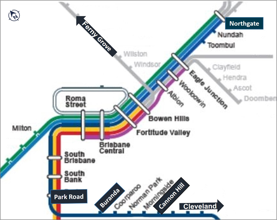
DW17 was scheduled to stop at all stations between Cannon Hill and Northgate (Figure 1). It departed Cannon Hill on time at 1201.[1] The rail traffic crew consisted of a driver and a guard.
Figure 1: Excerpt of Brisbane suburban network showing origin (Cannon Hill) and destination (Northgate) of train DW17
Source: QR, modified by the ATSB
The train travelled towards the city on green signals before encountering a yellow (restricted) aspect in signal LS059, which was located on the approach to Buranda Station (the station prior to Park Road). As it passed over the automatic warning system (AWS)[2] magnet applicable to the signal, the AWS generated an audible and visible alarm in the driving cab, advising the driver of the restricted signal ahead. The driver acknowledged the alarm by pressing and releasing the AWS button.
After stopping at the Buranda Station platform, the driver placed the brake controller in full service but did not place the direction controller into neutral. This was inconsistent with the operator’s ‘start on a yellow’ procedure (see Citytrain driving procedures). The train departed Buranda on time at 1211:30.
The train then passed signal DP17 (displaying a flashing yellow aspect) and signal DP23 (displaying a single yellow aspect). Prior to passing each signal, the AWS generated a restricted signal alarm in the driving cab and the driver responded accordingly. Signal DP23 was the authority to proceed into platform 2 at Park Road Station. The driver subsequently reported that, based on the previous signal indications, they were expecting a red signal at Park Road Station.
Arrival at Park Road Station
At 1214:00, DW17 passed over the AWS magnet for signal DP 29 (the departure signal for platform 2 at Park Road), and the driver acknowledged the alarm. At that time, DP29 was displaying a red aspect.
At 1214:25, the train stopped at the relevant platform stopping mark at Park Road Station. The driver did not move the direction controller to neutral or apply the park brake, which was inconsistent with the operator’s ‘stopped at a red aspect’ procedure (see Citytrain driving procedure).
Signal DP29 was displaying a stop indication because the NCO had planned to briefly delay DW17 at the platform. This was to allow another suburban passenger train (1E65), which was running late, to proceed in advance of DW17 and pass through the middle road (platform 3) to connect with the down suburban line (Figure 2).
Figure 2: Signal DP29, the middle road and the down suburban line at Park Road Station
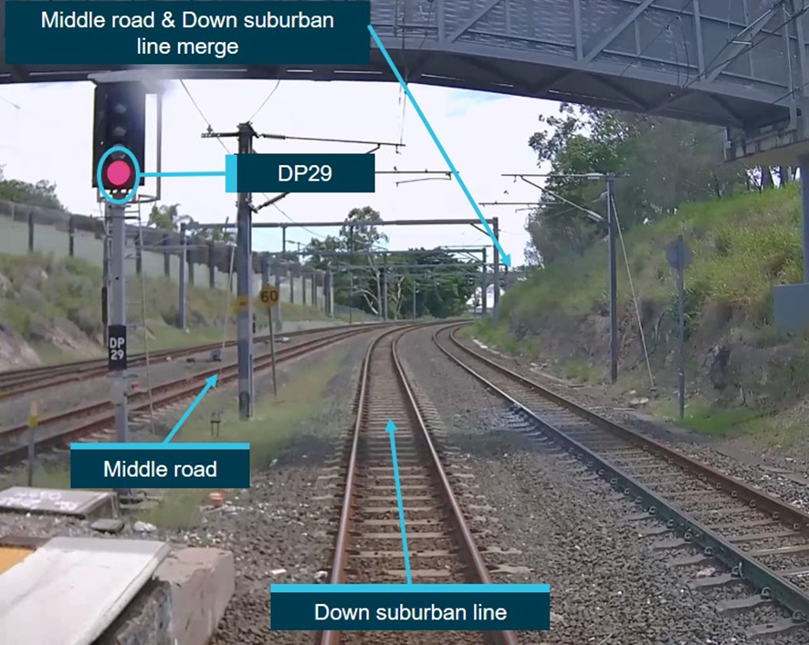
The image was taken from the forward-facing camera of DW17 on the day of the occurrence. It shows the down suburban line, which DW17 was traversing, and the red aspect in signal DP29. The middle road was set for the path of 1E65 to run in advance of DW17.
Source: QR, modified by the ATSB
1E65 was scheduled to run all stops between Beenleigh and Ferny Grove. The train departed Beenleigh 5 minutes late at about 1117. It recovered some lost time and arrived at Yeerongpilly Station (4 stations prior to Park Road) at 1207, 3 minutes behind schedule.
At the Yeerongpilly Station platform there was an unplanned driver change. A tutor driver, who was providing a trainee driver with route tuition, seconded the train at the platform and the trainee took over driving duties. At 1214:50, 1E65 came to a stop at platform 3 at Park Road. The platform 3 departure signal (DP27) displayed a green aspect to allow 1E65 to run in advance of DW17.
Signal passed at danger (SPAD)
On platform 2 at Park Road, a station porter aided a passenger in a wheelchair to board DW17. At 1215:02, the porter gave the ‘allright signal’[3] to the guard to signify platform duties were complete. There was no requirement in the allright process for station staff to check the indication in the departure signal. At that time, signal DP29 was still displaying a red aspect.
As signal DP29 was not visible from a guard’s location at the rear of an NGR train, a signal aspect indicator[4] (SAI) had been installed on the platform to assist guards with the process of providing ‘rightaway’ signals to drivers (Rightaway signal procedure).
The guard of DW17 stated that, after the train stopped, they stepped from the train onto the platform in accordance with the rightaway procedure. They noticed the porter assist a passenger into the train and then provide the allright signal. The guard said they then checked the SAI and noted that it was illuminated (indicating that DP29 was displaying a proceed indication). They then boarded the train and, at 1215:03, they provided the rightaway signal (2 bells) to the driver.
A review of closed-circuit television (CCTV) footage determined that the SAI was not illuminated and the guard did not step from the train onto the platform at Park Road, although they looked up and down the platform from within the crew compartment at the rear of the train.
On receipt of the rightaway, the driver pressed the doors closed button and waited for the ‘doors open’ tile to extinguish. At 1215:25, the driver applied traction power, and at 1215:27 the train (DW17) departed the platform on the down suburban line (with the departure signal DP29 still displaying a red aspect). The driver subsequently reported that they could not recall checking or sighting the status of signal DP29 prior to departing the station, and they were prompted to depart after receiving the rightaway from the guard.
At about the same time that DW17 departed from platform 2 on the down suburban line, 1E65 departed from platform 3 on the middle road (with the departure signal DP27 displaying a green aspect). The down suburban line and the middle road merged at a point about 250 m past signal DP29.
At 1215:34, the universal traffic control[5] (UTC) system at the Brisbane rail management centre generated an alarm to the NCO, which stated ‘train DW17 past signal 29 at STOP’. At the same time, the UTC system showed train 1E65 had passed signal DP27. The trains were traveling in the same direction on a collision course.
Response to the SPAD
Initially, the crews of both trains were unaware of the circumstances as they accelerated away from their respective platforms. However, the tutor driver in the driving cab of 1E65 soon became aware that the train on the adjacent track (DW17) had exceeded its authority and there was potential for collision at the merging points. At that time, the speed of 1E65 was 43 km/h. The tutor driver initially directed the trainee driver to apply the brakes to slow the train, but on hearing an emergency stop command over the train radio, the tutor driver directed the trainee to stop the train.
At 1215:43, the NCO transmitted ‘emergency, emergency, emergency’ DW17 stop your train, emergency, emergency, emergency DW17 Park Road stop your train’. The NCO then immediately transmitted a similar message for 1E65, and then transmitted ‘all trains Park Road stop your trains’ twice in succession. All of these messages were transmitted over the ultra high frequency (UHF) open radio network and could be heard by all drivers.
Initially, the driver of DW17 thought the emergency command was for another train, but then noticed the points ahead were set in reverse for the train on the middle road (that is, 1E65) (Figure 3). The driver then recognised that the emergency stop command related to their train, and that they had exceeded their limit of authority by passing signal DP29. At 1215:56, while travelling at 54 km/h, the driver applied the brakes, and the train came to a stop at 1216:08.
Figure 3: Points set in reverse for the path of 1E65

The image was taken from the forward-facing camera of DW17 immediately prior to the train running through the points that were set for 1E65.
Source: QR, modified by the ATSB
At 1216:10 the crew of 1E65 advised they had stopped their train. At 1216:17, the driver of DW17 also advised that their train was stopped.
DW17 exceeded its limit of authority by about 305 m (about 55 m past the conflict point between the 2 lines); 1E65 stopped about 70 m prior to the conflict point.
The SPAD occurrence resulted in no injuries and only minor damage to rail infrastructure. The damage was due to DW17 running through the points, which were set in reverse to facilitate the movement of 1E65 from the middle road to the down suburban line at Park Road.
As the damaged infrastructure was located under DW17 when it stopped, QR personnel evacuated the passengers from the train under the authority of an all trains block.[6] The passengers were assisted off the train and escorted along the permanent way back to Park Road Station. 1E65 was authorised to return to platform 3, from where the service continued to the city via the dual gauge line.
__________
- All time references in this report are in local time (Eastern Standard Time).
- The AWS is designed to provide an in-cab visual and audible indication of the aspect displayed in the next signal.
- The allright signal will be provided by the officer in charge or station staff, when they are in attendance, to indicate to rail traffic guard or passenger services staff that station duties have been completed and all persons are clear of the rail traffic. See Allright signal procedure for the EMU business operating model for further information.
- Where the viewing of a main signal is obstructed from viewing on a platform a signal aspect indicator (SAI) will be fitted to assist the guard when giving rightaway. It provides a white light when the signal is at proceed and no light when the signal is at stop (see Signal aspect indicators for further information).
- A system unique to QR that assists network control officers safely route and monitor the movement of trains.
- All trains block: an application at the NCO’s workstation that places signals at stop in the immediate area to prevent train movements.
Context
Train information
DW17 was an electric suburban passenger train operated by Queensland Rail (QR) Citytrain and timetabled to travel between Cannon Hill and Northgate. On departure from Park Road Station, it had 41 passengers on board.
DW17 was a new generation rollingstock (NGR) train, unit number 726. NGR trains consisted of 6 cars with a driving compartment at each end. They were operated with the guard positioned in the rear driving compartment. The trains were 146.7 m long and weighed 260 t.
The train operated as designed and there were no reported or recorded faults that influenced its serviceability. The train was fitted with an event recorder and front-of-train camera. These systems operated effectively during the occurrence sequence, and relevant information from these systems are included in this report where relevant.
Rail crew information
Driver qualifications and experience
The driver of DW17 joined QR in 1963 and gained train driver qualification in 1976 and they had almost 43 years’ service as a train driver.
In 1987, the driver obtained the qualification to operate electric multiple unit (EMU) trains. In January 2018, the driver achieved an additional qualification to operate NGR trains. DW17 was the only NGR train the driver operated on 25 March 2019. They reported having operated NGR trains about 30–40 times since they obtained their qualification and had last operated an NGR train on 23 March.
The driver was route competent[7] to operate trains throughout the Brisbane suburban rail network and frequently worked passenger trains from Cleveland to the city via Park Road. The driver reported being familiar with the signalling arrangements at Park Road and had traversed through Park Road platform 2 on numerous occasions.
Records supplied by QR showed that the driver was involved in a previous SPAD occurrence at signal SB21 (South Brisbane) on 23 August 2009. On that occasion, the driver did not apply the ‘stopped at a red’ procedure when stopped at the platform departure signal and did not check the departure signal after receiving a false (incorrect) rightaway signal from the guard. The driver’s 2009 SPAD occurrence at signal SB21 showed similarities to that of the SPAD at signal DP29 on 25 March 2019.
Driver medical information and recent work history
The driver underwent a medical assessment (rail category 1 – high-level safety worker) on 11 March 2019 and was assessed as fit for duty. Following the SPAD occurrence on 25 March 2019, the driver undertook a mandatory drug and alcohol test, which produced negative results (that is, no drugs or alcohol detected).
The driver’s duty times for the day of the occurrence (25 March 2019) and previous days are shown in Table 1. They had a day off duty on 16 March, followed by 7 shifts in a row prior to another day off duty on 24 March. They commenced duty on 25 March at 0412. The shifts on 15, 17 and 18 March were also originally designated as days off duty.
Table 1: Day-of-operations duty times for driver over previous 10 days
| Date | Work activity | Duty start | Duty end | Duty time | Time free (of duty) |
| 15 Mar 2019 | Train driving, various routes | 0845 | 1445 | 6.0 hours | 43.1 hours |
| 16 Mar 2019 | Day off | 40.0 hours | |||
| 17 Mar 2019 | Train driving, various routes | 0747 | 1543 | 7.9 hours | 12.4 hours |
| 18 Mar 2019 | Train driving, training | 0406 | 1242 | 8.6 hours | 16.1 hours |
| 19 Mar 2019 | Train driving, various routes | 0447 | 1047 | 6.0 hours | 16.8 hours |
| 20 Mar 2019 | Train driving, various routes | 0334 | 0934 | 6.0 hours | 20.0 hours |
| 21 Mar 2019 | Train driving, various routes | 0537 | 1425 | 8.8 hours | 12.6 hours |
| 22 Mar 2019 | Train driving, various routes | 0300 | 0900 | 6.0 hours | 16.9 hours |
| 23 Mar 2019 | Train driving, various routes | 0353 | 0953 | 6.0 hours | > 24 hours |
| 24 Mar 2019 | Day off | ||||
| 25 Mar 2019 | Train driving, various routes | 0412 | 1253 | 8.7 hours |
The driver stated that they obtained 6 hours sleep on the night of 24 March and felt well rested before commencing duty at 0412 on 25 March. They noted that 6 hours sleep was the minimum they needed to function effectively.
The driver operated multiple train services and had 2 meal breaks on the 25 March prior to operating a train from Bowen Hills to Cannon Hill and then commencing the DW17 service from Cannon Hill to Northgate. DW17 was scheduled as their last train service of the day.
Guard qualifications and experience
The guard of DW17 commenced work with QR in 1974 and performed various roles before being appointed to the position of train guard in 1984. In 1990, they transferred to Brisbane (Mayne depot) and thereafter worked as a Citytrain guard up until the SPAD occurrence on 25 March 2019.
The guard became qualified to conduct duties on NGR trains in August 2018. They stated they had conducted operations on NGR trains on numerous occasions, primarily on the Gold Coast line (including through platform 3 at Park Road). However, they had never worked an NGR train on the Cleveland line from Cannon Hill before and had never stopped on platform 2 at Park Road on an NGR train. Accordingly, they had not previously used the signal aspect indicator (SAI) for DP29 before 25 March 2019 (see also Communication of information about the location of the SAIs at Park Road).
Guard medical information and recent work history
The guard underwent a medical assessment (rail category 2 – safety critical worker) on 14 November 2018 and was assessed as fit for duty. Following the SPAD occurrence on 25 March 2019, the driver undertook a mandatory drug and alcohol test, which produced negative results (that is, no drugs or alcohol detected).
The guard’s duty times for the day of the occurrence (25 March 2019) and previous days are shown in Table 2. They had 2 days off duty before commencing duty at 0412 on 25 March.
Table 2: Day-of-operations duty times for the guard over previous 6 days
| Date | Work activity | Duty start | Duty end | Duty time | Time free (of duty) |
| 20 Mar 2019 | Day off | ||||
| 21 Mar 2019 | Guard duties, various routes | 1500 | 2359 | 9.0 hours | 12.0 hours |
| 22 Mar 2019 | Guard duties, various routes | 1200 | 2100 | 9.0 hours | > 24 hours |
| 23 Mar 2019 | Day off | ||||
| 24 Mar 2019 | Day off | ||||
| 25 Mar 2019 | Guards’ duties, various routes | 0412 | 1312 | 9.0 hours |
The guard was originally rostered to commence work at 0900 on 25 March 2019. However, at 2208 on 24 March, a QR roster clerk called the guard to ask if they could start work at 0412. The guard, who was awake at the time, accepted the earlier start time. Soon after that conversation, the guard required more information on the new shift so they called the on-duty roster clerk to gain these details. During these calls, the guard did not advise the roster clerks of any concern with undertaking the changed shift.
The guard recalled waking at 0200 on 25 March. Based on the available evidence, the ATSB concluded that the guard probably had approximately 3.0–3.5 hours’ sleep prior to starting work. The guard recalled feeling normal on the day of the occurrence.
The guard operated the same train services as the driver of DW17 on 25 March, including having 2 meal breaks prior to the occurrence.
Station and signal information
Park Road Station
Park Road is an interchange station for the Gold Coast and Cleveland lines. It is located about 4.3 rail km south-east of Roma Street Station and serves the Brisbane suburb of Woolloongabba. The station has 4 platforms (Figure 4) and caters mainly for medium to high frequency suburban passenger traffic.
Figure 4: Platform configuration at Park Road Station
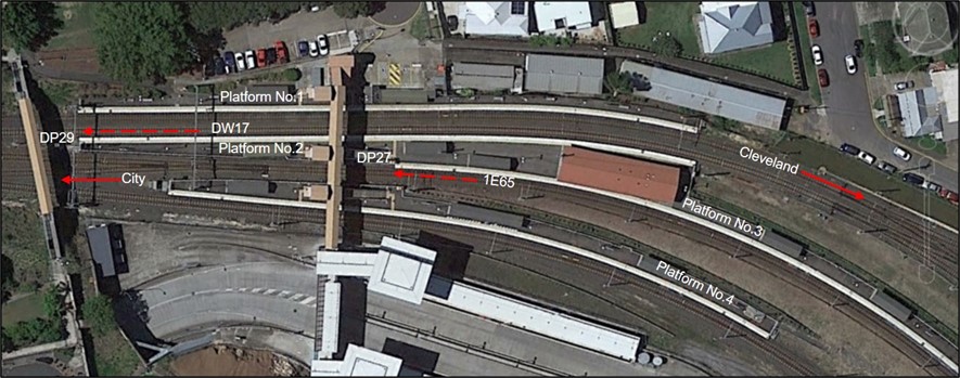
The image shows the platform configuration at Park Road, relevant signals, and the direction of travel of trains DW17 and 1E65. Source: Google maps, modified by the ATSB
Signal DP29
Signal DP29 was located at the 4.238 km mark.[8] It was about 5.8 m off the departure end of platform 2 at Park Road and 10 m from the 6-car stopping mark on the platform. Traditionally, signals at or near to the end of platforms were referred to as platform departure signals, although some suburban station platforms (such as at Buranda Station) did not have a departure signal.
Signal DP29 was a 4-aspect colour light signal, capable of displaying green, double yellow, yellow or red aspects and was fitted with light emitting diodes (LEDs). Figure 5 provides information about the function of the different aspects. More generally, the term ‘proceed’ is used to refer to a signal displaying a green, double yellow, single yellow or flashing yellow aspect, and ‘restricted’ is used to refer to a signal displaying a double yellow, single yellow, flashing yellow or red aspect.
Figure 5: Four-aspect colour light signal indications
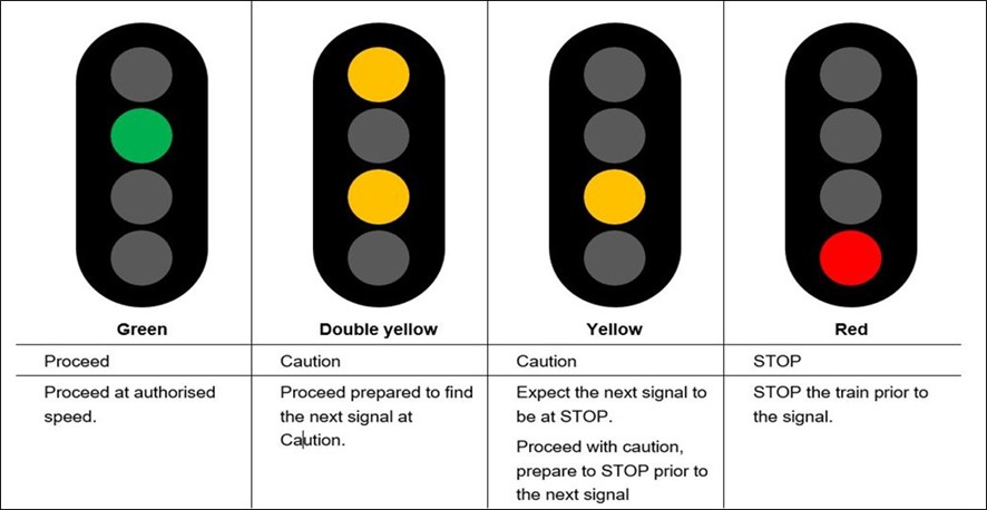
The image shows the indications displayed by a 4-aspect colour light signal and their authority. At some locations, a flashing yellow aspect is part of the 4-aspect colour light sequencing.
Source: Queensland Rail (QR)
The signal had an unrestricted sighting distance greater than 100 m, and the designated track speed approaching the signal was 40 km/h. The positioning and sighting of the signal complied with QR standard MD-10-95 (Signalling positioning principles).
QR advised there had been one other recorded SPAD occurrence at signal DP29 since 1996. This occurred in April 2004 and was categorised as a ‘signal restored in face of train’ occurrence, rather than a driver initiated SPAD.
Although signal DP29 was well positioned from a sighting perspective, the driver of DW17 stated they did not see the red aspect in the signal as the train approached and stopped at the platform. The driver said that they had lowered the windscreen blind to reduce sun glare reflecting off the dashboard and this may have restricted the sighting of the signal.
A review of station closed-circuit television (CCTV) footage showed that the blind was in a lowered (but not fully lowered) position on the windscreen as the train entered the station platform. The ATSB re-enacted the occurrence based on information from the driver and evidence from the station CCTV footage. The re-enactment showed that the position of the windscreen blind would not have hindered the driver’s view of the red aspect in the signal (Figure 6).[9]
Figure 6: A view of signal DP29 from the driver’s seat of an NGR service stopped at the 6-car stopping mark at platform 2 Park Road
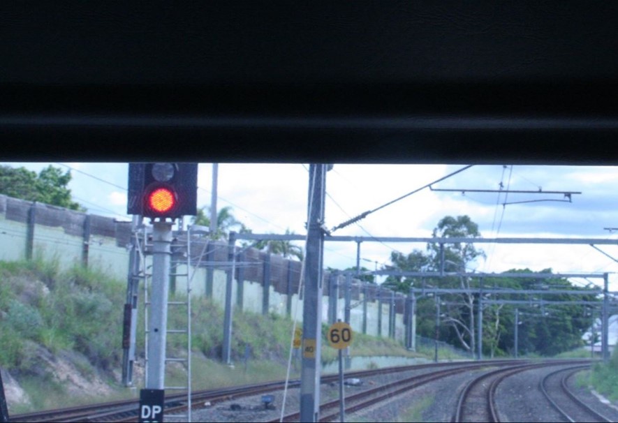
The photo, taken from the driver’s seat of an NGR service, shows the red aspect in signal DP29 with the front blind almost fully drawn.
Source: ATSB
In August 2017, an SAI was installed on platform 2 at Park Road Station as part of the introduction of NGR trains (see Location of the SAI on platform 2 at Park Road).
Citytrain driving procedures
Safe driving procedures
The QR suburban rail network had limited engineering or technical controls in place to detect potential or actual SPADs and manage their risk (see ATSB report RO-2018-002).[10] Consequently QR heavily relied on front line staff to manage risk through their compliance with procedures.
QR procedure MD-11-72 (TSD professional driving – Safe driving) outlined rules for train drivers to apply ‘to mitigate the incidence of Signals Passed at Danger (SPAD) and other adverse operational safety events’. The procedure stated:
Safe Driving focuses on planning, prioritising, communicating and taking appropriate positive actions. The methods of Safe Driving are important defences against the risk of error and are intended to reduce errors and mitigate risk in the event of errors occurring…
The technique shall be incorporated into all aspects of day to day driving, driver training, driver monitoring, assessment, accreditation and reaccreditation programs. The principle of the driving method is based around thinking safety, behaving and acting proactively and positively in all situations which could arise. Safe driving is mandatory.
The procedure included several specific rules to mitigate the risk of SPADs, and those relevant to the 25 March 2019 SPAD occurrence are outlined below.
Approaching yellow aspects
If a train was approaching a signal displaying a double yellow or single yellow aspect, the driver was required to reduce the train speed to (or below) 75% of the designated track speed when passing the signal. When approaching a signal displaying a flashing yellow aspect, the driver was required to pass the signal at a speed no greater than 40 km/h, or the designated track speed, whichever was the lower.
As signal LS059 (prior to Buranda Station) was displaying a single yellow aspect, the train speed was required to be limited to 45 km/h after departing Buranda. However, the train was accelerated to about 57 km/h before traction power was shut off as it approached signal DP17 (which was displaying a flashing yellow aspect). Under braking, the train passed DP17 at 47 km/h (in excess of the 40 km/h limit) and continued to slow to 25 km/h as it passed through a turnout with a 25 km/h speed limit.
Start on a yellow
When the platform departure signal was displaying a single yellow or flashing yellow aspect, then the driver was required to fully apply the train brakes (that is, to the full service position) and place the direction controller into the neutral position. The same action was required if there was no departure signal (such as at the Buranda Station platform) and the signal prior to the platform was displaying a single yellow / flashing yellow aspect.
Evidence from DW17’s event recorder showed that the driver did not fully comply with the ‘start on a yellow’ procedure at the Buranda Station platform; although they applied the train brakes to full service, they did not move the direction controller to the neutral position.
Approaching a red aspect
When approaching a signal displaying a red aspect, the driver was required to apply the ‘20 / 20’ rule. This stated that the driver must reduce the speed of the train to 20 km/h when passing over the AWS magnet (located about 80 m prior to the signal) and target a stopping point 20 m prior to the signal.
DW17’s event recorder showed that the train speed was moderately above 20 km/h passing over the AWS magnet for signal DP29. However, the driver demonstrated caution when approaching the signal, suggesting they were aware of its indication.
Stopped at a red aspect
When an electric suburban train stopped at a station platform and the departure signal was displaying a red aspect, the driver was required to:
- move the brake controller to the full service position
- place the direction controller into the neutral position
- apply the park brake
- release the driver’s safety control.[11]
After stopping the train at the Park Road platform, the driver of DW17 placed the brake controller to full service but did not move the direction controller to neutral or apply the park brake.
The driver stated that they were aware of QR’s start on a yellow and stopped at a red procedures and the reasons for the procedures, and agreed that they were a good idea for reducing the risk of a SPAD. The driver also stated that sometimes they followed these procedures, but at other times they tailored their own risk management measures, which they felt confident with, and they had applied this approach successfully over many years as a driver.
Safe driving assurance data
QR commenced a process to review event recorder data to collect data on driver compliance with key SPAD mitigation rules in April 2018 (see ATSB report RO-2018-002). QR advised that data for the periods from September 2018 to March 2019 indicated compliance rates as follows:
- 87% for the 75% rule (approaching a single yellow or double yellow aspect)
- 55% for the start on a yellow rule
- 99% for the 20 / 20 rule
- 92% for the stopped at a red rule.
Risk triggered commentary driving
To assist with reducing the frequency of SPADs, QR introduced risk triggered commentary driving (RTCD) in 2008–2009, and subsequently Citytrain made it a mandatory requirement for its drivers in 2011 for situations where they were approaching restricted signals. QR procedure MD-13-165 (TSD professional driving – risk triggered commentary driving) stated:
At a basic level, RTCD involves RTDs [drivers] acknowledging the aspect of the restricted signal, and intended actions, by speaking aloud. By applying RTCD, RTDs can listen to their thoughts and the subsequent actions they are planning to apply. This allows RTDs to ‘sense check’ what they should do next.
RTCD is required to be applied continuously from the acknowledgement of the restricted audible alarm on the Automatic Warning System (AWS) until the action that must be taken is actually performed…
The driver of DW17 stated that they were applying RTCD ‘to some degree’ during the period leading up to the SPAD occurrence on 25 March 2019. They had noted each of the 3 yellow signals prior to reaching Park Road, but they had not verbalised these signals (or the required actions) out aloud.
Further information regarding QR’s implementation of RTCD is provided in ATSB report RO-2018-002.
QR’s electric suburban train business operating models
Electric multiple unit (EMU) business operating model
In 1979, QR introduced electric multiple units (EMUs) to the Brisbane suburban rail network. The EMUs consisted of 3-car units that worked either as 3-car trains or coupled together as 6-car trains. The 6-car configuration with the guard working from the middle compartment of the train was the preferred business operating model (BOM).
Due to the location of the guard in the middle of the train, station platforms were designed with provisions in the middle of the platform to cater for the needs of passengers who required boarding assistance. It was the guards’ role to assist with passenger boarding / alighting arrangements at suburban station platforms as required.
Allright signal procedure for the EMU business operating model
Under the EMU BOM arrangement, there was no requirement for station staff at a suburban station platform to provide the allright signal to a train guard. However, due to high patronage at Brisbane central business district (CBD) stations (Roma Street, Central and Fortitude Valley), and at 2 designated suburban stations with bus connections on the Sunshine Coast line (Nambour and Gympie North), station staff were required to provide the allright signal for every suburban passenger train at those stations.
QR procedure MD-10-109 (Observance of signals manual) stated that, prior to giving the allright signal, station staff were required to:
- make sure … staff have completed all duties associated with the rail traffic
- blow whistle or use loudspeaker to warn people to stand clear of the rail traffic
- make sure all people are clear of the rail traffic
- make sure doors on passenger rail vehicles, not operated by the rail traffic driver, are closed...
Station staff communicated the allright signal to the guard during daylight hours by raising one arm at 45° above shoulder height, and in the hours of darkness by a white light held above shoulder height.
There was no official requirement for station staff to check the aspect indication in the platform departure signal prior to giving the train guard the allright signal.
During the course of the investigation, experienced current and former station staff informed the ATSB that there was a long-standing informal practice at Brisbane CBD stations and at Nambour for station staff to check that the departure signal was at proceed prior to giving the allright signal to the train guard. They recognised that checking the signal was not part of the station staff formal duties; however, the informal practice had been in existence over many years and it had been encouraged by more senior station staff as an additional assurance against false rightaways resulting in SPAD occurrences.
An ATSB investigator visited Central Station and observed station staff checking the departure signals prior to issuing the allright signal.
New generation rollingstock (NGR) business operating model
On 27 June 2017, QR adopted a BOM for the NGR. The configuration of the NGR fleet was different to the existing EMU fleet; NGR trains were permanently coupled 6-car units with no guard’s compartment in the middle of the train. Therefore, the BOM for NGR trains involved the guard working from the rear driving compartment of the 6-car train. In December 2017, NGR trains commenced operations on the Brisbane suburban (Citytrain) rail network.
The location of the guard at the rear of the train posed some challenges for operations, as the boarding point for passengers who required assistance with boarding and alighting remained in the middle of the train (and platform). To overcome these challenges, QR required station staff at all Citytrain stations (CBD and suburban station platforms) to meet every NGR service, where practicable, for the purpose of providing passenger assistance as required.
Allright signal changes for the NGR business operating model
At the time of the NGR being introduced into service, a station customer service (SCS) notice to station staff (SCS employees meeting trains – New generation rollingstock) stated that they were required to provide the allright signal to a guard:
- at the 3 CBD stations (Roma Street, Central, Fortitude Valley) and 2 nominated suburban stations (Nambour and Gympie North)for all services
- at all other suburban stations only when there was an assisted customer activity to complete and the boarding assistance was provided to the customer.
Station staff at suburban stations confirmed that they were trained to provide the allright signal only on the condition that they provided passenger assistance. During training they were told not to check the platform departure signal prior to giving the allright signal as that was not their role. They explained that delivery of the allright signal was an indication to the guard that platform duties were complete, and passengers and staff were clear of the train.
Citytrain’s SCS management also confirmed to the ATSB that, with the introduction of NGR services to the network in December 2017, station staff at suburban stations were only required to give the allright signal for an NGR service and only if they had assisted a passenger on or off the train. There was no requirement to provide the allright signal if passenger assistance was not provided.
Guards stated that initially this change resulted in confusion for them as it was contrary to the allright process at the CBD stations and the other 2 nominated stations, where the allright signal was given for all trains.
A search of train crew training modules (provided by QR) relevant to the NGR BOM identified no documented guidance for train guards relevant to the allright signal from station staff at suburban stations. An important operational notice (ION) (015_01_2018) titled NGR – Arrival/Departure Procedures, was disseminated by Citytrain’s train services delivery (TSD) section to train crew in January 2018. This notice stated that the allright signal would only be given at designated stations; however, it did not nominate the designated stations.
Modification of the NGR business operating model
On 10 January 2019, TSD issued another ION to train crew (drivers and guards) to advise that the NGR BOM had been modified. It stated:
In addition to the introduction of the New Generation Rollingstock (NGR), an NGR Business Operating Model (BOM) was introduced to outline the operational requirements for this class of Rollingstock. An agreement has been reached between Train Service Delivery and Station Customer Service (SCS) that SCS staff members will provide the ‘Allright’ signal, as well as one (1) whistle blow, when attending any NGR revenue service.
The ION also provided answers to frequently asked questions, including:[12]
Are SCS staff required to attend all NGR services at all platforms?
No, there may be circumstances which prevent a member of SCS staff attending to an NGR service. In this instance, the RTG [guard] is responsible for any assisted boarding activities when the platform is unattended and there is an assisted boarding requirement.
Are SCS staff required to give the Allright signal to the RTG, when attending NGR services?
Yes, SCS staff at Suburban stations are required to provide the Allright signal to the RTG when they attend to an NGR service.
Note: This does not affect the requirement for an RTG [guard] to receive the ‘Allright’ signal, for all trains, prior to giving Rightaway at Roma Street (excluding P2, P3 and P10), Central, Fortitude Valley, Nambour and Gympie North…
What information is the SCS staff member providing when they give the ‘Allright’ signal?
When an SCS staff member gives the Allright signal, it advises that they have finished their required platform duties only.
Note: This is not an indication that the departure signal is at proceed. The RTG is responsible for observance of signals prior to giving Rightaway…
On the same day, TSD issued another ION (006_01_2019), which replaced the 2018 notice regarding NGR arrival and departure procedures. It stated that station staff were required to provide the allright signal for an NGR train if they attended the train service.
At the same time, SCS issued an updated communication to station staff, which stated:
SCS employees are required to provide the ‘Allright’ signal to indicate to the RTG that assisted boarding and visual checks have been completed…
- Suburban stations are only required to provide this indication to the RTG for NGR services to indicate platform duties have been completed.
- CBD stations are required to provide the ‘Allright’ signal to all services including NGR services...
Station staff at suburban stations confirmed that they were advised of the change.
QR advised that, at the time of the January 2019 change, the NGR deployment was at an advanced stage and the BOM had been continually reviewed. The TSD and SCS sections were trying to clarify the exact requirements for the allright signal to ensure there were no unnecessary delays or impact on on-time running. The notices also updated other aspects of the departure process for personnel.
As a by-product of these changes to the dispatch procedures, from January 2019 onwards there was a significant increase in the frequency that allright signals were provided by station staff to train guards working NGR trains at suburban platforms.
Rightaway signal procedure
QR procedure MD-14-38 (Rail traffic crew manual) outlined the procedures for a guard to follow when a suburban passenger train was departing a station. These included:
- Once the train is stationary, open the cab door and step out onto the platform beyond the yellow line
- Walk sufficient distance to view the entire train (last door to first door), and departure signal or Signal Aspect Indicator (where provided)
- Ensure Proceed aspect is illuminated in departure signal or Signal Aspect Indicator
- Ensure all customers have boarded / alighted safely and provide customer service as required. At specified locations wait until the ‘Allright’ signal is given by station staff…
- Ensure all people remaining on the platform are clear of the yellow safety line
- Re-check departure signal / Signal Aspect Indicator displays a proceed aspect (where provided)
- Return to working cab and give rightaway to rail traffic driver
For NGR trains, the procedures stated:
When a NGR train is arriving at a station, the Rail Traffic Guard (RTG) will observe the external CCTV to confirm that station staff is in attendance and if anyone is waiting in the designated boarding assistance area.
Once stationary, the RTG will ensure that the platform side doors have been released, exit the cab and step onto the platform beyond the yellow line to observe the presence of station staff on the platform - as well as any passengers waiting in the assisted boarding area (In the absence of station staff, the RTG will provide any boarding assistance as required).
- The RTG will walk to view the Departure Signal or Signal Aspect Indicator (where provided)
- Ensure Proceed aspect is illuminated in the departure signal or Signal Aspect Indicator
- Ensure all customers have boarded / alighted safely and provide customer service as required.
- Ensure all people remaining on the platform are clear of the yellow safety line
- Re-check Departure Signal / Signal Aspect Indicator to ensure that it continues to display a proceed aspect (where provided)
At designated stations, an Allright signal will be provided by station staff…
As noted above, the circumstances where an allright signal would be provided for NGR trains were advised in IONs.
Regardless of the type of train, if viewing of the departure signal was obstructed, the guard had to ensure the associated signal aspect indicator (SAI) was illuminated (which indicated that the departure signal was not displaying a red aspect).
The guard provided the rightaway signal by bell communication (that is, pressing a button inside the guard’s cab twice, which would annunciate 2 bell sounds in the driver’s cab).
Driver procedure for responding to a rightaway signal
The receipt of ‘two bells’ was a signal to the driver that the guard had given authority to depart the platform. The driver was then required to follow the documented steps in procedure MD-11-282 (TSD professional driving – Train management train units) before moving the train:
- Check the indication of the departure signal
- Move the direction controller into the forward position (if not already in the forward position)
- Press the door closing button
- Sound the city horn
- Wait for the ‘doors open’ tile to extinguish
- “Scan before you go” [re-check the indication in the departure signal]
- Ensure headlight is on (if applicable)
This procedure was the same for EMU and NGR trains. As already noted in The occurrence, the driver of DW17 advised that they could not recall checking or sighting the status of signal DP29 after receiving the rightaway and prior to departing the platform. They recalled that the rightaway signal (2 bells) from the guard was the prompt to depart the platform. The driver stated that there were no distractions present on the platform or in the driving cab at the time.
The driver of DW17 also noted that they were not aware of the other train at the adjacent platform. They received no advice from the NCO that another train was going to be run ahead of them out of Park Road Station and that they would therefore be stopped at the station for longer than normal. The driver also noted that NCOs were inconsistent in advising drivers of such delays; some NCOs provided the advice whereas others did not.
Start against signal occurrences
Background information
A signal passed at danger (SPAD) is a relatively rare event. For example, during the period from July 2016 to June 2020, there were 119 SPADs on QR’s Citytrain rail network (about 30 SPADs per year). This equated to about 1.91 SPADs per million train km, and a rate of 34,900 red signals approached per SPAD[13] over the 4 years.
The 119 SPADs included:
- 70 (59%) driver misjudged SPADs (that is, the driver attempted to stop the train but failed to stop before passing the signal)
- 37 (31%) completely missed SPADs (that is, no attempt was made to bring the train to a stop before the signal)
- 6 (5%) start against signal SPADs (that is, a stationary train started at and proceeded beyond the signal)
- 6 (5%) other SPADs (that is, any authority exceeded that is not classifiable under one of the above subcategories).
QR considers ‘completely missed’ and ‘start against signal’ as the most significant SPADs, as generally the drivers involved have continued to operate the train unaware it had exceeded its limit of authority. Such occurrences are problematic on the Citytrain network as, currently, the controls designed to detect such an event have limitations.
QR’s universal train control (UTC) system provided a SPAD alarm at the network control officer’s (NCO’s) workstation if a train passed a ‘controlled’ signal.[14] Therefore, the system had the potential to mitigate the consequences of a SPAD by the NCO transmitting an emergency stop command via radio to the driver (as was the case with the 25 March 2019 SPAD at Park Road Station). However, there can be a significant delay between an NCO detecting a SPAD alarm, the NCO providing the stop command to the driver, the driver responding to the stop command and the train coming to a stop. In addition, a small proportion of station departure signals are non-controlled, and therefore will not be associated with a SPAD alarm if there is a start against signal SPAD.
Most start against signal SPADs (such as the 25 March 2019 SPAD) occur when starting from a station platform. Start against signal SPADs occurring at platforms have commonly involved guards providing a false rightaway to a driver (that is, they have provided the rightaway when there was a red aspect in the departure signal). Such SPADs have often been called ‘ding-ding-and-away’ SPADs, referring to the sound of the rightaway signal (2 bells) and an automatic, habitual action of the driver to start departing a station upon hearing the bells.
Start against signal occurrences on non-NGR trains
During the 9-year period from July 2012 to June 2021, Citytrain had 7 start against signal SPADs on non-NGR trains. These occurred from September 2012 to January 2018, with only one since June 2016 (in January 2018).
Database records provided by QR indicated that, for 6 of these SPADs, the guard provided a false rightaway to the driver, and details for the other SPAD did not include details regarding the guard’s action.
The database records also indicated that in some cases the driver did not check the signal after receiving the rightaway and prior to departing the platform, whereas in other cases the driver stated they had checked the signal and thought it was indicating a proceed aspect. In 2 of the cases, the database records indicated that the driver did not follow the stopped at a red procedure, whereas in another case it was noted that the driver did follow the procedure.
Start against signal occurrences on NGR trains
As previously noted, the first NGR train entered service in December 2017, but the procedure of providing an allright signal for each NGR train at each suburban station only commenced in January 2019. Between December 2017 and December 2018, Citytrain had no start against signal SPADs involving NGR trains. In the 18 months after the January 2019 procedure change, there were 5 start against signal SPADs on NGR trains, with another SPAD the following year. These included:
- signal DP29 (Park Road) – 25 March 2019
- signal SE16 (Shorncliffe) – 1 October 2019
- signal EJ38 (Eagle Junction) – 20 November 2019
- signal BH4 (Beenleigh) – 18 March 2020
- signal AP12 (International Airport) – 25 March 2020
- signal SL23 (Springfield Central) – 23 April 2021.
By the time of the first of the 6 SPADs (March 2019), 51 of the 75 NGR trains had entered service, and for the other 5 SPADs most or all of the NGR trains had entered service. However, throughout the period from January 2019 to June 2021, there were still more non-NGR train services on the network than NGR train services. QR advised that during the period from January 2019 to June 2021, non-NGR trains travelled 16.0 million track km per year whereas NGR trains travelled 8.6 million track km per year (35% of the total). In addition, non-NGR trains approached 554,000 red signals per year and NGR trains approached 430,000 red signals per year (44% of the total).
In summary, there was a substantial increase in the rate of start against signal SPADs in the 18-month period following the change of NGR dispatch procedures in January 2019 and all 5 of the SPADs involved NGR trains, which had less operations than non-NGR trains. The rate of start against signal SPADs decreased in the following 12 months with only one occurrence, which involved an NGR train.
Overall, the difference between the rate of start against signal SPADs (per red signals faced) for NGR trains during January 2019 to June 2021 was significantly higher than the rate for non-NGR trains.[15] In addition, the rate of start against signal SPADs was statistically higher for NGR trains from January 2019 to June 2021 when compared to all suburban trains during the period 2016 to 2018.[16]
In each of the 6 start against signal SPADs involving NGR trains:
- they occurred on a suburban station platform (where station staff did not routinely provide an allright signal for non-NGR trains)
- station staff provided the allright signal to the guard without checking the status of the departure signal (consistent with the required procedures for station staff at a suburban platform for an NGR train)
- the departure signal was not visible from the rear of the train and therefore the guard was required to check an SAI (rather than the departure signal) prior to giving the rightaway to the driver
- the SAI was not illuminated (because the departure signal was displaying a red aspect)
- the guard provided a false rightaway to the driver
- the driver promptly responded to the rightaway signal (2 bells) and departed when the departure signal was indicating a red aspect.
In some cases, the guard could recall receiving the allright signal from station staff, but could not recall checking the SAI, and in one case the guard had seen the station staff look at the SAI then give the allright signal, which influenced their decision to give the rightaway. In the other cases (including at Park Road), the guard stated they checked the SAI and thought it was illuminated. In 2 cases (including at Park Road), the guard did not leave the train (rear driving compartment) to conduct their tasks. Some of the guards noted that the SPADs occurred in the context of a late departure or waiting for the station staff to attend the train, and that after getting the allright signal they wanted to give the rightaway without delay.
In addition to the Park Road SPAD (where the driver could not recall checking the signal prior to departing the station), 3 of the drivers reported they did not check the signal after receiving the rightaway and prior to departing. One of these drivers stated that they had been distracted by dropping something in the cab, and another stated there was an unusually long dwell time at the station prior to them receiving the rightaway. In the other 2 cases, drivers reported they had looked at the departure signal and believed it was green when they departed.
In 3 of the 6 cases (including at Park Road), the driver did not completely follow QR’s stopped at a red procedure; in particular, they did not apply the park brake after stopping at the signal. In another case, the driver had applied the procedure, but then got distracted by dropping something in the cab (as noted above). In the other 2 cases, the drivers were taking over a train from another driver at a station platform.
Detection and response
In all of the 13 start against signal SPADs from 2012 to 2021, the UTC system detected the train had exceeded its authority, and the NCO issued an emergency call to the driver to stop (although in at least one case, the guard had alerted the driver to the problem and the driver had already started stopping). In 4 cases, the distance passed the signal was estimated to be 200–305 m and in another 6 cases the distance was 100–200 m.
In the case of the Shorncliffe SPAD, the time interval between the train passing the signal and coming to a complete stop was about 30 seconds, and the train stopped 275 m past the signal. In the case of the Park Road SPAD, the time interval was about 34 seconds and the train stopped 305 m past the signal.
False rightaway signals
As far as could be determined, all of the 13 start against signal SPADs on the Citytrain network from July 2012 to June 2021, including the 6 SPADs involving NGR trains since March 2019, were associated with the guard providing a false rightaway to the driver.
One driver involved in a start against signal SPAD on an NGR train advised the ATSB that, in a period of 2 months, they had received 4 or 5 false rightaways from guards on NGR trains, and they noted that the allright signal being provided by station staff had contributed to this situation. In addition, a tutor driver advised the ATSB in 2019 that they and other drivers had noticed a large number of false rightaways being given by guards on NGR trains while the departure signal was at stop, and some of these false rightaways involved very experienced guards.
QR did not specifically require that false rightaway events be reported by train crew under its safety management system (SMS). It advised that guards or drivers could report such an event by email to its SPAD email address or by lodging a worker hazard / incident reporting form. It also advised that it had no reports of a false rightaway being provided since January 2018.
Signal aspect indicators
General information
Within QR’s Citytrain network, signal aspect indicators (SAIs) were provided at station platforms where the train itself or an obstruction blocked the guard’s view of a platform departure signal.
An SAI consisted of multiple light emitting diodes (LEDs), which produced a white light (diagonal line)[17] on a black background when the platform departure signal was at proceed (that is, displaying a green aspect, double yellow aspect, single yellow aspect or a flashing yellow aspect). When the platform departure signal was displaying a red aspect (stop indication), the SAI was not illuminated (that is, the indicator was blank) (Figure 7). When illuminated, the white diagonal line in the SAI was about 18 cm long.
QR advised that the aspect design of an SAI matched the design principle of colour light signals when there was no signal aspect displayed in the signal head. That is, when the colour light signal is at blackout or blank it signifies the signal is at stop.
If a guard could not directly view the platform departure signal, they were required to check the SAI during platform dispatch to confirm that the departure signal was at proceed prior to giving the rightaway to the driver.
Figure 7: SAI on platform 2 at Park Road Station in its 2 states – proceed (left) and stop (right)
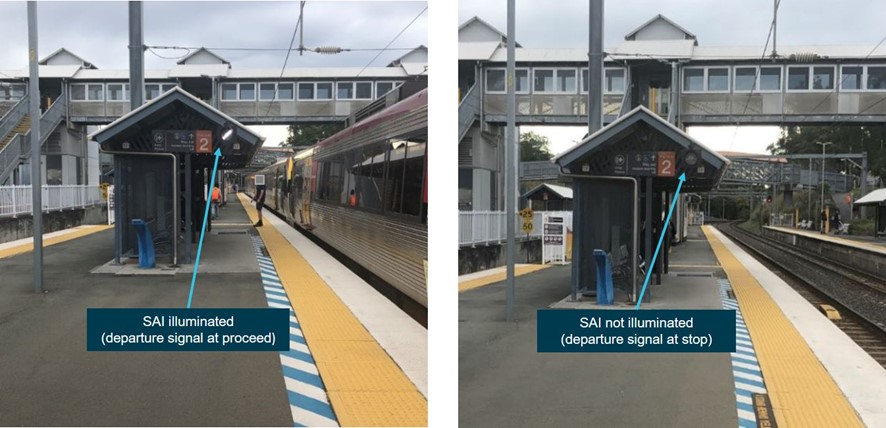
The image on the left shows the SAI illuminated, therefore the departure signal is at proceed. The image on the right shows no indication in the SAI, therefore the departure signal is at stop.
Source: ATSB
Location of SAIs at station platforms
The placement of signals on the QR network were governed by standard MD-10-95 (Signalling positioning principles). This standard stated that:
- signals will be positioned to provide optimum sighting and visibility
- signals will be positioned to provide some measure of commonality of placement
- signals will be positioned to minimise the distraction to the rail traffic crew by objects or structures in the foreground or background of the rail traffic crew’s line of sight to the signal...
The standard also included a detailed list of requirements for the positioning of signals. The standard did not include any specific guidance regarding the positioning of SAIs.
The standard also stated:
The officer who is responsible for the works requiring the review of signal sighting shall convene a signal sighting committee. The signal sighting committee shall consider operational issues relating to optimal location and visibility and assess sighting and visibility risks associated with the placement of the signal and its proposed positioning using the approved Signal Sighting Checklist.
The Signal sighting checklist (MD-12-349) included a detailed list of questions to consider, which expanded on the requirements in the standard. The questions were applicable to signals, with limited applicability to SAIs.
QR procedure MD-12-252 (Signal sighting committee) provided guidance for a committee to ‘ensure that all signals, indicators and safeworking signs and boards were positioned so that they afford Rail Traffic Crew adequate sighting and convey a clear and unambiguous indication’.
It was a requirement for the committee to consider issues arising from the position or sighting of signals, indicators, signs and boards when new or altered infrastructure was being designed, after infrastructure changes had been made, after a SPAD had occurred (if sighting was identified as a potential factor), or following a report of sighting issues. The procedure stated:
The position and structure of all signals, indicators, signs and boards shall be considered by a Signal Sighting Committee … which shall consider and decide the safest and most suitable position and structure of each signal and associated equipment.
The Rail Traffic Crew’s sighting distance and viewing distance on the approach to the signal shall be the prime consideration, but regard shall also be given to the signalling arrangements shown on the signalling plan and the present and proposed permissible speed. Signal Sighting Committee decisions shall conform to MD-10-95 Signalling Positioning Principles as a minimum and shall also consider other issues that impact signal sighting/viewing at the location.
The Signal Sighting Committee shall agree on the position of Guards Signal Aspect Indicators and 6 and 3 Car Stopping marks.
In terms of the location of the stopping marks, the procedure stated that the stopping mark signal sighting committee shall ‘ensure the guard can see the departure signal or the Signal Aspect Indicator’.
The procedure stated that the signal sighting committee were required to use the signal sighting checklist to record its considerations. Following the assessment, the committee was required to complete a signal sighting recommendation form identifying any required mitigating actions or recommendations.
SAIs had been installed at some suburban station platforms for a number of years. In preparation for the introduction of the NGR fleet and the changed location of the guard at the rear of the new trains, additional SAIs were installed at numerous locations within the Citytrain network, mainly due to curved platforms.
During interviews, some guards advised the ATSB that SAIs were not installed in consistent positions on suburban station platforms and that this inconsistency in the placement of SAIs, particularly when working NGR trains, made it more difficult to sight the indicators during station dispatch.
Visits to suburban stations by ATSB investigators also identified inconsistency in the location of SAIs at platforms. They were installed on the side of station buildings, platform shelters or on standalone posts that varied in distance from a guard’s location at the rear of an NGR train. At some locations, SAIs that were not illuminated were hard to sight as the black object (the extinguished lamp plus its mounting board) merged into the background.
Guards reported that the LEDs on an SAI were bright and easy to see. However, some guards also noted that on occasions at some platforms they could be potentially confused with station building lights or reflections, particularly if a guard was not sure of an SAI’s exact location.
Location of the SAI on platform 2 at Park Road
In March 2017, as part of the NGR business operating model, a signal sighting committee convened at Park Road Station and recommended the installation of SAIs on platform 1 and platform 2 (applicable to signal DP29), as well as relocating the SAI on platform 3 and lowering the position of the SAIs on platform 4.
The committee determined that the recommended location of the SAI on platform 2 was consistent with guidelines from MD-10-95. This was recorded in the recommendation form. Subsequently, the recommended location of the SAI was approved.
In August 2017, the SAI was installed on platform 2 at Park Road Station. The SAI was positioned on a passenger shelter under an awning, adjacent to a platform sign. The location was about 57 m away from the guard’s location at the rear of an NGR train.
ATSB investigators visited Park Road Station to observe the SAI indicator on platform 2. They noted that, when the SAI was illuminated, the white light was reasonably distinct from its background. However, when not illuminated (as shown in Figure 8), the SAI was not distinct from its background as the black indicator face had little contrast with the awning on the platform shelter. In addition, depending on exactly where the train stopped, some thin building posts could partially obstruct the sighting of the SAI. It could also be obstructed by passengers on the platform.
Figure 8: Location of the SAI relative to the location of the guard at Park Road platform 2
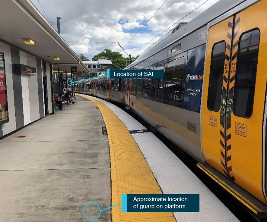
The image shows the location of the SAI at platform 2 Park Road Station. Its location on the platform limited the viewing of the indicator from a guard’s perspective, particularly when the indicator was not illuminated (as in this image).
Source: ATSB
Communication of information about the location of the SAIs at Park Road
In August 2017, Citytrain TSD issued an important operational notice (ION) to train crew to disseminate information relating to the new SAIs (including for DP29) and relocated SAIs at Park Road Station. The notice included a map showing the location of the SAIs at the station. Train crew were not required to verify that they had read and understood the information. Similar notices were sent regarding SAIs at other stations that were introduced or modified as a result of the introduction of the NGR fleet.
The ION regarding the Park Road SAIs was emailed to drivers and guards about 4 months prior to the first NGR train in service.
As noted in Guard qualifications and experience, the guard of DW17 had not operated an NGR train via platform 2 at Park Road Station prior to 25 March 2019 (the day of the SPAD). They also noted that they had had not been provided with any specific route familiarisation training regarding the location of the SAI for DP29 at Park Road Station before operating their first NGR train via that platform. However, the guard stated that they had worked traditional type trains (such as EMU trains) through platform 2 and had noted the position of the SAI during those occasions. However, they had never had to use the SAI before because EMU trains stopped with the guard’s compartment in advance of the SAI.
The guard of DW17 stated that when illuminated, the LED lamps of SAIs were quite bright and distinct. They also said that the SAI at Park Road platform 2 was hard to see. As noted in The occurrence, the guard stated that they checked the SAI and noted that it was illuminated (indicating that DP29 was displaying a proceed indication). The guard also stated that they were not aware of the status of the previous signals immediately prior to arriving at Park Road, and were not expecting to be stopped at Park Road (that is, they would have expected the SAI to have been illuminated).
Departure signal indicators used in New South Wales
The New South Wales (NSW) train network uses guards’ indicators, which are equivalent in function to SAIs. The indicators provide a circular LED light, which illuminates when the applicable departure signal is at proceed and are not illuminated when the signal is at stop.
When the indicators were rolled out across the NSW rail system in the late 1990s, they comprised white LED lights. However, the white LEDs were replaced with blue LEDs as fluorescent station lighting had been installed around the same time, and the blue LEDs provided clearer, easier distinction of the guards’ indicators from the fluorescent lights.
Risk management and change management processes
Overview of risk management processes
QR had a policy (MD-11-1337), standard (MD-11-1338), a general risk management procedure (MD-11-1340) and a safety risk management procedure (MD-11-1339), with the 2 procedures being merged in January 2019. It also had developed tools for risk assessments (for both simple and more complex assessments) and requirements for related processes such as change management, assurance and the communication of safety-relevant information.
The QR standard and procedures outlined a risk management process that was consistent with AS/NZS ISO 31000:2009 Risk management – Principles and guidelines. It included the following processes:
- communication and consultation
- establishing the context
- risk assessment (including risk identification, risk analysis and risk evaluation)
- risk treatment
- monitoring and review.
QR’s risk management standard stated:
Before any significant change, project or event occurs or when a significant external change or event is detected, a suitable risk assessment will be conducted in order to ensure all potential risks can, and will, be managed effectively.
Overview of change management processes
The Office of the National Rail Safety Regular (ONRSR) guidance document Preparation of a rail safety management system (January 2013) provided guidance for management of change processes.[18] It stated:
Different types of change introduce varying degrees of potential risk. The degree of scrutiny required, and the resulting level of detail at each step, should be proportionate to the degree of risk potentially introduced by the change, or the process of implementing the change…
Change within systems frequently has flow on effects to other parts of the system and can have unintended consequences if the effects are not fully identified. The management of change process is expressly intended to ensure that the effects and influences of change are identified and managed…
Accredited operators should have a range of management of change processes that require an increasing level of scrutiny as the potential level of risk associated with the change increases. The safety management system must include procedures for ensuring that changes that may affect the safety of railway operations are identified and managed…
AS 7472:2018 Railway operations – Management of change stated:
For the purpose of rail safety management, change includes anything that has the potential to alter existing risks or introduce new hazards.
As the rail industry implements innovative ideas or new technologies that improve efficiency and safety, it is important the industry demonstrates how it is managing risk with any change including the option of a trial and the transition to permanent application. Change is fundamental to continual improvement. Without change there can be no improvement.
Changes can be made to management, systems, processes, or assets for both new or modified applications. Change should include any change with a potential impact on the organisations safety management system (SMS) or conditions of accreditation…
The Australian standard listed a variety of examples of change, including changes to rolling stock, infrastructure, equipment, work practices, policies or procedures. It also stated:
On becoming aware of a change, the MOC [management of change] methodology detailed in section 3 of this Standard should be followed. The MOC methodology has a number of actions which form a systematic and structured process…
It is important to note all specific actions may not be necessary for simple, low risk changes. RTOs [rail transport operators] shall explore the impact of the change and should scale the MOC process to suit the agreed impact. A change can vary dramatically, from very simple to very complex and the degree of scrutiny required, and the resulting level of detail required at each action should be proportionate to the degree of risk introduced by the change. A change that is assessed as high risk will require more careful planning and risk analysis than a routine change. A simple, low risk change may not require all actions outlined in section 3 to be implemented. The process should stop once the assessment of risks has been undertaken and the change deemed sufficiently low risk to not require further action…
QR’s standard MD-12-219 (Safety change management) set out the organisation’s requirements for managing changes. The scope section stated:
The change management process will provide systems and procedures for ensuring changes that may affect safety are identified and managed, including any risks identified to other internal and external interfaces that may be impacted by the change…
This Standard shall be implemented for change activities undertaken by or on behalf of Queensland Rail with the potential to impact the safety of Queensland Rail’s operations, workers, customers or stakeholders...
Listed examples of changes included changes to physical assets, operating procedures and operating processes. In terms of the change management process, the QR standard stated:
Change management is a complex process that can be undertaken in various ways depending on the type of change, the size of the change and the relevant change theory implemented.
In general, the safety change management process shall:
- identify if the proposed change has any existing safety implications
- identify if the change will introduce any new safety and/or human factors risks…
The QR standard outlined the following activities that needed to be completed as part of a change management process:
- assess the change (in terms of the type and nature of the change and its impacts)
- identify stakeholders
- assess the risks
- consult with relevant parties
- review the safety and environment management system (to determine if any changes to the system’s documentation where required)
- identify how the change process will be reviewed
- determine systems assurance requirements (including whether an assurance plan is required and the systems and procedures for ensuring affected workers are fully informed and trained)
- identify resources available to implement and monitor the change
- obtain document approval
- implement the change in accordance with the change plan.
For complex changes with high risk and medium to high business impact, the standard required a documented safety change management plan. For simple low risk changes with low business impact, the standard required the completion of a safety change management checklist.
For some types of infrastructure changes, QR had additional change management standards or procedures. There were no specific change management procedures within train services delivery (TSD) or station customer service (SCS).
Risk process to evaluate NGR business operating models
As noted in previous sections, the first NGR train entered service in December 2017. For the overall implementation of the NGR fleet, QR developed safety change management plans.
As part of these activities, QR utilised its risk management process to identify the most safety-effective business operating model (BOM) for its rail operations. This involved undertaking a risk assessment during June–July 2016.
The objective of the risk assessment was to document and evaluate the risks associated with 2 proposed NGR BOMs – the ‘roaming guard model’ and the ‘guard at rear model’ – and compare them to the current EMU BOM (guard working from the middle of the train). In addition, the process evaluated the effectiveness of the existing risk controls and proposed treatments and provided an informed recommendation on the preferred NGR BOM.
QR’s risk management procedure stated:
Multidisciplinary teams of people that possess subject matter expertise and technical knowledge of the process or system under assessment will participate in the risk assessment. Individuals with the appropriate level of experience, skill and aptitude will facilitate the risk workshops.
A review of the individuals (and their substantive roles at the time) who participated in the NGR BOM risk assessments identified limited personnel with subject matter expertise in the field of train operations. For example, there were no train operations inspectors, tutor drivers or tutor guards involved in the risk assessment process.
Results of assessment of NGR business operating models
In all, the 2016 risk assessment identified 16 operational safety risks (as well as additional customer-related and workplace health and safety risks) to compare the 3 BOMs. One of the identified operational safety risks was:
RTC [rail traffic crew] leaving platform without proceed authority resulting in [start against signal] SPAD.
The risk assessment team identified 5 potential ‘causes’ that could generate the risk of a start against signal SPAD:
- the guard unable to sight signal / SAI
- the guard not verifying signal aspect
- the driver not following safe driving procedures
- a train crew distraction
- an altered workload.
A series of existing controls were then identified, which included:
- guards following procedures for giving the rightaway signal (as well as giving the emergency stop bell and using the emergency brake if required)
- drivers following procedures (such as stopped on a red procedure and observance of signals procedures)
- train crew maintenance of competency (MOC) processes
- route competency (awareness of signal location).
The risk assessments determined that the risk of a SPAD occurrence when departing from a platform under the roaming guard model was high. In contrast, the existing EMU model and guard at rear model was regarded as medium risk. That is, the guard at rear model presented no additional level of risk than the existing EMU BOM for this specific risk.
A series of proposed treatments was also identified for each of the models and for each of the risks. In addition to the existing controls for a start against signal SPAD, these included:
- review location and upgrade of current SAIs and identification of future SAIs
- traincrew notices and safety bulletins (reflect changes to network)
- revision of MOC processes
- introduction of the European Train Control System (ETCS)[19] or similar system
- workload assessment.
Overall, across all of the identified operational risks, the guard at rear model was evaluated as providing a lower risk level than the roaming guard model, and the guard at rear model was subsequently adopted.
Assessments relating to the allright signal at suburban platforms
Some other identified risks in the 2016 risk assessment were associated with the boarding / alighting of passengers who required assistance. The assessment identified that station staff would need to be actively involved in managing passengers who required assistance for the guard at rear BOM. It was identified that there would be the potential for confusion regarding who was providing assistance (station staff or the guard) and a need for clear delineation of roles, responsibilities and procedures for station staff and guards. The need to develop communication protocols between station staff and guards was also identified as a treatment.
At the time the 2016 risk assessment was completed, the exact nature of the tasks required of station staff and the guard had not been finalised. Nevertheless, it was determined that, under the guard at rear BOM, station staff at suburban platforms would be assisting passengers as, with the guard at the rear of the train, there would be significant delays to on-time running if station staff were not involved in the boarding / alighting process.
Based on the risk assessment documentation, the 2016 NGR risk assessment team did not consider the informal signal checking practices by station staff at Brisbane CBD stations, where the allright signal was not given to the guard unless the departure signal was at proceed. Therefore, the potential risk (or required treatments) associated with the station staff at suburban platforms giving the allright signal while the departure signal was displaying a stop indication were not documented.
As noted in the January 2019 ION, the NGR BOM was modified with the requirement for station staff to provide the allright signal for all NGR trains at suburban stations, significantly increasing the provision of allright signals at station platforms. No risk assessment or safety change management checklist were completed for this change. QR advised that the application of the safety change management standard (MD-12-219) was not considered to be required because the change was minor in nature.
Assessments of signal sighting issues on station platforms
As noted above, one of the proposed risk controls in the 2016 risk assessment was to review the sighting of signals and/or SAIs at station platforms due to possible signal sighting issues with the guard positioned at the rear of the train. As a result, QR conducted a signal sighting review at each station platform within the Brisbane suburban rail network as part of the introduction of the NGR (see Signal aspect indicators).
Processes for communicating safety-relevant information
QR procedure MD-12-826 (TSD communication of notices to rail traffic crew and rail operators) described the methods for communicating operational information to train crew (drivers and guards). The procedure outlined 3 methods of communicating information:
- a critical operational alert (COA), which addressed a hazard / risk that required immediate behavioural change (such as ‘significant changes to the network signalling / signage’)
- an important operational notice (ION), which addressed a hazard risk that required behavioural change though not necessarily immediate change (such as ‘minor network signalling / signage changes’)
- a general operational advice (GOA) for informational purposes (for example, ‘car parking issues’).
After receiving advice of a change or information that could impact TSD, the first step in the process was to undertake (‘when required’) a risk assessment to determine if the operational information to be communicated was critical, important, or general in nature. A subject matter expert was then assigned to draft the notice, which then was reviewed by other personnel and management before being distributed.
If a COA was issued, it was emailed to all train crew and the drivers and guards were required to read and understand the alert, then sign and date it, prior to performing duties relevant to the requirements of the COA. It was also posted to a portal for review by all personnel for 6 months. IONs and GOAs were also distributed by email and posted on the relevant portal, but did not require a process to verify that the drivers and guards had read and understood the contents (although a verification process could be initiated for an ION if required).
As noted in Communication of information about the location of the SAIs at Park Road, an ION regarding the location of SAIs at Park Road Station was distributed to train crew in August 2017. In addition, a January 2019 ION was disseminated to all TSD train crew advising that the allright signal would be administered by station staff for all NGR services. The ATSB requested documentation associated with any risk assessments used to determine this method of communication (that is, the use of an ION). QR advised that risk assessments were not undertaken.
Monitor and review
QR’s risk management standard stated:
Continuous monitoring and review are vital components of an effective risk management process. They may be undertaken as part of a formal periodic process, or performed on an adhoc basis, (e.g. change in policy or change in requirement).
The primary purpose of monitoring and review is to determine whether risks still exist, whether new risks have arisen, whether the likelihood or impact of risks have changed, and to reassess the risk priorities within Queensland Rail’s internal and external context.
Monitoring and review provides important feedback with regard to assurance over the efficiency and effectiveness of controls implemented to treat risks. It enables Queensland Rail to analyse and learn lessons from event successes, failures and near-misses.
QR’s risk management procedures provided additional requirements, including stating that each risk needed to be reviewed at least annually. The January 2019 version of the procedure also stated:
Safety Risks should be reviewed regularly when something occurs that could affect the outcome of the risk, such as:
- The occurrence of an incident or discovery of a hazard
- Change to the way things are done (Change Management)
- Change in legislation or standard that is relevant to the context of the risk
QR’s safety change management standard also noted that:
Monitoring and review arrangements must be introduced immediately following the implementation of the change to ensure all risk controls, including training, have been and remain effective, and the documentation has been updated.
The review of the change shall consider:
- any new risks that may have eventuated, or pre-existing risks that have changed, after implementation
- the effectiveness of pre-existing risk controls and additional risk controls added as part of the change.
The level of assurance required for the change shall be assessed in accordance with the requirements of the Assurance Standard MD-12-24 and Assurance Procedure MD-12-27.
QR’s standard (MD-16-24) and procedure (MD-12-27) provided more detailed requirements regarding the planning and conduct of assurance processes to ensure that risk controls and treatments were operating effectively. The extent of the assurance activities was dependent on the level of risk involved.
During the period following the introduction of NGR services, QR conducted various assurance activities associated with managing SPAD risk. However, none of these activities focussed specifically on NGR operations. In addition, the new process for dispatching NGR services from suburban station platforms, which involved a material change where station staff were providing the allright signal to train guards on NGR services, was not examined during an assurance activity.
Following the 25 March 2019 SPAD, QR’s investigation into the SPAD recommended that a second line[20] assurance activity be undertaken to determine guards’ compliance with rightaway procedures. The assurance activity was undertaken in the first quarter of 2020 and involved conducting 90 observations of SCS staff providing allright signals and guards providing rightaway signals. Results included:
- About half of the observations were conducted at the 3 CBD stations, and most of the observations (53) involved NGR trains.
- The assessment of each guard’s performance was limited to observing whether they exited the cab after arriving at the station and whether they walked beyond the yellow line on the platform before providing the rightaway.
- The proportion of guard observations assessed as being non-compliant was higher for non-NGR trains (13 out of 37) than NGR trains (9 out of 53).
- No problems were noted with the provision of the allright signal by station staff.
Further examination by the ATSB of the figures contained in the assurance report noted that, for non-NGR trains, all of the observed guard non-compliances occurred at CBD stations (13 out of 28 observations), where station staff always provided the allright signal for all trains and checked the status of the departure signal before doing so (Allright signal procedure for the EMU business operating model). For NGR trains, the rate of observed non compliances was similar for CBD stations (3 out of 16) and suburban stations (6 out of 37).
Incident reporting
QR standard MD-12-210 (Incident, accident and hazard reporting, recording and notification) stated:
All Incidents, Accidents and Hazards are to be reported to enable controls to be identified and implemented to prevent any further occurrence. Workers must be instructed to report all Incidents, Accidents and Hazards to their supervisor for action as soon as possible or prior to the end of the shift.
The standard and associated procedures outlined more specifically the types of events or hazards that were required to be reported. SPADs were required to be reported. However, false rightaway events were not required to be reported.
Drivers and guards directly involved in NGR SPAD occurrences stated that they were unaware of any safety campaign encouraging staff to report incidents associated with the introduction of the new NGR BOM, such as false rightaway events.
Various documentation provided to train crew and SCS personnel with the introduction of the NGR were reviewed by the ATSB. None of these communications specifically required or requested that any particular types of events be reported following the introduction of the NGR fleet.
Maintenance of competency processes
Overview of assessment processes
QR as a rail transport operator was required to ensure that rail safety workers such as drivers and guards were competent. To evaluate competency, drivers and guards on the Citytrain network were required to complete a maintenance of competency (MOC) assessment every 18 months. The MOC included a written assessment and a practical on-track assessment.
The MOC process for a driver involved the driver completing a written assessment (over 1 day) then a practical assessment (over 1 day) with a nominated assessor. The MOC process was undertaken one-on-one; the driver undertook the assessment while the assessor (tutor driver or train operations inspector) administered the activities. The written assessment typically involved nearly 300 questions.
The participant had to achieve 100% on the written assessment before advancing to the on-track practical component. If the driver was unsuccessful in more than 10% of the questions, they would be entitled to one retest (of the whole written assessment), which had to be completed on another day. If they were unsuccessful in some questions (but less than 10%), the participant was required to research the correct answers and then make corrections.
The MOC assessments for a guard followed the same basic process.
In 2018, QR used the MOC process for existing drivers to upgrade their train driving qualifications from Certificate III in train driving to Certificate IV. In all, 252 Citytrain drivers gained the higher level certificate as a result of the successful completion of their written and practical MOC assessments.
Assessors who administered training and assessment for QR had to have vocational competencies at least to the level being delivered and assessed and hold current industry skills relevant to the training and assessment being provided. In accordance with QR’s Registered training organisation specification (MD-13-591), only accredited assessors were permitted to conduct assessments. Assessors were to ensure they followed the principles of assessment and the rules of evidence when conducting assessments.
Previous ATSB investigation
During a recent investigation into a SPAD at Bowen Hills, the ATSB investigated QR’s MOC process for Citytrain drivers in detail.[21] The investigation identified that, in many cases, drivers achieved perfect or near perfect results in their written MOC assessments. However, it was also identified that in numerous cases answers requiring a detailed response in the written MOC assessment matched word-for-word the answers from the assessor’s marking guide.
Based on this and a range of additional evidence, the ATSB concluded that the following 2 safety issues existed:
- Queensland Rail’s administration of the maintenance of competency (MOC) assessment process provided limited assurance that its Citytrain train drivers met relevant competency requirements. (Safety issue RO-2018-002-SI-01)
- Queensland Rail’s management oversight of the Citytrain driver maintenance of competency (MOC) process did not include planned assurance activities or regular and effective auditing of how the MOC assessments were being conducted, even after there were multiple indications that the process was not being conducted as designed. (Safety issue RO-2018-002-SI-02)
Similar problems were noted in the ATSB report regarding the MOC assessments for guards.
DW17 driver’s maintenance of competency assessments
The driver of DW17’s last 2 MOC assessments were conducted in January 2016 and November 2018. The driver’s MOC assessment in January 2016 recorded 100% on the written component (on their first attempt) and a perfect result on the practical on-track assessment. The written assessment required the driver to respond to 273 questions that varied in complexity from marking the correct answer from a list to writing lengthy responses to technical questions.
The driver’s MOC assessment in November 2018, administered by a different tutor driver, showed similar results to that of their 2016 assessment. On the first attempt of the written assessment, the driver achieved 98.7% (100% after corrections), and the practical on-track assessment resulted in a perfect performance. By successfully completing the MOC assessment in 2018, the driver gained a Certificate IV in Train Driving.
The ATSB compared responses from the driver’s written MOC assessments against answers to questions in the assessor’s MOC marking guides. The results showed that the driver’s written responses in each MOC, for questions requiring a detailed response, were mostly identical or near identical to those in the assessor’s marking guide. In one of the written MOC assessments, an obviously incorrect answer in the marking guide was mirrored in the driver’s response.
The irregularities identified with the driver’s MOC assessments were similar to the findings identified in the ATSB’s previous investigation for other drivers, and indicated that the driver either had access to the assessor’s marking guide or had other assistance during the completion of the MOC assessments.
Following the SPAD occurrence at DP29 in March 2019, the driver participated in a post-incident on-track evaluation,[22] and a subsequent non-technical skill[23] (NTS) assessment. These occurred on 8 May 2019. The on-track evaluation found the driver ‘not yet competent’, while the NTS assessment identified deficiencies and recommended areas for improvement in the driver’s use of RTCD and observance of signals, particularly when departing from station platforms. The outcome of the driver’s evaluation and NTS assessment resulted in an operational improvement plan (OIP) that involved coaching and mentoring sessions administered by train operations inspectors (TOIs).[24]
Records provided by QR showed the driver participated in 17 coaching and mentoring sessions. On 14 occasions, the driver was assessed as ‘not yet competent’. On 28 June 2019, an on-track assessment successfully recorded the driver as competent. In addition, the NTS assessment, based on information collated from the coaching and mentoring session, also considered the driver competent. On 1 July 2019, the driver returned to normal duties.
DW17 guard’s maintenance of competency assessments
QR records showed that the guard of DW17 participated in a MOC process on 11 and 15 October 2018. Prior to the commencement of the written MOC component, the guard had a discussion with an assessor (not the assessor undertaking the MOC assessment) regarding possible language and literacy issues, which could affect their ability to complete the assessment successfully. This assessor recorded:
[the guard] … advised me [their] spelling was not accurate and reading capabilities is of a slow pace with not able to understand the questions correctly nor can [they] pronounce certain words and misunderstands the questions and [they] felt under pressure and stressed…
This information was conveyed to the MOC assessor and relevant training staff, and there was agreement to grant the guard an additional day to complete the written assessment as reasonable adjustment. The guard successfully completed the 207-question written assessment with a result of 96% on their first attempt (100% after corrections).
The assessor who the guard confided in prior to the MOC assessment submitted a ‘Language, literacy and numeracy (LLN) identification checklist’ (MD-14-829) recording the guard’s LLN issues. In addition, the assessor corresponded with the QR training and development section to advise them of the issue. The assessor considered that the guard:
- was unable to successfully complete the training and assessment required for their job
- was unable to read and understand work instruction procedures, or other relevant documentation
- had difficulty reading and/or interpreting diagrams, graphs, plans, flowcharts and similar documents.
On 15 October 2018, while participating in the on-track MOC component, the guard was assessed as ‘not yet competent’ due to a procedural error. A complete retest was scheduled for a later date.
Since the introduction of the MOC process in 2008, there was no previous evidence of recorded disclosure from the guard or assessors relating to the guard having LLN issues. However, records of assessments during that period indicated that the guard had successfully completed the MOC process without special needs assistance. On 24 October 2018, the guard resat the written MOC assessment and achieved 99% on their first attempt, and 100% after corrections. The written assessment showed no evidence that the guard was provided assistance in completing the assessment as a result of having LLN issues. Further review of the assessment identified very few spelling mistakes and there was no additional time required to complete the assessment.
Following the SPAD occurrence at DP29 in March 2019, the guard chose (supported by QR management) to relinquish the position of guard and subsequently took up another position within QR.
Fatigue management
Introduction
During the investigation, the ATSB noted that in the 8 days leading up to the occurrence, the driver had conducted seven shifts that commenced between 0300 and 0537 (see Driver medical information and recent work history). In addition, the ATSB noted that the guard was assigned an early shift on the day of the occurrence, commencing at 0412, with limited advance notice (see Guard medical information and recent work history). Accordingly, the ATSB examined QR’s processes for managing fatigue risk related to these aspects.
Rostering principles and guidelines
QR standard MD-10-178 (Fatigue risk management) prescribed hours-of-work principles for a master (long-term forecast) roster and day-of-operations (actual) roster for different types of rail safety workers. For suburban rail traffic crew, these principles included:
- maximum shift length of 9 hours
- minimum break between shifts of 12 hours
- maximum number of 12 shifts in any 14-day period.
With regard to roster design, the standard also stated:
For a robust hierarchical risk based approach the following should be considered and applied in this order unless not reasonably practicable.
1) Apply the good roster practice guidelines in Appendix 2 to roster development;
2) Where the good roster practice guidelines are not reasonably practicable in the business context, apply a risk based approach determined as SFAIRP [so far as is reasonably practicable] in the specific context that manages risk to a higher level than minimum requirements of this Standard;
3) Apply minimum requirements of this Standard, including checks against FAID [see below], hours of work principles and Enterprise Agreements.
The good roster practice guidelines included (but were not limited to):
- shifts with sign-on-times before 0500 limited to no more than 8 hours
- maximum of 4 consecutive night shifts in a row (defined as starting between 1800–0359)
- maximum of 5 consecutive early shifts (defined as starting between 0400–0600)
- minimum rest period between night shifts of 14 hours
- 2 days rest between a night shift and starting an early shift (that is, minimum 54 hours rest)
- 1 day rest between an early shift and starting a night shift
- avoiding significant adjustments in required sleep (such as transitioning from an early start to a night shift).
In the case of the driver and guard of DW17, their master and day-of-operations rosters for the period leading up to the occurrence complied with the mandatory hours-of-work principles.
With regard to the good roster practice guidelines, the driver had 6 consecutive shifts between 17–23 March that commenced between 0300 and 0537; 4 were classified as early shifts and 2 were classified as night shifts. These shifts did not meet the guidelines associated with rest breaks when transitioning between early shifts and night shifts. If these shifts were all considered to be early shifts, they would not have met the guideline regarding a maximum of 5 early shifts in a row.
In addition, both the driver and the guard conducted shifts of over 8 hours starting before 0500 on multiple occasions in the 14 days prior to the occurrence, including on the day of the occurrence (the driver on 3 shifts and the guard on 4 shifts).
Use of biomathematical models of fatigue
A biomathematical model of fatigue (BMMF) uses algorithms to predict the effect of different patterns of work on measures such as subjective fatigue, sleep or the effectiveness of performing work. Each model uses different types of inputs and produces different types of outputs, and each model is based on many assumptions and has limitations.
In particular, the models are based on group-averaged data, and it is widely agreed that the models are not well suited for predicting a specific individual’s level of fatigue. In addition, none of the models consider all of the factors that can influence fatigue. The models are designed to be only one element of a system for evaluating and comparing work rosters (see Civil Aviation Safety Authority 2014, Dawson and others 2011, Gander and others 2011, Independent Transport Safety Regulator 2010).
QR used the BMMF known as ‘FAID’[25] to conduct assessments of rosters. FAID has been widely used in the Australian rail and aviation industries since the early 2000s. It uses hours of work (start time and end time) as its inputs, and it produces a score based on an algorithm that considers the effects of the length of the duty periods, time of day of the duty periods, and the amount of work over the previous 7 days (Roach and others 2004). The higher the FAID score, the higher the potential for fatigue.
QR’s fatigue risk management standard stated:
All master and day of operations rosters for Queensland Rail workers performing shift work (including volunteers), must be analysed using … FAID … to ascertain if the rosters provide adequate sleep opportunity. This includes shift changes, shift swaps, extended and unplanned shifts.
The QR standard stated that FAID scores between 0-79 (green zone) were considered broadly acceptable and ‘all reasonable steps should be taken to ensure all rosters fall within this range’. Scores greater than 100 (red zone) were considered to provide an unacceptable sleep opportunity. Scores between 80–100 (yellow zone) were considered ‘acceptable with demonstrable risk assessment’. This meant that:
A documented risk assessment, undertaken in accordance with the Risk Management Framework, must be completed and approved as per the risk management matrix before workers can operate in this zone.
QR advised the ATSB that this did not mean that a specific risk assessment had to be conducted prior to any specific worker being assigned a shift with a FAID score of 80–100. Rather, for train crew, train services delivery (TSD) had conducted a risk assessment covering all fatigue-related hazards.
In terms of the risk of ‘worker fatigue’, one of the listed causes in the risk assessment was rosters with a FAID score in the yellow zone or outside of the hours of work principles. A number of controls and treatments were listed. These were mostly general in nature, such as MD-10-178 being implemented as the higher safety control, managers and rostering personnel completing fatigue management training, and conducting regular assurance activities on a sample of rosters. There was no requirement for any specific worker with a FAID score in the yellow zone to undergo an assessment prior to commencing work unless the worker had self-identified that they were fatigued or they had been observed to be experiencing signs of fatigue (see also next section).
For the 7 days leading up the occurrence, the guard’s FAID scores were below 80 and on the day of the occurrence the peak score was 40. For the driver, the peak FAID score on the day of the occurrence was 65. However, on both the 22 and 23 March, the driver’s peak scores were above 80 (and for 23 March the score was above 80 for about half of the duty period).
Self assessments of fatigue
QR’s procedures and code of conduct stated that fatigue risk management was a shared responsibility between the operator and rail traffic crew. The fatigue risk management standard stated that rail traffic crew were responsible for taking reasonable steps to ensure they did not present to work fatigued and that they managed non-work factors that could contribute to fatigue.
QR’s standard also required that workers ‘report instances of fatigue to their leader so additional controls can be implemented to manage the risk’. Such reports were required to use QR’s fatigue assessment form.
A critical operational alert issued to train crew in October 2017 advised train crew about a new version of the self-assessment form for train crew. It also stated that train crew were required to:
Using the new self-assessment form, assess whether you are fit to go prior to every shift as is current practice. If you are not fit to go for your entire shift and duties, contact the roster office to discuss your fatigue assessment result. If alternative duties are located and agreed to, or you are booked off, you are required to submit the completed fatigue self-assessment form as per the form instructions on your next shift.
The form included questions regarding the amount of sleep in the previous 24 hours and 48 hours, and the worker’s self-assessment of their level of alertness. If any of these parameters exceeded predetermined thresholds, then either personal risk mitigation strategies were required (if one of the scores was in the yellow zone), the result needed to be discussed with a supervisor, roster officer or train operations inspector and additional controls be specified (if one of the scores was in the red zone) or the worker was deemed not fit for duty (if one of the scores was in the black zone).
In terms of sleep in the previous 24 hours, the form stated that 5 hours or more sleep was in the green risk band, 4 hours was in the yellow band, 3 hours was in the red band and 2 hours was in the black band. In terms of sleep in the previous 48 hours, the form stated values of 12 or more hours, 11 hours, 10 hours and 9 or less hours for the 4 bands respectively.
There was no specific requirement for the driver or guard of DW17 to complete and submit a risk assessment form in the period leading up to the occurrence, and there was no evidence to indicate any forms were completed.
Fatigue management training
Citytrain train crew were required to undertake fatigue awareness training on a regular basis. The contents of the training provided an overview of sources and effects of fatigue, QR’s processes for managing fatigue and some individual fatigue alertness strategies.
In terms of hours of sleep, the course materials noted that less than 6 hours sleep was high risk and 6–8 hours’ sleep was moderate risk. This information was not fully consistent with the latest version of the fatigue assessment form (see previous section).
The course material also provided some information regarding FAID and how it was used by QR. The material noted that all master roster scores had to be below 80 (that is, in the green zone) whereas day-of-operations roster scores could be in the yellow zone.
Late-notice changes to a roster
According to the QR’s fatigue risk management standard, deviations from the mandatory hours-of-work principles could only occur for a day-of-operations roster or for an ‘emergency or unplanned event’. Similarly, rosters with FAID scores of 100 or more could only occur for an emergency or unplanned event. In such events, a fatigue assessment form for the worker was required to be completed and all reasonable steps taken to relieve the worker as soon as possible.
The guard was called at 2208 on the 24 March and asked if they were able to commence their shift on 25 March at 0412 (rather than the previously assigned time of 0900). QR rostering personnel stated that this was not considered an emergency or unplanned event; rather it was a shift vacancy caused by illness to another rail traffic crewmember.
QR rostering personnel noted that they managed the rosters of 2,800 employees (including train crew) and that the need to replace a rostered person at short notice was not unusual. In such cases, their systems would indicate which personnel were available to take the required shift (in terms of personnel who met the hours of work principles) and then they would ensure the selected personnel had a suitable FAID score (that is, 100 or less). If the selected personnel met the requirements, they would be offered the shift change or additional shift. It was not compulsory for the personnel to accept the change, and it was up to the personnel to assess their fitness to undertake the changed duty.
The ATSB requested information relating to any other risk controls used by QR to manage the fatigue risks associated with late-notice roster changes for rail traffic crew. There were no additional procedures for managing such changes. There was no requirement for a worker to complete a fatigue assessment form, unless they perceived themselves to be fatigued, and there was no requirement for rostering personnel to ask the worker about their level of alertness or hours of sleep when arranging a change.
__________
- Assessed as competent over the route and current to drive the route.
- Roma Street is the rail km starting point (0.000).
- The driver’s seat was positioned in its mid-range when evaluating the sighting of the signal in relation to the position of the blind. This recreation did not simulate the driver’s eye height or actual seating position, which were unknown. However, even with the blind almost fully lowered, the signal was able to be sighted from a normal seating position.
- ATSB RO-2018-002, Signal ME45 passed at danger involving suburban passenger train TP43 and near collision with another suburban passenger train, Bowen Hills, Queensland, on 10 January 2018. Available from www.atsb.gov.au.
- The driver’s safety control (DSC), formerly known as the deadman device, is a system that aims to confirm the presence of the driver at the controls. It requires the driver constantly hold, either by foot pedal or a hand lever, to inhibit the actuation of the device. If the driver becomes incapacitated, losing control of the foot pedal or hand lever, the train will lose brake pipe air and come to a stop. The driver can override the DSC, only while the train is stationary, by placing the brake controller in full service.
- A separate ION issued to guards at the same time also stated that station staff were required to provide the allright signal if they attended an NGR service.
- A red signal approached was recorded when the signal was displaying a red aspect when the train passed the previous signal. In some cases, the signal would have changed prior to the train reaching the signal. Therefore, it is likely that the number of red signals approached per SPAD was lower than the figures indicated.
- Controlled signals: a signal that is, or may be, controlled or operated by a network control officer. They normally display a red aspect.
- Fisher exact test, p < .01.
- Fisher exact test, p < .05.
- The white line was oriented at 45° upwards, left to right. It had a small discontinuity (break in the white line) at the lower left corner. The display was similar to that of a semaphore signal, which indicated proceed with an arm (long board) oriented at 45°. A semaphore signal also indicated stop when the arm was oriented horizontally.
- ONRSR published an updated guidance document, Guideline: Safety management system in April 2019. Other more recent guidance information is also available on ONRSR’s website.
- ETCS provides automated train protection and communications-based signalling and is being introduced into the Citytrain network (see ATSB investigation RO-2018-002 for further details).
- Second line assurance activity: A set of linked assurance processes where the manager responsible for assurance does not have direct control over the processes and activities being assessed.
- ATSB RO-2018-002, Signal ME45 passed at danger involving suburban passenger train TP43 and near collision with another suburban passenger train, Bowen Hills, Queensland, on 10 January 2018. Available from www.atsb.gov.au
- The purpose of the post incident on-track evaluation is to assess the driver performance and make recommendations towards an operational improvement plan.
- Non-technical skills assessment is based on information collated from the SPAD debrief session and post incident on-track evaluation to determine if a psychometric assessment is required as well as guiding development opportunities for the driver’s operational improvement plan.
- Train operations inspector: a senior train crewmember with operational knowledge, one position level above a tutor driver.
- FAID was initially known as ‘Fatigue Audit InterDyne’. It was subsequently renamed the Fatigue Analysis Tool by InterDynamics.
Safety analysis
Introduction
On 25 March 2019, a Queensland Rail (QR) Citytrain suburban passenger train (DW17) exceeded its limit of authority by passing signal DP29 at Park Road Station while the signal displayed a red aspect (stop indication). This resulted in a near collision with another QR suburban passenger train (1E65), which had been scheduled to run in advance of DW17 from Park Road Station.
There were no problems associated with the serviceability of the train, and the signalling system functioned as designed. The immediate reason for the signal passed at danger (SPAD) was that the driver did not effectively confirm the signal’s status prior to departing Park Road Station.
Such a ‘start against signal’ SPAD could have had very serious consequences as there were limited risk controls or defences in place on the QR Citytrain rail network to recover from the situation. In this case, the actions of a tutor driver in the driving cab of train 1E65 and a network control officer (NCO) likely prevented a train-to-train collision. Although a collision between 2 trains merging at a set of points would be less serious than some other collision scenarios, it would still have probably led to significant adverse consequences.
The safety analysis will initially discuss the actions of the driver and guard of DW17 and the context of those actions. It will also discuss the process associated with the placement of signal aspect indicators (SAIs) on station platforms with the introduction of the new generation rollingstock (NGR) business operating mode (BOM). In addition, it will consider QR’s risk management and change management processes relevant to the implementation of the NGR BOM and the risk of start against signal SPADs. The analysis will also discuss train crew maintenance of competency (MOC) processes and fatigue management in relation to late-notice roster changes.
Train crew performance
Checking the departure signal
Train driving is a specialised task that is acquired through comprehensive training and significant experience; it involves conducting routine, frequently-practiced tasks in a largely automatic manner (at a skill-based level) with occasional conscious checks on performance. Accordingly, most of the driver errors associated with SPADs occur at the skill-based level of performance (Gibson 2016), and such errors are generally known as slips or lapses (Reason 1990).
A common factor involved in most start against signal SPADs is expectancy. Expectations based on past experience strongly influence where a person will search for information and what they will search for (Wickens and McCarley 2008), and they also influence the perception of information (Wickens and others 2013). In simple terms, people are more likely to see what they expect to see, and less likely to see what they do not expect to see.
Prior to departing a station platform, a driver is required to check the status of the departure signal after receiving the rightaway signal (2 bells) from the guard. Citytrain train drivers receive more than 100 rightaways a day, and in almost all cases the rightaway is provided when the departure signal is displaying a proceed indication. Accordingly, drivers develop a very strong association between the sound of the rightaway signal and the presence of a proceed indication, and they therefore develop a very high level of expectancy that 2 bells (rightaway) is associated with departing from the platform.
As noted with a number of start against signal SPADs involving Citytrain drivers, this leads to some situations where drivers, performing their tasks at a skill-based level, receive a rightaway and either do not check the departure signal or check the signal but falsely perceive the signal to be displaying a proceed indication. This automatic or habitual tendency is well known in rail operations (for example, Multer and others 2019, Basacik and others 2008) and has also been demonstrated in experimental research (Haga 1984).
In this case, the driver of DW17 promptly departed the station platform after receiving the rightaway from the guard. The driver subsequently reported that they could not recall checking or sighting the status of signal DP29 prior to departing the station, and they were prompted to depart after receiving the rightaway.
The driver also stated they were expecting the departure signal to be red when they approached the station and their driving on approach to the station was consistent with this expectation. However, there was a longer than normal dwell time at the station, and such situations can disengage or dislocate a driver’s attention (Naweed 2013). It is also likely that, as DW17 was running on time, the driver had a low level of expectancy that the train would be delayed at Park Road to accommodate the passage of another train. They had received no advice from the NCO that they would be held at the station for an extended period (nor were they required to be advised).
Although the driver explained the SPAD as being a product of the signal being blocked by the train cab blinds, the ATSB determined this was not plausible. Furthermore, the implication of the driver’s account is that they consciously departed Park Road Station without checking the signal aspect. Sighting and confirming the aspect of a departure signal is a critical activity for safe train driving, and it is highly unlikely that an experienced train driver would intentionally depart a train station if they were consciously looking for but not able to confirm the signal aspect.
The red aspect in the signal had optimum viewing from within the driving cab of the train when it stopped at the platform, and there were no indications that the driver read through to another signal. In addition, there were no indications of distractions either inside or outside the driving cab at the time.
In summary, after receiving the rightaway signal, the driver promptly departed the station platform without effectively checking and confirming the aspect indication in the departure signal (DP29). Based on the available evidence, it is more likely that they did not check the signal rather than they misperceived the aspect indication. In either case, the driver was conducting their tasks at a skill-based (or automatic) level of performance and had a very high level of expectancy that the signal was indicating a proceed aspect, particularly after receiving the rightaway from the guard.
Application of the ‘stopped at a red’ procedure
A driver checking the status of the departure signal is the last risk control in place to prevent a start against signal SPAD. QR had in place other procedural risk controls that provided protection against the unauthorised departure of a train from a station platform. One key risk control involved drivers applying the ‘stopped at a red’ procedure. This required a driver to use operational interlocks (park brake and direction control settings) after stopping at a red signal to reduce the likelihood of an automatic or reflexive driver response to a false rightaway.
Such operational interlocks are used by many experienced drivers in different operators (Naweed and others 2015), and QR had formalised them into a standard procedure for its drivers. Based on QR data, the procedure had a relatively high compliance rate (92%). The procedure also appears to be effective in reducing the likelihood, but not eliminating, start against signal SPADs, as the compliance rate during such events was much lower. However, it is unclear how many drivers applied the start on a red procedure, received a false rightaway from a guard and then detected the red signal prior to departing a platform.
In this case, the driver of DW17 did not fully apply the start on a red procedure. Even though the driver was probably aware that the departure signal was displaying a red aspect during their arrival at the station, it is possible that their awareness of the status of the signal decreased soon after stopping at the platform. The driver said that their habit was to only sometimes use the stopped at a red procedure, depending on whether they felt confident in their ability to drive safely at the time. Inconsistent use of such procedures would degrade their effectiveness, and it is noted that the driver had also previously experienced a start against signal SPAD 10 years previously.
In summary, after DW17 stopped at Park Road Station, with the departure signal displaying a red aspect, the driver did not apply the operator's stopped at a red procedure. This probably contributed to them not detecting that the departure signal was displaying a red aspect after receiving the false rightaway from the guard.
Providing the rightaway signal
Another key risk control to minimise the risk of a start against signal SPAD was for guards to check the status of a platform departure signal, via direct observation of the signal (or as in this case the SAI), before providing the rightaway to the driver. The guard was required to check the departure signal or SAI twice; both before and after checking that all passengers had boarded / alighted (or where required after station staff had provided the allright signal).
Commencing in January 2019, station staff were required to provide the allright signal to the guard for every NGR service (regardless of whether they had to assist a passenger). In line with QR’s platform dispatch procedures, there was no requirement for station staff to check the departure signal prior to issuing the allright signal, and staff at suburban stations were also instructed not to check the departure signal.
In the case of DW17, the guard issued the rightaway to the driver after receiving the allright signal, even though the SAI was not illuminated. The guard stated that they had looked for the SAI after they received the allright signal and they thought that it was illuminated (indicating signal DP29 was at proceed).
The ATSB notes that the guard had significant time prior to receiving the allright signal to sight the SAI. However, after receiving the allright signal they immediately gave the rightaway signal to the driver, which could suggest the allright signal was the guard’s prompt to give rightaway. In addition, the guard did not step onto the platform to perform their tasks. Although the SAI could be sighted from the rear of the train, by not stepping out onto the platform the guard was less likely to be actively engaged in performing their tasks. The extent to which the guard was aware of the location of the SAI to use it effectively was also unclear (see Placement of signal aspect indicators).
Previous research in the UK has identified that guards have reported that they would be less likely to check a departure signal if station staff were involved in the departure process (Basacik and others 2008). In the course of the current investigation, the ATSB identified 5 similar SPAD events involving NGR trains where the guard had issued a false rightaway after receiving the allright signal from station staff. In some of these cases, the guards could not recall checking the SAI whereas in other cases they recalled checking the SAI and perceived it to be illuminated.
Regardless of whether they checked the SAI, it is likely that expectancy had a strong influence on most (if not all) of these guards’ responses. As with drivers, guards are conducting frequently-practised tasks at a skill-based level of performance, and through experience they have developed a very high level of expectancy that, if they are given the allright signal, then a departure signal will be displaying a proceed indication.
This expectancy has developed because:
- Before the introduction of the NGR to the Citytrain network, there was no requirement for station staff at suburban station platforms to provide the allright signal to train guards, other than at the 3 Brisbane CBD stations and 2 designated suburban stations (Gympie North and Nambour). At these stations, guards would always receive the allright signal from station staff, but they only receive it when the platform departure signal displayed a proceed indication. This was due to station staff executing the informal (and undocumented) practice of checking the departure signal was at proceed before providing the allright signal.
- With the introduction of NGR trains in late 2017, station staff at suburban platforms were only required to provide the allright signal if they assisted passengers. This occurred occasionally but not frequently.
- Given the lower levels of intersecting traffic and lower signal density outside of the Brisbane CBD, the likelihood of a red aspect in a departure signal at a suburban station platform was comparatively low.
The change to dispatch procedures in January 2019, which required station staff at suburban stations to issue the allright signal for all NGR trains, significantly increased the number of allright signals guards received each day. Because station staff at suburban platforms did not check the status of the departure signal before issuing an allright signal, this also increased the likelihood that guards would receive an allright signal while the departure signal was displaying a stop indication. As indicated by the SPAD statistics and anecdotal reports, this significantly increased the frequency of false rightaways that led to start against signal SPADs.
Overall, it is unclear whether the guard of DW17 checked the SAI after receiving the allright signal before providing rightaway to the driver. Regardless of whether they checked the SAI or not, the guard probably had a very high level of expectancy that the departure signal was at proceed after being issued the allright signal, as this is what they had previously experienced at Brisbane CBD station platforms. In addition, the guard had no knowledge of the restricted signal sequence encountered by the driver as the train approached and stopped at Park Road. Therefore, they had a low level of expectancy that the train would be delayed at Park Road to accommodate the passage of another train as DW17 was running on time.
Summary
The development of this occurrence required multiple errors by the driver and the guard. Effective safety systems utilise redundant controls to minimise the consequence of individual errors. In the case of start against signal SPADs, the procedural risk controls had redundancy, relying on both the driver and the guard to check the departure signal. In addition, there was a requirement for the driver to use the stopped at a red procedure as another risk control to capture the error of automatically responding to a false rightaway and departing from the platform.
Nevertheless, this start against signal SPAD (and the other 5 NGR start against signal SPADs) have reinforced the point that procedural (or administrative) risk controls will always be fundamentally limited in their effectiveness compared to well-designed engineering controls for detecting potential or actual SPADs and managing their risk (see also ATSB report RO-2018-002 for further discussion of this topic).
Placement of signal aspect indicators
A signal aspect indicator (SAI) plays an essential role in the platform dispatch process. If the guard cannot sight the departure signal, due to the curvature of the track or obstructions, they need some other indication on the status of the departure signal prior to providing the rightaway signal to the driver. Although SAIs were installed at some station platforms prior to the introduction of the NGR fleet, the guards’ location at the rear on NGR trains meant that SAIs were required to be installed or moved at a considerable number of platforms in the Brisbane suburban network.
A number of factors can influence how people search for information such as a signal, including knowledge of the signal’s location and the salience of the signal. In simple terms, if people know the exact location where a signal will be provided, then their performance will be better than if they do not know (Wickens and others 2013).
SAIs on platforms in the Citytrain network were not located in consistent positions; they varied in terms of what they were affixed to, and also their distance from the rear of an NGR train. In addition, QR procedures relevant to signal positioning and sighting principles provided limited guidance on the placement of SAIs, other than to state they should be positioned to provide adequate sighting and convey a clear indication. In contrast, the QR procedures and signal sighting checklist provided detailed guidance regarding the placement of signals.
It is understandable that the placement of SAIs involves considering a range of factors and will at times require compromises to be made. Nevertheless, limited consistency in the placement of SAIs presented difficulties to the guards who had to use them. This situation could be mitigated to some extent if guards knew the exact location of each SAI and were experienced with using them. However, when a considerable number of SAIs were installed or moved in a short period for the NGR fleet, it was probably not practical to give each guard detailed familiarisation training. Although guards were advised by notices about changes to the location of SAIs, they still needed to develop experience with using the SAIs to be able to effectively conduct their tasks.
In terms of salience, warnings and signals are typically designed to present their most conspicuous state when the system is in its most hazardous state, or at least the most hazardous state is presented in a clear and salient manner. As noted by Wickens and others (2013), the absence of something is harder for people to notice than the presence of something.
In the process of dispatching trains at station platforms, an SAI displays a bright light when the departure signal is at proceed (less hazardous state) and nothing when the departure signal displays a stop indication (most hazardous state). In addition, an SAI that is not illuminated often has a low level of contrast relative to its background and can be hard to detect, particularly if a person does not know exactly where it is located. In such situations, it is possible that a guard, with a high level of expectancy that a departure signal is at proceed, may mistake some other form of light or reflection in their visual field to be an illuminated SAI.
SAIs and similar indicators have been in place in the rail system for a long time, and originally their design was consistent with a fail-safe principle, because if the light failed then it would default to a safe (stop) indication. Redesigning such displays would present its own challenges due to the significant changeover and retraining cost. Nevertheless, positioning them close to the guard who is using them, or modifying their design or the design of their surrounding area to better show their location when not illuminated, would increase their salience and improve performance.
The SAI for DP29 was located 57 m from the location of the guard when working an NGR train. The SAI could be seen from the rear of an NGR train and also from the platform, however there were some obstacles (building infrastructure) on the platform that possibly could partially obstruct its sighting. Whether the SAI could be sighted from the train or the platform, its position was not consistent with optimal viewing for a guard.
The extent to which the guard of DW17 was aware of the exact location of the SAI for signal DP29 is unclear. The guard had received an important operations notice (ION) by email in August 2017 prior to the SPAD, but it is unlikely that they would have recalled this information 19 months later. The guard also stated they had never worked an NGR train through platform 2 at Park Road until the day of the SPAD. Although the guard stated they had previously seen the SAI when working other types of trains through that platform, the extent to which the guard could have promptly and reliably identified its location when it was not illuminated from the rear of an NGR train was difficult to determine.
In summary, QR’s process for the installation of SAIs did not provide sufficient detail to ensure consistent and conspicuous placement of SAIs at station platforms. This problem, combined with an SAI’s non-salient indication when the platform departure signal displayed a stop indication, increased the risk that an SAI would not be correctly perceived by a train guard. The extent to which this problem contributed to the SPAD on 25 March 2019 could not be reliably determined as it is unclear to what extent the guard actually checked the SAI (see Providing the rightaway signal).
Risk management associated with changing the allright signal process
As previously noted, the start of NGR operations in December 2017 resulted in station staff at suburban platforms providing the allright signal more frequently to train guards (that is, when they had assisted a passenger on or off an NGR service). The provision of the allright signal at suburban platforms then significantly increased in January 2019 when the dispatch procedures were changed to require the allright signal to be provided for each NGR service.
The provision of the allright signal played an important role in standardising communications between station staff and train guards of NGR services. However, the increased use of the allright signal at suburban platforms created an unintended hazard due to the way the allright signal was previously provided for all trains at the 3 CBD stations and 2 other designated stations.
More specifically, due to the undocumented practice of station staff providing allright signals at the designated stations only if the departure signal was displaying a proceed indication, guards had a very high level of expectancy that if they received an allright signal the departure signal would be displaying a proceed indication.
Based on the available information, QR did not effectively identify and assess the risk associated with this hazard during the introduction of the NGR, or when it changed the allright signal process in January 2019. Undoubtedly, identifying and assessing risks associated with a change is easier in hindsight during a safety investigation than when the change is occurring. Nevertheless, there were several limitations with processes during the introduction of the NGR BOM and the change to dispatch procedures in January 2019 that reduced QR’s ability to identify and assess the risk. These included:
- Although QR conducted a detailed risk assessment to compare 2 NGR BOMs in mid-2016, the team participating in this assessment did not include personnel with subject matter expertise in train operations (such as train operations inspectors, tutor drivers or tutor guards). This limited expertise would have reduced the team’s appreciation of how allright signals were provided at CBD stations and other designated locations, and reduced the potential for them to identify the use of the allright signal at suburban station platforms as a start against signal risk. Accordingly, there were no treatments recorded to specifically manage this risk.
- No formal risk assessment or change management process was conducted when the dispatch process at suburban platforms for NGR services was modified in January 2019. QR advised that this was because the change was considered minor in nature. It is understandable that personnel may have perceived that the change was actually helping to improve the clarity of communications between station staff and guards and therefore was reducing risk rather than increasing risk. Nonetheless, any changes to tasks or processes can have unintended consequences, particularly if the full context of the task has not been considered. In this case, the change affected how a large number of train dispatch movements at station platforms would be managed, and a more formal evaluation of the risk would have been justifiable.
- Important operational notices (IONs) were issued to train crew at several stages throughout the introduction of the NGR, including before the change to dispatch procedures in January 2019. Although TSD’s procedures required that a risk assessment be done ‘when required’ to establish whether the type of communication was appropriate, no formal assessments were conducted, removing another opportunity to evaluate the situation using a structured approach.
- Although a significant number of SAIs were installed or moved prior to the introduction of the NGR, as far as could be determined the changes at each station were managed as individual projects. There was no apparent consideration of the overall risk of the significant number of SAI changes on the ability of guards to effectively locate all the SAIs.
- No additional incident or event reporting requirements were introduced with the implementation of the NGR fleet. With any major project, it is foreseeable that the introduction of new systems or processes will present unanticipated risks. Accordingly, it is important for there to be processes in place to gather safety information after the change has commenced. More specifically, the introduction of the NGR presented an opportunity for QR to proactively promote its incident reporting systems at a targeted audience to capture safety information that may not have been identified through other activities. For example, there could have been a formal campaign to promote the reporting of any safety-related events associated with the introduction of the NGR, or it could have been more targeted towards specific types of events. It is likely that this approach would have provided QR with information about a significant increase in the number of false rightaways being provided by guards on NGR trains prior to any (or most) of the 6 start against signal SPADs.
- No assurance activities were planned to review SPAD risk or station dispatch procedures associated with the introduction of the NGR fleet. It is understandable that assurance activities need to be planned based on the level of expected risk, but as already noted there is also a need to ensure that unanticipated risks are not present following a change. An integral part of risk management with the introduction of a new system is to continually monitor and review the system’s integrity through the conduct of various assurance activities, such as audits, systematic observations or surveys of involved personnel.
In summary, there were limitations in QR’s application of risk management and change management processes relevant to the introduction of the NGR, which created a vulnerability that increased the risk of a start against signal SPAD. Specifically, multiple processes did not effectively consider the risk of station staff at suburban platforms providing the allright signal for all NGR trains even when the platform departure signal displayed a stop indication, which was in contrast to how allright signals were being applied in practice for all trains at the 3 CBD stations and 2 other designated stations.
Overall, if QR had developed a greater appreciation of the risk associated with increased false rightaways, they could have introduced additional mitigators, particularly prior to the January 2019 change to dispatch procedures. This could have included more extensive communications to guards and drivers, more active monitoring of rightaways (and reporting of false rightaways), and potentially further review of the positioning or salience of SAIs.
Ultimately, it is worth noting that the start against signal SPAD rate on NGR trains decreased within 18 months of the procedure change. This was probably associated with guards becoming more familiar with the differences between allright signal processes at suburban stations compared to the designated stations, guards becoming more familiar with the location of SAIs, and/or drivers becoming more familiar with the increased risk of false rightaways.
Overall, this change process has demonstrated important lessons for all operators about understanding the undocumented or informal risk controls that are in place, and how exactly operational personnel are applying procedures, prior to introducing changes. It has also demonstrated the importance of applying a formal change management process to assess the potential risk of procedural changes before determining that a change is minor in nature.
Application of the maintenance of competency process
Both the driver and guard had undertaken regular maintenance of competency (MOC) assessments, at least every 18 months, in the period leading up to the 25 March 2019. However, irregularities were found with the recent assessments conducted for both the driver and the guard.
In the case of the driver, answers to questions requiring a detailed response matched very closely to answers from the assessor’s marking guide. In addition, no problems were noted with the driver’s performance during practical MOC assessments in 2016 and 2018. However, following the 25 March 2019 SPAD, QR found the driver not competent on 14 occasions while participating in their post-SPAD coaching and mentoring sessions.
Similar, the guard was identified to have language and literacy difficulties in October 2018, which required special assistance in order for them to complete the written MOC assessments. However, there was no record that any special assistance or reasonable adjustment was provided on previous MOC assessments or a subsequent assessment conducted later in the same month, and there was no indication that the guard had any difficulty in completing the written assessments.
Overall, such irregularities were similar to those identified with MOC assessments during a previous ATSB investigation (RO-2018-002), which determined that QR’s administration of the MOC assessment process provided limited assurance that drivers met relevant competency requirements. As outlined in the previous investigation report, QR has taken and is taking steps to address this issue.
As noted in the previous investigation, the ATSB is not suggesting that QR’s Citytrain drivers and guards were not competent; rather, the application of the process for assessing competency had significant limitations in assuring their competency. It is very likely that most of the Citytrain drivers and guards possessed the skills, knowledge and aptitude to demonstrate competency at the time the assessments were conducted.
In this case, with regard to the specific actions of the driver involved in the 25 March SPAD, they knew the requirements of the stopped at a red, start on yellow and other relevant procedures involved in this SPAD. Similarly, the guard knew the requirements of the rightaway procedure. Accordingly, the available evidence indicates that the limitations identified with the application of the MOC process for the driver and guard did not directly contribute to this particular SPAD occurrence.
Train crew fatigue
Both the driver and guard of DW17 commenced duty on the day of the SPAD at 0412. Such early starts are problematic because people generally go to bed at (or cannot get to sleep until) their normal bedtime and they get less than their normal amount of sleep (Tucker and Folkard 2012). Research has shown that early morning shifts are associated with elevated levels of fatigue risk and higher self-ratings of fatigue compared to day shifts (Sallinen and Hublin 2015). Some researchers have stated early shifts be limited to a maximum of 3 in a row (Tucker and Folkard 2012) whereas others have recommended that rosters with several consecutive early morning starts be avoided where possible (Roach and others 2011).
Most people need at least 7–8 hours of sleep each day to achieve optimum levels of alertness and performance (Watson and others 2015), and research has shown that obtaining less than 5 hours sleep in the previous 24 hours is associated with significant performance decrements (Dawson and McCulloch 2005, Dawson and others 2021), with some research noting that 5–6 hours’ sleep in the previous 24 hours is problematic (Dawson and others 2021, Williamson and others 2011).
In the case of DW17, the driver reported having 6 hours sleep during the night before the SPAD. They had also been on duty for just over 8 hours, slightly longer than the maximum recommended by QR’s rostering guidelines for a shift commencing before 0500. However, given the time of the SPAD (1216), the time the driver had been awake (about 9 hours) and the fact that they had 2 rest breaks during their shift, there was insufficient evidence to conclude that the driver was experiencing a level of fatigue that has been demonstrated to adversely influence performance.
The guard was working the same shift as the driver, however they probably had 3.0–3.5 hours’ sleep during the night before the incident. Irrespective of other factors, this amount of sleep within the previous 24 hours, and the fact that little if any of this sleep would have occurred in the guard’s circadian low, was sufficient evidence to conclude that the guard was probably experiencing a level of fatigue that has been demonstrated to adversely influence performance.
The extent to which the guard’s level of fatigue contributed to them providing a false rightaway signal is difficult to determine. As previously discussed, such errors are commonly associated with high levels of expectancy such that, after receiving the allright signal, the rightaway signal can be provided. There was no specific evidence available to indicate that such errors are commonly associated with fatigue.
Management of roster changes
The guard’s restricted sleep the previous night was associated with a late-notice change to their roster. The guard was originally scheduled to commence duty at 0900, but they were asked if they could commence at 0412.
For a suburban passenger rail transport operator, there is a constant requirement to operate trains 7 days a week and most hours of the day. Rail transport operators will always have a need to manage changes to rosters, and on some occasions, there will be limited time available to organise these changes. However, it is still important that any such changes be managed in a way that minimises fatigue risk.
In the case of QR’s Citytrain train crew, there appeared to be 3 main requirements to be met prior to a driver or guard being offered a shift change to modify their day-of-operations roster:
- The resulting shift(s) complied with the mandatory hours-of work-principles (such as maximum shift length of 9 hours and minimum break between shifts of 12 hours).
- The resulting shift(s) had a FAID score that did not exceed 100.
- The driver or guard did not report that they were feeling fatigued when they accepted the revised shift(s) or prior to commencing the shift(s).
Although important and useful, rosters complying with the hours-of-work principles could still present an elevated risk of fatigue. In addition, depending on the roster pattern, FAID scores less than 100 can be associated with significant levels of fatigue. The Independent Transport Safety Regulator (2010) stated ‘a FAID score of less than 80 does not mean that a work schedule is acceptable or that a person is not impaired at a level that could affect safety’, and the US Federal Railroad Administration (2010) concluded that in some cases FAID scores between 70 and 80 can be associated with ‘extreme fatigue’.
Although a biomathematical model of fatigue (BMMF) score can provide a relative indication of a roster’s potential to provide adequate sleep opportunity (Dawson and others 2011), such models have many limitations and other processes need to be in place to help ensure an adequate sleep opportunity is actually provided. There are many types of roster changes that will result in restricted sleep opportunities that will not result in a FAID score that is problematic or significantly elevated. As noted by Gander and others (2011):
The current generation of bio-mathematical models cannot be used in real time, for example to estimate workers fatigue levels when reviewing roster swaps or deciding which staff will be less fatigued when being asked to carry out overtime…
In terms of self assessments, research indicates that people will generally underestimate their level of fatigue (Battelle Memorial Institute 1998), including underestimating the impact of several days of sleep restriction (Banks and Dinges 2007). Some research has also shown that people overestimate the amount of sleep they obtain (Lauderdale and others 2008, Jackson and others 2018). In addition, most rail transport operators have financial incentives in place for train crew if they accept changes or extensions to their planned shift or accept an additional shift. Concerns about self-reporting fatigue are also commonly perceived amongst train crew in the rail industry (for example, Fitness and Naweed 2017).
In the case of the guard of DW17, the revised start time for the guard’s shift met the hours-of-work principles because the guard had the previous 2 days off duty. In addition, because of the 2 days off duty, the guard’s FAID score was relatively low (40) and would have stayed well below a score of 100 (and even a score of 80) regardless of the start time.
Nevertheless, given the late-notice roster change, the guard did not have sufficient sleep opportunity prior to commencing their shift. The rostering personnel were asking the guard after 2200 the night before to undertake a shift at 0412, a situation that would almost certainly have resulted in the guard having a restricted sleep opportunity (and at most 4 hours of sleep before commencing duty). This problem was not able to be captured by either the FAID score or the hours-of-work principles.
To cope with the variable start times common in the rail industry, personnel may adjust their sleep patterns to some extent based on an expected roster. It is quite reasonable that the guard, expecting to start work at 0900, would stay up until after 2200. If they were aware, they would be commencing work at 0412, they may have attempted to go to sleep earlier or had a nap in the afternoon (although such actions may not be successful).
In such situations, with late-notice changes resulting in elevated fatigue risk, there is obvious merit for a rail operator to more actively seek assurance that personnel have obtained sufficient sleep prior to accepting the roster change and/or prior to commencing duty. The application of other mitigators, such as limiting the length of the shift, should also be considered. Passively assuming that personnel have conducted an accurate self assessment of their fatigue or alertness level in such situations does not provide assurance that the risk associated with the late-notice change has been adequately managed.
The ATSB investigation also noted that the driver had undertaken 3 additional shifts (to those originally rostered) during the period from 15–18 March 2019, conducted a series of 6 early start (starting between 0400–0600) or very early start (starting between 0300–0359) shifts in a row between 18–23 March, and had a FAID score exceeding 80 in the last 2 of these shifts. This sequence of shifts included several deviations from the operator’s rostering guidelines. In such situations, there would also be considerable merit in a more active approach to ensuring that the driver was assessed as being fit for duty prior to the last 2 shifts rather than passively relying on self assessments.
Findings
ATSB investigation report findings focus on safety factors (that is, events and conditions that increase risk). Safety factors include ‘contributing factors’ and ‘other factors that increased risk’ (that is, factors that did not meet the definition of a contributing factor for this occurrence but were still considered important to include in the report for the purpose of increasing awareness and enhancing safety). In addition ‘other findings’ may be included to provide important information about topics other than safety factors. Safety issues are highlighted in bold to emphasise their importance. A safety issue is a safety factor that (a) can reasonably be regarded as having the potential to adversely affect the safety of future operations, and (b) is a characteristic of an organisation or a system, rather than a characteristic of a specific individual, or characteristic of an operating environment at a specific point in time. These findings should not be read as apportioning blame or liability to any particular organisation or individual. |
From the evidence available, the following findings are made with respect to the signal passed at danger (SPAD) involving suburban passenger train DW17 and the near collision with another passenger train at Park Road Station on 25 March 2019.
Contributing factors
- After train DW17 stopped at Park Road Station, with the departure signal (DP29) displaying a red aspect, the driver did not apply the operator's ‘stopped at a red’ procedure.
- After receiving the 'allright' signal indicating station duties were complete, the guard promptly provided the driver with the 'rightaway' signal, even though the platform departure signal (DP29) was displaying a red aspect (stop) indication. This was probably associated with the guard having a very high level of expectancy that the allright signal indicated the departure signal was at proceed.
- After receiving the ‘rightaway’ signal from the guard, the driver promptly departed the station platform without effectively checking and confirming the aspect indication in the departure signal (DP29). This was probably associated with the driver having a very high level of expectancy that the rightaway signal indicated that the departure signal was at proceed.
- Limitations in Queensland Rail’s application of risk management and change management processes relevant to the introduction of the new generation rollingstock (NGR) increased the risk of a start against signal SPAD (signals passed at danger). Specifically, multiple processes did not effectively consider the risk of station staff at suburban platforms providing the allright signal for all NGR trains even when the platform departure signal displayed a stop indication, which was in contrast to how allright signals were being provided in practice for all trains at the 3 central business district stations and 2 other designated stations. [Safety issue]
Other factors that increased risk
- The maintenance of competency (MOC) assessments undertaken on the driver prior to the signal passed at danger (SPAD) occurrence on 25 March 2019 did not provide assurance that the driver met all relevant competency requirements, including competencies associated with minimising the risk of a SPAD. Anomalies were also identified with the MOC assessments undertaken on the guard.
- Queensland Rail's process for the installation of signal aspect indicators (SAIs) did not provide sufficient detail to ensure consistent and conspicuous placement of SAIs at station platforms. This problem, combined with an SAI’s non-salient indication when the platform departure signal displayed a stop indication, increased the risk that an SAI would not be correctly perceived by a train guard. [Safety issue]
- Due to a late-notice roster change and limited sleep the night before the occurrence, the train guard was probably experiencing a level of fatigue known to adversely influence performance.
- Queensland Rail’s fatigue management processes for Citytrain train crew had limited processes in place to actively identify and manage the risk of restricted sleep opportunity resulting from late-notice roster changes. [Safety issue]
Other findings
- The tutor driver on 1E65 identified the potential collision risk and took prompt action to stop that train prior to the potential collision point with DW17. In addition, after the universal traffic control system generated a SPAD alarm, the network control officer promptly transmitted an emergency stop command to the driver of DW17 and the crew of 1E65 to stop their trains.
Safety issues and actions
Central to the ATSB’s investigation of transport safety matters is the early identification of safety issues. The ATSB expects relevant organisations will address all safety issues an investigation identifies. Depending on the level of risk of a safety issue, the extent of corrective action taken by the relevant organisation(s), or the desirability of directing a broad safety message to the rail industry, the ATSB may issue a formal safety recommendation or safety advisory notice as part of the final report. All of the directly involved parties were provided with a draft report and invited to provide submissions. As part of that process, each organisation was asked to communicate what safety actions, if any, they had carried out or were planning to carry out in relation to each safety issue relevant to their organisation. Descriptions of each safety issue, and any associated safety recommendations, are detailed below. Click the link to read the full safety issue description, including the issue status and any safety action/s taken. Safety issues and actions are updated on this website when safety issue owners provide further information concerning the implementation of safety action. |
Risk management associated with changing allright signal procedures for the NGR
Safety issue number: RO-2019-009-SI-003
Safety issue description: Limitations in Queensland Rail’s application of risk management and change management processes relevant to the introduction of the new generation rollingstock (NGR) increased the risk of a start against signal SPAD (signals passed at danger). Specifically, multiple processes did not effectively consider the risk of station staff at suburban platforms providing the allright signal for all NGR trains even when the platform departure signal displayed a stop indication, which was in contrast to how allright signals were being provided in practice for all trains at the 3 central business district stations and 2 other designated stations.
Placement of signal aspect indicators at station platforms
Safety issue number: RO-2019-009-SI-001
Safety issue description: Queensland Rail's process for the installation of signal aspect indicators (SAIs) did not provide sufficient detail to ensure consistent and conspicuous placement of SAIs at station platforms. This problem, combined with an SAI’s non-salient indication when the platform departure signal displayed a stop indication, increased the risk that an SAI would not be correctly perceived by a train guard.
Management of late-notice roster changes
Safety issue number: RO-2019-009-SI-004
Safety issue description: Queensland Rail’s fatigue management processes for Citytrain train crew had limited processes in place to actively identify and manage the risk of restricted sleep opportunity resulting from late-notice roster changes.
Safety action not associated with an identified safety issue
| Whether or not the ATSB identifies safety issues in the course of an investigation, relevant organisations may proactively initiate safety action in order to reduce their safety risk. The ATSB has been advised of the following proactive safety action in response to this occurrence. |
Additional safety action Queensland Rail
The Queensland Rail (QR) internal safety investigation report into the 25 March 2019 SPAD occurrence at signal DP29 noted the following safety actions:
- Train Service Delivery has actioned an Operational Improvement Plan for the Rail Traffic Driver
- Train Service Delivery has actioned a Performance Management Plan for the Rail Traffic Guard
- Published a lessons learned from the investigation produced by the Investigation Team into the SPAD at DP29 to all Rail Traffic Crew
- Assurance team to undertake a 2nd Line Assurance activity to determine Rail Traffic Guard Compliance with Procedure MD-12-38 Rail Traffic Crew Manual (Version 5.0) AEQ 14 Rightaway Procedures – SEQ.
In 2020, QR completed the second line assurance activity. The findings from the investigation were included in the ATSB report (see Monitor and review). Following the assurance activity, an operational notice was sent to train crew regarding compliance with the rightaway procedure.
Glossary
AWS Automatic warning system
BMMF Biomathematical model of fatigue
BOM Business operating model
CBD Central business district
COA Critical operational alert (a type of TSD communication to train crew)
EMU Electric multiple unit (a type of electric suburban train)
FAID Fatigue Audit InterDyne, subsequently named Fatigue Analysis Tool (a type of BMMF)
GOA General operational alert (a type of TSD communication to train crew)
ION Important operational notice (a type of TSD communication to train crew)
LED Light emitting diode
MOC Maintenance of competency
NCO Network control officer
NGR New generation rollingstock (a type of electric suburban train)
QR Queensland Rail
RTC Rail traffic crew
RTCD Risk triggered commentary driving
RTD Rail traffic driver
RTG Rail traffic guard
SAI Signal aspect indicator
SCS Station customer service (a section within QR Citytrain)
SMS Safety management system
SPAD Signal passed at danger
TSD Train services delivery (a section within QR Citytrain)
UTC Universal traffic control (system used by train control)
Sources and submissions
Sources of information
The sources of information during the investigation included:
- Queensland Rail
- the driver and guard of DW17
- the train crew of IE65
- other Queensland Rail personnel
- event recorders from trains DW17 and 1E65
- closed-circuit television from trains DW17, 1E65 and from the station platform at Park Road Station.
References
Banks S and Dinges DF (2007), ‘Behavioral and physiological consequences of sleep restriction’, Journal of Clinical Sleep Medicine, 3:519–528.
Basacik D, Read C, Heavisides J, Jones M and Pollard G (2008) A review of passenger train dispatch from stations, Rail Safety and Standards Board, UK, research report T743.
Battelle Memorial Institute (1998) An overview of the scientific literature concerning fatigue, sleep, and the circadian cycle, Report prepared for the Office of the Chief Scientific and Technical Advisor for Human Factors, United States Federal Aviation Administration.
Civil Aviation Safety Authority (2014) Biomathematical fatigue models. Available from www.casa.gov.au.
Dawson D and McCulloch K (2005) ‘Managing fatigue: It’s about sleep’, Sleep Medicine Reviews, 9:365–380.
Dawson D, Noy YI, Härmäc M, Åkerstedtd T and Belenkye G (2011) ‘Modelling fatigue and the use of fatigue models in work settings’, Accident Analysis and Prevention, 43:549–564.
Dawson D, Sprajcer M and Thomas M (2021) ‘How much sleep do you need? A comprehensive review of fatigue related impairment and the capacity to work or drive safely’, Accident Analysis and Prevention, 151:105955.
Federal Railroad Administration (2010) Procedures for Validation and Calibration of Human Fatigue Models: The Fatigue Audit InterDyne Tool, Department of Transportation Technical Report DOT/FRA/ORD-10/14.
Fitness AJ and Naweed A (2017) ‘Causes, consequences and countermeasures to driver fatigue in the rail industry: The train driver perspective’, Applied Ergonomics, 60:12–21.
Gander P, Hartley L, Powell D, Cabon P, Hitchccok E, Mills A and Poplin S (2011) ‘Fatigue risk management: Organizational factors at the regulatory and industry/company level’, Accident Analysis and Prevention, 43:573–590.
Gibson H (2016) Industry human factors SPAD review: Project summary report, Rail Safety and Standards Board, UK.
Haga S (1984) ‘An experimental study of signal vigilance errors in train driving’, Ergonomics, 27:755-765.
Independent Transport Safety Regulator (2010) Transport Safety Alert 34 - Use of biomathematical models in managing risks of human fatigue in the workplace.
Jackson CL, Patel SR, Jackson WB 2nd, Lutsey PL, and Redline S (2018) ‘Agreement between self-reported and objectively measured sleep duration among white, black, Hispanic, and Chinese adults in the United States: Multi-Ethnic Study of Atherosclerosis’, Sleep, 41(6).
Lauderdale DS, Knutson KL, Yan LL, Liu K, and Rathouz PJ (2008) ‘Self-reported and measured sleep duration: how similar are they?’, Epidemiology, 19:838–845.
Multer J, Safar H, Roth E and France M (2019) Why do passenger trains pass stop signals? A systems view, Federal Railroad Administration, Department of Transportation Technical Report DOT/FRA/ORD-19/19.
Naweed A (2013) ‘Psychological factors for driver distraction and inattention in the Australian and New Zealand rail industry’, Accident Analysis and Prevention, 60:193–204.
Naweed A, Rainbird S and Chapman J (2015) ‘Investigating the formal countermeasures and informal strategies used to mitigate SPAD risk in train driving’, Ergonomics, 58:883–896.
Roach GD, Fletcher A and Dawson D (2004) ‘A model to predict work -related fatigue based on hours of work’, Aviation, Space, and Environmental Medicine, 75:61-69.
Roach GD, Sargent S, Darwent D and Dawson D (2012) ‘Duty periods with early start times restrict the amount of sleep obtained by short-haul pilots’, Accident Analysis and Prevention, 45S:22–26.
Sallinen M and Hublin C (2015) ‘Fatigue-inducing factors in transportation operators’, Reviews of Human Factors and Ergonomics, 10:138–173.
Tucker P and Folkard S (2012) Working time, health and safety: A research synthesis paper, Background Report to the International Labour Office for the ILO Tripartite Meeting of Experts on Working time Arrangements, Geneva: International Labour Office.
Watson NF, Badr MS, Belenky G, Bliwise DL, Buxton OM, Buysse D, Dinges DF, Gangwisch J, Grandner MA, Kushida C, Malhotra RK, Martin JL, Patel SR, Quan SF and Tasali E (2015) ‘Recommended amount of sleep for a healthy adult: A joint consensus statement of the American Academy of Sleep Medicine and Sleep Research Society’, Sleep, 38:843-844.
Wickens CD, Hollands JG, Banbury S and Parasuraman R (2013) Engineering psychology and human performance, 4th edition, Pearson Boston, MA.
Wickens CD McCarley JS (2008) Applied attention theory, CRC Press, Boca Raton, FL.
Submissions
Under section 26 of the Transport Safety Investigation Act 2003, the ATSB may provide a draft report, on a confidential basis, to any person whom the ATSB considers appropriate. That section allows a person receiving a draft report to make submissions to the ATSB about the draft report.
A draft of this report was provided to the following directly involved parties:
- the driver and guard of DW17
- Queensland Rail
- the Office of the National Rail Safety Regulator (ONRSR).
Submissions were received from Queensland Rail and ONRSR. The submissions were reviewed and, where considered appropriate, the text of the report was amended accordingly.
Purpose of safety investigationsThe objective of a safety investigation is to enhance transport safety. This is done through:
It is not a function of the ATSB to apportion blame or provide a means for determining liability. At the same time, an investigation report must include factual material of sufficient weight to support the analysis and findings. At all times the ATSB endeavours to balance the use of material that could imply adverse comment with the need to properly explain what happened, and why, in a fair and unbiased manner. The ATSB does not investigate for the purpose of taking administrative, regulatory or criminal action. TerminologyAn explanation of terminology used in ATSB investigation reports is available here. This includes terms such as occurrence, contributing factor, other factor that increased risk, and safety issue. Publishing informationReleased in accordance with section 25 of the Transport Safety Investigation Act 2003 Published by: Australian Transport Safety Bureau © Commonwealth of Australia 2022 
Ownership of intellectual property rights in this publication Unless otherwise noted, copyright (and any other intellectual property rights, if any) in this report publication is owned by the Commonwealth of Australia. Creative Commons licence With the exception of the Coat of Arms, ATSB logo, and photos and graphics in which a third party holds copyright, this publication is licensed under a Creative Commons Attribution 3.0 Australia licence. Creative Commons Attribution 3.0 Australia Licence is a standard form licence agreement that allows you to copy, distribute, transmit and adapt this publication provided that you attribute the work. The ATSB’s preference is that you attribute this publication (and any material sourced from it) using the following wording: Source: Australian Transport Safety Bureau Copyright in material obtained from other agencies, private individuals or organisations, belongs to those agencies, individuals or organisations. Where you wish to use their material, you will need to contact them directly. |
Occurrence summary
| Investigation number | RO-2019-009 |
|---|---|
| Occurrence date | 25/03/2019 |
| Location | Park Road Station, Brisbane |
| State | Queensland |
| Report release date | 29/03/2022 |
| Report status | Final |
| Investigation level | Systemic |
| Investigation type | Occurrence Investigation |
| Investigation status | Completed |
| Mode of transport | Rail |
| Rail occurrence category | SPAD (signal passed at danger) |
| Occurrence class | Serious Incident |
| Highest injury level | None |
Train details
| Train operator | Queensland Rail |
|---|---|
| Train number | DW17 |
| Type of operation | Suburban passenger service |
| Departure point | Cannon Hill, Queensland |
| Destination | Northgate, Queensland |
| Train damage | Minor |