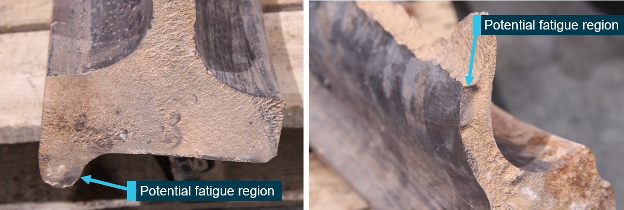
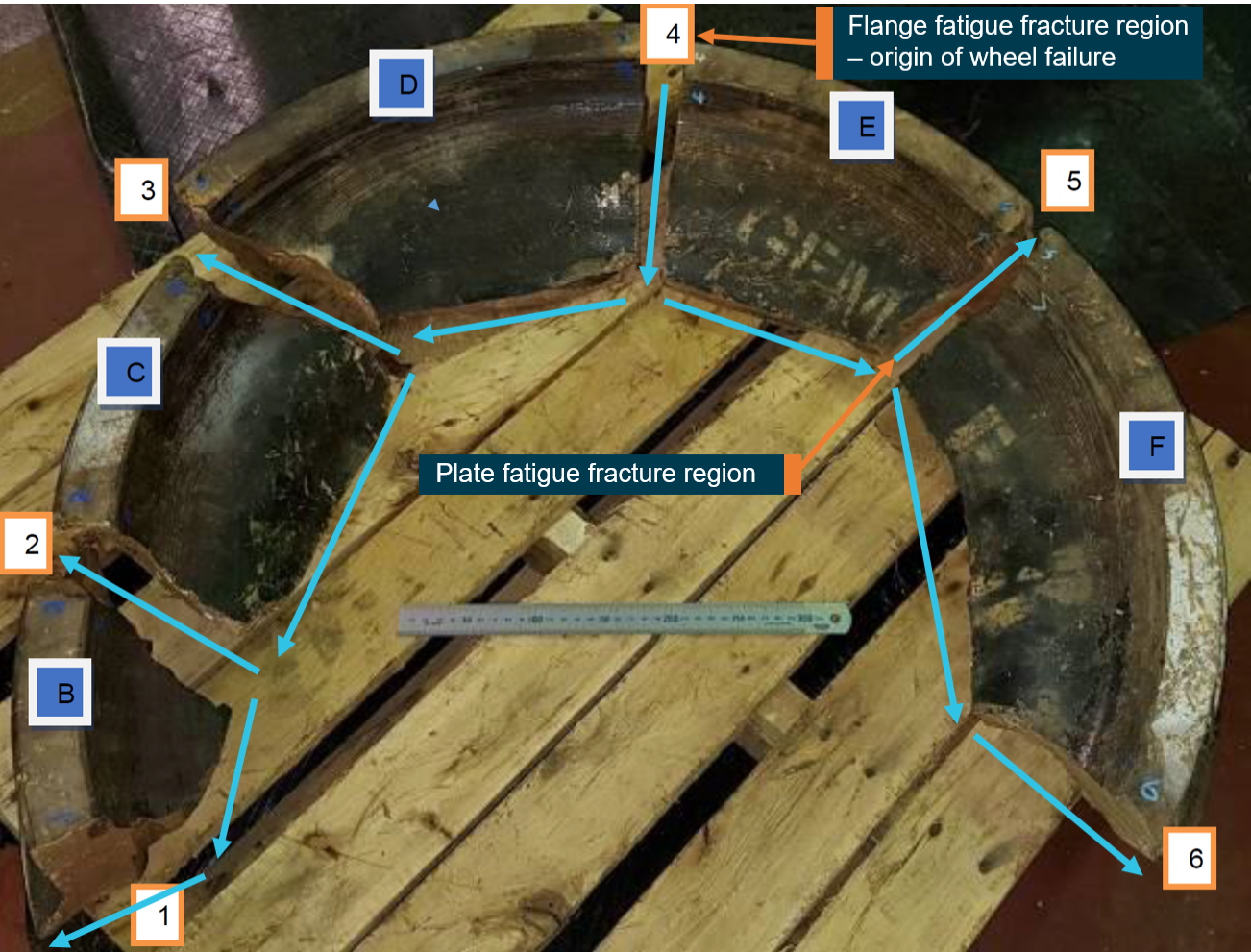
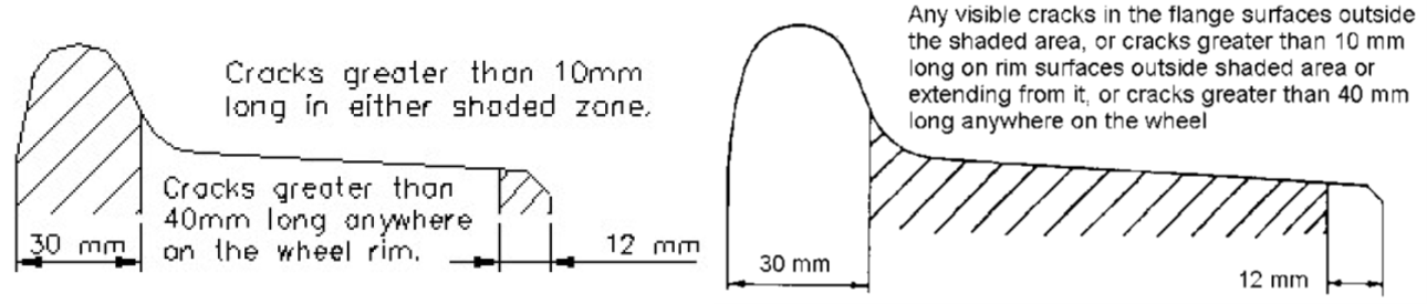
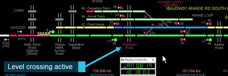
The ATSB is investigating the collision between a light engine and a coal train at Westwood, Queensland, on 18 June 2021.
The light engine (a diesel locomotive with no other rolling stock attached) was being used by Queensland Rail for driver tuition. There was a tutor driver and 2 other drivers on board, and the light engine was being operated westbound with the long end leading (that is, in the reverse direction of normal operation). The coal train was operated by Aurizon and was stationary at the Westwood loop (45.05 km from Rockhampton).
At about 1126 local time, the light engine struck the stationary coal train. The light engine and 5 wagons of the coal train were significantly damaged. Of the light engine’s 3 occupants, one sustained minor injuries, one was seriously injured and one was fatally injured. The 2 drivers of the coal train were uninjured.
A preliminary report, which detailed factual information established during the evidence collection phase, was released on 10 September 2021 (see below).
As part of the investigation, the ATSB has interviewed the drivers and train controller, analysed recorded data from the light engine's data logger and other sources, participated in a more detailed examination of the light engine and gathered additional information.
The final report has been drafted and is undergoing internal review to ensure the report adequately and accurately reflects the evidence collected, analysis, and agreed findings.
The report will be published at the conclusion of the investigation. However, should any critical safety issues be identified at any stage during the course of the investigation, the ATSB will immediately notify relevant parties so appropriate safety action can be taken.
Preliminary report
Report release date: 10/09/2021
This preliminary report details factual information established in the investigation’s early evidence collection phase and has been prepared to provide timely information to the industry and public. Preliminary reports contain no analysis or findings, which will be detailed in the investigation’s final report. The information contained in this preliminary report is released in accordance with section 25 of the Transport Safety Investigation Act 2003.
The occurrence
At about 1126[1] on 18 June 2021, a locomotive collided with the rear of a stationary coal train at Westwood, Queensland, located about 45 km west of Rockhampton.
The locomotive, operated by Queensland Rail (QR), was being used for route tuition[2] on the Blackwater system[3] in Queensland. It was being operated as a ‘light engine’ (that is, with no other rail vehicles attached) and it was assigned the train number LET0. The crew consisted of a tutor driver providing route tuition and two other QR drivers receiving route tuition. LET0 utilised a single QR class 2470 class locomotive (number 2471).
The intended route for the tuition was from Rockhampton to Bluff and then return (Figure 1). For the first leg of the route, the locomotive was long end leading (that is, operated in the reverse direction to normal operation, see Long end leading for further details).
Figure 1: Rail route on the Blackwater system showing the path of the locomotive and the collision point
Source: Google Maps, annotated by the ATSB
The three-person QR crew started and prepared the locomotive for traffic in Rockhampton yard. At 1041, LET0 left Rockhampton yard and entered the Blackwater system. One of the drivers receiving route tuition performed the role of the driver and the other driver receiving route tuition performed the role of co-driver.
Between Rockhampton and Bluff, there was an Up[4] line and a Down line. LET0 travelled on the Up line until it reached Kabra, where the network control officer (NCO) routed it to the Down line to allow for the passage of a loaded coal train travelling east on the Up line.
At Westwood there was a common loop.[5] There was a maintenance closure on the Down line to the west of Westwood, which meant all rail traffic in that area had to use the Up line, and the common loop at Westwood was used for passing traffic.
As LET0 approached Westwood, there was an Aurizon coal train (EE16) stationary in the common loop. EE16 was travelling westwards between Callemondah (Gladstone) and Ensham Mine (Comet), and it consisted of three Aurizon 3800 class locomotives and 102 empty coal wagons.
At 1107, the NCO set up the route for LET0 to travel to Westwood signal WD28, located to the east of Westwood (Figure 2). The NCO planned to route LET0 via the Westwood common loop and then for all traffic (EE16 and LET0) to travel via the Up line from Westwood to Windah. The signal interlocking system was set up to show a yellow (caution) aspect in the approach signal WD28P and a red (stop) aspect in WD28. That meant that LET0 would be required to stop at signal WD28 outside Westwood until EE16 had vacated the common loop, at which time the signal aspect in WD28 would change to proceed.
At 1119, while LET0 was travelling towards Westwood, the NCO set the 11 A/D points as planned from the Down line into the common loop at Westwood in preparation for the locomotive to enter the common loop after EE16 had departed (Figure 2).
Figure 2: The route of LET0 into Westwood common loop
The yellow solid line within the image shows the path of the locomotive on approach and after passing signal WD28. Source: Queensland Globe, annotated by the ATSB
The locomotive’s data logger showed that a partial application of the independent brake was initiated at 1125:42, as the locomotive entered a downhill gradient into Westwood yard.
At 1125:43, a SPAD (signal passed at danger) alarm was generated in the Aurizon network control centre, indicating that LET0 had passed signal WD28 while it was displaying a red (stop) aspect.
At 1125:46, LET0 entered the 11 A/D points. The locomotive’s data logger showed that it entered the 50 km/h turnout[6] from the Down line to the common loop at approximately 72 km/h.
At 1125:49, in response to the SPAD alarm, the NCO made an emergency broadcast over the network control radio. There was no response from the crew of LET0.
At 1125:53, a full independent brake application was made. At this time the speed of the locomotive was approximately 60 km/h.
At 1125:59, LET0 collided with the rear of EE16 at a speed of approximately 44 km/h. The collision occurred just after the locomotive entered the Westwood common loop. Figure 3 shows the collision point between the locomotive and the coal train on the common loop (centre track) of the three-track Westwood yard.
Figure 3: Collision site at Westwood, Queensland
Source: Queensland Police Service, inserts by the ATSB
The locomotive and the last nine wagons of the coal train sustained significant damage from the collision. The driver was fatally injured, the co-driver sustained serious injuries and the tutor driver received minor injuries.
At 1130, after attempting to call for help using the radio, the tutor driver of LET0 called the network control centre via mobile phone to advise that LET0 had been involved in a collision. The NCO provided first aid and CPR instructions to the tutor driver. At 1132, another Aurizon NCO contacted the Queensland Ambulance Service, and the first emergency vehicle arrived on scene at 1201.
Context
Signal testing
Aurizon was the rail infrastructure manager for the Blackwater system. Remote controlled colour light signalling controlled train movements on the system and it was operated by the Aurizon network control centre at Rockhampton.
Testing of the signalling system by Aurizon found that, at the time of the accident:
Approach signal WD28P was displaying a single yellow aspect, which indicated to a driver that the next signal, WD28 would be at red (stop).
The dynamic speed indicator[7] attached to WD28P was not illuminated.
WD28 was displaying a red aspect.
Train crew information
Driver
The main role of a driver is to control the movement of the locomotive. The driver is also responsible for observing and obeying signal aspects and maintaining control of the speed of the locomotive.
The driver of LET0 had been qualified as a QR driver for about 4 months, and had both the safeworking[8] and traction[9] competencies required to drive the locomotive. The driver was receiving route tuition for the section of track between Rockhampton and Bluff.
Co-driver
One of the roles of a co-driver is to observe, announce and confirm the signal aspects as they are sighted. When driving long end leading, the structure of the locomotive on 2470 class and similar locomotives limits vision for the driver and they rely heavily on the co-driver for observing signals.
The co-driver on LET0 had been qualified as a QR driver for about 6 months, and had both the safeworking and traction competencies required to drive the locomotive. It was intended that the co-driver would perform the role of the driver (from the driver’s position) for a period during the tuition that day. The co-driver was receiving route tuition for the section of track between Rockhampton and Bluff.
Tutor driver
A tutor driver is responsible for instructing drivers on all aspects of controlling a locomotive, which includes teaching train handling and route knowledge.
The tutor driver on LET0 had qualified as a driver with another rail operator about 9 years previously. They had been qualified as a tutor driver about 5 years earlier, before joining QR in that role about 3 years before the accident. They had the safeworking, traction and route competencies to drive the locomotive from Rockhampton to Bluff, and were providing tuition on that route to both the driver and co-driver.
Locomotive information
Locomotive 2471 was a Queensland Rail (QR) 2470 class locomotive with a single driving station at the front right of the cabin. The normal driving direction of the locomotive was with the cabin end leading (Figure 4).
Figure 4: Locomotive 2208D similar to a QR 2470 class locomotive
Source: ATSB
Figure 5 is a view from inside the cabin looking forward, showing the driver’s vision on the right and the co-driver and tutor driver’s view on the left when travelling in the normal direction.
Figure 5: View from inside the cab looking forward
Source: ATSB
Figure 6 is a plan view of the driver’s cabin with the seats in the normal position (driven cabin end leading). A driver seated in the driver’s seat has access to all the relevant controls. The only locomotive control available to the co-driver on a 2470 class locomotive is an emergency brake valve.
The tutor driver was positioned in a temporary seat (removable chair) located in the centre rear of the cabin, facing towards the front windows. From that position the tutor driver had a good view out the front of the train during normal operations. According to the tutor driver, it was normal practice for the tutor driver to take a position in the temporary seat at the centre rear of the cabin area when two drivers were undergoing route tuition. This would have been the configuration of the cabin for the return trip from Bluff to Rockhampton.
Figure 6: Plan view of the driver’s cabin in normal configuration
Source: Queensland Rail, annotated by the ATSB
Long end leading
‘Long end leading’ occurs when a locomotive travels with the driving cabin at the rear for the direction of travel. Figures 7 and 8 shows the limited view for the driver during this method of operation on a 2470 class locomotive, with a significant amount of the forward view being obstructed by the leading portion of the locomotive and the back wall of the cabin.
Figure 7: Driver's viewport when long end leading
Source: ATSB
Figure 8: View from inside the cabin from driver and co-driver perspective with long end leading
The image on the left shows the driver’s view from the locomotive’s active driving station when long end leading. The image on the right shows the view from the co-driver’s seat when long end leading. Source: ATSB
Figure 9 is a plan view of the driver’s cabin configured for long end leading. The driver’s position was such that they were required to face 90⁰ to the direction of travel to enable use of the driver controls. The driver’s attention was split between the driver controls, the gauge console and the view ahead.
The co-driver’s seat was rotated 180⁰. The co-driver was relied upon to convey observations to the driver because the driver’s view was obscured on the right side of the locomotive. When the co-driver was positioned this way, they could no longer reliably operate the emergency brake valve without moving from their seat.
On LET0, the tutor driver’s temporary seat was positioned as shown in Figure 9. They were facing rearward in relation to the direction of travel and had no forward view.
Figure 9: Plan view of driver’s cabin configured for long end leading
Source: Queensland Rail, annotated by the ATSB
Long end leading is conducted in the rail industry with many types of locomotives, usually for the purposes of manoeuvring to a location to turn around or for shunting wagons. Some types of locomotives are designed with additional controls at the rear of the cabin and cameras to facilitate long end leading operations. Some designs have eliminated long end leading by implementing driving cabins at each end of the locomotive.
QR used long end leading for tuition trains between Rockhampton and Bluff for its current training cohort since December 2020.
Safety action
On 21 June 2021, QR suspended all mainline long end leading operations both on its own network, and as an operator of its trains on other networks. Permitted operations for long end leading were limited to shunting, turning of a locomotive, setting back and propelling movements.
In addition, on 25 June 2021, the Office of the National Rail Safety Regulator issued a safety alert, requiring all rail infrastructure managers and rolling stock operators to review the risks associated with long end leading operations (if applicable) by the end of July 2021.
Further investigation
To date, the ATSB has:
gathered and undertaken preliminary analysis of locomotive event recordings and network control and locomotive voice recordings
conducted brake and operational control testing of the locomotive
gathered information about the locomotives, rail infrastructure and operational procedures
conducted a re-enactment of the event to identify visual limitations from long end leading operations, including on the curved section approaching signal WD28.
The investigation is continuing and will include:
review and examination of the functionality and cabin ergonomics of the 2470 class locomotives for long end leading operations and other factors that may have influenced the crew’s performance
review of the nature and extent of the use of long end leading for main line operations
review of long end leading risk controls related to collision and authority exceedance (SPAD) hazards
review of change management and risk management processes applicable to the use of long end leading for route tuition
review of post incident procedures for managing emergencies on the network
review and examination of the radio and signalling infrastructure and procedures on the Blackwater system
review of the Westwood signal interlocking event recordings and associated circuit diagrams.
Should a critical safety issue be identified during the course of the investigation, the ATSB will immediately notify relevant parties so appropriate and timely safety action can be taken.
A final report will be released at the conclusion of the investigation.
Purpose of safety investigations
The objective of a safety investigation is to enhance transport safety. This is done through:
identifying safety issues and facilitating safety action to address those issues
providing information about occurrences and their associated safety factors to facilitate learning within the transport industry.
It is not a function of the ATSB to apportion blame or provide a means for determining liability. At the same time, an investigation report must include factual material of sufficient weight to support the analysis and findings. At all times the ATSB endeavours to balance the use of material that could imply adverse comment with the need to properly explain what happened, and why, in a fair and unbiased manner. The ATSB does not investigate for the purpose of taking administrative, regulatory or criminal action.
Terminology
An explanation of terminology used in ATSB investigation reports is available here. This includes terms such as occurrence, contributing factor, other factor that increased risk, and safety issue.
Publishing information
Released in accordance with section 25 of the Transport Safety Investigation Act 2003
Ownership of intellectual property rights in this publication
Unless otherwise noted, copyright (and any other intellectual property rights, if any) in this report publication is owned by the Commonwealth of Australia.
Creative Commons licence
With the exception of the Coat of Arms, ATSB logo, and photos and graphics in which a third party holds copyright, this publication is licensed under a Creative Commons Attribution 3.0 Australia licence.
Creative Commons Attribution 3.0 Australia Licence is a standard form licence agreement that allows you to copy, distribute, transmit and adapt this publication provided that you attribute the work.
The ATSB’s preference is that you attribute this publication (and any material sourced from it) using the following wording: Source: Australian Transport Safety Bureau
Copyright in material obtained from other agencies, private individuals or organisations, belongs to those agencies, individuals or organisations. Where you wish to use their material, you will need to contact them directly.
On 10 June 2021, two SPENO Rail Maintenance Australia Road-Rail Vehicles (RRVs), FL18 and SP128, on-tracked at about the 196.012 km point, Binney Road level crossing, at Crystal Brook, South Australia, to undertake ultrasonic rail flaw detection. However, the track worker level 2 (TW) for the RRV travel inadvertently requested the protection limits for Train Running Information (TRI) travel from a location about 3 km in advance of where the RRVs were to on-track. The RRVs ontracked outside of the protection limits and travelled for about 3 km before protection for the movement was applied by the network controller (NC).
What the ATSB found
The TW incorrectly requested the signal for the protection limits for RRV travel as signal 24 Crystal Brook (current location), instead of signal 24 Rocky River, when communicating with the Australian Rail Track Corporation (ARTC) NC. In addition, there was no confirmation between the TW and the NC of where the RRV’s were to on-track while discussing the limits of protection required for the travel. Combined, these factors resulted in the NC applying Blocking Facilities from signal 24D at Crystal Brook to signal 3 at Coonamia and the RRV’s operating outside of the limits defined in the Train Running Information.
What has been done as a result
SPENO have undertaken a review and made amendments to processes for on-tracking of RRV’s. The proposed amendments include the provision to remove the single point of failure of the TW being responsible for identifying and communicating the location which RRVs would on-track in rail networks.
Safety message
This incident highlights the importance of identifying the location that travel or work on track will commence. Competent workers should provide all the information required for network controllers to identify and confirm that protection limits adequately cover the intended work site. Confirmation of location is especially important for providing Blocking Protection for RRV movements.
The investigation
Decisions regarding whether to conduct an investigation, and the scope of an investigation, are based on many factors, including the level of safety benefit likely to be obtained from an investigation. For this occurrence, a limited-scope investigation was conducted in order to produce a short investigation report, and allow for greater industry awareness of findings that affect safety and potential learning opportunities.
The Occurrence
On 10 June 2021, SPENO Rail Maintenance Australia (SPENO) had planned to conduct ultrasonic rail flaw detection on the Australian Rail Track Corporation (ARTC) Port Augusta Line, South Australia. The testing was to be from the 196.030 km point at Crystal Brook to 94.960 km at Spencer Junction, (Figure 1). The maintenance was planned to be conducted with two Road Rail Vehicles[1] (RRVs), the testing vehicle FL18 (Figure 2) leading, and the hand testing vehicle SP128 (Figure 3) following.
Figure 1: Location of Crystal Brook, South Australia
Source: Google Earth Pro, annotated by the ATSB
Figure 2: SPENO FL18 ultrasonic test vehicle (lead vehicle)
Source: SPENO Rail Maintenance Australia
Figure 3: SPENO SP128 ultrasonic test vehicle (second vehicle)
Source: SPENO Rail Maintenance Australia
To provide protection for the travel, a track worker level 2[2] (TW) assigned to the SPENO RRVs planned the protection required using a Worksite Protection Plan and Worksite Protection Plan Map that was marked with the limits of protection for Train Running Information[3] (TRI) travel (signal 24 Rocky River through the Westbound Mainline), RRV on-tracking location (196.012 km) and intended travel path denoted in light brown on Map (Figure 4).
Figure 4: Competent worker map of Crystal Brook showing intended limits of protection for RRVs
Source: Track Worker Level 2 Worksite Protection Plan Map Markup, annotated by ATSB
At about 0715[4] the TW briefed the SPENO work crew on protection arrangements. The SPENO work crew who attended the pre-work brief by the TW acknowledged the pre-work briefing by signing the Pre-Work Brief Form. At about 0721 the TW contacted the network controller[5] (NC) to initiate receiving TRI. During the initial conversation the NC asked the TW for their location, to which the TW replied, ‘Crystal Brook’. The TW and NC continued to exchange information, which included the limits for TRI travel. For the limits of protection, the TW requested signal 24 at Crystal Brook to signal 3 at Coonamia.
The NC noted Crystal Brook had a signal 24 and signal 24D and asked the TW if they required both the Eastbound Mainline and the Westbound Mainline for the intended work. The TW responded that they only required the Westbound Mainline for the travel, and the NC then stated that signal 24D was the protecting signal for that line.
After the signals for limits of protection were agreed, at about 0722 the NC placed Blocking Facilities[6] from signal 24D at Crystal Brook to signal 3 at Coonamia (Figure 5).
Source: Australian Rail Track Corporation, annotated by ATSB
After the TW received the TRI at about 0735, the SPENO crew prepared the RRVs and on-tracked at the 196.012 km point at the Binney Road Level crossing and proceeded towards Coonamia, conducting ultrasonic tests as they proceeded. On arrival at the number 20 points for the turnout[7] to the Eastbound Mainline or Eastbound Mainline at Crystal Brook, located at 21.144 km[8], the crew observed that the turnout was set for the Eastbound Mainline. The TW contacted the NC to request the number 20 points be set for their intended route to the Westbound Mainline.
The NC questioned the work crew’s current location, and after confirmation, the NC informed the crew that they were outside of the limits of protection. The TW then explained to the NC that they had on-tracked the RRVs at the 196.012 km Binney Road Level Crossing, which was about 3 km prior to the start limits of the protection applied by the NC. Figure 6 depicts the travel of the RRVs outside of their protection limits in red. The RRV end location and green section of track indicate the location of where the original protection limits started. (Figure 6).
Figure 6: Path of RRV’s outside of protection
Source: Google Earth Pro, annotated by the ATSB
Context
Track worker level 2
At the time of the occurrence, the TW had completed all the accredited and non-accredited course components and had been recertified, as of 21 May 2021, as current for Train Running Information and Code of Practice (CoP0 for the Defined Interstate Rail Network (DIRN), and the ARTC Addendum. The TW had undertaken Category 1 rail safety medical and had been deemed fit for duty subject to review on 10 December 2021. The review subject was not considered a factor in this occurrence. Alcohol and other drug tests were undertaken after the occurrence. The results were negative.
The work orders for SPENO for the planned scope of works had the times of 0600 – 1630 on two previous days and on the day of the occurrence. As the TW had adequate opportunities for rest prior to commencing work, fatigue was not considered to be a factor.
Network Rules and Procedures
When planning work or travel in a rail corridor, it is the TW’s responsibility to ensure that the work is planned, and the protection requirements are carried out according to network rules and procedures. In the case of the RRV travel for the ultrasonic testing, the applicable rules were governed by the CoP for the DIRN, ARTC Version 3.0: 01 July 2018 and the ARTC Addendum to the CoP for the DIRN Version 5.1: 02 July 2020.
Sections 3.11.22 and 3.11.23 of the CoP for the DIRN defined the requirements for initiation and format of a TRI. When a TW requested a TRI, the TW shall tell the NC their name and company, the location from which communications is made, type of vehicle or work to be undertaken and the TRI limits expressed as being between two locations which may include the following:
- kilometre locations - signal locations or numbers - a main track or crossing loop at a specific location - the track where there are multiple tracks, and - section name.
The Rail Industry Safety and Standards Board (RISSB) had a procedure within its suite of Australian Network Rules and Procedures (ANRP) that address the identification and verification of location for worksite protection. The RISSB procedure states:
Where worksite protection is primarily applied by the network control officer, the correct and accurate location of the worksite is critical in ensuring the safety of workers and rail traffic.
Further, the RISSB procedure has additional information the TW may use to identify that location, which included:
- Contact the Network Control Officer - Communicate the proposed worksite location using the identifiers below in the following order
- track name, and - station name or stations at both ends of the worksite, and - One or more of the following:
- the signal/Block Limit Board identification number/s giving entry to worksite, or - a points identification number located in the worksite, or - a kilometre location in the worksite, or - a permanent structure in the worksite that is visible on the Network Control Officer workstation
The ARTC rules and procedures did not specifically have a procedure for identification and verification of location. The ARTC Addendum to the CoP for the DIRN s23.1 had the following mandate under s23 Track Force Working:
23.1 Defining a Location and Train ID
A worker shall identify their location in km and m in a section whilst trains are to be identified as being from one location to another location.
Network Communication
The CoP for the DIRN had provisions for communications between rail safety workers. This included the requirement for a TW to establish communication with the relevant NC and provide sufficient detail to ensure adequate identification of location. The ATSB reviewed the voice recordings between the TW and NC during the establishment of the Train Running Information and noted that the communication of important safety information was informal, conversational and did not include the location that the RRVs would on-track. The TW included the location of Crystal Brook within the context of references to signal 24 and did not make any reference to signal 24 at Rocky River as the location required for the start of the protection limits.
The ARTC Train Notice (TN) 1928 - 2017 Track Worker Communication Protocol contains details for a competent rail safe worker (CRSW), to which a TW is aligned, is required to undertake to access the ARTC Rail Corridor.
The CRSW must on initial contact with Network Control, specify their physical location by stating:
- Location name and KM, or - KM and Signal Number.
The RISSB has a CoP for safety critical communications, which states it is important that safety critical communication is transmitted accurately and effectively to all rail safety workers.
When arranging worksite protection, it is important that safety critical communications are transmitted accurately and effectively between the NCO [network control officer][9] and the PO [protection officer][10], and with other parties where applicable.
Road Rail Vehicles
The SPENO work order information had kilometrage from 196.030 km at Crystal Brook to signal 43 at Spencer Junction (Figure 7). The SPENO crew attended the TW pre work briefing at about 0715. The SPENO Supervisor stated that the TW had mentioned the limits of protection would be signal 24 Rocky River to signal 3 Coonamia.
After the TW had received the TRI from the NC, the SPENO crew prepared the RRVs for work by lowering the rail wheels onto the rails, which guide the RRVs, at the 196.012 km and proceeded towards Coonamia.
Figure 7: SPENO Work Order from Crystal Brook to Spencer Junction
Source: Australian Rail Track Corporation, annotated by ATSB
Safety analysis
On the morning of 10 June 2021, while preparing for scheduled maintenance work on a section of track between Crystal Brook and Spencer Junction, South Australia, the protection officer for the work crew contacted the network control officer to obtain train running information and establish protection limits. During the discussion between the track worker level 2 and network controller, the exact location that the work crew would on-track was not clearly communicated and confirmed. Inclusion of the on-track location would have also provided an opportunity for the network control officer to recognise that the requested protection was inappropriate for the area of work. Consequently, the RRV on-tracked outside the limits of protection.
In addition, the track worker level 2 requested the protection limits start at signal 24 Crystal Brook, instead of signal 24 Rocky River. Signal 24 Rocky River encompassed their planned start location of Binney Road at the 196.012 km, which was the location they briefed the work crew and had annotated on their work plan. This resulted in the network controller applying Blocking Facilities on the incorrect section of track.
Findings
ATSB investigation report findings focus on safety factors (that is, events and conditions that increase risk). Safety factors include ‘contributing factors’ and ‘other factors that increased risk’ (that is, factors that did not meet the definition of a contributing factor for this occurrence but were still considered important to include in the report for the purpose of increasing awareness and enhancing safety). In addition ‘other findings’ may be included to provide important information about topics other than safety factors.
These findings should not be read as apportioning blame or liability to any particular organisation or individual.
From the evidence available, the following finding is made with respect to the RRV’s on-tracking outside of the limits of protection on the 10 June 2021.
Contributing factors
The track worker level 2 incorrectly requested the protecting signal for the protection area required as signal 24 Crystal Brook (current location), instead of signal 24 Rocky River, when communicating with the network controller. Further, there was no confirmation of where the road-rail vehicles were to on-track while discussing the limits of protection required for the work.
Safety actions
Whether or not the ATSB identifies safety issues in the course of an investigation, relevant organisations may proactively initiate safety action in order to reduce their safety risk. All of the directly involved parties are invited to provide submissions to this draft report. As part of that process, each organisation is asked to communicate what safety actions, if any, they have carried out to reduce the risk associated with this type of occurrences in the future. The ATSB has so far been advised of the following proactive safety action in response to this occurrence.
Safety action by SPENO Rail Maintenance Australia
SPENO have undertaken a review and made amendments to processes for on-tracking of RRVs. The proposed amendments include the provision to remove the single point of failure of the TW being responsible for identifying and communicating the location which RRV’s would on-track in rail networks.
Glossary
ARTC Australian Rail Track Corporation
CoP Code of Practice
CRSW Competent rail safe worker
DIRN Defined Interstate Rail Network
NC Network controller
TW Track worker
RRV Road-rail vehicle
TRI Train running information
Sources and submissions
Sources of information
The sources of information during the investigation included the:
Protection Officer of the occurrence
SPENO Rail Maintenance Australia
Australian Rail Track Corporation
Rail Industry Safety and Standards Board
Office of the National Rail Safety Regulator
References
Department of Transport and Regional Services 2002, Code of Practice for the Defined Interstate Network, Volume 3, ARTC Version 3.0: 01 July 2018, pp.70-71.
ARTC Addendum to the Code of Practice for the Defined Interstate Rail Network 2020, Volume 5.1, s23.1, p.88.
ARTC Network Information Book, West CTC, Dry Creek North Junction (exc) to Spencer Junction (inc), OGW-30-09 2020, Version 1.3.
ARTC Train Notice 1928 - 2017, Track Worker Communication Protocols.
ARTC Network Communications Standard 2020, OPE-PR-043, Version 1.0.
Rail Industry Safety and Standards Board 2017, Identification and Verification of Location, Version 1.0.
Rail Industry Safety and Standards Board 2017, Code of Practice, Safety Critical Communications, Version 1.0, p.5.
Office of the National Rail Safety Regulator 2019, Guideline, Road Rail Vehicle Management & Operations, Version 1.0.
Submissions
Under section 26 of the Transport Safety Investigation Act 2003, the ATSB may provide a draft report, on a confidential basis, to any person whom the ATSB considers appropriate. That section allows a person receiving a draft report to make submissions to the ATSB about the draft report.
A draft of this report was provided to the following directly involved parties:
Railsafe SA Pty Ltd, Protection Officer of the occurrence
SPENO Rail Maintenance Australia Pty Ltd, Ultrasonic Testing Supervisor
SPENO Rail Maintenance Australia Pty Ltd, Operator of FL18
SPENO Rail Maintenance Australia Pty Ltd, Operator of SP128
Australian Rail Track Corporation, General Manager, Safety and Environment
Australian Rail Track Corporation, Safety Assurance Manager
Office of the National Rail Safety Regulator
A submission was received from the Australian Rail Track Corporation, Safety Assurance Manager, and, where considered appropriate, the text of the report was amended accordingly.
Purpose of safety investigations
The objective of a safety investigation is to enhance transport safety. This is done through:
identifying safety issues and facilitating safety action to address those issues
providing information about occurrences and their associated safety factors to facilitate learning within the transport industry.
It is not a function of the ATSB to apportion blame or provide a means for determining liability. At the same time, an investigation report must include factual material of sufficient weight to support the analysis and findings. At all times the ATSB endeavours to balance the use of material that could imply adverse comment with the need to properly explain what happened, and why, in a fair and unbiased manner. The ATSB does not investigate for the purpose of taking administrative, regulatory or criminal action.
Terminology
An explanation of terminology used in ATSB investigation reports is available here. This includes terms such as occurrence, contributing factor, other factor that increased risk, and safety issue.
Publishing information
Released in accordance with section 25 of the Transport Safety Investigation Act 2003
Ownership of intellectual property rights in this publication
Unless otherwise noted, copyright (and any other intellectual property rights, if any) in this report publication is owned by the Commonwealth of Australia.
Creative Commons licence
With the exception of the Coat of Arms, ATSB logo, and photos and graphics in which a third party holds copyright, this publication is licensed under a Creative Commons Attribution 3.0 Australia licence.
Creative Commons Attribution 3.0 Australia Licence is a standard form licence agreement that allows you to copy, distribute, transmit and adapt this publication provided that you attribute the work.
The ATSB’s preference is that you attribute this publication (and any material sourced from it) using the following wording: Source: Australian Transport Safety Bureau
Copyright in material obtained from other agencies, private individuals or organisations, belongs to those agencies, individuals or organisations. Where you wish to use their material, you will need to contact them directly.
An ATSB statistical report into aerial firefighting occurrences between July 2000 and March 2020 (AR-2020-022) found an increase in occurrences per year over recent years. The report also found an increase in average size of aircraft and complexity of operations. Within the data was the 2019-2020 bushfire season which the National Aerial Firefighting Centre advised demanded activity of around four times the usual rate.
Additionally, the CSIRO has projected an increase in land use putting people into conflict with bushfires, and increased dangerous bushfire weather over the coming years.
Consequently, the ATSB is conducting a safety study into aerial firefighting in Australia to identify any systemic safety issues and other learning opportunities that could enhance the safety of aerial firefighting operations.
The safety study is divided into 4 parts:
Part A, AS-2021-015a, was published on 13 May 2026, and presents the key safety themes reported by interviewees. It does not contain findings. The goal of Part A is to better understand the aviation hazards interviewees faced, and the opportunities they could see to improve the safety of aerial firefighting operations.
Part B, AS-2021-015b, will present the results from a survey of NAFC-registered aerial firefighting pilots.
Part C, AS-2025-015c, will expand upon the ATSB statistical report AR-2020-022 and identify key trends in Australian aerial firefighting occurrences.
The final report, AS-2025-015, will present a synthesis of the conclusions in Parts A to C to identify any systemic safety issues and other learning opportunities that could enhance the safety of aerial firefighting operations.
On the afternoon of 6 June 2021, a Babcock Mission Critical Services Australasia, AgustaWestland AW139 helicopter, registered VH-YXH, was conducting a medical retrieval flight from Yielima, Victoria to the Royal Melbourne Hospital. The helicopter was being operated under the instrument flight rules (IFR). At the same time, a Moorabbin Aviation Services Piper PA-44-180 Seminole aircraft, registered VH-HMQ, was operating an IFR training flight from Wagga Wagga, New South Wales to Mangalore Airport, Victoria.
As the Seminole tracked north along the RNAV-Z runway 36 approach to Mangalore Airport, the helicopter was about 10 NM north of Mangalore and tracking south to overfly the airport at 3,100 ft. At about 1555, the Seminole commenced a missed approach resulting in the helicopter’s traffic alerting and collision avoidance system (TCAS) displaying a traffic advisory, followed by a resolution advisory. Six seconds later, the aircraft passed in cloud 451 m (in a straight line) from each other with a minimum vertical separation of 543 ft and a minimum horizontal separation of 333 m. Both aircraft were in cloud throughout the occurrence.
The helicopter continued to Royal Melbourne Hospital while the Seminole diverted to Shepparton. Both aircraft landed without further incident.
What the ATSB found
The helicopter pilot did not consider the possibility of the pilot in the Seminole conducting a missed approach and that it could conflict with the helicopter’s flight path. The Seminole’s pilot reported not hearing broadcasts from the helicopter and misinterpreted traffic advice from air traffic control. Consequently, the Seminole pilot was not aware of the helicopter’s presence and that an incident had occurred.
The ATSB also found that the helicopter operator's traffic alert and collision avoidance knowledge was inadequate with respect to resolution advisory alert terrain considerations and the required intensity of response manoeuvring.
What has been done as a result
The Seminole operator implemented a non-technical skills education program. This included situational awareness, potential biases, and the dangers of student-instructional distractions, particularly during periods of high workload.
The helicopter operator issued a safety alert to flight crew of TCAS equipped aircraft, alerting pilots to the ground inhibit functions of the system and the control response requirements for resolution advisory manoeuvres. The safety alert also highlights the mandatory compliance requirements of resolution advisories.
The helicopter operator has also updated the flight crew training courseware, syllabus and simulator program for 2022. The updated simulator program incorporates elements relevant to the occurrence along with simulator instructor guides.
Safety message
This incident shows that the effective use of radio remains a primary defence in avoiding mid‑air collisions. This is achieved by maintaining an effective listening watch and proactive communication. The ATSB publication A pilot’s guide to staying safe in the vicinity of non-towered aerodromes highlights some of the known challenges presented to pilots operating around uncontrolled airfields.
The incident also highlighted the importance of effective flight crew TCAS training. TCAS is a complex system which serves as a ‘last line of defence’ in airborne collision avoidance. Thorough knowledge of the system is critical in ensuring that crews respond appropriately to TCAS resolution advisories.
The ATSB also strongly encourages the fitment of ADS‑B transmitting, receiving and display devices as they significantly assist the identification and avoidance of conflicting traffic. The continuous positional information ADS‑B provides can highlight a developing situation many minutes before it becomes hazardous – a significant improvement on both point‑in‑time radio traffic advice and ‘see‑and‑avoid’. The ATSB also notes that ADS‑B receivers, for pilots operating under both the instrument or visual flight rules, are currently available within Australia at low cost and can be used in aircraft without any additional regulatory approval or expense.
It is also important to recognise that ADS‑B IN cannot be relied upon to display all nearby traffic so effective use of radio remains a primary defence in avoiding mid‑air collisions. In that context pilots need to make all required broadcasts detailed in the Aeronautical Information Publication, even if there is no known traffic, and respond to broadcasts if a potential traffic conflict is identified.
The occurrence
On the afternoon of 6 June 2021, a Babcock Mission Critical Services Australasia (Babcock MCS) AgustaWestland AW139, registered VH-YXH (Figure 1) was conducting a medical retrieval flight from Yielima, Victoria to the Royal Melbourne Hospital. The helicopter was being operated under the instrument flight rules (IFR) using the callsign HEMS3 with a pilot, two crewmembers and a patient onboard.
At the same time, a Moorabbin Aviation Services Piper PA-44-180 Seminole, registered VH-HMQ was operating an IFR training flight from Wagga Wagga, New South Wales to Mangalore Airport, Victoria. An instructor and a student were onboard the Seminole.
Figure 1: VH-YXH (left) and VH-HMQ (right)
Source: Tony Hanes and Grahame Bann
At 1531 Eastern Standard Time (EST),[1] the student in the Seminole commenced a very-high frequency omni radio range (VOR)[2] approach to Mangalore from 3,900 ft above mean sea level (AMSL). The approach was conducted entirely in cloud. During the approach, another helicopter (using the callsign HEMS1) transited the Mangalore common traffic advisory frequency (CTAF)[3] broadcast area at 5,000 ft. The instructor in the Seminole communicated with the pilot of HEMS1 to coordinate adequate aircraft separation.
During the VOR approach, the instructor communicated with a third helicopter operating beneath their approach path. As the Seminole descended to about 1,800 ft, the instructor elected to discontinue the approach to ensure separation with that helicopter. The instructor took control of the aircraft and positioned it at waypoint MNGSI, 13 NM south of Mangalore, to commence the RNAV-Z[4] approach (Figure 2) to runway 36[5] . The missed approach procedure for the approach required the aircraft be climbed to at least 2,800 ft on a continuation of the approach track (358 degrees Magnetic).
At 1548, as the Seminole crossed MNGSI and tracked north along the approach, the helicopter HEMS3, was about 20 NM north of Mangalore and tracking south toward the airport in visual conditions at 1,400 ft. The pilot observed that cloud conditions to the south prevented visual flight and climbed the helicopter to proceed in instrument meteorological conditions (IMC). Due to concerns regarding the welfare of the patient, the pilot intended to operate at the lowest available altitude. A route proceeding to Mangalore and then southwest toward Puckapunyal provided a lowest safe altitude of 3,100 ft so the pilot climbed the helicopter to continue toward Mangalore at that altitude. This flight path conflicted with the Seminole’s missed approach path.
At 1550, when the Seminole was positioned about 10 NM south of Mangalore, the student asked the instructor a question. At the same time, air traffic control (ATC) contacted the Seminole to advise that a helicopter with the callsign HEMS3 would be overflying Mangalore from the north. The instructor reported that, due to the overlap of the student’s question with the ATC communication, the altitude and callsign information provided by ATC was not heard. As a result, the instructor misinterpreted the traffic advice as relating to HEMS1, the helicopter with which separation had been coordinated about 15 minutes earlier.
Shortly after, ATC contacted the pilot of HEMS3, advising that the Seminole was conducting the RNAV-Z approach. The helicopter pilot reviewed the runway 36 RNAV-Z approach chart, determined the Seminole’s flight path and assumed that it would land from that approach. The pilot did not consider the potential conflict with the RNAV-Z missed approach path and, hence, did not change their flight path or contact the instructor to coordinate separation between the two aircraft.
At about 15:52, the instructor in the Seminole broadcast on the Mangalore CTAF that the aircraft was 7 NM to the south of the airport and conducting the RNAV-Z approach to runway 36. The helicopter pilot heard the broadcast and reported broadcasting on the CTAF about a minute later that HEMS3 was 10 NM to the north and overflying Mangalore at 3,100 ft. The instructor in the Seminole, however, reported not hearing this broadcast.
The Seminole continued along the approach and, at 1555, descended to the minimum descent altitude of 990 ft.[6] Cloud conditions prevented the instructor and student sighting the runway and, at 1555:32, the instructor commenced a missed approach from about 1.5 NM south of the airport. At that time, the helicopter was about 3.6 NM north of Mangalore at 3,100 ft. The instructor intended climbing the Seminole to 4,000 ft (the missed approach required a climb to at least 2,800 ft) and to divert to Shepparton Airport.
At 1556:18, the helicopter was about 1.8 NM to the north of Mangalore as the Seminole passed over the runway 36 threshold at an altitude of about 1,900 ft. At this time, the helicopter pilot observed the Seminole climbing toward the helicopter on the traffic collision avoidance system (TCAS) traffic display. Seven seconds later, the TCAS provided a traffic advisory alert to the pilot (see section titled Traffic alert and collision avoidance system). In response to the alert, the pilot commanded the autopilot to commence climbing the helicopter. Soon after, the instructor in the Seminole broadcast on the Mangalore CTAF that a missed approach had been commenced.
At 1556:39 the TCAS presented a resolution advisory alert to the pilot. The resolution advisory (RA) provided an aural alert ‘monitor vertical speed’ and presented a red ‘avoid’ indication on the vertical speed indicator (VSI) for descents of 500 ft per minute or greater (Figure 3).
Figure 3: Video capture of the resolution advisory indications during the occurrence
Source: Babcock MCS, annotated by ATSB
The pilot incorrectly perceived the RA as a descent instruction. At that time, the helicopter’s climb rate was increasing to 600 feet per minute and the pilot believed that transitioning to a descent could startle those onboard. The pilot also believed that following TCAS instructions could lead to a collision with terrain and therefore did not want to descend below the lowest safe altitude. Hence, the pilot attempted to increase separation by commencing a right turn away from the Seminole. By the completion of the turn, the climb rate had reduced to zero. The helicopter reached a maximum altitude during the event of 3,180 ft.
At 1556:45, six seconds after the RA, the two aircraft passed with a minimum vertical separation of 543 ft and a minimum horizontal separation of 333 m (451 m in a straight line).
At 1556:49, the TCAS alerted the pilot that the helicopter was clear of the conflict. The helicopter continued to the Royal Melbourne Hospital while the Seminole diverted to Shepparton. Both aircraft landed without further incident and no injuries resulted.
The crew of the Seminole, which was not equipped with TCAS or Automatic Dependent Surveillance Broadcast (ADS-B) IN, remained unaware of the incident until after the flight.
Both the instructor in the Seminole and the pilot of the helicopter reported being in cloud during the occurrence. At 1600 (about the time of the incident), the Bureau of Meteorology’s automatic weather station at Mangalore Airport recorded overcast cloud with a base of 767 ft AMSL (300 ft above ground level).
Traffic alert and collision avoidance system
The traffic alert and collision avoidance system (TCAS II) fitted to the helicopter is designed to alert flight crews to possible conflicting traffic and to provide recommended escape manoeuvres. The TCAS identifies a three-dimensional airspace around the aircraft based on the closure rate of other transponder-equipped traffic.
TCAS alerts
If a potential conflict meets defined vertical and horizontal parameters, the TCAS generates a visual and aural alert. Two alert types are generated by the system, a traffic advisory (TA) and a resolution advisory (RA).
A TA is intended to assist a pilot in the visual acquisition of the intruder aircraft and prepare for a potential RA. This is presented to the pilot as a visual indication (Figure 4) supplemented by an aural alert.
Figure 4: Representation of the TCAS TA
Source: ATSB
The RA alerts provided recommended avoidance manoeuvres (in the vertical plane only) to either increase or maintain the existing vertical separation between aircraft. When generated, the recommended manoeuvring is displayed on the VSI (Figure 5). The target vertical speed may be displayed as a green line and the vertical speed range to be avoided is displayed in a red band. Some RAs only display the vertical speeds to be avoided and may not necessitate a change in flight path.
Figure 5: Example of a TCAS ‘monitor vertical speed’ RA
Source: ATSB
TCAS aural alerts are in the form a specific annunciation based on the nature of the conflict and response required of the pilot (Table 1).
Altitude Crossing, Maintain Rate RA (Climb and Descend)
Maintain Vertical Speed, Crossing Maintain
Weakening of RA
Level Off, Level Off
Preventive RA (no change in vertical speed required)
Monitor Vertical Speed
RA Removed
Clear of Conflict
The helicopter operator’s procedures contained in the Babcock MCS Operations Manual (Part B) provided the following information for pilot response to TA and RA alerts:
Immediate manoeuvring is not required for Traffic Advisory (TA) information generated by TCAS II. Information on the display is provided as an aid to visually acquiring traffic. It is not a replacement for ATC instruction or ‘See and avoid’ techniques.
The recommended Pilot action on the activation of a Resolution Advisory [RA] is to immediately initiate a climb or descent as dictated by the TCAS II RA. The technique to achieve the requested profile will be dependent on the initial flight parameters such as airspeed, altitude, weight and guidance modes. On activation of an RA the Pilot should not initiate banking manoeuvres but attempt to fly the aircraft in accordance with the indication displayed on the vertical speed indicator.
Traffic display
The TCAS traffic display depicts the position of nearby traffic, relative to own aircraft. The information displayed includes vertical speed indications of traffic (Figure 6). Traffic are depicted using geometric symbols, depending on their threat status. A filled red square indicates an intruder that is the source of an RA.
An intruder’s relative altitude is displayed in hundreds of feet preceded by a plus (+) above the intruder symbol if it is above own aircraft or a minus (-) below the symbol if it is below own aircraft. When a target is reporting its altitude is changing by more than 500 feet per minute, an arrow to the right of its symbol indicates whether it is climbing (up arrow) or descending (down arrow).
Figure 6: Representation of the TCAS traffic display at the time of the RA
Note: The information generated for the Seminole shows it as an RA (red square) that is 500 ft below the helicopter (-5 below the red square) and climbing at more than 500 feet per minute (up arrow).
Source: Honeywell, annotated by ATSB
Resolution advisory inhibitions and manoeuvring
The United States Federal Aviation Administration (FAA) publication Introduction to TCAS II Version 7.1 describes the following inhibitions designed into the TCAS II system:
TCAS is designed to inhibit Increase Descent RAs below 1450 feet AGL; Descend RAs below 1100 feet AGL; and all RAs below 1000±100 feet AGL. If a Descend RA is being displayed as own aircraft descends through 1100 feet AGL, the RA will be modified to a Do Not Climb RA.
The TCAS aural annunciations are integrated with other environmental aural alerts available on the aircraft. The priority scheme established for these aural alerts gives windshear detection systems and ground proximity warning systems (GPWS) a higher annunciation priority than a TCAS alert. TCAS aural annunciations will be inhibited during the time that a windshear or GPWS alert is active.
The publication also describes the required response manoeuvring for an RA:
In modelling aircraft response to RAs, the expectation is the pilot will begin the initial 0.25 g[7] acceleration maneuver within five seconds to an achieved rate of 1500 fpm. Pilot response with 0.35 g acceleration to an achieved rate of 2500 fpm is expected within 2.5 seconds for subsequent RAs.
The publication also stated:
During an RA, do not maneuver contrary to the RA.
The AW139 flight manual included a caution which stated:
The TCAS II may request climb or descent actions which would exceed aircraft limitation or put the aircraft in undesirable conditions (i.e. autorotation). The pilot should achieve a maximum climb or descent rate applicable for the aircraft condition and maintain this until the conflict is clear or an alternative manoeuvre is requested.
Helicopter operator training and knowledge
The helicopter operator’s pilots underwent TCAS training during AW139 type rating training and during recurrent (twice annual) simulator training. This training included both theoretical and practical components and incorporated various RA scenarios.
During the investigation, the ATSB discussed the pilot’s understanding of the required response manoeuvring and potential for this to result in a terrain collision with senior members of the operator’s flying operations and training department. The operator supported the pilot’s decision-making in manoeuvring contrary to the perceived descent RA. The operator also shared the pilot’s misunderstanding of the terrain inhibitions designed into the system and stated incorrectly that following an RA could jeopardise terrain separation. It was also stated that a flight path change from a high rate of climb to a descent is undesirable in a helicopter as it can cause a rotor over-speed. However, the aircraft flight manual states that in such a scenario, the instruction should not be disregarded, but instead ‘the pilot should achieve a maximum climb or descent rate applicable for the aircraft condition and maintain this until the conflict is clear or an alternative manoeuvre is requested’.
The ATSB reviewed the helicopter operator’s TCAS training program and materials. These were found to adequately address the system and recommended pilot response actions. However, the pilot’s reasoning during the occurrence and subsequent statements along with the operator’s statements indicated misunderstandings of the terrain inhibitions and required RA response manoeuvring.
Recorded data
The Seminole was not equipped with any form of flight data recording.
Helicopter
The helicopter (VH-YXH) was fitted with a digital flight data recorder and flight deck video recorder, both of which captured the occurrence. The aircraft’s TCAS unit also recorded occurrence data.
Flight data
The flight data showed activation of the TA at 15:56:25. At 15:56:33, the helicopter commenced climbing and, at 15:56:38, commenced a right turn. Two seconds after the turn commenced, the climb rate peaked at 608 feet per minute before reducing to zero 10 seconds after the turn had commenced. The helicopter climbed 84 feet during the conflict.
Figure 7: Graphical representation of flight data
Note: The resolution advisory was not captured as a 'Traffic Alarm’ by the flight recorder and is therefore presented as ‘False’ in the graphical representation of the flight data.
Source: ATSB
The data also captured the activation of the radio transmit switch from 15:52:49 until 15:53:02 (the selected radio frequency was not captured). At that time, the helicopter was about 10 NM north of Mangalore. This duration and timing was consistent with the broadcast stating the pilot’s intention to overfly Mangalore.
TCAS unit
The TCAS unit recorded the occurrence TA and RA alerts, the associated aural alerts (Traffic, Traffic, Monitor Vertical Speed and Clear of Conflict) and the intruder hexadecimal code[8] from the Seminole’s transponder. Data indicates that at 15:56:45, separation between the aircraft reduced to a straight-line minimum of 451 m (543 ft vertically and 333 m horizontally).
Surveillance
Airservices provided surveillance data relating to the flight paths of the Seminole and the helicopter. The data captured both flights including the incident (Figure 8).
Figure 8: Representation of recorded surveillance data
Source: Airservices, Google Earth, annotated by ATSB
Communications
The Mangalore CTAF was not recorded.
Melbourne Centre air traffic control audio recordings for the time of the incident captured the crew of both aircraft being provided and acknowledging traffic information from ATC.
No broadcast was recorded on the Melbourne Centre frequency between 15:52:49 and 15:53:02, when the flight data from the helicopter showed a transmission being made. This indicates the broadcast made by the helicopter pilot at that time was very likely made on the Mangalore CTAF.
At 1556:25 (the same time as the TA), the air traffic controller contacted the helicopter pilot to confirm that the pilot had contacted the Seminole. The pilot responded ‘Just copied [the Seminole’s] last call (7 NM south of Mangalore) thanks. I’ve just got a traffic alert now, I’m going to climb to 5,000.’
At 1553 on 6 June 2021, the helicopter (VH-YXH, HEMS3) was 10 NM north of Mangalore Airport tracking south to overfly the airport at 3,100 ft AMSL. At the same time, the Piper Seminole (VH-HMQ) was conducting the RNAV-Z runway 36 approach to the airport from the south.
The helicopter pilot was aware of the Seminole’s movements from its broadcasts and air traffic control (ATC) advice. Consequently, the pilot reviewed the approach chart and determined the Seminole’s approach path for landing. However, the pilot did not consider the possibility of a missed approach and did not recognise that the helicopter’s flight path conflicted with the Seminole’s missed approach path. Therefore, the pilot decided that it was not necessary to alter their flight path or communicate with the Seminole’s pilot to manage separation.
When ATC provided traffic information for the HEMS3 helicopter to the Seminole’s pilot, the timing of the student’s question resulted in the instructor not interpreting this information correctly. The instructor assumed the advice related to HEMS1, a helicopter with which separation had been coordinated about 15 minutes earlier.
The ATSB considered callsign confusion as a possible reason for the instructor’s misinterpretation of the traffic advice. The instructor in the Seminole did not hear the altitude or callsign of HEMS3 in the traffic advice provided by ATC. The ATSB determined that it was these factors, not callsign confusion, that led to the instructor incorrectly believing the traffic advice related to HEMS1.
Recorded flight and ATC data indicates the helicopter pilot very likely made a transmission on the Mangalore CTAF when 10 NM to the north. The pilot reported that this broadcast stated an intention to overfly the airport, the instructor in the Seminole reported not hearing this or any other broadcast from the helicopter.
Subsequently, the Seminole’s pilot (instructor) did not sight the runway at the missed approach point and conducted a missed approach, unaware of the approaching helicopter. The two aircraft passed 451 m of each other (in a straight line) during the missed approach.
Collision avoidance procedures
During the incident, the helicopter’s traffic alert and collision avoidance system (TCAS) generated a traffic advisory followed by a resolution advisory (RA). The TCAS was designed to inhibit RA alerts when response manoeuvring may lead to terrain conflict or RA aural alerts when ground proximity warning system alerts were being generated. Additionally, if RA response manoeuvring is required, this manoeuvring is not severe (0.25g up to 5 seconds after an alert is generated).
As the aircraft was climbing and the RA prohibited descents of 500 ft per minute or greater, the correct response to the RA generated in this case did not require any manoeuvring. However, the helicopter pilot misinterpreted the RA as commanding a descent toward the intruder (the Seminole). The pilot incorrectly believed that RA manoeuvring instructions could lead to terrain collision and therefore, did not want to descend below the lowest safe altitude. The pilot also thought that the manoeuvring to transition from the climb to a descent may startle others on board. As the intruder was below and approaching from the left, the pilot elected to continue climbing and turn right. While not prohibited by TCAS guidance, the turn reduced the climb rate, nullifying the intended climb away from the intruder.
While the pilot’s actions did not reduce aircraft separation or conflict with the RA presented, the reasons provided for not complying with the misinterpreted RA indicated that system inhibitions and required actions were not properly understood. Senior members of the operator’s flying operations and training department demonstrated a similar misunderstanding of the terrain inhibitions designed into the system. These personnel further stated incorrectly that the RA required response could have led to an undesired aircraft state, such as rotor overspeed. This demonstrated a misunderstanding of the intensity of the required response manoeuvring and the flight manual caution information. This flight manual caution advised pilots to adhere as closely as possible to TCAS instructions within aircraft limitations rather than to disregard the instruction when an adverse aircraft state could be encountered. While the training program and materials were found to adequately address the system, these misunderstandings, shared by both the pilot and the operator, indicate that the operator’s TCAS training with respect to RA alerts and response actions was ineffective in delivering these details to the operational flight crew.
When operating in non-controlled airspace (such as the current Class G airspace around Mangalore), whether under the instrument or visual flight rules, pilots hold responsibility for separation from other aircraft. A review of past occurrences indicates that self-separation using broadcast traffic advice has been a largely reliable procedure.
The ATSB does however note that the effectiveness of the current pilot-separation method relies on individual pilots:
recognising a potentially unsafe situation
formulating an effective separation plan that often requires coordination with the occupants of the other involved aircraft.
While on this occasion one of the involved aircraft was equipped with TCAS, this process is almost exclusively reliant on individual human actions without other mechanisms potentially acting as a safeguard and/or safety redundancy, and as such subject to human error, even when it involves experienced pilots. Furthermore, such errors often increase under high workload associated with, for example, instrument flying approach procedures, low experience or a busy airspace environment.
Of note, the airspace surrounding Mangalore Airport accommodates a complex mix of aircraft types and operations, while also being located close to several other non‑controlled airports.
In that context, while the available evidence in this investigation does not support a conclusion that the present self‑separation system is unsafe, there is an opportunity to potentially reduce safety risk further.
In consideration of the above and the recently completed ATSB investigation AO-2020-012, mid-air collision south of Mangalore Airport, the ATSB supports systemic enhancements to the overall air traffic system that have been assessed by regulatory and air traffic specialists, in keeping with their obligations as providing a net overall safety increase. Key examples of such enhancements include:
the increased use of controlled airspace and ADS‑B aircraft surveillance data (both by air traffic services and in‑cockpit)
improved monitoring of air traffic movements (both quantity and complexity) to assist the identification of increasing risk areas.
With respect to this occurrence, had the aircraft been operating in controlled airspace they would have been positively separated, likely preventing the occurrence.
In September 2021, the CASA Office of Airspace Regulation (OAR) announced an aeronautical study into the airspace within a 25 NM area of Mangalore Airport, up to an altitude of 8,500 ft. The scope of this study involves:
a review of traffic type and density over the previous 5 years
an evaluation of the suitability and efficiency of the airspace
review of the equitability of access to the airspace, the appropriateness of the airspace classification and the suitability of the existing services and facilities provided by Airservices Australia.
As of May 2022, this aeronautical study was still in progress.
Findings
ATSB investigation report findings focus on safety factors (that is, events and conditions that increase risk). Safety factors include ‘contributing factors’ and ‘other factors that increased risk’ (that is, factors that did not meet the definition of a contributing factor for this occurrence but were still considered important to include in the report for the purpose of increasing awareness and enhancing safety). In addition ‘other findings’ may be included to provide important information about topics other than safety factors.
Safety issues are highlighted in bold to emphasise their importance. A safety issue is a safety factor that (a) can reasonably be regarded as having the potential to adversely affect the safety of future operations, and (b) is a characteristic of an organisation or a system, rather than a characteristic of a specific individual, or characteristic of an operating environment at a specific point in time.
These findings should not be read as apportioning blame or liability to any particular organisation or individual.
From the evidence available, the following findings are made with respect to airborne collision alert system warning involving AgustaWestland AW139 helicopter, VH-YXH, and Piper PA-44-180 Seminole aircraft, VH-HMQ, overhead Mangalore Airport, Victoria on 6 June 2021
Contributing factors
The helicopter pilot did not consider the possibility of the pilot in the Seminole conducting a missed approach and that it could conflict with the helicopter’s flight path.
The Seminole’s pilot reported not hearing broadcasts from the helicopter and misinterpreted traffic advice from air traffic control. As a result, the pilot was not aware of the helicopter’s presence and that an incident had occurred.
During the Seminole’s missed approach, aircraft separation reduced and resulted in the helicopter’s collision avoidance system generating alerts.
Other factors that increased risk
The helicopter operator's traffic alert and collision avoidance system knowledge was inadequate with respect to resolution advisory alert terrain considerations and the required intensity of response manoeuvring. (Safety issue)
Safety issues and actions
Central to the ATSB’s investigation of transport safety matters is the early identification of safety issues. The ATSB expects relevant organisations will address all safety issues an investigation identifies.
Depending on the level of risk of a safety issue, the extent of corrective action taken by the relevant organisation(s), or the desirability of directing a broad safety message to the aviation industry, the ATSB may issue a formal safety recommendation or safety advisory notice as part of the final report.
All of the directly involved parties are invited to provide submissions to this draft report. As part of that process, each organisation is asked to communicate what safety actions, if any, they have carried out or are planning to carry out in relation to each safety issue relevant to their organisation.
Descriptions of each safety issue, and any associated safety recommendations, are detailed below. Click the link to read the full safety issue description, including the issue status and any safety action/s taken. Safety issues and actions are updated on this website when safety issue owners provide further information concerning the implementation of safety action.
Inadequate traffic alert and collision avoidance training
Safety issue number: AO-2021-023-SI-01 Safety issue description: The helicopter operator's traffic alert and collision avoidance system knowledge was inadequate with respect to resolution advisory alert terrain considerations and the required intensity of response manoeuvring.
Safety action not associated with an identified safety issue
Whether or not the ATSB identifies safety issues in the course of an investigation, relevant organisations may proactively initiate safety action in order to reduce their safety risk. The ATSB has been advised of the following proactive safety action in response to this occurrence.
Proactive safety action by Babcock Mission Critical Services Australasia
The helicopter operator has updated the flight crew training syllabus to include:
A safety alert reminding all flight crew of the importance of proactive traffic separation management. This includes considering both the intended flight path of the conflicting traffic, and the possibility of a missed approach.
Simulator training sequences developed that include consideration of a missed approach flight path to ensure traffic separation.
Development of a simulator instructor guide. This guide includes scenario set up, teaching methods, and briefing topics to address threat and error management competencies related to flight crew consideration of conflicting traffic missed approach flight path.
Proactive safety action by Moorabbin Aviation Services
The Seminole operator implemented a non-technical skills education program. This included situational awareness, potential biases, and the dangers of student-instructional distractions, particularly during periods of high workload.
Glossary
AIP
Aviation information publication
ATC
Air traffic control
CTAF
Common traffic advisory frequency
FCOM
Flight crew operations manual
GNSS
Global navigation satellite system
IFR
Instrument flight rules
IMC
Instrument meteorological conditions
PFD
Primary flight display
RA
Resolution advisory
RNAV
Area navigation
TA
Traffic advisory
TCAS
Traffic alert and collision avoidance system
VOR
Very high frequency omni-directional radio range
VSI
Vertical speed indicator
Sources and submissions
Sources of information
The sources of information during the investigation included the:
Seminole instructor
helicopter pilot
Seminole operator
helicopter operator
Honeywell Aerospace
Airservices Australia
United States Federal Aviation Administration
the helicopter flight data recorder
the helicopter flight deck video recorder
References
United States Federal Aviation Administration 2011, Introduction to TCAS II Version 7.1, Washington DC, USA.
Submissions
Under section 26 of the Transport Safety Investigation Act 2003, the ATSB may provide a draft report, on a confidential basis, to any person whom the ATSB considers appropriate. That section allows a person receiving a draft report to make submissions to the ATSB about the draft report.
A draft of this report was provided to the following directly involved parties:
Babcock Mission Critical Services Australasia
Moorabbin Aviation Services
Helicopter pilot
Seminole instructor
Airservices Australia
Civil Aviation Safety Authority
The submissions were reviewed and, where considered appropriate, the text of the report was amended accordingly.
Purpose of safety investigations & publishing information
Purpose of safety investigations
The objective of a safety investigation is to enhance transport safety. This is done through:
identifying safety issues and facilitating safety action to address those issues
providing information about occurrences and their associated safety factors to facilitate learning within the transport industry.
It is not a function of the ATSB to apportion blame or provide a means for determining liability. At the same time, an investigation report must include factual material of sufficient weight to support the analysis and findings. At all times the ATSB endeavours to balance the use of material that could imply adverse comment with the need to properly explain what happened, and why, in a fair and unbiased manner. The ATSB does not investigate for the purpose of taking administrative, regulatory or criminal action.
Terminology
An explanation of terminology used in ATSB investigation reports is available here. This includes terms such as occurrence, contributing factor, other factor that increased risk, and safety issue.
Publishing information
Released in accordance with section 25 of the Transport Safety Investigation Act 2003
Ownership of intellectual property rights in this publication
Unless otherwise noted, copyright (and any other intellectual property rights, if any) in this report publication is owned by the Commonwealth of Australia.
Creative Commons licence
With the exception of the Coat of Arms, ATSB logo, and photos and graphics in which a third party holds copyright, this publication is licensed under a Creative Commons Attribution 3.0 Australia licence.
Creative Commons Attribution 3.0 Australia Licence is a standard form licence agreement that allows you to copy, distribute, transmit and adapt this publication provided that you attribute the work.
The ATSB’s preference is that you attribute this publication (and any material sourced from it) using the following wording: Source: Australian Transport Safety Bureau
Copyright in material obtained from other agencies, private individuals or organisations, belongs to those agencies, individuals or organisations. Where you wish to use their material, you will need to contact them directly.
On 4 June 2021, a crew member (from Turkey) on Star Planet fell into the cargo hold and sustained fatal injuries. The Bahamas Maritime Authority (BMA) initiated an investigation into the accident
At the request of the BMA, the ATSB assisted with the collection of information relevant to the investigation. To protect any information supplied by the BMA to the ATSB, and the ATSB's investigative work to assist the BMA, the ATSB initiated an investigation under the Transport Safety Investigation Act 2003. The ATSB has now concluded its involvement in the investigation.
The Bahamas Maritime Authority is responsible for and will administer the release of the final investigation report into this accident. Any enquires relating to the investigation should be directed to the Bahamas Maritime Authority at casualty@bahamasmaritime.com.
Late evening 29 May 2021, a Leonardo Helicopters AW139, registered VH-TJK, operated by Toll Helicopters, was tasked as single-pilot helicopter emergency medical service (HEMS) flight ‘Rescue 208’. Onboard the helicopter were 2 aircrew and 2 medical crew.
During the later stages of the approach into an unimproved helicopter landing site, the aircraft’s tail rotor struck a small tree. The contact was not identified by the crew. Having assessed the landing site as unsuitable, the crew discontinued the approach and diverted to a landing site about 1 km away. After shutting down, the flight crew conducted a walkaround inspection of the helicopter and identified evidence of foliage contact on the vertical fin.
What the ATSB found
The ATSB found that while manoeuvring to land within a confined area, unintended yaw and drift of the helicopter was not identified by the crew and stopped prior to the tail rotor striking a tree.
What has been done as a result
The operator has completed the following proactive safety actions:
amended their operational guidance on minimum clearances from terrain when operating in confined areas
issued guidance on site selection during primary missions
a final internal safety report was provided to the ATSB and proactively shared among the emergency helicopter network
installed the A800 Trakkabeam high‑intensity searchlights onto the fleet of aircraft.
Safety message
This incident highlights the need for flight crew to have a heightened situational awareness when operating into a confined area and unfamiliar location in the vicinity of obstacles, as there is very little to no margin to recover from any unexpected event(s).
Crew coordination plays a vital role in HEMS operations and ensures improved situational awareness, reduced errors, and the fostering of effective teamwork. Effective coordination and communication (including of concerns) minimises the risk of misinterpretation, ensures accurate transmission of information, and reduces the likelihood of mistakes.
The investigation
Decisions regarding the scope of an investigation are based on many factors, including the level of safety benefit likely to be obtained from an investigation and the associated resources required. For this occurrence, a limited-scope investigation was conducted in order to produce a short investigation report, and allow for greater industry awareness of findings that affect safety and potential learning opportunities.
The occurrence
On 29 May 2021, at about 2325 local time, a Leonardo Helicopters AW139, registered VH-TJK (callsign ‘Rescue 208’) and operated by Toll Helicopters, was tasked to conduct a helicopter emergency medical service (HEMS)[1] flight. The flight was planned under night visual flight rules (NVFR)[2] supplemented with the use of a night vision imaging system (NVIS).[3] The aircrew comprised a pilot and aircrew officer (ACO). The medical crew included a New South Wales health department (NSW Health) flight paramedic and an emergency specialist doctor.
The NSW Health aeromedical control tasked Rescue 208 to transit from Bankstown Airport to Shelly Beach (Figure 1) to assist with retrieval, stabilisation and transport of a patient to the Royal North Shore Hospital, NSW. After accepting the task, conducting pre-flight planning and briefing on the operation (including a planned winching retrieval), the pilot started the helicopter engines at about 2343.
Figure 1: Aircraft flight path
Source: Google Maps annotated by the ATSB
At about 2348, the aircrew and flight paramedic transitioned to using night vision goggles (NVG) and about a minute later, Rescue 208 departed Bankstown Airport, with the ACO in the rear cabin of the helicopter. While outbound at 1,500 ft, the paramedic was in contact the ground crew at the scene while the aircrew completed their checks. The aircrew had difficulties hearing the paramedic due to issues with the internal communication system.
The paramedic was informed by the scene commander on the ground at Shelly Beach that the plan had changed and was now for the crew to land in a playing field at Bear Cottage (Figure 2), instead of winching at the site. However, during that communication exchange, a second, closer landing option near the carpark at Shelly Beach was proposed, with the crew being advised that a HEMS helicopter had previously landed in the area (see the section titled Helicopter landing site).
Figure 2: Helicopter landing site options
Source: Google Earth annotated by the ATSB
Between 2352 and 2354, during the cruise, the doctor and flight paramedic discussed the equipment required for the rescue operation. A preparatory briefing was then conducted between the flight paramedic, the doctor and the ACO. At about 2355, the pilot acknowledged the briefing and subsequently briefed the crew on the weather, stating that there were light showers and the visibility was 5 km. Thirty seconds later, the pilot conducted the pre-landing checks, including lowering the landing gear, configuring and selecting the landing/search lighting system to ON (see the section titled Lighting and scan technique).
The aircraft arrived overhead Manly Beach at about 700 ft. The pilot then turned the helicopter south to parallel the beach and continued descent towards the proposed alternate landing area, while slowing the helicopter to an airspeed of 80 kt (Figure 3).
Figure 3: Aircraft flight path over Manly
Source: ATSB
At 2358, the pilot cleared the ACO to open the rear doors and continued descent while slowing to 60 kt. The ACO opened the right rear door and subsequently selected the winch power to ON, which also turned on the winch light. The pilot completed the pre-landing checks. The crew then received a radio call from the scene commander explaining the status of the patient, with a request that they land in the area near the Shelly Beach carpark if possible. The crew advised that they would assess that location and, if unable to land, they would reposition and land at Bear Cottage. About 30 seconds later, the helicopter was hovering at about 300 ft radio altitude (RA) adjacent to the proposed helicopter landing site (HLS).[4] From this position, the aircrew located the proposed landing area, primarily using the white search light rather than NVG.
At 0001, the pilot established the helicopter in a lower hover (between 100–130 ft RA) to assess the landing area. The ACO verbalised a description of the area, including the size, obstacles (advising that there were no power lines and that the trees were small), and available access. An approach plan was then discussed and the ACO then confirmed with the pilot and flight paramedic that they were happy to continue into the area. The pilot then handed over verbal control of the helicopter movement to the ACO, who then had responsibility for assisting the pilot by guiding them into the confined area HLS.[5]
The left rear cabin door was opened at about 0002 by the paramedic, who took up a position to ensure obstacle clearance to the left and rear of the helicopter. About 10 seconds later, the helicopter commenced an approach to the HLS on a heading of about 177°.
At 0003, as the helicopter descended, the ACO called ‘well clear of trees’ and guided the pilot through the movement of the tail through 20° right before stating ‘tail well clear’. The pilot then continued the descent, while undetected the helicopter yawed (see the section titled Helicopter movement) about 10° left to 145°. About 5 seconds later while at around 13 ft, the pilot asked the ACO about the slope of the site to which the ACO responded that it was ‘flat, or maybe a little bit nose to tail’. The flight paramedic responded to the comment of the slope stating it was ‘pretty heavy left’, this was not acknowledged by the other crew. During this conversation, the aircraft continued to gradually yaw further left.
Noticing the movement, the ACO told the pilot that they were drifting right and to move left. The ACO then advised that the tail was clear before again telling the pilot they were drifting to right. The ACO subsequently assessed that the helicopter was closer to the trees than they expected and called ‘climb climb climb’ and when the pilot did not respond, repeated the instruction. The pilot immediately responded to the second instruction and climbed the helicopter vertically to 100 ft (RA). Given the proximity of the trees, the ACO considered the possibility that the helicopter may have contacted them, however there had not been any indication of airframe contact (such as increased vibration).
Once out of the confined area, the pilot mentioned that they were happy to attempt another landing and the ACO agreed. The ACO did not mention the possibility the aircraft might have contacted the tree. However, the flight paramedic reiterated the increased slope on the left side of the aircraft and, after checking a second landing site in the car park, the crew diverted and landed at Bear Cottage.
After shutting down, the ACO and pilot conducted a walkaround inspection of the helicopter using hand-held torches. While inspecting the vertical fin, green material indicating contact with foliage was identified (Figure 4). The pilot then briefed the medical crew that the aircraft would be offline and notified the operator’s management of the incident.
Figure 4: Evidence of foliage contact on the vertical fin
Source: Toll Helicopters ACT/NSW
Context
Helicopter personnel
Pilot
The pilot had previously been employed by the operator for about 2 years from 2017–2019 and had recently returned to the role. They were cleared back to line flying on 29 April 2021. The pilot had a total of 4,594.8 flying hours, of which 1,219.7 were on the AW139. They had a total of 174.7 hours NVG flying time and since their return they had completed 16.1 NVG hours. An NVG/NVIS Capability Check Flight (CCF)[6] was completed 14 April 2021.
Aircrew officer
The ACO had 5,691 flying hours of which 2,001.1 were on the AW139. The ACO had 459 hours of NVG time at the time of the occurrence. They had completed an NVG/NVIS CCF on 19 May 2021.
Medical crew
The flight paramedic had previous experience in HEMS operations while working with another operator from mid-2015 to 2018. They started working with the operator in 2018 in road operations and in 2019 transitioned to flight paramedic. The flight paramedic was using NVG on the occurrence flight and had completed 3 hours of NVG flying within the last month.
The doctor had worked as an aeromedical doctor with another operator between August 2020 and February 2021 before joining the operator. At the time of the occurrence, they had about 10 months experience working in the HEMS operational environment. The majority of operations experienced during this time did not include night operations. The doctor was not using NVG on the occurrence flight.
Aircraft information
General
The Leonardo S.p.A AW139 is a medium-sized, multi-role helicopter, powered by two Pratt & Whitney Canada PT6C-67C turboshaft engines. The aircraft has a length of 16.66 m and a rotor diameter of 13.8 m. The AW139 aircraft is primarily used for emergency medical services (EMS) within Australia.
The tail rotor of the AW139 is a critical component of the aircraft’s flight control system, providing the necessary lateral force to counteract the torque generated by the main rotor system. Figure 5 outlines the aircraft dimensions and the area of foliage contact.
Figure 5: Area of impact with tree
Source: Leonardo Helicopters (Augusta Westland 139), annotated by the ATSB
Helicopter movement
Two important aspects of helicopter movement, especially in the context of hover operations are yaw and drift. Yaw refers to the rotation of the helicopter around its vertical axis. This is controlled by input to the tail rotor, which generates a lateral force to counteract the torque produced by engine/s driving the main rotor. The amount of yaw is adjusted by the pilot using the anti‑torque (tail rotor) pedals, which control the pitch (and therefore thrust) of the tail rotor blades. Yaw is important for controlling the heading of the aircraft and for maintaining balance in forward flight.
Drift refers to the (usually) unintended lateral movement of the aircraft as a result of wind/turbulence, flight control inputs and lateral tail rotor thrust (particularly in hovering flight). Drift can occur without the aircraft yawing and vice versa.
VH-TJK was fitted with an active vibration control system (AVCS). The system worked by sensing vibrations of the aircraft rotor system and using advanced algorithms to automatically adjust the pitch of the main rotor blades to reduce the amplitude of the vibration. The system could adjust the pitch of the blades up to 20 time per second, allowing it to quickly respond to changes in vibration levels.
External lighting
The aircraft was fitted with two pilot-steerable landing (search) lights mounted on the underside of the helicopter. Additionally, the aircraft was fitted with an ACO-steerable hoist light and each crew member had handheld torches available.
At low level, the operator required crews to make use of the external lights (white light), to assist the detection of wires and other obstacles and maintain terrain separation. This required the crew to conduct their scan with both the use of NVG and without.
Visual scan technique
Pilot
The pilot advised that during the approach their NVG goggles were in position, however they were also looking underneath and around them to use the white light to scan, and then doing a general scan through their NVG. To ensure they had adequate reference points, the pilot had one light directed to the front of the helicopter, with the second directed in the 3 o’clock[7] position.
The pilot also reported using lit houses in front and to their right, as reference points. During the descent, they used a dead tree in front of the helicopter and another identifiable tree to their right. They then transitioned to using ground references visible through the helicopter’s clear chin bubble. The pilot identified that the ground was sloping and decided they would assess the magnitude of the slope when they got to a low hover. The pilot also stated that they thought the inadvertent yaw occurred during a reduction in power associated with lowering the collective. They assessed this most likely happened when they brought their gaze down to the ground and were not using the identified trees as references. They did not believe that the unintended yaw was due to inadequate illumination of the confined area.
Aircrew officer
The ACO advised they used both NVG and the winch light to identify visual cues when descending into the HLS. They reported keeping the closest obstacle, being the contacted trees, to their right so they could observe and avoid them. They estimated the helicopter was 15‑20 ft away from the trees during the initial descent. The ACO moved from the right to left inside the helicopter and also lay on the floor to check underneath for clearance from obstacles. While monitoring the ground clearance, the ACO looked up and identified that the tail of the helicopter was significantly closer to the trees than expected, assessing that they may have misinterpreted yaw as drift when lying on the floor.
The ACO stated that they did not observe an excessive ground slope and were surprised by the paramedic’s assessment. They also advised that they were not relying on the paramedic to give advice on the helicopter clearance from objects. Finally, the ACO advised they did not consider visibility of the HLS was an issue, assessing the conditions as a relatively high visibility night.
Paramedic
The paramedic advised they were positioned on the left side of the helicopter during the approach to the confined area and, while they had NVG, they had better vision using the white light and a handheld torch. They advised that the role of the paramedic was to give negative clearances when asked, and to identify and call out potential hazards in the area. On the night, the paramedic recalled having a large clearance on the left side of the tail and they could see the ground dropping off behind the tail in the white light. They recalled that due to the references outside the aircraft they thought the aircraft had drifted.
The paramedic assessed that the underbelly lighting of the aircraft was not ideal for landing into the HLS and that with more white light the crew might have been able to identify more of the terrain.
Briefings
The crew arrived at the base at approximately 1930, for an overnight shift. They completed a shift hand-over, checked the local weather conditions and conducted a pre-flight inspection of the helicopter. The crew then went to bed at about 2200.
At 2325, the paramedic received a phone call for a priority job and woke the pilot. The pilot conducted a pre-flight operational risk assessment considering the:
weather that included moderate to strong winds, turbulence and showers
time of night
moon illumination
possibility of a winch.
The pilot determined the risk was within the appropriate levels to conduct the operation and woke the doctor and ACO.
The ACO completed an online reconnaissance of the area, to assess possible landing locations. The pilot completed the aircraft’s weight and balance and performance calculations and confirmed they allowed for an out of ground effect hover and winch, without the need for internal configuration changes.
During the transit to the scene a brief was completed, which included the crew duties, available equipment, possible landing locations, and weather.
The operator’s operations manual outlined that when a crew was operating to an unknown HLS, NVIS crews were required to conduct a thorough reconnaissance of the landing area with a white light prior to committing to an approach. This could be done either while conducting an orbit over the area or during a high hover over the site.
The crew completed 2 hovers, a high hover at approximately 300 ft and a low hover at approximately 100 ft (Figure 6).
Figure 6: Hover heights prior to entry into HLS
Source: ATSB
As a minimum, the reconnaissance and brief was required to assess the required power, wind, any obstacles and a plan for the approach and departure, typically based on the acronym PSWATP:
P – Power available/required and therefore performance margin
S – Size, shape, slope and surrounds
W – Wind direction, strength and any turbulence
A – Approach profile, departure and overshoot options
T – Terrain, turbulence relevant to the area
P – The plan, including crew duties, based on the reconnaissance
The pilot was to give a brief on the relevant information of the PSWATP briefing requirements and the ACO was expected to contribute to the reconnaissance.
Table 1 outlines the 6 sections of the PSWATP and at what point during the mission they were completed and by whom.
Table 1: Completion of Briefings
Section of PSWATP
Prior to departure
During flight
During reconnaissance hover
Power available/required and therefore performance margin
Pilot – completed the aircraft’s weight and balance and performance calculations. They also analysed the hover out of ground effect and confirmed it was acceptable for the mission.
Size, shape, slope and surrounds
ACO – discussed size, shape, and obstacles.
Pilot and Paramedic – confirmed ACO observations.
Wind direction, strength and any turbulence
Pilot – conducted a pre-flight risk assessment based on the weather that included moderate to strong winds, turbulence and showers, time of night, moon illumination and a possible NVIS winch
Pilot – communicated information on wind and rain
Pilot – confirmed wind direction with crew
Approach profile, departure and overshoot options
Pilot and ACO – discussed initial approach into HLS
Terrain, turbulence relevant to the area
ACO – completed an online reconnaissance of the area, to assess possible landing locations
ACO – described the terrain to the crew
The plan, including crew duties, based on the reconnaissance
Paramedic & Doctor – Discussed crew duties and what equipment would be brought based on a winching
The crew – discussed the planned approach and the revised plan for each crew member after receiving an update on the patient’s condition
Helicopter landing site
The landing site was adjacent to Shelly Beach carpark and was an ‘unimproved’ or ‘non‑conforming’ HLS.[8] The open area was about 21.5 m wide and 41.5 m at its longest point (Figure 7).
The air crew and the flight paramedic recalled the area was a confined area and a ‘tight fit’, however after a low-level reconnaissance at 100 ft, they determined that although there were some obstacles (foliage and trees) in the area, it was a suitable place to land.
When manoeuvring into the landing site, the ACO did not communicate the proximity of the obstacles at the rear of the aircraft and as such both the pilot and the flight paramedic were unaware of the hazard they posed.
The HLS had a slope of 10° towards the west, which was undetected by the ACO (Figure 7). The pilot advised that slope was difficult to detect using both NVIS and white light. The operator’s operations manual indicated that the slope limitation for the helicopter was 10° in all directions. The pilot advised that they had intended to check the slope in a low hover and even if there had been no other concerns, they may not have landed in the HLS due to the slope.
The operator required a minimum safety distance of 10 ft laterally around the main and tail rotor disk, with aircraft fuselage to be maintained clear of obstacles however, 20 ft lateral separation was preferred. A minimum safety distance of 6 ft vertically below the rotor disk was recommended and landing with any obstacle under the rotor disk was to be avoided wherever practical. Under night operations, crews were asked to increase safety margins depending on the situation, aircraft configuration, operating crew and environmental conditions.
The operator stated that once the aircraft was in a low hover in a confined area, manoeuvring should be minimised as it was difficult to maintain adequate visibility and obstacle recognition in all directions, particularly rearwards.
Figure 7: HLS slope and obstacle location
Source: Toll Helicopters annotated by the ATSB
Figure 8 shows the approach and intended landing directions. The plan was that when the helicopter was established in a low hover over the landing site, the nose would be turned right so the tail would fit in the cut-out area.
The ATSB did not attend the site, however the operator’s report advised that:
At night, with an approach to the south, it would be difficult to land in the pad due to the slope at the south-eastern corner requiring the aircraft to be close to the obstacles on the non-active side of the aircraft (the side opposite to where the PIC [pilot in command] and ACO are operating). However, at the time of the incident, the crew believed that they could achieve the required minimum operating procedure of a 10-foot obstacle clearance. This assessment reduced the margins of any drift or yaw as experienced by the incident crew. Had the crew planned to achieve the preferred 20-foot obstacle clearance, it is likely that the contact with the tree may not have occurred.
The operator confirmed that the same confined area had been used for a task by day, in good conditions, on 26 January 2021, however it was approached from the reciprocal direction. The reciprocal direction allows a larger landing area with more obstacle clearance due to the reduced slope.
The pilot advised the operator that the decision to approach the HLS was influenced by the information that a company helicopter had landed at the site previously. However, they also advised the ATSB that they were not influenced by this information when assessing the HLS. The paramedic recalled that the information played a part in deciding to go to the HLS. The ACO, recalled there had been an aircraft in the HLS previously, however, they did not state if that affected their decision to whether to conduct the approach.
Figure 8: Approach and intended landing orientation
Source: Google Earth annotated by the ATSB
Weather
Prior to the flight, the pilot reviewed the weather using the Bureau of Meteorology (BOM) meteorological aerodrome report (METAR) and terminal aerodrome forecast (TAF) for Sydney Airport. At the time of the incident, the METAR showed the wind from the south-south‑west at 18 kt, 10 km visibility, showers of rain in the vicinity, few clouds[9] at 1,800 ft and broken cloud at 3,300 ft.
The astronomical conditions at the time of occurrence included moon illumination of about 87%. The moon angle was at 50.03°, which produced a shadow length of about 25 m when at 100 ft. There was a possibility of reduced moon illumination due to the extent of the cloud and localised light rain in the area. The low angle of a rising or setting moon may reduce contrast detail and create strong shadowing effects which can mask hazards when operating under NVG. The crew reported ambient lighting generated from surrounding residential properties was present on approach to the HLS.
The operator’s operations manual states the minimum visibility for NVIS flight was 5,000 m and there should be no more than scattered cloud below 2,000 ft above ground level (AGL) within a 2 NM corridor either side of track. The weather at the time of this occurrence was above the minimum requirements for NVIS flight.
Flight data
The aircraft was fitted with a multi-purpose flight recorder (MPFR).[10] The MPFR data was found to contain the occurrence flight from Bankstown Airport to Bear Cottage, however the audio recording of the occurrence had been overwritten. Additionally, the operator provided the ATSB recorded rear cabin footage and the associated audio.
The MPFR data indicated that in the 30 seconds prior to the ACO instructing the pilot to climb, the aircraft experienced a 30° yaw to the left, a 2 ft lateral drift to the right followed by an 8 ft drift to the left, and a 3.5 ft longitudinal drift rearwards before a slight forward movement of 1 ft, as outlined in Figure 9.
Figure 9: Aircraft flight data
Source: ATSB
Training
Australian regulations required a minimum 6-month NVIS recency interval. However, the operator implemented a requirement for additional NVIS training, specifically ‘complex operations’ to confined areas, including winching in areas devoid of cultural lighting,[11] at least every 3 months. Further, 6-monthly recency flights were to be conducted with a training and checking pilot and/or ACO ‘to improve standardisation, enhance crews comfort levels and further develop the skills and knowledge required to operate on NVIS’.
The operator advised that the choice of NVIS training and checking locations was constrained by several factors, including proximity to the operator’s base (due required response time), the permission of various landowners, the presence of hazards, and to ensure sites were devoid of cultural lighting to maximise training effectiveness. As such, the operator also used simulators for recurrent pilot and ACO training and during clearance-to-line training. This included low level flying, winching, and manoeuvring into confined areas. Simulators were also used for ‘complex operations’ training for both pilots and ACOs.
Safety analysis
During the cruise, the crew were given 2 options for landing locations. The occurrence HLS was explained as a site where the operator had previously landed and had the advantage of being closer to the mission location. The advice that a company AW139 had previously landed at the site may have also influenced the crew’s decision to conduct the approach to that location.
The crew completed a reconnaissance in a hover, however they did not conduct an orbit of the site. Although not required by the operator’s procedures, an orbit would have allowed the crew to view the site from different angles and may have enabled them to identify the sloping ground, which was on the limits of the slope allowed for the helicopter type. It would also have provided an opportunity to fully assess the extent of the obstacles/available clearances. However, the crew advised that due to the prevailing weather conditions and avoiding the residential area close‑by they did not conduct an orbit.
Following the reconnaissance, the crew completed a briefing in the hover before approaching the HLS. They discussed the size and shape of the proposed HLS, they also discussed the approach and obstacles, ensuring all members of the crew were consulted. Although the non-standard HLS met the requirements of the operators 10 ft obstacle clearance, the crew were aware it was tight. As such, only small, controlled helicopter movements were allowable once established within the confined area.
During the approach, the communication between the ACO and the pilot was continual and clear. Additionally, once established inside the confines of the landing area, the ACO actively moved within the rear cabin to assess the lateral and vertical clearance to obstacles. Despite that, unintended movement of the helicopter – both yaw and drift (lateral and rearwards) was not identified by the crew and stopped prior to the tail rotor contacting foliage.
The crew did not identify the tail rotor strike until after the helicopter was shutdown at the alternate landing site. This may have been due to the relatively light foliage that was contacted, with the active vibration control system also possibly dampening any rotor vibrations from the collision.
The ACO suspected that the tail may have contacted the tree during the initial approach however, there was no physical confirmation in the aircraft airframe of this occurring. Despite this, if the ACO had advised the rest of the crew that a strike may have occurred, it would have allowed discussion and informed decision making on subsequent actions.
Findings
ATSB investigation report findings focus on safety factors (that is, events and conditions that increase risk). Safety factors include ‘contributing factors’ and ‘other factors that increased risk’ (that is, factors that did not meet the definition of a contributing factor for this occurrence but were still considered important to include in the report for the purpose of increasing awareness and enhancing safety). In addition ‘other findings’ may be included to provide important information about topics other than safety factors.
These findings should not be read as apportioning blame or liability to any particular organisation or individual.
From the evidence available, the following findings are made with respect to the tail rotor blade strike involving Leonardo Helicopters AW139, VH-TJK.
Contributing factors
While manoeuvring to land within a confined area, unintended yaw and drift of the helicopter was not identified by the crew and stopped prior to the tail rotor striking a tree.
Safety actions
Whether or not the ATSB identifies safety issues in the course of an investigation, relevant organisations may proactively initiate safety action in order to reduce their safety risk. The ATSB has been advised of the following proactive safety action in response to this occurrence.
Safety action by Toll Helicopters
The operator has completed the following proactive safety actions:
The operator has amended their operational procedures stipulating aircrew maintain the following minimum clearances from terrain when operating in confined areas:
20 ft from the main and tail rotors
by day only, 10 ft from main and tail rotors if operationally necessary
for obstacles below the main rotors, 6 ft vertically
3 ft from aircraft fuselage including antennas and ancillary equipment.
The operator issued guidance on site selection during primary missions outlining:
aircrew to prioritise lower risk landing and winching sites (i.e. large open areas, playing fields, parks etc.)
confined areas at or close to the scene should only be used if other options are not viable
recommended or directed sites from emergency services on scene are not mandatory and should be regarded as guidance information only
proximity to a scene should be regarded as secondary consideration.
A final internal safety report was provided to the ATSB and proactively shared among the emergency helicopter network.
Installed the A800 Trakkabeam high‑intensity searchlight onto the fleet of aircraft.
Sources and submissions
Sources of information
The sources of information during the investigation included:
the crew of the occurrence flight
Toll Helicopters (ACT/NSW)
Bureau of Meteorology
recorded data from the MPFR unit on the aircraft.
cabin video and audio recordings
References
The Federal Aviation administration (FAA) 2019, Helicopter Flying Handbook Chapter 2: Aerodynamics of Flight
Submissions
Under section 26 of the Transport Safety Investigation Act 2003, the ATSB may provide a draft report, on a confidential basis, to any person whom the ATSB considers appropriate. That section allows a person receiving a draft report to make submissions to the ATSB about the draft report.
A draft of this report was provided to the following directly involved parties:
Civil Aviation Safety Authority
Toll Helicopters (ACT/NSW)
Crew of VH-TJK
Transportation Safety Board of Canada
No submissions were received.
Purpose of safety investigations
The objective of a safety investigation is to enhance transport safety. This is done through:
identifying safety issues and facilitating safety action to address those issues
providing information about occurrences and their associated safety factors to facilitate learning within the transport industry.
It is not a function of the ATSB to apportion blame or provide a means for determining liability. At the same time, an investigation report must include factual material of sufficient weight to support the analysis and findings. At all times the ATSB endeavours to balance the use of material that could imply adverse comment with the need to properly explain what happened, and why, in a fair and unbiased manner. The ATSB does not investigate for the purpose of taking administrative, regulatory or criminal action.
Terminology
An explanation of terminology used in ATSB investigation reports is available here. This includes terms such as occurrence, contributing factor, other factor that increased risk, and safety issue.
Publishing information
Released in accordance with section 25 of the Transport Safety Investigation Act 2003
Ownership of intellectual property rights in this publication
Unless otherwise noted, copyright (and any other intellectual property rights, if any) in this report publication is owned by the Commonwealth of Australia.
Creative Commons licence
With the exception of the Coat of Arms, ATSB logo, and photos and graphics in which a third party holds copyright, this publication is licensed under a Creative Commons Attribution 3.0 Australia licence.
Creative Commons Attribution 3.0 Australia Licence is a standard form licence agreement that allows you to copy, distribute, transmit and adapt this publication provided that you attribute the work.
The ATSB’s preference is that you attribute this publication (and any material sourced from it) using the following wording: Source: Australian Transport Safety Bureau
Copyright in material obtained from other agencies, private individuals or organisations, belongs to those agencies, individuals or organisations. Where you wish to use their material, you will need to contact them directly.
[1] Helicopter Emergency Medical Service (HEMS): the use of helicopters to provide various kinds of medical care.
[2] Night Visual Flight Rules (VFR): a set of regulations that permit a pilot to operate an aircraft at night, in weather conditions generally clear enough to allow the pilot to see where the aircraft is going.
[3] Night vision imaging system (NVIS): a system of internal and external lighting, combined with night vision goggles, which provides enhanced vision to crew for operation at night.
[4] Helicopter Landing Site (HLS): an area (not located on an aerodrome) wholly or partly used for the arrival or departure of helicopter.
[5] Confined area: an area where the operation of the helicopter is limited in some direction/dimension by terrain or the presence of obstructions or obstacles, man-made or natural.
[6] Capability Check Flight (CCF): periodic check (6-monthly) regarding the capability of an NVIS aircrew member in accordance with Civil Aviation Order 82.6
[7] O’clock: the clock code is used to denote the direction of an aircraft or surface feature relative to the current heading of the observer’s aircraft, expressed in terms of position on an analogue clock face. Twelve o’clock is ahead while an aircraft observed abeam to the right would be said to be at 3 o’clock.
[8] Unimproved helicopter landing site (HLS): a place that has not been prepared or supplemented with guidance infrastructure, identified for use as a temporary landing site for the purposes of landing and take-off.
[9] Cloud cover: in aviation, cloud cover is reported using words that denote the extent of the cover – ‘few’ indicates that cloud is covering less than a quarter of the sky, if the sky is covered between 5/8 and 7/8 with clouds, it's reported as ‘broken’.
[10] Multi-purpose flight recorder (MPFR): includes a cockpit voice recorder (CVR) and flight data recorder (FDR)
[11] Cultural lighting: the illumination caused by the reflection of a major metropolitan area's lighting.
On the evening of 13 May 2021, a Hartwig Air Beechcraft Baron 95-B55 aircraft, registered VH‑CBG, departed Ceduna Airport, South Australia (SA), for a charter flight under the instrument flight rules (IFR) to Parafield Airport, SA, with the pilot and one passenger on‑board. During the flight, the autopilot system did not function as the pilot expected.
At 1851, the aircraft was cleared for a night visual approach and descended towards Parafield Airport. At the time, the pilot’s focus was on the autopilot, resulting in the pilot losing sight of the runway and inadvertently overflying the airport towards an area of rising terrain at an altitude well below the minimum safe altitude. The pilot maintained this altitude and continued the approach while looking for the runway. Despite the night conditions, there was enough light for the airport tower controller to see the aircraft and the hill‑line to the east, so its terrain clearance did not raise concerns.
At 1855, the aircraft re-entered the Parafield control area and was cleared for a visual approach to the runway, landing shortly thereafter.
What the ATSB found
The ATSB found that during the night visual approach under the IFR, the pilot lost situational awareness, probably as a result of distraction due to a perceived autopilot system issue. The approach was then continued at an altitude below the minimum safe altitude, removing obstacle clearance assurance.
What has been done as a result
The operator’s pilot training program has been updated to include a threat and error management course.
Airservices Australia advised that Parafield Airport tower controllers will be provided with a briefing paper about the incident and incorporate any learning opportunities and safety messaging from the ATSB investigation. The briefing will include information on the circling area, descent below the minimum safe altitude during visual approaches, go-arounds, and the ‘safety alert’ procedure. This procedure is intended to warn pilots that their aircraft is in unsafe proximity to terrain, obstruction, active restricted/prohibited areas, or other aircraft.
Safety message
Handling of approaches is one of the ATSB’s SafetyWatch priorities. Due to the reduced visibility at night, a night approach requires even greater pilot awareness. Unless there is a problem affecting flight safety, pilots should remain focussed on monitoring aircraft and approach parameters, which provides assurance that an approach can be safely completed. If a visual approach cannot be completed, pilots must inform air traffic control so assistance can be provided.
If the criteria for the safe continuation of an approach are not met, for example losing sight of the runway, pilots must initiate a go-around and attain a safe altitude to reduce the risk of colliding with obstacles or terrain.
The investigation
Decisions regarding whether to conduct an investigation, and the scope of an investigation, are based on many factors, including the level of safety benefit likely to be obtained from an investigation. For this occurrence, a limited-scope investigation was conducted in order to produce a short investigation report, and allow for greater industry awareness of findings that affect safety and potential learning opportunities.
The occurrence
On 13 May 2021, at 1700 Central Standard Time, [1] a Hartwig Air Beechcraft Baron 95-B55 aircraft, registered VH-CBG (Figure 1), departed Ceduna Airport, South Australia (SA), for a charter flight under the instrument flight rules (IFR) [2] to Parafield Airport, SA, with the pilot and one passenger on-board.
Figure 1: VH-CBG
Source: Andrew Lesty
During the flight, the pilot noted that when the autopilot was engaged, the aircraft was ‘snaking left to right’ but felt that, overall, its tracking was not greatly affected (the aircraft’s slight left and right lateral motion during the flight was evident in the aircraft’s tracking data). The pilot had also observed the same behaviour on an earlier flight that day.
At 1841, the aircraft was located about 22 NM from the waypoint [3]PORTA (Figure 2). At that time, Adelaide Approach air traffic control (ATC) instructed the pilot to turn left, and 4 minutes later, turn
right to separate the aircraft from other traffic. The pilot switched the autopilot from navigation (NAV) to heading (HDG) [4] mode and complied with the instructions.
At 1847, the pilot was instructed to resume navigation to PORTA. The pilot recalled switching the autopilot back to NAV mode to track toward PORTA, but the aircraft continued along the previously assigned heading, about 20° to the left of the track to PORTA. Shortly after, ATC requested the pilot to confirm tracking, and after the pilot acknowledged, the aircraft gradually turned right over the next minute until 1849, when it tracked toward PORTA.
Figure 2: Aircraft track from 1838 to 1901
Source: Google Earth, annotated by ATSB
At 1850, the aircraft was travelling south-east, descending over PORTA at a ground speed of 165 kt (the forecast wind was 20 kt from the south-west) and the autopilot initiated a turn towards the Parafield Airport non-directional beacon (NDB). The aircraft did not turn as quickly as the pilot anticipated, so the autopilot was disconnected, and the pilot completed the turn manually before re-engaging the autopilot.
One minute later, the pilot contacted the Parafield Airport Tower controller and was instructed to descend to 1,500 ft once established in the circling area for runway 21R (see the section titled Circling area), and report ‘visual’ [5] (it was dark at the time). At the same time, two other aircraft were conducting circuits [6] on runway 21R. The pilot selected the autopilot NAV mode to track to the Parafield NDB and reported ‘visual’.
Eighty seconds later, the aircraft descended below 1,700 ft above mean sea level (AMSL) at a ground speed of 180 kt with a 20 kt tailwind. The controller then instructed the pilot to join the right downwind leg of the circuit for the runway. After the pilot acknowledged the instruction, the aircraft continued toward the airport before commencing a slight left turn onto a heading of 022° magnetic, consistent with a downwind heading, but almost directly overhead the runway (Figure 3).
The aircraft passed over the control tower, in line with the upwind leg of the circuit for the reciprocal runway (03L) and descended to about 1,330 ft. At the same time, another aircraft was at 700 ft and turning onto the final leg of the circuit for runway 21R, so the tower controller instructed the pilot of CBG to maintain 1,500 ft. At this time, the pilot believed (incorrectly) that the aircraft was positioned on the downwind leg for runway 21R. Seventeen seconds later, the controller instructed the pilot to make a right turn with the intention of repositioning the aircraft to join final for runway 21R via a teardrop turn.
At 1854, the pilot started a right turn, during which the aircraft proceeded outside both the circling area and Parafield control area (see the section titled Airspace) at an altitude of 1,400 ft and a groundspeed of 157 kt. During the right turn, the pilot could not see the runway and continued flying south-east at 1,400 ft while looking for it.
About 30 seconds later, the tower controller requested confirmation that the pilot was returning to the airport and informed them that the aircraft was in non‑controlled airspace (see the section titled Airspace). Although it was dark, there was enough light for the controller to see the aircraft and the hill-line to the east, and therefore, they were not concerned about the aircraft’s terrain clearance. The pilot maintained a stable aircraft attitude and altitude as they could see the artificial street lighting on the ground, had good visibility ahead and below the aircraft, and were generally familiar with Parafield Airport.
After the pilot confirmed the intention to return to Parafield, the aircraft continued tracking away from the airport and the controller then instructed the pilot to track direct to the airport, maintain 1,500 ft, and join the upwind leg of the circuit. At 1855, with the aircraft still travelling south away from the airport, the controller requested confirmation that the pilot could see the airport. The pilot acknowledged and turned the aircraft towards Parafield Airport.
Figure 3: The approach
Source: Google Earth, annotated by ATSB
At 1856, the tower controller cleared the aircraft for a visual approach. The aircraft joined the circuit via the crosswind circuit leg for runway 21R, with a subsequent downwind leg ground speed of 138 kt and altitude of 1,000 ft, before landing safely at 1901.
Context
Pilot
The pilot held a Commercial Pilot Licence (Aeroplane) with a total flying time of 1,185 hours, having flown 82 hours in the previous 90 days. The pilot’s total time included 227 hours on the Beechcraft Baron 95-B55 aircraft and a total night flying time of 20 hours.
In discussing the incident, the pilot stated:
The behaviour of the autopilot led them to lose confidence in its performance and partly focus on the autopilot during the approach (no defect with the autopilot system was identified after the flight).
They felt they were ‘slipping behind the aircraft’ while inbound to Parafield from PORTA.
When the aircraft flew over the control tower in line with the runway, they believed the aircraft was positioned on the downwind leg.
They were not aware that the aircraft left the circling area and the control area.
There was no interaction with the passenger seated in the rear of the aircraft during the approach.
The ATSB collected information about the pilot’s 72 hours of activity prior to the incident, including a statement from the pilot that they felt ‘a little tired’ during the approach to Parafield. However, a review of the evidence identified that it was unlikely that the pilot was experiencing a level of fatigue known to affect performance.
Airspace
Parafield Airport is situated within Class D terminal airspace extending from the ground level up to an altitude of 1,500 ft. This airspace was controlled by an air traffic controller situated in the Parafield control tower. The airspace bordered both the Royal Australian Air Force Base Edinburgh airspace to the north and Adelaide Airport airspace to the south (Figure 4). The airspace east of Parafield Airport was non‑controlled up to 2,500 ft, with Adelaide Airport Class C airspace above that altitude.
During the conduct of a visual approach, a pilot must descend as necessary to:
…b. by night:
(1) For an IFR flight:
…Maintain an altitude not less than the route segment…MSA [minimum sector altitude]…until the aircraft is:
…within the prescribed circling area for the category of aircraft…and the aerodrome is in sight.
- Paragraph 2.11.3.9
…A pilot who is unable to continue a visual approach which has been authorised by ATC must immediately advise ATC.
Within a 10 NM radius of Parafield Airport, the minimum sector altitude (MSA) was 3,800 ft AMSL, which provided a minimum terrain clearance of 1,000 ft above all objects.
Circling area
The circling area is an area bounded by arcs drawn from the runway thresholds, with the radius of the arcs dependent on an aircraft’s performance category (Category A to E). The performance categories are based on an aircraft’s approach speed range. The Beechcraft Baron 95-B55 was a Category B aircraft with a circling area of 2.66 NM.
The Category B circling area provides obstacle clearance of not less than 300 ft at an altitude not below the appropriate minimum altitude for circling, which in this case was 1,580 ft. Circling was prohibited to the east of runway 21R at Parafield Airport due to relatively high terrain (Figure 5).
Figure 5: Circling area
Source: Google Earth, annotated by ATSB
Safety analysis
The aircraft’s track and its handling during the night approach was abnormal. This included a high inbound airspeed and incorrect downwind positioning. The pilot’s statements and recorded aircraft tracking indicate a loss of situational awareness, which involves three stages:
obtaining information
understanding of what is going on around you
identifying what is likely to happen next.
The loss of situational awareness was probably due to the perceived issue with the aircraft’s autopilot system, which distracted the pilot from managing the approach.
As the approach progressed, the pilot’s situational awareness became increasingly compromised, resulting in the aircraft being manoeuvred beyond both the circling area and the Parafield control area at an altitude significantly below the minimum sector altitude.
After turning onto what the pilot incorrectly believed was the circuit’s base leg, the runway could not be visually identified, but the approach was continued while looking for the runway. Familiarity with the airport and a favourable assessment of the prevailing visibility conditions led the pilot to believe that the safest option was to remain within the proximity of the airport and maintain the aircraft’s altitude.
However, the pilot had lost sight of the airport at night when the ability to visually identify obstacles was limited, so the safest option was to climb to the minimum safe altitude. Continuation of the night visual approach well below the minimum safe altitude removed obstacle clearance assurance and increased the terrain collision risk.
Findings
ATSB investigation report findings focus on safety factors (that is, events and conditions that increase risk). Safety factors include ‘contributing factors’ and ‘other factors that increased risk’ (that is, factors that did not meet the definition of a contributing factor for this occurrence but were still considered important to include in the report for the purpose of increasing awareness and enhancing safety). In addition ‘other findings’ may be included to provide important information about topics other than safety factors.
These findings should not be read as apportioning blame or liability to any particular organisation or individual.
From the evidence available, the following finding is made with respect to the flight below minimum safe altitude involving Beechcraft Baron 95-B55, VH-CBG 5 km north of Parafield Airport, South Australia on 13 May 2021.
Contributing factor
During the night visual approach under the instrument flight rules the pilot lost situational awareness, probably as a result of distraction due to a perceived autopilot system issue. The approach was then continued at an altitude below the minimum safe altitude, removing obstacle clearance assurance.
Safety actions
Whether or not the ATSB identifies safety issues in the course of an investigation, relevant organisations may proactively initiate safety action in order to reduce their safety risk. The ATSB has been advised of the following proactive safety action in response to this occurrence.
Safety action by Hartwig Air
The operator advised the ATSB that the operator’s pilot training program was being updated to include a threat and error management course.
Safety action by Airservices Australia
Airservices Australia advised the ATSB that Parafield Airport tower controllers will be provided with a briefing paper about the incident and incorporate any learning opportunities and safety messaging from the ATSB investigation. The briefing will include information on the circling area, descent below the minimum safe altitude during visual approaches, go-arounds, and the ‘safety alert’ procedure.
This procedure states that unless a pilot has advised that action is being taken to resolve an unsafe situation, a tower controller can communicate a safety alert to an aircraft when the controller becomes aware that it is in a situation that places it in unsafe proximity to:
terrain
obstruction
active restricted or prohibited areas
other aircraft.
Sources and submissions
Sources of information
The sources of information during the investigation included the:
operator
pilot
Airservices Australia
Bureau of Meteorology
Submissions
Under section 26 of the Transport Safety Investigation Act 2003, the ATSB may provide a draft report, on a confidential basis, to any person whom the ATSB considers appropriate. That section allows a person receiving a draft report to make submissions to the ATSB about the draft report.
A draft of this report was provided to the following directly involved parties:
operator
pilot
controller
Airservices Australia
Civil Aviation Safety Authority.
The controller provided a submission, which was reviewed and, where considered appropriate, the text of the report was amended accordingly.
Purpose of safety investigations
The objective of a safety investigation is to enhance transport safety. This is done through:
identifying safety issues and facilitating safety action to address those issues
providing information about occurrences and their associated safety factors to facilitate learning within the transport industry.
It is not a function of the ATSB to apportion blame or provide a means for determining liability. At the same time, an investigation report must include factual material of sufficient weight to support the analysis and findings. At all times the ATSB endeavours to balance the use of material that could imply adverse comment with the need to properly explain what happened, and why, in a fair and unbiased manner. The ATSB does not investigate for the purpose of taking administrative, regulatory or criminal action.
Terminology
An explanation of terminology used in ATSB investigation reports is available here. This includes terms such as occurrence, contributing factor, other factor that increased risk, and safety issue.
Publishing information
Released in accordance with section 25 of the Transport Safety Investigation Act 2003
Ownership of intellectual property rights in this publication
Unless otherwise noted, copyright (and any other intellectual property rights, if any) in this report publication is owned by the Commonwealth of Australia.
Creative Commons licence
With the exception of the Coat of Arms, ATSB logo, and photos and graphics in which a third party holds copyright, this publication is licensed under a Creative Commons Attribution 3.0 Australia licence.
Creative Commons Attribution 3.0 Australia Licence is a standard form licence agreement that allows you to copy, distribute, transmit and adapt this publication provided that you attribute the work.
The ATSB’s preference is that you attribute this publication (and any material sourced from it) using the following wording: Source: Australian Transport Safety Bureau
Copyright in material obtained from other agencies, private individuals or organisations, belongs to those agencies, individuals or organisations. Where you wish to use their material, you will need to contact them directly.
During the night of 25 March 2021, the pilot of a Leonardo Helicopters (formerly Finmeccanica) AW139 helicopter, registered VH-TJH, was performing aerial work near Katoomba, New South Wales, approximately 80 km west-north-west of Sydney. The task, conducted with the aid of night vision goggles (NVG), involved finding an injured bushwalker and winching in a paramedic and doctor.
While established in the hover at about 85 ft and facing cliffs near the Three Sisters, the aircrew officer started winching the paramedic down. The aircraft then stared drifting to the right towards rising terrain. The drift continued and a bank angle warning sounded as the aircraft rolled about 30° to the right. As the pilot corrected the drift the nose of the aircraft pitched up to about 51°. During the recovery manoeuvre an engine over torque occurred. After control of the aircraft was regained, the paramedic was retrieved, and the aircraft returned to Bankstown. None of the crew sustained injuries during the occurrence and a subsequent engineering inspection did not reveal any fault or damage to the aircraft.
What the ATSB found
The ATSB found that the external white lighting on the aircraft provided insufficient illumination for the pilot to maintain adequate visual references. It was also found that the lighting requirements specified by regulations provided no guidance or minimum requirements regarding the specifications or power output of the external white lights.
The ATSB also found that the operator provided insufficient guidance for the in-flight risk assessment specific to night vision imaging system (NVIS) winch operations. This led to the crew not evaluating or discussing components of the winch site that may have identified elements that made this winch site highly challenging.
It was also found that the operator’s currency requirements for NVIS winch operations did not provide the currency necessary to maintain competency in complex NVIS winch scenarios. The lack of recency in complex NVIS winch environments likely contributed to the pilot experiencing a high workload during the hover phase. This, in combination with the lack of visual cues probably led to the pilot becoming spatially disorientated and temporarily losing control of the aircraft.
It was also found that, despite being requested by the ATSB, the audio recording from the solid‑state multi-purpose flight recorder was not quarantined by the operator. This reduced the information available to the investigation team.
What has been done as a result
The operator advised the ATSB that they have updated their entire fleet with high powered Trakka searchlights, thus ensuring adequate lighting is available to illuminate the terrain at the required operating height during NVIS winching. Additionally, the operator has updated their NVIS winching recency requirements, with the addition of six-monthly recency requirement for NVIS winching in complex terrain, one of which is supervised by a Training and Checking pilot.
Furthermore, the operator has made significant changes to their winching procedures. The changes include additional guidance regarding risk management, pre-mission and pre‑winch risk assessment, as well as specific guidance to confirm and maintain adequate visual references during winch operations.
The Civil Aviation Safety Authority (CASA) have also advised that they will review the NVIS recency requirements. Consideration will be given to aligning with instrument flight recency (3 iterations in 90 days) and look at operational recency for winching and overwater SAR which will most likely require 3 iterations in 90 days. CASA have also made substantive changes to version 1.2 of the NVIS Multi-Part AC 91-13. These changes include guidance on the type of searchlight fitted and quantitative guidance regarding their capabilities.
Safety message
Inflight decision making, particularly involving pilots flying with reduced visual reference remains an ongoing safety concern. While flying visually at night it is crucial that pilots have sufficient visual reference to see and avoid obstacles. Visual cues are also required to maintain orientation so pilots know which way is up and can maintain control of their aircraft.
NVG provide a useful tool to supplement visibility for flying in low light conditions, however it is important to understand their limitations. Pressing on into conditions of reduced visual reference carries a significant risk of severe spatial disorientation due to powerful and misleading orientation sensations with reduced visual cues. Disorientation can affect any pilot, no matter what their level of experience.
Operators are reminded that regulations only set out the minimum requirements. As such, they are encouraged to assess the risks of their operations and modify their procedures, manuals, and risk assessments accordingly. Operators are also reminded that it is a requirement under the Transport Safety Investigation Act 2003 to quarantine evidence, including flight data recorders and cockpit voice recorders, when requested by the ATSB. Flight data and audio recorded during an occurrence can often be some of the most useful and compelling evidence in an investigation and can assist in finding safety factors and ultimately benefitting safety.
The occurrence
On 25 March 2021 the crew of a Leonardo Helicopters (formerly Finmeccanica S.p.A) AW139 helicopter, registered VH-TJH (TJH) were performing aerial work near Katoomba, New South Wales (NSW), approximately 80 km west-north-west of Sydney (Figure 1).
Figure 1: Occurrence location
Source: Google Earth, annotated by the ATSB.
The helicopter operator had been tasked to locate and extract an injured bushwalker from the Blue Mountains National Park. The bushwalker had reportedly fallen near the base of the Giant Stairway near the Three Sisters rock formation (Figure 2).
Figure 2: Location of bushwalker at the base of the Giant Stairway near Katoomba, NSW
Source: Google Earth, annotated by the ATSB.
The task involved flying TJH from its base at Bankstown Airport, NSW, to the vicinity of Katoomba, NSW (about 65 km) to locate the injured bushwalker. The flight was conducted under the night visual flight rules, with the assistance of night vision goggles (NVG). On board was the pilot, an aircrew officer (ACO), a paramedic and a doctor. Once located, the paramedic, doctor and an equipment bag were to be lowered to the bushwalker in 3 individual winch insertions. The paramedic and doctor would then assess the patient and devise an appropriate extraction plan.
The crew shift started at 1930 on the evening on 25 March. The shift began routinely with a debrief and hand-over with the crew from the previous shift. This was followed by a check of the aircraft and equipment, including the NVG system and a review of weather conditions. Later in the shift, shortly before 2200, the pilot was notified of a possible task in the Blue Mountains, and they began some initial preparations. At 2241 the formal tasking for the job was received and preparations continued, including a pre-departure risk assessment. The helicopter departed from Bankstown Airport at 2329 and transited to Katoomba (Figure 3).
Figure 3: Flight data for VH-TJH on 26 March 2021
Source: Google Earth, annotated by the ATSB.
Approaching Katoomba at about 2355, the pilot identified the location of the bushwalker via a first responders’ strobe light. They then overflew the pre-determined staging point, a car park at Echo Point at the top of the mountain that could be used as a landing site if required (Figure 4).
Figure 4: Flight data showing VH-TJH overflying the bushwalker and staging point before approaching the winch location
Source: Google Earth, annotated by the ATSB.
The pilot then manoeuvred the aircraft into the winch position, initially placing the aircraft in a high hover at about 400 ft above ground level, abeam the strobe light with the nose of the aircraft pointing out towards the valley to aid emergency egress if necessary.
Prior to establishing the helicopter into the final winch position the pilot and ACO conducted a brief on-site risk assessment in accordance with the operator’s standard practice. It was identified that the pilot would have better visual hover references if the aircraft was placed with the nose towards the cliff. It was recognised that this orientation came at the cost of an emergency flyaway option down the valley, but it was assessed that improved hover reference was more desirable. After this conversation the pilot moved the aircraft to the right, towards the winch site, and descended to about 85 ft. The nose of the aircraft was also repositioned to face directly towards the cliff.
Concurrently, the ACO opened the rear right sliding door and the paramedic removed their NVG in preparation for winching. With the aid of a downward facing winch light and a handheld search light, the ACO sighted the bushwalker and gave voice commands to the pilot to guide them into position.
With the helicopter facing the cliff, the pilot positioned the 2 moveable landing lights to aid visibility. The right light was placed in the one o’clock position, and the left one was angled in the 11 o’clock position. They then used NVG to identify a large dead tree on the slope of the cliff directly in front of the aircraft to use as a hover reference point. Additionally, looking down underneath the NVG, the pilot identified a bush on the slope in the lower 2 o-clock position which was illuminated with the white light of the landing light. Using these 2 points as reference, the pilot scanned their eyes between the dead tree in the 12 o’ clock position (though NVG), the bush on the ground in the 2 o’clock low position (underneath the NVG) and then to the flight instruments (also underneath the NVG). These visual references were used to maintain the hover while the ACO provided verbal feedback and commands to the pilot to assist maintaining position.
Once established in the winch position, and after a final scan for obstacles, the ACO started winching the paramedic down. With about 12 ft of cable payed out, the paramedic’s head was just past the level of the flight step, underneath the rear sliding door. At this point, during one of their scans while checking the engine torque, the pilot detected movement of the helicopter and looked up. About the same time, the ACO also noticed the aircraft had moved out of position and called to the pilot ‘you’re drifting right, you’re drifting right’, ‘hold’, hold’. Despite this command, the helicopter continued moving to the right and forwards towards rising terrain. The ACO then called ‘You’re going to crash, you’re going to crash, move back and up’, and a ‘bank angle’ warning sounded.
The pilot recovered control of the aircraft and climbed away from the cliff as the paramedic held onto the flight step. During the recovery, an over‑torque warning illuminated. A subsequent review of recorded flight data (Figure 5) identified that during the initial drift out of position the aircraft was banked right up to approximately 30° and during the recovery manoeuvre it was pitched nose-up to about 51°.
Figure 5: Flight data for VH-TJH showing the hover, drift and recovery
Source: Google Earth, annotated by the ATSB.
Once clear of the cliff face and in stable flight, the ACO winched the paramedic back on board and closed the rear door. The aircraft then returned to Bankstown Airport for an uneventful landing. None of the crew sustained injuries during the occurrence and a subsequent engineering inspection did not reveal any fault or damage to the aircraft. The bushwalker was winched out by another helicopter crew the next morning.
Context
Personnel information
Pilot
The pilot had over 15 years of helicopter flying experience, including military and emergency medical services (EMS) operations. They also held an Air Transport Pilot Licence (Helicopter) that was issued on 16 January 2019.
The pilot’s logbook showed a total flying experience of 3,484.1 hours to the last recorded flight on 25 March 2021. This included over 600 hours using night vision goggles (NVG). The pilot’s total flying experience on the AW139 was 338.9 hours. In the previous 90 days, the pilot had flown 70.7 hours on type, and in the previous 30 days the pilot had flown 28.4 hours on type. The pilot’s licence indicated that they had completed an AW139 flight review on 21 October 2020.
The pilot also held a Class 1 aviation medical certificate valid to 21 December 2021.
Aircrew officer
The Aircrew Officer (ACO) had over 13 years’ experience crewing helicopters. In that time, they had accumulated nearly 3,000 total hours of which about 700 involved the use of NVG.
Paramedic and doctor
The paramedic’s role included rescue crew officer duties, down‑the‑wire duties and inter-hospital operations. Given the condition of the bushwalker and their medical history, a doctor was also tasked to provide additional medical treatment. Neither the paramedic nor doctor were expected to be directly involved in the operation of the aircraft.
Aircraft information
General
The Leonardo Helicopters AW139 is a medium-sized, twin-engine helicopter powered by two Pratt & Whitney PT6C-67C engines. The combined maximum power output of both engines is greater than the main gearbox’s allowable power limit. Therefore, over torque of the transmission can occur when a pilot demands excessive engine power with both engines operative. VH-TJH was certified and maintained for both Instrument flight rules (IFR) and night vision imaging system (NVIS) operations.
Flight crew configuration
Civil Aviation Order 82.6 was in force at the time of this incident and stated that the minimum crew for NVIS operations must not be less than the highest requirement for NVFR, or IFR, specified in either:
the aircraft’s flight manual
the operator’s operations manual acceptable to CASA
Australian civil aviation legislation, including this Order, that applied to the aircraft.
Flight crew configuration for EMS helicopter operations was in accordance with the approved rotorcraft manual.
Supplement 24 of the AW139 rotorcraft manual detailed the minimum flight crew required for night visual flight rules operations as one pilot, unless otherwise required by operating rules.
Supplement 60 of the AW139 rotorcraft flight manual detailed the minimum flight crew required for night vision goggle operations and was to be read in addition to supplement 24 for EMS operations. This supplement allowed for the minimum flight crew to be a single pilot and an additional NVG‑equipped crew member during take-off and landing on unimproved sites to assist with obstacle identification and clearance.
Night vision imaging system
To improve vision during night operations, the helicopter crew utilised a night vision imaging system (NVIS). The operator was experienced in the application of this technology and trained their own crews and offered NVIS training to other operators.
The operator’s NVIS comprised:
AN/AVS-9 green phosphor NVG
NVG-compatible cockpit and cabin lighting
ACO‑controlled steerable winch and handheld light
Two pilot‑steerable white landing lights on the underside of the aircraft
Additional airworthiness requirements and NVIS specific procedures and training.
Despite the advantages provided by NVG, their application has inherent limitations including:
Optimal performance requires accurate set-up, including inter-ocular adjustment, tilt, vertical, horizontal (eye-relief), focus and dioptre.
The image generated by NVG is monochromatic[1] (green), resulting in a degradation in the ability to recognise objects and perceive depth (RTCA 2001b). This can result in a lack of contrast, and therefore degradation of visual acuity.[2]
The field of view (FOV)[3] in NVG is limited to 40° horizontally and vertically (ITT Industries 2003). This compares to the FOV for normal unaided vision of about 200° horizontally and 120° vertically (Miller and Tredici 1992).
The quality of the NVG image can be limited by environmental conditions, such as celestial illumination,[4] and weather conditions (e.g. humidity, fog, mist, cloud, precipitation) (RTCA 2001b).
Unlike military application, the use of white light was fundamental to the operator’s NVIS usage strategy. VH-TJO was fitted with the standard external AW139 lighting detailed above. The winch light pointed directly downward from the aircraft to illuminate the winch site, with illumination supplemented by the ACO’s handheld light. Low level operations (search and rescue/hover/winching) were conducted by the operator using a combination of references viewed both with and without NVG.
The pilot reported that the helicopter’s white lighting was ineffective in illuminating an area sufficient to maintain adequate visual references. The landing lights (which were also being used as search lights) were also described as being significantly less effective in comparison to the handheld light used by the ACO and also in comparison to other (purpose built) search lights used previously by the pilot with other helicopter emergency medical services (HEMS) operators.
Several other operators conducting similar night search and rescue, hover and winching operations, had modified their aircraft to include high‑powered search lights and additional external aircraft white lighting.
With regards to aircraft lighting, Civil Aviation Order (CAO) 29.11 – Air service operations – helicopter winching and rappelling operations, mandated that any helicopter engaged in winching over land by night was to be equipped with:
2 white lights, controllable by the ACO
2 white lights operable by the pilot and trainable in azimuth and elevation without removing their hands from the flying controls
an approved inter-communication system permitting continuous communication between the pilot and ACO
Additionally, CAO 82.6 - Night vision imaging system — helicopters required that:
The operator and the pilot in command of an NVIS operation must ensure that the helicopter has a serviceable pilot-steerable searchlight, adjustable in both pitch and azimuth from the flight controls.
Finally, Appendix V of CAO 20.18 - Aircraft equipment — basic operational requirements required:
2 landing lights except that, in accordance with the provisions of regulation 308 of CAR 1988, aircraft engaged in private and aerial work operations and charter operations not carrying passengers for hire and reward are exempted from this requirement provided that 1 landing light is fitted. Note A single lamp having 2 separately energised filaments may be approved as meeting the requirement for 2 landing lights.
None of the three CAOs contained guidance or stipulation regarding the minimum intensity/performance capabilities required of the 2 white lights operated by the pilot.
The aircraft was fitted with two pilot‑steerable white landing lights on the underside of the aircraft (also being used as searchlights), as well as an ACO‑controlled steerable winch light and handheld light.
Meteorological information
Bureau of Meteorology forecasts
The flight from Bankstown Airport to the Katoomba area and return occurred in the Graphical Area Forecast NSW-E (GAF NSW-E). Within the GAF NSW-E there were 2 subdivisions affecting the flight. The departure and landing site was located in subdivision A1, and the occurrence location was in subdivision A. The GAF NSW-E was valid from 2200 local time on 25 March 2021 to 0400 on 26 March 2021, with forecast conditions including:
average conditions of greater than 10 km visibility
broken[5] stratocumulus[6] cloud 2,000 to 6,000 ft above mean sea level (AMSL) in A1
scattered[7] stratocumulus cloud 2,000 to 3,000 ft AMSL
moderate turbulence was implied in cumulous, stratocumulus and altocumulus cloud.
Automatic weather station observations
The Bureau of Meteorology’s routine report of the weather conditions at Bankstown Airport at 2330 local time (1 minute after take-off) showed a westerly wind at 4 knots, with an air temperature of 19°C and a dew point temperature[8] of 12°C. Visibility was observed to be greater than 10 km with nil clouds detected. It also showed that no rainfall had been recorded in the preceding 10 minutes and only 0.2 mm had been recorded since 0900 that morning. The QNH[9] was 1010 hPa.
Environmental observations
The pilot and ACO stated that before departure from Bankstown they had examined weather conditions en route and in the Katoomba area. No weather-related restrictions were identified. The clear skies and light variable winds were noted during the pre-flight risk assessment, as was the good visibility afforded by the roughly 80% moon phase.
Once on-site, conditions were initially observed to be good with very good visibility. However, once the aircraft was lowered into the winch position it was now positioned behind the cliff in the moon’s shadow. Additionally, the pilot reported that, with the aircraft’s nose pointed towards the cliff, they had no visual reference to the horizon. The pilot later estimated approximately a 60% reduction in overall visibility once they were in the winch position as compared to the conditions en route and at higher altitudes.
Additional information
Recorded data
VH-TJH was fitted with a Penny & Giles Aerospace Limited solid-state Multi-Purpose Flight Recorder (MPFR)[10]. The MPFR recorded over 900 flight data parameters and 2 hours of audio recordings on 4 channels.
The aircraft was also fitted with an additional video and audio recording system specifically introduced by the operator as part of the aeromedical fit out for the AW139. It consisted of 3 cameras, 2 of which were in the cabin and one fitted to the right-side fuselage below floor level and focused downward on the winch site. The rest of the system consisted of a power control module, an audio mixer and interfaces with the existing aircraft audio panels. Video and audio files were recovered from this system. Audio was recorded from several inputs, however the separate inputs were combined and recorded into one audio file.
As part of this investigation the ATSB requested both the flight data and audio recordings from the MPFR under the provisions of the Transport Safety Investigation Act 2003. Although the operator provided the flight data, the audio recordings had been overwritten. Additionally, while the operator provided video and audio from the incident from the onboard system, the operator isolated only a portion of the recordings, then reinstalled the memory card and the remaining data was overwritten. Although the audio data was not recovered from the MPFR, the recorded flight data information and time stamps from the MPFR have been used for analysis and throughout the report. Additionally, an animation was created using the flight data recorded by the MPFR.
Video 1: Animation derived from flight data from the MPFR.
Source: Cesium, annotated by the ATSB.
Operational information – Operator flight manual
The operator’s manual included a volume relating specifically to winch operations (Vol 6L, Rev 7.1). The manual included guidance on the conduct of a pre-winch brief, to be conducted with the pilot before conducting any winch task. The brief was to include:
Emergency procedures and intended actions for loss of power / control in the hover. The crew will be informed whether the aircraft is Safe Single Engine, Flyaway or Committed
Helicopter performance
Relevant mission information
Safety considerations.
The manual also included a volume relating specifically to NVIS operations (Vol 6C Rev 7.1). The NVIS operations manual provided guidance regarding pre-flight Briefing and checklist. The NVIS flight planning was to include the establishment of a range of decision points for each NVIS flight that define go / no-go criteria. The decision points included to:
statement of deteriorating conditions criteria for initiating an IMC recovery (visibility, cloud base)
the NVIS Recovery Plan.
Neither of these volumes of the operations manual contained specific guidance pertaining to hazards associated with the combined operation of winching with NVIS in the form of an on-site risk assessment. However, overarching these volumes, the operators Volume 2 Rotary wing aircraft operations manual required the maintenance of visual references during a hover, stating:
Hovering is a visual manoeuvre that requires adequate references to maintain position. Where precision hovering is required, such as during live winching, hover exit/entry, fast roping, external load operations, etc, the operation is not to commence unless adequate visual references are available and can be maintained throughout the manoeuvre. If upon termination of an approach adequate hover references are not available, a go around is to be conducted as described in section 2D1.17.
Operational information - NVIS Recency
Operator requirements
At the time of the occurrence the operator’s recency requirements for a pilot to conduct NVIS operations included:
For a pilot with more than 50 hours of NVIS flight time:
3 hours incorporating at least 3 take-offs, circuits and landings within the last 6 months; or an NVIS operational proficiency check (OPC) in the last 6 months.
NVIS proficiency check (NPC): Annually after the first NPC, subsequent NPCs could be conducted within the 90 days before recency would otherwise expire.
NVIS winch: Conducted an NVIS winch in the preceding 6 months.
CASA requirements
Civil Aviation Order (CAO) 82.6 was in force at the time of this incident and established operational and airworthiness standards and approval requirements for the use of NVG in specialised helicopter aerial work operations.[11] CAO 82.6 and regulations 61.1010 and 61.1015 of Part 61 of the Civil Aviation Safety Regulations (CASR) 1998 stated that the minimum NVIS recency check requirements for a pilot with greater than 50 hours NVIS flight time included:
completed at least 3 hours flight time at night under the VFR using NVG within the previous 6 months; and
conducted at least 3 take-offs and at least 3 landings at night using NVG within the previous 6 months, or
become authorised to pilot any type of helicopter using NVG within the previous 6 months, or
by successfully participating in an operator's training and checking system for an operation at night using NVG, and the operator holds an approval under regulation 61.040.
International requirements
The United States (US) Federal Aviation Administration (FAA) stipulated 2-month currency requirements for NVIS Helicopter emergency service (HEMS) with passengers and 4 month currency without passengers. Additionally, within the previous 2 months for operations with passengers onboard the following were required:
3 take-offs and landings, with each take-off and landing including a climb out, cruise, descent, and approach phase of flight.
3 hovering tasks.
3 area departures and area arrivals.
3 tasks transitioning from aided night flight to unaided night flight and back to aided.
6 night vision goggle operations for helicopter operation.
The Transportation Safety Board of Canada, stipulated 3-month recency requirements, as did the European Aviation Safety Authority. The Civil Aviation Authority of New Zealand stipulated the minimum currency requirement for a NVIS crew member of 4 months.
Pilot recency
The pilot had over 600 hours NVIS flight time experience and satisfied both their operator’s and CASA’s recency requirements. However, their last NVIS winch was conducted on 2 February 2021 as part currency training, and it was noted that this was a very benign winch environment conducted in a local area. The last complex winch the pilot had conducted was on 3 February 2020, approximately 13 months before this incident.
During interview, the pilot reported that once on-site and in the hover, they felt a sense of unfamiliarity. They reported feeling rusty and cognisant that it was over a year since they had been in a similar situation. As a result, they felt they were ‘working really hard in an environment that used to be their bread and butter’. Having done one winch in the past 6 months, they felt ‘current but not competent’.
Workload
There are 4 general factors that can directly affect workload (Jarvis 2010).
difficulty of the task
number of tasks running in parallel (concurrently)
number of tasks in a series (switching from task to task)
the time available for the task (speed of task).
Other indirect factors such as durations of task, fatigue and level of arousal can also contribute to workload (CAA, 2016). Factors affecting workload for pilots may additionally include stress, recency, and the use of NVIS.
Flying a helicopter is a cognitively complex task requiring developed psychomotor skills.[12] When manually hovering, the pilot needs to coordinate simultaneous control inputs of both hands and feet precisely, requiring constant attention. This is because helicopters are inherently unstable in the hover.
During interview, the pilot reported that they were experiencing a higher than normal workload in the lead up to the occurrence, stating that the ‘workload is high’ and they were ‘working really hard’.
Spatial disorientation
Spatial disorientation is a type of loss of situation awareness, and is different to geographical disorientation, or incorrectly perceiving the aircraft’s distance or bearing from a fixed location. Spatial disorientation occurs when pilots do not correctly sense their aircraft’s attitude, airspeed or altitude in relation to the earth’s surface. In terms of an aircraft’s attitude, spatial disorientation is often described simply as the inability to determine ‘which way is up’, although the effects can often be more subtle than implied by that description.
Spatial disorientation occurs when the brain receives conflicting or ambiguous information from the sensory systems. It is likely to happen in conditions in which visual cues are poor or absent, such as in adverse weather or at night.[13] Spatial disorientation presents a danger to pilots, as the resulting confusion can often lead to incorrect control inputs and resultant loss of aircraft control. The misperceptions can be so compelling that spatial disorientation accidents have had fatality rates of 90–91% (Gibb, Gray and Scharff 2010).
During interview the pilot reported that, while they were scanning their eyes from the 2‑o’clock low position to the engine instruments, they felt movement in the aircraft and brought their eyes up the 12 o’clock position. They then observed that the tree being used as a visual reference was no longer visible. In response, the pilot reported being both startled and confused. Additionally, they had no recollection of applying control inputs so the voice commands from the ACO announcing that they were drifting right, as well as the bank angle warning, were completely unexpected.
The pilot reported not comprehending why they were receiving the feedback from the ACO that they were drifting, nor the bank angle warning. They reported ‘the worst sense for the leans’, and a ‘horrible tumbling feeling’. Despite this, the pilot was still aware of their proximity to the cliff and the inherent danger that posed, but not their actual position in space. When the pilot pitched the aircraft up to avoid the cliffs, they caught a glimpse of a tree through the NVG on the right-hand side. At this point the pilot regained their orientation, enabling them to recover control of the aircraft.
Related occurrences
A review of Australia’s national aviation occurrence database for the 20 years leading up to this incident revealed 4 similar investigated occurrences involving the loss of control of a helicopter at night while using NVIS. Summaries of the 4 investigations are as follows.
Terrain awareness warning system alert involving Eurocopter BK 117C-2, VH-SYB, near Crookwell, New South Wales on 21 October 2016 (AO-2016-160)
On the evening of 21 October 2016, a Eurocopter BK 117 C-2 helicopter, registered VH-SYB, departed from the Crookwell medical helicopter landing site, New South Wales. The crew were returning to their home base at Orange, New South Wales, after conducting an emergency medical service task. The flight was conducted as a night visual imaging system operation under night visual flight rules, with the pilot and aircrew member both wearing night vision goggles.
Shortly after take-off, the helicopter unexpectedly encountered low cloud, and the pilot initiated the operator’s inadvertent entry into instrument meteorological conditions (IMC) procedure. While conducting the procedure, the momentum of the helicopter’s climb reduced. In response, the pilot lowered the helicopter’s nose to regain airspeed, but inadvertently overcorrected the pitch angle to 15° nose-down, as well as allowing a slight roll to the left. The resulting unusual attitude triggered a caution alert from the helicopter’s enhanced ground proximity warning system.
Loss of control in flight involving Leonardo Helicopters AW139 helicopter, VH-YHF, near Adelaide River mouth, 38 km east‑north‑east of Darwin, Northern Territory on 13 May 2018 (AO-2018-039)
At 2000 Central Standard Time on 13 May 2018, the crew of a Leonardo Helicopters AW139, registered VH-YHF, departed Darwin, Northern Territory, to search for an active emergency position-indicating radio beacon (EPIRB). The crew flew under night visual flight rules with support of a night vision imaging system.
During an approach to a potential EPIRB target, smoke from nearby bushfires affected visibility and the helicopter developed an uncommanded high rate of descent. The Aircrew Officer, in the rear of the helicopter, called ‘Climb! Climb! Climb!’, and the pilot regained control with a rehearsed recovery drill. During the recovery procedure, the power demand exceeded airframe limitations. This exceedance went undetected, and the helicopter was flown on a second sortie that same evening.
Main rotor blade strike involving Leonardo Helicopters AW139, VH-EGK, 21 km west‑south‑west of Caboolture Airport, Queensland on 20 June 2020 (AO-2020-031)
During night winching operations, the helicopter's main rotor blades struck a tree. The crew conducted a return to Archerfield. The post-flight inspection revealed the majority of the main rotor blades had sustained damage. One blade tip was substantially damaged. At the time of writing, this investigation was ongoing.
Loss of control and near collision with terrain, Leonardo Helicopters AW139, VH-TJO (AO-2020-038)
On 24 July 2020, the crew of a Leonardo Helicopters AW139, registered VH-TJO, departed Shellharbour Airport, near Wollongong, New South Wales, with 4 crew onboard (including a single pilot and aircrew officer). The flight was conducted under the night visual flight rules, with the assistance of night vision goggles, to recover 2 bushwalkers from the Bungonia National Park, New South Wales.
On arrival at the search and rescue location the helicopter was descended to approximately 240 ft above ground level and the airspeed was reduced. The aircraft was then tracked over high ground past the edge of an escarpment, where the terrain dropped away to the valley floor. During this time an uncommanded, and increasing, rate of descent and lateral drift developed. This was identified by the aircrew officer, with corrective instructions provided to the pilot. During the recovery, the engine power output exceeded airframe limitations, rendering the helicopter temporarily unserviceable.
Safety analysis
Introduction
While conducting aerial work near Katoomba, about 65 km west of Bankstown Airport, New South Wales, a Leonardo Helicopters AW139 registered VH-TJH, was hovered above an injured bushwalker near the base of the Three Sisters walking trail. The aircraft was lowered to about 85 ft AGL (above ground level), about 20 ft above the treetops with its nose facing the cliff in preparation for winching. As the Aircrew Officer (ACO) started lowering the paramedic on the winch line, the aircraft started drifting to the right and towards the cliff. The ACO alerted the pilot to the drift and a bank angle warning sounded as the aircraft banked to about 30° to the right. Aware of the nearby cliffs, the pilot pitched the aircraft up and away from the cliffs, pitching the aircraft to about 51° nose up. During this manoeuvre an engine over‑torque occurred. After control of the aircraft was regained, the paramedic was retrieved, and the aircraft returned to Bankstown.
Post flight engineering inspections by the operator did not identify any damage to the aircraft. Nor were any defects identified that could have contributed to the occurrence. Additionally, no evidence was found to suggest any medical, fatigue‑related or physiological issues that would have affected the pilot’s performance on the day of the flight. Therefore, this analysis will focus on the operational and environmental factors that led to an experienced helicopter pilot temporarily losing control of their aircraft during a complex NVIS winching operation.
External aircraft white lighting
Although Civil Aviation Orders (CAO) 29.11, 82.6 and 20.18 required the aircraft to be fitted with 2 white lights operable by the pilot, there was no guidance or minimum intensity/performance capabilities specified for these lights. As a result, the operator believed they were complying with the CAO requirements by using the 2 moveable landing lights as search lights. These landing lights were described by the pilot as being ineffective in illuminating an area sufficient to maintain visual references. It was also noted that they were significantly less effective when compared to the handheld light used by the ACO and to other search lights used previously by the pilot with other HEMS operators.
The limited illumination provided by the available lights likely influenced the crew’s decision to face the aircraft relatively close, and directly towards, the cliff in order to maximise the available hover references. However, even when operating close to the cliff, the lights were still ineffective at illuminating the search area sufficiently to provide adequate visual reference for the pilot. This significantly increased the pilot’s workload during the hover phase.
Inadequate external lighting has previously been found to be a safety issue on another ATSB investigation (AO-2020-038). This occurrence also involved a loss of control and near collision during NVIS HEMS operations. It also involved the same operator, aircraft type and lighting system. That investigation found:
The external aircraft white lighting was inadequate to illuminate the terrain below and to the side of the aircraft at the required operating height. This delayed the identification and recovery from the unsafe aircraft state resulting in the pilot not identifying the developing rate of descent during the incident, delaying the recovery from the descent.
In‑flight risk assessment
During the initial positioning of the aircraft, the pilot hovered the helicopter abeam the bushwalker at about 400 ft above the ground and positioned the nose of the aircraft out towards the valley to aid egress if necessary. Before manoeuvring the aircraft into the final winch position, the pilot and ACO conducted a brief in-flight pre-winch risk assessment. It was decided to reposition the aircraft towards the cliff as they descended to about 80 ft. This decision aided visual references for the pilot at the expense of ease of egress. It also resulted in the aircraft being in the moon’s shadow behind the cliff and the pilot not having any visible horizon. Both the pilot and ACO identified the significant degradation in available illumination at the site compared to what was briefed during pre-flight risk assessment however, the implication of this was not discussed. Egress actions in the event of a goggle failure were also not discussed, nor the aircraft external lighting limitations. As the pilot became aware that their workload was unusually high, there was also no communication about this to the ACO, however that may have been influenced by the focussed attention required to control the helicopter.
Had a more effective in‑flight risk assessment been conducted, it would likely have identified the elements that made this winch site a highly challenging one, such as the low illumination and absent visible horizon. This could have allowed the pilot to more accurately assess the likely workload associated with maintaining a steady hover in those conditions. This, in turn, may have led to a conclusion that the site was unsuitable for NVIS winching.
Although operator guidance was provided for both winching and NVIS operations, as well as pre‑flight and pre-winch briefings, there was limited guidance pertaining to the risk assessment of the combined activity once on site. The inclusion of a structured on-site risk assessment process/checklist specific to NVIS winching would have emphasised the requirement to identify and assess site‑specific hazards, such as the adequacy of visual references and a safe method of recovery in the event of NVG failure.
Recency
The pilot and ACO both met the company recency requirements, as well as CASA’s, for NVIS winch currency. Despite this, the pilot found themselves in a challenging operational situation that they had not been in for over a year. This resulted in the pilot feeling a sense on unfamiliarity when they found themselves in a complex NVIS winch environment. Specifically, they reported feeling rusty and felt ‘current but not competent’. As a result, they felt they were ‘working really hard in an environment that used to be their bread and butter’.
Workload – spatial disorientation and loss of control
The pilot reported a higher‑than‑expected workload from the moment they got into the hover, combined with a feeling of unfamiliarity. In the past, the pilot had regularly flown in similar environments during military, search and rescue and HEMS operations however, at the time of the occurrence it had been over a year since their last complex NVIS winch. This likely contributed to the increased workload experienced by the pilot.
It is also likely that the lack of visual cues due to the moon’s shadow, the lack of visible horizon and the illumination provided by the external white lights as well as the pilot’s recency with complex NVIS winching, all contributed to the increased workload. These factors likely combined resulting in the pilot losing visual references during one of their instrument scans leading to the pilot becoming spatially disorientated and temporarily losing control of the aircraft. The engine over‑torque then occurred during the subsequent recovery manoeuvre.
Recovery of flight recorder audio
The ATSB requested that the multi-purpose flight recorder be quarantined for use in the investigation. Although flight data from the incident was recovered, the portion of the 2-hour audio recording that contained the incident was overwritten because power to the device was not removed while the aircraft was in transit.
Findings
ATSB investigation report findings focus on safety factors (that is, events and conditions that increase risk). Safety factors include ‘contributing factors’ and ‘other factors that increased risk’ (that is, factors that did not meet the definition of a contributing factor for this occurrence but were still considered important to include in the report for the purpose of increasing awareness and enhancing safety). In addition, ‘other findings’ may be included to provide important information about topics other than safety factors.
Safety issues are highlighted in bold to emphasise their importance. A safety issue is a safety factor that (a) can reasonably be regarded as having the potential to adversely affect the safety of future operations, and (b) is a characteristic of an organisation or a system, rather than a characteristic of a specific individual, or characteristic of an operating environment at a specific point in time.
These findings should not be read as apportioning blame or liability to any particular organisation or individual.
From the evidence available, the following findings are made with respect to the loss of control and near collision with terrain, involving Augusta AW139, VH-TJH, near Katoomba, New South Wales on 26 March 2021.
Contributing factors
The external aircraft white lighting was inadequate to illuminate the terrain below and to the side of the aircraft at the required operating height. [Safety issue]
The pilot likely experienced a sustained higher than normal workload while operating in a reduced visual cue environment, causing a misidentification of hover references and disorientation, leading to a subsequent loss of control.
Regulatory requirements did not ensure that aircraft lighting was adequate to conduct night vision imaging system winching operations safely. [Safety issue]
Toll recency for night vision imaging system (NVIS) winching was insufficient to ensure that complex NVIS winching operations, such as in this occurrence, could be conducted safely. [Safety issue]
Other factors that increased risk
Although the flight crew identified the degradation in available illumination at the winch site compared to what was briefed prior to departure, the risk posed by this hazard was not fully assessed on‑site.
Although the operator’s procedures for winching and night vision imaging system operations included the need to have adequate hover references and a method of recovery in the event of a night vision goggle failure, there was limited guidance to ensure these requirements were confirmed by the flight crew on‑site before commencing precision hover operations. [Safety issue]
Other findings
CVR was not recovered for this flight, however the company installed camera and audio were obtained for the period of the incident. This limited the ability of the investigation to ascertain specific information regarding the on‑site risk assessment conducted by the crew, which occurred outside the duration of the provided company footage.
Safety issues and actions
Central to the ATSB’s investigation of transport safety matters is the early identification of safety issues. The ATSB expects relevant organisations will address all safety issues an investigation identifies.
Depending on the level of risk of a safety issue, the extent of corrective action taken by the relevant organisation(s), or the desirability of directing a broad safety message to the aviation industry, the ATSB may issue a formal safety recommendation or safety advisory notice as part of the final report.
All of the directly involved parties were provided with a draft report and invited to provide submissions. As part of that process, each organisation was asked to communicate what safety actions, if any, they had carried out or were planning to carry out in relation to each safety issue relevant to their organisation.
Descriptions of each safety issue, and any associated safety recommendations, are detailed below. Click the link to read the full safety issue description, including the issue status and any safety action/s taken. Safety issues and actions are updated on this website when safety issue owners provide further information concerning the implementation of safety action.
Safety issue description: Regulatory requirements did not ensure that aircraft lighting was adequate to conduct night vision imaging system winching operations safely.
Safety issue description: The external aircraft white lighting was inadequate to illuminate the terrain below and to the side of the aircraft at the required operating height.
Safety issue description: Toll recency for night vision imaging system (NVIS) winching was insufficient to ensure that complex NVIS winching operations, such as in this occurrence, could be conducted safely.
Safety issue description: Although the operator’s procedures for winching and night vision imaging system operations included the need to have adequate hover references and a method of recovery in the event of a night vision goggle failure, there was limited guidance to ensure these requirements were confirmed by the flight crew on‑site before commencing precision hover operations.
Glossary
ACM
Air crew member
ACO
Aircrew officer
AGL
Above ground level
CAO
Civil Aviation Order
CASA
Civil Aviation Safety Authority
CASR
Civil Aviation Safety Regulations
CCTV
Closed-circuit television
CVR
Cockpit voice recorder
DAR
Digital aircraft recorder
EASA
European Aviation Safety Authority
EMS
Emergency Medical Services
EPIRB
Emergency Position Indicating Radio Beacon
FAA
Federal Aviation Administration
FDR
Flight data recorder
FOV
Field of view
GAF
Graphical area forecast
HEMS
Helicopter Emergency Medical Services
IAS
Indicated airspeed
ICAO
International Civil Aviation Organization
IFR
Instrument flight rules
NPC
NVIS proficiency check
NVFR
Night visual flight rules
NVG
Night vision goggles
NVIS
Night vision imaging system
OPC
Operational proficiency check
SMS
Safety management system.
US
United States
VFR
Visual flight rules
Sources and submissions
Sources of information
The sources of information during the investigation included the:
pilot of the occurrence flight
the aircrew officer of the occurrence flight
TOLL helicopters
Civil Aviation Safety Authority
Leonardo S.p.A Helicopters
Bureau of Meteorology
video footage taken from onboard the aircraft
recorded flight data from the MPFR.
References
RTCA 2001b, Concept of operations: Night vision imaging system for civil
Miller, R. E. and Tredci, T. J. 1992, Night vision manual for the flight surgeon, USAF Special Report No. AL-SR-1992-0002, Armstrong Laboratory, Brooks Air Force Base.
Part 61 of the Civil Aviation Safety Regulations (CASR) 1998
Jarvis S (2010). Workload. Proceedings of CAA RETRE Seminar, 2010. Flight-crew human factors handbook (CAA, 2016).
Gibb, R., Gray, R. & Sharff, L. Aviation Visual Perception: Research, Misperception and Mishaps.Ashgate, 2010
Submissions
Under section 26 of the Transport Safety Investigation Act 2003, the ATSB may provide a draft report, on a confidential basis, to any person whom the ATSB considers appropriate. That section allows a person receiving a draft report to make submissions to the ATSB about the draft report.
A draft of this report was provided to the following directly involved parties:
pilot of the occurrence flight
the aircrew officer of the occurrence flight
TOLL helicopters
Civil Aviation Safety Authority
Leonardo S.p.A Helicopters
Submissions were received from the Civil Aviation Safety Authority, TOLL helicopter and the aircrew officer. The submissions were reviewed and were considered appropriate, the text of the report was amended accordingly.
Purpose of safety investigations
The objective of a safety investigation is to enhance transport safety. This is done through:
identifying safety issues and facilitating safety action to address those issues
providing information about occurrences and their associated safety factors to facilitate learning within the transport industry.
It is not a function of the ATSB to apportion blame or provide a means for determining liability. At the same time, an investigation report must include factual material of sufficient weight to support the analysis and findings. At all times the ATSB endeavours to balance the use of material that could imply adverse comment with the need to properly explain what happened, and why, in a fair and unbiased manner. The ATSB does not investigate for the purpose of taking administrative, regulatory or criminal action.
Terminology
An explanation of terminology used in ATSB investigation reports is available here. This includes terms such as occurrence, contributing factor, other factor that increased risk, and safety issue.
Publishing information
Released in accordance with section 25 of the Transport Safety Investigation Act 2003
Ownership of intellectual property rights in this publication
Unless otherwise noted, copyright (and any other intellectual property rights, if any) in this report publication is owned by the Commonwealth of Australia.
Creative Commons licence
With the exception of the Coat of Arms, ATSB logo, and photos and graphics in which a third party holds copyright, this publication is licensed under a Creative Commons Attribution 3.0 Australia licence.
Creative Commons Attribution 3.0 Australia Licence is a standard form licence agreement that allows you to copy, distribute, transmit and adapt this publication provided that you attribute the work.
The ATSB’s preference is that you attribute this publication (and any material sourced from it) using the following wording: Source: Australian Transport Safety Bureau
Copyright in material obtained from other agencies, private individuals or organisations, belongs to those agencies, individuals or organisations. Where you wish to use their material, you will need to contact them directly.
[1] Monochromatic: (of light or other radiation) of a single wavelength or frequency.
[2] Visual acuity: the relative ability of the human eye to resolve spatial detail and interpret an image. Any atmospheric condition, which absorbs, scatters, or refracts illumination may reduce the useable energy available to NVG.
[3] Field of View (FOV) is the maximum area that can be seen without any movement of the head or eyes. It is expressed in terms of degrees.
[4] Celestial Illumination: natural lighting from the moon, planets and stars.
[5] Broken is used to describe an amount of cloud covering the sky of between five and seven oktas (eighths). In aviation forecasts and reports it is coded as BKN
[6] Stratocumulus: A principal cloud type, forming in the low levels of the troposphere and existing in a relatively flat layer but having individual elements, from which drizzle can fall. It can form from cumulus clouds becoming more stratified when they push up into a stable atmospheric layer. In aviation forecasts and reports it is coded as SC.
[7] Scattered is used to describe an amount of cloud covering the sky of three or four oktas (eighths). In aviation forecasts and reports it is coded as SCT.
[8] Dewpoint: the temperature at which water vapour in the air starts to condense as the air cools. It is used, among other things, to monitor the risk of aircraft carburettor icing or the likelihood of fog.
[9] QNH: the altimeter barometric pressure subscale setting used to indicate the height above mean seal level.
[10] The MPFR integrates the functions of both the Flight Data Recorder and Cockpit Voice Recorder into one unit.
[11] Specialised helicopter aerial work operations and includes search and rescue, refer to CAO 82.6 (definitions)
[12] Psychomotor skills: psychological processes associated with muscular movement towards voluntary movements.
Following the publication of the Transportation Safety Board of Canada’s report on their investigation of this accident, a directly involved party to that investigation requested the Board reconsider some of its findings as to causes and contributing factors.
Accordingly, the Board requested the assistance of the Australian Transport Safety Bureau in conducting an independent review of the investigation report; specifically, the role of the main rotor blades in this occurrence based on the available evidence and technical analysis conducted by the TSB Engineering Laboratory.
In support of this request and to ensure the protection of any sensitive information provided, the ATSB has initiated an external investigation under the Transport Safety Investigation Act.
Final
What happened
On 10 July 2019, a Robinson Helicopter Co model R44 helicopter, registered C-FJLH, with two persons on board, collided with terrain near Lac Valtrie, Quebec, Canada. Both persons died as a result of the accident.
The Transportation Safety Board of Canada (TSB) investigated the accident and released a public report on 31 March 2021 (A19Q0109). Subsequently, the helicopter manufacturer (Robinson) formally requested that the TSB reconsider its reported findings in relation to the role of the helicopter's main rotor blades (specifically the localised disbonding of the lower aerofoil skin of one blade) in the development of the accident.
ATSB involvement
In support of this request, on 13 May 2021, the TSB Chair formally requested assistance from the ATSB Chief Commissioner in the conduct of an independent review of the TSB report’s findings relating to the main rotor blades' role in the accident. Supporting materials were provided, including the TSB's laboratory report on the blade examination and, with the permission of the helicopter manufacturer, the submissions it provided on the laboratory, draft and public reports.
To support the review and ensure appropriate protections were afforded to the information provided, the ATSB commenced an External Aviation investigation (AE-2021-019) under the Australian Transport Safety Investigation Act 2003 (TSI Act). As such, all information received from the TSB was classified as Restricted Information in accordance with Section 60 of the TSI Act.
Investigation outcomes
The ATSB has completed its review of the TSB investigation and provided detailed feedback to the TSB management and Board under the provisions of s.62 of the TSI Act.
On 26 May 2021, the pilot of a Robinson R22 Beta helicopter, registered VH-KLY and operated by Stock & Station Aviation, was conducting mustering operations on a property 75 km west‑north‑west of Hay, New South Wales. The pilot was the only person on board. As the helicopter was flown towards cattle yards, it struck a powerline and collided with terrain. The pilot was fatally injured.
What the ATSB found
The ATSB found that, as it was not originally planned for the pilot to muster cattle to the yard, they did not do an aerial inspection and the hazards at the yard were likely not considered. During a turn most likely associated with an approach to land, the helicopter contacted a single wire earth return line, which was very difficult to detect. Control was subsequently lost, and the helicopter collided with terrain.
The ATSB also found the emergency locator transmitter (ELT) did not activate as the transmitter was selected to OFF. As the accident was witnessed, this did not affect the response.
Safety message
Mustering operations around yards and buildings are inherently dangerous due to low‑level hazards including powerlines. According to the ATSB’s Avoidable Accidents No. 1 - Low-level flying research report, about 63% of pilots involved in wirestrike accidents reported they were aware of the powerlines but had forgotten about them before they were struck.
As such, the Aerial Application Association of Australia has been working with landowners and energy suppliers to install markers on powerlines through their Powerline Safety Program. In addition, a number of power companies are making these markers available at reduced cost.
Operators are also reminded of the importance of regularly conducting a self-test of the emergency locator transmitter (ELT) system. Having a working ELT increases the likelihood that an aircraft and its occupants will be located quickly in the event of an accident.
The investigation
Decisions regarding whether to conduct an investigation, and the scope of an investigation, are based on many factors, including the level of resource required to obtain a safety benefit from an investigation. For this occurrence, a limited-scope investigation was conducted in order to produce a short investigation report and allow for greater industry awareness of findings that affect safety and potential learning opportunities.
The occurrence
On Wednesday 26 May 2021, the pilot of a Robinson Helicopter Company R22 Beta helicopter (Figure 1), registered VH-KLY (KLY) and operated by Stock & Station Aviation, was conducting mustering operations on a property 75 km west‑north-west of Hay, New South Wales. The pilot was the only person on board.
Figure 1: Exemplar R22 helicopter
Source: Archangel12. Used under the Creative Commons Attribution 2.0 Generic license. Registration and company branding removed.
The pilot had arrived at the property on the preceding Sunday afternoon, to assist with a wild goat muster. This was to be conducted over a number of days, during which the mustering crew were staying at a house on the property. The goats were to be mustered to a set of temporary yards.
The muster began on the Monday and, during the day, the pilot observed a small herd of cattle, which were required to be removed after the completion of the goat muster. The following day, the weather deteriorated during the morning and the muster was called off early, with the pilot returning to the house at about lunchtime.
On Wednesday the muster re‑commenced and, at approximately 0707 Eastern Standard Time,[1] the pilot flew to the temporary yards, landed the helicopter and shutdown. The goats were being drafted[2] before being loaded on to trucks and the helicopter was not required for that work.
After a few hours, the pilot had a brief discussion with the lead contractor and a stockperson, following which the contractor instructed the pilot to find the previously detected cattle and direct the stockperson to them. The pilot was then to return to their accommodation, before beginning another muster on a different area of the property. The stockperson was instructed to move the cattle to the main yards on the property. Prior to this, there had been no plan to use these yards during the muster.
The helicopter took off at 1032 and, as the pilot was locating the cattle, they detected a second larger herd. The pilot advised the stockperson over the UHF radio and directed them to these cattle. The pilot then advised the stockperson that they would locate and move the original small herd to the main yards using the helicopter.
The pilot subsequently located the cattle and began moving them along a fence line toward the yards. They then flew ahead to open the gates to the yard. At about 1150, a witness located near the yards, observed the helicopter as it passed (Figure 2). The pilot landed the helicopter, exited and opened the first gate at the entrance to the yards.
Figure 2: Last section of flight from recorded GPS data
Source: Google Earth with data from onboard GPS, annotated by ATSB
A short time later, the witness heard the helicopter take-off and, very soon after, heard a loud bang. Suspecting that the helicopter had crashed, they drove initially to the front of the yards and, when they did not find it, they then drove around to the back of the yards and found the helicopter on its side. Shortly after, two more people arrived and first aid was rendered, however the pilot sustained fatal injuries. The helicopter was substantially damaged, with indications that it had sustained a wirestrike.
Context
Pilot information
The pilot held a Commercial Pilot Licence (Helicopter) and a class 1 aviation medical certificate, with no restrictions. They also held a single‑engine helicopter rating with grade 3 instructor rating, an aerial application rating with fire endorsement, and a low-level rating with sling and mustering endorsements.
An assessment of their logbook revealed the pilot had accrued approximately 3,017 flying hours with 2,525 on the Robinson R22. They had flown approximately 128 hours in the previous 90 days and 30 hours in the previous 30 days.
The pilot had completed a crew resource management, hazards and human factors course with the Aerial Application Association of Australia in 2018. This course covered the hazards involved in low level flying, including operations around powerlines.
The pilot was reported to be fit and healthy and there was no indication they were experiencing a level of fatigue known to affect performance.
Medical and pathological informational
The forensic pathologist who conducted the post-mortem examination concluded that the pilot succumbed to injuries sustained during the accident sequence. At the time of publication of this report, the finalised post-mortem and toxicology report were unavailable to the ATSB.
Aircraft Information
VH-KLY (KLY) was a two-seat Robinson Helicopter Company (RHC) R22 Beta helicopter, serial number 4424, and was powered by a Textron Lycoming O-360-J2A, four-cylinder piston engine. It was manufactured in 2009 and registered in Australia the same year. It was purchased by Stock & Station Aviation in July 2017 and had been maintained by the same maintenance organisation since that time.
The helicopter was maintained in accordance with the manufacturers’ maintenance schedule, which required a periodic inspection every 100 hours or 12 months, whichever came first. A periodic inspection was completed on 13 May 2021 and a review of the maintenance release issued at that time indicated no outstanding maintenance requirements or serviceability issues. KLY had accrued 2,633.4 total time in service.
The helicopter did not have wirestrike protection equipment fitted, nor was it available for this helicopter type due to a lack of securing structure. In addition, KLY was being operated with the doors removed.[3]
Flight data
The helicopter had a Garmin 660 GPS unit and a TracPlus surveillance system installed. TracPlus provided real-time tracking through a satellite or mobile phone network. It reported position, altitude, and speed at set time periods, in this case every 15 seconds.
Analysis of the recorded flight data indicated KLY took off from the first gate at the yards and flew in a southerly direction, towards the second gate, at between 16–33 ft (5–10 m) above ground level (AGL) (Figure 3). The recorded groundspeed was about 22 kt, slowing to 15 kt[4] as the helicopter turned towards a closed gate adjacent to the accident site. This gate was required to be opened to allow the cattle access to the yards.
Analysis of the flight tracks flown during the previous days identified that the helicopter flew past the main yards once on the first day. On that flight, they flew in a northerly direction about 370 m east-south-east of the yards, passing over a single wire earth return (SWER) line (see the following section titled Powerline information) at approximately 280 ft AGL and at a speed of approximately 65 kt.
Figure 3: Flight track and powerline
Source: Google Earth, annotated by ATSB
Note: GPS data was recorded every 15 seconds so the line between track points was not necessarily representative of the actual flight path.
Powerline information
A power pole (green dot in Figure 3) was located about 75 m west-south-west of the accident site. It had one network consisting of 3-strands, which ran along the front of the yards. Above this, a SWER network ran across the northern side of the yards. The single strand was attached at the top of the pole at 10.48 m (34.4 ft) above the ground.
A SWER line is a single line of intertwined narrow-gauge steel wires. It spanned approximately 351 m to the next pole in the network. The minimum ground clearance of the SWER line was 7.23 m (23.7 ft). There were no markers or other devices installed on the powerline to enhance its visibility, nor was there a requirement to install such devices.
The power company advised there were no interruptions or surges reported in the electricity system at the time of the accident.
Visual cues during low-level flying
A key influence on the risk of a wirestrike when flying at low level is a pilot’s visual acuity in the given environmental conditions. According to Veillette (2015), the near invisibility of wires results from a number of factors including the:
size of the wire
viewing angle
sun position
condition of the aircraft’s transparencies (windscreen)
camouflaging effect of nearby vegetation.
Visibility of the powerline
Using a remotely piloted aircraft system (RPAS), the ATSB recreated the approximate flight path of the helicopter at about the time of day the accident occurred. The RPAS was flown at a similar speed and height above the ground to provide an appreciation of the pilot’s perspective (Figure 4).
Figure 4: Image taken by RPAS along approximate helicopter flight path
Image source: ATSB
Figure 5: Approximate helicopter flight path perspective with the SWER marked
Image source: ATSB
Weather and sun position
The Bureau of Meteorology graphical area forecast for NSW–West valid at the time of the occurrence indicated that from 1200, the forecast visibility was greater than 10 km with scattered[5] cloud between 4,000 and 8,000 ft. The relevant grid point wind and temperature chart valid at the time, forecast a wind from 250° at 31 km/h (17 kt). Witnesses reported that there was no cloud cover and very little wind at the time of the accident.
At 1200 that day, the altitude[6] of the sun was about 34° and its azimuth[7] was about 005°. During the flight, the pilot was wearing an aviation helmet, fitted with a retractable sun visor, designed to reduce glare. It was reported the pilot was not using the visor however, given the position of the sun, there was minimal potential for it to have been a factor in the wirestrike.
Previous operations at the yards
It was reported that the pilot had first worked at the property in May 2020. Prior to beginning that muster, the pilot and the lead contractor flew over the yards noting the hazards, including both sets of powerlines. They had then mustered cattle to the yards over the following days, reportedly flying in from multiple directions.
The pilot had worked at the yards again in February 2021, mustering cattle to the yards over 3‑4 days. It was reported that during that muster, the pilot had been reminded of the SWER line while cattle were being mustered in the same direction as the accident flight.
Wreckage and impact information
The wreckage was located on a dirt access road, just outside the fence at the north-west corner of the main yards. The area was clear flat ground with little grass and small shrubs (Figure 3). There was no evidence of a tree or bird strike, either on the helicopter, nor in the surrounding area.
All components of the helicopter were identified at the accident site. Examination of the site and wreckage indicated the helicopter collided with terrain largely inverted. Damage to the right side of the landing gear was consistent with a significant secondary impact, right side low and slightly nose up, before the helicopter came to rest on its right side, about 6 m from the initial impact point. The wreckage was located about 17 m from the SWER line.
Examination of the site and wreckage identified:
dirt embedded in the main rotor head assembly, the top and leading edge of one blade and the trailing edge of the second blade, along with ground scars consistent with the main rotor head and blades
the main rotor pitch links had failed in overstress
main rotor blade strike to the tail cone
no pre-existing defects with the rotors, drivetrain or flight controls that would have prevented normal flight
several indicators that the engine was providing power at the point of impact
the left skid, forward of the crosstube, had marks consistent with a wirestrike.[8] The marks indicated that the relative contact had been both towards, and away from, the front crosstube (Figure 7)
the right skid had collapsed under the fuselage.
The windshield was noted to be clean and in good condition, thereby not hindering the pilot’s view. In addition, it was noted that the ELT transmitter was selected to the ‘OFF’ position (see the section titled Emergency locator transmitter).
Figure 6: VH-KLY
Source: ATSB
Figure 7: Landing gear front left skid
Source: ATSB
The SWER line was found intact and the insulators on the power poles at either end of the span were undamaged. A polished area was observed on the SWER line in the approximate location of the flight path, consistent with it being contacted (Figure 8). Equipment available to the ATSB during the initial site visit was not sufficient to enable a close inspection of the wire. This mark was not visible when the ATSB returned to the accident site approximately 4 weeks later.
Figure 8: Contact mark on SWER line
Source: ATSB
Survival aspects
The survivable space within the helicopter cabin was maintained throughout the accident sequence (Figure 6). The right (pilot) seat displayed minor creasing on the right side. The storage under the right seat was filled to the volumetric capacity,[9] however, as the helicopter was inverted when it collided with terrain, this was not considered to have contributed to the pilot’s injuries.
The pilot was wearing a three-point harness and aviation helmet, both of which were reported to have been fastened correctly.
There was evidence that the pilot may not been fully restrained within the structure of the helicopter during the accident sequence. The ATSB examined the pilot’s helmet at its Canberra technical facility and determined that it was structurally intact with no sign of cracking or fracturing of the composite outer shell and no damage to the inner shell. Dirt was identified on the back of the helmet with scratch marks which appeared to be recent, however it could not be established how or when they occurred.
Emergency locator transmitter
The optional emergency locator transmitter (ELT) fitted to the helicopter consisted of the transmitter, located in the main transmission bay and a remote switch/annunciator, which was located in the cabin, left of the cyclic. The ELT transmitter is normally selected to ‘ARM’.[10] With the transmitter selected to ARM, the three-position remote switch/annunciator, with indicator light, operated as follows:
ON – ELT activated
ARM – permitted ELT activation when subjected to high ‘G’ load
Test/RESET – allowed brief functional testing of the ELT or reset in case of inadvertent activation
Light – red light illuminated when the ELT was transmitting.
RHC recommended following the ELT manufacturer’s documentation for installation, operation and maintenance. The ELT manufacturer recommended a self-test ‘once a month but not more than once a week’. The ELT transmitter battery was to be replaced every 6 years, with the unit subject to specialised inspection and testing at the same time. The RHC periodic inspection included, ‘ELT (if installed): inspect condition and verify security’.
The maintenance organisation acknowledged that the ELT should be checked routinely during a maintenance inspection. They advised that they normally checked the security of the unit, battery expiry date, and conduct a self-test of the system. For reasons that could not be determined, the ELT had not been inspected by the maintenance organisation during the time they had maintained the helicopter.
Wreckage examination identified the remote switch/annunciator was in the ARM position and the transmitter was selected OFF. The position and orientation of the transmitter meant the switch position was unlikely to be discovered without performing a self-test. While it could not be determined if the pilot performed a self-test, it is most likely they did not as the test would have failed.
Testing of the ELT at the ATSB technical facilities, determined it was capable of activation and transmission. However, it was also determined that due to the angle the helicopter collided with terrain, it was possible the ELT would not have activated.
Calculations by the ATSB indicated the helicopter was within the prescribed weight and balance limits for the flight.
Related occurrences
A review of the ATSB database identified that, between 1 January 2010 and 31 December 2020 there were 350 reports of aircraft collisions with powerlines. Of these 12 resulted in fatal accidents, with an additional 25 accidents resulting in serious injuries.
Significantly, analysis of wirestrike accidents reported to the ATSB between 2001‑2010, showed that 63 per cent of the time pilots were aware of the presence of the wire before they struck it but had momentarily forgotten about it. Two such examples are detailed below.
On 13 March 2019, a Robinson R44 helicopter, registered VH-ZWK, was conducting aerial spraying operations at Bool Lagoon, around 20 km south of Naracoorte, South Australia. While spraying along a drainage channel, the pilot momentarily lost awareness of the powerline while manoeuvring over a bridge. Nearby vegetation, which reduced the pilot’s ability to see the power poles and visually identify the powerline, probably reduced the pilot’s ability to maintain this awareness. The helicopter was destroyed, and the pilot sustained minor injuries.
On the morning of 20 February 2016, the pilot of a Robinson R22 helicopter, registered VH-LYW, was conducting aerial cattle mustering operations on a property about 88 km north‑east of Roma, Queensland. The pilot had mustered in that paddock several times previously and was aware of a set of high voltage transmission wires that had been erected across the property in the previous 12 months.
Prior to commencing mustering, the pilot overflew the paddock, sighted the powerlines and formed a plan to muster the cattle from north to south, giving due consideration to the wires running east‑west. The pilot then mustered the mob from north to south, and the helicopter remained above the wires during that time. The pilot then saw another vegetated area near the dam, where cattle may have been hidden from view, and flew the helicopter towards it. While the pilot’s focus was on searching for cattle in the scrub below, the helicopter neared the powerlines. The pilot’s attention suddenly returned to the wires, sighting them close in front at the same level. The pilot attempted to avoid the wires however, the tail rotor struck the earth wire. The helicopter sustained substantial damage and the pilot was seriously injured.
These investigations, and others, highlight the dangers posed by powerlines during low-level operations. They emphasise importance of pre-flight planning and continual reassessment of where an aircraft is in relation to the wires.
Safety analysis
The pilot had been tasked to direct a stockperson to a small herd of cattle and then return to base. However, during the flight, the pilot changed this plan due to the identification of further cattle and decided they would muster the original herd to the main yards. The ATSB Avoidable accidents No.2 - wirestrikes involving known wires: A manageable aerial agricultural hazard advised pilots to reassess risks when plans are changed.
The pilot was aware of the powerline locations at the main yards from their previous operations however, that was a significant period of time before so their presence is unlikely to have been front of mind for the pilot as they flew towards the yard. Additionally, while the recorded flight data showed that the helicopter had passed the yards once in the previous days, it is considered unlikely that the pilot was assessing the hazards as there was no plan to use the yards during this muster and the helicopter overflew at a height significantly above the wire. Further, there was no indication of any subsequent flights over, or around, the yards that may have provided an opportunity to reassess known hazards, including during the accident flight.
On the accident flight, the pilot flew in a southerly direction from the entrance of the yards, most likely with the intention of landing and opening a second gate to allow cattle to enter the yard. The SWER line, which crossed the yard, was very difficult to detect due to the:
lack of contrast to the background
next power pole in the SWER network being outside the pilot’s normal field of view in the direction of flight
absence of markers on the SWER line to increase the line’s visibility.
In addition, the power poles from the 3-strand network were in the pilot’s forward view. While also difficult to detect, if the pilot had seen them, it may have given them a false assurance that the powerlines were not in their immediate operating area.
The direction of the marks on the left skid indicate that the left skid contacted the SWER line on an oblique angle. The marks indicated the wire had rubbed along the skid toward the front crosstube, and then away from the tube. This, and the relatively low forward airspeed, likely contributed to the SWER line not being severed. It could not be determined if the pilot had observed the wire prior to contact and was trying to avoid it, or if they reacted as the wirestrike occurred.
After contacting the wire, the helicopter collided with terrain in an inverted position. It then rolled over with the front of the right skid collapsing under the fuselage while coming to a rest on its right side.
The ELT remote switch in the cabin was in the ARMED position and, as such, it is likely the pilot would have believed the system was operational, unaware the transmitter was selected to OFF. Why the transmitter was deactivated, and not detected via periodic self-testing, could not be determined. In this instance however, there was no effect to the outcome as wreckage was located quickly due to the nearby witness.
Findings
ATSB investigation report findings focus on safety factors (that is, events and conditions that increase risk). Safety factors include ‘contributing factors’ and ‘other factors that increased risk’ (that is, factors that did not meet the definition of a contributing factor for this occurrence but were still considered important to include in the report for the purpose of increasing awareness and enhancing safety). In addition ‘other findings’ may be included to provide important information about topics other than safety factors.
These findings should not be read as apportioning blame or liability to any particular organisation or individual.
From the evidence available, the following findings are made with respect to the wirestrike and collision with terrain involving Robinson Helicopter Company R22, VH-KLY, 75 km west‑north‑west of Hay, New South Wales on 26 May 2021.
Contributing factors
The helicopter struck a powerline which was very difficult to detect, resulting in a loss of control and collision with terrain.
As there was no plan for the pilot to muster cattle to the main yard and they did not conduct an aerial inspection, it is likely the hazards around the yard had not been considered.
Sources and submissions
Sources of information
The sources of information during the investigation included:
the lead contractor for the muster
Stock and Station Aviation Pty Ltd
Robinson Helicopter Company
the maintenance organisation for VH-KLY
Civil Aviation Safety Authority
New South Wales Police Force
witnesses
recorded data from the helicopter.
References
Gibb, R., Scharff, L. and Gray, R., 2010. Aviation Visual Perception: Research, Misperception and Mishaps (Ashgate studies in human factors for flight operations). Ashgate Publishing Group.
Veillette, P., 2015. Wire wary: what you don't see can kill, and does. Business and commercial aviation.
Submissions
Under section 26 of the Transport Safety Investigation Act 2003, the ATSB may provide a draft report, on a confidential basis, to any person whom the ATSB considers appropriate. That section allows a person receiving a draft report to make submissions to the ATSB about the draft report.
A draft of this report was provided to the following directly involved parties:
the operator
lead contractor for the muster
Civil Aviation Safety Authority
Robinson Helicopter Company
United States National Transportation Safety Board.
A response was received from the Robinson Helicopter Company. The submission was reviewed and, where considered appropriate, the text of the report was amended accordingly.
Purpose of safety investigations
The objective of a safety investigation is to enhance transport safety. This is done through:
identifying safety issues and facilitating safety action to address those issues
providing information about occurrences and their associated safety factors to facilitate learning within the transport industry.
It is not a function of the ATSB to apportion blame or provide a means for determining liability. At the same time, an investigation report must include factual material of sufficient weight to support the analysis and findings. At all times the ATSB endeavours to balance the use of material that could imply adverse comment with the need to properly explain what happened, and why, in a fair and unbiased manner. The ATSB does not investigate for the purpose of taking administrative, regulatory or criminal action.
Terminology
An explanation of terminology used in ATSB investigation reports is available here. This includes terms such as occurrence, contributing factor, other factor that increased risk, and safety issue.
Publishing information
Released in accordance with section 25 of the Transport Safety Investigation Act 2003
Ownership of intellectual property rights in this publication
Unless otherwise noted, copyright (and any other intellectual property rights, if any) in this report publication is owned by the Commonwealth of Australia.
Creative Commons licence
With the exception of the Coat of Arms, ATSB logo, and photos and graphics in which a third party holds copyright, this publication is licensed under a Creative Commons Attribution 3.0 Australia licence.
Creative Commons Attribution 3.0 Australia Licence is a standard form licence agreement that allows you to copy, distribute, transmit and adapt this publication provided that you attribute the work.
The ATSB’s preference is that you attribute this publication (and any material sourced from it) using the following wording: Source: Australian Transport Safety Bureau
Copyright in material obtained from other agencies, private individuals or organisations, belongs to those agencies, individuals or organisations. Where you wish to use their material, you will need to contact them directly.
This preliminary report details factual information established in the investigation’s early evidence collection phase and has been prepared to provide timely information to the industry and public. Preliminary reports contain no analysis or findings, which will be detailed in the investigation’s final report. The information contained in this preliminary report is released in accordance with section 25 of the Transport Safety Investigation Act 2003.
The occurrence
On 26 May 2021, the pilot of a Robinson R22 Beta helicopter, registered VH-KLY (KLY) and operated by Stock & Station Aviation, was conducting mustering operations on a property 75 km west‑north-west of Hay, New South Wales (Figure 1). The pilot was the only person on board.
Figure 1: Accident location
Source: Google maps annotated by the ATSB
At about 1150 Eastern Standard Time,[1] the pilot was moving a small group of cattle along a fence line to yards, where they were to be loaded on to a truck and removed from the property. The pilot flew ahead of the cattle to open the gates to the yard, with witnesses observing the helicopter as it passed their house. The pilot landed and exited the helicopter, then opened the first gate at the entrance to the yards (Figure 2).
Figure 2: First landing site
Source: ATSB
A short time later, a witness at the house heard the helicopter take-off and, very soon after, heard a loud bang. Suspecting that the helicopter had crashed, they drove to the yards and found the helicopter on its side. First aid was rendered to the pilot however, they sustained fatal injuries. The helicopter was substantially damaged.
Context
Flight data
Analysis of recorded flight data indicated KLY took off from the landing site at the first gate and flew in a southerly direction toward the yards at between 20–30 ft (6–9 m) above ground level (AGL) and up to 27 kt (Figure 3). The track then turned slightly towards a gate which was required to be opened to allow the cattle through. This gate is adjacent to the accident site.
Figure 3: KLY flight data
Source: Google Earth, annotated by the ATSB
Wreckage information
All of the major aircraft components were accounted for at the site. Examination of the aircraft’s flight controls, engine and aircraft structure did not identify any pre‑existing defects. However, there was evidence of wire strike marks on the front of the helicopter’s left skid (Figure 4).
Figure 4: Wire strike marks on left skid
Source: ATSB
Powerline
A single wire earth return (SWER) line runs across the yard (Figure 3). This line runs from a power pole adjacent to the yards to a pole approximately 351 m away. The wire is attached to the power pole closest to the yards at 34 ft (10 m) AGL and the minimum height of the wire as it spans between power poles is 24 ft (7 m) AGL. The helicopter came to rest about 27 m from the wire.
Ongoing investigation
The investigation is continuing and will include examination of:
aircraft maintenance documentation and operational records
recorded data
weather information
wire visibility
accident survivability
pilot qualifications and experience.
Should any safety critical information be discovered at any time during the investigation, the ATSB will immediately notify operators and regulators so appropriate and timely safety action can be taken.
A final report will be published at the conclusion of the investigation.
Purpose of safety investigations
The objective of a safety investigation is to enhance transport safety. This is done through:
identifying safety issues and facilitating safety action to address those issues
providing information about occurrences and their associated safety factors to facilitate learning within the transport industry.
It is not a function of the ATSB to apportion blame or provide a means for determining liability. At the same time, an investigation report must include factual material of sufficient weight to support the analysis and findings. At all times the ATSB endeavours to balance the use of material that could imply adverse comment with the need to properly explain what happened, and why, in a fair and unbiased manner. The ATSB does not investigate for the purpose of taking administrative, regulatory or criminal action.
Terminology
An explanation of terminology used in ATSB investigation reports is available here. This includes terms such as occurrence, contributing factor, other factor that increased risk, and safety issue.
Publishing information
Released in accordance with section 25 of the Transport Safety Investigation Act 2003
Ownership of intellectual property rights in this publication
Unless otherwise noted, copyright (and any other intellectual property rights, if any) in this report publication is owned by the Commonwealth of Australia.
Creative Commons licence
With the exception of the Coat of Arms, ATSB logo, and photos and graphics in which a third party holds copyright, this publication is licensed under a Creative Commons Attribution 3.0 Australia licence.
Creative Commons Attribution 3.0 Australia Licence is a standard form licence agreement that allows you to copy, distribute, transmit and adapt this publication provided that you attribute the work.
The ATSB’s preference is that you attribute this publication (and any material sourced from it) using the following wording: Source: Australian Transport Safety Bureau
Copyright in material obtained from other agencies, private individuals or organisations, belongs to those agencies, individuals or organisations. Where you wish to use their material, you will need to contact them directly.