On the afternoon of 26 February 2021, a Queensland Rail suburban express passenger train was approaching the Kianawah Road level crossing in the Brisbane suburb of Wynnum West, Queensland. The boom barriers were in the lowered position and other protection devices (flashing lights) were active at the level crossing.
At the same time, after stopping to give way to opposing road traffic at the intersection, immediately adjacent to the level crossing, a motor vehicle turned towards the crossing. It then continued through the level crossing, bypassing the lowered boom barrier, colliding with the train. The motor vehicle was destroyed, and the sole occupant was fatally injured. The only 2 occupants of the train, the driver and guard, were not injured.
What the ATSB found
The ATSB found that there was a 3.1 m gap between the tip of the boom barrier and the median island, which meant that the barrier only partially blocked road traffic that approached the level crossing from Lindum Road. In this instance, it was very likely that the driver of the motor vehicle followed the turn line markings on the road surface, which directed them past the end of the lowered boom barrier onto the level crossing and into the path of the approaching train. Safety concerns raised by local road users and work undertaken by the Government also indicated that the road-rail interface at the Kianawah Road level crossing was complex and visually noisy from a road user’s perspective.
Queensland Rail had not been managing risk at level crossings in accordance with the requirements of its level crossing safety standard. In particular, the standard stated that public and pedestrian level crossings were to be assessed every 5 years or sooner. However, the Kianawah Road level crossing had not been assessed for 19 years. Some other level crossings with high instances of incidents and accidents had also not been assessed for 20 years.
It was also identified that, between 2016 and 2021, Queensland Rail had just one person qualified to assess all their public, pedestrian, private, maintenance, and construction level crossings, which numbered in the thousands. Of the 1,138 public level crossings that required assessment within the 5-year timeframe, just 52 were completed.
Further, Queensland Rail and the Brisbane City Council did not have a formal road-rail interface agreement in place at the time of the accident, although negotiations were ongoing. This was a missed opportunity to collectively identify any unique risks associated with the level crossing and manage and maintain those risks through an agreed process.
What has been done as a result
Following the accident at the Kianawah Road level crossing, Queensland Rail and the Brisbane City Council have formalised an interface agreement encompassing all level crossings where they have a shared responsibility. In addition, Queensland Rail:
Has installed a new boom barrier at the level crossing, compliant with the Australian Standard (1742.7), that fully protects road users when approaching the active crossing from Lindum Road. In addition, rectified a safety issue where the boom barrier did not fully comply with the requirements of the Australian Standard at 29 other level crossings within its jurisdiction.
Assessed the Kianawah Road level crossing in accordance with the Australian Level Crossing Assessment Model (ALCAM) to establish a current assessment risk score rating.
Has trained 4 internal staff to undertake ALCAM assessments and introduced a procurement process to engage a contract firm to update outstanding regional ALCAM assessments over the next 5 years.
Safety message
Level crossings are a complex environment and are well known for their high-risk consequences. While the ultimate preference is to avoid or remove level crossings, this is often very costly and not a practical solution. Therefore, it is important that road authorities and rail infrastructure managers collectively manage these risks. To achieve this, they should enter into an interface agreement as soon as possible to identify and manage hazards and risks at the road and rail interface, so far as is reasonably practicable.
Further, it is also important that organisations ensure they follow the requirements of their safety management system, as it sets the minimum safety standard to ensure the effective management of risk.
The occurrence
Events prior to the collision
On 26 February 2021, a Queensland Rail suburban express passenger train, designation E820, was being operated as a scheduled service between Roma Street and Cleveland, in Brisbane, Queensland.
About the same time, the driver of a small red motor vehicle was visiting an address in the Brisbane suburb of Hemmant. At about 1330 local time, they left that address to drive to the neighbouring suburb of Wynnum.
As the driver of the motor vehicle travelled along Lindum Road, in an easterly direction, they approached the intersection of Lindum Road and North Road, which was located on the northern side of the Kianawah Road level crossing. As illustrated in Figure 1, the likely intention of the driver was to turn right at the intersection and pass though the level crossing enroute to Wynnum. A friend reported to the Queensland Police Service they did not know if the vehicle driver had been through this intersection previously, but assumed they would have been using a navigation system to assist with directions.
Figure 1: Road user’s likely intended route from Lindum Road through the level crossing
Source: Google Earth, annotated by the ATSB
Closed-circuit television footage from Lindum Station showed the motor vehicle approach the Lindum Road – North Road intersection and stopped in a queue behind 3 other road vehicles. During a pause in traffic, the first of the 3 vehicles turned right and could be seen passing through the level crossing.
At that time, the train approached the level crossing from the west, on the ‘Up’[1] Cleveland line, with only a driver and guard on board. The universal traffic control[2] replay showed that the train activated the Kianawah Road level crossing automatic protection system at 1339:17, when it was 820 m from the crossing. The train’s event recorder showed it was travelling at about 94 km/h at the time.
As the second vehicle in the queue moved away and passed through the level crossing, the flashing lights were active. As the third vehicle in the queue passed through the level crossing, the boom barriers at the crossing were lowering. Simultaneously, the driver of the small red motor vehicle moved forward and stopped at the intersection stop line. They delayed at the stop line to give way to a vehicle that was approaching from the north along North Road. That vehicle turned across the front of the motor vehicle into Lindum Road. After it passed, witnesses stated, and the station footage showed that the driver of the motor vehicle momentarily moved forward but came to a stop as another road vehicle (a utility vehicle) approached the intersection from North Road.
The event recorder showed that the train driver sounded the country horn[3] at the whistle board[4] to warn of the train’s approach to the level crossing. The speed of the train was 94 km/h, and the train’s headlights, visibility lights, and marker lights were illuminated.
At 1339:37, the universal traffic control replay and station footage showed that the boom barriers of the level crossing had fully lowered. The driver of the motor vehicle remained stationary at the stop line of the intersection waiting for the utility vehicle to pass on North Road. At that point, the train was about 280 m from the level crossing.
The driver of the utility stated that their intention was to turn right at the intersection (North Road – Lindum Road) into Lindum Road. As they approached the intersection, they noticed that the boom barrier at the level crossing was down (horizontal) and saw a train approaching the level crossing. As they turned right in front of the small red motor vehicle, they observed the driver looking left and right as if they were ready to move forward after they had passed. After turning into Lindum Road, the driver of the utility looked through the rear-view mirrors and observed the small red motor vehicle move off and approach the level crossing.
The accident
At 1339:44, the front of train camera showed that the small red motor vehicle was on the correct side of the road (to the left of the median island in direction of travel) as it entered the level crossing and passed to the right of the lowered boom barrier. At that time, the train was about 60 m from the level crossing and travelling at 94 km/h.
In interview, the train driver stated the vehicle was on the correct side of the road as it entered the crossing from their left (train’s direction of travel). The driver indicated that the vehicle was travelling at a slow and consistent speed as it passed through the crossing, and the driver of the motor vehicle was looking straight ahead.[5] On sighting the vehicle, the train driver applied emergency braking and sounded the town horn.
At 1339:47, the front left side of the train collided with the motor vehicle at about 82 km/h. The train continued a further 280 m before coming to a stop. The sole occupant of the motor vehicle was fatally injured. The driver and guard were not injured, and the train sustained minor damage.
Context
Train information
Queensland Rail (QR) service E820 was an electric suburban train scheduled to run express from Roma Street Station to Cleveland Station. The service was worked by new generation rollingstock 769, and the driver was operating from driving cab 8769 at the time of the accident. The train consisted of 6 cars, with a length of 146.7 m and a weight of 260 t.
For visibility purposes, the front of the new generation rollingstock (leading cab) were fitted with light emitting diode headlights, white marker lights, and visibility lights that flashed alternately for 20 seconds when either the town or country horn was operated. At the time of the accident all visibility lighting on the front of the train was illuminated.
The train was equipped with a front of train camera and an event recorder, which contained closed-circuit television images and data relevant to the accident journey. There were no faults or defects recorded with the operation of the train, and at the time of the accident the braking system functioned as designed.
Train crew information
The driver was qualified to operate all classes of QR electric passenger trains, including the new generation rollingstock, and was route competent to operate within the Brisbane suburban rail network, which included the Cleveland corridor.
The event recorder showed that the driver operated the train in accordance with QR’s operational guidelines on approach to the Kianawah Road level crossing and followed post-accident protocols immediately after the accident.
The driver and guard of train service E820 were drug and alcohol tested after the accident and both returned 0.00% readings.
Road vehicle driver information
The driver of the motor vehicle held a current Queensland driver’s licence. The licence was subject to a condition, which required the driver to wear corrective lenses while driving. A friend of the driver, who was the last contact prior to the accident, advised the Queensland Police Service that the driver of the vehicle would have been wearing either glasses or contact lenses as they never drove without them.
The police advised that there were no prescription glasses found at the accident site and the forensic report indicated that there was no evidence of the driver wearing contact lenses. The police further stated that due to the high impact collision and debris at the scene, it was possible that the driver’s glasses or contact lenses (if worn) were dislodged and overlooked when processing the accident site.
A toxicology report provided by the Queensland Health Forensic and Scientific Services indicated that the driver of the motor vehicle involved in the accident was not affected by alcohol or drugs.
An examination of the driver’s mobile phone records showed that there was no call or short message service (SMS) activity around the time of the accident or immediately before.
Meteorological information
The weather at the time of the accident was fine and clear. The driver of E820 recalled it being a fine, clear, sunny day as they approached the Kianawah Road level crossing.
At about 1340, the sun was high in the sky (azimuth: 331.61°and elevation: 69.02°). Therefore, sun glare had negligible effect on the motor vehicle driver’s approach to the intersection of Lindum and North Roads or the warning devices (half boom barriers and flashing lights) at the level crossing.
Rail and road information
Cleveland railway corridor
The Cleveland railway corridor was a branch line that extended from Park Road Station, an inner‑city station, east through to Cleveland Station. There were 8 public level crossings on the corridor. The railway corridor catered mainly for electric suburban passenger trains although there was a third line (dual gauge line) specifically for freight trains, which branched off from the railway corridor at Lindum.
On a normal weekday there were more than 150 train services that traversed the railway corridor, most of them suburban trains. The maximum speed for suburban trains on the corridor was 100 km/h and 80 km/h for freight trains.
Accident location
The accident occurred at the Kianawah Road level crossing in the suburb of Wynnum West, which was located 17 km east of the Brisbane central business district or 14.1 rail km from Park Road. The area surrounding the level crossing was a mix of light industrial and low‑medium density residential development. In near proximity to the level crossing was Lindum Station, Iona College (with a complement of 1,700 students), and a retirement village and aged care facility (Figure 2). The suburb had a population of about 16,000.
Brisbane City Council (BCC) controlled and maintained the road network, which included a multi‑modal intersection on either side of the level crossing where the Cleveland passenger and Port of Brisbane freight rail lines separated the local road network. The rail corridor was controlled and maintained by QR.
Figure 2: Density of population surrounding the Kianawah Road level crossing
Source: Google Earth, annotated by the ATSB
Road and rail interface
North Road and Kianawah Road ran along a north-south axis that formed a continuous road that spanned the northern and southern side of the Kianawah Road level crossing. The roads intersected the rail corridor at a 45° angle. There was one traffic lane in each direction and a painted median island separated the 2-way traffic lanes that passed through the level crossing.
Immediately prior to the level crossing, there were 2 intersections, one on either side of the crossing. On the northern side, Lindum Road connected with North Road and on the southern side, Sibley Road connected with Kianawah Road (Figure 3).
The North Road approach to the level crossing had a stop line painted on the road pavement just prior to the North Road – Lindum Road intersection. The stop line only applied to road users when the level crossing protection devices were active. There was also a turn-right only traffic lane from North Road that connected with Lindum Road just prior to the level crossing.
Lindum Road divided into 2 lanes at the intersection. The left lane was for road traffic turning left into North Road away from the level crossing. The right lane was for traffic turning right and passing through the crossing onto Kianawah Road. At the Lindum Road – North Road intersection there was a stop sign with a related stop line relevant to Lindum Road. From the stop line, turn line markings painted on the road pavement guided road traffic towards the entrance of the level crossing at about a 40o angle. If the level crossing was active, road users in the right lane were required to remain at the stop line until the level crossing and opposing road traffic were clear.
Depicted in Figure 3 are the potential variations in road vehicle travel through the level crossing (yellow). The path of the motor vehicle involved in the accident (orange), the direction of the train’s travel, and the point of the collision are also shown.
Figure 3: Kianawah Road level crossing showing intersections and general traffic flow
Source: Google Earth, annotated by the ATSB
Reported safety concerns
Over many years, members of the public have raised safety concerns about the Kianawah Road level crossing and its adjoining multi-modal intersections with the 3 levels of government.
In 2019, the Queensland Department of Transport and Main Roads undertook a review of 65 level crossings in south east Queensland to assist with developing a framework for prioritising upgrades. The review of each crossing considered the imperative for change, safety, network efficiency, and accessibility and connectivity. The Lindum Station level crossing was found to have less vehicles, buses, cyclists, and pedestrians than the average level crossing, along with a similar boom gate downtime. However, the crossing had more near misses and boom gate strikes than the average level crossing, likely indicating a heightened safety risk.
Consequently, in 2019-2020, the Queensland Government (Department of Transport and Main Roads), with support of the Australian Government, undertook a study to determine how to best enhance safety, network efficiency and accessibility to improve the Lindum Station precinct.
The study included a community engagement program (online engagement portal and a face‑to‑face component) allowing interested parties to provide feedback to enhance safety in the precinct for the local community and road users. One of the key topics raised, which was recorded in the subsequent report, was safety concerns relating to the level crossing and the complexities of the adjacent intersections. The report stated that:
As many as 50 per cent of respondents have had a safety-related incident at the Lindum [Kianawah Road] level crossing and 58 per cent currently avoid using the level crossing due to safety concerns or congestion issues.
Information provided by the Department of Transport and Main Roads, relating to the level crossing and the adjacent intersections, stated:
Safety
• The level crossing has a significant history of safety occurrences, including a recent pedestrian fatality in February 2019, and a high number of boom [barrier] strikes and near misses over the previous decade
• The intersections adjacent to the level crossing are complex and difficult to navigate for motorists, cyclists and pedestrians
- Driver confusion and frustration is likely contributing to increased risk taking by motorists, particularly for right turns, with a high [road accident] crash rate over the last five years, including three hospitalisations and the majority with failing to give way violations.
Traffic efficiency
• Currently the level crossing is closed between 28% and 36% of the time during peak periods, dropping to less than 20% in the inter-peak and off-peak periods
• Vehicles approaching from Lindum Road are experiencing a one-minute delay on average during the morning and afternoon peak periods and can experience queues of over 100 metres in the morning peak period and 200 metres in the afternoon peak period.
The study investigated a number of short-term, medium-term, and long-term options for addressing the issues identified at the Lindum Station precinct. These ranged from upgrading and the signalisation of intersections adjacent to the level crossing, constructing an active transport bridge over the rail corridor, to providing a grade separated road over the rail.
Following the 2019-20 study, the Department of Transport and Main Roads, in conjunction with Brisbane City Council, Queensland Rail and the Australian Government Department of Infrastructure, Transport, Regional Development, Communications and the Arts commenced a jointly funded preliminary business case investigation into long-term options for the level crossing precinct including the viability of a future grade separated road overpass.
Brisbane City Council and Queensland Rail were also working with the Department of Transport and Main Roads to develop a new upgraded level crossing alignment with traffic signalisation to further improve safety. The project was jointly funded by all 3 levels of government and at the time of publication of this investigation report, it was currently in the design phase.
Reported occurrences
According to QR data, there have been numerous reported incidents at the Kianawah Road level crossing involving road vehicles passing through the crossing after the protection had activated. More specifically, during the 2-year period from March 2019 to February 2021, there were:
5 reports by train drivers of applying emergency braking due to a road vehicle passing through the crossing with the boom barriers down
5 reports where a boom barrier had been hit by a road vehicle
6 reports where a boom barrier had come down on top of a vehicle
14 reports of a road vehicle passing through the crossing while the boom barrier was already down
9 reports of a road vehicle passing through the crossing while the boom barrier was coming down
5 reports of multiple vehicles passing through the crossing while the boom barrier was coming down
9 reports of multiple vehicles passing through the crossing while the lights were flashing.
Given the nature of the reports involving multiple vehicles, it was likely that the number of vehicles passing through the crossing after the lights were activated and/or the boom barrier started descending was much higher than reported. There was insufficient detail in most reports to determine how many events were associated with vehicles entering the crossing from Lindum Road.
In the same period, there were also numerous reports of pedestrians passing through the pedestrian gates at the crossing when they were closed.
Additional data supplied by QR recorded that since December 2015, the Kianawah Road level crossing had the fifth highest collision/near miss occurrences of level crossings in south-east Queensland (Table 1).
Table 1: South-east Queensland level crossings collision/near miss information since December 2015
Ranking
Level crossing
Collision/near miss numbers
1
Old Beaudesert Road
26
2
Oates Avenue
19
3
Beenleigh Road
16
4
Nathan Road
16
5
Kianawah Road
15
Level crossing information
General information
The National Level Crossing Safety Strategy 2023-2032 (National Level Crossing Safety Committee, 2023) emphasised that level crossing occurrences result in a significant social and economic impact on individuals, communities, and business. While total avoidance or removal of level crossings is the ultimate preference, both these options are often very costly and not practical. The strategy noted the complexity of the road-rail interface:
The nature of level crossings as an interface between road and rail transport is a complex environment so creating change to improve level crossing safety is a shared responsibility. While capital investment is part of the ongoing solution, strategic national collaboration is also at the forefront of actions.
The Office of the National Rail Safety Regulator stated in its Rail Safety Report2021‑2022:
There are more than 20,000 level crossings in Australia and at all of them there exists a level of risk to safety – indeed, other than suicide and trespass, accidents at level crossings are the primary cause of railway related fatalities among the general public.
There were 38 level crossing collisions between a passenger or freight train and road vehicle reported in the 2021–2022 financial year, resulting in three fatalities and three serious injuries:
» two of the fatalities were road vehicle occupants and one was a cyclist;
» all three of the serious injuries were road vehicle occupants; and
» 66% of the collisions occurred at crossings protected by active controls, such as lights and boom gates, representing an increase of 56% from 2020–2021.
Level crossing traffic control devices
Flashing signal assembly
According to the Australian Standard (AS) 1742.7, (Manual of uniform traffic control devices Part 7: Railway crossings), the railway crossing flashing signal assembly (RX-5) shall be used at crossings that require flashing signal control. The assembly consisted of an R6-25 sign, W7-2-2 sign, R6-9 sign and a railway crossing flashing signal that consisted of twin red circle aspects arranged horizontally and equipped to flash alternately. They may also include provision of multiple flashing signals to cover all approaches and may be supplemented by boom barriers (Figure 4).
An inspection of the northern side of the Kianawah level crossing identified an RX-5 assembly was installed for approaching road traffic from both North Road and Lindum Road. The flashing signal of the RX-5 assembly was designed to flash automatically on the approach of a train. Post‑accident functionality testing and an on-site observation conducted by QR, which included the warning devices at the level crossing, identified the flashing signals of the assembly were operating correctly.
Figure 4: Railway crossing flashing signal assembly (RX-5)
Source: Standards Australia
Boom barriers
Regarding the installation of boom barriers at level crossings, AS 1742.7 stated:
Boom barriers shall comprise as a minimum, a boom extending from the left side of the roadway-
(a) to the right hand kerb or edge of a one-way roadway;
(b) to the edge of a median island; or
(c) in the case of a two-way roadway, to the dividing line or centre of the roadway if no line is marked.
The boom in its lowered state should be placed at right angles to the road centre-line.
The active protection at the Kianawah Road level crossing was supplemented by half boom barriers. Under normal operating conditions, the boom barriers activated automatically when the signalling system detected an approaching train. The red lamps fitted to the boom barriers were equipped with light emitting diodes.
The boom barrier on the northern side of the level crossing, measured 9.94 m. In its lowered state it fully spanned the entire width of North Road. However, the boom barrier only partially protected road traffic from entering the crossing from Lindum Road as it did not extend to the edge of the median island in accordance with AS 1742.7. As a result, a 3.1 m gap existed between the tip of the boom barrier and the painted median island (Figure 6). To understand the relevance of the 3.1 m gap, it is necessary to provide comparisons to appreciate the significance. The width of:
a general traffic lane in an urban environment was 3.0–3.5 m[6]
the road vehicle involved in the accident was about 1.8 m.
Information provided by QR identified 29 other locations within its jurisdiction where the boom barrier of a level crossing did not comply with the requirements of AS 1742.7. In particular, the requirements of (b) and (c) above.
The boom barriers and their associated lamps had a design cycle time of 28 seconds prior to the arrival of a train at the crossing. The time and sequence order was:
8 seconds - lamp activation
10 seconds - boom barriers to lower
10 seconds - boom barriers in the horizontal position before the train’s arrival.
A post-accident functionality test of the track circuitry and the activation of the boom barriers determined they operated as designed and within the requirements of AS 1742.7. In addition, all light voltages at the lamp terminals associated with the level crossing and boom barriers were assessed and found to be within tolerance levels.
Road signage
A BCC signs and pavement marking plan, relevant to roads approaching the Kianawah level crossing, showed an RX-7 assembly (Figure 5) was required on the left side of the roadway on approach to the Lindum Road – North Road intersection. The AS 1742.7 stated:
An RX-7 assembly [combined W7-4 and W8-3(R) or W8-3(L) signs] shall be used to give advance warning on a through road of a crossing which is controlled by flashing signals when the crossing:
(a) is on a side road; and
(b) is too close to the intersection to provide the appropriate distance required for erection of the W7-4 sign on the side road …
The assembly shall be positioned on the through road on the left side of each approach to the intersection.
For a side road on the right the W8-3(R) sign shall be used.
An inspection of road signage, conducted by QR on 3 March 2021, identified an RX-7 assembly on the left side of Lindum Road about 80 m from the intersection, however, the W8-3 sign was missing from the assembly. It could not be determined if the W8-3 signal was in place at the time of the accident.
Figure 5: Railway crossing flashing signals ahead on side road assembly (RX-7)
Source: Standards Australia
Stop lines
Regarding the requirement for stop lines, AS 1742.7 stated:
At all railway crossings on sealed roads controlled by RX-2, RX-5, and RX-6 (STOP sign, flashing signals and gate control) assemblies, a stop line shall be provided on each approach to indicate the location at which vehicles must stop as and when required by law. It shall be placed at right angles to the road centre-line as follows:
(a) At STOP signs - 3.5 m minimum back from the nearest rail at its closest point.
(b) At flashing signal control - 3 m minimum back from the signal pedestal or boom barrier in its lowered position.
(c) At gates - 3 m minimum back from the gates when closed to road traffic.
In the absence of a dividing line or median, the stop line shall extend only to the centre of the seal.
A site inspection identified the stop line markings on the road pavement applicable to North Road and Lindum Road conformed with the AS.
Turn lines
The AS 1742.14 (Manual of uniform traffic control devices Part 14: Traffic signals - Section 6 - turn lines), in part stated:
Turn lines may be used within major or complex intersections to indicate the proper course to be followed by turning vehicles. They shall be used within an intersection to assist separation of traffic in the case of multiple turning lanes for the one turn. They are not required when the path to be followed is obvious to drivers under all conditions.
A site inspection identified faded/worn turn lines painted on the road surface starting at the stop line on Lindum Road and curving to the right to connect with the edge of the painted median island at the entrance to the level crossing (Figure 6). The entrance span (left side of the roadway, adjacent to the boom barrier, to the edge of median island) connecting Lindum Road to the level crossing measured about 12 m. Whereas, the road span entering the level crossing from North Road measured about 3.5 m.
Figure 6: Gap between boom barrier tip and the median island Lindum Road approach, and faded turn lines
Source: Queensland Police Service, annotated by the ATSB
Managing safety at level crossings
Historical information
In 1997, the Queensland Government convened an inquiry into Brisbane’s Citytrain rail network. A focus of the inquiry was to provide recommendations to improve safety at railway level crossings. A conclusion from the inquiry stated:
Level crossings are critical road intersections which provide essential amenity to road users and rail travellers. The government has no strategies in place to determine risks at crossings and therefore to address level crossing safety in a planned and systematic way. A system to fund level crossings across the state according to risk is required. This will also require a comprehensive audit to determine the current risks at individual sites. This demands cooperative effort by Queensland Transport, Queensland Rail, the Department of Main Roads, and local authorities. The committee concludes that a state-wide level crossing safety strategy is required. Criteria for gauging risks and prioritising sites for protection upgrades is needed to guide future investments in level crossing protection to maximise safety dividends.
From this conclusion relevant recommendations were made:
• That Queensland Transport undertakes a comprehensive safety audit of railway level crossings in Queensland. This audit should compile information about their road vehicle and train speed limits; types and volumes of road vehicle and train traffic carried; road and environment conditions; types of protection installed; accident history; alignments; and other risk factors.
• That Queensland Transport devises a methodology to quantify risks at railway level crossings and allocate priority for investment in safety upgrades.
• That Queensland Transport devises a state-wide strategy for railway level crossing safety upgrades.
Risk assessment tool
In 1999, as a result of these recommendations a ‘risk scoring matrix’ was developed as an assessment tool used to identify key potential risks at level crossings and to assist in the prioritisation of crossings for upgrades. In 2002, the assessment tool was re-named as the Australian Level Crossing Assessment Model (ALCAM), and a national committee was established to ensure its consistency of development and implementation. In 2003, ALCAM was endorsed by the Australian Transport Council and adopted by all states and territories as well as New Zealand. Since its introduction, ALCAM has been regularly reviewed and modified. For example, in:
2004, an updated version was released
2006, the introduction of ‘flags’ to highlight areas representing high levels of risk
2007, changes to align with AS 1742.7 (Manual of uniform traffic control devices)
2014, the release of an updated version.
The ALCAM risk score comprised of 3 separate components: how physical properties at each site will affect human behaviours; the control type, vehicle (or pedestrian) volumes and train volumes; and the expected outcome in the event of a collision. The score is expressed in terms of an expected number of equivalent fatalities per year and allows for a comparison of level crossings within a given jurisdiction based on the level of risk. In turn, a priority list can be produced, which can be used to assist in the development of safety improvement programs (Australian Level Crossing Assessment Model, 2016).
Queensland Rail level crossing assessments
Queensland Rail initially surveyed its public level crossings between 2001–2002, using the risk scoring matrix assessment tool, producing an individual risk score rating of each level crossing as a baseline. Table 2 shows QR’s top 20 level crossings based on their risk score. All the level crossings are in south-east Queensland.
As noted in the table, 9 of the level crossings were re-assessed between 2004–2016 using the ALCAM, while the remaining 11 had not been re-assessed since their initial survey. Of the top 20 level crossings by risk score, the Kianawah Road level crossing was ranked sixteenth.
Table 2: Queensland Rail’s top 20 level crossings by risk score
No.
Level crossing
Initial survey
Risk score
Reassessment
1
Boundary Road
4 December 2001
161515190
11 September 2008
2
South Pine Road
11 December 2001
101835834
25 October 2016
3
Mackie Road
2 January 2002
99067968
12 July 2016
4
Oates Avenue
8 January 2002
94970766
5
Beenleigh Road
19 November 2001
87584304
6
Todd’s Road
8 January 2002
86299824
7
Beams Road
11 December 2001
80649355
8
Cavendish Road
6 December 2001
77831571
9
Dawson Parade
21 February 2002
72420707
10
Rowley Road
29 January 2002
63258456
11
Wacol Station Road
19 November 2001
60117406
15 August 2006
12
Nudgee Road
11 December 2001
59015500
13
South Pine Road
18 February 2001
57633975
8 February 2011
14
Osbourne Road
21 February 2002
56858762
6 October 2004
15
Samford Road
12 November 2001
52329280
19 February 2009
16
Kianawah Road
12 February 2002
46218266
17
Warrigal Road
4 December 2001
37685078
18
Sherwood Road
4 February 2001
37309859
6 October 2004
19
Nathan Road
4 December 2001
36079244
20
St Vincents Road
5 March 2002
35740814
3 October 2012
Other factors to mitigate risk
As noted in the ALCAM in Detail report (Australian Level Crossing Assessment Model, 2016) although the ALCAM is a comprehensive tool for the assessment of level crossing hazards, it cannot be applied in isolation. The authorities responsible for safety at level crossings need to understand the limitations of the ALCAM and recognise the wider external context in which the risks at individual level crossings will be managed. Therefore, rail and road managers (that is, state and local government agencies) also need to consider other factors and measures to mitigate risk at level crossings, which include:
risk assessments
collision and incident occurrence history
inspections and assessment history
results of audits and assurance activities
engineering experience (both rail and road)
local knowledge of driver or pedestrian behaviour
interface agreements
standards and best practice.
Safety management system
General
It was a legislative requirement of accreditation that rail transport operators (RTOs) and rail infrastructure managers (RIMs) have an appropriate safety management system in place. QR, as the RTO and RIM, had such a system comprising of a suite of policies, standards, procedures, documents, and agreements, which together constituted the means to manage below and above rail operations.
Queensland Rail’s level crossing safety standard
QR’s level crossing safety standard (MD-10-115) formed part of its safety management system. The standard stated:
Queensland Rail as the Rail Infrastructure Manager (RIM) shall conduct the actions as described within this standard and meet the intent of the Level Crossing Strategies of Queensland Rail, Queensland Level Crossing Safety Strategy and National Level Crossing Safety Committee.
At grade level crossings introduce an interface which presents an undesirable safety risk and additional complexity to the railway. The RIM shall control the risks of the Queensland Rail portfolio of level crossings ‘so far as is reasonably practical (SFAIRP) by the following actions:
• Explore opportunities for grade separation or closing level crossings and seek to minimise any proposals to construct a public level crossing on a greenfield site, with a clear objective to add no further open level crossings to the network (Queensland Level Crossing Safety Strategy, Strategy #9)
• Design and select appropriate level crossing locations and controls
• Construct crossings to approved designs by competent workers
• Assess risk, maintain and upgrade infrastructure as appropriate (Queensland Level Crossing Safety Strategy, Strategy #7)
• Monitor existing level crossings for changes to the risk and continue the assessment of risk through application of the Australian Level Crossing Assessment Model (ALCAM)
• Maintain level crossing infrastructure in accordance with Queensland Rail Standards and management of defects to an appropriate priority
• Determine measures to manage risks and seek to enter into an interface agreement with the road manager of that road
• Dispose of level crossings by denying access where controls have been removed, and removing level crossing infrastructure (lights, boom, signs, etc) where railways are closed.
This standard sets out a consistent level of control measures for the RIM to apply to all crossings on track managed by Queensland Rail, and the responsibilities and processes the RIM should use in order to minimise the risk of accidents at level crossings.
To maintain safety of its level crossings, QR was required to perform distinct types of inspections/assessments. Patrol and track inspections were conducted more frequently than assessments. The inspections were performed by maintenance staff who were trained to visually check the condition of the track infrastructure, level crossings and their associated components at regular intervals. Depending on the type of inspection and whether the level crossing had active or passive controls, the frequency of the inspection varied. If the level crossing had active controls, a patrol inspection occurred every 96 hours. If the crossing had passive controls, an inspection was required every 7 days. A track inspection was scheduled annually.
Unlike inspections, the criteria for level crossing assessments had a separate set of requirements and measures to evaluate safety. Assessors were specifically trained to conduct assessments in line with these requirements and measures. In accordance with QR’s level crossing safety standard (at the time of the accident), when conducting the assessment, the assessor evaluated the level crossing against the requirements of:
the approved design for the crossing
MD-10-575 Civil Engineering Track Standard
AS 1742.7 Manual of Uniform Traffic Control Devices Part 7: Railway Crossings
Queensland Department of Transport and Main Roads Manual of Uniform Traffic Control Devices (MUTCD)
MD-15-51 GSS Part 3 Signals and Level Crossings.
The assessment was to be undertaken by a level crossing assessor on a site inspection and measurements were to be taken in accordance with the following references:
Australian Level Crossing Assessment Model (ALCAM)
applicable inspection, detailed assessment or ALCAM data collection forms (completed by field survey) and assessment process
Version 1.0 of QR’s level crossing safety standard released July 2010, and version 2.0 released June 2012, stated:
Risk assessments of public and pedestrian level crossings must be carried out in conjunction with the road authority. A joint recommendation must be made on the control measures appropriate to the level crossing, to adequately control the risks identified.
The level of protection required at the level crossing must be determined taking into consideration:
• the recommendation provided by the QT risk assessment matrix
• local knowledge including consideration of other site and surrounding specific conditions and problems that could affect the safety of the crossing. For pedestrian crossings this will include the proximity of schools, retirement villages, institutions, etc
• vehicle and typical pedestrian behaviour at the crossing
• minor improvements that would increase the level of safety.
Version 3.0 of the level crossing safety standard released March 2016, and version 3.1 released November 2017, stated:
All public level crossings and pedestrian crossings in the Queensland Rail network shall [mandatory] be assessed using a recognised level crossing risk assessment model, i.e. the Australian Level Crossing Assessment Model (ALCAM). Proposed new public level and pedestrian crossings shall be assessed using ALCAM as part of the approval process.
Queensland Rail will review public and pedestrian level crossings at least once every five years unless other changes to the crossing conditions require an assessment sooner. Responsible Road Managers will be invited to take part in these inspections in accordance with the relevant IA [interface agreement]. These inspections [assessments] shall be carried out to ensure the existing controls are still effective, ensure continuing compliance with the controls approved following the initial assessment for the crossing, and to verify that the conditions applying at the time of the initial assessment are still current.
Version 4.0 on the level crossing safety standard, released April 2020 and current at the time of the accident, stated:
The Asset Manager [QR] shall conduct assessments on all types of level crossings including, public, pedestrian, private, maintenance and temporary construction level crossings. These assessments shall include track inspections, signalling equipment servicing, level crossing assessments and detailed level crossing assessments.
It further stated:
Level Crossing Assessments and Detailed Level Crossing Assessments of public level crossings and public pedestrian crossings shall [mandatory] be assessed using the Australian Level Crossing Assessment Model (ALCAM). Proposed new public level and pedestrian crossings shall be assessed using ALCAM as part of the approval process.
Table 3 provided information on QR’s level crossing inspection and assessment process.
Table 3: Types of inspection/assessment of level crossings
Type
Conducted by
Purpose
Frequency
How
Patrol inspection
Road patroller
safety of rail traffic operations
96 hours active
7 days passive
Visual
Track inspection
Track inspector
safety of rail traffic operations
Annually
Walking
Level crossing assessment
Level crossing assessor
controls are in place and complete check for changes in traffic or context
5 years
On-site
Detailed assessment
Level crossing assessor
confirm the risk score rating of the crossing
as required by incident or other assessment findings
on-site ALCAM public level crossing
Resource availability
It was a requirement of an RTO/RIM to ensure it had systems and procedures for estimating the resources, including people and equipment needed to operate and maintain railway operations and to implement, manage and maintain its safety management system.
As previously mentioned, all versions of QR’s level crossing safety standard, since the release of version 3.0 in March 2016, noted that all public and pedestrian level crossings would be assessed using the ALCAM assessment tool. The standard also stated that level crossings would be assessed by a qualified assessor at the level crossing site at least once every 5 years. At that time, QR was responsible for the assessment of at least 1,138 public level crossings, and related pedestrian crossing if applicable.
Between 2016–2021, QR had one assessor qualified to conduct level crossing assessments. To comply with the level crossing safety standard, it meant the assessor was required to assess 227 public level crossings each year. In addition, the assessor was also required to assess pedestrian, private, maintenance and temporary construction level crossings according to the requirements of the standard. Information provided by QR, showed that during this time only 52 public level crossing assessments were conducted, which averaged 10 assessments per year.
Interface agreement
Prior to the introduction of the Rail Safety National Law (RSNL) Queensland in 2017, rail in Queensland was regulated by the provisions of the Transport (Rail Safety) Act 2010, and its supporting regulation. Both the past Act and the current Law required RIMs and road managers to identify risks to safety arising from rail or road crossings, determine measures to manage, so far as is reasonably practicable, those risks and seek to enter into an interface agreement.
According to the legislation, there was to be a written agreement between the relevant parties articulating the risk management process and framework necessary to identify and assess risks and have documented accountabilities/responsibilities of each party. According to the RSNL, and in part the superseded Transport (Rail Safety) Act 2010, an interface agreement was to include provisions for:
implementing and maintaining measures to manage risks identified under section 99(1)(c) associated with the interface
the evaluation, testing and (where appropriate) revision of measures in relation to identified risks and incidents considered
the respective roles and responsibilities of each party to the agreement in relation to those measures
procedures, by which each party to the agreement will communicate, monitor, and determine whether the other party complies with its obligations under the agreement
a process for keeping the agreement under review and its revision.
The guidance material from the Office of the National Rail Safety Regulator, relevant to the development of an interface agreement, indicated that this requirement could be conducted by performing risk assessments.
Section 109 of the RSNL (Identification and assessment of risks) stated:
A rail transport operator, rail infrastructure manager or road manager that is required under this Subdivision to identify and assess risks to safety that may arise from operations carried out by another person may do so—
(a) by itself identifying and assessing those risks; or
(b) by identifying and assessing those risks jointly with the other person; or
(c) by adopting the identification and assessment of those risks carried out by the other person.
As mentioned, with the introduction of the Transport (Rail Safety) Act 2010, there was a requirement for RIMs and road managers to seek to enter into interface agreements. A provision in the Act allowed for a 2-year transition period to progress the requirements necessary for this to occur.
During the transition period, there was limited coordination between QR and the BCC to progress an interface agreement. However, just short of the 2-year transition period, on 23 August 2012, QR supplied BCC a draft copy of an interface agreement for consideration.
In the following years there were multiple meetings and discussions between QR and the BCC in order to progress the agreement, however, outstanding matters between the 2 parties blocked its enactment. During the negotiations, the state rail regulator (prior to 2017), and the Office of the National Rail Safety Regulator (after 2017), communicated with both parties in order to finalise the agreement. Nonetheless, unresolved matters between the 2 parties continued to hinder the progress of the agreement for many years after. At the time of the accident there was no interface agreement in place.
Queensland Rail’s level crossing safety standard (version 4.0) current at the time of the accident, stated:
If an interface agreement has not been accepted, the Asset Manager [QR] shall take reasonable steps to manage the safety of the level crossing to meet the requirements of the RSNL and making use of powers from the Transport Infrastructure Act 1994 (Queensland).
The previous versions of QR’s level crossing safety standard (version 3.0 and 3.1) also stated:
If an interface agreement has not been agreed to, the responsibilities for managing level crossing safety shall be in accordance with the Transport Infrastructure Act 1994, unless there are other documented local procedures in place.
Safety analysis
Introduction
The driver and sole occupant of a small red motor vehicle was fatally injured after colliding with a suburban passenger train at the Kianawah Road level crossing in Brisbane, Queensland. The occupants of the train, the driver and guard, were not injured and there was only minor damage to the train.
At the time of the accident, the protection devices at the level crossing (half boom barriers and flashing lights) operated as the train approached.
This analysis will discuss the driver’s actions approaching and entering the intersection, the complexities of the intersection adjacent to the level crossing, and how conditions at the rail-road interface were confusing to road users. The length of the lowered boom barrier on the northern side of the Kianawah Road level crossing will also be examined. Further, it will discuss how risk at the crossing was not being managed in accordance with Queensland Rail’s (QR’s) safety management system, and the implications of QR and the Brisbane City Council not entering into a road-rail interface agreement in a timely manner.
Approaching and entering the level crossing
It was reported that the driver of the small red motor vehicle may not have been familiar with the intersection and was possibly using a navigation system to assist them with directions to their destination. As they travelled along Lindum Road towards the Lindum Road – North Road intersection they passed road signage (RX-7 assembly) providing information/advice of the upcoming level crossing. While it was unknown if the signage was fully intact at that time, the sign depicting the approaching level crossing was in situ and the driver was subsequently observed stationary at the stop line of Lindum Road.
The ATSB had considered if the driver was aware of the approaching intersection and adjacent level crossing, and whether their view of the flashing signal assembly (RX-5) on the opposite side of the intersection was obscured by other vehicles. However, there was insufficient evidence available to establish these factors.
After advancing to the front of the queue, and while stationary at the stop line, the protection devices of the level crossing were active, and the boom barriers had started to lower. At that time, the driver of the motor vehicle was observed actively looking in either direction for opposing road traffic. However, the ATSB could not determine whether the driver was aware of the active protection devices of the level crossing, if they had discounted them, or considered they did not apply to the passage of their vehicle.
Despite this, closed-circuit television footage and witnesses observed the vehicle move off from the stop line when a break in traffic became available. From the available evidence, it was very likely the vehicle followed the turn line markings on the road past the end of the lowered boom barrier into the path of the approaching train.
Complexity of road-rail interface
The intersections on either side of the Kianawah Road level crossing and the level crossing itself had a history of incident/accident occurrences. This was evidenced by the records provided by QR, which showed that, between December 2015 and February 2021, the level crossing had the fifth highest incident/accident numbers in south east Queensland. Likewise, for many years, residents have raised safety concerns relevant to the intersections and the adjoining level crossing.
Problems that existed for motorists using the Lindum Road turn-right lane was that it merged with North Road, Kianawah Road and the rail corridor at the level crossing. This created a condition where traffic from Lindum Road approached the entrance to the level crossing at a 40° angle, forming a significant 12 m wide entrance to the level crossing, as illustrated in Figure 3. This, and traffic activity connecting the various access roads at the intersection created complexity for road users. To reduce the complexity and driver confusion, turn line markings were painted on the road pavement connecting the stop line and the painted median island guiding road users from Lindum Road through the level crossing.
These details were consistent with the findings of the study initiated by the state government, and information provided by the Department of Transport and Main Roads, which concluded that the intersections adjacent to the level crossing were complex and difficult to navigate for motorists.
The study also reported that driver confusion and frustration at the intersections, particularly for motorists turning right from the side roads (Lindum Road and Sibley Road), was contributing to incidents/accidents between road vehicles at the intersections or between road vehicles and trains at the level crossing. This was more problematic in peak times or busy periods when traffic activity (both road and rail) intensified, therefore minimising the opportunity for road users to turn right from the side roads and pass through the crossing. Some local residents said that they would avoid the intersection due to delays and safety concerns.
The number of reported occurrences at the level crossing, the feedback received from road users, and the work undertaken by governments, all indicated that the road-rail interface at the Kianawah Road level crossing was complex and visually noisy from a road user’s perspective. Although the accident occurred outside peak periods, there was still sufficient road traffic at the intersection to heighten driver workload.
Boom barrier irregularity
In accordance with the Australian Standard 1742.7, (Manual of unform traffic control devices Part 7: Railway crossings), the boom barrier on the northern side of the Kianawah Road level crossing was to extend from the left-side of the roadway to the edge of the median island that separated traffic lanes. Its function was to block road traffic from North Road and Lindum Road when the level crossing was active. However, the boom barrier was too short and did not extend to the median island, forming a gap between the tip of the boom barrier and the median island.
The gap had no effect on road traffic approaching the crossing from North Road, as the boom barrier completely blocked road traffic from entering the level crossing. However, the 3.1 m gap between the tip of the boom barrier and the median island meant that the barrier only partially blocked road traffic that approached the level crossing from Lindum Road.
This was exacerbated by the turn line markings on the road pavement, although faded, which directed traffic towards the gap. These factors combined increased the risk of road users turning right from Lindum Road and bypassing the boom barrier while the crossing was active, which occurred on the day of the accident and could occur in vehicles as wide as a typical bus.
Another 29 locations were also identified with inconsistencies regarding the requirements for boom barriers, as stipulated in the Australian Standard.
Level crossing risk not managed
To constantly maintain safety, it is crucial that rail infrastructure managers commit to the ongoing risk management process, particularly at the road and rail interface of level crossings, which are well known for their high-risk consequences. The purpose of a level crossing assessment was to ensure that the existing controls were still effective, ensure continuing compliance with the controls approved following the initial assessment for the crossing, and to verify that the conditions applying at the time of the initial assessment were still current.
In 2001–2002, QR surveyed all their level crossings using the ‘risk scoring matrix’ as a standardised assessment tool to identify potential risks at crossings and to assist in the prioritisation of crossing upgrades. The results of these assessments were to establish a baseline for future assessments.
QR’s intent was to manage risks at level crossings through the process of monitor and review using the Australian Level Crossing Assessment Model. This thinking was captured in their level crossing safety standard. The standard provided the minimum safety requirements of level crossings, which included the assessment of level crossings, responsibilities of the rail infrastructure managers, the processes to be used to minimise the risk of accidents at level crossings and having an interface agreement with the road manager. The standard was part of the QR safety management system.
The provisions of QR’s level crossing safety standard, over time, has continued to meet the needs of the past Transport (Rail Safety) Act 2010 and the current Rail Safety National Law (Queensland) from a safety perspective. The content material within the standard has continued to define the requirements and measures necessary to mitigate risk at level crossings. This included assessing public and pedestrian level crossings at least once every 5 years unless other changes to the crossing conditions required an assessment sooner.
The Kianawah Road level crossing was initially assessed for risk in February 2002. Records provided by QR showed that, at the time of the accident, some 19 years after its initial assessment, the level crossing had not been reassessed. Likewise, the ATSB also identified other level crossings within south east Queensland, some of them with high-risk scores and records of high incident/accident rates, which had not been reassessed since their initial assessment more than 20 years ago.
Had QR reassessed the Kianawah Road level crossing in accordance with their level crossing safety standard, it was very likely that the 3.1 m gap between the tip of the boom barrier (in its lowered state) and the median island, and the irregularity of the turn line markings on the road pavement guiding road users through that gap, would have been detected and rectified. Similarly, there were missed opportunities to identify that a further 29 level crossings had similar issues where the lowered boom barriers did not comply with the requirements of AS1742.7 Manual of Uniform Traffic Control Devices Part 7: Railway Crossings.
Insufficient resources to assess safety at level crossings
The purpose of level crossings assessments is to determine whether the control measures in place at the last assessment are still effectively managing the risks unique to that location. It is important to identify any new hazard/s or hazard/s that may not have been identified at the last assessment.
Equally important is that the organisation has sufficient resources available to ensure assessments are conducted within the required timeframes. These assessments, if conducted in accordance with QR’s level crossing safety standard, provided assurance that risks at level crossings were being managed as far as is reasonably practicable.
Between 2016–2021, QR had one person appropriately qualified to assess all public, private, pedestrian, maintenance, and temporary construction level crossings within the rail network.
Records provided by QR showed that only 52 of the 1,138 public level crossings on the rail network were assessed over this 5-year period. Of the top 20 level crossings, according to their risk scores, just 2 were assessed. The QR level crossing safety standard stated that an on-site level crossing assessment of all crossings should be conducted every 5 years. However, based on the total number of level crossings, this task was impossible given the resources available.
Consequently, a substantial proportion of QR level crossings were not being assessed in accordance with its level crossing safety standard due to the lack of resources. In this case, it meant that the Kianawah Road level crossing had not been assessed since 2002, which was a missed opportunity to identify that the length of the boom barrier did not extend to the median island as required by the Australian Standard.
No interface agreement
Managing the risks of the road-rail interface was a shared responsibility between road authorities and rail infrastructure managers, formalised through an interface agreement. These agreements for public roads provided an opportunity for the relevant parties to conduct risk assessments, to identify and evaluate the risks at the interface, and control and maintain them through a systematic process. This established a coordinated approach to ensure risks at respective level crossings were identified and controlled.
Protracted negotiations between QR and the Brisbane City Council had commenced in 2012 and were ongoing. As a result, at the time of the accident, there was no interface agreement in place. Consequently, in accordance with QR’s level crossing safety standard, they were to take reasonable steps to manage the safety of the crossing. Other than the original assessment of the Kianawah Road level crossing in February 2002, there were no records indicating that further assessments had been conducted on the level crossing. However, having an interface agreement in place at this location was particularly important given the complexity of the road and rail interface. In this case, had there been an agreement, the associated risk assessment would have likely identified the problem with the boom barrier length and corrective action would have resolved the matter.
Findings
ATSB investigation report findings focus on safety factors (that is, events and conditions that increase risk). Safety factors include ‘contributing factors’ and ‘other factors that increased risk’ (that is, factors that did not meet the definition of a contributing factor for this occurrence but were still considered important to include in the report for the purpose of increasing awareness and enhancing safety). In addition ‘other findings’ may be included to provide important information about topics other than safety factors.
Safety issues are highlighted in bold to emphasise their importance. A safety issue is a safety factor that (a) can reasonably be regarded as having the potential to adversely affect the safety of future operations, and (b) is a characteristic of an organisation or a system, rather than a characteristic of a specific individual, or characteristic of an operating environment at a specific point in time.
These findings should not be read as apportioning blame or liability to any particular organisation or individual.
From the evidence available, the following findings are made with respect to a level crossing accident between an express suburban passenger train and road vehicle at Kianawah Road level crossing, Wynnum West, Brisbane, Queensland, on 26 February 2021.
Contributing factors
The road user very likely followed the turn line markings on the road surface directing them past the end of the lowered boom barrier onto the level crossing into the path of the approaching train.
The road-rail interface at the Kianawah Road level crossing was complex and visually noisy. This increased the risk of driver (vehicle) confusion and the potential for vehicle-train collisions.
Contrary to the relevant Australian Standard, there was a 3.1 m gap between the tip of the lowered boom barrier and the median island on the northern side of the Kianawah Road level crossing. With the turn line markings directing traffic towards the gap, this increased the risk of road users turning right from Lindum Road and bypassing the boom barrier while it was active. (Safety issue)
Although Queensland Rail’s internal standard required safety assessments of each public level crossing at least every 5 years, there had been no review or assessment of the Kianawah Road and other level crossings since 2001–2002. (Safety issue)
Queensland Rail had insufficient resources available to assess all 1,138 public level crossings at 5 yearly intervals or sooner as required by its level crossing safety Standard, with only one person qualified to conduct level crossing safety assessments. (Safety issue)
There was no formal interface agreement between Queensland Rail and the Brisbane City Council to jointly identify and manage ongoing and changing safety risks at the road and rail interfaces. (Safety issue)
Safety issues and actions
Central to the ATSB’s investigation of transport safety matters is the early identification of safety issues. The ATSB expects relevant organisations will address all safety issues an investigation identifies.
Depending on the level of risk of a safety issue, the extent of corrective action taken by the relevant organisation(s), or the desirability of directing a broad safety message to the rail industry, the ATSB may issue a formal safety recommendation or safety advisory notice as part of the final report.
All of the directly involved parties are invited to provide submissions to this draft report. As part of that process, each organisation is asked to communicate what safety actions, if any, they have carried out or are planning to carry out in relation to each safety issue relevant to their organisation.
Descriptions of each safety issue, and any associated safety recommendations, are detailed below. Click the link to read the full safety issue description, including the issue status and any safety action/s taken. Safety issues and actions are updated on this website when safety issue owners provide further information concerning the implementation of safety action.
Safety issue description: Contrary to the relevant Australian Standard, there was a 3.1 m gap between the tip of the lowered boom barrier and the median island on the northern side of the Kianawah Road level crossing. With the turn line markings directing traffic towards the gap, this increased the risk of road users turning right from Lindum Road and bypassing the boom barrier while it was active.
Safety issue description: Although Queensland Rail’s internal standard required safety assessments of each public level crossing at least every 5 years, there had been no review or assessment of the Kianawah Road and other level crossings since 2001–2002.
Insufficient resources to assess safety at level crossings
Safety issue description: Queensland Rail had insufficient resources available to assess all 1,138 public level crossings at 5 yearly intervals or sooner as required by its level crossing safety Standard, with only one person qualified to conduct level crossing safety assessments.
Safety issue description: There was no formal interface agreement between Queensland Rail and the Brisbane City Council to jointly identify and manage ongoing and changing safety risks at the road and rail Interface.
Glossary
ALCAM
Australian Level Crossing Assessment Model
AS
Australian Standard. Standards are developed either by a national standards body (like standards Australia) or other accredited bodies. Any standards developed under the Australian Standard® name have been created in Australia or are adoptions of international or other standards.
BCC
Brisbane City Council. A local government in the state of Queensland.
QR
Queensland Rail. A rail transport operator and rail infrastructure manager in the state of Queensland.
RIM
Rail infrastructure manager. Means the person who has effective control and management of the rail infrastructure, whether or not the person owns the rail infrastructure or has a statutory or contractual right to use the rail infrastructure or to control, or provide, access to it.
RSNL
The Rail Safety National Law. The purpose of the Law is to provide safe railway operations in Australia.
RTO
Rail transport operator. An organisation or entity that is a rail infrastructure manager or a rolling stock operator or both.
Sources and submissions
Sources of information
The sources of information during the investigation included the:
Queensland Police Service
Queensland Rail
Queensland Department of Transport and Main Roads
train driver of service E820
Office of the National Rail Safety Regulator
witnesses
closed-circuit television footage from Lindum Station and E820
event recorder data.
References
Australian Level Crossing Assessment Model (2016). ALCAM in Detail: An Introduction to the new ALCAM models (2014).
Under section 26 of the Transport Safety Investigation Act 2003, the ATSB may provide a draft report, on a confidential basis, to any person whom the ATSB considers appropriate. That section allows a person receiving a draft report to make submissions to the ATSB about the draft report.
A draft of this report was provided to the following directly involved parties:
Queensland Rail
Brisbane City Council
train driver of service E820
Office of the National Rail Safety Regulator.
Submissions were received from:
Queensland Rail
Brisbane City Council
Office of the National Rail Safety Regulator.
The submissions were reviewed and, where considered appropriate, the text of the report was amended accordingly.
Purpose of safety investigations
The objective of a safety investigation is to enhance transport safety. This is done through:
identifying safety issues and facilitating safety action to address those issues
providing information about occurrences and their associated safety factors to facilitate learning within the transport industry.
It is not a function of the ATSB to apportion blame or provide a means for determining liability. At the same time, an investigation report must include factual material of sufficient weight to support the analysis and findings. At all times the ATSB endeavours to balance the use of material that could imply adverse comment with the need to properly explain what happened, and why, in a fair and unbiased manner. The ATSB does not investigate for the purpose of taking administrative, regulatory or criminal action.
Terminology
An explanation of terminology used in ATSB investigation reports is available here. This includes terms such as occurrence, contributing factor, other factor that increased risk, and safety issue.
Publishing information
Released in accordance with section 25 of the Transport Safety Investigation Act 2003
Ownership of intellectual property rights in this publication
Unless otherwise noted, copyright (and any other intellectual property rights, if any) in this report publication is owned by the Commonwealth of Australia.
Creative Commons licence
With the exception of the Coat of Arms, ATSB logo, and photos and graphics in which a third party holds copyright, this publication is licensed under a Creative Commons Attribution 3.0 Australia licence.
Creative Commons Attribution 3.0 Australia Licence is a standard form licence agreement that allows you to copy, distribute, transmit and adapt this publication provided that you attribute the work.
The ATSB’s preference is that you attribute this publication (and any material sourced from it) using the following wording: Source: Australian Transport Safety Bureau
Copyright in material obtained from other agencies, private individuals or organisations, belongs to those agencies, individuals or organisations. Where you wish to use their material, you will need to contact them directly.
[1] Up line: the rail line that facilitates train movements in an easterly direction towards Cleveland.
[2] Universal traffic control: A system unique to Queensland Rail that assists network control officers safely route and monitor the movement of trains.
[3] The train had 2 horns: town and country. The country horn was the louder of the 2 and would be sounded when approaching level crossings.
[4] Whistle boards: are located at places where it is necessary for the driver to sound the horn. For example, level crossings, bridges, or tunnels.
[5] The train driver’s recall of the vehicle ‘travelling at a slow and consistent speed’ was consistent with speed calculations undertaken by the ATSB from the front of train closed-circuit television footage.
[6] Austroads Guide to Road Design (2021) Part 3: Geometric Design.
This preliminary report details factual information established in the investigation’s early evidence collection phase and has been prepared to provide timely information to the industry and public. Preliminary reports contain no analysis or findings, which will be detailed in the investigation’s final report. The information contained in this preliminary report is released in accordance with section 25 of the Transport Safety Investigation Act 2003.
The occurrence
At about 1340 on Friday 26 February 2021, a non-revenue express suburban train collided with a road vehicle at Kianawah Road level crossing, adjacent to Lindum Station on the Cleveland line in Wynnum West, a suburb of Brisbane, Queensland.
The road vehicle was a small 4-door hatchback (Hyundai i20). The driver was from the Sunshine Coast and was visiting a friend in Brisbane. At about 1330, the driver left the friend’s address to visit a location in Wynnum. The friend stated that the driver was unfamiliar with the area and the level crossing and it was likely that they used a navigation system to assist with directions.
The hatchback travelled in an easterly direction along Lindum Road. At the T-intersection of Lindum Road and North Road, the driver’s intention was to turn right and pass though the Kianawah Road level crossing en route to Wynnum (Figure 1).
Figure 1: Driver’s intended route from Lindum Road through the level crossing
Source: Google Earth, annotated by the ATSB
As the hatchback approached the Lindum Road–North Road intersection, there were two cars waiting in a queue in the turn right lane. During a pause in traffic, the first of the two cars turned right and passed through the level crossing. At that point in time, the express train, travelling in an easterly direction towards Cleveland, automatically activated the level crossing protection on its approach.
As the second car ahead of the hatchback moved away from the ‘stop line’ to turn right, the flashing lights on the opposite side of Lindum Road were operating, warning of the train’s approach. As that car passed through the level crossing, the boom barriers were lowering.
After the second car moved away from the intersection, the driver of the hatchback moved forward on Lindum Road and stopped at the intersection ‘stop line’. The driver delayed at the ‘stop line’ to give way to another car that was travelling south along North Road. This car turned right into Lindum Road in front of the hatchback. The driver then momentarily moved forward but came to a sudden stop as another car (a utility vehicle) approached the intersection from the same direction.
The driver of the utility vehicle stated that, as they turned right into Lindum Road, they observed the boom barrier was horizontal and saw a train approaching the level crossing. As they looked through their rear-view mirrors, they noticed that the hatchback which had been stopped at Lindum Road had moved off and was approaching the level crossing. They witnessed the car pass onto the level crossing and collide with the train.
Evidence from station closed-circuit television (CCTV) footage showed that the hatchback passed to the right of the boom barrier’s lowered arm, and to the left of the turn line from Lindum Road to Kianawah Road. The hatchback was destroyed, and the sole occupant was fatally injured. The train sustained minor damage and the only two occupants of the train, the driver and guard, were not injured.
Context
Level crossing general information
The Office of the National Rail Safety Regulator (ONRSR) stated in its Rail Safety Report 2019–2020:
There are more than 23,000 level crossings in Australia and at all of them there exists a level of risk to safety – indeed, other than suicide and trespass, accidents at level crossings are the primary cause of railway related fatalities among the general public.
There were 37 level crossing collisions between a freight train, passenger train or tram and a road vehicle reported in the 2019–2020 financial year, the majority of which involved a freight train. More than 60% of these collisions occurred at crossings protected by active control devices, such as bells, lights and boom gates. There were three fatalities [from two accidents] and two serious injuries reported as a result of these collisions, all affecting road vehicle occupants.
There were 6 level crossing collisions between a freight train, passenger train or tram and a person reported in the 2019–2020 financial year, resulting in four serious injuries to members of the public. Five of the six collisions took place at crossings protected by active control devices.
All rail safety stakeholders, including the general public, have a role to play in improving safety at level crossings and ONRSR continues to advocate for co-operation between all parties that will ultimately help reduce the rate of fatalities and serious injuries. ONRSR also continues to support the work being done by governments and industry to remove level crossings and their commitment to a policy of no new level crossings.
According to the Queensland Rail (QR) website:
In Queensland, there are over 1,200 level crossings that are connected to the road network. Level crossing incidents carry a high risk of serious injury or death. That is why signs and signals are in place to keep everyone safe. All level crossings have some form of protection including:
- Flashing lights - Flashing lights and Boom gates - Stop or Give Way signage - pedestrian crossing gates - warning signs…
In the 2019-2020 financial year, Queensland Rail recorded seven collisions in Queensland. In addition, there were 211 near miss incidents with 133 in South East Queensland (SEQ) and 78 in regional areas.
Kianawah Road level crossing design
QR was the rail infrastructure manager for the Cleveland rail line (and the rest of the Brisbane suburban rail network), including the rail infrastructure at the Kianawah Road level crossing. The Brisbane City Council (BCC) was the road manager for the roads surrounding the Kianawah Road level crossing.
The Kianawah Road level crossing is in Wynnum West, in the eastern suburbs of Brisbane. Kianawah Road runs in a northerly direction up to the rail corridor, and North Road runs in a southerly direction up to the rail corridor. Kianawah Road and North Road cross the rail corridor at a 40° angle. The roadway is about 13 m wide with one lane in each direction and a painted median island between the two lanes.
The level crossing had active control devices in place that were designed to control the movement of vehicular and pedestrian traffic through the crossing. These devices included level crossing flashing signals, boom barriers, and audible warning alerts. The devices were designed to activate prior to and during the passage of a train through the level crossing.
There was no requirement for a road user approaching the crossing on Kianawah Road or North Road to stop when the level crossing protections were not active. If the protections were active, road users were required to stop at ‘stop lines’ painted on the road in front of the boom barriers (Figure 2).
In the immediate area of the level crossing, there were two T-intersections, one on either side of the crossing. On the northern side, Lindum Road connected with North Road, and on the southern side, Sibley Road connected with Kianawah Road.
There was a stop sign on Lindum Road where it joined North Road, and a stop sign on Sibley Road where it joined Kianawah Road. Traffic flow was such that a vehicle turning right from Lindum Road to cross the level crossing (as was the case during the accident sequence) had to stop and give way to traffic from both North Road and Kianawah Road (Figure 2).
Figure 2 shows the Lindum Road and North Road intersection on the northern side of the level crossing and the Kianawah Road and Sibley Road intersection on the southern side of the crossing. Depicted in the image are the potential variations in road vehicle travel, the path of the vehicle involved in the accident, the direction of the train’s travel and the point of the collision.
The position of the two boom barriers on North Road and Kianawah Road are also indicated in Figure 2. The road surface was painted with yellow cross-hatched lines in the area between the two boom barriers. Level crossing flashing signals were positioned on the northern side to face road vehicle users approaching the crossing from North Road. There was also a set of flashing lights positioned to face road users approaching the crossing from Lindum Road (Figure 3).
Australian Standard (AS) 1742.7 – Manual of uniform traffic control devices (Part 7: Railway crossings) stated that:
Boom barriers shall comprise as a minimum, a boom extending from the left side of the roadway–
(a) to the right hand kerb or edge of a one-way roadway;
(b) to the edge of a median island; or
(c) in the case of a two-way roadway, to the dividing line or centre of the roadway if no line is marked.
The boom in its lowered state should be placed at right angles to the road centre-line.
A post-accident assessment of the Kianawah Road level crossing was conducted by the Queensland Police Service forensic crash unit. It identified that the boom barrier on the northern side, which protected vehicular traffic from entering the level crossing from Lindum Road, was 10 m long and did not extend to the edge of the painted median island or to the centre of the roadway which divided the two-way roadway. The gap between the edge of the median island and the tip of the boom barrier when in its lowered state was 3.1 m (Figure 3).
In comparison, the width of a general traffic lane in an urban environment is between 3.0 and 3.5 m. The width of the road vehicle involved in the accident was about 1.8 m. In other words, a normal road vehicle could turn right from Lindum Road on the correct side of the turn line and easily pass to the right of the lowered boom barrier (as occurred in the case of this accident).
Figure 3 shows the gap between the end of the boom barrier and the edge of the median island, if approaching the level crossing from Lindum Road. The yellow arrows indicate the white painted turn line markings, which had been worn due to vehicle activity.
In contrast, there was no gap between the boom barrier and the centre of the roadway on the southern side of the level crossing (that is, the approach from Sibley Road).
Figure 3: Gap between Lindum Road to Kianawah Road turn line and the boom barrier
Source: Queensland Police Service, annotated by the ATSB
Activation of level crossing protection devices
Under normal conditions, the level crossing protection devices will activate when the signalling system detects an approaching train. On the day of the accident, the universal traffic control (UTC) replay recorded the flashing light signals at the level crossing were operating for about 8 seconds before the boom barriers started to lower. The boom barriers took about 12 seconds to lower from vertical to the horizontal position.
Lindum Station CCTV footage showed that the boom barrier was in its lowered state for about 10 seconds before the hatchback passed onto the active crossing. The train arrived at the level crossing about 12 seconds after the boom barriers lowered to the horizontal position.
Based on the available evidence, the active control devices at the level crossing functioned as designed immediately prior to the accident.
The maximum allowable speed for a train passing through the crossing was 100 km/h. The train involved in the accident was travelling below the maximum speed, and the train driver complied with all relevant requirements on approach to the crossing.
Reported occurrences at Kianawah Road level crossing
According to QR data, there have been numerous reported incidents at the Kianawah Road level crossing involving road vehicles passing through the crossing after the protection had activated. More specifically, during the 2-year period from March 2019 to February 2021, there were:
5 reports by train drivers of applying emergency braking due to a road vehicle passing through the crossing with the boom barriers down
5 reports where a boom barrier had been hit by a road vehicle
6 reports where a boom barrier had come down on top of a vehicle
14 reports of a road vehicle passing through the crossing while the boom barrier was already down
9 reports of a road vehicle passing through the crossing while the boom barrier was coming down
5 reports of multiple vehicles passing through the crossing while the boom barrier was coming down
9 reports of multiple vehicles passing through the crossing while the lights were flashing.
Given the nature of the reports involving multiple vehicles, it is likely that the number of vehicles passing through the crossing after the lights were activated and/or the boom barrier started descending was much higher than reported. There was insufficient detail in most reports to determine how many events were associated with vehicles entering the crossing from Lindum Road.
In the same period, there were also numerous reports of pedestrians passing through the pedestrian gates at the crossing when they were closed. In February 2019, a pedestrian was struck and fatally injured by a train at the level crossing.
Over a period of many years, members of the public had raised safety concerns associated with the level crossing.
Level crossing assessments
The Australian Level Crossing Assessment Model (ALCAM) is an assessment tool used to identify hazards and risks at level crossings, and to assist the prioritisation of level crossing upgrade. It is a comprehensive tool for the assessment of level crossing hazards, but it cannot be applied in isolation. Any risk assessment and treatment also needs to consider other factors such as collision / near-collision history, local knowledge of driver behaviour, engineering experience (both rail and road), and relevant standards and best practice.
QR advised that its last ALCAM assessment of the Lindum Road level crossing was conducted in 2002. An additional assessment of the pedestrian crossing aspects was conducted in 2019, following the fatal pedestrian accident.
In November 2019, the Queensland Department of Transport and Main Roads initiated a study to investigate options to improve safety in the Lindum Station precinct for road users and the local community. The study was jointly funded by the Commonwealth Department of Infrastructure, Transport, Regional Development and Communications.
Interface coordination responsibility at level crossings
The Rail Safety National Law (RSNL) established a shared responsibility for safe railway operations at level crossings. More specifically, section 107 of the RSNL (Queensland) stated:
(1) A rail infrastructure manager must—
(a) identify and assess, so far as is reasonably practicable, risks to safety that may arise from railway operations carried out on or in relation to the manager's rail infrastructure because of, or partly because of—
(i) the existence of road infrastructure of a prescribed public road; or
(ii) the existence or use of any rail or road crossing that is part of the road infrastructure of a public road; and
(b) determine measures to manage, so far as is reasonably practicable, those risks; and
(c) for the purpose of managing those risks—seek to enter into an interface agreement with the road manager of that road…
(2) The road manager of a public road must—
(a) identify and assess, so far as is reasonably practicable, risks to safety that may arise from the existence or use of any rail or road crossing that is part of the road infrastructure of the road because of, or partly because of—
(i) the existence of road infrastructure of a prescribed public road; or
(ii) the existence or use of any rail or road crossing that is part of the road infrastructure of a public road; and
(b) determine measures to manage, so far as is reasonably practicable, those risks; and
(c) for the purpose of managing those risks—seek to enter into an interface agreement with the rail infrastructure manager of the rail infrastructure.
Under section 105, the requirements for an interface agreement included:
(a) implementing and maintaining measures to manage risks identified under section 99(1)(c) associated with the interface; and
(b) the evaluation, testing and (where appropriate) revision of measures in relation to identified risks and incidents considered; and
(c) the respective roles and responsibilities of each party to the agreement in relation to those measures; and
(d) procedures by which the parties to the agreement will exchange information about, and monitor compliance with, their obligations under the agreement; and
(e) a process for keeping the agreement under review and its revision.
The requirements for interface agreements had been in effect in Queensland since 2012.
Although there had been a significant amount of correspondence between QR and the BCC regarding a level crossing interface agreement, no interface agreement relevant to the Kianawah Road level crossing and the majority of other level crossings had been formalised at the time of the Kianawah Road level crossing accident on 26 February 2021. However, a small number of site-specific interface agreements had been entered into (for example, between BCC and Airtrain Citylink).
Safety action
Prior to the public release of the Preliminary report, Queensland Rail (QR) and the Brisbane City Council (BCC) advised of the following proactive safety actions they had undertaken and/or are undertaking:
QR undertook a post-incident updated level crossing assessment (using ALCAM), completed on 2 March 2021.
QR and BCC formalised a level crossing interface agreement to encompass all level crossings in the BCC area (signed on 4 August 2021).
As a result of QR monitoring of near-miss data, two active interventions have been triggered with the Queensland Police Service (QPS) at the Kianawah Road level crossing; one in August 2019 (targeting pedestrian and vehicle breaches) and one in June 2020. QR continue to work closely with the police in regard to driver behaviour at the crossing.
BCC, QR and the Department of Transport and Main Roads are participating in the Lindum Station Precinct Study. This study is reviewing interim, short-term and long-term options for the level crossing.
QR has commenced engineering activities to source and trial usage of a longer boom barrier than the one currently installed on the northern side of the Kianawah Road level crossing.
Further investigation
The investigation is continuing and will include further assessment of:
the recorded data and the sequence of events leading up to the collision
the design of the Lindum Road level crossing and its similarity to any other level crossings
maintenance activity associated with the level crossing and approach roads
history of inspections by the rail infrastructure manager and road manager relevant to managing risks at the level crossing
incident/accident history at the level crossing and connecting intersections
risk assessments conducted of the level crossing and the processes for conducting such assessments
the assurance activities conducted by the rail infrastructure manager and the road manager relevant to risk at level crossings, including the development of an interface agreement.
Should a critical safety issue be identified during the course of the investigation, the ATSB will immediately notify relevant parties so appropriate and timely safety action can be taken.
A final report will be released at the conclusion of the investigation.
Purpose of safety investigations
The objective of a safety investigation is to enhance transport safety. This is done through:
identifying safety issues and facilitating safety action to address those issues
providing information about occurrences and their associated safety factors to facilitate learning within the transport industry.
It is not a function of the ATSB to apportion blame or provide a means for determining liability. At the same time, an investigation report must include factual material of sufficient weight to support the analysis and findings. At all times the ATSB endeavours to balance the use of material that could imply adverse comment with the need to properly explain what happened, and why, in a fair and unbiased manner. The ATSB does not investigate for the purpose of taking administrative, regulatory or criminal action.
Terminology
An explanation of terminology used in ATSB investigation reports is available here. This includes terms such as occurrence, contributing factor, other factor that increased risk, and safety issue.
Publishing information
Released in accordance with section 25 of the Transport Safety Investigation Act 2003
Ownership of intellectual property rights in this publication
Unless otherwise noted, copyright (and any other intellectual property rights, if any) in this report publication is owned by the Commonwealth of Australia.
Creative Commons licence
With the exception of the Coat of Arms, ATSB logo, and photos and graphics in which a third party holds copyright, this publication is licensed under a Creative Commons Attribution 3.0 Australia licence.
Creative Commons Attribution 3.0 Australia Licence is a standard form licence agreement that allows you to copy, distribute, transmit and adapt this publication provided that you attribute the work.
The ATSB’s preference is that you attribute this publication (and any material sourced from it) using the following wording: Source: Australian Transport Safety Bureau
Copyright in material obtained from other agencies, private individuals or organisations, belongs to those agencies, individuals or organisations. Where you wish to use their material, you will need to contact them directly.
This investigation was conducted under the Transport Safety Investigation Act 2003 (Commonwealth) by the Office of Transport Safety Investigations (NSW Government) on behalf of the ATSB in accordance with the Collaboration Agreement. Released in accordance with section 25 of the Transport Safety Investigation Act 2003.
Executive summary
Source: Fire and Rescue NSW
What happened
On 24-25 February 2021, freight train 4BM4 operated by Pacific National (PN) was scheduled to travel from Brisbane, Queensland to Melbourne, Victoria. The train was crewed by two drivers and consisted of three locomotives and 37 wagons.
During the journey, the crew of train 4BM4 experienced heavy rainfall that became more intense the further south they travelled into New South Wales (NSW).
The driver of 4BM4 reported that after departing Kungala (between Grafton and Coffs Harbour in NSW) there was heavy rain and large amounts of water around the rail corridor. After passing Glenreagh they noticed water approaching the rail line that was building up near the rail head about 1‑1.5 km before the derailment site. They had recently passed a freight and passenger service that had been through the area but had not been advised of any issues so continued. On exiting a curve on approach to Nana Glen, a section ahead of the train had been washed away at 643.800 km. The drivers did not see the washaway but due to speed and sighting distance they would not have been able to stop if they had.
At 0137, the train passed over the washaway while travelling at approximately 59 km/h and derailed. The first and third locomotives derailed with the third locomotive coming to rest on its side. Ten wagons derailed, some of the wagons entered floodwaters on both sides of the rail line. During the derailment, the second driver received minor injuries and the fuel tank on the second locomotive was damaged and leaked. There were dangerous goods on the train, but they were not involved in the derailment.
There was significant damage to the rail line, rolling stock and freight. The rail line reopened after nine days once flood water had receded, rolling stock was removed and the track was repaired.
What the ATSB found
The network users were not aware of the extent of the severe weather event and had not been advised of an amber alert issued by the weather monitor Early Warning Network (EWN) prior to the derailment. Australian Rail Track Corporation (ARTC) and PN did not provide guidance for train crew on how to respond to extreme wet weather events or floodwater in the rail corridor. There was no guidance for when trains should stop or report if there was water on the track formation, covering the ballast, sleepers or the rail. Neither driver of two previous trains which passed through the section at 0054 and 0110 reported a condition affecting the network (CAN), relating to the poor weather conditions in the vicinity of Nana Glen, to the ARTC network controller. And, although visibility was severely affected, the drivers of all involved services did not slow their trains which reduced their opportunity to sight potential obstructions and safely traverse level crossings.
The culvert located nearest to the derailment at 643.849 km did not have sufficient capacity to discharge the runoff from the rain event on the night of 24-25 February 2021. Floodwater built up on the southern side of the embankment before overtopping the track and washing away the ballast at 643.800 km. The culvert at 643.849 km and numerous other culverts along the Mid North Coast rail network had been identified as far back as 1995, as susceptible to overtopping leading to an increased risk of track washing away.
The driver of 4BM4 observed water in and around the rail corridor after passing Glenreagh but continued close to track speed (between 60-70 km/h) towards Nana Glen. On exiting a right-hand bend, train 4BM4 derailed at a washaway at 643.800 km.
Although ARTC had procedures in place for monitoring and responding to extreme weather events, the process had significant limitations. The mechanism (email) for alerting operational personnel required to respond to amber alerts did not ensure that alerts were always identified or actioned in a timely manner. Furthermore, the actions specified for amber and red alerts were insufficient to respond to escalating rainfall and flooding events, both forecast and actual.
It was also found that ARTC could not reliably determine the risk of flooding along the Telarah to Acacia Ridge corridor or the risks associated with inadequate capacity cross drainage systems.While remote weather monitoring stations were being installed, ARTC had not undertaken formal assessments to determine the need for these stations or the locations where they should be installed to detect extreme weather events that could affect the integrity of its rail infrastructure.
In addition, the weather alerts issued by the EWN did not reliably meet the requirements of ARTC’s extreme weather monitoring procedure or the service agreement under which the information was provided. This likely impacted the expectations of ARTC users who relied on these warnings to inform their response.
What has been done as a result
The following proactive safety actions have been communicated by ARTC as being completed, in progress or planned:
Installed an additional 20 remote weather stations along the Telarah to Acacia Ridge corridor, with plans to install an additional 50 remote weather stations and 500 stream flow monitors across their network in the next two years.
Developed and implemented a work instruction for the management of flooding and special locations. Introduced an enterprise-wide special locations register (to capture infrastructure such as non‑standard culverts) which is maintained through their asset management system.
In December 2022, ARTC released a safety bulletin which increased the rainfall and flooding alerts by one category (i.e. red alerts treated as black alerts) as a preventative measure based on the cumulated conditions impacting on the network including saturated catchments and the La Niña weather pattern.
Initially reviewed the contract with the Early Warning Network (EWN) to revise inconsistencies between the contract and extreme weather monitoring procedure (OPE‑PR‑014) and ensured that monitoring for the Hunter Valley commenced.
In December 2022, ARTC awarded a new weather monitoring contract to a different provider that incorporated additional requirements for monitoring rainfall near flooding special locations, and flood warnings for specific locations along their network. The service agreement acknowledged the safety-criticality of the information being provided and the contract was prepared in line with the requirements of ARTC procedure OPE-PR-014.
ARTC also engaged a consultant to undertake a hydrology review of their network. The hydrology review will identify the theoretical hydraulic capacity of all of ARTC culverts along the length of its network. This will determine what the culverts are capable of handling and then use a risk analysis to prioritise the locations for installation of monitors and consideration for upgrading to a greater hydraulic capacity. The hydrology review is being informed by the results of analysis by separate consultant on the effects of climate change focussing on the Brisbane to Albury corridor.
ARTC advised that they are undertaking a formal review of their extreme weather monitoring procedure. ARTC have initiated a project and engaged a consultant to develop a risk model to support real-time decision-making on operational responses to extreme wet weather events. The first stage of this project is to understand ARTC’s current operational responses to extreme wet weather events, and to assess the strengths, weaknesses and opportunities for improvement, having regard to contemporary wet weather incidents and current industry practice. Later project stages will involve the development of a risk model, along with the proposal of strategies to leverage the risk model to better inform ARTC’s management of extreme wet weather events.
ARTC also advised it had discussed with PN investigating improvements to the processes and actions required by train drivers and network controllers when flood water is observed in the corridor. PN advised they supported discussion between Rail Operators and the Network Operator with regards to the development of guidance material to support the CAN network rule. The ATSB welcomes the intention by ARTC and PN, however, has issued recommendations to both parties to develop guidance for train crew to respond to and report extreme wet weather events or floodwater in the rail corridor.
The EWN advised that they revised their rainfall alert system and added all ARTC’s rainfall monitoring gauges. The locations of ARTC’s flooding special locations were added to trigger amber alerts should rainfall exceed the defined threshold. Additionally, monitoring of rainfall depths for the Hunter Valley corridor had been setup and was being performed.
Safety message
Extreme weather events pose a significant risk to the rail network and are likely to increase in frequency and intensity into the future. These events can affect the integrity and exceed the design of rail infrastructure. Rail infrastructure managers must ensure that they have sufficient processes in place to actively identify, monitor and manage foreseeable risks in relation to extreme weather. These processes should be frequently reviewed to ensure that they remain adequate and appropriate.
Both rail infrastructure managers and rolling stock operators must also ensure that they provide guidance and operational procedures to enable consistent responses to conditions that may adversely affect the integrity of rail infrastructure and operational safety.
The occurrence
Events prior to the derailment
On 24 February 2021, freight train 4BM4 operated by Pacific National (PN) was scheduled to travel from Brisbane Freight Terminal (BFT), Queensland to Melbourne, Victoria. Train 4BM4 consisted of three locomotives (NR43, AN3 and NR39) and 37 wagons with a length of 1459 m and a total mass of 2422 t. The train was carrying dangerous goods located in the 20th, 23rd, 30th and 31st wagons.
At 1750,[1] driver A and driver B commenced their shift at the BFT and departed at approximately 1820. Driver A operated the train from BFT to Kyogle, New South Wales (NSW) where the drivers changed position, and driver B operated the train to Grafton. At Grafton the drivers changed positions again and driver A operated the train towards Nana Glen (Figure 1).
Figure 1: Main north coast rail line
Source: Geoscience Australia, annotated by OTSI
At 0112[2] on 25 February 2021, train 4BM4 travelling in the Up[3] direction diverted into the loop at Kungala (Figure 2) to allow freight train 3MB4 travelling in the Down direction to pass.
Train 3MB4 was travelling from Melbourne to Brisbane and was operated by PN. This service was followed by the XPT passenger service NT31 that was travelling to Brisbane.
Train 3MB4 passed 4BM4 at 0115 at Kungala and a roll-by inspection[4] was performed. The driver of 3MB4 recalled speaking with 4BM4 by radio and being advised their train was intact.
Following the passage of 3MB4, train 4BM4 departed Kungala at 0120 and operated at around 70 km/h towards Glenreagh. At 0129 train 4BM4 passed an XPT passenger service NT31 that was standing in the loop at Glenreagh (Figure 2). There was no communication between the two trains on passing.
Figure 2: Train crossing movements
The train paths of 3MB4 and NT31 are shown travelling in the Down direction (north) with 4BM4 travelling in the Up direction (south) with crossing movements shown at Kungala and Glenreagh. The upper image shows the trains passing at Kungala at 0115 and the lower shows the trains passing at 0129 at Glenreagh.
Source: ARTC, annotated by OTSI
At interview the driver of 3MB4 advised that they experienced extremely heavy rain from Coffs Harbour onwards and that the windscreen wipers were struggling to cope. They reported that as they reached the top of Red Hill (618.990 km) the rain became more intense and continued as they passed through Coramba and Nana Glen. They recalled noticing rainwater runoff in the corridor during the journey but did not see any floodwater at Nana Glen and continued.
The driver of NT31 reported at interview that between Coramba and Glenreagh the force of the rain was obstructing their visibility. They advised that they did not notice any water in the rail corridor when passing through Nana Glen.
There were no speed restrictions through the area and no track circuit faults at the time of the incident or in the previous 24 hours.
The derailment
Train 4BM4 passed through Glenreagh at 71 km/h and continued towards Nana Glen. The train’s speed decreased to 66 km/h by 646.010 km. It gradually decreased to 56 km/h by 644.510 km and was powering in throttle notch 5 to increase speed.
The driver of 4BM4 reported after passing Glenreagh they noticed water in the rail corridor and approaching the rail line. The front of train (FOT) footage showed water built up near the rail and water was visible primarily on the left-hand side of the track (Figure 3). On exiting a 300 m radius curve, the FOT footage showed a section of track that had been washed away a short distance ahead of the train at 643.800 km (Figure 4 and Figure 5).
Figure 3: Floodwater on approach to Nana Glen
The front of train footage showed an accumulation of water in the cess and on the formation primarily on the left-hand side about 130 m prior to the washaway.
Source: Pacific National, annotated by OTSI
Figure 4: Approaching the washaway
The image shows the front of train footage with the section of track immediately ahead of the locomotive.
Source: Pacific National, annotated by OTSI
Figure 5: Washaway
The image shows two sections washed away just prior to the train passing over. The floodwater was flowing from left to right.
Source: Pacific National, annotated by OTSI
At 0137 the train passed over the washaway while travelling at approximately 59 km/h. The lead locomotive dipped as it passed over the section of track and derailed, before bouncing out of the washaway and continuing. Both drivers reported they were thrown into the air when they passed over the washaway. Driver A was uninjured and driver B reported that at the time they felt some discomfort in their neck and shoulder.
The first locomotive derailed the first and sixth axles and the second locomotive did not derail. Both locomotives remained upright and came to a stand approximately 360 m from the point of derailment (Figure 6). The train separated between the second and third locomotive with the third locomotive (NR39) coming to rest on its left-hand side in the direction of travel (Figure 7). The first 10 wagons in the consist derailed and concertinaed to the left and right of the rail line as the train came to a stand. A number of wagons entered the floodwaters on the Orara River (northern side) and one container came to a rest in the field on the southern side near the high-water mark (Figure 6).
Figure 6: Derailment site
The image was captured by a helicopter at 1528 on 25 February almost 14 hours after the derailment. At 1530 the river height at Glenreagh (6.48 km north west of the derailment site) was recorded at 10.02 m with water from the Orara River visible on the northern side of the derailment site. The location of the washaway and resting place of the locomotives and wagons are shown. Cowans Creek ran towards the Orara River and drained through a culvert at 643.849 km. The grass was stained with a high-water mark visible where the water had receded.
Source: NSW Rural Fire Service, modified and annotated by OTSI
Figure 7: Third locomotive NR39 derailed
NR39 shown laying on the side with wagons derailed behind. The topography of the area can be seen to rise behind the derailment site.
Source: OTSI
Events post-derailment
Following the derailment driver B contacted the Australian Rail Track Corporation (ARTC) North Coast B Network Controller (NCO) to advise they had derailed. The NCO sought further information and arranged emergency services. Driver A left the lead locomotive to inspect the consist and reported that there were multiple wagons derailed. They were prevented from inspecting further due to floodwaters. The train crew could not confirm if the wagons containing the dangerous goods were involved in the derailment.
Driver B shut down the second locomotive (AN3). The crew left the lead locomotive running so they could keep the headlights on and make it easier to be spotted by emergency services. While inspecting the derailment site further, the crew identified the fuel tank on AN3 was leaking but were unable to block the leak.
A short time later driver B identified a small fire on the air compressor of lead locomotive (NR43) which the crew successfully extinguished with a portable fire extinguisher.
Extensive flooding in the local area prevented vehicle access to the derailment site for several hours. The train crew reported that police arrived approximately two hours following the derailment after walking in on foot. The police remained with them until maintenance personnel arrived around 0630 by road rail vehicle (RRV).
The train crew were evacuated from site shortly after and conveyed to Coramba before being transferred to Coffs Harbour, to be assessed by ambulance officers. The crew were then conveyed back to Brisbane by the operator arriving around 1400.
Post‑incident drug and alcohol testing was not conducted as it could not be performed within the required three-hour timeframe.
While AN3, the second locomotive did not derail, the fuel tank cracked during the derailment. Approximately 10,000 L of fuel was believed to have leaked due to a crack in the underside of the fuel tank. Fire and Rescue NSW responded to the site and plugged the damaged fuel tank to prevent further diesel leaking. Containment booms were also used to limit the spread of fuel and oil on the site.
There was damage to the track and embankment at the area of the washaway and derailment. There was scouring[5] on the downstream side of the embankment at the washaway due to the flow of water, with scouring to the toe of the embankment. A land slip had also affected a section of the embankment on the northern side between 643.820 and 643.900 km (Figure 8). The slip came within about 1 m of the end of the sleepers.
Figure 8: Post derailment site
The image shows the extent of the damage and scouring at the washaway as well as scouring to the embankment between 643.820 and 643.900 km. The inset image shows the proximity of the slip to the rail line and sleepers.
Source: Fire and Rescue NSW and Google Earth, modified and annotated by OTSI
The rail line was closed following the incident until the flood waters receded, rolling stock was removed and repairs could be completed. Approximately 140 m of track required repairs to the formation[6] and replacement of rail, sleepers, and ballast. Additionally, about 180 sleepers beyond the washaway also required replacement. The slip along the embankment and near the culvert outlet was repaired using geofabric and rock fill to stabilise the embankment. The rail line reopened with a temporary speed restriction at 2036 on 6 March 2021.
The cost of repairs to the site were estimated to be $1.07 million, and damage to rolling stock and recovery of the wagons estimated at $4.05 million. The cost of the rail line closure, damaged freight, emergency services response and environmental impact were not assessed but would likely have been significant.
Context
Involved parties
Australian Rail Track Corporation
The Australian Rail Track Corporation (ARTC) was a rail infrastructure manager (RIM) and managed 8500 km of rail network across five states (Figure 9). ARTC owned or leased most of the Defined Interstate Rail Network (DIRN).[7] ARTC divided the DIRN into the east‑west and north‑south corridors:
east-west – Cootamundra, NSW to Kalgoorlie, Western Australia (WA) and Crystal Brook, South Australia (SA) to Melbourne, Victoria.
north-south – Telarah, NSW to Acacia Ridge, QLD and Melbourne to Macarthur (near Sydney).
These corridors were further divided into separate corridors as shown in Figure 9.
Figure 9: ARTC rail network
Map showing the ARTC network and separate corridors.
Source: ARTC, modified and annotated by OTSI
Within NSW, the DIRN and Hunter Valley (HV) corridor were leased to ARTC in September 2004 under a 60‑year lease from the NSW Government.[8] The rail assets were transferred to ARTC from the State Rail Authority (SRA) and Rail Infrastructure Corporation (RIC).
In NSW, ARTC managed the rail network from:
Islington Junction to North Star/Camurra Junction
Goobang Junction to Gulgong via Dubbo and Merrygoen
Telarah to Loadstone
Macarthur to Albury
Parkes to Broken Hill
The Sydney Metropolitan Freight network (MFN).
Pacific National
Services 3MB4 and 4BM4 were both operated by Pacific National (PN) with their own train crew. PN was a privately owned rail freight operator with rail safety accreditation to operate across mainland Australia.
NSW Trains
Passenger service NT31 was operated by NSW Trains, an agency of Transport for NSW (TfNSW).[9] NSW Trains provided rail and coach services for regional NSW, including intercity, regional and interstate train services and a network of connecting coach services.
NSW Trains was a rolling stock operator with rail safety accreditation to operate in NSW, Victoria and Queensland. NSW Trains operated a fleet of electric and diesel hauled rolling stock.
Early Warning Network
Early Warning Network (EWN) was a provider of services relating to adverse weather events, alerts, forecasting, climate risk and other climate related issues. EWN were engaged by ARTC for their weather services through a contract.
Rail line information
Telarah to Acacia Ridge
The Telarah to Acacia Ridge (TAR) corridor was 776 km long and ran from 194.92 km at Telarah to 971.136 km at Acacia Ridge, Queensland. This rail line was also referred to as the main north or north coast rail line as it joined Sydney and Brisbane. The rail line was a standard gauge (1435 mm) single line with loops located along the line to allow passing movements for services travelling in opposite directions, or to allow faster services to pass freight services.
The derailment occurred at Nana Glen which was located about 25 km north-west of Coffs Harbour on the Mid North Coast of NSW.
The TAR corridor was susceptible to East Coast Lows (ECL)[10] which could produce gale force winds, and heavy rain leading to flash flooding and major river flooding. ECL could be difficult for forecasters to accurately predict where they would occur along the east coast and could intensify rapidly.
Coffs Harbour to Kungala
From Coffs Harbour the rail line ran in a north-westerly direction rising up Red Hill to Landrigans before it gradually descended towards Glenreagh. The track speed for freight services in the Up direction varied between 70-100 km/h and 70-125 km/h for passenger services. In the Down direction the speed for freight services was between 60-80 km/h and 75-110 km/h for passenger services.
The track speed for freight services between Glenreagh and Nana Glen was 70 km/h in both the Up and Down direction. The XPT was permitted to travel between 75‑95 km/h in that section and through the derailment site the track speed was 75 km/h.
Between Coramba and Glenreagh there were 18 level crossings with the first at 624.727 km and the last at 651.600 km just before the loop at Glenreagh. Only four of those crossings had active protection with the remaining fitted with passive stop signs.
Between Karangi (622.906 km) and Kungala (664.460 km) the rail line ran in close proximity to the Orara River and crossed a number of other rivers and creeks. The Orara River drained to the Clarence River at Grafton and was subject to flooding.[11]
Nana Glen
At Nana Glen there was a loop located at 641 km. The rail line passed over several creeks including Bucca Bucca and Cowans Creek that joined the Orara River. There were a number of curves and the rail line was built on a freestanding embankment at the derailment site. The rail was 60 kg/m and was fastened to concrete sleepers by heavy duty resilient clips. The ballast depth was approximately 300 mm below the sleepers. The subgrade material comprised of clay material from the adjacent cutting.
Train information
4BM4
Train 4BM4 was an interstate freight service operating from Brisbane Freight Terminal (BFT) to Melbourne Freight Terminal. The train consisted of three locomotives, NR43 (leading), AN3 and NR39 and 37 wagons. The train had a total mass of 2422 t and a length of 1459 m.
The wagons were a mixture of containerised freight on single flat top wagons, 5 packs[12] and one well wagon (2 pack). As the train passed over the washaway, the leading portion of the train derailed and divided between the second and third locomotive. When the train separated, the brake pipe was broken, resulting in an emergency brake application along the length of the train.
The following locomotives and wagons derailed or were damaged in the derailment:
NR43 – derailed the first and sixth axle and remained upright
AN3 – did not derail, fuel tank damaged and leaked approximately 10,000 L diesel, remained upright
NR39 – derailed and on rolled on left-hand side, no fuel leaks
1st wagon – RCQY00715K
2nd wagon – RQHY07037G
3rd wagon – RRAY07253E
4th wagon – RQJW60037P
5th wagon – RRQY07306A
6th wagon – RQSY34446R
7th wagon – NQGY34470Q
8th wagon – RQFY00111K
9th wagon – RQSY34427K
10th wagon – RQJY60000U.
The three locomotives were repaired following the derailment. The 10 wagons derailed were made up of two 5-packs and eight wagons (18 platforms in total). Nine out of the 10 wagons that derailed were damaged beyond repair and scrapped. The cost associated with the damaged rolling stock and recovery of the wagons was estimated at $4.05 million.
There were dangerous goods[13] on the consist but they did not derail and were undamaged. The dangerous goods were located in the following wagons:
20th wagon – RRQY08343 – 23,000 L resin solution, flammable – UN No. 1866
23rd wagon – RQSY35042 – 40,000 L environmentally hazardous substance,[14] liquid, N.O.S.[15] (wastewater) in two tanks – UN No. 3082
30th wagon – RQFY00126 – 23,000 L resin solution, flammable – UN No. 1866
31st wagon – RQPW60078F
12,000 kg aerosols, 288 kg paint or paint related material and 224 L paint or paint related material – UN No. 1263.
40 kg flammable liquid, N.O.S (ink) – UN No. 1993.
The combination and quantity of the dangerous goods posed a risk to the train crew and surrounding environment if they had derailed.
Fuel tanks
During the derailment, the fuel tank on AN3 was damaged, causing an 18 mm crack on the underside of the tank. The contents of the 10,800 L tank leaked from the crack. There was other damage to the tank although no other leaks.
The fuel tank on NR39 had several impacts but remained intact during the derailment and when the locomotive rolled over.
The fuel tanks on both NR39 and AN3 were sealed, excluding the vents (breather pipes). The vents had a ball within the valve designed to close the valve in the event of a roll over. This design prevented the fuel from NR39 spilling into the floodwaters and reduced the hazards on site.
NT31
Train NT31 was the scheduled 1441 Sydney to Brisbane XPT passenger service operated by NSW Trains. The train consisted of two locomotives (power cars) and six trailer cars.[16] At the time of passing through Nana Glen at 0109, there were six train crew and 36 passengers on board. The train crew consisted of one driver and five on-board staff.
3MB4
Train 3MB4 was an interstate freight service operating from Melbourne Freight Terminal to Brisbane Freight Terminal. The train consisted of three locomotives and 37 wagons. The train had a total mass of 3327.91 t and a length of 1477.80 m.
There were dangerous goods on two wagons consisting of 27,000 kg of sulphur (molten), 1400 kg aerosols, 96 kg of flammable liquid (corrosive) and 250 kg of paint or paint related material.
Train crew information
4BM4 – Driver A
Driver A of 4BM4 was an experienced rail worker and appropriately qualified train driver. They were employed with PN for over nine years and had worked as a train driver for about six years.
Driver A commenced duty at 1750 on 24 February 2021, at their home depot in Brisbane, to operate train 4BM4 from Brisbane, Queensland to Taree, NSW with a co-driver (driver B). Driver A recalled being fit for duty and feeling refreshed after rostered days off. They were familiar with and experienced on the route, conducting one to two trips per week over the prior 15 months, with most duties at night. They had driven with driver B previously, although they were not the co‑driver they would normally drive with.
The train departed the Brisbane Freight Terminal (BFT) at 1820. Driver A stated that the journey was uneventful, up until the period immediately preceding the derailment. They reported that they were not provided with any adverse weather advice, before commencing or during the trip.
Driver A and driver B conducted changeovers in driving duty during the trip. Driver A operated from Brisbane to Kyogle, NSW before handing over to driver B, who operated from Kyogle to Grafton. Driver A resumed driving from Grafton up to the occurrence location.
The train stopped at Kungala, NSW to cross train 3MB4, then continued once clear. The train also crossed train NT31 at Glenreagh, standing in the loop.
Driver A reported that after departing Kungala, there was heavy rain and large amounts of water located around the rail corridor.
Driver A also reported observing rainwater building up in the rail corridor from Glenreagh, and that it was raining steadily. They recalled water mainly on the left side of the train (in the direction of travel), between the ballast and wall of the cutting, with the depth increasing towards the rail head, about 1-1.5 km before the derailment. The water appeared to be stationary, not fast moving.
Driver A reported that they had the locomotive’s headlights on but that it was dark, with reduced visibility due to rain. They stated that if they had observed water over the rail head, they would have stopped the train. At the time, they considered that the depth and position of the water, in proximity to the rail, did not meet the criteria for reporting to the Network Controller (NC).
Driver A recalled thinking that it was safe to proceed given two other trains (3MB4 and an XPT) had already travelled through the area, and the drivers of the other services and the NC had not advised them of any issues.
Driver A later reported that on approaching Nana Glen, they noticed the water on the side of the track encroaching towards the rail, with no water visible on the rail. It was dark with heavy rain. Driver A operated the train at around 65 km/h through that section where the maximum permissible speed was 70 km/h in that location.
Driver A stated that as the train travelled around the right curve (direction of travel) at Nana Glen, there appeared to be no indication of any track issues. Suddenly, the lead locomotive dipped and dropped about half a metre into water, before bouncing back up, jolting the drivers around in their seats. Driver A applied the emergency brake but believed the consist may have already separated and waited for the train to stop. The train crew then checked with one another that they were uninjured. Driver A was uninjured. Driver B reported feeling a twinge in their shoulder at the time.
Driver B notified network control while driver A left the cabin with a torch to survey the situation. Driver A observed that a locomotive was on its side, and wagons derailed to the left and right of the track. They were surrounded by water on the left and a significant drop in the topography on the right. A short time after the derailment, the train crew observed a small fire on the lead locomotive. Driver B extinguished the fire using a portable fire extinguisher.
The train crew were evacuated from the site about 0700 on 25 February 2021 by a road rail vehicle. They were then transferred to Coffs Harbour where they were checked by ambulance officers. The train crew were then transferred back to Brisbane by PN.
Driver A roster
In the 14-day period prior to and including the occurrence shift, driver A worked six shifts. They were rostered off from duty for 60 hours before commencing duty on 24 February 2021 (Table 1). Their roster was in accordance with the operator’s fatigue management requirements and there were no identified issues.
Table 1: Actual duty times for driver A for 14-day period
Date
Duty start
Duty end
Duty time
Time free (of duty) before next shift
11 February 2021
1400
2149
7 hours 49 minutes
12 February 2021
Rostered off
13 February 2021
Rostered off
14 February 2021
Rostered off
15 February 2021
Rostered off
16 February 2021
Rostered off
17 February 2021
2015
0900
11 hours 45 minutes
12 hrs 15 minutes
18 February 2021
2115
0702
9 hours 47 minutes
13 hrs 58 minutes
19 February 2021
2300
0600
7 hours
40 hours
20 February 2021
Rostered off
21 February 2021
2200
0549
7 hours 49 minutes
60 hours 1 minute
22 February 2021
Rostered off
23 February 2021
Rostered off
24 February 2021
1750
1340
19 hours 50 minutes
4BM4 – Driver B
The co-driver of 4BM4 (driver B) was an experienced rail worker and appropriately qualified train driver. They were employed with PN for over nine years as a train driver.
Driver B commenced duty at 1750 on 24 February 2021, at their home depot in Brisbane, to operate as a co-driver for train 4BM4 from Brisbane, Queensland to Taree, NSW with driver A. Driver B recalled being fit for duty at sign on for the occurrence shift. They were familiar and experienced on the route, having operated the service during night shift only.
Driver B reported that the departure of 4BM4 was delayed on 24 February 2021, due to a loading issue. They then proceeded as normal, with driving duties shared with driver A.
Driver B recalled that it had been raining during the trip, with the rainfall intensifying after leaving Grafton. Approaching Nana Glen, they experienced heavy rainfall, which resulted in reduced visibility from the cab. At that time, the locomotive air conditioner malfunctioned, and condensation was building up on the cab windscreen. They reported they did not see any water on the rail.
Driver B reported that during the occurrence trip, there were no weather alerts or condition affecting the network (CAN)[17] issued.
Driver B recalled that they approached the occurrence site at about 65 km/h. The lead locomotive dropped down then bounced out of a dip, up to the other side. Driver B sustained minor musculoskeletal injuries and items in the cab were dislodged. Driver B reported that they did not observe the track washout before the occurrence.
After coming to a stop, Driver B recalled driver A went out with a torch to assess the situation. Driver B notified network control of the derailment and advised that further information would be provided when available. Driver A then advised driver B, via radio, that the lead and second locomotive were separated from the rest of the train, with the third locomotive on its side and the wagons derailed behind.
Driver B continued with further calls to initiate the internal emergency response. The train crew then surveyed the site with torches, to determine if there were any immediate hazards to be managed. The second locomotive was shut down and the lead locomotive left running, to provide lighting from the headlights and visual reference for emergency responders.
The train crew returned to the lead locomotive and secured it. Driver B isolated the electrically driven compressor, which was making significant noise. About 20 minutes later, driver B identified that the compressor’s low oil light was illuminated and went to visually inspect it. The compressor was on fire. Driver B went back to the cab to alert driver A and get the portable fire extinguisher. Driver B then successfully extinguished the fire.
The train crew then identified a fuel spill from the second locomotive, which they reported to emergency services, who were in contact to determine the crew’s location and whether there were any dangerous goods on the train.
The first emergency responders were police officers on foot. Other emergency services and responders arrived after.
Driver B roster
In the 14-day period prior to and including the occurrence shift, driver B worked three night shifts. They were rostered off from duty for over 17 hours before commencing duty on 24 February 2021 (Table 2). Their roster was in accordance with the operator’s fatigue management requirements and there were no identified issues.
Table 2: Actual duty times for driver B for 14-day period
Date
Duty start
Duty end
Duty time
Time free (of duty)
11 February 2021
2245
0840
9 hrs 55 minutes
12 February 2021
Rostered off
13 February 2021
Rostered off
14 February 2021
Rostered off
15 February 2021
Sick certificate
16 February 2021
Sick certificate
17 February 2021
Rostered off
18 February 2021
Rostered off
19 February 2021
Rostered off
20 February 2021
Rostered off
21 February 2021
Rostered off
22 February 2021
Rostered off
23 February 2021
1400
0022
10 hours 22 minutes
17 hours 28 minutes
24 February 2021
1750
1340
19 hours 50 minutes
NT31 – Driver C
The driver of NT31 (driver C) was an appropriately qualified regional passenger train driver for NSW Trains, based at Grafton for about 4 years at the time of the occurrence. They had worked as a passenger train driver for about 12 years and employed with NSW Trains as a driver for over 5 years. They were experienced and familiar with the route operated by NT31 between Taree and Grafton, for both day and night operations.
On 24 February 2021, driver C was called out to operate passenger service NT31 from Taree, in place of a rostered duty out of Grafton. They recalled being fit for duty. Driver C was transferred via taxi from their home to Taree Station. NT31’s scheduled departure from Taree was at 2008. However, that night the service was delayed by about 80 minutes. Driver C relieved the outgoing driver of NT31 at Taree and continued operating the service to Grafton.
Driver C reported that the weather conditions on the night of the occurrence from Coramba to Glenreagh, were the worst that they had encountered in their driving career. They reported at interview that visibility was significantly reduced ahead, with no visibility to the left or right of the cab, due to intense rainfall. Driver C stated that they did not observe any water in the vicinity of the tracks, noting that the visibility was limited. The train’s headlights provided reduced lighting of the track ahead, with the cab windscreen wipers operating at maximum setting. Driver C recalled that they operated through that section from about 0058 to 0120 on 25 February 2021. They had driven a service through the same section two days earlier and there were no noticeable differences between services.
From Coffs Harbour to the distant signal at Glenreagh, NT31 had all green signals. At Glenreagh, the signal indicated that NT31 was to enter the crossing loop. A freight train passed NT31, which Driver C later learned was 4BM4.
NT31 then proceeded towards Kungala, where the NCO informed driver C that there was a derailment at Nana Glen due to the line washing away. The NCO advised they would hold NT31 at the home signal (42-3) at Kungala, so that a freight service could enter the loop. After being held at Kungala for about 30 minutes, NT31 proceeded to Grafton Station where driver C was relieved of duty as planned.
Driver C recalled that they did not make or receive any communication from other train drivers during that duty. They reported that typically, there would only be communications with the freight train crews if they observed any issues with the freight train, or to assist by advising the drivers when their train was clear in a crossing situation.
Driver C reported that they had not received any weather advice or alerts either prior to commencing duty on 24 February, or during that shift. They reported that they were surprised there was no weather alert issued by network control. Driver C was personally aware of a period of ongoing rainfall of about two weeks prior to the occurrence date, as they lived in the region. In their experience, they had previously observed floodwater in the Nana Glen showgrounds area (near 640.500 km) where the loop was located, when there was heavy rainfall. They had not seen water encroach the rail corridor and could not see the area on the night due to the conditions.
Driver C stated that if they observed floodwater in the rail corridor near the rail, they would advise network control. They considered that water approaching the rail head would constitute a CAN.
3MB4 – Driver D
The driver of 3MB4 (driver D) was an appropriately qualified train driver with over 17 years’ experience as a freight train driver operating between Melbourne and Brisbane, with the majority of their duties conducted at night.
Train 3MB4 was the last freight train to pass through the occurrence site about 43 minutes before the derailment of 4BM4.
Driver D recalled that while operating 3MB4, the weather slowly deteriorated as the train travelled north. There was no weather advice or alerts received from network control. Driver D also recalled that they received communication from network control about a requirement to maintain 3MB4 ahead of a following XPT service. Driver D reported operating on schedule and driving in accordance with the speed boards.
After departing Coffs Harbour, the rainfall became more intense approaching the top of the range, at Red Hill. Train 3MB4 continued through Coramba towards Nana Glen. Around Nana Glen, there was heavy rainfall, with the maximum speed of the locomotive cab windscreen wipers unable to keep the windows clear, due to the intensity of the rain. They travelled through Nana Glen at 0053 on 25 February, and through the incident site at about 0054. Driver D stated that they did not experience any abnormal line conditions at that time but noted that there was very heavy rainfall.
Driver D reported that they observed water starting to accumulate near the rail line through the section, but not near the level of the rail head. Due to the heavy rain, there were small streams of water runoff in the cess.[18] However, driver D also reported that the amount of rainwater water runoff was not as extensive as they had observed in the past, when operating through the same area. Trees adjacent to the line were hanging low and heavy from the rain, with 3MB4 hitting some low branches as the train travelled through. Driver D noted that the conditions were comparable to those resulting from a thunderstorm and not unusual.
After travelling through Nana Glen, train 3MB4 passed the stationary 4BM4 in the loop at Kungala at 0115. Driver D recalled they communicated with 4BM4, that their train was intact, and they could see the end of train marker as they passed, which was normal procedure. There was no other communication between the drivers. Driver D reported that radio coverage to communicate with other trains was limited once they were more than a train length apart. If they needed to communicate further, it would need to be via network control.
Driver D continued and they reported being unaware of the derailment at Nana Glen until their arrival in Brisbane.
Driver D reported at interview that trains would be stopped when water was above the rail head as water would then contact the locomotive traction motors, leading to faults. If water was running across the track, driver D would notify network control. Conditions on 25 February 2021 experienced by driver D did not meet these criteria. Driver D recalled that they had experienced such conditions previously, operating in a southerly direction on that line at Red Hill, towards Sydney, and had notified network control on that occasion.
Environment and weather
Forecast
The EWN provided the daily TAR corridor forecast to ARTC at 0809 on 24 February with the three-day look ahead, the daily forecast stated:
North of Coffs Harbour, isolated to scattered showers and isolated storms will be possible about the corridor over the course of today as an upper trough combines with onshore winds. Activity will mostly remain weak however there is the low chance of some severe storms occurring between Coffs Harbour and Grafton, and the moderate chance of severe activity north of Grafton to Acacia Ridge. Mostly the risk of damaging wind gusts is expected though the impacts of this will remain quite localised with rainfall rates remaining below the thresholds of concern. Storm activity is unlikely to occur today south of Coffs Harbour with showers expected across the remainder of the corridor.
Tomorrow will see showers and storms develop across the entire corridor as a broad area of instability extends along the eastern coastline of NSW. Expect the highest risk of severe storms to occur between Newcastle and Kempsey though rainfall rates will remain below the thresholds of concern. North of Kempsey, activity will tend more isolated with showers with activity largely remaining weak (though the risk of damaging winds cannot be ruled out).
Associated with the forecast was a colour coded geographical breakdown of the TAR corridor between Woodville Junction, NSW and Acacia Ridge, Queensland. The section NSW/QLD Border and Acacia Ridge were coded as amber[19] with a moderate risk (30-50 per cent) of severe storms. Between Coffs Harbour and Grafton it noted low risk (10-30 per cent) of severe storms and they were colour coded as green (Figure 10). The forecast for the three days (Thursday to Saturday) ahead were also colour coded as green.
Figure 10: EWN TAR corridor forecast 24 February 2021
Colour coded geographical breakdown of the TAR corridor with rainfall recorded in the previous 24 hours and predicted rainfall for the next 24 hours. Nana Glen was between Coffs Harbour and Grafton.
Source: Early Warning Network
The Bureau of Meteorology (BoM) provided two forecasts on 24 February 2021 for the Mid North Coast district, with the first issued at 0515 stating:
Weather Situation - A low pressure system lies near New Zealand, while a ridge of high pressure across Victoria extends an onshore flow across the eastern districts of New South Wales. A trough lies across inland New South Wales, and is likely to promote unsettled weather in many central and eastern districts over the coming days.
Forecast for the rest of Wednesday 24 February - Cloudy. High (80%) chance of showers. The chance of a thunderstorm during this afternoon and evening.
The second forecast was issued at 1630 and contained the same notes for the weather situation and the forecast noted ‘High (80%) chance of showers. The chance of a thunderstorm’.
NSW Trains utilised the BoM forecasts as well as any warnings from various rail network operators to inform their network services weather alerts. On 24 February these alerts were communicated at 0830 and 1800 to their operational personnel and were posted at train crewing sign on areas.
PN advised that their personnel within Integrated Planning Services (IPS) monitored the BoM website during extreme weather events. There was also a dedicated television screen that displayed the weather radar to monitor weather events. PN advised that use of some of this information was reliant on receiving weather alerts or reports of issues from either trains or network operators. In relation to defining if it was safe to operate trains, PN relied on ARTC as the rail infrastructure manager (RIM) to monitor and respond to extreme weather events.
Weather warnings and alerts
At 2152 on 24 February 2021 the BoM issued the following severe thunderstorm warning:
Severe thunderstorms are likely to produce damaging winds, large hailstones and heavy rainfall that may lead to flash flooding[20] over the next several hours in the North West Slopes and Plains and parts of the Hunter, Central Tablelands, Central West Slopes and Plains and Northern Tablelands districts. Locations which may be affected include Armidale, Tamworth, Gunnedah, Moree, Narrabri and Coonabarabran.
Severe thunderstorms are likely to produce heavy rainfall that may lead to flash flooding over the next several hours in parts of the Northern Rivers, Mid North Coast and Northern Tablelands districts. Locations which may be affected include Coutts Crossing, Nymboida and Glenreagh.
This warning was identified by the EWN as relevant and EWN communicated the alert to ARTC at 2159. The warning stated that heavy rainfall may lead to flash flooding and listed Glenreagh as an area that may be affected. The initial warning was communicated by the EWN to ARTC as an amber alert within 7 minutes of the BoM issuing the warning. The BoM threat map as depicted in the warning did not appear to show that the rail line would be affected by the weather event (Figure 11).
Figure 11: BoM severe thunderstorm warning 2152 and 2208 24 February 2021
The threat map for the severe thunderstorm warning issued at 2152 is shown on the left with the warning issued at 2208 on the right. In the later, the threat map warning area changed with the warning area now stretching to the coastline.
Source: Bureau of Meteorology, annotated by OTSI
The EWN advised that they reviewed each alert generated by the BoM and communicated those assessed as genuine alerts to ARTC. If the BoM issued more than one warning for the same weather event, the warnings would only be communicated to ARTC if there was an escalation of the event or significant time had passed between the warnings.
The BoM issued three further severe thunderstorm warnings prior to the derailment (Table 3). The subsequent warnings were not assessed as an escalation by the EWN, and ARTC received no further warnings.
The second alert issued by the BoM at 2208 provided similar information to the first alert however the threat map showed the warning area over a larger portion of the north coast and could impact the rail line (Figure 11). The warning escalated the threat to ‘Severe thunderstorms are likely to produce intense[21] rainfall that may lead to dangerous and life-threatening flash flooding’.
Table 3: Severe weather warnings
Date
Time
Warning Description
Comments
24 February 2021
2152
Severe thunderstorms are likely to produce heavy rainfall that may lead to flash flooding over the next several hours in parts of the Northern Rivers, Mid North Coast and Northern Tablelands districts.
Amber alert issued to ARTC at 2159.
24 February 2021
2208
Severe thunderstorms are likely to produce intense rainfall that may lead to dangerous and life-threatening flash flooding, damaging winds and large hailstones in the warning area over the next several hours.
No alert issued by EWN.
Escalation of threat level by BoM. Change of threat map area.
25 February 2021
0114
Severe thunderstorms are likely to produce heavy rainfall that may lead to flash flooding over the next several hours in parts of the Northern Rivers, Mid North Coast and Northern Tablelands districts.
No alert issued by EWN.
25 February 2021
0132
Severe thunderstorms are likely to produce heavy rainfall that may lead to flash flooding over the next several hours in parts of the Northern Rivers, Mid North Coast and Northern Tablelands districts.
No alert issued by EWN.
Prior to the derailment, the BoM issued two flood warnings for the Orara River at Glenreagh. The first warning was issued at 0003 on 25 February with minor flooding occurring at Glenreagh and flooding predicted to reach 5.8 m by 0200. The second warning was issued at 0034 with minor flooding occurring and flooding predicted to reach 7.4 m by 0200. Following the derailment, there were eight other flood warnings issued for the Orara River at Glenreagh and Coutts Creek (33 km north-west of the derailment site) between 0200 and 2045.
Weather observations
Rainfall
The BoM weather station at Nana Glen[22] recorded 310 mm of rain to 0900 on 25 February 2021. This was the highest recorded rainfall for this station. This station provided readings on a 24‑hour period but it was likely that the 310 mm fell over a much shorter duration.
Weather stations surrounding the area recorded between 80 mm and 216 mm while Coffs Harbour recorded 63 mm in 24 hours (Figure 12).
Figure 12: Record rainfall at 0900 on 25 February 2021 and river height monitoring locations
The figure shows the north coast rail line in orange with the recorded rainfall for weather stations around the derailment site. The Orara River is shown in red with the locations for the river gauges at Glenreagh, Orange Grove and Karinga marked in orange.
Source: Google Earth, annotated by OTSI
River heights
Between 0000 and 2000 on 24 February 2021 the Orara River at Glenreagh[23] rose from 1.83 m to 2.75 m, the height then rapidly rose to 8.59 m by 0130 on 25 February 2021. Rises in river height were also recorded at Orange Grove and Karangi[24] in the same period (Table 4 and Figure 12). The Orara River at Glenreagh peaked at 10.59 m after the derailment at 0930 on 25 February before beginning to recede. The river height would likely have peaked earlier at Nana Glen as the gauge at Glenreagh was approximately 8.8 km further downstream.
Table 4: Orara River heights 24 - 25 February
Date
Time
Glenreagh
Orange Grove
Karinga
24 February 2021
0000
1.83 m
2.46 m
1.43 m
2000
2.75 m
2.47 m
1.46 m
2100
2.96 m
2.64 m
1.54 m
2200
3.55 m
3.04 m
1.68 m
2300
5.30 m
3.57 m
1.88 m
25 February 2021
0000
6.98 m
3.79 m
2.13 m
0100
8.15 m
3.81 m
2.29 m
0130
8.59 m
3.97 m
2.35 m
0200
8.94 m
3.86 m
2.39 m
Source: Bureau of Meteorology
There was no river height monitoring for the Bucca Bucca Creek which joined the Orara River about 2 km south-west of the derailment site. Lower Bucca recorded 216 mm of rain which would have very likely contributed to the rapid rise in the river height at Glenreagh (Figure 12).
Radar
The BoM Grafton weather radar[25] was the primary weather radar for the North-East of NSW, with a southern range to Kempsey. It was located at the NSW Agriculture Research Station, Grafton, about 57 km north of the occurrence site.
The Grafton weather radar indicated consistent light to moderate precipitation (up to 35 mm/h) in the Nana Glen region, from 1710 on 24 February. The rainfall intensity increased in the area from about 2030, up to 50 mm/h, then up to 80 mm/h at 0050 on 25 February. A rain band of heavy intensity remained in the area and was present at the time of the derailment.
Simulations undertaken by the EWN for the rainfall accumulations based on the Grafton radar in the 6-hours to 0115 on 25 February, suggested rainfall of between 200‑300 mm may have fallen near the derailment site (Figure 13). Rainfall exceeding 300 mm may have fallen further east which was likely outside the catchment for Cowans Creek.
Figure 13: 6-hour rainfall accumulations to 0115 on 25 February 2021
Simulated radar rainfall accumulations shown with the colours depicting the accumulated rainfall depth on the map with the scale at the bottom. The approximate location of the derailment site is depicted.
Source: EWN, modified and annotated by OTSI
Climate conditions
In the months leading up to the event, the BoM declared a La Niña[26] weather pattern (Climate Drivers Update - 29 September 2020). In December 2020, the BoM predicted (Climate Drivers Update – 22 December 2020) that there would be above average rainfall January to March for most of the eastern third of Australia, which included the TAR corridor.
The effects of the La Niña as noted in the Australian Institute for Disaster Resilience (AIDR) Major Incidents Report 2020-2021 were that:
The 2020–21 La Niña increased the likelihood of rain bearing weather patterns over eastern Australia and it reduced evaporation due to increased cloudiness and reduced temperatures. These conditions resulted in an increase in soil moisture during the spring and summer, meaning any heavy rainfall on the wet catchments saw less water soaked up by the ground and a tendency for rivers to respond more quickly and reach higher levels compared to dry catchments.[27]
Actual rainfall preceding months
Between 1 December 2020 and 28 February 2021 large sections of the north coast of NSW recorded rainfall between 600 mm and 1400 mm (Figure 14). In the same period the weather station at Nana Glen recorded a total of 1530.8 mm, with 581.6 mm in December, 358.2 mm in January and 591 mm in February. Large sections of the north coast recorded rainfall either very much above average or highest on record between December to February (Figure 15).
Figure 14: New South Wales total rainfall (mm) 1 December 2020 to 28 February 2021
Rainfall map for New South Wales with the approximate location of Coffs Harbour shown.
Source: Bureau of Meteorology, annotated by OTSI
Figure 15: New South Wales rainfall decile ranges 1 December 2020 to 28 February 2021
Rainfall decile map for New South Wales with the approximate location of Coffs Harbour shown.
Source: Bureau of Meteorology, annotated by OTSI
Climate change
The North Coast Climate change snapshot predicted that in both the near future (2020 to 2039) and far future (2060 to 2079) that the NSW North Coast was likely to experience:
increases in maximum temperature and number of hot days above 35°C
decreased rainfall in winter but increased rainfall in autumn and spring
summer rainfall was projected to decrease in the near future but increase in the far future.[28]
The existing TAR rail corridor was designed prior to considerations of climate change and in some areas the infrastructure did not meet modern standards.
In relation to rainfall, it was noted in the State of the Climate 2020 report that:
Observations show that there has been an increase in the intensity of heavy rainfall events in Australia. The intensity of short-duration (hourly) extreme rainfall events has increased by around 10 per cent or more in some regions and in recent decades, with larger increases typically observed in the north of the country. Short-duration extreme rainfall events are often associated with flash flooding, and so these changes in intensity bring increased risk to communities.
…
As the climate warms, heavy rainfall events are expected to continue to become more intense. A warmer atmosphere can hold more water vapour than a cooler atmosphere, and this relationship alone can increase moisture in the atmosphere by 7 per cent per degree of global warming. This can cause an increased likelihood of heavy rainfall events. Increased atmospheric moisture can also provide more energy for some processes that generate extreme rainfall events, which further increases the likelihood of heavy rainfall due to global warming.[29]
The impact of more intense rainfall on existing infrastructure will likely be significant. Particularly in areas where the design of drainage systems does not meet modern standards or where the rail corridor is in close proximity to rivers and creeks. However, the influence of these changes may not be felt immediately.
Network control
Network Control Centre
The train control function for the DIRN within NSW was performed by the Australian Rail Track Corporation (ARTC) Network Control Centre South (NCCS) located at Junee, NSW.
The NCCS controlled the interstate operations on the DIRN between Acacia Ridge to Telarah, Macarthur to Melbourne, and Cootamundra to Broken Hill (Figure 9). The NCCS also controlled the Sydney Metropolitan Freight network.
The incident occurred within jurisdiction of the NCCS Coast B Board (known as the North Coast B Board), from Kempsey Signal 30-1 at 503.863 km to Acacia Ridge (Queensland) AR 1 Signal at 971.136 km. This section was a single line and method of train control was Rail Vehicle Detection (RVD).[30]
The NCCS was managed by the Service Delivery Manager (SDM), who reported to the General Manager Operations.
The Train Transit Manager (TTM), who reported to the SDM, was responsible for management of the transit of trains across the interstate network, in accordance with customer access contracts. The TTM role provided supervision of the NCCS, including the Network Controller (NCO) roles.
The role of the NCO was to oversee the day-to-day operational control of safeworking systems, including:
guide plans and manage the movement of trains over the ARTC network
control and recording of train performance
movement of trains and track vehicles over prescribed sections of ARTC’s railway network in accordance with ARTC Safe Working Rules and Procedures.
The Hunter Valley corridor was managed by the Network Control Centre North (NCCN) located at Broadmeadow, NSW. The NCCN was responsible for monitoring and responding to extreme weather events for the Hunter Valley corridor. The control centre operated in a similar manner although had some different titles due to the nature of the coal network operations.
Train Transit Manager
The TTM on duty, at the time of the occurrence, had over 17 years of experience in that role. They were trained and certified as competent.
The TTM was rostered on the night shift, from 2200 on 24 February to 0600 the following morning. They reported that they were fit for duty and did not recall feeling fatigued.
The TTM recalled at interview that they were aware that the north coast region was flooding but could not exactly recall how they were aware other than information from previous shifts. They stated that weather information was available by accessing weather radar data via the BoM website but that they relied on the EWN alerting system in operation in the NCCS.
The TTM reported that the computer displaying Bureau of Meteorology (BoM) weather radar images, in the foyer area of the NCCS, was generally for local area information and interest, and was not a designated weather information source.
The TTM stated that their role involved active monitoring and problem resolution within the NCCS, with minimal time in the separate TTM office, where their computer was located. In the event that an EWN amber alert was issued, it was transmitted to them via email. However, they would need to be at their computer to receive it. The NCOs would receive an amber alert email to their workstations if it was emailed to them by the TTM, but these may not be read. The TTM could not recall if an amber alert was issued or current at the time of the occurrence.
The TTM reported that on the night shift, they may convene a meeting at midnight with the NCOs, dependant on what was happening. The process was not documented and consisted of verbal discussion and briefing on relevant issues, such as weather and/or upcoming work/possessions. The TTM could not recall if a meeting was conducted with the NCOs during the occurrence shift.
Train Transit Manager roster
In the 14-day period prior to and including the occurrence shift, the TTM worked 13 shifts, with a single rostered calendar day free from any duty.
The TTM’s worked roster for that period contained two shift changes that were backwards rotating, with a minimum period away from duty of eight hours, between shifts (Table 5).
Table 5: Actual duty times for TTM for 14-day period (local times)
Date
Duty start
Duty end
Duty time
Time free (of duty) before next shift
11 February 2021
0600
1400
8 hours
16 hours
12 February 2021
0600
1400
8 hours
16 hours
13 February 2021
0600
1400
8 hours
16 hours
14 February 2021
0600
1400
8 hours
32 hours
15 February 2021
2200
0600
8 hours
16 hours
16 February 2021
2200
0600
8 hours
8 hours
17 February 2021
1400
2200
8 hours
8 hours
18 February 2021
0600
1400
8 hours
16 hours
19 February 2021
0600
1400
8 hours
56 hours
20 February 2021
Rostered off
21 February 2021
2200
0600
8 hours
8 hours
22 February 2021
1400
2200
8 hours
24 hours
23 February 2021
2200
0600
8 hours
16 hours
24 February 2021
2200
0600
8 hours
Network Controller
The NCO on duty on the North Coast B Board, at the time of the occurrence, had over 24 years of experience in NCO roles and had worked at ARTC’s NCCS since its commencement in 2004. They were trained and certified competent.
The NCO was rostered on the night shift, from 2300 on 24 February to 0700 the following morning. They reported that they were fit for duty.
On sign on, the NCO was assigned the North Coast B Board for the duration of the shift. At the time of the occurrence, the NCO had been on duty for about 2.5 hours. They reported that their plans were already in place and were in the execution phase. They stated that they did not feel fatigued.
The NCO reported that up until the derailment, the shift was uneventful, with normal traffic and workload patterns. The NCO recalled that there were no active weather warnings for the area, that they were aware of, in the period prior to the occurrence.
The NCO reported that weather information was available in the NCCS via a computer displaying the Bureau of Meteorology (BoM) weather radar images. The NCOs were also able to access the BoM weather radar images at their workstations. In addition, the Train Transit Manager (TTM) received weather alerts via email, which they would then verbally communicate to the relevant NCOs.
The NCO reported that ‘stand-up meetings’ were conducted around the period each NCO shift started. The TTM would brief the NCOs on several items, including any network issues and weather alerts. The NCO could not recall if a meeting was conducted at the commencement of the involved shift but considered that it would have occurred.
While the NCO later reported that they had received a briefing from the Train Transit Manager, ARTC had no record of any briefings completed on 24 or 25 February 2021.
The NCO recalled that their first communications with the involved train crew was a radio call from the driver reporting the derailment and location. The NCO reported that after checking on the welfare of the crew, the emergency response commenced. During the response, heavy rain in the area continued delaying the arrival of personnel to the derailment site.
The NCO reported feeling surprised when the derailment was reported, as the XPT had traversed the same section of track about 30 minutes earlier, without incident or report of a CAN, such as water near the rail head.
Network Controller roster
In the 14-day period prior to and including the occurrence shift, the NCO worked 11 shifts. In the seven-day period, from 11-18 February 2021 inclusive, the NCO worked 68 hours. The operator’s guidelines were for a maximum of 60 hours worked in seven days.
The NCO’s worked roster contained several shift changes that were backwards rotating, with a minimum period away from duty of eight hours, between shifts (Table 6).
Table 6: Actual duty times for NCO for 14-day period (local times)
Date
Duty start
Duty end
Duty time
Time free (of duty) before next shift
11 February 2021
Rostered off
12 February 2021
0800
1600
8 hours
15 hours
13 February 2021
0700
1500
8 hours
12 hours
14 February 2021
0300
1500
12 hours
12 hours
15 February 2021
0300
1500
12 hours
32 hours
16 February 2021
2300
0700
8 hours
8 hours
17 February 2021
1500
2300
8 hours
16 hours
18 February 2021
1500
0300
12 hours
58 hours
19 February 2021
Rostered off
20 February 2021
Rostered off
21 February 2021
1500
2300
8 hours
8 hours
22 February 2021
0700
1500
8 hours
32 hours
23 February 2021
2300
0700
8 hours
16 hours
24 February 2021
2300
0700
8 hours
Network Control Centre South fatigue management
The operator’s WHS-WI-423 Fatigue Work Instruction[31] outlined their processes to manage risks associated with fatigue. It applied to all ARTC employees, including those employed in the NCCS. A Fatigue Monitoring System was not in operation at the NCCS.
Section 2.2 Schedule work hours documented ‘hours of work guidelines’ including:
Maximum hours in 7 days 60 hours
Maximum hours in 14 days 108 hours
Maximum hours in 28 days 192 hours
Forward rotation of shifts Day -> Afternoon / Night -> Night.
The document stated that ‘forward rotation of shift means a pattern of shifts that rotate from day to afternoon to night’.
The documented stated that ‘should work be required outside of these guidelines, the likely level of additional risk(s) involved will be assessed and appropriate risk control measures identified’.
The method/process for assessing additional risks and identifying appropriate risk control measures was not defined, nor what control measures should be applied.
ARTC reported that where the shift cycles did not conform with the guidelines in WHS-HI-423, the ‘NCCS ensures the minimum specified time between shifts (8hrs) is applied and confirms at the start of every shift, as part of the sign on process, that each Network Controller is fit for work and not suffering the effects of fatigue’.
Track standards
Flooding
ARTC’s Code of Practice Section 10 Flooding[32] detailed how flooding was to be managed. The standard was divided into three sections including design and ratings, construction and maintenance, and inspection and assessments.
Design and ratings
The design of waterways[33] and drainage systems was to be in accordance with Australian Standard AS 5100,[34] Waterways Design Manual, Australian Rainfall and Runoff and Australian standards as applicable. ARTC advised that the applicable standards were AS 7637 and RTS 3433 for new railways on greenfield sites.[35]
These standards did not apply to existing infrastructure and there was no requirement to assess existing drainage systems against these standards. Additionally, this standard did not define the design flood events (flood immunity)[36] or the floodwater level relative to the track for a flood event.
Construction and Maintenance
This detailed the requirements for cleaning waterways and that care must be taken when performing maintenance to avoid undermining embankments or retaining structures.
Inspections and assessments
A register of special locations was to be established and maintained for sections of track that had been prone to flooding and flood damage.
Scheduled inspections were required, with patrol inspection performed weekly and general inspection performed annually. The persons conducting the patrol inspection were to keep a look out for scouring, blockage or partial blockages of waterways and indications of flood damage such as overtopping[37] and culvert or drain damage. The general inspection required additional inspection for scouring around culverts and structures, erosion to waterways and blockages or loss of slope for track drains and waterways.
Unscheduled inspections were required at flooding special locations or in response to suspected defects found during a patrol inspection, automatic rainfall monitoring or reported heavy rain and flooding. These inspections were required to check the integrity of the waterway and drainage systems and monitor the flood conditions until the risk had passed.
At the time of the derailment in 2021, there were no flooding special locations registers for NSW. The Corridor Manager (CM) reported that due to the flood prone nature of the TAR corridor they considered the entire corridor as a flooding special location.
Structures
Code of Practice Section 9 – Structures[38] was applicable to the design of new railways, road and rail bridges, culverts, and other significant structures on greenfield sites.
In relation to bridges and culverts, the design requirements for waterway infrastructure were dependant on the discharge of water through the structure. Major undertrack structures with discharges greater than 50 m3/sec were to be designed to 1% Annual Exceedance Probability (AEP),[39] structures with discharge less than this were considered minor and were designed to 2% AEP or 50 Annual Recurrence Interval (ARI).[40]
New bridges were required to be designed to have a flood immunity and serviceability limit of 100 ARI or 1% AEP as required by AS 5100.[41] ARTC reported that most existing bridges were built for 100 ARI flood events, although there was no requirement to confirm their flood immunity or serviceability limit.
Replacements of existing culverts was not addressed as part of the standard and there was no requirement to assess an existing structure against this standard.
Structures – culverts
The maintenance requirements for culverts were detailed in Structures Inspection ETE-09-01.[42]Culverts less than 500 mm were maintained and inspected by the civil maintenance team with larger culverts required to be inspected by qualified structural inspectors.
Culverts required a visual inspection every two years, with an inspection latitude of 10 per cent (+73 days). The purpose of the inspections was to assess the physical condition of the structure and that the structure was safe for operational purposes (continued safe use).
The inspection criteria included checking the culvert for subsidence, cracking, blockage and deformation or broken / separated joints. The inlets and outlets were also checked for cracking of the headwalls and wingwalls, scouring under the apron and heaving of the floor (Figure 16). Defects were defined based on the size or type of defect with a corresponding defect category. Depending on the defect size, the response ranged from monitoring to immediately stopping trains. Culverts that were blocked by more than 20 per cent were required to be reported, while less than 20 per cent could be monitored.
Figure 16: Culvert endwall structure
Source: Australian Rainfall and Runnoff, modified and annotated OTSI.
Technical Maintenance Plan
The maintenance requirements for ARTC’s infrastructure were detailed within their Civil Technical Maintenance Plan ETE-00-03.[43] This document detailed what items required inspection and the frequency of the inspection. The maintenance inspection requirements for structures were defined with the Code of Practice Section 9 – Structures and Structures Inspection ETE‑09-01 as above.
Track patrols were conducted weekly from a road rail vehicle along the corridor. The inspection scope was a general visual inspection and included but was not limited to inspection of the rail, sleepers, ballast, track geometry, earthworks, structures, drainage, signage, and level crossings.
While track patrols were conducted regularly, the inspections were limited to the detection of large or obvious defects on or near to the rail line.
More detailed general inspections were carried out annually, with those relevant to the occurrence below:
Earthworks – Inspection of embankments, cuttings, and geotechnical sites. Inspections included checking for slippage, slumping or heaving, scouring and erosion of track and embankments.
Flooding – inspection of waterways, surface drains (cess, top and toe), cess drainage pipes less than 500 mm.
Maintenance records
The maintenance records provided showed that the section of track had been inspected in accordance with ARTC’s TMP requirements with the most recent relevant inspections detailed at Table 7.
Review of the recent inspections against rainfall at Nana Glen and river height at Glenreagh on the day of the inspection and in the week prior, did not identify any periods of heavy rainfall that would have led to flooding at Nana Glen. During the most recent inspections, it was likely that there were no obvious signs of water accumulating at the culvert at 643.849 km.
Table 7: Recent maintenance inspections
Date
Task
Track kilometrage
21/09/2018
Visual Inspection of Large Culvert
643.849 km
25/11/2019
Visual Inspection of Small Culvert
643.481 km
25/11/2019
Visual Inspection of Small Culvert
644.015 km
27/02/2020
General Inspection of Earthworks - Geotechnical Sites
486.827 km to 739.620 km
05/05/2020
General Inspection of Earthworks - Embankments and Cuttings
486.827 km to 739.620 km
05/05/2020
Drainage - General Inspection
486.827 km to 739.620 km
24/06/2020
General Inspection of Waterways and Drainage Systems
486.827 km to 739.620 km
19/08/2020
General Inspection of Ballast
486.827 km to 739.620 km
30/08/2020
Visual Inspection of Large Culvert
643.849 km
19/01/2021
Detailed Inspection of Track Geometry - Recording Car
486.827 km to 739.620 km
11/02/2021
Front of train inspection
486.827 km to 739.620 km
16/02/2021 and 17/02/2021
Track Patrol
486.827 km to 739.620 km
23/02/2021 and 24/02/2021
Track Patrol
486.827 km to 739.620 km
Track drainage
Derailment site
The track at Nana Glen was in place when ARTC took over the management of the rail corridor in 2004. While details for the locations of culverts was recorded in their asset maintenance system, ARTC did not have any detailed design specifications or drawings for the culverts.
In the immediate vicinity of the derailment site at 643.800 km there were two culverts passing through the embankment with: a large culvert at 643.849 km and a small culvert at 644.015 km. The embankment at the site had a maximum height of between 5-10 m high. There was also a small culvert at 643.481 km that was not within the embankment but any flows that bypassed the culvert would have flowed towards the large culvert at 643.849 km.
The culvert at 643.849 km was a steel reinforced concrete pipe and was 24 m long with a nominal diameter of 2 m (2020 mm x 1970 mm). The inlet elevation to the invert [44] was 63.66 m and the outlet invert was at 63.45 m (Figure 17).[45] The culvert invert was nominally 9.8 m below the top of the rail, which was at an elevation of 73.398 m. The inlet and outlet of the culvert had concrete headwalls and wingwalls (Figure 18 and Figure 19). The slope of the culvert was approximately 1.7 in 200 (1.7 m in 200 m). There were no records for when this culvert was installed.
For further details relating to culverts see Appendix C – Culvert concepts.
The culvert at 643.849 km was inspected on 30 August 2020 and on 21 September 2018.
Photographs taken on 28 February and 1 March 2021 showed that some debris had collected around the inlet and some small branches were near the inlet. These photographs showed that the culvert about the water line was not blocked. Some of the debris would likely have moved as the water levels receded.
Figure 17: Track drainage
Drawing depicting a cross section of the embankment at the derailment site through the culvert at 643.849 km. The elevations for the culvert inverts and rail heights are also noted. Not to scale. The elevations were in reference to the Australian Height Datum.
Source: OTSI
Figure 18: Culvert inlet
The inlet of the culvert at 643.849 km is shown with the headwall and wingwalls. Debris was present near the inlet with some small branches laying across the channel as well as collected above the culvert.
Source: ARTC, modified and annotated by OTSI
Figure 19: Culvert outlet
The outlet of the culvert at 643.849 km is shown with the headwall and wingwalls. The culvert was visibly clear above the waterline and the branches visible at the inlet could be seen.
Source: ARTC, modified and annotated by OTSI
The large culvert at 643.849 km permitted Cowans Creek to flow through the embankment towards the Orara River. Cowans Creek ran in a northerly direction and was fed by runoff water coming from the south-east and flows coming off the steep escarpment which rises to approximately 300 m above the derailment site (Figure 20). The approximate catchment[46] size for Cowans Creek required to discharge through the culvert at 643.849 km was approximately 400‑450 ha or 4-4.5 km2.
There were two other smaller culverts located on either side of the derailment site (643.481 km and 644.015 km) that allowed water to flow towards the Orara River. These culverts were not fed from Cowans Creek.
The working plan noted that the embankment in the vicinity of the derailment had previously been washed away. It contained several handwritten notes marked as from April 1962:
643.68 to 643.71 km - scour 8-feet [2.43 m] deep
643.71 to 643.84 km - embankment completely washed away 14-feet [4.26 m] deep
643.84 to 643.91 km - scour 10-feet [3.04 m] deep.
The working plan also contained a record dated from 1938 that suggested the embankment at 643.600 km had been totally washed away. It was not clear what was the exact date of this or the source of the information.
Public records suggested that a railway embankment at Nana Glen had been washed away during the 1950 floods, however, the location was not noted.[47]
Figure 20: Topographical map and Cowans Creek
The grid is 1 km and contour lines are in 10 m increments. The approximate catchment area is highlighted in the red dashed line and was approximately 400-450 ha or 4-4.5km2.The path of 4BM4 is also marked in orange showing the approach to the derailment site.
Source: NSW Sixmaps, modified and annotated by OTSI
There were several rivers and creeks that joined the Orara River near Nana Glen including the Bucca Bucca Creek approximately 2 km south-west of the derailment site, and the Coldwater Creek approximately 800 m from the derailment site (Figure 20). A flood study undertaken for the Coffs Harbour Council for the Orara River noted:
The Orara River and Bucca [Bucca] Creek confluence downstream of the village of Nana Glen, and receive inflows from a number of significant tributaries, as follows:
Urumbillum River, Mirum Creek and Fridays Creek, discharging to the Orara River in Upper Orara;
Wongiwomble Creek discharging to the Orara River near Karangi;
Nana [Creek] and Coldwater Creek discharging to the Orara River near Nana Glen; and
Kings [Creek] and Finberg Creek discharging to Bucca [Bucca] Creek upstream of Nana Glen.[48]
It was likely that these creeks contributed to the rapid rise in Orara River height recorded at Glenreagh on 24-25 February 2021.
Culvert assessment study
In 1995, the then infrastructure manager SRA commissioned the North Coast Line Culvert Assessment.[49] This assessment was for culverts between Nana Glen (640.000 km) to Glenreagh (651.600 km) and Gurranang (727.900 km) to Lawrence Road (734.100 km).
The assessment consisted of developing a system to analyse the culvert capacity and assess the risk of failures, and to develop a prioritisation method for remedial works.
A total of 52 culverts were assessed as part of the study with the results summarised as:
15 of 52 culverts listed with capacities less than once in 20 year event [20 ARI]
washout or ash apparent in 5 of the 15 culverts and occurs with embankments heights between 2 to 10 metres
34 of 54 culverts have capacity greater than 50 years
4 culverts needed immediate attention.
The risk of overtopping was assessed as flooding exceeding the nominated freeboard[50] height under the designed rainfall conditions. The total freeboard height utilised for the assessment was 0.8 m below the top of the rail. The embankments were assessed for overtopping and ranked from those most likely to suffer from overtopping to the least likely due to the culvert capacity. The culvert nearest to the derailment site (643.800 km) at 643.849 km was ranked as 14th with the culvert at 643.481 km ranked 18th.
The culvert at 643.849 km was assessed at risk of overtopping the embankment for events of between 1 in 10 and 1 in 20 ARI. Evidence of ash[51] and previous washaways were also found at that location.
There were no records available for what actions, if any, were taken by SRA at the time of the study to address the issues. ARTC had records of the report and the information was recorded in their geotechnical sites database.
Geotechnical database
ARTC geotechnical database for Coramba (634.290 km) to Glenreagh (654.160 km), contained summary notes for the geotechnical sites along the corridor. In this section there were 121 geotechnical sites.
The geotechnical site where the derailment occurred was between 643.400 and 644.050 km. The site was described as:
Freestanding embankment. RH->LH [right-hand to left-hand]. Part of the embankment widened on the Downside during LX [level crossing] widening. Ash visible at 643.600 km and road base visible under track from 634.7 km to 634.75 km (was probably emergency fill).
Small culvert at 643.481 km, large culvert at 643.849 km and small culvert at 644.015 km.
Sag point in vertical curve ~643.8 km, with track grade rising for ~800 m City and Country sides.
The waterway area is too small. Hydrological study shows culverts at 643.481 km and 643.849 km are under capacity. Refer to report by Paterson Consultants June 1995.
Additional observations for this site were recorded as:
29/09/2005 - This problem is primarily to do with hydrology and no significant geotechnical problem was observed.
10/05/2016 - No change to site conditions. TP [Track Patrol] report no problems. Hydrology problem. Increase waterway.
There was a geotechnical risk ranking against those observations and the status was listed as inactive. There were no other records available from ARTC for this site. The hard copy records from the previous infrastructure maintainer were missing for this specific geotechnical site.
The database contained references to at least seven culverts identified as undersize through this section. These included those assessed as part of the culvert assessment study as well as others identified as having problems during rainfall and flooding of the Orara River.
ARTC were unable detail how these flood risks were assessed or provide copies of risk assessments associated with the identified risks.
ARTC weather monitoring
Weather monitoring and response
East-west corridor
ARTC’s extreme weather monitoring procedure (OPP-01-05)[52] was originally developed for the east-west corridor[53] in 2014. The procedure detailed the roles and responsibilities for the various network control and corridor personnel. The procedure required an Extreme Weather Group (EWG) made up of appropriately qualified ARTC staff to make decisions in relation to forecast extreme weather events[54] for amber, red and black forecasts (Table 8). The EWG consisted of representatives with sufficient seniority and expertise to formulate the organisation’s response. This group could assess and consider if the alert needed to be elevated to a red or black alert or downgraded to an amber or red alert.
A risk matrix was developed as part of the procedure which broke down weather events into rainfall, flooding and wind. The risk rankings were colour coded from green, amber, red and black alerts to denote the level of perceived risk (Table 8). The description for each level escalated from no threats to severe network disruptions or damage. The risk matrix detailed the severity of the weather for the corresponding alert level (Table 9).
The BoM provided rainfall data that could be used to assess rainfall Intensity, Frequency and Duration (IFD)[55] for an area. The IFD information, in conjunction with the Australian Rainfall and Runoff (ARR) 1987 guideline, was utilised to determine the design rainfall Average Recurrence Interval (ARI) for the ARTC east-west rail corridor.
The east-west corridor was broken into six different geographical areas[56] and an ARI rainfall depth for the durations of 1 hour, 6 hours, 24 hours and 72 hours were developed. ARTC advised that the thresholds of 20 ARI and 50 ARI for the red and black levels was to account for culverts that could be susceptible to rainfall events that exceed those limits. The intent was that should rainfall exceed a 20 ARI a red alert would be generated and if the 50 ARI was exceeded a black alert would be generated.
Stream flow monitoring gauges were also fitted to some culverts and configured to generate a black alert if flow was detected.
The procedure contained responses for rainfall / flooding, and wind that were colour coded and detailed the actions to be taken by the responsible party. Weather events classified as black were the most extreme risk, requiring all operations in the affected area to cease.
The procedure detailed the mechanism for communicating alerts and warnings to the nominated recipients as:
Green – Email
Amber – Email
Red – Email and text message (SMS message)
Black – Email and text message (SMS message).
Additional updates were also available to ARTC personnel for amber, red and black alerts if they wished to contact the EWN.
Defined Interstate Rail Network and Hunter Valley
In August 2017, ARTC expanded their extreme weather monitoring procedure to include their entire rail network with the procedure re-named OPE-PR-014.[57] Between 2017 and 2019 the extreme weather monitoring procedure was revised on three occasions. The version current at the time of the derailment was last updated in June 2019.[58] The risk matrix, threat level and mechanism for communicating forecasts, alerts and warnings was unchanged from the original procedure with most changes being clarification of roles or titles.
The EWG role was changed from the original procedure (OPP-01-05) from reviewing amber forecasts to one that was only required to review and assess forecast red and black alerts for rainfall / flooding as well as black alerts for wind. The purpose of the group, which was unchanged according to the revised procedure, was to determine the ARTC’s response to forecast extreme weather events.
The revised procedure (OPE-PR-014) divided the network into the Defined Interstate Rail Network (DIRN) and the Hunter Valley (HV) network. The roles and responsibilities were updated to reflect the differences in network control personnel for these two networks. The DIRN was divided into four corridors and the HV was listed as a standalone corridor. Each of the corridors was further divided into a total of 50 different geographic areas with a corresponding ARI threshold for each of five sections. The corridors consisted of the following sections:
Kalgoorlie to Cootamundra (KFC) – 6 geographic areas
Melbourne to Crystal Brook (MAC) – 10 geographic areas
North Corridor (Sydney to Brisbane) – 9 geographic areas
South Corridor (Melbourne to Sydney) – 10 geographic areas
Hunter Valley – 15 geographic areas.
Refer to Appendix B – ARTC and EWN rainfall monitoring areas for further details.
Under the revised procedure, responses to rainfall / flooding and wind were listed separately for the DIRN and HV but had similar responses for both networks for those alerts. The full details of the response required by ARTC personnel to the different alerts is contained in Appendix A – OPE-PR-014 response tables.
In response to the amber alert issued by the EWN at 2159 on 24 February, the TTM was required under the procedure (OPE-PR-014) to ‘advise operators and other network users[59] of the current alert level’ and to ‘ensure operators are advised’. The process of advising operators and network users required the TTM to send an email to a distribution list that would advise both internal users (NCOs, asset management and support functions personnel) and externals users (rolling stock operators and customer management centre) of the alert and its level.
As per the ARTC procedure, the Corridor Manager (CM), Service Delivery Manager (SDM) and Area Manager (AM) were also required to respond to amber alerts as outlined below and as per Table 14 the:
Corridor Manager was required to consider more frequent track inspections including inspection of culverts and water levels, and to make arrangements, if needed, to enable inspections after downpours or reports of high water.
Service Delivery Manager was required to advise customers of potential network disruptions due to an extreme weather event.
Area Manager was required to provide local input, collect information from maintenance crew, develop a local response plan and hold toolbox meetings as required.
At the time of the alert, the CM, SDM and AM were not working but had on-call personnel available who would have also received the alerts.
At interview the CM reported that they were woken by a message for the amber alert, but as on‑call personnel were available, they did not feel that it warranted further action by them. The CM advised that in any event, as it was an amber alert, they would typically wait for further alerts before responding as it was only a forecast alert. If further alerts were received detailing how much rain had fallen then that would have been the trigger for them to respond.
The CM reported that if it was a red alert or larger weather events were forecast, they would have considered mobilising personnel to inspect the network or position personnel at locations of known risk.
On the night of 24-25 February there were no track patrols or inspections prior to the derailment.
Rainfall thresholds
The ARI for the North Corridor between Border Tunnel (876.5 km) and Woodville Junction (595 km) is shown in Table 10. The ARI was for the overall corridor section rather than a specific location within the section.
Table 10: Border Tunnel to Woodville Junction ARI
In 2016, the BoM provided a new data set for the assessment of design rainfall IFD.[60] This replaced the 1987 dataset that was used by ARTC to determine the ARI thresholds for their procedure (OPE-PR-014). The actual ARI for the derailment site was higher than the thresholds specified for the Border Tunnel to Woodville Junction section. The design rainfall depths for Nana Glen are shown in Table 11 with the ARI and corresponding AEP.
Table 11: Nana Glen IFD design rainfall ARI and AEP
Weather monitoring service
At the commencement of the original weather monitoring service, ARTC engaged the EWN through a purchase order with standard terms and conditions. In April 2017 and prior to ARTC formally expanding their extreme weather monitoring procedure, they requested a quote from the EWN to include weather monitoring for the north-south and Hunter Valley (HV) corridors. The EWN provided the quote based on the service they were already providing for the east-west corridor with the inclusion of the new network areas. The quote was accepted in May 2017 and formalised the services the EWN were providing into a consultancy service agreement (CSA) contract (CA-SA-05445-00).
Monitoring of ARI rainfall depths required the EWN to identify weather stations within 50 km of the east-west and HV corridors, and 25 km of the north-south that would be used. Most stations were from the BoM and those were configured within the EWN monitoring software to trigger at the ARI thresholds. ARTC had also installed some remote weather monitoring stations with most along the east-west corridor to provide additional coverage. At the time of the occurrence, the nearest working ARTC weather station was at Roto, NSW, approximately 786 km from the derailment site.
The EWN had configured the weather stations for the east-west corridor as part of the weather monitoring for ARTC’s original procedure (OPP-01-05) and there were no changes to those stations. However, they needed to identify and configure the additional weather stations required for the expansion of the weather monitoring procedure (OPE-PR-014) to include the north-south and HV corridors and the revised 2017 contract. To allow the EWN to complete this work they required the following information from ARTC:
location of the rail corridor
appropriate corridor boundary (25 km and 50 km either side of the corridor)
threat matrix and rainfall depths for the sections
distribution list detailing who was to receive the alerts.
In May 2017, ARTC provided this information to the EWN. The EWN later advised ARTC that the new weather monitoring services would commence on 10 June 2017. The EWN commenced the weather monitoring for the DIRN and HV before ARTC’s revised weather monitoring procedure (OPE-PR-014) had been completed. It was completed in August 2017.
While not detailed within ARTC’s procedure, ARTC had requested EWN to provide a phone call service for all red and black alerts. The phone call was to consist of an automated message to the relevant network control centre to advise of a red or black alert.
When the inclusion of phone call notifications for red and black alerts was requested in November 2018, ARTC discovered that EWN had not implemented weather monitoring for the entire HV corridor. Instead, weather monitoring had only been set up in 2017 for Woodville Junction and Telarah.
Following this discovery, the EWN provided a new proposal that included weather monitoring for the entire HV corridor. The CSA was amended on 18 December 2018 to reflect this change. The EWN advised ARTC that forecasting for the entire HV corridor was set up and would commence on 2 January 2019.
The CSA was amended on three occasions (in December 2018, September 2019 and June 2020) to either extend the term of the contract or add additional culvert flow monitoring equipment along the east-west corridor.
In 2020, ARTC requested a revised service proposal from EWN which was accepted and became CA-SA-06312-00.[61] At the time of the occurrence, the services EWN provided under the CSA included:
Rainfall alerts – Colour coded (red and black) alerts utilising BoM and ARTC rainfall data to trigger when ARI thresholds were exceeded. Alerts to trigger for durations of 30 minutes, 1 hour, 6 hours and 24 hours.
Culvert (flow monitor) alerts – Colour coded alert generated if flow was registered in the culvert (amber), height reached the top of the culvert (red) or bottom of the sleepers (black). There were 36 culverts fitted with flow monitoring equipment along the east-west corridor.
Weather and bushfire alerts – There were six different alerts that the EWN provided that included:
Bushfire Watch & Act
Bushfire emergency warnings
Severe thunderstorm warning only if destructive winds in the headline
Severe weather warnings if destructive winds and/or heavy rain in the headline
Tropical cyclone watches and warnings
Tsunami warnings.
Daily brief and three-day forecast – Forecast for the DIRN and HV compiled by a qualified meteorologist for rainfall, temperature, wind and fire bans. The forecast was required to be sent by 0900 each morning.
The weather and bushfire alerts were required to be communicated to ARTC within 6-8 minutes of the BoM issuing an alert. The EWN issued an amber alert at 2159 on 24 February. It was communicated within seven minutes and there were no other alerts communicated to ARTC.
ARTC weather monitoring equipment
Automatic Rainfall Monitoring
ARTC had an engineering standard Automatic Rainfall Monitoring[62] that was applicable to NSW only. This standard detailed the requirements for determining the need for automatic rainfall monitoring (ARM) through to installation and commissioning. The standard was divided in to four stages including:
Initial assessment – Determine if a particular site or general areas were at increased risk of rainfall and identify areas where existing risk controls (track patrol, speed restriction) would not be effective.
Investigation – Geotechnical and hydrological studies to assess the rainfall conditions and risk at the site. Additional requirement to assess the risk characteristics including traffic density and type, stopping distance as well as system characteristics (train control and response times).
Detailed design – Review all information and develop the detailed design including thresholds and alert levels to be communicated to network control.
Purchasing, installation and commissioning – Approval to purchase and install once detailed design was complete. Commissioning and testing of equipment and alerts to network control.
The standard also contained a specific note that reassessment must be conducted at intervals of two years or less due to the likelihood of changing conditions over time.
Remote weather monitoring
In the week prior to the derailment, a remote weather monitoring station[63] had been installed at Nana Glen at 639.500 km. This station was approximately 3.7 km from the derailment site (643.800 km) but was not operating and commissioned at the time. A remote weather station had also been installed at Craven (290.724 km) on the TAR corridor and while working had not been commissioned. The station at Craven was approximately 250 km from Nana Glen. A further 12 remote weather stations were planned to be installed along the TAR corridor at:
Oakhampton 198.613 km
Dungog 245.747 km
Mt George 342.141 km
Wauchope 454.740 km
Kempsey 503.634 km
Koolkhan 706.321 km
Camira Creek 756.439 km
Wiangaree 846.210 km
Loadstone 864.210 km
Glenapp 888.550 km
Tamrookum 905.430 km
Greenbank 955.259 km.
At interview the CM indicated that the original intent of installing remote weather monitoring stations was to monitor temperature for track stability during hot weather. This was first considered in 2014, however, did not progress at the time. Further information provided by ARTC suggested that the locations for the 14 remote weather stations were selected in 2018/2019. Once installed and commissioned, the data from the weather stations was available to the EWN for their weather monitoring service.
Risk register
In March 2020, the installation of remote weather monitoring stations was listed as a proposed control within ARTC’s risk register which detailed the risk of Inclement weather (including flooding). The proposed treatment date for implementation of that control was listed as 30 June 2020.
Approximately two months after the derailment, the risk register was revised on 26 April 2021 with the risk re-named Infrastructure loss or degradation due to a weather event. A new treatment date of 30 June 2021 was listed for the installation of remote weather monitoring equipment as this work had not been yet completed. The description of the control was:
Placing remote weather stations at critical points where there is no information at the BoM. The information is web based and log-ins will be supplied to the EWN group to enhance their service.
The other controls listed within the risk register included ARTC’s weather monitoring procedure (OPE-PR-014) and the EWN service.
There were no stream flow detectors along the TAR corridor at the time of the occurrence and they were not considered within the risk register.
Network rules and procedures
Condition affecting the network
Network rule ANGE 206 Reporting and Responding to a Condition Affecting the Network (CAN)[64] detailed the requirements for reporting and responding to unsafe conditions affecting or potentially affecting the network. The requirements for reporting were:
Conditions that can or do affect the safety of rail operations in the ARTC NSW Network must be reported promptly to the Network Control Officer responsible for the affected portions of track.
The Network Control Officer must record the information on the Train Control Graph or where used in the Train Register Book.
If necessary, the competent worker[65] reporting the CAN was required to prevent rail traffic approaching the area by applying track protection. The NCO was required to communicate the CAN to other NCOs as well as operators’ representatives. As necessary, the NCO was also required to:
arrange to warn rail traffic crews of rail traffic approaching the affected portions of track
arrange to prevent rail traffic from approaching the affected portions of track, and apply blocking facilities
arrange for the 1500V supply to be isolated in accordance with Rule ANGE 228 Unplanned removal of 1500V supply
ask Maintenance Representatives to investigate.
Within rail vehicle detection (RVD) areas, a written CAN was required to warn rail traffic when the CAN related to the following conditions:
CAN block working is introduced
faulty or potentially faulty level crossings have been reported
level crossing warning equipment has been deactivated
rail traffic must be restrained where blocking facilities cannot be applied
speed restrictions during hot weather have been reported
temporary speed restrictions have been reported and no signs erected.
If possible, the NCO was to arrange for a competent worker to give a CAN form to the rail traffic crew prior to entering the affected portion of track. Where it was not possible, the NCO was to dictate the contents of the CAN to the rail traffic crew. Where a CAN did not relate to the above conditions, the NCO was permitted to give spoken (verbal) CAN warnings to rail traffic crews.
Rail traffic crew were required to acknowledge and comply with CAN warnings.
The NCO was required to continue warning rail traffic crew until the CAN no longer existed or the crew were warned by other means (such as signage). If maintenance representatives were asked to attend and investigate, the CAN was only able to be removed once the track had been certified as safe for rail traffic.
Responsibility of rail traffic crew
Rail traffic operating through the ARTC controlled network were required to comply with ARTC network rules and procedures. The responsibilities for rail traffic crew operating on ARTC’s network was prescribed in ANGE 232 Responsibilities of Rail Traffic Crews (Train Crews and Track Vehicle Crews).[66] Train crews were responsible for the safe operation of rail traffic and the safety of other crew and passengers. Train crew were also required to be qualified to operate the rail traffic and in the systems of safeworking for the area. This rule was applicable to both Pacific National and NSW Trains.
In addition to this, NSW Trains had their own procedure NTTWP 100 Responsibility of Train Crew[67] detailing the responsibilities of their train crew (drivers, guards and passenger service supervisors). The responsibilities of the train driver included, but were not limited to:
immediately inform Network Control Officers or any other relevant employees of any incident, problem or defect relating to trains, signalling, track or overhead wiring, or any other problem affecting or likely to affect train services.
operate the train in accordance with the requirements contained in the Professional Driving Guide[68]
be alert for and obey all fixed signal indications, Railway Track Signals and handsignals
if visibility is affected, slow the train to maintain safety
keep the train under control so that it can be stopped by applying the automatic air brake, if required
apply appropriate train management techniques for customer comfort…
The Rail Industry Safety and Standards Board (RISSB) network rule ANRP 2027 Responsibilities of Rail Traffic Crews[69] provided additional details for rail traffic vigilance. Rail traffic crews must:
observe the track in the direction of travel, and
be prepared to stop or reduce rail traffic speed if required, and
reduce rail traffic speed if it is considered that the conditions prevent safe operation at normal speed, and
pay particular attention when:
visibility is impaired for any reason, or
when approaching:
a crossing or passing location, or
signals, indicators and signs or
level crossings…
This rule was not mandatory for rail infrastructure managers but provided industry recommended best practice.
Australian and international rules – wet weather and flooding
Heavy rainfall and flooding have led to washaways and derailments across Australia and overseas (see Similar occurrences). In response to previous flooding, washaways and derailments, Queensland Rail (QR) and Aurizon both released safety alerts or guidance in 2016 which were similar in their wording. The Aurizon safety alert stated:[70]
Train Traffic Crew must immediately STOP and report to the Network Control Officer:
water on the formation and near the ballast
any potential track or formation deficiencies
if the track formation and / or supporting ballast cannot be seen
any signs of washouts or scouring on the side of the ballast or formation…
The diagram shown in Figure 21 was included in the safety alert to assist with identifying the sleepers, ballast and formation.
Figure 21: ATSB investigation RO-2018-007 - Except from Aurizon safety alert showing difference between ballast and formation
Source: Aurizon
In 2017, Aurizon issued a guide for Operations of rail traffic in adverse weather. The guide was to assist train crews operating in adverse weather. In relation to wet weather and where visibility was affected it stated:[71]
When it is necessary to operate rail traffic during fog, heavy rain, unexpected storms and similar circumstances where there is reduced visibility, RTC [rail traffic crew] are to take appropriate steps to protect their safety, the safety of the rail traffic and the track infrastructure by driving to the conditions. RTC should assess the situation and regulate the speed of the rail traffic in accordance with the conditions, and advise the NCO and LRC [live run coordinator] of their intended action, i.e. they are proceeding at reduced speed because of low visibility.
If operation of rail traffic in heavy rain is required, the Rail Infrastructure Manager (RIM) will normally monitor any flood indicator alarms and/or water levels and to take whatever action is necessary to ensure safe rail traffic operations (e.g. speed restrictions, track closures etc.). RTC operating rail traffic on the affected line(s) are to adhere to any instructions received and take whatever other action is necessary to ensure their own safety and the safety of the rail traffic they are operating.
Occasionally, RTC will encounter storms, flash flooding or similar events where advice is not received from the RIM. In these situations, RTC are to observe any water adjacent to the rail infrastructure. Where the water level is such that the sleepers and the supporting ballast is not visible, or there is signs of washouts or scouring on the side of the ballast and/or in the formation (Refer Figure 1, 2 & 3)[72] the RTC is required to stop the rail traffic and advise the NCO and LRC.
Some of the information and procedures from QR and Aurizon have evolved following incidents or in response to previous safety issues identified through ATSB investigations.
Internationally, the Rail Safety and Standards Board (RSSB) provides network rules and standards for the United Kingdom (UK). The rules for managing and operating in floodwaters were detailed in GERT8000-M3 Rule Book, Managing incidents, floods and snow.[73] This rule provided clear details for what drivers needed to report in relation to flooding. Train drivers were also required to stop their train if necessary, to provide that information. Drivers were required to report if they believed floodwater:
is up to the bottom of the rail head
is up to the top of the rail head
is above the top of the rail head
is moving and likely to dislodge the ballast
has dislodged the ballast.
To assist with the driver’s assessment, a diagram was provided detailing the location of floodwaters in reference to the rail and corresponding response (Figure 22). Trains were permitted to operate under normal working if the water was below the bottom of the rail head provided the water was not moving or had not dislodged or was unlikely to dislodge ballast. If floodwater was up to the top of the rail head, operations were restricted to a maximum speed of 10 km/h. Where water was above the top of the rail or was moving and likely to dislodge ballast or has dislodged ballast trains were to stop.
The driver was also required to ensure that if a train had been stabled or passed through floodwater above the bottom of the axle box that network control was advised. The signaller was provided with similar instructions detailing their response to reports of flooding.
Figure 22: Excerpt from GERT8000-M3 Rule Book, Managing incidents, floods and snow
Source: Rail Safety and Standards Board, United Kingdom
Regulatory oversight
Office of the National Rail Safety Regulator
The Office of the National Rail Safety Regulator (ONRSR) was the regulatory agency for rail in Australia. It was not a government agency, but an independent body corporate established under the Rail Safety National Law Act 2012. Its functions were to regulate the rail transport industry in Australia through its rail safety accreditation regime and the Rail Safety National Law (RSNL). ONRSR set requirements for rail safety management systems (SMS), conducted compliance activities including audits and inspections, and enforced the RSNL.
ONRSR advised that they utilised a risk-based approach to regulation as detailed in The ONRSR Way.[74] The regulatory information they collected for the industry and specific operators was utilised to determine their audit and inspection schedule. This was also utilised to set their national priorities. ONRSR advised that some risks associated with extreme weather were considered in their Track Conditions national priority for 2016 and 2017.
ONRSR had undertaken numerous audits and inspections of ARTC to assess the compliance of their safety management system with the RSNL. Between 2016 and the derailment, ONRSR had undertaken nine audits and 64 inspections across ARTC operations. In that period, they issued three improvement notices and 87 non-conformances to ARTC. One of the non‑conformances related to maintenance and recording of defects for drainage systems. That non‑conformance was issued in 2018 and closed in 2019. None of the other notices related to risk management of infrastructure risks or design and maintenance of flood mitigation.
Similar occurrences
There have been multiple occurrences with trains derailing during extreme wet weather due to flooding or encountering floodwaters across Australian and overseas. These occurrences provide learning opportunities for organisations to reduce the likelihood and/or consequences of similar occurrences.
ARTC occurrences
Between 2009 and 2014 the ATSB investigated three derailments due to flooding along the ARTC managed east-west corridor. These were:
Derailment of train 5PS6 near Golden Ridge, Western Australia (RO-2009-003)
Derailment of train 7SP3, Roto, New South Wales (RO-2012-002)
Derailment of freight train 3MP9, East of Malbooma, South Australia (RO-2014-006).
In each of these investigations it was found that the heavy rainfall likely exceeded the design of the drainage culvert leading to overtopping of the track and the ballast washing away. The trains then derailed when they passed over the section of track. Each of these trains was a freight train and only the crew of 5PS6 suffered minor injuries.
There were several safety issues and recommendations associated with these investigations that broadly related to the management of weather monitoring, track drainage and flooding, and lack of a flooding special locations register. To address these issues ARTC engaged the services of the EWN for weather monitoring and introduced the extreme weather monitoring procedure (OPP‑01‑05) initially along the east-west corridor. They also undertook flooding studies along the east-west corridor to assess the risk of flooding and installed culvert flow monitoring equipment at high-risk locations.
In relation to not having a register to record flooding special locations (RO-2014-006), ARTC advised that they were upgrading their electronic asset management system to optimise inspection and maintenance activities including recording of special locations.
On 27 December 2011, freight train 7AD1 derailed at the Edith River bridge near Katherine in the Northern Territory. A section of the embankment had been washed away by flooding that exceeded the 100 ARI flooding that the bridge had been designed for. It was found that the rail infrastructure manager did not have a system in place to monitor the river height at the bridge although information was readily available. It was also found that there were deficiencies in the procedures and training for the responses to severe weather events and the warning system in place was ineffective.
On 27 December 2015, a severe thunderstorm led to heavy rainfall near Julia Creek on the Mount Isa rail line in Queensland. The network control officer (NCO) was aware of the storms and had received reports from train crew and arranged a track patrol. The crew of freight train 9T92 were travelling towards Julia Creek when they observed a section of track that had been previously flooded but the water had receded. They then encountered another section that had been flooded, however, the flooding had scoured the ballast and compromised the integrity of the track. It was too late for the driver to stop once they sighted the washout and the train derailed. The lead locomotive rolled as it derailed and all 26 wagons containing acid also derailed.
It was found that reporting procedures implemented by Queensland Rail and Aurizon provided insufficient guidance to the NCO or rail traffic crew to identify and respond to potential hazards from a wet weather event.
Both Queensland Rail and Aurizon issued safety alerts to improve the effectiveness of their existing network rules and procedures.
On 7 March 2018, freight train 6792 encountered floodwaters at the Little Banyan Creek rail bridge in Queensland. A condition affecting the network (CAN) had been declared due to a wet weather event. The crew of freight train 6792 were required to operate at a controlled speed[75] due to the CAN for a significant part of their journey. While travelling at 50 km/h the train rounded a curve and encountered floodwaters at Little Banyan Creek that was under 0.6 m of flowing floodwater.
It was found that while there was weather monitoring equipment at the creek it had been out of service. Additionally, while there was a closed-circuit television camera (CCTV) to monitor the water levels, the illuminator to enable effective operations at night was also out of service. The network personnel were not aware that the weather monitoring equipment and illuminator were out of service and were expecting an alert and did not actively search for information.
It was also found Queensland Rail had no restrictions on the distance or time that controlled speed could be used as a risk control during CANs. The effectiveness of the control had the significant potential to deteriorate over extended periods due to workload, vigilance, fatigue and risk perception. Additionally, Aurizon’s procedures and guidance for two-driver operations during CANs did not facilitate effective sharing of duties.
Following the occurrence, Queensland Rail improved the processes and procedures for ensuring the reliability of weather monitoring systems and awareness of network control personnel of faults. Aurizon also undertook a review of its procedure for the management of workload for two-driver operations during CANs.
On 12 August 2020, a high-speed passenger train[76] derailed near Carmont, United Kingdom. Prior to the derailment, there had been significant storms causing extensive flooding and landslips. There were four landslips within close proximity to the derailment site that were known to network control prior to the derailment. While known, there was no clear requirement to operate at a reduced speed. The passenger train was authorised to operate at normal speed and derailed at 117 km/h after passing over a section of track that was covered by gravel.
The gravel had been washed onto the track from a drain near the rail line. The lead power car derailed and then stuck a bridge parapet a short distance ahead of the washout. This caused the power car to veer off the bridge, and down an embankment. All passenger carriages derailed and jack-knifed with some coming to rest on the side or roof. The fourth carriage remained upright but came to rest on top of the first carriage.
There were two train crew (train driver and conductor) and seven passengers on board at the time of the derailment. Both train crew and one passenger were fatally injured in the derailment. All other passengers were injured. Due to Covid-19 restrictions there were less passengers on-board and it was estimated that there would normally have been between 25-50 passengers.
The immediate cause was that the drain had not been installed in accordance with the design leading to the gravel surrounding the drain washing out and onto the rail line, the train then passed over the gravel and derailed.
There were several findings relating to the way that the rail infrastructure manager responded to and managed the risk of extreme rainfall, some of these were:
They have not addressed weaknesses in the way that it mitigated the consequences of extreme rainfall events. The underlying reasons for this were:
They had not recognised that their existing measures did not fully address the risk of extreme rainfall events.
Their assurance processes did not identify the areas of weakness in the implementation of their extreme weather processes or that the controllers lacked the resources and skills necessary to manage complex weather events.
They had not clearly identified weaknesses in their operational mitigation measures to manage the risk of earthworks and drainage failures.
While they were aware of the risk, they had not completed the implementation of additional control measures following previous extreme weather events.
There were 20 recommendations associated with the investigation for the improvement of rail safety. The recommendations were aimed at managing extreme weather events, civil engineering construction, assurances for railway control, train design, and applying learnings from previous events.
Safety analysis
Overtopping and washaway
The embankment at the derailment site had been identified as at risk of overtopping during rainfall events of 10-20 Annual Recurrence Interval (ARI) due to the capacity of the culvert at 643.849 km as part of the 1995 culvert assessment study.[77] The 24-hour rainfall recorded by the BoM of 310 mm on 25 February 2021 at Nana Glen, corresponded with an overall rainfall event between 20‑50 ARI (5% and 2% AEP) for that location (Table 11). The actual rainfall was over a shorter duration with varying intensity across the broader area.
The simulation of the rainfall accumulations from the Grafton radar suggested that in 6-hours leading up to the derailment, rainfall of between 200‑300 mm may have fallen near the derailment site (Figure 13). The 6-hour rainfall event may have been between 100‑200 ARI (1% and 0.5% AEP) and possibly exceeded a 500 ARI (0.2% AEP) for that location (Table 11). The actual duration and intensity of the rainfall could not be determined, although, exceeded ARTC’s threshold for black alerts and their infrastructure standards.
The location of the culvert at 643.849 km nearest to the derailment site would likely have been affected by rises in the Orara River with water flowing up Cowans Creek and into the field on the southern side of the embankment. During periods of no or light rainfall in the Cowans Creek catchment, the effect of the Orara River would have been minimal, however, if heavy rain occurred the effect could have been significant as outlined below.
The culvert outlet invert was at an elevation of 63.45 m while the banks of the Orara River were at approximately 60‑61 m. Rises in the river level above 5 m would likely have filled the entirety of the culvert as the inlet obvert was at an elevation of about 65.66 m.
Culverts can accommodate increases in headwater; [78] however, the headwater cannot be increased indefinitely without overtopping occurring. The level of rail infrastructure damage depends on the height of the headwater and velocity of water flowing across the track structure.[79] The height of the tailwater[80] also influences the damage on the downstream side of the embankment. Where there is a large difference in height, the velocity of the water flowing down the structure can be high and erosive.[81] Scouring of the embankment as well as the culvert outlet can occur under these conditions.
On the night of the occurrence, the culvert at 643.849 km did not have sufficient capacity to discharge the runoff water from Cowans Creek to the Orara River. Between the time of NT31 passing around 0110 and train 4BM4 arriving at Nana Glen at 0137, floodwater began to overtop the embankment (Figure 23).
Once the water began to overtop the embankment, its velocity increased and began to scour the ballast around 643.800 km on the downstream side. The scouring continued progressively getting wider with the ballast, as well as some of the subgrade material washing away (Figure 24). The scouring of the ballast and embankment continued for some time after the derailment until the headwater level receded below the top of the embankment.
Figure 23: Overtopping and washaway
The diagram (not to scale) depicts the overtopping of the embankment and process of ballast scouring. Initially the ballast on the downstream side would have washed away before all ballast was displaced. The headwater from Cowans Creek is depicted as a blue line while the possible tailwater and floodwater level from the Orara River is shown as solid blue.
Source: OTSI
Figure 24: Ballast washed away
The image shows an area of the embankment where the ballast had washed away with the sleepers resting on the subgrade material. The vegetation can be seen to be lying flat due to the flow of water over the embankment.
Source: ARTC, annotated by OTSI
The rainfall recorded for Nana Glen by the BoM was on the opposite side of the Orara River, approximately 1.5 km from the derailment. Based on the Grafton weather radar, it was probable that similar rainfall fell within the Cowans Creek catchment on the night of the derailment. The Orara River height at Glenreagh was recorded as rising rapidly from 2.75 m at 2000 on 24 February and reached 6.98 m by midnight. By 0100 on 25 February the height was recorded as 8.15 m, this rose to 8.59 m by 0130 (Table 4). The rainfall alone, would almost certainly have resulted in the overtopping of the embankment. However, the severity was probably increased due to the combination of both the rainfall and rises in the Orara River.
Derailment
At interview driver A reported observing water in and around the rail corridor after passing through Glenreagh. The track speed in the Up direction for freight services was 70 km/h in this section. The train speed was maintained between 65-68 km/h until around 646.010 km. The speed decreased to 63 km/h and then down to 56 km/h at 644.110 km. The train was powering through the section and throttle was maintained between notch 1 and 5. On approach to the derailment site, the speed was increasing and was in throttle notch 5. The conditions at the time were dark, it was raining and the headlights on 4BM4 were on. The track curvature would have provided limited sighting distance for the section of track ahead. The driver reported that there was no indication of a track issue and on exiting a right-hand bend the locomotive suddenly dipped as they passed over the washaway.
The front of train (FOT) footage showed two areas that were washed away as 4BM4 was approaching (Figure 5). As the train passed the washaway, the lead locomotive dipped around 300 mm as there was no ballast to support the weight of the loaded train. The locomotive continued and bounced out of the washaway before coming to a stop. With the continued scouring of the ballast the two areas washed away and joined to become one after the derailment.
The third locomotive and first 10 wagons derailed at the washaway with some wagons and containers entering the floodwater. The trailing portion of the train came to a stop due to the loss of the brake pipe air.
Driver A reported thinking at the time that it was safe to proceed given they had just passed two other trains that had been through the area and not been advised of any issues. Driver D recalled contacting 4BM4 as part of the roll-by inspection on passing at Kungala. Driver A believed they would have spoken to them but could not remember. There had been no communication with the passing trains in relation to the weather or track condition, and they had not received or reported a CAN. At the time Driver A felt the conditions they had observed prior to the derailment did not warrant a CAN.
Driver B recalled that they did not see any floodwater but on approach to Nana Glen were looking out for the distant signal. The water that was observed by driver A was primarily on the left‑hand side and would probably have been harder to see from a seated position for the second driver.
It is probable that if actions were taken to slow the train when it first encountered the water building up near the rail head, the train could have either stopped or at least slowed prior to encountering the washaway. If the train had not been able to stop, the train may still have derailed but the severity would have been significantly reduced.
Guidance for extreme weather and flooding
Under ARTC network rule ANGE 206, network users were required to report conditions affecting the network (CAN). Train crew were required to report ‘Conditions that can or do affect the safety of rail operation’ to network control. On the night, the network users and train crews had not received advice about the extent of the weather event or the amber alert.
The drivers of 3MB4, NT31 and 4BM4 were found to all have different interpretations of what ‘conditions can or do affect the safety of rail operations’ meant, especially when operating in extreme wet weather and flooding. While only driver A observed floodwater on approach to Nana Glen, each of the drivers had a different understanding of when trains were required to either stop or report floodwater in the rail corridor (Table 12).
Table 12: Drivers’ observations and understanding wet weather and flooding
Driver
Observation
Understanding
4BM4 - A
Visibility affected by extremely heavy rain. Water building up in the rail corridor and began to build up near the rail head about 1-1.5 km before the derailment.
Trains could continue providing water was not over the top of the rail.
4BM4 - B
Visibility affected extremely heavy rain and condensation on the window. Did not see floodwater.
Trains could continue providing water was no more than 100 mm above the rail head or they had not been advised by network control to stop. Reported concern if water was more than 100 mm above rail was due to the traction motors.
NT31 - C
Visibility affected extremely heavy rain. Did not see floodwater.
Would report floodwater if seen in the corridor and would be concerned if water was seen near the rail.
3MB4 - D
Visibility affected extremely heavy rain. Did not see floodwater.
Trains could continue providing the water was below the rail head as once the water was above this level it could get thrown up into the traction motors. Would report to network control if water was running over the track or if seen on the ballast approaching the rail.
The drivers were unable to detail how they had formed their understanding of the rule or indicate where it was documented. The CAN network rule was broad and open to interpretation by rail traffic crews as to what was to be reported to network control. None of the drivers considered the conditions on the night warranted a CAN and they did not report a CAN. Given the drivers’ of NT31 and 3MB4 understanding of what and when to report to network control, if they had sighted floodwater on passing through Nana Glen, they may not have reported the conditions to the NCO prior to 4BM4 arriving.
The absence of guidance to train crew on how to respond to extreme wet weather and flooding increased the risk of adverse events. Had the drivers of 3MB4, NT31, 4BM4 (or any other train) reported the extreme rain prior to the occurrence, it would have provided an opportunity for the NCO to become aware of the increased risk of flooding and to have implemented possible actions. In addition, clear guidance for when trains must stop or slow if floodwaters are encountered in the corridor would likely reduce the severity of the derailment. Without clear guidance, what conditions were to be reported was open to the interpretation of each driver and rail operator.
ARTC did have some details within their original weather monitoring procedure (OPP-01-05) relating to high water. The TTM was to advise train crew of the following for amber alerts:
High rainfall is expected in the ‘XXX to YYY’ region. Network users are reminded to drive to the conditions and report unusually high water levels adjacent to the track.
If a red alert was issued, the TTM was required to advise train crew of the following:
Very high rainfall and rapid stream rises is forecasted in the ‘XXX to YYY’ region. Network users are required to drive at speed that will enable to stop within ½ the distance that can be seen and report unusually high water levels adjacent to the track.
Train crew were also required to report unusually high water adjacent to the track, bridges and culverts. When the procedure (OPE‑PR‑014) was expanded in 2017, the requirements to warn rail traffic for amber alerts were removed. The details for what was reportable by train crews, as well as requirements for a reduction in speed were removed altogether.
As the rail infrastructure manager (RIM), ARTC had not defined the requirements or communicated what was reportable on their network for flooding events. ARTC had not provided any information or guidance to rail traffic crews operating in extreme wet weather or how to respond to flooding.
A review of some other rail operators and RIMs indicated that they have issued guidance material and safety alerts for operating in extreme weather and for reporting floodwater in the corridor. This material contained clear criteria to assist train crew operating in extreme wet weather and for reporting floodwater in the corridor, on the formation or covering the ballast, sleepers or rail.
Rail traffic crews were responsible for the safe operation of trains through ARTC’s network in accordance ANGE 232. This rule did not require rail traffic crew to reduce their speed if visibility was affected unlike RISSB ANRP 2027 or NSW Trains NTTWP 100. It was a requirement of these rules (ANRP 2027 and NTTWP 100) that if visibility was affected, trains were to slow to maintain safety, reflecting industry best practice. ANRP 2027 also contained specific requirements for rail traffic crew to pay particular attention when approaching a level crossing.
Trains NT31 and 3MB4 were the last two services that travelled through Nana Glen prior to train 4BM4 derailing. Both drivers reported that they experienced extremely heavy rain between Coramba and Glenreagh that affected their visibility. With their visibility severely affected by the weather, the drivers would have had a reduced opportunity to sight signals, potential obstructions or safely traverse the level crossings between Coramba and Glenreagh. The drivers relied on their knowledge of the route and location of signals to continue without reducing their speed.
The Pacific National (PN) train drivers were qualified to a Certificate IV in Train Driving and had undergone training in TLIF4410 Respond to abnormal situations and emergencies when operating rail traffic. The training material for this module provided general information but tended to suggest that network control would advise of abnormal situations. Weather was detailed as a potential abnormal situation with no further information for how train crew were to respond. PN had not provided their train crew with guidance for how to respond to extreme wet weather or flooding. There were no explicit requirements to reduce speed if visibility was affected or any details for what constituted a reportable condition in relation to weather or flooding.
Extreme weather monitoring procedure and response
Detection and communication of alerts
Weather forecasts and alerts issued by the EWN were communicated to ARTC personnel through several different methods. The daily forecast was typically sent between 0800 and 0900 by email. Receiving the forecast would be predictable and easily adapted to daily routines. The daily TAR corridor forecast issued by the EWN on the morning of 24 February was distributed to the network users and operators (internal and external stakeholders) by the dayshift Train Transit Manager (TTM) at 0922. The email from the TTM contained the note to ‘please pay extra attention to the area Northern NSW’. At 1114 the same TTM resent the forecast to network users and operators with the same note.
The mechanism (email) for advising those who were required to take action in response to an amber alert, would not have ensured that such personnel would have always been made aware in a timely manner. Weather alerts could be sent at any time and amber alerts were only required to be sent via email. These alerts required action but could be missed, in particular by network control personnel after hours.
While not a requirement of ARTC’s weather monitoring procedure, some personnel were configured to receive text messages to their phone for amber alerts from the EWN. On the night, the amber alert issued at 2159 was communicated by both email and text message. The text message went to numerous infrastructure maintenance personnel including the Corridor Manager (CM) and Area Manager (AM). The Service Delivery Manager (SDM) also received the message, however the CM, AM and SDM were not working at the time but on-call personnel were available. The TTM and Network Control Officer (NCO) were not configured to receive text messages and did not receive the alert to their phone.
Network controllers were not on the email distribution list to receive weather alerts or forecasts from the EWN. The NCOs would only have received weather alerts if they were detected and communicated by the TTM. If the TTM did not detect an alert, or did not detect it in a timely manner, then neither the alert nor potential risk to the network would be known by the NCO.
The TTM could not recall if they had seen the amber alert issued by the EWN at 2159 before or after the derailment but did confirm that the alert was not communicated to operators and network users as required.
Both Pacific National (PN) and NSW Trains confirmed they had not received any severe weather alerts from ARTC in the days prior to the occurrence. Reviewing the alerts issued by the EWN in the 72 hours prior to the derailment, there should have been at least three occasions where PN and NSW Trains were advised.
If the weather alerts had been communicated to the network users by the TTM, this would not necessarily have ensured that the train crew operating in the area would have received the alert. Neither PN nor NSW Trains had a process to actively communicate weather alerts to their crew once they were in-service. Both relied on ARTC to advise when it was unsafe to operate trains, their train crew to report conditions affecting the network (CAN), or to be advised by the NCO of a CAN.
The nature of train control is that in most instances, the controller is operating remotely from the trains under their control. Unless the control personnel actively searched for weather information or received alerts, they would have been unaware of the risk to the network.
On the night there were no other alerts communicated to ARTC by EWN for the evolving weather event along the north coast (Table 3).
The crews of trains 4BM4, NT31 and 3MB4 had not been advised of the weather event or received any information from the NCO prior to the derailment. While these crews experienced extremely heavy rain this was not reported to the NCO, reducing the controller’s awareness of the local conditions.
Red and black alerts issued by the EWN were more likely than amber alerts to be detected in a timely manner by ARTC personnel. Some personnel would receive text messages to their phone and the network control centre would receive an automated voice message to communicate the red and black alerts.
Response to rainfall and flooding - amber and red alerts
The responses to rainfall and flooding (amber and red) alerts were divided between the Defined Interstate Rail Network (DIRN) and Hunter Valley (HV) network, with the DIRN then divided into two corridors, east-west and north-south. The full details for each network are in Appendix A – OPE-PR-014 response tables. The design of ARTC’s colour coding in the tables was to classify the perceived risk to the network. Colour coded alerts could be for forecast weather, BoM weather warnings or if rainfall exceeded an ARI threshold.
Weather forecasts were based on the best judgement and assessment of the EWN meteorologist using the information available to them. These may or may not have been accurate when compared to actual weather conditions which could be vastly different to forecasts. The forecast on the morning for the TAR corridor was coded as green with two sections north of Grafton coded amber (Figure 10). The actual weather event on 24‑25 February far exceeded the forecast conditions from the BoM and EWN.
Under procedure (OPE-PR-014), the ARTC’s Extreme Weather Group (EWG) was only required to meet and determine the response to red or black forecasts. Any standalone weather alerts were the responsibility of individuals to respond to without the requirement of the EWG. There was no EWG on 24 February nor was it required based on the forecast.
ARTC’s procedure did not distinguish between the responses to forecast and actual extreme weather events. The procedural response to a weather alert for a forecast event (amber, red or black) was the same as to an alert generated by actual rainfall exceeding the ARI threshold. So, for decisions based on a forecast, there was time to review and consider other factors as the threat was not imminent. In contrast, if the red or black alert was triggered for actual rainfall exceeding the ARI threshold, the threat to the network would likely be more immediate and require a more rapid response.
The EWN would generate a red or black alert if rainfall exceeded an ARI threshold, however detection of this also relied on sufficient weather monitoring equipment in the area. While an alert would be generated, the location of the weather station, proximity to the rail line, topography of the area, track drainage features, as well as ground saturation, would all have influenced the level of potential risk to the network. These risks were not addressed as part of the procedure or responses for amber and red alerts. If a black alert was issued all operations were to cease in the area, once stopped, the immediate risk to people and trains in the area would likely be mitigated.
Without sufficient weather monitoring equipment to monitor the actual conditions, the process relied on reports from train crew, maintenance personnel or the results of track inspections to identify and mitigate any operating risks related to localised weather conditions.
In response to an amber alert the only action required by the TTM was to communicate the alerts to network users. There was no requirement for ARTC to advise train crew operating through an affected area of amber alerts for rainfall and flooding. For this occurrence, the TTM should have advised the network users by email, but there was no direct notification to the train crew by ARTC.
If a red alert was issued by the EWN, the TTM was required to ‘Ensure communication to trains and network users through the affected area’. In practice, the NCO for the affected area was required to communicate this to train crew. However, before the NCO could advise train crew, the alert would first have needed to be detected and communicated to them by the TTM. The subsequent communication to train crew may or may not be in the form of a condition affecting the network (CAN). There was no further information detailing how this information was to be communicated to train crew or what level of information was required. And, in any event the TTM did not advise the NCO of the alert in this incident.
ARTC advised they also utilised information from train crew reporting a CAN or reports of flooding to inform their response. However, what was reportable as a CAN was open to interpretation by train crew. On the night, there were no reports in relation to the extremely heavy rain in the area from the train crew. (See Guidance for extreme weather and flooding for further analysis relating to train crew reporting weather and flooding).
For red alerts, the TTM was also required to consider trains that should be held or moved to ‘safe’ locations. The procedure did not detail how a location would be assessed as ‘safe’ or require the considerations and assessment to be documented.
The responses for both the DIRN and HV network as defined in procedure OPE-PR-014 were similar, with some differences based on the different role descriptions or network control organisational structure. One difference of note between the DIRN and HV, was that in response to an amber alert, the HV TTM was required to actively search for weather information from the BoM and State Emergency Service (SES). This was not a requirement for the DIRN and the TTM advised at interview that they solely relied on alerts from the EWN. ARTC were unable to explain why there were differences in the procedure between the two networks.
For amber and red alerts, the Corridor Managers (CM) were required to consider several actions including higher frequency inspection and inspection of culverts. While they were to be considered, there was no requirement to act or to document what had been considered. Track patrols were to be considered for both amber and red alerts but were not mandatory. The CM advised that they would not have commenced track patrols for an initial amber alert but would have waited for other alerts or reports of rainfall. If a red alert was triggered by rainfall exceeding a threshold then they would have considered track patrols. The time to initiate a track patrol would have varied depending on the location of the alert and availability of on‑call personnel. There were no procedures to assist the CM to determine whether trains were required to slow or stop until the track was inspected.
At interview the CM detailed how they would position personnel across their network in preparation for larger events. These would typically be for red or black events that had been forecast. The purpose of this was to undertake inspections or monitor the performance of areas of known weather related risk. This relied on ARTC having already identified areas that were susceptible to flooding and on the local knowledge of maintenance personnel as there was no documented flooding special locations register. Such reliance would not have been a reliable process to manage the risk or ensure areas at increased risk of flooding were monitored.
For amber alerts, the Area Manager was required to collect information from maintenance crews and develop a local response plan. If a red alert was issued, they were required to implement that plan. On the night there were no inspections of the TAR corridor by infrastructure personnel in response to the amber alert.
ARTC’s procedure made specific reference to consider ‘more frequent and/or targeted track inspections with focus on known ‘high risk’ areas’. It was not clear how these known ‘high risk’ areas were determined or assessed as ARTC did not have a flooding special locations register for the TAR corridor or NSW rail network as required by its safety management system (SMS). See Flooding special locations on page 66 for further analysis on flood risk.
Both ARTC and the CM advised that some of their personnel used weather information from sources other than the EWN. These included the BoM, ARTC weather stations and social media groups. While these proactive steps could assist with developing a broader understanding for some, they were not part of a documented process or ARTC’s SMS, and as such were inconsistent in application and response. There were several alerts issued and publicly available from the BoM and SES prior to the derailment. If ARTC personnel were monitoring those, they were either not detected or not actioned. At interview the TTM advised that they solely relied on the alerts from the EWN and they were not required to actively search for information.
The evidence supports that the response to amber alerts in practice was to wait for additional alerts or information before acting. In locations where there was sufficient weather monitoring equipment (weather stations/stream flow detected) to report on actual conditions, this may have appropriately managed the medium risk of an amber alert. However, without this equipment or active monitoring of the actual conditions, weather events that exceeded the medium risk of amber could have gone undetected. While responses to red alerts were intended to be more proactive, they did not require specific action to manage the higher risk to the network.
Response to wind alerts
The risk posed by wind was different to the risk of rainfall / flooding. The risk to rolling stock from these risks is largely dependent on the train type (passenger, freight – single or double stacked, road-rail vehicles and track machines). Where there was an active wind alert (amber, red or black) ARTC’s procedures required train crew operating through the area to be advised of the alert. This requirement differed from amber rainfall events which did not need to be reported to the crew.
EWG meetings were only required for black wind alerts. The response for the Hunter Valley (HV) (Table 17 - Appendix A – OPE-PR-014 response tables) noted EWG meetings as a requirement for both red and black alerts which was incorrect. When the procedure was revised, the removal of EWG meetings for red alerts was not updated in the procedure.
ARTC and EWN weather monitoring service
Weather alerts prior to derailment
The EWN issued the daily forecast for the TAR corridor on the morning of 24 February, this detailed a low chance of severe thunderstorms (10-30 per cent) for the area between Coffs Harbour and Grafton. The actual event far exceeded the forecast for this area.
The weather alerts were issued to ARTC personnel based on the BoM forecasting districts applicable to the corridor section. Alerts for the TAR corridor consisted of:
The alert issued by the BoM at 2152 was applicable to NSW districts 1 and 2. The threat map showed the warning area away from the rail corridor (Figure 11). The second alert issued by the BoM at 2208 was also applicable to those two districts. The second threat map showed a large section of the corridor could be impacted. The EWN advised that they issued the alerts based on the districts affected rather than on the threat map area. If subsequent alerts were issued by the BoM but with the same description then it would not have been communicated to ARTC. The intent of this was to reduce unnecessary alerts being communicated which could potentially de‑sensitise the receivers.
The EWN utilised an alert generator (software program) to assist with generating and distributing weather alerts to their clients. Most severe thunderstorm warnings issued by the BoM were set to a threat level of amber by the EWN. The EWN advised this was based on the title description and some key terms or phrases used within the BoM alert. If the subject of the alert referenced giant hail, destructive winds or tornado, the alert would automatically have been set to a threat level of red.
The title of both alerts issued by the BoM at 2152 and 2208 referred to heavy rainfall, damaging winds and large hailstones. While the key words did not change, the phrasing of the rainfall intensity within the body of the alert did. The first alert referred to ‘heavy rainfall that may lead to flash flooding’ while the second alert referred to ‘intense rainfall that may lead to dangerous and life-threatening flash flooding’. The BoM advised that the change in phrasing was based on their definitions for rainfall:
Heavy Rainfall - Rainfall over a period between 30 minutes and 6 hours which exceeds the 10% AEP [Annual Exceedance Probability] depth.
Intense Rainfall - Rainfall over a period between 30 minutes and 6 hours which exceeds the 2% AEP depth.
At the time of the derailment, the EWN’s alert generator was not configured to detect the changes in rainfall intensity or references to life-threatening flash flooding used by the BoM. The escalation was not detected at the time and there were no further alerts sent to ARTC on the night. The EWN advised that the BoM had not communicated the change in wording of their alerts or their use of the term life-threatening flash flooding. The EWN reported they were aware of the change which occurred about 18 months before the derailment. The EWN advised they had not seen many examples of where the terms had been used prior to the derailment, so had not changed their program.
The second alert from the BoM referred to rainfall that exceeds the 2% AEP over a duration of 30 minutes to 6 hours. When compared to ARTC’s risk matrix this corresponded to rainfall that may have exceeded the minimum threshold for black alerts 50 ARI (2% AEP).
Once alerts were communicated by the EWN, it was up to ARTC personnel to assess if areas of the rail corridor could be affected and what actions were required. The alert issued at 2152 by the BoM stated flash flooding may occur at Glenreagh. The Orara River ran in close proximity to the rail line at both Glenreagh and Nana Glen. The BoM subsequently issued flood warnings for the Orara River but ARTC was not aware of them.
The BoM weather station at Nana Glen that recorded the 310 mm of rain was not being monitored by the EWN. This station reported on a 24-hourly basis, and the 310 mm of rain was reported about 7.5 hours after the derailment. The EWN advised that on the night of the derailment the rainfall gauge at Boyles Bridge[82] that they monitored was offline between approximately 2100 until 0600. If the gauge had been working, it may have triggered a rainfall threshold based on the weather radar.
Service agreement
ARTC had engaged the services of the EWN for weather monitoring of the east-west corridor of the DIRN around 2013. Weather monitoring criteria used by EWN was defined in ARTC’s original extreme weather monitoring procedure (OPP-01-05).
In 2017, ARTC introduced an expanded procedure (OPE-PR-014) to include the DIRN north‑south and HV corridors. Prior to finalisation of that procedure, ARTC requested a proposal from the EWN to extend the weather monitoring services they were already providing for the east‑west corridor to the north-south and HV corridors. The requested EWN proposal was accepted by ARTC. The ARTC understood the requirements of its expanded procedure (OPE‑PR‑014) would be applied to the east-west, north-south and HV corridors under the new service agreement. At the commencement of the new service agreement, ARTC provided information to the EWN that was needed to configure the additional network areas (north-south and HV) to meet ARTC’s specifications for weather monitoring under OPE‑PR‑014.
In 2018, ARTC identified that weather monitoring for the HV corridor was not being performed for the entirety of the corridor as expected under the contract with EWN. To address this, EWN provided a new proposal which was accepted by ARTC and the service agreement (CA‑SA‑05445‑00) was amended to include the missing areas. During the process of resolving the issue, ARTC again provided the information requested by the EWN to configure the additional network areas. On 20 December 2018, the EWN advised that weather forecasting for the HV corridor was scheduled to commence on 2 January 2019. In this same correspondence they advised that the alerts were operational.
Contract CA-SA-05445-00 expired in March 2020. In July 2020, ARTC requested a further proposal from the EWN based on delivery of their existing service. That proposal formed the basis of a new contract (CA‑SA‑06312-00) and was awarded in August 2020, 6 months prior to the derailment at Nana Glen. This contract included provision of forecasting and rainfall monitoring, as well as culvert flow and weather alerts for the entire ARTC network.
It was found that while forecasting commenced in 2019 for the HV corridor, alerts for rainfall exceeding the ARI thresholds had not been set up by the EWN at that time. The alerts referred to by the EWN as being operational (at commencement on 2 January 2019) were weather alerts based on the BoM districts rather than the rainfall monitoring that was defined in the new contract and expected by ARTC.
While ARTC had provided the information required by the EWN including the ARI thresholds, rail corridor boundary and distribution list needed to set up for these types of alerts. It was not clear why the set up for monitoring of rainfall depths for the HV corridor had not been completed by the EWN in January 2019. This issue had not been identified by ARTC at the time or during the subsequent contract replacement in July 2020.
ARTC’s extreme weather monitoring procedure (OPE-PR-014) required rainfall durations of 1 hour, 6 hours, 24 hours, and 72 hours to be monitored. These values were reflected in the 2017 contract (CASA-05445-00) between ARTC and the EWN. The duration of 30 minutes was also included although no values were noted within ARTC’s procedure. When that contract was replaced in 2020, the duration of 72 hours was not included in the contract by EWN and this was not detected by ARTC.
At the time of the derailment, the EWN were monitoring rainfall durations of 1 hour and 6 hours but not 24 hours as required by the procedure and contract. The EWN advised that when they initially commenced monitoring for ARTC the longer durations were being monitored but that it stopped after verbal feedback from ARTC that it may not have been useful, although they could not confirm when. EWN reported that they found the longer durations would generally trigger the ARI threshold after a rainfall event when the immediate risk of flooding was perceived to have passed. Post incident, ARTC confirmed that they expected the rainfall durations to be monitored in accordance with their procedure.
From 2017 to 2020, the EWN provided several proposals (quotes) in response to requests or changes of requirements from ARTC. Each of these proposals contained similar references to the EWN providing a ‘tailored solution’ to meet ARTC’s requirements, without further detailing how that was delivered. On each occasion that ARTC asked for a proposal, it was provided with the same service details becoming the service contracts (CA-SA-05445-00 or CA‑SA‑06312‑00). There may have been further discussions and reviews as to what the ‘tailored solution’ consisted of when the EWN were initially engaged for the east-west corridor. However, it was not done in sufficient detail for the expanded service for ARTC to understand if the ‘tailored solution’ met its new procedure requirements.
There were several differences between the services the EWN were providing, what was in the service agreement and in the ARTC’s extreme weather monitoring procedure (OPE-PR-014). ARTC had not undertaken any audits or inspections of EWN and these differences were not known to ARTC.
Risk matrix and rainfall thresholds
ARTC advised that the risk matrix (Table 9) from their weather monitoring procedure was the basis of EWN’s colour coding of rain / flooding and wind alerts. This risk matrix detailed the criteria for the alerts with a corresponding colour code for the perceived level of risk.
Records of the risk matrices used by the EWN were requested. Two different versions of the risk matrices were used internally at EWN and by different people. While both documents broadly aligned, there were some minor differences relating to the probability of severe thunderstorms used for the purpose of forecasting. When the two versions were compared against ARTC’s risk matrix (Table 9), they did not directly align to ARTC procedure (OPE-PR-014, version 3.4) or the original procedure (OPP-01-05) for the east-west corridor.
ARTC’s procedures had divided the network into 50 different geographic areas with corresponding rainfall depth thresholds assigned to each area. The DIRN consisted of 35 geographic areas and the HV corridor consisted of 15. The information for the rainfall depths for each area on the ARTC’s network had been provided to the EWN by ARTC. The EWN had configured the east‑west corridor areas within their weather monitoring software however the new corridor sections (north-south and HV geographical areas) had not been added when ARTC expanded their procedure (OPE‑PR‑014) in 2017.
The EWN provided to OTSI the thresholds they used for monitoring rainfall depths for ARTC on the east‑west and north-south corridors. Although the EWN were provided with the specifications for the 35 geographic areas for the DIRN, they had combined different areas based on the latitude and longitude and were only monitoring 15 areas for rainfall depth (see Appendix B – ARTC and EWN rainfall monitoring areas). The rainfall thresholds used by the EWN for the DIRN did not directly align to the thresholds specified by ARTC. In some areas the EWN thresholds were the same or lower than what ARTC had identified, while higher in other areas. Specifically, along the TAR corridor between Port Macquarie and Coffs Harbour, the EWN thresholds were higher when compared with ARTC’s procedures for red and black alerts:
Red alert
1 hour – 5-10 mm higher
6 hour – 18-27 mm higher
Black alert
1 hour – 7‑10 mm higher
6 hour – 18-35 mm higher.
Alerts in these areas would not have been triggered until rainfall had exceeded the higher EWN threshold. The differences were more significant for the 6-hour durations for red and black alerts. This increased the amount of flooding that could go undetected and so increased the likelihood that the integrity of the network would have been affected.
Although rainfall depth monitoring was detailed in the service agreement for both the north-south and HV corridors, it was found that rainfall depth monitoring for the HV corridor had not been configured within the EWN’s monitoring software. The 15 geographic areas for the HV corridor would not receive red or black alerts when rainfall exceeded the ARI threshold specified within ARTC’s procedure. These 15 areas would still have received weather alerts if issued by the BoM but not when rainfall exceeded design thresholds specified by ARTC.
It was also found that the EWN were only monitoring the durations of 1 and 6 hours for the DIRN. The longer durations of 24 hours and 72 hours were not being monitored as per ARTC’s procedure (OPE-PR-014) or as expected by ARTC.
The EWN also had two different versions of the ARI rainfall depths for the ARTC network. The second version included the durations of 24 hours and 72 hours, but this was not in use. There were no document control details for either version of the risk matrices or the ARI rainfall depths. It was not clear how changes were managed by the EWN.
Flood warnings
The ARTC risk matrix (Table 9) detailed flood warnings issued by the BoM:
Amber - BoM Flood Alert, Watch or Advice issued
Red - Flash flood or generalised flood warning by BoM
Black - BoM warning of Moderate or Major flooding in the region.
While detailed in the risk matrix, the EWN did not issue flood warnings to ARTC as standalone alerts as this was not in the service agreement. The EWN advised that flood watches and specific flood warnings were communicated to ARTC as part of the daily forecast.
ARTC advised that they thought, given BoM flood warnings were included in the risk matrix, that they would have received flood warnings from the EWN as they were occurring. The two flood warnings issued by the BoM at 0003 and 0034 on 25 February for the Orara River, were not communicated to ARTC by the EWN, nor were they required to be under the service agreement.
Remote weather monitoring equipment
At the time of the derailment, ARTC were installing remote weather monitoring stations along the TAR corridor. In total, 14 locations were identified for weather station installation. Two stations had been installed at the time of the derailment, with one at Craven and one at Nana Glen. Neither weather station had been commissioned.
Although ARTC had a standard for determining the need for automatic rainfall monitoring (ARM) it was not used to assess or determine where weather monitoring was required prior to the derailment in 2021. This standard also required ARTC to reassess the need for ARMs as well as the effectiveness of existing stations at least every two years. While the original intent in 2014 was to install weather monitoring equipment along the TAR corridor to monitor temperature, there had been no assessment since that time of the need for rainfall monitoring in accordance with the ARM standard.
ARTC advised that the placement of weather monitoring equipment was intended to provide sufficient coverage of their network. The weather information would then be available to the EWN for monitoring as well as to trigger alerts if rainfall exceeded the ARI threshold for that location. The CM recalled that there had been some discussions and meetings to determine the locations but was unable to provide any documentation. They advised that some consideration was given to monitoring the extremities of their network, and to provide some coverage between the provisioning centres.[83] The final locations for the installation of the 14 weather stations along the TAR corridor were selected using local knowledge and in areas that had access to a power supply.
Although ARTC had installed a weather station at Nana Glen, there was no specific evidence to support why this location had been chosen over others. It is possible that if this station had been operating and configured to alert the EWN, the derailment may have been prevented, or at least the consequences reduced.
While weather monitoring stations were listed as a proposed control within ARTC’s risk registers, the actual effectiveness of the proposed control was likely reduced, as the locations were not selected through a risk-based approach. There was no formal or documented assessment to determine areas of increased risk or susceptibility to extreme weather and flooding. The risk register referred to installing remote weather monitoring equipment at ‘critical points where there is no information from the BoM’, however, ARTC were unable to detail how critical points were assessed.
The EWN had identified existing weather monitoring equipment within 50 km (25 km each side) of the TAR corridor to monitor rainfall. These stations were primarily owned by the BoM and other government agencies and so were not placed for the purpose of detecting weather events that could impact the rail corridor. These stations did however provide an indication of rainfall in an area that could potentially flow towards the corridor. Not all BoM weather stations reported rainfall for frequencies less than 24 hours, which reduced the available data for assessment of shorter periods. Rainfall could have exceeded the 1 and 6 hour ARI for an area but would not have been detected by the EWN or ARTC, if the assessment area relied solely on BoM weather stations.
The lack of additional weather data in the form of weather monitoring stations at locations assessed as critical along the corridor, reduced the effectiveness of ARTC’s weather monitoring procedure to detect extreme rainfall events that exceeded rainfall design limits. The existing BoM stations utilised by the EWN provided limited assurance that rainfall, which could affect the integrity of the rain line, would be detected. None of the weather stations that the EWN monitored recorded rainfall at levels that would have triggered a red or black alert on the night of the occurrence.
Available corridor information at the time that could have highlighted identified risks with hydrology, including flooding and embankments susceptible to overtopping, was not used to inform the locations for installation of weather stations.
ARTC did not have an engineering standard or defined process to assess how or where weather monitoring was required across their network. The risk of rainfall was covered within their ARM procedure, but it did not address the risks associated with heat or wind. There was also no standard or defined process to determine where stream flow detectors were required or would be beneficial as an input to assessing the risk of flooding in the rail corridor.
Flood risk and cross drainage systems
Flooding risk
The Telarah to Acacia Ridge (TAR) corridor crossed many rivers and creeks that were prone to flooding. Some of these rivers and creeks were monitored by the BoM but most were not. Bridges over the larger rivers were reported as typically being designed for 100 ARI flooding. These bridges were less likely to experience flooding when compared to cross drainage[84] structures along the corridor.
Where there was river monitoring equipment (river gauges) the BoM and State Emergency Service (SES) could issue flood warnings for those specific rivers and creeks. More generalised flood warnings issued for other rivers and creeks were based on forecast or observed rainfall. While ARTC did not receive BoM flood warnings from the EWN as expected, they had not assessed the TAR corridor for areas that would be affected by those warnings.
Consequently, rises in river levels that could have affected the integrity of ARTC’s infrastructure may not have been reliably detected by ARTC. Additionally, areas of increased risk had not been assessed. Therefore, ARTC’s awareness of flooding that could have affected the integrity of network infrastructure relied on ARTC personnel to detect flooding through visual inspections or reports from train crew.
Extreme weather risk register
ARTC had a risk register for Extreme weather events that was applicable for the Defined Interstate Rail Network (DIRN). The risk was described as flooding causing damage, washaways and delays, as well as delays due to signal failures. The consequences of this risk were derailment, damage to track and train delays. The causes of these risks were extreme weather (including flooding) and unknown hydrology, and the preventative controls for both causes were:
Inspection
Hydrology reports
Inspect and restore drainage where inadequate - at risk areas from last known occurrence
Risk assess areas likely to be washed out where inadequate or no flood openings
Advice issued to drivers when extreme weather conditions known
Investigation of early warning devices now that could be used because of upgraded data availability
Risk assessment/hydrological surveys conducted for all replacement structures and when incidents are reported
Flood mitigation strategies reviewed or developed as a result of major flooding on a local basis and when required.
While the risk register included a control to inspect and restore drainage where inadequate and undertaking risk assessments for areas likely to be washed out, ARTC did not provide evidence of this being applied along the TAR corridor. It is possible there were some assessments historically to address these risks but evidence of these was not provided.
ARTC advised that they had undertaken some detailed flood assessments at locations with repeated flooding events to determine if additional risk measures were required. Evidence was provided for several studies undertaken for the east-west corridor. The outcome of those studies was the identification of high-risk locations and installation of 30 sets of stream flow monitoring equipment. Similar studies had not been undertaken along the TAR corridor.
Flooding special locations
It was a requirement of ARTC’s Code of Practice Section 10 Flooding, that a register of flooding special locations was established and maintained. While ARTC were aware that the TAR corridor was prone to flooding, they had not established or maintained a flooding special locations register. The Corridor Manager (CM) advised that they treated the entire TAR corridor as a flooding special location, however there was no register to document specific areas prone to flooding or damage.
ARTC had reduced visibility of areas affected by flooding as they had not systematically assessed and documented areas with a history of flooding. If a track patrol or unscheduled inspection was triggered by a defined event (rainfall or stream flow), areas of increased risk may not consistently have been inspected. ARTC was reliant on the memory and local knowledge of their maintenance personnel for areas at increased risk of flooding. This approach could have been inconsistent and or compromised by loss of knowledge with the movement of personnel and fallibility of memory.
A flooding special locations register would have been less effective for areas that had not experienced a flash flood event. However, a register of locations where flash flood events had occurred could have highlighted potential areas to monitor for flooding in the future. Recording of flash flooding events could also have provided an opportunity to assess the effectiveness of weather monitoring equipment and any responses for that area.
Drainage systems
There were a significant number of smaller creeks and rivers that needed to pass under the rail line through culverts along the TAR corridor. Of these, numerous culverts were identified as being at increased risk of overtopping the embankment or having issues with hydrology. Some were identified through the culvert assessment study[85] as far back as 1995 and others were noted in ARTC’s geotechnical database.
The culvert assessment study was completed nine years prior to the rail corridor being leased to ARTC, and evidence could not be found to explain what if anything had been done in response to the study prior to ARTC being granted the lease. While ARTC had a copy of the study and had recorded information in their geotechnical database, they were unable to provide any records that accounted for how the risk of overtopping and washaway was assessed, addressed, or mitigated in the intervening period. ARTC advised that they inspected all culverts in accordance with their Technical Maintenance Plan (TMP) and in line with their safety management system (SMS). Review of ARTC’s asset management system confirmed that the culverts had been inspected, however there was no requirement within their TMP to assess and confirm that the infrastructure was fit for purpose. ARTC were unable to provide any records detailing an assessment of embankment overtopping risk due to culvert capacity or an assessment of hydrology risks along the TAR corridor.
ARTC personnel reported that they treated most existing culverts as having an ARI of less than 20, however, there was no specific requirement to assess the actual capacity. While it was expected that red alerts would be triggered if rainfall exceeded a 20 ARI threshold, alerts would only be generated if there was weather monitoring equipment in the vicinity. However, based on the defined response for a red alert, culverts with capacities of less than 20 ARI may still not have been inspected and flooding could have gone undetected.
While acknowledging the significant number of culverts along the TAR corridor, ARTC had not undertaken assessments to determine locations at most risk of rainfall and flooding events that would exceed culvert design. This reduced the effectiveness of their response to flooding as well as limited the visibility of areas requiring future investment.
Occurrence culvert
The culvert at 643.849 km was known to be at increased risk of overtopping the embankment and washaways since 1995.[86] However, prior to the derailment ARTC did not have any detailed design documents for the culvert and had not undertaken any risk assessments to manage the identified risk.
In 2018, ARTC commissioned a study to assist in determining when it might be safe to re-open their network following a closure from a black alert for the north-south and east-west corridors.[87] To determine this, the study identified the catchments with the longest time of concentration (Tc)[88] for each section of track. The peak discharge for a 100 ARI event was then estimated using the Australian Rainfall and Runoff 1987 data set. A comparison was also performed using the Regional Flood Frequency Estimation (RFFE) Model[89] to validate the estimated the peak discharge.
The culvert at 643.849 km was assessed as being the culvert with the longest Tc for the section of track between 595 km to 877 km. The estimated discharge from the study for the culvert at 643.849 km are shown in Table 13. The upper and lower confidence limits are also shown indicating the potential peak discharges.
Table 13: Culvert 643.849 km peak flow discharge estimates
The RFFE model was used to estimate the peak flows for Cowans Creek based on the revised Australian Rainfall and Runoff data 2016.[90] The peak flow discharge estimates for six different rainfall events over a duration of six hours are shown in Table 14.
Table 14: Regions Flood Frequency Estimates – Cowans Creek – 643.849 km
The estimated peak flow discharges during 50 ARI (2% AEP) and 100 ARI (1% AEP) events (Table 14) as well as those from the 2018 study (Table 13) all exceeded 50 m3/s. As per ARTC’s structures standard, major undertrack drainage structures equalling or exceeding 50m3/s where required to be designed for 100 ARI (1% AEP) flood events. However, this standard was not applied by ARTC to existing structures, nor was it mandatory to apply if replacing existing structures. ARTC advised that when replacing existing structures, they would be assessed on a case-by-case basis using professional judgement and known risk of flooding.
Had the culvert been designed to either a 50 ARI or 100 ARI flood event, overtopping would probably still have occurred, although it probably would have been less severe.
Following the occurrence, no action was taken to increase the capacity of the culvert at 643.849 km. Although a known risk, ARTC did not undertake any risk assessments associated with the culvert capacity before re‑opening the TAR corridor. Post derailment, ARTC commissioned a hydrological study for the area, but it was not finalised as of this final report. To manage the risk until the hydrology study was completed, the area between Coramba and Kungala (640 km to 659 km) was added to their flooding special locations register developed after the derailment. The intent was to prevent rail traffic entering the entire area when rainfall exceeded the rainfall thresholds for that area until it was assessed as safe.
Network Control Centre South fatigue management
In the 14-day period prior to and including the occurrence shift, both the TTM and NCO worked several shifts that were not in accordance with the operator’s fatigue Work Instruction. These shifts were backwards rotating with a minimum of eight hours between some shifts.
There was no evidence available that their work outside of ARTC’s fatigue guidelines was assessed for the likely level of additional risk involved, or appropriate risk control measures identified, or applied.
While rostering of the TTM and NCO did not contribute to the occurrence, ARTC’s network control rostering practices increased the likelihood of persons experiencing fatigue at levels demonstrated to adversely affect safe performance.
Most people need at least 7-8 hours of sleep each day to achieve maximum alertness and performance, with research showing that less than 6 hours sleep can increase risk of fatigue.[91],[92] Research has also shown that sleep of less than 5 hours in the previous 24 hours is inconsistent with a safe system of work.[93] The rostered time free of duty between shifts, of 8 hours, provided a period of sleep opportunity of less than 8 hours, in consideration of travel time, meals and other domestic requirements.
In addition, there was a safety improvement opportunity for defining the risk assessment process, when work was required outside of the ARTC’s fatigue management guidelines, and for ensuring that identified controls were applied and documented.
Findings
ATSB investigation report findings focus on safety factors (that is, events and conditions that increase risk). Safety factors include ‘contributing factors’ and ‘other factors that increased risk’ (that is, factors that did not meet the definition of a contributing factor for this occurrence but were still considered important to include in the report for the purpose of increasing awareness and enhancing safety). In addition ‘other findings’ may be included to provide important information about topics other than safety factors.
Safety issues are highlighted in bold to emphasise their importance. A safety issue is a safety factor that (a) can reasonably be regarded as having the potential to adversely affect the safety of future operations, and (b) is a characteristic of an organisation or a system, rather than a characteristic of a specific individual, or characteristic of an operating environment at a specific point in time.
These findings should not be read as apportioning blame or liability to any particular organisation or individual.
From the evidence available, the following findings are made with respect to the derailment of freight train 4BM4 at Nana Glen, New South Wales on 25 February 2021.
Contributing factors
The network users were not aware of the extent of the severe weather event and had not been advised of the amber alert issued prior to the derailment.
The culvert located at 643.849 km did not have sufficient capacity to discharge the runoff from the rain event on the night of 24-25 February 2021. Floodwater built up on the southern side of the embankment before overtopping the track and washing away the ballast at 643.800 km.
The driver of 4BM4 observed water in and around the rail corridor after passing Glenreagh and continued close to track speed (between 60-70 km/h) towards Nana Glen. Water was observed encroaching the rail line and on exiting a right-hand bend, train 4BM4 derailed at a washaway at 643.800 km.
Although ARTC had procedures in place for monitoring and responding to extreme weather events, the process had significant limitations including:
The mechanism (email) for alerting operational personnel required to take action in response to amber alerts did not ensure that alerts were always identified or actioned in a timely manner.
The actions specified for amber and red alerts were insufficient to respond to escalating rainfall and flooding events, both forecast and actual. (Safety issue)
Other factors that increased risk
Neither driver of two previous trains through the section reported a condition affecting the network, relating to the poor weather conditions in the vicinity of Nana Glen, to the network controller. Additionally, although visibility was severely affected, as reported by the drivers, they did not slow the train which reduced their opportunity to sight signals, potential obstructions and safely traverse level crossings.
Neither ARTC or PN provided guidance for train crew to respond to extreme wet weather events or floodwater in the rail corridor. There was no guidance for when trains should stop or report if there was water on the track formation, covering the ballast, sleepers or the rail. (Safety issue)
The culvert at 643.849 km and numerous other culverts along the Mid North Coast had been identified as far back as 1995, as inadequate and susceptible to overtopping which increased the risk of the track structure washing away at those locations.
ARTC could not reliably determine the risk of flooding along the Telarah to Acacia Ridge corridor or the risks associated with inadequate capacity cross drainage systems. (Safety issue)
ARTC had not undertaken formal assessments to determine the need for or the locations of remote weather monitoring stations to detect extreme weather events that could affect the integrity of its rail infrastructure. (Safety issue)
The weather alerts issued by the EWN did not reliably reflect the data and frequency of ARTC’s extreme weather monitoring procedure or the service agreement. This and the services ARTC believed were included in the service agreement likely impacted the expectations of ARTC users who relied on these warnings to inform their response. (Safety issue)
The rostering practices for ARTC’s network control leading up to the occurrence, increased the likelihood of persons experiencing fatigue at levels that have been demonstrated to adversely affect safe performance.
Safety issues and actions
Central to the ATSB’s investigation of transport safety matters is the early identification of safety issues. The ATSB expects relevant organisations will address all safety issues an investigation identifies.
Depending on the level of risk of a safety issue, the extent of corrective action taken by the relevant organisation(s), or the desirability of directing a broad safety message to the rail industry, the ATSB may issue a formal safety recommendation or safety advisory notice as part of the final report.
All of the directly involved parties were provided with a draft report and invited to provide submissions. As part of that process, each organisation was asked to communicate what safety actions, if any, they had carried out or were planning to carry out in relation to each safety issue relevant to their organisation.
Descriptions of each safety issue, and any associated safety recommendations, are detailed below. Click the link to read the full safety issue description, including the issue status and any safety action/s taken. Safety issues and actions are updated on this website when safety issue owners provide further information concerning the implementation of safety action.
Safety issue description: Neither ARTC or PN provided guidance for train crew to respond to extreme wet weather events or floodwater in the rail corridor. There was no guidance for when trains should stop or report if there was water on the track formation, covering the ballast, sleepers or the rail.
Safety Recommendation description: The Australian Transport Safety Bureau recommends that Australian Rail Track Corporation develops guidance for train crew to respond to and report extreme wet weather events or floodwater in the rail corridor.
Safety Recommendation description: The Australian Transport Safety Bureau recommends that Pacific National develops guidance for train crew to respond to and report extreme wet weather events or floodwater in the rail corridor.
Safety issue description:ARTC had not undertaken formal assessments to determine the need for or the locations of remote weather monitoring stations to detect extreme weather events that could affect the integrity of its rail infrastructure.
ARTC and EWN weather monitoring procedure and service agreement
Safety issue description: The weather alerts issued by the EWN did not reliably reflect the data and frequency of ARTC’s extreme weather monitoring procedure or the service agreement. This and the services ARTC believed were included in the service agreement likely impacted the expectations of ARTC users who relied on these warnings to inform their response.
ARTC Extreme Weather Monitoring and Response (Amber and Red Alert)
Safety issue description: Although ARTC had procedures in place for monitoring and responding to extreme weather events, the process had significant limitations including:
The mechanism (email) for alerting operational personnel required to take action in response to amber alerts did not ensure that alerts were always identified or actioned in a timely manner.
The actions specified for amber and red alerts were insufficient to respond to escalating rainfall and flooding events, both forecast and actual.
Safety issue description: ARTC could not reliably determine the risk of flooding along the Telarah to Acacia Ridge corridor or the risks associated with inadequate capacity cross drainage systems.
Safety action not associated with an identified safety issue
Whether or not the ATSB identifies safety issues in the course of an investigation, relevant organisations may proactively initiate safety action in order to reduce their safety risk. The ATSB has been advised of the following proactive safety action in response to this occurrence.
Additional safety action by Early Warning Network (EWN)
The Early Warning Network advised that following the occurrence, they revised their alert generator (software program) for generating and distributing weather alerts to include the phrase 'life threatening flash flooding'. Weather alerts issued by the Bureau of Meteorology that included this phrase would automatically be identified as a red alert and communicated to the EWN's customers including ARTC.
Glossary
AEP
Annual Exceedance Probability: The probability that a given rainfall total accumulated over a given duration will be exceeded in any one year. AEP is usually expressed as a percentage, and common references include 1% AEP and 2% AEP. Source: RISSB AS 7637:2013.
ADH
Australian Height Datum
AIDR
Australian Institute for Disaster Resilience
AM
Area Manager
ARI
Average Recurrence Interval: The average or expected value of the periods between exceedances of a given rainfall total accumulated over a given duration. It is implicit in this definition that the periods between exceedances are generally random. ARI is generally expressed as years, and common references include 1 in 2-year ARI, 1 in 10-year ARI, 1 in 50-year ARI, and 1 in 100-year ARI. Source: RISSB AS 7637:2013.
ARM
Automatic Rainfall Monitoring
ARR
Australian Rainfall and Runoff is a national guideline document, data and software suite that can be used for the estimation of design flood characteristics in Australia.
ARTC
Australian Rail Track Corporation
BFT
Brisbane Freight Terminal
BoM
Bureau of Meteorology
CRIA
Country Rail infrastructure Authority
CM
Corridor Manager
Culvert
The term culvert is normally applied in engineering practice to any large underground pipe especially where used in relatively short lengths to convey streams or floodwater under an embankment or structure.
DIRN
Defined Interstate Rail Network
CCTV
Closed-circuit television
ECL
East Coast Lows
EWG
Extreme Weather Group
EWN
Early Warning Network
FOT
Front of train footage
ha
Hectare (ha) – a surface measurement, a common unit of measure for land in the metric system. 1 ha equals 10,000 square meters or 1 km2
Heavy rainfall
Rainfall over a period between 30 minutes and 6 hours which exceeds the 10% AEP depth (BoM).
HV
Hunter Valley
Intense rainfall
Rainfall over a period between 30 minutes and 6 hours which exceeds the 2% AEP depth (BoM).
IPS
Integrated Planning Services, Pacific National
Low visibility
Any condition that does not allow Competent Workers to view the distance required to work safely (RISSB). Visibility restricted by fog, mist, rain, dust, snow, low light or other similar cause (ARTC glossary).
km
kilometre, a unit of measure equal to 1,000 m
NC
Network Control
NCCN
Network Control Centre North, located at Broadmeadow in New South Wales
NCCS
Network Control Centre South, located at Junee in New South Wales
NCO
Network Control Officer
NSW
New South Wales
ONRSR
The Office of the National Rail Safety Regulator. Administered and enforced compliance with the Rail Safety National Law and Regulations.
PN
Pacific National
QR
Queensland Rail
RAIB
Rail Accident Investigation Branch, United Kingdom
RFFE
Regional Flood Frequency Estimation Model
RIC
Rail Infrastructure Corporation
RIM
Rail infrastructure manager
RISSB
Rail Industry Safety and Standards Board. Responsible for the provision of standards, codes of practice, guidelines, rules, safety data and analysis for the Australian rail industry.
RRV
Road rail vehicle
RSSB
Rail Safety and Standards Board, United Kingdom
RTO
Rail transport operator. Encompassed both rail infrastructure managers (track, signalling etc.) and rolling stock operators (locomotives, wagons etc.).
SDM
Service Delivery Manager
SES
State Emergency Services
SMS
Safety management system. A systematic approach to organisational safety encompassing safety policy and objectives, risk management, safety assurance, safety promotion, third party interfaces, internal investigation and SMS implementation.
SRA
State Rail Authority
t
tonnes, a unit of mass equal to 1000 kilograms
Tc
Time of concentration refers to the time for rainfall that falls at the furthest point in a catchment to flow as runoff to the outlet, in this case the culvert.
TfNSW
Transport for NSW
TTM
Train Transit Manager
UK
United Kingdom
Sources and submissions
Sources of information
The sources of information during the investigation included the:
train crew of 4BM4 and previous trains 3MB4 and NT31
network controller, train transit manager and corridor manager
Australian Rail Track Corporation
Bureau of Meteorology
Early Warning Network
Fire and Rescue NSW
NSW Trains
Office of the National Rail Safety Regulator
Pacific National
Rail Industry Safety Standards Board.
References
Australian Dangerous Goods Code (2020), Australian Code for the Transport of Dangerous Goods by Road & Rail, Edition 7.7.
Keller R and Weeks W (2019), Flood Hydraulics, Book 6, Chapter 3 Hydraulic Structures in Australian Rainfall and Runoff - A Guide to Flood Estimation, Commonwealth of Australia. Accessed at: https://arr.ga.gov.au/arr-guideline
Kellogg Brown & Root Pty Ltd (2018), ARTC Track Closure Timing Assessment - North South and East West Rail, BEW854-TD-WE-REP-0001, Rev. A, 5 July 2018
NSW Trains (2019), NTTWP 100 Responsibility of Train Crew, 24 October 2019
Paterson Consultants Pty Limited (1995), North Coast Line Culvert Assessment, Nana Glen to Glenreagh, Gurranang to Lawrence Road.
Rail Industry Safety and Standards Board (2013), AS 7367:2013, Railway Structures
Rail Industry Safety and Standards Board (2014), ANRP 2027 Responsibilities of Rail Traffic Crews, V1.2, 10 June 2014
Rail Safety and Standards Board (2020), GERT8000-M3 Rule Book, Managing incidents, floods and snow, Issue 3.1, 5 December 2020
Thomas MJW and Ferguson SA (2010), Prior sleep, prior wake, and crew performance during normal flight operations, Aviation, Space, and Environmental Medicine, vol. 81, pp. 665–670.
Tsubaki R, Bricker J, Ichhii K, and Kawahara Y (2016), Development of fragility curves for railway embankment and ballast scour due to overtopping flood flow, National Hazards and Earth Systems Science, 16, 2455–2472, 2016.
Williamson A, Lombardi DA, Folkard S, Stutts J, Courtney TK & Connor JL (2011), The link between fatigue and safety, Accident Analysis and Prevention, vol. 43, pp. 498–515.
Submissions
Under section 26 of the Transport Safety Investigation Act 2003, the ATSB may provide a draft report, on a confidential basis, to any person whom the ATSB considers appropriate. That section allows a person receiving a draft report to make submissions to the ATSB about the draft report.
A draft of this report was provided to the following directly involved parties:
train crew of 4BM4 and previous trains 3MB4 and NT31
network controller, train transit manager and corridor manager
Australian Rail Track Corporation
Early Warning Network
NSW Trains
Office of the National Rail Safety Regulator
Pacific National.
Submissions were received from:
Australian Rail Track Corporation
Early Warning Network
Office of the National Rail Safety Regulator
Pacific National.
The submissions were reviewed and, where considered appropriate, the text of the report was amended accordingly.
Appendices
Appendix A – OPE-PR-014 response tables and Appendix B – ARTC and EWN rainfall monitoring areas are detailed in the attached PDF copy of this report.
Appendix C – Culvert concepts
Culverts
Culverts are a hydraulic structure used to convey water under an embankment or other similar earthen structure. The shape of a culvert can be circular, square, arch and can be made of different materials. Culverts are usually laid on a slope to facilitate the flow of water and reduce sedimentation within the culvert.
Control method
Culverts will always be operating in one of two conditions, either inlet or outlet control. The control point can change during operation and can be difficult to predict. A culvert flowing full through its length will always be in outlet control, while a culvert flowing part full can be either inlet or outlet control.
When in inlet control the discharge only depends on the elevation of the headwater above the entrance (invert), and the inlet size and geometry. The length, slope and roughness of the pipe wall do not affect the discharge of the culvert. The discharge velocities can be high when operating under inlet control.
Culverts operating in outlet control are affected by all factors upstream of the outlet. These include the headwater elevation, entrance geometry, and the barrel size, length and slope. Tailwater is also a factor if it is above the elevation of the pipe outlet. With high tailwater, the outlet velocity can be low and high headwater can be an issue.[94],[95] High tailwater alone is capable of making a culvert operate under outlet control, when it would otherwise be under inlet control.[96]
With the rise in the Orara River the culvert would probably have been operating in outlet control. Once the tailwater passes above the height of the outlet, any change in the height of the tailwater (Orara River) would be reflected on the upstream headwater at one-to-one ratio.
Inlet and outlet structures
For culvert inlet and outlet structures, headwalls (endwalls) and wingwalls of reinforced concrete are usually needed to provide embankment stability and protection against erosion. Culverts with wingwalls should be designed with an apron extending between the walls. The actual configuration of the wingwalls will vary according to the direction of flow and so protection against scour is maximised through inclusion of the apron.[97]
Headwall (endwall) – The endwall structure alone acts to support the end of the culvert and as a retaining wall for the embankment.
Wingwall – Wingwall directs the water into the pipe and helps to transition the culvert flow smoothly into the downstream channel and protects the endwall so that it may continue to function in its original capacity.
Blockages
Culverts can be susceptible to blockages which can impact flood levels, change erosions and deposition patterns in channels, and physical damage to the structure.
The factors that can influence blockages include the location of the catchment and availability and type of debris. Leaves and branches can cause blockages very quickly. In larger culverts, rubble or debris can cause an issue. Blockages involving floating debris may arrive or build up as a floating raft that rises with the floodwater and is only deposited over the inlet. Sometimes mud, silt or other natural detritus can build up over time.[98]
Purpose of safety investigations
The objective of a safety investigation is to enhance transport safety. This is done through:
identifying safety issues and facilitating safety action to address those issues
providing information about occurrences and their associated safety factors to facilitate learning within the transport industry.
It is not a function of the ATSB to apportion blame or provide a means for determining liability. At the same time, an investigation report must include factual material of sufficient weight to support the analysis and findings. At all times the ATSB endeavours to balance the use of material that could imply adverse comment with the need to properly explain what happened, and why, in a fair and unbiased manner. The ATSB does not investigate for the purpose of taking administrative, regulatory or criminal action.
Terminology
An explanation of terminology used in ATSB investigation reports is available here. This includes terms such as occurrence, contributing factor, other factor that increased risk, and safety issue.
Publishing information
Released in accordance with section 25 of the Transport Safety Investigation Act 2003
Ownership of intellectual property rights in this publication
Unless otherwise noted, copyright (and any other intellectual property rights, if any) in this report publication is owned by the Commonwealth of Australia.
Creative Commons licence
With the exception of the Coat of Arms, ATSB logo, and photos and graphics in which a third party holds copyright, this publication is licensed under a Creative Commons Attribution 3.0 Australia licence.
Creative Commons Attribution 3.0 Australia Licence is a standard form licence agreement that allows you to copy, distribute, transmit and adapt this publication provided that you attribute the work.
The ATSB’s preference is that you attribute this publication (and any material sourced from it) using the following wording: Source: Australian Transport Safety Bureau
Copyright in material obtained from other agencies, private individuals or organisations, belongs to those agencies, individuals or organisations. Where you wish to use their material, you will need to contact them directly.
[1] Time shown as 24-hour time as Australian Eastern Standard Time (AEST).
[2] Times shown in 24-hour time as Australian Eastern Daylight Time (AEDT) for the remainder of this report.
[3] The Up direction refers to the direction of travel for trains heading towards Sydney. The Down direction refers to trains heading away from Sydney.
[4] Roll-by inspections were a visual inspection of moving rail traffic to identify equipment, loading security or other defects or failure.
[5] Scour: The removal of soil and rocks around a structure though erosion.
[6] Formation: The full width of the top of embankments or the bottom of cuttings upon which the track is constructed. Refer to Figure 21 for graphical representation.
[7] The Defined Interstate was the standard gauge interstate rail line linking the mainland capital cities (except Darwin) and the regional centres of Alice Springs, Darwin, Whyalla, Port Kembla and Newcastle.
[8] The original lease was between the State Rail Authority (SRA), Rail Infrastructure Corporation (RIC) and Australian Rail Track Corporation. In 2007, the assets held or owned by SRA were transferred to RIC. RIC was rebranded in 2010 as Country Rail Infrastructure Authority (CRIA). In 2012 the CRIA was abolished and control of all regional assets, rights and liabilities were transferred to Transport for NSW (TfNSW).
[9] An NSW Government agency constituted by the Transport Administration Act 1988 Part 1A Section 3C.
[10] East Coast Lows (ECL) are intense low pressure systems which occur, on average, several times each year off the eastern coast of Australia, in particular southern Queensland, NSW and eastern Victoria. Although they can occur at any time of the year, they are more common during autumn and winter with a maximum frequency in June. East Coast Lows will often intensify rapidly over a period of 12-24 hours making them one of the more dangerous weather systems to affect the eastern coast. Source: BoM
[11] The river height gauge at Glenreagh had recorded moderate flooding (9 m) on 31 occasions between 1972 and February 2021. Of those, 16 moderate floods were recorded between 2007 and 2021. Major flooding exceeding 13 m was also recorded in 2009 and 2013.
[12] An articulated wagon comprising five platforms, the adjacent ends of individual units being supported on a common bogie and permanently connected by a device which permits free rotation in all planes. Note, these do not always consist of five units; they could be 2-packs, 3-packs etc.
[13] Australian Dangerous Goods Code (2020), Australian Code for the Transport of Dangerous Goods by Road & Rail, Edition 7.7. The code details the classification and designation of dangerous goods, including the allocation of UN numbers.
[14] The environmentally hazardous substance designation was for substances and mixtures which were dangerous to aquatic environments.
[15] N.O.S: not otherwise specified (N.O.S) is the designation for substances not specified elsewhere as per the Australian Dangerous Goods Codes.
[16] NT31 consisted of the following carriages, XP2013 (leading), XAM2178, XL2230, XBR2152, XF2203, XF2220, XFH2106 and XP2004 (trailing).
[17] Refer to Condition affecting the network on page 44.
[18] Cess: the area between the outermost rail and the boundary of the rail corridor.
[19] Amber refers to ARTC’s classification of the risk associated with the weather. See Weather monitoring and response on page 37 and Table 9 for further details relating to the colour coding of weather alerts.
[20] Flash flooding: flooding occurring within about six hours of rain, usually the result of intense local rain and characterised by rapid rises in water-levels.
[21] The Bureau of Meteorology classified intense rainfall as rainfall over a period between 30 minutes and 6 hours which exceeds the 2 per cent Annual Exceedance Probability (AEP) depth. Heavy rainfall was classified as rainfall over a period between 30 minutes and 6 hours which exceeds the 10 per cent AEP depth.
[22] Recorded at the Nana Glen (Cowling Close, Station ID 059139) weather station which was located 1.59 km west of the derailment site on the opposite side of the Orara River.
[23] Glenreagh Bridge river monitoring equipment (BoM Id: 559066) was 6.48 km north west of the derailment site.
[24] River height gauges at Orange Grove (BoM Id: 559018) was 17.05 km south-south west from the derailment site and Karangi (BoM Id: 559023) was 16.56 km south of the derailment site (Figure 12).
[25] The BoM Weather Watch radars were effective for the detection of rain. These radars could be used by forecasters to interpret the patterns and intensity of the radar images, to provide warnings of major weather events such as severe thunderstorms and areas of heavy rainfall. The radar images showed the location of rain in relation to local features such as the coastline, with different colours used to depict rainfall intensity.
[26] La Niña events increase the chances of above-average rainfall for northern and eastern Australia during spring and summer. The La Niña is influenced by the trade winds and water temperatures of the Pacific Ocean and are of the El Niño Southern Oscillation (ENSO). ENSO is the oscillation between El Niño and La Niña conditions. While La Niña will typically result in above average rainfall the El Niño with typically result in below average rainfall.
[28] NSW Office of Environment and Heritage (2014), North Coast Climate change snapshot
[29] Bureau of Meteorology and CSIRO (2020), State of the Climate 2020
[30] Rail Vehicle Detection (RVD): the portions of line where the system of safeworking relies on track circuiting or axle counters.
[31] Australian Rail Track Corporation (2018), WHS-WI-423 Fatigue, Work Instruction, V4.1, 14 March 2018
[32] Australian Rail Track Corporation (2011), Code of Practice, Flooding, Section 10, V2.2, 8 November 2011
[33] Waterway: A channel or stream. In relation to hydraulic structures, the area available for water to pass through or under a structure.
[34] Australian Standard AS 5100:2017, Bridge Design – Parts 1 to 9
[35] Rail Industry Safety Standards Board (2013), AS 7367:2013, Railway Structures, and Australian Rail Track Corporation (2013), RTS 3433, Track Drainage – Design and Construction, Issue A, Revision 1, 6 June 2013
[36] Flood Immunity: A measure of the protection provided to infrastructure for a certain flood event (i.e. a bridge that is considered to be immune to a 100-year ARI flood is predicted to not be overtopped during this event).
[37] Overtopping: The rising of water over the top of a structure.
[38] Australian Rail Track Corporation (2019), Code of Practice, Structures, Section 9, V3.7, 31 January 2019
[39] Annual Exceedance probability (AEP): the probability of a rainfall event being equalled or exceeded within a year.
[40] Average Recurrence Interval (ARI): the average time period between occurrences equalling or exceeding a given value.
[41] Australian Standard AS 5100:2017, Bridge Design – Parts 1 to 9
[42] Australian Rail Track Corporation (2019), Structures Inspection, ETE-09-01, V2.6, 20 August 2019
[43] Australian Rail Track Corporation (2021), Civil Technical Maintenance Plan, ETE-00-03, V4.3, 27 October 2021
[44] Invert refers to lowest interior level or floor of a culvert, trench or tunnel. The obvert refers to the highest interior level or ceiling.
[45] Elevations referenced to the Australian Datum Height (ADH).
[46] Catchment: the land area draining to a point of interest, such as a water storage or monitoring site on a watercourse.
[47] GHD Pty Ltd for Coffs Harbour City Council (2012), Final Report Orara River Flood Study, Section 1-10, p 21.
[48] GHD Pty Ltd for Coffs Harbour City Council (2012), Final Report Orara River Flood Study, Section 1-10.
[49] Paterson Consultants Pty Limited (1995), North Coast Line Culvert Assessment, Nana Glen to Glenreagh, Gurranang to Lawrence Road.
[50] Freeboard: The difference in height between the calculated water surface elevation and the top, obvert, crest of a structure or the floor level of a building, and provided for the purpose of ensuring a safety margin above the calculated design water elevation.
[51] Waste ash from locomotive boilers was historically used as fill material to repair embankments.
[52] Australian Rail Track Corporation (2014), Monitoring and Responding to Extreme Weather Events in the East-West Corridor, OPP-01-05, V1.0, 29 May 2014
[53] East-west corridor for the purpose of the procedure was between Cootamundra, NSW and Kalgoorlie, Western Australia.
[54] Extreme weather event: any event including but not limited to floods, electrical storms, and damaging winds which demonstrate potential to impact on the ARTC rail network or the organisation’s operations.
[55] Intensity-Frequency-Duration (IFD): rainfall intensity (mm/h) or design rainfall depths (mm) are based on statistical analysis of historical rainfall events with a corresponding probability of the rainfall event occurring. The IFDs are used for designing infrastructure such as culverts, storm water drains and flood mitigation but can also be used to assess the severity of observed rainfall.
[56] The east-west corridor for the purpose of the procedure was Cootamundra to Broken Hill (NSW), Broken Hill to Peterborough (South Australia), Peterborough to Pimba, Pimba to Oodlea, Oodlea to Rawlinna (Western Australia), and Rawlinna to Kalgoorlie.
[57] Australian Rail Track Corporation (2017), Monitoring and Responding to Extreme Weather Events, OPE-PR-014, V3.0, 15 August 2017
[58] Australian Rail Track Corporation (2019), Monitoring and Responding to Extreme Weather Events, OPE-PR-014, V3.4, June 2019
[59] Train crew were not considered as ‘network users’ as part of the process of the TTM advising network users and operators.
[60] Bureau of Meteorology Design Rainfall Data System (2016) Australian Rainfall and Runoff - 2016 Design rainfalls
[61] Australian Rail Track Corporation (2020), Consultancy Services Agreement, CA-SA-06312-00, Early Weather Warning Alerts, 21 August 2020.
[62] Australian Rail Track Corporation (2010), Automatic Rainfall Monitoring, ETD-10-01, V1.1, 18 June 2010
[63] The remote weather monitoring stations that were being installed were the Davis, Vantage Pro 2 system.
[64] Australian Rail Track Corporation (2020), ANGE 206 Reporting and Responding to a Condition Affecting the Network (CAN), V3.2, 23 February 2020
[65] Competent worker: a worker certified as competent to carry out the relevant task.
[66] Australian Rail Track Corporation (2017), ANGE 232 Responsibilities of Rail Traffic Crews (Train Crews and Track Vehicle Crews), V3.1, 22 October 2017
[67] NSW Trains (2019), NTTWP 100 Responsibility of Train Crew, 24 October 2019
[68] The Professional Driver Guide provided further information for the safe operation of trains including, defensive driving and driving principals, risk associated with the route, signal and distractions.
[69] Rail Industry Safety and Standards Board (2014), ANRP 2027 Responsibilities of Rail Traffic Crews, V1.2, 10 June 2014
[70] ATSB Transport Safety Report, Rail Occurrence Investigation RO-2018-007, Collision with floodwater involving freight train 6792 Little Banyan Creek, Queensland, on 7 March 2018. Report issued 30 June 2020. Available at www.atsb.gov.au
[75] Controlled speed: a speed that allows rail traffic to stop short of an obstruction within half the distance of clear line that is visible ahead.
[76] The high-speed train was a Class 43 diesel-electric locomotive passenger train which was the design the XPT passenger train was based on.
[77] Paterson Consultants Pty Limited (1995), North Coast Line Culvert Assessment, Nana Glen to Glenreagh, Gurranang to Lawrence Road.
[78] Headwater: the water on the upstream side of a hydraulic structure, in this case a culvert.
[79] Tsubaki R, et al (2016), Development of fragility curves for railway embankment and ballast scour due to overtopping flood flow
[80] Tailwater: the water downstream of a hydraulic structure. Tailwater includes oceans, rivers, creeks, lakes and basins, and can either be considered as steady state or varying over time.
[81] Austroads (2018), Guide to Road Design Part 5B: Drainage – Open Channels, Culverts and Floodways, edition 1.1, August 2018.
[82] The Boyles Bridge (Corindi River) rainfall gauge was owned by Coffs Harbour City Council and was located 12.22 km north east of the derailment site. The gauge reported hourly rainfall data which when working was available on the Bureau of Meteorology’s website.
[83] Along the Telarah to Acacia Ridge (TAR) corridor there were provisioning centres (infrastructure maintenance depots) at Taree, Coffs Harbour and Casino.
[84] Cross drainage: a system of pipes or culverts which conveys storm flows transversely across or under a railway.
[85] Paterson Consultants Pty Limited (1995), North Coast Line Culvert Assessment, Nana Glen to Glenreagh, Gurranang to Lawrence Road.
[87] Kellogg Brown & Root Pty Ltd (2018), ARTC Track Closure Timing Assessment - North South and East West Rail, BEW854-TD-WE-REP-0001, Rev. A, 5 July 2018
[88] Time of concentration: the time for rainfall that falls at the furthest point in a catchment to flow as runoff to the outlet, in this case the culvert.
[89] The Regional Flood Frequency Estimation Model allowed for the estimation of peak discharges for ungauged catchments. The model had a number of limitations and could not be utilised for all catchment types or areas.
[90] Bureau of Meteorology Design Rainfall Data System (2016) Australian Rainfall and Runoff - 2016 Design rainfalls
[91] Thomas MJW and Ferguson SA (2010), Prior sleep, prior wake, and crew performance during normal flight operations, Aviation, Space, and Environmental Medicine, vol. 81, pp. 665–670.
[92] Williamson A, et al (2011), The link between fatigue and safety, Accident Analysis and Prevention, vol. 43, pp. 498–515.
[93] Dawson D and McCulloch K (2005), Managing fatigue: It’s about sleep, Sleep Medicine Reviews, vol. 9, pp. 365–380.
[94] Keller R and Weeks W (2019), Flood Hydraulics, Book 6, Chapter 3 Hydraulic Structures in Australian Rainfall and Runoff - A Guide to Flood Estimation, Commonwealth of Australia.
[95] Austroads (2018), Guide to Road Design Part 5B: Drainage – Open Channels, Culverts and Floodways, edition 1.1, August 2018.
[96] Federal Highway Administration (2012), Hydraulic Design Series Number 5, FHWA-HIF-12-026 HDS 5, U.S. Department of Transportation.
[97] Department of Transport and Main Roads (2019), Manual Road Drainage, Chapter 9 Culvert Design. Queensland Government
[98] Rigby T and Weeks W (2019), Flood Hydraulics, Book 6, Chapter 6 Blockage of Hydraulic Structures in Australian Rainfall and Runoff - A Guide to Flood Estimation, Commonwealth of Australia.
On 3 February 2021, a Robinson Helicopter Company R44 Clipper II helicopter, registered VH‑SXC, was operated by GSL Group Pty Ltd on a passenger charter flight from Proserpine Airport to Whitehaven Beach, Queensland. On board were the pilot and 2 passengers.
While cruising at 1,500 ft between Long Island and Hamilton Island, the pilot smelled burning rubber and saw the clutch warning light flicker briefly. The pilot then heard a bang from behind the cabin, and the clutch warning light illuminated and remained on. The pilot turned the helicopter back toward Long Island, declared an emergency to Hamilton Island air traffic control, and made a successful emergency landing on the beach on the western side of Long Island. The pilot and passengers were uninjured. There was minimal damage to the helicopter.
What the ATSB found
Of the 4 drive belts in the helicopter’s drive system, it was found that the forward 2 drive belts had dislodged and moved forward of the upper sheave. They then lodged against the sheave and clutch shaft, leading to damage to the drive belts and surrounding components.
The other 2 drive belts remained intact and shifted forward from their original sheave positions and were not effectively engaged within the grooves of the sheaves. Consequently, there was a complete loss of effective drive of the rotor system.
In consultation with the Robinson Helicopter Company (RHC), it was found that the previous procedure of extending the clutch actuator to stretch a new drive belt set, was no longer advised. This procedure, which had been carried out on VH-SXC, was performed with the engine stopped and the actuator extended, to hold the drive belts under tension for an unspecified time. RHC identified that if performed regularly, this may lead to overstretching and looseness in the drive belts during start-up. This in turn can result in the drive belts dropping below the lower sheave grooves and misaligning during start-up belt tensioning.
What has been done as a result
RHC has amended the Pilot’s Operating Handbook Safety Notice SN-33 ‘Drive Belt Slack’. This safety notice covers the pre-flight inspection requirements of the drive belts and the rotor turning time after clutch engagement.
RHC recognised that the practice of stretching the drive belts with the clutch actuator engaged was contributing to excessive slack in drive belts at start-up. The procedure of stretching new drive belts by extending the clutch actuator and leaving it engaged with the engine off, has been removed.
The helicopter maintenance organisation has raised awareness with their engineers and advised their customers and operators of the removal of the RHC drive belt stretching procedure. They have also reiterated the requirement for the main rotor blades to be turning within 5 seconds of clutch engagement, and to seek maintenance support if not within these limits.
Safety message
Following the helicopter manufacturer’s latest advice, operators should not stretch new drive belt sets using the clutch actuator. This will avoid overstretching and reduce instances of excessive slackness of the drive belts at start-up and the risk of misalignment.
The outcome highlights the importance of managing an in-flight emergency efficiently by following flight manual emergency procedures and having a pre-planned course of action. These fundamentals enabled the pilot to make a safe landing with no injuries or loss of the helicopter.
The investigation
Decisions regarding whether to conduct an investigation, and the scope of an investigation, are based on many factors, including the level of safety benefit likely to be obtained from an investigation. For this occurrence, a limited-scope investigation was conducted in order to produce a short investigation report, and allow for greater industry awareness of findings that affect safety and potential learning opportunities.
The occurrence
On 3 February 2021 at about 1240 local time, a Robinson Helicopter Company (RHC) R44 Clipper II helicopter, registered VH‑SXC and operated by GSL Group Pty Ltd, departed Proserpine Airport, Queensland. On board were a pilot and 2 passengers. The passenger charter flight was to visit Whitehaven Beach located on the eastern side of Whitsunday Island (Figure 1). Weather conditions at the time were fine, with clear skies and a 10-15 kt wind from the south-east.
The helicopter departed Proserpine Airport and tracked east over Conway Beach, toward the southern end of Long Island. The flight was to continue to the north of Hamilton Island and then traverse the southern side of Whitsunday Island.
Figure 1: Area of operation
Source: Google Earth, annotated by the ATSB
At about 1255 (15 minutes after departure) while approaching Pine Island at an altitude of 1,500 ft, the pilot identified the smell of burning rubber and observed the clutch actuator light momentarily flicker[1]. The pilot then reported hearing what sounded like ‘a rubber band smacking against the cowling’ from the rear of the cabin and saw the clutch light illuminate and remain on. The pilot also identified a rise in engine RPM, which was controlled by manipulating the throttle, and a slow reduction in main rotor RPM.
In response, the pilot lowered the collective[2] to maintain adequate main rotor speed and turned back toward a resort on the south-west side of Long Island. The pilot also made an emergency radio call to Hamilton Island air traffic control (ATC) detailing the developing situation. Approaching a beach near the resort, the pilot armed the emergency float system in preparation for a potential water landing. In response to the warning light, the pilot pulled the clutch circuit breaker as required by the R44 Pilot’s Operating Handbook (POH) (See the section titled Clutch caution light). The pilot noted the alternator light had also illuminated during the incident.
After conducting an emergency autorotation and landing on the beach, the pilot shut down the helicopter and evacuated the passengers to the front of the helicopter. The pilot advised ATC of the safe landing, and then moved both passengers away to the nearby resort facilities. During the operator’s subsequent inspection of the helicopter, the drive system was found to be damaged.
Photographs taken onsite following the event, showed the forward 2 drive belts had dislodged and shifted out of position from the upper and lower sheaves during operation (Figure 2). There was substantial damage to those drive belts. The images also showed a large amount of rubber dust in the area of the upper sheave, indicating the system had continued to operate while abrading the drive belts after they had dislodged.
The other 2 drive belts remained intact and on the upper and lower sheaves but had shifted forward from their original positions. As that occurred, it led to a loss of effective drive to the rotor system, resulting in the observed rise in engine RPM and a reduction in main rotor RPM.
Several other components were also damaged, these included the:
alternator belt, which was dislodged by the drive belts
oil cooler and oil supply line
lower sheave
fan shaft and bearing
clutch actuator.
Figure 2: Drive system of VH-SXC showing the rear two drive belts remaining on the upper and lower sheaves
Source: Operator photo, annotated by the ATSB
Context
Pilot information
The pilot held a valid commercial pilot licence for both helicopters and aeroplanes, and a current Class 1 aviation medical certificate. They were endorsed on several single and twin-engine, piston and turbine helicopters, including the Robinson R44 (R44).
At the time of the incident, they had about 3,600 flight hours experience, of which about 1,100 hours were in the R44. They completed their last flight review in December 2020, which included emergency autorotation procedures.
Helicopter information
The R44 is a 4-place helicopter that is primarily all metal construction with a 2-blade main and tail rotor system and powered by a 6-cylinder Lycoming piston engine. The Clipper II version of the R44 is fitted with an emergency pop-out float system.
VH-SXC was manufactured in the United States in 2019 and issued serial number 14285. It was initially imported to New Zealand in 2019, before being imported and registered in Australia, in the same year. The maintenance release indicated that VH-SXC had accumulated a total of 461.8 hours in service at the time of the occurrence.
Rotor drive system
The rotor drive on the Robinson R44 helicopter uses 4 reinforced rubber drive belts that engage with upper and lower multi-grooved sheaves. The lower sheave is mounted to the engine crankshaft and the upper sheave is mounted on a free-wheel clutch shaft that drives the main and tail rotor driveshafts.
When engaged, the clutch actuator extends and moves the upper sheave upwards a small amount, which applies tension to the drive belts, transmitting engine power to the rotors (Figure 3). When the drive belts are properly tensioned, the clutch actuator senses the compressive load (drive belt tension), and the clutch actuator switches off.
Figure 3: Robinson R44 rotor drive system
Source: Robinson Helicopter Company, annotated by the ATSB
During engine start, the drive belts are not under tension to reduce the load on the starter motor that would otherwise attempt to turn both the engine and the entire rotor system. After start, the pilot selects the clutch actuator to ENGAGE, tensioning the drive belts within the sheave grooves. The POH stated, that after engaging the clutch actuator switch, the rotors should be turning within 5 seconds. Also, Safety Notice SN-33, Drive Belt Slack states that if:
…rotor does not turn within 5 seconds, shut down and have actuator adjusted prior to flight.
The actuator may operate momentarily during flight as the drive belts warm up or stretch slightly. A caution light illuminates on the instrument panel to indicate any movement of the actuator and a momentary flicker during operation is considered normal.
Clutch caution light
The POH provided advice for the pilot with how to respond to a clutch caution light illumination which has occurred for greater than 10 seconds (clutch motor engaging or disengaging). The response requires the clutch circuit breaker to be pulled, therefore isolating power to the clutch motor. The advice notes:
Clutch light may come on momentarily during run-up or during flight to re-tension belts as they warm-up and stretch slightly. If, however, the light flickers or comes on in flight and does not go out within 10 seconds, pull CLUTCH circuit breaker and land as soon as practical. Reduce power and land immediately if there are other indications of drive system failure (be prepared to enter autorotation). Have drive system inspected for a possible malfunction.
VH-SXC operational and maintenance history
VH-SXC was previously utilised for flight training and, in April 2020 was involved in a dynamic rollover[3] accident which led to substantial damage of the helicopter[4]. The rebuild of the helicopter was consistent with the completion of the R44 2,200-hour overhaul[5] requirements and the 4,400‑hour component replacement schedules. The rebuild included the fitting of new drive belts, clutch shaft and actuator, tail cone and all drivetrain components.
Additionally, during the rebuild, repairs were carried out on the left and right lower frames in accordance with an approved engineering order[6]. Post-assembly alignment checks were performed on the airframe, engine, and drivetrain assemblies. These included adjustments of the sheaves, to ensure proper alignment of the drive belts from the engine lower sheave to the upper sheave. Post-rebuild rigging checks ensured there was no misalignment - a known contributor to drive belts disengaging during operation.
Since the rebuild, but prior to this occurrence, engineers had replaced the drive belts due to overstretching and looseness. Maintenance records showed that the sheave alignment was checked at that service. The drive belts fitted at that time are the subject of this report and failed after only 6.2 hours of flight. Table 1 details the history of drive belt replacement on VH-SXC.
While installing new drive belts following this occurrence, the sheave alignment was again checked, and maintenance records showed that the sheave alignment was stable, changing only 1 thousandth of an inch between drive belt sets. That replacement set of belts were themselves subsequently replaced on 15 February 2021, after only 8.6 flight hours due to overstretching.
Table 1: VH-SXC drive belt maintenance history
Date
Maintenance
Time in service
Notes
23 Apr. 2020
379.5
Dynamic rollover during hover taxi and collision with terrain. Helicopter was substantially damaged.
23 Nov. 2020
Helicopter rebuild carried out
379.5
New drive components fitted include new drive belt set, clutch shaft, and upper and lower sheaves. Sheave alignment carried out.
29 Jan. 2021
100-hour inspection carried out
455.6
Overstretched drive belt set replaced with a new drive belt set. Sheave alignment carried out. Drive belts flight time in service: 76.1 hours.
3 Feb. 2021
Incident flight
461.8
Drive belts disengaged from sheaves in flight leading to emergency landing. New drive belt set, lower sheave, clutch actuator, and alternator belt fitted. Sheave alignment carried out. Drive belts flight time in service: 6.2 hours.
15 Feb. 2021 (post‑incident)
Drive belt set replaced
470.4
Stretched and disengaged drive belt set replaced with a new drive belt set. Sheave alignment carried out. Drive belts flight time in service: 8.6 hours.
Source: VH-SXC maintenance logbook
Drive belt replacement and stretching
The maintenance manual task for the installation of a new drive belt set did not contain a procedure for drive belt stretching or checking drive belt tension. As the drive belts contain rubber, they warm and stretch during use. After shutting down, some drive belts shrink to a minimal slack condition as they cool. This can lead to increased drive belt tension and place additional load on the drive train during start-up.
To remedy this, the POH contained a procedure in Safety Notice SN‑33 (Appendix A) which specified a drive belt stretching procedure using the clutch actuator. The actuator would be engaged, with the engine stopped, and left in this condition for a period[7]. The clutch would then be disengaged during the next pre-flight. Robinson’s reason for this was to limit dimensional reductions that could occur as the drive belts cooled. Robinson further advised that this procedure was intended to be used as a one-off procedure, and then further adjustments to belt engagement time was to be done through adjustment of the clutch actuator down-limit switch. However, these details were not included in the safety notice.
The procedure for stretching the drive belts in service was listed only in the POH due to these characteristics of the drive belts. If the pilot determined that the drive belts were too tight, they could perform the stretching, without the need for maintenance personnel to be involved.
The maintenance organisation advised that the procedure for static stretching of the drive belt set as described in SN-33 was used for each set of new drive belts fitted to VH-SXC at the initial installation. Additional stretching of the drive belts was then performed by the operator, for a further 5 flight hours. This was conducted in accordance with SN-33, under the guidance from the maintenance organisation, with the clutch remaining engaged overnight.
Drive belt examination
The drive belt set was examined at the ATSB’s technical facilities in Canberra (Appendix B). The examination found that the 2 forward drive belts had dislodged, leading to substantial damage to the drive belts. The drive belts had also been damaged by the rotating drive system components, causing rubber to be abraded from the drive belts and a vee section of each drive belt to be torn free.
Both rear drive belts had remained on the upper and lower sheaves but had moved forward from their original locations and not engaged in the sheave grooves. The drive belt set was measured, and the rear drive belts had stretched about 40 mm greater in diameter when compared with the forward drive belts. This indicated that the rear drive belts had continued to operate after the forward drive belts had dislodged and were stretched by the extension of the clutch actuator.
Safety analysis
Repeated drive belt loss
Repairs to the helicopter had been performed according to applicable manufacturer’s instructions and engineering orders. The stability of the sheave alignment from rebuild, and between drive belt sets replacements, indicate that this was not the source of drive system failure.
The drive belt stretching procedure, which was current at the time and recommended by the manufacturer, was used on each set of drive belts, and for an additional 5 flight hours thereafter to remedy the tight drive belts. However, the procedure of engaging the clutch actuator as a means of stretching tight drive belt sets was later recognised by Robinson Helicopter Company as a contributing factor to excessive slack in the drive belts at start-up.
Robinson’s intent of the procedure in SN-33 was that the stretching of the drive belts was to be a once only application. However, this was not detailed in the safety notice and in-service feedback from operators showed it was being performed multiple times. It is likely that the multiple use of the stretching process contributed to the repositioning of the drive belts in operation.
Pilot response
In dealing with emergencies pilots follow a basic set of priorities: aviate, navigate, and communicate. Once the pilot of VH-SXC diagnosed a problem within the drive train, they reacted to the increasing engine speed and decreasing rotor speed by following the POH procedure and maintained control of the helicopter.
The pilot also followed the POH procedure for isolating power to the clutch by pulling the clutch circuit breaker following the steady illumination of the clutch warning light. On this occasion, had the circuit breaker for the clutch not been pulled, the remaining two rotor drive belts may have tensioned and restored drive to the rotor system. However, faced with the burning rubber smell, clutch light illumination and banging sound and no way to visually assess the drive belt condition, the pilot’s actions were prudent.
They then conducted an immediate return and navigated toward Long Island to a suitable landing location, before communicating their situation and intentions to Hamilton Island control tower.
Observing this fundamental approach and using the POH procedures allowed the pilot to have a clear decision-making process and procedure to achieve a safe outcome.
Findings
ATSB investigation report findings focus on safety factors (that is, events and conditions that increase risk). Safety factors include ‘contributing factors’ and ‘other factors that increased risk’ (that is, factors that did not meet the definition of a contributing factor for this occurrence but were still considered important to include in the report for the purpose of increasing awareness and enhancing safety). In addition ‘other findings’ may be included to provide important information about topics other than safety factors.
These findings should not be read as apportioning blame or liability to any particular organisation or individual.
From the evidence available, the following findings are made with respect to the drive system failure and forced landing, involving a Robinson Helicopter Company R44 II, VH-SXC 11 km west of Hamilton Island, Queensland on 3 February 2021.
Contributing factors
The drive belt stretching procedure current at the time of the occurrence was used, and likely overstretched the drive belts, permitting the drive belt set to become misaligned upon tensioning of the system.
The 2 forward drive belts displaced from the upper and lower sheaves and became entrapped against the rotating components, leading to abrading of the drive belts. The load on the remaining rear 2 drive belts led to them moving forward and disrupting the rotor system drive, necessitating a forced landing.
Other findings
In responding to the situation, the pilot carried out an emergency landing on a nearby island resulting in minimal damage to the helicopter and no injuries to the pilot or passengers.
Safety actions
Whether or not the ATSB identifies safety issues in the course of an investigation, relevant organisations may proactively initiate safety action in order to reduce their safety risk. All of the directly involved parties are invited to provide submissions to this draft report. As part of that process, each organisation is asked to communicate what safety actions, if any, they have carried out to reduce the risk associated with this type of occurrences in the future. The ATSB has so far been advised of the following proactive safety action in response to this occurrence.
Safety action by Robinson Helicopter Company
Robinson Helicopter Company (RHC) identified that the procedure utilising the clutch actuator to statically stretch the drive belts was a likely cause of excessive slack in the drive belts at start-up.
In July 2021, 5 months after this event, RHC proactively removed the drive belt stretching procedure from the safety notice contained in the pilot’s operating handbook, The amended page was published on the Robinson Helicopter Company website, and has likewise been updated for the R22.
Sources and submissions
Sources of information
The sources of information during the investigation included the:
pilot of VH-SXC
operator
maintenance provider
Robinson Helicopter Company
Submissions
Under section 26 of the Transport Safety Investigation Act 2003, the ATSB may provide a draft report, on a confidential basis, to any person whom the ATSB considers appropriate. That section allows a person receiving a draft report to make submissions to the ATSB about the draft report.
A draft of this report was provided to the following directly involved parties:
the pilot of VH-SXC
the operator
the maintenance provider
the Civil Aviation Safety Authority
Robinson Helicopter Company.
Submissions on that draft report were received from the:
operator
maintenance provider
Robinson Helicopter Company
Civil Aviation Safety Authority.
The submissions were reviewed and, where considered appropriate, the text of the report was amended accordingly. Given the nature of the amendments, a second draft was provided to the following directly involved parties:
the pilot of VH-SXC
the operator
the maintenance provider
Robinson Helicopter Company.
Submissions on the second draft report were received from the:
operator
Robinson Helicopter Company
The submissions were reviewed and, where considered appropriate, the text of the report was amended accordingly.
References
Australian Transport Safety Bureau, 2013, Reliability of the Robinson R22 helicopter belt drive system, AI-2009-038, Canberra, ACT
Robinson Helicopter Company 2020, R44 Pilot’s Operating Handbook, section 4, p.4-3 and section 10, p.26 Safety Notice SN-33.
The drive belt set from VH-SXC was sent to the ATSB’s technical facilities in Canberra for examination. For reference purposes, the drive belts were marked by the Robinson Helicopter Company (RHC) A through D. Belt A is the forward drive belt and belt D is at the rear of the drive belt set. The set is also marked by RHC with a painted arrow marking, which ensures that the drive belt set is installed in the same order each time they are removed.
The ATSB examination found that the drive belts contained 2 differing part numbers (PN). The forward drive belt was PN A190-3, while the rear 3 drive belts were identified as PN A190-2. All 4 drive belts were Revision (Rev) AB. Although the drive belts were marked with part numbers that applied to both the R44 and R22 helicopter type, the markings from manufacture indicated they were supplied as a matched set from the RHC factory (Figure 4).
Figure 6: Drive belt set removed from VH-SXC
Source: ATSB
RHC reported that the A190-2 Rev AB drive belts possess the same dimensions and characteristics as the A190-3 Rev AB drive belt. When the R22 reverted to the Rev Z drive belt, a significant number of A190‑2 Rev AB drive belts were re-measured, matched as a set and re‑identified as A190-3 Rev AB and categorised as an R44 drive belt set. The drive belt set removed from VH-SXC had the additional markings of a part numbered set of A190-3 AB, consistent with the information supplied by the manufacturer, confirming the correct part was fitted to the helicopter (Figure 5).
Figure 7: Drive belt set part number
Source: ATSB
All 4 drive belts appeared to be of a similar construction with 11 tensile cords contained within each ‘vee’. Figure 6 shows drive belt A, which had sustained significant loss in overall width and the rear part of the vee torn from the tie band. Belt B was similarly damaged, having the forward vee torn form the tie band. The intact drive belts, C and D, were of larger overall diameter, 40 mm, and 45 mm respectively, than the severely damaged drive belts, A and B.
To maintain the pre-set factory tension settings during the occurrence flight, the clutch actuator is likely to have applied additional load to the rear 2 intact drive belts (C and D). The observed stretching of drive belts C and D may be an indicator that the helicopter had operated with just those 2 drive belts for an extended period during the occurrence flight, after A and B had dislodged from the fitted position and become damaged.
Figure 8: Damage to forward drive belt (Belt A)
Source: ATSB
Purpose of safety investigations
The objective of a safety investigation is to enhance transport safety. This is done through:
identifying safety issues and facilitating safety action to address those issues
providing information about occurrences and their associated safety factors to facilitate learning within the transport industry.
It is not a function of the ATSB to apportion blame or provide a means for determining liability. At the same time, an investigation report must include factual material of sufficient weight to support the analysis and findings. At all times the ATSB endeavours to balance the use of material that could imply adverse comment with the need to properly explain what happened, and why, in a fair and unbiased manner. The ATSB does not investigate for the purpose of taking administrative, regulatory or criminal action.
Terminology
An explanation of terminology used in ATSB investigation reports is available here. This includes terms such as occurrence, contributing factor, other factor that increased risk, and safety issue.
Publishing information
Released in accordance with section 25 of the Transport Safety Investigation Act 2003
Ownership of intellectual property rights in this publication
Unless otherwise noted, copyright (and any other intellectual property rights, if any) in this report publication is owned by the Commonwealth of Australia.
Creative Commons licence
With the exception of the Coat of Arms, ATSB logo, and photos and graphics in which a third party holds copyright, this publication is licensed under a Creative Commons Attribution 3.0 Australia licence.
Creative Commons Attribution 3.0 Australia Licence is a standard form licence agreement that allows you to copy, distribute, transmit and adapt this publication provided that you attribute the work.
The ATSB’s preference is that you attribute this publication (and any material sourced from it) using the following wording: Source: Australian Transport Safety Bureau
Copyright in material obtained from other agencies, private individuals or organisations, belongs to those agencies, individuals or organisations. Where you wish to use their material, you will need to contact them directly.
[1] The presence of the clutch light flickering indicates the clutch is moving to take up normal drive belt looseness in operation.
[2] Collective: a primary helicopter flight control that simultaneously affects the pitch of all blades of a lifting rotor. Collective input is the main control for vertical velocity.
[3] Dynamic rollover: The helicopter rolls or pivots around a skid, or landing gear wheel, until a critical rollover angle is reached. The main rotor thrust then continues the roll and the helicopter rolls onto its side, regardless of cyclic control correction inputs.
[4] A report for this incident was released by the ATSB as occurrence brief AB-2020-015.
[5] The overhaul of the complete helicopter is carried out each 2,200 hours or 12 years, time-in-service of the helicopter.
[6] An engineering order is an approved modification, repair or alteration to an aircraft or system.
[7] There was no published limit to the amount of time that the drive belts could remain in a stretched condition between starts
At about 1701 on 22 February 2021, a road-train truck drove into the path of a freight train at the Yarri Road level crossing in Parkeston, Western Australia. The train collided with the truck, resulting in the derailment of the train’s locomotive. The level crossing was fitted with active control devices encompassing railway crossing flashing signal assemblies, which were operational prior to the collision.
The locomotive and truck were substantially damaged in the collision, and the 2 drivers on board the train were seriously injured.
What the ATSB found
The ATSB found that the road-train truck driver engaged in tasks related to setting up the truck cabin while approaching the level crossing. This distracted their attention away from the road ahead and probably contributed to them not identifying the flashing lights (indicating the presence of a train) until it was too late to stop.
The level crossing design was consistent with the applicable Australian standard and provided sufficient opportunity for attentive drivers to identify the flashing light level crossing controls and stop. Due to the curved geometry of Yarri Road approaching the level crossing, drivers needed to look ahead and across the curve to see the crossing lights. Because of the effects of distraction, the truck driver was probably only looking at the section of road directly ahead of their vehicle and did not look at the crossing lights.
What has been done as a result
As a result of this accident, the road-train truck company (MLG Oz) implemented an awareness campaign and supporting processes prohibiting the presence of mobile phones and mobile phone cradles with the cabin of its vehicles. Additionally, in coordination with the rolling stock operator, Aurizon, MLG Oz has undertaken a joint exercise to understand the constraints both truck drivers and locomotive drivers face utilising level crossings on a daily basis.
The road owner, City of Kalgoorlie-Boulder has removed vegetation to improve sighting at the level crossing. Main Roads Western Australia are currently reviewing the speed zones along Yarri Road, with discussions held with the City of Kalgoorlie-Boulder to consider extending the 60 km/h zone to incorporate the level crossing. Additionally, a feasibility study is planned to determine if active advance warning assemblies can be installed on the approaches to the level crossing.
Associated with the number of recent collisions and their potential consequences, the ATSB has commenced a safety study into level crossing collisions involving trains and heavy road vehicles in Australia.
Safety message
This incident highlights, for truck drivers (and other road users), the importance of completing preparatory set up of their cab prior to moving their road vehicle, or stopping their vehicle to undertake and complete these tasks. Distraction can significantly impair driving safety. Even though it may be possible to occasionally glance at the road ahead while engaged in another task, critical information from the broader road environment may not be effectively perceived and comprehended, particularly on curved road approaches to level crossings.
Decisions regarding whether to conduct an investigation, and the scope of an investigation, are based on many factors, including the level of safety benefit likely to be obtained from an investigation. For this occurrence, a limited-scope investigation was conducted in order to produce a short investigation report, and allow for greater industry awareness of findings that affect safety and potential learning opportunities.
The occurrence
On 22 February 2021, train 2C74 departed Parkeston, Western Australia, for a shuttle service to West Kalgoorlie. The freight train, operated by Aurizon, consisted of one locomotive (Q4002) and 12 wagons. The crew comprised a driver and a tutor driver.
At about 1700,[1] 2C74 (travelling west) rounded a left curve, which led onto a 500 m straight section of track approaching the Yarri Road level crossing. At the same time, a road-train truck with 3 trailers, designated fleet number TK070 and operated by MLG Oz, was travelling north on Yarri Road (Figure 1).
The northbound road approach to the Yarri Road level crossing consisted of a sweeping right curve leading up to the crossing (Figure 1). Two passive level crossing advanced warning signs provided advice to approaching road traffic of a crossing ahead, one located at the beginning of the curve and the other about half distance through the curve. At about the location of the second sign were ‘Rail X’ road markings.
Figure 1: Aerial view of the level crossing approach and road alignment
The road-train truck was travelling north along a sweeping right curve on Yarri Road before approaching the railway crossing. The train was travelling west.
Source: Google Earth, annotated by ATSB
The active controls at the level crossing began operating (flashing) when the train was about 440 m away and travelling at about 35 km/h.[2] A few seconds later, the train driver sounded the locomotive horn.[3] At this time, the truck was about 800 m from the crossing and travelling about 50 km/h,[4] though gradually accelerating. The truck driver reported that, at about this time, a mobile phone cradle that they had previously fixed to the truck windscreen, via its suction cup, dropped off of the windscreen. The truck driver then set about cleaning and reattaching the mobile phone cradle, before inserting their mobile phone.
When the train was about 200 m from the crossing, the truck was just passing the first warning sign, about 350 m from the crossing. The train driver sounded the locomotive horn a second time when about 175 m from the crossing. About 6 seconds later and about 120 m from the crossing, the train driver sounded the horn a third time. At about the same time, the truck driver, still engaged with setting up their mobile phone in the cradle, was passing the second warning sign, about 160 m from the crossing. During this period, the train was travelling at about 37 km/h and the truck about 70 km/h, and neither driver had noticed the other vehicle approaching the crossing.
About 5 seconds after passing the second warning sign, the truck driver noticed the level crossing flashing lights and then, shortly after, the train approaching from the right. The truck driver reacted by applying the brakes, causing the trailer brakes to lock up and introduce wheel skid. At almost the same time, the train’s tutor driver, participating in a crossing check of the level crossing with the train driver, observed the truck approaching the crossing from their left and gave warning to the train driver. The train driver reacted by placing the locomotive brake handle in the emergency position. The train at this point was about 40 m from the crossing.
Neither vehicle could stop in time to avoid a collision. At about 1701, the truck drove into the path of the freight train, and the train collided with the truck’s first trailer. The force of collision resulted in the derailment of the locomotive, which came to a stop about 40 m after the crossing (Figure 2). Both train drivers were seriously injured and required hospital treatment.
Figure 2: Locomotive, post-collision
Image taken towards the east of the locomotive post-collision. Also visible are the rear 2 trailers of the road-train truck TK070.
Source: Aurizon, annotated by the ATSB
The truck’s prime mover uncoupled from its trailers, left the road and came to a stop about 50 m after the crossing. The truck’s first trailer came to rest between the prime mover and locomotive on the northern side of the track, and the truck’s second and third trailers stopped on the southern side of the level crossing. The truck driver was shaken but otherwise unhurt.
Context
Level crossing information
Kalgoorlie is a regional city located about 595 km east-north-east of Perth, Western Australia. Parkeston is a suburb of Kalgoorlie, located about 3 km north-east of Kalgoorlie city centre (Figure 3).
Figure 3: Location of Parkeston, Western Australia
Source: NatMap, Geoscience Australia, annotated by the ATSB
The rail line through Kalgoorlie is part of the interstate rail network between Adelaide and Perth and provides passenger and freight services. The Yarri Road level crossing is near the interface between the Australian Rail Track Corporation (ARTC) network to the east, and the Arc Infrastructure rail network to the west. The ARTC was the designated rail infrastructure manager for the level crossing, and the City of Kalgoorlie-Boulder was the road manager.
The level crossing comprised a single standard gauge track that intersected the roadway at an angle of about 35/145°.
Yarri Road is a sealed road carrying traffic between Kalgoorlie and locations to the north-east of the town, including some mine sites. The road runs in a north-south orientation before curving right immediately prior to the level crossing, for traffic approaching from the south. The speed limit was 80 km/h for the section of road approaching the level crossing from the south. The speed limit increased to 100 km/h a short distance to the north of the level crossing. Yarri Road was part of the approved route[5] for MLG Oz for its regular road-train operations.
The land adjacent to Yarri Road on the approach to the level crossing was sparsely vegetated with low-lying scrub and a few trees. There was a slight gradient, with the road being higher than the train line around the vicinity of the rail approach to the east of the level crossing, reducing to level as the train line approached the level crossing.
The Australian Level Crossing Assessment Model (ALCAM) is an assessment tool used to identify hazards and risks at level crossings, and to assist the prioritisation of level crossing upgrades. The most recent calculation of ALCAM ratings for the Yarri road crossing was conducted in October 2018. This assessment noted an average annual daily road usage of 200 vehicles per day and an average train volume of 20 trains per day, and it determined a medium high risk of collision at the crossing, with a predicted 125 years between collisions.
The level crossing featured active[6] traffic control devices (flashing light level crossing controls and bells) and passive[7] road surface markings and roadside signage for both road approaches. Further information about the traffic control devices is provided in Traffic control devices at Yarri Road level crossing.
Environmental conditions
Conditions on the day of the accident included clear weather, with a temperature of 31.4 °C recorded at 1500 at the Kalgoorlie-Boulder airport weather station. There had been no significant rainfall recorded for 2 days prior to the accident. Camera footage from the road-train truck showed that there were no environmental factors affecting visibility along the road ahead at the time of the accident (see also Figure 7).
At 1700, the sun was at an altitude of 19.61° from the horizon, with an azimuth of 269.75°. As the road-train approached the level crossing, the sun was to the truck driver’s left, moving further behind the driver as they rounded the curve. With the flashing light level crossing controls aligned to the road centreline at about 220°, sunlight would have shone on the lights from an angle of about 70°. Given the relatively obtuse angle of the sun on the level crossing, and because the warning assembly comprised light-emitting diode (LED) type lights with hooded housings including a black supplementary target board to enhance visibility, the position of the sun was unlikely to have affected the truck driver’s ability to see the flashing light level crossing controls.
Train and train crew
Train 2C74 was 249.7 m in length, with a total weight of 335.6 t. No evidence was identified to indicate there were problems with the train’s braking performance or other train systems that were potentially relevant to the accident.
The rail crew consisted of 2 drivers; a driver in the left driver’s seat and a tutor driver, who had just stood up out of the observer’s seat at the time of the collision. The driver was a qualified driver receiving practical route tuition for the West Kalgoorlie to Parkeston route on the day of the accident.
The train crew reported that, proceeding towards the level crossing, they conducted a crossing check, with each driver checking the road approach to their side of the train, and each calling ‘all clear’. A few seconds after hearing the ‘all clear’ from the driver, the tutor driver cross-checked for left-side traffic. They saw the approaching truck TK070 and identified it was not going to stop. Shortly after, the driver applied emergency braking. The ATSB determined that, at the point the train crew conducted the initial crossing check, it was unlikely they could have taken any action to prevent the collision.
The resulting forces of impact to the locomotive (Q4002) of train 2C74 did not compromise the survivable space available to the train crew. The train crew injuries were as a result of being thrown around within the locomotive cabin due to the rapid deacceleration triggered by the impact.
The actions of the train crew prior to the collision were consistent with Aurizon’s emergency response training. As such, the train handling, train speed and train driver actions were not considered factors in this collision.
Road-train truck driver
The road-train truck driver had been employed by MLG Oz since 2018 and held the appropriate driver’s licence for operating the type of vehicle used on the day of the accident. The truck driver said they were very familiar with the level crossing at Yarri Road and had never seen a train there before.
Prior to commencing duty at 1630 on the afternoon of the accident, the truck driver undertook an MLG Oz test for blood alcohol concentration at about 1617, with no alcohol detected. Following the accident, the Western Australia Police Force conducted tests for the presence of an illicit drug and alcohol, which provided a negative result (that is, no alcohol or drugs were detected).
The truck driver was rostered on day shifts from 14–18 February and on night shifts for 19–22 February. The night shifts commenced at 1630 and ended at 0500, with a 1-hour break. The driver reported that they were not feeling tired on the afternoon of the accident, having slept well for about 7 hours before starting work. Overall, there was insufficient evidence to conclude that fatigue or non-work-related factors were affecting the driver’s performance in the period leading up to the accident.
Road-train truck information
Road-train truck TK070 consisted of a Mack Titan Tri Drive prime mover and 3 side-tipping trailers in A-Triple configuration (Figure 4). The road-train was loaded with 97.5 t of ore and had a combined mass of about 148 t.
Figure 4: Tri-Drive road-train combination in A-Triple configuration
The image shows a Tri-Drive prime mover with trailer combination in A-Triple configuration.
Source: MLG Oz
Post-accident inspection by the Western Australia Police Force found that the overall braking performance of the prime mover and first trailer met the requirements prescribed by regulations.[8]
Road-train onboard monitoring system
The prime mover was equipped with an in-cab driver monitoring system, comprising a driver-facing camera as well as other sensors and hardware. This system was configured to provide in-cab and back-to-base alerts and data if it detected signs of driver fatigue or distraction. The prime mover was also equipped with forward-facing and side-facing cameras.
The driver started their journey about 3 minutes before the collision. Footage from the driver-facing camera showed the period leading up to the collision. From about 1 minute before the collision, the footage showed the driver engaged in several activities related to configuring the cab for the journey. This included using a spray bottle to clean the suction cup of a mobile phone cradle, manipulating the mobile phone cradle, and placing the mobile phone into the cradle in front of the driver. There was no evidence of any incoming or outgoing SMS[9] messages or voice calls during this period.
When interviewed by the ATSB after the accident, the driver identified that manipulating the mobile phone cradle and the phone probably distracted them. However, the driver also said that manipulating the phone cradle was a simple task that could be conducted in a couple of seconds. The driver thought this was about as long as it took to fix the cradle and they had completed interacting with the phone before rounding the curve on the approach to the level crossing. This recollection was not consistent with the in-cab video, which showed it took about 30 seconds from when the driver picked up the phone cradle to when they appeared to have their hands free from this task. The footage also showed that the driver’s eyes appeared to remain focussed on objects in the cab and on the dash after the truck entered the straight section prior to the level crossing.
When compared with footage from the forward-facing camera, the driver-facing footage showed that the driver’s eyesight appeared mainly focussed on activities within the cab throughout the approach to the level crossing. When the truck was at the position of the second warning sign (about 170 m prior to the level crossing), the forward-facing footage showed the train visible and slightly right of straight-ahead. The driver did not appear to look at or notice the flashing light level crossing controls or the train until about 5 seconds before the level crossing.
The ATSB obtained a report produced by the manufacturer of the in-cab monitoring technology, which stated that the monitoring system did not detect any ‘distraction events’ during the journey before the accident. The manufacturer advised that the system was configured to detect distraction by tracking head movements. Distraction events were identified when a driver’s head moved outside a specified range of movement for a specified length of time. In this instance, the driver did not need to make large head movements to manipulate the mobile phone cradle, and the glances away from the target field of view were less than the threshold time. Although it was evident the driver’s attention was directed in part towards cab configuration activities rather than focussed on the driving task, there was no suggestion the in-cab monitoring technology was deficient within its operational specifications.
Traffic control devices at Yarri Road level crossing
Background information
Given the size and weight of most trains, it is not possible for them to brake at anywhere near the rate of a road vehicle. In most circumstances, by the time a train driver can sight an approaching motor vehicle and decide whether it will stop, the train is already close to the railway crossing. In such circumstances a train driver is unable to take any effective action to avoid the collision other than sound the locomotive horn to warn the motorist, and (if time permits) make an emergency brake application.
By comparison, a road vehicle can stop relatively quickly. It is for this reason that, regardless of the type of crossing control (passive or active), the onus to take appropriate action to avoid a collision rests almost entirely with the road vehicle user.
The critical requirement at crossings with active controls is the road vehicle user’s ability to sight the flashing lights, recognise their intended message and react in accordance with the road rules. Consequently, it is important that active controls are effective at alerting the road user that they are approaching a railway crossing, with sufficient time for them to stop safely before entering the crossing.
There are 2 standards relevant to railway level crossings in Australia:
Australian Standard (AS) 7658:2020 Level crossings – rail industry requirements. AS 7658 was prepared by the Rail Industry Safety and Standards Board (RISSB) with input from various railway organisations. The standard specified minimum operational and engineering requirements for the life cycle of a level crossing. The requirements were intended to supplement details prescribed in AS 1742.7 (following).
Australian Standard (AS) 1742.7:2016 Manual of uniform traffic control devices Part 7: Railway crossings. AS 1742.7 specified the traffic control devices to be used to control and warn road traffic at and in advance of railway level crossings.
Flashing signals – minimum warning time
Both AS 7658 and AS 1742.7 stipulated that, where flashing light level crossing controls are installed, a minimum warning time of 20 seconds[10] be provided between the activation of the flashing lights and the arrival of the train. This was intended to allow road vehicles:
to stop before entering the crossing, or
if unable to stop, to traverse and clear the crossing before a train arrives.
The ATSB established that the flashing lights had been operating for about 45 seconds before the arrival of train 2C74 at the Yarri Road level crossing. Therefore, from a timing perspective, the crossing exceeded the timing requirements of both AS 7658 and AS 1742.7.
Level crossing configuration
AS 1742.7 illustrated the requirements for several crossing configurations, such as straight road approaches, sharp curves immediately prior to a crossing, and a crossing near road junctions. The standard did not specify any control treatment variations for sweeping road approaches such as existed at the Yarri Road level crossing. The only curved approach referenced was in relation to the orientation of signage and flashing lights. The standard advised that level crossing signage should be oriented towards the approaching traffic rather than the road edge, with flashing lights oriented to be visible from any point along the stopping sight distance[11] sight line.
Consequently, the ATSB examined the Yarri Road approach with respect to the straight road approach treatment specified in the standard. Figure 5 (left) shows the minimum treatment as specified in AS 1742.7. An examination of road markings and signage at the Yarri Road level crossing identified slight variations from the requirements specified in the standard. Figure 5 (right) shows the configuration installed at the Yarri Road level crossing on 22 February 2021.
Figure 5: Comparison of traffic control required by AS 1742.7 (left) with the controls installed at Yarri Road level crossing on 22 February 2021 (right)
Note that the illustration shows the road for a straight road approach, whereas the Yarri Road approach consisted of a sweeping right curve.
Source: AS 1742.7-2016 Figure 4.6, with right comparison image annotated by the ATSB
The points of note are:
The optional ‘Railway crossing width marker assembly’ (RX-9) had been installed at the Yarri Road level crossing (Figure 5, Note 1). The standard stated that this assembly should be used ‘…where the conspicuity of the crossing needs to be enhanced, typically on high-speed rural road approaches.’
The flashing signal assembly (RX-5) installed at the Yarri Road level crossing included a large black supplementary target board (Figure 5, Note 2). The standard suggested that a black supplementary target board of suitable size may be used to enhance the visibility of a flashing signal.
A ‘Railway crossing flashing signal ahead’ sign (W7-4) was positioned approximately 170 m before the flashing light assembly (Figure 5, Note 3). This was consistent with a level crossing approach design based on 85% of road vehicles travelling between 75–90 km/h (V85), noting the road speed limit was 80 km/h.
A second (optional) ‘Railway crossing flashing signal ahead’ sign (W7-4), with distance plate (W8-5), was positioned 350 m before the flashing light assembly (Figure 5, Note 4). This was positioned on the straight section of road before the curved approach.
Overall, the level crossing configuration was generally consistent with AS 1742.7.
Stopping sight distance
Main Roads Western Australia (MRWA) manages and regulates the movement of heavy vehicles over pre-approved routes in Western Australia, known as Restricted Access Vehicle (RAV) networks. Yarri Road was approved for RAVs up to AAB-Quad configuration. Although truck TK070 in A-Triple configuration had the same maximum vehicle length as the AAB-Quad configuration, the A-Triple configuration had a lower maximum combined vehicle mass.
AS 1742.7 provided guidance for calculating the stopping sight distance for various vehicles (AAB-Quad presenting the worst-case scenario). This guidance included the general case assumption of 2.5 seconds perception reaction time while travelling at the speed limit.
Using the guidance documented in AS 1742.7, the stopping sight distance for a road-train in AAB-Quad configuration, traveling at the road speed limit of 80 km/h, was calculated as 199 m. For RAVs travelling roads in Western Australia with speed limits above 60 km/h, MRWA applied additional speed limits of 10 km/h less than the posted speed limit. At a road speed of 70 km/h, the calculated stopping sight distance for an AAB-Quad would reduce to 165 m.
Sighting surveys conducted by MRWA prior to the accident recorded an observed sighting distance of 220 m[12] for northbound vehicles approaching Yarri Road level crossing. For a vehicle travelling at 80 km/h, this would provide about 9.9 seconds continuous sighting of the level crossing warning lights. At 70 km/h, this would extend to about 11.3 seconds, providing 2.8 seconds more than the minimum (2.5 seconds) perception reaction time.
In this case, the flashing lights at the Yarri Road level crossing were operating for about 45 seconds. Consequently, the lights were flashing for the entire time while truck TK070 was within sighting distance of the crossing. Similarly, the available sight distance exceeded the required stopping distance, so there was sufficient time for the driver to observe the flashing lights, react and stop before the level crossing.
Flashing light conspicuity
The ARTC advised that the flashing lights at the Yarri Road level crossing comprised 10 high intensity LED lamp units in a combination of main lights and back lights, focussed at each road approach. Examination of data recorded by the railway crossing event logger supported that all LED lamps were functioning at the time of the collision.
LED lamp units provide high intensity illumination over a wide viewing angle and provide good performance (warning), from a road user perspective, compared to traditional incandescent lamps. LED lights are also less susceptible to the effects of sun glare and reflection. According to the manufacturer’s specifications, the LED lamp units in use at Yarri Road had a range of about 700 m and a light beam spread of 30°.
AS 7658 specified that site-specific focussing diagrams should be prepared to optimise the visibility of flashing light installations at level crossings. The engineering plans for the Yarri Road level crossing specified that the warning lights for the direction that the road-train truck approached be focussed towards the centre of the road at about 120 m from the lights (near the ‘Rail X’ road markings). Given this focus and the beam spread of the lights, they would have been visible from a northbound vehicle for all of the 220 m sighting distance (Figure 6).
Figure 6: LED light beam spread and vegetation affecting sighting distance on northbound approach to Yarri Road level crossing
Image shows the LED light beam spread for the northbound approach to Yarri Road level crossing, as well as the vegetation on the eastern side of the road. Note that the light spread encompasses the entire area from when the warning lights come into view after passing vegetation on the eastern side of road.
Source: Google Earth and WA Police Service, annotated by the ATSB
Curved level crossing road approach
The southern (northbound) approach to Yarri Road level crossing consisted of a sweeping right curve, before straightening about 70 m prior to the crossing. For this approach configuration, a road vehicle driver’s line of sight would need to look through the curve, across vegetation on the inside of the curve, to be capable of sighting the flashing lights (Figure 7). It is not until the vehicle is much closer to the crossing that a driver’s vision along the road would also coincide with line of sight to the crossing. By this time, it would be unlikely that a large multi-trailer truck, travelling at the speed limit, would be able to stop before the level crossing. It is for this reason that a driver must continuously scan the road ahead, so action can be taken to avoid hazards. In this case, scanning includes looking through the curve, identifying the flashing lights and bringing the vehicle to a stop in a controlled manner.
Figure 7: Curved road approach to the level crossing
Note that the 2 images show the curved road approach from about 180 m from the level crossing. The top image shows the approach overhead with an indication of the road-train truck driver’s line of sight. The bottom image shows a screen capture from the forward-facing video camera on road-train truck TK070 with the driver’s sight lines to the road and the level crossing ahead.
Source: MLG Oz and Google Earth, annotated by the ATSB
Notifiable occurrences
A search of the Office of the National Rail Safety Regulator (ONRSR) notifiable occurrence[13] data was conducted for similar events at the Yarri Road level crossing. The search was limited to level crossing near misses and collisions from the date[14] that ONRSR commenced rail safety regulation in Western Australia until the date of this accident. The search returned only one related record, details of which included:
A near miss with a B-Double fuel tanker at 1213 on 24 July 2017. The report noted that the B-Double tanker was able to stop in a safe location after taking evasive action, with the train crew reporting that they did not have enough time to apply emergency brake. The report did not state the direction that the B-Double fuel tanker had approached the Yarri Road level crossing.
Safety analysis
Road-train truck TK070 proceeded through the level crossing at Yarri Road while the flashing light level crossing controls were activated, and into the path of freight train 2C74. The truck driver had not noticed the flashing lights, and only noticed train 2C74 at a time when it was too late to prevent the collision. When the train crew of 2C74 saw the truck and identified that it was not going to stop for the crossing, it was too late for them to stop their train or reduce the severity of the impact.
This accident demonstrates that the safety of road and rail traffic at level crossings is dependent on road users attending to and responding to the level crossing controls. This is particularly the case for heavy vehicle road traffic, whose greater mass poses a greater hazard to rail traffic in the event of a collision.
The level crossing configuration was generally consistent with AS 1742.7. The flashing light level crossing controls were activated for the entire time truck TK070 was within sighting distance of the crossing. Although there was a sweeping curve on approach to the crossing, there was sufficient sighting for a driver scanning for hazards along the road ahead to react and stop before the level crossing. Overall, the ATSB concluded that the operation, design and maintenance of the level crossing was unlikely to have been contributory to the development of this accident.
Distraction occurs when a driver’s attention (meaning where the driver is looking, what they are manipulating/touching, and what they are thinking about) is diverted from activities critical for safe driving towards a competing activity (Parnell and others 2016). Research has shown that distracted drivers:
spend more time looking at objects in front of their vehicle and less on objects in the periphery
make fewer ‘anticipatory glances’ towards potential hazards
notice fewer objects in the driving scene, being more vulnerable to ‘look but failed to see’ errors (Strayer and Fisher 2016).
The effects of distraction can be insidious, since drivers can often be unaware of the extent to which their performance has been impaired. Performance can be impaired for up to 20 seconds after attention is redirected back to the primary driving task following a distraction (Bowden and others 2019). As such, even when a driver presumably believes that they are no longer distracted due to re-focussing on the road ahead, their performance may still be impaired.
Mobile phones can be a significant source of distraction for road vehicle drivers. Drivers who use their mobile phones while driving take longer to respond to hazards and other objects, have reduced sampling of information such as mirrors and speedometers, and are less able to maintain the position of their vehicle on the road (Caird and others 2014; Caird and others 2018). This is partly because of the interference caused by looking at and manipulating a phone or other technology, and partly because of the cognitive distraction caused by thinking about activities like holding a conversation (Young and others 2003). Research has also demonstrated that driving performance is similarly impaired by other in-vehicle technology such as navigation and entertainment systems (Ranney and others 2011).
Shortly after commencing the journey along Yarri Road, the road-train truck driver engaged in activities primarily related to configuring the cab, including setting up a dash-mounted mobile phone cradle and placing a mobile phone in the cradle. Although the driver was not using their mobile phone to dial or text, the interaction with the phone distracted the driver from the task of driving the truck, causing them to divide their attention between driving and manipulating the phone and its cradle, and to look away from the road ahead. The driver’s visual attention was diverted from the road ahead for significant periods during the 1 minute prior to approaching the level crossing, including during the critical period of the approach to the level crossing where the flashing light level crossing controls were visible and there was sufficient distance to stop.
The truck driver had never seen a train on previous journeys across the Yarri Road level crossing, and it is possible that a low expectancy of encountering a train contributed to the truck driver allocating a low level of attention to the crossing. Studies have found that drivers who are familiar with a level crossing are more likely to be involved in a crossing incident than drivers unfamiliar with the crossing, partly because they do not expect to encounter a train (Yeh and Multzer, 2015).
Due to the curved geometry of the road approaching the level crossing, the flashing light level crossing controls were located away from the driver’s straight-ahead line of sight. This continued until the truck approached the crossing straight-on, about 70 m before the crossing. Consequently, the driver needed to look through the curve of the road to see the flashing warning lights at the crossing in time to stop for the train. Due to distraction, the driver only made occasional glances ahead of the truck, probably only attending to objects immediately in front, and ensuring the truck remained on the road. The driver was probably not effectively scanning further ahead of the truck and through the curve to the crossing lights.
The driver of the road train thought they could safely re-attach the mobile phone cradle and conduct other activities while still operating their vehicle, believing this would only take a short time and take a small amount of effort.[15] This accident shows that even the simplest of tasks can distract attention away from the road ahead, sometimes at critical times when attention is required to detect signals, hazards or other road users. Wherever possible, it is safest to perform secondary tasks before commencing the journey or after pulling over and stopping the vehicle.
A small proportion of level crossing collisions tragically result in fatalities and/or serious injuries to those on board road vehicles. In addition, some level crossing collisions that involve heavy road vehicles can result in serious adverse consequences to those on board trains. The ATSB also noted that there were 11 collisions between heavy road vehicles and trains at level crossings in Australia between July 2020 and June 2021 (and 23 such collisions over the previous 5 years).
Accordingly, in 2021, the ATSB commenced a safety study into level crossing collisions involving trains and heavy road vehicles in Australia.[16] The study includes a review of previous collisions to determine their characteristics and circumstances, and also determine if there are any unidentified systemic safety issues or learning opportunities that could enhance the safety of future transport operations.
Findings
ATSB investigation report findings focus on safety factors (that is, events and conditions that increase risk). Safety factors include ‘contributing factors’ and ‘other factors that increased risk’ (that is, factors that did not meet the definition of a contributing factor for this occurrence but were still considered important to include in the report for the purpose of increasing awareness and enhancing safety). In addition ‘other findings’ may be included to provide important information about topics other than safety factors.
These findings should not be read as apportioning blame or liability to any particular organisation or individual.
From the evidence available, the following findings are made with respect to the collision between a road-train truck and a freight train at the Yarri Road level crossing near Parkeston, Western Australia, on 22 February 2021.
Contributing factors
While approaching the level crossing, the road-train truck driver engaged in several tasks related to setting up the truck cabin, taking attention away from the road ahead. As a result, the driver was distracted during the critical period when it was possible to notice the flashing light level crossing controls in time to stop for the train.
Other findings
The Yarri Road level crossing configuration provided sufficient sighting and stopping distance for an attentive road vehicle driver to notice the flashing light level crossing controls and bring the vehicle to a controlled stop before the level crossing.
Safety actions
Whether or not the ATSB identifies safety issues in the course of an investigation, relevant organisations may proactively initiate safety action in order to reduce their safety risk. All of the directly involved parties are invited to provide submissions to this draft report. As part of that process, each organisation is asked to communicate what safety actions, if any, they have carried out to reduce the risk associated with this type of occurrences in the future. The ATSB has so far been advised of the following proactive safety action in response to this occurrence.
Safety action by Aurizon
Aurizon advised it had completed the following proactive safety actions:
Aurizon engaged with Main Roads WA, ARTC, and ARC Infrastructure to understand the current Yarri Road ALCAM assessment, existing controls and potential for additional controls (such as active advanced warning assemblies). Main Roads WA has confirmed to Aurizon that the ALCAM assessment had been reviewed and updated. Main Roads WA advised Aurizon that it does not believe any changes to the level crossing are required based on a review of the accident. Aurizon will continue to work with Main Roads WA on strategies to reduce driver distraction.
Aurizon engaged with the road manager for Yarri Road, the City of Kalgoorlie-Boulder, to ensure there is a commitment to maintaining vegetation to a suitable level to ensure clear sighting distances at Yarri Road level crossing are maintained.
Aurizon has conducted a learning team with MLG Oz and QUBE to understand the constraints both truck drivers and locomotive drivers face utilising level crossings on a daily basis. A number of occurrences were also discussed, including this accident.
Aurizon conducted an emergency management risk review in September 2021.
Aurizon scripted and developed an awareness video, which will be distributed to staff as part of a level crossing reporting awareness program that is under development.
Aurizon stated it was also continuing to progress with the following proactive safety actions:
Occurrence and engineering data is being analysed to determine a location of safety in the locomotive cab (including raising discussions regarding seat belts/air bags for locomotives with the Rail Industry Safety and Standards Board as an industry-wide issue).
A locomotive familiarisation session is being conducted with the Department of Fire and Emergency Services (planned for April 2022).
Engineering data associated with crash pulse and energy management is being reviewed, using data gained from this accident. This review is being conducted in 2 phases:
short-term – a high-level analysis to provide clear options to drivers about positions of safety in the locomotive.
long-term – in conjunction with relevant industry working groups, complete detailed analysis on crash pulse and energy management in locomotives to define a position of safety and any design needs for locomotives.
A potential automated emergency warning notification device has been identified and is expected to be trialled in early 2022.
Options are being investigated to install an emergency tap (emergency brake) for the second driver to activate while seated in a Q class locomotive.
In addition, Aurizon advised that it continues to work with rail infrastructure managers and road managers on targeted intervention at high-risk level crossings. A working group is being stood-up to provide additional coordination to activities across multiple interfaces.
Safety action by Australian Rail Track Corporation
The Australian Rail Track Corporation made contact with the road manager for Yarri Road (City of Kalgoorlie-Boulder) and suggested that it consider the benefits of installing active advance warning assemblies.
Safety action by MLG Oz
MLG Oz advised that it had completed the following proactive safety actions:
reviewed its documentation and training that related to the use of mobile phones
delivered a use of mobile phones re-awareness campaign throughout the business, which was supported by the in-cabin footage from this accident
prohibited the use of mobile phone cradles within the cabin and reinforced that mobile phones were to remain out of reach in the driver’s crib/shift bag
added MLG Oz safety team to the in-cab monitoring system so that they will be notified of and could view distraction events, which will be reported on following monthly site visits
reviewed and updated the MLG Oz Trafficable Route risk assessment
produced an awareness video from the in-cabin footage obtained from this accident was used to outline how quickly a distraction event can result in a serious incident
reviewed MLG Oz’s Commercial Drivers Fatigue Management Plan and conducted a self-audit to ensure compliance with the Act
took part in a learning day with Aurizon to understand the constraints both truck drivers and locomotive drivers face utilising level crossings.
Safety action by City of Kalgoorlie-Boulder
The City of Kalgoorlie-Boulder advised that it had completed vegetation removal on the eastern side of Yarri Road to improve sighting towards the flashing light level crossing controls from the southern approach to the level crossing.
Safety action by Main Roads Western Australia
Main Roads Western Australia advised that it was currently reviewing the speed zones along Yarri Road. As part of this review, temporary traffic counters were being deployed along Yarri Road; these traffic counters will be used to determine the vehicle volumes, vehicle types and vehicle speeds along the road.
Discussions have been held with the City of Kalgoorlie-Boulder to consider extending the 60 km/h zone such that it incorporates the level crossing. A feasibility study is also being undertaken to determine if active advance warning assemblies can be installed on the approaches to the level crossing.
Sources and submissions
Sources of information
The sources of information during the investigation included:
the drivers of train 2C74
the driver of road train truck TK070
Aurizon
MLG Oz
Main Roads Western Australia
Western Australia Police Force
Australian Rail Track Corporation (ARTC)
Arc Infrastructure
City of Kalgoorlie-Boulder
Nine News
Telstra.
References
ARTC Annotated Code of Practice for the Defined Interstate Rail Network, Issue 3.0 - Volume 3, Operations and Safeworking Part1: Rules.
Baldauf D, Burgard E and Wittmann M (2009) ‘Time perception as a workload measure in simulated car driving’, Applied Ergonomics, 40:929–935.
Bowden VK, Loft S, Wilson MD, Howard J and Visser TA (2019) ‘The long road home from distraction: Investigating the time-course of distraction recovery in driving’, Accident Analysis & Prevention, 124:23–32.
Caird JK, Johnston KA, Willness CR, Asbridge M and Steel P (2014) ‘A meta-analysis of the effects of texting on driving’, Accident Analysis & Prevention, 71:311–318.
Caird JK, Simmons SM, Wiley K, Johnston KA and Horrey WJ (2018) ‘Does talking on a cell phone, with a passenger, or dialing affect driving performance? An updated systematic review and meta-analysis of experimental studies’, Human Factors, 60:101–33.
Parnell KJ, Stanton NA and Plant K (2016) ‘Exploring the mechanisms of distraction from in-vehicle technology: The development of the PARRC model’, Safety Science, 87:25–37.
Ranney TA, Baldwin GH, Parmer E, Martin J and Mazzae EN (2011) Distraction effects of manual number and text entry while driving, Report No. DOT HS 811 510, National Highway Traffic Safety Administration: Washington DC.
Strayer DL and Fisher DL (2016) ‘SPIDER: A framework for understanding driver distraction’, Human Factors, 58:5–12.
Yeh M and Multzer J (2008) Driver behaviour at highway-railroad grade crossings: A literature review from 1990–2006, Report No. DOT/FRA/ORD-08/03, Federal Railroad Administration: Washington DC.
Young K, Regan M and Hammer M (2003) Driver distraction: A review of the literature, Report No. 206, Monash University Accident Research Centre.
Submissions
Under section 26 of the Transport Safety Investigation Act 2003, the ATSB may provide a draft report, on a confidential basis, to any person whom the ATSB considers appropriate. That section allows a person receiving a draft report to make submissions to the ATSB about the draft report.
A draft of this report was provided to the following directly involved parties:
the drivers of train 2C74
the driver of road-train truck TK070
Aurizon
MLG Oz
Main Roads Western Australia
City of Kalgoorlie-Boulder
Australian Rail Track Corporation (ARTC)
The Office of the National Rail Safety Regulator (ONRSR).
Submissions were received from:
the drivers of train 2C74
Aurizon
MLG Oz
Main Roads Western Australia
ARTC
ONRSR.
The submissions were reviewed and, where considered appropriate, the text of the report was amended accordingly.
Purpose of safety investigations
The objective of a safety investigation is to enhance transport safety. This is done through:
identifying safety issues and facilitating safety action to address those issues
providing information about occurrences and their associated safety factors to facilitate learning within the transport industry.
It is not a function of the ATSB to apportion blame or provide a means for determining liability. At the same time, an investigation report must include factual material of sufficient weight to support the analysis and findings. At all times the ATSB endeavours to balance the use of material that could imply adverse comment with the need to properly explain what happened, and why, in a fair and unbiased manner. The ATSB does not investigate for the purpose of taking administrative, regulatory or criminal action.
Terminology
An explanation of terminology used in ATSB investigation reports is available here. This includes terms such as occurrence, contributing factor, other factor that increased risk, and safety issue.
Publishing information
Released in accordance with section 25 of the Transport Safety Investigation Act 2003
Ownership of intellectual property rights in this publication
Unless otherwise noted, copyright (and any other intellectual property rights, if any) in this report publication is owned by the Commonwealth of Australia.
Creative Commons licence
With the exception of the Coat of Arms, ATSB logo, and photos and graphics in which a third party holds copyright, this publication is licensed under a Creative Commons Attribution 3.0 Australia licence.
Creative Commons Attribution 3.0 Australia Licence is a standard form licence agreement that allows you to copy, distribute, transmit and adapt this publication provided that you attribute the work.
The ATSB’s preference is that you attribute this publication (and any material sourced from it) using the following wording: Source: Australian Transport Safety Bureau
Copyright in material obtained from other agencies, private individuals or organisations, belongs to those agencies, individuals or organisations. Where you wish to use their material, you will need to contact them directly.
On 25 February 2021, a Piper Aircraft PA-28, registered VH-FPS, operated by Moorabbin Aviation Services, departed Warrnambool Airport for Moorabbin Airport, Victoria. The flight crew were conducting a training flight under the visual flight rules (VFR). There was an instructor, student pilot and a passenger on board.
During the cruise, the weather deteriorated and the aircraft was returned to Warrnambool. As the aircraft approached Warrnambool, the visibility reduced and the instructor initiated a climb into cloud. They contacted air traffic control and received navigation assistance to an area free from cloud. The flight then proceeded to Moorabbin Airport where the aircraft landed safely.
What the ATSB found
The ATSB found that although the flight crew had conducted a pre-flight briefing, they did not detect the forecast deteriorating weather in the Warrnambool area. In addition, they did not assess the aerodrome forecast for both Moorabbin and Warrnambool to ensure they were suitable destination airports. The aircraft departed Warrnambool in visual flight conditions however, as forecast, the weather subsequently deteriorated and the flight crew initiated a return to Warrnambool. During the return, the conditions reduced below that required for visual flight resulting in the VFR certified aircraft entering instrument meteorological conditions (IMC).
After entering IMC, the pilot requested assistance from the controller and maintained control of the aircraft.
What has been done as a result
As a result of this occurrence, the operator advised that they have developed a:
weather information board, which displays the synoptic charts, relevant TAFs and grid point wind and temperature charts for the day at the Moorabbin base.
Warrnambool PowerPoint presentation for dual and solo flight exercises, to emphasis the prevailing weather in that region of Victoria and Bass Strait.
supervision policy in the Training Management Manual to facilitate varying supervision based on the experience level and proven competency of the junior instructors and other circumstances which may challenge the junior instructor’s skill set.
company policy to provide organisational support for flight crew required to stay away from base overnight due to adverse weather, aircraft unserviceability or pilot incapacity/fatigue, including arrangement and payment of transport and accommodation if required. This policy will be promoted through both staff and student levels.
program on effective decision making to be delivered to all staff.
Safety message
Weather related incidents continue to be a significant concern in aviation safety. As stated in the ATSB publication Accidents involving Visual Flight Rules pilots in Instrument Meteorological Conditions,1 in 10 VFR into IMC events result in a fatal outcome. This report highlights that ‘thorough pre-flight preparation is the best defence against flying into deteriorating weather’.
The ATSB encourages pilots, of all experience levels, to develop the knowledge and skills required to avoid unintentional operations in IMC. However, if a VFR‑rated pilot does find themselves in marginal weather, they should seek whatever assistance is available, including contacting air traffic services.
Decisions regarding whether to conduct an investigation, and the scope of an investigation, are based on many factors, including the level of safety benefit likely to be obtained from an investigation. For this occurrence, a limited-scope investigation was conducted in order to produce a short investigation report, and allow for greater industry awareness of findings that affect safety and potential learning opportunities.
The occurrence
On the morning of 25 February 2021 the flight crew of a Piper Aircraft PA-28-161 aircraft, registered VH-FPS (FPS) and operated by Moorabbin Aviation Services, arrived at Moorabbin Airport to prepare for a VFR training flight.[1] The flight crew consisted of an instructor and student pilot (student), with a second student pilot observing the flight. The flight was part of the navigation training for the student’s integrated commercial pilot licence training course.
The student obtained the weather forecast and completed the planning for the training flight, which was to depart Moorabbin Airport and overfly Bacchus Marsh, Ballarat, Ararat, Horsham, and then to Warrnambool, where they [2] planned to land before 1400. At Warrnambool, they planned to refuel, before returning to Moorabbin Airport (Figure 1).
Once the planning was complete, the student briefed the instructor on the forecast weather and the procedures for the flight. They identified that at the time of their arrival at Warrnambool, the aerodrome forecast (TAF) was forecasting the visibility to be greater than 10 km with scattered[3] cloud at 3,000 ft above ground level (AGL). However, at 1500 a forecast INTER[4] was due to commence, with the visibility decreasing to 5,000 m in showers of rain and the cloud cover increasing to broken[5] and the cloud base lowering to 1,000 ft AGL. The student pilot did not brief the instructor on deteriorating weather in the Warrnambool area which was forecast on the graphical area forecast (see the section titled Weather forecasts) and the instructor did not detect this omission. The instructor later advised that they did not put enough emphasis on considering the weather forecast during this briefing.
Figure 1: Flight planned track and diversion
The red full line shows the flight track, which was planned and flown, the red broken line shows the intended flight planned track and the blue line shows the track flown after the diversion from Lake Goldsmith, near Ballarat, to Warrnambool.
Source: Google earth, annotated by the ATSB
The flight departed Moorabbin Airport at around 1200 Eastern Daylight-saving Time,[6] an hour later than planned, with the student flying the aircraft from the left seat. After passing Ballarat at 4,500 ft above mean sea level (AMSL), the instructor put the student under the hood,[7] to practise flying with reference to instruments only. After flying for about 14 minutes, the hood was removed and the instructor asked the student to identify the location of the aircraft. The student correctly identified the aircraft’s position and the instructor then tasked them to divert directly to Warrnambool, which they did successfully.
The instructor advised that the aircraft landed at Warrnambool at around 1400. The weather was clear however, as they parked the aircraft, the wind strength increased. As an air ambulance helicopter was due to land and refuel, the student and passenger took a short break in the terminal. While the helicopter was refuelling, the cloud cover increased and it began to rain. The flight crew waited until the rain stopped before commencing refuelling their aircraft.
The instructor advised that while waiting for the weather to improve, they checked the weather from various sources using their mobile phone. They observed that the TAF for Warrnambool had been amended and was now forecasting a TEMPO[8] with the visibility reducing to 4,000 m in showers of rain and the cloud had increased to broken with the base at 800 ft AGL. They could not recall how much of the graphical area forecast (GAF)[9] was reviewed and whether they checked the TAF for Moorabbin Airport at this time.
The instructor then contacted two senior pilots at their Moorabbin base and advised them that they were delayed at Warrnambool as the weather had deteriorated. Both of these pilots advised the instructor to wait until the weather had cleared and the senior base pilot advised them to remain at Warrnambool overnight if required.
The instructor reported that the cloud level subsequently lifted and the aerodrome weather information service (see the section titled Warrnambool airport observations) stated that the cloud was scattered at 1,900 ft AGL. A decision was made to depart, with the plan that they would return to Warrnambool if the weather deteriorated. The instructor advised that at the time of departure, while there were some clouds, there were also patches of blue sky and the visibility to the east was clear. However, they noted that there was an increased amount of cloud to the north-west of the airport.
It was reported that, during the initial cruise, the visibility was good but the cloud base lowered as the flight progressed. The student stated that during the cruise they were maintaining about 1,200 ft above mean sea level (AMSL) with the cloud base lowering to 1,300 ft. The instructor advised they were continually checking behind them to ensure they had clear weather to return to Warrnambool if required.
Due to the deteriorating weather, the instructor decided to divert to Cobden Airport to land and wait until the weather cleared. As the aircraft approached Lake Elingamite, about 5 km south-west of Cobden (see Figure 1), the visibility reduced significantly in rain. As a result, the instructor, in the right seat, took control of the aircraft. They stated they could no longer see Cobden Airport and a decision was made to return to Warrnambool.
Figure 2: Photograph taken en route to Cobden Airport
Source: supplied
The flight crew reported that during the initial stages of the return, the visibility was good. As they got closer to Warrnambool however, the visibility reduced, and they had to descend as the cloud base again began to lower. The instructor advised they were continuously listening to the AWIS during the return. At about 1615, while approaching Warrnambool township, at approximately 450 ft AGL, the instructor slowed the aircraft and extended two stages of flap. The visibility reduced significantly and the instructor, not wanting to descend further, made the decision to climb into cloud.
Figure 3: Photograph taken at 1613 during the return to Warrnambool Airport
Source: supplied
The instructor advised that they unsuccessfully attempted to contact air traffic control (ATC) to report that they were a VFR aircraft changing category to instrument flight rules (IFR).[10] They reported that they were having radio difficulties and this call may not have been received. Despite that, ATC responded to a call where the instructor advised they were in cloud and were requesting assistance. After clarifying the aircraft’s location and the pilot’s intentions, ATC assisted with information on the local weather, the lowest safe altitude and subsequently provided advice to keep the wings level, maintain a constant speed and to trust their instruments.
Initially the instructor maintained a shallow climb and a low angle of bank turn to remain within an area around Warrnambool known to be clear of obstacles. When they reached 3,000 ft, they turned north to ensure they did not track over water. They advised that in an attempt to fix the apparent radio problems they also switched between the two radio units in the aircraft and exchanged headsets with the student pilot. They continued the climb to 4,500 ft.
ATC identified the aircraft on radar and issued the flight crew with a heading to Avalon Airport as the pilot of a helicopter in that area had reported operating clear of cloud. During the cruise, the instructor became concerned that they would enter controlled airspace and requested a clearance at 4,500 ft, which was approved.
The aircraft exited cloud about 10 NM south-west of Avalon Airport, where the instructor requested, and was cleared for, descent to 2,500 ft. The flight then continued to Moorabbin Airport for an uneventful landing.
Context
Personnel information
Instructor
The grade three instructor held a valid Commercial Pilot Licence (Aeroplane), with a class 2 aviation medical certificate. They held an instrument rating with multi-engine aeroplane (IR-MEA), IAP 2D and IAP 3D endorsements.[11] They had completed an instrument proficiency check in March 2020 but had not conducted any instrument flying since that date.[12] In addition, they had never conducted instrument flying from the right seat of the aircraft.
They had accrued a total of 1,241 flying hours, having flown approximately 62 hours in the previous 90 days.
At the time of the incident, the pilot had a self-assessed fatigue level[13] of ‘2: very lively. Responsive, but not at peak’.
Student pilot
The student pilot held a recreational pilot licence and was training for their commercial pilot licence. They had accumulated approximately 81 hours of flying with approximately 17 hours in the previous 90 days.
Aircraft
The Piper PA-28-161 is a single engine, low wing, four seat aircraft. FPS was certified for day and night VFR operations only. The main aircraft flight instruments are located on the left side of the cockpit (Figure 4).
Figure 4: PA-28 cockpit
Source: supplied
Weather forecasts
The student received the graphical area forecast (GAF)[14] at 0910. It was valid until 1600. The GAF was split into six different areas on the day (Figure 5). The flight was planned to traverse two of these areas: B and C.
Area C
The initial section of the flight from Moorabbin Airport was planned in area C. This area was forecast to have greater than 10 km visibility and scattered cloud between 1,600 and 3,000 ft AMSL. From 1500, cloud was forecast to increase to broken between 3,000 and 8,000 ft AMSL.
Area B
The flight was then planned to enter area B, which included Warrnambool. From 1400, the visibility in this area was forecast to reduce to 3,000 m in scattered rain with broken stratus[15] cloud between 500 and 2,000 ft AMSL and broken stratocumulus[16] clouds between 2,000 and 9,000 ft AMSL.
Grid Point Wind and Temperature forecast
The Grid Point Wind and Temperature forecast valid at the time of the flight, forecast the wind to be at 27 kt from 249˚ in the Ballarat area and 11 kt from 249˚ in the Warrnambool area.
No AIRMETs[17] or SIGMETs[18] were issued during the validity period.
Figure 5: Graphical area forecast valid for flight
Source: Bureau of Meteorology, annotated by the ATSB
Warrnambool aerodrome forecast
The TAF for Warrnambool was issued at 0445 and was valid when the student received the information at 0938. It was forecasting visibility greater than 10 km and scattered cloud with a base at 3,000 ft AGL. An INTER was forecast from 1500, where the visibility was forecast to reduce to 5,000 m in showers of rain with broken cloud at 1,000 and 2,500 ft AGL.
The Bureau of Meteorology released an amended TAF at 1243, after the aircraft had departed Moorabbin Airport. It forecast that at the time of their arrival the visibility would be greater than 10 km, with showers of rain and few[19] cloud with a base of 1,500 ft AGL. The forecast INTER was due to commence at 1600 with visibility reducing to 5,000 m in showers of rain and a broken cloud base at 1,000 ft AGL. The crew did not receive this forecast.
At 1500, a second amended TAF was released that forecast visibility to remain greater than 10 km with showers of rain and scattered cloud with bases at both 1,000 and 2,000 ft plus broken cloud at 3,000 ft AGL. There was also a TEMPO associated with this TAF which commenced at 1500, forecasting the visibility to reduce to 4,000 m in showers of rain and broken cloud at 800 and 2,000 ft AGL.
Warrnambool airport observations
An automatic weather station (AWS) recorded actual weather conditions at Warrnambool Airport. The cloud base and amount is measured by a ceilometer, which is a device that uses a laser, or other light source, to determine the height of the cloud base. As such, it measures the cloud in one direction only and this may not give an accurate interpretation of the surrounding conditions.
The AWS recorded a SPECI[20] report about 5 minutes before the aircraft departed Warrnambool that showed the visibility was greater than 10 km with scattered cloud at 1,100 ft and broken cloud at 1,900 ft AGL.
While the aircraft was returning to Warrnambool, the AWS recorded that the visibility was fluctuating between 5,000–9,000 m, with cloud at 900 ft AGL, varying between broken and scattered.
Moorabbin Airport forecast
The TAF current at the time of departure from Moorabbin Airport, issued at 0505, was valid for the entire flight. It forecast CAVOK conditions at the time of departure and for the return to Moorabbin.[21] However, a new TAF was issued at 1032, before the flight departed Moorabbin, which was valid from 1100 to 2300. It also forecast conditions to be CAVOK during the flight, with deteriorating conditions associated with an INTER due to commence at 1900.
Flight planning
Civil Aviation Regulations (CAR), 239Planning of flight by pilot in command, stated that ‘before beginning a flight, the pilot in command shall study all available information appropriate to the intended operation, and in the cases of flights away from the vicinity of an aerodrome…current weather reports and forecasts for the route to be followed and at the aerodromes to be used’.
Aeronautical Information Publication (AIP) Enroute 1.10 Flight planning stated that the forecast information must include an airport forecast for the destination and, when required, the alternate airport. It also stated that if the pre-flight information is obtained more than 1 hour prior to the estimated departure time, updated information is required.
In addition, AIP Enroute 1.1 10.7.2 Weather conditions stated that when planning a day VFR flight in a fixed wing aircraft, an alternate airport is required when conditions at the destination airport are forecast to be cloud greater than scattered below 1,500 ft or visibility less than 8 km. If a TEMPO is associated with the forecast, which reduces conditions below this requirement, then the pilot is required to plan an alternate airport or to have enough fuel to hold for 1 hour.
Visual flight rules
Civil Aviation Regulations 1988 (CAR), 172Flight visibility and distance from cloud, outlined that flight under the VFR can only be conducted in visual meteorological conditions (VMC).[22] Additionally, when operating at or below 2,000 ft above the ground or water, the pilot must be able to navigate by visual reference to the ground or water.
In addition to minimum visibility and distance from cloud, a pilot is also required to maintain a minimum height above the ground. CAR 157Low flying, directs that a pilot in command must not fly the aircraft over:
any city, town, or populous area at a height lower than 1,000 ft; or
any other area at a height lower than 500 ft.
This does not apply if ‘through stress of weather or any other unavoidable cause it is essential that a lower height be maintained’.
Similar occurrences
Between 2011 and 2021, the ATSB was notified of 106 occurrences, where a VFR flight entered IMC. Of these, there were 13 accidents that resulted in 26 fatal injuries.
Safety analysis
Both the instructor and the student pilot advised that they assessed the weather forecasts during the pre-flight planning. They also both advised that they planned to land at Warrnambool before 1400, which was before the deteriorating weather was forecast to commence on the Warrnambool TAF. However, they did not assess the forecast deteriorating weather in area B on the GAF, which was also due to commence at 1400.
Additionally, as the flight left more than 60 minutes after the pre-flight weather forecasts were obtained, updated weather forecasts were required. However, the weather information had not changed significantly. The delayed departure and the time spent on the ground in Warrnambool both added to the likelihood of the aircraft encountering the forecast deteriorating weather.
The instructor advised that they checked the weather for the return flight while they were on the ground at Warrnambool. However, they used the TAF for Warrnambool and the surrounding airports, rather than the area forecast and Moorabbin TAF, to provide an indication of the likely weather to be encountered on return to Moorabbin. This was a missed opportunity to identify the forecast reduced visibility and low-level cloud subsequently encountered during the flight.
In addition, as the instructor planned to return to Warrnambool Airport if conditions deteriorated, they should have considered the forecast in relation to its use as a destination. As the TAF forecast a TEMPO with conditions deteriorating below the alternate minima requirements, they were required to plan for an alternate airport or have enough fuel to hold for 1 hour.
The flight crew had refuelled at Warrnambool, so the aircraft had sufficient endurance for the required holding. However, when planning to hold for 1-hour, consideration should also be given to the likely weather conditions – in this case, the conditions were forecast to have visibility reducing to 4,000 m and broken cloud at 800 ft AGL. The flight crew had experienced the rapidly changing weather environment, and consideration should have been given to how they were going to hold for 1‑hour in potentially poor weather conditions.
The instructor also did not adequately reassess the conditions at Moorabbin prior to departure from Warrnambool, however the conditions were suitable for the return flight.
Although the conditions on departure from Warrnambool were suitable for VFR flight, they soon deteriorated resulting in the decision to return. During the return to Warrnambool, the aircraft encountered forecast conditions which were no longer suitable for VFR flight and the instructor climbed the aircraft and entered cloud. The instructor had an instrument rating however, they had not practiced this skill in eleven months. In addition, the aircraft was not certified for instrument flight.
After making the decision to enter cloud, the instructor was conscious that they were not current and had never flown with reference to instruments from the right seat, which required them to use the instruments on an angle across the cockpit. Consequently, they ensured that they minimised control movements to maintain control of the aircraft. They also contacted ATC at the earliest opportunity to advise of their situation and request assistance. This ensured the instructor could concentrate on flying and maintaining control of the aircraft and also expedite the return to visual flight conditions.
Findings
ATSB investigation report findings focus on safety factors (that is, events and conditions that increase risk). Safety factors include ‘contributing factors’ and ‘other factors that increased risk’ (that is, factors that did not meet the definition of a contributing factor for this occurrence but were still considered important to include in the report for the purpose of increasing awareness and enhancing safety). In addition ‘other findings’ may be included to provide important information about topics other than safety factors.
These findings should not be read as apportioning blame or liability to any particular organisation or individual.
From the evidence available, the following findings are made with respect to the VFR flight into IMC involving Piper Aircraft PA-28, VH-FPS, near Warrnambool, Victoria on the 25 February 2021.
Contributing factors
While conducting preparation for the flight, neither the instructor nor the student pilot identified the forecast deteriorating weather in the Warrnambool area.
Prior to departure from Warrnambool, the instructor did not analyse either the Warrnambool or Moorabbin aerodrome forecasts for their suitability as destination airports. This probably resulted in them selecting Warrnambool as an alternate airport, despite the forecast temporary deterioration, and encountering poor weather conditions during the return to Warrnambool.
Conditions reduced below that required for visual flight resulting in the VFR‑certified aircraft entering instrument meteorological conditions.
Other findings
After entering instrument meteorological conditions (IMC), the instructor maintained control of the aircraft and requested assistance from air traffic control.
Safety actions
Whether or not the ATSB identifies safety issues in the course of an investigation, relevant organisations may proactively initiate safety action in order to reduce their safety risk. All of the directly involved parties are invited to provide submissions to this draft report. As part of that process, each organisation is asked to communicate what safety actions, if any, they have carried out to reduce the risk associated with this type of occurrences in the future.
Safety action by Moorabbin Aviation Services
As a result of this occurrence, the operator have developed a:
weather information board which displays synoptic charts, relevant TAFs and grid point wind and temperature (GPWT) chart for the day at the Moorabbin base
Warrnambool PowerPoint presentation for dual and subsequent solo exercises to emphasis weather in that region of Victoria and Bass Strait
supervision policy in the Training Management Manual to facilitate varying supervision based on the experience level and proven competency of the junior instructors and other circumstances which may challenge the junior instructor’s skill set
company policy to provide organisational support for flight crew required to stay away overnight due to adverse weather, aircraft unserviceability or pilot incapacity/fatigue, including arrangement and payment of transport and accommodation if required. This policy will be promoted through both staff and student levels
program on effective decision making to be delivered to all staff.
Sources and submissions
Sources of information
The sources of information during the investigation included the:
flight crew
Moorabbin Aviation Services
Bureau of Meteorology
Airservices Australia
Submissions
Under section 26 of the Transport Safety Investigation Act 2003, the ATSB may provide a draft report, on a confidential basis, to any person whom the ATSB considers appropriate. That section allows a person receiving a draft report to make submissions to the ATSB about the draft report.
A draft of this report was provided to the following directly involved parties:
flight crew
Moorabbin Aviation Services
Bureau of Meteorology
Civil Aviation Safety Authority
Airservices Australia
Submissions were received from:
the instructor
Moorabbin Aviation Services
Civil Aviation Safety Authority
The submissions were reviewed and, where considered appropriate, the text of the report was amended accordingly.
Purpose of safety investigations
The objective of a safety investigation is to enhance transport safety. This is done through:
identifying safety issues and facilitating safety action to address those issues
providing information about occurrences and their associated safety factors to facilitate learning within the transport industry.
It is not a function of the ATSB to apportion blame or provide a means for determining liability. At the same time, an investigation report must include factual material of sufficient weight to support the analysis and findings. At all times the ATSB endeavours to balance the use of material that could imply adverse comment with the need to properly explain what happened, and why, in a fair and unbiased manner. The ATSB does not investigate for the purpose of taking administrative, regulatory or criminal action.
Terminology
An explanation of terminology used in ATSB investigation reports is available here. This includes terms such as occurrence, contributing factor, other factor that increased risk, and safety issue.
Publishing information
Released in accordance with section 25 of the Transport Safety Investigation Act 2003
Ownership of intellectual property rights in this publication
Unless otherwise noted, copyright (and any other intellectual property rights, if any) in this report publication is owned by the Commonwealth of Australia.
Creative Commons licence
With the exception of the Coat of Arms, ATSB logo, and photos and graphics in which a third party holds copyright, this publication is licensed under a Creative Commons Attribution 3.0 Australia licence.
Creative Commons Attribution 3.0 Australia Licence is a standard form licence agreement that allows you to copy, distribute, transmit and adapt this publication provided that you attribute the work.
The ATSB’s preference is that you attribute this publication (and any material sourced from it) using the following wording: Source: Australian Transport Safety Bureau
Copyright in material obtained from other agencies, private individuals or organisations, belongs to those agencies, individuals or organisations. Where you wish to use their material, you will need to contact them directly.
On the evening of 11 February 2021, the pilot of a Robinson R22 Beta II helicopter, registered VH‑HKC was conducting a private flight near his property,110 km NNW of Hughenden, Queensland. During the flight, the weather conditions in the direction of his return to the homestead deteriorated. While avoiding weather, the pilot landed at an adjacent property to refuel and obtain directions. The pilot however continued flying away from their homestead arriving at another station about 24 minutes later. After refuelling, and 5 minutes prior to last light in dark night conditions, the pilot departed in a northerly direction. When the helicopter became overdue and unable to be contacted, a search for the helicopter was commenced. The following morning, the pilot was found fatally injured and the helicopter destroyed adjacent to an unsealed road 36 km from their Reedy Springs station.
What the ATSB found
The ATSB found that the pilot of VH-HKC, who did not hold a night visual flight rules (VFR) rating, instrument rating or had night flying experience, continued flying towards his destination in a remote area after last light.
Planning, operational and navigational decisions made by the pilot before and during the flight did not adequately address the risk of visual flight into dark night conditions. Notably, the pilot had a number of opportunities to discontinue the flight before last light when he refuelled his helicopter at other stations in the area.
The pilot continued flying through the period of civil twilight into astronomical twilight then, in dark night conditions and without local ground lighting, inadvertently allowed the VFR-only equipped helicopter to descend into terrain.
The ATSB found that the pilot likely navigated at low-level over a sealed road in poor light conditions which likely resulted in the helicopter contacting a powerline. Failure of the powerline resulted in a loss of ground lighting in the direction of flight. Then, shortly after turning onto an unsealed road in overcast, moonless conditions the helicopter departed the road after a bend in the road before flying over open grassland and colliding with trees and terrain in a left bank, nose-down attitude.
Safety message
This accident highlighted the inherent high risk of night flying in remote areas due to the absence or degradation of the visual references for establishing an aircraft’s attitude and position. This risk is increased when night flying is attempted by pilots without night VFR or instrument flying qualifications. To avoid disorientation and the possibility of loss of control of their aircraft, day VFR pilots need to plan to arrive at their destination at least 10 minutes before last light and to have a realistic alternate plan if it becomes apparent that an intended flight cannot be completed in daylight.
The ATSB has previously published material as part of safety publication Avoidable Accidents No 7 - Visual flight at night accidents. The information contained in this document and supporting material is reiterated on release of this report.
The investigation
Decisions regarding the scope of an investigation are based on many factors, including the level of safety benefit likely to be obtained from an investigation and the associated resources required. For this occurrence, a limited-scope investigation was conducted in order to produce a short investigation report, and allow for greater industry awareness of findings that affect safety and potential learning opportunities.
The occurrence
On the morning of the accident, 11 February 2021, the pilot was briefly visited at their Reedy Springs homestead, Queensland, by close family members who were moving cattle by truck to an adjacent property. They advised that they may visit again later during their return journey if time allowed, although stormy weather in the area might prevent this. At 1600 Eastern Standard Time[1] the pilot started getting anxious when his family members had not arrived at the station as expected.
Departure from Reedy Springs Station
The weather in the area was reported as overcast with occasional showers. At 1715, during a clearing in the weather, the pilot departed the homestead in their Robinson R22 Beta II helicopter, VH-HKC, to search in an area near Cargoon Station, about 23 km east of the Reedy Springs homestead. The pilot was reported as leaving the homestead in a hurry.
Flight to Camden Park Station
At 1827, VH-HKC arrived at Camden Park Station, which is 35 km west-south-west of Cargoon and 18 km south-west of Reedy Springs.
On arrival at Camden Park Station, the pilot flew at low level over the entrance road towards the homestead, landing beneath a powerline (Figure 1). The pilot advised the owner he was lost, looking for Reedy Springs and that the helicopter’s low fuel[2] light was on.
Figure 1: Photo from 1829 EST - VH-HKC and pilot following arrival at Camden Park Station, property powerline indicated and southerly cloud conditions visible
Source: Camden Park Station owner, modified by the ATSB
The owner of Camden Park assisted the pilot to refuel the helicopter to full and provided directions for return to Reedy Springs to the north. The pilot appeared confused, disoriented and ‘bushed’ and appeared to not believe the directions provided. The owner offered to contact the pilot’s son at Pretty Plains Station[3] to confirm the directions, the pilot responded that he would be fine and not to worry about it. The helicopter departed Camden Park at about 1835 and headed south towards Hughenden, the direction described as a line of dark, low cloud by the Camden Park owner (Figure 1). Following VH-HKC’s departure the owner rang both the pilot’s spouse at Reedy Springs and a son who lived at Pretty Plains advising of the situation. The son, also a Robinson R22 pilot advised they couldn’t depart to try to find their father since it was raining at Pretty Plains (Figure 2).
Flight to Wongalee Station
At 1910, VH-HKC arrived at Wongalee[4] Station about 61 km south of Camden Park. The average ground speed in a direct line from Camden Park was calculated to be about 58 kt (106 km/h). The pilot spoke to a building contractor working at the property saying he had been avoiding storms and landing at stations. The pilot asked the contractor if it was Wongalee Station. When confirmed, the pilot flew to the hangar and was assisted to refuel the helicopter.[5] The contractor, unaware of the pilot’s intended destination, offered the pilot a meal and overnight accommodation. The pilot declined. The contractor observed that the pilot was disoriented although not anxious. At about 1920, after refuelling, VH-HKC departed Wongalee to the north in the direction of a storm (Figure 2).
Figure 2: VH-HKC accident flight - known locations and general direction of travel
Source: Google Earth, modified by the ATSB
Flight over Kennedy Developmental Road – Collision with powerline
Kennedy Developmental Road (Highway 62) was a remote unlit road heading north from Wongalee Station (Figure 2), recently sealed with side and centreline markings (Figure 3). The road was described by the contractor at Wongalee Station as not a busy road. The road was unlit.
Ergon Energy reported that at about 1954 EST, a high voltage powerline,[6] strung 6.8 m above the Kennedy Developmental Road (KDR), [7] 68 km north of Wongalee Station by road, was tripped. The poles supporting the wire on either side of the road were found bent towards the north and inwards with the easterly pole snapped near the base. The 3-strand single wire was broken directly above the road (Figure 3). The break in the line resulted in loss of power to nearby Mount Sturgeon and Pretty Plains Stations. This meant exterior and station lighting in the area was then not available to assist the pilot of VH-HKC.
Based on the nature and location of the wirestrike and accident location it was very likely that the pilot was initially flying above the sealed Kennedy Developmental Road (marked with a centreline and sidelines) then the unsealed Pretty Plains to Camden Park Road and using these roads for navigation to his intended destination. Both of these roads were in a remote rural area and not illuminated by street lighting.
Figure 3: Powerline above the Kennedy Developmental Road showing location of break and direction of supporting pole movement
Source: Queensland Police Service, modified by ATSB
Search and rescue - Collision with terrain
When VH-HKC did not arrive at Pretty Plains or Reedy Springs that evening, search and rescue authorities were alerted. The helicopter was located the following morning, 8 km north-east of the broken powerline and 160 m south of the unsealed Pretty Plains Camden Park Road (Figure 4). This location was 11 km by road from the powerline break and 4.5 km west of the Pretty Plains homestead. The pilot was fatally injured and the helicopter was destroyed.
Figure 4: Aerial view of accident site showing Pretty Plains Camden Park Road
Source: Queensland Police Service, modified by ATSB
Context
Pilot information
Qualifications and experience
The flight was conducted as a private category operation under the visual flight rules (VFR).[8] The pilot held a Civil Aviation Safety Authority (CASA) Private Pilot Licence (Aeroplane) that was first issued in 1960. This license was converted to Part 61 on 29 January 2020. The pilot was not rated for instrument flying or night VFR operations.
The pilot’s family reported that he had undertaken pre-license helicopter training in Cairns many years ago, however, the pilot’s license was not endorsed for helicopter operations.
The pilot had owned and operated two helicopters and had been flying helicopters for over 40 years. As the sole owner and pilot of VH-HKC, he had accrued flying time of 1,870.2 hours since 2006.
Recent history
The pilot flew VH-HKC almost exclusively over his Reedy Springs property using the helicopter for mustering cattle, attending to fences and water infrastructure maintenance. The only time the pilot left the property was for helicopter maintenance at Charters Towers.
Medical information
The pilot held a Class 2 medical valid until 19 July 2021, and his most recent aviation medical examination was on 15 July 2019. Restrictions on the certificate were for distance vision correction to be worn and reading correction to be available.
The pilot was described as a very fit and aware 82-year-old. The pilot had well-managed Crohn’s disease and had recently developed asthma following a chest infection. The pilot used medication for treatment of the condition as well as an asthma reliever and preventer.
The witness at Wongalee Station observed the pilot as ‘not puffing or panting’ on the day of the accident. The pilot’s glasses and a Ventolin (asthma) inhaler were located at the accident site.
The pilot’s autopsy identified that salbutamol (Ventolin) was not detected in the toxicology examination. In response to a suggestion that the pilot may have suffered an asthma attack prior to the accident the autopsy reported ‘there were…no features that could confirm a serious acute exacerbation of asthma.’
In response to a concern on whether a recent head injury whilst shopping in Charters Towers (described below) potentially contributed to the circumstances of his death, it was reported that ‘there were no features of significant recent (pre-crash) head injury identified at autopsy, although…difficult to completely exclude subtle pre-existing head injury’.
Events prior to the accident flight
In the two weeks leading up to the accident the pilot was in Townsville, Queensland. On 10 February 2021, the day before the accident, the pilot travelled about 350 km by road from Townsville to his homestead at Reedy Springs cattle station. During the journey, the pilot visited a Charters Towers hardware store. At about 1342, closed circuit television video footage recorded the pilot falling backwards to the ground when attempting to dismount from the tray of a utility vehicle. The pilot stood up from the fall within 10 seconds, before briefly talking to another customer and driving from the carpark. The pilot arrived at Reedy Springs at 1600 and reported he had lost balance on the utility vehicle and fell backwards onto concrete. He reported hitting the back of his head on the tyre of an adjacent vehicle in the carpark but did not have a lump on their head. After unpacking the vehicle, the pilot had a 30-minute rest before dinner at 1900. The pilot retired at about 2130 and had a normal night’s sleep.
On the day of the accident, the pilot woke about 0600 and then had a normal day, working around the Reedy Springs homestead eating both morning tea and lunch.
Aircraft information
VH-HKC was a Robinson R22 Beta II helicopter manufactured in the USA in August 2004. Initial registration of VH-HKC to the pilot was effective from February 2006. At the time of the accident, the helicopter had completed 1870.2 hours in service, and was certified for day VFR flight only. The last 100-hourly inspection was completed on 3 December 2020 at 1858.9 hrs, 11.3 hours prior to the accident, with all maintenance requirements completed.
The helicopter was equipped with two landing lights installed in the nose of the aircraft just below the canopy, and UHF/ VHF radios. In addition, it had an inertia reel lap/sash restraint fitted to the only installed seat.[9] R22 helicopters are not fitted with a wire strike protection system (cable cutter) on the front of the helicopter.
Recorded information
No flight plan was submitted by the pilot. VH-HKC was not visible on recorded radar data and no communications from the helicopter were recorded by Airservices Australia. The aircraft had no onboard recording equipment. The pilot carried a satellite phone and a dual frequency (406/121.5 MHz) personal locator beacon on the aircraft. Neither of these communication devices were activated.
Accident site information
The ATSB did not attend the accident site. The following is based on an assessment of accident site photos and statements provided by Queensland Police Service.
The area near the accident site was open grassland and grassland with trees. The initial impact point was coincident with the tree line at the edge of an open grassy area about 160 m south of the unsealed Pretty Plains Camden Park Road. The site was 4.5 km west of the Pretty Plains Homestead. The wreckage trail extended in a south-westerly direction of over an area of about 50 m long and 20 m wide.
Figure 5: Overview of VH-HKC accident site
Source: Queensland Police Service, modified by ATSB
Both landing gear skid tubes were broken off at the initial impact point just prior to the main cabin impact crater evident in the soft ground (Figure 5), with main rotor blade strikes forward and to the left of the area of impact. The impact captured the airspeed indication at 38 kt (70 km/h) and the vertical speed indication at -870 ft/min (-16 km/h). This correlated to a flight path angle of 13 degrees nose-down with a groundspeed of 37 kt (68 km/h).
Figure 6: Initial impact location
Source: Queensland Police Service, modified by ATSB
The tail rotor gearbox, blades and empennage were located close to the initial impact. The remainder of the tail boom remained attached to the main fuselage which was 27 m further along the wreckage trail (Figure 5 and Figure 6). The engine was located at the end of the wreckage trail (Figure 6).
Figure 7: Overview of accident site
Source: Queensland Police Service, modified by ATSB
One main rotor blade separated during the impact sequence; the other blade remained attached to the hub at the main wreckage. Both blades were deformed in a manner indicative of powered rotation on impact. The wreckage trail and damage pattern were consistent with a high-energy nose-down impact, likely in a left skid-low attitude.
The front landing skid cross tube and shattered Perspex canopy, both of which are common wirestrike locations, were unable to be examined for evidence of a wirestrike.
R22 Wirestrike collisions
A review of the ATSB occurrence database showed a number of occurrences where a Robinson R22 helicopter had contacted a powerline that did not result in damage or collision with terrain. Of these occurrences, 22% resulted in nil or minor damage to the helicopter and the pilot was able to continue with no loss of control.
Weather and environmental information
Storms
Witnesses at Reedy Springs, Camden Park and Wongalee Stations reported storms and rain in the area during the time of the flights. An image taken at 1756 at Camden Park (Figure 8) captured the prevailing conditions.
Figure 8: Image taken at Camden Park and captioned ‘Another storm is coming’ sent via WhatsApp at 1756 EST about 30 minutes before VH-HKC arrival at Camden Park
Source: Camden Park Station owner
The storm clouds to the south were evident at the time of the pilot’s arrival at Camden Park (Figure 1). The pilot reported to at least one witness that they had been avoiding storms. The Bureau of Meteorology satellite infrared imagery shows the presence of clouds and storms in the area of the route taken by the pilot (Figure 9). The white and purple-blue colours in Figure 9 represent a scale of cloud-top temperatures. The colder the cloud-tops, the higher they are.[10] The red and orange patches in Figure 9 were overlaid lightning strike data.[11] The image indicated that there was lightning in the discrete storm cells over Northern Queensland in the vicinity of VH-HKC and also showed the purple colour relating to the very high cumulonimbus cloud tops associated with the storms.
Figure 9: Satellite Infrared imagery[12] at 1830 showing extent of clouds and storms in the area visited by VH-HKC
Source: Bureau of Meteorology, modified by the ATSB
On 11 Feb 2021 the moon phase at Wongalee Station was a waning crescent with 1% of the moon's visible disk illuminated. Moonset was at 1851 and sunset was at 1902.[14] For aviation purposes, night is defined as the period of darkness commencing at the ‘end of evening civil twilight’,[15] also known as last light. The pilot landed at Wongalee Station at 1910, 15 minutes prior to last light.[16] VH-HKC departed Wongalee at 1920 EST during the period of civil twilight, about 5 minutes prior to last light (Figure 10).
Figure 10: Regions of twilight relative to VH-HKC location at Wongalee Station 1920 EST
Source: in-thy-sky.org/twilghtmap
The end of evening nautical twilight[17] was 1951. At this time, it was dark. Both the collision with the powerline on Kennedy Developmental Road and collision with terrain adjacent to the Pretty Plains Camden Park Road occurred in the period of astronomical twilight[18] (Figure 11).
Figure 11: Regions of twilight relative to VH-HKC accident location at 2000 EST
Source: in-thy-sky.org/twilghtmap
The flight involving the collisions was conducted during astronomical twilight, moonless and in overcast conditions (no starlight) in a remote area with limited terrestrial lighting. This was considered to be a dark night with minimal light available. The collision with the powerline exacerbated the situation by extinguishing the Pretty Plains Station terrestrial lighting in the direction of travel.
Visual flight rules requirements
A VFR flight must not be conducted at night, unless the pilot in command is authorised under CASR Part 61 to conduct a flight under the instrument flight rules (IFR) or at night under the VFR and the aircraft is appropriately equipped for flight at night or under the IFR.,..[19],[20] A pilot who does not hold a night visual flight rules rating or an instrument rating must not depart unless the estimated arrival time for the destination (or alternate) is at least 10 minutes before last light allowing for any required holding. [21]
Risks of flying in areas of reduced visual cues
Night flying in remote areas is an inherently high-risk operation due to the absence or degradation of the visual references for establishing an aircraft’s attitude and position. This risk is increased to unacceptable levels when night flying is attempted by pilots without night VFR or instrument flying qualifications.
The attempt to continue to the intended destination in fading or absence of daylight in this case, might have been reinforced by the availability of a well-marked but unlit road that could to some extent compensate for the navigational difficulties usually associated with degraded visibility. The pilot reportedly did not have any previous night flying experience.
The ATSB has previously highlighted the risk associated with VFR flight in dark environmental conditions. The ATSB Avoidable accidents booklet, ‘Visual flight at night accidents: What you can’t see can still hurt you’ (AR-2012-122) describes that on average between 1993 and 2012, there were nearly two accidents per year as a result of visual flight at night. Importantly, accidents at night tend to be unforgiving, with 75% of these accidents resulting in fatal outcomes. For the accidents during night visual conditions, half involved a loss of aircraft control, most likely due to the influence of perceptual illusions caused by the lack of visual cues. The other half involved controlled flight into terrain, where the pilot probably did not know of the terrain’s proximity immediately before impact. Nearly all of these accidents occurred on dark nights.
On the evening of 27 July 2011, the owner-pilot of a Robinson R22 helicopter was conducting a local flight from Big Rock Dam to Brooking Springs homestead near Fitzroy Crossing, Western Australia. The pilot was reported missing and the wreckage of the helicopter was located the following day, 14 km north-west of Fitzroy Crossing township. The helicopter was seriously damaged and the pilot sustained fatal injuries.
The pilot was attempting to fly visually at low level on a dark night in an area that did not contain any local ground lighting. About halfway into the flight, the pilot inadvertently allowed the helicopter to develop a high rate of descent, resulting in a collision with terrain.
The ATSB investigation found that the pilot was operating at night without the appropriate training or qualification in a helicopter that was not suitably equipped. An examination of the helicopter found no evidence of any pre-existent defects or anomalies.
On the afternoon of 25 August 2014, the pilots of two Robinson R22 helicopters were ferrying the helicopters from Yeeda to Springvale via a refuelling stop at Leopold Downs, within the Kimberley region of Western Australia. The pilot who was ahead by about 10 NM (18 km) arrived at Springvale about 40 minutes after last light but the pilot of the second helicopter did not arrive as expected.
A search using helicopters began early the next morning and the overdue helicopter was found in a seriously damaged state, close to the intended track and 25 NM (46 km) west of Springvale. The pilot had been fatally injured.
The ATSB found that the pilot, who did not hold a night visual flight rules (VFR) rating or instrument rating, continued flying towards the destination after last light (end of civil twilight), then in dark night conditions without local ground lighting, inadvertently allowed the helicopter to descend into terrain.
On 7 April 2016, the pilots of two Robinson R22 helicopters flew from Mossman, Queensland to various fishing locations to the north with a passenger in each helicopter. Late in the afternoon, the pilots commenced the direct return flight to Mossman. However, the pilots encountered weather and winds that slowed their progress and required them to refuel at Cooktown.
The pilots departed Cooktown at last light intending to track via the coast to Mossman. As the flights progressed, the light available from the sun continued to decrease and there was no moon. There were also patches of cloud and rain in the general area.
Shortly after passing Cape Tribulation, in dark night conditions, one of the helicopters collided with the sea. The passenger was injured in the accident but was able to reach the shore and notify emergency services. Unaware of the accident, the occupants of the other helicopter continued to Mossman. A search was initiated and the missing helicopter was located on 9 April 2016 in about 400 m offshore in about 10 m of water. The pilot was not located.
The ATSB found that the pilot, who was only qualified to operate in day-VFR conditions, departed on a night flight and continued towards the destination in deteriorating visibility until inadvertently allowing the helicopter to descend into water.
These fatal collisions all involved pilots of R22 helicopters attempting to fly visually at low-level on dark nights in areas that did not contain any local ground lighting.
Safety analysis
The speed of the impact in a nose-down, left-skid-low attitude indicated that the pilot collided with terrain with substantial energy. This, along with the helicopter rotor damage, were consistent with delivery of engine power to the rotors and at least some control. The following analysis examines the circumstances of the occurrence to identify the contributing factors and any safety implications.
Flying at low-level and collisions
Powerline
The timing and physical appearance of the severed powerline on the Kennedy Development Road was consistent with contact with the helicopter. The distance from Wongalee Station to the severed powerline along the Kennedy Development Road was about 68 km, which was consistent with a speed of about 64 kt (119 km/h) had the pilot been following the road. It was likely that in the dark conditions, the pilot navigated by following the road centreline illuminated by the helicopter’s landing lights.
Assuming the pilot was aware he had flown through a powerline, it should have served as an additional warning that he was flying with reduced visibility and risked a collision with terrain at this time.
Terrain
VH-HKC collided with terrain after departing from flight shortly after a bend above the unsealed and unmarked Pretty Plains Camden Park Rd. The pilot was almost certainly using this road for navigation. In the absence of ground lighting and a poor reflective surface after leaving the road, therefore losing his visual reference, the pilot left the SE heading road and flew at low-level over open grassland in a SE direction with a line of trees to the left until inadvertently descending into terrain at a speed of about 37 kt on a flight path angle of about 13 degrees nose down. The collision occurred at about 2000 EST which was in the period of astronomical twilight (after dark).
Operation at night
The pilot’s family advised that the pilot avoided flying at night and predominantly only flew over their own property. CASA flight crew licensing information showed that the pilot did not hold a night VFR or instrument rating. The logbook for VH-HKC confirmed that the helicopter was not certified for instrument flight rule (IFR) or night VFR operations and was not equipped with suitable instruments for this type of operation.
Within 5 minutes of departure from Wongalee, the pilot was flying at night, with no illumination being provided by the moon or stars. There was very minimal terrestrial lighting with the roads unlit and homesteads sparsely located. The remote Kennedy Development Road carries a low level of traffic. A collision with a powerline over the road occurred 29 minutes after last light (1954) and the collision with terrain about 35 minutes after last light (2000). In such conditions and in particular after the loss of power to local stations as a result of the cut powerline, the available visual references for establishing an aircraft’s attitude and position were degraded or absent.
The conditions on 11 February 2021 were particularly dark after departure from Wongalee Station. It was after moonset and sunset with the moon only 1% illuminated and in overcast weather. The flight after this time continued through the entire periods of civil and nautical twilight.
In very dark conditions such as rural areas, the skills needed to fly an aircraft at night are vastly different to day VFR flights, and may even exceed the capabilities of some pilots trained in night VFR operations.
Pilot’s operational decision making and opportunities to discontinue flight
The pilot did not assess that weather conditions in the vicinity of Reedy Springs and Cargoon were unsuitable for flight in a helicopter only equipped for flight under the visual flight rules (VFR). The pilot’s decision to depart Reedy Springs during a clearing in the weather was made in a hurry and without consideration of an alternate plan. The pilot subsequently became lost and close to fuel exhaustion before flying at low-level under powerlines at Camden Park Station.
The pilot did not consider suggestions at both Camden Park and Wongalee stations to discontinue his flight. Despite arriving at the familiar Wongalee Station within the prescribed 15 minutes before last light, the pilot elected to continue to his destination, likely by navigating at low-level, using a sealed highway. The pilot continued flying despite colliding with a powerline above the highway and flying into the night in dark conditions without the assistance of ground lighting.
The pilot also had opportunities to land the helicopter at a safe location and communicate by satellite phone or activate the personal locator beacon to obtain assistance.
The decisions that the pilot made both before departing Reedy Springs and during the flight both at Camden Park and Wongalee Station, including importantly, the decision to continue towards his destination despite offers of accommodation and attempts at discouraging continuing flight resulted in the pilot flying in dark night conditions where the eventual collision with terrain would have been difficult to avoid.
No helicopter endorsement
CASA flight crew licensing information indicated that the pilot’s license was not endorsed for helicopters. The pilot had considerable experience flying helicopters over many years but predominantly over his own familiar property during day visual meteorological conditions. At the time of the accident the pilot was operating outside the regulations without a helicopter endorsement and in night conditions.
Findings
ATSB investigation report findings focus on safety factors (that is, events and conditions that increase risk). Safety factors include ‘contributing factors’ and ‘other factors that increased risk’ (that is, factors that did not meet the definition of a contributing factor for this occurrence but were still considered important to include in the report for the purpose of increasing awareness and enhancing safety). In addition ‘other findings’ may be included to provide important information about topics other than safety factors.
These findings should not be read as apportioning blame or liability to any particular organisation or individual.
From the evidence available, the following findings are made with respect to the collision with terrain in dark night conditions involving Robinson R22 Beta II helicopter, registered VH-HKC, which occurred 87 km north of Hughenden, Queensland on 11 February 2021. The findings should not be read as apportioning blame or liability to any particular organisation or individual.
Contributing factors
While attempting to fly visually at low level, on a dark night without local ground lighting, the pilot inadvertently allowed the helicopter to descend, resulting in a collision with terrain.
The pilot was operating at night without the appropriate night flying qualification or experience, in a helicopter that was not suitably equipped for night operations.
The pilot continued flying towards the intended destination after last light (end of civil twilight), then in dark night conditions without local ground lighting despite opportunities available to discontinue the flight.
Other factors that increased risk
The pilot made a decision to depart on the flight without prior planning. A number of operational and navigational decisions made by the pilot during the flight did not adequately address the risk of visual flight into dark night conditions.
It was very likely that the helicopter struck a powerline above the Kennedy Developmental Road while flying at low-level in poor light.
Other (key) findings
The pilot held a private pilot's license for aeroplane operations, however, was not endorsed for helicopter operations.
Sources and submissions
Sources of information
The sources of information during the investigation included:
Civil Aviation Safety Authority
Queensland Police Service (Hughenden Police and Townsville Forensic Crash Unit)
the next-of-kin of the pilot
witnesses from Camden Park and Wongalee Stations, Queensland
Ergon Energy, Queensland
the maintainer of VH-HKC
Robinson helicopters
Submissions
Under section 26 of the Transport Safety Investigation Act 2003, the ATSB may provide a draft report, on a confidential basis, to any person whom the ATSB considers appropriate. That section allows a person receiving a draft report to make submissions to the ATSB about the draft report.
A draft of this report was provided to the following directly involved parties:
Civil Aviation Safety Authority
Queensland Police Service (Hughenden Police and Townsville Forensic Crash Unit)
the next-of-kin of the pilot
witnesses from Camden Park and Wongalee Stations, Queensland
Ergon Energy, Queensland
Submissions were received from;
Civil Aviation Safety Authority
Queensland Police Service (Hughenden Police and Townsville Forensic Crash Unit)
The submissions were reviewed and, where considered appropriate, the text of the report was amended accordingly.
Purpose of safety investigations
The objective of a safety investigation is to enhance transport safety. This is done through:
identifying safety issues and facilitating safety action to address those issues
providing information about occurrences and their associated safety factors to facilitate learning within the transport industry.
It is not a function of the ATSB to apportion blame or provide a means for determining liability. At the same time, an investigation report must include factual material of sufficient weight to support the analysis and findings. At all times the ATSB endeavours to balance the use of material that could imply adverse comment with the need to properly explain what happened, and why, in a fair and unbiased manner. The ATSB does not investigate for the purpose of taking administrative, regulatory or criminal action.
Terminology
An explanation of terminology used in ATSB investigation reports is available here. This includes terms such as occurrence, contributing factor, other factor that increased risk, and safety issue.
Publishing information
Released in accordance with section 25 of the Transport Safety Investigation Act 2003
Ownership of intellectual property rights in this publication
Unless otherwise noted, copyright (and any other intellectual property rights, if any) in this report publication is owned by the Commonwealth of Australia.
Creative Commons licence
With the exception of the Coat of Arms, ATSB logo, and photos and graphics in which a third party holds copyright, this publication is licensed under a Creative Commons Attribution 3.0 Australia licence.
Creative Commons Attribution 3.0 Australia Licence is a standard form licence agreement that allows you to copy, distribute, transmit and adapt this publication provided that you attribute the work.
The ATSB’s preference is that you attribute this publication (and any material sourced from it) using the following wording: Source: Australian Transport Safety Bureau
Copyright in material obtained from other agencies, private individuals or organisations, belongs to those agencies, individuals or organisations. Where you wish to use their material, you will need to contact them directly.
[1] Eastern Standard Time (EST) was Coordinated Universal Time (UTC) + 10 Hours
[2] The low fuel light illuminated when there was10 litres of fuel remaining
[3] Pretty Plains Station was the residence of a son of the pilot
[4] Wongalee Station, subject to building works at the time of the accident was the residence of another son of the pilot
[5] This required 15-20 litres of Avgas to fill the tanks which was done with the engine running
[6] The tripped powerline was a 19.1 kV single-wire earth return (SWER) transmission line supplying single-phase electrical power to homesteads in the area including Mt Sturgeon, Pretty Plains and Camden Park Stations. This event was recorded and reported by Ergon Energy
[7] Locally known as Hann Highway with sealing and line marking of the road (from The Lynd to Hughenden) completed in 2017 under the Federal Government Northern Australia Roads Program
[8] Visual flight rules (VFR) are a set of regulations which allow a pilot to only operate an aircraft in weather conditions generally clear enough to allow the pilot to see where the aircraft is going.
[9] The other seat had been removed from the aircraft by the pilot.
[10] The following scale is used for the IR imagery (purple=coldest, dark grey=warmest).
[11] The red patches represent lightning strikes which occurred in the 10 minutes prior to the image time, and the orange dots for strikes recorded in the period 10 to 30 minutes prior to the image.
[12] Reedy Springs (R) Wongalee (W) Hughenden (H) and Mt Sturgeon (S) marked on map. Location of VH-HKC at time of image denoted by the helicopter icon.
[13] Geoscience Australia maintains sunrise, sunset and twilight times and moon/ sun elevation angle on their website at Astronomical Information | Geoscience Australia (ga.gov.au) with a link to the United States Naval Observatory for moon phase data.
[14] Sunset is defined as the instant in the evening under ideal meteorological conditions, with standard refraction of the Sun's rays, when the upper edge of the sun's disk is coincident with an ideal horizon.
[15] When the sun is 6° below an ideal horizon. At this time, in the absence of moonlight, artificial lighting or adverse meteorological conditions, the illumination is such that large objects can be seen but no detail is discernible.
[16] Last light at Wongalee Station on 11 Feb 2021 was 1925.
[17] When the sun is 12° below an ideal horizon. At this time in the absence of moonlight, artificial lighting or adverse atmospheric conditions, it is dark for normal practical purposes.
[18] When the sun is 18°below an ideal horizon. At this time the illumination due to scattered light from the Sun is less than that from starlight and other natural light sources in the sky.
[19] Aeronautical Information Publication Enroute 1.2 Visual Flight Rules 28 Feb 2019.
[20] Night means the period between the end of evening civil twilight and the beginning of the following morning civil twilight.
[21] Aeronautical Information Publication Enroute 1.2 Visual Flight Rules 28 Feb 2019.
On 4 February 2021, VH-EBK, an Airbus A330-202 operated by Qantas Airways, departed Sydney, New South Wales, on a scheduled air transport flight to Perth, Western Australia. About 2 hours into the flight the Electronic Centralized Aircraft Monitor (ECAM) triggered a red CAB PR EXCESS CAB ALT warning alert due to the cabin altitude exceeding 9,550 ft. The alert’s procedure required the flight crew to don their oxygen masks and initiate an emergency descent.
The aircraft’s pressurisation data, however, indicated that the pressurisation system was operating normally, leading the flight crew to doubt the validity of the alert. As a result, they sought additional information, including guidance from the Flight Crew Techniques Manual (FCTM). This, and other distractions, resulted in the flight crew delaying the actioning of the required procedural response. About 7 minutes after the alert triggered, the flight crew donned their oxygen masks, and commenced a diversion to Adelaide with a precautionary descent to 10,000 ft. Shortly after the descent was initiated, the pressurisation system data indicated a sudden increase in the displayed cabin altitude, to which the flight crew responded by immediately commencing an emergency descent. The aircraft levelled at 10,000 ft and continued to Adelaide without further incident.
What the ATSB found
The aircraft was fitted with dual Cabin Pressure Controllers (CPCs) that automatically controlled the aircraft’s pressurisation—one CPC controlled pressurisation while the other operated as a backup. During the flight, a fault occurred in the pressure sensor of the CPC in control, but due to design limitations, that CPC was unable to detect the fault. The fault resulted in the loss of cabin pressure control and the aircraft to slowly depressurise. The loss of cabin pressure was detected by the standby CPC, which triggered the CAB PR EXCESS CAB ALT alert when the cabin altitude exceeded 9,550 ft. The design limitation meant that the systems display continued to present pressurisation data from the CPC in control, which directly conflicted with the alert.
An Airbus service bulletin that would have corrected the design limitations and prevented the loss of cabin pressure control from the pressure sensor fault was not incorporated on VH-EBK.
As the data presented by the faulty CPC conflicted with the alert, the flight crew responded to the red warning alert by seeking evidence to verify the failure, thereby delaying the execution of the required procedure. The delay was further compounded by uncertainty on the procedural guidance in the FCTM. The crew focussed on the need for data to support an emergency descent and did not consider the potential risk of depressurisation, delaying their use of oxygen to avoid the risk of hypoxia.
In response to the design limitations, Airbus required flight crew to action the CAB PR EXCESS CAB ALT alert irrespective of whether there was confirmatory data. However, both the operator’s and Airbus’ operating philosophies encouraged flight crew to seek confirmatory evidence of a failure before executing the required procedure. While the specific Airbus requirement for this alert was contained within a preamble to the FCOM abnormal procedure; it was not part of the ‘read and do’ procedural steps in response to the alert, and reliant on memory recall.
The mitigations introduced by Airbus to counter the design limitation associated with the A330 cabin pressure control systems were ineffective because the CAB PR EXCESS CAB ALT alert operational procedure did not ensure appropriate management of the fault, while the service bulletin had very limited uptake in the global fleet.
The investigation further identified that the operator’s training system did not adequately cover the unique requirements of the CAB PR EXCESS CAB ALT alert procedure, increasing the risk of an incorrect or delayed application of the procedure.
What has been done as a result
The operator modified its training to ensure that the unique requirements of the CAB PR EXCESS CAB ALT red warning alert procedure are properly covered in all aspects of the training program. The operator and Airbus have modified the FCTM content to properly reflect the requirements of the preamble to the CAB PR EXCESS CAB ALT alert procedure in the FCOM.
The operator’s fleet was checked for similar CPC faults. No other aircraft were identified with the same type of fault. All applicable CPCs within that fleet have been upgraded via the SB. The operator also established an enhanced CPC fault alert policy and monitoring system to manage suspected faulty CPCs.
Airbus advised that an evaluation of the mitigations used to address the design limitations associated with the cabin pressure control system in the A330 aircraft was underway as part of a product enhancement activity. However, as proposed safety action and a timeline were not provided, the ATSB issued a safety recommendation to support Airbus’ intended action.
Safety message
When there is a risk of aircraft depressurisation and hypoxia, the flight crew’s priority must be to immediately commence the use of oxygen.
Checklists are an aid to the memory and help ensure that critical items necessary for the safe operation of the aircraft are not overlooked or forgotten. Therefore, all essential components of a procedure must be included within that procedure’s checklist, whether the checklist is electronic or in paper form.
Airbus A320, A330, and A340 aircraft operators are encouraged to pro-actively incorporate the Airbus service bulletins intended to prevent similar cabin depressurisations from Cabin Pressure Controller pressure sensor faults.
The occurrence
At 2236 Eastern Daylight-saving Time[1] on 4 February 2021, an Airbus A330-202 registered VH‑EBK and operated by Qantas Airways, departed Sydney, New South Wales, on a scheduled air transport flight to Perth, Western Australia. There were 2 flight crew, 8 cabin crew and 61 passengers on board. The flight crew comprised the captain, who was the pilot flying (PF), and the first officer, who was the pilot monitoring (PM).[2]
The aircraft reached its initial cruise altitude of flight level (FL) 400[3] at 2308. At 0053 on 5 February, shortly after passing position SUBUM,[4] the aircraft’s Electronic Centralized Aircraft Monitor (ECAM) triggered a red warning alert identifying that the cabin altitude had exceeded 9,550 ft (see the section titled Electronic Centralized Aircraft Monitor). This alert triggered the CAB PR EXCESS CAB ALT message, and its associated abnormal procedure was displayed on the primary ECAM display. That procedure required the flight crew to immediately don oxygen masks and commence an emergency descent. The alert also caused the cabin pressure system information to be displayed to the pilots on the System Display (SD). The data presented on that display indicated that the pressurisation system was operating normally.
Delay in actioning alert
As the displayed pressurisation system data conflicted with the ECAM alert, the flight crew did not immediately commence the abnormal procedure. The captain’s uncertainty about the alert’s validity was based on observations that:
A related pressurisation alert that normally preceded a CAB PR EXCESS CAB ALT alert had not occurred (see the section titled Pressurisation system).
While the CAB PR EXCESS CAB ALT procedure required an immediate emergency descent, there was no other evidence of depressurisation.
The first officer, while somewhat unsure, assessed that the alert required actioning of the procedure.
Due to the conflicting information, the flight crew sought further information about the condition of the pressurisation system. However, about 1 minute after the alert had triggered, and as they were examining system indications to determine if there was a fault, the Customer Service Manager (CSM) called the flight deck to advise that the cabin lights and seatbelt signs had illuminated (see the section titled Cabin altitude alerts).
On completion of that call, and some 3 minutes after the alert had triggered, the first officer advised the captain of having recently read guidance on cabin pressurisation faults in the Flight Crew Techniques Manual. When the relevant section in that manual was reviewed, the captain found the information to be contradictory, resulting in further discussion about the intent of the guidance. During this discussion, there was also a further brief call from the CSM.
Crew action
After further discussion of the ECAM alert, at 0100, the flight crew donned their oxygen masks. About 2 minutes later, they determined that the abnormal procedure would be actioned. However, they also decided that, instead of an emergency descent, a precautionary descent[5] to 10,000 ft[6] would be conducted and the flight diverted to Adelaide.
Melbourne air traffic control (ATC) was flight following[7] the aircraft through the controller-pilot data link communications[8] however, the first officer called Brisbane ATC using high frequency band radio communications to advise the technical issue. A PAN PAN[9] was declared on that frequency. Brisbane ATC was also notified of the need to descend due to the aircraft’s pressurisation issue, and the intention to divert. During these communications, at 0105, the aircraft commenced a descent from FL 400 and turned towards Adelaide (Figure 1). Brisbane ATC acknowledged the PAN call at 0106.
Figure 1: VH-EBK track and principal events
Source: Google earth, modified by ATSB
About 2 minutes after commencing the descent, the flight crew identified that the cabin pressurisation data presented on the SD page had changed. The cabin altitude was now red (to highlight that it had exceeded 9,550 ft) and now indicating about 12,400 ft, while the other pressurisation indications were indicative of the cabin depressurising. The flight crew immediately responded by commencing an emergency descent. At 0108, the first officer transmitted a MAYDAY[10] call, which was acknowledged by Brisbane ATC.
During the descent, the flight crew diverted the aircraft to the north of the intended direct flight path to Adelaide to avoid significant weather. Brisbane ATC and Qantas attempted to contact the aircraft on a number of occasions during the descent, however, the flight crew did not respond until after the aircraft was established at 10,000 ft.
The flight crew noted that the pressurisation system returned to normal operation during the descent and continued to operate normally for the rest of the flight. The aircraft landed at Adelaide at 0202 without further incident.
Context
Pilot information
Both the captain and the first officer held Air Transport Pilot Licences (Aeroplane) with Class 1 aviation medical certificates and were appropriately qualified for the flight. They also reported being well rested and alert at the commencement of duty. No evidence indicating flight crew fatigue was identified.
The captain had accumulated about 17,100 hours of flight experience, of which about 8,000 hours were on the Airbus A330 (A330). In the previous 90 days, the captain had flown about 4 hours on A330 type aircraft. The first officer had accumulated about 15,700 hours of flight experience, of which about 4,100 hours were on the A330 with 15 hours flown in the previous 90 days.
Refresher training
As a result of the COVID 19 pandemic, the operator had significantly reduced its flight schedule in the 12 months preceding the occurrence. In the case of flight crews, this resulted in their rotation through a period of flying followed by an extended period of furlough. To ensure flight crews met operational standards prior to commencement of a flying cycle following furlough, the operator required them to complete a refresher program comprising simulator and training sessions. Scheduling requirements also ensured that returning flight crew were partnered with flight crew who had already completed several flights.
The captain had just completed the refresher program and the occurrence flight was the first in the new flying cycle. The first officer had completed the refresher cycle in the week preceding the occurrence and had completed 2 sectors 4 days prior to the occurrence.
The flight crew reported that the recency training provided to them by the operator had effectively prepared them for the flying cycle.
Aircraft information
Commercial aircraft, such as the A330, typically fly at altitudes of between 30,000 and 40,000 ft. As the air pressure and temperature at these altitudes is insufficient to maintain consciousness (or support life beyond a few minutes) the aircraft’s cabin must be pressurised. If cabin pressurisation is not maintained below the equivalent of 10,000 ft in altitude, hypoxia becomes a primary safety concern.
Hypoxia
Hypoxia is defined as a lack of oxygen in the body tissues, which is most often the result of a shortage of oxygen in the air being breathed. Individuals differ considerably in their ability to withstand hypoxia, such that in the early stages, one person may be more seriously affected than others.
While hypoxia and its effects are most critical at altitudes above about 20,000 ft, exposure to altitudes within the 11,000 ft to 20,000 ft range can lead to cognitive impairment that can critically affect the performance of flight crew. It is for this reason that flight crew are required to use oxygen when the aircraft’s cabin altitude exceeds 10,000 ft.
The A330 oxygen system
The A330 has separate oxygen systems for the flight crew and the passenger cabin. The flight crew’s oxygen supply is accessible at each flight crew station through a pre-connected full-face quick-donning mask and associated controls. To access oxygen, the flight crew member is required to perform specific steps to extract and then don the mask, which also initiates oxygen flow.
Passengers in the aircraft’s cabin are provided with oxygen through an independent oxygen system. When the cabin’s pressure altitude exceeded about 14,000 ft, detected by a pressure sensor separate to that used for cabin pressure control, individual masks for each passenger deploy above the passenger’s seat. A pre-recorded announcement that broadcasts instructions to the passengers also automatically commences as the masks deploy. The deployment process can also be initiated through a switch selection on the flight deck.
Pressurisation system
The aircraft pressurisation system regulates the flow of air to achieve a cabin pressure equivalent to an altitude that provides sufficient oxygen for normal human function. Pressurisation is achieved by pumping air from air‑conditioning units (commonly referred to as packs) into the cabin and then regulating the outflow of that air, and therefore the cabin’s altitude, through outflow valves (Figure 2). Conditioned air in the A330 is provided to the aircraft’s pressurised zones by 2 packs and controlled through two outflow valves located towards the rear of the fuselage.
Figure 2: Simplified pressurisation system overview
Description: A simplified view of the A330 pressurisation system. Note that the overview does not include other pressurisation system components.
Source: Airbus (modified by ATSB)
The general structure and operation of the A330 pressurisation system (Figure 3) was as follows:
Two identical, independent, cabin pressure controllers (CPC1 and CPC2) provided automatic cabin pressure control using data from multiple sources within the aircraft. The data enabled the controlling CPC to determine an outflow valve position to achieve the required cabin pressure, and the required rate of change of that pressure. Both CPC1 and CPC2 have their own independent cabin pressure sensor to determine cabin altitude.
Each CPC controlled its own electric motor on each of the two outflow valves, enabling a single CPC to control both outflow valves’ position.
A controller and its two motors comprised a system. Only one system operated at a time (control system) while the other acted as a backup (standby system). In normal operation, pressurisation was fully automated through the CPC in control.
If the controlling system failed, the backup system would automatically take control of the aircraft’s pressurisation. However, this automatic transfer only occurred when the failure was of a specific type. When a faulty CPC remained as the active controller, a forced changeover could be accomplished using a reset procedure.
If the CPCs were in automatic mode and the cabin altitude reached 15,000 ft, the outflow valves automatically closed. The pressure switch that closed the valves was independent of the CPC pressure sensors.
In the event of failure of both automatic systems, a third electric motor placed on each outflow valve enabled manual pressurisation control from the flight deck. A third pressure sensor provided cabin pressure data for manual control of aircraft pressurisation.
Figure 3: A330 pressurisation system
Source: Airbus
CPC pressure sensor fault detection
Each CPC monitored for pressure sensor faults by checking whether the sensor’s output:
was outside of a specified range
was not plausible, such that the difference between the cabin pressure and the outside pressure was outside of a defined range.
had not updated for more than 1 second.
If one of these criteria was met, the CPC logged a fault and switched to the other controller’s pressure sensor for cabin pressure control.
Electronic centralized aircraft monitor
The flight crew were provided with engine and aircraft systems information through the electronic centralized aircraft monitor (ECAM), which had two main functions:
detecting and alerting the flight crew to malfunctions or unsafe conditions through visual and aural cues, and displaying relevant procedural actions for those malfunctions.
presentation of aircraft systems and sensor data on the engine and warning display (EWD) and the system display (SD) (Figure 4).
Figure 4: Flight deck front panels
The figure shows the location and exploded view of the EWD and SD, with the CAB PR EXCESS CAB ALT procedure and CAB PR alert shown on the EWD and the associated CAB PRESS page displayed on the SD.
Source: Airbus, modified by ATSB.
ECAM used a colour coded system to aid in identifying the importance of information presented on the EWD and SD (Figure 4). The system used:
red for immediate action required
amber for awareness but immediate action need not be taken
green to identify normal operation
white for titles and remarks
blue for actions to be carried out or limitations.
The ECAM alert classification and priority system, detailed at Table 1, also used this colour coded system to assist flight crew in identifying the safety urgency of a detected malfunction or unsafe condition.
Table 1: ECAM failure mode alert classification and priority
Alert level
Alert colour
Alert significance
Flight crew response
3
Red
Safety priority
A system failure or condition that alters flight safety.
Immediate action by the flight crew is required.
2
Amber
Abnormal priority
A system failure that did not have a direct consequence on flight safety but required crew awareness.
Action should be taken without delay, time and situation permitting.
1
Amber
System degradation
A failure that leads to a loss of redundance or system degradation.
Crew awareness and then monitoring.
The data presented in this table is a simplified version of the ECAM alert classification system used by Airbus. It has been structured for the purposes of this investigation and should not be used for any other purposes.
Cabin pressurisation information could be displayed on the SD through the cabin pressure (CAB PRESS) system page (see SD at Figure 4). The displayed data was sourced from the controlling CPC and its associated cabin pressure sensor. During normal operations, the displayed information on this page included identification of the controlling CPC system (SYS1 or SYS2), cabin differential pressure (ΔP), cabin vertical speed (V/S), cabin altitude (CAB ALT), and the position of both outflow valves (FWD and AFT).
Cabin altitude alerts
There were two ECAM alerts related to high cabin altitude.
If the cabin altitude sensed by the controlling CPC was between 8,800 ft and 9,550 ft, an information advisory would be displayed to the flight crew advising that the aircraft’s cabin altitude was outside normal operating parameters. For that advisory, the:
EWD would display the CAB ALT advisory alert.
cabin altitude indicator on the SD page would pulse green.
procedure required to be actioned by the flight crew was contained in the Quick Reference Handbook (QRH) and involved changing the controlling CPC.
If the cabin altitude sensed by either CPC was above 9,550 ft, the:
EWD would display the CAB PR EXCESS CAB ALT warning alert (a level 3 alert).
aural and visual alerts associated with a level 3 alert activated.
SD would display the CAB PRESS system page.
sensed cabin altitude on the SD page would be red.
procedure required to be actioned by the flight crew would be displayed on the EWD.
cabin and seatbelt signs would illuminate.
Operational information
Manuals
The operator provided flight crew with a suite of operating manuals that contained policy, procedures, and crew actions for most normal and non-normal flight operations. This set of manuals included:
the Flight Administration Manual (FAM) and Flight Standing Orders (FSO) policy and procedures manuals.
aircraft operating manuals, which for the A330 comprised the QRH and the Flight Crew Operating Manual (FCOM).
training and checking manuals, which for the A330 included the Flight Crew Techniques Manual (FCTM).
Policy and procedure manuals
The FAM set out the operator’s policy, standards, and procedures, which were to be adhered to under all circumstances by flight crew when operating company aircraft. FAM policy could limit or provide additional definition or scope in the application of operational procedures.[11]
When abnormal conditions developed, the FAM stated that the flight crew’s hierarchy of references was the ECAM, the QRH, the FCOM and the FAM. The FCTM provided guidance on operating philosophy and practices. Time permitting, the FCTM could be referenced inflight, however, it was not intended to be the prime reference to address abnormal conditions.
Significantly, the FAM stated that flight crew were required to use oxygen whenever the cabin altitude exceeded 10,000 ft.
A330 Quick reference handbook
Some abnormal and emergency procedures were not displayed on ECAM. These procedures were available as checklists in the QRH. The EMERGENCY DESCENT procedure was one of those.
A330 Flight crew operating manual
The Qantas A330 FCOM was an Airbus document that was customised for the operator’s aircraft. It was intended to provide all necessary operating limitations, procedures, performance, and system information to enable flight crews to operate the A330 aircraft safely and efficiently during normal, abnormal, and emergency situations. The FCOM also contained a statement that declared its content to be sufficiently comprehensive to be used as a reference for initial and refresher flight crew training.
Text within the FCOM was arranged into 3 layers, based on its level of importance:
Layer 1: ‘Need to know’ information.
Layer 2: ‘Nice to know’ information designed to enable a full understanding of the logic of the aircraft and flight crew interfaces.
Layer 3: information that provided more detailed explanations, but not necessarily needed in flight.
The FCOM also identified the safety imperative attached to an operating procedure or techniques. This was achieved through the following structure:
Abnormal and emergency procedures
The procedures section of the FCOM included a subsection that covered abnormal and emergency procedures. The presentation of those procedures was, as far as practicable, designed to be identical to how it was displayed on ECAM. Aside from the specific design of the layers, the following observations were relevant to the structure of these procedures:
All actions and information displayed on ECAM were provided in large text, while other information not on ECAM was provided in small text. This type of information was generally labelled as Layer 1.
A procedure could have distinct preconditions necessary for the next step. These preconditions were identified and included in the FCOM procedure. If a precondition was to be displayed on ECAM, this was readily identifiable through standardised formatting within the FCOM.
CAB PR EXCESS CAB ALT procedure
When the CAB PR EXCESS CAB ALT alert triggered, the EWD displayed the following procedure to the flight crew:
These ECAM procedural items were to be executed using a ‘read‑&‑do’ principle, where each line item was to be read, applied, and the action monitored before moving onto the next item. As the flight crew actioned each line item, further elements of the procedure would be displayed.
The FCOM content for the procedure included the following additional layer 1 information that preceded the procedure:
Rely on the CAB PR EXCESS CAB ALT warning even if not confirmed on the CAB PRESS SD page. This warning can be triggered by a cabin pressure sensor different from the one used to control the pressure and display the cabin altitude on the SD.
This extra information was not displayed on the EWD when the CAB PR EXCESS CAB ALT alert triggered.
Memory item procedures
Certain procedures or actions required of the flight crew were time critical to ensure safety of flight. In these situations, the flight crew may not have time to refer to the ECAM or the QRH, and so these items were required to be memorised. Procedures that contained these memory items were clearly identified in the FCOM. The EMERGENCY DESCENT was a memory item procedure, but the CAB PR EXCESS CAB ALT procedure was not.
Flight crew techniques manual
The FCTM provided information that was complementary to the FCOM. This included general Airbus operational philosophy, additional information on FCOM procedures, as well as best practice and operating techniques.
The Abnormal and Emergency Procedures Miscellaneous section of the FCTM contained guidance on the conduct of an emergency descent. That guidance commenced with information that was specifically relevant to the CAB PR EXCESS CAB ALT procedure (Figure 5).
Figure 5: FCTM emergency descent guidance
Source: Airbus
The second paragraph contained guidance that the flight crew respond to the CAB PR EXCESS CAB ALT warning by executing the EMERGENCY DESCENT memory item procedure. The content of the EMERGENCY DESCENT procedure and the CAB PR EXCESS CAB ALT abnormal procedure contained the same procedural items, but their order of execution was different. In addition, the CAB PR EXCESS CAB ALT procedure was a read‑&‑do structured procedure.
Operating philosophy
While the policies and procedures necessary to operate an aircraft cover a broad spectrum of normal, abnormal, and emergency operational matters, they cannot cover all possible circumstances. In providing guidance on how to address circumstances not covered by these policies and procedures, both Airbus and the operator made use of an overarching philosophy. That philosophy should set out a clear order of priorities that apply under all circumstances, but which must also be consistent with policies and procedures (Degani 1997).
Airbus operating philosophy
The use of a philosophy of practice was evident in the general structure for the conduct of abnormal and emergency procedures within the A330 FCOM and FCTM. The FCOM contained a procedure that covered the initial actions for an ECAM alert, and while it did not contain any guidance on the general conduct of abnormal procedures, it did make direct reference to FCTM material that covered the management of abnormal operations.
The FCTM contained a section titled Airbus Operational Philosophy. Included within that section was a chapter on procedure design, and in particular, design of abnormal and emergency procedures. The following operational philosophy principles applied to these procedures:
In most situations the applicable sequence should be, in order of priority, memory items, ECAM and then QRH.
ECAM listed procedures were to be conducted using a ‘read‑&‑do’ method.
The general procedure for handling an ECAM alert in the FCTM included certain initial actions (Figure 6). The red boxed item identifies that standard ECAM procedure is to confirm an alert through checking flight deck instrument panels and/or the associated SD before taking action ‑ although it was noted that the sensors supplying these panels/SD pages may be different from the sensor that triggered the ECAM alert.
Figure 6: FCTM Airbus philosophy for ECAM actions
Source: Airbus
Qantas operating philosophy
While the FAM had no specific operating philosophy content, particularly in relation to the conduct of abnormal and emergency procedures, the following observations from the FAM were relevant to philosophy content within the rest of the operating suite of manuals:
The ECAM and FCOM took precedence in the conduct of abnormal and emergency procedures.
The FAM did not include the need for confirmation of a fault before executing an abnormal or emergency procedure.
The FCTM was subordinate to the FCOM as a reference source.
In a memo dated June 2020, the operator’s Head of Fleet Operations notified all flight crew of specific requirements for the management of non-normal (abnormal and emergency) events. The memo stated a default position that all flight crew should identify and confirm a malfunction before executing the required procedures. If the alert message could not be positively confirmed as false, then it was to be assumed to be a correct reflection of system status.
The flight crew understood there was a need to confirm a fault before commencing the required procedure.
Training
The operator’s ab initio A330 type training provided flight crew with a computer-based training segment and flight simulator training on the CAB PR EXCESS CAB ALT alert procedure. However, the simulator was limited in its capability to reproduce a scenario that met the circumstances of the preamble to this procedure, being only able to produce the alert in conjunction with abnormal pressurisation indications on the SD page.
When interviewed, the captain stated that the simulator depressurisation training always required evidence of a depressurisation before conducting an emergency descent. The flight crew stated that this resulted in a bias towards seeking evidence of depressurisation for the CAB PR EXCESS CAB ALT alert before commencing the required emergency descent. Simulator training also stressed the need to establish confirmatory evidence of a fault before actioning the relevant procedure (this was in line with both Airbus and the operator’s philosophy described previously).
The captain did not recall that the preamble in the CAB PR EXCESS CAB ALT alert procedure required flight crews to rely on the alert regardless of the SD indications. However, the first officer had recently read the FCTM emergency descent material as part of a self-study component of the post furlough refresher training and hence was aware of the preamble.
In May 2021, the operator conducted an informal survey of a small number of A330 flight crew on their knowledge of the specific requirements of the CAB PR EXCESS CAB ALT procedure’s preamble. Survey responses suggested that this unique requirement was not well known.
Cabin pressure controller system examination
Recorded information
The aircraft was equipped with a quick access recorder (QAR) and flight data recorder (FDR). Figure 7 shows flight data for certain recorded parameters at the time of the incident.
Figure 7: VH-EBK flight data
Source: Data recorders, interpreted by the ATSB
Review of the data identified that:
CPC2 was in control during the entire flight.
The aircraft was cruising at FL 400 with CPC1 and CPC2 cabin pressure altitude recording stable values of about 7,100 ft.
At about 0032, the CPC1 cabin altitude began to increase. The CPC2 cabin altitude remained unchanged at 7,100 ft.
At about 0053, the CPC1 cabin altitude reached 9,560 ft, triggering the CAB PR EXCESS CAB ALT warning. Meanwhile, CPC2 cabin altitude remained steady at 7,100 ft.
At about 0105, a precautionary descent was initiated. Shortly after, CPC1 recorded a cabin altitude of about 12,500 ft, and the CPC2 cabin altitude almost instantaneously started to record identical cabin altitude values to CPC1.
At about 0106, the emergency descent was initiated, and the cabin altitude started to decrease. The CPC1 and CPC2 cabin altitude values remained the same for the rest of the flight.
At about 0111, with the aircraft’s altitude indicating 11,500 ft and the cabin altitude about 9,500 ft, the CAB PR EXCESS CAB ALT warning deactivated. Shortly after, the aircraft was levelled off at about 10,000 ft.
Maintenance troubleshooting
After the flight, maintenance troubleshooting was conducted on the aircraft’s pressurisation system and each CPC. Pressurisation leak checks were found to be within normal limits, and the pressurisation system seals and valves were in serviceable condition. A post-flight maintenance report indicated that a CPC2 fault message was logged during the flight at 0105. This CPC was subsequently sent to the CPC manufacturer, Nord‑Micro, for examination.
Manufacturer investigation
Nord-Micro’s examination of the CPC2 pressure sensor found that it had experienced an intermittent hardware malfunction. However, the cause of the malfunction could not be determined.
The examination also found that during the flight, at 0032, when the cabin altitude was about 7,100 ft, the CPC2 cabin pressure sensor value appeared to ‘freeze’, but it continued to produce credible data. The faulty pressure sensor affected control of the outflow valves, and over time, this resulted in a loss of cabin pressure. It was not until about 0105, shortly after the precautionary descent was initiated, that the intermittent pressure sensor fault resulted in its output data exceeding any of the CPC’s internal fault detection criteria. At this time, the intermittent fault disappeared, and the pressure sensor started measuring the actual cabin pressure (12,500 ft cabin altitude). According to Nord-Micro, the sharp discontinuity in the pressure sensor value probably exceeded the fault detection criteria, triggering CPC2 to use the CPC1 pressure sensor data for cabin pressure control.
Since the specific cause of the fault could not be determined, Nord-Micro could not confirm if the aircraft’s precautionary descent had any effect on the intermittent fault disappearing.
Previous CPC2 faults
The examination further revealed that the CPC had logged 14 similar fault messages since June 2018 while the aircraft was either on the ground or in cruise flight. Qantas subsequently reviewed QAR data from 2 flights where the fault message was logged. That data showed a similar divergence of the CPC2 cabin altitude value, but the intermittent fault disappeared, and the cabin pressure control returned to normal before any cabin altitude alerts were triggered.
Qantas advised the ATSB that, prior to the occurrence, the CPC2 fault messages were being monitored,[12] but in accordance with the A330 troubleshooting manual, corrective maintenance action was only required within 1,000 flight hours of the logged event.
Airbus corrective action
The preamble
During an investigation into a 2006 in-service A320 cabin depressurisation event, Airbus became aware of a design limitation associated with the CPC systems. In that incident, incorrect but valid pressure sensor values were used by the aircraft’s controlling CPC system, resulting in a loss of control of cabin pressurisation and the eventual triggering of a cabin pressure alert, while at the same time presenting conflicting data on the CAB PRESS system page. The same issue was identified in A330 aircraft during a depressurisation event in 2007.
In order to mitigate the risk of flight crews not executing the required emergency procedure for the cabin pressure alert, a preamble for the CAB PR EXCESS CAB ALT alert was introduced into the A320, A330 and A340 Flight Crew Operating Manuals.[13] This preamble directed flight crew to execute the alert irrespective of the data being presented on the CAB PRESS system page. However, the ECAM EWD procedure associated with the CAB PR EXCESS CAB ALT alert did not include that direction.
Service bulletin
The previous A320 and A330 cabin depressurisation events in 2006 and 2007 were due to similar CPC pressure sensor failures as that experienced by VH-EBK. In those events, a pressure sensor fault in the controlling CPC was not detected, resulting in normal pressurisation indications to the flight crew and no automatic switchover to the standby CPC. In response to the pressurisation system issues, Airbus and Nord-Micro developed, among other safety enhancements, upgrades to the A320, A330 and A340 pressurisation systems to prevent cabin depressurisations from similar CPC pressure sensor faults.
This upgrade was released by Airbus for A330 aircraft in 2012 as part of service bulletin (SB) A330-21-3163, through CPC software logic updates. It had also been installed in aircraft produced since 2012, and was Airbus’ preferred method for addressing the design limitation. Airbus also advised that there had been limited uptake of the SB in aircraft produced before its release. One of those software changes allowed the CPC in control to use the lowest cabin pressure value of the 2 CPC pressure sensors in the event of a large enough deviation (20 hPa) between those sensors. According to Nord-Micro, had VH-‑EBK been fitted with the updated logic, the cabin depressurisation event would not have occurred.
The SB was classified by Airbus as ‘Recommended’[14] to reduce the likelihood of an inadvertent cabin depressurisation. An ATSB review of this SB identified that it did not include a summary of the operational events as background for the release of the SB, or an explanation of the CPC failure modes and how the accomplishment of the SB would prevent those failure modes.
Qantas assessed this SB in 2012 and again in 2015. These assessments concluded that the SB would be incorporated on attrition (when a CPC failed and needed replacement) based on the historically reliable performance of the CPCs. The SB had not been incorporated on VH-EBK at the time of this occurrence. ATSB review of the Qantas assessments identified that the 2012 assessment had not considered the risk related to incorporation of the SB on an attrition basis compared to early, pro-active completion. Additionally, although previously related operational events known to Airbus existed at the time of the 2015 assessment, these events were not included in the SB and therefore not considered by Qantas in their assessment.
Procedure design
The following extract from Human Performance Considerations in the Use and Design of Aircraft Checklists (Federal Aviation Administration, 1995) provides important guidance about the need for all critical components of a procedure to be included within the method for executing that procedure. While the guidance was in relation to checklist design, it applied with the same force to any ‘read & do’ list applicable to an ECAM procedure.
The complexity of today's aircraft requires a systematic approach to operation. The pilot and crew in fact, are an integral part of an aircraft system. Like any other complex system, when a system component fails, the entire system may be subject to failure.
Checklists have been the foundation of pilot standardization and cockpit safety for years. Such procedures, when applied in a disciplined and standard manner, are intended to support human performance by providing a firm foundation for the task, one which the pilot and crew can depend on during a "low" in performance. The checklist is an aid to the memory and helps to ensure that critical items necessary for the safe operation of aircraft are not overlooked or forgotten.
... From a human factors point of view, the checklist is an important interface between the human and the aircraft. In addition to assisting the crew to configure and operate the aircraft properly, the checklist provides a method and a sequence for verifying the overall system operation. It is an important aid in helping the crew to remain focused to the task at hand by eliminating guesswork that often accompanies periods when crew attention is divided especially during periods of stress or fatigue. The checklist is an important and necessary backup for the pilot and crew.
… Although it may be published in a manual, a checklist is designed for independent use so that the user does not have to reference a manual. Checklists are used to ensure that a particular series of specified actions or procedures are accomplished in correct sequence and to verify that the correct configuration has been established in specified phases of flight.
ECAM provides an electronic automated system for the notification and execution of the procedural actions required of flight crew in response to various systems alerts. ECAM’s functions include those of a checklist, that is to ensure that all necessary procedural actions are completed. As such, all essential procedural elements should be presented on ECAM.
Similar occurrences
Airbus reported that the depressurisation event involving VH-EBK was a rare event, but that there had been 7 similar occurrences since 2016, mostly in A320 aircraft. The following summaries of incidents involving CPC sensor failures commences with the originating A320 event. The other 2 occurrences described were also among the 7 similar ones reported since 2016.
A320 depressurisation event, G-MIDW
An Air Accident Investigation Branch (UK) (AAIB) report discussed a depressurisation event that occurred with an A320 aircraft registered as G-MIDW. On 8 October 2006, while en-route to Glasgow at FL 380, the flight crew of that aircraft received a CAB PR EXCESS CAB ALT warning indicating excessive cabin altitude. However, the SD showed the pressurisation parameters, including the cabin altitude, were normal. The crew believed that the warning was spurious, but donned oxygen masks as a precaution. The CAB PR EXCESS CAB ALT procedure did not include the preamble component at that time.
Eighteen minutes later they were advised by the cabin crew that the passenger oxygen masks had deployed. An emergency descent to FL100 was initiated, at which level the flight continued to its destination without further incident. Airbus confirmed an unspecified fault in one of the aircraft’s CPCs and commenced investigation of possible improvements to the cabin pressurisation system.
A340 depressurisation event, G-VGAS
An AAIB report discussed a depressurisation event that occurred with an A340 aircraft registered as G-VGAS. On 23 February 2017, while en-route to New York at FL 400, the crew of that aircraft received a CAB PR EXCESS CAB ALT warning indicating an excessive cabin altitude. Although the SD indicated no abnormalities, the ECAM warning remained. Further, 2 crew members and both pilots believed they had symptoms of hypoxia.
The pilots began a descent but, when passing FL 260, the ECAM warning extinguished. The pilots elected to level off at FL 250 and continue towards their destination but, after approximately 30 minutes, the ECAM warning returned. Indications on the pressurisation system display were still normal but the pilots descended the aircraft to an altitude of 11,000 ft. At the same time as the warning of excessive cabin altitude, a fault was recorded in a CPC. Engineers suspected that this caused the cabin outflow valves to open, resulting in a cabin altitude increase.
A320 depressurisation event, AP-BLV
A Safety Investigation Board of Pakistan report discussed a depressurisation event that occurred with an A320 aircraft registered as AP-BLV. On 18 October 2017, while en-route to Karachi at FL 320, that aircraft experienced several CAB PR EXCESS CAB ALT warnings. The flight crew maintained altitude and attempted to reset the cabin pressurisation system. During this reset all passenger oxygen masks deployed. The aircraft continued to its destination at FL 320.
A post‑flight investigation identified that the controlling CPC failed to regulate the cabin pressure at the desired altitude, and the backup CPC did not automatically take over. The controlling CPC fault caused the cabin altitude to climb, leading to the repeated cabin pressure warnings. The flight crew did not action the alert’s required procedure, but instead unsuccessfully attempted to change controlling CPCs (using an incorrect procedure). The cabin altitude eventually exceeded that required to automatically trigger the cabin masks deployment.
Safety analysis
In the early morning on 5 February 2021, while en route from Sydney to Perth the flight crew of an Airbus A330, registered VH-EBK, received an excess cabin altitude warning during cruise at about 40,000 ft. About 7 minutes later, the flight crew donned their oxygen masks and conducted an emergency descent, diverting to Adelaide without further incident.
The following analysis discusses the circumstances leading to the cabin depressurisation and the factors that influenced the flight crew’s response.
Cabin depressurisation
During cruise with the aircraft’s cabin altitude at 7,100 ft, the controlling cabin pressure controller (CPC2) experienced an intermittent pressure sensor fault, resulting in inaccurate control of the outflow valves. This fault was not automatically detected by CPC2, as the sensor continued to provide credible data. As the automatic transfer of pressurisation control for a sensor fault is dependent on that fault being detected, pressurisation control was not transferred to CPC1, which was functioning correctly. As a result, the aircraft began to slowly depressurise.
About 15 minutes after the undetected pressure sensor fault occurred, the actual cabin altitude (as recorded by CPC1) reached 8,800 ft. However, since CPC2 was still sensing 7,100 ft, the Electronic Centralized Aircraft Monitor (ECAM) advisory message CAB ALT was not activated. This alert was designed to notify the flight crew that the cabin altitude was outside normal operating parameters, but its triggering relied on the controlling CPC detecting this event. About 6 minutes later, the actual cabin altitude exceeded 9,550 ft, and CPC1 triggered the CAB PR EXCESS CAB ALT alert on the ECAM. This also resulted in the cabin pressure information being displayed to the flight crew on the CAB PRESS page on the System Display (SD). However, as CPC2 was still in control and sensing a cabin altitude of 7,100 ft, the cabin pressure indications on the CAB PRESS page appeared normal. Consequently, the flight crew were presented with conflicting information.
Cabin pressure controller fault
The preamble
In 2006, Airbus became aware of a design limitation associated with the CPC systems where a faulty cabin pressure sensor in the controlling CPC could cause misleading information to be presented to the flight crew on the CAB PRESS system page. In response, Airbus introduced a preamble into the flight crew operating manual’s (FCOM’s) CAB PR EXCESS CAB ALT alert procedure. The preamble required an immediate response to the ECAM alert by executing the associated procedure displayed on the engine and warning display, irrespective of system data indications.
A critical function of an emergency procedure checklist, or the ECAM ‘read & do’ procedure, is to ensure that items necessary for the safe operation of aircraft are carried out. Airbus introduced the preamble to the FCOM’s CAB PR EXCESS CAB ALT alert procedure as a risk mitigator against the limitations in the CPC fault detection capabilities. The preamble was unique in that it required flight crews to execute the procedure even without confirmatory data. However, this was contrary to an Airbus operating philosophy for flight crew to seek confirmatory evidence of a fault before executing the associated abnormal procedure.
Despite the importance of the preamble, it was not part of the ‘read‑&‑do’ procedural steps presented on the ECAM, and thus not presented to the flight crew during the execution of the required procedure. Instead, the immediate actioning of the procedure in response to the alert (as required by the preamble) was reliant on flight crew memory recall of the preamble’s requirement.
Service bulletin
Following previous CPC faults, Airbus released service bulletins (SB) for the A320, A330 and A340 aircraft types that included CPC software logic updates. For the A330, one of those software changes allowed the CPC in control to use the lowest cabin pressure value of the two CPC pressure sensors if there was a large enough difference between the values. The aircraft did not have this SB incorporated at the time of the incident.
While the SB would not have prevented the intermittent pressure sensor fault observed on VH‑EBK, its incorporation would have resulted in automatic identification of the pressure difference when the cabin altitude was about 8,000 ft, resulting in CPC2 using the CPC1 pressure sensor for cabin pressure control. This would have prevented the depressurisation event and activation of the CAB PR EXCESS CAB ALT alert.
Crew response
When the red CAB PR EXCESS CAB ALT warning alert was triggered, the flight crew immediately sought confirmatory data consistent with both the Airbus philosophy and the Qantas internal memo dated June 2020. The CAB PRESS page on the SD, however, indicated that the system was operating normally. The captain also identified that there had been no 8,800 ft CAB ALT advisory message preceding the red warning alert, raising questions about whether the controlling CPC was functioning correctly. As previous simulator depressurisation training had reinforced the need to obtain confirmation of a depressurisation before conducting the required emergency descent, the flight crew continued to seek further evidence of depressurisation. Discussion with the customer service manager further delayed the required response.
The first officer retrieved the Flight Crew Techniques Manual (FCTM) for guidance. The captain reported that, upon review, they found the information to be inconsistent and confusing, although the first officer assessed that the information instructed an immediate emergency descent. The confusion over the FCTM information resulted in the flight crew further delaying the execution of the alert’s procedure.
Emergency oxygen
When the aircraft’s cabin altitude exceeds 10,000 ft, the occupants’ risk of hypoxia is significantly elevated. Therefore, the loss of cabin pressurisation notified by the CAB PR EXCESS CAB ALT is a red warning alert, where the immediate imperative for the flight crew is the use of supplemental oxygen.
On activation of the ECAM alert on this occasion, the flight crew focussed on acquiring data to support the cabin altitude warning alert, and in particular the requirement to conduct an emergency descent for a depressurisation. Consequently, they overlooked the first line of the ECAM procedure, which was for both crew members to use oxygen. The risk from hypoxia is relevant in any cabin pressurisation issue, whether through explosive or slow depressurisation. Although the outflow valves would automatically limit the cabin altitude to 15,000 ft, this is still within the hypoxic range.
Use and content of manuals
When presented with conflicting data for the CAB PR EXCESS CAB ALT alert, the flight crew referenced the FCTM and not the FCOM. While the operator’s Flight Administration Manual (FAM) stated that the primary references for operational matters were the ECAM/Quick Reference Handbook (QRH), and then the FCOM and the FAM, the flight crew’s use of the FCTM was probably influenced by the first officer’s recollection that it contained information relevant to depressurisation/emergency descent.
Simulator training
Although actioning the CAB PR EXCESS CAB ALT alert was critical to flight safety and could potentially present a unique situation for flight crew, knowledge of the preamble’s unique requirement was not well known among the operator’s flight crew.
Further, the depressurisation training in the simulator potentially created a bias as flight crews became accustomed to always having supporting evidence of a cabin depressurisation alongside the CAB PR EXCESS CAB ALT alert. As such, the operator’s training system did not adequately cover the unique requirements of the CAB PR EXCESS CAB ALT alert procedure that may be encountered in flight, increasing the risk of an incorrect or delayed application of the required procedure.
Mitigations to CPC design limitation
In response to the possibility of cabin depressurisation events resulting from the CPC design limitation, Airbus introduced two specific mitigations for the A320, A330 and A340 fleets. These mitigations were:
to remove the design limitation through the application of improvements to the CPC through application of SBs released in 2012 and 2014
procedural changes, which included the incorporation of a preamble to the CAB PR EXCESS CAB ALT abnormal procedure around 2006.
As the CAB PR EXCESS CAB ALT alert is a red warning alert, being the highest priority alert, the required procedural response should be designed to ensure a correct application every time with no exceptions. However, since 2016 there have been 7 events of a similar nature to the VH-EBK according to Airbus. Of these 7 events, 2 had indications of the incorrect application of the procedure, where the preamble requirement did not appear to have been applied. The VH-EBK event was a further example.
These events, as well as the potential failure points of the reliance on memory recall and the various operational philosophy aspects, identified that the procedural mitigation did not ensure appropriate management of aircraft experiencing a cabin depressurisation due to the CPC design limitation. Further, while the SB is the Airbus preferred method of addressing the design limitation, there has been very limited uptake in the pre-2012 A320 and A330/340 fleets. Overall, the mitigations introduced to counter the CPC design limitation have not been sufficiently effective.
Findings
ATSB investigation report findings focus on safety factors (that is, events and conditions that increase risk). Safety factors include ‘contributing factors’ and ‘other factors that increased risk’ (that is, factors that did not meet the definition of a contributing factor for this occurrence but were still considered important to include in the report for the purpose of increasing awareness and enhancing safety). In addition ‘other findings’ may be included to provide important information about topics other than safety factors.
Safety issues are highlighted in bold to emphasise their importance. A safety issue is a safety factor that (a) can reasonably be regarded as having the potential to adversely affect the safety of future operations, and (b) is a characteristic of an organisation or a system, rather than a characteristic of a specific individual, or characteristic of an operating environment at a specific point in time.
These findings should not be read as apportioning blame or liability to any particular organisation or individual.
From the evidence available, the following findings are made with respect to the depressurisation involving Airbus A330, VH-EBK that occurred on 5 February 2021.
Contributing factors
Due to a design limitation associated with the aircraft’s cabin pressure controller (CPC) systems:
The controlling CPC was unable to detect a fault with its pressure sensor, resulting in the loss of cabin pressure control and the subsequent increase in cabin altitude.
While the backup CPC triggered the CAB PR EXCESS CAB ALT alert as required when the cabin altitude exceeded 9,550 ft, the data presented to the flight crew indicated normal cabin altitude.
The flight crew responded to the CAB PR EXCESS CAB ALT alert procedure by observing that there was no confirmatory data and, in seeking evidence to verify the failure, delayed executing the required procedure.
A preamble to the CAB PR EXCESS CAB ALT alert procedure was introduced as a procedural mitigation for the CPC system design limitation. This required flight crew to rely on the alert even if not confirmed by other system data. This mitigation had significant potential for error as:
although a critical component to the procedure, the preamble requirement was not part of the ‘read & do’ procedural steps and was reliant on memory recall
the required procedural action was contrary to both the operator and aircraft manufacturer’s procedural philosophy of confirming alerts with system data before executing abnormal procedures
An Airbus service bulletin (SB), introduced as a mitigation to the CPC design limitation, would have prevented the loss of cabin pressure control from the pressure sensor fault. However, the SB had not been incorporated on this aircraft.
The mitigations introduced by Airbus to counter the design limitation associated with the A330 cabin pressure control systems were ineffective because:
changes to the CAB PR EXCESS CAB ALT alert operational procedure did not ensure appropriate management of the fault
the service bulletin had very limited uptake in the A330/A340 global fleet. [Safety Issue]
The operator’s training system did not adequately cover the unique requirements of the CAB PR EXCESS CAB ALT alert procedure, increasing the risk of an incorrect or delayed application of the required procedure. [Safety Issue]
Other factors that increased risk
Contrary to the operator's Flight Administration Manual policy requirements, the flight crew referenced the Flight Crew Techniques Manual instead of the Flight Crew Operations Manual to resolve the conflicting data presented with the CAB PR EXCESS CAB ALT procedure.
While determining the need to execute the CAB PR EXCESS CAB ALT alert procedure, the flight crew focussed on the need for confirmatory data to support an emergency descent and consequently, did not don their oxygen masks, increasing the risk of hypoxia.
Safety issues and actions
Central to the ATSB’s investigation of transport safety matters is the early identification of safety issues. The ATSB expects relevant organisations will address all safety issues an investigation identifies.
Depending on the level of risk of a safety issue, the extent of corrective action taken by the relevant organisation(s), or the desirability of directing a broad safety message to the aviation industry, the ATSB may issue a formal safety recommendation or safety advisory notice as part of the final report.
All of the directly involved parties are invited to provide submissions to this draft report. As part of that process, each organisation is asked to communicate what safety actions, if any, they have carried out or are planning to carry out in relation to each safety issue relevant to their organisation.
The initial public version of these safety issues and actions will be provided separately on the ATSB website on release of the final investigation report, to facilitate monitoring by interested parties. Where relevant, the safety issues and actions will be updated on the ATSB website after the release of the final report as further information about safety action comes to hand.
The operator’s training system did not adequately cover the unique requirements of the CAB PR EXCESS CAB ALT alert procedure, increasing the risk of an incorrect or delayed application of the required procedure.
The mitigations introduced by Airbus to counter the design limitation associated with the A330 cabin pressure control systems were ineffective, because:
changes to the CAB PR EXCESS CAB ALT alert operational procedure did not ensure appropriate management of the fault
the service bulletin had very limited uptake in the A330/340 global fleet.
Safety action not associated with an identified safety issue
Whether or not the ATSB identifies safety issues in the course of an investigation, relevant organisations may proactively initiate safety action in order to reduce their safety risk. The ATSB has been advised of the following proactive safety action in response to this occurrence.
Additional safety action addressing the flight crew techniques manual content
Qantas advised of the following modification to the Emergency Descent section of the Flight Crew Techniques Manual:
The flight crew must rely on the CAB PR EXCESS CAB ALT warning, even if not confirmed on the CAB PRESS SD because the CAB PR EXCESS CAB ALT warning can be triggered by a cabin pressure sensor, different from the one used to control the pressure and display the cabin altitude on the SD. In absence of the CAB PR EXCESS CAB ALT warning, the emergency descent should only be initiated on positive confirmation that cabin altitude and rate of climb are excessive and uncontrollable.
The amended content was issued on 1 March 2021.
Qantas maintenance action
Qantas advised of the following maintenance action:
The Qantas fleet was checked for similar Cabin Pressure Controller (CPC) faults with no other aircraft identified with the same type of fault.
Qantas established an enhanced CPC fault alert policy to manage suspected faulty CPCs.
The Qantas A330 fleet was modified to incorporate the Airbus CPC software change and all CPC affected by the subject service bulletin have been modified.
Glossary
A330 Airbus type A330 passenger aircraft
ATC Air traffic control
CAB PRESS An ECAM cabin pressurisation system page, which presents data on the current status and operation of the aircraft’s pressurisation system
CPC Cabin pressure controller. VH-EBK had two controllers, labelled CPC1 and CPC2.
CPCLD Controller-pilot data link communications, a system used by ATC for aircraft flight following
CVR Cockpit voice recorder
CSM Customer Service Manager
EWD Engine and warning display
ECAM Electronic centralized aircraft monitor
FAM Flight administration manual
FCOM Flight crew operations manual
FCTM Flight crew techniques manual
FDR Flight data recorder
FL Flight level
FO First officer
MAYDAY An internationally recognised radio call announcing a distress condition where an aircraft or its occupants are being threatened by serious and/or imminent danger and the flight crew require immediate assistance.
Nord-Micro Manufacturer of the A330 CPC
PAN PAN An internationally recognised radio call announcing an urgency condition which concerns the safety of an aircraft or its occupants but where the flight crew does not require immediate assistance.
Preamble Text that preceded the FCOM’s CAB PR EXCESS CAB ALT procedure, which identified the need to execute the procedure irrespective of the data presented on the ECAM SD.
PF Pilot flying
PM Pilot monitoring
QAR Quick access recorder, a derivative of a digital flight data recorder
QRH Quick reference handbook
SD System display
Sources and submissions
Sources of information
The sources of information during the investigation included:
the cockpit voice recorder of VH-EBK
the flight data recorders of VH-EBK
the flight crew of VH-EBK
Qantas Airways
Civil Aviation Safety Authority
Airbus
Nord-Micro.
References
AAIB UK (Air Accident Investigations Branch United Kingdom) (2007) AAIB Bulletin: 7/2007 G-MIDWEW/G2006/10/07, United Kingdom Government Publishing Service website, accessed 26 September 2022.
Degani A, and Wiener E L (1997) ‘Philosophy, policies, procedures and practices: The four ‘P’s of flight deck operations’, in McDonald N, Fuller R and Johnston N (eds) Aviation psychology in practice, Routledge, London.
Federal Aviation Administration (1995) Human performance considerations in the use and design of aircraft checklists, US Department of Transportation.
SKYbrary a (n d) Hypoxia, SKYbrary website, accessed 26 September 2022.
SKYbrary b (n.d.) OGHFA – Hypoxia, SKYbrary website, accessed 26 September 2022.
Submissions
Under section 26 of the Transport Safety Investigation Act 2003, the ATSB may provide a draft report, on a confidential basis, to any person whom the ATSB considers appropriate. That section allows a person receiving a draft report to make submissions to the ATSB about the draft report.
A draft of this report was provided to the following directly involved parties:
the flight crew of VH-EBK.
Qantas Airways
Civil Aviation Safety Authority
Airbus
Nord-Micro
Bureau d’Enquêtes et d’Analyses pour la sécurité de l’aviation civile
Submissions were received from:
the flight crew of VH-EBK
Qantas Airways
Civil Aviation Safety Authority
Airbus
Nord-Micro
The submissions were reviewed and, where considered appropriate, the text of the report was amended accordingly.
Purpose of safety investigations
The objective of a safety investigation is to enhance transport safety. This is done through:
identifying safety issues and facilitating safety action to address those issues
providing information about occurrences and their associated safety factors to facilitate learning within the transport industry.
It is not a function of the ATSB to apportion blame or provide a means for determining liability. At the same time, an investigation report must include factual material of sufficient weight to support the analysis and findings. At all times the ATSB endeavours to balance the use of material that could imply adverse comment with the need to properly explain what happened, and why, in a fair and unbiased manner. The ATSB does not investigate for the purpose of taking administrative, regulatory or criminal action.
Terminology
An explanation of terminology used in ATSB investigation reports is available here. This includes terms such as occurrence, contributing factor, other factor that increased risk, and safety issue.
Publishing information
Released in accordance with section 25 of the Transport Safety Investigation Act 2003
Ownership of intellectual property rights in this publication
Unless otherwise noted, copyright (and any other intellectual property rights, if any) in this report publication is owned by the Commonwealth of Australia.
Creative Commons licence
With the exception of the Coat of Arms, ATSB logo, and photos and graphics in which a third party holds copyright, this publication is licensed under a Creative Commons Attribution 3.0 Australia licence.
Creative Commons Attribution 3.0 Australia Licence is a standard form licence agreement that allows you to copy, distribute, transmit and adapt this publication provided that you attribute the work.
The ATSB’s preference is that you attribute this publication (and any material sourced from it) using the following wording: Source: Australian Transport Safety Bureau
Copyright in material obtained from other agencies, private individuals or organisations, belongs to those agencies, individuals or organisations. Where you wish to use their material, you will need to contact them directly.
[1] Eastern Daylight-saving Time (EDT): Coordinated Universal Time (UTC) + 11 hours
[2] Pilot Flying (PF) and Pilot Monitoring (PM): procedurally assigned roles with specifically assigned duties at specific stages of a flight. The PF does most of the flying, except in defined circumstances, such as planning for descent, approach and landing. The PM carries out support duties and monitors the PF’s actions and the aircraft’s flight path.
[3] Flight level: at altitudes above 10,000 ft in Australia, an aircraft’s height above mean sea level is referred to as a flight level (FL). FL 400 equates to 40,000 ft.
[4] A reporting point on airway route T134 at 37° 48.7’ S 135°00.0’ E.
[5] An emergency descent is a procedure designed to get the aircraft down to a target altitude as quickly and safety as possible. In contrast, a precautionary descent does not have the same urgency, nor does it use the specific procedural requirements of the emergency descent.
[6] All altitudes are reported as height above mean sea level.
[7] The process of air traffic control maintaining contact with the specified aircraft to determine en route progress and for the provision of air traffic services.
[8] The aircraft had established flight following with air traffic control through controller-pilot data link communications (CPCLD). This flight following included position reporting and other ATC related communications. Backup radio communications were available through VHF frequencies with Melbourne Control, however, just prior to the alert, the aircraft had moved out of range for VHF communications.
[9] PAN PAN: an internationally recognised radio call announcing an urgency condition which concerns the safety of an aircraft or its occupants but where the flight crew does not require immediate assistance.
[10] MAYDAY: an internationally recognised radio call announcing a distress condition where an aircraft or its occupants are being threatened by serious and/or imminent danger and the flight crew require immediate assistance.
[11] Important policy and/or procedures yet to be incorporated into the operations manual suite were to be found in the Flight Standing Orders (FSO). The FSOs did not include any matters relevant to the investigation.
[12] Review of QAR data was not part of this monitoring process.
[13] The cabin pressurisation system was similar across the three aircraft types.
[14] Considered by the manufacturer to significantly improve the level of airworthiness compliance regarding identified system issues/failure modes.
Section 21 (2) of the Transport Safety Investigation Act 2003 (TSI Act) empowers the ATSB to discontinue an investigation into a transport safety matter at any time. Section 21 (3) of the TSI Act requires the ATSB to publish a statement setting out the reasons for discontinuing an investigation. The statement is published as a report in accordance with section 25 of the TSI Act, capturing information from the investigation up to the time of discontinuance.
Overview of the investigation
On 29 January 2021, the ATSB commenced an investigation into an incorrect configuration involving a Boeing 737-300 SF aircraft, registered VH-XMO, which occurred during final approach at Sydney Airport, New South Wales, on 27 January 2021. During the approach, the crew received a ‘TOO LOW GEAR’ warning from the aircraft’s ground proximity warning system (GPWS). The crew immediately conducted a go-around and conducted a second approach, landing without further incident.
The aircraft was being operated by Express Freighters Australia on a scheduled freight flight at night from Melbourne, Victoria, to Sydney. The captain was the pilot flying and the first officer was the pilot monitoring.
Air traffic control (ATC) cancelled speed restrictions and requested the crew conduct the RIVET THREE standard instrument arrival (STAR) to runway 16R. While the crew were conducting the STAR, ATC commenced providing vectoring to the crew, which had the effect of track shortening the approach and the aircraft intercepted the approach track between the initial and final approach fixes on the runway 16R instrument landing system approach. The vectoring also meant the aircraft intercepted the final approach track at a lower altitude than normally expected for the STAR. Combined with the speed intervention, the vectoring compressed the time, altitude, and track distance available for the crew to configure the aircraft for landing.
The crew attempted to program waypoints into the aircraft flight management computer after receiving the vectoring instructions from ATC. The first officer incorrectly programmed one of these waypoints, and this required multiple attempts to correct. The captain also became confused about an autopilot mode change. These concerns and distractions were resolved by the crew, however the captain later reflected that this may have affected their ability to ‘stay ahead of the aircraft’.
Conditions during the approach included scattered cloud and rain, and the crew planned to conduct the approach using low visibility procedures. This required the captain to transition their attention during the approach to primarily outside the aircraft, and to make ‘environmental callouts’ about the observed conditions. The first officer perceived the captain made many comments about the conditions.
The crew had planned to conduct the approach to land at Sydney using noise abatement procedures. These procedures required the crew extend the landing gear at 2,000 ft, then extend flaps and reduce the airspeed before completing the landing checklist. Operating procedures also required the crew to configure the aircraft for landing prior to 1,000 ft in instrument meteorological conditions (which were applicable on the occurrence flight).
Both pilots recalled that it was typical to extend the landing gear at about 2,500 ft, after which they would then conduct other steps to configure the aircraft. The captain recalled that they decided not to extend landing gear at 2,500 ft because they were conscious of not slowing down an aircraft behind them. The instructions provided by ATC had also indicated to the captain it was preferable to maintain speed during the approach.
As the aircraft continued to descend, the crew did not extend the landing gear, set flap extension beyond flaps 5, or reduce the selected airspeed. Additionally, the crew did not complete the landing checklist. The airspeed remained at 180 kt throughout the approach, which was significantly greater than intended.
As part of the investigation, the ATSB:
interviewed the flight crew
analysed data from the aircraft's flight data recorder and quick access recorder
reviewed recorded air traffic control audio and surveillance data
reviewed information provided by the aircraft operator, including operational procedures.
During the investigation, the ATSB identified that:
The captain did not use their normal height-related cue for extending the landing gear at 2,500 ft. As a result, the captain had to remember to extend the landing gear at a stage in the approach they would normally not expect to do so.
Neither pilot detected that the airspeed was significantly greater than intended. This indicated that the pilots were experiencing a high workload and either not scanning their instruments effectively and/or had reduced awareness of the aircraft’s position along the approach. The investigation did not determine the exact reason neither pilot identified the excessive airspeed.
The crew had strong habits for completing steps during an approach in a sequential fashion after extending the landing gear. The pilots’ normal cue for extending the landing flaps and reducing the airspeed was extending the landing gear. In turn, the subsequent steps in the procedures were normally the trigger for calling for the landing checklist. Because of these sequential cues, the crew’s omission of selecting landing gear created a condition where they were much more likely to forget to conduct the landing checklist.
When the aircraft descended through 500 ft, the GPWS generated a ‘TOO LOW GEAR’ alert. The system worked as designed and the crew immediately executed the missed approach/go-around. The quick decision to conduct a go-around and the correct execution of this procedure reduced the likelihood of any accident.
Reasons for the discontinuation
Based on a review of the available evidence, the ATSB considered it was unlikely that further investigation would identify any systemic safety issues or important safety lessons. Consequently, the ATSB has discontinued this investigation.
The evidence collected during this investigation remains available to be used in future investigations or safety studies. The ATSB will also monitor for any similar occurrences that may indicate a need to undertake a further safety investigation.
On 18 January 2021, at 2029 Eastern Daylight‑saving Time, a Sharp Airlines Fairchild SA227 aircraft, registered VH-OZV, departed Launceston Airport, Tasmania for a scheduled freight flight to Melbourne Airport, Victoria with one pilot on board.
At 2133, the aircraft was being positioned to commence a night-time Instrument Landing System approach to runway 27 at Melbourne. While joining the approach, a turn was not commenced until after the aircraft crossed the localiser track.
After crossing the localiser track and while descending along the approach glideslope, the aircraft descended clear of cloud and the pilot sighted the runway. At that time, the aircraft was positioned slightly less than full-scale on the course deviation indicator (CDI) to the right of, and tracking away from, the localiser track. From this position, the pilot elected to continue the approach visually. However, exacerbated by a prevailing southerly wind, the aircraft continued tracking away from the localiser and, shortly after, proceeded beyond the full scale of the CDI, requiring that a missed approach be initiated. Despite that, the pilot assessed that the visual approach could be continued.
The aircraft continued to deviate from the localiser track and at 2135, reached a maximum lateral deviation of 0.55 nautical miles. The pilot then turned the aircraft further to track toward the localiser while continuing to descend. At about the same time, the Melbourne Tower air traffic controller noticed the deviation and contacted the pilot.
At 2136, at about 980 ft above mean sea level (about 583 ft above ground level), the aircraft was re‑established within full-scale CDI deflection and landed shortly after.
What the ATSB found
The ATSB found that during approach to the airport in darkness, the aircraft was not maintained within the required navigational tolerance. While that should have resulted in the conduct of a missed approach, the approach was continued with the aircraft manoeuvring significantly below the minimum safe altitude.
Safety message
Handling of approaches is one of the ATSB’s SafetyWatch priorities. Adherence to operational procedures ensures consistency of pilot action and aircraft operation during the approach and landing phases of flight. This, along with careful monitoring of aircraft and approach parameters, provides assurance that an instrument approach can be safely completed.
Most importantly, if the criteria for safe continuation of an approach are not met, the pilot should conduct a missed approach to negate the risk of colliding with obstacles or terrain.
The investigation
Decisions regarding whether to conduct an investigation, and the scope of an investigation, are based on many factors, including the level of safety benefit likely to be obtained from an investigation. For this occurrence, a limited-scope investigation was conducted in order to produce a short investigation report, and allow for greater industry awareness of findings that affect safety and potential learning opportunities.
The occurrence
On 18 January 2021, at 2029 Eastern Daylight‑saving Time,[1] a Sharp Airlines Fairchild SA227 aircraft, registered VH-OZV (Figure 1), departed Launceston Airport, Tasmania for a scheduled freight flight to Melbourne Airport, Victoria with one pilot on board.
Figure 1: VH-OZV
Source: Jayden Laing
At 2122, the pilot commenced descending the aircraft in darkness from the cruising altitude prior to starting an Instrument Landing System (ILS) approach (see the section titled Instrumentlanding system) to runway 27 at Melbourne. During the descent, and prior to commencing the approach, the aircraft entered cloud.
At 2133, as the aircraft approached the ILS localiser track from the south‑east, in preparation to intercept the localiser track, the pilot changed the autopilot mode from navigation (NAV) to heading (HDG).[2] The selected heading, in combination with the prevailing southerly wind, resulted in a 36° intercept angle of the ILS localiser track (Figure 2).
Figure 2: Approach profile
Source: Google earth, annotated by the ATSB
The aircraft crossed the localiser track at the waypoint[3] VISAS on a continuation of the intercept angle. After the aircraft crossed the localiser track, the pilot reselected NAV mode to commence the intercept and establish the aircraft on the inbound track. However, the autopilot‑commanded turn toward the localiser track did not occur as quickly as the pilot anticipated so HDG mode was again selected with a commanded heading of 250° magnetic. Soon after selecting HDG mode, the aircraft approached the ILS glideslope. The pilot reported that the aircraft was still within half scale of the localiser course deviation indicator (CDI) so commenced descending along the glideslope and extended the landing gear.
Shortly after intercepting the glideslope, the aircraft descended clear of the cloud base at about 2,000 ft above mean sea level (AMSL) and the pilot sighted the runway. At that time, the aircraft was positioned slightly less than full-scale CDI deflection to the right of the localiser track and diverging away at an angle of about 9°. From this position, the pilot elected to continue the approach visually (see the section titled Night visual approach criteria and Figure 2). The pilot did not advise air traffic control (ATC) that the approach was continuing visually and was not cleared by ATC to conduct a visual approach. Had a visual approach clearance been provided, the pilot would have been required maintain the aircraft within full-scale CDI deflection and above the glideslope.
The aircraft continued tracking away from the localiser with the autopilot in HDG mode. Shortly after the pilot had elected to continue visually, about 6.8 NM from the runway 27 threshold, the aircraft proceeded beyond the full scale of the CDI. The pilot reported that they did not observe the CDI exceed full-scale deflection.
The aircraft continued to deviate from the localiser track. At 2135:17, the aircraft reached a maximum lateral deviation of 0.55 nautical miles (NM) and the pilot disconnected the autopilot to manually intercept the track. At about the same time, ATC personnel in both the Melbourne Airport control tower and Melbourne air traffic control centre observed the aircraft deviating to the north of the localiser track. The tower controller notified the pilot of the deviation and the pilot responded ‘adjusting’. A few seconds later, the aircraft reached a maximum angular deviation from the localiser track of 4.92° at about 1,680 ft AMSL.
The pilot then turned the aircraft further to track toward the approach track as it descended. At 2136:20, at about 980 ft AMSL (about 583 ft above ground level), the aircraft was re‑established within full scale CDI deflection.
The aircraft did not significantly deviate from the ILS glideslope angle during the approach and landed at 2137:39. No defect with the autopilot system or navigation instrumentation was identified after the occurrence.
Meteorology
At 2130, shortly before the approach, the Bureau of Meteorology (BoM) automatic weather station at Melbourne Airport recorded the wind being 18 kt from 228° magnetic. Three cloud layers: Few[4] at 2,034 ft, Scattered at 2,634 ft, and Broken at 3,634 ft AMSL were also present.
Instrument landing system
An Instrument Landing System (ILS) is an instrument approach procedure that provides lateral (localiser) and vertical (glideslope) position information necessary to align an aircraft with the runway for approach and landing. The system uses angular deviation signals from the glideslope antennas (located approximately 1,000 ft from the runway threshold) and the localiser antennas (located past the far end of the runway).
The localiser signals provide the angular deviation from the runway centreline, which in VH-OZV were presented as fly-left or fly-right commands on the CDI. A pilot or the autopilot (in NAV mode) follows these commands to track the localiser centreline. Localiser deviation was displayed in units of dots, where typically full-scale deflection (5 dots) equates to 105 m deviation from the localiser centreline at the runway threshold.
The glideslope signals provide the angular deviation from the nominal glideslope (usually 3°) which were presented as fly-up or fly-down commands on the glideslope indicator to follow the glideslope to the decision altitude.
For both the localiser and glideslope, no additional deviation indications are provided beyond full scale indicator deflection.
Minimum sector altitude
The ILS approach chart (Figure 3) included minimum sector altitudes (MSAs) that provided a minimum terrain clearance of 1,000 ft above all objects located inside a defined area. Within a 10 NM radius of Melbourne Airport, the MSA was 3,300 ft AMSL.
Figure 3: Melbourne Airport runway 27 ILS approach chart
Unless authorised to make a visual approach, an instrument flight rules (IFR) flight must conform to the published instrument approach procedure nominated by ATC.
During the conduct of a visual approach, a pilot must descend as necessary to:
…b. by night:
(1) for an IFR flight:
Maintain an altitude not less than the route segment MSA…until the aircraft is:
…within 10 NM of the aerodrome, established not below the ILS glide path with less than full scale azimuth deflection.
En Route 1.5:
- Paragraph 1.10 Missed Approach – Standard Procedures
(1) A missed approach must be executed if:
during the final segment of an instrument approach, the aircraft is not maintained within the applicable navigation tolerance for the aid in use.
Safety analysis
At about 2133, the aircraft was descending toward Melbourne Airport prior to commencing a night- time ILS approach to runway 27. The intercept of the ILS localiser track did not begin until after the aircraft had already crossed that track at an angle of about 36°. The southerly wind acting on the westbound aircraft resulted in it quickly deviating to the right of the localiser track.
While the aircraft continued deviating right of the track, as long as it was within the full-scale CDI deflection, the pilot was permitted to continue the ILS approach visually only with ATC authorisation. As this authorisation was not requested and provided, the pilot was required to adhere to the tracking tolerances of the ILS approach. Therefore, once the aircraft tracked beyond full-scale localiser CDI deflection, the pilot was required to conduct the published missed approach procedure.
The pilot reported that they did not observe the CDI exceed full-scale deflection, instead assessing that the visual approach could be continued. Continuing the approach took the aircraft significantly beyond the localiser tracking tolerance at altitudes as low as 980 ft AMSL (2,320 ft below the minimum sector altitude).
As the incident took place at night, the pilot’s ability to visually identify obstacles was limited. The continuation of the night approach outside of the localiser tolerance and below the minimum sector altitude was contrary to the required approach requirements. This in turn removed obstacle clearance assurance, increasing the collision risk to the flight.
Findings
ATSB investigation report findings focus on safety factors (that is, events and conditions that increase risk). Safety factors include ‘contributing factors’ and ‘other factors that increased risk’ (that is, factors that did not meet the definition of a contributing factor for this occurrence but were still considered important to include in the report for the purpose of increasing awareness and enhancing safety). In addition ‘other findings’ may be included to provide important information about topics other than safety factors.
These findings should not be read as apportioning blame or liability to any particular organisation or individual.
From the evidence available, the following findings are made with respect to the flight below minimum altitude involving Fairchild SA227, VH-OZV 9 km east of Melbourne Airport, Victoria on 18 January 2021.
Contributing factors
During approach to the airport in darkness, the aircraft was not maintained within the required navigational tolerance. While that should have resulted in the conduct of a missed approach, the approach was continued with the aircraft manoeuvring significantly below the minimum safe altitude.
Sources and submissions
Sources of information
The sources of information during the investigation included the:
operator
pilot
Airservices Australia
Bureau of Meteorology
Submissions
Under section 26 of the Transport Safety Investigation Act 2003, the ATSB may provide a draft report, on a confidential basis, to any person whom the ATSB considers appropriate. That section allows a person receiving a draft report to make submissions to the ATSB about the draft report.
A draft of this report was provided to the following directly involved parties:
operator
pilot
Airservices Australia
Civil Aviation Safety Authority
No submissions were received on the draft report.
Purpose of safety investigations
The objective of a safety investigation is to enhance transport safety. This is done through:
identifying safety issues and facilitating safety action to address those issues
providing information about occurrences and their associated safety factors to facilitate learning within the transport industry.
It is not a function of the ATSB to apportion blame or provide a means for determining liability. At the same time, an investigation report must include factual material of sufficient weight to support the analysis and findings. At all times the ATSB endeavours to balance the use of material that could imply adverse comment with the need to properly explain what happened, and why, in a fair and unbiased manner. The ATSB does not investigate for the purpose of taking administrative, regulatory or criminal action.
Terminology
An explanation of terminology used in ATSB investigation reports is available here. This includes terms such as occurrence, contributing factor, other factor that increased risk, and safety issue.
Publishing information
Released in accordance with section 25 of the Transport Safety Investigation Act 2003
Ownership of intellectual property rights in this publication
Unless otherwise noted, copyright (and any other intellectual property rights, if any) in this report publication is owned by the Commonwealth of Australia.
Creative Commons licence
With the exception of the Coat of Arms, ATSB logo, and photos and graphics in which a third party holds copyright, this publication is licensed under a Creative Commons Attribution 3.0 Australia licence.
Creative Commons Attribution 3.0 Australia Licence is a standard form licence agreement that allows you to copy, distribute, transmit and adapt this publication provided that you attribute the work.
The ATSB’s preference is that you attribute this publication (and any material sourced from it) using the following wording: Source: Australian Transport Safety Bureau
Copyright in material obtained from other agencies, private individuals or organisations, belongs to those agencies, individuals or organisations. Where you wish to use their material, you will need to contact them directly.
On the morning of 19 January 2021, the general cargo ship Trinity Bay (cover photo) grounded on Harrington Shoal in the Great Barrier Reef Marine Park mandatory pilotage area while on passage from Thursday Island in the Torres Strait to Cairns, Queensland. The ship sustained minor hull damage with no reported injuries or oil pollution. The ship was subsequently refloated on the rising tide and following an underwater inspection and change of key bridge personnel, resumed its passage to Cairns, arriving on 22 January.
What the ATSB found
The ATSB found that in attempting to address a non-conformance identified in an internal audit, a draft passage planning tool being trialled for use across the fleet was used to plan the ship’s passage from Thursday Island to Cairns. Errors in the planning tool’s waypoints resulted in the route being planned over Harrington Shoal, a potential navigational danger.
The ATSB also identified that the passage was not effectively planned or monitored. The passage planning process did not comply with the operator’s safety management system requirements to plan and check the route using the primary means of navigation (paper charts) or to conduct an independent verification of the route. Consequently, the dangers on the planned route were not identified and the monitoring of the ship’s passage was also ineffective in identifying these dangers.
Additionally, the ATSB found that at the time of the occurrence, the REEFVTS surveillance and monitoring system was subject to a known and reported fault, which resulted in abnormally high numbers of spurious alerts. Consequently, REEFVTS operators, including the operator on duty at the time of the grounding, were experiencing sustained periods of elevated workload, and alerts warning of Trinity Bay’s impending grounding, were acknowledged but not acted upon.
What has been done as a result
Sea Swift advised the ATSB that Trinity Bay’s electronic chart system program was removed from service and that it was investigating options for fully compliant electronic chart display and information systems for its ships. Additionally, a mentoring and audit program was implemented across the Queensland fleet to ensure crew understanding and effective implementation of the operator’s safety management system requirements for passage planning and navigation.
Maritime Safety Queensland advised the ATSB that, after successful testing, a software update for the REEFVTS monitoring and surveillance system was implemented in August 2021 thereby reducing the incidence of false alarms. Furthermore, from January 2022, the REEFREP reporting area was divided in 2 separate monitoring areas—VTS North Area and VTS South Area—operating respectively from Townsville and Gladstone, with a VTSO responsible for each area.
Safety message
The development and use of a detailed passage plan in accordance with the accepted principles of passage planning, including a thorough appraisal, with the route laid out and independently checked on the ship’s primary means of navigation, and effectively monitored when executed, remains essential to ensuring the safety of navigation.
The occurrence
Overview
On the morning of 19 January 2021, the general cargo ship Trinity Bay (cover photo) grounded on Harrington Shoal in the Great Barrier Reef Marine Park mandatory pilotage area while on passage from Thursday Island in the Torres Strait to Cairns, Queensland. The ship sustained minor hull damage with no reported injuries or oil pollution. The ship was subsequently refloated on the rising tide and following an underwater inspection and change of key bridge personnel, resumed its passage to Cairns, arriving on 22 January.
Crew handover
On 1 January 2021, Trinity Bay was alongside in Cairns, Queensland, (Figure 1) undergoing a routine crew change prior to commencing a 4-week roster transporting cargo between Cairns, Horn Island, Weipa, and Thursday Island. During the 4-week roster the crew generally undertook 4 return voyages[1] and later that afternoon, the ship departed Cairns for Horn Island on the first voyage.
Figure 1: Section of chart Aus 4620 showing Trinity Bay’s ports of call
Source: Australian Hydrographic Office, annotated by the ATSB
On 12 January, Trinity Bay departed Thursday Island for Cairns to complete the second return voyage using a route plan that had been regularly used over the previous 10 years. This original route was marked on the ship’s paper charts[2] in permanent red ink (Figure 2) and was also saved and displayed on the ship’s TRANSAS electronic chart system (ECS) program.[3] On this occasion, the master also directed the ship’s watchkeeping officers to evaluate a newly created route plan for the passage by comparing the proposed new route’s waypoints and courses (printed on paper) with those of the ship’s original route being executed.
By 1800 local time on 13 January, Trinity Bay was alongside in Cairns following an uneventful passage. The ship’s officers did not identify any significant concerns with the newly created route.
Figure 2: Section of Trinity Bay's chart Aus 839 showing original routes
Source: Sea Swift, annotated by the ATSB
New passage plans
While in Cairns, the ship’s crew were occupied with cargo operations, bunkering, and planned maintenance. In preparation for the next voyage, the master loaded the newly created‑ northbound routes into the ship’s ECS but did not plot them onto the paper charts, which retained the original routes in red ink (Figure 2). At 1340 on 15 January, Trinity Bay departed Cairns for Horn Island on the third return voyage. The master’s night orders[4] stated that the new routes displayed on the ECS would not align with the original routes marked on the paper chart and that watchkeepers were to follow the new routes displayed on the ECS. The northbound passages proceeded without incident and the ship arrived in Weipa at 0020 on 18 January.
While alongside in Weipa, the master loaded the new southbound routes into the ECS in preparation for the return to Cairns. Once again, the new waypoints and routes were not plotted onto the ship’s paper charts. The ship then departed Weipa for Thursday Island, arriving at 0200 on 19 January.
Passage and grounding
Departure from Thursday Island
At 0500 on 19 January, Trinity Bay departed Thursday Island bound for Cairns using one of the newly created‑ southbound routes. By about 0530, Trinity Bay had exited port limits and entered the Great Barrier Reef and Torres Strait vessel traffic service (REEFVTS)[5] monitoring area. The ship’s entry was verbally reported by the ship’s crew to REEFVTS over very high frequency (VHF) radio in accordance with REEFVTS reporting requirements.
The master was on watch at the time of departure while the remaining crew secured the ship for sea. At about 0545, the chief mate took over as officer of the watch (OOW). The ship was on autopilot, on a heading[6] of 116° at about 11.7 knots,[7] with draughts of 3.2 m forward and 3.8 m aft. The morning was partly cloudy with visibility recorded as 6 nautical miles (miles),[8] with light winds and calm seas.
At 0545, the duty REEFVTS operator sent Trinity Bay ship encounter information (SEI)[9] via Inmarsat-C.[10] Between 0600 and 0800, the OOW made hourly entries into the bridge logbook recording the ships heading, speed, gyrocompass error, weather observations, and sea state details. They also plotted radar position fixes on the paper chart at 15 minute intervals while also monitoring the ship’s progress against the new route on the ECS. As the new route was not marked on the paper chart, the OOW’s radar fixes did not align with the original route marked in red pen (Figure 3). However, the OOW expected this (as noted in the master’s night orders) and they assessed that the passage was progressing safely with the ship on the planned track as displayed on the ECS.
At about 0715, the OOW fixed the ship’s position on the paper chart. A few minutes later, the ship passed Mid Rock, a charted rock with a depth of 4.9 m, at a distance of about 0.18 miles. This did not elicit any concern from the OOW, and the ship continued on its planned track.
At 0736, the OOW altered course in accordance with the new passage plan and route displayed on the ECS. Following the course alteration, they noted that the parallel index[11] listed in the passage plan document for the new leg (148° and 0.46 miles off Albany Rock) was incorrect and did not correspond to the planned route. Despite that, the OOW kept the ship on the route displayed on the ECS and continued with the passage.
At 0745, the OOW plotted a radar fix on the paper chart. At about the same time, they sighted Harrington Reef west cardinal mark[12] off the ship’s port bow noting that it appeared closer than they were accustomed to when using the original southbound route. They went back to the radar to verify their fix and checked the ship’s track on the ECS. The OOW noted that the planned route on the ECS was laid west of Harrington Reef cardinal mark and assessed that the passage was proceeding as planned (Figure 3).
Figure 3: Section of Aus chart 839 used on board Trinity Bay
Image of a section of paper chart Aus 839 used on board at the time of the grounding showing original passage plans marked in red ink and radar fixes made by the OOW leading up to the grounding.
Source: Sea Swift, annotated by the ATSB
At 0800, the OOW plotted another radar fix on the paper chart and visually confirmed that the Harrington Reef west cardinal mark remained on the ship’s port side (Figure 3). They verified the radar fix again and then checked the depth sounder, which indicated a depth of 17.5 m. They noted that the paper chart indicated a similar depth, and once again assessed that there was no cause for concern.
The grounding
At about 0810, the OOW noticed the ship’s bow swing sharply to port. In response, they immediately switched to manual steering and placed the wheel hard-to-starboard. As the bow continued to swing to port, the OOW checked the radar and saw that the ship’s speed had reduced from about 12.1 knots to 7.3 knots and that the depth sounder indicated a depth of about 0.63 m. As the ship’s speed continued to decrease rapidly, the OOW realised that the ship was aground (Figure 4). In response, they brought the main engine telegraph to stop and called the master on the ship’s telephone.
Figure 4: Section of chart Aus 839 showing Trinity Bay’s track
Trinity Bay’s automatic identification system (AIS) data overlaid onto chart Aus 839.
Source: Australian Hydrographic Office, modified and annotated by the ATSB using electronically recorded data
Shipboard response
The master, who had awoken on hearing the ship’s engine pitch change, immediately went to the bridge. The master checked the ECS which showed that the ship was aground on Harrington Shoal, a charted feature with a depth of 0.9 m situated north-west of Harrington Reef (Figure 4). The master also noted that the ECS showed the route leg passing directly across Harrington Shoal. The master then checked the paper chart which confirmed that the ship’s track, projected forward from the OOW’s last two position fixes, passed directly over Harrington Shoal.
The master established that there was no immediate danger to the ship and that there were no visible signs of damage or pollution.[13] The ship’s bow appeared to be clear of the shoal which was composed mostly of sand.
The master asked the chief engineer to commence deballasting[14] and called the ship’s designated person ashore (DPA)[15] to advise them of the grounding. At the request of the DPA, the master sounded the ship’s tanks to confirm the integrity of the hull and sounded the surrounding waters to establish depths around the ship. The DPA also instructed the master to notify REEFVTS of the situation while they notified the Australian Maritime Safety Authority (AMSA).
At 0822, the master called the duty REEFVTS operator using a mobile phone and informed them that Trinity Bay was aground on Harrington Shoal. The REEFVTS operator, who was unaware of the grounding, notified their supervisor and the regional harbour master for Cairns.
At about 0950, the second mate, positioned at the bow, advised the master that the ship appeared to be moving with the rising tide. The master used the bow thruster to confirm that the bow was moving freely and then engaged astern propulsion (about 25% of available RPM), which resulted in the ship moving astern.
The ship continued to make sternway off the shoal while the master used the bow thruster to control the ship’s head and, by 1010, Trinity Bay was clear of Harrington Shoal. At about 1035 the master anchored the ship about 2 miles to the south-south-west of the shoal, just inside the western boundary of the designated shipping area (DSA).[16]
AMSA subsequently instructed the ship manager to ensure the ship remained at anchor until a hull inspection had been completed. Trinity Bay remained at anchor overnight while the crew undertook regular soundings of the ship’s accessible double bottom and wing tanks to confirm there was no water ingress.
Hull assessment and return to Cairns
At 0710 on 20 January, a commercial dive crew arrived at the ship. An underwater inspection of the ship’s hull identified minor paint damage amidships leading aft and a fresh dent amidships on the port side. Paint was stripped on the bottom of the hull through to the end of the skeg, but the propeller and rudder were undamaged. Some dents were noted on the port bilge keel, but no cracks were detected.
At about 1230, the ship’s marine manager and marine superintendent arrived at the ship by water taxi from Horn Island after flying up from Cairns earlier that morning. The master and chief mate were stood down and the marine superintendent took over duties as master.
The marine manager quarantined the charts onboard and replaced them with a fresh set of charts with a pre-prepared passage plan for a voyage to Cairns. The replacement master completed a new passage plan document incorporating the pre-prepared passage plan and sought AMSA approval for its use.
AMSA issued a prohibition notice[17] prohibiting the use of the TRANSAS ECS for navigation. As a result, the marine manager shut down the ECS and posted a notice on the bridge advising crew of its removal from service. AMSA subsequently permitted Trinity Bay to continue the voyage subject to conditions, including the provision of status updates and damage assessments every 12 hours.
At 1829, the replacement master advised REEFVTS they had clearance to resume the voyage. At 1835, the ship weighed anchor and resumed passage for Cairns, arriving at 0645 on 22 January.
Context
Trinity Bay
Trinity Bay is an 81 m,[18] general cargo vessel, built in Koje, South Korea in 1996. At the time of the grounding, the ship was owned and operated by Sea Swift as a coastal freighter operating a weekly service supplying communities around the Cape York Peninsula and Torres Strait. Trinity Bay was a domestic commercial vessel (DCV) certified by the Australian Maritime Safety Authority (AMSA) for operations in service categories 1C[19] and 2B.[20] Although certified to carry passengers,[21] the ship was primarily used to transport general cargo.
Equipment and machinery
The ship was equipped with the necessary navigational and safety equipment for a vessel of its service categories under the relevant DCV regulations and marine orders.[22]
The ship’s navigation equipment included:
official paper nautical charts
a radar
an automatic identification system (AIS)
gyrocompass
differential global positioning systems (DGPS)[23]
a bridge navigational watch alarm system (BNWAS)
a TRANSAS Navigator electronic chart system (ECS) program installed on a computer[24]
The ship’s propulsion was provided by a Caterpillar 3606 engine delivering 1492 kw at 900 rpm with a service speed of 13.5 knots. The ship was not equipped with a voyage data recorder (VDR),[25] nor was it required to be.
Charts
The regulations required that Trinity Bay carry adequate and up-to-date official nautical charts for the intended voyage. At the time of the grounding, the ship’s primary means of navigation (being used to meet the chart carriage requirements of the regulations) was official paper nautical charts issued by the Australian Hydrographic Office (AHO).
Electronic chart system (ECS)
In addition to the paper charts, Trinity Bay was equipped with a TRANSAS Navigator electronic chart system (ECS) program installed on a computer on the bridge. An ECS is a navigation information system that electronically displays vessel position and relevant nautical chart data from a database, but does not meet the International Maritime Organization (IMO) requirements for an electronic chart display and information system (ECDIS).
Trinity Bay’s ECS program (called a ‘chart plotter’ by the crew) did not use official electronic navigation charts (ENCs) and could not be used to meet the chart carriage requirements of the regulations.[26] The software and hardware were not type approved to meet the functional requirements for ECDIS and the ECS was also not capable of performing automated route safety function checks or look‑ahead safety function checks. The ECS was listed as a navigational aid in the ship’s passage plan documents, in the operator’s fleet memos and in the safety management system (SMS), which stated:
Advantage is to be taken of all the navigational equipment with which the vessel is fitted however, electronic navigational equipment is to be utilised as navigational aids only and must not be solely relied upon.
Furthermore, in September 2020, Sea Swift issued a fleet memo reminding crews that the ECS was not an approved ECDIS, and that navigation was to be conducted on up-to-date paper charts.
Crew
Trinity Bay was crewed by 9 crew as required by the vessel’s SMS and the ship’s certificate of operation. The ship’s complement comprised 4 deck crew, 3 deck watchkeeping officers (a master and 2 mates) and 2 engineers (a chief engineer and second engineer). The ship’s crew operated on a 4-week roster, and most had sailed together on the ship for several years.
The master had about 42 years of seagoing experience and held a valid Australian master’s certificate of competency (Master <80m NC).[27] The master had 30 years of experience in command of vessels operating in the Great Barrier Reef, of which 13 years was on Trinity Bay. The master was also approved to act as master of vessels (including Trinity Bay) that were exempt from the Torres Strait and Great Barrier Reef compulsory pilotage requirements. As master of Trinity Bay, they generally completed 48 transits of the inner route and Torres Strait pilotage areas annually.
The chief mate had about 11 years of seagoing experience and held a valid Australian chief mate’s certificate of competency (Mate <80m NC)[28] acquired in December 2018. The chief mate commenced employment with Sea Swift in late 2017 as a deckhand and was promoted to second mate shortly after obtaining their mate’s qualifications. They were subsequently promoted to chief mate and had about 12 months’ experience in the rank. The chief mate was approved to act as a navigational watchkeeper on vessels exempt from the compulsory pilotage requirements.
Operations
During a typical 4-week roster, the crew would generally undertake 4 return voyages, routinely departing Cairns on a Friday afternoon, calling at Horn Island, Weipa and Thursday Island before returning to Cairns the following Wednesday.
Trinity Bay had been operating to the same ports of call for about 10 years utilising the same routes that were marked in permanent red ink on paper charts (Figure 2) and saved on the ECS. Both northbound and southbound routes between Cairns and Thursday Island were generally laid outside of the two-way route between the mainland and Harrington Reef, to avoid larger shipping traffic.
Bridge watchkeeping
Trinity Bay’sdeck officers maintained a traditional 4-on 8-off watchkeeping schedule at sea although the master tended to keep watch for the first 6 hours after departure and the last 6 hours before arrival at ports to ensure rest hour requirements were complied with. During daylight hours, the officer of the watch (OOW) was the sole watchkeeper with an additional lookout (usually a deckhand) posted in hours of darkness. The vessel maintained a fatigue management log and recorded crew hours of rest in accordance with the vessel’s certificate of operation and STCW guidelines. Based on the available evidence, it was considered unlikely that levels of fatigue likely to influence performance were experienced by either the master (during the passage planning) or by the OOW (at the time of the grounding).
Safety management system
Trinity Bay operated under Sea Swift’s safety management system (SMS) as required by the relevant marine orders,[29]and the International Safety Management (ISM) Code.[30] The SMS included procedures for voyage planning, internal audits and management of change, among others.
Passage planning
Trinity Bay’s SMS procedures for passage planning reflected the general principles and guidance in SOLAS[31] and the IMO’s Guidelines for voyage planning.[32] The SMS stated that the purpose of voyage planning was:
To plan and display the vessel’s passage for the intended voyage berth to berth, to monitor and verify the vessel’s position throughout the voyage in relation to reported dangers to the safe navigation of the vessel.
IMO guidelines stated that the development of a passage plan and the close and continuous monitoring of the vessel's progress and position during the execution of such a plan, was essential for the safety of life at sea and protection of the marine environment. The guidelines directed masters and watchkeepers to ensure there was systematic bridge organisation that provided for cross-checking of individual human decisions so that errors could be detected and corrected as early as possible.[33]
Trinity Bay’s SMSincluded a standard work instruction (SWI) thatoutlined the procedures for passage planning. The SWI required that, prior to commencing a voyage, a documented passage plan was developed, printed out, signed by the master and watchkeepers, and retained on the bridge for use during the voyage. The second mate was the designated navigation officer on board Trinity Bay with responsibility for passage planning while the master was responsible for oversight and approval. In practice, the second mate was generally occupied with cargo operations with the master consequently assuming responsibility for passage planning. The second mate retained other navigational responsibilities such as chart corrections and publication updates.
The SWI also required that only routes approved by the designated person ashore (DPA) were to be used when passage planning and that any deviations from the approved route (other than for collision avoidance) had to likewise be approved by the DPA.
The use of standardised DPA-approved passage plans had been successfully implemented in Sea Swift’s Northern Territory operations and it was the intention to develop and adopt similar plans in the Queensland fleet. However, at the time of the grounding, there were no DPA-approved routes in existence for operations in Queensland.
Crews operating vessels in Queensland used several different passage planning tools based on their individual preferences including ones based on Microsoft Word documents and an Excel workbook. Following a review of tools in use across the Queensland fleet, Sea Swift shore management identified the Excel workbook as being the most suitable to form the basis of a standardised set of passage plans. The operator decided that a draft of the Excel workbook would be trialled on a ship (Biquele Bay) and would subsequently be introduced across the fleet as a standardised passage planning tool. Sea Swift reported that, at the time of the grounding, the Excel workbook was still being trialled and that there had been no official direction or advice to commence using the passage planning spreadsheet more widely.
Internal audits
The SMS included an internal audit process to verify the ship’s compliance with the SMS.
On 7 October 2020, an internal audit of Trinity Bay conducted by the ship’s marine manager identified several non-conformances related to the navigation requirements of the SMS. The audit recorded a non-conformance which stated that the ship’s passage plans were not in accordance with the passage planning SWI. Other identified non-conformances related to position fixing on charts, chart corrections and use of appropriate charts. The master at the time (the master on board at the time of the grounding) rectified some of the non-conformances and logged intended safety action for others.
Shortly after the audit, the master completed their 4-week roster, signed off, and then signed on again about 4 weeks later. About 2 weeks after their return, on 20 November, the ship’s marine manager sent the master a reminder to close out the safety action on the passage planning non‑conformance noting that there had been sufficient time for the ship ‘…to get the passage plan up to standard’. In response, the master decided to obtain and use what they believed to be a passage planning tool containing approved waypoints and routes to develop new passage plans.
The master requested and received copies of the draft Excel workbooks they knew were being trialled on board Biquele Bay and used these to construct new routes and to compile new passage plans (see the section titled Trinity Bay’s passage plans).
Risk and change management
The SMS also provided guidance for risk and change managementto control change within the organisation and its business. The change management procedures sought to reduce the health, safety, environmental and quality (HSEQ) hazards that could occur as a result of change, to control the occurrence of HSEQ events, to manage the way change was introduced and to maintain a high level of HSEQ competence.
The SMS procedures and guidance for the risks related to the management of change were not applied to the planned introduction of standardised passage plans and the operator did not consider them to be appropriate or useful in the circumstances.
Trinity Bay’s passage plans
Trinity Bay’s original routes and passage planshad been used without incident for at least the preceding 10 years. The ship’spassage plans had remained largely unchanged during that time with only minor amendments made to accommodate new ports or irregular port calls. The SMS divided passage planning into 4 stages: appraisal, planning, execution, and monitoring.
Appraisal
Appraisal is the process of gathering all available and relevant information to enable the planning officer and master to identify hazards to navigation and to designate appropriate safety margins in accordance with prudent seamanship and company requirements.
Trinity Bay’s SMS required that an overall assessment of the voyage be made by the master, in consultation with the planning officer and other deck officers, after all relevant information had been gathered. The passage plan document included a checklist of items to be considered, publications to be referenced and general navigation checks to be performed as part of the appraisal process. However, the appraisal for the new route from Thursday Island to Cairns relied almost exclusively on the master’s knowledge and past experience operating in the region and their belief that the waypoints in the workbook were safe and DPA-approved. Publications such as the sailing directions were not referenced for the new route, nor were other deck officers consulted.
Planning
The SMS stated that once a full appraisal had been carried out, a detailed plan was to be developed. The plan was to cover the whole voyage, from berth to berth, in accordance with the procedures in the SMS. In particular, the procedure required the master to ensure that only official nautical charts and publications were used for navigational purposes.
On 20 November 2020, following the reminder from the marine manager to address the non‑conformance, the master of Trinity Bay emailed the master trialling the workbook and requested a copy of the ‘…updated and latest passage plan from Cairns to Horn Island return.’. The master subsequently received two draft Excel workbooks named ‘Passage Plan CNS‑HI’ and ‘Passage Plan HI‑CNS’. The master trialling the draft workbook stated they had sailed the routes the previous week and that they were planned using the ‘Waypoints master list’ embedded in the workbooks (bottom tab in Figure 5). Following receipt of the draft passage planning workbooks, Trinity Bay’s master recalled that they spent about 30 hours developing 6 new passage plans for Trinity Bay’s regular voyages.
On 4 December, the master signed off once again and, in handover notes to the relieving master, stated that they had ‘…made up our new passage plans in the new Master Waypoint Spreadsheet format that management want us to use...’. In January 2021, following their return to the ship, the master loaded the newly developed routes into the ECS and subsequently used them.
Trinity Bay’s new routes
The draft workbooks consisted of a ‘COVER PAGE’, a ‘WAYPOINTS MASTER LIST, a ‘PASSAGE CALCULATION SHEET’ and a ‘PASSAGE PLAN FORM’. The ‘WAYPOINTS MASTER LIST’ consisted of named and numbered waypoints organised in sequence forming route segments (Figure 5).
Figure 5: Excel workbook ‘Passage Plan CNS‑HI’
Image of the passage planning spreadsheet detailing route segments and their associated waypoints, and coordinates.
Source: Sea Swift, annotated by the ATSB
Routes were constructed by selecting the relevant waypoints (or sequences of waypoints) from the ‘WAYPOINTS MASTER LIST’ tab (column B in Figure 5) and entering the waypoint numbers in sequence in the ‘PASSAGE CALCULATION SHEET’ tab. This resulted in the respective coordinates of each waypoint being populated in the ‘PASSAGE CALCULATION SHEET’ and functions embedded in the workbook calculated the distances and courses to steer for the various legs defined by the selected waypoints.
The waypoints, coordinates, distances and courses were also populated automatically in the ‘PASSAGE PLAN FORM’ tab, which was then printed off, signed, and retained on the bridge as part of the passage plan document. The ‘PASSAGE PLAN FORM’ tab also included a column called ‘PASSAGE PLAN NOTES’ where additional useful information such as details for parallel index lines could be entered. This column was not populated automatically and needed to be completed by the officer compiling the passage plan.
Trinity Bay’s master used the ‘Passage Plan CNS‑HI’ workbook (Figure 5), to construct the new route from Thursday Island to Cairns. Part of this route included a segment from Adolphus Channel to Cairns and the master utilised the waypoints listed for this segment directly from the ‘WAYPOINTS MASTER LIST’. This included a leg from waypoint 97 (Adolphus Channel)to waypoint 98 (Furze Point) which passed directly over Harrington Shoal (Figure 6). Additionally, the route planned using these waypoints also resulted in the preceding leg being laid across Mid Rock, a charted underwater rock.
Figure 6: Section of chart Aus 839 showing new route legs
Source: Australian Hydrographic Office, annotated by the ATSB
Navigation on ECS
The planning phase also included plotting the intended route onto appropriate charts and visually checking that every leg of the planned route was in safe water and clear of navigational dangers.
Once the new routes were planned, the master manually entered the waypoints directly into the ship’s ECS computer. The master stated that when entering the waypoints into the ECS, they visually checked that each waypoint was in safe water. They did not check the legs connecting the various waypoints and did not identify that the route leg connecting waypoint 97 to waypoint 98 passed directly over Harrington Shoal (Figure 7).
The newly created waypoints and route was not marked on paper charts, which were the ship’s primary means of navigation. There was also no independent verification of the route by another deck officer, nor was there a briefing for watchkeepers before commencing the voyage.
Figure 7: Image of Trinity Bay’s ECS screen
Image of TRANSAS ECS screen taken after grounding showing Trinity Bay’s planned route and track in vicinity of Harrington Shoal.
Source: Sea Swift, annotated by the ATSB.
ATSB analysis
During the investigation, the ATSB examined both workbooks that were received by Trinity Bay’s master, the final, printed passage plan document and the route saved on the ECS program.
The ATSB analysis identified several discrepancies in the ‘Passage Plan CNS‑HI’ workbook (used by the master to create the route from Thursday Island to Cairns) as summarised below and in Figure 8:
There were 3 waypoints (numbered 28, 96, 97) named ‘Adolphus Channel’ with the latitude and longitude for waypoints 96 and 97 differing from those of waypoint 28
the listed relative position (bearing and range from ‘Quetta Rock beacon’) for waypoint 28 was incorrect and inconsistent with the respective latitude and longitude coordinates
the resulting leg between waypoint 97 and 98 in the spreadsheet’s sequence for a route from Adolphus Channel to Cairns passed directly over Harrington Shoal
the leg preceding waypoint 97 passed over Mid Rock
there were two distinct waypoints numbered 28— ‘Adolphus Channel’ and ‘Quetta Rock’—with different coordinates for each.
Examination of the other workbook (the ‘Passage Plan HI-CNS’ workbook) found that waypoints 97 and 98 differed from those with the same name and number in the workbook used by the master to construct the new route. In the ‘Passage Plan HI-CNS’ workbook’ waypoint 97, although still named ‘Adolphus Channel’, had coordinates that were different, and matched those of waypoints 28 and 96 in the workbook used by the master. Additionally, in this workbook, waypoint 98 was an entirely unique waypoint named ‘Harrington Reef’.
The analysis showed that a passage constructed using the same numbered waypoints (waypoints 97 and 98) but taken from the ‘Passage Plan HI-CNS’ workbook would have resulted in a route that passed Harrington Shoal safely (Figure 8).
Examination of Trinity Bay’s printed passage plan document for the grounding voyage also showed that the parallel index lines listed for the new route’s legs from waypoint 97 to waypoint 98 and from waypoint 98 to waypoint 99 were incorrect. However, these incorrect parallel index lines corresponded to the equivalent legs had the route been constructed using the ‘Passage Plan HI‑CNS’ workbook. This indicated that the master likely used the incorrect waypoints from the ‘Passage Plan CNS‑HI’ but copied the parallel index line information for the equivalent route legs from the ‘Passage Plan HI‑CNS’ workbook.
Figure 8: ATSB analysis showing discrepancies in waypoints and resulting routes
The chart figure on the left shows the route passing over Harrington Shoal using waypoints from the ‘Passage Plan CNS – HI’ workbook. The chart figure on the right shows a route, constructed with the same numbered waypoints but from the ‘Passage Plan HI – CNS’ workbook, passing Harrington Shoal safely.
Source: Australian Hydrographic Office, annotated by the ATSB based on analysis of Sea Swift passage planning workbooks
Waypoint anomaly
Following the grounding, the master reviewed the passage plan and discovered that an additional error had been made while entering the new route’s waypoints into the ECS. Waypoint 97 (Adolphus Channel) whose latitude and longitude coordinates were 10° 41.96’ S 142°38.69’ Ehad been incorrectly entered into the ECS as 10° 42.21338’ S 142° 38.84375’ E. The master was unable to explain the discrepancy although the error was probably made in the course of using the ECS computer mouse to ‘drop’ waypoints onto the displayed electronic chart.
The difference in the waypoint coordinates equated to the incorrectly entered waypoint being about 0.30 miles south-east of the coordinates for waypoint 97 detailed in the printed passage plan (Figure 9). Routes using either waypoint resulted in the following leg passing directly over Harrington Shoal although the preceding leg was moved about 0.15 miles away from Mid Rock.
Figure 9: Section of chart Aus 839 showing incorrectly input waypoint
Source: Australian Hydrographic Office, annotated by the ATSB.
Execution and monitoring
The execution and monitoring phases occur concurrently. The planned route, which has been checked and approved, is executed and the vessel’s progress against the route is monitored using all available means. Any concern or doubt with regard to the passage plan or the safety of the ship required the officer of the watch to call the master and, in the meantime, take appropriate action to ensure the safety of the vessel. Having not identified Mid Rock or Harrington Shoal as potential dangers to navigation on the route during the planning stage, the last opportunity to do so was during the monitoring phase of the passage.
On 15 January 2021, on departure from Cairns and prior to using the new routes for the first time, the master’s night orders cautioned watchkeepers that the ‘…new route of plotter will not line up exactly with chart route. Follow plotter route…’. The orders also instructed watchkeepers to ‘…stay within cross track error guidelines on plotter unless avoiding traffic…’.
On the day of the grounding, the OOW was primarily monitoring the ship’s passage using the ECS and was focussed on ensuring the vessel remained within the route’s cross track limits as displayed on the ECS. They were also plotting radar fixes on the paper chart Aus 839 at about 15‑minute intervals. However, the most appropriate scale chart for the area was Aus 292 which was not used. Furthermore, the new route was not plotted on the paper charts, which still retained the original routes marked in red ink.
The OOW’s radar fix, plotted at 0715, (Figure 10) showed the vessel on track to pass dangerously close to Mid Rock, a charted underwater rock with a depth of 4.9 m. However, the OOW was not alerted to the danger and continued with the passage eventually passing about 0.18 miles from Mid Rock at about 0720.
Figure 10: Chart extracts showing Trinity Bay's passage close to Mid Rock
Source: Sea Swift and Australian Hydrographic Office, modified and annotated by the ATSB.
Radar fixes on the paper chart at 0745 and 0800 similarly showed the ship on track to pass over Harrington Shoal (Figure 11). While the OOW started to become concerned when they observed that the relative aspect of Harrington Reef west cardinal mark was different to what they were accustomed to, they nevertheless assessed that it was safe to continue the passage.
In both the above instances, the ECS display would also have shown the ship standing into danger.
Figure 11: Chart extracts showing Trinity Bay's passage leading up to grounding
Source: Sea Swift and Australian Hydrographic Office, modified and annotated by the ATSB.
Great Barrier Reef and Torres Strait vessel traffic service (REEFVTS)
Background
The Great Barrier Reef and Torres Strait regions are internationally recognised for their cultural and environmental significance. The Great Barrier Reef Marine Park was established in 1975 and added to the World Heritage list in 1981. IMO subsequently named the Great Barrier Reef as the world’s first particularly sensitive sea area (PSSA) in 1990 followed by the Torres Strait in 2005.
In December 2004, the Queensland and Australian Governments established the Great Barrier Reef and Torres Strait vessel traffic service (REEFVTS) with the stated purpose to:
make navigation in Torres Strait and the inner route of the Great Barrier Reef safer by working with shipping to give the best possible information on potential traffic conflicts and other navigational information;
minimise the risk of maritime accidents, and therefore avoid the pollution and damage which such accidents can cause to the marine environment in the Great Barrier Reef and Torres Strait; and
assist with quick response if a safety or pollution incident does occur.
Additionally, the Great Barrier Reef Marine Park Zoning Plan defined a designated shipping area (DSA) to help minimise impacts on the park from shipping activity. In 2014, a Two-Way Route system, designed to keep ships clear of charted hazards and to assist in safe and efficient navigation, was adopted by the IMO and implemented within the DSA.
REEFVTS authority and area
The Great Barrier Reef and Torres Strait Ship Reporting System (REEFREP) is a mandatory ship reporting system established under SOLAS and given effect by AMSA’s marine order 63 (MO 63)[34] which required ships, including Trinity Bay, to report to REEFVTS when navigating within the REEFVTS area (Figure 12).
REEFVTS is operated 24 hours a day by Maritime Safety Queensland (MSQ) under a memorandum of understanding with AMSA.
Figure 12: REEFVTS area boundary at the time of the grounding
Source: Reef VTS user guide, annotated by ATSB.
REEFVTS monitoring systems
REEFVTS monitors and communicates with ships to ensure safe and efficient navigation within the compulsory reporting area. REEFVTS achieved this objective by maintaining a vessel traffic image[35] of shipping in the REEFVTS area and by providing ship masters and pilots with ship encounter information, maritime safety information and navigational support. Vessel traffic service operators (VTSOs) used a decision support tool (DST) to display the vessel traffic image and to monitor vessels in the REEFVTS area.
MaritimeCONTROL
MaritimeCONTROL was a new DST, introduced at REEFVTS in December 2020 to replace the previous system. The MaritimeCONTROL system integrated information and data from ships transiting the REEFREP area making it accessible via a single monitoring tool. The system displayed the REEFREP area overlayed with information such as ship positions, routes, and navigation features using several sources, including automatic identification system (AIS) information, radar and satellite data.
The system allowed for the configuration of boundaries to areas of critical interest including potential grounding areas, shallow water areas and other areas hazardous to navigation. These boundaries enabled the generation of visual and audible alerts to alert the VTSO to the development of situations potentially dangerous to navigation including area penetration alerts, shallow water alerts, alerts for entry and exit to the REEFREP area, line crossing alerts for critical turns and alerts if a vessel’s speed slowed significantly (indicative of grounding) (Figure 13).
Figure 13: MaritimeCONTROL display showing visual alerts for Trinity Bay
Image of MaritimeCONTROL screen showing ENC overlay of the Two-Way route and route adherence area penetration boundaries. The top right of the screen shows visual potential grounding alerts for Trinity Bay as a result of its breach of the green area boundary around Harrington Reef and Wyborn Reef.
Source: Maritime Safety Queensland, annotated by the ATSB.
MaritimeCONTROL also allowed for specific routes to be configured into the system including options for deep, moderate, and shallow draught routes with multiple route variations within the Two-Way route capable of being monitored. Routes outside of the Two-Way route system but within the DSA, used by smaller, shallower draught ships were also incorporated into MaritimeCONTROL.
REEFVTS was normally advised of a ship’s intended route by the marine pilot or ship’s master upon entry to or on commencement of the ship’s voyage within the mandatory reporting area. However, the VTSO could also allocate routes based on familiarity with a vessel’s operations or could request a master to clarify their intended route. Once allocated, the system monitored the progress of vessels on these routes and, if a vessel significantly deviated from the route, a route adherence alert was generated.
The responsibility for maintaining the systems and software used in REEFVTS monitoring, including MaritimeCONTROL, was delegated to MSQ.
System fault
On 10 January 2021, a fault was identified and reported to MaritimeCONTROL’s vendor by MSQ. The level 2 fault,[36] was associated with AIS tracking and resulted in multiple spurious route adherence alerts being generated in different locations continuously. The high number of spurious alerts generated continuous audible and visual alerts on the system display. By 4 February 2021, a software fix had been developed and testing had commenced, however the issue was not resolved until 12 August 2021.
In the meantime, REEFVTS operators were authorised to mute the audible alerts, although the visual active alert panel continued to be triggered and remained highlighted on the display screen whilst the alert state existed (Figure 13).
Vessel Traffic Service operator (VTSO)
At the time of the occurrence, REEFVTS operated out of the MSQ VTS Centre in Townsville, Queensland. REEFVTS was continually staffed by one operator and supported, if required, by another VTSO (who otherwise usually performed port VTS duties). The VTSO staff comprised 8 permanent and 4 casual employees rotating through 12-hour shifts for 2 days, then 2 nights, followed by 4 days off.
On the day of the grounding, the duty VTSO commenced their shift at 0600 following 4 days off. Their duties required them to monitor applicable vessels[37] in the REEFREP area ( Figure 12) using the MaritimeCONTROL system. At the start of their duty period, there were 41 active ship movements within the monitoring area with 2 more ship entries expected. This was under the threshold of 45 movements, detailed in REEFVTS operating procedures, where an additional VTSO could be called in to assist monitoring.
Between 0600 and 0822 that morning (when the master of Trinity Bay called REEFVTS to advise of the grounding), the VTSO was subject to 80 alerts, 42 of which were spurious and the result of the reported fault.
Trinity Bay alerts
At 0710 on 19 January 2021, Trinity Bay triggered a route adherence alert followed by a potential grounding alert at 0712. The alerts were a result of Trinity Bay diverting from the monitored route (assigned by the VTSO to the vessel based on past experience) and breaching the alert boundary surrounding Mid Rock. At 0717, following an interaction with a different ship, the VTSO acknowledged the Trinity Bay alerts. At 0719, after managing multiple route adherence and potential grounding alerts generated by another ship, the VTSO investigated Trinity Bay’salerts and determined there was no cause for concern. At about that time, Trinity Bay was passing close to Mid Rock.
The VTSO recalled that, after departing Thursday Island for Cairns, Trinity Bay ‘triggered a couple of alerts’. In the VTSO’s experience, this was not unusual as coastal traders, particularly Trinity Bay, typicallytransited on the margins of configured routes and while this often triggered alerts, further investigation by the VTSO generally found the ship to be in safe water within the DSA. On this occasion, they investigated the alerts and determined that the ship was not in danger of grounding (as was typically the case in their experience) and that no action was necessary. They then turned their attention to managing other tasks and alerts.
At 0736, ship encounter information (SEI) was generated for Trinity Bay and forwarded to the ship by the VTSO. Between 0736 and 0759, the VTSO was occupied with various tasks including radio communications with other ships, manually generating and transmitting SEI, and acknowledging numerous alerts for other ships (see Appendix A – REEFVTS alerts leading up to the grounding for more detailed information).
At 0759, as Trinity Bay approached Harrington Shoal, the shiptriggered a route adherence alert, which was acknowledged by the VTSO at 0800 (Figure 13). At 0801, Trinity Bay triggered a potential grounding alert and at 0809, the ship triggered a slow speed alert (indicating grounding), both of which the VTSO acknowledged. The ship grounded about a minute later at 0810. However, the 3 alerts leading up to Trinity Bay’s grounding were not investigated by the VTSO, who remained unaware the ship had grounded until notified by the master.
Workload
The VTSO’s recollection of the number of active movements, the number of alarms on the day and the challenge of managing them indicate that they were probably experiencing a sustained period of high workload (overload). The number of ship movements in the REEFREP area on the morning of the grounding was close to the threshold where additional resources would generally be required. In addition, the number of system-generated false alerts added significantly to the VTSO’s workload. The VTSO recalled experiencing ‘10 times the normal workload’ and that they couldn’t concentrate or effectively monitor the ships within the REEFVTS area as a result.
Workload is described by Wickens and Hollands, 2013:
Mental workload characterises the demands of tasks imposed on the limited information processing capacity of the brain in much the same way that physical workload characterises the energy demands upon the muscles. In any resource-limited system, the most relevant measure of demand is specified relative to the supply of available resources.
Humans are limited in the amount of new information their brain can process at once. Once this limit of cognitive resources has been reached their performance starts to decline with increased error rates and delayed responses resulting in cognitive overload and thus mental fatigue. Factors that can increase workload can range from excessive task demands, time pressures, a lack of operator skills and knowledge, or environmental conditions.
This overload can create operator stress and lead to an increase in errors (Kum, Furusho, Duru & Satir, 2007). When workload gets too high for the available resources, task shedding can occur (Green et al., 1996), resulting in some tasks being shed altogether, and others being shed in a non-optimal manner (Wickens et al, 2013).
In the 70 minutes before being alerted to the grounding, the duty VTSO was subject to over 50 alerts, 5 of which were alerts generated by Trinity Bay, with the last 3 directly forewarning of the grounding. The alerts generated by Trinity Bay at 0710 and 0712 (as it approached Mid Rock) were acknowledged immediately but were not investigated by the VTSO until about 0719 (7 minutes later). These alerts were determined not to require VTSO action, and the ship proceeded to pass dangerously close to Mid Rock and inside the alerting area boundary around Mid Rock. The following 3 alerts at 0759, 0801 and 0809 were generated as Trinity Bay approached Harrington Shoal. These alerts were also acknowledged but this time were not investigated until the VTSO was notified of the grounding.
Alarm fatigue
Between 0600 (when the VTSO commenced duty) and 0822 (when the VTSO was alerted to the grounding), the duty VTSO received over 80 alerts of which at least 42 were false, generated as a result of the system fault.
Li and others (2017) explain that alarm fatigue refers to distrust or neglect of triggered alarms. In general, alarm fatigue can occur from alarm flood, false alarms, indistinct alarms and more. In a VTS context, alarm fatigue would impair the performance of VTSOs, reduce their situation awareness and increase the possibility of human errors occurring. The research goes on to explain that system design plays a large role in reducing alarm fatigue by addressing issues with false alarms and restoring operators’ trust in the system.
In an aviation context, air traffic controllers are exposed to multiple signals, which is a sensory stimulus that serves the general function of notifying a human operator of a situation that might require their intervention (i.e., an alarm, alert, or warning) (Ruskin et al. 2021). Signals that are perceived as unreliable are likely to provoke the so-called ‘cry wolf effect’.
The ‘cry wolf’ effect is a general syndrome whereby excessive alarms, many of them seemingly unnecessary to the operator (such as false alerts), lead to a distrust, or disuse, in the alarm system. In turn, this operator distrust, or disuse, leads to a disregard of (or late response to) some true alarms (Lee & See, 2004; Parasuraman & Riley, 1997). This leads to a loss of trust in the system developing over time.
Research has found that false-alarm prone automation reduces overall performance, particularly affecting operator compliance and reliance (Dixon, Wickens & McCarley, 2006). In addition, research has shown that when an individual has to detect specific types of targets or stimuli over an extended period, their performance level will decrease, (Wickens and Hollands 2013).
The VTSO described having to manage a ‘horrendous amount of alerts’ that were appearing faster than they could be addressed, including a significant number of false alarms, particularly whilst they were trying to manage genuine alerts requiring follow-up or action. Managing these false alarms increased the already high workload and reduced the VTSO’s ability to concentrate and effectively monitor the ships within the REEFVTS area.
Coastal pilotage
In 1991, following the declaration of the Great Barrier Reef as the world’s first particularly sensitive sea area (PSSA) the previous year, Australia introduced compulsory pilotage for ships of 70 m or more in length and all type/size of loaded tankers.[38] Under the Navigation Act 2012 (Nav Act), compulsory pilotage was required for applicable vessels in the Great Barrier Reef area north of Cairns[39] and the Hydrographers Passage (Figure 12). Pilotage is separately and additionally required in these areas under the Great Barrier Reef Marine Park Act 1975 (GBRMP Act). In 2006, the Nav Act’s compulsory pilotage regime was extended to include the Torres Strait[40] following its own recognition as a PSSA. These pilotage areas are defined in marine order 54 (MO 54)[41] and/or the Great Barrier Reef Marine Park Regulations 1983.
The Australian Maritime Safety Authority (AMSA) is responsible for the safety regulation of coastal pilotage including ensuring that domestic commercial vessels (DCVs) complied with the relevant requirements.
Pilotage exemptions
The master or owner of a vessel could apply for an exemption from the legislated requirement to engage an AMSA-licenced marine pilot in a compulsory pilotage area. The Nav Actand the GBRMP Acthave separate and discrete requirements relating to pilotage and an exemption granted under one Act does not equate to an exemption under both.
To operate as ‘coastal pilot exempt’, a vessel must have a current ‘exemption’ certificate issued by AMSA and/or the Great Barrier Reef Marine Park Authority (GBRMPA). Where an exemption is required exclusively for operations in the Torres Strait and/or the Great North East Channel pilotage area, a pilotage exemption is required under the Nav Act and granted by AMSA. Where an exemption is required for the Inner Route, Hydrographers Passage, or the Whitsundays (pilotage areas which are the subject of both Acts), separate applications must be made to AMSA as well as the GBRMPA.
In addition to the vessel exemption, the Nav Act requires that the master and any navigational watchkeepers on watch when the vessel is in a compulsory pilotage area should also have current AMSA ‘approval’ to act in their positions on the exempt vessel.
Depending on the pilotage area for which the exemption was sought, applications addressing the prescribed information[42] were required to be made to AMSA and/or the GBRMPA in accordance with the requirements of the corresponding act. AMSA and/or the GBRMPA then assessed the applications including a technical assessment of the vessel, the qualifications and experience of the master and nominated navigational watchkeepers, and a consideration of the associated environmental risks before deciding.
Trinity Bay’s exemption
On 6 November 2018, AMSA conducted an audit and inspection of Trinity Bay following an application for a coastal pilotage exemption. The inspection and audit were undertaken using an audit checklist and included assessment and/or verification of:
the prescribed information required to be provided in the application
the validity of the master’s and navigational watchkeepers’ certificates of medical fitness
the validity and appropriateness of relevant qualifications (including seafaring Certificates of Competency and radio operator’s certificates) for the master and navigational watchkeepers
details of recent navigational experience in the compulsory pilotage areas of the master and navigational watchkeepers
the validity of the vessel’s Certificate of Operation (and, if held, the Certificate of Survey)
a review of the vessel’s passage plans and their substantial compliance with the requirements of SOLAS and the IMO guidelines
a review of the application of appropriate navigational techniques and methodology including evidence of substantial compliance with passage plans
evidence of substantial compliance with REEFVTS reporting requirements and knowledge of REEFVTS services, operations and interaction
the status of relevant nautical publications and references held onboard
the nautical chart folio, application of Notices to Mariners, maritime safety warnings, meteorological warnings, updates and associated procedures
carriage of GBRMPA zoning information and charts
watchkeeping arrangements including relevant fatigue management policies and procedures
standing orders and night order’s content and understanding
automated watchkeeping alarms and bridge navigation watchkeeping alarm system status.
The audit recorded that compliance with a passage plan was evidenced during the audit, including that radar was the primary means of position fixing used on board. It was also noted that ECS was only used as an aid and that it provided a cross track error alarm capability.
Having conducted the audit, reviewed the information in the application, and considered the vessel’s risk profile (including maximum draught, areas of operation, navigational equipment onboard and the experience of the master and crew), the vessel was deemed to have met the requirements for an exemption. On 10 December 2018, AMSA issued a certificate of exemption for Trinity Bay valid for 5 years. Separately, endorsements were granted for the master and navigational watchkeepers approving them to act in those positions aboard Trinity Bay.
A letter detailing the assessment and recommending that Trinity Bay be exempted from the requirement to carry a licensed coastal pilot was subsequently forwarded to the GBRMPA on 21 November 2018. Consequently, the GBRMPA issued a vessel exemption for the same period.
Similar occurrences
Over the past 2 decades, flag administrations and agencies with a responsibility to investigate safety occurrences have investigated several groundings with certain common recurring themes relating to the planning and monitoring phases of the passage planning process.
Kaami
On 23 March 2020, the general cargo vessel Kaami ran aground on Sgeir Graidach shoal in the Little Minch on the west coast of Scotland, while on passage from Drogheda, Ireland to Slite, Sweden. The crew were safely evacuated from the vessel by coastguard helicopter and Kaami was successfully refloated by salvors on 4 May 2020. There were no injuries but the damage to Kaami’shull was extensive, and the ship was declared a constructive total loss.
The United Kingdom’s MAIB investigated the grounding and published Report No. 7/2021. The investigation concluded that:
a full appraisal of information was not made in the voyage planning process
a visual check of the route using appropriately scaled electronic navigation charts was not conducted
the ECDIS route safety check was not carried out
a second check of the voyage plan did not take place which meant the plan was created by a single person in isolation, and monitoring of the passage was ineffective.
Additionally, they concluded the watchkeepers at Stornoway Coastguard Operations Centre did not intervene prior to Kaami’s grounding as they were unaware of the developing situation.
Ovit
On 18 September 2013, the Malta registered chemical tanker Ovit grounded on the Varne Bank in the Dover Strait while on passage from the Netherlands to Italy. The ship’s primary means of navigation was ECDIS using MARiS 900 ECDIS units. The passage plan passed directly over the Varne Bank in the English Channel. The ship refloated on a rising tide about 2.5 hours after grounding with only minor paint damage.
The United Kingdom’s MAIB investigated the grounding and published Report No. 24/2014. The investigation concluded that the passage had been planned over the Varne Bank by an inexperienced, junior officer. The plan was not properly checked for navigational hazards using the ECDIS route checking function nor was it checked by the master.
CFL Performer
On 12 May 2008, the Netherlands registered dry cargo ship CFL Performer grounded on Haisborough Sand off the East coast of England while on passage from Suriname to the United Kingdom. The ship’s primary means of navigation was ECDIS using Furuno FEA-2107 ECDIS units. The ship’s route was planned across Haisborough Sand, a shoal about 10 mile long and 1 mile wide, where the charted depth of water was considerably less than the vessel’s draught. The ship grounded about 29 minutes after the OOW adjusted course to follow the ship’s planned route. The ship was refloated shortly after with no reported injuries, damage or pollution.
The United Kingdom’s MAIB investigated the grounding and published Report No. 21/2008. The investigation concluded that the route plan was not adequately checked for navigational hazards in either the planning or monitoring stages of the passage plan process. The ECDIS’s route check page was not used to check each leg of the route for navigational hazards. The investigation also found that none of the ship’s bridge watchkeeping officers had been trained in the use of ECDIS and that the ECDIS’s watch vector (look-ahead function) was not activated.
Safety analysis
Introduction
On the morning of 19 January 2021, the general cargo ship Trinity Bay grounded on Harrington Shoal while transiting the inner route of the Great Barrier Reef Marine Park mandatory pilotage area, on passage from Thursday Island in the Torres Strait to Cairns, Queensland. The ship sustained minor hull damage with no reported injuries or oil pollution.
Harrington Shoal was a charted feature in the Great Barrier Reef and Trinity Bay had successfully transited the area, about 8 times per month, for the preceding 10 years, but on this occasion was using a new passage plan for the voyage south to Cairns.
This analysis examines, among other factors, the operator’s safety management system (SMS) and introduction of standardised passage plans, the voyage planning process, shipboard use of unofficial electronic chart system (ECS) and REEFVTS surveillance and monitoring.
Crew fatigue, the Australian Maritime Safety Authority’s (AMSA) pilotage exemption processes and the management of change processes of the operator (Sea Swift) and REEFVTS were also considered and discounted as factors that contributed to the grounding.
Safety management system
Sea Swift’s SMS required that only designated person ashore (DPA)-approved routes be used for navigation. While Sea Swift was in the process of trialling a draft passage planning tool (an Excel workbook) with the intention of introducing standardised passage plans in the future, at the time of the occurrence there were no DPA-approved routes in existence in the operator’s Queensland fleet. This meant that vessels were effectively unable to comply with this SMS requirement.
In the absence of DPA-approved routes, crews on ships including Trinity Bay, continued to operate using proven routes that, in some cases, had been in use for over 10 years. However, during an internal audit, a non-conformance related to passage planning was recorded against the ship. In seeking to rectify the non-conformance, Trinity Bay’s master sought, and obtained, what they believed were safe, DPA-approved waypoints from the ship trialling the passage planning workbook. Trinity Bay’s master then used waypoints from this workbook to construct new routes, including the route from Thursday Island to Cairns. However, the waypoints defining one of the legs on the route to Cairns, as listed in the workbook, resulted in a route leg passing dangerously close to Mid Rock.
More significantly, a route leg also passed directly over the charted navigational danger of Harrington Shoal.
Passage planning
Planning
Passage planning procedures in Trinity Bay’s SMS generally reflected IMO guidelines and international best practice on the subject. Key elements of the planning phase involved laying out (or plotting) the route on the ship’s primary means of navigation (paper charts), visually checking the route for dangers and engaging an independent check to verify that the route was safe. In this instance, the master entered the waypoints for the new routes directly into the ship’s electronic chart system (ECS).
While the master reported checking that the waypoints were in safe water, the route legs between the waypoints were not visually checked for dangers, nor did the ECS possess automatic route safety checking functions. Furthermore, had the new waypoints and route been plotted on the ship’s paper charts, the physical act of drawing the route leg over Harrington Shoal would have made the danger obvious and readily identifiable. Finally, there was no independent verification of the passage plan sought from another deck officer, which meant that another opportunity to identify the danger during the planning phase was lost.
The failure in the planning phase to detect that the route was plotted across Harrington Shoal and close to Mid Rock meant that an unsafe passage had been planned and put into use. The remaining opportunity to detect the danger was the monitoring phase of the passage plan process.
Monitoring
Once the passage had been put into use, it fell to the officers of the watch (OOW) to execute and monitor the ship’s progress against the passage plan. The OOW was required to ensure that the ship remained safe at all times within the parameters set out in the approved passage plan and that the master was called in the event there were concerns with the passage.
On board Trinity Bay, the route in use was only displayed on the ECS and not plotted on the official paper charts which retained the ship’s old routes. The master’s night orders acknowledged this, advising OOWs that routes on the ECS and paper charts would differ and that the route displayed on the ECS was the route to be executed and monitored. Consequently, the OOW focussed on keeping the ship on the planned route displayed on the ECS.
Radar position fixes plotted on the paper charts by the OOW showed the ship on track to pass dangerously close to Mid Rock. Similarly, position fixes on the paper charts in the time leading up to the grounding, clearly showed the ship on track to ground on Harrington Shoal. In both instances, the danger posed to the ship should have been readily evident on the paper chart based on projecting the ship’s track (as indicated by the consecutive radar fixes) forward. Additionally, effective monitoring of the ship’s progress on the ECS should also have alerted the OOW to the fact that the route was laid across the shoal.
The OOW identified that parallel index lines listed in the passage plan did not correspond to the new route’s legs and observed that the ship appeared closer to the Harrington Reef west cardinal mark than usual. However, these did not alert the OOW to an issue with the route and they did not investigate further or call the master. There were several opportunities for the OOW to detect that Trinity Bay was running into danger however the monitoring of the passage was ineffective and, consequently they were unaware of the danger until the ship grounded.
REEFVTS
On the morning of the grounding, the duty vessel traffic service operator (VTSO) was very likely experiencing a sustained high workload. They were managing multiple vessel movements within the REEFREP area with the number of movements close to the REEFVTS-defined threshold when additional VTSO assistance would generally be required. Additionally, a known technical fault in the REEFVTS monitoring and surveillance system used by VTSOs resulted in a significant number of spurious alerts and alarms being generated. Consequently, the VTSO was also subject to a large number of false alarms interspersed with legitimate alerts requiring action.
The sustained high workload, compounded by likely alarm fatigue as a result of the system fault, probably resulted in decreased performance and in the VTSO being unable to adequately address and investigate all incoming alerts in an optimal manner. The VTSO’s experience and familiarity with Trinity Bay’s regular and relatively incident-free history of operations in the reef, also likely influenced their expectation that alerts generated by the ship were less likely to be indicative of a potential adverse situation developing.
In the 10 minutes leading up to Trinity Bay’s grounding, there were 3 alerts forewarning of the potential grounding. However, while these alerts were acknowledged, they were not investigated and the VTSO remained unaware of the situation until notified of the grounding by the master via mobile telephone.
Findings
ATSB investigation report findings focus on safety factors (that is, events and conditions that increase risk). Safety factors include ‘contributing factors’ and ‘other factors that increased risk’ (that is, factors that did not meet the definition of a contributing factor for this occurrence but were still considered important to include in the report for the purpose of increasing awareness and enhancing safety). In addition ‘other findings’ may be included to provide important information about topics other than safety factors.
Safety issues are highlighted in bold to emphasise their importance. A safety issue is a safety factor that (a) can reasonably be regarded as having the potential to adversely affect the safety of future operations, and (b) is a characteristic of an organisation or a system, rather than a characteristic of a specific individual, or characteristic of an operating environment at a specific point in time.
These findings should not be read as apportioning blame or liability to any particular organisation or individual.
From the evidence available, the following findings are made with respect to the grounding of Trinity Bay on Harrington Shoal, Queensland on 19 January 2021.
Contributing factors
Trinity Bay’s master used an uncontrolled, erroneous draft passage planning tool to make a new passage plan with the aim of addressing a recent internal audit non-conformity about passage planning and to comply with the operator’s requirement to use approved routes and waypoints.
An independent verification of the new passage plan, as required by the operator’s procedures and by best practice was not done, and no one identified that the ship’s planned track passed directly over the charted danger of Harrington Shoal.
The new planned tracks were entered into the electronic chart system instead of being annotated on the paper charts, the primary means of navigation, which indicated tracks along the ship’s usual passage plan.
Trinity Bay’s officer of the watch was not monitoring the ship’s progress effectively, resulting in the ship passing dangerously close to the charted danger of Mid Rock at about 0720 before grounding on Harrington Shoal 50 minutes later.
In the time leading up to the grounding and subsequently, route adherence alerts, potential grounding alerts and slow speed alerts associated with Trinity Bay were acknowledged by the duty operator at REEFVTS but not followed up. This was due to the operator experiencing a sustained period of elevated workload combined with a high level of expectancy that the ship was not at risk as it frequently transited the area.
An ongoing technical fault in the REEFVTS monitoring and surveillance system caused an abnormally high number of erroneous alerts and alarms. Consequently, REEFVTS operators were experiencing sustained periods of elevated workload, including that of the operator at the time of the Trinity Bay’s grounding. (Safety issue)
Safety issues and actions
Central to the ATSB’s investigation of transport safety matters is the early identification of safety issues. The ATSB expects relevant organisations will address all safety issues an investigation identifies.
Depending on the level of risk of a safety issue, the extent of corrective action taken by the relevant organisation(s), or the desirability of directing a broad safety message to marine industry, the ATSB may issue a formal safety recommendation or safety advisory notice as part of the final report.
All of the directly involved parties were provided with a draft report and invited to provide submissions. As part of that process, each organisation was asked to communicate what safety actions, if any, they had carried out or were planning to carry out in relation to each safety issue relevant to their organisation.
Descriptions of each safety issue, and any associated safety recommendations, are detailed below. Click the link to read the full safety issue description, including the issue status and any safety action/s taken. Safety issues and actions are updated on this website when safety issue owners provide further information concerning the implementation of safety action.
Safety issue description: An ongoing technical fault in the REEFVTS monitoring and surveillance system caused an abnormally high number of erroneous alerts and alarms. Consequently, REEFVTS operators were experiencing sustained periods of elevated workload, including that of the operator at the time of the Trinity Bay’s grounding.
Safety action not associated with an identified safety issue
Whether or not the ATSB identifies safety issues in the course of an investigation, relevant organisations may proactively initiate safety action in order to reduce their safety risk. The ATSB has been advised of the following proactive safety action in response to this occurrence.
Additional safety action by Sea Swift
In response to the incident, Sea Swift advised the ATSB that:
the TRANSAS electronic chart system program was removed from service.
a mentoring and audit program was implemented across the operator’s fleet to ensure crew understood the operator’s safety management system requirements on passage planning and navigation and that it was effectively implemented.
the operator was investigating fully compliant electronic chart display and information system options for its vessels.
Glossary
AIS
Automatic Identification System
AMSA
Australian Maritime Safety Authority
ECDIS
Electronic Chart Display and Information System
ECS
Electronic Chart System
ENC
Electronic Navigational Chart
GBRMPA
Great Barrier Reef Marine Park Authority
IMO
International Maritime Organisation
IMS
Integrated Management System
ISM Code
International Management Code for the Safe Operation of Ships and for Pollution Prevention.
MSQ
Maritime Safety Queensland
NSCV
National Standard for Commercial Vessels
PSSA
Particularly Sensitive Sea Area
REEFVTS
Great Barrier Reef and Torres Strait Vessel Traffic Service
SEI
Ship Encounter Information
SOLAS
The International Convention for the Safety of Life at Sea, 1974, as amended.
SMS
Safety management system
VTS
Vessel Traffic Service
Sources and submissions
Sources of information
The sources of information during the investigation included:
the master and chief mate on board Trinity Bay
Australian Maritime Safety Authority
Maritime Safety Queensland
Sea Swift.
References
Australian Maritime Safety Authority, 2016, Marine Order 27 – Safety of navigation and radio equipment 2016, AMSA, Canberra.
Australian Maritime Safety Authority, 2014, Marine Order 54 (Coastal pilotage) 2014, AMSA, Canberra.
Australian Maritime Safety Authority, 2019, Marine Order 63 (Vessel reporting systems) 2019, AMSA, Canberra.
Australian Maritime Safety Authority, 2018, Marine Order 504 – Certificates of operation and operation requirements - national law, AMSA, Canberra.
Dixon SR, Wickens CD, McCarley JS. How do automation false alarms and misses affect operator compliance and reliance? In Proceedings of the Human Factors and Ergonomics Society Annual Meeting 2006 Oct (Vol. 50, No. 1, pp. 25-29). Sage CA: Los Angeles, CA: SAGE Publications.
Green, R. G., Muir, H., James, M., Gradwell, D., & Green, R. L. (1996). Human factors for pilots. Second edition. Ashgate, UK.
International Maritime Organization, 2014, The International Convention for the Safety of Life at Sea (SOLAS) 1974 as amended, IMO, London.
Kum S, Furusho M, Duru O, Satir T. Mental workload of the VTS operators by utilising heart rate. TransNav, International Journal on Marine Navigation and Safety of Sea Transportation. 2007 Jun 1;1(2).
Lee JD, See KA. Trust in automation: Designing for appropriate reliance. Human factors. 2004 Mar;46(1):50-80.
Li F, Lee CH, Xu G, Chen CH, Khoo LP. A QFD-enabled conceptualization for reducing alarm fatigue in vessel traffic service centre. In Transdisciplinary Engineering: A Paradigm Shift 2017 (pp. 821-828). IOS Press.
Parasuraman R, Riley V. Humans and automation: Use, misuse, disuse, abuse. Human factors. 1997 Jun;39(2):230-53.
Ruskin KJ, Corvin C, Rice S, Richards G, Winter SR, Ruskin AC. Alarms, alerts, and warnings in air traffic control: an analysis of reports from the Aviation Safety Reporting System. Transportation research interdisciplinary perspectives. 2021 Dec 1;12:100502.
Sea Swift Integrated Management System (IMS) Standard Operating Procedures (SOP) IMS-SOP-020 Marine Operations, revision 1.8, 23 October 2020.
Sea Swift Integrated Management System (IMS)Standard Work Instruction (SWI) IMS-SWI-020.21 Passage Planning, revision 1.4, 3 November 2020.
Wickens CD, Hollands JG, Banbury S & Parasuraman R (2013) Engineering psychology and human performance, 4th edition, Pearson Boston, MA.
Submissions
Under section 26 of the Transport Safety Investigation Act 2003, the ATSB may provide a draft report, on a confidential basis, to any person whom the ATSB considers appropriate. That section allows a person receiving a draft report to make submissions to the ATSB about the draft report.
A draft of this report was provided to the following directly involved parties:
the master and chief mate of Trinity Bay
Sea Swift
Australian Maritime Safety Authority
Maritime Safety Queensland
Submissions were received from:
Australian Maritime Safety Authority
The submissions were reviewed and, where considered appropriate, the text of the report was amended accordingly.
Appendices
Appendix A – REEFVTS alerts leading up to the grounding
Table 1 below outlines the MaritimeCONTROL event list for the period from 0659 to 0822 on 19 January 2022, with description and actions taken in the lead up to Trinity Bay grounding.
Table 1: MaritimeCONTROL event list from 0659 to 0822 on 19 January 2021
Time
Action / Description
0659
Reef VTS communicated with MV Golden Kennedy for entry report on VHF 11
0704
MV Mount Hope triggered multiple RA [route adherence] and AP [area penetration] alerts
0705
Bulk Carrier MV Sammy triggered AP Slow Speed alert
0706
Reef VTS acknowledged MV Sammy alert
0709
SEI generated and sent for STI Topaz
0710
MV Trinity bay triggered RA alert
0712
MV Trinity Bay triggered PG [potential grounding] alert
0713
SEI generated and sent for MV Central
0717
Reef VTSO acknowledged both alerts
0718
MV Mount Hope triggered multiple RA and AP alerts
0719
Reef VTSO investigated MV Trinity Bay's position and situation
0723
LCT MV Biquele Bay triggered RA alert
0726
Reef VTS Acknowledged MV Biquele Bay alert
0728
MV Mount Hope triggered multiple RA and AP alerts
0730
Bulk Carrier MV Sammy triggered Critical turn alarm, Reef VTSO acknowledged. Reef VTSO commenced following ship by setting up a follow track sub window to monitor ship around the critical turn.
0731
MV PMG Pride Triggered PG alert Cowlishaw Reef
0734
MV Mount Hope triggered multiple RA and AP alerts
0735
MV Elm K triggered a RA alert, Reef VTSO acknowledged. Alert due to ship picking up reef pilot
0736
SEI generated and sent for MV Trinity Bay
0736
MV Ywam PNG triggered RA alert and line crossing alert. Reef VTSO acknowledged, investigated normal operation for small vessel.
0738
SEI generated and sent via Inmarsat to MV Legato II
0738
HMAS Leeuwin line crossing into Reef VTS area, Reef VTSO acknowledged
0740
Reef VTS communicated with West Treasure for entry report on VHF 11
0741
MV Mount Hope triggered multiple RA and AP alerts
0746
Reef VTS communicated with MV Leikanger for final report on VHF 14
0746
MV Malu Trojan triggered line crossing alert, Reef VTSO acknowledged
0746
Reef VTS answered TSV port VTS phone call
0747
MV Mount Hope triggered multiple RA and AP alerts
0747
HMAS Melville line crossing into Reef VTS area
0750
Bulk Carrier MV Sammy triggered RA alert, Reef VTSO acknowledged.
0750
MV Mount Hope triggered multiple RA and AP alerts, Reef VTSO acknowledged
MV Golden Kennedy triggered Critical turn alarm, Reef VTSO acknowledged
0804
MV STI Topaz triggered RA alert
0806
Reef VTS acknowledged MV STI Topaz RA alert
0806
MV Mount Hope triggered multiple RA and AP alerts
0808
MV Ywam PNG triggered line crossing alert
0809
MV Trinity bay triggered AP Slow Speed Alert (N.B. Trinity Bay grounded)
0811
MV Trinity Bay triggered AP alert acknowledged
0811
MV Mount Hope triggered multiple RA and AP alerts
0813
MV Tianjin Venture triggered RA alert
0813
MV Golden Wave triggered AP slow speed alert
0814
MV African Lake AP slow speed alert, Reef VTSO acknowledged
0814
MV Golden Wave triggered AP slow speed alert acknowledged
0814
MV Tianjin Venture triggered RA alert acknowledged
0816
SEI generated and sent via Inmarsat to MV African Lake
0822
Master of MV Trinity Bay advises via phone ship is aground
Purpose of safety investigations
The objective of a safety investigation is to enhance transport safety. This is done through:
identifying safety issues and facilitating safety action to address those issues
providing information about occurrences and their associated safety factors to facilitate learning within the transport industry.
It is not a function of the ATSB to apportion blame or provide a means for determining liability. At the same time, an investigation report must include factual material of sufficient weight to support the analysis and findings. At all times the ATSB endeavours to balance the use of material that could imply adverse comment with the need to properly explain what happened, and why, in a fair and unbiased manner. The ATSB does not investigate for the purpose of taking administrative, regulatory or criminal action.
Terminology
An explanation of terminology used in ATSB investigation reports is available here. This includes terms such as occurrence, contributing factor, other factor that increased risk, and safety issue.
Publishing information
Released in accordance with section 25 of the Transport Safety Investigation Act 2003
Ownership of intellectual property rights in this publication
Unless otherwise noted, copyright (and any other intellectual property rights, if any) in this report publication is owned by the Commonwealth of Australia.
Creative Commons licence
With the exception of the Coat of Arms, ATSB logo, and photos and graphics in which a third party holds copyright, this publication is licensed under a Creative Commons Attribution 3.0 Australia licence.
Creative Commons Attribution 3.0 Australia Licence is a standard form licence agreement that allows you to copy, distribute, transmit and adapt this publication provided that you attribute the work.
The ATSB’s preference is that you attribute this publication (and any material sourced from it) using the following wording: Source: Australian Transport Safety Bureau
Copyright in material obtained from other agencies, private individuals or organisations, belongs to those agencies, individuals or organisations. Where you wish to use their material, you will need to contact them directly.
[1] For the purpose of this report a ‘return voyage’ describes the ship’s weekly round trip commencing northbound from Cairns, calling at Horn Island, Weipa and Thursday Island in that order and then returning to Cairns.
[2] Official paper nautical charts were the ship’s primary means of navigation required to be used onboard to meet the chart carriage requirements of the regulations.
[3] See the section titled Electronic Chart Systems (ECS).
[4] A master uses a night orders book to record instructions for bridge watchkeepers on duty while the master is resting overnight.
[5] The Great Barrier Reef and Torres Strait Vessel Traffic Service (REEFVTS) is operated by Maritime Safety Queensland as a Vessel Traffic Service (VTS) authority approved by the Australian Maritime Safety Authority (AMSA).
[6] All ship’s headings are reported in degrees true unless specified otherwise.
[7] One knot, or one nautical mile per hour equals 1.852 kilometres per hour.
[9] SEI provide details of ships that may be encountered whilst transiting the REEFVTS area and is calculated based on ship’s speed and route.
[10] Inmarsat-C is a two-way store and forward communication system transmitting messages from ship-to-shore, shore-to-ship and ship-to-ship, operated by telecommunications company Inmarsat.
[11] Parallel indexing is a real-time radar monitoring technique used to verify that the vessel is maintaining its intended track and will therefore pass a radar mark at a predetermined range.
[12] A cardinal mark is a navigation mark which indicates the safe side to pass hazards, such as rocks, reefs or shallow water. A west cardinal mark indicates that the safest water is to the west of the mark.
[13] At the time the ship was carrying 113,000 litres of diesel.
[14] Deballasting is the process of discharging a ship’s ballast (sea water held in ballast tanks) in order to increase its buoyancy and reduce its draught.
[15] The International Safety Management (ISM) Code requires a ship’s managers to have a designated person ashore (DPA) who should aim to ensure the ship’s safe operation and provide a link between all those on board and the highest level of management ashore.
[16] Under the Great Barrier Reef Marine Park Zoning Plan (2004) ships may only navigate within the designated shipping area (DSA) and the general use zones of the park. The DSA was put in place to help minimise impacts from shipping, while having regard for the shipping industry and Australia’s international obligations.
[17] A marine safety inspector may issue a prohibition notice that prohibits an activity that the inspector believes involves, or will involve, an immediate threat to the health and safety of any person or a serious risk to the environment.
[18] The ship’s length overall (LOA) is recorded as 81 m on the Australian registration certificate. However, the measured length is recorded as 79.82 m on the ship’s DCV certificate of survey, which is used to determine the level of crew qualifications required to operate the ship.
[19] DCV vessel compliance requirements are dictated by the category of service desired by the operator, and a vessel classed as 1C denotes a passenger vessel (13 or more passengers onboard) which can operate in restricted offshore operations (within 30 nautical miles from the baseline of the Australian mainland, including Tasmania).
[20] A vessel classed as 2B denotes a non-passenger vessel (with up to 12 passengers onboard) which can conduct offshore operations (within 200 nautical miles from the baseline of the Australian mainland, including Tasmania).
[21]Trinity Bay was certified to carry up to 50 berthed passengers and 14 crew under the 1C service category, and 12 berthed passengers and 14 crew under the 2B service category.
[22] Marine orders are legal instruments made by AMSA pursuant to powers under Commonwealth legislation. They are also described as regulatory instruments or legislative regulations.
[23] Differential global positioning systems are an enhanced form of GPS providing greater positioning accuracy than standard GPS.
[24] The TRANSAS Navigator ECS program did not comply with the requirements of the USL code, NSCV or MO 27 for an ECS and did not use official electronic navigation charts (ENCs).
[25] A voyage data recorder is designed to collect and store data from various shipboard systems in compliance with SOLAS requirements.
[26] Certain DCVs less than 35 m in length could be equipped with an ECS that was compliant with the National Standard for Commercial Vessels’ (NSCV) standards for navigation equipment. However, all DCVs greater than 35 m in length were required to comply with Marine Order 27’s (MO 27) carriage requirements for shipborne navigational systems and equipment, which stated that if ENCs were used on board, they had to be displayed on a compliant ECDIS.
[27] A Master <80 m certificate of competency authorises the holder to command or act as Chief Mate or deck watchkeeper of a DCV less than 80 m in length and operate to the outer limits of the Australian exclusive economic zone (EEZ).
[28] A Mate <80 m certificate of competency authorises the holder to act as second in command of a DCV less than 80 m in length and operate to the outer limits of the Australian EEZ.
[29] Australian Maritime Safety Authority, 2018, Marine Order 504 – Certificates of operation and operation requirements - national law, AMSA, Canberra.
[30] International Maritime Organization, 2018, International Management Code for the Safe Operation of ships and for Pollution Prevention (ISM Code) as amended, IMO, London
[31] International Maritime Organisation (IMO), 1974, The International Convention for the Safety of Life at Sea, 1974, as amended (SOLAS 1974), Chapter V, regulation 34 Safe navigation and avoidance of dangerous situations, IMO, London.
[32] International Maritime Organisation (IMO), 1999, Resolution A.893(21) Guidelines for voyage planning, IMO, London.
[33] International Maritime Organisation (IMO), 1974, The International Convention for the Safety of Life at Sea, 1974, as amended (SOLAS 1974), Chapter V, Annex 23 Voyage Planning, IMO, London.
[34] Australian Maritime Safety Authority, 2019, Marine Order 63 (Vessel reporting systems) 2019, AMSA, Canberra.
[35] A vessel traffic image, or integrated surface picture, is a visual representation of the position and movement of vessels on a geographic information system.
[36] A level 2 fault was defined as: Severity 2 (Major) - The VTS DST solution is not fit for operational use with this defect unresolved. Resolution of this defect will be required prior to the VTS DST solution being fit for operational use. Business impact is high.
[37] All vessels 50 m or greater in length, tankers of any size and tug and tows with a tow greater than 150 m in length.
[38] The Navigation Act 2012 requires ships over 70 m in length, loaded oil tankers, loaded chemical carriers, and loaded liquefied gas carriers (irrespective of length) to embark a licensed coastal pilot when transiting coastal pilotage areas.
[39] The Whitsundays (Whitsunday Passage, Whitsunday Group and Lindeman Group) and the Inner Route (from Cape York to Cairns).
[40] The Torres Strait and the Great North East Channel (GNEC).
[41] Australian Maritime Safety Authority, 2014, Marine Order 54 (Coastal pilotage) 2014, AMSA, Canberra.
[42] Prescribed information means information that is required to be furnished in accordance with legislation. In this instance, prescribed information included information such as the name of the compulsory pilotage area for which the exemption was proposed, the names and addresses of the ship’s owner and applicant, the vessel’s name, type, IMO number, flag, principal dimensions, draught, hull material and other relevant information.


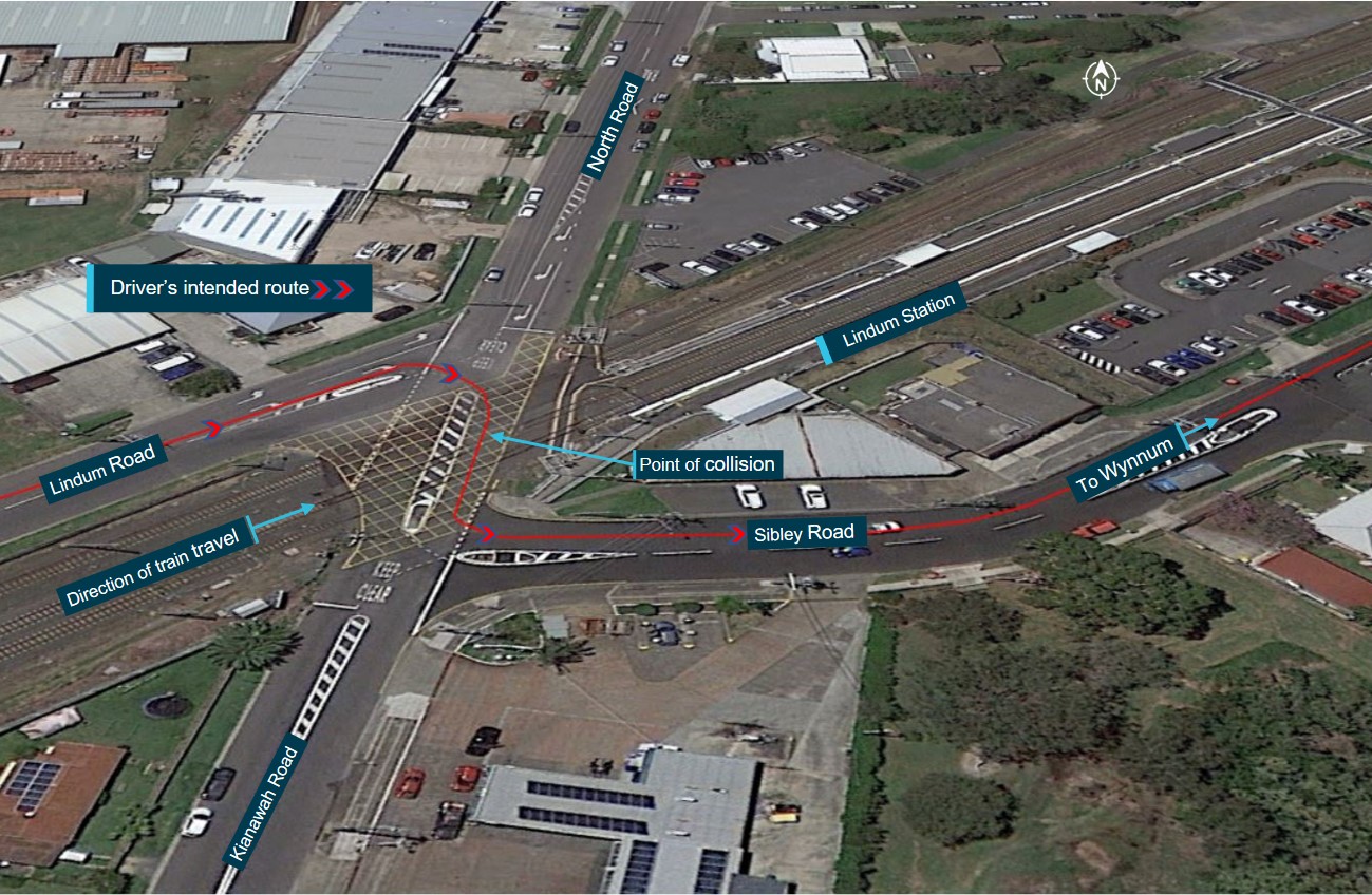
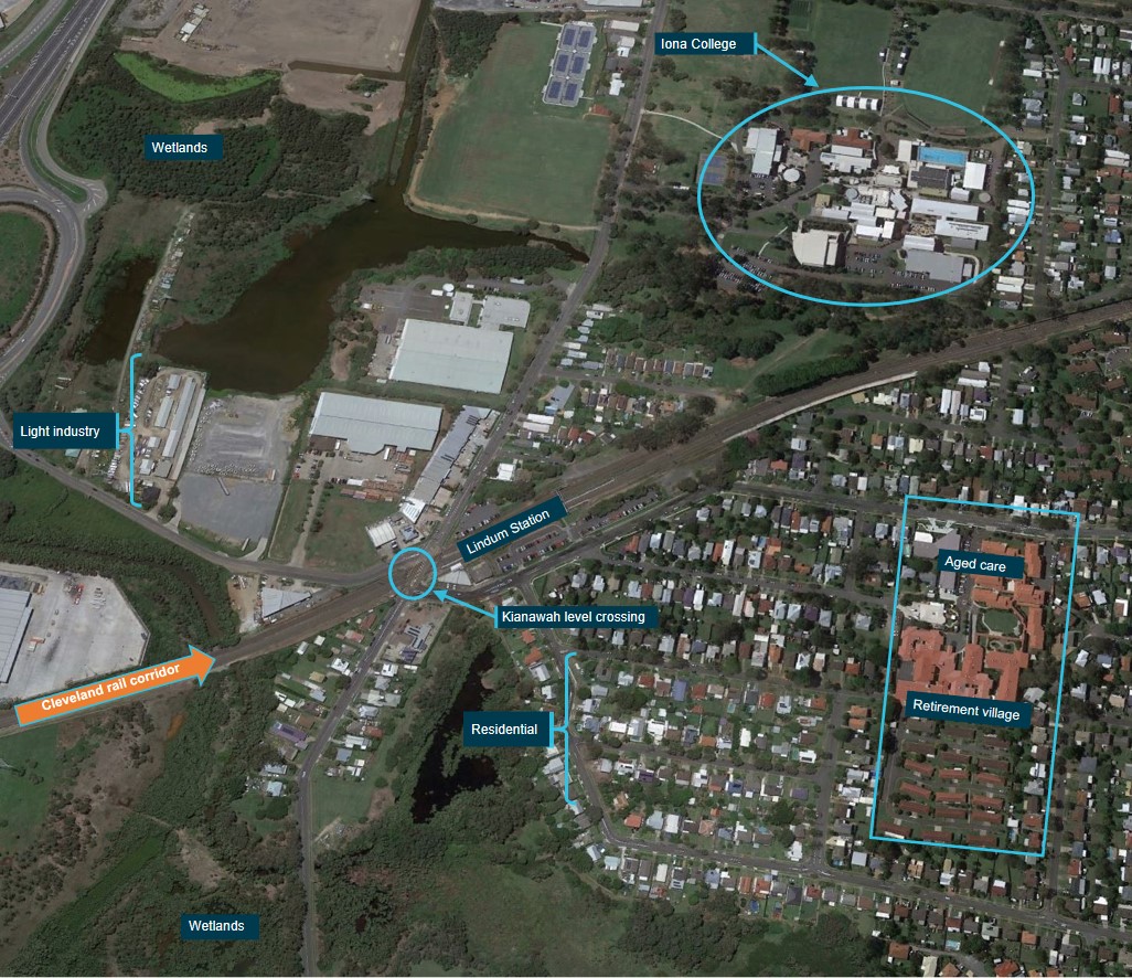
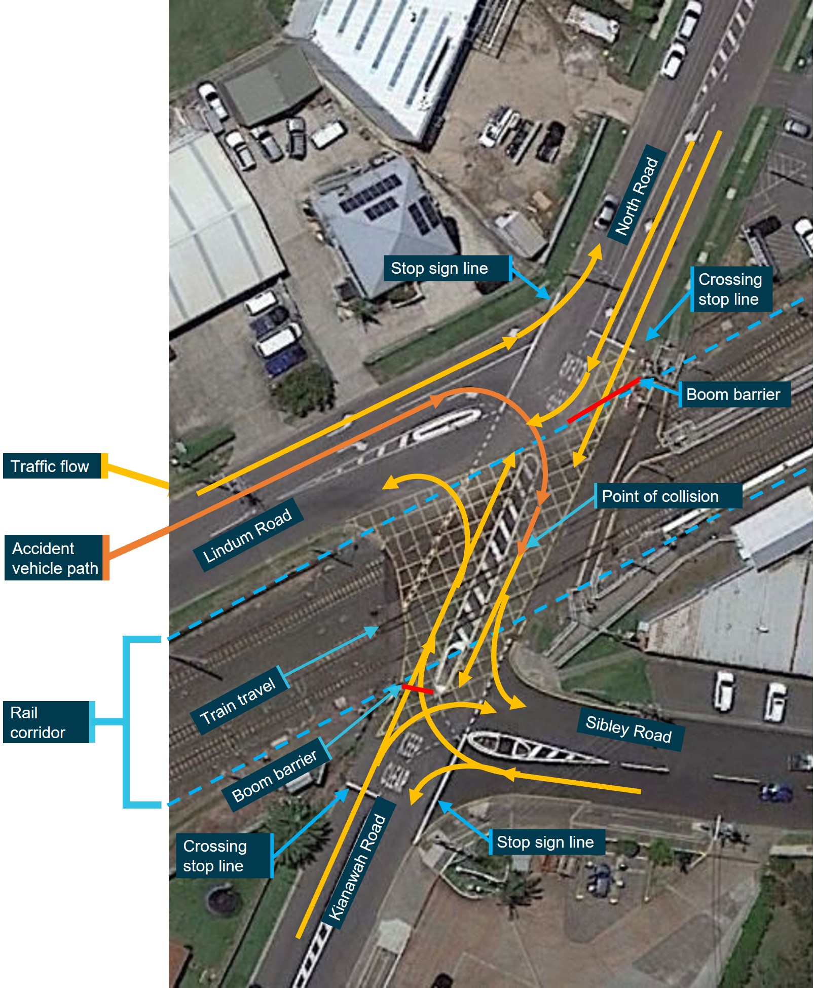
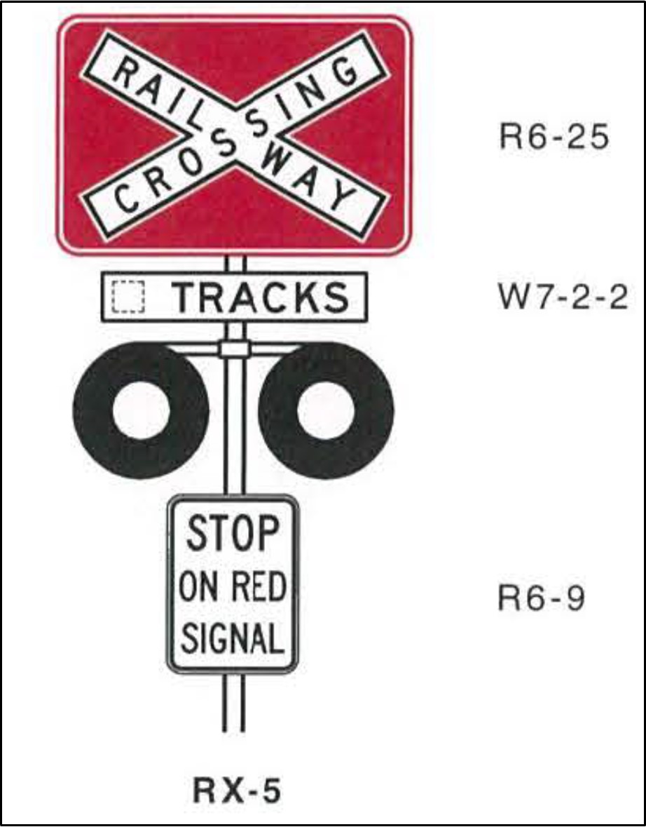
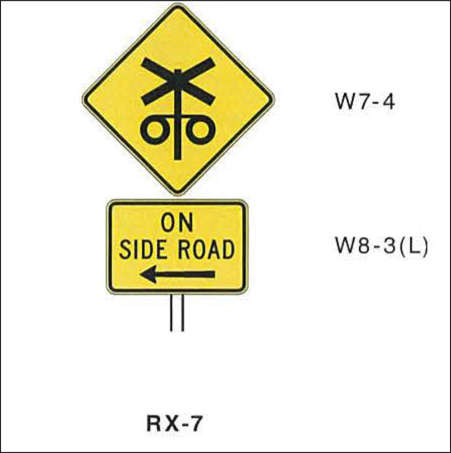
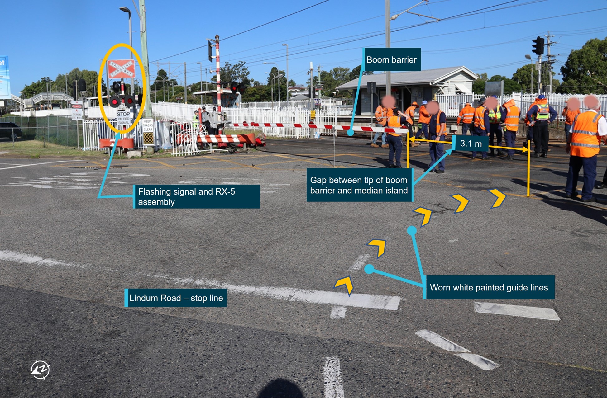

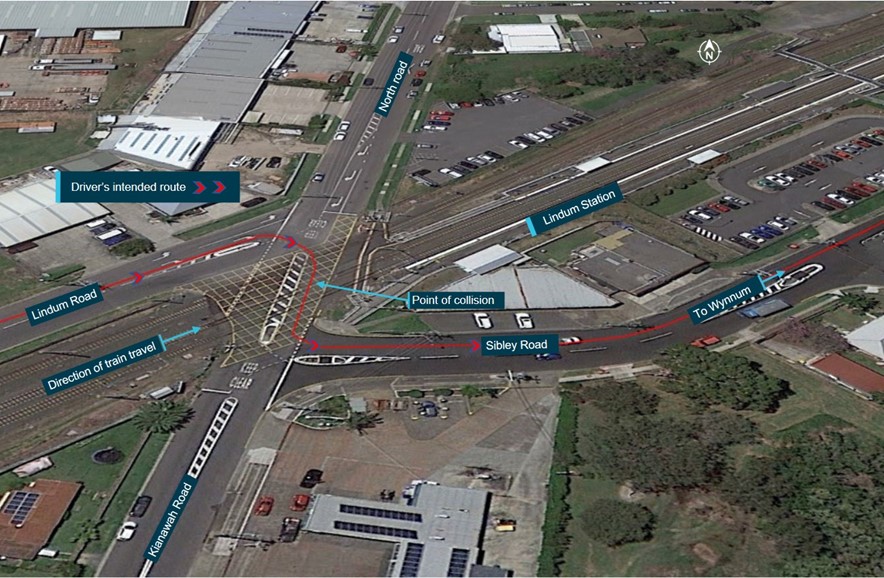
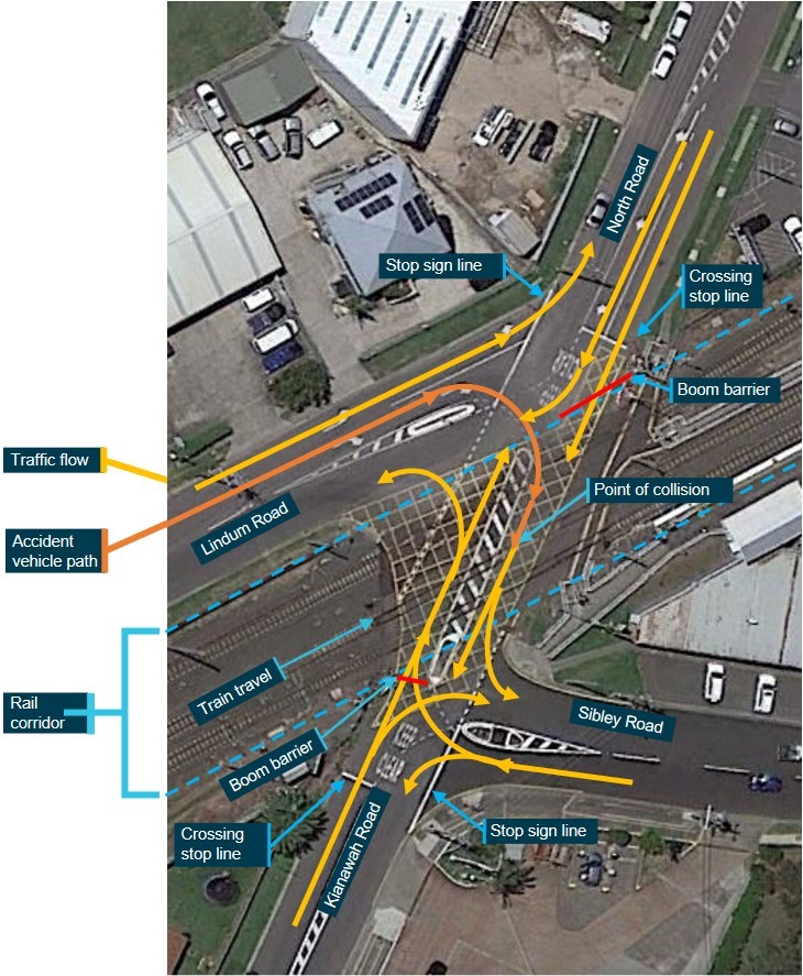

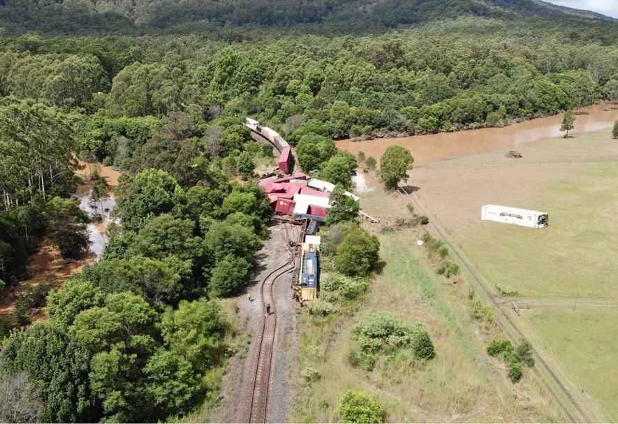
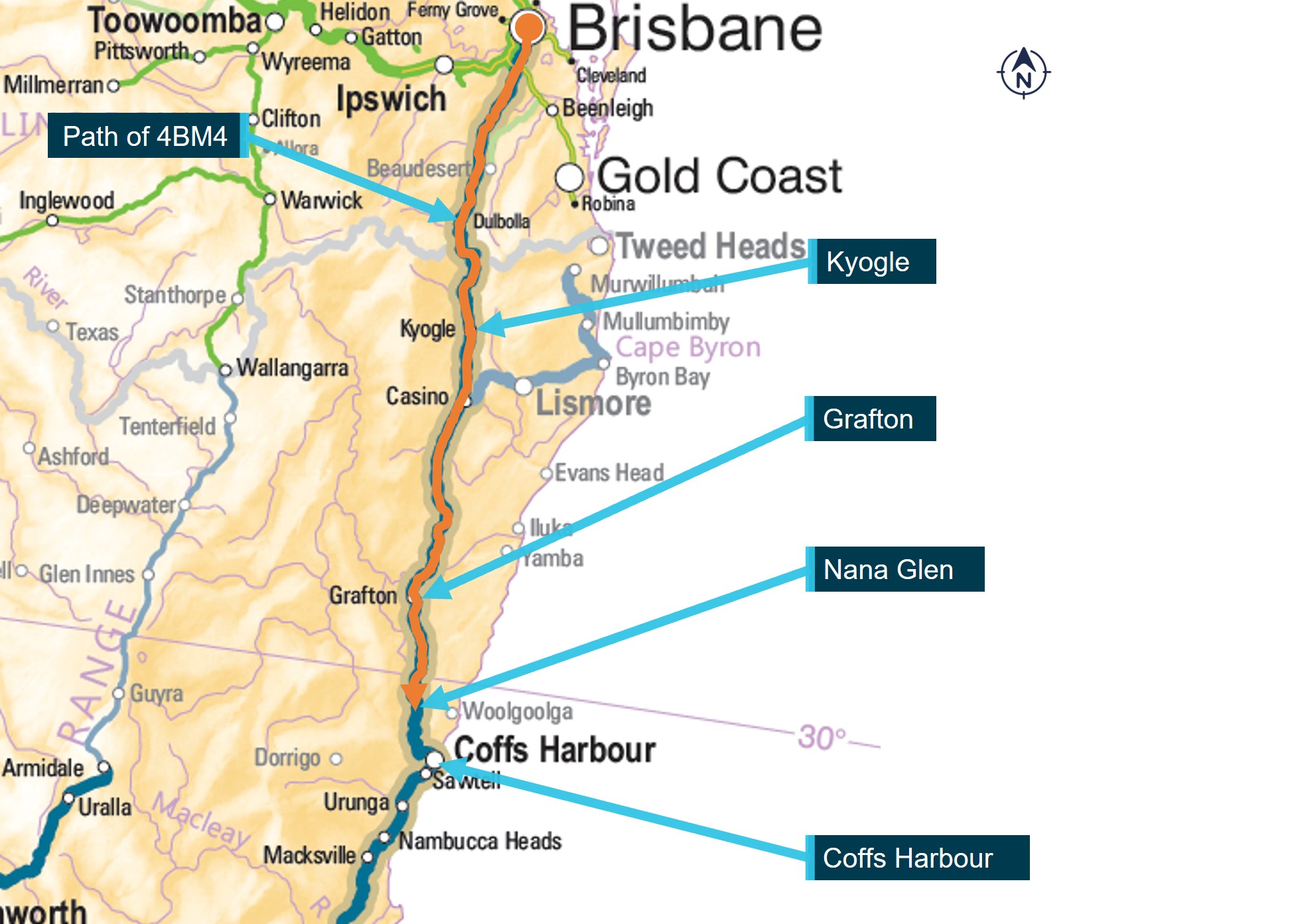
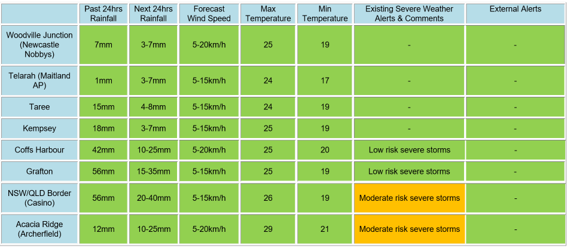
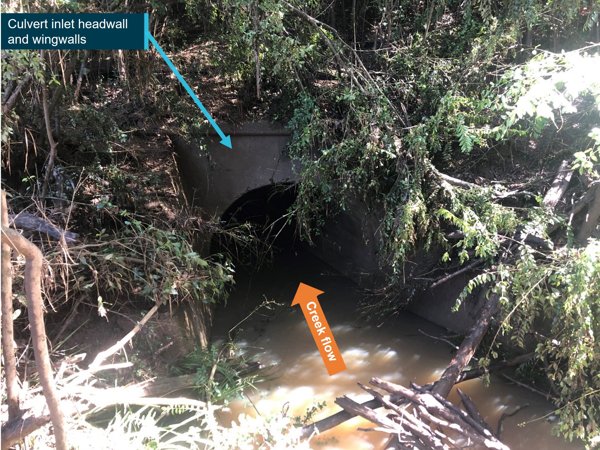
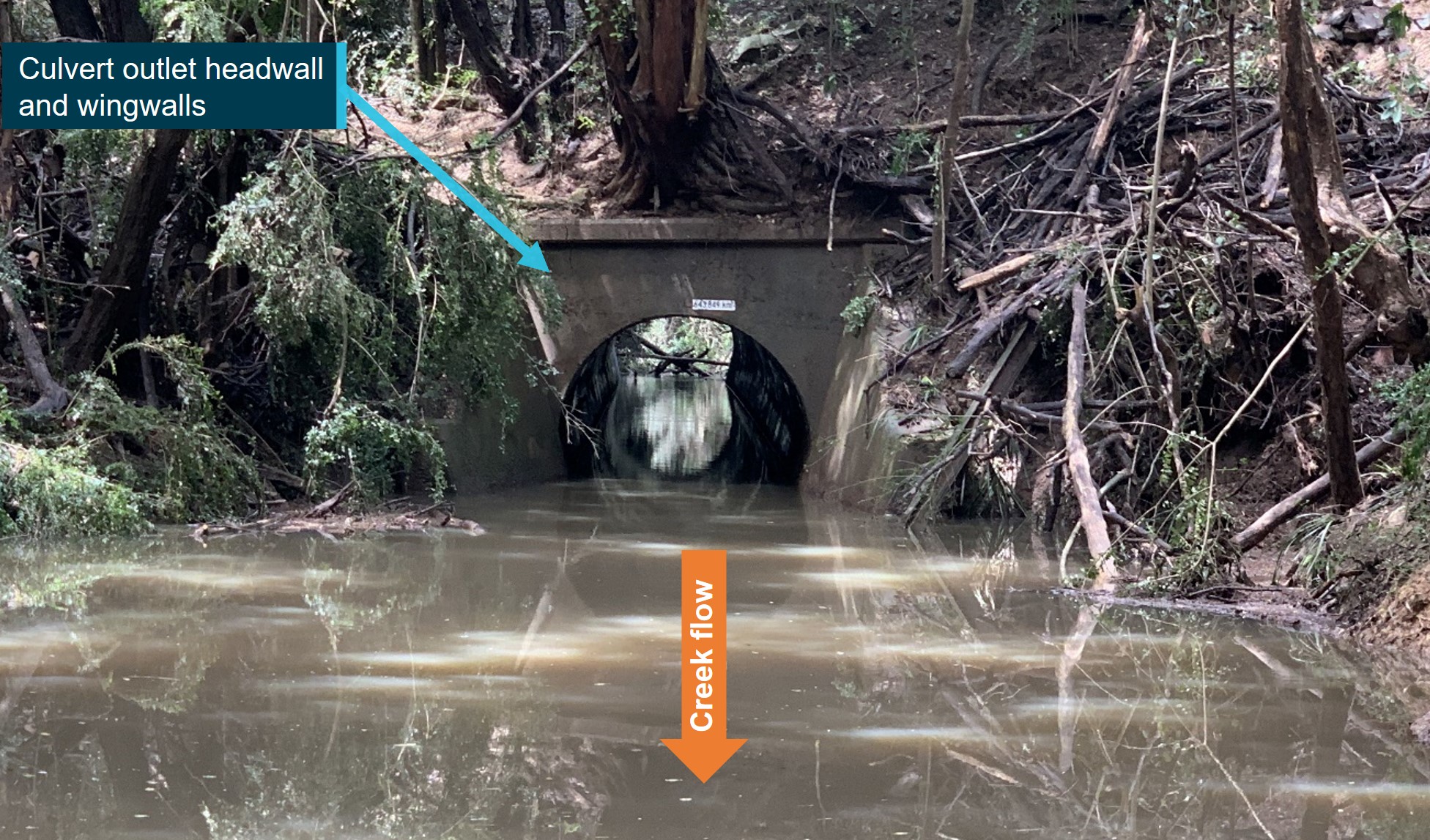
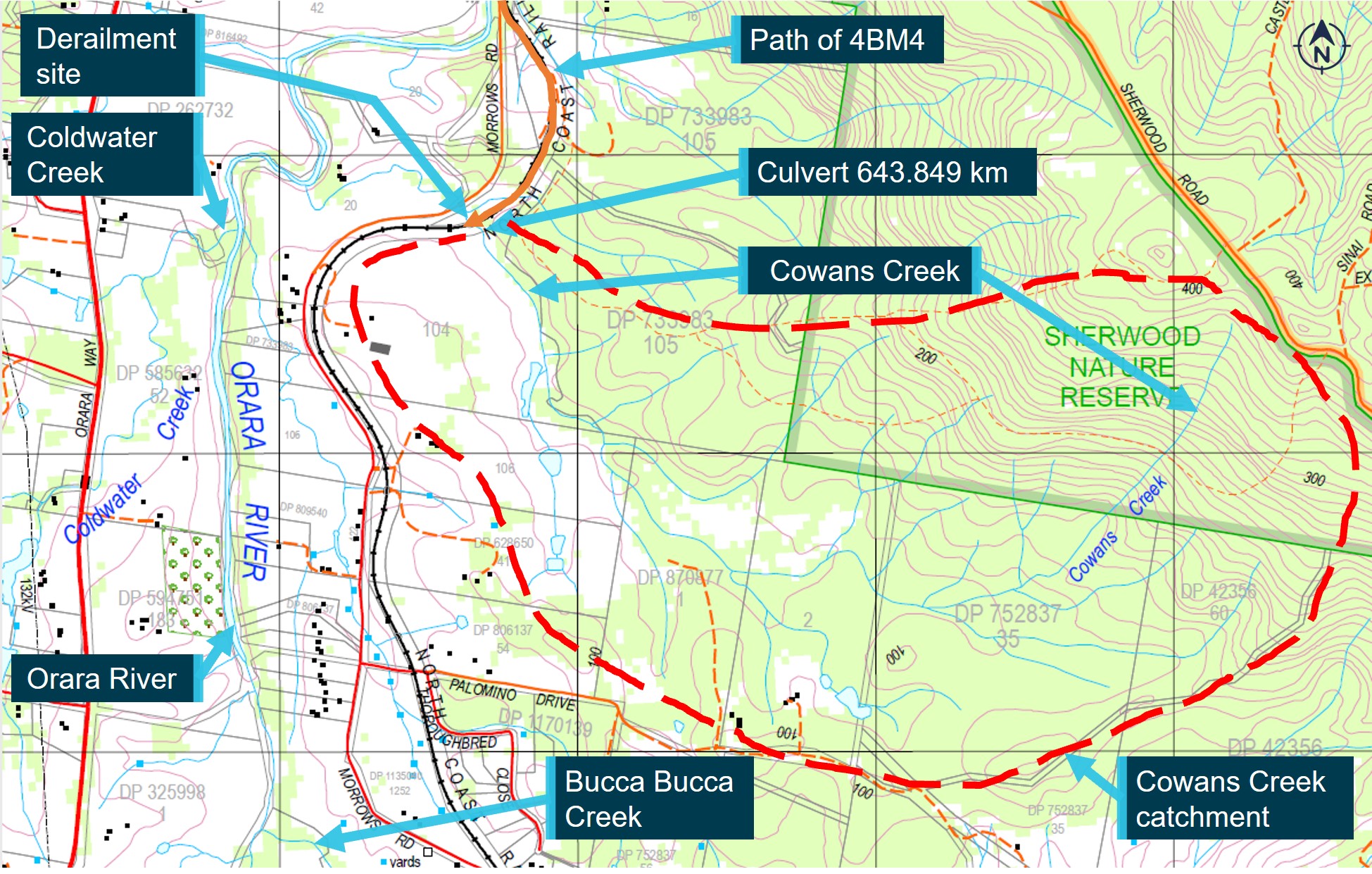
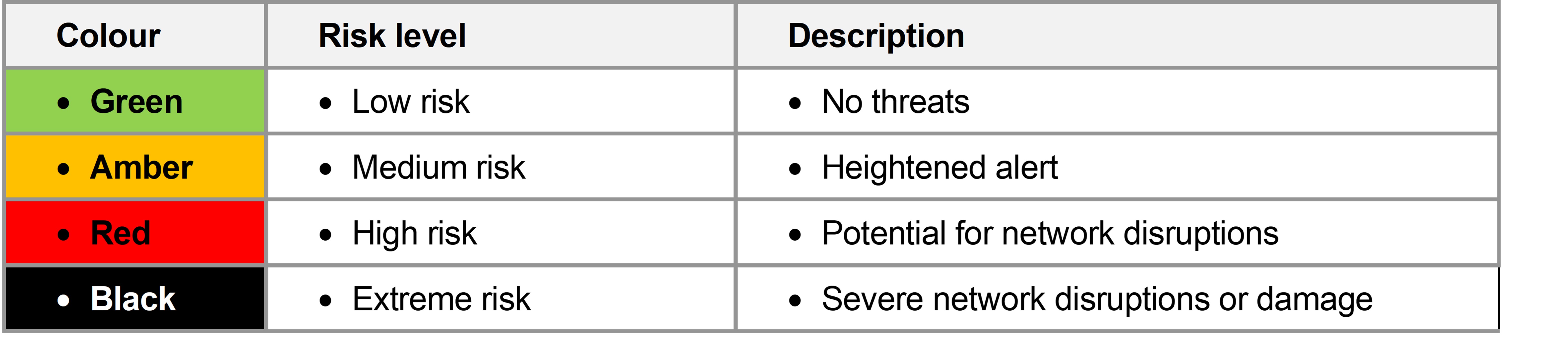
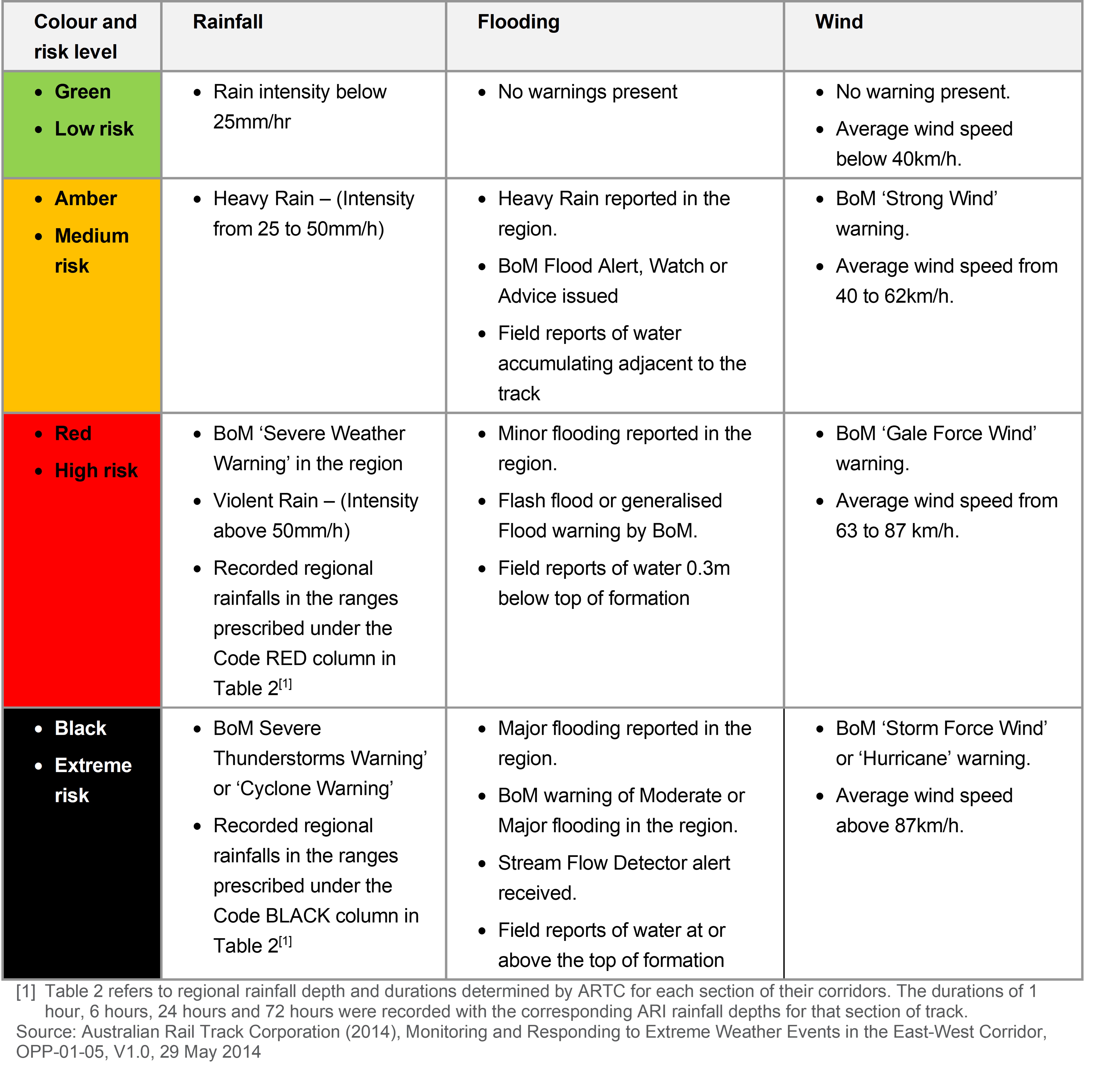
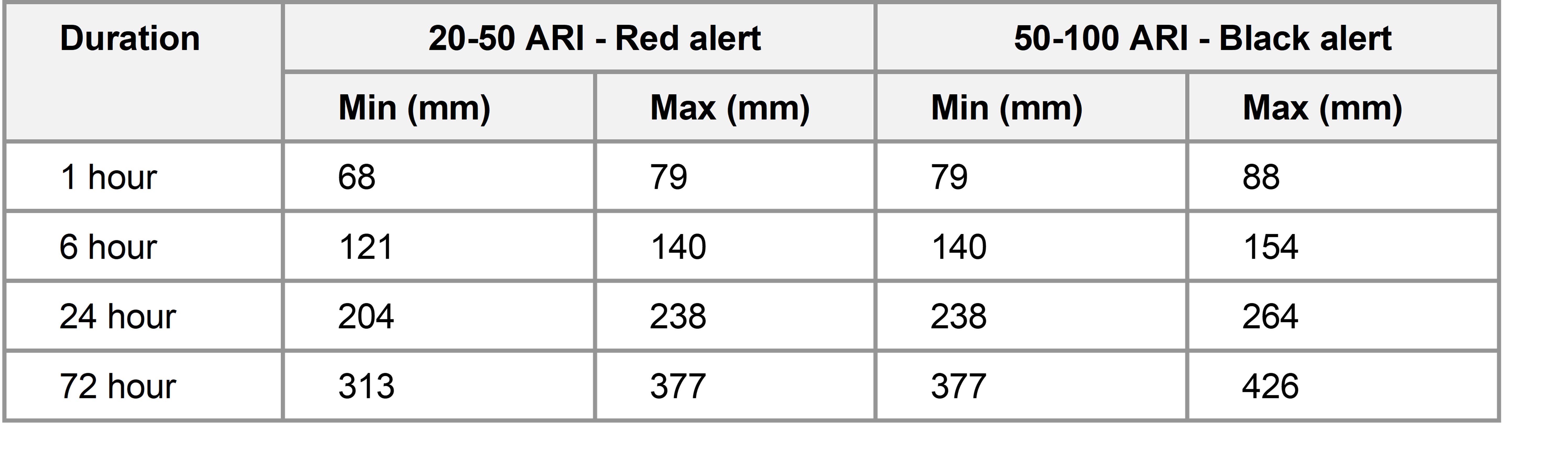
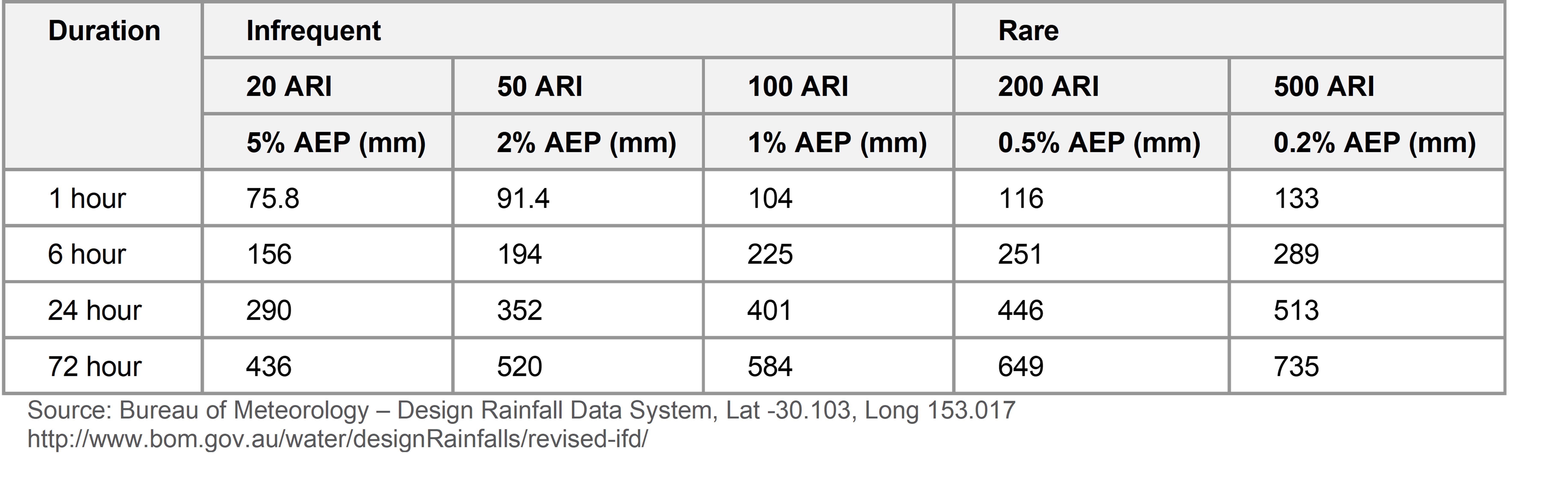
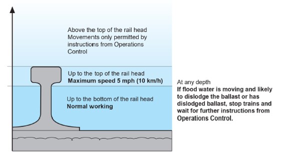
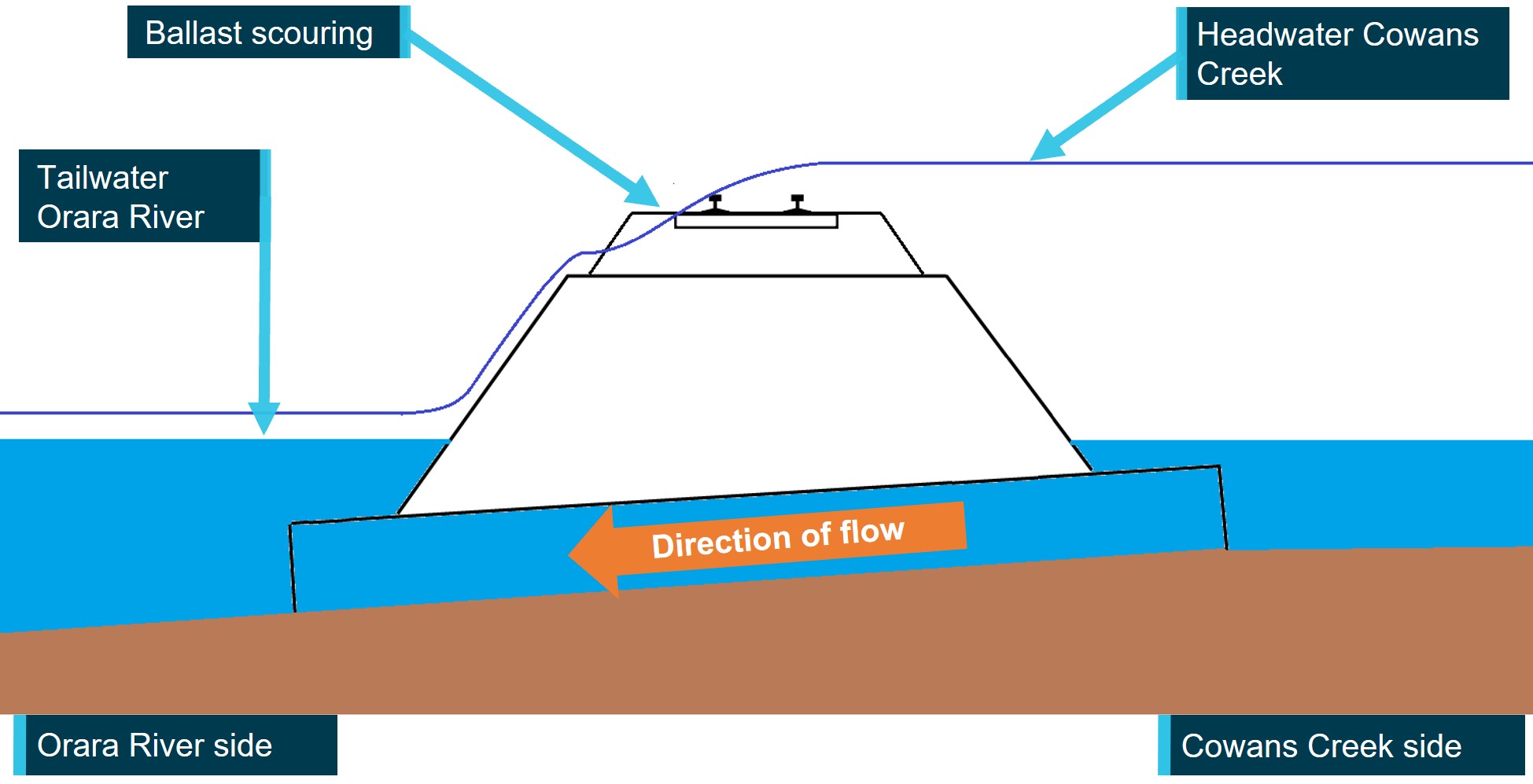
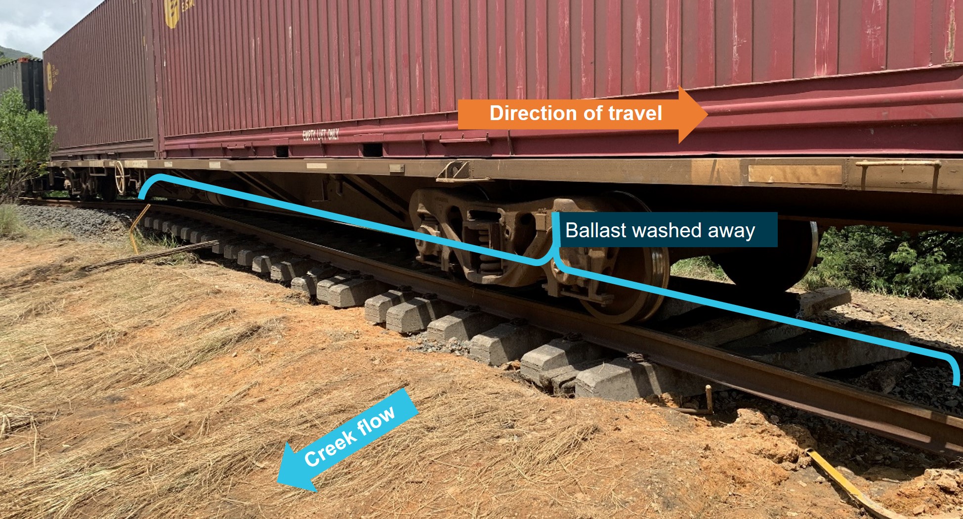
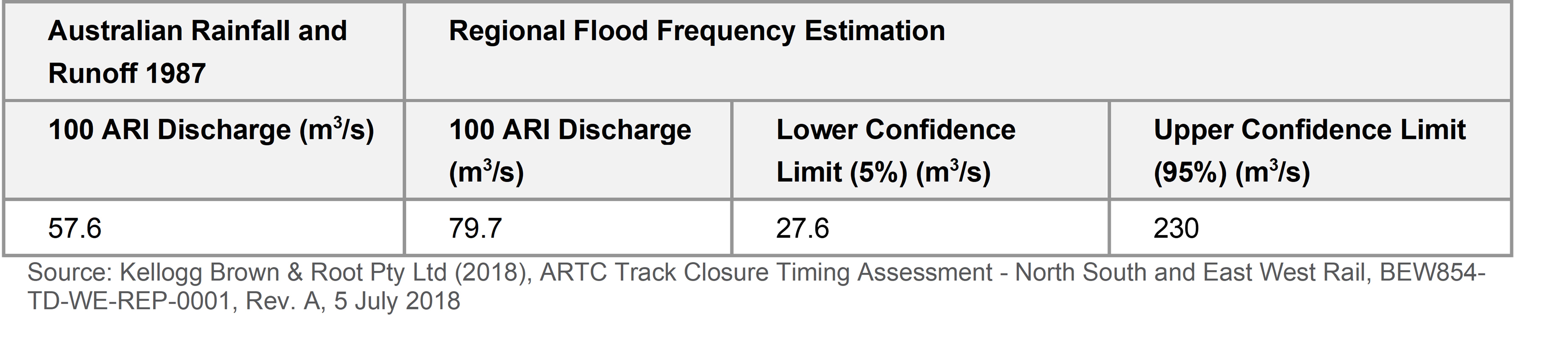


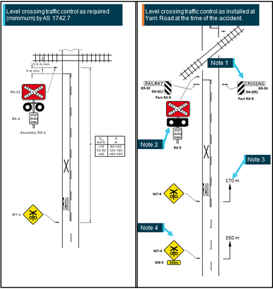
![Figure 9: Satellite Infrared imagery[12] at 1830 showing extent of clouds and storms in the area visited by VH-HKC](/sites/default/files/2023-01/AO-2021-006_figure%209.png)