Mountain wave turbulence

Mountain wave and associated turbulence

In Australia, mountain waves are commonly experienced over and to the lee of mountain ranges in the south-east of the continent. They often appear in the strong westerly wind flows on the east coast in late winter and early spring.

Mountain waves are a different phenomena to the mechanical turbulence found in the lee of mountain ranges, and can exist as a smooth undulating airflow or may contain clear air turbulence in the form of breaking waves and 'rotors'. Mountain waves are defined as 'severe' when the associated downdrafts exceed 600 ft/min and/or severe turbulence is observed or forecast.

'Breaking waves' and 'rotors' associated with mountain waves are among the more hazardous phenomenon that pilots can experience. Understanding the dynamics of the wind is important in improving aviation safety.
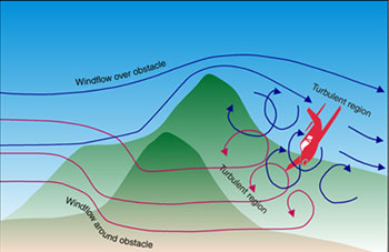
Windflow over obstacle

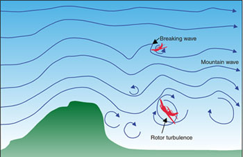
Mountain wave turbulence breaking wave

Glider pilots learn to use these mountain waves to their advantage; typically to gain altitude. However, some aircraft have come to grief in those conditions. Encounters have been described as similar to hitting a wall. In 1966, clear air turbulence associated with a mountain wave ripped apart a BOAC Boeing 707 while it flew near Mt. Fuji in Japan. In 1968, a Fairchild F-27B lost parts of its wings and empennage, and in 1992 a Douglas DC-8 lost an engine and wingtip in mountain wave encounters.

Mountain waves are the result of flowing air being forced to rise up the windward side of a mountain barrier, then as a result of certain atmospheric conditions, sinking down the leeward side. This perturbation develops into a series of standing waves downstream from the barrier, and may extend for hundreds of kilometres over clear areas of land and open water.

Mountain waves are likely to form when the following atmospheric conditions are present:

  • the wind flow at around ridge height is nearly perpendicular to the ridge line and at least 25 kts
  • the wind speed increases with height
  • there is a stable layer at around ridge height.

If the wave amplitude is large enough, then the waves become unstable and break, similar to the breaking waves seen in the surf. Within these 'breaking waves', the atmospheric flow becomes turbulent.

The crests of the waves may be identified by the formation of lenticular clouds (lens-shaped), if the air is sufficiently moist. Mountain waves may extend into the stratosphere and become more pronounced as height increases. Some pilots have reported mountain waves at 60,000 feet. The vertical airflow component of a standing wave may exceed 8,000 ft/min.

Rotors or eddies can also be found embedded in mountain waves. Formation of rotors can also occur as a result of down slope winds. Their formation usually occurs where wind speeds change in a wave or where friction slows the wind near to the ground. Often these rotors will be experienced as gusts or windshear. Clouds may also form on the up-flow side of a rotor and dissipate on the down-flow side if the air is sufficiently moist.

Many dangers lie in the effects of mountain waves and associated turbulence on aircraft performance and control. In addition to generating turbulence that has demonstrated sufficient ferocity to significantly damage aircraft or lead to loss of aircraft control, the more prevailing danger to aircraft in the lower levels in Australia seems to be the effect on the climb rate of an aircraft. General aviation aircraft rarely have performance capability sufficient to enable the pilot to overcome the effects of a severe downdraft generated by a mountain wave or the turbulence or windshear generated by a rotor. In 1996, three people were fatally injured when a Cessna 206 encountered lee (mountain) waves. The investigation report concluded, "It is probable that the maximum climb performance of the aircraft was not capable of overcoming the strong downdrafts in the area at the time".

Crossing a mountain barrier into wind also reduces the groundspeed of an aircraft and has the effect of keeping the aircraft in the area of downdraft for longer, while an aircraft flying downwind on the upwind side of a mountain range is likely to initially encounter updrafts as it approaches rising ground. Rotors and turbulence may also affect low level flying operations near hills or trees. In 1999, a Kawasaki KH-4 hit the surface of a lake during spraying operations at 30 feet. The lack of sufficient height to overcome the effects of wind eddies and turbulence was a factor in the accident.

Research into 'braking waves' and 'rotors' or eddies continues but there is no doubt that pilots need to be aware of the phenomenon and take appropriate precautions. Although mountain wave activity is usually forecast reasonably well by the Bureau of Meteorology, many local factors may effect the formation of 'breaking waves' and 'rotors'. When planning a flight a pilot should take note of the winds and the terrain to assess the likelihood of waves and rotors. There may be telltale signs in flight, including the disturbances on water or wheat fields and the formation of clouds, provided there is sufficient moisture for cloud to form.

Prudent flight planning may include allowing for the possibility of significant variations in the aircrafts altitude if updrafts and downdraughts are encountered. A margin of at least the height of the hill or mountain from the surface should be allowed, and consideration given to the need to adopt a manoeuvring airspeed appropriate to the circumstances. Ultimately, it may be preferable for pilots to consider diverting or not flying, rather than risk flying near or over mountainous terrain in strong wind conditions conducive to mountain waves containing 'breaking waves' and 'rotors'.

Further Reading

Bureau of Meteorology. (2007). Manual of Aviation Meteorology. Second Edition, pp 59, 60, 68. Airservices Australia.

Bureau of Air Safety Investigation Journal. (1991, September). Downslope winds are dangerous. BASI Journal, 9, pp 38-39.

Jorgensen, K. (undated). Mountain flying: A guide to helicopter flying in mountainous and high altitude areas. Westcourt, QLD: Cranford Publications.

Lester, P. F. (1993). Turbulence: A new perspective for pilots. Englewood, CO: Jeppesen Sanderson.

McCann, Donald W. (2006). Diagnosing and forecasting aircraft turbulence with steepening mountain waves. National Weather Digest, pp 77-92.

New Zealand Civil Aviation Authority (2006), Good Aviation Practice, Mountain Flying booklet.

Welch, John, F. (Ed.). (1995). Van Sickles modern airmanship (7th Ed). New York, NY: McGraw-Hill.

Woods, R. H., & Sweginnis, R. W. (1995). Aircraft accident investigation. Casper, WY: Endeavor Books.

Revised: 29 October 2009.

Publication details

Publication type Educational Fact Sheet
Publication mode Aviation
Publication date 01/02/2005

How does ATSB identify a safety problem in the aviation industry?

The primary objective of any investigation into an air safety occurrence is the prevention of an accident.

Sometimes an investigation will uncover a safety deficiency in the aviation system and recommendations are made to address the deficiency. At other times the details and circumstance of an accident or incident don't immediately uncover a safety deficiency or even provide immediate answers. However, the occurrence data is collected and stored in the ATSB database and may at some time in the future form part of a wider analysis of safety issues.

A safety deficiency is defined in the Transport Safety Investigation Act 2003 subsection 23(2) as one of the categories of transport safety matters that can be investigated. It is defined as:

Something that occurred that affected, is affecting, or might affect, transport safety.

To identify a deficiency the ATSB first collects information from an investigation or safety (research) study. Then it analyses the data and works with the industry to develop safety recommendations and actions.

Aviation safety deficiencies may be found in many factors and could include one or more of the following:

  • aircraft or component design
  • the manufacturing or quality control process
  • maintenance and/or engineering procedures
  • regulatory standard, information and advisory documents
  • operational procedures
  • Air Traffic Services procedures and documentation
  • corporate management procedures.

If recommendations are made as a result of a safety deficiency, they are sent to the most appropriate organisation or agency to effect change. This may include the Civil Aviation Safety Authority, Airservices Australia, maintenance and aircraft operators and manufacturers.

Publication details

Publication type Safety Education Material
Publication mode Aviation
Publication date 01/01/2005
Subject matter General information

Dangerous distraction: An examination of accidents and incidents involving pilot distraction in Australia between 1997 and 2004

An examination of the Australian Transport Safety Bureau's aviation occurrence database indicates that distraction has contributed to a number of aviation safety accidents and incidents. The purpose of this study was to:

(i) examine the characteristics of pilot distraction
(ii) explore the range of distraction sources that have contributed to aviation safety occurrences, and
(iii) develop a taxonomy of pilot distraction.

In total, 325 occurrences were identified using the database. The results showed that the majority of occurrences were incidents rather than accidents or serious incidents. Distraction affected all operational groups and occurred during all phases of flight, including both ground and in-flight phases. Although most occurrences did not result in injuries, there were two accidents in which fatal injuries were sustained by the pilot-in-command. Many sources of pilot distraction were associated with equipment malfunctions, problems communicating on the radio, passengers, and weather. The sources of distraction provided the basis for the development of a taxonomy of pilot distraction. When applied to the dataset, the results indicated that the majority of distraction sources could be grouped into the categories of 'flight management tasks', 'external objects', and 'people on board the aircraft'. In summary, the findings suggested that distractions can affect a pilot operating in any type of organisation, from small regional operations to large commercial airlines. Distractions can arise unexpectedly, during periods of high or low workload, or during any phase of the flight. The report concludes with a number of tentative suggestions for minimising the risk of pilot distraction.

Publication details

Publication type Research and Analysis Report
Publication mode Aviation
Publication date 27/02/2006
Review date 27/02/2011
ISBN 1 877071 97 8

Diabetes mellitus and its effects on pilot performance and flight safety: A review

Diabetes mellitus is a disease with a wide spectrum of severity and many potential complications if inadequately treated. Historically, diabetic pilots have been permanently disqualified from flying duties. This policy was based on the increased risk of sudden incapacitation in-flight due to hypoglycaemia and cardiovascular disease in diabetics. In recent decades, a shift in worldwide aeromedical policy has occurred. This has resulted in diabetic pilots in several countries, including the United States and Australia, being granted limited flying certification. These pilots are required to satisfy a number of stringent medical criteria to achieve this certification. Aeromedical policy must be based on an appropriate risk management strategy, taking into account all relevant issues. Australian guidelines for the certification of diabetic pilots are designed to limit certification to all but the most well-controlled, motivated, and well supervised diabetic with no disease-related complications.

Publication details

Publication number B2005/0027
Publication type Research and Analysis Report
Publication mode Aviation
Publication date 30/06/2005
Authors Dr David G. Newman
ISBN 1 921092 04 1
Subject matter Health

Examination of an RB211-524G-T Turbofan Engine Compressor Failure

Boeing 747-438, VH-OJU

EXECUTIVE SUMMARY

An Australian registered Boeing 747-438 aircraft operating a regular passenger transport flight sustained the failure of an engine shortly after take-off from Los Angeles, USA. The engine was subsequently shutdown and the aircraft returned for an uneventful landing.

The failed engine was a Rolls Royce RB211-524G2-T model. Preliminary inspection by the operator's maintenance personnel found evidence of extensive internal mechanical damage within the high-pressure compressor section of the engine and as a result, returned the engine to Australia for inspection and overhaul.

The Australian Transport Safety Bureau examined the engine following its disassembly into primary modules. The engine had failed as a result of the liberation of a single blade from the first-stage high-pressure compressor section. That failure subsequently precipitated a titanium metal fire within the compressor, extensively damaging the following stages and rendering the engine inoperative.

The engine manufacturer has attributed three previous failures of RB211 high-pressure compressors to the loss of blades from the first-stage rotor. The blade losses were all associated with fatigue cracking of the dovetail root connection. The manufacturer identified uneven centrifugal loads on the blade roots as a significant factor in the development of blade cracking; possibly exacerbated by 'patchy' root friction and minor mechanical imperfections in the critical blade root transition region.

Evidence from the current investigation indicated the nature of the failure to be very similar to the previously reported events.

Publication details

Publication mode Aviation
Publication date 15/12/2002
Review date 15/12/2002

Examination of the Main Landing Gear Wheel Bearings

During a routine departure from Melbourne aerodrome, the inner left main landing gear wheel separated from a B727 aircraft (registration VH-TXH) and was later recovered near the aerodrome perimeter fence. Preliminary examination showed that the outer axle bearing had failed, allowing the wheel hub to move axially outward over the retaining nut and off the stub axle (figure 1).

Publication details

Publication mode Aviation
Publication date 15/06/2002
Review date 02/06/2002

Cross Modal Safety Comparisons

There has been a long standing interest among various transport safety organisations, researchers, other stakeholders and the public concerning the relative safety of various transport modes. Questions are often posed along the lines: on average, is travel in a light aircraft safer than a typical journey in a private car? or - what is the safety difference between motorcycle riding and driving a car? Consideration of relative transport safety risks also has potentially important policy implications, particularly where contingent resource allocation or risk management decisions are involved. In an attempt to address the core substance of these questions this Discussion Paper explores some of the main issues associated with the development of comparative safety measures across various transport modes and compares the results available from Australian and other studies.

Publication details

Publication type Research and Analysis Report
Publication mode Aviation
Publication date 01/01/2005
Subject matter Statistics

Examination of a Failed Air Cooling Fan

Boeing Commercial Aircraft Group, 747-436, G-BNLK

1. FACTUAL INFORMATION

1.1. Examination brief

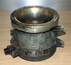
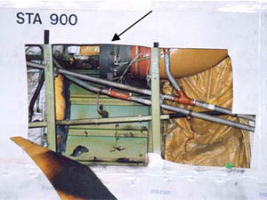
The disassembled components of an electric air-cooling fan (figure 1) were received by the ATSB Technical Analysis unit for examination and analysis of the damaged fan impeller. The fan unit had been fitted to a Boeing 747 aircraft (registration G-BNLK) to provide forced air circulation for a forward galley chiller unit. During the early stages of a flight on 10 August 2002, a small fire developed in the forward cargo compartment adjacent to this unit (figure 2). Physical and recorded evidence suggested the fire had initiated from electrical arcing that was a result of a wiring short-circuit near the fan terminal housing.

FIGURE 1:
FIGURE 2:
FIGURE 1: Cooling fan assembly. Inlet is at top.FIGURE 2: Cooling fan location (arrowed) behind cargo hold wall.

1.2. Samples received

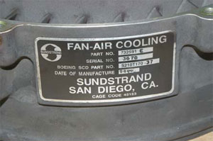
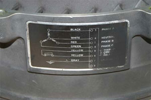
Data plates affixed to the fan housing (figures 3 & 4) identified the unit as a three-phase unit (part number 73259E, serial number 3676), manufactured by Sunstrand (San Diego, California) in 1994. The fan was an axial flow design, with a single bell-shaped impeller manufactured from a moulded resin material. The motor and fan outlet guide vane assembly shared an integral housing which also carried the (damaged) electrical terminal housing. The motor was a brushless (induction) design, with the armature supported on sealed rolling element bearings. Surrounding the impeller was an aluminium shroud, which formed the fan intake and also provided for the mounting and support of the unit and its associated ducting.

FIGURE 3:
FIGURE 4:
FIGURE 3 & 4: Data and wiring information plates affixed to the fan housing.

1.3. Visual examination

1.3.1. Impeller

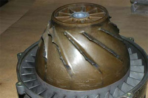
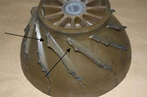
The impeller unit had been effectively 'cobbed', with all eleven blades fractured at or immediately adjacent to the impeller hub (figure 5). The uneven, irregular nature of the fractures suggested the failure occurred as a cascading fragmentation event, with multiple sections of blade breaking away and striking others, causing further break-up. A study of all fracture surfaces failed to identify any evidence of pre-existing defects or cracking that may have precipitated the initial blade failure, nor was any indication found of unusual hard-object impact damage that may have suggested foreign object ingestion. There was some evidence however that suggested early damage to the impeller blade forward corners - many blades showed breakage of a curved lip of material from the corners in a manner that suggested possible contact with the fan shroud (figure 6).

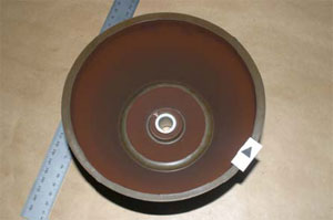
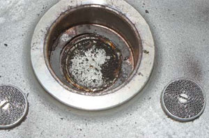
The inside surfaces of the impeller body carried a heavy coating of a powdery brown dust (figure 7), which was also evident inside the armature core and around the end of the motor housing. This material was loose and easily wiped away by hand and a sample was taken for later qualitative chemical analysis.

FIGURE 5:
FIGURE 6:
FIGURE 5: 'Cobbing' of all the blades from the impeller body.FIGURE 6: Scalloped fracture form at the forward edge of several impeller blades.
FIGURE 7:
 
FIGURE 7: Dusty brown deposit on inside of impeller body.
1.3.2. Fan shroud

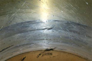
Produced as a machined die-casting from an aluminium alloy, the fan shroud encased the full impeller length and showed no evidence of having failed to fully contain the fractured impeller blades. Around the blade tip path, the shroud internal surfaces showed several circumferential wear bands that indicated significant tip interference (figure 8). These were most clearly defined at the forward and rear limits of the blade path. Random indentation and scratching damage was noted around the shroud 'throat' region - this was consistent with the effect of multiple fragment impacts produced by the failing impeller blades. No specific evidence of hard-object impact damage was found across the blade path. Dark, waxy stains produced by an unidentified liquid draining through the fan shroud were noted at the low-point of the assembly (figure 9) and a series of tide-marks were formed on the front face of the shroud as the liquid had accumulated and later drained away.

FIGURE 8:
FIGURE 9:
FIGURE 8: Fan shroud showing prominent evidence of rotational contact.FIGURE 9: Fan shroud with stains from liquid draining through the assembly.
1.3.3. Fan motor and housing

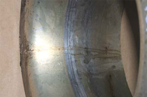
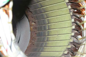
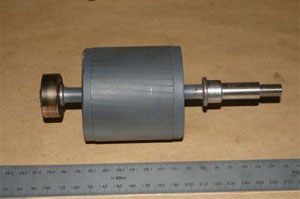
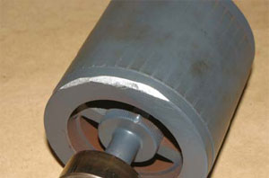
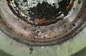
Being a brushless three-phase induction motor, the unit was comparatively simple in construction, with a star-wound stator containing a compact cage-type armature. Internal inspection found evidence of rub and erosion of the iron stator former over the innermost twenty millimetres of the stator length (figure 10), however the armature did not reflect this and showed no evidence of operational damage (figure 11). Several areas where material had been removed by bevelling the core corners were evidence that the armature had been re-balanced at some time following original manufacture (figure 12). Both armature shaft bearings rotated smoothly by hand and showed no notable indications of distress or abnormal operation. The rear armature bearing housing (figure 13) contained particulate debris that appeared to be the fine brown dust mixed with lubricant lost from the bearing unit. The contact points of the leaf spring and the housing bottom showed light fretting damage (figure 14), with some evidence of rotation also noted.

FIGURE 10:
FIGURE 11:
FIGURE 10: Motor stator inside surface showing clear evidence of rotational contact against the armature.FIGURE 11: Motor armature showing no evidence of contact with the stator.
FIGURE 12:
FIGURE 13:
FIGURE 12: Motor armature with material removed for balancing purposes.FIGURE 13: Motor end bearing housing with contaminants found.
FIGURE 14:
FIGURE 15:
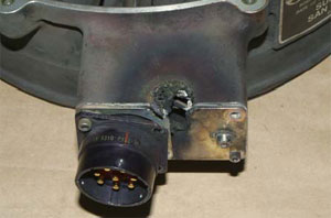
FIGURE 14: Area of fretting damage found between the seating spring and housing base.FIGURE 15: Electrical arcing damage and associated metal loss.

The fan motor electrical supply was routed behind the outlet guide vanes and terminated in an external housing fitted with an eight-pole connector. A localised area of heavy electrical arcing was clearly evident adjacent to the connector and had resulted in the melting and loss of around ten to fifteen millimetres of material in a v-shaped notch from both the front and side faces of the connector housing (figure 15). The metal loss had exposed some of the internal wiring and had produced an appreciable level of heating around the contact area, as evident from the tinting of the surrounding surfaces.

1.4. Dust analysis

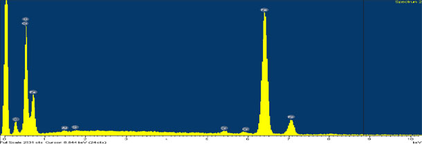
The sample of brown dust recovered from the underside of the impeller body was qualitatively analysed using energy-dispersive x-ray spectroscopy techniques under the scanning electron microscope. The results of this test work (figure 16) showed the material to be comprised primarily of an iron-oxide compound, with traces of chromium, aluminium and silicon.

FIGURE 16:
FIGURE 16: EDS spectra for the brown dust found beneath the impeller. Strong Fe and O peaks.

2. ANALYSIS

2.1. Impeller failure

All of the failed impeller blades exhibited brittle overload fractures. No evidence of material flaws, cracks or other pre-existing damage was shown by the blade stubs, however this was not conclusive, given the opportunity was not available to examine all of the blade remnants. Resin materials such as that used to manufacture the impeller have an inherent lack of ductility and as such, are prone to cracking and fracture under impact or elevated stress conditions. While no direct evidence was found to suggest the ingestion of foreign object/s, the damage sustained was not unlike that expected from such an event, and thus this possibility cannot be discounted.

2.2. Motor damage

The abrasion exhibited by the inner sections of the stator assembly was believed to be evidence of armature contact, presumably caused by the failure and collapse of the end bearing unit. The dust under the fan impeller was believed to be an accumulation of wear products from this contact - both the stator former and the armature core were ferrous alloys, while the remainder of the motor and fan assembly was predominantly aluminium based materials. Given that the installed armature showed no indication of stator contact and the end bearing was sound, it was concluded that the stator damage was a product of a previous failure that had been repaired by replacement of the armature and the re-use of the remaining components, including the impeller.

The collapse and failure of an armature shaft bearing and the shaft misalignment that results would be expected to alter the impeller - shroud clearances, with a risk of contact between the shroud and the impeller blade tips if the misalignment became severe enough. Impeller blade tip contact, if it did not produce immediate blade breakage, may produce latent cracking damage that could lead to later blade failures if not detected. While there was no evidence found to suggest that pre-existing damage of this nature existed, the possibility remained that this damage had been sustained given the evidence of the rear bearing failure and the contact marks inside the fan shroud.

2.3. Vibration

Rotary equipment such as the cooling fan relies upon accurate dynamic balancing to minimise the vibration induced during operation. Events such as the impeller failure will disrupt the balance of the assembly and can lead to significantly increased vibration levels. Wiring or piping that is installed against or in contact with the vibrating equipment may sustain fretting or erosion damage if the external protection or insulation has not safeguarded against this event.

3. CONCLUSIONS

3.1. Findings

  1. The cooling fan impeller had sustained gross breakage of all blades at or adjacent to the body of the impeller.
  2. All fractures were brittle in nature and showed no evidence of pre-existing defects.
  3. No evidence of foreign object damage was found.
  4. The fracture profiles of some blades suggested preferential tip breakage before the complete blade failure.
  5. The fan motor showed evidence of a previous rear bearing failure that had produced contact and wear between the armature and the stator. The armature had subsequently been replaced, however the stator and other motor components remained in service.
  6. The previous bearing failure may have allowed operating contact between the impeller blade tips and the fan shroud. This contact may have produced blade cracking which predisposed the impeller to failure in the manner observed.
  7. After failure, the fan impeller would have presented a significant unbalanced load to the fan.

Publication details

Publication mode Aviation
Publication date 10/08/2002
Review date 10/08/2002

Examination of a Failed Rolls-Royce RB211-524 Turbofan Engine

Boeing Commercial Aircraft Group, 747-436, G-BNLD

1. FACTUAL INFORMATION

1.1. History of the flight

On the evening of March 1, 2002, Boeing 747-436 aircraft G-BNLD sustained the failure of the number-3 (right inboard) engine during a scheduled regular passenger transport flight from Sydney to Bangkok. The flight crew experienced vibrations and received an ENG 3 REVERSER engine indicating and crew alerting system (EICAS) message. The crew shut down the number-3 engine and completed checklist items before returning the aircraft to Sydney.

An initial engineering examination found that a fan blade from the number-3 engine had failed and that debris had punctured the engine cowl, the right wing leading and trailing edge flaps and the fuselage; damaging a structural member above the wing root area. The inspection found fractured fasteners and other components beneath the fan cowls and damage to the structure associated with the thrust reverser assembly. Debris from the number-3 engine was also found embedded within the intake cowl of the adjacent number-4 engine.

Publication details

Publication mode Aviation
Publication date 01/03/2002
Review date 01/03/2002