On 23 September 2026, an Airbus A220-300, registered VH-X4A, was being operated as QantasLink flight QLK1550, a scheduled passenger service from Brisbane to Townsville, Queensland. During the approach into Townsville, the flight crew encountered reduced visibility due to low cloud and conducted a missed approach. Visibility did not improve for the second approach, and another missed approach was conducted.
Following a short period in a holding pattern, the flight crew commenced a third approach. During the approach, the flight crew declared a MAYDAY due minimum fuel, however visibility had subsequently improved, and the aircraft was able to land.
The ATSB has commenced the examination and analysis of the initial evidence collected.
To date, the ATSB has interviewed the flight crew, obtained operational documentation, recorded data, weather information and collected other relevant information.
A final report will be released at the conclusion of the investigation. Should a critical safety issue be identified during the course of the investigation, the ATSB will immediately notify relevant parties, so that appropriate safety action can be taken.
Occurrence Briefs are concise reports that detail the facts surrounding a transport safety occurrence, as received in the initial notification and any follow-up enquiries. They provide an opportunity to share safety messages in the absence of an investigation. Because occurrence briefs are not investigations under the Transport Safety Investigation Act 2003, the information in them is de-identified.
What happened
Sequence of events
On 14 May 2026, at about 0800 local time, the pilot of a Cessna 172 (C172) aircraft commenced a taxi from the northern hangars at Kalgoorlie-Boulder Airport, Western Australia, to depart from runway 29. The purpose of the flight was to conduct a local area scenic flight with one passenger on board.
The C172 pilot had heard a transmission on the local common traffic advisory frequency (CTAF) from an inbound passenger‑carrying Boeing 737 aircraft, which would soon land on runway 29. The C172 pilot made a transmission stating that they would taxi for a departure using runway 29.
While taxiing, at 0802, the pilot of the C172 heard a transmission from another large air transport aircraft, which was inbound from 30 NM (56 km) north of the airport. The pilot of that aircraft reported they expected to start a 5 NM (9 km) final approach to runway 29 at 0811 and to touchdown at 0813.
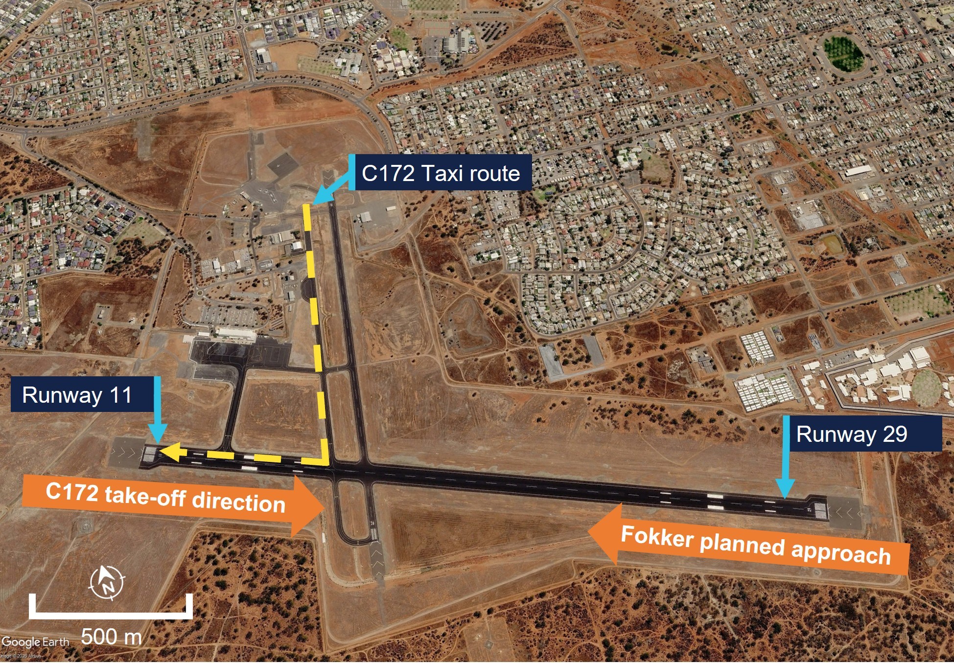
The pilot of the C172 had observed a light northerly wind, which meant a departure from either direction was suitable for their aircraft. To improve the scenic flight for their passenger, and as they assessed that they had the time before the arrival of the aircraft inbound from the north, they elected to change their planned departure to runway 11 (Figure 1).
The pilot of the C172 held short of runway 11/29 and observed the recently landed Boeing 737 vacate the runway for the apron. They visually checked for any other traffic in the area and at 0802:34 made a radio call to advise their intention to depart from runway 11, then entered and backtracked that runway. No other pilot acknowledged this transmission.
Meanwhile, unbeknown to the pilot of the C172, a Fokker 100 aircraft, carrying 94 passengers, was on the 10 NM (19 km) arc conducting a VOR-Z1 approach for runway 29. The captain, who was acting as the pilot monitoring,2 was also a check and training captain and was conducting a check flight for the first officer, who was the pilot flying for the sector to Kalgoorlie-Boulder.
The captain reported that they had originally briefed an arrival at Kalgoorlie-Boulder for runway 11. However, the forecast winds meant other aircraft may use runway 29 and the crew planned to change to runway 29 if the flow of traffic dictated it. After hearing the Boeing 737 use runway 29 for its arrival, the crew of the Fokker planned an arrival for runway 29 (Figure 1).
Figure 1: Kalgoorlie-Boulder Airport and planned departure for the C172 and arrival for the Fokker 100
Source: Google Earth, annotated by the ATSB
The crew of the Fokker had broadcast their intentions and expected landing times when at 25 NM (46 km) west and 9 NM (17 km) west-south-west of the airport. CTAF recordings from the airport showed that both of those calls were made before the taxi call from the C172. The captain of the Fokker stated they had received the C172 pilot’s initial radio call advising they were taxiing for runway 29. However, the captain indicated that they did not acknowledge the C172 pilot’s taxiing transmission and did not hear any subsequent calls from the pilot.
The pilot of the C172 made a radio call and commenced their take-off roll from runway 11 at 0803:54, while the Fokker was joining a 5 NM (9 km) final approach for the opposite direction runway 29.
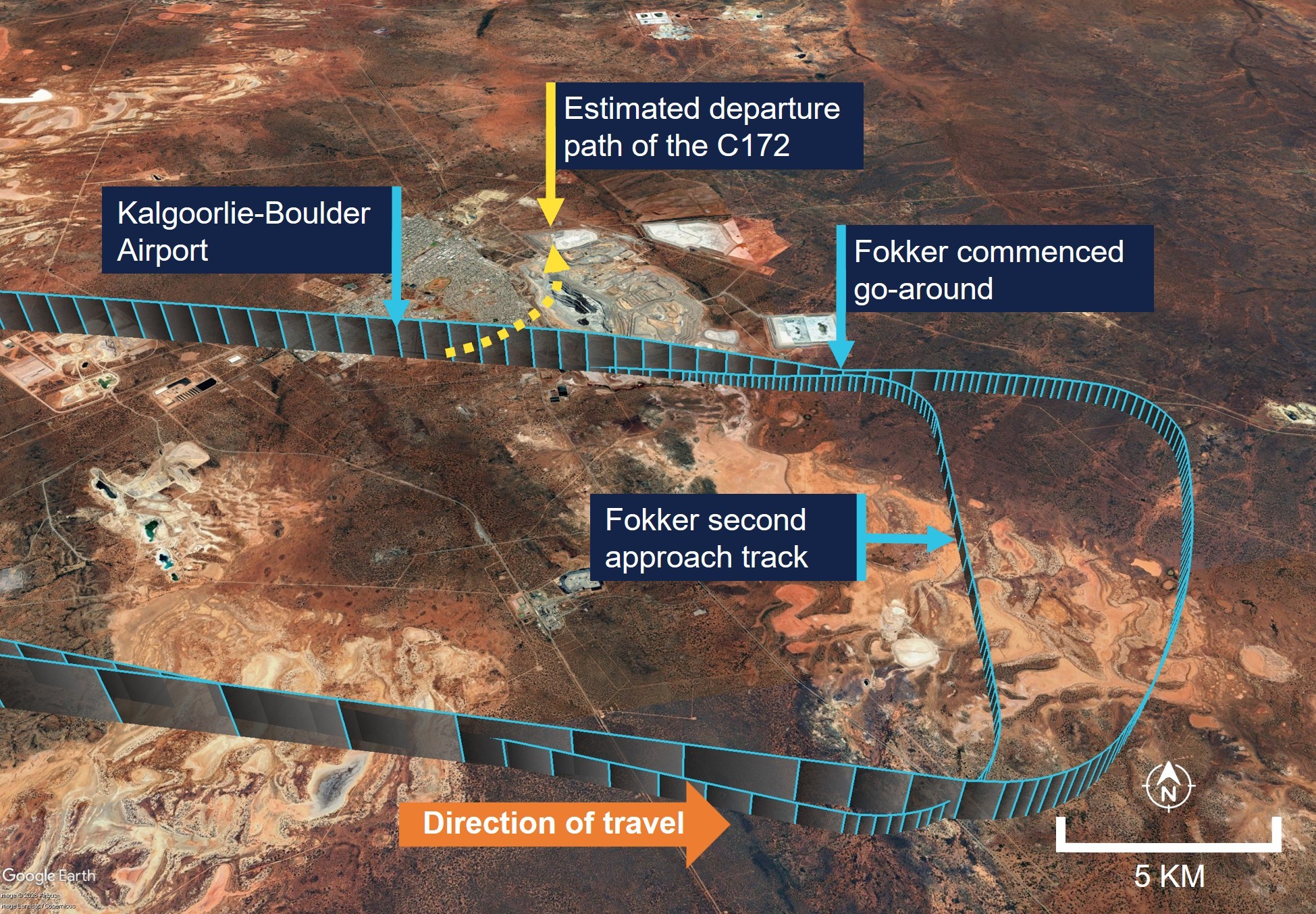
At 0805:11, the crew of the Boeing 737, now parked on the apron, proactively alerted the crew of the Fokker that the C172 had departed towards them. The pilot of the C172 estimated that they were about 1,700 ft above mean sea level when they heard this transmission and immediately commenced a left turn away from the airport. The crew of the Fokker, who were about 5 NM (9 km) from touchdown and at about 2,800 ft, made a radio call advising their understanding and intention to go around. The crew initiated the go-around, maintained their heading and climbed to 5,000 ft (Figure 2).
Figure 2: Fokker 100 track to Kalgoorlie-Boulder and C172 estimated departure path
Source: Google Earth and Flight Radar 24, annotated by the ATSB
The captain of the Fokker reported they had no indication of the traffic on their traffic alert and collision avoidance system3 (TCAS). After completing the go-around, the captain established direct communication with the C172 pilot and queried the status of that aircraft’s transponder.4 Although the C172 pilot stated that their transponder was ‘ON’, the C172 was not actually fitted with a working transponder nor was it required to be for the operations conducted that day.
The Fokker returned to the airport and landed without further incident on runway 29. The C172 completed the scenic flight and also returned without incident.
Frequency congestion
The captain of the Fokker reported that the Kalgoorlie-Boulder Airport CTAF was congested around the time of the occurrence. From about 0800, 3 large passenger‑carrying air transport aircraft, the C172 and an aircraft at Kambalda aerodrome, about 25 NM (46 km) south-south-east of Kalgoorlie-Boulder, were on the same frequency. While pilots had to wait for a break in transmissions to make radio calls, all pilots were able to communicate their intentions.
From the Fokker’s initial 25 NM (46 km) inbound transmission to the crew announcing their go-around around 10 minutes later, 18 transmissions from 5 aircraft were recorded on the CTAF. This accompanied a period of high workload for the crew of the Fokker 100 who were landing and conducting a check flight.
Safety action
The operator of the C172 advised that the aircraft was subsequently flown to Perth to be fitted with a transponder equipped with ADS-B.5 The pilot of the C172 was issued with an electronic flight bag6 and trained in its use for flight planning and record keeping purposes, and to also aid in additional traffic awareness.
Safety message
Proactive action by the crew of the Boeing 737, to alert the Fokker crew to the C172’s departure, played a large part in avoiding a more serious outcome. The information the B737 crew provided updated the understanding of the pilots of both converging aircraft to what was happening and both pilots were able to respond.
Flight crews are reminded that vigilance for other traffic at busy non-controlled aerodromes is essential and although TCAS is a useful aid for traffic awareness, not all aircraft are required to have transponders fitted. Therefore, TCAS cannot be solely relied upon for traffic information.
Pilots must understand the equipment fitted to their aircraft and how that impacts conspicuity. Operators of all aircraft, and especially those operating in busy, non‑controlled aerodromes, are strongly encouraged to consider the benefits of a Mode S transponder with ADS-B in and out capability. Further information on the current rebate scheme for the installation of ADS-B is available at ADS-B rebate scheme | Civil Aviation Safety Authority.
Pilots are reminded that although accurate and timely radio calls play a critical role in ensuring collision avoidance in non-controlled airspace, they cannot assume from an absence of other radio calls that there is no conflicting traffic. This is particularly important in an environment where there is a high expectation of mixing with other aircraft of different sizes, flight rules and performance levels, operating at the same time in the same airspace.
As aviation developed, with increasing aircraft performance, traffic density and flight in non-visual conditions, it became apparent that unalerted see-and-avoid had significant limitations. The need to enhance a pilot’s situational awareness led to the principle of ‘alerted see-and-avoid’.
The primary tool of alerted see-and-avoid that is common across aviation—from sport and recreational to air transport—is radio communication. Radio allows for the communication of information (in this instance traffic information) to the pilot from the ground (e.g. Air Traffic Services) or from other aircraft.
The ATSB SafetyWatch highlights the broad safety concerns that come out of our investigation findings and from the occurrence data reported to us by industry. This occurrence highlights the safety concerns around reducing the collision risk around non-towered airports.
About this report
Decisions regarding whether to conduct an investigation, and the scope of an investigation, are based on many factors, including the level of safety benefit likely to be obtained from an investigation. For this occurrence, no investigation has been conducted and the ATSB did not verify the accuracy of the information. A brief description has been written using information supplied in the notification and any follow-up information in order to produce a short summary report, and allow for greater industry awareness of potential safety issues and possible safety actions.
^VOR-Z: VHF Omnidirectional Radio Range-Z. The VOR approach is designed to allow an aircraft to descend on specified VOR radials to a specified minimum descent altitude.
^Pilot flying (PF) and pilot monitoring (PM): procedurally assigned roles with specifically assigned duties at specific stages of a flight. The PF does most of the flying, except in defined circumstances, such as planning for descent, approach and landing. The PM carries out support duties and monitors the PF’s actions and the aircraft’s flight path.
^A traffic alert and collision avoidance system is an aircraft collision avoidance system designed to reduce the incidence of mid-air collision between aircraft. It monitors the airspace around an aircraft for other aircraft equipped with a corresponding active transponder.
^Transponder: A flight transponder is an automated transceiver in an aircraft that emits a coded identifying signal in response to an interrogating received signal.
^Automatic dependent surveillance–broadcast is a surveillance technology in which an aircraft determines its position via satellite navigation and periodically broadcasts it, enabling it to be tracked.
^Software and data-service solution to digitise logbooks charts, and other flight documents to achieve a paperless cockpit.
Occurrence summary
Mode of transport
Aviation
Occurrence ID
AB-2026-030
Occurrence date
14/05/2026
Location
10 km east-south-east of Kalgoorlie-Boulder Airport
Occurrence Briefs are concise reports that detail the facts surrounding a transport safety occurrence, as received in the initial notification and any follow-up enquiries. They provide an opportunity to share safety messages in the absence of an investigation. Because occurrence briefs are not investigations under the Transport Safety Investigation Act 2003, the information in them is de-identified.
What happened
On 12 April 2026, a student pilot, the sole occupant of a Cessna 172R, was conducting solo circuits at Archerfield Airport, Queensland. Prior to this, dual training (with an instructor) was conducted for about half an hour. The flight was the third time the student had flown solo, and an instructor was responsible for supervising their flight. There was a quartering headwind at about 8 kt.
The solo circuits were initially conducted on runway 28L prior to the pilot requesting a ‘full-stop landing’1 to complete the flight. At this point the air traffic controller (tower) changed the runway assignment to runway 28R.
The pilot then conducted three unsuccessful landing attempts to runway 28R. Each of these attempts resulting in the aircraft either ‘bouncing’2 or ‘porpoising’3 followed by the student conducting a go-around. The student pilot reported that during one of the attempted landings a significant ‘bounce’ occurred.
The controller reported to the operator that the second landing attempt involved the aircraft porpoising, resulting in a tail strike and what appeared to be a possible propeller strike.
The supervising instructor reported observing that the third landing was a hard landing. noting the nose wheel came into contact with the runway first. The earlier landing attempts were not fully visible by the instructor due to them not having a clear line of sight.
After the third attempt to land, the supervising instructor contacted the air traffic control tower and communicated directly with the student, via the tower frequency, to provide the student verbal assistance, helping to facilitate a safe landing on the fourth attempt.
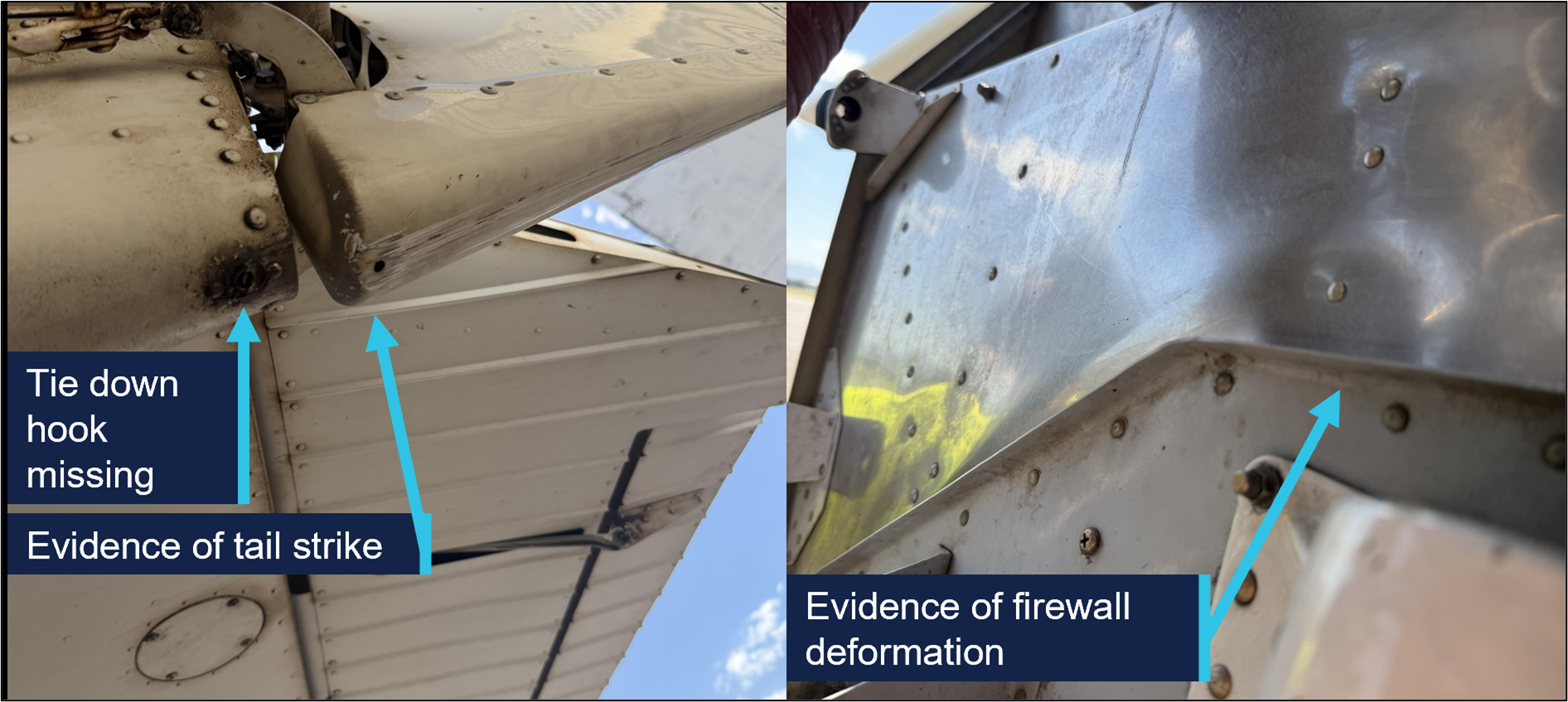
A post-flight inspection of the aircraft by the operator revealed the tail tie-down hook was missing, with evidence of a tail strike and firewall deformation (Figure 1).
Figure 1: Damage to aircraft
Source: Operator, annotated by the ATSB
Safety message
While conducting training flights, students can experience a high workload, particularly during solo flights and landing. Maintaining a calm mindset is important in order to adjust the aircraft’s profile and airspeed accordingly and determine if a go‑around is necessary.
All pilots, regardless of their experience levels, should be prepared to undertake a go‑around rather than continuing if they are not confident that a successful landing can be achieved. This occurrence also serves as a reminder that after any hard landing or other related incident where the integrity of the airframe or structure may be compromised, an engineering inspection can detect damage that may not be immediately apparent.
About this report
Decisions regarding whether to conduct an investigation, and the scope of an investigation, are based on many factors, including the level of safety benefit likely to be obtained from an investigation. For this occurrence, no investigation has been conducted and the ATSB did not verify the accuracy of the information. A brief description has been written using information supplied in the notification and any follow-up information in order to produce a short summary report, and allow for greater industry awareness of potential safety issues and possible safety actions.
^A ‘full-stop landing’ in pilot training means the pilot does not intend to take off again immediately.
^A bounced landing is a condition where the aircraft lands on the runway, but instead of rolling on the surface after touchdown, it rebounds/bounces off the ground.
^‘Porpoising’ refers to the manoeuvre that can occur after a bounced landing that is improperly recovered, in which the aeroplane comes in nose first setting off a series of cyclic vertical motions.
Occurrence summary
Mode of transport
Aviation
Occurrence ID
AB-2026-024
Occurrence date
12/04/2026
Location
Archerfield Airport
State
Queensland
Occurrence class
Accident
Aviation occurrence category
Control issues, Hard landing, Missed approach
Highest injury level
None
Brief release date
22/05/2026
Aircraft details
Manufacturer
Cessna Aircraft Company
Model
172R
Sector
Piston
Operation type
Part 141 Recreational, private and commercial pilot flight training
Activity
General aviation / Recreational-Instructional flying-Instructional flying - solo
Occurrence Briefs are concise reports that detail the facts surrounding a transport safety occurrence, as received in the initial notification and any follow-up enquiries. They provide an opportunity to share safety messages in the absence of an investigation. Because occurrence briefs are not investigations under the Transport Safety Investigation Act 2003, the information in them is de-identified.
What happened
On 16 April 2026, a pilot and passenger on board a Van’s RV-7 departed Archerfield Airport on a private flight to Fig Tree Aircraft Landing Area (ALA), Queensland. The Fig Tree ALA had a 400 m unsealed grass runway at an elevation of 1,600 ft AMSL. The pilot noted that they were conscious of the increased risk of operating into an airstrip with a short runway and had conducted short field landing practice at Archerfield the day prior.
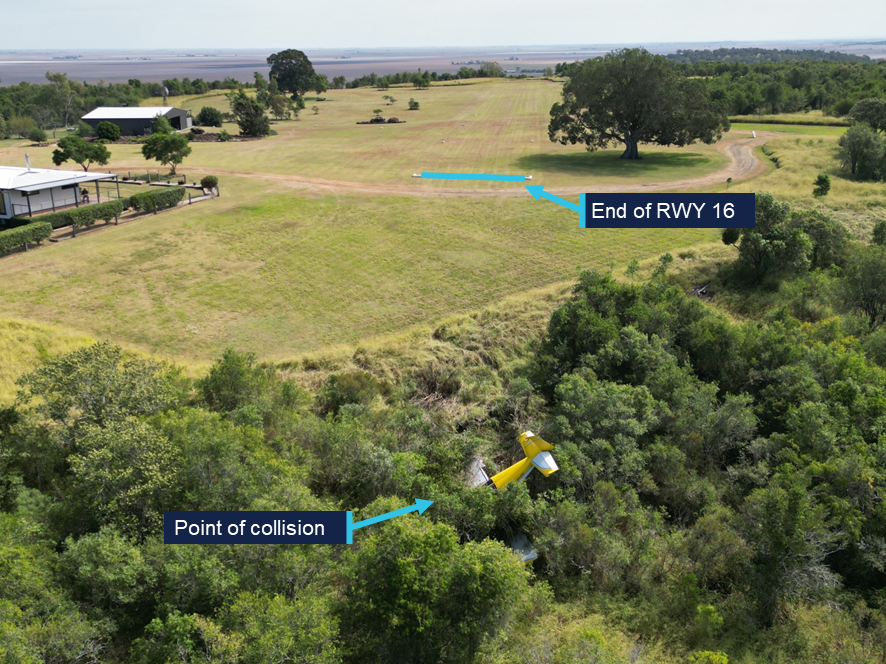
After arriving overhead Fig Tree airfield, a standard field inspection and a go-around was conducted to gain familiarity with the runway characteristics, as was required by the field operator. At 1110 local time, the aircraft commenced an approach and landing on runway 16. As the aircraft touched down midfield on the runway, the pilot determined that with the remaining landing distance available and the aircraft’s high speed, a go-around was required. During the go-around at approximately 20 ft AGL, the aircraft encountered sink and failed to climb as expected. The pilot made the decision to reduce the power to idle and attempted to conduct an off-field landing. The aircraft subsequently collided with thick shrubbery off the end of runway 16, resulting in substantial structural damage. (Figure 1). Both occupants were uninjured and extricated themselves from the aircraft.
After the occurrence, the pilot recalled that the accident approach was faster than anticipated. The operator determined there were no technical faults with the engine that affected the reduced climbing performance.
Figure 1: Fig Tree ALA
Source: Operator, annotated by the ATSB
Safety message
The margin for error while operating at airfields with short runways is limited and requires pilots to conduct the appropriate short field take-off and landing technique. In the case when an approach becomes unsuitable for a safe landing to occur, it is vital that pilots conduct a go-around as soon as practical.
The occurrence also highlights the importance for all pilots to have a personal minimums checklist that aligns with their individual flying experience. If at any time the conditions exceed these minimums or doubt is experienced, pilots should not continue to land and consider using alternative runways, alternative airfields or returning to the departure location if the available fuel permits.
About this report
Decisions regarding whether to conduct an investigation, and the scope of an investigation, are based on many factors, including the level of safety benefit likely to be obtained from an investigation. For this occurrence, no investigation has been conducted and the ATSB did not verify the accuracy of the information. A brief description has been written using information supplied in the notification and any follow-up information in order to produce a short summary report, and allow for greater industry awareness of potential safety issues and possible safety actions.
Occurrence summary
Mode of transport
Aviation
Occurrence ID
AB-2026-026
Occurrence date
16/04/2026
Location
Fig Tree Aircraft Landing Area
State
Queensland
Occurrence class
Accident
Aviation occurrence category
Collision with terrain, Control issues, Missed approach
Highest injury level
None
Brief release date
21/05/2026
Aircraft details
Manufacturer
Van's Aircraft
Model
RV-7
Sector
Piston
Operation type
Part 91 General operating and flight rules
Activity
General aviation / Recreational – Sport and pleasure flying – Pleasure and personal transport
Departure point
Archerfield Airport, Queensland
Destination
Irongate/Fig Tree Aircraft Landing Area, Queensland
The ATSB is investigating a near collision involving a Tecnam P2002 Sierra, registration 24-7996, and a Diamond Aircraft Industries DA40 NG, registration VH-YPH, at Port Macquarie Airport, New South Wales, on 29 April 2026.
During final approach, the crew of the Diamond DA 40 observed the Tecnam P-2002 enter active runway 21 and line up for take-off. The DA40 conducted a missed approach and subsequently overflew the P-2002 in close proximity.
The draft report internal review process has been completed. The draft report has been distributed to directly involved parties (DIPs) to check factual accuracy and ensure natural justice. Any submissions from those parties will be reviewed and, where considered appropriate, the draft report will be amended accordingly.
Following the external review process, any submissions and amendments to the draft report are internally reviewed. Once approved, the final report is prepared for publication and dissemination and released to DIPs prior to its public release.
The final report will be released at the conclusion of the investigation. Should a critical safety issue be identified during the course of the investigation, the ATSB will immediately notify relevant parties, so that appropriate safety action can be taken.
Last updated:
Occurrence summary
Investigation number
AO-2026-077
Occurrence date
29/04/2026
Occurrence time and timezone
1555 Australian Eastern Standard Time
Location
Port Macquarie Airport
State
New South Wales
Report status
Pending
Anticipated completion
Q4 2026
Investigation level
Short
Investigation type
Occurrence Investigation
Investigation phase
Final report: External review
Investigation status
Active
Mode of transport
Aviation
Aviation occurrence category
Missed approach, Near collision, Runway incursion
Occurrence class
Serious Incident
Highest injury level
None
Aircraft details
Manufacturer
Tecnam - C. Aeronautiche SRL
Model
P2002 Sierra
Registration
24-7996
Serial number
23
Sector
Piston
Operation type
Part 103 Sport and recreational aircraft
Activity
General aviation / Recreational-Instructional flying-Instructional flying - dual
Departure point
Port Macquarie Airport, New South Wales
Destination
Port Macquarie Airport, New South Wales
Injuries
None
Damage
Nil
Aircraft details
Manufacturer
Diamond Aircraft Industries
Model
DA40 NG
Registration
VH-YPH
Serial number
40.N289
Aircraft operator
Australian International Aviation College Pty Ltd
Sector
Piston
Operation type
Part 141 Recreational, private and commercial pilot flight training
Activity
General aviation / Recreational-Instructional flying-Instructional flying - dual
The ATSB is investigating a runway excursion and collision with tree involving a GippsAero GA8 Airvan, VH-WSU, at Lindeman Island, Queensland, on 8 March 2026.
During landing on soft and wet ground, the wheels slid and the pilot applied full power to conduct a go-around. The aircraft became airborne after the end of the runway and the landing gear contacted a tree, resulting in substantial damage. The aircraft was flown with reduced performance to Shute Harbour due to the runway condition at Lindeman Island being deemed unsuitable.
The final report has been drafted and is undergoing internal review to ensure the report adequately and accurately reflects the evidence collected, analysis, and agreed findings.
The final report will be released at the conclusion of the investigation. Should a critical safety issue be identified during the course of the investigation, the ATSB will immediately notify relevant parties, so that appropriate safety action can be taken.
Last updated:
Occurrence summary
Investigation number
AO-2026-065
Occurrence date
08/03/2026
Occurrence time and timezone
1435 Eastern Australia Standard Time
Location
Lindeman Island
State
Queensland
Report status
Pending
Anticipated completion
Q4 2026
Investigation level
Short
Investigation type
Occurrence Investigation
Investigation phase
Final report: Internal review
Investigation status
Active
Mode of transport
Aviation
Aviation occurrence category
Collision with terrain, Control issues, Diversion/return, Missed approach, Stall warning
Occurrence class
Accident
Highest injury level
None
Aircraft details
Manufacturer
Gippsland Aeronautics Pty Ltd
Model
GA8
Registration
VH-WSU
Serial number
GA8-17-244
Aircraft operator
Wave Air
Sector
Piston
Operation type
Part 135 Air transport operations - smaller aeroplanes
Activity
Commercial air transport-Non-scheduled-Joyflights / sightseeing charters
On the afternoon of 10 September 2025, a Tasman Cargo Airlines Boeing 767-300 (B767), registered VH-XQU and operating as Tasman 22, was approaching Sydney Airport, New South Wales, at the conclusion of an air transport freight‑only flight from Hong Kong International Airport, Hong Kong. While intercepting the glideslope for the instrument landing system approach for runway 16R, the aircraft’s autopilot pitched the nose down. Subsequently, the approach was conducted with a high rate of descent while descending away from the glideslope.
The descent triggered an air traffic control minimum safe altitude warning (MSAW) before the autopilot was disconnected and the aircraft levelled out at 1,700 ft, approximately 1,000 ft below the glideslope. It then descended a further 150 ft before a missed approach was commenced. On the subsequent approach, the crew elected to conduct a localiser approach and the aircraft landed without further incident.
What the ATSB found
The ATSB found that 2 Airbus A380s on the ground at Sydney Airport taxied through the instrument landing system critical area and in front of the glideslope antenna, causing interference to the glideslope signal. As a result, after detecting the interference, the Boeing 767's autopilot established the aircraft on a flight path that deviated away from the glideslope, before alerting the crew that it was operating in a degraded mode.
It was also determined that the pilot flying continued the approach with the autopilot in a degraded mode. As a result, the aircraft’s high descent rate triggered an air traffic control minimum safe altitude warning. After disconnecting the autopilot, the pilot flying delayed the initiation of a missed approach and the aircraft descended below the localiser segment minimum safe altitude. In addition, the pilot monitoring did not effectively monitor the aircraft's flight path during the approach and did not call out deviations or advise the pilot flying to conduct a missed approach.
Furthermore, it was found that Tasman Cargo Airlines allowed the practice of flight crew exchanging flying and monitoring roles prior to 1,500 ft when conducting a practice autoland. It was also identified that Tasman Cargo's training did not inform flight crew of the conditions under which instrument landing system critical areas were protected. Consequently, the flight crew believed that the critical area was being protected, and the risk of glideslope interference had been mitigated.
What has been done as a result
Tasman Cargo Airlines has conducted the following proactive safety action:
Removed the ‘glideslope out’ procedure from its policy and procedures manual (PPM), replacing it with the requirement to conduct a missed approach and notify air traffic control.
Added a note in the PPM referencing the flight crew operating manual glideslope interference bulletin.
Published an operational alert regarding Sydney Airport runway 16R glideslope interference with guidance information.
Updated computer-based training materials to better highlight the ILS critical area and requirements during normal and low visibility operations.
Introduced a requirement for the pilot flying to take control of the aircraft prior to the commencement of the approach when conducting an autoland.
In addition, while not in direct response to this occurrence, Boeing advised it is in the process of updating the flight control software for B767 aircraft. Planned for release in 2027, the update will include the following changes:
The flight director pitch bar will remain biased out of view if the autopilot is disconnected while in attitude stabilising mode.
Improved glideslope capture logic to reduce the occurrence of false captures leading to attitude stabilising mode.
Limiting the flight path angle while in attitude stabilising mode to be between 0–3.25° of descent.
Display of NO AUTOLAND after being in attitude stabilising mode for 15 seconds if the aircraft is still above alert height.
Automatic autopilot disconnect 10 seconds after the display of NO AUTOLAND if the aircraft is still above 500 ft AGL.
Safety message
Flight crew of Boeing 747-400, 747-8, 757, 767, 777 and 787 aircraft should familiarise themselves with their aircraft’s flight crew operating manual bulletin for ILS signal interference and be prepared to conduct prescribed procedures when encountering cockpit indications and autoflight behaviour consistent with the issue.
Automation can reduce pilot workload and enhance flight safety. However, it is critical that flight crew maintain constant awareness of the performance of the autoflight system. When under the control of automation, flight crew should monitor the flight path and verify that aircraft behaviour is consistent with the automation modes and parameters selected. If a discrepancy is identified, automation should be disconnected or the level of automation reduced until control is re-established.
The occurrence
On the afternoon of 10 September 2025, a Tasman Cargo Airlines Boeing 767-3JHF (B767), registered VH-XQU and operating as Tasman 22, was approaching Sydney Airport, New South Wales, at the conclusion of an air transport freight-only flight from Hong Kong International Airport, Hong Kong. On board were 3 flight crew, consisting of a captain, who occupied the left seat and was the pilot monitoring,1 a first officer who occupied the right seat and was the pilot flying, and a relief pilot who occupied a jump seat.
The crew planned to conduct a practice autoland approach (see the section titled Practice autoland) to perform a scheduled check of the aircraft’s systems. As company procedures required that the captain was the pilot flying for an autoland approach, the crew had briefed that the captain and first officer would exchange flying and monitoring roles at 1,500 ft above ground level (AGL). The first officer also recalled that the approach briefing conducted by the crew included items specific to an autoland (see the section titled Instrument approach briefing).
At 1454, when the aircraft was at its cruising level of flight level 350,2 the crew advised air traffic control (ATC) of their intention to conduct a practice autoland at Sydney, which the controller acknowledged. Shortly afterwards, the aircraft commenced descent. At 1510, the crew were transferred to the approach controller, who issued a clearance to continue descent. The crew read back the clearance and confirmed that the controller was aware they were conducting a practice autoland.
The approach controller subsequently advised the tower controller at Sydney Airport that the aircraft would be conducting a practice autoland, before transferring them to a second approach controller. At 1516, the aircraft was cleared to descend to an altitude of 3,000 ft and conduct the instrument landing system (ILS) approach for runway 16R.3 Two minutes later, at an altitude of 5,300 ft, the aircraft intercepted the localiser course for the approach. At the time, the autopilot was controlling the aircraft’s flight path and the autothrottle was engaged in speed mode (see the section titled Autoflight system).
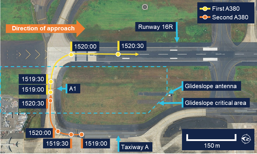
Concurrently, on the ground at Sydney Airport, an Airbus A380 was awaiting departure at holding point A1, adjacent to runway 16R (see the section titled Glideslope critical area). A second A380 was also waiting for departure in sequence on taxiway A. At 1519, the first A380 was cleared to line up on runway 16R and began moving onto the runway (Figure 1). The second A380 followed in sequence to hold at A1.
Figure 1: Ground movement of A380s
Source: Google Earth, overlaid with flight data, annotated by the ATSB
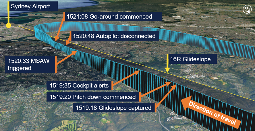
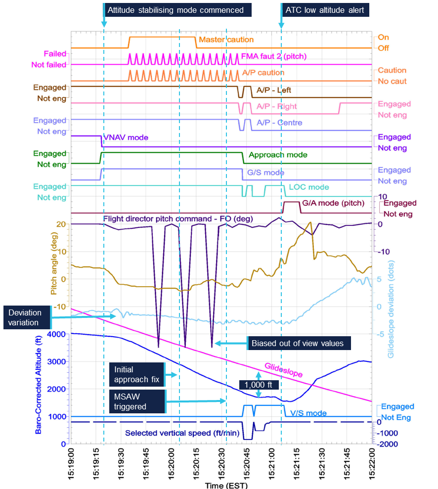
At 1519:18, when slightly below and flying to intercept the glideslope, the crew of VH‑XQU selected approach mode on the mode control panel and the autoflight system indicated that it had captured the glideslope (Figure 2). Two seconds later, the aircraft pitched down, adopting a nose down pitch of approximately 2°. As a result, the aircraft’s descent rate increased, and it began to diverge below the glideslope. At 1519:35, 15 seconds after the commencement of the pitch down and when the aircraft was descending through 3,730 ft, the crew were presented with several alerts in the cockpit:
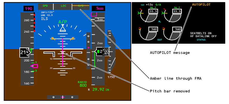
a line through the pitch (G/S) flight mode annunciation (FMA)
removal of the flight director pitch bar from the primary flight display
an autopilot caution message.
Figure 2: Flight path relative to runway 16R glideslope
Source: Google Earth, overlaid with flight data annotated by the ATSB
The first officer recalled seeing the autopilot caution and associated alerts. They also reported that they recognised that the aircraft’s descent rate had increased and that it was no longer following the glideslope. The captain also recalled identifying that the aircraft increased its descent rate, however they believed that this occurred later in the approach and that initially the aircraft followed the glideslope.
The aircraft continued to descend away from the glideslope, maintaining an average descent rate of 1,650 feet per minute (ft/min) for approximately another minute. During this time, the autopilot flight director system (AFDS) remained in approach mode with 3 autopilots engaged, and the alerts continued to be displayed to the crew. Both flight crew reported that, after being alerted, they discussed changing to conduct a localiser approach (see the section titled Instrument approach and landing chart). The first officer further recalled that, in addition, they began briefing and preparing for the change of approach. Both crew members advised that they considered they had time to have this discussion as the aircraft was still at a relatively high altitude and they had not yet passed the final approach point. The aircraft’s airspeed remained above the autothrottle selected airspeed, however the flight crew did not recall being required to manage excess airspeed during the approach.
The relief pilot, seated behind the captain and first officer, recalled that once the autopilot caution was observed, they assisted by calling out distances and required altitudes from the instrument approach chart (see the section titled Instrument approach and landing chart). The relief pilot further recalled that while doing this, they advised the other crew members that the aircraft was below the glideslope and called for them to slow the rate of descent.
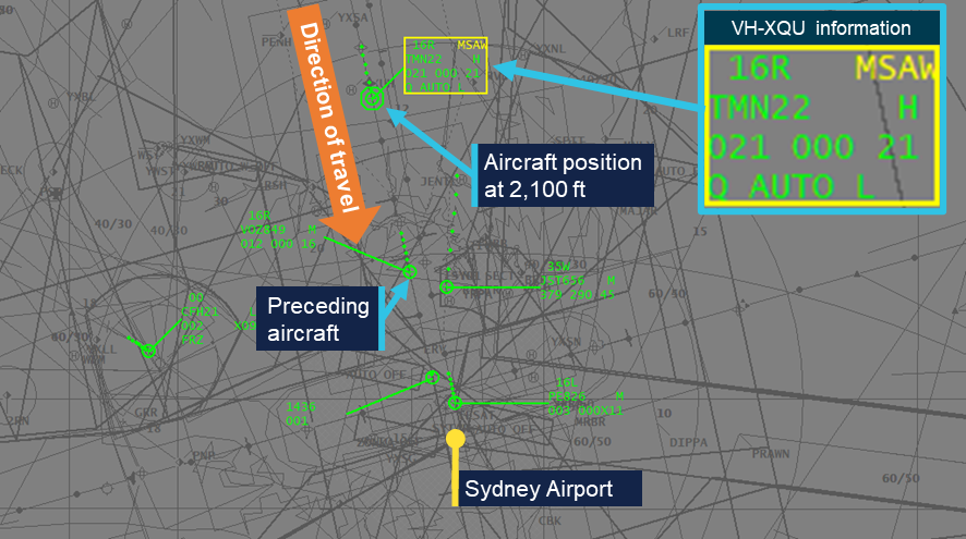
At 1520:33, ATC radar recorded the aircraft at an altitude of 2,200 ft with a descent rate of 1,731 ft/min approximately 10 NM (19 km) from the airport. This descent rate and low altitude triggered an ATC minimum safe altitude warning (MSAW),4 which was presented on the approach controller’s display (Figure 3). The approach controller had just instructed the flight crew to change radio frequency and contact the tower controller, therefore they asked the tower controller to issue a safety alert to the crew. Given the frequency change instruction had just been issued, the approach controller also attempted to contact the flight crew directly on the approach frequency. The crew responded they were still on that frequency. The approach controller gave the crew a low altitude alert, advising them to check their altitude and the crew responded that they were going around.
Figure 3: Approach controller display at 1520:39
Source: Airservices Australia, annotated by the ATSB
Just prior to the approach controller advising the crew of the low altitude warning, as the aircraft descended through 1,850 ft, the first officer disconnected the autopilot, re‑engaged the AFDS in vertical speed mode and raised the nose of the aircraft. As a result, the descent stopped at 1,700 ft, 8.6 NM (16 km) from the runway and approximately 1,000 ft below the glideslope. The aircraft then flew level for about 10 seconds before it began to descend again. At 1521:08, a go‑around was initiated from an altitude of 1,550 ft, as the low altitude alert was being given by ATC.
The aircraft climbed to 3,000 ft and was re-sequenced by ATC for another approach. This time, the crew elected to conduct a localiser approach, which they briefed while repositioning the aircraft to rejoin the approach. During this subsequent approach, the crew observed that the glideslope appeared to be functioning normally, and the aircraft landed without further incident.
After landing, the flight crew discussed the incident between themselves, and with the incoming crew for the next flight. They recalled that the B767 flight crew operations manual (FCOM) contained a bulletin that described the AFDS behaviour that was experienced (see the section titled Manufacturer signal interference bulletin) and concluded that glideslope interference had likely occurred.
Both the first officer and the relief pilot advised that they believed the glideslope critical area would have been protected because they were conducting an autoland; the captain also advised that they thought the glideslope critical area would have been protected, but due to the weather conditions at the time. The captain further reported that, after landing, they called ATC to enquire if there were any vehicles or aircraft that may have interfered with the glideslope signal and was advised that there were not. The aircraft’s ILS system was tested by maintenance personnel after landing and was assessed as serviceable.
Context
Pilot information
The captain held an Air Transport Pilot Licence (Aeroplane) and class 1 aviation medical certificate. They had 15,296 hours of flying experience, of which 2,567 were on the Boeing 767 (B767) aircraft type, with 102 hours accrued in the previous 90 days.
The first officer held a Commercial Pilot Licence (Aeroplane) and class 1 aviation medical certificate. They had 7,362 hours of flying experience, of which 440 were on the B767 aircraft type, with 84 hours accrued in the previous 90 days.
The relief pilot held an Air Transport Pilot Licence (Aeroplane) and class 1 aviation medical certificate. They had 20,599 hours of flying experience, of which 102 hours were on the B767 aircraft type, all accrued in the previous 90 days.
The flight crew had 2 days free of work prior to the flight and all pilots reported that they had slept adequately prior to, and had rested during, the flight.
Aircraft information
General information
VH-XQU was a Boeing 767-3JHF, manufactured in 2009 and first registered in Australia with the operator in 2022. The aircraft was fitted with 2 General Electric CF6‑80C2B7F turbofan engines and had accumulated 56,678 flight hours.
Autoflight system
Overview
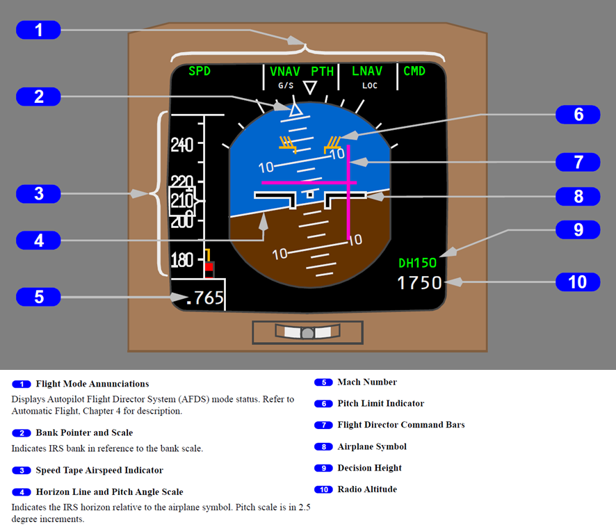
The aircraft’s automatic-flight system consists of an autopilot flight director system (AFDS), and an autothrottle system. The AFDS provides pitch (vertical) and roll (lateral) guidance via flight director command bars overlaid on the attitude direction indicator (ADI) display (Figure 4).
Figure 4: Attitude director indicator display
Source: The Boeing Company
Flight crew controlled the mode and associated flight parameters of the AFDS via the mode control panel. Available modes included:
Approach mode (APP): The flight director provided guidance to track the localiser laterally, and the glideslope vertically. This mode was used during an instrument landing system (ILS) approach.
Vertical speed mode (V/S): The flight director pitch bar indicated the aircraft pitch required to maintain the selected vertical speed. This speed was adjusted by flight crew using the vertical speed selector.
The aircraft was equipped with 3 autopilots. When engaged, each autopilot activated flight controls required for the aircraft to follow the flight director command bars. Only one autopilot was required to be engaged to provide autoflight capability, however multiple autopilots could be engaged to provide redundancy. This was required when conducting certain operations such as an autoland. When no autopilot was engaged the pilot flying was required to manually control the aircraft to follow the flight director.
Automatic control of engine thrust was provided by the aircraft’s autothrottle system. This system was also controlled via the mode control panel. When speed mode (SPD) was active, the autothrottle would control engine thrust, between idle and maximum thrust, to achieve the selected airspeed.
The flight mode annunciations (FMA) displayed (green) active and (white) armed modes of the AFDS and the (green) active mode of the autothrottle system to the flight crew.
The flight crew operations manual (FCOM) contained information about engaging and disengaging the autoflight system and advised that:
After localizer and glideslope capture, the localizer and glideslope modes can only be deactivated by disengaging the autopilot and turning both flight directors off or by selecting GA [go-around] mode.
The FCOM also advised that:
If unwanted operation is noticed or when an autopilot failure is annunciated, the autopilot should be disconnected and the airplane flown manually.
Meteorology
The automatic terminal information service (ATIS)5 at Sydney Airport reported weather conditions at the time of the occurrence that included:
cloud layers of few at 500 ft, scattered at 1,000 ft and broken at 3,000 ft6
wind from 140° M at 15 kt
visibility of 5,000 m in rain
temperature of 16°C
QNH7 of 1004
advice that turbulence was expected in the circuit area
an aerodrome warning that thunderstorms were expected from the west until 1845.
The flight crew advised that weather conditions were consistent with the ATIS, and that the aircraft was in instrument meteorological conditions8 throughout the approach and subsequent missed approach.
Recorded data
The ATSB was provided with data from the aircraft’s quick access recorder, which captured the incident flight. The data was also sent to the manufacturer for review (see the section titled Manufacturer review of recorded data). The cockpit voice recorder was not available due to the time that had elapsed since the occurrence.
A review of the data identified that at 1519:00, the aircraft, with 3 autopilots engaged, was at an altitude of 4,000 ft with the localiser captured (LOC) and descending slightly while intercepting the glideslope from below (Figure 5). At 1519:18, the AFDS changed to approach mode and the associated FMA indicated that the glideslope mode (G/S) was active.
Two seconds later, the aircraft pitch lowered from 4° nose up to approximately 2° nose down, and away from the flight director pitch command bar. The glideslope deviation then recorded a period of variations inconsistent with the aircraft’s position relative to the glideslope. The aircraft’s descent rate subsequently increased, and it began descending away from the glideslope.
Figure 5: Graphical representation of recorded flight modes and alerts
Note: Fight director pitch command – FO is the change in pitch angle the AFDS is commanding and reflects the difference between the required pitch attitude and the aircraft’s current pitch. A flight director pitch command of 0 indicates that the aircraft is at the desired pitch. Source: Quick access recorder data from VH-XQU, annotated by the ATSB
The data recorded the activation of a pitch fault FMA, an autopilot caution, and a master caution light at 1519:35. Approximately 15 seconds later, the flight director pitch command bar began showing values alternating between 0° and 45°, which the manufacturer advised was consistent with the flight director pitch bar being removed from the primary flight display (biased out of view).
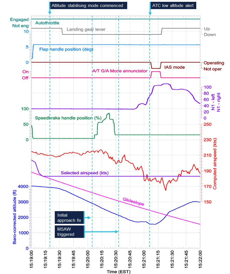
Over the next minute, the aircraft maintained a descent rate of approximately 1,650 ft/min. During this time, the 3 autopilots remained engaged. Also during this time, the aircraft’s airspeed remained above the selected airspeed (Figure 6) while the engines remained at idle thrust. At 1520:05 the aircraft passed the initial approach fix at an altitude of approximately 2,900 ft, with the glideslope deviation at 2 dots, or full-scale deflection. From 1520:08, the speedbrake was deployed in varying positions, before being armed for landing at 1520:29.
Figure 6: Graphical representation of recorded airspeed and configuration
Note: N1 is the rotational speed of the low-pressure rotor and represents the level of engine thrust. Source: Quick access recorder data from VH-XQU, annotated by the ATSB
At 1520:42, the 3 autopilots were disconnected and the FMA fault indication and autopilot caution ceased. The data also recorded a change in AFDS mode from approach mode to vertical speed mode at this time, initially with a descent rate of 1,600 ft/min selected, consistent with the aircraft’s vertical speed at the time.9 At 1520:50, the aircraft’s altitude stabilised at 1,700 ft as the aircraft’s pitch raised to 5° nose up. The vertical speed selected was then reduced to −800 ft/min, then to 0.
At 1520:59, the flight director pitch command bar progressively raised over 7 seconds. The aircraft pitch also increased over this time. Also during this period, the airspeed decreased to the selected airspeed of 183 kt and engine thrust increased above idle. At 1521:08 go‑around mode was selected and the aircraft commenced a climb to 3,000 ft.
Instrument landing system
Overview
An instrument landing system (ILS) is an instrument approach that uses lateral (localiser) and vertical (glideslope) position information, using angular deviation signals from the localiser antennas (located past the upwind end of the runway) and the glideslope antennas (located to the side of the runway). Aircraft systems detect these radio signals and provide instrument indications that enable an aircraft to be manoeuvred along a precise final approach path.
Instrument approach and landing chart
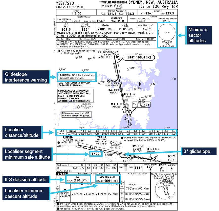
The flight crew used a Jeppesen instrument approach and landing (IAL) chart to brief and conduct the approach (Figure 7). The chart contained information required to conduct either an ILS approach, with the glideslope providing vertical guidance, or a localiser approach that provided distance and altitude information for the flight crew to manage the vertical path, when vertical guidance from the glideslope was not available.
Figure 7: Instrument approach and landing chart runway 16R ILS/LOC
Source: Jeppesen, annotated by the ATSB
The chart specified the 25 NM (46 km) minimum sector altitude as 2,700 ft. This was the minimum altitude an aircraft could descend to while maintaining terrain and obstacle clearance when between 10–25 NM (19–46 km) of the airport and not in visual conditions or conducting an instrument approach. The minimum sector altitude reduced to 2,100 ft when within 10 NM (19 km) of the airport.
The chart also included a caution message that advised of the risk of glideslope interference (see the section titled Glideslope interference) stating that:
GP [glidepath] false indications due acft [aircraft] near Twy [taxiway] A1.
Information on the chart specific to conducting the localiser approach included a segment minimum safe altitude associated with each segment of the approach. Flight crew were required to ensure the aircraft remained at or above these altitudes when within the corresponding segment to maintain minimum obstacle and terrain clearance. The chart also included table of distance/altitude relationships to assist in maintaining a 3° descent profile when glideslope guidance was not available.
Missed approach requirements
The Aeronautical Information Package (AIP) stated that when conducting an ILS approach, a missed approach was required to be executed under certain conditions, including:
During an instrument approach and below MSA (as specified on the IAL chart) the performance of the radio aid becomes suspect, or the radio aid fails.
Glideslope interference
Glideslope critical area
Disturbances to the ILS glideslope signal may occur when vehicles or aircraft are operated near the antenna. For this reason, an ILS critical area is defined around the glideslope antenna location, within which aircraft and vehicle movement is restricted under certain conditions.
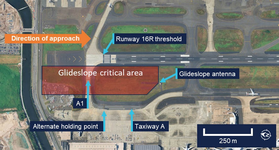
The glideslope critical area for runway 16R at Sydney Airport was an area 600 m long and 145 m wide and included the A1 holding point (Figure 8). When protection of this critical area was required, air traffic control (ATC) directed aircraft to hold at an alternate holding point on taxiway A, instead of A1.
Figure 8: Glideslope critical area for runway 16R
Source: Google Earth, annotated by the ATSB
The conditions under which the ILS critical areas were required to be protected were defined in the Manual of Air Traffic Standards (MATS), which stated:
When the ceiling10 is at or below 600 ft or the visibility is 2000 m or less, ensure no aircraft enter the glide path or localiser critical areas when an arriving aircraft is within: a) the outer marker; or b) 4 NM from the threshold if no outer marker exists.
Manufacturer signal interference bulletin
The FCOM contained a bulletin, issued in November 2021 and titled Erroneous Autopilot Flight Director System (AFDS) Guidance when Instrument Landing System (ILS) Signal Interference Occurs. The bulletin stated that:
Boeing has received several reports of unexpected pitch guidance when capturing or tracking the glideslope during an instrument landing system (ILS) approach. In each event for which data was provided, Boeing has determined that glideslope signal interference occurred at the time of the unexpected pitch guidance and, in most of these events, the unexpected pitch guidance occurred during glideslope capture. ILS signal interference can occur when vehicles, aircraft, or other factors affect the localizer or glideslope signal.
The bulletin further stated that:
The AFDS can detect the degradation or instability of radio signals that support specific autopilot modes. When the AFDS detects a degraded or unstable signal during an ILS approach with the autopilot engaged, the affected AFDS mode changes to an attitude stabilizing mode based on inertial data at the time of the signal degradation or instability. The purpose of the attitude stabilizing mode is to prevent large and abrupt pitch and roll changes during short periods of localizer or glideslope signal interference. When the localizer or glideslope signal stabilizes and the airplane is within parameters for capture, the AFDS returns to tracking the localizer or glideslope. Alternatively, if the localizer or glideslope signal does not stabilize or the airplane is not within parameters for capture, the attitude stabilizing mode remains active. In this case, the AFDS continues to provide guidance in the attitude stabilizing mode, with possible high rates of descent and significant deviation from the localizer or glideslope.
The bulletin also advised that:
There is no direct indication to the pilot that the attitude stabilizing mode is active if the airplane is above 200 feet radio altitude and either:
• the localizer attitude stabilizing mode is active for less than 20 seconds or
• the glideslope attitude stabilizing mode is active for less than 15 seconds
If the airplane is above 200 feet radio altitude and the attitude stabilizing mode remains active for 20 seconds or more (for localizer) or 15 seconds or more (for glideslope):
• the AUTOPILOT message shows (if autopilot is engaged) (Figure 9) and
• the flight director roll or pitch bar is removed (if flight director is on) and
• an amber line shows through the affected flight mode annunciation (FMA)
Figure 9: Indications following extended time in attitude stabilising mode
Figure shows indications on a typical aircraft model. Source: The Boeing Company
Operating instructions were given for flight crew conducting an ILS approach, which advised that:
While on an ILS approach, monitor localizer and glideslope raw data and call out any significant deviations. Perform an immediate go-around if not within the criteria to continue the approach.
It is essential to crosscheck altitude at the FAF [final approach fix] and monitor pitch attitude and descent rate throughout the approach.
If a glideslope anomaly is suspected, an abnormal altitude range-distance relationship may exist. This can be identified by crosschecking distance to the runway with altitude or crosschecking the airplane position with waypoints indicated on the navigation display. The altitude should be approximately 300 feet height above touchdown per NM of distance to the runway for a 3° glideslope.
Manufacturer review of recorded data
At the request of the ATSB, the manufacturer reviewed the recorded data from the occurrence flight. The review included analysis of glideslope beam variation at the time of glideslope capture and throughout the approach. It identified that:
At a longitudinal distance of approximately 15.5 nautical miles [29 km] prior to the runway threshold, the observed glideslope beam began to diverge from the ideal beam, moving below the ideal beam. This deviation between the ideal and observed beam is characteristic of a beam anomaly.
The observed glideslope beam reached approximately 300 feet below the ideal beam. The divergence then began to decrease as the observed beam began to converge towards the ideal beam.
The observed glideslope beam diverged from the ideal beam again, varying by up to 350 feet below and then 400 feet above the ideal beam over the next 1.5 nautical miles.
A second period of divergence between the ideal and observed glideslope commenced at approximately the same time as the second A380 entered the critical area.
Based on this analysis, the manufacturer concluded that:
The airplane experienced a beam anomaly while attempting to capture the glideslope from below the beam. The observed glideslope beam diverged below the ideal 3-degree beam by a vertical offset of 300 feet, causing the airplane to attempt glideslope capture prematurely.
The review also referred to the FCOM bulletin for glideslope interference and advised that:
In this event, the airplane behaviour was consistent with a glideslope beam anomaly, causing the AFDS to enter attitude stabilizing mode. The airplane encountered a beam anomaly while intercepting the glideslope in G/S mode before entering into a steady descent with an average calculated vertical speed of approximately -1,700 feet per minute. The AFDS did not return to tracking the glideslope after the glideslope signal stabilized, probably because the glideslope deviation was no longer within the parameters for capture. For approximately the first 15 seconds, there were no indications in the QAR [quick access recorder] data that attitude stabilizing mode was active until the Autopilot Caution and FMA Pitch Fault activated. An additional 15 seconds passed before the flight director pitch guidance became BOV [biased out of view], consistent with the removal of the flight director pitch bar. This state remained until the flight crew switched the pitch mode to V/S.
Noting the operational guidance in the bulletin, the review concluded that:
Earlier recognition of the airplane state and degraded autopilot performance may have reduced the magnitude of the deviation below the glideslope.
The manufacturer also advised that there was no evidence to show whether the glideslope deviation pointer would have been displayed during the period that the alerts were active.
Practice autoland
Overview
An autoland approach is an approach during which the aircraft is fully controlled by the autoflight system through to landing. During an autoland, pilots assume a monitoring role and intervene only in the event of a system failure or other abnormal event. The procedure is primarily intended to be used in low-visibility conditions, however an autoland can also be conducted in better conditions to meet aircraft or flight crew recency and currency requirements. An autoland conducted under these conditions is termed a practice autoland.
Regulatory requirements and guidance
Flight crew were required to advise ATC of an intention to conduct a practice autoland when arriving at an aerodrome and the AIP stated that:
In weather conditions where the ceiling and/or visibility are above CAT I minima, pilots should inform ATC about any intention to conduct:
a. an approach with minima less than standard CAT I; or
b. an autoland procedure.
This information must not be taken as a request for or expectation of the protection of the ILS but to enable ATC to inform the flight crew of any known or anticipated disturbance.
The AIP also stated that when receiving this advice, and the ILS critical area was not protected, the controller was required to report ‘ILS critical area not protected’. Airservices Australia advised that only a tower controller provided advice of any known or anticipated disturbances. They also confirmed that an intention to conduct a practice autoland procedure did not change ATC’s requirements with regards to protecting the ILS critical areas.
The Civil Aviation Safety Authority published Advisory Circular (AC) 91‑12 Conduct of practice autoland operations. The AC described the problems and potential risks when conducting an autoland and stated:
Multiple factors may influence the accuracy of the ILS signal when the ILS autoland system is to be used:
• in conditions where ATC is not protecting ILS critical and/or sensitive areas.
These factors include:
• interference of the ILS signal due to an intrusion within the ILS critical and sensitive areas by: - taxiing aircraft - ground vehicles - over-flight of the ILS localiser.
The AC also identified a number of considerations, procedures and instructions when conducting practice autoland operations, which included:
ATC should be informed about the crew’s intention to conduct an autoland. Pilots should not expect the protection of the ILS, but on receiving advice from the crew of their intention to conduct a practice autoland, ATC may inform the flight crew of any known or anticipated disturbance.
Operator procedures and training
Flight crew roles and responsibilities
The operator’s policy and procedures manual (PPM) defined the roles of the pilot flying and the pilot monitoring as:
The PF [pilot flying] will control and monitor the aircraft, regardless of the level of automation being used. The duties of the PF are:
• flight control: - flight path and airspeed control - navigation - aircraft configuration
• conducting normal procedures in compliance with company manuals
• monitoring flight status and condition.
The PM [pilot monitoring] will monitor the aircraft and action of the PF. The duties of the PM are:
• general monitoring and crosschecking the procedures for all flight phases including take-off, cruise, approach and landing, aircraft system status, and condition
• make callouts to PF for any deviation from the flight path or system malfunction or failure
• give advice to the PF to execute a missed approach when the approach becomes unstable or unable to continue the approach safely
A callout must be made by the PM for the other crew if a deviation occurs from the normal procedures, or intended flight path (attitude, speed, altitude, and direction). If there is a failure for the PF to respond to callouts of the PM, appropriate corrective action shall be made for the safety of the flight including taking over the aircraft control.
The PPM defined tolerances for certain flight parameters, including a tolerance of one dot when tracking the glideslope, and advised that:
These parameters are to be observed and sustained flight should not be allowed to continue without corrective action by the flight crew. Any deviation outside of approach tolerances in IMC must result in a GA [go-around].
Use of automation
The PPM contained an automation policy which advised:
Automation is provided to enhance safety, reduce pilot workload and improve operational capabilities.
Automation can be as beneficial as mentioned above for flight operations, if automation is used appropriately. However, at the same time, if flight crew members fail to maintain proficiency in the use of automation or to properly correspond to recognised degradation of automation performance, it could be an obstruction for the flight safety.
In addition, over-reliance on automation system may lead to flight crews accepting whatever the aircraft was doing without proper monitoring or may result in deterioration of flight crew members’ manual flying skills. Therefore, for safe flight operation, proper use of automation system, maintaining manual flying skills, and practical use of CRM [crew resource management] skills are required.
Following elements are imperative to use automation at the most appropriate level:
• full understanding and knowledge of automation system
• proficiency in the use of all levels of automation
• monitoring and cross-check of automation
• skills to recognize degraded performance of automation system
• skills to shift between all levels of automation including manual flying.
The PPM also contained guidelines for flight crew when using automation, which included that:
• The flight crew must compare the performance of autoflight system (operation status) with the flight path of the aircraft.
• It is the responsibility of the flight crew to maintain flight mode awareness and control to ensure the flight director provides the guidance required.
• If any autoflight system is not operating as expected or any doubt exists, disengage it.
Instrument approach briefing
The PPM required flight crew to conduct a briefing of the threats, plans and considerations of the expected approach after the approach had been loaded. Considerations to be included in the brief were:
• approach title and chart effective date
• manual or AUTOLAND Landing
• nomination of required navigation aids
• approach entry/holding pattern
i• nitial approach altitude
• approach track(s)
• limiting and check altitudes
• CAT I, CAT II, CAT III MDA/DH [minimum descent altitude / decision height] and visibility minimum
• aerodrome elevation
• circling procedures (if applicable)
• significant terrain
• missed approach procedure
• monitoring of approach aids.
In addition, the crew were required to brief specific items prior to commencing an autoland approach which included the following non-normal situations:
• persistent localiser or glideslope deviation alert between 500 ft RA [radio altimeter] & 200 ft RA or any deviation alert below 200 ft RA
• ASA [autoland status annunciator] changes to NO AUTOLAND
• ILS Localiser and/or Glideslope Transmitter Failure
• autopilot disconnect.
Glideslope out procedure
The PPM contained procedures for when the glideslope failed during an ILS approach. The procedures stated that when in IMC:
If the glideslope fails when the aircraft is established on the ILS procedure (or being radar vectored) after the IAF [initial approach fix] ATC must be notified immediately.
An approach may be continued if the following items can be completed prior to FAF [final approach fix]:
• complete briefing for a LOC [localiser] (GS [glideslope] out) approach
• mode change and operation for LOC approach
• set the next fix altitude or MDA on altitude window
• barometric altimeter bug set
• completion of landing configuration and landing checklist
A missed approach must be conducted for the following situations
• failure to complete the steps above, prior to the FAF
• failure of situational awareness for the LOC (GS out) procedure
• when directed by ATC.
Low visibility operations
Autoland procedures
The PPM defined procedures for taxi, take-off and landing in conditions where visual reference was limited by weather. This included procedures for conducting a low visibility operations (LVO) approach and landing including an autoland. It was stated that:
LVO approach and landings shall be carried out using the highest level of automation available to an autoland.
The left seat pilot is PF and the right seat pilot is PM for the approach, landing or missed approach.
In addition, crew responsibilities during an LVO landing were stated as:
Pilot Flying Duties
The PF shall guard the control column, rudder pedals and thrust levers throughout the approach, landing, or missed approach, make standard callouts and responses as per the LVO landing standard callouts and actions, and take manual control in the event of autopilot disconnect.
Pilot Monitoring Duties
The PM must monitor the aircraft flight path and flight instruments throughout the approach, landing and rollout, or missed approach. They are to remain ‘heads down’ and make no attempt to seek visual reference. Any deviation or system failure must be called to alert the PF.
Additionally, specific standard callouts (by the PM) and responses (by the PF) were required to be used when conducting an LVO landing. These specific callouts began at 1,500 ft AGL.
The PPM did not contain procedures specific to conducting a practice autoland. The operator later advised that when conducting LVO operations, the left seat pilot was required to be the pilot flying for the entire approach however, when conducting a practice autoland, the pilots could switch roles so long as the left seat pilot was the pilot flying prior to 1,500 ft AGL.
The PPM contained information about ILS critical areas that was relevant to the conduct of an autoland and advised that:
When the weather ceiling is above 600 ft and 2,000 m visibility the ILS critical and sensitive areas are not protected by ATC and a number of factors may influence the accuracy of the ILS signal.
These include intrusions of the ILS critical and sensitive areas by the following factors:
• taxiing aircraft
• ground vehicles
• over-flight of the ILS localiser.
The flight crew shall therefore notify ATC at the commencement of an autoland approach when the ceiling and visibility are above the parameters listed above. e.g. ‘We are conducting an autoland approach’.
When an approach condition develops where the glide slope or the localizer becomes unreliable, due to signal interference, the aircraft departs from the approach path, or for other causes where manual flying is required, the flight crew must transition to manual flying immediately.
Flight crew training
The operator provided training to flight crew for LVO via a combination of online computer-based training (CBT), in-person training and training and assessment in a flight simulator.
The CBT included information about the purpose of an ILS critical area, and of alternate holding point requirements when protection was in force. Presentation materials used during in-person training identified the loss of glideslope or localiser signal as a possible non-normal situation. The indications expected in this situation were:
• pointer disappears
• line through associated FMA
• FD [flight director] bar for failed mode is removed
• autopilot EICAS [Engine indicating and crew alerting system]
The operator advised that simulator training during both induction and ongoing training covered failures during approaches, including the glideslope. In addition, they advised this training covered the cockpit indications during a glideslope out scenario. They also advised that the FCOM signal interference bulletin was discussed during training with focus on the potential high rates of descent associated with the issue.
Reviewed training materials did not contain information about the conditions under which the ILS critical area would be protected.
The ATSB investigated a flight below minimum altitude of a Boeing 787 conducting an ILS approach to Perth Airport on 4 December 2015. It was found that interference to the glideslope signal likely occurred due to a Boeing 737 aircraft taxiing from the holding point to the runway at the time.
The ATSB also investigated a descent below lowest safe altitude of a Boeing 747‑400 aircraft conducting an ILS approach to Sydney Airport’s runway 16R on 12 February 2017. It was found that glideslope interference likely occurred due to a Boeing 787 aircraft holding at A1 during the approach. The report also identified 2 similar occurrences in March 2017 of Boeing 747 aircraft experiencing high descent rates during an ILS approach. In both instances an Airbus A380 was occupying taxiway A1 at the time.
Other occurrences
The ATSB occurrence database did not contain any additional occurrences after 2017 that could be identified as glideslope interference. However, as glideslope interference is not a reportable matter under the Transport Safety Investigation Regulations, it is likely an occurrence would only be reported to the ATSB if a consequential event required it and may not include detail to identify glideslope interference.
Following a notice to flight crew to report instances of glideslope interference, the operator was subsequently made aware of 9 additional instances of suspected glideslope interference when approaching runway 16R at Sydney Airport. For each, the ATSB reviewed publicly available flight data and identified an aircraft positioned either at holding point A1 or moving from the holding point onto the runway at the time of the reported interference.
Table 1: Subsequent occurrences of glideslope interference reported to operator
Date
Aircraft
Aircraft type at A1
1 November 2025
VH-FKX (B767)
Boeing 787
2 November 2025
VH-FKX (B767)
Boeing 777
9 November 2025
VH-EXZ (B767)
Airbus A350
22 November 2025
VH-EXZ (B767)
Airbus A350
27 November 2025
VH-XQU (B767)
Boeing 787
28 December 2025
VH-XQU (B767)
Airbus A350
2 January 2026
VH-EXZ (B767)
Airbus A380
23 February 2026
VH-XQU (B767)
Boeing 787
13 March 2026
VH-XQU (B767)
Airbus A380
In response to a request for reports of glideslope interference at Sydney Airport, Airservices Australia advised that several of the subsequent events listed by the operator were received and reviewed by technical surveillance specialists. All events were determined to be due to aircraft in the glideslope critical area with the effect on the approaching aircraft as expected. No reports of glideslope interference were received from other operators between January 2025 and January 2026.
Safety analysis
Introduction
This analysis will discuss the factors leading to the performance of the autoflight system and the protection requirements of the instrument landing system critical area. In addition, it will examine the actions of the flight crew in response. Finally, the analysis will consider the operator’s procedures and training for conducting precision approaches, low visibility operations and practice autoland approaches.
Glideslope interference
As the aircraft was intercepting the glideslope prior to the commencement of a practice autoland approach, an A380 aircraft holding at A1, within the ILS critical area, began moving onto the runway. A second A380 then entered the critical area as the first vacated. The movements of both aircraft coincided with anomalies observed in the glideslope signal received by the aircraft.
The weather conditions at Sydney Airport at the time were better than those for which protection of the ILS critical area was required. Therefore, ATC was not required to protect the area for a practice autoland. Furthermore, while the tower controller was required to inform the flight crew that the ILS was not being protected, the flight crew had not yet transferred to this controller. Therefore, there was no opportunity for the flight crew to be given this advice.
After initially attempting to capture the glideslope from below, the aircraft's descent rate increased away from the flight director pitch guidance, and it began deviating away from the glideslope. As described in the flight crew operations manual (FCOM) bulletin for ILS signal interference, when the autopilot flight director system (AFDS) detected an unstable glideslope signal it changed to an attitude stabilising mode. Cockpit alerts were subsequently displayed to alert the flight crew to the degraded performance of the autopilot. These alerts were consistent with those expected when the AFDS had been in attitude stabilising mode for 15 seconds. Therefore, the movement of the first A380 through the ILS critical area caused an interference to the glideslope signal, which was subsequently detected by the AFDS. As a result, after attempting to capture the glideslope prematurely, the AFDS entered and remained in an attitude stabilising mode before alerting the crew.
Contributing factor
Two Airbus A380s on the ground at Sydney Airport taxied through the instrument landing system critical area and in front of the glideslope antenna, causing interference to the glideslope signal. As a result, after detecting the interference, the Boeing 767's autopilot established the aircraft on a flight path that deviated away from the glideslope, before alerting the crew that it was operating in a degraded mode.
Descent below glideslope
Pilot flying
After the interference stopped, it is likely that the flight path deviation had increased beyond the threshold at which the AFDS could re-capture the glideslope. Therefore, the AFDS remained in attitude stabilising mode while the annunciations indicating the degraded performance of the autopilot continued to be displayed to the flight crew.
The pilot flying recognised that the autopilot was no longer following the glideslope, and that the aircraft was descending at a high rate. However, believing that they had sufficient time and altitude, they did not disengage the autopilot and commenced discussion and preparation for a change to a localiser approach. Both operator and manufacturer procedures required that if automation was not operating as expected then it should be disengaged and the aircraft flown manually. However, the pilot flying allowed flight below the glideslope to continue beyond the initial approach fix and below the approach commencement altitude.
After the aircraft’s flight path triggered a minimum safe altitude warning (MSAW), but prior to receiving the corresponding low altitude alert from ATC, the pilot flying did disconnect the autopilot. By this time, the aircraft’s position was significantly below the minimum sector altitude, below which a missed approach was required to be conducted when experiencing a failure of the glideslope. Furthermore, the manufacturer’s procedure specific to glideslope interference required a missed approach to be conducted when corresponding failure annunciations were displayed. These annunciations were continuously displayed throughout the approach. Following the disconnection of the autopilot, the pilot further delayed the initiation of a missed approach. During this period of manual flight, the aircraft descended a further 150 ft and below the localiser segment minimum safe altitude before a missed approach was commenced.
The ATSB considered the extended time between the MSAW being triggered and the flight crew receiving a low altitude alert. As the MSAW coincided with an instruction to the crew to contact the tower controller, the low altitude alert could not be given immediately because the approach controller was required to establish which frequency the crew were listening on. However, as the crew had already disconnected the autopilot and arrested the initial descent, this was not considered to be contributory.
Contributing factor
The pilot flying continued the approach with the autopilot in a degraded mode. As a result, the aircraft’s high descent rate triggered an air traffic control minimum safe altitude warning. After disconnecting the autopilot, the pilot flying delayed the initiation of a missed approach and the aircraft descended below the localiser segment minimum safe altitude.
Pilot monitoring
During the approach, the pilot monitoring was required to monitor the aircraft’s flight path and advise the pilot flying of any deviations. Specifically, when conducting an ILS approach, they were required to monitor the glideslope for deviation. If glideslope tracking deviated beyond one dot, a callout was required, and the flight path was required to be corrected by the pilot flying. When in instrument meteorological conditions (IMC) further deviation outside of this required a missed approach. At the commencement of the approach, the glideslope deviation was recorded as already at 2 dots (full scale) and remained so throughout the approach. However, both the pilot flying and the pilot monitoring could not recall that the glideslope deviation pointer was displayed after the autopilot alerts activated. Furthermore, the manufacturer could not determine whether the pointer was displayed to the flight crew after the AFDS entered attitude stabilising mode.
Notwithstanding this, other flight instruments were available to monitor the aircraft’s flight path. The aircraft’s pitch attitude was more nose down than expected during an ILS approach. In addition, the vertical speed indicator would have been indicating a descent rate greater than expected. The FCOM bulletin advised flight crew to monitor both pitch attitude and descent rate during an ILS approach. Furthermore, the relief pilot called out required altitudes and distances during the approach, providing additional information regarding the aircraft’s position below the glideslope. As no deviation calls or requests to conduct a missed approach were reported as being made by the pilot monitoring, it is likely that they were not effectively monitoring the aircraft’s flight path throughout the approach.
Contributing factor
The pilot monitoring did not effectively monitor the aircraft's flight path during the approach and did not call out deviations or advise the pilot flying to conduct a missed approach.
Operator procedures and training
Glideslope out procedure
The operator had a ‘glideslope out’ procedure that allowed the crew the flexibility to transition to localiser approach provided specific preparatory actions were able to be completed prior to the final approach fix. Recognising that on this occasion the crew experienced glideslope interference rather than glideslope out, the cockpit indications were similar. As such, consideration of transitioning to a localiser approach was understandable.
However, given the significant deviation from the expected flightpath due to the aircraft’s sustained high rate of descent, safe transition to a localiser approach was considered highly unlikely on this occasion. This was ultimately recognised by the crew and a missed approach initiated.
The operator advised that the procedure allowing the transition from an instrument landing system approach to a localiser approach was withdrawn following this occurrence.
Practice autoland procedure
As approved by the operator, the flight crew briefed that while the first officer was initially the pilot flying, they would exchange flying and monitoring roles at 1,500 ft above ground level (AGL), after which point the captain would be the pilot flying. However, the operator’s procedures did not differentiate between a practice autoland and one conducted in low visibility conditions. Therefore, the captain was required to be the pilot flying from the commencement of the approach.
In addition, while callouts required for an autoland did not commence until 1,500 ft AGL, there were specific responsibilities assigned to the flying and monitoring roles during an autoland approach that applied to the entire approach.
A practice autoland offered an opportunity to develop familiarity with, and proficiency in, those roles. Furthermore, the Civil Aviation Safety Authority guidance material highlighted the importance of flight crew responsibilities during transition to visual conditions, in deteriorating visibility or when failures occur. As such, exchanging roles introduced the potential for confusion or ambiguity as to the roles and responsibilities of each crew member during the approach, particularly if the handover coincided with a transition to visual conditions, or the need to respond to an abnormal event.
Other factor that increased risk
Tasman Cargo Airlines allowed the practice of flight crew exchanging flying and monitoring roles prior to 1,500 ft when conducting a practice autoland. This increased the risk of role confusion or ambiguity during a high workload activity.
Low visibility operations training
The operator provided training to flight crew for low visibility operations, which included information about the ILS critical area. However, the training did not include information about the conditions under which the critical area would be protected. In addition, while the operator's procedures informed flight crew that they should notify ATC of their intent to conduct a practice autoland, they did not specify that this notification did not change ATC protection requirements, implying that the notification would result in the critical area being protected.
The captain reported that they considered that the weather conditions would necessitate protection of the critical area. Additionally, both the first officer and the relief pilot reported that they thought the ILS was being protected as they had advised ATC of their intention to conduct an autoland. Therefore, while it likely did not influence the flight crew’s response to the glideslope interference, they mistakenly believed that the risk of such an event had been mitigated.
Other factor that increased risk
Tasman Cargo Airlines’ training did not inform flight crew of the conditions under which instrument landing system critical areas were protected. Consequently, the flight crew believed that the critical area was being protected, and the risk of glideslope interference had been mitigated.
Findings
ATSB investigation report findings focus on safety factors (that is, events and conditions that increase risk). Safety factors include ‘contributing factors’ and ‘other factors that increased risk’ (that is, factors that did not meet the definition of a contributing factor for this occurrence but were still considered important to include in the report for the purpose of increasing awareness and enhancing safety). In addition ‘other findings’ may be included to provide important information about topics other than safety factors.
Safety issues are highlighted in bold to emphasise their importance. A safety issue is a safety factor that (a) can reasonably be regarded as having the potential to adversely affect the safety of future operations, and (b) is a characteristic of an organisation or a system, rather than a characteristic of a specific individual, or characteristic of an operating environment at a specific point in time.
These findings should not be read as apportioning blame or liability to any particular organisation or individual.
From the evidence available, the following findings are made with respect to the descent below glideslope involving Boeing 767, VH-XQU, near Sydney Airport, New South Wales, on 10 September 2025.
Contributing factors
Two Airbus A380s on the ground at Sydney Airport taxied through the instrument landing system critical area and in front of the glideslope antenna, causing interference to the glideslope signal. As a result, after detecting the interference, the Boeing 767's autopilot established the aircraft on a flight path that deviated away from the glideslope, before alerting the crew that it was operating in a degraded mode.
The pilot flying continued the approach with the autopilot in a degraded mode. As a result, the aircraft’s high descent rate triggered an air traffic control minimum safe altitude warning. After disconnecting the autopilot, the pilot flying delayed the initiation of a missed approach and the aircraft descended below the localiser segment minimum safe altitude.
The pilot monitoring did not effectively monitor the aircraft's flight path during the approach and did not call out deviations or advise the pilot flying to conduct a missed approach.
Other factors that increased risk
Tasman Cargo Airlines allowed the practice of flight crew exchanging flying and monitoring roles prior to 1,500 ft when conducting a practice autoland. This increased the risk of role confusion or ambiguity during a high workload activity.
Tasman Cargo Airlines’ training did not inform flight crew of the conditions under which instrument landing system critical areas were protected. Consequently, the flight crew believed that the critical area was being protected, and the risk of glideslope interference had been mitigated.
Safety actions
Safety action not associated with an identified safety issue
Safety action by Tasman Cargo Airlines
Tasman Cargo Airlines has taken the following proactive safety action:
Removed the ‘glideslope out’ procedure from its policy and procedures manual (PPM), replacing it with the requirement to conduct a missed approach and notify air traffic control.
Added a note in the PPM referencing the glideslope interference bulletin from the flight crew operating manual.
Published an operational alert regarding Sydney Airport runway 16R glideslope interference with guidance information.
Updated computer-based training materials to better highlight the ILS critical area and requirements during normal and low visibility operations.
Introduced a requirement for the pilot flying to take control of the aircraft prior to the commencement of the approach when conducting an autoland.
Safety action by Boeing
While not in direct response to this occurrence, Boeing is in the process of updating the flight control software for B767 aircraft. Planned for release in 2027, the update will include the following changes:
The flight director pitch bar will remain biased out of view if the autopilot is disconnected while in attitude stabilising mode.
Improved glideslope capture logic to reduce the occurrence of false captures leading to attitude stabilising mode.
Limiting the flight path angle while in attitude stabilising mode to be between 0–3.25° of descent.
Display of NO AUTOLAND after being in attitude stabilising mode for 15 seconds if the aircraft is still above alert height.
Automatic autopilot disconnect 10 seconds after the display of NO AUTOLAND if the aircraft is still above 500 ft AGL.
Glossary
AC
Advisory circular
ADI
Attitude direction indicator
AFDS
Autopilot flight director system
AGL
Above ground level
AIP
Aeronautical Information Package
ATC
Air traffic control
ATIS
Automatic terminal information service
BOV
Biased out of view
CBT
Computer-based training
CDU
Control display unit
DH
Decision height
EICAS
Engine indicating and crew alerting system
FAF
Final approach fix
FCOM
Flight crew operations manual
FL
Flight level
FMA
Flight mode annunciation
FMS
Flight management system
GS
Glideslope
IAF
Initial approach fix
IAL
Instrument approach and landing
ILS
Instrument landing system
IMC
Instrument meteorological conditions
LOC
Localiser
LVO
Low visibility operations
MATS
Manual of Air Traffic Standards
MDA
Minimum descent altitude
MSA
Minimum sector altitude
MSAW
Minimum safe altitude warning
PF
Pilot flying
PM
Pilot monitoring
PPM
Policy and procedures manual
QAR
Quick access recorder
RA
Radio altimeter
Sources and submissions
Sources of information
The sources of information during the investigation included:
the flight crew
the operator
The Boeing Company
Airservices Australia
recorded data from the aircraft quick access recorder.
Under section 26 of the Transport Safety Investigation Act 2003, the ATSB may provide a draft report, on a confidential basis, to any person whom the ATSB considers appropriate. That section allows a person receiving a draft report to make submissions to the ATSB about the draft report.
A draft of this report was provided to the following directly involved parties:
the flight crew
the operator
The Boeing Company
Airservices Australia
Civil Aviation Safety Authority
United States National Transportation Safety Board.
Submissions were received from:
the operator
The Boeing Company
Civil Aviation Safety Authority.
The submissions were reviewed and, where considered appropriate, the text of the report was amended accordingly.
Purpose of safety investigations
The objective of a safety investigation is to enhance transport safety. This is done through:
identifying safety issues and facilitating safety action to address those issues
providing information about occurrences and their associated safety factors to facilitate learning within the transport industry.
It is not a function of the ATSB to apportion blame or provide a means for determining liability. At the same time, an investigation report must include factual material of sufficient weight to support the analysis and findings. At all times the ATSB endeavours to balance the use of material that could imply adverse comment with the need to properly explain what happened, and why, in a fair and unbiased manner. The ATSB does not investigate for the purpose of taking administrative, regulatory or criminal action.
About ATSB reports
ATSB investigation reports are organised with regard to international standards or instruments, as applicable, and with ATSB procedures and guidelines.
Reports must include factual material of sufficient weight to support the analysis and findings. At all times the ATSB endeavours to balance the use of material that could imply adverse comment with the need to properly explain what happened, and why, in a fair and unbiased manner.
An explanation of terminology used in ATSB investigation reports is available here. This includes terms such as occurrence, contributing factor, other factor that increased risk, and safety issue.
Publishing information
Released in accordance with section 25 of the Transport Safety Investigation Act 2003
Ownership of intellectual property rights in this publication
Unless otherwise noted, copyright (and any other intellectual property rights, if any) in this report publication is owned by the Commonwealth of Australia.
Creative Commons licence
With the exception of the Commonwealth Coat of Arms, ATSB logo, and photos and graphics in which a third party holds copyright, this report is licensed under a Creative Commons Attribution 4.0 International licence.
The CC BY 4.0 licence enables you to distribute, remix, adapt, and build upon our material in any medium or format, so long as attribution is given to the Australian Transport Safety Bureau.
Copyright in material obtained from other agencies, private individuals or organisations, belongs to those agencies, individuals or organisations. Where you wish to use their material, you will need to contact them directly.
^Pilot flying (PF) and pilot monitoring (PM): procedurally assigned roles with specifically assigned duties at specific stages of a flight. The PF does most of the flying, except in defined circumstances, such as planning for descent, approach and landing. The PM carries out support duties and monitors the PF’s actions and the aircraft’s flight path.
^Flight level: at altitudes above 10,000 ft in Australia, an aircraft’s height above mean sea level is referred to as a flight level (FL). FL 350 equates to 35,000 ft pressure altitude.
^Runway number: the number represents the magnetic heading of the runway. The runway identification may include L, or R as required for left or right when there are parallel runways.
^Minimum safe altitude warning (MSAW): an automated warning for air traffic controllers to draw attention to an aircraft that at its current descent rate is projected to conflict with terrain.
^Automatic terminal information service: the provision of current, routine information to arriving and departing aircraft by means of continuous and repetitive broadcasts. ATIS information is prefixed with a unique letter identifier and is updated either routinely or when there is a significant change to weather and/or operations.
^ Cloud cover: in aviation, cloud cover is reported using words that denote the extent of the cover – ‘few’ indicates that up to a quarter of the sky is covered, ‘scattered’ indicates that cloud is covering between a quarter and a half of the sky, ‘broken’ indicates that more than half to almost all the sky is covered, and ‘overcast’ indicates that all the sky is covered.
^QNH: the altimeter barometric pressure subscale setting used to indicate the height above mean sea level.
^Instrument meteorological conditions (IMC): weather conditions that require pilots to fly primarily by reference to instruments, and therefore under instrument flight rules (IFR), rather than by outside visual reference. Typically, this means flying in cloud or limited visibility.
^When vertical speed mode is engaged, it will initially target the vertical speed current at the time of engagement.
^Cloud ceiling: The height above the ground of the base of the lowest layer of cloud covering more than one-half the sky.
On 22 August 2025, a GippsAero GA8, operated by Air Kimberley and registered VH‑LHC, entered the circuit in preparation for landing at Djarindjin/Lombadina Airport, Western Australia. At about this time, the pilot identified an uncommanded 3-inch drop in engine manifold pressure. After briefly liaising with the chief pilot via phone, the pilot conducted an orbit between the base and final legs of the circuit to prepare for the landing.
Crossing the threshold, the pilot identified that they were between 20 and 25 kt above the target approach speed. Approximately two-thirds of the way down the runway, the pilot assessed there was insufficient runway remaining to land, commenced a go-around and attempted to climb away. However, the airspeed reduced and the pilot assessed that they did not have sufficient power to climb and elected to level the aircraft and conduct a turnback to land on the reciprocal runway. The pilot used the mixture control to reduce the engine’s power and landed without further incident.
What the ATSB found
During the approach, the securing mechanism for the aircraft’s throttle linkage failed, resulting in a loss of throttle control and a constant partial power setting. The approach then continued at a higher-than-normal speed that did not permit the aircraft to land safely.
During the subsequent go-around, the pilot assessed there was insufficient power to climb. This was due to the throttle failing to open to at least 75% in accordance with the manufacturer’s requirement, likely due to the spring that opened the throttle in the event of a disconnection not being fitted.
Additionally, the ATSB found that there were multiple inconsistencies between the throttle linkage hardware fitted to VH-LHC and that laid out in the aircraft documentation. Although the ATSB could not determine whether the inconsistencies contributed to this incident, they increased the risk of throttle disconnection due to unintended interactions between components in the linkage.
What has been done as a result
In response to the ATSB advice noting the inconsistencies between the linkage assembly and the manufacturer’s prescribed configuration, the maintenance organisation, BOAB Engineering (BOAB), conducted a review of the 3 GA8 aircraft that it was responsible for.
BOAB identified various inconsistencies related to incorrect throttle body lever arms, missing torsion springs and incorrectly located or missing spacers. At the time of writing, BOAB advised that the correct parts had been ordered and that the linkage assemblies would be re-assembled in accordance with the manufacturer’s requirements.
Safety message
Partial power loss can be more complex to manage than a complete power loss. The response to a complete power loss is definitive and standardised but the response to a partial power loss may be dependent on the amount of power lost and reliability of the remaining power. CASA's guidance is to treat a partial power loss as though it is a complete power loss and to ensure that the aircraft is landed as soon as possible. Where engine power is available pilots can consider using it to extend available flight time to identify a better landing site with the awareness that the power may reduce or fail at any time.
This occurrence also demonstrates the importance of being aware of and adhering to the manufacturer’s assembly requirements. Reconnecting a component’s attachment hardware on a like-for-like basis may not ensure compliance with the manufacturer’s requirements and can increase the risk of an adverse outcome.
The investigation
The ATSB scopes its investigations based on many factors, including the level of safety benefit likely to be obtained from an investigation and the associated resources required. For this occurrence, the ATSB conducted a limited-scope investigation in order to produce a short investigation report, and allow for greater industry awareness of findings that affect safety and potential learning opportunities.
The occurrence
On the morning of 22 August 2025, a GippsAero GA8, operated by Air Kimberley and registered VH‑LHC, departed Broome, Western Australia, for a charter flight to Djarindjin/Lombadina Airport (Figure 1) with the pilot, one passenger and freight on board.
Figure 1: VH-LHC flight location
Source: Google Earth and FlightRadar24, annotated by the ATSB
Approximately 55 minutes after departing Broome, the pilot joined the downwind leg of the circuit for runway 28 at Djarindjin/Lombadina Airport. Shortly after joining the circuit, at about 1251 local time, the pilot identified an uncommanded 10 kt reduction in airspeed and a drop from approximately 20 inches of mercury (inHg) of engine manifold pressure to 17 inHg. In response, the pilot moved the aircraft throttle lever across its full range of movement but did not hear or feel a response from the engine and reported no change to the manifold pressure.
At this time, the pilot contacted the operator’s chief pilot via mobile phone for guidance. The pilot reported that in the brief conversation they outlined the issue that they were encountering. While the pilot could not remember the details of the chief pilot’s response the general guidance provided was to land as safely as possible and to call back when they were on the ground.
Following this conversation, the pilot elected to conduct an orbit to extend the approach (Figure 2) and allow themselves more time to assess the problem and conduct pre‑landing checks and procedures. They intended to conduct the approach normally but with an extended final approach. The pilot also considered the early use of a second stage of flap to slow the aircraft. However, they decided against it due to the unknown reliability of the engine’s performance and extended the second stage of flap as part of the normal pre-landing process on final approach.
Figure 2: Downwind, final approach, go‑around and return
Note: Due to the light and variable winds at the time of the occurrence, the aircraft ground speeds were within 5 kt of the airspeeds that would have been presented to the pilot. Source: Google Earth, FlightRadar24 and Bureau of Meteorology, annotated by the ATSB
The pilot recalled, and recorded data confirmed, that the aircraft was at about 100 kt, 20–25 kt faster than planned, when crossing the threshold. Approximately two-thirds of the way down the runway, the pilot identified that the aircraft was ‘floating,’1 had insufficient runway remaining to land the aircraft, and elected to conduct a go-around. The pilot initiated a climb, retracted one stage of flap and felt the airspeed start to reduce from 84 kt at the time the go‑around was initiated, to 68 kt as they turned off the runway heading. The pilot reported reaching approximately 300 ft above ground level, assessed that there was insufficient performance to safely continue the climb and levelled the aircraft.
The pilot’s planned forced landing option when taking off from runway 28 at Djarindjin/Lombadina was a beach on the western side of scrubland beyond the end of the runway (Figure 2). However, the pilot assessed that this was not suitable and subsequently turned to the left for a return to runway 28.
During the turn, the aircraft maintained altitude and accelerated from 68 to 88 kt. The pilot reported that, after the turn, they were unsure if the engine would continue producing power long enough to complete a circuit. They subsequently decided to land on runway 10, the reciprocal runway. Having determined that they were able to reduce the engine’s power using the mixture control, the pilot brought the mixture to near the cut‑off position and conducted a turnback to runway 10, slowing the aircraft through 75 kt to 70 kt before landing.
After landing, the pilot increased engine power by returning the mixture to rich and taxied off the runway. Subsequently, after consultation with the company’s maintenance provider, it was determined that the throttle linkage had disconnected at the engine.
Context
Pilot information
The pilot held a Commercial Pilot Licence (Aeroplane) with a command instrument rating and a valid class 1 aviation medical certificate. The pilot reported that at the time of the occurrence they had 869 hours of total aeronautical experience with 385 of these being on the GA8 and 48 in the last 90 days.
Operational information
Emergency procedures
The GA8 pilot’s operating handbook contained relevant procedures for the operation of the aircraft in the event of an emergency. The manual did not contain a specific procedure for the management of partial power, however there were procedures for both a precautionary landing with engine power and an emergency landing without engine power.
The procedure for a precautionary landing with power included an indicated airspeed of 75 kt on approach with stage 1 flap extended. The procedure for landing without engine power included an indicated airspeed on final approach of between 64 and 71 kt depending on aircraft weight. In normal operation the approach speed was 71 kt.
The procedure for landing without engine power required the pilot to switch off the ignition, fuel shutoff valve, and the master electrical buses, to move the throttle to the closed position, the mixture to the idle cut off position and the propellor to coarse.
The procedure for a precautionary landing with power required the mixture to be moved to the idle cut‑off position and the ignition, fuel shut‑off valve and bus 1 and 2 master switches to be moved to the off position after touchdown.
Management of partial power loss
Management of a partial power loss is more complex than a complete power loss. The response to a complete power loss should be definitive and standardised while the number of factors that could lead to a partial power loss and the unreliability of any remaining power meant that a situationally specific response is required.
While the manufacturer did not provide guidance on the management of partial power loss in the GA8, both the Civil Aviation Safety Authority (CASA) and the ATSB have published general guidance on the subject – CASA in its flight instructor manual and the ATSB in Managing partial power loss after takeoff in single-engine aircraft (AR-2010-055 - Number 3). The guidance contains 3 key points:
a partial power loss event should be treated like a complete power loss and a landing should be conducted as soon as possible
any available power may be used to extend the flight time to locate a better landing area
this should be done with the consideration that the power may degrade further or be lost at any time.
Throttle operation
The GA8 flight manual advised that a normally aspirated engine had a manifold pressure range between 10 and 30 inHg. However, the range available for use was dependent on the altitude at which the aircraft was operating.
The pilot stated that when approaching Djarindjin/Lombadina on descent they typically set 20 inHg, reducing this to 18 inHg passing the threshold during the downwind leg of the circuit and then to 15 inHg when making the turn onto the base leg.
Meteorological information
An aerodrome meteorological report for Djarindjin/Lombadina was issued at 1300 local time, approximately 5 minutes after VH-LHC crossed the threshold on its first approach. The wind recorded was from 050° at 4 kt with 9,000 meters visibility, temperature 30°C and no recorded rainfall.
One-minute wind observations between 1250 and 1300 showed variable wind direction at 2–5 kt.
Aircraft information
General information
The GA8 is a single‑engine aircraft manufactured by GippsAero2 of Victoria, Australia. It is fitted with a Textron Lycoming IO-540-K1A5 piston engine and can seat up to 8 people, including the pilot. VH-LHC (serial number GA8-04-057) was manufactured and registered in 2004. At the time of the occurrence, it had accumulated 11,768 hours total time in service. For this flight, the aircraft was configured for a single passenger next to the pilot and with the rear passenger seats removed and appropriate securing equipment in place for carriage of freight.
Throttle cable attachment assembly
The throttle cable assembly translated movement of the throttle lever in the cockpit to the throttle body on the engine. The throttle body attachment consisted of a rod end and throttle body lever arm bolted together with a series of washers and spacers used to ensure appropriate geometry was maintained. The geometry of the washers and spacers allowed both the rod end and throttle body lever arm to move freely and limited interaction with the other components. If the geometry was not correctly maintained, the rod end could forcefully contact the penny washer and, as the rod end moved through its arc of motion, induce a rotation in the penny washer and subsequently, in the bolt. This interaction could result in a loosening or disconnection of the linkage.
Figure 3 shows the exploded diagram of the linkage from the aircraft manufacturer’s illustrated parts catalogue (IPC) and an exemplar assembly provided by the manufacturer.
Figure 3: Throttle cable attachment assembly
Source: Manufacturer, modified and annotated by the ATSB
The threaded end of the bolt specified in the IPC (AN3-11) is drilled allowing a split pin to be used as a secondary securing mechanism. However, the specified nut (MS21042-3) is a reduced hex nut that uses interference with an out of round section to lock the nut onto the bolt and consequently does not require a split pin. This combination, while permitted and approved, was not commonly used as a reduced hex nut is typically used in combination with a non-drilled bolt. When consulted, the manufacturer could not advise why this hardware combination had been prescribed for the aircraft. However, they advised that some elements of the design for this aircraft had been reproduced from the design of another aircraft, including the specified bolt.
The throttle body lever arm on the GA8 was developed by GippsAero by modifying the design of the standard arm supplied by the engine manufacturer. The modification made the arm approximately 12 mm shorter than when used for other applications with the same engine. This modification altered the arc through which the arm moved to ensure that the geometry between the throttle cable and the throttle body was correct. The manufacturer’s review of the images of VH-LHC’s throttle arm identified that a standard lever arm was fitted rather than the GippsAero lever arm.
Figure 4 shows the throttle lever arm as fitted to VH-LHC in comparison to an exemplar of the shortened lever arm as prescribed for the aircraft by GippsAero in the IPC. Note the throttle positions shown in the images are not the same and the image has been rotated to show the difference in length between the lever arms.
Figure 4: Throttle lever arm comparison
Source: Operator and aircraft manufacturer, modified and annotated by the ATSB
Spring‑loaded mechanism
The certification standard for the GA8 required that if the engine control separated, it must be designed so that the aircraft is capable of ‘continued safe flight and landing’. This requirement was implemented by the United States Federal Aviation Administration (FAA) in response to a 1981 National Transportation Safety Board (NTSB) study of single‑engine aircraft accidents involving separation of throttle linkages and subsequent loss of propulsive power. The NTSB recommendation (A-81-6) to the FAA was to:
Establish a requirement that, when throttle linkage separation occurs in a small single engine aircraft the fuel control will go to a setting which will allow the pilot to maintain level flight in the cruise configuration; (Class 11, Priority Action)
In response, the FAA introduced a requirement under regulation 23.1147(g) that:
For reciprocating single-engine airplanes, each power or thrust control must be designed so that if the control separates at the engine fuel metering device, the airplane is capable of continued safe flight and landing
For the GA8 to comply with this requirement, the throttle body linkage was fitted with a torsion spring with sufficient tension to drive the throttle to at least 75% of the full throttle setting. The torsion spring is mounted directly to the throttle body as shown in Figure 5 and can subsequently drive the throttle to the required position in the event of a disconnection anywhere along the throttle linkage.
Figure 5: Spring location
Source: Manufacturer, modified and annotated by the ATSB
In 2011, GippsAero published service bulletin SB-GA8-2011-64 in response to reports of throttles failing to open sufficiently. The service bulletin required that spring tension be tested and if it was not able to open the throttle sufficiently, a stiffer spring was required to be installed. This service bulletin was completed on VH-LHC on 28 February 2011 at 5,150.5 hours.
Post‑occurrence examination
The ATSB was provided with an image taken by the pilot immediately after the occurrence (Figure 6). It shows the throttle body lever arm at approximately 25% travel with the through bolt from the rod end disconnected from the lever arm. Only the bolt and penny washer from the cable attachment assembly were visible in the image. The remaining components including the nut, washer and spacers were unable to be identified.
Figure 6: Post‑occurrence image of throttle body and throttle cable attachment assembly
Source: Operator, annotated by the ATSB
Following reconnection of the linkage using new hardware, the ATSB requested the nut and bolt from the maintainers, however they were unable to provide either. They reported that the nut was not recovered during the repair and the bolt could not be located. The maintainers reported that damage to the bolt threads was identified when it was removed.
A subsequent review of the IPC identified that the correct securing mechanism was a reduced hex nut and not the castellated nut and split pin that had been fitted during the repair (see the section titled Engine change for further information).
Following the occurrence, the ATSB and the manufacturer reviewed the available imagery. The manufacturer stated that the imagery appeared to show an incorrect configuration of the throttle cable attachment assembly, with markings on the end of the throttle body lever arm indicating that at least one of the spacers had been incorrectly located. The ATSB also identified, and the manufacturer confirmed, that the spring on the throttle mechanism was missing (Figure 7).
Figure 7: Post‑occurrence imagery identifying location of throttle mechanism spring
Source: Operator and manufacturer, annotated by the ATSB
Maintenance information
Engine change
In June 2025, VH-LHC’s engine was removed due to detonation damage. The engine including the frame and ancillary components, such as hoses and baffles, were removed and a serviceable engine and propeller from another GA8 were installed. The aircraft was released back into service on 3 June 2025. The maintainer who conducted the engine change was contracting to the maintenance organisation and had not previously (and did not subsequently) work on this aircraft.
They reported that when they disconnected the linkage there were thick section washers fitted to either side of the rod end, a penny washer under the bolt and the linkage was secured with a castellated nut and split pin. They reported reusing the hardware from the removed engine with a new split pin and that their post‑installation checks identified no issues with the movement of the throttle.
The maintainer stated that, based on their experience and the presence of the hole in the bolt, the use of a castellated nut and split pin was logical, and they did not refer to the aircraft documentation to confirm the hardware configuration.
Related occurrences
A review of the ATSB’s occurrence database did not identify any similar occurrences, however the manufacturer identified a continuing airworthiness notice (CAN) issued in 2007 by the New Zealand Civil Aviation Authority (CAA) related to a similar issue and a review of the CASA defect reporting database identified a similar issue from an aircraft in Botswana in 2017.
New Zealand Civil Aviation Authority Continuing Airworthiness Notice 76‑001
On 5 July 2007, the NZ CAA released a CAN on all GA8 aircraft for an inspection of the throttle cable and the throttle lever installation. A CAA investigation had been prompted by reports of a sluggish feel in the throttle operation of a GA8. The investigation identified that the linkage bolt was rotating, resulting in a loosening of the nut securing the mechanism. Contact between the penny washer and the rod end resulted in movement of the rod end causing the penny washer, and subsequently the bolt, to rotate.
As published, the CAN contained a recommendation for an updated configuration of the linkage assembly intended to increase the approach angle between the penny washer and the rod end. In February 2026, the CAA advised that the manufacturer’s configuration addressed the issue and subsequently the CAN had been removed from the NZ CAA website. In response to the draft ATSB report, the CAA advised that the CAN was pending revision and reissue, following the release of the ATSB report.
Figure 8 compares the reconnected linkage configuration on VH-LHC (left) with the manufacturer’s exemplar configuration (right). The spacers shown in the manufacturer’s configuration provide increased clearance between the penny washer, rod end and the throttle body lever arm compared to the washers used in the reconnected configuration.
Figure 8: Throttle linkage assembly comparison
Source: Operator and manufacturer, annotated by the ATSB
The pre-occurrence configuration of the linkage fitted to VH-LHC was unable to be determined. However, the reconnected configuration showed a limited clearance between the rod end and the penny washer due to the missing spacers. This lack of clearance meant that the rod end was likely to contact the penny washer when the throttle was moved through the full range of motion.
As identified by the CAA’s investigation, this creates a risk of interaction between these parts and potential for loosening and disconnection of the linkage. In comparison, the spacers used in the manufacturer’s configuration separate the rod end from the penny washer to prevent interaction.
CASA defect report
A review of the CASA defect reporting database identified a report from 8 May 2017 related to aircraft A2-FTW,3as follows:
Loosened nut and insecure throttle control cable rod-end and bolt discovered, caused by engine vibration.
New nut installed and tightly secured to the throttle control linkage on fuel injector.
Safety analysis
Approach
The pilot reported that the flight to Djarindjin/Lombadina was uneventful until the aircraft entered the circuit. During the downwind leg of the circuit, the pilot observed an uncommanded drop in manifold pressure from 20 to 17 inHg and was no longer able to control engine power using the throttle lever. Once the pilot made the base turn, the 17 inHg manifold pressure was above the 15 inHg setting they would have typically been using. Imagery of the throttle linkage captured by the pilot following the occurrence showed the linkage disconnected and the securing nut missing with the throttle arm near to, but not at, the idle position. The consequence of the linkage disconnection was that movement of the throttle lever in the cockpit could not be translated to the throttle lever arm on the engine resulting in a loss of throttle control.
As the approach progressed, the pilot reported, and recorded data showed, that the aircraft was 20–25 kt above the recommended approach speed of 75 kt as it crossed the threshold. At that speed, the pilot assessed that there was insufficient runway available to slow the aircraft and make a safe landing.
Go-around
After the pilot identified that there was insufficient runway remaining to land safely, they commenced a go-around and the aircraft’s speed immediately started to reduce. The pilot reported that the aircraft was correctly configured for climb with one stage of flap, propeller pitch at full fine and that other than the limited power there were no issues that should have adversely affected climb performance. Unable to use the throttle to increase the power from the engine, the aircraft continued to slow, and so the pilot levelled the aircraft. The pilot then commenced a left turn and the engine was producing sufficient power for the aircraft to accelerate through the turn while maintaining altitude.
Aircraft certification standards required that, in the event of a throttle linkage disconnect, the engine side of the throttle linkage move to a position that would enable ‘continued safe flight and landing’. The manufacturer therefore required that a torsion spring be installed on the throttle linkage that would open the throttle to at least 75% of the open position in the event of a disconnection.
The image captured by the pilot immediately following the occurrence showed the throttle in a low power position, well below the 75% open position that was required by the manufacturer. Due to the number of factors that can impact the relationship between throttle position and observed manifold pressure, it was not possible to determine what the manifold pressure should have been if the throttle was open to 75%. However, as available power increases as the throttle opens, the position of the throttle arm below the 75% open position meant that there was less power available than that required by the manufacturer to sustain ‘continued safe flight and landing’.
It was further identified and confirmed by the manufacturer that the torsion spring was not visible in the imagery captured immediately after the occurrence. The ATSB considered 2 possible scenarios for the missing torsion spring. The first was that the spring had been present and had failed since the last maintenance activity or during the occurrence and the second was that the spring was not fitted at the time of the engine change.
As the spring was fitted around the shaft, in the event of a failure, the spring would have been retained on the shaft and been visible. Additionally, it is very unlikely that the spring would have failed at the time of the linkage disconnection as in the event of a disconnection the tension on the spring would have been released to drive the throttle arm to at least the 75% open position.
While it could not be conclusively determined if the required torsion spring was fitted at the time of the occurrence, it was considered very likely that it was not fitted due to:
the visible lack of the spring
the fact that the spring would have been retained should it have failed
the limited time between maintenance and the occurrence for the spring to become detached and be lost
the fact that the throttle did not open, which is the purpose of the spring being fitted.
Installation inconsistencies
There were several inconsistencies between the throttle linkage installation on VH-LHC and the arrangement outlined in the aircraft documentation, as follows:
the manufacturer identified that the throttle arm fitted was not correct for the aircraft
the maintainer reported using a castellated nut with split pin, rather than the specified reduced hex nut
the throttle opening spring was very likely not fitted
the spacers were likely not fitted correctly prior to the occurrence.
As shown by the New Zealand Civil Aviation Authority Continuing Airworthiness Notice, changes to the throttle linkage geometry can lead to undesirable interactions between components within the linkage, most notably the rod end and the penny washer. This can subsequently loosen the linkage and could result in complete disconnection.
The ATSB could not determine whether the inconsistencies between the recommended, and actual throttle linkage configurations contributed to the disconnection. This was primarily due to limited evidence about the sequence of the disconnection but was also influenced by the limited and incomplete information about the pre-occurrence linkage configuration. The likely configuration of the throttle linkage was determined based on manufacturer review of the available imagery, the recollection of the maintainer who completed the engine installation approximately 4 months before the occurrence and imagery of the reassembled linkage following the occurrence.
The individual impact of each of these inconsistences could not be determined. However, the combination of the inconsistencies, and their potential impact on the geometry of the linkage and subsequent interaction between the components, increased the risk of a disconnection.
Findings
ATSB investigation report findings focus on safety factors (that is, events and conditions that increase risk). Safety factors include ‘contributing factors’ and ‘other factors that increased risk’ (that is, factors that did not meet the definition of a contributing factor for this occurrence but were still considered important to include in the report for the purpose of increasing awareness and enhancing safety). In addition ‘other findings’ may be included to provide important information about topics other than safety factors.
These findings should not be read as apportioning blame or liability to any particular organisation or individual.
From the evidence available, the following findings are made with respect to the engine malfunction involving GippsAero GA8, VH-LHC, at Djarindjin/Lombadina Airport, Western Australia, on 22 August 2025.
Contributing factors
During the approach, the securing mechanism for the aircraft’s throttle linkage failed resulting in a loss of throttle control and a constant partial power setting. The approach then continued at a higher-than-normal speed that did not permit the aircraft to land safely.
During the subsequent go-around, the pilot assessed there was insufficient power to climb. This was due to the throttle failing to open to at least 75% in accordance with the manufacturer’s requirement, likely due to the spring that opened the throttle in the event of a disconnection not being fitted.
Other factors that increased risk
There were multiple inconsistencies between the throttle linkage hardware fitted to VH-LHC and that laid out in the aircraft documentation. This increased the risk of throttle disconnection due to unintended interactions between components in the linkage.
Safety actions
Whether or not the ATSB identifies safety issues in the course of an investigation, relevant organisations may proactively initiate safety action in order to reduce their safety risk. The ATSB has been advised of the following proactive safety action in response to this occurrence.
Safety action taken by BOAB Engineering
In response to the ATSB advice noting the inconsistencies between the linkage assembly and the manufacturer’s prescribed configuration, the maintenance organisation (BOAB) conducted a review of the 3 GA8 aircraft that it was responsible for.
BOAB identified various inconsistencies related to incorrect throttle body lever arms, missing torsion springs and incorrectly located or missing spacers. It advised that the correct parts had been ordered and that the linkage assemblies would be re-assembled in accordance with the manufacturer’s requirements.
Sources and submissions
Sources of information
The sources of information during the investigation included:
the pilot of the occurrence flight
the operator of VH-LHC
the maintenance organisation for VH-LHC
the maintainer who completed the engine change on VH-LHC
GippsAero
New Zealand Civil Aviation Authority
Civil Aviation Safety Authority
Bureau of Meteorology
Flight Radar 24
Federal Aviation Administration
National Transportation Safety Board.
Submissions
Under section 26 of the Transport Safety Investigation Act 2003, the ATSB may provide a draft report, on a confidential basis, to any person whom the ATSB considers appropriate. That section allows a person receiving a draft report to make submissions to the ATSB about the draft report.
A draft of this report was provided to the following directly involved parties:
the pilot of the occurrence flight
the operator of VH-LHC
the maintenance organisation for VH-LHC
the maintainer who completed the engine change on VH-LHC
GippsAero
Transport Accident Investigation Commission (New Zealand)
New Zealand Civil Aviation Authority
Civil Aviation Safety Authority.
Submissions were received from:
New Zealand Civil Aviation Authority
the maintainer who completed the engine change on VH-LHC.
The submissions were reviewed and, where considered appropriate, the text of the report was amended accordingly.
Purpose of safety investigations
The objective of a safety investigation is to enhance transport safety. This is done through:
identifying safety issues and facilitating safety action to address those issues
providing information about occurrences and their associated safety factors to facilitate learning within the transport industry.
It is not a function of the ATSB to apportion blame or provide a means for determining liability. At the same time, an investigation report must include factual material of sufficient weight to support the analysis and findings. At all times the ATSB endeavours to balance the use of material that could imply adverse comment with the need to properly explain what happened, and why, in a fair and unbiased manner. The ATSB does not investigate for the purpose of taking administrative, regulatory or criminal action.
About ATSB reports
ATSB investigation reports are organised with regard to international standards or instruments, as applicable, and with ATSB procedures and guidelines.
Reports must include factual material of sufficient weight to support the analysis and findings. At all times the ATSB endeavours to balance the use of material that could imply adverse comment with the need to properly explain what happened, and why, in a fair and unbiased manner.
An explanation of terminology used in ATSB investigation reports is available here. This includes terms such as occurrence, contributing factor, other factor that increased risk, and safety issue.
Publishing information
Released in accordance with section 25 of the Transport Safety Investigation Act 2003
Ownership of intellectual property rights in this publication
Unless otherwise noted, copyright (and any other intellectual property rights, if any) in this report publication is owned by the Commonwealth of Australia.
Creative Commons licence
With the exception of the Commonwealth Coat of Arms, ATSB logo, and photos and graphics in which a third party holds copyright, this report is licensed under a Creative Commons Attribution 4.0 International licence.
The CC BY 4.0 licence enables you to distribute, remix, adapt, and build upon our material in any medium or format, so long as attribution is given to the Australian Transport Safety Bureau.
Copyright in material obtained from other agencies, private individuals or organisations, belongs to those agencies, individuals or organisations. Where you wish to use their material, you will need to contact them directly.
Footnotes
1
Float: a term used to describe when the aircraft continues flying when the pilot intends to touch down but is unable due to the wing generating excess lift.
2
The manufacturer was previously known as Gippsland Aeronautics.
3
A2 is the national aircraft registration identifier of Botswana.
Occurrence summary
Investigation number
AO-2025-052
Occurrence date
22/08/2025
Occurrence time and timezone
1300 Western Standard Time
Location
Djarindjin/Lombadina Airport
State
Western Australia
Report release date
08/05/2026
Report status
Final
Investigation level
Short
Investigation type
Occurrence Investigation
Investigation status
Completed
Mode of transport
Aviation
Aviation occurrence category
Engine failure or malfunction, Missed approach
Occurrence class
Incident
Highest injury level
None
Aircraft details
Manufacturer
GippsAero
Model
GA-8
Registration
VH-LHC
Serial number
GA8-04-057
Aircraft operator
Air Kimberley
Sector
Piston
Operation type
Part 135 Air transport operations - smaller aeroplanes
Activity
Commercial air transport - Non-scheduled - Passenger transport charters
Occurrence Briefs are concise reports that detail the facts surrounding a transport safety occurrence, as received in the initial notification and any follow-up enquiries. They provide an opportunity to share safety messages in the absence of an investigation. Because occurrence briefs are not investigations under the Transport Safety Investigation Act 2003, the information in them is de-identified.
What happened
On the evening of 6 July 2025, a Saab 340 was being used to conduct a scheduled air transport flight to Sydney Airport, New South Wales. On board were 2 flight crew, 1 cabin crew and 27 passengers. The captain reported that the weather around Sydney at the time included developed thunderstorms and that holding and diversions had been in effect. They further reported that arrivals had recently been resumed as storms had passed and that, on final approach, weather radar indicated that the nearest storm cell was no closer than 19 km to the north.
When the aircraft was about 19 km west of Sydney, the automatic terminal information system (ATIS)[1] was revised to advise that the wind had increased from 20 kt from the west to include gusts of up to 40 kt. Consequently, air traffic control (ATC) changed the active runway to runway 25.[2] The aircraft was the second to be sequenced for an approach to the revised runway, following an Airbus A320. Passing about 14 km from the airport on final approach, the Saab crew heard a broadcast from the A320 crew that they were conducting a windshear escape[3] (Figure 1).
At the time, the A320 was approximately 9 km ahead. Hearing that the preceding aircraft had encountered windshear, the Saab crew discussed their windshear escape procedure and decided to continue the approach, waiting to hear more details about the nature of the windshear.
Figure 1: Aircraft flight path
Source: Flightradar24 overlaid on Google Earth, annotated by the ATSB
Approximately 2 minutes later, ATC advised the Saab crew that the A320 had encountered severe undershoot windshear.[4] The crew assessed that they were passing the position the A320 had first detected the windshear at this time. Shortly afterwards, when at approximately 700–800 ft, the captain reported that they observed a decrease in airspeed and an abnormal power indication consistent with windshear. The captain called for a windshear escape which the crew initiated. Throughout the subsequent climbing manoeuvre, they conducted a series of power, airspeed and configuration changes until confident they were no longer affected by windshear.
Two subsequent aircraft landed on runway 25 without any further reported windshear encounters, after which arriving aircraft were again sequenced for runways 34L/34R. Following the windshear escape, the aircraft was re-sequenced for runway 34L and landed without further incident.
Safety message
Low-level windshear is a serious threat to the safety of departing and landing aircraft. If windshear is encountered, rapid and large control inputs may be required and in severe cases, the effect of windshear may exceed the performance capabilities of the aircraft. Flight crew should use all available indicators to avoid areas of known windshear on the intended flight path. These include the presence of thunderstorm cells, and reports from pilots of other aircraft and air traffic control.
About this report
Decisions regarding whether to conduct an investigation, and the scope of an investigation, are based on many factors, including the level of safety benefit likely to be obtained from an investigation. For this occurrence, no investigation has been conducted and the ATSB did not verify the accuracy of the information. A brief description has been written using information supplied in the notification and any follow-up information in order to produce a short summary report, and allow for greater industry awareness of potential safety issues and possible safety actions.
[1]Automatic terminal information service: the provision of current, routine information to arriving and departing aircraft by means of continuous and repetitive broadcasts. ATIS information is updated either routinely or when there is a significant change to weather and/or operations.
[2]Runway number: the number represents the magnetic heading of the runway. The runway identification may include L or R as required for left or right when there are parallel runways.
[3]Windshear: a change in wind speed and/or direction over a short distance. A windshear escape is a pilot recovery technique used when an inadvertent windshear encounter is experienced.
[4]Undershoot windshear: a rapid decrease in the headwind component of the wind.
Occurrence summary
Mode of transport
Aviation
Occurrence ID
AB-2025-029
Occurrence date
06/07/2025
Location
5 km east of Sydney Airport
State
New South Wales
Occurrence class
Incident
Aviation occurrence category
Missed approach, Turbulence/windshear/microburst
Highest injury level
None
Brief release date
25/08/2025
Aircraft details
Manufacturer
Saab Aircraft Co.
Model
340B
Sector
Turboprop
Operation type
Part 121 Air transport operations - larger aeroplanes
On the afternoon of 9 August 2025, an Aero Commander 500-U, registered VH-LRI, and operated by 360° Aviation Group, was being repositioned from Bacchus Marsh Airport to Moorabbin Airport, Victoria, with a single pilot on board. At the same time, a Cessna 172, registered VH-EUE and operated by CAE Melbourne Flight Training, was being used to conduct circuit training at Moorabbin Airport with a flight instructor and a student pilot on board.
During the approach to Moorabbin, the Aero Commander crossed through the centreline of the intended runway 17R and instead aligned with the parallel runway 17L, behind the Cessna 172. Separation between the aircraft reduced as they proceeded on final before air traffic control (ATC) observed the aircraft in close proximity. ATC then instructed the Aero Commander to climb and the Cessna 172 to continue landing and the aircraft were deconflicted. The Aero Commander subsequently conducted a visual circuit and landed without further incident, and the Cessna 172 continued circuit training.
What the ATSB found
The ATSB found that the pilot of the Aero Commander configured their GPS navigation unit to provide guidance to the runway. However, due to the waypoint and track selected, the guidance provided was significantly offset from the runway’s centreline. As a result, the pilot inadvertently intercepted the final approach path of the parallel runway behind the Cessna 172.
It was also found that after identifying that the aircraft were in close proximity, air traffic control quickly issued instructions to both pilots, deconflicting the aircraft and directing them away from other traffic.
What has been done as a result
360° Aviation Group disseminated information to flight crew about the potential for misleading indications when using the aerodrome reference point for navigation at Moorabbin Airport. In addition, CAE Melbourne Flight Training advised that it was incorporating ADS-B in/out capability into the Cessna 172s in its fleet that were not currently equipped.
Safety message
Pilots are reminded of the importance of comprehensive preparation when planning a flight to an unfamiliar aerodrome. This is particularly the case when flying into a Metropolitan Class D airport due to their typical high traffic volumes, complex runway layouts, and use of local landmarks and procedures. When arriving during tower hours, advising air traffic control that you are unfamiliar with the airport alerts them to the fact that you may require additional guidance. They can also then direct extra attention to monitor your progress if their workload allows. It is also important to ask for clarification if an instruction from air traffic control is not understood, or if there is confusion or uncertainty about how the flight is progressing.
Airservices Australia publishes a number of resources for pilots operating into Class D airports. General information regarding operating in Class D airspace can be found in Operating in Class D airspace safety net and pilot safety information specific to each airport is available on the Airservices Industry Hub. The Civil Aviation Safety Authority (CASA) also publishes the Stay OnTrack series of booklets designed to help pilots flying under visual flight rules (VFR) in busy metropolitan areas.
The investigation
The ATSB scopes its investigations based on many factors, including the level of safety benefit likely to be obtained from an investigation and the associated resources required. For this occurrence, the ATSB conducted a limited-scope investigation in order to produce a short investigation report, and allow for greater industry awareness of findings that affect safety and potential learning opportunities.
The occurrence
On the afternoon of 9 August 2025 an Aero Commander 500-U, registered VH-LRI and operated by 360° Aviation Group, was being repositioned from Bacchus Marsh Airport to Moorabbin Airport, Victoria, with a single pilot on board. At the same time, a Cessna 172, registered VH-EUE and operated by CAE Melbourne Flight Training, was being used to conduct circuit training[1] at Moorabbin Airport with a flight instructor and a student pilot on board (Figure 1). Both aircraft were operating under the visual flight rules (VFR).[2]
Figure 1: Aircraft flight paths
Source: Flight data overlaid on Google Earth, annotated by the ATSB
Weather conditions at the airport included clear skies, greater than 10 km visibility and a light southerly wind. At 1321, the pilot of VH-LRI contacted Moorabbin Airport air traffic control (ATC) as the aircraft approached Brighton to request a clearance to enter the control zone. The western circuit controller cleared the aircraft to enter the control zone and continue toward the airport, instructing the pilot to join an oblique base for runway 17R.[3] The controller also advised the pilot that they were ‘number 1’, indicating that there was no traffic ahead that was approaching the same runway.
The pilot of VH-LRI recalled that at this time they configured their GPS navigation unit to assist them in orienting with the runway. To achieve this, they set the destination waypoint as ‘YMMB’, the airport code for Moorabbin Airport (see the section titledAerodrome reference point), and an inbound track of 170° corresponding to the approximate heading of runway 17R. This inbound track was 770 m offset to the east from the runway 17R extended centreline (Figure 2). They also carried an electronic flight bag (EFB) displaying navigation charts and showing the orientation of the runways.
Figure 2: Aircraft flight path relative to inbound track and runway centrelines
Source: Google Earth, annotated by the ATSB
At 1325, the western controller observed VH-LRI on the base leg of runway 17R and cleared the aircraft to land. By this time VH-EUE was on final approach to runway 17L. The pilot of VH-LRI recalled using a combination of visual references, and GPS navigation indications, to inform when they were approaching the centreline of runway 17R and should commence a turn to intercept the final approach course. They also recalled that, while expecting to be aligning with the western runway closest to the coast, they observed that their GPS unit was aligning them to the left of where they expected.
Approximately 12 seconds later, VH-LRI crossed the final approach course of runway 17R and turned to join final approach for runway 17L (Figure 3), aligning with the runway at 1325:26. The pilot of VH-LRI recalled that, at around that time they observed VH-EUE in front of them. Recognising that they had been advised not to expect preceding traffic they realised that they were not aligned with the correct runway.
Figure 3: VH-LRI and VH-EUE flight paths on final approach
The ATSB has connected the data points from each flight at the same time to show the relative positions of the aircraft at the corresponding time. Source: Flight data overlaid on Google Earth, annotated by the ATSB
The western circuit controller reported that when looking toward the final approach area of the runways they observed that VH-LRI and VH-EUE were closer to each other than expected. They alerted the eastern circuit controller to the situation and, at 1325:41, asked the pilot of VH-LRI over the radio to confirm they were on final for runway 17R. Observing the aircraft commence a left turn, they immediately asked the pilot why they were doing so, to which the pilot responded that they were orbiting. The controller then advised the pilot that they could not orbit and instructed them to join upwind for runway 17R and climb to 1,500 ft. They further advised the pilot that there was traffic low, on short final for the other runway and to make sure they joined upwind for runway 17R. The pilot read back this instruction, discontinued the orbit and commenced a climb back toward the airport.
At the same time as the western circuit controller contacted the pilot of VH-LRI, the eastern circuit controller contacted the occupants of VH-EUE to advise that there was an aircraft in their vicinity approaching the incorrect runway. In response, the instructor of VH-EUE advised that they would go around. The controller instructed them not to go around, and instead to continue their approach, clearing them for a touch-and-go landing. The instructor read back the instruction and continued toward the runway.
During the radio exchanges, at 1325:48, the proximity between the aircraft reduced to 52 ft vertically and 264 m horizontally. While the instructor on board VH-EUE did not see VH-LRI until it had passed on their left and had commenced climbing, the pilot of VH-LRI advised that they maintained visual contact with the Cessna throughout the final approach.
Following the deconfliction, VH-LRI climbed to 1,500 ft, conducted a visual circuit for runway 17R and landed without further incident. The instructor and student on board VH‑EUE completed a touch-and-go landing and continued circuit training. The instructor reported they were not aware of the proximity of VH-LRI until reviewing flight data after the flight. They also reported that the student pilot was solely focused on operating the aircraft at the time and was not aware that any incident had occurred.
Context
Pilots
The pilot of VH-LRI held a commercial pilot licence (aeroplane) issued in 2022 and a class 1 aviation medical certificate. They had accumulated 2,058 flight hours, of which 32 hours were operating the Aero Commander 500. In the previous 90 days, the pilot had accumulated 110 flight hours. They completed an instrument proficiency check in October 2024.
The pilot advised that they had flown into Moorabbin as pilot in command once previously, approximately 9 months before. They reported that they had talked to their chief pilot and another pilot at the operator familiar with Moorabbin Airport for advice prior to the flight. They further reported that they reviewed the En Route Supplement Australia (ERSA) and satellite imagery to familiarise themselves with the runway layout and procedures at Moorabbin and considered themselves sufficiently prepared.
The flight instructor on board VH-EUE held a commercial pilot licence (aeroplane) and a class 1 aviation medical certificate. They had accumulated 1,818 flight hours, of which 1,124 hours were operating the Cessna 172. In the previous 90 days, the pilot had accumulated 82 hours. The student pilot had accumulated 18 hours, all in the Cessna 172 and all within the last 90 days.
Aircraft
Aero Commander VH-LRI
VH-LRI was an Aero Commander 500-U aircraft fitted with 2 Lycoming IO-540-E1A5 engines, each driving a Hartzell constant speed propellor. The aircraft was manufactured in 1967 and first registered in Australia in 1991. It was subsequently registered with the operator in August 2025.
At the time of the occurrence, the aircraft had accumulated 5,543 hours total time in service. The last periodic inspection was conducted in May 2025, and the maintenance release showed no outstanding items. The aircraft was equipped with both ADS-B out and in capability, including a traffic awareness and alerting system. The pilot recalled hearing the aural traffic alert activate prior to Brighton due to traffic in the area. However, they did not recall hearing any alert on approach to the airport.
Cessna 172S VH-EUE
VH-EUE was a Cessna 172S fitted with a Lycoming IO-360-L2A engine powering a McCauley propellor. The aircraft was manufactured and registered with the operator in 2006. The ATSB did not request any information on the aircraft’s maintenance history. The operator advised that the aircraft was not equipped with ADS-B out or in capability, however recorded flight data was downloaded from the aircraft’s avionics.
Moorabbin Airport
Runway layout
Moorabbin Airport has numerous runways (Figure 4), with the preferred runways being the north-south parallel runways of 17/35. Two additional parallel runways 13/31 were also available, while the shortest of the runways, runway 04/22, was not available unless operationally required. At the time of the occurrence, runways 17L and 17R were nominated as the duty runways.
Figure 4: Moorabbin Airport runway layout
Source: Google Earth, annotated by the ATSB
The En Route Supplement Australia (ERSA) (Figure 5) contained information on the physical characteristics of each runway, including that the magnetic heading was 164° for runways 17L and 17R. The runway designations represented the magnetic heading of the runway to the nearest 10°. However, the magnetic variation at Moorabbin Airport had increased approximately 1° over the previous 40 years and therefore the magnetic heading of the runways had drifted slightly since they were originally named.
Figure 5: En Route Supplement Australia (ERSA) extract
Source: Airservices Australia, annotated by the ATSB
Aerodrome reference point
The airport’s aerodrome reference point (ARP) was the designated geographical location of the airport, and the location associated with the International Civil Aviation Organisation (ICAO) airport code YMMB in aircraft navigation databases. The ARP for Moorabbin Airport was located on the eastern side of the airport, near the runway 22 threshold and 440 m away from the runway 17R centreline. This location was published in the ERSA as a latitude and longitude and shown graphically on the aerodrome plan.
Air traffic control
During tower hours, Moorabbin Airport operated as a Class D aerodrome. Pilots were required to establish and maintain 2-way communications with the tower and receive a clearance prior to entering the control zone. When operating in the airspace, aircraft operating under the visual flight rules (VFR) were given traffic information with respect to all other flights, but did not receive a separation service. Pilots were responsible for sighting and maintaining separation from other aircraft. If a pilot was unable to see, or lost sight of, other aircraft notified as traffic they were required to immediately advise ATC.
When operating parallel runways, Moorabbin Airport operated simultaneous independent circuits with each circuit utilising a different radio frequency. The eastern circuit, on runway 17L, was predominantly for circuit training and used the radio frequency 118.1 for communications between flight crew operating in the circuit and ATC. The western circuit, on runway 17R, was typically used for aircraft arriving from and departing to the west and used the radio frequency 123.0. Pilots operating in one circuit were not expected to monitor the radio frequency of the other circuit and the Aeronautical Information Package (AIP) stated that:
Operations will be regulated independently in each circuit, with an ATC clearance required to enter the opposite circuit or airspace.
At the time of the occurrence, 3 controllers were on duty in the control tower. One controller was controlling the eastern circuit while another was controlling the western circuit. A third controller was responsible for ground movements on a separate frequency. The controllers communicated with pilots in their circuit on a headset. They also had an awareness of activity in the other circuit via speakers in the tower broadcasting each frequency. In addition, the controllers were positioned physically close to each other and could communicate directly when required.
The tower was equipped with a tower situational awareness display (TSAD) which provided radar information that could be used to assist when providing control services. The western circuit controller advised that information provided by this system was limited and therefore it was not typically utilised for monitoring aircraft within the circuit area. Instead, each aircraft was monitored visually, using binoculars to assist. They further advised that at the time of the occurrence the airport was busy with multiple aircraft arriving and departing, in addition to aircraft transiting outside of the control zone to the west. There were also multiple aircraft established in the eastern circuit in addition to VH-EUE. As such, the controllers’ workload required them to direct attention to each aircraft in turn.
Related occurrences
The ATSB database contained 73 instances of aircraft approaching or landing on the incorrect runway at Moorabbin between 2015 and July 2025. During the course of this investigation the ATSB was advised of a similar occurrence that occurred on 13 August 2025 involving the same aircraft, but with a different pilot and without confliction with other traffic. The pilot of this flight advised that they had similarly configured their GPS navigation unit to provide guidance to the aerodrome reference point without realising its distance from the runway. In addition, it was reported to the ATSB that due to the high number of training flights at Moorabbin Airport, aircraft inadvertently entering into the other circuit occurred relatively regularly and was something controllers were alert for.
Safety analysis
Planning the flight to Moorabbin Airport, the pilot of VH-LRI identified that having flown there only once previously, the flight required additional planning and preparation. This included:
consulting pilots familiar with Moorabbin Airport
reviewing the information in the En Route Supplement Australia (ERSA)
studying satellite imagery of the airport.
Additionally, in flight they utilised their electronic flight bag (EFB) to display the runway configuration and setup their GPS navigation to provide guidance. All of these measures were intended to improve the pilot’s situation awareness when approaching an unfamiliar aerodrome.
However, when reviewing the ERSA, the pilot did not identify that the aerodrome reference point (ARP) was located distant from the runway 17R centreline. Additionally, they did not identify that the magnetic heading of the runway differed slightly from that implied by its designation. Consequently, the inbound track configured for guidance was offset and deviated away from the runway centreline. At the point that the aircraft crossed the runway 17R centreline, the navigation unit would have indicated that the aircraft was still significantly to the right of the configured inbound track. Therefore, it is likely that the navigation indications contributed to the pilot flying through the runway centreline of 17R and joining final for 17L behind VH-EUE. VH-LRI was not advised of VH-EUE as traffic by air traffic control (ATC) as the other aircraft was operating in the eastern circuit, which required an additional clearance to enter. In addition, VH-EUE was not equipped with ADS-B out and therefore would not have been detected by a traffic awareness system.
VH-LRI was being periodically visually monitored by the western circuit controller as it approached the airport. During this time, both the eastern and western controllers’ attention was also directed to other traffic. Therefore, both controllers were likely looking away from the final approach path when VH-LRI crossed the runway 17R centreline and entered the eastern circuit. The deviation was not detected until visual contact was re‑established by the western circuit controller, by which time the aircraft was already on final approach for runway 17L.
While the distance between the aircraft reduced as they converged on the same final flightpath, as the pilot of VH-LRI reported that visual contact was maintained, there was likely no significant risk of a collision. However, upon intervention by ATC, the initial instinct of the pilot of VH-LRI was to orbit to the left, while the instructor on board VH‑EUE intended to climb. Initiation of a climb by VH-EUE would have increased the risk of collision between the aircraft, while an orbit would have placed VH-LRI in conflict with other aircraft in the eastern circuit. Therefore, the timely issuing of instructions contrary to the pilots’ intentions deconflicted the aircraft and directed them away from other traffic.
Findings
ATSB investigation report findings focus on safety factors (that is, events and conditions that increase risk). Safety factors include ‘contributing factors’ and ‘other factors that increased risk’ (that is, factors that did not meet the definition of a contributing factor for this occurrence but were still considered important to include in the report for the purpose of increasing awareness and enhancing safety). In addition ‘other findings’ may be included to provide important information about topics other than safety factors.
These findings should not be read as apportioning blame or liability to any particular organisation or individual.
From the evidence available, the following findings are made with respect to the approach to incorrect runway involving Aero Commander 500-U, VH-LRI, at Moorabbin Airport, Victoria, on 9 August 2025.
Contributing factors
Due to unfamiliarity with the airport, the pilot of the Aero Commander configured their GPS navigation unit to provide guidance to the runway. However, due to the waypoint and track selected, the guidance was significantly offset from the runway’s centreline, resulting in the pilot inadvertently intercepting the final approach path of the parallel runway in proximity to a Cessna 172.
Other findings
Identifying that the aircraft were in close proximity, air traffic control quickly issued instructions to both pilots, deconflicting the aircraft and directing them away from other traffic.
Safety actions
Whether or not the ATSB identifies safety issues in the course of an investigation, relevant organisations may proactively initiate safety action in order to reduce their safety risk. All of the directly involved parties are invited to provide submissions to this draft report. As part of that process, each organisation is asked to communicate what safety actions, if any, they have carried out to reduce the risk associated with this type of occurrences in the future.
Safety action by 360° Aviation Group
360° Aviation Group disseminated information to flight crew about the potential for misleading indications when using the aerodrome reference point for navigation at Moorabbin Airport.
Safety action by CAE Melbourne Flight Training
CAE Melbourne Flight Training advised that it was incorporating ADS-B in/out capability into the Cessna 172s in its fleet that were not currently equipped.
Sources and submissions
Sources of information
The sources of information during the investigation included:
the pilot and operator of the Aero Commander
the flight instructor and operator of the Cessna
the air traffic controllers
recorded data from aircraft avionics
Airservices Australia
Bureau of Meteorology.
Submissions
Under section 26 of the Transport Safety Investigation Act 2003, the ATSB may provide a draft report, on a confidential basis, to any person whom the ATSB considers appropriate. That section allows a person receiving a draft report to make submissions to the ATSB about the draft report.
A draft of this report was provided to the following directly involved parties:
the pilot and operator of the Aero Commander
the flight instructor and operator of the Cessna
the air traffic controllers
Airservices Australia
Civil Aviation Safety Authority.
Submissions were received from:
the operator of the Aero Commander
the operator of the Cessna
Airservices Australia
Civil Aviation Safety Authority.
The submissions were reviewed and, where considered appropriate, the text of the report was amended accordingly.
Purpose of safety investigations
The objective of a safety investigation is to enhance transport safety. This is done through:
identifying safety issues and facilitating safety action to address those issues
providing information about occurrences and their associated safety factors to facilitate learning within the transport industry.
It is not a function of the ATSB to apportion blame or provide a means for determining liability. At the same time, an investigation report must include factual material of sufficient weight to support the analysis and findings. At all times the ATSB endeavours to balance the use of material that could imply adverse comment with the need to properly explain what happened, and why, in a fair and unbiased manner. The ATSB does not investigate for the purpose of taking administrative, regulatory or criminal action.
About ATSB reports
ATSB investigation reports are organised with regard to international standards or instruments, as applicable, and with ATSB procedures and guidelines.
Reports must include factual material of sufficient weight to support the analysis and findings. At all times the ATSB endeavours to balance the use of material that could imply adverse comment with the need to properly explain what happened, and why, in a fair and unbiased manner.
An explanation of terminology used in ATSB investigation reports is available here. This includes terms such as occurrence, contributing factor, other factor that increased risk, and safety issue.
Publishing information
Released in accordance with section 25 of the Transport Safety Investigation Act 2003
Ownership of intellectual property rights in this publication
Unless otherwise noted, copyright (and any other intellectual property rights, if any) in this report publication is owned by the Commonwealth of Australia.
Creative Commons licence
With the exception of the Commonwealth Coat of Arms, ATSB logo, and photos and graphics in which a third party holds copyright, this report is licensed under a Creative Commons Attribution 4.0 International licence.
The CC BY 4.0 licence enables you to distribute, remix, adapt, and build upon our material in any medium or format, so long as attribution is given to the Australian Transport Safety Bureau.
Copyright in material obtained from other agencies, private individuals or organisations, belongs to those agencies, individuals or organisations. Where you wish to use their material, you will need to contact them directly.
[1]Circuit training: a phase of pilot training focused on take-offs and landings. It involves making approaches to the runway, touching down and then applying power to take off again.
[2]Visual flight rules (VFR): a set of regulations that permit a pilot to operate an aircraft only in weather conditions generally clear enough to allow the pilot to see where the aircraft is going.
[3]Runway number: the number represents the magnetic heading of the runway. The runway identification may include L, or R as required for left or right when there are parallel runways.