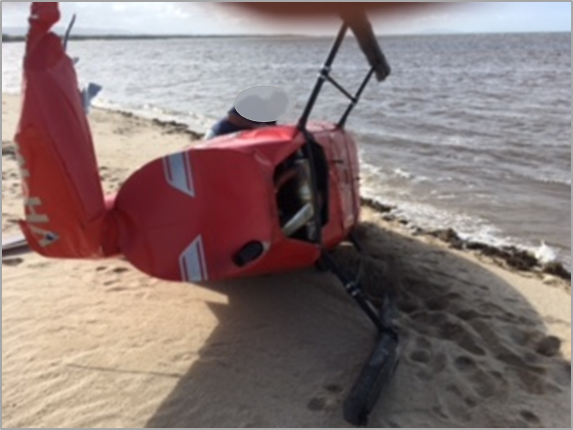
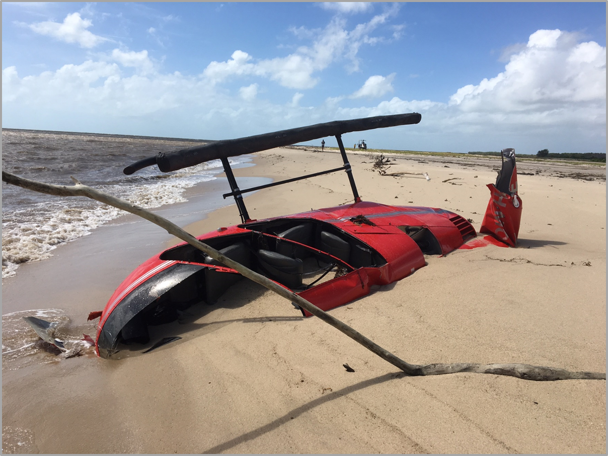
On 10 April 2024, a pilot of an Aeroprakt-32 aircraft, registered VH-VIK, was conducting a private flight from Moruya to Griffith, New South Wales. During the flight, while near Canberra, the pilot observed a lower-than-normal engine oil pressure indication. They continued following their planned track, climbed to 6,500 ft, and shortly thereafter flew over mountainous terrain. Around 14 minutes later, the pilot contacted air traffic control to advise of the indication and that they were diverting to Tumut Aerodrome. The pilot commenced the diversion and immediately initiated a descent. Soon after, the engine failed. They aimed to reach the runway at Tumut but had insufficient height to do so and conducted a forced landing in the field to the north of the aerodrome. The pilot received minor injuries and the aircraft sustained substantial damage.
What the ATSB found
For reasons that could not be determined, oil pressure was lost during the flight. This resulted in an engine failure when the aircraft was about 5 NM (9.2 km) from Tumut Aerodrome. The time taken by the pilot to make the decision to divert after the low oil pressure indication was first observed, resulted in the aircraft flying further away from a safe landing place (Canberra Airport) as the situation continued to deteriorate.
After diverting towards Tumut Aerodrome for a precautionary landing, the pilot elected to commence a descent rather than maintain altitude. This meant that, when the engine failed, there was insufficient altitude remaining to reach the runway.
Safety message
When faced with an abnormal event, pilots should not only consider the immediate situation but also the potential future implications of any issues they detect with the operation of their aircraft. For any issue that could lead to a loss of engine power, consideration should be given to making a precautionary landing at the nearest suitable location. Flight over inhospitable terrain should be avoided if possible. This investigation also highlights that, maintaining altitude whenever practical will provide more opportunity to find a suitable landing place should a situation develop where a forced landing is required.
The investigation
The ATSB scopes its investigations based on many factors, including the level of safety benefit likely to be obtained from an investigation and the associated resources required. For this occurrence, the ATSB conducted a limited-scope investigation in order to produce a short investigation report, and allow for greater industry awareness of findings that affect safety and potential learning opportunities.
The occurrence
On 10 April 2024, a pilot planned a private flight in an Aeroprakt‑32 aircraft, registered VH‑VIK, from Moruya to Griffith, New South Wales, which included a scenic flight route around Canberra, Australian Capital Territory. The aircraft departed Moruya at about 1038 local time, tracking along the coast to Ulladulla, before turning inland towards Canberra. The pilot entered the controlled airspace around Canberra Airport at 1136, maintaining an altitude of about 4,000 ft above mean sea level.[1] They completed three‑quarters of the City route alpha one scenic flight,[2] before continuing north‑east towards Griffith. During the flight, the aircraft experienced some turbulence and the pilot elected to hand fly the aircraft, instead of using autopilot as they would normally have done. In hindsight, they stated feeling fatigued from the increased workload of hand flying.
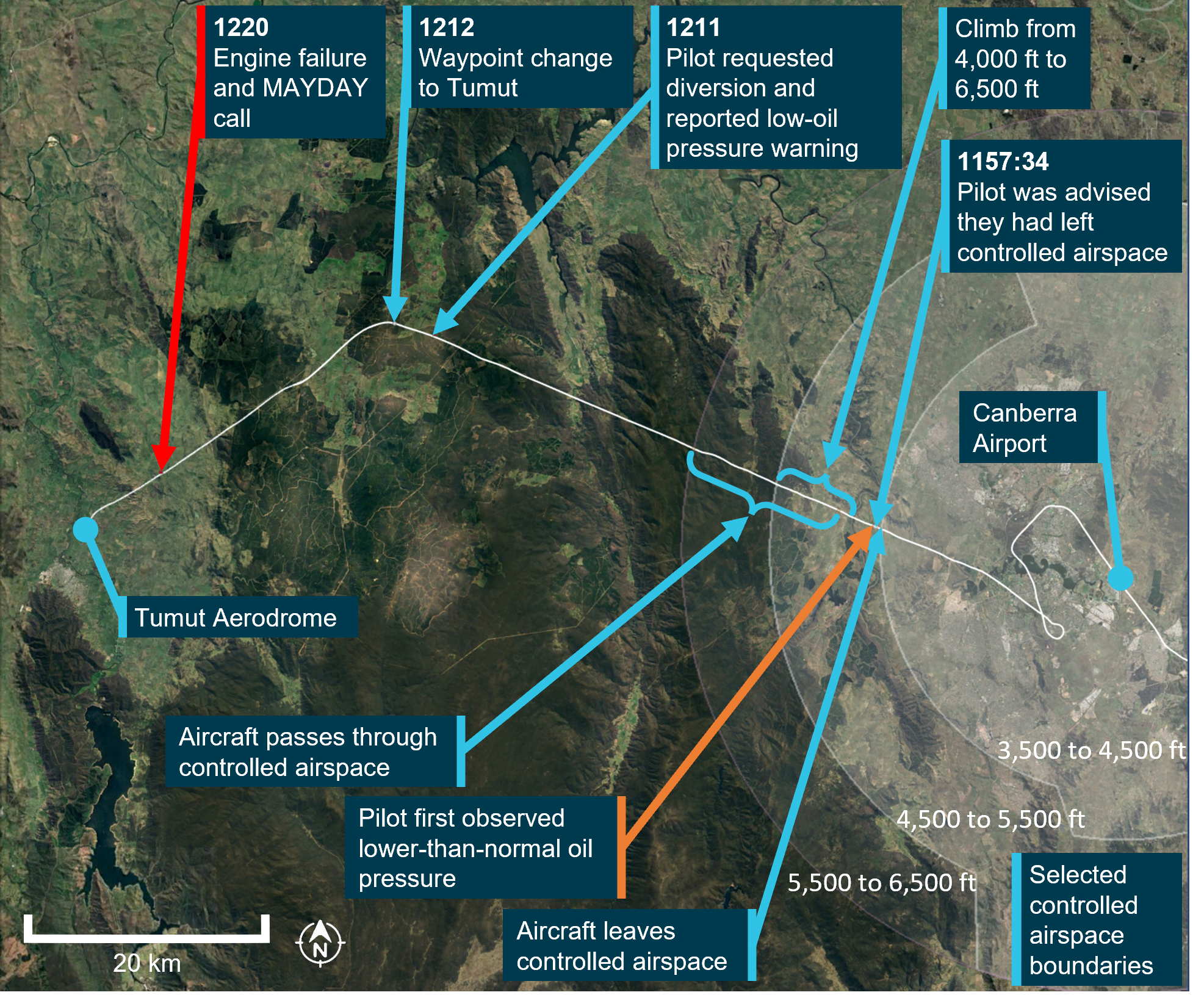
At 1157:34, air traffic control (ATC) advised the pilot that they had left controlled airspace and offered them flight following.[3] The pilot acknowledged leaving controlled airspace and accepted flight following. They then requested a climb from 4,000 ft to 6,500 ft, which ATC cleared. Although the aircraft was not in controlled airspace at this time, the pilot requested the clearance as they would briefly pass through controlled airspace to complete the climb to 6,500 ft (Figure 1). The pilot was cleared to enter and leave controlled airspace as required during the climb.
During interview with the ATSB, the pilot stated that, after they were contacted by ATC to advise of leaving controlled airspace, but before obtaining the clearance to climb, they observed a lower-than-normal engine oil pressure indication (Figure 1). At about 1158, when the pilot commenced the climb, the aircraft was around 11.4 NM (21.1 km) from Canberra Airport.
The pilot recalled initially thinking the low oil pressure might be related to the slower than usual airspeeds selected to conduct the scenic flight and a cooler outside air temperature. They thought the increased engine revolutions per minute (RPM) required during the climb would result in an increased engine oil pressure. On reaching 6,500 ft, the oil pressure was still low. When assessing options due to the ongoing engine oil pressure indication, the pilot believed Canberra was ‘far’ and reasoned that the farmland beyond the upcoming mountain range might be suitable if a precautionary,[4] or a forced landing[5] was necessary. The pilot continued the planned route towards Griffith over mountainous terrain. In interview with the ATSB, the pilot acknowledged they were reluctant to return to Canberra Airport to conduct a precautionary landing due to concerns with flying over a populated area, the presence of passenger aircraft, and lower familiarity with controlled airspace.
As the flight continued, the oil pressure did not recover and further dropped from 30 psi to 10 psi. The pilot stated that they delayed making a decision about diverting or landing, wanting to believe that there was no issue with the aircraft. At 1211:42, around 15 minutes after the initial observation of the low oil pressure, the pilot contacted ATC and reported that they were diverting to Tumut Aerodrome due to a low oil pressure warning. At this time Tumut Aerodrome, located west of the Great Dividing Range at an elevation of 863 ft, was the closest landing area, at 16.6 NM (30.7 km) distance. The pilot changed their navigation waypoint in their Dynon Skyview Touch flight computer to Tumut Aerodrome, turned the aircraft on to the new track, and immediately began a descent to expedite the landing. The pilot recalled feeling in denial that there was an issue, but with hindsight, recognised that it would have been beneficial to maintain altitude for as long as possible.
At 1220:17, around 9 minutes after the diversion, and while the aircraft was still 5 NM (9.3 km) from Tumut Aerodrome, the engine failed. The pilot reported focusing on the need to aviate, navigate, and communicate, then attempted to restart the engine, but was unsuccessful. At 1221:12, the pilot declared a MAYDAY,[6] reporting their location and an engine failure. They attempted a glide approach to runway 17,[7] which was aligned with their direction of travel, but the pilot judged that they had insufficient height, and at 1225 they conducted a forced landing in the field to the north of the aerodrome. The aircraft sustained substantial damage, and the pilot received minor injuries.
Figure 1: Flight track of VH-VIK after passing Canberra Airport
Source: FlightRadar24, Dynon Skyview unit, and Google Earth, annotated by the ATSB
Context
Pilot information
The pilot obtained a private pilot licence (aeroplane) in January 2016. At the time of the occurrence, the pilot had 790 hours flying experience, with around 600 hours in VH‑VIK. The pilot had flown 23.1 hours in the last 90 days, all of which were in VH‑VIK. The pilot stated that they flew with survival equipment including a personal locator beacon that they wore on their person.
Aircraft information
General
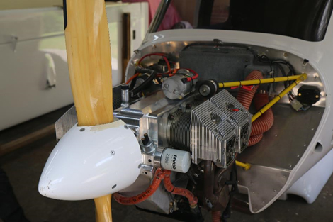
The aircraft was an Aeroprakt‑32 (serial number 025), which was manufactured in Ukraine and registered in Australia in 2016. It had a Bombardier Rotax 912 ULS piston engine. The most recent maintenance was a 50‑hour inspection completed on 15 March 2024. At this time, the aircraft had accumulated about 634.5 hours total time in service. The ATSB’s examination of documentation found that the aircraft maintenance was up to date with no outstanding maintenance items. The aircraft total time in service at the time of the occurrence was 655.9 hours.
Pre-flight inspection
On the morning of the flight, the pilot conducted a pre‑flight inspection. This included inspection of the engine compartment where there was no evidence of oil leaks. They checked the oil and observed that there was sufficient oil and it was a normal colour. The pilot stated that ‘normal’ in‑flight oil pressure for the aircraft was around 50 psi. This was consistent with the oil pressure information provided in the pilot’s operating handbook, which indicated a normal range of 29 to 73 psi when operating above 2,500 rpm, and a minimum and maximum of 12 psi and 100 psi, respectively.
Emergency procedures
The pilot’s operating handbook provided recommendations for pilots in case of an emergency in flight. For a ‘loss of oil pressure’, the instructions were:
Follow PRECAUTIONARY LANDING procedure, see section 3.2.6.
Engine overheating or stopped – follow EMERGENCY LANDING procedure, see section 3.2.5.
The recommendations for a precautionary landing were:
1. Airspeed – SELECT SAFE for the particular situation.
2. Throttle – SET to maintain selected airspeed.
3. Fuel – CHECK level and valves.
4. Map – CHECK for nearest airfields/area suitable for landing.
5. Landing area – SELECT.
6. Radio – REPORT decision to land on the selected place if necessary.
7. Landing – follow NORMAL or SHORT-FIELD landing procedure as appropriate.
Meteorological information
The Bureau of Meteorology graphical area forecast predicted that visibility for the flight would be greater than 10 km. Until 1200 local time, there was broken[8] cumulus and stratocumulus cloud with a 3,500 ft base over the Canberra region. In addition, moderate turbulence over land was expected below 7,000 ft.
The pilot did not mention any cloud at or below their eye level that would have required a descent to maintain visual meteorological conditions.[9] The prevailing wind conditions were more suited to a landing on runway 17 at Tumut Aerodrome.
Recorded data
The ATC audio recordings were obtained for the relevant part of the flight, starting at 1100 and ending at 1300. Automatic dependent surveillance‑broadcast (ADS‑B)[10] flight data was obtained from FlightRadar24. Further flight data was obtained from the pilot’s electronic flight bag[11] (AvPlan).
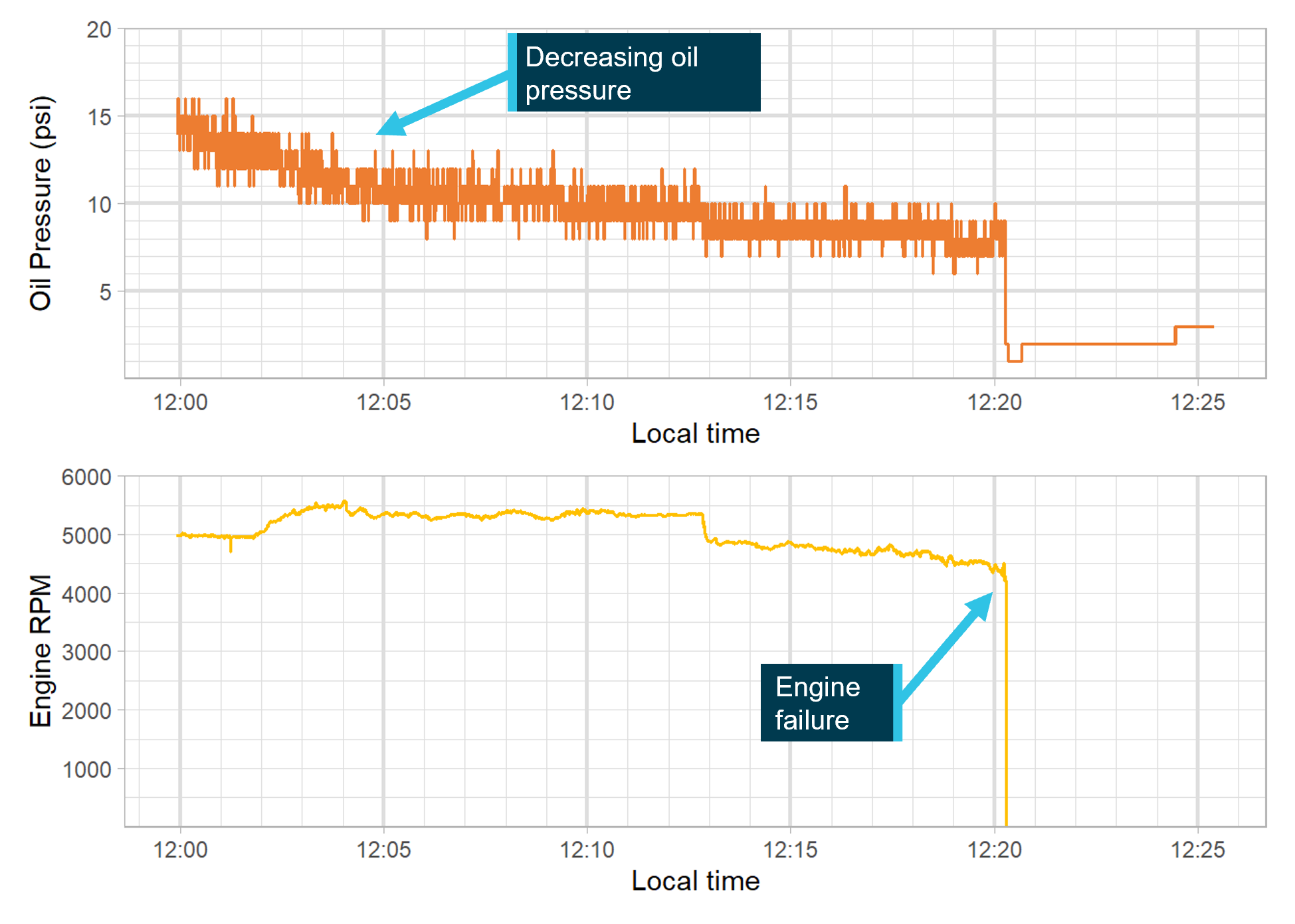
The aircraft was equipped with a Dynon Skyview Touch avionics system. This system recorded flight and engine parameters over the final 25 minutes of the flight, at a sampling rate of 16 entries every second. As such, it did not capture when the oil pressure began to drop below normal. The unit recorded that the pilot changed the programmed waypoint to Tumut at 1212:45, at which time the aircraft was about 16.6 NM (30.7 km) from Tumut Aerodrome. The data showed that the oil pressure continued to decrease after the diversion, and that the engine stopped at 1220:17, 7 minutes and 32 seconds after the waypoint change (Figure 2). Data recorded in previous flights indicated that the normal oil pressure was around 50 psi, which was consistent with the pilot’s recollection.
Figure 2: Oil pressure and engine RPM data recorded for accident flight
Source: Dynon Skyview unit, annotated by the ATSB
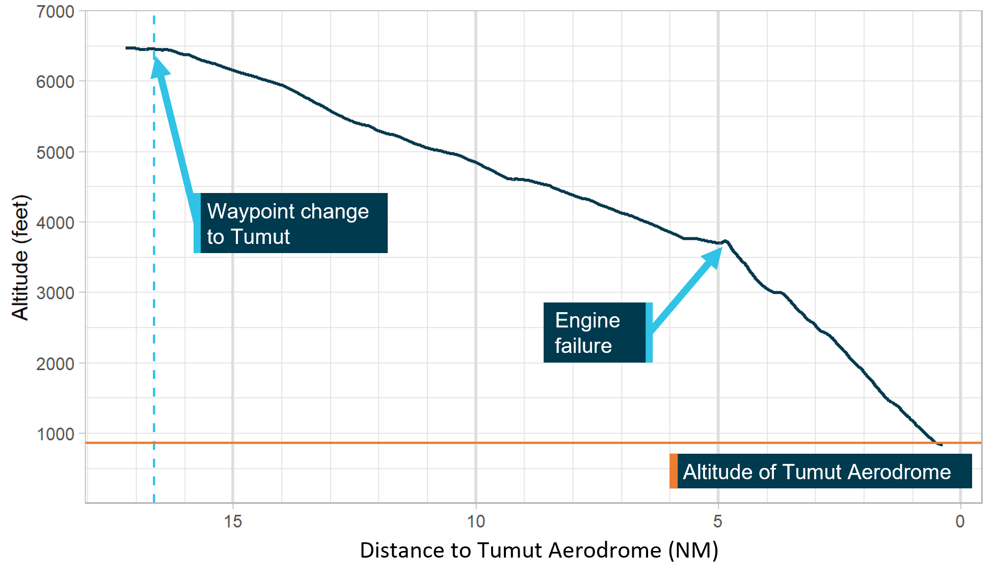
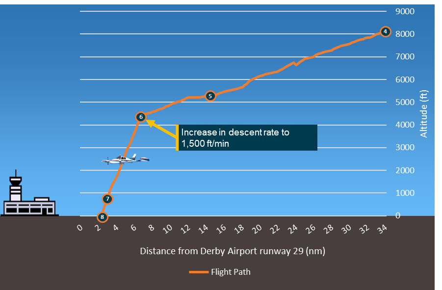
GPS data from the Dynon captured the descent profile of the aircraft from the diversion point until the forced landing (Figure 3). The profile showed that the pilot assumed a fairly constant rate of descent from the diversion point until the engine failed. Once the engine failed the rate of descent increased. Considering the descent profile of the aircraft following the engine failure, the ATSB estimated that, if the cruise altitude had been maintained until the failure, the aircraft would have been within glide range of the runway at Tumut.
Figure 3: Altitude (above mean sea level) as a function of distance to Tumut Aerodrome
Source: Dynon Skyview unit, annotated by the ATSB
Wreckage and impact information
The aircraft came to rest around 250 m north of runway 17 at Tumut Aerodrome, in a field of undulating terrain. The damage to the airframe was consistent with the landing and there was no indication of a pre‑existing airframe issue. No defects were noted with the flight control system and the pilot did not report any control issues during the descent. Accordingly, full control of the aircraft was likely available.
In addition to damage sustained from the landing, the engine had a hole in the upper crank‑case region. The oil cap was securely in position and no engine oil was visible on the oil tank dipstick. A significant quantity of oil was noted to be coating the engine lower cowl in the region of the oil cooler assembly. Oil residue also coated the aircraft belly aft of the engine, the left undercarriage fairing and wheel spat, and the upper surface of the left horizontal stabiliser. A fine sheen of oil was present on the cabin windscreen. Oil residues were also noted on the external surfaces of the engine cowl, in the region of the propeller shaft opening.
The engine oil cooler was collected for testing at the ATSB technical facilities. The testing indicated that, while the oil cooler was damaged during the landing sequence, there was no indication that the oil cooler was defective, and the condition of the vessel was regarded as intact and unlikely to be a source of oil leakage. The other engine systems that could have contributed to the engine failure appeared to have only sustained consequential damage.
Considerations for emergency landings
The United States Federal Aviation Administration (FAA) Airplane Flying Handbook (FAA, 2021) defines 2 types of emergency landings:
• Forced landing – an immediate landing, on or off an airport, necessitated by the inability to continue further flight. A typical example of which is an airplane forced down by engine failure
• Precautionary landing – a premeditated landing, on or off an airport, when further flight is possible, but inadvisable. Examples of conditions that may call for a precautionary landing include deteriorating weather, being lost, fuel shortage, and gradually developing engine trouble.
The FAA (2021) identified that a precautionary landing is generally less hazardous than a forced landing as the pilot has more time to select terrain and plan the approach, but also cautioned pilots that:
…many situations calling for a precautionary landing are allowed to develop into immediate forced landings, when the pilot uses wishful thinking instead of reason…
The FAA (2021) suggests that, following the identification of low oil pressure, pilots should land as soon as possible and that one factor that governs a pilot’s choice of emergency landing site is the height above the ground when the emergency occurs. Geeting and Woerner (1988) stated, regarding emergency landings while mountain flying, that ‘forced landings of any type nearly always benefit from having altitude and holding it as long as possible’. Training for a forced landing pattern indicated aiming for a height of 2,500 ft above ground level on the crosswind leg (CASA, 2006).
Decision‑making
The FAA (2023) defined aeronautical decision‑making as:
A systematic approach to the mental process used by pilots to consistently determine the best course of action in response to a given set of circumstances.
A crucial component of the aeronautical decision-making process is risk management. When faced with a hazard, the pilot assesses that hazard based on various factors and determines a course of action. Some situations, such as loss of oil pressure or engine failure, require an immediate pilot response using procedures. On other occasions there may be time during a flight to gather information and assess risks before reaching a decision.
Orasanu-Engel and Mosier (2019) stated that decision errors may arise within the 2 major components of the aviation decision model: (1) pilots may develop an incorrect interpretation of the situation, which leads to an inappropriate decision; or (2) they may establish an accurate picture of the situation, but choose an inappropriate course of action. Furthermore, decisions may not be optimal when pilots were aware of a threat that requires a response, but underestimates the likelihood or severity of possible consequences, especially when conditions are changing dynamically (Orasanu-Engel and Mosier, 2019). Operational factors, such as high workload, may affect pilots’ ability to make optimal decisions. Fatigue can be an effect of increased and sustained workload (United Kingdom Civil Aviation Authority, 2023).
Similar occurrences
ATSB occurrence database
A search of the ATSB database for similar occurrences over the 12 months prior to this event was conducted. Sixty occurrences were found related to aircraft in the cruise phase of flight that experienced either abnormal engine indications, an engine failure, or an engine malfunction. Of these, 44 occurrences resulted in the aircraft landing safety at either the destination or a diversion airport, while 14 occurrences resulted in a forced landing. There was insufficient information to categorise 2 occurrences. The forced landings resulted in 4 accidents, 8 serious incidents, and 1 incident. An example of a low oil pressure indication event that resulted in a precautionary landing is described in more detail below. In addition, an investigation where the benefit of maintaining aircraft altitude in an emergency was raised in association with a contributing factor to the accident is discussed.
ATSB occurrence (OA2024-02070)
On 8 April 2024, while conducting an aerial survey, the pilot of a Cessna 172 aircraft identified that the oil pressure had dropped below the green indicated area. They closely monitored the oil pressure and decided that landing as soon as possible would be the best course of action. The pilot identified a potential safe landing area and conducted a successful precautionary landing with no damage to the aircraft. The pilot reported that later inspection found a leak from the oil cooler.
On 20 June 2023, while conducting an air transport flight, the pilot of a Cessna 310R aircraft experienced engine surging as a result of fuel starvation. In their management of the situation, the pilot did not maintain altitude. Instead, they initiated a descent at the normal top of descent position. The report stated that maintaining the aircraft's potential energy (altitude) is crucial for extending an aircraft's range during an engine failure, providing more landing options and time to manage the emergency effectively.
Safety analysis
Delayed decision to divert
When about 11.4 NM (21.1 km) from Canberra Airport, the pilot observed lower‑than‑normal engine oil pressure, which continued to decay. Under these circumstances, the pilot’s operating handbook recommended course of action was to conduct a precautionary landing, which included a check for the nearest suitable airfield or landing area. The pilot acknowledged that they delayed making the decision to divert and that this was influenced by incorrectly interpreting that the low-oil pressure was due to the flight characteristics. Consistent with Orasanu-Engel and Mosier (2019), this resulted in the pilot underestimating the risk posed by the abnormal indication. Additionally, the pilot reasoned that they were already far from Canberra and were reluctant to return due to the perceived complexity of conducting a precautionary landing at an airport in controlled airspace. The pilot’s decision‑making may have also been degraded by fatigue generated by the increased workload they reported when they were hand flying the aircraft in turbulence near Canberra.
Given that the engine was operational for about 23 minutes after the initial observation of low oil pressure, it was very likely that, had the pilot diverted to Canberra Airport at this time, it would have been possible to conduct a safe precautionary landing before the engine failed. Ultimately, the 14 minutes taken to make the decision to divert took the aircraft 20 NM (37 km) further from Canberra Airport, over mountainous terrain, and meant that the engine failed in‑flight.
Intentional descent with developing engine issue
The recorded data showed that once the pilot made the decision to conduct a precautionary landing, they commenced a powered descent towards Tumut Aerodrome. Given the decreasing oil pressure, the pilot could not be assured the engine would continue to operate normally. As such, maintaining altitude, as suggested in the literature, until they were confident of reaching the aerodrome with a glide profile in case the engine stopped, would have increased the likelihood that Tumut Aerodrome would be reached.
At about 5 NM (9.3 km) from Tumut, the engine failed and, as expected, the data showed the descent rate increased. This escalated the situation from requiring a precautionary landing to a forced landing. The height of the aircraft at that location was insufficient to reach the runway and the pilot’s remaining option was to conduct the forced landing in a field. ATSB calculations indicated that it was likely that, had the cruise altitude of 6,500 ft been maintained to within 5 NM (9.3 km) of Tumut, the aircraft would have been within glide range of the runway. As such, when the engine failed, the pilot would have been able to complete the forced landing onto the runway.
Engine oil loss
The ATSB’s examination of the aircraft identified a lower‑than‑normal amount of oil in the engine and oil coating various parts of the aircraft. There was also no oil on the dipstick. The loss of oil observed was consistent with the flight data, which showed a decline in the oil pressure until the engine failed. The oil cap was found secure, the oil cooler was not defective, and no issues were found with the other systems that would explain the loss of oil and engine failure. Therefore, the ATSB could not determine the source of the engine oil loss.
Findings
ATSB investigation report findings focus on safety factors (that is, events and conditions that increase risk). Safety factors include ‘contributing factors’ and ‘other factors that increased risk’ (that is, factors that did not meet the definition of a contributing factor for this occurrence but were still considered important to include in the report for the purpose of increasing awareness and enhancing safety). In addition ‘other findings’ may be included to provide important information about topics other than safety factors.
These findings should not be read as apportioning blame or liability to any particular organisation or individual.
From the evidence available, the following findings are made with respect to the engine failure and forced landing involving Aeroprakt-32, VH-VIK, 0.1 km north of Tumut Aerodrome, New South Wales, on 10 April 2024.
Contributing factors
Following the low engine oil pressure indication, the pilot delayed the decision to divert, which removed an opportunity to conduct a precautionary landing at nearby Canberra Airport.
Commencing a powered descent after diverting towards Tumut meant that the pilot had to conduct a forced landing short of the runway due to insufficient glide range when the engine failed.
Other findings
The reason for the engine oil loss could not be determined.
Sources and submissions
Sources of information
The sources of information during the investigation included:
the pilot
the insurance provider of VH-VIK
the Civil Aviation Safety Authority
the aircraft manufacturer
the maintenance organisation
Airservices Australia
recorded data from the avionics unit on the aircraft
Geeting, D., & Woerner, S. (1988). Mountain Flying (First ed.). TAB Books Inc.
Orasanu-Engel, J., & Mosier, K. L. (2019). Flight Crew Decision-Making. In B. G. Kanki, J. Anca, & T. R. Chidester (Eds.), Crew Resource Management (Third ed., pp. 587-607). Academic Press.
United Kingdom Civil Aviation Authority. (2023). Flight-crew human factors handbook (Second Edition).
Submissions
Under section 26 of the Transport Safety Investigation Act 2003, the ATSB may provide a draft report, on a confidential basis, to any person whom the ATSB considers appropriate. That section allows a person receiving a draft report to make submissions to the ATSB about the draft report.
A draft of this report was provided to the following directly involved parties, the:
pilot
Civil Aviation Safety Authority.
A submission was received from the pilot.
The submission was reviewed and, where considered appropriate, the text of the report was amended accordingly.
Purpose of safety investigations
The objective of a safety investigation is to enhance transport safety. This is done through:
identifying safety issues and facilitating safety action to address those issues
providing information about occurrences and their associated safety factors to facilitate learning within the transport industry.
It is not a function of the ATSB to apportion blame or provide a means for determining liability. At the same time, an investigation report must include factual material of sufficient weight to support the analysis and findings. At all times the ATSB endeavours to balance the use of material that could imply adverse comment with the need to properly explain what happened, and why, in a fair and unbiased manner. The ATSB does not investigate for the purpose of taking administrative, regulatory or criminal action.
Terminology
An explanation of terminology used in ATSB investigation reports is available here. This includes terms such as occurrence, contributing factor, other factor that increased risk, and safety issue.
Publishing information
Released in accordance with section 25 of the Transport Safety Investigation Act 2003
Ownership of intellectual property rights in this publication
Unless otherwise noted, copyright (and any other intellectual property rights, if any) in this report publication is owned by the Commonwealth of Australia.
Creative Commons licence
With the exception of the Commonwealth Coat of Arms, ATSB logo, and photos and graphics in which a third party holds copyright, this report is licensed under a Creative Commons Attribution 4.0 International licence.
The CC BY 4.0 licence enables you to distribute, remix, adapt, and build upon our material in any medium or format, so long as attribution is given to the Australian Transport Safety Bureau.
Copyright in material obtained from other agencies, private individuals or organisations, belongs to those agencies, individuals or organisations. Where you wish to use their material, you will need to contact them directly.
[1]All altitude values in this report are above mean sea level unless stated otherwise.
[2]Scenic flight is commonly used to describe a flight over interesting sights and landmarks or near a popular tourism area.
[3]Flight following is the provision of an ongoing surveillance information service to visual flight rules flights in Class E and G airspace. This service can provide improved situational awareness and assists pilots in avoiding collisions with other aircraft.
[4]Precautionary landing: a premeditated landing, on or off an airport, when further flight is possible but inadvisable. Examples of conditions that may call for a precautionary landing include deteriorating weather, being lost, fuel shortage, and gradually developing engine trouble (FAA, 2021).
[5]Forced landing: an immediate landing, on or off an airport, necessitated by the inability to continue further flight. A typical example of which is an airplane forced down by engine failure (FAA, 2021).
[6]MAYDAY: an internationally recognised radio call announcing a distress condition where an aircraft or its occupants are being threatened by serious and/or imminent danger and the flight crew require immediate assistance.
[7]The runway number represents the magnetic heading of the runway. Tumut Aerodrome had one sealed runway with heading 17/35.
[8]Cloud cover: in aviation, cloud cover is reported using words that denote the extent of the cover – ‘broken’ indicates that more than half to almost all the sky is covered.
[9]Visual meteorological conditions: an aviation flight category in which visual flight rules flight is permitted – that is, conditions in which pilots have sufficient visibility to fly the aircraft while maintaining visual separation from terrain and other aircraft.
[10]ADS-B: Automatic dependent surveillance–broadcast is a surveillance technology in which an aircraft determines its position via satellite navigation and periodically broadcasts it, enabling it to be tracked.
[11]Electronic flight bag: software and data-service solution to digitise logbooks charts, and other flight documents to achieve paperless cockpit.
Occurrence summary
Investigation number
AO-2024-010
Occurrence date
10/04/2024
Location
0.1 km north of Tumut Aerodrome
State
New South Wales
Report release date
23/09/2025
Report status
Final
Investigation level
Short
Investigation type
Occurrence Investigation
Investigation status
Completed
Mode of transport
Aviation
Aviation occurrence category
Abnormal engine indications, Diversion/return, Engine failure or malfunction, Forced/precautionary landing
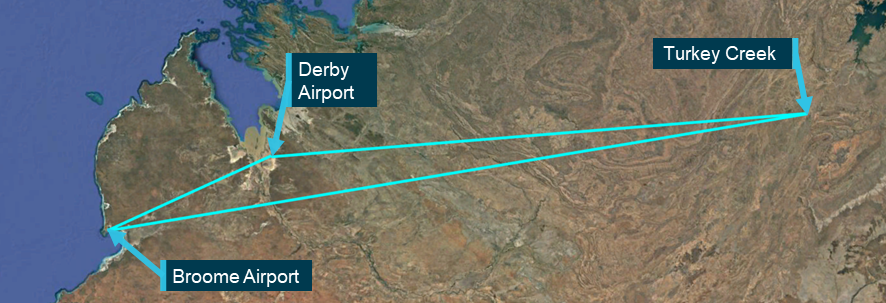
On 8 March 2024, the pilot of an Aero Commander 500-S, registered VH-MEH and operated by GAM Air, was conducting a return cargo transport operation from Bankstown Airport to Parkes Regional Airport, New South Wales with one intermediate stop outbound, and 2 intermediate stops on return.
After landing on the first sector, the pilot found the fuel cap was off and secured only by a retention chain. The pilot re‑secured the cap but after landing at Parkes on the second sector, they again found the fuel cap off, and arranged an inspection by a maintenance engineer. The engineer found a fault that prevented the fuel cap from locking and rectified it.
Later that day, the pilot commenced the return sectors to Bankstown. Shortly after departing Bathurst for the final sector, both engines lost power, and the pilot conducted a forced landing in a field. The aircraft was undamaged and the pilot was uninjured.
What the ATSB found
The ATSB found that for the first 2 sectors, the fuel cap was incorrectly installed with the retention chain lodged in the fuel tank’s anti-siphon valve, resulting in the cap dislodging in‑flight and fuel being siphoned overboard. At Parkes Regional Airport, the pilot identified an unexplained discrepancy between expected fuel remaining and gauge quantity indication but did not refuel to a known quantity or amend the flight log. As a result, the aircraft departed Parkes with the pilot unaware there was insufficient fuel to complete the remaining flights.
After departing Parkes, the pilot likely did not monitor the fuel gauge, continued fuel calculations based on an incorrect fuel quantity, and did not refuel the aircraft to a known quantity at Bathurst Airport. This resulted in fuel exhaustion shortly after the aircraft departed from Bathurst.
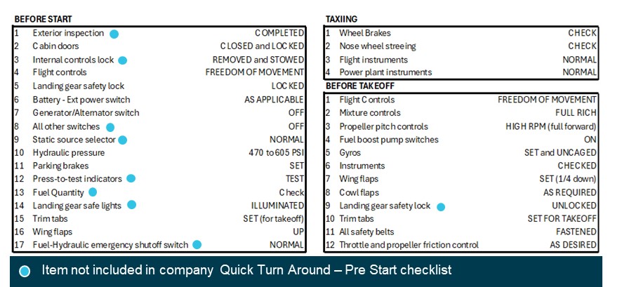
The ATSB also found that GAM Air's Quick Turn Around – Pre-Start checklist did not include a fuel quantity check before start, contrary to the aircraft flight manual’s before-start checklist.
What has been done as a result
GAM Air published a pilot notice reinforcing fuel management procedures for Aero Commander 500 series aircraft. The notice highlighted the importance of fuel tank cap security, and the likelihood of fuel loss should a fuel cap become dislodged, despite the anti-siphon valve. The notice also provided instructions and guidance on fuel planning, in-flight fuel calculations and fuel log entries to expand on information in the standard operating procedures.
GAM Air also commenced periodic auditing of pilot fuel calculations and advised an intention to discontinue use of the Quick Turn Around – Pre-Start checklist. The fuel supplier at Bankstown was also reminded of the requirement to let fuel settle when refuelling.
Safety message
A missing or unsecured fuel cap can lead to rapid and substantial fuel loss in‑flight, even when the fuel tank is equipped with an anti-siphon valve. Loss of a fuel cap in‑flight should be considered as an emergency and, if detected, an immediate diversion to the nearest suitable aerodrome should be conducted. In addition, in aircraft with rubber fuel cells or bladders, fuel gauge readings should not be relied upon as siphoning of fuel can lead to collapse and distortion of the cells causing the fuel gauge to overread. Filling to an amount that can be visually confirmed is required to re‑establish an accurate measure of fuel on board.
The Civil Aviation Safety Authority’s Advisory Circular 91-15 – Guidelines for aircraft fuel requirements, stated:
It is of critical importance that the amount of usable fuel on board an aircraft at the commencement of and during a flight is known with the highest level of certainty.
Pre-flight fuel quantity checks should use at least 2 different verification methods to determine the amount of fuel on board. When using computed fuel on board and comparing against gauge readings, it is important that calculations are accurate. If any discrepancy is detected between the 2 methods, another method such as filling to a known quantity is required.
The investigation
Decisions regarding the scope of an investigation are based on many factors, including the level of safety benefit likely to be obtained from an investigation and the associated resources required. For this occurrence, a limited-scope investigation was conducted in order to produce a short investigation report, and allow for greater industry awareness of findings that affect safety and potential learning opportunities.
The occurrence
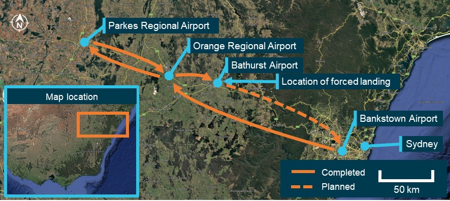
On 8 March 2024, the pilot of an Aero Commander 500-S, registered VH-MEH and operated by GAM Air, was preparing to conduct a return cargo transport operation from Bankstown Airport to Parkes Regional Airport, New South Wales (NSW). The planned flight to Parkes included a stop at Orange Regional Airport to unload a portion of the cargo. The aircraft and pilot were to remain at Parkes for the day before the aircraft was reloaded to return to Bankstown in the afternoon with intermediate stops at Orange and Bathurst airports to load additional cargo (Figure 1). All operations were conducted under instrument flight rules (IFR).[1]
The aircraft had been refuelled 5 days earlier by a contract refueller, with a written instruction to fully refuel the aircraft. Since refuelling, the aircraft had been repositioned on the ground but not flown.
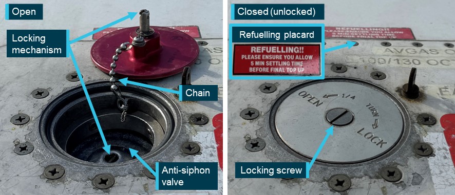
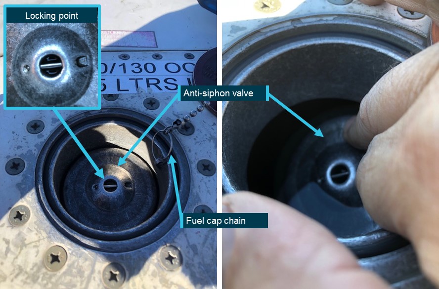
VH-MEH had a single fuel tank that supplied fuel to both engines, accessed through a filler port on the top of the right wing. A spring-loaded anti-siphon valve was installed at the fuel tank opening to mitigate in-flight fuel siphoning.[2] The anti-siphon valve could be pushed open when refuelling or when visually observing the fuel level. The fuel cap was secured to the filler neck by a chain and interlocked with the top of the anti-siphon valve, securing both the fuel cap in place and the anti‑siphon valve in its closed position when the locking screw was turned (Figure 2). To ensure the locking mechanism engaged correctly, pilots were advised to tap the structure around the tank cap once closed. That action should cause the cap to pop open if it was loose or unsecured.
Figure 2: Fuel cap and filling point components (not incident aircraft)
Source: GAM Air, annotated by the ATSB
At about 0610 local time, the pilot conducted a pre-flight inspection of the aircraft, during which they observed the fuel quantity to be 3–4 cm below the anti-siphon valve, which was below the level usually observed when the fuel tank was full. Based on that observation, the pilot estimated that they had 560 L of fuel on board of the total 590 L usable fuel[3] capacity. The pilot also received a weather briefing for the planned flights, which showed no significant wind effect en route (see the section titled Fuel planning).
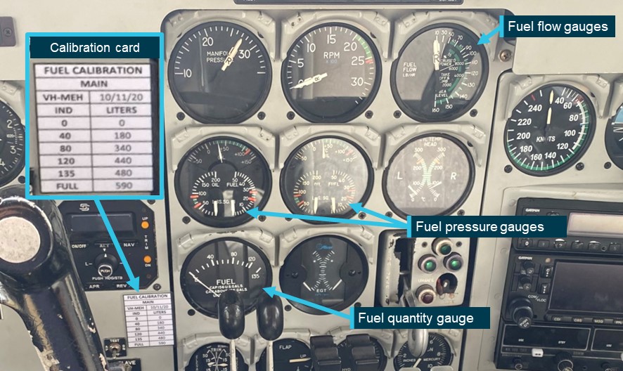
The aircraft had fuel quantity, fuel pressure and fuel flow gauges in the cockpit (Figure 3). A printed calibration card that provided the conversion of fuel gauge readings in US gallons (USG) to usable fuel in litres was affixed adjacent to the fuel quantity gauge. Although full fuel was 159 USG (590 L), the gauge could not indicate a quantity of fuel above 135 USG (480 L). Therefore, prior to commencing the flight, the pilot was unable to confirm the fuel level using the gauge. Because of this gauge limitation, the operator required pilots to begin flights with a fuel quantity that had been visually confirmed.
In accordance with the operator’s procedures, the pilot planned to assess the aircraft’s fuel on board by maintaining a log of fuel usage for each sector using a prescribed calculation method (see the section titled Fuel management). The calculated fuel on board would then be regularly compared to the fuel quantity gauge in the cockpit. The pilot used the estimated 560 L of fuel on board as the starting point for their calculations.
The aircraft departed Bankstown at 0658 and landed at Orange Airport at 0735. Upon landing, the pilot calculated that 89 L of fuel had been used. After shutdown, the pilot conducted a post-flight inspection. During the inspection the pilot found that the fuel cap was off, attached only by the chain, which they re‑secured. The pilot reported that they compared the calculated fuel remaining with the fuel quantity gauge reading and determined that there was no discrepancy. Additionally, the pilot reported that they expected the anti-siphon valve would have prevented any fuel loss from the unsecured cap.
The aircraft departed Orange at 0802 and landed at Parkes at 0825. After landing, the pilot calculated that 63 L of fuel would have been used for the sector and calculated the fuel remaining. The pilot conducted a post-flight inspection and again found that the fuel cap was off. They advised the company operations team, who arranged for an aircraft maintenance engineer at Parkes to inspect the fuel cap.
The pilot then identified that the fuel gauge was showing approximately 35–40 L less than the calculated fuel remaining. Due to the discrepancy, the pilot reported recalculating the fuel required for the remaining sectors, based on the fuel gauge indication, and determined that there was adequate fuel on board for the return flight. Specifically, even taking into account the required fuel reserves, the pilot calculated there was almost 1.5 hours excess fuel endurance. However, the pilot did not reduce the calculated fuel remaining on the flight log to reflect the lower gauge quantity indication. The pilot then left the airport.
The maintenance engineer inspected the fuel cap and found that the chain securing the fuel cap to the inside of the filler neck had disconnected from its attachment point and lodged under the anti‑siphon valve, holding it slightly open. This also prevented the fuel cap locking mechanism from engaging. The engineer removed the chain from its lodged position, re‑attached it to the filler neck, and successfully closed and locked the fuel cap. They also observed minor blue fuel dye staining aft of the fuelling point, consistent with Avgas 100 low lead fuel. The engineer later reported that they informed the pilot and the operator’s engineering department of what was found with the fuel cap.
The pilot returned to the airport in the afternoon and the aircraft departed for Orange at 1622, landing at 1644. The pilot calculated that 59 L of fuel had been used for that sector. After loading additional cargo, the aircraft departed Orange at 1702 and landed at Bathurst Airport at 1719, using a calculated 38 L of fuel (see the section titled Fuel monitoring). At that point, the pilot’s calculations determined that 311 L of fuel remained on board. The pilot later reported that they did not recall specific gauge readings at those intermediate stops, but that there were no noted discrepancies.
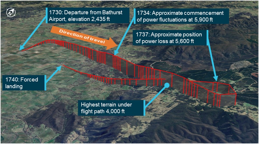
The aircraft departed Bathurst Airport at 1730 for the planned 73 NM flight to Bankstown Airport. At that time, the automated weather observation at the airport indicated no cloud, and wind from the north-east at 10 kt. The aircraft initially tracked north before turning right to track east towards Bankstown (Figure 4).
Source: FlightRadar24 flight data overlaid on Google Earth, annotated by the ATSB
The pilot reported that, approximately 4 minutes after departure, while climbing through 5,900 ft above mean sea level (AMSL), the aircraft yawed[4] significantly to one side, and then shortly afterwards, yawed to the other side. The pilot recalled performing initial engine failure actions, while using rudder to control the yaw as the engine noise and power fluctuated on both engines.
The pilot observed the fuel flow gauge readings increasing and decreasing in line with the fluctuating engine RPM indication and switched on the fuel boost pumps. The pilot was aware that the terrain below was at approximately 4,000 ft AMSL and the terrain ahead provided few options for a safe forced landing. The pilot advised air traffic control (ATC) of the situation before conducting a 210° left turn to track back towards Bathurst Airport, and towards flatter and lower terrain.
After completing the turn, both engines stopped making power, and the pilot prepared for a forced landing. The pilot selected a large field ahead as a suitable landing area. The pilot elected not to feather[5] the propellors in case partial power was restored and they could continue to the airport. As the aircraft approached the planned landing area, the pilot extended the landing gear prior to manoeuvring below power lines and over a fence. The aircraft landed in the field and came to a stop, after which the pilot advised ATC of their situation before securing the aircraft. The aircraft was undamaged and the pilot was uninjured.
Context
Pilot information
The pilot held a commercial pilot licence (aeroplane) issued in 2018 and completed an instrument proficiency check[6] in August 2023. A line check and a proficiency check were completed with the operator in September 2023, where the pilot was assessed as competent, and approved to conduct charter flights.
The ATSB obtained the pilot’s experience as of 2 months after the incident, by which time they had accumulated 1,745 total flight hours, 776 hours on multi-engine aircraft, of which 335 hours were logged on Aero Commander 500-type aircraft.
The pilot held a valid Class 1 aviation medical certificate with no restrictions and reported that they were well rested.
Aircraft information
VH-MEH was an Aero Commander 500-S aircraft fitted with 2 Lycoming IO-540-E1B5 290-hp piston engines driving Hartzell 3-bladed constant‑speed propellors. The aircraft was manufactured in the United States in 1975 and first registered in Australia in 1976.
The aircraft had an Australian Supplemental Type Certificate allowing an increased maximum take-off and landing weight of 3,243 kg for IFR operations.
The last periodic inspection was carried out on 13 December 2023, and there were no outstanding items recorded on the aircraft’s maintenance release.[7] At the time of the incident, the aircraft had accumulated 44,963.3 hours total time in service.
There were no onboard recording devices installed on the aircraft that recorded engine indications, gauge readings, fuel flow or fuel levels.
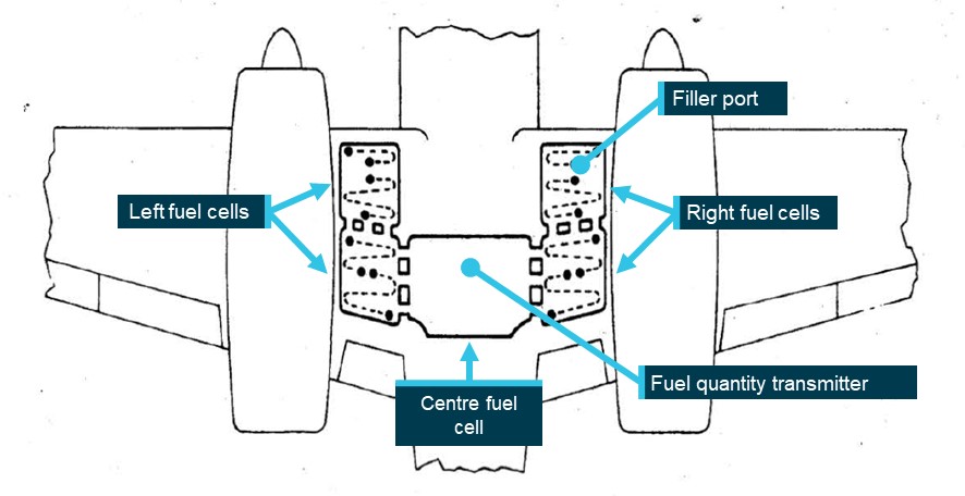
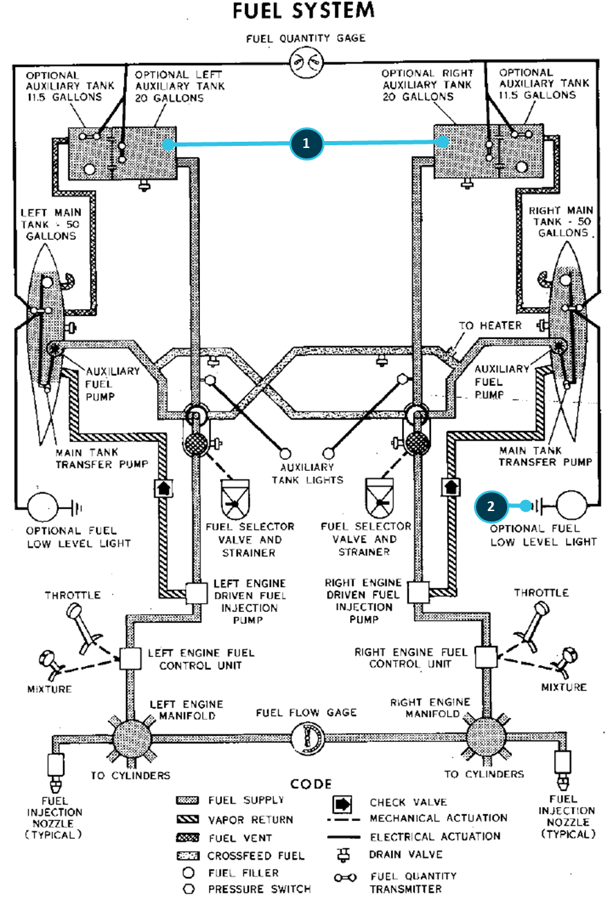
The aircraft’s fuel tank consisted of 5 interconnected synthetic rubber cells installed in the inboard and centre wing sections (Figure 5). A single fuel quantity transmitter was installed in the centre fuel cell and electrically connected to the fuel quantity gauge. Both the operator and the aircraft manufacturer reported that the distribution of the fuel throughout interconnected fuel cells made physical determination of the fuel level using a dipstick impractical. Therefore, the only way to confirm the fuel level was to observe the fuel at a level full or close to full. Additionally, during refuelling, the fuel could take time to settle and allow a reliable visual determination of the fuel level. A placard advising of this was placed adjacent to the filling point on the operator’s Aero Commander aircraft (Figure 2).
Source: Aero Commander 500-S maintenance manual, annotated by the ATSB
Post-incident inspection
The ATSB did not attend the incident site. Evidence from approximately 30 minutes after the incident showed the fuel gauge indicating empty when electrical power was turned on. The operator’s maintenance engineers conducted an on-site inspection of the aircraft 6 days later, at which point they reported that the fuel cap was found secured and locked, and the fuel drain points were in the closed position. A small amount of fuel discharged from them when opened, likely to be unusable fuel.[8]
The fuel cap was inspected and tested and was found to attach and remain on, with an observation that the retention spring in the locking screw was noted to be in weak condition, meaning that it could be turned by pressure from a finger or thumb rather than requiring a screwdriver. The fuel cap was replaced as a precautionary measure. Inspection and testing of fuel system components and a general inspection on the aircraft found no issues.
The aircraft was recovered 2 weeks later and taken to Bathurst Airport, where 180 L of fuel was added to the fuel tank, during which the fuel gauge was noted to read correctly and move as expected. Engine ground runs and propellor checks were conducted with all engine parameters observed as normal.
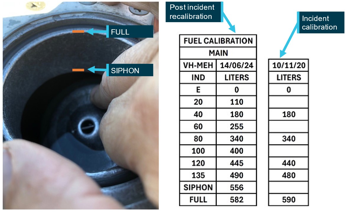
Fuel gauge calibration was required to be conducted every 4 years and prior to the incident was last conducted for VH-MEH on 10 November 2020. Before the aircraft was returned to service, the fuel gauge was recalibrated to verify the correct operation of the fuel indication system, and to fulfil the periodic recalibration requirement. The calibration was expanded to 10 increments from the initial 6. Additionally, a new visual fuel level, annotated as SIPHON, was added. Figure 6 shows how these 2 visible levels were observed and compares the re‑calibration with the calibration values available to the pilot during the incident flight.
Figure 6: Fuel gauge recalibration and observations (photo not VH-MEH)
Source: Parkes Aviation and GAM Air, annotated by the ATSB
The operator’s fuel policy described the procedures to be conducted to determine fuel on board before each flight. Those procedures stated that fuel quantity gauge readings were required to be crosschecked against either a visual confirmation of the fuel on board, or against calculated fuel on board. This was in line with guidance provided in the Civil Aviation Safety Authority (CASA) Advisory Circular AC 91-15v1.1 Guidelines for aircraft fuel requirements:
Unless assured and verified by the PIC that the aircraft fuel tanks are completely full, or a totally reliable and accurately graduated dipstick, sight gauge, drip gauge or tank tab reading can be made, the PIC should endeavour to use the best available cross-check process before engine start. The cross-check should use at least two different verification methods to determine the amount of fuel on board.
As it was not possible to establish the quantity of fuel on board by visual inspection other than when full, a flight log was required to be maintained to calculate fuel usage. This calculated quantity, based on the flight time and maximum altitude of each flight leg, was then deducted from the starting fuel quantity to determine the fuel remaining on board prior to take-off of each flight and compared against the fuel gauge. Table 1 lists the components used in this calculation.
The operator’s fuel policy stated that when a significant or unexplained discrepancy was identified between fuel gauge readings and calculated fuel on board the only way to ensure a known quantity of fuel was to fill the tank to full and confirm visually.
Any significant fuel discrepancy or variation between gauge readings, actual fuel on board (visual) and/or calculated shall be reported to Operations Control.
Where a significant or unexplained discrepancy exists the only way to ensure a known quantity of fuel on board is to fill the tanks full and visually confirm. Should a visual confirmation of actual full tanks not be possible, a flight must not commence unless the Pilot in Command has ensured that the fuel quantity on board has been checked by two separate methods.
The pilot maintained an aircraft flight log as required by the operator’s procedures to keep track of fuel usage. Table 2 compares the pilot’s calculations with the ATSB’s calculations based on the operator’s procedures detailed in Table 1, showing that the pilot underestimated the fuel used by 28 L (11%). The ATSB also reviewed flight log fuel calculations performed for flights on previous operating days of the incident aircraft. Those previous flights were operated by several different pilots, none by the incident pilot, and the calculations sometimes differed from the ATSB’s calculations based on the documented procedures, but to a lesser degree than the incident day flight log.
Table 2: Pilot calculations vs ATSB calculations – incident day
The aircraft operator maintained and provided pro forma flight plans and fuel plans for pilots operating their standard routes. The fuel plans calculated fuel required using fuel flow rates applicable to the specific aircraft in the fleet. Pilots were required to adjust the standard flight times and fuel loads for forecast winds.
The pro forma fuel plan required that in nil wind, aircraft conducting the planned Bankstown–Parkes–Bankstown flights including intermediate stops, started with a minimum of 461 L, comprising 278 L of flight fuel, 40 L of taxi allowance, 112 L of mandatory reserves, and an allowance for 31 L for ATC delays. When aircraft conducting that route started the day with full fuel, they typically returned to Bankstown with more than an hour of fuel in addition to required reserves.
The ATSB obtained the weather forecast that would have been available to the pilot prior to departure from Bankstown to determine if forecast winds would have been expected to affect the fuel required. Table 3 shows that the total expected flight time for all sectors would have differed by 1 minute, resulting in an additional 2 L of fuel required.
Table 3: Forecast wind effect on expected flight times
Route
Proforma plan flight time (nil wind)
Forecast Wind
Expected flight time
Bankstown – Orange
40 min
14 kt tailwind
37 min
Orange – Parkes
20 min
8 kt tailwind
19 min
Parkes – Orange
20 min
7 kt headwind
21 min
Orange – Bathurst
12 min
14 kt headwind
13 min
Bathurst – Bankstown
32 min
13 kt headwind
35 min
TOTAL
124 min
125 min
Initial fuel quantity
The pilot estimated the start fuel to be 560 L based on observing the fuel level 3–4 cm below the anti-siphon valve. Post-incident fuel calibration found the siphon level to be 556 L on VH-MEH and 490 L to be the maximum that could be shown on the fuel gauge. Based on that, the ATSB estimated that initial fuel was between 556 L and 490 L, as less than that would have indicated on the fuel gauge prior to departure. This indicated that the pilot overestimated the initial fuel by up to 70 L.
Unaccounted-for fuel
Applying the operator’s fuel calculation method, the ATSB calculated that 305 L of fuel would have been consumed by the engines for the flights conducted on the incident day until fuel exhaustion. Therefore, considering the above range of fuel onboard at the start of the flight, 185–251 L of fuel was unaccounted for (Table 4). The ATSB considered whether a higher rate of fuel consumption by the engines compared to that expected could account for that fuel. However, it was determined that the fuel flow required would have been at least 276 L/h, greater than the maximum continuous power specified in the aircraft flight manual (AFM) and more than the fuel flow gauges could indicate. Therefore, this was not considered to be a possibility. The flight times of each sector were also compared against the operator’s planned flight times and showed no significant differences, indicating that en route winds did not adversely affect fuel calculations.
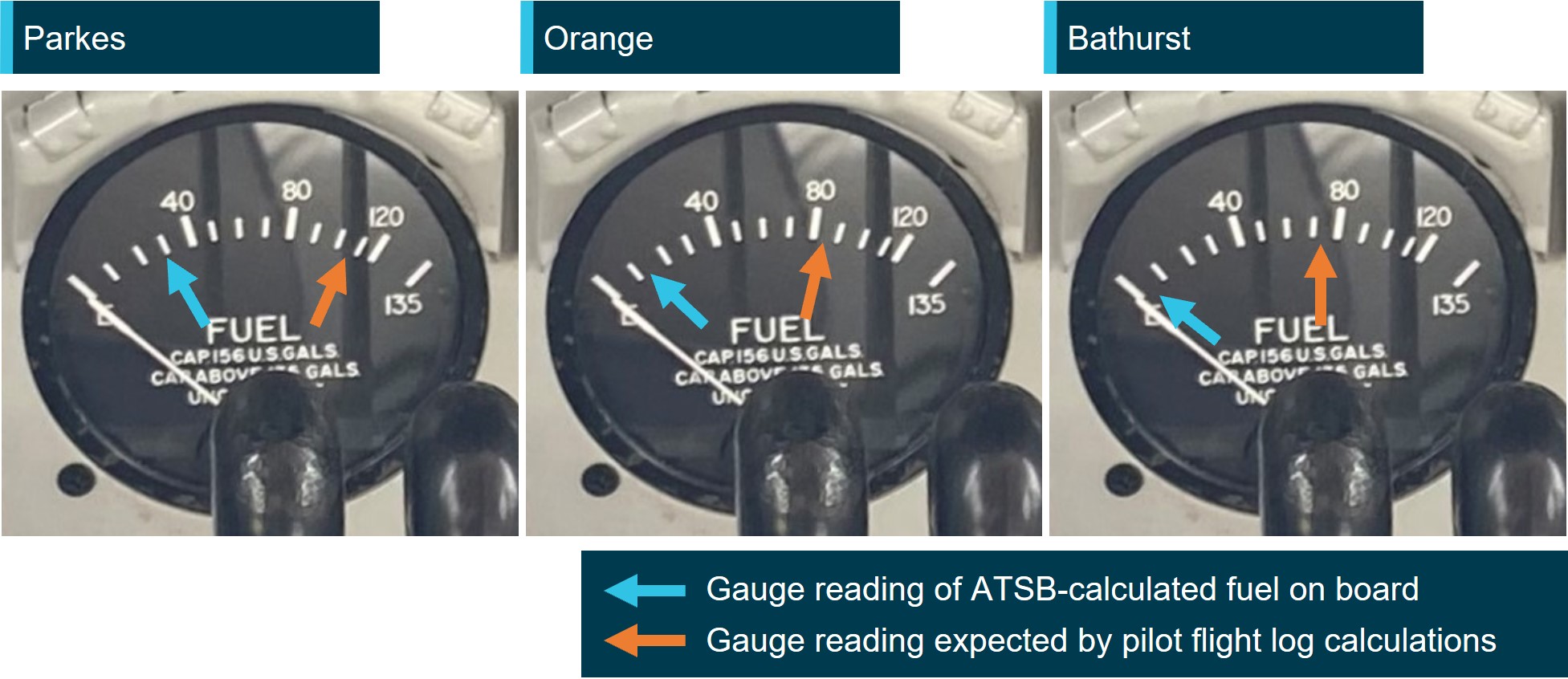
Based on the unaccounted-for fuel, for each of the return sectors, the fuel gauge reading that would have been showing according to the ATSB‑calculated start fuel was compared against the reading expected by the pilot based on their flight log (Figure 7).
Because the fuel filling point of VH-MEH was located on the top surface of the wing (as on most light aircraft), the low-pressure area on the top surface of the wing created when the aircraft was in‑flight could draw fuel up and out of the fuel tank if the fuel cap become dislodged.
The anti-siphon valve (Figure 8) provided a secondary barrier to fuel venting. The relatively higher pressure inside the fuel tank would act to hold the valve closed and reduce the opportunity for fuel loss without the fuel cap in place.
Any obstruction preventing the anti-siphon valve from closing would provide an opening for fuel to vent should the fuel cap become dislodged. Additionally, the fuel cap locking mechanism would be unable to engage as the locking point of the anti-siphon value would be held away from the locking component of the fuel cap, making it more likely to dislodge.
In 2018, the operator circulated a notice to pilots regarding fuel tank cap security in response to 2 incidents involving unsecured fuel caps. One of those incidents was an in-flight fuel siphoning event resulting in the loss of approximately 250 L of fuel. The notice was also issued to the incident pilot as part of their induction. The notice advised that significant fuel loss was possible from Aero Commander aircraft (turbine and piston engine) despite being fitted with an anti-siphon valve, and highlighted the pilot’s responsibility to ensure fuel tank caps were secured. It stated:
During the pre-flight inspection and after each refuelling all Aero Commander pilots will check tank cap security by:
• Ensuring the lock mechanism is secured by using a flat blade screw driver as found in the aircraft fuel drain tool (a 5 cent piece can be used only if no screw driver present)
• Firmly thump/bang the structure immediately around the fuel tank cap. A loose cap may ‘pop’ open if loose. Thumping the tank cap itself will not show if loose.
If there is any doubt about the fuel tank security or integrity pilots will advise Operations Control.
CASA’s Fuel and Oil Safety Advisory Circular (AC) 91-25v1.1 described the importance of maintaining the integrity of fuel caps in preventing in-flight fuel loss including the impact of a trapped fuel cap chain:
In-flight fuel loss by siphoning overboard is primarily attributed to poor maintenance and service practices. Siphoning overboard can be traced to problems such as fuel filler caps incorrectly installed and/or worn fuel filler caps and gaskets. Always check the condition of fuel filler cap O-rings, gaskets, pawls, and springs for evidence of wear and/or deterioration. Deformed or worn pawls may affect the sealing effectiveness of the O-rings or gasket. Similarly, a tank-cap attachment chain or lanyard can be trapped across the seal and defeat its purpose.
In addition to fuel loss, in aircraft where the fuel tanks were comprised of flexible rubber cells, the suction effect created by the low pressure above the wing could cause the fuel cells to collapse upwards from the bottom as fuel is siphoned out. The collapse and deformation of the cells could increase the level of the fuel as the volume of the fuel cells decreased causing the fuel quantity gauge to overread. AC 91-25v1.1 described the potential effect of fuel cell collapse and distortion on fuel quantity indication:
If the fuel gauge apparatus is in the vicinity of the pump and surrounded by relatively solid structure it may not be immediately affected by a tank collapse and could continue to give readings that may at first appear to be credible. It is possible for the indications to temporarily suggest a very low rate of usage or even show a transitory increase in the quantity of fuel in the tank. Whatever the cause or manner of fuel bladder collapse, a dangerous situation will result. CAUTION: Fuel bladder collapse may exaggerate indications of fuel in the tank.
The Flight Safety Australia article Caps tanks and drains: a three pronged attack (CASA, 2016), described the potential consequences of in-flight fuel siphoning due to a loose fuel cap, including the possibility of fuel cell deformation and its effect on fuel gauge readings.
The loose cap exposes the fuel to the low-pressure area over the wing; the fuel then obeys the laws of physics and finds its way out.
If the tank is a rubber fuel cell it will collapse upwards from the bottom, because the top of the rubber fuel cell is secured more firmly to the top wing-tank cavity. This can have at least three effects, all of them bad:
• The bottom of the tank keeps rising. Fuel is thus kept at or near the top of the tank near the cap hole, so that siphoning continues until most or all of the fuel is lost overboard.
• The float of the fuel tank quantity gauge can come into contact with and be supported, or even raised, by the rising of the tank liner bottom. As a result, the cockpit fuel quantity indicator may continue to show full or nearly full, despite the loss of fuel.
• The tank becomes distorted and wrinkled. The tank may not re-shape itself and volume is reduced for the next fill. The valleys now hold lakes and rivers that cannot be drained, until the aircraft is climbing.
Recognising the hazard posed by fuel cell distortion, the aircraft operator and maintainer advised that this was not possible in Aero Commander aircraft as the fuel tanks are interconnected via feed tubes and vent tubes. Additionally, the fuel sender unit is at the bottom of the main tank, and both the sender and the tank are held at the bottom via a large panel and a series of retaining bolts. It would therefore be impossible for the bottom part of the tank to suck up and affect the sender arm to give an erroneous high reading.
The aircraft manufacturer also advised that they would not expect fuel siphoning to lead to fuel gauge overreading.
Aircraft checklists
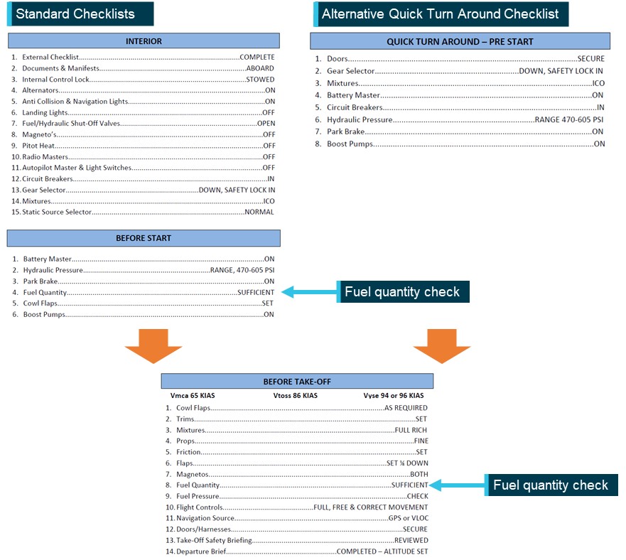
The operator’s checklists (Figure 9) to be used when operating VH-MEH provided points at which the fuel quantity was required to be checked.
Before the aircraft was started, the pilot was required to conduct the INTERIOR checklist, followed by the BEFORE START checklist. This second checklist contained an item to check that the fuel quantity was sufficient, and the gauge was indicating correctly.
To enable expediency during multiple sectors such as cargo operations, the operator provided a QUICK TURN AROUND – PRE-START (QTA) checklist as an alternative to those 2 checklists. The QTA checklist did not include a fuel quantity check. However, regardless of whether the standard or QTA checklists were used before aircraft start, a subsequent fuel quantity check was required to be conducted in the BEFORE TAKE-OFF checklist before the aircraft departed.
The ATSB compared the operator’s checklists with equivalent checklists in the manufacturer’s aircraft flight manual (AFM) (Figure 10). While standard checklists closely followed the checks included in the AFM, several checks were excluded when a pilot conducted the operator’s QTA Checklist.
Source: Aero Commander 500-S aircraft flight manual, annotated by the ATSB
Emergency procedures
The operator’s checklists and the AFM did not contain checklists specific to simultaneous power loss from both engines. However, having identified that an engine was inoperative, the checklists instructed the pilot to feather the propellor of the inoperative engine. Feathering the propellor of a failed engine reduces drag and adverse yaw (when only one engine has failed).
In the case of both engines failing, feathering both propellors significantly reduces drag, improves the handling characteristics and flight performance of the aircraft and, by increasing the glide distance, potentially expands options for a forced landing site.
Related occurrences
Australia
Excluding the incident flight, the ATSB occurrence database contained 97 reported occurrences of fuel leaking or venting from non-jet aircraft between 2014 and 2024. Of those occurrences, 7 resulted in fuel starvation or fuel exhaustion. Additionally, in 17 of those occurrences, the fuel cap was incorrectly installed or not secured prior to flight. Those numbers likely under‑represent the total number of incidents of this type, as the ATSB only requires instances of fuel leaking/venting or missing/insecure fuel caps to be reported for commercial passenger transport operations.
The database also contained one occurrence of fuel venting leading to starvation immediately after landing of an Aero Commander 500-S in 1995. Although the ATSB did not investigate the incident, it was reported that a post-landing inspection revealed the main fuel tank filler cap was defective and would not remain locked, allowing fuel to vent overboard in‑flight.
International
The ATSB identified the following occurrences of fuel exhaustion of an Aero Commander 500 aircraft:
Fuel exhaustion of Aero Commander 500 N107DF on 28 January 2023 (NTSB ERA23LA122)
The aircraft lost power to both engines and landed in a field, sustaining substantial damage and seriously injuring the pilot. It was determined that it was likely that the pilot did not visually confirm the aircraft’s initial fuel quantity prior to departing and that the available fuel was exhausted.
Fuel exhaustion of Rockwell 500 N900DT on 28 August 2020 (NTSB ERA20LA297)
The aircraft impacted a building and terrain about 10 minutes after take-off and was destroyed, fatally injuring both pilots. It was determined that this was due to a total loss of engine power due to fuel exhaustion. Contributing to the fuel exhaustion was the fatigue fracture of an electrical wire in the tank unit or fuel transmitter, which likely resulted in an inaccurate fuel quantity indication. It was also determined that the initial fuel quantity on board was not able to be confirmed visually.
Safety analysis
Prior to the day’s flights, the pilot estimated the fuel on board based on a visual assessment of fuel below the anti-siphon valve level. The fuel quantity was less than full due to either the refueller not allowing the fuel to settle during refuelling, ground running to reposition the aircraft, or a combination of both. Although the pilot likely overestimated the fuel quantity by up to 70 L, the aircraft departed Bankstown with enough fuel to complete the planned sectors and return to Bankstown with the required reserves intact, given the forecast winds.
As the pilot found the fuel cap off and replaced it after landing at both Orange and Parkes airports, it was likely that the fuel cap was also unsecured in‑flight during those sectors. The maintenance engineer in Parkes found that the fuel cap chain had been holding the anti‑siphon valve slightly open, preventing the fuel cap locking mechanism from engaging, and reported advising the pilot of that. Significantly, the engineer also detected evidence of fuel dye staining, indicating fuel had leaked from the tank.
After rectification by the maintenance engineer, the fuel cap remained secured including after the forced landing. ATSB analysis indicated that it was very likely that about 200 L of fuel siphoned overboard in‑flight during one or both sectors to Parkes. The loss of fuel en route to Parkes left the aircraft with about 143 L of fuel upon landing at Parkes, which was insufficient for the return sectors to Bankstown.
At Parkes, aware that the fuel cap had been unsecured on the 2 previous sectors, but unable to physically confirm the quantity of fuel in the tank, the pilot identified an unexplained discrepancy between their calculated fuel remaining and the fuel quantity gauge reading.
Due to the discrepancy, the operator’s procedures required the pilot to refuel the tank to full, to visually confirm the quantity of fuel onboard. However, instead of refuelling, the pilot reported recalculating the aircraft’s fuel state based on the gauge reading, although they did not update the flight log, and incorrectly determined that they had sufficient fuel for the remaining flights. Despite being informed of issues found with the fuel cap, the pilot’s decision not to refuel may have been influenced by their expectation that the anti-siphon valve would prevent fuel siphoning overboard and the typical excess of remaining fuel on board when completing the same route.
The ATSB assessed whether the fuel quantity gauge was likely to have been providing erroneous indications to the pilot. This was based on CASA guidance that during in-flight siphoning events in aircraft with rubber fuel cells, it was possible for the rubber to deform and move upwards away from the base of the tank, resulting in overreading of the fuel quantity sender. However, the aircraft operator/maintainer and manufacturer advised that this was not possible in Aero Commander aircraft due to the construction of the fuel cells and sender. There were also no reported issues or defects with the fuel gauge prior to the incident flight.
The fuel gauge was determined to be working correctly after the incident and 2 minor adjustments were made to fuller fuel quantities in the calibration conducted post‑incident. Therefore, the fuel quantity gauge was likely indicating correctly at Parkes and would have shown a significant discrepancy with the pilot’s assessed fuel quantity.
As a result of the pilot’s misunderstanding of the fuel quantity, the aircraft departed Parkes with significantly less fuel than determined by the pilot, and insufficient for the remaining flights. The pilot did not then effectively monitor the fuel state or refuel after landing at Bathurst. Consequently, fuel exhaustion occurred shortly after the aircraft departed from Bathurst.
Although not considered to have contributed to this occurrence, the operator’s Quick Turn Around – Pre-Start checklist was an abbreviated version of the before-start checklist specified in the aircraft flight manual and did not include a fuel quantity check. As there was a fuel quantity check in the operator’s and manufacturer’s before-take-off checklist, the pilot was required to verify the fuel quantity before departure. However, a fuel quantity check before start in accordance with the manufacturer’s procedures would have prompted the pilot to crosscheck the fuel state when workload was lower, and any discrepancy could have been more easily identified and addressed.
Findings
ATSB investigation report findings focus on safety factors (that is, events and conditions that increase risk). Safety factors include ‘contributing factors’ and ‘other factors that increased risk’ (that is, factors that did not meet the definition of a contributing factor for this occurrence but were still considered important to include in the report for the purpose of increasing awareness and enhancing safety). In addition ‘other findings’ may be included to provide important information about topics other than safety factors.
These findings should not be read as apportioning blame or liability to any particular organisation or individual.
From the evidence available, the following findings are made with respect to the fuel exhaustion involving Aero Commander 500-S, VH-MEH, 6 km east of Bathurst Airport, New South Wales on 8 March 2024.
Contributing factors
For the first 2 sectors, the fuel cap was incorrectly installed with the chain lodged in the fuel tank’s anti‑siphon valve, resulting in the cap dislodging in‑flight and a significant quantity of fuel being siphoned overboard.
At Parkes Regional Airport, the pilot identified an unexplained discrepancy between their calculated fuel remaining and the fuel quantity gauge indication but did not refuel to a known quantity. As a result, the aircraft departed Parkes with the pilot unaware that there was insufficient fuel to complete the remaining flights.
After departing Parkes, the pilot likely did not monitor the fuel gauge, continued fuel calculations based on an incorrect fuel quantity, and did not refuel the aircraft to a known quantity at Bathurst Airport. This resulted in fuel exhaustion shortly after the aircraft departed from Bathurst.
Other factors that increased risk
GAM Air's Quick Turn Around – Pre-Start checklist did not include a fuel quantity check before start, contrary to the aircraft flight manual’s before-start checklist.
Safety actions
Whether or not the ATSB identifies safety issues in the course of an investigation, relevant organisations may proactively initiate safety action in order to reduce their safety risk. The ATSB has been advised of the following proactive safety action in response to this occurrence.
Safety action by GAM Air
GAM Air published a pilot notice reinforcing fuel management procedures for Aero Commander 500 series aircraft. The notice highlighted the importance of fuel tank cap security, and the likelihood of fuel loss should a fuel cap become dislodged, despite the anti-siphon valve. The notice also provided instructions and guidance on fuel planning, in-flight fuel calculations and fuel log entries to expand on information in the standard operating procedures.
GAM Air also commenced periodic auditing of pilot fuel calculations and advised an intention to discontinue use of the Quick Turn Around – Pre-Start checklist. The fuel supplier at Bankstown was also reminded of the requirement to let fuel settle when refuelling.
Sources and submissions
Sources of information
The sources of information during the investigation included the:
pilot
aircraft operator and maintainer
Civil Aviation Safety Authority
Parkes maintenance engineer
aircraft manufacturer
recorded flight data.
Submissions
Under section 26 of the Transport Safety Investigation Act 2003, the ATSB may provide a draft report, on a confidential basis, to any person whom the ATSB considers appropriate. That section allows a person receiving a draft report to make submissions to the ATSB about the draft report.
A draft of this report was provided to directly involved parties including the:
pilot
aircraft operator and maintainer
Civil Aviation Safety Authority
Parkes maintenance engineer
aircraft manufacturer.
Submissions were received from the:
aircraft operator and maintainer
Civil Aviation Safety Authority
The submissions were reviewed and, where considered appropriate, the text of the report was amended accordingly.
Purpose of safety investigations
The objective of a safety investigation is to enhance transport safety. This is done through:
identifying safety issues and facilitating safety action to address those issues
providing information about occurrences and their associated safety factors to facilitate learning within the transport industry.
It is not a function of the ATSB to apportion blame or provide a means for determining liability. At the same time, an investigation report must include factual material of sufficient weight to support the analysis and findings. At all times the ATSB endeavours to balance the use of material that could imply adverse comment with the need to properly explain what happened, and why, in a fair and unbiased manner. The ATSB does not investigate for the purpose of taking administrative, regulatory or criminal action.
Terminology
An explanation of terminology used in ATSB investigation reports is available here. This includes terms such as occurrence, contributing factor, other factor that increased risk, and safety issue.
Publishing information
Released in accordance with section 25 of the Transport Safety Investigation Act 2003
Ownership of intellectual property rights in this publication
Unless otherwise noted, copyright (and any other intellectual property rights, if any) in this report publication is owned by the Commonwealth of Australia.
Creative Commons licence
With the exception of the Commonwealth Coat of Arms, ATSB logo, and photos and graphics in which a third party holds copyright, this report is licensed under a Creative Commons Attribution 4.0 International licence.
The CC BY 4.0 licence enables you to distribute, remix, adapt, and build upon our material in any medium or format, so long as attribution is given to the Australian Transport Safety Bureau.
Copyright in material obtained from other agencies, private individuals or organisations, belongs to those agencies, individuals or organisations. Where you wish to use their material, you will need to contact them directly.
[1]Instrument flight rules (IFR): a set of regulations that permit the pilot to operate an aircraft in instrument meteorological conditions (IMC), which have much lower weather minimums than visual flight rules (VFR). Procedures and training are significantly more complex as a pilot must demonstrate competency in IMC conditions while controlling the aircraft solely by reference to instruments. IFR-capable aircraft have greater equipment and maintenance requirements.
[2]In-flight fuel siphoning: a phenomenon where fuel escapes from the fuel tank of an aircraft in-flight. On aircraft where the fuel filler point is on top of the wing, the low-pressure area above the wing created when an aircraft is in‑flight can draw the fuel up and out of the fuel tank if it is not sufficiently sealed.
[3]Usable fuel: The amount of fuel which is available in the fuel tanks for supply to the engines.
[4]Yawing: the motion of an aircraft about its vertical or normal axis.
[5]Feathering: the rotation of propeller blades to an edge-on angle to the airflow to minimise aircraft drag following an in‑flight engine failure or shutdown.
[6]Instrument Proficiency Check: A 12-monthly assessment with a flight examiner to assess the flying skills and operational knowledge required to conduct flights under the IFR.
[7]Maintenance release: an official document, issued by an authorised person as described in Regulations, which is required to be carried on an aircraft as an ongoing record of its time in service (TIS) and airworthiness status. Subject to conditions, a maintenance release is valid for a set period, nominally 100 hours TIS or 12 months from issue.
[8]Unusable fuel is the amount of fuel in the tank below which continued running of the engine while performing the most adverse manoeuvre cannot be assured.
Occurrence summary
Investigation number
AO-2024-008
Occurrence date
08/03/2024
Location
6 km east of Bathurst Airport
State
New South Wales
Report release date
19/11/2024
Report status
Final
Anticipated completion
Q4 2024
Investigation level
Short
Investigation type
Occurrence Investigation
Investigation status
Completed
Mode of transport
Aviation
Aviation occurrence category
Forced/precautionary landing, Fuel exhaustion
Occurrence class
Serious Incident
Highest injury level
None
Aircraft details
Manufacturer
Aero Commander
Model
500-S
Registration
VH-MEH
Serial number
3258
Aircraft operator
General Aviation Maintenance Pty Ltd
Sector
Piston
Operation type
Part 135 Air transport operations - smaller aeroplanes
On 20 October 2023 the pilot of a Cessna 208 aircraft, registered VH‑UMV and operated by Experience Co, was conducting parachute operations at Barwon Heads Airport, Victoria with 16 parachutists on board. Passing about 500 ft on climb, the pilot detected a partial power loss consistent with a previously‑encountered transient power reduction.
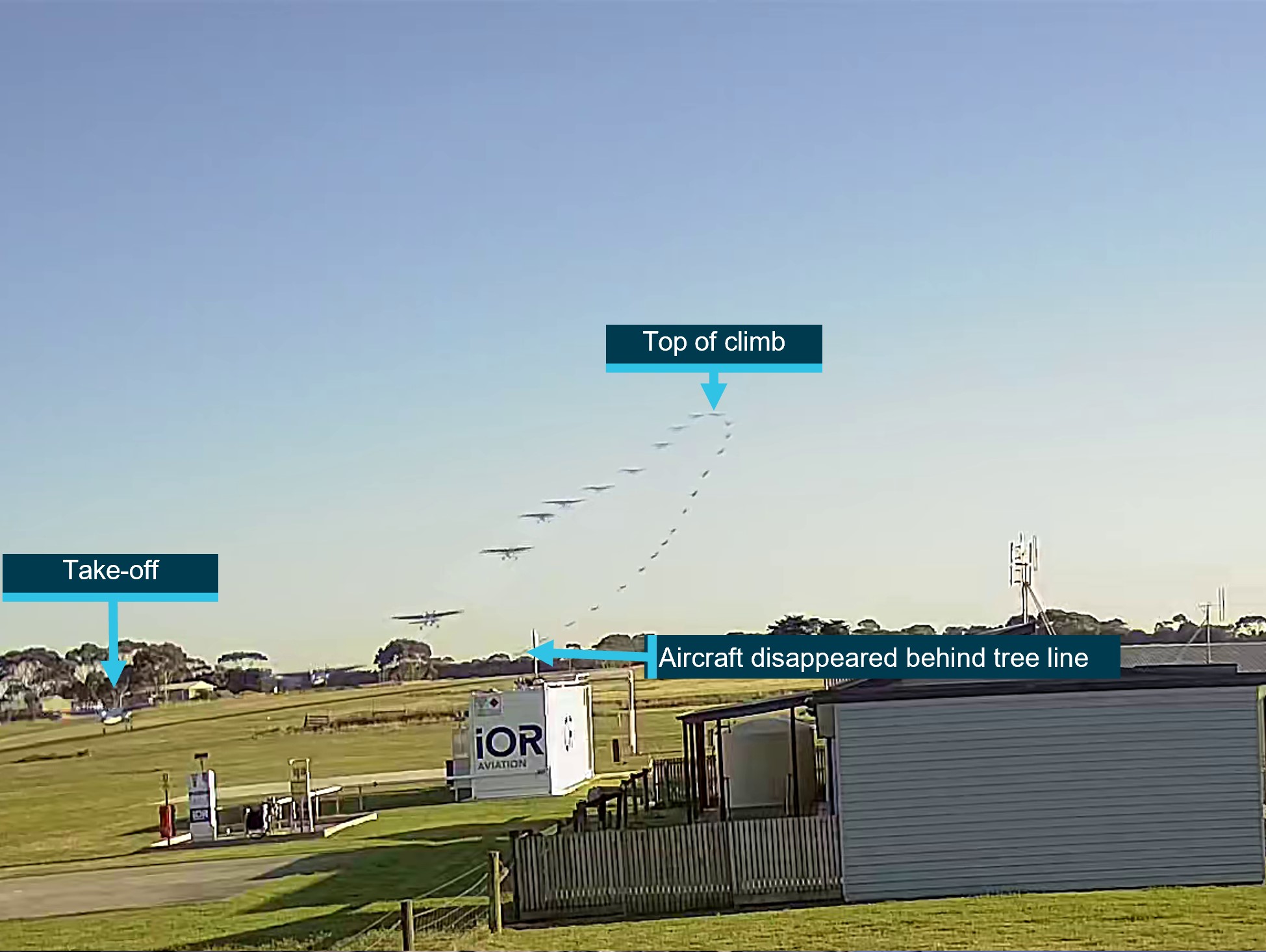
Expecting the power to return immediately, the pilot did not lower the aircraft’s nose to maintain airspeed. The airspeed continued to reduce until the stall warning horn sounded and, due to the low height, low engine power and low airspeed, the pilot attempted to conduct a forced landing. However, the aircraft collided with water before continuing onto the riverbank and ground for approximately 50 m before coming to rest.
The aircraft was substantially damaged, 6 of the parachutists received serious injuries, 8 sustained minor injuries, and 2 were uninjured. The pilot also sustained minor injuries.
What the ATSB found
The ATSB found that passing about 500 ft on climb, the power reduced likely due to abnormal activation of an engine torque and temperature limiting system. Expecting the power to return quickly and surge, and in preparation for turning off the system, the pilot moved the power lever aft to reduce the power setting and delayed lowering the aircraft’s nose to maintain airspeed, resulting in a stall warning and subsequent collision with water.
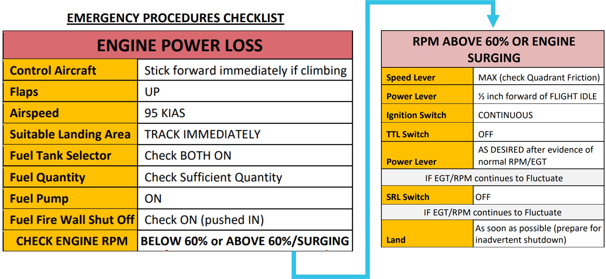
The ATSB also found that Experience Co’s engine power loss checklist instructed pilots to significantly reduce power in preparation for deactivating the engine limiting system, but did not specify a minimum safe height at which to do so. This increased the risk of a loss of control and/or ground collision.
Further, the ATSB found that the operator's weight and balance calculation for the accident flight did not include the bench seating weight or moment, and the loadmaster did not load parachutists in positions used for the calculation of the centre of gravity, therefore, although it did not contribute to the accident, the weight and balance was inaccurate for the intended flight. Additionally, the software used to calculate aircraft weight and balance did not provide a warning if individual aircraft zones were overloaded.
Finally, the ATSB found that Experience Co did not ensure sport parachutists received essential safety information about emergency exits, restraints and brace position, prior to take-off.
What has been done as a result
At the time of writing, Experience Co was re‑developing its sport skydivers safety video to include emergency procedures. Additionally, the following proactive safety actions have been taken:
A safety communique was developed and circulated at each drop zone reminding parachutists to be seated in accordance with their manifested location.
Chief instructors, drop zone safety officers and loadmasters were reminded of the loadmasters’ responsibilities to ensure parachutists were seated in accordance with the weight and balance calculation.
Skydive Operations Manual was amended to clarify the loadmasters’ responsibilities.
Additional training was provided for manifest staff.
A fleet-wide audit was undertaken to ensure all aircraft had accurate basic empty weight figures.
A prompt was added to the internal reporting software to confirm an entry has been made to the aircraft’s maintenance release when submitting a maintenance‑related internal safety report.
Briefings that cover essential safety information about emergency exits, restraints, and brace position, are now required annually by sport skydivers.
Additional pilot training relating to the single red line/torque and temperature limiter malfunctions has been developed and was scheduled to be delivered to all pilots.
Emergency exit signs in all aircraft were being assessed for compliance and effectiveness, and updated if necessary.
Engineering personnel have undertaken specialised TPE331 Powerplant and Systems training.
Information circulars were provided to company pilots about the proper defect reporting requirements using the aircraft maintenance release.
Experience Co was updating advice as to the altitude at which seatbelts must be worn.
Experience Co has developed Cessna 208 and Cessna 208B aircraft flight manual supplements, which outline the carriage of 17 parachutists and 21 parachutists respectively.
An additional support bracket has been designed to be fitted to the end of the bench seats in aircraft and will be installed once formally approved.
A new engine power loss checklist was developed in cooperation with the supplemental type certificate (STC) holder to be followed at or above 1,000 ft above ground level.
The Australian Parachute Federation (APF) has taken the following safety action:
The APF will ensure skydivers and pilots review their aircraft emergency procedures on a regular basis. Recommended topics are likely to include:
general safety around aircraft
hot loading
door activation
achieving correct restraint fitment
emergency landings
brace position
emergency exit altitudes and which parachute to use
communication during an emergency
for coastal operations, life jacket use in a ditching.
Each parachuting aircraft operator will conduct a thorough assessment of its aircraft to ensure single point restraints are properly installed, to prevent parachutists from moving outside their designated seating positions and to maintain the aircraft’s weight and balance.
The APF will review global data on the use of dual-point restraints to gather insights from other national parachuting organisations regarding their experiences with this system.
The APF examined aircraft flight manual wording of all aircraft currently conducting parachute operations in Australia to identify which aircraft would require a short-term CASA exemption to permit operations with the number of passengers onboard in excess of those able to occupy the normal seats under the type design. They identified 22 aircraft requiring an exemption, spanning 5 operators.
The APF added the following statement to the participant waiver form: ’parachuting aircraft are not operated to the same safety standards as a normal commercial passenger flight’.
Finally, the Civil Aviation Safety Authority advised that it is developing the following:
An exemption, for pilots or operators of parachuting aircraft who may be unable to comply with elements of the aircraft flight manual, is expected to be completed by mid‑2025.
CASA stated that it was satisfied that reasonable steps had been taken by the APF to ensure that a level of safety, commensurate with the risks involved in the parachuting activities in which participants engage, was provided to those participants in the interim while the exemption was being developed.
An amendment to the Civil Aviation Safety Regulations Part 21 Manual of Standards to specify the standards required for the modifications made to parachuting aircraft. This proposed action is expected to be finalised by the end of 2025.
Additional guidance to support aircraft owners and operators seeking to make an approved modification.
Lower the nose to maintain the glide speed of the aircraft. If turning is conducted, keep in mind an increased bank angle will increase the stall speed of the aircraft.
Maintain glide speed and assess whether the aircraft is maintaining, gaining or losing height to gauge current aircraft performance.
Fly the aircraft to make a landing, given the aircraft’s height and performance, and the pre-planned routes for the scenario.
If time permits, moving the power lever through the full range may result in increased power available to climb and/or create the time to diagnose the issue.
The ATSB SafetyWatch highlights the broad safety concerns that come out of our investigation findings and from the occurrence data reported to us by industry.
One of the safety concerns is reducing the severity of injuries in accidents involving small aircraft. This incident highlights the importance of passengers being appropriately briefed on the brace position and use of emergency exits. It also illustrates the higher injury risk associated with the carriage of parachutists, due to the increased number of occupants and inferior restraints compared to being secured in a certified seat.
The occurrence
Early on the morning of 20 October 2023, the pilot of a Cessna 208 aircraft, operated by Experience Co and registered VH-UMV, refuelled and inspected the aircraft in preparation for parachuting operations from Barwon Heads Airport, Victoria. No defects, including any fuel debris or contaminants, were identified.
The pilot’s first flight of the day was to carry 16 sport parachutists for a parachute jump from 15,000 ft. At about 0750 local time, the parachutists boarded the aircraft. The pilot recalled that the conditions were CAVOK,[1] with a light wind from the north. They taxied the aircraft to runway 36 for a northern departure.
A review of OzRunways[2] flight data, recorded at 5-second intervals, showed the aircraft commenced the take-off roll at 0757. The pilot reported moving the power lever forward until the engine reached 100% torque, and then reducing the power slightly during the take-off roll. Camera footage showed that the aircraft became airborne at 0757:22.
The pilot reported that, as the aircraft climbed and the airspeed increased, they retracted one stage of flap passing through 85 kt and another at about 95 kt. At 0757:47, climbing through about 400 ft, the aircraft reached its maximum recorded ground speed of 95 kt. The pilot reported that as the aircraft approached 500 ft above ground level and they reached for the flap lever to retract the last stage of flap, they heard a reduction in engine noise, and felt a deceleration.
The pilot initially associated the loss of power with activation of the torque and temperature limiter (TTL) (see the section titled Torque and temperature limiter), which they had previously experienced in that aircraft. Consistent with the previous TTL activation, the pilot expected the power to quickly return, and reported reducing power slightly to prevent the engine surging[3] as power was restored.
The reduction in engine power, combined with the climb pitch attitude, resulted in the airspeed reducing and activation of the stall warning horn. On hearing the stall warning, the pilot lowered the aircraft’s nose to reduce the angle of attack[4] and increase the airspeed.
At 0757:57 the aircraft reached the highest recorded altitude of about 700 ft at 88 kt ground speed and, 5 seconds later, had descended to 600 ft and the ground speed reduced to 71 kt, then to 69 kt 5 seconds later. This flight path was consistent with video camera footage of the aircraft’s flight path (Figure 1). At 0758:08 the ADS-B[5] data recorded a descent rate of 3,520 ft/m passing an altitude of approximately 400 ft.
Figure 1: VH-UMV flight path captured by the airport camera
The ATSB combined multiple images together to show the flight path of the aircraft as captured by a local video camera. Source: Airport operator, annotated by the ATSB
The pilot reported that, as the aircraft descended, they observed the engine torque indication reducing through approximately 30% and attempted to switch off the TTL in accordance with the operator’s Engine Power Loss checklist. Due to the aircraft’s low height above the ground, and the pilot’s assessment that there was an engine issue, the pilot then selected a field in which to conduct a forced landing.
The pilot turned to the loadmaster[6] seated beside them and called out ‘gear-up’, to alert parachutists to be ready to exit the aircraft. In response, the loadmaster began directing parachutists to open the roller door, secure their harnesses, and brace for landing. The roller door was opened, but not secured in that position.
The pilot selected a forced landing location in a clearing beyond a river. However, less than 1 minute after becoming airborne and unable to maintain altitude, the aircraft impacted the water short of the clearing, resulting in water entering the cabin and forcing the unsecured roller door closed. The aircraft continued onto the riverbank where the main landing gear detached, then travelled along the ground for about 50 m before coming to rest (Figure 2).
The pilot sustained minor injuries, 6 parachutists sustained serious injuries, 8 sustained minor injuries and 2 were uninjured. The aircraft was substantially damaged.
Figure 2: VH-UMV flight path
Source: ADS-B exchange flight data overlaid on Google Earth and image of accident site provided by operator, annotated by the ATSB
Context
Pilot information
The pilot held a commercial pilot licence (aeroplane) and a current class 2 aviation medical certificate. On 19 April 2023, the pilot completed their gas turbine engine design feature endorsement and single engine aircraft flight review in a Cessna 208 aircraft.
At the time of the accident, the pilot had accrued approximately 220 hours of total flight experience, which included 38 hours on the Cessna 208 aircraft type. Of those hours on type, 36 had been accrued in the previous 90 days.
The pilot reported that they were familiar with VH-UMV, having conducted multiple flights in it prior to the accident flight. The pilot was also aware of operator-specific engine operating limitations for VH-UMV, and reported having previously experienced an engine surge at 5,000 ft (see the section titled Engine surging).
Aircraft information
Certification details
The Cessna Aircraft Company 208 (C208) is an all-metal, high-wing aeroplane with tricycle landing gear and designed for general utility usage. The aircraft type certificate data sheet (TCDS) A37CE described the C208 as an ‘11-place closed land monoplane’, and under the heading ‘No. of seats’, provided a centre of gravity range for seating for one or 2 pilot seat locations and referenced the current Pilot’s Operating Handbook (POH) and United States (US) Federal Aviation Administration (FAA) Airplane Flight Manual (AFM) for passenger seat arrangements for seats 3 to 11.
The C208 POH Section 2 – Limitations – Maximum passenger seating limits stated that up to 11 seats, including the pilot’s seat/s, may be installed.
VH-UMV, serial number 20800077, was manufactured in 1986 and first registered in Australia in 2005. At that time, the aircraft was issued 2 certificates of airworthiness, one for normal category[7] operations and one for restricted category[8] operations for the purpose of carrying people for parachute jumping.
Operating in the restricted category required several conditions, including removal of the cabin seats, compliance with a specific engineering order and readily visible restricted category placards, none of which were in place on the accident flight. Additionally, under Civil Aviation Safety Regulations (CASR) current at the time of the accident (CASR 91.845, 91.025, 135.030), aircraft operating in the restricted category were not permitted to conduct air transport operations (carriage of passengers or cargo for hire or reward).
In 2017, the aircraft’s Pratt & Whitney PT6A-114 gas turbine engine was replaced with a Honeywell International Incorporated TPE331-12JR-704TT gas turbine engine that drove a 4‑bladed, constant‑speed, full‑feathering,[9] reversible[10] Hartzell HC-E4N-5KL propeller with hydraulically‑operated variable‑pitch control. The engine modification was completed under the Texas Turbine Conversions supplemental type certificate (STC) SA10841SC, with an associated AFM Supplement. Under the heading ‘Maximum passenger seating limits’, the AFM supplement stated ‘No changes’ (from the C208 AFM).
The aircraft was also modified in accordance with STC SA01180SE, which increased the original maximum take-off weight from 3,628 kg to 3,792 kg. Both STCs were approved by the US FAA and therefore accepted in Australia and taken as having been issued by CASA in accordance with CASR Part 21 regulation 21.114.
Three modifications made to VH-UMV and other aircraft in the operator’s fleet were completed under engineering orders in accordance with the CASR Part 21 regulation 21.437 Grant of modification/repair design approvals—grant by authorised person or approved design organisation:
ESE-C208-25-001—Rework of interior for parachute operations
ESE-C208-25-007—Installation of parachute bench seating
ESE-C208-95-003—Installation of Go-Pro cameras.
Torque and temperature limiter
VH‑UMV was fitted with a switch‑activated torque and temperature limiter (TTL) system designed to prevent these parameters exceeding specified limits. Where an exceedance of the allowable torque or exhaust gas temperature (EGT) was detected, the TTL computer restricted fuel flow to the engine. The maximum allowable fuel reduction of a normally-functioning bypass was about 68 L/hour (125 lbs/hour), resulting in a reduction of the torque output from 100% to about 62% (due to the approximate 25% reduction in fuel flow).
Texas Turbine Conversions advised that, when functioning normally, the system would maintain the lower of the allowable torque or EGT limits and if the TTL bypassed the maximum allowable fuel, it would be felt immediately. In that case, the appropriate pilot response was to switch off the TTL.
The aircraft’s engine monitoring system included a single red line (SRL) controller, associated with the EGT limit. Like the TTL, the SRL was switch‑activated and deselection of the SRL also deactivated the TTL.
The allowable EGT limit was dependent on the phase of flight. Specifically, the operating margin from the EGT limit in the climb phase was reduced in the cruise phase. The phase was dependent on the position of the speed lever. Therefore, if the speed lever was moved aft during take-off or climb, the EGT limit also reduced and could result in activation of the TTL. The operator reported that the speed lever was fully forward throughout the short flight, and therefore the climb EGT limit applied.
Operating limits
The AFM supplement for the Honeywell engine specified operating limits. With the SRL and TTL on, those limits included a maximum EGT of 650 °C, maximum 100% torque and maximum of about 101% RPM during take-off and climb. The supplement also provided an EGT table with limits for operating with the SRL off or inoperative, or ‘manual mode’. The limits were provided for operating at 100% RPM or 96% RPM based on the outside air temperature in 5 °C increments from −60 to +60 °C.
The AFM defined take-off power as the lower of 100% torque or 650 ºC EGT (SRL ON), whichever is reached first at 100% engine RPM.
Engine surging
On 17 October 2023, the pilot submitted an internal safety report relating to an uncommanded engine surge, which they experienced at an altitude of approximately 5,000 ft. The pilot report stated:
Torque roll back for a split second, noticeable reduction in power and deceleration.
The pilot reported reducing the power then slowly increasing it while monitoring engine parameters in response to the event.
Although not recorded on the aircraft’s maintenance release (MR),[11] reportedly due to their transient nature, pilots submitted 7 other internal safety reports between July and October 2023 of engine surging in VH‑UMV, assessed as being due to the TTL.
A review of maintenance recorded in VH-UMV’s engine logbook for the previous 12 months showed that the TTL controller was replaced ‘for fault isolation’ following the first reported surging occurrence on 3 April 2023. A further logbook entry on 18 September 2023 recorded that the EGT harness was replaced in response to reported engine surging at take-off power.
The engine surging safety reports indicated troubleshooting test flights were also conducted. A series of test flights on 7 September 2023 was able to replicate the previously‑reported surging.In addition, a test flight following the EGT harness replacement noted that the surging was still present. One of the experienced surges resulted in a torque value of 62% and fuel flow reduced by approximately 72 L/hour (128 lbs/hour). The MR current at the time of the accident identified that the aircraft operated over 90 flights prior to the next reported surge event on 17 October 2023. On that day, the aircraft operated 6 flights, and one surge occurrence was reported. According to the MR, 12 flights were conducted over the next 2 days (18–19 October), with no reports of engine surging submitted. However, the ATSB was also advised of an engine surge on 18 October, which was not recorded.
The MR current at the time of the accident recorded 257 flights over 3 months, during which there were 6 reported surging events. That frequency illustrated the intermittent nature of the anomaly, which likely hindered troubleshooting.
As a result of the internal reports, on 21 July 2023, pilots were advised to operate VH-UMV under a set of unique operating conditions to avoid the TTL scheduling a significant bypass of fuel and subsequent notable drop in available power. These were limitations of 95% torque and 640 °C EGT.
A review of the operator’s safety reports also identified that surging events were reported on 3 other company aircraft. For those aircraft, maintenance actions rectified the cause of each event and there were no subsequent surging events reported.
Minimum equipment list
Experience Co’s minimum equipment list (MEL) specified permissible unserviceable items with which the aircraft was permitted to operate temporarily under the stated procedures, conditions and limitations. The MEL included that both the SRL computer system and TTL ‘may be inoperative provided inoperative SRL system procedures and limits are observed’. In that case, it was also required that an MEL placard be fitted adjacent to the TTL or SRL switch for the inoperative system/s. There was no MEL placard for the TTL nor was it listed as inoperative at the time of the accident.
Engine power loss checklist
The Texas Turbine Conversions AFM supplement provided checklists for engine failures, but not for partial engine power loss. The operator’s ‘Engine Power Loss’ checklist for the C208 with the Honeywell engine (Figure 3), required pilots to first control the aircraft by moving the elevator control forward to lower the aircraft’s nose if climbing. After completing initial checks, if the RPM was above 60% or the engine was surging, the pilot was to move the power lever to ½ inch (12.7 mm) forward of the flight idle position, in preparation for turning off the TTL, so as not to produce a transient exceedance of the EGT.
Figure 3: Engine power loss checklist
Source: Aircraft operator
Weight and balance
Aircraft moment arms
To enable calculation of the aircraft’s weight and balance, the C208 POH included a 2-place seating option, which divided the cabin into 7 zones (zones 0–6) (Figure 4). The flight manual supplement for the Texas Turbine Conversions STC did not include changes to the zones or seating configuration, therefore the POH applied.
Source: Cessna 208 Pilot’s Operating Handbook, annotated by the ATSB
Accident flight weight and balance
Prior to departure, a member of the parachuting operations team calculated the weight and balance for the proposed flight using the IBIS Technology flight planning module software (Table 1).[12] The moment arms from the POH were used for the calculations. Zone 6 was not used.
Table 1: Planned weight and balance for accident flight
Item
Arm (mm)
Weight (kg)
Moment (kg-mm)
Aircraft basic empty weight
4,181
1,889
7,897.909
Fuel
4,680
272.152
1,273.672
Zone 0 [1]
3,442
272
936.142
Zone 1
4,277
218
932.386
Zone 2
4,948
318
1,573.464
Zone 3
5,613
173
971.049
Zone 4
6,261
404
2,529.444
Zone 5
6,896
173
1,193.008
Total
3719.152
17,307.075
Centre of gravity
4,653
The operator’s weight and balance used the crew seat arm as the zone 0 arm.
The calculated weight and balance resulted in a take-off weight of approximately 3,719 kg and the aircraft’s centre of gravity located at 4,653 mm aft of the datum. To remain inside the operating limitations, the maximum allowable weight was 3,792 kg. Additionally, the aircraft needed to remain within the centre of gravity envelope, which had an aft limit of 4,680 mm and the forward limit varied with the operating weight. Each zone had a maximum allowable weight limit, and the maximum for zone 0 was 159 kg. However, the calculation software did not provide a warning to notify the user a zonal limit had been exceeded.
Information provided by the parachutists included the position they were seated at the time of the accident. Those positions did not match the original seating positions on the planned weight and balance sheet provided to the pilot prior to departure. The operator calculated a revised weight and balance based on the probable parachutist seating positions, which moved the aircraft’s centre of gravity 5 mm aft, although still within the allowable envelope (Table 2). It also showed that zone 0 was under the allowable weight limit.
Table 2: Revised weight and balance for accident flight
Item
Arm (mm)
Weight (kg)
Moment (kg-mm)
Aircraft basic empty weight
4,181
1,889
7,897.909
Fuel
4,680
272
1,272.960
Crew seat
3,442
92
316.664
Zone 0
3,472
80
277.760
Zone 1
4,277
349.4
1,494.384
Zone 2
4,948
271.4
1,342.887
Zone 3
5,613
334.4
1,876.987
Zone 4
6,261
197
1,233.417
Zone 5
6,896
233
1,606.768
Total
3,718.2
17,319.746
Centre of gravity
4,658
Aircraft basic empty weight
A weigh of VH‑UMV on 17 October 2017 identified that the aircraft’s basic empty weight was 1,889 kg in the single pilot seat configuration (Figure 5).
Figure 5: VH-UMV configuration on date of reweigh
The image meta-data showed the image was taken on 17 October 2017 – the reweigh date. Source: AeroWeigh.
The aircraft seating configuration at the time of the accident is shown in Figure 6.
Figure 6: VH-UMV cabin seating arrangement
Source: Aircraft operator, annotated by the ATSB
The basic empty weight of the aircraft did not include the flooring, or the 36 kg bench seating installed under engineering order ESE-C208-25-007. The engineering order provided the moment arms and weights shown in Table 3.
Table 3: ESE-C208-25-007 Parachute bench seating options – bench seat weight and arm
Item
Arm (mm)
Weight (kg)
Forward seat & backrest right-hand side only – option 2, without oxygen bottle mount.
3,556
7.82
Centre cabin bench seats both left-hand and right-hand sides (2 x 10.92 kg)
5,003
21.84
Aft bench seat right hand side only
6,553
6.36
Total of unaccounted weight for bench seating
36.02
Using the operator’s revised weight and balance calculation that reflected the likely positions of the parachutists, and the additional weight of the bench seating, the ATSB determined the probable take-off weight was 3,754 kg and the centre of gravity was 8 mm aft of the originally calculated centre of gravity (4,661 mm).
The operator subsequently weighed the aircraft’s jump mat, single point restraints, rubber matting, and portable oxygen tank. The total of these items was 30.2 kg, increasing the probable take-off weight to 3,784 kg.
Weight and balance implications
Regarding the importance of accurate weight and balance, the FAA Pilot’s handbook of aeronautical knowledge stated:
An overloaded aircraft may not be able to leave the ground, or if it does become airborne, it may exhibit unexpected and unusually poor flight characteristics.
Changes of fixed equipment have a major effect upon the weight of an aircraft. The installation of extra radios or instruments, as well as repairs or modifications, may also affect the weight of an aircraft.
Loading in a nose-heavy condition causes problems in controlling and raising the nose, especially during take-off and landing. Loading in a tail-heavy condition has a serious effect upon longitudinal stability and reduces the capability to recover from stalls and spins. Tail heavy loading also produces very light control forces, another undesirable characteristic. This makes it easy for the pilot to inadvertently overstress an aircraft.
Recorded data
The ATSB obtained OzRunways and third-party ADS-B recorded data for the accident flight. That data was compared with flight data for the flight conducted by the same pilot in the same aircraft on 17 October 2023, which was the day the pilot reported engine surging at about 5,000 ft. The comparison did not show significant performance difference from take-off to about 500 ft between the 2 flights.
Although the aircraft had an engineering order to fit GoPro cameras, they were not in place for the accident flight. The operator reported that these were only used during the creation of promotional footage and not during day-to-day operations. There was also no video footage from inside the aircraft, but the airport operator provided video footage from cameras located at the airport. One of those cameras recorded the accident flight footage (Figure 1) and provided audio for analysis.
The recorded audio included the aircraft noise and the nearby road and wind noise. The camera was stationary, therefore as the aircraft departed its sound signature reduced. Analysis of the audio conducted by Honeywell found that the engine RPM was approximately 99% throughout the take-off and initial climb. However, the engine noise was not discernible from the background sounds recorded at the time of the reported engine surge.
Site and aircraft examination
Site assessment
The ATSB did not attend the accident site, but the aircraft operator and Victoria Police attended shortly after the accident and provided the ATSB with photos of the aircraft and cockpit. A review of the images showed that the:
flaps were fully retracted
power lever was in the max reverse position
speed lever was in the minimum position
condition lever was in shutoff/feather position.
Those positions were consistent with the pilot’s reported actions to secure the engine after the impact. Additionally, one image appeared to show the TTL switch ON and the SRL switch OFF, indicating that the pilot may have inadvertently selected the SRL OFF instead of the TTL.
Engine and accessories assessment
The aircraft’s engine was recovered by the operator and sent to the Honeywell Investigation Laboratory in the US. On behalf of the ATSB, the US National Transportation Safety Board (NTSB) arranged independent oversight of the engine examination that was conducted between 3–5 January 2024.
Honeywell and the NTSB subsequently oversighted inspection and testing of removed components at various technical facilities. The Honeywell investigation report, provided to the ATSB and aircraft operator, detailed the observations and findings from the engine and associated component examinations, as follows.
The SRL and TTL were tested on 27 February 2024. Although some test points were not within the specified test tolerances, both units were found to be functional. However, further examination of the fuel bypass valve conducted by Woodward Inc. on 5 November 2024, resulted in a maximum bypass flow of 110 L/hour (194.5 lbs/hour), which exceeded the maximum flow test range of 68–74 L/hour (120–130 lbs/hour). At take-off power, a normal fuel flow was approximately 312 L/hour (550 lbs/hour). Therefore, if a bypass of 110 L/hour occurred during the accident flight with take‑off power set, the fuel flow would have reduced by about 35%.
Initial inspection of the fuel bypass valve’s outer casing revealed impact markings (Figure 7). When the protective cover plate was removed, the pole associated with the impact side was found in contact with the armature. When a 4.5 kg (10 lb) force was applied to each of the poles, there was no visible movement. The armature was cut away from the spade to determine if the armature screws were loose. The armature screws were found to be suitably tightened, and the armature was not bent.
The findings of the inspection showed the out‑of‑limit test results were due to impact damage resulting from the accident. As such, the higher fuel bypass identified in the test was not considered to be contributory.
Figure 7: Fuel bypass valve
Source: Woodward Inc, annotated by the ATSB
The fuel control unit (FCU) was examined and tested between 26–27 March 2024. The FCU tested values were either within specified ranges or marginally outside of tolerance limits for new or overhauled components. The test results may have been affected by procedures for adjusting an in-service FCU defined in the engine maintenance manual.
On 11 January 2024, a computed tomography scan of the propeller governor was conducted by Honeywell. Between 26–27 March 2024, the propeller governor was subject to functional testing by the manufacturer. While there were abnormalities identified with the magnetic pickup voltage and RPM maximum/minimum speeds, no contributing anomalies were noted. It was then disassembled, inspected and reassembled, followed by an additional functional test. The results from both functional tests were consistent with expected parameters of various operational modes.
The fuel pump was functionally tested on 2 May 2024, and found to be operating within specifications.
The Honeywell investigation found that the damage was indicative of an engine that was rotating and operating at the time of impact. It found no pre-existing condition that would have prevented normal operation.
Photos of the propeller were provided to Hartzell for analysis. As the propeller was of composite material, on impact it fractured into parts rather than deforming the propeller shape. From the limited fragments that were retrieved, Hartzell concluded the blades were likely rotating under low power at the time of the accident.
The ATSB considered whether the pilot had moved the power lever to beta range, reversing the propeller, but Hartzell found it likely that the propeller was forced to a low pitch angle during the initial impact.
Carriage of parachutists
Cabin configuration
The aircraft was configured for skydiving such that:
the cargo door was replaced with a vertical sliding door (made of nylon, polycarbonate and aluminium)
the passenger seats and lap belts were removed
bench seating and 17 single point restraints were installed.
The restraints attached to the parachute harness and parachutists could be seated either on the bench seating or floor, facing toward the aft of the aircraft.
The associated flight manual supplements for the parachute configuration were:
cargo doors removed kit
in-flight openable cargo door
in-flight opening of doors
oxygen system
skydiving jump light
external mounted GoPro cameras.
Aircraft modifications
Classification of design changes
CASA stipulated regulations for modification of an aircraft from the original manufacturer specifications. CASA Advisory Circular (AC) 21-12 Classification of design changes provided different processes for modifying aircraft, depending on the type of change being made. These changes were classified as either major or minor.
A minor modification was anything that was not considered to be a major modification and could be completed by a CASA-authorised person under CASR Part 21.M. Any modification with a significant effect on airworthiness – structural, weight and balance, systems, operational or other characteristics, were classified as major. Additionally, any alteration to the type certificate datasheet was classified as a major change.
A major modification was further classified into a substantial change or a significant change. A significant change required a supplemental type certificate application to be completed with CASA’s involvement. A substantial change required a new type certificate application, which also involved CASA. The AC provided the following example of a significant change to a small aircraft:
Changes in types and number of emergency exits or an increase in maximum certificated passenger capacity.
The notes associated with that example were:
Emergency egress certification specifications exceed those previously substantiated. Invalidates assumptions of certification.
CASA advised that the modifications would be considered a major change if the number of persons was increased above that permitted by the aircraft type certificate data sheet. This was consistent with the US FAA Advisory Circular 105-2E – Sport Parachuting, which included:
The approved number of skydivers that each aircraft can carry for parachute operations will most commonly be found on FAA Form 337, Major Repair and Alteration (Airframe, Powerplant, Propeller, or Appliance), used for field approvals, or an aircraft Supplemental Type Certificate (STC).
In its submission to the draft report, CASA advised that it considered that the legal basis for conducting parachuting flights with a greater number of passengers than the TCDS specified may be met if the aircraft was modified appropriately by a suitably authorised person and there was an associated aircraft flight manual supplement.
In determining whether the parachuting configuration modification was major or minor, the CASA‑authorised design engineer assessed that it was minor as it had no significant effect on:
structure
cabin safety
flight
performance or function of:
systems
propellers
engines or powerplant installation
environment.
The engineer also assessed that the design did not:
alter airworthiness or operating limitations
require an adjustment of the type-certification basis
Technical assessment of modifications
Aircraft modifications must meet the airworthiness requirements of the aircraft’s certification basis. According to the type certificate data sheet, VH-UMV was certified under FAR 23 amendments 23-1 through 23-28. Modifications were required to comply with standards from that or subsequent amendments. Technical assessments of the modifications detailed in the engineering orders nominated FAR 23 amendment 62 as the certification basis for the parachuting configuration modifications, including the roller door, bench seating and oxygen system.
The technical assessments included a design compliance matrix, with the following key comments by the design engineer of relevance.
Weight and balance
The engineering order was to include that:
It is the operator’s responsibility to accurately update the aircraft’s load data sheet to reflect the quantity and positioning of oxygen bottles as this may vary dependant on the number of parachutists on a given high altitude drop.
Structure
Standard aircraft hardware is used to secure items of mass installed as part of the parachute fit out modifications. This modification does not alter or effect the strength of the aircraft structure to support all normal aircraft loads. All materials & fasteners used as part of this design package have been selected to have adequate structural properties for their intended use.
Flight loads
The document package includes instructions to ensure the Cessna standard Flight Manual Supplement for operations with the cargo door open/removed is in the Flight Manual.
Oxygen
The engineer assessed the oxygen requirements for conducting flights above 14,000 ft in an unpressurised aircraft, stating:
…The operators (max) occupant capacity for the 208 & 208B model aircraft is x16 & x20 occupants respectively. As such these aircraft must be fitted with a minimum of 2x oxygen dispensing face masks if more than x15 occupants are carried…
Emergency landing conditions
Engineers assessed that the oxygen cylinder restraints were adequate in all load cases. They also rated the seats to at least 170 lb (77 kg) as required by FAR 23.785.
Regarding the installation of the oxygen bottle the engineers provided the following:
…the seat base and surrounding structure is adequate to support the small increase in weight due to the installation…there is no risk of the installation coming loose and inflicting serious injury on the cabin occupants.
Control systems
The design package included instructions for the removal of the copilot control wheel and column in accordance with the aircraft maintenance manual, to configure the aircraft for parachuting operations. There was no change to the design or functionality of the pilot's primary flight controls.
Doors
The number and arrangement of doors was not altered by the modifications. Regarding ‘vibration and buffeting’, the parachute door had a proven service history, with no reported issues since the design was originally implemented in June 2012. Further, the roller-style parachute door was commonly installed on parachuting aircraft and Cessna had an approved roll-up door as part of the production standard design.
Operation of the roller door was ‘simple and obvious’, easily operable from inside and outside the aircraft. The door was held in place by gravity and friction and could not be accidentally opened. Decals specific to the operation of the parachute roller door were installed.
Seats and restraints
The single point restraints for the parachutists were previously approved for use by ‘Air Safety Solutions’.
The aircraft certification did not require dynamic testing of the seats and, although the bench seating was not tested, the design engineer referenced FAA AC 105-2E Sport parachuting, which stated:
1. Straddle benches can offer more occupant crash protection than floor seating since they can be designed to provide significant vertical energy absorption.
Emergency exits
For reference, FAR 23.807 required:
In addition to the passenger-entry door, for an airplane with a total passenger seating capacity of 16 through 19, three emergency exits, as defined in paragraph (b) of this section, are required with one on the same side as the passenger entry door and two on the side opposite the door.
(b) Emergency exits must be movable windows, panels, canopies, or external doors, openable from both inside and outside the airplane, that provide a clear and unobstructed opening large enough to admit a 19-by-26-inch ellipse. Auxiliary locking devices used to secure the airplane must be designed to be overridden by the normal internal opening means. The inside handles of emergency exits that open onward must be adequately protected against inadvertent operation. In addition each emergency exit must:
• be readily accessible, requiring no exceptional agility to be used in emergencies;
• have a method of opening that is simple and obvious;
• be arranged and marked for easy location and operation, even in darkness;
• have reasonable provision against jamming by fuselage deformation; …
(c) The proper functioning of each emergency exit must be shown by tests
The design engineer commented that there was no change to the number of emergency exits and that the ‘steps, handles, bench seats etc. installed for this modification met the requirements for egress in an emergency as specified by this regulation’. Additionally, as there was no change to the door functionality or positioning, no additional emergency testing was required.
The unmodified rear right passenger door met the requirements of the regulation in that a 19" x 26" (48 x 66 cm) ellipse may be passed through the door un-obstructed. However, the rear right bench seat extended across the door at a height of 10” (25.4 cm). The design engineer commented that access to the door handles/operation and decals was not obstructed, and no exceptional agility was required to exit through that door in an emergency.
The roller door was also required to meet the emergency exit criteria, including ‘reasonable provisions against jamming by fuselage deformation’, and that ‘proper functioning of each emergency exit must be shown by tests’. However, this was not documented.
The parachuting configuration detailed in the engineering orders enabled seating and single-point restraints for 17 parachutists, in addition to the fitted pilot seat and 5-point restraint. The design engineer had not intended to explicitly increase the seating capacity above the 11 specified in the TCDS, as the number of parachutists that could be carried was an operational consideration. The design engineer provided comment on a technical assessment provided to CASA in 2017 regarding maximum passenger seating configuration, that the aircraft operator’s understanding was:
it is the pilots [sic] responsibility to ensure the aircraft is loaded within the weight and balance and centre of gravity limitations of the aircraft at all times. From these calculations the maximum safe number of parachutists to carry on the Cessna 208 Caravan is 17...
Regulatory requirements
Part 105 of the CASR came into effect in December 2021 and set out the operational requirements for aircraft used to facilitate parachute descents. Civil Aviation Order (CAO) 20.16.3 paragraph 15 Carriage of parachutists was in force at the time of the accident, and the following regulations were relevant to the aircraft parachuting configuration:
CASR 91.200 Persons not to be carried in certain parts of aircraft permitted a person to be carried in ‘a part of the aircraft that is not designed to carry crew members or passengers’, if the aircraft was being operated for a parachute descent and met the Part 105 MOS.
CAO 20.16.3 required parachutists to wear a seatbelt, shoulder harness or approved single point restraint (except when about to jump). Similarly, CASR Part 105 section 105.105 required parachutists who were not flight crew to be provided with a seatbelt, shoulder harness or approved single-point or dual-point restraint.
The Part 105 Manual of Standards (MOS) came into effect on 2 December 2023, 44 days after the accident, and specified requirements in greater technical detail. CASA advised that the Part 91 Manual of Standards will be amended to remove ambiguity about approved passenger restraints being permitted in lieu of seatbelts.
Maximum passenger seating configuration
In drafting CASR Part 105, the number of parachutists that could be carried was a significant point of discussion between CASA and the parachuting industry.
In 2006, CASA proposed Civil Aviation Safety Regulation 105.140 paragraph 3.5.20 which stated:
Proposed CASR Part 105 seeks to provide clarity to the parachuting industry that operating a parachuting aircraft with more parachutists than the normal published aircraft seating capacity in passenger-carrying operations is acceptable, provided weight and balance and other manufacturer’s limitations for the aircraft are observed.
A subsequent notice of proposed rulemaking indicated that the following may be included in the proposed CASR Part 105.140 – Number of parachutists in aircraft:
(1) A parachuting aircraft may carry more occupants than the maximum number that is specified in the aircraft’s flight manual only if the aircraft is loaded in accordance with the following requirements and limitations set out in the flight manual or the certification data for the aircraft:
(a) the weight and balance requirements; and…
When the above proposed rule was not incorporated into draft CASR Part 105 or MOS, as detailed in meeting minutes of the technical working group that reviewed the 30 August 2022 draft Part 105 MOS, they proposed to meet with CASA’s Airworthiness and Engineering Branch to discuss:
possible options for parachuting aircraft to operate with seats removed, to carry more passengers than currently permitted by the aircraft’s type certificate or flight manual and regulatory support mechanisms for modifications (doors, handles etc.) that support safe parachuting operations.
The ATSB was unable to determine whether this discussion took place, however no related changes were incorporated into the regulations or MOS, noting that the MOS had not come into effect at the time of the accident.
In response to the ATSB’s request for clarification of CASA’s expectation for the number of parachutists that could be carried, CASA advised that:
The legal basis for conducting parachuting flights with a greater number of passengers than the TCDS is met where the aircraft has been modified appropriately by a suitably authorised person and the aircraft’s flight manual has been modified accordingly.
CASA has been aware for multiple decades that parachuting aircraft were carrying a maximum number of passengers greater than the TCDS maximum number of dedicated passengers.
CASA understood that the increase in passenger capacity for parachuting aircraft was achieved by operators through legitimate aircraft modification processes that removed the normal passenger seats and modified the aircraft for parachute‑specific operations.
CASA did not identify any immediate safety of flight issues.
In its submission to the draft report, CASA advised that it was ‘considering the issue of a legislative instrument to remove any doubt that an approved aircraft modification which replaces normal seating with appropriate alternative seating and restraint arrangements is explicitly permitted’.
Supplemental type certificate application
In April 2017, the design engineer applied to CASA on behalf of the aircraft operator for a supplemental type certificate based on the engineering order for the addition of bench seating. The STC application submitted to CASA included details and images of aircraft that already had modifications completed under an engineering order and did not include an increase in the seating capacity.
After several communications and iterations of the documents provided, in August 2017, CASA highlighted 2 areas directly related to safety of parachutists: the rear exit crashworthiness and the increase of maximum passenger capacity to 17.
In July 2020, the STC application was withdrawn by the applicant.
Other parachuting configuration supplemental type certificates
Cessna 182 models E to R
In 1996, CASA issued STC-214 to the APF. The STC background explained the application was the result of a CASA ramp check, which identified that there were 6 persons on board without single point restraints while conducting parachute operations, where the TCDS stated it was a 4‑seat aircraft.
The STC assessed the floor loading capacity of the aircraft to carry 6 persons (including the pilot) for the purpose of parachute operations. It concluded:
The floor was analysed and substantiated for parachutist loads. The hard points for the approved single point restraints were determined, analysed and substantiated for parachute loads... The aircraft loading is such that no special loading system needs to be devised as the aircraft will always be within the approved centre of gravity range.
The original C182 TCDS 3A13 showed ‘No. of seats 4’.
The amended TCDS for the STC showed ‘No. of seats 1, Parachutist 5’.
Cessna 208, 208B
In 2018, the US FAA issued supplemental type certificate SA04352CH, which incorporated many similar modifications made to model 208 and 208B aircraft certified under A37CE. The modifications included the installation of:
wind deflector
benches
external assist handle
internal assist handle
jump exit control light
external step
wind block (sliding parachute door).
The STC limitations and conditions included:
(3) This modification does not install Title 14 [US Code of Federal Regulations] CFR part 23 compliant seating and is therefore zero occupancy.
(4) The left and right hand benches are compliant as monuments and are not certified to carry any items of mass. Testing performed during certification would be sufficient for gust loading or seven evenly distributed masses of 215 pounds (97.5 kg) each…
Australian Parachute Federation
The APF is the peak body for the administration and representation of Australian Sport Parachuting. With the approval of the Civil Aviation Safety Authority, the APF:
applies the standards of operation
conducts competitions
issues parachuting licences, certifications and instructor ratings
conducts exams
distributes publications to keep its members informed of events and safety standards.
The APF organisation had over 55 group members also known as member organisations, 3,000 licenced members, and engaged with the operators of nearly 100 aircraft conducting parachute operations. As detailed above, the APF held an STC for parachuting operations in Cessna 182 models E through R for parachuting 6‑person operations. The associated supplemental type certificate data sheet amended the aircraft configuration to 1 seat and 5 parachutists from the 4‑seat configuration stated on the type certificate data sheet.
Aircraft operators that conducted parachuting operations as a member of the APF did so in accordance with the APF regulations. This included adhering to the APF Jump Pilot Manual. The Jump Pilot Manual Version 01-2023, in force at the time of the accident, stated:
5.3.3 Loading – Balance/C of G
A parachuting aircraft may carry more occupants than the maximum number that is specified in the aircraft’s flight manual only if the aircraft is loaded in accordance with the following requirements and limitations set out in the flight manual or the certification data for the aircraft:
(a) the weight and balance requirements; and
(b) any other limitations related to the provision of:
(i) adequate structural support for restraint of occupants; or
(ii) supplemental oxygen for the flight.
For paragraph 5.3.3 (b), the limitations do not include those that are solely related to the number of seats or seating positions that are, or are normally, fitted in the aircraft.
If an aircraft does not have a flight manual, then any information supplied by the manufacturer that relates to the matters mentioned above or is included in the aircraft’s airworthiness certificate, is taken to be the flight manual.
Balance must be a consideration for all aircraft involved in parachuting operations and can be especially critical during climb-out and exit, when changes occur. Know the operational limitations of your aircraft!
Under the Loadmaster’s supervision, the parachutists will normally load the aircraft in the reverse order of the exit.
The Jump Pilot Manual was accepted by CASA and CASA personnel reported having reviewed the manual. Regarding the wording that a parachuting aircraft could carry more occupants than the maximum specified in the AFM, CASA reported that they understood that only applied to Cessna 182 models E through R, for which the APF held a supplemental type certificate that permitted the carriage of 6 persons. CASA personnel also reported that the manual wording was ‘never intended to serve as a quasi-engineering approval’.
At the time of writing, CASA and the APF were engaged in ongoing discussions, including the carriage of occupants in excess of the number detailed in the TCDS without the necessary modification approvals.
Survivability
Passenger briefing requirements
The CASA Multi-Part Advisory Circular – Passenger safety information, stated:
2.1.1 In addition to certification standards for the crashworthiness of the aircraft and cabin crew evacuation procedures, well-informed and knowledgeable passengers contribute to survivability in an aircraft accident or incident. There are multiple factors that affect survivability. Physical factors include adopting the correct brace position for impact, the correct use of seatbelts, as well as the location and operation of all emergency exits.
2.1.2 Accident investigations have shown that survival rates are improved when passengers are provided with accurate and effective information about the correct use of equipment such as seatbelts, and the actions they should take in a life-threatening situation such as how to adopt the brace position.
A pilot in command was in contravention of regulation 91.565 if an aircraft commenced a flight and the passengers had not been given a safety briefing and instructions as prescribed by the Part 91 MOS, unless:
(a)the passenger has been previously carried on the aircraft; and
(b)the passenger has previously been given a safety briefing and instructions in accordance with this regulation; and
(c)in the circumstances it is not reasonably necessary to give the same safety briefing and instructions.
The CASR Part 91 MOS provided a list of items that must be covered in a passenger safety briefing and instructions before an aircraft takes off for a flight. Relevant to this occurrence, the list included:
(c) when seatbelts must be worn during the flight, and how to use them;
(f) how and when to adopt the brace position;
(g) where the emergency exits are, and how to use them;
(s) for a flight of a jump aircraft — the physical location(s) within, or on, the aircraft that the passenger must occupy during the flight in order to ensure the aircraft is operated within the aircraft’s weight and balance limits during the flight.
Operator’s safety briefing
The aircraft operator had 2 videos, one of which was shown to parachutists depending on whether they were conducting a tandem jump or a sport jump. The sport jump video was specific to the Barwon Heads operation and included:
aircraft climb performance
17 single point restraints, which were to be worn up to 2,000 ft
sport jumpers were to listen to the pilot in command in the event of an emergency
location of the door securing clip (but not instructions for use).
The video shown to tandem jump parachutists provided specific aircraft safety information including:
how to approach the aircraft
the use of single point restraints
the location of fire extinguishers
how to brace
how to egress
the requirement not to smoke
the use of life jackets where required.
For the accident flight, the pilot reported that they did not provide a safety briefing, and multiple parachutists reported not having received a safety briefing prior to flight. There was no procedure in the operations manual that waived the pilot’s responsibility to provide parachutists with a safety briefing. The pilot reported that they understood that the drop zone safety officer ensured everyone was briefed on emergency situations before jumping and a video briefing was provided to tandem parachutists.
The operations manual provided the following guidance for providing a safety briefing during an emergency landing with parachutists on board:
It will be the Load Masters responsibility to assist the pilot in ensuring;
1. Parachutists are briefed on and instructed to assume the BRACE position prior to touchdown.
2. Emergency Exits are opened and secured (where possible) prior to touch down.
3. Single point restraints are utilised by all occupants.
The aircraft also had a sign on the rear wall of the internal cabin, detailing the in-flight emergency plan (Figure 8). The sign stated that single point restraints were required as directed by the pilot and at all times below 1,500 ft, differing from the 2,000 ft stipulated in the sport jump video.
The APF Jump Pilot Manual required that restraints were utilised by all occupants below 1,000 ft, or as directed by the pilot.
Figure 8: In-flight emergency plan
Source: Victoria Police and the aircraft operator
Parachutist preparedness
After the accident, in response to an ATSB survey, parachutists reported a lack of awareness of how to brace and the location of emergency exits that were available if the main roller door became damaged and unavailable for use in an evacuation. On this occasion the clip that secured the roller door in the open position was not used, which resulted in it closing on impact. Fortunately, the parachutists were still able to successfully evacuate the aircraft via that door. As detailed further below, several of the parachutists also reported that their restraints were not taut prior to the ground collision.
Some parachutists recalled receiving aircraft-specific emergency information during their initial parachuting training. However, in some cases, several years had passed without receiving a refresher. Furthermore, some had conducted their initial training on different aircraft types.
Injuries and seating positions
The pilot wore a 5-point restraint, and the 16 parachutists each had a single-point restraint attached to their parachute. The probable seating arrangement at the time of the accident was determined based on the recollections of parachutists who responded to ATSB’s request for information (Figure 9). There were 4 parachutists seated on the floor, 4 on the left bench seat and 8 on the right bench seat. The parachutists were facing aft and those on the bench seats were seated between each other’s legs.
Injury information was obtained for the pilot and 14 of the 16 parachutists, with the other 2 assumed to have no injuries (Table 4). The injury mechanisms included deceleration, flail and impact with the aircraft or other occupants.
Figure 9: Seating positions
The seating positions in the image are referenced in Table 4: Injuries sustained. Source: Texas Turbines Cessna 208 pilot operating handbook, annotated by the ATSB
Table 4: Injuries sustained
Image reference
Injuries sustained
ATSB injury classification
Survivability Comments
A. (Pilot)
Cut on forehead, bruising, whiplash, bruised sternum, and difficulty talking/breathing
Minor
5-point safety harness; likely impact with control column/dash
B.
Pulmonary contusion, fifth and sixth rib fractures, psychological trauma, and lower back pain
Serious
Slipped off the end of the bench seat and ended up squashed against the ladder or back of the pilot seat due to a loose restraint
C.
No reported injuries
No injuries
D.
Tears to both rotator cuffs, tear to sternocleidomastoid muscle, and nerve damage to left arm and shoulder
Serious
E.
Broken ribs and internal bleeding to the chest.
Serious
Loose restraint
F.
Whiplash, fractured L4 transverse process, and nerve pain in right shoulder and leg
Serious
Loose restraint, seated on floor; adjacent end of bench seat
G.
Whiplash, bruising, and headaches
Minor
Seated on floor
H. (Loadmaster)
Cut injury to right leg requiring stitches, and sore back
Minor
I.
Strained back, cuts, and bruising
Minor
J.
Whiplash, cuts, and bruising
Minor
Loose restraint
K.
Whiplash, cuts, and bruising
Minor
Loose restraint
L.
Cuts to head, face, internal chest cuts, and bruising
Minor
Tight restraint
M.
Broken tailbone, bruising
Serious
Tight restraint
N.
Concussion, and bruising
Minor
O.
Swollen knee, bruised kidney, bruised vertebrae, and strained neck ligaments
Minor
Loose restraint
P.
Internal abdomen bleeding, Internal hematoma inner right leg, cuts, bruising, whiplash, and back pain.
Serious
Loose restraint; inappropriate structures around/in front
Q.
No reported injuries
No injuries
The single point restraints could not be adjusted, but an occupant could potentially position themselves such that the restraint was taut. Nine parachutists provided information about the tightness of their restraint; 7 reported their restraints were loose and 2 reported tight restraints. Of those with loose restraints, 3 sustained minor injuries and 4 sustained serious injuries. Of the 2 parachutists who reported having tight restraints, one sustained minor injuries and the other sustained serious injuries.
Of the 4 parachutists seated on the floor, 2 sustained serious injuries, one sustained minor injuries, and another was reported to have been uninjured. The other serious injuries were sustained by 2 parachutists on the left bench seat and one on the right bench seat.
The parachutist who sustained the most injuries of the highest severity was at the front of the left bench seat. As that bench seat did not have a seatback, the parachutist came off the forward end of the bench between the bench and pilot seat and contacted the back of the pilot’s seat and/or ladder adjacent to the seat. The injuries were likely also increased by the mass of the 3 other parachutists on that bench moving forward during the impact sequence.
The ATSB compared the injuries sustained by the pilot and parachutists of VH-UMV with those involved in 2 survivable accidents involving C208 aircraft, assessed as likely to have been subjected to similar impact forces (AO-2016-007 and AO-2024-001). In the 2 comparative accidents, some of the occupants sustained minor injuries while others were uninjured. The pilot and front seat passengers had 5-point restraints, and in the 2016 accident the other passengers wore lap belts. In the more recent accident, the other passengers wore 3-point restraints.
ATSB investigation AO-2014-053 found that single point restraints were less effective than dual restraints in mitigating injury for parachutists. This was consistent with the US FAA’s technical report – Evaluation of Improved Restraint Systems for Sport Parachutists, which found that dual straps attached to the parachute harness provided better restraint and produced less flailing and bending of the body than single point restraints (FAA 1988). The following loading of aft‑facing passengers was found to increase restraint effectiveness:
• the person most forward in the cabin should be leaning against a bulkhead or other substantial support to limit flailing and head impact.
• each parachutist’s restraint should be anchored to the floor aft of his/her pelvis (relative the aircraft’s orientation) at a point on the floor near the middle of the thigh. The restraint should be taut to reduce forward motion, and the loads transmitted to the person behind.
• the proper brace for impact position would be to lean toward the front of the aircraft onto the person or bulkhead behind them.
The US FAA AC 105-2E Sport parachuting also stated that single point restraints were ‘not very effective’, and that dual point restraints offered ‘superior restraint’.
The ATSB assessed that the increase in number and severity of injuries of the parachutists compared to passengers seated and restrained in seats, was probably a result of single-point restraints being less effective and less cushioning due to being seated on the floor or bench.
Related occurrences
National Transportation Safety Board Special investigation report
The US National Transportation Safety Board (NTSB), Special investigation report on the safety of parachute jump operations (2008), found that between 1980 and 2008 in the US, 32 accidents involving parachute aircraft resulted in fatal injuries of 172 people, most of whom were parachutists. Acknowledging risks associated with parachuting, the report stated:
Although parachutists, in general, may accept risks associated with their sport, these risks should not include exposure to the types of highly preventable hazards that were identified in these accidents and that the parachutists can do little or nothing to control. Passengers on parachute operations aircraft should be able to expect a reasonable level of safety that includes, at a minimum, an airworthy airplane, an adequately trained pilot, and adequate Federal oversight and surveillance to ensure the safety of the operation.
Of the 32 accidents, 8 involved exceedances of the aircraft’s weight and balance, and 21 resulted from inadequate airspeed or stall situations, and in 6 accidents, both were factors. There was one accident involving a Cessna 208, which resulted in 17 fatalities.
The report also acknowledged that parachuting is typically a revenue operation where a participant pays for a jump and receives the flight as part of that service, it stated:
Most parachute operations flights are operated under the provisions of 14 Code of Federal Regulations (CFR) Part 91 and are typically revenue operations; parachute jump operators provide the flights as part of their services to parachutists who pay to go skydiving, or parachutists pay dues for membership in parachuting clubs. The risks of parachuting are generally perceived to involve the acts of jumping from the aircraft, deploying the parachute, and landing; parachutists are aware of and manage these risks. However, a review of accident reports reveals that traveling on parachute operations flights can also present risks.
The report highlighted the potential for paying participants to be unaware of the risks they were accepting when they boarded a parachute aircraft.
The report identified the following recurring safety issues:
• inadequate aircraft inspection and maintenance;
• pilot performance deficiencies in basic airmanship tasks, such as preflight inspections, weight and balance calculations, and emergency and recovery procedures; and
• inadequate FAA oversight and direct surveillance of parachute operations.
Recent accidents
The following 3 more recent accidents involved aircraft conducting parachuting operations and resulted in injuries to the occupants.
Loss of engine power after take-off involving Cessna 208B, PH-FST, West of International Airport Teuge, Netherlands, on 25 June 2021 (2021062)
On 25 June 2021 at 0932 local time, a Cessna 208B with a pilot and 17 parachutists on board departed from International Airport Teuge. During the initial climb, the aircraft suddenly lost engine power after which the pilot made an emergency landing in a field close to a motorway. The aircraft was substantially damaged, and one parachutist sustained minor injuries.
Accident involving GA8-TC-320 Airvan, SE-MES, Storsandskär, Västerbotten, Sweden, on 14 July 2019 (RL 2020:08e).
The purpose of the flight was to drop 8 parachutists from an altitude of 13,000 ft. On the drop run, the pilot lost control of the aircraft. The parachutists were unable to evacuate the aircraft resulting in fatalities of the 9 persons on board.
The investigation found that control of the aeroplane was probably lost due to low airspeed. Other contributing factors were that the aeroplane was unstable as a result of a tail-heavy loading, weather conditions, and a high workload in relation to the pilot’s knowledge and experience.
Loss of control involving Cessna U206G, VH-FRT, Caboolture Airfield, Queensland, on 22 March 2014 (AO-2014-053)
On 22 March 2014, a Cessna U206G aircraft was being used for tandem parachuting operations at Caboolture Airfield, Queensland. At about 1124 local time, the aircraft took off from runway 06 with the pilot, 2 parachuting instructors and 2 tandem parachutists on board. Shortly after take-off, witnesses at the airfield observed the aircraft climb to about 200 ft above ground level before it commenced a roll to the left. The left roll steepened, and the aircraft then adopted a nose‑down attitude until impacting the ground in an almost vertical, left-wing low attitude. All the occupants on board were fatally injured. A post-impact, fuel-fed fire destroyed the aircraft.
The ATSB identified that the aircraft aerodynamically stalled at a height from which it was too low to recover control prior to collision with terrain. The reason for the aerodynamic stall was unable to be determined. Extensive fire damage prevented examination and testing of most of the aircraft components. Consequently, a mechanical defect could not be ruled out as a contributor to the accident.
A number of safety issues were also identified by the ATSB. These included findings associated with occupant restraint, modification of parachuting aircraft and the regulatory classification of parachuting operations.
Safety analysis
Introduction
On the morning of 20 October 2023, the pilot of a Cessna 208, registered VH-UMV, commenced take-off for a planned climb to 15,000 ft to drop 16 parachutists. Passing about 500 ft on climb, the pilot detected a partial power loss, consistent with an abnormal activation of the torque and temperature limiter (TTL). The pilot reduced the power to prevent the engine surging, but the combination of low power and airspeed resulted in the aircraft colliding with water before continuing into a field.
Six of the parachutists sustained serious injuries and the pilot and 8 parachutists sustained minor injuries. The aircraft was substantially damaged.
This analysis will discuss the TTL activation and response actions. The aircraft’s seating configuration, weight and balance and occupant safety will also be examined. Additionally, the analysis will consider the number of parachutists on board, and operational guidance from the Australian Parachute Federation manual approved by the Civil Aviation Safety Authority (CASA).
Operator’s prescribed actions
Normal operation of the TTL permitted reduction in the fuel flow to the engine to maintain the lower of 100% torque or 650 °C nominal exhaust gas temperature (EGT). However, the TTL manufacturer advised that the limiter was capable of restricting fuel flow sufficiently to reduce the maximum power to about 62% torque. A noticeable power reduction, followed quickly by a power increase, had been reported by the operator’s pilots as engine surging events associated with the TTL. However, maintenance actions had been unable to identify or resolve the cause of 6 reported engine surging events in VH-UMV over a 5‑month period.
Unable to resolve the intermittent excessive TTL response, the aircraft operator had advised pilots to limit torque to 95% and EGT to 640°C to prevent TTL activation. Although well intentioned, that was contrary to the aircraft flight manual supplement, which defined take-off power as 100% RPM and 100% torque or 650°C EGT, whichever was reached first. The operator had not assessed the TTL and single red line (SRL) systems as inoperable, which would have required pilots to manually ensure torque and temperature limits were not exceeded. Power reductions resulting from TTL activations were reported to be momentary and power returned to the previous level after the torque or EGT limit reduced below the limit.
Additionally, in the absence of an aircraft manufacturer’s checklist for partial power loss, the operator had created an engine power loss checklist. The first item was to immediately move the elevator control forward if climbing to prevent airspeed decay. After other initial actions, the checklist then instructed pilots to significantly reduce power if the engine RPM was above 60% or surging, in preparation for switching off the TTL. While that was intended to ensure engine limits would not be exceeded when the pilot subsequently reintroduced power, the operator did not specify a minimum height at which it was appropriate for a power reduction to be made.
Such a significant power reduction close to the ground increased the risk of a loss of control and/or ground collision.
Contributing factor
Experience Co’s engine power loss checklist instructed pilots to significantly reduce power in preparation for deactivating the TTL, but did not specify a minimum safe height at which to do so. This increased the risk of loss of control and/or ground collision.
Pilot actions
At the commencement of the take-off roll, in accordance with normal and the manufacturer’s procedures, the pilot reported applying full power – initially reaching 100% torque for take-off, before reducing power slightly in an attempt to remain under the operator‑specific torque limit of 95%. Whether the torque or temperature limit were reached during the initial climb could not be determined as these parameters were not recorded. However, the pilot detected a power reduction consistent with an abnormal TTL activation.
As shown by previous safety reports, in the event of TTL activation, the maximum power available may have been approximately 62%. Such a significant power reduction would have required the pilot to lower the aircraft’s nose attitude to prevent an aerodynamic stall, consistent with the operator’s engine power loss checklist.
However, the pilot did not initially lower the aircraft’s nose, instead they moved the power lever aft, reducing the power setting. This was in accordance with the operator’s procedure in preparation for switching off the TTL. Although the as‑found switch positions indicated that the pilot may have inadvertently selected the SRL switch instead of the TTL, in either event the TTL would have been deactivated. However, as the pilot had not lowered the aircraft’s nose, the aircraft approached an aerodynamic stall, and the stall warning horn sounded.
In response, the pilot lowered the aircraft’s nose and, due to the low height above terrain, low airspeed and low power, searched for a suitable field for landing. Although the pilot only reported reducing the power slightly, as the post-accident inspections found the engine was capable of producing normal power, and there were no pre-existing conditions that would have prevented normal operation, the low power was likely a result of the pilot reducing power to a level insufficient to maintain height in the climb attitude, and not restoring it.
At the low height above the ground at which the power loss occurred, the above factors led to the collision with water.
Contributing factor
Passing about 500 ft on climb, the power reduced likely due to abnormal activation of the torque and temperature limiter (TTL). Expecting the power to return quickly, and in preparation for deactivating the TTL, the pilot further reduced the power and delayed lowering the aircraft’s nose to maintain airspeed. This resulted in a stall warning and subsequent collision with water.
Weight and balance
The aircraft had all the aircraft’s certified seating removed other than the pilot’s seat, following which the aircraft was weighed, and a basic empty weight established. However, that weight did not include the bench seating, parachute restraints, floor matting or oxygen bottles which were fitted to the aircraft at the time of the accident. Although the weight and moment arm of the bench seating had been provided with the engineering order, it was not accounted for in the IBIS Technologies weight and balance calculation software used by the operator.
As a result, the bench seating and other aircraft fixtures were not accounted for in the accident flight weight and balance calculation. Additionally, parachutists did not sit in the positions used for the weight and balance calculations for the accident flight. Therefore, the calculated weight and balance was inaccurate.
Although the operator’s post-accident calculations found that the aircraft was almost certainly operating within the weight and balance limitations throughout the flight, an accurate weight and balance assessment prior to take-off to ensure the flight will operate below the maximum take-off weight is essential for the structural integrity of the aircraft. Operating outside the centre of gravity limits increases the risk of a loss of control. Exceeding weight and balance limitations has previously resulted in fatal accidents involving aircraft conducting parachute operations.
Other factor that increased risk
The operator's weight and balance calculation for the accident flight was inaccurate as it did not include the bench seating weight or moment, and the loadmaster did not load parachutists in positions used for the calculation of the centre of gravity.
IBIS Technologies flight planning module
When conducting post-accident weight and balance calculations using the operator’s IBIS Technologies flight planning module, the ATSB identified that, while warnings were provided when the aircraft was outside the overall weight or centre of gravity limit, there was no warning when the weight for a zone within the cabin exceeded the limit. This increased the likelihood of an aircraft being loaded contrary to zone limitations.
The lack of an alert did not contribute to this accident and, as noted above, the aircraft was not loaded in accordance with the planned overall or zonal distributions. However, the software used to calculate the aircraft weight and balance was used by many operators and overloading a zone limit could result in damage to the aircraft.
Other factor that increased risk
The IBIS technologies software used to calculate aircraft weight and balance did not provide a warning if individual zones were overloaded.
Safety briefings
To maximise survivability in the event of an emergency, pilots are required to ensure aircraft occupants receive a safety briefing and instructions including in the correct use of restraints, emergency exits and adopting the brace position. However, a pilot is not required to brief passengers on every flight, if they have previously been on the aircraft and are likely to be familiar with safety information.
The pilot understood that this responsibility had been delegated to the drop zone officer and that the parachutists had received the required safety briefing and information. However, there was no record of which parachutists had been briefed or when. Additionally, as none of the parachutists on board were tandem jump parachutists, they were unlikely to have viewed the operator’s video that included use of single point restraints, how to brace or exit the aircraft in the event of an emergency.
Although some of the parachutists on board had previously received a safety briefing, it had not necessarily been in the accident aircraft type or recently. Additionally, an ‘in-flight emergency plan’ printed on the rear of the cabin advised parachutists to remain seated with single point restraints attached and brace for an emergency landing when below 500 ft, but did not specify how to brace or exit the aircraft. As a result, some of the occupants were unaware of essential safety information regarding brace position and emergency exits.
Although the aircraft’s roller door closed on impact and water entered the cabin, all 17 occupants evacuated with no difficulties reported. The ATSB was unable to determine whether the absence of a safety briefing increased the severity of the injuries sustained by parachutists. However, adopting the correct brace position for impact, the correct use of restraints, and knowledge of the location and operation of all emergency exits, are factors demonstrated to increase survivability.
Other factor that increased risk
Experience Co did not ensure sport parachutists received essential safety information about emergency exits, restraints and brace position, prior to take-off. (Safety issue)
Seating configuration
The operator routinely conducted parachuting operations in Cessna 208 aircraft with the pilot and up to 17 parachutists on board. This was based on the CASA-accepted Australian Parachute Federation Jump Pilot Manual, which stated that the aircraft could carry as many parachutists as there were restraints and provided the aircraft was operated within the weight and balance limitations.
The aircraft’s cabin was configured with a roller door, oxygen system, bench seating and single‑point restraints for parachuting operations under an engineering order by a CASA‑authorised person. Although the configuration nominally provided restraints and seating (including on the floor) for up to 17 parachutists, this was not formally documented in the aircraft flight manual or a supplement. The engineer also assessed and modified the aircraft to supply oxygen for 16 occupants to meet the operator’s requirements of their intended operation.
CASA assessed that increasing the number of persons carried above that stated on the type certificate data sheet (TCDS) required a supplemental type certificate (STC) as it was a major modification. In this case the TCDS stated that the aircraft had a maximum seating capacity of 11, but the aircraft was modified to supply oxygen for an intended 16 occupants. As such, the CASA‑authorised engineer incorrectly assessed that the modifications they were approving were minor and conducted them under engineering orders. The ATSB considered whether conducting the modifications in that manner increased safety risk.
As part of the assessment of an STC application for the same modifications submitted by the design engineer in 2017, CASA questioned the modified rear exit crashworthiness and increased number of occupants. Specifically, it was noted that the effect of increased occupancy on speed and ease of emergency egress had not been established, nor had it been demonstrated that the roller door would be unlikely to jam in the event of fuselage deformation.
As that STC application was never finalised, the safety of egress via the modified exit was not verified. However, in this accident, all the occupants evacuated the aircraft through the roller door after impact. As such, while the STC process was not followed when modifying the aircraft, there was no evidence that it increased the safety risk on this occasion. Additionally, CASA advised that the legislative requirements would likely be met if a modification conducted by an authorised person (under an engineering order) included an associated aircraft flight manual supplement.
The expectation for parachuting operations was that the parachutists would jump from a planned height, or be able to exit the aircraft in the event of an emergency when above a safe height. However, they would be inside the aircraft during take-off, at low level, and if unable to exit in the event of an emergency. In those phases of flight or conditions, increasing the number of occupants increased the number of people exposed to the risk of harm in the event of an accident. In this accident, as the aircraft was too low for parachutists to exit airborne, 15 of the 17 occupants sustained injuries, some of which probably occurred due to impact with each other.
Although the parachuting configuration was assessed as compliant with the required airworthiness standards, parachutists were exposed to greater risk of harm than if they were passengers in certified seats with adequate restraints. Those seated on the floor did not have the benefit of a seat to absorb impact forces and the bench seating had not been shown to optimally absorb impact forces. Additionally, the lack of a seatback on the left bench seat likely increased the injuries sustained by the forward-most parachutist seated on that side. The parachutists were also using single-point restraints, demonstrated to be less effective than dual restraints.
Findings
ATSB investigation report findings focus on safety factors (that is, events and conditions that increase risk). Safety factors include ‘contributing factors’ and ‘other factors that increased risk’ (that is, factors that did not meet the definition of a contributing factor for this occurrence but were still considered important to include in the report for the purpose of increasing awareness and enhancing safety). In addition ‘other findings’ may be included to provide important information about topics other than safety factors.
Safety issues are highlighted in bold to emphasise their importance. A safety issue is a safety factor that (a) can reasonably be regarded as having the potential to adversely affect the safety of future operations, and (b) is a characteristic of an organisation or a system, rather than a characteristic of a specific individual, or characteristic of an operating environment at a specific point in time.
These findings should not be read as apportioning blame or liability to any particular organisation or individual.
From the evidence available, the following findings are made with respect to the partial power loss and collision with terrain involving Cessna 208, VH-UMV near Barwon Heads Airport, Victoria on 20 October 2023.
Contributing factors
Experience Co’s engine power loss checklist instructed pilots to significantly reduce power in preparation for deactivating the TTL, but did not specify a minimum safe height at which to do so. This increased the risk of loss of control and/or ground collision.
Passing about 500 ft on climb, the power reduced likely due to abnormal activation of the torque and temperature limiter (TTL). Expecting the power to return quickly, and in preparation for deactivating the TTL, the pilot further reduced the power and delayed lowering the aircraft’s nose to maintain airspeed. This resulted in a stall warning and subsequent collision with water.
Other factors that increased risk
The operator's weight and balance calculation for the accident flight was inaccurate as it did not include the bench seating weight or moment, and the loadmaster did not load parachutists in positions used for the calculation of the centre of gravity.
The IBIS technologies software used to calculate aircraft weight and balance did not provide a warning if individual zones were overloaded.
Experience Co did not ensure sport parachutists received essential safety information about emergency exits, restraints and brace position, prior to take-off. (Safety issue)
Safety issues and actions
Central to the ATSB’s investigation of transport safety matters is the early identification of safety issues. The ATSB expects relevant organisations will address all safety issues an investigation identifies.
Depending on the level of risk of a safety issue, the extent of corrective action taken by the relevant organisation(s), or the desirability of directing a broad safety message to the aviation industry, the ATSB may issue a formal safety recommendation or safety advisory notice as part of the final report.
All of the directly involved parties were provided with a draft report and invited to provide submissions. As part of that process, each organisation was asked to communicate what safety actions, if any, they had carried out or were planning to carry out in relation to each safety issue relevant to their organisation.
The initial public version of these safety issues and actions are provided separately on the ATSB website, to facilitate monitoring by interested parties. Where relevant, the safety issues and actions will be updated on the ATSB website as further information about safety action comes to hand.
Safety issue description: Experience Co did not ensure sport parachutists received essential safety information about emergency exits, restraints and brace position, prior to take-off.
Safety action not associated with an identified safety issue
Whether or not the ATSB identifies safety issues in the course of an investigation, relevant organisations may proactively initiate safety action in order to reduce their safety risk. The ATSB has been advised of the following proactive safety action in response to this occurrence.
Proactive safety action taken by Experience Co
Experience Co has taken the following proactive safety actions:
A safety communique was developed and circulated at each drop zone reminding parachutists to be seated in accordance with their manifested location.
Chief instructors, drop zone safety officers and loadmasters were reminded of the loadmasters’ responsibilities to ensure parachutists were seated in accordance with the weight and balance calculation.
Skydive Operations Manual was amended to clarify the loadmasters’ responsibilities.
Additional training was provided for manifest staff.
A fleet‑wide audit was undertaken to ensure all aircraft had accurate basic empty weight figures.
A prompt was added to the internal reporting software to confirm an entry has been made to the aircraft’s maintenance release when submitting a maintenance‑related internal safety report.
Briefings that cover essential safety information about emergency exits, restraints, and brace position, are now required annually by sport skydivers.
Additional pilot training relating to the SRL/TTL malfunctions has been developed and was scheduled to be delivered to all pilots.
Emergency exit signs in all aircraft were being assessed for compliance and effectiveness, and updated if necessary.
Engineering personnel have undertaken specialised TPE331 Powerplant and Systems training.
Information circulars were provided to company pilots about the proper defect reporting requirements using the aircraft maintenance release.
Experience Co was updating advice as to the altitude at which seatbelts must be worn.
Experience Co has developed C208 and C208B aircraft flight manual supplements, which outline the carriage of 17 parachutists and 21 parachutists respectively.
An additional support bracket has been designed to be fitted to the end of the bench seats in aircraft and will be installed once formally approved.
A new engine power loss checklist was developed in cooperation with the STC holder to be followed at or above 1,000 ft above ground level.
Proactive safety action taken by IBIS Technologies
IBIS Technologies amended its software to include an alert that will be flagged to the staff member in charge of manifesting the flight load if a zone exceeds zonal weight limits.
Proactive safety action taken by the Australian Parachute Federation
The Australian Parachute Federation (APF) has taken the following safety action:
The APF will ensure skydivers and pilots review their aircraft emergency procedures on a regular basis. Recommended topics are likely to include:
general safety around aircraft
hot loading
door activation
achieving correct restraint fitment
emergency landings
brace position
emergency exit altitudes and which parachute to use
communication during an emergency
for coastal operations, life jacket use in a ditching.
Each parachuting aircraft operator will conduct a thorough assessment of their aircraft to ensure single point restraints are properly installed, to prevent parachutists from moving outside their designated seating positions and to maintain the aircraft’s weight and balance.
The APF will review global data on the use of dual-point restraints to gather insights from other national parachuting organisations regarding their experiences with this system.
The APF examined aircraft flight manual wording of all aircraft currently conducting parachute operations in Australia to identify which aircraft would require a short-term CASA exemption to permit operations with the number of passengers onboard in excess of those able to occupy the normal seats under the type design. They identified 22 aircraft requiring an exemption, spanning 5 operators.
The APF added the following statement to the participant waiver form: ’parachuting aircraft are not operated to the same safety standards as a normal commercial passenger flight’.
Proposed safety action by the Civil Aviation Safety Authority
The Civil Aviation Safety Authority advised that it is developing the following:
An exemption, for pilots or operators of parachuting aircraft who may be unable to comply with elements of the aircraft flight manual, is expected to be completed by mid‑2025.
CASA stated that it was satisfied that reasonable steps had been taken by the APF to ensure that a level of safety, commensurate with the risks involved in the parachuting activities in which participants engage, was provided to those participants in the interim while the exemption was being developed.
An amendment to the Civil Aviation Safety Regulations Part 21 Manual of Standards to specify the standards required for the modifications made to parachuting aircraft. This proposed action is expected to be finalised by the end of 2025.
Additional guidance to support aircraft owners and operators seeking to make an approved modification.
Glossary
AC
Advisory circular
ADS-B
Automatic dependent surveillance broadcast
AFM
Airplane Flight Manual
APF
Australian Parachute Federation
CASA
Civil Aviation Safety Authority
CASR
Civil Aviation Safety Regulations
CAVOK
Conditions and visibility okay
EGT
Exhaust gas temperature
FAA
(United States) Federal Aviation Administration
FCU
Fuel control unit
MEL
Minimum equipment list
NTSB
(United States) National Transportation Safety Board
POH
Pilot’s Operating Handbook
RPM
Revolutions per minute
SRL
Single red line
TCDS
Type certificate data sheet
TTL
Torque and temperature limiter
US
United States
Sources and submissions
Sources of information
The sources of information during the investigation included:
the pilot and sports jump parachutists
Experience Co
Civil Aviation Safety Authority
Australian Parachute Federation
Victoria Police
Textron Aviation
Honeywell International Inc
OzRunways
Barwon Heads Airport
Texas Turbine Conversions
References
Federal Aviation Administration (2023). Pilot’s handbook of aeronautical knowledge. FAA-H-8083-25C.
Under section 26 of the Transport Safety Investigation Act 2003, the ATSB may provide a draft report, on a confidential basis, to any person whom the ATSB considers appropriate. That section allows a person receiving a draft report to make submissions to the ATSB about the draft report.
A draft of this report was provided to the following directly involved parties:
the pilot and aircraft operator
Australian Parachute Federation
Civil Aviation Safety Authority
Textron Aviation
Honeywell International Inc
Texas Turbine Conversions
Bowden Engineering solutions.
Submissions were received from:
the pilot and aircraft operator
Australian Parachute Federation
Civil Aviation Safety Authority
Honeywell International Inc.
The submissions were reviewed and, where considered appropriate, the text of the report was amended accordingly.
Purpose of safety investigations
The objective of a safety investigation is to enhance transport safety. This is done through:
identifying safety issues and facilitating safety action to address those issues
providing information about occurrences and their associated safety factors to facilitate learning within the transport industry.
It is not a function of the ATSB to apportion blame or provide a means for determining liability. At the same time, an investigation report must include factual material of sufficient weight to support the analysis and findings. At all times the ATSB endeavours to balance the use of material that could imply adverse comment with the need to properly explain what happened, and why, in a fair and unbiased manner. The ATSB does not investigate for the purpose of taking administrative, regulatory or criminal action.
Terminology
An explanation of terminology used in ATSB investigation reports is available here. This includes terms such as occurrence, contributing factor, other factor that increased risk, and safety issue.
Publishing information
Released in accordance with section 25 of the Transport Safety Investigation Act 2003
Ownership of intellectual property rights in this publication
Unless otherwise noted, copyright (and any other intellectual property rights, if any) in this report publication is owned by the Commonwealth of Australia.
Creative Commons licence
With the exception of the Commonwealth Coat of Arms, ATSB logo, and photos and graphics in which a third party holds copyright, this report is licensed under a Creative Commons Attribution 4.0 International licence.
The CC BY 4.0 licence enables you to distribute, remix, adapt, and build upon our material in any medium or format, so long as attribution is given to the Australian Transport Safety Bureau.
Copyright in material obtained from other agencies, private individuals or organisations, belongs to those agencies, individuals or organisations. Where you wish to use their material, you will need to contact them directly.
[1]Ceiling and visibility okay (CAVOK): visibility, cloud and present weather are better than prescribed conditions. For an aerodrome weather report, those conditions are visibility 10 km or more, no significant cloud below 5,000 ft, no cumulonimbus cloud and no other significant weather (Source: Airservices Australia).
[2]OzRunways is an electronic flight bag application that provides navigation, weather, area briefings and other flight information. It provides the option for live flight tracking by transmitting the device’s position and altitude.
[3]Engine surging as reported by the pilots of VH-UMV was a power reduction followed quickly by an increase in the power level.
[4]Angle of attack: the relative angle between the chord line of the wing and the relative airflow.
[5]Automatic dependent surveillance-broadcast (ADS-B) is a surveillance system that broadcasts the precise location of an aircraft through a digital data link.
[6]Loadmaster: a person nominated by the drop zone safety officer who is performing duties for a parachute descent.
[7]Normal category applies to aircraft which are intended for non-acrobatic operation, having a seating configuration (excluding pilot seats) of 9 seats or less, and a maximum take-off weight of 5,700 kg or less.
[8]Restricted category applies to aircraft which may carry out certain special purpose operations, but may not carry passengers or cargo for hire or reward.
[9]Feathering: the rotation of propeller blades to an edge-on angle to the airflow to minimise aircraft drag following an in‑flight engine failure or shutdown.
[10]The propeller can move to reverse when the engine is operating in beta mode, which results in thrust acting in the opposite direction of the aircraft. In beta mode, the propeller blade pitch is controlled by the power lever.
[11]Maintenance release: an official document, issued by an authorised person as described in Regulations, which is required to be carried on an aircraft as an ongoing record of its time in service (TIS) and airworthiness status. Subject to conditions, a maintenance release is valid for a set period, nominally 100 hours TIS or 12 months from issue.
[12]The parachutist’s names, weights, and seating locations removed.
Occurrence summary
Investigation number
AO-2023-049
Occurrence date
20/10/2023
Location
Barwon Heads
State
Victoria
Report release date
14/03/2025
Report status
Final
Investigation level
Systemic
Investigation type
Occurrence Investigation
Investigation status
Completed
Mode of transport
Aviation
Aviation occurrence category
Collision with terrain, Engine failure or malfunction, Forced/precautionary landing, Incorrect configuration, Loading related
On 20 June 2023, a Cessna 310R, registered VH-DAW and operated by Broome Aviation, was being flown on an air transport operation with a pilot and one passenger from Broome Airport to Turkey Creek, Western Australia (WA) and return. On the return flight, the pilot planned to stop at Derby Airport, to refuel.
On the return flight from Turkey Creek to Derby, the aircraft’s right engine began surging while being supplied from the auxiliary fuel tank. The pilot changed the tank selection to the right main tank, which had little fuel remaining. The right engine began surging a second time and the pilot determined there was enough fuel in the left main tank to sustain both engines to Derby. The pilot then selected the right engine to cross feed from the left main fuel tank.
Ten minutes later, both engines began surging. The pilot, assessing they had a dual engine fuel starvation, began switching fuel tanks searching for any remaining fuel. Unable to stop the engine surging, the pilot extended the landing gear and banked into a right turn with the intention of landing on the Derby Highway. During the turn, the right wing of the aircraft contacted a tree causing the aircraft to turn 180° and come to an abrupt stop on the edge of the highway.
The pilot sustained serious injuries, and the passenger sustained minor injuries. The aircraft was substantially damaged.
What the ATSB found
The occurrence
The ATSB found that the planned flight from Broome to Turkey Creek and return to Derby with the required fixed reserve and contingency fuel could not be achieved without refuelling the aircraft en route. In addition, the pilot did not intend to use all the available fuel in the auxiliary tanks and did not take this into consideration in their pre-flight planning, further reducing the amount of fuel available. Also, the aircraft fuel gauges did not indicate accurately.
The ATSB also found that the pilot inadvertently did not select the fuel supply to the right engine to the right auxiliary fuel tank during the first leg of the journey and did not manage the fuel in accordance with the pilot's operating handbook requirements. This resulted in the depletion of fuel in the main tanks to a level where continuous engine operation could not be maintained.
Further, after the fuel in the right main fuel tank had been used, the pilot did not divert the aircraft to the closest airport, select the left engine to the left auxiliary fuel tank, or maintain altitude to increase their safety margin. Additionally, the pilot was not wearing an upper torso restraint during the forced landing resulting in the pilot receiving serious head injuries during the collision.
The pilot also had a lack of understanding of the aircraft fuel planning, fuel management and emergency procedures, and due to a lack of consolidation training and limited to no operational oversight these issues were not detected.
Operator oversight
The ATSB also found that during the 8-month period from November 2022 until the accident, Broome Aviation provided its pilots transitioning to operating the Cessna 310 with limited supervision, guidance and support, including management of the fuel system. In addition, aircraft defects were not being written on the maintenance release, leading to several defects not being rectified or managed.
Further, Broome Aviation pilots experienced pressure to not report aircraft defects on maintenance releases, and many pilots also experienced or observed pressure from company management to conduct flights in aircraft with defects that they considered made the aircraft unsafe for flight.
Finally, Broome Aviation’s operations manual did not include a procedure for recording in‑flight fuel calculations. As a result, pilots adopted varying methods for fuel monitoring, leading to reduced assurance of accurate in‑flight fuel management.
Civil Aviation Safety Authority oversight
The ATSB identified that, following a complaint by a former Broome Aviation pilot regarding management pressure on pilots to operate unserviceable aircraft, the Civil Aviation Safety Authority (CASA) conducted a level 2 surveillance activity on the operator in early June 2023 with a key scope element being to evaluate the complaint. In addition, CASA received further complaints after the accident, that were also added to a level 1 surveillance activity in August 2023. However, the surveillance activity and the associated reports did not assess the subject of the complaints.
Additionally, CASA approved a head of flying operations (HOFO) for Broome Aviation in early December 2022 via an abbreviated assessment as they had already been assessed for another operator and due to an expectation that it was an interim appointment. The person subsequently remained in the position for a much longer period and, when this situation was identified by CASA, the HOFO’s ability to continue undertaking the position when returning to work for another operator full time as a line pilot and alternate HOFO was not fully assessed.
What has been done as a result
Broome Aviation updated its operations manual to the new format exposition in response to Civil Aviation Safety Authority (CASA) findings during a level 1 surveillance audit. It now outlines an in‑flight fuel management procedure.
The operator now has both a full-time HOFO and an alternative HOFO, who is also the Safety Manager. The new HOFO reported that all company pilots are fully aware that they are available to address questions or concerns. The operator has also modified its check and training system, implementing a revised check and training procedure and updated documentation to facilitate the tracking of pilot training and competency in line with current Civil Aviation Safety Regulations (CASR).
The new HOFO has changed the defect reporting process to ensure all defects are reported to either the HOFO or the alternative HOFO, and where required noted on the MR. The operator is now using maintenance releases to systematically document defects, ensuring that issues with aircraft in the fleet are properly tracked and addressed.
Finally, Broome Aviation has implemented a safety management system in line with the current CASR in relation to a CASA audit finding. Monthly safety meetings are now being held to address safety concerns.
Safety message
Accidents involving fuel mismanagement are an ongoing aviation safety concern. In addition to the importance of ensuring there is sufficient fuel prior to, and during, flight, this occurrence reinforces the need to:
be fully familiar with the aircraft’s fuel system and capacity
conduct a thorough pre-flight inspection, including verification of the fuel quantity
ensure the appropriate tank selections are made
ensure all aircraft documentation and placarding is up to date and readily available.
This accident and many other previous accidents demonstrate the importance of pilots having knowledge of the aircraft type and its systems, especially when faced with an abnormal situation. Operators, as part of their safety management processes, should provide the opportunity for skill consolidation during and following the initial training on a new aircraft type to reduce safety risk during this transition. This is particularly relevant for types with increased complexity compared to those a pilot has previously flown.
Pilots have a vital role in ensuring maintenance personnel are aware of all aircraft defects to enable prompt rectification and compliance with aviation regulations. This includes documenting aircraft defects on the maintenance release (MR) accurately and without omission. Failing to record defects compromises aircraft airworthiness and safety, placing crew, passengers, and operations at unacceptable risk.
Pilots who perceive serious risks, such as defects not being addressed, management pressure to operate defective aircraft, or being discouraged from documenting defects on the MR, are urged to report these concerns through their organisation’s safety management system (SMS). The SMS is designed to provide a structured and confidential channel for reporting safety issues to enable investigation and resolution.
If internal reporting channels are ineffective or unavailable, pilots are encouraged to report safety concerns confidentially to either the Civil Aviation Safety Authority’s confidential reporting system (Reporting illegal behaviour | Civil Aviation Safety Authority) or the ATSB’s REPCON scheme (REPCON – Aviation Confidential Reporting Scheme | ATSB). These reporting systems ensure the identity of individuals is protected, while enabling critical safety issues to be addressed. Accurate reporting of safety concerns and occurrences is essential to preventing accidents and fostering a strong safety culture.
The occurrence
Overview
On 20 June 2023, a Cessna 310R, registered VH-DAW and operated by Broome Aviation, was being prepared for an instrument flight rules (IFR)[1] air transport operation with a pilot and one passenger from Broome Airport, Western Australia (WA) to Turkey Creek, WA. On the return flight, the pilot planned to stop at Derby Airport to refuel before returning to Broome Airport (Figure 1).
At Broome Airport, the pilot completed flight planning, using software provided by the operator. They then completed the pre-flight checks of the aircraft, including visually confirming all 4 fuel tanks (see the section titled Fuel system) were full. The pilot then delivered a safety briefing to the passenger, which included the use of seatbelts, the location of the emergency locator transmitter (ELT) and the first aid kit.
The aircraft departed Broome at 0542 local time. The pilot supplied fuel to both engines from the main fuel tanks for 60 minutes before selecting the auxiliary fuel tanks. They advised that after 30 minutes, they reselected the main tanks and continued to Turkey Creek.
The pilot indicated that when switching between fuel tanks, they recorded the duration of usage for each tank and calculated the anticipated fuel consumption on a printed flight plan as the operator did not have a formal inflight fuel log.
The aircraft landed at Turkey Creek at 0744. The pilot shut down the engines and left both fuel selectors on the main tanks position. The pilot did not check the total remaining fuel on the gauges at that time. Both the pilot and the passenger left the runway strip for approximately 6 hours. The pilot recalled being able to see the aircraft from the building in which they were waiting for the passenger to complete their business.
Turkey Creek to Derby
Upon returning to the aircraft, the pilot completed a fuel quantity check by dipping the main tanks with a dipstick. They recalled that the left main tank had 110 L of fuel, which was in line with what they expected (see the section titled Pre-flight fuel plan). However, the right main tank contained only approximately 70 L of fuel. The pilot turned on the aircraft battery to compare the dipstick readings to the fuel gauge readings and reported that both main tank fuel gauge indications correlated with the dipstick readings. Upon checking the auxiliary tank gauges, the pilot noted the right auxiliary tank gauge was indicating full, 40 L more fuel than expected, and the left was indicating as expected. Due to the design of the auxiliary fuel tanks, the amount of fuel contained in the tank can only be visually verified when the tank is full. The pilot stated they did not visually confirm the fuel level in the auxiliary tanks at that time as they assumed both auxiliary tanks had been used during the flight to Turkey Creek.
The pilot assumed the difference in fuel distribution between the tanks may have been due to an internal fuel leak from the right main tank to the right auxiliary tank, while they were on the ground at Turkey Creek, which they reported had occurred on a previous occasion (see the section titled Main to auxiliary tank fuel leak). However, the pilot was confident there was enough fuel on board, between all 4 fuel tanks, to fly the second leg of the flight to Derby Airport based off an expected 1.5 hour flight time. The pilot used these revised fuel quantity figures for pre-flight fuel planning and filled in the relevant sections of the journey log. At 1333, the pilot started the engines, taxied out to the runway and at about 1339 departed Turkey Creek with the main tanks selected.
At about 1439, the pilot switched from main fuel tanks to the auxiliary tanks. Approximately 10 minutes later, the pilot changed the fuel tank selection for the left engine to run off the left main tank. The pilot kept the right engine selected to the right auxiliary tank due to the extra 40 L of fuel they had detected during the pre-flight fuel check. Due to belief that they could only draw fuel for 45 minutes from the auxiliary fuel tanks (see the section titled Limited fuel draw from auxiliary tanks), the pilot calculated there was approximately 30 minutes of fuel available for use in the right auxiliary tank.
At about 1454, (15 minutes after they had selected the right auxiliary fuel tank), the right engine began surging. Unsure why they were unable to run the right engine on the right auxiliary tank for longer, the pilot reselected the right main fuel tank, which resolved the surging. The pilot advised that, as the autopilot had difficulty maintaining altitude (see the section titled Autopilot), they selected it to OFF when the engine issues began. Ten minutes later, the right engine began to surge again. The pilot switched back to the right auxiliary fuel tank, however the surging continued. Now at the top of descent for Derby, the pilot deliberated 2 options: shut down the right engine and fly asymmetrically or crossfeed the right engine to the left main tank and run both engines off the left main tank.
After checking the fuel gauges, the pilot determined there was enough fuel in the left main tank (approximately 45 L) to run both engines to Derby. The pilot then selected the right engine to crossfeed from the left main fuel tank and referred to the quick reference handbook for engine failure in flight checklist to determine a possible cause for the surging.
Figure 2: VH-DAW flight path
1. Change from main tanks to auxiliary tanks; 2. Change the left engine from auxiliary tank to main tank; 3. Right engine surge – changed the right engine to right main tank; 4. Right engine surge – crossfeed right engine off left main tank; 5. Inbound call for Derby Airport; 6. Dual engine surge; 7. Mayday call; 8. Accident site. Source: Google Earth, annotated by the ATSB
At 1511, the pilot made an inbound call for Derby Airport on the common traffic advisory frequency. Both engines began surging 3 minutes later. The pilot, assessing they had dual engine fuel starvation, selected the fuel pumps to HIGH and began switching fuel tank selections, searching for any remaining fuel. They advised that after they selected each tank, they waited for a response however, there was no improvement. The pilot advised that the engines did not stop but they could not maintain altitude.
At 1516:40 the passenger began video recording the flight due to its ‘apparent turbulence’, capturing the engines surging. The recording concluded about 30 seconds later, as the pilot initiated a MAYDAY[2] call to Brisbane Centre air traffic control, stating ‘dual engine failure, suspected engine fuel starvation and I have to put it down on the road’. Brisbane Centre acknowledged the MAYDAY, requested the pilot activate their ELT on landing, and requested details on the number of people on board. The pilot did not respond.
The pilot alerted the passenger to the emergency and told them to brace for impact. Approximately 30 seconds later, the pilot extended the landing gear and banked into a right turn with the intention of landing on the Derby Highway. However, during the turn the right wing of the aircraft hit a tree causing the aircraft to turn 180⁰ and come to an abrupt stop on the edge of the highway.
Upon landing, the pilot was temporarily rendered unconscious. The passenger called emergency services and a local passerby stopped to help the pilot and passenger. The passenger recalled the area smelling of fuel when stepping out of the aircraft.
The pilot sustained serious facial injuries and the passenger sustained minor injuries. The aircraft was substantially damaged.
Context
Pilot information
Qualifications and experience
The pilot held a commercial pilot licence (aeroplane), issued in December 2020. They also held a multi-engine aircraft (MEA) class rating (issued on 21 June 2021), and an MEA command instrument rating (issued/renewed on 27 August 2021).
At the time of the accident, the pilot had about 776 hours of total flying experience, with about 613 hours as pilot in command and 43.4 hours as pilot in command of MEA.
The pilot joined the operator in July 2022, commencing operations on the Cessna 210 (C210). After a period of induction and flying in command under supervision (ICUS), the pilot completed a proficiency check with the substantive[3] head of flying operations (HOFO) (see the section titled Head of flying operations) on the C210 and then commenced passenger air transport operations as pilot in command.
Prior to joining the operator, the pilot had accumulated a total of 37.6 hours on MEA, of which 35 hours were dual day flying and 2.6 hours were dual night flying, completed during the pilot’s initial MEA flight training in 2019. Up until that time, the pilot’s MEA experience had all been gained on the Piper Seminole (PA-44).
In November 2022, the pilot and other pilots from the operator hired an external instructor, at their own expense, to complete instrument proficiency checks (IPCs) on MEA, using VH-DAW. CASA did not require pilots to have a type‑specific endorsement for the Cessna 310 (C310).
By the end of November 2022, the pilot had completed online theory training relating to the basic operation of the C310 and IFR theory, including a Civil Aviation Safety Authority (CASA) MEA questionnaire. On this assessment, the pilot had incorrectly stated the size of the C310 auxiliary tanks (see the section titled Fuel system), and the requirement to use the main tanks for 60 minutes prior to using the auxiliary tanks (see the section titled Fuel management). In mid‑December 2022, when the external instructor visited the organisation for the flight component of the IPC, the instructor assessed the MEA questionnaire using the aircraft’s pilot’s operating handbook (POH). They later advised that they noted the errors, and while they did not correct the answer on the questionnaire, they discussed the correct answers with the pilot.
The pilot’s C310 IPC training included general handling skills, stalls, turns, circuit operations, instrument approaches, asymmetric training, and an outline of how the auxiliary tanks were used. The auxiliary tanks were used for no more than 10 minutes during the first flight. The pilot obtained their IPC on 16 December 2022. The instructor noted that, although fuel management was not explicitly covered during the IPC flights, they had an expectation it would be covered during the organisation’s line training.
In total, the pilot gained approximately 8.1 hours ICUS on the C310 by the end of December 2022 (Table 1). The pilot then returned to flying the C210 for the operator.
A check-to-line flight on the C310 was planned to be conducted during a passenger-carrying air transport operation on 21 March 2023, however this flight was cancelled due to a hydraulic malfunction with the aircraft. A shorter, non-air transport operation, check-to-line flight was subsequently conducted by the interim[4] HOFO on 25 March 2023, 130 days after their IPC was issued. The pilot had not flown the C310 in the interim.
The check-to-line flight with the interim HOFO covered various operational aspects, however it was focused on ensuring the pilot was proficient flying under the IFR. The pilot could not recall completing emergency procedures during this flight or using the auxiliary fuel tanks. The pilot was assessed as competent in all areas. At the end of the check-to-line flight, the pilot had accrued 10.5 hours ICUS on the C310.
After completing the check-to-line flight, the pilot alternated between operating the C210 and the C310, accumulating 37 hours on the C210 and 43.4 hours on the C310 prior to the accident. At the time of the accident, the pilot had 53.9 hours experience on the C310, including 43.4 hours in the 90 days prior to the accident.
Recent history
In the 7 days prior to the day of the accident, the pilot completed flights on 14 June (4.6 hours flight time), 15 June (1.9 hours flight time), and 17 June 2023 (5.1 hours flight time). The pilot was rostered off duty on 18 and 19 June. They were within the operator’s flight and duty limitations for maximum cumulative flight and duty times in the 7 days prior to the accident (20 June).
The pilot reported that, on the evening of 19 June, they retired to bed at 2030, woke up at 0300 and began their pre-flight duties at 0500. The pilot noted that they went to bed earlier than normal, due to the early start time, but could not fall asleep straight away. It is likely they obtained about 5–6 hours of sleep.
The operator’s operations manual[5] detailed that, when starting between 0500–0559, pilots had a maximum available flight duty period (FDP) of 9 hours. Due to the pilot being on the ground at Turkey Creek for 6 hours, the operator reported they had organised a suitable sleeping accommodation for the pilot to allow for a split shift. This arrangement allowed the pilot’s FDP to be extended by 4 hours. The pilot was unaware of this facility, stating the operator had never previously given them suitable sleeping accommodation during a long day shift, only when needing to stay overnight. The pilot reported they waited for the client in an air‑conditioned room and had an adequate amount of food.
The pilot reported that they felt somewhat rested during the day of the accident flight and recalled that, although they had gone to bed early, they had not fallen asleep straight away. Based on the available information, the ATSB concluded that the early wake-up time and long duty day were problematic but, overall, there was insufficient evidence to conclude that the pilot was experiencing a level of fatigue known to affect performance.
Medical information
The pilot held a class 1 aviation medical certificate that was current to 3 May 2024. This specified a requirement for the pilot to wear distance vision correction. The pilot stated that they did not have any medical concerns or issues in the period prior to the accident.
Aircraft information
The Cessna 310R is a twin-engine, low-wing, 6-seat, unpressurised aircraft equipped with retractable landing gear and powered by 2 Continental IO-520 piston engines. VH-DAW was manufactured in the United States and first registered in Australia in 1975. Broome Aviation became the registration holder on 12 July 2011.
Fuel system
The C310 fuel system consists of 2 sets of fuel tanks in the wings – main and auxiliary, that supply fuel to each engine independently. Two fuel selectors, one for each engine, are installed on the floor between the pilot seats. These allow selection of main fuel, auxiliary fuel, crossfeed and fuel shutoff (Figure 10). The selector allows fuel to flow from the selected fuel tank to the engine‑driven fuel pump for the selected engine. Figure3 shows the layout of the standard fuel system installed in the aircraft.
1. VH‑DAW was fitted with both optional auxiliary tanks, totalling 31.5 US gallons on each side; 2. The aircraft did not have the optional low level fuel light fitted. Source: C310 POH, annotated by the ATSB
Main tanks
The 2 main fuel tanks for the C310 are integrally‑sealed aluminium tanks located on each wing tip. Each main tank holds 189 L (50 United States (US) gallons) of usable fuel, with approximately 7.5 L of unusable fuel. There are 2 fuel pumps in each main tank, the first (auxiliary fuel pump) is used to provide fuel pressure to prime the engine for start or to provide fuel pressure during an engine‑driven fuel pump failure. The second (transfer pump), operates continuously during flight and allows the transfer of fuel from the nose section to the centre section of the main tank, where the fuel outlet is positioned. The transfer pumps are on the same electrical circuit as the left landing light. The main tanks are vented to atmosphere and if overfilled, fuel will be vented overboard through these vents.
Auxiliary tanks
The auxiliary fuel tanks are bladder‑type tanks and are located in the outboard section of each wing. Each auxiliary tank holds 119 L (31.5 US gallons) of usable fuel. The POH stated that fuel could be drawn from the auxiliary tanks during cruise flight only.
Engine-driven fuel pump
Each engine had an engine‑driven fuel pump that contained a bypass, which continuously returned excess fuel and vapour to their respective main tank.
If auxiliary fuel tanks are to be used, select main fuel for 60 minutes of flight (with 40-gallon auxiliary tanks) or 90 minutes of flight (with 63-gallon auxiliary tanks). This is necessary to provide space in the main tanks for vapor and fuel returned from the engine-driven fuel pumps when operating on auxiliary fuel. If sufficient space is not available in the main tanks for this diverted fuel, the tanks can overflow through the overboard fuel vents.
It also stated:
Since part of the fuel from the auxiliary tanks is diverted back to the main tanks instead of being consumed by the engines, the auxiliary tanks will run dry sooner than anticipated; however, the main tanks endurance will be increased by the returned fuel. The total usable fuel supply is available during cruise flight only. An engine failure or engine driven fuel pump failure results in the auxiliary fuel on the side of the failure to be unusable.
It was recommended that auxiliary fuel was used until either exhausted or the flight phase had reached the top of descent. When questioned by the ATSB, neither the engine nor aircraft manufacturer could provide a fuel flow rate to calculate how much fuel was being returned to the main tank when the auxiliary tank was selected. The POH also advised ‘operation of the auxiliary fuel tanks near the ground (below 1,000 ft) is not recommended’.
The pilot advised that to simplify fuel management, they routinely used the main tanks for 60 minutes on each segment of a flight before selecting auxiliary tanks. They did not mention the reasoning behind using 60 minutes rather than the expected 90 minutes associated with the larger auxiliary fuel tanks (as fitted to VH‑DAW) detailed in the POH. Other pilots within the organisation who flew the C310 also reported using the 60-minute timeframe.
Fuel flow gauge
The fuel flow gauge indicated the approximate fuel consumption of each engine in pounds per hour. The POH stated that the gauge dial is ‘marked with arc segments corresponding to proper fuel flow for various power settings and is used as a guide to quickly set the mixtures. The gauge has markings for take-off and climb, and cruise power settings for various altitudes.’
The pilot advised that they used the fuel flow gauge while leaning the engines to determine the engines were receiving the appropriate fuel flow and to ensure the flow was stable after changing fuel tanks. The pilot reported that this process was completed during the accident flight on all tank changes.
Fuel quantity gauge
One fuel quantity gauge was located above the right-side control column and indicated the weight of the fuel (in both US gallons and pounds) for the left and right fuel tanks on the display. The gauge showed the fuel quantity for the selected tanks (either main or auxiliary) and the fuel quantity in the non-selected tanks could be displayed through the use of a toggle switch below the gauge. There were also 2 yellow indicator lights (one for each side), these illuminated when the auxiliary tank on the selected side was selected (see Figure 7).
The aircraft was not equipped with the optional independent low fuel warning lights for the main fuel tanks.
Vortex generators
VH-DAW was fitted with 88 vortex generators located on the wings and vertical fin with additional strakes mounted on the outboard of each engine nacelle. The Supplemental Type Certificate (STC) for this modification included various amendments to the limitations and performance, including reduced stall and VMCA[6] speeds, and allowed for an increased operating weight.
Site and wreckage
Accident site
The ATSB did not attend the accident site. The site was attended by members of the Western Australia (WA) Police Force on 20 June 2023 and by the aircraft operator the following day. The site inspection was recorded by the police and the video footage was provided to the ATSB, along with photographs taken on the day of the accident (Figure 4).
The wreckage was located on the edge of the road in an area of low foliage, approximately 2.8 NM (5.2 km) east-south-east of Derby Airport. The left main tank and right auxiliary tank were ruptured during the accident sequence.
The left auxiliary tank was reported by the operator as being intact and found to contain about 20 L of fuel, while the right main tank contained negligible amounts of fuel. As both wings displayed visible damage (Figure 5), the ATSB was unable to verify if fuel had leaked from the fuel tanks following the ground collision. The propellers on both engines were not in the feathered position.
Top image – left wing; bottom image – right wing. Source: Western Australia Police Force, annotated by the ATSB
While reviewing the video footage taken by the police onsite, the left landing light circuit breaker was found to have tripped. The ATSB could not verify if this occurred due to ground impact forces or during the flight.
The operator arranged for the wreckage to be transported to a non-secure storage area at Broome Airport, which required the wings and one horizontal stabiliser to be separated from the fuselage.
ATSB examination
On 30 June 2023, the ATSB examined the wreckage focusing on the aircraft fuel system, particularly the right wing, both auxiliary fuel tanks, and the fuel quantity indicating system (FQIS). Despite the disruption during the accident sequence and transportation, no pre-existing defects or fuel system anomalies were identified. The following key components were retained for further examination and testing:
right and left auxiliary interconnect check valves
right and left vapour return check valves
right fuel selector mains inlet port
right fuel selector auxiliary inlet port
FQIS indicator and signal conditioner.
Detailed technical examination of these components identified the following defects in 3 components, which likely existed prior to the accident:
right fuel selector – main tank inlet valve did not seal when closed (i.e. when not selected ON)
the check valve in the right auxiliary tank outlet bleed return line (interconnecting the inboard and outboard fuel cells) did not seal in the reverse flow direction
the right vapour return line (engine driven fuel pump to main tank) check valve did not seal in the reverse flow direction.
Testing of the check valve in the right auxiliary tank vent outlet bleed return line in the reverse direction identified a small leak. However, the testing indicated that the leak rate was significantly less than that required to allow fuel to have transferred from the main tank to the auxiliary tank while the aircraft was on the ground at Turkey Creek in the quantities reported by the pilot.
Civil Aviation Safety Authority (CASA) Airworthiness Bulletin (AWB) 28-010 stated that if this valve was leaking, it could allow the engine‑driven fuel pump to draw air into the fuel system resulting in either engine surging or loss of power. It was reported that this is most likely to occur when the auxiliary tank quantity was less than about half full.
The differential pressure applied to the check valve during testing was likely far lower than expected operating pressures. Therefore, it is possible that during engine operation with the auxiliary fuel tank selected, as the fuel quantity reduced, the increased system pressure affected the leak rate and resulted in an increased reverse flow. This may allow the engine driven fuel pump to draw air in sufficient quantity to effect engine performance.
There was no evidence of defects in the auxiliary tank inlet valve of the right fuel selector or the corresponding check valves from the left fuel system. The left fuel selector was not implicated in the occurrence and was therefore not tested.
The FQIS indicator and signal conditioner were not tested or examined due to difficulty finding a facility capable of testing the signal conditioner. Although testing may have established the serviceability status of these individual components, aircraft accident damage prevented operational testing of the whole system. As such, evidence provided by pilots that the FQIS system was not indicating correctly was relied upon (see section titled Fuel gauge displays).
Aircraft maintenance
Maintenance release
A maintenance release (MR) is required to be carried on an aircraft as an ongoing record of the aircraft’s time-in-service and airworthiness status. The operator’s system of maintenance stated that the MR was valid for 200 hours in service or 12 months from issue, with inspections to be completed at 50, 100, 150 and 200 flight hours.
A daily inspection was required to be carried out and the MR signed to show the inspection had been completed, prior to the first flight of the day. The inspection and certification could be made by any pilot licenced to fly the aircraft, or an appropriately licenced aircraft maintenance engineer. After the last flight of the day and before the aircraft was next flown, the total daily flight time was required to be entered and the progressive total time in service recorded.
The MR is also used to record any maintenance which is due on the aircraft prior to the next periodic inspection, or any defects[7] detected.
The last periodic maintenance inspection was carried out on 11 May 2023 at 150 flight hours. At that time the aircraft total time in service was 18,630 hours. The aircraft had flown 30 hours since this inspection with no defects recorded. The only maintenance issue recorded on the MR was a hydraulic leak in the right main brake, which was rectified and signed off by a maintenance engineer on 24 April 2023.
The ATSB interviewed all 5 pilots who had flown the operator’s C310 during the period from December 2022 to June 2023, as well as other pilots who flew the operator’s C210s. Most of the pilots interviewed stated they were encouraged not to write any defects with aircraft on the MRs. These pilots recounted that if any defects were documented on a MR, they would be reprimanded by the CEO and face a reduction in flight hours on the subsequent roster.
The pilots also reported that the interim HOFO (see the section titled Head of flying operations) exhibited more willingness for defects to be documented on the MR, however they firstly required assurance that the reported matter was a legitimate defect. The pilots had mixed views on the stance of the substantive HOFO, with 3 noting they had been told not to write defects on the MRs. Two pilots stated they had attempted to implement a ‘snag’ recording system as an alternate method of recording defects, however this was never adopted.
Most pilots advised that, to circumvent what they assessed as a restriction on using the MRs to record defects, they utilised a group chat to communicate specific issues they had encountered on different aircraft in the fleet. They also noted they found it easier to directly communicate with engineers in the maintenance facility if they had any issues after they completed a flight. This approach usually resulted in minor defects getting fixed immediately.
The substantive HOFO stated they were unaware of any ongoing defects with the operator’s C310 and were unaware of any instances of the CEO reprimanding pilots due to the recording of defects on the MRs. They also stated that, on occasion, pilots deviated from the standard documented procedure for defect reporting (see the following section titled Defect reporting process).
The interim HOFO also noted that any defects with aircraft in the fleet should have been reported to them and put on the MR, although even if this was not the case then pilots could go straight to the engineers in the maintenance facility to get the matters rectified. In relation to the C310, the HOFO stated the aircraft fuel gauges ‘weren’t fabulous’, however they did not offer an explanation why this was not written up on the MR. They reported being unaware of any other aircraft defects.
The chief engineer advised that all defects would be reported to them by either the HOFO or the CEO using the operator’s defect reporting process. Contrary to the process advised by the pilots, the chief engineer advised that as Broome Air Maintenance was not a part of Broome Aviation, all rectification work had to be requested, and that pilots were not permitted to bypass the request.
The CEO stated that if there was a defect with an aircraft, they would have expected the pilots to follow the company’s policy regarding defects and write them on the MR. When asked about the C310, the CEO recalled having no knowledge of any defects with the aircraft other than the autopilot not holding altitude. No reason was provided as to why this was not written on the MR. The CEO reported that the fleet were maintained to a high standard and that if a pilot found a defect on an aircraft it would be delt with accordingly. They dismissed the reports they would reprimand pilots for reporting defects, noting they were ‘pedantic’ about maintenance.
Defect reporting process
The operator’s operations manual outlined a formal process to report deficiencies detected between periodic inspections, which stated:
Line pilots shall report any deficiencies to the [head of flying operations] HOFO, [head of maintenance control] HAMC and CEO via email; verbal or text message notification may be used as a secondary notification method where appropriate or required.
Once an email was received from a pilot, the process required the HOFO to liaise with the HAMC to determine the steps to investigate and rectify the deficiency. The substantive HOFO advised that if a pilot were to call with an issue, if required, the HOFO would tell the pilot to endorse the issue on the MR and then the HOFO would follow up with engineering personnel.
The chief engineer reported that they did not use the maintenance release to record defects. Rather, if defects were identified either by the operator or by the maintenance organisation, these defects would be rectified and recorded in the aircraft’s Broome Air Maintenance (BAM) worksheets. The ATSB inspected the aircraft logbooks and was unable to identify any unscheduled maintenance. The last unscheduled maintenance recorded in the logbooks was dated 2017.
The interviewed pilots stated that if they detected an aircraft defect, it was easier to talk directly to individual engineers in the maintenance facility, as they were usually in the hangar when returning from a flight and it was more likely to be dealt with.
Reported aircraft issues
The operator’s pilots reported multiple issues with the aircraft to the ATSB, including:
inaccurate fuel gauge displays
an internal fuel leak from the right main tank to the right auxiliary tank
limited fuel draw from the auxiliary tanks
engine surging
inability of the autopilot to accurately maintain an assigned altitude
significant tail flutter.
During an interview with the ATSB, the chief engineer reported that, to their knowledge, the aircraft was fully serviceable with no issues identified. They also advised they were not aware of the issues raised by the pilots.
Fuel calibration cards are aircraft specific and used to enable an accurate assessment of fuel quantity. The aircraft’s dual indicating fuel quantity gauge was last tested and calibrated on 24 June 2020. Pilots reported that the main tank calibration card was disregarded as it was considered inaccurate.
There was no fuel calibration card relating to the auxiliary tanks. The ATSB was unable to confirm if the auxiliary tank calibration had occurred as there was no record in the maintenance worksheets or the aircraft logbook of the results. There was no regulatory requirement to record the results of a fuel gauge calibration test.
The next due date to test and recalibrate the fuel gauges was expected to be in June 2024 in compliance with the CASA Civil Aviation Order (CAO) 100.5 General requirements in respect of maintenance of Australian Aircraft – 2011 and the operator’s system of maintenance.
Pilots who operated the aircraft reported that the fuel gauges displayed significant inaccuracies when the tanks were full. Specifically, when the main tanks were full, the right main tank display would exceed full scale deflection, while the left main tank display would under‑read by approximately 64 L (105 lbs) (Figure 6).
Left image – expected fuel gauge indications for main tanks when full; right image – the reported fuel gauge indications for main tanks when full. Source: Braden Blennerhassett (Air Manager), edited by the ATSB
It was reported that, as fuel was used during the fight, the displays became progressively more accurate, however there was still a large discrepancy between the displays (Figure 7). The expectation was that, when the fuel tank selection was changed from main to auxiliary or vice versa, both sides would be changed at the same time.
Figure 7: VH-DAW main tank fuel gauge indications after supplying the engines for the same time
Both the left and right main tanks had been used for the same amount of time during the flight. Source: Pilot of VH-DAW, annotated by the ATSB
It was reported that when the gauge was selected to the auxiliary tank display, there was also a discrepancy when the tanks were full, although the difference was not as significant as that observed with the main tank display. It was reported that the display for the left auxiliary tank under‑read by approximately 9 L (15 lb), while the display for the right auxiliary tank under‑read by approximately 36 L (60 lb) (Figure 8). Pilots did not indicate that the accuracy of the auxiliary tank gauge displays improved during use. However, it was noted that the auxiliary tanks were never used below about 12 L.
Left image – expected fuel gauge display for auxiliary tanks when full; right image – reported fuel gauge display for auxiliary tanks when full. Source: Braden Blennerhassett (Air Manager), edited by the ATSB
The fuel gauge inaccuracy was reported to be widely known by pilots and informally reported to individual engineers in the maintenance facility, however the defect was not recorded on the aircraft’s MR. Pilots reported that maintenance personnel informed them that the external organisation capable of fixing the gauges indicated that new sensors were needed, and that the process of fixing the gauge was lengthy and the necessary parts were costly and so it was unlikely it would be completed. The CEO stated they were unaware of any issues with the fuel gauges.
The pilots advised that they adopted a time-based approach to track the amount of fuel in each tank during flight, noting there was no other guidance from the interim HOFO or senior management on how to manage the fuel quantity. Pilots stated that the most accurate way to ensure the known quantity of fuel on board prior to take-off was to depart Broome with full main and auxiliary tanks and, where possible, fill the main tanks to full when flying intermediate sectors.
The aircraft minimum equipment list (MEL) allowed 1 display on the gauge to be inoperative[8] providing a reliable means was established to ensure that the fuel quantity on board met the requirements for the intended flight.
The pilot of the accident flight and the supervisor of their first ICUS flight reported there were occasional instances where, having been fully refuelled, the right main tank would be missing approximately 10–30 L of fuel the following day. They further advised that when this occurred, the right auxiliary tank would overflow when the fuel cap was removed (Figure 9). This led the pilots to suspect a fuel leak between the right main and auxiliary tanks.
Figure 9: Auxiliary fuel tank overflowing on morning inspection
Source: Previous operator pilot, annotated by the ATSB
This issue was informally reported to maintenance staff, but not recorded on the MR. The CEO reported being unaware of the issue. After the initial report, the reporting pilot noted that engineers in the maintenance facility were unable to identify a fuel leak. Although the issue reportedly recurred, it was not further reported.
The pilot of the accident flight stated that the auxiliary fuel tanks could only supply the engines for 40–45 minutes before surging occurred. They noted that their initial understanding of the limited fuel draw came from the supervisor of their first ICUS flight. They further advised observing this limitation on their first solo passenger-carrying flight in the aircraft.
This issue was informally reported to individual engineers in the maintenance facility by the supervising pilot, and they recalled that maintenance was unable to identify a cause. The pilot of the accident flight assumed that since the issue had been reported previously, it had been addressed by maintenance. However, both the CEO and the chief engineer advised being unaware of the issue.
Other pilots stated that around the 40-minute mark while using auxiliary tanks, the aircraft’s engines would lightly surge before regaining power. They would then continue to use the fuel from the auxiliary tanks until about 12 L remained, before changing to the main tanks. The HOFO reported there were no issues when using the auxiliary tanks.
Engine surging
Multiple pilots recalled that the engines would surge during flight. The pilot of the accident flight and one other pilot noted the surging generally occurred when operating on auxiliary tanks, which they attributed to the limited fuel draw issue.
Other pilots also recalled the engines surging however, they could not confirm which tanks were selected at the time. These surges were described as minor and intermittent, typically ceasing after a few seconds and did not require the fuel pumps to be selected ON.
The engine surging had been reported to individual engineers in the maintenance facility verbally and had not been documented on the MR. Both the CEO and the chief engineer advised that they were unaware of this issue.
According to pilots who operated VH-DAW, the aircraft’s autopilot maintained an accurate heading, however, despite pre-flight testing of the system reportedly consistently indicating that the autopilot was fully operational, it could not maintain an assigned altitude. There was no evidence or record that this issue was formally or informally reported to the engineers in the maintenance facility, and the chief engineer advised not being aware of the issue. However, the issue was known to the organisation’s CEO, at the time of the occurrence.
An autopilot was considered inoperative if it was unable to maintain both altitude and heading. The aircraft MEL allowed continued operation with the autopilot inoperative under any one of the following conditions:
if flight was operated under IFR rules for RPT, charter[9] or aerial work, the aircraft was equipped with dual controls and had 2 control seats, with one control seat occupied by the pilot in command of the aeroplane and the other seat occupied by a person holding a commercial pilot (aeroplane) licence with an endorsement on the aircraft and an instrument rating
if the flight was operated under IFR rules with a single pilot for RPT, charter or aerial work, the flight was within the period of 3 days commencing on the day on which the autopilot became inoperative provided only one capability of the autopilot system was unserviceable
the flight was operated under VFR rules
the flight was operated for a private flight.
Elevator flutter
Pilots reported the presence of a known elevator flutter[10] on the aircraft, which was attributed to the installation of vortex generators on the elevator. This flutter resulted in challenging handling characteristics at low speeds, particularly during take-off and landing.
The engineers in the maintenance facility had conducted an extensive investigation into the issue in 2018, including the removal and reinstallation of the vortex generators. They concluded that the flutter did not impose stress on the airframe, and the aircraft was returned to service on 13 August 2018. The vibration defect was raised again on the MR on 20 October 2022 and cleared by maintenance personnel on 4 November 2022. There was no information regarding what was completed during the November sign‑off. The pilot of the accident flight stated that the elevator flutter was still present, although not noted on the accident flight.
Aircraft placarding
The fuel selectors had plaques stating the amount of fuel in each tank in US gallons. On inspection, it was noted that the auxiliary tank capacity for both sides incorrectly indicated that small auxiliary tanks (20 US gallons) were fitted to the aircraft (Figure 10).
This contradicted the usable fuel decals next to each filler cap on the airframe, which identified that the auxiliary tanks held 119 litres (31.5 US gallons) (Figure 11).
Just above the fuel selector plaques, there was a requirement for a plaque specifying how long to operate on the main tanks when first taking off with full tanks. For a C310 with the larger auxiliary tanks, the plaque was required to include:
Use main tanks for takeoff, landing and first 90 minutes of flight.
This plaque was missing from the aircraft (Figure 12).
Figure 12: VH-DAW internal placards relating to the fuel system
Top image – VH-DAW internal fuel placarding; bottom image – exemplar internal fuel placarding. Source: Top image – ATSB; bottom image – Textron, annotated by the ATSB
All aircraft placarding was required to be checked under the aircraft system of maintenance every 200 hours for security, presence and legibility. There was no requirement to check the validity of the information presented on the placards. The aircraft had five 200‑hourly maintenance events in the last 5 years, the last being August 2022.
The fuel selector placards had last been replaced on 24 October 2008, prior to the aircraft being registered to Broome Aviation. The installed placards were the incorrect part number and as such displayed the incorrect size of the auxiliary tanks. The ATSB was unable to determine if the plaque relating to the 90 minutes on mains had been removed previously or never installed.
The pilot of the accident flight was unaware that any of the plaques were incorrect, noting that they had not discussed it with the instrument proficiency check (IPC) instructor (see the section titled Qualifications and experience) or HOFO.
Fuel management
Pre-flight fuel plan
The flight plan used by the pilot on the day of the occurrence was destroyed during the accident and was not recorded by the operator’s planning software. During the draft report review process the pilot advised that they had recently found a copy of the flight plan, which they provided to the ATSB. The plan (Figure 13), generated by the flight planning software, showed a zero fuel margin. The pilot stated that they did not input the expected winds for the flight as they were unaware how to. Additionally, they recalled that all their previous flight planning had been conducted with nil wind.
A pre-flight fuel plan was created using the operator’s software (Figure 14). The flight plan software used a 120 L/h fuel burn for cruise and 150 L/h for climb. These figures were extracted from the POH performance tables using the typical operating conditions encountered for different phases of flight when flying out of Broome Airport.[11]
The known winds on the day of the occurrence were used. The fuel plan showed that the aircraft could not legally fly with the required reserves on the return flight to Derby.
Figure 14: Example fuel plan based off reported winds for each sector of the occurrence flight
Trip T – Trip total less taxi fuel; Contin – Contingency fuel (15% of expected trip total); F. Reserve – Fixed reserve; Fuel R – Fuel required for next leg including contingency and fixed reserve; Margin – Endurance subtracting fuel required; Endce – Endurance. Source: Operator, annotated by the ATSB
The ATSB also generated a fuel plan based on the pilot’s understanding of the amount of fuel they could use from the auxiliary tanks. The analysis used:
the flight times calculated by the operator’s software
the pilot’s standard use of 40 minutes from the auxiliary tanks
1.5 x fuel burn rate[12] – the extra fuel was diverted to the main tanks.
This resulted in approximately 120 L of fuel being available for use from the auxiliary tanks (40 L plus the redraw of 20 L = 60 L from each auxiliary tank). Therefore, the pilot’s perceived total available fuel onboard when all tanks were full was 498 L (main tanks 378 L + auxiliary tanks 120 L). As shown in Table 2, such a plan indicated there was insufficient fuel onboard to conduct the flight without fuel starvation.
A previous pilot of the C310 indicated that when flying the same route, on the return leg they would refuel the aircraft at Halls Creek, another base for the operator, as it was 77 NM south-west of Turkey Creek. They would then fly directly from Halls Creek to Broome. This flight route ensured they had enough fuel to complete the flight with reserves intact.
Previous flight
The pilot recalled completing the same flight 4 weeks prior to the occurrence. They stated that they had landed at Derby and refuelled the aircraft for the final leg back to Broome. A retrospective fuel log was created using the known winds on that day and the pilot’s reported timing of the fuel tank changes (Table 3). The ATSB also calculated the average fuel burn for the aircraft during this flight using the fuel added to refuel the aircraft to full after the flight which showed the aircraft used an average of 124 L/h.
The operator’s standard 12 L taxi fuel was used for the first leg of the flight. Due to the prevailing wind, the first leg from Broome to Turkey Creek was recorded as having a duration of 126 minutes, requiring the pilot to use the auxiliary tanks for 40 minutes (66 L draw from auxiliary tanks and 22 L returned to the main tanks on both sides).
The flight time from Turkey Creek to Derby was recorded as 90 minutes. Due to the assumed auxiliary tank issue and having used the auxiliary tanks for 40 minutes on the first leg, the pilot would have likely used main tanks for the entire leg. It is highly probable that the pilot landed at Derby with 21 L of useable fuel remaining in each of the main tanks, equating to about 15 minutes of remaining engine operation before fuel exhaustion.
Table 3: Retrospective fuel log of previous flight Broome – Turkey Creek – Derby on 25 May 2024
FUEL LOG
Broome – Turkey Creek
Phase
Left
Right
Auxiliary
Main
Main
Auxiliary
Taxi Broome
119
189
189
119
Departure Broome
119
183
183
119
Change to auxiliary tanks
119
123
123
119
Change to main tanks
59
143
143
59
Estimated fuel on landing
59
117
117
59
Turkey Creek – Derby
Taxi Turkey Creek
59
117
117
59
Departure Turkey Creek
59
111
111
59
Estimated fuel on landing
59
21
21
59
Fuel quantity analysis of the accident flight
The ATSB obtained flight data that was transmitted at regular intervals from a V2 Flight Tracker, which had been installed on the aircraft. A retrospective fuel log for the Turkey Creek to Derby leg (Table 4) was created using:
the pilot’s recalled amount of fuel in each tank on startup
the pilot’s recollection of when they completed tank changes
the operator’s average fuel consumption rate of 120 L/h
a conservative estimate of fuel return (0.5 multiplier) to the main tanks when using auxiliary tanks
a conservative estimate of fuel draw from the left main tank (2.5 multiplier) and return to the right main tank (0.5 multiplier) when cross feeding the right engine.
As such, it is only indicative of the fuel on board in each tank at each change of tank and at the time of the dual engine surging.
Table 4: Retrospective fuel log of remaining fuel in aircraft from Turkey Creek to the point of the dual engine surge using 120 L/h
FUEL LOG
Turkey Creek – Dual engine surge
Phase
Left
Right
Auxiliary
Main
Main
Auxiliary
1336: Taxi Turkey Creek (used 6 L each side)
74
110
70
119
1339: Departure Turkey Creek
74
107
67
119
1439: Change to auxiliary tanks
74
44
4
119
1449: Change left auxiliary to main tank
59
49 (44+5)
9 (4+5)
104
1454: Change right auxiliary to main tank
59
44
12 (9+3)
97
1504: Cross feed left main tank
59
34
2
97
1514: Dual engine surging
59
9
7 (2+5)
97
At the point of dual engine surge, it is estimated that the left main tank had approximately 9 L of fuel remaining.
The aircraft manufacturer stated that if the engines were surging while on the main tanks and there were no other issues with the fuel system and fuel available in the auxiliary tanks, the pilot should have been able to use the remaining fuel in the auxiliary tanks to regain full power. At the point of the dual engine surge, the left auxiliary tank had approximately 59 L and the right had approximately 97 L available.
The same calculations were completed using the pilot’s average fuel consumption rate of 124 L/h (see the section titledOperator fuel flow check). Those calculations (Table 5) indicated that about 6 L of fuel remained in the left main fuel tank (supplying both engines) at the point of the dual engine surging.
Table 5: Retrospective fuel log of remaining fuel in aircraft from Turkey Creek to dual engine surge using the pilot’s average 124 L/h
FUEL LOG Turkey Creek – Dual engine surge
Phase
Left
Right
Auxiliary
Main
Main
Auxiliary
1336: Taxi Turkey Creek (used 6 L each side)
73
110
70
119
1339: Departure Turkey Creek
73
104
64
119
1439: Change to auxiliary tanks
73
42
2
119
1449: Change left auxiliary to main tank
58
48 (42+6)
8 (2+6)
104
1454: Change right auxiliary to main tank
58
42
10 (8+2)
96
1504: Crossfeed left main tank
58
32
1
96
1514: Dual engine surging
58
6
5 (1+4)
96
Operator fuel planning requirements
Pre-flight
The operator’s procedures required the pilot to complete pre-flight fuel planning using the available electronic flight planning software. However, if the flight planning software was not available, the pilots were required to calculate the fuel required for the flight using the fuel flow guidelines for the aircraft.
The operations manual outlined the fuel figures, specific to the C310, to be used when manually completing fuel planning. The guidelines did not contain a fuel flow rate for climb. However, they did include a block (total) fuel margin of 47 L which was to be available for each sector. The operator advised they were not aware of where the margin of 47 L figure had originated from. The electronic flight planning software did not include this 47 L margin fuel when calculating fuel requirements.
To confirm the amount of fuel on board prior to flight, the operator’s fuel policy required pilots to visually confirm the fuel quantity in each tank using a dip or drip stick when possible, then compare this to the flight plan and fuel gauges. If there was a discrepancy more than an allowable margin with the fuel gauges the pilots were required to inform the HAMC and/or HOFO to determine the possible cause. The allowable margin quantity was not listed in the operator’s fuel policy.
Inflight
The operator’s procedures required pilots to recalculate fuel in flight at 2 specific points:
when reaching cruise
if required to divert.
The procedures outlined that once reaching cruise altitude pilots should:
calculate the remaining quantity of fuel on board for the proposed destination. This must be equal to or above the legal minimum final reserve quantity. If this is not the case, consider using more conservative fuel power settings, change cruise level for more favourable winds or divert to an alternative.
The procedure did not stipulate if this calculation was required to be recorded on any documentation, nor did it outline any requirement for a fuel crosscheck. Additionally, the operator did not have a fuel log or method of monitoring fuel during the flight.
If the pilot was required to divert, inflight fuel replanning was to be carried out using the fuel flow guidelines for the aircraft.
A previous pilot for the operator stated there was no standardised method of completing inflight fuel logs and it was based on pilot preference. They further reported a ‘feeling’ that the organisation had not had any fuel starvation events due to ‘luck’.
Post-flight
The operator’s procedures recommended that pilots conduct a fuel gauge check against the value on the fuel totaliser at the completion of a flight. However, the operator stated that none of its aircraft were fitted with a fuel totaliser. Additionally, the quantity of fuel used was to be checked against the expected burn from the flight plan.
Pilots were required to complete the fuel documentation, including recording on the journey log and manifest the amount of fuel at shutdown. The manifest did not provide the option to indicate the remaining fuel in each tank.
The operator reported that pilots were required to enter the amount of fuel consumed and flight time after each flight into the organisation’s data recording software. The program created a monthly report, which outlined the fuel flow rate for each flight, segregated by aircraft.
The substantive HOFO used this information to determine the average fuel flow for each aircraft, and which pilot completed each flight. If there was an unexpected trend for a particular pilot, the substantive HOFO would use this to discuss how the pilot was configuring the aircraft’s fuel system during flight. If the trend was over multiple pilots, the HOFO would liaise with maintenance to determine the cause.
The substantive HOFO noted there was no indication that the aircraft was burning more than the expected 120 L/h however, they could not confirm if this process was being completed by the interim HOFO while they were on leave. ATSB analysis of the pilot’s flight times and fuel uplift over the previous 10 flights indicated the aircraft was using 124 L/h on average.
Regulatory requirements
Pre-flight fuel planning
According to Civil Aviation Safety Regulation (CASR) Part 135 Australian air transport operations – smaller aeroplanes section 135.205 operators are required to provide pilots with an exposition which provides comprehensive tools, procedures, and guidance for effective pre-flight fuel planning. The exposition must outline step-by-step instructions for calculating fuel requirements to ensure compliance with Australian regulations and operational safety.
According to CASR Part 135.D.6 and the Manual of standards (MOS) Part 135 7.04, pilots must have access to resources for determining fuel needs for each phase of the flight, including:
taxi fuel
trip fuel
holding fuel
destination alternate fuel
contingency fuel
final reserve fuel
There should also be a process outlining:
fuel calculations
determining and recording fuel quantities – pre-flight
recording fuel quantities.
To support these calculations, operators must provide tools such as flight planning software, fuel calculation tables, or automated planning systems. Operators are also responsible for ensuring that pilots are trained to use these resources effectively and can adjust their fuel requirements based on dynamic operational factors, such as deteriorating weather or delays.
Part 135 manual of standards (MOS) Section 7.03 (2) required that the pilot in command must consider the effect of the relevant meteorological reports and forecasts when determining the quantity of useable fuel.
In-flight fuel management
The Part 135 MOS Section 7.05 (2) required that the exposition outline a process for regular inflight fuel checks, which required the pilot to:
determine the amount of fuel remaining
analyse planned fuel consumption against actual consumption
determine there is sufficient fuel on board
calculate the amount of fuel expected to remain at the destination.
According to the CASA Advisory circular 1-02 V4.1 Exposition and operations manual fuel policy guidance Annex D, the exposition should detail what maximum discrepancy between the actual fuel on board (gauge / visual) and calculated (journey log) figure is tolerable, noting that industry practice is a maximum of 3% discrepancy.
Part 135 MOS section 7.03 required that operators must provide pilots with aircraft‑specific fuel consumption. This could be sourced from the aircraft/engine manufacturer or taken from recent historical consumption records. Operators should also require pilots to document any significant deviations in fuel consumption or incidents involving fuel advisories or emergencies. This data enables operators to analyse and improve fuel planning and management procedures.
In addition, Part 135 MOS section 7.06 required that operators must also ensure that the exposition outlines clear procedures for pilots to follow in the event of a low-fuel situation, including:
a minimum fuel state
emergency fuel situation.
Finally, operators should regularly review and update their operational manuals to reflect lessons learned from safety reports and audits, ensuring continuous improvement in fuel management practices.
Operator requirements for training, experience and consolidation on new aircraft types
Induction and minimum qualifications
The operator’s operations manual stated that recruited pilots were to meet the following minimum requirements:
commercial pilot licence with no medical restrictions[13]
current Australian medical certificate
pass of a pre-employment check flight with the HOFO or a delegate.
Once inducted, a new pilot would learn the routes with existing pilots before being checked to line by the HOFO.
The operator’s operations manual stipulated 5 minimum requirements for a pilot in command of the C310 (Table 6).
Table 6: Operator’s 5 minimum requirements for operating the C310
Requirement number
Minimum requirements
1
5 hours on type for VFR operation
2
10 hours on type for IFR operation
3
Minimum of 750 total flying hours
4
Minimum 20 hours in command on MEA for VFR operation
5
A multi engine command instrument rating if flying IFR.
The HOFO was required to conduct a check-to-line flight and, if successful, the pilot would be cleared to conduct air transport operations as pilot in command on the new type. The substantive HOFO stated that generally it would be expected that multiple ICUS flights would occur with either the HOFO or a supervisory pilot before a check-to-line would be conducted. The CEO reported that generally 15–20 hours on type would be sufficient to conduct line operations as pilot in command.
During the draft review process, the CEO reported that the calibre of pilots coming through from flight schools was lower than previously experienced, noting that a lot of the organisation’s time was spent getting pilots up to commercial standard.
After completing the check-to-line flight, the pilot of the accident flight had accrued a total flying time of 740.5 hours. The operator received an exemption from the operator’s insurer for the pilot to undertake air transport operations in the C310 without meeting the specified minimum requirement of 750 hours.
Under CASR 61.650, pilots were required to have completed an IPC in the previous 12 months to fly a multi-engine aircraft under the IFR. The IPC must also be done in a multi-engine aircraft of the same category. The substantive HOFO noted that, once a pilot was checked to line, there was no follow up or specific oversight on their operating capabilities until their next proficiency check in 12 months, in line with the CASR requirements and the operations manual, which stated:
If flying under the IFR, pilots are required to conduct an Instrument Proficiency Check with an authorised Flight Examiner prior to one (1) year from the last day of the month in which it was issued (IFR operations).
There were no specific regulatory requirements for Broome Aviation to provide additional consolidation flights for pilots transitioning to the C310 as, at the time of the accident, the operator was operating under CASA exemption 87/21.[14]
In December 2021, Civil Aviation Safety Regulation (CASR) Part 135 (Australian air transport operations – smaller aeroplanes) commenced. It introduced more stringent requirements for flight crew training and checking for operators conducting air transport operations. However, operators could operate under the exemption that applied to a significant proportion of the previous small charter sector. This meant the operator was not required to conduct line training, a check-to-line, or complete proficiency checks, other than to ensure those proficiency checks and flight reviews mandated by Part 61 of CASR were carried out on their flight crew members.
Supervisory pilots
The CASA‑AMC/GM Part 119 - Australian air transport operators - certification and management v 2.3 noted that some operators have diverse fleets and there are scenarios where the HOFO may not be qualified on every aircraft type or in every role/function performed under its air operator’s certificate (AOC). In this case, operators can elect to use a structure where another pilot is identified to complete that position. In the case of Broome Aviation, the substantive HOFO conducted the check and training for the C210, in addition to nominated supervisory pilots, but for the MEA this position was covered by supervisory pilots. The operator required that supervisory pilots had:
a minimum of 20 hours total time on type
completed training with the HOFO or nominated person (with such training including the use of the line training and check forms)
met the relevant recency or proficiency requirements to act as pilot in command
been nominated, in writing, by the operator to be supervisory pilot and recorded as a named supervisory pilot.
The operator’s supervisory pilot register had not been updated since 1 December 2021. The register contained the name of one pilot who had been approved to conduct supervisory flights for the C310, however this pilot left the operator while the substantive HOFO was on leave. A second pilot had been listed as a supervisory pilot for the C210. The substantive HOFO stated that the second pilot had been assessed to conduct supervisory flights for the C310, however the register had not been updated to include this information. This pilot (detailed below as ‘Pilot 1’) also left the operator while the substantive HOFO was on leave.
During the period between December 2022 and June 2023, 7 pilots flew the operator’s C310, including one who had completed the training but had not been checked to line. Multiple pilots stated that training and guidance on the C310 during this period was limited. Of the 7 pilots:
Pilot 1 – was a senior pilot for the operator who was signed off as a supervisory pilot for the C310. They conducted the check-to-line for Pilot 2. Pilot 1 left the operator at the end of December 2022 and returned for 3 weeks at the end of February 2023.
Pilot 2 – completed no ICUS flights prior to completing a check-to-line flight in November 2022 that lasted 1.1 hours. The pilot was not formally signed off as a supervisory pilot on the C310, although they had extensive instructional time on MEA, prior to assisting with ICUS flights. The pilot left the operator at the end of February 2023.
Pilot 3 – completed 2 ICUS flights, one with the interim HOFO (3.7 hours) and 1 with Pilot 2 (1.6 hours), before completing a check-to-line (1.5 hours) with the interim HOFO a week later in February 2023. The pilot left the operator at the end of March 2023.
Pilot 4 (pilot of the accident flight) – completed 1 ICUS flight with Pilot 2 and 4 IPC flights with the external instructor on the aircraft. They were subsequently checked to line in April 2023, 130 days after their last flight in the aircraft, by the interim HOFO.
Pilot 5 – completed 3 IPC flights with the external instructor and completed no ICUS flights. They were checked to line in May 2023, 162 days after their last flight in the aircraft, by the interim HOFO.
Pilot 6 – completed 3 IPC flights with the external instructor and had not completed any ICUS flights since.
Pilot 7 (interim HOFO) – completed their check-to-line with Pilot 1 (3.6 hours) in December 2022 and completed 1 IPC flight with the external instructor.
At the time of their check-to-line, multiple pilots who conducted C310 operations for the operator during the period from November 2022 to June 2023, did not meet the operator’s minimum requirements 1, 2 and 3 detailed in Table 7. All pilots met requirements 4 and 5. The pilot of the accident flight and Pilot 5 both had limited experience flying MEA (under 50 hours), having not flown another MEA type outside of flight training.
Table 7: Compliance with operator’s minimum requirements on the C310 at the time of check-to-line
Pilot
Minimum 5 hours on type for VFR operation
Minimum 10 hours on type for IFR operation
Minimum of 750 total flying hours
Pilot 2
No
No
Yes
Pilot 3
Yes
No
Yes
Pilot 4 (pilot of the accident flight)
Yes
Yes
No
Pilot 5
Yes
No
No
Pilot 7 (Interim HOFO)
No
No
Yes
Pilot 1 was excluded as their check-to-line was completed prior to November 2022. Pilot 6 was excluded as they had not completed a check-to-line for the operator.
Multiple pilots reported that they had limited training on the C310 and anticipated completing additional ICUS flights before being checked to line. Three pilots assessed that they were tasked with operating the aircraft without adequate training on the fuel system. They expressed concerns about the limited training noting the C310 had a complex fuel system. Multiple pilots reported learning the systems while conducting operational flights.
Emergency procedures
The POH included emergency procedures for inflight engine failure, which included a requirement to check:
fuel flow rate
fuel selector positions
fuel quantity.
After the second surging event on the right engine, the pilot crossfed the left main tank to the right engine and referred to the quick reference handbook. This handbook outlined the ‘engine failure during flight’ checklist. The pilot stated that they referred to the checklist to determine whether any actions could be taken to address the surging, noting that the engine had not completely failed. There was no checklist to address engine surging.
At this point in the flight, the aircraft was located between 2 nearby diversion airstrips of Kimberley Downs Station, located approximately 5 NM to the south‑east, and Meda Station located approximately 16 NM west (Figure 15). The pilot noted they were familiar with the location of the airstrips, however they had never operated from them and were unaware on their suitability and condition. The pilot stated that because of these unknowns that they believed the only suitable airstrip was Derby Airport.
The pilot did not consider diverting to RAAF Base Curtin. Source: Google Earth, annotated by the ATSB
The flight data indicated that the pilot initiated their descent from 10,000 ft at the normal top of descent position, while continuing to track towards Derby Airport, at an average descent rate of 400 ft/min. Approximately 3 minutes into this descent, the pilot crossfed the right engine from the left main tank.
Engine surging
When surging occurred in both engines, the pilot noted that it appeared to be from fuel starvation. The aircraft manufacturer noted that in the event of simultaneous engine power losses or surging, the engine ’Airstart’ checklist could be actioned twice, as only one engine should be restarted at a time. Additionally, the ‘FORCED LANDINGS (Complete Power Loss)’ checklist should be used if pilots were unable to regain power.
The pilot continued tracking to Derby Airport while switching fuel tanks, attempting to draw any remaining fuel. The manufacturer noted that the certification rule, at the time of the aircraft’s certification, required multi-engine aircraft to regain full power and fuel pressure within 20 seconds after switching from an empty tank to a full tank in level flight. The aircraft tracking data indicated that at an altitude of approximately 4,500 ft the descent rate increased to 1,500 ft/min. The aircraft travelled approximately a further 5.5 NM over approximately 3 minutes before a forced landing was conducted (Figure 16).
Figure 16: Aircraft altitude variation with distance to Derby Airport
4. Right engine surge – crossfeed right engine off left main tank; 5. Inbound call for Derby Airport; 6. Dual engine surge; 7. Mayday call; 8. Accident site. Source: ATSB
When the pilot determined they would be conducting a forced landing, they declared a MAYDAY to ATC. The aircraft was at an altitude of approximately 700 ft. The pilot later advised they had insufficient time to complete any checklist items after the MAYDAY call, however they lowered the landing gear as they were aiming to land on the Derby Highway as it was assessed as the best available option. There were approximately 30 seconds between the MAYDAY transmission and the forced landing.
Survivability
Safety briefing
The operator had a safety briefing video for the C310. The video outlined the:
use of:
doors
seatbelts
emergency exits
location of:
life vests
safety briefing card
emergency supplies
installed emergency locator transmitter (ELT)
The pilot noted there were 2 main differences between the aircraft and the information in the video. The location of the emergency supplies was in the nose of the aircraft rather than the wing cargo locker, and the ELT was portable rather than installed (see the section below titled Emergency locator transmitter).
This was the second time the passenger had flown in VH-DAW with the pilot. The passenger noted that on the first time flying in the aircraft they were shown a safety briefing video. On this occasion they were not shown the video and instead were given a briefing while at the aircraft. They recalled the briefing outlined the information regarding the emergency exits and seatbelts, noting there were other topics covered that they could not recall. The passenger recalled that they did not read the safety card while in the aircraft as they flew frequently. The safety card contained information on how to adopt the brace position.
When the passenger was asked to brace by the pilot, they stated they were unsure how to brace properly in the aircraft and reverted to their knowledge of the brace position for larger commercial aircraft.
Seatbelts and upper torso restraints
The pilot seat was fitted with a lap belt and upper torso restraint (UTR),[15] consistent with the regulatory requirements. The pilot stated that they would not wear the UTR portion of the harness during cruise as it limited their ability to view the gauges on the opposite side of the cockpit. The UTR was only worn during take-off and landing. The pilot stated that during the emergency, they did not put on the UTR. The pilot sustained severe facial injuries and a loss of consciousness when the aircraft collided with terrain.
The passenger’s seat was fitted with a lap belt. This was worn by the passenger during the emergency and forced landing. The passenger received minor injuries, including bruising around the abdomen due to the lap belt.
The aircraft was fitted with a portable emergency locator transmitter (ELT).[16] The pilot recalled that on first flying the aircraft they had checked the expiry date of the ELT and noted it was out of date. The portable ELT was subsequently replaced prior to the aircraft’s next flight.
The safety briefing video showed an automatic installed ELT[17] within the aircraft. The pilot noted that during pre-flight briefing with the passenger they explained the location of the ELT was different to the safety briefing video, however they did not explain the process to activate it.
The CASR Part 135 MOS required aircraft that were flown more than 50 NM from the departure aerodrome to carry an automatic ELT. However, this requirement was not applicable to the aircraft until 2 December 2023. Prior to then, the aircraft was operating under regulation 252A of the Civil Aviation Regulations, and subsection 6 of Civil Aviation Order 20.11, which permitted either a portable ELT or an installed ELT in the aircraft.
Due to the pilot being rendered unconscious during the accident sequence, the portable ELT was not activated. The passenger contacted emergency services while still in the aircraft using their phone, identifying the accident location from a passerby who stopped to help.
Operator and management information
Overview
Broome Aviation was re-issued an air operator’s certificate (AOC) on 11 November 2022, to conduct operations under CASR Part 135 ‑ Australian air transport operations – smaller aeroplanes, allowing single and multi-engine piston and single engine turbine air transport operations. At the time of the accident, it operated the following Cessna aircraft:
7 x C210 (single-engine piston)
1 x C310 (multi-engine piston)
1 x C404 (multi-engine piston)
1 x C208 (single-engine turbine).
In addition to a head of flying operations (HOFO), the operator had 7 seasonal pilots in a combination of full-time and casual positions.
Figure 17: Operator’s organisational structure
Source: Broome Aviation
Chief executive officer
The CEO held the positions of flight operations manager[18] and head of maintenance control (HAMC) (Figure 15).[19] They also owned and operated Broome Air Maintenance (BAM). This maintenance facility performed all the maintenance on the Broome Aviation fleet. The facility’s personnel comprised a chief engineer, who was registered as a licenced aircraft maintenance engineer (LAME), and aircraft maintenance engineers (AMEs). The chief engineer began working at BAM in October 2022.
The interim HOFO stated that the CEO had a hands-on approach to the organisation, stating that the CEO would generally create the roster for the pilots, which the interim HOFO would check and approve. The chief engineer stated the CEO would also be the final authority of any maintenance conducted on an aircraft.
The Broome Aviation operations and maintenance manuals contained contradictory information relating to the person nominated in the HAMC position. In the operations manual, the chief engineer of BAM was incorrectly listed as the HAMC, whereas the maintenance manual accurately listed the CEO in the position. The CEO later stated that the chief engineer of BAM was filling a dual role of both chief engineer and HAMC, however this was not communicated to CASA and was not the understanding of the chief engineer.
Head of flying operations
During the period from December 2022 to June 2023, the HOFO position underwent a temporary change. The substantive HOFO took a period of leave, during which a new person assumed the position on an interim basis.[20]
The interim HOFO was employed as a full-time, permanent pilot for another operator (operator 2), which was also based in Broome and only conducted operations in Cessna 208 aircraft. Operator 2 was independent of Broome Aviation. The interim HOFO began to work with Broome Aviation in November 2021 as a casual pilot during operator 2’s off season. They recommenced casual work with Broome Aviation on 13 November 2022, again during operator 2’s off season.
In late November, Broome Aviation asked them if they were willing to fill the position of HOFO to cover the leave period of the substantive HOFO. Having agreed, their application was submitted to CASA on 25 November 2022 (see the section titled Head of flying operations assessment).
The interim HOFO was assessed for the HOFO position by CASA on 7 December 2022 and subsequently approved for that position on 12 December 2022. On the same day, a handover was completed with the substantive HOFO. CASA was informed that the handover had been completed. The interim HOFO was also assessed by CASA (18 November 2022) and approved for the position of ‘alternate’ HOFO with operator 2 in January 2023 (see the section titled Requirements for an alternate HOFO).
At the time of their appointment to the Broome Aviation HOFO position, the interim HOFO held a commercial pilot licence (aeroplane), issued in early 2008, with single and multi-engine aircraft (MEA) class ratings. They had a total flying experience of 5,049 hours, of which approximately 135 hours were on MEA (Table 8). They had flown the C310 once prior to their HOFO assessment, which was a check-to-line flight in VH-DAW on 3 December 2022.
Table 8: Interim HOFO flight hours prior to assessment
Single-engine
ICUS
Dual
Command
Day
Night
Day
Night
Day
Night
184.3
1.4
158.9
13.9
4,542.4
13.3
Multi-engine
13.9
3.8
31.7
1.5
76.4
7.9
The interim HOFO completed an IPC for MEA, in a different aircraft type, on 2 December 2021. It was renewed in the C310 during the external instructor visit to the operator in December 2022. Prior to conducting supervisory or check flights with Broome Aviation pilots, the interim HOFO had gained 20 hours flight time on the C310. This met the operator’s minimum requirements for supervisory pilots.
Check-to-line for the pilot of the accident flight
2.4
The interim HOFO stated that they expected to occupy the position until the end of February 2023, when they were to return to operator 2 and the substantive HOFO was expected to return from leave. This time period was agreed to by operator 2, with the understanding that all flight and duty times for either operator would be recorded in both operators’ systems to ensure flight and duty limits were not exceeded. The interim HOFO stated they were unaware they had been approved and appointed by CASA in the ‘HOFO’ position and assumed they were in the ‘alternate HOFO’ position for Broome Aviation. They advised they only became aware that they were the appointed HOFO during a CASA level 2 surveillance activity (see the section titled Level 2 surveillance – 20 June 2023).
Oversight of operations
Although the assessment CASA completed of the interim HOFO was for a period of one month, they did not contact the operator at the end of this period to consider if the assessment was still appropriate.
At the end of February 2023, the interim HOFO was told that the substantive HOFO’s return would be delayed until the end of June 2023. They advised that they discussed remaining as acting HOFO with the Broome Aviation CEO, however their duties would need to be reduced. These duties were subsequently reduced to check and training, confirmation of rosters (arranged by the CEO), and general availability for pilots requiring assistance. CASA was not informed of this change. The interim HOFO stated that their main responsibility after this time was with operator 2.
At the beginning of March 2023, the interim HOFO completed a 2-week flight instructor rating course for MEA in Darwin, which was funded by operator 2. Following its completion, the interim HOFO then recommenced full-time work with operator 2. They stated that they were still contactable for any pilots at Broome Aviation who needed assistance and noted that 2 ‘senior’ pilots were available during this time (one of these pilots being the pilot of the accident flight).
In March 2023, the management of operator 2 identified that the interim HOFO was still conducting flights for Broome Aviation. In response, they were advised to cease working for Broome Aviation as that work would affect their flight and duty times as they were also in the alternate HOFO position for operator 2. Operator 2’s management was unaware that the interim HOFO continued to conduct flights and remained the HOFO for Broome Aviation after the discussion in March 2023.
While at Broome Aviation, the interim HOFO checked 3 pilots to line on the C310. The interim HOFO had accumulated 23.1 hours on the C310 prior to conducting the check-to-line flight on the pilot of the accident flight. They recalled that, even though they had recently received their instructor rating for MEA at that time, they did not feel comfortable simulating single engine emergencies.
The interim HOFO stated that, after the pilot of the accident flight was checked-to-line, they followed up with them after their first couple of flights. The interim HOFO expressed no concern about the pilot’s operation of the C310 and noted the pilot had not contacted them in relation to issues or questions about the aircraft. The accident pilot confirmed they never contacted the interim HOFO regarding the C310, noting:
I didn’t feel comfortable contacting the HOFO with 310 questions … this was due to their very minimal type knowledge and support within the entire company, so I sought advice from outside the company from more experienced pilots on the 310.
During the 4-month period from March to June 2023, the interim HOFO recorded 33.85 duty hours at Broome Aviation, however they noted that they would often ‘drop in’ after completing flights for operator 2 and did not formally record all the time spent at Broome Aviation. The CEO later advised that the HOFO was available in the afternoons for discussions with pilots however, none of the pilots made use of that opportunity. Comparatively, the interim HOFO recorded 458 duty hours at operator 2 during this period and reported they flew full‑time for the operator, while also conducting check and training for its pilots.
At the time of the accident, the interim HOFO had been in the HOFO position for Broome Aviation for 7 months. A week after the accident flight, the substantive HOFO returned to the operator.
Pilots flying for Broome Aviation stated that, when contacting the interim HOFO between March and June 2023 they would not get an immediate response, noting that the HOFO’s priority was flying for operator 2. The pilot of the accident flight stated that they would generally reach out to another pilot (who had recently left Broome Aviation) for guidance on the C310 rather than the interim HOFO.
Multiple pilots reported that the CEO would monitor each flight using the operator’s online tracking system. If any deviations in flight time or route occurred, the pilot would receive a ‘barrage’ of foul language, be accused of not considering the monetary implications for the organisation, and then face threats of loss of flight hours or potential termination of employment. By contrast, the CEO stated they had little interaction with the pilots as their office was located at the maintenance facility, which was on the opposite side of the airport. They also stated that all communications about aircraft maintenance would be directly from the HOFO.
The interim HOFO reported that, after completing a day’s duties at operator 2, they would pass through Broome Aviation to check the operations for the day. They recalled they would have general conversations with pilots and considered them to be close friends as well as work colleagues. However, the pilots the ATSB spoke to stated that, during this period, they received little to no guidance on flight operations (for all aircraft types).
The substantive HOFO stated that they primarily spent the workday in their office and generally interacted with pilots while they were completing paperwork. Most interactions involving questions or issues occurred over the phone. They also reported that the CEO, whose office was located at the hangar, had more frequent face-to-face interactions with the pilots, often seeing them before and after their flights.
Safety management system
CASR Part 119 (119.190), which commenced on 2 December 2021, included a requirement for an operator conducting operations under CASR Part 135 (Australian air transport operations – smaller aeroplanes) to have a safety management system (SMS). However, at the time of the accident the operator was operating under exemption EX87/21 and was not required to have met the SMS requirement. This exemption applied to a significant proportion of the small charter sector and was not specific to this operator. Despite that, Broome Aviation was required to have completed an SMS implementation plan and submitted the plan to CASA by 4 April 2023. The operator had not completed that process at the time of the accident.
The operator’s nominated safety officer was a line pilot. They left the operator at the end of December 2022 and returned to complete a short 3-week stint at the end of February 2023. The operator did not nominate a new safety officer after this pilot left the organisation and they were not required to do so, as there was no regulatory requirement for them to have one.
While not required, the operator did not have a formal incident or hazard reporting system, or a means of identifying the development of hazardous trends. Interviews with various staff members indicated that, although there were safety meetings involving pilots to identify safety risks, these meetings had not been held since the arrival of the interim HOFO.
Organisational pressures
The ATSB interviewed the 5 pilots who conducted Cessna 310 operations for the operator during the period November 2022 to June 2023, as well as 2 other pilots. During interviews, most of these pilots revealed events in which they were reprimanded or challenged by the CEO, or they witnessed similar treatment to other pilots, for declining a flight due to a maintenance concern. Many pilots stated they had experienced pressure from the CEO to complete flights with aircraft they considered unairworthy.
They stated they were worried about the consequences, such as employment termination or the hindering of their career progression, if they did not complete those flights. Pilots also stated that they felt pressure to ‘get the job done’, with one pilot stating:
…it was always like you just have to do the job. You have to do the job. It's not anything to do with safety or if you have the training for it either…
During the draft report review process, the CEO acknowledged that at times they had reprimanded and challenged pilots. However, they stated that this was in response to pilot actions that they considered imposed unnecessary financial and/or reputational cost on the company.
Complaints received by CASA from pilots and a passenger (see the section titled Complaints to CASA) stated multiple concerns for the safe operation of aircraft. One complaint by a former pilot stated:
… operational pressure from the organisation and their management is forcing pilots to make unsafe decisions in flight. A report to CASA is better than trying to reason with the company. The mentality of not only managers but also the owner isn't conducive to safe aviation practices.
Senior management stated they were unaware of any instances where pilots were reprimanded for not flying an aircraft considered to be unserviceable. All stated that, if there was a defect with an aircraft, the operator’s stance would be to get it rectified before another flight was completed.
During interviews, former pilots expressed concerns for the operator’s future, and one stated:
I knew that either I was going to be involved in something that I shouldn't be or that an incident was going to happen.
Most of the pilots the ATSB spoke to who had left the organisation stated their decision to leave was based on aircraft maintenance issues and/or the unacceptable treatment they received as pilots from senior management.
Civil Aviation Safety Authority oversight
Head of flying operations assessment
Position requirements
Under the CASRs, the HOFO must meet specific requirements, including holding appropriate qualifications, demonstrating substantial operational experience, and having a thorough understanding of regulatory obligations. The HOFO is responsible for overseeing operational standards, managing safety and compliance frameworks, providing leadership to flight crews, and ensuring that all activities align with organisational and regulatory expectations.
Specifically, CASR sub regulation 119.140(1) stated that:
The head of flying operations of an Australian air transport operator must safely manage the flying operations of the operator.
CASR 119.135 required the HOFO to:
• hold a pilot type or class rating for a type or class of aircraft that is used to conduct a significant proportion of the operator’s air transport operations
• have at least 500 hours flight time on a type of aeroplane that is the same as, or substantially similar to the type of aeroplane used to conduct a significant proportion of the operator’s Australian air transport operations
• have at least 6 months experience in the conduct or management of air operations conducted under an AOC or equivalent foreign authorisation.
CASA’s acceptable means of compliance and guidance material (AMC/GM) Part 119 - Australian air transport operators - certification and management v 2.3 outlined recommended minimum hours and experience for a HOFO based on the size and complexity of the operator. For an operator with more than one MEA, such as Broome Aviation, CASA recommended that a HOFO have a minimum of:
Under CASR 119.205, there was a requirement for the operator’s exposition to list the qualifications, responsibilities, and names of key personnel. There was also a requirement to list the names of each person authorised to carry out the responsibilities of the position when the substantive position holder was absent from the position or unable to carry out their responsibilities. These authorised persons were referred to as alternate key personnel.
If an operator wanted to change the specific individual in the alternate key position, CASA approval was required, due to this being considered a significant change. Once approved, this should lead to the insertion of the nominated person into the operator's exposition as an alternate key position holder. Operators working under CASA exemption EX82/21, including Broome Aviation, were not required to name alternate key personnel in the exposition, even if they had an alternate.
The AMC stated that small operators with limited personnel may nominate alternate HOFOs employed by another operator, provided they detailed in their exposition how the alternate HOFO would perform the position effectively. The requirements for an alternate HOFO were the same as the HOFO position. In addition, the alternate HOFO had to have a direct relationship with the operator and sufficient capacity to fulfill their duties. It also stated that dual responsibilities for multiple operators were unlikely to meet this standard.
The operator’s operations manual stated that an alternative HOFO must be approved by CASA. It also stated that:
• a handover form must be completed prior to the transfer of the responsibilities from the HOFO to the alternate HOFO
• the alternate HOFO could not be the acting HOFO of any other operation while acting as the HOFO for Broome Aviation
• the alternative HOFO could only perform the duties of the HOFO during the specified period they had been nominated to act as HOFO
• CASA be informed within 7 days of the transfer being completed.
Assessment process
CASA’s HOFO suitability assessment was a formal process designed to evaluate a candidate’s suitability for the position of HOFO in a CASR Part 135 operator. It aimed to ensure the individual had the necessary qualifications, operational experience, and management skills to oversee flight operations safely and in compliance with CASA regulations. The assessment begins with a review of the candidate’s documentation, including licences, flight experience, and familiarity with the operator’s aircraft and procedures. CASA also examined the candidate’s knowledge of relevant regulations, operational procedures, and safety management principles.
The assessment included an interview where CASA evaluated the candidate’s understanding of key areas such as CASA regulations (Parts 135, 91, and 119), the operator’s exposition and procedures, SMS implementation, and human factors. The candidate was also required to demonstrate the ability to manage compliance, oversee pilot performance, and respond effectively to safety-critical situations. Leadership and decision-making skills were also a focus, as the HOFO must manage teams, promote a strong safety culture, and ensure the organisation adheres to all operational requirements.
The assessment may have also required a practical demonstration of the candidate’s ability to implement operational procedures and manage risk. Based on the assessment, CASA determined whether the candidate was fit for the position or if further experience was needed.
Applicant 1
In October 2022, the operator submitted an application to CASA for its HOFO position, replacing the substantive HOFO as they advised they were resigning from the key personnel position of HOFO for medical reasons on 17 October. It also submitted a change to its operations manual to replace the substantive HOFO with the proposed HOFO candidate. This applicant had 2,327 flight hours with 1,009 multi engine hours, however they did not have any air transport experience and had not been a HOFO with any other operator.
This application was assessed on 14 November 2022 and the CASA flight operations inspector (FOI) deemed the applicant unfit for the position due to:
limited experience in air transport operations
not meeting the 500-hour requirement on aircraft substantially similar to those primarily operated by the operator
an assessment, based on previous dealings with the CEO, that an experienced HOFO was required to ensure pilots were managed professionally and the operation was safe and efficient.
On 21 November, CASA advised the operator that the applicant was unsuitable. In internal CASA correspondence, the FOI noted that the application was to replace the substantive HOFO who would be on leave and would be returning at the end of April 2023. The FOI stated concern for continuity of the operation over this period.
The substantive HOFO continued in the role in a limited capacity.
On 19 July 2022, operator 2 applied to CASA for approval of an alternate HOFO position, with the applicant who was later approved to be Broome Aviation’s interim HOFO being the nominated candidate (Table 10). This application was assessed by the same FOI mentioned in the section above on 18 November 2022. When requested, CASA could not locate the assessment form completed on applicant 2 for this position. The FOI later stated that they had expected to complete a flight test for the interim HOFO during this original assessment, however an internal CASA decision was made that it would be a desktop assessment only.
Following the rejection of its first applicant, Broome Aviation submitted an application for an alternate HOFO position on 25 November 2022, with the interim HOFO being the nominated candidate and an expectation that this person would be acting in the HOFO position for a limited period. This application included changes to the operations manual to update the positions. The same FOI completed this assessment and stated that, because they had recently assessed the applicant as an alternate HOFO for operator 2, the process could be expedited as many of the assessment elements had previously been covered.
The assessment for the interim HOFO for Broome Aviation was completed by the FOI on 7 December 2022. The documentation stated that the assessment was for an ‘alternate’ HOFO position, with a time limitation of 1 month. It was also noted that the applicant had taken leave from their original operator to fulfill this position.
The FOI advised that the 1-month timeframe was due to their understanding that the substantive HOFO would be travelling overseas for this time and would be returning to the operator. However, there was also email evidence indicating that the FOI knew the substantive HOFO would be on leave until April 2023. In discussions with the ATSB, the FOI stated the 1‑month period was the primary timeframe considered for this applicant and as a result they were not assessed in their:
check and training experience
MEA experience
ability to conduct oversight, if working for 2 operators.
On 12 December, CASA formally issued the approval for the applicant to become the HOFO rather than as requested and stated in their own paperwork, the alternate HOFO for Broome Aviation. The updated operations manual specified the applicant was appointed in the alternate HOFO position, instead of the CASA‑approved position of HOFO. It did not change the nominated person for the HOFO position, even though they were on leave for a significant time. There was no explanation in the operations manual of how the alternate HOFO would manage this position if they returned to their original operator. The manual amendment was accepted by CASA. The FOI advised that the operations manual was accepted as the change was for a short time and they did not expect the operator to resubmit the manual when the substantive HOFO returned.
CASA stated that a key personnel position did not come with a time limitation, although one could be imposed by the operator and outlined in its exposition.[21] If this was the case, CASA would note the time limitation on its assessment of the applicant and place a note on file in the CASA system. While CASA’s assessment of the interim HOFO was based on a 1-month period, no note was placed on file.
In February 2023, while preparing for a level 2 surveillance activity, a regulatory oversight flight operations inspector (RO FOI) identified that the interim HOFO had been assessed for the position on the basis of performing that position for one month, however they were still acting in this position 3 months after the assessment had been completed.
The RO FOI contacted the interim HOFO to discuss the situation and was advised that the substantive HOFO would be on leave until June 2023 and the interim HOFO had been conducting HOFO duties. They also were advised that the interim HOFO would be recommencing seasonal work with operator 2 at the beginning of March 2023, with the intention of continuing with Broome Aviation as HOFO on a ‘remote basis’. The RO FOI ensured the interim HOFO was aware of their own requirements for fatigue management, discharge of responsibilities and general oversight of Broome Aviation activities while working with the other operator.
The RO FOI noted that, although there was nothing legislatively preventing this arrangement under CASR Part 119, it was unorthodox and created a level of concern. There was no reassessment of the interim HOFO in relation to their duties, as the RO FOI assumed a full assessment had been completed during the other FOI’s previous assessment in December 2022.
Complaints to CASA
The CASA Surveillance Manual 15.1 required that when CASA received a complaint about an operator, it be classified as a class A–C occurrence and action be taken if it was assessed as class A or B (Table 11). A class A assessment required instigation of a level 2 unscheduled investigation, while a class B assessment could be investigated or added as an item in an upcoming surveillance.
Table 11: CASA complaint occurrence classes and follow‑up action
Class
Occurrence event
Surveillance type
Action Type
A - Critical
Complete loss/failure of the aviation system(s), or a destructive failure, impacting directly on the safe operation of the aircraft
In November 2022, CASA received a complaint about Broome Aviation relating to operational issues. The complainant stated that:
there was an oppressive culture at the organisation, based on bullying and pressure from the CEO that ‘preys on junior pilots’.
It also detailed instances of:
pilots being forced to fly aircraft at night with unserviceable instruments
pilots being advised to fly outside legal operational requirements
comments made to pilots to ignore issues or defects with aircraft.
This information was passed to the CASA surveillance team, where the RO FOI followed up on the complaint by talking to the complainant in February 2023. Although evidence, including copies of text messages, was supplied to CASA, the RO FOI explained to the complainant the importance of reporting an incident (either via the company reporting system or the CASA confidential system), with specific details, at the time it occurred. They also outlined the legal obligations of a pilot in command to record aircraft defects correctly.
After discussing the matter with the complainant, the RO FOI assessed the complaint was either indicative of a ‘disgruntled’ former employee, or there was a cultural issue at the operator. The complaint was added to the scoping document for a June 2023 surveillance activity (see the section titled Level 2 surveillance – 20 June2023), and assessed as a class B.
There was no documentation outlining if the complaint was followed up after the audit.
CASA stated that the complaint it received in November 2022 did not provide sufficient specific information to act upon. The supplied text messages were not considered to be fully contextualised, clear, or related to specific events where additional evidence could be sought.
Following the accident on 20 June 2023, CASA received 2 more complaints. The first complaint was from a pilot who stated that there was operational pressure from management forcing pilots to make unsafe decisions in flight. The complainant stated that they had witnessed this firsthand. No specific examples were provided. The second complaint was from a passenger who stated that on a charter flight from Broome, the twin-engine aircraft experienced a technical fault, and the pilot was instructed by management to continue the flight.
The scope of these complaints was added to a level 1 audit scheduled to be completed in August 2023 (see the section titled Level 1 audit – August 2023).
There was no indication in any of the CASA documentation that the complaints received were followed up during or after either surveillance event.
CASA stated that complaints regarding the safety culture of an organisation that did not have a safety management system (SMS) were difficult to assess, and there was no guidance given to inspectors on what to specifically assess. As such, an assessment, if completed, would be subjective to the person completing it. An in-depth assessment of an organisation’s culture required people to be prepared to talk about specific events or actions to ensure the context of the situation was fully understood.
Surveillance activities
A level 1 CASA audit was a detailed evaluation that assessed an aviation organisation's compliance with regulatory and safety standards. Such an audit encompassed various aspects of the organisation’s operations, including:
the SMS
operational control
maintenance
airworthiness
training
competency
regulatory adherence.
It involved a sample of operational aspects, often including extensive documentation reviews, interviews, and inspections. It aimed to identify both systemic issues and specific non-compliance or safety concerns. Any findings from a level 1 audit required the organisation to implement corrective actions to enhance safety and ensure continuous compliance with aviation regulations. The audit was typically scheduled at regular intervals or when there was a significant change in the organisation’s operations, such as new certifications, major incidents, or regulatory changes. The last level 1 audit on Broome Aviation prior to the accident was conducted on 19 October 2018.
A level 2 CASA surveillance activity was a more focused evaluation conducted to examine specific areas of an organisation's operations. This type of surveillance was typically less comprehensive than a level 1 audit and entailed an examination of aspects such as operational procedures, training programs, or maintenance practices. This surveillance was often conducted in response to a specific incident, identified risks, previous audit findings, or as part of ongoing surveillance and monitoring efforts. The last level 2 surveillance activity on Broome Aviation prior to the accident was conducted on 19 August 2018.
At the beginning of March 2023, the CASA surveillance team approved a level 2 surveillance activity on the operator. This was initiated as a result of:
the complaint received by CASA in November 2022 regarding allegations of operational pressures placed on flight crew by the CEO
the process surrounding the assessment and appointment of a temporary HOFO while the substantive HOFO was on leave.
The surveillance was scoped to cover both topics and involved a site visit conducted by the RO FOI on 14 June 2023, 6 days before the accident. The scoping did not outline how the complaint received by CASA would be assessed during the surveillance and the surveillance report was finalised on 11 July 2023.
During the surveillance, discussions were held with the interim HOFO regarding their position and level of oversight of operations, noting they were working full time for another operator at that stage. It was concluded that the interim HOFO was providing a level of oversight and interaction with personnel, and this was achieved via:
regular discussions with crew
oversight of schedules and flight and duty via the organisation’s systems
conduct of company proficiency flights / line and remedial training with flight crew
some limited formal governance meetings.
The surveillance report noted that no documentation could be supplied to demonstrate that both informal and formal meetings were being conducted during the interim HOFO’s time in the position. CASA issued a safety observation to Broome Aviation to review and update the content of its operations manual to include the governance processes utilised by the HOFO and establish a method and database to record such meetings and their outputs.
CASA reviewed the documentation surrounding the interim HOFO’s flight and duty times at both organisations and assessed that these complied with regulatory requirements.
The RO FOI advised the ATSB that they had concerns about the level of oversight the interim HOFO was providing for Broome Aviation during the time they were concurrently employed as an alternate HOFO at another local operator. They noted the interim HOFO’s view of the position seemed to revolve around being there for a short time. This concern was not documented on the final audit report.
The final surveillance report contained no mention of the November 2022 complaint and how it was assessed during the surveillance activity, and there was no other documentation to explain why the complaint was not mentioned in the report. The RO FOI stated that the complaint gave little information around the specifics of the incident, making it hard to check while at the operator.
When asked if any of the pilots were interviewed regarding the topic of operational pressures, the FOI stated they witnessed pilots coming in and out of the office area while they were conducting the meeting with the interim HOFO and ‘everyone seemed happy’. They also recalled there was no indication there was anything out of the ordinary that would have made them want to talk to any of the pilots. The RO FOI stated that it was generally possible to find a way of talking to pilots during surveillance activities and they had done so on previous occasions (with other operators), but did not see the need to do so on this occasion. There was no indication the operator’s management was aware of the complaint at the time the audit was conducted.
CASA’s processes required that this surveillance report was submitted to the RO FOI’s manager for approval prior to the audit being finalised. The absence of any content about the complaint, one of the 2 reasons for the surveillance activity, was not addressed during the approval process.
A level 1 audit on the operator was conducted in August 2023. The audit’s scope originally covered:
airworthiness assurance
data and documentation
operational support systems
safety assurance
safety risk management.
It was subsequently expanded to include aspects associated with the apparent circumstances of the C310 accident, focusing on the fuel policy, flight planning, and training, and the 2 further complaints submitted to CASA on the operational pressures placed on flight crew. The audit team consisted of 3 inspectors, and included a site visit conducted on 28 August.
The audit found multiple issues with the operator’s operations manual. It noted that, although it met the basic requirements, it had not been updated in accordance with legislative changes. It also noted that the operations manual was not compliant with CASR Part 91/135 fuel and flight planning requirements.
The audit also identified that there was a general weakness with regard to the content and detail of the operations manual, in particular the policy and procedure surrounding the induction, operational training and release to line of junior pilots. The RO FOI stated that, due to the operator sitting under exemption 87/21, the requirements for meeting a training and checking system were not in place at the time. This situation meant no safety finding could be issued regarding the weaknesses in training and checking.
The audit found that, although the operations manual had an extensive section relating to operational use of maintenance releases (MRs), some references were either no longer valid or current legislative references were missing. It also found that Broome Aviation was no longer following the process for monitoring MRs and MELs that it had outlined in its maintenance control manual (MCM). The MRs of aircraft current at the time were not reviewed during this audit.
Previous level 1 audit
During the previous level 1 audit in October 2018, an airworthiness inspector noted various deficiencies with an aircraft during a ramp inspection. These deficiencies had not been entered into the MR or other aircraft documentation. The operator was given a list of these deficiencies in the surveillance report. No other aircraft or MRs were inspected during this event.
After the FOI was informed about the deficiencies on the aircraft, they identified that pilots’ maintenance training was not being conducted in accordance with the MCM or the operations manual. CASA recommended the operator undertake an educational program to provide guidance for the pilots in the following areas:
conducting accurate pre-flight inspections
entering defects into maintenance releases
checking for any potential items that could pose a risk to flight
correct use of maintenance releases.
CASA confirmed that Broome Aviation completed this educational program with all pilots who were employed at the time.
Related occurrences
Numerous fuel management and fuel starvation incidents and accidents have previously been investigated by the ATSB, including:
Engine power loss and forced landing involving Pilatus Britten-Norman Islander BN-2A VH‑WQA, Moa Island, Queensland on 3 October 2022 (AO-2022-046)
Fuel starvation event involving Cessna 310, VH-JQK, near Sunshine Coast Airport, Queensland, on 18 August 2022 (AO-2022-040)
Cessna C310R, VH-HCP, 3 km east of Newman Airport on 26 January 2001 (200100348)
The ATSB found that pilot understanding of, and management of aircraft fuel systems played a crucial role in these occurrences.
Safety analysis
Introduction
On the return leg of a flight from Turkey Creek to Derby, Western Australia, the pilot encountered dual engine surging. The pilot, assessing this was due to fuel starvation, began switching fuel tanks to utilise any remaining fuel. With no resolution, the pilot initiated a MAYDAY call to Brisbane Centre air traffic control, alerted the passenger to the emergency, and told them to brace for impact. During the subsequent forced landing, the right wing of the aircraft hit a tree causing the aircraft to turn 180⁰ and come to an abrupt stop on the edge of the highway.
The pilot sustained serious facial injuries, and the passenger sustained minor injuries. The aircraft was substantially damaged.
This analysis firstly considers the pilot’s fuel management during both the first and second leg of the flight, the response to the emergency, and survivability aspects relating to the injuries of those onboard. It also discusses contextual factors that potentially influenced the pilot’s performance during this period.
The analysis then discusses several other safety factors identified during the investigation related to pilot training and consolidation, operator oversight, organisational aspects and regulatory oversight. These factors either contributed to the accident, or increased aviation safety risk more generally.
The safety factors are discussed under the following topics:
management of fuel
response to the emergency
factors influencing pilot performance
defect reporting
legibility and accuracy of aircraft internal placards
survival aspects
operational pressures
regulatory oversight.
Management of fuel
Pre-flight planning
Pre‑flight planning is vital to ensure there is sufficient fuel for all phases of the flight. This includes accounting for fuel required for taxi, take-off, climb, cruise, descent, landing and the required fuel reserves.
The pilot used the operator’s flight planning software to plan the flight, however they did not know how to input forecast winds and reported that they routinely planned using nil wind. The operator also provided a manual system that would have enabled the pilot to accurately plan the fuel requirements for the flight. A pilot in command is required to ensure the relevant meteorological forecasts are considered when determining the quantity of fuel required for a flight.
Taking into account the known environmental conditions and the aircraft’s fuel consumption, if the pilot had used the available wind data, the flight plan would have identified to the pilot that the planned flight from Broome to Turkey Creek and return to Derby with the required fixed reserve and contingency fuel could not be achieved without refuelling the aircraft en route.
Pilot perception of fuel available in the auxiliary tank
The pilot conducted all their flights in the Cessna 310 (C310) with the assumption that the auxiliary tanks could not be used for longer than 45 minutes without the engines surging and so used the auxiliary tanks for 40 minutes. While it is likely that this behaviour was due to the reverse leak in the right auxiliary tank check valve, the ATSB was unable to conclusively determine if this was the reason for the engine surging reported by the pilot on the day of the accident.
As a result, the pilot had not intended to use all the usable fuel on board, reducing their actual endurance. However, this was not reflected during flight planning.
Contributing factor
The planned flight from Broome to Turkey Creek and return to Derby with the required fixed reserve and contingency fuel could not be achieved without refuelling the aircraft en route. In addition, the pilot did not intend to use all the available fuel in the auxiliary tanks and did not take this into consideration in their pre-flight planning, further reducing the amount of fuel available.
Broome to Turkey Creek
On assessing the remaining fuel following arrival at Turkey Creek, the pilot reported that it was unevenly distributed, with the right auxiliary tank full and less than expected in the right main tank. The ATSB considered the following possibilities to account for this reported distribution:
the pilot did not switch the right main tank to the right auxiliary fuel tank en route to Turkey Creek
the fuel leaked from the main tank to the auxiliary fuel tank on the ground at Turkey Creek.
Testing of the right auxiliary tank check valve indicated that, although there was a leak through the tank vent outlet bleed return line check valve, it is unlikely this leak was large enough to have resulted in the 40 L discrepancy the pilot experienced on the day of the occurrence. In addition, it is very unlikely that the amount of fuel that leaked would have been equal to the amount of fuel which would have been used if the pilot had selected the auxiliary tank during this leg of the flight. As such it was assessed that it was more likely that the pilot did not select the auxiliary tank on the right side during the flight.
This resulted in the pilot having full fuel in the right auxiliary fuel tank at Turkey Creek and 40 L of fuel less in the right main tank than the pilot expected.
Upon returning to the aircraft and completing pre‑flight checks, the pilot did not visually confirm the right auxiliary tank was full. As the fuel gauges in the aircraft were known to be inaccurate, a visual inspection of the auxiliary tank would have verified if it was full.
Return flight leg
The pilot routinely flew the aircraft with the main tanks selected for 60 minutes after take-off on each leg of a flight, rather than the 90 minutes detailed in the pilot’s operating handbook (POH) for the larger tanks fitted to VH‑DAW. While the pilot advised this was how they simplified inflight fuel management, that practice increased the risk of fuel being vented overboard from the main tanks.
When the pilot switched from the main tanks to the auxiliary tanks on the second leg of this flight, it is likely the right main tank had only approximately 4 L of fuel remaining, and the left main tank had approximately 44 L remaining.
The ATSB could not establish why the right engine reportedly surged when selected to the right auxiliary tank, as there should have been approximately 97 L of fuel in the tank, and the reported issue with the check valve occurred when the fuel level in the auxiliary tank was approximately half (60 L).
When the pilot reselected the right main tank in response to the surging, the amount of fuel contained in the tank would have increased to approximately 12 L due to the fuel returned when using the auxiliary tank. After a further 10 minutes, the right engine again surged, this time most likely due to fuel starvation, resulting in pilot crossfeeding to the left main tank, which also had minimal fuel at that stage.
Fuel calculations conducted by the ATSB determined that when the right engine was crossfed to also draw fuel from the left main tank there was approximately 34 L of fuel left in that tank. About 10 minutes later, the engines began surging as the fuel in the left main tank was reduced to approximately 9 L of useable fuel. While it could not be determined why that quantity was insufficient to maintain continuous power, supply issues associated with an inoperative transfer pump (due to the observed tripped circuit breaker) and/or debris and other contaminants in the bottom of the fuel tank were possibilities.
Contributing factor
It is likely that the pilot did not utilise the right auxiliary fuel tank during the first leg of the journey and did not manage usage from the main fuel tanks in accordance with the pilot's operating handbook. This resulted in the depletion of fuel in the main tanks to a level where continuous engine operation could not be maintained.
Continued operation with defective fuel gauges
Multiple pilots who flew the aircraft stated that the fuel gauges did not indicate the correct amount of fuel in both the main and auxiliary tanks. Multiple pilots recalled that the gauges would become more accurate as fuel was burnt, however images of the gauge after flights indicated there was a still a large disparity between the 2 sides. The reading for both the main tanks and the auxiliary tanks were determined to be significantly out of tolerance and did not show an accurate amount of fuel on board for most of the flight.
Accurate fuel gauges are crucial in an aircraft to ensure precise monitoring of fuel levels throughout the flight, directly impacting safety and operational efficiency. They provide the pilot with real-time information about the quantity of usable fuel, allowing for informed decision-making during critical phases of flight, such as when a diversion is required or in an emergency. Although the pilot was aware that the fuel gauges were unreliable, they relied on the indicated readings at multiple points in the flight.
CASA guidance stated that an operator’s exposition should detail the maximum allowable discrepancy between the actual fuel on board (gauge / visual) and calculated (journey log) figure, noting that industry practice was a maximum of 3% variation. This percentage was not outlined in the operations manual, and the gauge defects were not recorded on the maintenance release.
However, the ATSB assessed that the gauge display defect did not contribute to the accident as the pilot was able to assess the fuel quantities in the fuel tanks throughout the flight.
Other factor that increased risk
The aircraft fuel gauges did not indicate accurately.
Operator’s procedures for fuel management
Pre-flight
A review of Broome Aviation’s pre-flight planning software identified that it did not include the 47 L block (total) fuel margin required under the operator’s fuel policy. It did however have a fixed fuel flow rate for climb of 150 L/hr. Conversely, the documented fuel planning figures to be used for manual fuel calculations did not include a fuel flow rate to use for climb. Although the operator was unaware of where the 47 L requirement originated from, the ATSB assessed that the margin it provided would cover the additional fuel flow used during climb, despite not being originally intended for that purpose.
Inflight
Broome Aviation’s operations manual required pilots to conduct an inflight fuel check when reaching cruise or if needing to divert. It did not contain guidance on:
conducting fuel checks at regular time intervals
assessing fuel burn rates
verifying the remaining fuel relative to the reserves required for contingencies, alternate routing, and final reserve fuel
the maximum allowable discrepancy between the actual fuel on board (gauge / visual) and calculated (journey log) figure.
This resulted in pilots using a variety of procedures.
Under the Civil Aviation Safety Authority (CASA) Manual of Standards (MOS) 135 Part 7, operators are required to outline inflight fuel management procedures. CASA’s Advisory Circular (AC) 91-15 Guideline for aircraft fuel requirements stated that pilots should have 2 sources of fuel values to crosscheck the available fuel on board. While the operator’s pilots were using a time‑based approach to their fuel calculations in flight, they did not have a viable crosscheck as the fuel gauge was inaccurate. A crosscheck process mitigates the reliance on a single source of information and ensures that any fuel related issues, such as high burn rates or fuel system defects, are promptly detected and managed, reducing the risk of fuel exhaustion.
Although Broome Aviation’s operations manual did not include a procedure for recording inflight fuel calculations, the pilot completed an inflight fuel record every time they switched tanks. When the right engine surged the second time and crossfeed to the left main tank was selected, the pilot correctly assessed the amount of fuel remaining in the left main tank. They did not however accurately assess the remaining flight duration to Derby and the associated fuel required to fly that distance, considering that the right engine would be returning fuel to the right main tank.
The operations manual also gave little guidance on decision-making frameworks to address fuel‑related issues during flight, nor did it outline clear protocol for pilots to follow in the event of a low-fuel situation, including notification to air traffic services.
Post-flight
The operator’s post‑flight cross check methods could not be completed as there was no fuel totaliser on board the aircraft and the fuel gauges were inaccurate. As such, the remaining fuel at the end of the flight was based on the pilot’s fuel calculations or a visual check by the pilots, which was not required by the operator in the post‑flight process.
Consequently, an accurate record of the fuel remaining in the aircraft was not being documented for the next pilot, nor was it being accurately entered into the operator’s data recording software for fuel flow checks. The pilots were working around this issue by ensuring the fuel tanks were full prior to every flight.
Other factor that increased risk
Broome Aviation’s operations manual did not include a procedure for recording inflight fuel calculations. As a result, pilots adopted varying methods for fuel monitoring, leading to reduced assurance of accurate fuel management. (Safety issue)
Response to the emergency
After crossfeeding the right engine to the left main fuel tank, the pilot was confident that the available fuel was sufficient to reach Derby. They did not consider diversion to an alternate airstrip as they were unfamiliar with the condition and suitability of the nearby airstrips. They also did not consider the option of changing the left engine fuel selection to the left auxiliary fuel tank. This would have increased the fuel available in the left tank via the extra fuel return.
In addition, as the aircraft had passed the pilot’s planned top of descent, they initiated a 400 ft/minute descent reducing the available glide altitude. Maintaining the aircraft's potential energy (altitude) is crucial for extending an aircraft's range during an engine failure, providing more landing options and time to manage the emergency effectively.
Contributing factor
After the usable fuel in the right main fuel tank had been exhausted, the pilot did not divert the aircraft to the closest airport, select the left engine selection to the left auxiliary fuel tank, or maintain altitude to increase the safety margin.
Recognising the stress induced by an emergency, indecision during an engine power loss situation reduces the time available for a pilot to plan and conduct an effective forced landing. Delays caused by prolonged troubleshooting, uncertainty over the severity of the issue, or hesitation in selecting a course of action consumes valuable altitude.
Once both engines began surging, the pilotidentified that the left main tank had been drained of fuel and began to switch tanks in an attempt to utilise any remaining fuel. This included attempting to gain fuel from the main tanks a second time. Although the aircraft’s certification stipulated that power must be restored to the engines within 20 seconds in level flight if fuel was depleted from a tank, this requirement applied to level flight conditions and not during a descent phase. In a descent, the restoration of power, potentially extended beyond the 20 second threshold due to gravitational effects and reduced pressure in the fuel system.
At this point, only the auxiliary tanks had enough fuel to sustain engine power, but these tanks did not have fuel pumps to supply fuel to the engines. Textron advised that if the engines remained operating and the auxiliary tanks had been selected, the fuel could have been drawn from these tanks via the engine‑driven fuel pumps. As detailed above, it could not be established why the engines did not continue to operate at that stage as a small quantity of usable fuel remained in the left main tank.
There were 3 minutes between the start of the engine surging and the pilot's MAYDAY transmission. In this timeframe, a pilot who was experienced on the C310 would have had sufficient time to shut down and secure both engines (including feathering the propellers) and establish a glide approach. However, the pilot had limited familiarity with the aircraft fuel system, limited practical emergency procedure training on the C310, and the fuel gauges were faulty. As such, it is likely they struggled to methodically cycle through the fuel tanks while monitoring for engine response under the pressure of an unfolding emergency. During this time, the pilot also opted to continue to track towards Derby Airport, which increased the distance to the highway landing site, and delayed making a MAYDAY broadcast.
While acknowledging that if the pilot had been able to re‑supply the engine/s with fuel and restart at least one of them, they could have continued to Derby, the delay associated with the multiple tanks selections ultimately compromised the safety and control of the forced landing.
Factors influencing pilot performance
A review of the pilot’s activity in the days leading up to the accident identified an early wake-up time and long duty day. However, there was insufficient evidence to conclude that the pilot was experiencing a level of fatigue known to affect performance prior to, or during, the flight. The ATSB examined in detail the potential effects of experience and consolidation of skills around fuel planning and fuel management on the development of the accident.
Pilot experience and consolidation on the Cessna 310
Acquiring new skills, such as learning to fly a new aircraft type, requires training and practice. As the amount of experience on the aircraft increases, generally a pilot’s proficiency will improve, and performing tasks will become more automated and require less attention or mental resources (Wickens and others 2015, Stothard and Nicholson 2001). Prolonged gaps when flying an aircraft type have been known to affect skills, such as familiarity with specific aircraft systems, aircraft handling, and emergency procedures.
After completing their IPC on the C310 in December 2022, the pilot had a 130-day gap before their check-to-line flight in April 2023. This limited the opportunity for skill retention on the aircraft.
In addition, as the interim HOFO did not conduct any flights with the pilot that involved the use of auxiliary fuel tanks, there was no opportunity for the HOFO to see that the pilot was limiting their use of fuel from the auxiliary tanks to 40 minutes and the implications this had for fuel planning. Similarly, there was no opportunity to observe that the pilot was only using the main tanks for 60 minutes on every departure. The pilot also only began flying the C310 operationally after the interim HOFO had returned to their original operator. While the interim HOFO recalled discussing the pilot’s first flights with them, the pilot advised they only discussed operation of the aircraft with a pilot who had left the organisation.
Contributing factor
The pilot had limited understanding of the aircraft fuel planning and inflight fuel management, but due to a lack of consolidation training and limited to no operational oversight these issues were not detected by the operator.
Operator continued oversight and guidance
Pilots at Broome Aviation reported that the interim HOFO was unavailable most of the time between March and June 2023 due to their second job. Although the interim HOFO advised that they were available for any calls and were at the operator’s premises every day informally, the overall impression of pilots was that they were learning on their own and that they received little to no guidance on the operation of the C310.
In addition, the interim HOFO’s recorded flight and duty times indicated that, although they reported that they visited the operator often, there was limited available time to oversee the operation. CASA personnel noted they had concerns about this aspect, and stated they received limited evidence to prove appropriate oversight was being conducted. During a surveillance event conducted shortly after the accident, CASA issued a safety observation to the operator to update the contents of its operations manual to include governance processes to record interactions between the HOFO and the operator’s flight crew.
At the time of the accident, as the operator was operating under an exemption from some Civil Aviation Safety Regulations (CASR) Part 135 (Australian air transport operations – smaller aeroplanes) requirements, there were no specific regulatory requirements for them to provide additional consolidation flights for pilots transitioning to the C310. For many types of transitions, such as to a new single engine aircraft type, consolidation may not be necessary. However, when moving from single-engine to relatively complex multi-engine aircraft, a period of consolidation flights is an effective risk mitigator.
The operator had limited processes in place to ensure pilots with low time and experience on the C310 had the opportunity to effectively consolidate their skills prior to (or after) being checked to line. The substantive HOFO stated that they expected pilots new to the C310 to have completed multiple ICUS flights prior to a check-to-line flight. However, coincident with the substantive HOFO being on leave, several senior pilots left the organisation and the interim HOFO returned to work for their original operator. In combination this left limited capacity to supervise pilots.
Pilots who flew the C310 for the operator between November 2022 and June 2023 reported receiving limited training on the aircraft prior to being checked to line, noting they had expected to have completed more ICUS flights. Of the 7 pilots the ATSB contacted regarding C310 operations, 2 pilots reported they received less than the 5 hours required by the operator to fly under VFR, prior to being checked to line. Most pilots were checked to line with less than 10 hours on type. The pilot of the accident flight and one other casual pilot had limited MEA experience prior to being checked to line, having only flown one other MEA type, which was during their flight training.
Additionally, the interim HOFO had limited hours on MEA and the C310 prior to assuming the position at Broome Aviation. They accumulated a further 57 hours of MEA operation, including 23 hours on the C310, prior to checking the pilot of the accident flight to line. However, it is likely the interim HOFO’s limited experience on the aircraft type impacted the depth and accuracy of operational guidance provided to pilots during line checks, as well as the ongoing oversight of their flying performance.
Due to the relatively complex fuel system on the C310, pilots transitioning to the aircraft type require a thorough understanding of the system’s layout, managing fuel during normal and abnormal operations, and recognising potential problems. While this knowledge can be obtained via ground‑based study of the system, supervised practice helps ensure pilots develop the necessary skills and confidence to operate the system safely and effectively in all conditions. Most pilots who flew the C310 received little to no guidance on its fuel system.
Contributing factor
During the 8-month period from November 2022 until the accident, Broome Aviation provided its pilots transitioning to operating the Cessna 310 with limited supervision, guidance and support, including management of the fuel system. (Safety Issue)
Defect reporting
Recording defects on a maintenance release (MR) allows for the timely identification, assessment, and rectification of issues that could impact an aircraft’s performance or safety. This process ensures that maintenance personnel have a clear understanding of any outstanding defects requiring attention, thereby reducing the risk of oversight or miscommunication during maintenance activities. It also records important information for pilots operating the aircraft.
Furthermore, documenting defects on a MR creates an auditable maintenance history, which is essential for tracking repairs, modifications, and inspections over the lifecycle of the aircraft. This documentation is also a regulatory requirement, ensuring compliance with regulatory standards.
There were aircraft defects that had not been recorded on the MR, including inaccurate fuel gauges and a partially‑unserviceable autopilot. Although the operator had a process for pilots to report defects, this had generally not been followed by the pilots. The pilots advised that they would often talk to individuals in the maintenance facility after a flight about any defects or issues they had noted. Through this process, straightforward defects would likely be rectified but nothing would be written on the MR. However, defects requiring longer maintenance time and multiple parts, they reported being advised by maintenance personnel that the operator would not pay for the defect to be rectified and so consequently were not reporting them.
This situation meant that when the pilot of the accident flight encountered defects, such as the engine surging, they did not report the concern. Consequently, this reduced the likelihood that the interim HOFO would become aware of the issue and arrange for it to be resolved, or at least communicated to the company pilots.
Of the serviceability‑related issues raised by the pilots, the fuel gauges and the autopilot were assessed to have been inoperable at the time of the flight. The interim HOFO did not themselves report the gauge defects or encourage the pilots to do so.
Contributing factor
Aircraft defects were not written on the maintenance release, leading to several defects not being rectified or managed. (Safety Issue)
Legibility and accuracy of aircraft internal placards
The fuel selector placards fitted to VH‑DAW were incorrectly labelled, with both placards indicating that the aircraft was fitted with the smaller auxiliary tanks. In addition, the placard stating that the main fuel tank should be used for 90 minutes after take-off was missing and some of the internal fuel-related placards within the cockpit of the aircraft were partially illegible.
The ATSB determined that these issues likely did not contribute to the occurrence as the pilot was aware the aircraft had the larger auxiliary tanks, and the pilot did not notice the discrepancy between the size of the tanks and the placard. Despite that, in aircraft like the C310 with specific fuel usage requirements, fuel placarding plays a critical role in ensuring accurate operation of the fuel system.
Survival aspects
Upper torso restraints
A substantial body of research has demonstrated that wearing upper torso restraints (UTRs) in small aircraft significantly reduces the severity of injuries compared to wearing only a lap belt. In particular, UTRs reduce the risk of head, neck and upper body injuries, associated with the person’s upper body flailing forward. An NTSB study published in 2011 found that when wearing a lap belt only, a pilot was 49% more likely to receive a serious or fatal injury, compared to those wearing both the lap belt and UTR.
The pilot of VH-DAW was not wearing the aircraft’s sash-type upper torso restraint (mounted above the pilot’s left shoulder) at the time of the accident. The pilot received significant injuries, when they impacted the dash of the C310.
That injury outcome was consistent with the findings of previous ATSB investigations, which found that pilots or passengers in the front seats of small aeroplanes and helicopters have not always worn the available UTRs, exacerbating the severity of their injuries in many accidents (for example, ATSB investigations 199800442, 200605133, AO-2010-053, AO-2012-083, AO-2012-142, AO-2016-074, and AO-2022-027).
It is very likely that the severity of pilot’s head injuries would have been reduced if they had been wearing the available UTR.
Contributing factor
The pilot was not wearing an upper torso restraint during the accident flight, resulting in the pilot receiving avoidable serious head injuries during the collision.
Emergency locator transmitter
The CASR Part 135 Manual of Standards required aircraft that were flown more than 50 NM from the departure aerodrome to carry an automatic emergency locator beacon (ELT), however at the time of the accident there was an exemption for the aircraft to operate with a portable ELT.
A portable ELT requires manual activation during an emergency landing and on this occasion the pilot was rendered unconscious during the accident sequence and the passenger did not know the exact location of the portable ELT. Therefore it is very likely that if a forced landing of similar severity had occurred in a more remote location, notification of the accident to emergency services would have been significantly delayed. That in turn may have led to a more severe outcome for the aircraft’s occupants.
An effective safety culture relies on open communication channels, where employees can report hazards or errors without fear of reprisal. In this case, pilots reported to the ATSB that they experienced pressure from individuals in senior management to avoid recording defects on the MR, particularly those that could lead to operational delays, and pressure to conduct flights with aircraft that they considered were unsafe for flight. The sample involved several pilots selected by the ATSB based on them performing similar roles to the pilot involved in this accident. All the information they provided was consistent with similar concerns also reported to CASA by other pilots, together with a related complaint from a passenger.
The pressure the pilots reported experiencing led to them regularly flying aircraft with defects. With regards to the C310, pilots developed an understanding that it was normal and approved practice to conduct flights in an aircraft with inaccurate fuel gauges, an autopilot incapable of holding altitude and engines prone to surging.
In addition, the pressure the pilots reported experiencing probably led to them being less likely to formally report defects or discuss them with senior management as they had developed an understanding that they would not be remedied.
Based on the available evidence, management personnel were not fully aware of all the aircraft defects that the pilots were managing. If the defects had been formally reported through the defect reporting process, it is more likely they would have been discussed and, if they could not be rectified, then a more considered approach developed to manage the problem. For example, the issue around fuel supplied from the auxiliary fuel tanks would probably have been investigated further, or a mitigation put in place.
A study completed on the factors influencing the decision‑making of commercial pilots flying in outback Australia found that it was common for them to feel pressured to make risky decisions and commit ‘violations’ due to threat of employment termination. It also noted that career ambition was an important factor, with pilots seeking to build flight time for future employment with major airlines, leading them to take risks while flying (Michalski and Bearman, 2014). The extent to which this situation exists within the small aircraft air transport sector is difficult to determine, however the evidence from this investigation indicates that it existed within this operator.
Contributing factor
Broome Aviation pilots experienced pressure not to report aircraft defects on maintenance releases, and many pilots also experienced or observed pressure from individuals within the company management to conduct flights in aircraft with defects that they considered made the aircraft unsafe for flight. (Safety Issue)
Regulatory oversight
The purpose of regulatory oversight is to ensure operators are meeting regulatory standards and to monitor the ongoing safety, health and maturity of the operators. This oversight is comprised of both regulatory services activities and surveillance activities.
CASA response to complaints
CASA received a complaint in November 2022 regarding operational issues at Broome Aviation. This complaint was included in the scope of a level 2 surveillance activity conducted by CASA in June 2023, the week prior to the accident. The CASA regulatory oversight flight operations inspector (RO FOI) determined there was no reason to question pilots regarding the complaint after noting the pilots seemed ‘happy’. This perception occurred in an open environment where the FOI, the interim HOFO and the CEO were present with the pilots.
As CASA noted, complaints regarding the safety culture of an organisation that does not have a safety management system (SMS) can be difficult to assess. Interviews with pilots can provide valuable information, but the usefulness of that information can be limited if only a small sample size was used (and confidentiality could not be maintained), or corroboration from some form of documentary evidence could not be identified. Although there are clearly challenges with examining these types of topics during surveillance activities, on this occasion it appears an important opportunity was missed when the RO FOI did not discuss these concerns with any of the current pilots or bring it to the attention of the operator.
When the surveillance report was submitted by the RO FOI to their supervisor, the RO FOI was not questioned as to why the complaint had not been assessed, even though it was a key reason for the surveillance activity. This was a second missed opportunity for CASA to assess the safety culture within the operator.
When CASA received 2 further complaints after the accident, it had a further opportunity to examine operational issues which encompassed all 3 complaints. Although the complaints were added to the scoping of the level 1 audit in August 2023, the contents of the audit report indicated that they were again not investigated.
Acknowledging CASA’s difficulty with assessing the safety culture of such an organisation, there were multiple pilots within the organisation who could have provided valuable insights given their extended time and familiarity with the operator. Engaging with these individuals during either of the surveillance activities would have allowed CASA to gather a broader perspective and determine whether the reported organisational issues were systemic or simply reflective of dissatisfaction from potentially disgruntled former employees. As demonstrated during this investigation, there were widespread concerns about these matters within the pilot group.
Contributing factor
Following a complaint by a former Broome Aviation pilot regarding management pressure on pilots to operate unserviceable aircraft, CASA conducted a level 2 surveillance activity on the operator in early June 2023 and following further complaints, a level 1 audit in August 2023, with key scope elements being to evaluate the complaints. Despite that, the surveillance activities and the associated reports did not assess the subject of the complaints.
Head of flying operations assessment
Broome Aviation’s interim HOFO was firstly assessed by CASA for the position of alternate HOFO for another operator (operator 2) and then again for the position of alternate HOFO for Broome Aviation. CASA was unable to provide documentation outlining the specific elements discussed during the first assessment, so it was not possible to confirm what was specifically covered during that process.
The retention of assessment records ensures accountability and transparency in the evaluation process, including a documented trail of decisions. This transparency is important to ensure that any regulatory approval by CASA is supported by clear, justifiable, and objective assessments. Such records also assist CASA with future assessments of the same candidate.
In this case, this first assessment was used as a basis for CASA’s alternate HOFO assessment of the same candidate for Broome Aviation 19 days later, enabling the process to be expedited. The FOI specified that this assessment was for the alternate HOFO position, however the approval given was for the HOFO position. Although CASA advised that the assessment process for an alternate HOFO and a HOFO position was the same, the FOI noted that they did not complete a full assessment of the applicant’s experience due to the expected short timeframe of the appointment.
In addition, although no time limitations for a HOFO position could be recorded on the official approval, CASA accepted Broome Aviation’s operations manual, which nominated the substantive HOFO as the HOFO and the newly assessed HOFO in the alternate HOFO position. The operations manual also did not outline how the alternate was going to manage the dual positions while being employed for operator 2 conducting check and training for its pilots and full-time flying, and fulfil the HOFO duties for Broome Aviation. CASA was aware that the substantive HOFO would be on leave and the alternate HOFO would be the acting HOFO.
CASA did not contact the operator at the end of the month despite only assessing the HOFO for one month. When the operator was advised that the substantive HOFO was extending their leave beyond April, they did not advise CASA of the change in circumstances within 7 days as required.
Upon discovering in February 2023 that the interim HOFO had been conducting the role for longer than the timeframe considered in the assessment, the CASA RO FOI discussed the matter with the interim HOFO. However, CASA did not re-assess the suitability of the interim HOFO to act for an extended period, and to ensure that the interim HOFO was available to effectively oversee Broome Aviation pilots when they returned to operator 2 in March 2023.
The dual arrangement of a pilot serving as HOFO for one operator and full‑time line pilot for another, posed challenges with:
operational priorities
workload management
operational oversight
compliance with regulatory requirements.
In this instance, the interim HOFO reduced their flying duties at Broome Aviation to return to flying and conduct check and training for operator 2. The reduction resulted in the interim HOFO having reduced oversight of Broome Aviation pilots during the March–June 2023 period.
Under CASR regulations, key personnel must demonstrate the capacity to discharge their responsibilities fully and effectively. CASA emphasised that it is ‘highly unlikely’ for key personnel to meet this requirement when performing similar duties for multiple operators simultaneously. If this dual arrangement is pursued, the second operator must clearly outline in its exposition how a HOFO will fulfill their responsibilities. This includes ensuring sufficient availability and capability to respond promptly to operational demands. Although in this case CASA personnel stated concern for the operation and oversight of Broome Aviation at the time, the 4-month period in which the interim HOFO was working for both operators resulted in Broome Aviation effectively having little oversight of its pilots.
Contributing factor
The Civil Aviation Safety Authority approved a head of flying operations (HOFO) for Broome Aviation in early December 2022 via an abbreviated assessment due to an expectation that it was an interim appointment, and they had already been assessed. The person subsequently remained in the position for a much longer period. When this was identified by CASA, it did not fully assess the HOFO’s ability to continue undertaking the position when returning to work for another operator full time as a line pilot and alternate HOFO.
Findings
ATSB investigation report findings focus on safety factors (that is, events and conditions that increase risk). Safety factors include ‘contributing factors’ and ‘other factors that increased risk’ (that is, factors that did not meet the definition of a contributing factor for this occurrence but were still considered important to include in the report for the purpose of increasing awareness and enhancing safety). In addition ‘other findings’ may be included to provide important information about topics other than safety factors.
Safety issues are highlighted in bold to emphasise their importance. A safety issue is a safety factor that (a) can reasonably be regarded as having the potential to adversely affect the safety of future operations, and (b) is a characteristic of an organisation or a system, rather than a characteristic of a specific individual, or characteristic of an operating environment at a specific point in time.
These findings should not be read as apportioning blame or liability to any particular organisation or individual.
From the evidence available, the following findings are made with respect to the fuel starvation and forced landing involving Cessna 310R, VH-DAW, about 5 km south‑east of Derby Airport, Western Australia on 20 June 2023..
Contributing factors
The planned flight from Broome to Turkey Creek and return to Derby with the required fixed reserve and contingency fuel could not be achieved without refuelling the aircraft en route. In addition, the pilot did not intend to use all the available fuel in the auxiliary tanks and did not take this into consideration in their pre-flight planning, further reducing the amount of fuel available.
It is likely that the pilot did not utilise the right auxiliary fuel tank during the first leg of the journey and did not manage usage from the main fuel tanks in accordance with the pilot's operating handbook. This resulted in the depletion of fuel in the main tanks to a level where continuous engine operation could not be maintained
After the usable fuel in the right main fuel tank had been exhausted, the pilot did not divert the aircraft to the closest airport, select the left engine selection to the left auxiliary fuel tank, or maintain altitude to increase the safety margin.
The pilot had limited understanding of the aircraft fuel planning and in‑flight fuel management, but due to a lack of consolidation training and limited to no operational oversight these issues were not detected by the operator.
During the 8-month period from November 2022 until the accident, Broome Aviation provided its pilots transitioning to operating the Cessna 310 with limited supervision, guidance and support, including management of the fuel system. (Safety Issue)
Aircraft defects were not written on the maintenance release, leading to several defects not being rectified or managed. (Safety Issue)
The pilot was not wearing an upper torso restraint during the accident flight, resulting in the pilot receiving avoidable serious head injuries during the collision.
Broome Aviation pilots experienced pressure not to report aircraft defects on maintenance releases, and many pilots also experienced or observed pressure from individuals within the company management to conduct flights in aircraft with defects that they considered made the aircraft unsafe for flight. (Safety Issue)
Following a complaint by a former Broome Aviation pilot regarding management pressure on pilots to operate unserviceable aircraft, CASA conducted a level 2 surveillance activity on the operator in early June 2023 and following further complaints, a level 1 audit in August 2023, with key scope elements being to evaluate the complaints. Despite that, the surveillance activities and the associated reports did not assess the subject of the complaints.
The Civil Aviation Safety Authority approved a head of flying operations (HOFO) for Broome Aviation in early December 2022 via an abbreviated assessment due to an expectation that it was an interim appointment, and they had already been assessed. The person subsequently remained in the position for a much longer period. When this was identified by CASA, it did not fully assess the HOFO’s ability to continue undertaking the position when returning to work for another operator full time as a line pilot and alternate HOFO.
Other factors that increased risk
The aircraft fuel gauges did not indicate accurately.
Broome Aviation’s operations manual did not include a procedure for recording inflight fuel calculations. As a result, pilots adopted varying methods for fuel monitoring, leading to reduced assurance of accurate fuel management. (Safety issue)
Safety issues and actions
Central to the ATSB’s investigation of transport safety matters is the early identification of safety issues. The ATSB expects relevant organisations will address all safety issues an investigation identifies.
Depending on the level of risk of a safety issue, the extent of corrective action taken by the relevant organisation(s), or the desirability of directing a broad safety message to the aviation industry, the ATSB may issue a formal safety recommendation or safety advisory notice as part of the final report.
All of the directly involved parties were provided with a draft report and invited to provide submissions. As part of that process, each organisation was asked to communicate what safety actions, if any, they had carried out or were planning to carry out in relation to each safety issue relevant to their organisation.
Descriptions of each safety issue, and any associated safety recommendations, are detailed below. Click the link to read the full safety issue description, including the issue status and any safety action/s taken. Safety issues and actions are updated on this website when safety issue owners provide further information concerning the implementation of safety action.
Safety issue description: Broome Aviation’s operations manual did not include a procedure for recording inflight fuel calculations. As a result, pilots adopted varying methods for fuel monitoring, leading to reduced assurance of accurate fuel management.
Safety issue description: During the 8-month period from November 2022 until the accident, Broome Aviation provided its pilots transitioning to operating the Cessna 310 with limited supervision, guidance and support, including management of the fuel system.
Safety issue description: Broome Aviation pilots experienced pressure not to report aircraft defects on maintenance releases, and many pilots also experienced or observed pressure from individuals within the company management to conduct flights in aircraft with defects that they considered made the aircraft unsafe for flight.
Glossary
AC
Advisory circular
AMC
Acceptable means of compliance
AME
Aircraft maintenance engineer
AOC
Air operators’ certificate
AWB
Airworthiness Bulletin
BAM
Broome Air Maintenance
CAO
Civil Aviation Order
CASA
Civil Aviation Safety Authority
CASR
Civil Aviation Safety Regulation
CEO
Chief executive officer
ELT
Emergency locator transmitter
FDP
Flight duty period
FOI
Flight operations inspector
FOR
Flight operations regulations
FQIS
Fuel quantity indicating system
GM
Guidance material
HAMC
Head of maintenance control
HOFO
Head of flying operations
ICUS
In command under supervision
IFR
Instrument flight rules
IPC
Instrument proficiency checks
LAME
Licenced aircraft maintenance engineer
MCM
Maintenance control manual
MEA
Multi engine aircraft
MEL
Minimum equipment list
MOS
Manual of standards
MR
Maintenance release
POH
Pilot operating handbook
RO FOI
Regulatory oversight flight operations inspector
RPT
Regular public transport
SMS
Safety management system
SOM
System of maintenance
STC
Supplement type certificate
Sources and submissions
Sources of information
The sources of information during the investigation included:
the pilot and passenger of the accident flight and multiple other company pilots
the head of flying operations at the time of the accident
the operator and substantive head of flying operations of Broome Aviation
Civil Aviation Safety Authority (CASA)
Western Australia Police Force
Textron Aviation
the maintenance provider for VH-DAW (Broome Air Maintenance)
the maintenance tracking provider and logbook controller for Broome Aviation (Avtrac Maintenance Tracking)
Airservices Australia
video footage of the accident flight and other photographs and videos taken on the day of the accident
Stothard C & Nicholson R 2001, Skill acquisition and retention in training: DSTO support to the army ammunition study, Defence Science and Technology Organisation, report DSTO-CR-0218.
Wickens CD, Hollands JG, Banbury S & Parasuraman R 2013, Engineering psychology and human performance, 4th edition, Pearson Boston, MA.
Submissions
Under section 26 of the Transport Safety Investigation Act 2003, the ATSB may provide a draft report, on a confidential basis, to any person whom the ATSB considers appropriate. That section allows a person receiving a draft report to make submissions to the ATSB about the draft report.
A draft of this report was provided to the following directly involved parties:
the pilot
other pilots interviewed during the investigation
Broome Aviation
Civil Aviation Safety Authority
Textron Aviation
National Transport Safety Bureau
Broome Air Maintenance
Submissions were received from:
the pilot
other pilots interviewed during the investigation
Broome Aviation
Civil Aviation Safety Authority
Textron Aviation
Broome Air Maintenance
The submissions were reviewed and, where considered appropriate, the text of the report was amended accordingly.
Purpose of safety investigations
The objective of a safety investigation is to enhance transport safety. This is done through:
identifying safety issues and facilitating safety action to address those issues
providing information about occurrences and their associated safety factors to facilitate learning within the transport industry.
It is not a function of the ATSB to apportion blame or provide a means for determining liability. At the same time, an investigation report must include factual material of sufficient weight to support the analysis and findings. At all times the ATSB endeavours to balance the use of material that could imply adverse comment with the need to properly explain what happened, and why, in a fair and unbiased manner. The ATSB does not investigate for the purpose of taking administrative, regulatory or criminal action.
Terminology
An explanation of terminology used in ATSB investigation reports is available here. This includes terms such as occurrence, contributing factor, other factor that increased risk, and safety issue.
Publishing information
Released in accordance with section 25 of the Transport Safety Investigation Act 2003
Ownership of intellectual property rights in this publication
Unless otherwise noted, copyright (and any other intellectual property rights, if any) in this report publication is owned by the Commonwealth of Australia.
Creative Commons licence
With the exception of the Commonwealth Coat of Arms, ATSB logo, and photos and graphics in which a third party holds copyright, this report is licensed under a Creative Commons Attribution 4.0 International licence.
The CC BY 4.0 licence enables you to distribute, remix, adapt, and build upon our material in any medium or format, so long as attribution is given to the Australian Transport Safety Bureau.
Copyright in material obtained from other agencies, private individuals or organisations, belongs to those agencies, individuals or organisations. Where you wish to use their material, you will need to contact them directly.
[1]Instrument flight rules (IFR) are a set of regulations that permit the pilot to operate an aircraft in instrument meteorological conditions (IMC), which have much lower weather minimums than visual flight rules (VFR).
[3]The substantive HOFO held the position with the operator prior to December 2022 and after June 2023.
[4]The interim HOFO held the position from December 2022 to June 2023.
[5]Broome Aviation was in a transitional state to the Civil Aviation Safety regulations Parts 119 and 135 requirements and still used a document known as an operations manual rather than the exposition required by the new regulations.
[6]VMCA: the minimum speed, while in the air, that directional control can be maintained with one engine inoperative.
[7]An imperfection that impairs the structure, composition, or function of an object or system of an aircraft or component.
[8]Inoperative: an item for a flight of an aircraft is inoperative if, due to a defect, the item, or a function of the item, does not accomplish its intended purpose, or consistently function within the operating limits or tolerances mentioned in the approved design for the item or the flight manual for the aircraft.
[9]Under previous legislation, air transport operations were split into regular public transport (RPT) and charter flights.
[10]Elevator flutter: refers to an uncontrolled, rapid oscillation or vibration of the elevator control surface. This phenomenon can occur due to aerodynamic forces, structural dynamics, or a combination of factors.
[11]The Cessna 310R POH detailed numerous fuel flow rates for specific power settings.
[12]This was a conservative rate of fuel burn as the engine manufacturer could not give an expected fuel return rate as this was dependent of the engine power used and the conditions on the day.
[13]Medical restriction, as defined by the operator, was any condition that required the carriage of an additional flight crewmember.
[14]CASA EX87/21 was an exemption instrument providing certain operators with deferrals from specific requirements of the Flight Operation Regulations particularly concerning safety management systems, human factors principles & non‑technical skills, and training & checking. The deferrals applied to certain operators only and were subject to conditions.
[15]Upper torso restraint: a shoulder strap or harness. A shoulder strap, when paired with a lap belt, effectively makes the occupant’s restraint similar to the seatbelt on modern cars.
[16]Portable ELT: An emergency locator transmitter that is manually activated by a pilot or passenger when in distress.
[17]Automatic fixed ELT: An emergency locator transmitter that is permanently attached to the aircraft and designed to stay attached even after a crash to aid Search and Rescue (SAR) teams in locating a crash site.
[18]Flight operations manager: plans, coordinates and controls all operational activities of all aircraft movement.
[19]HAMC: monitors and records aircraft hours, cycles and equipment maintenance and other information relevant to maintenance scheduling. Coordinates defect rectification and unscheduled maintenance activities. Reviews Airworthiness Directives for applicability and compliance.
[20]Under CASR Part 119.080(1)(c) – Conditions of an Australian air transport AOC, the operator was required to fill the HOFO position at all times and the person fulfilling the role was to be approved by CASA (whether the permanent HOFO, a permanent alternate HOFO, or a person temporarily filling the position as an interim HOFO).
[21]Broome Aviation did not have an exposition at this time – the time limitation should have been stated in the operations manual.
Occurrence summary
Investigation number
AO-2023-029
Occurrence date
20/06/2023
Location
about 5 km south-east of Derby Airport
State
Western Australia
Report release date
30/04/2025
Report status
Final
Investigation level
Systemic
Investigation type
Occurrence Investigation
Investigation status
Completed
Mode of transport
Aviation
Aviation occurrence category
Collision with terrain, Forced/precautionary landing, Fuel starvation
Occurrence class
Accident
Highest injury level
Serious
Aircraft details
Manufacturer
Cessna Aircraft Company
Model
310R
Registration
VH-DAW
Serial number
310R0148
Aircraft operator
Broome Aviation Pty Ltd
Sector
Piston
Operation type
Part 135 Air transport operations - smaller aeroplanes
Departure point
Turkey Creek Aircraft Landing Area, Western Australia
On 9 December 2022 a Bell 206L-3 Longranger helicopter, registered VH-JSU and operated by Forest Air Helicopters, was conducting a low-level wildlife survey out of Deniliquin, New South Wales.
While surveying above forest, the pilot heard a ‘loud bang’, the helicopter pitched nose up, rolled to the left and started vibrating severely. With nowhere to land immediately, the pilot applied cyclic to counter the pitch and roll, and flew straight for about 10 seconds, at which point the vibration effectively stopped. The pilot then flew the helicopter about 2 kilometres to some farmland at the edge of the forest where they conducted a precautionary landing. It was subsequently found that the right, forward, pylon support link assembly had fractured. The link assembly formed part of the nodal beam transmission suspension system, designed to isolate and support the main rotor transmission and rotor, and reduce cabin noise and vibration.
What the ATSB found
The link assembly fractured due to fatigue cracking that initiated as a result of unidentified degradation of the lower, elastomeric bearing. The helicopter manufacturer advised the ATSB of two similar occurrences, causing partial control loss for the pilot and resulting in a hard landing and ditching respectively.
It was likely that the bearing degradation was present at the time of the most recent periodic maintenance inspection, however, the helicopter maintainer had not been removing the link assemblies in accordance with the helicopter manufacturer’s maintenance manual inspection requirements. This reduced the likelihood of detection of the degraded bearing.
What has been done as a result
The helicopter maintainer has updated its maintenance scheduling to include the requirement to remove the link assemblies for detailed examination in accordance with the maintenance manual.
Safety message
Maintenance personnel are reminded to ensure that all required maintenance procedures are appropriately reflected in their maintenance scheduling. Additionally, when inspecting for evidence of elastomeric degradation, consideration should be given to the particular installation or the presence of protective coatings that could potentially inhibit the release and detection of wear material.
The investigation
Decisions regarding the scope of an investigation are based on many factors, including the level of safety benefit likely to be obtained from an investigation and the associated resources required. For this occurrence, a limited-scope investigation was conducted in order to produce a short investigation report, and allow for greater industry awareness of findings that affect safety and potential learning opportunities.
The occurrence
On 9 December 2022 a Bell 206L-3 Longranger helicopter, registered VH-JSU and operated by Forest Air Helicopters, was conducting a low-level wildlife survey from Deniliquin, New South Wales. The helicopter had a pilot and 3 aerial work passengers on board.[1] The survey flights were conducted at 30 kt, about 5 to 10 m above the forest canopy. The occurrence flight was the second of the day and the helicopter had been flown for around 5 hours the previous day, without issue.
For the occurrence flight, the helicopter departed Deniliquin around 1100 and conducted a 20-minute transit to the survey site, about 60 km to the south-west. The crew completed a ‘5-mile’ survey run and were halfway down the second run when the pilot reported a ‘loud bang’, after which the helicopter pitched nose-up, rolled to the left and started vibrating severely.
The helicopter was above thick forest at the time and there was nowhere in the immediate vicinity to land safely. The pilot used cyclic inputs to compensate for the uncommanded pitch and roll and found that the helicopter could be flown straight. After about 10 seconds of flying straight and level, the vibration had effectively stopped. The pilot assessed that the helicopter was still flying well and conducted a slow turn to reach some farmland, about 2 kilometres away, at the edge of the forest. The pilot conducted a precautionary landing on the farmland and there were no injuries or damage as a result of the occurrence.
It was subsequently found that the right, forward, transmission link assembly had fractured (Figure 1). It was noted that the fractured ends of the link had become fouled on each other, which was considered to be the reason for cessation of the airframe vibration.
Figure 1: Right, forward, pylon support link assembly fracture
Source: helicopter operator, modified by ATSB
Context
Aircraft information
The Bell 206L-3 Longranger, serial number 51071 and registered as VH-JSU, was manufactured in the United States in 1983 and first registered in Australia in 2014. At the time of the occurrence, the airframe had accumulated 8,054 hours.
Pylon support link assembly
The Bell 206L-3 employs a nodal beam transmission suspension system to isolate and support the main rotor transmission and rotor, and reduce cabin noise and vibration. It consists of:
a left and right flexure assembly attached to support mounts, secured to the cabin roof beam
transmission restraint via 4 interchangeable pylon support link assemblies.
The link assemblies (part number 206-033-554-101) were forged aluminium alloy with elastomeric bearings at either end. The fractured link assembly, serial number LK12471, also displayed superseded part number 206-033-503-1, which indicated that the assembly had been upgraded from the original steel monoball (spherical) bearings to the elastomeric configuration preferred by Bell.
Link assembly examination
The fractured link assembly was removed by the maintenance provider on 14 December 2022 and examined at the ATSB technical facilities in Canberra.
The link fractured approximately 75 mm from the centre of the lower bearing. The fracture surface showed evidence of a high-cycle fatigue crack extending through approximately three-quarters of the cross-sectional area (Figure 2). A shallow area of mechanical deformation was identified at the crack origin, which was estimated to be within the Bell 206L Component Repair and OverhaulManual allowable limits.[2] Metallographic examination and hardness testing showed that the link was manufactured from a forged, high-strength aluminium alloy. The ATSB identified no material or manufacturing defects within the link that would significantly affect the fatigue life of the part.
Figure 2: Fractured link assembly and fatigue crack detail
Source: ATSB
The lower elastomeric bearing exhibited severe wear. The bearing is comprised of 3 concentric steel shims plus an inner member, each separated by elastomer. The innermost shim had completely worn through as a result of metal-to-metal contact with the inner member and the transition shim (Figure 3). The elastomer had been abraded away and/or extruded from between the steel elements. Away from the primary wear, the elastomer showed cracking and cohesive failure. The degree of metal-to-metal shim wear indicated that the bearing had operated for an extended period of time in a degraded state, although the ATSB was unable to more accurately assess the operational period.
A clear polymer coating had previously been applied to the surface of the bearing/elastomer at both ends of the link assembly. This had become loose and largely separated from the elastomer of the lower bearing. The ATSB was unable to visually assess the surface condition of the upper bearing elastomer through the applied coating.
Inner member removed for right hand image to show shim wear. Note: Inner member was designed with non-concentric bore and this was not a feature of the bearing damage.
Source: ATSB
The link assembly was shipped to Bell Textron for examination under the supervision of a representative from the United States Federal Aviation Authority. Bell confirmed that the link material and manufacture conformed to drawing requirements, and that the area of mechanical damage at the crack origin was within allowable limits. Bell concluded that the shim fretting damage and wear, and deterioration of the elastomer was consistent with bearing degradation during service and that, as the bearing degraded, loads in the link would have increased.
Bell subsequently forwarded the link assembly to the manufacturer, Parker Lord, which determined that the part was consistent with its manufacturing methods and there was no indication that the part was inauthentic. Parker Lord also noted that the clear material found around both ends of the link, encapsulating the elastomer, had not been applied by them.
Maintenance requirements
The Bell 206L-3 maintenance manual provided for either ‘progressive’ or ‘periodic’ airframe inspection programs. The progressive inspections were divided into inspections of different maintenance areas on the helicopter, to be completed within a 12-month period. The periodic inspections combined all the progressive inspections into one event.
Both the 100 and 300-hour progressive inspection events have tasks requiring inspection of ‘transmission link assemblies for damage and deterioration’ and reference chapter 63 of the Bell 206L3 Maintenance Manual. Relevant to this investigation were section 63-117, which contained an inspection procedure for the link assemblies, and the following section, 63-118, for inspection of the link assembly elastomeric bearings. Section 63-118 was prefaced with a statement indicating ’inspection of elastomeric bearings is feasible only with the link assembly removed from the helicopter.’
Section 63-119 of the maintenance manual detailed a procedure for sealing the elastomeric components with a silicone adhesive, to protect the elastomeric components against contact with oil, which can cause premature degradation of the elastomer. The procedure advised that the coating should be replaced if it cracks, peels or becomes loose on the elastomer, and cautioned that the replacement coating thickness should not prevent proper inspection of the component for deterioration.
The link assemblies did not have a retirement life and were maintained on-condition. Bell was unable to advise on the typical life of the link assembly elastomeric bearing, as it varies depending on the applied loads, operating environment and preventative maintenance. Parker Lord’s general advice on elastomeric bearings is that they are designed to have a long life and they have ‘gradual’ modes of degradation.
Maintenance history of VH-JSU
Link assembly LK12471 was installed in the right, front position on the airframe in July 2003 at 3,507 airframe hours. The link assembly was installed with zero hours as an overhauled item. The manufacturer, Parker Lord, had a record of LK12471 in its repair station in April 2003. There was no record of the link assembly having been overhauled in the time since the original installation, and therefore the component had likely accumulated 4,547 hours in service at the time of the occurrence.
ATSB examination of maintenance records indicated that relevant inspections had been done at the appropriate intervals. The most recent airframe periodic inspection was conducted on 8 November 2022, 12 flight hours prior to the occurrence. The inspection of the link assemblies was visual and conducted without removal of the parts from the helicopter. There was no defect recorded.
The maintainer, Forest Air Maintenance Engineering, reported that link assemblies were not routinely removed for periodic inspections. They were unaware of the manufacturer’s requirement to remove the link assemblies for inspection, which was therefore not included in the maintenance scheduling. The maintainer advised that during maintenance inspections, they visually examined elastomeric components for evidence of ‘dust’ or ‘crumb’ that is generated as the elastomer deteriorates.
The maintainer further advised that the links had most recently been removed from the helicopter during inspection of the main transmission, 587 hours prior to the occurrence. No formal inspection was documented, however the maintainer stated that because the links had been removed from the helicopter, it was likely they were visually inspected at that time.
Previous occurrences
Bell advised the ATSB of two link assembly fractures in other helicopters. Both were in the right, front location and fractured as a result of fatigue cracking in approximately the same location as the VH-JSU link. Both occurrences caused partial control loss for the pilot.
The first occurrence involved a hover-taxi at an airport at 20-50 ft above the ground. A large ‘crack’ sound was heard, after which the pilot was unable to maintain level flight. A hover-autorotation was attempted and resulted in a hard landing. The pilot and passengers were uninjured. The fractured link was found to have degraded bearing elastomer and metal-to-metal shim contact. The link assembly was also found to have had a bearing overhaul using a method that was not approved by the manufacturer.
The second occurrence happened during a sightseeing flight at around 900 ft. A large ‘bang’ was followed by an uncommanded left bank. The pilot attempted to compensate with control inputs, but was unable to maintain both altitude and direction. The pilot attempted a ditching but upon flaring the helicopter, it rolled left and impacted the water. All occupants were able to egress and swim to shore. The link assembly showed evidence of elastomer degradation and the fracture was attributed to ineffective maintenance practices.
A search of the Civil Aviation Safety Authority and US Federal Aviation Administration service difficulty reporting databases found one related report, involving a model 206L-1 with a left, rear link assembly fracture, in 2008. That occurrence resulted in a precautionary autorotation landing. There were no further details on the reason for the fracture.
Safety analysis
The uncommanded helicopter pitch nose-up and roll to the left was consistent with fracture of the right, forward, pylon support link assembly. Previous occurrences have resulted in a partial loss of control and forced landing, resulting in helicopter damage. The pilot in this instance was able to apply compensatory control inputs and continue the flight to a safe landing site, probably due to the fractured link being caught on itself and providing some residual support to the rotor pylon.
The degradation and wear of the lower elastomeric bearing would have progressively generated excess clearance and movement in the bearing, ultimately leading to the metal-to-metal shim contact. This would have also resulted in an abnormal loading condition through the link assembly during normal operation. In the absence of any pre-existing defect in the link, the bearing degradation was the most likely reason for initiation and propagation of the fatigue crack.
It was not possible to determine with certainty how long the helicopter had operated with visible wear on the bearings. However, the gradual degradation of elastomeric bearings under normal conditions, coupled with the extent of shim wear on the fractured link assembly bearing, indicated that the helicopter had been operating for an extended period with the link assembly bearing in a degraded state. It follows that some elastomeric degradation and shim wear would have been present at the most recent periodic inspection, 12 flight hours prior to the occurrence. However, the most significant degradation was positioned such that it would have been shielded to some extent by the installation in the flexure assembly (Figure 1 and 3). As the maintainer had not identified and applied the maintenance manual requirement to remove the link assemblies for inspection, the likelihood of detection of cracked or degraded bearing elastomer was reduced.
Furthermore, without disassembly, the maintainer was largely relying on visual indications of elastomer dust or crumb on the component surfaces adjacent to the bearing. While the protective adhesive coating is applied to the elastomer surface to help prevent premature degradation through fluid contamination, as a barrier coating, it is also likely to reduce the prevalence of these visual indications. Additionally, if applied too thickly, it could also hinder direct visual observation of the bearing condition. For this reason, maintainers should account for the potential influence of protective coatings on inspections.
Findings
ATSB investigation report findings focus on safety factors (that is, events and conditions that increase risk). Safety factors include ‘contributing factors’ and ‘other factors that increased risk’ (that is, factors that did not meet the definition of a contributing factor for this occurrence but were still considered important to include in the report for the purpose of increasing awareness and enhancing safety). In addition, ‘other findings’ may be included to provide important information about topics other than safety factors.
These findings should not be read as apportioning blame or liability to any particular organisation or individual.
From the evidence available, the following findings are made with respect to the transmission support, link assembly fracture involving Bell 206L-3, VH-JSU, 60 km south-west of Deniliquin Aerodrome, New South Wales on 9 December 2022.
Contributing factors
The helicopter's right, forward pylon support link assembly fractured due to fatigue cracking that initiated as a result of degradation of the lower, elastomeric bearing.
The pylon support link assembly was not removed for inspection during the last periodic maintenance. This reduced the likelihood of maintenance personnel detecting the degraded elastomeric bearing.
The maintainer had not identified the maintenance manual requirement to remove the pylon support link assemblies from the helicopter for periodic inspection of the elastomeric bearings.
Safety actions
Whether or not the ATSB identifies safety issues in the course of an investigation, relevant organisations may proactively initiate safety action in order to reduce their safety risk. All of the directly involved parties are invited to provide submissions to this draft report. As part of that process, each organisation is asked to communicate what safety actions, if any, they have carried out to reduce the risk associated with this type of occurrences in the future. The ATSB has so far been advised of the following proactive safety action in response to this occurrence.
Safety action by Forest Air Maintenance Engineering
Forest Air Maintenance Engineering updated their maintenance scheduling to include the requirement to remove the link assemblies for detailed examination in accordance with the maintenance manual.
To improve detection of elastomer degradation and in consultation with the helicopter manufacturer, the maintainer has elected to omit the protective silicone adhesive layer from the bearings. The maintainer is instead proactively managing the source of any fluid leaks to limit the likelihood of oil contamination of the bearings.
Sources and submissions
Sources of information
The sources of information during the investigation included the:
pilot
helicopter maintainer
helicopter manufacturer
pylon link assembly manufacturer.
Submissions
Under section 26 of the Transport Safety Investigation Act 2003, the ATSB may provide a draft report, on a confidential basis, to any person whom the ATSB considers appropriate. That section allows a person receiving a draft report to make submissions to the ATSB about the draft report.
A draft of this report was provided to the following directly involved parties:
pilot of the accident flight
helicopter maintainer
helicopter manufacturer
pylon link assembly manufacturer
Transportation Safety Board of Canada.
There were no comments submitted.
Purpose of safety investigations
The objective of a safety investigation is to enhance transport safety. This is done through:
identifying safety issues and facilitating safety action to address those issues
providing information about occurrences and their associated safety factors to facilitate learning within the transport industry.
It is not a function of the ATSB to apportion blame or provide a means for determining liability. At the same time, an investigation report must include factual material of sufficient weight to support the analysis and findings. At all times the ATSB endeavours to balance the use of material that could imply adverse comment with the need to properly explain what happened, and why, in a fair and unbiased manner. The ATSB does not investigate for the purpose of taking administrative, regulatory or criminal action.
Terminology
An explanation of terminology used in ATSB investigation reports is available here. This includes terms such as occurrence, contributing factor, other factor that increased risk, and safety issue.
Publishing information
Released in accordance with section 25 of the Transport Safety Investigation Act 2003
Ownership of intellectual property rights in this publication
Unless otherwise noted, copyright (and any other intellectual property rights, if any) in this report publication is owned by the Commonwealth of Australia.
Creative Commons licence
With the exception of the Coat of Arms, ATSB logo, and photos and graphics in which a third party holds copyright, this publication is licensed under a Creative Commons Attribution 3.0 Australia licence.
Creative Commons Attribution 3.0 Australia Licence is a standard form licence agreement that allows you to copy, distribute, transmit and adapt this publication provided that you attribute the work.
The ATSB’s preference is that you attribute this publication (and any material sourced from it) using the following wording: Source: Australian Transport Safety Bureau
Copyright in material obtained from other agencies, private individuals or organisations, belongs to those agencies, individuals or organisations. Where you wish to use their material, you will need to contact them directly.
[1] Survey flights are often conducted with an observer counting wildlife out each side of the helicopter and a safety spotter to assist the pilot.
On the morning of 20 April 2022, a Kubicek BB78Z hot-air balloon, registered VH‑RJR and operated by Liberty Balloon Flights, was being prepared for a balloon transport flight for 13 passengers from Royal Park, Victoria. This was the first flight of the balloon since manufacture and the intended destination was Moorabbin Airport.
The pilot did not observe any abnormalities during the pre-flight inspection, and after the passengers boarded, the balloon departed for an anticipated 1-hour flight. Shortly after departing, and while flying over the Melbourne Central Business District, the pilot noticed a small gap in the balloon’s manually operated deflation system between the edge of the vent panel – a fabric panel used to vent air out of the circular opening at the top of the balloon (vent aperture) – and the vent aperture. This gap allowed hot air to leak out reducing the buoyancy of the balloon. The pilot was unable to seal the gap and descended the balloon to a lower altitude in search of a suitable landing location.
The pilot decided to attempt a landing at Elwood Beach, with the basket impacting the roofs of 2 buildings on the way there. During the approach to the beach, the pilot descended the balloon through trees into a suburban street. The basket landed outside the entrance of an apartment building and the envelope deflated over the building’s roof. The balloon and basket sustained minor damage during the forced landing, and 3 passengers sustained minor injuries.
What the ATSB found
The balloon had a modified deflation system with longer spacing between the vertical load tapes at the vent aperture edge compared to the standard deflation system design. This spacing allowed normal envelope pressure to push the vent panel upwards through the vent aperture, allowing air to leak uncontrolled out of the envelope. This deflation system issue was only evident at elevated envelope temperatures, normally reached during flight when the pressure on the vent panel was higher.
Shortly after take-off, the balloon’s burners heated the air in the envelope increasing the pressure on the vent panel, and air started to leak out around the vent aperture edge. This leak led to a significant increase in burner (and fuel) use to maintain altitude. While searching for a suitable landing site at low altitude, control difficulties led to the balloon's basket colliding with the roofs of 2 buildings. After assessing available landing options, the pilot decided to attempt a landing at Elwood Beach.
While approaching the beach, fuel reduced to a level where altitude could not be maintained, and the pilot decided to land the balloon in a suburban street. During the forced landing, the basket collided with terrain resulting in minor injuries to 3 passengers.
The investigation found that, at the request of the operator, the balloon manufacturer developed and approved a design change to the balloon's deflation system. However, the manufacturer made incorrect assumptions about the deflation system design and subsequently did not conduct the required tests or analysis to ensure the safety of the design change on VH-RJR.
After the design change was approved, the balloon was subjected to the manufacturer’s production inflation test, undertaken to ensure each balloon was in a condition for safe operation. A temperature sensor was fitted during the test so a minimum internal envelope temperature could be reached. For reasons that could not be determined, the actual internal envelope air temperature reached during the test was lower than recorded, and below the minimum required value. The lower temperature achieved during the test reduced the upwards pressure on the vent panel such that the deflation system design issue was not identified.
Finally, the balloon manufacturer did not have an adequate process to verify the accuracy of the temperature recorded during production inflation tests, which probably contributed to the incorrect temperature reading recorded during the VH-RJR test. The ATSB brought this safety issue to the manufacturer’s attention.
What has been done as a result
Kubicek Balloons implemented several actions in response to this occurrence:
Temperature sensors are now calibrated annually.
The production inflation test procedure has been updated:
Roles and responsibilities are more clearly defined.
All balloons with a modified deflation system will undergo a more comprehensive inflation test with a specific test methodology, the use of 2 temperature sensors, guidance on how to correctly install and position the sensors, and use of the test results to show compliance of the design with affected certification requirements.
The production test for standard balloons (that is, balloons with no modifications affecting flight characteristics) has been amended. The minimum envelope temperature requirement has been removed and replaced with a specific weight to be placed into the basket depending on the size of the balloon envelope. The envelope will be heated to equilibrium temperature where the weight is lifted slightly off the ground before the deflation system is tested. This approach will ensure that each balloon is tested under the same load regardless of the ambient conditions that can change throughout the year.
The production quality control checklist was updated to verify whether any balloon modifications and required tests were completed.
Safety message
This investigation highlights the importance of engineering rigour in analysis, design, and testing.
Any assumptions used in the engineering analysis and design of safety critical features on aircraft must be based on sound engineering logic, subject to rigorous review to assess their validity, and documented. This is especially important when previously tested and approved designs are incorporated into different aircraft types.
Instrumentation used in aircraft testing, such as temperature sensors, play an important part in the monitoring and recording of data to ensure the safety and reliability of aircraft. Robust procedures and processes must be in place to ensure that instrument measurements are valid, accurate, and reliable.
The occurrence
On the morning of 20 April 2022, a Kubicek BB78Z hot-air balloon, registered VH‑RJR and operated by Liberty Balloon Flights, was being prepared for a balloon transport[1] flight for 13 passengers from Royal Park, Victoria. This was the first flight of the balloon since manufacture and the intended destination was Moorabbin Airport.
Before the flight, the pilot conducted a pre-flight inspection. This involved partially inflating the balloon envelope with a fan while on the ground to inspect the deflation vent system (see the section titled Balloon information). The basket contained 6 full propane fuel tanks, sufficient for the intended flight, and the burners were used to inflate the envelope with hot air. After the balloon was ‘stood up’, the pilot confirmed the correct functioning of the deflation vent system.
After the pre-flight inspection, the passengers boarded the balloon, and at 0635, the balloon departed for an anticipated 1-hour flight. The pilot noticed during the pre-flight heating and initial stages of the flight, that the overlap of the vent panel – a fabric panel used to vent air out of the circular opening at the top of the balloon (vent aperture) – and the vent aperture was smaller than on other Kavanagh balloons they had flown. However, the deflation system was sealing correctly during these stages, and so the pilot was not concerned. Passenger images showed the vent panel before take-off and about 2 minutes after take-off (Figure 1). The image taken shortly after take-off showed that the vent panel was close to, or was, pushing through the vent aperture.[2]
Figure 1: Vent panel before (left) and after (right) take-off
Source: Passenger
At about 0640, the pilot activated the burners to ascend above the Melbourne Central Business District (CBD). About 4 minutes later, and with the balloon flying over the CBD, the pilot noticed a small gap between the edge of the vent aperture and the vent panel. This gap allowed hot air to leak out, reducing the buoyancy of the balloon. The pilot attempted to seal the gap multiple times using the deflation system rope lines but was unsuccessful and decided that a forced landing was necessary. The pilot then descended the balloon to a lower altitude in search of a suitable landing location. As the flight progressed, the gap between the vent aperture and the vent panel expanded and altitude control became increasingly difficult, with precise altitude control no longer possible.
At about 0656, the pilot attempted a landing in Fawkner Park (Figure 2), but as the balloon descended over the Royal Botanic Gardens it tracked away from the larger central areas of the park. The pilot heated the envelope and ascended into north-westerly winds to attempt to track back towards the park’s centre but was unsuccessful. The balloon then continued to track south‑south‑east along the western edge of the park adjacent to nearby buildings.
Source: Google Earth and Hot Air, annotated by ATSB
At about 0706, the pilot descended the balloon to track towards Elwood Beach and instructed the passengers to adopt the landing position. During the descent, the balloon’s basket impacted a glass fence on top of a building. Shortly after, the pilot advised the passengers of a malfunction with the deflation system, for them to remain in the landing position, and the intent to land at Elwood Beach. The pilot continued to fly the balloon at low altitude towards Elwood Beach, which required almost continual operation of 1 or 2 of the balloon’s 3 burners to maintain altitude, with precise altitude control not possible.
At about 0714, the balloon’s basket impacted the top of another building. At about this time, liquid fuel for 2 of the balloon’s 3 burners was exhausted, significantly reducing the heat generated by those burners and rendering them ineffective.[3] Unable to maintain altitude, the pilot continued to activate the remaining burner to reduce the descent rate as much as possible as the balloon descended through trees into a suburban street. As the balloon struck the trees, the pilot pulled the fast deflation line to deflate the balloon envelope. However, this was only partially accomplished as tree branches pulled the line out of the pilot’s hands.
During the landing, the basket was not orientated with the long side perpendicular to the direction of travel. Although this was the normal procedure for any landing, the impact with the trees rotated the basket, and the pilot did not have time to correct this using the balloon’s rotation vents. Furthermore, using the rotation vents would have increased the rate of descent.
The basket came to rest outside the entrance of an apartment building and the envelope deflated over the building’s roof (Figure 3). The balloon and basket sustained minor damage during the forced landing, and 3 passengers sustained minor injuries.
Figure 3: Balloon landing site during the post-incident recovery
Source: ATSB
Context
Pilot information
The pilot held a commercial pilot licence (balloon) and had accumulated 3,950 hours of flying experience, of which about 300 hours were on balloons in the same class[4] as the BB78Z. The pilot had flown 60 hours in the previous 90 days. The occurrence flight was the first flight the pilot was undertaking in a BB78Z.
In discussing the incident, the pilot stated that:
After noticing the deflation system was not sealing correctly, the pilot maintained the balloon’s altitude as low as possible because it was safer and provided more potential landing areas. The heat required to ascend would have increased the fuel burn, reducing the balloon’s endurance. Moreover, later in the flight, keeping a lower altitude provided the shortest route to Elwood Beach – an area the pilot had previously landed a balloon. However, due to this low altitude with precise altitude control impossible, the pilot could not slow the balloon’s descent fast enough to avoid colliding with the two buildings.
Albert Park was a potential landing option, but the recent Formula One Grand Prix race meant that there was still a lot of work happening at the park with lots of associated equipment. The reduced altitude control would have also made it difficult to manoeuvre towards the park for a landing.
Elsternwick Park was also an option, but based on the prevailing winds would have required an ascent, increasing the fuel used. Therefore, the pilot attempted to land at Elwood Beach.
Figure 4: Balloon flight track with potential landing options
Source: Google Earth and Hot Air, annotated by ATSB
Meteorological information
North-north‑west surface winds at 7-8 kt and an air temperature of 11 °C were forecast at Essendon Airport and Moorabbin Airport for the balloon’s expected flying time.
The balloon’s GPS unit recorded its velocity during the flight (indicative of wind speed and direction) which, after descending over the Royal Botanic Gardens, mostly varied between 6‑10 kt.
Balloon information
The BB78Z is a 275,000 cubic feet hot-air balloon produced by Kubicek Balloons, a balloon manufacturer based in Czechia. The incident balloon (VH-RJR) was manufactured in 2021 (Figure 5) and included a T‑partitioned basket with 2 passenger compartments fitted with rope handles, and a triple burner system. The envelope has vertical load tapes which transfer the internal envelope forces to carry the basket, and 24 gores (vertical fabric panel sections between vertical load tapes).
Figure 5: VH-RJR
Source: ATSB
The balloon was equipped with a Kubicek 3-line deflation system (Figure 6). In-flight venting was achieved by pulling on the red-white line (parachute vent line) which in turn pulled the vent panel (Figure 7) at the top of the balloon for a controlled release of air through the vent aperture. Releasing the parachute vent line allowed the vent panel to close, being pushed upwards by the pressure of the heated air within the envelope.
The parachute vent line was used to descend the balloon, such as when approaching to land. For final landing, when the balloon was close to the ground, the fast deflation line (red line) was pulled so that the centre of the vent panel was pulled down into the balloon for rapid deflation. A white line was connected to the shroud centralising lines to stretch the vent panel over the vent aperture for proper sealing and to also reset the vent panel after the red line was pulled. A weight was attached to the white line to assist with sealing.
Figure 6: VH-RJR deflation system
Source: Kubicek Balloons, annotated by ATSB
Figure 7: Vent panel
Source: ATSB
The envelope was fitted with a temperature label which was a small strip sewn into the envelope fabric with several temperature-sensitive areas (116-154 °C) that changed colour permanently according to the maximum envelope fabric temperature reached. The envelope was also fitted with a temperature warning streamer which fell towards the pilot if the envelope air temperature exceeded its maximum limit of 124 °C.[5] Both temperature indicators were located internally near the top of the balloon.
Before the flight, the pilot completed a load chart based on the temperature at the launch site (10 °C) and expected maximum altitude (3,000 ft). This indicated that there was sufficient available lifting capacity to conduct the flight.
Number of passengers
The balloon’s basket had 2 passenger compartments, each with a maximum occupancy of 6 people, which was based on a minimum floor area for each person. This number was independent of the actual weight and size of the passengers, which also needed to be considered by pilots before each flight. The manufacturer advised that the maximum passenger compartment occupancy must never be exceeded due to the limited number of rope handles available, and the requirement for each passenger to adopt a safe and comfortable landing position.
On the incident flight, 7 people (adults and children) were carried within one of the passenger compartments. Although the additional passenger was reportedly able to adopt a good landing position, and no injuries were reported by this passenger, the carriage of the additional passenger increased risk. While the ATSB assessed that the risk was not significantly increased in this case, it is important that pilots adhere to the flight manual passenger limitations.
Post-incident balloon testing
The balloon was retrieved from the incident site and stored in a secure facility. In May 2022, the ATSB arranged for tests to be conducted on the balloon’s deflation system in Yarra Glen, Victoria. Representatives from the ATSB, balloon manufacturer, operator (including the incident pilot), and the Civil Aviation Safety Authority (CASA) were in attendance.
The envelope was first inflated on the ground using a fan to conduct an external and internal inspection of the envelope (Figure 8), with the following observed:
pulleys and rope lines were serviceable
there was minor impact damage to the envelope fabric from the landing
the temperature streamer was intact and the temperature indicator colour was unchanged.
Figure 8: Internal envelope inspection
Source: ATSB
A wireless temperature sensor was fitted to provide an indication of the maximum internal envelope air temperature reached during the test. The basket was tethered, and the burners were used to inflate the envelope. People were loaded into the basket to provide a similar weight to the incident flight. The ambient air temperature at the time of the test was about 7 °C at 230 ft above mean sea level.
The internal envelope air temperature was increased by operating the burners, while external and internal camera footage of the vent panel was taken (Figure 9). At low temperatures, the vent panel began to push up against the internal envelope and vertical load tapes as designed, creating a seal. At about 90 °C, edges of the vent panel between the vertical load tapes pushed up through the aperture creating many gaps for internal envelope air to vent out. Attempts to seal the gaps using the parachute vent line and white line were unsuccessful. At higher temperatures, the gaps became larger and more numerous.
Photos and video taken during the test indicated vent panel behaviour similar to that shown in the passenger’s video of the incident flight (Figure 1). The incident pilot also reported that the vent gaps were very similar to those observed during the incident flight. The balloon envelope was subsequently shipped to the manufacturer’s headquarters in Czechia for further examination.
Figure 9: Deflation system testing
Temperature values are approximate
Source: ATSB
Deflation system design change
The European Union Aviation Safety Agency (EASA) is the civilian aviation safety regulator for the European Union, responsible for prescribing minimum standards required in the interest of safety for the:
design
material
construction
quality of work
performance
of aircraft, aircraft engines, and propellers. EASA issue sets of certification requirements based on aircraft category. Successful completion of the certification process, where an aircraft (such as a balloon) complies with the certification requirements, enables the aircraft to receive a type certificate.
The BB78Z was certified under the EASA regulations, receiving a type certificate from EASA in 2016. For the BB78Z, the relevant EASA certification requirements were found in the certification specification for hot air balloons (CS‑31HB).
Before VH-RJR was manufactured in 2021, the operator requested a larger deflation vent (aperture and panel) to increase the balloon’s descent performance. Greater descent performance was desirable for flights over built-up areas such as Melbourne, where landing options were limited and small in area. To accommodate the request, the manufacturer increased the radius of the vent aperture from the standard 3.6 m to 4.0 m, and utilised the 4.0 m deflation system design that already existed on the manufacturer’s larger balloons. This modification was to be accomplished via a change to the balloon’s type certificate.
Changes to a type certificate under EASA regulations followed a general process:
Classification of the proposed change as either ‘major’ or ‘minor’[6] to determine the approval pathway.
Determining the certification requirements affected by the proposed change.
Providing evidence that the change is compliant with the affected certification requirements.
Change classification
Kubicek held a Design Organisation Approval[7] issued by EASA that granted privileges to develop and approve minor changes and some major changes, including new deflation systems (major change) and an exchange of deflation systems between different balloons (minor change). A change that Kubicek was not authorised to approve, could be developed by Kubicek and submitted to EASA for approval.
As the VH-RJR deflation system design change was based on the 4.0 m deflation system used on its larger balloons, Kubicek classified it as a ‘minor change’.
Approval
During the design change process, the certification requirements affected by the change are determined. Approval of the change is then based on whether compliance with the certification requirements can be demonstrated. The manufacturer listed the following certification requirement as being affected by the deflation system design change:
The suitability of each design detail or part that bears on safety must be established by tests or analysis.
The manufacturer’s design change approval form listed 8 documents against this requirement as evidence of compliance, and formed the basis upon which the deflation system design change was approved. The ATSB’s review of the compliance documents found that each one contained engineering drawings showing the larger 4.0 m deflation system geometry on the BB78Z balloon, but no evidence that the design met the stated certification requirement. The manufacturer provided the following comments on the design change approval:
No further analysis or testing was required for compliance with the certification requirement since previous certification activities and in-service experience showed that the 4.0 m deflation system design was suitable on larger balloons.
Although not explicitly part of the design change approval, the tethered manufacturer production test would provide some assurance on the suitability of the modified design.
Kubicek approved the design change and then manufactured VH-RJR with the modified deflation system. VH-RJR was the only balloon with this deflation system design change produced.
Post-incident investigation
After the incident, Kubicek compared the manufactured deflation system dimensions with the original design drawings and found no differences. The design differences between the VH‑RJR deflation system and the same size deflation system fitted to the manufacturer’s larger certified balloons was also reviewed. This found that when incorporated into the smaller BB78Z balloon, the vertical load tape spacing at the edge of the vent panel (Figure 10) differed from other designs as follows:
VH-RJR BB78Z with 24 gores and 4.0 m radius vent aperture – 1,042 mm spacing
Standard BB78Z with 24 gores and 3.6 m radius vent aperture – 940 mm spacing
Standard larger balloon with 28 gores and 4.0 m radius vent aperture – 893 mm spacing
Figure 10: VH-RJR vent panel spacing between load tapes
Source: ATSB
Regarding the effect of the increased vertical load tape spacing on VH‑RJR, Kubicek stated:
As this was the only major difference in the system geometry it was concluded that this [was the] probable cause of the [air] leak. The increased load tape spacing allowed the vent [panel] fabric to slip through, being pushed by the inner pressure of the envelope [air]. The inner pressure also prevented return of the vent panel to its closed position.
Manufacturer testing
All balloons manufactured by Kubicek were subject to a tethered test to ensure the balloon flight controls performed correctly and the balloon was in a condition for safe operation. The test involved the following:
balloon assembled with an internal envelope air temperature sensor, with the basket tethered to the ground
weight placed in the basket to allow internal envelope temperature to be raised to a minimum of 100 °C (not to exceed 124 °C)
heat the balloon to achieve a height of 0.5-3 m above the ground for at least 30 seconds
record the take-off temperature and maximum temperature achieved
check the function of the deflation system and rotation vent
conduct a visual inspection of the balloon shape.
The VH-RJR test was performed with an ambient air temperature of 7 °C and at 814 ft above mean sea level. The test report indicated that the maximum internal envelope temperature reached 114 °C, with no issues with the deflation system function. After successfully completing the test, the balloon was delivered to the operator.
Post-incident investigation
The post-incident testing arranged by the ATSB on VH-RJR indicated that gaps in the deflation system were forming between the vent panel and edge of the vent aperture at about 90 °C internal envelope temperature. This temperature was below the reported temperature reached during the manufacturer test with similar ambient conditions (temperature and altitude) such that similar internal envelope temperatures created comparable internal envelope pressure. To examine this discrepancy, Kubicek used software to estimate the actual envelope air temperature reached during the test. The software estimated that the maximum internal envelope temperature only reached about 89 °C instead of the 114 °C recorded on the report.
Temperature sensors
As part of the manufacturer’s tethered test, a wireless temperature sensor (probe and transmitter) was fitted to the top of the envelope to record the internal envelope air temperature. The sensor probe was placed inside a Velcro tab designed to measure the temperature at 20 mm from the envelope fabric surface during the test (Figure 11). A receiver located in the pilot’s compartment was wirelessly linked to the temperature transmitter and provided the temperature reading during the test.
Figure 11: Envelope air temperature sensor
Source: Kubicek, modified and annotated by ATSB
The primary purpose of the temperature sensor was to ensure that the test’s minimum envelope air temperature was achieved (100 °C), and the maximum allowable temperature (124 °C) was not exceeded. The envelope air temperature is directly related to the buoyancy force acting on the balloon which is generated by the heated air within the envelope. Significantly, as the internal envelope air temperature increases compared to the ambient air temperature outside the envelope, the pressure pushing upwards on the vent panel also increases.
The position of the sensor probe from the envelope fabric was important to obtain the targeted temperature reading as the air temperature within the envelope could vary significantly depending on location. Balloon temperature sensor research data indicated that at the top of the balloon, where the heated air accumulates, the temperature reading would increase as the sensor moved away from the fabric. For example, a sensor that was 20 mm from the fabric could read 25 °C higher than if positioned directly on the fabric.
In addition to sensor probe position, temperature sensor readings can also be affected by aging during storage, thermal stress, mechanical stress, receiver issues, and calibration problems.
Kubicek provided the following information regarding the use of temperature sensors:
Different models of temperature sensors and receivers were used to conduct the tests and each sensor and receiver combination was subject to an annual functional check. The sensors were not subjected to any recurrent calibration after purchasing from the temperature sensor manufacturers.
The tethered test inflation procedure did not include any procedures for the installation of the temperature sensors.
Information on the type of temperature sensor and receiver used during the tethered test inflations did not need to be recorded, and was not recorded during the VH‑RJR test.
The ATSB and balloon manufacturer reviewed images and video from the VH-RJR manufacturer test, but no conclusions could be drawn about the type of temperature sensor used, its location, or how it was installed.
Entry into service
Based on the BB78Z type certificate issued by EASA in 2016, CASA issued the BB78Z with a type acceptance certificate[8] in 2018, making the model eligible to receive an Australian standard certificate of airworthiness (CoA).
Under CASA’s Civil Aviation Safety Regulations, an imported aircraft certified by a recognised national aviation authority (including EASA) can be issued with a standard CoA if CASA or an authorised person[9] is satisfied that:
(a) the aircraft conforms to the type design; and
(b) any modifications or repairs to the aircraft have been carried out in accordance with a supplemental type certificate or an approved modification/repair design; and
(c) the aircraft is in a condition for safe operation
In practice, this process involved review of relevant documentation such as the type certificate, modification and repair approvals, maintenance records, log books, flight manual, and compliance with any airworthiness directives. The issue of the CoA was reliant on the accuracy and completeness of the information available and the information provided to CASA or authorised person by the applicant.
An inspection of the aircraft, either remotely through photos or a physical inspection, was also required to confirm that the aircraft's physical condition was acceptable and in a condition for safe operation. A manned free balloon[10] such as the BB78Z, also required a test inflation to ensure there were no obvious flaws, but the test was not mandatory if a similar test inflation had been entered in the balloon's logbook.
The operator received delivery of VH-RJR on 13 April 2022 – one week before its first flight (the incident flight) – and arranged for information to be submitted to an authorised person to apply for the CoA. Included in the supplied information was an extract from the balloon’s logbook which showed a 0.5 hour flight for the balloon manufacturer’s tethered test in October 2021.
The authorised person reviewed the supplied information and filled out the necessary checklists. The CoA for VH‑RJR was issued on 17 April 2022, with no associated limitations, and permitted the aircraft to begin passenger carrying operations. Once the CoA had been issued, there was no requirement for the operator to conduct any test flight before entry into service.
In discussing the VH-RJR CoA process, the authorised person stated the following:
No test inflation was conducted as part of the CoA application process since the balloon’s logbook included an entry for a manufacturer test.
If a test inflation was conducted as part of the CoA application, in terms of checking deflation system operation, it would only require a functionality check, which would be performed at relatively low envelope air temperatures. Since the deflation system problem identified on VH‑RJR occurred at relatively high envelope temperatures, the problem with the deflation system would very likely not have been identified during such a test.
None of the information supplied to the authorised person as part of the CoA application indicated that the envelope’s deflation system had been modified. However, for a new aircraft such as VH-RJR coming from the manufacturer, there was an assumption that any changes had been done in accordance with the type design, and any manufacturer approvals would be available. Therefore, even if the modification approval was reviewed as part of the CoA application, the CoA would still have been issued.
Safety analysis
Incident flight
On the morning of 20 April 2022, VH‑RJR was being prepared for a balloon transport flight for 13 passengers from Royal Park, Victoria to Moorabbin Airport. This was the first flight of the balloon since manufacture.
As the deflation system issue only became visible at elevated envelope temperatures normally reached during flight, the pilot was unable to identify the issue during the pre-flight checks. Shortly after VH-RJR departed, the pilot activated the burners to climb over the Melbourne CBD, raising the air temperature in the envelope which increased the upwards pressure on the vent panel. The increased pressure pushed the panel’s edge through the aperture creating gaps for the envelope air to leak out. The pilot noticed this, and after unsuccessful attempts to seal the gaps, decided to look for a suitable location for a forced landing.
Landing in built-up areas is challenging due to the many obstacles and limited large open spaces. Fawkner Park and Albert Park were potential landing areas, but both presented a high risk of collision with the adjacent buildings, while flying to Elsternwick Park would have required more fuel than Elwood Beach. The pilot's decision to remain at low altitude provided the best chance of completing a safe landing. Further, aiming for Elwood Beach, an area with minimal people and obstacles, and in the direction of the wind, was a suitable option.
The air escaping out of the envelope around the vent panel made it difficult for the pilot to control the balloon’s altitude and flight path, and required significantly increased burner use (and therefore fuel) to maintain altitude. In combination with flying at low altitude to search for a suitable landing location, obstacle avoidance was difficult, and the balloon’s basket collided with 2 buildings during the flight. However, the pilot instructed the passengers to adopt the landing position before each collision to reduce the risk of injury.
Although there was sufficient fuel on-board to conduct a normal balloon flight to Moorabbin Airport, the increased fuel burn to keep the balloon aloft reduced the fuel to a level where altitude could no longer be maintained. This occurred during the approach to Elwood Beach, and consequently, the pilot decided to land the balloon in a suburban street. During the forced landing the basket collided with trees and then terrain, resulting in minor injuries to 3 passengers.
Deflation system design change
Before VH-RJR was manufactured, the operator requested a larger deflation system to improve the BB78Z’s descent performance. The design change to the deflation system was classified as ‘minor’ and therefore approved internally by the manufacturer, Kubicek, within its EASA design organisational privileges. The change was based on the larger deflation system used on the manufacturer’s larger certified balloons.
As part of the design change approval process, the manufacturer needed to demonstrate that the change was compliant with relevant BB78Z certification requirements – which in this case was to establish the suitability of the design change by tests or analysis. However, the documentation used to show compliance with this requirement did not contain any tests, analysis, or information to demonstrate that the design was safe and suitable to use on the BB78Z.
The design change approval was based on 2 undocumented and incorrect assumptions:
A previously certified design feature would be suitable on a different sized balloon, even though the vent panel geometry between the vertical load tapes changed due to the different number of gores.
The manufacturer’s tethered test would provide assurance of the design’s suitability.
Implementing the 4.0 m deflation system design, used with the larger 28 gore balloons, on the BB78Z with only 24 gores, resulted in longer spacing between the vertical load tapes at the vent aperture edge. As this increased spacing was the only geometric difference identified, and production issues were ruled out, the longer spacing most probably allowed normal envelope pressure to push the vent panel up through the vent aperture.
Since no assessment on the design’s suitability was conducted during the design process, the design issues were not identified prior to approval of the change. The balloon was subsequently manufactured with the modified deflation system and subjected to the manufacturer’s production test.
Manufacturer production testing
All balloons manufactured by Kubicek were subject to a tethered test to ensure the balloon flight controls performed correctly and the balloon was in a condition for safe operation. The internal envelope temperature recorded on the VH-RJR manufacturer production test report (114 °C) was above the minimum required value (100 °C). However, based on post-test calculations, the actual temperature reached during the test was probably only about 89 °C. Information on the temperature sensor used during the test, its location, or how it was installed, was not available, so it was not possible to determine the reason for this significant temperature discrepancy.
Significantly, the lower envelope air temperature achieved during the test reduced the upwards pressure on the vent panel. As a result, the deflation system design problem, which began to occur at about 90 °C, was not identified. If the temperature reading during the test had been accurate and the minimum required value of 100 °C had been achieved, the vent panel gaps would have almost certainly been identified during the test. However, the production test was not a design‑related test, and as such, could not be relied on as assurance that a design was safe and suitable for use. For example, if the vent panel started to push up through the aperture at a temperature above 100 °C, the production test could be passed with a deflation system issue present.
The internal envelope temperature was an important parameter to record during the production test as it ensured that normal anticipated pressure acting on the vent panel were achieved. However, the manufacturer had limited ability to verify that the temperature being recorded was accurate since:
there was no procedure or information about the installation and correct positioning of the temperature sensor
the accuracy of the temperature sensors used by the manufacturer was not known
a single temperature sensor was used.
If the manufacturer had sufficient means to verify that the recorded temperature sensor readings were accurate, the incorrect temperature reading during the VH-RJR test would almost certainly have been identified.
Findings
ATSB investigation report findings focus on safety factors (that is, events and conditions that increase risk). Safety factors include ‘contributing factors’ and ‘other factors that increased risk’ (that is, factors that did not meet the definition of a contributing factor for this occurrence but were still considered important to include in the report for the purpose of increasing awareness and enhancing safety). In addition ‘other findings’ may be included to provide important information about topics other than safety factors.
Safety issues are highlighted in bold to emphasise their importance. A safety issue is a safety factor that (a) can reasonably be regarded as having the potential to adversely affect the safety of future operations, and (b) is a characteristic of an organisation or a system, rather than a characteristic of a specific individual, or characteristic of an operating environment at a specific point in time.
These findings should not be read as apportioning blame or liability to any particular organisation or individual.
From the evidence available, the following findings are made with respect to the collision with terrain involving Kubicek Balloons BB78Z, VH-RJR, 15 km north‑west of Moorabbin Airport, Victoria on 20 April 2022.
Contributing factors
The balloon's modified deflation system had longer spacing between the vertical load tapes at the vent aperture edge compared to the standard deflation system design. This spacing allowed normal envelope pressure to push the vent panel upwards through the vent aperture, allowing air to leak uncontrolled out of the envelope.
Shortly after take-off, air leaked out around the vent aperture edge. This reduced balloon control and led to a significant increase in burner (and fuel) use to maintain altitude.
While searching for a suitable landing site at low altitude, control difficulties led to the balloon's basket colliding with 2 buildings.
While approaching the intended landing area at Elwood Beach, fuel reduced to a level where altitude could not be maintained, and the pilot decided to land the balloon in a suburban street. During the forced landing, the basket collided with terrain resulting in minor injuries to 3 passengers.
At the request of the operator, the balloon manufacturer had developed and approved a design change to the balloon's deflation system. However, the manufacturer had not conducted the required tests or analysis to ensure the safety of the design change on the balloon (VH-RJR).
After the design change was approved, the balloon was subjected to the manufacturer’s production inflation test. For reasons that could not be determined, the actual internal envelope air temperature reached during the test was lower than that recorded, and below the minimum required value. The lower temperature achieved during the test reduced the upwards pressure on the vent panel such that the deflation system design issue was not identified.
The balloon manufacturer did not have an adequate process to verify the accuracy of the temperature recorded during production inflation tests. (Safety issue)
Safety issues and actions
Central to the ATSB’s investigation of transport safety matters is the early identification of safety issues. The ATSB expects relevant organisations will address all safety issues an investigation identifies.
Depending on the level of risk of a safety issue, the extent of corrective action taken by the relevant organisation(s), or the desirability of directing a broad safety message to the aviation industry, the ATSB may issue a formal safety recommendation or safety advisory notice as part of the final report.
All of the directly involved parties were provided with a draft report and invited to provide submissions. As part of that process, each organisation was asked to communicate what safety actions, if any, they had carried out or were planning to carry out in relation to each safety issue relevant to their organisation.
Descriptions of each safety issue, and any associated safety recommendations, are detailed below. Click the link to read the full safety issue description, including the issue status and any safety action/s taken. Safety issues and actions are updated on this website when safety issue owners provide further information concerning the implementation of safety action.
Safety issue description: The balloon manufacturer did not have an adequate process to verify the accuracy of the temperature recorded during production inflation tests.
Safety action not associated with an identified safety issue
Whether or not the ATSB identifies safety issues in the course of an investigation, relevant organisations may proactively initiate safety action in order to reduce their safety risk. All of the directly involved parties are invited to provide submissions to this draft report. As part of that process, each organisation is asked to communicate what safety actions, if any, they have carried out to reduce the risk associated with this type of occurrences in the future. The ATSB has so far been advised of the following proactive safety action in response to this occurrence.
Additional safety action by Kubicek Balloons
Kubicek advised that the flight manual for all balloons has been updated to include a new section which describes the purpose of the temperature sensor and its use during flight (a temperature sensor is optionally fitted to some balloons). At the time of this report, the revised flight manual was awaiting regulatory approval.
Glossary
CASA Civil Aviation Safety Authority
CBD Central Business District
CoA Certificate of Airworthiness
EASA European Union Aviation Safety Agency
Sources and submissions
Sources of information
The sources of information during the investigation included the:
balloon manufacturer
Bureau of Meteorology
Civil Aviation Safety Authority
authorised person for VH-RJR certificate of airworthiness
balloon operator
pilot of the incident flight
passengers
recorded data from the GPS unit on the aircraft
video footage and images of the incident flight.
Submissions
Under section 26 of the Transport Safety Investigation Act 2003, the ATSB may provide a draft report, on a confidential basis, to any person whom the ATSB considers appropriate. That section allows a person receiving a draft report to make submissions to the ATSB about the draft report.
A draft of this report was provided to the following directly involved parties:
the balloon pilot and operator
the balloon manufacturer
Civil Aviation Safety Authority
the authorised person for VH-RJR certificate of airworthiness
Civil Aviation Authority of the Czech Republic
Air Accidents Investigation Institute of the Czech Republic
European Union Aviation Safety Agency.
Submissions were received from:
The balloon pilot and operator
the balloon manufacturer
Civil Aviation Safety Authority
the authorised person for VH-RJR certificate of airworthiness.
The submissions were reviewed and, where considered appropriate, the text of the report was amended accordingly.
Purpose of safety investigations
The objective of a safety investigation is to enhance transport safety. This is done through:
identifying safety issues and facilitating safety action to address those issues
providing information about occurrences and their associated safety factors to facilitate learning within the transport industry.
It is not a function of the ATSB to apportion blame or provide a means for determining liability. At the same time, an investigation report must include factual material of sufficient weight to support the analysis and findings. At all times the ATSB endeavours to balance the use of material that could imply adverse comment with the need to properly explain what happened, and why, in a fair and unbiased manner. The ATSB does not investigate for the purpose of taking administrative, regulatory or criminal action.
Terminology
An explanation of terminology used in ATSB investigation reports is available here. This includes terms such as occurrence, contributing factor, other factor that increased risk, and safety issue.
Publishing information
Released in accordance with section 25 of the Transport Safety Investigation Act 2003
Ownership of intellectual property rights in this publication
Unless otherwise noted, copyright (and any other intellectual property rights, if any) in this report publication is owned by the Commonwealth of Australia.
Creative Commons licence
With the exception of the Coat of Arms, ATSB logo, and photos and graphics in which a third party holds copyright, this publication is licensed under a Creative Commons Attribution 3.0 Australia licence.
Creative Commons Attribution 3.0 Australia Licence is a standard form licence agreement that allows you to copy, distribute, transmit and adapt this publication provided that you attribute the work.
The ATSB’s preference is that you attribute this publication (and any material sourced from it) using the following wording: Source: Australian Transport Safety Bureau
Copyright in material obtained from other agencies, private individuals or organisations, belongs to those agencies, individuals or organisations. Where you wish to use their material, you will need to contact them directly.
[1] Civil Aviation Safety Regulations Part 131 (Balloons and hot air airships) commenced on 2 December 2021. However, at the time of the accident, the Part 131 Manual of Standards that contained most of the operational rules was deferred. Civil Aviation Order 95.53 (Commercial Balloon Flying Training and Balloon Transport Operations) Instrument 2021 required that balloon transport Air Operator’s Certificate holders comply with the operational requirements of the previously relevant Civil Aviation Regulations 1988 and Civil Aviation Orders.
[2] The air temperature inside the envelope is directly related to the buoyancy force acting on the balloon which is generated by the heated air within the envelope. As the internal envelope air temperature increases compared to the ambient air temperature outside the envelope, the upwards pressure on the vent panel also increases.
[3] When liquid fuel quantity diminished, so did fuel pressure. This decreased burner heat output and therefore capability for climbing to clear obstacles or arrest descents.
[4] The Civil Aviation Safety Authority (CASA) classifies balloons into three classes. Class 1 – Hot air balloons that have a volume of not more than 260,000 cubic feet. Class 2 – Hot air balloons that have a volume of more than 260,000 cubic feet. Class 3 – Gas balloons.
[5] Operating above the maximum temperature limits can cause a rapid decrease of the fabric strength and porosity of the envelope fabric.
[6] A ‘minor change’ has no appreciable effect on the mass, balance, structural strength, reliability, operational characteristics, operational suitability data, or other characteristics affecting the airworthiness of the product or its environmental characteristics. All other changes are ‘major changes’.
[7] A Design Organisation Approval is the recognition that a Design Organisation complies with the requirements of Part 21 Subpart J of the EASA Commission Regulations. This subpart details the elements required of a design organisation in order to hold the Design Organisation Approval. The approval grants privileges for the organisation to design new products, product modifications or repairs and may include approval for these designs.
[8] CASA can issue type acceptance certificates for aircraft manufactured in a foreign country based on a foreign type certificate being issued for the aircraft type by the national aviation authority of a recognised country. CASA recognised EASA as a national aviation authority of a recognised country.
[9] A person appointed by CASA to perform authorised functions for the purposes of a regulation subject to any conditions stipulated in an Instrument of Appointment.
[10] Manned free balloon: a free balloon that can carry 1 or more persons and is equipped with controls that enable the altitude of the balloon to be controlled. Manned free balloons consist of four major components; the envelope, the burner, the basket, and fuel tanks. The CoA is issued to the complete balloon.
Interim report
Report release date: 07/12/2022
This interim report details factual information established in the investigation’s evidence collection phase and has been prepared to provide timely information to the industry and public. Interim reports contain no analysis or findings, which will be detailed in the investigation’s final report. The information contained in this interim report is released in accordance with section 25 of the Transport Safety Investigation Act 2003.
The occurrence
Early on the morning of 20 April 2022, a Kubicek BB78Z hot-air balloon, registered VH‑RJR and operated[1] by Liberty Balloon Flights, was being prepared for a balloon transport flight for 13 passengers from Royal Park, Victoria. The intended destination was Moorabbin Airport and this was the first flight of the balloon since manufacture.
The pilot conducted a pre-flight inspection, which involved inflating the balloon envelope with a fan to inspect the deflation vent system (see the section titled Balloon information). The basket contained 6 full propane fuel tanks and the burners were used to inflate the envelope with hot air. After the balloon was ‘stood up’, the pilot confirmed the correct functioning of the deflation vent system.
After the passengers climbed into the basket, the pilot conducted a pre-flight safety briefing, where passengers were asked to physically demonstrate the required landing position. At 0635, the balloon departed for an anticipated 1-hour flight.
Passenger images taken during the incident flight showed the vent panel – a fabric panel used to vent air out of the circular opening at the top of the balloon (vent aperture) – before take-off and about 2 minutes after take-off (Figure 1). The image from shortly after take-off showed that the vent panel was almost, or already, pushing through the vent aperture at normal internal envelope operating temperatures.
Figure 1: Vent panel before and after take-off (both images to scale)
Source: Passenger
At about 0640, the pilot activated the burners to ascend above the Melbourne Central Business District (CBD). About 4 minutes later, and with the balloon flying over the CBD, the pilot noticed a small gap between the edge of the vent aperture and the vent panel. The pilot attempted to seal the gap using the deflation system rope lines but was unsuccessful. In response, the pilot then descended the balloon to a lower altitude in search of a suitable landing location. As the flight progressed, the gap between the vent aperture and the vent panel expanded and altitude control became increasingly difficult.
At about 0656, the pilot attempted an approach to land at Fawkner Park (Figure 2), but as the balloon descended over the Royal Botanic Gardens it tracked away from the larger central areas of the park. The pilot activated the burners and ascended into north-westerly winds to attempt to track back towards the park’s central area but was not successful. The balloon continued to track south‑south‑east along the western edge of the park adjacent to nearby buildings.
Figure 2: Balloon flight track
Source: Google Earth and Hot Air, annotated by ATSB
At about 0706, the pilot descended the balloon to track towards Elwood Beach and instructed the passengers to adopt the landing position. During the descent, the balloon impacted a glass fence on top of a building. Shortly after, the pilot advised the passengers of a malfunction with the deflation system, for them to remain in the landing position, and the intent to land at Elwood Beach. The pilot continued to fly the balloon at low altitude towards Elwood Beach, which required almost continual operation of 1 or 2 of the balloon’s 3 burners to maintain altitude.
At about 0714, the balloon impacted the top of another building. At about this time, fuel for 2 of the balloon’s 3 burners was reportedly running very low, which reduced the heat generated by the burners.[2] Unable to maintain altitude, the pilot activated the burners to reduce the descent rate as the balloon descended into a suburban street through trees. As the balloon impacted the trees, the pilot pulled the red rip line to deflate the balloon envelope. However, this was only partially achieved as tree branches pulled the red line out of the pilot’s hands.
The basket landed outside the entrance of an apartment building, and the envelope eventually deflated over the building’s roof (Figure 3). The balloon and basket sustained minor damage during the collision, and three passengers sustained minor injuries. During the collision, the basket was not orientated with the long side perpendicular to the direction of travel. Although this was the normal procedure for any landing, the impact with the trees rotated the basket, and the pilot did not have time to correct this using the balloon’s rotation vents. Further, using the vents would have increased the rate of descent during the landing.
Figure 3: Balloon landing site
Source: ATSB
Context
Pilot information
The pilot held a commercial pilot licence (balloon) and had accumulated 3,950 hours of flying experience, of which about 300 hours were on balloons in the same class[3] as the BB78Z. The pilot had flown 60 hours in the previous 90 days. The occurrence flight was the first flight the pilot was undertaking in a BB78Z.
In discussing the incident, the pilot stated that:
After noticing the deflation system was not sealing correctly, the pilot maintained the balloon’s altitude as low as possible because it was safer and provided more potential landing areas. The heat required to ascend would have depleted the fuel reserves earlier. Moreover, later in the flight, keeping a lower altitude provided the shortest route to Elwood Beach. However, due to this low altitude, the pilot could not slow the balloon’s descent fast enough to avoid colliding with the two buildings.
Albert Park was a potential landing option but there was still a lot of work going on and equipment in the park from the recent Formula One Grand Prix. Good altitude control would also have been necessary to manoeuvre for a landing.
Elsternwick Park was also an option but based on the prevailing winds would have required an ascent, increasing the fuel used, hence the pilot attempted to land at Elwood Beach.
Meteorological information
North-north‑west surface winds at 7-8 kt and an air temperature of 11° C were forecast at Essendon Airport and Moorabbin Airport for the balloon’s expected flying time.
The pilot completed a pre-flight load chart based on the temperature at the launch site (10° C) and expected maximum altitude (3,000 ft), which showed that there was sufficient available lifting capacity to conduct the flight.
The balloon’s GPS unit recorded its velocity during the flight (indicative of wind speed and direction) which, after descending over the Royal Botanic Gardens, mostly varied between 6‑10 kt.
Balloon information
The BB78Z is a 275,000 cubic feet hot-air balloon produced by Kubicek Balloons, a balloon manufacturer based in Czechia. The incident balloon (VH-RJR) was manufactured in 2021 (Figure 4) and included a T‑partitioned basket with two passenger compartments fitted with rope handles, and a triple burner system. The envelope has vertical load tapes which transfer the internal envelope forces to carry the basket, and 24 gores (vertical fabric panel sections between vertical load tapes).
Figure 4: VH-RJR
Source: ATSB
The balloon was equipped with a Kubicek 3-line deflation system (Figure 5). In-flight venting was achieved by pulling on the red-white line (parachute vent line) which in turn pulled the vent panel (Figure 6) at the top of the balloon for a controlled release of air through a circular opening (vent aperture). Releasing the parachute vent line allowed the vent panel to close.
The parachute vent line was used to descend the balloon, such as when approaching to land. For final landing, when the balloon was close to the ground, the fast deflation line (red line) was pulled so that the centre of the vent panel was pulled down into the balloon for rapid deflation. A white line was connected to the shroud centralising lines to stretch the vent panel over the vent aperture for proper sealing and to also to reset the vent panel after the red line was pulled. A weight was attached to the white line to assist with sealing.
The balloon was also fitted with rotation vents on the side of the envelope which pilots could use to orientate the balloon during flight. These vents were used to ensure that the long side of the basket was perpendicular to the direction of travel during landing so the backwards facing passenger landing position was effective.
The envelope was fitted with a temperature label which was a small strip sewn inside the envelope with several temperature-sensitive areas (116-154° C) that changed colour permanently according to the maximum temperature reached. The envelope was also fitted with a temperature warning streamer which fell towards the pilot if the envelope overheated (at least 124° C). Both temperature indicators were located near the top of the balloon.
Certification and entry into service
The BB78Z was certified under the European Union Aviation Safety Agency (EASA) regulations and United States Federal Aviation Administration (FAA) regulations, receiving a type certificate from EASA in 2016, and the FAA in 2017.
The Civil Aviation Safety Authority (CASA) issued this balloon model with a type acceptance certificate in 2018, making the model eligible to receive an Australian standard certificate of airworthiness.
Before VH-RJR was manufactured in 2021, the operator requested a larger vent (aperture and panel) to increase the balloon’s descent performance. The manufacturer subsequently increased the radius of the vent aperture from 3.6 m to 4.0 m, which was the same radius used on the manufacturer’s larger balloons and used the same type of deflation system. This design change was approved under the manufacturer’s Design Organisation Approval.[4] The balloon subsequently completed factory testing before being shipped to the operator, and due to the unique design change, was the only one of its kind produced by the manufacturer. VH-RJR was also the first BB78Z registered in Australia.
The operator received the balloon on 13 April 2022 and submitted the information necessary to apply for the CASA certificate of airworthiness, which was issued shortly after. The balloon’s first flight was on 20 April 2022 (the incident flight).
Post-incident balloon testing
The balloon was retrieved from the incident site and stored in a secure facility. In May 2022, the ATSB arranged for tests to be conducted on the balloon’s deflation system in Yarra Valley, Victoria, with key stakeholders present. Representatives from the ATSB, balloon manufacturer, operator, and CASA were in attendance.
The envelope was first inflated on the ground using a fan to conduct an external and internal inspection of the envelope (Figure 7), with the following observed:
white line, shroud centralising lines, and parachute vent line were tangled around the weight
pulleys and rope lines were serviceable
there was minor impact damage to the envelope fabric from the landing
the temperature streamer was intact and the temperature indicator colour was unchanged.
The manufacturer, operator, and maintainer considered the deflation system lines to be very likely caused by the abnormal packing of the disturbed envelope after the incident.[5] The lines were then untangled to continue with the test.
A wireless temperature sensor was fitted to provide an indication of the maximum internal envelope temperature reached during the test. The basket was tethered, and the burners were activated to stand the balloon up. People were loaded into the basket to provide a similar weight to the incident flight. The ambient temperature at the time of the test was about 7° C.
The internal envelope temperature was increased while external and internal camera footage of the vent panel was taken (Figure 8). At low temperatures, the vent panel began to push up against the internal envelope and vertical load tapes as designed, creating a seal. At about 90° C, edges of the vent panel between the vertical load tapes pushed up through the aperture creating many gaps for internal envelope air to vent out. Attempts to seal the gaps using the parachute vent line and white line were unsuccessful. At higher temperatures, the gaps became larger and more numerous.
The images indicated vent panel behaviour similar to that observed in the passenger’s video (Figure 1) during the incident flight. The pilot, who attended the test, also reported that the vent gaps were very similar to those observed during the incident flight.
After the test, the manufacturer designed a repair to fix the vent panel sealing issue and evaluated whether the spacing between the vertical load tapes at the edge of the vent panel was adversely affecting the seal. Another balloon test was conducted which showed that the repair improved the seal, however the balloon was not considered airworthy. The balloon envelope was subsequently shipped back to the manufacturer’s headquarters for further examination.
Manufacturer investigation
The manufacturer’s investigation focused on two key aspects:
vent panel seal
post‑manufacture factory testing.
Vent panel seal
The envelope’s deflation system dimensions were compared with the design data with no differences found. The design differences between the VH-RJR deflation system and the same size deflation system fitted to the manufacturer’s larger certified balloons was also reviewed. The review found that one significant difference was the vertical load tape spacing at the edge of the vent panel (Figure 9).
Figure 9: VH-RJR vent panel spacing between load tapes
Source: ATSB
The vent panel spacing was found to be:
VH-RJR BB78Z with 24 gores and 4.0 m radius vent aperture – 1,042 mm spacing
Standard BB78Z with 24 gores and 3.6 m radius vent aperture – 940 mm spacing
Standard larger balloon with 28 gores and 4.0 m radius vent aperture – 893 mm spacing
The modified deflation system on VH-RJR, which increased the vent panel radius from 3.6 to 4.0 m, was based on larger certified balloons which had 28 gores compared to the 24 gores of the BB78Z. This meant that the spacing at the edge of the vent panel between the load tapes on VH‑RJR became 149 mm longer than the larger balloons and 102 mm longer than the standard BB78Z.
Post‑manufacture factory testing
The manufacturer’s investigation into the post‑manufacture factory testing of VH-RJR found the following:
The factory test inflation report recorded that the internal envelope temperature reached 114 °C during the factory tethered test which was satisfactory.
Based on information provided within the test inflation report, software was used to estimate the internal temperature reached during the factory test. The calculations estimated the maximum internal temperature only reached about 89 °C. This was close to the temperature found during the ATSB test where the gaps in the vent panel started to form (about 90° C).
Further investigation
The investigation is continuing and will include review and examination of:
modification process and procedure
factory testing process and procedure
acceptance into service
Should a critical safety issue be identified during the course of the investigation, the ATSB will immediately notify relevant parties so appropriate and timely safety action can be taken.
A final report will be released at the conclusion of the investigation.
Purpose of safety investigations
The objective of a safety investigation is to enhance transport safety. This is done through:
identifying safety issues and facilitating safety action to address those issues
providing information about occurrences and their associated safety factors to facilitate learning within the transport industry.
It is not a function of the ATSB to apportion blame or provide a means for determining liability. At the same time, an investigation report must include factual material of sufficient weight to support the analysis and findings. At all times the ATSB endeavours to balance the use of material that could imply adverse comment with the need to properly explain what happened, and why, in a fair and unbiased manner. The ATSB does not investigate for the purpose of taking administrative, regulatory or criminal action.
Terminology
An explanation of terminology used in ATSB investigation reports is available here. This includes terms such as occurrence, contributing factor, other factor that increased risk, and safety issue.
Publishing information
Released in accordance with section 25 of the Transport Safety Investigation Act 2003
Ownership of intellectual property rights in this publication
Unless otherwise noted, copyright (and any other intellectual property rights, if any) in this report publication is owned by the Commonwealth of Australia.
Creative Commons licence
With the exception of the Coat of Arms, ATSB logo, and photos and graphics in which a third party holds copyright, this publication is licensed under a Creative Commons Attribution 3.0 Australia licence.
Creative Commons Attribution 3.0 Australia Licence is a standard form licence agreement that allows you to copy, distribute, transmit and adapt this publication provided that you attribute the work.
The ATSB’s preference is that you attribute this publication (and any material sourced from it) using the following wording: Source: Australian Transport Safety Bureau
Copyright in material obtained from other agencies, private individuals or organisations, belongs to those agencies, individuals or organisations. Where you wish to use their material, you will need to contact them directly.
[1] The flight was operated under Civil Aviation Safety Regulations Part 131 (Balloons and hot air airships).
[2] When fuel quantity diminishes, so does fuel pressure. This decreases burner heat output and the capability for climbing to clear obstacles or arrest a descent.
[3] The Civil Aviation Safety Authority (CASA) classifies balloons into three classes. Class 1 – Hot air balloons that have a volume of not more than 260,000 cubic feet. Class 2 – Hot air balloons that have a volume of more than 260,000 cubic feet. Class 3 – Gas balloons.
[4] A Design Organisation Approval is the recognition that a Design Organisation complies with the requirements of Part 21 Subpart J of the EASA Commission Regulations. This subpart details the elements required of a design organisation in order to hold the Design Organisation Approval. The approval grants privileges for the organisation to design new products, product modifications or repairs and may include approval for these designs.
[5] To avoid deflation system line tangles, the envelope must be packed in a specific manner.
On 14 May 2018, a Gippsland Aeronautics GA-8 Airvan (Airvan) aircraft, registered VH‑BFL, departed Kununurra, Western Australia (WA) on a scenic charter flight. The pilot and three passengers were on board.
After about one hour and fifteen minutes, the aircraft landed at Bellburn Airstrip (Bellburn), 202 km SSW from Kununurra, and picked up four more passengers. The aircraft departed at about 1600 Western Standard Time[1], to continue the scenic flight. A second company aircraft was utilised to carry the passengers’ baggage.
About 12 minutes after departure, the pilot commenced a planned climb from 2,500 ft to 3,500 ft above mean sea level, during which he felt the aircraft performance was a bit ‘sluggish’. The pilot reported that the climb rate was lower than expected with the aircraft’s speed between 85–100 kt. The pilot also observed the fuel flow was about 55–60 litres per hour (l/hr), which was less than expected for the full rich mixture setting selected.
The pilot reported that he then completed a check of the engine settings and physically confirmed, through touching the controls, that the mixture was full rich, the throttle control was set to 25 inches of manifold pressure, and the propeller lever was set to 2,500 revolutions per minute. The pilot turned the fuel pump on, which made no difference to the aircraft performance. He then notified the company chief pilot, who was flying the other aircraft.
The pilot decided to divert and commenced a turn back to Bellburn maintaining 3,500 ft. The pilot left climb power set and briefed the passengers that they were diverting to Bellburn. The fuel flow had now reduced to about 50–55 l/hr, however, airspeed and height were maintained. The pilot checked if there were any other abnormal indications but all gauges were indicating normally, with both fuel tanks indicating three quarters full and no warning lights illuminated.
During the transit back to Bellburn, the pilot performed some troubleshooting by gently moving the throttle back and forward. There was a noticeable deceleration when the throttle was moved back so the pilot returned it, to its original position for the transit back to Bellburn.
The pilot reported that about 18 km from Bellburn, without further pilot intervention, the power slowly started to decrease. To maintain height, the pilot increased the aircraft’s pitch, resulting in a decrease in airspeed. When the airspeed reached 80 kt, the best glide speed for the aircraft, the pilot commenced a shallow descent, maintaining 80 kt. The pilot reported fuel flow was reading approximately 45 l/hr in the turn. The pilot contacted the chief pilot to advise him of the descent and asked for further assistance. On suggestion from the chief pilot, the pilot moved the mixture control a few millimetres back and then forward again. Immediately the engine started to run very roughly. The fuel flow then dropped to 35 l/hr and the engine started to cough and splutter. The pilot estimated that they lost about 90 per cent of the power that had been available prior to adjusting the mixture setting.
At this point, the pilot determined that a forced landing was required and turned into wind. The pilot maintained 80 kt, and confirmed the fuel pump was on, the mixture control was set to full rich, the ignition was on both magnetos, and the throttle was pushed forward. The pilot advised the passengers that he was performing a forced landing and briefed them on the process for evacuating the aircraft after landing. During the descent, the pilot tried pushing the manual prime button, which produced no increase in engine performance.
The pilot selected a forced landing area and turned towards it. During the descent, at approximately 150 ft above ground level, the pilot secured the engine and turned off the aircraft’s electrical system. During the landing roll, the wings hit some small trees. Towards the end of the landing roll, the aircraft went into a ditch and tore off the nose landing gear.
The chief pilot reported that he notified air traffic control of VH‑BFL’s situation and position as the aircraft landed.
After the aircraft came to rest, the pilot directed the passengers out and away from the wreckage. The pilot checked everyone for injuries and provided assistance where required. The pilot returned to the aircraft, activated the emergency locator transmitter, and contacted the chief pilot in the company aircraft, which was circling overhead.
The pilot visually checked the fuel level in the left wing, and found it was close to full. There was a noticeable fuel leak from the right wing where a small tree had struck the wing, so the pilot turned off the master and avionics switches and went back to wait with the passengers.
After about ten minutes, two helicopters from Bellburn arrived and transferred the passengers and pilot back to Bellburn. The operator then utilised other aircraft in its fleet to ferry the pilot and passengers back to Kununurra where the pilot and three passengers attended the local hospital with minor injuries.
Figure 1: VH-BFL forced landing site
Source: Operator
The operator carried out a visual inspection of the aircraft at the accident site and noted that the number six cylinder air intake pipe was missing from the engine. Due to difficulties accessing the remote site, there was a delay in recovery and further examination of the wreckage by the operator.
The aircraft’s records indicated that a 110 hourly inspection was carried out three weeks prior to the accident. This included an inspection of the induction system and no defects were noted. The last engine overhaul was performed in April 2016, and no scheduled or unscheduled maintenance requiring the removal of the engine’s number six cylinder air intake pipe had been recorded since.
Records obtained from the fuel supplier indicated that checks were performed when the fuel was received, in addition to the subsequent daily inspections and a post-occurrence check following this occurrence. These checks all indicated the fuel was clear, bright, and contaminate-free.
Operator comments
The chief pilot provided the following comments:
When visiting the forced landing site, several days after the event, a search of the forced landing site was performed however, the missing intake pipe was not found (Figures 2 and 3).
The pilot had recently completed the company induction training package, which included several practice forced landings.
The chief engineer provided the following comments:
A ’spanner check’ was carried out immediately after the accident on all Lycoming engines in the operator’s fleet. The same check was also carried out on engines from other manufacturers that had been recently overhauled and fitted. No deficiencies were found.
Engineering staff were reminded to remain vigilant when refitting engine components.
Figure 2: Image of engine with number six cylinder air intake pipe missing
Figure 3: Lower (left image) and upper (right image) air intake pipe attachments points highlighted in red. Air intake pipe, bolts and flange are missing.
Source: Operator
Pilot comment
The pilot provided the following comments:
On the day of the incident, the pilot had flown VH‑BFL from Kununurra to Bellburn and taken off again without any issues.
The aircraft had sufficient fuel for the flight and was within weight and balance limits.
Prior to the flight, the pilot conducted fuel drains on VH-BFL. No water or other contaminants were found in the fuel.
Recent forced landing practice in the Airvan helped the pilot to feel more comfortable with the emergency. In particular, the recent practice gave the pilot a good appreciation for the Airvan’s glide ratio, which helped when selecting a suitable landing site.
Engine manufacturer comment
The engine manufacturer advised that detachment of an induction pipe will cause a loss of power and likely engine flame out. They further stated that:
The fuel injector measures the total induction airflow and meters fuel to the correct mixture ratio. An induction leak reduces the airflow through the injector, so there is less fuel metered, however the actual airflow to the cylinders is increased due to the leak, which results in an overall Lean mixture for all cylinders.
Previous occurrence
A review of the ATSB database identified a similar occurrence, involving the same aircraft type, which occurred on 21 October 2015, AO-2015-123. On that occasion the aircraft experienced a power loss shortly after take‑off however, sufficient power remained to permit a return to the departure airport. Prior to commencing operations that day a pre‑flight inspection of the aircraft had been conducted, with no defects found.
Examination of the aircraft after landing identified that the intake tube on the number four cylinder was loose. Maintenance, involving removal of the intake tube, had been conducted on 10 October 2019, however it was reported that the tube was securely re-fitted and that all other similar securing bolts were also checked. The circumstances that led to the fasteners loosening could not be established.
Safety analysis
During the flight from Kununurra to Bellburn and the subsequent departure from Bellburn, the pilot reported the aircraft was performing normally. From the start of the emergency, there was a gradual degradation in performance until a forced landing was required. The pilot noted that throughout the emergency, the fuel flow was indicating below normal and that all other engine indications were normal.
The reported performance of the aircraft was consistent with the likely symptoms resulting from the air intake pipe to number six engine cylinder becoming lose and then detaching in flight. Consequently, the ATSB concluded that the missing intake pipe was the cause of the loss of power however, consistent with the previous occurrence in 2015, the reason for the air intake pipe coming loose could not be determined.
The pilot made the decision to turn back to Bellburn Airfield early in this emergency and when the situation developed, he quickly recognised the need for a forced landing. By turning into wind and using the best glide speed for the aircraft, the pilot maximised the time available to deal with the emergency and his landing options. In addition, the pilot made good use of the supporting aircraft with the chief pilot on board for troubleshooting advice.
Although it could not be determined as to what extent the pilot’s recent forced landing practice influenced the accident sequence, it is likely that the practice reduced the risk of mishandling the emergency and may have prevented further injury to the occupants of the aircraft.
Findings
These findings should not be read as apportioning blame or liability to any particular organisation or individual.
The air intake pipe to engine cylinder number six probably detached in flight, leading to the loss of engine performance. There was insufficient evidence to determine why the intake pipe detached from the engine.
Recent forced landing practice performed by the pilot as part of the operator’s joining procedures likely reduced the risk of mishandling the emergency and may have prevented more serious injuries being received by the pilot and passengers during the forced landing.
Safety message
This accident highlights the importance of frequent emergency procedures training. The pilot’s handling of the forced landing contributed positively to the survivability of this accident in difficult terrain. Although, as a minimum, flight reviews are required every two years, pilots and operators are reminded of the benefits of more frequent practice of emergency procedures.
Purpose of safety investigations
The objective of a safety investigation is to enhance transport safety. This is done through:
identifying safety issues and facilitating safety action to address those issues
providing information about occurrences and their associated safety factors to facilitate learning within the transport industry.
It is not a function of the ATSB to apportion blame or provide a means for determining liability. At the same time, an investigation report must include factual material of sufficient weight to support the analysis and findings. At all times the ATSB endeavours to balance the use of material that could imply adverse comment with the need to properly explain what happened, and why, in a fair and unbiased manner. The ATSB does not investigate for the purpose of taking administrative, regulatory or criminal action.
Terminology
An explanation of terminology used in ATSB investigation reports is available here. This includes terms such as occurrence, contributing factor, other factor that increased risk, and safety issue.
Publishing information
Released in accordance with section 25 of the Transport Safety Investigation Act 2003
Ownership of intellectual property rights in this publication
Unless otherwise noted, copyright (and any other intellectual property rights, if any) in this report publication is owned by the Commonwealth of Australia.
Creative Commons licence
With the exception of the Coat of Arms, ATSB logo, and photos and graphics in which a third party holds copyright, this publication is licensed under a Creative Commons Attribution 3.0 Australia licence.
Creative Commons Attribution 3.0 Australia Licence is a standard form licence agreement that allows you to copy, distribute, transmit and adapt this publication provided that you attribute the work.
The ATSB’s preference is that you attribute this publication (and any material sourced from it) using the following wording: Source: Australian Transport Safety Bureau
Copyright in material obtained from other agencies, private individuals or organisations, belongs to those agencies, individuals or organisations. Where you wish to use their material, you will need to contact them directly.
At about 1500 Eastern Standard Time (EST) on 6 April 2017, a Robinson Helicopter R44 II, registered VH‑MQE (MQE), departed from Melanie Camp landing area, Queensland. The pilot and three passengers were on board the scenic charter flight.
After about half an hour into the scenic flight, the pilot commenced a large orbit around a lake that was located about 15 km NE of Melanie Camp. They turned downwind at about 550 ft above ground level (AGL), with an airspeed of about 65 knots and the main rotor RPM was about 101 per cent. About 15 seconds later, the main rotor low RPM horn sounded through the pilot’s headset. The pilot observed the main rotor low RPM warning light illuminate and a rapid decrease in main rotor speed. The pilot advanced the engine throttle and lowered the collective[1] but found that this made little difference with no increase in main rotor speed even though full engine power was applied. Shortly afterwards, the pilot initiated an autorotation[2] and prepared to land on a beach.
As the helicopter approached the landing spot, the pilot arrested the helicopter’s rate of descent and the skids contacted the sand in a run-on landing.[3] After touchdown, the helicopter continued to travel forward about 3 m before the left skid dug into soft sand, which resulted in a dynamic roll over.[4] The helicopter came to rest on the left side (Figure 1). The pilot unfastened their seat belt and noted that the engine was not operating. They turned the fuel selector to off, moved the engine throttle to idle cut off, and turned off the engine magneto switches and the electrical master switch. The pilot and three passengers exited the helicopter through the right forward and aft exits.
About 40 minutes later, a company helicopter that had also been flying in the area located them. There were no injuries, and the helicopter was substantially damaged (Figure 1).
Figure 1: VH-MQE accident site
Source: Pilot
Pilot comment
The pilot provided the following comments:
They had flown in this area previously. On the day of the accident, they had flown MQE to Coen Airport to pick up the passengers and flown back to Melanie Camp landing area without any issues.
They were using a noise-cancelling headset (active noise reduction), which cancelled out any ambient noise. The pilot noted that if they did not have this type of headset they may have been able to hear if there were any unusual engine noises.
At an altitude of about 550 ft they felt that there was insufficient height to position the helicopter into wind for landing. From that height, it was not possible to estimate the slope or the nature of the landing surface. After the landing, the pilot determined that the sand was very soft with a slight downslope towards the direction of the landing.
At about 10 minutes prior to the main rotor low RPM warning, the clutch light had illuminated. The light extinguished in about 4 seconds, which was within the normal operating limits for the clutch light. The pilot indicated that there had been no other issues with the clutch mechanism during the day.
The helicopter had sufficient fuel for the flight and was within the weight and balance limits.
They had not experienced such a dramatic decrease in main rotor RPM before, despite conducting practice autorotations.
Operator comment
The operator reported that subsequent to the accident, the helicopter sustained substantial damage due to ocean tide (Figure 2). The operator was not able to provide any information in relation to any mechanical defects that may have contributed to the accident.
Figure 2: Subsequent damage due to the ocean tides
Source: Operator
Previous accident
Another ATSB investigation (AO-2012-096 - Ditching involving Robinson R44, 83 km N of Horn Island Airport, Queensland) documented the accident pilot using a noise-cancelling headset on the flight. The accident pilot believed that the headset may have dampened any abnormal engine sounds. Consequently, they only became aware of the engine problems when the engine governor failed.
Safety analysis
Due to the nature of the subsequent damage to the helicopter after the accident the integrity of the helicopter systems prior to the accident were not determined. Consequently, the reason for the loss of main rotor speed was not determined.
The pilot indicated that if a noise-cancelling headset was not used then they would have been able to hear the ambient noises and detect any changes in the ‘normal’ sounds of the helicopter.
Findings
These findings should not be read as apportioning blame or liability to any particular organisation or individual.
At about 550 ft, after the main rotor low RPM warning system activated, the pilot initiated an autorotation and the helicopter rolled onto the left side after landing. The reason for the main rotor low RPM warning was not determined.
The pilot was using a noise-cancelling headset that may have masked any abnormal sounds from the helicopter prior to the low rotor RPM warning.
Safety message
The noise-cancelling headset worn by the pilot may have masked changes in the ‘normal’ sounds of the helicopter. The Civil Aviation Safety Authority (CASA) Airworthiness Article 1-43 Noise Isolating Headsets highlights that noise attenuating and noise-cancelling headsets can in some circumstances reduce the effectiveness of aural cues, such as abnormal noises, which might give some warning of unusual operations.
Purpose of safety investigations
The objective of a safety investigation is to enhance transport safety. This is done through:
identifying safety issues and facilitating safety action to address those issues
providing information about occurrences and their associated safety factors to facilitate learning within the transport industry.
It is not a function of the ATSB to apportion blame or provide a means for determining liability. At the same time, an investigation report must include factual material of sufficient weight to support the analysis and findings. At all times the ATSB endeavours to balance the use of material that could imply adverse comment with the need to properly explain what happened, and why, in a fair and unbiased manner. The ATSB does not investigate for the purpose of taking administrative, regulatory or criminal action.
Terminology
An explanation of terminology used in ATSB investigation reports is available here. This includes terms such as occurrence, contributing factor, other factor that increased risk, and safety issue.
Publishing information
Released in accordance with section 25 of the Transport Safety Investigation Act 2003
Ownership of intellectual property rights in this publication
Unless otherwise noted, copyright (and any other intellectual property rights, if any) in this report publication is owned by the Commonwealth of Australia.
Creative Commons licence
With the exception of the Coat of Arms, ATSB logo, and photos and graphics in which a third party holds copyright, this publication is licensed under a Creative Commons Attribution 3.0 Australia licence.
Creative Commons Attribution 3.0 Australia Licence is a standard form licence agreement that allows you to copy, distribute, transmit and adapt this publication provided that you attribute the work.
The ATSB’s preference is that you attribute this publication (and any material sourced from it) using the following wording: Source: Australian Transport Safety Bureau
Copyright in material obtained from other agencies, private individuals or organisations, belongs to those agencies, individuals or organisations. Where you wish to use their material, you will need to contact them directly.
On 11 November 2015, a Jabiru J160 aircraft, Recreational Aviation Australia (RAAus) registration 19-7549, sustained a partial loss of engine power while enroute from Gunnedah to Cessnock, NSW. Unable to maintain altitude, the pilot elected to divert to Scone aerodrome. However, due to an increasing rate of descent, the pilot conducted an emergency landing into an open field near Scone. The aircraft landed without incident.
Blockage of the wing fuel tank filler vent cap was found during the subsequent inspection of the aircraft fuel system. Partial disassembly of the engine also identified that the number-four cylinder had sustained a broken inlet valve spring.
The Civil Aviation Safety Authority (CASA) commenced an investigation into the circumstances surrounding the engine power loss. CASA requested the technical assistance and oversight of the Australian Transport Safety Bureau (ATSB) in conducting a detailed examination of the occurrence aircraft and its engine. To facilitate this assistance, the ATSB initiated an external investigation under the provisions of the Transport Safety Investigation Act 2003.
A report detailing the examinations and ATSB's findings was provided to CASA, RAAus and the aircraft manufacturer, on 30 May 2016. Enquiries relating to the investigation should be directed to CASA on 131 757.
Figure 1: The engine from Jabiru J160 aircraft, RAAus registration 19-7549 Source: ATSB
______________
The information contained in this web update is released in accordance with section 25 of the Transport Safety Investigation Act 2003 and is derived from the initial investigation of the occurrence. Readers are cautioned that new evidence will become available as the investigation progresses that will enhance the ATSB's understanding of the accident as outlined in this web update. As such, no analysis or findings are included in this update.
Shortly after take-off for the third aerial agriculture flight of the day, the pilot reported that the engine began to lose power. The pilot dumped the load, then after several unsuccessful attempts to regain power, landed the aircraft in a paddock. During the landing roll, soft ground was encountered and the aircraft overturned. The engine was later run on a testbed, but no faults were found. The weather at the time of the accident was humid, with a temperature of 23-25 degrees Celsius, which may have contributed to carburettor icing.
Occurrence summary
Investigation number
199304200
Occurrence date
21/12/1993
Location
Padthaway
State
South Australia
Report release date
14/06/1994
Report status
Final
Investigation type
Occurrence Investigation
Investigation status
Completed
Mode of transport
Aviation
Aviation occurrence category
Engine failure or malfunction, Forced/precautionary landing