On 18 November 2013, an ICP Savannah aircraft, registration 24-7787, collided with terrain near Moomba, South Australia. The pilot and sole occupant was fatally injured.
Recreational Aviation Australia (RA-Aus) is assisting the South Australian Police Service with their investigation of this accident. RA-Aus requested technical assistance from the Australian Transport Safety Bureau (ATSB) in the download of data from a portable Global Positioning System (GPS) navigation device from the aircraft. To facilitate this work and provide appropriate protections for the recovered data, the ATSB initiated an investigation under the Transport Safety Investigation Act 2003.
The AvMap Navigation GPS unit recorded the parameters date, time, latitude, longitude and altitude at a 5 second frequency. A total of 7 flights were successfully recovered from the unit including the accident flight. This data was provided to RA-Aus on 14 January 2014.
______________
Released in accordance with section 25 of the Transport Safety Investigation Act 2003.
On 4 December 2013, at about 1440 Eastern Standard Time (EST), a PZL Bielsko 51 glider, registered VH-XOP (XOP), was winched at the Gympie aeroplane landing area (ALA). About 20 minutes later, the glider entered the circuit on downwind at about 900 ft above ground level (AGL), and the pilot broadcast a downwind call on the common traffic advisory frequency (CTAF).
At about the same time, a Bell 206 helicopter, registered VH‑WCS (WCS), was conducting circuits from runway 32. The instructor of WCS broadcast on the CTAF when turning base and subsequently heard the downwind call of XOP. At that time he sighted the glider on mid-downwind. Soon after, the pilot of XOP broadcast turning base. The glider pilot then commenced a diagonal base leg, on about a 45° angle from the downwind leg.
WCS turned onto final and the instructor broadcast a final call. The instructor reported that at this time, he assumed the glider was on late downwind or base leg. The pilot of XOP then reported broadcasting a final call, but neither pilot heard the other pilot’s finals broadcast.
About 90 seconds later, the instructor of WCS sighted the glider to his right, at about the same height and about 10 m away. The pilot of XOP also observed the helicopter to his left and slightly above. In response, he lowered the nose of the glider to increase the airspeed to stay below the helicopter. The glider then landed on the grass to the left of the runway.
The instructor of WCS took control of the helicopter from the student, conducted a clearing turn and subsequently landed on the sealed runway.
This incident highlights the importance of broadcasting radio calls to alert pilots and assist in see-and-avoid practices. It serves as a reminder to keep a good lookout for other aircraft, particularly around non-controlled aerodromes.
On 9 December 2013, the pilot/owner of an amateur-built Stoddard-Hamilton Glasair III aircraft, registered VH-USW and operated in the ‘experimental’ category, was conducting a local flight from Jandakot Airport, Western Australia with a passenger on board.
Shortly after take-off, when about 2 km from the airport, the aircraft’s engine stopped without warning. During the ensuing forced landing onto a sports oval, the aircraft’s left wing detached from the fuselage after striking a metal goal post. Fuel from the ruptured left wing fuel tank ignited as the aircraft tumbled across the ground.
The pilot and passenger sustained serious burns and were taken to hospital. The aircraft was destroyed by impact forces and an intense post-impact fuel-fed fire.
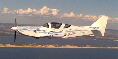
Photograph of Stoddard-Hamilton Glasair III, VH-USW
Source: Aircraft owner
What the ATSB found
During the aircraft’s construction, modification of the electronic ignition system incorporated a single point of failure in the intended dual system, increasing the risk of the simultaneous failure of both systems and a total loss of engine power. In addition, the connector plug used for the modification was inappropriate for the in-line installation, increasing the risk of its disconnection and disabling the ignition system.
Examination of the engine found that the single wiring harness for the ignition system was disconnected from the connector plug. However, due to the level of impact and fire damage sustained by the aircraft, the ATSB was unable to conclusively establish if this occurred inflight, resulting in the total engine power loss, or during the early stages of the impact sequence.
Safety message
The aviation industry has long recognised the need for redundant systems, particularly those relating to safety-critical components. The ATSB cautions that, even if unintended, the incorporation of a single point of failure into such systems during construction or modification can eliminate all levels of redundancy. In this case, damage to the aircraft’s modified single wiring harness resulted in the failure of an otherwise redundant system, with near-fatal consequences.
The occurrence
On the afternoon of 9 December 2013, the pilot/owner of an amateur-built Stoddard-Hamilton Glasair III aircraft, registered VH-USW (USW) and operated in the ‘experimental’ category, conducted a preflight inspection in preparation for a local flight from Jandakot Airport, Western Australia. The pilot reported that the aircraft’s wingtip fuel tanks were empty, the main tanks were full and 25 L was uploaded into the header tank. The pilot and passenger then boarded the aircraft and taxied for the flight.
The flight was the first since the aircraft’s electronic ignition system had undergone maintenance. While the ignition system was engine ground-run tested by a Licenced Aircraft Maintenance Engineer as part of that maintenance, the pilot elected to perform the engine run-up checks twice as a precaution. The pilot reported that the engine operated as normal.
At about 1434 Western Standard Time,[1] the pilot advised Jandakot Tower air traffic control that they were ready for departure and was subsequently cleared to take off from runway 24 Right (R). After take-off, the aircraft was climbed to 1,000 ft and a shallow right turn commenced toward Fremantle. The pilot and passenger stated that at about 1436 the aircraft’s engine suddenly stopped without warning and the pilot broadcast on the Jandakot Tower radio frequency that they had experienced an engine failure. The pilot reported that, while there was insufficient altitude to conduct the engine failure ‘trouble checks’,[2] they moved the two toggle switches for the aircraft’s ignition system to OFF and ON again in an attempt to re-start the engine, but with no effect.
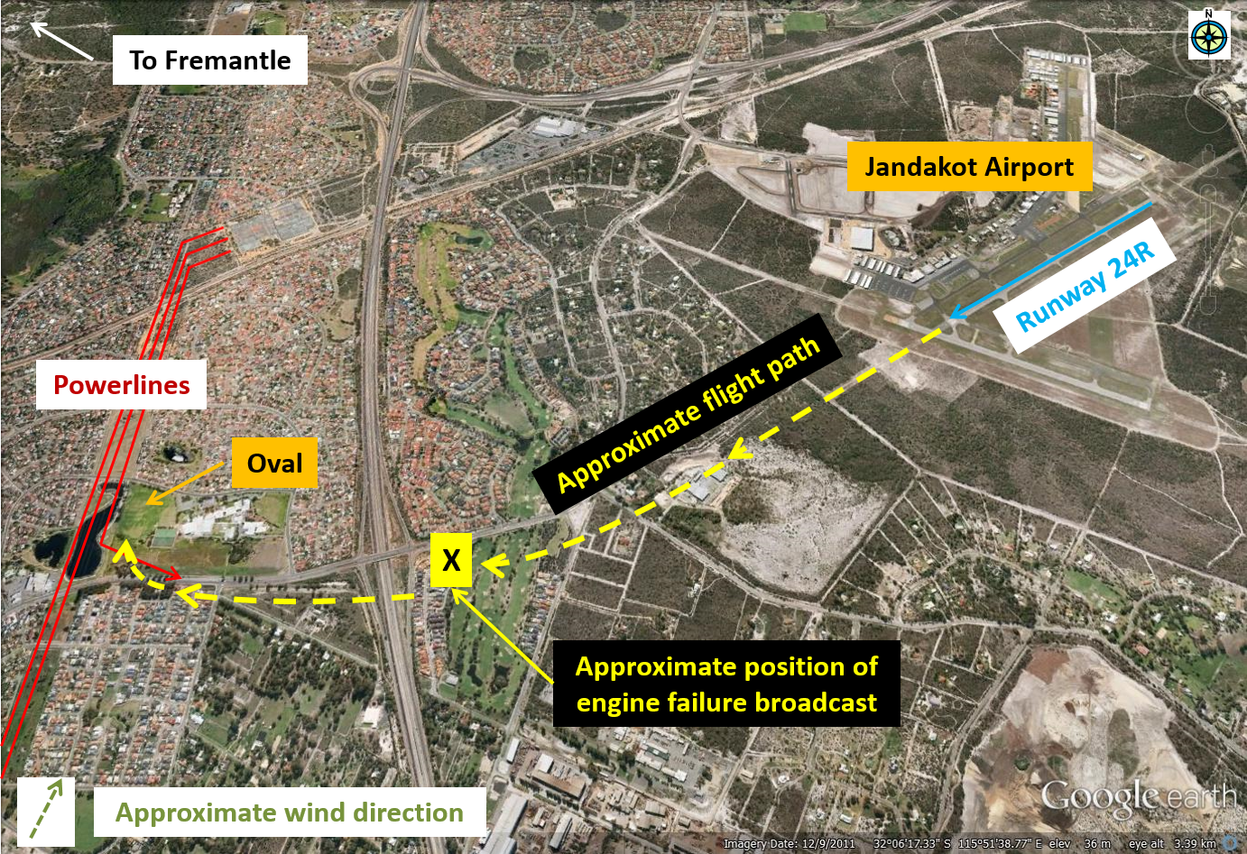
The pilot focused on flying the aircraft and looking for a suitable landing area. With very few options available, the pilot, who was aware of powerlines in the vicinity (Figure 1), manoeuvred the aircraft for a forced landing in a nearby grassed area (Lakelands Reserve Oval). It was reported that the propeller was windmilling during the descent.[3]
Figure 1: Approximate flight path and forced landing area
Source: Google earth, modified by the ATSB
Approaching the landing area, the pilot observed a powerline along the flight path and dived abruptly to pass beneath that line. At the same time, the pilot lowered the undercarriage and flaps to control the aircraft’s airspeed and avoid overshooting the oval. The pilot elected not to turn the aircraft’s electrical system off for the landing to ensure that the undercarriage lowered completely.
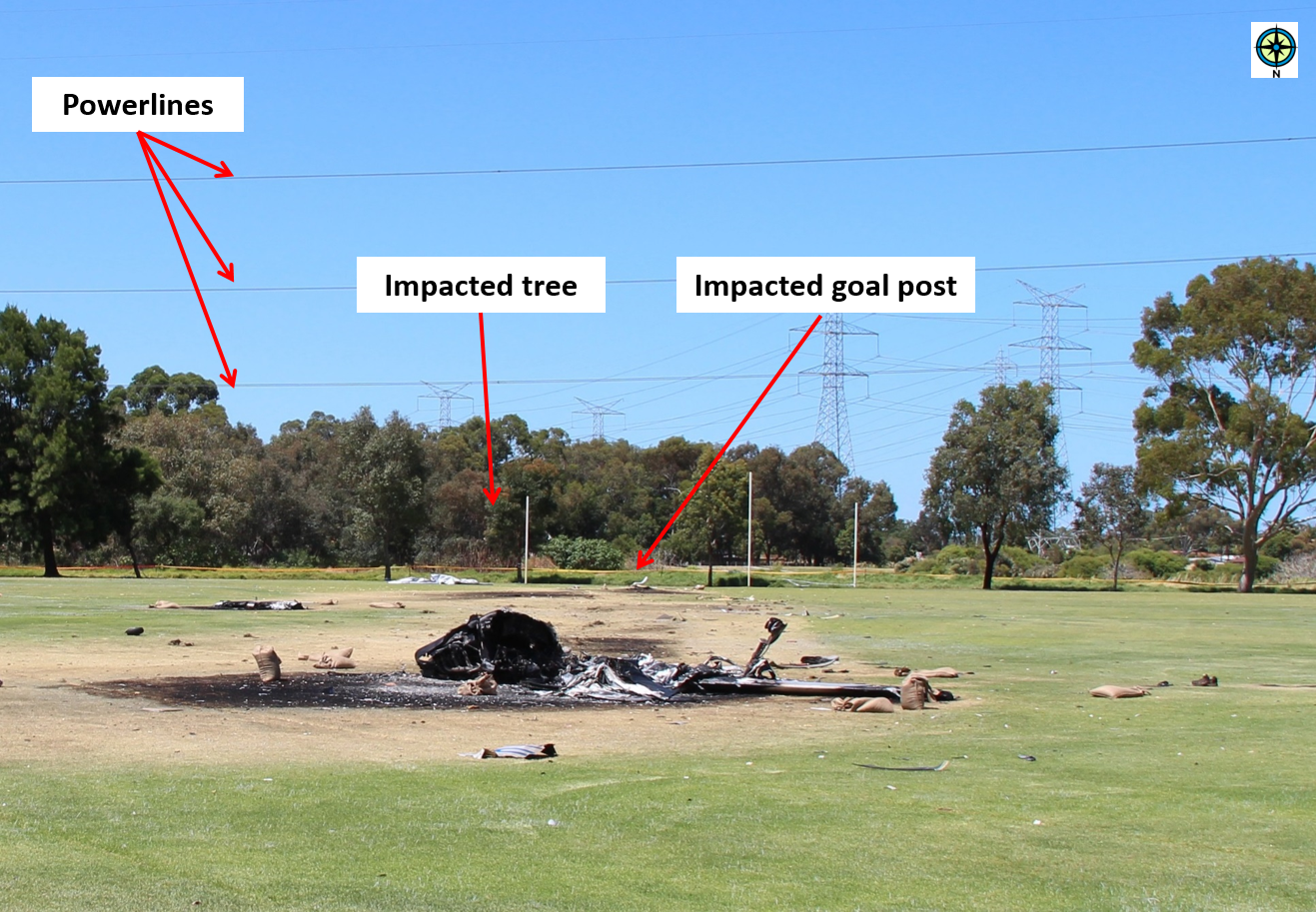
After flying under the powerline, the aircraft lightly clipped a tree bordering the oval before colliding with a metal goal post. The pilot reported not seeing the goal posts until it was too late to avoid the collision (Figure 2). The pilot recalled hearing the sound of the impact then next remembered lying on the ground and seeing the passenger nearby and the aircraft wreckage on fire. The pilot helped the passenger to move away from the wreckage and remove burning clothes items.
Figure 2: Three-strand powerline on late approach to the landing area and the impacted tree and goal post (looking back along the direction of travel)
Source: ATSB
Witnesses in the vicinity heard the sound of an impact and saw a fireball and the burning aircraft tumbling across the oval before coming to rest. A number of people rushed to assist and found the two occupants clear of the burning wreckage. They moved the occupants further away and administered first aid until emergency services personnel arrived.
The pilot and passenger both sustained serious burns and were taken to hospital. Emergency services extinguished the fire, but the aircraft was destroyed by the impact forces and intense fuel fed fire.
The pilot held a Private Pilot (Aeroplane) Licence that was issued on 12 March 1990 and a valid Class 2 Aviation Medical Certificate.[4] The pilot had a total flying experience of 3,265 hours, of which 114.6 hours were conducted in the Glasair III aircraft. In the previous 90 days, the pilot had flown 10.2 hours and they last completed an aeroplane flight review on 1 November 2013. This review was carried out in a Van’s Aircraft RV-8 and included a practice forced landing.
Aircraft information
General
The Stoddard-Hamilton Glasair III is a kit-built, all-composite aircraft (primarily fibreglass/resin and carbon fibre/resin) with a low-wing and retractable undercarriage. Consistent with its construction in the United States (US), an experimental amateur-built certificate of airworthiness was issued by the US Federal Aviation Administration (FAA) on 19 July 2000. The aircraft was subsequently purchased by the present owner/pilot and imported into Australia, where it was registered on 1 October 2008 as VH-USW. A special certificate of airworthiness designating the aircraft in the Experimental airworthiness category, and for operation as an amateur-built aircraft, was issued by a Civil Aviation Safety Authority (CASA) authorised person on 22 January 2009.
Engine and propeller
The aircraft was fitted with a six-cylinder, direct-drive, horizontally-opposed, air-cooled Textron Lycoming engine, model number IO-540-K1B5, serial number L-25612-48A. The engine drove a two-bladed Hartzell, constant-speed propeller, model HCCZYK-1BF.
Maintenance
A review of the aircraft’s logbook and other related documentation indicated that USW was maintained in accordance with an approved CASA maintenance schedule. The last periodic inspection was conducted on 11 March 2013, at which time the aircraft’s total time in service was 223.2 hours. The aircraft last flew on 12 November 2012 and had undergone several ground runs following maintenance since that time.
Recent maintenance was carried out on the aircraft’s Light Speed Engineering Plasma I capacitor discharge ignition (CDI) electronic ignition system. This included the removal of the aircraft’s two CDI modules for upgrade by the manufacturer before they were refitted to the aircraft and ground tested satisfactorily.
The power feed to each system was also modified during that maintenance to enhance the independence of the two CDI systems. It was reported that a wire that led from the main power bus to the voltmeter switch was temporarily disconnected (see the section Engine monitoring and recording) and that the wire was not reconnected prior to the occurrence. The aircraft had not flown in the intervening period.
Alternator V-belt
The aircraft’s maintenance records indicated that a notched alternator V-belt was fitted to the engine in about January 2000 and had not been replaced. The engine manufacturer specified that, following fitment of a new belt, the belt should be checked for correct tension 25 hours after installation. It was unknown if this had been conducted.
Routine maintenance inspections were certified as conducted in the intervening 14-year period. According to the FAA and CASA maintenance schedules, these inspections included an inspection of the V-belt. The pilot indicated that when inspected, no problems were identified with the condition of the belt. According to the belt manufacturer, the belt had an acceptable storage life of 8 years, even if stored for this time on the drive under tension. Examination of the alternator belt tensioning arm showed a single, circular witness mark that coincided with the under-head washer on the bolt. Consistent with the maintenance records, this indicated that the alternator belt had likely not been replaced since initial installation during the construction of the aircraft.
Further, in order to prevent ‘belt set’,[5] the manufacturer recommended that tension be removed from the belt if storage time before re-use was greater than about 6 months. Depending on a number of factors including drive design, storage environment and maintenance practices, serious belt damage may occur when starting this type of belt if ‘set’ had occurred and/or the belt had lost tension. The maintenance records for USW indicated a maximum storage time of just over 6 months. As such, there would have been no need to remove tension from the belt.
Electronic ignition system
During the aircraft’s construction, the engine was modified by replacing its dual magneto system and corresponding aircraft-type spark plugs and leads with the Plasma I capacitor discharge ignition (CDI) system (electronic ignition system). This system was originally designed to operate as a single CDI system and used dual-lead coils and automotive spark plugs and leads.
In normal operations, six-cylinder engine ignition timing on the Plasma I was achieved by a trigger coil system. As part of this system, a trigger plate mounted on the front of the engine crankcase contained three trigger coils and precisely-placed interrupter trigger bolts fastened to the ring gear support assembly (flywheel). This assembly is attached to the propeller hub. As the flywheel rotates, the trigger coils sense the trigger bolts and produce an electrical signal each time successive bolts pass the coils. This provides an indication of crankshaft position (timing) and allows the determination of the engine revolutions per minute (RPM) via wiring to the individual CDI modules located beneath the instrument panel in the cockpit. Timing, RPM and manifold pressure information is integrated by the CDI modules to optimise the timing of the spark in each cylinder.
Aircraft builders were supplied with a trigger plate assembly and were responsible for connecting a short wiring harness from the trigger plate to the pre-manufactured CDI module cable. The manufacturer’s diagram recommended that the wiring harness be attached using a suitable connector. The manufacturer also recommended a soldered joint connection as a preference. These connections were based on a single electronic ignition system installation.
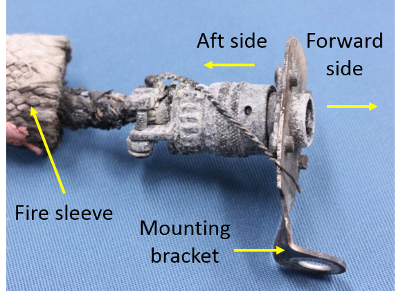
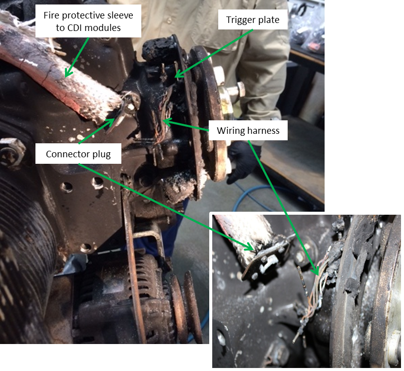
The aircraft’s ignition system was further modified by the aircraft builder to include a second CDI module and an auxiliary battery. The addition of an auxiliary battery was recommended by the manufacturer and independently powered the second system. The aircraft’s two CDI systems were intended by the builder to operate independently, providing redundancy in the event that one of the duplicated elements failed. To duplicate the wiring for the two CDI modules, the builder split the single wiring harness from the trigger plate into two using a MILSPEC connector plug.[6] This plug was designed to be attached to a metal box or a panel, such as a firewall. However, in USW, it was mounted onto a homemade, right-angled bracket that was fastened to the front of the engine crankcase (Figure 3). The connector plug and associated wiring were in an in-line arrangement.
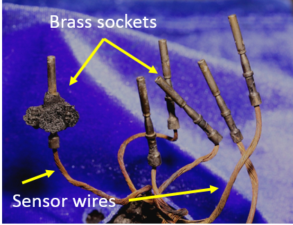
On the aft side of the connector plug in USW, the duplicated wires were clamped to relieve stresses from wire tension and were collectively shrouded in fire sleeving (Figure 3), which went to each CDI module. On the forward side of the plug, the single set of wires from the trigger plate was inside two plastic sleeves and their ends inserted into brass sockets, which were crimped for security (Figure 4). The sockets were then pushed into the forward side of the connector plug through a rubber sealing grommet and held in place in the cylindrical, plastic insulator by plastic clips. There was no means on this type of connector for relieving any stresses placed on the wires.
Figure 3: Bracket-mounted connector plug and fire sleeve
Source: ATSB
Figure 4: Sensor wires and brass sockets
Source: ATSB
Light Speed Engineering Plasma II and III ignition systems, such as the direct crank sensor installation, are now available as a dedicated dual system, with two independent wiring harnesses originating from the sensor plate and connecting directly to each CDI module. No intermediate plug, such as the connector plug used on USW, is required.
Engine monitoring and recording
The aircraft was fitted with a Vision Microsystems Inc. VM 1000 engine management system and an EC 100 electronic checklist and caution advisory system. The VM 1000 was normally used to display engine and aircraft system parameters during a flight. Additionally, when the engine RPM increased above 1,500 RPM, the VM 1000 automatically recorded the minimum and maximum values for various operating parameters for the flight. The system also had a built-in warning system whereby any out-of-tolerance parameter flashed on the display.
The recorded data for the occurrence flight was retrieved from the VM 1000 following the accident. This data showed a voltmeter reading of zero for the flight. This was consistent with the reported disconnection of the wire between the main power bus and voltmeter switch, which had been selected to indicate main bus voltage. The remaining values, including engine oil pressure and temperature, ammeter and fuel flow and pressure gave no indication of the reason for the engine failure.
The EC 100 operated in conjunction with the VM 1000 and alerted the pilot to abnormal conditions or trends in the engine operating parameters. The pilot could not recall a warning of a problem with the engine, but had reportedly mentioned to witnesses immediately after the accident that an unspecified engine warning had been received. The passenger reported not paying any particular attention to the warning display during the flight.
Fuel system and selection
The fuel was carried in integral fuel tanks located in each wing, with a reported total capacity of 114 L in each tank. A fuselage header tank located between the engine firewall and the cockpit had a total capacity of 25 L. Additionally, USW was fitted with optional wingtip tanks, but the pilot reported that they were empty for the flight.
A four-position fuel selector was located on the centre console near the pilot’s right knee. To prevent inadvertent selection, a button on the selector had to be raised in order to select the OFF position. The pilot reported selecting the left fuel tank for the flight.
The pilot also reported a previous temporary fuel starvation event with the header tank selected. In that instance the engine had coughed and surged, providing sufficient warning for the pilot to change tanks.
Meteorological information
The automatic terminal information service[7] at Jandakot Airport indicated a 14 kt (26 km/h) surface wind between 140° and 200° (south-south-easterly to south-south-westerly) and a temperature of 27 °C at the time. A nearby surveillance camera showed smoke from the post-impact fire being blown from the south-west.
Wreckage and impact information
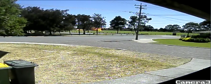
An examination of the wreckage found that the aircraft’s right wingtip clipped a tree on the southern boundary of the oval before the left wing was sheared off at the wing root by the collision with a tubular, metal goal post. This impact ruptured the left-wing fuel tank and severed aircraft wiring from the fuselage into the left wing. Images from a nearby surveillance camera showed that the fuel ignited shortly after the collision with the goal post (Figure 5).
Figure 5: Security camera image of the fire (looking south-south-east)
Source: Channel 7
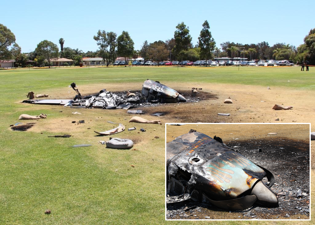
Damage to the aircraft was consistent with witness descriptions and the surveillance images depicting the aircraft tumbling before coming to rest with the fuselage, attached right wing and tailplane inverted. The engine, upper engine cowling, engine mounts and header tank were orientated in an upright position. The upper engine cowling was in situ and intact, with the engine still attached to the firewall assembly via the support frame. The damage to the propeller blades and strike marks on the ground were consistent with the propeller rotating at impact but the engine producing no power (Figure 6 inset).
The impact and fuel-fed fire destroyed the cockpit and severely damaged the composite airframe. This included the destruction of components of the electronic ignition and fuel systems, limiting or preventing examination of these parts.
Figure 6: Aircraft wreckage and propeller damage (see inset)
Source: ATSB
Fire
Shortly after colliding with the ground, a significant fire commenced that was initially fed by fuel from the ruptured left-wing tank. The right wing and header tanks were also breached during the impact sequence. The fire was subsequently extinguished by local fire authorities. The aircraft was destroyed in the fire and the occupants received serious burn injuries. The investigation was unable to identify the ignition source(s) for the fire; however, disruption of the aircraft’s wiring while still powered provided a potential ignition source for the fire.
The emergency procedures section of the Glasair III owner’s manual detailed the actions in the event of an engine failure, in particular, once committed to landing. These included the requirement for the aircraft’s alternator, master and ignition switches to be selected to OFF. In addition, the FAA Airplane Flying Handbook stated that:
Deactivation of the airplane’s electrical system before touchdown reduces the likelihood of a post-crash fire. However, the battery master switch should not be turned off until the pilot no longer has any need for electrical power to operate vital airplane systems.
In this instance, due to the difficult approach and landing area constraints, the pilot lowered the flaps and undercarriage to assist with controlling the aircraft’s landing speed and prevent an overshoot. As the undercarriage required electrical power to extend, the pilot elected to leave the aircraft’s electrical system on for the landing. This was consistent with the FAA guidance.
Survival aspects
The pilot reported that he and the passenger most likely escaped the burning wreckage during the break-up of the fuselage as the aircraft tumbled across the oval. This dislodged the seatbelt attachment points from the fuselage and released the pilot and passenger from the wreckage.
Tests and research
Engine examination
The engine was recovered from the wreckage and transported to an approved overhaul facility for technical inspection under the supervision of the ATSB. The examination found no evidence of internal mechanical failure of the engine that would have prevented normal operation prior to the occurrence.
The wires from the engine timing trigger plate for the aircraft’s electronic ignition system were found disconnected from the connector plug and displaced in the direction of engine rotation (Figure 7). In addition, there was no evidence of the alternator V-belt. Whether the belt failed or dislodged from the drive prior to or during the accident sequence, or was consumed in the postimpact fire could not be determined.
The remaining components from the aircraft’s ignition system and the alternator were removed from the engine. Together with the already-removed flywheel, these items were transported to the ATSB technical facilities in Canberra, Australian Capital Territory for further examination.
The wires for each of the trigger coils on the engine timing trigger plate were resistance tested and found within manufacturer’s specifications. A check for short circuiting between the wires was also conducted, with nil evidence found. This indicated that the trigger coils were capable of functioning prior to the occurrence.
Examination of the pins and brass sockets on the forward side of the connector plug showed damage consistent with the wiring harness being forcefully and unevenly disconnected either inflight or during the early stages of the impact sequence. However, no witness marks were identified on the two flywheel trigger bolts to indicate contact with another part of the engine or its accessories. This and the fire damage to the plastic insulation on the wiring harness meant that there was insufficient evidence to conclude that they had contacted a trigger bolt.
System redundancy and single points of failure
On 22 June 2001, the pilot of an amateur-built Quickie Aircraft Corporation Q2 aircraft reported that their aircraft’s engine stopped during the climb. The pilot attempted a forced landing at the departure aerodrome. The pilot reported that, as the aircraft approached the runway, they ‘encountered sink’ and undershot the runway. The aircraft collided with a boundary fence before coming to rest. The pilot reported that the switch for the aircraft’s ignition system had failed. The aircraft was fitted with a dual magneto ignition system but had a single ignition selector switch. The pilot indicated that not being able to select the individual ignition systems reduced the redundancy of the system (ATSB occurrence 200103043).
Downer (2009) described system redundancy as follows:
An element is redundant if it contains backups to do its work if it fails; a system is redundant if it contains redundant elements. This can mean having several elements that work simultaneously but are capable of carrying the ‘load’ by themselves if required…
Describing the advantages of system redundancy, Dekker (2011) highlighted that:
…redundancy is the best way to protect against hazard…safety-critical systems usually have multiple redundant mechanisms…it protects them against the failure of a single component or part that could directly lead to a bad outcome.
The October 2014 edition of the Sport Aircraft Association of Australia Airsport magazine included an article on the occurrence involving USW and the aircraft’s electronic ignition system. Specifically, the article discussed that, while the ignition system was well-built, with redundancies in place, the wiring from the trigger plate was a potential common point of failure that, if damaged, would result in a sudden and total power loss. The article further suggested a number of strategies to help manage this risk, including the installation of a hybrid ignition system (one magneto and one electronic ignition system) and/or ensuring the wiring was protected from mechanical damage. The manufacturer of the ignition system fitted to USW noted the benefits of having a dual electronic ignition system. In particular, dual ignition would provide enhanced performance and reliability when compared with traditional (two magnetos) or hybrid ignition systems. Regardless of the solution adopted by builders, the manufacturer reinforced that, in order to address the risk of a single point of failure, it is crucial that dual electronic ignition systems operate independently.
The US Federal Aviation Administration Advisory Circular 25.1309-1A (System design and analysis) suggests that in any safety-critical system, the failure of a single element, component or connection should be assumed, regardless of the probability. However, such single-point failures should not compromise the safety of a flight or significantly reduce the aircraft’s capability or a crew’s ability to cope with the resultant failure. A single point of failure can simultaneously eliminate all levels of redundancy (Berk 2009).
The loss without warning of engine power at about 1,000 ft shortly after take-off, combined with the surrounding built-up area and obstacles, presented the pilot with very few landing options. The loss of the left wing from the collision with the goal post contributed to the aircraft tumbling across the sports oval, increasing the severity of the occupants’ injuries and aircraft damage.
The extensive damage from impact forces and the post-impact, fuel-fed fire precluded examination of a number of the aircraft’s fuel system components. However, the pilot’s description of the symptoms associated with a previous loss of engine power from fuel starvation, and the amount of fuel on board so shortly after take-off, indicated that fuel-related issues were not a factor in the sudden engine power loss.
While the engine examination identified no internal mechanical failure or abnormality that would have precluded normal operation, the single wiring harness to the aircraft’s electronic ignition system was found disconnected.
This analysis will discuss the aircraft’s electronic ignition system and the possible reasons for, and timing of the disconnection of the wiring harness. It will also consider the suitability of the associated connector plug and discuss the risks to aircraft systems of single points of failure.
Electronic ignition system installation
During construction, the aircraft was fitted with a single electronic ignition system that was then modified by the builder of the aircraft with the addition of a second ignition module. The installation was intended by the builder to create a dual system that would provide for redundancy. That is, in the event of one system failing, the other would continue to operate. However, the modification retained the original single wiring harness from the engine timing trigger plate to the connector plug, incorporating a single point of failure in the intended dual system.
Cessation of the engine timing signal, such as from the disconnection of the single wiring harness, would result in the loss of timing signals to both ignition modules and failure of the ignition system. Without an ignition source, the engine would stop operating.
The alternator V-belt and the engine timing trigger bolts on the flywheel were the only two moving components within the vicinity of the single wiring harness and connector plug with the potential to disconnect the harness. The still rotating propeller meant that, dependent on the presence of an operational alternator belt, these components may still have been rotating at impact. However, the unavailability of the alternator belt for examination prevented any conclusion on its pre-impact condition or contribution to the disconnection of the harness. Regardless, the continued use of the V-belt, which had been stored under tension for longer than the manufacturer’s acceptable storage life, increased the risk of belt failure.
As with the difficulty determining the contribution, if any, of the V-belt to the occurrence, the lack of witness marks on the two flywheel trigger bolts and the fire damage to the plastic insulation on the wires precluded a conclusion that the wiring harness had contacted a trigger bolt.
In any case, examination of the connector plug and sensor wire sockets showed that the wiring harness was forcibly disconnected prior to the fire. However, given the number and nature of the multiple impacts with terrain during the accident sequence, the timing of the disconnection could not be established.
Suitability of the wiring harness connector plug
The connector plug and associated wiring forward and aft of the plug were an in-line installation. The connector allowed duplication of the wiring for the intended dual ignition system and provided clamping on the aft side of the plug to relieve wire tension. The clamping was not repeated forward of the plug, where the single wiring harness from the engine timing trigger plate had disconnected.
The wiring on the forward side of the plug relied on friction and an internal, plastic locking mechanism to retain the sensor wires and sockets in position. The limited support provided on the forward side of the plug increased the risk of the wiring harness disconnecting from the in-line installation.
Single point of failure
The aviation industry has long recognised the need for redundant systems, particularly those relating to safety-critical components. Incorporating a single point of failure into such systems during construction or modification can eliminate all levels of redundancy. In this case, the loss of the single wiring harness resulted in failure of an otherwise redundant system, with near-fatal consequences.
Findings
From the evidence available, the following findings are made with respect to the engine failure at about 1,000 ft shortly after take-off, and subsequent collision with terrain in a nearby sports oval involving an amateur-built Stoddard-Hamilton Glasair III aircraft, registered VH-USW, near Jandakot Airport, Western Australia on 9 December 2013. These findings should not be read as apportioning blame or liability to any particular organisation or individual.
Contributing factors
The aircraft's engine stopped without warning and, with very few landing options available and a number of obstacles on short finals to the intended landing area, the forced landing resulted in a collision with terrain.
Other factors that increased risk
Modification of the aircraft’s electronic ignition to an intended dual system during aircraft construction incorporated a single point of failure, increasing the risk of the simultaneous failure of both systems and a total loss of engine power.
The connector plug for the aircraft’s electronic ignition system was inappropriate for an in-line installation, increasing the risk of the single wiring harness becoming disconnected and disabling the ignition system.
The alternator V-belt fitted to the aircraft exceeded the manufacturer's storage life of 8 years, increasing the risk of belt failure.
Other findings
Although the initiator and timing of the disconnection could not be conclusively determined, the single wiring harness for the aircraft’s electronic ignition system was found disconnected from the connector.
Sources and submissions
Sources of information
The sources of information during the investigation included:
the pilot and passenger of VH-USW
the Licenced Aircraft Maintenance Engineer and electrical technical expert for VH-USW
Light Speed Engineering
a number of witnesses
the Civil Aviation Safety Authority.
References
Berk J 2009, Systems Failure Analysis, ASM International Ohio.
Dekker S 2011, Drift into failure: from hunting broken components to understanding complex systems, Ashgate Publishing Surrey.
Downer J 2009, When Failure is an Option: Redundancy, reliability and regulation in complex technical systems, Discussion Paper No. 53, Centre for Analysis of Risk and Regulation London.
Federal Aviation Administration 2004, Airplane Flying Handbook, Chapter 16: ‘Emergency procedures’, United States Department of Transportation.
Federal Aviation Administration 1988, System design and analysis, Advisory Circular AC 25.13091A.
George A 2014, ‘Engine failure Glasair III’, Airsport, October 2014, pp. 14–15.
Gates Facts Extended Storage of Belt Drives and Analyze Your Way to Longer Lasting, Better Performing V-belt Drives.
Submissions
Under Part 4, Division 2 (Investigation Reports), Section 26 of the Transport Safety Investigation Act 2003 (the Act), the ATSB may provide a draft report, on a confidential basis, to any person whom the ATSB considers appropriate. Section 26 (1) (a) of the Act allows a person receiving a draft report to make submissions to the ATSB about the draft report.
A draft of this report was provided to the pilot and passenger of VH-USW, the aircraft’s electrical technical expert, Light Speed Engineering, the Civil Aviation Safety Authority and the United States National Transportation Safety Board.
A submission was received from Light Speed Engineering. The submission was reviewed and where considered appropriate, the text of the report was amended accordingly.
Purpose of safety investigations
The objective of a safety investigation is to enhance transport safety. This is done through:
identifying safety issues and facilitating safety action to address those issues
providing information about occurrences and their associated safety factors to facilitate learning within the transport industry.
It is not a function of the ATSB to apportion blame or provide a means for determining liability. At the same time, an investigation report must include factual material of sufficient weight to support the analysis and findings. At all times the ATSB endeavours to balance the use of material that could imply adverse comment with the need to properly explain what happened, and why, in a fair and unbiased manner. The ATSB does not investigate for the purpose of taking administrative, regulatory or criminal action.
Terminology
An explanation of terminology used in ATSB investigation reports is available here. This includes terms such as occurrence, contributing factor, other factor that increased risk, and safety issue.
Publishing information
Released in accordance with section 25 of the Transport Safety Investigation Act 2003
Ownership of intellectual property rights in this publication
Unless otherwise noted, copyright (and any other intellectual property rights, if any) in this report publication is owned by the Commonwealth of Australia.
Creative Commons licence
With the exception of the Coat of Arms, ATSB logo, and photos and graphics in which a third party holds copyright, this publication is licensed under a Creative Commons Attribution 3.0 Australia licence.
Creative Commons Attribution 3.0 Australia Licence is a standard form licence agreement that allows you to copy, distribute, transmit and adapt this publication provided that you attribute the work.
The ATSB’s preference is that you attribute this publication (and any material sourced from it) using the following wording: Source: Australian Transport Safety Bureau
Copyright in material obtained from other agencies, private individuals or organisations, belongs to those agencies, individuals or organisations. Where you wish to use their material, you will need to contact them directly.
On 7 December 2013, the pilot of a Cessna 182 aircraft, registered VH-LMA, departed Albury, New South Wales on a private flight to the Tyabb aeroplane landing area (ALA), Victoria. The flight was being conducted under the instrument flight rules (IFR), and on board were the pilot and one passenger.
After the aircraft had left controlled airspace and with about 6 NM to run, the pilot levelled the aircraft at 1,100 ft to prepare to join the circuit on an extended left base leg for runway 17.
When on final approach, he checked the secondary windsock and noted the wind was predominantly crosswind from the right, gusting around 5-10 knots. With the final stage of flap selected, the aircraft touched down on the main wheels about 20-30 metres past the runway threshold, close to the centreline. The pilot estimated the aircraft speed at touchdown was about 65 knots. During the landing roll, he applied a small amount of right aileron to counter the crosswind.
When the aircraft had slowed he began to apply the brakes. At about the same time, a gust of wind pushed the aircraft to the left. The pilot applied right rudder in an attempt to steer the aircraft back to the centreline, but stated the aircraft pulled to the left and felt like the left brake had locked. The aircraft rapidly decelerated, and continued along a path through the wet grass a few metres to the left of the sealed runway. As it stopped, the aircraft nosed forward, and then tipped over onto its back.
The pilot and his passenger were hanging upside down in their seatbelts. A person who had been waiting for the aircraft to arrive assisted the young passenger and then the pilot. The pilot and passenger sustained minor injuries, and the aircraft was substantially damaged.
A search of the ATSB database for fixed wing, private operation accidents, 2004 to 2013 found the landing phase accounted for 33% of all accidents. The take-off and initial climb phases together accounted for 25% of accidents from this group.
On 6 December 2013, a Kavanagh Balloons B-350 balloon registered VH-JDI, was on final approach to land near Broke, New South Wales. At a height of about 50 ft, as the balloon flew over a river and a line of trees, the pilot observed the sun glistening off a power line on the left of the landing area and looked for the poles associated with that power line. The pilot did not observe any other power lines coming off the poles. The pilot instructed the passengers to get into the landing position. The landing area looked to be clear of obstacles. As the balloon came over the end of the tree line the pilot slowly vented the hot air in the envelope to descend to the landing area. The pilot then noticed that there was a pole to the right that had been in the shadows and that a power line stretched horizontally in front of the balloon flight path. The pilot opened the envelope ventilation system so the balloon would descend quicker. The basket touched the ground gently and came to rest just under the power line at about 0630 eastern summer time. The envelope folded over the three power wires and when the wires came together there was a spark. The pilot instructed the passengers to remain in the basket and when he considered that it was safe he exited the basket. The pilot telephoned the electrical company who confirmed that the system was isolated and that a technician would be dispatched. The passengers disembarked the basket. The pilot and 15 passengers were not injured. The balloon envelope had a small area of heat damage to the fabric where it had contacted the power lines.
This serious incident highlights the importance of pre-flight planning, especially when landing at an unfamiliar landing area.
The Pacific National broad-gauge freight train, No. 9204V, was travelling from Warrnambool to Appleton Dock, Victoria. Due to track works at West Footscray Junction—to repair damage arising from a previous derailment—the train was despatched from Tottenham Yard toward the port via an alternative route, the adjacent dual-gauge Main line. Track circuit failures resulting from the track damage meant that Up-direction Home signals on the Main line were displaying Stop indications, and for this reason the train had departed Tottenham yard on the authority of a Signalman’s Caution Order. The locomotive crew received two further Caution Orders en-route, the last of these being for Home signal DYN158.
Signal DYN158 protected a turnout that provided for a diverge of the standard-gauge line away from the broad-gauge, and the network control officer (NCO) had inadvertently set this turnout for a standard-gauge movement. The locomotive crew proceeded past the Home signal and through the points, resulting in derailment of the locomotive and one wagon at low speed.
What the ATSB found
The ATSB found that the NCO had established a standard-gauge route beyond signal DYN158 rather than the required broad-gauge route. Although the Train Control System software incorporated an on-screen gauge alarm to warn an NCO against setting an unviable route, in this instance that screen alert did not appear, since its generation was contingent on the gauge detection system that was not functioning. The signalling system had been degraded as a result of a previous derailment.
The Train Control System permitted the NCO to establish a route on an incorrect gauge for train 9204 and displayed that route as viable.
What's been done as a result
ARTC has introduced provisions to ensure that modifications made to the Phoenix Train Control System display are fully understood by Control Centre staff, and has also modified the Signalman’s Caution Order form to provide explicitly for the checking of the intended route and for the train crew to check the setting of points to be traversed.
The ATSB has recommended that ARTC undertakes further action to address the risk of directing trains onto incorrect gauge track in dual-gauge territory.
Safety message
When the signalling system and the functionality of safety intervention devices is degraded and an alternative process of safeworking is in use, there is a need for a heightened level of awareness and caution on the part of network control officers and train crew.
When designing control system safety mechanisms, such as the Gauge Alarm in this instance, the rail operator should consider all possible sub-system failures to ensure the intervention remains effective under all circumstances.
On 8 December 2013, at about 1430 Eastern Daylight-savings Time, a Eurocopter EC-120B helicopter, registered VH‑VMT, departed from a property 16 km north of the Ballina/Byron Gateway Airport, New South Wales for a local flight.
At about 1555, the helicopter returned to the property from the north, overflew and approached to land on a heading of about 340º. The pilot reported that the wind was from the north, at about 20 kt.
When about 3 ft above ground level, the pilot reported that he entered the hover. Immediately after, the helicopter began to yaw left. The pilot applied right rudder pedal to counteract the yaw and reduced the engine power to idle. The helicopter continued to yaw left and the pilot applied full right rudder pedal, but was unable to arrest the rotation. The helicopter rotated left about 90° before the left skid lowered and contacted the ground. It continued to rotate around and rolled onto its right side. The helicopter was substantially damaged, and the passengers were uninjured.
The pilot believed that a combination of main rotor downwash and a wind gust contributed to a loss of tail rotor effectiveness. By maintaining an awareness of the wind and its effect on the helicopter, pilots can significantly reduce the exposure to LTE.
On 13 November 2013, the pilot of a Robinson R22 helicopter, registered VH STK, was conducting aerial mustering on a property about 155 km SSW of Normanton, Queensland.
At about 1249 Eastern Standard Time, the helicopter was hovering behind a mob of cattle, when the pilot felt the helicopter jerking. He landed and conducted a magneto check. He selected the left magneto and the engine rapidly lost power. He then selected the right magneto and the engine ran normally. He reselected the magneto switch to ‘both’ and attempted to contact the property manager.
He was unable to make contact with the manager and elected to take-off. Once airborne, he was able to communicate with the manager via UHF radio. He turned the helicopter towards a road and commenced an approach to land on the road.
At about 20 ft above ground level, the engine stopped. The pilot lowered the collective and flared the helicopter for landing. On impact, the helicopter spun around 180°. The helicopter was substantially damaged, and the pilot was uninjured.
On 1 December 2013, an Aérospatiale AS350B2 helicopter, registered VH-HRQ (HRQ), was on a return flight to Davis Base, Antarctica, with a pilot and two passengers on board. HRQ was one of two helicopters that were tasked to take a scientist and two field training officers to a penguin rookery at Cape Darnley. The helicopters refuelled during the return flight at a fuel cache on the Amery ice shelf, before departing to the south‑east for their next refuelling stop.
As a result of a rapid reduction in visual cues, the pilot of HRQ maintained about 150 ft above ground level. The pilots of both helicopters discussed the reduced surface definition and loss of visible horizon along their flight path and elected to return to the fuel cache until the weather improved. During the turn back to the fuel cache, HRQ descended and impacted the ice shelf. The pilot and two passengers were seriously injured, and the helicopter destroyed.
What the ATSB found
The ATSB found that the pilot did not detect the descent during the turn back to the fuel cache. The ATSB concluded that, after initiating the right turn, the pilot probably became spatially disoriented. Factors contributing to the disorientation included a loss of visual cues as a result of the change in weather conditions, and a breakdown of the pilot’s scan of his flight instruments, resulting in collision with terrain.
What's been done as a result
Following this accident the operator introduced new helicopters equipped with an autopilot and other equipment to reduce pilot workload. They also introduced simulator training that is administered by an experienced Antarctic pilot, a situation awareness course, and training on the use of the autopilot in the new helicopters and limitations of the radar altimeter. The operator has also amended their operational documentation to prescribe minimum settings for radar altimeters, discuss the use of the autopilot in low visibility environments, and provide decision-making guidance in relation to early avoidance of, and action on encountering inadvertent white-out conditions.
Safety message
This accident provides a timely reminder to flight crews of the importance of monitoring the flight instruments when encountering areas of reduced visual cues. The risks associated with flight in these conditions have been highlighted on the ATSB website as a SafetyWatch priority, along with a number of strategies to help manage the risk and links to relevant safety resources.
On 21 November 2013, after a flight from Singapore, an Etihad Airways Airbus A330, A6-EYJ landed at Brisbane airport and was taxied to the terminal. Approximately 2 hours later, the aircraft was pushed-back from the gate for the return flight to Singapore.
The captain rejected the initial take-off attempt after observing an airspeed indication failure on his display. The aircraft taxied back to the terminal where troubleshooting was carried out, before being released back into service.
During the second take-off roll, the crew became aware of an airspeed discrepancy after the V1 decision speed and the take-off was continued. Once airborne, the crew declared a MAYDAY and decided to return to Brisbane where an overweight landing was carried out.
What the ATSB found
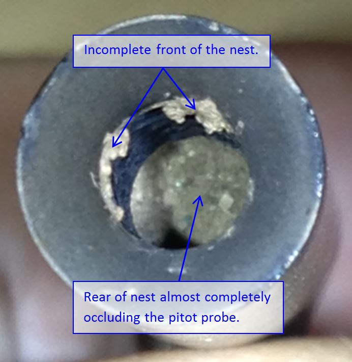
Engineering inspection after the overweight landing found that the Captain’s pitot probe was almost totally obstructed by an insect nest, consistent with mud-dauber wasp residue. The pitot obstruction had occurred during the 2 hour period that the aircraft was on the ground at Brisbane and was not detected during troubleshooting after the initial rejected take-off.
What's been done as a result
The aircraft operator has changed its policy on the use of pitot covers. They are now required to be used on all transits at Brisbane Airport, regardless of ground time.
The aircraft manufacturer has amended its maintenance troubleshooting manual to increase the likelihood that a blocked pitot probe will be detected.
The airport operator has extended its wasp inspection and eradication program and reviewed and updated its Wildlife Hazard Management Plan.
In addition, CASA has drawn attention to the safety implications of mud wasp activity through several publications.
Safety message
Operators can minimise the risk of pitot probe obstruction by consistently using pitot covers even during short transit periods.
Standard operating procedures include the cross-checking of airspeed during the take-off roll. These checks are an important last line of defence in preventing an aircraft from becoming airborne with airspeed indication problems.
The occurrence
On 21 November 2013, after a flight from Singapore, an Etihad Airways A330, registered A6-EYJ, landed at Brisbane Airport and was taxied to the terminal. It came to a stop at 0949 EST.[1] Pitot probe covers were not used during the transit. At 1152 EST, the aircraft was pushed-back for the return flight to Singapore. The captain rejected the initial take-off attempt on runway 01 after observing that there was an airspeed indication failure[2] on his primary flight display (PFD). The maximum airspeed recorded by the flight data recorder during the rejected take-off was 88 kt.
The aircraft taxied back to the terminal where troubleshooting was carried out. As part of the troubleshooting, air data inertial reference unit (ADIRU) 1 and ADIRU 2 were transposed and the aircraft was dispatched with the air data reference (ADR) part of ADIRU 2 inoperative, which was in accordance with the MEL.[3] The first officer’s (FO’s) air data[4] source was switched to ADIRU 3 and the captain’s air data source remained switched to the normal (ADIRU 1) position.
At 1345, the crew commenced the second take-off on runway 01, with the captain performing the pilot flying (PF) duties and the FO performing the pilot monitoring (PM) duties. During the take-off roll the crew reported that they became aware of an airspeed discrepancy after V1[5] and the take-off was continued. As a result of the airspeed discrepancy, the autothrust system and flight directors disengaged automatically. Once airborne, the auto-flight system reverted from normal law to alternate law for the remainder of the flight. At this time, the captain handed over control of the aircraft to the FO.
While climbing through a pressure altitude of 1,360 ft, the slat/flap lever was moved from the CONF1 to the 0 (up) position and the flaps began to retract, but the slats remained extended.[6] For a 2-minute period, a VFE[7] warning occurred as the slat limit speed was exceeded.
At 1347:30, the captain took over control of the aircraft for the remainder of the flight. Shortly afterwards, the crew declared a MAYDAY[8] and decided to return to Brisbane. The aircraft was manoeuvred to the east of the airport and maintained an altitude of approximately 2,000 ft. At 1351:36 the air data selector was switched to the ‘CAPT ON 3’ position and remained in that position for the remainder of the flight.
An overweight landing[9] was subsequently carried out on runway 01 and the aircraft taxied clear of the runway with the aviation rescue and fire-fighting (ARFF) services in attendance. The aircraft then taxied back to the terminal.
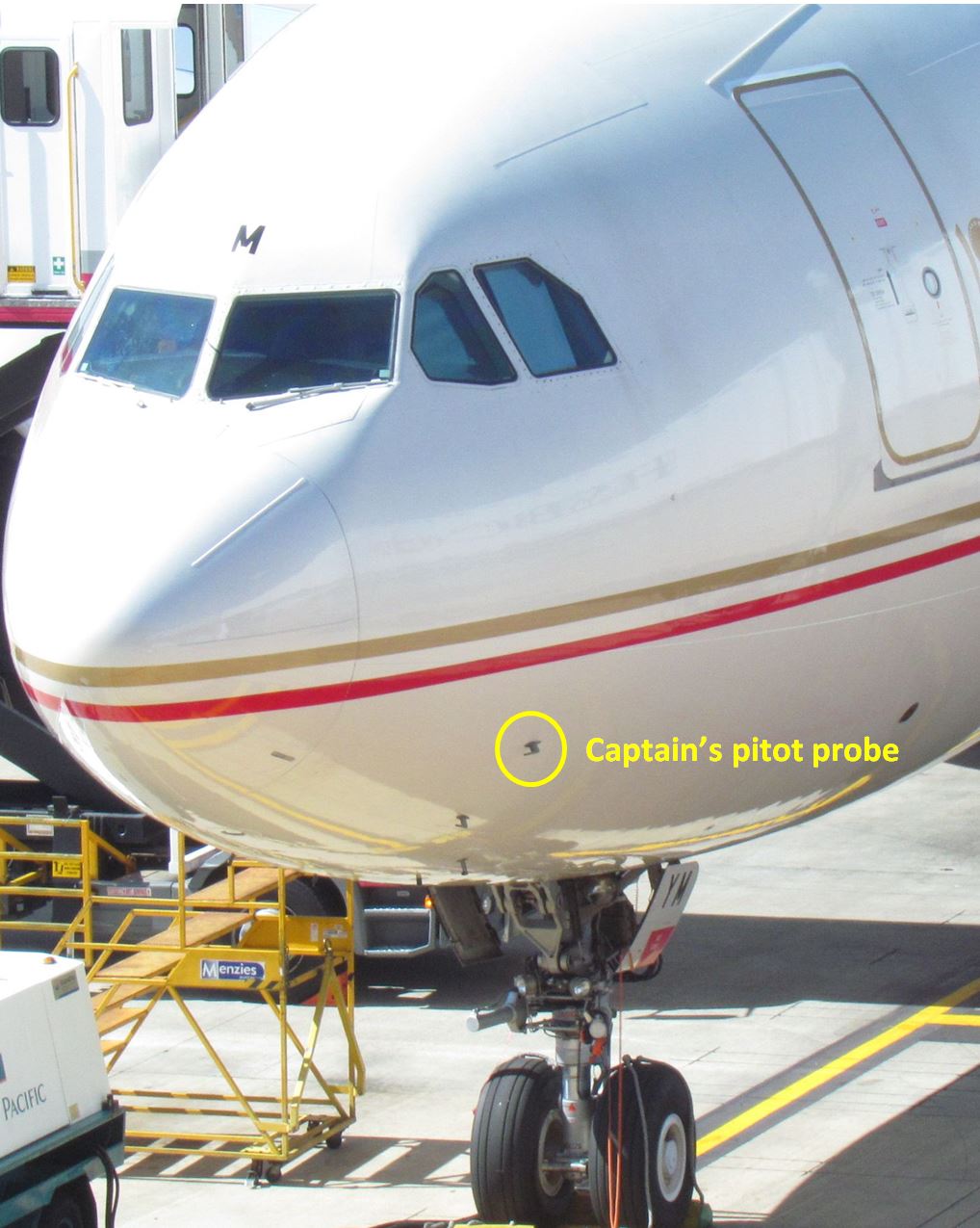
Subsequent visual inspection of the pitot probes found that there was an internal obstruction of the captain’s probe (Figure 1), while the FO and standby probes were clear.
The A330 has three independent systems for calculating and displaying airspeed information: (1) captain, (2) first officer, and (3) standby systems. Each system uses its own pitot probe, static ports, air data modules (ADMs), air data inertial reference unit (ADIRU), and airspeed indicator.
Each ADIRU comprises two parts, an air data reference (ADR) part and an inertial reference (IR) part which are integrated into a single unit. One part can be switched off while the other part can still operate.
Airspeed is measured by comparing total air pressure (Pt)[10] and static air pressure (Ps). On the A330, Pt was measured using a pitot probe, and Ps was measured using two static ports. A separate ADM was connected to each pitot probe and each static port, and it converted the air pressure from the probe or port into digital electronic signals.
Each pitot probe consisted of a tube that projected several centimetres out from the fuselage, with the opening of the tube pointed forward into the airflow. The tube had drain holes to remove moisture, and it was electrically heated to prevent ice accumulation during flight.
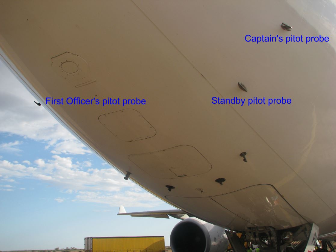
The locations of the aircraft’s pitot probes are shown in Figure 2.
Figure 2 : Locations of pitot probes
Source: ATSB
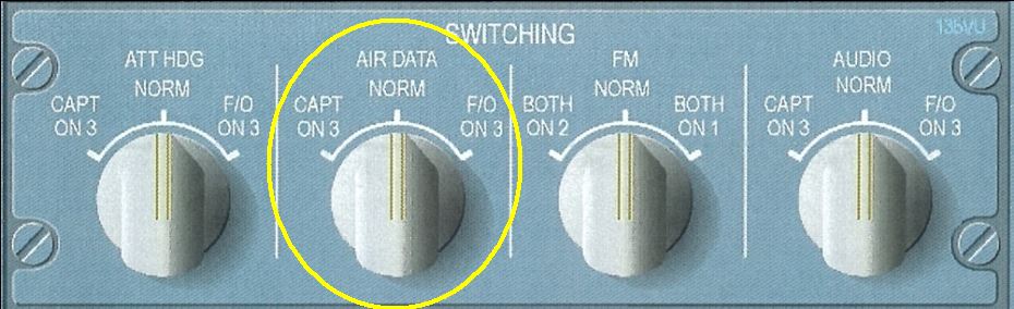
Normally, the airspeed displayed to the captain uses the captain’s pitot probe and ADIRU 1, but the source can be manually switched by the crew to the standby system (standby pitot probe and ADIRU 3) if required. Similarly, the airspeed displayed to the first officer (FO) normally uses the first officer’s pitot probe and ADIRU 2, but the source can be manually switched by the crew to the standby system if required (Figure 3).
Figure 3: Air Data Switching
Source: ATSB
Flight control system
The Airbus A330 had fly-by-wire flight controls. The aircraft’s flight control surfaces were electrically controlled and hydraulically activated, and flight control computers processed pilot and autopilot inputs to direct the control surfaces as required. There were three flight control primary computers (FCPCs) and two flight control secondary computers (FCSCs).
The FCPCs continuously monitored outputs from the three ADIRUs. The median (voted) value of each parameter was compared to each individual value. If the difference was above a predetermined threshold for a predetermined confirmation time, then the associated part of that ADIRU (IR or ADR) was rejected and the two remaining sources were used for flight control purposes.
The flight control system operated according to normal, alternate or direct control laws. Under normal law, the computers prevented the exceedance of a predefined safe flight envelope. If various types of aircraft system problems were detected, then the control law reverted to alternate law. Under alternate law, some of the protections were not provided or were provided with alternate logic. Under direct law, no protections were provided and control surface deflection was proportional to sidestick and pedal movement by the flight crew.
During the second take-off at 1345, the active control law changed from normal law to alternate law (for 8 seconds) then back to normal law (4 seconds) and finally back to alternate law. The second reversion to alternate law was latched for the remainder of the flight.
Flight guidance system
The flight guidance system used two independent flight management, guidance and envelope computers (FMGECs). The flight guidance part of each computer controlled the autopilot, autothrust and flight director (FD) functions. Flight director 1 displayed control orders from FMGEC 1 on the captain’s PFD and flight director 2 displayed control orders from FMGEC 2 on the first officer’s PFD.
Both FMGECs continuously monitored the altitude and computed airspeed from all three ADRs. During the second take-off at 1345, ADR2 was already rejected due to being switched off. When the FMGEC then detected a difference above the threshold between the two remaining ADRs, the autothrust and associated flight directors were automatically disconnected.
Maintenance action following the rejected take-off
Following the rejected take-off, the fault symptoms provided to the maintenance engineers were a combination of crew observations and messages from the on-board central maintenance system (CMS). The CMS enabled troubleshooting and return-to-service testing to be carried out rapidly from the flight deck. The hub of the CMS was the central maintenance computer, which assisted in the diagnosis of faulty systems.
Central maintenance computer (CMC)
Each aircraft system has built-in test equipment (BITE) which is used to test system components and detect faults, and to confirm system operation following any maintenance. Each of the aircraft’s systems communicates with the CMC and sends it information on detected faults and any warnings indicated to the flight crew.
When the aircraft was on the ground, maintenance engineers could access the CMC using a multi-purpose control and display unit (MCDU) from the flight deck and obtain information from the most recent flight or earlier flights. Through using the MCDU, BITE information from aircraft systems could be interrogated and the systems tested.
Aircraft systems could detect faults in two ways: internally, by monitoring its own operation, or externally, by another aircraft system which received and monitored information from the ‘faulty’ system.
Post flight report (PFR)
The CMC produced various reports that were accessible through the MCDU when the aircraft was on the ground. Those reports included the post flight report (PFR), which was produced and printed at the end of a flight. The PFR contained fault information received from other aircraft systems’ BITE and which was sent to the CMC during flight. The PFR showed one fault:
ADIRU1 (1FP1) BUS ADR
This had been reported by the electrical flight control system (EFCS) and was a Class 2 message. Class 2 messages are not presented to the crew during flight (including take-off). Associated with the fault message were two maintenance status messages:
MAINTENANCE STATUS EFCS 1
MAINTENANCE STATUS EFCS 2
Trouble Shooting Manual (TSM)
Trouble shooting is performed using the TSM. Crew observations and/or PFR items are used as entry points to the TSM. Accordingly, either of the following two TSM entries could have been used:
The RED SPD FLAG on CAPT PFD in the “EFIS PFD” part, and/or
The Maintenance message “ADIRU1 (1FP1) BUS ADR” in the “CMS Fault Messages” part.
These two symptoms are linked respectively to the following TSM tasks:
TSM Task 34-10-51-810-907-A “Loss of the AIR/GND signal in the DMC1”, with the following possible causes:
Display Management Computer 1 (DMC 1), or
Wiring between the DMC1 and the first terminal block.
TSM task 27-90-00-810-889-A “Failure of the ADIRU 1 ADR Bus on the FCPCs”, with the following possible causes:
ADIRU-1, or
Angle of Attack (AOA) sensor.
This last TSM task refers to the ADIRU 1 as a possible cause and asks for a BITE test of the EFCS to confirm the fault.
The aircraft maintenance engineer reported that the second task was performed and the EFCS 1 and 2 BITE tests did not confirm any faults i.e. the units tested with normal indications.
Although no faults had been positively identified, the engineer considered that ADR 1 was inoperative and transposed ADIRU 1 and 2. The aircraft was dispatched with the ADR part of ADIRU 2 inoperative, in accordance with the MEL. The FO’s air data source was switched to ADIRU 3 and the captain’s air data source remained switched to the normal (ADIRU 1) position.
Service Information Letter (SIL) 34-084 “Erratic Airspeed Indication Maintenance Actions”
Neither of the two relevant TSM tasks identified the pitot probes as a possible root cause of the airspeed indication failure. However, on 15 January 2013, Airbus issued Revision 7 of Service Information Letter (SIL) 34-084: Erratic Airspeed Indication Maintenance Actions on that subject, which provided operators with comprehensive maintenance recommendations in case of airspeed problems. One of these recommendations (SIL chapter 4.2.2) indicated that in case of a RTO due to a discrepancy between the captain’s and FO’s indicated airspeed, the TSM tasks linked to the PFR have to be performed but operators are also recommended to focus on specific tasks related to pitot probes (detailed in the SIL).
Airspeed checks by the crew during take-off
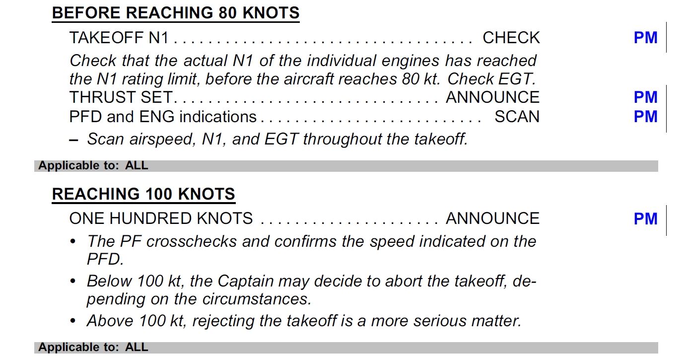
The operator’s standard operating procedures (SOP’s) were based on those of the manufacturer and included the following references to airspeed:
Figure 4: Extract from standard operating procedures for take-off
The aircraft manufacturer also provided the following generic guidelines (extracted from FCOM PRO-ABN-10 - Operating Techniques – Rejected Take-off):
Below 100knots
The decision to reject the take-off may be taken at the Captain’s discretion, depending on the circumstances.
The Captain should seriously consider discontinuing the take-off, if any ECAM warning/caution is activated. The speed of 100 kt is not critical, and was chosen in order to help the Captain make his/her decision and avoid unnecessary stops from high speed.
Rejecting the take-off at these speeds is a more serious matter, particularly on slippery runways, and it could lead to a hazardous situation if the speed is approaching V1. At these speeds, the Captain should be “go-minded” and very few situations should lead to the decision to reject the take-off:
1. Fire warning, or severe damage
2. Sudden loss of engine thrust
3. Malfunctions or conditions that give unambiguous indications that the aircraft will not fly safely
4. Any red ECAM warning
5. Any amber ECAM caution of the ENG system or the F/CTL (flight control) system.
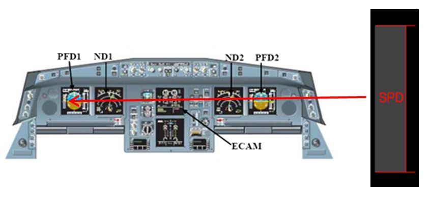
Red speed flag
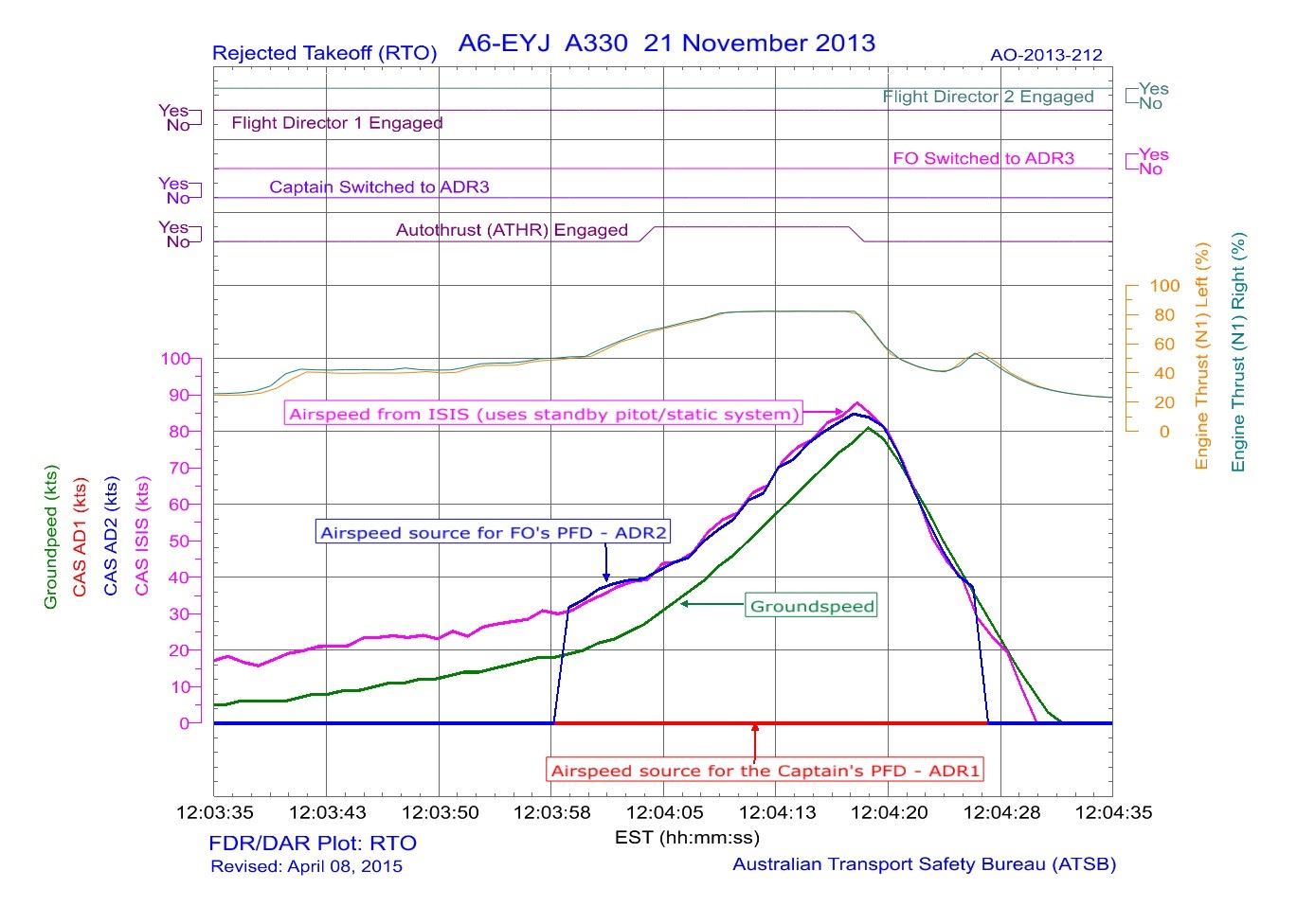
During the RTO the crew reported that a red speed (SPD) flag appeared on the captain’s PFD (Figure 5). One of the conditions for displaying this flag is that no valid[12] airspeed data was available from ADR 1 at the same time as ground speed data was valid and greater than 50 kt. The flight data (Figure 6) showed that CAS sourced from ADR1 (i.e. the CAS that was displayed on the captain’s PFD) was zero when ground speed increased through 50 kt and this is consistent with the crew report.
Figure 5: Location of the ‘Red speed flag’
Source: Airbus (modified by ATSB)
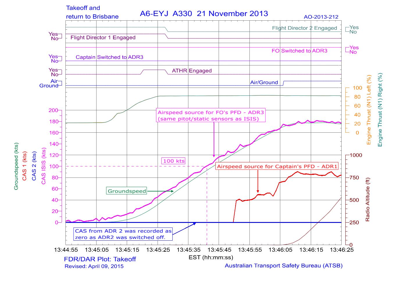
During the second take-off at 1345, the crew reported that the airspeed flag appeared after V1. However, the flight data again showed that CAS sourced from ADR1 (i.e. the CAS that was displayed on the captain’s PFD) was zero when ground speed increased through 50 kt (Figure 7).
Figure 6: Flight data for the rejected take-off
Figure 7: Flight data for the take-off and return to Brisbane
Examination of the captain’s pitot probe
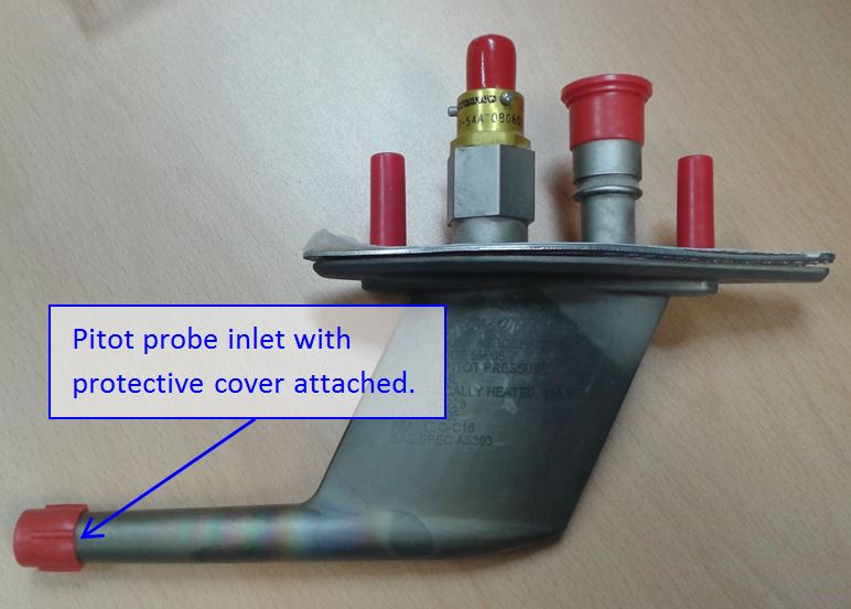
The captain’s probe (model 0851HL and serial number 242228) was removed from the aircraft and sent to the probe manufacturer in the USA (Figure 8). In consultation with the participants in the investigation, a test plan was developed prior to examination and testing of the probe.
Figure 8: Pitot probe
Source: UTC Aerospace Systems
The probe had been continuously fitted to A6-EYJ since its first flight and had been in service for approximately 7 ½ years. Its condition was consistent with its time-in-service with the probe inlet showing wear, but within component maintenance manual (CMM) limits. Visual inspection showed that there was no evidence of obstruction of the drain holes. A borescope examination was performed through the pitot inlet and also through the pneumatic port. The examination showed that the interior of the probe was occluded by an incomplete insect’s nest and the nest material was consistent with that of the mud-dauber wasp (Figure 9). Compressed air was applied to the probe and none of the material was dislodged. The base of the nest was broken away with a sharp instrument and was fully removed by flushing with hot water. After removal of the obstruction, the probe was tested and, according to the CMM, it could be re-certified and returned to service.
Figure 9: View looking into the pitot probe inlet
Source: UTC Aerospace Systems
Other recent occurrences
B737-8FE VH-VUG 3 April 2014 Brisbane 201402626
During take-off, while accelerating through 90 kt, caution message “EEC ALT”[13] annunciated. As engine thrust was normal, the captain continued the take-off. Once airborne, “IAS Disagree” and “ALT Disagree” messages were displayed on the crew’s PFDs and the captain’s stick-shaker[14] operated intermittently. Comparison between the captain’s, FO’s and standby airspeed indications showed that the captain’s airspeed was under-reading significantly. Control of the aircraft was handed over to the FO and the aircraft levelled at 7,000 ft before returning for landing at Brisbane. Later investigation showed that the inlet of the captain’s pitot probe was partly obstructed by material consistent with a mud-dauber wasp nest.
This analysis will consider the factors with the potential to have contributed to the aircraft becoming airborne with only a single valid source of airspeed data.
Mud-dauber wasp activity at Brisbane Airport
The captain’s probe was removed from the aircraft and sent to the probe manufacturer in the US for examination. The examination showed that the interior of the probe was occluded by an incomplete insect’s nest. The aircraft was on the ground at Brisbane for a period of 2 hours and 3 minutes. Despite this relatively short period, the nature of the material recovered from the captain’s pitot probe makes it highly likely that the obstruction was due to mud-dauber wasp activity after the aircraft had landed.
Mud-dauber wasp activity at Brisbane Airport has been investigated previously by the ATSB[15] and continuing reports and incidents indicate that it is an ongoing hazard. As the wasps cannot be completely eradicated, it is necessary to have control measures in place to minimise the chance of a pitot probe becoming obstructed. Following this incident, the Brisbane Airport Corporation (BAC) reviewed their Wildlife Hazard Management Plan (which includes wasp activity). The results of that review are detailed in the Safety Action section.
Pitot probe covers were not installed by maintenance staff during the period the aircraft was at the gate. The maintenance staff advised that the use of pitot covers was dependent on customer requirements and was not a standard practice. Operators can minimise the risk of pitot probe obstruction by consistently using pitot covers, even during short transit periods.
Maintenance action after the rejected take-off
By following the TSM procedures for an ‘ADIRU1 (1FP1) BUS ADR’ fault message, the aircraft maintenance engineer performed a BITE test of the EFCS 1 and 2. The units tested with normal indications and no faults were identified. The TSM procedure did not specifically identify the pitot probe as a possible cause.
Although no ‘hard’ (permanent) faults had been identified, the engineer, in consultation with the operator’s Maintenance Control Centre, considered that the best resolution would have been to make ADR 1 inoperative. However, this was not permitted under the MEL requirements for ETOPS[16] dispatch. Therefore the engineer transposed ADIRU 1 and 2 and performed a BITE test of both units. The aircraft was dispatched with the ADR part of ADIRU 2 inoperative (switched off) in accordance with the MEL. The FO’s air data source was switched to ADIRU 3 and the captain’s air data source remained switched to the normal (ADIRU 1) position. As a result, the blocked captain’s pitot probe remained undetected and the aircraft was dispatched with only one of the three airspeed sources able to provide valid data.
Airspeed monitoring during take-off
The SOPs require the PM to scan airspeed throughout the take-off and for the PF to cross-check airspeed at 100 kt. A red flag is displayed on the captain’s PFD when no valid airspeed data was available from ADR 1 at the same time as ground speed data was valid and greater than 50 kt.
The crew reported that during the RTO, a red airspeed flag was displayed on the captain’s PFD. This is consistent with the flight data, which showed that the captain’s CAS remained fixed at zero. During the RTO the maximum recorded CAS was 88 kt, so the take-off was able to be rejected below V1 (151 kt).
During the second take-off roll, the crew reported that the red airspeed flag was not apparent until after V1. However, the recorded flight data again indicated that it was likely that a red airspeed flag would have been displayed on the captain’s PFD, after the groundspeed had reached 50 kt.
As a result, the aircraft became airborne with only a single valid source of airspeed information, with consequential serious degradation of other aircraft systems.
From the available evidence, the following findings are made with respect to the air data system failure involving an Airbus A330 aircraft, registered A6-EYJ, that occurred near Brisbane Airport, Queensland on 21 November 2013. These findings should not be read as apportioning blame or liability to any particular organisation or individual.
Safety issues, or system problems, are highlighted in bold to emphasise their importance. A safety issue is an event or condition that increases safety risk and (a) can reasonably be regarded as having the potential to adversely affect the safety of future operations, and (b) is a characteristic of an organisation or a system, rather than a characteristic of a specific individual, or characteristic of an operating environment at a specific point in time.
Contributing factors
Pitot probe covers were not installed by maintenance staff during the period that the aircraft was at the gate.
The captain’s pitot probe was almost totally obstructed by an insect nest, consistent with mud-wasp residue, during the 2 hour and 3 minute period while the aircraft was in transit on the ground at Brisbane.
The blocked captain’s pitot probe was not detected by engineering staff after the initial rejected take-off. The relevant tasks in the trouble shooting manual did not specifically identify the pitot probe as a potential source of airspeed indication failure. [Safety issue]
During the second take-off roll, the faulty airspeed indication (displayed on the captain’s PFD) was not detected and acted upon by the crew before V1 and the take-off was continued.
Safety issues and actions
The safety issues identified during this investigation are listed in the Findings and Safety issues and actions sections of this report. The Australian Transport Safety Bureau (ATSB) expects that all safety issues identified by the investigation should be addressed by the relevant organisation(s). In addressing those issues, the ATSB prefers to encourage relevant organisation(s) to proactively initiate safety action, rather than to issue formal safety recommendations or safety advisory notices.
Depending on the level of risk of the safety issue, the extent of corrective action taken by the relevant organisation, or the desirability of directing a broad safety message to the aviation industry, the ATSB may issue safety recommendations or safety advisory notices as part of the final report.
Identification of pitot probe in the trouble shooting manual
Safety issue description:The relevant tasks in the trouble shooting manual did not specifically identify the pitot probe as a potential source of airspeed indication failure.
Additional safety action
Whether or not the ATSB identifies safety issues in the course of an investigation, relevant organisations may proactively initiate safety action in order to reduce their safety risk. The ATSB was advised of the following proactive safety action in response to this occurrence:
Brisbane Airport Corporation (BAC)
Once it had been determined that the pitot probe had been blocked due to insect activity, the BAC undertook the following actions:
Implemented a weekly inspection and eradication program for the International Terminal Building (ITB) to replace the monthly inspections which had been undertaken since 2006;
Implemented a weekly inspection and eradication program for the Common User – Domestic Terminal Building (DTB) and Terminal Services Building (TSB);
Engaged an entomologist to provide BAC and stakeholders with a better understanding of wasp activity, habits and behaviour;
Issued a NOTAM to communicate wasp activity;
Issued external stakeholder communication including to the following forums (Wasp specific meeting, Airside Safety Committee, Wildlife Working Group, Local Runway Safety Team);
Supplied wasp nests and wasps to the Australian Museum for DNA and stomach content analysis;
Extended the pest management program to include removal of spider webs (spiders are a food source for wasps);
Acquired pitot probes from Qantas and Virgin Australia to undertake research as to what aircraft type pitot tube is likely to be at a greater risk; and
Identified amendments to be made to the BAC Wildlife Hazard Management Plan (WHMP) which include wasp activity.
Etihad
Following this incident, the operator reviewed their policy on the use of protective covers and included a specific requirement for Brisbane: pitot probe covers and total air temperature covers should be used at Brisbane, irrespective of the ground time.
Civil Aviation Safety Authority (CASA)
CASA has drawn attention to the safety implications of mud wasp activity through the following publications:
The CASA Briefing for May 2015 ‘Be alert and alarmed about wasps’
Flight Safety Australia feature article of 27 July 2015 ‘Small but dangerous …’
These documents are available on the CASA website.
Sources and submissions
Sources of information
The sources of information during the investigation included the:
crew of A6-EYJ
the aircraft maintenance provider
the aircraft’s flight recorders
Airservices Australia
Bureau of Meteorology
UTC Aerospace Systems
Brisbane Airport Corporation
Airbus
Etihad Airways.
References
Australian Transport Safety Bureau, 2008, Rejected take-off, Brisbane Airport, Qld, 19 March 2006 VH-QPB Airbus A330-303, Transport Safety Occurrence Report 200601453.
Submissions
Under Part 4, Division 2 (Investigation Reports), Section 26 of the Transport Safety Investigation Act 2003 (the Act), the Australian Transport Safety Bureau (ATSB) may provide a draft report, on a confidential basis, to any person whom the ATSB considers appropriate. Section 26 (1) (a) of the Act allows a person receiving a draft report to make submissions to the ATSB about the draft report.
A draft of this report was provided to Etihad Airways, Airbus, pitot probe manufacturer, flight crew, Brisbane Airport Corporation and the Civil Aviation Safety Authority for comment.
Submissions received from those parties were reviewed and where considered appropriate, the text of the report was amended accordingly.
Purpose of safety investigations
The objective of a safety investigation is to enhance transport safety. This is done through:
identifying safety issues and facilitating safety action to address those issues
providing information about occurrences and their associated safety factors to facilitate learning within the transport industry.
It is not a function of the ATSB to apportion blame or provide a means for determining liability. At the same time, an investigation report must include factual material of sufficient weight to support the analysis and findings. At all times the ATSB endeavours to balance the use of material that could imply adverse comment with the need to properly explain what happened, and why, in a fair and unbiased manner. The ATSB does not investigate for the purpose of taking administrative, regulatory or criminal action.
Terminology
An explanation of terminology used in ATSB investigation reports is available here. This includes terms such as occurrence, contributing factor, other factor that increased risk, and safety issue.
Publishing information
Released in accordance with section 25 of the Transport Safety Investigation Act 2003
Ownership of intellectual property rights in this publication
Unless otherwise noted, copyright (and any other intellectual property rights, if any) in this report publication is owned by the Commonwealth of Australia.
Creative Commons licence
With the exception of the Coat of Arms, ATSB logo, and photos and graphics in which a third party holds copyright, this publication is licensed under a Creative Commons Attribution 3.0 Australia licence.
Creative Commons Attribution 3.0 Australia Licence is a standard form licence agreement that allows you to copy, distribute, transmit and adapt this publication provided that you attribute the work.
The ATSB’s preference is that you attribute this publication (and any material sourced from it) using the following wording: Source: Australian Transport Safety Bureau
Copyright in material obtained from other agencies, private individuals or organisations, belongs to those agencies, individuals or organisations. Where you wish to use their material, you will need to contact them directly.