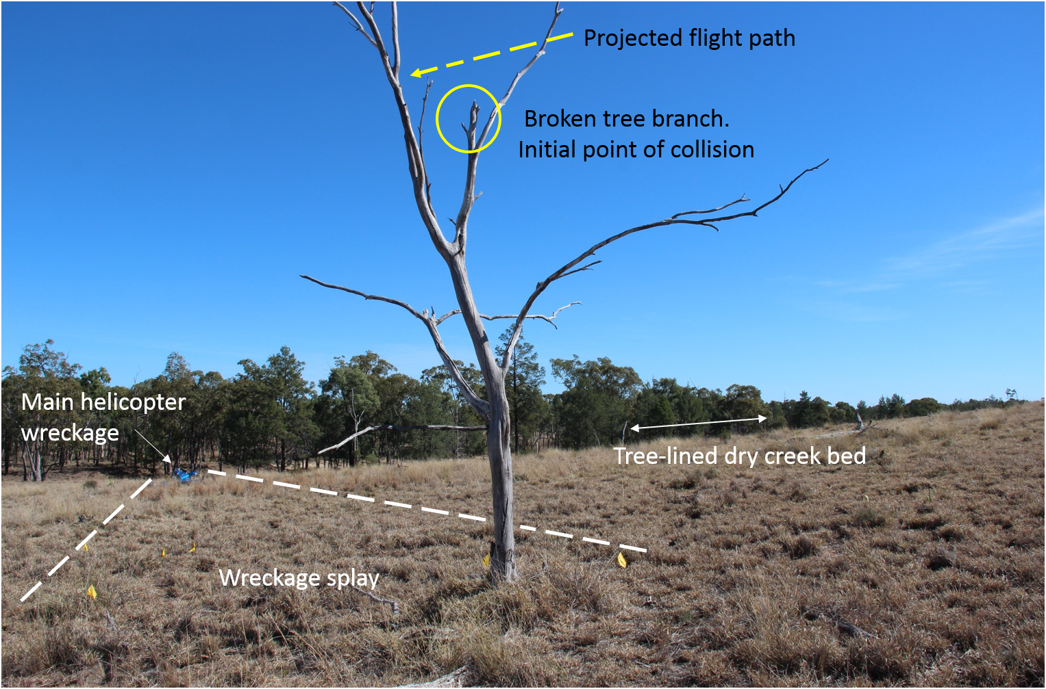
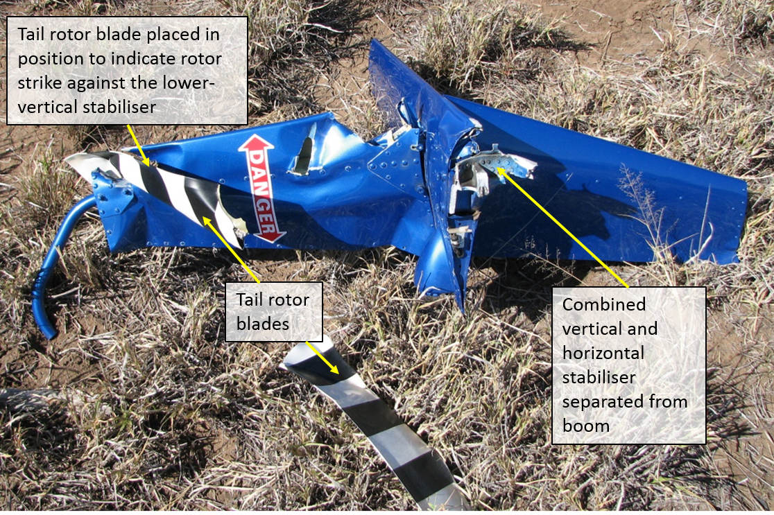
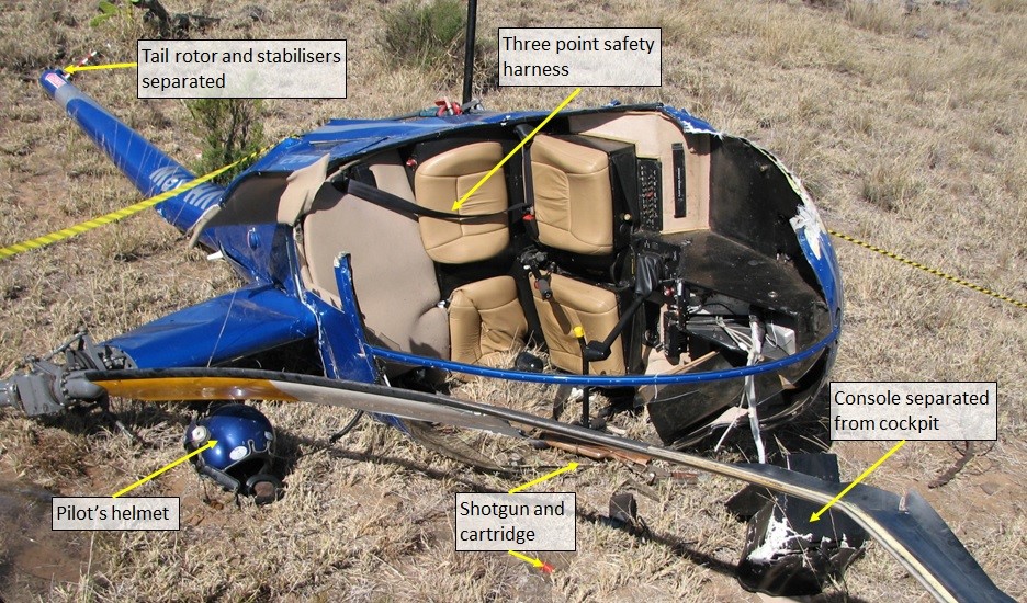
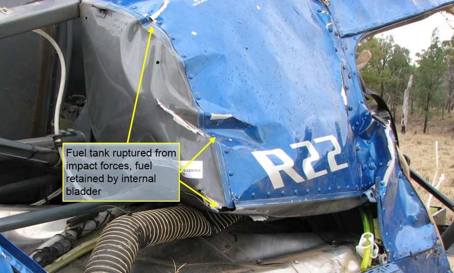
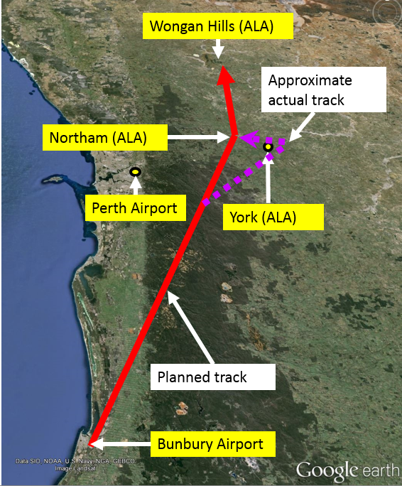
On 19 February 2015, a Robinson R44 helicopter, registration ZK-IPY, collided with terrain 12 km south-west of Queenstown Airport, New Zealand.
The New Zealand Transport Accident Investigation Commission (TAIC) conducted an investigation into the circumstances of the accident. As part of its investigation, TAIC requested technical assistance from the ATSB. To protect any information supplied by TAIC to the ATSB, and the ATSB's investigative work to assist TAIC, the ATSB initiated an investigation under the Transport Safety Investigation Act 2003.
The ATSB has finalised its work in support of the TAIC investigation and TAIC is responsible for the release of the final investigation report. Any enquiries in respect of the TAIC investigation or release of the investigation report should, in the first instance, be directed to the TAIC at: www.taic.org.nz.
Transport Accident Investigation Commission Level 16 80 The Terrace PO Box 10323 Wellington, 6143 New Zealand
_________________
The information contained in this web update is released in accordance with section 25 of the Transport Safety Investigation Act 2003.
Occurrence summary
Investigation number
AE-2015-059
Occurrence date
19/02/2015
Location
12 km south-west of Queenstown Airport, New Zealand
On 29 May 2015, an empty VLocity type passenger train was being transferred from Waurn Ponds to Geelong, passing through Marshall and South Geelong stations enroute and without stops. The empty-cars train was following a Melbourne-bound service.
When the empty-cars approached Marshall, the Distant signal for this location was displaying Caution. This indicated that at least one of the Home signals in advance was at Stop. The train’s speed was reduced in response to this indication, but was subsequently increased to above 100 km/h as the train continued towards Marshall Railway Station.
Nearing Marshall station platform, the driver observed the next Home signal at Stop and applied the train’s brakes. However, the train could not be stopped before it passed this signal and the next, which were both at Stop.
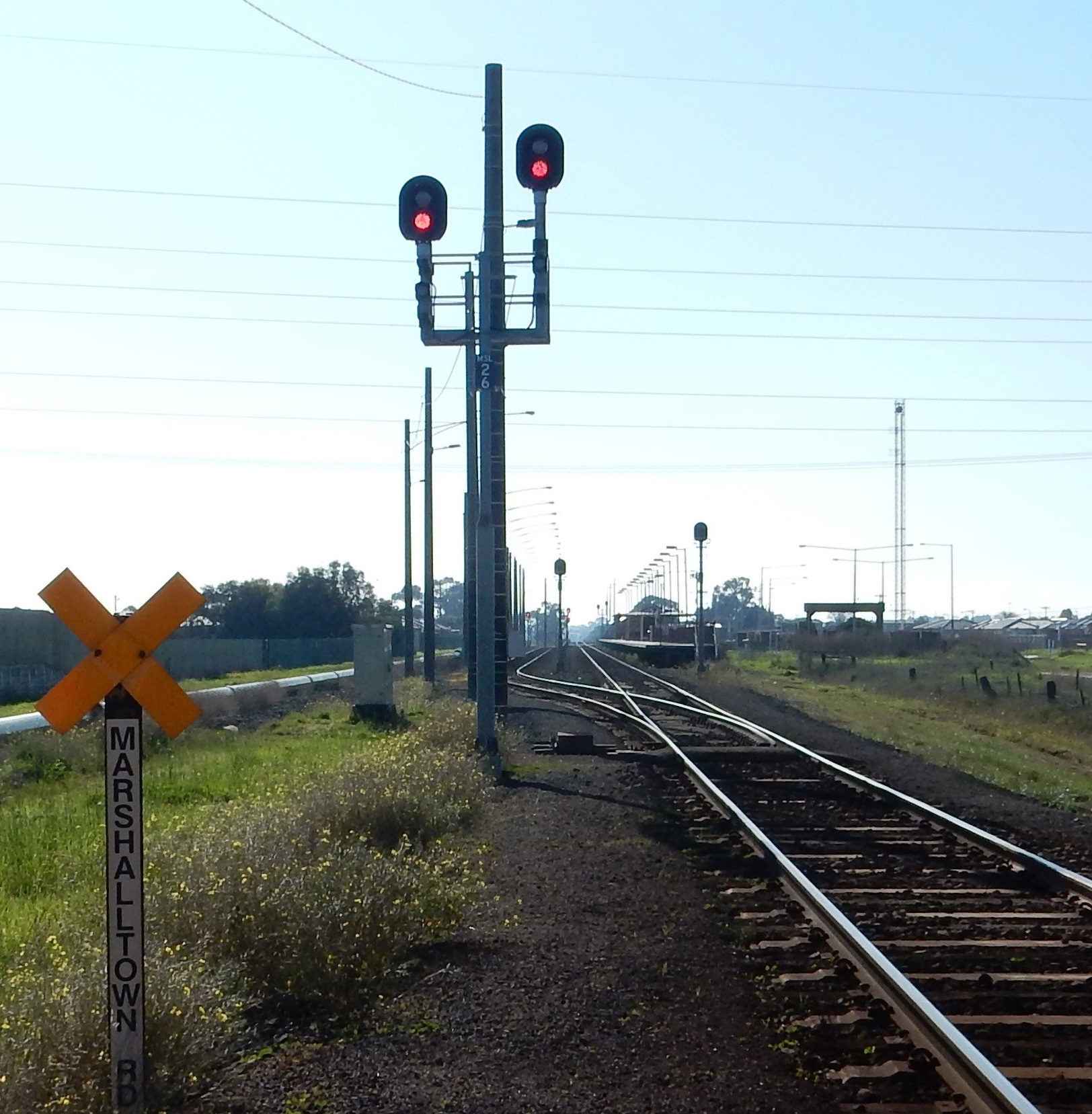
Marshalltown Road level crossing intersects with the railway about 140 m beyond Marshall Station and the empty cars entered the crossing before the warning devices activated.
There was no collision at the crossing, no injuries, and no damage to any infrastructure as a consequence of this incident.
What the ATSB found
The ATSB found that the driver of the empty-cars did not respond appropriately to the two-position signal indications through the Marshall location, including the Caution indication on the Distant signal. The speed of the train was too high as it approached Marshall station and as a result the train could not be stopped in response to observing the next signal at Stop.
The driver had recently qualified to drive passenger services and this was his first shift driving without supervision. It was found that the training had not adequately prepared the driver for the sequence of two-position signals at this location. The predominant signalling on the Melbourne-Geelong corridor is three-position.
The ATSB also found that the rule that described the required driver response to a Distant signal at Caution in a two-position signalling system did not fully reflect the design principles for this type of signalling configuration.
Since the re-establishment of Marshall station, rail passenger traffic through Marshall had increased tenfold, and there was scope to enhance the signalling configuration.
What's been done as a result
Immediate actions by V/Line included imposing temporary speed restrictions for this location and retraining the driver in two-position signalling. V/Line also developed a simulator session to improve driver training in two-position signalling.
V/Line advised that funding has been secured for the development of a business case and feasibility study for a track and signalling upgrade of the South Geelong – Waurn Ponds section.
ATSB has recommended that V/Line amends the rule for the required driver response to a Distant signal at Caution.
Safety message
Operating rules and Driver training should align with the underlying principles of a network’s signalling infrastructure.
The occurrence
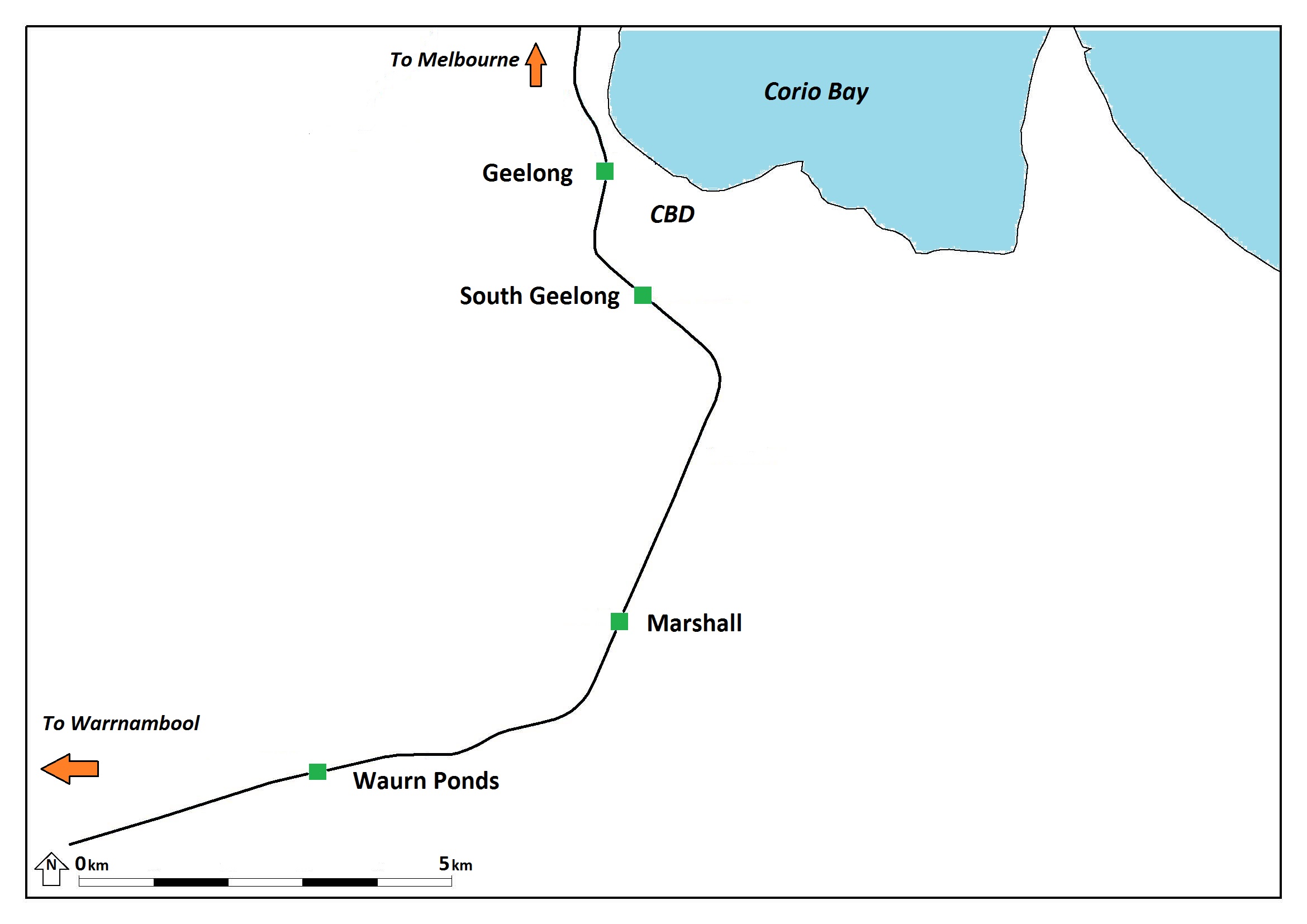
At about 1900 on 29 May 2015, the 1744 passenger service from Melbourne arrived at Waurn Ponds. Waurn Ponds is a suburb of Geelong, a regional city about 65 km southwest of Melbourne, Victoria. The section between Geelong and Waurn Ponds station is about 12 rail km and passes through South Geelong and Marshall Stations (Figure 1).
Figure 1: The route between Geelong and Waurn Ponds stations
Source: PASS Assets (Public Transport Victoria) adapted by Chief Investigator, Transport Safety (Vic)
The car-set and its driver was scheduled to return empty-cars to Geelong where the train would form a service to Melbourne. To allow a Melbourne-bound service from Warrnambool to pass through the section, the empty train was shunted into the siding at Waurn Ponds.
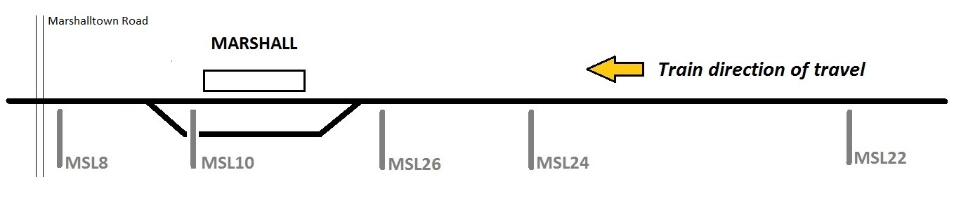
After the passage of the Melbourne-bound train (Train 8250), Train 1240 (the empty-cars) was signalled onto the mainline towards Marshall. It increased speed and travelled at between 80 and 90 km/h as it passed Waurn Ponds station. About a kilometre past Waurn Ponds, the train encountered Distant signal MSL22. This signal, about 3.6 km before Marshall Station, was the first of five signals that controlled Geelong-bound traffic on the mainline through Marshall (Figure 2).
Figure 2: The signals controlling Geelong-bound rail traffic through Marshall
Source: Chief Investigator, Transport Safety (Vic)
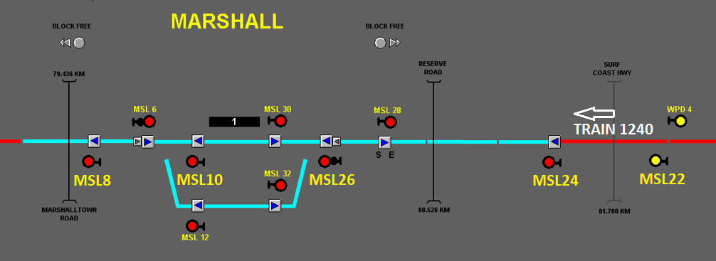
Distant signal MSL22 was at Caution when the train passed, and the signals ahead were at Stop (Figure 3). In response to the Caution indication of MSL22, the driver reduced the speed of the train from 83 km/h to 67 km/h.
Figure 3: Signal status when Train 1240 passed Distant Signal MSL22. MSL22 was at Caution (yellow), and other signals ahead were at Stop (Red). The red highlight on the line adjacent to MSL22 is indicating that Train 1240 is detected in the section.
Source: Geelong Regional Signalling Centre, extract and annotation of VDU recording by Chief Investigator, Transport Safety (Vic)
The next signal, Home signal MSL24, was located 2,276 m past the Distant signal. As the train travelled towards it, the signal indication changed from Stop to Proceed. Signalling through this section was two-position, meaning that Stop was indicated by a red light, and Proceed by a green light. Home signals in a two-position signalling system do not provide information on the required train speed, nor the condition of the next signal.
When the train was about 900 m from MSL24 and following the driver’s observation of its Green (Proceed) aspect, the speed of the train was increased. The train’s speed was about 90 km/h passing signal MSL24. As the train continued towards Home signal MSL26 that was 1,280 m away and at Proceed, its speed further increased. The train’s speed peaked at 105 km/h shortly after passing signal MSL26.
Soon after passing signal MSL26, the driver observed Home signal MSL10 at Stop, and probably also the next Home signal, MSL8, that was also at Stop. Both were at Stop because the train ahead had not yet cleared into South Geelong.
In response to the Stop indications, the driver made a brake application that within about five seconds progressed to an emergency application. Train 1240 could not be stopped in the distance available and passed Home signal MSL10 travelling at about 80 km/h and then Home signal MSL8 at about 60 km/h. In each instance, the signal was passed at Stop without authority resulting in a Signal Passed at Danger (SPAD) event.
The train then entered the Marshalltown Road level crossing travelling at about 50 km/h. The warning devices (lights and bells) began with the train on the crossing and the boom barriers lowered about 10 seconds later. There were no road vehicles nor pedestrians attempting to cross as the train entered the unprotected crossing. However, shortly prior, a route bus and light truck had traversed the crossing, 30 and 15 seconds prior respectively.
The train came to a stand with its leading cab about 80 m passed the crossing. There were no injuries resulting from the incident. The incident occurred at about 1932.
After reporting the incident, the driver was authorised to shunt the empty cars back into the crossing loop at Marshall. He was then stood aside from driving duties. A breath test was conducted with a zero alcohol result. Testing for the presence of drugs was not conducted.
Context
Marshall and surrounds
Development in southern Geelong
Marshall Railway Station had been closed in 1958. It was re-established in 2004 to serve the expanding southern suburbs of Geelong, and the demand for commuter services to Melbourne.
The re-development of Marshall was a State funded and managed project. During this period, lease arrangements and management of the regional network was transferred (in 2004) from Freight Australia Limited to Pacific National. Track management of the network was subsequently transferred to V/Line in 2007.
Marshall Station was re-established with a single platform serviced by the bi-directional mainline. The development included the introduction of a loop to cater for the crossing of trains and terminating locomotive hauled passenger trains from Melbourne. The loop allowed the locomotive to be ‘runaround’ the consist for the return trip to Melbourne. The signalling was designed to allow this locomotive movement to occur without the fouling or activation of the Marshalltown Road level crossing. There was nothing unusual about this configuration for these operations.
With the introduction of VLocity type DMU trains into the Geelong corridor, the use of locomotive hauled trains terminating at Marshall diminished significantly.
Waurn Ponds Railway Station was established in September 2014. A holding siding to shunt trains clear of the mainline was provided about two kilometres from this station, towards Warrnambool.
Waurn Ponds became the normal terminating point for trains travelling to the southern suburbs of Geelong and as a result, terminations at Marshall became less common.
Safeworking system background
Prior to the re-establishment of Marshall Station, Train Order Working[1] was in place for the single line section between South Geelong and Winchelsea (about 40 km west of Geelong). When re-established, Marshall became an Intermediate Terminal Station for the two sections South Geelong - Marshall and Marshall - Winchelsea.
Then, in September 2005, the Train Staff and Ticket Safeworking System[2] was introduced between South Geelong and Marshall and Marshall was made an attended Train Order Station. The signalling system at Marshall was to be operated locally and manned for all trains.
In December 2005, further changes to the safeworking arrangements were made. The sections between South Geelong and Marshall were altered to operate under the Track Block Safeworking System, and the operation of the signalling at Marshall was transferred to the Geelong Regional Signalling Centre.
Track Block Safeworking System
The operating rules and procedures applicable to the Track Block Safeworking System were described in Section 32 of the 1994 Book of Rules and Operating Procedures. The object of the system was to prevent more than one train being on the same line in the section between two adjoining locations. This was achieved by the signaller not being able to place the signal controlling the entrance to the Track Block single line section to the Proceed position until the preceding train had exited the section.
The Track Block Safeworking System was in use on the Victorian broad-gauge network between:
Newport - Brooklyn (West line)
Brooklyn - Sunshine
Geelong – Waurn Ponds
The Geelong-Waurn Ponds section was the only passenger line where it applied.
Signalling arrangements through Marshall
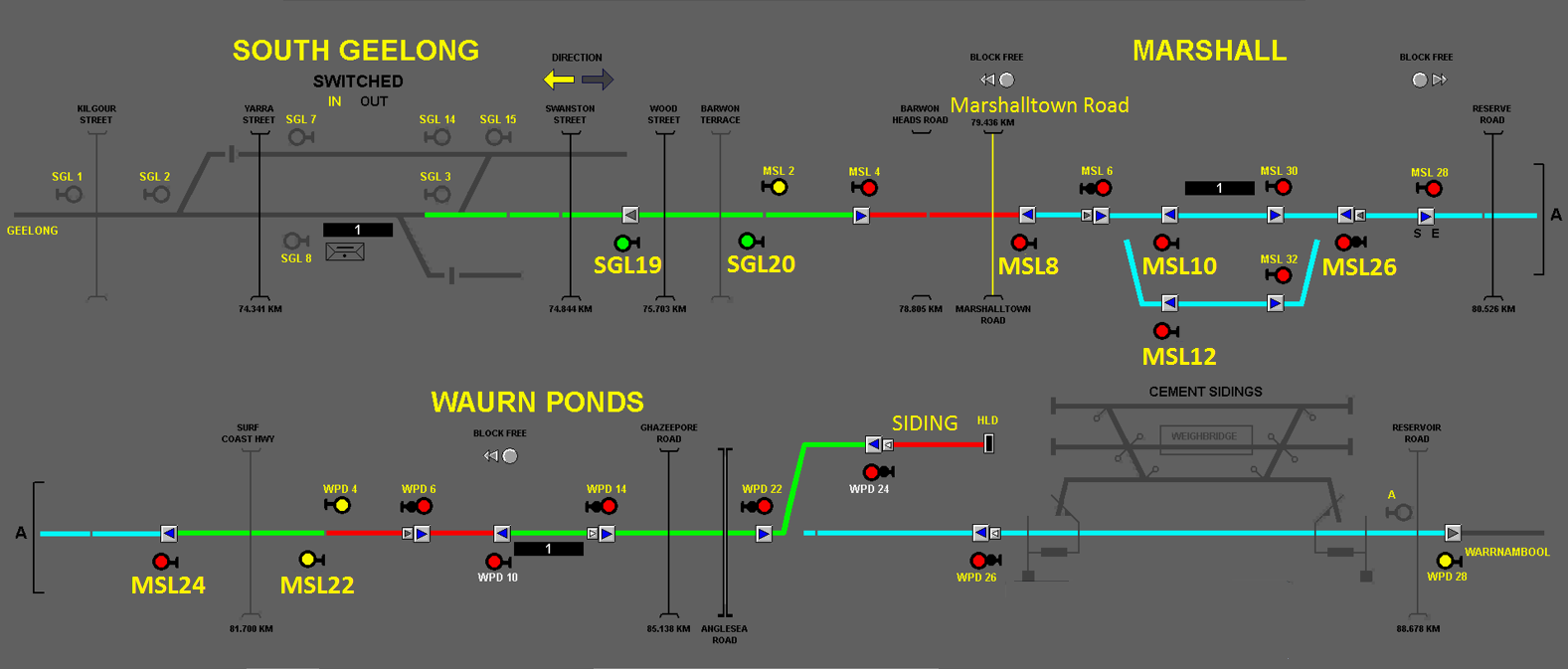
Two-position coloured-light fixed signalling was in place between South Geelong – Marshall – Waurn Ponds. The signal numbers relevant to this event are shown enlarged on an extract of the signalling control display (Figure 4).
Figure 4: Extract of signalling control display South Geelong - Marshall - Waurn Ponds
Source: V/Line Geelong Regional Signalling Centre, extract and annotation of VDU recording by Chief Investigator, Transport Safety (Vic)
The Marshall location had a signal sequence on the mainline in each direction of a Distant signal followed by a series Home signals. For Geelong-bound traffic, the signal sequence through Marshall was:
MSL22 (Distant signal)
MSL24 (Home signal)
MSL26 (Home signal) that had signals for the mainline and the loop track
MSL10 (Home Signal) and MSL12 (on the Loop track)
MSL8 (Home signal).
Signal control through Marshall
At the time of the incident, signalling control for Marshall was managed from the Geelong Regional Signalling Centre. This control function has since been relocated to Centrol[3] in Melbourne.
At Geelong, the relevant control workstation provided for remote control and monitoring of the signalling system between South Geelong[4] and Waurn Ponds. Signallers could observe the status of all the signalling in the area of control by means of a VDU Panel. The VDU panel also provided the means of operating the points and signals.
The signaller had control of all Home signals at Marshall. For Geelong-bound rail traffic, the Home signals could be operated individually or a through-route set such that signals would clear when the section ahead became available for following trains.
The signaller cannot control distant signal MSL22. The aspect of MSL22 was governed by the status of the Home signals through the location and functioned automatically. If all mainline Home signals at Marshall were clear, MSL22 would indicate Proceed (Green aspect), and if any was at Stop, MSL22 would indicate Caution (Yellow aspect).
Marshalltown Road level crossing activation
For trains approaching from Waurn Ponds when signals were at Proceed, a fixed track circuit activated the Marshalltown Road level crossing protection. This ensured that the crossing protection was activated in sufficient time prior to the arrival of the train.
When signal MSL8 was at Stop, the level crossing warning circuits were inhibited. This was to allow locomotive runaround movements without activating the crossing protection. Because of this configuration, Train 1240 did not trigger the crossing protection until it was beyond signal MSL8.
System protection for a train exceeding its authority
The two-position signalling system at Marshall did not include any additional controls to protect against a train exceeding its authority.
Waurn Ponds was commissioned about 10 years after Marshall and did include additional features to manage this risk. All Home signals at Waurn Ponds were fitted with Train Stop TPWS[5] to stop trains that passed a signal at Stop.
Signalling playback – recording of sequence of events
The status of signals and the movement of trains through the section were captured on the recording of the signaller’s display located at Geelong. The colour of the track section also provides an indication of its status with:
Red indicating the presence of a train in the section
Green indicating the track is clear and the route is set
Blue indicating the track is clear but no route is set.
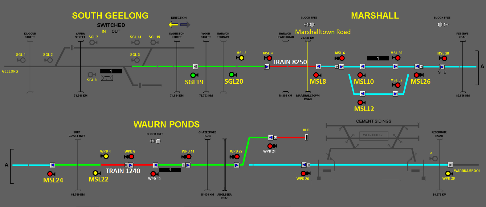
At about 1922 after departing the siding, Train 1240 was travelling between Waurn Ponds and Marshall (Figure 5). At this time Train 8250 (the train ahead) had passed through Marshall Station and the Marshalltown Road level crossing had activated (road shown highlighted yellow). Another train was in the Waurn Ponds siding waiting to follow 1240.
Figure 5: Extract of VDU screen at 19:22:07 showing train 1240 travelling between Waurn Ponds and Marshall, approaching Distant signal MSL22 at Caution. The signals through Marshall are at Stop. The train ahead (8250) has passed through Marshall Station.
Source: Geelong Regional Signalling Centre, extract and annotation of VDU recording by Chief Investigator, Transport Safety (Vic)
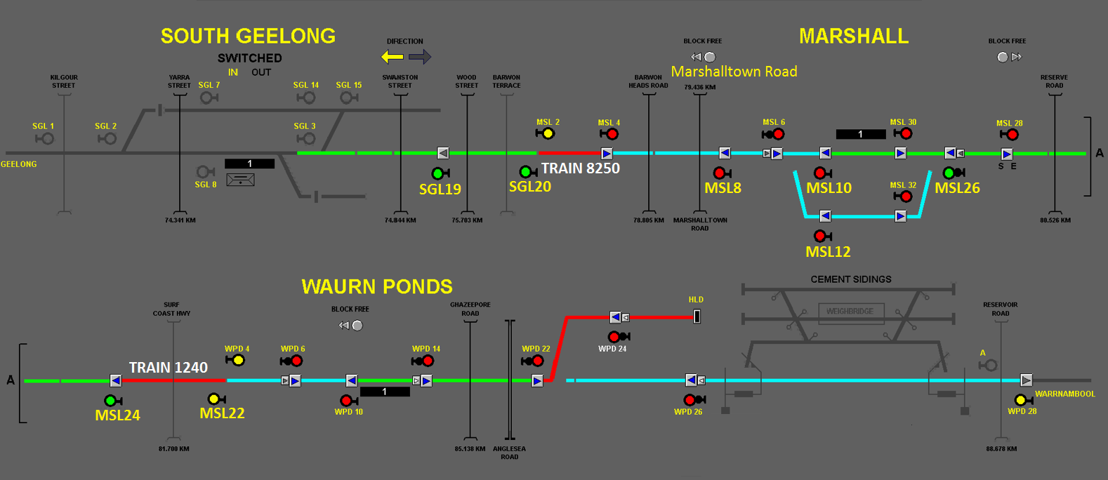
After Train 1240 passed Distant signal MSL22, MSL24 went to Proceed. The VDU screen at 19:23:03 showed MSL24 at Proceed and MSL26 still at Stop. All other Marshall signals were also at Stop.
Before Train 1240 passed MSL24, Home signal MSL26 also went to Proceed (Figure 6). At this point, the train ahead was approaching the Distant signal for South Geelong (SGL20), that was at Proceed (Green). Because this train was still occupying the section between MSL8 and SGL20, signals MSL10 and 8 were not yet cleared to Proceed.
Figure 6: Extract of VDU screen at 19:23:05 showing MSL26 now at Proceed. MSL10 and MSL8 are at Stop
Source: Geelong Regional Signalling Centre, extract and annotation of VDU recording by Chief Investigator, Transport Safety (Vic)
The VDU screen at 19:24:31 shows that the preceding train (8250) had passed the Distant signal for South Geelong, SGL20, at around the time Train 1240 had passed MSL24. Train 8250 had not yet passed SGL19 and signals MSL10 and MSL8 had not yet cleared to Proceed.
The VDU screen at 19:25:26 shows that Train 1240 had passed Home signal MSL26, which had reverted to Stop. MSL10 was still at Stop and soon to be passed by Train 1240 without authority. Marshalltown Road level crossing had not yet not activated.
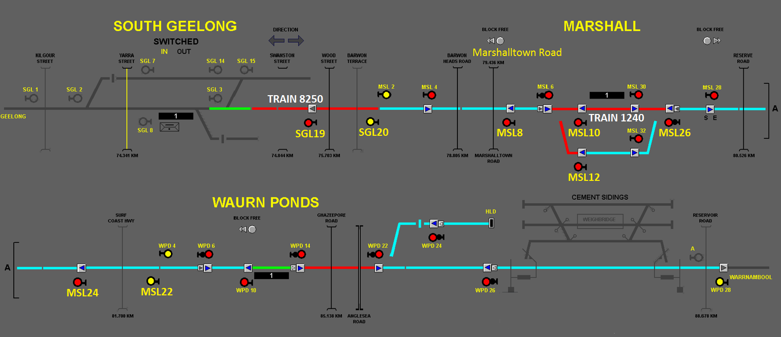
A few seconds later, Train 1240 had passed MSL10 at Stop (Figure 7) and was soon to pass MSL8 at Stop. Train 8250 was still progressing past SGL19. The headway between the two trains was such that Train 1240 needed to stop at Marshall to wait for Train 8250 to clear the section ahead.
Figure 7: Extract of VDU screen at 19:25:29 showing Train 1240 had now passed signal MSL10 at Stop
Source: Geelong Regional Signalling Centre, extract and annotation of VDU recording by Chief Investigator, Transport Safety (Vic)
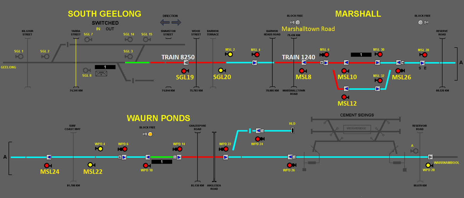
A short time later, MSL8 had also been passed at Stop (Figure 8). The Marshalltown level crossing protection was not yet active.[6]
Figure 8: Extract of VDU screen at 19:25:34 showing that Train 1240 has now passed signal MSL8 at Stop. The Marshalltown Road level crossing warning protection has not yet activated. Train 8250 has not completely cleared SGL19.
Source: Geelong Regional Signalling Centre, extract and annotation of VDU recording by Chief Investigator, Transport Safety (Vic)
Two-positioning signalling
Background
Two-position signalling was once common in Victoria but its use had declined. Two-position signals are route signals that apply to a single route. They do not provide drivers with information on the aspect of the next signal, nor specific guidance on the train speed to the next signal.
Home signals
Two-position Home signals are displayed as light signals or semaphores, although semaphore signals have become increasingly rare. Light signals come in various configurations and show either a red or green aspect (Figure 9).
Figure 9: Aspects of two-position Home signals
Signal number
Signal aspect
Signal meaning
Home signals:
MSL24
MSL26
MSL10
MSL8
STOP
Train must Stop at Signal
PROCEED
Train can Proceed to next Signal
Source: ATSB
Home signals with two indications on the same signal post
Where multiple routes are available, signals are mounted either on a bracket post or arranged vertically on a single post. MSL26 was fitted with lights on brackets (Figure 10). A Proceed aspect (Green) is only shown for the route for which the points are locked and detected.
Figure 10: Multiple route two-position signal MSL26, with two light signals. • The right hand signal provided an indication for the straight route and had a Green aspect (Proceed) for the passage of Train 1240.• The left hand signal provided a signal indication for the loop track and was red for Train 1240.
Source: Chief Investigator, Transport Safety (Vic)
Distant Signals
Configuration
Distant signals are located ahead of the first home signal for a location and provide information to drivers on the indication of Home signals on the through route. Distant signals are located no less than the braking distance for the line speed ahead of the first home signal at the location.
Distant signals (Figure 14) can be displayed as light signals or semaphores, although the use of semaphore Distant signals has become increasingly rare on the V/Line network.
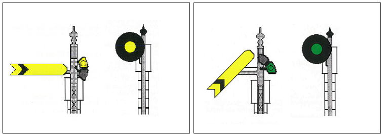
Distant signals display two aspects:
Yellow, indicating Caution and meaning that one or more of the Home signals applicable to the same line at that location may be at Stop.
Green, indicating Proceed and meaning that all Home signals applicable to the same line at that location are at Proceed.
Figure 11: Distant signal aspects, Yellow (indicating Caution) and Green (indicating Proceed), as they appear in V/Line training material. The semaphore configuration, shown on the left for each aspect, is used for V/Line assessments on Distant signals.
Source: V/Line driver training courseware
Rules and Procedures pertaining to Distant signals
Section 2 part 5 of the Book of Operating Rules and Procedures 1994[7] stated in part:
A Distant signal at the Proceed position indicates all other signals applicable to the same line as the Distant signal are also at Proceed.
When the driver observes a Distant signal at Caution, the train must be slowed to a precautionary speed to allow the train to be safely stopped at the next signal if that signal displays Stop.
In the description of the driver’s response to a Caution indication, there was no reference to the possibility of subsequent Home signals through the location being at Stop.
Victorian Rail Industry Operators’ Group (VRIOG)
The Victorian Rail Industry Operators’ Group (VRIOG)[8] was a collaborative committee made up of rail operators and transport agencies. The purpose of the group was to establish standards to facilitate the interoperability of operations and infrastructure to enhance network safety.
VRIOG Standard 012.0 Victorian Signalling Principles Section 4 described signalling principles, signals, and points, interlocking, track vacancy detection, level crossings, and signalled single lines and proceed authorities.
Section 4.1.5 of this VRIOG standard described, in part:
Two position signals are route signals. Each signal applies to one route only. Two position signals do not provide information about what speed the train should travel; nor do they provide information about the aspect of the signal ahead.
Distant signals provide information regarding the state of Home signals on the through route at an interlocking:
If all of the signals ahead are at Proceed, the Distant signal can display a Green aspect.
If any one of the signals ahead is at Stop the Distant signal will display a Yellow aspect.
Three-position signalling
Three-position signalling was the predominant signalling type in the Melbourne metropolitan and RFR (Regional Fast Rail) areas and was in use between Melbourne and Geelong.
Three-position signals use a minimum of two lights to convey the signal indication that may apply to several routes in advance. The multiple light configuration differentiates a three-position signal from a two-position signal that will only display a single light.
Three position signals convey information to a train driver regarding the:
permitted speed of the train over the block ahead
aspect of the signal ahead.
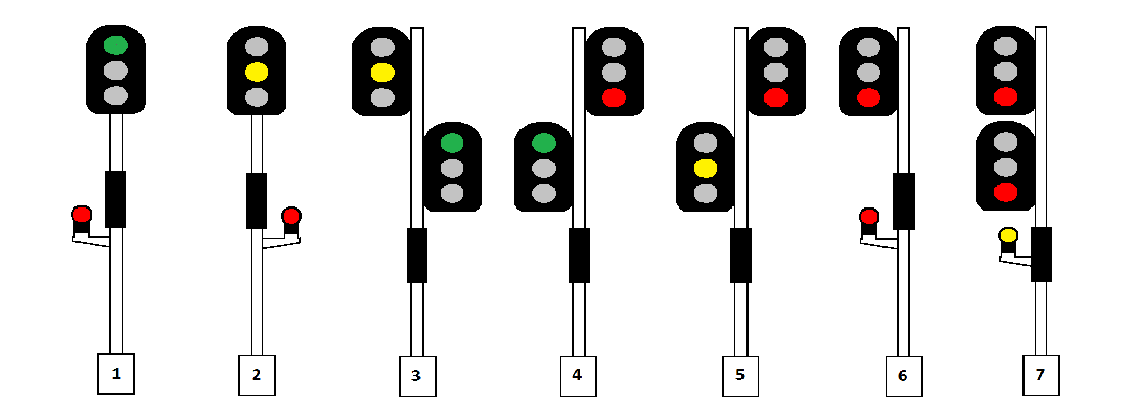
Three position-signals come in a range of physical configurations and the possible aspects of a particular signal will be tailored to the needs of a location. There are seven indications[9] that can be displayed by three-position signals in Victoria, in all instances using at least two lights (Figure 12).
Figure 12: Three-position signal aspects. Three-position signals can have various physical configurations. The illustrated signals are to present the light aspects only.
Source: Chief Investigator, Transport Safety (Vic)
The driver
Prior to joining V/Line, the driver had about five years experience operating freight trains between Echuca and Deniliquin. This territory was low traffic volume and low speed. Signalling was two-position, but without Distant signals.
The driver commenced employment with V/Line in October 2014 and was assigned to the Southern Cross driver’s depot. He had recently qualified to operate V/Line passenger trains on all lines worked by Melbourne based drivers. His medical was current with no restrictions recorded.
Prior to the incident shift, the driver had been rostered on shifts of eight hours duration working in and around Southern Cross Station on non-passenger services. His previous shift on 27 May 2015 was rostered to finish at 2000. He then travelled to Echuca to visit his family, returning to Melbourne on 29 May to be in position for the start of his shift at 1400. Roster induced fatigue is not considered to be a factor in this incident.
The shift on 29 May was the driver’s first operating passenger services without supervision.
Driver training
Scope
This driver commenced his training with V/Line in October 2014. Because of his previous operational experience, the driver was enrolled on the V/Line Conversion Driver Training Plan (Freight Train SCS-Regional Centres Conversion Training Plan). This training had a minimum duration of 21.4 weeks and comprised both classroom and in-field practical training.
He was required to complete all training modules covering train operations on the V/Line network including signalling and Safeworking. Some exemptions in subjects were provided in recognition of the driver’s freight experience, but none in subjects relevant to the circumstances of this incident.
The training module and assessments completed for two-position signals was the same as for any other new V/Line employee in training to be a driver.
Practical driving training comprised several stages as the driver progressed from guided driving (with supervisor guidance and explanation), through unguided driving (with supervision), and finally assessment of driving competency.
Training materials on two-position signals including Distant signals
The training material for two-position fixed signals described different signal types including Home signals and Distant signals, and included diagrams of both the older style semaphore signals and light-only signals. The training material addressed possible signal configurations, aspects, and indications. With respect to the application of Distant signals, the course notes were consistent with the published network rules and stated:
A Driver passing a Distant signal at Proceed would expect to find all other fixed signals applicable to the same line also at Proceed, but must read all signals and be prepared to act accordingly if the Home or Starting signal is at Stop.
A Driver having passed a Distant signal at Caution must slow the train to a precautionary speed to allow the train to be safely stopped at the next signal if this signal displays Stop.
There was no other guidance within the course material that described the design principles associated with Distant signals, and the specific scenario of a Distant signal at Caution and Home signals other than the first encountered being at Stop. Instructors may have explained these principles in class and during the practical training, but there is no supporting material within the training courseware.
Route knowledge training for Marshall
Route knowledge was taught through classroom and in-field training. The in-field component included a requirement that the driver undertake a minimum of three runs on each corridor. It was reported that this driver had four or five runs on the Waurn Ponds-Geelong sector, the last about two weeks before the incident. None of the familiarisation trips through Marshall were conducted at night.
Assessment
The driver assessment was conducted over several stages of the training program. Three written signal exams were conducted, all multiple-choice answer format. Assessment pertinent to Distant signals included:
Stage 2 Signal Exam – questions pertained to the two possible aspects of a Distant signal. The answer option for a driver’s response to a Distant signal at Caution was consistent with the published rule that the driver be prepared to stop at the next fixed signal.
Stage 10 Signals A Exam – similar to Stage 2 assessment.
Stage 10 Signals B Exam – limited to the identification of a Distant signal.
All photographs of Distant signals used in the written assessments were of the older style semaphore signals. There were no samples of light-only Distant signals in the assessment materials.
Practical assessment included train handling under guidance and check rides with an independent assessor. The Graduation stage included computer based route knowledge assessments and practical in-field assessments on all five regional corridors.
This driver had successfully completed all components of assessment by 25 May 2015, including the final route knowledge and practical in-field assessments on the five corridors, which included Marshall.
Human performance is by its nature highly variable. Our ability to perceive, pay attention to, and to hold and manipulate information in our memory is limited by our finite cognitive capacity, and is subject to a number of influencing factors.
One way of describing human performance is by reference to the level of conscious control applied to that performance. That is, the extent to which our actions in any given situation are governed by conscious attention or by developed habit patterns; automatic processes which operate largely outside of our conscious control.
Some tasks require a high level of conscious attention, such as whenever we are learning how to perform a new task, or are problem solving in unanticipated circumstances. Other tasks, as people become familiar and then expert at them, require less and less conscious effort, and become increasingly automated, habitual responses to a known set of circumstances, such as perceiving and interpreting a signal indication.
Errors at reduced conscious control levels, sometimes called rule based and skill based performance levels, can occur when the current circumstances require the operator to do something different to usual. The error occurs when the stronger habitual response associated with these particular situational cues dominates, thus producing an inappropriate action for the current situation. This has been referred to in the human performance literature as a ‘strong but wrong’ response.
When the driver of Train 1240 approached the Marshall Distant signal (MSL22), it was displaying a Caution indication, providing warning that any of the following signals through Marshall may be at Stop. The driver slowed the train accordingly, ready to stop at the next signal, the outer home (MSL24) if necessary. However, on observing Home signal MSL24 at Proceed and then MSL26 at Proceed, the driver mistakenly believed that he had a clear run though Marshall. In fact, further Home signals at Marshall, MSL10 and MSL8, were at Stop.
Knowledge
Distant signal MSL22 displayed a Caution indication signifying that any of the signals through Marshall may have been at Stop. This required the driver to operate the train at a speed that would allow the train to be safely brought to a stop at any signal within the Marshall location.
Evidence indicated that the driver did not have a clear understanding of the meaning of Distant signal MSL22 at Caution and its application through this two-position signalling location.
Distraction
The driver reported that as the train approached signal MSL26 he was looking towards the facing points to confirm they were correctly set for the straight route. However, because the MSL26 signal was indicating Proceed for the straight, there was no need for the driver to confirm the points setting. This unnecessary focus on the points setting possibly contributed to the driver’s late observation of signal MSL10 at Stop.
Driver training
Training program for this driver
The driver was in training with V/Line from October 2014 through to 25 May 2015. The scope of this training was based on a gap analysis, with consideration of the driver’s previous experience. Reduced training scope was generally limited to locomotive train handling and mechanical inspections, and there was no reduction in requirements for training and assessment in signalling systems or route knowledge. As a result, there was no identified reduction in training that may have influenced the driver’s knowledge of two-positioning signalling and its application at Marshall.
Training materials
The training materials for two-position signalling reinforced the application of the published rule for a driver’s response to a Distant signal at Caution. The course materials did not expand on the design principles associated with Distant signals nor describe the scenario of a Distant signal at Caution and a Home signal, other than the next, being at Stop.
Assessments
Written assessments focussed on the identification of different types of two-position signals and the associated rules, including the rule when a driver encounters a Distant signal at Caution.
Written assessments also exclusively used photographs of the semaphore Distant signal that is an older configuration. Assessments should reflect the contemporary arrangements and signal configurations that a driver will encounter in the field.
In-field training and route knowledge
The driver’s in-field exposure during his training was predominantly to three-position signalling systems. Conversely, his exposure to two-position signalling on the V/Line network was limited. While the driver’s previous freight experience was with two-position signalling, this was on low speed, low traffic lines where Distant signals were not used.
The driver had successfully completed the assessments and met the minimum criteria for route knowledge on this corridor. However, he had not encountered a sequence of signal indications at Marshall like those presented to train 1240 on the night of the incident. In addition, he had no familiarisation with driving this route at night.
Rule
The 1994 Book of Rules and Operating Procedures described the required driver response to a Distant signal at Caution. The rules referred to the condition of the next signal beyond the Distant signal, but were silent on the possible condition of other Home signals through the location.
Mixture of signalling arrangements
The use of different signalling systems within the same high volume commuter corridor created a local condition that was potentially error provoking. The section between Melbourne and South Geelong incorporated three-position signalling, while South Geelong to Marshall and Waurn Ponds was two-position signalling.
Human performance is such that habitual tasks that are consistently practised in the same fashion and in the same sequence become largely automatic,[10] which for the most part has the positive effect of freeing our conscious attention to manage unexpected or novel events. This can also have the undesirable effect of limiting our capacity to recognise when we need to switch to less common operating modes, leading to errors. The likelihood of these errors increases further when there are insufficient cues (either internal or external) to trigger the switch; often referred to as a ‘strong but wrong’ response.[11]
Thus, in a corridor that predominantly operated with three-position signalling, correct interpretation of a short section of two-position signalling required a driver to override their habitual response and to respond in a different way. The safe operation with this configuration was dependent on a driver’s route knowledge, and on the driver successfully remembering that the interpretation of the two-position signals required a change to their common practice.
Changing traffic profile
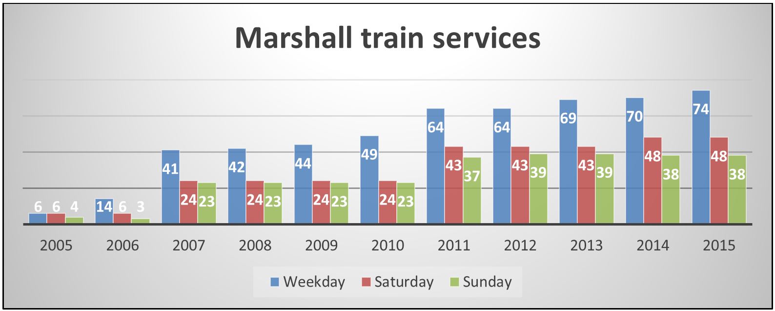
When re-opened, the only passenger services through Marshall were the Melbourne-Warrnambool services. Commuter demand led to services through Marshall steadily increasing (Figure 13).
Figure 13: Passenger train services per day to or through Marshall (total)
Source: Based on data supplied by V/Line Pty Ltd
Marshall was re-established with infrastructure that catered for the relatively small number of passenger services. However, over a ten year period, rail traffic increased significantly (16 in 2005 to 160 services per week in 2015), altering both the operating environment and the risk profile of the location.
To improve the control of traffic through this location, there was scope to upgrade to three-position signalling and potentially introduce measures to mitigate against SPAD events.
The following findings are made with respect to the Signal Passed at Danger (SPAD) events by train 1240 at Marshall, near Geelong, Victoria on 29 May 2015. These findings should not be read as apportioning blame or liability to any particular organisation or individual.
Safety issues, or system problems, are highlighted in bold to emphasise their importance. A safety issue is an event or condition that increases safety risk and (a) can reasonably be regarded as having the potential to adversely affect the safety of future operations, and (b) is a characteristic of an organisation or a system, rather than a characteristic of a specific individual, or characteristic of an operating environment at a specific point in time.
Contributing factors
The driver of train 1240 did not respond appropriately to the Caution indication on Distant signal MSL22 and subsequent two-position Home signals through the Marshall location.
The speed of train 1240 approaching Marshall station was too high for the driver to respond in sufficient time to the Stop indications displayed by signals MSL10 and MSL8.
The training and assessment of the driver did not ensure that he had an adequate understanding of the two-position signalling through Marshall. [Safety Issue]
Other factors that increased risk
The rule describing the required driver response to a Distant signal at Caution in a two-position signalling system did not fully reflect the signalling system design principles. [Safety Issue]
The presence of a section of two-position signalling on a corridor that was predominantly three-position had the potential to increase human error. There was a high reliance on driver route knowledge to manage this risk.
Since the re-establishment of Marshall station, rail passenger traffic had increased markedly, raising the risk profile of the location. There was scope to enhance the signalling configuration to better control these risks.
Safety issues and actions
The safety issues identified during this investigation are listed in the Findings and Safety issues and actions sections of this report. The Australian Transport Safety Bureau (ATSB) expects that all safety issues identified by the investigation should be addressed by the relevant organisation(s). In addressing those issues, the ATSB prefers to encourage relevant organisation(s) to proactively initiate safety action, rather than to issue formal safety recommendations or safety advisory notices.
Depending on the level of risk of the safety issue, the extent of corrective action taken by the relevant organisation, or the desirability of directing a broad safety message to the [aviation, marine, rail - as applicable] industry, the ATSB may issue safety recommendations or safety advisory notices as part of the final report.
The rule describing the required driver response to a Distant signal at Caution in a two-position signalling system did not fully reflect the signalling system design principles.
Sources and submissions
Sources of information
The sources of information during the investigation:
V/Line Pty Ltd
the train driver.
References
Loukopoulos, L.D., Dismukes, R.K. & Barshi, I. (2009). The Multitasking Myth. Handling Complexity in Real-World Operations. Ashgate: Farnham.
Reason, J. (1990). Human Error. Ashgate: Aldershot.
Purpose of safety investigations
The objective of a safety investigation is to enhance transport safety. This is done through:
identifying safety issues and facilitating safety action to address those issues
providing information about occurrences and their associated safety factors to facilitate learning within the transport industry.
It is not a function of the ATSB to apportion blame or provide a means for determining liability. At the same time, an investigation report must include factual material of sufficient weight to support the analysis and findings. At all times the ATSB endeavours to balance the use of material that could imply adverse comment with the need to properly explain what happened, and why, in a fair and unbiased manner. The ATSB does not investigate for the purpose of taking administrative, regulatory or criminal action.
Terminology
An explanation of terminology used in ATSB investigation reports is available here. This includes terms such as occurrence, contributing factor, other factor that increased risk, and safety issue.
Publishing information
Released in accordance with section 25 of the Transport Safety Investigation Act 2003
Ownership of intellectual property rights in this publication
Unless otherwise noted, copyright (and any other intellectual property rights, if any) in this report publication is owned by the Commonwealth of Australia.
Creative Commons licence
With the exception of the Coat of Arms, ATSB logo, and photos and graphics in which a third party holds copyright, this publication is licensed under a Creative Commons Attribution 3.0 Australia licence.
Creative Commons Attribution 3.0 Australia Licence is a standard form licence agreement that allows you to copy, distribute, transmit and adapt this publication provided that you attribute the work.
The ATSB’s preference is that you attribute this publication (and any material sourced from it) using the following wording: Source: Australian Transport Safety Bureau
Copyright in material obtained from other agencies, private individuals or organisations, belongs to those agencies, individuals or organisations. Where you wish to use their material, you will need to contact them directly.
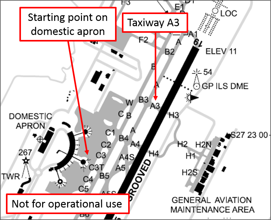
On 27 May 2015, a Cobham Aviation Services Boeing 717-200 aircraft, registered VN-NXM, was being operated from Brisbane to Gladstone, Queensland. The weather in Brisbane was fine and clear, with a light wind from the south. The Captain was the pilot flying (PF) and the First Officer was the pilot monitoring (PM).[1] As part of their preparation for the flight, the crew determined the required flap setting for take-off, and set the flap/slat control handle take-off position detent accordingly (see flap and slat control description). The PM later recalled that, on this occasion, a flap setting of 5.6 degrees was required. Engine start and push-back were normal, and the crew taxied soon after 0900 Eastern Standard Time (EST) for an A3 intersection departure from runway 19 (Figure 1).
Figure 1: Excerpt from Brisbane aerodrome chart showing the location on the domestic apron where the aircraft commenced taxiing and taxiway A3 where the aircraft waited for a clearance to enter the runway
Source: Airservices Australia, with annotations added by the ATSB
Flap and slat control
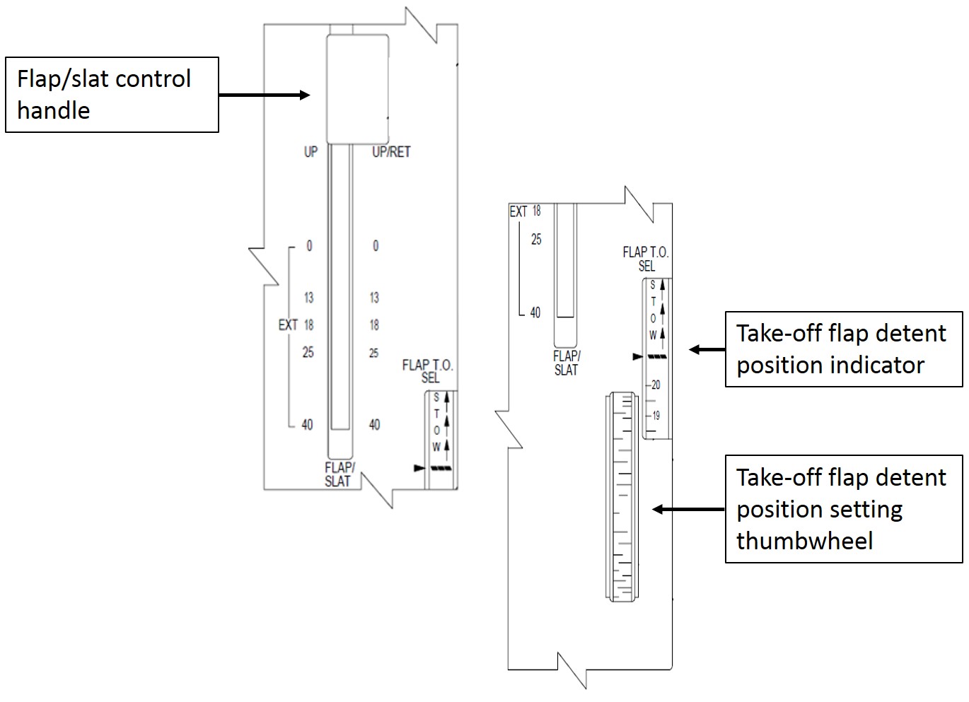
The flaps and slats are controlled by a handle on the right side of the centre pedestal (Figure 2). The flap setting for take-off is determined by the crew according to the conditions. The detent position setting thumbwheel is then used to position a detent for the control handle according to that determination, when a flap setting other than 13 or 18 degrees is required. The flap take-off selection indicator window displays the position of this movable detent. Unlike the flaps, the slats are either fully extended or fully retracted – there is no intermediate setting. The position of the flaps and slats is displayed on each pilot’s primary flight display, beneath the airspeed indicator (Figure 3). The flap/slat control handle needs to be lifted to move it forward from the 0/EXT setting (flaps up/slats extended) to the UP/RET setting (flaps up/slats retracted), to retract the slats.
Figure 2: Flap and slat control
Source: Boeing, with annotations added by the ATSB
As they taxied to the holding point, the crew completed relevant procedures, which included a requirement to confirm that the flap and slat configuration was set for take-off. The crew then held position on taxiway A3 while they waited for a clearance from air traffic control to enter the runway.
After waiting for several minutes, the crew were instructed by air traffic control to line up on the runway, but with a caveat that they needed to be ready for an immediate departure. The crew were ready, so accepted the clearance to line up, which was soon followed by their take-off clearance. The crew later commented that the wording used by air traffic control in providing the clearance to enter the runway was somewhat unusual, but there was no confusion and they clearly understood the intent. The crew entered the runway and commenced a rolling take-off.[2] The crew recalled that the take-off roll was normal in all respects, with standard communication and checks made as the take-off roll progressed.
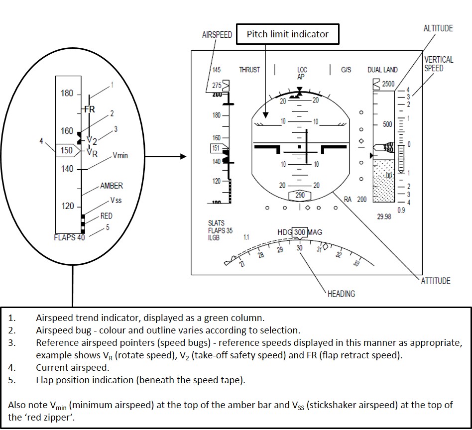
Soon after take-off, the stickshaker activated (see stickshaker description). The PF responded immediately by checking the control column slightly forward to reduce the aircraft pitch attitude. The PF noted that the airspeed at that moment was in the expected target range of V2[3] to V2 + 10 kt, but below minimum speed (Vmin)[4] and stickshaker activation speed (VSS)[5] (Figure 3). The PF also noted the airspeed appeared to be stable, with no indication of a speed reducing trend. The crew recalled that the stickshaker remained active for only a very brief period.
Stickshaker The stickshaker is part of the aircraft stall protection system. Stickshaker activation is based on a number of parameters, including the angle-of-attack of the aircraft and the position of the flaps and slats. When the required conditions are established, an oscillating force shakes the control column rapidly through a small angle to alert the crew that the aircraft may be approaching an aerodynamic stall. If the aircraft continues towards an aerodynamic stall, other levels of warning and protection may be activated, including visual and aural alerts, and a stickpusher.
The airspeed range for activation of the stickshaker is displayed as a ‘red zipper’ on the lower part of the airspeed indicator (Figure 3). VSS marks the top of the red zipper. When the airspeed is below VSS the pitch limit indicator (which provides an indication of the angle-of-attack margin to the activation of the stall warning system) changes colour from cyan to red, to provide an additional alert to the crew. Additionally, the digits (and the outline box surrounding the digits) representing the current airspeed indication turn red if the airspeed falls below VSS.
Figure 3: Primary flight display and description of relevant airspeed indications
Source: Boeing, with annotations added by the ATSB
Within moments of stickshaker activation, the PM noticed that the flap/slat control handle was set to the UP/RET position (flaps up/slats retract). Upon noticing the position of the handle, the PM immediately called ‘flaps’, and moved the flap/slat control handle to the previously determined take-off setting position.
As the aircraft continued to climb, the PF noticed that the landing gear was still down - the landing gear would normally be raised soon after having established a positive rate of climb (see description of the operator’s normal configuration management procedures). The crew then raised the landing gear and the climb continued. Later during the climb, the flaps were selected up, and soon after, as the aircraft continued to accelerate, the slats were retracted. The flight then continued to Gladstone without further incident.
Following the incident, the crew deduced that the PM must have selected the flap/slat control handle to the UP/RET position soon after take-off, rather than raising the landing gear handle. The crew’s deduction was based upon the configuration of the aircraft before, and immediately after, stickshaker activation. The crew were confident that before take-off procedures had been completed correctly, and that the flaps and slats had been correctly set. The crew also noted that had they commenced the take-off without the flaps and slats set, they would have received an aural warning alerting them accordingly – there was no such aural warning on this occasion.
Operator’s normal configuration management procedures after take-off
Normal procedures require that the landing gear be retracted soon after take-off. The PM observes that a positive rate of climb has been established and that the aircraft has accelerated to V2. Normally, when those conditions are met, the PM calls ‘positive rate’. If the PF is satisfied that the appropriate conditions are met, he/she responds by commanding ‘gear up’. The PM then raises the landing gear control handle to the UP position accordingly, and when the landing gear has retracted, calls ‘gear up’.
Later during the climb, as the aircraft accelerates through the flap retraction speed, the PF calls ‘flaps zero’. The PM checks that the speed is at or above the flap retraction speed, and that the aircraft is accelerating, then moves the flap/slat control handle to the 0/EXT position (flaps up/slats extended). When the flaps have reached the selected position, the PM calls ‘zero set’. Slat retraction follows a similar process at slat retraction speed which is a slightly higher speed than the flap retraction speed. To retract the slats, the PM sets the flap/slat control handle to the UP/RET position (flaps up/ slats retracted) and when the slats have retracted, calls ‘aircraft clean’.
Landing gear control
The landing gear control handle is located on the instrument panel, ahead of and slightly to the left of the pilot in the right seat. The handle is moved in a near vertical motion between the UP and DOWN positions to raise and lower the landing gear.
Flight data analysis
A review of the flight data downloaded following the flight showed that the flaps and slats had been set for take-off. The slats were extended and the flaps had been set to the take-off position determined by the crew. Soon after take-off, at around the time that the landing gear handle would normally be selected to the UP position, the flight data indicates that the flap/slat control handle was moved to the UP/RET position. The stickshaker activated shortly after the flap/slat control handle was moved. At that time, the airspeed was relatively steady at slightly over 160 kt.
The stickshaker was active for about 2 seconds, and stopped at about the time the PF lowered the pitch attitude of the aircraft from about 10 degrees noseup, to about 6.5 degrees noseup. The stickshaker stopped as the aircraft was climbing through about 170 ft, with the airspeed continuing to remain relatively steady at slightly over 160 kt. Although the climb shallowed momentarily immediately following stickshaker activation, a positive rate of climb was maintained throughout.
From about 7 seconds after the flap/slat control handle was selected to the UP/RET position, the handle was moved back to the position that had been set prior to take-off. During that 7 seconds, the flaps had travelled to the fully up position, and the slats had begun to retract. As the handle was reset, the slats moved back to the extended position (before having reached the fully retracted position) and the flaps moved back to the position that had been set prior to take-off. By the time the flaps and slats returned to the take-off configuration, the aircraft was accelerating through about 174 kt, and climbing through about 330 ft.
Flight data showed that after the configuration was reset, the aircraft continued to climb at a relatively steady speed of about 180 kt. As the aircraft climbed through about 700 ft, the landing gear was selected up. As the aircraft climbed through about 3,000 ft, the flaps were selected up as the aircraft accelerated, and soon after, the slats were retracted.
Crew comments
The crew made a number of comments regarding the incident, including:
When the stickshaker activated, the PF initially suspected a problem with the aircraft system that senses the position of the slats. Under some conditions, a faulty sensing system may result in a misleading stickshaker activation. The PF had experienced a failure of that nature previously, with similar symptoms.
When the stickshaker activated, the PF immediately assessed that the airspeed was appropriate (in the range V2 to V2+10) at that point, and that the pitch attitude was normal. Although there was no immediate explanation for stickshaker activation, the PF lowered the pitch attitude slightly to ensure that the speed was maintained. The PF then heard the PM call ‘flaps’, and became aware that the PM was manipulating the flap/slat control handle (this was at the point that the PM was resetting the configuration, back to the take-off configuration).
The PF also commented that with the benefit of hindsight, the thrust setting should have been increased at the onset of the stickshaker. Although that may have been an appropriate response, the limited duration of the stickshaker meant that there was little time to react.
The PM could not recall moving the flap/slat handle after take-off, and could not explain why the flap/slat control handle was selected to the UP/RET position when it was. Neither pilot could specifically recall the ‘positive rate’ and ‘gear up’ communication and command that normally takes place soon after take-off, but believe that it was probably carried out.
The PM indicated that, even though the flap/slat control handle needs to be lifted in order to move it forward from the 0/EXT position to the UP/RET position, the handle can be moved through the 0/EXT position in a single motion.
Both crew commented that, with the exception of brief remarks regarding the flow of air traffic while they waited on taxiway A3, sterile flight deck procedures[6] were being observed.
Neither the PF nor PM could recall any specific distractions that may have diverted the attention of the PM at a critical moment during the take-off.
For the PM, the day of the incident was the fourth consecutive day of duty. While the PM had slept adequately during the evenings leading up to the incident flight, they reported some tiredness associated with a recent change in personal circumstances and a longer commute to and from work.
For the PF, the day of the incident was the third day of a three-day roster, but the schedule was not demanding.
After a brief discussion immediately following the event, both pilots were conscious of the need to maintain their focus on the safe and efficient conduct of the flight ahead. They elected not to discuss the incident further during the flight until they were safely on the ground at their destination. Following the flight, they discussed the incident and submitted a report.
ATSB comment
Available evidence suggests that the PM inadvertently selected the flap/slat handle to the UP/RET position, instead of selecting the landing gear handle to the UP position. While the reasons are unclear, the most likely explanation resides in an understanding of human error types. The SKYbrary website includes information about human errors that may have relevance to this occurrence, particularly with respect slips and lapses – referred to collectively as execution errors (Human Error Types). The SKYbrary website also includes an article dealing with the relationship between human performance and level of arousal (Level of Arousal). The article illustrates that over-arousal can lead to a degradation in performance, but importantly, under-arousal can have a similar influence.
In a similar incident in 2003 (ATSB Report 200302037), the co-pilot of a Boeing 717-200 repositioned the flap/slat handle soon after take-off, instead of the landing gear handle. In response to that incident, the operator added the following caution to the procedures for flap/slat retraction after landing:
When retracting flaps/slats to UP/RET, pause at the UP/EXT position until the flaps indicate UP on the PFD prior to retracting the slats. Never move the flap/slat handle to UP/RET in one motion.
The ATSB report states that:
The purpose of the change was to separate the retraction of the flaps and slats into two distinct actions, in an attempt to prevent the retraction of the flaps and slats becoming `learned' as a single continuous action.
In another incident, the flaps of a British Aerospace 146-300 began to retract soon after take-off, just before the aircraft reached 100 ft above ground level. Flap retraction began at about the time the call to raise the landing gear would have normally been made (ATSB Investigation Report 9704041). Although there were numerous factors surrounding the incident, the report commented that ‘On balance … the likelihood rests that the co-pilot inadvertently selected the flaps up instead of the landing gear.’
More information about stall warnings in high-capacity aircraft is available in ATSB research report AR-2012-172 (Stall warnings in high-capacity aircraft: The Australian context 2008 to 2012). The report outlines the results of a review of 245 stall warnings and stall warning system events over a 5-year period from 2008 to 2013. Of those 245 events, 163 were stickshaker activations.
Safety message
This incident highlights the susceptibility of pilots to execution errors such as slips and lapses, irrespective of knowledge and experience. Pilots are encouraged to reflect on the circumstances surrounding this incident to help build their own awareness of human factors issues associated with operating complex equipment in a highly dynamic environment.
Decisions regarding whether to conduct an investigation, and the scope of an investigation, are based on many factors, including the level of safety benefit likely to be obtained from an investigation. For this occurrence, a limited-scope, fact-gathering investigation was conducted in order to produce a short summary report, and allow for greater industry awareness of potential safety issues and possible safety actions.
Publishing information
Released in accordance with section 25 of the Transport Safety Investigation Act 2003
Ownership of intellectual property rights in this publication
Unless otherwise noted, copyright (and any other intellectual property rights, if any) in this report publication is owned by the Commonwealth of Australia.
Creative Commons licence
With the exception of the Coat of Arms, ATSB logo, and photos and graphics in which a third party holds copyright, this publication is licensed under a Creative Commons Attribution 3.0 Australia licence.
Creative Commons Attribution 3.0 Australia Licence is a standard form licence agreement that allows you to copy, distribute, transmit and adapt this publication provided that you attribute the work.
The ATSB’s preference is that you attribute this publication (and any material sourced from it) using the following wording: Source: Australian Transport Safety Bureau
Copyright in material obtained from other agencies, private individuals or organisations, belongs to those agencies, individuals or organisations. Where you wish to use their material, you will need to contact them directly.
On 12 April 2015, just prior to the 1542 Belgrave-to-Melbourne service arriving at Upwey station, the signal control panel located at Upper Ferntree Gully station lost functionality. As a result, the signaller, no longer had control or indication of signals and interlocking at Upwey.
To continue train operations through the area, procedural safeworking was instituted under the control of the signaller at Upper Ferntree Gully. By this time the Belgrave-to-Melbourne service was stopped at Upwey with the Departure signal at Stop. Having been advised of the signalling system failure, the driver of this service contacted the signaller at Upper Ferntree Gully for further instructions. A short time later, at about 1551, the train departed Upwey and proceeded to Upper Ferntree Gully without authorisation.
What the ATSB found
The ATSB found that the train passed both the Upwey Home Departure and the Upper Ferntree Gully Home Arrival signals at Stop without authority. The departure from Upwey was possibly influenced by the driver’s anxiety at having to operate the points machine a short distance beyond Upwey.
The ATSB also found that there was a missed opportunity to contact the train after it was detected as having departed Upwey unauthorised.
What's been done as a result
MTM has reviewed training provided to drivers in the operation of Dual Control Points Machines. MTM is also considering [1] the incorporation of SPAD alarms at this location, and [2] modifying the communications network to capture all safeworking communications at Upper Ferntree Gully.
Safety message
An extra degree of responsibility and situational awareness is demanded of staff under conditions of degraded signalling and procedural safeworking.
The occurrence
The 1542 service (TD3050) from Belgrave to Melbourne departed Belgrave on time. The train was a six-car X’Trapolis Electric Multiple Unit.
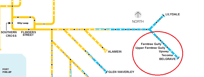
The Belgrave line (Figure 1) is part of the Melbourne metropolitan network managed by Metro Trains Melbourne (MTM). Between Belgrave and Ferntree Gully trains operate on a single bi-directional track, excepting at Upper Ferntree Gully and Upwey, where the line splits to pass either side of island platforms. These stations therefore provide the crossing points for trains travelling in opposing directions.
Figure 1: MTM network map (part)
Source: Metro Trains Melbourne – annotated by Chief Investigator, Transport Safety (Vic)
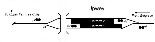
Train TD3050 arrived at platform 1 at Upwey Railway station (Figure 2) to cross the Belgrave-bound service that had arrived at about the same time and was at platform 2. Just prior to the arrival of TD3050, the signal control panel at Upper Ferntree Gully failed. As a result the signaller based at Upper Ferntree Gully (UFG) no longer had control of signals and points at Upwey and could not determine the location of trains in the vicinity of Upwey.
Figure 2: Upwey track layout with key signals and points marked
Source: Chief Investigator, Transport Safety (Vic)
The signaller at Upper Ferntree Gully reported the panel failure to Metrol, the control centre for train operations on Melbourne's suburban rail network. In response to this call, Metrol contacted the driver of train TD3050 by radio to advise of the failed signal control panel and to ascertain the train’s location. The driver confirmed his location at Upwey Platform 1, and was informed by Metrol that he would need to contact the signaller at Upper Ferntree Gully to obtain authority to depart from Upwey.
The driver of 3050 then called the signaller at Upper Ferntree Gully by mobile phone to obtain instructions. Conversations between the signaller and the driver of TD3050 were not recorded. The signaller advised the driver of the panel failure and that he did not have track detection. The signaller also advised the driver that he (the driver) would need to operate the points in front of him (№ 41 points).
Unable to see the status of № 41 points from the Upwey platform, the driver boarded his train and ran forward towards the points. By this action, he passed the Home Departure signal at Upwey at Stop. This was the first Signal Passed at Danger (SPAD[1]) event of this incident. Passing this Home signal at Stop, led to activation of the trip lever and a resulting enforced brake application which brought the train to a stand (see p5).
After the trip mechanism was reset by the driver, the train continued on slowly towards № 41 points. Approaching № 41 points the driver observed they were correctly set for his passage and continued on. As a result, he did not stop and lock the points in the hand position. The driver then continued on towards Upper Ferntree Gully.
Train 3050 next encountered Automatic signal[2] № 38 that was displaying a Stop indication. Particular rules apply to Automatic signals (see p4) that permit them to be passed at Stop without authority from a signaller or train controller. After passing the signal at stop and resetting from the resulting enforced brake application, the train continued on towards Upper Ferntree Gully.
About six minutes into the train’s passage between Upwey and Upper Ferntree Gully, the signaller noticed (on CCTV) that train 3050 was no longer visible at the Upwey platform. The signaller called Metrol to advise of this, and was informed by the train controller that they would contact the driver of the other train at Upwey (TD3639) for confirmation. There were no further calls made to clarify the position of TD3050.
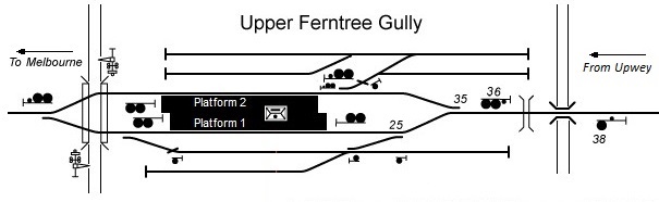
Train 3050 subsequently arrived at Home Arrival signal № 36 at Upper Ferntree Gully (Figure 3). Observing that the points appeared correctly set, the driver proceeded past this Home signal that was also at Stop, again experiencing a mandatory stop initiated by the mechanical trip system. This was the second SPAD event of this incident.
Figure 3: Upper Ferntree Gully track layout with key signals and points marked
Source: Chief Investigator, Transport Safety (Vic)
The train then recommenced its passage and passed through №s 35 and 25 points before arriving at Upper Ferntree Gully platform 1. The signaller became aware of the train as it arrived and instructed the driver not to move his train. The passage of train 3050 from Upwey to Upper Ferntree Gully had taken about 10 minutes. There was no damage to track infrastructure or the train and there were no injuries.
As a consequence of the signal panel failure, Metrol and the Station Master at Upper Ferntree Gully had agreed that Belgrave-bound trains would terminate at Upper Ferntree Gully. At the time that train TD3050 was arriving into Upper Ferntree Gully, a Belgrave-bound service was also approaching the adjacent platform.
The driver was qualified for the operation of this train on this route and was medically fit for duty. He was based at the Carrum depot and had qualified to drive suburban trains in February 2007. His most recent performance audit had been undertaken in January 2015. This incident was the driver’s first SPAD infringement.
Following the incident, testing of the driver returned a zero blood alcohol result and nil presence of drugs.
Track infrastructure
Upwey to Upper Ferntree Gully
From departure at Upwey railway station to arrival at the platform at Upper Ferntree Gully was about 2.4 km on a predominantly 1:30 downgrade. Between the mainline points at the two stations (№s 41 and 35 points) the line was single-track for a distance of approximately 2.05 km. Automatic signal № 38 is located midway between the stations.
Upwey
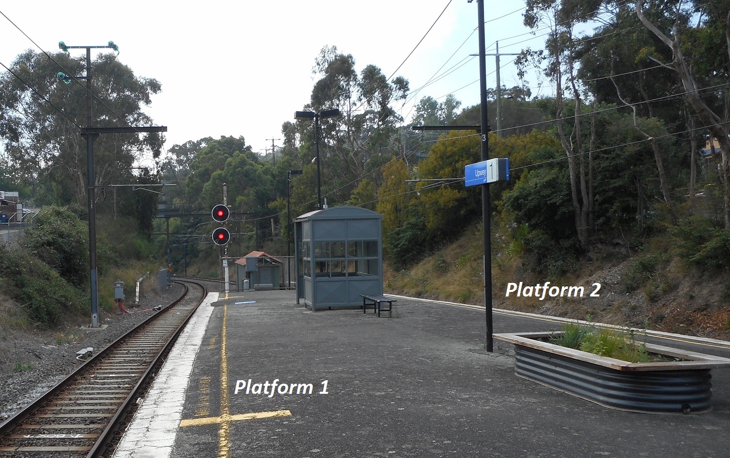
Upwey is an unattended crossing station, about 40 km from Flinders Street Station. Home Departure Signal № 42 is at the Melbourne end of Platform 1 (Figure 4).
Figure 4: Upwey railway station looking towards Upper Ferntree Gully and signal № 42
Source: Chief Investigator, Transport Safety (Vic)
About 160 metres from the Melbourne end of the Upwey island platform, № 41 points connects the two platform tracks to the single line extending towards Upper Ferntree Gully.
№ 41 points are controlled by a Dual Control Point Machine. They can be operated in ‘Motor’ (remote operation) or ‘Hand’ (manual operation) modes. This enables remote operation of the points by a signaller or hand operation in the case of system failure. In the case of system failure, all points are set to the Hand mode prior to being traversed to ensure the points cannot inadvertently operate while a train is passing across them. In addition, when set to ‘Hand’ mode, the Home signals protecting the points are held at Stop.
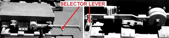
The Dual Control Point Machine has two levers – the Selector lever and the Hand Throw lever. The Selector lever is the shorter of the two. The normal position for the Selector lever is in the ‘Motor’ position (Figure 5 right-hand photo). To place the machine into ‘Hand’ mode the lever is rotated clockwise by 180 degrees (Figure 5 left-hand photo). With the Selector lever in this position, the Hand Throw lever can then be used to manually move the points to their required position. Figure 5 does not depict the actual point machine at the № 41 points at Upwey.
Figure 5: Dual Control Point Machine. The Selector lever is shown in the ‘Motor’ position (right-hand photo) and ‘Hand’ position (left-hand photo)
Source: Metro Trains Melbourne
Automatic signal № 38
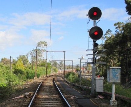
An intermediate Automatic signal was provided between Upwey and Upper Ferntree Gully. Automatic signal № 38 provided advance warning and indication of the status of the Home arrival signal № 36 at Upper Ferntree Gully.
An Automatic signal is not directly controlled by a signaller or train controller but by the passage of trains detected by track circuits. As part of a permissive signalling system, an Automatic signal at Stop is allowed to be passed by a train under conditions specified by a Rule.
At the time of the incident, a trial existed[3] to reinforce the process for passing Automatic signals at Stop. This trial involved train drivers who encountered an Automatic signal at Stop making use of a voice mail facility to receive an automated message conveying explicit instructions and to then provide certain identifying information. The driver of TD3050 did not follow this process.
Upper Ferntree Gully
Upper Ferntree Gully is an attended crossing station about 36 km from Flinders Street. Home Arrival Signal № 36 (Figure 6) is located about 220 metres prior to the platform.
Figure 6: Home arrival signal № 36 at Upper Ferntree Gully
Source: Metro Trains Melbourne
Trackage at Upper Ferntree Gully is more complex with several sidings either side of the mainline tracks (Figure 3). For mainline traffic, trains arriving at Upper Ferntree Gully from Upwey are typically directed to platform 1 by way of №s 35 and 25 points.
Train stops at signals
On the metropolitan network, Home and Automatic signals are fitted with Train Stops (Figure 7). This was the case at signal №s 42 (Upwey Departure), 38 (Automatic) and 36 (Upper Ferntree Gully Arrival).
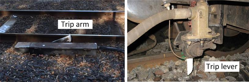
Figure 7: Automatic train stop (left) and trip lever on suburban trains (right)
Source: Chief Investigator, Transport Safety (Victoria)
The purpose of this device is to bring a train to a stand when the train passes a signal that is at Stop. When a signal is at Stop, the trip arm of the unit located beside the track is raised. This strikes the trip valve lever that is fitted on suburban trains causing an emergency brake application and the train to come to a stand. Before a train can proceed after being ‘tripped’, its trip mechanism has to be reset by the driver.
In this incident, the train brake was ‘tripped’ when passing signals №s 42, 38 and 36. This stopped the train in each case, and the driver manually reset the trip, enabling the train to recommence its journey.
Traffic control on the metropolitan network
Metrol
Metrol is the central control centre for the Melbourne suburban rail network. The centre’s train control function covers the whole suburban area, while its control of points and signalling covers a limited area within central Melbourne and one (recently modernised) outer suburban area.
Outside the centrally-controlled areas, train movements are controlled by signallers located either in dedicated signal-boxes or operating signal control panels at suburban railway stations. These signallers are under the direction of the Metrol controllers. Upper Ferntree Gully was such a location.
Local area signalling from Upper Ferntree Gully Station
Safeworking system
The safeworking system used at this location was Automatic Track & Control (ATC). In this system, authority for a train to enter a section of track is provided by signals located at each end of the section. In single-line operations, the signals at each end of a track section are arranged such that once a train is in the section, an opposing train cannot be signalled to enter.
Signal control panel
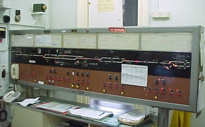
Upper Ferntree Gully, was staffed by a signaller for the control of the single-line section between Ferntree Gully and the line’s terminus at Belgrave. The station was equipped with a signal control panel (Figure 8) that provided information of signal and points status and train position.
MTM maintenance attended to the loss of panel functionality. The inspection identified that the panel fault was the result of a processing failure within the Railmaster compact telemetry unit. This is an interface component between the signal control panel and field equipment. The Railmaster unit had failed and required a hardware reboot. The equipment that had caused the signal control panel outage was reset after about an hour. However, a secondary and separate fault with a set of points resulted in a delay in re-establishing the signalling system.
Figure 8: Signal control panel, Upper Ferntree Gully
Source: VicSig – Chris Jordan
The Signaller at Upper Ferntree Gully
The signaller (who was also the Station Master) was medically fit[4] and appropriately qualified for his duty, and had been last audited at Upper Ferntree Gully (with no non-conformances) a month prior to the incident.
The station is usually staffed by two. However, on this day the rostered signaller had been sent home due to fatigue. As a result, the Station Master was also performing the role of the signaller. His duties included operating the signal control panel and dealing with passenger ticketing and enquiries. Around the time that the signal control panel failed, public inquiries were low and did not interfere with his response to the panel failure.
This was the signaller’s fifth consecutive 8-hour dayshift, following a five-day break off duty. There was no indication that fatigue affected the performance of the signaller.
Procedural safeworking and Caution Orders
Procedural safeworking on the MTM network, is instituted when there is a loss of signalling system and interlocking control. It permits the ongoing operation of the network, albeit at a reduced capacity.
The safeworking of trains was governed by the Book of Rules and Operating Procedures (1994). On the metropolitan network, implementation of these Rules was supported by procedures developed by the network manager, MTM.
Procedural safeworking requires coordination between the signaller (or train controller) and the train driver in order for signals to be safely passed and for points to be safely traversed. Home signals control arrival and departure movements at stations, and protect points and other interlocking.
The instrument of authorisation to pass Home signals displaying a Stop indication is called a Caution Order. This is an instrument used by a train controller or signaller to give a train driver authority to pass a signal at Stop in accordance with prescribed measures. The issuing of a Caution Order is a formally documented process, although its application can take various forms.
Procedures for departing Upwey
Upwey is an unattended station. Under circumstances of signalling system failure[5] at unattended stations, an ATC System Caution Order is the instrument used to permit a train to pass a Home Departure signal at Stop.
The process for issuing an ATC System Caution Order included:
On the direction of the train controller or signaller, the driver placing protected points in the ‘Hand’ mode and ensuring they were correctly set and secured for the train’s movement
The driver then contacting the signaller and confirming the points had been correctly secured
Once satisfied that points were secured and cognisant of other traffic, the signaller dictating the Caution Order to the driver, who would record the details of the order on a prescribed form
On completion of the prescribed form, the train would have authority to proceed past the signal at Stop.
Procedures for arrival at Upper Ferntree Gully
At an attended station such as Upper Ferntree Gully, the applicable instrument to use for a train to pass a Home signal at Stop is the Signaller’s Caution Order. This is a paper document that is passed from signaller to train driver. Before issuing such an authority, the responsibility for ensuring that any points are safe to traverse rests with the signaller.
Therefore at Upper Ferntree Gully station, in the case that the signaller was to issue a Caution Order, №s 35 and 25 points would be secured by the signaller, before a train was given the written authority to pass signal № 36 and proceed to Platform 1.
Voice communications
Drivers operating trains on the Belgrave line could communicate with the Upper Ferntree Gully signaller on the Digital Train Radio System (DTRS), which was recorded.
However, in this instance the driver contacted the signaller using his MTM-issued mobile phone – a mode of communication that is not recorded unless received on phones that are recorded, such as at Metrol.
The non-recording of safeworking communications leaves a significant gap in the capacity to review or resolve communications in the case of investigation or procedural auditing.
The signal control panel at Upper Ferntree Gully lost functionality as a result of a processing failure within the Railmaster compact telemetry unit.
Due to this failure, the signaller lost control over and information on the signals and points at Upwey. As a result, safeworking reverted to a back-up procedural system. This required the use of Caution Orders as the authority for trains to pass Home signals at Stop. This substitute process introduced a greater procedural burden on operational staff and an increased exposure to human error.
Departure from Upwey
The procedures for passing Home signals following signalling system failure are well established formal processes. At Upwey, the correct authority to proceed past the Home Departure signal that was at Stop was a dictated ATC System Caution Order. The train proceeded without this process being followed and therefore without authority. In addition, the train then proceeded over points № 41 without them first being secured by hand and the signaller being advised.
Having instructed the driver to check the 41 points at Upwey, the signaller’s expectation would have been that the driver would proceed on foot to the points, confirm their setting, and secure them in Hand mode. The driver would then return to his train to contact the signaller to advise accordingly and to have the ATC System Caution Order dictated by the signaller and recorded by the driver.
There are a number of factors that may have influenced the driver’s behaviour that led to these errors (unauthorised passing of signals at Stop). These include:
A lack of understanding of the applicable safeworking procedures
Distraction
A misunderstanding of instructions from the train controller or signaller
Expectation of a clear track ahead
Infrequent operation on this line
Fatigue.
Lack of understanding of safeworking procedures
Safeworking rules, including the application of Caution Orders, are a fundamental knowledge-based competency for drivers of trains. The driver’s record shows the completion of required training in safeworking procedures and also subsequent supervisory auditing. Due to the infrequency of use, the driver’s experience with using alternate safeworking in practice may have been limited.
The driver had no record of any SPAD incident during his 8-year career, and therefore no history of this type of error. There was no evidence to suggest a fundamental misunderstanding of rules and procedures. Rather, the response of the driver following the incident and realisation of his error suggests a possible lapse of awareness.
Distraction
The train driver was anxious about having to operate the set of points (№ 41) that he had been requested by the signaller to secure. The driver also reported having felt a sense of relief at seeing that the points were set for his movement. This was probably because it was some time since he had covered Dual Control Point Machines in his initial (2007) and refresher (2010) training The driver also suggested that he had never hand-operated such a machine in the field. Nonetheless, the required procedure was straightforward and assistance was available from the train controller or signaller if required.
Despite the ease of the task, it is apparent that the driver was apprehensive about operating the points. It is possible that this apprehension led to the driver forgetting the requirements to first check the points and then obtain a Caution Order before departing the train from Upwey.
Misunderstanding of communications with train controller or signaller
The driver’s communication with the Metrol train controller was straightforward and there is no indication that the controller’s instructions were misunderstood by the driver. The driver called the signaller at Upper Ferntree Gully as instructed.
The communication between the driver and the signaller was not recorded and so its precise nature is not known. Combined with the driver’s sense of anxiety at operating the points, it is possible that the signaller’s instruction that the points be checked prior to receipt of authority was construed as permission to pass the Home Departure signal. However, this would have been contrary to procedure.
The driver was required to then report the state of the points to the signaller. The possibility of a momentary lapse of awareness does not fully explain why, having observed the points, he then continued without reporting their status.
Expectation
The driver of train № 3050 was aware that the opposing Belgrave-bound train was already at Upwey Platform 2. He had been informed by Metrol that there were signalling problems at Upwey and that once the opposing train had arrived he should contact the signaller at Upper Ferntree Gully to obtain ‘authority to move past [the Home Departure signal]’. He would therefore have expected that the single line to Upper Ferntree Gully was clear and that there was no impediment to obtaining authority to proceed through the section.
Infrequent operation on this line
Carrum-based drivers mostly operate over the Frankston, Craigieburn, Hurstbridge, and Sunbury lines. To maintain familiarity, they are rostered to operate over the Belgrave line twice in each 16-week cycle. Therefore, the driver was not a regular operator on this line. This driver had also not been audited on the Belgrave line in the last three years.
While less familiarity with a route can contribute to apprehension or errors, it is unlikely that this factor contributed to the errors in this instance.
Fatigue
The driver had commenced his shift at 1009 and at the time the incident occurred had been on duty for about 5 hours and 30 minutes. Based upon the driver’s rostered work schedule, time-of-day, time-on-task, and the nature of the errors observed, it is considered unlikely that the driver’s performance was fatigue-impaired at the time of the SPAD events.
Arrival at Upper Ferntree Gully
At Upper Ferntree Gully the correct authority to proceed past the Home Arrival signal that was at Stop was a Signaller’s Caution Order. The train entered the station without this authority.
In proceeding into the station, the driver also operated the train across two sets of points without them first having been secured against the possibility of movement while being traversed.
There are no additional factors or events that may have influenced the driver’s behaviour in this second SPAD event. Being already in the section and in the belief that there were no opposing trains, the driver probably believed it was safe to proceed to the platform at Upper Ferntree Gully.
Missed opportunity to contact unauthorised train
About six minutes after train TD3050 departed Upwey, the signaller at Upper Ferntree Gully noticed on CCTV vision that the platform was vacant. The signaller conveyed this observation to the Metrol train controller. However, there was no further action-by either the signaller or the train controller-to contact the train. MTM SPAD risk management procedures specify that following a SPAD, contact must be made with the driver of a train and the train stopped.
After its detected departure from Upwey, about four minutes passed before the train arrived at Upper Ferntree Gully. There was an opportunity to stop the train during this period.
Findings
From the evidence available, the following findings are made with respect to the double-SPAD incident at Upwey and Upper Ferntree Gully, Victoria, on 12 April 2015. These findings should not be read as apportioning blame or liability to any particular organisation or individual.
Contributing factors
The signal control panel at Upper Ferntree Gully failed, requiring the introduction of procedural safeworking that resulted in an increased exposure to human error
The train passed the Upwey Home Departure signal at Stop without authorisation
The train passed the Upper Ferntree Gully Home Arrival signal at Stop without authorisation.
Other factors that increased risk
Although train TD3050 was identified as having made an unauthorised departure from Upwey, there was no follow-up action to contact the train.
Safety issues and actions
Safety actions
Whether or not the ATSB identifies safety issues in the course of an investigation, relevant organisations may proactively initiate safety action in order to reduce their safety risk. The ATSB has been advised of the following proactive safety action in response to this occurrence.
Metro Trains Melbourne advised that as a result of this occurrence they:
Have reviewed training provided to drivers in the operation of Dual Control Points Machines
Will consider a system modification to capture all safeworking communications at Upper Ferntree Gully
Will add the incorporation of SPAD alarms into asset management plans for future upgrading of signalling at this location.
Sources and submissions
Sources of information
The sources of information during the investigation included:
Metro Trains Melbourne.
References
MTM Weekly Operational Notice № 13/2015
National Standard for Health Assessment of Rail Safety Workers
The Book of Rules and Operating Procedures (1994) – PTC.
Submissions
Under Part 4, Division 2 (Investigation Reports), Section 26 of the Transport Safety Investigation Act 2003 (the Act), the Australian Transport Safety Bureau (ATSB) may provide a draft report, on a confidential basis, to any person whom the ATSB considers appropriate. Section 26 (1) (a) of the Act allows a person receiving a draft report to make submissions to the ATSB about the draft report.
A draft of this report was provided to the driver of the train, the Station Master at Upper Ferntree Gully, Metro Trains Melbourne, the Office of the National Rail Safety Regulator and Public Transport Victoria.
Submissions were received from Metro Trains Melbourne, the Office of The National Rail Safety Regulator, and Public Transport Victoria. The submissions were reviewed and where considered appropriate, the text of the report was amended accordingly.
Purpose of safety investigations
The objective of a safety investigation is to enhance transport safety. This is done through:
identifying safety issues and facilitating safety action to address those issues
providing information about occurrences and their associated safety factors to facilitate learning within the transport industry.
It is not a function of the ATSB to apportion blame or provide a means for determining liability. At the same time, an investigation report must include factual material of sufficient weight to support the analysis and findings. At all times the ATSB endeavours to balance the use of material that could imply adverse comment with the need to properly explain what happened, and why, in a fair and unbiased manner. The ATSB does not investigate for the purpose of taking administrative, regulatory or criminal action.
Terminology
An explanation of terminology used in ATSB investigation reports is available here. This includes terms such as occurrence, contributing factor, other factor that increased risk, and safety issue.
Publishing information
Released in accordance with section 25 of the Transport Safety Investigation Act 2003
Ownership of intellectual property rights in this publication
Unless otherwise noted, copyright (and any other intellectual property rights, if any) in this report publication is owned by the Commonwealth of Australia.
Creative Commons licence
With the exception of the Coat of Arms, ATSB logo, and photos and graphics in which a third party holds copyright, this publication is licensed under a Creative Commons Attribution 3.0 Australia licence.
Creative Commons Attribution 3.0 Australia Licence is a standard form licence agreement that allows you to copy, distribute, transmit and adapt this publication provided that you attribute the work.
The ATSB’s preference is that you attribute this publication (and any material sourced from it) using the following wording: Source: Australian Transport Safety Bureau
Copyright in material obtained from other agencies, private individuals or organisations, belongs to those agencies, individuals or organisations. Where you wish to use their material, you will need to contact them directly.
Section 21 (2) of the Transport Safety Investigation Act 2003 (TSI Act) empowers the Australian Transport Safety Bureau (ATSB) to discontinue an investigation into a transport safety matter at any time. Section 21 (3) of the TSI Act requires the ATSB to publish a statement setting out the reasons for discontinuing an investigation.
On 18 May 2015, the ATSB commenced an investigation into a number of loss of separation occurrences and radar vectors issued to flight crew when an aircraft was below the minimum vector altitude on 18 May 2015, near Adelaide Airport, South Australia involving:
a SAAB Aircraft Co 340B (S340), registered VH‑OLL (OLL), conducting a low capacity regular public transport flight from Mount Gambier, South Australia
an Airbus A320-232 (A320), registered VH‑VNH (VNH), conducting a high capacity regular public transport flight from Melbourne, Victoria
a Boeing 737‑8FE (B737), registered VH‑YVC (YVC), conducting a high capacity regular public transport flight from Melbourne
a Boeing 737 (B737) conducting a high capacity regular public transport flight from Sydney, New South Wales.
The aircraft were under the jurisdiction of an Airservices Australia (Airservices) Check and Standardisation Supervisor (workplace assessor), conducting a final assessment on a trainee Approach East controller (trainee). During the approach sequence there were two loss of separation occurrences, then OLL was below the minimum vector altitude while on a vector on one occasion, and OLL was not confirmed above the minimum vector altitude while being vectored on another.
An Airservices investigation into the occurrences found that the Adelaide Tower controller did not have sufficient understanding of the minimum vector altitude, that the intervention by the workplace assessor was not effective and that the controllers involved in a transfer of separation responsibility did not have a shared understanding, as there was no standard phraseology. The investigation report identified the following safety issues:
Compromised separation training for controllers at Adelaide Tower did not incorporate scenarios where aircraft were below the minimum vector altitued at night.
The updated Intervention Techniques and Prompting initial qualification training was not provided to existing on-the-job training instructors or workplace assessors. Additionally, the relevent refresher training module had not been updated.
There was no defined explicit requirements, including the required phraseology, for coordinating the transfer of separation responsibility between controllers.
Airservices subsequently advised that each of the safety issues had been addressed and all related safety actions had been completed.
The ATSB reviewed the Airservices report, safety issues and safety actions. Based on this review, the ATSB considered it was very unlikely that further investigation would identify any systemic safety issues. Consequently, the ATSB has discontinued this investigation.
On 28 May 2015, the pilot of a Robinson 22 helicopter, registered VH-HRW, was engaged in aerial mustering operations about 63 km north-north-east of Mitchell, Queensland. Late in the afternoon the helicopter’s tail rotor struck the branch of a 7 m-high dead and defoliated tree, the pilot lost control of the helicopter and it collided with terrain. The helicopter was destroyed and the pilot, the sole occupant, was fatally injured.
What the ATSB found
The ATSB found that the pilot was appropriately qualified and flying due west in a serviceable helicopter at low level. The sun was to the north-west and about 13°–15° above the horizon at that time. The helicopter’s tail rotor collided with the upper branch of an isolated tree. That collision separated a portion of the tail rotor blades, leading to the remainder of the tail rotor and the helicopter’s horizontal and vertical stabilisers and tail rotor gearbox also separating. The pilot could not control the helicopter and it collided with terrain.
Given the conditions, it is likely that sun glare and the darkened backdrop of a tree-lined dry creek bed affected the pilot’s vision and perception, and therefore ability to identify the isolated tree. Despite the pilot wearing a helmet that was fitted with sun visors, the ATSB could not determine whether the visors were lowered at the time. In any event, it is likely that the pilot did not see the tree, or misjudged its height and/or its distance from the approaching helicopter.
The ATSB did not identify any pre-existing mechanical defects and established that, at the time of the accident, the helicopter was likely serviceable. The helicopter was fitted with a three-point safety harness and bladder-type fuel tanks. These tanks decrease the risk of a post-impact, fuel-fed fire. Despite these additional safety features, and the safety benefits possible from the pilot wearing a helmet, the accident was not survivable due to impact forces. A number of unrestrained items in the cabin increased the risk of injury as a result of those forces.
Safety message
Low-level aerial mustering operations are an inherently high-risk activity. When conducting this type of operation, pilots need to consider the environmental conditions as part of their flight planning and operational risk assessment. The ATSB and the Civil Aviation Safety Authority have released a number of publications illustrating the risks associated with this type of operation that provide guidance and strategies for mitigating those risks.
The occurrence
On 28 May 2015, the pilot of a Robinson 22 helicopter, registered VH-HRW, was carrying out aerial mustering operations on a property about 63 km north-north-east of Mitchell, Queensland (Figure 1). One of the property owners reported that the pilot had previously conducted mustering activities at the property.
The pilot flew VH-HRW to the mustering area from his home base earlier that day. This entailed a flight of about 20 minutes. The majority of the mustering activity followed between 1032 and 1329 Eastern Standard Time[1].
One of the property owners reported that the pilot then had a long break and a meal with the property owners and a station hand. The afternoon’s activities were discussed during the meal. The plan for those activities included that, while flying back to his home base, the pilot would look for stray cattle and muster them towards a number of stationary vehicles. These vehicles were to be stationed to the west of the afternoon’s operating area.
After several minutes, the station hand unsuccessfully attempted to contact the pilot by ultra high frequency radio. The station hand then drove their vehicle in the direction that the helicopter had departed. After several more minutes, the station hand located the helicopter wreckage. An attempt was made to revive the pilot but without success.
Figure 1: Image showing the helicopter’s track (in white) during the morning’s mustering. This track was derived from data downloaded from the helicopter’s on-board Global Positioning System receiver. The location of the helicopter wreckage is shown (in blue) reference the townships of Roma and Mitchell
a Commercial Pilot (Helicopter) Licence that was issued in 2003
a Single Engine Helicopter rating
an Aerial Mustering Helicopter approval
a Civil Aviation Safety Authority (CASA) Aviation Medical Certificate.
A review of the pilot’s logbook and previous aircraft maintenance releases for VH-HRW showed that the pilot had accumulated about 1,170 flight hours in R22 helicopters prior to the accident.
Fatigue
Family and friends of the pilot provided a consolidated 72-hour history of the pilot’s activities prior to the accident. These were considered to be consistent with normal rural living. No activities that would be considered overly strenuous were identified and the pilot had adequate rest periods prior to, and on the day of the accident. The mustering activity on the day was not considered excessive.
Data downloaded from the helicopter’s Global Positioning System (GPS) receiver and witness accounts were reviewed to understand the pilot’s activities that day. This review showed that the pilot flew for about 3 hours and 20 minutes over a period of 7 hours. This included a stop to refuel and the previously-discussed rest period and lunch after completing the main mustering activity that morning.
Based on the recorded GPS data and witness statements, the ATSB concluded that it was unlikely pilot fatigue contributed to the accident.
Operations
The muster was coordinated with the property owners and a station hand and entailed the pilot using the helicopter to help ground personnel move the cattle to a holding point.
Recorded data from the helicopter’s GPS receiver indicated that the pilot commenced mustering at 1032 and completed the muster at 1329. This was consistent with the recollection of one of the witnesses. The muster was conducted over an area of about 16 km2 and could be expected to include turns and complex manoeuvres at low level to encourage cattle to move in the desired direction.
The station hand reported that, after lunch and resting, they observed the helicopter land on a property road shortly after it departed on the return flight to the pilot’s home base. The landing was to the west of a tree-lined dry creek. The pilot got out of the helicopter, opened a gate, got back in the helicopter, and then departed in an easterly direction.
The station hand and the property owner recalled separately that the 1600 radio news broadcast commenced on their vehicle’s radios at about that time.
The station hand, who reported being familiar with the helicopter, reported that when the helicopter departed from the road it sounded and appeared to be operating normally. That was the last recorded sighting of the helicopter prior to the discovery of the wreckage.
Wreckage information
Examination of the helicopter wreckage and ground scars found that the tail rotor blades collided with the upper branch of an isolated, 7 m-high dead and defoliated tree (tree) that was about 100 m to the east of a tree-lined dry creek bed. The terrain sloped down towards the creek bed at about 2°–5° (Figure 2).
Figure 2: Helicopter flight path looking to the west. The estimated right-to-left flight path (indicated by a yellow dashed arrow) is derived from the impact point with the dead and defoliated tree and the position of the main helicopter wreckage
Source: ATSB
On contact with the tree, segments of the two tail rotor blades separated from the tail rotor. During the ensuing impact sequence, one of these blades struck the lower-vertical stabiliser, causing the combined vertical and horizontal stabilisers[2] and tail rotor gearbox to separate from the tail boom (Figure 3). The tail rotor blades, combined horizontal and vertical stabilisers and gearbox were collocated in close proximity to the tree.
Figure 3: Combined horizontal and vertical stabilisers and tail rotor blades after their separation from the helicopter. One of the two tail rotor blades has been placed against the lower-vertical stabilizer to demonstrate the impact point after the initial strike with the dead and defoliated tree
Source: ATSB
The remainder of the helicopter continued for an additional 40–50 m west of the tree, impacted terrain and pivoted on the remainder of the tail boom in a clockwise direction. Shortly after, the fuselage and main rotor blades collided with terrain.
During the accident sequence, the main rotor blade pitch links fractured in overload, consistent with the impact forces. One of the two rotor blades penetrated the acrylic glass canopy. The instrument console was dislodged from its mounting and ejected from the cockpit (Figure 4). The helicopter’s clock stopped at 1605, not inconsistent with the helicopter colliding with terrain about 5 minutes after it departed from the property road and the time taken by the station hand to locate the wreckage of the helicopter.
The main and auxiliary fuel tanks contained a significant quantity of fuel. A sample of that fuel was tested on-site and found to be adequate for continued flight. The fuel tanks sustained significant crushing and deformation damage. In addition, the tail rotor drive train flex plate[3] coupling penetrated the full thickness of the main aluminium tank. However, the internal fuel bladder was not punctured and did not leak (Figure 5). There was no fire.
Continuity of the main rotor drive train was established with evidence that, at impact, the engine was producing significant power. This included torsional deformation of the main and tail rotor drive shafts, chord wise scratching of the main rotor blades and absence of main rotor blade coning.
The ATSB established that, based on the on-site physical evidence, it was likely the helicopter was mechanically sound prior to colliding with the tree with no preexisting mechanical defects that may have contributed to the accident.
Figure 4: Helicopter wreckage, showing the ejected instrument console, damaged main rotor blade and destroyed canopy
Source: ATSB
Survivability
Helicopter equipment
The two seat bases in the R22 helicopter also serve as storage compartments for the helicopter. Constructed of aluminium, the seat ‘boxes’ are designed to absorb and limit the transfer of impact forces to the pilot and passenger in the event of an accident. Goods that do not impede that safety feature, and are within specific weight limits, can be placed inside the storage compartment.
The pilot’s seat base was found partially compressed, consistent with the absorption of vertical impact forces during the accident sequence. The pilot and passenger seat bases contained various stowed items that were within the manufacturer’s allowable weight limits. All items found at the accident site had been retained within the compartments.
During recent maintenance the helicopter was fitted with front-seat three-point safety harnesses. The pilot was wearing their three-point safety harness and, although fatally injured, was effectively restrained during the impact sequence.
Installation of bladder-type fuel tanks
During the recent maintenance, the helicopter was modified and fitted with bladder-type fuel tanks. These tanks reduce the risk of a post-impact, fuel-fed fire.
Figure 5: Ruptured aluminium main fuel tank. Note that the remaining fuel was retained by the internal fuel bladder
Source: ATSB
Personal equipment - aviation helmet
The pilot was wearing an aviation helmet built to the United States (US) military standard MILDTL-87174A that was fitted with yellow and dark grey sun visors. The visors could be raised and lowered by the pilot at two pivot points, one on each side of the helmet. The ATSB could not determine if either visor was being used at the time of the accident.
Impact damage was identified to the left and right sides of the helmet. The right side of the cockpit, above the door cut-out, had an impression consistent with the shape of the pilot’s helmet sun visor pivot point.
Loose/unrestrained items
Loose, or unrestrained items were recovered in and around the wreckage. The most significant items were a digital single-lens reflex camera, two shotguns and a bag of live ammunition. A witness reported that some pilots use shotguns during mustering operations and for feral animal control.
One of the shotguns collided with one of the main rotor blades during the impact sequence. Live cartridges were scattered throughout the wreckage and the digital single-lens reflex camera was severely disrupted.
Unrestrained or loose items are known to increase the risk of loss of flight control or injury during flight.
Medical and pathological information
Post-mortem examination and toxicology analysis of the pilot did not reveal any evidence of a physiological condition that may have contributed to the occurrence, nor any evidence of drug or alcohol use. The examining forensic pathologist reported that the pilot sustained fatal injuries that were consistent with the type of injuries encountered in a helicopter accident.
Meteorological information
According to the Bureau of Meteorology, at about 1500 the weather at Mitchell, about 63 km south-south-west of the accident site, included few[4] clouds with light south-westerly winds and a temperature of 26 °C.
Witnesses who were associated with the mustering operation reported that the flying conditions at the property were ‘very good’.
The pilot was flying in a westerly direction at the time of the accident. According to the Geoscience Australia website (see www.ga.gov.au), between 1600 and 1615 the sun was at an elevation of about 13°–15° above the horizon and at an azimuth[5] of about 301°–303°. That was, about 30° to the right of the helicopter’s westerly track.
Research
Aerial mustering
Aerial mustering is the use of aircraft to locate, direct and concentrate livestock. It involves operating in an inherently hazardous environment while the aircraft is manoeuvred close to obstacles at very low heights, usually below a height of 500 ft above the surface.
In 2015, CASA released a report titled Sector Risk Profile for the aerial mustering sector. The report showed that the Robinson R22 helicopter is the most common model of helicopter on the Australian register and that about 62 per cent of the total R22 hours flown has been in aerial mustering operations. The report also discussed the development of a CASA risk profile tool to take account of the risks associated with aerial mustering operations and the associated operating environment. The report stated that the purpose of the ‘aerial mustering risk profile’ was to:
…present a picture of the key risks and effects arising from the operations of the sector’s fleet of aircraft at a given point in time. CASA and selected industry sector participants developed the sector risk profile through a process in which risks were jointly identified, assessed and evaluated for treatment. When fully implemented these risk treatments should reduce the risk profile of the sector.
A study conducted by the ATSB in 2004 titled Light Utility Helicopter Safety in Australia found that between 1985 and 2003, of the 141 accidents involving the R22 helicopter, 102 occurred during aerial mustering. The majority of aerial mustering accidents involved collision with terrain, trees, man-made features or other obstacles.
Sun glare
Research has shown that environmental conditions can greatly hinder a pilot’s ability to perform visual tasks. One of the most serious conditions in aviation is glare. When flying in the presence of strong light, as in this case flying directly towards the west when the sun was at an elevation of 13°–15° above the horizon, light from the sun is scattered within the eye and onto the retina. This results in a loss of visual performance and is termed ‘disability glare’. The problems associated with disability glare are reported to increase with age.
Disability glare is exacerbated when objects are being viewed through media or atmospherics that scatter the light further than that occurring naturally in the eye. Such conditions include dirty windscreens, flying in haze and taking off or landing directly into the sun. Research has found that pilots experience difficulty perceiving distances and depth due to glare from bright lights. Bright light sources are also shown to lead to visual misperceptions of height and distance and a momentary flash blindness (Nakagawara et al, 2006). In addition, glare was reported to distract pilot’s ‘truthful’ perception. A study conducted on behalf of the US Federal Aviation Administration (Nakagawara et al, 2003) of the US National Transportation Safety Board aviation accident database found that during a 12-month period there were:
…130 accidents in which glare from natural sunlight was found to be a contributing factor. The majority of the events occurred during clear weather and atmospheric conditions (85%), and were associated with the approach/landing and take-off/departure phases of flight (55%).
The study concluded that:
Exposure to glare from natural sunlight has contributed to aviation accidents, primarily under optimal visual conditions. The majority of accidents occurred during flight maneuvres at low altitude in airspace congested with other aircraft or obstacles, such as trees, power lines, utility poles, and terrain.
Related occurrences
The ATSB has investigated numerous accidents where sun glare was found to be a contributing factor. A number of these accidents and investigation reports are listed below and are available from theATSB website:
AO-2009-018. Midair collision involving Robinson Helicopter Company R22 Betta II, registered VHHCB, 15 km south-east of Springvale Station, Western Australia on 5 May 2009.
AO-2012-107. Runway excursion involving Cessna 210N, registered VH-WPD, at Urapunga Aeroplane Landing Area (ALA), Northern Territory on 23 August 2012.
AO-2012-146. Controlled flight into water involving Robinson R22 helicopter, registered VHHOA, 89 km north-north-west of Innamincka ALA, South Australia on 31 October 2012.
AO-2013-178. Hard landing involving Grob G-115C2 aircraft, registered VH-ZIV, at Merredin ALA, Western Australia on 11 October 2013.
AO-2014-118. Aircraft separation issue involving a Skyfox CA25N aircraft, registered 243265 and a Piper PA-28 aircraft, registered VH-WJO, near Roma Airport, Queensland on 3 July 2014.
AO-2014-191. Collision with terrain involving an Air Tractor AT-502 aircraft, registered VHPTF, 45 km west of Moree Airport, New South Wales on 18 December 2014.
This analysis will examine the factors in the development of an accident involving a qualified pilot, who was carrying out mustering operations in an airworthy helicopter, in good weather. These factors include:
the position and elevation of the sun and its impact on the pilot’s ability to see and react to an isolated, dead and defoliated tree (tree) along the pilot’s track
the loss of a number of helicopter components as a result of the helicopter striking that tree and the resulting effect on the pilot’s ability to control the helicopter
a number of survivability considerations.
Development of the accident
Examination of the wreckage and accident site found that the helicopter struck an upper branch of an isolated, 7 m-high tree about 100 m to the east of a tree-lined dry creek bed. This resulted in the tail rotor blades separating from the tail rotor assembly, followed by the vertical and horizontal stabilisers and structure, then the tail rotor gearbox. Control of the helicopter was no longer possible and the helicopter collided with terrain coming to rest on the right side.
The main wreckage was located about 50 m west of the tree. This was consistent with the helicopter being in forward flight, rather than in the hover, and indicated the helicopter’s westerly direction of travel preceding the tree strike.
The pilot’s reported departure from the road coincided at the commencement of the 1600 radio news. The time taken for the station hand to attempt to contact the pilot by ultra high frequency radio and then search for the missing helicopter, and the helicopter’s clock stopping at 1605 were consistent, suggesting that the helicopter impacted terrain sometime between about 1605 and 1615. At that time, the sun was at an elevation of about 13°–15°above the horizon and about 30° to the right of track.
Given the westerly direction of travel and the ambient conditions, it was likely that the pilot was subjected to sun glare. The ATSB considered whether the helicopter’s main rotor down-wash would have produced significant airborne dust and other particles, exacerbating the pilot’s disability glare. However, given the helicopter’s forward motion, any particles would, if agitated, have been behind the helicopter’s position along the westerly flight path.
The pilot was wearing an aviation helmet fitted with two sun visors but the ATSB could not determine if either or both of the visors were in use at the time. Even so, while visors lessen glare, they do not reduce its effect under all circumstances. Compounding the pilot’s difficulty identifying and/or avoiding the tree, it was possible that the tree line to the west along the dry creek bed acted as a darkened backdrop, decreasing the salience of the isolated tree.
The ATSB concluded it was probable that, due to the effects of sun glare, the pilot either did not see or misjudged the distance to the tree, leading to the tree strike and subsequent loss of control and collision with terrain.
Survivability
Unrestrained items in the cabin, including shotguns, a bag of ammunition and a digital single-lens reflex camera, increased the risk of flight control interference during normal flight and injury to the pilot during the accident sequence. Despite this, the ATSB could not determine if the unrestrained items contributed to the accident or the pilot’s injuries.
The helicopter was fitted with bladder-type fuel tanks that did not rupture during the accident sequence, preventing fuel leakage and therefore reducing the risk of a post-impact fire. In addition, the pilot’s seat structure was compressed, consistent with its design to absorb impact forces during an accident.
The helicopter was also fitted with three-point safety harnesses, increasing the likelihood of effective restraint in the case of an accident. Moreover, the pilot was wearing an aviation-flying helmet to reduce the risk of injury in an accident.
Despite all of the above safety features, the pilot was fatally injured. This indicated that the impact forces were such that the accident was not survivable.
Findings
From the evidence available, the following findings are made with respect to the collision with terrain involving Robinson R22 helicopter, registered VH-HRW, which occurred about 63 km north-north-east of Mitchell, Queensland on 28 May 2015. These findings should not be read as apportioning blame or liability to any particular organisation or individual.
Contributing factors
Given the low-level flight into the afternoon sun, it was likely that due to sun glare, the pilot did not see or misjudged the height and/or distance to the dead and defoliated tree before the tree strike.
As a result of the tree strike, the tail rotor, combined vertical and horizontal stabilisers and tail rotor gearbox separated from the tail boom, rendering the helicopter uncontrollable and resulting in the collision with terrain.
Other factors that increased risk
Unrestrained items in the helicopter’s cabin increased the risk of control interference during normal flight and injury to the pilot during the accident sequence.
Other findings
The helicopter was modified to include bladder-type fuel tanks, which did not puncture. This prevented fuel escaping after the impact and reduced the risk of a post-impact, fuel-fed fire.
Sources and submissions
Sources of information
The sources of information during the investigation included the:
witness reports from a number of participants in the muster that day
results and findings of the ATSB’s on-site investigation.
References
Aviation Research and Analysis report – B2004/0292, Robinson R22 helicopter aerial mustering usage investigation, ATSB Transport Safety Investigation report.
Civil Aviation Safety Authority (2015). Sector Risk Profile for the aerial mustering sector.
Gibb R, Gray R, and Scharff L (2010), Aviation Visual Perception, Ashgate Publishing Limited: Surrey England, pp.72-74.
Nakagawara V, Wood K, and Montgomery R (2003), Natural Sunlight and its Association to Aviation Accidents: Frequency and Prevention, Civil Aerospace Medical Institute, Federal Aviation Administration.
Submissions
Under Part 4, Division 2 (Investigation Reports), Section 26 of the Transport Safety Investigation Act 2003 (the Act), the ATSB may provide a draft report, on a confidential basis, to any person whom the ATSB considers appropriate. Section 26 (1) (a) of the Act allows a person receiving a draft report to make submissions to the ATSB about the draft report.
A draft of this report was provided to the Civil Aviation Safety Authority, the maintenance provider and a number of the witnesses.
No submissions were received from those parties.
Purpose of safety investigations
The objective of a safety investigation is to enhance transport safety. This is done through:
identifying safety issues and facilitating safety action to address those issues
providing information about occurrences and their associated safety factors to facilitate learning within the transport industry.
It is not a function of the ATSB to apportion blame or provide a means for determining liability. At the same time, an investigation report must include factual material of sufficient weight to support the analysis and findings. At all times the ATSB endeavours to balance the use of material that could imply adverse comment with the need to properly explain what happened, and why, in a fair and unbiased manner. The ATSB does not investigate for the purpose of taking administrative, regulatory or criminal action.
Terminology
An explanation of terminology used in ATSB investigation reports is available here. This includes terms such as occurrence, contributing factor, other factor that increased risk, and safety issue.
Publishing information
Released in accordance with section 25 of the Transport Safety Investigation Act 2003
Ownership of intellectual property rights in this publication
Unless otherwise noted, copyright (and any other intellectual property rights, if any) in this report publication is owned by the Commonwealth of Australia.
Creative Commons licence
With the exception of the Coat of Arms, ATSB logo, and photos and graphics in which a third party holds copyright, this publication is licensed under a Creative Commons Attribution 3.0 Australia licence.
Creative Commons Attribution 3.0 Australia Licence is a standard form licence agreement that allows you to copy, distribute, transmit and adapt this publication provided that you attribute the work.
The ATSB’s preference is that you attribute this publication (and any material sourced from it) using the following wording: Source: Australian Transport Safety Bureau
Copyright in material obtained from other agencies, private individuals or organisations, belongs to those agencies, individuals or organisations. Where you wish to use their material, you will need to contact them directly.
Occurrence summary
Investigation number
AO-2015-055
Occurrence date
28/05/2015
Location
63 km north-north-east Mitchell (near Kilmorey Falls)
On 19 May 2015, the pilot of a Beech A36 aircraft, registered VH-ANX, conducted pre-flight preparations for a private flight from Bunbury Airport to Wongan Hills aeroplane landing area (ALA), Western Australia (Figure 1). The pilot assessed that based on the weather forecast, they would be able to conduct the flight in visual meteorological conditions (VMC).[1] The pilot submitted a flight plan for the flight under the visual flight rules (VFR).[2] The pilot planned to track via Northam ALA at 3,500 ft above mean sea level (AMSL), in accordance with VFR cruise altitudes. The pilot also planned to remain clear of Perth air traffic control zone. At about 1525 Western Standard Time (WST), the aircraft departed from Bunbury, with full fuel on board.
Figure 1: The pilot’s planned route from Bunbury to Wongan Hills via Northam (red) and the approximate actual track, via York (purple)
Source: Google earth annotated by ATSB
When approaching abeam Perth, the pilot observed significant cloud in the Perth area. The pilot reported seeing cloud to the left and right, but could see a clear path ahead. They then descended to about 3,000 ft to remain clear of cloud, and continued on the planned route.
When about 10 NM south-west of York ALA, the pilot observed the cloud start to close in, and build to the west. The pilot made multiple diversions to the right of the planned track, but the cloud continued to close in. The pilot then commenced turning back, but the cloud had closed in behind the aircraft. The pilot climbed the aircraft to 3,500 ft and elected to enter the cloud and continue towards Northam.
At about 1547 WST, when about 1 NM east of York ALA and at 3,500 ft AMSL, the pilot contacted Perth air traffic control (ATC) and requested assistance. The pilot advised that the flight was operating under a VFR flight plan, had entered cloud, and was instrument rated. The controller identified the aircraft on radar, then at 3,700 ft. The controller asked whether the pilot was able to remain in instrument meteorological conditions (IMC),[3] and the pilot responded in the affirmative. The controller then advised that the lowest safe altitude in the area was 3,300 ft, and asked whether the pilot wanted to continue the flight under the instrument flight rules (IFR),[4] to which the pilot replied ‘I have no choice I am in IMC’.
The controller then allocated the aircraft a unique transponder code, asked how many people were on board and the fuel endurance remaining. The controller also asked whether the pilot wanted to divert to Jandakot Airport and be provided with the radar lowest safe altitude. However, the pilot responded by asking for advice regarding the weather to the north.
As the aircraft was outside the Perth control area, the controller then coordinated[5] with the Melbourne centre controller to hand the aircraft over. The controller also requested an update on the weather be provided to the pilot. The controller then advised the pilot that the aircraft was now indicating an altitude of 2,800 ft and the pilot responded ‘just climbing back up’.
At about 1552 WST, the pilot communicated with the Melbourne centre controller, and advised that they were now visual and would continue tracking to Northam at about 2,400 ft AMSL. The aircraft landed at Wongan Hills ALA at about 1630 WST, without further incident.
Pilot experience
The pilot had about 800 hours total flying time, attained an instrument rating about 2 years prior to the incident, and had completed 82 hours of instrument flight time. The pilot had completed an instrument flight in the simulator three weeks prior to the incident, and was therefore current (and qualified) for flight under the instrument flight rules.
The aircraft was IFR approved and equipped.
Pilot comments
The pilot was not aware it was possible to contact ATC and request change from VFR to IFR flight while airborne. They had not set up any navigation aids prior to entering IMC, and reported that they were navigating primarily by reference to the directional indicator while in cloud.
The pilot could not recall why the aircraft descended below the applicable lowest safe altitude during the flight. They thought it was possibly because they were distracted by responding to ATC’s request for the aircraft’s fuel endurance, or checking the aircraft’s position on their iPad. The pilot assessed their own workload to be moderate, and only slightly increased when the aircraft entered cloud.
Weather forecast
The area forecast (ARFOR)[6] for area 60, current at the time of the incident, for the subdivision south of a line joining Cue and Geraldton, included:
Table 1: Area forecast for area 60
Cloud cover
Cloud type
Cloud base
Cloud tops
Weather
Broken
Stratus
1,000 ft AMSL (2,000 ft inland)
2,000 ft AMSL (3,000 ft inland)
Broken
Cumulus/stratocumulus
2,000 ft AMSL (3,000 ft inland)
8,000 ft AMSL
Showers of rain
The terminal aerodrome forecast (TAF) current for Perth included scattered cloud with base at 3,500 ft above ground level.
ATSB comment
During flight, pilots are able to request ATC amend their flight plan from VFR to IFR, or vice versa. When requesting a change from VFR to IFR while in flight, the aircraft should remain at a VFR level and in VMC, until the IFR clearance is received. The details required by ATC include:
aircraft callsign and type
departure and destination points
current location
number of people on board
fuel endurance.
Safety message
Pilots are encouraged to make conservative decisions when considering how forecast weather may affect their flight. If poor weather is encountered en route, timely and conservative decision making may be critical to a safe outcome. VFR pilots are encouraged to familiarise themselves with VMC criteria detailed in Aeronautical Information Publication (AIP) Australia. Where forecast or actual conditions are such that continued flight in VMC cannot be assured, pilots should assess all available options. Unplanned flight into conditions of limited visibility can rapidly lead to loss of orientation and loss of aircraft control.
If the pilot and aircraft are rated and certified for instrument flight, and weather conditions may not be suitable for flight under the VFR, it may be judicious to be prepared for an IFR flight. During the flight, if the pilot is not assured that VMC conditions can be maintained, the pilot may then request changing to IFR flight. When amending from a VFR to IFR flight en route, it is important to have the necessary details ready and contact ATC for an IFR clearance prior to entering IMC. Ensuring all available navigation aids are set up correctly even for a VFR flight will reduce the pilot’s workload when changing to instrument flight.
Decisions regarding whether to conduct an investigation, and the scope of an investigation, are based on many factors, including the level of safety benefit likely to be obtained from an investigation. For this occurrence, a limited-scope, fact-gathering investigation was conducted in order to produce a short summary report, and allow for greater industry awareness of potential safety issues and possible safety actions.
Publishing information
Released in accordance with section 25 of the Transport Safety Investigation Act 2003
Ownership of intellectual property rights in this publication
Unless otherwise noted, copyright (and any other intellectual property rights, if any) in this report publication is owned by the Commonwealth of Australia.
Creative Commons licence
With the exception of the Coat of Arms, ATSB logo, and photos and graphics in which a third party holds copyright, this publication is licensed under a Creative Commons Attribution 3.0 Australia licence.
Creative Commons Attribution 3.0 Australia Licence is a standard form licence agreement that allows you to copy, distribute, transmit and adapt this publication provided that you attribute the work.
The ATSB’s preference is that you attribute this publication (and any material sourced from it) using the following wording: Source: Australian Transport Safety Bureau
Copyright in material obtained from other agencies, private individuals or organisations, belongs to those agencies, individuals or organisations. Where you wish to use their material, you will need to contact them directly.
THROTTLE STICKING IN FLT-MADE STEEP APP IN CASE OF MALFUNCTION-ACFT OVERSHOOTING-CLOSED THROTTLE-JAMMED CLOSED-UNDERSHOT-HIT FENCE-CONTACTED EMBANKMENT HEAVILY.THROTTLE SHAFT SEIZED IN SHAFT BUSHES.
ACFT OBSERVED MAKING LOW RUN BELOW LEVEL OF COASTAL SAND HILLS,THEN SUDDENLY PULLED UP INTO STEEP CLB TO ABOUT 400' WHERE ACFT ROLLED OVER THEN ROTATE/DESC STEEPLY,ROTATED SEVERAL TIMES TILL IMPACT.
LOSS OF OIL PRESSURE DUE RUPTURE OF OIL COOLER INLET HOSE.PLT ATTEMPTED FORCED LDG BUT AT A HEIGHT OF APPROXIMATELY 480 FT ACFT STALLED AND ENTERED INCIPIENT SPIN.INSUFFICIENT HEIGHT TO RECOVER.