On 6 August 2015, the pilot of a Grumman G164 aircraft, registered VH-LKN, was conducting aerial spreading of superphosphate on a property about 33 km south-west of Tharwa, Australian Capital Territory. The target zone for the spreading was about 7 km to the south-east, and at an elevation about 1,000 ft higher than the airstrip and loading site.
The pilot commenced operations at about 1000 Eastern Standard Time (EST) and completed spreading of six loads of superphosphate. The pilot then had a lunch break and refuelled the aircraft to a total of about 180 L of fuel. The aircraft was also loaded with about 500 kg of superphosphate, which was about half its carrying capacity. The pilot observed a light, westerly wind of about 2 to 5 kt in the vicinity of the airstrip.
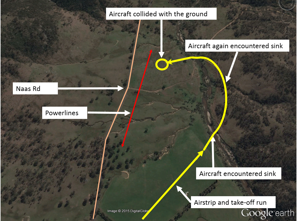
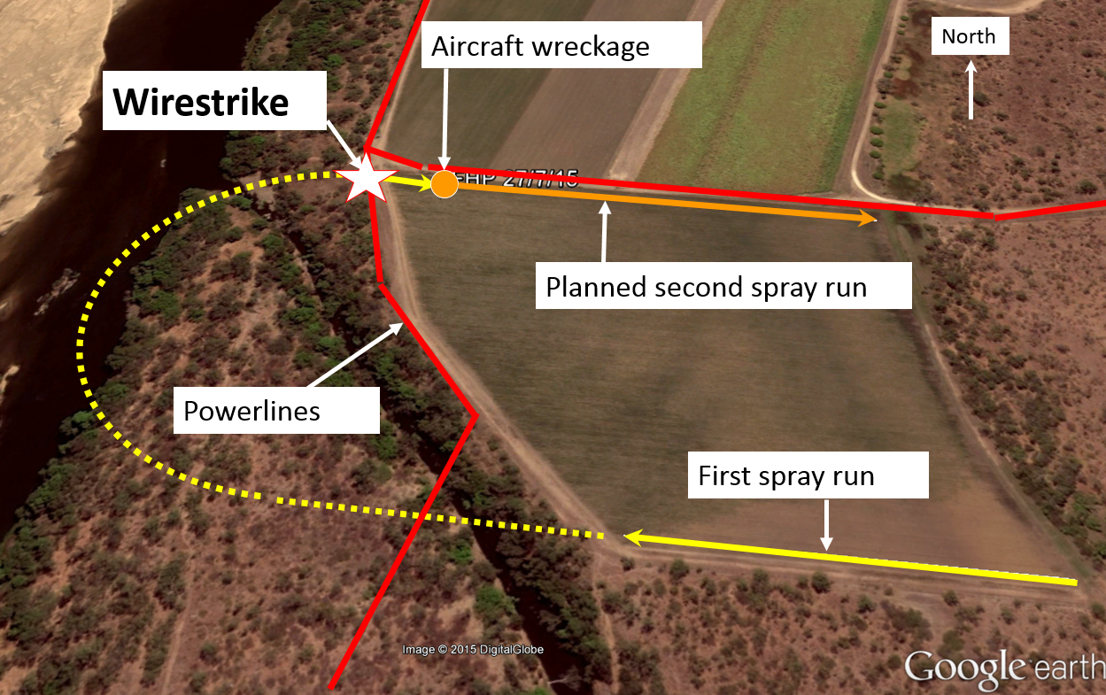
At about 1400, the pilot commenced the take-off run for the seventh load of the day. As the aircraft became airborne, the aircraft started to sink (Figure 1). To stop the aircraft sinking, the pilot applied the dump lever to start dumping the load of superphosphate. The aircraft then started to climb, so the pilot stopped dumping the load. The pilot also commenced a shallow left turn, away from rising terrain. As the aircraft turned, when at about 100 ft above ground level, it started to sink again. As it sank, the pilot felt a shake through the airframe, indicating that the aircraft was close to stalling. The pilot re-applied the dump lever to open the hopper door and try to reduce the aircraft load. Simultaneously, the pilot lowered the aircraft’s nose and rolled the wings level, to try to recover from the incipient stall.
Figure 1: Departure airstrip, aircraft track and accident location
Source: Google earth and pilot recollection – annotated by the ATSB
The pilot sighted powerlines, a road and a row of trees ahead, beyond which the terrain rose steeply. The aircraft continued to descend and the pilot maintained the aircraft in a normal nose attitude for landing. As the aircraft neared the ground, the pilot reduced the throttle to idle and held the aircraft control stick in the full back position. The tailwheel struck the ground first, and then the right main landing gear dug into soft ground. The aircraft flipped over and came to rest inverted.
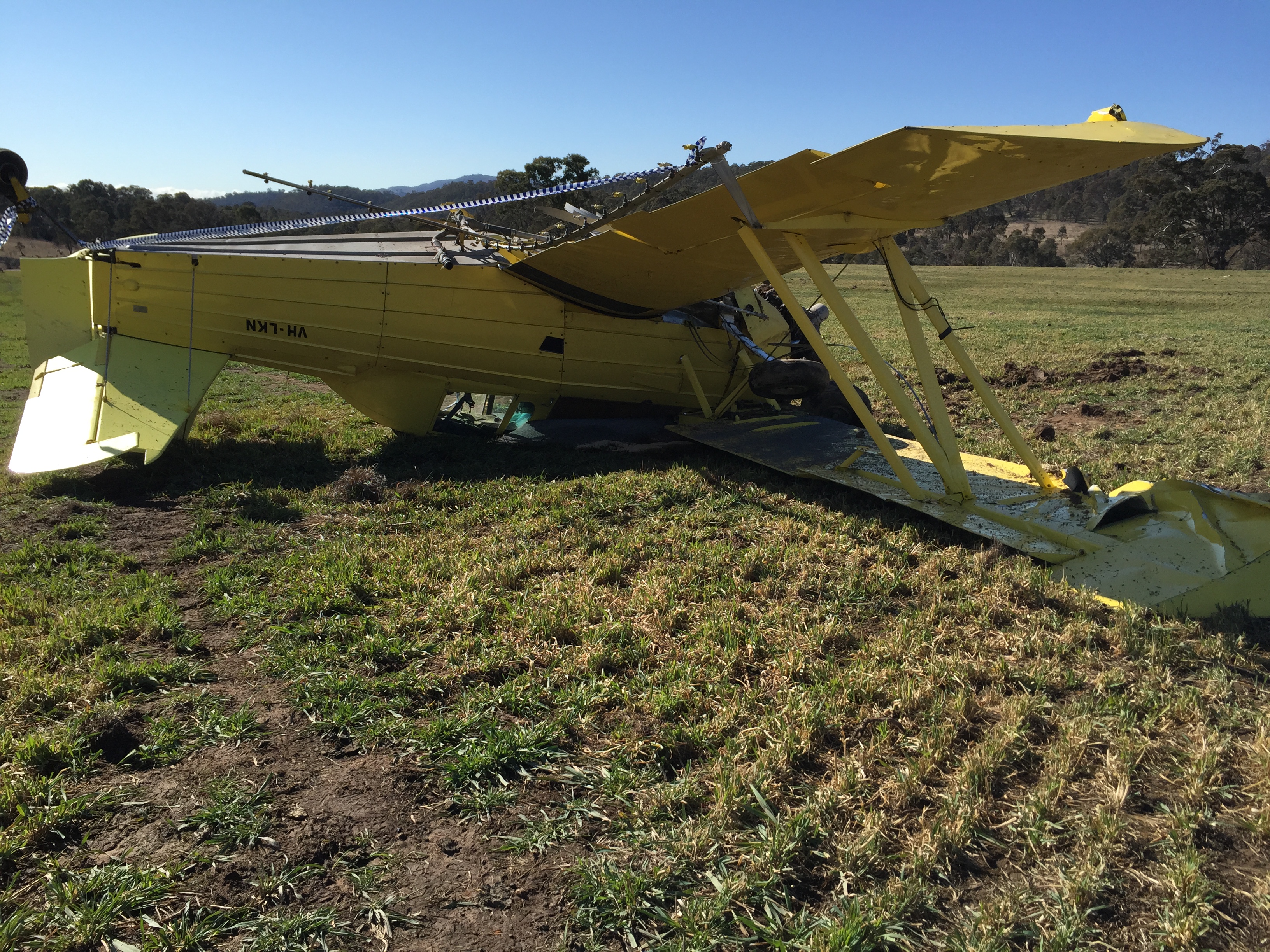
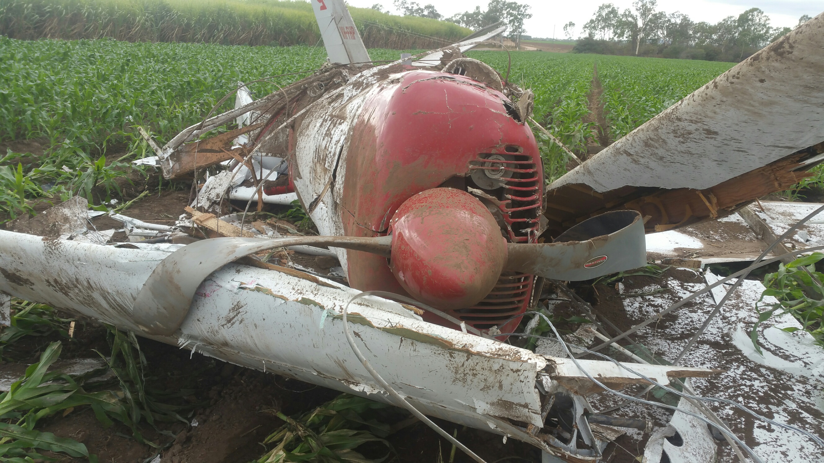
The pilot sustained minor injuries and the aircraft was substantially damaged (Figure 2).
Figure 2: Damage to VH-LKN
Source: Pilot
Pilot comments
The pilot provided the following comments:
The airstrip was at an elevation of about 2,100 ft above mean sea level. The target pasture was about 1,000 ft higher than the airstrip.
The airstrip was about 500 m in length and the fuel and chemical load was relatively light. The aircraft was well within its operational limitations.
The weather forecast had indicated calm conditions, and the temperature was about 14°C.
The sink that the aircraft encountered may have been a downdraft coming off the hill.
If the airstrip had been higher up and closer to the target zone, the pilot would have had more time to dump the load, less distance to climb on each load, and a more accurate assessment of the wind conditions.
Dumping liquid takes a few seconds, but granular substances like superphosphate take minutes for the hopper to empty when dumping the load.
After the accident, the pilot verified that the hopper door was open, and superphosphate was present in the paddock, indicating that it had been dumping at the highest rate. Despite that, about 300 kg of superphosphate remained in the hopper.
Safety message
The pilot stated that the key to avoiding similar incidents was to understand the atmospheric conditions in steep mountainous country. Variations in wind strength and direction due to terrain can have serious consequences on flight safety, particularly when operating at low airspeeds and close to the ground.
ATSB investigated a similar accident involving a Grumman G-164A, in AO-2014-001.
Decisions regarding whether to conduct an investigation, and the scope of an investigation, are based on many factors, including the level of safety benefit likely to be obtained from an investigation. For this occurrence, a limited-scope, fact-gathering investigation was conducted in order to produce a short summary report, and allow for greater industry awareness of potential safety issues and possible safety actions.
Publishing information
Released in accordance with section 25 of the Transport Safety Investigation Act 2003
Ownership of intellectual property rights in this publication
Unless otherwise noted, copyright (and any other intellectual property rights, if any) in this report publication is owned by the Commonwealth of Australia.
Creative Commons licence
With the exception of the Coat of Arms, ATSB logo, and photos and graphics in which a third party holds copyright, this publication is licensed under a Creative Commons Attribution 3.0 Australia licence.
Creative Commons Attribution 3.0 Australia Licence is a standard form licence agreement that allows you to copy, distribute, transmit and adapt this publication provided that you attribute the work.
The ATSB’s preference is that you attribute this publication (and any material sourced from it) using the following wording: Source: Australian Transport Safety Bureau
Copyright in material obtained from other agencies, private individuals or organisations, belongs to those agencies, individuals or organisations. Where you wish to use their material, you will need to contact them directly.
On 20 July 2015, the pilot of a Bell 206L3 (Longranger) helicopter, registered VH-BLV (BLV), conducted a charter flight from Essendon Airport to Falls Creek, Victoria, with five passengers on board. The aircraft took off from Essendon close to its maximum take-off weight. Due to the weight, and therefore fuel limitations, the pilot landed and refuelled at a property near Lake Eildon. At about 1000 Eastern Standard Time (EST), the helicopter departed from the property for the 60 NM flight to Falls Creek, again close to its maximum take-off weight.
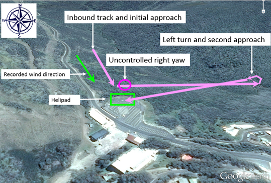
At about 1030, while 700 ft above ground level and tracking from the north-west, the pilot conducted a shallow approach towards the helipad at Falls Creek (Figure 1). As the helicopter descended to about 50 ft above ground level, the pilot found that significantly more power was required to conduct the approach than anticipated. The pilot assessed that there was insufficient power available to continue to land, and elected to abort the approach. The pilot pushed forwards on the cyclic[1] to increase the helicopter’s airspeed and conducted a left turn towards the valley.
Figure 1: Falls Creek helipad, approximate helicopter track and wind direction
Source: Google earth and pilot recollection – annotated by the ATSB
As the helicopter turned left, it started to yaw[2] rapidly towards the right. The pilot applied full left pedal to counteract the yaw, but the helicopter continued to yaw. The helicopter turned through one and a half revolutions, as the pilot lowered the collective.[3] Lowering the collective reduced the power demand of the power rotor system, thereby increasing the ability of the anti-torque pedals to stop the right yaw. The combination of lowering collective and applying forward cyclic to gain forward airspeed, allowed the pilot to regain control of the helicopter. The pilot then conducted a left turn towards the helipad and made an approach to the helipad from an easterly direction. The helicopter landed following the second approach without further incident.
The pilot and passengers did not sustain any injuries and the helicopter was undamaged.
Weather
The pilot expected that the wind at Falls Creek would be variable at 2 kt, as it had been on departure from Essendon. The pilot did not see the windsock at the helipad prior to conducting the approach.
The Bureau of Meteorology provided the ATSB with a report of weather observations for Falls Creek. The automatic weather station is located south of the helipad at about 5,790 ft above mean sea level, above the village. Between 1020 and 1040, the recorded wind speed was from 17 to 20 kt, gusting to 24 kt, and wind direction was from 327° to 344° (degrees true), or 314° to 331° (degrees magnetic). The temperature was 1 °C.
Pilot comments
The pilot reported that the following combination of factors contributed to the incident:
Unfamiliarity with the landing site and area.
Inexperience operating at altitude, and unfamiliarity with the associated power requirements. The helipad at Falls Creek is at an elevation of about 5,000 ft above mean sea level.
Lack of experience in the aircraft type – although the pilot had about 60 hours experience in the Bell Jetranger, this was only the pilot’s second flight in the Longranger.
High all up weight.
Incorrect assessment of the wind direction – the pilot assumed that the wind would be light and variable at Falls Creek as it was had been on departure from Essendon. During the approach, the pilot assessed that the wind was from the right or a tailwind gusting to about 15 kt.
Operator comment
The operator of VH-BLV assessed that the unanticipated yaw was a result of too little pedal input, applied too late. This was most likely due to a combination of the pilot’s inexperience on the 206L3, and being surprised by the downwind approach.
Hover ceiling
Hovering requires more power than any other flight regime. Additionally, hovering at higher altitudes requires more power than to hover at lower altitudes. The ‘hover ceiling’ is the height at which the power available equals the power required to hover. An increase in power increases the main rotor torque. This additional torque needs increased tail rotor thrust, to prevent the helicopter from yawing.
The Bell 206 L3 flight manual provides a Hover ceiling – out of ground effect[4] chart. At 5,000 ft, a temperature of 0 °C, and a gross weight of about 1,814 kg (4,000 lb), the helicopter was just within the chart’s hover ceiling envelope. This indicates that adequate power should have been available to hover with those parameters. However, the wind direction and velocity also affect hovering performance.
A stronger head wind reduces the power required to hover, while a tailwind increases the power required to hover. On the initial approach to the helipad, a tailwind meant that an increase in power and tail rotor thrust was required. The increased tail rotor thrust absorbs power from the engine, which means less power is available for the main rotor to produce lift. This led to the pilot’s assessment of insufficient power available, and decision to discontinue the approach.
Unanticipated right yaw
The US Federal Aviation Administration (FAA) Helicopter flying handbook describes loss of tail rotor effectiveness (LTE) or an unanticipated yaw, as ‘an uncommanded, rapid yaw towards the advancing blade which does not subside of its own accord’. It is caused by an interaction between the main rotor and tail rotor.
At high altitudes, the lower air density reduces tail rotor thrust and efficiency. Therefore, when operating at high altitudes and high gross weights, particularly while hovering or at low airspeeds, the tail rotor thrust may not be sufficient to maintain directional control. This can result in unanticipated yaw or LTE. In these circumstances, the hover ceiling is effectively limited by the tail rotor thrust, rather than the power available.
In this incident, other factors may also have contributed to the unanticipated yaw: low and slow flight outside of ground effect, a low speed downwind turn and a large change of power at low airspeed as the pilot aborted the approach.
The US Federal Aviation Administration Advisory Circular, Unanticipated right yaw in helicopters, stated that unanticipated right yaw, or loss of tail rotor effectiveness (LTE) has been determined to be a contributing factor in a number of accidents. These mishaps have occurred at low altitude and in low-speed flight, often on final approach to landing. Unanticipated right yaw may occur during any manoeuvre in which the pilot is operating in a high-power, low-airspeed environment with a left crosswind (in aircraft with counter-clockwise blade rotation) or tailwind.
Three additional factors can significantly influence the severity of LTE:
gross weight and density altitude
low indicated airspeed
a rapid application of power, causing power droop.
In order to reduce the onset of LTE, when manoeuvring between hover and 30 kt, the pilot should:
Avoid tailwinds.
Avoid out of ground effect hover and high-power demand situations, such as low-speed downwind turns.
Be aware of wind direction and velocity. A loss of translational lift results in an unexpected high-power demand and an increased anti-torque requirement.
Be aware that if a considerable amount of left pedal is being maintained, a sufficient amount of left pedal may not be available to counteract an unanticipated right yaw.
Stay vigilant to power and wind conditions.
If a sudden unanticipated right yaw occurs, the pilot should:
apply full left pedal
simultaneously move cyclic forward to increase speed
if altitude permits, reduce power.
Safety message
Pilots should understand and avoid conditions that are conducive to uncontrolled yaw or loss of tail rotor effectiveness. Pilots can reduce their exposure to LTE by maintaining awareness of the wind and its effect on the helicopter. If a pilot encounters unanticipated yaw, quick application of the correct response is essential to recover control of the helicopter. The ATSB reported on an incident involving LTE in AO-2013-121.
This incident also highlights the effect of gross weight and airfield elevation on aircraft performance. Understanding controllability issues at the limits of the normal operating envelope can assist pilots in recognising the symptoms of reduced aircraft performance. Further information is available in ATSB report AO-2013-203.
Decisions regarding whether to conduct an investigation, and the scope of an investigation, are based on many factors, including the level of safety benefit likely to be obtained from an investigation. For this occurrence, a limited-scope, fact-gathering investigation was conducted in order to produce a short summary report, and allow for greater industry awareness of potential safety issues and possible safety actions.
Publishing information
Released in accordance with section 25 of the Transport Safety Investigation Act 2003
Ownership of intellectual property rights in this publication
Unless otherwise noted, copyright (and any other intellectual property rights, if any) in this report publication is owned by the Commonwealth of Australia.
Creative Commons licence
With the exception of the Coat of Arms, ATSB logo, and photos and graphics in which a third party holds copyright, this publication is licensed under a Creative Commons Attribution 3.0 Australia licence.
Creative Commons Attribution 3.0 Australia Licence is a standard form licence agreement that allows you to copy, distribute, transmit and adapt this publication provided that you attribute the work.
The ATSB’s preference is that you attribute this publication (and any material sourced from it) using the following wording: Source: Australian Transport Safety Bureau
Copyright in material obtained from other agencies, private individuals or organisations, belongs to those agencies, individuals or organisations. Where you wish to use their material, you will need to contact them directly.
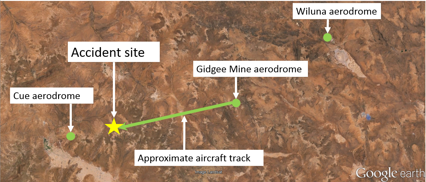
On 1 August 2015, at about 1110 Western Standard Time (WST), a Cessna 210 aircraft, registered VH-ERU, departed Gidgee Gold mine for a private flight to Cue, Western Australia (Figure 1). The pilot was the sole occupant of the aircraft. The pilot reported that all engine indications were normal from the start and into the cruise at 3,500 ft above mean sea level. The elevation of the terrain in the area was about 1,700 ft above mean sea level.
Figure 1: Aircraft track and accident location
Source: Google earth – annotated by the ATSB
About 25 minutes into the flight, the pilot observed the engine oil temperature rising rapidly. The pilot opened the cowl flaps in an attempt to reduce the engine oil temperature, and noted that the cylinder head temperature and engine oil pressure were still in the normal range. As the pilot tried to determine the cause of the problem, the manifold pressure started to increase. The pilot reduced the throttle to try to decrease the manifold pressure, but it continued to rise.
The pilot then felt a slight vibration in the engine and through the aircraft controls, and broadcast a PAN[1] call on the Melbourne Centre radio frequency. The pilot did not receive any response to the broadcast, probably due to the aircraft’s remoteness and low altitude. The aircraft was descending steadily, and the pilot looked for a suitable place to conduct a precautionary landing. However, the surrounding area was heavily treed. After turning towards the north and more open country, the vibration increased, and the pilot broadcast two Mayday[2] calls. Again, the pilot did not receive any response.
When about 500 ft above ground level, the vibration further increased and the engine failed with a bang. Smoke emanated from the engine compartment and over the windscreen, reducing the pilot’s visibility through it. The pilot then sighted a fence line to the right and prepared for a forced landing, aiming to touchdown in a cleared area alongside the fence.
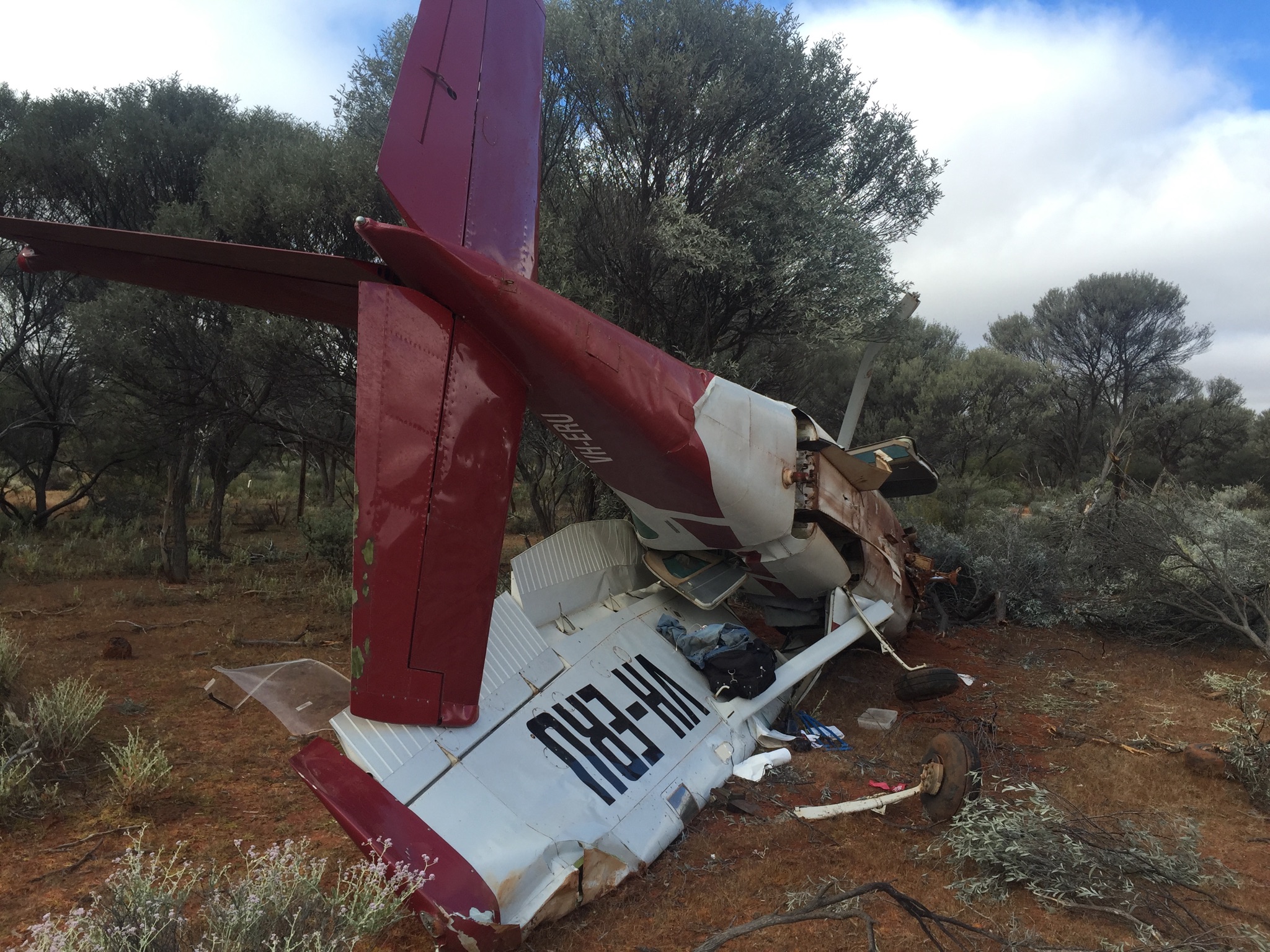
The pilot lowered the landing gear and extended the flap. When at about treetop height, the pilot selected the master switch and fuel off. The pilot also tightened the seatbelt and opened the aircraft door. As the pilot flared the aircraft to land, the right wing and strut collided with a tree. The aircraft yawed to the right, and the right main landing gear struck the ground and broke off. Although the pilot applied full left rudder to try to regain control of the aircraft, it collided with another tree and rolled onto its left side, before skidding and coming to rest against a third tree. The pilot suffered minor injuries and the aircraft sustained substantial damage (Figure 2).
The right fuel line ruptured during the impact sequence, causing fuel to run down into the cabin and onto the pilot. The pilot quickly exited the aircraft, concerned about the risk of fire, particularly as there was about 240 L of fuel in the tanks.
After waiting about half an hour for the fuel to stop running into the cockpit, the pilot returned to the aircraft and selected the master switch on. The pilot then made another radio broadcast requesting assistance, and again did not receive any response. The aircraft’s emergency locator transmitter (ELT)[3] did not activate on impact, and its light had not illuminated. The pilot then tried, without success, to use the aircraft battery to power the ELT.
At about 1400, the pilot again made radio broadcasts without any response. As there was no mobile phone signal at the accident site, the pilot started walking towards higher terrain. At about 2200, after walking 25 km, the pilot gained mobile phone coverage and was able to call for assistance. After making the call, the pilot lit a fire to provide warmth and to deter a pack of wild dogs that had been circling. At about 0200 on 2 August, low cloud rolled in and it started to drizzle. About an hour later, the pilot provided rescue personnel with the coordinates of the location, obtained from the mobile phone. At about 0730, a rescue aircraft located the pilot and police arrived about 40 minutes later.
Figure 2: Accident site showing damage to VH-ERU
Source: Western Australia Police
Pilot comments
The pilot provided the following comments:
The number three cylinder failed and blew a hole in the top of the engine casing.
The pilot usually carried a satellite phone, but did not have it on this flight as it was being serviced.
It was about a 40-minute flight to Cue, and the pilot would normally have advised someone of the planned route and expected arrival time, but omitted to do so on this day.
The pilot had water, a first aid kit and a lighter in the aircraft, and planned to get a personal location beacon to carry in future.
Aircraft engine
The aircraft was fitted with a Continental IO-520 engine. The pilot had owned the aircraft for about 4 years, during which time the aircraft had accrued about 60 hours of flying time. Shortly after the pilot bought the aircraft, the number three cylinder had failed and been replaced. The pilot had recently replaced the propeller in accordance with an airworthiness directive.
The aircraft was damaged beyond repair. At the time of completing this report, no engineering inspection of the engine had been, or was expected to be, conducted following the accident.
Safety message
The ATSB reminds all pilots to let someone know where they are going, and what time they expect to arrive, before embarking on a flight. Although the incident flight was not in a designated remote area, it demonstrates that it is vitally important to carry emergency supplies, such as water, food, matches (or lighter), and first aid essentials. Where mobile and radio coverage is not available, a satellite phone can provide life-saving access to help.
Electronic locator transmitters installed in aircraft should be tested in accordance with the manufacturer’s instructions. The ATSB research report AR-2012-128 found that ELTs function as intended in about 40-60% of accidents. NASA is currently conducting research to find ways to make ELTs more likely to function after a survivable crash.
Decisions regarding whether to conduct an investigation, and the scope of an investigation, are based on many factors, including the level of safety benefit likely to be obtained from an investigation. For this occurrence, a limited-scope, fact-gathering investigation was conducted in order to produce a short summary report, and allow for greater industry awareness of potential safety issues and possible safety actions.
Publishing information
Released in accordance with section 25 of the Transport Safety Investigation Act 2003
Ownership of intellectual property rights in this publication
Unless otherwise noted, copyright (and any other intellectual property rights, if any) in this report publication is owned by the Commonwealth of Australia.
Creative Commons licence
With the exception of the Coat of Arms, ATSB logo, and photos and graphics in which a third party holds copyright, this publication is licensed under a Creative Commons Attribution 3.0 Australia licence.
Creative Commons Attribution 3.0 Australia Licence is a standard form licence agreement that allows you to copy, distribute, transmit and adapt this publication provided that you attribute the work.
The ATSB’s preference is that you attribute this publication (and any material sourced from it) using the following wording: Source: Australian Transport Safety Bureau
Copyright in material obtained from other agencies, private individuals or organisations, belongs to those agencies, individuals or organisations. Where you wish to use their material, you will need to contact them directly.
On 23 July 2015, an Airbus A330 aircraft, registered VH-QPJ and operated by Qantas Airways, was being loaded at Bangkok Airport, Thailand, prior to flying to Sydney, Australia. The ground-handling agent (and loading supervisor) was in Bangkok, and the load controller was in Warsaw, Poland.
The load instruction report (LIR) displayed a pictorial representation of the planned uplift. To maximise uplift within the aircraft’s operational limitations, the report contained a set of loading instructions. These instructions identify positions within the aircraft hold for loading containers, baggage and freight.
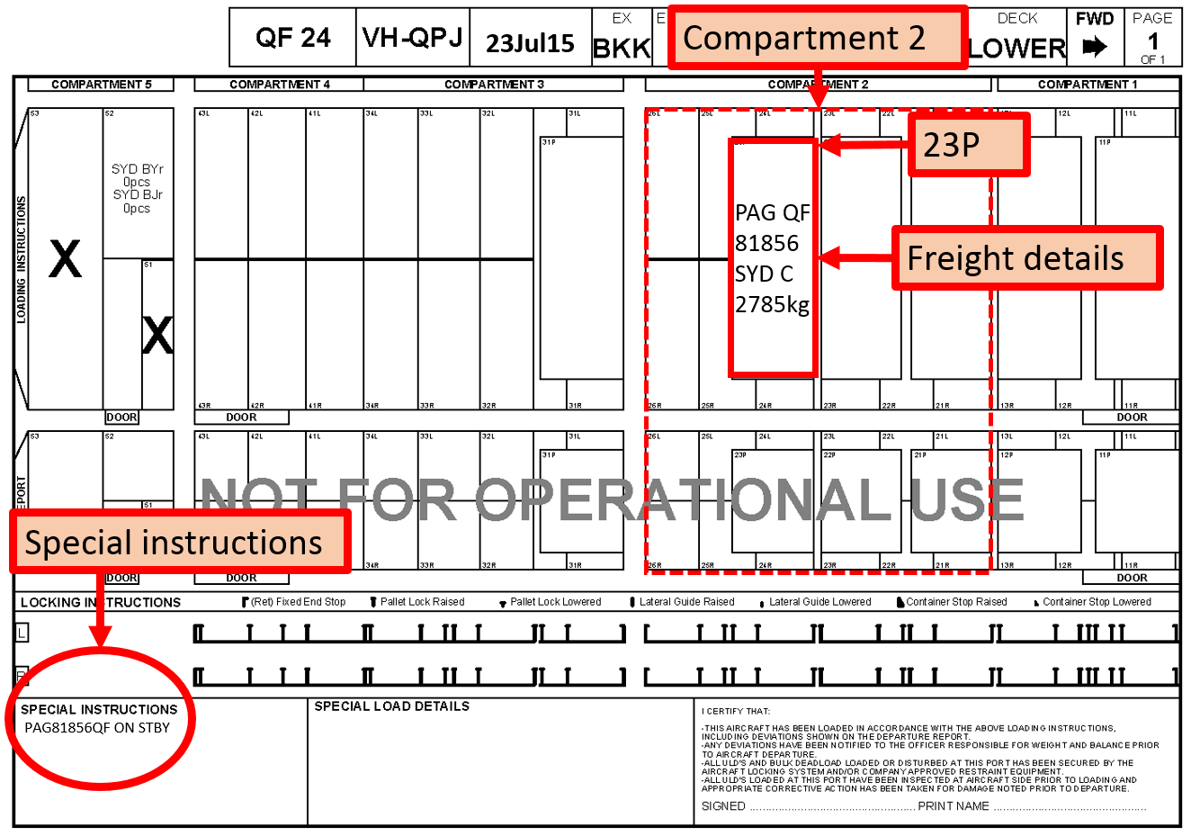
The load controller in Warsaw issued a load instruction report (LIR) to the loading supervisor in Bangkok (Figure 1). The loading supervisor was required to load the aircraft in accordance with the LIR. The LIR also contained ‘Special instructions’ and ‘Special load details’. The Special instructions for QF24 stated that the freight pallet shown on the LIR in position 23P was on standby. The loading supervisor then called the load controller by telephone to provide a ‘partial read back’. The supervisor read back to the controller how the aircraft had been loaded, based on the LIR.
The loading supervisor commenced by reading out the description and weight of the pallet loaded into position 23P. The load controller responded that the pallet in 23P was on standby as per the Special instructions, and directed the loading supervisor to offload that freight. The supervisor responded ‘yes’, and stated that the loading was in accordance with the LIR. The loading supervisor then continued to read the loading to the controller, again commencing with the pallet in 23P, followed by the rest of the loaded freight. The pallet in 23P remained loaded on the aircraft.
Figure 1: Load instruction report showing freight positions and special instructions
Source: Aircraft operator
After completion of the loading, the loading supervisor again phoned the load controller to provide the final read back of the loading. The loading supervisor stated ‘forward compartment no change’, to which the load controller responded clarifying position 23P was ‘no fit’[1]. The loading supervisor replied, ‘yeah, no change’ and the load controller responded ‘ok’.
The load controller then prepared the final load sheet for the flight, based on the information provided over the phone by the loading supervisor. The load controller transmitted the final load sheet to the flight crew via the Aircraft Communications Addressing and Reporting System (ACARS). The load sheet included the calculated aircraft total and component weights including fuel, passenger, baggage and freight weights. It also provided the aircraft balance details including the aircraft take-off trim setting position.
The flight crew then used this data to calculate reference speeds for take-off, fuel consumption rates, and initial climb altitude. At about midday local time, the aircraft departed Bangkok for Sydney and the flight crew did not detect any abnormal flight characteristics, nor did they receive any warnings related to the aircraft’s weight or balance.
After the flight had closed, the load control system automatically generated a Container Pallet Message (CPM) report. The report was based on the input from the load controller, and therefore did not include the pallet in 23P. The loading supervisor identified that the pallet in 23P was not on this report and contacted the load controller. The load controller confirmed that the pallet should have been offloaded, and was therefore not included in the uplift weight calculations. The load controller then contacted the Qantas Integrated Operations Control (IOC) in Sydney and advised them that a pallet had been loaded onto the aircraft, which was not included in the load sheet, and that some operational limitations had been exceeded.
About 75 minutes after the aircraft departed from Bangkok, the IOC advised the aircraft flight crew of the error. The flight crew entered the amended aircraft weight into the flight management computer.
Load discrepancy
The weight of the standby pallet for 23P indicated on the LIR was 2,785 kg. The final load sheet indicated 1,225 kg of freight in compartment 2. Compartment 2, depicted in Figure 1, included a number of freight positions including 23P. The calculation for total freight weight in Compartment 2 was based on freight loaded in positions 26L (615 kg), 26R (610 kg) and zero in 23P.
Based on the final load sheet, the taxi weight was calculated to be 235,485 kg (maximum 233,900 kg) and the take-off weight was 232,300 kg (maximum 233,000 kg).
As a result of the discrepancies, Qantas advised that the maximum taxi weight had been exceeded by 1,585 kg, and the maximum take-off weight by 2,085 kg. The initial cruise altitude of 35,000 ft did not exceed the maximum altitude when the actual weight was subsequently entered into the aircraft flight management computer.
Qantas investigation
Qantas conducted an investigation into the incident, which included a review of the transfer of load control operations to Warsaw (from its previous location in Hong Kong), the systems supporting the load controller and loading supervisor, and their individual actions.
The investigation identified a number of safety factors that contributed to the incident. These included the following.
Depiction of standby freight
The load controller represented the standby freight as listed on the LIR, with the freight depicted in the loaded position, and a standby notation included in the Special Instructions box. The Qantas investigation found that was not a documented procedure for handling standby freight, but it was an accepted practice. The training of loading supervisors did not include how standby freight was to be documented on the LIR.
Communication
The communications between the loading supervisor and load controller were open to misinterpretation, had ambiguous phraseology, untimely transmissions, and did not involve a read-back hear-back process.
During the partial read back, the offload instruction caused confusion as to whether the pallet in 23P was to be loaded or not, and that confusion was not resolved.
During the final read back, a misunderstanding resulted from the load controller’s use of the phrase ‘no fit’, meaning not loaded, and the loading supervisor’s use of the phrase ‘no change’ meaning no change to the loading depicted on the LIR.
Training
Irregularities were identified with the training regarding LIR presentation and interpretation. Specifically, the training on procedures for handling standby items provided to load controllers did not cross-reference the training provided to loading supervisors and vice versa.
Safety actions
Whether or not the ATSB identifies safety issues in the course of an investigation, relevant organisations may proactively initiate safety action in order to reduce their safety risk. The ATSB has been advised of the following proactive safety action in response to this occurrence.
Aircraft operator
As a result of this occurrence, Qantas advised the ATSB that they are taking the following safety actions:
Immediate action taken
For all flights out of Bangkok, the loading supervisor must receive a scanned copy of the final LIR before transmitting the final load sheet to the flight crew (by ACARS).
Standard phraseology is to be used for all read back communications.
Standby freight procedure
Load Control will document the following:
procedures for listing standby freight in the LIR Special Instructions
use of LIR Special Instructions
sample communications for instructions to offload and the required response from loading supervisors.
Training
The training provided to load controllers and loading supervisors was to be coordinated. The training procedures will include a standardised process for handling standby freight.
A process for updating load control training material will also be implemented.
Firstload
An automated read back system, ‘Firstload’, is scheduled to be introduced to Bangkok and other international ports in November 2015. Firstload is an iPad-generated LIR and read back system. Implementation of the system will remove the requirement for verbal read backs.
Safety message
This incident highlights the importance, particularly when dealing with safety-critical data, for:
standard phraseology in verbal communications
ensuring a verbal instruction has been understood and complied with
validating verbal communication with written documentation.
The ATSB SafetyWatch highlights the broad safety concerns that come out of our investigation findings and from the occurrence data reported to us by industry. One of the safety concerns is data input errors.
Decisions regarding whether to conduct an investigation, and the scope of an investigation, are based on many factors, including the level of safety benefit likely to be obtained from an investigation. For this occurrence, a limited-scope, fact-gathering investigation was conducted in order to produce a short summary report, and allow for greater industry awareness of potential safety issues and possible safety actions.
Publishing information
Released in accordance with section 25 of the Transport Safety Investigation Act 2003
Ownership of intellectual property rights in this publication
Unless otherwise noted, copyright (and any other intellectual property rights, if any) in this report publication is owned by the Commonwealth of Australia.
Creative Commons licence
With the exception of the Coat of Arms, ATSB logo, and photos and graphics in which a third party holds copyright, this publication is licensed under a Creative Commons Attribution 3.0 Australia licence.
Creative Commons Attribution 3.0 Australia Licence is a standard form licence agreement that allows you to copy, distribute, transmit and adapt this publication provided that you attribute the work.
The ATSB’s preference is that you attribute this publication (and any material sourced from it) using the following wording: Source: Australian Transport Safety Bureau
Copyright in material obtained from other agencies, private individuals or organisations, belongs to those agencies, individuals or organisations. Where you wish to use their material, you will need to contact them directly.
On 28 July 2015, the pilot and owner of an amateur-built Cicaré CH-7BT helicopter, registered VH‑JEW, was conducting a ferry flight from Indee Station to Roy Hill Station, Western Australia. When about 8.5 NM north‑east of Roy Hill Station, the stabiliser assembly fractured leading to an in-flight break up and collision with terrain. The pilot, and sole occupant, was fatally injured and the helicopter was destroyed.
What the ATSB found
The ATSB examined the helicopter wreckage and identified that the stabiliser had separated in‑flight from the tail boom as a result of fatigue cracking of the stabiliser mount. This was the second fatal accident in Australia involving in-flight stabiliser separation on a Cicaré CH-7B helicopter (In-flight break-up involving Cicaré CH-7B, VH-SWQ, 43 km north-west of Barcaldine Airport Queensland on 12 May 2014 (AO-2014-086)). Following the event in 2014, the helicopter manufacturer, Cicaré S.A., released a mandatory service bulletin, BSC007, which required inspection of the stabiliser assembly. However, the bulletin did not include an initial or recurrent time interval for that inspection.
The ATSB found that there were notable differences between VH-JEW and SWQ, and the accidents were not directly comparable. However, it was established that both helicopters were fitted with an external storage pod, likely without the appropriate engineering assessment to ensure there would be no adverse effects on the performance, handling and structure of the helicopter. In addition, both helicopters had previously been used for mustering operations, although the helicopters were designed be used for recreational use only. The ATSB found other Cicaré CH-7B owners were also likely using their helicopters for aerial mustering and other agricultural activities. The addition of unapproved modifications and use for mustering operations can produce unintended stresses on the airframe leading to premature failure of components.
The ATSB determined that a combination of factors could have contributed to the development of the fatigue crack including, the stabiliser design, operating the helicopter in high load mustering activities, and the use of untested accessories. However, the investigation was unable to determine the contribution of these factors.
What's been done as a result
On 6 August 2015, the ATSB emailed an information letter to registered Cicaré CH-7B owners, informing them of the second accident, the mechanism of stabiliser failure, and a recommendation to ensure the integrity of the stabiliser prior to further operation and on an ongoing basis.
The ATSB has also released a Safety Advisory Notice (AO-2015-089-SAN-014) to raise awareness among amateur-built helicopter owners and the aerial mustering community regarding the risks associated with operating outside the recommended design intent.
A revision to the original bulletin, BSC007, was released in September 2015, which provided some additional information with regard to disassembly of the component to allow examination. The contents of this bulletin was incorporated into the ongoing maintenance documentation for the helicopter in March 2016, with the inspection required to be performed every 100 hours. The stabiliser was also redesigned, originally for the bigger CH-8 series helicopter. The latest design was incorporated into all new Cicaré helicopters and is available for retrofit on the CH-7T/B/BT. A number of operators in Australia have already installed the new stabiliser assembly.
Safety message
The addition of external loads may result in forces in excess of the manufacturer’s limitations. This accident highlights the significance of ensuring that any modifications, such as external accessories, are appropriately assessed, and the effects on structural integrity and handling characteristics are considered prior to flight.
Further, it emphasises the importance of operating aircraft in accordance with the manufacturer’s intent and limitations. Operating outside these has the potential to induce stresses on the aircraft, leading to premature wear and possible failure.
Lastly, as detailed in the information letter released in March 2016, the ATSB reinforces the importance of CH-7B owners ensuring the integrity of the stabiliser on an on-going basis. If any doubt arises concerning the inspection or maintenance of any part, piece or component, owners should immediately contact Cicaré.
The occurrence
On 28 July 2015, at about 1535 Western Standard Time,[1] the pilot and owner of an amateur-built Cicaré CH-7BT helicopter, registered VH-JEW, departed Indee Station for a 2.5-hour flight to Roy Hill Station, Western Australia. The flight was a repositioning flight, for mustering work at Roy Hill Station, which was to commence the following day.
At about 1810, a company pilot who had arrived at Roy Hill Station about 2 hours prior, phoned another pilot who had remained at Indee Station to advise that VH-JEW had not yet arrived. They decided to give the pilot a little more time, however, when the helicopter still had not arrived by about 1930, it was reported missing to search and rescue, and the police. A search and rescue operation commenced the following morning.
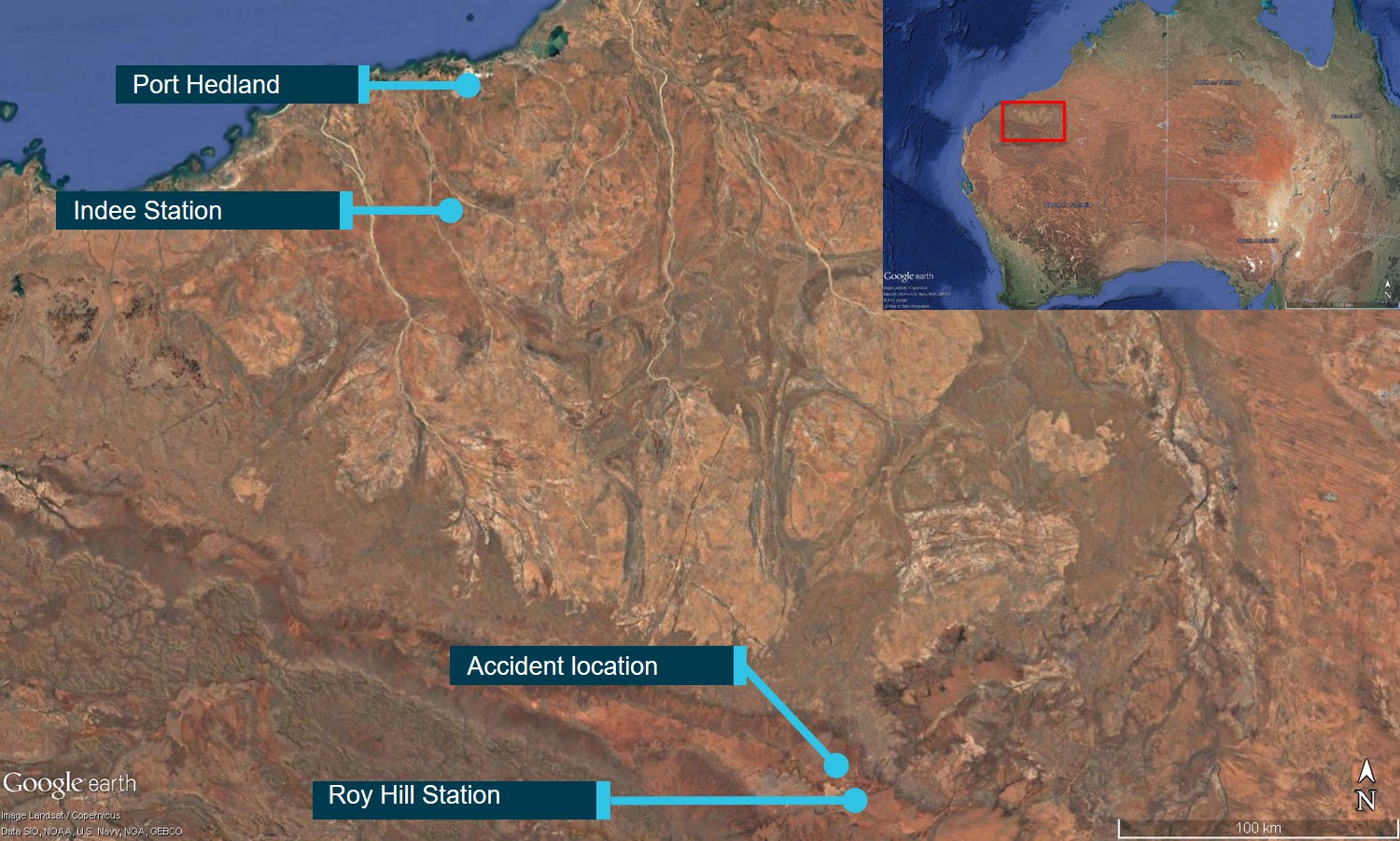
On 29 July 2015, at about 1500, the wreckage was located about 8.5 NM north-west of Roy Hill Station, and 0.5 NM west of the intended track between Indee and Roy Hill Stations (Figure 1). The pilot was fatally injured, and the helicopter destroyed.
Figure 1: VH-JEW accident site location, near Roy Hill Station
The pilot held a Commercial Pilot (Helicopter) Licence, issued on 13 June 1980. The pilot last completed a single-engine helicopter and low-level flight reviews in June 2015, valid until 30 June 2017 and 24 June 2017 respectively.
At the time of the accident, the pilot’s Class 1 Aviation Medical Certificate required for conducting commercial operations[2] had expired on 13 April 2015 and the pilot was in the process of revalidation. The pilot held a Class 2 certificate, valid to 13 April 2016.
In May 2015, the pilot indicated on his aviation medical questionnaire that he had accumulated a total of 28,559 hours, with 78 hours of helicopter operations in the previous 6 months. The pilot was reported to have had extensive experience as a cattle mustering pilot. Anecdotal information supplied to the ATSB indicated that most of this flying had been completed in a Robinson Helicopter Company R22. The pilot had only recently starting flying the Cicaré CH-7BT, and it was reported that the pilot had been conducting commercial mustering operations[3] in the weeks leading up to the accident.
Witness reports from family and acquaintances indicated that the pilot was in good health and mental state prior to the flight. A post-mortem examination did not reveal any preconditions that would have affected the pilot’s ability to fly the helicopter.
Helicopter information
VH-JEW was a single-seat, amateur-built[4] Cicaré CH-7BT helicopter, serial number 032, which was first registered with the Civil Aviation Safety Authority (CASA) on 25 June 2015 (about one month before the accident). It had a two‑bladed, semi-rigid main rotor system, a two-bladed tail rotor system, and was powered by a Rotax 914 UL turbo-charged, four-cylinder piston engine. The helicopter kit manufacturer was located in Argentina with the kits and product support available through an Australian distributor. As at March 2019, there had been 39 CH-7B[5] kits sold worldwide, 13 of which were in Australia. At time of publication, there were six on the CASA VH‑register.
Meteorological information
Personnel on the ground at Ginbata aerodrome (about 10 NM from the accident site) described the weather conditions on the day as fine and clear with light wind. This was consistent with the Bureau of Meteorology area forecasts for the afternoon.
Sunset was recorded to be at 1737 and last light[6] at 1801. The helicopter departed Indee Station at about 1535, which would have put the arrival time at Roy Hill at about 1800. However, a worker at the nearby Roy Hill mining camp reported seeing black smoke for about 20 minutes at about 1720. Therefore, it was considered unlikely that the weather and available light conditions were a contributing factor to the accident.
Wreckage and impact information
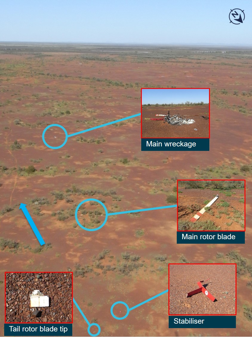
The helicopter was found in an open area, having broken into multiple fragments. The fuselage was subject to a post-impact fire, and the tail rotor stabiliser assembly was identified some distance away from the main wreckage (Figure 2).
Figure 2: Wreckage distribution showing main body and tail rotor stabiliser assembly, the blue arrow shows direction of travel
Source: ATSB
The stabiliser assembly and the tip from one tail rotor blade were the first items identified in the wreckage trail. The main rotor head components were located about 70 m beyond the stabiliser. The tail boom was still attached to the main wreckage, which was lying on its left side and facing opposite to the intended direction of travel, and was a further 180 m along. The tail rotor gearbox assembly was located near the fuselage. Overall, the wreckage distribution was about 250 m long in a southerly direction and consistent with an in-flight break-up.
The helicopter had been subjected to a post-impact fire, which destroyed much of the fuselage. Examination of the remaining wreckage identified:
all major components of the helicopter were accounted for
flight control damage was consistent with the in-flight break-up and did not indicate any pre‑existing issues
no indications of any issues with the engine and its related systems that may have contributed to the accident
the stabiliser assembly had separated at the point where it mounted to the tail boom
the tail rotor gearbox had fractured at its mount in overstress
the main rotor head assembly had separated from the main mast in a manner consistent with severe mast bumping.[7]
The fracture surfaces of the stabiliser assembly attachment bracket that remained with the tail boom appeared to correspond to those of the separated stabiliser assembly in shape and irregular texture. The rear section of the tail boom, including tail rotor components and the stabiliser assembly were retained by the ATSB for further examination (see Stabiliser assembly below).
Similar occurrence
The ATSB investigated a similar fatal accident where the stabiliser assembly on a Cicaré CH-7B had separated from the tail in-flight leading to a collision with terrain (In-flight break-up involving Cicaré CH-7B, VH-SWQ 43 km north-west of Barcaldine Airport Queensland on 12 May 2014 (AO-2014-086)). The investigation found that fatigue cracking of the stabiliser mount had led to the failure of the stabiliser assembly. The helicopter was reported to have had an issue with airframe vibration, and thee stabiliser had undergone two weld repairs following the identification of cracking of the stabiliser mount tube. The first weld repair was at about 130 hours’ total time-in-service, after the fins were removed following reports of movement within the stabiliser structure. The second weld repair was performed at about 295 hours’ total time-in-service. The investigation found these repairs were performed by a welder who did not hold a CASA-issued aviation welding authority, and that the first unauthorised welding carried out on the mount did not prevent further in-service metal fatigue cracking. The helicopter had also experienced a hard landing, sufficient to distort the rear cross-tube on the skid-landing gear. The investigation also found that the helicopter had undergone modifications, including the addition of heli-baskets and larger fuel tanks, which were not approved by CASA and/or the kit manufacturer, and could have affected the serviceability and flight characteristics.
Following this accident, the ATSB sent an advisory letter to all Australian registered owners of the CH-7B on 6 March 2015 which detailed the in-flight separation of the stabiliser.
The kit manufacturer advised that the accidents involving VH-SWQ and VH-JEW were the only known stabiliser fractures in the worldwide fleet of Cicaré 7 series helicopters[8].
Stabiliser assembly
The stabiliser assembly consisted of one horizontal and two vertical aerodynamic fins fitted to the helicopter tail boom. The fins generate aerodynamic forces during forward flight that keep the helicopter level and reduce the thrust required from the tail rotor.
Flight characteristics without stabilisers
The kit manufacturer advised that they had performed testing of the flight characteristics of the helicopter when the stabiliser assembly was not fitted and found the following:
…proving that for hovering flight condition and low speeds, the change in controllability was verily [sic] noticeable and for translational flight over 30 knots the helicopter showed a light instability in pitch and yaw that can be easily corrected by the pilot, a pilot with standard training is able to execute the emergency maneuver [sic].
However, the manufacturer also noted that:
In case of loss of stabilizer [sic] in flight, even if the stabilizer doesn’t hit the tail rotor, sudden change on aerodynamic loads and CG [centre of gravity] balance due to the sudden absence of the stabilizer would cause an unstable flight condition.
With regard to the failure of the tail rotor/gearbox, the manufacturer advised:
For the case of an eventual tail rotor loss, during flight-testing there was no presence of “loss tail rotor effectiveness” under normal flight operations. In case of tail rotor or tail rotor gearbox failure, due to the variety of conditions that may occur it’s not possible to determine the exact behaviour of the aircraft.
Assembly build and fitting
While the build manual provided instructions for manufacturing this component, the kit manufacturer and Australian distributor advised that the CH-7B kits for Australia were supplied with the stabiliser assembly as a pre-assembled component (inset, Figure 3).
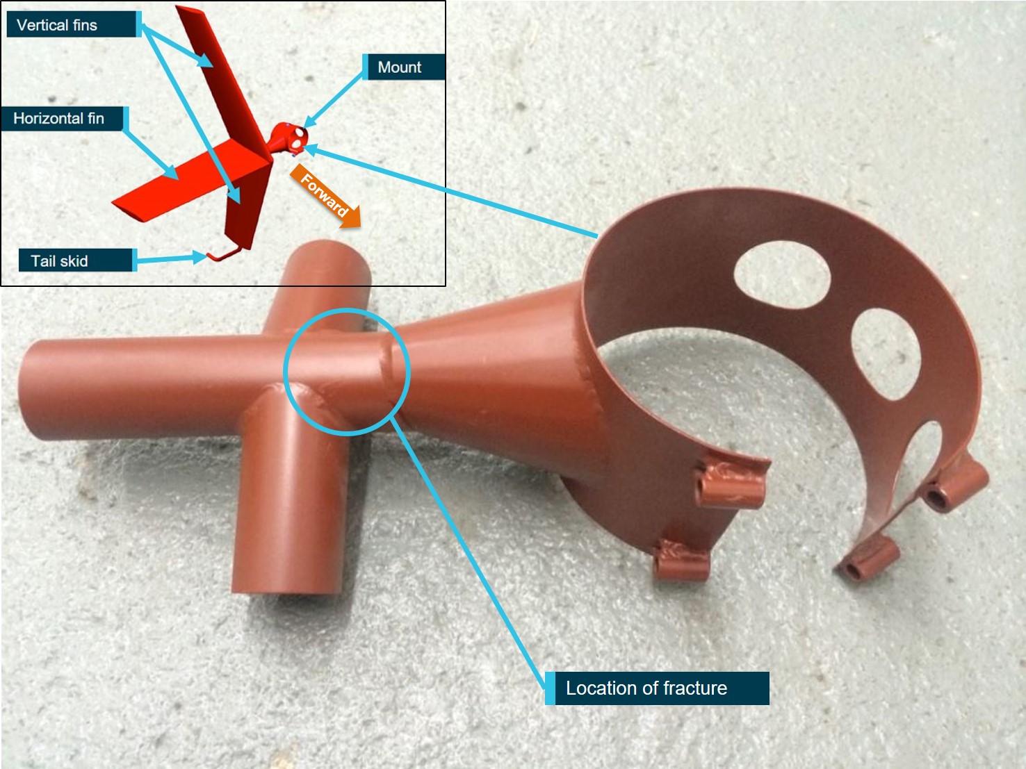
Figure 3: Stabiliser assembly showing location of fracture on VH-JEW
Source: Cicaré, modified by the ATSB
The CH-7BT kit build manual provided instructions for fixing the stabiliser on the tail boom. A factory pre-drilled hole in the stabiliser mount was to be positioned 115 mm forward of the tail rotor gear box mount and aligned with the top centreline of the tail boom. A hole was then drilled into the boom skin, using the locator hole as a guide, and a bolt inserted through the mount and boom.
Technical examination of the stabiliser assembly
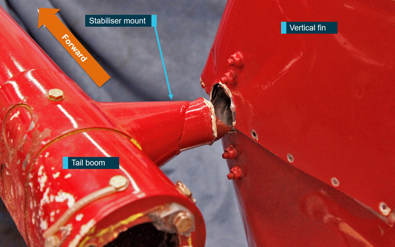
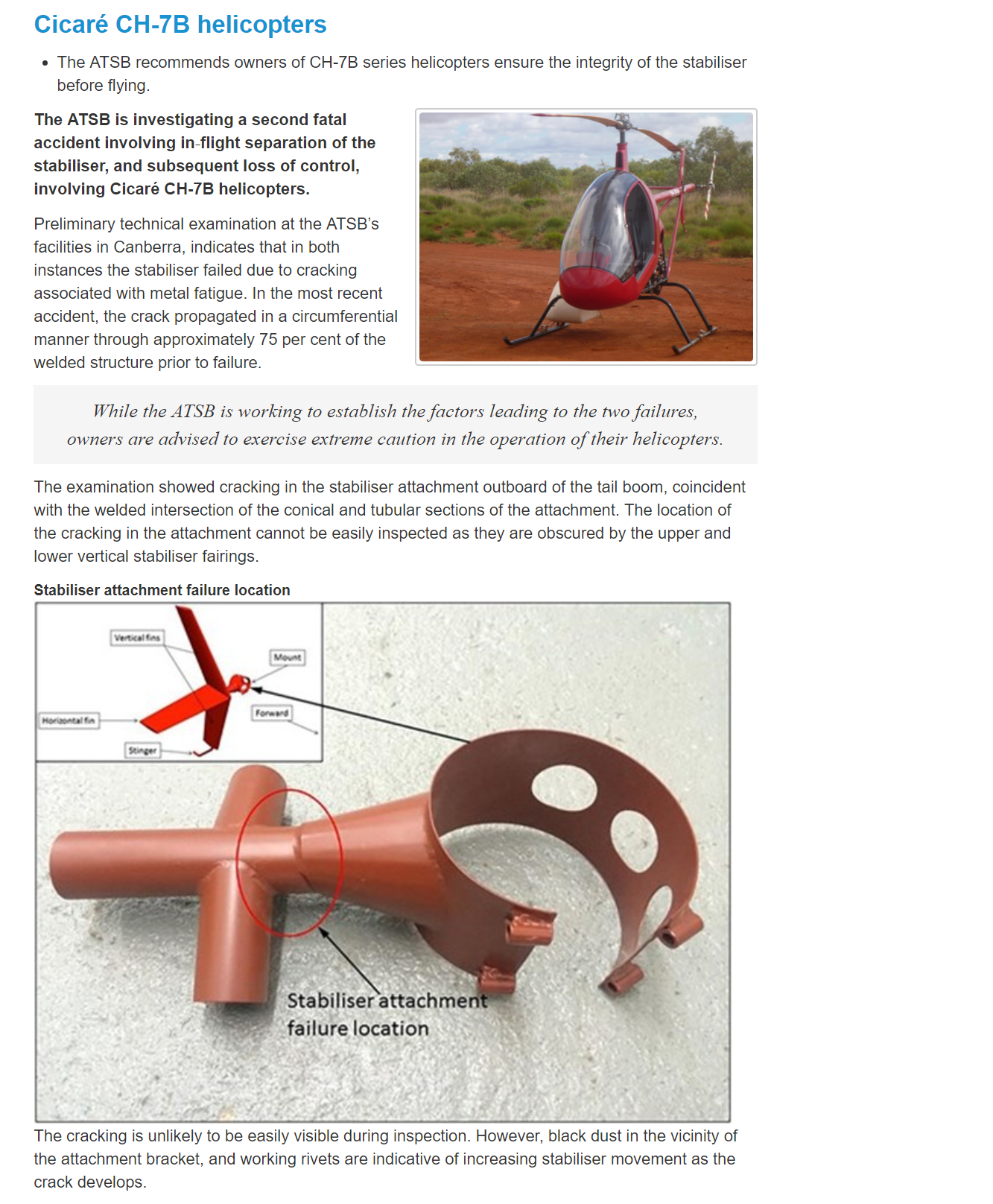
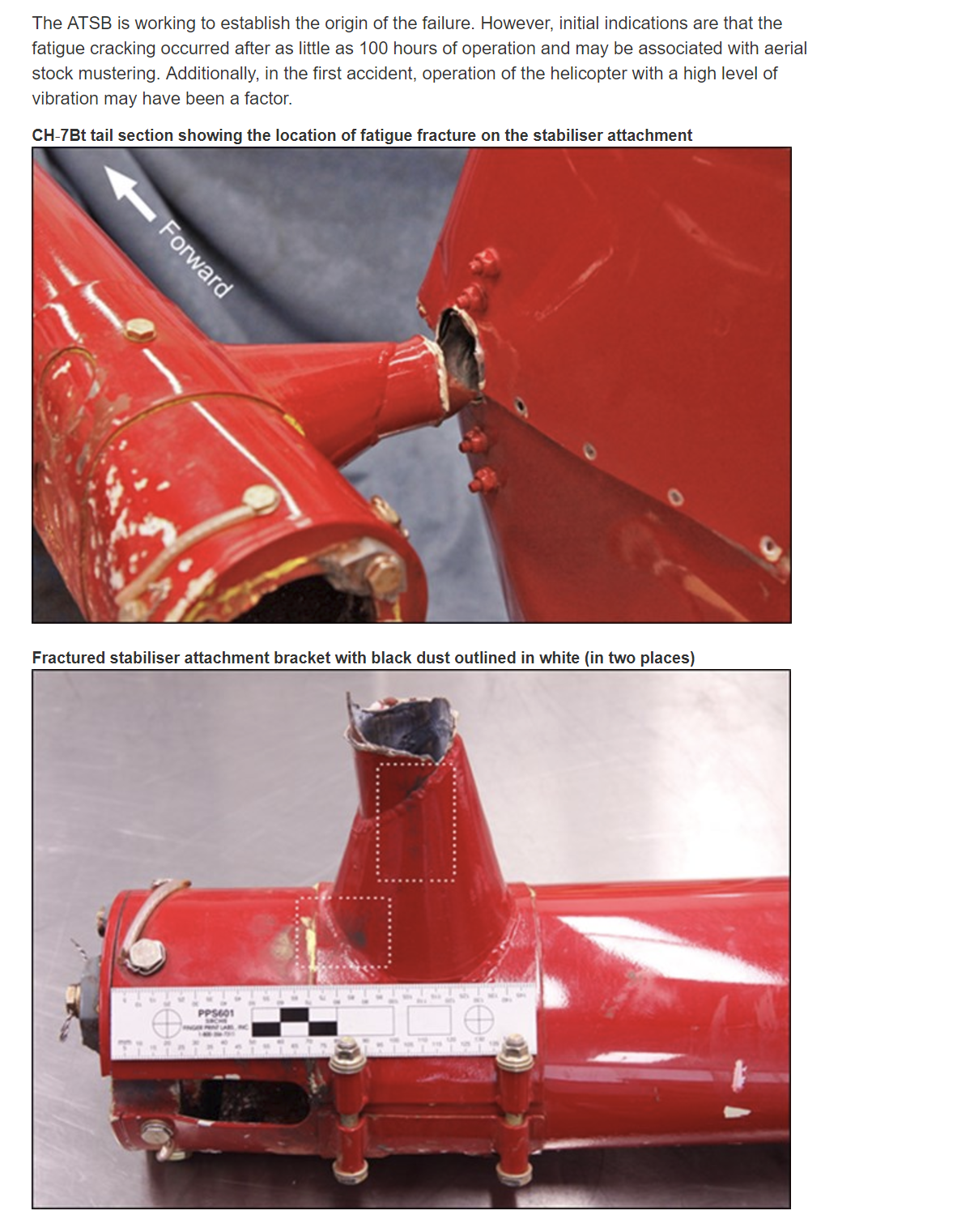
While it was outside the scope of the investigation to conduct an engineering assessment of the helicopter design, a detailed examination of the retained tail components was conducted at the ATSB’s technical facilities in Canberra, with a focus on the fracture of the stabiliser support. That examination found that the failure had occurred adjacent to the welded region of the support. The location of the cracking was also coincident with the point at which the upper and lower vertical stabiliser fairings met the mount (Figure 4).
Figure 4: Location of the stabiliser failure adjacent to the welded region
Source: ATSB
Stabiliser mount
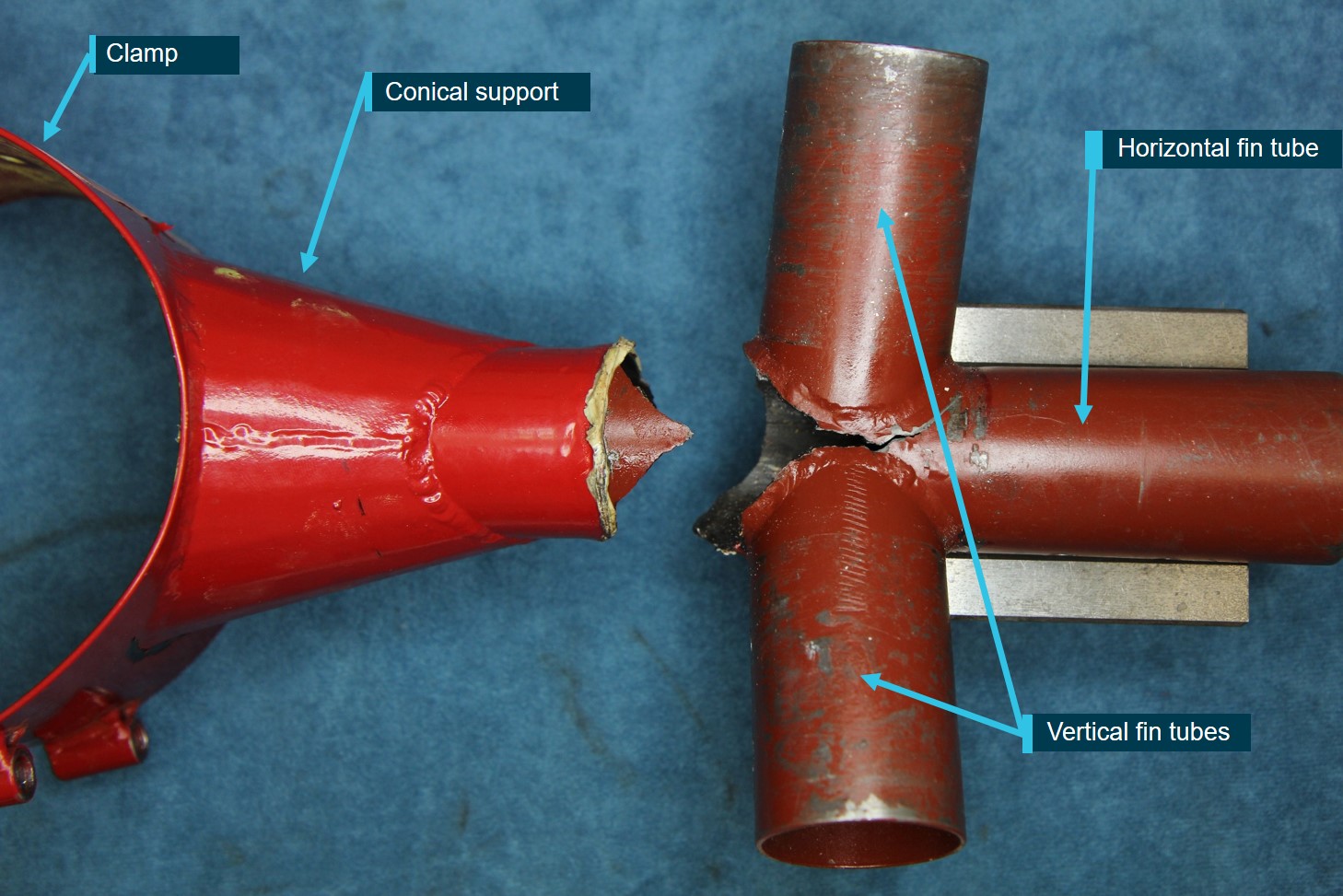
The stabiliser fins were removed from the stabiliser assembly in order to completely expose both portions of the fractured stabiliser mount (Figure 5). The stabiliser mount was comprised of three main sections; a clamp for attaching to the tail boom, conical support, and three oval-shaped, thin‑walled seamless metal tubes that were used to locate and secure the fins into position (Figure 5). During manufacture at the factory, the three tubes had been cut to fit and then welded together at the conical support.
Figure 5: Location of the stabiliser failure following removal of the fins
Source: ATSB
Detailed microscopic examination of the stabiliser mount fracture surfaces was accomplished using a binocular microscope. The examination revealed that the fracture path primarily followed the welded portions of the tube junction. A large portion of the fracture surface was discoloured, and exhibited fretting and corrosion product along with the presence of a series of finely spaced continuous progression marks. Such features were consistent with a fatigue crack growth mechanism as a result of in-service cyclic stresses and suggested that the crack had been present for some period of time prior to final fracture.
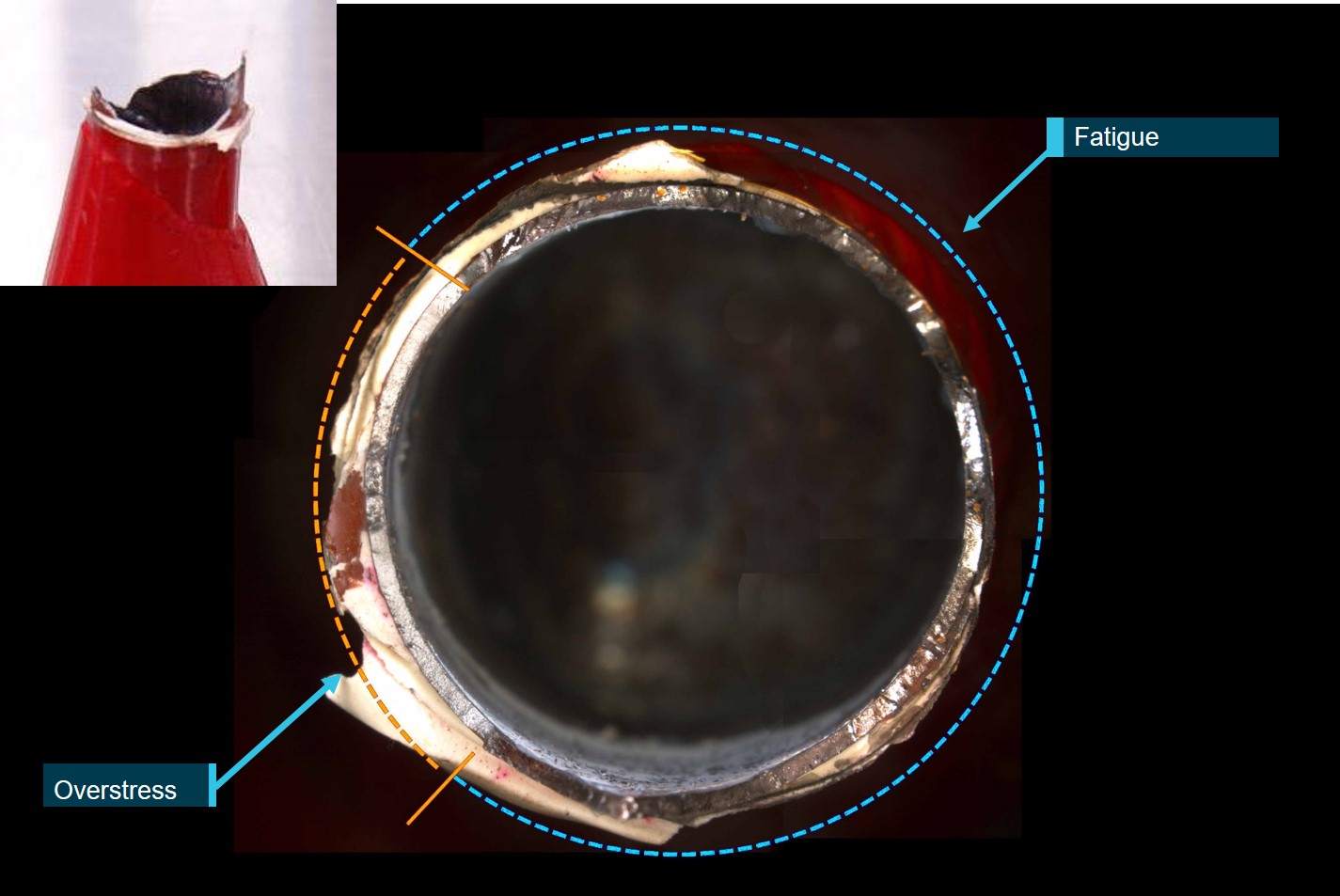
The fatigue crack had propagated in a circumferential manner through about 75 per cent of the structure prior to the failure (Figure 6). Once a significant portion of the cross section had fractured, the remaining section could no longer sustain in-flight loads and the stabiliser failed due to overstress. The origin of the fatigue cracking could not be clearly identified due to post‑accident damage. No obvious defects or anomalies were observed in the welded regions that might have otherwise contributed to the growth of the fatigue cracking.
Figure 6: Stabiliser fracture surface showing fatigue and overstress areas
Source: ATSB
Sectioning of the fracture surface for detailed microstructural examination and hardness testing did not reveal the presence of any anomalies that might have contributed to the failure. Chemical analysis of the stabiliser mount tubes was consistent with an SAE grade 4130 steel, as specified by the manufacturer.
Comparison between the stabiliser mount of VH-JEW and VH-SWQ
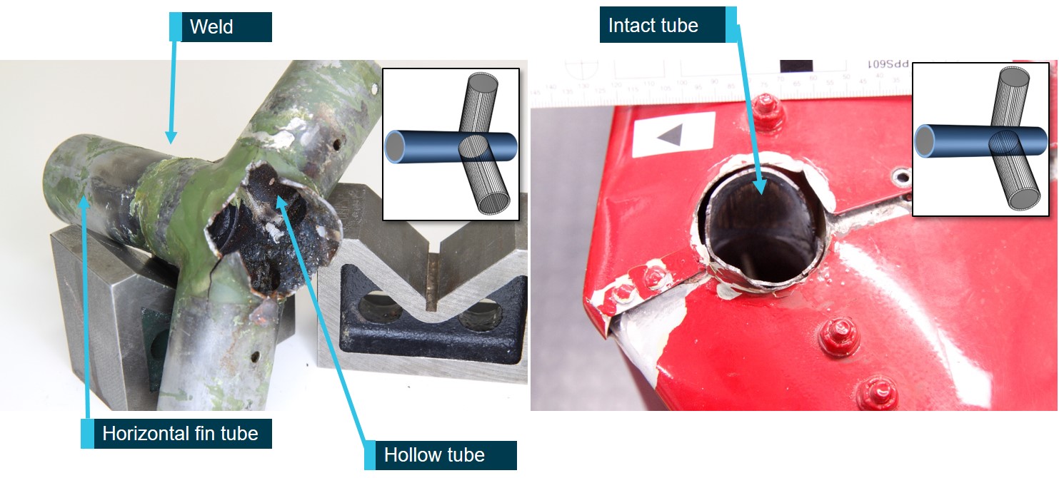
The two stabilisers had failed in a similar location, however, three differences were observed between the construction of the stabiliser mount of VH-JEW and VH-SWQ[9] including:
The vertical and horizontal tubes had been manufactured from welded tube for VH-SWQ, and seamless tube for VH-JEW.[10]
The mount on VH-SWQ was hollow through the joins in the horizontal tube where the vertical tubes were attached (Figure 7 left). For VH-JEW, the horizontal tube was not hollow (intact tube) where the vertical tubes were attached (Figure 7 right).
The horizontal tube for VH-JEW was welded at the conical support, while for VH-SWQ the tube was welded in two locations – at the conical support and just outboard of the intersection with the vertical tubes. (Figure 7 left).
Figure 7: Comparison between stabiliser fracture on VH-SWQ (left) and VH-JEW (right)
Source: ATSB
VH-JEW information and history
Construction and certification
VH-JEW was constructed as an amateur-built and experimental (ABE) aircraft under the Civil Aviation Safety Regulations 1998 (CASRs) Part 21 Subpart H, and Civil Aviation Regulations 1988 (CAR 1988) 262AP. Regulation 21.191 outlined the reasons an experimental certificate may be issued. Referring to the operation of amateur-built aircraft, sub-part (g) stated: ‘the major portion of which has been fabricated and assembled by a person who undertook the construction project solely for the person’s own education or recreation’. CASA Advisory Circular AC-21.4(2) Amateur-built Experimental Aircraft – Certification, provided guidance and information to those applying for an experimental certificate.
An aircraft that does not have a standard certificate of airworthiness[11] cannot operate unless it has been issued with a special certificate of airworthiness (including an experimental certificate) or a special flight permit. According to CASA Advisory Circular AC-21.10 v4.2 (issued March 2019), Experimental certificates:
Special certificates of airworthiness (CofA), which include experimental certificates, are issued to permit certain kinds of operations of aircraft that do not meet the requirements for a standard CoA or that, because of certain modifications, do not conform to their type certificates, but are capable of safe operations under defined operating conditions and purposes.
In recognition of the lack of compliance with some of the airworthiness standards, the aircraft is normally permitted to be operated under more restrictive operating conditions than in the case of a comparable aircraft operating on a standard CofA.
An authorised person (AP)[12] could issue experimental certificates under CASR 21.195A to allow operation of amateur-built and kit-built aircraft. This special certificate of airworthiness detailed the conditions under which the aircraft was permitted to be operated. For example, the helicopter involved in the previous ATSB investigation (refer to Similar occurrence), VH-SWQ, had a special certificate of airworthiness with a condition that it was not to be flown for commercial operations.
Under the experimental certificate, ABE aircraft were inspected at least once prior to the initial test flight by CASA or by an AP, who may operate under the Sport Aircraft Association of Australia (SAAA) maintenance procedures. Advisory Circular AC-21.4(2) described that the purpose of the inspection was to:
allow the inspector to make a subjective assessment of the workshop methods, techniques and practices used in the construction of the aircraft solely for the purpose of prescribing appropriate conditions and operating limitations necessary to protect other airspace users and persons on the ground or water, i.e. to protect persons and property not involved in the activity.
As part of the certification process, an ABE aircraft was initially limited to operations within an assigned flight test area for at least 25 hours, to demonstrate it was capable of safe flight.
VH-JEW was built by the pilot and owner in south-east Queensland in early 2015 from a kit supplied by the manufacturer. It was reported to the ATSB that the helicopter build took longer than the pilot expected. Below is a timeline of the events related to the helicopter build:
26 March 2015: The pilot initially contacted the SAAA requesting an onsite inspection of VH‑JEW on 4 May 2015.[13] According to documentation provided by the SAAA, that visit was cancelled and rescheduled as the helicopter was not ready for inspection.
The onsite inspection was rescheduled to 27 May 2015, however, it was again delayed as the helicopter was not ready for inspection.[14]
3 June 2015: The pilot submitted an application for a special certificate of airworthiness in the experimental (kit-built) category.
4 June 2015: A visit was carried out by the SAAA AP, however, it was reported that the helicopter was still not completed, and some of the required documentation was not completed or available. Following that visit, the pilot continued discussions with the SAAA about completion of the relevant requirements. The outstanding items were not related to the stabiliser or tail boom assemblies.
16 June 2015: The SAAA AP received an email containing a copy of the helicopter logbook and test flight record pages, dated 28 June 2015, indicating that 26.2 flight hours had been completed.[15]
25 June 2015: The helicopter was registered with CASA.
15 July 2015: As the SAAA AP had not issued the authorisation for test flights to commence, a letter was sent to the pilot,[16] advising that:
You are currently flying your aircraft without a Certificate of Airworthiness
The process of submitting the requested information listed on previous email has not been received
Copies of certifications for duplicate inspections from airframe log book not received
Submission of the nominated pilots and nominated flight test area not received.
As a result, the SAAA advised that they were unable to proceed any further with the application at that time. Due to the limited timeframe between when the letter was dated, and the date of the accident, the investigation could not be assured that the pilot had received the letter.
Helicopter flight history
Following the build, the pilot departed Queensland in VH-JEW on the morning of 27 June 2015 and arrived in Western Australia on the evening of 29 June 2015. At the time of the accident, the most recent entry on the maintenance release (5 days prior on 23 July 2015) showed the helicopter had accumulated 168.7 hours’ total time-in-service. Of the eight entries recorded, six of them showed the helicopter had accumulated between 8.3 and 11 hours on these days. This, together with information supplied by associates of the pilot, indicated that it was likely that the helicopter had been involved in some (commercial) aerial work, including aerial stock mustering and/or spotting, since arriving in Western Australia. It was also reported that the pilot was generally happy with the operation of the helicopter, and had not mentioned any major issues or the presence of vibrations.
Following the accident, a colleague of the pilot stated that there was a report of the temperature gauge reading above the normal operating range, however, it was mentioned that it was a one‑time occurrence and the reason for this was not determined. An acquaintance of the pilot reported to the ATSB that the pilot had advised him that the helicopter had experienced a hard landing in early July 2015, but it didn’t appear to have caused any damage to the helicopter.
Airworthiness and maintenance
Under sub-regulation 42ZC(6) of CAR 1988, the owner/builder of an amateur-built aircraft may be authorised to carry out maintenance on the aircraft, if they were the primary builder. CASA Instrument 33/13 Authorisation of person to carry out maintenance on certain amateur-built, kit‑built and light sport aircraft with a special certificate of airworthiness, detailed the conditions of the owner/builder’s maintenance authorisation. One of the conditions was that the owner/builder was required to have satisfactorily completed a course in maintenance procedures.[17] Further, maintenance conducted could only be on the elements of the aircraft that they had assembled.
The most recent maintenance release, issued by the pilot on 16 July 2015, at 105.9 hours’ total time‑in‑service, indicated the helicopter was to be maintained in accordance with the manufacturer’s maintenance schedule manual. The maintenance manual recommended a complete inspection of the helicopter every 12 months or 100 hours’ time-in-service. This included:
During inspection, check the general condition of the components and observe if there is evidence of damage, color change due to high temperatures, dents, scratches, notches, corrosion and specially cracks. Also check for any sign of friction in the parts that are near one another.
Specific to the stabilisers, the manual stated the following:
Check the whole surface of the stabilizers. Verify there are no scratches or cracks.
Check each stabilizer bearing. Verify there are no cracks around the attachment holes. Also check that the attachment screws are in proper condition.
Check the tailskid. Verify if there is evidence of strikes against the ground.
As the helicopter logbooks were not located, the ATSB was unable to determine what, if any, maintenance and/or inspections had been carried out on VH-JEW since leaving Queensland.
In addition, the ATSB also noted that there were several omissions and inaccuracies with how the maintenance release had been completed, making it invalid. However, as the aircraft had not been authorised for flight operations, it was determined there would be little benefit in further investigation. While these irregularities did not likely contribute to the accident, continued operation and maintenance outside of the regulations increases the risk that the safety protections they offer will be eroded.
Manufacturer’s stabiliser mount inspection
Following the accident involving VH-SWQ (refer to Similar occurrence), the manufacturer released a service bulletin on 24 September 2014 (BSC007) requiring dye penetrant inspection of the stabiliser. This document included instructions on how to perform the testing on the stabiliser mount. However, there was no mention of how to remove the support assembly from the horizontal and vertical fins to perform the inspection, which would have been necessary to inspect the relevant area. For VH-JEW, as this component had been pre‑assembled by the manufacturer for import into Australia, this maintenance would need to have been performed by an appropriately qualified person, such as a licensed aircraft maintenance engineer. Additionally, the document did not include any inspection interval requirements (initial or recurrent). The manufacturer reported that owners were advised to evaluate the stabiliser mount every 100 hours, or if there were any signs of wear on the stabiliser. No evidence was supplied to the ATSB as to how this information had been disseminated to owners.
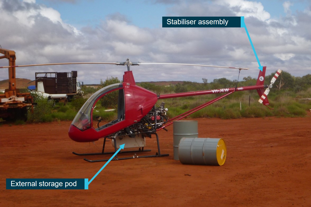
External storage pod
The helicopter had been modified with an external storage pod, attached to the rear strut of the right skid-landing gear (Figure 8). The storage pod was not included on the weight and balance documents provided as part of the special certificate of airworthiness approval process. It was reported that this pod was fitted for the flight from Queensland to Western Australia. However, as the helicopter logbooks were not located, the ATSB was unable to establish if the storage pod remained fitted for the life of the helicopter, or if any authorisations[18] had been received.
Figure 8: External storage pod as fitted to VH-JEW at Indee Station on 23 July 2015
Source: Andrew Miles, annotated by the ATSB
Helicopter landing gear is designed to provide energy absorbing capabilities during landing. Fixing external loads to the landing gear can result in forces applied to the landing gear in excess of the design limit and can also increase the in-flight dynamic loads due to increased vibration. Advice published by Robinson Helicopter Company for the R22 in the pilot operating handbook included a safety notice, SN-13, which stated that;
…even a small weight attached to the landing gear may change the natural frequency[19] enough to cause high loads to inflight vibration.
The ATSB could not determine whether the potential effects on the in-flight loads, flight characteristics and operating weight were considered by the pilot prior to the fitment of the external storage pod.
The Cicaré CH-7B was promoted in the Australian website Beef Central[20] in a 19 April 2011 article Heli-mustering game-changer, which included the promotion of the use of an external storage box:
While the Cicaré has a payload limit of around 100kg (not including pilot), it can be set up with a storage box to carry a chainsaw, fencing tools and enough wire for many on-the-job fencing repairs, for example.
However, correspondence from the kit manufacturer advised that the helicopter was not designed to carry external loads, and had not been tested under asymmetrical load conditions. The kit manufacturer was of the opinion that the difference between the two helicopters with cracked stabilisers and the rest of the Cicaré fleet with unaffected stabilisers was the addition of accessories (the storage pod in the case of VH-JEW and a heli-basket and larger fuel tanks for VH-SWQ), ‘making it very hard to ignore that this [sic] accessories could be related to the premature wear of the stabilizer’.
Ground handling
The flight manual contained the procedures for moving the helicopter on the ground, using the wheels provided, which attached to the landing gear. These procedures stipulated that the helicopter was to be pushed or pulled by holding the tail rotor gearbox. Additionally, the flight manual included the following caution:
Do not move [the] Cicaré CH-7BT by holding either the horizontal or vertical stabiliser, or from the tail rotor, or the tail rotor controls, or tailskid.
Manoeuvring the helicopter via the tail skid, particularly over rough terrain, could induce unintended forces on the stabiliser mount. However, as the pilot’s ground handling practices could not be established, the ATSB was unable to determine if this contributed to the development of the stabiliser mount fatigue crack.
Commercial flying
In order to conduct commercial aerial work operations, including aerial mustering and spotting, at the time of the accident, the pilot was required to hold a Commercial Pilot Licence. Additionally, Civil Aviation Regulations 1988 (CAR) 206 stated that an Air Operator’s Certificate was also required to conduct commercial operations.
The pilot held a Commercial Pilot Licence (Helicopter), and had regularly conducted commercial flying operations in helicopters. The pilot also held an AOC, on which two Robinson Helicopter Company R22’s were listed. VH-JEW was not listed on the Air Operator’s Certificate.
Operational aspects
The Cicaré S.A. website stated that the Cicaré CH-7B was a helicopter ‘for sport use’. However, the Australian experience indicated that these helicopters were increasingly being used for agricultural operations and other aerial work, such as mustering and spotting.
Both VH-SWQ and VH-JEW had been used for mustering operations during their lifetime, and the ATSB was aware of one other reported accident involving another Cicaré CH-7B helicopter while engaged in agricultural operations in October 2018.
While the use of an amateur-built helicopter for private agricultural operations, including mustering and spotting, was not specifically excluded under the CASA regulations, such operations can involve extremely frequent manoeuvring and rapid power changes that can apply very high loads on the helicopter. The fatigue life of various components can be adversely affected by the type of operation and loading history of the components. CASA Airworthiness Bulletin (AWB) 02-015 Helicopter – Effects on fatigue on life limited components described some operational situations where the fatigue life might be affected, and included:
…Operations of helicopters in low level flying, agricultural, mustering or other operations where high loads may be encountered more frequently than envisaged by the designer/manufacturer.
Cicaré CH-7B flying activity
Activity data for the CH-7B between 2011 and 2018 was supplied by the Bureau of Infrastructure, Transport and Regional Economic (BITRE) is shown in Table 1.[21] This data was reported to BITRE by registered aircraft owners in the annual BITRE General aviation activity survey.
Table 1: Reported flights and hours for Cicaré CH-7B aircraft between 2011 and 2018
2011
2012
2013
2014
2015
2016
2017
2018
Number of aircraft
3
4
8
4
7
5
6
5
Number of landings
24
35
62
10
89
51
293
562
Total hours
17
28
52
19
83
43
457
408
Private
17
28
52
-
-
-
-
-
Agriculture mustering
-
-
-
0
6
0
0
0
Agriculture-other
-
-
-
19
0
19
397
0
Other aerial work
-
-
-
0
0
0
0
181
Pleasure and personal transport
0
48
8
57
7
Other sport and pleasure flying
-
-
-
0
29
16
3
7
Other flying
-
-
-
0
0
0
0
213
Source: Bureau of Infrastructure, Transport and Regional Economics
The data showed that only 6 hours total had been attributed to agricultural mustering over this period. However, in 2017-2018, there was a significant increase in the reported landings/hours for the Cicaré CH-7B fleet, together with an increase in the number of hours attributed to ‘agricultural-other’ (which includes all non-mustering and non-spraying agricultural activities including stock spotting), other aerial work and other flying categories.
The manufacturer advised that a number of helicopters within the fleet had accumulated up to 400 hours in Argentina and at least one helicopter in Australia had reached 1,500 hours total time-in-service. However, they were unable to provide any information on what types of operations these helicopters may have been performing when these house were accumulated.
Previous research
Stress loads from aerial stock mustering and spotting
In 2004, the ATSB commissioned AeroStructures, an Australian engineering company, to undertake a study of the forces acting on a Robinson Helicopter Company (RHC) R22 (also extensively used in mustering operations in Australia) while engaged in aerial mustering operations. The study (Robinson R22 helicopter aerial mustering usage investigation) provided a comparison of the flight profiles in aerial mustering operations and compared these with the flight profiles used during certification.
The report found that aerial mustering exhibited frequent low speed manoeuvres and rapid power changes, and five measurements showed higher peak stresses than for the certification flights, one of which was the tail rotor drive shaft torque. The report stated that:
Owners and operators need to fully appreciate the stresses placed on aircraft during mustering operations, and the characteristics of aerial mustering operations, which may be quite different [to] the type of flying for which the type originally received certification
Advice was contained in a safety notice produced by the Robinson Helicopter Company, who manufactured the R22 helicopter. Safety Notice, SN-37 - Exceeding approved limitations can be fatal discussed how fatigue damage can accumulate within components without a visible indicator.
The kit manufacturer, Cicaré S.A, advised that
experimental category covers recreational and sport use. However, this won't prohibit anyone to use it for other activities.
Amateur-built aircraft research
ATSB research has identified that amateur-built aircraft are over-represented in aviation accidents and incidents in Australia (AR-2007-043 (2) Amateur-built aircraft Part 2: Analysis of accidents involving VH-registered non-factory-built aeroplanes 1988-2010). The research found that, although pilots of amateur-built aircraft involved in accidents were significantly more experienced overall than pilots of accidents in equivalent factory-built aircraft, they were less experienced on the type that they were flying at the time of the accident.
While this report did not include amateur-built helicopters due to the small numbers in operation at that time, much of the data and outcomes of the report were relevant to aeroplanes and helicopters. The prevalence of amateur-built helicopters in Australia is also increasing.
While on a ferry flight from Indee Station to Roy Hill Station, Western Australia, the stabiliser assembly on VH-JEW fractured leading to an in-flight break-up and collision with terrain. The pilot was fatally injured, and the aircraft was destroyed.
Available information indicated that it was unlikely that the pilot became incapacitated during the flight, and pilot fatigue, weather and poor manufacturing of the welded stabiliser structure were not considered factors.
This analysis will examine the potential factors that may have led to the failure of the stabiliser and resulting in-flight break-up.
In-flight break-up
The fracture of the stabiliser mount and subsequent in-flight separation of the stabiliser from the tail boom led to severe mast bumping sufficient to sever the mast and main rotors. Consistent with the wreckage distribution, the helicopter broke up in-flight, resulting in a collision with terrain.
In the event of a stabiliser failure, the manufacturer indicated that, although the helicopter was theoretically controllable under certain circumstances, the sudden change to the aerodynamic loads and centre of gravity balance, would lead to an unstable flight condition. Additionally, this was the second accident where a loss of control had resulted following the loss of the stabiliser assembly.
Stabiliser mount cracking
Analysis of the tail components identified that the stabiliser assembly mount was significantly weakened by cracking associated with metal fatigue. While the ultimate fracture of the mount was due to overstress, a fatigue crack was found to have propagated about 75 per cent of the way around the mount’s circumference, adjacent to the welded region. The investigation considered the potential factors that contributed to the cyclical loading that resulted in fatigue cracking of the stabiliser mount. These included, in no particular order:
fitment of the external storage pod
possible operations exceeding the manufacturer’s limitations
stabiliser assembly design.
The helicopter had been fitted with an external storage pod attached to the rear strut of the right skid‑landing gear, although it was unknown if it was in place on the accident flight. The storage pod was not on the weight and balance documents associated with the special certificate of airworthiness process, and a special certificate of airworthiness had not been issued. While the helicopter logbooks were not located, it was unlikely that an engineering assessment had been conducted prior to the helicopter departing Queensland.
In addition, the manufacturer indicated that the helicopter was not designed to carry external loads and expressed reservations about the addition of an accessory on both VH-JEW and VH-SWQ. Specifically, they were of the opinion that the fitment of the external accessories to both these aircraft could have been the reason for the premature failure of the stabiliser. The fitment of the pod had the potential to adversely affect the structural integrity and handling characteristics of the helicopter. However, as it was likely the pod had not been assessed, the ATSB was unable to determine the extent to which this contributed to the initiation and propagation of the fatigue crack.
While the Australian activity data indicated minimal mustering activity in the CH-7B, the ATSB was aware of three accidents where the helicopter had, at some point, been conducting this type of operation. For VH-JEW, the investigation was able to establish that the helicopter had operated for 168.7 hours up until 23 July 2015, and likely only a few hours on the day of the accident. The available records indicated that in the month prior to the accident, it had been used for at least 60 hours of low-level mustering operations. The Cicaré CH-7B helicopter is advertised as being for recreational use, and operation outside the manufacturer’s limitations has the potential to induce stresses on the airframe and components, leading to premature wear and possible failure. Further, operations such as mustering and similar activities can also increase the risk of premature ageing of aircraft structure due to an increased load spectra.
In addition, while two aircraft in Australia exhibited premature failure of the same component, in a similar location, at relatively low time in-service, these were the only two helicopters in the worldwide fleet to exhibit cracking. While there were some similarities between the accidents involving VH-SWQ and VH-JEW, in that both helicopters had been fitted with untested external accessories and were being used for mustering operations, there were some notable differences. VH-SWQ had experienced a number of other issues, including a hard landing and ongoing airframe vibrations possibly, as a result of a tail rotor imbalance, which may also have contributed to the development of a fatigue crack within the stabiliser mount. In addition, the design of the stabiliser had been modified for helicopter kits manufactured after VH-SWQ, including VH-JEW. Therefore, it was not possible to make a direct comparison between the two accidents.
While it was outside the scope of the investigation to conduct an engineering assessment of the helicopter design, the stabiliser mount has been shown to be susceptible to fatigue cracking of under certain conditions. However, if there was an inherent design issue with the helicopter, it was not unreasonable to expect more incidence of cracking in the worldwide fleet. This was particularly so given a number of helicopters in the fleet had accumulated up to 400 hours in Argentina and at least one helicopter in Australia had reached 1,500 hours total time-in-service. However, VH-JEW and VH-SWQ were the only helicopters that have exhibited cracking. As a result, the investigation was unable to determine the contribution of all factors such as design, operating conditions, untested accessories, and the magnitude of the effect these elements may have had on the development of the fatigue crack.
Manufacturer’s service bulletin
Following the accident involving VH-SWQ in 2014, the manufacturer released a mandatory service bulletin, BSC007, to all operators of the Cicaré 7 series helicopters. While the service bulletin provided a general instruction to perform a non-destructive dye penetrant inspection of the stabiliser mount, it did not include essential information such as how to disassemble the stabiliser to perform the inspection, a compliance time, or a recurring inspection interval.
Given the extent of the fatigue crack found on the stabiliser mount, it was likely that the crack had been present for some time since the helicopter entered service. However, the absence of a compliance timeframe or requirement for a recurring inspection reduced the likelihood of the crack being detected prior to reaching a critical size. Additionally, as the bulletin was released prior to the pilot purchasing and building the helicopter, it was possible that he did not have knowledge of the requirement to conduct the inspection.
Airworthiness documentation and regulatory aspects
Amateur-built experimental aircraft are not required to comply with the full range of safety regulations that are applicable to commercially manufactured aircraft. However, the regulations that do apply are fundamentally important and have been introduced to control and reduce (as much as possible) the risks associated with the operation of this category of aircraft.
At the time of the accident, the aircraft had not been issued with a Civil Aviation Safety Authority (CASA) special certificate of airworthiness. As a result, the aircraft was not on the operator’s Air Operator’s Certificate, and therefore, not authorised to be flown for commercial aerial work such as aerial spotting or mustering. Not having the certificate meant that compliance with the applicable airworthiness standards could not be assured.
In addition, as an amateur-built experimental helicopter, it was very likely that the special certificate of airworthiness would have been issued with prescriptive operational uses, which would not have included commercial mustering. It was reported that the pilot had been conducting commercial aerial mustering operations in the helicopter in the weeks leading up the accident and was intending to continue after arriving at Roy Hill Station.
While the pilot had significant aeronautical experience and held a valid Class 2 Aviation Medical Certificate, the pilot’s Class 1 certificate had expired several months prior. Although he was in the process of revalidation, the pilot was unable to exercise the privileges of a Commercial Pilot’s Licence until such time. Of note, the pilot had no apparent medical issues.
The ATSB had considered if the pilot was experiencing time or commercial pressures to complete the build of VH-JEW. However, due to the limited information available, this could not be established. Therefore, the ATSB was unable to determine if this had influenced his actions with regard to the aircraft certification process.
The pilot’s decision not to follow certain regulations may not have directly influenced the in‑flight break-up of the stabiliser assembly. However, it did result in the helicopter being used for commercial mustering operations that it was not authorised for and would very likely not have been approved for by the Civil Aviation Safety Authority. This exposed the helicopter to higher operational stress and had the potential to increase the risk to the pilot and those working around the helicopter during the flying operations.
Findings
From the evidence available, the following findings are made with respect to the collision with terrain of a Cicaré CH-7BT helicopter, registered VH-JEW, that occurred near Roy Hill Station, Western Australia on 28 July 2015. These findings should not be read as apportioning blame or liability to any particular organisation or individual.
Safety issues, or system problems, are highlighted in bold to emphasise their importance. A safety issue is an event or condition that increases safety risk and (a) can reasonably be regarded as having the potential to adversely affect the safety of future operations, and (b) is a characteristic of an organisation or a system, rather than a characteristic of a specific individual, or characteristic of an operating environment at a specific point in time.
Contributing factors
While conducting a ferry flight, the stabiliser mount fractured, resulting in an in-flight break-up and collision with terrain.
The helicopter’s stabiliser mount fractured due to overstress, following propagation of a fatigue crack in the area adjacent to the weld. While the ATSB was unable to fully determine the reasons for the intiation and propagation of the fatigue crack, it was likely the result of some combination of the design, operating conditions, and untested accessories.
Other factors that increased risk
The helicopter was modified with an external storage pod, likely without the appropriate engineering assessment to ensure there would be no adverse effects on the performance, handling and structure of the helicopter.
Although the amateur-built Cicaré CH-7B helicopter was intended for recreational and sport use only, this and other CH-7B helicopters had been used for agricultural mustering. Operating outside the manufacturer’s design intent had the potential to induce stresses on the aircraft, leading to premature wear of components and possible failure.
The Cicaré 7T/B/BT mandatory service bulletin (BSC007) for the general stabiliser support assembly provided limited guidance for disassembly of the manufactured component and did not stipulate a compliance period within which to perform the inspection nor provide consideration for repeat inspections. This potentially reduced the opportunity to detect the presence of crack initiation and growth in the stabiliser support assembly. [Safety issue]
Other findings
The helicopter was being operated without a Civil Aviation Safety Authority special certificate of airworthiness. Further, it was being used for commercial mustering operations, however, as an amateur-built experimental helicopter it would very likely not have been approved to conduct such operations. In addition, while the pilot had significant aeronautical experience, his Class 1 Aviation Medical Certificate had expired and although in the process of renewing it, the pilot was unable to exercise the privileges of his Commercial Pilot’s Licence.
Safety issues and actions
The safety issues identified during this investigation are listed in the Findings and Safety issues and actions sections of this report. The Australian Transport Safety Bureau (ATSB) expects that all safety issues identified by the investigation should be addressed by the relevant organisation(s). In addressing those issues, the ATSB prefers to encourage relevant organisation(s) to proactively initiate safety action, rather than to issue formal safety recommendations or safety advisory notices.
Depending on the level of risk of the safety issue, the extent of corrective action taken by the relevant organisation, or the desirability of directing a broad safety message to the [aviation, marine, rail - as applicable] industry, the ATSB may issue safety recommendations or safety advisory notices as part of the final report.
All of the directly involved parties were provided with a draft report and invited to provide submissions. As part of that process, each organisation was asked to communicate what safety actions, if any, they had carried out or were planning to carry out in relation to each safety issue relevant to their organisation.
The initial public version of these safety issues and actions are repeated separately on the ATSB website to facilitate monitoring by interested parties. Where relevant the safety issues and actions will be updated on the ATSB website as information comes to hand.
Safety issue description: The Cicaré 7T/B/BT mandatory service bulletin (BSC007) for the general stabiliser support assembly provided limited guidance for disassembly of the manufactured component and did not stipulate a compliance period within which to perform the inspection nor provide consideration for repeat inspections. This potentially reduced the opportunity to detect the presence of crack initiation and growth in the stabiliser support assembly.
Additional safety actions
Whether or not the ATSB identifies safety issues in the course of an investigation, relevant organisations may proactively initiate safety action in order to reduce their safety risk. The ATSB has been advised of the following proactive safety action in response to this occurrence.
Additional safety action taken by Cicaré S.A.
Cicaré have advised that they are intending to release a revision to the Pilot’s Operating Handbook at the end of January 2020, which will indicate that the helicopters are not intended or recommended for aerial work, particularly mustering operations, which can cause a significant increase of loads and affect the fatigue life.
Operating a helicopter within the stated design intent and limitations is essential for safe conduct of flight. The ATSB advises owners/operators of amateur-built experimental aircraft to be fully aware of the risks associated with this category of aircraft and that operation outside the limitations prescribed by the manufacturer, such as the addition of unapproved modifications and use for mustering operations, can produce unintended stresses on the airframe leading to premature failure of components.
ATSB information letter
On 6 August 2015, an information letter was emailed to registered Cicaré CH-7B owners, informing them of the second accident, the mechanism of stabiliser failure and a recommendation to ensure the integrity of the stabiliser prior to further operation and on an ongoing basis. The content of the letter is included as an Appendix and is also available on the ATSB website.
Sources and submissions
Sources of information
The sources of information during the investigation included the:
The Civil Aviation Safety Authority
Western Australia Police and Coroner
Cicaré S.A.
The Australian importer of Cicaré S.A. kits
Bureau of Meteorology
Sport Aircraft Association of Australia
Bureau of Infrastructure, Transport and Regional Economics.
References
Australian Transport Safety Bureau (2004), Robinson R22 helicopter and aerial mustering usage investigation (B2004/0292). Retrieved from www.atsb.gov.au/media/29947/b20040292.pdf.
Australian Transport Safety Bureau (2016), In-flight break-up involving Cicaré CH-7B, VH-SWQ 43 km north-west of Barcaldine Airport Queensland on 12 May 2014 (AO-2014-086). Retrieved from www.atsb.gov.au/media/5756707/AO-2014-086%20-%20Final.pdf.
Under Part 4, Division 2 (Investigation Reports), Section 26 of the Transport Safety Investigation Act 2003 (the Act), the Australian Transport Safety Bureau (ATSB) may provide a draft report, on a confidential basis, to any person whom the ATSB considers appropriate. Section 26 (1) (a) of the Act allows a person receiving a draft report to make submissions to the ATSB about the draft report.
A draft of this report was provided to Cicaré S.A., the Civil Aviation Safety Authority, the Sport Aircraft Association of Australia, the distributor of Cicaré helicopters in Australia, and the pilot’s next of kin.
Submissions were received from Cicaré S.A., the Civil Aviation Safety Authority, and the pilot’s next of kin. The submissions were reviewed and, where considered appropriate, the text of the report was amended accordingly.
Appendices
Appendix A – ATSB information letter
Purpose of safety investigations
The objective of a safety investigation is to enhance transport safety. This is done through:
identifying safety issues and facilitating safety action to address those issues
providing information about occurrences and their associated safety factors to facilitate learning within the transport industry.
It is not a function of the ATSB to apportion blame or provide a means for determining liability. At the same time, an investigation report must include factual material of sufficient weight to support the analysis and findings. At all times the ATSB endeavours to balance the use of material that could imply adverse comment with the need to properly explain what happened, and why, in a fair and unbiased manner. The ATSB does not investigate for the purpose of taking administrative, regulatory or criminal action.
Terminology
An explanation of terminology used in ATSB investigation reports is available here. This includes terms such as occurrence, contributing factor, other factor that increased risk, and safety issue.
Publishing information
Released in accordance with section 25 of the Transport Safety Investigation Act 2003
Ownership of intellectual property rights in this publication
Unless otherwise noted, copyright (and any other intellectual property rights, if any) in this report publication is owned by the Commonwealth of Australia.
Creative Commons licence
With the exception of the Coat of Arms, ATSB logo, and photos and graphics in which a third party holds copyright, this publication is licensed under a Creative Commons Attribution 3.0 Australia licence.
Creative Commons Attribution 3.0 Australia Licence is a standard form licence agreement that allows you to copy, distribute, transmit and adapt this publication provided that you attribute the work.
The ATSB’s preference is that you attribute this publication (and any material sourced from it) using the following wording: Source: Australian Transport Safety Bureau
Copyright in material obtained from other agencies, private individuals or organisations, belongs to those agencies, individuals or organisations. Where you wish to use their material, you will need to contact them directly.
On 27 July 2015, the pilot of an Eagle DW1 aircraft, registered VH-FHP, was conducting aerial spraying operations on a property about 77 km southeast of Townsville, Queensland. The pilot completed aerial spraying of two paddocks, and then loaded the aircraft with about 450 L of chemical (about half capacity), and half a tank of fuel.
At about 0930 Eastern Standard Time (EST), the pilot took off to spray the third paddock for that day. The pilot overflew the paddock and identified two sets of powerlines. The pilot formed a plan to spray the paddock using a racetrack pattern and flying it in a clockwise direction. One set of powerlines ran parallel to the spray direction, and the other ran across it at the western end. There was a line of trees along the western powerline, which obscured vision of the power poles.
The pilot completed the first spray run towards the western powerline, overflew it, and then turned to line up for the second spray run (Figure 1). A small area of about 30 m of trees had been cleared for a pump installation and the clearing was in line with the start of the second spray run. The pilot noted the powerline ahead, but then diverted their attention to the other powerline, running parallel to the direction of flight, and about 5 m off the left wingtip. The pilot also looked inside at the GPS to check the aircraft’s line for the spray run.
Figure 1: Paddock to be sprayed showing powerlines and wirestrike location
Source: Google earth and the pilot of VH-FHP – annotated by the ATSB
The pilot commenced the descent into the paddock through the clearing in the trees and did not see the powerline at that time. As the aircraft descended, the pilot looked up and suddenly sighted the powerline. The pilot elected to push forwards on the controls to make the aircraft descend. The aircraft then struck the powerline above the propeller on the wing struts.
After the aircraft struck the wires, it yawed violently to the left. The pilot used the right rudder to turn the aircraft away from the other powerlines, and the force of the aircraft pulled the transformer off the power pole on the left. The aircraft then yawed to the right. The force broke the power pole on the right and severed the powerline.
The aircraft decelerated rapidly, and the wires pulled the aircraft towards the ground. The pilot landed the aircraft with the wings level. The landing gear sheared off, the propeller struck the ground and the aircraft ground-looped, coming to rest facing the opposite direction. The pilot sustained minor injuries and the aircraft was destroyed (Figure 2).
Figure 2: VH-FHP at the accident site showing damage to the aircraft and wires
Source: Aircraft operator
Pilot comments
The pilot provided the following comments:
The pilot had sprayed that paddock once previously, and had used an anticlockwise racetrack pattern. On that occasion, as the power poles were on the eastern side of the trees, they were more visible from that direction.
The pilot elected to descend after sighting the powerline, to prevent the landing gear from potentially catching on the wires and flipping the aircraft over.
The aircraft had a wire cutter on the undercarriage and a wire deflector between the top of the wing and the tail, but not on the struts where the wire struck.
The powerlines were three phase.
Safety message
The pilot was aware of the powerline the aircraft collided with, but did not have it front-of-mind at the start of the spray run. The pilot’s attention was diverted to other powerlines, parallel to the direction of flight, and also inside the aircraft to the GPS. The pilot reported that stating aloud ‘powerlines ahead’, would have helped to maintain awareness of the wires.
The Aerial Agricultural Association of Australia suggests a way to keep focus is to ask yourself:
Where is the wire now?
What do I do about it?
Where am I in the paddock?
For further risk management strategies for agricultural operations, refer to the Aerial Application Pilots Manual.
The ATSB research report Aerial application safety: 2014-2015 year in review, stated that aerial application operations have a high accident rate relative to other aviation sectors. These operations involve inherent risks. Those risks include low-level flying, high workloads and obstacles such as powerlines. More than half of the total accidents and serious incidents over the past 10 years were wirestrikes.
The report also stated that it is important to constantly monitor the environment, so the hazards that were identified in pre-planning can be recognised and avoided. If a pilot is not specifically looking for a hazard, it is unlikely they will notice it.
The ATSB investigated a similar accident, involving a Robinson R66 helicopter. A copy of that report is available here: AO-2014-142.
Decisions regarding whether to conduct an investigation, and the scope of an investigation, are based on many factors, including the level of safety benefit likely to be obtained from an investigation. For this occurrence, a limited-scope, fact-gathering investigation was conducted in order to produce a short summary report, and allow for greater industry awareness of potential safety issues and possible safety actions.
Publishing information
Released in accordance with section 25 of the Transport Safety Investigation Act 2003
Ownership of intellectual property rights in this publication
Unless otherwise noted, copyright (and any other intellectual property rights, if any) in this report publication is owned by the Commonwealth of Australia.
Creative Commons licence
With the exception of the Coat of Arms, ATSB logo, and photos and graphics in which a third party holds copyright, this publication is licensed under a Creative Commons Attribution 3.0 Australia licence.
Creative Commons Attribution 3.0 Australia Licence is a standard form licence agreement that allows you to copy, distribute, transmit and adapt this publication provided that you attribute the work.
The ATSB’s preference is that you attribute this publication (and any material sourced from it) using the following wording: Source: Australian Transport Safety Bureau
Copyright in material obtained from other agencies, private individuals or organisations, belongs to those agencies, individuals or organisations. Where you wish to use their material, you will need to contact them directly.
On 24 July 2015, container freight train 6MC2 lost two containers from the train as it passed through Bowser, north of Wangaratta. The two containers lost from the train landed clear of the track on the eastern side. The train continued its journey with the crew unaware of the incident.
At about 0430 the following morning, the driver of another freight train noticed a container and reported it to train control.
What the ATSB found
The ATSB found that it was very likely that the twist locks that secured the containers to the train were ineffective prior to the incident. This condition allowed the unsecured containers to fall from the train. It is probable that strong winds contributed to the movement of the unsecured containers. Other external forces, such as train and track dynamics, may have also contributed to the movement. However, there was no evidence of such contribution.
Given the containers were located some distance behind the locomotives, and that no other train operational systems were affected when they fell from their respective wagons, the train crew were not aware of the incident.
What's been done as a result
As a result of the incident, Pacific National undertook an internal investigation into the incident and has taken action to:
initiate a process to include checks for twist lock operation as part of wagon maintenance and inspection
develop a twist lock inspection manual
update freight loading manuals to include methodology for identifying defective twist locks
update wagon maintenance manual to include methodology for identifying defective twist locks
update twist lock training materials to include identification of defective twist locks
initiate a review of twist lock integrity history
initiate a review of twist locks currently in service – supply and type
calculate the failure rate of twist locks across the Intermodal fleet for probability and risk mitigation considerations.
Safety message
Rail operators should satisfy themselves that their procedures can ensure that all twist locks are effective at securing freight containers to their respective wagons before the transit of trains.
The occurrence
At about 1428 on 24 July 2015, container freight train 6MC2 departed Appleton Dock, Melbourne headed for Griffith, New South Wales. The train was programmed to detach wagons at certain locations along the standard gauge route. Train 6MC2 was owned and operated by Pacific National (PN). The train consisted of three locomotives (two were off line) hauling 60 wagons, was 1272 m long, with a total mass of 2051 t. The train was a scheduled service, transporting containers between Melbourne and Griffith.
At about 1805, train 6MC2 passed through Wangaratta travelling on the east track. A short time later near Bowser (North Wangaratta), the train passed V/Line passenger train 8630 on the west track heading to Melbourne. A little further on, the train crew noticed the trees alongside the track swaying violently in a localised storm event. The crew commented that the wind swayed the locomotive. At this point, unbeknown to the train crew, two containers fell off the train.
The train continued on its programmed journey towards Griffith. At Ettamogah, 13 wagons were detached, but the missing containers were not noticed.
At about 0430 on 25 July 2015, the driver of freight train 3PW4 (travelling on the west track) sighted a shipping container lying next to, but clear of, the east track between Wangaratta and Springhurst at the 244.500 track km point. The driver reported the container to the Australian Rail Track Corporation (ARTC) Network Control Centre South located at Junee, New South Wales. The ARTC network control centre warned another following train, XPT passenger train ST21 travelling from Sydney to Melbourne on the east track, to proceed at caution. At 0447, the driver of ST21 confirmed the details and location of the container with the ARTC network control centre.
Figure 1: Containers laying adjacent the track
Note: The blue container in the foreground was located on the 17th wagon. The red container in the background was located on the 13th wagon. The direction of travel shown with a red arrow. Source: Pacific National
The ARTC arranged to have the track inspected. At about 0634, the inspector arrived on site and discovered a second shipping container near the track. Both containers were clear of the track and normal train running resumed.
The ARTC established that the containers had fallen from train 6MC2 the previous night. By then, seven trains had passed the location since the containers were lost from train 6MC2. Of the seven passing trains, five were on the West track and two on the East track.
Safety analysis
Twist locks
Containers are loaded onto suitable rail vehicles and secured at each corner by twist locks. Pacific National’s Freight Loading Manual[1] (FLM) details specific requirements for securing containers to wagons. The manual specifies:
All devices used to secure containers to rail wagons must be in a sound and serviceable condition.
All containers MUST have all four securing devices locked in position prior to transit.
There are four types of approved securing devices:
Portable twist locks (automatic operation)
Portable twist locks (manual operation)
Portable anchor brackets
Internal hook type
External clamp type
Retractable fixed twist locks
Hinged type
Pop up type
Patrick Port Logistics (PPL) loaded the two containers that subsequently fell from train 6MC2. PPL also had requirements[2] for securing containers to rail wagons. These requirements largely reflected the Pacific National (PN) specific requirements. On the day of the incident, PPL used eight automatic twist locks, one on each corner, securing both containers to the rail wagons. PPL used a combination of two Gavan, one Celtec Cel-Lock TFA, and five Celtec Cel-Lock TFAD twist locks, Figure 2 and Figure 4.
Figure 2: Twist lock types
Source: Pacific National
The normal position of an automatic twist lock is in the locked position, Figure 3. When a container is loaded onto a rail wagon the container pocket unlocks the twist lock head. When the container is fully seated, the twist lock head returns to the locked position, securing the container. When a container is unloaded, the lifting action applies sufficient force to unlock the twist lock head and releases the container.
If a twist lock sticks, operators can release the lock manually. Twist locks are fitted with an emergency release pin and/or a visual safety indicator. Once released manually, operators must manually reset before the next use. Loading staff can visually inspect these indicators (indicator and/or pin) to ascertain the state of the twist lock.
Figure 3: Twist lock engagement
Note: Celtec TFAD type twist lock showing unlocked and locked positions. Source: Celtec.
Following the incident, PN found the twist locks still fastened to the rail wagon. One lock was broken and all others were in the unlocked position, as shown in Figure 4.
Figure 4: Twist lock layout as found
Note: Based on ‘as found’ condition by PN.
Twist lock inspection
Following the incident, Pacific National commissioned a report to investigate the condition of the twist locks. A specialist inspected the twist locks from both wagons to determine the serviceability of them. The report notes:
All but one twist lock was in open position when collected. 2 X Gavan + 1 X first generation Celtec TFA had broken Emergency Release (See new design Celtec TFAD and TFAE how the house is designed so that ER is not exposed to impact as much as the old TFA). 2 X Celtec TFAD could be returned to activated position. 1 X Celtec TFAD had a broken shaft. The twist locks should not have been in use as they were not activated or could not be activated…
It is concluded that containers MAGU5655514 and MRKU8741873 were able to break free from their respective wagons due to twist locks being in poor condition rendering them completely ineffective.
Based on the condition of the twist locks, and supported by the specialist report, it is very likely that the twist locks were not working prior to the incident. This condition allowed the containers to fall from the train. Given the distance behind the locomotives, dark light condition, and that no other train operational systems were affected, the train crew were not aware of the incident.
Furthermore, the generally poor condition of the twist locks, including serviceability, was not detected particularly during the pre-loading, or post loading inspections. Before loading, twist locks must be inspected for serviceability before use. Any unserviceable twist locks are quarantined from further use until repaired. After loading, the twist locks are not specifically checked during pre-departure or in-service inspections. Although the FLM provides guidance on pre-loading inspection of twist locks, there is no other guidance available to perform adequate post-loading inspections.
At no stage were the defective twist locks identified. In this case, allowing ineffective twist locks to enter service affected the safe transit of the train.
Environmental conditions
Both drivers of train 6MC2 commented on abnormal weather conditions north of Wangaratta. The conditions were such that the leading locomotive was shaken as debris was blown across the track.
Weather station data was obtained from the Bureau of Meteorology (BOM) located at Wangaratta aero, about 12 km from the incident site. At 1500, on the day of the incident, the temperature was recorded as 11 °C, 99 per cent relative humidity, and wind from the north at 13 km/h. In addition, data was obtained from a local council weather station at Bowser, about 6 km from the incident site. At the time of the incident, this data recorded the temperature as 12 °C, 94% relative humidity, and wind from the southwest at 17 km/h.
Notwithstanding the weather data, the train crew witnessed a weather event. Based on the proximity of the Bowser weather station, the event was most likely localised. The local council had no reports of storm damage.
Weather effect on train 6MC2
The Rail Industry Safety and Standards Board (RISSB) provides guidelines[3] on calculating wind force on railway vehicles. These guidelines were used to determine minimum wind force needed to unlock twist locks (in good condition and effective) and blow the containers off the train.
Based on the characteristics of the wagons, a perpendicular wind speed in excess of 160 km/h would be needed to apply sufficient lifting force to unlock the twist locks and tip the containers off. There is no evidence of a weather event in that location generating wind speeds in excess of 160 km/h.
Summary of environmental conditions
There was no evidence that environmental conditions existed that were severe enough to tip containers, if secured by effective twist locks.
However, considering the post incident condition of the twist locks in this case, it is probable that the weather witnessed by the train crew contributed to the movement of the unsecured containers (Figure 5). Other external forces, such as train and track dynamics, may have also contributed to the movement however, there was no evidence of such contribution.
Figure 5: Wind affect
Related occurrences
The Office of the National Rail Safety Regulator (ONRSR) maintains a database of occurrence events reported. A review of that database for the previous 12 months showed 28 reported instances of containers found with ineffective twist locks in service.
Based on this data, it is not uncommon to find ineffective twist locks in service. Although the container remained on the rail vehicle in most instances, the risk of loss still existed.
Findings
From the evidence available, the following findings are made with respect to the loss of containers from train 6MC2 near Bowser, Victoria, on 24 July 2015. These findings should not be read as apportioning blame or liability to any particular organisation or individual.
Contributing factors
A localised weather event probably shifted the inadequately secured containers from the wagon.
The twist locks were in an unserviceable condition meaning that they did not engage during loading. The containers were not adequately restrained during transit.
Pacific National had documented instructions for pre-loading inspections, but in this case the poor condition of the twist locks was not detected.
Pacific National did not have any documented instructions requiring post-loading inspection for twist lock effectiveness.
Whether or not the ATSB identifies safety issues in the course of an investigation, relevant organisations may proactively initiate safety action in order to reduce their safety risk. The ATSB has been advised of the following proactive safety action in response to this occurrence.
Pacific National
As a result of the incident, Pacific National undertook an internal investigation into the incident and completed the following actions:
initiate a process to include checks for twist lock operation as part of wagon maintenance and inspection
develop a twist lock inspection manual
update freight loading manuals to include methodology for identifying defective twist locks
update wagon maintenance manual to include methodology for identifying defective twist locks
update twist lock training materials to include identification of defective twist locks
initiate a review of twist lock integrity history
initiate a review of twist locks currently in service – supply and type
calculate the failure rate of twist locks across the Intermodal fleet for probability and risk mitigation considerations.
About this report
Decisions regarding whether to conduct an investigation, and the scope of an investigation, are based on many factors, including the level of safety benefit likely to be obtained from an investigation. For this occurrence, a limited-scope, fact-gathering investigation was conducted in order to produce a short summary report, and allow for greater industry awareness of potential safety issues and possible safety actions.
Publishing information
Released in accordance with section 25 of the Transport Safety Investigation Act 2003
Ownership of intellectual property rights in this publication
Unless otherwise noted, copyright (and any other intellectual property rights, if any) in this report publication is owned by the Commonwealth of Australia.
Creative Commons licence
With the exception of the Coat of Arms, ATSB logo, and photos and graphics in which a third party holds copyright, this publication is licensed under a Creative Commons Attribution 3.0 Australia licence.
Creative Commons Attribution 3.0 Australia Licence is a standard form licence agreement that allows you to copy, distribute, transmit and adapt this publication provided that you attribute the work.
The ATSB’s preference is that you attribute this publication (and any material sourced from it) using the following wording: Source: Australian Transport Safety Bureau
Copyright in material obtained from other agencies, private individuals or organisations, belongs to those agencies, individuals or organisations. Where you wish to use their material, you will need to contact them directly.
On the afternoon of 26 July 2015, the pilot prepared a PA32-300 (Cherokee Six) aircraft, VH-BDG (BDG), for a private joy flight around the Whitsunday Islands off the Queensland coast, (Figure 1) departing from the Lakeside Airpark. The pilot had arranged for five acquaintances to come on the flight as passengers.
About a week earlier, the pilot, who had an injured right foot at the time, organised another pilot to fly BDG on a re-positioning flight to the Lakeside Airpark. Due to being unable to fly the re-positioning flight, the accident flight became the pilot’s first time operating from the Airpark.
Pilot recollections
The pilot reported that they delivered a safety brief outlining the relevant safety features of the aircraft, just prior to loading the passengers. After loading the four rear passengers, the pilot secured the left rear cargo door, and then entered the cockpit through the front right door, followed by the front seat passenger.
The flight departed at about 1400 Eastern Standard Time (EST), and remained outside controlled airspace. The flight overflew some of the Whitsunday Island group as well as the outer reef area of the Great Barrier Reef, prior to setting a return course to the Airpark about one and half hours later (Figure 1).
Figure 1: A google earth extract showing the general area where the joyflight was conducted
Source: Google earth, annotated by the ATSB
The pilot approached the extended centreline at an oblique angle and conducted a straight in approach to runway 22 (Figures 2 and 3). When about 6 NM from the airfield, at about 2,300 ft above mean sea level, the aircraft was configured for descent. After reducing the airspeed from about 135 to about 100 kt, and with 10° of flap selected, the aircraft descended to about 1,800 ft.
Figure 2: An extract from the Queensland Country Airstrip Guide. Diagrammatic representation of Lakeside Airpark and local hazards
Source: Queensland Country Airstrip Guide, 2012 edition
Figure 3: Approach to runway 22 at Lakeside Airpark. Note the unsealed and sealed portion of the runway. Also, note the difficulty in detecting the power lines on approach. Photo taken about a week prior to the accident
Source: Barry Dionysius
In order to maintain sufficient clearance over the two rows of power lines, and still land near the threshold, well before the sealed section of the runway, the pilot planned a steeper approach than normal. The flap was set to 40° (full flap) and the rate of descent increased to about 500-600 feet per minute.
On short final, the aircraft suddenly began to sink rapidly, and the pilot recalled seeing a tree pass close by the left window. Judging that the aircraft was now too low; the pilot applied full power, held the aircraft nose in a raised position, turned the aircraft left toward lower ground, and initiated a go-around.
However, the aircraft continued to sink throughout this manoeuvre, and the tail struck the runway about 20 m in from the threshold. Throughout this attempt to go-around, the tail continued to drag along the gravelled section of the runway, leaving a mark about 30-35° to the left of the runway direction for about 18m.
Although not yet showing a positive rate of climb, the aircraft seemed to be flying. The pilot reported that the stall warning had not sounded, so assessed there was a choice between removing the power and attempting to land back on the runway, or continuing with the go-around. The pilot elected to continue with the go-around and continued toward the lower ground.
A witness mark made by the right wheel, commenced at about the same spot where the mark made by the tail stopped. The wheel mark continued for about 35m into the grassed area beside the runway.
Once into the grassed area, and with the aircraft most probably airborne, it struck a wire fence (Figure 4) then the raised embankment of the dam, which ran perpendicular to the runway. The pilot reported that the left wing tip struck the water and the aircraft spun around and entered the water. At some point throughout this sequence, the main wheels detached from the aircraft. The pilot reported continuing to battle for control of the aircraft, up until it arrived in the water.
Figure 4: Looking along runway 22 taken a few days after the accident
Source: Pilot
Post water impact
When the aircraft settled on the surface of the water, the pilot reported yelling to the passengers to ‘get out’. The pilot then opened the front right door, pushed the passenger occupying the front right seat out, and then exited. The opening of the door resulted in the muddy water gushing inside and rapidly filling the aircraft. The passengers seated in the rear of the aircraft were unable to open the rear door. The water almost filled the entire cabin during this time.
The pilot was eventually able to get the rear door open from outside the aircraft and assisted some of the passengers out. The remaining passengers either made their own way out, or were assisted by other passengers.
One of the passengers sustained serious injuries, and the pilot and another passenger, minor injuries. The aircraft was almost completely submerged resulting in substantial damage (Figures 5 and 6).
Figure 5: Post accident showing VH-BDG partially submerged in the dam
Source: Airpark operator
Figure 6: VH-BDG after retrieval from the lake. Passenger 2 (below) reported that the left wing crumpled during the ‘cartwheeling’ toward the lake. Note:Significant damage occurred during the retrieval process
Source: Pilot
Pilot experience and comments
The pilot had approximately 581 total flying hours with about 112 of these on Cherokee Six type aircraft. The pilot made the following points:
the hazard briefing conducted by the airpark operator some weeks earlier, included a request to land on the gravel area of the runway, as the seal was recently laid but had proved to be quite soft
both weight and balance, and performance calculations were conducted for the flight, however these documents were damaged when the aircraft became submerged
there may have been some wind shear or a down draft which contributed to the aircraft sinking on the approach
the tail scraping along the gravel and over the fence during the attempted go-around added extra drag, which detracted from the aircraft’s performance
Passenger comments
Three of the five passengers elected to provide their accounts of what happened.
Passenger one recalled:
there was no pre-flight safety briefing; the pilot just indicated where each of them should sit
during the landing approach, this passenger recalled thinking how low they were, when still some distance from touchdown
the tail struck the ground, and recalls power being applied after that
the aircraft flipping over and ‘cartwheeling’ toward the lake
Passenger two recalled:
there was no pre-flight safety briefing
during the approach to land they heard the pilot verbalising that the aircraft needed to slow down, and noted a significant decrease in speed
the aircraft tail dragging along the ground, and the pilot calling out for assistance
the left wing striking the ground and instantly crumpling (Figure 6)
the aircraft then ‘cartwheeled’ ending up in the lake
the water rose quickly in the aircraft when the front door was opened, leaving a very small pocket of air for the rear passengers
they were rescued by the pilot through the rear door
Passenger three recalled:
there was no pre-flight safety briefing
the aircraft struck the ground prior to the runway
the pilot shouted for assistance as the aircraft “went out of control during the approach”
the aircraft ‘cartwheeled’ before arriving in the dam
Meteorological data
The ATSB obtained the Bureau of Meteorology weather report for area 44 covering the time of the accident. Area 44 was in two divisions that day and the southern division, which applied to the area south of Proserpine, including Lakeside Airpark, forecast variable winds of about 10 knots.
Lakeside Airpark landing area
Lakeside Airpark Landing area was identified in Enroute Supplement Australia (ERSA) (28 May 2015 version) as “UNCR” meaning it is both uncertified and unregistered.
As per the requirement for operations at this aerodrome, the pilot sought prior permission to operate there and a briefing on local hazards from the aerodrome operator. This onsite briefing by the aerodrome operator pointed out local hazards such as the powerlines in the vicinity and the preferred protocol of taking-off on runway 04, and landing uphill on runway 22, wind permitting. There was no hazard map available as mentioned in the ERSA.
Advisory material
The Civil Aviation Advisory Publication (CAAP) 89O-1 (2) “Published aerodrome information andreporting changes (November 2000) is available on the CASA website. This publication provides advisory material for publishing aerodrome information and reporting changes in respect of both licenced and unlicensed aerodromes that are included in the (ERSA).
Unlicensed aerodromes:
Unlicensed aerodromes are not required, under the regulations, to provide aerodrome information to [Aeronautical Information Service] (AIS) or the [Civil Aviation Safety Authority] (CASA) and to have their aerodromes included in ERSA.
…unlicensed aerodromes may also be included in ERSA, on request of the aerodrome operators. However, the aerodrome information published will be of limited format, being of a non-operational nature…”
CASA is conducting a post-implementation review of CASR Part 139 – Aerodromes. As part of this project, this CAAP and other Part 139 CAAPs and ACs will be reviewed. Additionally, CASR Part 175, which regulates the publication of aeronautical information, commenced on 5 March 2015 and the contents of CAAP 89O-1 (2) will be reviewed, to be consistent with this new regulation.
ATSB comment
The ATSB did not undertake an onsite investigation into this accident, but were provided with information through telephone interviews, reports, and detailed photographs.
The ATSB was unable to reconcile the differences evident between the recollections of the pilot and those of the three passengers who provided information.
Safety message
This accident highlights the importance of thorough pre-flight planning and preparation to minimise safety critical decisions in flight.
CASA have an online kit ‘CASA Flight Planning Always Thinking Ahead” available from the downloaded from the CASA website.
This tool kit addresses the three levels of flight planning (the straightforward elements, unusual situations and whether to go) and their application over eight stages of flight.
The ATSB research report, Improving the odds: Trends in fatal and non-fatal accident in private flying operations(AR-2008-045) is available from the ATSB website.
This report encourages pilots to make decisions before the flight, continually assess the flight conditions, evaluate the effectiveness of their plans, set personal minimums, assess their fitness to fly, and to seek local knowledge (and if necessary a check flight) on the route and / or destination as part of the pre-flight planning process.
Also on the ATSB website, is a copy of the investigation (199804109) into a fatal accident involving another Cherokee Six aircraft (VH-POW). The pilot attempted to conduct a go-around from a degraded performance configuration with full flap extended and a nose-high attitude. The ATSB found that the aircraft's climb performance would have been substantially degraded with this configuration. The aircraft's nose-high attitude during the climb would have obstructed the pilot's forward vision and he may have been unaware that the aircraft had diverged from the extended centreline of the airstrip.
Decisions regarding whether to conduct an investigation, and the scope of an investigation, are based on many factors, including the level of safety benefit likely to be obtained from an investigation. For this occurrence, a limited-scope, fact-gathering investigation was conducted in order to produce a short summary report, and allow for greater industry awareness of potential safety issues and possible safety actions.
Publishing information
Released in accordance with section 25 of the Transport Safety Investigation Act 2003
Ownership of intellectual property rights in this publication
Unless otherwise noted, copyright (and any other intellectual property rights, if any) in this report publication is owned by the Commonwealth of Australia.
Creative Commons licence
With the exception of the Coat of Arms, ATSB logo, and photos and graphics in which a third party holds copyright, this publication is licensed under a Creative Commons Attribution 3.0 Australia licence.
Creative Commons Attribution 3.0 Australia Licence is a standard form licence agreement that allows you to copy, distribute, transmit and adapt this publication provided that you attribute the work.
The ATSB’s preference is that you attribute this publication (and any material sourced from it) using the following wording: Source: Australian Transport Safety Bureau
Copyright in material obtained from other agencies, private individuals or organisations, belongs to those agencies, individuals or organisations. Where you wish to use their material, you will need to contact them directly.
The pilot joined the circuit on downwind leg for runway 27. The wind was observed on the windsock to be swinging from south through to southwest. It was reported as 180/11 on the ATIS. On short final, full flap was selected and the speed reduced to 65 knots. As the pilot initiated the flare the aircraft encountered a wind gust which displaced it to the right of the sealed runway.
The pilot recovered but then encountered another gust which caused the right wing to drop. He applied full power to go around and got the wings level, but the aircraft then hit the ground hard on all three wheels with full power still applied. The nosewheel dug into the dirt and broke off. The aircraft then nosed over onto its back.
Factors
The following factors were considered relevant to the development of the accident:
1. The aircraft was affected by significant wind gusts at a critical stage during landing.
2. The pilot was unable to recover the aircraft from the effects of the wind gusts.
The captain reported that at flight planned optimum cruise altitude the aircraft failed to meet expected cruise performance. When the aircraft arrived at Perth a re-weigh of the payload was requested. The re-weigh showed that the payload was approximately 3500 kg more than was indicated on the loading documentation. This meant that the aircraft had been operated at weights in excess of its maximum zero fuel weight and maximum brakes release weight.
The investigation revealed that four unrelated factors had contributed to the overloading of the aircraft.
The first involved accepting freight from another air freight company on the basis of the weights provided by that company and not re-weighing the freight to check the weights.
The second involved weighing freight on scales with which the airfreight personnel were not familiar and not properly positioning the freight trolleys on the scales.
The third involved a communication breakdown between loading personnel which resulted in freight being loaded on the aircraft that was not included in the loading documentation.
The final factor was minor in nature and involved last minute removal and addition of freight from/into containers without accurate adjustments being made to the loading documentation. The company has addressed these problems and taken corrective action to prevent a recurrence.