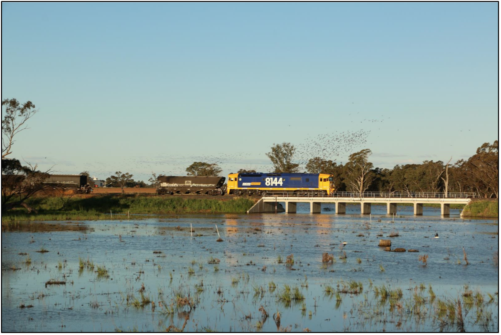
On 29 September 2015, train 3K26 loaded with bulk grain was travelling from Avon Yard to the port at Kwinana in Western Australia, when it exceeded its limit of authority. On that day, track re-railing works were in progress along the route requiring the closure of the Up Main line between Moondyne and Jumperkine. The closure resulted in the diversion of train movements to the adjacent track and the implementation of single line block working under the rules applicable to train order working.
The crew of train 3K26 received a train order to proceed from Moondyne to the station limits board at the 48 km location where they were to stop. Attached to the train order was an additional instruction relating to tasks required when approaching the worksite beyond the 48 km location. After accepting the train order and departing Moondyne, the train crew continued to discuss the additional instructions relating to the tasks required when passing the worksite.
As the train approached the 48 km location, the train crew observed a station limits board and a track closed warning device that marked the limit of the authority. With little time to respond, the driver applied an emergency brake application. The train collided with the track closed warning device before coming to a stop approximately 400 metres past the limit of authority. There was no imminent risk of collision with people or other rail traffic as the distance separating the train and the worksite was approximately 4 km.
What the ATSB found
The ATSB found that the additional instructions attached to the train order distracted the crew from their principal task, which was to stop at the 48 km location. The ATSB also found that there were no visual cues to alert train crew that they were approaching the limit of their authority.
What's been done as a result
Brookfield Rail erected non-crossing indicator boards on each approach to the station limits board. Additionally, safeguards to protect the worksite were increased to include extra infield protection at either end of the closed section of track.
In March 2016, Brookfield Rail introduced a new suite of safe working rules and procedures consistent with the Australian Network Rules & Procedures.
Safety message
Communication of information through non-standard practices and/or the addition of information irrelevant to the intended task may reduce clarity and introduce a source of distraction.
In an operational environment, effective communication, crosschecking and shared understanding by train crew, together with appropriate environmental cues contribute to ensuring the effective performance of tasks.
The occurrence
In the second half of 2015, Brookfield Rail, scheduled maintenance work on the dual gauge rail line between Kwinana (near Perth) and Avon Yard (near Northam), Western Australia. Brookfield Rail contracted John Holland to remove and replace existing rail as part of this work.
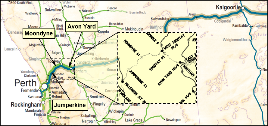
The rail replacement work included sections of track located in the Avon Valley, between Millendon Junction at the 28 km[1] and Moondyne at the 61 km (Figure 1). This line consisted of duplicated tracks for the Up and the Down direction[2], with bypass loops adjoining the tracks at various locations to facilitate the crossing or passing of rail traffic.
Figure 1: Location of Moondyne, Jumperkine and Millendon Junction in the Avon Valley
Source: Australasian Railways Association with annotation by the ATSB
At the commencement of the re-railing works, John Holland implemented a rail safety sub-plan. The plan included the implementation of an alternative safe working system to facilitate the continuation of rail operations around the proposed worksites. The intention was to provide information, guidance and an outline of the general responsibilities assigned to the safe working personnel involved in the project. Brookfield Rail network operations issued special train notices[3] (STN) to advertise the commencement of these altered working arrangements.
In September 2015, Brookfield Rail issued a series of STNs for works between Moondyne and Jumperkine. The STN advised operators of the proposed track closure times required to facilitate the re-railing works programed for the Up Main line. Rail traffic would continue to operate on the Down Main line.
The signalling system did not allow for bi-directional running on the Down Main line. Consequently, the STNs specified that Train Order Working[4] was the alternative method of safe working during the closure. A Network Control Officer[5] located at the Eastern Midland control centre in Perth would be responsible for the issuing train orders[6] for the passage of trains in the affected areas during the closure.
At about 0927[7], on 29 September 2015, the network control officer issued a Safe Working Instruction Form SW6,[8] instituting single line block working under the rules applicable to train order working. The rail replacement works advertised in the STN for that day were programmed on the Up Main line between the 43 km and 44 km track location, about 2 km west of Jumperkine.
Trains travelling towards Perth diverted from the Up to the Down Main line via the bypass loop at Moondyne. The trains would then travel towards Jumperkine before crossing back onto the Up Main and continuing to Perth under signal indications.
Suitably qualified employees designated as stationmasters[9] were positioned at Moondyne (61 km) and Jumperkine (41 km) to facilitate the train order working. An additional stationmaster was also positioned at an intermediate train order non-crossing location[10] at the 48 km location, approximately 4 km prior to the worksite. The responsibilities of the stationmaster included receiving the train orders from the network control officer and delivering them to the train crew at the appropriate time.
At about 1000 hrs, the train crew involved in the occurrence signed on for duty at Avon Yard. They were rostered to relieve the crew of train 3K26, a service operated by Watco. The train comprised two lead locomotives hauling 52 loaded grain wagons. After the crews changed, the train departed Avon Yard and proceeded to West Toodyay and then on towards Moondyne.
At 1125, the network control officer contacted the stationmaster at Moondyne and issued a train order for the passage of train 3K26 from Moondyne to the 48 km location. The network control officer advised the stationmaster that the expected arrival of the train at Moondyne would be around 1145. The stationmaster subsequently conferred with the track protection officer in charge of the work site confirming it was clear to issue the train order to train 3K26 on its arrival at Moondyne.
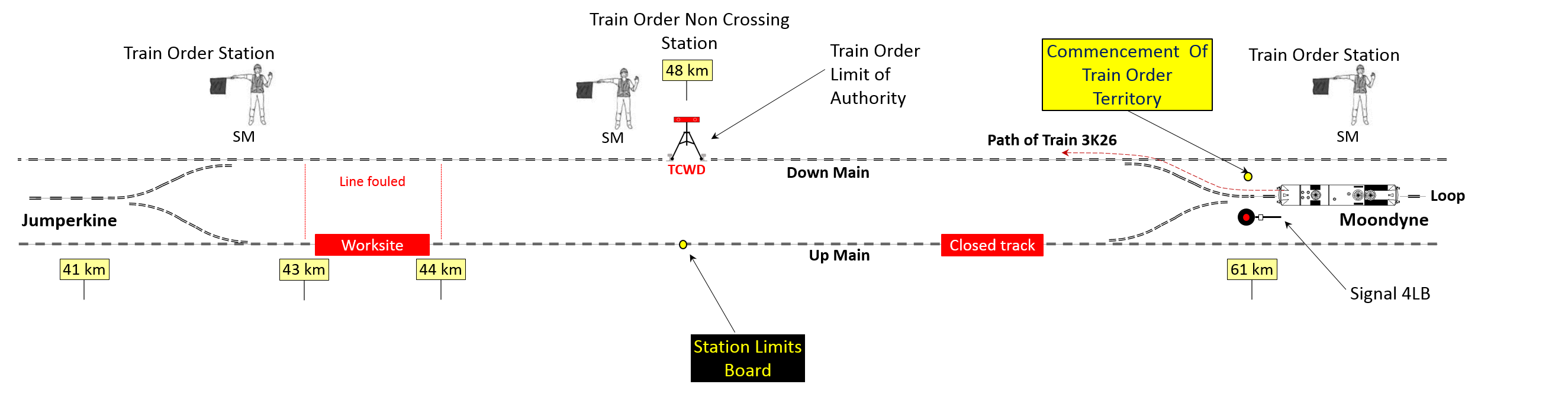
The network control officer advised the crew of train 3K26 that train order working was in place from Moondyne to Jumperkine. At 1149, train 3K26 arrived at Moondyne and after a brief stop the train entered the bypass loop and stopped at signal 4LB (Figure 2).
Figure 2: Map showing positions of the Stationmasters and authority limits
Source: Australian Transport Safety Bureau
The stationmaster entered the cab of the locomotive and provided the crew with Form SW6, advising of train order working and delivered the completed train order to proceed onto the section. The crew received both documents to read and acknowledge their understanding of the contents. The crew signed the train order and it remained with them in the cab of the locomotive.
The train order stated in part:
Proceed to 48 km Station Limits
Do not enter until authorised
There are no unfulfilled train orders for opposing trains
In addition, the stationmaster had attached a yellow post-it note[11] to the train order, which included instructions relating to the track section beyond that of the train order. The note stated the following:
Speed restriction 40 km/h
43-44 km
Blow horn continuously please
The stationmaster also initiated a short discussion with the train crew concerning the required actions on approach to the worksite, also relating to the track section beyond that of the train order. There was no further discussion surrounding the contents of the train order.
The stationmaster then exited the cab and removed the red flag centred in the middle of the track next to signal 4LB.
At about 1203, the train crew advised the network control officer that they were in possession of the train order and completed a read-back[12] of the information. During the read-back, the crew also mentioned information contained on the post-it note, stating:
There is a speed restriction of 40 km/h between the 43 and 44 km
The network control officer acknowledged that the read-back of the authority was correct, but made no mention about the additional instructions not contained in the train order. The network control officer then advised the crew that the points were set and locked, and authorised the crew to pass signal 4LB at stop and depart Moondyne (Figure 2).
At 1205, the train departed Moondyne (61 km). The crew continued to discuss the instructions contained on the note attached to the train order. They discussed the implications of continuously sounding the horn while approaching a worksite, its possible misinterpretation as an emergency and the effect it might have on track workers. They agreed to sound the horn intermittently to avoid any confusion as they approached the worksite.
Meanwhile, the network control officer contacted the stationmaster at the 48 km location and issued a further train order for train 3K26 to proceed to Jumperkine.
This provided the authority for train 3K26 to travel from the 48 km, past the worksite at the 43-44 km location and on to Jumperkine. The stationmaster was to hand the authority to the train crew[13] on the train’s arrival at the 48 km location.
The stationmaster seated within a motor vehicle at the 48 km location had the vehicle headlights illuminated and was facing the train’s approach. The vehicle was located adjacent to the Down Main line and within the immediate vicinity of a level crossing. A Track Closed Warning Device[14] (TCWD), placed to protect against unauthorised movements, was located within the gauge of the Down Main line next to the vehicle’s location. Adjacent to the TCWD, positioned within the gauge of the Up Main line, was a temporary station limits board.
At about 1220, train 3K26 was approaching the limit of its authority (48 km), negotiating a sweeping left bend followed by a straight section of track. The train crew initially observed the station limits board from a distance and briefly discussed its relevance. The crew discounted the significance of the board because of its position on the adjacent line.
At that point, the train was travelling at about 67 km/h on a slight descending grade. The locomotive was already in dynamic brake[15] and the driver had made an initial air brake application to further control train speed.
A short time later, at about 1221, the driver noticed the TCWD located immediately in front of the train. The driver made an emergency brake application and sounded the train horn, followed shortly thereafter by the collision with the TCWD. It was also at this time that the stationmaster leaned out of the car window and waved to the train crew to get their attention.
The train came to a stop at about 1222, approximately 400 metres beyond its limit of authority. The driver exited the locomotive cab and walked back to check on the circumstances with the stationmaster. The second driver contacted the network control officer and reported the incident.
In consultation with the operator, the crew exchanged driving positions, with the second driver taking up the driving duties. The train then continued to Jumperkine under the authority of a new train order. The train arrived at Jumperkine where the drivers undertook routine drug and alcohol testing which provided a negative result. They were relieved from driving duties and returned to their depot by motor vehicle.
The train order working system is predominately an administrative control to maintain safe separation between trains. The effectiveness of this control relies on the accurate communication of relevant safety critical instructions and the understanding and retention of their meaning by the train crew.
The safe working rules and procedures applicable to train order working required the network control officer to issue train orders in a prescribed format to the train crew. The network control officer could transmit the train order either directly to the train crew or, if required, to a qualified worker who was then responsible for delivering the train order to the relevant train crew.
On the day of the occurrence, the network control officer issued the train order to the stationmaster at Moondyne, who then delivered it to the train crew. However, a post-it note was attached that contained additional instructions for action by the train crew.
The crew understood the meaning of the instructions within the train order and read it back to the network control officer, including the additional instructions written on the post-it note. The network control officer authorised the train crew to depart Moondyne, without questioning the inclusion of the additional instructions relayed by the crew during the read-back process.
Factors affecting the actions of the train crew
The train order provided authorisation for train 3K26 to travel from Moondyne to the 48 km location. The instructions on the post-it note were related to the worksite beyond the 48 km and had no relevance to the block section the train was about to traverse. Similarly, the in-cab discussion between the train crew and the stationmaster at Moondyne also related to the track section beyond that of the train order.
The process for authorising and issuing train orders is deliberately constrained. Train orders should convey information or instructions essential and relevant to the section the train is to traverse. This premise reduces the potential for errors or misunderstanding of safety critical information.
The train crew were executing a non-routine task involving train order working to operate on a line against the normal direction of rail traffic flow. The train crew were presented with additional instructions that were not standard practice (sounding the horn continuously at the worksite) and not relevant to the current authority or section of track. The crew were concerned that track workers might misinterpret the actions described in the instructions, so were discussing the issue while travelling towards the 48 km location.
The introduction of the unrelated instructions, reinforced by the stationmaster at Moondyne, resulted in the crew formulating plans that applied to the block section beyond the one which they were traversing. This may have distracted the crew from the immediate task of planning to stop at the 48 km location.
Without having formed a clear plan to stop at the 48 km location, and with their attention focussed on discussing the actions required at the worksite, the train crew most likely forgot about the direction to stop at the limit of authority.
Forgetting to perform a known future task (stopping at the 48 km location) while occupied by a current task (planning actions at the worksite) is common and referred to as a failure of prospective memory. Failure in prospective memory is sometimes described as forgetting to remember.
Prospective memory depends on several cognitive processes, including planning, attention, and task management. It requires forming an intention to perform the task, retaining that intention while performing other unrelated tasks and then remembering to perform the task at a later time, often without being explicitly prompted to do so (Dismukes and others, 2005 and Kramer and others, 2006).
In this case, the train crew understood the task was to stop at the limit of authority (as documented on the train order), but forgot about the task when it became time to remember it. In addition, there were limited prompts to remind the crew about the task.
Operational cues
In operating a train, drivers take cues from their knowledge of track infrastructure and signage to assist in performing tasks to safely manage the train. Effective train handling requires drivers to consider the previous, present and potential future performance of the train, and prepare for conditions sometimes several kilometres in advance of the train’s current location. Heavy freight trains can take many hundreds of metres to stop (dependent on speed) and the driver must commence braking at an appropriate distance before the required stopping point.
The rules and procedures, current at the time, did not require the provision of station limits or station indicator (advanced warning) boards where rail traffic on double line automatic signalling sections was being worked over one line under train order working. However, the rail safety sub-plan stipulated the placement of a station limits board and a track closed warning device to mark the location of the temporary train order non-crossing station at the 48 km mark. The plan made no mention of utilising any form of advance warning board. The station master positioned the track closed warning device in the middle of the Down Main line while the station limit board was positioned adjacent the warning device in the middle of the Up Main line.
The crew initially sighted the station limits board but concluded it was not applicable to the passage of their train since the board was position within the profile of the adjacent closed track.
The track closed warning device was positioned within a tree-shaded area of the rail corridor. The sign was painted with a non-reflective material and was in a faded condition. The sign placement and condition made it inconspicuous to the approaching train crew. When the crew observed the track closed warning device, it was too late to stop. Although an emergency brake application was made, the train collided with the warning device and exceeded the limit of authority.
The absence of a visual cue before the 48 km location meant that there were limited prompts to alert or remind the crew about the task of stopping the train at the limit of authority.
Findings
From the evidence available, the following findings are made with respect to the authority exceedance of train 3K26 at the 48 km track location near Jumperkine, WA on 29 September 2015. These findings should not be read as apportioning blame or liability to any particular organisation or individual.
Safety issues, or system problems, are highlighted in bold to emphasise their importance. A safety issue is an event or condition that increases safety risk and (a) can reasonably be regarded as having the potential to adversely affect the safety of future operations, and (b) is a characteristic of an organisation or a system, rather than a characteristic of a specific individual, or characteristic of an operating environment at a specific point in time.
Contributing factors
The additional instructions attached to the train order distracted the crew from their principal task, which was to stop at the 48 km location.
There were no visual cues provided to alert the train crew that they were approaching the limit of their authority.
Other factors that increased risk
The rules applicable for train order working on one line, in a double line signalled section, did not require the installation of cues to draw train crew attention to the limit of authority.
The additional information attached to the train order, did not form part of the instructions issued by the network control officer.
Safety actions
Additional safety action
Whether or not the ATSB identifies safety issues in the course of an investigation, relevant organisations may proactively initiate safety action in order to reduce their safety risk. The ATSB has been advised of the following proactive safety action in response to this occurrence.
Proactive safety action taken by Brookfield Rail Pty Ltd
Brookfield Rail in consultation with John Holland arranged for the placement of Train Order ‘non-crossing indicator boards’ at 600 metres either side of the Station Limits Board to further identify the Train Order non-crossing location for the remainder of the re-railing project. There was also an increase with infield protection to include three track-warning devices 20 metres apart on each rail in advance of the track closed warning sign. Brookfield subsequently carried out similar works under newly implemented Brookfield Rail Network Safe working Rules and Procedures.
Proactive safety action taken by Watco Pty Ltd
Watco have undertaken improvements regarding emphasis on Crew Resource Management (CRM) following the incident. These included
Providing additional checkpoints to their Operational Check Ride form related to cab situational awareness
Cab situational awareness monitoring through periodical locomotive data downloads
Increased time at the footplate by Managers of Operating Practices (MOP’s) and Operational Zone Managers (OZM’s) to reinforce, coach and mentor the concept and practices surrounding cab situational awareness.
Sources and submissions
Sources of information
The sources of information during the investigation included:
Brookfield Rail Pty Ltd
John Holland Pty Ltd
Watco
Train crew and qualified workers involved in the occurrence
References
Rail Safety Sub Plan – Avon Valley Re-railing Project, John Holland, 2015,
Rail Industry and Safety Standards Board, 2010, National Guideline Glossary of Railway Terminology
Westnet Rules and Procedures
Dismukes, K 2010, Remembrance of Things Future: Prospective Memory in Laboratory Workplace and Everyday Settings. NASA Ames Research Centre.
Dismukes, K & Nowinski, J 2005, Prospective Memory, Concurrent Task Management, and Pilot Error. New York: Oxford University Press.
Dodhia, R M & Dismukes, R K 2008, Interruptions Create Prospective Memory Tasks, San Jose: Wiley InterScience.
Kramer, A F & Weigmann, D A Kirlik, A 2006. Attention: From Theory to Practice. New York: Oxford University Press.
Loukopoulos, L D Dismukes, R K Barshi, I 2016, The Multitasking Myth: Handling Complexity in Real-World Operations. U.K.: Routledge.
Stanton, N A Stewart, R Harris, D Houghton, R J Baber, C McMaster, R Salmon P 2006, Distributed Situation Awareness in Dynamic Systems: Theoretical Development and Application of an Ergonomics Methodology, Ergonomics, vol. 49, pp. 1288-1311.
Submissions
Under Part 4, Division 2 (Investigation Reports), Section 26 of the Transport Safety Investigation Act 2003 (the Act), the Australian Transport Safety Bureau (ATSB) may provide a draft report, on a confidential basis, to any person whom the ATSB considers appropriate. Section 26 (1) (a) of the Act allows a person receiving a draft report to make submissions to the ATSB about the draft report.
A draft of this report was provided to Brookfield Rail, Watco, Office of the National Rail Safety Regulator (ONRSR) and individuals involved in the occurrence.
Submissions were received from Brookfield Rail, Watco, Office of the National Rail Safety Regulator (ONRSR) and individuals involved in the occurrence. The submissions were reviewed and where considered appropriate, the text of the report was amended accordingly.
Purpose of safety investigations
The objective of a safety investigation is to enhance transport safety. This is done through:
identifying safety issues and facilitating safety action to address those issues
providing information about occurrences and their associated safety factors to facilitate learning within the transport industry.
It is not a function of the ATSB to apportion blame or provide a means for determining liability. At the same time, an investigation report must include factual material of sufficient weight to support the analysis and findings. At all times the ATSB endeavours to balance the use of material that could imply adverse comment with the need to properly explain what happened, and why, in a fair and unbiased manner. The ATSB does not investigate for the purpose of taking administrative, regulatory or criminal action.
Terminology
An explanation of terminology used in ATSB investigation reports is available here. This includes terms such as occurrence, contributing factor, other factor that increased risk, and safety issue.
Publishing information
Released in accordance with section 25 of the Transport Safety Investigation Act 2003
Ownership of intellectual property rights in this publication
Unless otherwise noted, copyright (and any other intellectual property rights, if any) in this report publication is owned by the Commonwealth of Australia.
Creative Commons licence
With the exception of the Coat of Arms, ATSB logo, and photos and graphics in which a third party holds copyright, this publication is licensed under a Creative Commons Attribution 3.0 Australia licence.
Creative Commons Attribution 3.0 Australia Licence is a standard form licence agreement that allows you to copy, distribute, transmit and adapt this publication provided that you attribute the work.
The ATSB’s preference is that you attribute this publication (and any material sourced from it) using the following wording: Source: Australian Transport Safety Bureau
Copyright in material obtained from other agencies, private individuals or organisations, belongs to those agencies, individuals or organisations. Where you wish to use their material, you will need to contact them directly.
On 25 September 2015, a Cessna 550 aircraft (Citation Bravo), registered VH-FGK, taxied at Lismore Airport for a private flight to Baryulgil, New South Wales. The flight crew consisted of a captain and copilot, who were the only occupants of the aircraft.
The flight crew did not detect anything abnormal during the taxi and take-off roll, until the captain attempted to rotate the aircraft to the take-off pitch attitude. When the aircraft had achieved the required rotate speed, the captain applied the normal backpressure on the control column to achieve a standard rate of rotation, and the aircraft did not rotate. The captain then applied full backpressure and reported that the controls felt very heavy. Neither the captain nor the copilot detected any change in the aircraft’s pitch attitude or any indication of pitch-up on the attitude direction indicator.
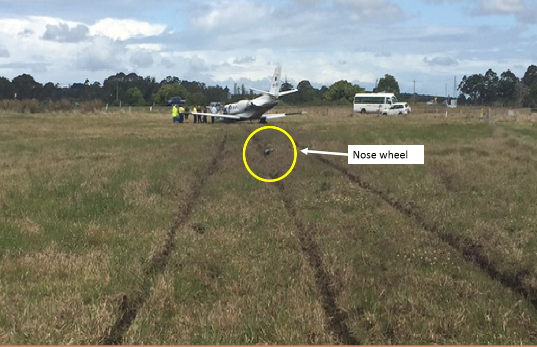
The captain rejected the take-off, applied full braking and reverse thrust, but the aircraft overran the runway. The nose landing gear detached from the aircraft about 50 m beyond the end of the sealed runway, and the aircraft came to rest in long grass and mud. The aircraft sustained substantial damage, and the captain and copilot were uninjured.
What the ATSB found
The aircraft did not accelerate normally as the acceleration was retarded by drag associated with rolling friction. This was indicative of partial brake pressure remaining during the take-off run. The partial brake pressure was possibly due to the parking brake being selected on at the holding point with enough pressure to retard aircraft acceleration during the take-off, but not sufficient to prevent the aircraft reaching rotate speed.
Furthermore, the nose-down moment generated by the partial brake pressure probably prevented the aircraft rotating sufficiently to become airborne, despite normal nose-up elevator deflection.
Heat in the brakes due to partial pressure during the take-off run may have reduced their effectiveness when the captain rejected the take-off, contributing to the runway overrun.
What has been done as a result
The Australian Transport Safety Bureau issued a safety recommendation that Textron Aviation (Cessna) take safety action to address the fact that Citation aircraft do not have an annunciator light to show that the parking brake is engaged and the Cessna 'before take-off' checklist does not include a check to ensure the parking brake is disengaged.
Safety message
For pilots, this incident highlights the importance of attention to the configuration of the aircraft and cockpit settings at all stages of flight, but particularly during take-off. For manufacturers, this incident highlights the importance of systems that bring an irregular or abnormal configuration or cockpit setting to the attention of the crew, especially when that configuration has the potential to adversely affect aircraft performance or control.
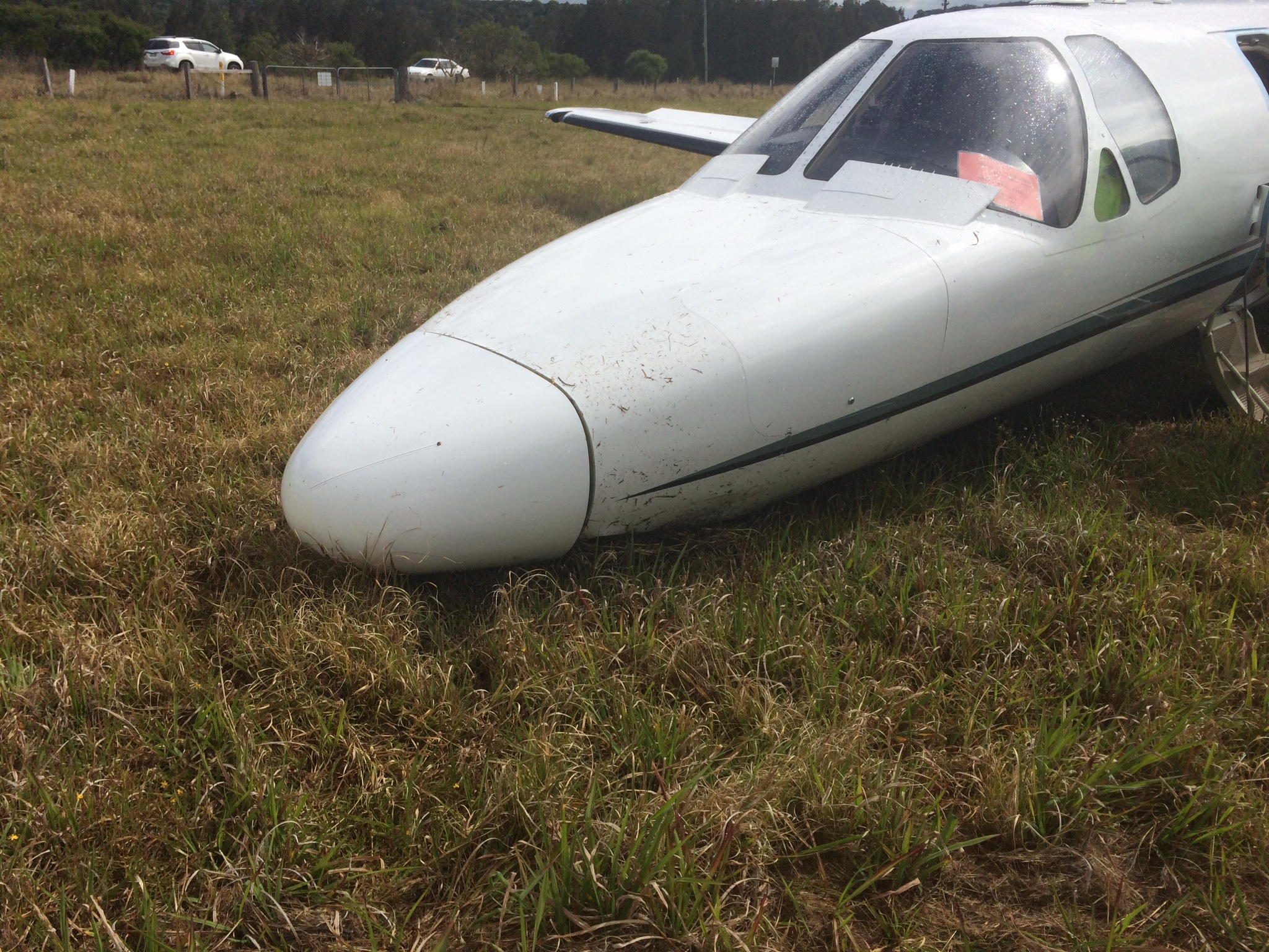
Accident site of Cessna 550 aircraft (Citation Bravo), registered VH-FGK, at Lismore Airport
Source: Aircraft operator
The occurrence
History of the flight
On the morning of 25 September 2015, the captain and copilot of a Cessna 550 aircraft (Citation Bravo), registered VH-FGK, prepared to conduct a private flight from Lismore Airport to Baryulgil, about 40 NM south-west of Lismore, New South Wales. The aircraft had been parked at the northern end of the airport overnight, with engine covers and control locks on.
After arriving at the airport, the flight crew conducted a pre-flight inspection, with no abnormalities identified. They then commenced the normal pre-start checks, which included the disengagement of the flight control locks.
The crew elected to use runway 15 for take-off, and used the Cessna simplified take-off performance criteria (see Take-off performance simplified criteria) to determine the thrust settings and take-off reference speeds. The resultant reference speeds were 105 kt for the decision speed (V1)[1] and 108 kt for the rotation speed (VR).[2]
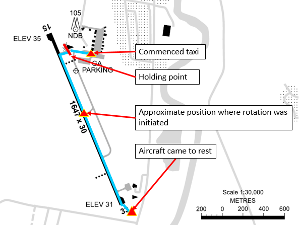
At about 1300 Eastern Standard Time,[3] the flight crew started the engines and performed the associated checks, with all indications normal. The crew reported that they completed the after-start checks, and the captain then taxied the aircraft to the holding point for runway 15, less than 200 m from where the aircraft was parked (Figure 1). While stopped at the holding point, the crew completed the taxi and pre-take-off checks, the copilot broadcast the standard calls on the common traffic advisory frequency, and the captain communicated with air traffic control (ATC).
Figure 1: Lismore Airport showing aircraft track
Source: Airservices Australia – annotated by ATSB
The captain taxied the aircraft onto the runway, and turned left onto the runway centreline to commence the take-off run from the intersection (Figure 1). While rolling along the runway, the captain advanced the thrust levers to the approximate take-off setting. The captain then called ‘set thrust’, and the copilot set the thrust levers to the more precise position needed to achieve the planned engine thrust for the take-off.
As the aircraft accelerated, the copilot called ‘80 knots’ and crosschecked the two airspeed indicators were in agreement and reading 80 kt. The copilot called ‘V1’ and the captain moved their hands from the thrust levers to the control column in accordance with the operator’s normal procedure. A few seconds later, the copilot called ‘rotate’ and the captain initiated a normal rotate action on the control column.
The crew reported that the aircraft did not rotate and that they did not feel any indication that the aircraft would lift off. The copilot looked outside and did not detect any change in the aircraft’s attitude as would normally occur at that stage. The captain stated to the copilot that the aircraft would not rotate, and pulled back harder on the control column. The copilot looked across and saw the captain had pulled the control column firmly into their stomach.
Although the aircraft’s speed was then about 112 kt, and above VR, the crew did not detect any movement of the attitude director indicator or the nose wheel lifting off the ground, so the captain rejected the take-off; applied full brakes, and set the thrust levers to idle and then into reverse thrust.
The aircraft continued to the end of the sealed runway and onto the grass in the runway end safety area (RESA), coming to rest slightly left of the extended centreline, about 100 m beyond the end of the runway (Figure 2).
Figure 2: Accident site
Source: Lismore City Council – annotated by ATSB
Injuries and damage
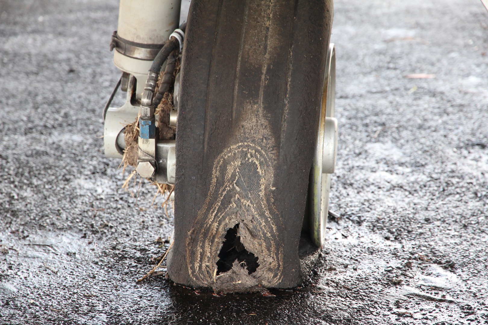
The aircraft sustained substantial damage and the flight crew, who were the only occupants of the aircraft, were uninjured. The nose landing gear separated from the aircraft during the overrun (Figure 2), and there was significant structural damage to the fuselage and wings. The right wheel tyre had deflated due to an apparent wheel lockup and flat spot, which had progressed to a point that a large hole had been worn in the tyre (Figure 3).
Both flight crewmembers were appropriately trained and qualified for the flight, and reported feeling well rested and healthy.
Captain
The captain held an Airline Transport Pilot (Aeroplane) Licence, command instrument rating and a valid Class 1 medical certificate. The captain had a total aeronautical experience of 5,937.7 hours, including 800.6 hours on Citation aircraft, and also had check and training approval for the Citation.
Copilot
The copilot held a Commercial Pilot (Aeroplane) Licence, command instrument rating and a valid Class 1 medical certificate. The copilot had a total aeronautical experience of 377.8 hours, including 40.4 hours on Citation aircraft.
Aircraft information
Weight and balance
There were two crewmembers on board and no passengers. The crew reported that each pilot had a small bag stowed in the nose locker and there was no additional baggage on the aircraft. According to the loadsheet for the flight, there was about 4,000 lb (1,814 kg) of fuel on board (full fuel was 4,871 lb (2,214 kg)), and the take-off weight was about 13,518 lb (6,132 kg), below the maximum take-off weight of 14,800 lb (6,713 kg).
The crew reported they completed the weight and balance calculations prior to the flight, in accordance with their normal procedures. The load sheet obtained by the ATSB showed that the centre of gravity was within the allowable range.
Aircraft examination
The operator’s engineering manager inspected the aircraft on 1 October 2015, for any mechanical reason for the reported lack of response to elevator control input. The maintainer reported that the elevators were able to be operated to full deflection to the mechanical travel stops from the cockpit in the up and down sense. There was no binding or restrictions to travel noted in around the control yoke in the cockpit. There was no external evidence on or in the vicinity of the elevators to cause any restriction to travel.
The aircraft owner, who also inspected the accident site, reported that:
the nose locker was filled with water and mud,
the control lock could not be bypassed (that is, was working correctly),
the weight and balance was towards the middle of the allowable envelope, and
the elevator controls and surfaces had full deflection and were able to be moved in the correct sense.
The ATSB inspected the aircraft on 4 November 2015, after it had been moved to a hangar. The aircraft examination was limited to external general observations and a detailed examination of the flight control lock and elevator and trim systems, in an attempt to ascertain the reasons for an apparent lack of elevator response during the incident.
The control lock, elevator and trim system were in good mechanical order. All functional checks, tests and examinations did not find a fault that may have contributed to the runway overrun.
The left brake had been removed during the recovery of the aircraft as the brake had seized due to overheating (see Brakes).
Airspeed indications
The aircraft was equipped with three separate and independent pitot-static systems. The two primary systems served the captain’s and copilot’s systems. The third provided pitot and static air pressure to the standby flight display. Altitude and airspeed data was generated by micro air data computers, which transmitted the information to the primary flight displays. With two independent sources, and the copilot verifying at 80 kt that both airspeed indicators were in agreement, it is unlikely that they were both indicating the same but incorrect airspeed. Available evidence suggests that the airspeed indicating system was functioning normally during the take-off.
Thrust
The flight data and crew reports indicated that the thrust was set in accordance with the settings indicated in the simplified take-off performance reference. Both crew reported engine indications were normal. The flight data showed the engine RPM was consistent with four previous flights.
The flight data shows that the engines were delivering the expected amount of thrust during the take-off, and reverse thrust was not selected until after the captain rejected the take-off.
Elevator deflection and control movement
The captain checked the flight controls as part of the pre-take-off checks, and verified full and free movement, and normal feel of the control column. The crew were unable to see the elevator to assess whether control movement matched control surface deflection, however, normal deflection was evident in the recorded flight data.
The crew stated that the captain pulled the control column as far back as possible during the take-off roll, but that the aircraft did not rotate. The flight data showed that the elevator achieved normal deflection in the correct sense in response to the control input. The elevator was also operating correctly immediately after the accident when the operator’s engineer inspected it, and when the ATSB subsequently inspected the full length of the elevator system.
Therefore, it can be concluded that the control input resulted in a correct and normal elevator deflection.
Aircraft configuration
From the available evidence, the following were configured correctly for the take-off:
There was no evidence of any external securing articles still in place at the time of the accident. The post-accident inspection did not find any such articles. The crew reported having completed a normal pre-flight external inspection. There was no indication in the flight data of aerodynamic drag from, for example, an unsecured panel.
The control lock was released. The aircraft will not start without the control lock being released, as it locks the thrust levers. The control lock mechanism was subsequently found to be working correctly and therefore would have prevented the pilot from starting the engines if it had been left in place.
Based on the crew reports, cockpit voice recording and photo of the cockpit centre console immediately after the accident, the elevator trim was set correctly for take-off – in the take-off position marked on the trim indicator.
The flight data showed that the speed brakes were not deployed.
The flight data showed the autopilot was not engaged.
The crew reported that the flaps were set in the ‘take-off/approach’ position marked on the flap indicator. The flight data was consistent with the flaps being set for take-off.
Based on the cockpit voice recording, the crew completed all after-start, taxi and pre-flight checks in the sequence of the published aircraft checklist. The captain’s response to the copilot’s call of ‘brakes’ during the after-start checks was ‘I’ll check them’. There was no subsequent reference to the brake check on the CVR, however, the required action was to apply the toe brakes and ensure symmetrical retardation and positive pressure existed.
Aircraft parking brake
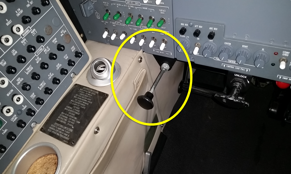
The parking brake was set by either pilot applying and holding footbrake pressure and the pilot in the left (captain’s) seat pulling out the parking brake lever underneath the left instrument panel (Figure 4). The lever could be selected OFF or fully ON. There was no partial release position of the lever. When the lever was pushed forward from the ON position, pressure in the lever would continue to release the lever until it was in the OFF position. The position of the parking brake lever was not visible to the pilot in the right seat. There was no cockpit annunciation that the parking brake lever was in the ON position.
Figure 4: Parking brake lever in the ON position
Source: Aircraft owner
With the parking brake on, the applied pressure in the brake lines is trapped, and when the footbrake is released, the pressure at the brakes remains. If the parking brake handle is pulled with no footbrake pressure applied, no pressure will be present in the brakes. However, any subsequent footbrake pressure will be trapped and maintained, until the parking brake lever is returned to the OFF position. The park brake is certified to ensure that with full pressure applied, the wheels will remain locked even if full thrust is applied on both engines.
The parking brake was found engaged following the accident. However, the captain reported engaging it after the aircraft came to rest in the grass. The captain also reported that evacuation training always included setting the park brake as one of the first actions. The captain could not recall selecting the parking brake ON while at the holding point, where the aircraft was stationary for over 4 minutes.
Brakes
The aircraft brakes consisted of alternating discs connected to the wheel and axle. When the brakes are applied when the wheels are moving, their temperature will rise. If the brakes overheat, the disc pack will seize and the wheel will stop rotating. The brakes incorporated an anti-skid system. When a skid or impending locked wheel condition is sensed, a signal is sent to release the pressure in the affected brake.
After the accident, the left brake had seized and both brakes appeared to have been exposed to very high temperatures.
If the brakes were partially engaged while the aircraft was moving throughout the take-off run, they would have been absorbing energy and increasing in temperature. In the event of a rejected take-off, the brakes would then be less effective than usual due to their elevated temperature.
The operator’s engineering manager who inspected the accident site reported that they were unable to inspect the brakes as the brake and wheels were packed solid with grass and mud, and one tyre was fully deflated. The engineering inspection report provided to the ATSB (see Aircraft examination above) was limited to the elevator control functionality.
A failure of the parking brake valve could result in partial brake pressure. The brake valve was not inspected after the accident by the operator nor assessed during the ATSB’s inspection of the aircraft. However, as the braking system was working during the taxi to the holding position, the short time between holding to enter the runway and taxiing onto the runway was the only opportunity for it to fail. Further, a senior air safety investigator from Textron Aviation (Cessna) was unaware of any other failures of the valve to operate correctly.
Airport information
Runway
Runway 15 at Lismore had an available take-off length of 1,647 m (5,403 ft). The runway sloped down by 0.1 per cent. The aircraft was taxied onto the runway at the northern taxiway intersection, about 152 m (500 ft) beyond the runway threshold (Figure 1). Although the take-off was commenced from the intersection, an additional 152 m of runway was available to the crew for the take-off.
Runway end safety area
The Civil Aviation Safety Authority Regulation (CASR) 139 Manual of Standardsrequires Code 3 and 4 runways[4] like runway 15 at Lismore to have a runway strip extending 60 m beyond the runway end, and a runway end safety area (RESA) for 90 m beyond the runway strip. In addition, the International Civil Aviation Organization Annex 14 recommends that the RESA should extend (as far as is practicable) to a length of at least 240 m beyond the end of the runway strip.
Runway strips consist of a fully graded area surrounding the runway at both ends and beyond the side of the runway. Runway strips are required by CASR 139 to be free of all fixed objects and potential obstructions, other than visual aids for guiding aircraft or vehicles. These objects must be of low mass and frangible. The aim of this area is to reduce the risk of damage to aircraft running off the ends or sides of the runway.
RESAs are areas of graded flat ground beyond the end of a runway and runway strip, designed to enhance aircraft deceleration. These are symmetrical about the extended runway centreline, and are free from any non-frangible obstacles or obstructions.
By assisting aircraft to decelerate in a controlled manner, RESAs are designed to reduce the risk of damage to an aircraft that undershoots the runway, rejects a take-off and overruns the runway end, or overruns the runway end following a landing.
Using measurements from a Google Earth image of Lismore Airport taken in 2014, the overrun area beyond the sealed end of runway 15 at Lismore was about 180 m to the airport boundary fence, flat, grassed and free of obstacles.
Accident site
Similarly, using measurements from Google Earth based on photos of the accident site, the aircraft came to rest about 150 m beyond the sealed runway and before the airport boundary fence. The RESA at Lismore may have assisted in decelerating the aircraft after the rejected take-off and reduced risk of injury and damage to the aircraft.
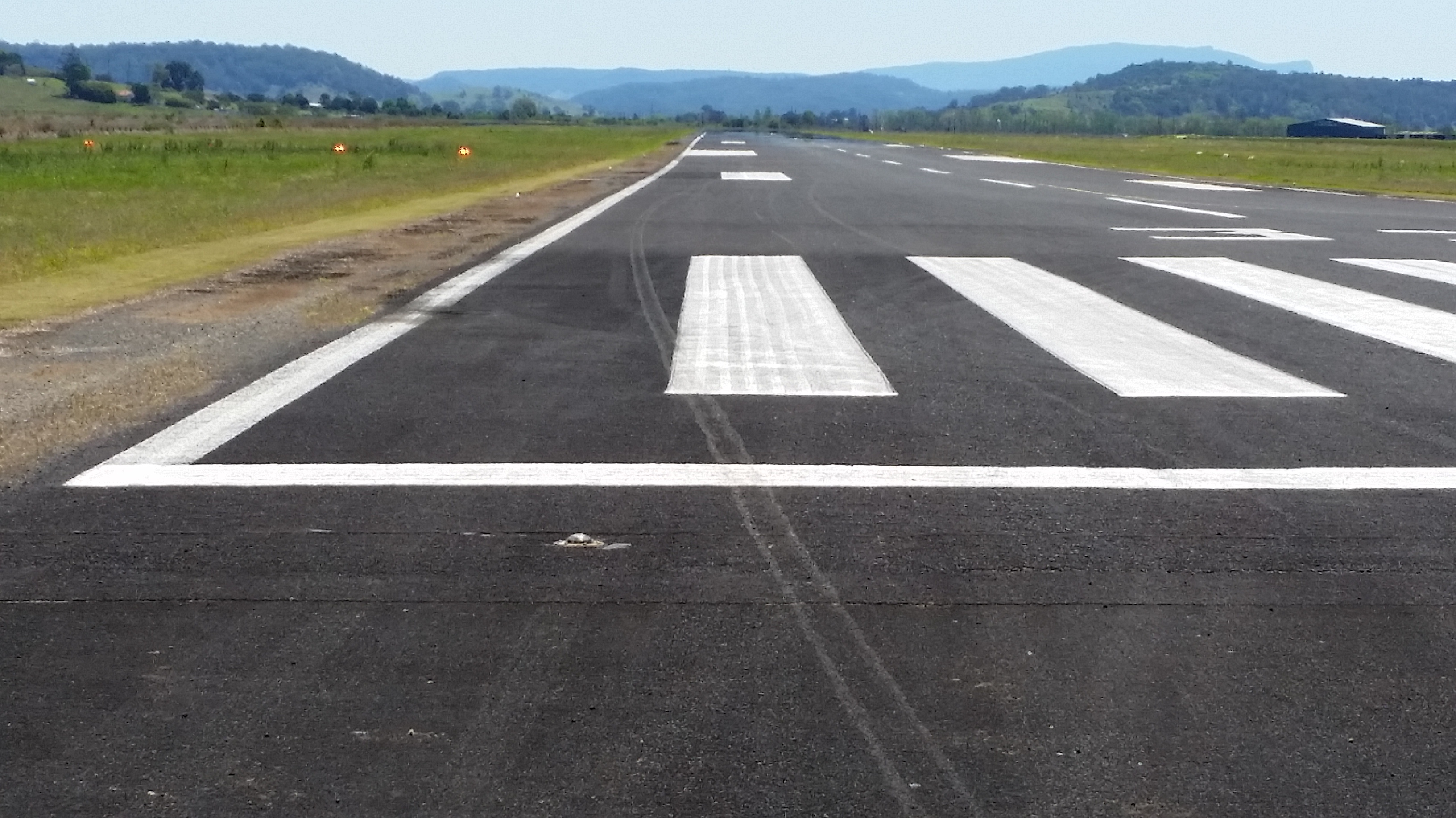
Distinctive marks on the end of runway 15 indicated that the right wheel tyre had deflated after the captain rejected the take-off and the wheel’s rim was making contact with the runway. The position of the tyre witness marks on the runway showed that the aircraft remained just to the right of the centreline but moving towards the left as it exited the runway (Figure 5).
Figure 5: Southeast end of the runway showing right wheel contact marks on the runway and their position in relation to the runway centre line
Source: Aircraft owner
Operational information
Weather
According to the Meteorological Terminal Aviation Routine Weather Report (METAR) for Lismore Airport issued at 1230, the wind was from 190° at 10 kt, and the temperature was 18 °C. The runway was dry at the time of the accident.
Take-off performance simplified criteria
The Cessna 550 pilot operating handbook specified values for speeds and power settings for a reduced thrust take-off, known as simplified take-off performance criteria. The simplified criteria could only be used if the following conditions were met, including:
flaps set to 15° (take-off and approach setting)
available take-off field length of 5,200 ft (1,585 m) or longer
no tailwind
no runway gradient
dry paved runway.
The crew used the reduced-thrust reference speeds and power setting based on an aircraft weight of 14,000 lb (6,350 kg) or less, airport altitude 3,000 ft or below, and the ambient temperature between -1 °C and 35 °C.
The aircraft weight, airport altitude and temperature met the required criteria, and the flaps were recorded in a position suitable for take-off and consistent with the simplified take-off criteria. In addition, by commencing the take-off run from the taxiway intersection, the runway length remaining (4,900 ft) was about 300 ft (91 m) less than that required.
Flight data
Accident flight
The ATSB analysis of the flight data recorder (FDR) showed:
the control column input (to rotate the aircraft) started at about 105 kt (which was the calculated V1; VR was 108 kt)
the maximum elevator position of 11° occurred at about 111 kt
the maximum pitch attitude of 4.7° occurred at about 112 kt
the aircraft took about 19 seconds to accelerate from 40 kt to 110 kt.
Flight data comparison
The accident flight data was compared with four previous flights. Although numerous variables would have differed for each of the previous flights, such as aircraft weight and balance and environmental conditions, the difference in the take-off run data between those flights was not significant compared with the evident differences in the data from the accident flight. Although the engine RPM was not significantly different from the previous flights, the accident flight differed to the others in the following ways:
For the accident flight, the aircraft took about 19 seconds to accelerate from 40 to 110 kt, or almost twice that of the previous four flights, which took 10-12 seconds.
While the rate of change of the elevator deflection after VR was similar to four previous flight, the total deflection was greater.
The rate of change of aircraft pitch after VR was significantly lower (1.6° per second) than previous flights (3.6-4.8° per second). The maximum pitch angle was 4.7° whereas for the previous flights it was about 11°.
Analysis of flight data
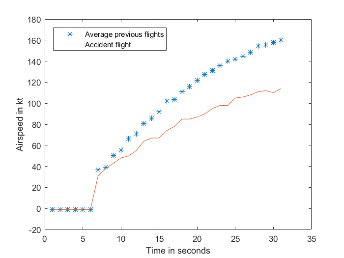
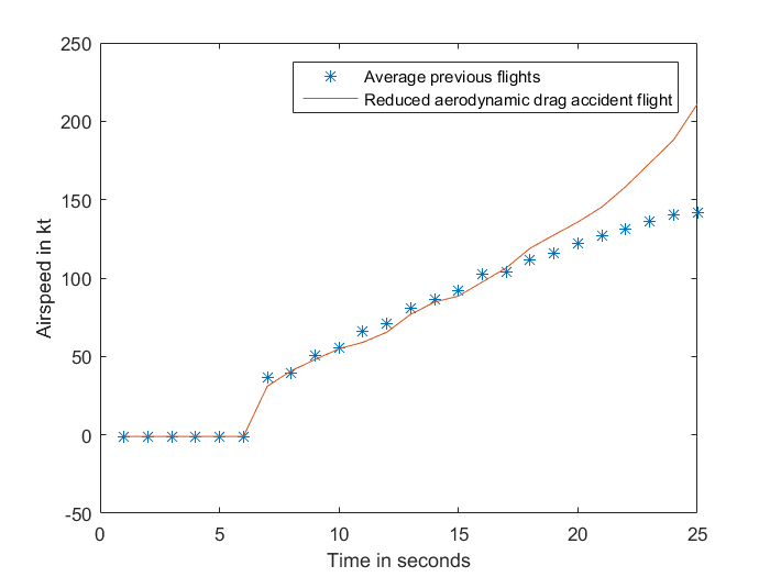
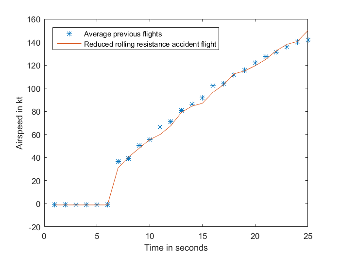
During the take-off run, the aircraft accelerates against the aerodynamic drag of the aircraft and rolling resistance of the wheels. The variations of these with speed[5] are different. The aerodynamic drag increases with the square of speed. In contrast, principal components of the rolling resistance are a constant force that varies with rolling speed. As shown in Appendix A, removing a component of aerodynamic drag to the accident flight speed profile does not result in a similar speed profile to the previous four flights throughout the take-off run. However, correcting the acceleration at a constant rate of 2.5 kt/sec does result in a closely correlated speed profile with the previous four flights. As such, it is evident the slow acceleration was a product of additional rolling resistance of the wheels rather than additional aerodynamic drag.
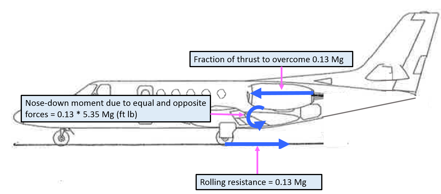
Appendix A also shows that an additional rolling resistance on the wheels, given the aircraft’s thrust line (engine height) was above the main wheels contact point with the runway, would create a nose-down moment on the aircraft. Full elevator deflection, at the thrust setting and the airspeed when the captain attempted to rotate the aircraft, would have been insufficient to overcome this nose-down moment. (Aerodynamic drag would not produce the nose-down moment preventing rotation.)
Similar incidents
In 2010, a Cessna Citation CJ1, registered N646VP, overran the runway at Leeds Bradford Airport, West Yorkshire, UK. During the take-off run, the pilot assessed that the aircraft would not accelerate to V1 and rejected the take-off. As the pilot braked, both brakes failed, the right brake caught fire and the aircraft overran the end of the runway. The accident investigation by the UK Air Accident Investigation Branch (AAIB), and reported in AAIB bulletin 3/2011, concluded that the brakes were probably on, at least partially, during the take-off run.
The US National Aeronautics and Space Administration (NASA) provided the ATSB with a report of Cessna Citation parking brake engaged or partially engaged during takeoff roll incidents from the Aviation Safety Reporting System (ASRS).[6] This included the following two (of three) reports:
A Cessna 525 owner/pilot reports hiring a professional pilot to fly him to an airport due to a strong gusty wind forecast. The professional pilot forgets to release the parking brake prior to takeoff and this omission is not detected until airborne. Upon landing the right brake is locked and the right tire fails causing directional control problems.
On landing, a Cessna 550 blew both main tires which was caused by a partially engaged parking brake. There is no warning system or light that indicates the parking brake is still engaged.
A Senior Investigator from Textron Aviation (Cessna) indicated that there have been similar events where pilots have attempted to take off with the parking brake set and enough pressure to keep the aircraft rolling at idle thrust, resulting in similar incidents. This led to the publication of an article in Cessna’s Direct Approach magazine issued in December 2008, which reminded operators to make sure to disengage the parking brake.
There is no parking brake indicator to alert the flight crew that the park brake handle is engaged. Flight crews should follow the procedures in the Airplane Flight Manual (AFM) and the Pilots’ Abbreviated Checklist regarding the brake system operation. The pilot in command is the last set of eyes to make certain the brake system switch, circuit breaker, and park brake are all in the correct positions before taxi or takeoff.
While the crew did not detect anything abnormal during the take-off run until rotation, the flight data showed a significantly reduced acceleration despite normal thrust and engine RPM, and normal aircraft configuration. When the captain attempted to rotate the aircraft, the aircraft did not rotate despite full elevator deflection. The captain rejected the take-off, applying full brakes and reverse thrust. Before the aircraft could stop, it overran the runway onto the grass over-run area, which minimised damage to the aircraft and prevented serious injuries occurring.
There was no evidence that the slow acceleration was related to aircraft weights or balance, weight and balance calculations, aircraft configuration or thrust settings, or inaccurate airspeed readings. There was also no evidence to suggest that the lack of rotation was related to insufficient elevator deflection or control column movement, external locks, control locks, inappropriate elevator trim, or inappropriate airspeed.
Flight data analysis showed that the slow acceleration and lack of rotation at VR was consistent with a constant rolling resistance on the wheels. The analysis will consider the possibility that this rolling resistance was a result of partial brake pressure on the wheels as a result of an engaged parking brake. It will look at the limited opportunities the crew have to detect an engaged parking brake when it results in only a small amount of brake pressure. The analysis will also examine the implications of the captain’s late take-off rejection and the intersection departure, and the runway end safety area, on the safety of flight.
Partial brake pressure during take-off
Rolling resistance on the wheels could be a result of a number of factors, such as soft ground, a wheel, tyre or brake failure, or partially applied braking pressure to the wheels.
The runway was a sealed hard surface, so it is not feasible the surface had any effect.
Neither crew member detected any tendency for the aircraft to yaw. Additionally, the position of the tyre witness marks on the runway showed that the aircraft remained on the runway centreline until after the captain rejected the take-off. This is indicative of equal resistance from both main wheels and not a failure of one wheel, brake or tyre.
Given that only one tyre was damaged (and that witness marks indicate it was damaged after the rejected take-off), it is therefore probable that the rolling resistance experienced by the aircraft was a result of partial brake pressure in both wheels. This affected both the slow acceleration rate and inability to rotate the aircraft at VR.
Previous incidents have also shown that partial brake pressure in the wheels can lead to slow acceleration and an inability to rotate during take-off.
Parking brake not disengaged
The partial brake pressure to both wheels could have been a result of one of the flight crew applying toe braking throughout the take-off, a mechanical failure of the parking brake valve, or an engaged parking brake.
Both crew were sufficiently experienced to make it very unlikely that either was accidently applying toe braking during the take-off run. Furthermore, the copilot (as pilot monitoring) reported having their feet flat on the floor during the take-off.
The possibility of mechanical failure of the parking brake valve was unlikely. The crew had been able to release the parking brake and commence taxiing to the holding point, and confirmed pressure was achievable in the toe brakes during the taxi. Although they were not inspected after the accident, there was very limited opportunity for them to fail (after leaving the holding point), and there was no evidence of failure or history of failures of the park brake valve in other Cessna Citation aircraft.
In order for partial braking pressure to exist in the wheel as a result of the parking brake lever not being disengaged, a small amount of pressure from toe braking would also need to have been trapped.
The captain could not recall whether they selected the parking brake on while at the holding point. The aircraft was stationary at the holding point for over 4 minutes. The captain reported that only light pressure on the toe brakes would have been necessary to stop the aircraft at the holding point with the engine thrust at idle and after a short taxi. This would be consistent with enough partial pressure remaining in the brakes to affect acceleration but not sufficient to prevent the aircraft reaching VR.
The parking brake was found engaged following the accident. The captain reported they engaged it after the aircraft came to rest in the grass. However, it is possible that having observed the parking brake engaged on returning to the aircraft after exiting following the accident, and expectations based on evacuation training, the captain may have assumed they engaged it during the shutdown process, influencing their subsequent memory. The flight crew reported being quite shocked and in a hurry to exit the aircraft in case of fire following the accident, and the CVR showed that the copilot needed to remind the captain to complete another pre-evacuation action (shutting down the engines). The copilot was unable to see the parking brake lever from their position.
The aircraft manufacturer was aware of a number of events where pilots have attempted to take off with the parking brake on and just enough pressure remaining in the brakes to permit the aircraft to roll even at idle thrust. These have resulted in similar incidents, including a runway overrun involving a Cessna Citation CJ1 (with the same braking system) in 2010 in the UK. Further, the captain, aircraft operator and owner, and Cessna, have all reported that it is not uncommon to attempt to taxi the Citation aircraft with the park brake engaged.
Therefore, although there is no direct indication that the parking brake was engaged resulting in a small amount of pressure being trapped in the brakes, the plausibility of it, past occurrences where it has occurred, and the absence of other explanations given the evidence suggests it is probable that the parking brake was still engaged during the take-off run.
No related cockpit annunciation or checklist item
The park brake lever was the only indication that the park brake was engaged in Cessna Citation aircraft. However, the lever is on the captain’s side and is not visible from the copilot’s seat. Further, it is outside the captain’s normal line of sight during a routine instrument scan.
There was no cockpit annunciation on the instrument panel to show that the parking brake was on, and there was no check that the parking brake in the (manufacturer supplied) aircraft’s pre-take-off checklist. The lack of one of either the annunciator light or a checklist item makes it difficult for any crew to realise when the parking brake is inadvertently left engaged when only partial brake pressure exists.
A representative from Textron Aviation (Cessna) advised that they were aware of similar events occurring due to pilots attempting to take off with the parking brake set, and only enough pressure to allow the aircraft to keep rolling at idle thrust. Cessna’s Direct Action magazine had published a reminder to operators of Citation aircraft to ensure the parking brake was disengaged in response to a previous similar incident. The article stated ‘There is no parking brake indicator to alert the flight crew that the park brake handle is engaged’.
Given the position of the park brake lever, the lack of annunciator light on the instrument panel, and no pre-take-off check, in addition to the fact that the slow acceleration was not perceivable to the crew, made it almost impossible for the crew to discover that the parking brake was engaged.
Rejected take-off and overrun
Following the reduced acceleration during the take-off run, the aircraft accelerated to VR but did not rotate, so the captain rejected the take-off.
When the aircraft reached VR, the captain initiated rotation with normal backpressure (for a 3 degree per second rotation) on the controls. The captain reported that the controls felt heavy, and the aircraft did not rotate. The captain then applied full backpressure on the controls, and neither crew member detected any indication that the aircraft had pitched up, or that it would become airborne. The heavy feel of the control column and lack of rotation led the captain to assess that the aircraft was not capable of flight, and with the end of the runway looming, the captain rejected the take-off above critical speed.
The captain rejected the take-off, applying full brakes and reverse thrust. Partial pressure in the brakes during the take-off run would have overheated the brakes, reducing their effectiveness in the rejected take-off. Once the right tyre had blown, braking action would have been further compromised. The reduced acceleration during the take-off run meant the aircraft was further down the runway than normal when the aircraft reached VR. Combined with the reduced braking effectiveness, the aircraft could not stop on the runway.
Rejecting the take-off despite the aircraft exceeding V1 (after assessing the aircraft was not capable of flight) was in accordance with the operator’s standard pre-take-off safety brief. The captain did not attempt to increase thrust (to try to get airborne) when the aircraft failed to rotate. If the captain had increased thrust, the aircraft may have achieved a sufficient speed to become airborne despite little or no rotation. However, the captain could not be certain of this. The decision to reject the take-off at this late stage resulted in the runway overrun, but reduced the overall risk to the flight compared to the potential for catastrophic damage and injury if the aircraft failed to achieve adequate lift, or achieved a successful take-off followed by a landing with partial brake pressure, ineffective brakes and a strong nose-down moment.
Intersection departure
The flight crew conducted an intersection departure with reduced thrust without realising the runway remaining was 300 ft (91 m) less than the 5,200 ft (1,584 m) stipulated in the simplified reduced thrust take-off criteria. The crew elected to commence the take-off from the taxiway intersection reducing the available runway length by about 500 ft (150 m).
Use of the full runway length may have reduced the distance the aircraft overran the runway by, however, the flight data indicated that the aircraft was still travelling at about 77 kt when it ran off the end of the sealed runway, and therefore that significant deceleration occurred due to the wet grass and mud in the runway overrun area. Therefore, it is unlikely that the use of the full runway would have prevented the runway overrun in this case.
By not realising the simplified criteria did not apply to the runway length available when using an intersection departure, the crew were increasing risk of a runway overrun if they rejected the take-off at about V1.
Runway end safety areas
The grass overrun area beyond the sealed end of runway 15 at Lismore was about 180 m to the airport boundary fence, longer than the required 150 m (90 m runway end safety area extending beyond the 60 m runway strip), and contained the aircraft which came to rest about 150 m beyond the end of the runway. The suitable overrun area restricted the aircraft damage and resulted in no injuries resulted from the accident.
Findings
From the evidence available, the following findings are made with respect to the runway excursion involving a Cessna 550, VH-FGK, at Lismore Airport, New South Wales, on 25 September 2015. These findings should not be read as apportioning blame or liability to any particular organisation or individual.
Safety issues, or system problems, are highlighted in bold to emphasise their importance. A safety issue is an event or condition that increases safety risk and (a) can reasonably be regarded as having the potential to adversely affect the safety of future operations, and (b) is a characteristic of an organisation or a system, rather than a characteristic of a specific individual, or characteristic of an operating environment at a specific point in time.
Contributing factors
There was probably residual braking pressure in the wheel brakes during the take-off run.
The aircraft’s parking brake was probably applied while at the holding point and not disengaged before taxing onto the runway for take-off.
The Citation aircraft did not have an annunciator light to show that the parking brake is engaged, and the manufacturer’s before take-off checklist did not include a check to ensure the parking brake is disengaged. [Safety issue]
The aircraft experienced a retarded acceleration during the take-off run, and did not rotate as normal when the appropriate rotate speed was reached, resulting in a critical rejected take-off and a runway overrun.
Other factors that increased risk
The flight crew conducted an intersection departure with reduced thrust without realising the runway remaining was 300 ft (91 m) less than the 5,200 ft (1,585 m) stipulated in the 'simplified reduced thrust take-off criteria'.
Other findings
The captain did not increase thrust (to try to get airborne) when the aircraft failed to rotate as it was assessed that the aircraft was not capable of flight. Although increasing thrust and speed may have resulted in the aircraft taking off with little or no rotation, the captain could not be certain of this. The decision to reject the take-off at this late stage resulted in the runway overrun but reduced the overall risk to the flight.
The grass runway strip and runway end overrun area at Lismore was about 180 m or more (longer than the required 150 m), which contained the aircraft which came to rest about 150 m beyond the end of the runway, resulted in no injuries and restricted aircraft damage.
Safety issues and actions
The safety issues identified during this investigation are listed in the Findings and Safety issues and actions sections of this report. The Australian Transport Safety Bureau (ATSB) expects that all safety issues identified by the investigation should be addressed by the relevant organisation(s). In addressing those issues, the ATSB prefers to encourage relevant organisation(s) to proactively initiate safety action, rather than to issue formal safety recommendations or safety advisory notices.
All of the directly involved parties were provided with a draft report and invited to provide submissions. As part of that process, each organisation was asked to communicate what safety actions, if any, they had carried out or were planning to carry out in relation to each safety issue relevant to their organisation.
Descriptions of each safety issue, and any associated safety recommendations, are detailed below. Click the link to read the full safety issue description, including the issue status and any safety action/s taken. Safety issues and actions are updated on this website when safety issue owners provide further information concerning the implementation of safety action.
No cockpit annunciation or checklist item for parking brake status
Safety recommendation description: The Australian Transport Safety Bureau recommends that Textron Aviation (Cessna) take safety action to address the fact that Citation aircraft do not have an annunciator light to show that the parking brake is engaged and the Cessna 'before take-off' checklist does not include a check to ensure the parking brake is disengaged.
Sources and submissions
Sources of information
The sources of information during the investigation included:
the captain of VH-FGK
the copilot of VH-FGK
the owner of VH-FGK
the operator of VH-FGK
the licenced aircraft maintenance engineer for VH-FGK
the aircraft’s flight data recorder
the aircraft’s cockpit voice recorder
Cessna (Textron Aviation)
References
Civil Aviation Safety Authority, 2008, Manual of Standards Part 139 – Aerodromes (v. 1.4). Canberra: CASA.
International Civil Aviation Organization, 2004. Annex 14 to the Convention on International Civil Aviation, Aerodromes, Volume 1, Aerodrome Design and Operations (4th edition). Montreal: ICAO.
Kettle D.J. 1958, Ground Performance at Take-off and Landing – A chart for the estimation of either unstick or landing roll distance, Aircraft engineering.
Submissions
Under Part 4, Division 2 (Investigation Reports), Section 26 of the Transport Safety Investigation Act 2003 (the Act), the Australian Transport Safety Bureau (ATSB) may provide a draft report, on a confidential basis, to any person whom the ATSB considers appropriate. Section 26 (1) (a) of the Act allows a person receiving a draft report to make submissions to the ATSB about the draft report.
A draft of this report was provided to the captain and copilot, aircraft operator, aircraft owner, Cessna, NTSB, and CASA.
Submissions were received from the aircraft operator, owner, captain and copilot. The submissions were reviewed and where considered appropriate, the text of the report was amended accordingly.
Appendices
Appendix A – Analysis Report
Reduced acceleration
Interpretation of airspeed data during take-off run
The accident flight take-off data shows a reduced acceleration compared with the previous four flights, but a similar engine RPM. Figure A-1 shows the airspeed of the accident flight and the average of the four previous flights, which were not significantly different from each other.
Figure A-1: Airspeed of accident flight compared to the average of four previous flights
Source: Analysis of aircraft flight data conducted by ATSB
During the take-off run, the aircraft accelerates against rolling resistance of the wheels and aerodynamic drag of the aircraft. The variations of these with velocity are different. Note that the flight data includes airspeed rather than groundspeed. While the groundspeed of the aircraft would have differed from the airspeed, by a number of factors including wind strength and direction, both speeds increase at effectively the same rate and the acceleration is comparable.
Aerodynamic drag
The aerodynamic drag increases with the square of speed. If the increased drag was primarily aerodynamic, the effect on the airspeed curve would be an increase in the curvature (downwards) as speed increased, after being similar at lower airspeeds. Figure A-2 shows the airspeed from the accident flight with a component of aerodynamic drag removed, and compared to the average previous flights. As can be seen from the graph, this does not reflect a similar acceleration profile to the previous flights. The graph depicts the airspeed showing the commencement of the take-off run, to when the captain rejected the take-off in the accident flight.
Figure A-2: Airspeed of accident flight without an aerodynamic drag component, compared to the average of four previous flights
Source: Analysis of aircraft flight data conducted by ATSB
Rolling resistance
The principal components of the rolling resistance are a constant force and a force that varies with rolling speed. If the acceleration was retarded by an increase in rolling resistance, the effect on the airspeed curve would be a general reduction over all airspeeds. This would show a more linear relationship (as depicted in Figure A-3 rather than the curve in Figure A-2).
Assuming, as was evident from the flight data, that the thrust was similar to previous flights, some of the thrust was required to overcome the additional rolling resistance, therefore effectively less thrust was available to accelerate the aircraft.
A correction of an acceleration of 2.5 kt/second as a constant applied to the accident flight is depicted in Figure A-3. As can be seen, the corrected line correlates closely with the average take-off acceleration from the previous four flights. Adding an acceleration component equates to a deceleration (or rolling resistance) component present in the accident flight data. A deceleration component of 2.5 kt/second is 0.13 g.
Figure A-3: Airspeed of accident flight with a reduced rolling resistance component, compared to the average of four previous flights
Source: Analysis of aircraft flight data conducted by ATSB
Rolling coefficient of friction
The rolling coefficient of friction is assumed to be constant with speed and independent of wheel load. The following values (g) have been suggested:[7]
Table 1: Suggested values for rolling coefficient of friction (g)
Runway surface
Rolling coefficient of friction (g)
Hard surface
0.03
Hard turf
0.04
Short grass
0.05
Long grass
0.10
Soft ground
0.10-0.30
From the data in Table 1, a deceleration component of 0.13 g plus the constant for a hard dry runway of 0.03 g equates to a rolling coefficient of friction of about 0.16 g. Therefore, the effect of the rolling resistance force was equivalent to taking off on soft ground.
Failure to rotate
During a normal take-off run, a portion of the thrust equals the rolling resistance. The rolling resistance occurs at the point of contact between the wheels and the runway. The engine thrust occurs through a line parallel to the rolling resistance, at the height of the centre of the engines; the height of the thrust line above the ground for this aircraft is 5.35 ft. An acceleration of 0.13 g on an aircraft of mass M requires a force of 0.13 Mg (Figure A-4). As the thrust line is 5.35 ft above the wheel contact point, it creates a nose-down moment on the aircraft.
Figure A-4: Representation of thrust, rolling resistance and nose-down moment
Source: Aircraft owner – annotated by ATSB
The nose-down moment of the thrust force required to counteract the additional rolling resistance of 0.13 g, is 0.13 Mg x 5.35 (ft lb).[8]
Centre of gravity (CG)
In order for an aircraft to be stable on the ground, the CG is designed to be forward of the main landing gear (otherwise it would tip on its tail). At rotation, a downward force on the tailplane rotates the aircraft about the wheel contact point, raising the aircraft nose and increasing the wing angle of attack. The downward force on the tailplane is produced by an upward deflection of the elevator.
The elevator control power limits the forward CG position of the aircraft. The CG position is conventionally expressed as a per cent mean aerodynamic chord (MAC). According to the Type Certificate Data Sheet for the 550 Bravo, the MAC was 80.98 inches. If the centre of gravity is too far forward, and beyond the design limitation, the elevator will not have sufficient moment to rotate the aircraft.
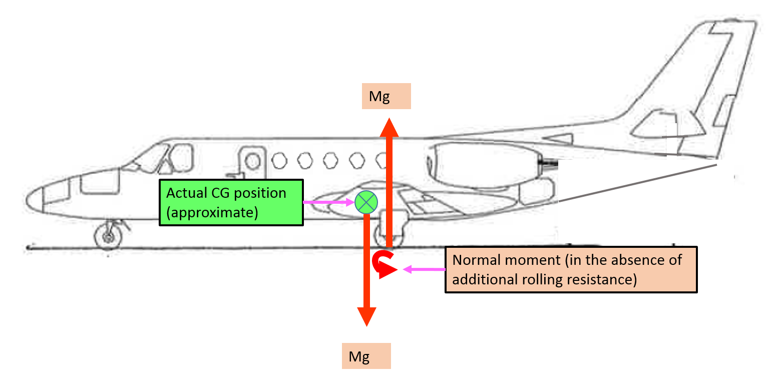
Figure A-5 depicts the normal nose-down moment of the aircraft, in the absence of additional rolling resistance, and the approximate actual CG position for the accident flight.
Figure A-5: Representation of normal nose-down moment and centre of gravity (in the absence of additional rolling resistance)
Source: Aircraft owner – annotated by ATSB
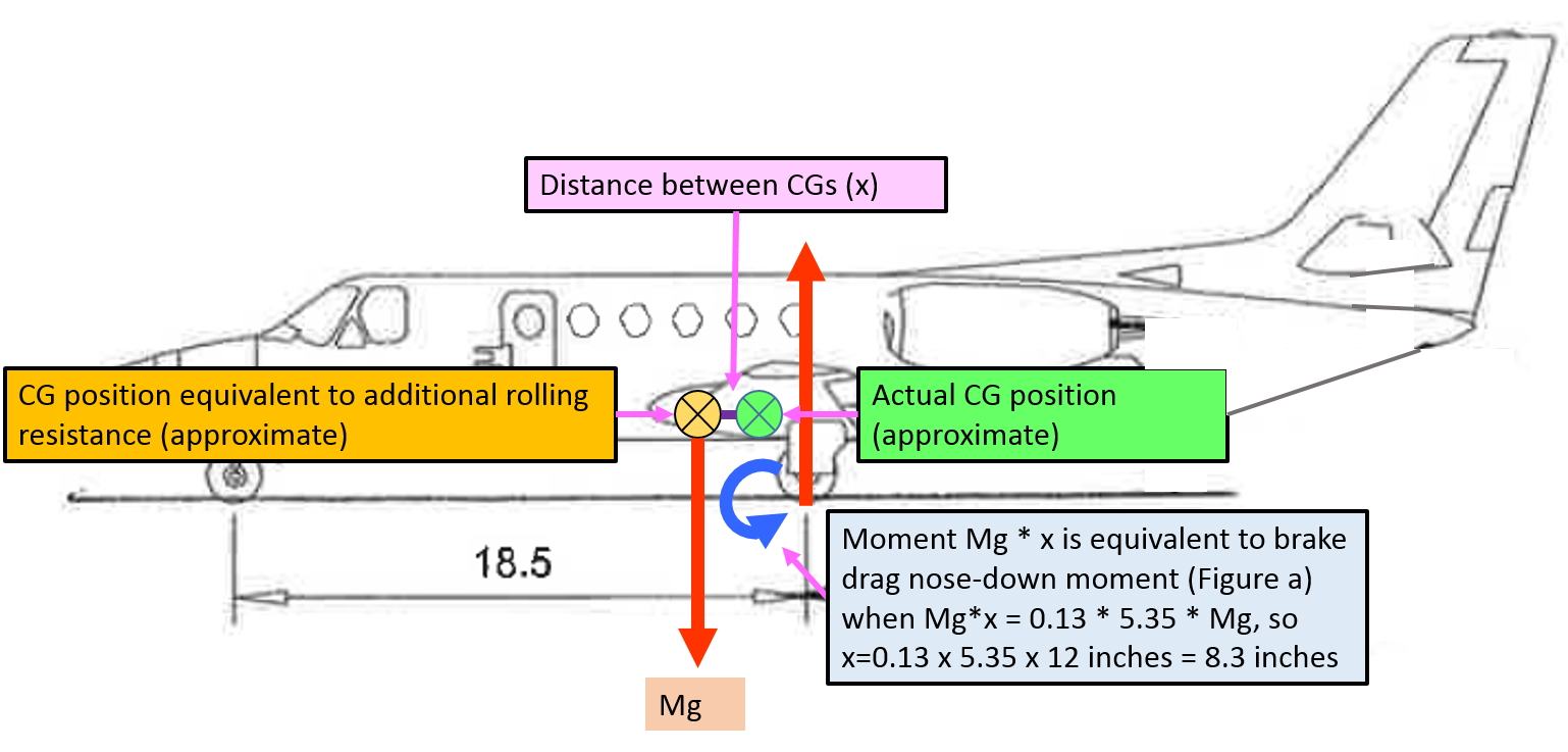
The nose-down moment due to the additional rolling resistance, depicted in Figure A-4, is equivalent to the nose-down moment due to the vertical force (Mg) through a more forward centre of gravity position (Figure A-6). So that 0.13 Mg * 5.35 (ft) * 12 (inches per foot) = Mg * x, where x is the effective forward movement of the CG. Therefore, x is 8.35 inches, which is 10.3% MAC.
Figure A-6: Representation of nose-down moment with additional rolling resistance equivalent to more forward centre of gravity
Source: Aircraft owner – annotated by ATSB
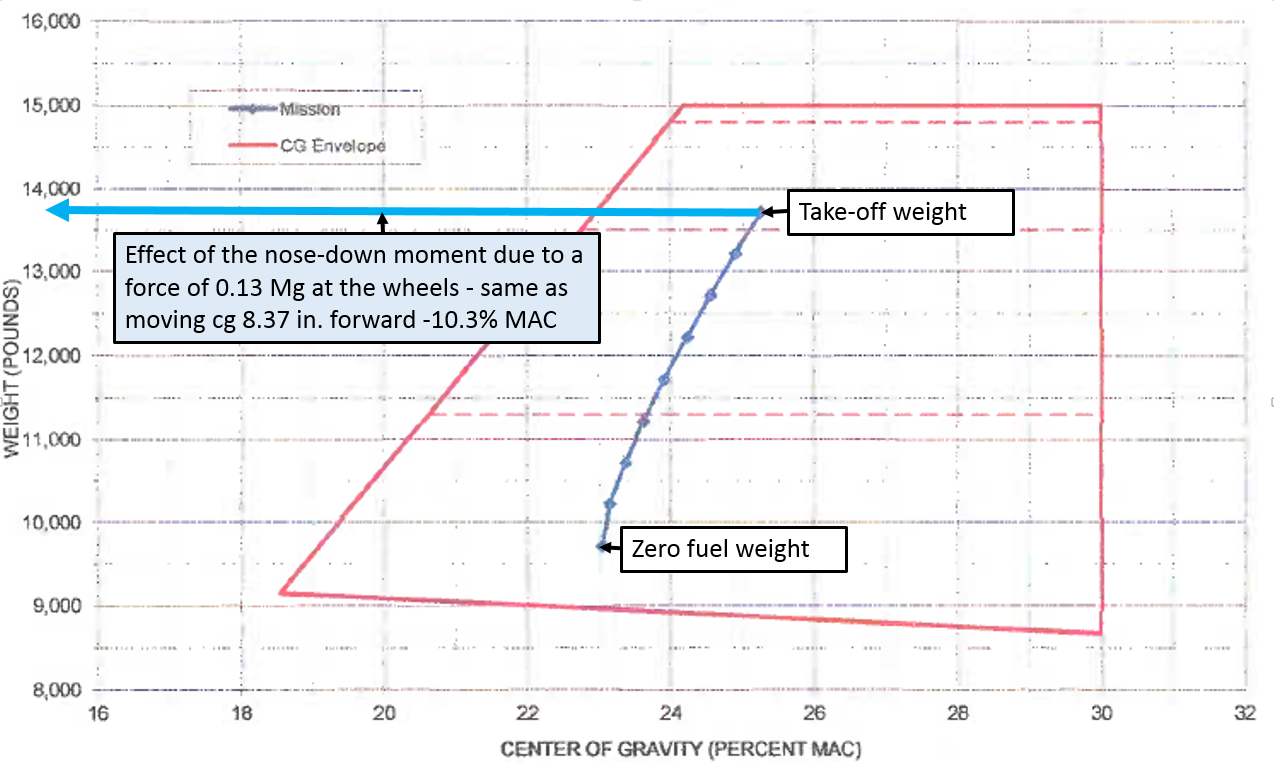
The aircraft’s load sheet the flight crew prepared for the flight is depicted in Figure A-7. The computed CG was 25.1% MAC at take-off. The most forward allowable at that weight was 22% MAC. Moving the centre of gravity forwards 8.35 inches, or 10.3% MAC, would place the effective centre of gravity over 5 inches forward of the allowable range (and off the chart). In that condition it should be impossible to raise the nose of the aircraft – to rotate on take-off.
Figure A-7: Load sheet for VH-FGK showing the accident flight computation of weight and balance from take-off to landing, and the effect of moving the centre of gravity 8.35 inches forward
Source: Aircraft owner – annotated by ATSB
Despite achieving full elevator deflection, at the thrust setting and the airspeed when the captain attempted to rotate the aircraft, it was insufficient to overcome the nose-down moment caused by the additional rolling resistance.
If sufficient rotation could have occurred for the speed that the aircraft achieved (to the necessary angle of attack), the aircraft would have flown (and the wheel rolling resistance would no longer be a factor until landing). In addition, if there were sufficient thrust to continue accelerating the aircraft, at some airspeed it would have lifted off in the ground run attitude, without rotation.
Note that an increase in aerodynamic drag is not only inconsistent with the form of the airspeed curve, but would also not produce the nose-down moment preventing rotation.
The objective of a safety investigation is to enhance transport safety. This is done through:
identifying safety issues and facilitating safety action to address those issues
providing information about occurrences and their associated safety factors to facilitate learning within the transport industry.
It is not a function of the ATSB to apportion blame or provide a means for determining liability. At the same time, an investigation report must include factual material of sufficient weight to support the analysis and findings. At all times the ATSB endeavours to balance the use of material that could imply adverse comment with the need to properly explain what happened, and why, in a fair and unbiased manner. The ATSB does not investigate for the purpose of taking administrative, regulatory or criminal action.
Terminology
An explanation of terminology used in ATSB investigation reports is available here. This includes terms such as occurrence, contributing factor, other factor that increased risk, and safety issue.
Publishing information
Released in accordance with section 25 of the Transport Safety Investigation Act 2003
Ownership of intellectual property rights in this publication
Unless otherwise noted, copyright (and any other intellectual property rights, if any) in this report publication is owned by the Commonwealth of Australia.
Creative Commons licence
With the exception of the Coat of Arms, ATSB logo, and photos and graphics in which a third party holds copyright, this publication is licensed under a Creative Commons Attribution 3.0 Australia licence.
Creative Commons Attribution 3.0 Australia Licence is a standard form licence agreement that allows you to copy, distribute, transmit and adapt this publication provided that you attribute the work.
The ATSB’s preference is that you attribute this publication (and any material sourced from it) using the following wording: Source: Australian Transport Safety Bureau
Copyright in material obtained from other agencies, private individuals or organisations, belongs to those agencies, individuals or organisations. Where you wish to use their material, you will need to contact them directly.
Early in the morning on 10 September 2015, the pilot refuelled and prepared a C172 aircraft, registered VHFPZ, for a private flight departing Carlton Hill Station aircraft landing area (ALA), Western Australia (Figure 1). The pilot, the sole person on board, had planned a routine flight around the station to check stock water supplies. After conducting the before take-off checks, the pilot taxied the aircraft from the hangar to the threshold of runway 12, just before 0550 Western Standard Time (WST).
Figure 1: Location of Carlton Hill ALA
Source: Google earth annotated by the ATSB
The pilot configured the aircraft with 10° flap, and commenced the take-off run in good weather conditions, with a head wind of about 10 kt and a temperature of about 18°C. The aircraft reportedly accelerated normally, with lift-off occurring at around 65-70 kt. As per normal, the pilot allowed the aircraft to accelerate toward the cruise climb speed of about 75-80 kt prior to establishing it in the climb.
At about 150-200 ft above the ground, the aircraft performance rapidly deteriorated. The pilot reported that the revolutions per minute (RPM) dropped from about 2,700 rpm to about 2,000 rpm, and the engine was making an abnormal mechanical sound. The pilot immediately checked the fuel and mixture control settings and applied carburettor heat. However, the aircraft was not able to maintain altitude. With the pilot unable to determine the cause of the partial engine failure, they prepared for a forced landing.
With limited time and options available, the pilot selected a space between trees at the end of the runway to land. They then turned off the fuel, pulled the mixture control to idle cut off, and selected full flap. In the seconds remaining, the pilot steered the aircraft between trees to keep the cabin intact. The wings struck the trees, resulting in the outboard section of the left wing breaking off. The aircraft travelled a further 20 m, before coming to rest (Figure 2). The pilot, who was not injured, was able to exit via the passenger door. The aircraft was substantially damaged (Figure 3).
Figure 2: VH-FPZ after the forced landing with part of the left wing in the foreground
Source: Pilot
Figure 3: VH-FPZ damage.Note the substantial damage to the left wing and tree impact on right wing
Source: Pilot
Pilot experience and comments
The pilot held a Private Pilot’s Licence (Aeroplane) and had a total of about 518 hours at the time of the accident. VH-FPZ was the dedicated aircraft for Carlton Hill station, and the pilot had been flying it since the start of 2015, with about 150 hours on the aircraft.
The pilot reported that everything appeared routine and there were no abnormalities with the aircraft during the pre-take-off engine and instrumentation checks.
The pilot commented that the engine malfunction was unexpected, and the event unfolded very quickly.
The aircraft, VH-FPZ
The pilot reported that there were no outstanding defects on the maintenance release and that the aircraft had completed all scheduled maintenance. In the time the pilot had been operating this aircraft, it had had one previous instance of degraded performance. However, in that instance, a post flight engineering inspection was unable to determine a cause.
Weather
The two aerodrome weather reports (METAR) obtained from the Bureau of Meteorology for nearby Kununurra Airport (approximately 20 NM to the south-east of Carlton Hill ALA) did not indicate conditions suitable for carburettor icing.
Post-accident inspection
While a full engine examination has not yet been completed, an examination by a Licenced Aircraft Maintenance Engineer found that the left magneto had failed. This most likely contributed to the aircraft’s deteriorated performance.
Safety message
Simulated total loss of power and a subsequent practice forced landing is at the core of a pilot’s emergency training. However, data shows that for light single engine aircraft a partial power loss is three times more likely to occur than a complete engine failure.
Confronted with minimal options at low altitude, the pilot in this occurrence had to make important decisions in a short space of time. The ATSB’s publication and You Tube video “Managing partial power loss after take-off in single-engine aircraft” is available on the ATSB website. This information highlights the importance of pre-flight decision making and planning, for emergencies and abnormal situations, for each particular aerodrome.
Decisions regarding whether to conduct an investigation, and the scope of an investigation, are based on many factors, including the level of safety benefit likely to be obtained from an investigation. For this occurrence, a limited-scope, fact-gathering investigation was conducted in order to produce a short summary report, and allow for greater industry awareness of potential safety issues and possible safety actions.
Publishing information
Released in accordance with section 25 of the Transport Safety Investigation Act 2003
Ownership of intellectual property rights in this publication
Unless otherwise noted, copyright (and any other intellectual property rights, if any) in this report publication is owned by the Commonwealth of Australia.
Creative Commons licence
With the exception of the Coat of Arms, ATSB logo, and photos and graphics in which a third party holds copyright, this publication is licensed under a Creative Commons Attribution 3.0 Australia licence.
Creative Commons Attribution 3.0 Australia Licence is a standard form licence agreement that allows you to copy, distribute, transmit and adapt this publication provided that you attribute the work.
The ATSB’s preference is that you attribute this publication (and any material sourced from it) using the following wording: Source: Australian Transport Safety Bureau
Copyright in material obtained from other agencies, private individuals or organisations, belongs to those agencies, individuals or organisations. Where you wish to use their material, you will need to contact them directly.
On 23 September 2015, two Pacific National terminal operators and the train crew were completing a shunt of train 4MW2 at the Sydney Freight Terminal. After detaching the remaining wagons, the train crew moved the five locomotives toward the end of the stabling road, where a shunt driver was waiting trackside to take over. After stopping, the train crew exited the cab and alighted from the lead locomotive. The train crew had left the locomotive independent brake handle fully applied but did not operate the park brake prior to leaving the cab.
The shunt plan required two of the five locomotives to be uncoupled and stabled. In readiness to uncouple, one of the terminal operators entered between the locomotives and isolated the air taps, disconnected the train hoses and lifted the coupling pin to the two trailing locomotives. Neither the train crew nor shunt driver realised that the rear two locomotives had been uncoupled. Shortly after, the shunt driver boarded the lead locomotive and in conjunction with the other terminal operator moved the front three locomotives to another area of the terminal. The two trailing locomotives remained at the end of the road, unattended by a qualified worker.
Shortly before 1751, sufficient air had bled from the brake cylinders to allow locomotives NR24 and NR12 to begin to roll away. The locomotives continued to roll uncontrolled through the Sydney Freight Terminal before exiting into the Australian Rail Track Corporation network. The locomotives travelled a short distance on the Down South Fork before coming to rest at Chullora West Junction. There were no injuries or damage due to the run away.
What the ATSB found
The ATSB found that a combination of individual action and ambiguous radio communications resulted in a breakdown of controls to prevent an uncontrolled movement of rolling stock. The interface coordination arrangements at the eastern interface between Pacific National and the Australian Rail Track Corporation were ineffective in capturing an uncontrolled movement before exiting the Sydney Freight Terminal.
What's been done as a result
The Australian Rail Track Corporation have issued instructions for the restoration of points at the interface following each movement and commenced investigation into the feasibility of automatic resetting of the points at that location.
Pacific National undertook toolbox briefings and issued Business Safety Notices restricting terminal operators from uncoupling locomotives and reinforcing the importance of applying communications and shunting procedures.
Safety message
Rail transport operators and rail safety workers must ensure the correct and consistent application of communication protocols and procedures when undertaking safety critical work, such as detaching and securing unattended locomotives.
The occurrence
On 23 September 2015, Pacific National (PN) freight train 4MW2 departed Melbourne and travelled along the Interstate Main Line via Junee and Goulburn toward Sydney. Within the Sydney area, 4MW2 traversed sections of the Australian Rail Track Corporation (ARTC) Southern Sydney Freight Line and the Metropolitan Freight Network en route to, the PN Sydney Freight Terminal (SFT) at Chullora (Figure 1). Train 4MW2 consisted of five locomotives hauling 76 wagons.
Figure 1: Location of Pacific National Sydney Freight Terminal
Map of Sydney area showing various passenger and freight rail lines. Train 4MW2 travelled along the rail line from Goulburn through Cabramatta then toward the Pacific National Sydney Freight Terminal at Chullora. Source: Geoscience Australia, annotations by ATSB
At about 1657,[1] as train 4MW2 approached Chullora, the co-driver contacted staff at the SFT by radio seeking instruction on the final destination road[2] for the train within the terminal. A terminal operator waiting for the arrival of 4MW2 informed the train crew that it was to enter the EPA1[3] road in preparation for shunting.
At about 1658, train 4MW2 arrived at the EPA1 road where the terminal operator further advised the train crew that there were no local relief train crew available, and that they would need to assist in the shunt of train 4MW2. The train crew, in conjunction with two terminal operators then commenced a series of shunt movements onto the various EPA roads. The terminal operators coordinated with each other to control the shunt and to uncouple and secure the required wagons in accordance with the shunt plan for that train.
After completing the shunt movements to the EPA roads, a terminal operator instructed the train crew to push the remainder of the train to the number 9 road. Number 9 road was located adjacent to the gantry crane roads in another section of the SFT.
The train crew, with the assistance of the terminal operators, moved the five locomotives and remaining wagons to the gantry crane area and toward the dead end of the number 9 road. The terminal operators again coordinated with each other to position the shunt movement along the road.
Around this time, a SFT shunt driver was working on number 6 road testing the air brake system of a rake of wagons in the gantry crane area. On completing the testing, the SFT shunt driver moved the shunt locomotive to the entrance of the number 6 road, secured it and took a short rest break.
At about 1734, a terminal operator (TO1) uncoupled and secured the remaining wagons from the locomotives. The same terminal operator also contacted the train crew to ask where they wanted to leave the back two locomotives (NR24 and NR12), as the shunt plan had also listed them to be detached, but did not specify the final road. The locomotive driver replied that they wanted to leave all five locomotives and get off. Shortly after, the other terminal operator (TO2) who was at the opposite end of the wagons situated at the dead end of number 9 road interrupted, suggesting that the locomotives be moved to the entrance of number 9 road where the SFT shunt driver could take over from the train crew and finish the shunt of the locomotives.
The train crew subsequently moved locomotives (NR91, NR82, AN8, NR24, and NR12) forward toward the entrance to the number 9 road. The driver applied the independent brake[4] fully, stopping the locomotives adjacent to the SFT shunt driver. The SFT shunt driver on returning from the rest break overheard a conversation between the terminal operators and train crew that he was to take over the locomotives on number 9 road. The SFT shunt driver then waited trackside adjacent to number 9 road.
As the terminal operator (TO1) continued to secure the detached wagons, the other terminal operator (TO2) moved from the dead end of number 9 road to meet the five locomotives that were now stationary at the entrance of number 9 road. The terminal operator (TO2) knew that the back two locomotives were to be detached but did not know the final road for stabling. The SFT shift manager and terminal operator briefly discussed arrangements for the two locomotives and decided to leave them on number 9 road where a local train crew would attend to them when available, about 30 minutes later.
Once adjacent the locomotives, the terminal operator (TO2) went between locomotives AN8 and NR24, disconnected the air hoses to the main reservoir and brakes, and lifted the pin in the coupler. Immediately after completing this task, the terminal operator departed the area to take a meal break. There was no direct communication between the terminal operator and train crew or SFT shunt driver, so the drivers were unaware that the terminal operator had entered between the locomotives and undertaken this task.
About the same time, the train crew were in the process of alighting from the lead locomotive and meeting with the SFT shunt driver, who was standing on the ground adjacent to the locomotives. After discussing the operational state of the five locomotives, the train crew departed and the SFT shunt driver boarded the lead locomotive.
Shortly after, the terminal operator (TO1), who had completed securing the wagons that were detached earlier, joined the SFT shunt driver. The terminal operator and SFT shunt driver then moved locomotives NR91, NR82, and AN8 from number 9 road. Neither the shunt driver nor terminal operator was aware the locomotives had been uncoupled. Locomotives NR24 and NR12 remained on the number 9 road and unattended by a qualified worker.
About 8 minutes later, sufficient air had leaked from the brake cylinders to allow locomotives NR24 and NR12 to commence rolling away. The locomotives continued an uncontrolled movement through the SFT traversing a number of roads and trailable points[5], reaching a maximum speed of about 21 km/h within the yard.
The locomotives continued toward the eastern interface point between the SFT and the ARTC network. While signal ED288 was set to stop, the points at the interface were set to direct rail traffic toward the ARTC Chullora West Junction.
At about 1751, locomotives NR24 and NR12 passed signal ED288 at stop. This generated a Signal Passed at Danger (SPAD) alarm at the ARTC Network Control Centre South (NCCS) in Junee. About a minute later, the locomotives passed a further signal (ED278), generating another SPAD alarm.
The NCCS NCO contacted the SFT shift manager to identify the train movement that triggered the SPAD alarms. The SFT shift manager confirmed that there was no shunting operation occurring in that area, but would investigate the source of the SPAD alarms. At about 1759, the SFT shift manager confirmed to the NCO that two locomotives (NR24 and NR12) had run away and exited the SFT. The locomotives came to rest with the front of the lead locomotive (NR24) located at about the 17.407 km point[6] on the Down South Fork of the Chullora West Junction.
The SFT shift manager dispatched Pacific National staff from the SFT to take control and secure the locomotives. The locomotives remained at that location until ARTC and Pacific National staff had inspected the track sections traversed by the locomotives. There was no damage identified to either the locomotives or track.
At about 2035, locomotives NR24 and NR12 cleared from the ARTC main line to the interface area and back towards the SFT.
The SFT was located at Chullora in Sydney, NSW at about the 19.828 km point on the ARTC Sydney Metropolitan Freight Network (Figure 2). Rail access from the Sydney Metropolitan Freight Network (MFN) to the western and eastern extremity of the SFT was available via turnouts located at Enfield West and the Chullora West Junction respectively. The ARTC Network Control Centre South (NCCS) at Junee controlled rail operations along the MFN and at the interface with the private sidings at Chullora.
Figure 2: ARTC Sydney Rail Freight Corridors
Figure illustrates the various main line track arrangements in the Sydney area and relative location of Chullora and the Chullora West Junction. Source: Australian Rail Track Corporation, annotations by ATSB
Train and train crew information
Train 4MW2 consisted of five locomotives (NR91 leading, NR82, AN8, NR24 and NR12) and 76 wagons. The train was 1501 m long and had a trailing mass of 3132 t. The trailing mass included the locomotives AN8 and NR24 because they were setup as ‘off line’. Train 4MW2 was crewed by a driver and co-driver.
In conjunction with the train crew, two terminal operators and an SFT shunt driver also undertook various activities in the shunting of 4MW2 within the terminal. Post incident, the train crew of 4MW2, two terminal operators and the SFT shunt driver underwent preliminary testing for the presence of alcohol or a drug[7]. The result of this testing was negative.
The locomotive drivers and terminal operators held PN qualifications for shunting rolling stock and using communications systems. An examination of the health assessment records confirmed that their health assessments were current and that each satisfied the standards prescribed by the National Standard for Health Assessment of Rail Safety Workers.
Chullora – Private Sidings
The Chullora area contained four private sidings[8] that interfaced with the ARTC MFN at five locations (Figure 3).
The PN Sydney Operations Yard was a private siding with an eastern and western interface to the ARTC network. Motorised point machines on the turnout at each interface may be set to direct an uncontrolled movement (runaway) toward a dead end track section. The NCO controlled the points and signals at the interface locations remotely from the NCCS.
The NCO also controlled rail movements at the interface with the other private sidings by providing a release from the NCCS. The release enabled a qualified employee to set the points by operating the associated local ground frame[9].
A motorised catch point[10] was located at the eastern boundary of the Chullora interface area to protect the ARTC network from an uncontrolled rolling stock movement (runaway) from the private sidings entering the Down south fork and Down Main line. The ARTC controlled the signals, catch-point, and all other motorised point machines at the Chullora West Junction remotely from the NCCS.
Figure 3: Track arrangement at Chullora West Junction
Figure illustrates the main line track arrangement at Chullora Junction including the interface connections to the Pacific National Sydney Operations Yard and other private sidings. Source: Australian Rail Track Corporation annotations by ATSB
ARTC/PN Interface coordination – Sydney Freight Terminal
An interface agreement[11] stipulated the arrangements for the joint management of the operational risk at the ARTC/PN boundary. The interface agreement was in draft, dated 23 April 2015. The risk assessment of operational hazards in the draft agreement identified no site-specific risk factors that raised the generic ARTC corridor risk rating above low.
The PN risk assessment for the SFT[12] access and egress through the interface boundary identified the hazard of unauthorised entry or exit of a train to/from the SFT. An unauthorised movement may take the form of a train operated by a driver or rolling stock (locomotive or wagon) that is uncontrolled. The risk assessment identified various controls requiring the driver to comply with signal indications and approval protocols that permitted access/egress through the interface. For an uncontrolled rolling stock movement approaching the interface, the risk control relied on diverting the rolling stock away from the interface area.
At the eastern end of the SFT, motorised points adjacent signal ED288 provided the control mechanism to divert rolling stock toward a dead end track section (shunt neck) and away from the ARTC network (Figure 4). The signalled route selected determined the orientation of the motorised points. At the time of the uncontrolled movement, the route was set to allow access between the ARTC network and the SFT.
Figure 4: PN Sydney Freight Terminal eastern interface point and dead end road
Interface point at the eastern end of the PN Sydney Freight Terminal. Signal ED288 and the motorised point machine were controlled by the ARTC from the Junee control centre. The points should be positioned as shown to route any uncontrolled movement toward the dead end and away from the roads of the other private sidings and main lines at Chullora West Junction. Source: Australian Transport Safety Bureau
Pacific National Sydney Freight Terminal
The SFT encompassed the EPA, Gantry, Shed, and Transfer rail marshalling areas (Figure 5). The PN Shift Manager controlled the incoming and outgoing rail movements in conjunction with the other routine internal shunting operations. The standby train crew or a terminal shunt driver in coordination with terminal operator ground staff undertook the rolling stock shunting operations for the marshalling of trains within the various areas of the SFT.
Within the SFT areas, the terminal operator ground staff manually operated (hand throw) points to route the rolling stock between the various roads of each area. The design of a number of these manually operated points enabled a trailing movement[13] through the point assembly by the rolling stock.
The track grade from the entrance to of the Gantry road area toward Chullora West Junction started with a falling grade of about 0.70% before increasing to 1.166% through the Arrivals road area. The falling grade then reduced to around 0.060% through the Transfer road area before transitioning to a rising grade of around 0.26% through the interface area with the ARTC.
At the top of the grade in the Gantry area, four of the roads (#5, 6, 7 and 8) were equipped with a manually operated derail mechanism to prevent unauthorised access into or to capture an uncontrolled movement from the respective road. Road #9 was not equipped with a derail mechanism.
Figure 5: Pacific National Sydney Freight Terminal
View of the Pacific National Sydney Freight Terminal showing the relative location of the EPA and Gantry road areas. The uncontrolled movement of locomotives NR24 and NR12 commenced at the #9 road in the gantry area before travelling through the transfer road area and toward Chullora West Junction. Source: Google, annotated by ATSB
Pacific National shunting procedures
The Pacific National standard[14] and procedure[15] outlined the safe practices established for the movement of rolling stock. Both documents were applicable to operations undertaken on the main line, a terminal or a yard.
The standard identified PN’s obligation relating to the assessment of shunting risks and defined the responsibilities for the PN staff involved. In a terminal or yard, the terminal operator in charge of a shunt was responsible for providing instructions to the locomotive driver to facilitate the placement of rolling stock. The terminal operator was also responsible for detaching or coupling wagons.
Rolling stock - Wagons
The PN procedure detailed the specific processes and communication exchange protocols required when undertaking a shunt movement. A key component of the procedure was the implementation of a three-step protection process before a qualified worker (terminal operator or locomotive driver) entered between rolling stock to detach or couple wagons.
The intention of the three-step protection process was to ensure clear communications between the driver and qualified worker (in the case of 4MW2, the terminal operator) of the intention to enter in between rolling stock to undertake a task. The process was reliant on a sequential exchange of instruction and acknowledgement between the two parties to ensure the driver had undertaken actions to secure the rolling stock from moving.
To implement the thee-step protection, the driver was required to:
fully apply the locomotive’s independent brake and if required the automatic brake[16]
position the throttle to idle
move the reverser lever to the centre position
Once the driver confirmed these protections, the qualified worker could then enter between the rolling stock. On completing the required task, further communication between the terminal operator and the driver was to occur before removal of the protections and the locomotives operated.
Where a wagon or number of wagons were uncoupled and left unattended for any period, the qualified worker was also responsible for ensuring the application of the park brake. A PN generic procedure[17] for securing trains with park brakes specified the minimum number of park brakes required to hold the rolling stock. The number of park brakes required varied depending on the location where stabled and local track grade.
Rolling stock - Locomotives
The safe practices contained in the standard and procedure were similarly applicable to the shunting of locomotives. Where a locomotive or locomotives were to be left unattended[18], the locomotive driver (whether operating as a two-man crew or as Driver Only Operation) was responsible for the uncoupling of locomotives and ensuring that the park brake was correctly applied. A PN generic procedure[19] for securing locomotives with park brakes specified the required actions to ensure the correct application of the park brake.
The park brake on the NR locomotives was a spring-operated device held off by the application of air pressure sourced from the main reservoir. When selected, by the operation of a pushbutton in the locomotive cab, the device released the air pressure and the spring applied the brake to the wheels. The park brake selection relayed electrically to other similarly equipped locomotives coupled in the train via the Multiple Unit interconnector cable.
Previous occurrences
Several incidents have occurred of the uncontrolled movement of rolling stock (run away) in New South Wales. None was directly comparable to the runaway incident at the SFT on 23 September 2015. That is, they did not involve runaway locomotives.
The previous incidents principally related to the securing of wagons that were uncoupled from locomotives or stabled. The incidents prompted the Independent Transport Safety Regulator (ITSR) to issue a Transport safety alert on 13 April 2011[20] to address the effective securement with handbrakes and stop block functionality.
The Office of Transport Safety Investigations (OTSI) also investigated a runaway of rolling stock at Enfield Yard on 3 May 2011[21]. A rake of 28 wagons loaded with aggregate (total mass in excess of 2500t) ran away from North Road No. 1 in Enfield Yard and through the yard before colliding with a rake of 15 empty fuel tanker and three flatbed wagons stabled in South Road No. 1. The investigation identified the immediate cause of the incident was that, during maintenance activities, the air brakes were released on a wagon and the rake ran away due to the rake’s remaining brakes being insufficient to hold it stationary on the prevailing grade.
Pacific National proposed a number of safety actions in response to the Transport safety alert and investigation into the runaway at the Enfield yard.
In planning a shunt, the PN standard required the communication of the shunt plan to the shunting team (terminal operators) and locomotive driver to ensure:
the identification of the shunter in control and responsible for coordinating shunting movements
the identification of the roles of each shunter involved in the shunt
the planning to complete the shunt in the safest number of moves
the informing of locomotive driver and the shunt team about the planned shunt moves
confirming the shunt sequence and rolling stock to be moved
On 23 September 2015, the communication of the shunt plan commenced when a terminal operator advised the inbound train crew via radio that they would be operating the locomotives to shunt from the EPA1 road onto the EPA3 and EPA4 roads, before heading to the number 9 road.
The terminal operators then commenced uncoupling wagons in accordance with the shunt plan. The terminal operators communicated between each other to transfer the role of shunter in control. The shunter in control communicated instructions to the train crew for the movement of the train. The train crew did not have a copy of the shunt plan to facilitate clear understanding of shunt sequence and the rolling stock that would be uncoupled.
After detaching the remaining wagons on the number 9 road, the last entry in the shunt plan indicated ‘to bed’ against locomotives NR12 and NR24. There was a series of communications:
between the shunter in control at that time and the train crew
between the two terminal operators, and
between one of the terminal operators and the SFT shift manager.
Each conversation contained information related to the intended actions to address the shunt plan for locomotives NR12 and NR24. However, the communications did not ensure that there was a clear understanding among all parties of what was to occur.
Communication protocols
The PN voice radio protocols promoted effective spoken radio communications to be:
clear and unambiguous
relevant to the task at hand
agreed as to its meaning before being acted upon
The communication protocols and shunting procedures required the locomotive driver and terminal shunter to reply to each communication to indicate that they have complied with the request or to acknowledge the previous communication. The protocols contain a warning that qualified workers must not assume that a receiver has understood a message before the receiver confirms that the message has been understood.
The sequencing of radio exchanges between the parties that occurred during the preparation for the final shunt of the locomotives resulted in essential information being misunderstood or lost. This was particularly pertinent to the application of the three-step protection process.
The application of these processes to ensure protections were in place before the terminal operator entered between rolling stock may have alerted the train crew of the intention to uncouple the locomotives.
Procedures for uncoupling locomotives
Following the request from a terminal operator, the driver moved the locomotives forward to the entrance of number 9 road and applied braking using the independent brake lever.
The independent brake valve was self-lapping, meaning the degree of braking effort was proportional to the positioning of the lever by the driver. The valve regulated the air pressure applied to the brake cylinders of the lead locomotive, and through the train pipe and interconnecting hoses to the brake cylinders of the four trailing locomotives to stop the train.
Once stationary, the driver left the independent brake handle in the full application position, which maintained the air pressure to the brake cylinders holding the locomotives with maximum braking effort. The train crew then gathered their gear and vacated the cab in preparation to leave the locomotive.
The train crew did not apply the locomotive park brake prior to vacating the cab. The implementation of the park brake requirements in the procedure for securing locomotives would almost certainly have prevented the runaway from occurring.
When on the ground, a short conversation occurred between the crew and the SFT shunt driver, which included a briefing on the set up of the locomotives in the train on arrival at the SFT. During this time, the terminal operator entered between locomotives AN8 and NR24 and uncoupled the locomotives. The terminal operator on completing this task assumed that the locomotive drivers were aware of the intention to undertake a task, and had made the rolling stock safe in accordance with the three-step process. The terminal operator did not subsequently contact the drivers to arrange the removal of protections to enable the operation of locomotives.
Terminal operators were only authorised by PN to undertake the task of uncoupling wagons. The task of uncoupling and securing locomotives was the responsibility of the locomotive crew or SFT shunt driver. It was apparent however that some terminal operators, who during their employment with other rail operators, had received training in undertaking this task and would on occasion assist a locomotive driver to uncouple locomotives.
Although PN undertook compliance and safety audit monitoring programs, these had not identified the practice of terminal operators assisting locomotive drivers existed, or that variances in the application of the radio communication protocols, such as the three-step process, were occurring at the SFT.
Interface risk assessment
The ARTC Engineering (Signalling) Standard[22] includes the option of providing self-normalisation[23] of catch points on sidings to protect the main line. Where self-normalisation is provided in the signalling arrangement, the catch point sets to normal (open position) when the signalling interlocking system indicates that the catch point has been continuously free to move for a period not less than 45 seconds. The self-normalisation principle could also apply for power-operated points on a turnout (as installed at each end of the SFT).
The design of the ARTC interlocking at Chullora did not include the functionality to self-normalise either the catch point or points at the interface between PN and ARTC.
The PN assessment of risk from an unauthorised movement exiting the SFT relied on the effectiveness of a series of engineering and administrative controls. The assessment identified the automatic operation of the points at either end of the SFT toward a dead end track section, when the associated signals were at red as an engineering control. The assessment assigned responsibility for this control to the ARTC.
As the interlocking design at Chullora did not include automatic operation of the points, PN’s reliance on automatic operation as an engineering risk control was therefore incorrect at this location.
The signalling at Chullora operated as an ‘Entrance – Exit’ system. To set a route the NCO operated controls to select the required entrance and exit signals along the desired route. The interlocking set the points (if free to move) to the required orientation before clearing the required signals along the route. If required, the system also enabled the NCO to operate the point machines individually to set the desired orientation.
The interface coordination required liaison between the SFT Shift Manager and NCO to progress movements through the interface area. Signalled routes were set to enable train services to enter or exit the SFT. If required, signalled routes could also be set to enable PN to shunt long trains from the SFT through the interface area and onto the main line. The point machines within the selected route would lie in the orientation set for the previous movement until the operation of another set of entrance and exit signals to request a new route.
The draft interface agreement identified the Chullora operational boundaries at ED 288 signal and the clearance point at the back of 361B turnout. The agreement identified the ARTC and PN as responsible for operations within their respective territory, and jointly responsible for the management of risk at the interface. The correct orientation of the ARTC controlled point machine 361B situated between the interface boundary of the PN Sydney freight terminal and PN dead end track section, was essential to ensure the preferred routing of an uncontrolled movement toward the dead end (that is, away from the main line).
The administrative process associated with the interface coordination between the PN Shift Manager and the NCO did not ensure that, on the completion of PN rail movements, the motorised point machine adjacent signal ED288 diverted any uncontrolled rolling stock movement toward a dead end track section and away from the ARTC network.
The Interface Agreement IA1919 was in draft since mid-2014. Neither ARTC nor PN had endorsed the interface coordination arrangements for the joint management of risk at the ARTC/PN boundary. The absence of a self-normalising turnout or a finalised agreement on responsibilities for the coordination at the interface, likely increased risk to the ARTC corridor.
On 23 September 2015, the points at the eastern interface toward Chullora West Junction remained set from a previous PN rail movement through the interface area. This allowed locomotives NR24 and NR12 to exit the PN controlled SFT and onto the ARTC network.
From the evidence available, the following findings are made with respect to the uncontrolled movement (runaway) of locomotives NR24 and NR12 from the Pacific National Sydney Operations yard onto the ARTC main line at Chullora, NSW on 23 September 2015. These findings should not be read as apportioning blame or liability to any particular organisation or individual.
Safety issues, or system problems, are highlighted in bold to emphasise their importance. A safety issue is an event or condition that increases safety risk and (a) can reasonably be regarded as having the potential to adversely affect the safety of future operations, and (b) is a characteristic of an organisation or a system, rather than a characteristic of a specific individual, or characteristic of an operating environment at a specific point in time.
Contributing factors
A terminal operator entered between locomotives AN8 and NR24 disconnecting the air hoses to the main reservoir and brakes, and lifted the pin in the coupler.
The train crew did not apply the locomotive park brake prior to vacating the cab.
Power operated point machines at Sydney Freight Terminal eastern interface were not set to direct rolling stock toward the dead end track section.
The implementation of communication protocols and procedures for the planning and coordination of the shunt was ineffective in ensuring that the shunt plan was clear and unambiguous and that adequate protections against the unintended movement of rolling stock were in place.
Other factors that increased risk
The engineering control listed in the Pacific National risk assessment SFT SHT-01 incorrectly identified the availability of an automatically operated point machine at the interfaces to the Australian Rail Track Corporation network to mitigate risk from an uncontrolled rolling stock movement.
Safety actions
Additional safety action
Whether or not the ATSB identifies safety issues in the course of an investigation, relevant organisations may proactively initiate safety action in order to reduce their safety risk. The ATSB has been advised of the following proactive safety action in response to this occurrence.
Additional safety action taken by Australian Rail Track Corporation
On 28 October 2015, the Australian Rail Track Corporation issued an instruction to all Network Control Officers at the Network Control Centre South (NCCS), Junee requiring:
The restoration of the points at the eastern end interface of the Sydney Freight Terminal to the normal position (toward the dead end track section) following each rail movement. There was no exception to this requirement, even when following train movements were to occur.
The Australian Rail Track Corporation also advised the commencement of an investigation into the feasibility of modifications to the signalling control systems to restore the points at the interface automatically and the provision of a catch point alarm on the NCO’s control panel at Junee.
Additional safety action taken by Pacific National
Pacific National post incident actions included:
Toolbox meetings involving all train crew and terminal operators at the Sydney Freight Terminal briefing on the incident and reinforcing the importance of correct communications and the need to follow procedures.
Issue a Business Safety Notice, BSN 15-29 to outline the restrictions on terminal operators uncoupling locomotives, reiterate the application of the three-step protection, and the shunting procedures.
The provision of a manually operated derail situated at the entrance to the Number 9 road in the Gantry road area.
The review and update of the shunting procedures used at the Pacific National Sydney Freight Terminal. The revised procedure includes instruction prohibiting Terminal Operators from uncoupling locomotives from other locomotives.
The locomotive crew undertook re-training in the relevant procedures for securing locomotives and in radio protocols.
Pacific National monitors, on a random basis, the orientation of turnouts at the interface. Where found to be incorrectly set, the ARTC control centre at Junee is requested to set the points for the correct orientation.
Sources and submissions
Sources of information
The sources of information during the investigation included the:
Australian Rail Track Corporation
Pacific National
Pacific National Sydney Freight Terminal staff
Office of the National Rail Safety Regulator
Office of Transport Safety Investigations
RISSB Glossary of Railway Terminology – Guideline Version 1, December 2010
References
Australian Rail Track Corporation ESD-05-01 Common Signal Design Principles S1 – Signalling Locking and Train Dynamics, Version 3.0 Dated 13 October 2015
Australian Rail Track Corporation, Interface Agreement IA1919, Version 8 - draft, dated 23/04/2015
Independent Transport Safety Regulator, Transport Safety Alert, TSA no. 36, Dated 13 April 2011, Effective securement with handbrakes and stop block functionality
Office of Transport Safety Investigations, Rail Safety Investigation Report, Runaway of Rolling Stock, Enfield Yard, 3 May 2011, Investigation reference 04514
Pacific National, Safety Standard Form risk assessment, SFT SHT-01, Revision 4
Pacific National, PN-STD-SAF Shunting Standard, Version 1, 1 June 2015
Pacific National, PN-PRO-SAF Shunting Procedure, Version 1, 1 June 2015
Pacific National, GPR_6_10 Securing Trains with Park Brakes – R02, Dated 1 July 2015
Pacific National, GPR_6_12 Securing Locomotives with Park Brakes R02, Dated April 2009
Rail Safety National Law National Regulations 2012
Submissions
Under Part 4, Division 2 (Investigation Reports), Section 26 of the Transport Safety Investigation Act 2003 (the Act), the Australian Transport Safety Bureau (ATSB) may provide a draft report, on a confidential basis, to any person whom the ATSB considers appropriate. Section 26 (1) (a) of the Act allows a person receiving a draft report to make submissions to the ATSB about the draft report.
A draft of this report was provided to the Australian Rail Track Corporation, Pacific National, the Office of the National Rail Safety Regulator and the relevant Sydney Freight Terminal staff involved in the shunt of 4MW2.
Submissions were received from the Australian Rail Track Corporation, Pacific National, the Office of the National Rail Safety Regulator. The submissions were reviewed and where considered appropriate, the text of the report was amended accordingly.
Purpose of safety investigations
The objective of a safety investigation is to enhance transport safety. This is done through:
identifying safety issues and facilitating safety action to address those issues
providing information about occurrences and their associated safety factors to facilitate learning within the transport industry.
It is not a function of the ATSB to apportion blame or provide a means for determining liability. At the same time, an investigation report must include factual material of sufficient weight to support the analysis and findings. At all times the ATSB endeavours to balance the use of material that could imply adverse comment with the need to properly explain what happened, and why, in a fair and unbiased manner. The ATSB does not investigate for the purpose of taking administrative, regulatory or criminal action.
Terminology
An explanation of terminology used in ATSB investigation reports is available here. This includes terms such as occurrence, contributing factor, other factor that increased risk, and safety issue.
Publishing information
Released in accordance with section 25 of the Transport Safety Investigation Act 2003
Ownership of intellectual property rights in this publication
Unless otherwise noted, copyright (and any other intellectual property rights, if any) in this report publication is owned by the Commonwealth of Australia.
Creative Commons licence
With the exception of the Coat of Arms, ATSB logo, and photos and graphics in which a third party holds copyright, this publication is licensed under a Creative Commons Attribution 3.0 Australia licence.
Creative Commons Attribution 3.0 Australia Licence is a standard form licence agreement that allows you to copy, distribute, transmit and adapt this publication provided that you attribute the work.
The ATSB’s preference is that you attribute this publication (and any material sourced from it) using the following wording: Source: Australian Transport Safety Bureau
Copyright in material obtained from other agencies, private individuals or organisations, belongs to those agencies, individuals or organisations. Where you wish to use their material, you will need to contact them directly.
On 23 September 2015, an eastbound road-train truck, hauling grain, collided into the side of Pacific National grain train 8834N, (travelling on the main line between Narromine and Peak Hill) at the Tullamore – Narromine Road railway crossing, about 4 km southwest of Narromine, in New South Wales. The railway crossing was controlled by flashing lights, an audible warning device (bell); passive warning signs installed on the road approaches and road surface markings.
The collision and a post-impact fire destroyed the prime mover and one of the two trailers; the truck driver was fatally injured. The crew of the train were physically unhurt. As a result of the impact two wagons, were damaged, one of which derailed. Some of the railway crossing infrastructure (flashing lights) was destroyed and required replacement.
What the ATSB found
The ATSB found that the driver of the road-train truck was probably travelling too fast for the prevailing conditions, and entered the Tullamore – Narromine Road railway crossing while it was active, and the flashing lights were operating. It was concluded that the truck driver’s attention was probably focussed on negotiating the sweeping right-hand curve that preceded the crossing, at a critical time when he needed to check for the activation of the crossing. It is likely that when the driver perceived that the flashing lights were operating, he was too close to the crossing to stop, and collided with the train.
The ATSB identified a number of areas of potential improvement related to road design (signage and standards associated with railway crossing traffic control) especially with respect to curved approaches, before railway crossings.
What's been done as a result
Furney Flour Mills, the Narromine Shire Council, and Standards Australia have implemented a range of initiatives to reduce the risk of a similar occurrence in the future, including:
enhanced employee training and medical assessment initiatives
provision of additional (road) approach passive warning signs, (W7-4) plus a review of road alignment and railway crossing road approach speeds
a review of AS 1742.7-2016, with respect to railway crossing approaches, in particular curved approaches, and the location of signage.
Safety message
Although the road rules (NSW - Road Rules 2014) make motorists primarily responsible for avoiding a collision with a train at railway crossings, prudent road design and/or advance warning of a train’s presence at railway crossings should be considered as a strategy to lower the risk of road and rail vehicle collisions.
Road and rail authorities should consider added measures to enhance the situational awareness of motorists approaching railway crossings, especially at locations with restricted sighting due to curved approach roads.
It is imperative that road vehicle drivers always approach railway crossings with extreme care. The level of care and attention required increases as road vehicle gross mass increases.
Road-train truck at collision site
Source: P. Smith
The occurrence
At 0615[1] on 23 September 2015, the truck driver involved in the occurrence commenced work from his home depot in Dubbo, New South Wales. During the first part of the morning, he worked an International T-line series truck from Dubbo to Narromine (Figure 1) and return.
Figure 1: Location of Dubbo, Narromineand Peak Hill, New South Wales
Source: NatMap, Geoscience Australia
Later that morning, about 0930, he set off for a property near Brown’s Lane Road, (about 84.5 km southwest of Dubbo) in a road-train truck to collect a load of grain. He arrived at the property about one hour later. When the truck was loaded, he returned to Dubbo, arriving about 1230. While enroute he passed through the Tullamore - Narromine Road railway crossing (Figure 2).
Figure 2: Road-train truck route from property off Brown’s Lane Road to Dubbo
Source: Google Maps, with annotation ATSB
At about the time the truck driver returned to Dubbo (1230) the two train drivers involved in the occurrence had signed on for duty at the Pacific National Parkes Depot in New South Wales. They were rostered to work train 8834N from Nyngan to Manildra. After signing on, they travelled by car from Parkes to Nyngan. While in transit, they were directed to join train 8834N near Nevertire. At 1456, train 8834N stopped before reaching Nevertire, to facilitate the crew changeover. Following the crew change and the train driver completed air brake validation checks, the train departed for Nevertire at 1508. At nearly the same time, the truck driver set off for the Brown’s Lane property, to collect a second load of grain. The truck driver arrived at the Brown’s Lane property about 1610.
At 1636 train, 8834N arrived at and commenced shunting operations within the Narromine yard.
After taking on the second load of grain and completing safety checks, the truck driver was ready to depart the Brown’s Lane property. At about 1644, he received a phone call from a work colleague at Dubbo. The discussion concluded about 2 minutes later (1645:58), after which the truck driver set off for Dubbo.
At about 1705, the driver of a motor vehicle (witness), about to enter the Tullamore - Narromine Road from Fairview Road, (Figure 2) observed the road-train truck coming from the southwest, towards him. He let the truck pass and when safe to do so, entered the Tullamore - Narromine Road.
By this time, train 8834N had completed all shunting operations. At 1707:53 as train 8834N departed Narromine for Peak Hill, the truck was about 12.7 km from the railway crossing.
As 8834N approached the Tullamore - Narromine Road level crossing, the train driver observed the ‘Main Line Indicator’ displaying a pulsating white light, signifying that the level crossing equipment was set for the passage of the train. At 1714:53, with the train heading in a south-westerly direction, (610 m from the railway crossing) the flashing lights began to operate. The truck was now about 950 m from the crossing. The truck continued to approach the crossing with the witness vehicle close behind. At a distance of about 300 m from the railway crossing, (Figure3 and Figure 4) the truck entered a sweeping right hand curve (85 km/h advisory speed limit); the flashing lights continued to operate. The train driver sounded the locomotive horn when the train was about 200 m from the railway crossing. As the truck continued to progress through the right hand curve, the witness behind noted that the truck was travelling ‘really quickly’, and not slowing for the railway crossing.
Figure 3:Aerial view,truck about 300m from railway crossing
Source: Google Maps, with annotation ATSB
Figure 4:View approaching railway crossing at 300 m (Inset 30 x zoom)
Source: ATSB
At a distance of about 180 m from the railway crossing, (Figure 5 and Figure 6) it is likely the truck driver perceived the operation of the flashing lights, and made an emergency brake application. The witness behind saw the road-train truck brake heavily; smoke billowed from the tyres. Skid marks from the truck were evident about 84 m before the railway crossing (Figure 7).
Figure 5:Aerial view, truck about 180m from railway crossing
Source: Google Maps, with annotation ATSB
Figure 6:View approaching railway crossing at 180 m (Inset 30 x zoom)
Source: ATSB
Figure 7:View approaching railway crossing at 84 m, evidence of skid marks from road-train truck
Source: ATSB
At this time, train 8834N was about 60 m from the railway crossing. The train driver again sounded the locomotive horn. The train began to clear an area of low trees and shrubs that was restricting the southwest view of the Tullamore – Narromine Road. Just as the train cleared the vegetation, the two train drivers saw the fast approaching road-train truck. Smoke was billowing from the tyres. The truck was clearly travelling too fast to stop, and a collision was imminent. The train driver made an emergency brake application and sounded the train horn continuously.
The truck rapidly approached the railway crossing before colliding with train 8834N (1715:31) between the second and third wagons. At the time of collision, the train was travelling at 60 km/h. Truck parts scattered in all directions, but generally along the line of train travel. The force of the collision crushed the prime mover’s bodywork and ruptured its fuel tanks, which subsequently caught fire. The motorist (witness) directly behind the truck, pulled over and ran towards the prime mover cabin. The truck driver was not moving, and appeared fatally injured. The witness tried to extract the truck driver from the crushed cabin, but retreated when flames engulfed the cabin (Figure 8).
During this time, train 8834N continued under emergency brake application, the train split behind the first wagon (Figure 9). The locomotive came to a stand 777 m beyond the crossing. The second wagon was derailed by the collision, it continued upright along the track, coming to a stand about 551 m beyond the crossing. The train’s second driver made an emergency call to the Australian Rail Track Corporation (ARTC) network control centre – advising the network control officer (NCO) of the collision and requesting attendance by the emergency services.
Emergency services (NSW Police and Ambulance) arrived within minutes, fire services attended within 20 minutes.
Figure 9: Photo of train 8834N while split between first and second wagon was occurring
Source: P. Smith
Post-occurrence
NSW Police took control of the accident site until evidence was gathered.
The impact and post-collision fire destroyed the prime mover and damaged the road-train trailers. There was no damage to the locomotive (8144) and the first wagon, but the second and third wagons were damaged by the collision and subsequent derailment. Damage to track infrastructure was mainly confined to the northwest approach flashing lights, which were destroyed by the fire.
The locomotive crew were shaken but otherwise unhurt. The site was handed over to the ARTC (infrastructure manager), following withdrawal of the NSW Police.
There were two independent witnesses, the motorist directly behind the road-train truck, and an amateur photographer, who was located at a distance southwest of the collision site.
The Tullamore – Narromine Road railway crossing (Figure 2) is located on the main line at the 552.956 km point [2], between Narromine and Peak Hill. It is about 4 km southwest of the township of Narromine, New South Wales. The road approaching the railway crossing from the southwest (direction of road-train truck travel) was fully sealed. The speed limit along the road was 100 km/h, with an 85 km/h advisory speed limit, 455 m before the crossing. The road was gazetted for road-train trucks (the type involved in the collision) up to a maximum permissible speed of 90 km/h.
Train and Crew
Following a review of evidence it was determined that there were no mechanical defects or deficiencies with the train which would have contributed to the collision.
An examination of the train drivers’ records confirmed that they had been assessed as meeting the medical standards prescribed by the National Standard for Health Assessment of Rail Safety Workers. Following a review of the drivers’ rosters in combination with interview evidence, the ATSB determined that fatigue impairment was unlikely to have affected their performance. Both train drivers indicated that they felt well when signing on for duty and just before the collision.
The NSW Police tested the train drivers for drugs and alcohol; (post collision). The results were negative for a drug, within the meaning of the Rail Safety National Law National Regulations 2012, or alcohol.
Train handling and train driver performance were not considered factors in the collision.
Road-train truck information
Furney Flour Mills was the owner/operator of the road-train truck involved in the collision. The company’s primary business is flour milling, stock feed manufacture, baking and farming; these activities involve the substantial transportation of grain.
Figure 10: Western Star prime mover (left photo) and road-train trailers (right photos)
Source: Furney Flour Mills
The company operates a small fleet of trucks, (including road-train trucks) in and around the Dubbo area. The road-train truck (double road train) involved in the collision consisted of a Western Star prime mover (Figure 10) towing two tri-axle trailers connected by a double-axle dolly. The overall length of the road-train truck was about 36 m with a gross mass of about 80 t.
The prime mover had passed NSW heavy vehicle inspection requirements in Dubbo, on 23 March 2015. All vehicles (that is, the prime mover, trailers and dolly) were regularly serviced and well maintained. Records show the prime mover was electronically speed limited to 100 km/h.
Due to the extent of impact and fire damage, the NSW Police were unable to form a comprehensive picture of the mechanical condition of the road-train truck at the time of collision. However, examination of the brake linings determined that these were in good condition. In the moments just before the collision, the train drivers and witness (car behind the road-train truck) all noted that smoke billowed uniformly from all truck and trailer tyres. The post collision examination of the (tyre) skid mark pattern on the road/pavement surface revealed that this was consistent and uniform; there was no evidence of the vehicle skewing under heavy/emergency braking.
These observations in conjunction with maintenance records, strongly suggest that there were no mechanical deficiencies (braking performance) with the prime mover, trailers and dolly.
Truck driver information
The truck driver was a 46-year-old male from Dubbo, NSW. He had extensive experience within the grain transportation sector before working for Furney Flour Mills. He had worked for Furney Flour Mills for about four years, initially as a driver, and later as a driver/manager. He was appropriately qualified/licensed to drive the road-train truck involved in the collision. He had no known prior convictions or traffic offences that may have indicated an increased propensity for this type of collision.
Environmental conditions
Weather information for the Tullamore – Narromine railway crossing was based on data sourced from the Dubbo airport weather station, about 38 km east of the crossing. Maximum temperature on the day was recorded as 17.5°C; no rain had fallen in the 24-hour period preceding the collision. At the time of the collision, the temperature was about 14°C, with a wind speed of 22 km/h from the south.
The weather was fine and unlikely to have been a factor in the collision.
Railway crossing protection and risk control
Given the size and weight of most trains it is not possible for them to brake at anywhere near the rate of a road vehicle. Heavy freight and passenger trains may take several kilometres to stop from high track speeds.
In most circumstances, by the time a train driver is able to sight an approaching motor vehicle, and make a determination as to whether it will stop, the train is relatively close to the railway crossing, by which time a collision may be imminent. In such circumstances a train driver is unable to take any effective action to avoid the collision other than sound the locomotive horn to warn the motorist, and (if time permits) make an emergency brake application.
By comparison, a road vehicle can stop relatively quickly. It is for this reason that, regardless of the type of crossing control, (passive[3] or active[4]) the onus to take appropriate action to avoid a collision rests almost entirely with the motorist.
Consequently, it is important that road traffic controls are effective at alerting the motorist that they are approaching a railway crossing, with sufficient time for them to stop safely before entering the crossing.
Traffic control at the Tullamore - Narromine Road railway crossing
The traffic controls installed at the Tullamore – Narromine Road railway crossing comprised flashing lights, and an audible warning device (bell) at the crossing; road surface markings and passive warning signs on the road approaches to the crossing.
NSW - Road Rules 2014, Part 10, Section 123 stipulate that a road user must not enter a railway crossing if the warning lights (or bell) are operating.
Railway crossing warning time
At the time of the collision, Australian Standard AS 1742.7-2007 Manual of uniform traffic control devices Part 7: Railway crossings,[5]at clause 4.3.1 required that flashing signals commence activation a minimum of 20 s prior to the arrival of a train.Australian Standard AS 7658-2012 Railway Infrastructure: Railway Level Crossings at Appendix D: ‘Operational Timing of Active Traffic Control Devices’, stipulates that flashing light warning signals commence activation, a minimum of 25 s prior to the arrival of a train.
The intent of the two standards is (when lights commence flashing) to allow road vehicles:
to stop before entering the crossing, or
if unable to stop, to traverse and clear the crossing, before a train arrives.
The ATSB established that the flashing lights had been operating for 38 s before the arrival of train 8834N at the crossing. Therefore, from a timing perspective, the crossing exceeded the timing requirements of both AS 1742.7-2007 and AS 7658-2012.
AS 1742.7-2007 provides guidance for the determination of stopping sight distance[6] (S1) for vehicles approaching passive railway crossings.[7] For a road-train truck travelling at 90 km/h, this stopping distance was calculated as 215 m. Utilising the Austroads Guide to Road Design Part 4: Intersections and Crossings – General (AGRD04-09),[8] the calculated stopping distance for a road-train truck travelling at 90 km/h, was 177 m. However, if an allowance of 1.5 s (road-train truck ‘brake delay’) is included, as per AS 1742.7-2007, the stopping distance becomes 215 m, (177 m + distance travelled in 1.5 s at 90 km/h = 38 m); the same as that derived from AS 1742.7-2007.
Assuming that the truck was travelling at a constant 90 km/h, (legal speed limit for road-train truck involved in collision) the flashing lights commenced operating when the truck was about 950 m (25 m/s x 38 s) from the crossing. While this is well in advance of 215 m, (the calculated stopping distance required by a road-train truck) it is likely that the curved approach, (Figure 3 and Figure 4) limited the truck driver’s opportunity to perceive the operating flashing lights until he was significantly closer to the crossing.
AS 7658-2012 – item ‘4. Track & Civil’, section 4.1 clause 2(a) and 2(b) refers to the Austroads guidelines and at clause 3(a) sight distances, obstructions, and clause 3(b) time for road vehicles to traverse and clear the railway crossing. However, there are no specific guidelines for assessing sighting distance requirements for locations with active/flashing light control, or for locations where the requirement to negotiate curved approaches creates potential for compromised driver perception.
Railway crossing compliance and sighting distance
AS 1742.7-2007 prescribes the requirements for road markings, roadside signs and configuration of active traffic controls at railway crossings throughout Australia. Figure 11 (left) shows the minimum treatment as specified in AS 1742.7-2007 and Figure 11 (right), shows the configuration installed at the Tullamore – Narromine Road railway crossing on 23 September 2015.
Figure 11: Signage as required (minimum) by AS 1742.7-2007 (left). Signage as installed at the Tullamore – Narromine Road railway crossing, on 23 Sept. 2015 (right)
Source: AS 1742.7 and ATSB
A review of the site against the standard established no non-compliances; the following observations are nevertheless provided for completeness:
The Narromine Shire Council (NSC) exceeded the basic requirements of AS 1742.7-2007 by providing a chevron/railway crossing (D4-1-1A/G9-32/33) sign on the left side of the road 125 m before the crossing. Note: AS 1742.7-2007 suggests the use of yellow chevron alignment markers D4-6 in lieu of the D4-1-1A white chevron markers, in conjunction with the G9-32/33 signs where used.[9]
Road markings were present and in accordance with AS 1742.7-2007, but faded.
Two ‘Railway crossing flashing signal ahead’ signs (W7-4), located about 180 m (in lieu of one sign – left side only) before the crossing. The placement of the W7-4 signs at a distance of about 180 m before the flashing light assembly (RX-5) was consistent with AS 1742.7-2007 for road vehicles travelling at 90 km/h (85th percentile). However, AS 1742.7-2007 at clause 2.3.3 allows for the provision of additional advance warning signage (W7-4) at a long distance (e.g. 500 m) in advance of the crossing, with a distance plate below if considered necessary. These were not provided.
Flashing light conspicuity
In Australia, active flashing light hardware (that is the mast, flashing lamp units and bell) generally complies with the Association of American Railroads (AAR) requisites for highway grade crossing signals (Figure 12).
Figure 12: Typical railway crossing signal assembly, (RX-5) complete with four lamp units, ‘Rail Way Crossing’ sign, and ‘Stop on Red Signal’ sign
Source: AS 1742.7 and ATSB
The flashing lights at the Tullamore – Narromine railway crossing comprised eight high intensity LED lamp units, in a combination of main-lights[10] and backlights.[11] Examination of data recorded by the railway crossing event logger showed that all LED lamps were functioning at the time of the collision.
LED lamp units provide high intensity illumination over a wide viewing angle and provide good performance (warning) from a road user perspective, compared to traditional incandescent lamps. LED lights are also less susceptible to the effects of sun glare and reflection.
AS 7658-2012 – item ‘3. Signalling’, section 3.4.2 clause 2 specifies that Site-specific focussing diagrams should be prepared to optimise the visibility of flashing light installations at level crossings. While ARTC do not have a site specific alignment diagram for the crossing, the focusing/alignment for flashing lights at this location was covered by ARTC’s standard SMS 13 – (RIC Standard: SC 07 60 01 00 EQ). A site inspection (post-collision) established that the southwest facing flashing lights provided good coverage, from at least 300 m before the crossing, all the way through to the crossing. While the flashing lights did provide good coverage, the approach to the crossing from the southwest, through a sweeping right hand curve, requires that a motorist must continually re-direct their view from the road ahead, to the right, to be able to see the flashing lights.
Note: Although sighting of the flashing lights was unobstructed, should vegetation develop on the right side of the road, (southwest approach) this could compromise sighting in the future.
Audible warning device
Historically, audible devices have been considered an important sensory medium used to warn motorists of an approaching train. However, soundproofing, air conditioning and in-vehicle entertainment systems in modern vehicles raise questions regarding the effectiveness of railway crossing and train audible devices.
The high standard of soundproofing in modern motor vehicles, with closed windows, would require a significant sound volume for any audible device to be heard within the vehicle. Consequently, audible warning devices are more suited to bicycle riders and pedestrians.
Increasing the loudness of railway crossing and/or train audible devices is not considered a practical option, particularly for use in populated areas, as the sound level would exceed reasonable environmental/community standards.
It is considered unlikely that the truck driver would have heard either the railway crossing and/or train horn, and be alerted in sufficient time to take appropriate action.
The Australian Level Crossing Assessment Model (ALCAM) is used to assess potential risks at railway crossings and to assist in the prioritisation of safety improvements at railway crossings according to their comparative safety risks. ALCAM is currently applied across Australia and in New Zealand, and is overseen by the National ALCAM Committee, which comprises representatives from the various jurisdictions to ensure its consistency of development and application. NSW is represented on the National ALCAM Committee by Transport for NSW (TfNSW) – a state government department.
ALCAM plays a critical role in planning and developing the NSW Level Crossing Improvement Program (LCIP), which is managed by TfNSW. ALCAM, is used as the principal means of ranking public railway crossings for major upgrades funded under the LCIP. The LCIP also allocates funding towards ALCAM data collection each year to improve the quality of the railway crossing data in the model.
TfNSW undertakes periodic ALCAM surveys of railway crossings throughout NSW. The last ALCAM survey carried out at the Tullamore – Narromine railway crossing, before the collision on 23 September 2015, was on 18 November 2011. The survey identified the crossing in a low to medium risk band, within the control class of active flashing lights. ALCAM data for the Tullamore – Narromine railway crossing, as documented, identified several areas of risk when approaching the crossing from the southwest, including:
Visibility of traffic control at crossing – This relates to sighting the flashing lights, because of road curvature.
Distance from advance warning signs (W7-4) to crossing – This relates to the location of the advance passive warning signs, and vehicle (truck) stopping distance/capability.
Possible sun glare and sighting of the flashing lights.
Previous occurrences
Roads and Maritime Services (NSW) have advised that about 542 road vehicles (standard axle pairs) use the Tullamore – Narromine railway crossing daily, of which about 7 percent are heavy vehicles. About five trains use the crossing daily.
For the period September 1990 through to September 2015, the Office of the National Rail Safety Regulator (ONRSR) recorded only two occurrence events at the Tullamore – Narromine railway crossing (Table 1).
Table 1: ONRSR occurrence data for the Tullamore – Narromine Road railway crossing
Collision with motor vehicle. At the time of this collision, the railway crossing did not have active flashing light control. Passive warning signs only controlled the crossing.
23 November 2010
Near miss. Driver of a road-train truck failed to stop for the passage of train 8926.
Source: Office of the National Rail Safety Regulator
Rail/Road interface coordination planning
During the investigation, it was noted that the ARTC and the NSC did not have a formalised ‘Interface Agreement’ covering their respective maintenance responsibilities for this railway crossing. It was also noted that various inconsistencies exist between AS 1742.7-2007 (AS 1742.7-2016), AS 7658 – 2012 and related AustRoad standards. While these issue were not a factor with respect to this collision, the establishment of consistent standards/practices is desirable to ensure that all parties are aware of their responsibilities and accountabilities. For example, road authorities generally provide approach-warning signage. However, it has not always been clear who is responsible and who should fund the capital cost and maintenance of approach warning signage. The lack of consistent standards, and formal agreements potentially expose organisations to risk, particularly where items are not provided or maintained in accordance with mandated standards because the responsibilities between the parties were ill-defined.
Rail is one of the safest modes of transport, but where road and rail interface at railway crossings, accidents can and do occur. Railway crossing accidents frequently result in fatalities, serious injuries and extensive damage to infrastructure.
The collision at the Tullamore – Narromine Road railway crossing, between an eastbound road-train truck and a Pacific National grain train, (8834N) was a serious event – resulting in fatal injuries to the truck driver and extensive damage to infrastructure. Based on a review of evidence the ATSB concluded that:
The road-train truck was probably travelling at a speed of about 90 km/h as it approached the Tullamore – Narromine Road railway crossing. The truck continued at high speed until about 180 m from the crossing, when it would appear that the truck driver probably saw the flashing lights operating. He made an emergency brake application, but was unable to stop the road-train truck before colliding with the train.
Inspection of the site established that the passive approach warning signs and flashing lights complied with Australian standards and were functioning. The flashing lights gave a warning well in excess of the mandated 20 s, (AS 1742.7-2007) and should have been distinct and clearly visible to the truck driver approaching from the southwest.
The train driver could do little to avoid the collision. He sounded the locomotive horn, and made an emergency brake application.
Factors influencing the truck driver’s behaviour
Human information processing is limited, in that each person has finite mental resources, available to attend to information or perform tasks during any particular period. In general, if a person is focussing on one particular task, then their performance on other tasks will be degraded.[12] In the context of a motor vehicle driver approaching an active railway crossing, the extent of performance degradation may depend on factors such as:
task competence including factors such as driving experience and history of any driving violations/errors
the influence of other factors such as fatigue, drugs, alcohol or a medical condition
the extent to which the flashing lights are conspicuous/easy to observe
the extent to which a train is expected and
the motorist’s workload at the point in time and the existence of any distractions.
The following section examines possible factors, which may have influenced the truck driver’s actions just before the collision.
Driver competence
In accordance with legislative requirements, 'Heavy Vehicle National Law (NSW) (2013 No 42a)' the truck driver held an MC class licence and was certified to operate a combination heavy vehicle of the type involved in the collision. Based on NSW Police records it was established that he did not have a history of traffic law infringements, and had not been involved in any major road accidents or incidents. There was no evidence in his driving history to suggest a propensity for risky driving behaviour.
It is considered unlikely that the driver was deliberately violating the flashing light warning in trying to run the crossing before the arrival of the train.
Medical and toxicology
A review of the driver’s RMS (Roads and Maritime Services – NSW) ‘Medical Report’ shows that he had a cardiovascular condition, (dilated cardiomyopathy) but was certified medically as fit to drive a heavy vehicle. Post mortem, toxicology testing of the truck driver was negative for alcohol and illicit drugs but corroborated that he had an enlarged and dilated heart, which was associated with the cardiovascular condition.
In conclusion, the post mortem examination established that the driver’s level of cardiac disease was significant. Therefore, it was possible, that he had a sudden abnormal heart related event causing incapacitation while driving/approaching the railway crossing, thus precipitating the collision; but, this could not be validated by the autopsy.
However, witness observations and available evidence, suggest that it was unlikely the truck driver was incapacitated. He was actively controlling the truck through a sweeping curve, followed by an emergency brake application, probably in response to the flashing lights. It is therefore considered unlikely that the truck driver’s medical condition was a factor in the collision, although it cannot be discounted.
Fatigue
In the context of human performance, fatigue is a physical and psychological condition primarily caused by prolonged wakefulness and/or insufficient or disturbed sleep.[13] Fatigue can have a range of influences on performance, such as decreased short-term memory, slowed reaction time, decreased work efficiency, reduced motivational drive, increased variability in work performance, and increased errors of omission.[14] Fatigue impairment has been identified as causal in many transport related accidents.
The truck driver involved in this occurrence was based at the Furney Flour Mills, Dubbo. The business is locally based, drivers rarely undertake overnight haulage activities, and normally operate within 100 km of the depot. The occurrence driver was on a salary, in his driver/manager role, and worked day shift only. His driver’s logbook was destroyed during the post collision fire but reconstruction of the 14-day period preceding the collision, established that he worked about 77 hours, of which 38 percent was involved in driving. On the day of the collision, he booked on for duty at 0615. During the morning, he drove from Dubbo to Narromine and return. Later that morning he collected a load of grain from a property about 85 km west of Dubbo. He returned from the property to Dubbo at 1230. At 1500, he set off to collect a second load of grain from the same property, arriving about 1610. He departed the property about 1646. The collision occurred at 1715. At the time of the collision, he had been on duty for about 11 hours of which 45 per cent was involved in driving.
While records indicate that the occurrence driver did not exceed mandated driving hours, and that he worked a nominal 40 hour week, it is likely that he actually worked in excess of this amount. This was probably related to a self-imposed (high) work ethic, in wanting to meet his management obligations.
Corroborating this observation, (working long hours) a work colleague advised that the occurrence driver expressed concerns about his work-life balance, and was contemplating stepping down from his management role.
If considering just documented hours worked, and the time of day, it would seem unlikely that fatigue was a factor in this collision. However, in his management role, the occurrence driver probably worked in excess of documented hours, and may have experienced elevated levels of stress and associated fatigue. These factors, coupled with truck driver’s medical condition indicate that although fatigue is unlikely, it cannot be ruled out as a possible factor.
Conspicuity
Conspicuity refers to those visual characteristics of an object or condition that determine the likelihood that it will come to the attention of an observer. Some of the key attributes that contribute to the conspicuity of an object are its brightness, contrast and physical size. In general terms, objects that stand out from their visual background are more easily noticed, and, when all else is equal, larger objects are generally easier to see and hence more conspicuous than smaller objects.[15]
There are two key visual conspicuity factors, which can affect this judgement: glare and contrast.[16]
Figure 13: Photo taken at 1715 (4 days after the collision), about 200 m (Inset 30 x zoom) from railway crossing. Sun almost directly behind road-train truck, its position (azimuth and altitude) was similar to that just before collision
Source: ATSB
Glare and contrast
The collision occurred at 1715, about one hour before sunset. The sun’s azimuth[17] and altitude[18] was 276° 02’ 21” and 9° 31’ 44” respectively. Therefore, the sun was quite low, (close to the horizon) and almost due west. This meant the sun was initially on the truck driver’s left side, about 300 m from the crossing, and then almost directly behind (Figure 13) the truck as it turned east and neared the flashing lights.[19]
With respect to this collision, with the sun being almost directly behind the truck, sun-glare had the potential to reduce the truck driver’s ability to see the flashing lights by shining on them. It was therefore important to inspect the crossing under similar environmental conditions, and at about the same time as the collision, to determine the possible influence of sun-glare.
The inspection was conducted on 28 September 2015 between 1700 and 1730. During the site inspection, (see section on Flashing light conspicuity) the flashing lights were operated to check for the influence of sun-glare. Site observations established that the flashing lights (operating) were clearly visible from at least 300 m before the crossing, all the way through to the crossing.
It was concluded that had the driver been specifically looking for the flashing lights, he would almost certainly have seen them operating. However, the ‘A pillar’ and air snorkel, (prime mover, driver near side, Figure 10) probably restricted the view[20] of the flashing lights (intermittently), as the truck approached the railway crossing (Figure 14).
Figure 14: Typical restrictions on field of view (shown yellow) for a truck/prime mover
Source: D Blower (2007). Truck Mirrors, Fields of View and Serious Truck Crashes (UMTRI). Original drawing modified by ATSB to reflect right-hand-drive.
Expectancy
Prior to the day of the collision, the truck driver had traversed the Tullamore – Narromine Road railway crossing about 38 times (each direction) in a four-year period. Five days prior to collision, he traversed the crossing, (each direction) and on the day of the collision travelled over the crossing, three times, twice in a westerly direction and once in an easterly direction (same direction as at time of collision).
A road-train truck of the type involved in this collision, travelling at 90 km/h, has a stopping distance of about 215 m (see section ‘determination of stopping sight distance’). Therefore, to be consistent with the intent of the Austroads guidelines (see section on ‘warning time to decelerate to a stop’) it is probably appropriate that the advance warning W7-4 signs are located at a distance of at least 215 m before the railway crossing.
With respect to this collision, the truck driver had regularly used the Tullamore – Narromine Road and would have been well aware of the railway crossing. Consequently, the position of the W7-4 sign was less critical, as an error due to an unawareness of the crossing (for this truck driver) was unlikely.
The frequency of train movements across Tullamore – Narromine Road railway crossing was however, relatively low - about five train movements per day. Therefore, while the truck driver would have been aware of the railway crossing, the probability of him encountering trains was low.
Studies undertaken into motorist behaviour have found that drivers who are familiar with a railway crossing are more likely to be involved in a crossing incident than drivers unfamiliar with the crossing.[21] Where train frequency is relatively low (trains rarely seen), motorists familiar with the crossing, are even less likely to expect a train. This observation was somewhat corroborated by the motorist behind the truck, in that he noted that the truck did not slow down as it approached the railway crossing. It is therefore possible that the truck driver’s familiarity with the railway crossing and a low expectation of encountering a train contributed to him not expecting a train and therefore not looking for the flashing lights.
The truck driver’s failure to react to the flashing lights indicates that his conscious attention was probably not directed towards the task of looking for the flashing lights – very possibly because he was not expecting a train.
Distraction and workload
Driver Distraction
Distraction can be understood as a type of inattention, where a person’s attention is diverted by a particular event or object. Driver distraction has been more specifically defined as ‘the diversion of attention away from activities critical for safe driving toward a competing activity (occurring) voluntarily or involuntarily.’ [22]
Driver distraction can involve a range of factors either inside or outside a vehicle that draw on limited human physical, visual and cognitive resources, and can result in a degradation of the driver’s performance. For example, eating, drinking, operating devices integral to (or brought into) the vehicle, (such as a mobile telephone) and smoking, are all activities that may distract from the driving task.[23]
The truck driver had a mobile phone, and used it at 1645 just before departing the Brown’s Lane property. An examination of phone records established that he made no further use of the mobile phone after the 1645 entry. The truck driver was the sole occupant of the road-train truck, so distraction by another person did not occur.
Based on the available evidence, there was nothing to indicate that the driver’s attention had been diverted by a distracting object or event.
Cognitive workload
Human performance is highly variable and subject to a number of influencing factors. The term ‘cognitive workload’, refers to a measure of the nature of work being undertaken with regard to its demands on an individual’s cognitive resources. Cognitive workload can be in overload where the demands on the working memory are excessive, or in underload, brought about by periods of relative inactivity and boredom.[24] Factors influencing workload can include the quantity and complexity of concurrent or consecutive tasks, as well as time requirements for their completion.
With respect to this collision, at about 1705, a motor vehicle entered the Tullamore - Narromine Road and was following close behind the truck. The occupant of the motor vehicle observed the collision. It is likely that the truck driver was also aware of the presence of this vehicle and had probably been monitoring it for potential overtaking/passing manoeuvres.
The Tullamore – Narromine Road, while gazetted for road-train trucks was relatively narrow, with worn shoulders and areas of uneven surface. Travelling in the direction of the road-train truck, (from the southwest) when about 540 m before the crossing, the road passes over a small bridge. Traversing the bridge requires additional driver attention, due to narrowing of the road and transition irregularities. The road then sweeps to the right, (Figure 3 and Figure4) as it approaches the railway crossing, and would have increased the complexity of the driving task. AustroadsGuide to Road Design Part 3: Geometric Design (AGRD03-09) at Section 7 Horizontal Alignment - 7.1 General, recognises a need to consider curved road approaches, in particular for heavy vehicles.
The Austroads guide states that:
Designers should avoid locating features that are likely to require large/special vehicles to brake on curves…’
At Appendix F of AGRD03-09 Transition Curves (Spirals) section F.1.1 Effects on Braking, the Austroads guideline includes the following:
When drivers brake on curves, a combination of forces applies on the tyres, effectively reducing the maximum force that can be developed for braking or cornering. Articulated trucks also have problems with braking on curves because of the tendency of these vehicles to jack-knife.
At a distance of 420 m from the crossing, a local dirt road enters the main road from the left. On this occasion, as the truck driver passed by the road, he would have observed a local resident about to enter the main road. At 145 m from the crossing, a second public dirt road, also on the left, enters the main road.
Therefore, as the truck driver passed through this area it is likely that his attention was directed to the areas of highest perceived risk, notably, monitoring the vehicle behind, handling the truck over the bridge, negotiating a sweeping right hand curve at speed, and scanning for approaching vehicles, all on a narrow section of road. It is most likely as the truck driver’s workload increased with these various tasks, that the majority of his attentional resources were directed towards the road immediately ahead and to the left, and not towards the flashing lights, which were to the right of his direct line of vision.
The Austroads Guide to Traffic Management Part 6: Intersections, Interchanges and Crossings (AGTD03-09) at section 7.2 ‘Horizontal Alignment’ identifies an opportunity for improving motorist awareness when approaching active railway crossings. At section 7.2.2 ‘Active Protection’ the guideline suggests the use of active advanced warning signs (AAWS). That is, alternating flashing yellow lights, located ahead of the railway crossing flashing light signals as a way of:
… improving safety on high-speed road approaches used by heavy vehicles, such as road trains, and where the required visibility to the flashing signals at the crossing cannot be attained by normal measures.
Austroads - Railway crossings and heavy vehicle studies
At railway crossings, visual devices remain the primary method for warning motorists of an approaching train. This may be by way of passive signage or a combination of passive signage and active visual devices such as flashing lights and boom barriers.
Active visual devices are more likely to attract a road user’s attention. Where provided, boom barriers add a further visual cue, and a physical barrier, and as such may provide further protection for drivers who make an error.
In recent times, Austroads has undertaken two studies[25] specifically related to enhancing heavy vehicle safety at railway crossings. The two studies are:
AP-R347/09: Heavy Vehicle Sight Distance Requirements at Rail Crossings, and
AP-R370/10: Measures for managing safety of heavy vehicles at passive and active railway level crossings.
In the first study, (AP-R347/09) Austroads identified that:
Drivers of the larger heavy vehicles need sufficient warning time to decelerate to a stop once the signals have been activated by an approaching train. Therefore measures need to be identified and developed to manage the risks at both active and passive rail level crossings.
In the second study, (AP-R370/10) Austroads identified a variety of risk mitigation measures for use at passive and active level crossings (see Table 2) including speed control and the use of AAWS.
AS 1742.7-2007 also identifies the use of AAWS and provides the following guidelines:
The assembly should be considered for use wherever a risk assessment indicates an unacceptable train/road user collision risk or the risk of road user rear-end collision can be reduced by the use of the device. It would generally be expected that the section of road would have a posted speed limit to ensure some uniformity in vehicle speeds and at least one of the following minimum conditions would be met:
(a)The crossing is the first active signal control encountered after a long distance of unencumbered travel.
(b)The railway crossing has a known history of vehicle crashes of a type which cannot reasonably be alleviated by other warning signs or devices.
(c)Available driver stopping sight distance to the primary flashing signals at the railway crossing is below that required for the 85th percentile approach speed and cannot be reasonably increased by other measures.
(d)Driver visibility of the operating railway crossing flashing lights may be reduced by sun-glare, either as a consequence of the sun shining directly upon the signal lenses or due to the sun shining directly into the driver’s line of vision.
In the case of the Tullamore – Narromine Road railway crossing, it is the first active signal control encountered after a long distance of unencumbered travel. AAWS therefore has the capacity to provide an early alert, that a train is approaching the railway crossing, well before a motorist sights the flashing lights at the crossing. Table 2 within AP-R370/10 (below) further identifies a range of risk mitigation strategies that are available for use at passive and active railway crossing that should also be considered for enhancing railway crossing safety.
Table 2: Summary of recommendations on risk mitigation measures and schemes
Items
Measures
Recommendations from the stakeholder workshop
Passive level crossing
Upgrading from passive to active protection.
Generally accepted practice.
Alternatives to upgrading from passive to active level crossings.
Various alternative treatments could be implemented in parallel or used as a short, medium or long-term strategy depending on application.
Active level crossing
Lengthen the timing between the onset of the flashing lights and the arrival of the train.
Could be considered for special situations to address RAV safety.Should be applied based on consistent principles (i.e. extended where required based on specific parameters such as RAV passage rather than applied uniformly at all level crossings).
Train predictors.
Generally accepted practice.
Active advanced warning signs (AAWS).
Generally accepted practice; however, further evaluation is warranted.
Second train warning.
Could be considered for multi-track (i.e. two or more tracks) applications.
Combination of flashing lights and boom barriers.
Generally accepted practice.
Traffic management measures
Review sight distance standard.
Sight distance requirements as outlined in AS 1742.7 (2007) to be reviewed.This is to be undertaken in conjunction with a review of the sight distance requirements outlined in the Guide to Road Design – Part 4: Intersection and crossings – general, Section 10 (Austroads 2009b).A review of whether the sight distance requirements for level crossing be included in both Section 10 of Austroads (2009b) Guide and AS 1742.7 (2007) or be limited to just Austroads (2009b) should be undertaken.
Speed reduction for road and rail users.
A decision on speed reductions at level crossings should be made by the individual jurisdictions.Should be supported by studies outlining their effectiveness.Could be applied to RAVs only, e.g. through signage or by a permit system.
Rumble strips.
Further investigation is needed.May not be an effective measure in every application.
Crossing conspicuity.
Generally accepted practice.Need to cater for the eye height of the general vehicle and RAV drivers.
Dial-up systems to provide advice about train movements.
Australian Level Crossing Assessment Model (ALCAM).
ALCAM should incorporate risk mitigation measures and modifications to AS 1742.7 (2007) and Austroads (2009b). Austroads to support research to improve the rigor of ALCAM when applied to RAVs.
Over dimension/over length permit systems.
Need to develop and agree to a national, consistent permit system.
Education and enforcement
Combination of education and enforcement.
Generally accepted practice.
Automated enforcement.
Generally accepted practice.
Integration with Intelligent Access Program (IAP).
Integrate level crossing safety with the IAP consistently across Australia.
On Wednesday afternoon, the 23 September 2015, an eastbound road-train truck, hauling grain, collided into the side of Pacific National grain train, 8834N, (travelling on the main line between Narromine and Peak Hill) at the Tullamore – Narromine Road railway crossing, about 4 km southwest of Narromine, in New South Wales.
From the evidence available, the following findings are made with respect to the collision and should not be read as apportioning blame or liability to any particular organisation or individual.
Contributing factors
The driver of the road-train truck entered the railway crossing while the flashing lights were operating; he did not stop and give way to the train as required by the NSW road rules.
It is likely that the truck driver did not look for, or perceive the flashing lights due to a combination of factors, including:
familiarity with the crossing, not expecting a train to be present, and
increased cognitive workload associated with handling the truck at higher speeds (driver was probably travelling too fast for the prevailing conditions) through a relatively narrow section of road, around a sweeping curve, while monitoring for surrounding traffic.
The viewing angle approaching the railway crossing (from the southwest) through the right hand curve meant that at higher road speed there was reduced opportunity for the truck driver to identify that the flashing lights were operating.
It is likely that when the truck driver perceived that the flashing lights were operating, he was too close to the crossing to stop, and collided with the train.
Other factors that increased risk
AS 1742.7-2007[26] does not provide guidance for assessing stopping sight distance for active railway crossings, in particular the standard requires additional considerations for curved approaches.
While meeting legislative requirements, the control systems used by Furney Flour Mills did not identify the elevated levels of risk for the truck driver’s medical fitness and fatigue.
The W7-4 signs that were located in advance of the Tullamore – Narromine Road railway crossing (approaching from southwest) were too close to the crossing to be consistent with the Austroads study, AP-R347/09.
The Australian Rail Track Corporation and Narromine Shire Council do not have a formalised ‘Interface Agreement’ covering their responsibilities with respect to the maintenance of railway crossing signage.
Other findings
The Tullamore – Narromine Road railway crossing signs were located in accordance with Australian Standard, AS 1742.7-2007.
The flashing lights were operating as per design, and clearly visible in advance of the road-train truck braking distance.
Sun-glare was unlikely to have been a factor.
It is unlikely that there were mechanical deficiencies (braking performance) with the road-train truck involved in the collision.
Train handling and train driver performance were not considered factors in the collision.
Whether or not the ATSB identifies safety issues in the course of an investigation, relevant organisations may proactively initiate safety actions in order to reduce their safety risk. The ATSB has been advised of the following proactive safety actions in response to this occurrence.
The viewing angle approaching the railway crossing (from the southwest) through the right hand curve meant that at higher road speed there was reduced opportunity for the truck driver to identify that the flashing lights were operating.
Additional safety action taken by: Narromine Shire Council
The Narromine Shire Council has advised of the following proactive safety action:
Narromine Shire Council is lobbying the Roads and Maritime Services for a speed zone review to occur on the southern approach to the railway crossing, to look at the alignment of the road and the opportunity to reduce the speed limit on the approach. This issue was raised at the Local Traffic Committee held on 2 November, 2015 and is being followed up on a regular basis.
ATSB finding: Stopping sight distance, guidance for active crossings
AS 1742.7-2007 does not provide guidance for assessing stopping sight distance for active railway crossings, in particular the standard requires additional considerations for curved approaches.
Additional safety action taken by: Standards Australia
Standards Australia has advised of the following proactive safety action:
Standards Australia have advised that AS 1742.7-2007 was recently revised, and was superseded by AS 1742.7-2016 on the 21 March 2016. The ATSB report (RO-2015-016) will be referred to the Australian Standard Technical Committee MS-012 - Road Signs and Traffic Signals, to determine whether the revised standard AS 1742.7-2016 adequately addresses the identified ATSB finding.
ATSB finding: Fitness for duty
While meeting legislative requirements, the control systems used by Furney Flour Mills did not identify the elevated levels of risk for the truck driver’s medical fitness and fatigue.
Additional safety action taken by: Furney Flour Mills
In response to this finding, the Furney Flour Mills has advised of the following proactive safety action:
The company has engaged a registered training organisation to conduct tutoring for drivers, supervisors, schedulers and management in the national recognised courses in:
TLIF3063A - Administer the implementation of fatigue management strategies
TLIF0001 - Apply chain of responsibility legislation, regulations and workplace procedures
TLIF0002 - Administer chain of responsibility policies and procedures.
Engaged an accredited service provider to develop a fatigue management and chain of responsibility policy.
Arranged with Dubbo Care Family Practice, for all heavy vehicle drivers, working for Furney Flour Mills, to undergo a comprehensive medical examination to ensure fitness for duty.
Commissioned an extensive accident review report on this occurrence from both internal and external sources, these prompted a review of our current business practices, resulting in further improvements and implementation of the following:
Induction policy and procedures revised with a renewed focus given to chain of responsibility and fatigue references.
Medicals to be conducted yearly for all drivers
Employment of new drivers to include a medical report, in line with yearly check-ups requirements
Staff assessments on fatigue and chain of responsibility policy completed yearly as a refresher
Monthly management meetings now include a section for reporting and discussing risk assessments, non-compliances, training conducted and inductions.
In house training modules on fatigue and chain of responsibility to be integrated into training schedules for applicable staff
Continue to encourage all staff to participate with continual improvement program.
Increased general awareness of fatigue and chain of responsibility laws throughout the company, including signage located in lunchrooms and noticeboards.
ATSB finding: W7-4 signs closeness to railway crossing
The W7-4 signs that were located in advance of the Tullamore – Narromine Road railway crossing (approaching from southwest) were too close to the crossing to be consistent with the Austroads study, AP-R347/09.
Additional safety action taken by: Narromine Shire Council
In response to this finding, the Narromine Shire Council has advised of the following proactive safety action:
Narromine Shire Council will be installing additional W7-4 approach signs on the southern approach at a designated distance on 250m to allow for an additional warning sign for the rail crossing.
ATSB finding: Interface coordination plan
The Australian Rail Track Corporation and Narromine Shire Council do not have a formalised ‘Interface Agreement’ covering their responsibilities with respect to the maintenance of railway crossing signage.
Additional safety action taken by: the Australian Rail Track Corporation and Narromine Shire Council
In response to this finding, the Australian Rail Track Corporation and Narromine Shire Council have advised of the following proactive safety action:
ARTC will continue its efforts to establish an Interface Agreement with Narromine Shire Council.
Narromine Shire Council has been in contact with the IPWEA[27] in regards to the validity of the Interface Agreement as written by ARTC (waiting on advice). Council has signed an Interface Agreement with John Holland. Council is waiting on advice from the IPWEA on the issues that have been identified within the ARTC Agreement.
Road-train truck details
Vehicle owner/operator
Furney Flour Mills (Dubbo)
Vehicle type:
Western Star prime mover hauling two tri-axle trailers, connected by a double-axle dolly. Overall length of the road-train truck about 36 m with a gross mass of about 80 t.
Registration:
Private - Furney Flour Mills (Dubbo)
Persons on board:
Driver – 1
Passengers – Nil
Injuries:
Driver – Fatality
Passengers – Nil
Damage:
Destroyed
Infrastructure
Track manager:
Australian Rail Track Corporation (ARTC)
Track:
Track through the Tullamore – Narromine Road railway crossing comprises standard gauge (1435 mm) 47 kg/m rail fastened to concrete sleepers on a ballast bed.
Flashing lights:
Assembly RX-5 to AS 1742.7-2007. Flashing lights fitted with Light Emitting Diode (LED) - type FL03. Train detection by DC track circuits.Flashing lights monitored by a Cerberus data logger.
The sources of information during the investigation included the:
Austroads
Australian Rail Track Corporation
Narromine Shire Council
NSW Police (Dubbo)
Office of the National Rail Safety Regulator (ONRSR)
Pacific National Pty Ltd
Roads and Maritime Services (NSW)
Furney Flour Mills
Transport for New South Wales (TfNSW)
Witness
References
Australian Government, Geoscience Australia
Australian Level Crossing Assessment Model ALCAM
Australian Standard AS 1742.7-2007 – Manual of uniform traffic control devices Part 7: Railway crossings.
Australian Standard AS 7658-2012 – Railway Infrastructure: Railway Level Crossings.
Austroads Guide to Road Design Part 4: Intersections and Crossings – General (AGRD04-09)
Austroads Guide to Road Design Part 3: Geometric Design (AGRD03-09)
Austroads study: Heavy Vehicle Sight Distance Requirements at Rail Crossings (AP-R347/09)
Austroads study: Measures for managing safety of heavy vehicles at passive and active railway level crossings (AP-R370/10)
Battelle Memorial Institute (1998). An Overview of the scientific literature concerning fatigue, sleep, and the circadian cycle. Report prepared for the Office of the Chief Scientific and Technical Advisor for Human Factors, US Federal Aviation Administration.
Blower D. (2007). Truck Mirrors, Fields of View and Serious Truck Crashes. University of Michigan Transportation Research Institute
Gray, R. & Regan, D. (2007). Glare susceptibility test results correlate with temporal safety margin when executing turns across approaching vehicles in simulated low-sun conditions. Ophthalmic & Physiological Optics, 27, 440-450.
Kahneman, D. (2011). Thinking Fast and Slow. Farrar, Straus & Giroux: New York.
National Transport Commission (2008). National Rail Safety Guideline. Management of Fatigue in Rail Safety Workers.
National Transportation Safety Board (1998). Safety at Passive Grade Crossings, Volume 1 Analysis: Safety Study NTSB/SS-98-02: Washington DC.
Olsen, P.L., Dewar, R. & Farber, E. (2010). Forensic Aspects of Driver Perception and Response (3rd ed.). Lawyers and Judges Publishing Company: Tucson. p91.
Regan, M.A., Hallett, C. & Gordon, C.P. (2011). Driver distraction and driver inattention: Definition, relationship and taxonomy. Accident Analysis and Prevention, 43, 1771-1781.
Yeh, M. & Multzer, J. (2008). Driver Behaviour at Highway-Railroad Grade Crossings: A Literature Review from 1990-2006. Human Factors in Railroad Operations. United States Department of Transportation, Federal Railroad Administration: Washington DC.
Under Part 4, Division 2 (Investigation Reports), Section 26 of the Transport Safety Investigation Act 2003, the ATSB may provide a draft report, on a confidential basis, to any person whom the ATSB considers appropriate. Section 26 (1) (a) of the Act allows a person receiving a draft report to make submissions to the ATSB about the draft report.
A draft of this report was provided to:
ALCAM
Standards Australia
Australian Rail Track Corporation
Coroner – Dubbo, NSW
Furney Flour Mills
Narromine Shire Council
Next of kin (NoK)
NSW Coroner (Dubbo)
NSW Police (Dubbo)
Office of the National Rail Safety Regulator (ONRSR)
Pacific National
Rail Industry Safety and Standards Board
Train drivers
Transport for New South Wales (TfNSW)
Witnesses
Submissions were received from ALCAM, the Australian Rail Track Corporation, Furney Flour Mills, Narromine Shire Council, NoK, NSW Police (Dubbo), the Office of the National Rail Safety Regulator, Pacific National, Transport for New South Wales, and witnesses. The submissions were reviewed and where considered appropriate, the text of the report was amended accordingly.
Purpose of safety investigations
The objective of a safety investigation is to enhance transport safety. This is done through:
identifying safety issues and facilitating safety action to address those issues
providing information about occurrences and their associated safety factors to facilitate learning within the transport industry.
It is not a function of the ATSB to apportion blame or provide a means for determining liability. At the same time, an investigation report must include factual material of sufficient weight to support the analysis and findings. At all times the ATSB endeavours to balance the use of material that could imply adverse comment with the need to properly explain what happened, and why, in a fair and unbiased manner. The ATSB does not investigate for the purpose of taking administrative, regulatory or criminal action.
Terminology
An explanation of terminology used in ATSB investigation reports is available here. This includes terms such as occurrence, contributing factor, other factor that increased risk, and safety issue.
Publishing information
Released in accordance with section 25 of the Transport Safety Investigation Act 2003
Ownership of intellectual property rights in this publication
Unless otherwise noted, copyright (and any other intellectual property rights, if any) in this report publication is owned by the Commonwealth of Australia.
Creative Commons licence
With the exception of the Coat of Arms, ATSB logo, and photos and graphics in which a third party holds copyright, this publication is licensed under a Creative Commons Attribution 3.0 Australia licence.
Creative Commons Attribution 3.0 Australia Licence is a standard form licence agreement that allows you to copy, distribute, transmit and adapt this publication provided that you attribute the work.
The ATSB’s preference is that you attribute this publication (and any material sourced from it) using the following wording: Source: Australian Transport Safety Bureau
Copyright in material obtained from other agencies, private individuals or organisations, belongs to those agencies, individuals or organisations. Where you wish to use their material, you will need to contact them directly.
Section 21 (2) of the Transport Safety Investigation Act 2003 (TSI Act) empowers the Australian Transport Safety Bureau (ATSB) to discontinue an investigation into a transport safety matter at any time. Section 21 (3) of the TSI Act requires the ATSB to publish a statement setting out the reasons for discontinuing an investigation.
At 1653 Western Standard Time on 3 September 2015, a British Aerospace PLC AVRO 146-RJ85 aircraft, registered VH‑NJW and being operated by Cobham Aviation Services, was flying from Granny Smith Mine to Perth Airport, Western Australia. During the flight, the flight crew observed an engine vibration indication on the No.1 engine. The crew followed the appropriate checklist procedures, carried out a precautionary engine shut down and advised air traffic control. The flight continued to Perth for landing.
A subsequent maintenance investigation found that the indications of an engine vibration were the result of an instrument display defect. No engine defects were identified. The No.1 engine instruments display was replaced and normal vibration indications were displayed during the subsequent engine run.
The ATSB has determined that the display defect was managed using published operational and maintenance procedures. The ATSB has assessed that there is little potential for the enhancement of transport safety through further investigation of this occurrence. On that basis, the ATSB has decided to discontinue its investigation.
On 17 September 2015, at about 1330 Eastern Standard Time (EST), the pilot of a Cirrus SR22 aircraft, registered VH-OPX (OPX), conducted a short flight from Moree Airport, New South Wales, to a private airstrip about 6 NM to the north. The pilot was the sole occupant of the aircraft.
The aircraft approached the airstrip from the south, and the pilot elected to overfly the runway at the eastern end, then turn left and join the circuit on a left downwind for runway 09. The pilot had observed the wind at Moree Airport to be from a southerly direction at about 15 kt, and therefore anticipated having a crosswind for the landing at the airstrip.
The pilot reported that the circuit and approach were normal. On final approach, the pilot extended full flap, and commenced the flare at an airspeed of about 80-90 kt. To align the aircraft with the runway, the pilot reported applying almost full left rudder and right aileron due to the crosswind.
The right main landing gear touched down first, and the aircraft bounced back into the air. The pilot immediately applied full power to initiate a go-around. However, the left wing dropped and the aircraft yawed to the left. The aircraft’s left wing and propeller then collided with a dam wall (Figure 1). The aircraft stopped abruptly and spun around. The engine separated from the aircraft and came to rest about 20 m away, the tail broke off and the nose landing gear collapsed. The pilot suffered minor injuries, and the aircraft sustained substantial damage (Figure 2).
Figure 1: Accident site
Source: Google earth – annotated by the ATSB
Figure 2: Damage to VH-OPX
Source: NSW Police Force
Pilot experience
The pilot held a private pilot licence and had about 1,400 hours of aviation experience, with 80 hours experience in the Cirrus aircraft. The pilot had not flown into that airstrip before the accident flight.
Airstrip information
Prior to conducting the flight to the private airstrip, the pilot contacted the owner and obtained information about the runway condition.
The runway was about 850 m long – unsealed for about 150 m at the western end, then sealed with bitumen for about 700 m. The runway was situated east-west, and the pilot elected to land towards the east. The aircraft initially touched down on the dirt, just prior to the start of the sealed part of the runway, which was slightly beyond where the pilot anticipated it to land.
As the aircraft overflew the runway, the pilot looked for, but did not see, a windsock by which to verify the conditions at the airstrip. The owner of the airstrip reported that there were three windsocks located at various positions near the runway.
Wind
The Bureau of Meteorology provided the ATSB with the wind recorded at Moree Airport. Table 1 depicts the calculated downwind and crosswind components based on the runway direction of 090° magnetic (101° true) of the airstrip 6 NM north of Moree. As seen in the table, at 1334, a significant wind gust of 22 kt from 242°, would have equated to a downwind component of 17 kt and a crosswind of 15 kt. If the aircraft had encountered similar conditions during the landing, this may have affected the pilot’s ability to control the aircraft.
Table 1: Wind direction, speed, gusts and calculated downwind and crosswind components
Safety message
This incident highlights the importance of the identification and management of risks associated with operating into unfamiliar airfields. Pilots should carefully assess the environmental conditions, runway surface and surrounds before attempting to land at an airfield.
The Civil Aviation Safety Authority Out-N-Back video Aircraft landing areas and precautionary search and landing, stated: ‘A precautionary inspection of an unfamiliar airstrip before landing is a logical and effective way to satisfy yourself that you have chosen a suitable landing area for your aircraft, and for your skill level’. This airborne inspection includes assessing the wind velocity and direction, and whether any terrain surrounding the field may affect a go-around.
Decisions regarding whether to conduct an investigation, and the scope of an investigation, are based on many factors, including the level of safety benefit likely to be obtained from an investigation. For this occurrence, a limited-scope, fact-gathering investigation was conducted in order to produce a short summary report, and allow for greater industry awareness of potential safety issues and possible safety actions.
Publishing information
Released in accordance with section 25 of the Transport Safety Investigation Act 2003
Ownership of intellectual property rights in this publication
Unless otherwise noted, copyright (and any other intellectual property rights, if any) in this report publication is owned by the Commonwealth of Australia.
Creative Commons licence
With the exception of the Coat of Arms, ATSB logo, and photos and graphics in which a third party holds copyright, this publication is licensed under a Creative Commons Attribution 3.0 Australia licence.
Creative Commons Attribution 3.0 Australia Licence is a standard form licence agreement that allows you to copy, distribute, transmit and adapt this publication provided that you attribute the work.
The ATSB’s preference is that you attribute this publication (and any material sourced from it) using the following wording: Source: Australian Transport Safety Bureau
Copyright in material obtained from other agencies, private individuals or organisations, belongs to those agencies, individuals or organisations. Where you wish to use their material, you will need to contact them directly.
On 17 September 2015, the pilot of an Air Tractor 502B aircraft, registered VH-FNX, was conducting aerial application (spraying) operations on a property about 23 km to the west of Hay Aerodrome, New South Wales. The spray application area consisted of a block of nine adjoining paddocks, separated by combination of irrigation channels and access roads that allowed for movement of plant and equipment. There was a single paddock included in the spray application area that joined the larger block at the eastern end, separated from the other paddocks by an irrigation channel. The pilot planned to spray the group of paddocks as a single block (Figure 1).
Figure 1: Spray application area - a block of nine paddocks with another adjoining paddock at the eastern end
Source: Google earth (supplied by the agricultural company and annotated by the ATSB)
As per normal procedure, while en route to the spray application area, the pilot had made a broadcast on UHF Channel 25 advising that spraying operations were about to commence, and also, the area where that would occur. UHF Channel 25 was monitored by employees on the property, and used for general communications.
At the time the pilot made the broadcast, there was a tractor operating in the southern part of the spray application area, and the tractor driver responded to the pilot’s broadcast. The pilot determined that although the tractor was inside the spray application area, there was no likelihood of an immediate conflict with the spraying operations. Due the southerly wind, the pilot intended to commence spraying runs along the northern edge of the block and gradually work toward the south. The pilot advised the tractor driver that they would be able to safely continue in that southern area, without creating any conflict for spraying operations, for about an hour. Without hearing any other responses to the broadcast, the pilot switched to a different UHF frequency (Channel 20), in accordance with their normal practice.
The pilot commenced spraying operations at about 1100 Eastern Standard Time (EST). The pilot was flying a left hand racetrack pattern, in an east-west direction; moving the pattern further south with each spray run. After a short time, the pilot departed the spray application area to reload with more chemical mixture at a nearby property.
The pilot then returned to the spray allocation area, and resumed spraying operations at about 1130. The pilot did not make another UHF radio broadcast upon the resumption of spraying operations.
At about 1145, as part of the continual southerly movement of the race-track spray pattern, the pilot was conducting a spray run in an easterly direction, along a roadway that divided some of the paddocks inside the spray application area. The pilot intended to continue the run, across the irrigation channel, and along the southern boundary of the eastern most paddock in the spray area (Figure 2).
During this run, the pilot reported seeing a white Toyota Hilux Double Cab utility vehicle turn onto an irrigation channel crossing ahead of the aircraft (Figure 2). However, the Hilux appeared to the pilot to be slowing to a stop, short of the intersection/irrigation channel crossing. The pilot assumed that the driver of the Hilux had seen the aircraft, and was stopping to allow the aircraft to continue its run over the channel crossing.
Figure 2: Layout of accident site, showing path of the aircraft, path of the tractor and Hilux along the irrigation channel bank, the south-eastern border of the spray application area, and the point where the collision occurred
Source: Google earth (supplied by the agricultural company and annotated by the ATSB)
Confident that the vehicle was stopping, the pilot continued the spray run and, as per normal routine, checked the spray pressure gauge, and momentarily looked to each side of the aircraft to confirm that no spray nozzles were blocked. As the pilot then turned their attention forward again, and commenced a short climb to clear the raised channel bank,[1] they saw that the Hilux had not stopped, but had continued along the road, turned right, and was climbing up over the raised channel bank. (Note: the agricultural company report advised that the tractor was ahead of the Hilux and already moving down the other side of the channel bank at this stage – refer section titled ‘Movement of Hilux’).
The pilot immediately stopped the spray and continued to climb, but was unable to clear the Hilux. The left wheel of the aircraft struck the tray headboard of the Hilux. As the vehicle and aircraft were both heading east, the aircraft struck the Hilux from behind.
Following the collision, the pilot climbed the aircraft to a higher altitude. The pilot checked that the aircraft was handling normally, including a brake pressure check, to confirm that the landing gear was still attached. The pilot saw that the driver had exited the vehicle, so made a broadcast on UHF Channel 25, advising farm personnel of the accident and requesting assistance for the driver. The driver of the vehicle responded to that broadcast. The pilot then flew back to the loading area and conducted a fly-by to enable the support crew to inspect the landing gear, prior to an uneventful landing.
The pilot was unhurt, but the driver of the vehicle sustained a shoulder injury.
Subsequent inspection of the aircraft revealed that the parts of the left landing gear were damaged, particularly in the area where the leg of the landing gear attaches to the aircraft structure. The vehicle was substantially damaged in the collision, particularly the tray headboard and roof structure on the passenger side of the cabin area (Figures 3 and 4).
Figure 3: Rear view showing damage to the Hilux headboard
Source: Agricultural company
Figure 4: Roof structure damage on passenger side
Source: Agricultural company
Movement of the Hilux
The Hilux driver had been attending to other tasks on another property (unrelated to the spraying operations) during the morning of the accident, but was aware of the spraying operations. Although the driver commented that notification regarding the spraying operations from the agricultural company was not provided until relatively late, the driver had been emailed about the spraying the day before, and the topic was again discussed on the phone on the morning of the accident. The driver was planning to assist with the logistics associated with moving the tractor from its location inside the spray application area to another part of the property. The tractor driver was relatively new to the property, so the Hilux driver intended to coordinate the move, and provide guidance to the tractor driver.
While en route to the property to coordinate movement of the tractor, the driver heard the pilot’s broadcast on UHF Channel 25 regarding commencement of spraying operations. The driver recalled hearing that the pilot intended to start spraying at the northern boundary of the spray application area. The Hilux driver attempted to respond to the broadcast, but was unable to establish contact, perhaps because the vehicle was still some distance away at the time. In any case, the Hilux driver was aware that the tractor driver had responded to the pilot’s broadcast.
As they prepared to move the tractor, the Hilux driver noted that the aircraft appeared to be still operating in the northern part of the spray application area (having returned from a chemical mixture reload). With that in mind, and because the planned route of the tractor and Hilux was along the south-eastern perimeter of the spray application area, the driver believed this would keep them clear of the spraying operation. Furthermore, the Hilux driver was of the impression that the pilot was operating to the north to accommodate movement of the tractor. The Hilux driver therefore elected not to contact the pilot as they were moving the tractor, because they believed that the move could be conducted safely without disrupting the pilot.
The Hilux driver was proceeding slowly, so as to monitor the progress of the tractor ahead. The driver’s attention was on the tractor as it turned right towards the east, to negotiate the raised channel crossing.
Following the tractor, the Hilux driver turned right to cross the channel. Near the top of the crossing, the aircraft collided with the vehicle from behind. The driver was unaware of the approaching aircraft until hearing the sound of the engine immediately before the collision.
Pilot and driver comments
The pilot commented that with the benefit of hindsight, it was unwise to assume that the Hilux driver had seen the aircraft and was travelling slowly for that reason. The pilot and driver both commented that the accident highlighted the importance of effective communication.
Agricultural company investigation
The agricultural company conducted a Workplace Health and Safety investigation into the accident. In general terms, contributing factors identified by the investigation related substantially to ‘assumptions’ and ‘ineffective communication’.
The agricultural company investigation also identified that the Pesticide Application Management Plan (PAMP)[2] had expired at the end of June 2015. Notwithstanding expiry of the document, the investigation report identified some areas where, in the opinion of the investigator, PAMP instructions were not effectively applied. The report also noted that the PAMP did not require that aerial application operators use the same UHF channel as that used by farm employees, apart from a broadcast announcing spraying intentions. The report identified that this channel mismatch potentially hindered timely and effective communication.
Notification to the driver: The agricultural company reported that the Hilux driver had been emailed about the spray operations the day before the accident; and that the spray job was again discussed on the telephone the following morning.
Safety action
Whether or not the ATSB identifies safety issues in the course of an investigation, relevant organisations may proactively initiate safety action in order to reduce their safety risk. The ATSB has been advised of the following safety action in response to this occurrence.
Agricultural company
As a result of this occurrence, the agricultural company (in consultation with contracted aerial application operators) has indicated their intent to revise and re-issue the PAMP, to better identify procedures, roles and responsibilities, in the interests of safety improvement. The agricultural company investigation report made a number of recommendations with respect to the PAMP. These recommendations are broadly summarised as follows:
Issue the 2015/2016 PAMP as soon as possible (noting that the 2014/2015 PAMP had expired).
Provide more specific instructions regarding roles and responsibilities, including the responsibilities of managers, farm employees and pilots engaged in aerial application operations (including communication requirements).
Promulgate specific requirements with respect to buffer zones separating equipment and aircraft, and define responsibilities related to the application of those buffer zones.
Improve relevant signage at property entry points notifying (and reminding) staff and visitors of spraying operations, movement restrictions and communication requirements.
Require farm employees and pilots engaged in aerial application operations to operate on the same UHF channel.
Include relevant procedures in property site instructions to provide for safe movement of farm employees, visitors and equipment when spraying operations are planned.
Safety message
This accident highlight the importance of effective communication by all parties involved with aircraft operations. Effective communication substantially reduces the risk of a misunderstanding, reduces the likelihood that false assumptions will prevail, and allows for timely action to reduce the likelihood of any confliction in the first instance.
ATSB Research and Analysis Report AR-2015-031 Aerial application safety: 2014 to 2015 year in review, provides statistical data regarding aerial application accident rates, and summarises a number of accidents that occurred during aerial application operations. The report includes a section that highlights the importance of communication and coordination of operations. Although the report deals primarily with inter-pilot communication, the same message relates to all parties involved with aerial application operations. The report includes a lesson learnt:
Communication is important in parts of aerial agriculture and firefighting operations, including planning to convey information to relevant parties, and during the operation to reiterate the plan and notify parties of any new information arising during the task. Do not rely on other pilots communicating, and always scan for other aircraft even when you are at remote locations.
Organisations with responsibility related to the safe conduct of aerial application operations should ensure that all staff are familiar with planned operations (including being advised in a timely manner), and that all associated responsibilities are clearly documented and understood. Relevant documents should be regularly reviewed and updated, and the associated procedures and instructions consistently applied. Risk assessments should address the importance of effective communication.
The accident also highlights the manner in which assumptions can elevate risk. Pilots are encouraged to exercise caution, and not assume that the actions of others will necessarily be based upon a common understanding. If any doubt exists with respect to the intentions of others, pilots should adopt a safe course of action in the first instance. This is particularly important where the margin for error is small, such as in aerial agriculture operations.
Decisions regarding whether to conduct an investigation, and the scope of an investigation, are based on many factors, including the level of safety benefit likely to be obtained from an investigation. For this occurrence, a limited-scope, fact-gathering investigation was conducted in order to produce a short summary report, and allow for greater industry awareness of potential safety issues and possible safety actions.
Publishing information
Released in accordance with section 25 of the Transport Safety Investigation Act 2003
Ownership of intellectual property rights in this publication
Unless otherwise noted, copyright (and any other intellectual property rights, if any) in this report publication is owned by the Commonwealth of Australia.
Creative Commons licence
With the exception of the Coat of Arms, ATSB logo, and photos and graphics in which a third party holds copyright, this publication is licensed under a Creative Commons Attribution 3.0 Australia licence.
Creative Commons Attribution 3.0 Australia Licence is a standard form licence agreement that allows you to copy, distribute, transmit and adapt this publication provided that you attribute the work.
The ATSB’s preference is that you attribute this publication (and any material sourced from it) using the following wording: Source: Australian Transport Safety Bureau
Copyright in material obtained from other agencies, private individuals or organisations, belongs to those agencies, individuals or organisations. Where you wish to use their material, you will need to contact them directly.
On 19 September 2015, the flight controller of a DJI ‘Spreading Wings’ S900 remotely piloted aircraft (RPA), prepared to conduct aerial photography in Toowoomba, Queensland.
As part of the preparations, the flight controller identified potential hazards associated with the planned operation. The flight was to be conducted over a populated area, and within 3 NM of the Toowoomba aerodrome. The risk assessment included the identification of suitable emergency landing sites for the RPA. The RPA was designed to be capable of flight in the event of one rotor failure, and was also fitted with a parachute. The parachute deploys automatically in certain conditions, and deployment can also be commanded by the flight controller.
The flight controller conducted a daily inspection of the RPA, and found it to be serviceable, including no evidence of damage or cracking to the arms.
Prior to the flight, the flight controller conducted the pre-flight checks and made the appropriate broadcasts on the Toowoomba common traffic advisory frequency (CTAF). The flight controller performed control checks and verified that the controls were working correctly on the ground.
At about 1415 Eastern Standard Time (EST), the flight controller launched the RPA from the rooftop of a nine-storey building. The flight controller again performed control checks, and then commanded the RPA to climb out to the north-northeast. About 30 seconds after becoming airborne, the flight controller heard a loud crack and observed the RPA roll rapidly onto its back. The flight controller commanded the parachute to deploy, but the RPA descended rapidly and collided with the roof of a parked car in the street below.
The RPA was destroyed, the car roof was dented, and no one was injured.
DJI Spreading Wings S900
Source: dji.com
RPA serviceability
The RPA had a total time in service of 10.1 hours prior to the incident flight. Six arm tubes connect the motors to the main frame. The No. 5 arm, constructed of carbon fibre, was fractured, but remained attached to the main frame by the motor cable running through it.
The parachute had deployed and the gas canister used to deploy it was empty, but the parachute did not effectively decelerate the RPA. This was probably due to the RPA being on its back and preventing the parachute from opening properly.
Arm inspection
The ATSB conducted a visual inspection of the fractured arm. The arm was primarily comprised of plies of unidirectional carbon fibre tape. The ply orientation alternated between running parallel to the tube length and 90° to the tube length. The outer layer of the tube was woven carbon fabric with a clear gel coat.
Within the unidirectional plies around the fracture site, there were regions where the carbon fibres were not well consolidated or bonded with the resin matrix. Figure 1 shows some of the loose filaments observed on the innermost layer of the tube.
Figure 1: Innermost layer showing loose filaments
Source: ATSB
Distributor comments
The Australian distributor of the DJI S900 advised that their pre-sales testing included the following.
During the process of assembly and configuration of the UAV system, all arms were raised and lowered numerous times.
Upon installation of each arm, each arm was tested individually to ensure correct tension on the arm screws, light horizontal pressure was applied to ensure there is no lateral movement in the arm when it is locked, and to listen for any stress sounds that may emanate from the carbon fibre and/or connecting joints.
The UAV system was tested to ensure proper and consistent functionality of the system. This included flying ‘full stick’ in all directions, and sudden stops.
Australian Certified UAV Operators Incorporated (ACUO) comments
The ACUO advised that they had no known issues regarding motor arm failures of DJI products.
ATSB comment
The ATSB was unable to determine whether or not pre-existing damage was present from prior operation or transit. However, the ATSB identified regions close to the fracture surface where fibres were not well consolidated within the resin. This may have affected the strength of this arm, possibly resulting in the in-flight failure.
The observed lack of bonding between fibre and resin is a result of manufacturing processes and would not have been caused by damage during transport or operation.
Even under maximum loads, the flight tests performed by the distributor may not necessarily identify defects (such as poor bonding between fibre and resin) within the manufactured carbon fibre tube, regardless of whether or not these defects ultimately result in failure. This is because subsurface cracks can propagate unpredictably in fibre composites. Failure can occur at a later time and even when the arm is experiencing loads below its designed maximum.
Despite this, the ATSB is unaware of any other arm failures on this model RPA, indicating that the design and properties of the arms are probably appropriate for the intended application.
Safety message
This incident highlights the importance of appropriate RPA operational controls and procedures. These are particularly important where operations are intended in the vicinity of populous areas or other traffic. The careful application of operational controls and procedures, underpinned by robust risk assessment, is essential as RPA use increases.
Information about remotely piloted aircraft systems (RPAS) is available from the CASA website.
Decisions regarding whether to conduct an investigation, and the scope of an investigation, are based on many factors, including the level of safety benefit likely to be obtained from an investigation. For this occurrence, a limited-scope, fact-gathering investigation was conducted in order to produce a short summary report, and allow for greater industry awareness of potential safety issues and possible safety actions.
Publishing information
Released in accordance with section 25 of the Transport Safety Investigation Act 2003
Ownership of intellectual property rights in this publication
Unless otherwise noted, copyright (and any other intellectual property rights, if any) in this report publication is owned by the Commonwealth of Australia.
Creative Commons licence
With the exception of the Coat of Arms, ATSB logo, and photos and graphics in which a third party holds copyright, this publication is licensed under a Creative Commons Attribution 3.0 Australia licence.
Creative Commons Attribution 3.0 Australia Licence is a standard form licence agreement that allows you to copy, distribute, transmit and adapt this publication provided that you attribute the work.
The ATSB’s preference is that you attribute this publication (and any material sourced from it) using the following wording: Source: Australian Transport Safety Bureau
Copyright in material obtained from other agencies, private individuals or organisations, belongs to those agencies, individuals or organisations. Where you wish to use their material, you will need to contact them directly.
On 3 September 2015, several multi-engine turboprop aircraft converged on the airspace above Mount Hotham Airport, Victoria, as part of a multi-day charter involving several operators. While conducting a number of area navigation (RNAV) Global Navigation Satellite System (GNSS) approaches, the pilot of a participating Beech Aircraft Corp B200 (King Air) aircraft, registered VH‑OWN, descended the aircraft below the minimum altitude and exceeded the tracking tolerance of the approach after experiencing GPS/autopilot difficulties. The pilot twice climbed the aircraft without following the prescribed missed approach procedure and manoeuvred in the Mount Hotham area. During this manoeuvring, the aircraft came into close proximity to another King Air, registered VH‑LQR, which had commenced the same approach. Both aircraft were in instrument meteorological conditions and unable to sight each other. Significant manoeuvring was also observed as VH‑OWN was on final approach to the Mount Hotham runway. All aircraft landed safely at Mount Hotham without injury to passengers or crew.
What the ATSB found
Difficulties in operating the GPS/autopilot resulted in the pilot of VH‑OWN experiencing an unexpected reduction in the level of supporting flight automation, and a significant increase in workload, while attempting to conduct RNAV (GNSS) approaches into Mount Hotham Airport. This increased workload affected both the pilot’s ability to follow established tracks such as the published approach and missed approach, and his ability to communicate his position accurately to other aircraft and the air traffic controller.
Although radar coverage in the area was limited, there were opportunities for the air traffic controller to identify when VH‑OWN was having tracking difficulties during all three approaches, and when VH‑OWN tracked towards the expected position of VH‑LQR. However, this position information was not effectively communicated, resulting in a missed opportunity to prevent a potential controlled flight into terrain and/or collision with VH‑LQR.
What's been done as a result
The pilot of VH‑OWN underwent flight testing by both a delegate of the Civil Aviation Safety Authority (CASA), and by a flying operations inspector employed by CASA, who recommended remedial training. Independent of this investigation, in February 2017 it became mandatory for all aircraft operating under instrument flight rules to be fitted with Automatic Dependence Surveillance – Broadcast, further increasing surveillance capability nationally, including in the Mount Hotham area.
Additionally, and independent of this investigation, the Department of Defence radar system, capable of surveillance in the Mount Hotham area, is scheduled for upgrade in late 2018. The radar system upgrade is likely to enhance the national air traffic system through the increased compatibility between that radar and the Airservices Australia surveillance system.
Safety message
Maintaining the pilot skill of operating an aircraft without the use of automation is essential in providing redundancy should the available automation be unexpectedly reduced. Additionally, as the responsibility for separation from other airspace users and terrain in Class G airspace lies with aircrew, it is imperative that pilots maintain the skills to navigate accurately, and interpret and utilise traffic information to maintain safe separation. From an air traffic control perspective, the occurrence highlights the safety benefit of communicating any apparent tracking anomalies and/or conflicts to the involved pilots.
Mount Hotham runway
Source: Mount Hotham Airport and Resort
The occurrence
At about 0825 Eastern Standard Time[1] on 3 September 2015, five low‑capacity twin‑engine turboprop aircraft flew from differing originating aerodromes towards Mount Hotham Airport, Victoria, (Mount Hotham) as part of a passenger charter involving a number of different operators. As the weather on arrival at Mount Hotham was below that required for a visual approach, the aircraft needed to carry out the published area navigation (RNAV) Global Navigation Satellite System (GNSS) instrument approach (see the section titled RNAV (GNSS) approach design) in order to navigate clear of cloud before landing.
The first aircraft to arrive in the Mount Hotham area was a Beech Aircraft Corp B200 King Air (King Air), registered VH‑OWN (OWN). At about 0829, the pilot of OWN commenced the RNAV (GNSS) approach for runway 29[2] from the south via the initial approach fix (IAF) waypoint HOTEC (EC)[3] using the autopilot, but experienced tracking difficulties on reaching the intermediate fix waypoint HOTEI (EI) (Figure 1).
Radar data showed that from EC to EI, OWN descended to 7,300 ft, 400 ft below the minimum permitted safe altitude. At 0830 the aircraft did not turn to intercept the inbound approach track at EI, but instead continued tracking to the north of the prescribed approach path and continued to descend to 6,300 ft. In response to the tracking difficulties, the pilot eventually discontinued the approach.
The pilot then climbed the aircraft to the minimum safe altitude of 7,700 ft while still tracking towards the north, rather than via the prescribed missed approach track. At 0834, the pilot of OWN advised the air traffic controller (controller) that he was in the missed approach, and commenced manoeuvring in the airspace in the Mount Hotham area, as the other charter aircraft progressively arrived for the RNAV (GNSS) approach for runway 29 (Figure 2).
Due to surveillance limitations to the north of Mount Hotham, surveillance data for OWN was not available to the controller from 0832 to 0838. During that time, the aircraft tracked from the east of Mount Hotham at 6,400 ft, to a position about 4 NM (7 km) east of the airfield at 7,900 ft. At 0838, the aircraft’s position did not match the pilot’s reported tracking details, though the controller did not comment on the erroneous tracking when providing the pilot with position information.
Figure 1: Partial radar data for the first approach conducted by VH‑OWN
VH‑OWN’s track overlaid on the RNAV (GNSS) approach chart for Mount Hotham. Source: Airservices Australia, annotations by the ATSB
The second aircraft, also a King Air, arrived at Mount Hotham on the same track as OWN, commencing the approach at 0841 as the pilot of OWN reported that he would track to waypoint HOTEB (EB) and hold. The pilot of that aircraft conducted the RNAV (GNSS) approach from waypoint EC and landed on runway 29 at about 0846, having become visual with the ground close to the approach minimum altitude (741 ft above the runway).
Figure 2: Partial radar data for the second approach conducted by VH‑OWN
VH‑OWN’s track overlaid on the RNAV (GNSS) approach chart for Mount Hotham. Source: Airservices Australia, annotations by the ATSB
Shortly after the pilot of OWN reported tracking for EB, the pilot of another aircraft tracking for Mount Hotham advised him on the area radio frequency that they were trying to talk to him on the Common Traffic Advisory Frequency (CTAF) (see the section titled Airspace and air traffic services).[4] The CTAF at Mount Hotham was not recorded, nor was it monitored by air traffic control.
The third aircraft to commence the approach was another King Air, registered VH‑LQR (LQR). On receiving advice from the pilot of OWN on the CTAF that he was to the west of Mount Hotham (see the section titled Traffic separation and collision avoidance in Class G), the pilot of LQR tracked inbound from the north-east on descent to 7,700 ft to commence the approach at the IAF HOTEA (EA). It was reported that subsequent broadcasts from the pilot of OWN on the CTAF indicated that the pilot was unsure of his position. Consequently, the pilot of LQR stopped descent at 8,000 ft while still to the north of EA.
At 0848, the controller attempted to contact the pilot of OWN and, when not successful, advised the pilot of LQR that OWN was going to conduct an approach in front of LQR. This information was surmised by the controller from the observed track of OWN. The pilot of LQR advised the controller that he believed the pilot of OWN was ‘on the approach’ but he was unable to contact him. Shortly afterwards, the pilot of LQR advised the controller that OWN was ‘turning inbound at EB for the approach’. However, surveillance data showed that, at that time, OWN was just to the south of EI at 7,700 ft tracking in a north-easterly direction.
From 0849, when LQR was about 18 NM (33 km) north of EA at flight level (FL) 141[5] to 0854 when the aircraft was about 1 NM (2 km) north of EA at 8,200 ft, surveillance data for LQR was not available to the controller. Surveillance data remained available for OWN during that period that showed the aircraft tracked to the east of EI and towards EA at 7,700 ft.
Figure 3: Radar data showing the near-collision between VH‑OWN and VH‑LQR
Department of Defence radar data showing the near-collision between VH‑OWN and VH‑LQR. This information was not available to the Airservices Australia air traffic controller. Source: Department of Defence, annotations by the ATSB
Although not available on the controller’s surveillance display, data from the Department of Defence radar to the south of Mount Hotham at East Sale, Victoria, showed that OWN passed 300 ft below LQR, just north of EA at 0853 (Figure 3).
The pilot of OWN then attempted another approach (Figure 4) and experienced similar tracking difficulties. Radar data shows that the pilot again continued to descend to the north of the RNAV (GNSS) approach track to 5,800 ft, with the pilot later stating that he became visual and clear of cloud during the descent. The aircraft was then observed to carry out significant manoeuvring close to the ground while establishing the aircraft on short final to the runway before landing at about 0918.
All the involved aircraft were equipped with at least two independent communication radios, enabling the pilots to remain on the controller’s area frequency while also communicating with those in the other aircraft on the CTAF. During this time, none of the pilots reported transferring to the CTAF, and a number of pilots continued to make position reports to the controller, and to request updates on the location of other aircraft in the area, as well as advising tracking details.
Figure 4: Partial radar data for the third approach conducted by VH‑OWN overlaid on the RNAV (GNSS) approach chart for Mount Hotham.
VH‑OWN’s track overlaid on the RNAV (GNSS) approach chart for Mount Hotham. Source: Airservices Australia, annotations by the ATSB
The following day, the pilot of OWN, along with a Civil Aviation Safety Authority (CASA)‑approved testing officer, conducted a test flight in OWN which included a practice area navigation RNAV (GNSS) approach in daylight visual meteorological conditions. While the aircraft reportedly did demonstrate a minor tracking anomaly when approaching the final approach fix, this did not replicate the situation of the previous day. Further opportunity to test-fly the aircraft and/or the GPS was hampered when the pilot of OWN destroyed the GPS removable data card before the ATSB had commenced an investigation, making it impossible to replicate the conditions of the occurrence flight. This action was taken after the pilot was reportedly told the data card was likely corrupted.
The pilot of OWN voluntarily suspended RNAV (GNSS) operations until he could undergo independent flight testing by CASA. This testing by CASA then resulted in a recommendation that the pilot complete remedial training before undergoing a further flight test. Following the second flight test, the pilot was deemed proficient and competent to resume operations. At no time during the two test flights were any anomalies with the GPS and/or autopilot recorded by either the occurrence pilot or the CASA-approved testing officers. CASA, however, advised that no formal testing of the aircraft or its equipment was conducted during those two flights beyond observation of functionality.
Mount Hotham Airport (Mount Hotham) is a certified aerodrome equipped with a sealed east-west runway, a passenger terminal and an aircraft parking apron adjacent to the runway. Located in the Victorian Alps at an elevation of approximately 4,300 ft above mean sea level, it is the highest certified aerodrome in Australia and is surrounded by mountainous terrain. The airport is not equipped with a control tower or air traffic control facilities and does not have ground-based navigation aids.[6] Approaches during weather conditions below those required for visual flight utilise a single area navigation (RNAV) Global Navigation Satellite System (GNSS) approach aligned with runway 29. The airport operator was a certified meteorological observer and weather observations were available on request, however many routine meteorological services associated with larger certified aerodromes were not available.
Airspace and air traffic services
The airspace above Mount Hotham is designated as Class G (uncontrolled) from the surface to Flight Level 180. In Class G airspace, pilots are responsible for separation from other airspace users and from terrain (see the section titled Traffic separation and collision avoidance in Class G).
To assist pilots to organise their own separation from other airspace users, some airports have been allocated a Common Traffic Advisory Frequency (CTAF). Pilots broadcast their position and intentions on the CTAF, enabling other pilots to identify them as a possible conflict and to manage their separation accordingly. Additionally, IFR aircraft in Class G airspace are provided with a traffic information service by an Airservices Australia (Airservices) air traffic controller (controller) about conflicting IFR and observed visual flight rules aircraft. The traffic information is based on pilot reports and, where coverage exists, air traffic service (ATS) surveillance data. The obligation to provide the traffic information ceases when the pilot reports changing to the CTAF.
To the south of Mount Hotham is East Sale airspace,[7] which falls under the jurisdiction of Department of Defence (Defence) controllers. Due to the location of Mount Hotham and the surrounding terrain, radar coverage of the area from Airservices equipment was limited to about 6,000 ft above mean sea level to the south and on the approach to Mount Hotham and to about 10,000 ft to the north of the airport. Defence radar coverage, however, was available above about 5,000 ft. At the time, Airservices did integrate some of the data from the East Sale radar, but due to an incompatibility between the systems, Defence radar data for the area to the north of Mount Hotham was not incorporated into the Airservices system.
The Civil Aviation Safety Authority (CASA) mandated the fitment and use of Automatic Dependant Surveillance Broadcast (ADS-B)[8] for all IFR flights in Australia from early 2017. At the time of this occurrence, however, the aircraft involved were not fitted with ADS-B, nor was it required.
The provision of a traffic information service is limited by the information available to the controller and the means available to pass that information to pilots. As each aircraft tracked towards Mount Hotham, the responsible controller provided a traffic information service in relation to aircraft in the vicinity. The controller also updated aircraft already in the vicinity of Mount Hotham of further aircraft entering that airspace. Once the aircraft began manoeuvring below 10,000 ft in the vicinity of Mount Hotham, including when conducting the approach, the controller could not always see them on their surveillance display. As such, a continuous surveillance service was not possible. None of the involved aircraft reported switching to the CTAF, resulting in radio communications occurring on both the CTAF and area frequencies. Additionally, as they were all operating under the IFR, there was still an obligation for the controller to provide a traffic information service.
The Airservices surveillance system incorporates a number of warnings and alerts to assist in the provision of an ATS. One of these, the Short Term Conflict Alert (STCA), provides advance warning to a controller that aircraft may be in conflict within the next 90 seconds. To operate, the STCA requires surveillance data on the aircraft involved. As there was limited surveillance data of the developing proximity event to the north of Mount Hotham, the STCA did not activate. In the event of a STCA activation, controllers are only able to provide an alert on the area radio frequency, not the CTAF
Pilots are assisted with separation from terrain around some airports in Class G airspace by the design of instrument approaches that include a minimum safe altitude in the vicinity of the airport. The instrument approach chart for Mount Hotham, the RNAV (GNSS) approach to runway 29, has a commencement height of not below 7,700 ft which is also the minimum safe altitude within 25 NM (46 km) of the Airport. The chart also notes that the Airport is 4,260 ft above mean sea level and displays a number of obstacles in the vicinity. These include a 4,200 ft obstacle to the north, and two obstacles to the west at 4,460 ft and 5,450 ft. Descent below 7,700 ft in the vicinity of Mount Hotham when not established on the RNAV (GNSS) approach reduces the safety margin for aircraft operating in instrument meteorological conditions.
Traffic separation and collision avoidance in Class G
The accurate provision and interpretation of traffic information is essential to enable pilots to separate their aircraft from other airspace users in Class G airspace. This allows pilots to accurately assess and respond to another aircraft’s position relative to their aircraft. During times of restricted visibility in uncontrolled airspace, aircraft separation is achieved by pilots broadcasting their position information and listening for and interpreting the position reports of other pilots. Additionally, as discussed above, a traffic information service is provided to the pilots of IFR flights and is also available on request to pilots of VFR aircraft, subject to controller workload. The timeliness and accuracy of traffic information broadcasts, including accurate position information and pilot intentions, is therefore pivotal in assuring adequate separation.
Prescribed traffic patterns such as air routes, mandatory approach and missed approach tracks and holding patterns also assist pilots in describing and interpreting an aircraft’s position relative to that traffic pattern (e.g. the aircraft is on the outbound leg of the holding pattern). It is mandatory for pilots flying in instrument metrological conditions to track via the prescribed missed approach procedure when aborting an approach in Class G airspace, unless a higher emergency exists.
Airspace risk management
The airspace above Mount Hotham Airport is classified as Class G from ground level to FL180. Above that sits Class E airspace from FL180 to FL245. The Australian Airspace Policy Statement (AAPS), published on 13 July 2015 and pursuant under the Airspace Act 2007, provides guidance to CASA on the administration of airspace. As stated previously, Class G airspace permits both IFR and VFR aircraft and they both receive a flight information service which includes directed traffic information to IFR flights on other IFR flights and known VFR flights. Class E airspace permits IFR and VFR flights however, IFR flights are provided with an ATC service and are separated from other IFR flights and receive traffic information on VFR flights as far as is practicable. VFR flights are provided with a flight information service, which includes traffic information, as far as is practicable.
The AAPS also determines when changes to airspace classification may be required in the airspace immediately around an aerodrome. Criteria on the annual passenger transport operations aircraft movements, the annual number of passengers and total annual aircraft movements must be met before a determination on the level of change can be made. The criteria numbers for Mount Hotham were substantially lower than what is required and as such Class G has been deemed as an appropriate classification.
The AAPS did not preclude CASA from examining the requirement for airspace changes should CASA consider such examination was required, for example, on risk or safety grounds.
Under the Airspace Regulations 2007, CASA is responsible for ensuring that the airspace architecture is appropriate for users and administrators and this is achieved through a review programme. The programme is cyclic and aims to review the entire Australian airspace architecture every 5 years.
At the time of this incident there had been no recent review of the airspace in the vicinity of the Mount Hotham Airport. However, an airspace review was completed in December 2011 on the airspace sectors that encompassed Mount Hotham Airport. The collision probability at numerous aerodromes within the review area was ascertained and utilised the CASA Office of Airspace Regulation Airspace Risk Model. Using that model, the risk was assessed as 3.38 x 10⁻⁶ for Mount Hotham. An airspace assessment for the entire area was also estimated at 1.39 x 10⁻⁴, which equated to about one collision every 7,200 years per airport.
The findings/conclusions for the review found that, based on analysis of data and received feedback, the airspace classification and hence air traffic services for those airspaces, within the review area were suitable.
Aircraft equipment
In addition to other flight guidance instruments, VH‑OWN (OWN) was equipped with a single certified GPS capable of conducting IFR enroute navigation and non-precision approach procedures.[9] The installation consisted of the Garmin GPS 155 receiver display unit (RDU), an external antenna, an annunciation control unit and the horizontal situation indicator (HSI).[10] The RDU received and processed signals from up to 12 GPS satellites to determine the aircraft’s position, altitude and time. Software within the unit provided information to the pilot for navigating the aircraft through a series of earth-referenced waypoints. The RDU, horizontal situation indicator and annunciator control unit were located on the instrument panel (Figure 5).
Figure 5: Cockpit instrument layout of VH‑OWN
The image depicts the aircraft on the ground with no power to the systems, and the insert of the expanded GPS annunciator panel is representative of the one installed in the aircraft. Source: ATSB
Receiver display unit and horizontal situation indicator
The navigation information was presented on the RDU in various user-selectable forms on a liquid crystal display. This information included groundspeed, aircraft track, distance, bearing and time to the next waypoint, and a graphical course deviation indicator (CDI). Selection of navigation data and presentation of the navigation information was controlled by the pilot using function keys and rotary knobs on the face of the unit. The display also presented various messages regarding the navigation mode and operational status of the receiver.
The pilot’s HSI could present course deviation indications based on information derived from the GPS receiver. When GPS was selected for display on the HSI, the CDI reflected the same graphical CDI displayed on the RDU.
Waypoint coordinates for RNAV (GNSS) non-precision approaches were stored in a navigation database on a data card, similar to a computer flash memory card. The data card was inserted into the RDU, and the data card waypoint coordinates could not be edited by the pilot. Jeppesen[11] provided an updated database for the GPS receiver every 28 days.
Annunciator control unit
The annunciation control unit was a combined annunciation and switching unit that allowed the pilot to:
select the navigation source between GPS or ground-based VHF navigation aids for presentation on the HSI (controlled by the GPS NAV button and annunciated by the GPS or NAV indicator),
manually ‘arm’ and ‘disarm’ a non-precision approach (controlled by the GPS APP button and annunciated by the ARM or ACTV indicator),
pause the automatic sequencing of waypoints (controlled by the GPS SEQ button and annunciated by the HOLD or AUTO indicator) (Figure 5).
The GPS manufacturer’s pilot guide described the use of the annunciator control panel when conducting a RNAV (GNSS) approach. Included in this guidance in order for the automatic waypoint sequencing to occur required:
the GPS SEQ button set to AUTO
the HSI set to the desired final course
the final approach waypoint as the active waypoint.
The guide required that when the SEQ switch is selected to HOLD and the HSI course is required to be adjusted, the HSI course must be set at least 2 seconds prior to returning the SEQ switch to AUTO. Releasing the SEQ switch from HOLD prior to setting the HSI course would result in the GPS capturing the present HSI setting as the desired course and/or may not give the autopilot sufficient time to react to any required heading change.
RNAV (GNSS) approach design
A landing approach to a runway can be conducted visually in visual meteorological conditions (VMC) and/or by using navigational instruments. However, in weather conditions below that determined for VMC (termed instrument meteorological conditions or IMC), pilots must conduct an instrument approach (Figure 1).
RNAV (GNSS) approaches are a type of non-precision instrument approach used by pilots to position an aircraft close to a runway with the intention to land. They provide pilots with lateral and longitudinal guidance based on a series of waypoints. These waypoints are published latitude and longitude positions in space with no associated ground navigational aid, and are pre-programmed into a GPS receiver in the aircraft.
There is generally more than one choice for the first waypoint (the initial approach fix or IAF), giving pilots a choice of direction to enter the approach, for example, from the south, east, or north, for a final runway approach from the east. As such, there are up to three waypoints published for the initial approach fix. The fifth and only unique letter of the initial approach fix is, for example, either A, B or C. The final four waypoints have the standard fifth letter of I (for intermediate fix or IF), F (for final approach fix or FAF), M (for missed approach point or MAPt) and H (for holding point beyond the runway for when a missed approach is conducted). A MAPt is also published, and is generally 500 m before the runway threshold, however in the case of Mount Hotham, it is 1.6 NM (3 km) from the runway threshold to allow for a steep initial climb requirement to avoid terrain in the event of a missed approach.
During the approach, the RDU in the cockpit displays how far the aircraft is away from the next waypoint in the approach sequence. From that information, pilots must determine what altitude they should be at based on published altitudes given in the approach chart. There is no vertical guidance generated by the RDU.
Conducting an RNAV (GNSS) approach
To operate an RNAV (GNSS) approach, a pilot must first select a pre-programmed approach in the aircraft’s RDU, selecting one of the three initial approach fixes (IAF). Once the approach is selected, the RDU will provide navigation guidance to the IAF and will automatically arm the approach within 30 NM (56 km) of the aerodrome. A course deviation indicator on the RDU and a cockpit HSI displays navigation error to the pilots. Approaching the IAF, the HSI will become more sensitive, making a steady transition from the 5 NM (9 km) to the 1 NM (1.8 km) scale either side of the desired track (Figure 6).
Once the aircraft has passed the IAF, the RDU will display the estimated distance and estimated time to travel to the IF. The desired track between the IAF and IF is shown on the RDU, matching the track shown on the approach chart. The approach chart also shows the desired altitude, or vertical profile, between these waypoints and the sector minimum safe altitude between these waypoints.
Once past the IF, the waypoint indicator displayed on the RDU changes to the FAF, and the estimated distance and time to the FAF is shown on the RDU. From 2 NM (3.7 km) from the FAF, the CDI scale will gradually change from 1 NM (1.8 km) either side of the track to 0.3 NM (600 m) by the time the FAF is reached so the pilot can more accurately track to the runway.
Figure 6: Generic RNAV (GNSS) approach
Source: ATSB
As the aircraft approaches the FAF, the same process occurs as for approaching the IF, except the pilot must normally start the descent. Some approaches start the descent before the IF but this is not the case for Mount Hotham. To maintain the appropriate constant angle approach path, the pilot can use the altitude profile in the altitude/distance table on the approach chart for guidance.
Passing the FAF, the RDU waypoint distance changes again, with the distance displayed being referenced to the MAPt. Again, reference altitudes from the approach chart need to be compared with the distance displayed on the RDU to maintain the appropriate descent profile.
Receiver autonomous integrity monitoring
Receiver autonomous integrity monitoring (RAIM) is a technology developed to assess the integrity of GPS signals in a GPS receiver system. It is of special importance in safety-critical GPS applications, such as in aviation or marine navigation. Recorded RAIM data was examined for the period encompassing the occurrence and the representative integrity value was considerably better than that required for the conduct of the RNAV (GNSS) approach. Further to this, other aircraft conducting the approach with similar equipment reported no difficulties or RAIM alerts.
While attempting to make an approach and landing to Mount Hotham Airport (Mount Hotham) in instrument meteorological conditions, the pilot of VH‑OWN (OWN) experienced difficulty in remaining within tracking tolerances of the prescribed approach and did not follow the missed approach. Consequently, the pilot continued descending when outside of the approach tracking tolerances, and did not follow the prescribed missed approach when finally aborting the approach attempts. This, combined with inaccurate position broadcasts by the pilot of OWN to other aircraft in the area, nearly led to a collision with VH‑LQR (LQR) as that aircraft commenced the approach from the north‑east. During another final approach attempt, and after exiting the cloud layer, the pilot of OWN was observed carrying out significant manoeuvring at low altitude, north of the published approach path in order to line up with the runway and land at Mount Hotham.
The analysis will examine the following:
any global positioning system (GPS)/autopilot idiosyncrasies that resulted in an unexpected reduction to the level of automation available to the pilot of OWN
the effects of increased workload on the pilot’s ability to carry out the approach and provide accurate position reporting
the provision of a traffic information service
limitations in surveillance coverage and their effect on the ability of the air traffic controller (controller) to provide traffic information and/or traffic alerts in the Mount Hotham area.
Operation of the GPS/autopilot during the approach
The ATSB re-creation of the flight using Airservices Australia (Airservices) and Department of Defence (Defence) radar data showed that on the attempted approaches, OWN did not make the left turn onto the final course at the intermediate fix waypoint HOTEI (EI), and failed to intercept the desired final approach course of 291°. Instead, the aircraft maintained the approximate previous course of 001° used to track from the initial approach fix waypoint HOTEC (EC). This sustained course resulted in the aircraft exceeding the tracking tolerances of the approach and descending below the minimum safe altitude.
During interview, the pilot of OWN stated that in order to reduce workload, he always used the autopilot’s coupling function when conducting area navigation (RNAV) Global Navigation Satellite System (GNSS) approaches. This function automatically varied the aircraft’s heading to intercept and maintain the desired course. The pilot also stated that on approaching the intermediate fix waypoint EI, he received an alert from the GPS to indicate it was time to adjust the course deviation to the final approach course, and this was carried out with the autopilot coupled to the GPS track, and the GPS SEQ control switch continuously in AUTO.
Post-occurrence testing of the GPS/autopilot was hampered by the destruction of the GPS receiver’s removable data card, which stored pertinent waypoint and tracking data for various approaches. This, combined with the absence of a flight data recorder, cockpit voice recorder and further recall from the pilot, limited the opportunity to diagnose or attempt to replicate the occurrence conditions further. Flight testing carried out post occurrence by three separate Civil Aviation Safety Authority (CASA) testing officers in the aircraft did not see a repeat of the reported occurrence scenario.
The recall of events described by the pilot during initial interviews and follow-up questions did not coincide with recorded data from Airservices and Defence, or from other pilots in the area during the occurrence. Several hypotheses were tested regarding the operation of the GPS SEQ control switch and/or the direct-to functions of the GPS/autopilot system, and with statements obtained from other operators that used the same equipment. While some characteristics of the tracking difficulties during the occurrence could only be partially replicated, the investigation determined it was probable that the pilot of OWN experienced difficulties in tracking the final approach course, from the intermediate fix, when using the GPS coupled to the autopilot. Pilot recognition and response to these difficulties is discussed below.
Effects of workload on performance
Single-pilot flight under instrument flight rules, the conduct of the Mount Hotham RNAV (GNSS) approach in poor weather, and dealing with a high level of traffic outside controlled airspace are known to be highly demanding tasks. A combination of these tasks could elevate workload to the point that it adversely effects performance.
Workload has been defined by Orlady & Orlady (1999) as ‘reflecting the interaction between a specific individual and the demands imposed by a particular task. Workload represents the cost incurred by the human operator in achieving a particular level of performance.’ Each individual has a finite set of mental resources which allow them to process information and identify appropriate tasks.
High workload is known to lead to an increased error rate, and has the effect of reducing overall productivity (Harris, 2011). When the workload gets too high for the available set of resources, an individual will start to task shed, initially systematically and eventually randomly as the workload continues to increase. This leads to an overall degradation in performance (Green et al., 1996). Dismukes, Berman & Loukopoulos (2007) identify that this might occur by a pilot moving from a proactive assessment of a situation, commonly referred to in aviation as ‘being ahead of the aircraft’, to a reactive situation, where a pilot responds to events as they occur, without an overall strategy to manage the situation.
Automation is designed to support the human and reduce the mental capacity requirements on the pilot when in use, but cannot eliminate high workload situations from occurring altogether. Even with automation to assist, a pilot’s mental capacity may be reduced to the point that errors in navigation and flight control can still occur (Burian et al., 2013). A common effect of avionics issues in single-pilot, high performance aircraft is a deviation from the planned flight path (Burian, 2007). From this, it is likely that the deviation of flight path from the prescribed missed approach, and subsequent tracking difficulties, was an expected outcome of a high workload following on from the avionics issue.
Additionally, it is known that a reliance on a source of automation (in this case the ability of the aircraft to follow a programmed track with a reduced requirement for pilot input) may lead a pilot to insufficiently monitor the inputs into an automated system in order to reach effective decisions should the automation malfunction (Parasuraman & Riley, 1997). The outcome of doing this may be ’more severe when the automation failures are infrequent, occur for the first time in the operator’s experience and/or occurred after long periods of error-free performance’ (Wickens et al., 2016).
Further to this, the ATSB (2006) had previously surveyed 748 pilots on their experiences and perceptions of RNAV (GNSS) approaches. The survey results showed that, for pilots of category A and B aircraft (such as OWN), the RNAV (GNSS) approach was one of the highest workload approaches in terms of mental workload, physical workload and time pressure. Furthermore, in this study, Mount Hotham was ranked as the most difficult RNAV (GNSS) approach in Australia in terms of number of identified responses per 1,000 commercial movements. Circumstances known to increase the difficulty of an RNAV (GNSS) approach identified as present in this occurrence, include:
single-pilot operation of a multi-engine aircraft under instrument flight rules
operating in instrument meteorological conditions with cloud base close to the approach minimum altitude
unexpected reduction in the level of available automation
realigning the aircraft after aborting the approach
a high level of traffic in the vicinity of the airport
operating outside controlled airspace
Common Traffic Advisory Frequency (CTAF) and area frequency radio requirements
use of older or unfamiliar GPS equipment.
The pilot appeared to effectively manage the enroute task demands of the flight and descent into instrument meteorological conditions, up until the point on approach where the aircraft did not turn onto the expected inbound track at EI. From this position and for the rest of the flight, the pilot of OWN identified and reported his workload as ‘high’. The pilot’s desire to climb the aircraft clear of cloud, and his focus on attempting to restore a high level of automation (instead of reverting to hand flying without automation) could be indicative of wanting to lower the workload to a manageable level. At the same time, tracking tolerances for the approach were exceeded, the prescribed missed approach track was not followed, and inaccurate position reports were transmitted by the pilot. The investigation concluded that the pilot’s workload had elevated to a level that affected his ability to follow established tracks and accurately communicate his position to the air traffic controller and the other aircraft in the area.
Deviation from the prescribed missed approach
The regulations pertaining to the conduct of instrument approaches state that a pilot must follow the missed approach procedure specified for the instrument approach flown. For the Mount Hotham RNAV (GNSS), the prescribed missed approach required that, while on climb to the lowest safe altitude of 7,700 ft, aircraft should track towards the missed approach point before conducting a left-hand turn towards the holding waypoint HOTEH (EH), 8.7 NM (16 km) south of the runway.
The pilot of OWN reported to the Airservices’ controller being in the missed approach with the intention of then tracking to the holding waypoint EH. However, Defence radar data and later statements from the pilot of OWN to the ATSB indicated that at no time did the aircraft track via the prescribed missed approach. Instead, after descending to 6,300 ft to the north, OWN climbed in a northerly direction before turning back to the west, then south to bisect the initial and final tracks of the approach.
Due to limited surveillance data for the area, the controller was unable to determine that the pilot’s report of being in the missed approach was incorrect. The controller’s advice to the other traffic inbound for Mount Hotham that OWN was conducting the missed approach was based on the pilot’s report. As that report was erroneous, a false expectations of OWN’s position and intentions was created for the other aircraft in the vicinity, and for the controller.
Given the importance of accurate position reporting in supporting collision avoidance in Class G airspace, the inaccurate position and intention broadcast made by the pilot of OWN increased the risk of collision for other aircraft in the Mount Hotham area.
Provision of a traffic information service
The pilots of OWN and LQR were both operating under instrument flight rules and, as they did not report changing to the CTAF, they were monitoring both the area frequency as well as the CTAF. Consequently, the controller was required to continue to provide both pilots with a traffic information service. Consistent with that controller obligation, at different times, both pilots requested, and were provided with, traffic information and, when available, radar‑derived position information.
The Airservices’ surveillance data was limited in the final phase of approaches into Mount Hotham Airport. However, there were a number of opportunities for the controller to detect the inaccurate position and incorrect tracking reports made by the pilot of OWN:
the aircraft’s continued tracking in a north‑westerly direction after passing over the waypoint HOTEI (EI) while continuing to descend
re-acquisition of the aircraft by radar to the east of Mount Hotham 4 minutes after the pilot had reported established in the missed approach, which would have taken the aircraft to the west then south of Mount Hotham
Despite advising the intention to track towards waypoint HOTEB (EB), the aircraft instead tracked close to EI and then turned towards waypoint HOTEA (EA).
These were all opportunities to query the pilot on the aircraft’s track and the pilot’s intentions. Additionally, even though the actual position for LQR was not displayed to the controller between 0849 and 0854, the controller was aware that the pilot of that aircraft was tracking for EA, on descent to 7,700 ft to commence the approach. There was therefore the opportunity to identify the reducing separation between OWN and LQR.
Due to the size of the area under the controller’s jurisdiction, the scale of the surveillance display being used by the controller and a possible focus on higher priority tasks may have restricted their ability to detect the inaccurate tracking and position reports by the pilot of OWN. Further to this, the controller would not have been aware that the pilot was in instrument meteorological conditions, nor would the controller be aware of any position reports the pilot of OWN was making on the CTAF. Additionally, system warning and alerting functions designed to assist the controller in providing a service, such as the Short-Term Conflict Alert (STCA), were also impeded by the limitations of the surveillance coverage.
The provision of traffic information and alerts by controllers, however, are supplemental to the pilot’s responsibility to ensure separation from other airspace uses and terrain in Class G airspace. Additionally, CASA’s review of the airspace and level of air traffic service in the Mount Hotham area concluded that they were both suitable.
Positive pilot reaction to inconsistent position reports
The pilot of LQR stated that while tracking inbound to waypoint EA and on descent to 7,700 ft, he heard inconsistent position reports from the pilot of OWN on the CTAF. Initially the pilot of LQR believed that OWN was to the west of Mount Hotham and therefore not a traffic conflict. When the pilot of OWN corrected his position to being to the east of Mount Hotham, the pilot of LQR became concerned that there was a potential for a traffic conflict. The pilot of LQR then stopped descent at 8,000 ft and confirmed that both aircraft were using the same barometric setting on their respective altimeters. The pilot of LQR stated that this was not considered a suitable level of separation, but a last line of defence given the sudden threat of traffic conflict that he was presented with.
In uncontrolled airspace, it is a requirement to maintain a minimum of 1,000 ft vertical separation from other aircraft operating in close proximity under instrument meteorological conditions. In accordance with these regulations, for an altimeter to be usable in instrument meteorological conditions it must demonstrate an accuracy of ± 75 ft, but typically errors are, in reality, much smaller. Assuming the maximum allowable error existed in both aircraft, any discrepancy between the altimeters was limited to less than ± 150 ft.
Had the pilot of LQR not reacted to the inconsistent position reports by levelling off before reaching 7,700 ft, the proximity of the two aircraft would have been reduced from a vertical separation of 300 ft, ± 150 ft, to less than ± 150 ft.
Findings
From the evidence available, the following findings are made regarding the near-collision between two Beech Aircraft Corp B200 King Air aircraft, registered VH‑OWN and VH‑LQR, and other operational events involving VH‑OWN in the vicinity of Mount Hotham Airport, Victoria, on 3 September 2015. These findings should not be read as apportioning blame or liability to any particular organisation or individual.
Contributing factors
Due to difficulties with the operation of the GPS and coupled autopilot, VH‑OWN did not turn at the intermediate fix to intercept the final approach course. As these difficulties were not corrected by the pilot, the aircraft deviated outside of the tracking tolerances of the approach, while descending below the lowest safe altitude during each of the multiple approach attempts.
Due to high workload and difficulties with the operation of GPS/autopilot system, the pilot of VH‑OWN did not broadcast accurate position reports, resulting in reduced separation, and a near-collision, with VH‑LQR.
The pilot’s ability to follow established tracks and accurately communicate the aircraft’s position was likely adversely affected by experiencing a high workload, due to factors including single-pilot IFR operations while conducting an area navigation (RNAV) Global Navigation Satellite System (GNSS) approach, existing weather minimums and the reduced available flight automation.
Despite intermittent surveillance coverage in the area of the Mount Hotham Airport, there was sufficient radar data to identify that the pilot of VH‑OWN was having tracking difficulties and that the aircraft was tracking towards the expected position of VH‑LQR. Due possibly to a focus on higher priority tasks, this information was not communicated to the affected pilots contrary to the intent of the traffic information service they were receiving.
Other factors that increased risk
The pilot of VH‑OWN did not track via the prescribed missed approach and prescribed holding pattern when experiencing global positioning system (GPS)/autopilot difficulties, and did not communicate this to the air traffic controller or the other traffic in the area. This increased the risk of a collision.
Airservices Australia’s surveillance coverage of the Class G airspace in the area to the north of the Mount Hotham Airport was limited. This negated protections such as automated system warnings and alerts, for example Short Term Conflict Alerts to warn the air traffic controller of traffic situations that could result in collisions.
Other findings
After detecting inconsistencies in the position reports from the pilot of VH‑OWN, the pilot of VH‑LQR stopped his descent at 8,000 ft. As a result, the separation between the aircraft was around 300 ft, ± 150 ft, and a collision was likely avoided.
General details
Pilot details – VH-OWN
Licence details:
Commercial Pilot Licence (Aeroplane)
Endorsements:
BE-20 (B200 King Air)
Ratings:
Instrument Rating (multi engine command)
Chief Pilot Approval
Medical certificate:
Class 1, valid at the time of occurrence
Aeronautical experience:
Approximately at time of occurrence:
7,510 hours total time
2,400 hours on the BE-20 (B200) type
Last flight review:
(Prior to 3 September 2015)
An Instrument Proficiency Check was conducted on 22 September 2014
Pilot details – VH-LQR
Licence details:
Airline Transport Pilot Licence (Aeroplane)
Endorsements:
BE-20 (B200 King Air) Endorsement (issued 23 February 2011), Multi Engine
Aeroplane Class Rating and other various aircraft endorsements
Ratings:
Instrument Rating (multi engine command)
Flight Instructor Rating (Grade 1)
Instrument Rating Training Approval
Multi Engine Training Approval
Training Approval for B200 (both for the B200 simulator and the B200 Aircraft) – specific to the B200 type
Chief Pilot Approval
Testing approval for Instrument Ratings and Multi Engine Aeroplanes (including the B200 King Air) (issued in October 2015)
Medical certificate:
Class 1, valid at the time of occurrence
Aeronautical experience:
Approximately at time of occurrence;
4,300 hours total time
1,640 hours on the BE-20 (B200) type
Last flight review:
(Prior to 3 September 2015)
\An Instrument Proficiency Check was conducted on 30 June 2015
Sources and submissions
Sources of information
The sources of information during the investigation included the:
Beech Aircraft Corp B200 Pilot Operating Manual
Garmin TSO 155XL GPS Pilot Guide
Civil Aviation Safety Authority Manual of Standards Part 139
Aeronautical Information Publication Australia
Airservices Australia
Department of Defence
pilots of VH‑OWN, VH‑LQR and the other aircraft operating in the Mount Hotham area
Mount Hotham Airport operator.
References
ATSB (2006) Perceived Pilot Workload and Perceived Safety of RNAV (GNSS) Approaches. (20050342). Australian Transport Safety Bureau, Canberra.
Dismukes, R.K., Berman, B.A., and Loukopoulos, L.D., (2007). The Limits of Expertise, Rethinking Pilot Error and the Causes of Airline Accidents. Ashgate, UK.
Burian, B.K., (2007) Very light jets in the national airspace system. In Proceedings of the 14th International Symposium on Aviation Psychology. Wright State University, Ohio.
Burian, B.K., Pruchnicki, S., Rogers, J., Christopher, B., Williams, K., Silverman, E., Drechsler, G., Mead, A., Hackworth, C., Runnels, B., (2013) Single-Pilot Workload Management in Entry-Level Jets. Study: 09-AJP61FGI-0048. Federal Aviation Administration & NASA Ames Research Centre, USA.
Green, R.G., Muir, H., James, M., Gradwell, D., Green, R.L., (1996) Human Factors for Pilots. Second Edition. Ashgate, UK.
Harris D., (2011) Human Performance on the Flight Deck. Ashgate, UK.
Orlady, H.W., and Orlady, L.M., (1999) Human Factors in Multi-Crew Flight Operations. Ashgate, UK.
Parasuraman, R., and Riley, V., (1997) Humans and Automation: Use, Misuse, Disuse, Abuse. Human Factors, June 1997 39(2), 230-253.
Wickens, C.D., Hollands, J.G., Banbury, S., Parasuraman, R., (2016) Engineering Psychology and Human Performance. Fourth Edition. Routledge, UK.
Submissions
Under Part 4, Division 2 (Investigation Reports), Section 26 of the Transport Safety Investigation Act 2003 (the Act), the Australian Transport Safety Bureau (ATSB) may provide a draft report, on a confidential basis, to any person whom the ATSB considers appropriate. Section 26 (1) (a) of the Act allows a person receiving a draft report to make submissions to the ATSB about the draft report.
A draft of this report was provided to a next of kin representative of the pilot of VH‑OWN, the pilot of VH‑LQR, Airservices Australia, the Department of Defence and the Civil Aviation Safety Authority.
Submissions were received from the Civil Aviation Safety Authority, Airservices Australia and the Department of Defence. The submissions were reviewed and, where considered appropriate, the text of the report was amended accordingly.
Purpose of safety investigations
The objective of a safety investigation is to enhance transport safety. This is done through:
identifying safety issues and facilitating safety action to address those issues
providing information about occurrences and their associated safety factors to facilitate learning within the transport industry.
It is not a function of the ATSB to apportion blame or provide a means for determining liability. At the same time, an investigation report must include factual material of sufficient weight to support the analysis and findings. At all times the ATSB endeavours to balance the use of material that could imply adverse comment with the need to properly explain what happened, and why, in a fair and unbiased manner. The ATSB does not investigate for the purpose of taking administrative, regulatory or criminal action.
Terminology
An explanation of terminology used in ATSB investigation reports is available here. This includes terms such as occurrence, contributing factor, other factor that increased risk, and safety issue.
Publishing information
Released in accordance with section 25 of the Transport Safety Investigation Act 2003
Ownership of intellectual property rights in this publication
Unless otherwise noted, copyright (and any other intellectual property rights, if any) in this report publication is owned by the Commonwealth of Australia.
Creative Commons licence
With the exception of the Coat of Arms, ATSB logo, and photos and graphics in which a third party holds copyright, this publication is licensed under a Creative Commons Attribution 3.0 Australia licence.
Creative Commons Attribution 3.0 Australia Licence is a standard form licence agreement that allows you to copy, distribute, transmit and adapt this publication provided that you attribute the work.
The ATSB’s preference is that you attribute this publication (and any material sourced from it) using the following wording: Source: Australian Transport Safety Bureau
Copyright in material obtained from other agencies, private individuals or organisations, belongs to those agencies, individuals or organisations. Where you wish to use their material, you will need to contact them directly.