At about 1250 Eastern Daylight Time on 21 January 2018, a Schleicher ASH-25E (AMT Jet) experimental powered glider, registered VH-GOA (GOA), was launched from the Bathurst Soaring Club facilities (Piper’s Field) New South Wales. The experienced pilot intended to conduct a cross-country flight, and was the sole occupant.
Eight minutes into the flight, the glider had climbed to about 2,200 ft in a thermal. Shortly after, it abruptly started to descend and track back towards the airfield. Witnesses saw smoke or liquid trailing from the glider and flames in the area behind the cockpit.
At about 1300, when at about 1,100 ft AGL, the pilot jettisoned the front-seat canopy but did not exit the glider. Fire engulfed more of the rapidly descending aircraft’s fuselage before it collided with the ground in a nose-down attitude. The pilot was fatally injured, and the aircraft was destroyed.
What the ATSB found
The glider caught fire in-flight, with flames seen near the engine housing. However, due to the severe post‑impact fire damage, the ignition source of the fire could not be determined. The pilot was probably attempting to return the burning glider to the airfield when it departed controlled flight and collided with terrain. The loss of control was probably due to the effects of fire incapacitating the pilot and/or affecting the aircraft’s flight controls.
The ATSB found that the pilot had the necessary equipment to make an emergency egress from the glider to escape the effects of the fire. He jettisoned the glider's canopy but possibly due to incapacitation, did not exit.
Finally, the glider’s cockpit and engine housing were not separated by a firewall. That resulted in limited containment of smoke and fire, and reduced the available time to make an emergency exit.
What’s been done as a result
Following the occurrence, the Gliding Federation of Australia published an Airworthiness Directive and Airworthiness Advice Notice, both entitled Engine Compartment Fire Containment and Retardation, which provide guidance regarding fire safety. The Airworthiness Directive requires all powered glider operators to inspect and repair fire retardant paint, fit ‘in case of engine fire’ cockpit placards, and ensure there is no flammable material on the cockpit side of any firewalls.
Safety message
Although not an airworthiness requirement, pilots of powered experimental gliders are strongly encouraged to install fire protection between themselves and the engine housing. The ability to exit a glider relies on avoiding incapacitation that can happen quickly in the event of in-flight fires.
The occurrence
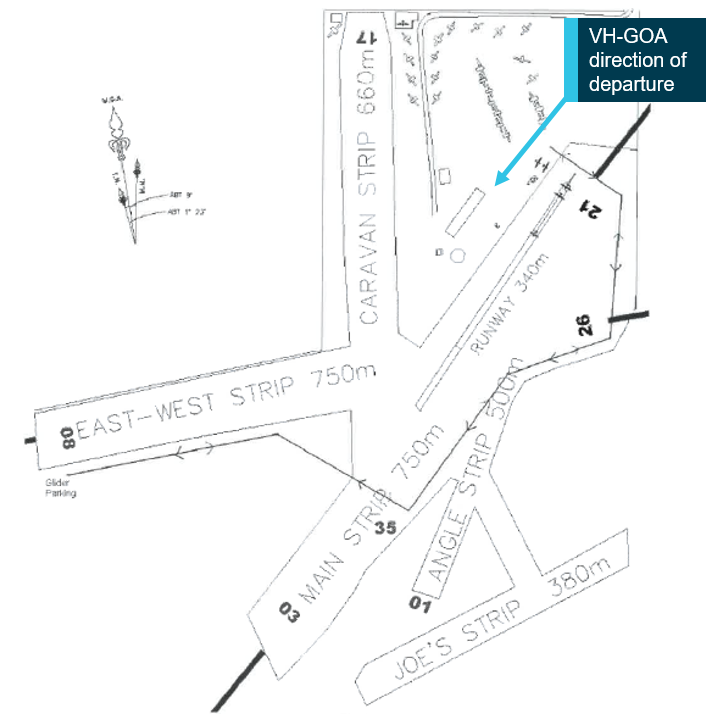
At about 1250 Eastern Daylight‑saving Time[1] on 21 January 2018, a Schleicher ASH-25E (AMT Jet) experimental powered glider, registered VH-GOA (GOA), launched from the Bathurst Soaring Club’s facility at Piper’s Field, New South Wales (Figure 1). The glider was launched by an aero‑tow aircraft from runway 21 with the pilot as the sole occupant. The purpose of the flight was for GOA and another glider to conduct a cross-country flight. The other glider launched about 5 minutes before GOA.
Figure 1: Bathurst Soaring Club facilities at Piper’s Field
Source: Bathurst Soaring Club, with permission, modified by ATSB
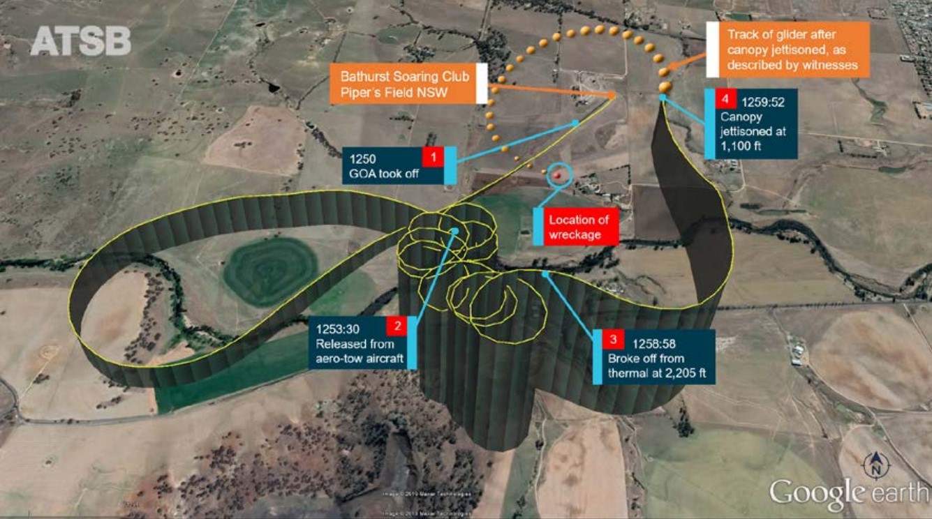
Witnesses at the airfield reported that, after departing, (Figure 2, item 1), GOA tracked out for about 1.5 NM. The pilot released from the aero-tow aircraft at 800 ft above ground level (AGL)[2] (Figure 2, item 2), made a radio call on the Soaring Club frequency that he had disengaged from the aero-tow. On-board GPS position and altitude information showed that by 1258:58 GOA had climbed to 2,205 ft AGL in a thermal situated to the south of the airfield. The glider then abruptly departed the thermal and started to descend and track back towards the northern end of the airfield (Figure 2, item 3).
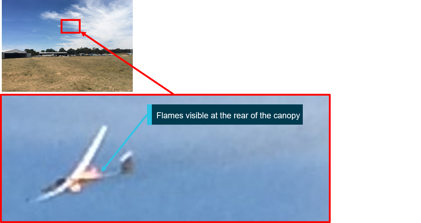
Witnesses reported seeing something trailing from GOA, which they thought was smoke or a liquid, while the glider was in a steep nose-down attitude. They then saw flames emanating from the top and bottom of the airframe, behind the cockpit (Figure 3). The pilot jettisoned the front seat canopy at 1259:52, at a height of about 1,100 ft AGL (Figure 2, item 4), but despite wearing a parachute, he did not exit the glider.
Figure 2: Aircraft track as recorded by the on-board GPS and as recalled by witnesses
Source: GPS data overlaid on Google earth, annotated by ATSB
Figure 3: Photograph of GOA after the front canopy was jettisoned
Source: Witness photograph, modified by ATSB.
At this stage, GOA was seen maintaining a steep nose-down attitude and high speed with a bank angle of about 15°. Witnesses also recalled that there did not appear to be any discernible control inputs after the canopy was jettisoned and by the time the glider descended to about 500 ft AGL, more of the fuselage was engulfed in fire. At about this time, at least one of them called emergency services.
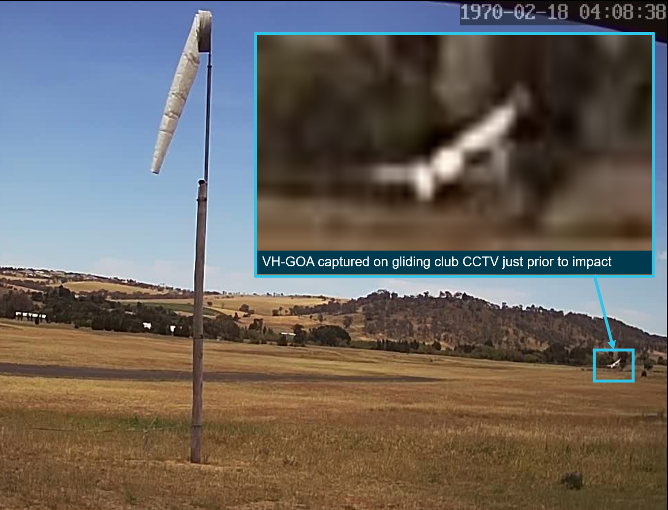
The soaring club’s closed-circuit television camera recorded that the glider banked left just prior to impact (Figure 4). A witness similarly reported that the glider’s left wing tip impacted the ground first, before it came to rest in an inverted position. The wreckage continued to burn after impact, and a fire spread to the surrounding grass.
Some witnesses moved to the accident site with handheld fire extinguishers to control the fire. About 10 minutes later, fire services arrived on the scene and extinguished the fire before it spread to neighbouring properties.
The pilot received fatal injuries and the aircraft was destroyed.
The pilot held a valid Glider Pilot Certificate issued by the Gliding Federation of Australia (GFA) in October 2017. He also held a Private Pilot (Aeroplane) License that was issued in July 1977. In addition to holding all necessary qualifications for gliding operations, his endorsements included:
carriage of private passengers
cross-country/touring (self-launching sailplane)
low level finish
self-launching sailplane.
At the time of the occurrence, the pilot had accrued between 8,000 and 11,000 hours of gliding experience over more than 2,000 flights. The pilot also held a maintenance authority to conduct specific powered glider and airframe maintenance.
The pilot held a valid medical Certificate of Fitness issued by a Medical Practitioner as required by GFA. The criteria for issuing a Certificate of Fitness were based on the medical standards that Austroads set for issuing a driver’s license medical certificate for a private motor vehicle. He had previously held a class 2 aviation medical certificate, which expired in 2012.
Evidence to assess the likelihood of the pilot experiencing fatigue was gathered, including available information on sleep obtained, any factors potentially affecting his ability to maintain adequate alertness during the flight, and other aspects that affects sleep opportunity. However, there was insufficient evidence to ascertain whether the pilot was likely to have been experiencing a level of fatigue known to affect performance.
Aircraft information
The Alexander Schleicher ASH-25E is a two-seat, mid-wing, powered sailplane with camber changing flaps, t-tail unit, retractable landing gear, and provision for water ballast. The aircraft also has a retractable engine pylon that accommodates a Rotax 275 engine, designed for self‑sustaining flight. The engine pylon extension/retraction mechanism was powered by a 12 V lead-acid battery. The glider had front and rear canopies, each of which could be separately jettisoned in-flight by the pilot.
The major construction materials for the ASH-25E airframe included carbon fibre-reinforced polymer rebar in the wings and winglets, carbon and aramid fibres in the fuselage, hard foam sandwich in the fin, wings and control surfaces, and fibreglass in the winglets. The flight control cables were steel ropes, the long push rods were aluminium alloy, and the shorter push rods were steel.
VH-GOA was manufactured in Germany in 1988. In 2010, the pilot removed the Rotax engine and propeller and replaced them with two diesel‑fuelled Titan AMT gas turbine engines. Two 25 L collapsible fuel cells were installed into the wing root to supply the replacement engines. Information about the design standards, the cockpit and canopy, the engines, fire protection and maintenance is summarised below.
Design and airworthiness
Following the engine modification, the glider was re-classified as experimental, and listed as an ASH-25E (AMT Jet). This re‑classification meant there was no regulatory requirement for GOA to comply with existing design standards.
A special Certificate of Airworthiness (CoA) was issued in 2014 under the Civil Aviation Safety Regulations (CASR) Part 21.191 (i) Private Operation of a Prototype Aircraft for the purposes of research and development, showing compliance with regulations, exhibition and air racing. Under the CoA, the glider was expressly limited to using the jet engines for ‘sustainer flight’[3] only. Once the glider was listed as an experimental aircraft, the aircraft could be modified, but operated under the GFA under Civil Aviation Orders (CAO) 95.4 Power-assisted sailplanes, powered sailplanes and sailplanes.
The Gliding Federation of Australia published the Manual of Standard Procedures (MOSP) Volume 3 Airworthiness Procedures and, under Section 2.6 Experimental Certificate, it outlined that:
Flying in an aircraft under an [Experimental Certificate] is entirely on the basis of voluntary acceptance of risk by the persons who elect to do so [and that person] should ensure they have sufficient knowledge to understand the nature of the risk...GFA promotes innovation and some member’s desire to build, modify and service their own aircraft.
EC’s may only be issued in accordance with CASR Part 21.191 to 21.195B. All ECs will clearly list the terms and limitations applicable to the allowed flight(s)…
Cockpit and canopy
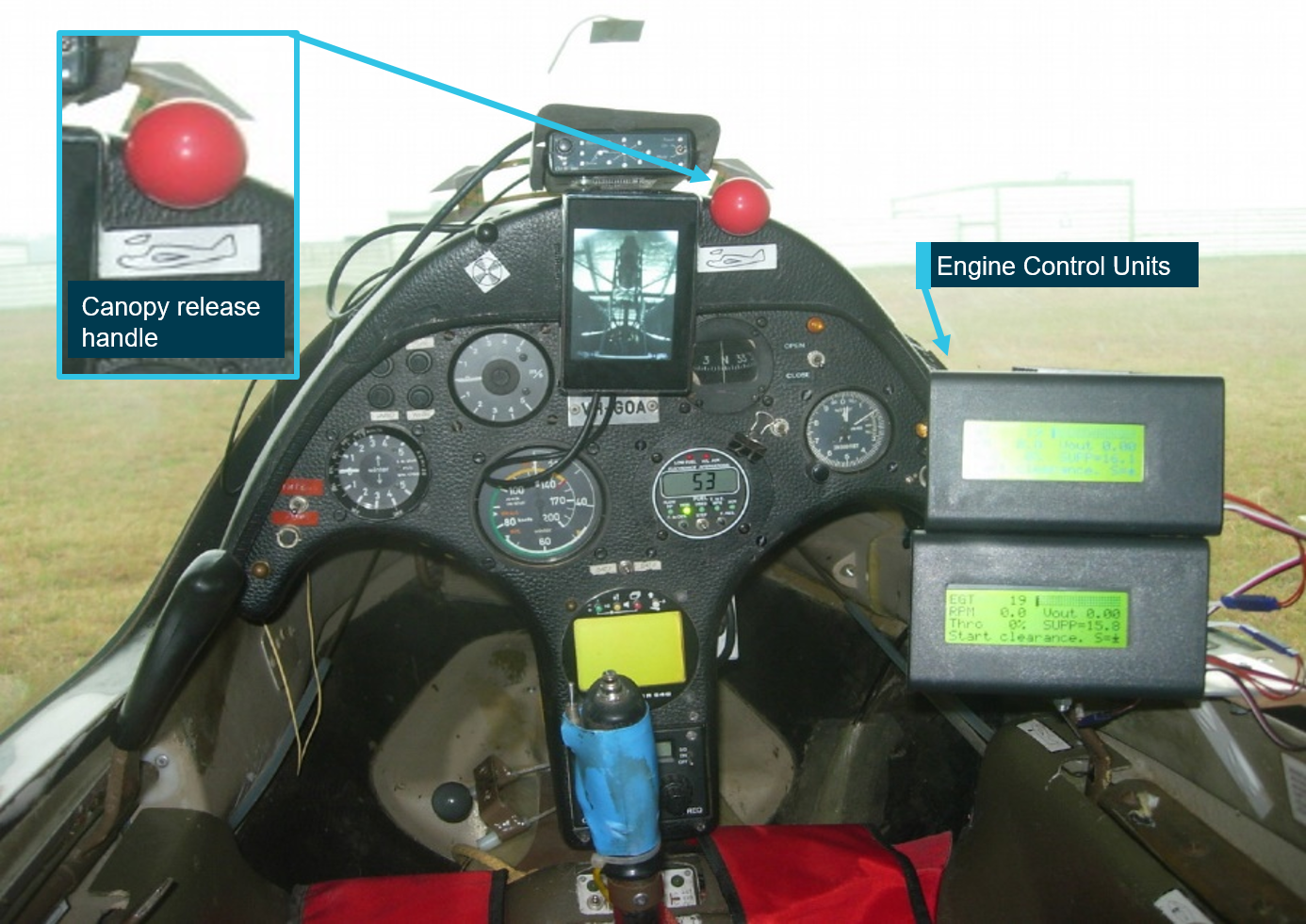
The cockpit of GOA contained two seats, one behind the other. The pilot operated the glider from the front seat on solo flights. In addition to the standard instruments, installed equipment included two engine control unit (ECU) displays, a rear-facing camera (to see the engines when operating) and an ‘LxNav’ flight recorder.
A placarded canopy jettison release handle was positioned on the top right side of the instrument panel (Figure 5).
Figure 5: View from front seat in GOA’s cockpit
Source: Flight Manual, amended by the ATSB
Engine start system
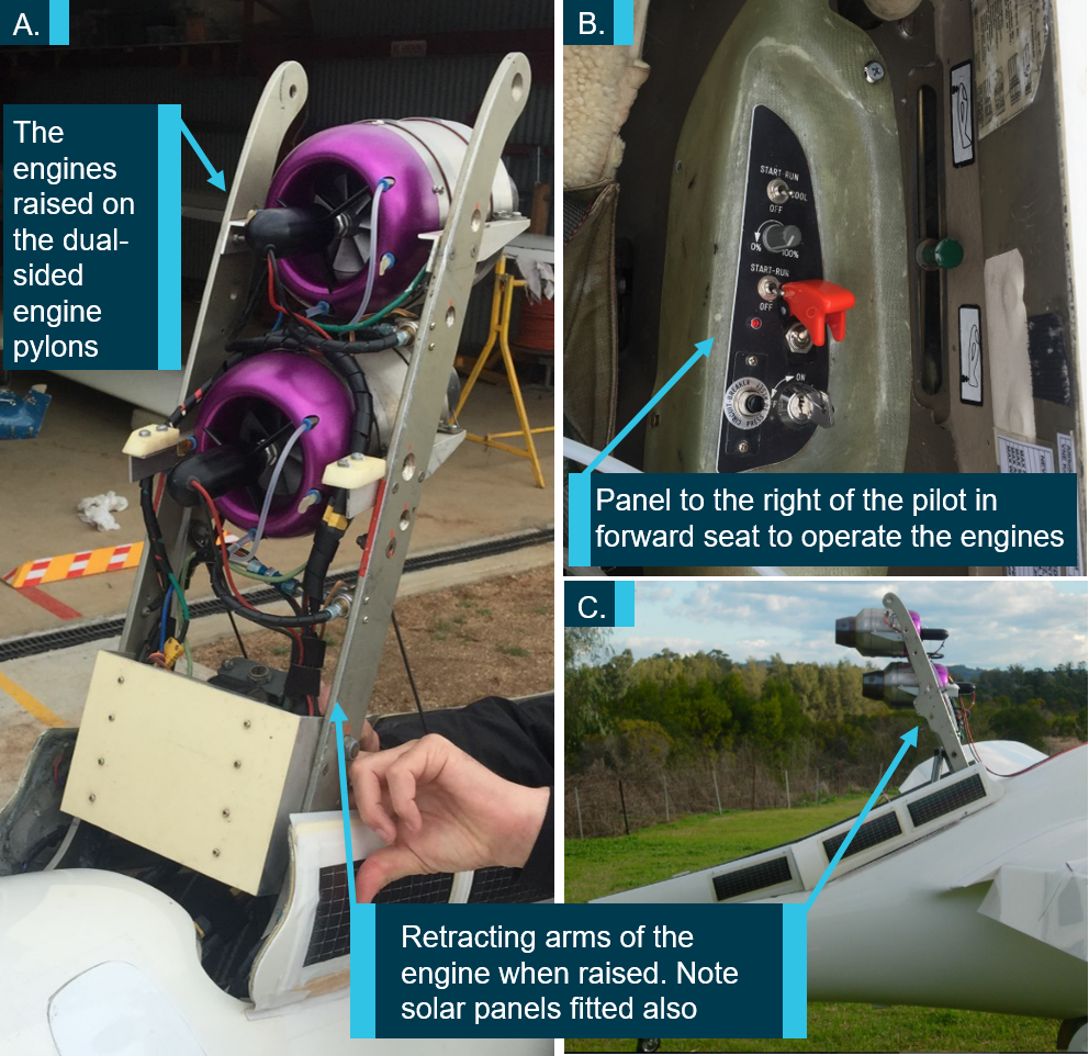
The two vertically-aligned Titan AMT Netherlands gas turbine engines were installed on the existing dual-sided pylon. The Titan was constructed from a single radial compressor and an axial flow turbine stage (Figure 6). Fuel attachments on the front cowl of the engine, with Teflon tubing and push-in Polytetrafluoroethylene (PFTE) fittings were used. The engines were housed in the engine bay when not in use, and were raised as part of the one-switch start sequence.
The Titan engines’ fuelling and operating speed were controlled by the two electronic control units (ECUs), which also regulated performance, and were each powered by a lithium polymer battery. The ECU displays were fitted inside the cockpit (Figure 5). The engines’ ignition system was designed in a manner to prevent start-up when the pylon was lowered. In the event of an emergency, the flight manual recommended lowering the pylon, which would cause the fuel flow to stop immediately.
The ignition system for the engines comprised a disposable propane gas bottle installed in the engine bay. The specially developed ASH-25J Flight Manual for GOA contained further information on the propane system:
A disposable canister of propane connects to two solenoid operated valves which are controlled by the ECU. These valves are open only during the start up phase. PFAN tubing is used to carry the propane gas...Since the valves are open only during the start phase of the engine, the risk of gas release through ruptured hoses is minimised.
The engines were started sequentially. An electric starter would spin up the turbine, a glow plug activated, and propane was then fed into the engine. If the propane ignited successfully, the EGT would start to increase and the fuel pump would switch on. The solenoid valve to the propane was then closed.
Figure 6: Images of the engines fitted to GOA
Source: ASH-215J Flight Manual
The ATSB conducted a bench test on the fuel system plumbing, constructed from plastic tubing to confirm the product was fire-resistant. The test results showed that the tubing had high temperature resistance and did not support combustion.
ECU batteries
A dedicated rechargeable lithium polymer (LiPo) battery powered each engine’s running circuit. The batteries were situated at the rear of the cockpit along with the other ECU components, the lead‑acid battery, fuel lines, and other electrical leads and components (Item B in Figure 7). The fuel lines from the wing fuel cells were situated next to the batteries.
Thermal runaway describes an accelerating process whereby increased temperature releases energy that in turn further increases temperature. If defective, or handled improperly, some rechargeable batteries with sealed cells can explode during thermal runaway. The ASH-25J Flight Manual noted that ‘LiPo batteries are potentially dangerous’, and that it was important to ensure that they were protected from mechanical forces and the effects of heat due to their ‘high energy density’. The GFA investigation report for this occurrence stated that:
[LiPo batteries] can undergo thermal runaway…due to overcharge, over-discharge, over-temp, short circuit, mechanical damage…
Witnesses reported seeing the pilot removing the LiPo batteries after a flight the day before, and recharging them.
Fire protection
Sealed firewalls reduce the spread of fire and prevent the leakage of flammable substances, like propane gas or diesel, reaching the cockpit.
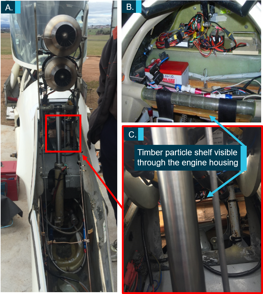
When lowered, the engines were accommodated within the fuselage tail boom (Figure 7, item A). Regarding the aircraft design, Schleicher confirmed that the ‘ASH-25E was not [originally] equipped with a forward firewall’ and it appeared that during the subsequent modification, one was not added. Schleicher also confirmed that ‘the factory-made engine compartment was primed with a fire protection paint’.
Between the engine housing and the shelf in the cockpit, there was an unobstructed opening through to the timber particle shelf (Figure 7, item B and C). In their investigation report, GFA stated that ‘it is likely that when the two stroke engine removal [was done], the electronic shroud cover and carbon fibre electronics bay were removed from the aircraft and not refitted.’ An inspection of the images of the particle shelf, and remnants of fuel lines, indicated that there did not appear to be any heat protective sleeves used.
Figure 7: Engine housing and cockpit (A. Engines – rear view, B. Cockpit area – rear view, C. Area between engine housing and particle shelf)
Source: Gliding Federation of Australia, with permission
The European Aviation Safety Agency (EASA) Certification Specification CS-22 Sailplanes and Powered Sailplanes (introduced in 2003) set design specifications applicable to the manufacturing of Schleicher gliders. Under Power-Plant Fire Protection, it outlined that:
The engine must be isolated from the rest of the sailplane by a firewall, shroud or equivalent means.
The firewall or shroud must be constructed so that no hazardous quantity of liquid, gas or flame can pass from the engine compartment to other parts of the sailplane…The firewall and shroud must be fireproof...
The materials accepted as fireproof included stainless steel (0.38 mm thick), mild steel sheet (0.5 mm thick), and/or steel or copper-based alloy firewall fittings.
The CASR 1988 Part 22 Airworthiness standards for sailplanes and powered sailplanes stated that the standards set out in EASA CS-22 were in force. The engineering report to support the experimental CoA stated that there was little risk of fire in the engine bay, as the engines were only able to operate in a raised configuration. That report did not document any specific consideration of compliance with the firewall requirements outlined in CS-22, although due to its experimental classification there was no regulatory requirement to comply.
Aircraft maintenance
General information
The special CoA stipulated that glider maintenance was to be conducted in accordance with the manufacturer’s recommendations, the requirements of the GFA Manual of Standard Procedures (MOSP) 3 and the Maintenance Manual ASH 25-J Turbo Engine Project. A review of the aircraft’s maintenance documentation indicated that there was no history of issues associated with the fuel system, batteries or engines.
Pre-flight maintenance issues
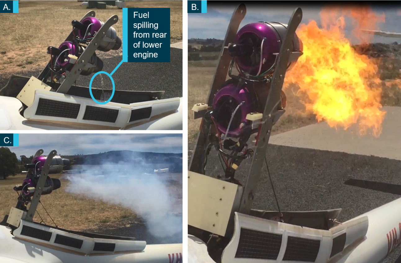
On the day before the occurrence, the pilot was observed performing ground testing on the glider’s engines. A video was also taken of the tests. Significant observations included:
fuel pouring out of the lower engine on lowering (Figure 8, item A)
significant engine flaming (Figure 8, item B)
white smoke billowing from the lower engine (Figure 8, item C)
After shutting down the engines, the pilot was heard on the video commenting that the exhaust gas temperature (EGT) read 906C. The maintenance manual for the engines listed an EGT of 700 C as normal. Following the engine testing, the pilot took a passenger for a flight. The passenger reported that the pilot did not start the engines during the flight. After landing, the passenger helped the pilot with further engine testing.
The ATSB considered how the recorded fuel leak from the lower engine may have occurred, and consulted with gliding experts and the manufacturer. They advised that there may have been a leak within the fuel lines, or at the connection point between the PFTE tubing and the engine cowling. It was the manufacturers’ opinion that this can occur when the lines are roughly cut (for example using pliers).
It was evident from the video taken that the radial compressor on the lower engine was not rotating. Therefore, another possible source of the leak may have been the way the fuel flow was initiated. The system was designed to engage the fuel pump only when the engine speed reached a certain level. Therefore, it should not have been possible for fuel to flow while the compressor was not rotating.
Figure 8: Photographs from engine testing
Source: witness, with permission
Operational information
The ASH-25E flight manual listed operating limitations, including a ‘never exceed speed’ (VNE) of 151 kt. The normal operating speed range for the glider was between 52‑97 kt.
Pre-flight checks
According to the ASH-25J flight manual, a pre-flight inspection of the engines was required, including raising the engine pylon, inspecting all hoses for leaks, all electrical cables and connections for integrity, and checking the security of restraining wires and the engine bay floor for leaks. The GFA Inspector’s handbook for powered sailplanes stated that a daily walk-around was required, which included an inspection of the battery installation, instruments and radio, oxygen bottle and systems and powerplant, and a ‘check [that] there are no fuel or oil leaks’.
Witnesses, and others who knew the pilot, reported that he would often perform an engine run prior to departure, but they did not see him do so on the day of the occurrence.
In-flight engine use
In order to deploy and operate one or both of the engines in-flight, the pilot needed to:
turn on the key switch
activate the master circuit breaker
move the engine pylon switch forward and wait till it had raised (which the pilot could see via a rear-facing camera) then, after seeing START CLEARANCE on the ECU,
move one or both of the engine control switches forward to START/RUN and then open up the throttle once the ECU displayed STARTED UP.
The ASH-25J Maintenance Manual outlined that the engine’s pylon circuit was powered from the glider’s 12V battery, and triggered the START CLEARANCE on the ECU, without which the engines could not be started.
Stopping the engines in flight was achieved by selection of a POWER DOWN switch. In an emergency, selection of the STOP/OFF position or movement of the pylon switch rearwards would instantly stop the fuel.
Recorded data
The ATSB recovered data from a flight recorder unit that the pilot had fitted to the canopy of GOA. The device was a LxNav Nano flight recorder, which is a 66-channel GPS receiver, altimeter and effective noise level sensor. The standard recording rate is once per second, and the unit was configured to automatically start recording once movement above 1 m/s was detected.
Medical and pathology
Post-mortem/toxicology reports and consultation with aviation medical experts identified that:
With regard to possible smoke inhalation, examination results ‘suggest that the deceased may not have had the chance to inhale the smoke related to the fire’.
The pilot suffered from advanced stage coronary artery disease at the time of the occurrence but there was insufficient evidence to determine if that may have influenced the development of the accident.
Survivability
Egress assist cushion
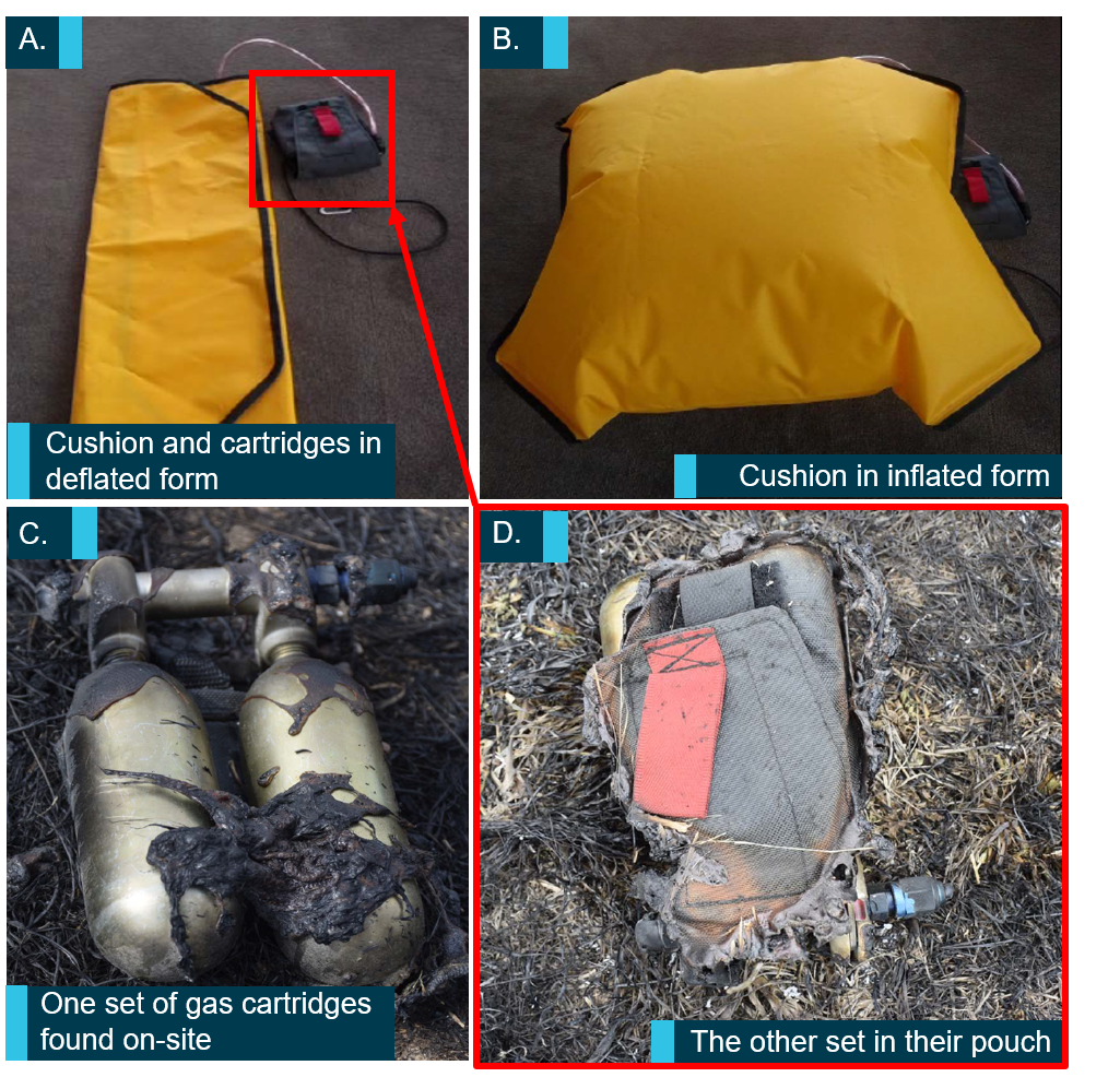
The pilot had designed his own egress assistance cushion to allow an easier in‑flight exit from the glider, particularly if the occupants needed to egress in the case of a mid-air collision. It consisted of two hermetically-sealed carbon dioxide cartridges from commercially-available life jackets that fed the gas through to an inflatable bag via a manifold and flexible hose (Figure 9). Using it required both hands – one to steady the pouch, and the other to manipulate a lanyard.
In the case of an emergency that required abandoning the aircraft, the pilot would jettison the canopy first, undo the seat harness, open the flap of the pouch to reveal a lanyard attached to the actuators, and then pull the lanyard to activate the flow of gas.
Due to the extent of fire damage, it could not be determined whether the pilot deployed the egress assistance cushion.
Figure 9: The components of the egress assist cushion
Source: ATSB
Pilot parachute
Glider pilots typically wear a parachute to exit a glider in an emergency. The passenger that the pilot had taken flying the day before recalled that they both wore a parachute, and the egress assistance cushions (described above) were in both the front and rear seats on the glider. Images from the wreckage indicated the pilot was wearing a parachute.
The most common minimum deployment height of parachutes typically worn by glider pilots was 500 ft AGL.
Site and wreckage
Wreckage location
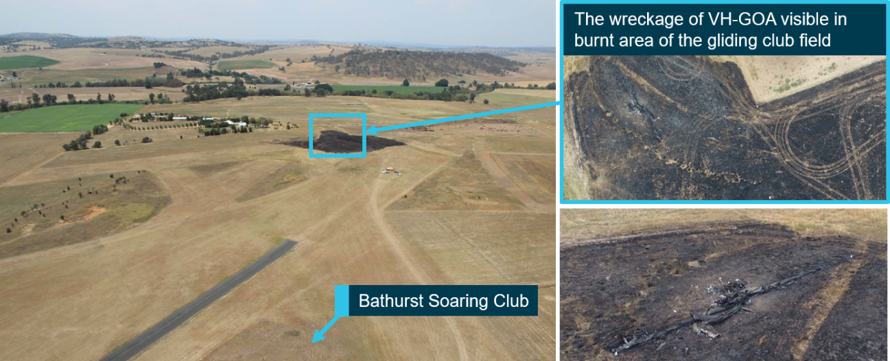
The aircraft wreckage was located in a large burnt patch of grass on the property of Bathurst Soaring Club, about 445 m away from the threshold of airstrip runway 03. The wreckage trail was spread across about 125 m. Ground scars and evidence from the wreckage indicated that GOA impacted the ground in a nose-down, left wing configuration in a northerly direction, then rolled or tumbled after the initial impact and came to rest inverted. It was determined that the impact sequence was likely not survivable. The in-flight fire continued and spread to the surrounding area (Figure 10).
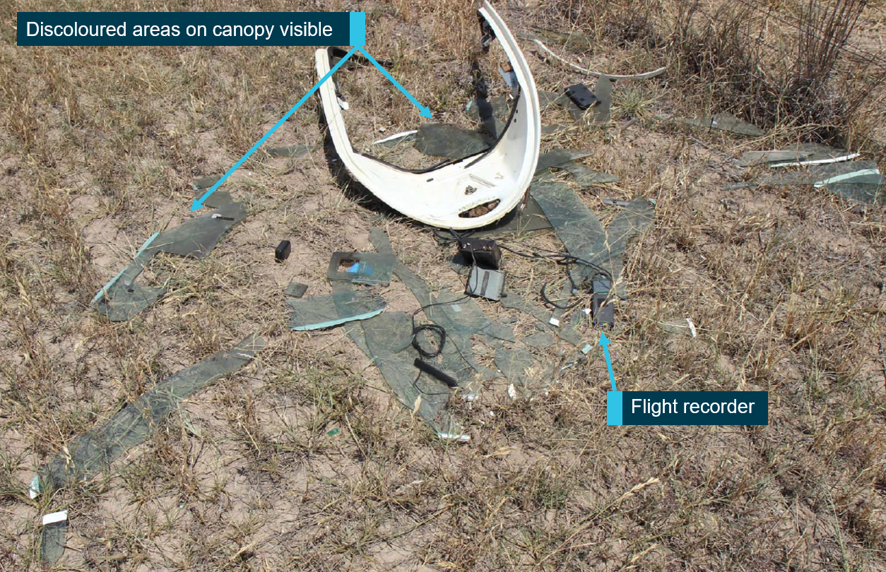
The shattered components of the canopy, as well as the GPS unit and flight recorder, were found on private property adjacent to Piper’s Field, about 440 m away from the fuselage.
Figure 10: Location of the wreckage on the Bathurst Soaring Club property
Source: ATSB
On-site examination
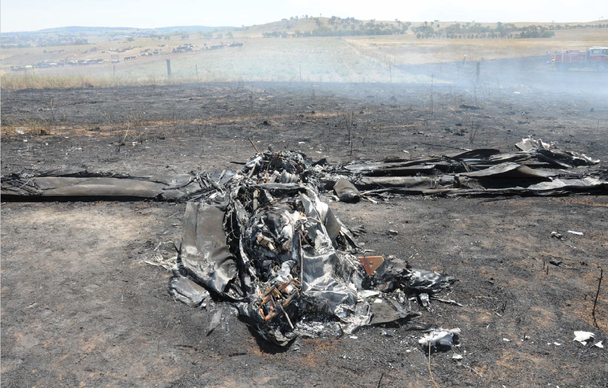
On-site examination of the severely fire‑ and impact-damaged fuselage, wings (Figure 11) and engines did not identify any obvious pre-existing faults that could have contributed to the accident. The wings, although destroyed in the post-impact fire, had all carbon fibre structures accounted for. The flap position at time of impact could not be determined. The engine pylon appeared to have been lowered at the time. A propane canister was found, but damage from the fire meant that it was not possible to determine whether it had contained any gas. The landing gear mechanism was found in the extended position, suggesting it had been lowered prior to the impact. The pilot was located within the wreckage around the area of the cockpit, although it could not be determined if he was secured in his seat.
A small number of components were retained for further examination and testing. The shattered components of the canopy’s Perspex were also examined. There was evidence of smoke residue on some of the shards (Figure 12) on the internal side of the canopy. There was also some residue on the forward third on the external side of the canopy’s ‘clearview’ hatch. These indicated that there was some smoke inside the cockpit, and it had passed through that hatch.
Figure 11: Wreckage of VH-GOA
Source: NSW Police
Figure 12: Canopy in-situ (in a field adjacent to the Bathurst Soaring Club)
Source: ATSB
Related occurrences
The pilot and the same glider were involved in a previous occurrence reported to GFA. On that occasion, during the launch of the glider, the pilot ‘noticed abnormal engine readings and saw flames coming from the jet engine via the monitor.’ In response, the pilot shut down and then lowered the engine and continued the flight.
Other related occurrences
In 2007, GFA completed its investigation into an occurrence involving a Stemme model powered glider S-10, registration VH-ZVT involved in in-flight fire, which resulted in two fatalities. The investigation identified that at some stage before impact, the pilot jettisoned the canopy. The GFA also determined that the complex nature of the fuel systems on board, and the use of fuel lines that were not fireproof, would have allowed any leaking fuel to come into contact with engine‑related heat sources.
The United States National Transport Safety Board investigated an accident involving a Stemme S10-VT in Wisconsin on 14 July 2001. The pilot took off using the engine in its self‑launching capacity. Shortly after, the engine began running rough and smoke entered the cockpit. The pilot shut down the engine, initiated an emergency landing and exited the glider. Within five minutes of the engine failure, the aircraft was engulfed in flames. The fire originated in or around the engine compartment. Following that occurrence, it was recommended that certification standards require the evaluation of the engine compartment such that liquids, smoke and gases cannot pass freely between it and the cockpit, and for extinguishing systems be installed.
In 2017, the Air Accident Investigation Branch in the United Kingdom issued a special bulletin relating to a battery fire on board an HPH Glasflugel 304 eS powered sailplane. It was determined that there was insufficient warning to the pilot of a fire in the front electric sustainer (FES) battery compartment, and that fires behind the pilot are difficult to see. This reduced the time available for a pilot to make a decision about abandoning the aircraft by parachute. One of the recommendations was for the European Aviation Safety Agency to require manufacturers to install a FES warning system in all powered sailplanes to alert the pilot to fire or smoke.
From the available information, in-flight flames were first seen near the engine housing, at the rear of the cockpit. Therefore, the ATSB considered potential ignition sources associated with the engines and the lithium polymer (LiPo) batteries.
Engine‑related ignition source
Normal operation of the engines only provided an ignition source during the start sequence or when operating. The design of the engine systems prevented the engines from starting while lowered and stowed. Specifically, the START CLEARANCE on the ECU was not displayed until the pylon was fully raised, and an interlock prevented engine start in the lowered position. While a malfunction that bypassed these mechanisms could not be ruled out, it was considered unlikely that the start sequence initiated while the engines were housed inside the fuselage.
The pilot had experienced an in-flight engine fire on VH‑GOA (GOA) in the past, and had reportedly lowered the engine into the housing to extinguish it. While it was therefore likely that he would have performed the same action if faced with another in‑flight fire, the ATSB could not find any supporting evidence that the pilot attempted to start the engines in flight. Specifically:
The pilot did not run the engines on the ground before the occurrence flight. Given his reported past practice, this indicated that he was not intending to use them.
Witnesses reported that they did not hear the distinctive sound of the engines either before or after the departure of GOA. It was also not possible to discern from the witness photos whether the engines were raised.
The rate of climb that GOA achieved in the thermal was possible without the engines.
The engines were likely lowered at the time of the impact (although it was not possible to determine what their position was at all times during the flight).
The ATSB was therefore unable to determine if the source of the fire was related to an attempt (successful or not) to raise and start the engines. However, given the recorded engine operation the previous day - fuel leakage and excessive flaming, similar in-flight behaviour during the accident flight could have resulted in an airborne fire. Additionally, as propane ignites at lower temperature than the diesel fuel, a propane leak could also have plausibly ignited.
Prior to the installation of the jet engines in 2010, the ASH-25E had a forward shroud and fire protection paint within the engine housing, but it appears the shroud was removed with the original engine. Based on several sources of evidence, there was no effective fire protection between the engine housing and the cockpit on GOA.
Thermal runaway
The pilot had charged the batteries on the evening before the occurrence. If a battery experienced thermal runaway, the resulting heat would be sufficient to ignite any diesel or propane nearby, as well as causing the fuselage to combust. However, due to the intense post‑impact fire, the battery was not identifiable within the wreckage, so it was not possible to assess the likelihood that it was the source of ignition.
Summary
The investigation found that the in-flight fire probably started near the aircraft’s engine housing. However, the extent of fire damage precluded identification of the specific ignition source.
Despite that, the circumstances of this accident (and previous occurrences) clearly illustrate the importance of having a sealed firewall to prevent, or at least delay, the effects of fire reaching the cockpit area. In that context, the ATSB recommends that any modifications to powered gliders are conducted with reference to the European Aviation Safety Agency Certification Specification CS‑22 Sailplanes and Powered Sailplanes.
Loss of control and collision with terrain
After disengaging from the aero tow aircraft, the glider started to climb in a thermal. The other glider that departed a few minutes before GOA climbed to about 10,000 ft in the same thermal, indicating that it would likely have supported the continuation of a positive climb for GOA. Therefore, when the pilot of GOA broke off from the thermal, this was probably a result of identifying the fire behind the cockpit. The glider then tracked back towards the direction of the airfield.
The subsequent high rate of descent indicated that the pilot probably deployed the glider’s air brakes to expedite the descent. The glider passed by the threshold of runway 21 when in the continuous nose-down, left-bank attitude, a configuration that could indicate the pilot was no longer in control. It collided with terrain in this same configuration at a relatively high speed.
The ATSB assessed that the control loss was probably due to the effects of fire incapacitating the pilot and/or affecting control of the glider.
It is possible that the pilot became incapacitated, for the following reasons:
exposure to smoke, fumes or fire (there was evidence that smoke entered the cockpit)
a medical event, possibly linked to the stress of the in‑flight fire and/or his coronary heart disease
the canopy or associated airflow may have impacted the pilot as it was jettisoned.
Based on the available evidence, the ATSB was not able to determine whether the pilot became incapacitated prior to the impact with terrain. However, as discussed further below, the apparent partial completion of the egress sequence could support that conclusion.
Images of GOA just prior to impact indicated that the glider was structurally intact prior to impact however, it is possible that the flight control cables and/or pushrods were damaged by the in‑flight fire. Due to the severity of the post-impact fire, it was not possible to ascertain if the flight controls were fire‑damaged before the ground impact.
Glider egress
The ATSB established that the pilot was wearing a parachute, which probably had a minimum deployment height of 500 ft, and that he was probably sitting on his egress assist cushion. He therefore had the necessary equipment to be able to exit the glider.
The time between the pilot breaking off from the thermal and then jettisoning the canopy was about 54 seconds, and it appeared as though the glider was under control. However, witnesses reported the fire visibly became more intense over that time. There was smoke residue on the inside of the canopy, which indicated that the pilot was exposed to at least one incapacitating factor before jettisoning the canopy. Fire smoke contains a mixture of narcotic and irritant gases, and incapacitation results from exposure to this combination, where ‘incapacitation’ encompasses a range of possible conditions, including unconsciousness, severe physical distress, or inability to determine how to escape (Gann, 2004).
Jettisoning the canopy required the pilot to pull a handle in the cockpit. This indicated that he was not incapacitated up to that moment. However, it is possible that after jettisoning the canopy, the pilot was not able to exit due to incapacitation. Alternatively, he may have assessed that he was now too low to exit the aircraft, or made a conscious decision to land the glider.
Findings
From the evidence available, the following findings are made with respect to the collision with terrain on the experimental ASH-25E glider, registered VH-GOA that occurred 13 km west‑north‑west of Bathurst Airport (Piper’s Field) on 21 January 2018. These findings should not be read as apportioning blame or liability to any particular organisation or individual.
Contributing factors
Shortly after launch, an in-flight fire commenced near the engine housing. The ignition source of the fire could not be determined due to severe post-impact fire damage.
The pilot was probably attempting to return the burning glider to the airfield when it departed controlled flight and collided with terrain.
The pilot had the necessary equipment to make an emergency exit from the glider and escape the effects of the fire. He jettisoned the glider's canopy but possibly due to incapacitation, did not exit.
Other factors that increased risk
The glider's cockpit and engine housing were not separated by a firewall. This limited containment of the in-flight fire, resulting in greater exposure of the pilot to fire/smoke and reduced egress time.
Safety action
Whether or not the ATSB identifies safety issues in the course of an investigation, relevant organisations may proactively initiate safety action in order to reduce their safety risk. The ATSB has been advised of the following proactive safety action in response to this occurrence.
The Gliding Federation of Australia
As a result of this occurrence, and others throughout the gliding and recreational aviation sectors, GFA advised the ATSB that on 11 March 2019, GFA published an Airworthiness Advice Notice (AAN), and on 15 March 2019 published an Airworthiness Directive (AD), both entitled Engine Fire Containment and Retardation. The affected aircraft types included all self-launching and power‑assisted sailplanes, including those fitted with jet engines.
The AAN stated that:
…many instances have been found of potential fire hazards in the form of fuel leaks, oil leaks and deficient exhaust systems. Instances found of fires starting, then self-exhausting. Adding to the mix are some powered sailplane types that may not fully meet the fire protection standards…’
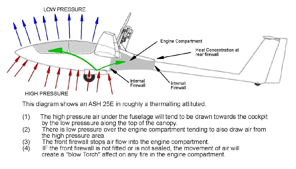
The AAN outlined the fire protection standards from EASA publication CS-22 (summarised in the Context section of this report), the engine installations of key concern (including the ‘fully buried’ engine such as GOAs), and the risks of defects in any fire retarding paint. Intumescent paint was suggested for use, which is ‘a paint cover which, when heated, expands [to shelter] the material it is covering, from heat and combustion...’ Glider pilots were also encouraged to consider the effects of airflow on fire propagation, and used a diagram of the ASH 25E (Figure 13). Lastly, the AAN covered pilot actions in the case of an engine fire, with the key advice being to shut off the fuel supply and contain the fire.
Figure 13: ASH 25E diagram displaying pressure, airflow in and out of the airframe
Source: Gliding Federation of Australia
The AD provided pilots with inspection guidelines and procedures to meet a minimum standard for fire containment and retardant. Before 30 June 2019, all glider operators and inspectors needed to complete a Form 2 inspection, inspect the condition of fire retardant paint, determine the configuration of the firewall(s), and provide the Inspection Schedule to GFA. By 30 November 2019, all paint deficiencies were required to be rectified. All subsequent inspections then needed to include a paint inspection, and also an assurance that no flammable material is attached to the cockpit side of the firewall. If the glider cannot be fitted with a firewall, a ‘strong case for non compliance’ must be made to GFA.
Sources and submissions
Sources of information
The sources of information during the investigation included:
Alexander Schleicher
the AMT Netherlands
Bathurst Soaring Club and its members
the Civil Aviation Safety Authority
the Gliding Federation of Australia and members of the gliding community
New South Wales Police
Witnesses and neighbours of the Soaring Club.
References
AAIB, Special Bulletin S3/2017 on HPH Glasflugel 304 eS, G-GSGS, 25 September 2017, Air Accidents Investigation Branch United Kingdom
CASA, CASR Part 22 – Airworthiness standards for sailplanes and powered sailplanes, Civil Aviation Safety Authority
EASA 2003, Certification Specification CS-22 – Sailplanes and Powered Sailplanes, European Union Aviation Safety Agency
NTSB, Docket CHI01LA216, accident involving a Stemme S10-VT in Wisconsin on 14 July 2001, National Transport Safety Board
Submissions
Under Part 4, Division 2 (Investigation Reports), Section 26 of the Transport Safety Investigation Act 2003 (the Act), the Australian Transport Safety Bureau (ATSB) may provide a draft report, on a confidential basis, to any person whom the ATSB considers appropriate. Section 26 (1) (a) of the Act allows a person receiving a draft report to make submissions to the ATSB about the draft report.
A draft of this report was provided to the Gliding Federation of Australia and the Civil Aviation Safety Authority.
Submissions were received from the Gliding Federation of Australia and the Civil Aviation Safety Authority. The submissions were reviewed and, where considered appropriate, the report was amended accordingly.
Purpose of safety investigations
The objective of a safety investigation is to enhance transport safety. This is done through:
identifying safety issues and facilitating safety action to address those issues
providing information about occurrences and their associated safety factors to facilitate learning within the transport industry.
It is not a function of the ATSB to apportion blame or provide a means for determining liability. At the same time, an investigation report must include factual material of sufficient weight to support the analysis and findings. At all times the ATSB endeavours to balance the use of material that could imply adverse comment with the need to properly explain what happened, and why, in a fair and unbiased manner. The ATSB does not investigate for the purpose of taking administrative, regulatory or criminal action.
Terminology
An explanation of terminology used in ATSB investigation reports is available here. This includes terms such as occurrence, contributing factor, other factor that increased risk, and safety issue.
Publishing information
Released in accordance with section 25 of the Transport Safety Investigation Act 2003
Ownership of intellectual property rights in this publication
Unless otherwise noted, copyright (and any other intellectual property rights, if any) in this report publication is owned by the Commonwealth of Australia.
Creative Commons licence
With the exception of the Coat of Arms, ATSB logo, and photos and graphics in which a third party holds copyright, this publication is licensed under a Creative Commons Attribution 3.0 Australia licence.
Creative Commons Attribution 3.0 Australia Licence is a standard form licence agreement that allows you to copy, distribute, transmit and adapt this publication provided that you attribute the work.
The ATSB’s preference is that you attribute this publication (and any material sourced from it) using the following wording: Source: Australian Transport Safety Bureau
Copyright in material obtained from other agencies, private individuals or organisations, belongs to those agencies, individuals or organisations. Where you wish to use their material, you will need to contact them directly.
Occurrence summary
Investigation number
AO-2018-009
Occurrence date
21/01/2018
Location
Pipers Field, 13 km west-north-west of Bathurst Airport
On 20 January 2018, the pilot of a Cessna 182P aircraft, registered VH-TSA, departed The Vale Airstrip, Sheffield, for a private airfield at Tomahawk, Tasmania. On arrival, the pilot conducted a number of orbits prior to approaching the runway. The aircraft touched down more than halfway along the runway before bouncing several times. In response, the pilot commenced a go‑around but the aircraft collided with a tree beyond the end of the runway and impacted the ground. The passenger was fatally injured, and the pilot sustained serious injuries. The aircraft was substantially damaged.
What the ATSB found
The ATSB identified that the selected approach direction exposed the aircraft to a tailwind that significantly increased the groundspeed on final approach and resulted in insufficient landing distance available. Additionally, the final approach path was not stable. In combination with the tailwind, that resulted in the aircraft being too high and fast with a bounced landing well beyond the runway threshold.
Finally, the go-around was initiated at a point from which there was insufficient distance remaining for the aircraft to climb above the tree at the end of the runway in the landing flap configuration and tailwind conditions.
Safety message
The ATSB reminds pilots of the importance of obtaining all relevant information about the local conditions, including wind direction and strength, prior to commencing an approach to an aerodrome. While a windsock is not required for all aircraft landing areas, it provides a simple visual means for pilots to assess the wind direction and strength.
This accident highlights the importance of conducting a standard approach to an aerodrome. This enables assessment of the environmental and runway conditions and allows checks to be completed in a predictable manner. When approaching a non-controlled aerodrome, pilots are required to join a leg of the circuit and, if joining on final, to establish the aircraft on final approach at least 3 NM from the runway threshold to ensure a stable approach path. If a safe landing cannot be assured, a pilot should initiate a go-around early, and ensure the aircraft is configured in accordance with the operating handbook.
The occurrence
On 20 January 2018, at about 1645 Eastern Daylight-saving Time,[1] a Cessna 182P aircraft, registered VH-TSA (TSA), departed The Vale Airstrip, Sheffield, Tasmania for a private airfield at Tomahawk, 146 km to the east‑north‑east (Figure 1). The private flight was conducted under the visual flight rules[2] at 3,500 ft above mean sea level (AMSL). On board were the pilot occupying the front left seat and a passenger (also a qualified pilot), seated in the front right seat.
The pilot broadcast on the multicom frequency (126.7 MHz) when the aircraft was 10 NM (19 km) from, and inbound to, Tomahawk. Recorded data showed that the aircraft commenced descent from its cruising altitude at 1712. The pilot stated that airfield was hard to identify visually and that he sighted it after descending to about 1,000 ft AMSL. There was no windsock at the airfield to identify the wind speed and direction. The pilot reported that he anticipated that the wind would be from the same north‑westerly direction encountered during the flight, and therefore decided to land towards the north-west.
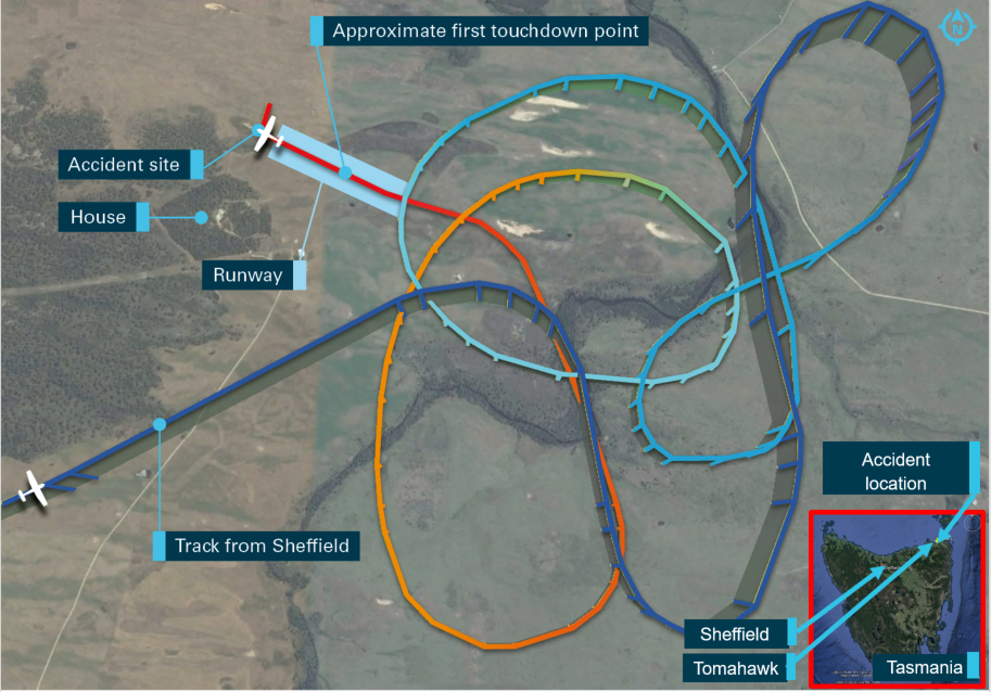
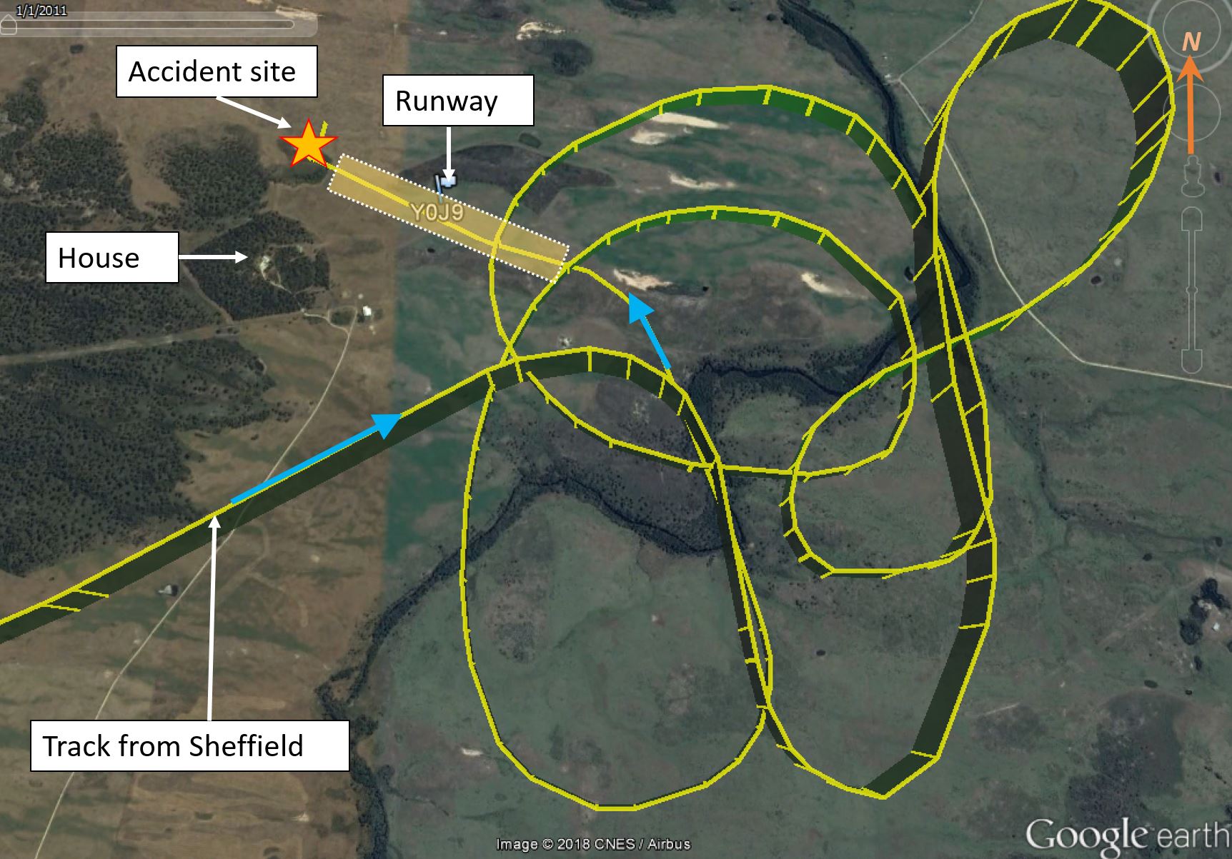
On arrival at Tomahawk, the pilot conducted a number of orbits to the right and left in the vicinity of the airfield (Figure 2). He reported that he manoeuvred the aircraft in that manner prior to approaching the runway because the aircraft was too high, and its groundspeed was faster than normal, for the approach.
Figure 1: Recorded aircraft track
Source: AvPlan data – annotated by ATSB
The pilot stated that he felt some pressure to land due to the weather, with clouds at about 1,400 ft and light showers of rain in the area. Additionally, it was later than their original estimated arrival time of 1700. He was aware that the passenger had advised the airfield owner that their arrival time would be closer to 1730.
At about 1720, the airfield owner saw and heard the aircraft operating south-east of the airfield. A second witness, who was standing between the house and airfield, saw the aircraft approaching the runway heading in a westerly direction.
The airfield owner was working outside at the time the aircraft arrived. He was also a pilot, and reported that he was concerned that the pilot of TSA was attempting to land the aircraft towards the west, which would result in a tailwind he estimated to be about 15 kt. In response, the airfield owner drove his vehicle onto the runway towards the approaching aircraft, with headlights on and hazard lights flashing, in an attempt to communicate to the pilot to abort the landing. The pilot reported that he thought the driver was indicating where to land, and so he continued the approach. Having determined that the pilot intended to continue the landing, the airfield owner vacated the runway.
Tyre marks on the grass identified that the aircraft first touched down 433 m beyond the runway threshold, with 284 m of runway remaining. Subsequent wheel marks showed that the aircraft then bounced several times, with the last wheel marks visible on the runway 161 m before a 7 m high tree, located on rising terrain 36 m beyond the end of the runway. The pilot reported that, following the bounced landing, the passenger instructed him to initiate a go‑around. In response, he applied full power and recalled that the engine appears to have responded normally.
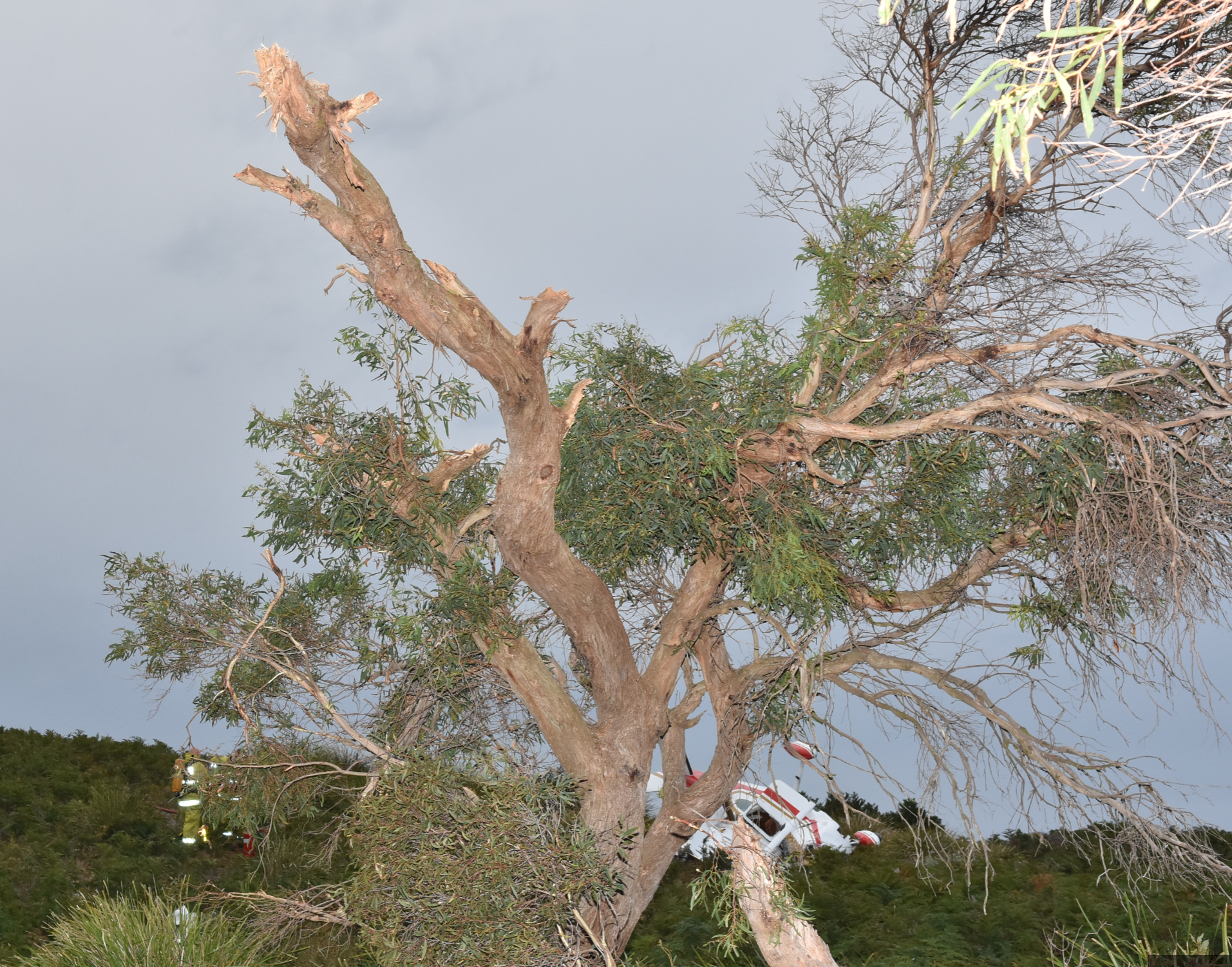
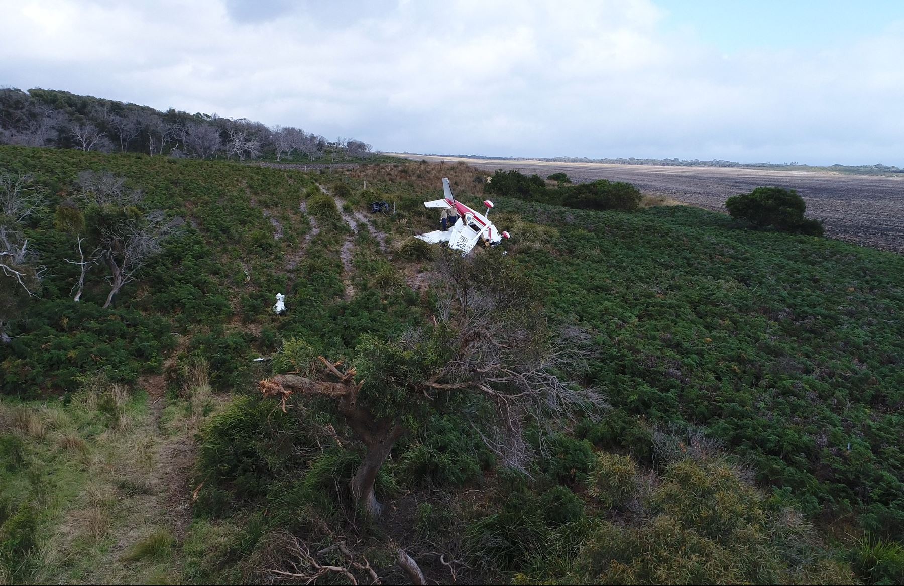
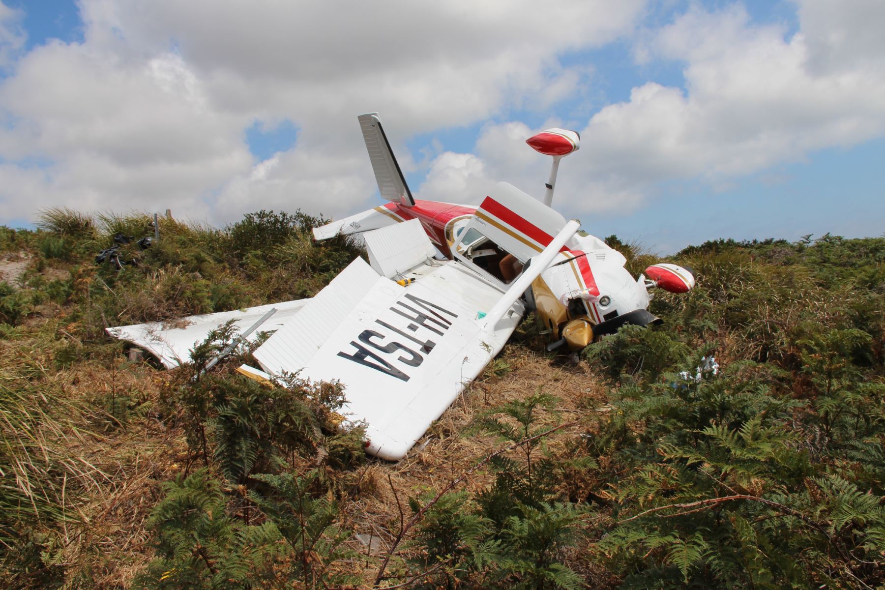
The aircraft started to climb, however it collided with a branch of the tree 5.6 m above the ground. The impact damaged the right wing, and the aircraft then collided with terrain and came to rest on its right side (Figures 2 and 3). The passenger sustained fatal injuries and the pilot was seriously injured. The aircraft was substantially damaged.
Figure 2: Accident site facing west, showing the tree branch struck by the aircraft’s right wing and the rising terrain in the background
Source: Tasmania Police
Pilot information
The pilot held a current Private Pilot (Aeroplane) Licence issued by the Civil Aviation Safety Authority on 17 February 2016, a single‑engine aeroplane class rating and a manual propeller pitch control design feature endorsement, as required for operation of VH‑TSA.
The pilot also held a Class 2 Aviation Medical Certificate valid until 8 November 2019 with the restriction of vision correction. In conjunction with a flight review conducted on 18 December 2017, the pilot had successfully completed an operational check of his vision following eye surgery.
The pilot had about 560 hours total aeronautical experience and 46.7 hours on the Cessna 182P.
The passenger also held a current Private Pilot (Aeroplane) Licence and Class 2 Aviation Medical Certificate, and had about 1,280 hours total aeronautical experience.
The pilot and passenger had conducted many flights together around Australia. Although the passenger had been the pilot in command for the majority of those flights, both had exposure to operating at remote and unfamiliar airfields. They had also completed a bush pilots training course. Additionally, at his flight review two months prior to the accident, the pilot had conducted a simulated forced landing, in which he demonstrated his ability to select an appropriate landing site.
Aircraft information
The Cessna Aircraft Company 182P is a four-seat, high‑wing, single-engine aircraft equipped with fixed tricycle landing gear. The aircraft was powered by a Teledyne Continental Motors O-470-S engine and fitted with a McCauley two-blade, constant-speed propeller, model 2A34C203.
VH-TSA was a 1976-model 182P aircraft, recorded as being manufactured in the United States in 1977. It was first registered in Australia in 1978 and registration was transferred to the current operator in 2012. The aircraft’s total time in service was 6,160 hours. The engine had exceeded the manufacturer’s recommended time between overhauls but was permitted to continue in service and was assessed by the maintainer as serviceable at the last 100-hourly scheduled maintenance at 6,064 hours on 15 February 2017.
The aircraft was operated in the private category and was loaded within its weight and balance limitations on the day of the occurrence.
Aerodrome information
An aerodrome is defined as an area of land or water that is intended for use for the arrival, departure or movement of aircraft. The airfield in Tomahawk was a privately owned, non‑controlled aircraft landing area and met the definition of an aerodrome. The prepared grass surface of the east-west runway was 717 m long, orientated in a direction of 281° magnetic, and had a short grass surface. The runway sloped down towards the west at an average slope of 1.5° for the first 500 m, and was then level. There was rising ground at both ends of the runway and a tree about 7 m high on the rising ground at the western end (Figure 3).
A shorter runway heading 050°/230° magnetic intersected the main runway just east of its midpoint. White plastic markers indicated the eastern and western thresholds and the crossing runway intersection.
There was no windsock at the airfield and one was not required to be there. The Civil Aviation Safety Authority (CASA) Civil Aviation Advisory Publication CAAP 92-1(1) – Guidelines for aeroplane landing areas paragraph 8.7 stated:
A method of determining the surface wind at a landing area is desirable. A windsock is the preferred method.
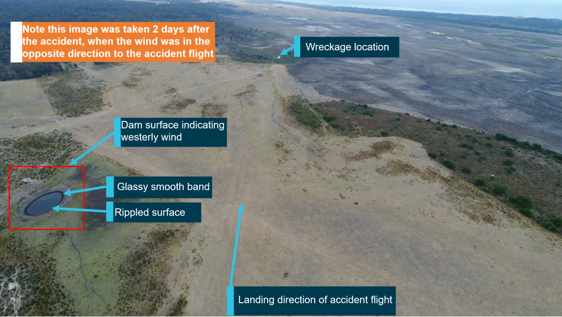
Although there was no windsock, other means were available by which the pilot could assess the local wind. These included the ability to observe the water surface pattern on several waterholes in the circuit area, including the dam adjacent to the runways depicted in Figure 3, or a comparison of airspeed versus GPS groundspeed during the final approach.
The CAAP referred to the requirements of Civil Aviation Regulation 92 (1), which detailed that a pilot shall not land an aircraft unless, having regard to all circumstances, including the prevailing weather conditions, the aircraft can land at the place in safety.
A document containing information pertaining to the airfield was found in the cockpit. The document depicted the runways as 11/29 725 m in length and 24/06 400 m in length. There was no text adjacent to the ‘windsock’ section, nor was there any mention of rising terrain or a tree to the west of the runway, reducing the runway’s effective length. The following text was under ‘Special procedures and remarks’:
runway 29/11 slopes down to the north-west
pilot to ensure the landing area is suitable
taxi on marked runways
slight undulations on runways
short strip 400 m rising to the north slightly
both strips are ok for use in each direction.
Figure 3: Airfield looking in the landing direction (west) from runway threshold, showing dam surface. Note: image was taken 2 days after the accident, in a westerly wind
Source: ATSB
Landing distance required
CAAP 92-1(1) stated that ‘a runway length equal to or greater than that specified in the aeroplane’s flight manual…is required’. Additionally, paragraph 5.2 of the CAAP recommended that a 15 per cent factor safety factor be applied to required runway lengths.
Based on the landing distance chart in the Pilot’s Operating Handbook (POH), the total distance required for the Cessna 182P to clear a 50 ft obstacle when landing at sea level pressure altitude in nil wind, on short dry grass at 30°C was 1,648 ft (502 m). Therefore, in nil wind conditions, there was sufficient length available for a landing on the runway used by the pilot.
While landings are normally conducted into wind to reduce the groundspeed and landing distance required, it is possible to conduct landings with a limited tailwind. The POH stated that a 50 per cent increase in landing distance was required with a tailwind up to 10 kt. In this instance, that equated to a required distance of 2,472 ft (753 m). Therefore, if the POH guidance was followed, the longest available runway length at the airfield was too short for landing with a 10 kt tailwind.
Approach to land
A stabilised approach is one in which the pilot maintains a constant descent angle to the aiming point for landing on the runway. The advantages of conducting such an approach is that it enables the pilot to:
configure the aircraft for landing and complete all checks
assess the local environmental and runway conditions, including the wind speed and direction
reduce their workload, particularly at unfamiliar aerodromes.
CAAP 166-01 Operations in the vicinity of non-controlled aerodromes, stated that:
The turn onto final approach should be completed 500 ft above the aerodrome elevation. This will allow sufficient time for the majority of aircraft to fly a stabilised approach and landing.
Where a pilot is unfamiliar with the aerodrome layout, or when its serviceability, wind direction, wind speed or circuit direction cannot be ascertained prior to arrival, an overfly procedure should be used.
Aircraft must join the circuit (or avoid the circuit – i.e. when overflying).
When conducting a straight-in approach, the aircraft must be established on final not less than 3 NM from the runway threshold.
Pilots are required to determine the wind velocity and runway in use prior to conducting a straight-in approach.
Only minor corrections to speed and flight path, to maintain a stable approach, should be required within 3 NM on final.
CASA recommends that pilots join the circuit on crosswind (midfield) or downwind leg.
Pilots who choose to join on base should do so only if they have determined a number of factors including the wind direction and speed.
Analysis of the recorded flight track information identified that the pilot of TSA did not join a leg of the circuit or establish the aircraft on final approach from at least 3 NM.
Conduct of a go-around
The POH stated that for a go‑around or 'Balked Landing', the wing flap setting should be reduced to 20° immediately after full power is applied.
The pilot reported that the passenger stated she ‘would get the flaps,’ during the go‑around and he assumed that she had selected the flap lever to the 10° position. Examination of the wreckage identified that, while the flap lever was in that position in the cockpit after impact, measurement of the flap actuator showed that the flaps were still in the fully extended position. Given that discrepancy, the ATSB concluded that either the lever had not been selected up for sufficient time to enable the flaps to start to retract before the aircraft collided with the tree, or the lever moved during the accident sequence.
The aircraft is required by Civil Aviation Order 20.7.4.9.1 to climb at a minimum of 3.2 per cent in the landing configuration, that is, with the flaps extended 40°. To out-climb the tree, the top of which was 7 m high, at that minimum gradient with the flaps extended, the pilot would have had to commence the go‑around 224 m before the tree in nil wind conditions. A go-around conducted with a tailwind reduces the angle of climb and therefore increases the distance required to out‑climb obstacles. The last wheel contact marks were 160 m before the impacted tree.
Data provided to the ATSB by the aircraft manufacturer identified that the aircraft type was capable of out-climbing a 7 m tree from 160 m in nil wind when flown in the landing configuration (full flap) and within 3 kt of the aircraft’s best angle of climb speed (59 kt indicated airspeed). However, with a 15 kt tailwind, the remaining distance was insufficient to climb 7 m in the landing configuration at any airspeed.
Weather information
Weather forecast
A report provided to the ATSB by the Bureau of Meteorology (BoM) detailed that several layers of cloud were forecast in the Tomahawk area around the time of the accident. These included scattered[3] altocumulus and altostratus above 10,000 ft, scattered cumulus and stratocumulus with bases between 2,500 and 4,000 ft, and broken stratus with bases between 1,000 and 2,000 ft with isolated showers of rain.
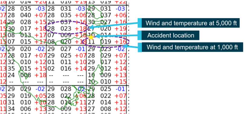
The BoM also identified that, due to a strong temperature inversion at about 4,500 ft AMSL, there were westerly winds above that level, with an easterly sea breeze below it. An extract of the forecast grid point wind and temperature chart valid for the flight is depicted in Figure 4.
The Tomahawk area is located in the top right grid and shows the wind at 1,000 ft above mean sea level (AMSL) was forecast to be from 110° true[4] at 19 kt and temperature 16°C. In the top centre grid, where the aircraft was en route from Sheffield to Tomahawk at 3,500 ft, the forecast wind at 5,000 ft AMSL was from 280° true at 23 kt and temperature 18°C.
The terminal aerodrome forecast (TAF) for Devonport Airport, 124 km from Tomahawk on a north-facing coastline, indicated a northerly wind of 9 kt.
Figure 4: Grid point wind and temperature chart showing en route and destination forecast
Source: Bureau of Meteorology annotated by ATSB
Actual conditions
The actual conditions at Tomahawk around the time of the accident were consistent with the forecast. Witnesses reported an easterly wind of 15 to 20 kt at the time of the accident. There was high overcast cloud and the pilot reported encountering some lower-level cloud with a base of about 1,400 ft and some showers in the vicinity of the destination airfield. An experienced pilot who had operated numerous times at the airfield reported that the location was frequently affected by a sea breeze.
Pilot’s weather assessment
The pilot reported having obtained the weather forecast prior to departure, including the area forecast and the TAF for Devonport. He reported that he did not identify the forecast difference in wind direction between 5,000 and 1,000 ft and commented that he found the grid point wind and temperature graphical information provided by the BoM more difficult to interpret than the text format used until November 2017. Information about interpreting the new format forecasts is available on the BoM website.
Recorded flight data
The aircraft was not equipped with a flight data or cockpit voice recorder and neither was it required to be. However, the aircraft was fitted with a GPS capable of recording flight data. The aircraft’s track was also recorded on a personal device carried in the aircraft. A review of the data recorded on the device identified that the aircraft cruised on a direct track from The Vale to Tomahawk at 3,500 ft AMSL at a groundspeed between 136 and 150 kt.
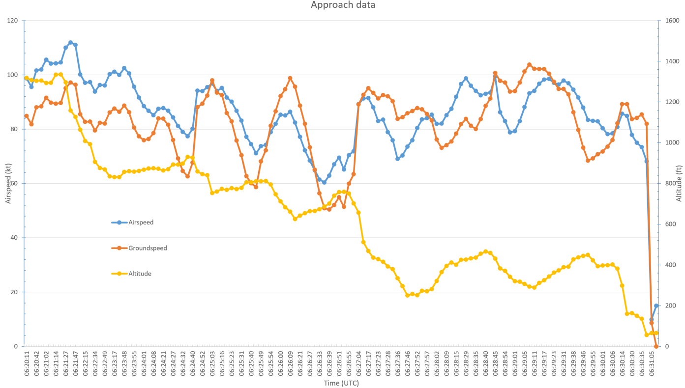
During the descent from 3,500 ft, the groundspeed reduced in a manner consistent with both a reduction in power and the aircraft passing through a wind change from a westerly to an easterly direction. After the aircraft descended to about 900 ft AMSL, the pilot conducted a number of orbits on approach to the airfield. While conducting those orbits during the last 4 minutes of the flight, the aircraft’s altitude and groundspeed varied before the descent to land.
To estimate the aircraft’s airspeed from the recorded groundspeed, the ATSB applied a 15 kt easterly wind to the approach data. This showed that the airspeed varied between about 60‑100 kt throughout the approach (Figure 5).
The last data for the flight was recorded at 1731.
Figure 5: Approach data showing altitude, groundspeed and derived airspeed based on a 15 kt easterly wind
Source: ATSB
Wreckage and impact information
Examination of the accident site and aircraft wreckage indicated that the aircraft’s right wing struck the branch of a tree 5.6 m above, and about 36 m beyond, the end of the runway.
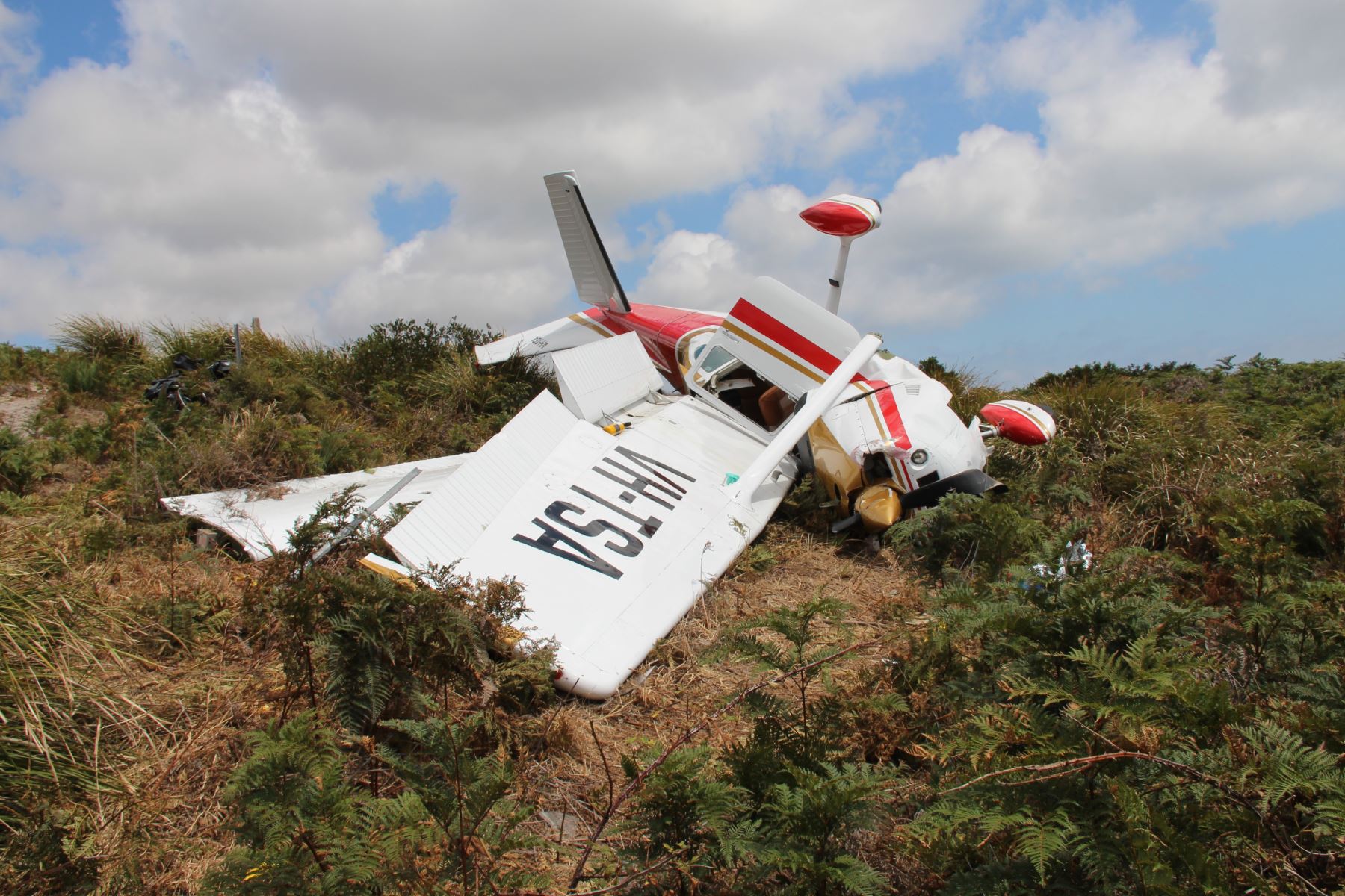
The right wing strut fractured on contact with the tree and separated from the aircraft. The wing failed, but remained connected to the fuselage. The aircraft subsequently rolled to the right and pitched nose-down. The propeller and the front of the engine struck the ground and the aircraft rotated about the impact point before coming to rest on its right side. During the impact sequence, the left wing strut fractured at the fuselage and the left wing came to rest on top of the right wing (Figure 5).
Fuel leaked from aircraft’s ruptured wing fuel tanks, but there was no fire.
Examination of the aircraft did not identify any pre-existing faults and the pilot reported that the aircraft, including the engine, was operating normally at the time of the accident. The bending and impact marks on the propeller blades indicated that the engine was producing significant power when the blades struck the ground.
The right flap detached following impact with the tree and the left flap was extended. The flap actuator extension indicated that the flaps were in the fully extended position of 40°.
The lap sash and shoulder strap of both seatbelts were fastened at impact.
Figure 5: Damage to VH-TSA
Source: ATSB
Survivability
The passenger’s seat was found in the fully forward and raised position, and the occupant was seated with a supplemental cushion (also called a booster seat) behind her back and one on the seat base. The United States Federal Aviation Administration (FAA) reported that as supplemental cushions are considered ‘carry-on’ items, they are not regulated.
When the FAA certifies a seat, a specific seat reference point (SRP) is identified, which relates the seat structure to the Anthropomorphic Test Dummy position during certification. If a manufacturer wants to alter the cushion on the seat it must maintain the SRP within an established tolerance, otherwise the seat will have to be re-certificated. When the occupant adds a supplemental cushion it moves them away from the nominal position, which changes how they flail with respect to their surroundings, as well as where their body is relative to the installed restraints.
In this accident, the effect of the supplemental cushions moved the occupant’s body upwards and forwards. This put her at an increased risk of impacting the surrounding structure during the accident sequence. The use of supplemental cushions can also affect the occupant’s vertical acceleration relative to the seat structure increasing the risk of spinal injury. It could not be determined if this alteration from the nominal seating position increased the severity of the injuries sustained.
By adding supplemental cushions, a short-statured pilot increases their flail envelope,[5] which increases their injury potential. However, without the supplemental cushion they may have reduced visibility or may not be able to operate the flight controls effectively.
The pilot identified the predominantly westerly tailwind at the cruising altitude while the aircraft tracked east‑north‑east towards an airfield in Tomahawk. However, the easterly local surface wind at the airfield, although forecast, was not identified.
The pilot reported that before landing at an aerodrome, he normally overflew and assessed the windsock then joined the circuit depending on the direction of the wind. However, on this occasion there was no windsock available. While a windsock provides a simple visual means to assess wind strength and direction (and is the preferred method recommended by the Civil Aviation Safety Authority), there were a number of other means by which the pilot could have assessed the wind prior to commencing the approach. These included:
interpretation of the wind‑effect on the surface of a nearby dam or vegetation
a comparison of the airspeed with the GPS‑derived groundspeed during a stabilised segment of flight associated with either an upwind or downwind circuit leg or long final approach.
The pilot had previously demonstrated his ability to assess local wind conditions, without a windsock, while conducting a simulated forced landing as part of a flight review. On this occasion however, the landing runway was selected in anticipation of a similar westerly wind direction to that encountered during cruise. The resultant approach direction exposed the aircraft to about a 15 kt tailwind, which significantly increased the groundspeed on final approach and resulted in a manufacturer‑calculated landing distance in excess of that available. It also significantly reduced the available climb gradient in the event of a go-around.
The pilot was unfamiliar with the airfield and also reported the presence of low cloud and reduced ambient lighting conditions on arrival at Tomahawk. He also stated that arrival time was later than planned. It is possible that these factors may have influenced the approach preparation and conduct.
Unstable approach and go‑around
On arrival at Tomahawk, the pilot conducted a number of orbits south-east of the airfield at varying height and airspeed rather than joining the circuit or conducting a straight-in approach. This manoeuvring reduced the stability of the final approach and the opportunity for the pilot to assess the local wind conditions via a comparison of airspeed and GPS groundspeed.
The pilot recalled realising just prior to landing that the groundspeed was higher than the airspeed – indicative of a tailwind. Despite that, a go-around was not conducted at that point and the aircraft touched down over halfway along the prepared runway surface, with insufficient remaining runway to come to a stop.
Following a number of subsequent bounces, the pilot assessed that the aircraft was not going to be able to stop before the end of the runway. In response, he increased the power and raised the aircraft’s nose to go-around but the flaps were not altered from the landing configuration. This reduced the aircraft’s climb performance and, combined with the tailwind, led to insufficient distance remaining for the aircraft to climb above the tree at the end of the runway. The aircraft’s wing struck the tree and was damaged to the extent that the aircraft became uncontrollable. The aircraft then rolled to the right, pitched nose-down and collided with the terrain.
Findings
From the evidence available, the following findings are made with respect to collision with terrain involving Cessna Aircraft Company 182P, registered VH-TSA, that occurred at Tomahawk, Tasmania on 20 January 2018. These findings should not be read as apportioning blame or liability to any particular organisation or individual.
Contributing factors
The selected approach direction exposed the aircraft to a tailwind that significantly increased the groundspeed on final approach and resulted in insufficient landing distance available.
The pilot did not conduct a stabilised approach, which combined with the tailwind, resulted in the aircraft being too high and fast and a bounced landing well beyond the runway threshold.
From the point at which the go-around was initiated, there was insufficient distance remaining for the aircraft to out-climb the tree at the end of the runway in the landing flap configuration and tailwind conditions.
Other factors that increased risk
There was no windsock at the airfield to enable a simple visual assessment of the wind strength and direction.
Sources and submissions
Sources of information
The sources of information during the investigation included
the pilot of VH-TSA
several pilots operating in the local area
the airfield owner
AvPlan
Airservices Australia
the Civil Aviation Safety Authority
the United States National Transportation Safety Board
Textron Aviation
References
Rolfe ST& Barsom JM 1977, Fracture and fatigue control in structures, applications of fracture mechanics, Prentice-Hall New Jersey, pp. 414-440.
Submissions
Under Part 4, Division 2 (Investigation Reports), Section 26 of the Transport Safety Investigation Act 2003 (the Act), the Australian Transport Safety Bureau (ATSB) may provide a draft report, on a confidential basis, to any person whom the ATSB considers appropriate. Section 26 (1) (a) of the Act allows a person receiving a draft report to make submissions to the ATSB about the draft report.
A draft of this report was provided to the pilot, the airfield owner, the aircraft manufacturer, the Civil Aviation Safety Authority and the United States National Transportation Safety Board and Federal Aviation Administration.
Submissions were received from the airfield owner and the Federal Aviation Administration. The submissions were reviewed and where considered appropriate, the text of the report was amended accordingly.
Purpose of safety investigations
The objective of a safety investigation is to enhance transport safety. This is done through:
identifying safety issues and facilitating safety action to address those issues
providing information about occurrences and their associated safety factors to facilitate learning within the transport industry.
It is not a function of the ATSB to apportion blame or provide a means for determining liability. At the same time, an investigation report must include factual material of sufficient weight to support the analysis and findings. At all times the ATSB endeavours to balance the use of material that could imply adverse comment with the need to properly explain what happened, and why, in a fair and unbiased manner. The ATSB does not investigate for the purpose of taking administrative, regulatory or criminal action.
Terminology
An explanation of terminology used in ATSB investigation reports is available here. This includes terms such as occurrence, contributing factor, other factor that increased risk, and safety issue.
Publishing information
Released in accordance with section 25 of the Transport Safety Investigation Act 2003
Ownership of intellectual property rights in this publication
Unless otherwise noted, copyright (and any other intellectual property rights, if any) in this report publication is owned by the Commonwealth of Australia.
Creative Commons licence
With the exception of the Coat of Arms, ATSB logo, and photos and graphics in which a third party holds copyright, this publication is licensed under a Creative Commons Attribution 3.0 Australia licence.
Creative Commons Attribution 3.0 Australia Licence is a standard form licence agreement that allows you to copy, distribute, transmit and adapt this publication provided that you attribute the work.
The ATSB’s preference is that you attribute this publication (and any material sourced from it) using the following wording: Source: Australian Transport Safety Bureau
Copyright in material obtained from other agencies, private individuals or organisations, belongs to those agencies, individuals or organisations. Where you wish to use their material, you will need to contact them directly.
Preliminary report
Report release date: 23/02/2018
This preliminary report details factual information established in the investigation’s early evidence collection phase and has been prepared to provide timely information to the industry and public. Preliminary reports contain no analysis or findings, which will be detailed in the investigation’s final report. The information contained in this preliminary report is released in accordance with section 25 of the Transport Safety Investigation Act 2003.
Sequence of events
On 20 January 2018, at about 1645 Eastern Daylight-saving Time,[1] a Cessna 182P aircraft, registered VH-TSA, departed The Vale airstrip, Sheffield, Tasmania, for a private flight to a private airstrip at Tomahawk, Tasmania. The flight was a distance of 79 NM, tracking to the east‑north‑east at 3,500 ft above mean sea level (AMSL) and was conducted under the visual flight rules.[2] On board were the pilot occupying the front left seat and a passenger (also a qualified pilot), seated in the front right seat.
The pilot broadcast on the Multicom frequency when the aircraft was 10 NM from, and inbound to, the destination airstrip. Recorded data showed that the aircraft commenced a descent from its cruising altitude of 3,500 ft at 1712. The pilot reported that he sighted the airstrip after descending to about 1,000 ft AMSL. There was no windsock at the airstrip. The pilot anticipated that the wind would be from the same north‑westerly direction they reported encountering during the flight, and therefore decided to land towards the north-west.
The pilot conducted a number of orbits (Figure 1) and later reported manoeuvring the aircraft prior to approaching the runway because the aircraft was too high and its groundspeed was faster than normal for the approach.
Figure 1: Recorded aircraft track
Source: AvPlan data – annotated by ATSB
At about 1720, a witness at the property saw and heard the aircraft operating south-east of the airstrip. A second witness, who was standing between the house and airstrip, then saw the aircraft approaching the runway heading in a westerly direction.
One of the witnesses was concerned that the pilot was attempting to land the aircraft towards the west, with a tailwind estimated to be about 15 kt. He drove his vehicle onto the runway towards the approaching aircraft, with headlights on and hazards lights flashing, in an attempt to communicate to the pilot to abort the landing.
The pilot thought the driver was indicating where to land and continued the approach. As the aircraft continued towards him, the driver vacated the runway.
Tyre marks on the grass showed that the aircraft first touched down 433 m beyond the runway threshold, with 284 m of runway remaining. The aircraft bounced several times along the airstrip before the pilot initiated a go-around, applying full power, to which the engine appears to have responded normally. The pilot reported raising the aircraft’s nose and the aircraft commenced climbing, however it collided with a tree and terrain beyond the end of the runway. The aircraft came to rest on its right side (Figures 2 and 3).
The passenger sustained fatal injuries and the pilot was seriously injured. The aircraft was substantially damaged.
Figure 2: Accident site of Cessna 182P aircraft, VH-TSA
Source: ATSB
Pilot information
The pilot held a current Private Pilot (Aeroplane) Licence issued by the Civil Aviation Safety Authority on 17 February 2016, a single‑engine aeroplane class rating, and a manual propeller pitch control design feature endorsement, as required for the flight.
The pilot also held a Class 2 Aviation Medical Certificate valid until 8 November 2019 with restrictions, including that vision correction must be worn and reading correction was to be available while exercising the privileges of the licence. In conjunction with a flight review conducted on 18 December 2017, the pilot had successfully completed an operational check of his vision following eye surgery.
The pilot had about 560 hours total aeronautical experience.
The passenger also held a current Private Pilot (Aeroplane) Licence and Class 2 Aviation Medical Certificate. The passenger had about 1,280 hours total aeronautical experience.
Aircraft information
The Cessna Aircraft Company 182P is a four-seat, high‑wing, single-engine aircraft equipped with fixed tricycle landing gear. The aircraft was powered by a Teledyne Continental Motors O-470-S engine and fitted with a McCauley two-blade, constant-speed propeller.
VH-TSA, serial number 182-64969, was a 1976-model 182P aircraft, recorded as being manufactured in the United States in 1977. It was first registered in Australia in 1978 and registration was transferred to the current operator in 2012. The aircraft’s total time in service was 6,160 hours.
The aircraft was operated in the private category.
Airstrip
The runway was 717 m long, orientated in a direction of 281° magnetic, and had a short grass surface. The runway sloped down towards the west at an average slope of 1.5° for the first 500 m, and was then level. A shorter runway heading 050°/230° intersected the main runway just east of its midpoint. White plastic markers indicated the eastern and western thresholds and the crossing runway intersection. There was no windsock at the airstrip.
Weather
The aircraft tracked east-north-east to Tomahawk, and the pilot reported having a westerly tailwind of 18 kt during the cruise. At the landing airstrip, witnesses reported an easterly wind of about 15 kt at the time of the accident. There was high overcast cloud.
Recorded data
The aircraft was not equipped with a flight data or cockpit voice recorder, nor was it required to be. However, the aircraft was fitted with a GPS that could record data. The aircraft’s track was also recorded on a personal device carried in the aircraft (Figure 1). The last data for the flight was recorded at 1731.
Wreckage and impact information
Examination of the accident site and aircraft wreckage indicated that the aircraft’s right wing struck the branch of a tree 5.6 m above and about 36 m beyond the end of the runway.
The right wing strut fractured and separated from the aircraft and the wing failed, but remained connected to the fuselage. The aircraft subsequently rolled to the right and pitched nose-down. The propeller and the front of the engine struck the ground and the aircraft rotated about the impact point before coming to rest on its right side. During the impact sequence, the left wing strut fractured at the fuselage and the left wing came to rest on top of the right wing (Figure 3).
Fuel leaked from aircraft’s ruptured wing fuel tanks, but there was no fire.
Examination of the aircraft did not identify any pre-existing faults and the pilot reported that the aircraft, including the engine, was operating normally at the time of the accident. The bending and impact marks on the propeller blades indicated that the engine was producing significant power when the blades struck the ground.
The right flap detached following impact with the tree and the left flap was extended. The flap actuator extension indicated that the flaps were in the fully extended position – 40° flap.
The lap sash and shoulder strap of both seatbelts were fastened at impact.
Figure 3: Damage to VH-TSA
Source: ATSB
Continuing investigation
The investigation is continuing and will include examination of the following:
electronic data
aircraft and site survey data
forecast and actual weather conditions
pilot qualifications and experience
survivability.
___________ The information contained in this web update is released in accordance with section 25 of the Transport Safety Investigation Act 2003 and is derived from the initial investigation of the occurrence. Readers are cautioned that new evidence will become available as the investigation progresses that will enhance the ATSB's understanding of the accident as outlined in this web update. As such, no analysis or findings are included in this update.
Purpose of safety investigations
The objective of a safety investigation is to enhance transport safety. This is done through:
identifying safety issues and facilitating safety action to address those issues
providing information about occurrences and their associated safety factors to facilitate learning within the transport industry.
It is not a function of the ATSB to apportion blame or provide a means for determining liability. At the same time, an investigation report must include factual material of sufficient weight to support the analysis and findings. At all times the ATSB endeavours to balance the use of material that could imply adverse comment with the need to properly explain what happened, and why, in a fair and unbiased manner. The ATSB does not investigate for the purpose of taking administrative, regulatory or criminal action.
Terminology
An explanation of terminology used in ATSB investigation reports is available here. This includes terms such as occurrence, contributing factor, other factor that increased risk, and safety issue.
Publishing information
Released in accordance with section 25 of the Transport Safety Investigation Act 2003
Ownership of intellectual property rights in this publication
Unless otherwise noted, copyright (and any other intellectual property rights, if any) in this report publication is owned by the Commonwealth of Australia.
Creative Commons licence
With the exception of the Coat of Arms, ATSB logo, and photos and graphics in which a third party holds copyright, this publication is licensed under a Creative Commons Attribution 3.0 Australia licence.
Creative Commons Attribution 3.0 Australia Licence is a standard form licence agreement that allows you to copy, distribute, transmit and adapt this publication provided that you attribute the work.
The ATSB’s preference is that you attribute this publication (and any material sourced from it) using the following wording: Source: Australian Transport Safety Bureau
Copyright in material obtained from other agencies, private individuals or organisations, belongs to those agencies, individuals or organisations. Where you wish to use their material, you will need to contact them directly.
On 18 January 2018, a Malaysia Airlines Berhad (MAB) Airbus A330-323 aircraft registered 9M‑MTM was operating a scheduled passenger flight designated MH122, which departed from Sydney, New South Wales, for Kuala Lumpur, Malaysia. On board were two flight crew, 10 cabin crew and 243 passengers. During the flight, the left engine malfunctioned, necessitating a diversion to Alice Springs where the aircraft landed safely.
What the ATSB found
The left engine, a Pratt & Whitney PW4170, had a third stage outer transition duct (OTD) segment liberation, which created a rise in exhaust gas temperature and significant turbulent airflow within the engine. That in turn led to low pressure turbine blade failure, high vibration and compressor stall/surge events. There have been a total of 16 similar events globally within the past 4 years that were all attributed to an engine modification, including five involving MAB aircraft. The modification increased the gas path temperature at the outer diameter of the flowpath, which led to distortion and liberation of OTD segments.
What's been done as a result
The engine manufacturer Pratt & Whitney had ceased production of PW4000-100 series engines for the Airbus A330 in July 2017. They have also redesigned the OTD to withstand higher temperatures. The newly designed hardware will be available for purchase from November 2019 and recommended by service bulletin for installation at the customers’ discretion in affected engines when they are next scheduled for disassembly at an overhaul facility. Engines that have scheduled overhauls and repairs before the redesigned OTDs are available will receive a full new set of current OTDs. This will remove ducts that were potentially exposed to elevated temperatures.
While the ATSB welcomed the availability of the redesigned OTD, as their fitment is not mandatory, safety recommendations were issued to Pratt & Whitney and the United States Federal Aviation Administration (FAA) to maximise fitment of the improved components.
MAB has implemented scheduled borescope inspections that are designed to identify precursors to an OTD failure. One of the five MAB events was identified while conducting a borescope inspection.
Safety message
This incident is an example of an engine modification that had undesirable consequences. The negative effect of the redesign was identified by the engine manufacturer during analysis of a previously unseen failure mode in the PW4000-100 series engine.
The engine manufacturer has taken timely and significant safety action to redesign the outer transition duct. If fleet‑wide replacement is implemented, the safety issue is expected to be addressed.
Finally, while the crew's response to the elevated temperature was in accordance with the required procedure, this occurrence highlights that significantly abnormal indications are often symptomatic of a developing problem. In such circumstances, the safest course of action is to discontinue the flight as soon as possible.
Pratt & Whitney PW4170 gas turbine engine
Source: Pratt & Whitney, modified by the ATSB
The occurrence
What happened
On 18 January 2018, a Malaysia Airlines Berhad Airbus A330-323 (A330) aircraft, registered 9M‑MTM, was operating a scheduled passenger flight designated MH122, from Sydney, New South Wales, to Kuala Lumpur, Malaysia. On board were two flight crew, 10 cabin crew and 243 passengers.
The aircraft departed Sydney at 1306 Eastern Daylight-Saving Time[1] and while passing an altitude of about 1,500 ft, the flight crew received an electronic centralised aircraft monitoring (ECAM) exhaust gas temperature (EGT) 1 OVERLIMIT message, which indicated a fault with engine number 1 (left engine). The crew performed the checklist actions and reduced the left engine thrust to maintain the EGT within limits.
The aircraft continued to climb, and the left engine was restored to full climb thrust at flight level[2] (FL) 240. The EGT of the left engine was observed by the crew to be about 70°C higher than the right engine EGT, however it did not exceed its limits during the climb and cruise phase.
About four hours into the flight, while cruising at FL 360 about 37 km north of Curtin Airfield, Western Australia, the crew received an ECAM notification, ENG 1 STALL[3], with corresponding ‘bang’ sounds heard emanating from the engine on three or four occasions. The engine vibration monitor indicated significant vibration increases during the engine stalls. The flight crew carried out the ECAM action and thrust was reduced to flight idle. A PAN-PAN[4] call was made and the aircraft turned left and initiated a descent to the single engine flight altitude of FL 240.
During the descent, an attempt was made to restore thrust to the left engine, however this had a corresponding effect of increased vibration. Consequently, the engine thrust was reduced back to flight idle, and the descent was continued to FL 240. The engine was not shut down. The flight crew reviewed the nearest suitable airport to conduct a landing. With the weather at Darwin, Northern Territory (NT), assessed as unsuitable, a decision was made to land at Alice Springs, NT.
During the diversion to Alice Springs, the cabin crew were told to prepare the cabin for an emergency landing. That request was later revised following a reassessment of the situation and several passenger announcements were made to inform passengers to expect a normal landing. The aircraft landed safely at Alice Springs at 1746 Central Standard Time[5] and taxied to the parking apron under its own power.
An engineering inspection conducted on the day of the incident found that despite the left engine operating at flight idle until it was shut down on the apron at Alice Springs, the N1 rotor (fan) was unable to be rotated by hand. Molten debris was found in the exhaust, and the last turbine stage had numerous nicks and dents. The following day, when the engine had cooled, the fan was able to be turned by hand. The engine was deemed to be unserviceable, removed from the aircraft and shipped to a suitable engine overhaul facility so that a detailed disassembly and inspection could be conducted by the engine manufacturer.
Engine history
The Pratt & Whitney PW4170 high by-pass turbine engine serial number 735135 had not been removed from the aircraft since it was fitted during the aircraft’s manufacture in 2013. It had accumulated 22,591 hours and 3,415 cycles in service.
Advantage 70™ engine
The engine was an upgraded version of the PW4168 engine, called the Advantage 70™. It was specifically redesigned to increase the Airbus A330’s maximum take-off weight. The modifications could be retrofitted to legacy engines, and was introduced as standard in the A330 fleet from 2010. The modifications included:
the inclusion of high-pressure turbine technology with new thermal barrier coatings
a redesigned combustor
a redesigned ring compressor case
software enhancements.
The effects of the modifications were:
a 1 per cent decrease in fuel consumption and 2 per cent increase in thrust
an increase in the gas path outer end wall temperature.
Engine disassembly and inspection
The engine disassembly and inspection identified that a third stage outer transition duct (OTD) segment had separated at the gas path entry point of the low-pressure turbine. (Figure 1).
Figure 1: Cutaway view of the PW4170 showing outer transition duct location
Source: Pratt & Whitney, modified by the ATSB
Specifically, the OTD at the number 5 position distorted, partially released from the front retaining hook and fractured so that a large section moved to a position that lay across the gas path of the low-pressure turbine nozzle guide vanes (Figure 2). That partial blockage created turbulent airflow within the engine, and caused an increase in exhaust gas temperature. Downstream engine damage, including separation of some low-pressure turbine blades, was attributed to the turbulent airflow and impact damage from sections of the OTD and released turbine blades.
Various components, including the OTDs, were sent to the manufacturer’s materials analysis facility for further examination.
Figure 2: Front view of low-pressure turbine section showing the outer transition duct segment separation and movement into the low-pressure turbine airflow path
Source: Pratt & Whitney, modified by the ATSB
Material failure analysis
A material analysis report was supplied to the ATSB by the engine manufacturer on 12 February 2019. The summary and conclusions stated that:
Review of the low-pressure turbine outer transition duct segments found that the segment identified as #5 had fractured. Examination of the fracture surfaces found that the features appeared dendritic [microstructure affected by heat]; no evidence of fatigue was observed.
Metallographic sections were prepared through two outer transition duct segments selected based on the condition of the corresponding high pressure turbine 2nd stage blade outer air seals and dimensional inspection of the segments. Examination of the sections found evidence of microstructural changes indicative of exposure to elevated temperatures.
Figure 3 shows the fractured and recovered sections of the number 5 OTD that were examined.
Figure 3: Non gas path side of the failed number 5 outer transition duct sections
Source: Pratt & Whitney
The ATSB asked the engine manufacturer if they were aware of the reason why there appeared to be degradation of the OTD due to elevated temperatures. The engine manufacturer stated that:
The elevated temperature exposure of the OTD identified during the failure analysis activity is attributed to the OD [Outer Diameter] of the gas path being hotter in engines configured with the Talon IIB-combustor (includes all Advantage70 engines). Spallation of the 2nd Stage Blade Outer Air-seals (BOAS) immediately upstream of the OTD is an additional contributor.
Similar occurrences
At the time of drafting this report, the PW4000-100 series engines with the Talon IIB combustor or configured as PW4170 Advantage 70™ (as fitted to the Airbus A330-300) have had 16 OTD separation events dating back to 2015, including this incident. A further two engines were identified following a shift in engine parameters requiring borescope inspections and unscheduled engine removals.
There have been a total of 306 modified engines produced, with the 16 engine events representing 5.22 per cent of the entire fleet requiring unscheduled removal due to this issue within the last 4 years.
The consequence of these events have been EGT increases, engine surges and diversions or air turn-backs, with two in-flight engine shut‑downs. None of these events were uncontained engine failures, but all resulted in engine damage which necessitated unscheduled engine removal for repair. All of the OTD liberations occurred within 3,104 to 8,887 flight cycles since installation at manufacture or incorporation of the Advantage 70™ modification.
Five of the 16 events occurred on the incident operator’s aircraft, with one being identified during a borescope inspection following a shift in engine parameters.
Flight data
Data from the incident flight showed a significantly elevated temperature on the left engine from take-off, four hours before the engine vibration and surging occurred.
The operator supplied engine trend data for the failed engine. That data did not show any increase or exceedance in engine exhaust gas temperature, or any other parameter in the 18 months preceding the incident.
Safety analysis
Occurrence event
The flight crew handled the engine malfunction in accordance with the non‑normal checklist, reducing the engine’s thrust to idle, and safely diverting and landing the aircraft at the closest suitable location. Recognising that the crew's response to the elevated temperature shortly after take‑off was in accordance with the electronic centralised aircraft monitoring procedure, this occurrence highlights that significantly abnormal indications are often symptomatic of a developing problem. In such circumstances, crews should give serious consideration to returning and landing the aircraft rather than continuing with the flight.
Engine failure analysis
The engine manufacturer identified that the outer transition duct (OTD) distorted over a period of time to a point where the axial length was reduced enough for the front hook to disengage. Once disengaged, the OTD partially moved into the gas path which elevated its temperature. The temperature and gas path loads fractured the OTD, and the rear section rotated and came to rest on the low-pressure nozzle guide vanes. That created significant turbulent airflow within the engine which led to low pressure turbine blade failure, high vibration and the compressor stall/surge events (Figure 4).
There had been a total of 16 OTD liberations in service since 2015, with all but one occurring within the Advantage 70™ modified engine. The engine that did not have the modification did have the newer Advantage 70™ Talon IIB combustor fitted. Those figures represented over 5 per cent of all modified engines requiring unscheduled removal for repair. The modifications had an effect of increasing the outer duct gas path temperature. This increase in temperature led to the distortion and degradation of the OTD’s, which ultimately led to the failures. It is likely that OTD liberations will continue in Advantage 70™ engines until modifications are made to rectify the issue. Refer to the Safety action section for the engine manufacturer’s proactive safety action.
Figure 4: Plan view of the low pressure outer transition duct, front and rear attachment points, the fracture point, the engine gas path and the low pressure nozzle guide vane.
Source: Pratt & Whitney, modified by the ATSB
Findings
From the evidence available, the following findings are made with respect to the engine malfunction involving Airbus Industrie A330-323 registered 9M-MTM that occurred near Curtin Airfield, Western Australia, 18 January 2018. These findings should not be read as apportioning blame or liability to any particular organisation or individual.
Safety issues, or system problems, are highlighted in bold to emphasise their importance. A safety issue is an event or condition that increases safety risk and (a) can reasonably be regarded as having the potential to adversely affect the safety of future operations, and (b) is a characteristic of an organisation or a system, rather than a characteristic of a specific individual, or characteristic of an operating environment at a specific point in time.
Contributing factors
While in the cruise the left engine experienced surging and increased vibration, which necessitated a power reduction and diversion for a precautionary landing.
The engine malfunction was a result of a third stage outer transition duct segment liberation that partially blocked a stage of the low-pressure turbine vane inlet, creating a rise in exhaust gas temperature, turbulent internal engine airflow, and consequent failure of the low-pressure turbine blade/s.
There were a total of 16engine malfunction events globally over a 4-year period attributed to modification of the Advantage 70™ engine. The modification increased the engine outer duct gas path temperature, which led to distortion and liberation of the outer transition duct segments. [Safety issue]
Safety issues and actions
The safety issue identified during this investigation is listed in the Findings and Safety issues and actions sections of this report. The ATSB expects that all safety issues identified by the investigation should be addressed by the relevant organisation(s). In addressing those issues, the ATSB prefers to encourage relevant organisation(s) to proactively initiate safety action, rather than to issue formal safety recommendations or safety advisory notices.
Depending on the level of risk of the safety issue, the extent of corrective action taken by the relevant organisation, or the desirability of directing a broad safety message to the aviation industry, the ATSB may issue safety recommendations or safety advisory notices as part of the final report.
All of the directly involved parties were provided with a draft report and invited to provide submissions. As part of that process, each organisation was asked to communicate what safety actions, if any, they had carried out or were planning to carry out in relation to each safety issue relevant to their organisation.
Descriptions of each safety issue, and any associated safety recommendations, are detailed below. Click the link to read the full safety issue description, including the issue status and any safety action/s taken. Safety issues and actions are updated on this website when safety issue owners provide further information concerning the implementation of safety action.
Safety issue description: There were a total of 16 engine malfunction events globally over a 4-year period attributed to modification of the Advantage 70™ engine. The modification increased the engine outer duct gas path temperature, which led to distortion and liberation of the outer transition duct segments.
Safety recommendation description: The ATSB recommends that Pratt & Whitney, together with the United States Federal Aviation Administration, take action to maximise incorporation of the redesigned outer transition duct as detailed in Service Bulletin PW4G-100-A72-261.
Safety recommendation description: The ATSB recommends that the United States Federal Aviation Administration, together with Pratt & Whitney, take action to maximise incorporation of the redesigned outer transition duct as detailed in Service Bulletin PW4G-100-A72-261.
Additional safety action
Whether or not the ATSB identifies safety issues in the course of an investigation, relevant organisations may proactively initiate safety action in order to reduce their safety risk. The ATSB has been advised of the following proactive safety action in response to this occurrence.
Malaysia Airlines Berhad (MAB), the aircraft operator advised they have:
implemented scheduled borescope inspections that will identify precursors to an outer transition duct (OTD) failure. The MAB fleet will be upgraded in stages once the new designed OTD is introduced in November 2019.
Sources and submissions
Sources of information
The sources of information during the investigation included the:
aircraft operator
engine manufacturer
National Transport Safety Board
Federal Aviation Administration.
Submissions
Under Part 4, Division 2 (Investigation Reports), Section 26 of the Transport Safety Investigation Act 2003 (the Act), the ATSB may provide a draft report, on a confidential basis, to any person whom the ATSB considers appropriate. Section 26 (1) (a) of the Act allows a person receiving a draft report to make submissions to the ATSB about the draft report.
A draft of this report was provided to Malaysia Airlines Berhad, National Transportation Safety Board, Pratt & Whitney, Bureau d’Enquêtes et d’Analyses, Airbus Industries and the Civil Aviation Safety Authority.
Submissions were received from Malaysia Airlines Berhad, National Transportation Safety Board, Pratt & Whitney, Bureau d’Enquêtes et d’Analyses, Airbus Industries and the Civil Aviation Safety Authority. The submissions were reviewed and where considered appropriate, the text of the report was amended accordingly.
Purpose of safety investigations
The objective of a safety investigation is to enhance transport safety. This is done through:
identifying safety issues and facilitating safety action to address those issues
providing information about occurrences and their associated safety factors to facilitate learning within the transport industry.
It is not a function of the ATSB to apportion blame or provide a means for determining liability. At the same time, an investigation report must include factual material of sufficient weight to support the analysis and findings. At all times the ATSB endeavours to balance the use of material that could imply adverse comment with the need to properly explain what happened, and why, in a fair and unbiased manner. The ATSB does not investigate for the purpose of taking administrative, regulatory or criminal action.
Terminology
An explanation of terminology used in ATSB investigation reports is available here. This includes terms such as occurrence, contributing factor, other factor that increased risk, and safety issue.
Publishing information
Released in accordance with section 25 of the Transport Safety Investigation Act 2003
Ownership of intellectual property rights in this publication
Unless otherwise noted, copyright (and any other intellectual property rights, if any) in this report publication is owned by the Commonwealth of Australia.
Creative Commons licence
With the exception of the Coat of Arms, ATSB logo, and photos and graphics in which a third party holds copyright, this publication is licensed under a Creative Commons Attribution 3.0 Australia licence.
Creative Commons Attribution 3.0 Australia Licence is a standard form licence agreement that allows you to copy, distribute, transmit and adapt this publication provided that you attribute the work.
The ATSB’s preference is that you attribute this publication (and any material sourced from it) using the following wording: Source: Australian Transport Safety Bureau
Copyright in material obtained from other agencies, private individuals or organisations, belongs to those agencies, individuals or organisations. Where you wish to use their material, you will need to contact them directly.
On 16 January 2018, a container on freight train 2BM9 collided with station infrastructure at Maitland, New South Wales (NSW). The collision damaged gutter retaining brackets on platform 1 at Maitland Railway Station. Train 2BM9 continued its journey with the crew unaware of the incident, until contacted by the network control officer.[1]
Train 2BM9 was a scheduled service owned and operated by SCT Logistics (SCT) and was transporting general freight and containerised freight from Brisbane, Queensland (QLD) to Melbourne, Victoria. The train consisted of two locomotives hauling 18 single and multi-platform wagons, and it was 795 m long with a total mass of 1,690 t. The train manifest recorded that 23 containers on this train were empty, including the container involved in this incident (MGCU7810161), which was loaded on the 18th wagon (PQQY50015).
Train 2BM9 was marshalled, loaded and examined in the SCT Terminal at Bromelton, QLD. The train examination[2] certificate was recorded as completed at 1745 on 15 January 2018, the day of departure, and did not record any anomalies.
At about 1901[3] train 2BM9 departed SCT Terminal at Bromelton. The train travelled on the ARTC[4] North Coast rail network from Bromelton to Maitland, NSW. The journey included crosses[5] with other rail services at Glenapp, Kyarran, Kungala, Nana Glen, Nambucca Heads, Stroud, and Dungog (Figure 1). This journey took place without incident or out-of-gauge[6] advice from crossing train crews undertaking roll-by[7] inspections of 2BM9.
Figure 1: ARTC North Coast rail line between Maitland and Bromelton
Image shows ARTC North Coast rail line between Bromelton and Maitland shown in red. Locations between Bromelton and Maitland where freight train 2BM9 passed other rail services are also indicated.
Source: ARA Railways of Australia Map 2014, annotated by ATSB.
Train 2BM9 passed through Maitland Railway Station at approximately 0748 on 16 January 2018. At about this time, the trailing edge of container MGCU7810161 placed on the fifth platform of PQQY50015 collided with the verandah gutter mounting brackets on platform 1 at Maitland Railway Station (Figure 2).
Figure 2: Maitland Railway Station layout
Image shows Maitland Station Platform 1 with 2BM9 path shown by yellow line, point of collision with station infrastructure, and train 2BM9 direction of travel.
Source: Google Earth annotated by ATSB.
At 0753, the Sydney Trains Station Master at Maitland reported the collision to the ARTC network control officer. The network control officer contacted the 2BM9 train crew at 0755 and organised for them to undertake an inspection of their train at Hexham, NSW. The train crew confirmed at 0829 that a container on wagon PQQY50015 was not secured by the two trailing twist locks (see Load restraint below) and was out of gauge (Figure 3).
Figure 3: Out of gauge container MGCU7810161 placed on wagon PQQY50015
The left Image shows out of gauge Container MGCU7810161 on wagon PQQY50015. The right image shows the miss-located twist lock. Photos taken at Hexham siding NSW, shortly after collision.
Source: SCT, annotated by ATSB.
As a result of the collision, two lengths of the verandah gutter dropped to the surface of platform 1 at Maitland Railway Station (Figure 4). Although there were some people on the platform at this time, the immediate area of the collision was unoccupied, and no injuries were reported.
Figure 4: CCTV event recordings from Maitland Railway Station at the time of collision
The first image shows container MGCU7810161 out of gauge prior to the collision and the gutter collapsing. The second image shows the detached guttering shortly after the collision prior to 2BM9 departing the scene.
Source: Sydney Trains annotated by ATSB.
Context
Train handling
The ATSB explored the possibility that train handling had contributed to this incident. To establish this, a review of the lead locomotive (SCT014) event recorder was undertaken. The ATSB concluded that train 2BM9 was handled in a manner consistent with normal train operations. There was no evidence to suggest that train handling contributed to the two twist locks on wagon PQQY50015 releasing container MGCU7810161.
Track infrastructure
ARTC manage the standard gauge rail infrastructure between Bromelton and Maitland. The ATSB undertook a review of ARTC’s track condition and track defect records to determine if the rail infrastructure condition may have contributed to the load shift of container MGCU7810161. The review also considered the amount of rail infrastructure geometry deviation needed to create the forces required to release a container from a TFAD automatic twist lock. The ATSB found no evidence of track geometry with sufficient deviation to dislodge a properly secured container. Consequently, the ATSB concluded it was unlikely that track condition contributed to the two twist locks releasing container MGCU7810161.
Rolling stock
Freight wagon
The wagon involved in this incident, PQQY50015, is a 5-pack[8] wagon designed to carry containerised freight. The PQQY class wagons were manufactured by CSR[9] in 2014.
The last maintenance inspection on wagon PQQY50015 was a scheduled inspection undertaken on 23 November 2017. The maintainer undertaking this inspection recorded that no repairs were required. The ATSB found that there was no evidence to suggest that the wagon condition contributed to the incident.
Load restraint
The fifth platform of wagon PQQY50015 was fitted with four TFAD type automatic twist lock load restraints manufactured by Celtec Rail Pty Ltd (Figure 5).
Figure 5: TFAD automatic type twist lock
Photo shows an automatic TFAD type twist lock, the same type as in use on platform 5 of wagon PQQY50015 at the time of this incident.
Source: Celtec Rail Pty Ltd.
The twist lock’s purpose is to restrain freight containers to a rail wagon. The twist lock works by the twist lock head turning within an elongated corner casting on a freight container, thereby restraining the container by its corner casting. The automatic type twist lock applies a spring force to the twist lock head. As the container is lowered onto the rail wagon, the downward force turns the twist lock head, which springs back into its initial position to automatically restrain the container. Conversely, the lifting of the container applies an upward force to release the twist lock from the container corner casting.
The scheduled maintenance inspection of wagon PQQY50015 (23 November 2017) included checks of the twist locks for correct operation, and wear or damage. The maintainer undertaking this inspection recorded that no repairs were required.
After the infrastructure collision at Maitland, train 2BM9 was directed into a siding so that container MGCU7810161 could be re-secured to platform 5 of wagon PQQY50015. The container was re-secured to the wagon without a need to replace the twist locks. Train 2BM9 continued its journey to Melbourne without incident.
Upon arrival in Melbourne an inspection was undertaken on the twist locks. This inspection reported that:
all containers on wagon PQQY50015 were positioned correctly and securely locked with twist locks
all four automatic twist locks on container MGCU7810161 were securely locked
there were no gaps present between container MGCU7810161 and the twist locks
there were no abnormalities in the removal process of container MGCU7810161.
Considering the performance of the twist locks after the collision, the ATSB concluded that a mechanical failure of the twist locks was unlikely to have been the reason container MGCU7810161 shifted on its wagon and collided with the Maitland Railway Station verandah.
Environmental conditions
In the days preceding the journey of 2BM9, high winds had been forecasted between Bromelton and Maitland.
Weather station data was obtained from the Bureau of Meteorology (BOM) for nine weather station sites adjacent to the ARTC rail network between Bromelton and Maitland.
The ATSB examined the weather station data for 15 and 16 January 2018 during the times 2BM9 travelled through the area. The ATSB compared the data with the calculated wind severity required to provide sufficient lifting force to release an empty 48-foot container secured with twist locks. The ATSB analysis concluded that the recorded wind speeds were unlikely to have been of sufficient magnitude to lift container MGCU7810161 from its twist locks.
In addition, there was no evidence of twist lock release for any other empty containers loaded on 2BM9. The ATSB found that it is unlikely that environmental conditions were severe enough to have released container MGCU7810161 from its twist locks.
Train loading and examination
SCT is required to have systems in place to manage the hazards associated with its rail operations. One of the hazards that SCT has identified is equipment/freight falling from a train due to an unsecured load. The SCT risk assessment had identified wagon specific loading instructions, the training of these instructions to loader operations staff, and qualified train examiners as controls for managing this hazard.
Container loading
The loading operator stated that his duties while loading train 2BM9 involved the loading and unloading of containers from trucks, and the loading of containers on to train 2BM9. These duties included applying checks to ensure that containers were square to the wagon when loading and unloading. The loading operator did not observe any issues or malfunctions in the process of loading container MGCU7810161 onto wagon PQQY50015.
In accordance with SCT’s training needs analysis, the loading operator held the required SCT competencies for the task of loading containers onto rail wagons.
The ATSB reviewed the SCT risk controls, namely, wagon specific loading instructions and their training arrangements with respect to the loading checks expected from SCT loading operators.
SCT had established a loading instruction WI 048 for its PQQY class wagons. This instruction provided guidance on the loading requirements and limits. However, it did not specify any loading checks required from loading operations staff when securing containers to wagons. Further to this, the SCT training materials also did not specify any loading checks expected from loading operations staff.
From this, although it is likely that the requirement for loading checks was informally communicated to the loading operator involved in this incident, the ATSB found that SCT had not documented its process for loading checks expected from SCT loading operations staff when securing containers to wagons.
Train examination
The pre-departure train examination of SCT trains from an originating terminal required a full mechanical examination in accordance with ROA Section 5.[10] The ROA Section 5 full mechanical examination, with respect to this incident, included a visual examination of twist locks, plus checks that loads were secured and within gauge.[11]
The train examiners reported that, when 2BM9 departed Bromelton on 15 January 2018, all wagons and containers were within specifications, secured, and safe to travel towards Melbourne.
The train examiners involved in the pre-departure and roll out examination of train 2BM9 held current competencies for this task.
Station infrastructure
ATSB investigators noted that the platform 1 verandah at Maitland Railway Station verandah protruded further into the rail corridor than the station platform, potentially increasing the possibility of collision. Consequently, the ATSB examined the design and actual clearances between rolling stock and infrastructure at Maitland Railway Station.
ARTC has defined maximum loading dimensions and outlines[12] for their rail network to ensure adequate clearances and prevention of collisions between rolling stock and static trackside infrastructure. The clearance standards take into consideration infrastructure conditions such as track curvature and track geometry tolerances, plus allowances for the dynamic movement of rolling stock.
The ARTC documentation defines the following:
Maximum container loading – the maximum container loading dimensions inclusive of rail vehicle that are permitted on a defined corridor.
Structure outline – the outline that determines which structures on a line section should be included in a clearance register, and become subject to maintenance intervention.
Static rolling stock outline – the cross-sectional outline of a maximum sized rail vehicle at rest, and the base point for determination of the dynamic or kinematic rolling stock outline. ARTC documentation specifies a number of static rolling stock outlines for various rolling stock loadings, including the network routes that each static rolling stock outline is permitted.
Kinematic rolling stock outline – the outline that includes the effects of rail vehicle centre and end throw, track curvature and geometric tolerances and dynamic rolling stock limits on the static rolling stock outline. An infringement of this outline is treated as a track obstruction.
Base operating standard for structures – the outline derived from a 100 mm increase from the kinetic rolling stock outline. This outline may be infringed only in special circumstances and subject to there being no exceedance of the appropriate track tolerances.
Maintenance intervention standard for structures – the outline derived from a 200 mm increase from the kinetic rolling stock outline. This outline provides the first limit where maintenance intervention will be required for structures that infringe.
The ARTC documentation considers an infringement of the kinematic rolling stock outline to be a track obstruction. As the normal practice is to locate platforms as close as possible to the train for passenger safety, ARTC requires that, subject to approvals, new platforms may be built to the kinematic rolling stock outline defined for that route. From this, it is reasonable to conclude that the kinematic rolling stock outline is the absolute boundary for any station infrastructure.
The maximum container loading permitted for travel between Bromelton and Maitland has a height limit of 4,050 mm and width of 2,500 mm. For train 2BM9, container MGCU7810161 on wagon PQQY50015 had an estimated height of 4,040 mm and a width of 2,500 mm. To examine clearance conditions at Maitland station, the ATSB overlayed these dimensions on to the largest static rolling stock outline that ARTC has permitted for travel on that corridor, rolling stock outline plate D[13] (Figure 6).
Figure 6: Clearance outlines for ARTC rolling stock outline type D to track side infrastructure for straight track between Bromelton and Maitland rail corridor
The image compares the applicable clearance outlines for trains hauling containerised freight between Bromelton and Maitland on straight track.
Source: ARTC Route Access Standard – General Information, and ARTC Engineering (Track and Civil) Code of Practice – Section 7 Clearances, annotated by the ATSB.
When including the rail infrastructure design for platform 1 at Maitland Railway Station, it can be seen that the verandah gutter coincides with the kinematic rolling stock outline. For a maximum container loading, this provides for a vertical design clearance of approximately 70 mm and a horizontal design clearance of approximately 150 mm (Figure 7).
Figure 7: Maitland Railway Station Platform 1, designed clearance outlines
The image depicts the design clearance outlines for platform 1 at the Maitland Railway Station for a correctly secured container loaded on a PQQY class wagon. Note that verandah height is above container.
Source: ATSB.
However, post-collision measurements showed that the measured track height through platform 1 had increased from the design height. Because of the change in track height, the station verandah encroached on the kinematic rolling stock outline, effectively becoming a track obstruction. With respect to a correctly secured container load, the change in track height removed the vertical clearance (previously 70 mm), with the remaining safety margin only provided by the horizontal clearance of approximately 150 mm (Figure 8).
Figure 8: Maitland Railway Station platform 1, actual clearance outlines
The image depicts the measured clearance outlines for platform 1 at the Maitland Railway Station for a correctly secured container loaded on a PQQY class wagon. Note that verandah height is now at same height as container, and infringing on kinematic rolling stock outline.
Source: ATSB.
Track inspection and maintenance
It is common practice for rail infrastructure managers to monitor track movement adjacent to fixed structures such as railway station platforms, to ensure compliance with design clearances and ultimately control infrastructure collision hazards. The ATSB examined the ARTC inspection and assessment arrangements adopted for managing clearances at platform 1 of Maitland Railway Station.
The ARTC had scheduled and undertaken inspections of clearances for the railway station on a yearly cycle prior to this incident. These inspections required the measurement of the vertical and horizontal clearance between the closest rail and physical measurement plaques fitted to the platform wall (Figure 9).
The image shows a measurement plaque on the Maitland Railway Station platform 1 wall, with inset graphic showing where scheduled clearance measurements were undertaken prior to the collision.
Source: ATSB.
The horizontal and vertical clearance inspection records for platform 1 at Maitland showed that over time the vertical clearance measurement had reduced due to an increase in the track height through platform 1. The change in vertical clearance exceeded the limits defined by the ARTC management of clearance specification, and the platform 1 design measurements.
The increased track height and consequential decrease in vertical clearance measurement at Maitland railway station was not identified (or corrected) by ARTC.
Safety analysis
Train loading and examination
The container fitted to wagon PQQY50015 was an empty container. It is known that a downward force is required to overcome the spring tension on an automatic twist lock to effect the securing of a container. In consideration of this, and the absence of a more probable reason, it is possible that there was not enough downward force applied to container MGCU7810161 to overcome the twist lock spring tension to effect load restraint on wagon PQQY50015.
In further support of this, the ATSB explored train handling, track condition, rolling stock/twist lock serviceability, and environmental conditions as potential contributing factors to this incident. From this, the ATSB concluded that it is likely that none of these contributed to the incident. Therefore, the ATSB considers it reasonable to conclude that:
It is likely that container MGCU7810161 was not secured to the two trailing twist locks of wagon PQQY50015 correctly at Bromelton.
It was almost certain that the departing train examination at Bromelton did not detect the partially unsecured container MGCU7810161.
Maitland Railway Station infrastructure
On 16 January 2018, container MGCU7810161 had shifted laterally on wagon PQQY50015 by approximately 150 mm, exceeding the permissible ARTC static rolling stock outline for that rail corridor. The ATSB found that the reduction in structure clearances due to the raised track height (relative to the documented design for platform 1), combined with the out-of-gauge container on wagon PQQY50015, contributed to the collision with the Maitland Railway Station verandah. (Figure 10).
Figure 10: ARTC rolling stock clearance outline in respect to Platform 1 at Maitland Railway Station, with container load shifted towards station verandah
The image depicts the dimensions of the rolling stock, with an estimated amount of load shift based on witness observations. Note that the magnified portion of graphic shows the container infringing on the ARTC Rolling Stock Outline, and station verandah infringing on the ARTC Kinematic Rolling Stock Outline.
Source: ATSB.
The horizontal and vertical clearances of the track at Maitland were inspected yearly to ensure compliance with limits. However, although the vertical clearances had reduced over the years, it had not been recognised that they had exceeded both the ARTC management of clearance specification, and the platform 1 design measurements.
Findings
These findings should not be read as apportioning blame or liability to any particular organisation or individual.
It is likely that container MGCU7810161 was not secured to the two trailing twist locks of wagon PQQY50015 correctly prior to its departure from Bromelton, Queensland.
SCT had not documented its process for loading checks expected from SCT loading operations staff when securing containers to wagons.
It was almost certain that the departing train examination at Bromelton, Queensland did not detect any partially unsecured containers on train 2BM9.
The reduction in structure clearances due to the raised track height, combined with the out-of-gauge container on wagon PQQY50015, contributed to the collision with the Maitland Railway Station verandah.
The increased track height and consequential infringement on both the ARTC management of clearance specification, and the platform 1 design measurements at Maitland Railway Station, was not identified and corrected by ARTC.
Safety action
Whether or not the ATSB identifies safety issues in the course of an investigation, relevant organisations may proactively initiate safety action in order to reduce their safety risk. The ATSB has been advised of the following proactive safety action in response to this occurrence.
SCT Logistics
As a result of this incident, SCT has advised the ATSB that it is taking the following safety actions:
SCT published a National Safety Alert advising terminal staff of the SCT protection process to be employed when checking that containers are correctly secured to rail wagons.
SCT counselled the loader operator involved in loading train 2BM9 and arranged for further training.
SCT consulted with loading, shunting, and train examination personnel in the development of a documented procedure to describe SCT expectations in relation to inspections and checks that are to be undertaken when loading containers on to rail wagons.
Australian Rail Track Corporation
As a result of this incident, ARTC has advised the ATSB that it is taking the following safety actions:
ARTC have communicated to all ARTC teams that no further work is to occur at Maitland Railway Station which will impact on track geometry.
ARTC has installed new physical plaques at Maitland Railway Station and amended track design documentation to indicate that track height must not be raised at this location.
ARTC has undertaken a detailed survey of the clearance at platform 1, Maitland Railway Station.
ARTC has committed to lowering the track height through Maitland Railway Station back to the design levels. An interim 20 km/hour speed restriction will apply for coal and freight traffic until this work is completed.
Safety message
Rail infrastructure managers and maintainers must satisfy themselves that maintenance activities and subsequent infrastructure clearance inspection results are properly analysed against design specifications, and that appropriate corrective action is taken when infrastructure clearance inspection measurements exceed design specifications.
Rail operators should satisfy themselves that the human reliant risk controls for ensuring that loads are secured have been documented, communicated and understood by workers required to implement them.
Rail safety workers involved in the loading and examination of train services are reminded of their responsibilities for ensuring loads are secured to their respective wagons before the transit of trains.
Purpose of safety investigations
The objective of a safety investigation is to enhance transport safety. This is done through:
identifying safety issues and facilitating safety action to address those issues
providing information about occurrences and their associated safety factors to facilitate learning within the transport industry.
It is not a function of the ATSB to apportion blame or provide a means for determining liability. At the same time, an investigation report must include factual material of sufficient weight to support the analysis and findings. At all times the ATSB endeavours to balance the use of material that could imply adverse comment with the need to properly explain what happened, and why, in a fair and unbiased manner. The ATSB does not investigate for the purpose of taking administrative, regulatory or criminal action.
Publishing information
Released in accordance with section 25 of the Transport Safety Investigation Act 2003
Ownership of intellectual property rights in this publication
Unless otherwise noted, copyright (and any other intellectual property rights, if any) in this report publication is owned by the Commonwealth of Australia.
Creative Commons licence
With the exception of the Coat of Arms, ATSB logo, and photos and graphics in which a third party holds copyright, this publication is licensed under a Creative Commons Attribution 3.0 Australia licence.
Creative Commons Attribution 3.0 Australia Licence is a standard form licence agreement that allows you to copy, distribute, transmit and adapt this publication provided that you attribute the work.
The ATSB’s preference is that you attribute this publication (and any material sourced from it) using the following wording: Source: Australian Transport Safety Bureau
Copyright in material obtained from other agencies, private individuals or organisations, belongs to those agencies, individuals or organisations. Where you wish to use their material, you will need to contact them directly.
In the evening of 17 January 2018, a Professional Helicopter Services Robinson R44 helicopter, registered VH-HGX, departed the Yulara Town helipad, Northern Territory, for a 15-minute scenic flight with the pilot and three passengers onboard. Shortly after take-off, the rotor RPM began to decay and the low rotor RPM warning activated. The rotor RPM continued to decay to a level from which the pilot could not recover. The pilot attempted a forced landing, but was unable to arrest the rate of descent, resulting in a hard landing. The pilot and two passengers were seriously injured, and the remaining passenger experienced minor injuries. The helicopter was substantially damaged.
What the ATSB found
The ATSB found that the take-off was conducted at a high density altitude[1] at near maximum weight. Therefore, a high engine manifold pressure (MAP) would be expected for the take-off. However, passenger video evidence indicated the rotor RPM (revolutions per minute) decay started at a relatively low MAP, and that the MAP increased slowly as the RPM steadily decayed. The ATSB found that the engine was producing the published rated take‑off power earlier on the day of the accident and that the pilot had flown the same departure with a full load of passengers on three previous flights. The rotor RPM decay was consistent with the low observed MAP. As such, the ATSB concluded the helicopter's rotor RPM steadily decayed due to a likely limited opening of the engine throttle during take-off. Fine-tuning of the engine throttle is controlled automatically by the engine governor, but it can be manually overridden by the pilot. The reason for the limited opening of the throttle could not be determined.
Following activation of the low rotor RPM warning, the pilot initially did not apply full throttle (for at least 5 seconds), and the helicopter maintained a positive rate of climb. At the time, the pilot was conducting the departure procedure low over the tree tops with an early left turn, which required visual attention outside of the helicopter for the majority of time. As a result, it was likely that the pilot had no spare attentional capacity at this time to immediately comprehend and respond to the deteriorating situation. In consideration of the potential power margin available at the time, if the pilot had applied full throttle in the first 5 seconds, and then lowered the collective lever sufficiently to prevent the helicopter from climbing, the low rotor RPM was likely recoverable.
The helicopter continued flight for about another 90 seconds, during which it climbed to about 200 ft at a low airspeed. This resulted in the rotor RPM decaying further to a level from which the pilot could not recover (likely below 80 per cent).
The ATSB further established that the pilot had inadvertently adopted a practice of conducting the rotors running turn-around (for passenger transfers) with the governor switched off. This was not in accordance with the Robinson Helicopter Company R44 checklist requirement for the governor to remain on from start until shut-down, nor the operator’s procedure for the governor to be selected on for the engine run-up. Although the pilot reported that the governor was selected on and checked before lift-off, this practice increased the risk of an inoperative governor not being detected before take-off.
The operator used individual passenger weights for their loading calculations, which was considered best practice. However, it was found that the operator’s passenger scales were not calibrated and were under‑reading the actual occupant weights. This resulted in the helicopter operating at a higher weight than planned, but less than the maximum weight. While the operating weight was within the published limits, the under-reading scales increased the risk of their helicopters not achieving their take-off performance.
The ATSB also found that the Robinson Helicopter Company’s R44 pilot operating handbook emergency procedure for low rotor RPM recovery did not include reference to the minimum power airspeed. Knowledge of this as a subsequent consideration to the immediate actions could assist pilots in the recovery from this safety-critical condition.
What has been done as a result
The operator temporarily suspended their tourist flights at their Uluru Base (including the Yulara Town helipad). Their chief pilot then conducted check flights with the local base pilots to ensure they could safely resume operations. In addition, the operator completed an audit of the helipad and updated their helicopter landing site register in accordance with the latest recommendations from the Civil Aviation Safety Authority (2014), and introduced a calibration schedule for their passenger scales.
The ATSB have issued a safety recommendation to the Robinson Helicopter Company to review the R44 pilot's operating handbook low rotor RPM recovery procedure for consideration to include a reference to the minimum power airspeed (Vy) for pilot awareness. Robinson reported that this will be reviewed by their engineering staff for possible revision to the pilot operating handbook.
Safety message
The intent behind checklist actions is not always apparent when learning procedures. Pilots should ensure they understand the purpose behind all checklist items, and if any doubt exists, seek clarification to reduce the likelihood of misunderstanding the requirements.
Low rotor RPM may develop in various flight conditions, but it is the low airspeed-low height condition, which is most likely to result in an accident. Helicopter pilots should ensure they are familiar with the power curve, the associated airspeeds for their particular helicopter, and be prepared to respond immediately to a low RPM warning.
Robinson Helicopter Company reported that pilots of their piston-engine helicopters should roll on throttle while lowering the collective lever, as per the low RPM recovery procedure, so that the throttle remains open. There is an overtravel spring in the throttle linkage that may, or may not, compress during the recovery. Pilots should not be concerned if the spring is, or is not, compressed, they should continue to roll the throttle on and lower the collective lever until the RPM is recovered.
In addition, the Robinson Helicopter Company website provides training videos for higher risk flight conditions that have resulted in fatal accidents. They include several presentations on energy management, tailored specifically for Robinson helicopter pilots, which could be beneficial to pilots during their initial training, upgrades and flight reviews.
On 17 January 2018, at about 1828 Central Standard Time,[2] a Professional Helicopter Services Robinson R44, registered VH-HGX, sustained a rotor revolutions per minute (RPM) decay on take-off from Yulara Town helipad, Northern Territory (NT), resulting in a hard landing about 0.63 km south of the helipad (5 km south of Ayers Rock Airport, NT) at about 1830.
Background
In the month of January 2018, the accident pilot became aware of an upcoming large charter group visit (115 people). The flights were scheduled to be from the operator’s Uluru Base[3] Yulara Town helipad. On 17 January, the pilot started the day with ground duties until lunchtime. Ground duties included passenger safety briefings and bus driving. At 1300, the area manager and deputy area manager held a meeting with staff to brief them on the charter group operation, which was scheduled to start at 1500. The staff briefing included the passenger manifest and scenic route to be flown to separate the helipad departures with arrivals.
After the charter group arrived at 1500, the pilot conducted two short flights in another R44 and then about 40 minutes of ground duties. The pilot then took over VH-HGX from another company pilot, who had been operating the helicopter on scenic flights since about 1000. According to the run sheet, the pilot took one load of three passengers on the scenic flight before flying to Ayers Rock Airport to refuel. The helicopter departed the airport at 1727 with 100 L of fuel. The pilot reported that the fuel loading was predetermined from the staff meeting and believed the helicopter would be within the weight and balance requirements for the passenger manifest.
After returning to the Yulara Town helipad, the pilot took two groups of three passengers on the scenic flight. Ten litres of fuel consumption was recorded for the return flight from the airport and for each of the scenic flights.
Accident flight
At about 1827, the helicopter was loaded with three passengers from the Yulara Town helipad for a planned 15-minute scenic flight, with 70 L of fuel on board. This was the third scenic flight for the pilot in the accident helicopter since the last refuel earlier that afternoon. After the passengers boarded, the pilot accelerated the engine and rotor RPM from idle to 90 per cent, conducted a low RPM warning horn check (90 to 98 per cent RPM), selected the governor on (extinguishes the governor off light), and checked the engine and rotor indications were stable.
The pilot reported conducting a confined area[4] take-off[5] profile to clear some low trees in the departure path, which provided a headwind component for the departure. Passenger phone footage and helicopter tracking data indicated lift-off from the helipad was at about 1828. The departure consisted of the helicopter climbing about 17 ft vertically before the pilot applied forward cyclic[6] about 5 seconds after lift-off to accelerate forwards for take-off while continuing to climb. Helipad surveillance camera and passenger phone cameras recorded the departure of the helicopter. The pilot reportedly checked the instruments were in the ‘green’ (normal operating range) in the hover prior to take-off, and the passenger videos indicated the ‘governor off’ light was extinguished for the departure.
About 3 seconds after take-off, and just prior to passing overhead the first trees in the departure path, the helicopter’s low rotor RPM warning horn and caution light activated (Figure 1). This indicated that the rotor RPM had decayed from 101–102 per cent (normal operation) to 97 per cent. The engine and rotor RPMs were matched and decreasing. The engine manifold pressure (MAP) was at 22.5 in Hg[7] and the airspeed at 25 kt; both were increasing. Based on estimates from a combination of the helipad surveillance video and passenger video of the flight instruments, the low rotor RPM warning occurred at approximately 37 ft above ground level (20 ft climb above take-off height).
Figure 1: Activation of low rotor RPM warning
Source: Passenger, annotated by the ATSB
The helicopter continued to climb and increase forward airspeed, and the rotor RPM decayed to 90 per cent. A left turn was commenced shortly after take-off to avoid a no-overfly zone (Yulara Resort and Township) and join the scenic flight traffic pattern. During the left turn, the airspeed reached a maximum of about 38 kt before the helicopter pitched up slightly, resulting in a decay in airspeed as the helicopter continued to climb.
About 15 seconds after take-off, the engine and rotor RPM had decayed to 80 per cent, with a MAP of 26 in Hg, airspeed of 33 kt, height of about 87 ft above ground and vertical speed of 300 ft/min (Figure 2).[8] The onset of vibrations became noticeable in the final seconds of the passenger video of the departure, which ended about 17 seconds after take-off. The helicopter continued to turn left onto a southerly track, instead of following the planned scenic flight departure pattern to the west.
Figure 2: Rotor RPM decay
Source: Passenger, annotated by the ATSB
The pilot initially reported that they applied full throttle in response to the low RPM warning horn, and that there was ‘not enough height to do much else’. This initial recollection was associated with the warning activating at a height of 300 ft, after the left turn, with 22–23 in Hg MAP. In response to the draft report, the pilot submitted that they had been taught to ‘open throttle and lower the collective’ in response to the low RPM warning, and that is what they would have done regardless of the height. Helipad footage indicated the helicopter was at a height of about 200 ft when it was abeam the helipad and in relatively level flight until it passed out of the camera view 42 seconds after take-off.
About 91 seconds after take-off, the pilot broadcast an emergency radio call ‘going down’. The deputy area manager immediately responded with a radio call to the pilot to ‘put it [helicopter] into wind’, and the pilot attempted a forced landing to what appeared to be a clear patch of sand. The pilot was unable to recall any other actions, but that there was a ‘couple of kicks’ of the helicopter just prior to the final descent. The front left seat passenger reported that the helicopter was climbing and descending during the flight, and then a ‘big shudder’. Both rear seat passengers reported that the helicopter started shaking from side to side (vibrations) at about 15 seconds after take-off and that the intensity of the shaking increased from moderate to extreme until the final descent.
During the descent, the rotor RPM was too low for the pilot to be able to arrest the helicopter’s rate of descent to a safe vertical speed, resulting in a hard landing. The landing area was a small knoll with a steep bank, which resulted in the helicopter rolling over. The pilot and two passengers were seriously injured, and the remaining passenger experienced minor injuries. The helicopter was substantially damaged.
The rear right seat passenger’s phone camera was activated intermittently in video mode several times during the flight. The low rotor RPM warning was audible throughout the recordings, which included the ground impact, and was reported by the passenger as sounding continuously throughout the flight. Figure 3 depicts the accident site. Figure 4 depicts the accident flight path, based on tracking data provided by the operator. The flight track was about 1.0 NM (1.85 km) at an average ground speed of about 40 kt.
The pilot held a Commercial Pilot (Helicopter) Licence with about 300 hour’s total flying experience and a Class 1 Aviation Medical Certificate with no restrictions. The pilot’s training was conducted on the Robinson R22 and R44 helicopters with the operator. The pilot was offered a job at the operator’s Uluru Base on completion of training. After passing a company check flight in the R44 on 12 July 2017, the pilot moved to the Uluru Base and started work the same month.
The pilot was initially employed in-command-under-supervision. On 21 September 2017, the pilot was cleared by the operator as pilot in command for passenger flights after successfully completing the operator’s line training for the local airport procedures, helipad procedures, scenic flight patterns, radio procedures and no-fly zones. The pilot had accumulated about 180 hours on the R44 from July 2017 until the accident flight.
72-hour history
The pilot had a couple of rest days prior to starting work at 0930 on 17 January and had been on duty for about 8 hours and 52 minutes at the time of the accident. The pilot had completed six scenic flights, which was about 1 hour and 30 minutes of flight time, plus a return flight to the airport for refuelling (about 5 minutes each direction). When asked about fatigue management, the pilot reported that it was a good work-rest schedule and that it was a comfortable work arrangement. Business was normally performed with a morning and afternoon crew. The morning crew would start at sunrise, if required, and end at 1400 when the afternoon crew would take over. The pilot reported being well rested and fit for duty on the day of the accident.
Helicopter information
General details
The Robinson Helicopter Company (RHC) R44 Raven 1 is a four-seat piston-engine helicopter, powered by a Lycoming O-540-F series six-cylinder carburetted engine. VH-HGX was manufactured in 2000 and registered in Australia in May of the same year. The last 100‑hourly maintenance inspection was completed on 15 January 2018, at which time it had accumulated 3,489.5 airframe hours. That inspection included an engine governor system functional check and cylinder compression check. They were all assessed serviceable.[9] In addition, the engine air filter was ‘replaced for company convenience’.
Engine power and drive
The engine take-off power (TOP) is rated at 260 horsepower (hp) at 2,800 revolutions per minute (RPM), which can be maintained up to a pressure altitude of 800 ft. Maximum continuous power (MCP) of 235 hp can be maintained up to a pressure altitude of 4,000 ft.[10] Robinson provide pilots with the de-rated figures of 225 hp and 205 hp for TOP and MCP respectively at 2,718 RPM. This allows the helicopter to maintain engine performance on a climb from sea level to several thousand feet before the power available will start to decay below their published TOP.
The rotors are driven by the engine with a V-belt drive system and gearboxes. The drive system reduces the engine RPM of 2,718 to the main rotor RPM of 408. The engine and rotor RPM are both presented to the pilot as a percentage on the cockpit tachometer gauges, so that they are matched under normal operating conditions. An engine governor system is installed to provide automatic control of engine RPM, which will control the rotor RPM via the associated drive-train.
Engine throttle control and governor system
RHC reported that there are three ways the engine throttle can be manipulated, via the same mechanical input at the carburettor, as follows:
The correlator: a linkage between the collective lever[11] and the throttle. As the collective is raised, the throttle is opened and as the collective is lowered, the throttle is closed. This performs the majority of the throttle control in-flight. Provided the throttle is already partially open to achieve 102 per cent RPM on the ground, full throttle can be achieved by the correlator.
The governor: an electronic throttle control using a controller unit and motor to fine tune the engine RPM through a friction clutch, which applies a twisting force to the pilot’s throttle grip. The further away from the target speed (102 per cent), the faster the controller will move the throttle to return to the target, but for the most part, it is very small, slow movements.
The pilot: in normal flight the pilot is not required to manipulate the throttle, but more aggressive manoeuvres or demanding environments may require the pilot to make manual adjustments. The governor can be overridden by the pilot gripping the throttle (twist grip located on the end of the collective lever) and turning as needed.
The MAP sensor measures air pressure downstream of the throttle, which is less than atmospheric pressure when the engine is running. The MAP will increase if the throttle is opened, or if the engine RPM decays, or combination of the two.
The engine throttle control is depicted in Figure 5. The engine right magneto (RM) senses engine RPM, which is sent to the governor controller. The governor controller provides the correction signal to the engine throttle via the governor motor, friction clutch and pilot’s twist grip on the collective lever. This provides a closed-loop system to maintain RPM. Figure 5 shows the components in green that were tested during the investigation, the components in yellow are the cockpit gauges and those in blue represent the air intake path.
Figure 5: R44 engine throttle control
Source: ATSB
In Figure 5, the governor switch is represented in the off position, which will illuminate the ‘governor off’ light. The governor switch is located at the end of the collective lever and was not visible in any videos. When the switch is closed (on position) by the pilot, the ‘governor off’ light will extinguish to indicate the controller is receiving electrical power - the light does not provide a fault indication.
If there is a fault with the right magneto points, a faulty signal will be sent to the controller, which will respond accordingly. The engine tachometer in the cockpit receives a signal from the same source as the controller (RM). Therefore, irregular engine RPM indications (erratic movement) will be present if the points are producing a faulty signal. This was not observed on the passenger video or reported by the accident pilot.
The governor controller is active from 79–111 per cent engine RPM. Within the active range there is a 1 per cent wide dead-band from 101.5–102.5 per cent where it will not take action provided the RPM is steady. At 101.5 per cent there is a step change in the controller output voltage, followed by a ramp increase to maximum voltage output at about 97 per cent, which is maintained to the cut-off at 79 per cent. The controller dead-time[12] was not published, but the advice received from RHC was as follows:
From the pilot’s perspective, the output response is typically immediate, but the result may not be. For example, if the throttle is half open and the collective is aggressively raised, causing the RPM to drop, the governor will immediately open the throttle aggressively, but if the load on the engine is greater than power available (at that lower RPM), the RPM will be slow to increase.
Overtravel spring
During the ATSB’s examination of the wreckage (refer to section titled Post-accident tests and inspections), the overtravel spring assembly was found bent (Figure 6), most likely as a result of the ground impact. Robinson reported that, from the overtravel spring to the engine throttle valve, the system can be considered to be a purely mechanical link and extension or compression of the overtravel spring does not occur during normal flight regimes, only at the extremes of throttle travel.
With reference to Figure 6, the arm connected to the collective lever assembly and overtravel spring assembly can move vertically or in rotation. When the collective lever is raised or lowered, it will move vertically to increase or decrease engine throttle. When the pilot rotates the twist grip, or driven by the governor motor, it will rotate to increase or decrease engine throttle.
Figure 6: VH-HGX collective lever assembly and overtravel spring assembly
Source: ATSB
Post-accident tests and inspections
The ATSB did not conduct an on-site visit to inspect the wreckage and impact. However, from the various video recordings, the ATSB and RHC noted the engine operation ‘sounded good’ until the sound of the engine RPM being retarded by the decaying rotor RPM became noticeable.
The pilot who flew the accident helicopter earlier on the day reported that it was achieving the pilot’s operating handbook (POH) published TOP range of 24.2–25.8 in Hg MAP and that the movement of the twist grip could be felt as the governor adjusted the throttle to maintain RPM. In addition, the accident pilot reported that the helicopter was ‘operating correctly’ at take-off. As a result of this information, the ATSB was primarily interested in the helicopter information related to the engine power and RPM control.
Right magneto, light bulb and switch
Following the accident, at the request of the ATSB, the right magneto was removed from the helicopter by the insurance surveyor. An inspection and test of the right magneto and associated wiring was conducted. No fault was found with the right magneto tachometer points used for the engine tachometer and the governor controller, and the magneto tested serviceable. No fault was found with the associated wiring. The ‘governor off’ light bulb and governor switch were later tested and also found to be serviceable, but with the limitation that each item was tested in isolation as the instrument panel was already removed from the airframe.
Governor controller test
Following the inspection of the magneto and wiring, the governor controller was removed and sent to RHC to perform an inspection and functional test of the unit under the supervision of the United States National Transportation Safety Board. There were no indications of tampering or thermal damage, and the unit’s electrical connector was clean and pins straight. A functional test was performed in accordance with the RHC process. The test results were observed to be within specifications and no fault was found.
ATSB post-onsite wreckage examination
Following the serviceability assessment of the governor controller, the ATSB examined the stored wreckage to inspect and test the governor motor, friction clutch and pilot’s throttle twist grip, in accordance with RHC’s procedures. After removal of the damaged surrounding structure, and disconnection of the deformed overtravel spring, the components were found to be in a satisfactory condition to be tested in situ.
Each test was repeated with no fault found and assessed to be serviceable. The ATSB noted the governor motor was capable of rotating the pilot’s twist grip from full closed to full open in about 8 seconds. The friction clutch operated as designed when hand pressure was increased on the twist grip, which provided override of the governor motor and full manual control of the arm in both vertical and rotational movement.
The governor switch was in the off position when the ATSB attended the wreckage. The operator reported a witness at the accident site noted the switch was in the off position, but this was only observed after the occupants had been removed from the wreckage. Therefore, it was possible that the switch was disturbed after impact.
The governor circuit breaker and low RPM light and horn circuit breakers were in. The warning lights’ circuit breaker (includes ‘governor off’ light) was out. However, several other circuit breakers for systems that were observed to be working during the flight were also out, which indicated that some circuit breakers tripped during the accident.
Robinson helicopters have been subject to isolated cases of obstruction to the air induction systems from a deterioration of components, such as air filters. This has resulted in several service defect reports in Australia, including reports of loss of power, and several RHC service bulletins on the subject of air filter deterioration.
The R44 maintenance manual low power troubleshooting checklist included inspecting the air induction system for obstructions. Therefore, the ATSB reviewed post-accident images of the condition of the air filter fitted to VH-HGX. The air filter was found to have been pushed up through the carburettor by the ground impact while the engine was running, resulting in considerable damage to the air filter and the carburettor ingesting sand and debris. As such, the ATSB was unable to determine the condition of the air filter prior to impact.
Engine performance study
According to the R44 POH, the MCP limit was 24.2 in Hg MAP at 2,000 ft pressure altitude and 40 °C (205 hp). An additional 1.6 in Hg can be added to MCP for a 5‑minute TOP rating of 25.8 in Hg MAP (225 hp). Passenger footage of the previous flight revealed the helicopter climbed to about 3,500 ft pressure altitude at 22–23 in Hg MAP, which indicated the engine was producing 187–197 hp at an elevation about 1,700 ft above the helipad. This was consistent with the performance of the engine as reported by the pilot who operated the helicopter earlier on the day of the accident.
The right rear seat passenger’s video provided an uninterrupted view of the cockpit instruments during the first 8 seconds of the departure, which was sufficient time for the MAP to indicate a response from either governor or pilot throttle input. Therefore, the video recording period of t=0 to t=8 was chosen for the engine performance review. The video indicated the low rotor RPM warning started about 3 seconds after take-off (t=3).
Cockpit instrument indications
The cockpit instrument indications for vertical speed (VSI – ft/min), airspeed (ASI - kt), MAP (in Hg) and engine RPM (%) were plotted (Figure 7). The measurements were based on passenger video footage of instrument readings using 1 second time intervals. Therefore, the accuracy of any individual data point should be treated with caution. As the engine and rotor RPM decayed together (within the tolerance of 1 per cent of each other), the rotor RPM trend can be inferred from the engine RPM trend.
The top left graph of Figure 7 shows that the vertical speed reduced after the low rotor RPM warning activated but remained positive (climbing). A number of factors could have accounted for this change, such as a loss of ground effect, increase in forward cyclic or reduced collective setting. The top right graph shows the airspeed steadily increased after it started to provide a reliable indication. The bottom left graph shows the MAP steadily increased and the bottom right graph shows the RPM steadily decreased.
Figure 7: Data plot of instrument indications
Note: The data plots of instrument indications include a red vertical line for the low rotor RPM warning at t=3 seconds. The dashed line at the start of the airspeed indicates unreliable indications.
Source: ATSB
Engine power
Using the RPM, MAP, environmental conditions and the Lycoming O-540-F series performance chart, the ATSB plotted the engine horsepower from t=0 to t=8 seconds (Table 1). The lowest RPM on the chart was 2,500 (93.8 per cent RPM), therefore, the results for t>=6 were based on extrapolated data but considered to provide a reliable trend based on the helicopter’s increasing airspeed and positive rate of climb. As the RPM continued to decay, data points beyond t=8 did not appear to change the trend but resulted in the need for greater extrapolation of the charts, which increased uncertainty in the results obtained. Therefore, these have not been included.
Although engine power is proportional to RPM, it is also proportional to mechanical and volumetric efficiency, which may improve as the RPM decays. This can result in a relationship between power and RPM that is not strictly linear. The engine manufacturer was unable to provide a power (or torque) curve for the engine, so it could not be determined at what RPM the engine power would start to decay, but the ATSB accept that the power available would have reduced at some stage during the departure as the RPM decayed.
The Table 1 figures indicate that MAP and engine power were increasing during take-off, but at a decreasing rate. The engine manufacturer’s fuel consumption charts indicate that the same throttle setting will produce a higher MAP at a lower RPM. Therefore, a MAP equivalent to the MCP throttle setting did not appear to have been achieved in this period. Figure 8 depicts the trend in engine power as a percentage of 205 hp (MCP) and the trend in RPM decay.
Table 1: Engine power
Time (s)
RPM (%)
MAP (in Hg)
Power (hp)
Percent 225 hp
Percent 205 hp
0
2,691 (101)
20.5
164
73
80
1
2,665 (100)
21.0
169
75
82.5
2
2,638 (99)
22.0
180
80
88
3
2,585 (97)
22.5
181
80.5
88.5
4
2,531 (95)
23.0
184
82
90
5
2,531 (95)
23.0
184
82
90
6
2,478 (93)
23.5
187
83
91
7
2,425 (91)
24.0
189
84
92
8
2,398 (90)
24.0
189
84
92
Figure 8: Trend in engine power and RPM
Note: The trend in engine power and RPM includes a red vertical line for the low rotor RPM warning at t=3 seconds.
Source: ATSB
Airflow restriction
The low MAP and power during take-off indicated the engine was producing good suction power but receiving inadequate airflow. Therefore, the limited power output from the engine during take‑off was considered by the ATSB to potentially be the result of a partial obstruction of the intake airflow or restriction of the throttle butterfly valve (stuck throttle), upstream from the MAP sensor. This would produce a low MAP and decay in RPM when the collective lever was raised. However, engine power increased during take-off at the same time that the RPM was decaying, which indicated that the throttle was opening and intake airflow was able to increase. Passenger footage of the helipads revealed they were clean and free of debris, and that the passengers were escorted to and from the helicopters on the pad. This suggested the RPM decay was unlikely to be the result of a foreign object obstruction or stuck throttle.
Overpitching
Overpitching is a phenomena that happens when the collective pitch is increased to a point where the main rotor blade angle of attack creates so much drag that all available engine power cannot maintain or restore normal operation rotor RPM.[13]
There are two commonly understood mishandling techniques, which can result in a pilot overpitching the helicopter during take-off. If a pilot raises the collective lever to a point beyond the full throttle position (where full throttle was required to maintain RPM), then there will be more power required by the rotors than power available from the engine, resulting in a rotor RPM decay. However, during the accident flight, the rotor RPM started to decay when the MAP was below the published MCP rating. There was also an indication that power increased after the decay started. Therefore, a rotor RPM decay as a result of the pilot raising the collective lever beyond the full throttle position was considered very unlikely.
A second mishandling technique involves a pilot raising the collective lever at a rate that is faster than the rate at which the correlator and governor open the throttle, and the pilot does not compensate by adding more throttle. In this case, the rotor RPM may rapidly decay to a level that is too low for the engine power available to recover. According to RHC, the further away from the target RPM, the faster the governor will move the throttle, and for the R44, the engine power response to a throttle input is almost instantaneous. Therefore, as the engine RPM decays the throttle setting should increase and provide a corresponding increase in the MAP as the governor attempts to recover the engine RPM.
The rotor RPM decayed at a relatively steady rate of 11 per cent over 8 seconds. During this period, the MAP did not increase to a value representative of full throttle. Therefore, the decay in RPM as a result of the pilot raising the collective lever at a rate faster than the governor could immediately respond to, was considered unlikely.
Summary
The instrument indications, and subsequent plots of power and throttle, were consistent with the pilot raising the collective lever during the initial climb and acceleration phase of the take-off. This indicated there was mechanical continuity between the collective lever and the engine throttle. In addition, the engine run-up from idle prior to lift-off indicated there was mechanical continuity from the pilot’s twist grip to the engine throttle.
As the helicopter was operating at near maximum all-up-weight and a high density altitude environment, a high collective lever setting, requiring a high engine power, would have been expected for this phase of flight. Therefore, it was concluded that, as the power required by the rotors increased during take-off, the engine throttle position did not increase by a corresponding amount to produce sufficient power to maintain RPM. In addition, there was no MAP indication of a corrective input to the throttle, equivalent to MCP–TOP, in response to the RPM decay in the initial 8 seconds of the video.
Operational information
Yulara Town helipad
The Yulara Town helipad was part of the operator’s Uluru Base, which included scenic flight operations from Kings Canyon and a maintenance facility at Ayer’s Rock Airport. The Uluru operations were managed by an area manager and deputy area manager. The Yulara Town helipad comprised two concrete pads and a building located on the west side of the Yulara Resort facility. In support of the operation, the operator published local ‘PHS Town Helipad Procedures’. The local procedures included housekeeping, general safety and operational rules, flight procedures and record keeping.
Oversight
The operator’s senior management reported that their oversight of the Uluru Base included regular phone calls with the area manager and deputy area manager, and site visits. The site visits included conducting company check and training flights, and holding staff meetings.
In the 2017 calendar year, the chief pilot visited the base for pilot training, supervision and staff meetings in April, May, August and September. The general manager operations visited the base in April, May, July and August. In addition to the visits made by senior management, the operator reported there were multiple visits by their instructors throughout the year for training and check flights to ensure standardisation against company procedures.
Charter group weights
On the day of the accident, the area manager was involved in the flying activities for the afternoon charter group and the deputy area manager was responsible for managing the ground operations. Prior to the activity day, the operator sent the charter group organiser a blank manifest for them to fill in the names and weights of the passengers. This was returned to them with names only and no weights recorded. Therefore, when the passengers arrived at the helipad on the day, they were individually weighed using the operator’s scales.
After weighing, the passengers were divided into groups and allocated to helicopters on the manifest in a manner to ensure the maximum weight limits were not exceeded. The operator used one Aerospatiale AS350 helicopter and three R44 helicopters for the operation. The practice of weighing individual passengers for a flight was in accordance with best practice for aircraft with small seating capacities, rather than using standard weights.[14] However, at the time of the accident, the operator’s passenger scales were not subject to a calibration schedule.[15]
The passengers on board the accident helicopter and on other flights reported that the scales under-recorded their weights. Personal reports of weights indicated an error of 6–9 per cent, and hospital records indicated an error of 11.8–12.2 per cent for the pilot and one passenger. The overall error for the occupants on the accident flight was an under-estimation of 9.6 per cent.
Running turn-around procedure
The passenger boarding and disembarkation from the helicopters was conducted as a running turn-around (RTR) procedure. There is no RTR procedure in the normal procedures section of the POH, therefore the operator developed their own procedure. According to the operator, the RTR procedure was for the pilot to run the engine down to idle and turn off the governor prior to passenger disembarkation. After passenger boarding, the pilot should turn on the governor and run the engine and rotors up to 102 per cent RPM. There was no requirement during the RTR to check the low rotor RPM warning.
Turning the governor on before running the engine up from idle during the RTR was consistent with the RHC R44 ‘starting engine and run-up’ checklist. The operation of the governor can be checked by allowing it to accelerate the engine from 79 to 102 per cent. Robinson reported that ‘the pilot should ensure the governor is operating properly when rolling the throttle open during the start-up checks’.
During the RTR, the accident pilot would run the engine down to idle and turn off the governor for the passenger disembarkation. However, after passenger boarding the pilot would run the engine up manually, with the governor off, check the operation of the low rotor RPM warning from 90 to 98 per cent RPM, then turn the governor on, make a radio call, and check indications were in the ‘green’[16] in the hover after lift-off.
Passenger phone footage of the pilot’s previous flight RTR revealed the low rotor RPM warning check was being conducted with the governor off, consistent with the pilot’s reported practice. The pilot submitted that they were trained to check the governor was on and working before take-off, and that they were confident this was done after the low rotor RPM horn check. The passenger footage of the accident flight departure indicated the ‘governor off’ light was extinguished, which would have provided a visual indication to the pilot that the governor was selected on.
The Civil Aviation Safety Authority (CASA) reported that this practice was not in accordance with the POH procedures, which indicated that the governor should be on prior to engine start and remain on until shut-down. Robinson safety notice 36, issued in 2000, required ensuring the governor was selected on before increasing RPM above 80 per cent. The Civil Aviation Safety Authority also reported that if the ‘governor off’ light globe had extinguished without the governor being selected on, the pilot may not have been alerted to the possibility that the governor was off.
Take-off procedures
The operator had published normal (in-ground-effect[17] - IGE) and confined area (out-of-ground-effect - OGE) take-off procedures in their operations manual. In addition, they had published a local departure procedure for the Yulara Town helipad, which required their pilots to avoid overflying the Yulara Resort on departure and approach. The operator’s take-off procedures were as follows:
Normal take-off profile:
Adopt a 3 foot hover at take-off RPM and note the power being used. For passenger carrying charter operations the power margin[18]MUST BE sufficient to ensure there is no height loss during the initial take-off phase. Conduct the pre take off checks. Lower the nose slightly and wait for the helicopter to move. As the speed builds up, keep gradually lowering the nose until you get an accelerating attitude that is NOT excessive. This ensures that you are in the best possible configuration to handle an engine failure during this phase of take-off.
As you pass effective translational lift[19] (ETL) speed maintain the selected attitude and raise the collective slightly to commence climbing. Don’t use excessive power prior to reaching the BROC [best rate of climb] speed, as this is the most critical part of the take-off. This ensures that you remain outside the height/velocity curve [avoid area].[20]
Confined area / Steep (when obstacles preclude the use of a normal take-off profile):
Before lifting off, check for obstructions around the helicopter and plan to make maximum use of the available space for take-off. Before commencing the take-off, check for overhanging trees ABOVE THE HELICOPTER and ALONG THE TAKE-OFF PATH. For passenger carrying charter operations, there MUST BE sufficient power to maintain an OGE hover before commencing the take-off.
Commence a vertical climb and check the RPM and power before moving forward. If these parameters are not acceptable, descend vertically back to the pre take-off position and re-assess the situation. Aim to clear the obstacles by a minimum of 15 ft. Do not climb higher than necessary to achieve this.
The normal take-off profile allowed the helicopter to accelerate forward at a height of typically less than one rotor diameter until it reached its best rate of climb speed before initiating a positive rate of climb. The confined area take-off required the helicopter to climb vertically and initiate the take‑off from a height greater than one rotor diameter, and therefore the helicopter required OGE performance. The operator reported that their confined area take-off procedure was designed to ensure there is sufficient power available to clear obstacles by 15 ft, while minimising exposure to the avoid area of the height-velocity diagram.
Accident flight take-off
Helipad camera video footage captured the accident helicopter arrive at the far pad (pad 2), and change passenger loads for what would be the accident flight.[21] The footage showed the helicopter lift-off and continue to climb vertically to a height of about half a rotor diameter (16.5 ft)[22] before transitioning into forward flight 5 seconds after lift-off, while continuing to climb. The take-off direction selected by the pilot required the helicopter to clear smaller trees closer to the pad and then larger trees beyond the smaller trees (Figure 9).
Figure 9: Departure path from pad 2
Source: Passenger footage from previous flight
At the start of the passenger video, the helicopter had started to transition forward. The altimeter then indicated a climb of about 20 ft in the 3 seconds from the start of the recording to the activation of the low rotor RPM warning. The airspeed increased from no positive indication to about 25 kt in this period, which was consistent with a take-off into wind. Consequently, it was likely the helicopter had reached a height of about 37 ft, and accelerated through translational lift, when the low rotor RPM activated (Figure 10). The proximity of the trees at the time of the low rotor RPM warning did not permit a safe abort.
Figure 10: Approximate position of the low rotor RPM warning
Source: Operator, annotated by the ATSB
The operator noted that the MAP at the start of the passenger video indicated the helicopter had sufficient power margin for the take-off profile, and that the observed profile complied with their procedural requirement to ‘not climb higher than necessary’.
Helicopter performance
Meteorological information
Ayers Rock Airport is at 1,626 ft in elevation. On the day of the accident at 1830, the recorded airport weather was temperature of 38 °C, QNH[23] 1007 hPa and wind of 9 kt from 080° (the pilot reported the helipad windsock indicated about 5–10 kt).[24][25] This resulted in a pressure altitude of 1,788 ft and density altitude of 4,936 ft. Based on the Ayers Rock Airport weather and helicopter tracking data provided by the operator, the ATSB estimated the pilot’s take-off direction included about a 6 kt headwind component and 7 kt cross wind component from the right. However, the increase in airspeed on take-off suggested the local wind above tree height might have been stronger.
Take-off weights, profiles and power
The helicopter’s published maximum weight was 1,089 kg. The planned weight for the flight (group 9) was 1,046 kg.[26] Using the actual weights provided by the passengers following the accident and hospital records for the pilot and right rear seat passenger, the ATSB calculated the take-off weight was about 1,080 kg.[27] The two previous flights for VH-HGX were at the planned weights of 1,038 kg (80 L fuel – group 8) and 1,073 kg (90 L fuel – group 7) respectively. Applying the error from the accident flight to the occupants of the two previous flights produced estimated weights of 1,067 kg and 1,105 kg, 22 kg below and 16 kg above the maximum weight of the helicopter.
The accident flight take-off weight was within the helicopter’s published weight for an IGE take-off, but it exceeded the weight for an OGE take-off, which was about 1,025 kg. The deputy area manager reported that the traffic pattern for the flights permitted either an IGE or OGE take-off option, noting the OGE was more into wind. He also commented that the accident flight departure looked similar to the pilot’s previous departures, and that none of the pilots had provided a reduced operating weight for OGE performance.
It was initially unclear to the ATSB why the pilot reported following the procedure for the confined area take-off, but had not provided a reduced OGE operating weight. The operator explained that the OGE chart is used for a flight planned to a confined area to ensure there will be an adequate power margin for the arrival and departure. The Yulara Town helipad was not a confined area and there was no requirement to use the OGE chart. In addition, the operator had recommended that a confined area take-off could be conducted/continued if the IGE MAP during the hover power check was 2 in Hg below TOP, which the passenger video indicated the accident flight had.
Although the pilot reported following the confined area procedure, the helipad and passenger video indicated the take-off started from IGE and translational lift was likely achieved at, or close to, a height equivalent to OGE. The operator described this as a steep profile, rather than a confined area profile. The Civil Aviation Safety Authority (CASA) reported that there is no strict definition for a confined area and that the avoid area of the height-velocity diagram (used for a steep or OGE take-off) for this category of operation is a recommendation and not mandatory.
The Civil Aviation Safety Amendment (Part 133 – Australian air transport operations – rotorcraft) Regulations 2018 are scheduled to commence in December 2021. They will see the introduction of performance class operations, which CASA reported will provide greater regulatory effect to the avoid area in the height-velocity diagram and take-off weight performance criteria, similar to the current standards for this type of operation in the United States[28] and Europe.[29]
Low rotor RPM recovery procedure
Immediate actions
According to the R44 POH, the recommended procedure to recover from a low rotor RPM warning condition (warning horn and caution light) was as follows:
To restore RPM, immediately roll throttle on, lower collective and, in forward flight, apply aft cyclic.
Lowering the collective lever will reduce the power required by the rotors to aid the recovery of rotor RPM. However, in the R44 helicopter the correlator will decrease the throttle when the collective is lowered and reduce engine power unless the pilot rotates the twist grip to roll throttle on. This is a standard response, irrespective of the operational state of the governor system, because the pilot can apply throttle faster than the governor.
The operator reported that if the collective lever is lowered in an attempt to recover RPM in the R44 Raven 1 with the throttle already fully open, then the pilot must hold the twist grip open against overtravel spring pressure to keep the engine throttle fully open and prevent a loss of engine power during the recovery.
Robinson reported that if the throttle is fully open and the collective is lowered, the correlator linkage will decrease the throttle accordingly. If the pilot rolls on throttle while lowering the collective, as per the procedure, the throttle will remain open and may, or may not, compress the overtravel spring. Pilots should not be concerned if the spring is compressed or not, they should continue to roll the throttle on and lower the collective until the RPM is recovered.
A pilot may not necessarily know if the throttle is fully open or not, when the low RPM warning is activated. If the throttle is not fully open and the collective is lowered, followed by the pilot instantly rolling on throttle enough to compress the overtravel spring, an overspeed is probable.
The ATSB and Robinson noted that lowering the collective lever from level flight may result in a descent, and therefore this action may be inappropriate when the helicopter is close to obstacles. However, in the accident flight, the helicopter continued to climb on departure and Robinson indicated that, ‘if the pilot performed the recovery procedure, reducing collective just enough to stop the ascent [climb] and acceleration, the RPM would most likely have recovered and increased immediately’.
Minimum power airspeed (Vy)
The minimum power airspeed (Vy) for the R44 is 55 kt. This will provide the greatest power margin in‑flight (lowest collective lever position to maintain airspeed and altitude), and correspondingly the best rate of climb (maximum excess power). However, there was no reference to this airspeed in the POH low rotor RPM recovery procedure. Robinson reported the reason for this as follows:
The recovery procedure is designed for immediate correction of low RPM, it would be the pilot’s responsibility to determine the best course of action to prevent a recurrence depending on the circumstances. The power margin would be a consideration.
With respect to airspeed and the immediate actions for low rotor RPM recovery, CASA reported the following:
Aft cyclic should only be applied with substantial forward speed. When at slower speeds, which is when low rotor RPM is dangerous, forward cyclic should be applied very gently to gain airspeed.
The ATSB discussed low rotor RPM recovery with one of the operator’s Robinson helicopter flight instructors who had viewed the passenger video footage. The instructor noted from the footage that the MAP appeared to be low for the departure and that, after initially increasing airspeed, the helicopter pitched up in the turn and the airspeed decayed. Consequently, the helicopter remained on the ‘back-end of the power curve’.
The instructor suggested that the recovery technique, while departing over obstacles where there is no suitable landing, should be to ‘apply full throttle, get speed on and reduce the collective to reduce pitch as speed increases… [to attain the] bottom of the power curve’. This will increase the power margin to facilitate RPM recovery. The instructor reported that the techniques for RPM recovery are taught and assessed in the ‘governor malfunctions’ element of the operator’s pilot training syllabus.
The pilot who flew the accident helicopter earlier in the day reported that they were taught to increase throttle and lower the collective lever to regain rotor RPM. Following the accident the pilot ‘learned…some [pilots] would increase airspeed to gain lift to overcome RPM droop [decay]’. The ATSB reviewed various online training videos for R44 low rotor RPM recovery and noted there were references to 55 kt as a target speed during the recovery, but that recovery would occur as soon as there was a sufficient power margin available.
Robinson have produced a series of instructional videos to support the training of R22 and R44 pilots in several subject areas, which are associated with high risk flight conditions. They include the following:
These videos are publicly available from their company website.[31] In their training video: Energy Management, RHC reported that the three forms of energy available to a pilot are rotor RPM, airspeed and height. The minimum power airspeed is highlighted as providing the greatest power margin. The ‘back side’ of the power curve is described as the situation where the helicopter will require more power to fly slower, which makes it an unstable region for power and airspeed. They reported that one of the most common causes of helicopter accidents is the situation where the pilot allows the rotor RPM and airspeed to decay.
Figure 11 depicts a generic power curve for a helicopter in stable level flight. As airspeed increases, the power required to produce lift reduces, and the power to overcome fuselage drag increases, producing a bucket-like curve. A reduction in engine power and/or increase in weight will reduce the power margin available. At low airspeeds, a combination of high weight, high density altitude and low RPM could result in the power required becoming greater than the power available. To recover rotor RPM, a positive power margin is required. That is, the power produced (normally limited by the power available) must exceed the power required.
Figure 11: Generic power curve for stable level flight
Source: ATSB
To accelerate the helicopter in level flight, the pilot applies forward cyclic control, which tilts the main rotor disc forward. This increases the power required, which is why CASA advise to apply forward cyclic ‘very gently’ if at slower airspeeds. Hence, any loss of airspeed below Vy will result not only in an increase in the power required for level flight, but also a further increase in the power required if an attempt is made to accelerate to regain Vy.
The flight envelope power requirements for many light helicopters, such as the R44, are not published. However, RHC reported that the Vy power requirement would be approximately 60 per cent of the zero airspeed (OGE hover) power. The ATSB applied a correction for half a rotor diameter height to the accident flight helicopter’s power, taking 164 hp as the hover power prior to the pilot initiating take-off. The correction for ground effect provided an approximate zero airspeed power of 188 hp.[32],[33] This resulted in a Vy power of approximately 113 hp. Therefore, the power produced on departure would have provided a margin of about 76 hp to the power required at Vy.
The R44 POH emergency procedures section includes references to recommended airspeeds for pilots to fly in various emergency situations. They include the autorotation airspeeds for the minimum rate of descent and for the maximum range. The ATSB selected another light helicopter, the Aerospatiale AS350, certified to similar standards as the R44, and reviewed the emergency procedure checklists for evidence of recommended airspeed information. It was noted that there were numerous references to recommended airspeeds to assist a pilot in either their immediate or subsequent emergency procedure recovery actions.
Pilot’s training
The pilot was trained by the operator on a commercial pilot licence (helicopter) course from the period June 2016 to June 2017. In consideration of the pilot’s performance during training, the operator offered the pilot a job at their Uluru Base.
The pilot’s training records indicated that handling governor failures in the R22 was covered in July 2016, for which the instructor recorded ‘good RPM recovery and monitoring’. The ATSB discussed the pilot’s throttle handling with two of the pilot’s instructors. They reported that the technique of a pilot over-riding the governor input with a tight grip on the collective lever twist grip was well known throughout the industry (known as ‘strangling the throttle’). This was a focus point for students at the beginning of their training and was not identified as an ongoing problem for the accident pilot. There was no report of this problem in the pilot’s training records to indicate otherwise.
During the pilot’s company check flight on 12 July 2017 the governor failure sequence and limited power were assessed. The check pilot reported that the pilot’s ‘general flying was excellent’, limited power was ‘very good’ and confined area operations were ‘all ok’, but included a focus point for the pilot to ‘check PWR/RPM [power margin, engine and rotor RPM] before rolling out of a confined [confined area]’.
Calculating IGE and OGE performance was captured in the pilot’s training, which included confined area flying training. However, according to one of the pilot’s line training instructors,[34] it was not specifically assessed during the line training at the Uluru Base, where the pilot was cleared to fly the line on 21 September 2017. The line training sign-off flights for the helipads were conducted without passengers, but with an emphasis on the safest departures and approaches. The pilot’s training report included out-landings, confined area, weight and balance, and flight planning.
A minimum of three take-offs and landings were flown to each pad during the line training. The instructor did not note any problems, which would have prevented a recommendation for the pilot’s release to line, and there was no indication the pilot was ‘strangling the throttle’. The pilot’s grip on the collective lever was not visible in the passenger video of the accident flight take-off, but it was noted that the pilot appeared to hold the cyclic with a light grip in the video of the accident flight and an earlier flight.
Survival factors
The helicopter came to rest inverted with significant damage to the landing gear, airframe and seating. The rear left seat and front left seat passengers were able to exit from the wreckage, but the pilot and rear right seat passenger required assistance to exit from the wreckage. A company AS350 helicopter tracking behind VH-HGX provided first response with the operator’s personnel. On arrival at the accident site, they assisted the remaining occupants to egress from the wreckage.
After the occupants of VH-HGX were removed from the wreckage, the AS350 was used to ferry emergency response personnel and equipment to the accident site. The Yulara Clinic Manager triaged the occupants based on the assessment of the nature of their injuries and administered medical assistance to stabilise them before their evacuation. They were subsequently evacuated to the local medical clinic by helicopter and emergency services vehicles when last light precluded further flights to the accident site.[35]
The iBrace Survivor Questionnaire[36] was completed for the pilot and passengers with the following results:
The pilot, seated in the front right seat, was wearing a 3-point harness and was unable to exit unassisted from the wreckage. The pilot suffered a broken back, spinal cord injury and a wound to the right arm.
The front left seat passenger was wearing a 3-point harness and was able to exit unassisted from the wreckage. The passenger suffered multiple fractures, which included back, ribs, chest, pelvis and heel, and a laceration to the elbow. The passenger did not recall being shown a brace position, and reported that the pilot did not make a ‘brace’ call prior to impact, but did announce ‘we are going down’.
The rear right seat passenger was wearing a 3-point harness, which reportedly broke during the accident. The passenger reported that they were not provided with a ‘brace’ warning prior to impact and that they were unable to exit unassisted from the wreckage. The passenger suffered an eye injury, broken back, spinal cord injury, and fractures to the chest, abdomen and pelvis area, and a deep cut to the ankle.
The rear left seat passenger was wearing a 3-point harness and was able to exit unassisted from the wreckage. The passenger suffered cuts and bruises to the head and face, and bruising and soft tissue injuries to the torso. The last announcement the passenger heard from the pilot was that they were ‘going down’. The passenger braced for impact, but was not shown a brace position and reported that the pilot did not make a ‘brace’ call prior to impact.
The helicopter’s certification standard for emergency landing conditions was based upon providing the occupants with a reasonable chance of escaping serious injury in a minor crash. This was based on the helicopter absorbing the landing loads with an ultimate descent velocity of five feet per second.[37] The damage to the underside of the helicopter (refer Figure 3), suggested that the landing was outside of the certification standard to prevent serious injuries.
Previous occurrences
Governor malfunctions
A review of the CASA service defect reporting system revealed three prior reported incidents of R44 governor malfunctions, dated 26 May 2017, 23 October 2014 and 7 September 2012. No part number information was provided for the report dated 7 September 2012, but the other two reports indicated the governor controllers had the same part number as the accident helicopter, D278-1.
The report dated 23 October 2014 stated: ‘Pilot reported the governor was not functioning correctly. Governor was replaced with serviceable item. AC [aircraft] tested serviceable.’
The report dated 26 May 2017 stated: ‘While in cruise, pilot noticed the main rotor RPM decayed and low rotor horn activated. Pilot maintained RPM by manually opening the throttle and established that the governor controller was u/s [unserviceable]. The helicopter was flown manually on the throttle per the approved flight manual. The Governor controller was replaced with an overhauled item per RHC MM [maintenance manual].’
Low airspeed-low rotor RPM accidents
A review of previous ATSB investigations, which involved low airspeed-low rotor RPM conditions in the R44, was conducted. The review found two fatal accidents involving low experience commercial pilots, operating their helicopters in a high-density altitude environment with a full load of passengers on board.
200600979: A commercial pilot and three passengers were fatally injured while conducting aerial work – survey. The helicopter had insufficient performance to hover or operate at slow speed OGE and collided with terrain following an over-pitching event. The pilot had 327.8 hours total helicopter flight time, which included 143.9 hours in the R44.
AO-2008-062: A commercial pilot and three passengers were fatally injured during a scenic charter flight. The investigation found the helicopter was operated OGE in the hover or at slow speed with marginal performance for the purpose of photography. The pilot had recorded about 477 hours flight time, which included 346 hours in the R44.
Previous related safety issue
In response to the AO-2008-062 accident sequence of events, the ATSB raised, and closed, safety issue AO‑2008-062-SI-01: Robinson-specific training, on 7 July 2010.
Safety issue
There was no Australian requirement for endorsement and recurrent training conducted on Robinson Helicopter Company R22/R44 helicopters to specifically address the preconditions for, recognition of, or recovery from, low main rotor RPM.
Proactive action by the Civil Aviation Safety Authority
The Civil Aviation Safety Authority (CASA) has advised that it will review the requirements for initial pilot training and endorsement and recurrent training on all helicopters. This will include a review of the Helicopter Flight Instructors Manual.
Civil Aviation Safety Authority update to safety issue
The Civil Aviation Safety Authority reported that as a result of the review into helicopter pilot training, they undertook to conduct all flight tests for the initial issue of helicopter instructor ratings and their renewals in an effort to raise the standard of flight training activities. The CASA Helicopter Flight Instructors Manual was amended in 2012 to include a new section 25: Hazards.
A project to develop a Civil Aviation Advisory Publication (CAAP) 5.14-3(0): Helicopter Flight Instructor Training, was started, but not completed due to work commitments to the Civil Aviation Safety Regulations 1998 Part 61: Flight crew licensing - Manual of Standards. The Part 61 Manual of Standards incorporated aeronautical knowledge and practical flight standards to address the risks identified in AO-2008-062-SI-01. The current training standards for the Commercial Pilot Licence (Helicopter) were transferred from the previous licensing scheme to Part 61, including the competency standards from the previous day visual flight rules syllabus to the Part 61 Manual of Standards.
The introduction of Part 61 required pilots of R22 and R44 helicopters to complete initial flight training and a flight review on each type. In addition, it is a condition for pilots operating the R22 or R44 to complete a flight review on either type within the preceding 24 months.
Cockpit image recording equipment
The absence of recording equipment can result in limiting fatal accident investigations to the basic mechanics of the accident, without insight into the operational and human factors. In the event of a non-fatal accident with serious injuries, the physical and psychological trauma may adversely affect the memories of the occupants, resulting in a limited and, or erroneous recollection of events. This severely limits the ability of the investigation to communicate safety lessons to the industry and provide policy makers with informed safety recommendations.
The Robinson family of helicopters, including the R44, do not currently have the option for flight data, cockpit voice or image recorders. However, RHC reported they are in the final phases of getting United States Federal Aviation Administration approval for a cockpit video system and expect to begin deliveries in 2020. There are versions available for all their helicopter models. The system will start recording on helicopter start-up and record video and audio for the entire flight and will capture the final seconds before power is lost.
Robinson are also certifying a new governor for their piston-powered helicopters. The governor has recording capabilities, which include multiple parameters (including rotor RPM) that will be available for maintenance and accident investigation purposes. The new governors will be standard on all R22s and R44s ordered since late January 2020. In addition, RHC is finalising a control position recorder, which will record limited information on cyclic and collective position, rotor and engine RPM, and global positioning system location. Robinson are installing prototype units on their eight company-owned helicopters, which are flown regularly, to collect reliability data before the units are provided to owners. The product is intended to become standard on all models of RHC helicopters.
The Civil Aviation Safety Regulations 1998 Part 133 will introduce the regulatory requirement for flight data and cockpit voice recorders into rotorcraft air transport operations in Australia. However, the requirement will not include light helicopters, and it is this sector of the industry that comprise the vast majority of the ATSB’s fatal helicopter accident investigations. The need to introduce cockpit image recorders has been recognised and advocated by several investigation bodies. These include:
United Kingdom Air Accidents Investigation Branch: Report on the accident to AS332 L2 Super Puma helicopter, G-WNSB on approach to Sumburgh Airport on 23 August 2013. Safety Recommendations 2016-014 and 2016-015 issued to the European Aviation Safety Agency.
New Zealand Transport Accident Investigation Commission: Aviation inquiry AO-2015-002 Mast bump and in-flight break-up, Robinson R44, ZK-IPY, Lochy River, near Queenstown, 19 February 2015. Safety Issue 014/16 issued to the Secretary of Transport.
US National Transportation Safety Board: Loss of control at take-off, Air Methods Corporation Airbus Helicopters AS350 B3e, N390LG, Frisco, Colorado, July 3, 2015. Safety Recommendations A-13-12 and A-13-13 issued to the Federal Aviation Administration.[38]
During the departure from the Yulara Town helipad, Northern Territory, VH-HGX experienced a rotor speed (revolutions per minute - RPM) decay at a point from which the take-off could not be safely aborted. The rotor RPM continued to decay to a level from which the pilot could not recover, resulting in a hard landing when the pilot attempted a forced landing. The pilot and two passengers were seriously injured, and the remaining passenger experienced minor injuries. The helicopter was substantially damaged.
This analysis will discuss the pilot’s running turn-around, the most likely reason for the rotor RPM decay, and the pilot’s response to the low rotor RPM condition. It will further discuss the increased risk to the flight associated with inaccurate passenger scales, an opportunity to improve the helicopter’s emergency procedures for a low rotor RPM recovery, and the benefits and limitations of the recordings.
Running turn-around
The operator reported that the governor would be turned off during the turn-around procedure for transferring passengers, and then selected on for the engine run-up. However, the pilot had adopted a practice of manually running the engine from idle, with the governor turned off, until completion of the low rotor RPM warning check at 98 per cent engine RPM. The ATSB considered that this practice could have inadvertently resulted in the pilot running the engine up into its green operating range (101–102 per cent engine RPM) before the governor was turned on.
The pilot submitted that they were confident the governor was on and working before take-off. However, any movement of either the twist grip throttle or the collective lever by the pilot after engine run-up that produced an RPM response could have been mistaken for a governor response. Therefore, an RPM indication in the green operating range, combined with the ‘governor off’ light extinguished, could have provided a false positive confirmation that the system was operating before take-off.
The extinguished ‘governor off’ light only indicated that the circuit for the light was open. This occurs when the governor switch is selected to the on position to provide electrical power to the controller but will also occur if the light’s circuit breaker trips. It did not provide an indication that the controller was operative. If the governor is not functionally checked from its low RPM operating range to 102 per cent, then a take-off may occur with an undetected problem.
Therefore, the pilot’s practice of engine run-up with the governor off increased the risk of an inoperative governor (either selected off or with a fault) not being detected prior to take-off. Since it was the operator’s procedure to turn the governor off during the running-turn-around, the ATSB considered it likely that the pilot had adopted this practice inadvertently.
Rotor RPM decay
The engine performance study used manifold pressure (MAP), engine RPM, the local environmental conditions and the engine manufacturer’s charts to determine the engine power and throttle movement. The passenger phone footage started at about the time of the take‑off (start of forward flight), at which time the RPM was at about 101 per cent. That review concluded that the engine throttle and power initially increased while the engine and rotor RPMs decayed during the departure.
The take-off was conducted at a high-density altitude at near maximum weight. Therefore, a high MAP would be expected on departure under these conditions. However, the passenger video indicated the RPM started to decay at a relatively low MAP, which increased slowly, as the RPM steadily decayed to 90 per cent over an 8 second time period. The decay continued to 80 per cent over the following 7 seconds.
The engine was operated in the maximum continuous power (MCP) to take-off power (TOP) range on the day of the accident. The pilot had flown the same departure with a full load of passengers on three previous flights (including one at a higher planned operating weight), which indicated it was capable of flying the departure. The decay in RPM at a relatively low MAP indicated that it was likely associated with insufficient airflow to the engine to enable it to produce the power required. Therefore, the ATSB evaluated the evidence against the scenarios of (1) overpitching, (2) air induction obstruction, (3) inoperative governor and (4) throttle mishandling. An inoperative governor or throttle mishandling were considered the most likely scenarios.
The increase in power during take-off indicated the engine was capable of producing more power than it did initially produce and found no evidence of a corrective throttle response from the governor system in the first 8 seconds of the engine and rotor RPM decay. Therefore, an overpitching event, in which the governor system would attempt to recover RPM, was considered unlikely.
The increase in MAP and power during take-off, as the RPM decayed, indicated the engine throttle was not stuck and that there was unlikely to be an obstruction of the air induction system preventing engine power from increasing. Therefore, an obstruction of the engine air induction was also considered unlikely to be the reason for the RPM decay.
Inoperative governor
The engine run-up and increase in power on take-off indicated there was mechanical continuity between the pilot’s controls and the engine throttle. The throttle opening is increased by the correlator when the pilot raises the collective lever and by the governor if it detects the engine RPM is low. Both inputs will result in an increase in MAP and power, but the correlator is an open loop process that does not monitor or manage engine RPM. It is the governor system that provides the closed loop process to correct for excursions in RPM by adjusting the engine throttle. Without a corrective input from the governor, as the pilot introduces control inputs via the collective, cyclic or tail rotor pedals, the engine throttle may not open to a position where the power produced is sufficient for the power required. This may produce an RPM decay at a low MAP, which was consistent with the observed indications.
The rise in MAP from 20.5 to 22.5 in Hg was in the same period that the vertical speed and airspeed increased, which was consistent with the pilot raising the collective lever for take‑off. The RPM decayed during this period from 101 to 97 per cent and engine power increased, which suggested the rise in MAP was a result of the correlator increasing the throttle opening as the pilot raised the collective lever. After the low rotor RPM warning, there was a continued decay in RPM from 97 to 90 per cent in the following 5 seconds, with only a small increase in MAP and engine power. This period provided no indication of a corrective throttle response from the governor in terms of a rise in MAP to a value equivalent to a full throttle setting.
The governor system was tested serviceable at the previous 100‑hour maintenance inspection 2 days before the accident, and it was reported to be working on the day. Robinson (RHC) testing of the governor controller found no fault and ATSB testing of the governor motor, friction clutch and pilot’s twist grip indicated that the governor system should have been capable of producing full throttle within the first 8 seconds.
Although, the ATSB and RHC found no faults with the components that were tested following the accident, the governor system could not be tested in its entirety under the accident conditions due to the damage sustained. Therefore, in consideration of the possibility that the governor operation was not verified before lift-off, the ATSB could not rule-out the possibility of a rotor RPM decay as a result of an inoperative governor.
Throttle mishandling
The pilot can inhibit the governor input to the throttle if the twist grip is held with a firm grip (known as ‘strangling the throttle’). This will provide the same instrument indications (and result) as an inoperative governor. The correlator will still increase and decrease the throttle when the collective lever is raised and lowered, providing a power response, but the pilot’s grip will inhibit corrective input from the governor to the throttle if an RPM excursion (over-speed or under-speed) occurs.
In consideration of the potential for mishandling the throttle, the ATSB reviewed the pilot’s training records and interviewed several of the pilot’s instructors. The phenomena of ‘strangling the throttle’ was well known, but there was no evidence of this problem in the accident pilot’s training records or from interviews. On review of the passenger video footage, the ATSB was unable to sight the pilot’s grip on the collective throttle twist grip, and therefore could not determine what technique was employed on take-off. However, as no individual governor system component was found to be unserviceable during post-accident testing, the ATSB could not rule-out the possibility that the pilot’s grip inhibited the governor input to the throttle.
Low rotor RPM response
The low rotor RPM warning activated when the helicopter was climbing over trees in the departure path. The RHC published low rotor RPM recovery procedure required the pilot to ‘immediately roll throttle on, lower collective and, in forward flight, apply aft cyclic’.
The pilot initially reported that when the low rotor RPM warning activated, they opened the throttle, but ‘could not do much else’. Although the pilot’s recollection was that this occurred at 300 ft, video evidence indicated the helicopter was at about 37 ft, and there was no significant increase in throttle for at least 5 seconds after the warning activated.
In the 5 seconds following activation of the low RPM horn, the MAP had only reached 24.0 in Hg and therefore the throttle position was likely still below the full throttle setting. The collective lever twist grip was found to be serviceable in post-accident testing. The engine run-up before lift-off, and the increase in power on departure indicated there was mechanical continuity from the pilot controls to the engine throttle. Therefore, it was likely that the pilot did not apply full throttle prior to the rotor RPM decaying to 90 per cent, as this action would have resulted in a rapid rise in MAP to a value in the vicinity of 25–26 in Hg.
The pilot later submitted that they would have applied full throttle and lowered the collective lever, irrespective of the height available. In addition, the operator submitted that the simultaneous action of opening the throttle and lowering the collective lever might have produced the observed MAP indications. However, the steady decay in RPM on departure indicated there was no significant change in the difference between power delivered and power required by the rotors.
If the power margin changes, then the RPM rate of decay will also change, reaching zero when the power applied to the rotors is equal to the power required by them. As there was no reduction in the engine power produced (as indicated by MAP) when the RPM decayed from 97–90 per cent during the departure, the steady decay in rotor RPM indicated that there was no significant reduction in the power required by the rotors. This, in combination with the continued climb to about 200 ft, suggested the collective lever was not lowered.
It is possible that during the early stages of the rotor RPM decay the pilot’s attentional resources were consumed with the departure over the treetops, and an early left turn to avoid a no-overfly area. This manoeuvre required the pilot’s visual attention outside of the helicopter for the majority of time. As a result, while the pilot may have perceived the low RPM warning, it was likely that they did not have the spare attentional capacity to immediately comprehend and respond to the warning in the early stages of the decay.
Allowing the helicopter to climb and lose airspeed during the take-off resulted in the power margin decreasing, at a time when the opposite was required. The passenger video of the take-off ended before the helicopter levelled off, and it continued flight for about another 70–80 seconds. This suggested the engine was continuing to produce power. As the rotor RPM had reached 80 per cent at about 87 ft above the ground, and the helicopter was still indicating a climb of 300 ft/min, it was likely that the rotor RPM continued to decay below 80 per cent, resulting in less engine power available for RPM recovery.
The front seat passenger’s report of the helicopter climbing and descending suggested the pilot may have lowered the collective lever in an attempt to recover rotor RPM. This section of the flight was not recorded, and the pilot had no recollection of it, so it could not be determined exactly what was occurring. However, it was likely that there was insufficient height, airspeed and engine power to recover from the low RPM condition that had developed on departure, resulting in the need for a forced landing.
With minimal height available above obstacles at the time the low rotor RPM activated, the optimum flight condition for RPM recovery was full throttle with the lowest collective lever position. For the R44, the lowest collective lever position in level flight is achieved at 55 kt, which would have provided a power margin of about 76 hp to the power produced on departure. In consideration of the potential power margin available, if the pilot had applied full throttle in the first 5 seconds and then lowered the collective lever sufficiently to prevent a climb, the low rotor RPM was likely recoverable.
Hard landing
Tracking of the main rotor blades and balancing of the main rotor system is conducted to minimise in-flight vibrations that occur at the normal operating speed of the main rotor. However, as RPM decays, the rotor blades will lose their rigidity, allowing them to flap up and down with greater amplitude. Excessive flapping of the main rotor blades may result in the blades rotating out‑of‑track and the rotor system operating out‑of‑balance. According to Kroes et al. (2013), incorrect tracking of rotor blades will produce a vertical vibration and an unbalanced main rotor system will produce a lateral vibration.
The development of low frequency vibrations (main rotor vibrations) associated with low RPM, as described by the passengers, may be a precursor to a main rotor blade stall event if corrective action is not taken immediately. Whether or not these vibrations precede a stall is situational dependent – a main rotor blade stall could occur without this warning if the RPM decay is rapid. According to the R44 pilot operating handbook, a main rotor blade stall will either ‘cut off the tailcone’ or the helicopter will ‘just stop flying and fall at an extreme rate’. A video review of other R44 low RPM incidents suggested the vibrations reported by the passengers were consistent with an RPM of 70–80 per cent.
Either due to the lack of identified suitable landing sites, a belief that the low rotor RPM was recoverable, or a combination of the two, the pilot continued to fly the helicopter for about 70–80 seconds after the RPM had decayed to 80 per cent. The continued decay of the RPM below 80 per cent at low height and airspeed meant that recovery was not going to be possible. At the time the pilot made a distress call and selected a forced landing site, the RPM was likely too low for it to be recovered and used to arrest the rate of descent before touchdown, resulting in a hard landing and serious injuries.
Passenger scales
On the day of the accident, the passengers were weighed on arrival at the helipad with the operator’s scales. Their weights were entered into a spreadsheet along with the helicopter empty weight, pilot weight and planned fuel load for each flight.
When the ATSB compared the recorded occupant weights on the accident flight with their actual weights, it was noted that the individual recorded weights for the accident flight were underestimated by about 9.6 per cent.
This discrepancy was also noted for passengers on other flights, in addition to those on the accident flight. Consequently, while the helicopter was likely operating below the maximum weight, it was operating at a higher weight than the planned weight and was potentially overweight on an earlier flight. The under-reading of the passenger scales was likely due to them not having a calibration schedule.
A high weight in favourable environmental conditions could result in a pilot incorrectly assessing the helicopter’s power margin in the hover as adequate for take-off. If unfavourable conditions subsequently develop during take-off, such as a change in the wind conditions, then the observed power margin from the hover could prove to be insufficient to safely continue.
The under-reading scales increased the likelihood that the helicopters would be operated overweight, which could have resulted in the power required being in excess of the power available. This condition increased the risk that the operator’s helicopters would not achieve their expected take-off performance.
Pilot operating handbook
The R44 pilot operating handbook emergency procedure for low rotor RPM recovery required the pilot to ‘immediately roll throttle on, lower collective and, in forward flight, apply aft cyclic’. These factors will maximise the likelihood of the pilot successfully recovering rotor RPM, but are dependent on the energy available, in the form of height or airspeed, to convert to rotor speed.
While these actions are listed in the handbook as immediate actions, lowering the collective lever may not always be practicable, such as low flying over obstacles. Further, the application of aft cyclic to use the forward airspeed as a driving force for the main rotor disc will also decelerate the helicopter. Therefore, the power required will increase if this is performed on the back-end of the power curve. In these situations, there is little energy available in terms of height or airspeed to convert to rotor speed. Consequently, there may be more benefit in allowing the airspeed to gently increase to the minimum power airspeed to reduce the power required for level flight, which will allow the pilot to progressively lower the collective lever and increase the power margin.
The minimum power required airspeed of 55 kt was published in the pilot operating handbook – normal procedures, as the recommended airspeed for maximum rate of climb. It was also included in the emergency procedures section of the handbook for the minimum rate of descent procedure with a power failure, but there was no reference to this airspeed in the low rotor RPM recovery procedure. However, there was reference to 55 kt as a target airspeed to recover from overpitching events in on-line educational videos. This suggested that it was a known and recognised target airspeed within the industry.
The ATSB selected another light helicopter and reviewed the emergency procedure checklists for evidence of advisory airspeed information. It was noted that there were numerous instances throughout the various checklists of advisory airspeeds to assist a pilot in their recovery actions. These included immediate actions and subsequent considerations.
The ATSB noted that the low airspeed-low RPM accidents were often associated with operations at low heights where lowering the collective lever may not be an option. These circumstances may require a variation to the published procedure, such as an overshoot (known as an escape manoeuvre) with full throttle to increase airspeed so that the collective lever can then be lowered to reduce the power required. If a pilot has not been exposed to this in a risk managed training environment, and their response to this scenario is instead based upon rote learning the procedure, they may not have the knowledge and handling skills to apply to the situation.
Therefore, the ATSB considered that the inclusion of the minimum power airspeed as a subsequent consideration to the immediate actions for low rotor RPM recovery could improve the safety-critical information available to pilots. In addition to making less experienced pilots aware of this airspeed, the inclusion of it in the procedure may lead to the promotion of broader discussion and understanding of the power curve, the risks associated with low airspeed-low rotor RPM conditions, and how to adapt the emergency procedure actions to the various scenarios in which it might be encountered.
On-board recordings
In this investigation, it was fortunate that the operator and passengers volunteered video recordings of the accident flight. This enabled the ATSB to focus on the relevant technical and human factors, without expending resources on unnecessary inspections and tests in an attempt to rule-in or rule-out out potential contributing factors. However, several key pieces of evidence from the accident flight, such as the pilot’s grip on the throttle twist grip and attempts to recover rotor RPM, were not recorded. The development of the low rotor RPM condition on take-off was captured by chance alone.
The availability of the helipad and passenger video recordings assisted the investigation in the identification of operational factors that were not all apparent from the various interviews and statements obtained. This enabled the ATSB to focus the safety lessons on the actions needed to reduce the risk of future similar accidents.
Findings
ATSB investigation report findings focus on safety factors (that is, events and conditions that increase risk). Safety factors include ‘contributing factors’ and ‘other factors that increased risk’ (that is, factors that did not meet the definition of a contributing factor for this occurrence but were still considered important to include in the report for the purpose of increasing awareness and enhancing safety). In addition, ‘other findings’ may be included to provide important information about topics other than safety factors.
Safety issues are highlighted in bold to emphasise their importance. A safety issue is a safety factor that (a) can reasonably be regarded as having the potential to adversely affect the safety of future operations, and (b) is a characteristic of an organisation or a system, rather than a characteristic of a specific individual, or characteristic of an operating environment at a specific point in time.
These findings should not be read as apportioning blame or liability to any particular organisation or individual.
From the evidence available, the following findings are made with respect to the rotor RPM decay and hard landing involving a Robinson R44 helicopter, registered VH-HGX, 5 km south of Ayers Rock Airport, Northern Territory, on 17 January 2018.
Contributing factors
During take-off, the helicopter's rotor RPM steadily decayed due to a likely limited opening of the engine throttle, which resulted in the engine power produced being less than the power required. The reason for the limited opening of the throttle could not be determined.
Following activation of the low rotor RPM warning, the pilot initially did not apply full throttle and lower the collective lever to avoid a climb, which resulted in the rotor RPM decaying further to a level from which the pilot could not recover.
While attempting a forced landing, the rotor RPM decayed to an extent that the pilot was unable to arrest the rate of descent sufficiently to prevent a hard landing, resulting in serious injuries to the occupants.
Other factors that increased risk
The pilot had inadvertently adopted a practice of running the engine up manually with the governor off during passenger transfers, which increased the risk of an inoperative governor not being detected prior to take-off.
Professional Helicopter Services did not have a calibration schedule for their passenger scales, which were under-reading. This increased the risk of their helicopters not achieving their expected take-off performance. [Safety Issue]
The Robinson R44 pilot’s operating handbook low rotor RPM recovery procedure did not include reference to the minimum power airspeed for the helicopter as a consideration, which may assist a pilot to recover from a low rotor RPM condition. [Safety Issue]
Other findings
The passenger and helipad video recordings of the flight provided essential data to understand how the accident developed. However, this investigation would have benefited from flight data recorder or image recorder data to maximise the safety lessons for industry.
Safety issues and actions
Central to the ATSB’s investigation of transport safety matters is the early identification of safety issues. The ATSB expects relevant organisations will address all safety issues an investigation identifies.
Depending on the level of risk of a safety issue, the extent of corrective action taken by the relevant organisation(s), or the desirability of directing a broad safety message to the aviation industry, the ATSB may issue a formal safety recommendation or safety advisory notice as part of the final report.
All of the directly involved parties were provided with a draft report and invited to provide submissions. As part of that process, each organisation was asked to communicate what safety actions, if any, they had carried out or were planning to carry out in relation to each safety issue relevant to their organisation.
Descriptions of each safety issue, and any associated safety recommendations, are detailed below. Click the link to read the full safety issue description, including the issue status and any safety action/s taken. Safety issues and actions are updated on this website when safety issue owners provide further information concerning the implementation of safety action.
Safety issue description: Professional Helicopter Services did not have a calibration schedule for their passenger scales, which were under-reading. This increased the risk of their helicopters not achieving their expected take-off performance.
Safety issue description: The Robinson R44 pilot’s operating handbook low rotor RPM recovery procedure did not include reference to the minimum power airspeed for the helicopter as a consideration, which may assist a pilot to recover from a low rotor RPM condition.
The ATSB makes a formal safety recommendation, either during or at the end of an investigation, based on the level of risk associated with a safety issue and the extent of corrective action already undertaken. Rather than being prescriptive about the form of corrective action to be taken, the recommendation focuses on the safety issue of concern. It is a matter for the responsible organisation to assess the costs and benefits of any particular method of addressing a safety issue.
Safety recommendation description: The ATSB recommends that the Robinson Helicopter Company reviews the R44 pilot's operating handbook low rotor RPM recovery procedure for consideration to include a reference to the minimum power airspeed (Vy) for pilot awareness.
Safety action not associated with an identified safety issue
Whether or not the ATSB identifies safety issues in the course of an investigation, relevant organisations may proactively initiate safety action in order to reduce their safety risk. The ATSB has been advised of the following proactive safety action in response to this occurrence.
Professional Helicopter Services
As a result of this occurrence, Professional Helicopter Services has advised the ATSB that they have taken the following safety actions:
Check flights
They temporarily suspended commercial operations at their Uluru Base in order to enable the chief pilot to conduct several check flights with each pilot before resuming operations.
Helipad procedures
They completed an audit of the Yulara Town helipad and amended the published departure and approach procedures to align with designs recommended, but not mandated, by the Civil Aviation Safety Authority in Civil Aviation Advisory Publication 92-2(2): Guidelines for the establishment and operation of onshore Helicopter Landing Sites.
General details
Pilot details
Licence details:
Commercial Pilot (Helicopter) Licence, issued 20 June 2017
Endorsements:
Gas turbine engine
Ratings:
Single-engine helicopter
Medical certificate:
Class 1, valid to 26 May 2018
Aeronautical experience:
Approximately 300 hours (approximately 180 hours R44)
Last flight review:
12 July 2017
Aircraft details
Manufacturer and model:
Robinson Helicopter Company R44 Astro
Year of manufacture:
2000
Registration:
VH-HGX
Operator:
Professional Helicopter Services
Serial number:
0762
Total Time In Service
3,489.5 (as of last 100 hourly)
Type of operation:
Charter - Passenger
Persons on board:
Crew – 1
Passengers – 3
Injuries:
Crew – 1 (serious)
Passengers – 3 (2 serious; 1 minor)
Damage:
Substantial
Sources and submissions
Sources of information
The sources of information during the investigation included the:
Civil Aviation Safety Authority
Insurance Senior Surveyor
Northern Territory Police
Professional Helicopter Services
witnesses
Robinson Helicopter Company.
References
Australian Transport Safety Bureau 2017. AO-2016-172: Forced landing involving Robinson R44, VH-SJK, 16 km S of Sydney Airport, NSW, on 17 December 2016. Canberra.
Australian Transport Safety Bureau 2010. AO-2008-062: Collision with terrain – 6 km NE Purnululu ALA, Western Australia – 14 September 2008, VH-RIO, Robinson Helicopter Company R44. Canberra.
Australian Transport Safety Bureau 2007. 200600979: Collision with terrain – 10 km west of Gunpowder Mine, Qld – 21 February 2006, VH-HBS, Robinson Helicopter Company R44. Canberra.
Civil Aviation Safety Authority 2015. Advisory Circular 21-35(1.1): Calibration of inspection and test equipment. Canberra.
Civil Aviation Safety Authority 2014. Civil Aviation Advisory Publication 92-2(2): Guidelines for the establishment and operation of onshore Helicopter Landing Sites. Canberra.
Civil Aviation Safety Authority 1990. Civil Aviation Advisory Publication No. 235-1(1): Standard passenger and baggage weights. Civil Aviation Publications Centre. Carlton, Victoria.
Davies JM, Wallace WA, Colton CL & Yoo KI (in press). Two aviation accident investigation questionnaires for passenger & crew survival factors & injuries. Aviation Medicine and Human Performance.
Hayden JS 1976, The effect of the ground on helicopter hover power required, in 32nd AHS Annual Forum, Washington DC, cited in Filippone A 2006, Flight performance of fixed and rotary wing aircraft, American Institute of Aeronautics and Astronautics Inc., USA.
International Civil Aviation Organization 2011, Manual of Aircraft Accident and Incident
Investigation Part III: Investigation, Doc 9756, ICAO, Montréal.
Kroes MJ, Watkins WA, Delp F & Sterkenburg R 2013, Aircraft maintenance and repair, 7th edn, McGraw-Hill, USA.
Submissions
Under Part 4, Division 2 (Investigation Reports), Section 26 of the Transport Safety Investigation Act 2003 (the Act), the Australian Transport Safety Bureau (ATSB) may provide a draft report, on a confidential basis, to any person whom the ATSB considers appropriate. Section 26 (1) (a) of the Act allows a person receiving a draft report to make submissions to the ATSB about the draft report.
A draft of this report was provided to the operator, pilot, passengers, Civil Aviation Safety Authority, Insurance Senior Surveyor, Northern Territory Police, Robinson Helicopter Company and United States National Transportation Safety Board.
The submissions from those parties were reviewed and were considered appropriate, the text of the draft report was amended accordingly.
Purpose of safety investigations
The objective of a safety investigation is to enhance transport safety. This is done through:
identifying safety issues and facilitating safety action to address those issues
providing information about occurrences and their associated safety factors to facilitate learning within the transport industry.
It is not a function of the ATSB to apportion blame or provide a means for determining liability. At the same time, an investigation report must include factual material of sufficient weight to support the analysis and findings. At all times the ATSB endeavours to balance the use of material that could imply adverse comment with the need to properly explain what happened, and why, in a fair and unbiased manner. The ATSB does not investigate for the purpose of taking administrative, regulatory or criminal action.
Terminology
An explanation of terminology used in ATSB investigation reports is available here. This includes terms such as occurrence, contributing factor, other factor that increased risk, and safety issue.
Publishing information
Released in accordance with section 25 of the Transport Safety Investigation Act 2003
Ownership of intellectual property rights in this publication
Unless otherwise noted, copyright (and any other intellectual property rights, if any) in this report publication is owned by the Commonwealth of Australia.
Creative Commons licence
With the exception of the Coat of Arms, ATSB logo, and photos and graphics in which a third party holds copyright, this publication is licensed under a Creative Commons Attribution 3.0 Australia licence.
Creative Commons Attribution 3.0 Australia Licence is a standard form licence agreement that allows you to copy, distribute, transmit and adapt this publication provided that you attribute the work.
The ATSB’s preference is that you attribute this publication (and any material sourced from it) using the following wording: Source: Australian Transport Safety Bureau
Copyright in material obtained from other agencies, private individuals or organisations, belongs to those agencies, individuals or organisations. Where you wish to use their material, you will need to contact them directly.
On 5 January 2018, at about 1600 Western Standard Time[1] the pilot of a Cessna 172M, aircraft registered VH-TUX (TUX) operated by Goldfields Air Services conducted a forced landing into scrubland about 72 km south-south-west of Kalgoorlie Airport, Western Australia. The pilot and one fire spotter were uninjured. The aircraft sustained minor damage.
On 4 January 2018, TUX returned to service following repairs due to significant damage sustained during a storm in January 2017. The repairs involved a bulk strip of the engine, and replacement of the propeller and both wings.
On the morning of 5 January 2018, the pilot returned from a flight in another Cessna 172 around the Kalgoorlie area. The pilot’s next scheduled flight was to conduct fire-spotting operations in the Lake Johnstone area to the south-west of Kalgoorlie (Figure 1).
Figure 1: Location of Kalgoorlie – Boulder airport and overlay of flight paths to fire fronts
Source: Hema- Australia map, flight path overlay by Goldfields Air Services. Annotated by ATSB
The pilot anticipated fire-spotting operations would typically run for two to three hours. The pilot was familiar with TUX and had flown it on numerous occasions over a period of about 18 months prior to its repair and return to service.
At about 1100, the pilot performed a daily inspection and checked the aircraft’s maintenance release. This was the first revenue flight following the repairs and the pilot noted two previous entries from when the aircraft was signed out by the Chief Pilot for check flights prior to its return to service. Apart from the installation of a new propeller, the pilot reported that the aircraft appeared largely unchanged.
During the daily inspection, the pilot dipped the right-hand tank noting the fuel dipstick was graduated in fractions (1/4, 1/2, 3/4 and F) rather than decimal increments in litres as it was when the pilot had flown TUX prior to its return to service. For this flight, the calibration of the dipstick was not important as the pilot had decided to take a full fuel load due to there being only one other person on-board. The pilot recorded a total fuel quantity of 180 litres on board at the start of the flight.
After refuelling, the pilot met with the fire spotter to discuss the flight. During this briefing, the fire spotter identified a second fire front located north-east of Fraser Range that would also require an inspection. The pilot reported that they planned the flight using the OzRunways, electronic flight bag application however, the flight planning requirements detailed in the operations manual were not conducted.
At about 1217, TUX departed Kalgoorlie aerodrome heading east-south-east for the first leg. The aircraft climbed to a cruising altitude of 7,500 ft above mean sea level and continued to a location 232 km from Kalgoorlie. At this location, the pilot descended TUX to between 500 and 1,000 ft above ground level to inspect an active fire front. The pilot circled at that location for approximately 20 minutes before departing to the second location.
The second location was approximately 289 km south-west from the first. The pilot departed the first location and climbed to a cruising altitude of 8,500 ft. Upon arrival at the second location the pilot again descended TUX to between 500 and 1,000 ft above ground level, spending approximately 15 minutes inspecting the second fire front.
The pilot departed the second fire front, climbing to 7,500 ft for the final leg of the flight northward toward the Kalgoorlie aerodrome. At about 1555 at 7,500 ft, the engine speed began to steadily reduce toward idle. The pilot switched between fuel tanks and adjusted the mixture and throttle settings. This resulted in the engine speed momentarily increasing before returning to idle.
The aircraft was about 72 km from Kalgoorlie aerodrome over scrubland. The pilot noticed a dirt road (Burra Rock Road) to the north-west of his current track and prepared TUX and the fire spotter for a forced landing on the road. The pilot made a MAYDAY[2] call at about 5,000 ft and shortly after activated the Emergency Locator Transmitter (ELT).
As TUX descended below 2,000 ft, the pilot realised the aircraft glide range would be insufficient to land on the road. The pilot identified an area of less dense scrub and landed TUX, coming to a stop approximately 30 m from the Burra Rock Road with minimal damage. Both pilot and fire spotter exited the aircraft with no injury. The pilot was unable to make contact by VHF radio[3] or mobile phone at the landing site so they walked about 1 km to Burra Rock Main Dam where mobile phone reception was possible.
At about 1600, the Australian Maritime Safety Authority contacted the operator and requested their assistance to undertake a search and rescue flight to the ELT location. Shortly after, the search aircraft arrived at the location and held overhead until emergency services attended the site at about 1700.
Fuel management
Fuel system
The Cessna 172M utilises a gravity feed fuel system from a fuel tank mounted in each wing. Both wings on TUX had been replaced during the recent repairs, with wings from another Cessna 172M. However, the replacement wings were fitted with smaller capacity tanks, which reduced the useable fuel capacity from the original 182 litres to 144 litres. A fuel gauge calibration check was performed on 21 December 2017 and a fuel calibration placard was affixed to the centre of the instrument panel. Fuel quantity labels were also placed adjacent to the fuel filler caps indicating the respective tank’s fuel capacity (Figure 2).
Figure 2: Fuel placard and label installed on VH-TUX
Source: Goldfields Air Services
A hand written entry dated 22 December 2017 adjacent section 1.3 Fuel in the Pilots Operating Handbook recorded ‘Wings replaced, fuel capacity 144 litres, Refer PenYan Supplement[4] for fuel consumption data.’
Accurate fuel determination
Prior to the fire spotting flight in TUX, the pilot dipped the right tank which indicated about 3/4 full on the dipstick. The pilot did not dip the left tank, as the intention was to fill the tanks before departing for the flight. The pilot uploaded a total of 45.9 litres of fuel between the two tanks. The pilot stated the fuel quantity uploaded was consistent with his expectation, based on previous experience with TUX, to fill the tanks on this aircraft.
The pilot did note that the dipstick was graduated in quarters, rather than in decimal increments (litres). He considered that these markings when used to determine the fuel quantity remaining was not optimal as it potentially made it more difficult for a pilot to check actual fuel (in litres) remaining in the aircraft, if departing with less than full tanks (Figure 3).
Because TUX had just returned to line following evaluation flights post repair, no Trip Sheet[5] was available in the aircraft to indicate recent fuel usage history. The pilot raised a new Trip Sheet and recorded a fuel upload of 46 litres and that the total fuel on board at start-up was 180 litres.
Figure 3: Fuel dip sticks from Cessna aircraft TUX and CAL
Image of fuel dipsticks from the incident aircraft VH-TUX (left) and the aircraft VH-CAL (right) flown by the pilot earlier on the morning of 5 January 2018. Source: Goldfields Air Services, annotated by ATSB
Flight planning
The pilot checked weather conditions for the flight which were ideal (CAVOK)[6] for the rest of the day. To determine the time available at each location, the planned flight paths to the fire front locations were calculated using the OzRunways application and Jeppesen circular slide rule. Based on previous experience in flying TUX, the pilot determined that with full fuel tanks, there was a flight time of 4 hours available from when they took off, which would give about 15‑20 minutes at each fire location for the inspections. The pilot’s methods for planning the flight were inconsistent with the operator’s standard operating procedures and instructions.
In-flight fuel management
The cruise sections of the flight were undertaken at 2,500 RPM, to run the engine in following the rebuild. The pilot climbed to 7,500 and 8,500 ft and leaned the mixture. The pilot had noted the departure time and estimated time of arrival to ensure the flight could be completed within the calculated fuel endurance. The pilot periodically checked the fuel gauges[7] during the flight, which were indicating a steady decrease as the flight progressed. As TUX approached the second fire front located in the Lake Johnston area, the pilot noticed the gauges were indicating lower than he would have expected but discounted the lower than expected indication on the basis of his calculated fuel endurance.
The pilot reported that he had one fuel gauge indicating around 5 US gallons and the other around 2 US gallons when the engine reduced to idle and ceased producing power. The pilot did not recall which gauge provided the respective indications.
Operator’s report
The operator conducted their own investigation of the occurrence circumstances. Their investigation report listed a number of applicable standard operational procedures that specified the minimum requirements for pre-flight preparation, planning and in-flight fuel management for the intended operation type. These procedures required a pilot to ensure the documentation of flight plans, weather briefings and other information prior to departure. With the exception of the Trim and Trip sheets, there was no evidence of a documented flight plan, weather information, or a navigation log completed by the pilot.
The operator utilised flight planning software, which contained the approved performance data for each aircraft, including fuel consumption. As part of their internal investigation, post‑incident flight planning calculations were undertaken using this software as well as the actual fuel consumption during the occurrence flight. Those calculations indicated that TUX did not have the available fuel capacity, even if fitted with the original larger fuel tanks, to complete the intended flight with the operator‑required fixed fuel reserve of 45 minutes[8].
Aircraft inspection
On 6 January 2018, the operator’s maintenance personnel inspected and commenced recovery of TUX from the landing site. The aircraft was powered-up and the gauge for the left wing tank was observed to indicate a reading equating to approximately 10 litres of fuel in the tank. There was no record in the operator’s report of the indication on the right tank gauge. The fuel was drained from the wing tanks and fuel system strainer yielding about 200 mL in total (around 25 mL from the tanks and 150 mL from the fuel strainer).
On 9 January 2018 following the recovery of TUX, the operator’s maintenance personnel reconnected the fuel gauges and found both gauges indicated empty. Although the wing was not fitted to the fuselage, 30 litres of fuel was added and drained from the left wing tank to check the correspondence of indications on the left tank gauge. With fuel added, the gauge indicated just under the half-full mark. After draining the fuel, while tapping the wing to simulate normal vibrations during flight, the gauge returned to indicate just below empty. Although this test did not take into account unusable fuel, the operator considered these indications were within expectation for the quantity of fuel added, and the fuel transmitter was found to operate smoothly across the full range checked.
On the 12 January 2018 the engine of TUX was started with no roughness at idle evident. After warming, the engine was accelerated up to maximum ground RPM. The engine accelerated smoothly with no abnormal sounds and oil pressure and exhaust gas temperature indicated a normal reading.
Operator communication with pilots
The operator’s chief pilot communicated to line pilots either verbally, by e-mail, or through the Alerts feature of the operator’s Air Maestro Safety Management System software. The Air Maestro system was primarily used to formally disseminate information related to scheduling, rosters, safety reports and new operational alerts or notifications. The operator acknowledged an omission occurred in the dissemination of information, which resulted in no operational alert/notification being published on Air Maestro in relation to the change in the useable fuel capacity or upgraded engine for TUX.
The aircraft was equipped with a folder containing the maintenance release, the manufacturer’s pilot operating handbook, weight and balance data and aircraft supplements. The pilot’s operating handbook for TUX included handwritten amendments by the chief pilot in the fuel section. The amendments were dated 22 December 2017, recording the aircraft wings had been replaced and the fuel capacity of 144 litres. Reference was also included to refer to the Pen Yan flight manual supplement for fuel consumption data associated with the newly‑installed engine.
Safety analysis
While the pilot conducted his pre-flight planning activity, it was not consistent with the regulatory requirements for flight planning and preparation, or the operator’s electronic flight bag administration and in-flight fuel management procedures. Consequently, the pilot did not identify that, even if it had been fitted with the original larger fuel tanks, the aircraft had insufficient endurance to safely conduct the flight.
The pilot’s pre-flight planning was based on the expectation that the aircraft’s endurance would be 4 hours after departing Kalgoorlie. This was consistent with the pilot’s belief that the useable fuel capacity and fuel consumption of TUX was unchanged from the 182 litres available when the pilot operated the aircraft before its removal from line in January 2017. The pilot did not detect the change to the flight manual or the fuel tank capacity displayed on the cockpit fuel calibration card or tank placards installed following the installation of the new wings and calibration of the fuel system. Additionally, because this was the first flight of TUX following return to service, there was no available information available from a Trip Sheet, to provide an indication to the pilot that the fuel capacity had reduced.
During the fight, the pilot observed a steady decrease in the indications on the fuel gauge. Although the indications appeared lower than expected at the second fire front location, the pilot discounted the accuracy of the indications. The pilot’s in-flight fuel management was likely also based on the expectation of the aircraft’s endurance, rather than crosschecking the expected fuel burn against the fuel burn achieved during flight at the 30-minute intervals required under the operator’s standard operating procedures.
The change to the aircraft’s total fuel tank capacity (and corresponding reduction in the aircraft’s endurance) was not formally published in the operators Air Maestro Safety Management System to alert line pilots of the significant modification to the aircraft prior to its return to line on the 5 January 2018.
The absence of information alerting pilots to the change in the aircraft’s endurance and the pilot’s pre-flight fuel management planning (based on an expectation), meant that there was insufficient fuel available for the intended flight. Furthermore, pilot’s in‑flight fuel management resulted in the aircraft exhausting its useable fuel supply about 3 hours and 38 minutes into the flight with the aircraft about 72 km from the intended landing point.
When the engine began to reduce power, the pilot’s experience from instructing student pilots on the protocols for an engine restart and practice forced landings likely aided in managing workload during the emergency and led to the successful forced landing.
Findings
These findings should not be read as apportioning blame or liability to any particular organisation or individual.
The pilot's fuel management practices resulted in a complete loss of engine power due to fuel exhaustion that led to a forced landing in scrubland.
The aircraft's reduced fuel capacity was not adequately communicated to the pilot in accordance with the operator’s standard practices.
Safety action
Whether or not the ATSB identifies safety issues in the course of an investigation, relevant organisations may proactively initiate safety action in order to reduce their safety risk. The ATSB has been advised of the following proactive safety action in response to this occurrence.
Goldfield Air Service conducted an internal review to:-
determine incidence of deviation within the pilot group from the implementation of standard operating procedures
examine the operator’s change management plan to determine, at an organisational level, why the effect of the changes to the aircraft configuration were not fully captured and broadcast to all operating crews.
Safety message
Fuel starvation and exhaustion events continue to be reported to the ATSB. It is therefore important for pilots to continue to educate themselves on the risks and controls associated with fuel management.
Decisions regarding whether to conduct an investigation, and the scope of an investigation, are based on many factors, including the level of safety benefit likely to be obtained from an investigation. For this occurrence, a limited-scope, fact-gathering investigation was conducted in order to produce a short summary report, and allow for greater industry awareness of potential safety issues and possible safety actions.
Publishing information
Released in accordance with section 25 of the Transport Safety Investigation Act 2003
Ownership of intellectual property rights in this publication
Unless otherwise noted, copyright (and any other intellectual property rights, if any) in this report publication is owned by the Commonwealth of Australia.
Creative Commons licence
With the exception of the Coat of Arms, ATSB logo, and photos and graphics in which a third party holds copyright, this publication is licensed under a Creative Commons Attribution 3.0 Australia licence.
Creative Commons Attribution 3.0 Australia Licence is a standard form licence agreement that allows you to copy, distribute, transmit and adapt this publication provided that you attribute the work.
The ATSB’s preference is that you attribute this publication (and any material sourced from it) using the following wording: Source: Australian Transport Safety Bureau
Copyright in material obtained from other agencies, private individuals or organisations, belongs to those agencies, individuals or organisations. Where you wish to use their material, you will need to contact them directly.
On the morning of 13 January 2018, the International Balloon Flight Company (Australia) prepared to conduct morning scenic charter flights in the Hunter Valley, New South Wales, utilising four of the operator’s balloons. The operator stated that on the evening of 12 January 2018 he reviewed several weather websites to assess the conditions the following morning. The weather websites reportedly indicated light surface winds with a sharp increase in surface wind speed from 1100 Eastern Daylight‑saving Time.[1] He stated he made a further check at 0330 on 13 January 2018, which showed the weather conditions were unchanged. Based on the assessed conditions, a decision was made to continue with the morning’s four simultaneous balloon flights. The operator reported that the forecast surface winds were light at the planned launch time of about 0540.
The four pilots and the ground crew met at a location about 7 km north of Cessnock. They assessed the local conditions and decided on the take-off and landing site. The balloon ground crews launched a piball[2] at the meeting location and surface winds were assessed as being about 5 kt.[3] As it ascended, the piball initially went in a northerly direction and then veered to steady on a heading of about 140° T. Based on the local assessment, the pilots decided to take off from the most northerly take-off site, at Whittingham, which was of a similar elevation to the meeting location. The intended landing site was in a paddock, 19 km to the south-east near Rothbury (Figure 1).
Figure 1: Take-off site, intended and actual flight paths and landing sites
Source: Google earth, modified by the ATSB
The crew and passengers then travelled to the launch site. At the launch site, the ground crew inflated another piball and reportedly observed similar conditions to the meeting site. Each of the four balloon pilots then conducted a safety briefing with their passengers. The briefings included the passengers’ positions in the basket and a demonstration of the brace landing position, in accordance with the operator’s procedures.
At 0540, a Kavanagh B-425 balloon registered VH-OKX, with 15 passengers and one pilot onboard, lifted off in conditions that were reported to be a light north-westerly wind, at about 5 kt. The operator’s other balloons launched soon after OKX.
OKX maintained 40 ft above ground level (AGL) for about 5 minutes, then climbed to about 2,500 ft AGL. The balloon was then carried in an east-south-easterly direction over undulating country in the general direction of Maitland. The pilot stated the wind direction changed and the speed increased at about 0600, which was significantly earlier than he expected.
The balloon pilots communicated with each other regarding the wind speed and decided to land at the first suitable site. The predetermined landing areas were no longer available to them, as the wind change had taken them further east than they had planned. The area selected was a large open field that was not one of their normal landing areas.
The pilot of OKX reported that the balloon descended gradually over the next 15 to 20 minutes, and the balloon’s speed increased. He briefed the passengers for landing and advised them to rest their backs on the basket padding and hold on to the internal grab handles as per their previous briefing. The passengers maintained that position for the duration of the landing. The balloon approached the landing site about 4 km south of Greta, with a ground speed of about 20 kt.
As the balloon descended into the centre of the clearing (several feet above the surface), the pilot turned off the gas to the burners and opened the envelope deflation system. The balloon landed lightly with the basket upright, then the basket laid over onto its side and was dragged across the field by the balloon envelope acting as a sail in the wind.
The pilot stated that following the landing, the balloon changed direction slightly and was dragged about 40 m towards a large bush in the centre of the field. The basket subsequently contacted the bush, lifted up rapidly on its right side and landed back down heavily. It was then dragged a further 50-60 m before coming to rest (Figure 2). Due to the significant ground impact forces, one passenger was seriously injured, and three others sustained minor injuries. All four passengers were taken to hospital for examination, with three being discharged on the same day.
Figure 2: Landing site terrain with the deflated balloon, basket and the bush it contacted
Source: Australian Broadcasting Corporation with annotation by ATSB
Two of the other three company balloons were landed in the same open area, laid over and dragged for a short distance with no occupant injuries or damage. The third balloon continued flying for about half an hour and landed safely, but the balloon’s envelope was damaged by contact with foliage.
Other occurrences
A search of the ATSB occurrence database found that over the period from January 2007 to January 2018 there were 46 other balloon inadvertent hard landings, contact with obstacles or collision with terrain. Most occurrences were reported to be associated with changing weather conditions.
Weather forecasts
The operator stated he reviewed several weather websites to obtain weather models for the intended flight on 13 January 2018. Bureau of Meteorology (BoM) forecasts were reportedly reviewed, but as the forecasts were for the general area, the operator stated that he preferred local weather models for specific areas. He stated that these models indicated surface winds of 7 kt at 0500 and 5-6 kt at 0800, with a sharp increase at 1100. He advised that he knew the upper winds were stronger but was confident with the weather model.
In discussing preparation for flight, the Aeronautical Information Publication (AIP) ENR 1 – GENERAL RULES AND PROCEDURES, Section 1.10 ‑ FLIGHT PLANNING, paragraph 1 ‑ FLIGHT PLAN PREPARATION, sub‑paragraph 1.1 stated:
Before beginning a flight, a pilot in command must study all available information appropriate to the intended operation and, in the case of flights away from the vicinity of an aerodrome…must make a careful study of:
a. current weather reports and forecasts for the route to be flown and the aerodromes to be used;
…
Further, sub‑paragraph 1.2.1 required that:
Forecast information must include:
…
b. one of the following:
(i) flight forecast; or
(ii) GAF [graphical area forecast[4]] (at or below A100)…
…
c. wind and temperature forecast
For a flight to a destination for which a prescribed approach procedure does not exist, the minimum requirement is a GAF.
The BoM graphical area forecast (GAF) valid for the intended flight indicated broken cloud and isolated showers with severe turbulence forecast below 7,000 ft from 0400 on 13 January 2018. Additionally, a forecast for moderate turbulence that affected the intended flight area had been in place since 0000 on 13 January 2018.
The grid point wind and temperature (GPWT)[5] forecast (Table 1) indicated wind speeds that were consistent with the forecast severe turbulence. At 0200, the GPWT forecast indicated a steady increase in wind speed from 1,000 ‑ 5,000 ft. At 0500, the wind speed was forecast to significantly increase with altitude. The air temperature was forecast to remain steady at about 30°C at 2,000 ft and below.
Table 1: The grid point wind and temperature forecast at 0200 and 0500 EDT, 13 January 2018
An inflated balloon envelope displaces a proportionate volume of air and in the process creates lift equivalent to the weight of the displaced air. For a balloon to start rising, its buoyancy needs to be increased by heating the air within the envelope with a gas-powered burner(s). Heating decreases the air density within the envelope such that the balloon’s mass becomes relatively less than the lift created by the displaced air. To descend, the pilot allows the air in the envelope to cool naturally. For a given air temperature/density within the balloon envelope, buoyancy is reduced by increased altitude, increased outside air temperature and increased humidity.
In stable flight, a balloon flies at the same speed and direction as the wind at that altitude. A degree of directional control is achieved by climbing or descending to levels with the desired wind direction.
Safety analysis
Weather conditions on the day of the incident
The operator advised that they relied on weather models for the local area and that when the balloons launched at about 0540, the surface temperature was 22°C. The pilot of OKX stated that at about 0600, and 2,500 ft, some 20 minutes after the balloons launched, the air temperature measured from the balloon basket increased to 29°C. The operator assessed that, as a consequence, the sudden increase in temperature near the surface penetrated an inversion layer. He further concluded that situation resulted in the mixing of wind layers above and below the balloon, resulting in turbulence, and a rapid change in wind speed and direction.
However, a review of the GPWT and GAF forecasts for the area indicated that the air temperature was forecast to be about 30°C, at 2000 ft, at the time of the flight. The temperature was consistent with the balloon pilot’s observed air temperature, when OKX was at 2,500 ft. Further, the GPWT forecast at 0200 and 0500 showed winds speeds increasing over time and with altitude. Based on the forecast conditions, the ATSB concluded that the encountered turbulence was probably the result of mechanical effects associated with strong winds rather than the result of penetrating an inversion layer.
More significantly, a review of the forecast weather conditions, consistent with the AIP requirements, would have identified the likelihood of the flight encountering strong winds and severe turbulence. In that context, the ATSB considers that the exposure of the pilots and passengers to hazardous weather conditions during the flight, and the injuries sustained during the landing, were avoidable.
Layover landings in strong winds
In light winds, the basket normally remains upright on landing. However, in winds greater than about 10 kt, layover landings can occur. During these landings the basket tips onto its side and is dragged until the balloon envelope deflates. The baskets are designed to withstand these type of events and have padding and grab handles on the inside of the basket for occupant protection and support. Layover landings, although undesirable, are not unusual and should not significantly increase risk, provided they are prepared for and executed appropriately in a suitable landing area.
OKX landed at a ground speed of about 20 kt. At that speed the pilot needed an approximate clearing of about 200 m to land the balloon safely, allowing for a significant stopping distance. Based on the safe landings executed by two other company balloons, the clearing selected was suitable with the exception of the large bush that was struck by the basket.
As the basket landed, the balloon envelope started to drag the basket (on its side) across the terrain (Figure 2). Between the vent outlet and top of the balloon, a 5‑6 m bubble of hot air remained, and the balloon envelope started to act like a sail, further dragging the basket. This also changed the direction of the basket and it was dragged towards a bush. The right-hand side of the basket struck the bush, bouncing it forcefully back into the air. It subsequently came down on one corner and was dragged a further 50-60 m before coming to rest.
The landing site was largely cleared and the pilot had landed the balloon with clear ground in the direction of travel. However, the direction of drag changed, which resulted in the collision with the bush. When the basket collided with the bush and became airborne, the subsequent ground impact resulted in four injuries.
Findings
These findings should not be read as apportioning blame or liability to any particular organisation or individual.
Shortly after take-off, the balloon experienced strong winds and turbulent conditions, as predicted in the Bureau of Meteorology graphical area forecast and grid point winds and temperature forecast. Consequently, the balloon deviated from its intended flight path and landing area. Due to the adverse conditions, the pilot decided to land at the first suitable site, which was a clearing that was unfamiliar to him.
Due to the wind conditions, the balloon landed with a significant forward velocity and was dragged for a considerable distance on its side by the balloon’s partially deflated envelope. As the basket was being dragged, it struck a large bush, forcing it upwards before impacting the ground with considerable force that resulted in injuries to four of the passengers.
Safety action
Whether or not the ATSB identifies safety issues in the course of an investigation, relevant organisations may proactively initiate safety action in order to reduce their safety risk. The ATSB has been advised of the following operator safety actions in response to this occurrence.
Operator actions
The operator advised the ATSB that the following lessons were learnt from this occurrence:
Future flights at Whittingham will need another weather check to be carried out at a more elevated location to gain a better perspective of surface winds and temperature changes.
Pressure dropping to 1,000 hPa and below is an indication of changing weather conditions and should be taken into strong consideration when making a decision to fly.
The area south of Greta was the first large open area to land. Another very large landing area at a lower elevation has been identified for use should there be another weather event.
Elderly passengers will be positioned in compartments with more people to restrict the potential for flail‑type injuries.
Safety message
This accident highlights the importance of studying all available weather information when preparing for a flight. In this instance the aviation‑specific products generated by the Bureau of Meteorology clearly identified the presence of weather that was hazardous to balloon operations.
About this report
Decisions regarding whether to conduct an investigation, and the scope of an investigation, are based on many factors, including the level of safety benefit likely to be obtained from an investigation. For this occurrence, a limited-scope, fact-gathering investigation was conducted in order to produce a short summary report, and allow for greater industry awareness of potential safety issues and possible safety actions.
Publishing information
Released in accordance with section 25 of the Transport Safety Investigation Act 2003
Ownership of intellectual property rights in this publication
Unless otherwise noted, copyright (and any other intellectual property rights, if any) in this report publication is owned by the Commonwealth of Australia.
Creative Commons licence
With the exception of the Coat of Arms, ATSB logo, and photos and graphics in which a third party holds copyright, this publication is licensed under a Creative Commons Attribution 3.0 Australia licence.
Creative Commons Attribution 3.0 Australia Licence is a standard form licence agreement that allows you to copy, distribute, transmit and adapt this publication provided that you attribute the work.
The ATSB’s preference is that you attribute this publication (and any material sourced from it) using the following wording: Source: Australian Transport Safety Bureau
Copyright in material obtained from other agencies, private individuals or organisations, belongs to those agencies, individuals or organisations. Where you wish to use their material, you will need to contact them directly.
On 10 January 2018, a Queensland Rail (QR) Citytrain suburban passenger train (TP43) was en route to Brisbane Domestic Airport, Queensland, with a scheduled crew change at Bowen Hills. While the train was stopped at Bowen Hills, the departure signal (ME25) at the northern end of No.2 platform was displaying a yellow aspect, which meant that at that time the next signal (ME45) was displaying a red aspect (stop indication).
After departing the platform, TP43 exceeded its limit of authority by passing signal ME45, which was still displaying a red aspect (stop indication). After receiving a signal passed at danger (SPAD) alarm, the network control officer broadcast an emergency stop command to the driver of TP43. The train was stopped 220 m past signal ME45, and 126 m prior to a conflict point. At the time that TP43 came to a stop, another suburban passenger train had just cleared the conflict point.
What the ATSB found
When approaching signal ME45, the driver of TP43 probably read through to another signal for an adjacent line that was displaying a green aspect, which they incorrectly believed was signal ME45.
The Citytrain rail network was fitted with an automatic warning system (AWS) that provided a driver with an audible and visual alarm when approaching a restricted signal. If the driver did not acknowledge the alarm, the AWS would generate a penalty brake application. Although the driver of TP43 acknowledged the AWS alarm on approach to signal ME45, this was almost certainly an automatic response, and did not result in the driver effectively checking the aspect of the signal. Therefore, the signal’s red aspect was not detected.
The AWS provided the same alarm for all restricted signals (that is, double yellow, yellow, flashing yellow and red aspects). The potential for habituation, and the absence of a higher priority alert when approaching a signal displaying a red aspect, reduced the effectiveness of the AWS to prevent SPADs. This placed substantial reliance on procedural or administrative controls to prevent SPADs, which are fundamentally limited in their effectiveness.
The ATSB found that QR’s administration of the train driver maintenance of competency (MOC) process provided limited assurance that its Citytrain train drivers met relevant competency requirements. It should be noted that the ATSB is not suggesting that Citytrain drivers were not competent; rather, the application of the process for assessing competency had significant limitations in assuring the drivers’ competency. Nevertheless, following this occurrence, the driver of train TP43, who was very experienced, was found not to meet the relevant competency requirements even though their previous MOC assessments showed no indications of any problems.
The ATSB also found that QR’s management oversight of the Citytrain driver MOC process did not include planned assurance activities or regular and effective auditing of how the MOC assessments were being conducted, even after there were multiple indications that the process could have been undermined by not being conducted as designed.
In addition to the safety issues associated with the AWS and the MOC process, the ATSB also identified safety issues with QR’s implementation of risk triggered commentary driving (RTCD) and the limited use of recorded data to determine driver compliance with key operational rules that had been designed to minimise the risk of SPADs on the Citytrain network.
What has been done as a result
QR has undertaken a range of actions to change the design and implementation of its train driver MOC process, and it has also undertaken a number of oversight activities focussing on the MOC process. In addition, it has undertaken a range of activities to improve the implementation and consistency of the application of RTCD, and the use of event recorders to monitor driver compliance with key operational rules.
There is limited potential to effectively redesign the AWS to reduce SPAD risk. However, QR is in the process of introducing the European Train Control System (ETCS) in parts of the south-east Queensland network, and this system, where and when it is implemented, will provide more sophisticated engineering controls for detecting potential SPADs and managing their risk.
Safety message
This investigation has highlighted the importance for rail organisations to have an assurance system in place that effectively monitors and reviews processes for maintaining and assessing the competence of rail safety workers. In addition, assurance activities must be suitably designed and implemented as designed, to ensure that they appropriately evaluate the controls that manage risk.
The rate that individual drivers pass a signal at danger is extremely low. Efforts to ensure reliable driver performance are necessary but need to be considered in the context that human error cannot be eliminated entirely. This occurrence has highlighted the importance for suburban passenger rail networks to have sophisticated engineering controls in place to detect potential or actual SPADs and manage their risk.
Even though SPADs are rare events for most drivers, the role of driver performance in minimising the risk of SPADs is obviously still critically important. This investigation provides an opportunity for train drivers to reflect on the need for crosschecking signal information, particularly at locations where there is potential for a signal read-through.
The occurrence
Overview
On 10 January 2018, Queensland Rail (QR) electric suburban passenger train, designation TP43, was en route from Varsity Lakes to Brisbane Domestic Airport, Queensland. Shortly after departing Bowen Hills station, the train passed signal ME45 while it was displaying a red aspect (or stop indication). The network control officer (NCO) made an emergency call to the driver, who stopped the train.
Events prior to departing Bowen Hills
At about 1036,[1] TP43 approached Bowen Hills station, where a scheduled crew change (driver and guard) was to take place at No.2 platform.
Just prior to the arrival of the train at Bowen Hills, the incoming driver [2] was waiting on the platform. This driver noticed that the departure signal (ME25) at the northern end of No.2 platform was displaying a yellow aspect (Figure 1). To a driver, a yellow aspect is an indication to proceed with caution and expect the next signal to be displaying a red aspect. In this case, the next signal was ME45, located about 390 m beyond the platform.
Figure 1: Signal ME25 showing a yellow aspect as TP43 arrived at Bowen Hills
The image taken from the front-of-train camera as TP43 stopped at Bowen Hills No.2 platform. The signal displayed a yellow aspect, which the driver recalled seeing prior to the arrival of the train.
Source: Queensland Rail annotated by the ATSB
At 1036:42, the train arrived at the platform. The outgoing driver[3] activated the door release for passengers and placed the direction controller to neutral and the brake controller to full service in accordance with the QR ‘start on yellow’ (SOY) procedure. After exiting the driving cab, the outgoing driver had a brief discussion with the incoming driver, but they did not discuss the aspect indication in the departure signal.
At 1036:53, the incoming driver entered the driving cab. The driver recalled being surprised when sitting down as the driver’s seat quickly descended to the bottom of its range and jarred their back.
At 1037:04, the guard gave rightaway,[4] indicating that platform duties were complete, and passengers were clear of the train. The driver recalled that this occurred just after they had jarred their back. The driver stated that they elected not to adjust the seat at the platform, as this would take about 10–15 seconds and delay the departure of the train. Instead, the driver chose to continue to the next station (Albion) where they could adjust the seat during the scheduled dwell time at that platform. Although the seat was at its lowest level, the driver’s view of the track and signals was not impeded.
At 1037:13, the driver moved the direction controller from neutral to forward, released the brake controller to the off position, and simultaneously pressed the ‘door closed’ button. At 1037:17, the driver reapplied the train’s brake as the door light ‘tile’ on the driving console had not extinguished, meaning the train doors had not closed.[5]
At 1037:24, the door light tile extinguished, and the driver again released the train brake, applied traction power, and departed the platform. The driver could not recall checking the aspect indication in signal ME25 prior to leaving the platform; they stated that they probably had not checked it due to the distraction associated with the seat. Closed-circuit television (CCTV) footage from the platform showed signal ME25 was displaying a yellow aspect as the train departed.
Events after departing Bowen Hills
At 1037:35, the driver shut off traction effort to the train when it reached the speed board limit of 25 km/h. As the train coasted towards the 30 km/h speed board for a sweeping right curve, the train speed reached 29 km/h. The driver later recalled that, as the train traversed the sweeping right curve, they saw a green aspect in a signal and thought that was signal ME45 (Figure 2). However, CCTV footage from the front-of-train camera showed the aspect in signal ME45 was displaying a red aspect, while signal ME37 (relevant to the adjacent running line) was displaying a green aspect indication.
As the driving cab of the train exited the sweeping right curve, it was 175 m from signal ME45, and from the driving cab there was a clear and unrestricted view of the signal. As the train cleared the neutral section,[6] less than 150 m prior to the signal, the driver applied low traction effort to gradually increase the train’s speed.
Figure 2: Location of signal ME25, signal ME45 and related information
The image shows the route of TP43 (in red) on the down suburban line and the colour light aspects displayed in signals ME25 (yellow) and ME45 (red). It also shows the relevant speed boards (yellow circles) and the potential conflict point with train TR50 on the up main line (in green).
Source: Queensland Rail, annotated by the ATSB
At 1038:04, the leading car of the train passed over the automatic warning system[7] (AWS) magnet for signal ME45, which was located 79.5 m prior to the signal (Figure 3). The in-cab AWS equipment generated an audible and visual alarm, to warn the driver the train was approaching a restricted signal (in this case a stop indication in signal ME45).
At 1038:05, the driver acknowledged the AWS alarm by pressing and releasing the AWS acknowledgement button. In a subsequent interview, the driver could not recall acknowledging the AWS alarm. The train speed at this time was about 30 km/h, which was compliant with the designated speed board.[8]
Figure 3: AWS magnet and signal ME45 displaying a red (stop) aspect
The front-of-train image from TP43 shows the AWS magnet, and signal ME45, which was displaying red aspect (stop) indication. The AWS magnet was located 79.5 m from signal ME45.
Source: Queensland Rail, annotated by the ATSB
Signal passed at danger
At 1038:14, QR’s universal traffic control[9] (UTC) system detected that TP43 had exceeded its limit of authority by passing signal ME45. With low traction power still applied, the train speed was about 35 km/h and increasing.
At 1038:17, after a system re-check, the UTC generated a signal passed at danger (SPAD) alarm at QR’s rail management centre (RMC), alerting the NCO of the occurrence.
At 1038:26, the NCO first issued an emergency stop command via the train radio to the driver of TP43, followed by additional stop commands. At that point, the train’s speed was 41 km/h. The driver commenced braking at 1038:32 and came to a stop at 1038:42, about 126 m short of a crossover[10] that was occupied by another suburban passenger train (TR50) as TP43 was braking to stop (Figure 2).
During the associated communications, the NCO asked the driver; ‘just got an alarm to suggest you have passed signal ME45 at danger’. The driver replied by saying:
…halfway off Bowen Hills [referring to the yellow aspect in signal ME25] the next one was green [referring to signal ME45].
These communications support that the driver of TP43 had sighted a green aspect and believed at the time that this green aspect was related to signal ME45.
As of 10 January 2018, Brisbane suburban and interurban passenger services were operated under the Citytrain brand of Queensland Rail (QR) (see organisational structure Figure 4). The Citytrain rail network extended south to Varsity Lakes on the Gold Coast, north to the Sunshine Coast, and west to Rosewood.
There were about 240 electric suburban passenger train units that made up the Citytrain fleet. All Citytrain electric suburban trains were crewed by a driver and guard. The train service delivery (TSD) operations section of Citytrain employed about 600 drivers and 500 guards to service more than 7,500 weekly train journeys over the rail network.
The TSD operations section also included 20 train operations inspectors (TOIs), who were experienced train drivers that performed a range of roles, which included providing train crew with technical and non-technical mentoring and coaching, monitoring of on-time running, providing operational support and response to day-to-day operations, and incident investigation. They also conducted competency assessments of train crew for various purposes.
The Citytrain TSD training section had a training manager, support staff, tutor drivers and tutor guards. Tutor drivers were experienced train drivers who were qualified to conduct driver training and assessments. Overall, 49 tutor drivers and 23 tutor guards were employed for training and assessment purposes. The role of the manager was to oversee TSD training and its legislative requirements. The training manager had a small number of support staff to provide administrative assistance and compliance monitoring. As required, the TSD training section received support from QR’s learning and development team.
Figure 4: Simplified organisation structure of QR Citytrain
Train information
TP43 was an electric suburban passenger service operated by QR Citytrain and timetabled to travel between Varsity Lakes (Gold Coast) and Brisbane Domestic Airport. The train was on schedule when it arrived at Bowen Hills station at 1036.
TP43 consisted of an interurban multiple unit (IMU168) and a suburban multiple unit (SMU285), with the IMU168 unit leading. Overall, the train was 144 m long and weighed 254.78 t.
The multiple units that worked TP43 operated as designed and there were no reported or recorded faults that influenced their serviceability. Both units were fitted with event recorders and front-of-train cameras. These systems operated effectively during the occurrence sequence, and relevant information from these systems are included in the report where relevant.
Network and signalling information
Train safeworking system and signalling
The train safeworking system in the Brisbane suburban network was remote controlled signalling (RCS). The system included procedures, colour light signals and power operated points, controlled by a local fail-safe interlocking, which was supervised by a universal traffic control (UTC) system located at QR’s rail management centre (RMC).
By operating the UTC, network control officers (NCOs) were able to safely route trains over a wide area of railway, aided by safeguards built into the system. These safeguards prevented a signal being cleared if it allowed a conflicting path to be set.
Various indications were displayed on the UTC workstation monitors for the information of the NCO. These indications included the location of all trains, points, signals, and some types of alarms. A signal passed at danger (SPAD) auditory and visual alarm, in most cases, was generated if a train passed a signal displaying a stop indication and in addition, the NCO received a visual alert.
The signalling system within the Brisbane suburban network had intrinsic safeguards to mitigate the risk of SPADs and reduce the potential for train-to-train collisions. This included signal aspect sequencing, which was designed to keep safe separation between trains providing the train driver operated the train according to the aspects displayed in the signals.
In addition, a safety feature known as ‘overlap’ reduced the risk of a train-to-train collision should a train exceed its limit of authority by passing a stop signal. This feature provided a safety margin distance on the departure side of the signal. The overlap varied in distance depending on factors like maximum track speed.
Signal ME45 information
Signal ME45 was a controlled signal operated from QR’s RMC. It was located at 3.877 km[11] on the down suburban line between Bowen Hills and Albion stations.
The signal was a four-aspect colour light signal, capable of displaying green, double yellow, yellow or red aspects and was fitted with light emitting diodes (LEDs). Figure 5 provides information about the function of the different aspects. More generally, the term ‘proceed’ was associated with a signal displaying a green aspect, and the term ‘restricted’ was used to refer to a signal displaying a double yellow, single yellow, flashing yellow or red aspect.
Figure 5: Four-aspect colour light signal indications
The image shows the indications displayed by a four-aspect colour light signal and their authority. Although not displayed in this image, a flashing yellow aspect meant ‘special caution’ - proceed to the next STOP signal at a speed not exceeding 40 km/h.
Source: Queensland Rail
On 10 January 2018, during the period leading up to the SPAD occurrence, signal ME45 operated as designed. It was displaying a red aspect (stop) indication because another suburban passenger train (TR50) was occupying a conflicting track section.
According to QR’s 2017 signalling statistics, trains that approached signal ME45 encountered a red aspect (or stop indication) 0.9 per cent of the time. The rate was lower in January 2017 (0.5 per cent) relative to other months.
Signal ME45 was located about 390 m north of Bowen Hills station, but could not be seen from the platform due to a sweeping right curve and a road overpass (Figure 2). From the driving cab, the signal could first be sighted from about 230 m but there was restricted viewing due to the overpass pillars and overhead line equipment masts.
Immediately prior to first sighting signal ME45, there was the potential for a driver to ‘read-through’ to another signal.[12]This occurred when the viewing angle from the driving cab, as a train traversed the sweeping right curve, brought signal ME37 into view momentarily before signal ME45 came into view (Figure 2). Signal ME37 applied to the down main line, two tracks left of the up suburban line.
As trains exited the sweeping right curve and entered the straight section of track (about 175 m from signal ME45), there was clear and unobstructed vision of ME45. This complied with QR’s sighting distance requirement of 135 m at this type of location (as outlined in QR standard MD-10-95, Signalling positioning principles).
At the time of the occurrence, signal ME37 was displaying a green aspect. The driver of TP43 stated in interview that they sighted a green signal as the train traversed the sweeping right curve, and they subsequently believed this was probably signal ME37 rather than ME45.
Signal ME45 SPAD history
In March 1996, a suburban passenger train (1195) passed signal ME45 which was displaying a stop indication and then collided with a freight train (C760). Although the SPAD generated an alarm in the network control centre, the controller was not in a position to respond to the situation and transmit an emergency stop command to the driver of the passenger train. The collision derailed both trains and a number of passengers were injured. The SPAD was attributed to driver inattention/distraction.
Between January 1996 and January 2018 there were 10 SPAD occurrences at signal ME45 , including the collision in March 1996 and the occurrence on 10 January 2018. According to QR records, at least five of the 10 SPAD occurrences happened following a driver changeover at Bowen Hills, which included the 10 January 2018 occurrence.
In June 2013, signal ME45 was classified as a multi-SPAD signal because of two SPAD occurrences within a 3-year period, and it was included on QR’s monthly multi-SPAD and blackspot report. QR’s SPAD Prevention Working Group assessed it to be high risk because of the high traffic junction the signal protected. Accordingly, the working group requested the QR signal sighting committee conduct a review of signal ME45.
The signal sighting committee completed its review in August 2013. It identified the potential for a ‘read-through’ scenario with signal ME37. To mitigate the risk, the committee recommended that the incandescent aspects in signal ME45 be upgraded to the brighter LEDs. In addition, it recommended that the stopping mark at Bowen Hills No.2 platform be relocated to a position where drivers had a better view of signal ME25 when their trains were stopped at the platform.
These recommendations were completed by June 2014. In addition to upgrading ME45 to LEDs, the incandescent aspects in signal ME37 were also upgraded to LEDs in accordance with MD‑10‑95.[1] Signal ME45 was included in QR’s April 2016 multi-SPAD and blackspot report, and at that time it was noted: ‘Assessment of circumstances has highlighted no obvious engineering solutions. Continue to Monitor’. It was then removed from the monthly report in May 2016.
The current driver route map for the area was last updated in October 2016. It included signal ME45 as a ‘Black Spot/Multi SPAD signal’.
Conflict between train TP43 and TR50
The NCO’s emergency stop command to the driver of TP43 was initiated at 1038:26, 12 seconds after the train had passed signal ME45 and 9 seconds after the SPAD alarm was generated. In that time, the train had travelled about 130 m. Simultaneously, suburban passenger train TR50 was traversing the crossover from the down main line to up main line (see Figure 2 for conflicting train paths).
The driver of TP43 responded to the emergency call and brought the train to a stop 220 m past signal ME45 and 126 m prior to the conflict point. At the time that TP43 came to a stop (1038:42), TR50 had just cleared the conflict point. The NCO’s intervention therefore significantly reduced the risk of a train-to-train collision.
To determine the potential for a collision without the NCO’s intervention, the ATSB carried out rudimentary calculations based on known facts, speed board locations and time and distance travelled. It was established that had the driver of TP43 maintained a speed of 41 km/h (the speed at the time of the NCOs emergency stop command) and complied with the designated speed boards, TR50 would have cleared the conflict point about 13 seconds prior to the arrival of TP43, or 90 m clear of the conflict point prior to the arrival of TP43.
Automatic warning system
QR’s Citytrain suburban rail network was fitted with an automatic warning system (AWS). According to the QR standard MD-10-119 (Automatic warning system (AWS) operations manual), AWS was designed to:
provide an in-cab visible and audible indication of the aspect displayed in the next signalprompt and warn the rail traffic driver of a RESTRICTED signal aspect displayed in the next signa
stop the rail traffic if the rail traffic driver fails to acknowledge the AWS alarm of a RESTRICTED signal aspect
AWS is an advisory system and not a control system.
The setting of rail traffic speed remains with the rail driver, but the AWS is designed to apply the brake when the rail traffic driver does not acknowledge a restrictive aspect…
The system recognised two states:
clear (the signal aspect was green): inside the driver’s cab, the AWS indicator provided a black visual display and an audible sound (a short series of beeps) to indicate the signal aspect was green. The alert was designed to prompt the driver to check the aspect displayed in the signal. No further action was required from the driver.
restricted (the signal aspect was either double yellow, single yellow, flashing yellow or red): inside the driver’s cab, the AWS indicator provided a yellow and black (sunflower) visual display and an audible warning alarm. In response, the driver was required to check the aspect displayed in the signal, and then acknowledge the alarm by pressing and releasing the AWS acknowledge button on the driver’s console. If the driver did not acknowledge the alarm within 3 seconds, the AWS would generate a penalty brake application.[14]
The AWS provided the same aural and visual indication for every type of restricted signal (that is, double yellow aspects, single yellow aspect, flashing yellow aspect and red aspect).
The AWS was originally introduced into railway systems in the United Kingdom. The Brisbane suburban rail network commissioned the use of the AWS in 1979 with the introduction of electrification.
The ATSB recently published reports on three SPAD occurrences in the Brisbane suburban network where drivers acknowledged an AWS alarm but did not recognise that the associated signal was displaying a red aspect (RO-2017-010,[15]RO-2017-012[16] and RO-2017-015[17] In the case of RO-2017-012 and RO-2017-015, the drivers did not recall acknowledging the AWS alert. The same situation also occurred with the SPAD occurrence on 10 January 2018.
Citytrain driving procedures
Safe driving procedures
The QR suburban rail network had limited engineering or technical controls in place to detect potential or actual SPADs and manage their risk (see Use of engineering-based risk controls); consequently it heavily relied on front line staff to manage risk through their compliance with procedures.
QR procedure MD-11-72 (TSD professional driving – Safe driving) outlined rules for train drivers to apply ‘to mitigate the incidence of Signals Passed at Danger (SPAD) and other adverse operational safety events’. The procedure stated:
Safe Driving focuses on planning, prioritising, communicating and taking appropriate positive actions. The methods of Safe Driving are important defences against the risk of error and are intended to reduce errors and mitigate risk in the event of errors occurring…
The technique shall be incorporated into all aspects of day to day driving, driver training, driver monitoring, assessment, accreditation and reaccreditation programs. The principle of the driving method is based around thinking safety, behaving and acting proactively and positively in all situations which could arise. Safe driving is mandatory.
The procedure included several specific rules to mitigate the risk of SPADs, including the start on yellow (SOY) rule from platforms, procedures for approaching different types of signals, the ‘75%’ rule and the ’20 / 20’ rule. Other relevant procedures for mitigating the risk of SPADs, such as risk triggered commentary driving (RTCD), were published in other documents.
Start on yellow (SOY)
As applicable to an electric suburban train at a station platform, the SOY rule stated:
When the platform departure signal is displaying a single yellow / flashing yellow aspect or, where there is no departure signal and the signal prior to the platform was displaying a single yellow / flashing yellow aspect, then the RTD [rail traffic driver] must:
When stopped at the platform, fully apply the… brakes and place the direction controller… into the neutral position
When starting on a yellow / flashing yellow, minimum traction power applied so as not to e-xceed 75% road speed, maximum 40kph or if a lower speed is indicated the lower speed applies.
The ‘starting on a single yellow aspect’ rule provided additional details. It stated:
Scan for the departure signal or check the AWS indicator (where fitted) if there is no departure signal.
Confirm signal aspect and location of next signal
Place the direction controller… into forward position
Release the brakes when satisfied all doors are closed (after the door open tile light extinguishes…)
Implement and maintain RTCD, calling signals and actions aloud
Apply and maintain the 75% speed rule
Maintain situation awareness and vigilance through scanning, crosschecking and continued RTCD…
Approaching signals
Procedure MD-11-72 outlined the following procedures for signals indicating red, yellow and green aspects.
Approaching a green aspect
Confirm signal aspect Check AWS response (where fitted) The train may be operated under normal circumstances…
Approaching a single yellow aspect
Confirm the signal aspect Confirm the signal applies to your track Initiate or maintain RTCD, calling signals and actions aloud Confirm and acknowledge the AWS alarm (where fitted) Apply or maintain the 75% Speed Rule Maintain situation awareness and vigilance through scanning, crosschecking and continued RTCD Confirm the location of the next (Red) signal…
Approaching a red aspect
Confirm the signal aspect Confirm the signal applies to your track Maintain RTCD, calling signals and actions aloud Apply the 20 / 20 rule Maintain situation awareness and vigilance through scanning, crosschecking and continued RTCD
Note: IMU160 / SMU260 class not to exceed 30kph when within150 metres of a red stop signal unless a lower speed is indicated in which case the lower speed applies
Related to approaching a yellow aspect was the 75% rule, which stated:
A train must be travelling at or below 75% of designated track speed when passing a double yellow / single yellow aspect signal.
Normal driving could be resumed upon sighting and confirming a green aspect.
Related to approaching a red aspect was the 20 / 20 rule, which stated:
Reduce the speed of the Rail Traffic to pass over the Automatic Warning System (AWS) transponder (Magnet) for a red signal at a speed no great than 20kph. When stopping at a red signal, target at a stopping point 20 metres before the signal.
Risk triggered commentary driving
QR procedure MD-13-165 (TSD professional driving – risk triggered commentary driving [RTCD]) outlined QR’s requirements for RTCD. It described the technique as follows:
At a basic level, RTCD involves RTDs acknowledging the aspect of the restricted signal, and intended actions, by speaking aloud. By applying RTCD, RTDs can listen to their thoughts and the subsequent actions they are planning to apply. This allows RTDs to ‘sense check’ what they should do next.
RTCD is required to be applied continuously from the acknowledgement of the restricted audible alarm on the Automatic Warning System (AWS) until the action that must be taken is actually performed. This is because information may not be retained if the message is not repeated within 10 to 20 seconds.
Procedure MD-13-165 further stated:
Primarily, RTCD has been developed to manage risks while running on restricted signals. Other applications may include managing adverse conditions, managing operational risks (level crossings, signal in advance cannot be sighted, etc. The application of RTCD:
Encourages RTDs to verbalise the positive actions they will apply
Helps RTDs manage distractions by keeping the mind focused on operational priorities such as signals, safeworking and train management
Is to be applied when RTDs are exposed to restricted signal indications, and is recommended for use when exposed to degraded working, fatigue and during other identified operational risk factors
Assists RTDs to detect and manage threats and prevent errors
Supports RTDs in minimising SPAD and other operational risks
Reinforces route competence and maintains optimum cognitive function during times of low workload or potential fatigue
The procedure emphasised that RTCD was not simply announcing the signal. It also provided some examples of suggested word strings. More specifically, it stated:
RTCD is not just repeating what RTDs see, but also the required action they will need to take to the next signal.
Examples are:
“… Single Yellow located…reduce speed not exceeding 75% of road speed, which is….”
“Departing on single yellow aspect, not exceeding 75% track speed (50% on IMU160 / SMU260 class) and scanning for next signal which is located….” Target 20kph over AWS Magnet.
The procedure also emphasised the following:
It is a mandatory requirement that RTCD be verbalised aloud, including when a second person is in the operating cab, e.g. Train Operations Inspector (TOI), Tutor Driver...
It is important to note that the trigger for applying RTCD is the sound of the restricted audible alarm on the AWS.
When nominating restricted road speed, the RTD must state the intended speed, e.g. ‘75% of 100km which is 75 km’…
Adjusting the driver seat
QR procedure MD-11-282 (TSD professional driving – Train management train units) outlined some additional procedures relevant to drivers of electric trains. The procedure for adjusting the driver’s seat stated:
On entering a driving cab, and before moving the train, it is important that the RTD’s seat be personally adjusted so that all relevant controls are in comfortable reach and can be operated safety. …[outgoing] RTC [rail traffic crew] to inform relieving [incoming] RTC the seat may require adjusting…
Rightaway procedures
For a suburban train at a station platform, the guard was required to provide a rightaway signal to the driver when station duties were complete, and all people were clear of the train. In addition, the guard had to ensure that the departure signal was not indicating a red aspect. If these conditions were met, the guard would blow the whistle and provide the rightaway signal to the driver, which was indicated by two bells. The driver was then required to follow the documented steps in procedure MD-11-282:
After receiving Rightaway and before moving, the RTD shall:
Check the indication of the departure signal
Move the direction controller into the forward position (if not already in the forward position)
Press the door closing button
Sound the city horn
Wait for the ‘doors open’ tile to extinguish
Scan before you go”
Ensure headlight is on (if applicable)
Train driver information
Qualifications and experience
The driver of train TP43 was a permanent full-time employee of QR. The driver’s personal records showed that they gained driver qualification in 1983. At the time of the 10 January 2018 SPAD occurrence, the driver was qualified to operate the rolling stock that worked TP43, and route competent to travel over the down suburban line between Bowen Hills and Albion, which included the location of signal ME45. The driver reported having frequently travelled over the route and being familiar with the signal.
According to QR records, the driver was last assessed as competent in line with QR’s driver maintenance of competency (MOC) process in February 2017, which was still current at the time of the SPAD.
QR advised that the driver was last involved in a SPAD occurrence in June 2006.
Medical information and recent history
Medical records provided by QR showed that the driver underwent a medical assessment (rail category 1 – high-level safety worker) on 13 February 2017 and was assessed as fit for duty. The fitness certificate was valid for a 12-month period and was still current as of 10 January 2018.
The driver’s duty times for the day of the occurrence (10 January 2018) and the previous 4 days are shown in Table 1.
Table 1: Actual duty times for the driver during 6–10 January 2018
Date
Work activity
Duty start
Duty end
Duty time
Time free (off duty)
6 Jan 2018
Day off
7 Jan 2018
Day off
8 Jan 2018
Train driving, various routes
0404
1231
8.5 hours
16.5 hours
9 Jan 2018
Train driving, various routes
0500
1400
9.0 hours
14 hours
10 Jan 2018
Train driving, various routes
0357
1320
9.4 hours
The driver stated that they normally set their alarm at home about 75 minutes prior to sign-on time and they normally obtained 5–6 hours sleep prior to an early start. The driver recalled that their sleep on the night of 9 January (and the previous two nights) was consistent with this normal practice.
On 10 January, the driver signed on for duty at 0357 at Mayne depot, and considered themself fit for work. They conducted some driving duties and then had a rest break (including a meal) at Bowen Hills from 0911 until 1036, the arrival time of train TP43. The driver stated that they felt alert when taking over the train.
Following the SPAD occurrence, the driver undertook a mandatory drug and alcohol test, which produced negative results (that is, no drugs or alcohol detected).
The driver stated that they had nothing on their mind in the period leading up to the SPAD except work-related tasks. They were not in conversation with the guard or using a mobile phone at the time of the occurrence. A review of information on the driver’s phone indicated that they were not involved in any phone calls or sending or receiving text messages at the time of the occurrence. The driver reported that they were thinking about ‘the route ahead to the airport and where the signals were located’.
Maintenance of competency assessment results
QR train drivers on the Citytrain network were required to complete a MOC assessment every 18 months. The MOC included a written assessment and a practical on-track assessment (see Citytrain driver maintenance of competency process for further details about the MOC).
The ATSB requested the driver’s most recent MOC assessment (February 2017) as part of the investigation process. While analysing the written assessment, the ATSB identified a number of irregularities. On three separate occasions, questions were answered out of order. For instance, the answer to question No.34 was recorded under question No.31. In addition, answers to questions that required detailed responses matched almost word-for-word with the MOC written assessment marking guide. The driver obtained 97 per cent correct answers on the first attempt and made the necessary corrections, including the answers to questions that were out of order, to attain 100 per cent. No development plan was recorded.
The irregularities identified in the driver’s written assessment prompted the ATSB to request all MOC assessments undertaken by the driver since the introduction of the MOC process in 2008. Between 2008 and 2017, the driver participated in six MOC assessments and, on the first attempt, achieved 100, 100, 100, 98, 99 and 97 per cent respectively on the written assessments. Of the driver’s six practical MOC assessments, five recorded perfect results (with no gaps identified in driving performance) and the other recorded near perfect results.
On closer examination, the driver’s previous three written MOC assessments prior to 2017 showed similar word-for-word answers compared to the assessor’s MOC marking guide. There were also other identified anomalies, such as incorrect answers marked correct.
In addition, anomalies were identified with the driver’s performance on elements of risk triggered commentary driving (RTCD) in the MOC assessments. More specifically:
According to QR training records, the driver of TP43 attended RTCD training in December 2012. The driver could not recall doing this training.
The written MOC assessment included specific questions in relation to safe driving procedures and RTCD. No problems were noted with the driver’s responses to these questions on their three written assessments after 2012 (in 2013, 2014 and 2017). The practical MOC assessments in 2013, 2014 and 2017 included documented evidence of the driver correctly applying RTCD.
During interview, the driver stated that they were not applying RTCD at the time of the SPAD occurrence. The driver also did not recall RTCD being covered in the MOC, and they did not use RTCD as a normal practice, either during normal driving or when participating in MOC assessments. The driver further stated that they had never called signal indications to others who were travelling in the driving cab and would not have called signals to the assessor while undertaking a practical MOC assessment. According to QR standard MD-10-109 (Observance of Signals Manual), calling signals to others in the driving cab was a mandatory requirement.
Operational improvement plan
Following the SPAD occurrence on 10 January 2018, the driver participated in a post-incident on‑track observations session that was administered by a train operations inspector (TOI). The purpose of the session was to assess the driver’s performance against safe driving procedures and make recommendations towards an operational improvement plan (OIP). Throughout the observation session, the TOI identified and recorded multiple deficiencies with the driver’s performance, some of which included:
not calling signals to the other person in the driving cab
not using RTCD when travelling on restricted signals
not applying the start on yellow (SOY) rule at station platforms
not complying with other safe driving procedures.
In summary, the TOI’s report stated the driver:
… needs to be brought up to speed on RTCD and professional driving…needs to address bad habits … developed in driving style.
The driver was allocated an OIP following the observation session, which involved participating in practical on-track coaching and mentoring sessions. The driver participated in 11 individual coaching and mentoring sessions, which were administered by various TOIs. On each occasion, the TOIs identified deficiencies in many areas of driving performance. With specific relevance to SPAD mitigation procedures, these included:
not applying the SOY rule on multiple occasions
not applying the 75% speed rule on approach to restricted signals
not applying the 20 / 20 rule on approach to a red (stop) signal
not applying RTCD on multiple occasions.
On the eighth session, the monitoring TOI provided a report on the driver’s performance. The report stated the driver:
…. is making an effort to get things correct. On occasions, [the driver] forgets the order of RTCD, especially when running on a series of restricted signals. [The driver] gets confused and frustrated so by the time … completes the spiel … is almost past the signal…
The report also noted that the driver was having difficulty completing some other driving-related tasks that would routinely be covered during MOC assessments. In addition, it stated the driver:
…. is an old driver that has been driving the same way for some 32 years…is obviously making an effort to learn all the things required…, however it will take more time and more coaching.
On the eleventh and final session, the same TOI deemed the driver ‘not competent’ and provided an updated appraisal on the driver’s performance. The report stated:
…driving has greatly improved from last time… [The driver] uses RTCD without prompting although … sometimes still gets the order of things incorrect. [The driver] is a bit slow commencing RTCD so by the time … says all the info … is almost on top of the next signal.
Following this last session, the driver chose (supported by QR management) to relinquish the position of train driver and subsequently took up the position of trainee guard.
Citytrain driver maintenance of competency process
Overview of maintenance of competency process
QR as a rail operator was to ensure that rail safety workers such as drivers were competent. Up until 2008, train drivers were required to undertake re-accreditation training every 3 years to maintain their safeworking accreditation. This involved group training over 5 days in a classroom environment. A TOI administered the training and assessment process.
In 2008, QR replaced the safeworking re-accreditation training program with the driver MOC process. The purpose of the MOC was to assess the skills and knowledge of drivers and identify any performance gaps and (if required) implement remedial action to ensure drivers met the required level of competency. Recently qualified drivers would undertake their first MOC after 12 months, and existing drivers would undertake a MOC assessment every 18 months. Tutor drivers normally administered the driver MOC process, and TOIs were also appropriately qualified to administer the process.
The MOC process involved each driver completing a written assessment (over 1 day) then a practical assessment (over 1 day) with a nominated assessor. The MOC process was undertaken one-on-one; the driver undertook the assessment while the assessor (tutor driver or TOI) administered the activities.
The MOC was initially designed to subject drivers to events, situations, and scenarios that they would rarely encounter under normal operating conditions as well as various regulatory requirements. Over time, the subject material within the written and practical components increased due to findings from investigations, changes to legislation and procedures, and for other operational reasons.
In April 2013, version 2.0 of the MOC was released, which contained significant modifications to the format and content of the MOC assessment. The format then remained basically the same up to and including version 8.1 (July 2016), with minor changes in versions associated with changes in terminology, updates to legislation or procedures, or similar reasons.
In September 2017 (version 9.0), the MOC was reviewed and updated in line with the Rail Safety National Law and regulatory requirements, and various other modifications were made. This involved changing the wording of several questions.
In 2018, QR used the MOC assessment for existing drivers to upgrade their train driving qualifications to a Certificate IV. In 2018, 252 (current) Citytrain drivers progressed from Certificate III in train driving to Certificate IV in train driving as a result of the successful completion of their written and practical MOC assessments.
Written MOC assessment
Version 2.0 of the written MOC assessment contained about 300 questions and covered a range of topics. In general, the questions related to train operations, signals, safeworking, responding to various emergency and abnormal situations and a variety of general safety topics. It also included a number of scenarios. The structure and format of the assessment questions varied. Some questions required selection of the correct answer from a list, where others required short answers, and some required a more detailed response.
Since version 2.0, the instructions for the written MOC assessment was contained in the written paper itself (used by the participant) and the associated marking guide (used by the assessor). The instructions stated that if the driver was unsuccessful in more than 10 per cent of the questions, they would be entitled to one retest (of the whole written assessment), which had to be completed on another day. If they were unsuccessful in some questions (but less than 10 per cent), the participant was required to research the correct answers and then make corrections, with the participant writing the correct answers in red pen on the paper.
The participant had to achieve 100 per cent on the written assessment before advancing to the on-track practical component.
The assessors’ written MOC marking guide provided further instructions for the assessors. As of May 2014, the marking guide’s instructions stated:[18]
The Participant is to complete all written questions without assistance... Assessors are only required to assist where the Participant requires further clarification of the questions.
If the Participant appears to struggle with writing responses, or self-identifies Language, Literacy and Numeracy (LLN) issues, the Assessor is to offer assistance where possible.
This can be done by reading each question, writing down the Participant’s answers, reading back the answers and asking the Participant to confirm response.
In addition, the marking guide provided generic answers to questions as required and more detailed answers to questions that required a specific answer. Overall, the purpose of the marking guide was to aid the assessors throughout the assessment process and to provide guidance when marking a participant’s written responses.
In September 2017, the instructions in the written MOC paper and marking guide were supplemented by instruction MD-17-406 (Rail traffic driver maintenance of competency assessment process). This instruction stated that for the written MOC, the participant was to complete the assessment in blue pen, the assessor was to use black pen and any corrections (by the participant) were to be undertaken in red pen. The instruction also included the following:
Under no circumstances is a learner [participant] to view or be provided access to the marking guides…
During [written] assessment if the learner requests assistance the assessor may provide guidance but must not provide answers or breach the code of conduct.
Similar guidance was provided to tutors in a series of emails in 2016–2017 (see 2016 investigations into conduct of MOCs and 2017 correspondence to tutors).
Practical MOC assessment
The practical MOC assessment involved a holistic assessment of the drivers’ on-track performance. This included observing a suite of activities including train management, safe driving, route knowledge, train preparation, train testing, shunting, and train amalgamation and division. It also included a train simulator component that assessed unusual scenarios and emergency situations. In addition, the drivers were assessed on their ability to apply risk mitigation controls to manage the risks associated with the work environment.
The assessors were required to collect and record both direct and indirect evidence while they observed a driver’s on-track performance. Where observations about a specific aspect were not possible, due to unavailability or safety issues, an appropriate question or scenario was to be provided to the driver and written in the evidence section of the assessment report, complete with the answer supplied by the driver.
Following the assessment, and once all the evidence was evaluated, the assessor made a judgement on whether the driver was competent or not yet competent. If the driver was assessed as competent, they would return to normal duties. However, if they were assessed as not yet competent, relevant management personnel were advised accordingly.
If a driver was deemed not yet competent in either the written or practical components of the MOC assessment, the assessor was required to complete a development plan for the driver documenting any outstanding performance or acknowledgement gaps.
Training and assessment qualifications
QR was an enterprise registered training organisation (RTO), which meant it could deliver internal training and assessment to provide national qualifications to its drivers and guards.
Assessors, who administered training and assessment for QR, had to have vocational competencies at least to the level being delivered and assessed, and hold current industry skills relevant to the training and assessment being provided. In addition, they had to have current knowledge and skills in vocational training and assessment, which included holding a certificate IV in training and assessment.
The QR specification MD-13-591 (Registered training organisation – Governance and administration) stated that:
The aim of assessment is to determine whether the learner [participant] has achieved the learning outcomes. Therefore, the completed assessment is evidence a person has the skills and knowledge that match the requirements associated with the learning course. It is very important that assessment evidence is clear and complete to the extent to be admissible in a court of law.
Assessments in Queensland Rail have been developed to follow the ‘Principles of Assessment’ and ‘Rules of Evidence’ and to ensure trainers and assessors can easily follow these principles and rules.
Principles of Assessment:
Validity – that the assessment assesses what it claims to assess Reliability – that the assessment instruments will be able to be used consistently and have clearly defined marking guides Fairness – that the assessment process has clear and easily understood information for the learner, and that the learner has the opportunity to identify when he/she is ready to be assessed Flexibility – that the learner’s individual needs are considered.
Rules of Evidence:
Validity – the evidence gathered through assessment clearly aligns to whatever the assessment is supposed to assess and supports the assessor’s decision on competency Sufficiency – the evidence gathered shows how all aspects of competency were assessed Currency – the evidence demonstrates the learner’s current level of skills and knowledge Authenticity – the evidence is, or relates to the learner’s own demonstration of skills and knowledge.
Tutor drivers conducted the training for trainee drivers as well as administered the 12-month MOC assessments for recent drivers[19] and the 18-month MOC assessments for existing drivers.[20]As trainers and assessors, tutor drivers possessed the relevant vocational competencies and qualifications to administer training and assessment for Citytrain drivers. The tutors were members of QR’s accredited trainer and assessor association (ATAA), which assisted QR in meeting its learning needs and obligations as an enterprise RTO.
The ATAA framework set out the expectations of the assessors who delivered training and assessment outcomes for nationally recognised training. The ATAA provided a framework that underpinned the registration requirements of the RTO and set benchmarks for training and assessment delivery.
With the introduction of the revised driver MOC (version 9.0) in September 2017, a formal instruction MD-17-406 (Rail Traffic Driver Maintenance of Competency Assessment Process) was issued to tutor drivers. The instruction contained expanded requirements and guidance on the MOC process, supplementing the information already contained in the MOC materials and marking guides. The instruction was accompanied by formal training for all tutor drivers and TOIs who delivered MOC assessments. The training provided information on how to gather and record evidence associated with the on-track practical component of the MOC and how to administer the written MOC assessment.
Review of drivers’ MOC assessments and results
Due to the discrepancies identified with the 10 January 2018 SPAD driver’s MOC results, the ATSB requested additional MOC assessments for analysis. This included MOC assessments for a sample of drivers who had experienced SPADs, all the MOC assessments undertaken in November 2017 and a small sample of MOC assessments undertaken in June 2018.
The majority of the MOCs provided by QR were from 2017–18. Most of the MOC assessments were administered by tutor drivers, with a few conducted by TOIs. The ATSB conducted a detailed analysis of 38 of these MOCs undertaken on existing drivers.
The results of the written MOC assessments ranged between 95–100 per cent on their first attempt, with all drivers successfully achieving competency after corrections.
A detailed examination of the written MOC assessments showed widespread irregularities or anomalies with nearly all of the assessments analysed. These included:
almost all cases with word-for-word or almost identical answers to that of the assessor’s MOC marking guide for questions requiring a detailed response
three cases where answers to questions were out of order on the assessment paper (that is, a correct answer was provided but written next to the wrong question)
five cases of an obvious spelling error in the assessor’s MOC marking guide being reproduced by drivers in their written response (that is, the incorrect word ‘collusion’ being used instead of the correct word ‘collision’)[21]
several cases where answers that were incorrect (compared to the marking guide) were marked correct by the assessors.
The analysis of the on-track practical MOC assessments also indicated potential concerns regarding the integrity of the process. Almost all of the assessments reviewed showed perfect results, with a few showing negligible gaps in driving performances. In addition, the assessors generally recorded minimal contextual evidence on which to base assessment decisions for justifying their appraisal of a driver’s on-track performance.
None of the MOC assessments in the analysed sample showed performance, skills, or knowledge gaps on completion, and therefore there were no recorded development plans for the drivers.
The ATSB also conducted a brief analysis of a number of other MOCs, which appeared to be consistent with those from the sample that was analysed in detail.
MOC results of drivers with SPAD performance issues
During the period 2015–2018, there were eight Citytrain drivers who either were demoted, had their employment terminated or took a voluntary reduction from the role of driver to guard because of multiple SPAD occurrences. This count did not include the driver involved in the 10 January 2018 SPAD occurrence.
Two of the eight drivers were recent drivers, with just over 12 months experience after spending more than 1 year in the trainee driver training program. The other six existing drivers had various years of experience. One of the existing drivers had been involved in eight SPAD occurrences between 1999 and 2016, and one of the recent drivers was involved in three SPAD occurrences in less than 12 months.
At the request of the ATSB (and in addition to previous driver MOC assessment requests), QR provided the most recent MOC assessments undertaken by each of the eight drivers (prior to their SPAD occurrence). However, QR could not locate one of the driver’s written MOC assessments, but the driver’s on-track practical assessment was available.[22]
A review of their written MOC assessments showed results ranging from 95–100 per cent on their first attempts, with all the drivers achieving competency after corrections. Overall, the MOCs were similar in nature to the other samples analysed by the ATSB. There were many multiple word-for-word answers on questions requiring a detailed response that were close or identical to that of the assessor’s MOC marking guide. In addition, seven of the eight drivers recorded faultless on‑track practical assessments. All drivers progressed through the MOC process as competent. None of the eight drivers had any details recorded in development plans.
After their most recent SPAD occurrences, three of the eight drivers participated in individual OIPs and subsequent coaching and mentoring sessions. According to QR documentation, these drivers were assessed as not competent on multiple occasions due to numerous issues. These findings were inconsistent with the results recorded in their MOC assessments prior to their recent SPAD occurrence, and notably similar to the assessment findings of the driver involved in the SPAD occurrence at signal ME45 on 10 January 2018.
Processes to monitor knowledge and performance gaps
Although the driver MOC assessment had a formal section (MOC assessment report) for the assessor to record knowledge or performance gaps, this section was rarely populated. The ATSB’s analysis of driver MOC assessments did not identify any assessment where the assessor recorded knowledge or performance gaps.
In about 2008, Citytrain TSD developed a compliance monitoring database. The database provided a section for assessors to comment on a driver’s MOC assessment or monitoring session and include information regarding future areas of focus or record development plans based on the results of the driver’s monitoring session or MOC. An assessor could then review these comments prior to conducting the next assessment on that driver.
In August 2014, QR conducted a second line assurance activity (audit) that examined aspects related to SPAD controls. The audit noted that the TSD compliance monitoring database had been abolished, therefore TOIs were unable to review focus areas identified in previous monitoring sessions prior to undertaking a new session.
At the time of the 2014 audit, TSD management advised the auditor that each monitoring session was conducted as if the driver was competent. Any identified issues in the previous session would be corrected by coaching, until the driver was considered competent. The audit report noted that TOIs on occasions communicated driver performance issues verbally or by email to other assessors, as they were no longer able to review focus areas in the database. The audit report did not specifically discuss the use of the database for MOC sessions.
In 2019 QR advised the ATSB that the compliance monitoring database ‘was decommissioned by previous Queensland Rail management about 5 years before and information from the database is no longer accessible’.
Management oversight of the maintenance of competency process
Overview of risk management and assurance processes
QR had documented standards and procedures for risk management and assurance. The standard MD-11-1338 (Risk management) stated:
Risk management embodies an organisational culture of prudent risk-taking within Queensland Rail. It is the process of identifying, assessing and responding to risks, and communicating the outcomes of these processes to the appropriate parties in a timely manner…
Risk management is a responsibility of all and should be considered as part of how Queensland Rail does business. Managing risk effectively requires people at all levels in the organisation to have specific accountabilities, authorities, delegations and appropriate competence to establish, apply and maintain the risk management framework as a basis for good decision making. It is important to have complete and current risk information available as this information assists in ensuring informed decisions around both strategic direction and operational objectives.
Risk management is not a stand-alone discipline and requires integration with existing business processes such as business planning, assurance and Internal Audit, in order to provide the greatest benefits…
For risk management to be effective, controls must be regularly monitored and reviewed. Controls must be monitored to ensure that they continue to perform as intended and continue to modify the risk in the manner and to the extent assumed in the risk assessment.
In the section on monitoring and reviewing, the standard stated:
Assurance is a process that provides a level of confidence that objectives are achieved within an acceptable level of risk.
Assurance is a planned and deliberate activity, should be continuous and dynamic and primarily conducted by those with day-to-day responsibility for the relevant risk management activity.
All managers are responsible for ensuring that controls are designed to address risks. The design of risk controls will involve considering and recording when, by what means and how control and assurance activities take place…
Queensland Rail applies three levels of assurance to ensure there is an appropriate balance between control and assurance activities refer to the Assurance Standard MD-16-24 and Assurance Procedure MD-12-27.
QR standard MD-16-24 (Assurance) expanded on the monitor and review concepts. It stated that in order for risk management to be effective, QR should comply with a set of assurance principles, which included:
Assurance is an integral part of all organisational processes. Assurance is not a stand-alone activity that is separate from the main activities and processes of the organisation.
Assurance is risk-based. Assurance should be weighted to risk and control effectiveness. The importance of this is highlighted by following an integrated risk and assurance approach. Ultimately assurance is part of risk management…
Assurance activities are aimed at obtaining reasonable assurance, rather than absolute assurance over Queensland Rail internal performance of controls.
Assurance is systematic, structured and timely. A systematic, timely and structured approach to assurance contributes to efficiency and to consistent, comparable and reliable results…
Assurance is a continuous process that facilitates unceasing improvement. It consists of assurance providers and management incorporating consistent and systematic processes in their day-to-day activities to monitor and assess control effectiveness…
Assurance activities are interdependent and inter-related. All previous and planned assurance activities form an integrated whole and contribute to the application of the Three Lines of Defence Assurance Model.
The three lines of defence model was summarised in a diagram, as shown in Figure 6.
Figure 6: QR’s three lines of defence assurance model
Source: Queensland Rail
The procedure MD-12-27 (Assurance) stated that:
First line assurance activities are essential management activities that shall be incorporated into existing business processes and systems when they are being designed and updated as the processes and systems are being implemented.
The general objective of first line assurance activities is to verify that the controls are operating effectively and as intended. The scope and complexity of each management assurance activity are determined based upon a sound understanding of the risk and controls, control effectiveness and risk tolerances. The time and resources to be allocated shall be commensurate to the level of risk.
Where practicable or required by legal and regulatory compliance obligations, first line assurance planning will be undertaken. First line assurance planning focuses on the risks and controls each Leader has accountability and / or responsibility for and applies to different Leader...
With regard to second and third line activities, the assurance procedure stated:
An integrated assurance plan focussing on second and third line assurance providers must be consolidated and reviewed annually (Risk, Insurance and Compliance) through an assurance mapping exercise to provide a holistic view of all assurance activities in relation to the corporate risk hierarchy.
The assurance procedure also stated that the planning of second and third line activities would be based on many matters. These included:
The relevant Key Operating Risks (KOR) and Event Risks (ER) of the Corporate Risk Hierarchy, their linked risks and key controls and the risk tolerance levels.
Findings, conclusions and status of actions from previous management reviews.
Findings, conclusions and status of actions from previous second line and third line assurance activities (including investigations) impacting the risks and controls.
Assurance activities performed by other managers with the Group, Function and other Functions…
A review of the Citytrain TSD master assurance schedules[23] between 2012 and 10 January 2018 identified numerous scheduled assurance activities. Some of these activities examined MOC assessments, with this examination generally limited to assuring management that drivers had completed the MOC process within the timeframe allocated.
During the investigation, QR was asked to provide copies of all reviews, audits, assessments or investigations conducted into the MOC or the MOC process between 2012 and 2018. In addition, a review activity in 2011, which provided information on the MOC process, was also requested. Relevant activities are presented in the following sections in chronological order.
2011 SPAD management study (independent review)
In 2011, QR contracted a consultancy firm to undertake an independent review of SPAD events in the Roma Street rail precinct of Brisbane. As part of its activities, the review evaluated the Citytrain driver MOC process. The report submitted to QR stated:
It is recognised by both the train service delivery (TSD) …. and the train crew that this assessment [MOC] process is deficient…
Drivers feel that this test is impossible to fail, probably because any deficiencies identified by the [assessor] early in the assessment process are developed (hopefully) to a competent level within the MOC process… Drivers also view it as a paper-filling exercise rather than skill assessment and maintenance.
Both drivers and TMIOs [assessors] raised the questionnaire [written assessment] as an issue. The same questionnaire is used at each assessment, which means a large area of their knowledge is never retested. This is certainly contrary to best practice, which recommends the use of a (large) pool of questions from which a questionnaire containing a set number of questions is randomly generated.
The review recorded that historically drivers were required to re-train every 3 years to maintain their safeworking reaccreditation, and were taken off driving duties and rostered to classroom training to facilitate this process. Drivers felt the previous process was much more effective at maintaining and assessing their skill and knowledge levels.
The review outlined many recommendations. Relating to the driver competency assessment processes, recommendations included:
consider how to implement best a practice competency management system
review the effectiveness of coaching training for tutor drivers
consider how assessment questionnaires can be less predictable and examine broader areas of drivers’ knowledge.
According to the report, QR advised that there were plans under development within the compliance office to evaluate and validate the assessment tools and to update the assessment process. ‘This will be become a 5 day, off-road reskilling and assessment process based on adult learning principles and making full use of the simulator’. As far as could be determined, minimal (if any) changes were made to the MOC process following this review.
2014 audit of SPAD prevention measures
In May 2014, a second line assurance activity examining SPAD prevention strategies included an examination of the extent to which current drivers had completed a MOC and also met relevant route competency requirements. No problems were identified.
2015 investigation into distribution of written MOC marking guide
In October 2014, a QR driver who had obtained a copy of the ‘driver maintenance of competency (MOC) written assessment marking guide’ emailed the document to several other drivers and another person they thought was a driver. The latter recipient, however, was a member of the public who resided in New South Wales. In January 2015, that person advised QR that the document held questions and answers to an assessment.
Initially, QR referred this matter to the Queensland Crime and Corruption Commission (CCC) for investigation. QR’s correspondence to the CCC suggested concern as it was possible that some 300 drivers may have had access to the document, but the precise number, at that time, was unknown. The correspondence stated that:
… in distributing/viewing the Marking Guide could have resulted in a number of Locomotive Drivers being deemed competent who may not be competent. This means there may be Locomotive Drivers undertaking driving duties without sufficient training or understanding, which is a significant risk to the safety of passengers travelling with Queensland Rail.
After evaluating the material, the CCC referred the matter back to QR for investigation. In early February 2015, QR convened an investigation into this matter. The investigation determined that the drivers who had obtained the marking guide were using it as a ‘study guide’ and there was no evidence that they used the document during their MOC assessments. However, correspondence associated with the QR investigation indicated that some staff had previously been caught using a mobile phone during the MOC process which had images of answers.
In April 2015, the internal investigation identified deficiencies with QR’s processes relating to security of information and document security classification and, as such, issued the following recommendations:
The marking guide should be reclassified from ‘official’ to ‘confidential’.
The ‘audience’ category in the marking guide should be amended from ’All rail traffic crew recent employees’ [TSD Employees] to ’Tutor Driver / Assessors’.
It should be noted that the ‘audience’ category in the assessor’s marking guide was changed to ‘tutor drivers’ in September 2017 (version 9.0) in accordance with the recommendation. However, the classification from ‘official’ to ‘confidential’ was not changed. There were considerations to change the MOC questions and process, however this did not occur and did not form part of the recommendations.
2015 audit of competency accreditation and SPAD management controls
In May 2015, a second line assurance activity examined QR’s driver competency accreditation program (to ensure drivers were appropriately trained and accredited), as well as the effectiveness of SPAD investigation processes and the processes for post-SPAD management of drivers.
In terms of training and MOC processes, the audit reviewed documentation associated with six trainee drivers, six recent drivers and six existing drivers. Although various inconsistencies with the monitoring of recent drivers were noted (compared to stated requirements or ‘best practice’), they had all completed a MOC within 18 months of graduation as required. The six existing drivers also had completed a MOC within the previous 18 months as required.
2015 audit of the MOC process
In November 2015, a second line assurance activity was conducted into the train crew MOC process. The purpose of the activity was to determine if TSD was compliant with protocols related to the:
completion of the train crew MOC prior to the due date
removal of the relevant train crew qualification if the MOC was not completed by the due date
implementation of a performance plan for train crew who were unsuccessful in their attempt at the MOC.
The audit reviewed 34 driver and 34 guard MOC assessments. It identified that all assessments were conducted within the relevant timeframes except for two drivers and two guards who were on leave when their MOC assessments were due. The audit recorded that the qualifications of both drivers were removed and reinstated after completing the assessment. However, the required process was not completely followed for the two guards.
The audit noted that none of the drivers or guards had been found to be ‘not yet competent’ through the MOC process. Four drivers (and 10 guards) had documented development plans whereas 12 other drivers (and two guards) had gaps identified by the auditor that were not documented in a development plan. The auditor also noted that of the 14 crew that had development plans, none of the MOCs had complied with the requirement to have the driver or guard undertake the unsuccessful questions on a separate day to the original assessment. In addition, most of the associated MOCs did not have the relevant answers corrected in red pen, which was also a compliance requirement.
During the audit process, the auditor identified that some answers to questions within the written MOC assessment matched word-for-word with the answers documented in the assessor’s MOC marking guide. To confirm this finding, the auditor chose at random a question from each MOC assessment (driver and guard) that required a lengthy response. The auditor then checked the responses provided by the participants against the answers in the relevant marking guides. The auditor found that 14 of the drivers (41 per cent) and 13 of the guards (38 per cent) provided an answer that matched word-for-word with the answer in the assessor’s marking guide. The extent to which the other responses were substantially similar was not noted.
As this finding was outside the scope of the audit, the auditor recorded it as an observation rather than a finding. The audit report, including two recommendations about other matters, was forwarded to the relevant TSD managers.
2016 advice to tutors
In January 2016, the TSD training manager determined that written correspondence was necessary to notify tutor drivers about accountabilities when undertaking training and assessment. After consulting with senior management, the training manager’s resultant email to the tutor drivers stated:
In the context of our business group, examples of unacceptable behaviours include, (but are not limited to):
Providing crews with marking guides to assist them in completing written or practical assessments
Signing crews off in a set competency or qualification without conducting adequate assessment activities
Intentionally arriving late and/or leaving early for rostered activities, without prior approval
Please note that any examples of the above behaviours will be considered a breach of code of conduct obligations…
The email was re-forwarded to tutor drivers by a team leader in June 2016, in association with a reminder about attendance requirements.
2016 investigations into conduct of MOCs
On 23 August 2016, a TSD manager reported an incident to the QR human resources (HR) section relating to a driver who was allegedly in possession of the assessor’s MOC marking guide while undertaking a written MOC assessment. The tutor driver administering the assessment was not in the room with the driver at the time. After interviewing the driver and the tutor driver involved, the manager who witnessed the event cancelled the driver’s MOC and referred the matter to HR for investigation.
In early September 2016, a TSD compliance officer, conducting a ‘front-line’ audit process, identified a guard’s written MOC assessment with word-for-word answers to that of the assessor’s MOC marking guide. This was reported to a manager who subsequently referred the matter to TSD senior management and HR. The manager noted that the tutor guard involved in the MOC assessment stated that their procedure was to:
…engage the participant in discourse over the subject matter, and when the individual articulated a correct response, …read the answer in the MOC to ensure a ‘word perfect’ response.
The manager concluded that the tutor needed retraining, and that:
In response to this incident, I have instigated an immediate change to the written MOC assessment and marking guide, and will be releasing an urgent communication to all tutor staff notifying them of their responsibilities in conducting assessments with qualified staff.
On 23 September 2016, correspondence was sent to the tutor group advising that identified word-for-word responses from written MOC marking guides had been identified in train crew assessments.
Also in September 2016, the HR investigation into the 23 August 2016 event concluded that the tutor had left the marking guide with the driver, and noted that a number of the driver’s answers were word-for-word matches with the marking guide. It recommended that the tutor driver be provided a ‘communication of expectations’ in regards to their obligations as a tutor driver.
The HR investigation also concluded that no outcome should be issued to the driver because:
We have not substantiated that the driver used the assessor’s marking guide during his MOC assessment. The evidence is based on one witness account, which essentially is one person’s word against the other.
Management have disclosed that any other employee’s MOC assessment would also be word for word…
We have identified that there are clear issues with the process and how the MOC assessments are conducted generally. Specifically, each tutor requires different levels of information and at times tutors will read out the answer for the driver or guard who is undertaking the assessment.
The business has not implemented the recommendations that were made last year [2015] following a similar case.
In terms of the third dot point, the HR officer later clarified with the training manager that some tutors required a high level of detail and others only required a few words for an answer. In addition, some tutors allowed the driver/guard to verbally give an answer and then, if that was close enough to the answer in the marking guide, allow the driver/guard to note down the answer from the guide.
In terms of the second dot point, the ATSB was subsequently advised that this comment was based on meetings with train crew management, which led the HR officer to form a view that it was common practice for tutors to verbally verify answers and then, once answers had been provided, to let the drivers copy the answer from the marking guide.
Following further correspondence within QR, the HR section made the following recommendations to TSD in December 2016:
Review the entire Maintenance of Competency training process and determine if the current process is the best and most suitable way to train our drivers and guards.
Develop clear instructions for Tutor Drivers and Guards on how to undertake the process.
Send out a clear communication to all Tutors, Guards and Drivers on what is expected during the entire assessment process and potential outcomes should the process be breached.
Ensure all Tutors are trained correctly and consistently in how to undertake the MOC assessment process.
As noted in Citytrain driver maintenance of competency process, in September 2017 version 9.0 of the MOC included rewording of several questions, and a written instruction (MD-17-406) was issued to supplement the instructions in the MOC paper and marking guide. However, a review of relevant documentation identified no significant changes to the MOC process prior to the 10 January 2018 SPAD occurrence at ME45.
2017 correspondence to tutors
In 2017, a manager sent a series of emails to tutors regarding maintaining the security of assessment materials.
In February 2017, an email stated that:
Maintaining the integrity of TSD training is critical to ensure that only those trainees who are deemed as competent by a qualified Assessor become qualified drivers and guards for Queensland Rail.
An important part of this obligation is ensuring the security of assessment materials.
Please ensure you:
Do not share assessment materials with those who are not authorised…
Ensure assessment materials are secure at all times.
Please be reminded of our obligations under the Queensland Rail code of conduct…
In June 2017, another email with the same content and additional dot points was disseminated to the tutor group. These included:
Do not leave materials on desks, in communal areas or anywhere a trainee may access…
Marking guides are for Tutors ONLY and must never be provided to a trainee.
Another email in June 2017 noted that security of assessment materials had been tightened ‘as concerns have been raised that these resources may have been provided to people outside of the TSD training area’.
Instruction MD-17-406 (Rail Traffic Driver Maintenance of Competency Assessment Process), issued to tutor drivers in September 2017, included the following statements:
Under no circumstances is a learner [participant] to view or be provided access to the marking guide…
During the assessment if the learner requests assistance the assessor may provide guidance but must not provide answers or breach the code of conduct.
Additional information related to the MOC process
Regulatory oversight activities
Prior to 30 June 2017, the Department of Transport and Main Roads (DTMR) was the Queensland rail regulator.[24] Its function, in part, was to ensure accredited rail transport operators[25]had the competence and capacity to carry out particular railway operations safely. To facilitate this outcome, DTMR evaluated rail compliance through audits and compliance inspections.
Between June 2012 and June 2017, DTMR directed a number of regulatory audits / compliance inspections relevant to QR’s (Citytrain) driver maintenance of competency process:
In May 2012, DTMR conducted an audit to determine compliance of QR's safeworking and maintenance of competency training for Citytrain drivers in the Brisbane suburban area.
During July–September 2013, DTMR facilitated a compliance inspection to determine if Brisbane-based category one driver route competence was assessed against competency element 14 (direction of travel) for all tracks relating to MD-10-199 Safeworking Training.
Between December 2016 and June 2017, DTMR conducted an audit to determine if the requirements contained in QR’s safety management system were being adhered to for ensuring the competence of rail safety workers who carried out rail safety work was assessed and recorded with the focus on 32 TSD Citytrain trainee drivers who were currently progressing through the assessment of the competence process.
A review of the findings recorded only minor discrepancies with the Citytrain driver MOC process and nothing that related to assessment irregularities.
Although DTMR recorded that rail traffic crew competency for QR as an important aspect of operational risk, there was no specific audit or oversight activity that examined in detail the integrity of the MOC process.
Commission of Inquiry into train crewing practices
In the course of this investigation, the ATSB reviewed the findings from the Queensland Rail Train Crewing Practices Commission of Inquiry initiated in November 2016, with the final report completed in January 2017. The independent inquiry was initiated by the Queensland Government as a result of Citytrain train crew shortages and subsequent suburban train cancellations with the introduction of the Redcliffe rail corridor.
One of the relevant underlying issues the inquiry identified for the reduction in qualified train drivers was ‘Management decisions to reduce training staff and halt driver training intakes between February 2014 and February 2015’. The report also noted that the shortfall between supply and demand of drivers was not widely understood in the organisation, partly associated with the TSD team being ‘focussed on short-term operations’ and it did not ‘sufficiently recognise or escalate longer-term issues’.
In addition, the report noted that in 2012–13 QR initiated a voluntary redundancy program, which resulted in eight tutor drivers and 10 TOIs leaving the organisation, and that ‘reductions in training programs and tutors was a contributing factor to the undersupply of train crew’. The inquiry also identified that QR had significant challenges with the implementation of risk management processes, in particular in relation to each of the three lines of defence.
Additional information from training managers
The ATSB interviewed several personnel who served in the role of TSD training manager or provided specialist support to the manager during the period from 2015 to 2018. These personnel all stated that the driver MOC was an assessment designed to appraise the drivers’ skills and knowledge in accordance with enterprise, legislative and regulatory requirements. They further stated that the assessor’s MOC marking guide highlighted the fact that it was an assessment. In addition, correspondence, in the form of multiple emails relayed to the tutor group, emphasised that the MOC was an assessment not a coaching session.
All of the managers interviewed stated that the TSD training section was short-staffed in their time as manager, which presented challenges due to the high number of drivers, guards, trainees and tutors in TSD.
From late 2013 until June 2015, there was no training manager in TSD. The responsibilities of the training manager were merged with those of the manager TSD operations during this period. In June 2015, a training manager was appointed to the role. This manager stated that at that time there were only three support staff in the training team: a compliance officer, training officer and a team leader.
The manager also recalled that their initial task was to correct legacy issues resulting from the absence of a training manager. Initially, the focus was on responding to regulatory requirements such as expired train crew competencies, derogations near to elapse and ‘issues that were broken’. In addition, there was a need to increase the driver and guard numbers due to identified crew shortages in Citytrain. This limited the availability of training staff to undertake assurance audits.
However, the manager recalled utilising staff to undertake periodic compliance checks on the train crew MOC process. They noted that on at least one occasion, a compliance officer noted that answers to questions in a written MOC assessment were word-for-word with the assessor’s MOC marking guide (see 2016 investigations into conduct of MOCs).
Additional information from tutor drivers
The ATSB interviewed nine Citytrain tutor drivers, all of which had at least 7 years’ experience as a tutor. Many of these tutors stated that they believed the MOC was and/or should be a process to ensure that, at the end of the assessment, the driver was competent. However, some noted that in recent times management had deemed that it was an assessment of competency rather than a process to maintain competency. Some tutors also noted that drivers were not provided time or specific guidance material to prepare for a MOC, and therefore treating the process as only an assessment was an unrealistic expectation.
There was significant variation amongst the tutors with regard to how the driver MOC process was administered, particularly in terms of the written assessment. Two of the tutors indicated that they would verbally read the question to the driver then discuss it with the driver before the driver wrote their answer. Others indicated that the driver would read and answer the questions in writing on their own, with the tutor either waiting in the same room or just outside, providing assistance as required. However, the amount of this assistance appeared to vary significantly, with some tutors saying that they would only help the driver by rephrasing the question to make it clearer, whereas others indicated they would also discuss scenarios and/or use a whiteboard to provide information to help the driver understand what the question was ‘looking for’. None of the tutors stated that they provided the marking guide to the drivers or provided the actual answers to any of the questions.
All of the tutors advised that drivers would need assistance with some of the questions. Some indicated that this was because the content of the questions was information that was rarely encountered in the drivers’ day-to-day work. Although several tutors noted that a number of the questions were not relevant to the role of a train driver, some of these tutors noted that this problem had been addressed in a recent version of the MOC.
Most of the tutors also noted that some of the questions were worded ambiguously, causing difficulty for the drivers in identifying the correct response. It was further noted that the ordering of questions was sometimes misleading, resulting in drivers being confused as to the intent of some questions. Some tutors reported having provided feedback about poorly worded questions, but this feedback was rarely responded to, which deterred them from further reporting suggested changes. Correspondence regarding the MOC reviewed by the ATSB included examples where tutors provided concerns regarding MOC questions and feedback was provided to the tutors.
None of the tutors interviewed stated that they had conducted a MOC in which the driver was found to be ‘not yet competent’, with some indicating that they had always managed to coach the driver up to the required standard. Many of the tutors noted that they were dealing with qualified drivers who already knew the information required, but just needed some assistance with understanding the intent of the questions. The tutors advised that the duration of the MOC assessment would vary depending on the driver and other factors, and that fitting it within 2 days was often difficult but usually achieved, with some MOCs requiring a 3rd day.
Additional information from drivers
During the course of this investigation and other recent investigations, the ATSB interviewed a number of drivers about training and assessment and the MOC process. Most of the drivers interviewed stated that they were not provided with the assessor’s written MOC marking guide when completing the written assessment. They advised that they were coached or assisted (to various degrees) in answering some of the questions by the assessor.
Some drivers noted that some of the questions were poorly written, which made them difficult to answer. Another common complaint was that in most cases a MOC assessment was scheduled at short notice, which meant there was no time to study for the assessment.
A trainee driver stated that, while under assessment conditions, the assessor would vacate the room and leave the assessor’s marking guide in clear view of the participants. The trainee driver further stated that in their experience it was the culture within TSD to be provided with answers to assessment questions or be assisted in some way. The trainee driver stated that, when they were working as a guard, on two occasions the assessor’s MOC marking guide was made available to them during a MOC assessment. They also recalled being directed to rephrase the answers to questions when completing the written assessment, so the answers were not word-for-word with the assessor’s marking guide. In addition, they were instructed to get some answers wrong in order to disguise audit attention.
One experienced driver who was interviewed stated that during their last MOC assessment they were provided with the assessor’s written MOC marking guide at the start of the assessment and told to use it if required. The driver stated that 50 per cent of the time they referred to the marking guide to answer the questions. The driver indicated that ‘no driver would pass the MOC assessment in its current form’ without assistance. The driver further suggested that some of the questions in the written MOC assessment were not applicable to a driver’s role and questioned their relevance.
Implementation of risk triggered commentary driving (RTCD)
Introduction of RTCD
In 2005, Arriva Trains Wales, a rail operator in the UK, and railway consultancy business Halcrow developed risk triggered commentary driving (RTCD) after Arriva experienced a significant number of SPAD occurrences.
In 2008–09, Queensland Rail (QR) introduced RTCD for Citytrain train service delivery (TSD) drivers with assistance from Halcrow. Initially, RTCD was recommended as a self-regulated tool, which allowed drivers to personalise and/or individualise their verbal rehearsals and allow flexibility on its application. However, after a sharp increase in the number of SPAD occurrences midway through 2011, TSD management mandated the application of RTCD. Other business functions within QR that had implemented RTCD continued using it as a recommended (but not mandatory) technique.
The ATSB requested documentation and supporting evidence from QR on how it facilitated the management of change with the decision to mandate RTCD within Citytrain TSD. In response, QR was not able to provide documentation to demonstrate that a risk management approach was followed in accordance with its internal management of change process. There was also no documented evidence available to establish if literature reviews, risk assessments or consultation with stakeholders was considered or undertaken as part of the change process.
2013 review of RTCD application
In mid-2013, relevant QR executive management sponsored a working group to review SPAD controls due to over-represented SPAD numbers in the Brisbane inner-city. RTCD was one aspect examined by the SPAD Prevention Working Group.
In November 2013, the working group produced a recommendation paper. The paper noted that QR Citytrain was the only Australian passenger rail operator to have mandated the use of RTCD for its drivers. In addition, the paper noted there was no conclusive evidence to determine the efficacy of mandating RTCD. The working group conducted literature reviews and consulted with subject matter experts on the topic, which culminated in a recommendation paper.
The working group presented the ‘RTCD review recommendation paper’ to Citytrain senior management. The paper reviewed relevant literature relating to the technique and how it was applied, with the focus on whether the technique should be mandated. It noted that, under the model proposed by Halcrow, RTCD was based on the following principles:
RTCD is recommended, but not mandatory, using a system where the driver speaks the aspect of the signal/indication/hazard and the specific action that needs to be taken.
If the driver does not want to speak the instructions recommend that the driver uses a technique that is acceptable to them – such as quietly “muttering” this to themselves or silently repeating it back.
It is applied during situations which introduce increased risk – such as driving on restricted signals, departing a platform on restricted signals and the signal ahead cannot be seen, when certain degraded conditions apply; and
Other essential tasks required of the driver will take priority over RTCD in certain circumstances (e.g. answering the emergency intercom, completing Safeworking forms, and other high workload situations).
The review paper also noted there ‘was no empirical study identified that researched the application of RTCD in the rail environment’. It also noted that there were no studies in any industry that either recommended or advised against mandating verbalisation or RTCD.
The paper referred to a 2008 fact sheet produced by the UK Rail Safety and Standards Board (RSSB). The fact sheet stated that the RSSB human factors team noted that using RTCD had both positive and negative effects for drivers:
Benefits included providing a tool to help them evaluate their next actions and helping them remain alert and able to remember key information.
Negative aspects included the potential for excessive workload and distraction from driving, particularly when drivers were learning the technique or having difficulty articulating what they are thinking, and sustained use leading to the technique being applied automatically without drivers thinking about what was said.
The RSSB fact sheet stated that RTCD could be of great benefit to some drivers, but also noted it should be stopped under high workload conditions or if a driver felt that it was ‘taking away from their driving performance’.
The SPAD Prevention Working Group’s review paper also stated that:
Stakeholders advised the current RTCD training materials and delivery are inadequate and require immediate review.
It was suggested that training inconsistencies [variations on the training delivery of RTCD] are likely due to personal preferences regarding risk from individual instructors [tutor drivers], which confuses the end users [drivers].
Two of the paper’s recommendations included:
3. Based on RTCD literature, industry research and application, the use of RTCD should be highly recommended to RTDs as one effective risk management control, but its application not be mandated.
4. Queensland Rail (suggested lead – TSD with Learning and Development input) review the current procedures and training materials for RTCD and delivery of training for Rail Traffic Drivers to ensure it aligns with the agreed definition and is appropriate for the function.
Appendix ‘A’ of the review paper provided minutes from a review meeting. The minutes noted there was currently no means to effectively monitor the use of RTCD in driver only operations. They also stated that participants had different views about whether the technique should be mandatory, but that all agreed there were problems with consistency in the understanding, delivery and assessment of RTCD.
Appendix ‘B’ of the review paper allowed stakeholders to provide their comments in relation to the recommendations. Human factors specialists involved in the review agreed that RTCD was a helpful tool for drivers to manage risk, but they opposed the mandatory application of RTCD. One HF specialist indicated that their resistance to the mandatory application was based on the impacts of workload.
Representatives from Citytrain TSD training stated that no strong evidence had been presented against mandating the technique and the technique should remain mandatory. TSD compliance personnel noted that most SPADs involved problems with situational awareness and RTCD was designed to help situational awareness. They also noted that post SPAD briefings with drivers had shown that no SPAD had occurred while a driver was using the technique, although this claim was subsequently disputed and some examples were provided of SPADs that had occurred with drivers reporting they had been using the technique.
Following the review, Citytrain senior management decided to maintain RTCD as a mandatory technique.
August 2015 audit that examined RTCD
In August 2015, QR conducted a second line assurance activity to determine the effectiveness of the implementation and monitoring, by Citytrain, of the 75% rule and RTCD.
The auditor documented the following observations regarding RTCD:
Discussions with two tutor drivers and review of comments in monitoring records indicate that the application of RTCD is inconsistent; while calling the signal [aspect] is complied with, calling the [drivers] action is inconsistently applied and reinforced. The two tutor drivers advised their understanding was that it was only compulsory to verbalise RTCD when a second person was in the cab. Inconsistent application of RTCD by trainers and assessors does not meet mandatory requirements outlined in the TSD Professional Driving – RTCD instruction…
Review of monitoring materials and discussions with TOIs indicate inconsistent enforcement of RTCD with each employing different levels of compliance and record keeping…
The auditor also recorded irregularities with the effectiveness of the change management process with the updated release of MD-13-165 (TSD Professional Driving – Risk Triggered Commentary Driving, version 1.0, July 2013). As TSD management had mandated the application of RTCD, there was a requirement to communicate the procedure to drivers, trainers, monitoring officers and assessors with a consistent framework for the understanding, delivery, application and assessment of RTCD. In addition, the auditor noted that a review of monitoring documents and discussions with tutor drivers and TOIs had identified a variance in the comprehension of RTCD requirements, indicating communications had not been effective.
The auditor also noted limitations with the MOC written assessment questions related to RTCD, with no questions emphasising the importance of calling the required action as well as the signal, and one question potentially indicating that RTCD was only required if a second person was in the cab.[26]
The auditor noted there was no method of verifying compliance with RTCD. However, during post-SPAD interviews with drivers involved in 13 SPADs, none reported using RTCD at the time of the SPAD.
The assurance activity report concluded there was inconsistent understanding of RTCD mandatory requirements across rail traffic crew, and it recommended:
Distribute clear, concise communication to all Rail Traffic Crew [drivers, tutor drivers and TOIs] regarding mandatory requirements of Risk Triggered Commentary Driving to eliminate current inconsistencies and misunderstanding.
Interviews with tutor drivers and drivers regarding RTCD
Following the SPAD occurrence on 10 January 2018, the ATSB interviewed a sample of tutor drivers and drivers about their understanding of RTCD and how it was applied.
During the interviews, the following information emerged:
There was wide variation amongst interviewees as to the purpose of RTCD, although most understood it to be an attempt to improve awareness of hazards and risks.
A number of interviewees reported a belief that ‘internal’ RTCD was sufficient for experienced drivers; that is talking the hazards and risks as well as actions non-verbally to themselves rather than speaking them aloud as documented in the procedure.
There was confusion in relation to the mandatory application of RTCD. Most of the interviewees understood that it was mandatory for all risks identified by the driver to be spoken aloud, not just for restricted signals as documented in the procedure.
A number of interviewees confused RTCD with cross calling all signals when there was more than one person in the driving cab.[27]
Knowledge of the verbal phrasing and order of the phrasing of RTCD requirements was inconsistent within the interview group. Some believed there were mandatory phrases that a driver must use, while others reported that it did not matter about the phrase or order as long as the key information was verbalised.
The interviews indicated there was a widespread misunderstanding of the requirements of RTCD amongst drivers and tutor drivers. One tutor driver reported having copied the appropriate passages from the RTCD procedure and using this to assist in discussions with numerous colleagues who misunderstood the practice.
In addition, a driver who had recently completed driver training advised that there was a lack of standardisation within the tutor driver group on the delivery of RTCD. Some tutors required the driver to verbally call all signals, hazards, speed boards, level crossings and speed reductions while continuing to recall and repeat new information as it developed. Other tutor drivers wanted the verbal recall (word phrasing) of information in a particular way, while others were not so particular.
The recent driver stated that, after being in the driver-training program for more than 12 months, they had only recently learnt that RTCD was only mandatory when encountering restricted signals. They mentioned that this was not emphasised in driver training. The recent driver also recalled the case of a trainee driver who went straight past a platform because they were so busy using RTCD and calling the road[28] they forgot to stop.
Additional information
The QR investigation report into the 10 January 2018 SPAD at signal ME45, noted that the analysis of SPAD occurrences during 2017 found that RTCD was not utilised in at least 67 per cent of the occurrences. The report also noted that not all investigation reports had noted whether or not RTCD was being used. In addition, the report noted that there were currently no methods available for monitoring compliance with RTCD when drivers were alone in the cab.
SPAD risk management processes
General information
The occurrence of SPADs is a significant, ongoing problem for most rolling stock operators. Although most SPADs result in negligible safety consequences, a small proportion result in collisions, derailments or other accidents with significant adverse consequences.
A wide variety of factors can contribute to SPADs, as indicated in Figure 7, taken from the Rail Industry Safety and Standards Board (RISSB) SPAD Risk Management Guideline.
Figure 7: Types of factors that can contribute to SPADs
Source: RISSB SPAD Risk Management Guideline
In order to minimise the risk of SPAD occurrences, it is widely recognised that a rolling stock operator needs to utilise a range of processes and controls as part of an overall SPAD risk management framework.
Queensland Rail (QR) had been actively monitoring and managing the risk of SPAD occurrences for many years using a variety of processes, controls, and programs. In addition to its other risk management and assurance processes, it had specified requirements in its SPAD Risk Management Standard (MD-10-89), SPAD Risk Management Procedure (MD-13-362), TSD SPAD Risk Management Instruction (MD-13-446), and a variety of other associated documents.
More specifically, QR’s processes and controls for managing the risk of SPAD occurrences included (but were not limited to):
ensuring signals and related infrastructure met relevant design requirements
ensuring drivers were provided with relevant training and met relevant competency requirements
reporting, recording and investigation of SPADs
reviewing any signals and related infrastructure that has been involved in a SPAD
post SPAD management of drivers involved in a SPAD
analysis and classification of SPAD information
communication of SPAD information and lessons learned.
SPAD prevention activities were also developed, facilitated and promoted by various cross-sectional groups within QR. For example, in March 2013, the SPAD Prevention Common Outcome Group was initiated to direct and deliver progressive improvement in the management of SPADs. Prior to this time, the SPAD Prevention Working Group performed a similar role. In October 2017, QR convened the SPAD Prevention Taskforce.
SPAD management activities were subject to first line and second line assurance activities on a regular basis.
Overview of QR SPAD statistics
In the period from July 2012 to March 2019, QR recorded 287 SPADs. This equated to an average SPAD rate of 42.5 SPADs per year (or 3.5 per month). Most (75 per cent) of these occurred within the Citytrain rail network.
For all of QR, during the financial years 2015–16, 2016–17 and 2017–18, there were 40, 35 and 43 SPAD occurrences, respectively. As shown in Figure 8, the SPADs per million train kilometres trendline decreased over the period from July 2012 to March 2019. For the years 2015–16, 2016–17 and 2017–18, it was 2.16, 1.93 and 2.35 SPADs per million train kilometres, respectively. For Citytrain, the rates were similar, with 2.11 SPADs per million train kilometres over the 2 years 2016–18.
Figure 8: QR SPADs and SPADs per million train kilometres from July 2012 to March 2019
Source: Queensland Rail
For all of QR, the annual rate of red signals approached per SPAD[29]for 2015–16, 2016–17 and 2017–18 was 31,700, 34,900 and 26,800, respectively. For Citytrain, the rates were similar, with 31,000 red signals approached per SPAD over the 2 years 2016–18.
For all of QR, during the period from July 2012 to March 2019, there were:
154 driver misjudged SPADs (that is, the driver attempted to stop the train but failed to stop before passing the signal)
93 completely missed SPADs (that is, no attempt was made to bring the train to a stop before the signal and the train proceeded into the next section or block without the necessary authority; the driver did not realise the train had passed the signal until they were notified by train control or a more serious event occurred)
13 starting against signal SPADs (that is, a stationary train started at and proceeded beyond the signal)
27 other SPADs (that is, any authority exceeded that is not classifiable under one of the above subcategories).
QR considers ‘completely missed’ and ‘start against signal’ as the most significant SPADs, as generally the drivers involved have acknowledged the AWS alarm immediately prior to passing the red (stop) signal and continued to operate the train unaware it had exceeded its limit of authority. These two SPAD categories were associated with 106 occurrences, which represents about 37 per cent of the total SPADs during the period from June 2012 to March 2019. For Citytrain over the same period, the rate was similar (34 per cent).
Use of engineering controls
Because most (but not all) SPADs involve driver errors, it is widely agreed that various types of engineering or technical controls are usually the most effective in preventing SPADs, reducing the likelihood of SPADs and/or minimising the consequences of SPADs.
QR advised that engineering controls on the Citytrain network to reduce the risk of SPADs included the design of the signals themselves, signal aspect sequencing (and the cues that provides to the driver), overlaps, track design and routing. In addition, other risk controls to reduce the exposure to potential SPADs included timetabling.
The Citytrain network also included engineering controls that provided various alerting functions to minimise the risk of SPADs. These included the automatic warning system (AWS), which provided various advisory information to drivers on their approach to a signal (Automatic warning system).
In addition, although QR’s universal train control (UTC) system did not prevent SPAD occurrences, in most cases the system provided a SPAD alarm at the network control officer’s (NCO’s) workstation if a train passed a ‘controlled’[30] signal. Therefore, the system had the potential to mitigate the consequences of a SPAD occurrence by the NCO broadcasting an emergency stop command to the driver (as was the case with the 10 January 2018 SPAD at signal ME45). However, ‘non-controlled’[31] signals located on the QR suburban rail network did not generate a SPAD alarm on the UTC system.
There are also other engineering controls available that can play a more active role in detecting potential or actual SPADs and managing their risk. Some examples of such systems used by other Australian infrastructure and rolling stock managers include:
Automatic train protection (ATP): involves the installation of technology on the trains themselves and the tracks (trackside). The ATP technology transmits information from the trackside equipment to the train that supervises train speed, target speed, and enforces braking when necessary to prevent derailments and SPAD occurrences.
Signal train stops: a train stop system involves a trip cock on the vehicle and a trip arm located trackside which, directly initiates an emergency brake application from the trip cock coming into contact with the trip arm. The trip arm is located adjacent to the signal, and the lever arm elevates when the signal is displaying a red aspect and returns horizontal when the signal clears.
As noted by the RISSB SPAD Risk Management Guideline:
Reducing the SPAD consequence can dramatically reduce overall risk and largely involves the use of technical solutions, such as Automatic Train Protection (ATP), positive train control or other enhanced train separation. Ultimately, these are the most effective means of reducing SPAD risk, however, it is recognised that they may not provide the optimum solution because:
Technical solutions often come at a high cost – the balance of costs and benefits need to be considered to determine the best use of resources;
Problems with interoperability – systems may not be compatible or standardised between RTOs [rail transport operators] or across the rolling stock fleet. Many networks carry mixed traffic including metropolitan passenger trains, regional passenger trains and freight trains, each with their own type of rolling stock and train protection systems. There are additional problems of interoperability given the variation in network rules across state boundaries;
Compatibility with legacy systems – rail infrastructure can vary greatly even across the same network. This may be due to variance in asset age and/or variability in adopted standards;
Potential for de-skilling – some technical solutions may reduce the efficiency of route knowledge or inadvertently impact the manner in which routes are navigated.
Although QR had considered introducing ATP on the Citytrain network at various times, it had not been introduced prior to the 10 January 2018 SPAD occurrence.
In 2016, the Queensland Government agreed to fund the introduction of the European Train Control System (ECTS). A ‘Building Queensland’ cost benefit analysis summary released in May 2016 stated:
In February 2016, the Queensland Government requested that Building Queensland lead the development of a Business Case for the European Train Control System (ETCS) – Inner City project, in conjunction with the Department of Transport and Main Roads and Queensland Rail.
The ETCS – Inner City Project delivers a complete overhaul of the inner-city rail signalling and communications system with new, state-of-the-art equipment.
ETCS Level 2 is a new generation of train protection and control for the rail network in SEQ, providing automated train protection and communications-based signalling.
Geographically, the scope of the project has been identified as the area of the network between Northgate and Milton stations. This area encompasses the key area of the network through which all trains must pass, and includes Roma Street, Central, Fortitude Valley and Bowen Hills stations.
Lineside signals would be progressively removed from the network as they would no longer be required. To support ETCS L2, the project replaces and upgrades a number of existing signalling and telecommunications systems that are nearing end-of-life and are due for replacement.
Monitoring of driver performance
Introduction
In addition to the use of the maintenance of competency (MOC) assessments for existing drivers, QR also had a number of other planned and unplanned methods to monitor driver compliance with procedures and rules to minimise the risk of SPADs.
In-cab performance monitoring
An observation of the Citytrain TSD master assurance schedule (July 2013 to June 2016) showed evidence of planned monthly first line assurance activities where TOIs were scheduled to conduct compliance audits on driver performance. However, there was no evidence to determine the extent these activities were conducted as planned. The assurance schedule for July 2017 to June 2018 showed no planned evidence of such line assurance activities.
Recent driver monitoring
Recent driver monitoring was another method used by QR Citytrain to assess driver compliance. This involved a TOI riding with and observing the driver’s performance and providing feedback at specified intervals.
QR originally introduced this process due to the over representation of SPAD occurrences by drivers with less than 2 years’ driving experience. Initially, these monitoring sessions were scheduled at the 1, 3, 6, 9,12,15,18 and 24-month intervals after driver qualification was gained. However, an internal audit in May 2015 identified anomalies with this process where monitoring sessions occurred outside of the specified times and on some occasions did not occur at all. The practitioner undertaking the audit was advised by Citytrain management that:
…the requirements set out in the abovementioned monitoring program are an example of ‘best practice’ and are ‘nice to have’ but they are not mandated. Therefore, drivers who are delayed in obtaining their milestone monitoring are not deemed ‘incompetent’ and this does not have any impact on our safety accreditation with the regulator.
In April 2016, Citytrain TSD management revised the recent driver monitoring schedules and changed them to 2, 6, 12, 18 and 24-month intervals after the initial driver qualification was gained.
Post SPAD coaching and mentoring sessions
Following a SPAD occurrence, a TOI evaluated the involved driver’s on-track performance and documented areas for improvement. Normally this would be followed up with detailed coaching and mentoring sessions, also administered by a TOI. The results of the coaching and mentoring sessions were recorded in a database for retrieval as required.
Use of event recorder data
The RISSB SPAD Risk Management Guideline included guidance regarding ‘good practice’ relating to various SPAD management processes. Under a section on developing and maintaining staff competence, it stated:
Include, within the assessment cycle, programmed assessment events such as practical rides, unannounced monitoring through, for example, on-train data recorder analysis, random monitoring of safety critical communications, monitoring from stations and yards, monitoring using CCTV etc
QR personnel reported that, prior to the 10 January 2018 SPAD occurrence at ME45, event recorders were not systematically used to evaluate driver compliance against rules and procedures, other than when investigating specific incidents and for a planned project to analyse driver behaviour in 2015. That 2015 project involved the comprehensive analysis of driver behaviour by the use of event recorders and front-of-train CCTV. To ensure the validly of the analysis, the event recorder and CCTV were calibrated for the purpose of accuracy. This enabled the analyst to see what the driver was viewing while the event recorder displayed inputs generated by the actions of the driver.
Although this was a protracted undertaking, this process provided the organisation with a comprehensive understanding of driver behaviour, risk exposure and the benefit of knowing the data was reliable if required for strategic use. In addition, the data could also be used to crosscheck other evidence gained from audits and assurance activities to form the basis for good strategic decision-making. It also provided a benchmark to evaluate future safety performance if strategic initiatives were introduced after the initial data collection.
Although the outcome of the project was well received by QR, there was no proposal to maintain the analysis of driver behaviour through the examination of event recorders.
QR advised the ATSB that it had not subsequently introduced any other program to review event recorder data to monitor driver performance prior to the 10 January 2018 SPAD. However, the SPAD Prevention Taskforce established in 2017 identified the use of proactive event recorder analysis as one of its critical SPAD prevention initiatives. After a period of planning, baseline data collection commenced in April 2018.
QR personnel involved in the analysis advised that the data collection was based on four SPAD mitigation rules (Citytrain driving procedures):
75% rule
‘start on yellow’ (SOY) rule
stopped at red rule
20 / 20 rule.
As of March 2019, QR was still collecting baseline data. Data for the periods from September 2018 to March 2019 indicated compliance rates as follows:
87 per cent for the 75% rule
55 per cent for the SOY rule
92 per cent for the stopped at red rule
99 per cent for the 20 / 20 rule.
QR personnel advised that the data collection process did not use front-of-train CCTV footage as part of the analysis. Accordingly, there were assumptions made regarding some aspects of these analyses (in terms of what signal aspects a driver was exposed to in some cases).
Soon after departing Bowen Hills station, suburban passenger train TP43 was approaching signal ME45 on the down suburban line. The signal was displaying a red aspect (or stop indication), but the train continued past the signal, gradually accelerating.
There were no problems associated with the operation of the train or the serviceability of the train, and the signal functioned as designed. The immediate reason for the signal passed at danger (SPAD) was that the driver perceived the signal was displaying a green aspect and drove according to that belief.
Such a ‘completely missed’ SPAD can have very serious consequences as there were limited risk controls or defences in place on the Queensland Rail (QR) Citytrain rail network to recover from the situation. In this case, the network control officer (NCO) promptly responded to the SPAD alarm and alerted the driver of TP43, who stopped the train. Had the NCO not issued the stop instruction, there was potential for a collision with another suburban train.
The safety analysis will initially discuss the most likely factors that contributed to the driver’s misperception of the signal. It will then discuss some of the key risk controls that QR had in place to minimise the risk of such SPADs. In particular, the analysis will discuss:
the automatic warning system (AWS)
risk triggered commentary driving (RTCD)
the maintenance of competency (MOC) process
the oversight of the MOC process
other means of monitoring driver performance.
Potential factors associated with the SPAD
Overview
Train driving is a specialised task that is acquired through comprehensive training; it involves conducting routine, frequently practiced tasks in a largely automatic manner (at a skill-based level) with occasional conscious checks on performance. In addition, it relies on well-developed safeworking and route knowledge, particularly the location of signals and the sequence in which they function. Instead of simply responding to each signal in isolation (as is largely the case with road vehicle drivers), train drivers are required to anticipate the state of future signals based on the signal aspect indications of the preceding signals and other relevant information.
As stated by Stanton and Walker (2011):
Assuming that the individual has the correct route knowledge for operating the train, their schema will enable them to anticipate events (such as the signals and signs they expect to see and routes they expect to take), search for confirmatory evidence (such as looking at the signal aspect, trackside objects, routing information, speed indicators and notes), direct a course of action (such as braking and accelerating) and continually check that the outcome is as expected (such as the slowing down or the speeding up of the train).
Accordingly, most of the driver errors associated with SPADs occur at the skill-based level of performance, and such errors are generally known as slips or lapses (Reason 1990). As noted by a recent UK Rail Safety and Standards Board (RSSB) report (Gibson 2016):
The dominant driver error types that are causal or contributory to SPADs can be grouped together as slips or lapses, and are cases where the driver had the correct intention, but their performance based on that intention did not go as planned (for example forgetting to implement routine signal observation tasks or misperceiving signal aspects). These slips or lapses are primarily related to observing and acting on caution and stop aspects and are causal or contributory in 70% of SPAD incidents. Key mechanisms underpinning these errors include attention (for example distraction) and expectation (for example, a caution signal is perceived to be green rather than at caution because it is usually at green in the driver’s experience).
In this case, the driver misperceived signal ME45 to be displaying a green aspect as the train traversed the sweeping right curve prior to the signal. When traversing the curve, the driver would have first sighted signal ME37 (which was displaying a green aspect) just before sighting signal ME45 (which was displaying a red aspect). Therefore, based on the available evidence, the driver probably read through to the other signal (ME37) and mistook it for ME45, and subsequently assessed that ME45 was displaying a green aspect.
Expectancy
Expectations are based on past experience and other sources of information. They strongly influence where a person will search for information and what they will search for (Wickens and McCarley 2008), and they also influence the perception of information (Wickens and others 2013). In simple terms, people are more likely to see what they expect to see, and less likely to see what they do not expect to see.
Exactly what the driver was expecting when the train departed Bowen Hills and on approach to signal ME45 could not be determined, as the manner in which a train is driven after departing Bowen Hills is not significantly different when the departure signal is at yellow compared to when it is at green. However, a read-through error when approaching signal ME45 (and assessing the signal to be green) would be consistent with the driver expecting that signal ME45 was not displaying a red aspect.
In this case, the driver of TP43 was very familiar with the route, and statistics provided by QR showed that drivers rarely (less than 1 per cent of the time) encountered a red aspect at signal ME45. This context would generally create an expectation, in the absence of other information, that the signal would not normally be displaying a red aspect.
Prior to boarding the train, the driver noted that the departure signal (ME25) was displaying a yellow aspect. This meant that, at that time, signal ME45 would have been displaying a red aspect, and the driver should have expected that signal ME45 would be at red. It is also noted that, when contacted by the NCO after passing ME45, the driver was able to recall that the departure signal was at yellow. However, their ability to recall that signal after being stopped by a controller does not necessarily mean they had a high level of awareness of that signal (and therefore the likely status of ME45) when approaching ME45.
A number of factors could have reduced the driver’s awareness of the status of the departure signal, and affected their expectancy of the status of signal ME45 when approaching that signal:
The signal aspect of ME25 was not discussed during the changeover with the outgoing driver.
After boarding the train, the driver’s attention was distracted due to problems with their seat (see also next section).
The driver could not recall checking or sighting the departure signal after boarding the train, and they reported they probably did not check the signal. Based on the available information, it would appear very unlikely that the driver did check the signal.
The driver did not apply risk triggered commentary driving (RTCD) as a general practice, or specifically on this occasion, in response to the restricted signal prior to departing Bowen Hills.
Drivers often encounter situations where the signals ahead of a train stopped at a platform upgrades prior to them leaving the platform. Similarly, as noted by Punzet and others (2018), ‘In some situations and under certain conditions, a strong route knowledge can be detrimental as it can lead to habituation and incorrect assumptions. For example, if a signal in a particular location is often or always on amber (indicating the next signal may be on red), but the next signal is actually green by the time the train approaches it, a train driver may become habituated to the fact that the second signal is always green and so may assume it is green on every approach.’
At least five of the 10 SPAD occurrences at signal ME45 since 1996 involved drivers who had just boarded the train following a changeover at Bowen Hills. During this period, it is likely that significantly more than half the trains passing through signal ME45 did not have a driver change at Bowen Hills. Therefore, this data indicates that the process of boarding a train may increase the likelihood of a driver not fully recognising the significance of a yellow departure signal, and other expectancies may have more influence on their performance than the status of the departure signal.
Drivers who board a train at Bowen Hills when signal ME45 is displaying a red aspect only receive cues from signal ME25 (displaying a yellow aspect), whereas drivers that do not change at Bowen Hills would receive a double yellow aspect at the signal prior to ME25 as well as the yellow aspect in ME25.
Based on the available evidence, the ATSB concluded that the driver was probably not expecting to see a red aspect when approaching ME45, even though they had identified that the departure signal was displaying a yellow aspect prior to boarding the train.
The driver had opportunities to maintain or reinforce their awareness of the status of the departure signal prior to departing the station and on approach to signal ME45. In particular, not consciously checking the departure signal, either before or after receiving the ‘rightaway’ from the guard, removed a critically important opportunity. However, the extent that this action by itself would have prevented the subsequent error could not be determined, due to the number of other potential factors involved.
Distraction
Research has shown that distraction or diverted attention involving the driver is commonly associated with SPADs (Naweed and Rainbird 2013). Distractions can arise from task-related activities (both inside and outside the locomotive cab), activities unrelated to the task or internal thoughts (Regan and others 2011).
In this case, the primary potential distraction the driver experienced after boarding the train was the seat descending to its lowest position. Associated with this distraction, it is very likely that the driver did not check/sight signal ME25 prior to departing the station.
The driver reported that they did not adjust the seat’s position prior to departing the station, or during the approach to signal ME45, instead intending to fix the adjustment at the next station. Regardless of whether the driver was attempting to adjust the seat after departing the station, there was still the significant potential for distraction associated with a jarred back and being in an unusually low seating position during this period.
After exiting the sweeping right curve, the driver would have had 175 m of clear unobstructed view of signal ME45. During the 25–27 seconds it took to travel this distance, the driver did not detect that the signal was displaying a red aspect. The extent to which the driver looked at the signal during this period could not be determined. However, if the driver had already decided that the signal was displaying a green aspect, they may not have noticed the red aspect even if they looked at the signal. A substantial body of research has shown that when a person’s attention is focussed on another task, they often do not detect an unexpected object or event, even sometimes when it is salient and the person is looking directly at it (Chabris and Simons 2010). In this case, in addition to aspects associated with the seat, the driver’s attention would have been focussed, at least to some extent, on the signals after ME45.
Summary
The investigation considered a variety of other explanations for why the driver perceived the signal aspect of ME45 to be green. However, there was no evidence to indicate the driver had a medical or vision problem, and there was no indication that sun glare or other factors were affecting the visibility of the signal.
Other than the seat, there appeared to be no other sources of distraction. Some research has indicated that time pressure associated with dwell times at stations can be a source of distraction for drivers (Naweed 2013). In this case, the driver indicated that they would rather not fix the problem with the seat at Bowen Hills and extend the station dwell time. Instead they chose to adjust the seat at the next station (Albion) during that station dwell time, therefore not delaying the train. However, there was insufficient evidence to conclude that concerns regarding on-time running was affecting the driver’s attention.
On the day of the SPAD, the driver had commenced a third early start shift in succession. However, there was sufficient rest opportunity between shifts for the driver to be fit for duty and they had a significant rest break just prior to boarding the train. There was no indication that the SPAD resulted from a delayed response time or not sighting a signal at all, which would be more likely associated with fatigue. Overall, there was insufficient evidence to conclude that the driver was experiencing a significant level of fatigue at the time of the SPAD.
Due to the skill-based nature of train driving, it is not always possible for drivers to have a full recollection of events and their thought processes, and therefore it is not always possible to determine the immediate reasons why a SPAD occurred. In this case, when approaching signal ME45, the driver probably read through to another signal displaying a green aspect, which they misidentified as signal ME45. Expectancies of the usual indications of ME45 and distraction associated with the seat position probably contributed to this error and the driver’s ability to detect this error.
Effectiveness of the automatic warning system
The Citytrain network had an automatic warning system (AWS) in place to provide drivers with a visual indication and aural alarm if an upcoming signal aspect applicable to the path of the train was ‘restricted’ (that is, any colour other than green).
In this case, the driver of TP43 promptly responded to the aural alarm for signal ME45 by acknowledging the AWS reset button, but they did not recall doing so. The alarm also appeared to have no influence on the driver’s misperception that the signal was displaying a green aspect. The extent to which the AWS resulted in the driver checking the signal indication could not be determined, but as previously noted any such check may not have been effective depending on the driver’s focus of attention and expectancy at the time.
Although the AWS reduces the likelihood of SPADs in some situations, it is widely acknowledged that its design is fundamentally limited, and it does not eliminate SPADs. More specifically, because the system provides the same visual and aural alarm for all restricted signals (including those with a double yellow, yellow, flashing yellow or red aspect), the significance of approaching a red aspect (stop) indication is substantially diminished.
Research has indicated that a significant number of drivers in many rail networks have reported that they have ‘automatically’ acknowledged the AWS alarm at a restricted signal (McLeod and others 2005, Naweed and others 2015). That is, they have acknowledged the alarm without recognising that it had occurred. This is known to occur in situations where drivers frequently encounter restricted signals with yellow or double yellow aspects. Some research has shown that at times drivers respond so fast to an AWS alert that it appears to be done proactively in anticipation of the alert rather than reactively in response to the alert (Stanton and Walker 2011).
The inner-city part of Citytrain’s network runs at near full capacity during peak periods, with trains closely following other trains. This means that drivers frequently encounter restricted signals. For that reason, it is understandable how drivers can become conditioned to cancelling the AWS alarm as a habitual, automatic and/or reflexive reaction.
With almost all ‘completely missed’ SPAD occurrences, the drivers have automatically responded and cancelled the AWS alarm without recognising the situation. In many cases, the drivers have not even been aware that they have cancelled the alarm, therefore nullifying the driver-signal relationship. This was almost certainly the case with the 10 January SPAD occurrence, and a significant number of other SPAD occurrences on the Citytrain network.
In summary, the AWS was not a highly effective risk control because it provided the same audible alarm and visual indication on the approach to all restricted signals. The potential for habituation and the absence of a higher priority alert when approaching a red aspect (stop indication) reduced the effectiveness of the AWS to prevent SPADs.
The Citytrain network had various engineering controls in place to reduce the potential likelihood of a SPAD (such as track design, signal design or signal aspect sequencing) or reduce the consequences of a SPAD (such as overlaps). However, there were limited engineering controls in place to detect potential or actual SPADs and manage their risk. Citytrain had SPAD alarms within its universal traffic control (UTC) system that provided an alert if a train passed a signal displaying a red aspect, but this only applied to controlled signals. Such a system also required the NCO to interpret the situation and then issue an emergency stop command to the driver, a process that involved a short time delay and would not always be successful.
Given the limitations of the AWS and UTC SPAD alarms, Citytrain had to place substantially more reliance on driver performance and associated administrative controls to minimise the risk of SPADs compared to rail networks that had additional or more sophisticated engineering controls in place to detect potential or actual SPADs and manage their risk. Accordingly, Citytrain had specified operational procedures and rules for drivers to use to minimise the risk of SPADs. In addition, it had introduced a range of processes and controls to maximise the use of these rules, such as training its drivers, routinely assessing driver performance (using the maintenance of competency process), implementing risk triggered commentary driving, investigating SPADs, and assessing and managing the performance of drivers involved in a SPAD .
Although procedural and administrative risk controls will always be necessary, it is important to recognise that the use of such controls will always be fundamentally limited in their effectiveness compared to well-designed engineering controls for detecting potential or actual SPADs and managing their risk (see also Other processes for monitoring compliance with operational rules). The future implementation of the European Train Control System (ECTS) to the Citytrain network should play a significant role in managing SPAD risk at locations where it is fitted.
Implementation of risk triggered commentary driving (RTCD)
To assist with reducing the frequency of SPADs, QR introduced risk triggered commentary driving (RTCD) in 2008–2009, and subsequently Citytrain made it a mandatory requirement for its drivers in 2011 for situations where they were approaching a restricted signal. The justification for RTCD was to reduce driver distraction/inattention by getting drivers to speak aloud the signal aspect and their required actions while travelling on restricted signals.
In this case, the driver of TP43 reported that they did not apply RTCD. If the driver had applied RTCD in accordance with the operator’s procedures when departing Bowen Hills (starting on a yellow aspect), it is possible this may have facilitated an expectation that signal ME45 would be displaying a red aspect. However, the extent that this would have overcome other expectations is unclear. In addition, having (incorrectly) perceived signal ME45 was displaying a green aspect, there was no requirement for the driver to continue RTCD. Overall, it is difficult to conclude that in this case applying RTCD would have prevented the SPAD.
The application of RTCD when approaching a restricted signal will potentially have benefits for many drivers in many situations. However, there were some problems with the way the technique was implemented within Citytrain that limited its potential effectiveness. These problems included:
The technique was made mandatory (for restricted signals) in Citytrain without any explicit acknowledgement that its application in some cases actually increased risk. Human factors specialists in the UK Rail Standards and Safety Board and QR noted that in high workload situations the use of the technique would be problematic.
Unfortunately, in the rail environment there has been very little formal research that has examined RTCD. Although research into road vehicle drivers has shown some benefits with using different forms of verbal commentary (Young and others 2014), research has also shown that producing a verbal commentary can decrease concurrent hazard perception in road vehicle drivers (Young and others 2017) and adversely affect the performance of airline pilots in high workload situations (Earl and others 2017). Potential problems with workload and distraction when using the technique in high workload situations were also raised by human factors specialists external to and within QR prior to the Citytrain decision to mandate the technique. Not clearly recognising and managing such limitations when implementing RTCD increased the likelihood that the technique would not be perceived as useful by drivers.
The changes implemented in 2011 did not effectively ensure that tutor drivers, and therefore drivers, had a consistent understanding of when the technique was required to be used and how it should be applied. The SPAD Prevention Working Group in 2013 and a QR audit report in 2015 noted this problem. This problem was also evident in late 2018 when the ATSB interviewed a sample of tutor drivers and drivers. In general, there appeared to be a common belief that RTCD was mandatory under all conditions (rather than just for restricted signals). Such beliefs would likely lead to reduced perceptions of its practicability or usefulness and detract from its application when it was most relevant.
There was limited information to confirm that the practical on-track MOC assessments were effectively being used to assess driver competence and/or compliance with the RTCD procedure. The driver involved in the 10 January 2018 SPAD reported that they did not use RTCD, including during MOC assessments, yet no problems were identified with their RTCD performance during multiple MOC assessments.
Other than actually observing a driver apply RTCD during a practical MOC assessment or an in-cab monitoring activity, there was no formal method to establish if the technique was actually being applied on a routine basis. Conducting observations of its use is problematic, as it may not reflect normal operations. However, some form of anonymous or de-identified survey of drivers could have been undertaken to assess reported usage of the technique and perceptions of its usefulness. Without some form of measurement, QR and Citytrain had a limited understanding of the technique’s usage rate or effectiveness.
During SPAD investigations, QR had asked drivers whether they were applying RTCD at the time of the SPAD, and in most cases the drivers reported it was not being used. Although such a result could be interpreted as indicating the technique was effective (if it was being used), any firm conclusions about effectiveness would be tenuous without having data about how often the technique was actually being used correctly. The data from SPAD investigations may simply be indicating that the technique was rarely being used in general.
In summary, based on the available evidence, Citytrain did not implement RTCD in a manner likely to maximise its potential benefits and minimise its potential limitations or risks. This was mainly due to change management limitations associated with introducing the technique as a mandatory risk control, limited processes in place to evaluate its utilisation and effectiveness, and ineffective risk management associated with not detecting and rectifying identifiable shortfalls with some drivers’ understanding of the technique and how it should be applied.
Application of the maintenance of competency process
Train drivers perform a safety-critical role, both in terms of minimising the risk of SPADs but also in terms of minimising the risk of many other types of safety-related occurrences. Therefore, a train driver’s performance needs to be systematically assessed at regular intervals to ensure they are competent to perform their role. This is also a regulatory requirement.
Accordingly, QR had invested significant resources into designing its MOC process to ensure it assessed a wide range of knowledge and skills required by its drivers. In addition, it was investing significant resources into administering MOC assessments, by allocating a tutor driver to conduct a 2-day MOC assessment with each driver every 18 months.
Even though significant resources had been applied to the design and administration of QR’s Citytrain driver MOC process, the ATSB’s review of a number of MOC assessments and related evidence identified a number of anomalies or limitations. These included:
There was evidence that, at least on some occasions, drivers had access to a copy of the assessor’s written MOC marking guide when completing the written MOC assessment. This was stated in some reports from witnesses and drivers. It was also indicated by the way answers were presented in some written MOC assessments, with word-for-word answers from the marking guide. This included a spelling error in the assessor’s marking guide which was reproduced in some of the drivers’ MOC assessments, and also answers to questions written out of order.
There were numerous other occasions when answers requiring a detailed response in the written MOC assessment matched word-for-word the answers from the assessor’s marking guide. The extent to which this occurred was inconsistent with how a sample of tutors described their process for administering the written MOC assessment, with most saying that the drivers would write down their initial answer first before being provided the answer from the marking guide.
It is likely that at least in some cases drivers were providing their initial answers to the written MOC questions verbally, and then tutors provided the correct answer from the marking guide for the driver to write down, resulting in word-for-word answers. This practice was inconsistent with the MOC instructions and the general rules of evidence for assessments (in terms of authenticity).
The guidance material for assessors and Citytrain training managers stated that the MOC was an assessment of competency; however many of the tutor drivers who administered MOC assessments suggested it should be considered more as an opportunity to train or coach drivers. In other words, many tutor drivers regarded the MOC as a means to ensure competency rather than a means of assessing competency. Despite various communications from management to the tutors in 2016–2017, it did not appear that these different perspectives were effectively resolved, with many written MOC assessments appearing to involve significant coaching.
There were significant variations in how tutors were administering the MOC. Although some variation is natural when dealing with a large pool of assessors and a long assessment process, significant variation appeared to create the potential for some tutors to use their judgement to shortcut the assessment process for some items if they did not believe the items were important.
Based on the available documentation, drivers were achieving very high levels of success on all the assessments, with very few indications of areas where initial responses or performance could be improved. Such results were unrealistic for such a large written assessment. Such results also meant that topics that drivers had some difficulty with were not being formally noted in development plans, or for identifying areas of focus for future assessment.
There was no systematic process for recording questions that drivers were having difficulty with across all the MOC assessments. This limited the potential for Citytrain to identify and evaluate questions to see if they needed rewording or if broader education or communication strategies were required across the driver cohort.
The driver involved in the 10 January 2018 SPAD achieved perfect or near-perfect results in their previous written and practical MOC assessments prior to the SPAD. However, the results of the driver’s post-SPAD coaching and mentoring sessions indicated that they had developed some driving habits over an extended period that were inconsistent with Citytrain procedures and guidance. It was very likely the non-compliance issues had become characteristic and well entrenched, as the driver had difficulty readjusting to QR’s driving procedures even with the aid of 11 coaching and mentoring sessions. This pattern was consistent with a driver who was learning the required procedures and techniques, rather than a driver who had recorded near faultless written and practical MOC results over a period of 10 years. A similar pattern was subsequently identified with three other experienced drivers who had been involved in SPAD occurrences.
As noted in the previous section, the driver involved in the 10 January 2018 SPAD reported that they did not use RTCD, yet no problems were identified with their RTCD performance during multiple MOC written and practical assessments.
All of the drivers’ on-track practical MOC assessments analysed by the ATSB showed faultless or near perfect results. It is not likely that these results could have been achieved by all. The on-track practical MOC assessment was performed over an entire day, which encompassed a wide range of activities that provided many hundreds of opportunities for error. It is reasonable to expect that tutor drivers noted errors or other problems in many if not most of these MOC assessments, and potentially discussed these with the drivers, but no details were recorded in the MOC assessments.
Overall, these limitations resulted in a situation where Citytrain’s administration of the MOC process provided limited assurance that the drivers who undertook the MOC assessments met relevant competency requirements. Many of the driver MOC assessments were being completed in a manner that was inconsistent with the specified instructions. In such cases where there are routine deviations from a defined procedure or process, it becomes difficult for those involved to determine what aspects of the specified instructions are essential or important.
It should be noted that the ATSB is not suggesting that QR’s Citytrain drivers were not competent; rather, the application of the process for assessing competency had significant limitations in assuring the drivers’ competency. It is very likely that most of the Citytrain drivers possessed the skills, knowledge and aptitude to demonstrate competency at the time the assessments were conducted. However, the limitations with the process meant that some drivers would be assessed as competent when they could not meet all the relevant requirements. As indicated above, this was found to have occurred on multiple occasions.
In the case of the driver involved in the 10 January 2018 SPAD, it is apparent that the MOC assessments administered prior to the SPAD were not effective in identifying problems with the driver’s knowledge and skills that probably existed at the times those assessments were conducted. However, based on the available evidence, the ATSB was unable to conclude that the main limitations in the driver’s ongoing performance, identified after the SPAD, were related to the specific actions involved in the SPAD occurrence sequence. Nevertheless, the problems associated with the administration of the MOC process across the driver cohort was a significant safety issue with the potential to contribute to other safety occurrences.
It is likely that the limitations in the MOC process evolved due to a combination of many factors. The high number of questions (up to 300) in the written MOC assessment placed pressure on both the drivers undertaking the assessment and the tutor drivers administering the assessment. This was exacerbated by the absence of a dedicated period of retraining prior to the administration of a written MOC, and limited, tailored guidance material for drivers to review prior to undertaking the assessment. There were also perceptions that a number of the questions on the written MOC were not relevant the drivers’ role, although the ATSB’s review of the MOC assessments indicated that the majority of the MOC questions had relevance. In addition, there was limited oversight of the tutors within TSD training due to the nature of the organisational structure and the nature of the one-on-one assessments of the drivers.
Overall, these types of factors contributed to the differences in perception about the purpose of the MOC process and/or how it should be administered between those who designed the MOC and the training managers compared to the tutor drivers and drivers. In addition, the ATSB noted that there was significant pressure on the Citytrain TSD training section during the years prior to 2018 associated with ensuring that sufficient numbers of new drivers were trained, at the same time that the MOCs for existing drivers were being conducted.
Oversight of the maintenance of competency process
Regardless of the exact reasons for it, there was a significant problem occurring with the administration of driver MOC assessments and the overall level of assurance being provided by the MOC process. Accordingly, the ATSB examined the extent to which QR and Citytrain had identified and was attempting to assess and address the problem.
The MOC was a necessary and important component of QR’s safety management system and obviously a very important risk control used by QR to manage risk. In addition, the MOC was particularly important in Citytrain’s management of SPADs, given the suburban network was carrying a large number of passengers with limited engineering controls in place to detect potential or actual SPADs and manage their risk, and there were limited processes in place to monitor driver compliance with SPAD management procedures (see next section).
Overall, QR had a defined structure and process for risk management, which included various policies, standards and procedures and incorporated three lines (or levels) of assurance. The process identified risks and planned second line and third line assurance activities accordingly, with first line assurance activities being conducted at the local level by relevant personnel.
In the case of the MOC, there were planned second line assurance activities that examined the MOC process. However, these activities focussed on determining the extent to which MOCs were being conducted at the required time intervals. Given the formal requirements associated with conducting MOCs at 18-month intervals, this focus was understandable. There was minimal focus on examining how the MOCs were being conducted, and it would be reasonable to expect that many transport operators would not have identified a need to focus assurance activities on how their competency processes were being conducted.
Nevertheless, through a second line assurance activity conducted in November 2015, it was identified that a high percentage of driver and guard written MOC assessments contained answers matching word-for-word with the assessor’s marking guide, and this was raised as an observation in the auditor’s report. Similarly, a first line assurance activity undertaken in 2016 within TSD training identified a case of a tutor’s MOC containing word-for-word answers, and this activity was conducted soon after a manager observed a driver undertaking a written MOC assessment with a copy of the marking guide, and a number of that driver’s responses contained word-for-word answers. QR’s Human Resources (HR) section also encountered the problem in another investigation in 2015, and at that time were advised by TSD management that word-for-word answers from the marking guide would be common.
In response to some of these identified problems, TSD managers sent out a series of reminder emails to tutors regarding the importance of ensuring marking guides were secure and not able to be accessed by drivers or guards undertaking MOC assessments. In addition, a written instruction for the MOC process was developed in September 2017, which expanded on guidance already contained within the written MOC assessment and the associated marking guide.
Although these interventions occurred, at no stage did QR or Citytrain ever seek to conduct a more detailed audit or review of the situation to determine the extent of the problem or the underlying reasons for the problem, or whether the problem was still ongoing after the interventions. When the ATSB reviewed a sample of written MOC assessments from November 2017, and a smaller sample in June 2018, the problems associated with word-for-word answers were still evident. Problems with individual development plans in the MOC process were also identified in a November 2015 audit, but as far as could be determined, were not revisited in subsequent assurance activities.
It is acknowledged that during the period leading up to the 10 January 2018 SPAD occurrence, the TSD training section was under significant pressure with its requirements for training new drivers as well as administering MOCs for existing drivers. Nevertheless, given the significance of the MOC as a risk control, and the nature of the problems previously identified, further assurance activities were warranted.
In summary, the driver MOC process was a necessary and very important risk control within Citytrain. However, QR’s management oversight of the Citytrain driver maintenance of competency (MOC) process did not include planned assurance activities or regular and effective auditing of how the MOCs were being conducted, even after there were multiple indications that the process was not being administered as designed.
Other processes for monitoring compliance with operational rules
QR Citytrain carried a large number of passengers each year and, as already discussed, it had limited engineering controls in place to detect potential or actual SPADs and manage their risk . Accordingly, Citytrain placed a heavier reliance on driver performance to minimise the risk of SPADs compared to rail networks that had additional or more sophisticated engineering controls.
However, although SPADs are somewhat frequent events in terms of the number of occurrences per year on a rail network, they are rare events in terms of the number of times they occur per driver. For example, an independent review of SPADs commission by QR in 2014 noted that on the Citytrain network each driver would average about 2.2 SPADs in a 40-year career (or about one SPAD every 18 years).
In addition, SPADs are also rare events in terms of the number of red aspects encountered. For example, in the UK rail context, the UK RSSB (Gibson 2016) estimated that the rate of SPADs was one per 25,000 approaches to a red aspect. It also noted that this level of performance was approaching the currently understood limits of human reliability for such tasks. Although it is problematic comparing SPAD performance between different networks, it appeared that Citytrain’s SPAD performance was at about these levels (averaging about one SPAD per 31,000 approaches to a red aspect during the period from July 2016 to June 2018).
Given such statistics and the inherent nature of human performance, it is not possible to eliminate SPADs by focussing on driver performance. Nevertheless, a rolling stock operator needs to continually review and enhance its processes and controls to improve and/or at least maintain its SPAD performance levels.
As part of such activities, it is considered good practice for a rolling stock operator to collect and analyse information about normal operations in order to understand the level of compliance with relevant rules and procedures, and to best target further efforts for improving driver performance. QR had some processes in place for monitoring driver performance. These included the MOC for existing drivers, a program for monitoring recent drivers, and occasional in-cab monitoring of drivers. However, with such processes, drivers know they are being assessed, and may perform differently to their normal operations. In addition, sample sizes may not be sufficient to understand the true nature of driver performance on a network and the factors that may be influencing driver performance.
In contrast, a best-practice process of monitoring driver compliance with relevant rules and procedures would involve reviewing event recorder data from normal operations. Although QR had trialled such a process in 2015, this was not continued.
In summary, prior to the SPAD occurrence on 10 January 2018, QR did not routinely and systematically analyse recorded data to determine driver compliance with key operational rules that had been designed to minimise the risk of SPADs. As such, its ability to effectively target interventions to continually improve driver performance or identify problems with particular locations or other factors, on the Citytrain network was limited.
It is noted that QR started considering another process for reviewing event recorder data in late 2017, which commenced collecting baseline data in April 2018. Until more sophisticated engineering controls to detect potential or actual SPADs and manage their risk can be introduced on the Citytrain network, such a process is essential to better target future interventions to improve driver performance.
Last line of defence
In March 1996, a suburban passenger train and a freight train collided after the suburban train exceeded its limit of authority by passing signal ME45 while it displayed a red aspect (stop indication). As the suburban train passed ME45, the signalling system generated a SPAD alarm in the network control centre, warning the network control officer (NCO) that the train had exceed its authority. However, at that time the NCO was not in a position to respond to the situation by transmitting an emergency stop command to the driver of the suburban train. Therefore, the final opportunity to prevent the train-to-train collision was lost.
The 10 January 2018 SPAD at ME45 has similarities to the March 1996 SPAD and subsequent train-to-train collision. In both cases, the drivers passed signal ME45 unaware it was displaying a stop indication, and in both cases there was an opposing train movement.
However, on 10 January 2018, the NCO observed the SPAD alarm and issued a stop command to the driver, and the driver stopped the train prior to reaching the conflict point. Although the two trains would not have collided had they continued at their expected speeds, this occurrence has highlighted the potential consequences of a SPAD and the importance of having an effective series of risk controls in place to minimise the likelihood of a SPAD and maximise the ability to detect and manage potential or actual SPADs before adverse consequences can occur.
Findings
ATSB investigation report findings focus on safety factors (that is, events and conditions that increase risk). Safety factors include ‘contributing factors’ and ‘other factors that increased risk’ (that is, factors that did not meet the definition of a contributing factor for this occurrence but were still considered important to include in the report for the purpose of increasing awareness and enhancing safety). In addition ‘other findings’ may be included to provide important information about topics other than safety factors.
Safety issues are highlighted in bold to emphasise their importance. A safety issue is a safety factor that (a) can reasonably be regarded as having the potential to adversely affect the safety of future operations, and (b) is a characteristic of an organisation or a system, rather than a characteristic of a specific individual, or characteristic of an operating environment at a specific point in time.
These findings should not be read as apportioning blame or liability to any particular organisation or individual.
From the evidence available, the following findings are made with respect to TP43 passing signal ME45 without authority resulting in a near miss with suburban passenger train TR50 near Bowen Hills, Queensland on 10 January 2018.
Contributing factors
Approaching the first signal (ME45, displaying a red aspect) after departing from Bowen Hills, the driver probably read through to another signal for an adjacent line that was displaying a green aspect, which they incorrectly believed was signal ME45.
Although the driver of train TP43 acknowledged the automatic warning system audible alarm, this was almost certainly an automatic response that did not result in an effective check of signal ME45’s aspect indication, resulting in the signal’s red aspect not being detected.
The automatic warning system (AWS) provided the same audible alarm and visual indication to a driver on the approach to all restricted signals (that is, double yellow, yellow, flashing yellow and red aspects). The potential for habituation, and the absence of a higher priority alert when approaching a signal displaying a red aspect, reduced the effectiveness of the AWS to prevent signals passed at danger (SPADs). This placed substantial reliance on procedural or administrative controls to prevent SPADs, which are fundamentally limited in their effectiveness. (Safety issue)
Other factors that increased risk
Although the driver of TP43 had observed the departure signal (ME25) displaying a yellow aspect before boarding the train at Bowen Hills, it is very likely they did not check the signal again, either before or after receiving the ‘rightaway’ from the guard. This removed a critically important opportunity to reinforce their awareness of the status of the departure signal, and the likely status of the next signal (ME45).
After mandating the use of risk triggered commentary driving (in 2011) to mitigate the risk of signals passed at danger, Queensland Rail Citytrain did not provide the necessary support to its trainers, assessors and drivers to effectively maximise the potential benefits of the technique and minimise the potential limitations or risks associated with the technique. (Safety issue)
Queensland Rail’s administration of the maintenance of competency (MOC) assessment process provided limited assurance that its Citytrain train drivers met relevant competency requirements. (Safety issue)
Queensland Rail’s management oversight of the Citytrain driver maintenance of competency (MOC) process did not include planned assurance activities or regular and effective auditing of how the MOC assessments were being conducted, even after there were multiple indications that the process was not being conducted as designed. (Safety issue)
Prior to the signal passed at danger (SPAD) occurrence in January 2018, Queensland Rail did not routinely and systematically analyse recorded data to determine driver compliance with key operational rules that had been designed to minimise the risk of SPADs. (Safety issue)
Other findings
After the universal traffic control system generated a SPAD alarm, the network control officer broadcast an emergency stop command to the driver of TP43 to stop their train.
Safety issues and actions
Central to the ATSB’s investigation of transport safety matters is the early identification of safety issues. The ATSB expects relevant organisations will address all safety issues an investigation identifies.
Depending on the level of risk of a safety issue, the extent of corrective action taken by the relevant organisation(s), or the desirability of directing a broad safety message to the rail industry, the ATSB may issue a formal safety recommendation or safety advisory notice as part of the final report.
All of the directly involved parties were provided with a draft report and invited to provide submissions. As part of that process, each organisation was asked to communicate what safety actions, if any, they had carried out or were planning to carry out in relation to each safety issue relevant to their organisation.
Descriptions of each safety issue, and any associated safety recommendations, are detailed below. Click the link to read the full safety issue description, including the issue status and any safety action/s taken. Safety issues and actions are updated on this website when safety issue owners provide further information concerning the implementation of safety action.
Safety issue description: Queensland Rail’s administration of the maintenance of competency (MOC) assessment process provided limited assurance that its Citytrain train drivers met relevant competency requirements.
Oversight of the train driver maintenance of competency process
Safety issue description: Queensland Rail’s management oversight of the Citytrain driver maintenance of competency (MOC) process did not include planned assurance activities or regular and effective auditing of how the MOC assessments were being conducted, even after there were multiple indications that the process was not being conducted as designed.
Safety issue description: The automatic warning system (AWS) provided the same audible alarm and visual indication to a driver on the approach to all restricted signals (that is, double yellow, yellow, flashing yellow and red aspects). The potential for habituation, and the absence of a higher priority alert when approaching a signal displaying a red aspect, reduced the effectiveness of the AWS to prevent signals passed at danger (SPADs). This placed substantial reliance on procedural or administrative controls to prevent SPADs, which are fundamentally limited in their effectiveness.
Implementation of risk triggered commentary driving (RTCD)
Safety issue description: After mandating the use of risk triggered commentary driving (in 2011) to mitigate the risk of signals passed at danger, Queensland Rail Citytrain did not provide the necessary support to its trainers, assessors and drivers to effectively maximise the potential benefits of the technique and minimise the potential limitations or risks associated with the technique.
Use of event recorders to monitor driver performance
Safety issue description: Prior to the signal passed at danger (SPAD) occurrence in January 2018, Queensland Rail did not routinely and systematically analyse recorded data to determine driver compliance with key operational rules that had been designed to minimise the risk of SPADs.
Safety action not associated with an identified safety issue
Whether or not the ATSB identifies safety issues in the course of an investigation, relevant organisations may proactively initiate safety action in order to reduce their safety risk. The ATSB has been advised of the following proactive safety action in response to this occurrence.
Additional safety action by Queensland Rail
The Queensland Rail (QR) internal safety investigation into the 10 January 2018 SPAD occurrence at signal ME45 was completed in February 2018. The report included the following safety action that had been initiated relating to signal ME45:
Rail Safety Specialist to lead a systemic and comprehensive review of the effectiveness of current Signal Passed at Danger (SPAD) risk controls specific to signal ME45 including but not limited to:
- Analyse the timetabling and routing of services that traverse the signal and the crossovers and diamonds beyond the signal
- Investigate potential initiatives to reduce risk specifically at this signal including signalling, interlocking, UTC, approach signage and timetabling.
- Use the ‘Hierarchy of Control’ model to identify and inform appropriate recommendations in establishing safety measures that would prevent or minimise the risk of SPAD events occurring at signal ME45 thus reducing the risk of collision.
In February 2019, Queensland Rail (QR) advised the ATSB that an engineering solution had been identified for signal ME45 to significantly reduce the possibility of collision risk due to a signal passed at danger (SPAD). In March 2021, QR also advised the following regarding signal ME45:
In order to minimise the risks associated with trains passing signal ME45 at danger, 290 and 291 points (the conflict point past signal ME45) are now required to be set in the normal position before signals ME23 and ME25 will clear and allow trains to approach signal ME45.
This significantly reduces the risk of a SPAD occurring due to ‘read through’ and the risk of a train-to-train collision. There have been no further SPADs at signal ME45 since this intervention.
Following earlier advice in June 2018, in March 2021 QR also advised:
Following the incident and subsequent on-track observation session, the driver was allocated an Operational Improvement Plan (OIP). On the eleventh and final practical on-track coaching and mentoring session, the Relief Driver was deemed ‘not competent’ having not met the required Professional Driving standards.
The Relief Driver chose (supported by QR management) to relinquish the position of train driver and subsequently took up the position of Trainee Guard.
Sources and submissions
Sources of information
The sources of information during the investigation included:
Queensland Rail
the driver of train TP43
a range of Queensland Rail personnel
event recorders and CCTV footage from TP43
the Department of Transport and Main Roads (Queensland).
References
Chabris C & Simons D 2010, The invisible gorilla and other ways our intuition deceives us,
HarperCollins, Hammersmith UK.
Earl L, Mavin TJ & Soo K 2017, ‘Demands on cognitive processing: Implications for verbalisation in complex work environments’, Cognition, Technology and Work, vol. 19, pp.31–46.
Gibson H 2016, Industry human factors SPAD review: Project summary report, Rail Safety and Standards Board, UK.
McLeod RW, Walker GH & Mills A 2005, ‘Assessing the human factors risks in extending the use of AWS’, in JR Wilson, B Norris, T Clarke & A Mills (Eds) Rail human factors: Supporting the integrated railway, Ashgate, Aldershot UK, pp.109–119.
Naweed A 2013, ‘Psychological factors for driver distraction and inattention in the Australian and New Zealand rail industry’, Accident Analysis and Prevention, vol. 60, pp.193–204.
Naweed A, Rainbird S & Chapman J 2015, ‘Investigating the formal countermeasures and informal strategies used to mitigate SPAD risk in train driving’, Ergonomics, vol.58, pp.883–896.
Punzet L, Pignata S & Rose J 2018, ‘Error types and potential mitigation strategies in Signal Passed at Danger (SPAD) events in an Australian rail organisation’, Safety Science, vol. 110, pp.89–99.
Reason J 1990, Human error, Cambridge University.
Regan MA, Hallett C & Gordon CP 2011, ‘Driver distraction and driver inattention: Definition, relationship and taxonomy’, Accident Analysis and Prevention, vol. 43, pp.1771–1781.
Stanton NA & Walker GH 2011, Exploring the psychological factors involved in the Ladbroke Grove rail accident’, Accident Analysis and Prevention, vol. 43, pp.1117–1127.
Wickens CD, Hollands JG, Banbury S & Parasuraman R 2013, Engineering psychology and human performance, 4th edition, Pearson Boston, MA.
Young AH, Chapman P & Crundall D 2014, ‘Producing a commentary slows concurrent hazard perception responses’, Journal of Experimental Psychology: Applied, vol. 20, pp.285–294.
Young AH, Crundall D & Chapman P 2017, ‘Commentary driver training: Effects of commentary exposure, practice and production on hazard perception and eye movements’, Accident Analysis and Prevention, vol. 101, pp.1–10.
Submissions
Under section 26 of the Transport Safety Investigation Act 2003, the ATSB may provide a draft report, on a confidential basis, to any person whom the ATSB considers appropriate. That section allows a person receiving a draft report to make submissions to the ATSB about the draft report.
A draft of this report was provided to the following directly involved parties:
the driver of TP43
Queensland Rail
the Office of the Rail Safety Regulator (ONRSR).
Submissions were received from Queensland Rail and ONRSR. The submissions were reviewed and, where considered appropriate, the text of the report was amended accordingly.
Purpose of safety investigations
The objective of a safety investigation is to enhance transport safety. This is done through:
identifying safety issues and facilitating safety action to address those issues
providing information about occurrences and their associated safety factors to facilitate learning within the transport industry.
It is not a function of the ATSB to apportion blame or provide a means for determining liability. At the same time, an investigation report must include factual material of sufficient weight to support the analysis and findings. At all times the ATSB endeavours to balance the use of material that could imply adverse comment with the need to properly explain what happened, and why, in a fair and unbiased manner. The ATSB does not investigate for the purpose of taking administrative, regulatory or criminal action.
Terminology
An explanation of terminology used in ATSB investigation reports is available here. This includes terms such as occurrence, contributing factor, other factor that increased risk, and safety issue.
Publishing information
Released in accordance with section 25 of the Transport Safety Investigation Act 2003
Ownership of intellectual property rights in this publication
Unless otherwise noted, copyright (and any other intellectual property rights, if any) in this report publication is owned by the Commonwealth of Australia.
Creative Commons licence
With the exception of the Coat of Arms, ATSB logo, and photos and graphics in which a third party holds copyright, this publication is licensed under a Creative Commons Attribution 3.0 Australia licence.
Creative Commons Attribution 3.0 Australia Licence is a standard form licence agreement that allows you to copy, distribute, transmit and adapt this publication provided that you attribute the work.
The ATSB’s preference is that you attribute this publication (and any material sourced from it) using the following wording: Source: Australian Transport Safety Bureau
Copyright in material obtained from other agencies, private individuals or organisations, belongs to those agencies, individuals or organisations. Where you wish to use their material, you will need to contact them directly.
On 17 December 2017, a Qantas A330 aircraft, registered VH-QPD, was being loaded with freight in preparation for an international passenger flight from Sydney, New South Wales to Beijing, China. After landing in Beijing, the operator’s freight agent identified that the aircraft had been loaded incorrectly. As a result, the aircraft exceeded its maximum take-off weight on departure from Sydney by 494 kg.
What the ATSB found
A decision by the flight crew to uplift additional fuel for the flight to Beijing led to a reduction in the aircraft’s freight capacity. This required the operator’s load control department to re-issue the ‘load instruction report’ for the flight. The re-issued report required that a 2,005 kg freight pallet be replaced with a lighter unit weighing 1,130 kg.
The required cargo variation was not actioned by the loading supervisor as electronic messages associated with the revised loading instruction were acknowledged without being correctly interpreted. That action was probably influenced by the supervisor’s experience that load changes were accompanied by verbal advice, and that did not occur on this occasion.
In addition, the loading irregularity was not immediately reported, as required by the operator’s procedures.
What's been done as a result
As a result of this, and other freight loading occurrences, Qantas have updated the technology used by staff directly involved in freight operations. The update involved the introduction of handheld scanning devices that automate much of the freight confirmation and mobile communication process using printed barcode and scanning technology. The hand scanners were implemented at most domestic and international Qantas ports by June 2019.
Qantas also advised that in order to reduce the potential for communication errors between those responsible for loading the aircraft, an amendment to their Weight and Balance Manual was implemented on 1 September 2019. The changes formalised communication associated with loading changes.
Safety message
This incident highlights a loading error that led to a maximum take-off weight exceedance during the conduct of a high-capacity passenger flight from Sydney to Beijing. Planning and loading of freight within this sector is often conducted in a time-pressured environment where delays can lead to scheduling issues. Effective communication between all parties responsible for aircraft loading can assist in reducing errors in such an operating environment.
The occurrence
What happened
On 17 December 2017, an Airbus A330-303 aircraft, registered VH-QPD and operated by Qantas Airways, was being prepared for passenger flight QF107 from Sydney, New South Wales, to Beijing, China (Figure 1). The loading of baggage and freight into the lower hold of the aircraft was conducted as part of pre-departure operations. The aircraft departed from the international terminal at Sydney Airport at 1346 Eastern Daylight-saving Time.[1] After landing in Beijing, the operator’s freight agents identified that the aircraft had been loaded incorrectly. An incorrect freight pallet resulted in the aircraft exceeding its maximum take-off weight on departure from Sydney.
Figure 1: A330 aircraft VH-QPD
Source: Anthony Filippousis
Aircraft loading sequence of events
The following sequence of events describes the primary actions and decisions during the freight-loading process prior to the departure of QF107 from Sydney. The sequence of events is further summarised in Figure 2.
Preparations for loading the aircraft typically commenced about two hours prior to departure. These included finalisation of passenger numbers, freight planning, fuel uplift and aircraft departure weight calculations. The freight that had been prepared for transport to Beijing on QF107 included three unit load devices (ULDs).[2] All three ULDs were weighed and assigned a unique identification number as follows:
PMC42476QF at 2,175 kg
PMC41566QF at 2,005 kg
PMC42559QQ at 1,130 kg.
The pallets were then towed to a holding bay near the aircraft.
At 1210, the operator’s staff within the load control office determined that the aircraft’s maximum take-off weight (MTOW) would be exceeded if all three ULDs were loaded into the hold. Load control determined that only two of the three ULDs could be sent on QF107. PMC42476QF at 2,175 kg and PMC41566QF at 2,005 kg were selected. The provisional flight plan was subsequently issued to the operating flight crew for review.
At 1225, approximately 75 minutes prior to the scheduled departure time, Edition 1 of the load instruction report (LIR) was sent from the load control office to the ramp staff allocated to load the aircraft. The ULDs PMC42476QF at 2,175 kg and PMC41566QF at 2,005 kg were identified in the LIR to be loaded into the aircraft. The loading supervisor accessed Edition 1 of the LIR using his portable electronic tablet (iPad).
At 1234, the operating flight crew contacted the load control office with a request to remove some cargo from the aircraft due to the requirement to carry an additional fuel reserve for the flight to Beijing. In order for the aircraft to depart below its MTOW, load control elected to switch a heavier ULD with a lighter unit. The resultant changes to aircraft take-off weight required the release of another LIR (Edition 2), detailing that:
PMC42476QF at 2,175 kg was to remain as originally planned and to be loaded within the rear hold of the aircraft at position 31P.
PMC41566QF at 2,005 kg was to be removed and replaced with the lighter weight unit, PMC42559QQ at 1,130 kg, within the forward hold at position 24P.
At 1237, the load control officer contacted the ground services coordinator to advise that a ULD change had been requested by the operating flight crew and to delay loading the ULDs pending release of Edition 2 of the LIR.
At around 1238, all three ULDs were brought by tug from the holding bay to the aircraft. By 1248 PMC42476QF at 2,175 kg and PMC41566QF at 2,005 kg were loaded and secured into their respective positions on board the aircraft, in accordance with Edition 1 of the LIR.
At 1248, the operating flight crew contacted the load control office to confirm the final fuel upload data, also confirming that a change to a lighter ULD would be required to offset the weight of the additional fuel.
At 1250, the load control officer ‘locked out’ the flight within the freight management system. Just prior to the freight management system lock out, the loading supervisor at the aircraft accessed the system and both loaded ULDs were ‘ramp cleared’, indicating they had been loaded and secured into their respective positions. The loading supervisor then logged off from the system, and directed the tug driver to return the remaining ULD (PMC42559QQ at 1,130 kg) back to the freight terminal.
At 1251, Edition 2 of the LIR was entered into the freight management system with three accompanying electronic messages from the load control office:
1. Flight Locked by Load Control. Please contact Load Control.
2. Edition has changed
3. 24P has changed Ref: PMC41566QF to PMC42559QQ Cargo Weight: 2005 to 1130
At 1252, shortly after the release of Edition 2 of the LIR, the loading supervisor locked the forward hold door of the aircraft.
At 1254, the load control officer contacted the ground services coordinator in the ramp office to confirm that Edition 2 of the LIR had been released with a requirement for the heavier ULD to be exchanged with the lighter unit.
At 1300, the loading supervisor at the aircraft logged back into his iPad and resumed using the freight management software. All three messages advising that Edition 2 of the LIR had been issued, that a ULD change was required, and that he was to contact Load Control, were displayed on the tablet device. The supervisor acknowledged the electronic messages and tapped the ‘OK’ button, clearing them from the system. Despite the electronic acknowledgement, the supervisor did not change the ULD configuration at Position 24P.
The final load sheet provided to the operating flight crew incorporated the ULD change from Edition 2 of the LIR, where the 1,130 kg ULD had been loaded to Position 24P, when in fact the heavier 2,005 kg ULD remained on the aircraft. Calculations showed that with the heavier unit in place the aircraft take-off weight was 233,494 kg, which was 875 kg above the planned take-off weight and 494 kg above the aircraft’s MTOW.
The flight crew were unaware of the load discrepancy during the flight. There were no reported handling or control issues encountered during take-off and no associated abnormal indications were received.
Figure 2: Sequence of events for this loading event
The A330-303 is a wide-body aircraft with underfloor cargo hold areas used for the carriage of baggage and freight (Figure 3). As is typical of most wide-body aircraft, all of the freight in the main cargo hold area is contained within a unit load device (ULD) (Figure 4). Specialised loading equipment is required with trained operators to ensure that the correct freight is loaded and positioned in accordance with the load instruction report (LIR).
The freight loading of wide-body aircraft is generally considered more complex than the loading of smaller, narrow-body aircraft in which freight is predominantly handled manually. The Airbus A330-303 aircraft cargo area consists of a forward and rear hold. Position 24P, which was associated with the loading of the incorrect ULD, is located in the forward hold as shown in Figure 5.
Figure 3: Typical A330-300 cargo hold
For reference only – internal detail of the A330‑300 rear cargo hold.I Source: ATSB
Figure 4: Sample unit load devices being loaded into an A330 forward hold
Source: ATSB, image digitally altered to remove aircraft operator logos
Figure 5: A330-300 series cargo hold showing the position of location 24P (shaded red) within the forward hold
Source: Qantas, edited by ATSB
Freight management system
To facilitate communication between those responsible for loading a departing aircraft, Qantas used an electronic freight management system. The system provided a direct means of sending data or messages between staff at the load control office, the ramp and the ramp office. Once an aircraft’s departure load was determined, the freight was configured and an electronic copy of the LIR sent from the load control office to the loading supervisor’s portable electronic tablet.
The LIR was also sent to the ramp office where it was automatically printed for hard-copy distribution to ramp personnel. The ramp office was staffed by the ground services coordinator, whose role was to provide liaison between the load control office and ramp staff, at the aircraft.
Any additional announcements or instruction from the load control office were also sent to the loading supervisor’s tablet via this system. If a LIR was re-issued, Qantas procedures required the load control office to make contact with ramp staff.
Qantas reported that loading supervisors often received messages on their iPad while using the freight loading application. Though not necessarily directly related to the loading task, all messages received from load control were related to the specific flight being worked on. To use the application on the iPad, loading supervisors were required to ‘log in’ to a specific flight, in order to progressively record the ULDs loaded onto that aircraft.
Aircraft loading procedures
The LIR assigned a specific location to each container or pallet in order to maintain the calculated weight and balance of the aircraft. It was the responsibility of the loading supervisor on the ramp to ensure that each item of allocated freight was loaded and secured in the correct position.
The procedures describing the loading supervisor’s responsibilities are contained in the Qantas Ramp Operations Manual. Section 5.2.2.2 of the manual describes the specific operating procedures that the loading supervisor was required to follow when loading a departing aircraft, including:
When loading, the Loading Supervisor and in-hold operators are all responsible for confirming that the following details are checked and in accordance with the LIR:
• Flight Number and Date
• Destination
• ULD numbers (containerised aircraft), where the ULD numbers are noted on the LIR.
After finalising the load, section 5.2.2.3 of the Ramp Operations Manual required the loading supervisor to record the final load, including any variations to the planned load on the LIR before a final ‘ramp clearance’ is given to the load control office.
In the event that an LIR was re-issued, Section 5.7.2.4 of the Ramp Operations Manual indicated that the load control office would make contact with the loading supervisor or ramp staff. Section 5.5.3.2 of the Ramp Operations Manual required that:
If a subsequent edition of the LIR is received during the loading process the Loading Supervisor must instruct the team to cease loading until the next edition LIR has been received and distributed to ALL relevant operational team members.
The operator’s Weight and Balance manual specified that:
Load Control (are) to make contact with and Notify Ramp in the event that an LIR needs to be re-issued.
Load Instruction Report – Edition 2
When Edition 2 of the LIR for flight QF107 was issued by the load control office, a copy of the LIR was automatically printed in the ramp office. The officer responsible within the load control office contacted the ramp office by telephone and spoke to the ground services coordinator, advising of the new edition LIR.
Qantas advised the ATSB that they were unable to establish the person on duty within the ramp office at that time. Nor could that they establish why the message that a new LIR had been released was not conveyed directly to the loading supervisor and his team at the aircraft.
Loading supervisor
The loading supervisor performs an integral role during the loading of an aircraft. The main tasks of the loading supervisor include managing ramp staff during aircraft-loading activities and ensuring that freight, goods and other luggage are appropriately loaded on a departing aircraft. The loading supervisor responsible for loading QF107 had about 15 years of experience in aircraft freight operations. In relation to this loading occurrence, the loading supervisor advised the ATSB that he:
had no clear recollection of the QF107 freight-loading irregularity. This was largely due to the high number of aircraft he had subsequently loaded and the latency period between the incident flight and the time it was reported.
had no clear recollection that an Edition 2 LIR had been released, requiring an exchange in the freight pallet at position 24P from the 2,005 kg unit to the 1,130 kg unit.
indicated that in his experience, ramp staff were always verbally contacted whenever the load control office released a new edition LIR. The announcement arrives from personnel within the ramp office, or via a radio or telephone call from the load control office.
advised that messages were often received on the iPad that were not necessarily directly related to the current task.
Load control officer
The load control officer had about 16 years of experience in aircraft loading and freight operations and the following comments were provided to the ATSB:
Contact with the loading supervisor or ramp staff was accomplished through various means including a messaging system on the loading supervisor’s portable tablet device (iPad), a phone call, or ground-to-ground radio contact.
When a new Edition LIR is released from the load control office, it must be acknowledged by the loading supervisor on their iPad.
When the Edition 2 LIR was issued, the freight management system was programmed to change the colour of position 24P from ‘green’ to ‘white’. That colour change would have been displayed on the loading supervisor’s iPad when he logged back into the system. It would have also required the loading supervisor to ramp clear position 24P again, despite already completing that task minutes earlier.
The load control officer’s understanding was that the ground services coordinator within the ramp office would deliver a printed copy of the new edition LIR to the loading supervisor once Edition 2 had been released.
Ground services coordinator
Qantas advised the ATSB that they could not identify the duty officer (ground services coordinator) within the ramp office when Edition 2 of the load instruction report was released. The ATSB was therefore unable to interview that person to discuss the occurrence.
Communication and actions
The loading supervisor reported that he had always been verbally contacted by the load control officer via radio or telephone if an aircraft load plan had changed while he was on the ramp, and he had never previously simply been issued a change via iPad with no accompanying verbal notification. Therefore, his expectation was that if a change occurred in this case, it would be accompanied by a call.
Since this occurrence, Qantas has formalised a procedure for verbal communication to accompany any changes in the load instruction report (refer to section titled Safety issues and actions).
Operator’s investigation
The operator’s agents noted a discrepancy with the palletised freight during the evening of 18 December when the aircraft was unloaded in Beijing. The contents of the offload instruction report indicated that ULD PMC42559QQ (1,130 kg) should have been within the forward hold of the aircraft. The ATSB received an occurrence notification of the maximum take-off weight exceedance on 10 January 2018, approximately 3 weeks after the incident had occurred. The Qantas investigation into this occurrence detailed a number of factors that led to the reporting delay.
Operator’s notification procedures
In their investigation report of this loading occurrence, Qantas indicated that their procedures for international airports contained various options when addressing an operational incident. The response and level of escalation was dependant on the identified level of safety risk. The risks were categorised from Very Low through to Extreme. Incidents that led to a breach in the MTOW limits qualified as a Medium Risk requiring an immediate escalation to the company authorities. The Qantas procedures for international airports required that when an irregular load was identified, such as a misplaced ULD, an internal report was to be lodged within a 12-hour period.
The Qantas investigation established that the freight personnel in Beijing had not realised the aircraft MTOW limits had been exceeded by the ULD discrepancy. As such, the occurrence report was not identified as an occurrence notifiable to any authority. On 19 December 2018, two days after the occurrence had been identified, an internal notification report was lodged into the Qantas reporting system. The report was titled, ‘Miss Handle of Cargo’.
Due to a combination of the corporate Christmas shutdown period, the classification level of the notification, and a significant backlog of other accumulated notifications, the report relating to the MTOW exceedance remained in triage within the internal Qantas reporting system and unattended for another 10 days. On 9 January 2018, the significance of the ULD discrepancy was identified by a quality assurance manager who realised the aircraft’s MTOW had been exceeded. The occurrence report was then internally escalated and the ATSB was notified.
Previous loading-related occurrences
A search of the ATSB occurrence database was conducted for ’Aircraft loading’ occurrence types involving high-capacity, Australian-registered aircraft, throughout the years 2010 to 2019. The search returned 1,135 Aircraft Loading occurrences[3] over the 10-year reporting period. Nearly all of these reported occurrences involved passenger-carrying operations. They were further defined into three broad categories (displayed in Figure 6):
Occurrence types identified as Loading Related have the potential to affect the aircraft weight and/or balance, aircraft structural integrity, aircraft performance and its flight characteristics. In the reporting period, there were 25, or about 6 per cent, of the notifications that described an impact on aircraft performance involving centre of gravity and/or maximum take-off weight. Of the 408 Loading Related occurrences within the 10-year reporting period, 12 investigations were commenced by the ATSB.[5] Most of the loading occurrences had minimal impact on the safety of operations and there were either people, processes, procedures, and/or engineering equipment to control the risks to the aircraft.
Figure 6: Aircraft Loading occurrence types over the period 2010 to 2019 (left chart), and (right chart), a subset of the Loading Related occurrence types with a descriptor breakdown
Image source: ATSB
Further derivation of the Loading Related data revealed 123 occurrences attributable to ‘Load Sheet Errors’ that included unaccounted freight, receipt of a new load sheet after take-off, incorrectly recorded weights of baggage and freight items, and calculation of the weight of children as adult passengers.
There were 82 occurrences coded as ‘Load Restraint’ mostly relating to securing of containers and pallets. Some also related to bags not being secured with webbing. For the 60 occurrences relating to an aircraft ‘Weight Error’, most were the result of either non-manifested containers, pallets or bags being loaded. The most significant ‘Weight Error’ involved additional and unaccounted baggage that constituted an additional 1,600 kg of weight to the aircraft. The 44 ‘Incorrect Position’ occurrences related to passengers in the wrong seating location or baggage and freight being loaded into the incorrect position within the hold.
There were 37 occurrences coded as a ‘Locks Problem’. Containers and pallets are positioned in the hold using a series of electronically controlled rollers, which are then locked into place using retractable latches integrated into the floor or wall of the aircraft. These latches, called cargo locks, stop containers and pallets from moving while the aircraft is in flight or when taxiing.
The following analysis discusses the factors surrounding the incorrect freight pallet being loaded onto the Qantas A330, which resulted in an exceedance of the aircraft’s certified maximum take-off weight (MTOW) on departure.
Maximum take-off weight exceedance
An operational requirement for additional holding fuel resulted in the issuing of a revised load instruction to carry less cargo. This instruction was not actioned and led to a heavier pallet of freight remaining on board the aircraft, instead of being exchanged for a lighter unit. The aircraft subsequently departed Sydney 875 kg above the weight listed in the revised load sheet and 494 kg above the aircraft's maximum take-off weight.
The heavier freight was positioned in the underfloor hold close to the aircraft’s centre of gravity. This limited the potential for control of the aircraft to be affected. Further, the flight crew did not report any control or performance anomalies. While the outcome was benign in the case of QF107, the operational risk level is increased when any significant addition of freight and/or passengers remains unaccounted. Continued operation of an aircraft that has exceeded its certificated weight may lead to unaccounted structural damage and pose a safety risk.
Load instruction report not actioned
Although the presence of an electronic message of a cargo variation was acknowledged by the loading supervisor, as confirmed through pressing ‘OK’ on the iPad, it was not correctly interpreted. This led to the required cargo variation not being actioned. The lack of accompanying verbal advice from load control or the ramp office personnel meant that the usual prompt for the loading supervisor of a significant change to the aircraft cargo configuration did not exist. This variation from normal practice probably influenced the actions of the loading supervisor on this occasion.
Additionally, as the freight had been loaded and the forward cargo doors locked by the time the new electronic messages were received, it is possible that the messages were perceived as not relevant.
Reporting delay
A number of factors were identified that led to a three-week delay in the operator identifying, and subsequently reporting to the ATSB, that the aircraft MTOW limits had been exceeded when QF107 departed from Sydney.
The freight agent in Beijing did not immediately report the loading irregularity, as required by the Qantas procedures for international airports. Additionally, the initial occurrence report did not identify the ULD irregularity as a serious risk. This limited the ability of the company to understand and address the circumstances associated with the loading error.
Another factor identified by the operator’s investigation was the significant backlog of occurrence notifications awaiting processing. The backlog, in combination with a corporate shutdown period, led to the delay in identifying the significance of the MTOW breach and its subsequent reporting to the ATSB. Although there was no consequence associated with this occurrence, reporting delays can lead to an increased safety risk with regard to continued operation of an overstressed aircraft and/or identification of deficiencies in the loading process.
Findings
From the evidence available, the following findings are made with respect to the loading-related occurrence involving an Airbus A330-303, registered VH-QPD on 17 December 2017. These findings should not be read as apportioning blame or liability to any particular organisation or individual.
Contributing factors
An operational requirement for additional holding fuel resulted in the issuing of a revised load instruction to carry less cargo. This instruction was not actioned and led to a heavier freight pallet remaining on board the aircraft, instead of being exchanged for a lighter unit. The aircraft subsequently departed Sydney 875 kg above the weight listed in the revised load sheet and 494 kg above the aircraft's maximum take-off weight.
The required cargo variation was not actioned by the loading supervisor as electronic messages associated with the revised loading instruction were acknowledged without being correctly interpreted. That action was probably influenced by the supervisor’s experience that load changes were accompanied by verbal advice, and that did not occur on this occasion.
Other factors that increased risk
The loading irregularity was not immediately reported, which was not in accordance with the operator’s procedures for international airports, therefore delaying any assessment of the hazard presented by the exceedance of the aircraft’s maximum take-off weight.
Safety issues and actions
Whether or not the ATSB identifies safety issues in the course of an investigation, relevant organisations may proactively initiate safety action in order to reduce their safety risk. The ATSB has been advised of the following proactive safety action in response to this occurrence.
Freight management
Qantas advised that an internal project to address freight discrepancies and loading errors was commenced in June 2018 and was completed in June 2019. The project involved the replacement of the loading supervisors’ portable electronic tablets (iPads) with handheld scanning devices. The new devices provide an automated freight confirmation and mobile communication process using printed barcode and scanning technology. The vast majority of domestic and international Qantas ports are using the scanners to validate freight before loading onto an aircraft.
Internal occurrence reporting
A change to the Qantas international airports occurrence notification form has been made. The completion of the ‘Loading Related Incident’ field within the form is now mandatory.
Load control to loading supervisor communication
To reduce the potential for communication errors between load controllers, ramp staff and loading supervisors, an amendment to the Qantas Weight and Balance Manual was incorporated on 1 September 2019. The amendment stated:
The preferred methods of contacting the Loading Supervisor when notifying of a LIR/LGR new edition or any other urgent message are:
1. Directly via phone, VHF radio or FM Messenger to First Load requiring a positive response that the message has been understood, not just read, e.g. “have you received the changes in EDNO 2?”,
2. Via Ramp office or Duty Manager, explicitly stating the Loading Supervisor MUST be notified.
CAUTION: If at any point you are unsure that the Loading Supervisor will not or has not received and understood the message, lock out the FirstLoad application by setting the Load Control status to LO or LL until contacted.
Sources and submissions
Sources of information
The sources of information during the investigation included:
Qantas Airways.
Submissions
Under Part 4, Division 2 (Investigation Reports), Section 26 of the Transport Safety Investigation Act 2003 (the Act), the ATSB may provide a draft report, on a confidential basis, to any person whom the ATSB considers appropriate. Section 26 (1) (a) of the Act allows a person receiving a draft report to make submissions to the ATSB about the draft report.
A draft of this report was provided to the loading supervisor, and the load controller, Qantas Airways and the Civil Aviation Safety Authority.
Submissions were received from Qantas Airways and the Civil Aviation Safety Authority. The submissions were reviewed and where considered appropriate, the text of the report was amended accordingly.
Purpose of safety investigations
The objective of a safety investigation is to enhance transport safety. This is done through:
identifying safety issues and facilitating safety action to address those issues
providing information about occurrences and their associated safety factors to facilitate learning within the transport industry.
It is not a function of the ATSB to apportion blame or provide a means for determining liability. At the same time, an investigation report must include factual material of sufficient weight to support the analysis and findings. At all times the ATSB endeavours to balance the use of material that could imply adverse comment with the need to properly explain what happened, and why, in a fair and unbiased manner. The ATSB does not investigate for the purpose of taking administrative, regulatory or criminal action.
Terminology
An explanation of terminology used in ATSB investigation reports is available here. This includes terms such as occurrence, contributing factor, other factor that increased risk, and safety issue.
Publishing information
Released in accordance with section 25 of the Transport Safety Investigation Act 2003
Ownership of intellectual property rights in this publication
Unless otherwise noted, copyright (and any other intellectual property rights, if any) in this report publication is owned by the Commonwealth of Australia.
Creative Commons licence
With the exception of the Coat of Arms, ATSB logo, and photos and graphics in which a third party holds copyright, this publication is licensed under a Creative Commons Attribution 3.0 Australia licence.
Creative Commons Attribution 3.0 Australia Licence is a standard form licence agreement that allows you to copy, distribute, transmit and adapt this publication provided that you attribute the work.
The ATSB’s preference is that you attribute this publication (and any material sourced from it) using the following wording: Source: Australian Transport Safety Bureau
Copyright in material obtained from other agencies, private individuals or organisations, belongs to those agencies, individuals or organisations. Where you wish to use their material, you will need to contact them directly.
On the morning of 27 December 2017, a Network Aviation Fokker F100 aircraft, registered VH‑NHA was on final approach to Karratha Airport, Western Australia. The aircraft was operating as a scheduled passenger flight from Perth.
After a normal descent and touchdown, the captain selected both engine thrust reversers. The right engine thrust reverser did not activate. The aircraft decelerated using normal braking and taxied to the gate without further incident. There was no damage to the aircraft or injuries as a result of the incident. The captain reported the thrust reverser issue to maintenance personnel for investigation.
What the ATSB found
During maintenance the previous day in Perth, the right engine thrust reverser ‘minimum equipment list’ (in-service) lockout bolt had been installed instead of the maintenance lockout bolt. The maintenance bolt had a red warning flag and needed to be booked out from the tool store. Using the in-service bolt rendered ineffective the visual checks (warning flag) and procedural tooling check that were in place to ensure the bolt’s removal. Consequently, the aircraft was released to service with the bolt installed.
What's been done as a result
The aircraft’s maintenance organisation advised that in response to this incident it has taken safety action to highlight to maintenance staff the importance to follow the safety instructions and warnings contained in the aircraft maintenance manual. Further, the procedures for maintenance activities including task assessments, tooling and task procedures, have been reinforced.
Safety message
This investigation highlights the risk of varying procedures when performing maintenance tasks. It is important that, in all parts of the maintenance system, there is an awareness of human factors associated with completion of the task. An understanding of the demands associated with a task may help identify informal work practices that can then be aligned with the formal procedures (see Civil Aviation Safety Authority publication Safety Behaviours: Human Factors Resource Guide for Engineers).
The occurrence
What happened
On the morning of 27 December 2017, a Network Aviation Fokker F100 aircraft, registered VH‑NHA (NHA) was on final approach to Karratha Airport, Western Australia. The aircraft was operating as a scheduled passenger flight from Perth, with three flight crew, three cabin crew, and 64 passengers.
At about 1039 Western Standard Time,[1] air traffic control cleared NHA to land. After a normal descent and touchdown, the captain (pilot flying) selected both engine thrust reversers.[2] The left engine thrust reverser activated but the right engine thrust reverser did not. This was followed by an alert tone and a message on the multifunction display that the thrust reverser had not operated.
The flight crew continued with the landing and the aircraft decelerated to a taxi speed using normal braking. The captain moved the thrust reverser controls to the stowed position, the aircraft taxied to the gate without further incident and the passengers disembarked.
The flight crew reported the thrust reverser issue to engineering personnel for investigation. The subsequent engineering inspection found that the right engine thrust reverser had the ‘minimum equipment list’ (in-service) lockout bolt installed, effectively deactivating the reverser. The lockout bolt (Figure 1) was removed, normal operation of the thrust reverser was confirmed, and the aircraft returned to service.
There was no damage to the aircraft or injuries as a result of the incident.
Figure 1: In-service thrust reverser lockout bolt and lock tab
Source: Operator, annotated by ATSB.
Previous maintenance
Maintenance on the aircraft’s right engine was carried out in Perth on 26 December, the day before the incident flight, by a licensed aircraft maintenance engineer (engineer).The engineer began his scheduled day shift at about 0400.
The engineer initially progressed a maintenance task on another Fokker F100 to a stage where he was waiting on the availability of parts. In the interim, at about 0900, he was allocated another task to inspect both engines’ emergency fuel shut-off cables on two Fokker F100 aircraft, including NHA.
The Fokker F100 job instruction card specified using a rigging pin to de-activate the thrust reversers. Instead of using the rigging pin, the engineer decided to use the in-service lockout bolt from the aircraft’s cockpit. The aircraft maintenance manual specified the use of a maintenance bolt. This bolt was available from the tool store and had a red warning flag about 0.5 m long (Figure 2). The in-service bolt did not have an attached warning flag, nor was it required to.
Figure 2: Maintenance lockout bolt
Source: Operator, annotated by ATSB.
The engineer completed the inspections on the first aircraft and returned the in-service bolt to the aircraft cockpit. He then began inspections on NHA, again using the lockout bolt from the cockpit. After completing the inspection on the left engine, he installed the bolt into the right engine. The installation position was about 3.5 m from the ground and required the engineer to use a stand to insert the bolt (Figure 3).
Figure 3: Photograph of right engine with an exemplar in-service thrust reverser lockout bolt
Source: Operator, annotated by ATSB.
The engineer completed the inspection but, due to a reported oversight, did not remove the bolt. He then completed the maintenance paperwork for both aircraft inspections.
At the release to service of NHA, a tooling inventory check was conducted. As the bolt installed in NHA’s engine was not booked out on the store’s computer, it did not show up during the check so the error went undetected.
As part of the maintenance on NHA, the engineer remembered conducting a circuit breaker task that involved activating the engine and auxiliary power unit (APU) circuit breakers. That task required the use of specified warning labels in the cockpit marked ‘do not operate the engine controls’ and ‘do not start the APU’ warnings. The engineer did not recall using these warning labels.
Subsequently the aircraft was released to service with the lockout bolt installed. The installed bolt was not identified during the dispatch engineer’s and the flight crew’s pre-departure inspections.
In September 2018, the engine thrust reversers on a Jetstar A320 aircraft did not activate following landing at Sydney Airport, New South Wales. The ATSB investigation of that occurrence found that the thrust reverser lockout pins on both engines were not removed after maintenance at the Brisbane Airport, Queensland facility before the flight.
In that case, the aircraft maintenance lockout pins (fitted with warning flags) were also substituted with in-service pins without flags. Further, the functional check of the thrust reversers following reactivation as per the operator’s task card for that planned maintenance was not carried out. The investigation also found that operational pressure to expedite the maintenance probably influenced the deviation from procedures.
In December 2017, the left engine thrust reverser on a Jetstar A320 aircraft did not activate after landing at Gold Coast Airport, Queensland. The ATSB investigation found that the thrust reverser lockout pin was not removed after maintenance at the Adelaide Airport, South Australia facility before the flight.
The aircraft maintenance lockout pin in this case had a 1 m long red warning flag that was difficult to see in the prevailing low-light conditions. Further, the lockout pin was not booked out of the tool store nor was its installation recorded in the technical log.
Safety analysis
The right engine thrust reverser did not activate after VH-NHA landed at the Karratha Airport, because its in-service lockout bolt was installed. The engineer who installed the bolt during the maintenance in Perth before the flight had mistakenly not removed the bolt after the maintenance was completed. The presence of the bolt was missed for a number of reasons.
The engineer used the lockout bolt during the maintenance task to safely isolate the thrust reverser mechanism. However, he used the bolt from the cockpit because it was conveniently located. Therefore, the risk controls associated with using the specified maintenance lockout bolt were rendered ineffective.
Specifically, there was no warning flag to alert the engineer, dispatch engineer and flight crew that the lockout bolt was still installed. Further, the tooling check that would have identified that the bolt had not been removed was circumvented. Additionally, there were no warning labels in the cockpit to warn the flight crew that the bolt may be installed. Consequently, the aircraft was returned to service with the thrust reverser deactivated, but that was not identified prior to flight.
Findings
These findings should not be read as apportioning blame or liability to any particular organisation or individual.
The lockout bolt on the right engine thrust reverser was not removed after maintenance, resulting in the aircraft returning to service with it deactivated.
The engineer used the in-service lockout bolt from the cockpit instead of the maintenance lockout bolt. As a result, the risk controls associated with using the maintenance bolt (red warning flag and tool store check‑out procedure) were rendered ineffective.
Safety action
Whether or not the ATSB identifies safety issues in the course of an investigation, relevant organisations may proactively initiate safety action in order to reduce their safety risk. The ATSB has been advised of the following proactive safety action in response to this occurrence.
Network Aviation
The aircraft maintenance organisation, Network Aviation, advised the ATSB that it has taken safety actions that include highlighting to maintenance staff the importance of following the safety instructions and warnings contained in the aircraft maintenance manual. Further, the procedures for maintenance activities including task assessments, tooling and task procedures have been reinforced.
Purpose of safety investigations
The objective of a safety investigation is to enhance transport safety. This is done through:
identifying safety issues and facilitating safety action to address those issues
providing information about occurrences and their associated safety factors to facilitate learning within the transport industry.
It is not a function of the ATSB to apportion blame or provide a means for determining liability. At the same time, an investigation report must include factual material of sufficient weight to support the analysis and findings. At all times the ATSB endeavours to balance the use of material that could imply adverse comment with the need to properly explain what happened, and why, in a fair and unbiased manner. The ATSB does not investigate for the purpose of taking administrative, regulatory or criminal action.
Terminology
An explanation of terminology used in ATSB investigation reports is available here. This includes terms such as occurrence, contributing factor, other factor that increased risk, and safety issue.
Publishing information
Released in accordance with section 25 of the Transport Safety Investigation Act 2003
Ownership of intellectual property rights in this publication
Unless otherwise noted, copyright (and any other intellectual property rights, if any) in this report publication is owned by the Commonwealth of Australia.
Creative Commons licence
With the exception of the Coat of Arms, ATSB logo, and photos and graphics in which a third party holds copyright, this publication is licensed under a Creative Commons Attribution 3.0 Australia licence.
Creative Commons Attribution 3.0 Australia Licence is a standard form licence agreement that allows you to copy, distribute, transmit and adapt this publication provided that you attribute the work.
The ATSB’s preference is that you attribute this publication (and any material sourced from it) using the following wording: Source: Australian Transport Safety Bureau
Copyright in material obtained from other agencies, private individuals or organisations, belongs to those agencies, individuals or organisations. Where you wish to use their material, you will need to contact them directly.