On 11 November 2019, at about 1510 Central Standard Time, a Bombardier DHC-8-315 aircraft, registered VH-ZZE and operated by Surveillance Australia, was about to start the take-off roll from Darwin Airport, Northern Territory, on a surveillance flight. There were four crew on board.
The aircraft was on the departure runway with the brakes on. Power was applied to both engines, but when take-off power was reached, and prior to the release of the brakes, the crew heard a loud bang. The take-off was aborted, and air traffic control advised the crew of smoke from the right engine. After reviewing the engine instrumentation, the crew shut down the engine and returned the aircraft to the maintenance hangar.
A subsequent inspection of the runway identified metal fragments behind the aircraft’s take‑off position. An external inspection of the right engine revealed significant damage to the power turbine (PT) assembly.
What the ATSB found
The PT shaft of the aircraft's right engine fractured due to fatigue cracking, resulting in secondary damage and engine failure. The fatigue cracking initiated at corrosion pitting, which was probably associated with prolonged low‑altitude operation in a marine environment.
The PT shaft originally installed in the engine was replaced during its first overhaul in 2011 due to excessive corrosion pitting. However, the finding of corrosion was not escalated by the maintenance organisation to Pratt & Whitney Canada (P&WC), possibly due to the informal reporting process at the time (this process was replaced in 2018 with formal guidance and criteria for reporting such findings).
The ATSB investigation also identified that the PT shaft in Pratt & Whitney Canada PW100 series engines operating in certain marine environments is susceptible to corrosion pitting, which can grow undetected between scheduled inspections, increasing the risk of shaft fracture and engine failure.
What has been done as a result
Pratt & Whitney Canada advised the ATSB that it had commenced a review of historical overhaul experience of the PT shaft in an effort to identify which engines and operators are potentially exposed to an increased risk of PT shaft corrosion.
In addition, P&WC has proposed a range of safety action to address the safety issue concerning corrosion-related fracture of PT shafts in PW100 series engines that should complement its formalised reporting. This includes considering a borescope inspection of the PT shaft between overhauls during hot section inspections (HSI) with defined corrosion inspection criteria. A method to remove contaminants from inside the shaft during service is also being investigated. Additional mitigating action for engines within the PW100 engine fleet that have completed an HSI but are potentially exposed to the risk of PT shaft corrosion, is also being assessed.
While the proposed actions should address the safety issue, no timeline for their implementation was provided. As such, the ATSB has issued a safety recommendation to P&WC to support the proposed action.
Safety message
The corrosion-related fracture of the power turbine shaft of the aircraft’s engine in this occurrence highlights that corrosion pitting that exceeds repair limits on safety‑critical components should be a warning sign to manufacturers, maintainers, and operators that the existing maintenance strategy may not be effective.
Additionally, manufacturers should provide guidance and criteria to maintenance organisations for assessing and reporting corrosion on safety‑critical components. This enables identification of whether the maintenance strategy is effective or if changes are required to reduce the risk of in‑service failures.
The occurrence
On 11 November 2019, at about 1510 Central Standard Time,[1] a Bombardier DHC-8-315 aircraft, registered VH-ZZE (ZZE) and operated by Surveillance Australia,[2] was about to start the take-off roll from Darwin Airport, Northern Territory, on a surveillance flight. There were four crew on board – the captain (pilot monitoring), the first officer (FO) who was the pilot flying, and two system operators.[3]
The aircraft was on the departure runway with the brakes on. Power was applied to both engines, but when take-off power was reached, and prior to the release of the brakes, the crew heard a loud bang. In response, the captain aborted the take-off, reduced both power levers to flight idle, and instructed the FO to contact air traffic control (ATC) to advise they were aborting the take-off and had an engine issue. Air traffic control acknowledged the advice and reported sighting smoke from the right engine before informing emergency services. The captain checked the right engine instrumentation and advised the crew that the torque gauge had failed, and the propeller RPM gauge indicated zero. Other indications for the gas core of the engine, such as fuel flow, appeared normal. The captain instructed the FO to shut down the engine.
After confirming the aircraft brake, hydraulic and electrical systems were functioning, the crew returned the aircraft to the maintenance hangar. A subsequent inspection of the runway by a safety car identified metal fragments behind the take-off position of ZZE.
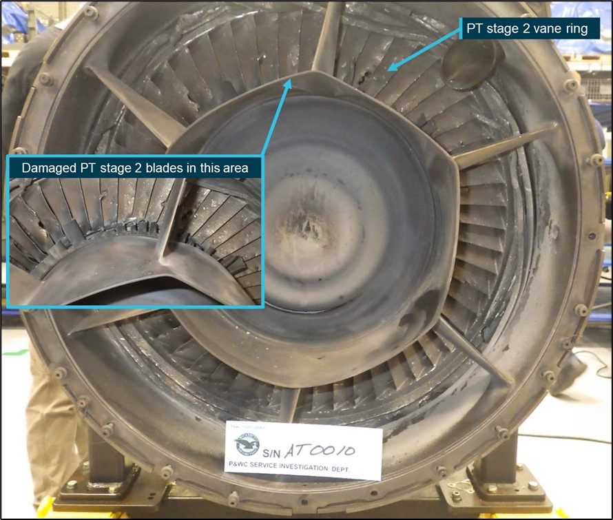
The right engine was subsequently removed from the aircraft with an external inspection revealing that all of the second-stage power turbine (PT) blades had separated from the disk (Figure 1). The PT assembly could not be rotated but the propeller shaft turned freely.
Figure 1: Rear-view of engine showing second-stage PT damage
The aircraft, registered VH-ZZE (ZZE), formed part of the operator’s fleet of 10 DHC-8 aircraft, which provided aerial surveillance operations for the Australian Border Force. Some of the aircraft began these operations in 1996 and all were fitted with Pratt & Whitney Canada (P&WC) PW100 series engines.
Operating environment
These aircraft were used for maritime surveillance activities, which required extensive flying at low level over the sea. The elevated moisture and salt content in the air at those levels created a corrosive operating environment. The fleet accumulated approximately 15,000 hours per year, with all aircraft and engines being exposed to a marine environment for a similar amount of time.
According to P&WC, there are other PW100 series operators within the global fleet that also conducted maritime surveillance activities.
Aircraft and engine information
The aircraft was a Bombardier DHC-8-315, manufactured in 2007 and operated by Surveillance Australia since March 2008. The aircraft was fitted with two P&WC PW123E turboprop engines, which form part of the PW100 series engine family.
The PW123E engine has a compressor comprising a low pressure (LP) and a high-pressure centrifugal impeller, each driven by an independent axial turbine. In addition, there is a reverse flow annular combustor and a two-stage power turbine (PT) that provides the drive for the reduction gearbox and propeller shaft. At the time of the incident, the right engine, serial number AT0010, had accumulated 25,801.51 hours in service and 12,254.21 hours since its last overhaul.
Engine examination
The damaged engine was transported to a P&WC maintenance facility in Canada for a detailed technical examination, supervised by the Transportation Safety Board of Canada. The following is a summary of the examination’s findings.
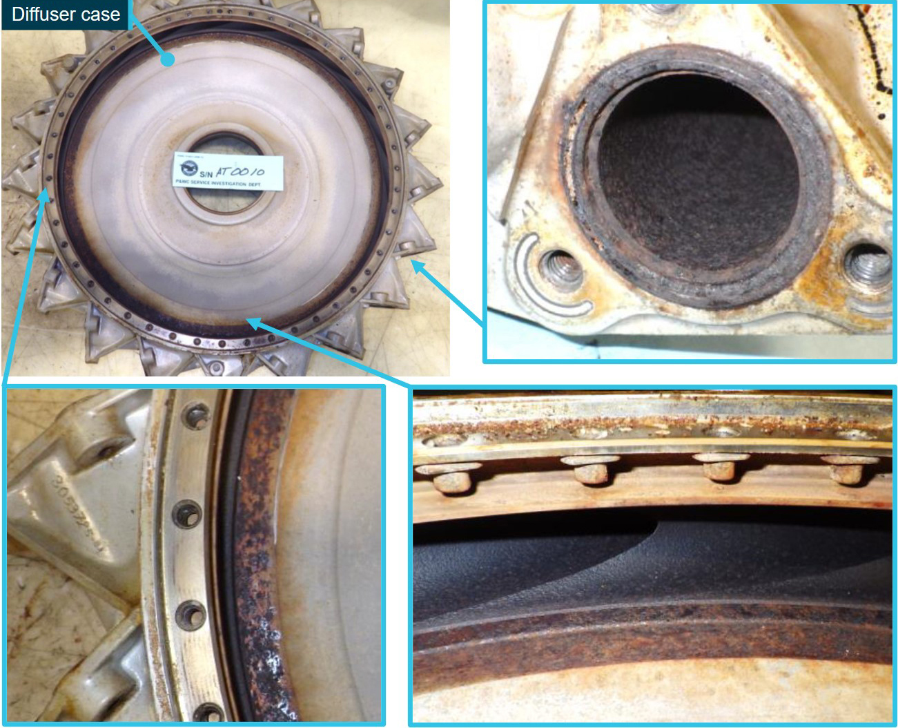
Visual examination of the diffuser case, which contained the LP centrifugal impeller, showed corrosion at several locations (Figure 2). The LP impeller blades showed leading edge erosion.
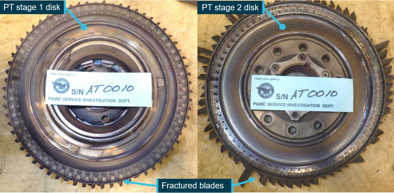
All PT stage 1 and stage 2 blades had fractured through tensile overload (Figure 3).
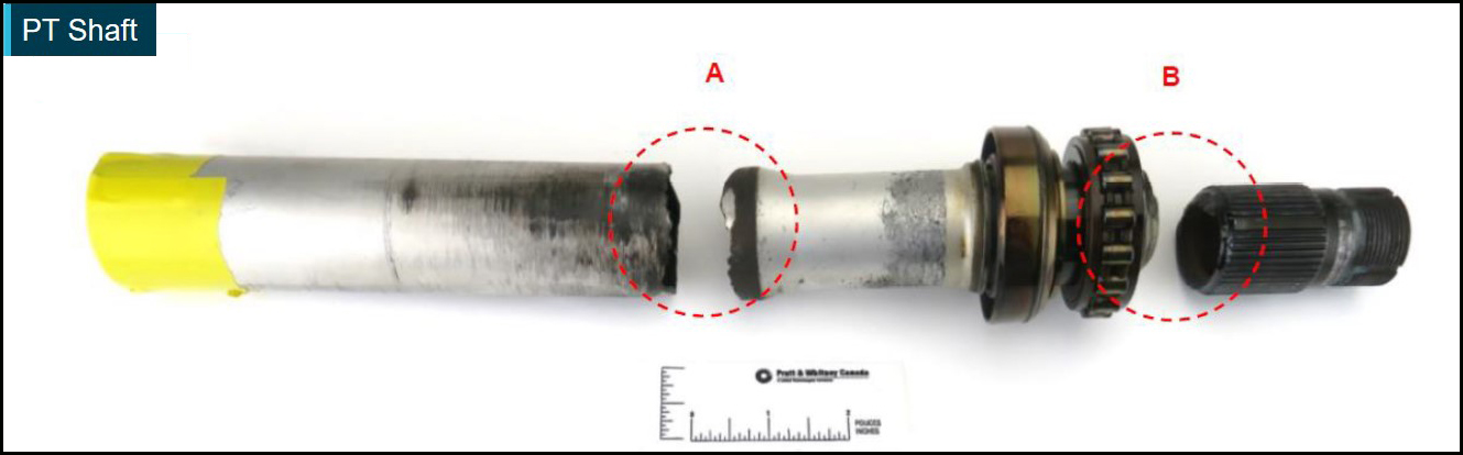
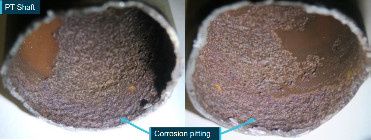
The PT shaft (serial number A0030D9A) had fractured in two locations, referred to as surface ‘A’ and ‘B’ (Figure 4). Visual examination of the inner diameter next to surface A indicated corrosion pitting (Figure 5).
No. 6 and No. 7 bearing oil transfer tubes had evidence of impact damage, and the vent transfer tube was fractured.
The turbine interstage baffle was found buckled.
The LP turbine disk assembly showed rubbing and cracks at the blade tips.
The PT stator and vane ring exhibited impact damage.
The exhaust case was deformed.
Figure 2: Diffuser case showing areas of corrosion
Source: P&WC, annotated by ATSB
Figure 3: Power turbine disk assemblies with all blades fractured
Source: P&WC, annotated by ATSB
Figure 4: Fractured PT shaft
Circled locations A and B refer to the two different fracture surfaces. Source: P&WC
Figure 5: Corrosion pitting of PT shaft internal diameter next to fracture surface A
Source: P&WC, annotated by ATSB
Metallurgical analysis
Following the engine examination, P&WC conducted a metallurgical analysis on the PT shaft which found that:
Fatigue cracks had initiated from corrosion pits on fracture surface A. Due to the corrosion, the material thickness was 25 per cent below the minimum thickness requirement.
The base material (steel alloy) and its hardness were consistent with the design specification.
The corroded layer near the fracture origin showed the presence of sodium, phosphorus, sulphur, and chlorine.
Fracture surface B showed evidence of bending (as opposed to torsional) overload fracture.
The analysis concluded that the PT shaft had fractured from fatigue cracking, which initiated at the internal corrosion pitting at surface A. The fracture of the shaft at surface B was considered secondary. After the shaft fractured, the PT stage 1 and stage 2 disks moved backwards. The stage 1 disk subsequently went into an overspeed condition, which caused the blades to fracture by tensile overload near each blade platform as designed.[4] The stage 2 disk contacted the exhaust duct, resulting in the blades fracturing through tensile overload, at various heights above the blade platforms, from impact and overspeed.
The damage to the bearing oil transfer tubes, turbine interstage baffle, PT stator, PT vane ring, exhaust case and LP turbine disk assembly were consistent with secondary damage due to the PT shaft fracture. According to P&WC, the LP impeller leading edge erosion, diffuser corrosion and PT shaft corrosion was due the engine’s operational environment.
Power turbine air system and corrosion protection
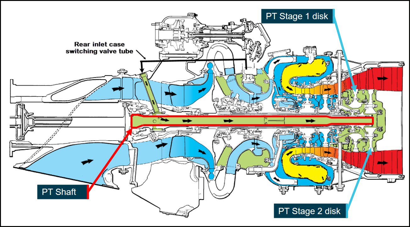
During normal engine operation, some of the air flowing through the compressor is delivered to the inside of the PT shaft via internal and external tubes. This air is used to seal bearings and cool the PT stage 1 and stage 2 disks (Figure 6).
Figure 6: PW100 series air system
The black arrows show the direction of air flow. The green colour denotes PT shaft related air flow. Source: P&WC, annotated by ATSB
Internal corrosion resistance is provided by an aluminium coating applied to the inside of the shaft during manufacture. P&WC stated that during the metallurgical analysis, it was not possible to evaluate the coating near the surface fractures. However, there were no other indications, such as delamination, which would suggest the coating had been incorrectly applied. P&WC also indicated that based on in-service experience, the aluminium coating had historically provided good corrosion protection.
Engine washes
P&WC advised that engine desalination washes,[5] which are commonly used to clean and remove corrosive contaminants from the compressor and turbine sections, are not intended to perform a similar function for the PT shaft. As the shaft is part of the air system, water and washing fluid can enter the shaft during an engine wash, but not for the purpose of cleaning or removing contaminants. Any residual fluid inside the shaft is expected to evaporate when a post-wash engine run is performed in accordance with the engine maintenance manual (EMM). At the time of the occurrence, there were no maintenance procedures to clean the internal surface of the PT shaft.
Power turbine shaft maintenance
The PT shaft did not have an operational service life and was maintained ‘on condition’. It was subject to maintenance at each overhaul which included cleaning, inspections and, if applicable, repairs.[6] The aluminium coating was removed as part of the cleaning process and then re-applied after inspection or after any repairs. Any corrosion on the shaft (if observed) was evaluated against the repair limits. If within limits, the shaft was repaired, otherwise it was replaced.
The time between overhaul (TBO) depended on whether the operator’s engine maintenance regime was hard-time or soft-time (on‑condition). Engines maintained on hard-time maintenance were overhauled every 8,000 hours. Engines maintained on‑condition, using P&WC’s on‑condition Maintenance Program (OCP), were overhauled based on the condition of the engine, which could extend the TBO beyond 8,000 hours. To be eligible for the OCP, an operator was required to conduct additional inspections and checks between overhauls, but there were no additional tasks required for the PT shaft. The operator was utilising an OCP for its DHC-8 engine fleet.
Engine maintenance history and management of findings
Engine AT0010 was manufactured in 2000 and was fitted to various other DHC-8 aircraft in the operator’s aerial surveillance fleet throughout its life. The original PT shaft (serial number A000547M) was removed for the engine’s first overhaul at 13,547.3 hours in March 2011 due to ‘deep corrosion pitting’ on the inner diameter of the shaft, beyond the repair limits. Corrosion was also observed on various components throughout the engine’s gas path. The shaft was replaced with the subject PT shaft (serial number A0030D9A) that was new from manufacture, which then accumulated 12,254.21 hours in service before fracturing.
The operator advised that post wash engine runs were being performed on its DHC-8 fleet after every engine wash in accordance with the EMM. In addition, engine AT0010 had not experienced any extended periods of inactivity, so had not undergone any preservation[7] since its last overhaul.
P&WC managed in-service findings by categorising them into one of five categories. This process was to ensure the communication of in-service findings which had affected, or had the potential to affect, flight safety or aircraft availability. Category 5 (CAT 5) was introduced in 2018 and covered unusual or unexpected findings discovered by maintenance organisation’s during scheduled engine maintenance.[8] It was intended to provide P&WC with visibility of potential warning signs that might need assessment.
P&WC stated that the reporting process at the time of the engine’s first overhaul in 2011 was informal and relied primarily on the maintenance organisation’s judgement of what constituted an unusual finding worth reporting. Historical P&WC records indicated that the P&WC overhaul facility did not raise the PT shaft corrosion finding during the engine’s first overhaul. Although the introduction of the CAT 5 process provided procedural guidance for maintenance organisations to raise unusual findings, P&WC further stated that engineering judgement, rather than specific criteria, would still be exercised when raising a CAT 5.
Other occurrences
P&WC advised that this PT shaft fracture was the first confirmed to have occurred due to corrosion. P&WC had previously received images of a similar looking fracture, but the parts were not in a condition that allowed for detailed examination. Therefore, the cause of that fracture could not be determined.
Since this occurrence, corrosion on the inside of a PT shaft was discovered during a hot section inspection (HSI)[9] of another engine in the operator’s DHC-8 fleet. While a PT shaft inspection is not normally carried out during an HSI, P&WC elected to conduct an unscheduled visual inspection of the shaft as a result of this occurrence. The shaft was subsequently sent to its maintenance facility in Canada for further analysis.
Examination of the power turbine (PT) shaft by the engine manufacturer, Pratt & Whitney Canada (P&WC), identified conclusively that it fractured due to fatigue cracking that originated from corrosion pitting. Excluding the low pressure impeller leading edge erosion and diffuser corrosion, the observed damage to other engine components, including the second PT shaft fracture location, was consistent with secondary damage due to the initial fatigue fracture.
Although the gas core of the engine continued to operate after the PT shaft fracture, no power could be transmitted to turn the section of the PT shaft still connected to the gearbox and propeller. As a result, no engine power was available, and the crew shut down the engine.
Power turbine shaft corrosion
The corrosion products identified at the PT shaft fracture origin indicated that the corrosion was probably caused by salt-laden air. Since air from the compressor entered the PT shaft during normal engine operation, corrosion causing contaminants (for example, salt) and moisture within the ambient air probably built up on the inside of the shaft, allowing corrosion to occur.
The engine had been operated at low altitude over the sea throughout its life, with PT shaft and air system corrosion evident at its first overhaul and subsequent engine examination. These observations supported P&WC’s conclusion that the PT shaft corrosion was caused by the engine’s operational environment.
As a result of the operator utilising an engine on-condition maintenance program, the engine operated significantly beyond the hard-time overhaul of 8,000 hours, with no additional maintenance of the PT shaft. Coupled with the absence of a cleaning process to remove contaminants from the shaft during inactivity, meant an increased operational time and calendar time between PT shaft inspections, both of which probably contributed to corrosion formation and growth.
Since post wash engine runs were being performed and the engine had not undergone any preservation, it was unlikely that any fluid or moisture would have remained in contact with the shaft surface for any extended period while the engine was inactive. There were also no indications that the shaft’s protective aluminium coating had been incorrectly applied. Therefore, it was unlikely that any of these factors contributed to the observed PT shaft corrosion.
Corrosion management
The information obtained by the ATSB during this investigation indicated three instances of corrosion forming within the PT shaft of PW100 series engines that grew undetected between the scheduled overhaul inspections. All three occurred within the operator’s engine fleet which have been used primarily in a marine environment, with one resulting in a fracture of the shaft.
The PT shaft fracture due to marine environment exposure demonstrated that the existing protective coating and maintenance requirements were not sufficient to prevent progression to corrosion‑related fatigue fracture. Although corrosion pitting may not always lead to a fracture before overhaul, it provides sites for fatigue crack initiation, presenting an increased risk of premature fatigue fracture.
Given the power turbine shaft design and function is the same across all PW100 series engines, and there are other PW100 series operators conducting maritime surveillance activities, there is potential for this risk exposure to extend to other operators within the global fleet.
While P&WC indicated that based on its experience the PT shaft coating provided good corrosion protection, corrosion pitting outside of repair limits might not necessarily have been reported by maintenance organisations during overhaul. Reporting such findings was probably less likely prior to the introduction of the additional guidance through the CAT 5 process in 2018. Therefore, P&WC may have had limited visibility on engines exposed to an increased risk of PT shaft corrosion.
Although engine AT0010 exhibited ‘deep corrosion pitting’ of the PT shaft outside of repair limits at the engine’s first overhaul, the finding was not escalated by the maintenance organisation to P&WC for further assessment, possibly due to the informal reporting process in place at the time. Additionally, it does not appear that the location, extent, size, and depth of the corrosion was recorded. Furthermore, there was no recorded information available regarding an assessment of the finding. Therefore, there was insufficient information to determine whether that specific finding should or should not have been escalated.
Nevertheless, the circumstances of this occurrence illustrate the importance of specific guidance and criteria on how to assess corrosion. In this instance, this would probably have provided P&WC with greater visibility of engines in the global fleet that are exposed to an increased risk of corrosion-related failure.
Findings
ATSB investigation report findings focus on safety factors (that is, events and conditions that increase risk). Safety factors include ‘contributing factors’ and ‘other factors that increased risk’ (that is, factors that did not meet the definition of a contributing factor for this occurrence but were still considered important to include in the report for the purpose of increasing awareness and enhancing safety). In addition ‘other findings’ may be included to provide important information about topics other than safety factors.
Safety issues are highlighted in bold to emphasise their importance. A safety issue is a safety factor that (a) can reasonably be regarded as having the potential to adversely affect the safety of future operations, and (b) is a characteristic of an organisation or a system, rather than a characteristic of a specific individual, or characteristic of an operating environment at a specific point in time.
These findings should not be read as apportioning blame or liability to any particular organisation or individual.
From the evidence available, the following findings are made with respect to the engine failure during take-off involving a Bombardier Dash 8, registered VH-ZZE, which occurred at Darwin Airport, Northern Territory, on 11 November 2019.
Contributing factors
The power turbine shaft of the aircraft’s right engine fractured due to fatigue cracking, resulting in secondary damage and engine failure.
The fatigue cracking in the engine’s power turbine shaft initiated at corrosion pitting, which probably resulted from prolonged low‑altitude operation in a marine environment.
The power turbine shaft in Pratt & Whitney Canada PW100 series engines operating in certain marine environments is susceptible to corrosion pitting, which can grow undetected between scheduled inspections. This increases the risk of shaft fracture resulting in engine failure.[Safety issue]
Safety issues and actions
Central to the ATSB’s investigation of transport safety matters is the early identification of safety issues. The ATSB expects relevant organisations will address all safety issues an investigation identifies.
Depending on the level of risk of a safety issue, the extent of corrective action taken by the relevant organisation(s), or the desirability of directing a broad safety message to the aviation industry, the ATSB may issue a formal safety recommendation or safety advisory notice as part of the final report.
All of the directly involved parties were provided with a draft report and invited to provide submissions. As part of that process, each organisation was asked to communicate what safety actions, if any, they had carried out or were planning to carry out in relation to each safety issue relevant to their organisation.
Descriptions of each safety issue, and any associated safety recommendations, are detailed below. Click the link to read the full safety issue description, including the issue status and any safety action/s taken. Safety issues and actions are updated on this website when safety issue owners provide further information concerning the implementation of safety action.
Safety issue description: The power turbine shaft in Pratt & Whitney Canada PW100 series engines operating in certain marine environments is susceptible to corrosion pitting, which can grow undetected between scheduled inspections. This increases the risk of shaft fracture resulting in engine failure.
Sources and submissions
Sources of information
The sources of information during the investigation included the:
aircraft operator (Surveillance Australia)
flight crew
recorded data (CVR and FDR)
engine manufacturer (Pratt & Whitney Canada)
Submissions
Under section 26 of the Transport Safety Investigation Act 2003, the ATSB may provide a draft report, on a confidential basis, to any person whom the ATSB considers appropriate. That section allows a person receiving a draft report to make submissions to the ATSB about the draft report.
A draft of this report was provided to the following directly involved parties:
the flight crew
Cobham Aviation Services
Pratt & Whitney Canada
De Havilland Aircraft of Canada
Transportation Safety Board of Canada
Transport Canada
Civil Aviation Safety Authority
A submission was received from:
Pratt & Whitney Canada
The submission was reviewed and, where considered appropriate, the text of the report was amended accordingly.
Purpose of safety investigations & publishing information
Purpose of safety investigations
The objective of a safety investigation is to enhance transport safety. This is done through:
identifying safety issues and facilitating safety action to address those issues
providing information about occurrences and their associated safety factors to facilitate learning within the transport industry.
It is not a function of the ATSB to apportion blame or provide a means for determining liability. At the same time, an investigation report must include factual material of sufficient weight to support the analysis and findings. At all times the ATSB endeavours to balance the use of material that could imply adverse comment with the need to properly explain what happened, and why, in a fair and unbiased manner. The ATSB does not investigate for the purpose of taking administrative, regulatory or criminal action.
Terminology
An explanation of terminology used in ATSB investigation reports is available here. This includes terms such as occurrence, contributing factor, other factor that increased risk, and safety issue.
Publishing information
Released in accordance with section 25 of the Transport Safety Investigation Act 2003
Ownership of intellectual property rights in this publication
Unless otherwise noted, copyright (and any other intellectual property rights, if any) in this report publication is owned by the Commonwealth of Australia.
Creative Commons licence
With the exception of the Coat of Arms, ATSB logo, and photos and graphics in which a third party holds copyright, this publication is licensed under a Creative Commons Attribution 3.0 Australia licence.
Creative Commons Attribution 3.0 Australia Licence is a standard form licence agreement that allows you to copy, distribute, transmit and adapt this publication provided that you attribute the work.
The ATSB’s preference is that you attribute this publication (and any material sourced from it) using the following wording: Source: Australian Transport Safety Bureau
Copyright in material obtained from other agencies, private individuals or organisations, belongs to those agencies, individuals or organisations. Where you wish to use their material, you will need to contact them directly.
At about 1555 on 26 October 2019, Transperth passenger train service 5077CP travelling from Perth to Armadale stations in Perth, Western Australia arrived on platform two at the Gosnells Railway Station.
As multiple passengers alighted the train and moved along the platform toward the exit gate, a young male child separated from his family group. The child walked among the other passengers but wandered toward the edge of the platform and the side of the stationary railcar.
Around the same time, the driver of 5077CP was preparing to depart the train from the platform. The driver viewed the Driver Assist Video monitor located on the driver’s console to check passengers had completed boarding/alighting the train and were clear before commencing the processes to close the doors.
As the doors were closing, the child crossed the painted safety line and continued to approach the edge of the platform before turning and looking back toward his family group. He stumbled against the side of the third railcar adjacent to its rear door and accidentally stepped off the edge of the platform coping, falling between the railcar and platform to the track formation below.
Nearby persons on the platform and the child’s family members responded almost immediately raising an alarm while attempting to retrieve the child. As train 5077CP commenced to move, a passenger in the third railcar responded to the persons on the platform and contacted the driver via the emergency passenger intercom, calling for the driver to stop.
The train travelled around 12 metres before stopping. After the train stopped, family members lifted the child from the track and onto the platform. Police incident reports indicated the child was uninjured during the fall and retrieval. However, a family member was reported to have sustained injuries and subsequently transported to hospital for treatment.
What the ATSB found
A young male child separated from his family group and wandered close to the platform edge before losing his footing and falling between the platform and adjacent railcar to the track below. The swift reaction by the driver to stop the train in response to an alarm raised by a passenger via the internal emergency intercom system very likely prevented more serious injuries from being received by the young child or other family members.
Safety message
Passengers and other persons present at a railway station platform must observe the markings on its surface that specify the required separation to keep from the platform edge and adjacent track.
The Occurrence
What happened
At about 1555[1] on 26 October 2019, Transperth passenger train service 5077CP[2] travelling from Perth to Armadale stations in Perth, Western Australia arrived at platform two of the Gosnells Railway Station.
As multiple passengers alighted the train[3] and moved along the platform toward the exit gate, a young male child travelling with his family exited the train from the front door of the third railcar. Shortly after alighting, while family group members stopped to attend to a sibling, the young male child separated from the group. The child walked among the other passengers but wandered toward the edge of the platform and the side of the stationary railcar.
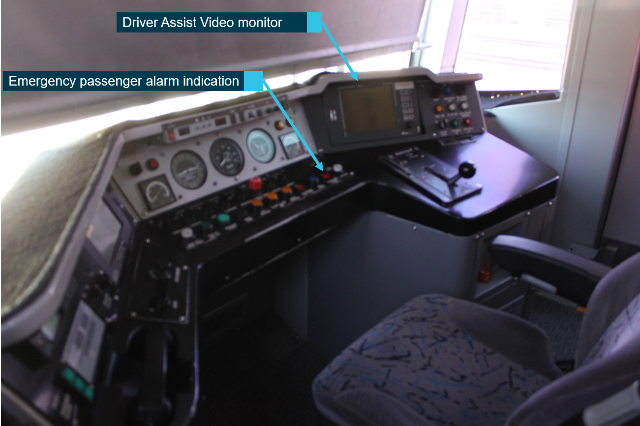
Around the same time, the driver of 5077CP[4] was preparing to depart the train from the platform. The driver viewed the Driver Assist Video (DAV) monitor located on the driver’s console (Figure 1) to check passengers had completed boarding/alighting the train. The DAV displayed vision from a CCTV camera[5] of the platform and along the side of the train from front to back. The angle of the camera was sufficient to provide drivers a view along the side of the whole train.
Satisfied the doors were clear, the driver then operated the controls to commence the sequence of processes to close the doors. The driver’s attention then focused toward checking the indication displayed on the trackside signal #453 and the status of the Dorothy Street level crossing ahead.
Figure 1: View of driver’s panel
Source: ATSB
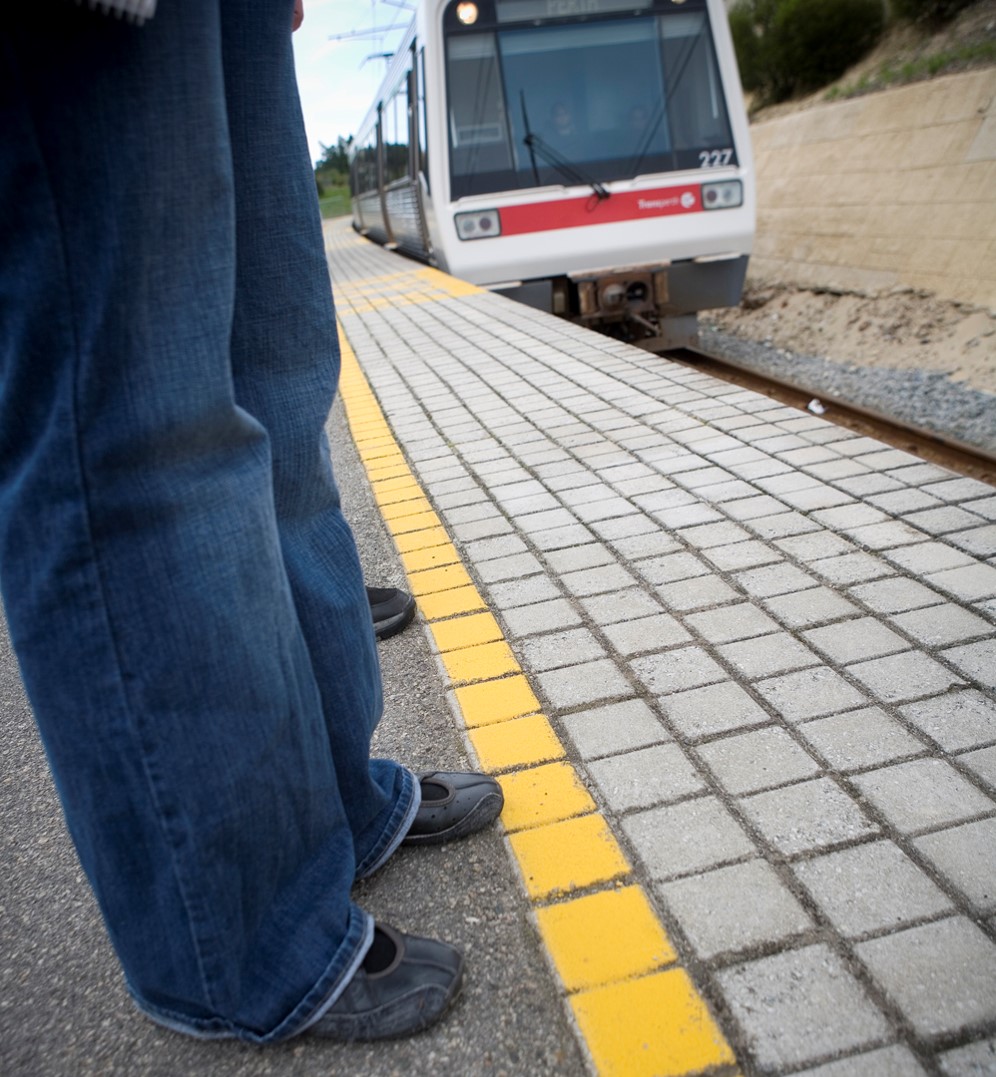
There were still numerous passengers across the width of the platform walking toward the station exit adjacent to the last (fourth) railcar. As the doors were closing, the child crossed the painted safety line (Figure 2) and continued to approach the edge of the platform before turning and looking back toward his family group. He stumbled against the side of the third railcar adjacent to its rear door and accidentally stepped off the edge of the platform coping, falling between the railcar and platform to the track formation below. Nearby persons on the platform and the child’s family members responded almost immediately raising an alarm to passengers on-board the train or reaching down between the platform and railcar trying to retrieve the child.[6]
Figure 2: Typical platform showing painted safety line
Source: Transperth ‘Get on Board’ safety education program.
As train 5077CP commenced to move, a passenger in the third railcar responded to the persons on the platform and contacted the driver via the emergency passenger intercom, calling for the driver to stop. The driver, unaware of the reason for the emergency call,[7] reacted swiftly, applying full service braking to stop the train.
The train travelled around 12 metres before stopping. During the movement of the train, a family member of the child sustained injuries either from contact with the side of the railcar or the platform edge. After the train stopped, family members lifted the child from the track and onto the platform. Police incident reports indicated the child was uninjured during the fall and retrieval.
Emergency services attended Gosnells Station. An ambulance transported the injured family member to hospital for assessment/treatment. Another family member took the young child to hospital. Following clearance from WA Police and train control, train 5077CP departed Gosnells Station for Armadale at about 16:12. Transperth relieved the train crew from duty at Claisebrook Station to conduct follow-up enquiries.
Findings
These findings should not be read as apportioning blame or liability to any particular organisation or individual.
A young child separated from his family group and wandered close to the platform edge before losing footing and falling between the platform and adjacent railcar.
The swift reaction by the driver to stop the train in response to an alarm raised by a passenger via the internal emergency intercom system very likely prevented more serious injuries from being received by the young child or other family members.
Purpose of safety investigations
The objective of a safety investigation is to enhance transport safety. This is done through:
identifying safety issues and facilitating safety action to address those issues
providing information about occurrences and their associated safety factors to facilitate learning within the transport industry.
It is not a function of the ATSB to apportion blame or provide a means for determining liability. At the same time, an investigation report must include factual material of sufficient weight to support the analysis and findings. At all times the ATSB endeavours to balance the use of material that could imply adverse comment with the need to properly explain what happened, and why, in a fair and unbiased manner. The ATSB does not investigate for the purpose of taking administrative, regulatory or criminal action.
Terminology
An explanation of terminology used in ATSB investigation reports is available here. This includes terms such as occurrence, contributing factor, other factor that increased risk, and safety issue.
Publishing information
Released in accordance with section 25 of the Transport Safety Investigation Act 2003
Ownership of intellectual property rights in this publication
Unless otherwise noted, copyright (and any other intellectual property rights, if any) in this report publication is owned by the Commonwealth of Australia.
Creative Commons licence
With the exception of the Coat of Arms, ATSB logo, and photos and graphics in which a third party holds copyright, this publication is licensed under a Creative Commons Attribution 3.0 Australia licence.
Creative Commons Attribution 3.0 Australia Licence is a standard form licence agreement that allows you to copy, distribute, transmit and adapt this publication provided that you attribute the work.
The ATSB’s preference is that you attribute this publication (and any material sourced from it) using the following wording: Source: Australian Transport Safety Bureau
Copyright in material obtained from other agencies, private individuals or organisations, belongs to those agencies, individuals or organisations. Where you wish to use their material, you will need to contact them directly.
Section 21 (2) of the Transport Safety Investigation Act 2003 (TSI Act) empowers the ATSB to discontinue an investigation into a transport safety matter at any time. Section 21 (3) of the TSI Act requires the ATSB to publish a statement setting out the reasons for discontinuing an investigation. The statement is published as a report in accordance with section 25 of the TSI Act, capturing information from the investigation up to the time of discontinuance.
Overview of the investigation
During an approach to Sydney Airport’s runway 16L on 16 October 2019, VH-VNR, a Tiger Airways A320, was at a speed in excess of that required for that particular phase of the approach. The pilot in command (PIC), performing the pilot monitoring (PM) role, instructed the pilot flying (PF)[1] to correct the speed and configure the aircraft for landing, however, the required corrections did not occur. As a result, the PIC took control of the aircraft, extended the speed brake to reduce the airspeed and configured the aircraft for landing.
During that configuration, at an altitude of about 1,300 ft, the speed brake was extended while the aircraft was in the landing configuration. This resulted in an EGPWS SPEED[2] alert. The configuration was corrected and the approach was stable by 1,000 ft. The PIC returned control of the aircraft to the PF, and the aircraft completed a stable approach and a safe landing.
On 22 October 2019, the ATSB commenced an investigation into the occurrence. As part of its investigation, the ATSB:
interviewed the flight crew
examined digital flight data and flight crew training records
analysed fatigue related data
reviewed the operator’s policy and procedural requirements and the recent occurrence data.
The ATSB determined that the two flight crew system operated as designed, detecting the incorrect approach conditions and correcting those conditions in sufficient time to enable a stable approach. A human factors review of the flight crew’s conduct and a fatigue assessment and examination of the flight crew’s training and the operator’s response to the occurrence, did not identify any factors that justified further investigation.
ATSB comment
Based on a review of the available evidence, the ATSB considered it was unlikely that further investigation would identify any systemic safety issues. Consequently, the ATSB has discontinued this investigation.
The evidence collected during this investigation remains available to be used in future investigations or safety studies. The ATSB will also monitor for any similar occurrences that may indicate a need to undertake a further safety investigation.
Finally, the ATSB briefed Tiger Airways about some of its observations and potential learnings. However, it considered that broader communication of this information would not be of significant benefit to other parties.
This investigation was conducted under the Transport Safety Investigation Act 2003 (Commonwealth) by the Office of Transport Safety Investigations (NSW) on behalf of the Australian Transport Safety Bureau in accordance with the Collaboration Agreement.
Safety summary
What happened
On 15 October 2019, a Protection Officer (PO) arranged with the Westmead panel signaller at Granville signal box to implement protection for work on track by use of Absolute Signal Blocking (ASB).
ASB was authorised and signals GE455 and GE463 were set to stop and blocked to prevent access to the worksite. Train 133U left Parramatta station and the signaller set the route for the train and it passed signal GE463 on the Down West Main line. The train was on a route to travel through 727 points to then travel along the Down West Suburban line.
After passing the signal, the driver encountered three workers on the track in front of the train, two were in the four foot of the Down Main line and another was in the danger zone adjacent to them. The driver sounded the train whistle to alert the workers and they vacated the track and danger zone. The driver also applied the emergency brakes and stopped just near where the workers had been.
What the ATSB found
The investigation found the relief signaller at Granville signal box had mistakenly believed the workers were further away from the location that was provided in the agreed arrangements for ASB. This mistaken belief led to the signal protection for the worksite being removed to allow 133U to run on the Down Main to access 727 points.
The relief signaller and the PO had earlier discussed the need to divert trains around the worksite, but neither correctly comprehended the implications of doing this, that is, the diversion would route a train into the worksite. The relief signaller was possibly experiencing the effects of cumulative fatigue due to rostering issues as well as experiencing a high workload. The rostered signaller at the Granville signal panel was absent from their workstation at the time and the relief signaller was operating both the Granville and Westmead signal panels.
The lack of advance notification to the relief signaller about the intended work, and its consequent impact on train running, meant the relief signaller had to devise an improvised train operations plan with no notice, adding to the pressure of operating two signal panels concurrently.
The Network Rules and Procedures for ASB had very little direction and guidance to workers about how to manage the risk of clearing a protecting signal for an alternative route in order to run a train.
What has been done as a result
After this incident, Sydney Trains temporarily prohibited the practice of signallers being permitted to clear any signals used for ASB protection in order to run trains via an alternative route. Changes to the ASB rule and procedure were implemented in December 2020 to prohibit the clearing of the signal immediately protecting a worksite in order to run a train via an alternative route.
Safety message
Railway safeworking rules are in place to achieve safe rail operations and should be developed so that the desired outcomes are supported by suitable procedures.
Signallers are safety critical workers that perform work vital to the safe performance of the rail network. These workers require supervision and should be subject to suitable management arrangements to ensure compliance to relevant work instructions and requirements.
The occurrence
Overview
At 2245[1] on Tuesday 15 October 2019, a PO called the Westmead panel signaller at Granville signal box to arrange work on track protection for a Sydney Trains civil work group. The work group were intending to perform welded track stability analysis (WTSA) measurements on the Down Main line between Parramatta and Westmead stations.
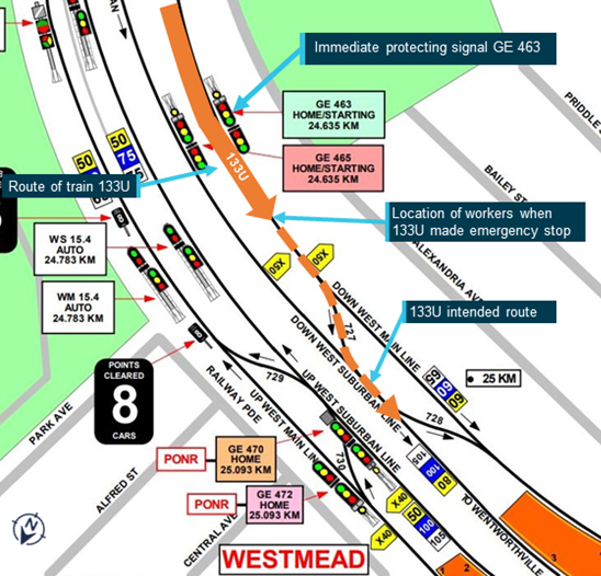
The specific location of the worksite was identified by the PO between absolute signal[2] GE463 and permissive[3] signal M16.1. The location of the workers and the protecting signals used for the protection are depicted on the diagram below, which is based on a map prepared by the PO on their Worksite Protection Plan (Figure 1).
Figure 1: Driver’s Route Knowledge Diagram for Westmead
Source: Sydney Trains annotated by OTSI
The method of work on track protection proposed by the PO was Absolute Signal Blocking (ASB). The PO and the signaller agreed that absolute signals GE455 and GE 463 would be used to protect the worksite, in addition to 728 points being secured in the normal position.
During the conversation between the PO and signaller about the safeworking arrangements, there was discussion about the need to divert rail traffic around the work area. This diversion would require the use of the protecting signals for the alternative route to be able to run rail traffic via 727 points from the Do[4] This was a manoeuvre that was permitted under the Network Rules and Procedures for ASB at the time.
At 2253, the signaller authorised ASB with blocking facilities on signals GE455 and GE463 and 728 points were locked and blocked in the normal position. The workers then made their way to the designated work location at Westmead and commenced work on track under the ASB.
At 2302, the signaller observed run 133U depart Parramatta station and removed the blocking facilities for signals GE455 and GE463 and set the route for the train via 727 points. This movement effectively routed the train into the worksite protected by the ASB.
The driver of run 133U saw the workers on track on the Down Main at approximately 24.700 km and sounded the train whistle. At the same time, other workers outside the rail corridor observed the approach of 133U and shouted a warning of “Train on”. The workers on track quickly vacated the Down Main line to the down cess area. The driver made an emergency brake application and the train stopped just past the location where the workers had been.
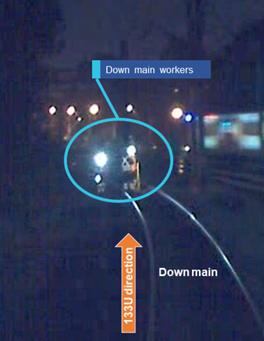
The image at Figure 2 is taken from the CCTV on the front of train 133U and shows the three workers in the Danger Zone as the train approaches 727 points on the Down Main line. It is estimated they were approximately 20-30 m from the front of 133U when this image was recorded.
Figure 2. CCTV image from train 133U
Source: Sydney Trains annotated by OTSI
Post incident
The train driver called the signaller at 2305 to report the incident. The signaller called the PO and the ASB was ended at 2307. The signaller then reported the incident to the Train Service Delivery Manager (TSDM) at the Rail Operations Centre.
A Sydney Trains Incident Rail Commander (IRC) was despatched to the site to investigate the incident. The signaller at Granville signal box was relieved of safeworking duties and stood down pending the investigation. The Protection Officer was also stood down from safeworking duties pending the investigation.
Drug and alcohol testing was conducted on the PO and the signaller with negative results for both.
Sydney Trains administer a suite of safeworking network rules and procedures to safely manage work on track. Absolute Signal Blocking (ASB) is one of several methods to protect work on track in the Sydney Trains network. The rule has been in place since July 2012. The rule was previously known as Controlled Signal Blocking, which was introduced in 2001.
Location
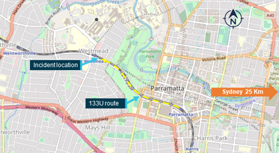
Westmead station is located approximately 25 km west of Sydney Central station on the main western line. Four railway lines run through Westmead, the Up West Main, the Up West Suburban, the Down West Suburban and the Down West Main.
Figure 3: Map of Westmead and surrounds
Source: Geoscience Australia
The work on track
The work being performed by the infrastructure workers was WTSA. This involved the workers taking measurements to detect and correct locations that are vulnerable to misalignment of rails. The location of the work was between signal GE463 at 24.635 km and signal M16.1 at 25.932 km.
The work involved two Sydney Trains Infrastructure workers and a PO from Swetha International Pty Ltd, a labour hire company that provides safeworking services to Sydney Trains.
The train involved
133U was a Waratah 8-car A set, A44. The train was crewed by a driver in the leading power car, and a guard in the rear car. The train was operating on a route from Central to Penrith, departing at 2225 and scheduled to arrive at Penrith at 2347.
No abnormal operation of the train was reported during the journey, and it is therefore not considered a factor in the incident.
Operating environment in Granville signal box
Granville signal box is a two-panel signal box, consisting of the Granville and Westmead signal panels. Each panel is operated by a signaller. A relief signaller is always there to provide coverage when the rostered signaller is on a rostered meal break or comfort break.
The roster for the signallers gives specific acronyms to each signaller on shift. These acronyms will be used within this report.
The rostered signaller for the Granville panel is known as GG, the signaller for the Westmead panel is known as GW, and the relief signaller is known as GT. This stands for Granville Table. The Table signaller is the colloquial name for the relief signaller. The table refers to the spare desk or workstation in the signal box where the GT signaller performs various support functions while not providing relief on the signalling panels.
The system of safeworking for Granville signal box is unidirectional rail vehicle detection. The system is described in the Sydney Trains Network Rule NSY 500 Rail Vehicle Detection.
The signaller
The GT signaller operating the Westmead panel at the time of the incident had 15 years’ experience as a signaller in the Sydney Trains/RailCorp network. The GT signaller had no reported history of involvement in safeworking incidents. The GT signaller had all the necessary certifications in place to fulfil the functions of the role, except they had not attended a mandatory safety course. This course was called ‘Apply safety critical communications in the rail industry’. The GT signaller attended this course two weeks after the Westmead incident.
Fatigue management for signallers
Sydney Trains rostering and fatigue management principles were embedded in the operating practices of the organisation. Managing Shift Work and Rostering was an operating procedure used to manage rostering practices to help reduce the cumulative effects of fatigue on rail safety workers, including signallers.[5]
The protection officer
The PO, employed by Swetha International, was an experienced PO with a 12-year history of safeworking qualifications. The PO had only one safeworking incident recorded in their work history at that time, a relatively minor event of protection being left on the track after a possession. There was no evidence from the rostering and work patterns that the PO was fatigued. Consequently, fatigue of the PO is not considered a factor in this incident.
ASB works on the principle of rail signals being set to stop with blocking facilities applied to exclude rail traffic from the work area. Within the rule there are several options to provide protection, including:
Having two controlled absolute signals set to stop with blocking facilities applied or
Having one controlled absolute signal set to stop with blocking facilities applied and
Removing an ESML/EOL key, or
Securing points to prevent access, or
There being an easily reached safe place available and providing a lookout.
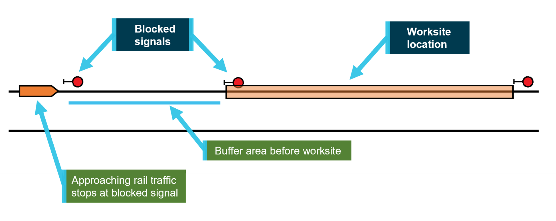
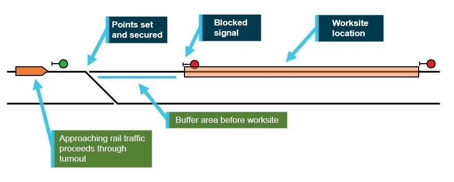
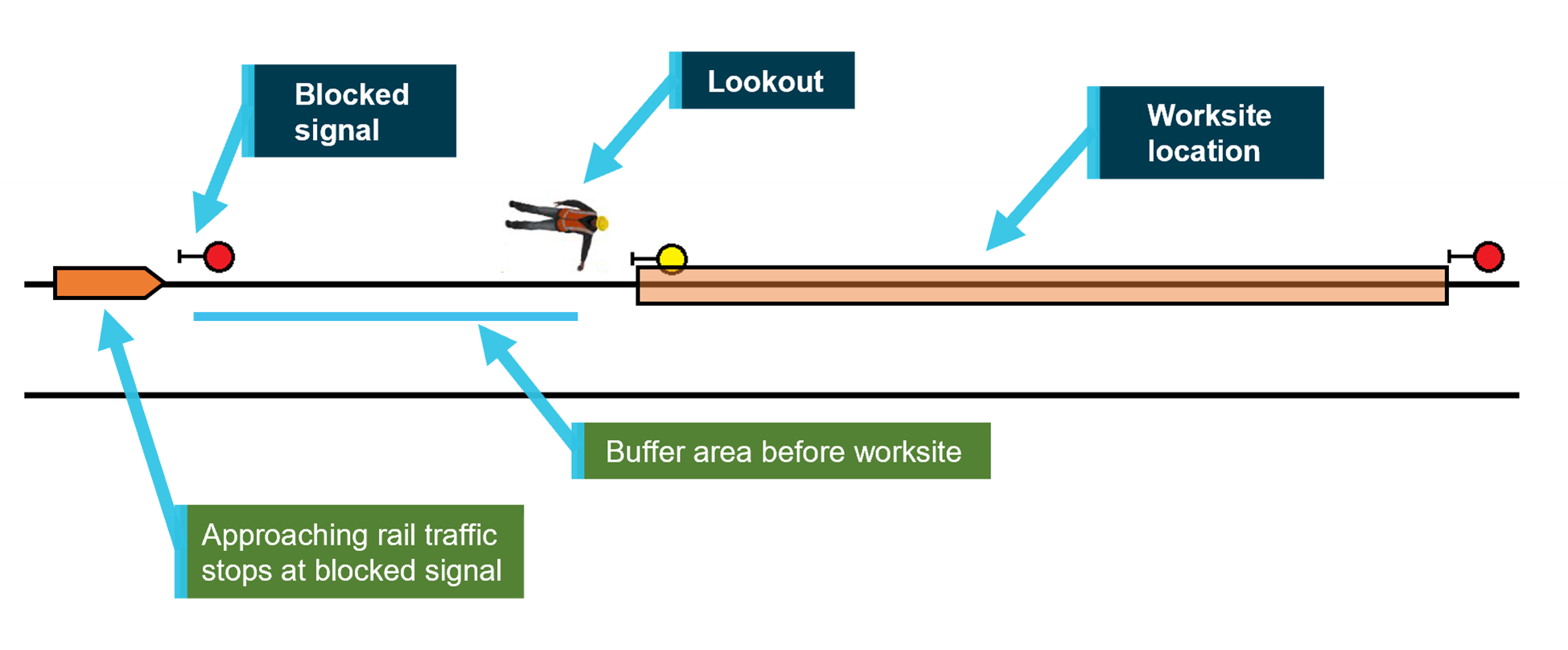
It is important to note that the rules provide two layers of protection. This provides a buffer area so that if a train that inadvertently passes the first blocked signal, it does not immediately enter a worksite location. For example:
Figure 4: ASB – Two consecutive controlled absolute blocked signals
Figure 5: ASB – One controlled absolute blocked signal and points secured
Figure 6: ASB – One controlled absolute blocked signal and Lookout
The ASB rule has the facility to allow the protection to be temporarily suspended in order to run rail traffic through the work area, provided certain assurances are gained. When rail traffic has left the work area, the ASB may be re-established. This facility was not used in relation to the work involved in this incident.
Within the ASB rule, there was also the facility to be able to clear signals being used for ASB protection to run rail traffic on an alternative route. This facility required the PO and the signaller to agree about the movements and make sure the worksite is clear of the alternative route. Other than these brief instructions, there was no other guidance in the rule, procedure, or other material to help make decisions when this facility in the rule was used. Sydney Trains withdrew this facility from the Network Rules on 16 October 2019, the day after the Westmead incident. This was achieved by issuing a temporary amendment document known as a Safe Notice Telegram 2019-1047.
The telegram stated:
‘ABSOLUTE SIGNAL BLOCKING (ASB) UPDATED REQUIREMENTS
Effective from 1800 hours, Wednesday 16 October 2019
In exception to NWT 308: Absolute Signal Blocking, when blocking facilities have been applied to exclude rail traffic from a portion of line, blocking facilities MUST not be removed to allow signals to be cleared for an alternate route. Blocking facilities MUST remain applied while the ASB is in force. These requirements will also apply when blocking facilities are applied to signals that are used to exclude rail traffic from a portion of line in accordance with NTR 432: Protecting activities associated with in service rail traffic.’
In December 2020, Sydney Trains introduced rule and procedure changes for ASB that permanently prohibited the clearing of the signal immediately protecting the worksite for the purpose of running a train on an alternative route.
Protection methods under ASB and their principle of operation
Basic principles of protection
The basic principle of protection under ASB is that a signaller will set and maintain one or more signals at stop to prevent rail traffic from intruding into the work area. This is achieved through a mutual arrangement of understanding between the PO and the signaller about the location of the work, the signals needed to protect the work and the choice of which option is used from the choices available within the rule.
The critical element of the protection measure is that someone remote from the work area is responsible for the function of setting and maintaining the signals at stop. This is what stops a train from entering the work area. For the most part, the workers on the track have no control over the status of the protecting signals – they rely upon the competence, capability and diligence of the signaller to ensure the protection is set and maintained for the duration of the work.
Clearing signals for an alternative route
When the ASB rule permits the same signals providing protection to be cleared in order to run rail traffic through an alternative route, it introduces a potentially conflicting objective that must be carefully managed to avoid the situation that occurred in this incident. The ASB rule, as it was on the 15 October 2019, provided almost no direction for those involved in managing the protection and how to deal with this potentially conflicting objective.
The extract from the rule NWT 308, as it was on 15 October 2019, said the following:
‘If protecting signals need to be cleared for an alternative route, the Protection Officer and the Signaller must agree about the movements and make sure that the worksite is located clear of the alternative route.’
The associated procedure NPR 703 Using Absolute Signal Blocking had no direction or guidance at all about how to manage this activity.
Detecting rail traffic approaching the worksite
Workers on track using ASB are also reliant on a signaller remote from the work area correctly identifying that there is no rail traffic closely approaching the worksite before the protection is approved and workers enter the danger zone.
A worker was fatally injured at Kogarah, NSW, in 2010 when a signaller did not detect the presence of a train between the protecting signals and the worksite in time to warn the workers. After the protection was implemented the workers went on track and the then train entered their worksite, striking and fatally injuring a worker.
The NSW Office of Transport Safety Investigations (OTSI) compiled a report about that fatal incident and the findings included how poor practices relating to signal box management contributed to the accident.
This is an example of the safety of the workers on track being a joint responsibility, including a worker who is remote from the worksite, who has a number of other responsibilities and distractions that can lead to errors, mistakes and omissions from this task.
Alternate methods of protection
Rail systems across the world have adopted technologies and practices that place the protection of the work on track in the hands of those doing the work, and who bear the risk of being struck by a train. This includes;
devices to activate track circuits at the worksite to put protecting signals to stop
switches on signals that allow a worker to set and maintain a signal to stop
automatic train warning systems that detect approaching rail traffic and warn workers to move to a place of safety.
Sydney Trains have projects in place that either are under trial or in implementation phase that seek to introduce technologies that provide greater control for worksite protection.
This program is called the Enterprise Track Worker Safety (ETWS) Program. These projects and trials are currently in various stages of progress and development. Use of protection systems that look to eliminate the human error in areas like miscommunication, distraction or performance are to be encouraged.
A device that activates the track circuit of the protecting signal, or a switch that acts on the signal itself to place it at stop, would likely have prevented this incident, as the activation of this type of protection would be in the control of the Protection Officer with the work group. The Protection Officer was with the work team and would be very unlikely to clear a signal that would knowingly allow a train to enter their own work area.
Operating arrangements at Granville signal box
Rosters and meal breaks
Both panels in the Granville signal box are attended 24 hours a day, 7 days a week by a signaller for the purpose of routing trains through their area of control. A relief signaller is present on all shifts to provide coverage for the two signallers rostered on to the panels. The table signaller provides meal and comfort break relief and administrative support to the operating signallers in the form of processing various operational documents that are circulated daily in the Sydney Trains network.
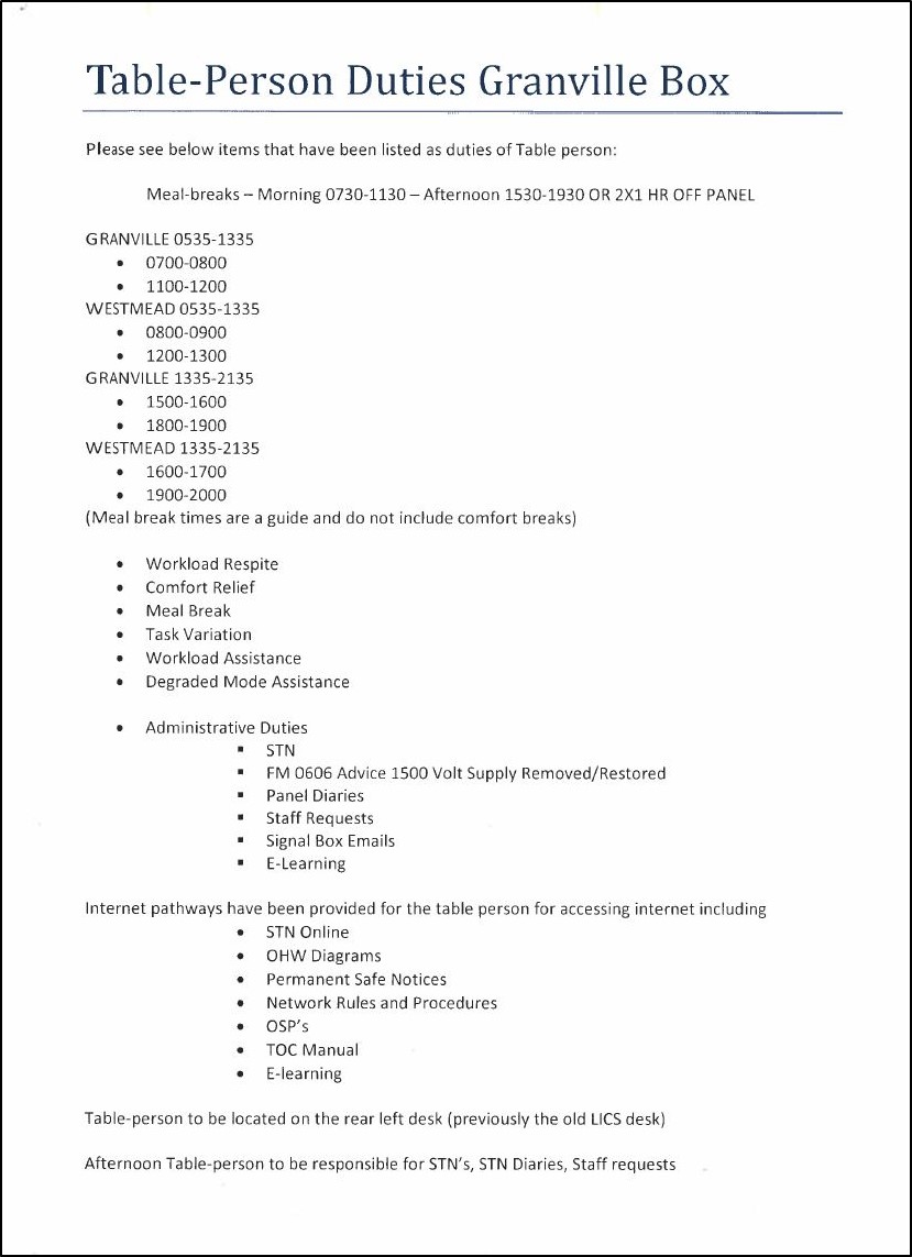
Night shift at Granville signal box runs from 2135 each night to 0535 the following morning. The arrangements for staffing the panels are contained in a document called ‘Table person duties Granville Box’. The document is not published anywhere within the Sydney Trains electronic document management system. It is in hard copy only.
The document is not signed, approved or authorised by any Sydney Trains line management and has no document control or numbering, however it did have currency with the signallers in relation to the operating arrangements.
The document indicates that each signaller has two one-hour meal breaks per eight hour shift on day and afternoon shift. This document does not address the meal break and coverage arrangements for night shift. The document only shows meal breaks and panel coverage for day and afternoon shifts.
Figure 7 – Table Person Duties Granville Box
Source: Sydney Trains
The signallers at Granville signal box therefore had no guidance, direction or other instruction about how and when meal breaks should be taken on night shift or how and when coverage for the signalling panel should be arranged. It was essentially a self-managed function.
On the night of the incident, the GW signaller started work on night shift at 2135 and immediately went on a two-hour meal break. The signaller GT was then required to work on the Westmead panel from the start of the shift to provide a two-hour meal break relief for signaller GW.
At interview, the Sydney Trains line manager advised that it was not normal practice for signallers to commence their shift and immediately have a two-hour meal break. The Sydney Trains line manager advised at interview that two-hour paid meal breaks are not the common practice for Sydney Trains signallers, however this is what occurred on the night of the incident.
Supervision and work arrangements in Granville signal box
At around 2200 hours the signaller GG, rostered to be working the Granville panel, decided they would leave the panel and sit at the desk at the back of the signal box normally reserved for the GT, or table person.
The signaller GG did some of the work normally done by the table signaller, including processing Special Train Notices. The signaller GG also marked some training papers that they attended to as part of their role as a signaller trainer. Signaller GG left the control room at around 2300 to go to the meal room to prepare some food, leaving signaller GT alone in the control room.
This meant the GT signaller was managing both signalling panels for over one hour prior to the ASB incident at Westmead, and for a period of around ten minutes was the only person in the control room out of a team of three. The GT signaller is recorded as answering operational calls for both panels until the incident happened at 2304.
The role and responsibilities of signallers are documented in Network Rule NGE 234 Responsibilities of Signallers.
These responsibilities include:
Safe operation of signalling equipment
Responding to signalling faults, failures and warning alarms
Authorising and issuing procced authorities, work on track authorities and methods
Obtaining authority from the Sydney Trains Rail Operations Centre (ROC) to operate unscheduled rail traffic like defective trains, trains being worked out of service, empty trains being relocated and light engine movements
Dealing with train delays and incidents.
The signallers roles are full time rail safety workers and the signalling panels are attended 24 hours a day, including on night shift. There is still rail traffic at night, including late night passenger and freight trains, and there is normally maintenance activity conducted at night. This warrants the full time attendance of signallers on both signal panels with rostered relief.
No explanation was offered by Sydney Trains for the unapproved absence of signaller GG. At interview, the Sydney Trains line manager considered the act of a signaller leaving their post without normal relief a code of conduct issue. There was no indication this matter was addressed as such.
Sydney Trains have a procedure that generally manages signal box operations, ‘Signal box management procedure’.[6] The procedure was originally issued in 2015.
The procedure covers generic issues including:
Responsibilities of signallers
Operation of signalling equipment
Communication and supervision
Administration and safety equipment.
The signal box management procedure does not have a recognised document number to indicate it is part of the Sydney Trains document management system. The procedure is shown as managed by the Compliance Standards Manager and approved by the Network Operations Manager.
The procedure does not mention how internal operational coverage is managed at individual signal boxes. It does not mention meal breaks or the role of relief signallers during their shift. Given the absence of any direction in this procedure, and the unauthorised nature of the Granville signal box document, Sydney Trains did not address this important aspect of network operations within their established management system.
Fatigue management for signallers
This Sydney Trains rostering and fatigue procedure included eight rostering principles to be observed in order to reduce or manage the cumulative effects of fatigue. These eight rostering principles, and a description of these principles, are reproduced below from the Sydney Trains procedure:
Principle
Description
Acclimatisation
Workers new to shift work and those returning after an extended period of annual or sick leave should not be rostered on night work or an early morning start for their first shift. When on leave, human circadian rhythms quickly re-establish a pattern of sleeping at night and being active during the day. Returning to night or early morning starts may be difficult, a bit like ‘Mondayitis’.
Shift length
The length of a shift should not exceed 12 hours including overtime, especially if it involves a night shift. Human performance declines significantly when people have been working for 12 hours or more, especially where work is done at night or in the early morning.
Total hours worked
Aim for no more than 48 hours per week including overtime, which can be averaged across the roster cycle. The risk of fatigue increases towards the end of a week/roster cycle. This is because a sleep debt has accumulated. Limiting the number of hours worked in a week or roster cycle, provides time off to recover and repay the sleep debt.
Limit night shifts and early morning starts
Aim for no more than: • four consecutive shifts where 12 hour shifts are worked • five consecutive shifts where 10 hour shifts are worked • six consecutive shifts where 8 hour shifts are worked. Working a series of night/early morning shifts disrupts circadian rhythms and leads to accumulation of a sleep debt.
Break during a shift
Schedule frequent breaks especially during a night shift or if the work involves sustained mental or physical activity, if local arrangements allow. Breaks during a shift provide workers with an opportunity to rehydrate and get a short rest. Breaks during a shift may be rostered or managed informally, depending on local arrangements and the nature of the work.
Break between shifts
Aim for at least 12 hours from the end of a shift and the start of the next shift. Industrial agreements may allow for less than 12 hours, however, to reduce the risk of fatigue, a minimum of 12 hours break is needed. Breaks between shifts need to allow enough time for recovery and sleep. Night shifts may need longer breaks between shifts. This is because workers will need to sleep during the day when it is difficult to get good quality sleep
Breaks between cycles
Make sure there are adequate breaks between shift cycles. For example: • Two days off in a 7 day shift cycle • Four days off in a 14 day shift cycle • Eight days off in a 28 day shift cycle. Days off should be a minimum of two consecutive days. Evidence indicates shift workers need at least two consecutive nights sleep per week to enable them to report to work feeling refreshed.
Shift cycles
Schedule consistent start times where possible, or if rotating rosters are used, shift start times should move in a forward rotation i.e. morning-afternoon-night. Consistent start times can help shift workers get into a routine. Where rotating rosters are used, there is evidence that a forward rotating roster allows shift workers to delay sleep and wake up later. This is easier to do than going to sleep earlier or waking up earlier.
The planned, or master, roster and shifts actually worked for the period from 6 – 19 October 2019 for signaller GT is included in the table below.
Date
Planned shift times
Actual shift times
Hours worked
Time until next shifts
6 October 2019
1335 – 2135
1335 – 2135
8
48 hrs
7 October 2019
0000 – 0000
0000 – 0000
0
8 October 2019
1335 – 2135
2135 – 0535
8
16 hrs
9 October 2019
1335 – 2135
2135 – 0535
8
16 hrs
10 October 2019
1335 – 2135
2135 – 0535
8
8 hrs
11 October 2019
1335 – 2135
1335 – 1735 (half shift)
4
20 hrs
12 October 2019
2135 – 0535
2135 – 0535
8
16 hrs
13 October 2019
2135 – 0535
2135 – 0535
8
16 hrs
14 October 2019
2135 – 0535
2135 – 05:35
8
16 hrs
15 October 2019
2135 – 0535
2135 – 0535 (incident 2303)
8
Off roster post incident
Five of the eight rostering principles were not met in relation to the roster of signaller GT in the eight days leading up to the incident. The five principles, and the nature of the departure from these principles, are outlined below.
Rostering principle
Departure from principle during this incident
Limit night shifts and early morning starts
From the 8 October to 15 October 2019, the signaller was rostered for eight consecutive shifts, seven of which were night shifts.
Break during a shift
One continuous shift break was rostered for the shift
Break between shifts
11 October 2019 there was a break of eight hours between shifts
Breaks between cycles
7 October 2019 was a single book off shift
Shift cycles
11 October 2019 backwards rotation of eight hours
According to the Managing Shift Work and Rostering procedure, when departures from these rostering principles occur, line managers must intervene and put in place measures to try and correct the situation. The line manager for signaller GT was unaware of the departure from these rostering principles, and therefore did not put measures in place as required by the procedure. The line manager for GT had not undertaken the mandatory training course ‘Fatigue Management for Managers’.
Sydney Trains acknowledged in their internal investigation report that the requirements for the procedure Managing Shift Work and Rostering were not being followed. Sydney Trains adopted a recommendation from their internal report as follows:
‘Review why the requirements of SMS-08-OP-3128 Managing Shift Work and Rostering, in relation to the diverting from Rostering Principles, are not being followed and determine appropriate corrective actions. In particular: · the process for identifying and managing exceptions to the rostering principles with day to day operations (recording exceptions and capturing controls that are identified as a result); · who has completed the required fatigue training to ensure understanding of the rostering principles; · reporting exceptions to rostering principles; and · the processes around the implementation of the Network operations – fatigue risk management checklist and its integration with the SMS.’
At interview, the signaller GT stated that they were well rested for the shift prior to the incident. Signaller GT recounted how they had an effective rest regime at home when working night shift and had obtained sufficient rest, had slept as usual from about 0830 to 1500, and felt fit and able to carry out their shift.
It is unknown whether the amount of sleep was sufficient to allow for recovery from the seven consecutive shifts. It is possible that the signaller GT was affected by the cumulative effects of fatigue given the deviations from five rostering principles leading up to the day of the incident. However the evidence is not definitive and it is not possible to ascribe fatigue as a contributing factor with any certainty.
Use of bio-mathematical fatigue scores
Sydney Trains employed fatigue modelling (using FAID[7]) for roster design and to ensure that employees were provided with adequate rest opportunity between shifts. Bio-mathematical models attempt to predict the effects of different working patterns on subsequent job performance, with regard to the scientific relationships among work hours, sleep and performance.[8] FAID ‘assigns a recovery value to time away from work based on the amount of sleep that is likely to be obtained in non-work periods, depending on their length and the time of day that they occur.’[9]
That is to say, FAID does not predict fatigue per se but rather predicts a sleep opportunity, demonstrating only that the organisation has provided employees with an adequate opportunity to sleep, producing a work-related fatigue score.[10]
The FAID score is a single number based on a zero to above 120 range. The number ranges and descriptors are given below:
Standard: 0-40
Moderate: 40-80
High: 80-100
Very High: 100-120
Extreme: above 120
The Sydney Trains Operations Manager West/Illawarra was responsible for the planned shift work roster for signaller GT. According to the Operations Manager they would only conduct a risk assessment when the FAID score exceeds 100. The FAID score on the day of the incident was calculated by Sydney Trains as 93. There was no consultation with signaller GT about the planned shift work roster. Departure from the rostering principles, as occurred in this case, did not trigger any action by the line manager related to managing the potential fatigue of the signaller GT.
Sydney Trains have conducted a review of the use of the FAID score as it related to this case. They found that there was no documented rationale for the use of a FAID score exceeding 100 as a trigger for risk management actions.
FAID, along with other bio-mathematical models, is a useful tool to account for hours of sleep opportunity provided, thereby providing an indication of fatigue exposure across a group of employees. It cannot account for the hours of sleep actually achieved by individuals, nor for the quality of that sleep. These additional factors necessitate the use of multiple layers of controls to manage fatigue-related risk.
As a result of inconsistencies with the application of rostering principles Sydney Trains have recommended a review of their procedure for Managing Shift Work and Rostering. In particular:
The process for identifying and managing exceptions to the rostering principles with day to day operations (recording exceptions and capturing controls that are identified as a result);
Who has completed the required fatigue training to ensure understanding of the rostering principles;
Reporting exceptions to rostering principles; and
The processes around the implementation of the Network operations – fatigue risk management checklist and its integration with the SMS.
Safety Critical Communication
The communication between signaller GT and the Protection Officer
Signaller GT and the Protection Officer discussed the need to divert trains around the work area, however neither worker identified that the intended route through 727 would intrude on the worksite.
The lack of direction in the rules and procedures about how to manage this conflict contributed to the error. The error was likely compounded by an assumption from Signaller GT that the work was taking place further west at Westmead platform. This assumption was based on previous work on track activity, like track cleaning, which regularly took place through Westmead platform.
During the period of the conversation between the signaller GT and the PO to establish the ASB, signaller GT was regularly interrupted by phone calls related to the Granville signal panel, which the signaller GT was operating as well, because signaller GG had vacated their workstation.The signaller was performing multiple tasks in ensuring normal train running was occurring, monitoring multiple computer monitors, and ultimately attending to the request for worksite protection.
The communication requirements in NGE 204 require that interrupted communications must be restarted, however the signaller GT and the PO resumed their conversation after the interruption rather than restart it.
There was no advance notification to the signaller about the intended work, and its consequent impact on train running. An improvised train operations plan needed to be implemented. This added to the workload of the signaller and was likely a contributing factor to the error in assuming the workers were located clear of 727 points. The signaller GT misunderstanding of the position of the workers on track and the error in routing the train was likely the result of the cumulative effects of fatigue, magnified by the increased workload.
The lack of direction in the rules and procedures about how to properly identify the actual location of the workers within the area protected by the ASB, compounded by the signaller GT’s assumption about the location of the workers, led to the error of allowing the train 133U to pass protecting signal GE 463 and enter the worksite.
Planning of work in the Sydney Trains network
Sydney Trains Engineering and Maintenance Division employ several thousand people, including maintenance and upgrading staff, performing a multitude of tasks in and around the rail corridor. Sydney Trains also employ numerous contractors performing work on or around the track. Other organisations like Transport for NSW and Sydney Metro are also doing works in and around the rail network.
Many work activities are undertaken within a planned possession regime when occupation of the track is planned in advance and train operations are altered or replaced with buses. This work is advertised, and significant work goes into its delivery, including the altered train working arrangements.
In May 2020, Sydney Trains implemented the Access Pre-Advice system, (APS). This system is regarded as a planning and registration system, not a safety system. The purpose of the APS is to require work outside of a Local Possession Authority to be planned and logged into the system four days in advance, so that Network Operations have some visibility of the intended work and can plan for it.
In the period 20 May to 20 June 2020, there were 1063 applications for Absolute Signal Blocking in the Sydney Trains Network as recorded in the APS. Not all of these requests would result in train diversions, however, this figure illustrates the amount of unannounced work that Network Control Officers had to deal with in the Sydney Trains network prior to the introduction of the APS.
Sydney Trains also have a worksite protection planning system called the Corridor Safety Centre (CSC). This system requires the Protection Officer to contact the CSC and have their protection arrangements reviewed and validated before work commences.
In April 2021, Sydney Trains announced a trial of the integration of these two systems at Waterfall in NSW. This trial may introduce improvements to the process of planning and delivering worksite protection in the network.
At the time of the incident in October 2019, a significant proportion of the work on track that occurred in the Sydney Trains network was done with no prior knowledge of, or advice to, the Operations Division. In this incident, the first knowledge that the signaller had that the work was to occur was when the PO2 called Granville signal box to request the ASB.
There was no evidence available to indicate that the impact to train operations from the proposed work was considered by the Engineering and Maintenance Division. The effort was only put into determining the worksite protection required to permit the work to occur. Any resulting change to train operations is therefore a responsibility that is handed to the signaller to organise, with no advance notice.
Even a relatively small job like the WTSA inspections can cause train operations disruption, because of the need to exclude trains, and therefore, divert trains from their normal timetable. Diversions mean trains are not on their normal rostered path, stopping patterns are altered because different platforms need to be used for passenger working and the volume of services get compressed from two tracks to one.
Passenger information must be dispersed, station staff need to be informed and other adjoining signal boxes need to be advised of the altered train running arrangements. A decision to grant an ASB for a relatively simple task of taking track measurements can have a large effect on the network.
Because the WTSA inspections work was not known to the signaller, the signaller had to devise an improvised train operations plan, with little time to consider the implications of what was being planned. The signaller also had to attend to the other normal train running activities associated with the signal box on those tracks unaffected by the ASB.
The lack of an integrated planning regime for work outside the possession planning process could have increased the possibility of errors and omissions during the delivery of protection for work on track.
At the time of the incident, there was no requirement for this work to be notified to the Operations Division of Sydney Trains, so that some form of planning and preparation for the impact could have been made. At the time of this incident, Sydney Trains did not employ an integrated system to manage work on track in the rail network.
ATSB investigation report findings focus on safety factors (that is, events and conditions that increase risk). Safety factors include ‘contributing factors’ and ‘other factors that increased risk’ (that is, factors that did not meet the definition of a contributing factor for this occurrence but were still considered important to include in the report for the purpose of increasing awareness and enhancing safety). In addition ‘other findings’ may be included to provide important information about topics other than safety factors.
Safety issues are highlighted in bold to emphasise their importance. A safety issue is a safety factor that (a) can reasonably be regarded as having the potential to adversely affect the safety of future operations, and (b) is a characteristic of an organisation or a system, rather than a characteristic of a specific individual, or characteristic of an operating environment at a specific point in time.
These findings should not be read as apportioning blame or liability to any particular organisation or individual.
From the evidence available, the following findings are made with respect to the near hit incident with workers on track at Westmead on 15 October 2019.
Contributing factors
The PO and the signaller did not come to a clear understanding about the arrangements to use the protecting signal in order to run a train on the alternative route.
The signaller experienced a period of high workload during the shift which likely contributed to the error where signal protection for the worksite was removed to allow a train to run through the worksite.
The signaller's roster departed from rostering principles and the rostering arrangements did not provide sufficient assurance in managing the risks.
Sydney Trains did not provide suitable management arrangements for supervision at Granville signal box to ensure there was adequate coverage on both signalling panels. (Safety issue)
The ASB rule NWT 308 and procedure NPR 703 did not provide sufficient description for the task of using protecting signals for an alternative route. (Safety issue)
There were inconsistences with Sydney Trains’ application of their fatigue management system, in particular the use of a bio-mathematical model to predict individual fatigue risk. (Safety issue)
Other factors that increased risk
The FAID score of 100 used by Sydney Trains as a threshold for intervention has no documented rationale.
A significant proportion of the work on track that occurred in the Sydney Trains network was done with no prior knowledge of, or advice to, the Operations Division.
The Granville signaller was absent from the panel with no rostered relief.
Safety issues and actions
Central to the ATSB’s investigation of transport safety matters is the early identification of safety issues. The ATSB expects relevant organisations will address all safety issues an investigation identifies.
Depending on the level of risk of a safety issue, the extent of corrective action taken by the relevant organisation(s), or the desirability of directing a broad safety message to the rail industry, the ATSB may issue a formal safety recommendation or safety advisory notice as part of the final report.
All of the directly involved parties are invited to provide submissions to this draft report. As part of that process, each organisation is asked to communicate what safety actions, if any, they have carried out or are planning to carry out in relation to each safety issue relevant to their organisation.
Descriptions of each safety issue, and any associated safety recommendations, are detailed below. Click the link to read the full safety issue description, including the issue status and any safety action/s taken. Safety issues and actions are updated on this website when safety issue owners provide further information concerning the implementation of safety action.
The ASB rule and procedure for using an alternative route
Issue number description: The ASB rule NWT 308 and procedure NPR 703 did not provide sufficient description for the task of using protecting signals for an alternative route. (Safety issue)
Safety issue description: Sydney Trains did not provide supervision at Granville signal box to ensure there was adequate coverage on both signalling panels. (Safety issue)
Inconsistencies with application of fatigue management system
Safety issue description: There were inconsistences with Sydney Trains’ application of their fatigue management system, in particular the the use of a bio-mathematical model to predict individual fatigue risk. (Safety issue)
Glossary
ASB Absolute Signal Blocking
CCTV Closed Circuit Television
CSC Corridor Safety Centre
EOL Emergency Operation Lock
ESML Emergency Switch Machine Lock
ETWS Enterprise Track Worker Safety program
GG Granville signalbox, Granville panel signaller
GT Granville signalbox, Table signaller
GW Granville signalbox, Westmead panel signaller
IRC Incident Rail Commander
NGE 234 Network Rule General 234
NPR 703 Network Procedure 703
NWT 308 Network Rule Work on Track 308
PO Protection Officer
TSDM Train Service Delivery Manager
WTSA Welded Track Stability Analysis
Sources and submissions
Sources of information
The sources of information during the investigation included the:
Sydney Trains Systemic Safety Investigation Report
Swetha International Pty Ltd Investigation report
Voice recording data from Granville signal box
References
Dawson, D., Noy, Y.I., Harma, M., Akerstedt, T. & Belenky, G. (2011). Modelling fatigue and the use of fatigue models in work settings. Accident Analysis and Prevention, 43, 549-564.
Folkard S, Robertson KA, Spenser MB (2006). The development of a fatigue / risk index for shiftworkers. p.12.
Roach, G.D., Fletcher, A. & Dawson, D. (2004). A model to predict work -related fatigue based on hours of work. Aviation, Space, and Environmental Medicine, 75(3), 61-69.
Submissions
Under section 26 of the Transport Safety Investigation Act 2003, the ATSB may provide a draft report, on a confidential basis, to any person whom the ATSB considers appropriate. That section allows a person receiving a draft report to make submissions to the ATSB about the draft report.
A draft of this report was provided to the following directly involved parties:
Sydney Trains
Transport for NSW
The Office of the National Rail Safety Regulator
Swetha International Pty Ltd
Submissions were received from Sydney Trains and The Office of the National Rail Safety Regulator. The submissions were reviewed and, where considered appropriate, the text of the report was amended accordingly.
Purpose of safety investigations & publishing information
Purpose of safety investigations
The objective of a safety investigation is to enhance transport safety. This is done through:
identifying safety issues and facilitating safety action to address those issues
providing information about occurrences and their associated safety factors to facilitate learning within the transport industry.
It is not a function of the ATSB to apportion blame or provide a means for determining liability. At the same time, an investigation report must include factual material of sufficient weight to support the analysis and findings. At all times the ATSB endeavours to balance the use of material that could imply adverse comment with the need to properly explain what happened, and why, in a fair and unbiased manner. The ATSB does not investigate for the purpose of taking administrative, regulatory or criminal action.
Terminology
An explanation of terminology used in ATSB investigation reports is available here. This includes terms such as occurrence, contributing factor, other factor that increased risk, and safety issue.
Publishing information
Released in accordance with section 25 of the Transport Safety Investigation Act 2003
Ownership of intellectual property rights in this publication
Unless otherwise noted, copyright (and any other intellectual property rights, if any) in this report publication is owned by the Commonwealth of Australia.
Creative Commons licence
With the exception of the Coat of Arms, ATSB logo, and photos and graphics in which a third party holds copyright, this publication is licensed under a Creative Commons Attribution 3.0 Australia licence.
Creative Commons Attribution 3.0 Australia Licence is a standard form licence agreement that allows you to copy, distribute, transmit and adapt this publication provided that you attribute the work.
The ATSB’s preference is that you attribute this publication (and any material sourced from it) using the following wording: Source: Australian Transport Safety Bureau
Copyright in material obtained from other agencies, private individuals or organisations, belongs to those agencies, individuals or organisations. Where you wish to use their material, you will need to contact them directly.
While the Boeing 767, VH-EXZ, was taxiing for departure from Auckland an imbalance in the fuel load between the left and right main tanks developed while the centre tank was providing fuel to both engines. That imbalance triggered the FUEL CONFIG advisory alert message. In response, the flight crew considered whether there was a fuel leak and, having determined this was not the case, decided to depart and correct the out‑of‑balance condition airborne.
Once airborne, the flight crew delayed the procedure to rebalance the fuel until the centre tank fuel had been depleted. As a result, the fuel imbalance increased to 2.6 t, a weight difference in excess of the fuel imbalance limitation published in the operator’s policy and procedures manual. On arrival at Sydney, the flight crew verbally notified the maintenance personnel of the imbalance but did not enter it into the technical log. The return flight was not loaded with centre tank fuel. The operator’s maintenance organisation did not become aware of the fuel imbalance issue until about 3 days after the occurrence.
What the ATSB found
The ATSB found that the fuel imbalance was the result of abnormal fuel system behaviour, due to a fault within the fuel system, which resulted in fuel being fed into the right main tank from the centre tank. As the imbalance occurred before take‑off, a procedure within the Minimum Equipment List (MEL) required the flight crew to action the relevant non-normal checklist and if discontinuation of the flight was not required, then consult the MEL to determine whether maintenance action was required.
Application of the MEL would have required the aircraft to return for maintenance action.
The flight crew had differing knowledge of the MEL requirements however, they shared a common belief that the risk was low enough for the flight to proceed. Consequently, having consulted only the non‑normal checklist, the aircraft departed Auckland.
Airborne, the flight crew identified that the abnormal fuel system operation was the result of fuel being pumped into the right main tank. Additionally, the flight crew continued to monitor for a fuel leak and noted that the aircraft’s handling did not appear to be affected by the imbalance. Further, as fuel system guidance and the low priority of the FUEL CONFIG advisory alert message indicated minimal risk from a fuel imbalance condition, the flight crew chose to delay rebalancing. Consequently, the flight crew did not determine whether there was full access to the remaining fuel until they had recommenced the FUEL CONFIG non-normal procedure.
The fuel system unserviceability was verbally notified to engineering, however, contrary to the requirements of the operator's policy and procedures manual, it was not entered into the technical fault log. This delayed maintenance corrective action, and likely hampered determination of the cause of the imbalance.
What has been done as a result
The aircraft’s operator advised the ATSB that an amendment to the MEL has been drafted to include clarification as to crew actions in the event of an Engine Indication and Crew Alerting System (EICAS) message between off‑blocks and take-off. This amendment will be situated in the early part of the MEL Introduction section.
The operator has also stated that it will alert flight crew to the procedural requirement through notification of the MEL amendment.
Safety message
This occurrence highlights the value of flight crews being fully conversant with operating procedures, particularly those related to aircraft unserviceability. Those procedures are critical to the safety of flight operations.
It is also important that any unserviceability is recorded in the aircraft’s technical log to ensure that it is addressed and to provide future reference in case of further, or related, instances.
The occurrence
At 1154 New Zealand Standard Time[1] on 27 July 2019, a Tasman Cargo Airlines Boeing 767‑3JHF, registered VH-EXZ, was taxiing for departure from Auckland, New Zealand, for a freight service to Sydney, New South Wales. As the aircraft was entering the runway for departure, the Engine Indication and Crew Alerting System (EICAS) displayed a FUEL CONFIG advisory alert message on the primary EICAS display. The message was the result of an imbalance condition that exceeded a pre-set limit between the left and right main fuel tanks.
The flight crew commenced their duty at about 0930, and consisted of the aircraft captain, who occupied the left seat and was the pilot monitoring (PM), and the first officer, who occupied the right seat and was the pilot flying (PF).[2] The flight, which was scheduled to depart at 1145, was the first of two sectors for the aircraft and flight crew that day.
The flight was dispatched as an EDTO flight[3] authorised to operate up to 120 minutes from an alternate aerodrome. The aircraft was loaded with about 21 t of fuel, with 8.0 t in the centre tank and the remainder distributed evenly between the left and right main tanks. The flight crew arrived early at the aircraft and started the aircraft’s auxiliary power unit (APU) before commencing pre‑flight duties.
Engine start was commenced at 1137 and completed at 1140. Following completion of the engine start:
the fuel panel was properly configured for flight
fuel was distributed as 6.6 t in the left main tank, 6.5 t in the right main tank and 7.9 t in the centre tank.
Taxi for departure commenced shortly thereafter.
The first officer reported that, on approaching the holding point for the departure runway the FUEL CONFIG light on the fuel panel started to intermittently illuminate.[4] The cause of the light was identified as an imbalance between the left and right main tanks, with the left tank low. At that time, the first officer attributed the imbalance to the refuelling being out-of-balance and extended APU use during pre-flight.
At 1156, just after the flight crew had completed departure procedures and the aircraft cleared to enter the runway, the FUEL CONFIG light illuminated. This triggered the FUEL CONFIG advisory alert message. The left tank was indicating 6.6 t, the right tank 7.7 t, while the centre tank had decreased to 6.2 t.
The flight crew established that the fuel panel was correctly configured and assessed that the imbalance was not due to a fuel leak—through comparing the fuel totaliser and the flight management computer’s calculated fuel remaining figures (see the section titled FUEL CONFIG non-normal checklist). They began completing the non-normal checklist and then decided to continue with the departure and address the imbalance condition once airborne because:
rebalancing required changes to the fuel panel (an action that the captain did not wish to do immediately prior to take-off)
the imbalance was not critical to departure
the departure was imminent.
The aircraft departed Auckland at 1200.
Post departure, the flight crew reassessed the fuel imbalance condition. The captain stated that the fuel imbalance did not cause any controllability issues and that the aircraft trim remained at zero for the duration of the fuel imbalance event. The captain continued to check for a fuel leak airborne, and stated that at no time was there any indication of a fuel leak. It was, however, noted that the source of the imbalance was fuel being fed into the right tank.
The first officer reported that, early in the climb, the imbalance was identified to be the result of abnormal operation of the fuel system. While the centre tank fuel quantity was decreasing as expected, and the left main remained stable, the right main was unexpectedly increasing.
The captain stated that, as the rebalancing procedure involved making changes to the fuel panel, which in turn would have resulted in the triggering of the FUEL CONFIG advisory alert message, it was decided to delay rebalancing until the centre tank was nearly empty. As a result, the FUEL CONFIG non-normal procedure that was to be actioned in response to the alert message was not commenced until about 30 minutes after departure. During that period, the imbalance between the left and right main tanks continued to increase. The aircraft reached its cruising altitude of FL 360[5] at 1216.
The flight crew reported that rebalancing of fuel system commenced when the fuel pressure low lights illuminated on the centre tank’s left and right fuel pumps, indicating that the centre tank quantity had reduced to about 400 kg. At that time, the imbalance between the left and right main tanks was 2.6 t. Rebalancing commenced at 1229, with the flight crew actioning the FUEL CONFIG non-normal checklist. When the left and right main tanks were re-balanced, the fuel panel was returned to a normal configuration. The aircraft’s main fuel tanks remained balanced for the remainder of the flight.
On arrival into Sydney, the flight crew reported the abnormal fuel system behaviour by telephone to the maintenance engineer in Auckland who had dispatched the aircraft. It was also discussed with the maintenance engineer who met the aircraft in Sydney. However, no maintenance action to address the fuel imbalance issue was carried out in Sydney and the defect was not entered into the aircraft’s maintenance log prior to the return leg to Auckland.
Fuel was not loaded into the centre tank for the return flight to Auckland. The flight crew reported that, on that return flight, the fuel system operated normally. After arrival in Auckland, the fuel imbalance issue from the previous sector was again not entered into the aircraft’s maintenance log. Maintenance action concerning the imbalance did not commence until 3 days later.
The captain held an Air Transport Pilot License (Aeroplane) and a Class 1 medical certificate. The pilot’s flight experience totalled approximately 19,100 hours, of which 176 hours were on the Boeing 767 (B767). In the 90 days preceding the occurrence, the pilot had flown about 55 hours on B767 type aircraft.
The first officer held an Air Transport Pilot License (Aeroplane) and a Class 1 medical certificate. Their flight experience totalled approximately 9,000 hours, of which 450 hours were on the B767. In the 90 days before the occurrence, the pilot had flown about 105 hours on B767 type aircraft.
Both pilots reported being well rested and alert at the commencement of duty for the occurrence flight and there was no evidence to indicate a risk that fatigue affected the flight crew’s performance.
Aircraft information
Fuel system
The B767 fuel system (Figure 1) comprised:
three fuel tanks—the centre tank, and the left and right main tanks
two fuel pumps in each tank
a fuel quantity system that determined fuel density and quantity to display fuel in kg
a fuel crossfeed system that could supply fuel to an engine from the opposite side fuel tank
fuel panel controls.
Figure 1: The B767 fuel system
A schematic of the B767 fuel tank locations, and the fuel system components. The lower schematic shows the relationship between the left and right wing tank and centre tank, the fuel pumps, crossfeed system and the controls for those systems.
Source: Boeing, modified by ATSB.
The Flight Crew Operating Manual (FCOM) description of the fuel system included the following with respect to the:
fuel tank pump outputs:
The two center tank fuel pumps have greater output pressure than the left and right main tank fuel pumps. When all six pumps are operating, the center tank pumps override the left and right main tank pumps so that center tank fuel is used before [the] left or right main tank fuel.
FUEL CONFIG light:
When the fuel quantity in [the] left and right main tanks differ by 900 kilograms (plus or minus 200 kilograms) or center fuel pump switches are OFF with more than 500 kilograms in the center tank, the FUEL CONFIG light illuminates and the EICAS advisory message FUEL CONFIG is displayed.
fuel imbalance:
Fuel balancing is accomplished by opening the crossfeed valves and turning off the fuel pump switches for the left or right main fuel tank that has the lowest quantity. Fuel balancing may be done in any phase of flight.
FUEL CONFIG Engine Indication and Crew Alerting System (EICAS) advisory alert message, which was triggered when:
Both center pump switches are OFF with fuel in the center tank, or a fuel imbalance between main tanks, or the fuel quantity is low in a main tank.
Fuel for the aircraft’s Auxiliary Power Unit (APU) was fed from a pump located in the left main tank.
Engine Indication and Crew Alerting System
The EICAS provides flight crew with aircraft engine and systems information. It also provides an alerting system to the flight crew about aircraft configuration issues, or system faults and failures. The primary feature of the EICAS are two vertically‑mounted, centrally‑located displays on the forward instrument panel (Figure 2). The EICAS also incorporates visual and aural alerting systems.
Figure 2: Front instrument panel
B767 front instrument panel showing the primary and secondary EICAS screen locations, with expanded view of both. The primary EICAS is displaying warning, caution and advisory level messages.
Source: Boeing modified by ATSB.
EICAS alerts are displayed on the primary EICAS display, with type‑specific visual and aural alerts. The type of alert that EICAS will produce depends on the nature of the issue and its importance or priority. There are four types, or categories of EICAS alerts. Ranked in order of priority, these are:
time-critical warning, which required immediate crew awareness and immediate corrective action
warning, which required immediate crew awareness and corrective action
caution, which required immediate crew awareness and for which corrective action may be required
advisory, which required routine crew awareness and for which corrective action may be required.
The specific alert may also require performance of a non–normal checklist. Non-normal checklists were contained within the Quick Reference Handbook (QRH) and were referenced using the alert message displayed to the flight crew.
Aircraft operating limits
The introduction to the ‘Limitations’ chapter of the FCOM stated that it contained Airplane Flight Manual[6](AFM) limitations, AFM operational information and non‑AFM operational information. The introduction stated that limitations and operational information were included within that chapter if they were operationally significant or prescribed under regulation. Limitations were not included where they were incorporated into normal, supplementary, or non-normal procedures, or were shown on a placard, display or other marking.
The Limitations chapter did not include any fuel system limitations relevant to the fuel imbalance event, although the FUEL CONFIG advisory alert message was triggered for an imbalance that was 900 kg, plus or minus 200 kg.
Operational information
The FCOM contained the normal and supplementary procedures, and the QRH detailed the non‑normal checklists, necessary for the operation of the aircraft. The pre‑eminent source of operations policy and procedure was the Policy and Procedures Manual (PPM). The PPM contained specific procedures, instructions and information required by the Civil Aviation Safety Authority (CASA) that were necessary to ensure the safe conduct of flight operations. Guidance material relevant to the operation of the aircraft was also found in the Flight Crew Training Manual (FCTM).
Normal procedures
FCOM normal procedures
The normal procedures section of the FCOM contained pre-flight and before start procedures that contained specific fuel system configuration selections required of the first officer. These procedures identified that, when there was fuel in the centre tank, the fuel system was to be configured with (see Figure 1):
the FWD and AFT fuel pump switches for the left and right main tanks ON
both FUEL XFEED valve switches OFF
the centre tank left pump and right pump (CTR L and CTR R) switches ON.
The climb and cruise procedures included procedures for when the centre tank emptied of fuel, and/or the CTR L or CTR R FUEL PUMP EICAS advisory alert message was displayed.
FCOM supplementary procedure—fuel balancing
The supplementary procedures section included a fuel balancing procedure. This procedure commenced with advice to use the ‘Fuel Leak Engine’ procedure if a fuel leak was suspected. It then stated the following:
When the fuel quantities in left main and right main tanks differ by an appreciable amount:
Chapter 14 of the PPM provided information on the operator’s operations manual suite. That chapter included the following:
The Aircraft Flight Manual is an integral part of the Certificate of Airworthiness of the aircraft. It will be carried in the aircraft at all times.
The PIC is required to comply with requirements, instructions, procedures or limitations concerning the operation of the aircraft as set out in the Aircraft Flight Manual.
In the unlikely event that the requirements of the Aircraft Flight Manual conflict with the requirements of any manual from the [Tasman Cargo Airlines] TCA manual suite, the requirements of the Aircraft Flight Manual shall take precedence.
PPM—fuel system limitations
The normal operations section of the PPM contained procedures related to the fuel system. Included within that section were requirements concerning fuel usage with fuel in the centre tank. With respect to a lateral fuel imbalance, that section stated:
The maximum allowable fuel imbalance between left and right main tanks for all operations is 1,134 kgs when the total main tank fuel is 21,772 kgs or less...
The operator advised that the PPM fuel imbalance limitations were sourced from the B767 AFM for VH-EXZ. Also sourced from the AFM, the PPM detailed a fuel loading schedule, which required the wing tanks to be filled before fuel was loaded into the centre tank. That schedule permitted 10.0 t of fuel to be loaded into the centre tank with less than full main tanks, provided specific fuel jettison capability and maximum aircraft zero fuel weight criteria were met.
PPM—loading of the centre tank fuel
As the operator’s B767 sectors were exclusively between New Zealand and the Australian east coast, normal fuel loading resulted in the centre tank not being utilised. The operator identified that the aircraft’s capacity for long range operations could be limited by the serviceability of the centre tank system if that system was not regularly used. As the regular schedule was for weekday evening return flights from Auckland to Sydney, which were curfew limited, and a Saturday daylight flight, the operator commenced a policy to load 8 t of fuel into the centre tank on the Saturday flights only.
Non-normal procedures
FUEL CONFIG non-normal checklist
The FUEL CONFIG EICAS message was classified as an advisory alert, which was triggered when one or more of the following conditions occur:
Both centre pump switches are off with more than about 500 kg of fuel in the centre tank
A fuel imbalance of 900 kg ± 200 kg between the left and right main tanks
The fuel quantity is low, less than around 1,000 kg, in a main tank.
The QRH checklist for the FUEL CONFIG advisory alert message stated the following:
1 If an engine has low fuel flow and unusual engine indications, a fuel imbalance may show due to engine damage instead of a fuel leak.
2 The FUEL CONFIG message may be caused by an engine fuel leak, center pump switches off incorrectly, an imbalance, or low fuel.
3 A fuel leak should be suspected if one or more of the following are true:
The total fuel quantity remaining is less than the planned fuel remaining.
An engine has excessive fuel flow.
On PROGRESS page 2, the totalizer is less than the calculated fuel.
The TOTALIZER fuel is the sum of the individual tank quantities.
The CALCULATED fuel is the totalizer value at engine start minus fuel used.
Fuel used is calculated using the engine fuel flow sensors.
The QRH checklist then presented two options to manage a FUEL CONFIG advisory alert:
If a fuel leak was indicated, the flight crew were directed to conduct the ‘Fuel Leak Engine’ checklist
If a fuel leak was not indicated, the checklist continued with the steps required to bring the fuel tanks back into balance. These steps were the same as the fuel balancing supplementary procedure. Finally, the checklist required consideration with respect to low fuel quantity, a condition that was not relevant to this occurrence.
FCTM—fuel balance guidance
The FCTM included the following regarding fuel balance:
The primary purpose of fuel balance limitations on Boeing airplanes is for the structural life of the airframe and landing gear and not for controllability. A reduction in structural life of the airframe or landing gear can be caused by frequently operating with out-of-limit fuel balance conditions. Lateral control is not significantly affected when operating with fuel beyond normal balance limits. The primary purpose for fuel balance alerts is to inform the crew that imbalances beyond the current state may result in increased trim drag and higher fuel consumption. The FUEL CONFIGURATION [non normal checklist] should be accomplished when the fuel balance alert is received.
The FCTM also stated that the flight crew should consider, among other things, that:
during critical phases of flight, fuel balancing should be delayed until workload permits. This reduces the possibility of crew errors and allows crew attention to be focused on flight path control.
The take-off is a critical phase of flight.
Boeing Aero magazine—fuel imbalance
In 2000, Boeing published an article on in-flight fuel imbalance in the quarterly Aero magazine.[7] That article contained the following information about fuel imbalance indications:
With the introduction of the two-crew member flight deck...fuel system automation was incorporated to relieve the flight crew of most fuel management tasks. Fuel use is monitored electronically by the [fuel quantity indicating system], fuel management system, or flight deck indication system. These systems monitor fuel usage and annunciate a fuel imbalance condition in the flight deck when the imbalance reaches a specific value...No action is required by the flight crew unless a fuel imbalance indication is displayed, which the flight crew should address on a time-available basis in accordance with operations manual procedures...
The amount of fuel imbalance allowed before the indication is displayed minimizes additional fuel consumption caused by lateral trim drag and limits the amount of fuel balancing that the flight crew must accomplish. As the fuel becomes unbalanced, lateral trim is required to maintain wings-level flight. The lateral trim requirement increases airplane drag and consequently increases fuel consumption. Waiting until the indication to balance fuel is displayed limits the number of times the fuel must be balanced without significantly increasing fuel consumption.
An indicated fuel imbalance does not affect the ability of the airplane to safely complete its scheduled flight. The flight crew should accomplish the fuel imbalance procedure in a timely manner, but lateral control capability is not significantly affected by an indicated fuel imbalance...
Recorded information
Figure 3 is a graphical display of the fuel tank quantities recorded by the digital flight data recorder (DFDR). The time period covered is from completion of engine start, at 1140 to the time at which the centre tank was completely drained of fuel, at about 1330.
Figure 3: DFDR recorded fuel tank quantities.
A graphical presentation of DFDR data for the fuel quantities recorded in the left and right wing fuel tanks and the centre fuel tanks. The graph covers the recorded data from just after engine start until the centre tank is completely drained of fuel.
Source: ATSB
The data identified that the imbalance was the result of fuel being fed into the right main tank while the engines were being fed fuel from the centre tank. This abnormal condition commenced around the time of the engines start and continued until the centre tank pumps were switched off. The data also identified that, from post‑engine start until landing, the fuel panel switch positions were properly set and in accordance with the normal and supplementary procedures.
The maximum differential of 2.6 t occurred at about 1230. At that time, the centre pump low pressure lights illuminated. In response, the flight crew turned the centre tank pumps off and configured the fuel panel to rebalance the fuel between the left and right tanks. The left and right main fuel tanks returned to a balanced condition at 1308, after which the flight crew returned the fuel panel to a normal configuration. The left and right main fuel tanks remained in balance for the remainder of the flight.
Maintenance information
Prior to a flight, the aircraft captain was required to ensure that instruments and equipment necessary for that flight were installed and functioning properly, and that the aircraft was safe for flight. Further, the captain was required to confirm that maintenance actions from the previous flight had been completed and certified as required. The aircraft’s technical log was the document for recording defects and maintenance action undertaken on the aircraft.
The captain was required to certify that the aircraft was airworthy, and that no further maintenance was required, through signing the acceptance section of the aircraft’s technical log. The VH-EXZ technical log page for the 27 July flight from Auckland to Sydney included the captain’s pre-flight inspection signature with a date time just prior to the aircraft’s departure.
Not all aircraft components, however, were required to be serviceable before flight. Those components that could be unserviceable, and the processes involved in accepting that unserviceability, was determined through the operator’s Minimum Equipment List (MEL).
The Minimum Equipment List
Background
Aircraft are designed to have specific levels of redundancy to achieve a required level of safety. Aircraft manufacturers and the certification authorities have established that the required level of safety is able to be maintained with certain aircraft components being temporarily unserviceable, provided specific conditions are met. The conditions attached to a permitted unserviceability include requirements, such as time limits and/or procedures, to be applied. These permitted unserviceabilities, and their conditions, are published in the aircraft type’s Master Minimum Equipment List (MMEL). All items not included within the MMEL are required to be operative, unless they are non-safety-related items.
CASA required an aircraft operator to develop a Minimum Equipment List (MEL). The MEL was to be based on the latest version of the MMEL, but was also required to take into consideration:
the operator’s particular aircraft configuration and equipment
operating conditions
routes flown
any specific legislative and/or regulatory requirements.
The VH-EXZ MEL
The Introduction section in the MEL contained the following guidance:
Once an aircraft has dispatched, the primary source of information is the Quick Reference Handbook (QRH).
The MEL defined dispatch as:
The point at which an aircraft first moves under its own power for the purpose of commencing flight.
The MEL also contained a section titled Criteria for Dispatch, which included a subsection titled Managing Defects Occurring after Dispatch and before the Commencement of Take-off that contained the following procedure:
If after dispatch and before take-off a defect is discovered the following procedure shall be adopted:
a) The associated 'Non-Normal Checklist' shall be consulted / accomplished. Any failure or checklist that does not permit take-off or requires the aircraft to land at the nearest suitable airport will require the flight to be discontinued.
b) The MEL shall then be consulted to determine if dispatch with the item inoperative is available.
i) If the item is not listed in the MEL, or the MEL dispatch remarks or exceptions prohibit dispatch for the proposed type of flight (eg: flight is not conducted in known or forecast icing conditions), then the flight shall be discontinued.
ii) If dispatch is permitted by the MEL, there is no associated (M) procedure and the PIC considers that the unserviceability does not affect the safety of flight having regard for any associated (O) procedures, the weather conditions likely to be encountered enroute, the duration of the flight and the departures, arrivals and approaches expected to be flown, then the flight may continue...
The MEL contained a cross-reference list that matched EICAS messages to their relevant MEL item. That list included the FUEL CONFIG message, which listed three MEL items associated with that message. Two of those MEL items had (M) maintenance procedures attached to them. An (M) annotation identified that a maintenance procedure was required prior to continued operation of the aircraft.
The flight crew reported that, as the aircraft had dispatched the QRH was the primary procedural document. They also assessed that the risk in departing was low.
With regard to the MEL requirements for managing defects after dispatch but prior to take‑off, the captain advised not recalling that procedure at the time of the occurrence. The first officer reported having an awareness of the procedure but that it was not consulted in response to the FUEL CONFIG message.
CASA advised that, based on the dispatch criteria and the content of the MEL, the fight crew’s required response to the FUEL CONFIG advisory alert message was to return to the gate and seek maintenance action.
Maintenance action in response to the abnormal fuel system condition
Tasman Cargo Airlines (TCA) held an Australian Air Operators Certificate (AOC) issued by CASA for regular public transport (cargo only) operations. Civil Aviation Safety Regulations (CASR) Part 42 required an AOC holder to be approved by CASA as a continuing airworthiness management organisation (CAMO). The TCA maintenance department held the delegated CAMO responsibility for TCA. Their responsibility included:
ensuring rectification of defects
making only approved repairs
ensuring that each item of operational equipment required by or under the regulations was serviceable and fitted
if the aircraft was to operate with a defect, that operation was permitted by, among other things, the MEL.
The function of carrying out maintenance on an aircraft required an organisation with specific facilities, trained personnel, and approval to conduct that maintenance under CASR Part 145—that is, it required an approved maintenance organisation (AMO). TCA contracted the provision of maintenance for its aircraft to an AMO external to TCA. That AMO was responsible for line maintenance of TCA aircraft at Auckland and Sydney. The occurrence aircraft was dispatched from Auckland by an AMO engineer, and met in Sydney by an AMO engineer.
The aircraft’s technical log was the source document for recording defects and details of all maintenance carried out on the aircraft. The operating flight crew and authorised ground engineering personnel were required to enter defects, while engineering rectification of that defect was to be recorded by engineering personnel prior to the next flight. The operator also had authorisation for limited pilot performed maintenance, however, this was not relevant for this occurrence.
As the abnormal behaviour of the fuel system was not entered into the aircraft’s technical log, the CAMO reported that they first became aware of the fuel system’s abnormal behaviour on the Tuesday following the occurrence during scheduled interrogation of the aircraft’s Central Maintenance Computer (CMC). Prior to the CAMO becoming aware of the issue, the aircraft had completed a further Auckland to Sydney and return service on the Monday.
In response to the information derived from the CMC, the engineering personnel checked the fuel system, in accordance with the B767 Fault Isolation Manual (FIM) requirements. The abnormal fuel transfer could not be replicated during the ground maintenance inspection. The operator also reported that there were no specific maintenance procedures required following an exceedance of the fuel imbalance limitation.
Boeing advised that the possible causes of the abnormal behaviour were faults in one of three valves. These valves were identified in the FIM procedure for unwanted fuel transfer from the centre tank to a main tank. That FIM procedure identified these valves as being a boost pump bypass valve, a boost pump discharge valve, and a float operated shutoff valve.
PPM—maintenance requirements
The PPM stated that the pilot in command was responsible for the correct completion of all paperwork, including entries into the aircraft’s technical log. Post flight, the operating flight crew were required to complete the technical log entries for the flight, including defect reporting where necessary.
The maintenance procedures section also contained requirements on the use of the MEL. This section included the following:
The MEL contains only those items of airworthiness significance, which may be inoperative prior to dispatch, provided specified limitations and appropriate procedures are observed. Items that are not included in the MEL and related to the airworthiness of the aircraft are required to be operative. Equipment that is not required for safe operation is not listed, e.g. cargo system items that have no airworthiness significance.
Weather information
The Auckland METARs[8] for the period 1130 to 1230 identified that the weather at the aerodrome was fine, the mean wind was north‑easterly at 14 kt, visibility was 10 km or greater, the temperature was 17° C and the cloud cover was FEW[9] at 3,100 ft. The METARs were also appended with the trend forecast NOSIG, which identified that no significant changes to the existing conditions were expected for the following three hours.
Related occurrences
A review of the ATSB database did not find any other incidents involving the required use of an MEL post-dispatch/pre take-off. However, the ATSB has previously investigated the following fuel imbalance occurrence that resulted in the aircraft diverting.
On 15 April 2012, a Boeing 737-800 aircraft was being turned around at Gold Coast Airport, Queensland, for a scheduled flight to Melbourne, Victoria. During the turn-around, the fuel system was reconfigured to prevent a fuel imbalance developing because of extended ground operations. That reconfiguration procedure involved the crossfeed valve being selected open. Just prior to departure, procedures required the crossfeed valve to be selected closed. During both operations of the crossfeed valve, the crossfeed valve light indicated normal valve operation.
Following departure from the Gold Coast and during the climb, the flight crew observed that both engines were being supplied fuel from the right fuel tank only. This resulted in a fuel imbalance between the left and right main tanks. In response, the flight crew executed the relevant checklist, which confirmed that no engine fuel leak existed. With centre tank fuel available, the flight crew selected the centre tank fuel pumps on, which resulted in the fuel imbalance stabilising. As the flight crew were unable to confirm that fuel from the left main tank could be used once the centre tank pumps were selected off, or that no fuel leak existed, they elected to divert to Brisbane, Queensland.
Subsequent maintenance action identified the cause of the abnormal fuel system operation was a faulty fuel crossfeed valve. The fault prevented the valve from fully closing, resulting in valve leakage.
While VH-EXZ was taxiing for departure from Auckland, a fault in the fuel system resulted in the development of an imbalance in the fuel load between the left and right main tanks. The fault occurred while fuel system was configured for the aircraft’s engines to be supplied with fuel from the centre tank. The imbalance became sufficient to trigger the FUEL CONFIG Engine Indication and Crew Alerting Systems (EICAS) advisory alert message.
After some deliberation, the flight crew decided to continue with the departure and address the imbalance airborne. Once airborne, the imbalance continued to increase until, with the centre tank fuel exhausted, the flight crew completed the FUEL CONFIG non-normal checklist to rebalance left and right main tanks.
This analysis will examine the:
underlying cause of the increasing fuel imbalance
operational response to the fuel imbalance/FUEL CONFIG alert
requirements of the Minimum Equipment List (MEL) for equipment failures that occur post‑dispatch/pre take-off
maintenance notification requirements.
The fuel system fault
When the centre tank contains fuel, the fuel system’s normal setup is for the centre tank to supply fuel to both engines, with the main (wing) tanks being available to provide fuel should the centre tank fuel pressure fall. This is achieved through the centre tank having higher pump output pressure than the main tank pumps, and all tanks feeding a common manifold through one-way valves (Figure 1). With normal centre tank operation, fuel is not to be pumped from the centre tank into either the left or right main tank.
The effect of the fuel system fault was that fuel was pumped into the right main tank during centre tank operation. The fault did not affect the left main tank, the content of which remained stable. As the right main tank quantity increased while the left remained unchanged, eventually an imbalance resulted that was sufficient to cause the FUEL CONFIG light to activate. This in turn triggered the EICAS FUEL CONFIG advisory alert message.
Maintenance investigation was unable to determine the source of the fault. However, Boeing stated that the likely cause was a fault in one of three fuel system valves.
The departure
During the taxi for departure, the first officer observed the FUEL CONFIG light on the overhead panel briefly flicker. On checking the fuel tank gauges, an imbalance condition was identified, which was marginally around the value necessary to intermittently trigger the FUEL CONFIG advisory alert message.
The first officer rationalised the cause of the imbalance to be extended APU usage and an imbalanced fuel load. While a reasonable assumption, it was incorrect and further examination of available information and discussion between the crew members could have resolved the cause of the imbalance at this stage. Departure procedures and clearance to enter the runway for departure followed, by which time the abnormal fuel system behaviour had increased the imbalance sufficiently to activate the FUEL CONFIG advisory alert message.
The flight crew’s response to the FUEL CONFIG alert
The activation of an EICAS alert message required the flight crew to initiate the associated non-normal checklist. The EICAS prioritised alerts in a manner that indicated the safety impact of the triggering fault or condition. In the hierarchy of alerts, the advisory alert was the lowest priority. It identified a need for crew awareness, and that corrective action may be required.
The checklist actions in response to an EICAS FUEL CONFIG advisory alert message were found in the Quick Reference Handbook (QRH). The FUEL CONFIG checklist identified that a possible cause of an imbalance was a fuel leak, and in its first item it required determination of whether a fuel leak existed through the conduct of a specific procedure. The flight crew performed this check.
The remainder of checklist required adjustment of the fuel panel to bring the fuel tanks back into balance. As the alert was of a low priority, the flight crew conferred and agreed to depart and address the imbalance condition airborne. The low priority of the alert and the impending departure, however, appears to have influenced investigation of the cause of the imbalance and the fault indications that were present.
The Minimum Equipment List procedure
The actions required of the flight crew in response to the FUEL CONFIG advisory alert message before departure were not limited to the conduct of the relevant non-normal checklist. The operator’s Minimum Equipment List (MEL) for VH-EXZ also contained a procedure required to be conducted by the flight crew in the event of equipment failure occurring post-dispatch but before take-off.
That procedure first required completion of the relevant QRH checklist. If that checklist did not require a return for maintenance action, then the MEL item for that equipment failure was to be examined. If the requisite MEL relief required maintenance action, then the aircraft was to be returned for that action. There were also other safety related considerations to be completed that also required return for maintenance.
On this occasion the captain did not recall the MEL procedure relating to the management of defects that occurred between dispatch and take‑off. While the first officer did report an awareness of this procedure, both flight crew were influenced by the QRH being the primary document for response to the alert. After applying the required QRH checklist to the point where the procedure called for changing the aircraft’s fuel system configuration, they decided to take-off.
That action was probably the result of a common belief that the risk was low enough for the flight to proceed. That assessment could be supported by the advisory status of the alert message as well as Boeing’s guidance regarding fuel imbalance and on delaying balancing during critical phases of flight.
However, non-compliance with the MEL procedure meant that a risk control designed to prevent the aircraft departing with faulty equipment was not applied.
Departure decision with fuel imbalance
The aircraft departed Auckland with a fuel system that was operating in an abnormal manner as a result of a fault. This raised the risk that further fault could affect the safety of the flight. The departure was also made without the required MEL consideration.
Flight crew’s actions airborne
The flight crew did not identify the abnormal behaviour of the fuel system until after the aircraft had departed Auckland and was established in the climb. Having identified that fuel was being transferred into the right main tank and was causing an increasing imbalance, the flight crew decided to continue to monitor the fuel system and delay rebalancing the fuel distribution until after the fuel in the centre tank was depleted. This decision was based on:
the rebalancing procedure requiring the centre tank pumps to be switched off, which in turn would result in the FUEL CONFIG advisory alert message
Boeing guidance on fuel imbalance, which indicated that the fuel imbalance alert was a compromise between minimising crew attention to rebalancing and minimising excess fuel usage due to trim considerations
the aircraft’s trim indicating that the aircraft was not affected by the imbalance condition
the low priority of the FUEL CONFIG advisory alert message.
While these considerations indicated minimal risk from delaying rebalancing, the Policy and Procedures Manual required the flight crew to observe the Aircraft Flight Manual fuel imbalance limitation. This limitation was significantly exceeded because of the delay in rebalancing. Further, while the flight crew exhibited a level of concern about the system’s operation, as demonstrated by the captain’s continued check for a fuel leak, they did not determine whether the fuel system fault affected access to all fuel in the tanks. As a result, the flight crew’s actions once airborne presented an increased risk to the aircraft's operation.
Maintenance notification requirements
All faults and abnormal system behaviour were required to be reported in the aircraft’s technical log to ensure corrective maintenance action was completed. The responsibility for this rested with the aircraft’s captain. While the captain verbally notified the maintenance engineers in Sydney and Auckland about the abnormal behaviour, the engineering system’s structure and the absence of the technical log entry resulted in a significant delay in maintenance action to identify and correct the fault.
Further, that delay resulted in the aircraft being dispatched for an Auckland to Sydney and return service without corrective maintenance action being undertaken. While centre tank fuel was not taken on that flight, the delay in maintenance action directly affected the likelihood of the maintenance being able to identify and correct the fault that caused the imbalance to occur.
Findings
ATSB investigation report findings focus on safety factors (that is, events and conditions that increase risk). Safety factors include ‘contributing factors’ and ‘other factors that increased risk’ (that is, factors that did not meet the definition of a contributing factor for this occurrence but were still considered important to include in the report for the purpose of increasing awareness and enhancing safety). In addition, ‘other findings’ may be included to provide important information about topics other than safety factors.
These findings should not be read as apportioning blame or liability to any particular organisation or individual.
From the evidence available, the following findings are made with respect to the fuel imbalance involving the Boeing 767-3JHF at Auckland Airport, New Zealand on 27 July 2019.
Contributing factors
A fault in the fuel system, likely caused by the malfunctioning of one of three fuel system valves, resulted in fuel inadvertently being fed into the right main tank and a gradually increasing fuel imbalance between the left and right main tanks. As the aircraft approached the departure runway, this abnormal fuel system behaviour triggered the FUEL CONFIG caution light, and the associated Engine Indication and Crew Alerting System advisory alert message.
Having considered the likelihood of a fuel leak and the low priority of the alert, the flight crew decided to address the imbalance once airborne. However, they did not consider the Minimum Equipment List procedural requirements to return to the line for maintenance action.
Other factors that increased risk
The flight crew became aware of the abnormal fuel system operation shortly after becoming airborne but delayed completion of the associated non-normal checklist. That resulted in continued increase in the fuel imbalance beyond the allowable limit, unnecessarily elevating the safety risk.
Contrary to the requirements of the operator's policy and procedures manual, the abnormal behaviour of the fuel system was not entered into the aircraft’s technical fault log. This resulted in a delay to maintenance corrective action until after a further two sectors had been flown by the aircraft, and probably impacted identification of the underlying fault.
Safety action
Safety action not associated with an identified safety issue
Whether or not the ATSB identifies safety issues in the course of an investigation, relevant organisations may proactively initiate safety action in order to reduce their safety risk. The ATSB has been advised of the following proactive safety action in response to this occurrence.
Additional safety action by Tasman Cargo Airlines
On 22 March 2021, Tasman Cargo Airlines advised the ATSB that an amendment to the Minimum Equipment List (MEL) had been drafted to include clarification as to crew actions in the event of an Engine Indication and Crew Alerting System (EICAS) message between off blocks and take‑off.
This amendment will be situated in the early part of the MEL Introduction section. Tasman Cargo Airlines will also alert flight crew to the procedural requirement through notification of the MEL amendment.
Sources and submissions
Sources of information
The sources of information during the investigation included:
the flight crew of VH-EXZ
Tasman Cargo Airlines
the Civil Aviation Safety Authority
The Boeing Company
recorded data from the aircraft’s Digital Flight Data Recorder.
References
Bolstad, C. A., and Endsley, M. R. (1999). Shared mental models and shared displays: An empirical evaluation of team performance. Proceedings of the 43rd Annual Meeting of the Human Factors and Ergonomics Society. Santa Monica, CA: Human Factors and Ergonomics Society.
Endsley, M. R., and Jones, W. M. (1997). Situation awareness, information dominance, and information warfare (AL/CF-TR-1997-0156). Wright-Patterson AFB, OH: United States Air Force Armstrong Laboratory.
Submissions
Under section 26 of the Transport Safety Investigation Act 2003, the ATSB may provide a draft report, on a confidential basis, to any person whom the ATSB considers appropriate. That section allows a person receiving a draft report to make submissions to the ATSB about the draft report.
A draft of this report was provided to the following directly involved parties:
the flight crew of VH-EXZ
Tasman Cargo Airlines
the Civil Aviation Safety Authority
The Boeing Company
the National Transport Safety Board.
Submissions were received from:
the flight crew of VH-EXZ
Tasman Cargo Airlines
the Civil Aviation Safety Authority.
The submissions were reviewed and, where considered appropriate, the text of the report was amended accordingly.
Purpose of safety investigations
The objective of a safety investigation is to enhance transport safety. This is done through:
identifying safety issues and facilitating safety action to address those issues
providing information about occurrences and their associated safety factors to facilitate learning within the transport industry.
It is not a function of the ATSB to apportion blame or provide a means for determining liability. At the same time, an investigation report must include factual material of sufficient weight to support the analysis and findings. At all times the ATSB endeavours to balance the use of material that could imply adverse comment with the need to properly explain what happened, and why, in a fair and unbiased manner. The ATSB does not investigate for the purpose of taking administrative, regulatory or criminal action.
Terminology
An explanation of terminology used in ATSB investigation reports is available here. This includes terms such as occurrence, contributing factor, other factor that increased risk, and safety issue.
Publishing information
Released in accordance with section 25 of the Transport Safety Investigation Act 2003
Ownership of intellectual property rights in this publication
Unless otherwise noted, copyright (and any other intellectual property rights, if any) in this report publication is owned by the Commonwealth of Australia.
Creative Commons licence
With the exception of the Coat of Arms, ATSB logo, and photos and graphics in which a third party holds copyright, this publication is licensed under a Creative Commons Attribution 3.0 Australia licence.
Creative Commons Attribution 3.0 Australia Licence is a standard form licence agreement that allows you to copy, distribute, transmit and adapt this publication provided that you attribute the work.
The ATSB’s preference is that you attribute this publication (and any material sourced from it) using the following wording: Source: Australian Transport Safety Bureau
Copyright in material obtained from other agencies, private individuals or organisations, belongs to those agencies, individuals or organisations. Where you wish to use their material, you will need to contact them directly.
On 28 September 2019, an Airbus Zephyr 8 (Zephyr) unmanned aerial vehicle (UAV) was launched from Wyndham Airport, Western Australia. The UAV was being operated by Airbus and the purpose of the flight was to conduct beyond visual line of site, high-altitude aerial work.
While climbing through 8,000 ft above mean sea level, the UAV experienced a series of uncommanded turns. The UAV self-recovered from the first two uncommanded turns however, the third upset resulted in the aircraft entering an uncontrolled spiral descent. Despite attempts to return to controlled flight, the UAV sustained an in-flight break-up.
What the ATSB found
The investigation found that the UAV entered an area of unstable atmospheric conditions that were beyond the aircraft’s ability to remain in controlled flight. Once the UAV departed controlled flight, it exceeded its structural limitations, resulting in an in-flight break‑up.
Airbus operated the UAV within the Civil Aviation Safety Authority’s authorisation and their own established procedures. As a result, the operation of the Zephyr aircraft was conducted with minimal risk to the public and environment.
What has been done as a result
Airbus conducted an investigation of this occurrence, which resulted in several safety recommendations being directed to the design and operational departments of the Zephyr program. Implementation of these recommendations will likely contribute to continued safe development of the Zephyr UAV.
Safety message
The number of UAVs and remotely piloted aircraft (RPA) in Australia, and worldwide, is increasing rapidly. Through reporting and investigation of UAV and RPA accidents and incidents, the ATSB is able to monitor trends and identify areas for safety improvement. This information is used to enhance the safety of all aircraft, and the public in general, enabling this sector of the aviation industry to continue to grow and develop.
The investigation
Decisions regarding whether to conduct an investigation, and the scope of an investigation, are based on many factors, including the level of safety benefit likely to be obtained from an investigation. For this occurrence, a limited-scope investigation was conducted in order to produce a short investigation report, and allow for greater industry awareness of findings that affect safety and potential learning opportunities.
The occurrence
On 28 September 2019, at 2143 Western Standard Time[1] an Airbus Zephyr 8 unmanned aerial vehicle (UAV), serial number Z8B-03,[2] was launched from Wyndham Airport, Western Australia. The UAV was being operated by Airbus and the purpose of the flight was to conduct beyond visual line of site, high-altitude aerial work. The launch was described by the crew as ‘ideal’ and a systems check, conducted at about 1,200 ft above mean sea level, did not identify any issues. The UAV continued to climb, in a south-easterly direction, toward its typical operational altitude of 60,000-74,000 ft.
At about 2240, while climbing through 5,200 ft, the UAV experienced an uncommanded roll of about 15˚ to the right. This was likely induced by isolated thermal turbulence as the aircraft passed over a dry salt lake. The UAV’s track changed approximately 180˚, before self-recovering. At this point, the crew elected to continue the climb, to the north, toward anticipated smoother conditions. Power was increased to counter the corresponding headwinds, however, the UAV’s ground speed reduced to around 1 kt.
As the climb continued, the UAV entered an area of increasingly unstable atmospheric conditions. At about 2307, while passing through 8,700 ft, the UAV experienced another uncommanded roll of 14˚ to the right, followed by 17˚ to the left. The aircraft again self‑recovered, however, the turbulent conditions persisted. The UAV descended about 1,000 ft over the next 7 minutes, while the crew increased power and tried to direct the aircraft to calmer conditions.
The UAV sustained a third uncommanded roll to the right, at about 2315, from which it was slow to recover. During the attempted recovery, the UAV exceeded its maximum airspeed (Vne).[3] The aircraft, with full left rudder applied, did not self-recover and the roll angle subsequently increased beyond limits. The UAV then entered an uncontrolled spiral descent.
At about 2316, the UAV’s airspeed increased further beyond Vne, which shortly thereafter, resulted in an in‑flight break-up, with both wings fracturing at about mid-span (Figure 1). Coincident with the break-up, the crew noted that vision from the wingtip camera[4] was lost. Shortly thereafter, both separated wing sections were observed in vision from the forward-looking camera mounted on the aircraft’s fuselage.
The loss of the outboard section of both wings meant the UAV was no longer able to maintain itself in the flight envelope and it entered into the ‘soft termination’ phase.[5] The intent of soft termination was to have the UAV descend within the predicted ‘cut-down’ vector.[6] The soft termination phase also disabled the aircraft’s battery charging system to reduce the risk of a post‑accident fire.
The crew initiated the post-crash management plan and monitored the telemetry from the UAV until it was lost behind terrain, at 872 ft, about 5 minutes later. The accident site was located about 5.5 km east of Wyndham Airport and within the predicted cut-down zone (Figure 2).
Figure 2: Flight path
Source: Airbus, Google Earth – annotated by ATSB
The distribution of the wreckage was consistent with an in-flight break-up. The rudder was not located despite an extensive search. The recovered components were taken to a hangar at Wyndham Airport for examination. Examination of the wreckage identified that the wings failed about mid-span, due to overstress (Figure 3 and Figure 4). The aircraft batteries were tested and were all found to be within operational voltages.
Figure 3: Right wing outboard section
Source: Airbus
Figure 4: Left wing outboard sections
Source: Airbus
Context
Aircraft information
The Airbus Zephyr unmanned aerial vehicle was an ultra-light weight, high-altitude pseudo‑satellite, developed by Airbus Defence and Space.[7] The Zephyr was solar-electric and designed to operate in the stratosphere,[8] above the weather and conventional air traffic (refer to section titled Meteorological information). Flight testing begun in 2008, with multiple successful missions launched from Arizona, in the United States, and Dubai, in the United Arab Emirates. These missions provided valuable operational experience and flight data, for the research and development phase. In August 2018, a Zephyr completed a 25‑day flight. The ultimate goal for the program was to operate for over 100 days without landing.
The Zephyr (Figure 5) has a polyhedral wingspan of 25 m,[9] weighed about 65 kg and could accommodate various payloads, for communication and surveillance roles. The carbon-fibre wing structure contained an array of solar panels which powered the two motors, aircraft systems and recharged the aircraft’s batteries. Control was provided via the rudder, elevators and differential power from the motors.[10] The Zephyr was launched by hand[11] and climbed at a low airspeed with a climb rate of about 5,000 ft/hr. Due to the Zephyr’s light weight and low airspeed it was susceptible to turbulent atmospheric conditions.
The Zephyr UAV design was similar to a glider where, ascending during daylight under power, to a maximum altitude of about 74,000 ft, was similar to a glider being towed to altitude. The UAV then slowly descended overnight (to about 60,000 ft) in a glide, reducing reliance on the aircraft batteries until the latter part of the night.
Figure 5: Airbus Zephyr
Source: Airbus
Design standard
At the time of publication of this report, there were no design standards for unmanned aircraft systems (UAS). In the absence of a defined certification process, Airbus developed their own design standard, which was approved through the Ministry of Defence, United Kingdom.
The Joint Authorities for Rulemaking on Unmanned Systems (JARUS) consisted of a group of experts from various national aviation authorities and international safety organisations. Their objective was to provide guidance material to facilitate each national authority to develop their own specific technical, safety and operational requirements for the certification and safe integration of UAS requirements, while avoiding duplicated effort.
The Civil Aviation Safety Authority (CASA) utilised the JARUS specific operations risk assessment (SORA) to identify and set minimum operational organisational and technical requirements to achieve an acceptable level of safety for operations in Australia.
Operational information
The Zephyr program commenced operations from Wyndham Airport, 2,200 km north-east of Perth, Western Australia, in late 2018. Wyndham was chosen due to its remoteness, providing good separation from standard flight routes and areas of high population.
CASA issued Airbus with an authorisation to operate beyond visual line of sight (BVLOS), and at night, from the surface to 90,000 ft, over the defined movement area and not within 3 NM of any other aerodrome. Some of the authorisation’s requirements were:
a current ‘notice to airmen’ (NOTAM)[12] was required for all operations over 400 ft above ground level and BVLOS
Airbus was to coordinate air traffic from the ground to 18,000 ft (FL180)[13]
Airservices Australia was to coordinate traffic between FL180 and FL550.
The operational base at Wyndham Airport consisted of two ground control stations (GCS).[14] The GCS contained the necessary equipment to support flight operations. In addition, the Zephyr could be monitored and controlled from the main base in Farnborough, United Kingdom, or any other GCS however, only the Wyndham GCS was authorised by CASA for Australian operations.
Crew information
The core crew, for the launch and initial climb, consisted of a remote pilot, remote pilot in command, mission planner and flight test engineer. In addition, there were several subject matter experts, observing and providing guidance as required. All crewmembers were appropriately qualified for this mission. Further, all self-reported to being healthy and not suffering from a level of fatigue that may affect their ability to carry out their roles.
Meteorological information
Wyndham’s climate includes a wet season, from late November to March, and a dry season typically from April to early November. [15] The wet season is associated with convective atmospheric conditions that are not compatible with Zephyr operations.
Weather forecast
Knowledge of the effects that atmospherics conditions had on the UAV were developed over several years of operation in the northern hemisphere. Wyndham weather information was obtained via various global weather forecasting organisations, the Bureau of Meteorology (Australia) and locally launched radiosondes.[16] The crew reported that, due to the remote, and mostly rural, location of Wyndham, the weather forecasting data was lower in resolution than was required for their operations. Therefore, the locally launched radiosondes, combined with their knowledge base from the northern hemisphere-operations, were utilised for forecast modelling during mission planning.
Forecast weather for the occurrence flight identified:
a broad scale upper trough to the west, slowly progressing east
no cloud expected above inversion layer, located at approximately 11,000 ft
a mixing layer (rising and descending air) just below the inversion layer
no storm activity
likely areas of turbulence, both terrain-induced and atmospheric.
Mission planning
Due to the UAV’s susceptibility to turbulence, the climb and descent phases were considered critical as they took up to 10 hours to transit the troposphere.[17] As a result, the climb and descent phases were carefully planned to avoid areas of convective activity. A launch would not go ahead when a mixing layer greater than 1,500 ft was identified. Experience had shown mixing layers typically reduced or dissipated in the evening. In addition, the possibility of aircraft drift had to be considered, to ensure the UAV remained within the defined operational area.
Weather forecasting data was analysed at each ‘launch decision point’ throughout the day, analysis continued for the duration of the climb and in preparation for descent. General considerations included:
evaluation of upper air wind strength
notable cloud activity and level
the risk of icing
topography assessment of mountain or gravity wave severity
evaluation of humidity and likely thermal activity
forecast rain or thunderstorms
launch requirements of surface temperature less than 40˚C and winds of 2-5 kt.
This flight was originally planned to launch on 27 September 2019. The crew conducted the mission planning as per their procedures, however, the surface winds were not suitable for launch. The flight was subsequently put on hold, pending assessment of weather conditions the following morning.
On the morning of 28 September 2019, some of the crew met at 1100 for a briefing and review of the latest weather information. Over the course of the day, the crew noted that the conditions improved as the day progressed into evening, as was anticipated. In addition, the crew reported that while likely areas of turbulence had been identified, ‘it was not expected to be unmanageable’. When the surface conditions were identified as 29˚C with winds of 2-4 kt, from the south‑east, the decision was made to launch.
Other occurrence
In March 2019, another Zephyr 8 was involved in an accident, after launching from Wyndham Airport, WA. The resulting collision with terrain was also within the safe, predicted cut-down vector and there were no injuries to people or damage to local infrastructure. Following this occurrence, Airbus developed several safety recommendations. These included:
enhanced pre-mission forecasting based on a better understanding of the effects of weather on the Zephyr
expanded mission planning to determine optimum flight route, designed to avoid weather conditions known to affect the Zephyr
crew to include additional subject matter experts, in operational and observer roles, to provide knowledge and guidance, as required
refining procedures to ensure that no one person was making critical decisions, while also ensuring every member of the crew had the opportunity to provide input
refining post-crash management procedures.
The ATSB spoke with eight members of the crew following the September 2019 occurrence, which was the first flight after the March accident. The crew referred, with positive comments, to the enhanced procedures being utilised during the mission planning, flight operations and post‑crash management.
Analysis
Designed for high‑altitude flight, the Zephyr unmanned aerial vehicle (UAV) was extremely sensitive to atmospheric instability during the climb and descent phases. At the time of the occurrence, the Zephyr program was in its early operation phase. As such, information regarding the UAV’s structural limitations and methods to forecast turbulence were still evolving.
About one hour after launch, the UAV encountered atmospheric conditions that resulted in a departure from the planned flight. The UAV self-recovered from several turbulence‑induced upsets, and the crew increased power and tried to command the aircraft into calmer conditions. Due to the UAV’s low air speed, local winds reduced the groundspeed to around 1 kt, reducing its ability to move out of the unstable conditions in a timely manner. The UAV was unable to self‑recover from the final uncommanded turn and entered into an uncontrolled spiral descent. During this descent, a combination of high bank angles and airspeed exceeded its structural limitations and resulted in an in-flight break-up.
Multiple successful missions, over several years, in the dry desert-like locations in the northern hemisphere, had provided valuable data to assist in identifying the optimum weather conditions for the sensitive climb and descent phases. This was only the second launch from Wyndham and, as such, the unique local terrain and weather conditions were not fully understood. The first, failed launch from Wyndham resulted in the implementation of enhanced planning procedures, which were utilised for this mission, with positive reports from the crew. While this mission also resulted in a loss of the UAV, both launches resulted in a greater understanding of local meteorological conditions.
The two launches from Wyndham, while unsuccessful, have shown that the cut-down vector, soft‑termination and post‑crash management procedures were effective. These steps reduced the likelihood that the Zephyr UAV would present a fire risk following the collision with terrain, and that it came to rest at the predicted location, minimising risk to the public and environment.
Findings
ATSB investigation report findings focus on safety factors (that is, events and conditions that increase risk). Safety factors include ‘contributing factors’ and ‘other factors that increased risk’ (that is, factors that did not meet the definition of a contributing factor for this occurrence but were still considered important to include in the report for the purpose of increasing awareness and enhancing safety). In addition, ‘other findings’ may be included to provide important information about topics other than safety factors.
These findings should not be read as apportioning blame or liability to any particular organisation or individual.
From the evidence available, the following findings are made with respect to the in-flight break-up involving an Airbus Zephyr 8 unmanned aerial vehicle, near Wyndham Airport, Western Australia on 28 September 2019.
Contributing factors
The Airbus Zephyr 8 entered an area of unstable atmospheric conditions that exceeded the aircraft's ability to remain in the flight envelope, resulting in an in-flight break up.
Other findings
Operational and post-crash management procedures were effective in minimising risk to the public and environment.
Safety issues and actions
Whether or not the ATSB identifies safety issues in the course of an investigation, relevant organisations may proactively initiate safety action in order to reduce their safety risk. All of the directly involved parties are invited to provide submissions to this draft report. As part of that process, each organisation is asked to communicate what safety actions, if any, they have carried out to reduce the risk associated with this type of occurrences in the future. The ATSB has so far been advised of the following proactive safety action in response to this occurrence.
Safety action by Airbus
As a result of this occurrence, Airbus conducted an investigation which resulted in several safety recommendations. These included the development of tools capable of forecasting local weather phenomena to the higher accuracy and resolution required for the Zephyr Program. These tools are intended to assist the flight crew with mission planning and in-flight decision-making. In addition, enhanced procedures were developed to assist the flight crew in efficiently managing abnormal situations.
Sources and submissions
Sources of information
The sources of information during the investigation included:
Airbus
flight crew.
Submissions
Under section 26 of the Transport Safety Investigation Act 2003, the ATSB may provide a draft report, on a confidential basis, to any person whom the ATSB considers appropriate. That section allows a person receiving a draft report to make submissions to the ATSB about the draft report.
A draft of this report was provided to the following directly involved parties:
Airbus
flight crew
Civil Aviation Safety Authority.
Submissions were received from:
Airbus
Civil Aviation Safety Authority.
The submissions were reviewed and, where considered appropriate, the text of the report was amended accordingly.
Purpose of safety investigations
The objective of a safety investigation is to enhance transport safety. This is done through:
identifying safety issues and facilitating safety action to address those issues
providing information about occurrences and their associated safety factors to facilitate learning within the transport industry.
It is not a function of the ATSB to apportion blame or provide a means for determining liability. At the same time, an investigation report must include factual material of sufficient weight to support the analysis and findings. At all times the ATSB endeavours to balance the use of material that could imply adverse comment with the need to properly explain what happened, and why, in a fair and unbiased manner. The ATSB does not investigate for the purpose of taking administrative, regulatory or criminal action.
Terminology
An explanation of terminology used in ATSB investigation reports is available here. This includes terms such as occurrence, contributing factor, other factor that increased risk, and safety issue.
Publishing information
Released in accordance with section 25 of the Transport Safety Investigation Act 2003
Ownership of intellectual property rights in this publication
Unless otherwise noted, copyright (and any other intellectual property rights, if any) in this report publication is owned by the Commonwealth of Australia.
Creative Commons licence
With the exception of the Coat of Arms, ATSB logo, and photos and graphics in which a third party holds copyright, this publication is licensed under a Creative Commons Attribution 3.0 Australia licence.
Creative Commons Attribution 3.0 Australia Licence is a standard form licence agreement that allows you to copy, distribute, transmit and adapt this publication provided that you attribute the work.
The ATSB’s preference is that you attribute this publication (and any material sourced from it) using the following wording: Source: Australian Transport Safety Bureau
Copyright in material obtained from other agencies, private individuals or organisations, belongs to those agencies, individuals or organisations. Where you wish to use their material, you will need to contact them directly.
On the evening of 25 September 2019, the flight crew of a GIE Avions de Transport Régional ATR72 aircraft, registered VH-VPJ and operated by Virgin Australia Airlines, received a clearance to line‑up on runway 35 from intersection ‘Golf’ at Canberra Airport, Australian Capital Territory. While taxiing to the runway, the flight crew inadvertently lined-up on runway 30. Almost immediately after commencing the take-off roll, and at about the same time air traffic control instructed them to ‘stop’, the flight crew rejected the take‑off. The aircraft was re‑positioned for a departure from runway 35.
What the ATSB found
The ATSB found that the flight crew elected to depart from intersection ‘Golf’ for runway 35. Due to the close proximity of the aircraft’s parking bay to the ‘Golf’ runway holding point, the selection of this intersection reduced the distance, and therefore the amount of time available for the flight crew to complete their pre-departure checks. After passing through the holding point, the captain taxied the aircraft onto runway 30, following the lead-on lights for that runway, while the first officer’s attention was focussed on completing procedures and checklists. This likely resulted in the flight crew having reduced awareness of the runway environment and aircraft orientation.
The lead-on lights to runway 30 were active with the taxiway lighting and the lead-on lights to runway 35 were activated when the holding point stop bar at intersection ‘Golf’ was turned off by air traffic control. Therefore, both runway lead-on lights were active. This increased the risk of an aircraft being manoeuvred onto the incorrect runway, particularly at night and/or in low visibility conditions. In this case, the captain, who recalled being focused on the lead-on lights, followed the first set of lights that led to runway 30.
The ATSB also established that Virgin Australia Airlines’ ATR72 Before take-off procedure did not specify when ‘ready [for take-off]’ was to be communicated to air traffic control. This increased the risk of procedures and checklists being completed while the aircraft was taxiing onto the runway, at a time when monitoring was critical. Virgin Australia Airlines’ procedures applicable to all the aircraft in their fleet did not include a runway verification check using external cues, including runway markings, signs and/or lights.
What has been done as a result
After the incident, Virgin Australia Airlines discontinued the use of intersection ‘Golf’ for departure at Canberra Airport during the day and night. Subsequent action included a proposal to amend the ATR72 Before take-off procedure to ensure it was completed at a time when the flight crew’s attention was not diverted to other tasks. However, ATR72 operations ceased before this was implemented. In addition, Virgin Australia Airlines have developed a runway verification procedure to be included in their Flight Crew Operating Manual for the Boeing 737, their current fleet.
Safety message
The design of airport runways and taxiways vary from relatively simple to more complex layouts. This can be exacerbated by reduced visual cues, such as night-time or poor weather, which can easily increase confusion. It is important for all flight crew to familiarise themselves with these layouts, particularly any unique designs, and ensure effective flight crew co-ordination is employed to minimise the risk of a runway incursion.
Operators should ensure the design of their operating procedures minimises the risk of human error. Clearly delineating procedural steps may reduce the likelihood of flight crews’ heads down activities at critical moments throughout the flight.
The occurrence
What happened
On the night of 25 September 2019, at about 1840 Eastern Standard Time (EST),[1] the flight crew of a GIE Avions de Transport Régional ATR72-212A (ATR72) aircraft, registered VH‑VPJ and operated by Virgin Australia Airlines, were preparing for a scheduled passenger service from Canberra, Australian Capital Territory, to Sydney, New South Wales. The flight was planned to depart at 1900 and the captain recalled they were running ahead of schedule.
As part of their pre-flight planning, the flight crew elected to depart from intersection ‘Golf’ (G) for runway 35 (refer to section titled Canberra Airport information). The flight crew reported they based this decision on the aircraft’s performance, taking into account the weight and environmental conditions at the time, and the proximity of intersection G to their parking bay.
At about 1855, after the flight crew completed their pre-flight briefing, they requested a pushback clearance from air traffic control (ATC), which was approved. Several minutes later, the flight crew requested a taxi clearance to the holding point at intersection G, which was also approved. At around the same time, the flight crew of two other aircraft also requested clearances for pushback and taxi.
At about 1858, the captain commenced taxiing the aircraft. While taxiing to intersection G, the flight crew completed their departure review, which included checking the departure runway and intersection, take-off performance speeds and the flap setting. Before departure, there was no mention of the departure’s complexity or its designation as a hotspot. Just prior to reaching the holding point, the first officer (FO) advised ATC that they were ‘ready’ [to take-off] and then commenced the Before take-off procedure (refer to section titled Take-off performance).
At about 1859, ATC instructed the flight crew to line-up on runway 35 and about a minute later, they were cleared for take-off, with both instructions read back correctly by the FO. After the stop bar was deactivated by ATC, the aircraft crossed the holding point and the captain commenced turning through the intersection, inadvertently aligning with the centreline of runway 30.
During the turn, the FO was completing the final Before take-off checks and therefore, only looked up after the aircraft was lined-up on the runway. The captain recalled focusing on taxiing the aircraft to follow the lead-on lights (refer to section titled Airport lighting) and trying not to go too far into the intersection. Both flight crew recalled ‘the picture didn’t look right’ when they were lined-up on what they thought was the departure runway (runway 35). They also reported the runway (runway 30) appeared shorter than expected and that there was no centreline lighting (Figure 1). Neither of the flight crew could recall if they cross-checked the aircraft’s heading or position by available means as per the operator’s Before take-off procedure when they were in the lined-up position.
Figure 1: Night comparison of runway 30 and runway 35 from intersection Golf
Note: The vehicle lights were turned on in the runway 35 photograph (right).
Source: Canberra Airport, annotated by the ATSB
Air traffic control reported noticing the aircraft moving on runway 30 and immediately instructed the flight crew to ‘stop stop’ as they ‘seemed to be taking off on [runway] 30’. About 6 seconds later, the FO advised ATC they were ‘stopping’. The flight crew reported that take-off power[2] had not been applied, nor the take-off roll commenced, and no braking was required. However, recorded flight data showed an immediate increase in torque for both engines from 4-6 per cent during taxi to 17.7 per cent, as well as a decrease in brake pressure to 16 pounds per square inch (psi) after the turn onto runway 30 (Figure 2). About 4 seconds later, the engine torque reached 28.1 per cent, indicating the power levers had been advanced to commence the take-off. At about this time, ATC instructed the flight crew to stop, after which, the data showed a decrease in the power lever positions to flight idle and an increase in brake pressure to 1,686 psi.
The flight data was consistent with airport closed-circuit television footage. This footage showed the aircraft cross the holding point and line-up on runway 30, followed by a brief pause, then a short acceleration before a sudden braking. The aircraft then remained stationary on the runway for a few seconds before it was taxied forward along the runway and vacated at the next exit.
Air traffic control provided further instructions to the flight crew to taxi off runway 30 and reposition for a departure from intersection ‘November’ for runway 35. The flight continued to Sydney without further incident.
Figure 2: Flight data showing the aircraft’s turn onto runway 30 with key events
Note: The green line from taxiway golf onto runway 30 indicates the aircraft track.
Source: Virgin Australia Airlines, annotated by the ATSB
The captain held an Air Transport Pilot (Aeroplane) Licence, multi-engine command instrument rating and a Class 1 Aviation Medical Certificate. At the time of the incident, the captain had a total of 6,500 hours of aeronautical experience, of which 2,375 hours were on the ATR72.
The captain was based in Brisbane and scheduled to travel on the 2130 service from Sydney to Brisbane on arrival in Sydney. However, during the turn‑around in Canberra, the captain contacted the airline’s crewing department to reschedule the commute to an earlier flight that departed Sydney at 2000, 10 minutes after the incident flight’s scheduled arrival time in Sydney.
First officer
The FO held a Commercial Pilot (Aeroplane) Licence, multi-engine instrument rating and a Class 1 Aviation Medical Certificate. At the time of the incident, the FO had a total of 6,700 hours of aeronautical experience, of which 6,100 hours were on the ATR72.
Experience in Canberra
Both the captain and the FO reported regularly operating from Canberra Airport over a number of years during both the day and night and being familiar with the airport’s layout. However, they could not recall previously using intersection G for departure at night but had used it for departure at least once during the day.
Fatigue considerations
A review of the sleep and roster information obtained found there was a low likelihood the flight crew were experiencing a level of fatigue known to have an adverse effect on performance.
Canberra Airport information
Canberra Airport has two runways, 17/35,[3] with a length of 3,283 m and width of 45 m; and 12/30, with a length of 1,679 m and width of 30 m. At the time of departure, both runway 30 and 35 were active.
The intersection departures available for runway 35 were from taxiways ‘Golf’ (G), ‘Mike’, ‘Papa’, and ‘November’ (Figure 3). Taxiway G leads to the intersection of the two runways 17/35 and 12/30 and is listed as a runway incursion hotspot due to this complex layout (refer to section titled Runway incursions). There are few airports in Australia where a taxiway led to the intersection of two runways.
Figure 3: Canberra Airport chart
Source: Virgin Australia Airlines, annotated by the ATSB
Airport signs
Canberra Airport had runway and taxiway signs as per the Civil Aviation Safety Authority’s Part 139Manual of Standards for Aerodromes and International Civil Aviation Organization’s Annex 14: Aerodromes. However, these documents do not include standards for signs at taxiways that lead to the intersection of two runways. Intersection G had a red runway sign for 12/30 on the left and a runway sign for 17/35 on the right of the taxiway when viewed from the cockpit (Figure 4). Adjacent to the holding point lights on the left side of the taxiway was the yellow runway distance remaining board for runway 35.
Figure 4: View of intersection G at Canberra Airport
Source: Canberra Airport, annotated by the ATSB
In comparison, the United States Federal Aviation Administration Aeronautic Information Manual stated that if a sign was located on a taxiway that intersects the intersection of two runways, the designation for both runways should be shown on the sign along with arrows showing the approximate runway alignment of each runway. In addition to showing the approximate runway alignment, the arrow indicates the direction to the threshold of the runway whose designation is immediately next to the arrow (Figure 5).
Figure 5: Federal Aviation Administration standards for signs at holding points with two runways
Source: Federal Aviation Administration
While intersection G was a complex layout, the runway signs were consistent with the applicable standards. Although other signs could be used at taxiways that lead to the intersection of two runways, such as those shown above, there were no other incidents reported for Canberra Airport where an aircraft had been inadvertently taxied onto the wrong runway from intersection G.
Airport lighting
The lighting system at Canberra Airport included runway lighting and taxiway lighting (Figure 6). Runway lighting consisted of white lights on the edges of the runway, and green and red lights positioned at the ends of the runway landing and departure thresholds respectively. Taxiway lighting consisted of green centreline lighting. There were also red stop bar lights at all the holding points for both runways. Only runway 17/35 had white centreline lighting.
Stop bars are installed at runway entry points to prevent an aircraft inadvertently entering the runway without a clearance. The lead-on lights for runway 35 from intersection G were linked with the stop bar so that when the stop bar was deactivated by ATC, the green centreline lighting beyond the stop bar activated. The lead-on lights for runway 30 were on the same circuit as the taxiway lighting, and therefore already active irrespective of the state of the stop bar. Therefore, it was possible for the lead-on lights to both runway 30 and 35 to be illuminated at the same time.
Figure 6: Canberra Airport lighting
Source: Canberra Airport, annotated by the ATSB
Operational information
Aircraft performance
From intersection G, there was 1,810 m of take-off run available[4] and 1,870 m of take-off distance available[5] for departure from runway 35. For runway 30 there was 1,030 m of take-off distance available. Factoring the aircraft’s weight and environmental conditions, about 1,700 m was required for the take-off. The accelerate stop distance[6] required for either runway was about 1,650 m.
Given the shorter length of runway available for take-off from intersection G, the aircraft’s limitations for using this intersection was a maximum take-off weight of 20,541 kg and maximum air temperature of 31 °C. At the time of the incident, the aircraft’s actual take-off weight was 20,000 kg and the ambient air temperature was recorded as 11 °C.
As part of an internal review following the incident, Virgin Australia Airlines examined the ATR72 specific departure data from Canberra Airport for the 9 months prior to the incident. The data showed that 4 per cent of all ATR72 departures were from intersection G during both the day and night. Less than 1 per cent of all departures were from intersection G at night.
Simulator session
To assess the outcome of a take-off from runway 30, Virgin Australia Airlines conducted a simulator session. The same data as the incident flight was loaded into the simulator and the flight crew briefed an intersection G departure from runway 35. When the flight crew reached the intersection of runway 30 and 35, they were instructed to keep turning until they were lined-up on runway 30. Since the aircraft was lined-up near the intersection of the runways, the course deviation bar was observed to be centred.
The flight crew conducted the take-off, applying full torque of 90 per cent. The aircraft reached a height of 50 ft at the upwind threshold and continued without any terrain warnings. The scenario was repeated with an engine failure after take-off, which resulted in the flight crew receiving a terrain warning. Based on the results from these sessions, it was assessed that the take-off could have been successful if the departure was continued from runway 30. However, a runway overrun would have likely occurred if these was an engine failure at around their selected V1[7] speed, or if there was any mishandling of the take-off. The operator’s flight technical specialists reviewed the flight data and conditions on runway 30 on the night of the incident and estimated around 980 m was required for the aircraft to become safely airborne using a minimum rotate/unstick airspeed.
Operator procedures
Take-off performance
At the time of the incident, Virgin Australia Airlines did not publish ATR specific performance charts for departure using runway 12/30. Therefore, the flight crew were restricted to using runway 17/35 only.
Before take-off procedure and checklist
In preparation for departure, the flight crew were required to complete the Before take-off procedure and checklist specified in Virgin Australia Airlines’ ATR72 Standard Operating Procedures. This procedure was to be completed after the cabin was secure and the departure review had been conducted. The procedure did not include a step for when ‘ready’ [for take-off] should normally be reported to ATC, and the flight crew recalled they would often report ‘ready’ [for take-off] prior to commencing the Before take-off procedure. By comparison, calling ‘ready’ was placed at the end of Virgin Australia Airlines’ Boeing 737 Before take-off procedure.
The ATR72 procedure referred to flight crew member 1 (CM1) as the pilot in the left seat (the captain) and flight crew member 2 (CM2) as the pilot in the right seat (the FO). Each flight crew member was assigned specific tasks to complete, which were applicable to all flights. Table 1 lists the tasks to be completed as part of the Before take-off procedure. Of note, the second to last item was required to be performed prior to entering the runway for take-off and the last item was to be completed on the runway. On the evening of the incident, the flight crew allowed themselves less than 90 seconds to complete this procedure while taxiing to the intersection. In comparsion, taxiing to the other intersections closer to the runway end would have taken several minutes, allowing more time to complete this procedure.
Table 1: Virgin Australia Airlines ATR72 Before take-off procedure
CM1 (captain)
CM2 (FO)
Call ‘cabin secure’ and turn over the CABIN SECURE card to display the green lettering ‘secure’.
Conduct the take-off review, which involves verifying their assigned runway and calculated speeds.
Call ‘gust lock’, check for unrestricted rudder travel, and check rudder cam is centred.
Release gust lock and check for unrestricted aileron and elevator travel in all directions and check spoiler lights.
Set the bleed valves in accordance with performance data calculations and check airflow is selected to NORM.
Call ‘before take-off checklist’
Check the flight controls and confirm the bleed valves/airflow were set. Then call ‘before take-off checklist’ complete.
Immediately prior to entering the runway for take-off or when back tracking the runway (as appropriate) cycle the NO DEVICE switch to achieve the two audible chimes.
When on the runway both the flight crew are required to verify they are lined up on the centreline by checking the flight director lateral bar is centred when in the lined-up position.
Note: This table combined the Before take-off procedure and checklist provided by Virgin Australia Airlines.
The Before take-off procedure also specified that flight crew were required to verify the aircraft had lined-up on the correct runway using internal cues within the cockpit such as those provided by the horizontal situation indicator.[8] Specifically, the procedure stated:
Use all available information such as heading and [flight management system] course indication [primary flight display],[9] lateral profile [multi-function display][10] and departure runway [multi‑function control and display unit][11] to ensure the aircraft is at the assigned runway and correct intersection for take-off.
Virgin Australia Airlines’ procedures applicable to all fleet did not include the use of external cues to verify the aircraft’s position prior to entering the runway and/or commencing the take-off roll at all times. The only reference to checking the take-off runway was during low visibility operations. External cues include runway markings, lights, and signs. An informal review of other operators’ procedures found they included a runway verification check, which was conducted prior to take‑off. This procedure required the flight crew to confirm the runway entry point prior to entry, and the departure runway prior to commencing take-off, with reference to both internal and external cues. This procedure would be conducted by both flight crew, and it required them to verbalise the identification and verification.
Runway incursion prevention
Virgin Australia Airlines’ Operations Manual: Operating Policies and Procedures applicable to all aircraft in their fleet described strategies to assist flight crew to manage the risk of runway incursions. These strategies included:
To avoid a runway incursion, flight crew must maintain a high level of situational awareness and vigilance during taxi, both before take-off and after landing. The following will assist flight crew in achieving this:
1. The Pilot Flying (PF) should brief the anticipated taxi route during the departure or approach briefing, as applicable, when:
a. Complex taxi routing is expected; or
b. Advice including NOTAMs affect taxiway routing or runways; or
c. Active runways will be crossed; or
d. Runway incursion 'hotspots' are identified on airport charts.
Ensure the aircraft location and that of other proximate traffic is known at all times by use of airport signage and reference to the airport diagram chart. Navigation displays should be used to aid orientation whenever practicable. During complex taxiing the [pilot monitoring] may assist awareness by verbal confirmation of taxiway passage or clearances.
Administrative tasks and checklists should be accomplished at the appropriate time, with due consideration to active runway or ‘hotspots’ on the taxi route.
Prior to crossing a runway or entering a runway for take-off the flight crew must:
a.) Verify the correct runway.
b.) Confirm that there is no conflicting traffic on the runway or on approach. Use of Traffic Collision Avoidance System may assist in the display of traffic but does not preclude visual verification.
Runway incursions
The International Civil Aviation Organization (2007) define runway incursions as:
Any occurrence at an aerodrome involving the incorrect presence of an aircraft, vehicle or person on the protected area of a surface designated for the landing and take-off of aircraft.
Incident reports show runway incursions are often clustered at particular runway holding points and/or intersections. These are known as ‘hotspots’. Specifically, a runway incursion hotspot is defined as ‘a location on an aerodrome movement area with a history or potential risk of collision or runway incursion, and where heightened attention by pilots/drivers is necessary’ (International Civil Aviation Organization 2007). These hotspots are included on charts provided by Airservices Australia and Jeppesen. Virgin Australia Airlines provided their flight crew with Jeppesen charts for their flight planning.
According to Airservices Australia’s Pilot’s Guide to Runway Safety (2016) a reason why runway incursions occur was due to runway confusion, which is when pilots enter, take-off, or land on the incorrect runway. The risk increases at airports with multiple runways, complex layouts or during night operations. One countermeasure to avoid runway confusion was to visually identify the correct runway before you enter or land on it using available cues such as signage, orientation, and runway markings.
An ATSB research report Factors influencing misaligned take-offs at night reviewed Australian and international occurrences where aircraft lined up on runway edge lighting or departed from closed/incorrect runways or taxiways. Common themes identified in these occurrences were flight crew divided attention/distraction/eyes inside (including due to workload and lack of familiarity with runway or airport) and confusing runway/taxiway entry/lighting.
The Pilot’s guide to runway safety also provided the following considerations to avoid runway incursions (not limited to):
plan the taxi using available airport charts
minimise heads down activity while the aircraft is moving
resist the pressure to take short cuts.
Similar occurrences
A review of the ATSB’s occurrence database did not find any other incidents where an aircraft entered runway 30 instead of 35 at Canberra Airport while taxiing from intersection G in the previous 5 years. The following incidents were identified where aircraft had been lined-up on the incorrect runway or intersection:
On 21 January 2017, the flight crew of an Airbus A320 aircraft, registered VH-VNC, prepared to conduct a regular passenger service from Cairns to Brisbane, Queensland.
At about 1511, ATC cleared the flight crew to taxi to holding point ‘B5’, which was the clearance they had expected and briefed. The aircraft was then taxied behind another aircraft along taxiway B. However, as that aircraft entered the runway from taxiway ‘B4’, the FO of VH-VNC inadvertently also taxied to holding point B4. At about 1515, the captain advised ATC that they were ready for take-off. Air traffic control cleared the flight crew to line up on the runway. The FO taxied the aircraft onto the runway and the flight crew completed the pre-take-off checks.
About 1 minute later, ATC cleared the flight crew to take-off. Immediately after, the captain read back the take-off clearance and ATC advised the flight crew that they were lined up at the B4 (not B5) intersection. The take-off clearance was cancelled. The aircraft subsequently took off from the B5 intersection and the flight continued without incident. Intersection B4 was 403 m shorter than B5.
The investigation noted that the pre-take-off checklist required the flight crew to verbally confirm that they were on the correct runway. However, reference to an intersection was not part of the verbal check/response. The FO commented that confirming the intersection as well as the runway during the pre-take-off checks may prevent a similar incident occurring.
On 25 November 2007, a Gulfstream Aerospace Corporation G-IV aircraft, registered HB-IKR, was being operated on a charter flight from Brisbane, Queensland to Sydney, New South Wales. At about 2225, the pilot in command of the aircraft commenced a take-off run on taxiway Alpha, adjacent to the active runway 01. Air traffic control instructed the pilot to cancel the take-off clearance. The flight crew stopped the take-off and ATC instructed them to taxi to the end of the runway for a take-off using the full runway length.
The investigation identified various factors that contributed to the attempted take-off on the taxiway, including the take-off being conducted at an intersection departure from taxiway A7, which did not have normal runway threshold markings. Further, there was increased workload for the captain and possible self-imposed time pressure.
On the evening of 25 September 2019, the flight crew of a GIE Avions de Transport Régional ATR72 aircraft, registered VH‑VPJ and operated by Virgin Australia Airlines, received a clearance to line-up on runway 35 from intersection ‘Golf’ (G) at Canberra Airport, Australian Capital Territory. The aircraft was inadvertently taxied onto runway 30 and the take-off roll was commenced. The flight crew rejected the take-off about the same time as air traffic control (ATC) issued them an instruction to ‘stop’.
This analysis will discuss the flight crew’s actions and responsibilities prior to take-off, and the runway lighting characteristics. It will further discuss Virgin Australia Airlines’ Before take-off procedures and the cues used to verify an aircraft’s position in relation to the runway environment.
Line-up on incorrect runway
Shortly after the flight crew were cleared for take-off on runway 35 at night by ATC, the captain inadvertently taxied the aircraft onto runway 30. After lining-up on runway 30, the engine power increased and brake pressure decreased, which was consistent with commencing the take-off roll. The recorded flight data was consistent with the airport closed-circuit television footage of the aircraft’s movements on the taxiway and runway 30.
While the flight crew did not recall commencing the take-off roll, they did notice there were differences in the runway environment to what they were expecting and discussed it with each other. Specifically, there was no centreline lighting and the runway appeared shorter than expected. The abrupt rejection of the take-off at about the same time ATC issued the ‘stop’ instruction was consistent with the flight crews’ reported awareness of a problem with the runway environment.
Time pressure before take-off
The flight crew elected to depart from intersection G for runway 35 primarily due to its proximity to their parking bay and this departure was within the performance limits. Although there were no delays on the night of the incident and the flight was reported to be running early, it was possible that the flight crew were also attempting to depart ahead of the other two aircraft, particularly given the captain’s rescheduled flight to Brisbane. However, neither flight crew recalled these factors influenced their decision to use intersection G for departure.
By selecting intersection G, the flight crew only allowed themselves around 90 seconds to complete their preparatory tasks before arrival at the holding point. These tasks included the departure review and Before take-off procedure. If they had selected another taxiway entry to runway 35, they would have had several additional minutes before arrival at the respective holding point in which to complete their checks.
This self-imposed time pressure led to the First Officer (FO) calling ‘ready’ as the aircraft taxied to the holding point for intersection G and prior to completing the Before take-off procedure. This procedure should have been completed before entering the runway, with the exception of the last item in the procedure to confirm that they were lined-up on the runway’s centreline. This resulted in the FO’s attention being diverted to the procedure when entering the runway environment.
Reduced awareness of the runway environment
On the night of the incident, the flight crew elected to depart from intersection G for runway 35. Although they operated routinely to Canberra Airport, they both reported they could not recall having departed from this intersection at night. After pushback and while taxiing towards intersection G, the flight crew briefed the departure, but did not specifically include the layout of the intersection in their brief.
As they approached intersection G, the FO reported focusing on the Before take-off procedure and was therefore not monitoring the external environment. The captain reported being focussed on the lead-on lights. However, the Before take-off procedure was a challenge and response procedure, and therefore would have required some of the captain’s attention. This likely resulted in the captain taxiing the aircraft through the intersection with divided attention while the FO’s attention was focussed inside the cockpit. Barshi and others (2009) reported that during busy periods, it is easy for attention to be absorbed in one task, which can divert attention from other important tasks, such as monitoring.
Neither flight crew could recall if they checked the aircraft’s heading after line-up. As they subsequently commenced the take-off roll, they had not identified they were lined-up on the incorrect runway. This indicated the flight crew had a reduced awareness of their position within runway environment.
Lead-on lights from intersection ‘Golf’
Taxiway G led to the intersection of runway 12/30 and runway 17/35. This intersection was identified as a hotspot, which could potentially be confusing to flight crew, particularly at night. When ATC issued the line-up clearance to the flight crew from this intersection, the stop bar was selected off by ATC and the lead-on lights for runway 35 illuminated. The lead-on lights for runway 30 were already illuminated with the taxiway lighting, which resulted in the lead-on lights for both runways illuminated at the same time. As the lead-on lights for runway 30 were the first set encountered when entering the intersection, these lights likely drew the captain’s attention, resulting in the aircraft being manoeuvred to follow them.
A risk when operating at an airport with a complex layout at night and/or low visibility conditions is runway confusion, where pilots enter, take-off, or land on the incorrect runway (Airservices Australia 2016). This can occur when features of the taxiway or runway, such as lighting are misidentified. While there were no other known incidents at Canberra Airport, the simultaneous activation of the lead‑on lights at intersection G increased the risk of an aircraft being manoeuvred onto the incorrect runway.
ATR72 before take-off procedure
The flight crew called ‘ready’ prior to commencing the Before take-off procedure on the night of the incident, which they reported they had done frequently. However, the Virgin Australia Airlines ATR72 Standard Operating Procedure did not specify a particular time when the flight crew were to make this call to ATC. By comparison, calling ‘ready’ was specified as the final item in the operator’s Boeing 737 Before take-off procedure, meaning that there were no further tasks to be completed until the flight crew received their take-off clearance from ATC.
Degani and Weiner (1993) as well as Barshi and others (2016) research into checklist design concluded that checklists should be designed in such a way that their execution will not be integrated with other tasks. They suggested countermeasures could include carefully examining the content and timing of procedures and checklists, such as specifying the tasks that must be completed at specific points in each phase of flight. Specifically, the timing of the procedure and checklist should minimise the risk of interruptions, distractions, and concurrent tasks. Similarly, Virgin Australia Airlines and Airservices Australia provide general guidance to consider the timing of tasks, such as avoiding heads down activity while the aircraft is moving.
For the incident flight, the timing of the ‘ready’ call resulted in the aircraft crossing the holding point and entering the runway with the FO focussed on checklist items. Consequently, the FO was unable to monitor the environment as the aircraft entered the runway to line-up.
Therefore, the omission of a step in the ATR72 Before take-off procedure for the ‘ready’ call, increased the risk of flight crews actioning this procedure while entering the runway. In turn, diverting their attention to checklist items at a time when monitoring and verifying the runway environment was critical.
Runway verification cues procedure
Virgin Australia Airlines’ ATR72 Standard Operating Procedure and fleet-wide policy and procedures draw reference to the importance of verifying the aircraft is on the correct runway. However, the only cues listed in the ATR72 Before take-off procedure to achieve this related to internal cues such as the cockpit instruments, including the horizontal situation indicator. The only other reference to external runway verification cues was in specific reference to low visibility operations.
The external cues available to the flight crew at the intersection G holding point prior to runway entry included the airport chart and runway marker boards. The cues to indicate they were on runway 30, in addition to the aircraft instruments, were the absence of centreline lighting, the presence of the apron lighting and the proximity of the runway end lights.
Other operators, particularly those operating into airports with complex layouts, include a runway verification procedure. This procedure would require the flight crew to verbalise their identification and verification of the runway entry point prior to entry, and the departure runway prior to commencing take-off using available internal and external cues. Making use of all available external cues at an airport, including signs, lighting, and markings will improve awareness of the environment and reduce the risk of runway incursions (Federal Aviation Administration 2016).
To avoid a runway incursion or overrun event, operators and flight crew need to ensure the aircraft enters the correct runway from the correct holding point and is then lined-up on the correct runway for take-off. The inclusion of a published procedure could promote a habit of directing attention to both internal and external cues, to verify the aircraft’s position in the runway environment.
Detection of incorrect runway
When the flight crew lined-up and commenced the take-off roll on runway 30, ATC immediately issued a stop instruction. At around the same time, the flight crew rejected the take-off and commenced braking. The ATSB’s calculations based on the runway length and the aircraft’s performance data showed that there was insufficient distance available on runway 30 for the aircraft to take-off. Virgin Australia Airlines conducted simulator sessions that demonstrated a successful take-off was possible if there were no abnormal conditions.
Therefore, had neither the flight crew nor ATC detected the aircraft was lined-up on the incorrect runway, it was possible that the take-off would have been achieved. However, if an engine failure occurred near V1, or if the take-off was mishandled, there was a risk of a runway overrun due to the shorter runway length.
Findings
ATSB investigation report findings focus on safety factors (that is, events and conditions that increase risk). Safety factors include ‘contributing factors’ and ‘other factors that increased risk’ (that is, factors that did not meet the definition of a contributing factor for this occurrence but were still considered important to include in the report for the purpose of increasing awareness and enhancing safety). In addition, ‘other findings’ may be included to provide important information about topics other than safety factors.
Safety issues are highlighted in bold to emphasise their importance. A safety issue is a safety factor that (a) can reasonably be regarded as having the potential to adversely affect the safety of future operations, and (b) is a characteristic of an organisation or a system, rather than a characteristic of a specific individual, or characteristic of an operating environment at a specific point in time.
These findings should not be read as apportioning blame or liability to any particular organisation or individual.
From the evidence available, the following findings are made with respect to the take-off being commenced on the wrong runway involving GIE Avions de Transport Régional, ATR72, VH‑VPJ, Canberra Airport, Australian Capital Territory, on 25 September 2019.
Contributing factors
At night, the flight crew inadvertently lined-up and commenced the take-off roll on runway 30, rather than the assigned runway 35. The flight crew and air traffic control noticed the error about the same time and the take-off was rejected.
The runway intersection selected reduced the taxi time, resulting in the flight crew announcing they were 'ready' before completing the 'before take-off' procedure.
While taxiing onto the runway, the captain was focused on following the runway lead-on lights while the first officer was completing the Before take-off procedure and checklist. This likely resulted in them having a reduced awareness of the runway environment and aircraft orientation.
When the runway holding point stop bar at intersection Golf was turned off, the lead-on lights to both runway 30 and 35 were illuminated. This increased the risk of an aircraft being manoeuvred onto the incorrect runway, particularly at night and/or in low visibility conditions.
The Virgin Australia Airlines Before take-off procedure did not include a stepto report ‘ready’ to air traffic control. This increased the risk of flight crews completing this procedure while entering the runway, diverting their attention to checklist items at a time when monitoring and verifying was critical (Safety issue).
Virgin Australia Airlines did not require flight crew to confirm and verbalise external cues such as runway signs, markings, and lights to verify an aircraft’s position was correct prior to entering and lining up on the runway (Safety issue).
Other findings
The immediate response of air traffic control and the flight crew with rejecting the take-off, reduced the risk of a runway overrun.
Safety issues and actions
Central to the ATSB’s investigation of transport safety matters is the early identification of safety issues. The ATSB expects relevant organisations will address all safety issues an investigation identifies.
Depending on the level of risk of a safety issue, the extent of corrective action taken by the relevant organisation(s), or the desirability of directing a broad safety message to the aviation industry, the ATSB may issue a formal safety recommendation or safety advisory notice as part of the final report.
All of the directly involved parties are invited to provide submissions to this draft report. As part of that process, each organisation is asked to communicate what safety actions, if any, they have carried out or are planning to carry out in relation to each safety issue relevant to their organisation.
Descriptions of each safety issue, and any associated safety recommendations, are detailed below. Click the link to read the full safety issue description, including the issue status and any safety action/s taken. Safety issues and actions are updated on this website when safety issue owners provide further information concerning the implementation of safety action.
Safety issue description: Virgin Australia Airlines did not require ATR flight crews to complete the Before take-off procedure prior to reporting ‘ready’ to air traffic control. This increased the risk of flight crews completing this procedure while entering the runway, diverting their attention to checklist items at a time when monitoring and verifying was critical.
Safety issue description: Virgin Australia Airlines did not require flight crew to confirm and verbalise external cues such as runway signs, markings, and lights to verify an aircraft’s position was correct prior to entering and lining up on the runway.
Safety action not associated with an identified safety issue
Whether or not the ATSB identifies safety issues in the course of an investigation, relevant organisations may proactively initiate safety action in order to reduce their safety risk. The ATSB has been advised of the following proactive safety action in response to this occurrence.
Discontinuation of departures from intersection G
After the incident, Virgin Australia Airlines issued a flight notice to all flight crew advising departures using intersection G at Canberra Airport would be discontinued. All performance platforms on the ATR72 were updated and the Canberra ‘TWY G’ intersection departure was removed.
Proposed changes to the ‘Before take-off’ procedure
Virgin Australia Airlines approved changes to the ATR72 standard operating procedure to include an additional statement highlighting the checklist must be completed before entering the runway. However, ATR72 operations ceased prior to the implementation of this change.
Sources and submissions
Sources of information
The sources of information during the investigation included:
the flight crew
Virgin Australia Airlines
Airservices Australia
Canberra Airport.
References
Airservices Australia 2016, A pilot’s guide to runway safety. Airservices Australia.
Barshi, I, Loukopoulos, LD & Dismukes, RK 2009. The multitasking myth: Handling complexity in real-world operations. Ashgate Publishing Aldershot.
Barshi, I, Mauro, R, Degani, A. & Loukopoulou, L 2016, Designing flightdeck procedures, National Aeronautics and Space Administration Technical Memorandum NASA/TM—2016–219421
Civil Aviation Safety Authority 2017, Manual of Standards Part 139 - Aerodromes. Canberra: CASA.
Degani A & Wiener EL 1993, ‘Cockpit checklists: Concepts, design, and use’, Human Factors, vol. 35(2), pp.345–59.
Federal Aviation Administration 2016, Pilot’s handbook of aeronautical knowledge FAA-H-8083-25B. US Department of Transportation, Federal Aviation Administration, Flight Standards Service.
Federal Aviation Administration 2020, Aeronautical Information Manual. US Department of Transportation, Federal Aviation Administration.
International Civil Aviation Organization 2007, Manual for the prevention of runway incursions (Doc 9870), Montreal: ICAO.
International Civil Aviation Organization 2018, Aerodromes - Volume 1: Aerodrome design and operations (8th edition), International Civil Aviation Organization.
Submissions
Under section 26 of the Transport Safety Investigation Act 2003, the ATSB may provide a draft report, on a confidential basis, to any person whom the ATSB considers appropriate. That section allows a person receiving a draft report to make submissions to the ATSB about the draft report.
A draft of this report was provided to the following directly involved parties: the captain, first officer, the tower controller, Airservices Australia, Virgin Australia Airlines, Canberra Airport, and Civil Aviation Safety Authority.
Submissions were received from Virgin Australia Airlines, Canberra Airport, and the first officer. The submissions were reviewed and where considered appropriate, the text of the draft report was amended accordingly.
Purpose of safety investigations & publishing information
Purpose of safety investigations
The objective of a safety investigation is to enhance transport safety. This is done through:
identifying safety issues and facilitating safety action to address those issues
providing information about occurrences and their associated safety factors to facilitate learning within the transport industry.
It is not a function of the ATSB to apportion blame or provide a means for determining liability. At the same time, an investigation report must include factual material of sufficient weight to support the analysis and findings. At all times the ATSB endeavours to balance the use of material that could imply adverse comment with the need to properly explain what happened, and why, in a fair and unbiased manner. The ATSB does not investigate for the purpose of taking administrative, regulatory or criminal action.
Terminology
An explanation of terminology used in ATSB investigation reports is available here. This includes terms such as occurrence, contributing factor, other factor that increased risk, and safety issue.
Publishing information
Released in accordance with section 25 of the Transport Safety Investigation Act 2003
Ownership of intellectual property rights in this publication
Unless otherwise noted, copyright (and any other intellectual property rights, if any) in this report publication is owned by the Commonwealth of Australia.
Creative Commons licence
With the exception of the Coat of Arms, ATSB logo, and photos and graphics in which a third party holds copyright, this publication is licensed under a Creative Commons Attribution 3.0 Australia licence.
Creative Commons Attribution 3.0 Australia Licence is a standard form licence agreement that allows you to copy, distribute, transmit and adapt this publication provided that you attribute the work.
The ATSB’s preference is that you attribute this publication (and any material sourced from it) using the following wording: Source: Australian Transport Safety Bureau
Copyright in material obtained from other agencies, private individuals or organisations, belongs to those agencies, individuals or organisations. Where you wish to use their material, you will need to contact them directly.
On 22 September 2019, when approaching the Andoom loading station, near Weipa, Queensland, the driver of the RTA Weipa bulk ore train applied various braking configurations, but the train did not slow. Consequently, when travelling at about 37 km/h, the empty ore train collided with the partially loaded rake of wagons at the loading station. The locomotive (R1006) and 4 empty wagons at the rear of the partially loaded rake, derailed on impact. The collision resulted in the leading end modular driver’s operating cabin being crushed and separating from the main structure of the locomotive, coming to rest on the ground. It also resulted in the last wagon of the rake splitting in half. The driver’s cabin sustained substantial damage. The driver was initially trapped inside the cabin but received only minor injuries.
What the ATSB found
The ATSB established that, during the coupling process, the pneumatic brake pipe cock was not opened between the locomotive and wagons preventing continuity of air through the train’s brake pipe. This resulted in the wagon brakes not operating when commanded, only leaving the locomotive brakes operational. Consequently, when approaching the loading point, the driver applied the train brake, however, the train did not respond as expected.
The manual brake continuity test was not completed during the pre-departure check as part of the coupling process, which removed an opportunity to detect that the pneumatic brake pipe cock to the wagons had not been opened. The process being used was inconsistent with the published procedure for the brake continuity testing.
While the operator had routinely conducted audits at Weipa, these audits had not detected that the brake continuity test procedure was being applied inconsistently among the drivers. Further, while the operator had change management processes in place, these processes were not applied when the end of train telemetry system became inoperable and the Lorim Point dump station was automated. There were missed opportunities to review the adequacy of the existing procedures.
The manual brake continuity test required 2 competent staff, however, there was no procedure in the operations manual to ensure that a second person was present to assist the driver with the test.
During the collision sequence, the modular cabin mount retention pockets failed due to material overload, allowing the cabin to fold back on itself, into the locomotive structure behind, and become dislodged from the locomotive frame. This compromised the survivable space within the cabin afforded by the collision posts. The ATSB found that the design of the modular cabin mount was not resilient to frontal impact forces in the event of a collision. Also, the Rail Industry Safety Standards Board did not provide design and/or performance standards on modular cabin resilience and retention for locomotive crashworthiness.
What has been done as a result
RTA Weipa Pty Ltd have installed a revised telemetry system and confirmed functionality. This allows the driver to perform brake continuity tests without relying on a second person to assist with the manual procedure. In addition, they have also introduced safety improvements to the manual brake continuity testing and all relevant team members were re-trained in the continuity brake test requirements, as per the Railway Operational Procedures Manual.
The new owner of the locomotive design, Progress Rail, have re-engineered the modular cabin mounts to improve strength to reduce the risk of cabin separation in the event of a collision.
The Rail Industry Safety Standards Board included modular cabin retention within the update to Australian Standard 7520 that had already been underway.
Safety message
This accident highlights the importance of ensuring that published rules and procedures are followed, through an effective monitoring and audit process, which is fundamental to rail safety. Likewise, changes to rail operations need to be adequately managed to identify new or altered risks.
Further, in the event of an accident, the preservation of survivable space is critical. Without a recognised design and/or performance standard, it is difficult to measure the adequacy and effectiveness of current and redesigned crashworthiness systems.
The occurrence
The connection at Lorim Point
On 22 September 2019, at about 0330 Eastern Standard Time,[1] a production train driver (driver) signed-on for duty to commence operating trains for RTA (Rio Tinto Aluminium) Weipa Pty Ltd between the Andoom loading station and Lorim Point dump station, near Weipa, Queensland. The driving task involved locomotive R1006 hauling loaded ore wagons (rake)[2] from the loading station to the dump station, 19.5 km away (Figure 1). The locomotive would leave the loaded rake at Lorim Point for unloading, and then attach to an awaiting empty rake to take it away back to the Andoom loading station.
Figure 1: Location of Andoom and Lorim Point
Source: Google Earth, annotated by the ATSB
The cameras used for remotely monitoring the wagons at the automated dump station at Lorim Point were not operational on the day of the occurrence, meaning that a person had to be present. Earlier that morning (at 0830), the fixed plant crew leader had made their way to the dump station, although they had been called away on another task before the train arrived.
At about 0903, the train arrived at the Lorim Point dump station. The driver commenced the procedure of detaching the locomotive from the loaded rake (rake 1) and attaching to the empty rake (rake 3). After detaching the loaded rake, the driver moved the locomotive away, past the dump pit toward the empty rake, as shown from the locomotive video in Figure 2.
Figure 2: Locomotive at the Lorim Point dump station detaching rake 1
Source: RTA Weipa Pty Ltd, annotated by the ATSB
The locomotive was coupled with the empty rake, then moved to perform a stretch test to check the integrity of the coupling. Once successfully tested, the driver secured the locomotive by placing the reverser handle in the neutral position, applying the independent brake, selecting the generator field switch off, and reducing the brake pipe pressure by 100 kPa.[3]
At about this time, the driver noticed the fixed plant crew leader arrive back at the dump station. The driver gestured to the fixed plant crew leader who responded and began assisting with the coupling process.
The driver transferred control from cabin 2 to cabin 1,[4] then exited cabin 2 and started walking toward cabin 1. The fixed plant crew leader recalled connecting the brake pipe hoses, opening both brake pipe cocks simultaneously and slowly, hearing the equalisation ‘hiss’ of air, then setting the auxiliary air compressor to transit. Once done, the fixed plant crew leader gave a ‘thumbs up’ to the driver, then moved clear and walked to the dump station office.
After receiving the thumbs up from the fixed plant crew leader, the driver reported they checked the brake pipe pressure was as expected via the in-cabin gauge on the functionality integrated railroad electronics screen. Shortly following this, the driver released the brakes and the train was pushed back from the dump station clear of the number 13 points. Ordinarily, when past the number 13 points, the driver would stop the train with the locomotive just clear of the points and associated signal. The driver would then drive forward (pulling the rake) to Andoom on the adjacent main line via the number 13 points. On this occasion, the driver made a (more than expected) train brake application to stop the train, but had to supplement this with the locomotive independent brake as the train brake was not sufficient. Subsequently, the train stopped further beyond the number 13 points than normal (Figure 3 left).
The driver moved the train forward (pulling the rake) to the usual standing position just clear of number 13 points and signal (Figure 3 right). At this time, the driver dismissed the braking anomaly as a consequence of an auxiliary compressor issue that had not fully recharged the braking system on the rake. The driver deduced that, since the rake was connected to the locomotive, the locomotive compressor would fully recharge the rake brakes (auxiliary reservoir) and it would be checked at Andoom.
Figure 3: Empty train stopped further beyond the number 13 points (left) and moving forward to Andoom (right)
Source: RTA Weipa PTY Ltd, annotated by the ATSB
At about 0910, the driver released the brakes and commenced accelerating through the number 13 points, onto the main line towards Andoom. Several minutes later, the train past locomotive R1005 (machinery move train) in the siding, and continued towards Andoom at up to 65 km/h, the prescribed speed limit. Other than a minor brake pipe pressure reduction passing R1005, no other brake applications were noted in the locomotive data. The journey towards Andoom was uneventful. Throughout the trip, the driver routinely reported back to the safe working driver,[5] located on R1005. Just prior to approaching the regular braking point, the driver reported to the safe working driver while passing the 16.5 km marker at 0930.
The collision at Andoom
At the 17.5 km marker, travelling at 64 km/h, the driver made a service brake[6] application to slow the train for the 25 km/h turnout on the approach to Andoom. This was about 1,300 m before a rake of wagons (rake 2) being loaded at the Andoom loading point. However, the brake application did not slow the train. In response, the driver released the brake, applied the dynamic brake[7] on the locomotive, and again attempted to apply a service brake application. During this sequence, the train passed the turnout signal (about 970 m before rake 2) at about 62 km/h. Recognising the train was not slowing enough for the turnout, the driver made an emergency brake application,[8] which was not effective at reducing speed and did not perform as the driver expected.
The train passed through the turnout at 54 km/h, above the 25 km/h limit. At that time, the end of rake 2, at the Andoom loading point was 635 m beyond the turnout. At about 300 m from rake 2, the driver applied the locomotive independent brake to slow the train. As the independent brake only applies on the locomotive, there was only a slight decrease in train speed. The driver was aware that a train collision was imminent but was unable to prevent it despite different combinations of brake commands (Figure 4). During this period, the driver contacted the control centre by radio and advised them of the circumstances.
Figure 4: Front of train video capture just prior to the collision
Source: RTA Weipa Pty Ltd, annotated by the ATSB
At 0933, while travelling at about 37 km/h, the train collided with the partially loaded rake of wagons (rake 2). Locomotive R1006 and 4 empty wagons at the rear of rake 2 derailed on impact. The collision resulted in the leading end modular driver’s operating cabin 1 separating from the main structure of the locomotive, coming to rest on the ground. The driver was initially trapped inside the cabin but received only minor injuries.
Post-accident examination
An examination of the wreckage found that the pneumatic brake pipe cock was open on the locomotive (Figure 5 ‘locomotive handle on’) but closed on the wagon directly behind the locomotive (Figure 5 ‘wagon handle off’). This configuration would prevent continuity of air through the train’s brake pipe.
Figure 5: Position of brake pipe cocks on the locomotive (right) and following wagon (left)
Source: RTA Weipa Pty Ltd, annotated by the ATSB
Context
Personnel information
Driver
The driver had driven ore trains in Weipa since 1996, worked in the plant, then returned to full-time driving in 2006. The driver was qualified to perform the role, holding a Certificate III in Transport and Logistics (Rail Operations), and had undergone regular refresher and reassessment training, most recently in April 2019. RTA Weipa Pty Ltd Train Drivers Reassessment Tool conducted in April 2019 included questions relating to brake pipe continuity and brake tests, which were answered correctly by the driver.
An examination of the driver’s records confirmed that their health assessment was current and that they met the required standard. There was no evidence to suggest that any medical or physiological factors affected the driver’s performance on the day. Further, a review of the driver’s sleep and roster information found it was highly unlikely that they were experiencing levels of fatigue known to have an adverse effect on performance.
Fixed plant crew leader
The fixed plant crew leader had commenced with RTA Weipa Pty Ltd in 2009 as a plant operator, which included initial and refresher training for coupling and uncoupling trains. The most recent refresher training was completed in December 2016 and included questions relating to brake pipe continuity, and brake tests associated with coupling and uncoupling trains tests, which were answered correctly. The next refresher training was due in 2018, however, this did not occur. In 2018, the individual was promoted to fixed plant crew leader and this role did not require that competency to be refreshed, nor the couple or uncouple task to be performed. The fixed plant crew leader indicated that, as a plant operator, they had performed thousands of coupling and uncoupling tasks.
An examination of the fixed plant crew leader’s records confirmed that their health assessment was current and that they met the required standard. There was no evidence to suggest that any medical or physiological factors affected their performance on the day. Further, a review of the leader’s sleep and roster information found it was highly unlikely that they were experiencing levels of fatigue known to have an adverse effect on performance.
Train information
Locomotives
RTA Weipa Pty Ltd utilised 2 JT42C diesel-electric locomotives (R1005 and R1006), each with a rated tractive power of 3,000 hp, total length of 22 m, and weight of 128 t. The locomotives were built by Downer EDI Rail[9] and entered service in 2009. The locomotive design was specified as JT42C, with twin modular driver’s cabins, which was based on widely used designs. Although the locomotives were capable of travelling up to 100 km/h, the speed was restricted to a maximum of 65 km/h on this network. At the time of this accident, there were about 473 locomotives fitted with modular cabins in service on Australian rail networks, equating to about 21% of the total locomotive fleet.
The 2 operating cabins on the accident locomotive (R1006), one on either end, were fitted with identical operating controls (Figure 6). Each cabin was fitted with:
In addition, the locomotive was fitted with a single locomotive data recorder covering both cabins.
Figure 6: Locomotive cabin, representative of locomotive R1006
Source: RTA Weipa Pty Ltd, annotated by the ATSB
A review of the locomotive logs and maintenance history found there were no defects known to have an adverse effect on braking performance.
Collision protection systems
The locomotive was fitted with an anti-climber and collision posts (Figure 7). In the event of a collision with another rail vehicle, the anti-climber device prevented the locomotive from riding over the top of the other vehicle during an impact. When fitted to both locomotives involved in a collision, the anti‑climber features would engage and resist any relative vertical movement. The anti-climber was complimented by the collision posts to prevent telescoping, where a rail vehicle body breaches the end structure of another rail vehicle and passes into the occupied space.
The driver’s cabin had a collision steel frame reinforced with 6 vertical support members welded to the top of the underframe at each end to protect the lower part of the cabin. This collision protection extended to the window height of the cabin.
Figure 7: Locomotive collision protection systems
Source: RTA Weipa Pty Ltd, annotated by the ATSB
Rolling stock
RTA Weipa Pty Ltd transported raw bauxite ore via top loading, bottom dumping hopper wagons. Each wagon had a tare weight of 20 t and gross weight of 100 t. Generally, ore wagons were assembled into 3 rakes, each with 34 wagons, via automatic couplers with flexible pneumatic hoses and connectors with isolating cocks.
Brake and control systems
Braking systems
Train speed is controlled by the operating driver, through the application (either combined or singularly) of the automatic air brake, independent locomotive brake, dynamic brake, and throttle.
A service brake application was used for normal operation of the train’s brake. Applying the service brake required a reduction in the brake pipe pressure between 50 kPa (minimum application) and 170 kPa (full application). When the brakes were released, the brake pipe pressure increased to the 620 kPa.
The dynamic brake provides braking effort by reversing the function of the locomotive’s electric traction motors. The motors act as generators with the mechanical (braking) effort required to turn the motors being converted to electrical energy, which is subsequently dissipated through electrical resistor banks on the locomotive roof. The driver controls dynamic braking via the locomotive master controller.
A brake pipe running the length of the train and containing compressed air from the locomotive, is used to apply and release the air brakes on each wagon. Driver commands through the automatic brake handle regulate the air pressure in the brake pipe that runs the length of the train. Any reduction in brake pipe air pressure from the nominal 620 kPa results in the train brake applying, including the locomotive. Put simply, the more the air pressure is reduced below the nominal pressure in the brake pipe, the more the train brakes apply (up to a full-service application). The number of brake applications over a given period is limited to the volume of air in the auxiliary reservoir (located on each wagon), actuation of the brake cylinders, and the amount of recharging from the brake pipe between applications. Safe driving practice maximises the recharging of the auxiliary reservoir between applications.
Regulating the brake pipe pressure using the automatic brake handle will apply brakes to both the locomotive and the wagons. The driver may choose to ‘bail off’ (remove) the application of the locomotive’s brakes by pushing the independent brake handle down. Alternatively, the automatic brake handle can be left in the release position (maintaining full brake pipe pressure) and the driver may apply brakes only on the locomotive by moving the independent brake handle forward.
In emergency situations, the driver may move the automatic brake handle into the emergency position, resulting in a rapid depletion of the brake pipe air pressure and maximum brake application. Similarly, if the train separates, or the brake pipe is interrupted, the air will rapidly deplete resulting in maximum brake application.
Auxiliary air compressor
During transit operations between Andoom and Lorim Point, pressurised air is supplied to the brake pipe via the locomotive air compressor. However, when loading or discharging the ore there is no locomotive attached. Compressed air is instead provided via an auxiliary compressor located on each rake. The auxiliary compressor maintained the rake brake pipe pressure at a nominal 620 kPa, which keeps the wagon brakes released. This allowed the indexing arms on the dump machine to engage with the rake to move it over the dump pit.
When the locomotive was connected to the rake, the auxiliary compressor was switched to transit mode so that it did not interfere with brake commands from the locomotive when in transit.
Telemetry system
The telemetry system is a device secured to the coupler of the last vehicle, which communicates via radio link to the locomotive and provides real time end-of-train air pressure and other related information. RTA Weipa Pty Ltd stated that the purpose of the system was to expediate the rake changeover procedure and improve efficiency.
The system was intended to operate using one locomotive, 3 compressor wagons and 3 end of rake wagons powered up at the one time. The telemetry modules were in each of the compressor and end of rake wagons, and continually monitored brake pipe and brake cylinder pressures. This ensured that brake pipe continuity existed throughout the entire rake of wagons. If the system failed, a manual back-up system was in place that could be operated via an override switch on each compressor wagon.
The system allowed for 3 modes of operation: load, transit and dump. Their functions were:
Load – applies the automatic brake and operates the dump door exhaust solenoid and supplies air to the wagon brake pipe.
Transit – releases the automatic brake and operates the dump door exhaust solenoid but does not supply air to the wagon brake pipe.
Dump – applies the automatic brake and operates the dump door pressure solenoid and supplies air to the wagon brake pipe.
This meant that, during loading and unloading, when the locomotive has been detached, brake pipe air pressure was maintained by one of the compressor wagons when the load or dump mode had been selected. When coupled to the locomotive, air was supplied to the wagon braking system by the locomotive. By using the telemetry control buttons, or by manually setting a valve on the compressor wagons using the manual override switch, the air supply could be changed from the locomotive to the compressor wagon.
When the locomotive was commissioned (in early 2008), the original telemetry system was installed by RTA Weipa Pty Ltd on its arrival to Weipa. This system was operational, however, was found not to be reliable. In 2016, a decision was made to change to another system with similar functionality. The sourcing and purchasing of the new design took until 2017. The original system was removed in September 2017 and the new one installed,[10] however, it did not operate as per design. The changes made to the locomotives and wagons made it too costly to reinstall the original system, and a decision to progress with the new system was made.
At the time of the accident, the system was working within the rakes, but there was no radio signal into the locomotive. The telemetry upgrade was in a transition phase with the intention of using the same operating system as the original installation, but upgrading the radios and programmable logic controllers. This meant that the driver could not perform the brake continuity testing from the locomotive cabin, instead reverting to a manual pre-departure procedure contained in the Rio Tinto Weipa Railway Operational Procedures Manual (refer to Rules and procedures).
Following the accident, the telemetry system was made operational, with the radio signal now available in the locomotive. The operational controls on the rakes and the telemetry (in cabin) controls did not change.
Recorded information
Data downloads from the accident locomotive (R1006) and other locomotive (R1005) were provided by RTA Weipa Pty Ltd and analysed by the ATSB. In total, there were 36 empty/loaded round trips within the data across the 3 days prior to, and including the accident.[11]
Accident trip
A review of the data for the accident trip showed that the locomotive appeared to conduct a relatively normal shunting operation (detaching from the loaded rake and attaching to the empty rake) at Lorim Point. It initially departed at low speed (about 20-30 km/h). Most of the trip was conducted at about 65 km/h and the train was travelling at 64 km/h when the automatic brake handle was first moved. Table 1 (also refer to Appendix A - Brake applications ) details the braking applications and train speeds from this point up until the collision.
Table 1: Braking applications and train speed approaching Andoom
Time (local)
Distance (m) to collision
Speed (km/h)
Brake pressure (kPa)
Brake cylinder pressure
Comment
0931:52
1,316
64
620
0
The automatic brake was applied and the locomotive brakes were suppressed.
0931:54
1,280
64
565
0
Brake pipe pressure was reduced by about 50 kPa, and remained for 3 seconds.
0931:57
1,226
64
537
0
A further brake pipe pressure reduction was initiated.
0931:58
1,208
64
510
0
Brake pipe pressure maintained for about 6 seconds and the locomotive brakes were suppressed.
0932:04
1,100
64
565
0
All brakes released.
0932:12
961
62
613
0
Full dynamic brake applied.
0932:14
927
61
586
0
The automatic brake was applied again, with brake pipe pressure reducing to 475 kPa, but the locomotive brake did not apply.
0932:23
776
59
213
0
The automatic brake was moved to the emergency position, and power and dynamic brake removed. The locomotive brakes begin to apply.
0932:28
695
57
0
337
Locomotive brakes were fully applied and the brake cylinder pressure was about 340 kPa.
0932:47
417
48
0
220
Locomotive brakes released (‘bail off’), emergency brake still active.
0932:57
285
46
0
6 (and increasing)
Locomotive brakes begin to be reapplied.
0933:02
222
45
0
344
Locomotive brakes were fully applied.
0933:22
0
37
0
379
This is last reliable measurement prior to the collision. Emergency brake still applied.
The use of the bail function during the braking sequence, and the short application of the dynamic brake, decreased the amount of time the locomotive brakes were applied and therefore removed opportunity to decrease the impact speed. The locomotive air brakes were fully applied for only 39 seconds of the total 90 seconds between the first application and the collision.
Comparison of braking points
Twenty empty trips (the occurrence and 19 prior) were extracted from the data and compared by distance. Those that had the same distance travelled as the accident trip were considered for comparison, which equated to 16 trips.[12] The data (Figure 8) showed that the braking point on 13 of the trips was consistent with the brake application from the accident. In these cases, the initial brake application was made at between about 18.95 and 19.31 km. In a further 3 trips, the train had not braked but instead reduced speed by coasting over a much longer distance.
On the day of the accident, 4 trips were performed by the driver. For the previous day, based on the driver’s start time and shift period, it was estimated that they performed 7 trips. Therefore, it was very likely that the remaining trips were performed by another driver or drivers. Based on this, the data reviewed indicated that the brake application point used by the driver during the accident was consistent with their normal practice, and the practice of other drivers, except for the 3 coasting trips.
Figure 8: Comparison of braking point on multiple trips - distance base
Source: ATSB (based on data supplied by RTA Weipa Pty Ltd)
Shunt at Lorim Point
The recorded data showed that when the empty train was pushed to the number 13 points at Lorim Point, an initial automatic brake application (with the independent brake ‘bailed off’) to 565 kPa was made for 9 seconds, with the throttle in notch 2. The recorded speed increased slightly during this period. Subsequently, over a period of 9 seconds, the brake pipe pressure was reduced to 427 kPa, the throttle moved to off, and the independent brake handle was moved to apply, with the locomotive brake cylinder pressure consequently reaching about 260 kPa. The empty train took about 52 s and 141 m to stop from 12 km/h using these brake levels.
In contrast, the data showed that, for the braking on arrival at Lorim Point with the loaded train from 25 km/h, the brake pipe and equalising reservoir pressure were initially about 565 kPa with 0 kPa brake cylinder pressure and that throttle (master controller handle) remained at notch 1 or 2. At about 9 km/h the brake pipe and equalising reservoir pressure further reduced to about 503 kPa. The loaded train took about 114 s and 500 m to stop from 25 km/h.
Brake pipe connection
As outlined below in Operational information, the brake pipe was to be connected both after the stretch test and with the locomotive independent brake applied (brake cylinder pressure not 0 kPa). Further, a brake continuity test required the brake system to first be fully charged (a stable 620 kPa in the brake pipe achieved) before a 100 kPa brake pipe pressure reduction was made.
The period of coupling the brake pipe from the locomotive to the wagons was identified for the accident trip and for 8 prior trips. It was found that there was some variation in how this process was performed, and that this variation did not appear to be associated with which driver performed the process. This included:
Change of cabin: some were performed before the brake pipe connection (as per the procedure – refer to section titled Rules and procedures), others possibly at the same time, and some after the propelling move.
Brake pipe connection: was being performed while the brake pipe was in an unknown state during the change of cabin process when the airbrake was cut out, sometimes with the brake pipe at 620 kPa (as required), or with a 100 kPa reduction in the brake pipe pressure.
Brake continuity test: while all the prior trips had a 100 kPa reduction recorded as expected from the required continuity tests, this should have been seen after the brake pipe was connected. This was observed in 3 of the trips but not others, including the accident trip.
For the accident trip, the data showed that, instead of the 100 kPa reduction, a total 200 kPa reduction (from about 600 kpa to 400 kPa) was performed and that this was likely either coincident with, or prior to the brake pipe connection.
Air flow response
The air flow meter parameter recorded the rate of flow of air from the main reservoir into the brake pipe. Therefore, it could be used to indicate what the volume of the brake pipe was at a given time in relative terms, with a large flow required to increase the pressure in a large volume by a given amount and a small flow for a small volume.
The move forward after decoupling from the loaded wagons, and the stretch test, were always performed with a ‘light locomotive’ which has a known small volume brake pipe (only the pipe on the locomotive). After properly connecting the brake pipe to the wagons, the apparent volume of the brake pipe should have increased due to the increased length of the pipe. Therefore, there should have been an increase in the recorded air flow for automatic brake releases (brake pipe recharges) after the coupling compared to before.
This characteristic was present for all earlier trips but not the accident trip. The accident trip indicated a similar small airflow (indicating a small volume) when the brake pipe was recharged both before and after the brake pipe connection. This indicates that the brake pipe volume remained small, suggesting the brake pipe air was not flowing to the wagons.
Operational information
General information
RTA Weipa Pty Ltd transported bauxite ore from Andoom to Lorim Point via a 19 km standard gauge[13] single track rail line across the Mission River (Figure 1). The topography of the rail corridor is flat.
Generally, RTA Weipa Pty Ltd operated with 2 locomotives and 3 rakes consisting of 34 hopper wagons in each rake. At any one time, there was a rake loading at Andoom, a rake discharging at Lorim Point,[14] and another rake in transit being hauled by one locomotive. The other locomotive was used for equipment movements or otherwise spare.
While loading at Andoom and discharging at Lorim Point, the rake (at each location) was moved automatically by a pair of rake movers (indexing arms) without a locomotive. To facilitate the operation of wagons at the loading and discharging points, an auxiliary air compressor was located on each rake to provide air to the brake pipe (BP) when not coupled to a locomotive.
When the transiting train (locomotive and rake) arrived at either the loading or discharge point, there was a procedure to detach the locomotive from the transit rake (within the indexing arm zone[15]). The locomotive would then move forward a short distance and attach to the stationary rake (just loaded or discharged), perform pre-departure tests, push back clear of points, then depart. On average, 8 full cycles were performed each shift, equating to about 16 attach/detach cycles per shift.
Lorim Point discharging station
At the Andoom loading station, the coupling and uncoupling task was assisted by the plant operators, as it was considered a time critical task. Unlike the Andoom loading station, RTA Weipa Pty Ltd did not consider dumping operations at Lorim Point as time critical. Up to about mid-2018, a permanent plant operator was based at the Lorim Point to operate the dump station, which included managing the process control system and dump sequence, visually monitoring wagons, as well as assisting with the coupling and uncoupling of the locomotive.
After this time, the dump station became automated and the plant operator task was performed remotely, which meant they could no longer routinely assist in the coupling and uncoupling task. However, this task and procedure still required a trained competent person to assist, such as plant operators, train drivers, or rail team members. The RTA Weipa Pty Ltd railway supervisor was accountable for ensuring a competent person was available to assist train drivers.
At interview, the accident driver reported that the drivers mostly completed the uncoupling and coupling process on their own, but if a second person was available (whether another driver or plant operator), they would assist. The RTA Weipa Pty Ltd internal investigation also noted that a plant operator infrequently assisted with this process.
Rules and procedures
The Rio Tinto Weipa Railway Operational Procedures Manual[16] prescribed procedures for staff to follow on the RTA Weipa Pty Ltd network, including shunting procedures at Andoom and Lorim Point. The document stated:
The purpose of this document is to provide procedures to manage the risks and hazards involved with the Railway Operations at Weipa from Weipa Railway Yard (Lorim Point) to Andoom Railway Yard inclusive.
These risks and hazards include the likelihood of a collision, derailment, or other incident related to the movement of Trains, movement of On-track Vehicles, operation and location of rail infrastructure and protection of personnel carrying out track and rollingstock maintenance.
Note: This document provides the minimum requirements to manage the present risks, and may be used as a basis for development of more detailed procedures to further manage the risks present.
Lorim Point
Section 5.3 of the Rio Tinto Weipa Railway Operational Procedures Manual provided safety procedures to facilitate rail movements into and out of Lorim Point. Section 5.3.4.2 specified the procedures for the driver when coupling the locomotive to an empty train. The procedure involved a trained competent person as well as the driver, and has been described diagrammatically in Figure 9.
Figure 9: Schematic of Lorim Point shunting movements
Source: ATSB
The procedure required that, after uncoupling from the loaded rake (Figure 9, step 2), the driver moved the locomotive to couple it to the empty rake. Following this, they tested that the coupling was secure by performing a stretch test and then the driver (Figure 9, step 3):
Fully applies the Locomotive Independent Brake
Open the Field Generator switch
Centre the Reverser
Signals the Competent Person that it is safe to enter the Rake to couple the Brake Pipe by indicating with the Thumbs Up signal.
The competent person then:
Obtains a Thumbs up signal from the Driver that it is safe to go between the Rake and locomotive to couple up the Brake Pipe hose
Uncouples the Brake-pipe Hoses from the Dummy Couplers
Couples the Brake-pipe Hoses together
Opens the Brake-pipe Isolating Cock on the Locomotive
Slowly opens the Brake-pipe Isolating Cock on the Wagon so that a penalty Brake-pipe application does not result
Presses the TRANSIT button, located on the corner of the Compressor Wagon
Holds for 3 seconds and ensures that the READY FOR TRANSIT light comes on
Moves clear and signals to the Driver using the Thumbs up signal that all is clear to proceed with any necessary Brake tests.
Finally, the driver:
Follows all directions and signals from the Competent Person
Provides the necessary signals and information in return to the Competent Person
Changes end on the Locomotive [Figure 9, step 4]
Performs a Brake-pipe [BP] Continuity Test as per Section 5.6.5. Brake Tests. This will ensure that the air system has no blockages and tests that a brake application can be successfully applied to all operational Wagons throughout the Train. The brake test is to be performed every time a Locomotive couples to a Rake. (If telemetry fails a manual continuity brake test must be performed)
Push the Train back clear of 13 Switch [Figure 9, step 5].
Both the driver and fixed plant crew leader recalled largely following the procedure.
The ATSB’s review of the operator’s procedures was unable to identify a specific process for ensuring that, as part of the railway supervisor’s accountabilities, that a competent person was scheduled to be present at Lorim Point to assist the driver with the coupling process.
Brake tests
Section 5.6.5 Brake Tests provided information on the types of brake tests and when they needed to be performed. They were:
Terminal test
This test is performed to ensure that there is a continuous flow of air along the Brake pipe from front to rear, and also to ensure that the integrity of the Rollingstock is compliant following a period where the Rollingstock has not be used for more than 12 hours. It should be performed:
After shut-down days or following major maintenance work on a Rake.
On Flatcars at the commencement of a Machinery Move.
When the number of Wagons attached during a Shunting operation exceeds One Third of the total number of Wagons on the Train.
Leakage test
This test is performed to monitor the rate of Leakage of Brake pipe pressure throughout the Train. It should be performed:
During a Terminal test.
On each Rake every 12 hours. The normal procedure is to test the first three Rakes of every shift. Thereafter, the Brake pipe leakage status of every Rake should be monitored as convenience allows and during any delays that may occur.
Continuity test
This test is performed to ensure that there is a Continuous flow of air along the Brake pipe from the front to rear of the Train. It should be performed:
Each time a Locomotive is attached to either end of a Rake of Wagons or Flatcars.
When the Locomotive has been detached and reattached to the other end of the Train.
When the Shunting movement involves more than half the number of vehicles in the Train Rake.
When any changes from ‘AUTO’ to ‘MANUAL’ are made to the wagon Telemetry system a “MANUAL” continuity brake test is to be performed.
Modified test
This test is performed to ensure that Brake pipe continuity still exists following a Shunting movement where the continuity of the Brake pipe has been interrupted. It should be performed:
Each time the continuity of the Brake pipe has been interrupted during a Shunting movement unless:
The Shunting movement involves more than half the number of vehicles in the Train Rake.
The Locomotive has been attached to a new Rake of Wagons.
The Locomotive has been detached and reattached to the other end of the Train.
When the number of wagons attached during a Shunting operation exceeds one Third of the total number of wagons on the train.
Based on the driver’s interview, and associated paperwork, the terminal test and leakage test was performed prior to the accident trip.
There was no requirement in the Rio Tinto Weipa Railway Operational Procedures Manual to conduct a running brake test, that is, to perform a test on a moving train to ascertain that the brakes were operational.
Continuity testing
Continuity of the brake pipe from the locomotive through to the last wagon was normally conducted using a telemetry system. This system monitored the pressure in the brake pipe at the last wagon and displayed it to the driver in the locomotive cabin. In the event of any end of train telemetry issues (refer to section titled Brake and control systems), the telemetry systems could not be used to perform pre‑departure continuity tests remotely by the driver in the locomotive cabin. Instead, a manual procedure was available as outlined in Section 5.6.5.4 Continuity Test. The manual procedure required a competent person to assist the driver, as detailed below:
If the Telemetry system is not functioning or the wagon on the end of the Rake pressure readings are not giving the Driver the indications above, the Continuity test will be carried out manually in the following manner after the Override Switch has been placed from Auto Mode to Manual Mode:
Competent Person asks for permission to enter the rear of the rake, then connects the hand held test gauge to the end of the Rake brake pipe hose, slowly opens the Brake Pipe cock, asks the Driver if the brake system is fully charged, and compares the pressure reading with the Driver, and then requests the Driver to make a 100kPa Brake pipe reduction.
The Driver make’s a 100kPa reduction by advancing the Auto brake handle and watching the Equalising Reservoir gauge. An indication that the Brake pipe has stabilised is when both Equalising Reservoir and Brake Pipe pressure gauges are reading within +/- 5kPa of each other.
Note: If the Equalising Reservoir and Brake Pipe pressure keep reducing, ensure that the wagon Telemetry is not in Dump or Load mode.
Competent Person checks that pressure has reduced by 100kPa and the brakes have fully applied to the last two wagons and compares the air pressure reading with the Driver.
Driver releases the brakes.
The Driver will check that the Flow meter indicates a flow of air to the brake system.
Competent Person checks that the brakes have released on the last two wagons and that the Brake pipe pressure has returned to at least 550 Kpa and relays the air pressure reading to the Locomotive Driver.
Competent Person closes the Brake Pipe cock, removes the hand held test gauge, places the air hose in the dummy and informs the Driver when clear of the Rake.
At interview, the accident driver indicated that no one ‘walks the train’ for the continuity test. The Rio Tinto investigation established that the continuity test conducted at Lorim Point was not completed in accordance with the procedure described above. The pressure check on the last wagon had not been completed and the flow meter was not checked. Reportedly, the driver had been shown how to complete the continuity tests by another driver and been applying this process for some time. The investigation concluded that there was an inconsistent understanding and application of the continuity test among the drivers. More than 6 months prior to the accident, the coupling and uncoupling process had changed to a predominantly single person process. However, the drivers had adopted an alternative process, which the drivers believed was an effective test.
Organisational information
Operator oversight
RTA Weipa Pty Ltd was exempt from accreditation under the Transport (Rail Safety) Act 2010, Queensland, as a low-risk railway. Low-risk railways were defined as being ‘a railway that is not connected to or associated with railway tracks of any other rail infrastructure of another railway or connected or associated with a rail or public road crossing’. On 1 July 2017, the Office of National Rail Safety Regulation became the rail regulator for Queensland. RTA Weipa Pty Ltd operated under a transitional arrangement until 22 May 2020, when they became accredited[17] under the Rail Safety National Law.
Audit and compliance activities
RTA Weipa Pty Ltd had an integrated health, safety and environment management system, which applied to all operational activities at Weipa. This system incorporated the rail safety management system, the Performance Assessment and Auditing Standard, and Critical Risk Management [CRM] Procedure, covering monitoring and audit.
The Performance Assessment and Auditing Standard outlined performance of the operations and was measured in several ways such as audits, interactions, inspections, recording incidents, and preventative, corrective and improvement actions. Audit and inspection requirements to measure compliance and conformance were also described in the standard. All audits conducted at Weipa and their findings were documented and remedial actions planned and implemented. Completion of actions was tracked in the HSE business solution and in the results of the Weipa’s conformance audits.
The CRM system, introduced in late 2015, identified the main risks in rail operations as rail collisions and rail impact on persons. The CRM was a layered verification process focussed on fatality elimination. The CRM provided a means to verify that critical controls were well designed, understood, in place and working at the front line, including controls described in the Rail Operations Manual.
The operator provided the ATSB with CRM verification records of audits conducted. A review of the records, for 2 years prior to the accident, showed regular audits being conducted addressing the ‘rail collision’ risk of the CRM. Of note is audit comments on 12 July 2019 and 12 December 2018. Both audits commented on procedures for shunting and continuity testing during every rake change in accordance with the railway operations manual. No non-compliance comments were recorded regarding shunting and continuity testing in accordance with the railway operations manual. However, shortly after the accident, Rio Tinto made the following comment with respect to securing rolling stock:
…Communicated with train drivers at shift start prohibition notice and requirement to perform brake continuity test as per operating manual for every rake change.
In addition to the above, the operator indicated that they conducted business conformance audits every 2 years, which was a second party assurance process. This generally involved the audit team attending the site (Weipa), reviewing procedures and records, and interviewing key personnel. An audit report was subsequently provided to the site and any findings were reviewed, with appropriate action taken. The details were then entered into the business solution. These audits had been completed at Weipa prior to the accident in 2016 and 2018.
In late 2016, the operator had also introduced the Rail Safety Group Procedure with a supporting audit protocol. This specified the mandatory requirements for the management of hazards with operating and maintaining railway infrastructure and rolling stock.
Change management process
The Rail Industry Safety and Standards Board Railway operations – Management of change (AS 7472:2018) safety standard ‘describes the requirements to be applied by all rail organisations to ensure that safety risks associated with changes to railway operations, assets, or systems are identified and eliminated or reduced so far as is reasonably practicable’. Essentially, change includes anything that has the potential to alter existing risks or introduce new hazards. Therefore, a systemic view of Rio Tinto’s management of change process should be adopted to ensure that the impact on the rail system can be systematically identified, assessed, and controlled.
Under the HSEMS, the Rio Tinto Management of Change [MOC] Standard, in place since 2008, was applicable to the Weipa operations including rail operations. The intent of this standard was to ensure that changes to plant, process, and people systems that may cause harm, damage or have an adverse effect, were appropriately managed. This applied to new installations and changes in processes. The standard detailed the procedural steps to be taken when a change occurred including, but not limited to:
investigating the impacts of the change
conducting a risk assessment
authorising the change
communicating with affected stakeholders
implementation
evaluating change outcomes
documenting an implementation plan using the MOC planning sheet
entering the change into the change recording system.
During this investigation, RTA Weipa Pty Ltd advised the ATSB that a MOC entry had been made in the change recording system in 2010 detailing the amended wagon telemetry system at both the dump and load stations. They also supplied documents showing the engineering change management process was undertaken for this. However, no MOC process records for either the inoperability of the new telemetry system in late 2017 or the automation of the Lorim Point dump station in mid-2018 was provided. The Rio Tinto investigation report had also identified that a MOC or associated risk assessment could not be found for when the uncoupling and coupling process had changed from a 2-person to a 1-person task with the automation of the station.
RTA Weipa Pty Ltd later provided the ATSB with a MOC planning form, dated 16 October 2019, for reinstating the telemetry system.
Survival aspects
Collision sequence
The collision sequence was determined from closed-circuit television footage at the Andoom loading station. Figure 10 shows the trajectory of the second last (2089 - red line) and third last (2002 - amber line) wagon of the stationary rake when it was struck by locomotive R1006. Outside the field of view (to the left) was the last wagon (2023) of the rake. This wagon split in half on impact with the locomotive, with a portion landing on the rake mover mechanism to the left and another large portion landing to the right of the locomotive. The second last wagon could be seen to override remnants of the last wagon and then ride up over the locomotive before coming down to the right on its side. It was pushed clear of the adjacent track by the third last wagon, which the locomotive came to rest against (Figure 11).
Figure 10: Footage of the collision sequence (composite of 1 second intervals travelling left to right)
Source: Rio Tinto Aluminium Weipa, modified by the ATSB
Figure 11: Aerial photograph of the wreckage
Source: Rio Tinto Aluminium Weipa, annotated by the ATSB
The coupler and frame of the locomotive took the majority of the initial impact forces. While the collision posts were struck as the locomotive under rode the trailing wagons, and withstood the impact with very little deformation, they were not effective at preventing the cabin from being crushed (Figure 12).
Figure 12: Locomotive collision posts
Source: Rio Tinto Aluminium Weipa, annotated by the ATSB
The driver’s cabin, which was a modular design (see Modular cabin crashworthiness below) became separated from the locomotive frame during the impact sequence. The cabin roof panel buckled under the compressive load of a wagon striking the windscreen area, and the horizontal roof panel folded back on itself. Further, it was also observed that, based on the folded direction of the panel to the rear of the side window aperture (Figure 13), a vertical compressive load had also been applied to the driver’s cabin at some point in the impact sequence.
Figure 13: Damage to the driver’s cabin
Source: Rio Tinto Aluminium Weipa, annotated by the ATSB
The vertical compressive load could have occurred due to an object coming down on the cabin or the cabin landing on its roof in the process of coming off the sub-floor structure. The damage sustained to the top right of the collision post near the modular cabin mounting point and the asymmetric compression of the services compartment immediately behind the cabin, suggests at least one wagon rode up over the collision posts
Modular cabin crashworthiness
Modular cabin mounting points
The 2 modular driver cabins in the JT42C locomotive (one at either end) had 4 isolating resilient mounting points (Figure 14) that connected the cabin to the superstructure of the locomotive. The rear mounting points were on each side underneath the floor approximately 250 mm from the rear of the modular cabin unit. The front mounting points were situated on each side midway up the front face of the cabin. These front mounts sat on top of the collision posts.
Figure 14: Position of the cabin isolating resilient mounts
Source: Downer EDI Rail, annotated by the ATSB
Each of the 4 mounts were a modular system of 2 elastomer blocks sandwiched between a cast iron wedge and aluminium outer casting with parallel angular faces (Figure 15). The wedge (and cabin) is held in the outer casting by gravity during normal operations and is designed to dampen vibrations through the elastomer blocks. When unloaded, or under a tensile load, the wedge is retained by 2 retention plates that bolt to the top of the wedge. The plates were slotted underneath a retention pocket feature in the outer casting. In normal operation, clearance was provided between the plates and pockets such that vibrations went through the elastomer blocks. The retention plates were only installed for the inverted (vertical up) load case.
Failure of the mounts
During the impact sequence, the front cabin mounts failed first under impact overload conditions. This allowed the cabin to fold back into the locomotive structure behind, resulting in the rear mounts also failing and the cabin separating from the locomotive structure.
In all cases, the wedge remained intact and the outer casting portion failed (Figure 15). Both front outer castings had peeling shear signatures from horizontal pressures applied by the wedge and elastomeric blocks. Markings on the rear right casting indicated the wedge departed to the right. The rear left outer casting disintegrated and had marks indicating the wedge may have departed with a large angle of rotation.
Figure 15: Cabin isolating resilient mounts
Source: Rio Tinto Aluminium Weipa, annotated by the ATSB
A feature common to both sides of all 4 aluminium outer castings was the failure of the top face of the retention pocket. This indicated that a substantial upwards load had been applied to each mounting point. All failures were symptomatic of a brittle material failing in overload. The failure force had been applied by the retention plates installed on the top of the wedge. The state of the retention plates after the accident varied widely. While some were bent and others were not, some were missing entirely due to their attachment bolts failing. However, there was evidence that some retention plates may have deformed or failed after the cabin had separated from the locomotive structure. In at least one case, a retention plate was bent upwards, which could not occur with the wedge positioned in the outer casting.
Collision standards
RTA Weipa Pty Ltd locomotives
In 2007, RTA Weipa Pty Ltd commenced a locomotive replacement program. As part of this process, a technical specification was developed, which specified the minimum requirements for the design of the locomotive to operate on the RTA Weipa Pty Ltd network.
During the procurement process, RTA Weipa Pty Ltd specified within the contract that the locomotive must meet the relevant standards as follows:
4.0 Codes and Standards
The locomotive shall be designed and manufactured in accordance with the appropriate:
Australian Standards
British standards where Australian standards are not available
Association of American Railroads standards
Federal Railroad Administration of America
International standards applicable to rotating and semiconductor electrical machines,
Railways of Australia Manual 1992 for standard gauge interstate freight and passenger stock.
It was noted that specific references, revision status, or hierarchy of the required standards were not detailed.
The Downer EDI Rail Engineering Report CER01061 – LM10 Locomotive Compliance Plan stated that the collision protection system complied with a 1994 version of an Association of American Railroads standard AAR S-580. At the time of the locomotive’s construction, the 2005 revision was current. The reason for the choice of AAR S-580 revision was not determined.
The technical specifications[18] required ‘Where an isolated cabin is fitted the supplier shall provide full details of the separation protection system in the event of collision with other rolling stock’. The compliance plan only referred to S-580 and stated the cabin sat behind the collision posts. It did not address the specification’s requirement to resist separation other than routine operational cabin retention.
The manufacture of these locomotives predated the rail co-regulatory framework by which Australian rail, including the manufacture of rolling stock, is now governed. However, the locomotives were based on an existing design,[19] circa 1997, which would have met the above standards. This was potentially the reason for the JT42C locomotive being designed to a 1994 crashworthiness standard.
For this JT42C locomotive, the Railways of Australia manual 1992 appeared to have been the primary design standard as it was cited in the Downer EDI compliance plan as part of the locomotive replacement contract. While the standard did not refer to modular cabins, the loads and loading criteria requirements were all encompassing in their application. Therefore, it appeared the design requirements for the locomotive modular cabin had been 4g longitudinally, and 2g laterally and vertically. The similar GT42CU-AC locomotive design (involved in the Ambrose derailment discussed in Similar occurrences) calculations used a ‘Vertical acceleration of 2g plus static load’.
It was noted that, given the unseating of a cabin is more likely to result from an impact with another vehicle rather than from inertia, defining a force for collision protection systems and loading criteria could be more suitable than an acceleration.
Survivable space
Crashworthiness standards are intended to preserve life using methods that limit the loads experienced by occupants through restraint and retention of occupants. A key aspect of this is to ensure that the space provided for occupants is not crushed, is free from harmful objects (such as loose or sharp objects) or otherwise become dangerous (for example, debris ingress). A space designed to perform in this manner may be considered a ‘survivable space’. This can be achieved through design and/or performance criteria.
In the Australian context, survivable space was discussed during the investigation into the level crossing collision between the Cairns tilt train (CTT) and a loaded B-Double truck at a level crossing at Rungoo, Queensland on 27 November 2008 (Queensland Transport report QT2459). The 2 train drivers were fatally injured and the truck driver sustained moderate injuries. In addition, 9 passengers were injured. The investigation findings noted:
26. The driver’s cabin of the Cairns Tilt Train lozenged during the collision sequence thereby reducing the amount of survivable space within the driver’s cabin.
27. Australian and international rollingstock standards do not take into account high levels of lateral loading in their crashworthiness requirements.
33. It was unlikely that a train driver’s cabin built to a modern crashworthy standard, if subjected to the forces involved in the collision at Rungoo, would have resulted in significantly greater survivable space.
The Queensland Coroner’s findings into the collision at the Rungoo level crossing also highlighted the importance of survivable space to preserve life:
The front of the CTT impacted the leading trailer of the B-double truck about eight metres from the truck’s front bull-bar. The angle of the collision and the speed and weight of the B-double truck imparted very high lateral forces on the driver’s cabin of the CTT. This caused the driver’s cabin to lozenge which, in turn, reduced the amount of survivable space afforded to the train’s two drivers. In essence, the lead power car and, in particular, the driver’s cabin of the CTT, bore the brunt of the force of the collision. This was evidenced by the fact that the power car was rotated about 135 degrees in an anti-clockwise direction and that the driver’s cabin sheared to the left while the rest of the train’s nine carriages remained relatively undamaged.
Crashworthiness of the Drivers’ Cabin
The drivers’ cabin of the Tilt Train lozenged during the collision sequence reducing the amount of survivable space. The Rail Safety Investigation found that the Tilt Train was constructed in accordance with the QR crashworthiness requirements of the applicable standard from 1999. That standard was consistent with European and American Standards for crashworthiness at the time. However, these rolling stock standards do not take into account high levels of lateral loading in their crashworthiness requirements. Further, not all of the aspirational specifications contained in the standard were fully confirmed as being incorporated in the design of the Tilt Train drivers’ cabin. Even if the Tilt Train driver’s cabin had been fully compliant with all the aspirational requirements, the survivable space would not have been significantly greater. Further, it is unlikely drivers’ cabin built to a modern crash standard, if subjected to the forces involved in this collision, would have resulted in significantly greater survivable space.
Although the CTT investigation focussed on reduced survivable space due to lateral loads, the same observations can be made in relation to the accident at Andoom involving longitudinal and vertical loads, the engineered protection provided by the collision post, and movement of the modular cabin away from that protection. In the context of this investigation, Figure 16 illustrates the potential survivable space of a modular cabin that has separated (left) versus remained fixed behind the collision posts (right).
Figure 16: Locomotive cabin survivable space
Note: Green represents a higher probability of survival, red represents a lower probability of survival.
Source: ATSB
Australian crashworthiness standards at the time of the collision
The rail industry in Australia uses the Australia Standards, administered by the Rail Industry Safety and Standards Board (RISSB), to benchmark design and performance standards for the rail industry. As part of the RISSB suite of standards, the following applied to new locomotive crashworthiness at the time of the accident, but not at the time of build of R1006 (JT42C):
AS 7520.1 – Australian Railway Rolling Stock – Body Structural Requirements Part 1 – Locomotive
AS 7521 – Interior Crashworthiness
AS 7533.1 – Australian Railway Rollingstock – Driving Cabs – locomotives.
AS 7520.1-2012 required rolling stock to meet load requirements for horizontal and vertical components of compressive loads, tensile loads, anti-climb devices and collision posts (referring to Association of American Railroads (AAR) S-580:2008 for the latter). The standard also required a crash energy management system.
AS 7520.1-2012 also required rollover protection. This included assessments of the structures of the locomotive for inverted and sideways load scenarios. Although they were static scenarios and only needed to support half and the whole weight of the vehicle with the vehicle at rest. It did not consider the loads involved in arresting the vehicle during a rollover event or impact. The cabin roof also required a penetration test, which equated to 3,000 joules. However, it did not consider the cabin separating from the locomotive structure.
Further, body mounted equipment was required to meet ‘shock/minor impact loading’. It was unclear whether a modular cabin would be considered ‘body mounted equipment’. However, the inertia requirements were the same as applied to equipment in the Railways of Australia manual 1992 (section 13.7.1.2 for fixtures and cabin structure/penetration) and as applied during the mounting system check after the Ambrose accident (refer to section titled Similar occurrences).
In the event of a collision between 2 trains, a considerable amount of energy must be dissipated. One of the potential consequences of such a collision is override of one of the leading vehicles onto the other. Due to their high longitudinal strength and stiffness, locomotives are particularly susceptible to underride when they collide with another vehicle. This often results in significant consequences to the occupants of the under-riding vehicle.
At the time of accident, there was no Australian standard that specifically covered the crashworthiness of locomotive modular resilience and retention. Notwithstanding this, the JT42C (R1006) locomotive design pre-dated the above standards and met the current Australian standards.
Similar occurrences
The ATSB conducted research into other occurrences where modular cabin mounts had failed. Four accidents were found, detailed below.
Ambrose
On 8 February 2013, a coal train derailed near Ambrose, Queensland. The coal train consisted of 100 wagons hauled by 4 locomotives, 2 at the head end and 2 mid-set operating under distributed power. Approximately 12 wagons ahead of the remote locomotives derailed. These wagons and the 2 remote locomotives (4020 and 4128) jack-knifed and derailed. The driver’s cabins on both these locomotives separated from the main structure (Figure 17 and Figure 18).
Following the derailment, multiple internal reports were conducted by the operator (Queensland Rail) and the manufacturers (Downer EDI and ElectroMotive).
Figure 17: Locomotive 4020 and disconnected cabin
Source: ElectroMotive Engineering Report
Figure 18: Locomotive 4128 driver’s cabin
Source: ElectroMotive Engineering Report
ElectroMotive concluded that the base of each resilient mount on the modular cabins had failed under the loads experienced during the collision. According to Downer EDI, the Ambrose GT42CU‑AC locomotives were designed prior to AS7520.1. However, the original customer had specified the same shock load requirements as detailed in this standard. That is, 4g longitudinal, and 2g lateral and vertical. Similarly, Downer had specified the same requirements for the cabin mounts, with the addition of considering the static load for the vertical acceleration.
The modular cabin design compliance with Railways of Australia manual 1992 had been conducted by Downer following the Ambrose derailment. The Ambrose vehicles were GT42CU‑AC locomotives, however, the style of modular cabin mounts and positions were the same as the JT42C locomotives. The supplier of the mounts performed tests to check the overload capacity of the mounts. When compared with the specifications for the mounts, the ATSB’s analysis of the test results found that the cabin mount system had, for the worst-case scenario, a 10% margin of safety on the design requirements and 75% margin of safety on the tested strength of the fittings.
It was assumed that the mass of the GT42CU-AC and JT42C locomotive cabins were similar, and considered acceptable to the JT42C given the nature of the simple static force assessment.
Both the Downer EDI and ElectroMotive reports made recommendations that the cabin mounts be strengthened. The Downer report additionally stated, ‘It is highly undesirable that the cabin should separate from the locomotive, even under overload conditions’. The Downer EDI report discussed a modification to the design that claimed a fourfold increase in strength.
Downer EDI did not implement the new cabin mount design following this recommendation as the locomotive design was transitioning to a new owner, Progress Rail. However, upon enquiries by the ATSB, Progress Rail conducted their own review and initiated a different design change.
On 23 October 1997, a loaded coal train struck the rear of a stationary coal train at Beresfield, New South Wales. A total of 3 locomotives and 13 coal wagons were derailed and destroyed. The second locomotive (8219) ended inverted with the driver’s cabin disconnecting from the main structure (Figure 19). It was not occupied at the time. A New South Wales Department of Transport independent inquiry was conducted by the Bureau of Air Safety Investigation (BASI).
Figure 19: Locomotive 8219 inverted with cabin disconnected
On 11 October 2011, an empty ore train struck loaded grain wagons traversing a turnout at Dry Creek, South Australia. The lead locomotive obliquely struck the wagons impacting the top right corner of the modular drivers’ cabin (Figure 20).
Figure 20: Locomotive SCT014 with collapsed right side of cabin
Source: ATSB
The ATSB investigation found that the front right mount (on top of the collision post) failed due to direct contact with the grain wagons. While there was gross intrusion into right side of the cabin, the survivable space was maintained as the cabin structure remained in place behind the collision posts.
On 17 April 2011, a coal train collided with a stationary maintenance-of-way equipment train at Red Oak, Iowa, United States. This resulted in the last 4 cars of the equipment train riding up and over the coal train locomotive. The last car caught the windscreen and roof pulling it up and rearwards, detaching the front mounts of the modular cabin and crushing it against the structure behind. Both crewmembers on the striking coal train were fatally injured.
The modular cabin had sustained a substantial loss of occupied space. The cabin had separated from the locomotive and the bottom half of the cabin rotated up just over 90°. The roof and left rear corner of the cabin were crushed. The side walls remained intact to the point of the window line and the underside was relatively intact. The general condition of the modular cabin attachment points indicated that they had been subjected to severe vertical forces and shear. When the cabin separated, the short hood and collision posts no longer provided the protection intended by the crashworthiness design standards. It was noted in this impact that the collision posts were bent back over 30° (Figure 21).
Figure 21: Locomotive over-ridden by equipment train
Source: National Transportation Safety Board
While the National Transportation Safety Board’s (NTSB) investigation emphasised that modular cabins were very effective at reducing crew noise and vibration exposure, there were no crashworthiness criteria for these type of cabins in the existing standards. They concluded that the current standards included a procedure to validate alternative locomotive crashworthiness designs, but this was not effective in identifying modular cabins as an alternative design. The NTSB indicated that the existing crashworthiness requirements were design standards rather than performance standards distinguished by:
Design standards fix requirements under prescribed conditions, which are not necessarily related to the variety of conditions that could occur in a collision. They were based on specific accident scenarios and on locomotive designs in use at the time of their development. In comparison, performance standards attempt to define equipment performance requirements. For example, maintaining survivable space in a control compartment following a collision is a performance standard; prescribing the strength of a collision post in front of the control compartment is a design standard.
Therefore, the NTSB recommended that the Federal Railroad Administration (FRA) (R-12-21) and Association of American Railroads (R-12-23) amend the relevant regulations and standards to ensure the protection of occupants of modular cabins in the event of a collision. They also recommended the FRA require crashworthiness performance validation for all new locomotive designs (R-12-22).
The FRA responded that they had published a final rule that had fulfilled the intent of the recommendations. The NTSB did not agree with this, noting the ruling had been published before the recommendations were issued. On that basis, the NTSB closed the FRA recommendation as unacceptable. The Association of American Railroads had made some changes to the standards, but the recommendation remained open as the revisions did not apply to all locomotives nor did it define modular cabins or subfloor.
Safety analysis
Introduction
When approaching the Andoom loading station, near Weipa, Queensland, the driver applied various braking configurations, but the train did not slow. Consequently, when travelling at about 37 km/h, the empty ore train collided with a partially loaded rake of wagons at the loading station. This resulted in the locomotive and 4 empty wagons derailing on impact. The collision also resulted in the leading end modular driver’s operating cabin being crushed and separating from the main structure of the locomotive, coming to rest on the ground.
This analysis will discuss the actions and processes applied, and required, to ensure continuity of the train’s braking system. It will also consider the design and crashworthiness requirements of modular driver cabins.
The connection
After the accident, the pneumatic brake pipe cock was found to be open on the locomotive but closed on the wagon directly behind the locomotive. This configuration would have prevented continuity of air through the train’s brake pipe from the locomotive to the wagons.
The brake pipe was last connected at Lorim Point when the locomotive was connected to a rake of empty wagons by the driver assisted by the fixed plant crew leader. Following the brake pipe connection, recorded data showed that there was a small airflow during brake pipe recharging, similar to when the brake pipe was recharged before the connection. This differed from what was detected on the earlier trips and indicated that the brake pipe volume remained small, and that brake pipe air was not flowing to the wagons. This is consistent with the pneumatic brake pipe cock not being opened as observed after the accident.
Therefore, it was almost certain that during coupling operations at the Lorim Point dump station, the fixed plant crew leader inadvertently did not open the pneumatic brake pipe cock on the first wagon. This resulted in the wagon brakes not operating when commanded by the driver on approaching Andoom, leaving only the locomotive brakes functional.
Pre-departure checks
The continuity brake test was a preventative control to check there was a continual flow of air along the brake pipe from the front to rear of the train before movement, indicating the system was correctly connected. As the telemetry system was not available, this process was done manually with a second person assisting the driver. Indications that the pipe was not correctly connected could be detected by the second person observing that the brakes on the wagons did not apply, and/or by the driver observing that there was not a normal (large) air flow when the brake pipe was recharged.
However, the recorded data showed that, for the accident trip, a 100 kPa brake pipe reduction was not observed after connection. The only change was a reduction from 600 to 400 kPa but this was either coincident with, or prior to the brake pipe connection. Therefore, based on the recollections of the driver and fixed plant crew leader at interview, along with recorded data timings, the brake continuity test was not performed during the pre-departure check (after brake pipe connection) despite being required in the coupling procedure. The brake continuity test was an opportunity to detect, diagnose, and correct the omission to open the brake pipe cock on the first wagon. Pre-departure checks are critical to ensuring the integrity of the train and braking system.
Further, during the push-back of the empty rake to behind the number 13 points, the train did not respond as expected. The recorded data showed significantly less braking was required by the driver when arriving at Lorim Point with a loaded train when compared with that required for pushing the empty rake back to the number 13 points. The driver had used a near full-service application of the automatic brake and a significant amount of independent brake in order to stop the empty train after the propelling move. However, the driver dismissed this as an auxiliary compressor and continued the journey towards Andoom. This was another missed opportunity, through checking gauges, to correct the brake pipe cock omission before starting the journey.
The collision
Due to the railway alignment, topography, and train handling, there was no requirement for the driver to use the train brake during the journey until reaching the Andoom arrival braking point. When approaching the loading point at a location consistent with previous trips, the driver applied the train brake when at 64 km/h. However, the train did not respond as expected.
Consistent with the recorded data, the driver reported attempting to slow the train using different braking configurations, including the emergency brake. However, the train only decelerated to 37 km/h before colliding with the rear of a stationary ore train.
Inconsistent application of procedures
As the telemetry system had not been operating since late 2017, the manual technique for conducting the brake continuity test as part of the coupling process, as stipulated in the operator’s procedures manual, was to be followed. This procedure required 2 people (the driver and a competent person) to conduct the process. However, with the automation of the Lorim Point dump station, a qualified plant operator was no longer routinely available at the station to assist with this process. The accident driver reported that the coupling process was completed by the driver primarily unassisted. This was consistent with the operator’s investigation, which indicated that a second person infrequently assisted.
The ATSB’s analysis of the locomotive recorder data prior to the accident showed variations with the coupling process across the drivers. In particular, these related to the change of cabin, brake pipe connection, and brake continuity test processes. The accident driver had also indicated that no one would ‘walk the train’ for the continuity test, although the test required visual observation of the brakes being released and comparing the brake pipe pressures at the rear of the train with that shown in the driver’s cabin. Likewise, the operator had identified that the drivers had adopted an alternative process.
Procedures are designed to assist with reducing variation within a given process and ensure operations are performed correctly. The inconsistencies identified for the coupling process likely increased the risk of the omission of an action, an inappropriate action, or critical errors not being detected and corrected before departing. In this case, the pneumatic brake pipe cock not being opened on the first wagon, the pressure check on the last wagon not being completed, and the flow meter not being checked.
Auditing railway operations
RTA Weipa Pty Ltd was conducting regular workplace safety activities under the critical risk management system and had also conducted a business conformance audit leading up to the accident. This encompassed the period where the manual coupling process was being applied and the dump station was automated. The audits conducted included elements of rail operations such as shunting and the brake continuity testing.
The purpose of the critical risk management system audits was to verify that the critical controls put in place were well designed, were understood, and were working at the time. However, the audits did not identify, and therefore correct, the inconsistent application of the coupling process at Lorim Point, in particular, the manual brake continuity test.
Change management
The operator’s health, safety and environment management system, included a management of change standard, which detailed the process to be taken when new installations were introduced or changes to processes were made. The operator had demonstrated that this process had been previously used in 2010 and after the accident. However, there was no evidence to indicate that such a process had been applied when the newly installed telemetry system was deemed inoperable resulting in the pre-departure brake continuity test having to be performed manually. Likewise, when the Lorim Point dump station became automated, changing this test from a 2‑person to a 1‑person process. This was also identified by the operator as part of their internal investigation.
As emphasised by the Rail Industry Safety and Standards Board, management of change processes ensure that any impact on the rail system resulting from a change can be systematically identified, assessed, and controlled. In this case, not completing the process for these changes were missed opportunities to review the adequacy of the existing procedures and ensure that any potential safety risks were appropriately managed. This potentially influenced the drivers adopting an alternative brake continuity testing process.
Modular cabin crushed and separated
During the collision sequence, the modular cabin mount retention pockets failed due to material overload. This failure allowed the cabin to lift and fold back on itself, into the locomotive structure behind, and become separated from the locomotive frame. The failure, lift, and separation compromised the survivable space within the cabin, normally afforded by the collision posts. Although, in this instance, the driver was not seriously or fatally injured, the cabin was severely crushed. Cabin integrity during a collision is critical to survivability.
Survivability is associated with the preservation of survivable space within the cabin design. The more survivable space, the greater the survivability. In both the safety investigation and Coroner’s report into the tilt train accident at Rungoo, Queensland, on 27 November 2008, survivable space was featured and used as a measure of survivability. In addition, the United States National Transportation Safety Board investigation report into the accident at Red Oak, Iowa, links survivable space to increased survivability.
Modular cabin mount design
As discussed above, the frontal impact of the locomotive (type JT42C) with the last wagon on the stationary rake resulted in the front modular cabin isolating resilient mounts failing followed by the rear mounts. The ATSB’s photographic examination identified that the damage sustained to all 4 retention pockets indicated that a substantial upwards load had been applied to each mounting point during the impact sequence.
Similarly, the resilient mounts on the modular cabins in the Ambrose accident (locomotive type GT42CU‑AC) had also failed under impact forces. While these 2 accidents involved different locomotive types (but from the same manufacturer - Downer EDI), the style of modular cabin mounts and positions were the same. As a result of the Ambrose accident, it was recommended that the cabin mounts be strengthened noting that it was undesirable for the cabin to separate from the locomotive particularly during an impact.
These 2 accidents demonstrated that the modular cabin mounts were not resilient to frontal impact forces during a collision. As previously discussed, the collision posts provide protection for the survivable space in the event of such a collision. However, if the mounts fail and the cabin becomes separated from the locomotive structure, this protection is lost.
Crashworthiness standards
The use of modular locomotive cabins is not new. The JT42C locomotive was based on a pre‑existing design, which met the required Australian crashworthiness standards used by the rail industry, both at the time of manufacture and at the time of the accident. However, these standards did not provide specific design and/or performance requirements for locomotive modular cabin resilience and retention. Without clear design and/or performance measures, the rail industry used standards that best matched, such as the Railways of Australia 1992, section 13, fixtures and cabin structure/penetration standards.
Collision protection systems, including the collision posts, and the locomotive underframe provided adequate survivable space for cabin occupants. This protection was provided by design standards based on prescribed forces. While the introduction of modular cabins improved in-cabin vibration and noise issues, it created a disconnect between the collision posts and what they were designed to protect, survivable space.
In this accident, the collision posts and underbody structure remained intact and provided a volume suitable for survival space. Although the structure provided protection from the initial impact (in the lower half of the cabin), with the cabin separating from the locomotive, that protection was lost. The cabin was now vulnerable to the derailing wagons going over the top and to either side.
This was consistent with the Red Oak accident in the United States, where it was established that, once the cabin had separated, the short hood and collision posts no longer provided the protection intended by the crashworthiness design standards. The investigation into this accident had also concluded that the existing standards did not stipulate crashworthiness criteria for modular cabins. Consequently, recommendations were made for the inclusion of such criteria in the relevant regulations and standards to ensure the protection of the occupants in the event of a collision.
The absence of standards for modular cabin mount strength and retention created the risk that the survivable space could move from behind the protection of the collision posts. Without specific design and or performance standards for modular cabins, there was no baseline measure of safety for preservation of survivable cabin space during a collision.
Missing procedure
As previously discussed, the coupling process incorporating the brake continuity test required 2 people to complete as per the documented procedure. Since Lorim Point had become automated and a permanent plant operator was no longer positioned at the station, the railway supervisor was accountable for ensuring a second competent person was available to assist the driver with the coupling process. However, the ATSB was unable to identify a procedure to support this requirement.
Therefore, the availability of a second person was more informal. This was consistent with the accident driver and operator’s experience, where they indicated that a second was not always present to assist. Consequently, drivers had to adapt the 2-person task when required.
Standard operating procedures are a crucial risk control for ensuring day-to-day operations are performed consistently and correctly. This also ensures that all those involved in the process have a shared mental model of the task and their individual expectations are clear. In this case, without a formal procedure, there was no assurance that a competent person was always scheduled and available at the station for the coupling process.
Findings
ATSB investigation report findings focus on safety factors (that is, events and conditions that increase risk). Safety factors include ‘contributing factors’ and ‘other factors that increased risk’ (that is, factors that did not meet the definition of a contributing factor for this occurrence but were still considered important to include in the report for the purpose of increasing awareness and enhancing safety). In addition ‘other findings’ may be included to provide important information about topics other than safety factors.
Safety issues are highlighted in bold to emphasise their importance. A safety issue is a safety factor that (a) can reasonably be regarded as having the potential to adversely affect the safety of future operations, and (b) is a characteristic of an organisation or a system, rather than a characteristic of a specific individual, or characteristic of an operating environment at a specific point in time.
These findings should not be read as apportioning blame or liability to any particular organisation or individual.
From the evidence available, the following findings are made with respect to the collision between two ore trains at Andoom, near Weipa, Queensland, 22 September 2019.
Contributing factors
The pneumatic brake pipe cock was not opened between the locomotive and wagons during the coupling process, resulting in the wagon brakes not operating when commanded.
The brake continuity test was not performed during the pre-departure check. This, combined with the greater than normal braking required on push back past the number 13 points, were missed opportunities to detect that the pneumatic brake pipe cock to the wagons had not been opened.
When approaching the loading point at 64 km/h, the driver applied the train brake, however, the train did not respond as expected. The driver applied the emergency brake and the train decelerated to 37 km/h before colliding with the rear of a stationary ore train.
The coupling process being used was inconsistent with the published procedure, including pre‑departure checks involving brake continuity testing. The inconsistencies likely increased the risk of the omission of an action, an inappropriate action, or critical errors not being detected and corrected before departing.
Routine audits conducted by the operator on the Weipa operations did not identify the inconsistent application of the coupling process.
Management of change processes were not conducted when the telemetry systems became inoperable and the Lorim Point dump station was automated. These were missed opportunities to review the adequacy of existing procedures to identify, eliminate or reduce potential safety risks associated with these changes.
Other factors that increased risk
During the collision sequence, the modular cabin mount retention pockets failed due to material overload, allowing the cabin to fold back on itself into the locomotive structure behind, and become separated from the locomotive frame. This compromised the survivable space within the cabin afforded by the collision posts.
The design of the modular cabin mount was not resilient to frontal impact forces in the event of a collision. This increased the risk of their failure and separation of the cabin, removing the effectiveness of protection afforded by the collision posts. (Safety issue)
The Rail Industry Safety Standards Board did not provide design and/or performance standards on modular cabin resilience and retention for locomotive crashworthiness. (Safety issue)
The RTA Weipa Pty Ltd procedure for pre-departure testing, as part of the coupling procedure, required two competent staff. However, there was no procedure in the operations manual to ensure that a competent and qualified person was present to assist the driver. (Safety issue)
Safety issues and actions
Central to the ATSB’s investigation of transport safety matters is the early identification of safety issues. The ATSB expects relevant organisations will address all safety issues an investigation identifies.
Depending on the level of risk of a safety issue, the extent of corrective action taken by the relevant organisation(s), or the desirability of directing a broad safety message to the rail industry, the ATSB may issue a formal safety recommendation or safety advisory notice as part of the final report.
All of the directly involved parties were provided with a draft report and invited to provide submissions. As part of that process, each organisation was asked to communicate what safety actions, if any, they had carried out or were planning to carry out in relation to each safety issue relevant to their organisation.
Descriptions of each safety issue, and any associated safety recommendations, are detailed below. Click the link to read the full safety issue description, including the issue status and any safety action/s taken. Safety issues and actions are updated on this website when safety issue owners provide further information concerning the implementation of safety action.
Safety issue description: The design of the modular cabin mount was not resilient to frontal impact forces in the event of a collision. This increased the risk of their failure and separation of the cabin, removing the effectiveness of protection afforded by the collision posts.
Safety issue description: The Rail Industry Safety and Standards Board did not provide design and/or performance standards on modular cabin resilience and retention for locomotive crashworthiness.
Safety issue description: The procedure for predeparture testing, as part of the coupling procedure, required two competent staff. There was no procedure in the operations manual to ensure that a competent and qualified person was present to assist the driver.
Safety action not associated with an identified safety issue
Whether or not the ATSB identifies safety issues in the course of an investigation, relevant organisations may proactively initiate safety action in order to reduce their safety risk. The ATSB has been advised of the following proactive safety action in response to this occurrence.
Additional safety action by RTA Weipa Pty Ltd
Following the accident, the telemetry system was made operational, with the radio signal now available in the locomotives. When functioning, a continuity test can be performed by a single person. RTA Weipa Pty Ltd also advised that:
All relevant team members (train drivers, rail personnel, plant operators) were re-trained in the continuity brake test requirements, as per the Railway Operational Procedures Manual.
Safety improvements to the manual brake continuity testing by installing fixed gauges to end of rake wagons to eliminate the need to enter the high risk zone between the wagons when completing the test.
In addition to the telemetry system being made operational, the manual brake continuity tests continue to be completed each shift, on each rake, to confirm telemetry operation.
Glossary
AAR Association of American Railroads
AS Australian Standard
BP Brake pipe
CRM Critical risk management
CTT Cairns tilt train
FRA Federal Railroad Administration (United States)
MOC Management of change
NTSB National Transportation Safety Board (United States)
RISSB Rail Industry Safety and Standards Board
Sources and submissions
Sources of information
The sources of information during the investigation included the:
incident driver
fixed plant crew leader
RTA Weipa Pty Ltd
Office of the National Rail Safety Regulator
Progress Rail
Downer EDI and Electromotive EMD
Queensland Department of Transport and Main Roads
Queensland Rail
Rail Industry Safety Standards Board
National Transportation Safety Board (NTSB), United States of America
Federal Railroad Administration (FRA), United States of America
Association of American Railroads (AAR), United States of America.
Submissions
Under section 26 of the Transport Safety Investigation Act 2003, the ATSB may provide a draft report, on a confidential basis, to any person whom the ATSB considers appropriate. That section allows a person receiving a draft report to make submissions to the ATSB about the draft report.
A draft of this report was provided to the following directly involved parties:
RTA Weipa Pty Ltd
Rail Industry Safety Standards Board
Office of the National Rail Safety Regulator
Progress Rail
incident driver
fixed plant crew leader
Queensland Department of Transport and Main Roads.
Submissions were received from:
RTA Weipa Pty Ltd
Rail Industry Safety and Standards Board
Office of the National Rail Safety Regulator
Progress Rail.
The submissions were reviewed and, where considered appropriate, the text of the report was amended accordingly.
Appendix
Appendix A - Brake applications
Source: ATSB (based on data supplied by RTA Weipa Pty Ltd)
Purpose of safety investigations
The objective of a safety investigation is to enhance transport safety. This is done through:
identifying safety issues and facilitating safety action to address those issues
providing information about occurrences and their associated safety factors to facilitate learning within the transport industry.
It is not a function of the ATSB to apportion blame or provide a means for determining liability. At the same time, an investigation report must include factual material of sufficient weight to support the analysis and findings. At all times the ATSB endeavours to balance the use of material that could imply adverse comment with the need to properly explain what happened, and why, in a fair and unbiased manner. The ATSB does not investigate for the purpose of taking administrative, regulatory or criminal action.
Terminology
An explanation of terminology used in ATSB investigation reports is available here. This includes terms such as occurrence, contributing factor, other factor that increased risk, and safety issue.
Publishing information
Released in accordance with section 25 of the Transport Safety Investigation Act 2003
Ownership of intellectual property rights in this publication
Unless otherwise noted, copyright (and any other intellectual property rights, if any) in this report publication is owned by the Commonwealth of Australia.
Creative Commons licence
With the exception of the Coat of Arms, ATSB logo, and photos and graphics in which a third party holds copyright, this publication is licensed under a Creative Commons Attribution 3.0 Australia licence.
Creative Commons Attribution 3.0 Australia Licence is a standard form licence agreement that allows you to copy, distribute, transmit and adapt this publication provided that you attribute the work.
The ATSB’s preference is that you attribute this publication (and any material sourced from it) using the following wording: Source: Australian Transport Safety Bureau
Copyright in material obtained from other agencies, private individuals or organisations, belongs to those agencies, individuals or organisations. Where you wish to use their material, you will need to contact them directly.
[1] Eastern Standard Time (EST): Coordinated Universal Time (UTC) + 10 hours.
[3] kPa kilopascal, a unit of measure for air pressure.
[4] The locomotive had an operating cabin on either end. Cabin 2 was leading into Lorim Point and cabin 1 was leading departing Lorim Point.
[5] A designated person in charge of safe working operations for the railway corridor.
[6] A brake application in the normal operating mode, without using the emergency position.
[7] Braking that uses the momentum of the locomotive and train to cause a braking effect. The traction motors are in effect turned into generators and the power is dissipated as heat through fan blown grids on the locomotive.
[8] Maximum brake application made when a train must be stopped in the minimum distance possible, initiated by the driver or other crew member, or by a fault in the brake system such as rupture to the brake pipe, air hoses becoming disconnected, etc.
[9] Progress Rail acquired the Downer EDI freight business in 2018.
[10] The accident locomotive was fitted with a one-way telemetry system where data was only sent from the end of the train to the receiver in the locomotive.
[11] Actual wheel diameters were not provided to correct the speed and distance parameters, however. comparison to recorded GPS data provided confidence sufficient to complete this comparative analysis.
[12] Three trips were shorter with a different shunt pattern, likely due to re-fuelling of the locomotive.
[14] Lorim Point was an automated discharge station.
[15] The zone in which the indexing arms manage the movement of the rake.
[16] Rio Tinto Weipa Railway Operational Procedures Manual, version 1.6, dated 01/11/2017.
[17] Exemption dated 30 June 2020 for the fatigue requirements relating to rolling stock operations, specifically in Queensland only.
[18] Appendix 2, Specification for the purchase of new locomotive, section 9.2 Anti-climber and collision protection system, page 19, locomotive replacement contract 5600017129.
This preliminary report details factual information established in the investigation’s early evidence collection phase and has been prepared to provide timely information to the industry and public. Preliminary reports contain no analysis or findings, which will be detailed in the investigation’s final report. The information contained in this preliminary report is released in accordance with section 25 of the Transport Safety Investigation Act 2003.
What happened
On 22 September 2019, an empty bauxite train was travelling the 19.5-km route between Lorim Point and Andoom, near Weipa, Queensland. At the 17.5 km mark, travelling at 64 km/h, the driver made a service brake application to slow the train for the 25-km/h turnout on the approach to Andoom, however, the brake application did not slow the train. In response, the driver released the brake, applied the dynamic brake on the locomotive, and again attempted to apply a service brake application.
Recognising the train was not slowing enough for the turnout, the driver made an emergency brake application, which was not effective. At 59 km/h, the driver applied the locomotive independent brake as a means to slow the train. As the independent brake only applies on the locomotive, there was only a slight decrease in train speed.
The train passed through the turnout at 54 km/h. At the time, a rake of wagons was being loaded at the automated loading point at Andoom, 635 m from the turnout. The driver was aware that a train collision was imminent but was unable to prevent it. During this period, the driver contacted the control communication centre by radio and advised them of the circumstances.
At 37 km/h, the train collided with the partially loaded rake of wagons. The locomotive of the moving train, and four empty wagons at the rear of the partially loaded rake, derailed on impact. The collision resulted in the modular driver operating cab separating from the main structure of the locomotive, coming to rest on the ground (Figure 1 and Figure 2). The cab sustained substantial damage. The driver was initially trapped inside the cab but sustained only minor injuries.
Figure 1: Train collision at Andoom loading point
Locomotive R1006 with its detached and damaged modular operating cab resting inverted to the right of the locomotive. Empty wagons shown are from the rake of wagons the train collided with. Source Rio Tinto.
Figure 2: Damaged modular operating cab of locomotive R1006
Detached and damaged modular operating cab from locomotive R1006. Source: Rio Tinto.
Further investigation
To date, the ATSB has:
interviewed the train driver and witnesses
conducted preliminary analysis of data from the locomotive’s event recorder
obtained the securing components of the modular operating cab.
The ATSB investigation is continuing and will examine:
analysis and testing the crashworthiness of the modular operating cab
factors associated with the braking on the train
further analysis of the event recorder
policies, procedures and guidelines relating to Rio Tinto rail operations at Weipa.
Purpose of safety investigations
The objective of a safety investigation is to enhance transport safety. This is done through:
identifying safety issues and facilitating safety action to address those issues
providing information about occurrences and their associated safety factors to facilitate learning within the transport industry.
It is not a function of the ATSB to apportion blame or provide a means for determining liability. At the same time, an investigation report must include factual material of sufficient weight to support the analysis and findings. At all times the ATSB endeavours to balance the use of material that could imply adverse comment with the need to properly explain what happened, and why, in a fair and unbiased manner. The ATSB does not investigate for the purpose of taking administrative, regulatory or criminal action.
Terminology
An explanation of terminology used in ATSB investigation reports is available here. This includes terms such as occurrence, contributing factor, other factor that increased risk, and safety issue.
Publishing information
Released in accordance with section 25 of the Transport Safety Investigation Act 2003
Ownership of intellectual property rights in this publication
Unless otherwise noted, copyright (and any other intellectual property rights, if any) in this report publication is owned by the Commonwealth of Australia.
Creative Commons licence
With the exception of the Coat of Arms, ATSB logo, and photos and graphics in which a third party holds copyright, this publication is licensed under a Creative Commons Attribution 3.0 Australia licence.
Creative Commons Attribution 3.0 Australia Licence is a standard form licence agreement that allows you to copy, distribute, transmit and adapt this publication provided that you attribute the work.
The ATSB’s preference is that you attribute this publication (and any material sourced from it) using the following wording: Source: Australian Transport Safety Bureau
Copyright in material obtained from other agencies, private individuals or organisations, belongs to those agencies, individuals or organisations. Where you wish to use their material, you will need to contact them directly.
_____________
The information contained in this preliminary report is released in accordance with section 25 of the Transport Safety Investigation Act 2003 and is derived from the initial investigation of the occurrence. Readers are cautioned that new evidence will become available as the investigation progresses that will enhance the ATSB's understanding of the accident as outlined in this preliminary report. As such, no analysis or findings are included.
Section 21 (2) of the Transport Safety Investigation Act 2003 (TSI Act) empowers the ATSB to discontinue an investigation into a transport safety matter at any time. Section 21 (3) of the TSI Act requires the ATSB to publish a statement setting out the reasons for discontinuing an investigation. The statement is published as a report in accordance with section 25 of the TSI Act, capturing information from the investigation up to the time of discontinuance.
Overview of the investigation
The occurrence
On 19 September 2019, the ATSB commenced a transport safety investigation into an unstable approach involving a Vietnam Airlines Boeing 787 aircraft landing in Melbourne, Victoria. During the approach to Melbourne Airport, the aircraft was not appropriately configured for landing or slowed to the approach reference speed, which resulted in an unstable approach. After 2 advisory calls from the Melbourne tower air traffic controller, concurrent with an aircraft-generated configuration alert indicating that the landing gear was not extended, the captain initiated a go‑around.
The incident
On 19 September 2019, at about 0725 Eastern Standard Time,[1] the crew of a Vietnam Airlines Boeing 787-9 aircraft, registered VN-A870, operating a scheduled passenger service from Ho Chi Minh City, Vietnam, were on descent into Melbourne, Australia. The captain was the pilot flying (PF) and the first officer was the pilot monitoring (PM).[2]Visual meteorological conditions were present at Melbourne Airport for the arrival.
The crew had planned to track via the ARBEY 4A standard terminal arrival route (STAR)[3] prior to conducting the runway 34 RNAV-Z[4] approach. The aircraft was descended in accordance with instructions from air traffic control.
At 0757:15, while the aircraft was maintaining 6,000 ft, the Melbourne approach controller requested that the crew cancel all speed restrictions and hold their speed for as long as possible. The PM responded that they were maintaining 240 kt and the approach controller replied ‘just the best you can do, thank you’.
At 0758:03, the approach controller provided the crew with their clearance to descend via the STAR to 2,500 ft and that they were cleared for the RNAV-Z approach to runway 34. From 0758:28 to 0801:02, the crew incrementally reduced the aircraft’s speed from 240 kt to 185 kt and selected 2 stages of flaps (flaps-1 then flaps-5).
During the STAR, a tailwind, in combination with the instruction from air traffic control to hold their speed for as long as possible resulted in an average groundspeed of about 280 kt, requiring the crew to use the speedbrake to decelerate and descend.
At 0802:13, after the aircraft had commenced the turn to intercept the approach, the approach controller instructed the crew to contact the Melbourne tower controller. After initial frequency congestion, the PM contacted the tower controller and confirmed they were cleared for the approach.
At 0804:18, the aircraft passed the final approach fix, 4 NM (7 km) from the runway, at 1,493 ft, about 157 ft below the intended glidepath. The aircraft configuration remained at flaps-5 with the landing gear up. The airspeed was about 186 kt, which was 26 kt above the maximum procedure approach speed of 160 kt and about 36 kt above their calculated flaps-30 approach reference speed of 150 kt. The autopilot captured the glidepath at 0804:25, just beyond the final approach fix, at an altitude of 1,493 ft, which was about 1,059 ft above field elevation (AFE).[5] At 0804:30, the tower controller cleared them to land.
At about 0804:45, the Essendon Fields Airport tower controllers, located about 8 km south-east of Melbourne Airport, visually identified that the landing gear was retracted. The aircraft was descending through 1,305 ft (871 ft AFE) at an airspeed of 181 kt and about 3.0 NM (6 km) from the runway 34 threshold. At about that time, the PM reportedly prompted the PF to continue the configuration for landing.
The Essendon tower controller advised the Melbourne tower controller via an internal coordination hotline ‘Vietnam 781 check wheels’. At 0804:56, the Melbourne tower controller relayed this to the crew as ‘Vietnam 781 check wheels’, at which time the aircraft was at 960 ft radio altitude (RA).[6] However, the PM misheard the advisory call as a ‘check wind’ request from the tower and replied ‘Vietnam 781, wind three-six-zero [360] twenty-five [25] knots’. The Melbourne tower controller immediately recognised the advisory call was misunderstood and provided a second call to the crew ‘Vietnam 781 check your wheels, they were observed up’.
At 0805:06, as the aircraft descended through 1,014 ft (780 ft RA and 580 ft AFE) at 183 kt with flaps-5 and the landing gear up, the crew received a master warning alert with an associated ‘CONFIG GEAR’ message.[7]In response, the PM moved the landing gear handle to the down position, while the PF announced ‘go-around’ and selected the autothrottle take-off go‑around[8] button. The PF disconnected the autopilot and the PM reported to tower ‘Vietnam 781 go-around’. The aircraft’s lowest recorded altitude was 862 ft (600 ft RA and 428 ft AFE) at about 1.5 NM (3 km) from the runway 34 threshold. Following the go-around, a second approach was conducted without further incident.
Investigation activities
During the investigation, the ATSB:
interviewed the crew and air traffic controllers involved
reviewed air traffic control audio recordings and aircraft recorded flight data
reviewed the operator’s Standard Operating Procedures and crew fatigue information
reviewed ATSB occurrence data of similar events.
ATSB observation
Stable approach criteria
The Vietnam Airlines standard operating procedures required the correct flight path, approach speed and aircraft configuration to be met, and all briefings and checklists completed by 1,000 ft above ground level for an approach to be considered stable. The procedures also stated that a go‑around must be initiated immediately if the approach became unstable below this height. The ATSB found that the aircraft was not correctly configured and the aircraft’s deviations from the operator’s stabilised approach criteria were not effectively managed, which resulted in an unstable approach.
Non-standard phraseology
The International Civil Aviation Organization Manual of Radiotelephony (ICAO Doc 9432) recommended that landing gear checks by air traffic control use the phraseology ‘check gear down and locked’, which was consistent with the Airservices Australia aeronautical information publication for a civil aircraft. However, the publication provided alternative phraseology to be used when controlling military aircraft of ‘check wheels’.
Fatigue
Considering the crew’s local home time in Ho Chi Minh City, and the approach into Melbourne was conducted during their window of circadian low, this increased the risk of fatigue for the crew. In addition, information provided to the ATSB from the crew indicated that, at the time of the incident, the captain had been awake for around 15 hours and the first officer for around 21 hours. The extended time of wakefulness also increased the risk of fatigue affecting the pilots.
Safety message
Unstable approaches are known to be a hazard to aircraft operations. According to the International Air Transport Association, between 2012–2016, there was an average of 6 accidents per year, which were preceded by an unstable approach.[9] The Flight Safety Foundation approach-and-landing accident reduction task force identified several factors that contributed to unstable approaches, which included:[10]
crew fatigue
crew or air traffic control-induced circumstances resulting in insufficient time to plan, prepare and conduct a safe approach, which includes accepting requests from controllers to fly higher/faster or to fly shorter routings than desired not recognising deviations
not adhering to parameter-deviation limits
belief that the aircraft will be stabilised at the minimum stabilisation height or shortly thereafter
confidence by the PM that the PF will achieve a timely stabilisation.
In March 2019, the United States National Transportation Safety Board published Safety Alert 077 Stabilized approaches lead to safe landings. This reiterated that, failing to maintain a stabilised approach could lead to a landing with too much speed or too far down the runway, and ultimately to a runway excursion, loss of control or collision with terrain. The alert went on to urge pilots of all types and classes of aircraft to comply with standard operating procedures and industry best practice for stabilised approach criteria and go-arounds.
Reasons for the discontinuation
Based on a review of the available evidence, the ATSB considered it was unlikely that further investigation would identify any systemic safety issues or important safety lessons. Consequently, the ATSB has discontinued this investigation.
The evidence collected during this investigation remains available to be used in future investigations or safety studies. The ATSB will also monitor for any similar occurrences that may indicate a need to undertake a further safety investigation.
The ATSB has communicated with Vietnam Airlines and Airservices Australia about some its observations and potential learnings. However, it considered that broader communication of this information would not be of significant benefit to other parties.
At about 0640 Eastern Standard Time on 20 September 2019, a Mooney M20J aircraft, registered VH-DJU, departed Murwillumbah, New South Wales for a private flight under visual flight rules to Taree, New South Wales. On board were the pilot and one passenger.
At 0717, when DJU was 45 NM north of Coffs Harbour, the pilot contacted air traffic control and requested a clearance to transit the Class C controlled airspace at 6,500 ft. Air traffic control advised that a clearance was not available at that altitude and that, due to cloud conditions, a visual transit of the airspace would only be possible at an altitude not above 1,000 ft. The pilot then advised that the flight would descend to ‘not above 1,000 ft’.
The aircraft continued on a direct track to Taree and at 0724 the pilot reported that the aircraft was operating outside controlled airspace in clear conditions at 4,100 ft and would remain on that track. The aircraft was then climbed to 4,500 ft and at 0732, commenced a descent in the vicinity of high terrain.
The aircraft did not arrive at Taree as expected so a search was initiated. The aircraft was found to have collided with terrain about 26 km west of Coffs Harbour Airport. The two persons on board were fatally injured and the aircraft was destroyed.
What the ATSB found
The ATSB found that the pilot was not provided clearance to transit Class C airspace due to the trainee controller’s conservative assessment that workload would not allow it although there was no conflicting traffic, meteorological factor or limiting air traffic control instructions or procedures. The trainee’s supervisor accepted the assessment as an alternate transit option was provided to the pilot. Additionally, the information subsequently provided by air traffic control likely resulted in the pilot deciding to descend the aircraft from 6,500 ft instead of other available safe options. This descent exposed the flight to increased risk.
The ATSB also found that the pilot was not carrying suitable navigation equipment and had most likely not obtained the required weather forecasts. These factors reduced the pilot's ability to manage the flight path changes and identify the high terrain. This led to the aircraft being descended toward the high terrain in visibility conditions below that required for visual flight, resulting in controlled flight into terrain.
The pilot had also not completed the required flight reviews or proficiency checks. This resulted in the pilot not possessing the required licence to undertake the flight and likely led to a deterioration in the knowledge and skills required for effective flight management and decision‑making.
What has been done as a result
Following the occurrence, Airservices Australia (Airservices) provided additional training for air traffic controllers focussing on clearance issues, workload assessments, and coordination with other traffic units where decisions affect the other unit. An information and education package was developed for controllers regarding the provision of advice and information to pilots not subject to a clearance.
Performance checks and unit reviews were also undertaken to provide assurance that airways clearances were consistently issued in accordance with documented procedures. Airservices also included additional content in on‑the‑job instructor professional development sessions to ensure trainees’ capability is commensurate with actual workload to optimise performance.
Safety message
The safety risks of visual pilots flying into non-visual conditions are well documented. This continues to be a recurring factor in aircraft accidents and has been the focus of numerous previous ATSB reports and publications.
This accident also emphasises the importance of pilot and flight preparation. Ensuring that all required training is completed assists a pilot to both develop and maintain the necessary skills to manage challenges that may be encountered during a flight, such as inclement weather or inadvertent entry into non-visual conditions. Further, confirming that appropriate operational information is obtained and readily available ensures that a pilot is well prepared to anticipate in‑flight complications and successfully manage unforeseen challenges.
The accident also illustrates the significant influence that air traffic control can have on the conduct of a flight.
The occurrence
At about 0640 Eastern Standard Time[1] on 20 September 2019, a Mooney M20J aircraft, registered VH-DJU, departed Murwillumbah, New South Wales for a private flight under visual flight rules (VFR)[2]to Taree, New South Wales. On board were the pilot and one passenger.
After departing Murwillumbah, the aircraft climbed to 6,500 ft above mean sea level (AMSL) on a direct track to Taree (Figure 1).
At 0717 when the aircraft was 45 NM north of Coffs Harbour Airport, the pilot contacted Brisbane Centre air traffic control (ATC) and requested a clearance to transit Class C controlled airspace (see the section titled Airspace and airways clearances) on a continuation of the direct track to Taree at an altitude of 6,500 ft. The air traffic controller advised the pilot that a clearance to enter controlled airspace was not available at 6,500 ft and provided the option to request clearance through the underlying Coffs Harbour Class D controlled airspace.
Figure 1: Aircraft track (yellow) on 20 September 2019
Source: Google Earth, annotated by ATSB
The pilot subsequently contacted the Class D controller in the Coffs Harbour air traffic control tower and requested a clearance. In response, the tower controller contacted the Brisbane Centre Class C controller to discuss and coordinate the aircraft’s transit. Following that discussion, at about 0721, the tower controller advised the pilot that due to the extensive cloud cover, ‘the only way’ to transit that airspace under the VFR would be at an altitude not above 1,000 ft. The pilot responded that the aircraft would descend to ‘not above 1,000 ft’.
Recorded air traffic surveillance data indicated that at about this time, the pilot manoeuvred the aircraft slightly further laterally away from the Class C airspace however, during the descent, it briefly entered that airspace without a clearance.
The aircraft then continued on a direct track outside controlled airspace (OCTA) towards Taree and at 0724, the pilot advised the tower controller the flight was ‘currently 4100 in clear and we’re OCTA’. In the context of the preceding discussion regarding the extent of the cloud, the ATSB assessed the pilots reference to ‘in clear’ was an indication that the aircraft was operating in clear weather conditions at an altitude of 4,100 ft at that time. The pilot also advised that the flight would continue on that track and that a clearance request would be made upon reaching the airspace boundary (the aircraft’s track intersected further Class D controlled airspace to the south of Coffs Harbour). The tower controller acknowledged this and asked that the pilot report entering controlled airspace.
A review of recorded air traffic control surveillance data showed that after the pilot reported that the flight was operating in clear conditions, the aircraft was climbed to about 4,500 ft in Class G uncontrolled airspace and continued on a direct track until 0732. At that time, the aircraft commenced a descent, which continued until the last recorded position about 1 minute later. The aircraft was last recorded descending through an altitude of 3,564 ft at a ground speed of 165 kt. No further position or radio broadcasts were received from the aircraft.
In response to the aircraft not arriving at Taree as expected, a search was initiated. Although the search was initially hampered by rain and low cloud in the vicinity of the aircraft’s last known position, the aircraft was located, having impacted terrain at an elevation of 2,920 ft. The wreckage was positioned in line with the last recorded track and about 2.8 km south of the last recorded position. The two persons on board were fatally injured and the aircraft was destroyed (Figure 2).
The pilot obtained a Civil Aviation Regulation 1988 Regulation 5 (CAR 5) Private Pilot Licence (Aeroplane) in 1982. For that licence, the pilot held endorsements for single engine aircraft below 5,700 kg maximum take-off weight, manual propeller pitch control, retractable undercarriage, tail wheel undercarriage and operation in controlled airspace. The pilot had never held an instrument rating.
The pilot was reported to have kept an up to date logbook but it was not found at the accident site or located during the investigation. An earlier logbook provided to the ATSB, contained two entries, including one relating to the conduct of a flight review in January 2010. The pilot had declared a total aeronautical experience of 1,006 hours at their last medical examination in November 2017.
Licencing and flight reviews under CASR Part 61
In September 2014, the Civil Aviation Safety Authority (CASA) introduced new flight crew licencing regulations, Civil Aviation Safety Regulation 1998 (CASR) Part 61. As part of the transition to the new licencing system, pilots could continue to exercise the privileges of their CAR 5 licence until 31 August 2018. Between September 2014 and 31 August 2018, pilots were required to make an application for a new Part 61 licence in conjunction with their next required flight review or proficiency check.
From 1 September 2018, CASA ceased recognising CAR 5 licences and a pilot was required to hold a CASR Part 61 licence in order to conduct a flight.
Prior to conducting a VFR private flight, CASR Part 61 required an aeroplane flight review (AFR), or other specified proficiency check, to have been undertaken within the previous 2 years.
The CASA Flight reviews information sheet provided the following guidance on the purpose and benefits of flight reviews:
A flight review is an opportunity to receive training that refreshes your flying skills and operational knowledge. Pilots undertake flight reviews to ensure they continue to be competent flying particular types of aircraft or exercising the privileges of an operational rating.
After gaining a qualification, it is normal for some skills to deteriorate over time. A flight review ensures your piloting skills remain - or are brought back up - to standard.
During an AFR, a pilot is required to demonstrate competency as outlined in the Part 61 manual of standards. The AFR also serves as an opportunity for a pilot to receive training to attain the required standards.
The manual of standards included the following competencies which were relevant to the management of hazards associated with the accident flight:
2.2 3 (d) perform diversion procedure
2.5 5 (a) perform basic flight manoeuvres using full instrument panel
2.7 7 (a) recognise and manage threats and errors during pre-flight planning and in-flight;
(b) maintain effective lookout and situational awareness;
(c) assess situations and make appropriate decisions;
(d) set priorities and manage tasks;
(e) maintain effective communication with stakeholders;
(f) communicate effectively using aeronautical radio.
4 (c) obtaining, interpreting and applying meteorological and aeronautical information;
(d) navigation and flight planning for day VFR operations;
(j) hazard identification and risk management;
(m) hazardous weather;
Prior to the introduction of CASR Part 61, flight reviews were only required to be recorded in a pilot’s logbook. After the introduction of CASR Part 61, flight reviews and proficiency checks were required to be recorded in a pilot’s licence, logbook and with CASA. As the pilot’s current logbook was not recovered during the investigation, the date of any flight review after January 2010 and before September 2014 could not be determined.
However, CASA did not hold any record of an application for a flight review or equivalent proficiency check after September 2014. The ATSB contacted flying training organisations at Murwillumbah Airfield and Gold Coast Airport, where the pilot’s previous aircraft was maintained, and the pilot was reported to have regularly visited. None of these organisations held training records for the pilot.
Based on the available information, the ATSB concluded that the pilot had not met the CASR Part 61 flight review requirements and, as such, did not hold the required licence to undertake the flight.
Fatigue
The ATSB collected information about the pilot’s 72 hours of activity prior to the accident. A review of that evidence identified that it was unlikely that the pilot was experiencing a level of fatigue known to affect performance.
Medical and pathological information
The pilot held a Class 2 medical certificate valid until November 2019.
Two prescription medications belonging to the pilot were found in the wreckage and the pilot’s toxicology report confirmed the presence of both medications. The use of one of those medications was not recorded in the pilot’s medical file held with CASA. It is unlikely that this medication adversely affected the pilot’s performance during the accident flight.
CASR Part 67 describes the requirements for aviation medical certification. One of the criteria for exercising the privilege of a Class 2 medical certificate is that the use of ‘any over‑the‑counter or prescribed medication or drug… that causes the person to experience any side effects likely to affect the person to an extent that is safety‑relevant’ is prohibited.
Further, medical certificate applicants are required to answer ‘every question asked by the examiner that the examiner considers necessary to help…CASA decide whether the applicant meets the relevant medical standard’. They are obliged to notify CASA of changes in medical conditions that impair their ability to ‘do an act authorised by the license’.
The following extracts from CASA-developed brochures are particularly relevant to pilot medical examinations.
Designated aviation medical examiners (DAMEs) and pilots together should foster a culture where it is likely that pilots will feel comfortable disclosing medical problems, even if they may impact on their ability to maintain an aviation medical.
Your DAME…will expect you to answer both written and verbal questions, honestly and fully...
Under the clinical practice guidelines for DAMEs, certain risk assessment protocols allowed them to take into account the pilot’s need for medication use when assessing if the applicant met the relevant medical standard. A CASA brochure states ‘only 0.29 percent of all initial and renewal medical certificates were refused by CASA during 2016-2017’.
Aircraft information
The Mooney M20J is a four seat, piston-engine aircraft with a two-blade variable-pitch propeller and retractable tricycle landing gear. VH-DJU (serial number 24-1075, Figure 3) was manufactured in 1981 and first registered in Australia in 2005.[3]
Figure 3: The aircraft, VH-DJU
Source: Previous aircraft owner
The pilot purchased the aircraft on 6 July 2019, about 3 months prior to the accident, and had flown about 31 hours in the aircraft. The most recent entry on the maintenance release was 11 days prior to the accident (9 September 2019) and showed that the aircraft had accumulated 3,295 hours total time‑in‑service.
At the last scheduled maintenance inspection, in December 2018, the required inspections and test of the pitot-static system[4] to maintain the aircraft’s approval for instrument flight rules (IFR)[5]operation were not undertaken. However, as a condition of purchasing the aircraft, the pilot of the accident flight required that the test and inspections be carried out. In April 2019, this was carried out and at the time of the accident the aircraft was equipped and approved for IFR operation (Figure 4).
Figure 4: Composite image of the instrument panel
Source: Supplied
The aircraft was equipped with an autopilot capable of maintaining a selected heading and navigation track. The autopilot did not have an altitude hold function or ability to manipulate the vertical flight profile.
Two smartphones and a tablet computer were recovered from the wreckage. Neither smartphone contained an electronic flight bag or other aviation application. The tablet computer was found packed in an overnight bag indicating that it was not used during the flight.
Date-expired air navigation charts for the area encompassing the flight were found stowed in a flight bag indicating that they were not being used at the time of the accident. No paper flight plan or other flight planning notes were located in the wreckage.
Global Navigation Satellite System units
Passengers who had flown with the pilot reported that the pilot routinely used a Garmin Aera 500 Global Navigation Satellite System (GNSS)[6] unit carried in their lap. The aircraft was also equipped with a Garmin GTN650 GNSS unit.
Aera 500
The Aera 500 unit carried by the pilot was not approved as a sole means of navigation. However, the unit did present useful information relating to the progress of the flight. This included topographical and airspace information. The unit had a terrain function that required a valid 3D GNSS position solution and a valid terrain and obstacle database to operate properly. Terrain information was advisory only and could include:
display of altitudes of terrain and obstructions relative to the aircraft’s altitude
pop-up terrain alert messages issued when flight conditions meet parameters set within the terrain system software algorithms
forward looking terrain avoidance alerts
The ATSB recovered data from this unit indicating that it was in use at the time of the accident. However, it could not be established which mode was selected at the time of the accident or whether the terrain function was operable and the status of any user and system inhibitions.
GTN650
The GTN650 unit fitted to the aircraft operated as both a radio communications unit and an IFR‑approved GNSS unit. The unit was capable of operating in different modes, which could display a significant amount of information relating to progress of the flight. This included the selected track, any deviation from this track, topographical, and airspace information.
Like the Aera 500, the GTN650 had a terrain function. The unit provided similar advisory information and alerts as the Aera 500 unit with similar limitations. The previous owner of the aircraft, a flying instructor, advised the ATSB that at the time of the pilot’s purchase of the aircraft, the pilot declined familiarisation training with the GTN650 unit as the Aera 500 would be used. It could not be determined if the pilot subsequently undertook user training for the GTN650 unit.
The ATSB was not able to recover any data from the GTN650 unit to determine if it was used during the accident flight.
Terrain in the accident vicinity
At the time of the request to transit Class C airspace, the aircraft was about 10 NM north of Grafton (Figure 5). The area to the north of and surrounding Grafton was low-lying coastal terrain with elevations generally below 1,000 ft AMSL. However, the line of hills associated with the Coast Range, between the aircraft’s position and a track toward the coast and Coffs Harbour, rose to elevations in excess of 1,000 ft AMSL.
Figure 5: World Aeronautical Chart extract showing terrain in the vicinity of the aircraft’s track
Source: ATSB
Along a direct track toward Taree, the aircraft’s path passed over a region where the Great Dividing Range extended near to the coast at Coffs Harbour. This area included the mountain range encompassing Dorrigo National Park. The topography within this region was substantially more rugged and elevated than the terrain further north, rising in excess of 3,000 ft AMSL.
The terrain over which the aircraft was flying at the time of the descent from 4,500 ft was within this mountain range. The highest obstacle near the aircraft’s track were two towers on Mount Moombil at 3,950 ft, 400 m east of the track. Immediately south of Mount Moombil was a broad valley, which rose on the southern side to a ridge. The highest point of the ridge was 3,018 ft.
Meteorology
Airservices Australia (Airservices) did not hold any National Aeronautical Information Processing System (NAIPS)[7] login records for the pilot for that, or any past, flights. A review of the pilot’s
personal electronic devices identified that there were no aviation flight planning or aviation weather applications and no weather documentation relevant to the accident flight was found in the wreckage.
The ATSB obtained relevant weather information from the Bureau of Meteorology (BoM).
BoM information
Graphical area forecast
The graphical area forecast for the accident region forecast the following cloud conditions for the time of the accident (all heights AMSL):
Satellite images (Figure 6) for the area just prior to the accident time showed generally clear conditions between Murwillumbah and Grafton. South of Grafton and throughout the area encompassing the high terrain west of Coffs Harbour, the images showed extensive cloud coverage. Further along the intended route towards Taree, the cloud coverage reduced near the coast, but persisted inland.
Figure 6: Meteorological satellite image extract for 0730 on 20 September 2019
Source: Bureau of Meteorology, annotated by ATSB
Analysis
The BoM provided the following analysis of meteorological conditions for the Coffs Harbour region on the morning of the accident:
On the 19th of September 2019, the analysed mean sea level pressure (MSLP) chart for 1800 UTC (4 am AEST 20th September) showed a strong, slow-moving high-pressure system over the Tasman Sea extending a ridge over eastern New South Wales. A coastal trough situated north of Coffs Harbour, whilst an approaching cold front was moving east through Central Australia at approximately 30 knots.
At the time of the incident the region was covered in widespread broken low cloud. With bases generally between 2000 - 3000ft above mean sea level, this most likely resulted in cloud on ground around Mount Moombil. Recent rainfall over the area with persistent onshore flow likely increased the low-level moisture within the air mass, creating saturated conditions.
The top of the broken low cloud layer was approximately 3,000 (±1,000) ft AGL [above ground level] with a second cloud layer, few to scattered in its extent and at approximately 8,000 (±1,000) ft AGL.
Automatic terminal information service
At the time of the accident, the Coffs Harbour automatic terminal information service detailed the following weather information:
wind: Variable at 5 kt
visibility: Greater than 10 km
cloud coverage: Few at 1,500 ft and broken at 2,500 ft[9]
temperature: 17° C
Witness
A witness located about 10 km south‑east of the accident site stated that cloud was ‘down to the ground’ at the base of the mountain from 0700 until 0830 on the morning.
Visual meteorological conditions
Visual meteorological conditions (VMC) are the minimum meteorological conditions in which flight is permitted under the VFR – that is, conditions in which pilots have sufficient visibility to fly the aircraft while maintaining visual separation from terrain and other aircraft. Additionally, when operating VFR at or below 2,000 ft above the ground or water, the pilot must be able to navigate by visual reference to the ground or water.
The VMC requirements for aeroplanes vary for different classes of airspace (Table 1).
Table 1: Visual meteorological conditions
Airspace
Flight visibility
Distance from cloud
Additional conditions
Class C below 10,000 ft AMSL
5,000 m
1,500 m horizontal
1,000 ft vertical
ATC may permit operations in weather conditions that do not meet this criteria (special VFR)
Class D
5,000 m
600 m horizontal
1,000 ft vertically above; or 500 ft vertically below
ATC may permit operations in weather conditions that do not meet this criteria (special VFR)
Class C & D Special VFR
1,600 m
Clear of cloud
Operate within the requirements of Civil Aviation Regulation 157 Low flying.
Class G below 10,000 ft (subject to below)
5,000 m
1,500 m horizontal
1,000 ft vertical
Class G at or below (whichever is the higher) of:
(a) 3000 ft AMSL;
(b) 1000 ft AGL
5,000 m
Clear of cloud and in sight of ground or water
Radio must be carried and used on the appropriate frequency
Source: Aeronautical Information Publication ENR 1.2
Airspace and airways clearances
Coffs Harbour airspace
Coffs Harbour Airport is situated within Class D terminal airspace (Figure 7). This airspace was controlled by an air traffic controller situated within the Coffs Harbour control tower. The Class D airspace extended to the north and south‑west at ground level to a 7 NM boundary. West of the airport, the airspace extended about 6 NM and further west of this boundary, the controlled airspace base was the overlying Class E airspace at 8,500 ft.[10] To the north and south‑west, the airspace fanned out at increasing distances from Coffs Harbour. The base of the airspace also progressively stepped up at increasing distances to a maximum altitude of 4,500 ft at about 22 NM.
Overlying the Class D airspace was Class C en route airspace, which continued up from 4,500 ft to overlying Class A airspace at flight level (FL) 180.[11] The Class C airspace was controlled by an air traffic control position situated in Brisbane. At the time of the accident, this position was occupied by a trainee controller (trainee) in the first week of on-the-job training and under the supervision of an on-the-job training instructor (OJTI). The trainee and OJTI were managing both the sector of Class C and uncontrolled Class G airspace overlying and surrounding Coffs Harbour (Grafton) combined with a second sector of Class C and Class G airspace (Newell) extending to the west over the New England region.
The base of the Class C airspace also fanned out and progressively stepped up at further distances from Coffs Harbour Airport. At a distance of about 30 NM, where the pilot of DJU requested to enter the airspace, the base of the Class C airspace was 5,500 ft. Outside of these boundaries was Class G uncontrolled airspace that extended up to the base of overlying Class A airspace at FL 180.
Within Class C airspace, aircraft were identified and controlled using automatic dependent surveillance broadcast (ADS-B) or radar surveillance data. IFR aircraft were positively separated from both IFR and VFR aircraft. VFR aircraft were provided traffic information about other VFR aircraft. The controllers had access to relevant weather forecasts and observations, but as they were physically located in Brisbane, they could not see the actual weather conditions.
In addition, Class C controllers provided pertinent operational information to IFR aircraft as well as to VFR aircraft upon request within the Class G airspace.
Within Class D airspace aircraft were not identified and controlled using surveillance data, and separation between aircraft was provided as follows:
IFR flights were separated from other IFR and special VFR flights,[12]
IFR flights were provided traffic information for VFR flights,
VFR flights were provided traffic information on other VFR flights, and
special VFR flights were separated from other special VFR flights in conditions less than VMC.
The Class D controller at Coffs Harbour Airport had access to weather forecasts, observations and could observe the prevailing weather conditions for the airspace. In addition, the control tower was fitted with a tower situation awareness display (TSAD). This displayed ADS-B and radar aircraft position information to enhance controller awareness but was not used for traffic management or separation.
Flight notification
The pilot was not required to and did not submit a flight plan prior to departure.
As the pilot intended to operate in the Class C airspace, notification of the flight was to be provided to ATC as per Airservices’ Aeronautical Information Publication (AIP) requirements. The pilot provided this notification when the aircraft was 10 NM north of Grafton (about 4 minutes prior to reaching the airspace boundary), with detail of the intended track and a clearance request to transit the Class C airspace.
Traffic
At the time of the Class C clearance request, there was no other traffic below 10,000 ft in the Coffs Harbour airspace, nor were there any impending arrivals or departures during the time the aircraft would have transited the airspace. Within the remaining airspace being managed by the trainee and OJTI, there were five other aircraft being provided an air traffic service.
Additionally, in the minute prior to receiving the request from VH-DJU, the trainee had completed handling a flight following request from a VFR aircraft.
Class C clearance request
The pilot requested a clearance to proceed from a position 10 NM north of Grafton (14 NM from the airspace boundary) direct to Taree at an altitude of 6,500 ft. This track passed within the Class C airspace for a distance of about 7 NM (2 minutes and 50 seconds at the aircraft’s speed).
On receiving the clearance request, the trainee assessed that workload and priorities would not permit a clearance at the requested level, and that the transit would be better facilitated through the underlying Class D airspace. The trainee then advised the pilot accordingly, providing the option to request clearance for the Class D airspace. The trainee or OJTI did not contact the Class D controller prior to initially proposing the pilot contact that controller. The OJTI felt that it was more effective for the pilot to contact the Class D controller directly rather than coordinating the request.
Workload assessment
The Airservices investigation report into the accident identified the following:
Sampling of Grafton sector controller performance assessment reports and daily training records included debriefing and coaching comments emphasising to trainees and controllers to be cautious with issuing clearances below A080 through the [Coffs Harbour] airspace. These comments are intended to highlight the known complications of transiting aircraft with processing IFR departures and arrivals. Techniques including the use of alternative clearances for departing and overflying aircraft are also emphasised during training and checking together with options for transiting aircraft to climb/descend to transit the airspace to manage the traffic scenarios. Assessing the options available with regard to the traffic picture is also emphasised during training and checking.
While acknowledging the complexities during training and checking is appropriate, this may unduly influence decision-making particularly in trainees and inexperienced controllers as they gain confidence and familiarity with new airspace volumes. In these cases, perceived workload may be prioritised ahead of an appropriate assessment of the current and projected traffic disposition.
The OJTI assessed that the workload at the time of the clearance request was low, but the trainee being new to the role may have perceived the workload as higher. The OJTI also stated that while the trainee’s decision was conservative, it was appropriate. The OJTI felt no intervention was required as the pilot had been provided a suitable option. The OJTI further stated that 6,500 ft was a level that created separation difficulties with Coffs Harbour arrivals and departures and given the limited size of the airspace this can very quickly create a significant workload issue.
Class C airspace infringement
After being advised that a Class C clearance was not available, the aircraft entered the Class C controlled airspace without clearance. After entering the controlled airspace, the pilot descended the aircraft before exiting the airspace about 1 minute later (see the section titled Class D clearance request and communications below).
The trainee did not attempt to contact the pilot of the aircraft during the airspace infringement. The OJTI noted that this airspace infringement did not cause any separation or traffic management concerns.
Class D clearance request and communications
The direct track to Taree from the pilot’s position did not intersect the northern sections of the Class D airspace and therefore a clearance was not required on the direct track at or below 4,500 ft. However, the track did intersect the southern section of the airspace beyond Coffs Harbour.
The pilot requested a clearance with the Class D controller for a transit at 6,500 ft on a direct track to Taree. This flight path would have transited the Class C airspace and the Class D controller, queried whether the pilot wanted to remain at 6,500 ft. The pilot stated being ‘happy to remain at 6,500 ft’ and the controller, unaware of the previous Class C clearance request, instructed the pilot to contact the Class C controller for a clearance through that airspace.
The Class D controller then contacted the trainee to advise that the pilot would be calling them to request the clearance through the Class C airspace and that they wanted to transit at 6.500 ft. The Class D controller informed the trainee that a VFR transit would be difficult. During this discussion between the controllers, the pilot again contacted the Class C controller for the clearance.
The trainee advised the pilot that the Class D controller had been in contact and instructed the pilot to again contact that controller.
At 0721, the pilot again contacted the Class D controller. The Class D controller advised that a clearance through the Class D airspace would only be available ‘about not above 1,000 ft’ and the pilot responded that the flight would descend to that level. The Class D controller asked the pilot to report entering the airspace at the 7 NM boundary. While a change in track was required to enter the airspace at the 7 NM boundary, no tracking instruction or guidance was provided to the pilot. The pilot did not voice any concerns about the advice provided by the Class D controller.
At 0724, about 10 minutes prior to the accident, the pilot contacted the Class D controller and advised that the flight was operating outside controlled airspace, in clear conditions at 4,100 ft AMSL, would remain on that track and request a clearance upon reaching the airspace boundary. No clearance was issued by the tower controller, but the controller acknowledged the request and instructed the pilot to report entering controlled airspace. No further broadcasts were heard from the aircraft.
Seventeen minutes later, at around the time the controller expected the pilot to enter controlled airspace (and about 7 minutes after the accident had occurred), the Class D controller tried contacting the pilot twice without receiving a response.
Uncertainty phase not declared
Aircraft to the west of Coffs Harbour were known to disappear from the TSAD (as DJU did about 1 minute prior to the accident) due to the effect of the surrounding terrain. It was also common for VFR aircraft to be uncontactable by Coffs Harbour ATC when operating in Class G airspace in that area. The controller reported that, as the pilot had advised that the flight was operating in clear conditions at 4,100 ft, they held no concern for the progress of the flight. Consequently, no uncertainty phase was declared with respect to the flight.[13]
Fatigue
The ATSB found no indicators that increased the risk of the controllers experiencing a level of fatigue known to affect performance.
Future Coffs Harbour airspace reclassification
Prior to the accident, Airservices commenced the Airspace Modernisation Program. This program will reclassify the Class C airspace above Coffs Harbour to Class E. At the time of writing, the timeframe for the completion of this program was not available.
Undertaking a VFR transit of the Class E airspace will not require a clearance.
Recorded flight data
The aircraft was not required to be and was not fitted with flight data recorders.
Airservices provided ADS-B and radar surveillance data relating to the flight. The data captured the flight from soon after departure at Murwillumbah until about 2.8 km north of the accident site (Figure 8).
Figure 8: Recorded flight path near accident site (towers on Mt Moombil not depicted)
Source: Google Earth annotated by ATSB
From 0722 until 0724, the aircraft descended from its cruising altitude of 6,500 ft to 4,100 ft. At this time, the pilot reported operating in clear conditions. About 2 minutes later, the aircraft climbed to 4,500 ft.
The aircraft remained at 4,500 ft until 0732 when a descent commenced and continued until the last recorded position at 0733:50. The descent rate averaged about 850 ft per minute with a groundspeed between 165 kt and 175 kt. The observed wind was almost directly across the descent track at 10-20 kt. According to the aircraft’s previous owner, this descent profile was consistent with maintaining a cruise engine power setting.
During this descent, the aircraft passed a saddle about 400 m west of the summit of Mount Moombil. On top of the summit were two towers, 538 ft high. The aircraft passed about 386 ft below the top of these towers and continued descending across a broad valley. Throughout the descent, no significant variations in either aircraft track, speed or descent rate were recorded.
Data recovered from the pilot’s Aera 500 GNSS unit was similar to the surveillance data until 3 minutes prior to accident (about 1 minute before the final descent) when the recorded data ended. The ATSB’s examination of the unit determined that the data loss was most probably the result of power supply interruption during the accident sequence, before that data was recorded to the non-volatile memory.
Accident site and wreckage
The accident site was located at an elevation of 2,920 ft in heavily wooded, steep terrain within Dorrigo National Park (Figure 9).
Figure 9: Aircraft wreckage
Source: ATSB
The path made by the aircraft through the vegetation continued for about 65 m from the first identified aircraft component to the ground impact point (Figure 10). Tree-impact marks and the impact crater showed that the aircraft entered the vegetation in a wings-level attitude on a continuation of the previously recorded descent angle of about 2°.
Examination of the wreckage found that the aircraft entered the vegetation at relatively high speed with the flaps and landing gear retracted. No pre-impact faults were identified, but the examination was limited by the extensive damage. The serviceability of the flight instruments and associated systems could also not be verified. Both fuel tanks ruptured, and an odour of fuel was present. The engine separated from the fuselage and the engine controls were severely disrupted during the accident sequence, which prevented determination of their positions. Damage to the propeller indicated that it was being driven by the engine at the time of the accident. The accident was not survivable.
Figure 10: Final descent path of the aircraft
Source: ATSB
Similar occurrences
The safety risks of visual pilots flying into non-visual conditions are well documented and continue to represent a significant factor in aircraft accidents and fatalities.
A large amount of reference material is available to pilots for guidance on avoiding VFR flight into adverse weather as well as recovering a flight should inadvertent IMC entry occur, including by seeking the assistance of ATC. The United States Aircraft Owners and Pilots Association Air Safety Institute website VFR into IMC provides an online course, videos and reference materials to assist pilots in avoiding and managing these scenarios. The following articles also provide valuable guidance on the subject.
On the morning of 20 September 2019, while en route from Murwillumbah to Taree, New South Wales, a Mooney M20J, registered VH-DJU (DJU) descended into an area of low visibility and high terrain near the town of Dorrigo. During this descent, the aircraft collided with steep, forested terrain within Dorrigo National Park.
A review of the pilot’s medical records, post‑mortem toxicology results and recorded data indicated that it was very unlikely that the pilot became incapacitated during the flight. While examination of the wreckage was limited by extensive damage, no defects or anomalies were identified that contributed to the accident. As such, this analysis focuses on the examination of the operational factors that led to the aircraft’s collision with terrain while being operated under the visual flight rules (VFR).
Class C clearance request
At 0717, about 4 minutes prior to reaching the Class C airspace north of Coffs Harbour, the pilot notified the controller (in Brisbane) of their intended track and requested clearance to transit the airspace. The intended transit would be short (7 NM, less than 3 minutes) and there was no other aircraft in the Class C or D airspace overlying Coffs Harbour, or any impending departures or arrivals there.
The aircraft was cruising at 6,500 ft and the pilot reported being ‘happy’ at that altitude, indicative of the visibility and conditions at the time. Based on the Bureau of Meteorology (BoM) analysis of the cloud conditions, the ATSB assessed that a VFR transit of the airspace at or above 6,500 ft was possible.
At the time the transit clearance request was made, the trainee controller (trainee) controlling the Class C airspace was managing five aircraft across two airspace sectors and had just completed handling another request. The trainee assessed that the workload would not allow the clearance requested for DJU and advised the pilot that it was not available and to contact the Coffs Harbour control tower to transit via the underlying Class D airspace.
The supervising on-the-job training instructor (OJTI) felt that the trainee’s perception of workload was higher than it actually was, but it was a conservative assessment and appropriate given the trainee’s experience (within the first week of on-the-job training). In any case, the OJTI was satisfied with the trainee’s handling of the request as the decision to not provide a clearance was not considered unsafe and the pilot had been provided with an appropriate alternative.
The trainee and the OJTI also reported considering that the requested 6,500 ft transit may create separation difficulties with aircraft departing Coffs Harbour Airport under instrument flight rules. However, at the time there was no traffic expected to or from the airport. Additionally, a review of the available evidence indicated that there were no meteorological factors, traffic control instructions or procedures that prevented the pilot of DJU being provided with a clearance.
When DJU subsequently infringed Class C airspace as it descended, the trainee took no action and the OJTI felt the infringement did not present any traffic management issues. This indicates that the clearance requested could have been accommodated without any significant increase in controller workload.
Acceptance of the ATC option to seek a clearance through Class D airspace resulted in the pilot deviating from their intended plan and commenced a sequence of events that ultimately culminated in the accident. However, it is also important to recognise that the pilot had other available safe courses of action that were not utilised (discussed further below) and the ultimate outcome could not have been anticipated.
Decision to descend
When communicating with the Coffs Harbour tower controller to transit the Class D airspace, the pilot reported being ‘happy at 6,500 ft’. An assessment of the BoM cloud conditions analysis indicated that visual meteorological conditions (VMC) allowed the flight to progress at and above that altitude or below about 2,000 ft, but extensive cloud cover probably prevented VMC flight between those two levels. The analysis also indicated that it was possible to proceed in VMC around the Class C controlled airspace at or above 6,500 ft. Conditions also permitted a diversion or descent to the north of Grafton to proceed coastal beneath the cloud layers south to Taree.
In response to the pilot’s request, the Class D controller advised that ‘…the only way you could transit this airspace VFR would be around… not above one thousand [feet]’. The pilot responded that the flight would descend to ‘not above 1,000 ft’ and commenced a descent from 6,500 ft.
The controller had also requested that the pilot report at the 7 NM airspace boundary to receive a clearance but had not provided any tracking information. Given the aircraft’s position at the time, the pilot would have had to change track to reach that boundary.
At altitudes less than 1,000 ft along a track between the aircraft’s position and Coffs Harbour Airport and more significantly, along a continuation of the direct track to Taree, terrain clearance was not possible. However, the pilot did not voice any concerns with the advice provided and the flight descended on the direct track to Taree.
While it was the pilot’s decision to descend from 6,500 ft and continue along the direct track instead of other available safe options, this decision was likely influenced by the information provided by the controller. The descent took the aircraft toward both significant cloud and high terrain, increasing risk to the flight.
Pre-flight preparation
Although out-of-date, the aeronautical charts carried by the pilot showed the high terrain west of Coffs Harbour. However, the pilot was not using the charts at the time of the accident. Additionally, an electronic flight bag program was not used to provide topographical information. The pilot was heavily reliant on the global navigation satellite system units for situational awareness, but the limitations of these units may have prevented them from displaying adequate terrain information.
There was no evidence that the pilot obtained weather information prior to departure or during the flight, nor was any weather information found in the wreckage. As the weather encountered during the flight was similar to forecast, this information would have provided the pilot with advance notice of the likely conditions and supported more effective decision-making.
In summary, the pilot probably did not have an adequate understanding of the weather conditions or awareness of the topography west of Coffs Harbour. These factors reduced the pilot's ability to manage the flight path changes and identify the high terrain into which the aircraft was descending.
Flight into unsuitable conditions
The BoM analysis indicated that conditions across the mountain range west of Coffs Harbour at the time of the accident were below the minimum stipulated for VMC. This is consistent with the account of a witness located 10 km south‑east of the accident site.
About 8 minutes after reporting that the aircraft was operating in clear conditions, surveillance data showed that the aircraft commenced a descent. Given the weather conditions in this area, it is possible that the pilot initiated this descent to remain clear of cloud (to comply with the VFR) as it is a pilot’s responsibility to ensure VFR flights operate in accordance with VMC.
During the descent, the aircraft passed about 400 m to the west of and about 386 ft below the top of two towers at the summit of Mount Moombil. At or after that time, no significant change in flight path was recorded, which suggests that the aircraft had encountered poor visibility and/or these towers were not sighted.
The aircraft’s path through the vegetation to the final impact point was a continuation of the previous descent angle and track. This indicates that the flight was under control until the collision and that the pilot was unable to identify the high terrain in the aircraft’s path in sufficient time to take avoiding action.
Flight reviews
An aeroplane flight review (AFR) is required every 2 years for a pilot to exercise the privileges of a flight crew licence. A current logbook was not located during the investigation, a previous logbook contained the only recorded flight review undertaken by the pilot, in January 2010. As the pilot had not undertaken an AFR since the introduction of CASR Part 61 in September 2014, by September 2018, the pilot’s CAR 5 licence was no longer valid, and the pilot was not licensed in accordance with Part 61.
As some piloting skills deteriorate over time, flight reviews serve as valuable opportunities for pilots to ensure that these skills remain at, or return to, the required standard. Furthermore, a number of the competencies required to be demonstrated during a flight review were relevant to the challenges faced by the pilot during the accident flight. Any deterioration in these skills would have diminished the pilot’s ability to effectively manage these challenges. Therefore, undertaking the required regular training would very likely have assisted the pilot in the management of the flight. However, insufficient data was available to identify whether the uncompleted flight reviews contributed to the accident.
Mandatory medical disclosure
Toxicological examination identified that one of the medications that the pilot was using was not recorded in the pilot’s medical file held by CASA. However, the ATSB found no evidence that the pilot’s actions and decision making was impacted by this medication or a medical condition.
Nevertheless, it is important to declare all medications to address risks that could affect performance. While it is acknowledged that some pilots may be concerned about not meeting medical certificate requirements if they declare using medications or have a medical condition, pathways exist for managing certain medical conditions while maintaining a medical certificate.
Findings
ATSB investigation report findings focus on safety factors (that is, events and conditions that increase risk). Safety factors include ‘contributing factors’ and ‘other factors that increased risk’ (that is, factors that did not meet the definition of a contributing factor for this occurrence but were still considered important to include in the report for the purpose of increasing awareness and enhancing safety). In addition, ‘other findings’ may be included to provide important information about topics other than safety factors.
These findings should not be read as apportioning blame or liability to any particular organisation or individual.
Contributing factors
From the evidence available, the following findings are made with respect to the collision with terrain involving Mooney M20J, VH-DJU, which occurred 26 km west of Coffs Harbour Airport, New South Wales on 20 September 2019.
The pilot was not provided with a clearance to transit Class C airspace despite no limiting meteorological factors. Instead, the Class C controller provided the option to seek a clearance at a lower altitude with an increased risk of encountering poor weather.
The limited information provided by the Class D controller to enter that airspace probably led to the pilot’s decision to descend into a hazardous area instead of other available safe options.
The pilot was not carrying appropriate navigation equipment and had most probably not obtained weather forecasts. This reduced the pilot's ability to manage the flight path changes and identify the high terrain.
The aircraft was descended into an area of high terrain in conditions below that required for visual flight, leading to controlled flight into terrain.
Other factors that increased risk
The pilot had not undertaken required recurrent flight reviews or proficiency checks to maintain currency or obtain the licence required to undertake the flight. This probably led to a deterioration in the knowledge and skills required for safe flight management and decision making.
Although there is no evidence that it contributed to this occurrence, the pilot was taking an undisclosed medication. The disclosure and recording requirements for a pilot’s medical certificate aim to address the risks associated with medications or conditions that could affect performance.
Safety action
Safety action not associated with an identified safety issue
Whether or not the ATSB identifies safety issues in the course of an investigation, relevant organisations may proactively initiate safety action in order to reduce their safety risk. All of the directly involved parties are invited to provide submissions to this draft report. As part of that process, each organisation is asked to communicate what safety actions, if any, they have carried out to reduce the risk associated with this type of occurrences in the future. The ATSB has so far been advised of the following proactive safety action in response to this occurrence.
Additional safety action Airservices Australia
Following the occurrence, Airservices Australia implemented the following proactive safety actions:
Classroom briefings and simulator exercises were completed by all New England controllers focussing on clearance issue techniques and workload assessment, as well as coordination with other units, where decisions taken will affect the other unit.
Performance checks and unit reviews were undertaken to provide assurance that airways clearances were consistently issued in accordance with documented procedures.
An information and education package was developed for controllers regarding the provision of advice and information to pilots not subject to a clearance.
Inclusion of additional content to the on-the-job-instructor professional development sessions on ensuring the trainee’s capability is commensurate with actual workload to optimise performance.
Purpose of safety investigations & publishing information
Purpose of safety investigations
The objective of a safety investigation is to enhance transport safety. This is done through:
identifying safety issues and facilitating safety action to address those issues
providing information about occurrences and their associated safety factors to facilitate learning within the transport industry.
It is not a function of the ATSB to apportion blame or provide a means for determining liability. At the same time, an investigation report must include factual material of sufficient weight to support the analysis and findings. At all times the ATSB endeavours to balance the use of material that could imply adverse comment with the need to properly explain what happened, and why, in a fair and unbiased manner. The ATSB does not investigate for the purpose of taking administrative, regulatory or criminal action.
Terminology
An explanation of terminology used in ATSB investigation reports is available here. This includes terms such as occurrence, contributing factor, other factor that increased risk, and safety issue.
Publishing information
Released in accordance with section 25 of the Transport Safety Investigation Act 2003
Ownership of intellectual property rights in this publication
Unless otherwise noted, copyright (and any other intellectual property rights, if any) in this report publication is owned by the Commonwealth of Australia.
Creative Commons licence
With the exception of the Coat of Arms, ATSB logo, and photos and graphics in which a third party holds copyright, this publication is licensed under a Creative Commons Attribution 3.0 Australia licence.
Creative Commons Attribution 3.0 Australia Licence is a standard form licence agreement that allows you to copy, distribute, transmit and adapt this publication provided that you attribute the work.
The ATSB’s preference is that you attribute this publication (and any material sourced from it) using the following wording: Source: Australian Transport Safety Bureau
Copyright in material obtained from other agencies, private individuals or organisations, belongs to those agencies, individuals or organisations. Where you wish to use their material, you will need to contact them directly.