On 9 January 2020, the pilot of a Garlick Helicopters UH-1H, registered VH-ONZ, was tasked at Moruya, New South Wales, to assist fire-ground crews with a bush-fire clean-up operation near the town of Eden. After arriving in the hover overhead the Ben Boyd Reservoir to uplift water, the helicopter’s engine failed, resulting in a rapid descent, and impact with the water followed by sinking and rollover. The pilot conducted an underwater escape and sustained a minor injury. The helicopter was substantially damaged and later recovered from the reservoir.
What the ATSB found
The helicopter’s engine intake and compressor section were found to be damaged on initial examination by the operator’s maintenance organisation and the engine was subsequently sent to Honeywell Engines in the United States for a teardown inspection and failure analysis. Honeywell found indications of a restriction of oil flow to the main bearings in the front section of the engine, which led to their failure. This resulted in contact between the power and compressor shafts, disconnection of rotational drive to the fuel pump and fuel control, and subsequent fuel starvation. As the oil passages for the front section of the engine passed their flow tests, the reason for the restriction could not be determined.
The pilot had completed helicopter underwater escape training about 8 months prior to the accident and credited this as a life-saving course. The training also included elements for emergency breathing systems (EBS), but the pilot did not conduct those elements as the equipment had not been introduced into the company’s operation. Survivability research reports have consistently found drowning to be the leading cause of fatalities in helicopter water impact and ditching accidents, and therefore, the ATSB concluded that an EBS would have reduced the risk of drowning.
What has been done as a result
Following the accident, the pilot acquired a compressed air EBS and intends to conduct the EBS elements of future helicopter underwater escape training courses. The operator reported they have started investigating how to implement EBS company-wide, and how to attach the units to their pilots without limiting their movement when conducting long-line operations.
Safety message
Although helicopter fire control operations are predominantly conducted overland, the requirement to uplift water results in repeated approaches and departures overwater. If a catastrophic failure occurs in this period of the operation, the helicopter may have insufficient energy to be manoeuvred clear of water to an emergency landing site. Where helicopter underwater escape training is required for an operation, there is a recognition that an emergency may result in the need for an underwater escape, in which case an EBS would also likely be beneficial.
Summary video
The occurrence
On 9 January 2020, at about 0830 Eastern Daylight-saving Time,[1] the pilot of a Garlick Helicopters UH-1H, registered VH-ONZ, was tasked at Moruya, New South Wales, to assist fire‑ground crews with a bush-fire clean-up operation near the town of Eden. The helicopter was equipped with a 100 ft long-line and 1,400 L water bucket. It was flown from the left seat, with essential engine instruments and caution lights mounted on the left door for ease of reference. A bubble window was fitted to the left door so that the pilot could view the bucket at the end of the long-line underneath the helicopter.
TracPlus[2] data recorded the helicopter’s departure from Moruya Airport at 0957. On arrival at the Eden fire-ground, the pilot made radio contact with the fire-ground crew and received approval to use the Ben Boyd Reservoir as the water source for the day. Two refuels were conducted at Merimbula Airport at 1227 and 1516. The helicopter departed Merimbula on completion of the second refuel at 1547 to return to the fire-ground. The last recorded TracPlus data was overhead the Ben Boyd Reservoir at 1559 (Figure 1).
Figure 1: Flight track and key locations
Source: Google earth with TracPlus data supplied by operator, annotated by the ATSB
On arrival in a 100 ft hover over the reservoir, the pilot heard a grinding noise. At that time, the pilot was looking below the helicopter at the bucket and did not notice any engine gauge readings or if any caution lights activated. Following the grinding noise, the pilot jettisoned the long-line and bucket, and applied forward cyclic to move the helicopter forward to a small clearing on a headland. However, a complete loss of engine power occurred before the helicopter could reach land, resulting in an immediate descent into the water.
The pilot reported making several emergency broadcasts and using all the main rotor energy available to reduce the rate of descent before the helicopter impacted the water in what was described as a ‘belly-flop, straight down’. On impact, the chin-bubbles fragmented, and the helicopter rolled inverted, filled with water, and sank (Figure 2).
Figure 2: Helicopter inverted in reservoir
Source: Department of Defence, annotated by the ATSB
The pilot waited for all motion to cease and attempted to open the pilot’s left door using the normal mechanism. The door could not be opened, so the pilot released the lap-strap (harness) and moved across the cockpit to open the co-pilot door. This door could not be opened, and the pilot then moved into the cabin.
In the cabin, the pilot found a pocket of air and ‘took a couple of breaths’, then attempted to open the cabin sliding doors, but was unsuccessful (the cabin doors comprised a rear sliding door that latched to a forward hinged panel (quarter door)). The pilot then punched out the right sliding door rear window and egressed. No attempts were made to open any of the doors or windows using their emergency release mechanisms.
After exiting the cabin, the pilot inflated the lifejacket, swam to shore, and then walked about 1 km to a road to be collected. About 15 minutes later, an ambulance arrived to take the pilot to hospital for a medical examination. The pilot sustained a minor injury, and the helicopter was substantially damaged and later recovered from the reservoir (Figure 3).
Figure 3: Recovery of VH-ONZ - cabin sliding doors removed
The pilot held a Commercial Pilot Licence (Helicopter) with the required ratings and endorsements for the operation and had accumulated a total of 12,023 flying hours (3,008 hours on the UH-1H). The pilot held a valid Class 1 Aviation Medical Certificate and recalled feeling fully alert at the time of the accident.
Helicopter underwater escape training (HUET) was a New South Wales Rural Fire Service contract requirement with a 3-year currency. The pilot last completed the course on 13 May 2019, about 8 months prior to the accident, and had completed about five to six courses since the requirement was introduced. The HUET course included emergency breathing systems (EBS) for underwater escape, but the pilot did not complete those elements as the equipment had not been introduced into their operation. The carriage of EBS was not a requirement for the operation.
Engine information
The engine was a Honeywell model T53-L-13B, serial number LE-22213R.[3] This model of engine is a five-stage axial, single-stage centrifugal compressor driven by a two-stage gas generator turbine section. Output power is generated by a two-stage power turbine using a reverse flow, annular combustion chamber (Figure 4).
Figure 4: T53-L-13 engine
Source: Honeywell
Maintenance inspection of the engine
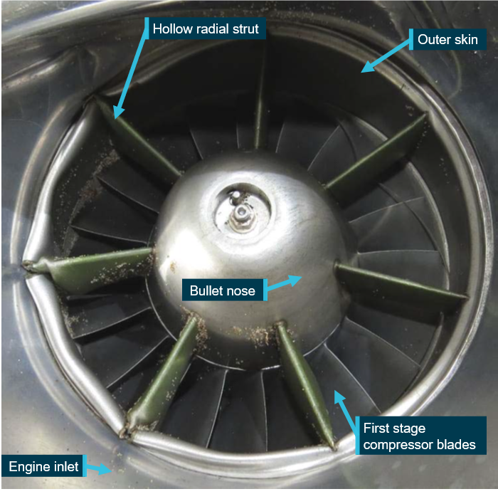
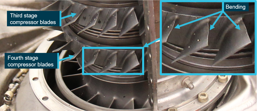
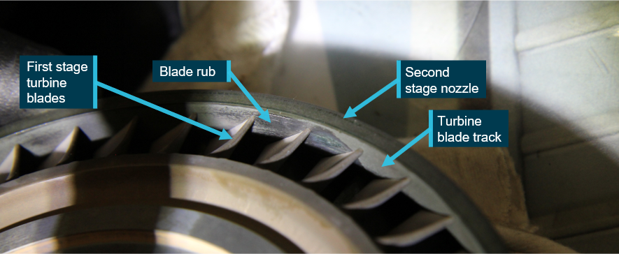
Following recovery of the helicopter from the reservoir, the engine was inspected by the operator’s maintenance organisation. A borescope inspection of the engine compressor section revealed a rotor blade failure in addition to other rotor blade and inlet guide vane damage (Figure 5). The engine was sent to Honeywell Engines in the United States for a teardown inspection and failure analysis. The following engine information sections summarise their findings.
Figure 5: Borescope image of damage to engine inlet and compressor
Source: Operator, annotated by the ATSB
Engine teardown and failure analysis
Honeywell’s examination found that the bearings at the front of the engine (no. 1 compressor shaft bearing and no. 21 power shaft bearing) had failed and exhibited excessive heat damage (Figure 6). However, the main bearings located at the rear of the engine (no. 2, no. 3 and no. 4) did not exhibit this damage. This indicated that a reduction in oil flow had occurred to the front section.
The engine is lubricated by filtered oil delivered from the oil pump, driven by the accessory gearbox, into two main flow paths. One flow path is through the internal passages in the inlet housing to the front section of the engine, while the other is through the external oil pressure hose assemblies to the rear section of the engine.
Debris adhering to the engine oil chip detector,[4] located nearest the external oil reservoir, was found to be consistent with the steel base and silver-plating materials for the no. 1 and no. 21 bearings and their cages.[5] This suggested that the bearings were failing while the engine was still rotating and transferring oil through the engine. A continuity check of the engine oil chip detector determined that the circuit was ‘closed’, which would indicate a chip detection (although none recalled by the pilot).
The oil flow passages for the no. 1 and no. 21 bearings were inspected and flow tested with no evidence of a blockage found. Metallic debris, consistent with bearing material, was captured from the power shaft bearing retainer (oil flow pathway to the front section). However, this material was released at a very low-pressure during testing, which indicated the debris was likely transported to this location during the last moments of the engine failure and shutdown and was not likely blocking oil flow during earlier operation. No other debris was noted in the lubrication oil passages to the no. 1 and no. 21 bearings that would have prevented normal operation.
Figure 6 depicts the compressor (N1 in blue) and power (N2 in red) sections of the engine, the locations of the main bearings for the front (no. 1 and no. 21) and rear (no.2, no.3 and no.4) sections, and the accessory drive system (includes drives for the oil pump and fuel control).
Figure 6: Cross-section of a T53-L-13 engine showing the location of the main components and bearings
Source: Honeywell, annotated by the ATSB
From the information provided by the pilot, and examination of the engine, Honeywell provided the following sequence of events for the engine failure:
Lubrication oil to the no. 21 and the no. 1 bearings was reduced or blocked.
The no. 21 bearing began to overheat and fail, resulting in excessive heat being generated in the power shaft and nearby components.
The forward compressor shaft seal assembly began to fail resulting in additional heat input to the nearby components.
The no. 1 bearing began to fail due to excessive heating.
Due to the no. 1 bearing failing, the forward end of the compressor shaft was no longer properly retained. This allowed contact between the compressor and power shafts as well as axial compressor blade tip contact with their respective shrouds. This likely resulted in the ‘grinding noise’ heard by the pilot shortly before the loss of engine power.
The compressor shaft accessory drive bevel gear, attached to the forward end of the compressor shaft, began to lose mesh with the driven accessory drive bevel gear, which provided rotational power to the fuel pump and the fuel control.
The fuel pump and fuel control stopped rotating due to the loss of drive from the compressor shaft accessory drive bevel gear.
The engine flamed out due to a loss of fuel flow from the fuel pump and fuel control.
Power was lost to the engine.
Figure 7 depicts the damage found to the power shaft (top and bottom left) and no. 21 bearing (bottom right). The yellow arrows depict wear, and the red bracket (bottom left) depicts a groove in the shaft at the location of the no. 21 bearing. Figure 8 depicts a comparison no. 21 bearing fitted to its power shaft bearing retainer.
Figure 7: Damaged power shaft and no. 21 bearing
Source: Honeywell
Figure 8: Comparison no. 21 bearing
Source: Honeywell
Engine bearings history
At the previous engine hot section[6] inspection on 22 February 2018, the no. 1 and no. 21 bearings were replaced. The engine inspection facility[7] reported that the no. 1 and no. 21 bearings were replaced for compliance with service bulletins T53-180 and T53-056, respectively. There were no defects regarding wear or discoloration of the removed bearings. Both bearings were replaced with new parts purchased directly from Honeywell. The engine oil supply and scavenge pump was functionally tested by another facility and deemed serviceable.
The engine was subject to 150-hourly oil filter inspections and 300-hourly oil replacements. The last 150-hourly inspection, which included an oil replacement and chip detector inspection, was certified as completed on 9 January 2020, the morning of the accident. No defects were found. The bearings had accumulated about 1,128 hours prior to the accident, at which stage the engine had accumulated about 1,880 hours since the last engine overhaul.
A search by Honeywell did not find any previous no. 21 bearing failures from inadequate lubrication reported to either Lycoming or Honeywell. Honeywell reported that, in the 1970s and 1980s, there were several no. 21 bearing failures attributed to the use of a bronze cage surrounding the rollers. Lycoming released a service bulletin in the 1980s to replace the bronze cage with a steel cage, with a compliance time limit. The accident no. 21 bearing had a steel cage, which did not fail.
A search of the Civil Aviation Safety Authority service defect reporting system found no reports for restriction or blockage of oil flow, or problems with the no. 1 or no. 21 bearings, in the previous 20 years for either the Lycoming T53 family of engines or the Honeywell T5313B engine. However, the ATSB was able to locate a Honeywell report from 29 October 2009 for a T53-L-703 engine failure in the United States. The report concluded that the engine experienced a failure of the no. 1 bearing and that a cage failure may have been the initiating event. This was a bronze cage that had separated into multiple fragments. There was evidence of high metal temperature exposure, but no evidence of oil starvation. The no. 21 bearing was not removed but observed to be intact and rotated freely. The cause of the cage failure and over-temperature condition could not be determined. The accident no. 1 bearing cage did not fail and was a different part number to the earlier 2009 report.
Survival aspects
Underwater exits
The pilot reported that normal and emergency release mechanisms for exits were included in the HUET course, but recalled that during the accident, ‘[I] didn’t think about any of the emergency releases for the doors or windows…if one didn’t work, then went for another exit’. The pilot reported that the cabin door window used for the escape was selected as ‘daylight’ could be seen through it and punched it with the belief that it was the quarter door window. Following the recovery of the helicopter it was found to be the right sliding door rear window that had an emergency release. The pilot could not recall how the air pocket was found in the cabin prior to the escape.
Following the recovery of the helicopter from the reservoir, the operator checked the pilot and co‑pilot doors and found that they were both jammed due to airframe distortion and could not be opened. The rear of the airframe was less distorted, and the cabin doors could be opened.
A 2020 European Union Aviation Safety Agency (EASA) research report, Underwater escape from helicopters, found that the ability to escape through a particular exit was influenced by several factors. They noted:
It is generally accepted that if a helicopter occupant needs to remove an exit or escape window, then it is highly desirable to do this with the seat harness still secured, enabling the individual to apply force effectively. This was confirmed by Mills and Muir (1998, 1999a); a number of their study participants had released their seat belt before operating the exit, making operation of the exit either difficult or impossible.
Despite the difficulty with the underwater escape, the pilot described the HUET course as ‘great’, and very realistic. When the helicopter impacted the water and started to sink and rollover, the pilot placed one hand on the seatbelt and the other on the door handle and waited for all movement to stop before attempting to escape, in accordance with one of the HUET objectives to maintain orientation. At interview, the pilot reported ‘would have been dead without HUET’. As previously emphasised by the ATSB (Regular helicopter underwater escape training):
…HUET (helicopter underwater escape training) is considered to provide individuals with familiarity with the crash environment and confidence in their ability to cope with the emergency situation. Interviews with survivors from helicopter accidents requiring underwater escape frequently mention they considered that HUET had been very important in their survival. Training provided reflex conditioning, a behaviour pattern to follow, reduced confusion, and reduced panic.
Figure 9 depicts the helicopter inverted in the reservoir and the location of the right sliding door rear window, used by the pilot for the underwater escape.
Figure 9: Location of escape window
Source: Department of Defence, annotated by the ATSB
Emergency breathing systems
In May 2001, the North Atlantic Treaty Organization’s Research and Technology Organization published report RTO-AG-341, The Requirements for an Emergency Breathing System (EBS) in Over-Water Helicopter and Fixed Wing Aircraft Operations. Their report concluded that a persistent 15 per cent fatality rate in helicopter ditching was due to drowning and that the principal cause was the inability to breath-hold long enough to make an escape. They concluded that some form of EBS, whether a rebreather or compressed air unit, would improve survivability.
In their February 2008 manual, the Research and Technology Organization discussed the benefits and limitations of three distinct types of EBS. They were the compressed air, rebreather, and hybrid rebreather systems.
Compressed air system
A compressed air system is based on a self-contained underwater breathing apparatus. This type of equipment is classed as an open-circuit demand system and can be purged underwater prior to use. This means that, when the user breathes out, the exhaled air leaves the demand valve and enters the water. None of the expelled air is collected and reused again, as in the case of a closed-circuit demand system such as a rebreather.
Rebreather system
The rebreather is based on exhaling and rebreathing your own air. As exhaled air contains un‑metabolised oxygen, it can be rebreathed many times before the oxygen is used up. The air is collected at atmospheric pressure by the wearer expelling a deep breath into a counter‑lung (air bladder) via the mouthpiece prior to submersion. It can then be inhaled and exhaled into the counter-lung when the user is unable to hold their breath anymore.
Hybrid rebreather system
This system works on the same principle as a rebreather, but it also contains a small cylinder of compressed air fitted to the counter-lung. The air cylinder can be automatically activated by saltwater immersion or manually activated using an emergency inflator pull cord. The reason for the cylinder is to provide some air for those who did not get a breath of air before submersion.
Technical standard for emergency breathing systems
Drowning is the primary cause of death in helicopter water impact accidents. It is a well documented fact that a helicopter will capsize and/or sink in a high proportion of water impact accidents (e.g. Rice & Greear, 1973; Brooks, 1989; Clifford, 1996). To make a successful escape, the occupant must be conscious, mobile, and be familiar with escape procedures and escape routes. The risk of drowning is very high due to the fact that there is a mismatch between the time needed to escape from the inverted and possibly sinking helicopter and the time that individuals can hold their breath underwater (Cheung et al, 2001). When considering the means of mitigating the risk of drowning, considerable effort has gone into improving both the crashworthiness of helicopters and the ability to keep helicopters afloat (see CAA, 2005 for review of research).
Emergency breathing systems (EBS) provide an alternative or additional means to mitigate the risk of drowning. They are designed to allow helicopter occupants to breathe underwater for at least 1 minute, overcoming the need to make a single breath last for the duration of the escape process. If deployed successfully, EBS use should therefore increase the likelihood of survival.
The CAP draft technical standard proposed two categories of EBS performance. Category ‘A’ systems were those with the capability to be deployed underwater and therefore suitable for use in the worst-case water impact accidents where capsize and/or sinking occur immediately after impact. Category ‘B’ systems were those that were required to be deployed in air, and therefore limited to ditching scenarios where there was sufficient time to deploy the system prior to submersion.
The CAP noted there was a small risk of barotrauma[8] associated with the compressed air EBS and hybrid EBS, and that a few injury cases had been reported during training. Therefore:
When selecting EBS, the end user must carry out a risk assessment looking at likely conditions of use, training needs, and maintenance and servicing requirements before deciding on a suitable device that best matches those requirements.
Height-speed envelope avoid area
If a helicopter is unable to be safely landed following a loss of power, the manufacturer must provide a limiting height-speed envelope diagram. The diagram must include the avoid areas, which denote the combinations of height and forward airspeed where it may not be possible to establish a satisfactory autorotation prior to contacting terrain. A height of 100 ft and airspeed less than 40 kt places the UH-1H helicopter with the T53-L-13B engine within the avoid area of its height-speed envelope, which is where the accident helicopter was at the time of the water uplift and engine failure.
While conducting fire control activities in the vicinity of Eden, New South Wales, using the Ben Boyd Reservoir as the water source, the helicopter’s engine failed in the hover over the reservoir. This resulted in a rapid descent into the water, followed by a successful underwater escape by the pilot.
This analysis will discuss the collision with water and underwater escape by the pilot, the results of the engine failure analysis and use of emergency breathing systems.
Collision with water and underwater escape
When the pilot heard a mechanical ‘grinding noise’, their attention was initially focussed on the bucket below the helicopter. The pilot then immediately transitioned to an emergency landing site in front of the helicopter. However, as the helicopter was in the avoid area of the height-speed envelope, the pilot was unable to arrest the rate of descent before impacting the water. The severity of the impact fragmented the chin bubbles and distorted the airframe, which resulted in the helicopter rapidly filling with water and sinking.
The pilot had completed helicopter underwater escape training about 8 months prior to the accident and was able to wait for all motion to cease, then perform the initial actions to maintain orientation. While the pilot did not attempt to open the pilot or co-pilot doors with the emergency release mechanism, it was unlikely the doors would have released due to the airframe distortion.
After moving from the cockpit into the cabin, the pilot found a pocket of air to breathe, but was unable to open the cabin sliding doors. This was likely a result of the underwater environment impeding the pilot’s ability to apply sufficient force to overcome the normal static friction of the sliding doors. However, the pilot was able to punch out the rear window of the right sliding door. This highlights the importance of the design of windows as emergency escape routes, and the potential need for a supplementary air supply for underwater escape, which is discussed further in the section on Emergency breathing systems.
Engine failure mechanism
Following the discovery of damage to the engine inlet and compressor section by the operator’s maintenance organisation, the engine was sent to Honeywell Engines for teardown and failure analysis. Honeywell concluded that the no. 1 and no. 21 bearings in the front section of the engine had failed and exhibited heat damage. This indicated a reduction in oil flow to the front of the engine. There was no evidence of this for the bearings at the rear section of the engine, which were supplied by a separate oil flow pathway.
The failure of the main bearings at the front of the engine resulted in contact between the power and compressor shafts, disconnection of rotational drive to the fuel pump and fuel control, and subsequent fuel starvation. As the oil passages to the bearings at the front of the engine passed their flow tests, it could not be determined how or why a reduction in lubrication occurred. A review by the manufacturer and ATSB found no historical evidence of a similar failure mechanism.
Emergency breathing systems
The ATSB reviewed several research reports into helicopter overwater accident survival and noted that they consistently reported drowning as the leading cause of fatalities. All reports attributed this to the inability of the occupant to breath-hold for the duration of the escape with a variety of contributing factors. In this accident, the cockpit doors were both jammed, which required the pilot to locate an alternate escape route through the cabin. The pilot found an air pocket in the cabin, which enabled the escape time to be extended beyond the initial breath-hold time. This provided the pilot with sufficient oxygen for the physical effort required to attempt to open the sliding doors and then push out a window. It could not be determined if the pilot would have drowned without the air pocket, but it would have increased the likelihood.
While helicopter underwater escape training provides a learning environment for the essential skills of maintaining orientation, location, and operation of exits, it does not address the potential need to extend an individual’s breath-hold. Extending breath-hold may be necessary for problem‑solving and physical effort during the underwater escape sequence, such as dealing with snagging hazards, obstructions, or inoperative exits that require an alternative escape route, as in this accident. An emergency breathing system would have afforded the pilot sufficient time to perform the escape actions without an air pocket and therefore reduce the risk of drowning.
Findings
ATSB investigation report findings focus on safety factors (that is, events and conditions that increase risk). Safety factors include ‘contributing factors’ and ‘other factors that increased risk’ (that is, factors that did not meet the definition of a contributing factor for this occurrence but were still considered important to include in the report for the purpose of increasing awareness and enhancing safety). In addition, ‘other findings’ may be included to provide important information about topics other than safety factors.
These findings should not be read as apportioning blame or liability to any particular organisation or individual.
From the evidence available, the following findings are made with respect to the engine failure involving Garlick Helicopters UH-1H, registered VH-ONZ, near Eden, New South Wales, on 9 January 2020.
Contributing factors
While hovering over the Ben Boyd reservoir to uplift water for fire control operations, the helicopter's engine failed, which resulted in a collision with water and underwater escape by the pilot.
For reasons undetermined, the no. 1 and no. 21 bearings at the front of the engine failed due to inadequate lubrication. This resulted in contact between the power and compressor shafts, disconnection of rotational drive to the fuel pump and fuel control, and subsequent fuel starvation.
Other factors that increased risk
The pilot was not equipped with an emergency breathing system, nor required to be. Although the pilot was able to successfully escape from underwater after finding an air pocket, an emergency breathing system would have reduced the risk of drowning.
Other findings
The pilot had completed helicopter underwater escape training about 8 months prior to the accident and at 3-year intervals since it was introduced on the New South Wales firefighting aerial support contract.
Safety action
Whether or not the ATSB identifies safety issues in the course of an investigation, relevant organisations may proactively initiate safety action in order to reduce their safety risk. All of the directly involved parties are invited to provide submissions to this draft report. As part of that process, each organisation is asked to communicate what safety actions, if any, they have carried out to reduce the risk associated with this type of occurrences in the future. The ATSB has so far been advised of the following proactive safety action in response to this occurrence.
Additional safety action by the pilot and operator
Following the accident, the pilot acquired a compressed air emergency breathing system and has decided to conduct those elements of future helicopter underwater escape training courses. The operator reported they have started investigating how to implement emergency breathing systems company-wide, and how to attach the units to their pilots without limiting their movement when conducting long-line operations.
Glossary
CAA Civil Aviation Authority (United Kingdom)
CAP Civil Aviation Publication (CAA)
EASA European Union Aviation Safety Agency
EBS Emergency breathing system
HUET Helicopter underwater escape training
RTO Research and Technology Organization (North Atlantic Treaty Organization)
Sources and submissions
Sources of information
The sources of information during the investigation included the:
Department of Defence (Defence Flight Safety Bureau)
Honeywell Engines
operator
operator’s maintenance organisation
References
Brooks CJ, Tipton MJ 2001, The Requirements for an Emergency Breathing System (EBS) in Over-Water Helicopter and Fixed Wing Aircraft Operations, North Atlantic Treaty Organization Research and Technology Organization RTO-AG-341.
Coleshaw S, Howson D 2020, Research report: Underwater escape from helicopters, European Union Aviation Safety Agency.
Gibbs P 2008, The Principles of Emergency Breathing Systems (EBS) for Helicopter Underwater Escape, in Chapter 7 of Survival at Sea for Mariners, Aviators and Search and Rescue Personnel, North Atlantic Treaty Organization Research and Technology Organization RTO-AG-HFM-152.
UK Civil Aviation Authority 2013, Civil Aviation Publication 1034: Development of a technical standard for emergency breathing systems, The Stationary Office, May 2013.
Submissions
Under section 26 of the Transport Safety Investigation Act 2003, the ATSB may provide a draft report, on a confidential basis, to any person whom the ATSB considers appropriate. That section allows a person receiving a draft report to make submissions to the ATSB about the draft report.
A draft of this report was provided to the following directly involved parties:
Civil Aviation Safety Authority
Department of Defence (Defence Flight Safety Bureau)
Honeywell Engines
the operator
the operator’s maintenance organisation
the pilot
United States National Transportation Safety Board.
No submissions were received from the directly involved parties.
Purpose of safety investigations & publishing information
Purpose of safety investigations
The objective of a safety investigation is to enhance transport safety. This is done through:
identifying safety issues and facilitating safety action to address those issues
providing information about occurrences and their associated safety factors to facilitate learning within the transport industry.
It is not a function of the ATSB to apportion blame or provide a means for determining liability. At the same time, an investigation report must include factual material of sufficient weight to support the analysis and findings. At all times the ATSB endeavours to balance the use of material that could imply adverse comment with the need to properly explain what happened, and why, in a fair and unbiased manner. The ATSB does not investigate for the purpose of taking administrative, regulatory or criminal action.
Terminology
An explanation of terminology used in ATSB investigation reports is available here. This includes terms such as occurrence, contributing factor, other factor that increased risk, and safety issue.
Publishing information
Released in accordance with section 25 of the Transport Safety Investigation Act 2003
Ownership of intellectual property rights in this publication
Unless otherwise noted, copyright (and any other intellectual property rights, if any) in this report publication is owned by the Commonwealth of Australia.
Creative Commons licence
With the exception of the Coat of Arms, ATSB logo, and photos and graphics in which a third party holds copyright, this publication is licensed under a Creative Commons Attribution 3.0 Australia licence.
Creative Commons Attribution 3.0 Australia Licence is a standard form licence agreement that allows you to copy, distribute, transmit and adapt this publication provided that you attribute the work.
The ATSB’s preference is that you attribute this publication (and any material sourced from it) using the following wording: Source: Australian Transport Safety Bureau
Copyright in material obtained from other agencies, private individuals or organisations, belongs to those agencies, individuals or organisations. Where you wish to use their material, you will need to contact them directly.
On the morning of 9 January 2020, a Fokker 100 registered VH-NHY and operated by Network Aviation conducted a regular public transport service from Perth to Newman, Western Australia.
The weather forecast for Newman Airport included heavy rain, moderate to severe turbulence below 5,000 ft and a 25 kt crosswind. At the time the aircraft departed Perth, Newman Airport had received about 88 mm of rain since 0900 the previous morning.
After a stable approach, the aircraft touched down in moderate rain, at or before the touchdown zone, at a speed 16 kt above the reference landing speed for the configuration. The crosswind at the time was recorded as gusting to 35 kt. The flight crew experienced lower than expected braking performance and reported aquaplaning during the landing roll. The pilot flying used the aquaplaning response technique to maintain directional control and subsequently commanded maximum reverse thrust.
The aircraft stopped 70 m beyond the end of the runway inside the runway end safety area. There were no injuries to crew or passengers and an inspection of the aircraft found that the loose gravel had damaged some of the landing gear components
What the ATSB found
The combination of the approach speed required by the prevailing wind conditions and the poor braking effectiveness in the wet conditions resulted in the aircraft overrunning the runway.
The ATSB also found that despite assessing the weather as a threat, the flight crew did not identify the potential effect of the rainfall on the stopping distance. Additionally, neither the operator nor the regulator had guidance to allow the crew to recognise the conditions at the time as a hazard to the operation.
Prior to the occurrence, the runway had been examined and found to be requiring maintenance to ensure an adequate level of surface friction, however no maintenance was performed.
What has been done as a result
Following the occurrence, the operator circulated additional guidance and procedures to flight crew for identifying runway water contamination and to ensure appropriate speed control on approach and landing.
Since the occurrence, the Civil Aviation Safety Authority has published guidance, reflecting research from the United States Federal Aviation Authority, that found landing on ungrooved runways in moderate rain has the potential to significantly affect braking performance.
Safety message
Active precipitation, particularly moderate to heavy rainfall, is one of many factors that can influence the stopping distance of an aircraft. Water on a runway that is not grooved can significantly reduce the ability of the aircraft to slow down. In wet weather, additional conservatism is encouraged when calculating the required landing distances.
Operators and pilots are encouraged to review the latest guidance and tools available in relation to maintaining safety on runways and the factors that cause runway overruns.
The occurrence
On 9 January 2020, a Fokker 100 registered VH-NHY and operated by Network Aviation (a subsidiary of the Qantas Group), was conducting a regular public transport service from Perth to Newman, Western Australia.
Pre-flight, departure and cruise
The flight crew arrived at the airport at about 0430 Western Standard Time[1] to prepare for the flight. During the pre-flight briefing, the flight crew received the weather forecast for Newman, which included:
As a consequence of the significant weather, the captain requested additional fuel to provide for a potential diversion to an approved alternate, Port Hedland Airport. The weather observation from Newman Airport at the time indicated that the cumulative rainfall since 0900 the previous day was 87.6 mm.
The aircraft departed Perth at 0536 with 5 crew and 88 passengers on-board. Due to the unfavourable weather, the captain assumed the role of pilot flying and the first officer (FO) was pilot monitoring.[3]
During the cruise phase, the FO requested the latest Newman meteorological aerodrome report from Melbourne Centre. The controller provided updated observations for the destination, which included:
wind 150o at 19 knots, gusting to 30 knots
a reduction in visibility (reduced to 2,500 m)
cloud covers of scattered at 700 ft, broken at 1,100 ft and broken at 1,600 ft
recorded (actual) rain (1.6 mm within preceding 10 minutes, equivalent to 9.6 mm/hour).[4]
The approach
The captain reported that due to the potential for windshear during the final approach segment, a flaps 25 (rather than flaps 42) with speed brake extended approach was selected, resulting in a faster than usual final approach speed (VAPP)[] . The operator’s procedures (see the section titled Operator documentation and guidance) and the Fokker flight manual required an additional 10 knots be added to the usual reference landing speed (VREF[6] + 5 knots) to account for wind, bringing the final approach speed to 153 knots.
The captain reported not calculating the landing field length required on the day as they routinely operated to Newman and knew that the performance of the aircraft would allow for landing at maximum landing weight in dry or wet conditions. At interview, the captain recalled that the required landing field length for flaps 25 and maximum landing weight, the configuration and weight on the day, was about 1,750 m.
Prior to commencing the approach briefing, the flight crew interrogated the Newman aerodrome weather information service (AWIS).[7] The information they received was consistent with the previous weather observations provided by Melbourne Centre, except the wind direction had changed to 130o. Due to the wind direction the crew elected to conduct an approach to runway 05.
As part of the approach brief, the flight crew identified the weather as the primary threat to the operation and discussed a potential diversion to Port Hedland. Their discussions were focussed on the cloud base and the visibility required to conduct the approach, the expectation of windshear, turbulence and the strong crosswind. The rainfall rate and potential for runway contamination or reduced braking effectiveness were not discussed.
At 0655, 17 minutes prior to landing, the flight crew reinterrogated the AWIS. The visibility had reduced to 1,200 m and the rainfall rate had increased to 4.8 mm in 10 minutes (28.8 mm per hour). The captain commented to the FO that the reduced visibility was likely related to a rain shower.
Flight recorder data indicated that the approach was within the operator’s stable approach criteria. Recorded values of airspeed during the final approach and landing showed fluctuations consistent with gusty conditions. At the decision height, coincident with the FO beginning to state ‘no contact’,[8] the captain announced that the runway was in-sight and continued the approach.
At interview, the FO explained that they[9] were unable to see the runway due primarily to two factors. The FO was not familiar with the approach, which had a 6º offset angle between the approach path and the runway, causing the nose of the aircraft to point right of the centreline. This difference between the approach course and the runway heading was exacerbated by the crosswind from the right of the runway, further pushing the nose of aircraft to the right of the centreline.
At the time that the captain announced that the runway was in sight, the aircraft was 3.4 km from the runway threshold, which was the required visibility for the approach.
The flight crew reported that during the approach the rainfall was of a moderate intensity. The aerodrome reporting officer (ARO) reported observing a slight increase in the rain intensity just prior to the aircraft landing but considered it to be moderate rain.
Landing
At 0712, the time of the landing, a maximum crosswind gust of 35 knots was recorded.[10] This was the highest recorded gust between 0700 and 0730. The crosswind limit for the Fokker 100 is 35 knots. The aircraft touched down at 154 knots airspeed and a groundspeed of 159 knots (Figure 1). The touchdown was positive[11] and at, or slightly before, the touch down zone.
Figure 1: Flight data from the occurrence landing
Source: ATSB
Eleven seconds after landing, the captain requested assistance with the brakes[12] from the FO. The recorded deceleration during this part of the landing was medium to low (less than 0.25 G) and reduced further as the landing roll progressed (Figure 1). Throughout the landing, there were directional oscillations about the runway heading as the aircraft weathercocked into the strong crosswind.
The captain reported that the aircraft aquaplaned during the landing. Approximately 20 seconds after touching down, the aquaplaning response technique was conducted. This involved reducing manual braking (brake pressure) with the intent of regaining traction and stowing the thrust reversers to increase directional stability. After completion of the aquaplaning response technique, maximum reverse thrust was applied which provided high deceleration (greater than 0.5 G) just before the aircraft departed the runway.
The aircraft stopped about 70 m beyond the upwind runway threshold, off the runway surface, within the runway end safety area[13] (Figure 2). There were no injuries and the passengers and crew disembarked via the front stairs and were transported to the terminal.
Figure 2: Image taken of the aircraft stopped within the runway end safety area
Source: Network Aviation
A visual examination of the tyres identified some deep scratches, likely due to the abrasive surface of the runway end safety area. An inspection of the aircraft found that the loose gravel had damaged some of the landing gear components.
At the time of the occurrence, the captain had 5,594.7 hours total flying time with 1,963.4 hours on the Fokker 100. The captain had flown regularly to Newman, the last time being the week prior.
The first officer had 2,920.5 hours total flying time with 182.8 hours on the Fokker 100. It was the first officer’s second time flying into Newman.
Runway information
Newman Airport runway 05/23 was 2,072 m long, 30 m wide and ungrooved (lateral grooving is used to improve braking performance in wet conditions).
The most recent maintenance on the runway surface was a retexturing and excess rubber removal completed in June 2018 after a Civil Aviation Safety Authority (CASA) audit found that severe pavement bleeding and flushing[14] was occurring at the touchdown zones.
On the morning of the occurrence, the aerodrome reporting officer[15] (ARO) at Newman Airport inspected the runway at 0500 and again at 0630, 45 minutes before the aircraft landed. This was in accordance with the ARO’s procedures for the runway to be inspected ‘as soon as practicable prior to the first RPT [regular public transport] flight’. At those times, the ARO recalled a significant amount of standing water on the grass strips on either side of the runway. However, the ARO described that the main runway surface appeared clear of any noticeable standing water and was serviceable throughout the morning.
About a year after the occurrence, an image was taken of the runway showing standing water on the runway after rainfall (Figure 3).
Figure 3: Image of standing water on the runway at Newman Airport.
Source: Qantas
Friction tests
Aerodrome operators were required to ensured that runway friction levels were above minimum limits[16] as detailed in Part 139 (Aerodromes) of the Manual of Standards 2017, version 1.14, which was current at the time. In order to demonstrate compliance, the friction was required to be periodically tested via one of the prescribed methods. The Manual of Standards also specified the ‘maintenance planning level’ for friction, which is the level that if the measured friction falls below the aerodrome operator must initiate appropriate corrective maintenance action to improve the friction and ensure ongoing safety of the runway.
A runway friction test was conducted in March 2019. The test took continuous skid resistance measurements at 3 and 6 m offsets from the centreline at 65 km/h and 95 km/h. These measurements were averaged over 10 m to produce a continuous data plot of the friction. A 100 m rolling average was also included in the friction test report.
The report described the differences between the 65 and the 95 km/h test indicating that the 65 km/h test was affected more by the microtexture of the surface and the 95 km/h test was more affected by the macrotexture. Low friction values for the 65 km/h test indicated that the fine texture may be filled with rubber. The 95 km/h test gave an indication of how fast water was able to escape from the surface. The report also stated that seasonal variation can affect the friction measurements by up to 15 per cent.
The continuous friction measurements for the 95 km/h test recorded numerous measurements below the maintenance planning level and some measurements below the allowable minimum friction levels (Figure 3). However, when averaged over 100 m, the lowest friction measurements were at maintenance planning level. The Manual of Standards had no requirement, nor did it specifically permit the averaging of the friction measurements.
Figure 4: Results from runway friction report
These plots show the data from the 95 km/h test at 3 m offset from centreline. The upper image shows 10 m averages considered to the continuous friction measurement, the lower image is the same data using 100 m rolling averages.
Source – Fulton Hogan
The report did not mention the friction values below the minimum design limit and concluded that:
there were sections of the runway at maintenance planning level
the runway met the surface friction requirements as specified in the Manual of Standards.
Several weeks after the occurrence the runway was re-tested via the same method. The friction values recorded in the 2020 test were generally higher (i.e. better grip). However, there were still areas in the touch down zones that were at maintenance planning level. No rubber removal or surface maintenance had been performed between the 2019 and 2020 tests.
Aquaplaning
The three types of aquaplaning are dynamic, viscous and reverted rubber.
Dynamic aquaplaning occurs at high-speed and is the result of water being unable to be forced away from under the tyre. This creates a layer of water underneath the tyre thereby reducing the coefficient of friction.
Viscous aquaplaning is a similar phenomenon but can occur at lower speeds and relies on a low coefficient of friction of the runway surface, usually due to rubber build up. The smooth surface enables a small film of water to cause the tyre to slip during braking.
Reverted rubber aquaplaning is the breakdown of the tyre material from heat generated as part of the braking or as a result of a skid or lockup. Reverted rubber aquaplaning is the only type of aquaplaning that leaves evidence marks on the tyre surface.
Runway contamination
The Civil Aviation Order (CAO) 20.7.1B defined a contaminated runway as a runway that has more than 25 per cent of the runway surface area within the required length and width being used covered by:
water, or slush, more than 3 mm deep; or
loose snow more than 20 mm deep; or
compacted snow or ice, including wet ice.
Advice from runway subject matter experts indicated that strong crosswinds can increase the chances of the windward side of the runway being contaminated. This is because the wind effectively slows or stops the water from draining along the built-in slope away from the centreline.
Federal Aviation Administration (FAA) Safety Alert for Flight Operators (SAFO) 19003
In response to several landing events where the braking coefficient was found to be less than what was expected for a wet runway, the United States Federal Aviation Administration (FAA) issued Safety Alert for Flight Operators (SAFO) 15009 in August 2015. In 2019, this SAFO was updated with SAFO 19003 (Turbojet Braking Performance on Wet Runways) to align with current guidance.
While the FAA recognised that landing overruns on wet runways usually involved multiple contributing factors, their analysis of those landing events raised concerns regarding stopping performance assumptions. The cause of the braking underperformance was not fully understood, but the FAA in SAFO 15009 cited possible factors relating to runway conditions including texture, drainage, puddling in wheel tracks and active precipitation. Specifically, the analysis showed that, 30‑40 per cent of additional stopping distance may be required in certain cases where the runway was very wet, but not flooded.
As a result of the above, the FAA suggested that whenever there is likelihood of moderate or greater active rain on a smooth (ungrooved) runway, or heavy rain on a grooved or porous friction course runway, landing distance calculations should be done assuming the surface is contaminated.
There is no standard definition of rainfall intensity across the aviation industry. However, the World Meteorological Organization[17] stated:
While there is no agreed international definition regarding rainfall intensity, some use the following criteria: Heavy rain is defined as rates in excess of 4 mm per hour while heavy showers are defined as rates in excess of 10 mm per hour. Showers are further classified as being violent if the rate exceeds 50 mm per hour, although these are normally considered to be rates typical for tropical regions.
The below table includes the published definition from the FAA and the Australian Bureau of Meteorology (BoM).
Table 1: Comparison of rain intensity definitions between FAA and BOM
Rain intensity
FAA
BoM
Moderate
4.5 to 12.5 mm/hr
2.2 to 6 mm/hr
Heavy
12.5 to 50 mm/hr
Greater than 6 mm/hr
Calculation of required landing field length
Civil Aviation Order (CAO) 20.7.1B (Aeroplane weight and performance limitations) specified that landing distance required shall be 1.67 times the distance required to bring the aeroplane to a stop on a dry runway. For wet runways, an additional 15 per cent margin is to be added be added making the landing field length required 1.92 times the distance required to bring the aeroplane to a stop on a dry runway.
The Fokker 100 airplane flight manual (AFM) provided the required landing field length for flaps 25 for the aircraft weight as 1,520 m. In line with the CAO, the manual stated that if forecasts or observations indicate the runway may be wet, the required landing field length was an additional 15 per cent of the distance in dry conditions. This brought the required length to 1,748 m. These lengths were predicated on the aircraft being at the reference landing speed (VREF) at 50 ft above the runway threshold.
Fokker provided advice to the ATSB that they recognised that in normal operation the threshold crossing speed is often higher than VREF. In those cases, the landing distance may be larger than the landing distances determined during the certification flight tests of the aircraft. However, the increase will not be larger than the 1.67 factor used in the AFM graphs for required landing field length for dry conditions.
Operator documentation and guidance
Runway contamination
The weather briefing section of the Flight Administration Manual (FAM) indicated that the possibility of runways being contaminated at the departure and destination airports should be considered during the planning process. Network Aviation policy did not approve operations on contaminated runways. However, limited guidance within the documented material was provided on how to determine if the runway was contaminated, and moderate or heavy rain were not identified as possible runway contaminants.
The Fokker 100 Aircraft Operating Manual (AOM) contained a section for operating on contaminated runways. The section contained the CASA definition of contaminated runways and additional information on possible runway contamination. The section stated that a runway may also be considered contaminated in conditions including:
A runway with a smooth/slippery surface (rubber deposits / oil) or a recently resurfaced runway covered with a thin layer of water (less than 3mm) […] may have a considerably reduced friction (slippery wet runways).
In heavy rain showers even on runways with a good drainage.
The section also stated that:
The magnitude of the effects of runway contamination are determined in general by: […]
- The runway surface condition and texture, grooved or non-grooved runways;
- The weather conditions (cross wind, gust, actual precipitation);
- The aircraft configuration (flaps, reversers, autobrakes, speedbrakes)
Advice was sought from the operator on how flight crew were expected to assess if a runway was contaminated. The operator indicated that the flight crew should check NOTAM’s[18] prior to departure for any published runway unserviceability. During the flight, they should monitor the aerodrome weather information service (AWIS) broadcast, noting that the AWIS broadcast does not include any reference to standing water. There was also an expectation that the ARO strip inspection prior to the arrival would identify if the runway was contaminated and if so, contact the arriving aircraft. There was no guidance relating rainfall intensity to runway contamination.
Aircraft configuration selection
The configuration section of the AOM stated that:
Flaps 42 should be used when landing on contaminated runways or runways with reduced braking action.
The windshear section of the AOM encouraged flight crew to consider using flaps 25 for landing and increasing approach speed if weather conditions were such that a windshear may possibly exist, but a safe approach and landing was thought to be feasible. The manual also stated that considerations should be given to the increased landing distance as a result of the increased approach speed.
Approach briefing
The approach briefing section of the Flight Crew Operating Manual (FCOM) listed inclement weather and adverse runway conditions as elements to brief as required. In accordance with the manual, the approach briefing consisted of five modules; Charts, Terrain, Weather, Operational and Plus. With Plus being the section of the approach brief for the crew to identify any threats not previously discussed.
The ‘runway state’ was a line item within the Operational section of the briefing, however, there was no additional information provided on how to assess the runway state.
Regulator guidance
At the time of the occurrence, there was a Civil Aviation Advisory Publication (CAAP) 235-05 which had advisory information on landing distance. However, this did not reflect the latest FAA guidance on the potential contamination and reduction in braking performance resulting from active moderate or heavy precipitation on an ungrooved runway.
In October 2020, 10 months after the occurrence, CASA published an update to the CAAP 235-05 - New performance provisions for CAO 20.7.1B and CAO 20.7.4. Section 3 of the update, titled Landing Distance, included advice on landing in very wet conditions. Included was the information from, and a reference to, the FAA SAFO 19003 (discussed above) identifying moderate active precipitation and ungrooved runways as being risks to landing performance.
Related occurrences
In 2015, an Australian registered Boeing 737 landing at Christchurch, New Zealand, in wet conditions, did not decelerate as expected and stopped 5 m from the runway end. The ATSB investigation (AO-2015-046) found that the reduced braking effectiveness was likely as a result of water on the runway.
Relevant publications
In 2008, the ATSB published a two-part research report (AR-2008-018) titled Runway Excursions with the objective of analysing international and Australian trends in runway excursions. Part 1 of the report explored the contributing factors associated with runway excursions between 1998 and 2007. Water-affected and contaminated runways was one of the contributing factors identified.
After touching down on runway 05 at Newman Airport the aircraft did not decelerate as expected. The captain, sensing the aircraft aquaplane, conducted the aquaplaning response technique and subsequently applied maximum reverse thrust, stopping the aircraft 70 m beyond the upwind runway threshold. This analysis will cover the speed at touchdown, the braking effectiveness, and the environmental conditions at touchdown; as well as the information available to the flight crew to conduct their threat assessment and the condition of the runway.
Landing speed, wind conditions and braking performance
The flight crew selected the approach speed based on the known environmental conditions. The selection was a correct application of the guidance for the forecast turbulence, due to the possibility of windshear conditions. The flaps 25 approach along with the additional mandated speed margins, due to the wind conditions, resulted in a higher approach airspeed than for a flaps 42 approach.
The final approach speed was flown as planned however, the aircraft did not slow after crossing the threshold and entering the flare. During this period, a higher groundspeed than airspeed was recorded indicating a possible unforecast tailwind component, which may have limited the ability to reduce the speed. A higher touchdown speed requires a longer stopping distance due to the additional energy to be dissipated by the deceleration devices. As a general rule, a 10 per cent increase in approach speed results in a 20 per cent increase in the required landing distance.
During the landing roll, after the captain (pilot flying) asked for assistance with applying the brakes, it is highly likely that the maximum manual braking effort was being applied. During this same period, the recorded deceleration was low, indicating that the braking effectiveness was reduced. The captain’s report of aquaplaning is consistent with this low deceleration and the directional oscillations recorded during the landing.
The crosswind conditions combined with the aquaplaning increased the difficulty of maintaining directional control. In accordance with the advice in the Aircraft Operating Manual in relation to aquaplaning response, the crew were limited in the amount of reverse thrust that could be applied as the priority was on maintaining the directional stability and keeping the aircraft on the centreline. Without the crosswind, it is likely that the captain could have engaged maximum reverse thrust much earlier in the landing roll, which would have significantly reduced the landing distance.
Given the magnitude of the runway overrun (70 m), it is highly likely that if either the landing speed had been reduced, the braking effectiveness had been normal or there had been less crosswind, the overrun would not have occurred.
Threat identification
During the approach briefing, the flight crew correctly identified the primary threat as the significant weather. However, their focus was primarily on the wind and the visibility. Despite the forecast for heavy rain obtained before the flight and the aerodrome weather information service providing observations of heavy rain occurring there was no consideration of the effect of the rainfall on the runway state or the braking performance.
The faster flaps 25 approach was selected to address the identified threat of possible windshear. However, this selection (compared to the standard flaps 42 approach) further increased the risks associated with reduced runway braking performance. The crosswind was discussed in relation to the selection of the runway but was not identified as possibly affecting the ability of the aircraft to brake effectively or reducing the drainage of water from the runway surface on the windward side.
The approach briefing procedure provided a prompt to discuss the runway state. However, there was no information available to the crew to enable them to identify the potential for a significant reduction in braking performance posed by the active moderate rainfall. As a result, had the crew identified and discussed the threat, the options for them to manage the threat were limited to their own judgement. Therefore, it is possible that even if the flight crew had identified the threat, they would have continued the approach. There was no information reasonably available to the crew to assist them to identify the runway as potentially water contaminated by the active rainfall.
Operator and regulator documentation
Network Aviation policy did not permit operations on contaminated runway however, flight crews were not provided with adequate information to identify all possible runway contaminated situations. At the time of the occurrence, the only information relevant to the conditions on the day within the operator’s document suite was advisory information in relation to heavy rain being a possible contaminant of the runway. There were no specific procedures to identify the rainfall intensity or relating to conducting approaches during active precipitation.
The United States Federal Aviation Administration (FAA) safety alert for flight operators (SAFO) provided a practical means to assess the potential for runway contaminations based solely on the type of runway surface (grooved or ungrooved) and the rain intensity at landing. Using the FAA document and guidance on rainfall intensity it would have been possible for the crew to determine that there was a potential for poor braking performance and take some mitigating action.
At the time of the occurrence, the lack of Civil Aviation Safety Authority (CASA) advisory information reflecting the FAA alert regarding the potential effect of active moderate or heavy rainfall on braking performance, reduced the likelihood that the operator would have the appropriate guidance for mitigating this hazard.
Runway condition
The flight crew and the aerodrome reporting officer (ARO) reported moderate rain at the time of the landing. The lack of grooving on the runway reduced the ability of water to drain from the runway surface. The FAA SAFO advised that moderate rain on an ungrooved runway can cause a significant reduction in braking performance. The heavy rain prior to the final approach and the ARO’s observations in relation to the water accumulation around the runway meant that drainage of water from the runway may have been slower than usual at the time of landing. The high crosswind at the time of landing would also have slowed the drainage of water on the windward side of the runway.
The runway friction measurements taken in 2019 had values below the recommended maintenance planning levels and some measurements below the minimum friction limits as specified by the Manual of Standards. Although still safe for operations, at the levels recorded, it would generally be expected that maintenance should be performed in the lower friction areas to ensure ongoing safe operation on the runway.
The water pooling observed a year after the occurrence may have been present at the time of the occurrence but would have been hard to identify during active precipitation.
Had there been additional maintenance performed on the runway, there would have been an increase in the overall friction of the runway. However, while an increase in friction may have affected the outcome on the day, it is not possible to conclusively state that the overrun would not have occurred.
Findings
ATSB investigation report findings focus on safety factors (that is, events and conditions that increase risk). Safety factors include ‘contributing factors’ and ‘other factors that increased risk’ (that is, factors that did not meet the definition of a contributing factor for this occurrence but were still considered important to include in the report for the purpose of increasing awareness and enhancing safety). In addition, ‘other findings’ may be included to provide important information about topics other than safety factors.
Safety issues are highlighted in bold to emphasise their importance. A safety issue is a safety factor that (a) can reasonably be regarded as having the potential to adversely affect the safety of future operations, and (b) is a characteristic of an organisation or a system, rather than a characteristic of a specific individual, or characteristic of an operating environment at a specific point in time.
These findings should not be read as apportioning blame or liability to any particular organisation or individual.
From the evidence available, the following findings are made with respect to the runway overrun involving VH-NHY at Newman Airport on 09 January 2020.
Contributing factors
The combination of the approach speed required by the prevailing wind conditions and the poor braking effectiveness in the wet conditions resulted in the aircraft overrunning the runway.
Other factors that increased risk
During the flight, the potential for the heavy or moderate rainfall to significantly impact the landing distance was not recognised by the flight crew and therefore not considered as a threat.
Despite technical examination of the runway identifying areas requiring maintenance to maintain the surface friction, no corrective action was taken.
The operator's documentation required crew to consider contamination of runways at the departure and destination airports. However, the provided definition and guidance did not include the means to identify water contamination from active rainfall. (Safety Issue)
CASA advisory publications did not include information regarding the potential for reduction in braking performance resulting from active moderate or heavy rainfall. (Safety Issue)
Safety issues and actions
Central to the ATSB’s investigation of transport safety matters is the early identification of safety issues. The ATSB expects relevant organisations will address all safety issues an investigation identifies.
Depending on the level of risk of a safety issue, the extent of corrective action taken by the relevant organisation(s), or the desirability of directing a broad safety message to the aviation industry, the ATSB may issue a formal safety recommendation or safety advisory notice as part of the final report.
All of the directly involved parties are invited to provide submissions to this draft report. As part of that process, each organisation is asked to communicate what safety actions, if any, they have carried out or are planning to carry out in relation to each safety issue relevant to their organisation.
Descriptions of each safety issue, and any associated safety recommendations, are detailed below. Click the link to read the full safety issue description, including the issue status and any safety action/s taken. Safety issues and actions are updated on this website when safety issue owners provide further information concerning the implementation of safety action.
Safety issue description: The operator's documentation required crew to consider contamination of runways at the departure and destination airports. However, the provided definition and guidance did not include the means to identify water contamination from active rainfall.
Safety issue description: Civil Aviation Safety Authority (CASA) advisory publications did not include information regarding the potential for reduction in braking performance resulting from active rainfall.
Safety action not associated with an identified safety issue
Whether or not the ATSB identifies safety issues in the course of an investigation, relevant organisations may proactively initiate safety action in order to reduce their safety risk. The ATSB has been advised of the following proactive safety action in response to this occurrence.
Additional safety action by Network Aviation
Network Aviation advised that they have taken the following proactive safety action in response to this occurrence:
Flight Crew experienced scenarios of potentially contaminated runway during the 2021 1A/1B cyclic training program.
Network Aviation have engaged with the aerodrome reporting officer to confirm reliability of aerodrome weather information service.
Runway overrun protection system has commenced implementation and fitment to the A320 fleet.
Flight Operations governance amended to provide enhanced and embedded F100/A320 Touchdown Zone scatter plot reporting to monitor runway excursion risk.
Implemented pre-cyclic quiz for all pilots - verifying knowledge of runway surface condition requirements
Qantas group and other airlines sharing consistent approaches to contaminated runways, ensuring aligned procedures.
Benchmarking and sharing Runway Excursion Risk flight data analysis program data across Qantas group to drive continuous improvement.
Sources and submissions
Sources of information
The sources of information during the investigation included:
Network Aviation
flight recorder data
the involved flight crew
the duty aerodrome reporting officer and East Pilbara Shire council
aerodrome subject matter experts
Bureau of Meteorology.
Submissions
Under section 26 of the Transport Safety Investigation Act 2003, the ATSB may provide a draft report, on a confidential basis, to any person whom the ATSB considers appropriate. That section allows a person receiving a draft report to make submissions to the ATSB about the draft report.
A draft of this report was provided to the following directly involved parties:
Network Aviation
flight crew
East Pilbara shire council
Civil Aviation Safety Authority
Fokker
Dutch Safety Board
Submissions were received from:
Network Aviation
the flight crew
East Pilbara shire council
Civil Aviation Safety Authority
The submissions were reviewed and, where considered appropriate, the text of the report was amended accordingly.
Glossary
AFM Airplane flight manual
AOM Aircraft operating manual
ARO Aerodrome reporting officer
AWIS Aerodrome weather information service
BoM Bureau of Meteorology
CAAP Civil Aviation Advisory Publication
CAO Civil Aviation Order
CASA Civil Aviation Safety Authority
FAA United States Federal Aviation Administration
FAM Flight administration manual
FCOM Flight crew operations manual
FO First officer
ICAO International Civil Aviation Organization
PF Pilot flying
PM Pilot monitoring
RPT Regular public transport
SAFO Safety Alert for Flight Operators
VAPP Final approach speed
VREF Reference landing speed
WMO World Meteorological Organization
Purpose of safety investigations & publishing information
Purpose of safety investigations
The objective of a safety investigation is to enhance transport safety. This is done through:
identifying safety issues and facilitating safety action to address those issues
providing information about occurrences and their associated safety factors to facilitate learning within the transport industry.
It is not a function of the ATSB to apportion blame or provide a means for determining liability. At the same time, an investigation report must include factual material of sufficient weight to support the analysis and findings. At all times the ATSB endeavours to balance the use of material that could imply adverse comment with the need to properly explain what happened, and why, in a fair and unbiased manner. The ATSB does not investigate for the purpose of taking administrative, regulatory or criminal action.
Terminology
An explanation of terminology used in ATSB investigation reports is available here. This includes terms such as occurrence, contributing factor, other factor that increased risk, and safety issue.
Publishing information
Released in accordance with section 25 of the Transport Safety Investigation Act 2003
Ownership of intellectual property rights in this publication
Unless otherwise noted, copyright (and any other intellectual property rights, if any) in this report publication is owned by the Commonwealth of Australia.
Creative Commons licence
With the exception of the Coat of Arms, ATSB logo, and photos and graphics in which a third party holds copyright, this publication is licensed under a Creative Commons Attribution 3.0 Australia licence.
Creative Commons Attribution 3.0 Australia Licence is a standard form licence agreement that allows you to copy, distribute, transmit and adapt this publication provided that you attribute the work.
The ATSB’s preference is that you attribute this publication (and any material sourced from it) using the following wording: Source: Australian Transport Safety Bureau
Copyright in material obtained from other agencies, private individuals or organisations, belongs to those agencies, individuals or organisations. Where you wish to use their material, you will need to contact them directly.
On 2 January 2020, at about 1415 Eastern Standard Time, the pilot of a Gippsland Aeronautics GA8 aircraft, operated by Air Fraser Island and registered VH-BNX, conducted a local scenic flight at Fraser Island, Queensland, with seven passengers on board. After the 13-minute flight, the aircraft returned to land on the same beach landing area it had taken off from.
During the approach, the pilot saw a vehicle moving close to the runway. To remain clear of the perceived vehicle hazard, the pilot opted to land about a third of the way down the marked runway. Shortly after the first touchdown, the aircraft became airborne again. The pilot reported that he had pulled back on the control column to raise the aircraft nose off the ground, in order to minimise the discomfort to passengers as the aircraft passed over holes in the sand.
After passing the holes, the aircraft landed and the pilot attempted to brake. However, the aircraft was still at speed as it approached the end of the runway, beyond which was a washout. As the aircraft overran the runway, the pilot reported raising the nose to lift the aircraft over the washout, concerned that the aircraft would flip if the nose wheel struck the water. Immediately beyond the washout, the aircraft pitched forwards heavily onto the nose landing gear, which collapsed. The propeller struck the sand and the aircraft came to a halt.
The aircraft sustained substantial damage, but there were no injuries to the pilot or passengers.
What the ATSB found
The pilot did not conduct a go-around despite several cues to do so, including sighting a vehicle near the runway and when becoming airborne again after the first touchdown. The aircraft subsequently landed with insufficient runway remaining to prevent a runway overrun. The overrun was onto a section of beach unsuitable for a landing roll due to a washout.
The pilot did not obtain passenger weights or use standard weights to calculate the aircraft weight and balance prior to the flight from which to assess the required landing distance.
Safety message
This accident is a reminder to pilots to be go-around minded. This is of particular importance when operating at a runway in conditions where the full available runway length is required for a safe landing and no obstacle-free overrun area exists.
The Flight Safety Foundation Approach-and-landing accident reduction tool kit Briefing note 6.1 – Being prepared to go around, stated that the importance of being go-around prepared and go-around minded must be emphasised because a go-around is not a frequent occurrence.
The investigation
Decisions regarding whether to conduct an investigation, and the scope of an investigation, are based on many factors, including the level of safety benefit likely to be obtained from an investigation. For this occurrence, a limited-scope, fact-gathering investigation was conducted in order to produce a short summary report, and allow for greater industry awareness of findings that affect safety and possible safety actions.
The occurrence
On 2 January 2020, at about 1415 Eastern Standard Time,[1] the pilot of a Gippsland Aeronautics GA8 aircraft, operated by Air Fraser Island and registered VH-BNX, conducted a local scenic flight at Fraser Island, Queensland, with seven passengers on board. After a 13-minute flight, the aircraft approached Cornwell’s beach aeroplane landing area (ALA), from where it had taken off.
Cornwell’s ALA was located on the east coast of Fraser Island (Figure 1). The runway, which was on the beach, was 500 m long and marked with traffic cones. The wind was 5-10 kt from the east-north-east and the beach was busy, with vehicles on the beach and campers in the sand dunes. There were also vehicles parked on the edge of the clearway, which extended 100 m either end of the runway.
Figure 1: Fraser Island and Cornwell’s aeroplane landing area
Source: Google Earth, annotated by ATSB
As the pilot commenced a straight-in approach from the south, he communicated with ground crew via radio and was advised that all vehicles were stationary. As the aircraft neared the runway, the pilot saw a car moving close to the runway area. A ground crewmember tried to get the driver to stop and the car then changed direction and moved clear of the runway. To ensure the aircraft remained clear of the vehicle hazard, the pilot opted to move his aiming point further along the runway, and the aircraft touched down a third of the way down the marked runway and well beyond the runway threshold markers.
About half way along the runway, there were 10 cm-deep ‘melon holes’[2] in the sand. Video footage taken from inside the aircraft indicated that it touched down briefly, then became airborne again. The pilot reported that approaching the holes, he had extended flap and pulled back on the control column in an attempt to lift and hold the aircraft nose wheel off the ground, to minimise the discomfort to passengers. After passing the holes, the pilot reported that he lowered the nose and attempted to brake. The safety manager later paced out the distance from where the aircraft landed after passing the holes, and reported that approximately 100 m of runway remained.
The aircraft was still at speed as it approached the end of the runway. As the aircraft overran the runway, the pilot raised the nose to get the aircraft over a washout, concerned that it would flip if the nose wheel struck the water. Immediately beyond the washout, the aircraft pitched forwards heavily onto the nose landing gear, which collapsed. The propeller struck the sand and the aircraft came to a halt (Figure 2). The video footage showed that less than 5 seconds elapsed between the landing and when the aircraft stopped.
The aircraft sustained substantial damage. There were no injuries to the pilot or passengers. The pilot and front passenger were wearing four-point harnesses and rear passengers wore over-shoulder harnesses with lap sash seatbelt. The pilot reported he had verified that everyone was wearing their seatbelts and had headsets on so he could communicate with them before commencing engine start.
Figure 2: VH-BNX at the accident site
Source: Air Fraser Island
Context
Pilot qualifications and experience
The pilot held a commercial pilot licence (aeroplane) issued in July 2018, a single-engine aeroplane class rating, and a valid Class 1 medical certificate. He commenced training in beach operations at Air Fraser Island on 14 January 2019 and was employed as a pilot on 5 March 2019. Since then, he had accrued 300-350 hours in GA8 aircraft conducting beach operations.
Air Fraser Island pilots underwent beach operations flight checks every 90 days in accordance with their operations manual. The pilot’s last beach operations and 6-monthly route check was completed successfully on 18 October 2019. The flight included circuits, soft-field take-offs and landings, and emergency operations.
Aircraft information
The aircraft had 10,844.4 hours total time in service at the start of the accident day. The maintenance release (MR)[3] current on the day was issued on 30 December 2019 following a 100-hourly inspection. The aircraft had subsequently flown 6.7 hours and made 31 landings. No defects were recorded on the MR. The daily inspection certification on the MR had been signed for 2 January.
The chief engineer advised that the operator’s aircraft fleet generally made 200-300 landings every 100 hours and the safety manager stated that on a busy day, pilots would conduct 20 to 30 take-offs and landings. The number of landings per hours flown for VH-BNX was normal for Air Fraser Island’s operations. Nearly all the landings were soft- and short-field landings on beach runways. This high number of landings and salty, sandy environment had resulted in ongoing unscheduled maintenance of aircraft landing gear, particularly brakes.
Brakes
Unscheduled brake maintenance
Air Fraser Island’s chief engineer reported that unscheduled maintenance of the brake system consisted of replacing brake pads, discs, calliper o rings, bearings, master cylinders and undercarriage bushes. They found that when pilots have sand on their shoes and put their feet on the (brake) pedals, the sand drops on top of the master cylinders, eventually works its way down into the cylinders and wears out the o rings.
Sand in the master cylinders wearing the o rings can result in leakage of brake fluid and has the effect of making the brakes feel spongy. Pilots reported that when the brakes felt spongy on landing, they would pump the brake pedals a few times, and the pressure would return and the brakes would stop the aircraft effectively. In response to finding sand in the master cylinders, in November 2019, the aircraft operator commenced a program of replacing all the master cylinder and calliper o rings at every 100-hourly inspection. The chief engineer advised that the master cylinders, calliper o rings and brake pads on VH-BNX had been replaced during the 100-hourly inspection, 3 days before the accident.
Daily inspection
The Air Fraser Island operations manual, stipulated that in the pilots’ daily inspection of aircraft, special attention must be given to brakes. Pilots were required to check the brake disc rotor for cracking and corrosion, brake linings for wear and callipers to look for any signs of brake fluid seepage. The pilot of VH-BNX reported that company pilots checked the brake fluid and topped it up when needed, as part of the daily inspection.
Braking during the occurrence
The pilot reported that he attempted to brake when the aircraft was beyond the melon holes, but that the left brake felt spongy. Before the first flight of the day, he had conducted the daily inspection on the aircraft and had not found any issue with the brakes. He had also checked the brakes when at about 900 ft during the approach, by depressing the pedals, at which stage the brake pressure felt normal.
After the accident, the chief engineer tested the left brake by pushing the pedal with his hand and found that the brake was hard and did not find any defect with the brakes. The safety manager and chief pilot also inspected the tyre tracks in the sand from the accident landing. The left tyre track was different from the right, in which the tyre grooves were distinct. They assessed that the left tyre track was indicative of the left wheel having locked up and skidded across the surface of the sand. The nose wheel track was not very distinct, consistent with the pilot’s attempt at raising the aircraft nose.
Aeroplane landing areas
The company operations manual specified that beach runways were to be established in accordance with the Civil Aviation Safety Authority (CASA) Civil Aviation Advisory Publication (CAAP) 92-1(1) Guidelines for aeroplane landing areas. The CAAP recommended minimum physical characteristics of landing areas applicable to daytime operation of the GA8.
Runway length
The CAAP stated that ‘a runway length equal to or greater than that specified in the aeroplane’s flight manual or approved performance charts or certificate of airworthiness, for the prevailing conditions is required (increasing the length by an additional 15% is recommended when unfactored data is used).’
The pilots were required to use soft-field landing technique, as described in the company operations manual:
The pilot in command shall use sufficient braking to enable the aircraft to slow to a taxi speed as soon as possible after touchdown. Constant back pressure should be maintained on the control column whilst braking to relieve nose wheel pressure.
The landing technique described in the pilot operating handbook for the GA8 aircraft, was consistent with a short-field technique:
The aircraft approaches with idle power down to the 50 feet height point at the given airspeed appropriate to weight. After touch down maximum wheel braking is used to bring the aircraft to a stop.
From the performance charts in the pilot operating handbook, the take-off distance required was greater than the landing distance. The chief pilot reported that landing distance required was about two thirds of that required for the take-off roll. From the performance charts, the aircraft operator had derived a standard take-off ground roll distance required of 480 m. This was based on 30 ºC temperature, maximum take-off weight, nil wind, a ‘short dry grass or gravel’ runway surface and the recommended increase of 15 per cent as the data was unfactored. From the calculated distance, the ground crew were to mark out 500-metre-long runways where possible. However, the safety manager commented that if a runway length of 350-500 m was all that was available, the pilots could still operate on the runway but would take fewer passengers and/or less fuel.
The operations manual stipulated that pilots ‘must calculate the take-off and landing distance required for a flight considering take-off/landing distance available, aircraft weight, pressure/density height and obstacles.’ Additionally, the pilot must ensure that all passenger (and cargo) weights were calculated prior to loading the aircraft, using standard or actual passenger weights, but not a combination of the two.
The passenger manifest was completed after the accident. Standard weights were not used, but passengers later reported that they did not provide their weights to the ground crew when completing the manifest. The accuracy of the recorded weights was unknown. The aircraft take-off weight on the manifest was 1,767 kg, less than the maximum take-off weight of 1,814 kg.
Based on the power-off landing chart, at 30 °C, the manifest aircraft weight, nil wind and slope, short dry grass or gravel surface and without consideration of 50 ft obstacle clearance, the landing distance required was about 480 m and the landing roll required was 200 m. There was no published data for sand runways.
Runway ends
The CAAP further stated that ‘Both ends of a runway…should have approach and take-off areas clear of objects above a 5% slope for day [operations].’ The CAAP contained no recommendations or guidance regarding the suitability or nature of the ground under the approach and take-off areas similar to the requirement for obstacle-free areas above. The safety manager reported that the highest obstacle they needed to climb above on the beach were 5 m high tour buses. They used a clearway of at least 100 m at the end of the runways, marked with bollards to distinguish the clearway markers from the runway touchdown cones.
The clearways were used to ensure obstacle clearance and their surfaces were not intended to be used for take-off or landing ground roll. The safety manager advised that soft sand, pooling water, washouts and dips were all suitable in the clearway in accordance with the CAAP.
Comparison with certified aerodromes
Certified aerodromes are intended to accommodate aircraft with more than 30 passenger seats conducting air transport operations. As such, the requirements surrounding certified aerodromes are in excess of those for ALAs.
The International Civil Aviation Organization (ICAO) Annex 14: Aerodromes, stated that for non‑instrument runways less than 800 m (code 1 runway), there shall be a runway strip[4] beyond the runway end of a distance of at least 30 m. It also recommended that a runway end safety area[5] of at least 30 m should be provided at each end of the runway strip.
Similarly, the CASA Manual of Standards for Part 139 - Aerodromes indicated that, for certified aerodromes, a runway strip shall extend at least 30 m from the end of the runway. However, the standards did not require a non-instrument code 1 runway to have a runway end safety area. The runway strip requirement was to ensure, in the case of a runway excursion (overrun and veer-off), the aircraft had enough room to stop, reducing the risk of damage to an aircraft and injury to occupants.
Although these standards were not applicable for ALAs, in this occurrence, the pooling water at the end of the runway increased risk of aircraft damage and occupant injury in the event of a runway excursion.
In an investigation into an accident in 2018, where an aircraft overran the runway of an ALA and collided with a watercourse (AO-2018-025), the ATSB identified a safety issue that CAAP 92-1(1) did not have guidance for the inclusion of a safe runway overrun area at ALAs. The ATSB issued a safety recommendation to CASA in October 2019 to include guidance for the inclusion of runway end safety areas at ALAs in CAAP 92-1(1).
Cornwell’s aeroplane landing area
Cornwell’s runway used on the accident flight was 500 m long and 15 m wide, marked with touchdown cones, and 100 m clearways beyond either end, marked by bollards and a sign. It was a ‘high beach’ landing area, set towards the dunes and either side of the runway was hard sand. There was a length of about 50 m with melon holes mid-strip and an ankle-deep freshwater soak, or washout, at the northern end of the runway.
Earlier in the day, ground crew had driven up and down the strip, assessing that the melon holes did not pose undue risk. Other company pilots had also inspected the strip and landed there with no issues. Prior to the accident flight, the pilot had landed VH-BNX on the Cornwell’s runway with no passengers on board. On that landing, the aircraft stopped before the melon holes, using less than half the available runway distance.
The safety manager assessed that on the accident flight, the aircraft landed with less than 100 m runway remaining beyond the melon holes, which was insufficient distance to stop with the aircraft fully loaded, and the conditions on the day.
The pilot subsequently reported that he may have misidentified the end of the runway, mistaking the end-of-clearway bollards beyond the landing strip to be the end-of-runway cones. He further commented that at the time, he had thought there was ample distance remaining to stop, until he saw the washout.
Go-around procedures
The chief pilot and safety manager emphasised that because of the short-field (minimum length) landing areas and dynamic beach conditions, pilots were trained to conduct a go-around if safety could not be assured at any stage during approach or landing. The company operations manual specified both missed approach and go-around procedures (Figure 3). The chief pilot reported that pilots must conduct an orbit (missed approach procedure), if, during the approach, they saw anything that could encroach on the runway. In this case, he advised that the pilot should have conducted a 2-minute orbit and communicated with ground crew via radio to clear vehicles from the area.
The manual stated that the go-around procedure was to be flown ‘if the go-around is initiated during the final approach or landing phase.’
Figure 3: Extract from operations manual depicting missed approach and go-around procedures
Source: AIAC annotated by ATSB
Safety analysis
Fraser Island beaches posed a very dynamic aircraft operating environment. Potential hazards included vehicles, people, animals and changing tides and sand conditions. To mitigate and manage the hazards, the operator used runway markers, ground crew and reinforced the importance of, and pilot skills in, conducting go-arounds when safe landing could not be assured. Additionally, to enable better control of landing areas, the operator used runways of the minimum safe length for take-off and landing, which necessitated that pilots use short-field and soft-field techniques. This meant that both landing beyond the runway threshold and becoming airborne again during the landing phase, increased the risk of a runway overrun.
Furthermore, because there were few high obstacles on the beaches, going around was less likely to result in a collision than encountering unsuitable surfaces beyond the designated landing area. The pilot was proficient at conducting go-arounds and the reason he omitted to do so in this occurrence, could not be determined.
Although the aircraft was still on the beach during the runway overrun, the area beyond the runway contained a washout unsuitable for a landing roll. The pilot’s action in raising the aircraft nose prior to the washout likely prevented a more serious outcome.
The pilot reported that the left brake was spongy and that this had affected his ability to stop the aircraft. The aircraft operator also reported that there had been a history of brake issues due to the operating environment. However, the maintainer inspected the brakes after the accident and other than accident damage, could not reproduce a fault with the brakes. While the ATSB could not determine whether the brakes had been functioning correctly at the time of the accident, in any event, there was almost certainly insufficient runway remaining to stop given the aircraft weight and conditions.
The pilot subsequently reported that he may have mistaken the clearway bollards for the runway marker cones, thereby assessing that he had more stopping distance than actually remained. However, the bollards were deliberately different from the marker cones to mitigate against this misidentification. Additionally, the pilot had previously overflown the runway, which was the normal length used by the operator, and then landed on it, prior to the accident flight. Whether this misidentification contributed to the accident could not be determined.
The passenger manifest was completed after the accident. However, this was required to be completed prior to flight, as it included passenger weights from which to calculate aircraft take-off weight and assess take-off and landing distances.
Findings
These findings should not be read as apportioning blame or liability to any particular organisation or individual.
The pilot did not conduct a go-around including when faced with a vehicle hazard, landing well beyond the runway threshold and becoming airborne again during the landing. This resulted in the aircraft landing with insufficient runway remaining and a runway overrun onto an area of the beach unsuitable for the landing roll.
The pilot did not obtain passenger weights or use standard weights to calculate the aircraft weight and balance prior to the flight from which to assess the required landing distance.
Sources and submissions
Sources of information
The sources of information during the investigation included the:
pilot
ground crew
aircraft operator
aircraft maintainer
Civil Aviation Safety Authority.
Submissions
Under Part 4, Division 2 (Investigation Reports), Section 26 of the Transport Safety Investigation Act 2003 (the Act), the ATSB may provide a draft report, on a confidential basis, to any person whom the ATSB considers appropriate. Section 26 (1) (a) of the Act allows a person receiving a draft report to make submissions to the ATSB about the draft report.
A draft of this report was provided to the pilot, ground crewmember, aircraft operator, aircraft maintainer, aircraft manufacturer and the Civil Aviation Safety Authority.
Submissions were received from the aircraft manufacturer and pilot. The submissions were reviewed and, where considered appropriate, the text of the report was amended accordingly.
Purpose of safety investigations
The objective of a safety investigation is to enhance transport safety. This is done through:
identifying safety issues and facilitating safety action to address those issues
providing information about occurrences and their associated safety factors to facilitate learning within the transport industry.
It is not a function of the ATSB to apportion blame or provide a means for determining liability. At the same time, an investigation report must include factual material of sufficient weight to support the analysis and findings. At all times the ATSB endeavours to balance the use of material that could imply adverse comment with the need to properly explain what happened, and why, in a fair and unbiased manner. The ATSB does not investigate for the purpose of taking administrative, regulatory or criminal action.
Terminology
An explanation of terminology used in ATSB investigation reports is available here. This includes terms such as occurrence, contributing factor, other factor that increased risk, and safety issue.
Publishing information
Released in accordance with section 25 of the Transport Safety Investigation Act 2003
Ownership of intellectual property rights in this publication
Unless otherwise noted, copyright (and any other intellectual property rights, if any) in this report publication is owned by the Commonwealth of Australia.
Creative Commons licence
With the exception of the Coat of Arms, ATSB logo, and photos and graphics in which a third party holds copyright, this publication is licensed under a Creative Commons Attribution 3.0 Australia licence.
Creative Commons Attribution 3.0 Australia Licence is a standard form licence agreement that allows you to copy, distribute, transmit and adapt this publication provided that you attribute the work.
The ATSB’s preference is that you attribute this publication (and any material sourced from it) using the following wording: Source: Australian Transport Safety Bureau
Copyright in material obtained from other agencies, private individuals or organisations, belongs to those agencies, individuals or organisations. Where you wish to use their material, you will need to contact them directly.
On 23–24 December 2019, intermodal freight train 7MP5 was being operated by Pacific National, from West Kalgoorlie to Perth, Western Australia. The train was being operated as a driver only operation. Arc Infrastructure was the rail infrastructure manager for the network.
Following a scheduled driver change, 7MP5 departed West Merredin at 2207 on 23 December. A loaded grain train, 2K66, was travelling ahead of 7MP5. Train 2K66 was stopped at Jumperkine signal 4La to facilitate the movement of another freight train (3PM4) in the opposite direction on the adjacent track. To protect 2K66 from 7MP5, signal U45 was displaying a caution (yellow) aspect and signal 12L was displaying a stop (red, ‘at danger’) aspect.
At about 0156 on 24 December, 7MP5 passed signal U45 at caution and, at about 0159, travelling at about 72 km/h, passed signal 12L at stop (an event known as a signal passed at danger or SPAD). It then travelled for about 800 m before it collided at 0200 with the rear of 2K66 at about 41 km/h.
The locomotives and leading wagons on 7MP5 and the trailing wagon of 2K66 were substantially damaged in the collision. A significant amount of grain entered the lead locomotive cabin of 7MP5, and the driver of 7MP5 sustained fatal injuries.
After the collision, the third train, 3PM4, was permitted to retain its authority to enter Jumperkine on the adjacent track. Although this third train did not collide with the wreckage from the collision of 7MP5 and 2K66, there was a risk of a secondary collision.
What the ATSB found
On Arc Infrastructure’s network between Kalgoorlie and Perth, there was no automatic safety system to prevent a train from passing a signal at danger and overrunning its limit of authority, or reactively stopping a train after passing a signal at danger and overrunning its limits of authority. As such, the safeworking system was reliant on rail traffic crews observing and complying with displayed signal aspects. Although reliance on signal compliance has been central to the rail safety system in Australia for many years, it is fundamentally limited in situations where the driver is not fully attentive to the rail corridor or misperceives a signal. Human performance is inherently variable, and there are multiple reasons why a competent, well-trained driver may not correctly observe a signal.
After departing Tammin (at about 2341), 7MP5 travelled for over 2 hours and about 158 km past 33 consecutive unrestricted green signals until reaching the restricted yellow and red signals protecting 2K66 at Jumperkine. Recorded information showed that 7MP5 passed signal U45 at caution and then signal 12L at stop without the driver slowing or preparing to stop the train. The speed of 7MP5 was also not reduced in preparation for a 30 km/h temporary speed restriction on the section of track after signal 12L.
The ATSB concluded that, upon arrival at Jumperkine, the driver of 7MP5 was almost certainly unaware that they had passed signal 12L at stop and that 2K66 was stopped ahead. The driver did not commence emergency braking until the rear of 2K66 became visible on the track ahead, at which point it was too late to avoid a collision.
The ATSB found that both the signalling system at Jumperkine and the brakes of 7MP5 operated as designed. In addition, there was insufficient evidence to conclude that incapacitation, signal and sign visibility and/or distraction affected the driver’s performance. Rather, the recorded data and the nature of the accident sequence were strongly indicative of the driver’s performance being impaired by fatigue. More specifically, the ATSB found that, due to a combination of insufficient sleep in the 48 hours prior to the accident and operating in the window of the circadian low, the driver of 7MP5 was likely experiencing a level of fatigue known to adversely affect performance.
The locomotive vigilance system on board was designed to provide a visual alarm after 40 seconds without driver inputs and an auditory alarm after another 10 seconds without inputs, following which it would initiate emergency braking to stop the train. The system on 7MP5 operated as designed, although in the 35 minutes prior to passing signal 12L the driver’s response times to alarms became longer. Consistent with the known limitations of locomotive vigilance systems, the system on board 7MP5 did not identify when the driver was fatigued and not attentive to rail signals.
The 7MP5 driver’s shift pattern involved irregular working hours and they had often worked additional shifts on their rostered days off. However, prior to signing on for duty at 2120 on 23 December, the driver of 7MP5 had over 17 hours free of duty. Shiftwork will inherently increase the risk of fatigue, and the number and nature of the additional duties assigned to and undertaken by the driver increased their potential for fatigue. However, it could not be established that the pattern of shifts worked significantly contributed to the driver’s fatigue at the time of the accident beyond that associated with conducting tasks at 0200 in the morning.
Nevertheless, with regard to Pacific National’s fatigue management processes, the ATSB concluded the following factors increased risk:
Fatigue management procedures required train drivers to not work if they felt fatigued. This requirement primarily relied on drivers self-reporting if they felt fatigued, and there was no proactive assurance that drivers had obtained adequate sleep, including for higher fatigue risk situations. Self-reporting mechanisms were very seldom utilised, and the operator had not conducted surveys or used other audit mechanisms or processes to identify any perceived or actual barriers to drivers self-identifying fatigue.
The rostering and fatigue management system used the FAID biomathematical model of fatigue to assess the fatigue risks associated with train driver rosters, applying a threshold FAID score of 80 for driver only operations and 100 for other operations. The operator had not conducted analysis to determine that train drivers working rosters according to these thresholds were sufficiently rested to conduct driving duties.
The operator’s analysis of the comparative safety records for driver only operations and multi‑rail traffic crewed operations relied on incorrectly categorised safety incidents, and incorrectly concluded that there was no difference in the safety records of the 2 operational modes. This incorrect analysis resulted in a missed opportunity to review the risk controls for driver only operations SPAD and fatigue management.
Overall, the ATSB concluded that Pacific National had limited controls for managing the risk of signals passed at danger during driver only operations, including incidents associated with driver fatigue. The safety system relied on a single driver correctly observing and responding to signals at all times, including during the window of the circadian low (when fatigue risk is greatest).
The ATSB also considered the activities and processes of the rail infrastructure manager. As a courtesy, about 26 minutes prior to the collision, the network control officer (NCO) proactively advised the rail traffic crew of 2K66 that they would be brought to a stop at Jumperkine. Although 2K66’s rail traffic crew acknowledged receipt of this open channel communication, there was no requirement for the following driver of 7MP5 to acknowledge and repeat back the advice that they too would need to stop. As already noted, upon arrival at Jumperkine, the driver of 7MP5 was almost certainly unaware that train 2K66 was stopped ahead.
The ATSB concluded that defensive opportunities existed that could have been applied to potentially reduce the likelihood and/or consequence of a driver completely missed SPAD on the network. More specifically, the Arc Infrastructure practice of pathing a following train up to the same section of track occupied by a stopped train, coupled with no requirement for the NCO to communicate and confirm rail traffic crews were aware when approaching another stopped train, increased risk.
Although there was no automatic train protection or similar system, the network was equipped with a SPAD alarm system that provided visual and aural alerts to an NCO if a train passed a signal at stop. In the case of train 7MP5, it was very likely about 42 seconds after receiving a SPAD alarm before the NCO began calling the driver of 7MP5. The timing of this call (about 7 seconds after the driver had commenced emergency braking and 5 seconds before the collision) was not effective in communicating the need to stop the train in time to avoid the collision or reduce the speed of the train prior to the collision. In addition, the NCO’s call was not an emergency call and did not indicate a level of urgency.
The Arc Infrastructure safeworking procedures, in respect to rail traffic crews, required immediate action upon awareness of a SPAD or other overrun of authority. In contrast, the ATSB found that the rail infrastructure manager’s requirements for NCOs, although mandatory, were not required to be immediate. This was a significant point of divergence from the template Rail Industry Safety Standards Board (RISSB) rules and procedures, which the Arc Infrastructure rules and procedures were based on.
Following the collision, the rail traffic crew of 2K66 were aware that they had observed a bump in their train, but they were unaware of the overrun of the limit of authority immediately behind them by 7MP5. At the same time the NCO, aware of 7MP5 overrunning its limit of authority but unaware of a collision, was focussed on trying to make contact with the driver of 7MP5 to either confirm they had stopped or direct them to stop. There was no collision advice available to the NCO and the NCO was unaware of the collision. Accordingly, the NCO did not take action to stop train 3PM4 entering the same location, increasing the risk of a secondary collision involving train 3PM4 operating on the adjacent track.
Related to this response, the ATSB concluded that Arc Infrastructure’s procedures included no requirement for an NCO to make an emergency call and advise potentially ‘at risk’ trains that another nearby train had overrun its limit of authority. In addition, although RISSB’s procedures included a requirement for an NCO to immediately arrange to stop rail traffic that had overrun its limits of authority and other rail traffic that was at risk, it did not require the NCO to make an emergency call to advise potentially ‘at risk’ trains that another nearby train had overrun its limit of authority.
What has been done as a result
Immediately following the accident, the rolling stock operator Pacific National undertook the following proactive safety actions:
A risk assessment was undertaken to address new identified hazards and permit restart of operations.
A risk assessment and safety case was undertaken regarding night operations between 0001 and 0600, identifying additional interim controls that were implemented on driver only operated train services between Perth–Kalgoorlie and Port Augusta–Adelaide. These controls included:
addition of a second person in the cab between 0001 and 0600
a check-in process every 30–45 minutes if a service extended after 0001 due to out-of-course running
a requirement to maintain radio volume at audible levels.
Since this initial action was taken, Pacific National, as part of an enforceable voluntary undertaking (EVU) with the ONRSR, committed to:
engage a full-time fatigue risk manager and a full-time human factors specialist to develop an updated fatigue management standard and guideline in relation to fatigue-related hazards, the core principles of fatigue risk management, and how to develop a decision-making pathway for applying those principles so that rail freight operational risks can be better managed
procure training for drivers in relation to the updated fatigue management documents
engage a service provider to implement a physical health and wellbeing program for intermodal freight train drivers
host a rail freight safety conference for participants in the rail freight sector (including rail safety workers) to encourage and promote safety in the industry
convene a meeting with an accredited rail infrastructure manager to discuss signal visibility and location and review the procedures for train handling in locations in the vicinity of the accident site
trial driver advisory systems to support the driver in remaining vigilant and alert through the early detection of signals and obstructions to assist in the prevention of safety incidents such as proceed authority exceedance (PAE) and collision events, for which driver fatigue and distraction is a contributing factor.
The ONRSR has recorded this EVU status as ‘current’ on its website.
Arc Infrastructure, as rail infrastructure manager, also undertook the following proactive safety actions immediately following the accident:
The fleeting or automatic signal calling function within the Arc Infrastructure network control system was not to be used in the Avon Valley. Train routes had to be called as required manually by the NCO.
A process was introduced for network controllers requiring that where a train has, or must be, stopped, any following trains must, where possible, be held at the station in the rear and not be advanced until the stationary train has recommenced its journey.
A process was commenced requiring communications with train crews in the event a train has stopped ahead of a following train. Where it is necessary to hold trains in the Avon Valley, or a train had come to a stand due to unforeseen circumstances, the rail traffic crew of the first following train had to be advised over open channel radio of the circumstances and their limit of authority. Acknowledgment of this communication had to be confirmed by the train crew.
Arc Infrastructure Network Safeworking Rules and Procedures – Overrun of Limit of Authority, Rule Number 6001, was revised on 3 February 2020. This revision included a requirement for the NCO to make an emergency radio call following rail traffic overrunning its limit of authority.
Since this initial action was taken, Arc Infrastructure, as part of an EVU with ONRSR, committed to:
installation of a specific SPAD audible alarm (to differentiate SPAD alarms from other alarms)
appointment of a network control technical trainer and assessor, with the role of providing relevant and practical training to NCO’s
develop a dedicated training facility to allow NCOs to undertake simulation or scenario-based training and assessment (including emergency incident response), with a requirement for all NCOs to undertake a minimum of 1 day simulation training each year
establish a SPAD Working Group. The working group was established in November 2020 and it provides a forum for industry collaboration and ongoing engagement between industry members on initiatives to reduce the risk of SPADs on the rail network and to share key learnings.
The ONRSR has recorded this EVU status as complete on its website.
Safety message
The ATSB’s SafetyWatch highlights the broad safety concerns that come out of our investigation findings and from the occurrence data reported by industry. One of the current priorities is improving the management of fatigue. This accident highlights the consequences that can arise when train drivers perform their duties without sufficient sleep. Train drivers are reminded that there is a shared responsibility for managing the risks associated with fatigue under the Rail Safety National Law (RSNL). Such as, for drivers to effectively utilise the rest opportunity provided by rostered breaks, and to self-report if they have had less sleep than required to safely operate a train. Rail transport operators should promote an environment in which identification of fatigue concerns is encouraged and any barriers to fatigue reporting are examined and understood.
Multiple investigations have also identified problems with the use of a biomathematical model of fatigue (BMMF) as part of a fatigue risk management system (FRMS). Although a BMMF can play a very useful role, operators and other organisations need to ensure that they understand the model they use and how to apply it effectively within the context of their own FRMS. This includes using a systematic process to determine the most appropriate threshold scores for evaluating rosters.
Another of the current ATSB SafetyWatch priorities is encouraging the use of available technology to enhance safety. This accident reinforces learnings that common locomotive vigilance systems used in the rail industry are limited in their ability to identify and capture symptoms of fatigue or other human performance risks that do not involve complete incapacitation of a train driver. The ATSB encourages rolling stock operators, industry bodies and others to develop technological improvements to vigilance systems or other technologies to enhance the ability to identify when drivers are fatigued or otherwise inattentive.
In much of the Australian freight rail network, there is no automatic safety system to prevent a train from passing a signal at danger and overrunning its limit of authority, or reactively stopping a train after passing a signal at danger and overrunning its limits of authority. The ATSB encourages rail industry organisations to consider, develop and / or implement technical solutions that reduce the reliance on rail crews’ observance of signals as a single point of failure,[1] noting that the continual improvement of safety within the rail system is a shared responsibility between rolling stock operators and rail infrastructure managers.
Until automatic train protection or similar technology is viable, rail transport operators should ensure that the set of risk controls they have in place provides sufficient assurance to minimise the risk associated with a signals passed at danger (SPADs) or other overruns of authority. Although relevant to all types of operations, this need particularly applies to rolling stock operators conducting driver only operations. With regard to rail infrastructure managers, this responsibility involves considering (among other things) the pathing of trains under their control, the communication of information to affected drivers, and the processes in place to respond to a SPAD alarm or overrun of authority.
The occurrence
Overview
On 23–24 December 2019, intermodal freight train 7MP5, operated by Pacific National, was travelling from West Kalgoorlie to Perth, Western Australia (Figure 1). At about 0200[2] on 24 December at Jumperkine, the train overran its limit of authority and passed signal 12L at stop. Train 7MP5 continued without authority for about 800 m further and collided with the rear of a loaded Watco grain train 2K66, which was stopped at Jumperkine. The locomotive cabin of 7MP5 was damaged and the driver of 7MP5 sustained fatal injuries.
After the collision, a third train, Pacific National train 3PM4, was permitted to enter Jumperkine on an adjacent track. Although this third train did not collide with the wreckage from the collision of 7MP5 and 2K66, there was a risk of a secondary collision.
Figure 1: Kalgoorlie to Perth Arc Infrastructure network geography
The image shows the location and place names of locations relevant to this accident.
Source: ARA Railways of Australia Map 2014, annotated by ATSB
Events prior to departure
Train 7MP5 departed Melbourne, Victoria, towards West Kalgoorlie on 21 December 2019 as a multi-rail traffic crewed (2-driver) operation. After arrival into West Kalgoorlie on 23 December, 7MP5 changed to a driver only operation (DOO).[3] This operating mode was intended for the rest of the train’s journey towards Perth, which included a driver change at West Merredin.
At about 0340 on 23 December 2019, the driver involved in this accident booked off duty and began rostered rest at the West Merredin drivers’ barracks. The driver’s next rostered shift was scheduled to commence at 2120 on the same day for a different train (7SP5). The driver was subsequently advised that their assigned service was changed to 7MP5 with the same rostered start time.
Train 7MP5 arrived at West Merredin at about 2057. The driver taking over the service commenced duty at 2120. At about 2200, the driver contacted Pacific National Integrated Planning Services (IPS)[4] to advise that they had been waiting for 40 minutes for 7MP5 and questioned why they had been booked on so early. The IPS operator confirmed that 7MP5 was waiting at West Merredin. The driver advised that they must have missed the arrival of the train and thanked the IPS operator before heading towards the train to undertake the driver change. Further details regarding conversations between the driver and IPS are provided in the Train driver section.
West Merredin to Jumperkine
Following the driver change, at about 2207, 7MP5 departed West Merredin for Perth. The track between West Merredin and Avon Yard was single line, with dual line extending after Avon Yard towards Perth.
Train 7MP5 undertook crossing movements[5] with an opposing train at Doodlakine, Bungulla, and Tammin prior to reaching Avon Yard (Figure 1). The last communication between the network control officer (NCO) and the driver of 7MP5 was to advise of the planned crossing movement at Tammin at about 2324, with 7MP5 completing the crossing movement and departing Tammin at about 2341. A crossing movement involved the driver of 7MP5 operating the train in response to restricted signal aspects.[6] The last time that 7MP5 was brought to a stop with restricted signals was at Tammin.
After Tammin, 7MP5 passed 33 consecutive signals displaying unrestricted clear (green) aspects on the up[7] main line prior to reaching Jumperkine. Throughout the journey, the driver controlled the train’s speed and acknowledged the vigilance system[8] alerts, as well as communicated for roll‑by inspections[9] with train services 7GP1, 2PM6, and 2PM9 that were passed on the dual line track after Avon Yard towards Jumperkine. The last roll-by communication was with 2PM9 at about 0147 on 24 December.
At about 0114, 2K66 (also travelling towards Perth) passed through Toodyay West (Figure 1), about 28 km ahead of 7MP5. Both trains continued their journey towards Perth. Train 3PM4, at about 0124, departed Perth towards Jumperkine in the opposite direction on the adjacent down main line.
At about 0134, as 7MP5 was approaching Moondyne and 2K66 was approaching Jumperkine (Figure 1), the NCO called the rail traffic crew of 2K66 on the open channel[10] train control radio system to advise that 2K66 would be brought to a stop on the main line at Jumperkine to allow for the passage of 3PM4 on the adjacent track.[11] The crew of 2K66 acknowledged and confirmed their understanding of this advice. The driver of train 3PM4 recalled overhearing this open-channel communication at about the time they were departing the Perth freight terminal.
The driver of 7MP5 commenced braking for a 20 km/h temporary speed restriction (TSR) at Moondyne at about 0137, reaching the target speed at about 0139. Train 7MP5 entered the start of the TSR at 0141 and commenced accelerating back towards the normal track speed (80 km/h) at about 0145, after the entire train had passed through the TSR.
Train 2K66 came to a stop at about 0148 on the approach to signal 4La displaying a stop (red) aspect at Jumperkine (Figure 2). At about this time, 7MP5 was about 14.5 km behind 2K66 and approaching Jumperkine. To protect 2K66 from 7MP5, signal U45 was displaying a caution (yellow)[12] aspect and signal 12L was displaying a stop (red, ‘at danger’) aspect. Train 2K66 was stopped with its last wagon about 800 m after (or west of) signal 12L.
Figure 2: Arc Infrastructure signal system layout at Jumperkine
This image shows the signal identifications and track configuration at Jumperkine relevant to the accident. Included are the location where 2K66 was stopped, the signal aspects displayed for 7MP5, and the location of 30 km/h TSR after signal 12L.
Source: Arc Infrastructure, annotated by ATSB
At about 0152:54, while the locomotive speed of 7MP5 was about 84 km/h (track speed limit 80 km/h), the driver placed the locomotive throttle to idle to reduce speed. At this time, the train was about 4 km away from signal U45. Train 7MP5 continued towards signal U45, without a need for the driver to undertake any control changes that would have reset the locomotive vigilance time count. The driver continued acknowledging the vigilance system alerts by pressing the vigilance acknowledgement pushbutton when necessary.
Signal passed at danger
At about 0156:10, 7MP5 passed signal U45 (displaying a caution aspect) and proceeded at about 75 km/h, below the track speed limit of 80 km/h, towards the next signal, 12L (displaying a stop aspect) (Figure 2).
Soon after passing signal U45, 7MP5 passed a temporary speed restriction (TSR) ahead sign,[13] warning of a 30 km/h speed restriction 2,500 m ahead. The driver continued acknowledging the vigilance system alerts, however they did not undertake any actions to prepare the train for the approaching TSR. At about 0159:05,[14] and 3 seconds before signal 12L was likely visible, the driver acknowledged a vigilance system alert (for the last time) using the vigilance acknowledgement pushbutton.
Train 7MP5 passed Jumperkine signal 12L (Figure 2) at about 0159:24, travelling at about 72 km/h (and unprepared for the 30 km/h TSR). As a result of passing the signal when it was displaying a stop aspect, a ‘signal passed at danger’ (SPAD) alarm was generated at about 0159:25 in the Arc Infrastructure network control centre.
Collision with train 2K66
At about 0159:27 (about 3 seconds after passing signal 12L at danger), 7MP5 passed the 30 km/h TSR start sign[15] travelling at about 72 km/h. At about 0159:30, after entering the TSR location, 7MP5 passed over a set of points (‘11 points’, Figure 2). As the locomotive of 7MP5 passed over the points, the locomotive’s forward-facing camera recorded a clunking sound consistent with the normal sound of locomotive wheels passing over the points. Shortly after this sound, the driver made a service brake[16] application (Figure 3).
Figure 3: Overview of Jumperkine accident site landmarks and braking information
The image shows the track curvature and geography of the Jumperkine accident site. This includes graphics showing about where 7MP5 service and emergency brake applications were made as well as the location of signal 12L and train 2K66.
Source: Google Earth and Pacific National, annotated by the ATSB
The train’s speed gradually reduced as it travelled around a sweeping left and then right curve before a straight section of track (Figure 3). The rear of 2K66 did not come into view in the night‑time conditions until illuminated by the headlights of 7MP5 as the track straightened out (Figure 4). At this point (about 0200:00), the driver made an emergency brake[17] application (Figure 3). At this time, 7MP5 was travelling at about 59 km/h and was about 175 m from the rear of 2K66.
Figure 4: Forward-facing camera image from 7MP5
The image shows forward-facing vision from the lead locomotive of train 7MP5. The top image is about the time a line-of-sight opportunity existed to identify the rear of train 2K66. The bottom image is about the time that the headlights of train 7MP5 illuminated the rear of train 2K66 and shortly before the driver applied the emergency brake.
Source: Pacific National, annotated by the ATSB
At about 0200:07 (about 7 seconds after the emergency brake application and about 42 seconds after the SPAD alarm was generated in the network control centre), the Arc Infrastructure NCO commenced calling the driver of 7MP5 on the radio (stating ‘7MP5, control'). This initial call was about 5 seconds prior to the collision and the driver of 7MP5 never replied to this radio call or subsequent calls.[18]
At about 0200:12 (about 12 seconds after the emergency brake application), 7MP5 collided with the rear of 2K66 (Figure 5). Although the emergency brake application had decreased the train’s speed, the collision speed was about 41 km/h. The cabin of 7MP5’s lead locomotive (NR80) was damaged (Figure 5), and the driver sustained fatal injuries.
Damaged vehicles from 7MP5 and 2K66 came to rest away from the down main line track being used by 3PM4.
Figure 5: Accident site, lead locomotive of 7MP5 and last wagon of 2K66 post collision
The image shows damage to rolling stock from train 7MP5 and last wagon on train 2K66 post collision.
Source: Western Australia Police, annotated by the ATSB
Events post collision
At the time of the collision, the rail traffic crew of 2K66, unaware that 7MP5 had passed the signal directly behind them at stop, recalled that they felt a bump in their train. Although there was no direct alarm advising of a collision, the rail traffic crew did receive a train line (T/L) alarm.[19] In response to the T/L alarm, the crew observed that there had been no changes in the brake pipe pressures or flow rates of their train, and they began troubleshooting the alarm. One of the rail traffic crew went to inspect the trailing locomotive. Upon accessing the cab of the trailing locomotive, the crew member identified that a T/L alarm had also been generated without any other alarms that could assist their troubleshooting. The crew were confused by this information and discussed among themselves the possibility of a collision.
During this time the NCO, unaware of the collision, continued attempts to make contact with the driver of 7MP5. At about 0205:08, the NCO contacted the driver of 3PM4, which was approaching Jumperkine on the adjacent down track. The NCO, without advising that 7MP5 had passed a signal at stop, requested the driver of 3PM4 to get the attention of the driver of 7MP5 and request them to contact the NCO.
As 3PM4 entered Jumperkine, at about 0206:38, the rail traffic crew of 2K66 attempted to communicate to the driver of 3PM4 that something may have hit them from behind. However, this communication was not received or did not register with the driver of 3PM4.
At about 0207, as 3PM4 passed alongside 2K66, the driver of 3PM4 observed that 7MP5 had collided with the rear of 2K66. At about 0207:36, the driver of 3PM4 made an emergency call and reported the collision to the NCO.
Context
Network and infrastructure information
Track information
Arc Infrastructure was the rail infrastructure manager (RIM) for the rail infrastructure from West Kalgoorlie to Perth, including Jumperkine. The line is single bi-directional line between West Kalgoorlie and Avon Yard, where it changes to unidirectional double line towards Perth (including Jumperkine). The section of track between West Kalgoorlie and Perth forms part of the interstate main line.
The track through Jumperkine is mixed gauge comprising both standard gauge (1,435 mm) and narrow gauge (1,056 mm) using a common rail. Jumperkine contains a centre loop serviced by the up and down unidirectional double main line (Figure 6). The track consists of continuously welded rail secured to concrete sleepers by resilient fasteners and supported on ballast.
The up track between Avon Yard and Jumperkine (towards Perth) exhibits a mostly down gradient, varying between 1 in 3,875 and 1 in 210, with multiple left and right curves varying in radius between 400 m and 3,460 m.
The normal track speed approaching and through Jumperkine for a train configured like 7MP5 was 80 km/h. At the time of this accident, 2 additional temporary speed restrictions (TSRs) were in place on the approach to Jumperkine. These were both applied due to 2 separate track conditions that were being managed:
A 20 km/h TSR was applied on 31 October 2019 to the track turnout at the western end of Moondyne (about 20 km prior to Jumperkine).
A 30 km/h TSR was applied on 15 April 2019 to the track turnout at the eastern end of Jumperkine (Figure 6).
Figure 6: Jumperkine rail infrastructure layout
The image shows the track and signal infrastructure layout at Jumperkine, including the location of the TSR.
Source: Arc Infrastructure, annotated by the ATSB
Safeworking system
Safeworking systems are an integrated system of procedures and technology aimed at ensuring the safe operation and separation of rail traffic.
In May 2016, Brookfield Rail,[20] the predecessor to Arc Infrastructure, implemented the Network Safeworking Rules and Procedures as the safeworking system for its network. These network rules and procedures were aligned, with some variations, to the suite of Australian Network Rules and Procedures (ANRP). The ANRP was maintained and updated as required by the Rail Industry Safety Standards Board (RISSB) in collaboration with industry representatives.
The Arc Infrastructure Network Safeworking Rules and Procedures permitted 2 main safeworking methods:
train order working (TOW) – where rail traffic crews are verbally advised of their proceed authorities and its limits by the network control officer (NCO).
centralised traffic control system (CTC)[21] – where proceed authorities and their limits were communicated to rail traffic crews via line side signals, with some of these signals being controlled by the NCO from a centralised location.
The safeworking system in place between West Kalgoorlie and Jumperkine was CTC. The CTC system communicated proceed authorities, caution advice, and authority limits to rail traffic via coloured light signal aspects.
In the Arc Infrastructure CTC system context, local signal interlocking determined the exact signal to display based on the track occupancy status ahead for an intended train route. In addition, some of these signals required NCO input before they would display a proceed aspect. More specifically, the CTC system made use of 2 types of signals:
controlled absolute signals – where the NCO, based in a central location, was required to request the signal clear to a proceed aspect before the local signal interlocking could arrange to display a proceed signal aspect. These signals were generally at yards and crossing loops where points and multiple routes existed.
automatic absolute signals – where the NCO could not directly change the signal displayed, and whereby the signal would automatically clear to a proceed aspect as soon as the track occupancy status ahead was clear of other rail traffic. These signals were generally located in intermediate areas between crossing loops and prior to controlled absolute signals.
The Arc Infrastructure application of the CTC system was not equipped with any technical solutions or supervisory systems to prevent a train overrunning its authority, such as automatic train protection (ATP),[22] or to directly stop a train that had overrun its authority, such as automatic train stops.[23]
As discussed in the Signal passed at danger warning system section of this report, Arc Infrastructure’s network did include a signal passed at danger (SPAD) warning system, which provided an alarm to a network control officer (NCO) to alert them to a SPAD, and thereby the NCO could direct a rail traffic crew to stop a train.
At the time of the accident, the Arc Infrastructure risk register for managing SPAD or exceedance of limits of authority hazards identified the following controls:
the accredited safety management systems[24] of rolling stock operators accessing its network
SPAD incident investigations
safety interface agreements with rolling stock operators accessing its network
track access accreditation requirements for rail traffic crews operating on its network
driver route knowledge (managed by rolling stock operators accessing its network)
driver vigilance
driver situational awareness (via open channel radio communications)
NCO vigilance.
These controls placed a substantial reliance on a rolling stock operator’s safety management system, which includes train driver(s) observing signal aspects and controlling their train in compliance with the displayed signal aspect.
Signal information
Jumperkine signal arrangement
Rail traffic entering Jumperkine in the up direction was controlled by entry signal 12L (located at 41.738 km)[26] and its approach signal U45 (located at 45.935 km, or 4,197 m before signal 12L) (Figure 6). The TSR ahead sign was located about 1,430 m after signal U45 and the TSR start sign was located about 100 m after signal 12L.
Signal 12L was a controlled absolute colour light signal at the eastern up track entry into Jumperkine. The NCO operated this signal remotely from the Arc Infrastructure Metro Control Centre (see Safeworking system and Network control information sections for more information). Signal U45 was an automatic absolute colour light signal and was automatically controlled by the signal interlocking system in reaction to the status of signal 12L as well as the occupancy condition of the track section ahead.
Signals U45 and 12L were incandescent searchlight[27] style colour light signals, manufactured by McKenzie and Holland. This style of signal was capable of displaying green, yellow or red colour aspects. Generally, the term ‘proceed’ was associated with a signal displaying a clear (green) or caution (yellow) aspect, and the term ‘at stop’ or ‘at danger’ was used to refer to a signal displaying a stop (red) aspect (Figure 7). Caution (yellow) and stop (red) aspects were also collectively termed ‘restricted’ aspects, and clear (green) were collectively termed ‘unrestricted’ aspects.
Figure 7: Arc Infrastructure signal aspects
The image shows the colour light signal aspects and describes their intended communication to drivers.
Source: ATSB
A signal displaying a caution (yellow) aspect is advising the rail traffic crew that the next signal is displaying a stop or ‘at danger’ aspect. This notifies the rail traffic crew that their train must be brought to a stop prior to the next signal. Although the Arc Infrastructure Network Safeworking Rules and Procedures did not specify how close to a signal displaying an ‘at danger’ aspect a rail traffic crew must stop their train, Pacific National had specified a ‘hard and fast’ rule of 50 m within its SPAD Commandments document.
At the time of the accident, 2K66 occupied a track section directly ahead of Jumperkine signal 12L. As 7MP5 approached Jumperkine, the preceding signal U45 displayed a caution (yellow) aspect, and signal 12L displayed a red (stop) aspect. As such, the signalling system at Jumperkine operated as designed.
Signal sighting
The Arc Infrastructure signal sighting procedure specified the minimum time a signal shall be available for sighting by an approaching train was 8 seconds. For a train like 7MP5 travelling at 80 km/h, the track speed for this location, the signal must be visible on the approach from no less than 178 m.
The track approaching signal U45 at Jumperkine consists of a left curve which opens out into a straight section of track towards the signal. A review of the forward-facing camera footage from 7MP5 identified that signal U45, displaying a yellow caution aspect, came into view at about 400 m from behind foliage on the inside of the left curve (Figure 8). At track speed for freight train drivers (80 km/h), this provided about 18 seconds of signal sighting. The signal sighting for signal U45 was found to be compliant with Arc Infrastructure’s procedure for signal sighting.
Figure 8: Approach to signal U45
The image shows the track curvature towards signal U45 between Moondyne and Jumperkine, and an image of the first available sighting of signal U45 from 7MP5 (top left).
Source: Pacific National, and Google Earth, annotated by the ATSB
The speed of 7MP5 on the approach to signal U45 was about 76 km/h, providing about 19 seconds of sighting of the caution aspect prior to passing the signal. The ATSB did not identify any environmental factors that could have affected the driver’s ability to sight signal U45.
The track approaching signal 12L at Jumperkine consists of a left curve followed by a right curve. A review of the forward-facing camera footage from 7MP5 identified that signal 12L, displaying a red stop aspect, came into view at about 340 m from behind foliage on the inside of the right curve (Figure 9). At track speed for freight train drivers, this provided about 15 seconds of signal sighting. The signal sighting for signal 12L was found to be compliant with Arc Infrastructure’s procedure for signal sighting.
The speed of 7MP5 on the approach to signal 12L was about 72 km/h, providing about 17 seconds of sighting of the stop aspect prior to passing the signal. If 7MP5 had approached signal 12L compliant with the 30 km/h TSR, about 41 seconds of sighting would have been provided. The ATSB did not identify any environmental factors that could have affected the ability to sight signal 12L.
Figure 9: Approach to signal 12L
The image shows the track curvature towards controlled absolute signal 12L at Jumperkine, and an image of the first available sighting of signal 12L from 7MP5 (bottom right).
Source: Pacific National, and Google Earth, annotated by the ATSB
Signal 12L SPAD history
The ATSB requested the SPAD records for Jumperkine signal 12L from Arc Infrastructure. A review of these records identified 5 SPAD events during 2010–2012, with none prior to or after this time. The records for the 5 SPAD events noted that the majority were outside of the drivers’ control and related to the signal restoring as the train approached, with only one being likely related to driver anticipation. There were no records of any driver completely missed[28] SPADs.
The signal interlocking data[29] was analysed for the month preceding the accident. This sample of about 336 rail traffic movements through Jumperkine identified that about 98% of trains approached signal 12L at Jumperkine displaying a proceed aspect.
Communications systems
Arc Infrastructure utilised an ultra-high frequency (UHF) radio system for communications on its network between Kalgoorlie and Perth. The UHF radio system incorporated channels that were assigned to different network control areas as well as channels available for local communications.
The local communications channels were generally not monitored by NCOs. These channels were intended for local communications that did not require the NCO, such as between different rail traffic crews during roll-by inspections as well as between rail traffic crews and track maintenance workers.
The network control channels were monitored by the NCO assigned to that geographic portion of the rail network. These channels were designed to be open channel (‘party-line’)[30] communication systems so rail traffic crews and track maintenance workers could hear communications not directed to them and maintain awareness of activities close to their area of operation. Further information about NCO communications is provided in Communication protocols.
Environmental conditions
Information obtained from the Bureau of Meteorology (BoM) established that the weather near Jumperkine was clear in the period leading up to the accident, and there was no recorded rainfall.
Sunrise was at 0508 with astronomical twilight[31] commencing at 0328 and civil twilight[32] commencing at 0440. Moonrise in the waning crescent phase[33] was at about 0324, providing no reflected or natural light at Jumperkine at the time of the accident. The location of the accident, within the Walyunga National Park, meant there was no artificial lighting in the vicinity. As such, all information indicated it was dark at the time of the accident (Figure 10).
Figure 10: Train 7MP5 view of Jumperkine signal 12L
The image shows available lighting and environmental collisions at first sighting opportunity of Jumperkine signal 12L.
Source: Pacific National, annotated by the ATSB
Train information
Train 7MP5
General information
Train 7MP5 was a standard gauge Pacific National intermodal[34] freight service between Melbourne, Victoria and Perth, Western Australia. The train was 1,070 m in length, consisting of 2 NR class locomotives with 25 single and multi-platform wagons, and had a total weight of 1,958 t. A driver only operation (DOO) was in use for 7MP5 between West Kalgoorlie and Perth (Figure 1).
Train 7MP5 locomotives
The 2 locomotives hauling 7MP5, NR80 and NR59, entered service in 1997. The NR class locomotives were a standard gauge Cv40-9i model diesel electric locomotive manufactured by A. Goninan & Co Limited.
The in-cab communication equipment (ICE) radio fitted to the locomotives transmitted and received all selected frequencies within the locomotive cab. The driver’s last communication with an NCO via radio on the open-channel frequency occurred at about 2324, and no problems were noted with this communication. The driver’s last known communication with another rail traffic crew via radio on a local frequency (during a roll-by inspection) occurred at about 0147. The driver was required to maintain a listening watch of the open-channel frequency while operating the train. The volume setting of the radio in the cab at the time of the collision could not be determined.
The NR class locomotives were fitted with an event recorder and a forward-facing camera. The microphone for the forward-facing camera was installed with the braking system pneumatic control rack. Information from the event recorder and forward-facing camera from the train’s locomotives have been included in the report where relevant.
The locomotives of 7MP5 were not fitted with in-cab voice or video recording devices, nor was it required.
In regard to the braking system responses required for rolling stock operators accessing the Arc Infrastructure network, Arc Infrastructure general operating instructions specified that:
All trains operating on the Arc Infrastructure Rail Network must be capable of stopping within a distance of 2000 metres on a down gradient of 1 in 150, in order to comply with Arc Infrastructure's Rail Track Signals protection and signalling system.
The average gradient within the Jumperkine crossing loop (40 km to 41.7 km) was calculated to be about 1 in 340, a much flatter section of track than the 1 in 150 gradient specified by Arc Infrastructure.
Pacific National’s trains such as 7MP5 that travelled from Melbourne to Perth had to comply with the requirements of other rail infrastructure managers, including that of the Australian Rail Traffic Corporation (ARTC). In order to meet these requirements, a train such as 7MP5 on a relatively level gradient needed to meet the braking system response requirements outlined in Figure 11.
Figure 11: ARTC minimum full service braking requirement for train type MLF-115[35]
The image shows the minimum requirements for train brake performance on the ARTC rail network as specified for operations of trains closest to the mass and length of 7MP5.
Source: Graphed by ATSB from data contained within Draft Code of Practice for the DIRN – Volume 5: Rollingstock, Appendix A
Both Arc Infrastructure’s requirements and ARTC’s requirements contemplated a full service brake application rather than an emergency braking application. Event recorder data on 7MP5’s emergency braking system response prior to the collision was limited to a relatively small sample period (that is, recorded speed for about 11 seconds sampled once a second). Analysis of this data indicated that the train’s braking performance was better than that specified by both the Arc Infrastructure and ARTC requirements. However, there was insufficient data to reliably predict the full braking performance of the train had the collision not occurred.
Event recorder data showed that a service brake application was made when the train was approximately 720 m from the point of collision (at about 0159:30). In addition, an emergency brake application occurred about 167 m prior to the collision (at about 0200:00), when the train was travelling at about 58 km/h. If the train had been travelling at 30 km/h in compliance with the temporary speed restriction (TSR) when the emergency brake was applied, it was likely that the train would have avoided the collision or the speed of impact would have been significantly reduced.
The ATSB considered the effect on the consequence of this accident had the emergency brake been initiated earlier at key events. Noting the limitation of assumptions made,[36] it was estimated that the train’s emergency braking distance when travelling at about 72 km/h (the speed prior to the service brake application) was about 516 m. More specifically:
The distance from the first available sighting of signal 12L to the rear of 2K66 was about 1,200 m. The signal first became visible at about 0159:08 and the train was travelling at about 72 km/h. Had the emergency brake been applied immediately after this point, the train would very likely have stopped prior to colliding with the rear of 2K66.
The distance from signal 12L to the rear of 2K66 was about 800 m. The train passed the signal at 0159:24 and the train speed was at about 72 km/h. Had the emergency brake been applied immediately after this point, the train would likely have stopped prior to colliding with the rear of 2K66.
The distance between the 11 points and the rear of 2K66 was about 715 m. The train passed over the points at 0159:30 at a speed of about 72 km/h. Had the emergency brake been initiated immediately after this point, the train would likely have stopped before colliding with the rear of 2K66 or the speed of impact would have been significantly reduced.
Lead locomotive NR80 and trailing locomotive NR59 braking systems were inspected and tested post-accident. There were no anomalies identified from these inspections and tests that were found to have contributed to this accident.
For more explanation of train braking systems, refer to Appendix A – Train Braking Systems
Train 2K66
General information
Train 2K66 was a narrow gauge Watco bulk grain service between Koorda and Perth, Western Australia (Figure 1). The train’s length was 793 m and weight was 3,900 t. The train consisted of lead locomotive CBH10, trailing locomotive CBH04, and 52 CBHN class grain wagons. It was operated by a 2-person rail traffic crew.
Train 2K66 locomotives
The locomotives hauling 2K66, CBH10 and CBH04 entered service in 2012. These CBH class locomotives were a narrow gauge MP27CN model diesel electric locomotive manufactured by MotivePower Inc.
The CBH class locomotive was fitted with an event recorder and a forward-facing camera. The microphone for the forward-facing camera was installed within the driver’s cabin.
CBH class locomotives were fitted with a Q-Tron QES-III control system. The QES-III control system, among other tasks, monitored the locomotive’s operating parameters to ensure all systems were operating normally. In the event that the QES-III control system identified a potential abnormality or problem, it would, depending on the severity, generate either a message or alarm. These messages or alarms were then displayed to the driver on the computer display unit (CDU), located within the driver’s console. The locomotive’s CDU also displayed other operational parameters, such as locomotive speed, fuel levels, braking system pressures and flow rates, traction currents, and other operational measurements.
Train line fault alarm
One alarm included on the CDU was a train line (T/L) Alarm. This alarm is generated when a locomotive in the consist had at least one alarm active on its CDU.
At the time of the collision, a T/L alarm was generated on the CDU of lead locomotive CBH10, indicating to the rail traffic crew that the trailing locomotive had an alarm. The same alarm in trailing locomotive CBH04 was also found by the rail traffic crew to be active. However, the T/L alarm in the trailing locomotive was not accompanied by any other alarms to assist the rail traffic crew with diagnosis. This unexpected alarm response, coupled with being unaware of the overrun of authority limits by 7MP5, likely confounded the 2K66 rail traffic crew’s assessment as to what had happened.
Locomotive flow meter
One of the operational parameters the locomotive CDU displayed was the brake pipe flow rate. The brake pipe flow rate was a measurement of the air flow from the locomotive main air reservoir into the brake pipe. This measurement provided an indication of when and at what rate the train’s brake pipe was charged or attempting to be charged by the locomotive.
The brake pipe air flow measurement can provide warning that the brake pipe pressure has been affected, indicative of a leak or broken / ruptured brake pipe in the train, potentially related to a train separation, derailment, or collision.
Train 2K66 braking system response
At the time of the collision, 2K66 had a brake pipe pressure of about 331 kPa, when stopped at Jumperkine. This was consistent with the train’s automatic brake being fully applied. During and after the collision, the rail traffic crew did not detect a change in brake pipe pressure or brake pipe air flows, and none were identified in the locomotives’ event recorder data.
The ATSB determined that the brake pipe within the last wagon of 2K66 was likely crushed and sealed by the impact of 7MP5. Although there may have been some initial loss of brake pipe air pressure at the rear or the train, it was not significant enough to be recorded at the locomotives.
Train 2K66 visibility
The Arc Infrastructure Network Safeworking Rules and Procedures – Rail Traffic Lights and Markers, Rule Number 4005, described the lighting and marker requirements for the front and rear of trains operating within its network. Consistent with Rail Industry Safety Standards Board (RISSB) standards AS7531 Rolling Stock Standard – Lighting and Visibility, and AS7503.6 Rolling Stock Standard – Train Identification and Integrity, the Arc Infrastructure document required the rear of rail traffic to be identified by an end-of-train marker.
In normal main line train operations, the main purpose of the end-of-train marker was to enable a rail traffic crew to confirm that a train is complete. That is, a rail traffic crew undertaking examination of their train, or a roll-by examination of a passing train, could confirm that the last wagon/rail vehicle was fitted with an end-of-train marker, enabling a conclusion that the train being examined was complete. Due to the significant differences in braking performance between rail traffic and road traffic, the end-of-train marker should not be considered as a tail-light in the road traffic sense.
The Arc Infrastructure rule number 4005 required the end-of-train marker to be one or more clearly visible, steady or flashing red lights. In line with these requirements, the rear of 2K66 was fitted with an end-of-train marker that consisted of a white disk with 2 independently flashing red LED[37] marker lights. However, at the time of the collision, neither of the flashing red LED marker lights on 2K66 were operational (illuminated) as required for night operations.
The ATSB considered the effect that the non-operational end-of-train marker of 2K66 had on the accident. It is possible that, had the end-of-train marker been operational, the driver of 7MP5 may have identified a stopped train ahead earlier. However, due to the accident happening at night, coupled with the track curvature approaching the stopped train and multiple adjacent tracks (that the stopped train could have been perceived to be on), it is possible that the optical effects may not have enabled the driver to immediately identify the stopped train as being in their path. That is, after passing through the curve, and as the track straightened out, the driver may not have been able to identify that the stopped train was in their path until their headlights illuminated its rear wagon. This was about the same time that the emergency brake was recorded as being applied in this accident.
Train 3PM4
General information
Train 3PM4 was a standard gauge Pacific National intermodal freight service between Perth and Melbourne. The train was 691 m in length, consisting of 2 NR class locomotives with 36 single and multi-platform wagons, and had a total weight of 1,078 t. A DOO was in use for 3PM4 between Perth and West Kalgoorlie.
Site and wreckage information
Location
The accident occurred on the Arc Infrastructure network at Jumperkine, approximately 40 track kilometres east from Perth (Figure 1).
The damage to rail infrastructure was reported as minor, with environmental damage limited to grain spill and some diesel from 7MP5. The rolling stock damage was more significant and is described in the following sections.
Train 7MP5 damage and injuries
The resulting forces of the collision involving the lead locomotive (NR80) of 7MP5 and the rear of 2K66 did not compromise the survivable space available to the driver. However, the cabin of the locomotive was damaged, with a large amount of grain from the ruptured rear wagon of 2K66 entering the cabin (Figure 12).
Figure 12: Grain ingress to lead locomotive NR80 of 7MP5
The image shows accident site wreckage of train 7MP5 and train 2K66, including ingress of grain to the lead locomotive (NR80) of 7MP5.
Source: ATSB
The driver was found on the floor of the locomotive near the observer’s seat position on the non‑driving side of the cabin. The post-mortem examination concluded that the fatal injury to the driver was asphyxiation as a result of the locomotive cabin being filled with grain.
Analysis of the wreckage identified that the lead locomotive (NR80) brake handle was in the emergency position.
The rapid deceleration of the front of the train, coupled with the momentum of the trailing portion of the train, caused the trailing locomotive (NR59), empty crew van RZAY00283C, and loaded intermodal freight wagons RQGY34999Y and RRYY00037R to be derailed and substantially damaged. Likely due to the curvature of the track at the point of collision, the crew van and freight wagon debris came to rest on the southern side of the track, clear of the main line that 3PM4 was pathed towards (Figure 13).
Train 2K66 damage
The last grain wagon CBHN1221 of 2K66 was ruptured and substantially damaged. This last wagon was lifted from the trailing end during the collision with 7MP5. The collision also caused some minor damage to the trailing end of the penultimate grain wagon CBHN1172, when the 2 wagons came into contact above their couplers.
Train 3PM4 damage
The debris from the collision did not obstruct the path of 3PM4 on the down main line. As such, this train was not damaged (Figure 13).
Figure 13: Jumperkine accident site (overhead view)
The image shows the site and wreckage layout at Jumperkine.
Source: Western Australia Police, annotated by the ATSB
Network control information
Traffic control system
Jumperkine was in Arc Infrastructure’s eastern network control area, which encompassed Avon Yard to Canning Vale (Figure 1). The network control officer (NCO) responsible for this area was located at the Arc Infrastructure Metro Control Centre located at Midland (in Perth) and operated the CTC system using the proprietary Phoenix computer-based traffic control system (TCS). The TCS presented the track layout in a plan view on a series of contiguous display monitors (Figure 14), with numerous real time indications displayed for the information of the NCO. These indications included the location of trains, train identification information, points, signals, and some types of alarms.
Additionally, the TCS provided the NCO with several assistive features. One is the option of applying the fleeting feature to controlled absolute signals. When fleeting was applied to a controlled absolute signal (such as signal 12 L), the TCS automatically, as soon as the route ahead of the signal was available, issued the request to the interlocking to clear the fleeted signal. This essentially changed a controlled absolute signal into an automatic absolute signal, until the fleeting feature was removed. At the time of the accident, the TCS fleeting feature had been applied to signal 12L at Jumperkine.
The NCO, by operating the TCS system, was able to safely route rail traffic over a wide area of railway, aided by the signal interlocking safeguards built into the system. These signal interlocking safeguards were designed to keep safe separation between trains.
Signal passed at danger warning system
The TCS system was equipped to provide a reactive warning after a train passed a signal displaying a stop aspect (that is, a signal passed at danger or SPAD). This warning, known as a SPAD alarm, consisted of an audible alert accompanied with a visual dialog box that appeared on the NCO’s TCS screen (Figure 14). The dialog box typically included information about the train’s identification number, and the location and number of the signal.
The SPAD visual dialog box was not diagnostic about the type of SPAD or extent of exceedance. The visual dialogue box remained until the SPAD reason (from a set list) and an optional comment was recorded by the NCO and then the dialogue box was acknowledged. If a SPAD alarm was not attended to, the visual dialogue box would remain displayed and the auditory alert would remain on.
The ability of this reactive warning to contribute to the prevention of a more serious consequence (such as a collision) was reliant on how much time the NCO and train driver had before the train that had overrun its limit of authority reached a point of conflict.
Figure 14: TCS SPAD warning
The image shows a portion of the track layout including Jumperkine, and an inset image of the SPAD warning dialog box like that provided by the Phoenix TCS system.
Source: Arc Infrastructure, annotated by the ATSB
A SPAD alarm could be triggered for legitimate reasons, ranging from a rail traffic crew starting their trains and moving against a signal, to completely missing the signal while travelling at track speed, as was the case for the 24 December 2019 accident at Jumperkine. However, false SPAD alarms could also be triggered for normal operational reasons, such as for rail traffic that had been verbally authorised past a signal at stop and track/signal maintenance works, or due to signal system faults or telemetry system faults. Consequently, following the receipt of a SPAD alarm, an NCO in response would typically need to determine whether it was a legitimate SPAD alarm or a falsely triggered SPAD alarm. This assessment would likely involve the NCO undertaking various checks to eliminate the falsely triggered alarm sources, such as confirming that the SPAD alarm was not:
due to the NCO themselves verbally authorising the train to pass a signal at stop
a signal system fault, such as a track fault or loss of communications with the field equipment
related to a signal system power supply outage
triggered by maintenance works
due to an unknown/not obvious reason (not associated with a legitimate train movement).
After an NCO has confirmed that a falsely triggered SPAD was unlikely, they would typically treat the SPAD as a legitimate SPAD. This requires the NCO to action their responsibilities within the Arc Infrastructure Network Safeworking Rules and Procedures – Overrun of Limit of Authority, Rule Number 6001, to deal with the matter.
The TCS did not provide a specific alarm or warning related to a collision.
Rules for responding to a signal passed at danger
The Arc Infrastructure Network Safeworking Rules and Procedures – Overrun of Limit of Authority, Rule Number 6001, defined the operational process for managing rail traffic that had overrun its limits of authority. An overrun of a limit of authority was defined as occurring when rail traffic, without authority:
passed a signal at STOP (SPAD)
passed a sign that shows limit of authority
overran the limit of an occupancy authority
entered a block without the correct authority.
Arc Infrastructure’s rule 6001 was sourced from the Australian Network Rules and Procedures (ANRP) rule 6001. Both versions assigned responsibilities or required actions to the rail traffic crews and NCOs in relation an overrun of a limit of authority. Although the ANRP and Arc Infrastructure versions of rule 6001 made the responsibilities of the rail traffic crew and NCO mandatory, the Arc Infrastructure version did not require the immediate actioning of NCO responsibilities. The comparison of these responsibilities (with the key difference underlined) is described in Table 1.
Table 1: Rule 6001, NCO and Rail traffic crew responsibilities
Role
Arc Rule 6001 responsibilities
ANRP Rule 6001 responsibilities
Rail traffic crew
Rail traffic crews that have overrun a limit of authority must immediately:
stop their rail traffic, and
broadcast an emergency radio call where the rail traffic crew believes there is an immediate danger, and
take action to prevent a collision with other rail traffic, and
report overrun to NCO.
Rail traffic crews that have overrun a limit of authority must immediately:
stop their rail traffic, and
broadcast an emergency radio call, and
take action to prevent a collision with other rail traffic, and
report overrun to NCO.
Network control officer
The NCO must:
arrange to stop rail traffic that has overrun its limit of authority and has not stopped, and
arrange to stop other rail traffic movements that are at risk, and
notify protection officers at affected worksites, and
notify affected rail traffic crew to await further instructions, and
determine the method of working to be used to clear rail traffic, and
report overrun to network rail operations manager, and
report overrun to rolling stock operator’s representative, and
report overrun to other affected NCOs.
The NCO must immediately:
arrange to stop rail traffic that has overrun its limit of authority and has not stopped, and
arrange to stop and prevent other movements that are at risk, and
notify protection officers at affected worksites, and
notify affected rail traffic crew to await further instructions, and
determine the method of working to be used to clear rail traffic, and
report overrun to rail infrastructure manager’s representative, and
report overrun to rolling stock operator’s representative; and
if a controlled absolute signal has been passed, tell other affected NCO’s.
Common to both the Arc Infrastructure and the source ANRP rule 6001, there was no requirement for the NCO to broadcast an emergency call, either to rail traffic that had overrun its limit of authority or to ‘at risk’ trains when another nearby train had overrun its limit of authority. This responsibility was only assigned to the rail traffic crew.
The Arc Infrastructure risk register had also not specifically identified or considered the immediacy of NCO responses to a SPAD alarm as a potential risk mitigation for a collision. In addition, Arc Infrastructure had also not specified its performance criteria for NCO responses to SPAD alarms or had any system in place to monitor this performance.
The ATSB explored the NCO response times to SPAD alarms for completely missed SPADs, with the response time defined as the time between the SPAD alarm and a radio communication to the rail traffic crew regarding the SPAD (Figure 15). The response time taken by the NCO for the 24 December 2019 SPAD event at Jumperkine was about 42 seconds. Due to the limited availability of historical recordings[38] to confirm the SPAD alarm response times, only a small sample size (3 samples, including the Jumperkine accident) for Arc Infrastructure was obtained. The other 2 events had similar NCO response times to the Jumperkine accident. In all 3 of these events involving Arc Infrastructure, the NCO’s initial call to the train that had overrun its limit of authority was not an emergency call.
To provide comparison and increase the sample size, the review was extended to include another freight-based rail infrastructure manager’s network that used similar technology to trigger SPAD alarms. Almost all (16) of these 18 events involved response times of more than 30 seconds. The overall median response time for the 18 events on both networks (including the Jumperkine event) was 91 seconds. The timeliness with which NCOs had assessed the situation and determined collision risk potential prior to communicating with rail traffic crews in most of the events could not be determined.
Figure 15: NCO response comparison for completely missed SPAD
The image shows a comparison of NCO responses to completely missed SPADs for both Arc Infrastructure and a similar operation managed by another rail infrastructure manager.
Source: ATSB
The ATSB has investigated several occurrences involving SPAD events in recent years on different rail networks where the NCO provided an emergency call to the rail traffic crew of the train that overran its limit of authority and/or other rail traffic at risk. Examples include RO‑2013‑003 and RO-2021-007 involving freight trains and several RO-2017-010, RO-2017-012, RO-2017-015, RO-2018-001, RO-2018-002, RO-2019-009 and RO-2020-019 involving suburban passenger trains. NCO response times were provided in 4 of these reports (including for the 2 freight trains), ranging from 6 to 17 seconds with a median time of 9 seconds.
Network control officer responsibilities
Network control officers (NCOs) were responsible for the productivity, safety, and record keeping of rail operations within their assigned geographic area of the Arc Infrastructure network. These responsibilities were broken down into broad tasks, as shown in Table 2.Table 2.
Table 2: Network control officer (NCO) tasks
NCO Responsibility
NCO Tasks
Productivity
Plan, set priorities for, and manage the rail traffic and network availability to efficiently meet business and customer requirements. This includes:
issuance of movement authorities to rail traffic crews verbally via train order working safeworking systems, or via control of the CTC safeworking system
applying prioritisation decision making in line with guidelines
ensuring train consist information is correct, taking action to correct or report any incorrect train consist information
monitor rail traffic and seek advice from rail traffic crews in regards to any time lost on scheduled run times
monitor maintenance activities and seek advice from protection officers in regard to any delays related to scheduled hand back of work site possessions
maintaining and frequently updating anticipated rail traffic paths in relation to the progress of rail traffic currently operating, or anticipated to enter the network
initiating frequent advice of anticipated rail traffic arrival times to neighbouring control areas, rail infrastructure managers, and customers.
Safety
Ensure safe passage of rail traffic, and protection requested by rail safety workers is applied. This includes:
application of protection for track side rail safety workers, via train order working safeworking processes or with the application of blocks using the CTC safeworking system
reporting and responding to all actual and suspected safety breaches
reporting and responding to any failures, or emergencies
reporting and responding to any incidents / accidents
assisting with any testing of infrastructure equipment or facilities receiving maintenance attention
reporting and responding to rail traffic crews reporting fatigue to enable them to be brought to a stop
reporting signal failures/irregularities by verbally advising rail traffic crews and maintenance representatives
communicating with customers regarding any safety breaches, incidents, accidents or emergencies involving their rail traffic and rail traffic crews
applying processes to ensure completion of safety critical tasks prior to commencing a new task
reporting and communicating to rail traffic crews conditions affecting the network (e.g. temporary speed restrictions, level crossing equipment faults or deactivations)
obtain permission from neighbouring rail infrastructure managers and/or network control officers before authorising rail traffic to proceed to an area controlled by another NCO
taking action to slow down or reduce workload if the NCO believes fatigue or workloads are compromising their ability to make safe decisions.
Record Keeping
Maintain records and details of all protection applied, and details of rail traffic moving over the assigned network area. This includes recording:
the progress of each rail traffic movement
track closures, track out-of-service and conditions affecting the network
works for maintenance of track, communications, signalling and other infrastructure as necessary for the network
rail traffic crew names
train consist information, including any changes
consistent and detailed recording of information for the purpose of hand over to NCOs on subsequent shifts
signal failures/irregularities requiring repair
rail traffic delays to scheduled running, and/or delays in track possession hand back
safety breaches, incidents / accidents, and emergencies.
An NCO will typically prioritise these tasks to ensure that safety-critical tasks are conducted completely and correctly. At times, NCOs may employ tactics like not starting a new task until all safety-critical steps of the current task are complete. For example, an NCO may complete application of controlled signal blocking,[39] and annotating the train control diagrams,[40] before issuing authorities to rail traffic or workers on track. As such, an NCO’s response to new tasks or train control system alarms is largely dependent on what other tasks are underway, and the level of operational activity the NCO is exposed to at that time.
Communication protocols
The protocols for communication between Arc Infrastructure NCOs and rail traffic crews were described in the Arc Infrastructure Network Safeworking Rules and Procedures – Network Communications, Rule Number 2007. These protocols included the following requirements for open-channel communication:
communication must identify the receiver, such as by identifying the train number
the sender must not assume a message has been understood unless the receiver confirms it has been understood.
NCOs at times provided supplementary advice to rail traffic that they were approaching a location where they would be required to stop. However, this supplementary advice was provided as a courtesy as there was no mandatory requirement for its provision. As such, the overall system was reliant on rail traffic crews observing the displayed signal aspects and operating their trains accordingly.
At 0134 on 24 December, the NCO made an open-channel communication to provide supplemental advice to the rail traffic crew of 2K66. This communication identified 2K66 as the recipient of the advice, and the crew acknowledged that they understood they would be stopping at Jumperkine. The driver of 7MP5 did not acknowledge having overheard this communication, and nor was there any requirement for them to do so.
Emergency communication protocols
The Arc Infrastructure emergency communication protocols were also described within Arc Infrastructure Network Safeworking Rules and Procedures – Network Communications, Rule Number 2007. These protocols required that emergency communications:
had to start with ‘Emergency, Emergency, Emergency, this is…(reporter’s identification)’
when answered, the reporter had to provide details of the emergency and advice on whether emergency services are required
if not answered, the reporter had to repeat the emergency communication until answered
had to be given priority
had to be answered immediately by the intended recipient
if on an open-channel radio, other channel users had to stop transmission immediately if there was an emergency message being communicated.
In respect to an overrun of limits of authority or SPAD, the Arc Infrastructure Network Safeworking Rules and Procedures – Overrun of Limit of Authority, Rule Number 6001 specified a requirement for an emergency communication (see Rules for responding to a signal passed at danger). The execution of this responsibility was assigned to the rail traffic crew; it did not also state a requirement for the NCO to initiate an emergency communication upon the receipt of a SPAD alarm. The NCO’s responsibilities following receipt of a SPAD alarm were limited to making contact with the rail traffic crew, and directing the rail traffic that had overrun its limit of authority to stop if they had not already stopped.
Network Control Officer information
The NCO responsible for the eastern control area at the time of the accident commenced their employment as an NCO with Arc Infrastructure’s predecessor (Brookfield Rail) in 2010. Personnel records showed that the NCO was awarded a certificate of competency for the eastern train control console in June 2010, and completed a certificate IV in rail network control (TLI42211) in February 2015.
Arc Infrastructure procedures required regular on-the-job observations[41] to assess compliance with the general responsibilities of a network controller procedure. On the job observations of the NCO involved in this accident, conducted in 2017, 2018 and 2019, did not identify any non‑compliances with the general responsibilities or functions of an NCO.
The NCO’s most recent rail safety worker health assessment (category 1) was on 29 January 2019, which found the NCO was fit for duty based on the standards described in the National Standards for Health Assessment of Rail Safety Workers. At interview, the NCO reported being in good health.
The Office of the National Rail Safety Regulator (ONRSR) organised for a post-accident drug and alcohol test of the NCO, which produced negative results (that is, no drugs or alcohol detected).
The NCO worked a rotating shift pattern, which included alternating sequences of 12-hour night shifts (1800-0600) and day shifts (0600-1800), followed by 3–5 days off. NCOs worked only day shifts in one sequence, and only night shifts in the alternating sequences. The NCO recalled that shift patterns varied between 3 and 5 shifts in length.
On the evening of the accident, the NCO was on their second consecutive night shift, having started at 1800. At the time of the accident, the NCO had been at work for about 8 hours.
ARC infrastructure advised that, at the time of the accident, NCOs were permitted to take rest breaks when required and that NCOs managed their own breaks to ensure the risk of fatigue was mitigated. ARC did not have records of the timing of rest breaks taken by NCOs.
When interviewed by the ATSB, the NCO stated that they were well rested prior to signing on for duty at 1800 on 24 December 2019 and they could not recall feeling tired on the evening of the accident. They recalled that it was a normal night shift, and that they were not particularly busy.
Network control officer actions
At the time that 7MP5 passed Jumperkine signal 12L at stop, the NCO was operating the CTC system for about 6 main line trains within their area of responsibility. The NCO recalled it being a normal work night without any signal faults or failures to manage, and that they did not feel busy or overwhelmed.
The Arc Infrastructure train control system (TCS) events log indicated that the NCO set a route for an unrelated shunt movement at about 0158:58, with an unrelated[42] ‘unknown train’ message generated at 0159:21. After this unrelated ‘unknown train’ message, at about 0159:25, the TCS events log recorded that a SPAD alarm was generated after 7MP5 passed Jumperkine signal 12L at stop.
There was no recorded data available to confirm the exact time that the SPAD alarm dialog box was displayed to the NCO, or in other words, that the TCS event log matched what was displayed to the NCO. The ATSB initiated a series of tests post-accident to determine the typical time taken from a SPAD event until the SPAD alarm dialog box displayed on the NCO’s TCS screen. These tests found the that the dialog box consistently displayed about 2 seconds after a SPAD was simulated at Jumperkine. As such, it is likely that at the time of this accident the SPAD alarm dialog box was displayed to the NCO in a similar timeframe.
The NCO recalled looking at the TCS screen when the SPAD alarm appeared. The NCO did not recall any tasks being undertaken that delayed their response and recalled trying to contact the driver of 7MP5 soon after observing the SPAD alarm. As previously noted, Arc Infrastructure had no explicit requirement for NCOs to take immediate action after a SPAD alarm.
Locomotive vigilance system information
Overview
Locomotive vigilance systems are safety devices that monitor the activity of train drivers and apply the train’s brakes (penalty brake application) if there is no activity detected in a specified period. The basic design of a vigilance system is a timed cycle of alerts consisting of an initial visual alert via a warning light, followed soon after by the addition of an audible alert. If neither alert is acknowledged by the driver via the vigilance acknowledgement pushbutton (Figure 16), the system initiates a penalty brake application, causing the train to stop. Thus, to continue movement and avoid the locomotive making a penalty brake application, the driver must press the vigilance acknowledgement pushbutton according to the vigilance system cycle alerts.
Modifications to the basic design include activity-based systems (also called task-linked systems) that also reset the vigilance system cycle whenever the driver interacts with the locomotive controls (such as braking and throttle changes). Other vigilance systems use a random-timing vigilance cycle, or a vigilance cycle where the interval between alerts decreases with faster train speeds.
Vigilance systems at Pacific National
The Pacific National Locomotive Vigilance Control Systems procedure stated that vigilance control systems were:
provided to assist locomotive drivers / train crews to remain alert at all times whilst a train is in motion, and as a defence against driver incapacity. This is to ensure that locomotive drivers / train crews may continue to respond to their operational duties to safely operate Pacific National trains.
This procedure, dated April 2009, also stated that most Pacific National locomotives were fitted with random-timing vigilance systems, and that the intention was to ensure all locomotives were fitted with random-cycle systems.
Pacific National’s safety management system listed vigilance systems as one of multiple risk controls for managing a compromise to train driver performance by fatigue, drugs and alcohol, and/or medical conditions. In the case of driver only operations (DOO), the safety management system listed vigilance systems as providing additional mitigation for these hazards due to a shorter vigilance alerting cycle (compared to the cycle used for other train operations).
Vigilance control system on board NR class locomotives
The vigilance system fitted to NR class locomotives (such as that fitted to lead locomotive NR80 of 7MP5) was an activity-based, fixed-cycle system. Various activity parameters were monitored to reset the vigilance system timer.
The rail traffic crew interface to the vigilance system fitted to the NR class locomotive included the vigilance acknowledgement pushbutton, a visual alert (warning light), and an audible alert device. Additionally, the locomotive monitoring screen also provided a visual alert with advice on the vigilance cycle countdown to an alert (Figure 16).
Figure 16: NR class locomotive vigilance system
The image shows the key in-cab components of an NR class locomotive vigilance system.
Source: Pacific National, annotated by the ATSB
The NR class locomotive vigilance system had 3 unique fixed cycle times available for selection with ‘Cycle A’ applicable for DOO. The length of cycle A times and alerts is described in Table 3. Cycle A was the most sensitive vigilance cycle programmed into the vigilance system, with other cycles (used for multi-rail traffic crewed operations) allowing for up to 90 seconds of inactivity before generating an alert (compared to 40 seconds for cycle A).
Table 3: NR Class Locomotive DOO cycle (cycle A) times
Vigilance Cycle A
Time
Cycle time (prior to visual alert)
40 seconds
Visual alert ONLY (warning light)
10 seconds
Visual and audible alert (warning light and audible alert)
10 seconds
Event recording analysis confirmed that lead locomotive NR80 of train 7MP5 was set to DOO cycle A. Post-accident testing and inspections of locomotive NR80 concluded that the vigilance system passed all functional tests.
The vigilance cycle time could be reset whenever a driver control input to the locomotive throttle, brakes and other controls was made. Driver control inputs made during the cycle time before a vigilance system visual alert was raised would reset the cycle time to 0 seconds, and therefore pre-emptively reset the visual alert before it displayed.
The ATSB noted that the NR class locomotive maintenance and operational manuals did not include any explanation of whether the vigilance acknowledgement pushbutton also provided an ability for a driver to pre-empt the vigilance system visual alerts (that is, reset the cycle time to 0 seconds before a visual alert appeared). To understand this, post-accident testing of another NR class locomotive was undertaken. This testing confirmed that the vigilance system visual alert could be pre-empted by pressing the vigilance acknowledgement pushbutton prior to the start of the visual alert. This reset the cycle time to 0 seconds and prevented a vigilance system visual alert from being generated. Additional testing confirmed that there were no observable limits to how many times the visual alert could be pre-emptively reset by using the vigilance acknowledgement pushbutton.
Train 7MP5 driver vigilance inputs
The driver’s vigilance acknowledgement pushbutton inputs for the lead locomotive of 7MP5 were recorded by the locomotive event recorder. The ATSB analysis of the driver vigilance acknowledgement pushbutton inputs for 7MP5 with the fixed vigilance alert cycle times showed that:
The data did not indicate that the driver was frequently pre-empting the visual alerts.[43]
At the start of the journey, the driver typically responded to the vigilance system alarm when it was in the visual alert only phase of the alerting cycle (that is, in the first 10 seconds of the alerting cycle).
In the 35 minutes prior to 7MP5 passing signal 12L at danger, the response times to the vigilance alarms became longer. During this time, most of the driver’s responses to the vigilance alarm occurred only after the audible alert activated.
For about 6 minutes prior to 7MP5 passing signal 12L at danger, the only recorded driver action was the operation of the vigilance acknowledgement pushbutton (Figure 17), with the last use of the pushbutton recorded at 0159:05. At about 0159:33, about 9 seconds after passing signal 12L, the driver made a service brake application, resetting the vigilance cycle timer.
Figure 17: Recorded data showing the driver of 7MP5’s vigilance acknowledgement pushbutton response time to vigilance demands
The image shows the vigilance acknowledgement pushbutton response times for the full shift of the driver of 7MP5. The grey portion of the graph indicates the vigilance system cycle time (up to 40 seconds), the yellow portion indicates the visual alert response time (up to 10 seconds), and the red portion indicates the visual and audible alert response time (up to 10 seconds). Note that the vigilance system cycle time resets undertaken by activity-based manipulation of locomotive controls, such as throttle, brakes, and horn, are not reflected in this graph.
Source: ATSB
Driver responses during a previous SPAD event
In August 2019, a Pacific National train with NR class locomotives and with DOO was involved in a SPAD event at Beckwith, Western Australia. A Pacific National internal safety investigation identified that the driver[44] was probably in ‘a state of sleep’ during the event and was not alert to their surroundings. The investigation found the driver continued to acknowledge alerts from the activity-based, fixed-cycle vigilance system. The investigation report noted that, in the minutes prior to the SPAD, the driver only responded to the vigilance system after the audible alerts activated, rather than responding to the visual only alerts. The investigation recommended a number of corrective actions, such as:
adopt a variable (random) vigilance cycle for all locomotives
consider changing the vigilance acknowledgement system to require a combination of actions to acknowledge vigilance alerts
consider introduction of drowsiness detection technology[45] in main line locomotives, similar to equipment which was already operating in Pacific National light vehicles.
Pacific National had considered and undertaken some work to progress these recommendations. However, the recommendations that PN assessed as reasonable and practicable had not yet reached implementation at the time of the 24 December 2019 accident at Jumperkine.
Limitations on vigilance systems
Previous safety investigations have noted that vigilance device reset can occur during a period of acute fatigue. The following excerpt from the National Transportation Safety Board report on an accident at Macdona, Texas, 28 June 2004[46] describes this phenomenon:
(That the train driver) could have remained sufficiently alert to make train control inputs and yet be unable to respond to vitally important signal indications may be explained by the fact that making such inputs and manipulating the alerter (vigilance system) are highly practiced, nearly reflexive, motor responses that require only lower level cognitive effort. During the engineer‘s [train driver’s] transition from wakefulness into the normal perceptual disengagement of unintended sleep, his capacity for information processing would have been severely compromised. Thus, he could have been able to continue the reflexive control activities while being unable to perform the higher level cognitive tasks of extrapolating information from the signal indications…
Research on the limitations of locomotive vigilance systems is described in Appendix B – Research on locomotive vigilance system limitations In summary, because train drivers often habituate to vigilance systems and respond to alerts without conscious thought, vigilance systems in their present form have limited capacity to be effective controls for ensuring drivers are alert and attentive to the rail environment.
Train driver information
Qualifications and experience
The driver of 7MP5 was an experienced train driver who had worked for other rail transport operators in New Zealand and Australia. The driver relocated to Australia in 2010 to take up a train driver role with another operator in Western Australia before starting with Pacific National in Western Australia in 2014.
The driver held route competency[47] for the section of track at Jumperkine. The driver’s roster recorded regular journeys, in both directions, over the section of track at Jumperkine in the 3 months prior to the accident. Accordingly, the driver would have been familiar with the temporary speed restrictions located at Moondyne and Jumperkine.
Medical information
The driver’s most recent rail safety worker health assessment (category 1) was on 22 May 2019, which found the driver was fit for duty based on the standards described in the National Standards for Health Assessment of Rail Safety Workers (NSHARSW). The driver’s partner described them as in good health and fitness. The driver did not drink alcohol or coffee, and the only hot beverages they consumed did not contain a high level of caffeine.
During the category 1 health assessment, the driver reported no difficulty maintaining alertness during normal activities.[48] The driver indicated they had not experienced choking or interrupted breathing while asleep. The driver advised the physician that they had previously been diagnosed with sleep apnoea, however this was resolved with surgery 15 years prior to the examination. Based on these responses, and because the driver did not meet criteria[49] relating to body mass index or neck circumference, the driver was not referred for a sleep study to assess the probability of sleep apnoea.
In their most recent health assessment, the driver identified that they had hearing aids. The hearing assessment conducted as part of the health assessment was undertaken without the use of hearing aids, and the driver was recorded as meeting the prescribed hearing level standards defined in NSHARSW. The NSHARSW required safety-critical workers who had hearing aids to also undergo an evaluation of their ability to hear speech in noise or quiet. There were no records provided of these additional tests being undertaken.
The driver of 7MP5 was not wearing hearing aids at the time of the accident. Since the driver had been able to hear and communicate earlier in their journey, the ATSB assessed that this was unlikely to have affected the driver’s ability to hear any transmitted radio calls.
Post-mortem examination undertaken on behalf of the West Australian Coroner did not detect any traces of alcohol or other drugs. The cause of death was established as asphyxia from the ingestion of grain.
Recent history
Observations about alertness and wellbeing
The driver’s partner recalled that the driver would normally sleep about 8 hours a day, usually between about 2100 to 0600, when the driver was not working or did not have other commitments. The driver was reported to sleep soundly in such situations and did not take long to fall asleep at night. The partner also told the ATSB that the driver was known to be able to nap during the day, and would often nap at about 1400 prior to the start of a night shift (sometimes achieving a couple of hours sleep).
The driver’s partner reported that, in the weeks leading up to the accident, the driver appeared very tired. The partner said the driver had frequently mentioned concerns about their roster and the impact it was having on their ability to sleep through between shifts at times, and that they were tired when they woke up. The driver’s partner was concerned about this tiredness and encouraged the driver to take sick leave on 21 December 2019. The partner recalled that this leave day was taken only because of the driver’s tiredness and the driver had not been unwell or injured. Pacific National documentation recorded the leave day as casual sick leave without a certificate, with no other information recorded. One of the driver’s friends also recalled the driver describing being exhausted from work in the period around the time of the accident. Other than the sick leave taken on 21 December, the driver had not taken any personal leave or annual leave during October to December 2019.
The driver was known to undertake many additional or overtime shifts (that is, shifts additional to or different to that assigned in their planned roster). The Pacific National investigation report into the Jumperkine accident involving 7MP5 reported that the driver had often requested overtime. The driver’s partner recalled that the driver regularly filled in for other drivers and was reluctant to refuse requests to take an additional duty when the operator was short of available drivers. One of the driver’s colleagues said the driver did a lot of additional shifts, and recalled the driver saying they felt guilty if they refused taking on additional shifts when asked.
The driver’s partner reported that the driver was often involved in volunteer activities when not conducting work duties.
Roster information
Pacific National provided copies of the driver’s weekly planned working rosters, as well as records of the actual hours the driver worked during October to December 2019. The planned shifts and actual hours of work for the driver in December 2019 is illustrated in Table 4, and a detailed description of the 10 days prior to the accident is shown in Table 5.
The ATSB reviewed the driver’s roster during October to December 2019 and compared their planned and actual shifts to rules described in Pacific National documentation (see Rostering practices at Pacific National). Observations about the drivers’ planned and actual (worked) rosters included:
The driver worked shifts on 11 of the 24 rostered days off (RDOs) allocated to them in the roster.
The driver’s actual roster did not include an average of 2 RDOs per week in either October, November or December.
The driver worked a maximum 49.5 hours in a 7-day period, and there were several other instances when the driver worked more than 40 hours in a 7-day period.
The driver’s roster included several ‘quick returns’ where less than 11 hours interval between shifts was provided.
The additional shifts also increased the variability of shift timing. For example, when the driver worked 17 and 18 December, instead of taking the allocated RDOs, this created a shift pattern of a night shift, an afternoon shift, a morning shift and then an early morning start.
Otherwise, the driver’s rosters were generally consistent with the prescribed rules, and there were no violations of rules relating to maximum consecutive shifts, maximum shift length, minimum rest opportunity or maximum FAID scores (see Pacific National use of biomathematical models of fatigue).
Table 4: Working (planned) roster and actual hours worked by the driver of 7MP5 in December 2019
Date
1 Dec
2 Dec
3 Dec
4 Dec
5 Dec
6 Dec
7 Dec
Planned
RDO
0600-1400
0600-1400
0800-1536
1710-2330
2050-0310
Actual
RDO
0600-1400
0600-1400
0800-1536
1830-0050
2050-0358
Date
8 Dec
9 Dec
10 Dec
11 Dec
12 Dec
13 Dec
14 Dec
Planned
0330-1200
0900-1700
RDO
RDO
RDO
2200-0630
2000-0400
Actual
0330-1200
0600-1400
RDO
RDO
RDO
2200-0630
2000-0400
Date
15 Dec
16 Dec
17 Dec
18 Dec
19 Dec
20 Dec
21 Dec
Planned
2000-0400
RDO
RDO
0700-1200
2335-0635
1400-2230
Actual
2000-0354
1955-0232
1230-1747
0700-1159
0300-1028[1]
SICK
Date
22 Dec
23 Dec
Planned
2030-0340
2120-0430
Actual
2030-0337
2120-0337
Source: Information provided by Pacific National summarised and tabulated by ATSB
[1] This shift was the same service that was originally scheduled to commence 3 hours earlier (that is, 2335–0635 starting 19 December).
Table 5: Recent duty times for driver of 7MP5
Date
Work activity
Duty start
Duty end
Duty time
Time free (of duty)
13 Dec 2019
Shunting, Perth
2200
0630
8.5 hours
13.5 hours
14 Dec 2019
Shunting, Perth
2000
0400
8.0 hours
16.0 hours
15 Dec 2019
Shunting, Perth
2000
0354
7.9 hours
>24 hours
16 Dec 2019
Off duty (after finishing at 0354)
17 Dec 2019
Additional shift, DOO train from Perth to West Merredin
1955
0232
6.6 hours
10.0 hours
18 Dec 2019
Additional shift, drive car from West Merredin to Perth
1230
1747
5.3 hours
13.2 hours
19 Dec 2019
Additional shift, drive car from Perth to West Merredin
0700
1159
5.0 hours
15.0 hours
20 Dec 2019
Additional shift, DOO train from West Merredin to Perth
0300
1028
7.5 hours
>24 hours
21 Dec 2019
Off duty (sick leave)
22 Dec 2019
DOO train from Perth to West Merredin
2030
0337
7.1 hours
17.7 hours
23 Dec 2019
DOO train from West Merredin to Perth
2120
Source: Information provided by Pacific National summarised and tabulated by ATSB
Rest opportunity and probable sleep in the days prior to the accident
Having taken sick leave (reportedly due to tiredness) on 21 December, there was a 58-hour period off duty between the end of the driver’s shift on 20 December and the start of their shift at 2030 on 22 December. After finishing work at 0337 on the morning of 23 December, the driver had about 18 hours off duty before starting work that evening at 2120.
The ATSB collected information from the driver’s mobile phone and other sources to understand how the driver utilised these periods free of duty, in terms of when the driver was awake and when they had opportunity to sleep.[50] The mobile phone records showed times when the driver was almost certainly awake (such as sending messages, making and receiving phone calls, and visiting web pages). It was not possible to determine how the driver utilised the times they were not using their phone and thus to identify the exact duration of sleep.
Table 6: Timeline showing times worked, sleep opportunity, and phone use by the driver of 7MP5 in day prior to the accident
Note: Times worked by driver of 7MP5 are shown as ‘W’, times of probable rest opportunity are shown as ‘S’, and times identified as active phone use are shown as ‘A’.
A timeline (Table 6) was established for recorded instances of mobile phone activity, duty time, and sleep opportunity for this period. The ATSB determined that:
The driver had an opportunity for about 8 hours sleep from 2130 on 21 December until 0530 on 22 December.
The driver’s partner recalled that the driver undertook various volunteer activities during the morning and early afternoon of 22 December. They had lunch with the driver sometime after 1400 on 22 December, and after that they went for a walk together. The partner recalled that, later in the afternoon the driver retired to rest, although they did not recall the timing or duration of this rest.
Mobile phone records did not detect any active phone use for 4 hours from about 1450 to 1840 that afternoon (which probably included the post-lunch walk). The driver normally left home for work about 1 hour prior to their sign on time.
In summary, it is likely that the driver obtained a normal amount of sleep on the night of 21 December. It is possible that the driver also obtained some additional sleep on the afternoon of 22 December before commencing duty in Perth at 2030 that evening, but the duration of any sleep period could not be reliably determined.
Following the end of their shift at 0337 on 23 December, the driver had 17.7 hours off duty at the barracks in Merredin before starting work at 2120 for a second consecutive night shift that evening. The driver’s partner recalled that the driver had indicated that Merredin was one of their preferred barracks’ locations. In addition:
One Pacific National driver advised that the barracks in Merredin were well appointed, as they had good light and temperature control and the beds were comfortable.
Another Pacific National driver advised that, at the same time that the driver of 7MP5 was at Merredin barracks, things were normal with nothing unusual in the barracks that would have made sleeping difficult.
The driver’s mobile phone records showed that they used their mobile phone many times during the off-duty period at Merredin. After the driver finished work on the morning of 23 December, the first recorded phone use was a text message sent by the driver at 0844. Assuming a minimum 45‑minute period to begin sleeping after finishing work at 0337, this indicates that the driver had a sleeping opportunity of about 4.3 hours. The actual sleep obtained may have been less, as it is unknown for how long the driver was awake before commencing sleep or before sending the text message.
After this time, mobile phone records showed the driver was awake at times including 0910, 1030, 1150, 1240, 1300, 1330, 1410, 1610, 1840 and 2000 (with relatively constant use from 2000 until they commenced duty at 2120).[51] Phone calls at 1300 and 2000 were probably work related, and the other phone use was probably non-work related. There was no record of the driver visiting internet pages, nor any outgoing phone call or text message from the driver’s mobile phone, after 2200 on 23 December.[52]
The ATSB considered the likelihood that the driver obtained some sleep during the afternoon of 23 December. Recorded information showed the driver’s mobile phone use ceased for about 2 hours during 2 separate periods (commencing at 1410 and 1610), and it is possible the driver obtained sleep during 1 or more of these periods or at other stages with smaller breaks between recorded phone use. There was no evidence available to determine the extent of any actual sleep obtained during these periods.
The ATSB notes that the types of mobile phone activity detected at 1610, 1840 and 2000 were self-initiated (accessing email, sending a text message and making a phone call), which indicates that the driver had been awake for a time before using the phone.[53] Additionally, if the driver attempted to nap after being awake at 1610, 1840 and 2000, this would have been at a time of day when most people have the lowest propensity to sleep (Bes and others 2009).
In summary, the sleep on the morning of 23 December was significantly shorter than was normal for the driver during non-work periods. The ATSB could not establish to the required level of certainty whether the driver napped on the afternoon of 23 December. Any naps that were achieved were probably of less restorative value than night-time sleep. If the driver did not achieve any rest during the napping opportunities, then at the time of the accident they would have been awake for over 17 hours, having slept no more than about 4 hours in the previous 24 hours.
Events prior to departure from Merredin on 23 December 2019
At about 2000, the driver involved in this accident called the Pacific National Integrated Planning Services (IPS). At this time, phone voice recordings at the IPS logged that the driver asked if their assigned train (7SP5) was on time (with their duty period scheduled to commenced at 2120). The IPS operator advised that they had an estimate of 2259, noting that the IPS operator with a more accurate update was busy on another call. The driver acknowledged this advice, laughing and remarking that ‘at least’ the train was arriving the same day. The driver requested a half-hour warning call from IPS before the start of their shift.
Shortly after, at about 2004, the IPS operator called the driver back and advised that 7SP5 was ‘really late’, and that 7MP5, retaining the same rostered start time of 2120, had been allocated to the driver instead. The driver, without providing any reason, advised that they were happy to wait for the originally scheduled train (7SP5). The IPS operator explained that there were no other drivers available, with the only thing changing for the driver being the train number, not their rostered start time. The IPS operator asked if this was ‘okay’, and the driver (without giving any reason) replied’not really, but anyhow I’ll take it’.
Train 7MP5 had stopped at West Merredin platform at about 2057. In preparation for the driver change with the incoming driver, the driver commenced their rostered shift at 2120 and proceeded to the eastern end of the West Merredin platform (Figure 1). At about 2200, the driver called IPS, likely in a location that they could not see the train, reporting that they had been waiting for 40 minutes for 7MP5 and questioned why they had been booked on so early for it. The IPS operator confirmed that 7MP5 was waiting at West Merredin. At this time, the driver realised and advised the IPS operator that they must have missed the arrival of the train.
The ATSB considered a plausible explanation for the driver’s conduct when interacting with IPS was that they wanted additional rest time ahead of the journey to Perth. There was also a small remunerative benefit for additional time in barracks for the driver. Ultimately, the ATSB was unable to determine the reasons for the driver’s conduct when interacting with IPS. The driver did not report any reasons for their concerns to the IPS operator or provide clear advice that they were not fit to commence work at 2200.
Fatigue risk management
Pacific National fatigue risk management program
Pacific National managed its fatigue related risks using a fatigue risk management program, as required by the Rail Safety National Law (WA). The Pacific National Fatigue Risk Management Standard stated that the operator used a ‘risk-based approach’ for managing fatigue risk. The standard described the overall structure of Pacific National’s fatigue management as comprising:
health assessments to ensure workers were fit for their assigned tasks
rostering rules and scheduling practices that sought to reduce the potential for fatigue (which included the use of a biomathematical model of fatigue or BMMF when designing rosters and varying existing rosters)
fatigue self-reporting practices such that workers would self-report if they felt fatigued
recording and investigation of fatigue events, and continuous improvement of fatigue management systems.
The Pacific National Fatigue Risk Management Standard specified that each work area must develop a fatigue risk profile that identified relevant fatigue hazards and applicable controls. At the time of the accident, there was no fatigue risk profile applicable to the intermodal freight operations in Western Australia.
Rostering practices at Pacific National
The operator maintained a master roster that described the general structure of expected shifts for a work group. Working rosters were developed at least 9 days before the start of each working week, and described the actual shifts each driver was expected to work.
Train driver rosters were developed to ensure rosters complied with rules in the relevant enterprise agreement (EA), as well as rules designed to reduce fatigue risk. The EA applicable to drivers at the Perth depot was the Pacific National Intermodal Train Crew Enterprise Agreement 2017.
Rostering rules within the EA included:
a limit of 9 hours for driver only shifts, with a 12-hour maximum for all shifts
a minimum of 12 hours between shifts while resting at home, which could be reduced to 11 hours with consultation
a minimum of 10 hours between shifts when away from home for driver only operations (DOO) (whereas for multi-rail traffic crewed operations the minimum rest between shifts at a rest location was 10 hours after shifts terminating between 0400 and 2200, and 8 hours after shifts terminating at other times)
a maximum of 11 consecutive shifts, inclusive of sick days (after which train crew were required to take a rest day)
non-peak[54] master rosters were to average 38 hours and peak master rosters were to average 40 hours per week.
The EA provided additional rostering requirements for DOO, stating that, where possible, driver only shifts should include:
shift start times held constant over a run of consecutive shifts
shift start times which move in a forward direction
other work types to break up sequential driver only shifts.
Pacific National advised in correspondence to the ATSB that the following rules were also used when developing rosters:
Master rosters were developed to achieve an average of 2 RDOs per week. Working rosters were developed to achieve an average of 2 RDOs per week, and labour planners would conduct a weekly count of RDOs.
The roster would group like shifts together to enable consistent workflow rather than alternating from days to nights then to afternoons.
Pacific National used the FAID BMMF during roster development. This is described in more detail in Pacific National use of Biomathematical Models of Fatigue.
Provision and use of rest breaks
The EA provided an entitlement for drivers to take a 30-minute paid meal/rest break between the third and fifth hour of a DOO journey. Pacific National training material further stated that:
The [personal needs break] will help the driver remain more alert and reduce the possibility of an incident due to fatigue.
The DOO driver should arrange the location and time of the [personal needs break] with the Network Controller prior to departure where possible; to allow the Network Controller to plan other movements around the DOO train to reduce delays to other services. Where it is not possible to arrange the [personal needs break] prior to departure, the DOO driver and the Network Controller should both agree on the location and time of the [personal needs break] as early as possible. DOO drivers are entitled to additional breaks where they find it necessary, such as a toilet break.
There was no evidence that the driver of 7MP5 attempted to arrange a rest break with the Arc infrastructure NCO. The accident occurred in the fourth hour of the driver’s shift and, had the accident not occurred, the train could have arrived at Perth prior to or shortly after the fifth hour of the driver’s shift.
One Pacific National driver who conducted DOO told the ATSB that, although drivers were entitled to a rest break during a shift, they did not know of any drivers who did so. This driver said this was partly because shifts were often not long enough to take breaks, and also partly because of perceived pressure not to inconvenience network control. The driver identified that shift scheduling, and hence the start time of the oncoming driver at the next shift change, did not incorporate the timing of a rest break. The driver also stated that, if required, a driver could contact network control at any stage to arrange a rest break.
Pacific National advised the ATSB that it did not collect records of driver utilisation of the rest provisions for DOO, and nor had the operator undertaken any reviews or audits of the utilisation of these breaks.
Start times worked by Pacific National drivers
The ATSB observed that the shifts worked by the driver of 7MP5 often included irregular start times. Another Pacific National driver also noted that there was little consistency in shift start times, and that the roster was often backwards rotating. That driver said that they were not able to develop a ‘genuine sleep pattern’ working under the roster. They highlighted an example involving a day shift, followed by a series of days off, followed by a night shift. They reported that they found it very difficult to sleep in to prepare for the night shift.
The ATSB obtained the rosters worked by all 30 drivers working from the Perth freight terminal between October and December 2019. The rosters showed that other drivers also occasionally worked shift patterns with irregular start times. For example, drivers worked the following patterns of start times:
The ATSB conducted a review of the available research literature dealing with irregular working rosters and their influence on fatigue, summarised in Appendix C – Research on irregular roster patterns and fatigue risk. In summary, there is insufficient research on irregular working patterns to determine if they cause an increased risk of fatigue compared to other shift patterns such as consistent night shifts.
Fatigue events and fatigue assessments
The Pacific National Fatigue Risk Management Standard required workers to always present to work in a fit and rested manner, and report to their manager any instances of feeling tired or fatigued before, during or after work. The standard also required that managers investigate and record all fatigue reports, and update fatigue risk controls as necessary.
A total of 15 fatigue events were self-reported by Pacific National employees in the 5-year period prior to the 24 December 2019 accident involving 7MP5. None of these reports were from Western Australia operations, and none related to the driver of 7MP5.
Pacific National also used a Safe Worker Assessment Tool (SWAT) to conduct a structured assessment of drivers who may be experiencing fatigue. Procedures required that a SWAT be completed whenever a worker:
exceeded a FAID threshold [see Use of FAID threshold values]
exceeded hours of work limits
felt fatigued, or if supervisors or co-workers were concerned about the worker’s fatigue
was driving a Pacific National light vehicle fitted with drowsiness detection technology system[55] and the system detected a distraction or drowsiness event.
The SWAT procedure used a traffic-light style assessment of fatigue risks and symptoms. Table 7 shows the categories used to assess fatigue risk in this tool.
Table 7: Safe worker assessment tool questions and categories
Question/Category
AMBER fatigue risk
RED fatigue risk
FAID score
80-99
>99
Perceived fatigue
Feeling okay, less than fresh, a little tired
Feeling tired or drowsy, difficult to concentrate, having trouble staying awake
Sleep in previous 24 hours
Slept but did not obtain their ideal amount of sleep
Did not sleep
Sleep quality (previous 24 hours)
Average
Poor
Signs and symptoms of fatigue
1 or 2 minor symptoms
Some symptoms. Can include microsleeps or a recorded drowsiness event detected by in‑vehicle monitoring technology
Source: ATSB, based on Pacific National procedural documents
The procedures specified that main line train drivers who returned any red fatigue risks could not drive a vehicle or operate a train alone.
Other than SWAT assessments when rostering limits were exceeded, there was no requirement for rostering personnel to ask about a driver’s alertness or sleep, or any requirement to check on a driver’s alertness during the course of train journeys.
There were no records of any SWAT reports associated with the driver of 7MP5. There were 47 SWAT reports provided by Pacific National applicable to operations between Kalgoorlie and Perth from December 2017 and 2019. All of these 47 SWAT reports were related to the assessment of potential distraction[56] or drowsiness[57] events identified by Pacific National’s light vehicle (car) drowsiness detection technology system.
Pacific National reported that it had not conducted any reviews of the effectiveness of its fatigue self-reporting system, such as surveys of train drivers about their willingness to self-disclose if they felt tired.
Fatigue training and education
Pacific National had established training for workers engaged in shiftwork to support their ability to identify and manage fatigue. Objectives of this training included instruction on the causes of fatigue, fatigue symptoms, the consequences of fatigue on safety, and the implementation of fatigue management strategies in line with Pacific National’s policy.
Information presented in the training included that:
Employees were expected to prepare and recover from shifts, and to manage non-work related tasks to minimise fatigue.
Adequate sleep quantity and quality was required for safe working, and that a sleep loss of 1 to 2 hours in a single night typically caused impaired performance and alertness. The training did not identify how much sleep was typically required.
Workers had a responsibility to monitor fatigue at work, and to report fatigue events. The training included some guidance about self-reporting fatigue events, encouraging participants to self-report being tired to their supervisor. The training said that after a self-report a SWAT assessment would be conducted before any further work was undertaken, and that additional controls or restrictions may be applied to manage risk.
The driver of 7MP5 completed the fatigue training a few weeks before the accident, and achieved a score of 100%.
Pacific National use of biomathematical models of fatigue
Overview of models
A biomathematical model of fatigue (BMMF) uses mathematical algorithms to predict the effect of different patterns of work on measures such as subjective fatigue or sleep. Different BMMFs make different assumptions about sleep and fatigue and use different inputs and produce different outputs to provide a fatigue measure. Each available model has different limitations in its use. In particular, the models are based on group-averaged data, and it is widely agreed that the models are not well suited for predicting a specific individual’s level of fatigue. In addition, none of the models consider all of the factors that can influence fatigue. The models are designed to be one element of a system for evaluating and comparing work rosters (see Civil Aviation Safety Authority 2014, Dawson and others 2011, Gander and others 2011, Independent Transport Safety Regulator 2010).
Pacific National used the FAID[58] BMMF to conduct assessments of rosters. FAID uses hours of work (start time and end time) as its inputs, and produces a score based on an algorithm that considers the effects of the length of the duty periods, time of day of the duty periods and the amount of work over the previous 7 days (Roach and others 2004). The more recent the duty period, the more effect the duty period has on the resulting score. The higher the score then the higher the potential for fatigue.
The developers of FAID stated that the model ‘assigns a recovery value to time away from work based on the amount of sleep that is likely to be obtained in non-work periods, depending on their length and the time of day that they occur’ (Roach and others 2004). Dawson and colleagues (2011) noted that FAID does not predict fatigue per se but rather predicts a sleep opportunity, demonstrating only that the organisation has provided employees with an adequate opportunity to sleep, producing a work-related fatigue (FAID) score.
FAID user documentation stated that a 5-day work schedule of shifts from:
0900–1700 produced a FAID score of 41
0600–1600 produced a FAID score of 79
2300–0700 produced a FAID score of 97.
Describing the level of performance impairment associated with high FAID scores, FAID user documentation stated that:
A study by Dawson and Reid indicates that FAID scores between 80 and 100 (high fatigue likelihood) are comparable to the level of fatigue-related impairment after 21-24 hours of continuous sleep deprivation (Dawson & Reid, 1997). This result was observed when the sleep deprivation started at 8 a.m. on a Monday, following a standard working week and weekend break.
In addition, FAID user documentation stated scores of 40–80 were broadly consistent with a safe system of work. However, the threshold for deciding the acceptability of a roster needed to be set by the operator based on a fatigue hazard assessment, taking into account the fatigue-related hazards specific to the role or task, and determining the acceptable level of fatigue tolerance for that role or task. Without this assessment, the FAID program defaulted to a fatigue tolerance level of 80.
Pacific National use of FAID
The Pacific National rostering system calculated the FAID scores for each shift, and provided an updated FAID score for new future shifts when shifts were added or varied. The FAID score allocated to each shift was the peak FAID score for the shift. The system included a highlighting function that indicated to rostering personnel when FAID scores exceeded programmed thresholds, or when other criteria were breached. Pacific National advised the ATSB the following FAID thresholds were applicable:
DOO main line operations had a soft limit of 60 and a hard limit of 80.
DOO terminal operations had a soft limit of 70 and a hard limit of 80.
Multi-rail traffic crewed operations had a soft limit of 80 and a hard limit of 100.
There were no documented procedures that described how rostering personnel used and interpreted FAID scores. Pacific National advised the ATSB that if a planned shift exceeded a soft limit, then rostering personnel would also consider the impacts of late running and extended shifts, and rostering personnel would not schedule a shift that breached hard fatigue limits. Pacific National stated that, in practice, rostering personnel were unlikely to identify a fatigue-related problem with a planned shift unless a FAID threshold was exceeded.
The driver of 7MP5’s FAID scores for the 10 days prior to the 24 December accident included a highest peak FAID score of 68 on 20 December. The predicted peak FAID score for the night of the accident was 56 at about 0420.
Pacific National provided the ATSB with records from 1 October to 28 December 2019 of the actual hours worked by all the drivers at the Perth depot, and the associated FAID score for each shift. Table 8 shows the distribution of FAID scores for relevant shifts, according to the threshold values described by Pacific National.
The maximum FAID score was 95 for all shifts. The maximum DOO FAID score was 86. The ATSB did not establish the circumstances of this exceedance of the DOO FAID threshold, with possible reasons including shift extension due to unplanned or emergency events. The FAID exceedance was not related to the driver of 7MP5.
Table 8: Summary of FAID peak score distributions by number of shifts during October to December 2019
Multi-rail crewed, main line (n=240)
DOO, main line (n=428)
Shunting [1] (n=293)
FAID > 80
16 (6.7%)
1 (0.2%)
7 (2.4%)
FAID > 70
40 (16.7%)
13 (3.0%)
35 (11.9%)
FAID > 60
89 (37.1%)
69 (16.1%)
79 (30.0%)
[1] Shunting is the movement of trains or rail vehicles within rail yards and terminals for the purpose of marshalling trains or altering their consist. Pacific National records did not indicate the crew composition of shunting shifts. ATSB investigator experience is that shunting operations are typically conducted with 1 driver in the train.
Development and review of FAID threshold values
In late 2013 the ATSB published an investigation into a multiple SPAD event at Hurlstone Park, New South Wales, on 30 January 2013, involving a Pacific National bulk service using 2-driver crew.[59] The investigation identified the following safety issue:
Pacific National's fatigue management system is over-reliant on the use of a bio-mathematical model to predict individual fatigue risk, being based principally on rostered work hours without due consideration to higher level fatigue risk management strategies.[60]
The report also stated:
An organisation using FAID to assess its fatigue risk must first conduct a fatigue hazard assessment, taking into account the fatigue-related hazards specific to the role or task, and determining the acceptable level of fatigue tolerance for that role or task. Without this assessment, the FAID program defaults to a Fatigue Tolerance Level (FTL) of 80. When using the default FTL of 80, scores between 70 and 80 would be considered to be in the FAID Yellow Condition, and scores over 80 would be considered to be in the FAID Red Condition. Pacific National was unable to produce evidence of having conducted such a fatigue hazard assessment for driver, trainee driver or trainer driver roles. Further, based on available evidence, Pacific National’s analysis of the suitability of the rosters appeared to rely solely on the FAID score…
In response to the safety issue, the rolling stock operator advised at that time:
Pacific National is in the process of releasing an updated Fatigue Management Standard to meet the requirements of Regulation 29 of the National Law. Pacific National Bulk rail will consider the appropriate use of these bio-mathematical tools as part of the fatigue risk management review process.
The ATSB acknowledges that Pacific National undertook work to improve its fatigue management processes since 2013. However, with regard to the determination of FAID threshold scores, Pacific National advised the ATSB during the Jumperkine investigation that there were no records showing how the threshold values utilised for assessing its rail traffic crew rosters were set, and nor were there any records of reviews or studies validating the thresholds.
The use of FAID scores of 80 and 100 as thresholds for evaluating rosters is a common practice within the rail industry, and has previously been described in other ATSB investigations.[61] Regarding the widespread adoption of ‘standard’ thresholds when using BMMFs, Dawson and others (2017) noted:
If we look at how ‘safe’ thresholds have been developed, we can see that they were introduced quite quickly into [Biomathematical Modelling] software tools as either in-built features, default settings or part of the user manual and guidance materials. Arguably, embedding these in the software or guidance materials resulted in an artificial reification of these thresholds. In practice, these thresholds were, at best ‘guesstimates…
…It is worth noting that the data sets on which these thresholds are based are often narrow in scope and of limited generalizability. Moreover, there has been little attempt to develop post-implementation surveillance of the appropriateness of thresholds within specific organizations…
Based on a decade of experience with [FAID] in Australia… we have observed that the initial benchmarking values adopted in one setting were often uncritically recommended by developers and vendors and adopted in other workplace settings and industries without reflection – especially by end-users and, to a limited extent, by some regulators. For example, initial ‘expert’ recommendations from the FAID developers to permit all working time arrangements under a score of FAID80 (for rail engineers in some state jurisdictions), FAID100 (for some rail engineers in other state jurisdictions…, were quickly adopted by other industries (and their regulators) with very little discussion of the very different risk ecologies associated with demonstrably different tasks, workplaces and risk profiles. Unfortunately, pre-existing thresholds based on ‘expert’ opinion – even when developed for other organizations or industries – often provided a greater degree of perceived legal defensibility for regulators and organizations than that afforded by de novo organizational risk assessments.
The ATSB notes that FAID scores (and the scores from any BMMF) need to be interpreted with caution. The Independent Transport Safety Regulator of New South Wales (2010) stated that, due to various factors associated with the model, ‘a FAID score of less than 80 does not mean that a work schedule is acceptable or that a person is not impaired at a level that could affect safety’. In addition, the US Federal Railroad Administration (2010) concluded that in some situations FAID scores between 70 and 80 can be associated with ‘extreme fatigue’.
Other contextual information relevant to fatigue
Underload and monotony
Although the task of freight train driving is complex and often demanding, it sometimes also involves long periods in which the driver is not called upon to significantly interact with the train controls. In such circumstances, the driver’s task can be categorised as monotonous and involving very low level of task demands (also called ‘underload’).
Extended periods of low task-demands can have a negative effect on vigilance and attention, leading to an increased safety risk. Research shows a disproportionate amount of fatigue-related road accidents occur on highways or other ‘low demand’ environments (Williamson and others, 2011). Simulated road research has shown that monotonous road conditions such as straight roads or repetitive roadside scenery are associated with more frequent dangerous driving behaviours (Tiffault and Beregon 2003). As summarised by Larue and colleagues (2011):
A lack of visual, motor or cognitive stimuli can alter the ability to sustain vigilance. Drivers experience vigilance decrement[62] more frequently in monotonous environments, especially when driving on highways at night…Monotony related crashes occur mainly on highways (predictable, straight lanes) at night. This can be explained by the fact that a hypovigilant driver is unable to react on time (or react at all) to critical events such as going off the road. This occurs rapidly and thirty minutes of monotonous driving has been shown to be enough to induce vigilance impairment.
Both performing a monotonous task and driving in a monotonous environment have consequences on the driver’s ability to drive. Indeed under such conditions the driver may quickly lose the motivation to perform the task and then become less vigilant. …Driving performance is most seriously affected by short episodes of sleep occurring when the individual tried to stay awake, episodes called microsleeps.[63] However, decrement in performance occurs during reduced level of vigilance without microsleeps…
Monotonous driving conditions have been found to increase fatigue risk, independent of the effect of sleep restrictions, and similar results have been shown for laboratory visual tracking tasks. Interventions that target monotony by increasing arousal have been shown to reduce the effects of fatigue (Williamson and others 2011).
When drivers are fatigued, they will have even greater difficulty maintaining attention and alertness in low demand situations, and will respond more slowly to hazards, with one researcher arguing that the vigilance decrement is the strongest effect of fatigue (Dinges 1995). A fatigued driver will have a lower baseline level of attention and vigilance performance, and will therefore be more vulnerable to the effects of monotony.
Summarising the effects of monotony and underload on train driving, the Transportation Safety Board of Canada[64] stated:
• Low-workload and monotonous tasks can lead to increases in feelings of sleepiness and tiredness, as this reduces the individual's arousal levels. In particular, long periods with minimal control inputs can lead to passive fatigue. If an individual is already fatigued, low workload with minimal inputs could exacerbate the perception of that fatigue.
• Reductions in workload and arousal levels may lead to corresponding reductions in vigilance. Vigilance is associated with states of sufficient alertness to monitor the environment effectively, with a particular emphasis on scanning for potentially dangerous stimuli.
Workload associated with the operation of 7MP5
In the direction that 7MP5 approached Jumperkine, the track had a mostly down gradient, varying in slope between 1 in 3,875 and 1 in 210, with multiple left and right curves varying in radius between 400 m and 3,460 m. An experienced driver over this section of track explained that, depending on the length and weight of a train, these curves could have a slowing effect on some trains (that is, counteracting against the down gradient). This driver added that, if the signals were green, a driver operating on this section would not be busy, perhaps with the throttle in idle or, if needed, small durations of throttle or dynamic brake to manage the train’s speed when required. This driver said that they tended to ‘relax a bit’ through this section if they were encountering green signals.
Early in the 7MP5 driver’s shift, the driver encountered some restricted signals when undertaking crossing movements with opposing trains at Doodlakine, Bungulla and Tammin (Figure 1). After the last crossing movement at Tammin (at about 2341), 7MP5 travelled for over 2 hours and about 158 km past 33 consecutive unrestricted green signals until reaching the restricted yellow and red signals protecting 2K66 at Jumperkine (Figure 18).
Figure 18: Train 7MP5 signal aspects between West Merredin and Jumperkine
The image shows a graph of the signal aspects* likely encountered by 7MP5 between West Merredin and Jumperkine, versus time at track kilometrage. Note* Signal aspects between Merredin and Cunderdin are estimated based on TCS data and expected signal system behaviour. Signal aspects between Cunderdin and Jumperkine were confirmed from forward-facing camera footage from 7MP5.
Source: ATSB
Information from 7MP5’s locomotive event recorder (Figure 19) showed that, at about 0152:54, the driver moved the throttle to idle to manage the train’s speed with reference to the track limit speed of 80 km/h. After the throttle was moved to idle, the train speed was somewhat constant, although did slow slightly approaching Jumperkine. The recorded locomotive driver control changes after the throttle was moved to idle were limited to the operation of the vigilance acknowledgement pushbutton, with most of these actions occurring after an audible alert (see also Train 7MP5 driver vigilance inputs section).[65]
Figure 19: Train 7MP5 lead locomotive NR80 event recorder data from 0151 until 0201
The image shows a sample of the recorded event data from the lead locomotive (NR80) of 7MP5. The data shows that at 0152 the driver moved the throttle to idle, after this point until passing signal 12L at Jumperkine, the driver’s tasks were limited to acknowledging the vigilance system alerts.
Source: Pacific National data, graphed and annotated by the ATSB
In summary, the driver of 7MP5 encountered predominantly unrestricted green signals and, in the closing minutes of their journey, the driver’s task demands for control inputs lowered. This situation was consistent with advice from another driver experienced on this section of track.
Other train driver actions approaching Jumperkine
Train 7MP5 passed signal U45 approaching Jumperkine while that signal was displaying a caution (yellow) aspect. The caution aspect displayed by signal U45 should have informed the driver that the next signal, signal 12L (4,197 m past signal U45), was at stop, and that the train was required to be managed so that it could be stopped prior to this signal. Accordingly, the driver should have commenced slowing the train significantly in advance of signal 12L. However, the train remained at about the track limit speed (80 km/h) approaching and passing the signal.
Additionally, about 1,430 m after passing signal U45, 7MP5 passed a temporary speed restriction (TSR) ahead sign warning of a 30 km/h speed restriction ahead. This should have reminded the driver that there was a TSR ahead that the train needed to be prepared for. The location of the TSR (about 100 m past signal 12 L) was such that the driver needed to start slowing the train a significant distance before reaching signal 12L.
The driver had successfully slowed the train to comply with a 20 km/h TSR at Moondyne, returning the train to normal track speed (80 km/h) at about 0145. In comparison with the driver’s actions in relation to the TSR at Moondyne, the driver could have been expected to have commenced slowing their train at Jumperkine at about 1,800 m past signal U45. The driver did not make any attempt to stop or slow 7MP5 between signals U45 and 12L. The only recorded interactions between the driver and the locomotive controls during this time was the acknowledgement of vigilance system alerts via the driver’s vigilance acknowledgement pushbutton.
Effects of fatigue on train driver performance
Fatigue impairs the ability to perform simple and complex tasks. An extensive body of research has shown that fatigue negatively affects decision making, reaction time, memory, and information processing (see Lim and Dinges, 2010). A review by Williamson and colleagues (2011) summarised that, in transport and other operational contexts, sleep loss leads to impaired performance and accidents.
Research has noted that in railway operations, fatigue is associated with performance impairment such as slowed reaction time to safety alarms (Hildebrandt and others 1974) and reduced conformance with operating requirements, including heavy brake applications and maximum speed exceedances (Dorrian and others 2007). Fatigue has been identified as a contributing factor to numerous major rail accidents, and fatigue has been shown to significantly increase the likelihood of a human-factors rail accident (Raslear and others 2013, Rudin-Brown and others 2019).
Karrer and colleagues (2005) describe the phenomenon of ‘driving without awareness’, where a driver remains seated upright with eyes open but is not attentive to the road environment and not able to react to hazardous situations. This phenomenon, which has also been described as ‘highway hypnosis’ and ‘driving without attention mode’, has been attributed to conditions including underlying fatigue, the monotony of the driving task, and the automatization of driving due to highly practiced or highly predictable road conditions.
Some researchers describe this phenomenon as a precursor event to falling asleep, and as a ‘drowsy interval between waking and sleeping’ (Briest and others 2006). Briest and others used video analysis techniques to identify instances of driving without awareness, and observed that this often preceded or accompanied subjects experiencing microsleep events, and that driving without awareness was associated with fatigue-related changes in blinking behaviour. An alternative explanation for driving without awareness is that the phenomenon reflects a state where the driving task becomes highly automated and attention is not allocated to the road environment. These explanations cite the common experience of reaching a familiar destination and having no recollection of the drive (Charlton and Starkey 2011).
Pacific National driver only operations and SPAD risk controls
Application of driver only operations
The traditional rail traffic crew composition for freight trains is 2 people, with a primary driver mainly responsible for operating locomotive controls and another person (commonly a driver but sometimes another qualified person) responsible for cross-calling[66] signals as well as other support duties.
Driver only operations (DOO) involve the use of only one train driver. The implication is that the tasks otherwise conducted by, or shared with, the second person must either be performed by the primary driver or not performed at all. Therefore, supporting and reminding tasks, such as cross‑calling signals, are no longer possible.
Pacific National has operated main line DOO services between Kalgoorlie and Perth since 2003, and it also operated DOO services in Queensland and South Australia. The ATSB requested details of the risk assessment and change management documentation conducted prior to the commencement of DOO services between Kalgoorlie and Perth. However Pacific National advised that, due to the time elapsed since commencing these operations, no records could be found.
Appendix D – Additional contextual information about Driver only operations provides additional information about research and statistics of the safety of DOO.
Driver only operations SPAD prevention controls
The Pacific National main line risk assessment described the risk controls used in the Pacific National safety management system. This included the risk controls applied to manage the hazards of collision or derailment due to an overrun of limits of authority (with a SPAD being one type of overrun of limit of authority). A sub-table in the risk assessment described the additional risk controls for the same hazards for DOO. Table 9 shows the ‘hazard/risk causes’ for collisions and derailment due to overrun of limits of authority identified by Pacific National, and their associated risk controls.
Table 9: Pacific National overrun of limits of authority (SPAD) risk controls
Hazard
Risk controls
Additional DOO controls
Driver performance compromised by fatigue, drug and alcohol, or medical condition
Vigilance system
Health assessments
Drug and alcohol testing
FAID (threshold 100)
Rostering rules
Suitable barracks
Shorter vigilance cycle
Lower FAID threshold (80)
Greater minimum break times
Extended time driving train compromises performance because of the required high concentration
Rostering rules
Driver rotation
Shift limits when working with trainee drivers
Shorter maximum shift times. 30-minute break between third and fifth hour
Driver has insufficient knowledge to identify end of authority
Route certification
Competency assessment
Network signal system
Network rules
Automatic train protection (Queensland only)
Driver does not take appropriate action to comply with network rules and PN procedures
Competency assessment
Incident investigation
Performance management
Data logger downloads and review
Driver is distracted by other activities
SPAD management procedures
Defensive driving strategies
Competency assessments
Incident investigation
Performance management
Source: ATSB, based on Pacific National risk management documents
As shown in the table, the Pacific National risk register for DOO identified additional hazards associated with the train driver having their performance compromised (including due to fatigue) and specified additional risk control measures, including a shorter vigilance system alert cycle, amended rostering rules, and a lower FAID threshold.
Pacific National procedures for managing the risk of SPAD were described in its SPAD Prevention Management Standard, which stated (among other requirements) that all rail traffic crew were responsible for:
• active identification of all signal aspects and cross calling all signals regularly and routinely
• ensuring that each person involved in the safe operation of the train has recognised and understood the signal aspects.
The Pacific National SPAD Commandments procedure stated that one of the ‘hard and fast rules’ for reducing SPAD risk was ‘Call and Cross call ALL signals’.
Neither the Pacific National SPAD Commandments nor the SPAD Prevention Management procedures made specific mention of DOO. The Pacific National briefing package for DOO stated that, consistent with the procedural requirements for other operations, DOO drivers were required to call the aspect of all signals en route. The document further stated:
Although there may not be any other person in the locomotive cab, it is strongly recommended that a DOO driver verbally acknowledge a signal to provide an active recognition that the signal has been sighted, and its meaning is clearly understood.
The DOO risk controls (in the main line risk assessment for overruns of limit of authority) did not explicitly consider the hazards associated with the reliance on the single driver for observing and complying with signals for main line DOO operations.
The investigation was not able to establish whether the driver of 7MP5 was verbally calling out signals on the day of the accident (or would normally call out signals while conducting DOO).
Safety performance of driver only operations
In November 2017, Pacific National produced a statistical report titled ‘Safety and Train Performance Review’ that examined the safety performance of Pacific National DOO and multi-rail traffic crewed train services between January 2015 and July 2017. The report compared the safety records of DOO against multi-rail traffic crewed operations on various types of occurrences, and concluded there was no evidence to suggest that DOO had more safety-related occurrences.
One of the types of occurrences examined was SPADs due to driver error. In correspondence to the ATSB, Pacific National identified that 4 SPAD events that had been identified as multi-rail traffic crew in its initial analysis were in fact DOO. Pacific National was unable to determine the crew configuration of 3 additional SPADs. As such, the analysis presented in the Pacific National review document underestimated the SPAD rate of DOO and overestimated the rate for multi-rail traffic crew services. When the data was corrected, it indicated that the SPAD rate for DOO was almost twice the rate for multi-rail-traffic crewed operations (Table 10).
Table 10: DOO and multi-rail traffic crew SPAD rate comparison[67],[68]
Type of operation
SPADs
Million km
SPAD per million km
DOO – Western Australia and South Australia
6
1.6
3.8
Multi-crew – Western Australia and South Australia
11
14.9
0.7
Multi-crew – Australia excluding Queensland
101
49.7
2.0
Source: ATSB, based on information provided by Pacific National
Additional statistical analysis conducted by the ATSB using the revised SPAD events showed that the SPAD rate for DOO in Western Australia and South Australia was significantly[69] greater than the rate for multi-rail traffic crew operations in those states. The difference in SPAD rates for DOO in Western Australia and South Australia compared to multi-rail traffic crewed operations in all mainland states except Queensland was not statistically significant, probably due to the small sample for DOO.
The rail infrastructure manager, Arc Infrastructure, in respect to DOO train services undertaken on its network, did have processes for when DOO drivers exited the cab of their locomotive / train. However, Arc Infrastructure did not identify any changed or additional risks to the safety of its network, or make any specific requirements of its customers, with respect to DOO train services operating on its network.
Related occurrences
Overview of running line collisions
The Office of the National Rail Safety Regulator (ONRSR) Rail Safety Report publicationbetween 2015[70] and 2020reported the following instances of running line collisions within Australia (Table 10). These running line collision statistics include track maintenance vehicle collisions and light rail vehicles/trams, as well as a series of collision contributors that were unrelated to the Jumperkine accident. To normalise this information with the events related to this accident, the ATSB reviewed the ONRSR rail safety report data and identified which of these running line collisions had a pre-cursor SPAD event, and which ones were directly related to heavy rail operations like that involved in this accident (Table 11). As evidenced in the table, there were no other such collisions during the period from July 2015 through to June 2020.
Table 11: ONRSR reported running line collisions between trains and rolling stock
Year
Running line collisions
Heavy rail collisions[1]
Collisions involving SPADs[2]
2015 – 2016
6
3
0
2016 – 2017
4
2
0
2017 – 2018
6
4
0
2018 – 2019
4
3
0
2019 – 2020
4
3
1[3]
Source: ONRSR Rail Safety Report, and the ATSB.
[1] ONRSR running line collisions excluding collisions involving light rail vehicles / trams, road rail vehicles, and track maintenance vehicles. [2] Heavy rail collisions which included pre-cursor signals passed at danger events. [3] Relates to the accident at Jumperkine.
ONRSR normalised its running line collision statistics with the kilometres travelled in Australia. This analysis reported that there had been a downward trend, with overall collision rates dropping from about 0.04 per million train kilometres in 2015 to less than 0.02 per million train kilometres in 2020.
The ATSB reviewed Australia wide ATSB investigation reports between 1997 and 2019 as well as Pacific National and Arc Infrastructure Western Australia based investigation reports between 2015 and 2019. This review sought to identify investigations into other completely missed SPADs, as well as main line near misses and collisions involving rolling stock. Due to the extent of this sample, the review filtered investigations that identified similar safety factors and themes to the Jumperkine accident. The occurrences are discussed under the following sections:
collisions without a pre-cursor SPAD
collisions with a pre-cursor SPAD
SPADs on the Arc Infrastructure network
other potentially related SPADs without a collision.
Collisions without a pre-cursor SPAD
The ATSB identified 2 investigations for this category, which relate to 2 train-to-train collisions occurring in South Australia and New South Wales. These investigations were undertaken by the ATSB.
Yass Junction, New South Wales on 9 December 2010[71]
At about 0153 on 9 December 2010, bulk grain train 3234N passed signal YJ20 at the western end of Yass Junction, New South Wales. The signal was displaying a 'Calling on/Low speed’ aspect.[72] Train 3234N proceeded at low speed, but subsequently collided with the rear end of another bulk grain train 8922N, which was stationary on the main line.
The ATSB found that the driver of 3234N, on receiving a ‘Calling on/Low speed’ signal aspect, proceeded at a speed greater than the required speed to enable the train to stop, ‘within half the distance of clear line that is visible ahead’, as prescribed by the operational rules. The driver was aware that the operational rules stipulated that the ‘block ahead may be occupied or obstructed’ but did not expect that 8922N was stationary on the track so close ahead. As the driver of 3234N approached 8922N, a combination of track curvature, embankments and the effective illumination of the train’s headlight initially obscured their view of the stopped train. When the driver finally saw the rear of 8922N, they immediately made an emergency brake application, but was unable to stop the train before it collided with 8922N.
The ATSB found that the speed of the train (being too fast for the prevailing conditions), was the primary factor in the Yass Junction collision. In addition, even though NCOs were not required to provide ‘close quarters’ information, the driver had expected to be told by the NCO if a train was stopped ahead (likely influenced by previous experiences where this information had been provided).
At about 0730 on 31 March 2015, intermodal freight train 2MP9 passed No. 1 signal at the southern end of the Mile End crossing loop (South Australia). The signal was displaying a 'Calling on/Low speed’ aspect. Train 2MP9 proceeded at low speed, but subsequently collided with the rear end of intermodal freight train 2MP1, which was stationary on the main line.
The ATSB found that the driver of 2MP9, on receiving a ‘Calling on/Low speed’ signal aspect, proceeded at a speed not greater than 25 km/h, but was unable to stop the train ‘within half the distance the line ahead was clear’, as prescribed by the operational rules. The driver was aware that the operational rules stipulated that the ‘block ahead may be occupied or obstructed’ but did not expect that 2MP1 was stationary on the track so close ahead. As the driver approached 2MP1, some stumpy vegetation and a low fence initially obscured their view of the empty flat wagons at the rear of the train. When the driver finally saw the rear of 2MP1, they immediately made an emergency brake application, but was unable to stop the train before it collided with 2MP1.
The ATSB report included the following 2 safety issues:
The practice of pathing a following train onto a line occupied by a preceding train, when an alternate route was available and not obstructed, presented an elevated level of risk.
The practice of pathing a following train onto the same line occupied by a preceding train, without pre-warning the driver regarding the train ahead, presented an elevated level of risk.
In response to the safety issues, the rail infrastructure manager (Australian Rail Track Corporation) advised it would issue a notice to control centres advising ‘that when operationally possible maximum use of available and suitable infrastructure should be made available while optimising train running’.
Collisions with a pre-cursor SPAD
The ATSB identified 2 investigations for this category, which relate to 2 train-to-train collisions occurring in South Australia and New South Wales. These investigations were undertaken by the ATSB.
Beresfield, New South Wales on 23 October 1997[74]
On 23 October 1997, at 0632, coal train DR396 collided with the rear of another coal train (MT304). The collision occurred in clear conditions, adjacent to the western end of Beresfield railway station. Both of the rail traffic crew of DR396 were seriously injured, and there were injuries to 2 other people at the station. The 3 locomotives and first 10 coal wagons of DR396 were derailed, as were the 3 rear wagons of MT304. Wreckage blocked both coal roads and adjacent main lines. Beresfield station and associated structures also suffered extensive damage. Considerable disruption to passenger and freight operations resulted from the accident.
Train DR396 was on a journey from Port Waratah to Drayton, and the rail traffic crew reported that they observed clear (green) signals throughout this journey. At the time of the collision signal C113.0 was showing a caution indication and signal C112.2 was showing stop. Recorded data from DR396 showed no significant change to the progress of the train as it passed signals C113.0 and C112.2. Emergency braking was applied by the driver about 370 m prior to impact, consistent with first sighting the rear wagon of MT304. The predicted stopping distance required by DR396 was 579 m. There were no defences in place with the capability to warn the crew of DR396 of signals missed, or to arrest the progress of the train on passing a stop signal.
The investigation found the circumstances of the accident were consistent with the crew of DR396 not complying with caution and stop signal aspects protecting the stationary MT304. Reduced driver alertness, associated with work related fatigue, was found to be a significant factor in the events leading to the collision. The report noted that it was unlikely that the driver was asleep, but it was probable that that they were experiencing some form of reduced alertness such that they were able to perform simple or familiar tasks (such as operating the vigilance control) but were incapable of responding quickly to more critical tasks and situations.
This investigation also found that the locomotive vigilance system was ineffective in detecting reduced levels of alertness. It also found that the safe progress of the train relied on a system intolerant of human error, depending entirely on the rail traffic crew observing and correctly responding to track signal indications.
At approximately 0105 on 11 October 2011, empty ore train 1901S passed signal 13 displaying a stop aspect at Dry Creek Junction in South Australia. Train 1901S subsequently collided with loaded grain train 5132S, which was travelling in the opposite direction and traversing the turnout at Dry Creek Junction to enter the Dry Creek North Yard. The collision was at low speed and there was no injury to the train crew of either train. There was significant damage to the crew cab of the lead locomotive of 1901S and to the grain wagons of 5132S that were struck during the collision.
The ATSB determined that the SPAD of signal 13 was a result of the driver-in-training and co‑driver (supervising driver) of 1901S becoming distracted during the approach to the preceding signal, 135, which was displaying a caution aspect indicating that signal 13 ahead was at stop.
The investigation revealed that a combination of individual actions and systemic issues contributed to the collision. The driver’s limited route knowledge, combined with an expectation of a clear run through the area, probably influenced the driver not observing signal 135 at caution. The supervising driver was completing an administrative task that diverted their attention away from the primary task of supervising the actions of the driver-in-training.
While fatigue impairment was not considered a contributing factor in this occurrence, the process for assessing driver rosters for relay operations relied excessively on a score produced by a biomathematical model (FAID), and the operator had limited mechanisms in place to ensure drivers received an adequate quantity and quality of sleep during relay operations.
SPADs on the Arc Infrastructure network
Overview
Following the fatal accident at Jumperkine on 24 December 2019, Arc Infrastructure commissioned a review of its network SPAD data for 2010–2019. This review identified that there were 976 recorded SPADs during this period. Overall, 660 SPADs (68%) were attributable to rail infrastructure manager irregularities (including 535 where the signal restored as train approached), 260 (27%) attributable to rail traffic crew error, and 49 (5%) related to rolling stock movement (such as a rollback or shunting operations within rail operator yards). With reference to SPADs attributable to rail traffic crew error, recorded SPAD subtypes included:
11 driver completely missed (about 1.1 % of overall total of 976)[76]
220 driver misjudged (23% of overall total of 976)
29 (3%) limit of authority missed by train crew.[77]
The SPADs attributable to rail traffic crew error were distributed over 5 rail transport operators.
The review noted that the driver misjudged category was frequently used but for most of those SPADs the distance exceeded was not recorded. In addition, there were 12 driver misjudged SPADs where the exceedance distance was 50 to 500 m.
One of the conclusions of the review was that data associated with SPAD events was not systematically collected and analysed, limiting the ability of the review team to develop an accurate understanding of the rail infrastructure manager’s SPAD risk profile. The review also noted that there were ‘a number of significant SPADs’ attributable to rail traffic crew error where the driver had no intention of stopping until advised by the network control officer (NCO). Such SPADs included a SPAD in December 2016 (exceedance by about 1,650 m, involving another operator) and a SPAD in March 2017 (exceedance by 3,000 m, involving Pacific National at Darrine, discussed below). The review also noted another ‘serious incident’ SPAD event at Moondyne resulted in a train stopping about 120 m from the rear of another train (discussed below).
Moondyne, Western Australia, on 16 September 2016
At about 0546 on 16 September 2016, freight train 3MP5 passed signal 12L displaying a stop aspect at Moondyne, Western Australia. The train was operated by Pacific National as a driver only operation (DOO). The SPAD event was not investigated by the ATSB. The following information was obtained from the Pacific National investigation report (and other sources where noted).
Train 3MP5 was following another freight train (5426) on the route from Merredin to Perth. Train 3MP5 was brought to a stop at signal U66 (showing a stop aspect) as 5426 was being brought to a stop ahead. After about 13 minutes, when the rear of 5426 vacated the overlap of signal 12L, signal U66 changed to caution and 3MP5 departed towards signal 12L.
Approaching signal 12L, 3PM5 reached a maximum speed of about 58 km/h. About the time the driver sighted signal 12L displaying a stop aspect, the driver applied the emergency brake, and the train passed the signal at about 39 km/h. The train stopped about 160–180 m past the signal, which was about 100–120 m to the rear of 5426.
Given that the driver noticed the stop aspect and commenced braking prior to passing the signal, this event was a ‘driver misjudged’ SPAD rather than a completely missed SPAD.
The Pacific National report concluded that the ‘root cause’ of the event was the driver not complying with the operator’s SPAD Prevention Management Standard when operating the train in a safety-critical zone as it approached Moondyne. Other notable aspects in the report included:
The driver was originally scheduled to commence their shift at West Merredin at 2315 but this was subsequently rescheduled to 0135. The driver had 15 hours off duty at Merredin but reported that they had difficulties sleeping at the accommodation at West Merredin. They also reported that they felt tired and misjudged the location of the signal. The operator’s report concluded that there was insufficient evidence to conclude that the SPAD was due to fatigue.
There was fog in the Avon Valley prior to the SPAD, however there were no reports to the NCO regarding the fog. A review of the locomotive forward-facing camera footage showed signal 12L at Moondyne was visible from the cab of the locomotive at a distance of approximately 450 m.
The driver reported that they were not aware that they were following 5426 until after the SPAD and they came to a stop behind the stationary train ahead.
The rail infrastructure manager, Brookfield Rail, routinely queued trains one signal behind preceding trains. (The Brookfield Rail investigation report also noted that the rail infrastructure manager accepted that trains will occasionally have a SPAD but that there were built-in safety margins to mitigate the risk of collision as a result.)
Darrine, Western Australia, on 1 March 2017
At about 2206 on 1 March 2017, freight train 2SP7 passed signal 2L displaying a stop aspect at Darrine, Western Australia. The train was operated by Pacific National as a driver only operation (DOO). The SPAD event was not investigated by the ATSB. The following information was obtained from the Pacific National investigation report (and other sources where noted).
A speed restriction of 60 km/h was in place over signal 2L, and the train passed the signal at 48 km/h. At the time, the driver was conducting a roll-by inspection of another train (and therefore not looking for the signal aspect).
The driver was not aware they had passed signal 2L at stop until notified by the Arc Infrastructure NCO. The train was stopped about 2,800 m past the signal.
The investigation concluded that the ‘root cause’ was that the driver did not have the train under sufficient control when it entered the safety critical zone. The driver commenced their shift at 1910 and reported no issues with fatigue during the investigation.
Based on the available information received, the ATSB was not able to confirm the response time of the NCO to the SPAD alarm. The ATSB was able to confirm that the initial radio call to the driver was not an emergency call.
Beckwith, Western Australia on 14 August 2019
At about 0610 on 14 August 2019, freight train 3PM7 passed signal 2R displaying a stop aspect at Beckwith Loop, Western Australia. The train was operated by Pacific National as a driver only operation (DOO). The SPAD event was not investigated by the ATSB. The following information was obtained from the Pacific National investigation report (and other sources where noted).
The train passed the previous signal (D466) displaying a caution aspect at 95 km/h and then signal 2R at stop at 104 km/h. The driver was not aware they had passed signal 2R at stop until notified by the Arc Infrastructure NCO. Information from Arc Infrastructure indicated that the NCO contacted the driver 31 seconds after the SPAD (with no emergency call broadcast). The Pacific National report indicated that the NCO’s call prompted an emergency brake application. with train 3PM7 passing signal 2R by approximately 1,605 m. It was reported that train 3PM7 came to a stand about 895 m from the lead locomotive of stationary bulk ore train 3036.
The investigation concluded that the ‘root cause’ was that the driver of 3PM7 failed to adhere to defensive driving strategies to allow them to stop prior to passing signal 2R as a result of being unaware of their surroundings. The report also identified the following contributing factors:
The driver was in a state of sleep leading up to and during the SPAD event. The driver had about 35 hours free of duty at home (Merredin) before commencing the shift. The driver’s shift was scheduled to commence at 0055 and they were contacted by IPS at 2320 with a revised start time of 0230. They subsequently fell back to sleep and woke up at 0230. The driver reported that they had not rested well due to various factors. Soon after the SPAD, the driver reported to IPS that they ‘must have dozed off’.
The driver was able to acknowledge the locomotive vigilance system while being in a state of sleep. The driver acknowledged the vigilance system at least 8 times via vigilance acknowledgement pushbutton operation and throttle manipulation when both audible and visual alarms were active (50 to 60 second period) between Koolyanobbing East and Beckwith in Western Australia.
A number of safety recommendations were identified by Pacific National in relation to this investigation, including the consideration of some engineering controls related to locomotive‑based fatigue detection and vigilance systems. At the time of the Jumperkine accident (4 months later), Pacific National was progressing the accepted recommendations and actions.
Other potentially related SPADs without collision
The ATSB identified 4 other investigations with potential relevance to the current investigation, although the list was not intended to be exhaustive. The investigations included 3 completely missed SPADs (where a significant overrun past the signal or a very near miss had occurred) and 1 driver misjudged SPAD. The ATSB investigated occurrences were in Queensland and New South Wales.
Fisherman Islands, Queensland on 20 September 2004[78]
At about 0738 on 20 September 2004, 8868 was nearing the end of its journey from Rockhampton to the Brisbane port of Fisherman Islands when it passed signal FS66 showing a stop aspect. The passing of this signal at stop circumvented the initial phase of the level crossing protection and the train passed through the Pritchard Road level crossing before the boom gates were in the horizontal position. There were no injuries or damage as a result of this incident.
The driver noticed cars on the level crossing ahead and then noticed that signal 8868 was at stop when about 15 m from the signal and then applied emergency braking when at 48 km/h. The train stopped about 175 m past the signal (and 74 m beyond the level crossing). At that time, no SPAD alarm was provided to the relevant NCO for that signal. The area coordinator, who received a SPAD alarm, did not advise the driver or the NCO of the alarm.
The ATSB found that the driver of 8868 had a maximum of 4.5 hours sleep between shifts and was fatigued and probably experiencing microsleep episodes on the approach to signal FS66. The locomotive vigilance control system was ineffective in maintaining the driver’s vigilance. Additionally, it was found that there were no secondary protection measures to guard against such errors in a driver only operation.
At about 0750 on 11 March 2008, a Pacific National freight train 2WB3, travelling from Newcastle to Brisbane passed the Gloucester outer home signal at stop. The Australian Rail Traffic Corporation (ARTC) was the rail infrastructure manager.
At the time of the SPAD, the distant signal was at caution and the outer home signal was at stop. The rail traffic crew (driver and tutor driver) reported that visibility was reduced to 100–150 m in fog. When they sighted the distant signal at caution, they realised that they needed to slow down and the driver made a service brake application. The speed did not reduce quickly enough and the driver made an emergency brake application. At about that time, the rail traffic crew sighted the outer home signal about 100 m away. The train passed the signal at about 45 km/h and stopped about 140 m past the signal.
The NCO received a SPAD alarm (with visual and auditory alert) when 2WB3 passed the outer home signal at stop. About 22 seconds later, they received a phone call from a track worker about another matter and dealt with that matter. About 3 minutes after the SPAD alarm, the NCO received a call from the train crew advising of the SPAD. The NCO reported in interview that because 2WB3 was (only) occupying the track circuit beyond the outer home signal that they ‘knew’ it was stationary. The NCO also said that if the next track circuit beyond the home signal had showed as occupied then they would have initiated a call to the driver of train.
A contributing factor to the SPAD was insufficient sighting distance of the distant signal and outer home signal. One of the other findings in the ATSB report was the following safety issue:
ARTC procedures for managing limit of authority over-runs by trains appear to be inconsistent with the applicable network rule as they do not mandate an immediate emergency call from the train control centre to the train crew as the first response.
Hurlstone Park, New South Wales, on 30 January 2013[80]
At about 0229 on 30 January 2013, a Pacific National freight train 9837, travelling from Nowra to Orange, passed signals SM109G and SM115G at stop between Dulwich Hill and Hurlstone Park in Sydney.
The ATSB found that the train crew did not take action in response to the aspects of 3 consecutive signals, resulting in the passing of 2 of those signals at stop without authority. It was found that the more senior co-driver had inadvertently fallen asleep on the approach to these signals. The trainee driver, in a reduced state of alertness, missed the first signal at caution, and the next signal at stop. It was found that likely due to an expectation that they would not have to stop at the incident location the more senior co-driver had probably relaxed and inadvertently fallen asleep on the approach to these signals. The network control officer broadcast an emergency message to the train crew after the first SPAD, with no response from the train crew. The trainee driver applied the brakes once the train passed the final signal at stop upon realising this signal applied to their train.
The investigation report stated that the available evidence indicated the driver was responding as required to the activation of the vigilance system, and that it was plausible that the trainee driver continued to respond to the vigilance system requirements in a reduced state of alertness, as had been implicated in other SPAD events.
A number of Pacific National’s policies and procedures were examined to determine if any area of the management or training of the train crew contributed to the incident. Fatigue management, and in particular over-reliance on the use of biomathematical model scores used to roster train crew, was one area where a need for improvement was identified (see also Development and review of FAID threshold values). The ATSB also concluded that Pacific National’s SPAD strategy focused on individual crew actions and the costs of SPADs, rather than developing integrated error-tolerant systems of work with regard for the broader systemic issues known to contribute to SPAD events.
On the 1 March 2019, at 0504 local time, Pacific National (PN) grain train 5KC3 passed signal 04‑26 at stop at Wagga Wagga, New South Wales, while on a journey from Ararat, Victoria to Cootamundra, New South Wales. The train continued its journey north, passed another 2 signals at stop and through a set of points in Wagga Wagga yard. The train was stopped after the NCO contacted the train crew by radio and informed them of the SPAD events. Train 5KC3 was a multi‑rail traffic crewed operation.
Another train, 4BM9, had departed Bomen and was heading towards Wagga Wagga to cross 5KC3 about the same time that 5KC3 passed the signals at stop. After 5KC3 passed the up direction starting signal for the Wagga Wagga to Bomen section, it was heading into a potential collision with 4BM9. The 2 trains were around 2.5 km apart by the time they were both brought to a stand.
This investigation was conducted by the Office of Transport Safety Investigation on behalf of the ATSB and discontinued on 20 April 2021. However, at the time the discontinuation was published, the ATSB reported a number of factors:
The rail traffic crew of 5KC3 commenced their shifts at about 2000 the previous evening and their recent shifts were not regarded as being outside the normal rostering parameters for the operator.
The crew of 5KC3 did not react to the signal aspects within Wagga Wagga yard limits that were set at first to caution and then stop. The reason for the crew of 5KC3 not responding to the signal indications could not be conclusively determined.
The data logger of the leading locomotive of 5KC3 indicated the driver was successfully responding to the demands of the locomotive vigilance control system.
There was no evidence that either of the rail traffic crew of 5KC3 were affected by a medical or other health episode.
Neither of the crew members could recall their journey beyond the southern entrance to Wagga Wagga yard limits until the notification of the SPAD events by the NCO.
The reasons for the rail traffic crew not responding to the signals may have been determined if the driver’s cab was fitted with an inward-facing camera recording of the actions of the rail traffic crew.
The contributing factors to this SPAD highlight the need for a positive train control system to provide additional control in the prevention of SPAD events and their subsequent consequences.
During the Jumperkine investigation, the ATSB sought additional information from ARTC, the rail infrastructure manager associated with the Wagga Wagga event. Based on this information, the response time of the NCO to the initial SPAD alarm was estimated to be 66 seconds, and the initial call to the rail traffic crew was not an emergency call. The rail infrastructure manager’s procedures on its New South Wales network for an NCO’s response to a train overrunning its limit of authority were similar to those of Arc Infrastructure (that is, there was no requirement to 'immediately’ stop the train that had overrun its authority and no requirement for the NCO to make an emergency radio call).[82]
Information available to the investigation
The lead locomotive on 2K66 was fitted with an event recorder and a forward-facing camera. The microphone for the forward-facing camera was installed within the driver’s cabin. The ATSB investigation was greatly assisted by the availability of in-cab audio recording from the lead locomotive of 2K66. The in-cab audio recordings from the lead locomotive of 2K66 supported the written statements from the train crew, which in isolation, may have been considered controversial. This provided efficiencies in the evidence collection phase and removed the necessity for the train crew of 2K66 to be subjected to a formal ATSB interview.
Audio and video recording technology was not installed in the cab of the lead locomotive 7MP5. Although there was no requirement for such technology, had such technology been in place, its use may have enhanced the ability of the investigation to better understand the actions and state of the driver in the period leading up to the collision. Such technology would also have improved efficiencies in the analysis phases of this investigation.
In October 2021, ONRSR introduced a policy proposal that each passenger and freight train operating on the main line must be fitted with an in-cab audio and video recorder in the driver’s cab of the controlling locomotive. This proposal was endorsed by the Infrastructure Transport Ministers Meeting (ITMM)[83] in December 2021.
In December 2022, Ministers noted proposed legislation to require installation of audio and video cameras in driver cabs. Ministers also noted the desire to limit the circumstances under which ‘live-feed’ style recordings would be permitted to genuine emergencies only, and for the inclusion of reporting requirements. Ministers tasked ONRSR to work with unions, operators, and jurisdictions to settle any remaining changes to the proposed legislation. Agreement on the outstanding issues has not yet been reached.
The ATSB acknowledges the difficulties that rail transport operators, ONRSR, and rail safety worker representatives have had in working towards the implementation of this policy proposal. Given the significant benefits of in-cab recordings for rail safety investigations, the ATSB encourages ITM members, ONRSR, rail transport operators and representatives of rail safety workers to negotiate solutions and protections that will enable implementation of this policy proposal.
Safety analysis
Introduction
On 24 December 2019 at about 0159, Pacific National freight train 7MP5 passed absolute entry signal 12L into Jumperkine at stop (red aspect) and continued into a section of track that was occupied by train 2K66. Following this, at about 0200, 7MP5 collided with the rear of Watco grain train 2K66.
As 7MP5 passed signal U45 at caution (yellow aspect) and then approached signal 12L at stop, the train was operated within the limits of the track speed (80 km/h). The train was not slowed to enable a stop at signal 12L, and was not slowed for a 30 km/h temporary speed restriction (TSR) that was in place at points about 100 m past signal 12L.
Soon after passing signal 12L at stop, 7MP5 passed over a set of points that were the location of the TSR. Shortly after passing the points, which likely produced a noticeable noise and movement in the locomotive cabin, a service brake application was made. The extent of this service brake application was only likely to slow the train rather than bring it to a stop. Slowly decelerating, 7MP5 proceeded towards the stopped 2K66 ahead.
At about 0200:00, the rear of 2K66 was illuminated by 7MP5’s headlights. At about this time, while 7MP5 was travelling at 59 km/h, the driver of 7MP5 engaged the train’s emergency braking system. The braking system likely worked as designed and reduced the speed of 7MP5. However, about 12 seconds later, 7MP5 collided with the rear of 2K66 at about 41 km/h, and the collision impact was still sufficient to rupture the grain wagon at the rear of 2K66. Grain spilled from the grain wagon and filled the cabin of the lead locomotive of 7MP5. The driver of 7MP5 received fatal injuries.
In summary, in the minutes before the collision 7MP5 had passed signal U45 at caution and (4,197 m later) signal 12L at stop while travelling within the limits of normal track speed. The driver had also not slowed in preparation for the TSR section, which the driver was familiar with and was appropriately marked by a trackside advanced warning sign. The investigation found there were no technical faults with the trackside infrastructure or the train.
Consequently, this analysis considers reasons an experienced train driver passed a red signal and did not commence braking until it was too late to prevent the collision and the risk controls in place to manage the risk of such a collision. The analysis also considers the operation of the safeworking system that authorised 7MP5 up to the section of track occupied by a stationary train, as well as the Arc Infrastructure overrun of limits of authority processes.
Factors affecting train driver performance
Introduction
Train driving is a specialised task that involves conducting routine, frequently practiced tasks in a largely automatic manner (at a skill-based level) with occasional conscious checks on performance. In addition, it relies on well-developed safe-working and route knowledge, particularly the location of signals and the sequence in which they function. Instead of simply responding to each signal in isolation (as is largely the case with road vehicle drivers), train drivers are required to anticipate the state of future signals based on the signal aspects of the preceding signals and other relevant information.
The cognitive requirements of train driving include the successful retrieval of route information from long-term memory, as well as vigilant attention to the rail environment. The US Federal Railroad Administration (Multer and others 2019) identified that common cognitive problems associated with signal passed at danger (SPAD) events include:
Perception and understanding of the railway environment are driven by expectations, resulting in potential for error if expectations are violated.
Cognitive processes are vulnerable to distractions, both from external events and ‘internal’ mind wandering.
Fatigue can increase susceptibility to distraction, and affect judgement and decision making.
In this case, the driver of 7MP5 made no attempt to slow the train after passing signal U45 and when approaching Jumperkine signal 12L. The train driver initially only made a service brake application to slow the train upon arrival at the TSR, which was associated with auditory and tactile cues as the locomotive ran over the associated set of points. As such, the evidence available to the investigation indicated that the driver did not notice the restricted signal aspects and detect a requirement to stop, or notice the TSR ahead sign and a requirement to slow the train. The driver likely only identified the overrun of their limit of authority when they noticed 2K66 on the track ahead, by which time it was too late to stop.
The ATSB considered several factors that may have affected the performance of the driver, including incapacitation, signal visibility, distraction, expectancy and fatigue.
Driver incapacitation
Information recorded by 7MP5’s event recorder showed that the driver continued to interact with the locomotive vigilance system during the approach to Jumperkine. In addition, the driver promptly initiated a service brake application in response to the cues of running over the points, and promptly initiated an emergency brake application at the time that the rear of 2K66 became visible. These actions indicated that the driver was not completely or significantly incapacitated by a medical event or other cause.
Signal and sign visibility
Although it was dark at the time, there was no evidence that conditions outside the cab of the locomotive affected the visibility of the signals or TSR warning signs. The available signal sighting and location of warning signs were aligned with the related Arc Infrastructure standards.
Distraction
One possible explanation for the missed signals during the approach to Jumperkine was that the driver’s attention was distracted by events outside the locomotive or with other tasks for an extended period of time. When train drivers are distracted, they are more likely to miss important information, and distraction has been associated with previous accidents and incidents involving missed red signals.
However, there was no evidence of any event or task that distracted the driver during the approach to Jumperkine. In particular, there was no evidence of any problems with the serviceability of the train and its systems, and the workload associated with the train driving task on the approach to Jumperkine was relatively low. In addition, there was no record that the driver was engaged in any communications via radio or on their phone in the period prior to passing signals U45 and 12L entering Jumperkine.
Onboard, in-cab recording technology was not installed in 7MP5, nor was there any requirement for such technology. Had such information been available it would have enhanced the ability of the investigation to understand the events inside the train cab during the period leading up to the collision.
Expectancy
Expectations are based on past experience and other sources of information. They strongly influence where a person will search for information and what they will search for (Wickens and McCarley 2008), and they also influence the perception of information (Wickens and others 2013). In simple terms, people are more likely to see what they expect to see, and less likely to see what they do not expect to see.
Due to the performance characteristics of long and heavy trains, freight train drivers proactively manage train energy using the train brakes and throttle. Rather than reactively slowing and accelerating the vehicle based on the immediately observable environment, a train driver will frequently utilise route knowledge stored in long-term memory to anticipate the route ahead and thus the appropriate train handling technique. As such, train driving is a task in which the operator is frequently thinking about future events, and thus is particularly affected by expectations.
Train drivers form expectations for signal aspects based on long-term memory of that location. As described by Moray and others (2017):
If a driver has almost always driven over a stretch of track in which the signals show a green aspect, his long-term expectations will predict that to be the case again.
This phenomenon, where a driver has a low expectancy for encountering a restricted aspect due to prior experience of mainly proceed aspects in previous journeys, has been implicated in previous SPAD incidents and accidents.[84]
The driver of 7MP5 was very familiar with the journey from West Merredin to Perth. ATSB analysis of the signal interlocking data sampled for the month preceding the accident showed that drivers rarely encountered a red aspect at Jumperkine signal 12L. It is likely that prior to commencing the journey to Perth, the driver had a low expectancy of stopping at Jumperkine.
Train drivers’ expectancies for signal aspects are also formed by information perceived during a train journey. This can be described in terms of a short-term mental model of the rail track the driver is utilising, with the signals encountered en route shaping the driver’s expectancy of other rail traffic and thus the probability of encountering restricted signals. Prior to reaching the restricted caution and stop signals at Jumperkine, 7MP5 travelled about 150 km and passed 33 signals sequentially with unrestricted green aspects. Drivers typically receive sequential green signals during journeys when no other rail traffic is ahead of them, and the driver may have formed a belief that this was the situation on the morning of the accident. Had the driver received a restricted signal sometime before approaching Jumperkine, even if it had subsequently cleared, this may have shifted the driver’s expectation such that they anticipated a higher likelihood of further restrictive signals. As it was, the sequence of unrestricted green signals probably contributed to the driver forming an expectation that upcoming signals, including U45 and 12L at Jumperkine, would also be green.
There was an open-channel communication between the NCO and the rail traffic crew of train 2K66 about 2K66 being bought to a stop at Jumperkine. This communication provided an opportunity for the driver of 7MP5 to identify that 2K66 would be stopped at Jumperkine, and thus form an expectancy of encountering restrictive signals when approaching that location. The ATSB could not determine why this advice was not effective for alerting the driver to a requirement to stop (see Driver awareness of 2K66 for further discussion), although notes that a radio call directly to the driver requiring a response would have provided more assurance that the driver understood the situation (see Pathing options and provision of traffic advice to drivers).
In summary, the driver of 7MP5 probably had a low expectancy of encountering a red signal at Jumperkine because of prior experiences at that location, and because of the consecutive green signals encountered during the journey. This low level of expectancy potentially increased the likelihood of the driver not detecting the yellow (caution) aspect in signal U45 and the red (stop) aspect in signal 12L.
Fatigue
Symptoms of fatigue
Although the ATSB could not directly observe the driver’s alertness during the journey, recorded information from the locomotive event recorder provided some indications. There were no recorded brake applications during the approach to signal 12L (which was red), or for the TSR shorty after 12L. This data indicates that the driver was not attending to the rail environment, or did not notice important changes or cues in the rail environment. Degradation of visual attention and the perception of important information is a known effect of fatigue.[85]
The locomotive data also showed that for about 7 minutes prior to the driver’s service brake application when they became aware of their arrival at the TSR, the only recorded driver actions were to acknowledge vigilance alarms. Towards the end of the journey, the driver began responding more slowly to the vigilance alarms, with most of these responses likely triggered by the audible alert. Slowing reaction times is also a well-established symptom of fatigue.
Overall, the evidence indicates the driver remained able to complete simple, routine tasks such as responding to vigilance alarms, but was potentially operating in such a degraded state that they were unable to identify and respond to the unexpected signals at U45 and 12L and the TSR warning signs. This pattern of behaviour is indicative of the driver being in a near-sleep state consistent with the phenomenon of ‘driving without awareness’.
Recent sleep
A common source of fatigue is restriction in the quantity and/or quality of recent sleep periods. Most people need at least 7–8 hours of sleep each day to achieve optimum levels of alertness and performance (Watson and others 2015). Research has shown that obtaining less than 5 hours sleep in the previous 24 hours, and less than 12 hours sleep in the previous 48 hours, is associated with significant performance decrements (Dawson and McCulloch 2005, Dawson and others 2021). Other research suggests a slightly stricter threshold, noting that 5–6 hours sleep in the previous 24 hours is problematic (Dawson and others 2021, Williamson and others 2011). A significant amount of research has also shown that a person’s performance starts to decline after 16–18 hours of extended wakefulness (Dawson and others 2021).
Witnesses told the ATSB that the driver reported being tired in the weeks prior to the accident, and the sick leave taken by the driver on 21 December was reported to be associated with tiredness. It is possible that the driver was experiencing chronic problems with fatigue, but based on the available information the ATSB was not able to confirm whether this was the case.
On the evening of 21 December, the driver had an opportunity for a normal amount of sleep (8 hours) before waking at about 0530 on 22 December. The driver may have also obtained some additional sleep (or nap) on the afternoon of 22 December, prior to commencing work at 2030 that evening. The extent to which the sleep prior to commencing duty on 22 December enabled the driver to overcome their reported tiredness could not be determined.
After finishing work at 0337 on 23 December, the driver had 17.7 hours off duty before starting work at 2120 on the night of the accident. Although this off-duty period provided a significant opportunity for the driver to sleep, most of it was outside of the normal sleep period (consistent with many shiftwork rosters). The driver was awake at 0844, providing a maximum sleep opportunity of about 4.3 hours until that time. The driver may also have obtained some additional sleep (or nap) during the afternoon of 23 December.
Any naps that were achieved on the afternoons of 22 and 23 December were probably of less restorative value than night-time sleep. If the driver did not achieve any sleep during the napping opportunities on 23 December, then at the time of the accident they would have been awake for over 17 hours.
There are significant differences between individuals in terms of how much sleep they obtain in general as well as in a particular situation. Research has shown that, on average, train drivers obtained significantly less total sleep during rest periods when the rest period began at about 0400 (about 6 hours) compared to when their rest periods begin in the afternoon or evening (Roach and others 2003). A biomathematical model of fatigue (BMMF) known as FAID Quantum (available since 2016) estimates the amount of sleep obtained during rest periods based on multiple research studies.[86] Given the driver’s roster, the model estimated that an average person would have obtained about 6.5 hours sleep during the rest period on 23 December (with 6.25 hours of this obtained from about 0437 onwards and the remainder in the evening).
Ultimately, based on the available information, it was not possible to determine exactly how much sleep the driver obtained in the 24 hours and 48 hours prior to the accident. The ATSB concluded that the driver probably obtained about 4 hours sleep on the morning of 23 December and potentially an additional 1–2 hours sleep during the afternoon of 23 December. In addition, in the 48-hour period up to the accident on 24 December (at 0200), the driver probably obtained 3.5 hours sleep (up to 0530 on 22 December) and potentially an additional 2 hours sleep during the afternoon of 22 December. Therefore, the driver had probably obtained about 5–6 hours sleep in the 24 hours prior to the accident, and about 10.5–11.5 hours sleep in the 48 hours prior to the accident. It is possible the driver obtained less sleep, and it is also possible but unlikely that the driver obtained more sleep.
Time of day
Human beings are typically most alert (and least fatigued) during the day, and least alert at night. This reflects the daily (circadian) cycle of sleep and wake. Work during the so-called ‘window of circadian low’ is widely understood as increasing the risk of fatigue-related errors. Similarly, rest opportunities at times outside the window of circadian low typically provide a poorer opportunity for restorative sleep.
The International Civil Aviation Organization (2015) defined the window of circadian low as:
Time in the circadian body clock cycle when fatigue and sleepiness are greatest and people are least able to do mental or physical work. The WOCL occurs around the time of the daily low point in core body temperature - usually around 0200-0600 when a person is fully adapted to the local time zone. However, there is individual variability in the exact timing of the WOCL.[87]
The ICAO document further stated that peaks in sleepiness were ‘…different in people who are morning types (whose circadian rhythms and preferred sleep times are earlier than average) and evening types (whose circadian rhythms and preferred sleep times are later than average).’ Given that the driver was normally reported to awaken at about 0600, it is likely that a time of 0200 would have been associated with their normal window of circadian low.
The driver’s journey from Merredin to Perth was planned between 2207 and 0400, thus spanning the window of the circadian low. More specifically, the accident occurred at a time (0200) when the circadian component of fatigue exposure was relatively high.
Workload
Sustained periods of high workload can increase the likelihood of fatigue. Alternatively, as described in Other contextual information relevant to fatigue, sustained periods of low workload can exacerbate the effects of fatigue.
The geometry of the rail corridor for the section of rail track approaching Jumperkine probably provided a low level of task-related workload for train drivers when the signals were mainly green, such as on the night of the accident. Low workload and monotony on the night of the accident therefore increased the risk of the driver experiencing fatigue due to other factors.
Summary
Overall, there was insufficient evidence to conclude that incapacitation, signal and sign visibility and/or distraction affected the driver’s performance. Rather, the recorded data and the nature of the accident sequence were strongly indicative of the driver’s performance being impaired by fatigue. More specifically, the ATSB found that, due to a combination of insufficient sleep in the 48 hours prior to the accident and operating in the window of the circadian low, the driver of 7MP5 was likely experiencing a level of fatigue known to adversely affect performance. This fatigue almost certainly contributed to the driver not identifying and responding to signals U45 and 12L, and ultimately the overrun of authority and collision with 2K66 at Jumperkine at 0200 on 24 December.
Factors exacerbating the extent of fatigue on this occasion included the low workload or monotonous nature of the driving task in the minutes leading up to the SPAD and then collision. In addition, it is noted that the driver had not undertaken a rest break since commencing duty at 2120. The driver may also have not fully recovered from a period of being reportedly tired prior to commencing the shifts on 22 and 23 December.
As well as leading to a low workload situation, the extended period of 33 unrestricted green signals prior to reaching signals U45 and 12L, together with signal 12L’s normal setting being a proceed aspect, may have created a high level of expectancy that the signals would have been unrestricted. However, the extent to which this expectancy contributed to the driver’s reduced state of alertness, or the non-detection of the signal aspects, could not be reliably determined.
The ATSB notes that there was no requirement for the train to be fitted with in-cab voice or video recording devices. Had such technology been in use it would have enhanced the ability of the investigation to understand the actions and state of the driver, as well as better understand the quality of radio communications received by the driver in the locomotive cabin.
Effectiveness of the vigilance system
The driver of 7MP5 continued to respond to the vigilance system’s acknowledgement demands throughout the journey. Even though the driver’s response times slowed towards the end of the journey, consistent with the effects of fatigue, the vigilance system did not generate a penalty brake application. In this instance, the vigilance system was not effective at preventing the driver’s reduced level of alertness from leading to a collision. This outcome is consistent with the known limitations of vigilance systems and the development of other similar accidents.
The vigilance system fitted to NR class locomotives was an activity-based, fixed-cycle system. This system allowed the driver to pre-empt the visual alerts by resetting the cycle time using the vigilance acknowledgement pushbutton. There was also no limit to how many times the cycle time could be reset pre-emptively by the vigilance acknowledgement pushbutton. However, there was no evidence that the driver was regularly pre-empting the vigilance alerts prior to the collision on this occasion. Rather, as already discussed, towards the end of the journey the driver began responding more slowly to the vigilance alarm. The ATSB did not identify that either the fixed alerting cycle or ability to pre-empt the alert were contributory to the development of the accident.
The ATSB notes that the fundamental design of vigilance systems means that they detect some types of driver activity, and this is a limited approximation of alertness and attention. Regardless of whether vigilance systems use fixed-cycle or variable-cycle alerts, or if they are activity-based, the ability of drivers to respond to vigilance systems while not effectively attending to the driving task is a fundamental limitation of the technology.
Following a SPAD incident at Beckwith, Western Australia, in August 2019, the operator identified similar issues with the effectiveness of vigilance systems. The operator recommended changes including modifying the vigilance system technology to require alternate modes of response, such as a combination of actions that the driver must perform to reset the vigilance cycle. The ATSB is not aware of any research showing the effectiveness of such technology, but in principle it may reduce the likelihood of drivers responding to vigilance alerts in a highly automated way. The ATSB encourages operators, industry bodies and others to develop technological improvements to vigilance systems or other technologies to enhance the ability to identify when drivers are fatigued or otherwise inattentive.
In particular, the ATSB observed that, during the development of this accident, the train driver responded to the vigilance system alerts more slowly with the driver responding to mainly the audible vigilance alerts in the 35 minutes prior to the collision. The ATSB believes this pattern is indicative of fatigue and suggests that future improvements to vigilance system technology could include automatically identifying such patterns to prompt additional intervention.
In summary, consistent with the known limitations of locomotive vigilance systems, the system on board train 7MP5 did not identify when the driver was experiencing a level of fatigue known to adversely affect performance and not be attentive to rail signals.
Fatigue risk management of rail traffic crew
Roster worked by the driver of 7MP5
As noted in Factors affecting train driver performance, the driver was probably experiencing a level of fatigue known to adversely affect performance during the journey from Merredin to Perth, and had reportedly been tired in the weeks before the accident. As such, the ATSB considered the risk controls used by Pacific National to reduce the likelihood of its drivers experiencing fatigue while operating trains.
It is noted that shiftwork is an inevitable part of commercial transport, and irregular working hours are a common feature of rail scheduling. Overall, night shifts will generally have a negative effect on a person’s amount of sleep, sleepiness and performance (Akerstedt and Wright 2009, Sallinen and Kecklund 2010). The primary reason is that people are generally adapted to a normal sleep‑wake cycle (with sleep at night), and a night shift forces people to work and sleep at the physiologically least suitable times of day.
Pacific National designed rosters for train drivers according to rules that were intended to ensure drivers had sufficient rest prior to commencing shifts. In general, the rostering rules provided significant rest opportunities to drivers and were consistent with industry practice for fatigue management.
Records showed that the driver of 7MP5 regularly worked on their rostered days off (RDOs), missing about half the planned RDOs in the 3 months prior to the accident. The effect of the additional shifts was an inevitable increase to the hours worked by the driver over the planned roster, and thus a potential reduction in the opportunity to obtain recuperative sleep. The additional shifts also increased the variability of shift timing, which was not consistent with the operator’s intention to provide stable shift patterns.
Overall, the roster worked by the driver was not ideal. However, although these factors had the potential to increase any fatigue experienced by the driver of 7MP5 in the weeks prior to the accident, the available evidence did not indicate that the driver’s roster was necessarily unsafe. The duty periods were generally a duration of 8 hours or less, and the roster typically provided an interval between shifts for the average person to obtain sufficient rest, although often not at the most suitable time of day (as is inherently the case with shiftwork). The driver had significant time off duty in the days prior to the accident, albeit with the use of a sick day on 21 December. They then had 17.7 hours free of duty prior to starting work on the night of the accident.
In summary, shiftwork will inherently increase the risk of fatigue, and the number and nature of the additional duties assigned to and undertaken by the driver increased the potential for fatigue. However, it could not be established that the pattern of shifts worked significantly contributed to the driver’s fatigue at the time of the accident beyond that associated with conducting tasks at 0200 in the morning.
The effects of shift patterns on sleep and fatigue are subject to individual variability, and it is possible that the driver of 7MP5 was more susceptible to these effects than the average person in the weeks leading up to the accident. The adequacy of shift patterns for reducing fatigue risk is also based on assumptions about how rest opportunities will be used, and it is possible that the driver may have engaged in activities while not working that contributed to fatigue in the weeks before the accident.
Fatigue reporting systems and proactive assurance of fitness for duty
The Pacific National fatigue risk management system placed an emphasis on drivers’ responsibility for ensuring they were alert when commencing driving duties. Drivers were expected to identify if they were unfit to perform duties, and self-report fatigue problems either at the start of their shift or during their shift.
Because the driver had recently been provided fatigue training and had worked in the rail industry for a number of years, it is likely they were broadly aware of the effects of fatigue on performance. However, the driver did not report that they were experiencing fatigue or had restricted sleep prior to commencing their shift on the evening of 23 December. Several factors may have contributed to this decision:
The driver may not have known the extent that their performance was affected by fatigue. Research has shown that people will generally underestimate their level of fatigue (Battelle Memorial Institute 1998), including underestimating the impact of several days of sleep restriction (Banks and Dinges 2007). Some research has also shown that people overestimate the amount of sleep they obtain (Lauderdale and others 2008, Jackson and others 2018).
Due to the variation in alertness associated with circadian factors, it is likely that the driver was more alert when they signed on for work at 2120 compared to later in their shift.
Even if the driver had identified that they were experiencing a level of fatigue (or would likely experience a level of fatigue), they may have perceived implicit pressures that prevented self‑disclosure of that impairment. The driver had previously reported feeling as though they would be letting people down if they did not take additional shifts, and was probably aware that sourcing a replacement driver to run a train from West Merredin (in rural Western Australia) in the days before Christmas would be disruptive for the operator.
The operator’s fatigue management training did not emphasise the amount of sleep typically required each day for an average person to maximise alertness and performance.
Once the journey commenced, the likelihood of the driver self-reporting that they were impaired due to fatigue potentially declined further. There would have been an additional operational burden associated with stopping the train to arrange a replacement driver, or even to some extent to request a rest break. There may also have been perceived difficulties associated with self‑disclosing fatigue after having commenced a journey.
Ultimately, the ATSB could not establish what the driver knew about their potential fatigue impairment prior to and during the journey to Perth. Nonetheless, the events preceding the accident highlight both the importance of train drivers enacting their shared responsibility to self‑disclose when they have had restricted sleep or otherwise at increased fatigue risk, and the importance of multi-layered fatigue risk management systems that do not extensively rely on self‑disclosure. The ATSB also notes that there were at least 2 previous SPAD events on the same network involving Pacific National trains conducting driver only operations (DOO) during 2016–2019 where drivers reported, after the event, difficulties with recent sleep and tiredness.
Although fatigue self-reporting was the primary mechanism for identifying real-time fatigue problems, there were very few instances of Pacific National drivers self-reporting fatigue in the years prior to the accident. Several explanations may account for this, including:
drivers did not identify signs or symptoms of fatigue, and did not identify instances where they had insufficient sleep prior to commencing duty
drivers identified fatigue-related impairment and removed themselves from duty using other mechanisms, such as taking sick leave.
fatigued drivers were unwilling to self-report and instead presented for, or continued with, their duty.
Concerns about self-reporting fatigue are commonly perceived among train crew in the rail industry (for example, Fitness and Naweed 2017). The topic is not restricted to any particular operator, and has been discussed in other ATSB reports into rail and aviation occurrences.[88]
Although it was not possible to determine the exact reasons that Pacific National drivers seldomly self-reported problems with fatigue, the absence of fatigue reports was an indication that the systems that supported train drivers to identify and manage fatigue were not operating effectively. Given the importance of self-reporting within the fatigue management system, Pacific National could have taken steps to review the use of the self-reporting systems in order to identify perceived or actual barriers to drivers self-identifying fatigue problems. However, the operator had not undertaken any audits, driver surveys or other types of reviews for this purpose.
In addition, Pacific National had limited other processes in place to provide assurance that drivers had obtained adequate sleep during times off duty and were not operating trains while fatigued when working their rostered shifts. There was no routine questioning of drivers to proactively identify potential restricted sleep or fatigue-related problems unless a driver self-identified they were fatigued, another person raised concerns about a driver’s fatigue or alertness, or the driver’s roster exceeded FAID limits or other rostering rules. Passively assuming that personnel have conducted an accurate self-assessment of their fatigue or alertness level provides limited assurance that the risk associated with shiftwork rosters has been adequately managed.
Although proactively seeking assurance from drivers may not be considered necessary in all situations, it would be appropriate in situations where drivers had more potential to be at higher fatigue risk. Examples would include undertaking a significant number of additional shifts, conducting operations such as DOO on night shift, and potentially also if they have recently undertaken sick leave.
In summary, Pacific National's fatigue management procedures required train drivers to not work if they felt fatigued. This requirement primarily relied on drivers self-reporting if they felt fatigued, and there was no proactive assurance that drivers had obtained adequate sleep, including for higher fatigue risk situations. Self-reporting mechanisms were very seldom utilised and Pacific National had not conducted surveys or used other audit mechanisms or processes to identify any perceived or actual barriers to drivers self-identifying fatigue.
In the case of the Jumperkine accident, it was not possible to determine to what extent the driver was aware that they were experiencing the effects of fatigue, or were likely to experience such effects given their limited sleep. It was also not possible to reliably determine whether factors such as perceived pressure to complete the journey to Perth would have affected how the driver would have responded to proactive questioning about their recent sleep or alertness on the day of the accident. Consequently, there was insufficient evidence to determine whether limitations to the effectiveness of fatigue self-reporting systems, and the absence of proactive assurance of driver alertness, were contributory to the fatigue experienced by the driver of 7MP5. Nevertheless, improving these processes will reduce the risk of fatigue and the likelihood of future fatigue-related occurrences.
Use of FAID scores
The Pacific National fatigue risk management system included the use of the FAID biomathematical model of fatigue (BMMF) to evaluate planned shifts, to evaluate new and modified shifts, and to inform self-assessments of fatigue. The operator used threshold peak FAID scores of 80 for driver only operations (DOO) shifts, permitting scores of up to FAID 100 for other operations. When shifts were compliant with the relevant enterprise agreement (EA) rostering rules, rostering personnel relied on FAID scores to identify fatigue risks, and additional checks would not be made to determine roster fatigue risk when FAID scores were less than 80 for DOO. Train drivers sometimes worked shifts with predicted FAID scores above 80, although this was infrequent.
It is probable that the FAID thresholds used by Pacific National reflected a default to standard practice within the rail industry, which probably originate from guidance provided when FAID was first introduced. The ATSB reiterates analysis of Dawson and others (2017) which highlighted that these commonly used thresholds were initially developed as ‘guestimates’ and were not based on large-scale research. Consistent with the recommendations of the FAID developer, where operators apply FAID thresholds to evaluate rosters, this should be based on a documented assessment of the appropriateness of those thresholds for the planned operations. Operators should also undertake validation that, when employees work rosters designed according to set thresholds, they achieve adequate levels of rest.
Pacific National could not provide evidence of analysis of the appropriateness of its FAID thresholds or validation of the rest achieved by drivers based on using these thresholds. As such, the ATSB found that Pacific National’s rostering and fatigue management system had not conducted analysis to determine that train drivers working rosters according to its specified thresholds were sufficiently rested to conduct driving duties.
The ATSB notes that this problem was previously discussed in another ATSB investigation involving Pacific National (RO-2013-003). In addition, similar problems have also been identified with other transport operators in ATSB investigations (for example, RO-2019-018[89] and AO‑2009‑072).[90] Accordingly, together with assurance of the effectiveness of fatigue reporting, the application of appropriate thresholds when using a BMMF is another important lesson for all transport operators.
Use of technical solutions to manage SPAD risk
The defences-in-depth approach to safety seeks to ensure that major, catastrophic risks are controlled by multiple-overlapping forms of risk controls. Administrative controls, such as procedural rules, provide the weakest form of protection against the likelihood and consequence of individual actions by frontline personnel that increase risk. In contrast, technical solutions or engineering controls will generally provide more assurance that the risk associated with individual actions can be managed effectively.
The safeworking system for rail traffic between Merredin and Perth was primarily reliant on train drivers correctly observing and responding to rail signals to prevent an overrun of their limit of authority. Although reliance on signal compliance has been central to the rail safety system in Australia for many years, it is fundamentally limited in situations where the driver is not fully attentive to the rail corridor or misperceives a signal. Existing risk controls focus on ensuring train drivers remain alert and able to identify signals, however there will always be some instances when drivers mistakenly proceed through signals at stop. Human performance is inherently variable, and there are multiple reasons why a competent, well-trained driver may not correctly observe a signal – with fatigue being one of these reasons. The number of driver completely missed SPAD events on Australian railways each year is evidence of this inherent vulnerability to error.
In recent decades, rail safety investigations in the United States and Canada have made observations about the limitations of reliance on signal observance, and the importance of technical solutions or engineering controls to prevent SPADs or prevent collisions following SPADs. Since December 2020, and following many recommendations made by the National Transportation Safety Board (NTSB), all Class 1 railways in the United States have implemented fail-safe engineering controls, collectively known as positive train control.[91] These systems utilise a combination of train-borne and track-side technologies to prevent specific forms of accidents (such as train-to-train collisions, overspeed derailments, incursions into work zone limits, and movements through a switch left in the wrong position). As noted by the Transportation Safety Board of Canada (2022):
A positive train controls system (addresses) the risk of crews misinterpreting or not following signal indications by automatically intervening to slow or stop a train in the event that an operating crew does not respond appropriately to a signal displayed in the field. A fully functioning system (also offers) a physical fail-safe defence against operating crew errors that are influenced by fatigue.
In the Australian freight rail network, there is no obligation to implement positive train control / automatic train protection style systems. At this time, there is very low coverage of these systems, and no such system existed on the track section between Perth and Kalgoorlie. The same situation also applies on some suburban rail networks in Australia. The ATSB encourages rail industry organisations to consider, develop and / or implement technical solutions that reduce the reliance on rail crews’ observance of signals as a single point of failure, noting that the continual improvement of safety within the rail system is a shared responsibility between rolling stock operators and rail infrastructure managers.
The following sections discuss Pacific National and Arc Infrastructure’s risk controls for managing SPAD risk between Perth and Kalgoorlie, given the absence of technical solutions (for example, automatic train protection). As noted in later sections, the train control system (TCS) did have a SPAD alarm, a reactive or recovery risk control that could reduce the potential consequences of a SPAD. However, processes associated with this risk control reduced its potential effectiveness.
Pacific National risk controls for reducing the risk of SPADs
Overview
As already noted, the safeworking system for rail traffic between Merredin and Perth was primarily reliant on train drivers correctly observing and responding to rail signals to prevent an overrun of their limit of authority. As such, the rolling stock operator’s risk controls in place sought to reduce the likelihood of SPADs by ensuring train drivers were familiar, alert and attentive to the rail environment, including through the use of onboard vigilance systems and the fatigue risk management system.
Limitations of preventive fatigue management
Key to Pacific National’s risk controls for ensuring drivers were able to remain alert during train journeys (and therefore avoid SPADs) was the fatigue risk management system. Rostering processes provided opportunity for sleep prior to the driver’s journey to Perth, however the driver probably did not obtain sufficient sleep on this occasion and (as already discussed) their performance was impaired during the accident journey. As such, this accident illustrates that driver fatigue can develop through many different mechanisms, including those outside of an operator’s control.
Due to the variable nature of individual circumstances, it is likely that over a sufficiently large number of shifts there will always be instances where drivers have not achieved enough sleep prior to commencing work, regardless of the rostering rules applied. The risk of fatigue is inherently greater for operations conducted at night, particularly during the window of circadian low. Due to circadian patterns of sleep and alertness, drivers conducting night journeys will experience lower levels of alertness and will typically find it much more difficult to obtain restorative sleep during the day.
The safe management of fatigue in this situation required the driver to not drive on the night of the accident, having probably not had sufficient sleep for work, or to seek additional mitigators (such as a rest break). The rolling stock operator’s fatigue risk management system included procedures requiring drivers to self-report if they were fatigued, however (as already discussed) there was limited assurance that this process would be effective. With the driver commencing the journey while likely experiencing a level of fatigue known to adversely influence performance, it was no longer possible to rely on the driver for adequate levels of attention and alertness. The safety system therefore relied on systems on board the train or within trackside or network infrastructure to ensure the safe journey.
Pacific National documentation included the onboard locomotive vigilance system as one of the risk controls for mitigating against driver performance being compromised by fatigue and leading to a SPAD. As summarised in Effectiveness of the vigilance system, the effectiveness of locomotive vigilance systems for assuring driver attention, or for preventing fatigue-related impairment other than complete incapacitation, is inherently limited.
Risk management for driver only operations
The Pacific National operational model for its rail operations between Perth and Kalgoorlie included the use of driver only operations (DOO), including at night and during the window of circadian low. DOO involved significant differences to the hazards from multi-rail traffic crewed operations, both in terms of the management of fatigue risks and the ability to prevent, detect and manage the consequences of driver errors.
Multi-rail traffic crewed operations present opportunities for fatigue management that are not possible in DOO journeys. As a preventative control for fatigue-related errors, train drivers can share duties along the journey, facilitating rest breaks and reducing time on task. The second crew member can help identify the signs and symptoms of fatigue, increasing the likelihood of the primary driver either having a break from the driving task, or utilising another form of fatigue countermeasure.
In addition, error management controls appliable to multi-rail traffic crewed operations include the requirement for the rail traffic crew to conduct cross-checking of each signal, reducing the likelihood that a signal will be missed or misread. The second driver can also remind the primary driver of the aspect of the preceding signal, helping reduce the risk of errors where the primary driver misperceives or forgets the previous signal. Although these procedural controls are imperfect and rely on the second driver actively engaging in the train driving task, they afford multiple opportunities to correctly observe rail signals and minimise the risk of one driver experiencing fatigue. Driver completely missed SPADs and (occasionally) collisions do still occur in multi-rail traffic crewed operations, but overall the risk is reduced through the use of procedural controls.
The Pacific National fatigue risk management system sought to reduce the likelihood of driver fatigue during DOO journeys by including greater restrictions on working hours, such as shorter shift times and longer breaks between shifts, more restrictive FAID thresholds, and reduced vigilance system cycle times. However, there were no risk controls that mitigated the risk associated with a fatigued (or otherwise inattentive) driver missing or misperceiving signals. A single-person operation cannot facilitate a cross check or reminding process. DOO operations are therefore reliant on a single driver confirming and remembering rail signals; in other words, they are a single point of failure system. The operator’s safety management system did not explicitly identify the absence of cross-checking or reminding as a potential for greater risk during DOO, and there were no additional controls that met that function.
Analysis of driver only operations safety records
Pacific National had analysed the safety records for DOO and multi-rail traffic crewed operations and concluded there was no evidence of higher incident rates for DOO. However, this analysis included incorrectly categorised safety incidents. When the safety incidents were categorised correctly, the data indicated a higher SPAD rate for DOO journeys.
Had Pacific National correctly identified the higher rate of SPAD for DOO, this should have prompted a review of DOO risk management and the inclusion of additional risk controls for these operations. In other words, the incorrect categorisation resulted in a missed opportunity to review the risk controls for DOO SPAD and fatigue management.
Summary
Among the risk controls identified by the operator to manage the risk of a train driver not attending to rail signals was a vigilance system, which was unlikely to effectively reduce the risk in the case of driver fatigue. Although, the fatigue management system provided rest opportunity to train drivers prior to DOO shifts, there were residual risks of driver fatigue, particularly during the window of the circadian low.
Without any technical solutions or engineering controls that assured rail traffic separation, or detected when a driver was fatigued and not attentive to the rail environment, the safety management system for Pacific National DOO relied on the single driver being attentive to rail signals for safe operations: this was a single point of failure safety system. In situations when the driver was fatigued or inattentive for other reasons, there were no risk controls in place that would identify driver inattention or prevent inattention from leading to a major accident.
In summary, the ATSB found that Pacific National had limited controls for managing the risk of signals passed at danger during driver only operations, including incidents associated with driver fatigue. The safety system relied on a single driver correctly observing and responding to signals at all times, including during the window of the circadian low (when fatigue risk is greatest).
Arc Infrastructure risk controls for managing the risk of SPADs
Overview
As noted in Use of technical solutions to manage SPAD risk, the safeworking system for rail traffic between Merredin and Perth was primarily reliant on train drivers correctly observing and responding to rail signals to prevent an overrun of their limit of authority. However, there were various risk controls that the rail infrastructure manager used, and others that also could have been used, to minimise the risk associated with driver completely missed SPADs. Prior to discussing such risk controls, this section briefly discussed the extent to which the driver of 7MP5 was aware of the location of train 2K66.
Driver awareness of 2K66
As described in the section on Expectancy, the driver of 7MP5 probably had a low level expectation of encountering a restrictive aspect signal approaching Jumperkine, based on prior experiences at that location and because of the 33 consecutive green signals encountered during the journey.
The driver maintained their train at about 72 km/h after passing signal 12L at stop and did not commence braking until about 8 seconds and about 160 m after passing the signal. The timing of this brake application was shortly after the train passed over a set of points. The ATSB considered the audible clunking sound triggered by passing over the points likely stirred the driver into a more alert state. The driver’s recognition of the points also likely alerted them to their location and arrival at the TSR location at Jumperkine.
At this time the driver’s initial braking application was limited to a service brake application. The use of service brake was consistent with the train driver attempting to reduce the speed of their train. The most likely explanation for this action was that the driver identified their arrival at Jumperkine, then recalled the long-standing temporary speed restriction and attempted to comply with it by slowing the train.
This initial service brake application was not consistent with the driver intending to stop the train after passing the signal at stop, or to stop before train (2K66) shortly ahead. That is, had the train driver known or recalled 2K66 was stopped at Jumperkine, even if signal 12L was missed, the expected response upon identifying their location at Jumperkine would have been to stop the train.
ATSB analysis showed that application of the train’s emergency brake at this time may have prevented the collision, and if not, almost certainly would have reduced the impact forces. The driver of 7MP5 applied the emergency brake about 175 m before the collision. This emergency brake application coincided with the rear of 2K66 coming into view around a left curve. This set of evidence indicates that the driver of 7MP5 was reacting to what was seen, further supporting a summary of the analysis above that the train driver was almost certainly not aware that signal 12L was at stop and that 2K66 was stopped ahead when they arrived at Jumperkine.
In summary, the ATSB found that, upon arrival at Jumperkine, the driver of train 7MP5 was almost certainly unaware that they had passed signal 12L at stop (red) and that train 2K66 was stopped at Jumperkine. The driver did not commence emergency braking until the rear of 2K66 became visible on the track ahead, at which point it was too late to avoid a collision.
Pathing options and provision of traffic advice to drivers
In order to comply with a work directive and facilitate the movement of train 3PM4 on the up track past 2K66 on the down track, the NCO stopped 2K66 at Jumperkine. At this time, 7MP5 was pathed towards the stopped 2K66. Although not without risks of their own, defensive opportunities existed that could have been considered to potentially reduce the likelihood and/or consequence of a driver completely missed SPAD involving 7MP5. These opportunities included:
defensive pathing of 7MP5 towards the un-occupied middle road at Jumperkine (proactive but not optimal as it created a risk of derailment if the train exceeded the turn out points speed limit)
stopping 7MP5 at the previous controlled absolute signal at Moondyne about 18 km away from signal 12L (provided more time to execute overrun of the limits of authority process if a SPAD occurred at Moondyne)
the NCO directly communicating with 7MP5 and confirming receipt of advice from the driver that there was a stopped train ahead (proactively providing traffic information and confirming awareness to reduce the likelihood of a SPAD).
Although such potential defensive operational options were available, there were no Arc Infrastructure operational processes, rules, or guidance requiring these options to be considered or applied by NCOs. As a result, reliance on drivers responding to displayed signal aspects became even more critical to control the risk of collision when trains were closely routed towards stopped trains.
In addition to the displayed signal aspects, at the time of the accident a defensive opportunity existed where drivers could gain supplementary situational knowledge of what was happening around them from listening to open channel communications between NCOs and other rail traffic crews. In the case of 2K66, the NCO did proactively communicate to the rail traffic crew that they would be brought to a stop at Jumperkine. Although 2K66’s rail traffic crew acknowledged receipt of this open channel communication, there was no requirement for the following driver of 7MP5 to acknowledge and repeat back the advice that they too would need to stop. In the absence of a repeat-back confirmation from the driver of 7MP5, the NCO was unaware whether the driver had received and/or understood the open-channel communication.
The NCO’s proactive open channel communication was heard by other rail traffic crews. In the absence of recorded sound within the cab of 7MP5, the ATSB could not confirm if the open channel communication was received by 7MP5’s radio and heard by the driver of 7MP5. The driver was required to listen out for communications on the open channel and there was no obvious reason why the driver would have turned the volume of the radio down or been distracted by other radio communications or tasks at the time. However, without a specific communication directed to the driver of the 7MP5 to inform them that they would also be required to stop behind 2K66, and confirm their receipt of this message, there was no assurance that the driver understood the situation.
Additionally, there was also the potential that the driver heard the communication between the NCO and the crew of 2K66 and then did not later recall it when approaching or after arriving at Jumperkine. Remembering information about the stopped train and anticipating signals to slow the train would require prospective memory (Loukopoulos and others 2009). Prospective memory refers to an intention to perform an action at a later time, and a delay between forming the intention and acting on it. It is known to be vulnerable to failure and has been associated with many incidents in aviation and other work domains (Dismukes 2012). Conditions that increase this vulnerability include the delay between the intention to do a task and the execution of the task being filled with other activities, an interruption to a task sequence, and the cues or prompts to retrieve the intention from memory not being explicit (Dismukes 2012). In the case of train 7MP5, the driver probably did not have any strong cues or prompts for recalling the presence of the train ahead. In addition, there was a significant delay between the radio call to 2K66 (0134) and 7MP5’s arrival at Jumperkine (0159).
In previous ATSB investigations, findings have been made about the absence of pre-warning advice of stopped trains to rail traffic crews, in particular collisions at Mile End, South Australia, in March 2015, and at Yass, New South Wales, in December 2010. The trains instigating the collision in both of these accidents proceeded into sections of track occupied by stopped trains, without knowledge of the stopped train ahead. Although these trains were authorised via low speed / calling on signals, with administrative rules that were not observed, the drivers operated their trains without awareness that there was actually a train stopped ahead of them. Due to local environmental circumstances, upon sighting the stopped train ahead neither of the rail traffic crews could stop their trains before a collision.
In summary, in the case of the Jumperkine accident, defensive opportunities existed that could have been applied to potentially reduce the likelihood and/or consequence of a driver completely missed SPAD. More specifically, the Arc Infrastructure practice of pathing a following train up to the same section of track occupied by a stopped train, coupled with no requirement for the NCO to communicate and confirm rail traffic crews were aware when approaching another stopped train, increased risk.
In this instance, it is probable that due to the effects of fatigue, the driver of train 7MP5 was not attending to rail signals at Jumperkine. In addition, there was insufficient evidence to determine if the driver had heard and attended to radio calls from the NCO when approaching Jumperkine. Given this context, there was insufficient evidence to determine whether the pathing of 7MP5 up to the section of track occupied by train 2K66 and no direct advice to the driver of 7MP5 was contributory to the development of the accident. Stated alternatively, it is possible that the collision could have still occurred even if additional defensive opportunities had been utilised.
Response to SPAD alarm
Introduction
Train 7MP5 passed signal 12L at about 0159:24 and a SPAD alarm was recorded by the train control system (TCS) alarm log file at about 0159:25. The time the SPAD alarm was displayed to the NCO was not recorded. However, based on simulations, it is very likely that it was displayed about the same time.
At about the time that the emergency brake commenced application on 7MP5 (0200:00), 34 seconds had elapsed since the SPAD alarm was very likely displayed to the NCO. The timing of the NCO’s initial attempt to contact the driver of 7MP5 was 0200:07, which was very likely about 42 seconds after it was displayed to the NCO. The NCO’s initial call was also about 5 seconds prior to the collision (0200:12) and 12 seconds after the driver had already applied the emergency brake.
There are 2 key aspects of the NCO response that require further discussion: the response time and the type of response.
Response time
A range of factors can influence the time it takes to respond to an alarm or similar situation. For example, Stanton and others (2008) discussed the model of alarm initiated activity (AIA), which includes a number of stages: observation (detection of the alarm), acceptance, analysis (assessment and prioritisation), investigation (of the underlying reasons), correction (implementing the response), monitoring (the effectiveness of the response), and resetting (or extinguishing the alarm).[92] Each of these phases adds to the total response time, with the analysis and investigation phases involving more complexity and often contributing most to the overall time. A range of different factors can influence the time taken in each phase, including the way the alarm system is designed, and the expectancies and workload of the person involved.
Stanton and Baber (2008) discussed the specific case of the collision at Ladbroke Grove in the United Kingdom between 2 passenger trains. They noted that the official inquiry questioned why it had taken 18 seconds for the NCO (known as a ‘signaller’) from the onset of the SPAD alarm to implement an action (in this case switching the next signal for the train that exceeded its authority to stop). Using a critical path analysis technique, the authors modelled an expected response time of about 19 seconds for such a response. Stanton and Baber also noted that expectancy could play a key role in such events, with the signaller involved in the Ladbrook Grove accident stating that in every other SPAD they had been involved with the train had stopped within the overlap, and that in this case they initially monitored the situation expecting the train to stop.[93]
The alarm system, task and context involved in the Ladbrook Grove accident was different to the Jumperkine accident, and it is difficult to extrapolate an expected response time from Stanton and Bader’s analysis. However, based on the system described, it appeared that the task of locating the alarm message and interpreting that message would probably have been simpler in the Jumperkine accident.[94] Nevertheless, due to a range of potential factors, there are likely to be significant differences between NCOs in responding to any particular situation, and significant differences between a particular NCO’s responses to similar situations.
As with most types of SPAD alarm systems, the Arc Infrastructure SPAD alarm included an auditory tone as well as a visual dialogue box. The NCO recalled looking at the TCS screen when the SPAD alarm appeared and attempting to contact the driver soon after noticing the SPAD alarm. Although it is known that NCOs may prioritise making safe existing safety-critical tasks before actioning new tasks like responding to SPAD alarms, the ATSB could not determine if the NCO had any other high priority tasks at the time or the nature of any specific contextual reasons for the 42-second response time taken by the NCO. However, it is noted that the response time in this case was not unusual (relative to available response times to 2 other driver completely missed SPADs on the same network and others on a network with a similar system). In addition, as discussed in the next section, the rail infrastructure manager’s processes did not explicitly require an immediate response.
Type of response
Considerations about the effectiveness of the NCO response time need to allow time for the NCO to verbally communicate the essential information via radio, the driver to understand the information and determine the required response, the time to initiate the braking action, and the time for the emergency brake application propagation.[95] The overall time to achieve braking action following the start of an NCO radio call will not be immediate, and could vary significantly depending on several factors.
The initial radio call from the NCO to the driver of 7MP5 only included the train number and a request for the driver to contact the NCO, with no urgency attached and no emergency call. Accordingly, it could have taken several seconds for the driver to respond to the NCO’s radio call and then the nature of the problem to be conveyed by the NCO. The driver’s response to the initial call may have been delayed if they were busy with other tasks, still experiencing the effects of fatigue, or experienced a significant degree of surprise regarding the situation. In addition, as already discussed, the volume setting of the radio in the locomotive could not be determined, although the driver was required to be maintaining a listening watch.
Given these types of aspects, it is clear that an initial radio call from an NCO to a driver that is an emergency call to stop the train is very likely to significantly reduce the time to stop a train compared to a standard call. Again it is noted that the type of NCO response in this case was not unusual relative to that used in other SPADs on the same network referred to in this report and, as discussed later, the rail infrastructure manager’s processes did not explicitly require an emergency call. In contrast, the ATSB is aware through previous investigations of prompt, emergency calls by NCOs to drivers of trains that have exceeded their authority on multiple other networks, many of which played an important role in reducing the risk associated with those SPAD events.
Potential influence of the NCO response
As already noted, the NCO’s initial call to the driver occurred after the driver had already applied the emergency brake. Therefore, the call was too late to have any influence on the consequences of the accident.
The ATSB considered the extent to which an earlier response by the NCO to the SPAD alarm could have had on the outcome. However, such an analysis was complicated by a number of factors:
There was limited information available to determine what would be regarded as a reasonable response time or a normal response time range for an NCO on this type of system (assuming the NCO was required to and intending to provide an immediate or high-priority response). A person’s overall response time varies significantly depending on a range of factors, including workload, focus of attention, expectations, the salience of the event or hazard, and the complexity of the response (Wickens and McCarely 2008, Wickens and others 2013). In addition, response times are not normally distributed, and consequently design standards in some contexts are based on an 85th or similar percentile response rather than a median or mean response time.
As already discussed, the type of NCO radio call will also have an influence on a driver’s response time. An emergency call will very likely be more effective than a standard radio call, but there can be variations in exactly how either type of radio call is delivered that could influence a driver’s response.
There was uncertainty regarding how quickly the driver would have responded to a radio call, particularly given their state of alertness. Although it is very likely that a response to an emergency call would have been quicker than a standard radio call, there may still have been some delay. It is noted that the driver appeared to respond promptly when applying a service brake application to the stimulus of running over the points. However, the extent to which a radio call would have had the same effect as this stimulus is unclear.
There was uncertainty regarding the actual deceleration rate being achieved by the train. Although the available recorded data indicated that the train’s braking performance was better than the applicable requirements, the actual braking system response could not be determined with certainty.
There was uncertainty regarding what speed would have resulted in significantly less serious consequences.
The ATSB notes that the median response time for an NCO to make an emergency call in 4 other occurrences it has investigated with known NCO response times (and emergency calls) on other networks was 9 seconds (ranging from 6 to 17 seconds). If an emergency call was made within 9 seconds and emergency braking commenced within 12 seconds of the SPAD alarm on this occasion, then it is likely that the train would have stopped prior to the collision or a collision would have resulted in only minor consequences. However, for the reasons stated above, there is uncertainty whether such an overall response time could have reasonably been achieved on this occasion and also some uncertainty regarding the effects of slower responses times.
Although determining the influence of different response times in this case was difficult, this accident has shown that response times to SPAD alarms need to be quicker than 42 seconds to effectively reduce collision risk, depending on the separation between the signal and the end of a train or other hazard ahead.
Summary
In summary, after the Arc Infrastructure train control system generated a signal passed at danger (SPAD) alarm when train 7MP5 passed signal 12L at stop (red), it was very likely about 42 seconds after receiving the alarm before the NCO began calling the driver of 7MP5. The timing of this call was not effective in communicating the need to stop the train in time to avoid the collision or reduce the speed of the train prior to the collision. In addition, the NCO’s call was not an emergency call and did not indicate a level of urgency. Even if the NCO had made an emergency call rather than a normal call to the driver, a significantly faster response time would have been required to have had a meaningful influence on the consequences of the accident.
SPAD alarm response processes
The SPAD alarm functionality within Arc Infrastructure’s train control system was a reactive or recovery risk control, in place to minimise the consequences of a train passing a signal at stop and overrunning its limits of authority. Given that there were no technical solutions or engineering controls in place to automatically prevent a train from overrunning its limits of authority (or automatically stop a train that had overrun its limits of authority), the SPAD alarm had a potentially important role in minimising the consequences of a driver completely missed SPAD. However, the success of a SPAD alarm at preventing a more serious consequence following an overrun of the limits of authority was reliant on both the time available before a train reaches a point of conflict, and the immediacy and nature of both the NCO and rail traffic crew response.
The Arc Infrastructure Network Safeworking Rules and Procedures – Overrun of Limit of Authority, Rule Number 6001, in respect to rail traffic crews, required immediate action upon awareness of an authority overrun. In contrast, the rail infrastructure manager’s requirements for NCOs, although mandatory, were not required to be immediate. This was a significant point of divergence from the template Rail Industry Rail Industry Safety Standards Board (RISSB) Australian Network Rules and Procedures Rule 6001, which the Arc Infrastructure Rule 6001 was based on.
In addition to not explicitly requiring an immediate response, the rail infrastructure manager’s procedures with respect to its NCOs also did not explicitly require an emergency radio call in response to a SPAD alarm. More broadly, Arc Infrastructure had also not specified its performance criteria for NCO responses to SPAD alarms or had any system in place to monitor this performance. Overall, this situation was consistent with the potential importance of SPAD alarms not being appropriately recognised within the rail infrastructure manager’s safety management system. In particular, its risk register had not specifically identified or considered the immediacy of NCO responses to a SPAD alarm as a potential risk mitigation for a collision.
In summary, the Arc Infrastructure processes for the management of rail traffic overrunning its limits of authority were reliant on the immediate actions of the rail traffic crew and did not explicitly require immediate actions from the NCO. This situation increased the risk of driver completely missed SPAD events, particularly in cases where the rail traffic crew’s awareness or capacity was potentially compromised.
Post SPAD actions
After 7MP5 proceeded past signal 12L at danger, the NCO and rail traffic crew were required to action their responsibilities of the Arc Infrastructure Network Safeworking Rules and Procedures – Overrun of Limit of Authority, Rule Number 6001. These requirements included the rail traffic crew who had overrun their limit of authority broadcasting an emergency radio call if they believed there was an immediate danger (to other rail traffic or other parties). The RISSB Australian Network Rules and Procedures and Arc Infrastructure versions of Rule 6001 included a similar requirement.
In contrast, although the NCO was required by the Arc Infrastructure rule to arrange to stop rail traffic that had overrun its limits of authority and other rail traffic movements that were at risk, there was no explicit requirement to broadcast an emergency radio call (or to do this immediately). The RISSB rule also included no explicit requirement for an emergency radio call, although it did require the NCO to ‘immediately’ arrange to stop rail traffic.
Relying only on rail traffic crew to broadcast an emergency call has obvious limitations. In the case of a driver completely missed SPAD, the driver of the train that has overrun its authority has no awareness of the SPAD. Therefore, they have no awareness of the need to make such an emergency radio call until they become aware of the situation. For example, the driver of 7MP5 only became aware of the situation shortly before the collision, too late to prevent the collision or reduce the severity of its consequences.
In addition, other rail traffic crews will often not be aware of the situation prior to a collision or, in many cases, after a collision. For example, no other rail traffic crews had any awareness of the SPAD involving 7MP5 prior to the collision. After the collision, the rail traffic crew of 2K66 were aware that they had observed a bump in their train that coincided with a locomotive train line fault alarm. However, due to the absence of an emergency call, the crew of 2K66 were unaware of the overrun of the limit of authority immediately behind them by 7MP5. While the crew of 2K66 were suspicious of a collision, the normal brake pipe and brake pipe flow rates observed at that time coupled with the rarity of main line collisions likely focused their attention on troubleshooting the source of the locomotive train line fault alarm within their trailing locomotive.
At the same time the NCO, aware of 7MP5 overrunning its limit of authority but unaware of a collision, was focussed, as required by Rule 6001, on trying to contact the driver of 7MP5 to either confirm they had stopped or direct them to stop. The NCO made 5 attempts to make direct contact with the driver of 7MP5 (with no emergency call or explanation of the situation) before requesting the crew of an approaching train, 3PM4, to try to make contact with 7MP5. In the absence of any collision advice, the NCO, was unaware of the collision between trains 7MP5 and 2K66, and did not appear to consider 3PM4 to be at risk entering Jumperkine adjacent to the location of trains 7MP5 and 2K66.
Overall, the rail traffic crew of 2K66 and the NCO were in possession of partial information. This partial information, if shared between the rail traffic crew of 2K66 and the NCO, could have enabled the NCO to become aware of the collision and identify the risk to 3PM4. Rather than waiting to understand the full nature of the situation, a more effective approach would be to require an NCO to make an emergency call to all affected rail traffic in any situation where a known SPAD has occurred.
In summary, although the NCO received a SPAD alarm involving 7MP5 passing signal 12L at stop, there was no collision advice available to the NCO and the NCO was unaware of the train's collision with the stationary train 2K66. Accordingly, the NCO did not take action to stop train 3PM4 entering the same location, increasing the risk of a secondary collision involving 3PM4 operating on the adjacent track.
More broadly, Arc Infrastructure’s procedures included no requirement for an NCO to make an emergency call and advise potentially ‘at risk’ trains that another nearby train had overrun its limit of authority. In addition, although RISSB’s procedures required an NCO to ‘immediately’ stop other rail traffic, they did not explicitly require the use of an emergency call.
Findings
ATSB investigation report findings focus on safety factors (that is, events and conditions that increase risk). Safety factors include ‘contributing factors’ and ‘other factors that increased risk’ (that is, factors that did not meet the definition of a contributing factor for this occurrence but were still considered important to include in the report for the purpose of increasing awareness and enhancing safety). In addition ‘other findings’ may be included to provide important information about topics other than safety factors.
Safety issues are highlighted in bold to emphasise their importance. A safety issue is a safety factor that (a) can reasonably be regarded as having the potential to adversely affect the safety of future operations, and (b) is a characteristic of an organisation or a system, rather than a characteristic of a specific individual, or characteristic of an operating environment at a specific point in time.
These findings should not be read as apportioning blame or liability to any particular organisation or individual.
From the evidence available, the following findings are made with respect to the collision of freight train 7MP5 into train 2K66 at Jumperkine, Western Australia, on 24 December 2019.
Contributing factors
Train 7MP5 passed absolute entry signal 12L into Jumperkine at stop (red aspect) and continued into a section of track that was occupied by train 2K66.
Due to a combination of insufficient sleep in the 48 hours prior to the accident and operating in the window of the circadian low, the driver of 7MP5 was likely experiencing a level of fatigue known to adversely affect performance.
Consistent with the known limitations of locomotive vigilance systems, the system on board train 7MP5 did not identify when the driver was fatigued and not attentive to rail signals.
Pacific National had limited controls for managing the risk of signals passed at danger during driver only operations, including incidents associated with driver fatigue. The safety system relied on a single driver correctly observing and responding to signals at all times, including during the window of the circadian low (when fatigue risk is greatest). (Safety issue)
Upon arrival at Jumperkine, the driver of train 7MP5 was almost certainly unaware that they had passed signal 12L at stop (red) and that train 2K66 was stopped at Jumperkine. The driver did not commence emergency braking until the rear of 2K66 became visible on the track ahead, at which point it was too late to avoid a collision.
Other factors that increased risk
Pacific National's fatigue management procedures required train drivers to not work if they felt fatigued. This requirement primarily relied on drivers self-reporting if they felt fatigued, and there was no proactive assurance that drivers had obtained adequate sleep, including for higher fatigue risk situations. Self-reporting mechanisms were very seldom utilised and Pacific National had not conducted surveys or used other audit mechanisms or processes to identify any perceived or actual barriers to drivers self‑identifying fatigue. (Safety issue)
Pacific National’s rostering and fatigue management system used the FAID biomathematical model of fatigue to assess the fatigue risks associated with train driver rosters, applying a threshold FAID score of 80 for driver only operations and 100 for other operations. The operator had not conducted analysis to determine that train drivers working rosters according to these thresholds were sufficiently rested to conduct driving duties. (Safety issue)
Pacific National analysis of the comparative safety records for driver only and multi-rail traffic crewed operations relied on incorrectly categorised safety incidents, and incorrectly concluded that there was no difference in the safety records of the 2 operational modes. This incorrect analysis resulted in a missed opportunity to review the risk controls for driver only operations SPAD and fatigue management.
The Arc Infrastructure practice of pathing a following train up to the same section of track occupied by a stopped train, coupled with no requirement for the network control officer (NCO) to communicate and confirm rail traffic crews were aware when approaching another stopped train, increased risk. (Safety issue)
After the Arc Infrastructure train control system generated a signal passed at danger (SPAD) alarm when train 7MP5 passed signal 12L at stop (red), it was very likely about 42 seconds after receiving the alarm before the network control officer (NCO) began calling the driver of 7MP5. The timing of this call was not effective in communicating the need to stop the train in time to avoid the collision or reduce the speed of the train prior to the collision. In addition, the NCO’s call was not an emergency call and did not indicate a level of urgency.
The Arc Infrastructure processes for the management of rail traffic overrunning its limits of authority were reliant on the immediate actions of the rail traffic crew and did not explicitly require immediate actions from the network control officer (NCO). This situation increased the risk of driver completely missed signal passed at danger (SPAD) events, particularly in cases where the rail traffic crew’s awareness or capacity was potentially compromised. (Safety issue)
Although the network control officer (NCO) received a signal passed at danger (SPAD) alarm involving 7MP5 passing signal 12L at stop, there was no collision advice available to the NCO and the NCO was unaware of the train's collision with the stationary train 2K66. Accordingly, the NCO did not take action to stop train 3PM4 entering the same location, increasing the risk of a secondary collision involving 3PM4 operating on the adjacent track.
Arc Infrastructure’s procedures included no requirement for a network control officer (NCO) to make an emergency call and advise potentially ‘at risk’ trains that another nearby train had overrun its limit of authority. (Safety issue)
Although the Rail Industry Safety and Standards Board Australian Network Rules and Procedures (ANRP) product, and its replacement the National Rules Framework, included a requirement for a network control officer (NCO) to immediately arrange to stop rail traffic that had overrun its limits of authority and other rail traffic that was at risk, it did not require the NCO to make an emergency call to advise potentially ‘at risk’ trains that another nearby train had overrun its limit of authority.
Other findings
The speed of train 7MP5 was not reduced to comply with the 30 km/h temporary speed restriction (TSR) located at Jumperkine.
The braking systems of train 7MP5 likely worked as designed.
Train 7MP5 was not fitted with in-cab voice or video recording devices, nor was there any requirement for such devices. Had such technology been in use it would have enhanced the ability of the investigation to understand the actions and state of the driver in the period leading up to the collision.
Safety issues and actions
Central to the ATSB’s investigation of transport safety matters is the early identification of safety issues. The ATSB expects relevant organisations will address all safety issues an investigation identifies.
Depending on the level of risk of a safety issue, the extent of corrective action taken by the relevant organisation(s), or the desirability of directing a broad safety message to the rail industry, the ATSB may issue a formal safety recommendation or safety advisory notice as part of the final report.
All of the directly involved parties are invited to provide submissions to this draft report. As part of that process, each organisation is asked to communicate what safety actions, if any, they have carried out or are planning to carry out in relation to each safety issue relevant to their organisation.
Descriptions of each safety issue, and any associated safety recommendations, are detailed below. Click the link to read the full safety issue description, including the issue status and any safety action/s taken. Safety issues and actions are updated on this website when safety issue owners provide further information concerning the implementation of safety action.
Safety issue description: Pacific National’s rostering and fatigue management system used the FAID biomathematical model of fatigue to assess the fatigue risks associated with train driver rosters, applying a threshold FAID score of 80 for driver only operations and 100 for other operations. The operator had not conducted analysis to determine that train drivers working rosters according to these thresholds were sufficiently rested to conduct driving duties.
Safety issue description: Pacific National's fatigue management procedures required train drivers to not work if they felt fatigued. This requirement primarily relied on drivers self-reporting if they felt fatigued, and there was no proactive assurance that drivers had obtained adequate sleep, including for higher fatigue risk situations. Self-reporting mechanisms were very seldom utilised and Pacific National had not conducted surveys or used other audit mechanisms or processes to identify any perceived or actual barriers to drivers self-identifying fatigue.
Pacific National limited risk controls for driver only operations
Safety issue description: Pacific National had limited controls for managing the risk of signals passed at danger during driver only operations, including incidents associated with driver fatigue. The safety system relied on a single driver correctly observing and responding to signals at all times, including during the window of the circadian low (when fatigue risk is greatest).
Arc Infrastructure network control procedures – stopping advice
Safety issue description: The Arc Infrastructure practice of pathing a following train up to the same section of track occupied by a stopped train, coupled with no requirement for the network control officer (NCO) to communicate and confirm rail traffic crews were aware when approaching another stopped train, increased risk.
Arc Infrastructure network control procedures for an immediate response to a SPAD
Safety issue description: The Arc Infrastructure processes for the management of rail traffic overrunning its limits of authority were reliant on the immediate actions of the rail traffic crew and did not explicitly require immediate actions from the network control officer (NCO). This situation increased the risk of driver completely missed signal passed at danger (SPAD) events, particularly in cases where the rail traffic crew’s awareness or capacity was potentially compromised.
Arc Infrastructure network control procedures for an emergency call following a SPAD
Safety issue description: Arc Infrastructure’s procedures included no requirement for a network control officer (NCO) to make an emergency call and advise potentially ‘at risk’ trains that another nearby train had overrun its limit of authority.
Safety action not associated with an identified safety issue
Whether or not the ATSB identifies safety issues in the course of an investigation, relevant organisations may proactively initiate safety action in order to reduce their safety risk. The ATSB has been advised of the following proactive safety action in response to this occurrence.
Additional safety action undertaken by Pacific National
Following the accident, Pacific National offered an enforceable voluntary undertaking (EVU) to the Office of the National Rail Safety Regulator (ONRSR) in April 2023, which was accepted by ONRSR in May 2023, and varied in October 2023. Commitments in the EVU included:
engage a full-time fatigue risk manager and a full-time human factors specialist to develop an updated fatigue management standard and guideline in relation to fatigue-related hazards, the core principles of fatigue risk management, and how to develop a decision-making pathway for applying those principles so that rail freight operational risks can be better managed
procure training for train drivers in relation to updated fatigue management documents
engage a services provider to implement a physical health and wellbeing program for intermodal freight train drivers
host a rail freight safety conference for participants in the rail freight sector (including rail safety workers) to encourage and promote safety in the industry
convene a meeting with an accredited rail infrastructure manager to discuss signal visibility and review the procedures for train handling in the vicinity of the accident site
trial driver advisory systems to support the driver in remaining vigilant and alert through the early detection of signals and obstructions to assist in the prevention of safety incidents such as proceed authority exceedance (PAE) and collision events, for which driver fatigue and distraction is a contributing factor. Additionally, it will participate as an observer in a similar trial being conducted in the United Kingdom.
Additional details of the Pacific National EVU can be found on the ONRSR website.
Additional safety action undertaken by Arc Infrastructure
Following the accident, Arc Infrastructure offered an enforceable voluntary undertaking (EVU) to the Office of the National Rail Safety Regulator (ONRSR) in June 2022, which was accepted by ONRSR in June 2022. Commitments in the EVU included:
work with the owner of Arc Infrastructure’s train control system (TCS) to install a SPAD specific audible alarm (to differentiate SPAD alarms from other TCS alarms)
appoint (on 4 January 2022) a network control technical trainer and assessor, with the role of providing relevant and practical training to NCOs
upon the introduction of its new TCS, develop a dedicated training facility to allow NCOs to undertake simulation or scenario-based training and assessment (including emergency incident response), with a requirement for all NCOs to undertake a minimum of 1 day simulation training each year.
establish a SPAD Working Group. The working group was established in November 2020 and it provides a forum for industry collaboration and ongoing engagement between industry members on initiatives to reduce the risk of SPADs on the rail network and to share key learnings.
Additional details of the Arc Infrastructure EVU can be found on the ONRSR website.
Additional safety action undertaken by the Rail Industry Safety and Standards Board
In relation to the safety factors for this accident, the RISSB has advised that it intends to undertake a number of activities, including:
a development group was established in December 2023 to develop a code of practice to assist rail transport operators implementing driver only operation to so far as is reasonably practicable (SFAIRP).
the development of a code of practice to address vigilance timing cycles
finalise and publish Australian Standard (AS) 7531 Rollingstock Lighting and Visibility
It also advised that it had recorded a change request for RISSB Degraded Operation Rule 4[100] for consideration of the ATSB investigation findings at the next scheduled review of this product.
RISSB advised that these activities will be incorporated into the RISSB work plan for 2024 and 2025.
Glossary
CTC
Abbreviated term for 'centralised traffic control'. A safeworking system of remotely controlling the points and signals at a number of locations from a centralised control room.
Down
Identification of the track or train direction of travel. In respect to Jumperkine, Down refers to rail traffic travelling away from Perth.
DOO
Driver only operation is where one rail safety worker has the responsibility for the control, operations and procedures of a train.
ONRSR
The Office of the National Rail Safety Regulator. Administered and enforced compliance with the Rail Safety National Law and Regulations.
Mixed gauge
In the Arc Infrastructure context at this location track that is constructed with a mixture of both standard gauge (1435 mm) and narrow gauge (1067 mm) widths utilising a common rail.
NCO
Network control officer, a competent worker who authorises, and may issue, occupancy authorities, and who manages rail traffic paths to ensure safe and efficient transit of rail traffic in the network. The competent worker may also be referred to as a train controller, network controller or signaller.
Rail infrastructure
Defined in RSNL as facilities that are necessary to enable a railway to operate, and includes:
railway tracks and associated railway track structures
service roads, signalling systems, communications systems, rolling stock control systems, train control systems and data management systems
notices and signs
electrical power supply and electric traction systems
associated buildings, workshops, depots and yards
plant, machinery and equipment,
but does not include—
rolling stock
any facility, or facility of a class, that is prescribed by the national regulations not to be rail infrastructure.
RIM
Rail infrastructure Manager. Defined in RSNL as a person that has effective management and control of rail infrastructure.
RISSB
Rail Industry Safety and Standards Board. Responsible for the provision of standards, codes of practice, guidelines, rules, safety data and analysis for the Australian rail industry.
Rolling stock
Defined in the RSNL as a vehicle that operates on or uses a railway, and includes a locomotive, carriage, rail car, rail motor, light rail vehicle, train, tram, light inspection vehicle, self propelled infrastructure maintenance vehicle, trolley, wagon or monorail vehicle, but does not include a vehicle designed to operate both on and off a railway when the vehicle is not operating on a railway
RSNL
Rail Safety National Law, as administered by ONRSR.
RSO
Rolling Stock Operator. Defined in RSNL as a person who has effective control and management of the operation or movement of rolling stock on rail infrastructure for a railway, but does not include a person by reason only that the person drives the rolling stock or controls the network or the network signals.
RTO
Rail transport operator. Defined within the RSNL as either a rail infrastructure manager, rolling stock operators, or both.
Running Line
Defined in the RSNL as a railway track used primarily for the through movement of trains.
Siding
Defined in the RSNL as a portion of railway track, connected by points to a running line or another siding, on which rolling stock can be placed clear of the running line.
SFAIRP
So far as is reasonably practicable
SMS
Safety management system. A systematic approach to rail safety aligned to the requirements of RSNL.
SPAD
Signal passed at danger. Defined as unauthorised passing of a signal displaying a stop aspect.
Up
Identification of the track or train direction of travel. In respect to Jumperkine, Up refers to rail traffic travelling towards Perth.
Sources and submissions
Sources of information
The sources of information during the investigation included the:
event recorders and front of train camera from 7MP5
rail traffic crews of 2K66 and 3PM4
Pacific National management representatives
Pacific National
Arc Infrastructure
network control officer
rolling stock operator of train 2K66
Western Australia Police Service
SCT Logistics
Office of the National Rail Safety Regulator
Australian Rail Track Corporation
workplace health and safety regulator
health assessment service provider
Services Australia
mobile phone service providers.
References
Akerstedt T and Wright KP (2009) ‘Sleep loss and fatigue in shift work and shift work disorder’, Sleep Medicine Clinics, 4:257-271.
Australian Rail Operations Unit (AROU) (November 2002), Draft Code of Practice for the DIRN – Volume 5: Rollingstock standard.
Banks S and Dinges DF (2007) ‘Behavioral and physiological consequences of sleep restriction’, Journal of Clinical Sleep Medicine, 3:519-528.
Battelle Memorial Institute (1998) An overview of the scientific literature concerning fatigue, sleep, and the circadian cycle, Report prepared for the Office of the Chief Scientific and Technical Advisor for Human Factors, United States Federal Aviation Administration.
Bes F, Jobert M and Schulz H (2009) ‘Modeling napping, post-lunch dip, and other variations in human sleep propensity’, Sleep, 32:392-398.
Blaivas AJ, Patel R, Hom D, Antigua K and Ashtyani H (2007) ‘Quantifying microsleep to help assess subjective sleepiness’, Sleep Medicine, 8:156-159.
Briest S, Karrer K and Schleicher R (2006) ‘Driving without awareness: Examination of the phenomenon’, Vision in Vehicles XI, 89-141.
Chang AM, Aeschbach D, Duffy JF and Czeisler CA (2015) ‘Evening use of light-emitting eReaders negatively affects sleep, circadian timing, and next-morning alertness’, Proceedings of the National Academy of Sciences, 112:1232-1237.
Charlton SG and Starkey NJ (2011) ‘Driving without awareness: The effects of practice and automaticity on attention and driving’, Transportation research part F: traffic psychology and behaviour, 14:456-471.
Dawson D, Darwent D and Roach GD (2017) ‘How should a bio-mathematical model be used within a fatigue risk management system to determine whether or not a working time arrangement is safe?’, Accident Analysis & Prevention, 99:469-473.
Dawson D and McCulloch K (2005) ‘Managing fatigue: It’s about sleep’, Sleep Medicine Reviews, 9:365-380.
Dawson D, Noy YI, Härmä M, Åkerstedt T and Belenky G (2011) ‘Modelling fatigue and the use of fatigue models in work settings’, Accident Analysis & Prevention, 43:549-564.
Dawson D and Reid K (1997) ‘Fatigue, alcohol and performance impairment’, Nature, 388:235-235.
Dawson D, Sprajcer M and Thomas M (2021) ‘How much sleep do you need? A comprehensive review of fatigue related impairment and the capacity to work or drive safely’, Accident Analysis and Prevention, 151:105955.
Dinges DF (1995) ‘An overview of sleepiness and accidents’, Journal of Sleep Research, 4:4-14.
Dismukes RK (2012) ‘Prospective memory in workplace and everyday situations’, Current Directions in Psychological Science, 21:215–220.
Dorrian J, Chapman J, Bowditch L, Balfe N and Naweed A (2022) ‘A survey of train driver schedules, sleep, wellbeing, and driving performance in Australia and New Zealand’, Scientific Reports, 12:3956.
Dorrian J, Roach GD, Fletcher A and Dawson D (2007) ‘Simulated train driving: Fatigue, self-awareness and cognitive disengagement’, Applied Ergonomics, 38:155-166.
Dunn NJ and Soccolich S (2023), The fatigue and safety of locomotive engineers and conductors, Technical Report DOT/FRA/ORD-23/17, US Department of Transportation, Federal Railroad Administration.
Federal Railroad Administration (2010) Procedures for validation and calibration of human fatigue models: The fatigue audit InterDyne tool, Technical Report DOT/FRA/ORD-10/14, US Department of Transportation.
Ferguson SA, Baker AA, Lamond N, Kennaway DJ and Dawson D (2010) ‘Sleep in a live-in mining operation: the influence of start times and restricted non-work activities’, Applied Ergonomics, 42:71-75.
Ferguson SA, Kennaway DJ, Baker A, Lamond N and Dawson D (2012) ‘Sleep and circadian rhythms in mining operators: limited evidence of adaptation to night shifts‘, Applied Ergonomics, 43:695-701.
Härmä M (2006) ‘Workhours in relation to work stress, recovery and health’, Scandinavian Journal of Work, Environment & Health, 32:502-514.
Haworth N, Regan M and Larsson T (1998) Investigation into Effectiveness of Driver Vigilance Control Systems on Locomotives – Research Undertaken for FreightCorp, Monash University Accident Research Centre.
Hertig-Godeschalk A, Skorucak J, Malafeev A, Achermann P, Mathis J and Schreier DR (2020) ‘Microsleep episodes in the borderland between wakefulness and sleep’, Sleep, 43: zsz163.
Hildebrandt G, Rohmert W and Rutenfranz J (1974), 12 and 24 h rhythms in error frequency of locomotive drivers and the influence of tiredness, International Journal of Chronobiology, 2:175‑180.
ICF Incorporated (2015) Evaluation of single crew risks: Comparative risk assessment, Report prepared for the Association of American Railroads.
Independent Transport Safety Regulator (2010) Transport Safety Alert 34 - Use of bio-mathematical models in managing risks of human fatigue in the workplace.
Independent Transport Safety and Reliability Regulator (2006) Driver safety systems, Discussion Paper.
International Civil Aviation Organization (2016) Fatigue management guide for airline operators, second edition.
Jackson CL, Patel SR, Jackson WB 2nd, Lutsey PL and Redline S (2018) ‘Agreement between self-reported and objectively measured sleep duration among white, black, Hispanic, and Chinese adults in the United States: Multi-Ethnic Study of Atherosclerosis’, Sleep, 41(6).
Karrer K, Briest S, Vohringer-Khunt T, Baumgarten T and Schleicher R (2005) ‘Driving without awareness’, in G Underwood (ed) Traffic and Transport Psychology: Theory and Application, Elsevier, Oxford.
Larue GS, Rakotonirainy A and Pettitt AN (2011) ‘Driving performance impairments due to hypovigilance on monotonous roads’, Accident Analysis & Prevention, 43 pp.2037-2046.
Lauderdale DS, Knutson KL, Yan LL, Liu K, and Rathouz PJ (2008) ‘Self-reported and measured sleep duration: how similar are they?’, Epidemiology, 19:838–845.
Lim J and Dinges DF (2010) ‘A meta-analysis of the impact of short-term sleep deprivation on cognitive variables’, Psychological Bulletin, 136:375-389.
Loukopoulos LD, Dismukes RK and Barshi, I (2009) ‘The perils of multitasking’, AeroSafety World, 4(8):18-23.
Moray N, Groeger J and Stanton N (2017) ‘Quantitative modelling in cognitive ergonomics: predicting signals passed at danger’, Ergonomics, 60:206-220.
Multer J, Rudich R and Yearwood K (1998), Human factors guidelines for locomotive cabs, Technical Report DOT-VNTSC-FRA-98-8, US Department of Transportation, Federal Railroad Administration.
Multer J, Safar H, Roth E and France M (2019) Why do passenger trains pass stop signals? A systems view, Technical Report DOT/FRA/ORD-19/19, US Department of Transportation, Federal Railroad Administration.
Naweed A and Balakrishnan F (2013) Safety case for driver only operations: Qualitative analysis and real world observations, report prepared for the CRC for Rail Innovation.
Naweed A, Every D, Balakrishnan G and Dorrian J (2014) ‘One is the loneliest number: exploring the role of the second driver in Australian rail operations’, Ergonomics Abstracts, 1:1-8.
Naweed A, Balakrishnan G and Dorrian J (2018) ‘Going solo: hierarchical task analysis of the second driver in “two-up” (multi-person) freight rail operations’, Applied ergonomics, 70.202-231.
Oliver Wyman (2015) Analysis of North American freight rail single-person crews: Safety and economics, Report prepared for the Association of American Railroads.
Raslear TG, Gertler J and DiFiore A (2013) ‘Work schedules, sleep, fatigue, and accidents in the US railroad industry’ Fatigue: Biomedicine, Health & Behavior, 1:99-115.
Roach GD, Fletcher A and Dawson D (2004) ‘A model to predict work -related fatigue based on hours of work’, Aviation, Space, and Environmental Medicine, 75:61-69.
Roach GD, Reid KJ and Dawson D (2003) ‘The amount of sleep obtained by locomotive engineers: Effects of break duration and time of break onset’, Occupational and Environmental Medicine, 60:e17.
Rudin-Brown, CM, Harris, S and Rosberg, A (2019) ‘How shift scheduling practices contribute to fatigue amongst freight rail operating employees: Findings from Canadian accident investigations‘, Accident Analysis & Prevention, 12:664-69.
Rudin-Brown, CM and Rosberg, A (2021) ‘Applying principles of fatigue science to accident investigation: Transportation Safety Board of Canada (TSB) fatigue investigation methodology’, Chronobiology International, 38:296-300.
Sallinen, M and Kecklund, G (2010) ‘Shift work, sleep, and sleepiness—differences between shift schedules and systems’, Scandinavian journal of work, environment & health, 36:121–133.
Stanton, N and Baber, C (2008) 'Modelling of human alarm handling response times: a case study of the Ladbroke Grove rail accident in the UK', Ergonomics, 51:423-440.
Stein C, Liu A, Brown DA and Porch A (2019) Monitoring engineer fatigue (MEFA), Technical Report DOT/FRA/ORD-19/48, US Department of Transportation, Federal Railroad Administration.
Thiffault, P and Bergeron, J (2003), ‘Monotony of road environment and driver fatigue: a simulator study’, Accident Analysis & Prevention, 35:381-391.
Transportation Safety Board of Canada (2022) TSB Recommendation R22-04 (Enhanced train control for key routes).
Tucker P and Folkard S (2012) Working time, health and safety: A research synthesis paper, Background Report to the International Labour Office for the ILO Tripartite Meeting of Experts on Working time Arrangements, Geneva: International Labour Office.
Watson NF, Badr MS, Belenky G, Bliwise DL, Buxton OM, Buysse D, Dinges DF, Gangwisch J, Grandner MA, Kushida C, Malhotra RK, Martin JL, Patel SR, Quan SF, Tasali E (2015) ‘Joint consensus statement of the American Academy of Sleep Medicine and Sleep Research Society on the recommended amount of sleep for a healthy adult: methodology and discussion’, Journal of Clinical Sleep Medicine, 11:931-952.
Whitlock A (2002) Driver vigilance devices: Systems review, Report No. 03 T024 QUIN 22, Rail Safety Standards Board, London.
Wickens CD, Hollands JG, Banbury S and Parasuraman R (2013) Engineering psychology and human performance, 4th edition, Pearson Boston, MA.
Wickens CD and McCarley JS (2008) Applied attention theory, CRC Press, Boca Raton, FL.
Williamson A, Lombardi DA, Folkard S, Stutts J, Courtney TK and Connor JL (2011) ‘The link between fatigue and safety’, Accident Analysis and Prevention, 43:498–515.
Submissions
Under section 26 of the Transport Safety Investigation Act 2003, the ATSB may provide a draft report, on a confidential basis, to any person whom the ATSB considers appropriate. That section allows a person receiving a draft report to make submissions to the ATSB about the draft report.
A draft of this report was provided to the following directly involved parties:
the rail traffic crew of train 2K66
the network control officer
Pacific National
Arc Infrastructure
Watco (the operator of train 2K66)
the Office of the National Rail Safety Regulator (ONRSR)
the Rail Industry Safety and Standards Board (RISSB).
Submissions were received from the following directly involved parties:
Pacific National
Arc Infrastructure
ONRSR
RISSB.
The submissions were reviewed and, where considered appropriate, the text of the report was amended accordingly.
Appendices
Appendix A – Train Braking Systems
Dynamic brake
The dynamic brake, independent brake, and automatic brake are sub-systems of the train’s overall braking system.
Dynamic braking is a locomotive braking function present in diesel-electric and electric drive locomotives. It is not a substitute for the train’s air braking but is a supplementary system that provides an additional means of speed control. A benefit of dynamic braking is to reduce the wear and heat generated by the friction style train braking equipment used by the independent and automatic braking sub-systems.
Dynamic braking uses the locomotive electrical traction motors as generators, converting the kinetic energy of a moving train into electrical energy. The electrical energy generated is dissipated into fan cooled electrical resistor banks. Increasing or decreasing the amount of electrical resistance in the resistor banks varies the load on the traction motor generator, which applies a corresponding resistance/braking effect on the rotating locomotive wheels.
Independent brake
The independent brake solely controls air brakes within the locomotive(s) and works independently of a train’s other braking control systems. The locomotive brakes are applied when the locomotive brake cylinder pressure is increased. This pressure can be increased or decreased via the driver’s independent brake control handle.
Automatic brake
The automatic brake controls the air brakes in the entire train, including the locomotive(s). An application of the automatic brake applies the locomotive(s) brakes by increasing locomotive brake cylinder pressure (similar to control via the independent brake system). The automatic brake simultaneously triggers the application of the train’s wagon brakes by reducing the air pressure within the train’s brake pipe. Maximum wagon braking effort is achieved when the brake pipe pressure is reduced to about 350 kPa, and wagon brakes are released when the brake pipe is charged to about 500 kPa.
The driver can vary the train’s braking effort by operating the locomotive’s automatic brake control handle. Brake pipe air pressure is reduced at the service rate for normal braking applications, or at the greater emergency rate when an emergency brake application is made. The driver also has a ‘bail-off’ feature whereby they can suppress the braking action of the locomotive(s) following an automatic brake application, therefore enabling only the wagon brakes to stop the train.
Train-line emergency brake application
In the event that the train’s brake pipe is broken or ruptured following a train separation, derailment, or collision, the train’s wagon and locomotive brakes are automatically applied at the emergency rate. This safety feature of the automatic brake is also known as a train-line emergency brake application.
To detect train separations, locomotives are fitted with braking control systems designed (among other control purposes) to detect the rapid reduction of the train’s brake pipe pressure. In the event that a rapid reduction of brake pipe pressure is detected, the braking control systems enable the locomotive(s) emergency braking systems to remove the locomotive drive and provide a faster braking response to bring the train to a stop. These additional emergency braking system actions can include:
faster exhaustion of brake pipe air pressure towards 0 kPa via the locomotive’s brake control valves
removal of the brake pipe charging source (compressor output) from attempting to re-charge the train’s brake pipe
application of the locomotive brake
de-energization of the locomotive traction power via the pneumatic control switch/power knockout switch (PCS)
Appendix B – Research on locomotive vigilance system limitations
The Rail Industry Safety and Standards Board (RISSB) standard AS 7511 Onboard Train Protection Systems identified vigilance systems as a partial control against ‘failures’ relating to the task of train driving or supervising the rail corridor. The standard describes vigilance systems as being:
Effective at stopping the train and disabling traction power when it detects that driver has not performed a linked task or responded to a Vigilance alert. Drivers say it can wake them up.
There is widespread understanding within the rail industry that although vigilance systems are a useful control for detecting complete driver incapacitation, they are fundamentally limited for managing other forms of inattentiveness, particularly a low level of alertness. AS7511 provided a summary of the main limitations of vigilance systems, noting that:
[A] Driver can be doing linked tasks or responding to vigilance alerts from vigilance but not be alert, vigilant or attending to the tasks of driving a train or supervising the rail corridor. There is a time period during which driver response is not being monitored (timing cycle).
Analysis by the US Federal Railroad Administration (Multer and others 1998) helps explain this limitation, and how it is inherent in the way vigilance systems work:
The use of devices to detect physical activity determines if the engineer[102] is awake. However, true vigilance requires mental attention to the task. Wakefulness is a necessary, but not sufficient, condition for ensuring vigilance. Current vigilance devices set up four possible conditions. First, the device can detect activity and the engineer's attention is on the task. Second, the device does not detect activity, but the engineer is attending to the task. Third, the device can detect activity, but the engineer is not attending to the task. Fourth, the device does not detect activity and the engineer is not attending to the job.
The potential for habitual and automatic responding to vigilance alarms is a known limitation to vigilance systems, with regulators and industry bodies making similar conclusions about the limitations of vigilance devices:
The US Federal Railroad Administration (Stein and others 2019) summarised that although vigilance detection devices can identify when drivers are physically disengaged, if drivers are mentally disengaged but physically engaged using automatic behaviour then this scenario will not be identified.
The New South Wales Independent Transport Safety and Reliability Regulator (ITSRR 2006) noted that drivers may respond automatically to vigilance demands, and that drivers may pre-empt the vigilance alarms.
The UK Rail Safety and Standards Board (Whitlock 2002) summarised that ‘drivers are reported to respond to these types of vigilance devices in an automatic manner as a result of becoming used to their temporal spacing (habituation) or anticipating their action (prediction). Habituation and prediction can significantly reduce the effectiveness of traditional vigilance devices’.
There have been numerous examples where fatigued, distracted or otherwise inattentive drivers were still able to respond to vigilance system alerts prior to derailment and collision accidents:
Collision at Sugar Valley, Georgia USA, 1990: The US National Transportation Safety Board (NTSB) report[103] found that the onboard vigilance detection system ‘was so easily reset that it could be done by a reflex action without conscious thought’.
Collision at Beresfield, NSW, 1997 (see alsoCollisions with a pre-cursor SPAD: This investigation found that ‘Operating a train vigilance control was a task that would have been simple and automatic to the crew of DR396…The vigilance control system was ineffective in detecting reduced levels of alertness’. This investigation suggested that fixed-time alerting cycles were inferior for monitoring and assuring vigilance, compared to random intervals.
Collision at Macdona, Texas, 2004: The NTSB report[104] identified that the engineer (driver) was able to respond to the vigilance device (called ‘alerter’ in the US), despite probably being impaired by fatigue. The report stated ‘That the engineer could have remained sufficiently alert to make train control inputs and yet be unable to respond to vitally important signal indications may be explained by the fact that making such inputs and manipulating the alerter are highly practiced, nearly reflexive, motor responses that require only lower level cognitive effort…[The engineer] could have been able to continue the reflexive control activities while being unable to perform the higher level cognitive tasks of extrapolating information from the signal indications.’
Derailment at Benalla, Victoria, 2006: This ATSB investigation[105] found that the driver and co‑driver were probably in a state of degraded alertness prior to the accident, and that ‘The fixed time base vigilance system installed on (the locomotive) was possibly ineffective in ensuring an adequate level of driver alertness.’
Uncontrolled run-back at Cumbria, UK, 2010: This UK Rail Accident Investigation Branch (RAIB) report[106] found ‘… the driver acted less frequently to control their train but more frequently to cancel warnings from the driver’s vigilance device and the automatic warning system. Cancelling frequent warnings is known to become habitual, particularly with reduced alertness and monotony.’
There are consistent themes in these accidents, where drivers were able to respond to vigilance alarms and prevent penalty brake applications while not being sufficiently alert or attentive, due to habitual or automatic responding to the alarms. Pressing a vigilance acknowledgement pushbutton is very simple and drivers can respond to vigilance alarms without much thought or attention. On many freight train journeys, a driver may travel over long stretches of geographically uncomplicated track where their most frequent ‘task’ is acknowledging the vigilance alarm. This situation can further habituate the driver to the vigilance alarm and reduce the amount of attention allocated to responding.
After the Beresfield accident in 1997, the Monash University Accident Research Centre reviewed in-cab vigilance devices on board Freight Corp trains (Haworth and others 1998). Using interviews and in-cab videos, this study found:
The current Vigilance Control System can be operated in a largely automatic manner and does not require conscious attention or vigilance to respond to the system.
The study observed examples of automatic responding to vigilance demands, and described anecdotes such as drivers returning from work pressing an imaginary pushbutton in their car, or pressing an imaginary pushbutton on their partner while they slept.
The Monash University study of Freight Corp vigilance systems identified 2 potential design features that may have been contributory to the drivers’ automatic responding to the vigilance warnings:
Pre-emption of warnings: The study found that ‘One of the main contributors to the automaticity of the current [vigilance system] is the ability of drivers to respond prior to the presentation of the light. The drivers have developed a strategy of pre-emption which removes the requirement of looking at the light…the pre-emption response was found to be an extremely strong pattern of behaviours.’’
Fixed cycle lengths: The study stated that ’major contributor to the automaticity of the current [vigilance system] is the fixed cycle length…this fixed interval is a fundamental flaw because it allows pre-emption to be a successful strategy for performing the task’.
In theory, pre-emption of the vigilance alert may reduce the effectiveness of the system as it allows the pushbutton press to become wholly divorced from the demands of the vigilance system. If the driver is continually pressing the vigilance acknowledgement pushbutton prior to the vigilance alert, the driver may never be alerted when the system detects inactivity. AS 7511 required vigilance systems allow a maximum of one pre-emption of the vigilance cycle, stating that:
At the request of the [Rail Transport Operator], the vigilance system shall allow up to one pre-emption in the pre-alert phase of the vigilance cycle. Subsequent pre-emptions will be ignored until the vigilance cycle is reset by another means.
A pre-emption is the [driver] using one of the manual acknowledgement options before the alert (the pre-alert phase). This requirement limits [drivers] in building up a pattern of acknowledgement that can be carried without conscious thought (habituation). One pre-emption feature is available in some long-distance passenger rolling stock for the [driver] to use when approaching and stopping at a station.
The ATSB is not aware of any research comparing the sensitivity of vigilance systems that allow drivers to pre-empt warnings versus systems that do not allow pre-emption.
A report by ITSRR (2006) argued that varying the timing of vigilance demand cycles may not address the issue of drivers automatically acknowledging the alarm, since the automaticity was in response to the vigilance prompts rather than the constant prompting cycle. However, there is also no known research that empirically tested the effectiveness of fixed versus random interval cycles for vigilance devices.
Appendix C – Research on irregular roster patterns and fatigue risk
Irregular working hours are a common feature of rail scheduling. One plausible hypothesis is that irregular, unpredictable shift schedules contribute to fatigue risk because they interfere with the development and maintenance of a ‘sleep pattern’. Rail investigations by the Canadian Transportation Safety Board have identified ‘sporadic disruptions to normal sleeping patterns’ as factors associated with the development of several major accidents (Rudin-Brown and others 2019).
Dorrian and colleagues (2022) surveyed 751 train drivers from Australia and New Zealand, and found that over half reported that their shift patterns were either irregular or very irregular. This study found that workers with irregular and variable shift patterns tended to have less sleep on workdays, with greater variation in sleep lengths. As shown in Figure 20, irregular shift patterns were strongly associated with poorer self-reported sleep quality, and more frequent feelings of tiredness (Figure 20).
Figure 20: Research findings from Dorrian and others (2022), showing self-reported sleep and tiredness of train drivers
Note: From Dorrian and others (2022). Vertical axes show perceptions of sleep amounts (left) and tiredness (right), split by schedule regularity (horizontal axis).
The Federal Railroad Administration (FRA) reported on a survey of over 9,000 train drivers in the US (Dunn and Soccolich 2023). This survey found that drivers regularly experienced irregular shift patterns. Over 90% reported 2 or more changes from day to night shifts each week, and over 60% reported day-to-day variation in start time of 8 hours or more.
The research conducted by the FRA included questions to measure self-reported fatigue. Analysis showed that irregular shift patterns were strongly associated with self-reported fatigue, for example showing that workers who reported very irregular working hours were 2.3 times more likely to be ‘highly fatigued’ than those who conducted the majority of their work during the day. When the drivers were asked which factors contributed most to fatigue at work, irregular working hours was the most commonly identified factor, nominated by over 80% of drivers.
Although some research indicates a link between irregular rosters and fatigue, an alternative hypothesis is that shiftworkers’ sleep and alertness does not adapt to the timing of work and therefore there is no such thing as an idiosyncratic ‘sleep pattern’ formed by the timing of recent shifts. In support of this, research has shown that most people will generally not adapt their sleep‑wake cycle while on night shifts (Tucker and Folkard 2012). Ferguson and others (2010, 2012) examined roster patterns in a mining environment with day shifts followed by night shifts. The amount of sleep did not increase over the week of night shifts, and various measures indicated that the workers’ sleep-wake cycles did not adapt during the week of night shifts.
Other research has shown that rapidly rotating shift schedules were associated with more sleep and greater levels of alertness than schedules that required workers to conduct consecutive night shifts (Harma 2006). This indicates that rapidly changing schedules presented a lower cost, in terms of fatigue risk, compared to working more shifts at night (with a more consistent ‘sleep pattern’).
To date, there has been limited systematic research evaluating the effects of irregular schedules of sleep and fatigue. Sallinen and Kecklund (2010) noted that:
…It is not possible to conclude whether irregular shift systems are worse than regular ones, although the general impression of the studies is that individuals having irregular work schedules may be at higher risk of developing cumulative sleep loss and excessive work-related sleepiness. In addition, the shortage of controlled intervention studies makes it difficult to provide recommendations on how irregular shift systems should be designed to reduce sleep loss and severe sleepiness.
The ATSB concluded that the evaluation described by Sallinen and Kecklund is probably still representative of the current state of research on irregular shift patterns, and that there is not sufficient evidence to conclude that irregular shift patterns produces a significant independent risk factor for the development of fatigue.
Appendix D – Additional contextual information about driver only operations
Research into driver only operations
Naweed and others (2013; 2014) conducted interviews with Australian freight and passenger drivers, and conducted cab-ride observations of freight and passenger driver only operations (DOO) and multi-rail traffic crew services. Observations from multi-rail traffic crewed main line driving operations showed that both drivers shared responsibility for calling out and confirming signs and signals, and the researchers noted that this:
…points to the function of the second driver as one that may increase vigilance, safety and tolerance to error, but raises additional questions of whether it would be a necessity or a desirable feature of mainline driving.
The research was qualitative in nature, meaning there was no quantitative comparison of the safety of DOO compared to multi-rail traffic crewed operations.
Freight drivers tended to perceive that having multiple rail traffic crew on board was beneficial for safety, partly because the second driver provided a second pair of eyes for observing signals and other important tasks. Comments recorded in this research included:
• ’If it’s yellow light, slow down. Are you going to put the brakes on [primary driver], put the [expletive] brakes on! So there’s prompts and stuff.’
• ‘[The second driver] can actually see some of the signals before you do.’
• ’It never hurts to have more than one pair of eyes.’
The research also identified that some drivers perceived that the presence of a second driver could also have a negative effect on safety, because of conflict between drivers and because of the potential of the second driver to distract the primary driver.
More recent research (Naweed and others 2018) supported these findings, noting:
Other than the running brake test and monitoring/response to warning/safety systems, the second driver was involved in every arm of tasks associated with achieving the goal of driving on the mainline. These included monitoring of train condition and integrity, reviewing and tracking other trains, reviewing and updating weather conditions (Task 3.7), maintaining vigil of the external environment (Task 3.8), communicating with the controller (Task 3.9), and the Shift Coordinator (Task 3.10). Additionally, the second driver was involved in 20 of the 26 review and update location sub tasks (77%), two of which were performed independently.
International assessment of driver only safety
In 2016, the United States Federal Railroad Administration (FRA) issued a Notice of Proposed Rulemaking (81 FR 13917) which outlined regulations that would require a minimum of 2 rail traffic crew members for US railroad operations, with some exceptions. In proposing these regulations, the FRA noted that due to an absence of high-quality incident data it could not ‘provide reliable or conclusive statistical data to suggest whether one-person rail traffic crew operations are generally safer or less safe than multiple-person rail traffic crew operations’.
Although not able to demonstrate an increase in accident risk through data, the FRA proposal cited several reports indicating potential risks associated with single driver operations, including the following relating to fatigue:
…it appears that a railroad considering a one-person train crew operation should consider whether the crew member is likely to be fatigued. In a railroad's safety analysis, prior to implementing a one-person operation, it would be prudent for the railroad to consider what redundancy backstops have been implemented in case the crew member falls asleep on the job. If FRA needed to review and approve an operation with less than two crew members, the agency would be looking to see if the railroad implemented strategies for reducing railroad worker fatigue, such as improving the predictability of schedules, considering the time of day it permits one-person train crews to operate, and educating workers about human fatigue and sleep disorders. This study could help provide a railroad with some ideas for reducing fatigue in its train crew members.
A report in submission to this proposed rule included analysis using publicly available data comparing the safety of DOO and multi-person rail traffic crew operations in the United States, showing no significant safety differences between the 2 modes of operation (Oliver Wyman 2015). The same report also included analysis of incident rates in the United States (where rail freight was primarily conducted with 2 drivers) and comparable European jurisdictions that primarily used DOO. The analysis found that European operations were typically as safe or safer than those in the United States. Significantly, all European operations examined in this analysis utilised a form of positive train control or similar.
Another report in submission to the proposed rulemaking analysed the risk of specific accident causes in US main line freight operations (ICF Incorporated 2015). The analysis determined that there were almost no differences between the safety of DOO and 2-person operations in rail networks where positive train control was fully implemented.
In 2019, the FRA withdrew the notice of proposed rulemaking for rail traffic crew requirements, stating ‘no regulation of train crew staffing is necessary or appropriate for railroad operations to be conducted safely at this time.’ In December 2020, the FRA announced the full implementation of positive train control across the United States freight network.
There is infrequent coverage of positive train control or automatic train protection systems upon the Australian freight rail network, and therefore the observations made in relation to other jurisdictions about the impact of DOO may not be applicable to the Australian network. The ATSB is not aware of any research that has evaluated the safety record of freight rail networks using DOO without positive train control or automatic train protection systems.
Purpose of safety investigations
The objective of a safety investigation is to enhance transport safety. This is done through:
identifying safety issues and facilitating safety action to address those issues
providing information about occurrences and their associated safety factors to facilitate learning within the transport industry.
It is not a function of the ATSB to apportion blame or provide a means for determining liability. At the same time, an investigation report must include factual material of sufficient weight to support the analysis and findings. At all times the ATSB endeavours to balance the use of material that could imply adverse comment with the need to properly explain what happened, and why, in a fair and unbiased manner. The ATSB does not investigate for the purpose of taking administrative, regulatory or criminal action.
Terminology
An explanation of terminology used in ATSB investigation reports is available here. This includes terms such as occurrence, contributing factor, other factor that increased risk, and safety issue.
Publishing information
Released in accordance with section 25 of the Transport Safety Investigation Act 2003
Ownership of intellectual property rights in this publication
Unless otherwise noted, copyright (and any other intellectual property rights, if any) in this report publication is owned by the Commonwealth of Australia.
Creative Commons licence
With the exception of the Coat of Arms, ATSB logo, and photos and graphics in which a third party holds copyright, this publication is licensed under a Creative Commons Attribution 3.0 Australia licence.
Creative Commons Attribution 3.0 Australia Licence is a standard form licence agreement that allows you to copy, distribute, transmit and adapt this publication provided that you attribute the work.
The ATSB’s preference is that you attribute this publication (and any material sourced from it) using the following wording: Source: Australian Transport Safety Bureau
Copyright in material obtained from other agencies, private individuals or organisations, belongs to those agencies, individuals or organisations. Where you wish to use their material, you will need to contact them directly.
[1] Wherever possible, such technical solutions should also be interoperable across different networks. See the National Transport Commissions National Rail Action Plan regarding standardisation and interoperability of systems.
[2] All time references in this report are local time (Western Standard Time).
[3] Driver only operation: a train crewing configuration where a single driver operated the train without the presence or assistance of any other onboard personnel.
[4] Integrated Planning Services: a section of Pacific National that provided real-time management of its trains as they transited across Australia. This included the real-time monitoring of drivers’ work hours in line with the fatigue management system requirements and the progress of its train services.
[5] Crossing movement: a movement that allows trains travelling in opposite directions on single tracks to pass each other at a station or crossing loop.
[6] A caution (yellow) or a stop (red) signal aspect.
[7] Up and down: identification of the track direction of travel. In respect to Jumperkine, up refers to rail traffic travelling towards Perth, and down refers to rail traffic travelling away from Perth.
[8] Vigilance system: a system that will react by directly initiating an emergency brake application if an acknowledgment input is not received within a specified time increment. Inputs occurred via the driver pressing the vigilance acknowledgement pushbutton. The system also reset if the driver made some types of driver control inputs. See Locomotive vigilance system information for details on the vigilance system used on 7MP5’s locomotives.
[9] Roll-by inspection: a visual inspection of a train to identify equipment, loading security or other defects or failure while the train is moving.
[10] Open channel: radio communications can be received by other train crews and track workers in the area of operations.
[11] At the time of the collision, due to reduced track clearances, Arc Infrastructure had in effect a work directive prohibiting the crossing of narrow gauge up rail services (such as 2K66) with standard gauge down rail services (such as 3PM4) between Jumperkine and Midland.
[12] Caution: an aspect that advises the driver that the next signal may be red (or at danger), requiring the train to stop. In the Arc Infrastructure context it is indicated by a single yellow aspect.
[13] Temporary speed restriction ahead signs are diamond shaped with a yellow background and a horizontal black stripe. This sign is placed 2,500 m before a temporary speed restriction start sign. Placed below the ahead sign is a maximum speed sign displaying the maximum speed permitted for the restricted area.
[14] Events were derived from multiple sources that were not automatically time synchronised. These sources were manually synchronised post-accident by the ATSB using events common to the sources. As a result of this, there may be slight variances in the times reported throughout this report.
[15] Temporary speed restriction start signs are circular shaped with a yellow background with a horizontal black stripe. This sign is placed 50 m before the area covered by a temporary speed restriction. Placed below the temporary speed restriction start sign is a maximum speed sign displaying the maximum speed permitted for the restricted area. The temporary speed restriction start sign at Jumperkine indicated the start of the 30 km/h speed restricted location.
[16] Service brake: a brake application of the automatic brake in the normal operating mode, without using the full service or emergency positions. Such an application is intended to slow the train but not stop it.
[17] Emergency brake: maximum brake application made when a train must be stopped in the minimum distance possible, initiated by the driver or other crew member, or by a fault in the brake system such as rupture to the brake pipe or air hoses becoming disconnected.
[18] The NCO made similar radio calls to 7MP5 at 0200:21, 0200:53, 0202:39 and 0204:32.
[19] In the context of the CBH class locomotive, this alarm is generated if a trailing locomotive in the consist had at least one alarm active on its Computer Display Unit. The type of alarm that triggered the T/L Alarm is diagnosed from the trailing locomotive which was the source of the alarm.
[20] Brookfield Rail was rebranded to Arc Infrastructure on 17 July 2017.
[21] Centralised traffic control system: a system of remotely controlling the points and signals at a number of interlocked stations, junctions and crossing loops in automatic signalling areas, from a centralised control room or signal box.
[22] Automatic train protection (ATP): involves the installation of technology on the trains themselves and the tracks (trackside). The ATP technology transmits information from the trackside equipment to the train that supervises train speed, target speed, and enforces braking when necessary to prevent derailments and SPAD occurrences.
[23] Automatic train stops: a train stop system involves a trip cock on the vehicle and a trip arm located trackside that directly initiates an emergency brake application from the trip cock coming into contact with the trip arm. The trip arm is located adjacent to the signal, and the lever arm elevates when the signal is displaying a red aspect and returns horizontal when the signal clears.
[24] As accredited by the Office of the National Rail Safety Regulator (ONRSR).
[25] The overlap of a signal is an extension of a track circuit beyond a stop signal to provide a margin of safety beyond that signal. The overlap must be unoccupied and free of opposing signal locking before the signal is permitted to show a proceed aspect.
[26] These distances refer to track kilometres from Perth.
[27] Searchlight: a colour light signal that can display red, yellow and green aspects from a single optical assembly by placing separate coloured lenses in front of a single lamp.
[28] Driver completely missed SPAD: where no attempt has been made to bring a train to a stand before the signal at danger and the train has proceeded into the next section or block without authority. The driver has not realised that the train has passed a signal at danger until a more serious event results, or the driver is stopped by network control communication, the next signal, or by other external intervention.
[29] The signal interlocking data was derived from a proprietary microprocessor-based logic controller specifically designed for railway fail-safe applications. The system provided all the interlocking functions between points, signals and conflicting train routes. The system processed all the field inputs and drives the outputs interfacing with designated field equipment while simultaneously maintaining a log of the various commands and the state of the input/output field equipment.
[30] Party-line: a communication system where multiple subscribers are connected to the same communication channel.
[31] Geoscience Australia defined the ending of astronomical twilight as the instant in the evening when the centre of the sun is at a depression angle of 18° below an ideal horizon. At this time, the illumination due to scattered light from the sun is less than that from starlight and other natural light sources in the sky.
[32] Geoscience Australia defined the ending of civil twilight as the instant in the evening when the centre of the sun is at a depression angle of 6° below an ideal horizon. At this time, in the absence of moonlight, artificial lighting or adverse atmospheric conditions, the illumination is such that large objects may be seen but no detail is discernible. The brightest stars and planets can be seen, and for navigation purposes at sea the sea horizon is clearly defined.
[33] The waning crescent phase is an intermediary phase between the third quarter and the new moon (when the moon is almost invisible).
[34] Intermodal freight transport involves the transportation of freight in an intermodal container or vehicle, using multiple modes of transportation, without any handling of the freight itself when changing modes.
[35] Medium freight train, about 680 m in length, and 1,500 t.
[36] The braking performance requirements contemplated a full service brake application. An example of a pure full service brake application of train 7MP5 was not available. Instead, the emergency brake application response for 7MP5 was used for braking response estimates. Note that these estimates assume that:
the mass of the train is uniformly distributed throughout the length of the train
the gradient is constant over the entire braking distance
the train deceleration due to the brake application is constant
the track is straight (no curves) over the entire braking distance
there is no delay in propagation of brake application
other forces such as friction, wind, adhesion, and rail head contaminants effecting adhesion have been ignored.
Given these assumptions, there are likely variances between these estimates and what may have happened at the time of the collision.
[37] Light emitting diode: a semiconductor device that emits a bright light when current flows through it.
[38] Details of one of these events is provided in Beckwith, Western Australia on 14 August 2019. The other event occurred after the Jumperkine accident and involved a different rolling stock operator.
[39] Controlled signal blocking: a method used by qualified workers to carry out work on track using controlled signals set and kept at stop.
[40] Train control diagram: a diagram, also known as a Train Control Graph, showing operational information for a train control area.
[41] On-the-job observations were undertaken to observe the network control officer’s compliance with the general responsibilities of a network controller procedure, and any other day-to-day function.
[42] Relates to a shunt movement of another train at another location (Forrestfield), within the NCO’s area of control of the Arc Infrastructure network .
[43] Driver pre-emption of alarms is displayed in Figure 16,as the grey time-up period that does not progress to a visual alert.
[44] The driver involved in the August 2019 Beckwith SPAD event was not involved in the 24 December 2019 accident at Jumperkine.
[45] Drowsiness detection technology involves in-vehicle equipment which monitors metrics such as head position and eye closure, and generates in-vehicle and/or back-to-base alerts when fatigue symptoms are detected.
[46] NTSB.Railroad Accident Report NTSB/RAR-06/03, Collision of Union Pacific Railroad Train MHOTU-23 with BNSF Railway Company Train MEAP-TUL-126-D with subsequent derailment and hazardous materials release, Macdona, Texas, June 28, 2004
[47] Assessed as competent over the route and current to drive the route.
[48] The category 1 rail safety worker health assessment included the Epworth Sleepiness Scale, which asks respondents to rate the likelihood they would fall asleep in common situations (such as watching TV). The driver indicated they would never fall asleep in any of the situations described by the questionnaire.
[49] The National Standard for Health Assessment of Rail Safety Workers (2017), published by the National Transport Commission, specified that a worker should undergo a sleep study if they had a history of loud snoring or sleep apnoea events, had a body mass index (BMI) over 40, or had a BMI over 35 and type 2 diabetes or high blood pressure.
[50] The term ‘sleep opportunity’ is distinct from the amount of sleep obtained. Sleep opportunity in the context of this report’s analysis of the driver’s recent history refers to periods the driver was not on duty and no other data indicated they were awake. The actual sleep obtained by the driver was probably less than the sleep opportunity.
[51] Times were rounded to the nearest 10 minutes.
[52] Phone records indicated that the driver’s mobile phone received a text message at 2356 and an email at 0037. It is not known whether the driver reviewed these messages in the period prior to the accident. There were limitations in mobile phone coverage along the route.
[53] Use of artificially-lit devices can negatively affect sleep quality, quantity and alertness (Chang and others 2014). If the driver had attempted to rest between these periods of phone use, the duration and quality of the sleep may have been negatively affected by the light exposure from the mobile phone.
[54] In the context of rostering, ‘peak’ and ‘non-peak’ described different times of year, with the ‘peak’ period being 1 October to 31 December.
[55] The drowsiness detection technology fitted to the Pacific National light vehicles was provided by the Guardian system supplied by Seeing Machines and it was a non-invasive driver alertness and drowsiness warning system. This system was configured to provide in-cab and back-to-base alerts and data if it detected signs of driver fatigue or distraction.
[56] Distraction in this context is when the vehicle is exceeding 30 km/h and the driver’s head is not pointed in the forward-facing direction, with eyes not focussed on the road ahead for a period greater than 4 seconds.
[57] Drowsiness in this context is when the vehicle is exceeding 30 km/h and the driver’s eyes are closed for a period greater than 1.5 seconds.
[58] FAID was initially known as ‘Fatigue Audit InterDyne’. It was subsequently renamed the Fatigue Analysis Tool by InterDynamics.
[62] Vigilance decrement in this context is the deterioration in the ability to remain vigilant for critical signals with time, as indicated by a decline in the rate of the correct detection of signals.
[63] A microsleep is a sleep event with very short duration. There is no generally accepted definition of microsleep (Hertig-Godeschalk and others, 2020). Blaivas and others (2007) describe microsleeps as ranging from 3 to 15 seconds.
[64] TSB Railway Investigation Report R14V0215, Main-track derailment Canadian National Railway Train Q19771-09, Kwinitsa, British Columbia, 15 November 2014
[65] The last recorded braking applications were moving dynamic brake from notch 4 to 6 at about 0149:20 and then to notch 0 at about 0150:10.
[66] Cross-calling is a formal 2-way in-cab communication process, where rail traffic crew verify verbally that each other has recognised and understood displayed signal aspects.
[67] To replicate this analysis with more recent data, the ATSB requested similar data from Pacific National for 2018 and 2019. However, Pacific National was not able to obtain kilometres travelled data for each operation type to do a comparison of rates.
[68] The number of SPADs per km travelled is a limited indicator of the safety performance of train systems. This rate does not account for the exposure of drivers to restricted signals.
[69] The term statistical significance indicates the probability there was no true difference between variables, after accounting for random variation. The ATSB has applied a conventional threshold (alpha) of 0.05, meaning for a test to be statistically significant there was less than 5% probability of there being no true difference.
[70] ONRSR Rail Safety data for Western Australia was not included until Western Australia joined the ONRSR on 2 November 2015.
[72] Calling on/Low speed signal: subsidiary signal that, when showing a ‘proceed’ indication, authorises the driver to proceed under control into a section of line that may be obstructed at any point.
[76] The ATSB reviewed and accuracy checked completely missed SPAD records from the ONRSR notifiable occurrence data between November 2015 and December 2019. From this, the ATSB identified a similar completely missed SPAD rate to the Arc Infrastructure’s review.
[77] This category refers to an overrun of limits of an authority, where the authority limits are not communicated by signal indication and the rail traffic crew did not recognise the overrun.
[82] In June 2019, following this Wagga Wagga occurrence, the rail infrastructure manager amended its procedures to require an emergency response from the NCO for rail traffic that had exceeded its limits of authority (SPAD).
[83] The Infrastructure and Transport Ministers' Meetings provide a forum for inter-governmental collaboration, decision-making and progressing priorities of national importance. The meetings facilitate work with the Commonwealth, state, territory and local governments to drive national reforms that improve the safety and productivity of Australia's transport and infrastructure systems.
[85] For a review of the effects of fatigue on cognitive performance see Lim and Dinges (2010). For a useful summary see also Rudin-Brown and Rosberg (2021).
[86] FAID Quantum is a different BMMF to the normal FAID (Standard) BMMF. It is available from the same provider as FAID.
[87] The Office of the National Rail Safety Regulator (ONRSR) Fatigue Risk Management Guideline (2022) essentially provided the same definition, sourced from the ICAO document. It also noted that the exact timing could vary due to individual differences, time of year, light exposure and time zone.
[93] In the Ladbrook Grove accident, the train control system presented several different alarm messages and changes on a map display that progressively indicated the train’s position from 5 seconds after the SPAD alarm.
[94] For example, in the Ladbroke Grove accident, the train control system presented all alarm messages on a different screen to the map display.
[95] In this context, the brake application propagation is the time from when the driver physically applies the emergency brake until maximum braking effort is applied on each wagon.
[96] The ATSB is satisfied that the corrective action identified by Pacific National will reduce the risk of this safety issue. This ATSB determination is unrelated to the status of the EVU with ONRSR (see ONRSR website for EVU status details).
[97] A controlled automatic signal operating as an automatic signal is said to be operating in ‘fleeting mode’. Refer to Traffic control system section for more details.
[98] Section of main line between Avon Yard and Millendon (Figure 1).
[99] In the Jumperkine context, this would be the previous controlled absolute signal to Jumperkine signal 12L, which would be signal 4L at Moondyne, about 21 km away.
[100] This rule has superseded the RISSB Australian Network Rules and Procedures (ANRP) rule 6001.
[101] Sanding is used in train operations to improve adhesion or traction in both braking and traction.
[102] Within the US rail system the term ‘engineer’ is used to describe the primary locomotive driver
[103] NTSB Railroad Accident Report NTSB/RAR-91/02, Collision and derailment of Norfolk Southern train 188 with Norfolk Southern train G-38 at Sugar Valley, Georgia, August 9, 1990
[104] NTSB.Railroad Accident Report NTSB/RAR-06/03, Collision of Union Pacific Railroad Train MHOTU-23 with BNSF Railway Company Train MEAP-TUL-126-D with subsequent derailment and hazardous materials release, Macdona, Texas, June 28, 2004
[105] ATSB rail occurrence investigation report 2006005, Derailment of train 5MB7 at Benalla, Victoria, 2 June 2006
[106] RAIB Rail Accident Report 15/2011, Uncontrolled freight train run-back between Shap and Tebay, Cumbria, 17 August 2010
Preliminary report
Report release date: 06/04/2020
The occurrence
Overview
At about 0200[1] on 24 December 2019, freight train 7MP5 (operated by Pacific National) collided with the rear of a loaded grain train 2K66 (operated by Watco) at Jumperkine, Western Australia (WA) (Figure 1). The locomotive cabin of 7MP5 was damaged with a significant amount of grain entering the locomotive cabin. The driver of train 7MP5 sustained fatal injuries.
Figure 1: Kalgoorlie to Perth Arc Infrastructure network geography
The image shows the location and place names of locations relevant to this accident.
Source: ARA Railways of Australia Map 2014, annotated by ATSB.
Sequence of events
At about 0340 on the 23 December 2019, the Pacific National driver involved in this accident booked off duty for his rostered rest at the Merredin drivers barracks. The driver’s next rostered shift was scheduled to commence later on the 23 December 2019 at 2120. Whilst there had been a change to the assigned train, the driver’s actual shift start time remained in line with his previously scheduled start time.
The driver commenced his rostered shift at 2120 and proceeded to West Merredin (Figure 1) to do a crew change with the driver on the incoming train 7MP5. Following the crew change, the new driver and train 7MP5 departed West Merredin and continued towards Perth at about 2207. Train 7MP5 travelled between West Merredin and Jumperkine, with the driver acknowledging the vigilance system[2] alerts as well as communicating with other train services.
At about 0114 on the 24 December 2019, train 2K66 (also travelling towards Perth) was about 28 km ahead of train 7MP5 as it passed through Toodyay West (Figure 1). Both trains continued their journey towards Perth. About 34 minutes later, Train 2K66, came to a stop on the approach to signal 4La displaying a red, stop aspect at Jumperkine (Figure 2). At about this time, 7MP5 was about 14.5 km behind 2K66 and approaching Jumperkine.
Figure 2: Moondyne to Jumperkine Arc Infrastructure signal system layout
This image shows the signal identifications and track configuration between Moondyne and Jumperkine relevant to the accident. As well as location where train 2K66 was stopped, the signal aspects displayed for train 7MP5, and location of 30 km/h temporary speed restriction after signal 12L.
Source: Arc Infrastructure, annotated by ATSB.
Train 7MP5 passed signal U45 at caution[3] (yellow aspect) at about 0156 and proceeded towards the next signal 12L at Jumperkine (Figure 2). At this time, Jumperkine 12L signal was at danger[4], displaying a red aspect as train 2K66 was stopped with its last wagon about 800 m after this signal (Figure 2).
Soon after passing signal U45, train 7MP5 passed a Temporary Speed Restriction Ahead sign[5] warning of a 30 km/h speed restriction 2,500 m ahead. The driver of 7MP5 continued towards Jumperkine, without undertaking any driver control changes that would have reset vigilance time count. The driver was acknowledging the vigilance system alerts and resetting the vigilance time count via the driver’s push button when necessary. Shortly before signal 12L was likely visible, the driver acknowledged the last vigilance system alert via the driver’s push button. About 21 seconds later, train 7MP5 passed Jumperkine signal 12L at danger (Figure 2), travelling at about 72 km/h. This resulted in a ‘Signal Passed at Danger’ (SPAD) alarm being generated in the ARC Infrastructure network control centre.
Train 7MP5 continued at a speed of about 72 km/h for about 3 seconds where it passed the Temporary Speed Restriction Start Sign[6] and entered the start of 30 km/h speed restricted location. About 3 seconds after entering the speed restricted location, a service brake[7] application was made. The train’s speed gradually reduced as it travelled around a sweeping left hand curve and onto a straight section of track (Figure 3). It is likely that the rear of train 2K66 came into view at about this point, and about 28 seconds after the service brake application, an emergency brake[8] application was made. At this point 7MP5 was travelling at about 59 km/h and was about 175 m from the rear of train 2K66.
Figure 3: Overview of Jumperkine accident site landmarks and braking information.
The image shows the track curvature and geography of the Jumperkine accident site. This includes graphics showing about where service and emergency brake applications were made as well as location of 12L signal and train 2K66. An inset photo shows the night time vision through the curve.
Source: Google Earth and Pacific National, Annotated by the ATSB.
Shortly before the collision, the Arc Infrastructure network controller[9] had commenced calling the driver of 7MP5 on the radio. However, the driver of 7MP5 never replied to the radio calls from the network control officer.
At about 0200, about 13 seconds after the emergency brake application, train 7MP5 collided with the rear of train 2K66. While train speed had further reduced following the emergency brake application, the collision speed was still above 40 km/h (Figure 4). The lead locomotive cabin (NR80) was damaged with a significant amount of grain entering the locomotive cabin. The driver sustained fatal injuries.
Additionally, wagon CBHN 1221 on 2K66, the trailing locomotive of 7MP5 (NR59) and the empty crew van of 7MP5 all sustained substantial damage as a result of the collision.
Figure 4: Accident site, lead locomotive of 7MP5 and last wagon of 2K66 post collision.
The image shows damage to lead locomotive of 7MP5 (NR80) and last wagon on 2K66 (CBHN 1221) post collision.
Source: WA Police and ATSB, Annotated by the ATSB.
Context
Train information
Train 7MP5
Train 7MP5 was a Pacific National intermodal freight service between Melbourne, Victoria and Perth, WA. The train was 1,070 m in length consisting of two NR class locomotives with 25 single and multi-platform wagons and a train weight of 1,958 tonne. A driver only operation[10] was in use for train 7MP5 between West Kalgoorlie, and Perth, WA (Figure 1).
Train 2K66
Train 2K66 was a Watco bulk grain service between Koorda and Perth, WA (Figure 1). The train was 793 m long consisting of two CBH class locomotives and 52 CBHN class grain wagons for a train weight of 3,900 tonne. Train 2K66 was operated by two train crew.
Track information
Arc Infrastructure operated and managed the rail infrastructure from West Kalgoorlie towards Perth, including the Jumperkine accident site. The safeworking system in place between West Kalgoorlie and the Jumperkine accident site was centralised traffic control.[11]
Safety action
Since this accident, as rolling stock operator Pacific National have taken the following proactive safety actions:
Risk assessment undertaken to address new identified hazards and permit restart of operations.
Risk assessment undertaken regarding operations between 0001 and 0600, identifying additional controls such as implementation of second person in cab, check in process every 30-45 minutes if services extend after 0001 due to out of course running, and requirement to maintain radio volume at audible levels.
Arc Infrastructure as rail infrastructure manager, have also instigated the following proactive safety actions:
The fleeting or automatic signal calling function within the Arc Infrastructure network control system is not to be used in the Avon Valley. Train routes must be called as required manually by the network controller.
Introduction of a process for network controllers requiring that where a train has, or must be, stopped, any following trains must, where possible, be held at the station in the rear and not be advanced until the stationary train has recommenced its journey.
Commencement of a process requiring communications with train crews in the event a train has stopped ahead of a following train. Where it is necessary to hold trains in the Avon Valley, or a train has come to a stand due to unforeseen circumstances, the first following train must be advised over open channel radio of the circumstances and what their limit of authority is. Acknowledgment of this communication must be confirmed by the train crew.
Further investigation
To date, the ATSB has:
Gathered and undertaken preliminary analysis on:
all locomotive event recordings
all forward facing locomotive video recordings
network control voice recordings
Jumperkine and Moondyne signal interlocking event recordings
West Kalgoorlie to Jumperkine train control system replays.
Gathered information about the train, locomotives, rail infrastructure, operational records, employment records, health assessment records, and operational procedures.
The investigation is continuing and will include:
Review and examination of the functionality of locomotive braking control and vigilance systems.
Further analysis of the event recordings and video recordings.
Review of driver only operation risk controls related to collision and authority exceedance (SPAD) hazards.
Review of controls associated with the management of human performance.
Review of factors that can affect human performance, such as fatigue, rostering, health and fitness, as well as other factors, including the post-mortem and toxicology analysis of the driver.
A final report will be released at the conclusion of the investigation. Should a critical safety issue be identified during the course of the investigation, the ATSB will immediately notify relevant parties so appropriate safety action can be taken.
The information contained in this preliminary report is released in accordance with section 25 of the Transport Safety Investigation Act 2003 and is derived from the initial investigation of the occurrence. Readers are cautioned that new evidence will become available as the investigation progresses that will enhance the ATSB's understanding of the accident as outlined in this preliminary report. As such, no analysis or findings are included.
Purpose of safety investigations
The objective of a safety investigation is to enhance transport safety. This is done through:
identifying safety issues and facilitating safety action to address those issues
providing information about occurrences and their associated safety factors to facilitate learning within the transport industry.
It is not a function of the ATSB to apportion blame or provide a means for determining liability. At the same time, an investigation report must include factual material of sufficient weight to support the analysis and findings. At all times the ATSB endeavours to balance the use of material that could imply adverse comment with the need to properly explain what happened, and why, in a fair and unbiased manner. The ATSB does not investigate for the purpose of taking administrative, regulatory or criminal action.
Terminology
An explanation of terminology used in ATSB investigation reports is available here. This includes terms such as occurrence, contributing factor, other factor that increased risk, and safety issue.
Publishing information
Released in accordance with section 25 of the Transport Safety Investigation Act 2003
Ownership of intellectual property rights in this publication
Unless otherwise noted, copyright (and any other intellectual property rights, if any) in this report publication is owned by the Commonwealth of Australia.
Creative Commons licence
With the exception of the Coat of Arms, ATSB logo, and photos and graphics in which a third party holds copyright, this publication is licensed under a Creative Commons Attribution 3.0 Australia licence.
Creative Commons Attribution 3.0 Australia Licence is a standard form licence agreement that allows you to copy, distribute, transmit and adapt this publication provided that you attribute the work.
The ATSB’s preference is that you attribute this publication (and any material sourced from it) using the following wording: Source: Australian Transport Safety Bureau
Copyright in material obtained from other agencies, private individuals or organisations, belongs to those agencies, individuals or organisations. Where you wish to use their material, you will need to contact them directly.
On 3 December 2019, a de Havilland Canada DHC-8-202 (Dash 8) aircraft registered VH-ZZA departed Darwin Airport, Northern Territory to conduct aerial work. During the early stages of the climb, the flight crew heard a loud bang. There were no issues with systems or controllability, so the flight was continued without further incident. Subsequent inspections of the aircraft revealed the number 2 blade collar on the right propeller was missing. There was also damage on the number 1 blade and the ice shield on the fuselage. Removal of the ice shield revealed that the fuselage had been penetrated in two places.
What the ATSB found
The ATSB identified that the propeller blade collars on the number 2 and number 3 blades were last repaired in the field, having been found loose. Following this occurrence, both blades were examined. There was evidence of inadequate cleaning/preparation on the number 2 blade shank, and the collar on the number 3 blade was loose due to adhesive remaining from a prior repair.
Based on those observations, it was likely that issues with surface preparation during field repairs resulted in a lack of adhesion between the number 2 blade and its collar, allowing it to separate in flight. The blade collar then struck the number 1 blade, accelerating the fragments of the collar forcefully into the aircraft's fuselage.
What has been done as a result
As a result of this occurrence, the operator released an engineering notice requiring the entire blade assembly to be replaced in the event of a loose or cracked blade collar. If a serviceable blade assembly was not available, collars were to be replaced in consultation with the relevant Technical Services Engineer, and in strict accordance with the component maintenance manual.
Safety message
Due to constraints on equipment, time, and experience, field repairs can be a source of added risk to an aircraft. To minimise risk, maintenance manuals should be closely followed when conducting field repairs, and operators should consider alternatives such as replacement over repair whenever practical.
This occurrence also illustrates that in‑flight damage may not always be apparent to flight crew and the risks posed by incorrect attribution. Serious consideration should be given to terminating the flight following any unexplained abnormal indication.
The investigation
Decisions regarding whether to conduct an investigation, and the scope of an investigation, are based on many factors, including the level of safety benefit likely to be obtained from an investigation. For this occurrence, a limited-scope investigation was conducted in order to produce a short investigation report, and allow for greater industry awareness of findings that affect safety and potential learning opportunities.
The occurrence
On 3 December 2019, a de Havilland Canada DHC-8-202 (Dash 8) aircraft, registered VH‑ZZA (ZZA) and operated by Cobham Aviation Services Australia (Cobham), departed Darwin Airport, Northern Territory shortly before 1200 Central Standard Time[1] to conduct aerial work. At 1200, on climb between 1,000 and 2,000 ft above mean sea level, the flight crew heard a loud bang. One crewmember saw something fly past the window, and assumed a birdstrike had occurred. There were no issues with controllability and all systems were functioning normally, so the crew elected to continue with the mission.
The aircraft landed without further incident, but an engineering inspection subsequently found damage to the right propeller and to the ice shield on the right side of the fuselage. Subsequent removal of the ice shield revealed that the fuselage had been penetrated in two places (Figure 1).
Figure 1: Fuselage penetration
Source: Cobham
The right propeller showed signs of damage on the leading edge of the number 1 blade, and the number 2 blade collar was missing. Cobham’s engineering team reported that the collar had separated from the number 2 blade and struck the number 1 blade. No pieces of the collar were found and there were no other components missing from the aircraft that could have damaged the fuselage.
Context
Blade collar design
The blade collar was a plastic component fixed to each propeller blade to improve aerodynamic performance. The two halves of the collar, such as those shown in Figure 2, were screwed together and secured to the blade shank by an adhesive. The two approved adhesives for installation were RTV157 and PR-1826 Class B.
Figure 2: Blade collar halves
Source: Cobham Aviation Service Australia
In 2015, the blade manufacturer, Collins Aerospace, released an updated design for the blade collar as the original design was not dimensionally stable, which prevented consistent bonding with the blade. This in turn caused a number of collars to separate from the blade shank during service. The new design was only to be installed using RTV157 adhesive.
To reduce the potential loss of adhesion, Collins Aerospace also released Action Item D9274‑AI07499 on October 3, 2019. This item added the use of primer SS4004P during the collar bonding operation.
Propeller maintenance history
An overhauled Hamilton Sundstrand 14SF propeller was fitted to the right engine of ZZA in 2016. The blade collars were the original design, as the updated collars were unavailable. On 2 March 2018, the number 2 and number 3 blade collars were found to be loose. Cobham’s engineering team inspected and refitted both collars in a field repair, as the updated blade collars had limited availability.
Nine days later, on 11 March 2018, the number 2 blade collar was found to have moved around the blade, indicating it had de-bonded. Cobham subsequently replaced it with the updated collar design in another field repair. At this time, the use of primer had not yet been included in the component maintenance manual. There was no further maintenance performed on either the number 2 or number 3 blades, and prior to the incident they were last inspected on 15 October 2019.
Post-occurrence inspection
Following the collar separation, the number 2 blade was sent to Cobham’s propeller repair vendor for examination. The number 3 blade was also sent for examination because it had last been repaired at the same time as the number 2 blade.
While the number 2 blade collar was never recovered, the impression left in the remaining adhesive indicated that the collar had been abraded prior to installation, as required. The adhesive remaining on the blade was RTV157, the correct type for the updated collar design. The vendor also noted, however that:
The remaining adhesive was easily peeled from the blade shank, indicating poor adhesion.
The vendor determined that this was most likely due to insufficient surface preparation/cleaning prior to adhesion. Figure 3 shows the adhesive being peeled off the number 2 blade shank where the separated collar was previously attached.
Figure 3: RTV157 adhesive being peeled off the number 2 blade shank
Source: Propeller repair vendor
The number 3 blade collar was the original design, so both adhesives were permitted. The rear half was securely bonded to the blade with PR-1826, however the front half had been re-attached with RTV157. PR-1826 still coated the blade shank and the vendor reported no adhesion between the different adhesives. As a result, the front collar half was loose.
The component maintenance manual required old adhesive to be removed from the blade shank before a collar was re-attached.
Similar occurrences
A search of the ATSB’s database found similar occurrences involving blade collar separation from the same propeller type fitted to Dash 8 aircraft:
In 2003, a Dash 8 experienced an in-flight blade collar separation shortly after take-off from Sydney, New South Wales. The subsequent examination revealed that the adhesive used had been contaminated. The source of the contamination could not be identified. The same operator experienced another collar separation in 2004. Subsequent inspections on the rest of the fleet indicated five other aircraft with at least one loose blade collar. As a result, the operator initiated a repetitive collar inspection regime on their fleet.
ATSB occurrence 201203474
In 2012, on final approach into Port Macquarie Airport, New South Wales, the flight crew of a Dash 8 heard an impact noise on the left side of the aircraft. Engineering later determined that a blade collar had separated from the left propeller before striking a blade and then the engine nacelle. No potential reason for collar separation was provided to the ATSB.
Internationally, de Havilland Canada identified one occurrence in which the fuselage of a DHC-8 aircraft may have been penetrated by collar fragments. In October 2011, a post-flight inspection of a DHC-8-314 revealed part of a blade cuff missing, along with damage to one of the propeller blades and two holes in the fuselage. While no debris was found, it was concluded that fragments of the collar or attaching hardware likely struck the blade and was propelled into the fuselage.
Analysis
The adhesive remaining on the number 2 blade was not well bonded to the blade shank, likely due to problems with the preparation/cleaning of the bonding surfaces prior to adhesion. The lack of adhesion between the collar and blade shank resulted in the collar becoming loose and separating in flight. Similar problems were observed on the number 3 blade, where adhesive from a previous field repair prevented adequate bonding between the blade and collar.
The number 2 blade collar was the only component found missing from the aircraft during the post‑flight inspection. Given that the number 1 blade was also damaged, it follows that the number 1 blade accelerated the detached collar fragments into the fuselage with sufficient force to penetrate it. This appears to be consistent with a previous occurrence, where it was determined that fragments of blade collar likely struck a propeller blade, accelerating them into the fuselage.
This incident illustrates that component failure and in‑flight damage may not always be apparent to flight crew, and there are potential risks in incorrectly attributing the cause of events such as a loud bang. As such, serious consideration should be given to terminating the flight following any unexplained abnormal indication, especially if it occurs in proximity to a suitable airport.
Findings
ATSB investigation report findings focus on safety factors (that is, events and conditions that increase risk). Safety factors include ‘contributing factors’ and ‘other factors that increased risk’ (that is, factors that did not meet the definition of a contributing factor for this occurrence but were still considered important to include in the report for the purpose of increasing awareness and enhancing safety). In addition ‘other findings’ may be included to provide important information about topics other than safety factors.
These findings should not be read as apportioning blame or liability to any particular organisation or individual.
From the evidence available, the following findings are made with respect to the propeller blade collar failure of a de Havilland DHC-8-202, registered VH-ZZA, that occurred near Darwin, Northern Territory, on 3 December 2019.
Contributing factors
When the number 2 blade collar was replaced, there was a lack of adhesion between the collar and blade, likely due to improper preparation of the bonding surfaces. This resulted in the collar debonding and separating in flight.
The detached number 2 propeller blade collar struck the number 1 propeller blade. This accelerated collar fragments into the aircraft's fuselage with sufficient force to penetrate it.
Safety issues and actions
Whether or not the ATSB identifies safety issues in the course of an investigation, relevant organisations may proactively initiate safety action in order to reduce their safety risk. The ATSB has been advised of the following proactive safety action in response to this occurrence.
Safety action by Cobham Aviation Services Australia
As a result of this occurrence, Cobham released an engineering notice in March 2020 requiring the entire blade assembly to be replaced in the event of a loose or cracked blade collar. If a serviceable blade assembly was not available, Cobham required collars to be replaced in consultation with the relevant Technical Services Engineer and emphasised that all preparation instructions from the component maintenance manual were to be observed during the repair.
Sources and submissions
Sources of information
The sources of information during the investigation included:
Cobham Aviation Services Australia
the propeller repair vendor
Collins Aerospace
De Havilland Canada.
Submissions
Under section 26 of the Transport Safety Investigation Act 2003, the ATSB may provide a draft report, on a confidential basis, to any person whom the ATSB considers appropriate. That section allows a person receiving a draft report to make submissions to the ATSB about the draft report.
A draft of this report was provided to the following directly involved parties:
the flight crew
Cobham Aviation Services Australia
De Havilland Canada
Collins Aerospace
the propeller repair vendor
the Civil Aviation Safety Authority
the Transportation Safety Board of Canada.
Submissions were received from:
the flight crew
Cobham Aviation Services Australia
Collins Aerospace.
The submissions were reviewed and, where considered appropriate, the text of the report was amended accordingly.
Purpose of safety investigations
The objective of a safety investigation is to enhance transport safety. This is done through:
identifying safety issues and facilitating safety action to address those issues
providing information about occurrences and their associated safety factors to facilitate learning within the transport industry.
It is not a function of the ATSB to apportion blame or provide a means for determining liability. At the same time, an investigation report must include factual material of sufficient weight to support the analysis and findings. At all times the ATSB endeavours to balance the use of material that could imply adverse comment with the need to properly explain what happened, and why, in a fair and unbiased manner. The ATSB does not investigate for the purpose of taking administrative, regulatory or criminal action.
Terminology
An explanation of terminology used in ATSB investigation reports is available here. This includes terms such as occurrence, contributing factor, other factor that increased risk, and safety issue.
Publishing information
Released in accordance with section 25 of the Transport Safety Investigation Act 2003
Ownership of intellectual property rights in this publication
Unless otherwise noted, copyright (and any other intellectual property rights, if any) in this report publication is owned by the Commonwealth of Australia.
Creative Commons licence
With the exception of the Coat of Arms, ATSB logo, and photos and graphics in which a third party holds copyright, this publication is licensed under a Creative Commons Attribution 3.0 Australia licence.
Creative Commons Attribution 3.0 Australia Licence is a standard form licence agreement that allows you to copy, distribute, transmit and adapt this publication provided that you attribute the work.
The ATSB’s preference is that you attribute this publication (and any material sourced from it) using the following wording: Source: Australian Transport Safety Bureau
Copyright in material obtained from other agencies, private individuals or organisations, belongs to those agencies, individuals or organisations. Where you wish to use their material, you will need to contact them directly.
At about midday, on 19 December 2019, a turbine‑powered Cessna P210N ‘Silver Eagle’ with United States registration N210BA, departed Bankstown Airport, New South Wales, for a private flight under instrument flight rules to Cambridge Airport, Tasmania. The aircraft was occupied by a pilot and one passenger.
Shortly after reaching the cruise altitude of about 18,000 ft, the aircraft encountered icing conditions. After descending to 16,000 ft, approximately 22 km south‑south‑east of Moruya Airport, the engine experienced a total power loss and could not be restarted. The aircraft subsequently arrived in the vicinity of Moruya Airport at about 8,000 ft above ground level. A glide approach to runway 18 was unsuccessful, and the aircraft impacted terrain about 560 m north of the runway threshold. The aircraft was destroyed, with the pilot seriously injured and the passenger receiving minor injuries.
What the ATSB found
The ATSB found that the accident flight was planned and conducted through forecast icing conditions, for which the aircraft was not certified or equipped.
Continued flight in icing conditions for an extended period resulted in significant accumulation of ice on the airframe. The subsequent descent to avoid further ice build‑up coincided with the pilot deactivating available engine ice-protection systems, which in turn led to an engine flameout from ice ingestion.
Due to the environmental conditions, the engine was unable to be restarted because of a phenomenon known as ‘rotor lock’ however, sufficient height was available to conduct a forced landing at Moruya Airport.
The investigation found that the pilot’s initial manoeuvring during the glide approach resulted in the aircraft being too low to reach the most appropriate runway and subsequent distraction led to a misjudged approach to the remaining runway options.
A number of other factors associated with pre‑flight preparation and the operation of the aircraft and its systems were also identified. The ATSB also found that the seatbelts and shoulder harnesses worn by the pilot and passenger probably reduced the extent of their injuries, and the prompt attendance of nearby paramedics further reduced their risk.
Safety message
Thorough knowledge of an aircraft’s limitations and systems, in combination with an understanding of hazardous weather and aviation meteorological products, is critical to safe and effective flight operations.
Icing conditions can be extremely hazardous to light aircraft and every icing encounter, to some extent, is unique and unpredictable. While inadvertent icing encounters can occur, a cautious approach during planning can reduce the likelihood of encountering these conditions. Pilots should carefully evaluate all available relevant meteorological information when determining whether icing conditions are likely along the planned flight path. Where the aircraft is not certified or equipped to operate in icing conditions, any ice-protection systems on the airframe, propeller, or engine should be regarded as a means to provide time to exit unexpected icing conditions, not to continue to operate in those conditions.
Although forced landings can occur in a variety of circumstances, in general, pilots should focus on remaining visual with the intended landing area in order to accurately assess the aircraft’s performance in glide, and reach key decision points to refine the course of action. Practice and proficiency in simulated forced landings and power-off approaches improves the likelihood of successfully managing these emergencies.
The occurrence
Precursor events
On the afternoon of 17 December 2019, a Cessna P210N Silver Eagle (P210N) with United States registration N210BA, landed at Bankstown, New South Wales following a flight from Griffith, New South Wales. The aircraft was fully refuelled, without anti-icing additive,[1] before being stored in a hangar (see the section titled Fuel and anti-icing).
On the morning of 19 December, the pilot prepared the aircraft for flight and checked the fuel quantity and quality (water check). At about 1147 Eastern Daylight‑saving Time,[2] the aircraft departed Bankstown under the instrument flight rules (IFR)[3] for a private flight to Cambridge, Tasmania, with the pilot and one passenger on board.
By about 1218, the aircraft was at the planned cruising altitude of flight level (FL) 180.[4] Shortly after, the pilot noted that rime ice[5] was accumulating on the leading edge of both wings and the front windscreen. The pilot recalled that the propeller de-ice and all engine (turboprop) ice‑protection systems were activated at the time.
At about 1225, the pilot requested, and received, a clearance from air traffic control (ATC)[6] to descend to FL 160 due to the ice accumulation. During that descent, the pilot deactivated the propeller de-ice and engine ice-protection systems. Another engine ice-protection system, which functioned automatically when the aircraft was pressurised, continued operating (see the section titled Ice protection). Some 5 minutes later, after reaching FL 160, the pilot recalled that the aircraft was positioned between cloud layers.
Between 1233 and 1238, the pilot made a number of track deviations up to 1.0 NM left and 2.7 NM right of track to avoid entering cloud. At about 1245, the pilot took several photographs, including one which showed ice on the leading edge of the left wing and pitot probe (Figure 1). At that time the aircraft was operating between two cloud layers, relatively close to the upper layer.
Figure 1: Ice accumulation on the left wing and pitot probe
Source: Pilot, annotated by ATSB
Engine failure
At about 1246, approximately 22 km south-south‑east of Moruya Airport, the aircraft’s engine lost all power (Figure 2). The pilot recalled not hearing any grinding, popping, or banging noises from the engine at the time, and that it sounded similar to the engine being shut down normally. About 5 seconds later, the pilot made a right turn towards the coastline and unsuccessfully attempted to restart the engine (see the section titled Unsuccessful engine restarts). Thirty seconds after the engine failure, the pilot called ATC, declared MAYDAY,[7] and was provided a heading to Moruya Airport. The pilot then tried restarting the engine again, without success.
Figure 2: N210BA flight track
Source: Google Earth, annotated by ATSB
Shortly after, the pilot requested ATC provide the local weather and airport‑related information. The pilot was given the meteorological aerodrome report (METAR),[8] which indicated an 8 kt south-easterly wind, visibility up to 8,000 m, and scattered[9] cloud at 2,800 ft above mean sea level (AMSL).[10] The pilot assessed runway 18[11] (length 1,523 m) as the most suitable and programmed a radial bearing for the runway into the aircraft’s Garmin GNS 530 GPS navigation system. The pilot was also using the synthetic vision feature in the Garmin Pilot application on an iPad to provide a three-dimensional representation of the surrounding terrain and location of the airport runways.
At about 1251, the aircraft arrived south of the airport at 8,000 ft, where the pilot began a clockwise orbit. Shortly after, the pilot broadcast details of the emergency situation and intention to land on runway 18 over the Moruya common traffic advisory frequency (CTAF).[12] The crew (pilot and observer) of a nearby Robinson R44 helicopter (R44), heard that transmission while conducting aerial shark patrol activities. In response, the R44 pilot advised the P210N pilot that they would notify people on the ground (at the airport) of the emergency (Figure 3 and Table 1), and soon after, notified the chief instructor of a skydiving company at Moruya Airport to organise emergency services. The R44 pilot recalled then flying directly to the airport, intending to be on the ground early to avoid distracting the P210N pilot.
At about 1255, the P210N pilot broadcast being on a ‘…no engine, right base approach to runway one eight’ (Figure 3 and Table 1). Shortly after, the aircraft briefly climbed from 1,400 ft to 1,500 ft while approaching the Moruya River, before turning east and descending to about 1,000 ft (Figure 3). The pilot recalled experiencing windshear and an increased rate of descent at this point, resulting in an assessment that there was insufficient remaining height to conduct a glide approach to runway 18. Consequently, the pilot decided to land on either runway 36 or runway 22.
Figure 3: N210BA flight track in the vicinity of Moruya Airport (see Note)
Note: Labels ‘A’ to ‘F’ are the approximate locations of CTAF radio calls between the pilots of N210BA and the R44. A transcript of these radio calls is included in Table 1. All altitudes are in AMSL.
Source: Google Earth, annotated by ATSB
Table 1: Extracts from relevant radio communications
Label in Figure 2
From
Transcript extract
A (1252)
N210BA
Moruya traffic…November two one zero bravo alpha is a mayday aircraft…circling overhead to land on runway one eight zero bravo alpha
B (1254)
R44
Yeah the aerodrome yeah you do have runway one eight…have you contacted anyone down there do they know what’s happening?
C (1254)
N210BA
…negative we’ve just let Melbourne Centre know what’s happening but that’s it zero bravo alpha
D (1254)
R44
Roger not a problem I’m only about a minute and a half away from landing I might…notify the people on the ground there and let them know your situation
E (1254)
N210BA
OK thanks for that I’m probably about three minutes out zero bravo alpha
F (1255)
N210BA
Zero bravo alpha is on a no engine right base approach to runway one eight…zero bravo
The R44 pilot reported that, at about 1256, they were 1‑2 NM north-east of the airport and saw N210BA heading east over the river. At about the same time, skydive instructors recalled seeing the aircraft with the propeller in feather, the landing gear down, and flap partially extended. The R44 pilot thought landing at the airport would be a distraction to N210BA, so they positioned their aircraft just off the coast, at about 200 ft above the water, abeam the mid-point of runway 18. The skydiving company was holding an event that included two Australian Defence Force (ADF) paramedics. Following notification of the developing emergency, the instructors and ADF paramedics followed the aircraft in vehicles as it descended.
The P210N pilot recalled rejecting both the runway 36 and runway 22 approach options as they wanted to stabilise the aircraft and they could not sight the R44. The pilot reported that at that stage of the approach, they were pre-occupied with sighting the R44 helicopter to avoid a collision.
The aircraft entered the downwind leg for a left circuit to runway 18 at approximately 600 ft and, at about 300 ft, abeam the runway 18 threshold, the aircraft was turned onto a left base. The pilot assessed that the aircraft would not make the runway, or its undershoot, and instructed the passenger to secure their seatbelts. The pilot then tried to reduce the aircraft speed to just above the stall speed to reduce the impact severity, which activated the stall warning system. The pilot reported targeting an airspeed of 44 kt[13] during the latter stage of the forced landing. At about 1258, the aircraft’s left and right wing clipped a pair of trees, followed by a ground impact about 560 m north of the runway 18 threshold.
Post-accident emergency response
After witnessing the accident, the R44 pilot repositioned the helicopter near the crash site, terminating in a low hover. The observer exited the helicopter and assisted the occupants. The R44 pilot then guided the skydive instructors and ADF paramedics to the accident site from the air before landing nearby.
The skydive instructors and R44 observer attempted to remove the unconscious pilot from the aircraft but they were unable to open the main entry door. One of the ADF paramedics assisted the injured passenger who had exited through the broken front windscreen. As fuel was leaking from the aircraft, the chief skydive instructor reached through the windscreen and switched off some of the electrical systems.
The R44 pilot and two additional paramedics from the Westpac Lifesaver Rescue Helicopter Service (based at Moruya Airport) travelled by car to the accident site. After finding a tyre lever, the aircraft’s emergency exit door was pried open, and the pilot was removed onto a stretcher. Following additional treatment, the pilot and passenger were airlifted to Canberra Hospital. The pilot suffered serious injuries while the passenger received minor injuries.
The pilot held a Private Pilot Licence (Aeroplane) issued by the Civil Aviation Safety Authority (CASA) in 1997. The pilot also held a single-engine aeroplane class rating and a manual propeller pitch control design feature endorsement. The pilot’s last flight review, conducted in May 2019, was valid at the time of the accident.
In October 2019, the pilot obtained a United States (US) Federal Aviation Administration (FAA) Private Pilot Licence for a single-engine airplane in recognition of the pilot’s previously issued CASA licence. The FAA licence included an instrument rating achieved in the US. At that time, the pilot also completed a flight review in the US, and received endorsements to operate a ‘complex’, and ‘high-performance’[14] aircraft, such as the P210N.
Type-specific experience and training
The pilot had a total of 430 flight hours, of which 162 were in a P210N. In the 90 days before the accident, the pilot had flown about 74 hours, of which 45 were in a P210N.
In 2019, the pilot completed a non-mandatory training course for the P210N at Propjet 210 Aviation[15] (PropJet) in the US. The course was intended to help pilots transitioning from piston to gas turbine powered P210N aircraft. The training syllabus covered many topics, including:
slow flight
stalls
ice protection and inadvertent icing encounters
use of fuel system icing inhibitor
managing engine failures, including restart procedures
simulated forced landing techniques
owner responsibility for required maintenance.
The pilot completed engine-out training in a P210N (non-turbine) in May 2019 and, later that year, additional engine-out training for an instrument rating.
Medical information and fatigue
The pilot held a Class 2 aviation medical certificate issued by CASA with no restrictions, which was valid until February 2021.
The pilot was unconscious immediately following the collision but, after neurological examinations, cleared of any impairments two weeks post-accident. The ATSB collected information about the pilot’s 72 hours of activity prior to the accident. A review of that evidence identified that it was unlikely that the pilot was experiencing a level of fatigue known to affect performance.
Aircraft information
The Cessna P210N is a six seat, pressurised aircraft with retractable tricycle landing gear. The aircraft (N210BA) was manufactured in 1979 and was originally fitted with a piston engine. In 1997, the aircraft underwent supplemental type certificate (STC) modifications[16] that included the fitment of a Rolls-Royce Model 250-B17F/2 turboprop engine[17] and Hartzell propeller. Cessna 210 aircraft modified in this manner were branded ‘Silver Eagle’.
Fuel system
General description
The fuel system consists of:
two inner wing tanks
two wing tip tanks
an auxiliary transfer tank in the baggage compartment
two fuel reservoir (header) tanks.
The inner wing tanks gravity feed the header tanks, where the fuel then passes through a fuel selector valve, two electric boost pumps (one a backup), a fuel filter with bypass valve, an engine driven pump, and then into the engine fuel nozzle. The fuel selector valve allows fuel to be delivered to the engine from either the left or right header tank, or from both header tanks simultaneously. The auxiliary and wing tip tanks only resupply the wing tanks. The aircraft Pilot’s Operating Handbook and FAA‑Approved Airplane Flight Manual Supplement (flight manual) identified Jet A1 as the primary fuel.
The engine cockpit instrumentation included a fuel pressure gauge and a fuel flow indicator. The cockpit annunciator panel provided visual indications for the fuel related systems. There were red warning lights for:
fuel bypass warning (fuel filter blocked to the point where it was being bypassed)
fuel pressure warning (fuel pressure reduced to below 5 pound per square inch (psi))
low fuel quantity (either main wing tank was 7 US gallons or less).
The pilot reported that before, and at the time of the engine power loss, there were no annunciator panel warnings illuminated, and there were indications of adequate fuel pressure.
Fuel and anti-icing
Water can exist within aviation turbine fuel in three different forms: dissolved, entrained, or free water. Due to the affinity of turbine fuel to water, some dissolved water will always exist within the fuel but is not considered a contaminant if it remains dissolved. Entrained water can be caused by agitation of the fuel as it passes through system components during refuelling or flight, and from the separation of dissolved water if the fuel temperature cools sufficiently. Free water can be introduced during refuelling, condensation from moist air entering the tanks through the vent system (either on the ground or during flight), or the settling of entrained water. Entrained and free water cooled below the freezing point of water can form ice within the fuel system.
Anti‑icing additive, when used in the correct concentration, can prevent formation of fuel system ice from any entrained or free water at fuel temperatures as low as about ‑40 °C. The additive works by lowering the freezing point of water. The aircraft’s flight manual limitations section contained the following instruction about fuel additive use:
For flight at ambient temperatures of 40° [F] (4° C) and below, the fuel used in this aircraft MUST have an anti-icing additive in compliance with MIL-I-27686D or E or Phillips PF A55MB, incorporated or added into the fuel during refuelling in accordance with the additive manufacturer’s instructions.
The pilot reported that they interpreted the temperature stated in this instruction as being the ambient temperature at the refuelling point (that is, on the ground). Otherwise, the pilot pointed out, additive would be used all the time as ambient temperatures at the usual high operating altitudes were normally below 4 °C. The pilot also stated never having used additive or encountering any issues when operating at low temperatures, and believed fuel system icing was an issue only in temperatures below ‑35 °C.
The forecast ambient temperature at the pilot’s planned cruise altitude was between -9 and -11 °C (see the section titled Area forecasts). The pilot did not request anti-icing additive, which was available at Bankstown Airport when the aircraft was refuelled, and the fuel already in the aircraft also did not contain anti-icing additive.
Fuel documentation showed that the aircraft was refuelled with about 88 gallons of Jet A1 on 17 December 2019. The pilot stated that before departure on 19 December, the auxiliary tank, wing tanks, and tip tanks were dipped and found to be essentially full, with no water present.[18] The pilot estimated that the aircraft had used approximately 30 gallons of fuel before the engine power loss.
A strong smell of aviation turbine fuel was present at the accident site. Additionally, the fuel filter in the engine bay was full of fuel (about 1 litre) with no water detected in a sample tested using a fuel water detector syringe. The pilot also advised that PropJet’s examination of the fuel filter found no signs of discolouration, which PropJet stated was usually associated with water contamination.
Training
The pilot attributed their understanding of anti-icing additive usage to information they received during the 2019 PropJet training course, adding that other P210N pilots had the same interpretation. The pilot stated that PropJet training flights were conducted between FL 150 to FL 200 without anti-icing additive and recalled an ambient air temperature below -4 °C on one occasion. The pilot also noted that additive was available at the refuellers where those flights were undertaken.
The ATSB requested the PropJet training course material to review its content, but was advised by PropJet that, as the course was delivered face-to-face and verbally one-on-one, there was no documented training material. However, the topics covered were available, and included the use of anti-icing additive. PropJet also advised that the course was delivered using information in the aircraft’s flight manual and was consistent with the engine manufacturer’s (Rolls-Royce) recommendations. Due to the verbal training delivery, it was not possible to review the specific content relating to the usage of anti‑icing additive. More importantly, the information provided to pilots undertaking that training was not available for their later reference.
Recorded data
The aircraft was fitted with a transponder that broadcast ADS-B[19] data every 5–10 seconds. This data was available up until about 9 seconds before the collision with terrain. During the flight, the pilot used the US-based software program ForeFlight,[20] which provided GPS position and altitude up to about 5 seconds before the impact. The GPS ground speed was generally consistent with the ADS-B ground speed. The last reliable ground speed was recorded about 14 seconds before the impact, which indicated an approximate ground speed of 78 kt on a 290° track.
In the 5 minutes leading up to the engine power loss, the following ADS-B parameters and range of values were recorded:
altitude – 16,001‑16,100 ft
ground speed – 164‑170 kt
track – 187‑198°.
Engine information
The Rolls-Royce Model 250-B17F/2 (M250-B17F/2) engine is a M250 series turboprop variant with a four-stage axial compressor and centrifugal impeller, driven by a two-stage gas producer turbine. The engine has a reverse flow annular combustor and two-stage power turbine that provides the drive for the reduction gearbox and propeller shaft. The propeller gearbox and power turbine are not mechanically coupled to the gas producer turbine and compressor.
Ice protection
The aircraft’s flight manual prohibited flight into known icing conditions (see the section titled Icing conditions). The aircraft was not fitted with any airframe anti-ice or de-ice protection systems. However, the aircraft was fitted with ice-protection systems in case of an unexpected icing encounter. These consisted of heating for the pitot probe and the windshield, while the propeller blades had electrically heated elements that provided de-ice protection by cycling every 20 seconds. In addition, the engine had the following ice-protection systems (Figure 4 and Figure 5):
Engine inlet[21] – mounted to the compressor front support (compressor inlet) with compressor bleed air providing anti-ice protection. A cockpit gauge provided the heated air temperature.
Compressor inlet – the compressor inlet consists of an outer skin, hollow radial struts, and a hub (bullet nose). Compressor bleed air provides anti-ice protection.
Continuous engine ignition – the igniter sparks continuously to relight the fuel-air mixture in the event combustion is extinguished due to a momentary change in the fuel-air ratio.
Figure 4: Side view of an exemplar P210N propeller and engine inlet
Aircraft engine, propeller, and engine inlet shown are similar to N210BA.
Source: Mattia De Bon, annotated by ATSB
Figure 5: Front view of N210BA engine inlet and compressor inlet (post-accident)
Source: Rolls-Royce
The STC holder advised that the cockpit switch labelled ‘inlet heat’ activated all three ice protection systems. Although, when the aircraft cabin was pressurised, the engine inlet ice‑protection automatically operated irrespective of the switch position. However, the compressor inlet ice‑protection and continuous ignition required manual activation by using the inlet heat switch. Continuous engine ignition could also be manually activated using another, separate cockpit switch.
When interviewed after the accident, the pilot’s description of the ice-protection systems did not include the compressor inlet ice-protection system. While this indicated a gap in knowledge, the pilot noted that, although the engine inlet fitted operated automatically when the aircraft was pressurised, out of habit they turned the inlet heat switch on in icing conditions (which in turn activated the compressor inlet ice-protection system).
Inadvertent icing encounter checklist
If icing conditions were encountered, the Inadvertent icing encounter emergency checklist in the aircraft’s flight manual instructed the pilot to ensure all the ice-protection equipment was activated and to exit the icing conditions as soon as possible. The introductory note in the checklist stated:
The engine inlet anti-ice lip [engine inlet] and engine anti-ice [compressor inlet], propeller de-ice, and continuous ignition must be activated for flight or ground operation in visible moisture at an OAT [outside air temperature] of 41° F (5° C) and below or while operating in falling or blowing snow regardless of ambient temperature. These systems must be operated in the above-mentioned conditions even if there is no visible sign or airframe ice and/or snow accumulation.
Deactivation of the system shall not be made until the above-mentioned conditions have been left and all accumulated airframe ice and/or snow has dissipated.
The pilot advised that they were not aware of this checklist but stated that ‘…if you get into inadvertent icing, get out of it’, indicating an awareness of the associated risk. The pilot recalled that the engine ice-protection systems were on during the icing encounter at FL 180 but turned them off during the descent to FL 160 since the aircraft was no longer in visible moisture and not accruing any more ice.
The pilot reported that the decision to descend was mainly based on the passenger’s concern about the observed ice build-up. They further advised being familiar with the performance of the P210N airframe with ice accumulation from previous icing encounters that had not caused any operational problems. The pilot also stated that some of those encounters involved more severe icing than this occurrence, and that other P210N owners/pilots had reported that the aircraft could carry a substantial amount of ice without any problem.
Recorded data
The pilot reported that, since acquiring the aircraft in 2019, the engine had not presented any abnormal indications. Photos captured by the pilot[22] about 30 seconds before the engine power loss showed some of the engine instrumentation in the cockpit. The position of cockpit controls and instrument readings were obtained from those photographs (Table 2 and Table 3). Where relevant, engine operating limitations for maximum continuous operation have been included.
Table 2: Engine instruments
Instrument
Reading[1]
Maximum continuous limitation
Turbine outlet temperature (°C)
~750
752
Engine Gas Generator (% RPM)
~98[1]
105[3]
Propeller (RPM)
~2,050[2]
2,030
Engine Oil Pressure (psi)
~130
130
Fuel Pressure (psi)
~20[3]
25
Fuel Flow (gallons per hour)
25.8
STC holder specifications indicates 20 gallons per hour at 23,000 ft
Engine Inlet air temperature (° C)
109
Not applicable
[1] The symbol (~) indicates the value is approximate and taken from an analogue display. All analogue readings were obtained from gauges that were positioned at an angle in the photograph and are therefore subject to some degree of reading error.
[2] These readings were obtained from gauges that were at a greater angle in the photograph, and the end of the pointers could not be seen on the gauge face. There was also sun glare on the fuel pressure gauge that obscured a more accurate reading. These values were subject to a greater degree of reading error. Therefore, the propeller RPM reading was likely not more than the maximum continuous limitation.
[3] The aircraft’s flight manual stated that 94 % gas generator RPM was the maximum continuous value. However, the P210N STC holder (Griggs Aircraft Refinishing) advised that the engine gas generator RPM could operate at a maximum continuous value of 105 %. The engine gas generator RPM could not exceed 94 % when both the torque and turbine outlet temperature were at their maximum continuous values (92 psi and 752 °C respectively).
Table 3: Cockpit control and instrument information
Cockpit control / instrument
Reading
Continuous ignition switch
OFF
Inlet heat switch
OFF
Outside air temperature (°C)
-4
Altitude (ft)
16,030[1]
Attitude indicator
Approximately wings level bank and zero degree pitch
[1] This value is approximate and taken from a non-precise digital display.
Post‑accident engine examination
Following an initial assessment at the accident site, the engine was relocated to the ATSB’s technical analysis facilities in Canberra for further inspection, which identified the following:
A small amount of residual fuel in the fuel nozzle with no blockages.
The igniter condition appeared normal.
All three magnetic chip detectors and oil filter had no visible chips, shards, or specks of metal, and both the filter and oil were clean.
The engine was subsequently transported to Asia Pacific Aerospace, a Rolls‑Royce authorised maintenance repair and overhaul centre, where the Rolls-Royce supervised examination found:
continuity and functionality of control linkages
fuel system and engine anti-ice components were serviceable
continuity of gas producer rotor and power turbine rotor
light rub contact on one third of the compressor shroud face
soft body impact damage on some of the stage two, three and four compressor blades, but primarily on the fourth stage (Figure 6)[23]
significant cracking on the first stage gas producer turbine nozzle shield (P/N 23062750), but no indications that pieces of the shield had liberated (Figure 7)
a crack on the trailing edge of the inner band face of the first stage turbine nozzle
light rub contact over a short section of the first stage gas producer turbine blade track located within the second stage turbine nozzle (Figure 8).
Figure 6: Fourth stage compressor blade damage
Source: ATSB
Figure 7: First stage gas producer turbine nozzle shield cracking
Source: ATSB
Figure 8: Rub contact on first stage gas producer turbine blade track
Additional blade rub on the turbine blade track was evident but not shown in this photo.
Source: ATSB
Rolls-Royce stated that there was insufficient evidence to determine the source of the observed compressor blade damage. With respect to the first stage nozzle crack, Rolls-Royce noted that cracks in this area were typical of in-service experience and were unlikely to grow to critical length between maintenance inspections. Rolls-Royce concluded that there were no pre-existing conditions that should have prevented normal engine operation.
First stage turbine nozzle shield inspections
Due to in‑service cracking of first stage turbine nozzle shields in M250 series engines, Rolls-Royce had issued commercial engine bulletins (CEB) in March 2000 recommending initial and recurring inspections of affected turbine nozzle shields for cracking. Recurring inspections were not needed if the nozzle shields were replaced with unaffected shields. For M250-B17F series engines, CEB A‑72-2069 was applicable and outlined that partial, or complete separation of the nozzle shield due to cracking, could result in heat distress and coking of the gas producer turbine bearing, and an oil fire.
The bulletin recommended the following inspections of the nozzle shield P/N 23062750:
initial inspection – inspect at 1,000 cycles. If the cycles are unknown, or the nozzle has more than 1,000 cycles, inspect within 100 cycles
recurring inspection – inspect every 1,000 cycles of operation.
A 2015 engine test report indicated that the aircraft’s M250-B17F/2 engine had accumulated 1,386 cycles (since new). Review of the engine maintenance history did not identify any entries relating to completion of CEB A-72-2069 or maintenance on the nozzle shield.
Engine power loss
A review of the captured engine parameters (Table 2) by the ATSB and Rolls-Royce did not identify any operational abnormalities, while the engine examination found no mechanical issues. Further, the pilot described the engine power loss as similar to the engine being shut down normally. On that basis, the ATSB concluded that the engine probably experienced a flameout. The aircraft’s flight manual defined a flameout as an ‘unintentional loss of combustion chamber flame during operation’. As a flameout can occur for various reasons, several potential causes were investigated.
Fuel exhaustion or starvation
Evidence at the accident site indicated there was sufficient fuel on-board the aircraft with fuel continuity evident up to the engine fuel nozzle, and no blockages due to fuel contamination. There was no water detected in fuel from the fuel filter, which indicated there was no potential for hazardous ice formation in the fuel system. Additionally, the pilot reported that there were indications of adequate fuel pressure prior to, and just after the flameout. Further, during the engine examination, the relevant fuel system components were tested and shown to be functioning. All of this evidence supported a conclusion that fuel exhaustion or fuel starvation was not a likely cause.
Compressor stall
A compressor stall occurs when there is a breakdown in airflow through the compressor. This can lead to flow reversal, banging sounds, and flame expulsion. The pilot reported not hearing any popping or banging sounds from the engine at the time of the flameout. Additionally, the recorded engine parameters and manufacturer’s post‑accident examination of the engine did not identify anything that would support a compressor stall event.
Incorrect fuel‑air mixture
If the rich or lean limit of the fuel-air ratio is exceeded in a gas turbine engine’s combustion chamber, the flame will extinguish.[24] At the time of the flameout, there were no significant changes in the aircraft’s course, speed, or altitude based on flight track data that would have required a change in the engine speed or power level. While there was bushfire activity in the general area along the aircraft’s flight path, photographs taken by the pilot about 30 seconds before the flameout did not indicate that the aircraft was flying in bushfire smoke‑contaminated or polluted air, while the fuel flow and fuel pressure indications appeared normal. Therefore, the evidence did not support a flameout resulting from a rich or lean fuel mixture. Additionally, there was no evidence of any engine fuel‑metering component defects.
Significant weather
At the time of the flameout, the aircraft was not operating in rain or reported turbulence. As such, engine water ingestion or turbulence disrupting airflow into the engine were both ruled out. However, as previously detailed, there was a significant build-up of airframe ice preceding the engine power loss. Consequently, the ATSB considered the likelihood that icing may have affected the operation of the engine.
Intake icing
The M250-B17F/2 engine is certified to operate in icing conditions prescribed by the Federal Aviation Regulations[25] when all the engine ice-protection systems are activated.[26] Rolls-Royce stated that if the compressor inlet ice-protection system was deactivated during an icing encounter, ice would begin to accumulate. Depending on the amount of ice build-up, the airflow would be reduced to the engine, degrading performance, and causing a rise in the gas producer turbine temperature – measured as turbine outlet temperature (TOT). Significant ice build‑up at the compressor inlet could affect the airflow sufficiently to cause a flameout.
The pilot reported deactivating the compressor inlet ice-protection system during the descent to FL 160 (supported by the photographs). Therefore, it is possible that sufficient ice accumulated on the compressor inlet to flameout the engine during the descent and subsequent level flight at FL 160. However, the pilot also advised that there were no changes in TOT from the cruise phase at FL 180 until the flameout. Based on that account, and the advice provided by Rolls‑Royce, any ice present on the inlet was of insufficient quantity to produce a noticeable rise in TOT. Additionally, the adjacent engine inlet ice-protection system was operating up to the point of the engine power loss, possibly reducing the potential for ice accumulation in the vicinity of the compressor inlet.
Certification of the M250-B17F/2 engine utilised some of the ice certification test results of another M250 series engine variant with the same compressor design. These tests did not assess the effectiveness of the engine inlet anti‑ice system as that was an airframe‑specific component. One of the certification tests was conducted in icing conditions using a 60‑second delay before turning the electrically heated compressor inlet ice-protection system on. The test was undertaken in a ‑20 °C icing environment, reduced power setting, and with the continuous ignition off. That test found that there was a large build-up of ice on the compressor inlet that subsequently detached and was ingested when the compressor inlet ice-protection was turned on. The ingestion caused a flameout and bending of a first stage compressor blade.
Based on the results of the test, it was considered unlikely that any ice build‑up on the compressor inlet following deselection of the ‘inlet heat’ switch would have been sufficient to cause a flameout unless it detached and entered the engine.
Ice ingestion
The engine’s certification did not include specific requirements for tolerance to foreign object ingestion, such as ice and water. However, tests conducted by Rolls-Royce identified that a minimum of 30 mL of water, ingested within 0.25 seconds, was sufficient to cause a flameout. Based on that result, Rolls-Royce estimated that at least 30 mL of ice could similarly cause a flameout. A related Rolls-Royce study in 1968 confirmed that 30 grams of snow or slush ingested into M250 series engines could result in a flameout.
Roll-Royce records indicated 10 flameout events due to ice or snow ingestion in M250 series engines since 1996 (helicopter applications). Engine damage caused by ice ingestion was usually in the form of soft body damage (for example, aerofoil bending) on the first stage compressor blades, but if the ingestion was not hard (for example, snow) there may not be visible damage.
Rolls-Royce issued Revision 3 of a commercial service letter in October 2005 that warned owners, operators, and pilots of aircraft with M250 series engines that snow or ice ingestion can cause an engine flameout. The letter reminded customers that the aircraft’s flight manual should be referred to for the operation of ice protection systems.
Unsuccessful engine restarts
Rotor lock
The engine restart emergency procedure in the aircraft’s flight manual contained the following warning:
Due to thermal changes within the turbine, the gas producer section of the engine may lock up after an inflight shutdown. This is a temporary condition which may exist after the engine has been shutdown for approximately one minute and which may continue for up to ten minutes following shutdown. Therefore, if at all possible, air starts should not be attempted during the time period between one minute after shutdown and ten minutes after shutdown.
Rolls-Royce stated that M250 series engines have tight clearances between the first and second stage gas producer turbine wheel blades and their respective blade tracks on the second stage nozzle. These components expand and contract at different rates due to thermal changes during engine operation. After a flameout, the outer rim of the second stage nozzle, which contains the blade tracks, can cool more quickly than the turbine blades. This differential cooling can result in contact between the blades and blade track, temporarily preventing gas producer rotation (compressor and turbine). Once the turbine blades cool sufficiently, and the clearances return, gas producer rotation is restored. This thermally‑induced condition is commonly referred to as ‘rotor lock’ or ‘core lock’.
An engine’s susceptibility to rotor lock, including the amount of time taken before the gas producer section locks, and the duration of its locked state, is dependent on many variables. These variables include outside air temperature, altitude, blade tip clearances, second stage nozzle roundness, and engine health. Rolls-Royce indicated that M250 turboprop engines (used in aeroplanes) are more susceptible to rotor lock than M250 turboshaft engine variants (used in helicopters). This is because turboprop aircraft typically operate at a higher altitude with lower ambient air temperature, and higher speeds, for longer periods of time. These operational conditions produce a rapid cooling effect of the turbine case structure in the event of a flameout, increasing the chance of rotor lock compared to the turboshaft variants.
Rolls-Royce stated that a substantial amount of turbine blade rub along the first or second stage gas producer turbine blade track was usually indicative of rotor lock. Rolls-Royce could not confirm whether or not the blade rub found during the engine examination (Figure 8) was due to rotor lock, but advised expecting to have found more turbine blades rub on the blade track if rotor lock had occurred. Rolls-Royce also pointed out that the starter/generator circuit breaker should activate if a restart was attempted while the engine was in the rotor lock condition.
Restart attempts
The starter/generator is used for engine starting and to provide power to the aircraft’s electrical systems while the engine is operating. The starter/generator is linked by gearing to the shaft that couples the compressor and gas producer turbine. Visual examination of the starter/generator showed no signs of overheating or arcing, and all the terminals were correctly installed. The starter’s drive shaft was intact and rotated freely by hand.
The pilot reported being familiar with the rotor lock warning in the flight manual, specifically the need to perform a quick restart, and had practiced the restart procedure before the accident flight to commit it to memory. The pilot stated that the first restart attempt was within 20 seconds of the flameout and followed the memorised procedure but was not seeing any indication of the expected gas generator rotation. The pilot then reviewed the ForeFlight engine restart checklist and confirmed that the correct procedure was completed.
The pilot stated that the ForeFlight restart checklist was used for the second unsuccessful restart attempt. There had been no problems with the starter/generator or electrical systems during the flight and the starter/generator circuit breaker did not activate during the restart attempts. The pilot recalled an increase in amperes on the aircraft’s cockpit ammeter while the starter button was being pressed but did not hear the engine’s turbine spinning up or see any percentage increase on the gas generator rpm gauge.
Meteorological information
Area forecasts
Bureau of Meteorology
A significant weather (SIGWX) chart is a routine forecast, covering FL 100–250 and FL 250–630, that provides information on certain weather phenomena, including moderate (see the section below titled Icing conditions) and severe icing.[27] A SIGMET[28] is a non-routine weather advisory covering all altitudes that, in relation to icing conditions, only covers advisories on severe icing. An AIRMET[29] is also a weather advisory on conditions not already included in the Graphical Area Forecast, and includes forecasts for moderate icing up to 10,000 ft.
There was no AIRMET or relevant SIGMET applicable to the planned flight but a SIGWX chart covering FL 100–FL 250 was available (Figure 9). This chart included weather associated with a transiting cold front moving east to north-east at about 45 kt that included broken altostratus and altocumulus clouds with moderate icing from below 10,000 ft to FL 190, and isolated embedded cumulonimbus from below 10,000 ft to above FL 250.
Figure 9: BoM forecast significant weather chart applicable to the planned flight
The orange highlighted area shows the transiting cold front that was not included on the ForeFlight FL 250–FL 630 SIGWX chart. The top half of original chart is not shown.
Source: Bureau of Meteorology, annotated by ATSB
ForeFlight
At 0914 on 19 December, the pilot used ForeFlight to file the flight plan. ForeFlight generated a graphical weather report for the route, including a vertical cross section chart and SIGWX chart. A section titled ‘SIGMETs/AIRMETs’ was also presented and included a single SIGMET for severe turbulence from FL 210–FL 400. The vertical cross section chart showed the planned flight path, which indicated that during cruise the aircraft would pass through forecast areas of light and moderate icing, with ambient air temperatures between -9 °C and -11 °C (Figure 10).
Figure 10: ForeFlight vertical cross section chart for planned flight
Source: Pilot
The SIGWX chart covered FL 250 to 630 (Figure 11). The pilot incorrectly interpreted the chart as showing no significant weather at the planned flight level (FL 180), and expressed an understanding that the chart was a graphical representation of SIGMETs.
Figure 11: ForeFlight significant weather chart for planned flight
Source: Pilot
At the time of the accident, ForeFlight software capabilities were mainly dependent on the user’s geographical region. In the region covering Australia, AIRMETs, and SIGWX charts covering FL 100–FL 250 were not supported. The geographical weather limitations were detailed in an article on the ForeFlight website but there was no indication of those limitations within the software’s graphical weather report.
The pilot assumed all relevant weather information was being provided in the same way as it had been when using the software in the United States and Europe.
In Australia, CASA approves organisations as data service providers (for example, those that offer electronic flight bag software). Approved data service providers are authorised to publish aeronautical data such as weather and charts, which pilots can use as an alternative to data published by Airservices Australia. At the time of the accident, the four approved data service providers for Australian airspace were Jeppesen, Avsoft Australia, OzRunways, and Garmin International. The use of unapproved electronic flight bag software in Australia, such as ForeFlight, increases the risk of missing important weather information.
Icing conditions
Icing severity is generally classified as trace, light, moderate, or severe. The Bureau of Meteorology (BoM) provided the following general advice on moderate icing severity:
…the rate of accumulation is such that even short encounters become potentially hazardous and use of de-icing/anti-icing equipment or diversion is necessary.
The FAA provided the following interpretation of ‘known’ icing conditions.[30]
…“Known icing conditions” involve…circumstances where a reasonable pilot would expect a substantial likelihood of ice formation on the aircraft based upon all information available to that pilot.
Pilots should also carefully evaluate all of the available meteorological information relevant to a proposed flight including applicable surface observations, temperatures aloft, terminal and area forecasts, AIRMETs, SIGMETs, and pilot reports (PIREPs). As new technology becomes available, pilots should incorporate the use of that technology into their decision-making process. If the composite information indicates to a reasonable and prudent pilot that he or she will be operating the aircraft under conditions that will cause ice to adhere to the aircraft along the proposed route and altitude of flight, then known icing conditions likely exist.
The United States National Transportation Safety Board (NTSB) position on the subject was similar, stating that ‘…known icing conditions exist when a pilot knows or reasonably should know about weather reports in which icing conditions are reported or forecast.’
While the aircraft’s flight manual stated that flight into known icing conditions was prohibited, the pilot interpreted this as applying only when an AIRMET or SIGMET for icing was issued.
Additionally, the pilot stated that the forecast icing was ‘…more of a heads up than anything else’ and that ‘…you adjust accordingly as per the conditions when you’re there’, indicating an interpretation of just needing to be aware of potential icing when in cloud at a particular flight level. The pilot also interpreted the likelihood of encountering the forecast icing conditions as more probable than not but expected that an AIRMET or SIGMET for icing would be issued if those conditions were highly probable. The pilot reported having used the Windy[31] program to view cloud top information before the flight, recalling that the cloud tops were at FL 140, and hence expected to be above clouds at the planned cruise altitude of FL 180.
Moruya Airport weather
The forecast winds at various altitudes in the Moruya Airport area at the time of the accident were:
35 kt from 260° at 7,000 ft
24 kt from 270° at 5,000 ft
12 kt from 150° at 2,000 ft
7 kt from 150° at 1,000 ft.
Additionally, the following automated surface observation for Moruya Airport was available from the routine aerodrome weather report issued shortly after the accident:
1300 – winds 140° at 7 kt with greater than 10 km visibility and nil cloud detected.
The pilot of the R44 helicopter stated that there was a ‘…light southerly [wind] blowing but nothing really’ with a considerable amount of haze in the area (based on the helicopter’s flight to Moruya at about 500 ft).
The P210N pilot stated that the wind between 3,000–9,000 ft was more benign than that below 3,000 ft. The pilot also reported experiencing a significant increase in tailwind as well as ‘…getting a lot of sink’ approaching Moruya River between 2,000 ft and 1,500 ft, and strong gusts at lower levels.
Due to the presence of bushfire smoke haze, the pilot recalled not being able to see the airport clearly at 9,000 ft, even when only about 2 NM away. They also reported difficulty seeing the end of runway 18 on the downwind leg late in the glide approach.
Accident site and wreckage information
The pilot reported that there were no control issues with the aircraft during the flight and that it was controllable until ground impact. No pre-existing faults with the aircraft were identified during the wreckage examination.
Impact sequence
Examination of the accident site indicated that the left and right wing each clipped a tree immediately before the aircraft impacted the ground in a left-wing low attitude about 560 m north of the runway 18 threshold (Figure 12). The wreckage trail was about 30 m long and orientated 212°. Based on the tree and ground impact marks, the aircraft struck the trees at a left bank angle of about 16° with a subsequent descent angle of approximately 14°.
The left wing struck the ground first followed by a single, feathered propeller blade, and subsequent heavy impact on the left engine exhaust and lower engine cowling. The aircraft then yawed left through 180° before impacting several trees, causing the tail assembly to separate. The aircraft came to rest facing the opposite direction to its flight path.
Examination of the wreckage indicated that the aircraft entered the vegetation with approximately 10° of flaps and the landing gear extended.
Figure 12: N210BA main ground impact mark and wreckage
Source: ATSB
Occupant restraints
Both front seats were fitted with a lap belt and single shoulder harness that provided a three-point restraint system. The pilot briefed the passenger on emergency procedures before impact, including fastening the seatbelt. Accounts from the passenger and a first responder confirmed that both occupants had fastened their seat belts and shoulder harnesses before impact.
Emergency egress
The aircraft’s main entry door was at the front on the pilot’s side (left side of aircraft) and included several pin-type lock devices spaced around the edges. An emergency exit door was located on the front passenger’s side (right side of aircraft) and could only be opened and closed from inside the aircraft. The aircraft’s emergency landing without power checklist included the check: ‘Door ‑ UNLATCH PRIOR TO TOUCHDOWN’.
First responders found the main entry door in the latched and locked position after the accident with all pressurisation lock pins still engaged in the airframe and no evidence of failure of the door latching and locking mechanism. The pilot stated that they intentionally did not open the main entry door before impact in order to ‘retain cabin strength’ during the ground contact. However, they advised asking the passenger to open the emergency exit door before impact, but there was no time to do so.
The pilot also advised that they did not complete the emergency landing without power checklist before the impact, but indicated following the ‘C-GUMPS’ checklist[32] while on the downwind leg for runway 18.
Operational information
Checklists
While the aircraft’s flight manual was stored in the aircraft, the pilot used a set of electronic checklists within the ForeFlight program on the accident flight, which were read out electronically through the headset using a feature called ‘Checklist Speak’. The ForeFlight program contained pre-built checklist templates for various aircraft based on their flight manuals. However, it also allowed users to edit these templates or create their own checklists. At the time of the accident, ForeFlight did not include a pre-built template for a P210N aircraft. The pilot used checklists that were obtained from another P210N owner, and had not made any changes to the emergency procedures within those checklists.
As part of the investigation, the ATSB compared three emergency procedures from the ForeFlight electronic checklists with their equivalent in the aircraft’s flight manual. Of these, the engine restart checklist was the only emergency checklist used by the pilot during the accident flight. Some of the inconsistencies found in the electronic checklists are listed below.
Engine failure during flight
items from the Engine failure during flight and Engine restart procedures checklists in the flight manual were combined into a single checklist
the rotor lock warning in the flight manual was omitted (see the section titled Rotor lock)
checklist item ‘Fuel Pumps ‑ OFF’ in the flight manual was omitted
order of items in the flight manual were different
additional items absent from the flight manual were included
Emergency landing without engine power
checklist item ‘Seats, Seat Belts, Shoulder Harnesses ‑ SECURE’ in the flight manual was omitted
checklist item ‘Fuel Pumps ‑ OFF’ in the flight manual was omitted
checklist item ‘Mixture ‑ IDLE CUT-OFF’ not applicable to the engine type was included.
Inadvertent icing encounter
introductory note regarding activation and deactivation of engine ice-protection systems in the flight manual was omitted (see the section titled Inadvertent icing encounter)
Two other notes in the flight manual were omitted.
A review of the Engine failure during flight electronic checklist by Rolls-Royce concluded that following the checklist would not prevent a successful restart. A review of the ‘Checklist Speak’ feature by the ATSB found that only the checklist item was read out to the user. Any additional text attached to the item including notes, warnings, and cautions, were not read out. As such, there was the potential to miss important checklist information (although it was not contributory to this accident).
The FAA issued a safety alert for operators (SAFO) in 2017 to warn pilot’s and operators about the risks of using commercial off-the-shelf (COTS) checklists, or developing their own checklists, instead of using those in the aircraft’s flight manual. The SAFO was released after an investigation into an accident where a pilot landed with partially extended landing gear. The pilot used a COTS checklist that did not match the aircraft’s flight manual with respect to landing gear failure and manual gear extension, which significantly contributed to the pilot’s inability to fully extend the landing gear.
The SAFO recommended that pilot’s and operators that choose to use COTS checklists, or develop their own, should thoroughly compare these to the aircraft’s flight manual to ensure all the manufacturer’s pertinent information is available during flight.
Aircraft weight and balance
The aircraft’s maximum take-off weight and landing weight was 4,000 lbs (1,814 kg) and 3,800 lbs (1,724 kg) respectively, and the take-off and landing centre of gravity envelopes were different shapes (Figure 13). The pilot used a ForeFlight program feature to conduct the pre-flight weight and balance assessment. Program documentation outlined that the feature, which required user information input, could only be used if the aircraft met certain requirements. One requirement was identical take-off and landing centre of gravity limit envelopes. The software provided a warning to the user if the aircraft’s weight or balance exceeded any user-input limitations.
The pilot provided the ATSB with a ForeFlight document, created about 25 minutes before take-off on 19 December that showed the aircraft’s planned take-off weight was 4,111 lbs (1,864 kg). The pilot advised that there were no related software warnings before the accident flight.
The pilot also provided the ATSB with another ForeFlight document (created after the accident flight) that contained the centre of gravity envelope from the pilot’s N210BA weight and balance profile. The maximum take-off and landing weight values mirrored the aircraft’s flight manual, but the shape of the envelope was different, and included an offset area with boundaries beyond the maximum take-off weight (Figure 13). Program documentation indicated that the offset area was probably due to data entry errors.
Figure 13: Centre of gravity envelope comparison
Take-off and landing limits have been highlighted.
Source: Pilot, modified by ATSB
The ATSB assessed that, based on cargo weights, estimated fuel, and occupant weights, the aircraft’s take-off weight was similar to the value on the ForeFlight document prepared by the pilot before the accident flight. Considering the likely fuel burn rate, the aircraft’s weight at impact was estimated to be about 3,910 lbs (1,774 kg). The aircraft’s centre of gravity was within the take-off and landing limits.
Glide performance
Information detailed in the flight manual supplement associated with the installed turbine engine indicated a glide ratio of approximately 19:1 with the propeller feathered,[33] no wind, flaps and landing gear up, and the best glide speed flown (93 kt at 4,000 lb). Extending the landing gear and flaps both significantly reduced the glide ratio.
The aircraft’s average glide ratio from about 6,000 ft until impact was approximately 11.2:1 (based on the distance travelled from the GPS data). The pilot reported extending the landing gear, and at least 10° of flap, at about 6,000 ft, to lose altitude and while sufficient battery power was available. This was due to concern that there would not be enough electrical power to operate those systems at a later point during the glide approach. The landing gear could be manually extended without electrical power, although this process was much slower than normal gear extension. The aircraft could also be safely landed without the flaps extended.
The pilot also reported that, before extending the landing gear and flaps, the aircraft had much better glide performance than experienced during the PropJet training. That training was undertaken with low engine power intended to simulate a feathered propeller. After being notified by the pilot that the simulated drag was higher than experienced during the accident flight, PropJet adjusted the engine power used during training to be more representative of the aircraft’s actual glide performance.
Stall speeds and warning
The published stall speed at the maximum take-off weight varied depending on the flap setting, angle of bank, and centre of gravity (with bank angle and flap deflection having the greatest effect). The lowest stall speed was 59 kt (0° bank, 30° flap), and for a 16° degree bank angle and 10° of flap, the stall speed was about 72 kt.
The aircraft had a vane-type stall warning system in the leading edge of the left wing. The vane sensed changes in airflow over the wing and produced a continuous tone and aural message through the cockpit speaker between 5 –10 kt above the stall in all configurations.
The pilot reported that the aural stall warning sounded through the headset and recalled that it activated after the aircraft turned onto the base leg for runway 18. The pilot further advised that the activation was expected since they were deliberately trying to slow the aircraft down to just above a stall. The pilot stated that the aircraft had a ‘…very distinctive stall buffet’ and a ‘…very docile stall’.
The pilot initially advised targeting an indicated airspeed of 44 kt during the forced landing after realising the aircraft would not make the runway, as they recalled the aircraft stalled at this speed with full flaps during slow speed training in the P210N. As detailed in the aircraft’s flight manual, it was not possible to attain an airspeed of 44 kt during the glide approach without stalling the aircraft.
The pilot subsequently advised that they were targeting 44 kt ground speed in the latter stages of the approach to reduce the collision energy. As aircraft control is dependent on airspeed, targeting a groundspeed increases the risk of losing control. Additionally, given the wind conditions on the day, it was not possible to attain a groundspeed of 44 kt without stalling the aircraft.
Forced landing
The CASA Flight Instructor Manual(Aeroplane) provided guidance on the initial stages of managing a forced landing following an engine failure:
Having selected the field and landing direction a plan must be formulated. This depends principally on the height available and distance to the field. If the aeroplane is say, 5,000FT above the field it will probably be advantageous to fly around the field.
Remaining above the landing area improves a pilot’s ability to continually assess their altitude, positioning, wind, and manage any misjudgements or changes in these factors. Once the aircraft arrived above the landing area, the CASA manual further stated:
…the aeroplane must be flown to a position some 1,000FT above ground level which is, in effect, on the base leg relative to the chosen field and from which a comfortable glide into the field can be made.
The CASA Visual Flight Rules Guide also provided a visual representation of the forced landing procedure (Figure 14). This procedure recommended a flight path including key positions (high key / low key) to assist pilots in judging the glide approach and evaluating the situation. Pilots should use any combination of gliding manoeuvres to arrive at the key positions, at which point a power-off approach[34] can be conducted by following the regular landing circuit.
Figure 14: Forced landing procedure
Source: Civil Aviation Safety Authority
Pilots should glide to the downwind (low) key position, located abeam the intended landing spot, before making any configuration changes. The United States’ FAA Airplane Flying Handbook, Chapter 8 – Approaches and Landings provided the following specific guidance.
At or just beyond the [low] key position, the landing gear is extended if the airplane is equipped with retractable gear... After reaching that point, the turn is continued to arrive at a base-leg key position… Flaps may be used at this position, as necessary, but full flaps are not used until established on the final approach. The angle of bank is varied as needed throughout the pattern to correct for wind conditions and to align the airplane with the final approach. The turn-to-final should be completed at a minimum altitude of 300 feet above the terrain [AGL].
Pilots should maintain the aircraft in the optimal glide configuration until arriving at a position within the landing circuit where there is more assurance of a successful landing (for example, the low key position). If pilots want to alter the glide approach before this point, adjustments can be made via manoeuvring (for example, slips or altering turn radius).
Although not explicitly stated, the CASA and FAA guidance implied a left circuit approach as fixed‑wing aircraft are usually piloted from the left seat. Hence, a left circuit approach improves the pilot’s visibility of the intended runway or landing area and enables a constant assessment of the aircraft’s position and glide performance.
The FAA handbook further included the following guidance with regard to aircraft speed when an off‑airport landing on terrain becomes necessary.
The overall severity of a deceleration process is governed by speed (groundspeed) and stopping distance. The most critical of these is speed; doubling the groundspeed means quadrupling the total destructive energy and vice versa. Even a small change in groundspeed at touchdown—be it as a result of wind or pilot technique—affects the outcome of a controlled crash. It is important that the actual touchdown during an emergency landing be made at the lowest possible controllable airspeed, using all available aerodynamic devices.
Similar occurrences
In-flight engine and airframe icing have been factors in many aviation incidents and accidents, especially in general aviation. Significant guidance material has been published on the hazardous effects of ice on aircraft (see the references list within the section titled Sources and submissions). An FAA SAFO was issued in November 2006 to increase pilot awareness of the dangers of flight in icing conditions and advised the following:
Pilots should use all available meteorological information where forecasts indicate that structural icing may occur and should plan flight to avoid these areas if possible. If flight weather conditions are such that icing may occur, pilots should know how to recognize the early signs of ice accumulation on their airplane, e.g., ice on the windshield wipers, propeller spinners, and ice behind the boots. Other cues such as airspeed degradation, higher power settings, and unanticipated trim changes may also indicate icing accumulation. Finally, if icing conditions are encountered, pilots should follow the guidance in their flight and operating manuals for operating in icing conditions and exit the icing conditions as soon as practicable.
The ATSB identified the following two previous occurrences involving P210N aircraft that experienced engine flameouts due to operation in icing conditions.
On 6 May 1996, the pilot of a P210N aircraft, registered N450T, was conducting a private flight at 7,000 ft in the United States. About 30 minutes after take-off, the aircraft’s M250-B17F/2 engine experienced a total loss of power. The aircraft descended for a forced landing and collided with trees resulting in fatal injuries to the pilot and passenger.
Examination of the wreckage identified no pre-impact failure of the engine, airframe, fuel system, or propeller. The NTSB investigation found that N450T was not certified for flight into known icing conditions, and that some of the anti-ice and de-icing equipment specified in the aircraft’s flight manual was not used. The pilot had received weather information before the flight indicating forecast icing conditions above 5,000 ft in the destination area.
The investigation determined the probable causes of the accident to be:
…improper planning/decision by the pilot, which led to flight into icing conditions; and his failure to use all anti-ice and de-icing equipment, as specified by the airplane operator's manual for inadvertent flight into icing conditions. This resulted in loss of engine power due to ice, a forced landing, and subsequent collision with trees during the forced landing.
On 27 October 1999, the pilot of a P210N aircraft, registered N62J, was conducting a private flight in Australia, cruising at FL 160. While en route, the pilot reported an engine failure to air traffic control before colliding with steep mountainous terrain resulting in fatal injuries to the pilot.
Examination of the wreckage identified that there was an in-flight breakup before impact from the airframe being stressed beyond its design limits. An inspection determined that the M250-B17F/2 engine was producing significant power at impact. No evidence was found to suggest that anti‑icing additive had been added to the fuel. Conditions in the area at the time of the reported engine failure were conducive to engine intake icing.
The ATSB investigation concluded that the engine power likely reduced significantly because the aircraft was operating in conditions for which it was not designed or certified. As the aircraft descended into warmer air below the freezing level, the engine probably regained normal operation.
Just after midday on 19 December 2019, while en route from Bankstown, New South Wales, to Cambridge, Tasmania, a Cessna P210N Silver Eagle (P210N), registered N210BA, experienced a total power loss at Flight Level (FL) 160, about 22 km south‑south‑east of Moruya Airport, New South Wales. Following a glide approach to the airport, the aircraft impacted terrain 560 m north of the runway 18 threshold, injuring the two occupants.
In the context that there were no aircraft defects or anomalies that contributed to the accident, the following analysis will discuss the reason for the power loss and other significant operational factors.
Pre-flight planning
An effective pre-flight risk assessment requires, among other things, an adequate knowledge of:
weather reports and forecasts
the capabilities and limitations of the aircraft and its systems.
The aircraft’s flight manual prohibited flight into ‘known’ icing conditions as the aircraft was not appropriately equipped to operate safely in such conditions. Specifically, while the engine had systems to counter ice-formation and its effects, the airframe did not.
The Bureau of Meteorology (BoM) forecast valid for the proposed flight predicted moderate icing at the intended flight altitude. In practice, that meant ‘…the rate of accumulation is such that even short encounters become potentially hazardous and use of de-icing/anti-icing equipment or diversion is necessary.’ Additionally, such a forecast met the definition of ‘known’ icing conditions used by both the United States Federal Aviation Authority (FAA) and the National Transportation Safety Board.
While the pilot did not use the BoM forecast during their pre‑flight preparation, the electronic flight bag software (ForeFlight) used by the pilot generated a pre-flight weather report that also forecast light to moderate icing conditions along the planned flight path. As such, information was available to identify that known icing conditions would probably be encountered.
However, the pilot believed the ForeFlight icing forecast, while providing an indication of possible icing, did not prevent the planned flight from proceeding. Additionally, the pilot incorrectly believed that icing forecasts were relevant only when an associated AIRMET or SIGMET had been issued. While the BoM‑produced SIGWX chart (a routine forecast) indicated moderate icing above 10,000 ft, the pilot did not view the chart, nor was it displayed in the ForeFlight report (see the section titled Electronic flight bag).
The aircraft’s flight manual required use of fuel system anti-icing additive for flight in ambient air temperatures less than 40 °F (4 °C). The pilot incorrectly believed this limit applied to the ambient air temperature on the ground. This interpretation was the result of the pilot’s assessment that, as flights were usually conducted at high altitude, and therefore below 4 °C, the reference in the manual was to temperature on the ground because, otherwise, additive would be routinely required. This belief was probably reinforced by the experience of not encountering any problems during flights at low temperatures without additive use, and the similar experiences of other pilots. The pilot also stated that fuel system icing was only a problem if air temperatures below -35 °C were expected, indicating a limited understanding of icing in aviation turbine fuels.
Consequently, although air temperatures in flight were forecast to be significantly below 4 °C (-9 to -11 °C), the pilot never considered the use of anti-icing additive. While the evidence, including the examination of the fuel system, indicated that it was unlikely the absence of additive contributed to the engine power loss, its omission increased the risk of ice formation in the fuel system and potential engine fuel starvation.
In summary, the pilot did not have adequate knowledge of the aircraft’s systems limitations or weather reports and forecasts with respect to icing. Consequently, the flight was planned and conducted through forecast icing conditions for which the aircraft was not certified or equipped.
Operation in icing conditions
The aircraft’s flight manual emergency checklist for an inadvertent icing encounter stated that icing conditions must be exited as soon as possible, and engine ice protection systems left operating while ice was visible on the airframe. Therefore, when the forecast icing conditions were encountered at FL 180, an immediate descent was the safest option.
The pilot’s in‑flight photographs showed substantial airframe ice build‑up. However, the pilot was not aware of the checklist requirement and reported that they were not concerned about operating in icing conditions for an extended period. That perspective was due to an inadequate understanding of the risks involved, reinforced by the pilot’s own experience and that of others. The pilot’s decision to descend was made after the passenger expressed concern about visible ice accumulation on the aircraft.
In addition to the photographed airframe ice, continued flight in icing conditions probably resulted in ice accumulation on other unprotected areas on the airframe, propeller, and engine. The descent to avoid further ice build-up coincided with the pilot deactivating available ice-protection systems, contrary to the flight manual. That action increased the risk of further ice formation, any accumulated ice remaining, and the risk of an icing‑related engine flameout.
Engine flameout
Based on the pilot’s description of the engine power loss being similar to a normal engine shut down, and the absence of any identified mechanical issue with the engine or its systems, the ATSB concluded that the engine probably experienced a flameout. Several potential causes of engine flameout were considered. The evidence indicated that:
fuel exhaustion/starvation
compressor stall
a rich or lean fuel mixture
turbulence
water ingestion
were all unlikely to have occurred. However, given the presence of airframe ice at the time of the power loss, an icing‑related flameout was considered further.
The Rolls-Royce M250 series engines are certified to operate in icing conditions when all the associated protection systems are functioning. Based on the pilot’s account that the engine anti‑ice systems were operating up until the commencement of the descent from FL 180, it was therefore considered unlikely that any significant engine ice accumulated prior to that descent. Once the protections of continuous ignition and compressor inlet heat were removed, ice could form at the compressor inlet.
Based on the described constant turbine outlet temperature leading up to the engine failure, it was probable that if any such ice build‑up occurred, it would have been insufficient to have produced a flameout from blocking the flow of air into the compressor. Additionally, the pilot reported that the compressor inlet heat was only switched off as it was assessed that the aircraft had exited icing conditions.
Despite the pilot’s assessment, given the extent of the forecast icing and recorded aircraft manoeuvring on reaching FL 160, icing conditions may have persisted after the commencement of the descent. In that case, and as indicated in Rolls‑Royce certification testing, that would have permitted ice accumulation at the compressor inlet during at least part of the aircraft’s descent to FL 160, and subsequent level flight up until the engine power loss.
Testing conducted by Rolls‑Royce also identified that only a relatively small quantity of ingested ice is required to produce an engine flameout. In addition, deactivation of continuous ignition increased the engine’s susceptibility to such a flameout.
During certification testing, compressor inlet heat was required to dislodge the built‑up ice. Noting the compressor inlet heat was not reinstated on this occasion, the engine inlet heat was on continuously before the engine failure. Given the vicinity of that heat source to the compressor inlet, a potential mechanism existed to dislodge ice capable of entering the engine. Additionally, aerodynamic effects and/or vibration were equally feasible mechanisms to dislodge accumulated ice.
In summary, given the:
known icing conditions, operation of the engine without full anti‑ice protection at the time of the power loss, and susceptibility of the engine to flameout from small amounts of ingested ice
described nature of the engine power loss
absence of other likely causes
the ATSB concluded that the engine flameout was probably due to ice ingestion.
Rotor lock
Rotor lock is a temporary condition where differential changes in thermal contraction of gas producer turbine components after an engine flameout results in contact between rotating and fixed components sufficient to prevent engine rotation. Due to relatively small internal clearances between components, the M250 series engines are known to experience rotor lock.
Given the:
prior functionality of the engine starter
examined condition of the starter components after the accident
absence of any other reported electrical issues/related warnings during the flight
reported amperage increase when the starter was being engaged
the starter and related circuit was most probably serviceable at the time of the engine failure.
Based on the pilot’s account, it’s likely that the engine restart procedure was performed correctly with the first attempt completed before the 60 seconds indicated in the flight manual for rotor lock. However, due to its variable nature, rotor lock can occur in less than 1 minute. At the time of the power loss, the engine had probably been operating close to the maximum continuous temperature limit of the gas producer turbine for approximately 1 hour. At the same time, the aircraft was operating at relatively low ambient air temperature and high speed. In combination, that produced a significant thermal gradient and high potential for differential component cooling. Consequently, though the engine examination was not conclusive about rotor lock and the starter circuit breaker did not reportedly activate, the ATSB concluded that it probably occurred and prevented the engine restarts.
While the variable nature of rotor lock provides no certainty of a successful restart, the gas producer turbine may have been free to rotate when the aircraft reached Moruya River at 1,500 ft, about 10 minutes after the engine flameout. However, it is not reasonable to expect that the pilot would have attempted another engine restart so late in the approach as their focus was on conducting the forced landing.
Forced landing
Initial glide approach
Due to concern that electrical power would not be available late in the glide approach, the pilot elected to extend the landing gear, and at least 10° of flap, at an altitude of about 6,000 ft. In the event of electrical power loss, it was still possible to manually lower the landing gear. However, that method was significantly slower than normal extension and would have added to the pilot’s workload during the glide approach. While the early reconfiguration for landing significantly reduced the available glide performance and was contrary to advice provided in the FAA’s Airplane Flying Handbook, the aircraft arrived above the intended runway threshold at an altitude of 4,500 ft – sufficient height for a successful landing.
From that position, the pilot elected to fly south-east, away from the airport, which at the furthest point was about 3 NM from the runway threshold (at an altitude of 2,800 ft). Although the pilot was using navigation equipment to assist orientating the aircraft for the glide approach, tracking away from the airport in that manner reduced visibility of the intended runway, and the ability to continually assess the situation. By contrast, had the pilot elected to lose the required height in the vicinity of the runway threshold by remaining over the runway, visual assessment of the glide profile in the hazy conditions would have been significantly easier.
Following the manoeuvring to the south‑east, the aircraft was then tracked back towards the airport, arriving south of the Moruya River at 1,400 ft about 1.8 NM from the intended downwind (low key) position. At that point the aircraft was now too low to conduct a glide approach to runway 18. That was recognised by the pilot and the decision made to approach an alternative runway.
Manoeuvring in the vicinity of the airport
The pilot’s account of the accident strongly supports that, after deciding to abandon the approach to runway 18 and track east along Moruya River for an alternative runway, the pilot’s attention became primarily focused on visually sighting the R44 helicopter. This preoccupation distracted the pilot from managing the remaining approach and forced landing.
Attention is a focusing response to a stimulus or task that reflects a state of arousal or concentration.[35] Studies indicate that attention paid to a particular stimulus or task generally occurs in the context of competition among multiple stimuli or tasks for limited processing capacity.[36] Multiple stimuli or tasks that make simultaneous demands on an individual’s central processing mechanism will tend to interfere with each other. Should one or more of these competing stimuli or tasks be sufficient to interfere with, or divert attention, from the original focus of attention, then the individual becomes distracted.[37] It is within the context of attention that the process of distraction occurs.
Distractions ultimately influence and change our decisions. Decision making is regarded as the cognitive process resulting in the selection of a belief or a course of action among several possible alternative options. It is a reasoning process based on assumptions of values, preferences, and beliefs of the decision-maker.[38]
The focus on the helicopter’s position probably occurred because of the pilot’s prioritisation of risks. The pilot appeared more concerned about the risk of colliding with the helicopter than the risk of missing the runway and colliding with terrain.
By focussing on the helicopter, the pilot became distracted from managing the aircraft’s speed, position, and altitude, causing them to misjudge an approach to the remaining viable runways (runway 36 and 22). This misjudgement resulted in the aircraft arriving at a position where an off‑airport landing was the only option, leading to the collision with terrain. While the prioritisation of ‘aviate, navigate, communicate’ is well known to pilots, on this occasion additional radio communication during the glide approach to ascertain the position of the R44 may have reduced distraction for the accident pilot during a period of high workload.
Distraction has contributed to many aviation safety accidents and incidents. Data from the ATSB showed that between 1997 and 2004 there were over 500 occurrences attributed to distraction, with the majority involving pilot distraction.
After realising an off-airport landing was imminent, the pilot reported targeting a speed of 44 kt based on a belief that it was the aircraft’s stall speed. However, the aircraft’s lowest published stall speed was 59 kt. Therefore, the pilot was probably targeting an airspeed well below the stall speed for the aircraft’s configuration at the time, increasing the risk of loss of control close to the ground. From the available evidence (recorded data, tree and ground impact marks, and the pilot’s recall) it was not possible to determine if the aircraft was in a stalled condition before impact. More generally however, maintaining control of the aircraft all the way to ground contact increases the likelihood of survival during a forced landing.
Survivability
A substantial amount of research has shown that seat belts in small aircraft that include an upper torso restraint (UTR), such as a shoulder harness, significantly reduce the risk of injury compared to lap belts only. A UTR can minimise the flailing of the upper body and reduce the risk of impacts involving the head and upper body.
The pilot’s and the passenger’s seatbelt and shoulder harness were secured upon impact and probably reduced the extent of their injuries. In addition, the close proximity of first responder paramedics resulted in the rapid provision of first aid, which further reduced risk to them.
The aircraft’s emergency checklist for forced landings included unlatching the main door to avoid its opening mechanism jamming during impact, preventing egress or access. However, the pilot kept the door locked to retain cabin strength. While it was not possible to determine if this objective was achieved (due to the variables involved), the locked door delayed the first responders accessing the cockpit. While this did not affect the outcome severity on this occasion, under different circumstances such as a post‑impact fire or ditching, it could have proved fatal.
Electronic flight bag
The pilot used the ForeFlight electronic flight bag (EFB) software, which was not a Civil Aviation Safety Authority‑approved operational data source. As detailed earlier, the use of this EFB software resulted in the pilot missing important weather products as they were regionally unsupported.
The ATSB determined that the aircraft’s maximum take-off weight was exceeded by about 50 kg. Based on the estimated fuel burn, the aircraft was above the maximum landing weight by a similar amount when it impacted terrain. Although not a contributing factor to this accident, operating above the specified weight limits can significantly affect aircraft performance and structural integrity.
The ForeFlight software reflected the flight manual weight limitations, however, the pilot reported that it did not generate any weight‑related warnings during pre‑flight preparation. It was also identified that the ForeFlight weight and balance function was not compatible with the P210N, and the centre of gravity envelope used by the pilot was different to that in the aircraft’s flight manual. These differences can result in the aircraft being beyond the allowable weight and centre of gravity limits, but not generate an alert. Therefore, if relying on an EFB, it must be compatible with the aircraft manufacturer’s source data.
Finally, a review of the electronic emergency checklists on the pilot’s ForeFlight EFB identified several important differences to the aircraft’s flight manual checklists. For example, a key omission from the Engine failure during flight electronic checklist was the requirement to isolate the engine from the fuel, an important step in the event of a catastrophic engine failure or fire. In addition, the checklist omitted a warning about rotor lock, which specified the importance of time in engine restart success. Additionally, the Emergency landing with no engine power electronic checklist was missing the requirement to secure the seat belts and shoulder harnesses and another item intended to prevent a potential source of fire, both important checks for a forced landing.
Nozzle shield cracking
The aircraft’s M250-B17F/2 engine was the subject of a Rolls-Royce engine service bulletin for crack inspections of the first stage nozzle shield. The engine's total cycles at the time of the accident indicated that if the bulletin had been complied with, the engine should already have been inspected. However, as significant cracking of the nozzle shield was identified during the ATSB engine examination, it was likely that the engine had not been inspected as required by the bulletin. Further, a review of the engine maintenance history did not show any record of compliance with the bulletin.
While there was no associated Airworthiness Directive mandating compliance, cracking of the nozzle shield increased the risk of coking of the gas producer turbine bearing and the potential for an oil fire.
ATSB investigation report findings focus on safety factors (that is, events and conditions that increase risk). Safety factors include ‘contributing factors’ and ‘other factors that increased risk’ (that is, factors that did not meet the definition of a contributing factor for this occurrence but were still considered important to include in the report for the purpose of increasing awareness and enhancing safety). In addition, ‘other findings’ may be included to provide important information about topics other than safety factors.
These findings should not be read as apportioning blame or liability to any particular organisation or individual.
From the evidence available, the following findings are made with respect to the engine failure and collision with terrain involving a Cessna P210N, registered N210BA, which occurred near Moruya Airport, New South Wales, on 19 December 2019.
Contributing factors
The accident flight was planned and conducted through forecast icing conditions for which the aircraft was not certified or equipped.
Flight in icing conditions for an extended period resulted in significant accumulation of ice on the airframe. The subsequent descent to avoid further icing coincided with the pilot deactivating available engine ice-protection systems, which in turn led to a flameout from ice ingestion.
The engine restarts were unsuccessful, most probably because of a temporary thermal rotor lock condition where rapid and differential cooling of the engine’s gas producer turbine prevented it from rotating.
Although sufficient height was available to conduct a forced landing at Moruya Airport, the pilot’s initial manoeuvring resulted in the aircraft being too low to conduct a glide approach to the most appropriate runway.
Due to distraction in the latter stage of the approach, the pilot misjudged the approach to the remaining runway options that preceded the subsequent collision with terrain.
Other factors that increased risk
The electronic emergency checklists used by the pilot were contrary to the aircraft’s flight manual, omitting safety critical checks.
The aircraft was about 50 kg above the maximum take-off weight on departure from Bankstown Airport and about the same amount above the maximum landing weight at the time of the collision.
The aircraft was operated in temperatures conducive to fuel system icing without the protection of fuel anti-icing additive.
The premature configuration of the aircraft, due to concern over electrical power depletion, significantly decreased the aircraft’s glide performance before the landing was assured.
The pilot targeted an airspeed below the manufacturer-specified stall speed during the forced landing, increasing the risk of control loss.
The engine’s first stage gas producer turbine nozzle shield showed significant cracking, which increased the risk of an oil fire. There was no evidence that the manufacturer’s service bulletin for initial and ongoing inspections for cracking had been completed.
Other findings
The seatbelts and shoulder harnesses worn by the pilot and passenger probably reduced the extent of their injuries, and the prompt attendance of paramedics further reduced their risk.
Glossary
ADF
Australian Defence Force
ADS-B
Automatic Dependent Surveillance–Broadcast
AGL
Above ground level
AIRMET
Advice on deteriorating conditions not already included in the relevant area forecast
AMSL
Above mean sea level
ATC
Air traffic control
BoM
Bureau of Meteorology
CASA
Civil Aviation Safety Authority
CEB
Commercial engine bulletin
C-GUMPS
Mental checklist used mostly by pilots of retractable gear aircraft with piston engines – Carburettor heat, Gas (fuel), Undercarriage, Mixture, Propeller(s), Switches and seatbelts
COTS
Commercial off-the-shelf
CTAF
Common traffic advisory frequency
EFB
Electronic flight bag
FAA
Federal Aviation Administration
FL
Flight level
GPS
Global positioning system
IFR
Instrument flight rules
METAR
Meteorological aerodrome report
NTSB
National Transportation Safety Board
psi
Pound per square inch
RPM
Revolution per minute
SAFO
Safety alert for operators
SIGMET
Significant meteorological information weather advisory
SIGWX
Significant weather chart
STC
Supplemental type certificate
TOT
Turbine outlet temperature
US
United States
UTR
Upper torso restraint
Sources and submissions
Sources of information
The sources of information during the investigation included the:
Bureau of Meteorology
Civil Aviation Safety Authority
United States National Transportation Safety Board
pilot and passenger of accident flight
PropJet 210 Aviation
R44 helicopter pilot
recorded data (GPS, ADS-B, photographs)
Rolls-Royce
P210N STC holder (Griggs Aircraft Refinishing)
skydive instructor
References
AOPA (Aircraft Owners and Pilots Association) (2008), Safety Advisor: Aircraft Icing, United States
AOPA (Aircraft Owners and Pilots Association) (2021) Icing and Cold Weather Ops [online document], accessed 10 May 2021.
ATSB aviation research investigation report AR-2008-044(1), A pilot’s guide to staying safe in the vicinity of non-towered aerodromes, Australia.
ATSB aviation occurrence investigation 199905037, Cessna Aircraft Company P210N, N62J, 14 km W Hernani, NSW, 27 October 1999, Australia.
ATSB aviation research investigation report B2004/0324, Dangerous Distraction: An examination of accidents and incidents involving pilot distraction in Australia between 1997 and 2004, Australia.
Berlyne, D. E. (1993). Conflict, arousal and curiosity. New York: McGraw-Hill.
BoM (Bureau of Meteorology) (2021) Knowledge Centre [online document], accessed 10 May 2021.
Broadbent, D. E. (1953). Perception and communication. New York: Pergamon Press.
CASA (Civil Aviation Safety Authority) (2006), Flight Instructor Manual (Aeroplane), Issue 2, Australia
CASA (Civil Aviation Safety Authority) (2021) Icing [online document], accessed 10 May 2021.
CASA (Civil Aviation Safety Authority) (2021), Visual Flight Rules Guide, version 6.3, Australia
EGAST (European General Aviation Safety Team) (2015), In Flight Icing, GA 10, Germany
FAA (Federal Aviation Administration) (2015), Pilot Guide: Flight in Icing Conditions, AC 91-74B, United States.
FAA (Federal Aviation Administration) (2016), Airplane Flying Handbook, FAA-H-8083-3B, United States.
Herbert Alexander Simon (1977). The New Science of Management Decision. Prentice-Hall.
Kahneman, D. (1973). Attention and Effort. New Jersey: Prentice-Hall.
NASA (National Aeronautics and Space Administration) (2019) Aircraft Icing Training [online document], accessed 10 May 2021.
Nelson, J. E., Duncan, C. P., & Kiecker, P. L. (1993). ‘Toward an understanding of the distraction construct in marketing’. Journal of business research, 26, 201-221.
Under section 26 of the Transport Safety Investigation Act 2003, the ATSB may provide a draft report, on a confidential basis, to any person whom the ATSB considers appropriate. That section allows a person receiving a draft report to make submissions to the ATSB about the draft report.
A draft of this report was provided to the following directly involved parties:
the pilot
Civil Aviation Safety Authority
PropJet 210 Aviation
Griggs Aircraft Refinishing
ForeFlight
Rolls-Royce
National Transportation Safety Board.
Submissions were received from:
the pilot
Civil Aviation Safety Authority
Griggs Aircraft Refinishing
National Transportation Safety Board.
The submissions were reviewed and, where considered appropriate, the text of the report was amended accordingly.
Purpose of safety investigations
The objective of a safety investigation is to enhance transport safety. This is done through:
identifying safety issues and facilitating safety action to address those issues
providing information about occurrences and their associated safety factors to facilitate learning within the transport industry.
It is not a function of the ATSB to apportion blame or provide a means for determining liability. At the same time, an investigation report must include factual material of sufficient weight to support the analysis and findings. At all times the ATSB endeavours to balance the use of material that could imply adverse comment with the need to properly explain what happened, and why, in a fair and unbiased manner. The ATSB does not investigate for the purpose of taking administrative, regulatory or criminal action.
Terminology
An explanation of terminology used in ATSB investigation reports is available here. This includes terms such as occurrence, contributing factor, other factor that increased risk, and safety issue.
Publishing information
Released in accordance with section 25 of the Transport Safety Investigation Act 2003
Ownership of intellectual property rights in this publication
Unless otherwise noted, copyright (and any other intellectual property rights, if any) in this report publication is owned by the Commonwealth of Australia.
Creative Commons licence
With the exception of the Coat of Arms, ATSB logo, and photos and graphics in which a third party holds copyright, this publication is licensed under a Creative Commons Attribution 3.0 Australia licence.
Creative Commons Attribution 3.0 Australia Licence is a standard form licence agreement that allows you to copy, distribute, transmit and adapt this publication provided that you attribute the work.
The ATSB’s preference is that you attribute this publication (and any material sourced from it) using the following wording: Source: Australian Transport Safety Bureau
Copyright in material obtained from other agencies, private individuals or organisations, belongs to those agencies, individuals or organisations. Where you wish to use their material, you will need to contact them directly.
On 15 December 2019, an Airbus A330-202 aircraft, registered VH-EBC and operated by Qantas Airways, departed Sydney, New South Wales on a scheduled passenger service. About 7 minutes after departure, the flight crew were alerted to a problem with one of the aircraft’s 3 hydraulic systems. The flight crew followed the required checklists and decided to return to Sydney. Following an uneventful landing, the flight crew stopped the aircraft on a taxiway. Shortly after, the auxiliary power unit (APU) was started and the bleed air selected on to maintain air conditioning in the aircraft cabin, and the aircraft was towed to the terminal.
After the aircraft arrived at the terminal, a haze/smoke began to form in the cabin and flight deck, followed by passengers and crew experiencing physical symptoms. After consultation with the customer service manager and the first officer, the captain commanded an evacuation.
The first of 2 aerobridges had already been connected to the aircraft when the evacuation command was given. At this time, some passengers were already standing and had retrieved their cabin baggage. Slides were successfully deployed on 3 exits, and the second aerobridge was then connected to another exit. Two of the other 3 exits were not used and the slide was not successfully deployed at the other exit. Of the passengers who used the escape slides, one received serious injuries and 5 received minor injuries.
What the ATSB found
The rudder servo flexible pressure hose from the aircraft’s green hydraulic system ruptured during the flight, which resulted in a hydraulic fluid leak towards the rear of the aircraft. The rupture was due to a combination of corrosion and fatigue cracking of the stainless streel braid in the hose.
Following a significant period of time after landing, the hydraulic fluid was ingested into the APU air intake, which led to atomised hydraulic fluid contaminating the aircraft cabin and flight deck through the air conditioning system. Although cabin crew members had smelt an odour, they thought was related to the hydraulic system failure or similar fumes prior to arriving at the terminal, they did not convey this information to the flight crew.
The evacuation occurred at a unique time when cabin crew members had completed their shut-down duties, and the aircraft was at the terminal with all the doors disarmed. Although cabin crew had covered a similar scenario during their initial training, in subsequent evacuation training the doors would always be armed. This may have been contributory to 2 of the cabin crew not rearming their door prior to opening it during the evacuation. In contrast, 2 of the other cabin crew members had verbalised what they would do if they were required to evacuate and were successful in executing their procedures without hesitation.
Some passengers (who used the aerobridges or the slides) retrieved their cabin baggage after the evacuation command was given. In addition, some passengers who evacuated using the slides carried their cabin baggage down the slides. As a result, the evacuation was delayed and the risk of injury to themselves and others was increased. The ATSB also found that information provided to passengers via the safety briefing and during the evacuation about what to do with cabin baggage in an evacuation and the use of escape slides was limited and inconsistent.
In addition, the primary evacuation commands practiced by cabin crew to instruct passengers in an evacuation did not include phrases such as 'leave everything behind' and 'jump and slide'. Consequently, passengers would generally not receive specific guidance until they reached an exit, which could potentially slow an evacuation. The operator also did not have a procedure for a rapid disembarkation, which would allow for rapid deplaning at a slower and more controlled pace than an emergency evacuation.
What has been done as a result
Qantas introduced a procedure for A330 flight crew to refrain from turning the APU bleed on until an engineering inspection had occurred following a hydraulic system leak. The operator also introduced a periodic replacement program for the pressure supply line to the hydraulic servo for all 3 hydraulic systems.
In addition, Qantas introduced periodic training that required cabin crew members to physically demonstrate the procedures for an evacuation at the terminal. It also amended its passenger safety briefing video showing passengers how to descend the escape slide. The operator advised it was also looking to incorporate ‘leave everything behind’ into its primary evacuation commands, and developing a procedural framework for the rapid disembarkation of passengers in circumstances where an evacuation and the use of escape slides may not be necessary.
Safety message
The management of passengers in an emergency situation is the last line of defence in avoiding injury and fatalities, therefore it is important that passengers are well informed through the provision of sufficient and accurate communication about what they may be required to do.
The timing of this occurrence highlights the necessity for crew members to remain prepared to react to an emergency at any time, until everyone has disembarked the aircraft. Using a method such as the silent review prompts cabin crew members to mentally rehearse emergency procedures, which ensures they are ready to act in case of an emergency.
Communication between the cabin crew and flight crew is essential in abnormal situations, and it is important for information to be relayed as soon as it becomes available. Cabin crew should be trained to recognise and report to the flight crew any unusual smells, sounds and sights, including the use of common terminology to describe odours.
The occurrence
Hydraulic system failure and return to Sydney
On the morning of 15 December 2019, an Airbus A330-202 aircraft, registered VH-EBC and operated by Qantas Airways, departed Sydney, New South Wales, on a scheduled passenger service to Perth, Western Australia. On board were 2 flight crew, 8 cabin crew and 222 passengers. The first officer (FO) was the pilot flying (PF) and the captain was the pilot monitoring (PM).[1]
The pre-flight preparations, boarding taxi and take-off were uneventful and the aircraft departed Sydney at 0844 Eastern Daylight-saving Time.[2]
At about 0851, a ‘green’ hydraulic system leak (HYD G SYS LEAK) message was displayed on the aircraft’s electronic centralised aircraft monitor (ECAM). The flight crew monitored the leak and noted that the hydraulic fluid level for the green system was fluctuating and decreasing. As per the required ECAM actions, they turned off the engine-driven pumps for the green hydraulic system. At 0854, the flight crew advised air traffic control (ATC) of a hydraulic problem and requested to level off at flight level (FL) 230.[3]
At 0855, the pressure in the green hydraulic system started dropping and soon after the ECAM displayed a green hydraulic system[4] low pressure warning (HYD G SYS LO PR). The flight crew completed the required actions and decided to return to Sydney.
The captain took the role of PF and the FO the role of PM. The FO advised ATC and the operator about the return to Sydney and a requirement for a tow after landing. The captain informed the customer service manager (CSM)[5] and made a public announcement (PA) to the passengers, advising of the decision to return to Sydney.
The flight crew reviewed the ECAM status page and the inoperative systems. They also completed all checklist items, carried out an arrival briefing, and commenced descent. The weather for their arrival was reported to be clear visibility, with some scattered low cloud, wind from the north-west at about 8 kt, and a temperature of 24° C.
The flight crew later stated they had considered whether to issue a PAN[6] call, but decided they were not experiencing a situation that required urgency. Although the aircraft had lost one hydraulic system, there were still 2 other hydraulic systems available and they were not expecting any problems with landing the aircraft or exiting the runway after landing.
During the approach, the flight crew conducted the landing gear gravity extension procedure that was required due to loss of hydraulic control of the aircraft landing gear, which resulted in the landing gear doors remaining open for landing.
In response to the flight crew’s advice about the hydraulic failure, ATC activated an alert phase[7] and 2 aviation rescue fire fighting service (ARFFS) vehicles (known as a tenders) were dispatched to attend the aircraft.
At 0927 the aircraft landed on runway 34 left and the captain taxied the aircraft off the runway onto the high-speed taxiway exit B9, using differential braking to steer the aircraft as the nose-wheel steering was unavailable.[8]
Events on the ground prior to the evacuation
The aircraft remained parked on a taxiway due to the nose-wheel steering being unavailable, and the flight crew confirmed to ATC that a tow to the terminal was required. While waiting for the tug to arrive to tow the aircraft, the flight crew started the auxiliary power unit (APU).
When the engineers and tug arrived at the aircraft, the flight crew shut down both engines (at 0936) and selected APU bleed air[9]on to enable air conditioning and electrical power to be maintained in the cabin. Engineers completed an inspection of the exterior of the aircraft and, aside from the landing gear doors remaining open, observed nothing of note. At 0947, a tug started towing the aircraft back to the terminal.
The ARFFS requested that the captain contact the fire commander, who was now in attendance and following the aircraft back to the terminal. After speaking to the captain, the ARFFS fire commander stood down the other tender in attendance and accompanied the aircraft back to the terminal.
After the aircraft had stopped on the taxiway, the CSM recalled smelling a very strong mechanical oil smell that they thought, based on previous experience, was attributable to the hydraulic and nose-wheel steering problem. At that time, the CSM discussed the smell with the R1[10] cabin crew member, who also recalled smelling something they described as being like ‘cooking oil’. Both cabin crew recalled thinking the smell was nothing of concern and did not contact the flight crew or other cabin crew at that time.
The FO reported that they told the captain that they could smell something strange during the tow to the terminal but had thought that the smell was smoke or diesel fumes from the tug. The FO again discussed the smell when the aircraft arrived at the terminal.
Just prior to the aircraft reaching the terminal, the cabin crew received the standard instruction from the flight crew to ‘disarm doors and crosscheck’. In response, the cabin crew disarmed all doors and completed a call back to the CSM. The L3 cabin crew member recalled that, just before the call back, when they were crossing over to complete their crosscheck procedure, they said to the R3 cabin crew member that they could smell something similar to ‘dirty socks’. During the call back, the L3 cabin crew also advised the CSM that they could now see a ‘haze’ forming in the cabin. Other cabin crew also recalled they could see a haze, mist or smoke in the cabin at about this time.
The aircraft arrived at the terminal at 0957:53 and was parked at gate 10, facing towards the south. At this time the wind direction was from the north at a speed of about 7 kt, which resulted in the wind blowing from the aft to the front of the aircraft.
The flight crew reported that, soon after stopping at the terminal, they noticed an acrid smell in the flight deck and they started to experience irritation to the eyes and throat, prompting them to open the flight deck windows. The captain recalled seeing a haze in the flight deck and the FO recalled seeing mist or smoke in the flight deck.
Soon after the call back in the cabin, the captain and the CSM had a conversation over the interphone about the haze and smell in the aircraft.[11] During the call, the CSM asked other cabin crew nearby at the L2 and R2 doors about the severity of the haze, and then advised the captain that the conditions were getting worse and that they needed to ‘get out’. The captain recalled that the CSM had confirmed the need to evacuate, however the CSM did not recall specifically speaking about an evacuation. Following the discussion with the CSM, the captain confirmed the need to evacuate with the FO, to which the FO agreed.
Emergency evacuation at the terminal
Emergency evacuation command
The captain ordered an evacuation over the PA system and the FO declared a MAYDAY[12] to ATC, stating they had ‘smoke in the cabin’. The MAYDAY broadcast started at 1000:08 but the exact time of the evacuation command could not be determined.
Prior to the emergency evacuation command, both aerobridges [13] for the L1 door and the L2 door were in the process of being connected to the aircraft. The aerobridge at L1 was connected and the door started to be opened at 1000:18 and was fully open at 1000:22. Closed-circuit television (CCTV) showed the CSM ending the call to the captain at this time. Passengers were reportedly already standing, and some had retrieved their cabin baggage.
Exit availability and use
Figure 1 shows the 8 exits on the A330 aircraft. Five exits were used during the evacuation; 2 exits connected to the aerobridges (L1 and L2), and 3 other exits which had escape slides deployed (R3, L4 and R4).
Figure 1: Cabin layout showing doors used during the evacuation
Source: Qantas, annotated by the ATSB
More specifically, the following occurred at each exit:
The L1 door was open at 1000:22, with passengers beginning to evacuate about 5 seconds later through this exit and via the aerobridge.
The doors at L4 and R4 were opened at 1000:38, with the slides deployed and ready for use soon after. Both L4 and R4 doors were armed by the cabin crew members before opening and the slides deployed successfully. The cabin crew at these exits recalled checking outside the aircraft both prior to and then following the evacuation command. They also verbalised to each other the need to rearm their doors prior to opening them.
The door at R3 was initially opened at 1000:29. However, the door was opened in the disarmed mode and the cabin crew member then closed, rearmed, and reopened the door and the slide deployed successfully at 1000:54.
The door at L3 was opened at 1000:35 but the slide was not deployed. The cabin crew member at L3 recalled that they checked outside conditions before opening the door. However, because the door was still disarmed, the slide was not deployed. They then declared their exit blocked and directed passengers to available exits.
The second aerobridge was connected to the L2 door and was open at 1001:18. The cabin crew member at the L2 door reported that they did not check outside conditions as per their procedure; they assumed that an aerobridge would be available and waited for this to be connected. Until that occurred, they directed passengers to the L1 door. The aerobridge operator knocked at the door for about 10 seconds before the L2 turned around to acknowledge the operator and open the door.
The cabin crew member at R2 reported that the haze/smoke they could see inside the cabin may have indicated that there was a fire outside. They recalled that, although they checked outside conditions, which were clear, they decided to block their exit and they directed passengers to the exits attached to the aerobridge at L1 and, when it opened, the aerobridge at L2.
The cabin crew member at R1 recalled seeing vehicles outside when they checked outside conditions and declared their exit blocked. They recalled that they did not continue to check outside conditions but instead directed passengers to the aerobridge at L1.
Of the 222 passengers, 129 utilised the 2 aerobridges to exit and the other 93 left via the 3 available escape slides. The last passenger using the aerobridge at L1 exited at 1001:30 and the last passenger using the aerobridge at L2 exited at 1002:04. The last passenger using the slides exited R3 at 1002:39.
During the evacuation, the FO exited the flight deck with their torch and entered the cabin. At this stage, the CSM had briefly left the L1 door area. When the FO came into the cabin, a passenger was attempting to re-enter the aircraft to retrieve a bag and the FO directed them to leave the aircraft. The FO exited the aircraft via the nearest available exit (the aerobridge at L1) at 1001:43 and proceeded to the tarmac via a ladder attached to the aerobridge. Once on the tarmac, they provided ARFF personnel with information about passenger numbers and advised that there were no dangerous goods onboard.
Handling of cabin baggage
As the evacuation occurred at the terminal, some passengers had already retrieved, or started to retrieve, bags prior to the evacuation command. Video footage captured by passengers after the evacuation command showed passengers retrieving cabin baggage from overhead baggage compartments (Figure 2).
Figure 2: Still image of passenger video taken during the evacuation
Passengers collecting cabin baggage from overhead lockers during the evacuation.
Source: Channel 7
Cabin crew at doors with escape slides deployed reported that some passengers arrived at the doors carrying bags. The cabin crew stated that they advised those passengers to leave their bags and, when they did, the passengers were generally compliant, with a number of passengers leaving their bags in the galley area on the way to their exit. However, video footage showed several passengers taking bags down the escape slides (Figure 3). CCTV and video footage taken by passengers also showed that at least 40 of the 129 passengers who exited via the 2 aerobridges were carrying cabin baggage (such as a small suitcase or backpack).
Figure 3: Still image showing passengers evacuating with cabin baggage
Source: Sydney Airport Corporation Limited, annotated by the ATSB
Use of escape slides
Cabin crew reported that many passengers did not know how to use the escape slides when they reached the exits, with some passengers pausing to ask what to do and others descending the escape slides by kneeling or lying down.
Of the passengers who used the escape slides, one passenger was seriously injured, and 5 others received minor injuries. The serious injury involved tendon ruptures in both knees. The other passenger injuries ranged in type and severity, and included but were not limited to knee sprain/strains, friction burns to the hands, and cuts/abrasions to the elbow. All of the injuries occurred during the use of the slides. Other passengers reported anxiety and chest pain.
Of the 222 passengers, there were 12 passengers who were listed on the flight manifest as requiring special assistance, including infants, children and others. As far as could be determined, most of these passengers evacuated using an aerobridge, although one of the 4 infants was carried down a slide.
Emergency service response
The ARFFS fire commander reported that, when the aircraft stopped at the terminal, all ARFFS crew members left their vehicle. The commander could smell and taste oil (which they thought was a hydraulic fluid) in the air and noticed a golden coloured fluid on the aircraft ‘tail pipe’ (that is, near the APU). In response, the fire commander set up an exclusion zone around the rear of the aircraft.
The fire commander proceeded to the nose wheel of the aircraft and was speaking with an engineer when the airport’s crash alarm activated in response to the MAYDAY call. The fire commander reported that they initially thought that the crash alarm was a test, as it was usual for a test of the alarm to occur around the same time each Sunday. About 3–5 seconds after the alarm, the fire commander recalled hearing a loud bang and seeing the aircraft escape slides deploy.
At this time both ARFFS crew members and the 2 engineers that had approached the aircraft were at the nose wheel. Due to the activation of the crash alarm, all the other ARFFS tenders responded from their stations.
The ARFFS reported assisting passengers at the bottom of the escape slides, directing passengers 15–20 m away from the aircraft on both sides, and organising a triage area.
Post evacuation actions
After all passengers had evacuated the aircraft, the cabin crew and captain checked the cabin of the aircraft. During this period, a paramedic tending to the seriously injured passenger at the bottom of the R3 slide asked one of the cabin crew for an emergency first aid kit. The cabin crew member called for the R3 cabin crew member to obtain the kit and the R3 cabin crew member slid the kit down the slide.
Cabin crew members reported that, after checking the cabin, they considered using the escape slides to evacuate the aircraft. However, when they consulted the captain, the captain advised that they could exit via the aerobridge if they preferred. Therefore, the captain and all cabin crew evacuated the aircraft through the aerobridges. The captain proceeded to the tarmac to assist passengers before returning to the aircraft cabin.
CCTV footage showed that, following the full evacuation of passengers from the aircraft, multiple cabin crew members re-entered the aircraft via the L1 aerobridge to retrieve cabin baggage and other items. Other staff members, including engineering staff, also entered the aircraft cabin before it had been deemed safe by the ARFFS. The last cabin crew member (who had re-entered the cabin) left the aircraft at 1007:53.
Two ARFFS personnel entered the aircraft wearing breathing apparatus to assess the cabin air with the purpose of deeming the aircraft safe at 1012:13.
The captain and first officer (FO) both held an Air Transport Pilot (Aeroplane) Licence (ATPL) and were appropriately qualified for the flight.
The captain had been flying with the operator for about 30 years, initially on the Boeing 737 type aircraft, and undertaking a number of senior roles within the organisation, before moving onto the Airbus A330 type aircraft about 3.5 years prior to the occurrence. They had accumulated about 20,100 flight hours, of which 8,238 hours were on the A330. The captain last completed a cyclic simulator training session (which included a hydraulic system failure) in July 2019, and emergency procedures training (which covered land evacuations) in August 2019.
The FO had been flying with the operator for 15 years and had recently transitioned from the Boeing 747 type aircraft to the A330 in October 2018. They had a total of about 12,200 flight hours, of which 900 hours were on the A330. The FO completed emergency procedures training in February 2019 and last completed a cyclic simulator training session (which included a hydraulic system failure) in September 2019.
Cabin crew
There were 8 cabin crew on board, with one cabin crew member stationed at each of the 8 aircraft doors. All cabin crew were qualified to operate on the A330. The cabin crew had a varied level of flying experience, ranging from 11 months to 30 years flying with the operator (Table 1).
Table 1: Cabin crew experience and date of last emergency procedures (EP) training
Door position
Experience with the operator based on start date
Date of last EP training
L1
27 years
July 2019
R1
4 years
April 2019
L2
11 months
February 2019
R2
11 months
December 2019
L3
28 years
December 2018
R3
12 years
December 2019
L4
30 years
October 2019
R4
24 years
April 2019
The cabin crew member stationed at L1 was the customer service manager (CSM).
Aircraft information
General information
The Airbus A330-202 (A330) is a twin engine, wide-body (dual aisle) medium-to-long-range air transport operation aircraft.
VH-EBC, serial number 0506, was manufactured in 2003 by Airbus, with a total time in service of 67,833 flight hours. VH-EBC was brought onto the Australian aircraft register in 2003 by Qantas Airways and was one of 28 A330 type aircraft utilised by the operator.
The passenger seating capacity on VH-EBC was 271, including 28 business class seats and 243 economy seats.
Hydraulic system description
The Airbus A330 has 3 independent hydraulic systems designated as green, blue and yellow (see also Appendix A). The operational pressure is 3,000 psi. The 3 hydraulic systems are powered by 4 engine-driven pumps and there are 3 electrical pumps that can automatically act as backup for each hydraulic system.
If green hydraulic system pressure is lost, the only functions that are not performed by the other systems are emergency power generation, nose-wheel steering and landing gear extension. With nose-wheel steering lost for taxiing, it was possible to steer the aircraft using a differential braking technique. However, if the flight crew did not have experience with this technique, the A330 Flight Crew Techniques Manual (FCTM) stated it was preferable to request a tow to return to the terminal. The loss of the green hydraulic system prevented the landing gear from being extended by normal means, necessitating a gravity free-fall extension to the down position.
Hydraulic system monitoring
The hydraulic system monitoring unit (HSMU) and the electronic centralised aircraft monitor (ECAM) monitored the condition of the hydraulic system continuously. If a fault occurred, an ECAM message and associated aural alert informed the flight crew.
When the green system hydraulic fluid reservoir quantity falls below 17 L, the indication of the fluid level on the ECAM hydraulic system page will change from a green line to 2 amber lines. It also triggers a hydraulic system leak message.
For the occurrence involving VH-EBC, the messages displayed on the ECAM related to the hydraulic system leak and their timings included:
HYD G SYS LEAK (0851)
HYD G ENG 1+2 PUMPS LO PR (0854)
HYD G SYS LO PR (0854) (recorded flight data indicated that this occurred at 0854:57)
HYD G RSVR LO LVL (0919).
When these messages displayed, they were accompanied by a checklist of actions and considerations for the flight crew.
The flight crew took the necessary actions indicated by each of the checklists, including a landing gear gravity extension. The crew were also aware that there may not be nose-wheel steering available, as this was communicated via the ECAM.
Engineering inspection
The aircraft was inspected by the operator’s engineers after the evacuation to identify the source of the hydraulic leak. There was evidence of residual hydraulic fluid on the tail flowing down towards the auxiliary power unit (APU) air intake (Figure 4).
Figure 4: Tail of VH-EBC showing hydraulic fluid leak towards APU air intake
Source: Qantas, annotated by the ATSB
The operator’s engineers examined the internal sections of the vertical stabiliser and identified the hydraulic leak emanating from a flexible hose connected to the centre rudder hydraulic servo, which was powered by the green hydraulic system rudder servo pressure hose. The leak occurred near where the hose joined a 45° end fitting (Figure 5). Apart from this leak, there was no discernible visual defects.
Figure 5: Location and position of green system rudder servo hoses and position of leak
Source: Qantas, annotated by the ATSB
The green hydraulic system rudder servo high pressure hose (part number AE2464379H0316) is a flexible hose constructed of 3 layers:
a seamless extruded Teflon resin inner tube
an outer braid consisting of densely packed small diameter stainless steel wires
a blue Teflon abrasion sleave.
The purpose of the stainless steel braid is to reinforce, and prevent rupture of, the inner tube, which is exposed to high pressure fluid in normal operation.
The failed hydraulic hose was removed from the aircraft and sent to the aircraft manufacturer for a detailed examination. That examination identified:
The leakage was confirmed between 45° fitting and metallic label. The outer steel braid of the hose was found damaged. The fractured wires of the steel braid exhibit corrosion attack and corrosion products. Fatigue striations were detected indicating a fatigue fracture. The fractures of the wire originated from corrosion attack and fails due to fatigue load and corrosion. No other mechanical damage could be identified which could act as crack starting points.
Figure 6 shows the hydraulic hose stainless steel braid fractures, with evidence of corrosion and fatigue cracking at varying degrees of magnification.
Each of the 3 independent hydraulic systems had 2 rudder servo flexible hoses (one pressure and one return). The hoses were considered to be an on-condition part with no life limit. The Airbus A330 recommended maintenance program stipulated a visual inspection of the rudder servo flexible hoses every 24 months. The last inspection conducted by the operator on VH-EBC was completed in June 2019.
At the time of the occurrence, this was the operator’s second A330 hydraulic loss occurrence involving a hydraulic system rudder servo pressure hose in the previous 4 years. The first occurrence was on 6 May 2019 and involved the green system; on that occasion no fluid was ingested into the APU air intake. That occurrence involved an aircraft that was a similar age, flight hours and flight cycles as VH-EBC. Both of the failed hoses were original fitment during manufacture in 2003.
The ATSB is aware of another rudder servo pressure hose failure on another operator’s A330 that resulted in hydraulic fluid entering the APU air intake and then the aircraft cabin and flight deck via the air conditioning system. That serious incident occurred in 2014 and involved an A330 with a similar serial number and manufacture date to VH-EBC (see Related occurrence) and a hose with the part number AE2464373H0316. The failure occurred at a similar point on the hose as the VH-EBC occurrence, near the 45° end fitting. Examination of the hose identified that the rupture was due to fatigue failure of the metal braid. There was no indication of corrosion. The hose was original fitment during manufacture in 2003.
The ATSB requested hydraulic hose failure history information from Airbus. The manufacturer stated:
It is difficult to have a comprehensive view of all cases, as not all are reported to Airbus as per Occurrence reporting rules, only those cases which had an impact on a system would be reported.
Airbus has regularly to demonstrate to the EASA that the safety objectives are still met, and that the situation is not degrading...
The hose PN AE2464379H0316 that failed on MSN 506 [VH-EBC] was fitted on A330-200 aircraft (ST7 variant) from MSN 181 to MSN 555 only but only about 220 of those are still operated worldwide. From A330 MSN 555 onwards…, the hydraulic system has been modified and those involved hoses are not installed anymore.
Airbus do not have information about exact failure rates, what they have recovered is the number of parts that have been ordered during a 3 years period, those orders cannot be linked directly with a failure, but it gives an idea. Moreover, please note that there are 3 hoses per aircraft (for blue, green, yellow hydraulic lines) and that it is common practice to order some spares in addition to the parts needed.
Here are the figures Airbus could retrieve:
68 parts PN AE2464379H0316 [green rudder servo hydraulic pressure hose]
The A330 has mandatory flexible hose replacements for areas identified as having a high in-service failure rate. However, according to Airbus, the rudder servo flexible hoses did not require mandatory replacement based on the in-service failure rate. Other than the 2014 serious incident, the manufacturer advised that it had not investigated any other occurrences involving failures of this type of rudder servo flexible hose.
Skydrol hydraulic fluid
The hydraulic fluid utilised in the Airbus A330 is a fire-resistant phosphate ester-based fluid known as Skydrol.
According to the material safety data sheet, Skydrol is toxic to humans and animals. If it is heated to decomposition, it emits acrid smoke and fumes. If smoke and fumes are carried via the air conditioning system into the aircraft cabin and flight deck, occupants have been known to experience irritant effects to the eyes and respiratory system. There have also been other reported symptoms affecting the central nervous system, which can include dizziness, lack of concentration and coordination.
The first aid treatment suggested for inhalation of Skydrol is to have the person breath fresh air, and if breathing difficulty is experienced to provide oxygen; and in both cases seek medical assistance if necessary.
Auxiliary power unit (APU) and bleed air intake
Figure 7 is a schematic of the APU showing the air intake that was the entry point for the hydraulic fluid ingress. The air intake provides inlet air to the APU gas generator and also the load compressor. The load compressor provides pressurised air to the cabin air conditioning system when the aircraft is on the ground and the APU bleed air valve is open.
There is an air intake diverter and fluid gutters installed in and around the APU air intake. Together with the diverter, the fluid gutters form a frame that protrudes from the fuselage skin around the air intake opening. The frame is designed to minimise fluid ingress into the APU air intake. However, when the aircraft is on the ground some fluid may bypass the frame due to the lack of airflow.
Figure 7: A330 APU schematic showing air intake and path of the atomised hydraulic fluid contamination into the cabin
Source: Airbus, annotated by the ATSB
The operator’s Flight Administration Manual (FAM) contained guidance to flight crew on APU management after arrival at an airport. Although it did not specifically address the situation faced by the flight crew on this occasion, it did include information about the use of the APU to supply air conditioning when the outside air temperature exceeded 21 °C or there was inadequate ventilation inside the aircraft.
The flight crew of VH-EBC used their discretion and decided that, given the time that it might take to tow the aircraft to the terminal, the APU bleed was selected on to maintain passenger and crew comfort.
Emergency exits and escape slides
Types of doors
The A330-202 type aircraft has 6 type A doors (3 on each side), and 2 type 1 doors (one on each side) (Figure 8). All 8 doors are equipped with emergency escape slides and are designed for use in an emergency evacuation.
The differences between a type A door and a type 1 door are that the type 1 door is smaller, equipped with a single lane slide (as opposed to dual lane), is a slide only exit, and the slide cannot be used as a raft.
Figure 8: Location of A330-200 type A and type 1 doors
The left and right sides of the aircraft have identical slide configuration.
Source: Airbus, annotated by the ATSB
Door arming and disarming
For all 8 doors, the door had to be armed to enable the escape slides to automatically deploy. To arm a door, the slide arming lever (Figure 9) is placed into the armed position. When the lever is put into this position, the girt bar (a horizontal metal rod attached to the escape slide) is connected to the floor brackets on both sides of the door. When the door is opened, the slide pack will then be pulled out from the door container and fall under gravity, triggering the automatic escape slide inflation mechanism. If the automatic inflation fails, the escape slide can be manually inflated. Opening the door from the outside disarms the door and the escape slide will not deploy.
Figure 9: Type A door arming lever location and related features
Source: Qantas and Airbus, annotated by the ATSB
To ensure that the aircraft doors were prepared for an emergency, the operator’s procedures required the cabin crew to arm the doors just after the aircraft started to move from its parking position (just after pushback). The procedure required the CSM to make an announcement to the cabin crew instructing them to ‘arm doors and crosscheck’.
After the door was armed, the cabin crew member removed the safety pin (shown with the red tag in Figure 9), moved the arming lever into the armed position and placed the safety pin in a pouch located at the door. Therefore, when the door was armed there was no red tag visible to the cabin crew.
The doors remained armed until the aircraft had landed, and the cabin crew were instructed by the flight crew to disarm the doors. The public announcement (PA) from the flight crew typically occurred when the aircraft was in close vicinity of the terminal. After receiving the instruction, the cabin crew disarmed their doors and completed a crosscheck, ensuring that the doors were in the disarmed position. When the doors were disarmed, the reverse procedure was undertaken, and the safety pin was re-inserted following the movement of the arming lever into the disarmed position.
The exits are disarmed to allow the aircraft doors to be opened and connected to aerobridges or stairs for passenger disembarkation, and to avoid any injuries to personnel outside the aircraft if there was an inadvertent slide deployment.
At the time of the captain’s evacuation command on VH-EBC, all doors had already been disarmed.
Operation of aircraft doors in an emergency
The operator’s Aircrew Emergency Procedures Manual (AEPM) stated that, for the operation of the A330 type A doors in an evacuation, cabin crew were required to:
1. Check outside to ensure the door is safe to open.
2. Open door in ARMED Mode.
3. Lift Door Handle rapidly fully up and release it.
4. The door power assist will open the door.
5. The slide will automatically deploy and inflate.
The operation of the type 1 door was almost identical in a land evacuation, aside from a cover that had to be lifted from the handle to open the door.
The aircraft manufacturer’s recommended procedure[14] for cabin crew to use when operating the exits in an emergency evacuation was similar. However, the recommended procedure required that the cabin crew check that the door was armed prior to checking outside conditions and operating the door.
Use of the escape slides in an emergency
In a section titled ‘Safe Slide Use’, the AEPM stated:
In an evacuation using an escape slide, to reduce the chance of injury, a Crew member should:
- Jump well clear of the girt bar area, (this is to avoid contact with the area where the slide is attached to the aircraft resulting in possible injuries).
- Drop into seated position with legs straight, feet shoulder width apart and toes pointed back.
- Lean well forward by placing their hands on their knees to slow the descent. Using this technique also ensures hands are to be kept clear of the slide fabric avoiding possible friction burns.
- Be aware that deceleration pads at the bottom of the slide will assist them returning to a standing position.
- Keep moving to let their momentum carry them away from the bottom of the slide.
The operator’s procedures also included instruction on how to assist passengers with special needs when evacuating via the slides; however, there was no guidance provided in relation to evacuation with infants.
Research conducted by the United States Federal Aviation Administration (FAA) in 2001[15] indicated that, for passengers carrying infants, faster egress could be achieved by jumping onto the evacuation slide. There was no definitive guidance provided about appropriate boarding and carrying positions, although it was suggested that the best position would be that which was most comfortable for the person carrying the child, as long as support was provided to the child’s head and neck.
The operator’s cabin crew and flight crew practiced an escape slide descent during their initial training, and they watched a video explaining safe slide descents to maintain currency each year.
Emergency procedures
Smoke / mist in cabin procedure
The Quick Reference Handbook (QRH), located on the flight deck, contained checklists for various emergencies and abnormal events, including a checklist for smoke / fumes / avionics smoke. The procedure applied to events in flight and on the ground, and the initial actions on the first page focussed on smoke / fumes events while in flight.
The second page of the procedure started with:
- If AIR COND smoke suspected:
APU BLEED…………………….OFF
The procedure then provided additional actions for that scenario and other scenarios.
Fumes event procedures
In 2015, the International Civil Aviation Organization (ICAO) provided detailed guidance about training and reporting of fumes events.[16] It stated:
Various types of fumes, smoke, haze and mist may contaminate the cabin and flight deck air supply system. Outside air may be contaminated with engine oil, hydraulic fluid, engine exhaust, ground service vehicle exhaust, fuel, de-icing fluid or ozone. Recirculation fans are another potential source of contaminated air.
Of all of these potential contaminants in the cabin and flight deck, particular concerns have been raised regarding the negative impact on flight safety when crew members are exposed to oil or hydraulic fluid fumes or smoke, and experience acute symptoms in flight. Due to the potential flight safety implications, it is beneficial to provide guidance and instructional material to enable crew members to promptly recognize and respond to suspected air supply system-sourced fumes…
Crew members use a wide variety of terms to describe oil and hydraulic fluid fumes. Often, oil fumes do not smell like oil. Instead, they are typically described as smelling like dirty socks/smelly feet, foul, or musty. Hydraulic fluid often has a distinctive and recognizable odour that is often described as acrid.
It recommended that training be provided to cabin crew in ‘odour descriptors’. It stated:
Cabin crew members should attempt to identify and locate the source of the fumes (i.e. air supply system or cabin equipment/item) and attempt to identify the type (e.g. dirty socks, musty/mouldy, acrid) and intensity (e.g. mild, moderate or strong) of the fumes.
This same information was replicated in guidance issued by the Civil Aviation Safety Authority (CASA) in 2018.[17]
The operator’s AEPM stated:
If fumes are suspected in the cabin, initial actions include:
Protect yourself – limit personal exposure to fumes. Consider removing yourself from the area.
Communicate – via Emergency All Stations Call. It is vital that information is relayed to the Flight Crew as a priority. This assists in providing the information required to adequately assess and deal with the event.
Limited access to the area and exposure to crew/passengers.
Investigate and monitor as directed by Flight Crew – should a return to area be necessary, consider using a PBE [portable breathing equipment]. Note that PBE use may compromise communications efforts.
The operator’s Cabin Crew Operating Manual (CCOM) detailed the following guidance in relation to fumes in the cabin:
9.9.2 Cabin Fumes Considerations
Fumes caused by oil contaminated bleed air have been described as having a strong odour similar to ‘dirty socks’, and possibly a blue smoke haze or mist. However, a fumes event may not necessarily be characterised by visible smoke. A fumes event may be characterised experiencing any of the following symptoms:
- Cough, wheeze, shortness of breath, chest tightness, difficulty with speech;
- Dizziness, headache, sensation changes or weakness anywhere in the body, difficulty balancing, loss of hearing, difficulty concentrating; and/or
- Nausea and/or vomiting.
Crew are advised that they should seek a medical consultation if any of the above symptoms occur following a fumes event. Fume odour can appear strong initially and mistakenly appear to subside with further exposure. A conservative approach should be adopted during all events. Refer to … the AEPM for the initial actions in a fumes event.
The same guidance was detailed in the flight administration manual (FAM) applicable to the flight crew, with the only difference being that there was no instruction to refer to the procedure detailed in the AEPM.
Communication in an emergency
The operator’s AEPM stated that, if there was a situation that required ‘URGENT’ simultaneous contact with all stations, including the flight deck, this was to be achieved by pressing the PRIO ALL call button on any of the interphone handsets in the cabin. The flight crew could either use the overhead guarded emergency call button or press the EMER CALL on the flight deck interphone handset.
If an emergency occurred that only required the flight deck to be informed, the CSM or other cabin crew members could make a call to the flight deck using the PRIO CAPT on the interphone handset. This call will be between the cabin crew member and the flight crew only and will not include the other stations in the cabin.
When contact was made about the haze/smoke in the cabin and flight deck on VH-EBC, the call was reported to be an emergency call between the captain and CSM. An ‘emergency all stations call’ that would include all cabin crew was not utilised.
Evacuation signal
According to the AEPM, the captain was responsible for initiating an evacuation. The AEPM stated that the captain should do so by as many means as possible. The 3 possible methods listed were:
- PA “Evacuate, Evacuate, Evacuate”.
- Verbal evacuation order by Flight Crew Member entering cabin.
- Emergency Evacuation Signal System (as installed).
The emergency evacuation signal system was an option on the A330 and was installed on VH‑EBC. The system itself could be used as a means of initiating an evacuation and alerting passengers to an emergency. To operate the system, there was a guarded command switch located in the flight deck and on the forward attendant panel at L1 in the cabin (Figure 10).
Figure 10: Evacuation signal controls
Source: Qantas, annotated by the ATSB
Figure 10 shows a switch in the flight deck that could be set to either CAPT, or CAPT & PURS. This selection would determine whether or not the aural alert for the cabin could be activated in the flight deck only (set to CAPT) or also by the button at the forward attendant panel (CAPT & PURS). It was the operator’s normal practice to have the switch set to CAPT & PURS.
In either setting, when the command switch was pressed by the captain, an aural alert (like an alarm with repeated high pitch tones) would sound in the cabin and visual indications would appear on the flight deck overhead panel (red flashing light) and on all cabin attendant indication panels located in the cabin (red flashing light and the word EVACUATION).
Although the AEPM provided information to cabin crew about how the evacuation signal functioned, there was no procedure documented in Qantas’s manuals that detailed when the cabin crew were required to (or advised to) activate the evacuation signal.
When the evacuation occurred on VH-EBC, the captain issued the command via the PA. Neither the cabin crew nor the captain operated the evacuation signal.
Flight crew evacuation checklist
The QRH included a checklist for an evacuation (on the back page). The checklist detailed the sequence of actions to be taken by the flight crew in an emergency evacuation.
The evacuation checklist was also documented in other flight crew manuals within the operator’s suite. Following this evacuation, the operator found that the QRH checklist in the Flight Crew Operating Manual (FCOM) had been expanded to include ‘Press the EVAC COMMAND’ for the initiation of the evacuation (Figure 11). This additional action was not included in the actual QRH on the aircraft.
Figure 11: Flight crew evacuation checklists
Source: Qantas, annotated by the ATSB
On this occasion, the captain initiated the evacuation before referring to the emergency evacuation checklist in the QRH.
Flight crew land evacuation procedures
The operator’s AEPM contained a land impact drill that detailed actions to be taken by the flight crew if an evacuation was required. As well as completing the evacuation checklist, both the captain and FO had additional actions they had to undertake. The captain was required to monitor and oversee the evacuation, and when all assistance had been rendered, evacuate the aircraft. The FO was required to enter the cabin and repeat the evacuation command, exit the aircraft through the first available exit, and report to emergency services. Both the captain and FO were also required to supervise the welfare of passengers until relieved by rescue personnel.
For the evacuation involving VH-EBC, the flight crew reported that, and were observed to, complete the land impact drill as per the documented procedure.
Cabin crew land evacuation procedures
The operator’s AEPM also detailed actions that the cabin crew were required to undertake in the event of an emergency evacuation (see Appendix B). Key actions to evacuate passengers included:
commence evacuation commands (after the evacuation order is given)
check door/exit is safe to open and open the exit (including checking for fire/obstructions)
guard exit until the escape slide is correctly inflated
direct passengers using appropriate commands and try to ensure that passengers do not take cabin baggage when evacuating
if a door/exit is unusable, redirect passengers; and continually reassess the door/exit for suitability.
Key actions after passengers had evacuated included:
take a torch and check the cabin for remaining passengers, communicating with crew so as not to duplicate areas that have been checked
evacuate through the closest available exit and take a megaphone if located at their station
assist passengers on the ground (including administering first aid and directing passengers to safe areas).
Procedures for an evacuation at a terminal
The operator’s AEPM procedure for an evacuation at a terminal highlighted additional considerations for cabin crew. These included the use of stairs and aerobridges if available, checking outside for vehicles and obstructions, and a reminder to rearm doors prior to opening, if the area outside the aircraft was clear.
Post evacuation procedures
The AEPM contained additional procedures for after an evacuation. These procedures required both the flight crew and cabin crew to assist on the ground until relieved by emergency services personnel. For the cabin crew, the procedures required them to:
- Assist passengers away from slides.
- Direct passengers toward the blue flashing light. If a blue flashing light is not visible direct passengers upwind. Note: Blue flashing light used in Australia only.
- Marshall passengers away from the aircraft and treat injured – begin First Aid.
- Strictly enforce NO SMOKING.
- Protect passengers from fire, fuel and vehicles.
In addition, the operator’s procedures advised of other considerations following an evacuation on land. These included:
- Remain clear of the aircraft, upwind and marshall passengers together.
- Do not re-enter the aircraft under any circumstances, unless in liaison with the Fire Commander/Police Officer…
Flight and cabin crew emergency procedures training
There was a regulatory requirement for annual proficiency testing of crew in the execution of emergency procedures. Appendix IV of Civil Aviation Order (CAO) 20.11 detailed what should be covered in the proficiency test, which included evacuation procedures and exit operation in normal and emergency mode. Civil Aviation Regulation (CAR) 217 required that each crew member undergo 2 checks of their competency each year.
Prior to July 2014, the operator’s cabin crew undertook 2 days of assessment and training each year. After July 2014, this was changed to 1 day of training and assessment, with a second check of competency undertaken via computer-based training and assessment.
The operator had covered all the documented evacuation procedures in initial training, which included an evacuation at the terminal. However, there was no explicit regulatory requirement for operators to conduct the evacuation at the terminal procedure on a regular basis during annual recurrent training and assessment, and it was not included the operator’s 3-year recurrent training matrix approved by CASA. The operator advised that the procedure had not been covered outside of initial training for a number of years.
Additionally, cabin crew reported that, during their annual training and assessment, the door would always be in the armed mode during an evacuation scenario, and therefore they did not need to rearm the door before opening it during the exercise.
In July 2003, there was an evacuation of one of the operator’s Boeing 747 aircraft (VH-OJU) at Sydney Airport following a fire in the landing gear after the aircraft had arrived at the gate.[18] At the time of that evacuation, the 12 aircraft doors had been disarmed and one of the doors was connected to an aerobridge. During the evacuation, 8 of the 11 doors were opened by the cabin crew by rearming the door prior to opening. The other 3 exits were not armed first and were declared blocked by the cabin crew members at those doors.
The ATSB investigation report into the July 2003 occurrence stated:
The operator indicated that during the 2002 – 2003 bi-annual EP training, a land evacuation at the terminal was practiced. The scenario for the exercise was a wheel well fire warning after engine shut down procedures had been completed. During the exercise the doors were disarmed, so door rearming by cabin crew was required.
Silent review
The use of a silent review is a well-known tool utilised by cabin crew to assist them to mentally prepare for an emergency situation.
The operator’s CCOM documented the requirement for cabin crew to undertake a silent review of emergency procedures and equipment during take-off and landing, during the no-contact phase[19] of flight. A mnemonic ‘OLDABC’ was used as a prompt for cabin crew to remember emergency procedures:
- Operation of exits
- Location of emergency equipment
- Drill (impact)
- Able-bodied and disabled passengers
- Brace position and signal
- Commands
The cabin crew stationed at the rear exits (R4 and L4) on VH-EBC reported conducting a similar review with each other after the aircraft had arrived at the terminal. Within the context of an abnormal event, they recalled discussing that the doors were disarmed, where the assist handles were for each door (as they were different on each side of the aircraft), and their evacuation commands. In addition, prior to the call to evacuate, both cabin crew members checked outside conditions and reported to each other what they could see, which at the time included a fire tender in the vicinity of the L4 door. Once the evacuation command was made, the crew member at R4 reportedly yelled to the L4 crew member to arm their door before opening it.
Evacuation commands to passengers
Operator commands at the time of the occurrence
The operator’s AEPM provided commands for use by crew members in a land evacuation (Figure 12). It included core commands and other recommended commands.
Although none of the core commands specifically referred to cabin baggage, the cabin crew had the option of using the command ‘leave everything behind’ as required. The operator also provided recommended actions for cabin crew to take if passengers attempted to take cabin baggage during an evacuation. The AEPM stated:
Where possible during an evacuation, passenger baggage must remain onboard the aircraft as it has potential to slow the evacuation, damage the escape slide and injure other passengers at the bottom of the slide. However, considerations should be given to avoiding:
- Piling up of baggage in exits, aisles and crossovers and in front of the flight deck door.
- Confrontation with passengers over baggage (the result which may impede the evacuation).
Possible strategies for dealing with baggage if it is surrendered at the door include:
- Throwing it on to seats (if configuration permits).
- Throwing it out of the aircraft forward or aft of the slide (away from the base of the slide) in an evacuation only.
CAUTION: Be alert for people moving around the base of the slides or under the aircraft.
Note: The crew member should not compromise their position in the doorway to retrieve a bag.
The cabin crew on VH-EBC reported that the core commands were practiced and rehearsed during training and the other recommended commands (in Figure 12) were those that could be used by cabin crew depending on the situation.
All the cabin crew on VH-EBC reported that, during the evacuation, they used the core commands for a land evacuation. The cabin crew at the doors where escape slides had been deployed (R3, L4 and R4) reported that passengers arrived at their exits with cabin baggage, and/or were unsure of how to use the slides. Consequently, they started to use instructions like those in the recommended commands, such as ‘leave your bags’ or ‘jump and slide’, but only when the passengers had reached their door. The cabin crew member at R3 recalled changing their commands to ‘sit and slide’ when they assessed that there was less urgency to evacuate.
The cabin crew members at blocked exits (R1, R2 and L3 and for a period L2) reported using the re-direction commands such as ‘go across’ in addition to other core commands, but reported they did not use the command ‘leave everything behind’ prior to passengers reaching the other doors with their cabin baggage.
The passenger who was seriously injured with injured knees when using the slide at R3 recalled hearing the commands ‘get out, come on go’. They advised that they heard no other instruction on how to use the escape slide during or prior to the evacuation. They stated that they stood at the slide, sat down and then someone tugged them and they ended up going fast and chaotically down the slide, and ended up landing on the tarmac on their knees when they arrived at the bottom.
One cabin crew member also advised that the AEPM commands had changed since they started with the operator. They thought the ‘old commands’, which included instructions about slide use, may have been useful to passengers prior to reaching the exit.
Operator’s previous commands and change process
The operator completed a review of its evacuation commands in June 2004 following the occurrence that resulted in the evacuation of the Boeing 747 VH-OJH at a terminal in July 2003. The ATSB report stated:
The cabin crew reported a number of difficulties in applying the evacuation procedures, particularly those regarding cabin luggage. Some were unsure as to whether the priority should be to get the passengers off the aircraft as quickly as possible and ignore cabin baggage, or to insist that all cabin baggage be left on the aircraft. Other cabin crew, who followed operator procedures and insisted that cabin baggage be left behind, reported a build-up of baggage in the aisles and around doorways, potentially slowing passenger movement from the aircraft…
The [AEPM] procedure did not specify commands to leave cabin baggage behind. The on-board safety cards located in each seat depicted a bag with a circled cross through it next to a passenger evacuating, symbolising that bags were not to be taken during evacuations.
Following the occurrence, the operator conducted a review of its cabin crew commands. Figure 13 shows the operator’s commands at the time of the review (and the time of the July 2003 occurrence).
Figure 13: Operator’s previous land and ditch commands
Source: Qantas
The review included:
an examination of 16 other airlines’ commands for land and water evacuations
a survey of 50 random passengers at the Sydney domestic airport to determine what commands those passengers would expect to hear
extensive internal review and a change management process, which included obtaining and reviewing feedback from CASA.
As a result, the review team recommended that a change be made to the commands to split them into ‘core commands’ and ‘other recommended commands’, as well as adding the command ‘leave everything behind and get out’ to the other recommended commands. There were also commands that were recommended for use in a precautionary disembarkation (see Procedure for precautionary disembarkation).
The changes made to the commands as per the recommendations are reflected in Figure 12, excluding commands for a precautionary disembarkation.
Research and guidance about evacuation commands
Commands instructing passengers to leave cabin baggage behind
Guidance produced by a number of sources including CASA, the aircraft manufacturer, ICAO, and the International Air Transport Association (IATA) recommended that cabin crew use commands during an evacuation that instruct passengers to leave their cabin baggage behind. This is to reduce delays and reduce the potential for passengers blocking aisles and exits and/or damaging escape slides.
All guidance, except that from CASA, also specifically advised that the commands should occur at the beginning of the evacuation. One reason for this was that it was too late to provide this instruction when the passenger had reached the exit with their cabin baggage. All sources also suggested that passengers be advised in the pre-flight safety briefing about leaving cabin baggage behind during an evacuation.
An ATSB research report Evacuation Commands for Optimal Passenger Management (2006) detailed the results of a survey of Asia Pacific and Australian airline operators. In response to a question about what instructions were given to passengers in relation to cabin baggage, all but one of the operators surveyed stated they employed a command to direct passengers to leave their cabin baggage behind during an evacuation. It was also noted that in previous research conducted by the NTSB,[20] there had been instances where passengers and cabin crew had argued during an evacuation about taking cabin baggage and this had caused disruption to the evacuation flow.
The research report also noted the ATSB report into the July 2003 evacuation involving VH-OJH indicated similar problems with cabin baggage and passenger flow. In addition, the research report highlighted that there may be a need to remind passengers, in an operator’s pre-landing announcement, about leaving cabin baggage behind if required to evacuate. However, at the time of the 2006 survey, most operators (including the operator of VH-OJH) did not provide such information in the pre-landing announcement.
Commands for escape slide use
Escape slides are designed to enable a quick and safe egress for passengers and crew in an emergency. To help facilitate an expeditious exit, cabin crew are trained to be assertive and use short, concise commands to get passengers out of the aircraft as quickly and safely as possible.
When transport aircraft are certified, testing is conducted to ensure that an evacuation can be undertaken within 90 seconds using half of the exits. A successful evacuation is not only affected by the configuration or design of the aircraft itself, but also procedural aspects. This includes the actions taken by cabin crew to influence the speed of the evacuation, including the use of commands.
In the NTSB’s Safety study: Emergency Evacuation of Commercial Airplanes (2000), speed was identified as the primary reason airlines utilised the command ‘jump and slide’ at exits. The NTSB noted that it was not aware of any aircraft being certified with a ‘sit and slide’ procedure, and it concluded that evacuations involving slide use could be delayed if passengers sat at exits before boarding a slide or if crew commands did not direct passengers how to get onto a slide. The report recommended that the FAA review airline procedures and training programs to ensure that the commands used for slide evacuations were consistent with the commands used for slide evacuations during certification.
The ATSB research report Evacuation Commands for Optimal Passenger Management (2006) also discussed commands for slide use. It stated:
The reason for commands that encourage passengers to ‘Jump’ or ‘Jump and slide’ when evacuating is to achieve the required flow rate of 70 people per lane per minute down the slide (FAA, 1990). This rate could not be achieved if a procedure of ‘Sit and slide’ was used, as the act of sitting takes valuable time. One study found that if 100 passengers were to sit on the slide, they would take 33 seconds longer to evacuate than 100 passengers who jumped (see Johnson, 1984)…
‘Jump and sit’ may cause confusion, as it is possible that some passengers might interpret this to mean that either jumping or sitting is acceptable… The command ‘Jump and slide’ may increase the speed of the evacuation and could therefore have an impact on the injuries sustained by passengers. This is not likely to be a key issue in a genuine emergency situation, such as where a post-crash fire is present. However, in precautionary emergency evacuations, where the airframe is evacuated ‘just in case’, it is possible that passengers will not tolerate a higher injury rate…
In addition to conducting a survey, the ATSB 2006 research report also involved conducting trials of different types of evacuation commands in a simulator. In aircraft with dual lane slides, such as the A330, the report also noted:
The results showed that evacuations without dual-lane flow commands were faster, but more disorganised. With a larger passenger load, dual-lane flow commands could be useful for managing the evacuation in a more orderly and less congested fashion.
The improvisation of commands was also discussed in the ATSB research report in the context of an operator permitting cabin crew to use commands they thought were appropriate when instructing passengers to fit life jackets, rather than having trained them to say scripted commands. The report noted ‘the danger of this approach was that it is widely recognised in the literature on learning and skill acquisition that over-training can often be required to ensure competence in infrequent events.’
Other guidance in ICAO’s Manual on Information and Instructions for Passenger Safety (2018) advised:
Once cabin crew members open the exits and verify that assisting evacuation means (e.g., slide, slide-raft) are ready for use; they should instruct passengers to move towards the usable exits. At exits equipped with dual-lane slides, cabin crew members should instruct passengers to divide into two lines at the doorway to evacuate as many passengers as possible simultaneously in pairs.
Procedure for a rapid disembarkation
A rapid disembarkation (sometimes known as a rapid deplaning or precautionary disembarkation) is a procedure used in an abnormal situation that has the potential to escalate into an emergency, and where passengers and crew need to deplane quickly as a precautionary measure.
A rapid disembarkation usually happens at the airport and the emergency exits and slides are not used unless it is decided that this is necessary, in which case this will be done in a controlled manner with commands such as ‘sit and slide’ used to instruct passengers about slide use. As it is a rapid egress from the aircraft, passengers will be instructed to leave their belongings behind.[21]
Rapid disembarkation procedures are commonly used among Australian and other overseas operators, and assessed by CASA when an operator is applying for an Air Operator’s Certificate (AOC). Both ICAO in its manual Cabin crew safety training manual and Manual on Information and Instructions for Passenger Safety, and IATA in its Cabin operations best practices guide reference a rapid disembarkation as an alternative procedure to an evacuation.
Qantas previously had a rapid disembarkation procedure (which they termed a precautionary disembarkation), which was in both the AEPM and the QRH and was included in crew emergency procedures training and assessment. The operator advised the ATSB that the process to remove the precautionary disembarkation procedure began in 2012 with a risk assessment, and the process was finalised in 2017. In 2020, the operator provided the following summary to the ATSB regarding the reason for removal of the procedure:
A number of previous safety investigations between 2005 and 2013 had identified that the precautionary disembarkation procedure was not effective in managing the actual disembarkations as designed and expected.
The organisation recognised that our events had become less routine and more unique. We therefore needed to provide crew with a formal framework that provided the flexibility to manage these events safely and effectively, in a wide range of circumstances.
The operator also provided a flight operations memo dated June 2017, which was distributed to flight crew, that explained some limitations and additional reasoning for the removal of the procedure:
It is acknowledged that there may be some highly unusual instances where options are limited and outside the scope of company policy where the Capt determines that neither an evacuation or a non-routine disembarkation is appropriate. In such cases the captain retains the authority under CAR 145[22] and 224 to deplane passengers using escape slides or any other means.
Additionally, a number of abnormal events (eg smoke in the cabin) have occurred at the terminal while attached to an aerobridge. In these situations, it was identified that the 'Precautionary Disembarkation' lacked the necessary flexibility to effectively manage the deplaning of passengers.
Accidents around the world continue to demonstrate that the use of escape slides pose a significant risk to injury to passengers. While this is justified in emergency scenarios (when grave or imminent danger to occupants) the injury risk is no longer considered acceptable during non-emergency events.'
The precautionary disembarkation procedure was replaced by a ‘non-routine disembarkation’ in 2017, which was classified as a normal procedure and therefore not referred to in the AEPM or the QRH. A non-routine disembarkation was documented in both the CCOM and the FCOM. Text in the CCOM stated:
A Non-Routine Disembarkation is a process to be used when it is not possible for passengers to disembark the aircraft in a routine or normal manner but where there is insufficient risk to passenger or aircraft to justify continuation of alert phase and/or evacuation. The pace of a Non-Routine Disembarkation is slower than that of a routine disembarkation, to ensure passenger safety. A Non-Routine Disembarkation may be upgraded to an evacuation if the situation requires and in this instance, all primary escape routes, providing they are safe, must be opened.
With the removal of the precautionary disembarkation procedure, the only procedural option available to flight crew to rapidly disembark or to get passengers out of an aircraft quickly was to use the evacuation procedure, which involved using escape slides.
Following the occurrence involving VH-EBC, and as part of its safety action, the operator provided details of non-technical skills training that demonstrated how the evacuation procedure could be adjusted by a captain in different scenarios. The event used as an example occurred during engine start in Cairns in February 2019. After the passengers had been loaded onto a Boeing 737 aircraft, there was an engine overheat indication and subsequent fire warning. In response, the captain decided that an evacuation was required. This was due in part to the unavailability of stairs after the aircraft had returned to the bay, and partly because there was no other procedural option whereby the slides were permitted to be used for disembarkation. It was reported that in this instance the captain adjusted the evacuation procedure by nominating exits for use on the right side of the aircraft only, and advised the cabin crew that the over-wing exits were not required. This event was utilised as an example of where the captain used their authority under CAR 145, which permitted the captain of an aircraft to adjust the emergency procedure to avoid immediate danger.
Airbus also previously had a rapid disembarkation procedure documented in its version of the CCOM, however this procedure was removed in 2008. When asked about the reason for the removal of the procedure, the manufacturer advised:
The precautionary evacuation procedure was deleted for the following reasons: In the case of obvious rapid disembarkation on the stand initiated by the flight crew, specific airline procedure for both aircraft and on ground activities should apply.
Research and previous safety investigation reports advocating the use of a rapid disembarkation procedure is provided in Appendix C.
Passenger safety briefing
Regulatory requirements for passenger safety briefings
CAO 20.11 (Emergency & lifesaving equipment & passenger control in emergencies) stated an operator shall ensure all passengers are provided with an oral safety briefing before each take-off. The order detailed a list of items that passengers must be briefed on, including the location of emergency exits. There was no specific requirement to provide passengers with information about what to do with cabin baggage in an emergency, or the use of the escape slides.
CAO 20.11 also required that a safety briefing card was available for passengers on regular public transport (RPT) aircraft with a seating capacity of more than 6 (including crew). The card was required to contain additional information on several matters, including diagrams of emergency exits and the methods of operating the exits.
Guidance on passenger safety briefings
ICAO in its manual on Information and Instructions for Passenger Safety provided guidance on how and what safety related information should be provided to passengers prior to and during flight. In respect to information about passenger cabin baggage and slide use, it was suggested that the pre-flight safety demonstration contain information about what to do with cabin baggage and belongings in case of an evacuation, and provide information on the location of emergency exits. It also suggested other information that could be included such as how to evacuate with infants and children.
CASA had produced similar guidance, including the following guidance on the content of the passenger briefing card in CAAP (Civil Aviation Advisory Publication) 253-2 V2.0 Passenger safety information: Guidelines on content and standard of safety information to be provided to passengers by aircraft operators (initially released in 2004, with the same text repeated in the revised version in 2018):
Evacuation slide use. The card should contain instructions consistent with the manufacturer’s recommended procedures (e.g. for passengers to jump outward in the seated position with legs extended, and not to stop and sit at the door sill). Use of the slide or other assist means should be consistent with the exits on that aircraft. Removal of high heels prior to using an escape slide is recommended.
Operator’s safety briefing
The operator used an audio-visual presentation to relay safety information to passengers. At the time of the occurrence, the video showed people travelling to different locations around the world and provided the required instructions to passengers in the different contexts, none of which were in an aircraft.
Figure 14 shows still images from the video where information was provided about cabin baggage in an emergency, and the use of emergency escape slides. There was no information provided to passengers about the use of the escape slide with infants.
Figure 14: Still images from the operator’s passenger safety video
Source: Qantas
The audio provided the following information, which matched the subtitles in the video:
It also has escape slides and life rafts which the crew will operate in an emergency. If you have to evacuate leave all items behind. Slide leaning forward with your hands on your knees.
As evident in the figure, the images in the video were not consistent with the subtitles or the audio.
Operator’s safety briefing card
The operator provided a copy of its A330 safety briefing card utilised at the time of the occurrence. Figure 15 shows the pictorials on the card that provided information about cabin baggage and the use of escape slides in a land evacuation.
Figure 15: Excerpt of operator’s A330 safety briefing card
Source: Qantas, annotated by the ATSB
Related occurrence
There was one previous serious incident involving an A330 where, following the failure of a rudder servo pressure hose, hydraulic fluid entered the APU air intake and then the aircraft cabin. It occurred at Karachi International Airport on 4 October 2014 and involved an A330-243 with serial number 0518. The serious incident was investigated by the United Arab Emirates Air Accident Investigation Sector, General Civil Aviation Authority.[23]The report’s synopsis stated:
On 4 October 2014, Emirates Airline flight EK609, from Jinnah International Airport (JIAP), Karachi, Pakistan, to Dubai International Airport (OMDB), the United Arab Emirates, with 14 crewmembers and 68 passengers onboard was operated by an Airbus A330 Aircraft, registration A6-EAQ. As preparations for departure were completed the flight crew sensed an odor accompanied by a yellow hydraulic system low pressure indication on the electronic centralized aircraft monitoring (ECAM) system.
The odor was due to hydraulic fluid mist that entered the cabin and cockpit through the airconditioning system. The source of the hydraulic fluid mist was leakage from a fractured hose that provides hydraulic pressure to the rudder yellow system actuator. The leaking hydraulic fluid entered the auxiliary power unit (APU) from where it entered the airconditioning system. Examination of the hose concluded that the cause of the fracture was, most probably, fatigue failure of the metal braiding, followed by fracture of the hose PTFE core pipe.
The mist filled the cockpit and cabin and caused difficulty in breathing, throat discomfort, and eye irritation for some occupants…
Based on initial information, the Commander [captain] decided to return the Aircraft to the stand and disembark the passengers and crew using steps. The Commander requested information about the situation in the cabin from the L4 cabin crewmember, who stated that visibility in the cabin was now limited to four rows. On receiving this information, the Commander decided to order an evacuation while the Aircraft was at its final pushback position.
The Air Accident Investigation Sector (AAIS) determined that the cause of the dense mist was the failure of a yellow hydraulic system rudder servo hose that allowed leaking hydraulic fluid to enter the APU, become heated and atomized, and then to be fed into the Aircraft airconditioning system. The cause of the hydraulic hose failure was not determined by the Investigation…
A contributing factor to the Incident was that the flight crew were unable to identify the source of the mist/smoke and decided to leave the APU running in case it became necessary to shutdown both engines.
During the 2014 occurrence, the aircraft had not yet commenced taxiing for departure. The atomised hydraulic fluid appeared to enter the cabin and flight deck via the APU about 1 minute after the yellow hydraulic system low pressure warning. In the case of VH-EBC, the atomised hydraulic fluid appeared to enter the cabin and flight deck via the APU about 2 minutes after the aircraft stopped at the terminal.
The investigation report included the following recommendation which was issued to Airbus:
SR49/2016
Assess the risk of amending the existing SMOKE/FUMES/AVNCS SMOKE and SMOKE/FUMES REMOVAL checklists to distinguish between inflight and on-ground smoke scenarios, and insert text in the checklists to differentiate between the aircraft be on the ground or inflight.
Airbus responded to the recommendation (Appendix D), and reiterated that the procedure for smoke/fumes inflight was suitable for use on the ground.
About 7 minutes after departure from Sydney, the flight crew became aware that there was a problem with the A330 aircraft’s green hydraulic system. The flight crew followed the required checklists and decided to return to Sydney rather than continue to Perth. After landing, the crew shut down the aircraft’s engines and started the auxiliary power unit (APU) in preparation for being towed to the terminal. The APU bleed was selected on to enable air conditioning in the cabin.
Approaching the terminal, the aircraft doors were disarmed by the cabin crew as per the normal procedure. Soon after the aircraft stopped at the terminal, a haze/smoke was evident and worsening in the cabin and flight deck, with some crew and passengers experiencing physical symptoms. After consultation with the customer service manager (CSM) and the first officer (FO), the captain commanded an evacuation. The evacuation was called at about the time one aerobridge was being connected and a second was in the process of being positioned at the aircraft, therefore the passengers evacuated via both aerobridges and escape slides.
This analysis first considers the hydraulic hose failure. It then discusses the communication between the cabin crew and flight crew, and the overall management of the evacuation of the passengers, including the use of escape slides at the terminal, and aspects of passenger behaviour.
In addition, the analysis discusses a number of additional safety factors identified during the investigation, which relate to the operator’s passenger safety briefings, commands used in an evacuation, and other procedural aspects such as the unavailability of a rapid disembarkation procedure.
Hydraulic hose failure
The source of the hydraulic issue related to the loss of hydraulic fluid from a ruptured green system rudder servo hydraulic hose. Materials analysis conducted by the manufacturer indicated that the hose failure was due to a combination of corrosion and fatigue cracking of the stainless streel braid. Once the stainless steel braid failed, this left the inner Teflon hose structurally unsupported, resulting in high pressure hydraulic fluid rupturing the inner Teflon hose.
This occurrence was the operator’s second occurrence involving a failure of the same hose type, fitted to the same position on 2 different aircraft with a similar age, flight hours, and cycles. Those occurrences were 6 months apart on 2 of the oldest A330s in the operator’s fleet. A similar failure had occurred on a yellow system hose on an aircraft of the same age involving another operator.
The aircraft manufacturer did mandate a calendar time replacement of some other hydraulic hoses (located in the wheel wells of the aircraft) that had a higher failure rate. However, the green system rudder servo hydraulic hose was not a mandatory replacement. Rather, it was an on-condition part that either had to have an identified visual defect or fail before it was required to be replaced. The hose had been visually inspected about 5 months prior to failure. However, the identification of any defect other than a hydraulic leak was not likely as the failed hose did not have any visual defects externally, even after it had failed.
Although the failure of the same hose on 2 different aircraft in the same fleet may indicate an underlying issue, there was not enough worldwide data to indicate an emerging trend to warrant a mandatory calendar replacement of the part. That said, there is nothing preventing individual operators from introducing a replacement program based on their own historic in-service fleet-wide analysis.
Hydraulic fluid ingestion into the APU
The flight crew were unaware that there was hydraulic fluid leaking into the tail cone area of the aircraft and out onto the lower surface of the empennage. Engineers who inspected the aircraft after landing, and prior to it being towed to the terminal, did not notice any leaking hydraulic fluid on or around the aircraft. It is possible there was limited hydraulic fluid present during these inspections, and more fluid was later forced from the failed hydraulic hose as the aircraft was turned to park at its allocated gate, with the nose-wheel hydraulic actuator movement pushing residual fluid out.
The hydraulic fluid from the hose leak at the rudder servo ran down the tail and was ingested into the open APU air intake. The APU was started, and the bleed air selected on while the aircraft was on the taxiway, 22 minutes prior to the aircraft arriving at the terminal. About 2 minutes after the aircraft stopped at the terminal, the low-pressure suction at the APU air intake drew hydraulic fluid into the APU load compressor, enabling the air conditioning system to deliver atomised hydraulic fluid to the aircraft flight deck and cabin.
The aircraft was fitted with an air intake diverter and fluid gutters to minimise the likelihood of fluid entering the APU air intake. These features would prevent fluid intake in most cases when the aircraft was on the ground. No significant fluid appeared to enter the air intake while the aircraft was stationary on the taxiway (for 11 minutes after the APU was started) and while it was being towed (about 11 minutes). However, as evidenced in this case and the other similar serious incident involving an A330 in 2014, the diverter and gutters can be bypassed by leaking hydraulic fluid in some situations when the aircraft is stationary on the ground. In the case of VH-EBC, the wind direction when the aircraft was parked at the terminal may have assisted the hydraulic fluid ingestion (the wind was blowing from the aft to the front of the aircraft when parked).
Communication between the cabin and flight crew
The cabin crew members at the L1 and L2 doors reported smelling something unusual when the aircraft had stopped on the taxiway, and during the tow to the terminal. When the aircraft arrived at the terminal and the cabin crew commenced the procedure to disarm the doors, the cabin crew member at L3 reported that they could smell ‘dirty socks’; however, they did not communicate this to the CSM, instead reporting only about the haze that could be seen in the cabin. The FO had also smelt something unusual and reported this to the captain, however they had not provided the same descriptions as the cabin crew.
It is vitally important that cabin crew provide the flight crew information about unusual smells in the cabin with as much detail and common terminology as possible (such as using an odour descriptor). If the flight crew on this occasion had been provided with information that there was an unusual smell (particularly one that the CSM had associated with a hydraulic system problem or one which may have indicated a fumes event), this may have raised the threshold for considering the relevance of the smell in relation to the hydraulic event.
Regardless of the source of the unusual odour (it may not have been related to the hydraulic leak), this information may have prompted the flight crew to turn the APU bleed air off, as this action forms part of the smoke/fumes procedure. If the APU bleed had been turned off this would have resulted in very limited hydraulic fluid mist contamination of the aircraft cabin.
Aircraft evacuation
Use of evacuation signal
The captain issued the evacuation command via the public announcement (PA) system, stating the required words (‘evacuate, evacuate, evacuate’). The announcement was effective in alerting the cabin crew and passengers of the need to evacuate the aircraft.
The operator’s procedure required a captain to initiate an evacuation using all available means, which in this case included the use of the emergency evacuation signal (alarm) that was fitted to VH-EBC as well as making the PA. The use of the evacuation signal is a secondary method to alert crew and passengers that there is a need to evacuate the aircraft, which provides additional assurance that passengers and crew are made aware of a need to evacuate in case the PA command is not fully effective.
In this case, the captain did not activate the emergency evacuation signal. Not all of the other A330 aircraft in the operator’s fleet had the evacuation signal fitted. In addition, the Quick Reference Handbook (QRH) located in the flight deck of VH-EBC did not include the use of the evacuation signal in the evacuation checklist, even though this was in the operator’s other operational documents for flight crew. Therefore, even if the captain referred to the checklist, they would have had to recall that they were on an A330 that had this function fitted.
The emergency evacuation signal could also be activated on the flight attendant panel in the cabin on VH-EBC. However, there was no procedure detailing when the cabin crew should ensure the signal was activated. This removed an additional redundancy. In situations where a flight crew did not or could not activate the signal, the cabin crew will be unlikely to activate it without a procedure that details when they should do so.
Decision to use exits
When the captain ordered the evacuation, they did not provide any additional information to the cabin crew about the exits to be used during the evacuation. That is, the captain had not used their powers under Civil Aviation Regulation 145 to adjust the procedure for the specific situation (as detailed in some of the operator’s training as a suitable alternative in some cases), nor were they required to or needed to. Accordingly, it would be expected that all available exits would be utilised, and passengers would be evacuated as quickly as possible as per the documented emergency procedure. The operator’s evacuation at the terminal procedure identified additional considerations when an evacuation occurred at a terminal, which included the use of stairs and aerobridges; however, this did not indicate that these options should be used instead of other available exits.
When the captain issued the evacuation command, the aerobridge was being connected to door L1, which provided an easy means of escape for passengers near that door. Of the other exits, 2 doors with slides were opened promptly at the rear of the aircraft (L4 and R4), with R3 also being available soon after (see below). L2 was connected to an aerobridge about 1 minute after the evacuation command, and R1 and R2 were not opened.
Although L2 eventually had an aerobridge connected, there was no reason that the R2 exit could not have been opened as the cabin crew member had assessed that the exit was clear on 2 occasions. They based the decision not to open the exit on an assumption but no visual evidence of an external fire, and possibly the fact that there was an aerobridge already connected at L1 and there was a flow of passengers towards that exit.
The R1 exit remained closed due to a vehicle being seen outside initially; however, this exit was not reassessed for availability. The L2 exit was also not checked for availability to ensure that an aerobridge was being connected and to facilitate it being available as soon as possible.
Ultimately, most of the passengers in the front of the aircraft were directed to the L1 exit to evacuate for the first 50 seconds of the evacuation. Although using the aerobridge reduced the risk of physical injuries on this occasion, not opening available exits in an evacuation as soon as practicable can have catastrophic consequences depending on the situation.
Operation of the doors during the evacuation
Two of the 4 cabin crew who opened a door with the intention to activate an escape slide did not rearm the door before opening it (L3 and R3). One of the cabin crew members then promptly closed the door, rearmed the door and opened it again to activate the slide (R3).
The cabin crew members were all trained and assessed against the operator’s published and approved procedures, and they were all qualified to operate the flight. However, the training for an evacuation at the terminal was limited. Cabin crew had practiced the procedure for an evacuation at a terminal during initial training, which identifies additional considerations such as ensuring that the doors are rearmed. Nevertheless, the cabin crew had not practiced the procedure in recurrent training for a number of years, and most of the cabin crew had not practiced the procedure since their initial training.
The operator’s procedure to open the doors in an emergency stated that they should open the door ‘ARMED’, and this implied that the cabin crew should first check the door was armed. Reports from cabin crew advised that in their annual training and assessment, the door was always in the armed position in an evacuation scenario, and therefore it was not habitual for them to check that the door was armed prior to opening.
In comparison, the manufacturer’s procedure explicitly stated that the person should check that the door was armed before opening. It would therefore be beneficial to ensure that the procedure for opening the door in an emergency includes a step that ensures that the cabin crew check the status of the door prior to opening, and that cabin crew are trained to check that the door is armed, regardless of where an evacuation occurs.
Review of procedures after landing
Just after the cabin crew at the rear of the aircraft (L4 and R4) were alerted to the haze/smoke in the cabin, they completed a verbal review of evacuation procedures together, which included discussion about the need to rearm their doors if an evacuation was required. As a result, they were prepared for the evacuation, rearmed their doors when the evacuation command was given, and successfully deployed both escape slides.
Both the rear cabin crew members recalled utilising the silent review concept with each other just prior to the evacuation being called. The silent review is a well-known tool utilised by cabin crew during the take-off and landing stages of flight and will usually be undertaken when the no-contact phase is in place. The use of this same premise, coupled with communicating what actions were required, is a great example of the use of non-technical skills by these cabin crew members. Cabin crew should be encouraged to mentally rehearse their procedures anytime they have been alerted to an abnormal situation, as well as during take-off and landing, and it would be advisable that crew members are reminded to remain alert to any abnormalities until everyone has safely disembarked the aircraft.
Cabin baggage and use of escape slides
Passenger safety briefing
Information about what to do with cabin baggage in an emergency and the use of escape slides was provided to passengers in a safety video (with audio and subtitles) and was supplemented by the information in the safety briefing card. However, the content provided to passengers was both limited and inconsistent in the following ways:
The procedure to descend the escape slide safely included instructions about jumping past the girt bar, keeping legs straight with toes pointed upwards; this information was not included in the safety video. Although the briefing card had a pictorial that could be interpreted as having a requirement to jump and slide with toes pointed upwards, it could not be determined to what extent passengers had this interpretation.
The safety video showed a passenger sitting and then sliding, which is not the recommended means of using an escape slide. As research has shown, this method (rather than jumping first) can cause delays in an evacuation.
The safety video showed a passenger leaning back with their hands on their knees, rather than leaning forward, which is the safest means of use.
The briefing card showed a person jumping and crossing their arms to descend the slide. Although this would be an acceptable position when sliding, it was not consistent with the operator’s procedure or the safety video.
The safety video depicted a passenger putting their cabin baggage next to the slide as they sat down to descend the slide. However, it is obviously preferable that passengers do not bring cabin baggage to the exits at all.
The briefing card showed a small pictorial of a bag with a circle and a line through it to indicate to passengers that cabin baggage should not be taken when exiting; this was the only reference to the requirement to leave bags behind on the briefing card.
The in-flight announcements (just prior to landing) did not include a reminder to leave cabin baggage behind in an emergency.
There was no information provided about how to descend the escape slide safely with infants and children, either in the information provided to passengers or in the operator’s procedures for cabin crew.
Although there is no guarantee that passengers will attend to safety information provided to them in pre-flight safety briefings, there have been a number of developments in the utilisation of audio/visual presentations (video) by operators, using entertainment in an attempt to gain passenger attention. However, there has been no research that has proven that this approach leads to safer outcomes in emergencies.
Regulatory requirements dictate what information must be provided to passengers orally and in a written format, and in this case those minimum requirements were met. However, the operator’s safety video provided the information in differing contexts outside of the aircraft environment. For example, it utilised a slide at an amusement park rather than an actual aircraft emergency evacuation slide. In this part of the safety video, the audio and subtitles provided information about the use of the escape slides and the requirement to leave cabin baggage behind, but the visual content did not match the audio information.
The majority of airlines who fly domestically in Australia do not use a safety video and are not required to do so; rather, information about cabin baggage and slide use is provided orally (using a pre-recorded announcement or a public announcement by the cabin crew) and via the safety briefing card. Utilising a video can certainly be useful in providing passengers a visual representation of actions they may be required to take. However, to be most effective, the information in the video about cabin baggage and the use of the slides should be consistent with the information given in both the safety card and the audio, and clearly outline the required actions.
Research conducted by the NTSB (2000) and the ATSB (2004) found that passengers tend not to look at the safety briefing card, and even if passengers do look at the card not all of them will understand the instructions provided. The NTSB also found that passengers believed that the safety briefing should include information on how to operate the exits and escape slides. As it cannot be guaranteed that a passenger will attend to and understand the information provided on a safety briefing card, it should only be used as a supplement to the oral briefing and not the primary source of safety information provided.
The management of passengers in an emergency situation is the last line of defence in avoiding injury and fatalities. Therefore it is important that passengers are well informed through the provision of sufficient and accurate communication about what they may be required to do. It is widely known that more knowledgeable passengers will be better equipped to react appropriately in an emergency, and that briefing passengers does in fact increase passenger survivability (Meng-Yuan, 2014). In this occurrence, the passengers were provided with information that was limited and inconsistent, and this meant that there was more reliance on cabin crew providing instructions to passengers on what to do during the evacuation.
Commands used during the evacuation
Qantas’s cabin crew primary evacuation commands to passengers did not include phrases such as 'leave everything behind' and 'jump and slide'; instead, these phrases were optional. Consequently, passengers would generally not receive specific guidance about required actions until they reached an exit, which would likely slow down an evacuation.
Interviews with all 8 cabin crew indicated that the commands they used to instruct passengers were consistent with the core commands documented in the operator’s Aircrew Emergency Procedures Manual (AEPM), which were those they had practiced in training. However, some of the cabin crew reported that they had not utilised the ‘other recommended commands’.
It is very likely that passengers may attempt to evacuate with cabin baggage in an emergency, particularly when disembarking at a terminal, and there have been examples where confrontation with cabin crew at the exits has caused an interruption to the evacuation flow. Accordingly, it is important that cabin crew advise passengers at the beginning of the evacuation to leave everything behind. This may not stop all passengers bringing cabin baggage to the exit but may prevent some passengers from attempting retrieval, and can limit the potential number of bags brought to the exits.
In terms of escape slide use, almost all passengers will have never had the opportunity to utilise an aircraft escape slide and therefore will rely on the cabin crew to provide instruction on its use. The passenger safety briefing and briefing card in this occurrence provided conflicting and limited information, and this made the reliance on cabin crew instructions even greater. The cabin crew reported only providing additional instruction to passengers when they reached the slide, some of which were not consistent with guidance provided by the manufacturer and others for safe and efficient slide use in an emergency, for example ‘sit and slide’, ‘get out’.
Research has shown that the trained evacuation commands used in an evacuation should be aligned with those used during certification. This is because when the aircraft is certified, the testing that is undertaken provides assurance that not only the aircraft design is effective, but also the procedural aspects such as cabin crew commands are too. Without additional testing or research, a significant change to those commands becomes an unknown in terms of their effectiveness. For example, the operator no longer requires the passengers to form 2 lines for dual lane slides and does not always use the command to jump (onto the slide).
Passenger behaviour during the evacuation
Passenger behaviour in emergencies will always be unpredictable, particularly given that many emergencies will have unique aspects. However, in several previous evacuations passengers have taken cabin baggage, even when instructed explicitly not to.
In this case it was reported that passengers were reasonably compliant when given instruction directly. Given the timing of the evacuation, where some passengers were already standing getting ready to disembark, it is also understandable that they would have already retrieved some cabin baggage. However, it was still very evident that a significant number of passengers retrieved baggage after the evacuation command, and some evacuated with cabin baggage using the escape slides. This resulted in a slower evacuation pace. In this case, the risk of harm from the fumes was less once the doors were opened and the cabin was ventilated. Therefore, there was a lower risk of incapacitation or significant effects from exposure to the atomised hydraulic fluid.
Video footage and reports from the cabin crew showed that many passengers were unaware of what to do when they used the evacuation slides. Some passengers reportedly sat and slid, and others went down the slide on their knees or were lying down. Six passengers were injured as a result of using the escape slides, with a variety of injuries reported, including friction burns to the hands. Friction burns to the hands are a result of placing hands on the slide when sliding down. This is partly why the recommended safe slide position includes placing the arms across the chest or on the knees, the other reason is to provide stability and maintain a slower speed.
The passenger who was seriously injured could not recall any instructions prior to or during the evacuation about how to descend the escape slide. It could not be determined whether other passengers who received injuries paid attention to the information provided in the safety video, or whether they could recall the information.
Post evacuation
The operator’s procedures required that both the flight and cabin crew assist passengers on the tarmac after they have evacuated, until relieved by emergency services. On this occasion, emergency services were present when the evacuation occurred. Nevertheless, none of the cabin crew provided assistance to the passengers who had evacuated using the slides. The cabin crew, who have first aid training, may have been able to assist in attending to passengers on the tarmac, particularly those with injuries.
Cabin crew did ask the captain if they should exit via the slides, however the captain gave the cabin crew the choice of evacuating via the aerobridges. Both the cabin crew and the flight crew exited via the aerobridges, with the flight crew proceeding to the tarmac to report to the fire commander and provide assistance, before returning to the terminal.
The operator’s procedures, and the procedures of the aviation rescue fire fighting service (ARFFS), stipulated that the fire commander was required to conduct a risk assessment of the aircraft before flight crew, cabin crew and ground personnel, were cleared to re-enter. However, following the evacuation, cabin crew continued to re-enter the aircraft cabin to collect cabin baggage and other items for both passengers and other crew members. Other personnel also entered the aircraft cabin. They did so without being given a clearance that it was safe to do so. These personnel were not equipped to re-enter the cabin, nor were they in a position to conduct an informed assessment of the risk.
Rapid disembarkation
The objective of an evacuation is to optimise the use of all available exits. The captain on this occasion commanded an evacuation believing that it was necessary to get out of the aircraft as quickly as possible. The captain was aware of haze, mist or smoke in the flight deck and cabin, was not sure of the source of the problem, and was aware that the problem was getting worse. Given this context, the captain’s decision to evacuation was appropriate.
However, to reduce the number of potential injuries related to escape slide use, a rapid disembarkation (if available) may be a suitable alternative in other situations where there may be a need to get out of the aircraft quickly, but not with the same level of urgency. This includes situations such as a fuel spill, fumes event or bomb threat where the rapid disembarkation can be upgraded to an evacuation if required.
In this case, at least some of the cabin crew were inadvertently actioning a form of rapid disembarkation/rapid deplaning procedure, as opposed to an evacuation that required all available exits to be used and the aircraft to be ‘evacuated’ as quickly as possible. Although the captain had commanded an evacuation, some of the cabin crew had assessed that there was no immediate danger in the cabin, and had decided that it was in the best interests of passengers to only use certain exits and at a slower pace.
For example, the cabin crew in the forward section of the aircraft who did not have an aerobridge connected, upon establishing a flow of passengers, did not continue to check outside their exits to determine if they were usable and instead decided to redirect passengers to the exits connected to the aerobridges. In addition, the cabin crew member at R3 changed their commands for passengers reaching the exit to sit down and slide.
This assessment by the cabin crew of less urgency did not result in any adverse outcomes on this occasion. However, without any further consultation with the flight crew, the cabin crew may not have had all the information to effectively downgrade the emergency response.
As evidenced in the operator’s training material, a captain could initiate an evacuation and nominate the use of some exits only. However, adding specific instructions to an evacuation procedure can add complexity to the situation, and the use of selected exits would be more compatible with a rapid disembarkation procedure, if available. A rapid disembarkation procedure can be upgraded to an evacuation at any time. However, it is more difficult to go the opposite way and downgrade an evacuation after it has been initiated, which also has the potential to lead to an increased number of injuries to passengers.
Having a rapid disembarkation procedure ensures that there is a broader framework for crews to use to respond to abnormal or emergency events. It also ensures that flight crew and cabin crew will be routinely trained and assessed in the use of the procedure for responding to particular types of events.
As highlighted by a number of investigation reports, accidents around the world continue to show that there is a significant risk of injury to passengers when escape slides are used. This risk is acceptable in a life-threatening situation where the alternative may be catastrophic; however in cases such as a fumes event, fuel spill or other similar situation where passengers can be disembarked in a quick but controlled manner, particularly if an aerobridge is already attached, a procedure that allows passengers to disembark quickly in a controlled manner may be preferable to prevent unnecessary injury.
Findings
ATSB investigation report findings focus on safety factors (that is, events and conditions that increase risk). Safety factors include ‘contributing factors’ and ‘other factors that increased risk’ (that is, factors that did not meet the definition of a contributing factor for this occurrence but were still considered important to include in the report for the purpose of increasing awareness and enhancing safety). In addition ‘other findings’ may be included to provide important information about topics other than safety factors.
Safety issues are highlighted in bold to emphasise their importance. A safety issue is a safety factor that (a) can reasonably be regarded as having the potential to adversely affect the safety of future operations, and (b) is a characteristic of an organisation or a system, rather than a characteristic of a specific individual, or characteristic of an operating environment at a specific point in time.
These findings should not be read as apportioning blame or liability to any particular organisation or individual.
From the evidence available, the following findings are made with respect to the hydraulic system malfunction, return and evacuation, involving Airbus A330, VH-EBC on 15 December 2019.
Contributing factors
The rudder servo hydraulic system pressure hose ruptured in flight, depleting the green hydraulic system of fluid, which necessitated a return to Sydney.
After the auxiliary power unit (APU) was started and bleed selected on, and the aircraft was towed back to the terminal, the leaking hydraulic fluid was ingested into the APU air intake. The atomised hydraulic fluid, which appeared as haze, mist or smoke, was then distributed into the cabin and flight deck through the air conditioning system, resulting in the captain deciding to evacuate the aircraft.
A number of passengers evacuated using the escape slides in a manner that increased the risk of injury (for example, on their knees, lying down or sitting before sliding, or with hands on the slides). Of the 93 passengers that used the escape slides to exit the aircraft, one was seriously injured and 5 received minor injuries.
Other factors that increased risk
Although some cabin crew members had detected unusual smells both before and after the aircraft had been towed back to the terminal, they did not pass this information on to the flight crew prior to the captain’s decision to initiate an evacuation.
Although some of Qantas’s A330 aircraft were fitted with an emergency evacuation signal, the emergency evacuation checklist located in the flight deck for these aircraft did not include the use of the evacuation signal. In addition, there was no documented procedure that detailed when the evacuation signal should be used by cabin crew.
A cabin crew member did not open an available exit even though they had observed that there were no signs of smoke, fire or obstruction outside the aircraft. Rather, they assumed that there was fire outside due to haze/smoke being visible inside the cabin.
During the evacuation, one cabin crew member did not assess outside conditions properly and 2 cabin crew members did not continue to check exit availability, instead directing passengers to the available aerobridge(s).
The aircraft evacuation occurred at a time when cabin crew members had completed their shut-down duties and the doors had all been disarmed, with an aerobridge already connected to the aircraft. As a result, 2 exit doors were opened in the disarmed mode. Although one of these exits was then armed and reopened and the slide deployed, the other exit remained open without the slide deployed and was declared blocked.
Qantas’s cabin crew recurrent training did not include any situation whereby a disarmed door would have to be rearmed in an emergency. This increased the likelihood that a door would be opened without the escape slide deployed, reducing the number of available exits. (Safety issue)
Qantas’s method of briefing passengers provided limited and inconsistent information about how to use the escape slides safely and what to do with cabin baggage in an emergency. (Safety issue)
Qantas's cabin crew primary evacuation commands did not include phrases such as 'leave everything behind' and 'jump and slide'; instead, these phrases were optional. Consequently, passengers would generally not receive specific guidance until they reached an exit, which would likely slow down the evacuation. (Safety issue)
Some passengers evacuated utilising the slides and aerobridges carrying their cabin baggage. As a result, the evacuation was delayed and the risk of injury to themselves and others was increased.
Following the evacuation, the cabin crew did not assist the passengers who had evacuated using the slides on the tarmac (as required by Qantas’s procedures).
Following the evacuation, the passengers were cleared from the cabin, but the cabin crew and other staff members re-entered the cabin prior to the aircraft being deemed safe by emergency services (as required by Qantas’s procedures).
Qantas did not have a procedure for a rapid disembarkation, or other similar procedure that would effectively enable rapid deplaning at a slower and more controlled pace than an emergency evacuation. Therefore, the only option for rapid deplaning was an emergency evacuation utilising slides, which unnecessarily increased the risk of injuries in some situations. (Safety issue)
Other findings
Just after the cabin crew at the rear of the aircraft were alerted to the haze/smoke in the cabin, they completed a verbal review of evacuation procedures together, which included discussion about the need to rearm their doors if an evacuation was required. As a result, they were prepared for the evacuation, rearmed their doors when the evacuation command was given, and successfully deployed both escape slides.
Safety issues and actions
Central to the ATSB’s investigation of transport safety matters is the early identification of safety issues. The ATSB expects relevant organisations will address all safety issues an investigation identifies.
Depending on the level of risk of a safety issue, the extent of corrective action taken by the relevant organisation(s), or the desirability of directing a broad safety message to the aviation industry, the ATSB may issue a formal safety recommendation or safety advisory notice as part of the final report.
All of the directly involved parties were provided with a draft report and invited to provide submissions. As part of that process, each organisation was asked to communicate what safety actions, if any, they had carried out or were planning to carry out in relation to each safety issue relevant to their organisation.
Descriptions of each safety issue, and any associated safety recommendations, are detailed below. Click the link to read the full safety issue description, including the issue status and any safety action/s taken. Safety issues and actions are updated on this website when safety issue owners provide further information concerning the implementation of safety action.
Passenger safety information
Safety issue number: AO-2019-073-SI-03 Safety issue description: Qantas’s method of briefing passengers provided limited and inconsistent information about how to use the escape slides safely and what to do with cabin baggage in an emergency.
Evacuation commands
Safety issue number: AO-2019-073-SI-01 Safety issue description: Qantas's cabin crew primary evacuation commands did not include phrases such as 'leave everything behind' and 'jump and slide'; instead, these phrases were optional. Consequently, passengers would generally not receive specific guidance until they reached an exit, which would likely slow down the evacuation.
Cabin crew training
Safety issue number: AO-2019-073-SI-02 Safety issue description: Qantas's cabin crew recurrent training did not include any situation whereby a disarmed door would have to be rearmed in an emergency. This increased the likelihood that a door would be opened without the escape slide deployed, reducing the number of available exits.
Procedure for a rapid disembarkation
Safety issue number: AO-2019-073-SI-05 Safety issue description: Qantas did not have a procedure for a rapid disembarkation, or other similar procedure that would effectively enable rapid deplaning at a slower and more controlled pace than an emergency evacuation. Therefore, the only option for rapid deplaning was an emergency evacuation utilising slides, which unnecessarily increased the risk of injuries in some situations.
Safety action not associated with an identified safety issue
Additional safety action by Qantas Airways Limited
Replacement of hydraulic hoses in 4 of the oldest A330’s
Even though the manufacturer did not recommend proactive replacement of the hoses, the operator advised that it had replaced the hoses for the green system on its 4 oldest A330 aircraft as a precautionary measure.
Periodical replacement program for all 3 hydraulic systems
Qantas implemented a periodical replacement program (discard limit) for the pressure supply line to the rudder hydraulic servo on all 3 hydraulic systems on its A330 fleet. This was to be repeated at 8 years or 12,000 flight cycles, whichever came first, on both mechanical controlled rudder aircraft (hose part number AE2464379H0316) and fly-by-wire rudder (different hose part numbers).
Procedure for the management of smoke/fumes on the ground
Following the occurrence, in April 2021 the operator made changes to its procedures in its Flight Administration Manual (FAM) to include further considerations when a smoke/fumes event occurs on the ground:
FAM Section 22.10.X Management of Smoke / Fumes Events On The Ground (A330 Only) Smoke/Fumes Abnormal Procedures should be utilised to manage both on ground and inflight events. On the ground and after an associated system failure e.g. hydraulic system leak, the APU BLEED valve should remain closed until Engineering personnel (where available) perform an external visual inspection to confirm that there is no risk of fluid ingestion into the APU inlet.
In addition, the following caution was added to the Flight Crew Operating Manual (FCOM) in the section that instructed flight crew on what to do if there was a nose-wheel steering fault:
If the NWS is inoperative due to hydraulic fluid loss, APU bleed air should not be used to supply the air-conditioning packs during towing due to the risk of hydraulic fluid ingestion into the APU inlet and resulting smoke and/or fumes in the cabin. If cabin temperatures become excessive, APU bleed may be used to supply the air-conditioning packs only after an engineer performs an external visual inspection to confirm there is no risk of fluid ingestion into the APU inlet.
Sources and submissions
Sources of information
The sources of information during the investigation included:
the flight crew and cabin crew on VH-EBC
Qantas Airways Limited
the Civil Aviation Safety Authority
Airbus
Airservices Australia
the Sydney Airport Corporation Limited.
References
Australian Transport Safety Bureau (2004) Public attitudes, perceptions and behaviours towards cabin safety communications’, ATSB Research and Analysis Report.
Corbett C L (2005) Caring for precious cargo, Part II: Behavioural techniques for emergency aircraft evacuations with infants through type III overwing exits. Federal Aviation Administration.
Meng-Yuan L (2014) An evaluation of an airline safety education program for elementary school children. Evaluation and Program Planning.
National Transportation Safety Board 2000, ‘Safety Study: Emergency Evacuation of Commercial Airplanes’, NTSB/SS-00/01 PB2000-917002, Washington DC, USA.
Submissions
Under section 26 of the Transport Safety Investigation Act 2003, the ATSB may provide a draft report, on a confidential basis, to any person whom the ATSB considers appropriate. That section allows a person receiving a draft report to make submissions to the ATSB about the draft report.
A draft of this report was provided to the following directly involved parties:
Civil Aviation Safety Authority (CASA)
the flight crew and cabin crew on board VH-EBC
French Bureau d’Enquêtes et d’Analyses pour la sécurité de l’aviation civile
Qantas Airways Limited
Airbus
Airservices Australia.
Submissions were received from Qantas Airways Limited, Airbus and CASA. The submissions were reviewed and, where considered appropriate, the text of the report was amended accordingly.
Glossary
AC
Advisory Circular
AEPM
Aircrew emergency procedures manual
AMC
Acceptable means of compliance
AMM
Aircraft maintenance manual
AOC
Air Operator’s Certificate
APU
Auxiliary power unit
ARFFS
Aviation Rescue and Fire Fighting Service
ATSB
Australian Transport Safety Bureau
BEA
French Bureau d’Enquêtes et d’Analyses pour la sécurité de l’aviation civile
CAAP
Civil Aviation Advisory Publication
CAO
Civil Aviation Order
CAR
Civil Aviation Regulation
CASA
Civil Aviation Safety Authority
CASR
Civil Aviation Safety Regulation
CCOM
Cabin crew operations manual
EASA
European Aviation Safety Agency
EST
Eastern Standard Time
FAA
Federal Aviation Administration
FAM
Flight administration manual
FCOM
Flight crew operating manual
IATA
International Air Transport Association
ICAO
International Civil Aviation Organization
MOS
Manual of Standards
NTSB
National Transportation Safety Board
PBE
Protective Breathing Equipment
UTC
Coordinated Universal Time
Appendices
Appendix A – Hydraulic system supply overview
Figure 16 shows the hydraulic system architecture on the Airbus A330 and the system redundancies in design. The diagram shows that the green hydraulics are the primary system with the blue and yellow systems providing redundancy for flight controls and secondary functions such as engine thrust reversers.
Figure 16: A330-200 hydraulic system supply diagram
Source: Qantas
Appendix B – Operator cabin crew land evacuation impact drill
Basic impact drill
Expanded drill
1. As directed by captain commence evacuation commands.
The decision making process may take several minutes, however after impact has occurred and the aircraft has stopped, the engine shutdown procedure may only require 5-10 seconds.
After shutdown the captain orders the evacuation by as many means as possible.
Upon receipt of the evacuation order or signal, cabin crew move to assigned door/exit, continually repeating evacuation commands.
Repeat these commands until doors/exits are available for use. Continue with motivational and directional commands as applicable.
2. Check door/exit safe to open.
Check through door/exit windows adjacent to door to ensure no fire or obstruction is present.
3. Open door/exit
Information regarding actions required to open doors/exits is contained in the evacuation provisions section of the appropriate Aircraft Type Chapter. [See Operation of aircraft doors in an emergency]
4. Ensure correct inflation
Guard the door while the slide/slideraft inflates.
5. Direct passengers
Grasp assist handle (as fitted)
Stand clear of door.
Establish even passenger flow.
Strike at arm or leg of passengers blocking a door/exit.
If doors/exits are slow to evacuate, redirect passengers where evacuation is moving faster
Make all attempts to ensure passengers do not take cabin baggage when evacuating
Use appropriate commands during this phase
6. Take torch, check your area, assist other areas
When the flow of passengers to the door ceases, take torch and check the following places for passengers/crew:
- seats
- aisles
- between seats
- galleys
- lavatories
- flight deck
- crew rest areas
After capable passengers are evacuated, attempt to move others. These include unconscious, incapacitated, disabled etc.
To prevent duplication of area checks, crew must communicate with each other and nominate when the area they are checking is clear. Teamwork is essential during area checks.
7. Evacuate
Render assistance until cabin clear or can no longer be occupied
Evacuate through first available exit
Take megaphone (if located at your station)
8. Assist on the ground
Check activity at slides being used
Assist passengers away from slides
Direct passengers upwind from aircraft
Assemble passengers and treat injured – begin first aid
Ensure strictly NO SMOKING
9. Door unusable – remain, block, redirect and reassess
Remain at door
Declare blocked exit
Redirect passengers to useable exits upon hearing the ‘come this way’ command
Use appropriate commands to redirect passengers to other doors/exits
Unusable doors/exits must be constantly reassessed
Appendix C – Research and previous occurrences related to rapid disembarkations
The National Transportation Safety Board (NTSB) in its Safety study: Emergency Evacuation of Commercial Airplanes (2000) discussed the importance of the assessment and utilisation of all available exits in an evacuation, rather than the nomination of certain exits by flight crew or cabin crew. There was however recognition of an alternative procedure (rapid deplanement) that permitted the use of only some exits that had stairs already available and when there was no imminent threat to the passengers.
Qantas utilised this NTSB report, in part, to justify a response to an ATSB recommendation that was issued following the evacuation of VH-OJH in July 2003, during which an over-wing slide was used during the evacuation following a brake fire. The ATSB recommendation text included:
Safety Recommendation R20050003
The Australian Transport Safety Bureau recommends that Qantas Airways Ltd, review the adequacy of their procedures for the deployment of over-wing slides during known brake fire situations. This review should take into consideration the visual cues used and potential risk to passengers of evacuating within close proximity of a fire zone.
The operator’s response to this recommendation also identified the precautionary disembarkation procedure as an alternative to an evacuation where exits could be nominated:
Qantas has a Precautionary Disembarkation procedure that caters for disembarkation in non-normal circumstances when a evacuation is not yet but maybe required. This allows certain doors to be directed for use during disembarkation in an expeditious but planned manner.
The ATSB has reported on the use of a precautionary disembarkation procedure in a number of previous investigations, including 2 other investigations into occurrences that involved the operator.[25] Following the investigation into an in-flight uncontained engine failure involving an Airbus A380-842 (QF32) in November 2010, the ATSB noted:
The crew’s decision to perform a precautionary disembarkation via the stairs likely provided the safest option, particularly given the low immediate safety threat and the elevated risks associated with an emergency evacuation into a potentially hazardous external environment.
The French Bureau d’Enquêtes et d’Analyses pour la sécurité de l’aviation civile (BEA) investigation into an occurrence involving smoke in the cabin during boarding and evacuation of passengers involving a Boeing 777 in July 2013[26] identified a problem with the operator not having a rapid evacuation (rapid deplaning) procedure. The investigation report noted that the captain did not have a procedure for the strategy that they wanted to implement, which was to get passengers and crew off quickly using the aerobridges. In this case the captain used language that was not suited to the situation, and, with the absence of a procedure, cabin crew were in doubt about what the evacuation instruction meant. It was noted in this investigation that other airlines had implemented such a procedure. Safety action taken by the French operator included the development of a rapid deplaning procedure as an alternative to an evacuation.
The United Kingdom Air Accidents Investigation Branch (AAIB) investigated a smoke event resulting in an evacuation at London Heathrow airport on 26 June 2016, involving an Airbus A330-323 aircraft.[27] In this instance, just following boarding, while still connected to the aerobridge, smoke filled the aircraft cabin. The cabin crew attempted to contact the captain but were unsuccessful. As a result, the cabin crew initiated an evacuation, which the captain tried to stop. It was noted in the investigation report that an ‘Emergency Deplaning’ drill may have been more appropriate but did not exist at the time. Safety action taken by the operator included the development of an emergency deplaning procedure as an alternative to an evacuation.
Research conducted by the Royal Aeronautical Society published in its paper Emergency Evacuation of Commercial Passenger Aeroplanes (2020) discussed the relevance and use of a procedure as an alternative to an evacuation, stating:
Some incidents might require passengers to leave the aeroplane with some degree of urgency, but not necessarily via evacuation slides. Rapid disembarkation might be preferable to an evacuation in circumstances where, for example, there are fumes in the passenger cabin, or there has been a large fuel spillage outside the aeroplane, or the commander has been advised that an explosive device might be on board.
The report also advised that conducting a rapid disembarkation rather than the use of evacuation slides has the potential to avoid external hazards such as ground service equipment and vehicles, as well as ground personnel. In such circumstances, injury to aircraft occupants and ground personnel can be avoided. However, unlike the operator’s previous rapid disembarkation procedure that had the option to use slides, the report suggested that the rapid disembarkation could only be achieved when airstairs and/or aerobridges were connected to the aircraft or could be rapidly repositioned at floor level emergency exits.
Appendix D – Airbus response to recommendation SR49/2016
Purpose of safety investigations & publishing information
Purpose of safety investigations
The objective of a safety investigation is to enhance transport safety. This is done through:
identifying safety issues and facilitating safety action to address those issues
providing information about occurrences and their associated safety factors to facilitate learning within the transport industry.
It is not a function of the ATSB to apportion blame or provide a means for determining liability. At the same time, an investigation report must include factual material of sufficient weight to support the analysis and findings. At all times the ATSB endeavours to balance the use of material that could imply adverse comment with the need to properly explain what happened, and why, in a fair and unbiased manner. The ATSB does not investigate for the purpose of taking administrative, regulatory or criminal action.
Terminology
An explanation of terminology used in ATSB investigation reports is available here. This includes terms such as occurrence, contributing factor, other factor that increased risk, and safety issue.
Publishing information
Released in accordance with section 25 of the Transport Safety Investigation Act 2003
Ownership of intellectual property rights in this publication
Unless otherwise noted, copyright (and any other intellectual property rights, if any) in this report publication is owned by the Commonwealth of Australia.
Creative Commons licence
With the exception of the Coat of Arms, ATSB logo, and photos and graphics in which a third party holds copyright, this publication is licensed under a Creative Commons Attribution 3.0 Australia licence.
Creative Commons Attribution 3.0 Australia Licence is a standard form licence agreement that allows you to copy, distribute, transmit and adapt this publication provided that you attribute the work.
The ATSB’s preference is that you attribute this publication (and any material sourced from it) using the following wording: Source: Australian Transport Safety Bureau
Copyright in material obtained from other agencies, private individuals or organisations, belongs to those agencies, individuals or organisations. Where you wish to use their material, you will need to contact them directly.
On 14 December 2019, two pilots were conducting a private flight in an Angel Aircraft Corporation Model 44 aircraft, registered VH-IAZ, at Mareeba, Queensland. An instructor seated in the right pilot seat was conducting a flight review of the pilot (and aircraft owner) in the left seat.
The aircraft took off from Mareeba Airport at 1058 Eastern Standard Time,[1] after which witnesses reported hearing one of the engines hesitating and backfiring, accompanied by a sooty smoke trail from the right engine. The aircraft operated in the training area until returning to the airport circuit area at 1112. Witnesses observed the aircraft touch down on the runway, accelerate and take off again. After take-off, the aircraft climbed to about 100-150 ft above ground level before entering a right descending turn. The aircraft was airborne for about 20 seconds before witnesses observed it rolling rapidly to the right and impacting terrain in a cornfield 475 m north of the runway. The pilots sustained fatal injuries and the aircraft was destroyed.
What the ATSB found
Based on the witness reports of abnormal engine sounds and because the instructor had planned to conduct a simulated engine failure after take-off, the ATSB assessed whether the accident occurred following a simulated or real engine failure.
Examination of the fuel system found that two of the fuel injectors in the right engine showed evidence of partial blockage by corrosion particles. Such blockage would have resulted in the over-fuelling of the other injectors and the engine running overly rich; reducing the maximum power available from that engine. There was, however, no evidence of a complete power loss, with both engines producing power at the time of impact.
The ATSB found that shortly after take-off, the flight instructor very likely conducted a simulated failure of the right engine in environmental conditions and a configuration in which the aircraft was unable to maintain altitude with one engine inoperative. Power was not immediately restored to the right engine to discontinue the exercise and the pilots were unable to maintain altitude or heading, particularly with the aircraft banked towards the inoperative engine. The pilots did not reduce power and land ahead, as required by the Airplane Flight Manual, resulting in a loss of directional control and roll. The loss of control occurred at a height too low to recover and the aircraft impacted terrain.
The instructor had limited experience in multi-engine aeroplanes with retractable landing gear and only one short flight in the Angel 44 aircraft several years earlier. Therefore, the instructor was likely unfamiliar with the time necessary for the landing gear and flaps to retract (significantly longer than other aircraft the instructor had flown) and the associated detrimental effect that extended flaps and landing gear had on the aircraft’s single-engine climb performance. This likely influenced the decision to initiate a low-level simulated engine failure and diminished the instructor’s ability to interpret and manage the situation.
Additionally, the pilot (in the left seat) had not flown for 3 years prior to the accident flight, which likely resulted in a decay of skills at managing tasks such as an engine failure after take-off. The pilot probably over-estimated their self-assessed competency for the planned task and did not demonstrate proficiency at a safe height before the low-level simulated engine failure.
The ATSB found that the right-side altimeter was probably set to an incorrect barometric pressure, resulting in it over-reading the aircraft’s altitude by about 90 ft.
The aircraft had not been flown regularly for more than 2 years and the engines had not been preserved in accordance with the manufacturer’s procedures. Both engines had mild internal corrosion and the right engine had signs of water contamination within the fuel system, including in the engine‑driven fuel pump and fuel injection servo. Corrosion particles in the fuel injection servo likely originated from the fuel tank. These particles lodged in two of the fuel injection nozzles and contributed to the right engine running overly rich, backfiring and a reduction in maximum power available.
Safety message
Flight reviews
Flight reviews that are conducted without the oversight of a training organisation remove the opportunity to include training. Due to the known limitations of self-assessed competency, pilots who choose this option should have recent demonstrated proficiency in all of the required exercises.
Simulated engine failures
In light twin-engine aeroplanes, loss of power on one engine shortly after take-off poses a high risk due to low altitude, low airspeed and generally limited single-engine climb performance. The asymmetric thrust can lead to a loss of directional control that, if mishandled, will likely result in an accident due to insufficient height above the ground to recover.
The regulatory requirement to use simulators for conducting engine failure after take-off exercises has eliminated the risk for those aircraft where simulators are available. However, where simulators are not available, there is still a requirement to perform the exercise in the aircraft. In those situations, it is essential to understand the risks and ensure effective controls are in place to prevent the simulation turning into a loss of control at low level, where recovery will probably not be possible. Consideration of these risks should include:
the method of simulating engine failure
instructor/check pilot training, experience and proficiency specific to the aircraft make and model
ensuring the pilot/student has first demonstrated the ability to maintain asymmetric control at a safe height and understands handling one engine inoperative flight and associated risks
thorough pre-flight briefing including minimum control speed, configuration including flaps and landing gear, safe intentional single-engine speed, one engine inoperative climb performance and limitations
ensuring the aircraft is in a configuration and at an airspeed at which climb with one engine inoperative is possible
criteria for aborting the procedure including airspeed, height above terrain/obstacles, directional control and bank angle
effect of, and time required to restore power to the simulated inoperative engine
understanding when a reduction in power and landing ahead may be ultimately necessary to avoid a loss of control.
Attempting to continue flight with one engine inoperative in a multi-engine aeroplane when directional control cannot be maintained, carries a high risk of an accident and fatal injuries.
Airframe and engine preservation
If an aircraft is not flown regularly, the airframe and engine/s should be preserved in accordance with the manufacturer’s procedures. Incorrect or inadequate preservation can increase the likelihood of in-flight failures, with the associated safety risks.
On 14 December 2019, at 1046 Eastern Standard Time,[2] an Angel Aircraft Corporation Model 44 aircraft, registered VH-IAZ (Figure 1), commenced taxiing at Mareeba Airport, Queensland. On board the aircraft were two pilots. The pilot in the left seat (‘the pilot’) owned the aircraft and was undertaking a flight review,[3] which was being conducted by the Grade 1 flight instructor in the right seat (‘the instructor’). The planned flight was to operate in the local area, as a private flight and under visual flight rules.[4]
Figure 1: VH-IAZ (when formerly registered as VH-IOZ)
Source: Aircraft maintainer
As the aircraft taxied towards the runway intersection, the pilot broadcast on the common traffic advisory frequency (CTAF)[5] that VH-IAZ was taxiing for runway 28.[6] The pilot made another broadcast when entering and backtracking the runway, then at 1058, broadcast that the aircraft had commenced the take-off roll.
Witnesses who heard the aircraft during the take-off reported that it sounded like one of the engines was hesitating and misfiring. An aircraft maintainer who observed the aircraft take off, reported seeing black sooty smoke trailing from the right engine. The maintainer then watched the aircraft climb slowly and turn right towards the north. Another witness who heard the aircraft in flight soon afterwards, reported that it sounded normal for that aircraft, which had a distinctive sound because the engines’ exhaust gases pass through the propellers.
Once airborne, the pilot broadcast that they were ‘making a low-level right-hand turn and then climbing up to not above 4,500 [feet] for the south-west training area.’
About 2 minutes later, the instructor broadcast that they were just to the west of the airfield in the training area at 2,500 ft and on climb to 4,000 ft, and communicated with a helicopter pilot operating in the area. After 8 minutes in the training area, the pilot broadcast that they were inbound to the aerodrome.
At 1112, the aircraft’s final transmission was broadcast by the pilot, advising that they were joining the crosswind circuit leg for runway 28.
Witnesses then saw the aircraft touch down on the runway and continue to take off again, consistent with a ‘touch-and-go’ manoeuvre, and heard one engine ‘splutter’ as the aircraft climbed to an estimated 100–150 ft above ground level. At about 1115, the aircraft was observed overhead a banana plantation beyond the end of the runway, banked to the right in a descending turn, before it suddenly rolled right. Witnesses observed the right wing drop to near vertical and the aircraft impacted terrain in a cornfield. Both pilots were fatally injured and the aircraft was destroyed (Figure 2).
Figure 2: Accident site showing the take-off direction, initial impact point and fuselage resting position
Pilot medical status, qualifications and experience
The 73-year-old pilot’s Class 1 aviation medical certificate had expired in February 2017. Although the pilot had attended a general practitioner and completed a Class 2 medical examination on 12 August 2019, the requirements to be issued with a medical certificate had not been completed at the time of the accident.
The pilot held a commercial pilot licence (aeroplane) and had accrued over 20,000 flying hours, approximately 300 of which were in VH-IAZ. When purchasing the aircraft, the pilot had completed aircraft type training in the Angel 44 aircraft with the manufacturer in the United States (US). The pilot had operated the aircraft for commercial passenger-carrying charter flights and had previously been authorised by the Civil Aviation Safety Authority (CASA) to perform training in it, although that authority had lapsed.
In 2015, the pilot had completed flight instructor and instrument rating proficiency checks, but those ratings were no longer current. The pilot had last flown in June 2016, in VH-IAZ (which at the time was registered VH-IOZ). Also in 2016, the pilot had completed a flight review, valid for 2 years, which expired in February 2018.
Instructor medical status, qualifications and experience
The 63-year-old instructor had a valid a Class 1 medical certificate, and was in the process of renewing it, as it was due to expire in January 2020.
The instructor held an air transport pilot licence (aeroplane), current multi-engine aeroplane class, instructor and instrument ratings, and had accrued 5,029.5 hours of aeronautical experience.
According to the instructor’s logbooks, most of the recorded 976 hours of multi-engine command time was obtained in Vulcanair (formerly Partenavia) P68 C and Britten-Norman Islander aircraft, both aircraft types having fixed (non-retractable) landing gear. The instructor had also recorded limited hours in several multi-engine aeroplanes with retractable landing gear, including Piper PA34, PA31 and Cessna 421 aircraft. The instructor’s most recent experience in an aeroplane with retractable landing gear was in January 2018, when the instructor conducted flight training in a Piper PA34 aircraft.
From available evidence, the instructor’s only Angel 44 experience was ‘a circuit’ in VH-IAZ with a senior pilot on board, about 4 years prior to the accident flight. At that time, the instructor was assessed as ‘not ready’ to be employed as a charter pilot operating the aircraft.
The day before the accident flight, the instructor had satisfactorily completed a multi-engine instructor rating proficiency check[7] in a P68 C aircraft with the chief flying instructor (CFI) of a flight training school based at Mareeba Airport. The CFI reported that the proficiency check involved the instructor giving a briefing on asymmetric operations and a pre-flight briefing on single-engine (simulated one engine inoperative) circuits. The flight included upper airwork in the training area near Mareeba followed by simulated engine failures in the aerodrome circuit including after take-off, which were initiated between 400 and 500 ft above ground level (AGL).
The CFI reported that the instructor came across as quite professional, with handling skills slightly above average and ‘really good’ non-technical skills.
Post-mortem and toxicology results
Post-mortem examination established that both pilots received severe, non-survivable injuries as a result of the accident.
The examination also found that the pilot had 75 per cent narrowing of one of the major coronary arteries and the instructor had 75 per cent narrowing of two of the major coronary arteries. The instructor also had significant heart enlargement with thickening of the major heart chamber and stiffening and hardening of the aortic heart valve. However, neither the pilot nor the instructor had any features to indicate a recent heart attack.
The forensic pathologist reported that:
both pilots had a sufficient degree of coronary artery narrowing (atheroma) that is associated with a significant increase in the possibility of a potentially lethal heart rhythm disturbance that might render a pilot (or passenger) unconscious or have onset of chest pain or shortness of breath that might incapacitate a pilot.
It is possible that this may have led to some level of incapacitation of either the pilot or the instructor during the accident flight, however, this can be neither confirmed nor excluded on the basis of autopsy examination.
Toxicology results included the presence of a blood pressure lowering medication in the pilot’s blood, which was consistent with that prescribed by the pilot’s general practitioner.
Aircraft information
Angel 44, VH-IAZ
The Angel Aircraft Corporation Model 44 is an eight-seat, twin-engine aeroplane with retractable tricycle landing gear (Figure 1). It was designed as a utility aircraft, with short take-off and landing capability. The aircraft is powered by two Lycoming IO-540-M1C engines with ‘pusher-configuration’ aft-mounted Hartzell three-blade constant speed feathering propellers.[8]
The occurrence aircraft, serial number 004, was manufactured in the US in 2008. It was the only Angel 44 aircraft in Australia, where it was first registered in January 2010 as VH-IOZ. It was deregistered in November 2017 for sale and international export. The sale did not proceed, and the aircraft was re-registered, this time as VH-IAZ, in March 2019. VH-IAZ was approved to operate under instrument flight rules[9] and in the charter category and was fitted with dual flight controls. The aircraft had a maximum gross weight for take-off and landing of 2,630 kg (5,800 lb).
Aircraft maintenance history
The aircraft was to be maintained as per the CASA maintenance schedule, with a periodic inspection required every 100 hours or 12 months, whichever came first. Table 1 details the recent maintenance and operational history of VH-IAZ.
Table 1: Recent maintenance and operational history
Date
Flight hours
Description of event
28 June 2016
0.2
Left engine replaced due suspect oil analysis – factory overhauled engine fitted. Maintenance release issued.
29 June 2016
0.9
Flight
4 September 2016
0.9
Flight
12/14/15 October 2016
5.1
Three flights over 3 days
22 February 2017
0.5
Flight
30 May 2017
0.5
Right engine replaced, no reason for change noted – factory overhauled engine fitted
13 September 2017
0.5
Periodic inspection and maintenance release issued and flight
30 September 2017
0.6
Flight (last recorded flight hours)
1 November 2017
Airworthiness Directive 2017-0788 Identification of connecting rods with non-conforming small end bearings, which referenced Lycoming service bulletin 632B, carried out on left engine (not applicable to right engine) and other minor maintenance tasks.
14 November 2017
VH-IOZ removed from Australian register
29 March 2019
Aircraft registered as VH-IAZ
26 April 2019
Certificate of airworthiness issued
30 April 2019
Current maintenance release issued.
Right fuel tank water contamination – both fuel tanks drained, flushed, 70 litres AVGAS[10] uploaded into the fuel tanks, ground run carried out and fuel lines flushed.
5 December 2019
‘All fuel drains removed, cleaned of wasp nests and refitted. Both tacho cables removed, lubed, flushed outer cables, refitted and ops check off.’
10 December 2019
Two new spark plugs fitted to right engine No. 3 cylinder due magneto drop, ground run okay.
14 December 2019
Accident flight: nothing recorded on maintenance release, no daily inspection signed. No flight hours recorded since 30 September 2017.
Source: Aircraft maintainer
The two licenced aircraft maintenance engineers who maintained VH-IAZ reported that the aircraft had been ground run a few times since it was last flown, but not to a specified schedule. These ground runs were not recorded, nor were they required to be.
The last recorded flight time was on 30 September 2017 and no flights had been recorded since the aircraft was reregistered in March 2019.
A certificate of airworthiness is issued when CASA, or an authorised person, has assessed that the aircraft complies with applicable airworthiness requirements and has been satisfactorily maintained, ensuring the aircraft is in a condition for safe operation. VH-IAZ was issued with a certificate of airworthiness on 26 April 2019. This involved a review of the aircraft logbooks and continued airworthiness requirements, a visual inspection of the aircraft, and verification that engine and airframe serial numbers were in accordance with the documentation.
The authorised person reported that, at the time of the inspection, they were aware the aircraft had not been flown for some time. Therefore, the authorised person sought confirmation from the maintainers that the engine fuel components had been assessed for serviceability and that the engine internals had been checked for evidence of corrosion. Following discussion with the maintainers, the authorised person was satisfied these items had been addressed and did not identify any issues regarding the engines’ serviceability.
The current maintenance release, issued on 30 April 2019, recorded that the aircraft had accrued 1,803.5 hours total time in service. Records show that evidence of water contamination was found in the right engine fuel system at that time. Therefore, both fuel tanks were drained and flushed, filters were cleaned, and the fuel lines were flushed. After draining the tanks, 70 L of fuel was uploaded into them. They were then stored until the accident flight with significantly less fuel than the total capacity of 840 L. No flights, or additional maintenance, had been recorded on the maintenance release and the required daily inspection had not been endorsed prior to the accident flight.
Weight and balance
The aircraft was operating within the approved weight and balance envelope during the flight, at a take-off weight of 2,344 kg (5,169 lb) and a centre of gravity (CG) forward of mid-range.
Hydraulic system
The hydraulic system operates the nose, left main and right main landing gear and flaps. Hydraulic pressure is provided to the gear and flap control valves by an electric pump located in the nose of the aircraft. The landing gear and flaps were held up by hydraulic pressure and when fully extended, the landing gear was locked down by a mechanical stop and springs.
The Airplane Flight Manual (AFM) stated:
9.4.8 It is normal for the landing gears not to retract simultaneously. Since all 3 landing gears are interconnected hydraulically, the gear requiring the least pressure will retract first, then the next, and the one requiring the most pressure will be last.
9.4.9 When the landing gear and flap operations are selected simultaneously, their systems are interconnected. Since the flaps require less pressure, they will retract first. A check valve in the gear pressure line prevents the gear from going back down while the flaps are moving.
According to the aircraft manufacturer and pilots who had flown the aircraft, the landing gear took about 14 seconds to move from the extended (down) to fully retracted (up and locked) positions when selected up. As the gear and flap systems were interconnected, this time would increase if the flaps were selected up while the gear was retracting. If hydraulic pressure is lost, the landing gear will free-fall down and be locked over centre by springs.
Engine preservation
Unprotected surfaces in the engine, including cylinder walls, valves and fuel system components are susceptible to corrosion from moisture that naturally occurs in aviation fuels and the atmosphere. It is widely acknowledged that aircraft located in humid regions, and near the ocean and lakes, are at a greater risk of damaging corrosion than those in dry, low humid areas.
When a six-cylinder engine is stationary, generally at least one valve will be open in four of the six cylinders. With the day/night heating and cooling cycle, there is an exchange of air via the inlet or exhaust systems. If the air is warm and humid when it flows in and the engine then cools down, the water vapour can condense in the cylinders. This accumulation of moisture on the surfaces can lead to corrosion. Similarly, air exchange via the crankcase breather results in condensation in the oil. This can lead to formation of acidic compounds that promote surface corrosion.
In-service engines will generally self-purge the moisture through the combustion process and heating of the lubricating oil, which will provide a degree of protection to this corrosion. Engines in aircraft that are not flown frequently, and those that have flown less than 50 hours in total, are especially susceptible to corrosion. In this instance, effective storage procedures are required to ensure that the serviceability of the engine is maintained.
Storage procedures
The aircraft maintenance manual detailed three storage procedures when the aircraft is not expected to be flown for a period. For all three storage methods, the pitot[11] tube should be covered.
Flyable storage procedures – where the aircraft is not expected to be flown for an indefinite period but is kept in a condition to ‘fly quickly’ included:
Turn each engine by hand at least 5 revolutions each week to redistribute the oil and ensure the engine does not ‘end up in the same place each time.’
Keep fuel tanks as ‘full’ as possible.
The aircraft wheels should be chocked and the aircraft tied down securely, if stored outside.
After 30 days, the aircraft should be flown for at least 30 minutes, or ground run until the oil reaches operating temperature.
Short-term storage procedures – where the aircraft is not expected to be flown for a period of up to 3 months included:
The engine is to be inhibited by spraying a small amount of corrosion inhibitor through the spark plug holes and oil filler tube.
Cover exhausts, pitot, static and cowl openings.
Lock landing gear retraction linkage.
Disconnect or remove the battery.
Long-term storage procedures – where the aircraft is not expected to be flown for an extended indefinite period included:
The aircraft should be stored inside or under some type of cover if possible.
Replace the engine oil with a defined lubricating mixture and fly the aircraft for 15-30 minutes, then spray the lubricating mixture into the cylinders and replace upper spark plugs with blanks. Respray the cylinders and interior of the engine at least every 6 months.
An alternate method is as per short-term storage, but de-inhibit the engine and run it every 90 days, before reapplying corrosion inhibitor.
The engine manufacturer, Lycoming, also had procedures for corrosion prevention in engines that will be inactive for a period up to 30 days. These were similar to the aircraft maintenance manual procedure for short-term storage, in that the engine is sprayed with corrosion preventative oil. In addition, the engine manual had the note:
Ground running the engine for brief periods of time is not a substitute for the following procedure; in fact, the practice of ground running will tend to aggravate rather minimise this corrosion condition.
Lycoming Service Letter L180B Engine preservation for active and stored aircraft reinforced the requirement for short-term storage, of up to 30 days, and long-term storage practices, particularly in humid environments. Long-term storage also included the use of a desiccant,[12] which should be inspected at least every 15 days.
Further, CASA airworthiness bulletin 85-021 Piston engine low utilisation maintenance practices reinforces following the manufacturer’s procedures to prevent corrosion.
The fuel injector manufacturer, Precision Airmotive also published short- and long-term storage requirements in their operation and service manual. In addition, this manual stated:
A complete overhaul is mandatory regardless of any FAR [US Federal Aviation Regulation] operational category when the injector or fuel system component has been subjected to severe environment such as but not limited to…contaminated fuel such as water, rust sand, etc.
Recorded data
The aircraft was not equipped with a flight data recorder or cockpit voice recorder, nor was it required to be.
Post-accident examination and assessment
Accident site
The accident site was located in a cornfield about 475 m north of the runway at Mareeba Airport. Based on an analysis of the wreckage and ground marks, it was evident that the aircraft impacted terrain right wingtip first, while travelling in a northerly direction. The nose landing gear impacted the ground about 33 m beyond the initial impact point, after the right wing had fractured and collapsed under the weight of the aircraft. At that point, the fuselage was at, or slightly over, vertical, and the cockpit folded under and to the left.
The aircraft then slid on its left wing at about mid-span, until the left wingtip dug into the terrain, resulting in the fuselage lifting and clearing a section of corn, before coming to a halt, upright, and 67 m from the initial impact point.
An assessment of the area beyond the runway identified that obstacle-free forced landing areas were limited to a road which ran perpendicular to the runway (Figure 2).
On-site examination
From the accident site examination, there was no evidence of an in-flight breakup or discontinuity of the flight controls that may have contributed to a loss of aircraft control. The rudder trim lever was in the neutral position and the elevator trim was fully forward in the down position.
The left altimeter QNH was set to 1013[13] and the right altimeter QNH was set to 1009. Due to the design of the selector, these settings were unlikely to have moved during impact. An aerodrome forecast service for Mareeba Airport was available from the Bureau of Meteorology, which included forecast QNH. Additionally, an Aerodrome Weather Information Service was available by phone or VHF radio, which provided actual QNH. However, it could not be determined whether the pilots accessed either service prior to the flight.
Landing gear and flaps
The landing gear selector was in the up position. The nose landing gear was fully or almost fully retracted, the right main landing gear was partially extended, and the left main landing gear was extended and on the mechanical (down) lock. However, the electric pump for the hydraulic system detached from the aircraft when the nose impacted the ground. This removed the hydraulic pressure required to hold the landing gear and flap up. After that, the main landing gear (and flap) was able to free-fall. As such, the main landing gear was either retracted and free-fell down during the impact sequence, or was not fully retracted before impact. From the observed flight path, the aircraft was airborne for about 20 seconds; for approximately 5 of those seconds after take-off, the landing gear remained extended. This left a maximum of about 15 seconds for all three wheels to retract to the up-and-locked position. As it took about 14 seconds for the landing gear to retract, and longer as the flaps also retracted (see section Hydraulic system), it was probable that the landing gear had not fully retracted prior to impact.
The normal take-off flap position was 20 degrees extension. At the accident site, the flap was extended 5-15 degrees, however, the associated paint transfer mark on the fuselage indicated that the flap was likely up or almost fully up prior to impact and was pushed down in the accident sequence. The flap selector lever was at about a 45-degree angle, indicative of the flaps selected in the fully extended position, but due to disruption of that part of the panel during the impact sequence, it was not indicative of the actual flap position.
Engines and propellers including controls and indications
Both of the fuel mixture levers were fully forward in the ‘rich’ position, with the fully aft position denoted ‘lean’. The propeller pitch levers were both fully forward in the full fine position, denoted ‘Hi RPM’, with the fully aft position denoted ‘feather’. The left throttle lever was fully forward in the ‘open’ position, with the aft position denoted ‘close’. The right throttle lever was at mid-travel and was likely at that position prior to impact, as the lever had been bent to the right during the impact sequence. That position was consistent with the right engine tachometer, which was stuck at about 1,300 RPM and was likely in that position immediately prior to impact.
For both a normal take-off and in response to an (actual) engine failure after take-off, the expected lever positions would be all six levers in the fully forward position.
Initial on-site examination found no evidence of pre-impact mechanical, electrical or other catastrophic failure to either engine or propeller assembly. The propeller blades indicated that both engines were making power at impact, with the right engine operating at lower power than the left. The propellers and engines were taken to specialist facilities for further examination.
Propeller examination
Chord-wise scoring and leading-edge damage was present on both propellers, consistent with the propellers operating under engine power (not windmilling) during the impact sequence.
The left propeller had all three tips missing, one of which was severed twice and another had twisted during separation. This was consistent with the left engine producing significant power at the time of impact. The right propeller blade tips had not detached.
The location of the pusher-propellers and impact sequence, including the materials the blades passed through, likely affected the blade damage signatures. The right blades typically showed less substantial markings from having passed through soil, vegetation and the fuselage. The left propeller blades had more damage, due to impact with the airframe including the wings.
Engines and fuel system examination
There was no evidence of catastrophic failure of the engines or fuel system components. All magnetos and spark plugs were tested and found serviceable.
Mild corrosion was evident in cylinder bores of both engines. While the internal corrosion was consistent with inadequate preservation and storage of the engines, it was unlikely to have contributed to significant power loss or engine failure.
There was no evidence of water contamination in the left engine fuel system. The right engine-driven pump and right fuel injection servo unit carried a black residue – consistent with water contamination. For this to occur, the right engine would have to have been run with water contamination in the fuel.
When tested, the fuel injector nozzles from cylinders No. 2 and 4 on the right engine had reduced flow due to particulate contamination. Partially obstructed fuel injectors had the potential to contribute to the unaffected cylinders running overly rich. This was consistent with carbon deposition observed in the No. 2 and No. 4 cylinder exhaust and witness reports of a dark sooty trail emitting from the right engine on the first take-off of the flight.
ATSB examination found the particulates were consistent with iron-oxide (corrosion). The contamination and deposits in the right engine had the possibility to reduce engine efficiency and performance, but the broader effect on the flight could not be determined.
Weather and environmental information
At 1115 EST, the temperature at Mareeba Airport was 34 ºC, the dewpoint 15 ºC, and the wind from 266º (westerly) at 6 kt gusting to 9 kt. There was no cloud and the QNH was 1012 hPa.
The aerodrome elevation was 1,650 ft and with the given temperature and QNH, the density altitude[14] was 4,440 ft.
Planned flight
Purpose
The purpose of the flight was to conduct a flight review so the pilot could exercise the privileges of a multi-engine aeroplane class rating.
Preparation
The ATSB obtained evidence to determine what opportunities the instructor had to gain familiarity with the aircraft prior to the flight. On 30 November 2019, the pilot contacted the instructor to ask whether they could do this flight review. The instructor responded being happy to do the review and would be qualified to do so following completion of an instructor rating renewal (proficiency check). The instructor anticipated needing about 1 hour on the ground to become familiar with the aircraft and reported having flown it previously, with an experienced pilot. On December 10, the instructor arranged to conduct the instructor rating renewal on December 13 and confirmed with the pilot that they would do the flight review on December 14.
Documents that the instructor carried immediately before and/or during the accident flight included information about the P68 C aircraft flown the previous day for the instructor rating renewal and regulations pertaining to flight reviews. There was no information about the Angel 44 aircraft.
Pre-flight planning
On the morning of the accident flight, the pilot departed from a friend’s house at about 0800. A witness saw the pilot conducting engine run-ups in VH-IAZ at about 0915 and closed-circuit television (CCTV) footage showed the aircraft taxi and park near the maintainer’s hangar at 0922.
CCTV footage showed the pilot and instructor walking past the hangar together in a westerly direction at 0950, both carrying flight bags. About 21 minutes later, they walked east towards the parked aircraft. It is probable that the plan for the flight was discussed between them during that time, and as they walked to the aircraft, the pilot can be heard to say ‘right circuit’, which was the circuit direction for runway 28. Another 35 minutes elapsed before the aircraft commenced taxiing.
In-flight exercises
Table 2 shows a transcription of a document found at the accident site, confirmed to be in the instructor’s handwriting. The aircraft registration, model and date were written across the top of the page, followed by the numbers ‘10-58’ and ‘10-44’. The pilot broadcast rolling on runway 28 at 1058, consistent with the instructor logging the time the aircraft became airborne. The second time (1044) may have been the engine start time, as the aircraft commenced taxiing at 1046.
The document listed items that were required to be demonstrated for a multi-engine flight review. Of the standards required to demonstrate competency for a flight review, the list represented what could be considered a bare minimum of the required procedures (see section Flight reviews). Of the listed exercises, some had been ticked, presumably to indicate they were complete. The item ‘Missed approach’ was ticked. The next item on the list was a short-field landing, which was consistent with witnesses observing the aircraft touch down just before commencing the second take-off, rather than a missed approach, where it would not be expected to touch down. A simulated engine failure after take-off was next in the sequence, which was to be followed by a single-engine approach and landing. A diagram that the instructor had drawn on the same document as the list, showed a missed approach followed by an engine failure after take-off in a single circuit pattern.
Table 2: Transcribed copy of handwritten plan for the flight
IAZ ANGEL 44 14/12/19
10-58 10-44
Short field take-off
Stall and recovery
✓
Steep turn
✓
500’ turn
✓
1 full circuit
Missed approach
✓
Short field landing
Engine failure take-off (EFATO)
Single engine approach and land
Source: Retrieved from the accident site by Queensland Police, transcribed by ATSB
Flight reviews
Flight instructor requirements
The instructor held grade 1 training and multi-engine aeroplane training class rating endorsements and was authorised to do the flight review in accordance with Civil Aviation Safety Regulations (CASR) including 61.1175. However, the instructor was not authorised to include any training, as the review was not being conducted under the oversight of a training organisation.
General competency requirement
To operate an aircraft, pilots are required to be competent. CASR 61.385 Limitations on exercise of privileges of pilot licences—general competency requirement, included:
1. The holder of a pilot licence is authorised to exercise the privileges of the licence in an aircraft only if the holder is competent in operating the aircraft to the standards mentioned in the Part 61 Manual of Standards for the class or type to which the aircraft belongs, including all of the following areas:
a) operating the aircraft’s navigation and operating systems;
b) conducting all normal, abnormal and emergency flight procedures for the aircraft;
c) applying operating limitations;
d) weight and balance requirements;
e) applying aircraft performance data, including take-off and landing performance data, for the aircraft.
Flight review requirements
CASR 61.745 Limitations on exercise of privileges of aircraft class ratings—flight review, required a pilot to complete a flight review within the previous 24 months to exercise the privileges of a rating, in this case a multi-engine aeroplane class rating. As the pilot had not completed a flight review within the 24 months prior to the accident flight (or completed CASA medical requirements), the instructor was the pilot-in-command for the flight.
The CASA publication Flight crew licensing—Flight reviews, described a flight review as an opportunity to receive training that refreshes your flying skills and operational knowledge.
It stated that the instructor is responsible for designing appropriate content for your flight review. A flight review should include training, so it is not just an assessment.
It explained that if the review includes training, it must be done under an approved training organisation.
However, while CASA strongly encourages pilots to include training within their flight reviews, flight reviews could be conducted as a private flight, not under the oversight of a training organisation, as long as training was not included.
The publication further stated that the requirements of a flight review are met when the instructor conducting the review is satisfied you have demonstrated competency for the rating according to the Part 61 Manual of Standards (MOS).
If on initial assessment, the instructor deemed that the pilot needed training, that would then have to be conducted with the oversight of a training organisation.
CASR 61.400 Limitations on exercise of privileges of pilot licences—flight review, required the pilot to demonstrate in the flight review, that they are competent in each unit of competency mentioned in the Part 61 MOS for the rating.
Relevant standards
Of particular relevance to this occurrence, the Part 61 MOS standards required to demonstrate competency for a multi-engine aeroplane class rating flight review, included:
2.6 FR-MEAC.6 – Manage non-normal and emergency conditions
(a) manage a simulated engine failure in the take-off segment;
(b) manage a simulated partial engine failure;
(c) manage a simulated complete engine failure and execute a simulated asymmetric approach and landing;
(d) manage aircraft system malfunctions.
CASA does not provide a definition of the ‘take-off segment’ or what maximum height above the runway this extends to. However, CASA guidance recommends that instructors consider not conducting simulated engine failure in the take-off segment exercises below 400 ft (see Simulated engine failures after take-off).
Comparison flight review requirements
The US Federal Aviation Regulations also required a flight review every 2 years with an instructor, with some exemptions. A US flight review must consist of a minimum of 1 hour of ground training and 1 hour of flight training. The FAA did not permit flight reviews to be conducted without including training. The US Federal Aviation Administration (FAA) advisory circular (AC) 61-98D – Currency requirements and guidance for the flight review and instrument proficiency check, provided the intent of a flight review as ‘a training event in which proficiency is evaluated.’ The AC advised that flight reviews should always include abnormal and emergency procedures.
Regarding instructor qualifications, the FAA AC advised that:
For aircraft in which the flight instructor is not current or with which he or she is not familiar, he or she should obtain recent flight experience or sufficient knowledge of aircraft limitations, characteristics, and performance before conducting the review.
Additionally, US Federal Aviation Regulation 61.195 stipulated that a flight instructor may not give training in a multi-engine aeroplane, unless they have at least 5 flight hours of pilot-in-command time in the specific make and model aeroplane.
Transport Canada provides several means for private pilots to remain current and proficient, including a biennial component, of which one option is a flight review conducted by an instructor. The alternative options to a flight review include attending a seminar or completing on-line study.
The European Union Aviation Safety Agency’s multi-engine piston rating for aeroplanes was valid for 1 year. To revalidate the rating, a pilot must pass a proficiency check with an approved examiner, in a multi-engine piston (single-pilot) aeroplane or an approved simulator. During the rating validity period, the pilot must have completed at least one route sector of a single-pilot multi-engine aeroplane with an examiner.
Multi-engine class rating and the Angel 44
The Angel 44 aircraft was included in the multi-engine aeroplane class rating. This means that CASA assessed it as not having unusual performance or handling characteristics compared with other light (under 5,700 kg) twin-engine aeroplanes. International Civil Aviation Organization Annex 1 recommended (2.1.3.1.1) that class ratings should be established for aircraft for single-pilot operations which have ‘comparable handling, performance and other characteristics.’
The last pilot to fly the aircraft prior to the accident flight had about 30 hours of experience in it. That pilot reported that the controls were all familiar but slightly unusual. Having previously conducted a simulated engine failure after take-off at about 500 ft above the ground, the pilot reported that the aircraft handled normally when the yaw was corrected, the standard actions performed and blue-line speed (see section Key speeds below) was maintained. While that pilot would not recommend a pilot flew it without any training, the pilot’s expectation was that any commercial multi-engine rated pilot should be able to manage a circuit with both engines operative.
A pilot with extensive experience flying Angel 44 aircraft advised that the aircraft was more ‘docile’ than other twin-engine aeroplanes and had less propeller torque effect due to the geometry of the engines and propellers. That pilot reported that during take-off, unlike other twin-engine aeroplanes, it yaws right (rather than left), so left rudder is needed to keep straight. However, with one engine inoperative, it is the same as other twin-engine aeroplanes in that opposite rudder (to the inoperative engine) is used to counteract the yaw. That pilot confirmed that the initial actions following an engine failure are the same as for other twin-engine aeroplanes.
The experienced pilot further commented that if a pilot was new to the aircraft, it would take several hours in the aircraft to be competent and 5 to 12 hours to get comfortable with it. The pilot advised that in the US, although the regulations require an instructor to have 5 hours before they can instruct in an aircraft, insurers generally require 12 hours experience in the aircraft make and model.
Asymmetric flight
Asymmetric control
In light twin-engine aeroplanes, with one engine inoperative, the asymmetric thrust will cause the aeroplane to yaw (rotate about its vertical axis) towards the inoperative engine. As a secondary effect of yaw, it will also roll. The yawing needs to be countered by deflection of the rudder and a small aileron deflection to raise the inoperative engine wing in order to maintain straight flight or ‘directional control’. The amount of rudder deflection needed increases as the operative engine power increases and airspeed reduces, to a minimum control speed, below which the rudder is ineffective in maintaining directional control. Angle of bank has a large effect on the minimum control speed, and if the aeroplane is banked towards, instead of away from the inoperative engine, the minimum control speed increases significantly.
Below the minimum control speed, the pilot must reduce power on the operative engine to reduce the asymmetric force, and/or lower the aircraft nose to increase airspeed, to prevent a loss of control. If directional control is lost, the aircraft will yaw and then roll rapidly. While controlled flight can be recovered if enough height is available, reducing power and lowering the nose when close to the ground may result in a landing. The US FAA Airplane Flying Handbook Chapter 12 stated:
Landing under control is paramount. The greatest hazard in a single-engine take-off is attempting to fly when it is not within the performance capability of the airplane to do so. An accident is inevitable.
Performance requirement
Subsection 8 of Civil Aviation Order 20.7.4 required multi-engine aeroplanes below 5,700 kg to be able to climb at a gradient of 1 per cent, or to maintain height, as follows:
8.1 Multi-engined aeroplanes engaged in charter operations under the Instrument Flight Rules or aerial work operations under the Instrument Flight Rules must have the ability to climb with a critical engine inoperative at a gradient of 1% at all heights up to 5 000 feet in the standard atmosphere in the following configuration:
(a) propeller of inoperative engine stopped;
(b) undercarriage (if retractable) and flaps retracted;
(c) remaining engine(s) operating at maximum continuous power;
(d) airspeed not less than 1.2 VS [stalling speed].
8.2 Multi-engined aeroplanes (other than those specified in paragraph 8.1) must have the ability to maintain height at all heights up to 5 000 feet in the standard atmosphere in the configuration specified in subparagraphs 8.1 (a), (b), (c) and (d).
Key speeds
Three key ‘V’ speeds critical to understanding the accident flight were specified in the Angel 44 AFM. They are stalling speed, best rate of climb speed with one engine inoperative, and minimum control speed.
These reference V speeds are published for specific configurations and the actual V speeds will be different in any other configuration. The ATSB investigation considered the published V speeds and the likely actual V speeds associated with the aircraft’s probable configuration when the loss of control occurred.
The aircraft configuration was:
approximately 5,100 lb (2,313 kg) weight
CG slightly forward of mid-range
flaps up or nearly up
landing gear partially retracted
15 degrees right wing down angle of bank
left engine at full power
right engine between idle and 1,300 RPM
right propeller not feathered.
Stalling speed
Stalling speed (VS) is defined as the minimum steady flight speed at which the aeroplane is controllable in a given configuration. VSO is the stalling speed in the landing configuration.
The AFM specified VSO as 57.5 kt calibrated airspeed (KCAS)[15] for the aircraft in 1G flight at maximum gross weight, most forward CG, power off and in the landing configuration (flaps and landing gear fully extended).
However, an aircraft will stall when the critical angle of attack is exceeded, regardless of airspeed. To this end, the AFM provided a table from which to derive stalling speeds including:
at weights less than the maximum gross weight
flap at 0°, 20° and 37° (fully extended)
landing gear up and down
0°, 15°, 30°, 45° and 60° angle of bank
aft CG.
The stalling speed in the probable configuration at the point of loss of control was about 68 KCAS. Flight testing for aircraft certification found that full power (on both engines) reduced stalling speed by about 12 kt. Therefore, the stalling speed with 1,300 RPM on the right engine may have been 4–6 kt lower, that is, 62–64 kt.
As increase in power reduces the stalling speed, asymmetric thrust will also produce asymmetric stall characteristics, with the inoperative engine side wing stalling at a higher airspeed than the operative engine wing.
The AFM also stated that when recovering from single-engine stall, an altitude loss of 800 ft could be expected.
Best rate of climb speed with one engine inoperative
The best rate of climb speed with one engine inoperative (single-engine) (VYSE) is marked on the airspeed indicator with a blue radial line and is therefore also known as the ‘blue-line speed’. In the Angel 44 aircraft it was a thick line or ‘sector’ marked from 90–92 KIAS (Figure 3). This represented the single-engine best rate of climb speed at maximum weight, with the lower value of 90 KIAS for 5,000 ft AMSL and the higher value of 92 KIAS for sea level. According to the AFM, the single engine best rate of climb is established in the following configuration:
gear and flaps up
the critical (left) engine[16] feathered [note that the flight test data detailed in the next section states that the right engine was the critical engine but that the difference was not significant]
full power on the right engine
the inoperative engine wing up about 1°.
The AFM Climb performance summary table specified single-engine climb performance in feet per minute (fpm) and the associated best rate of climb speed. These were provided for gross weights of 5,800 lb (2,631 kg) and 4,800 lb (2,177 kg) and altitudes at the associated international standard atmosphere (ISA) temperatures from sea level to 20,000 ft AMSL.
Interpolating from the AFM table for the 4,500 ft density altitude (at 100 ft above ground level on the accident flight) and the aircraft weight (which was less than maximum weight), the single engine climb rate was approximately 169 fpm at a single engine best rate of climb speed of 89 KIAS. Note this equates to a climb gradient of about 1.87 per cent. Therefore, a positive rate of climb could have been expected on the accident flight if the aircraft had been configured for the best rate of climb as above.
However, compared with the configuration for best single engine climb performance, at the time of the loss of control on the accident take-off, the landing gear was probably not fully retracted, the right engine was probably simulated inoperative and the propeller was not feathered (although an engine speed of 1,300 RPM may have been selected to simulate the reduced drag from a feathered propeller) and the right wing was banked down about 15 degrees rather than up 1 degree. Therefore, the aircraft was not configured to achieve the expected rate of climb. Moreover, in the environmental conditions and with the landing gear extended, the aircraft was almost certainly unable to maintain altitude. This was specified in the AFM, which warned:
The airplane will not maintain altitude at most weights, altitudes and temperatures with gear or flaps extended.
Figure 3: Airspeed indicator from VH-IAZ showing red-line (VMC) and blue-line (VYSE) speeds
Source: VH-IAZ annotated by ATSB
Minimum control speed
Definition
The CASA Civil Aviation Advisory Publication (CAAP) 5.23-1(2) Multi-engine aeroplane operations and training, defined minimum control speed (VMC) as:
a speed that is associated with the maintenance of directional control during asymmetric flight. If the pilot flies below this speed the tail fin and rudder are unable to generate enough lift to prevent the aircraft from yawing. If uncorrected, the yaw causes roll, the nose drops, the aircraft rapidly assumes a spiral descent or even dive, and if the aircraft is at low altitude, it will impact steeply into the ground. This type of accident is not uncommon in a multi-engine aircraft during training or actual engine failure.
Flight test and published figure
Minimum control speed (VMC) is published in the AFM and obtained from testing in a specific configuration. There is both a ground value (VMCG) and an airborne value (VMCA), but for simplicity, VMC usually refers to VMCA. VMC is marked with a red line on the airspeed indicator, and often referred to as ‘red-line speed’ (Figure 3).The AFM specified the aircraft’s minimum control speed (VMC) as 65 KIAS and stated:
This is the minimum speed at which the airplane is controllable with takeoff power on one engine, the other engine suddenly made inoperative, 5° bank toward the operating engine, takeoff flaps (20°), and the landing gear retracted.
At the time of the Angel 44’s certification, VMC was tested in accordance with US Federal Aviation Regulations (FAR) 23.149 Minimum control speed. This has since been replaced with FAR 23.2135 Flight characteristics - Controllability, which includes:
(c) VMC is the calibrated airspeed at which, following the sudden critical loss of thrust, it is possible to maintain control of the airplane. For multiengine airplanes, the applicant must determine VMC, if applicable, for the most critical configurations used in takeoff and landing operations.
The aircraft manufacturer provided details about the VMC flight testing for the aeroplane. Because aircraft weight does not appreciably affect VMC but does affect VS, it is conducted at a light weight (and aircraft loaded to aft CG) to demonstrate that VMC does not exceed 1.2 VS1[17] (which was 69 KCAS).
There were two steps to determining VMC. These were conducted in the take-off configuration with flap extended 20° and landing gear down, full power on the left engine, right engine inoperative and propeller windmilling in the fully fine pitch setting.
Step 1: The aircraft was gradually slowed until directional control (heading) could not be maintained with the right wing raised 5°. This was done at various altitudes and extrapolated to sea level. For the Angel 44 aircraft, the VMC obtained was about 61 kt and the published VMC value was 65 kt.
Step 2: Engine cuts were performed (by pulling the mixture control) at 65 kt. The ability to maintain control (heading) and not allow speed to decay below 61 kt was verified.
The flight data computed VMC obtained from testing decreased linearly from 65 kt at mean sea level to 54 kt at 10,000 ft, so at 5,000 ft the VMC would be 60 kt.
The manufacturer advised that the pusher-propeller configuration significantly reduced some of the asymmetric effects of single-engine operation. While the amount of yaw was still large, the amount of roll was much less (than for a normal ‘tractor’ propeller aeroplane).
Actual minimum control speed
The published VMC is for the specified configuration. The actual VMC that a pilot will experience in flight varies depending on weight, altitude, rudder, thrust settings, configuration and, most significantly, on bank angle. Flight testing is generally not performed at bank angles other than with the inoperative engine wing raised 5°, as it is not required. Therefore, there is limited published data to show the effect of different configurations.
The CASA CAAP 5.23-1(2), stated that flight tests conducted in a Cessna Conquest aircraft, which had a published VMCA of 91 kt, found that if the wings were held level instead of the inoperative engine wing raised 5°, the actual minimum control speed was 115 kt – an increase of 24 kt. Further, the testing found that lowering the wing towards the failed engine (instead of raising it), increased the minimum control speed by about 3 kt per degree of bank.
Other light twin-engine aeroplanes would similarly show an increase in actual minimum control speed with bank.
In the accident flight, witnesses assessed the aircraft’s bank angle during the right turn at 15–30 degrees. That is, 20–35 degrees in the wrong direction of bank from the published VMC. The density altitude, some power on the right engine and flap retracted, would have reduced the actual VMC but would not diminish the bank angle effects. Additionally, as the right main landing gear was likely last to retract, due to the forces during the right turn, it would have further compounded the asymmetric drag, increasing the actual VMC.
The US FAA Airplane Flying Handbook Chapter 12 – Transition to multiengine airplanes, stated:
The first consideration following engine failure during takeoff is to maintain control of the airplane. Maintaining directional control with prompt and often aggressive rudder application and STOPPING THE YAW is critical to the safety of flight…At least 5° of bank should be used initially to stop the yaw and maintain directional control. This initial bank input is held only momentarily, just long enough to establish or ensure directional control.
At speeds below the actual VMC, the aircraft will lose directional control – yaw and then roll towards the inoperative engine. Transport Canada’s Instructor Guide: Multi-engine class rating (TP 11575) stated:
It cannot be too strongly emphasized that control will be regained only by a reduction in power of the good engine or by increasing airspeed through a change in pitch attitude, or both.
VYSE as a safety margin above VMC
In the accident flight, banking towards the inoperative engine significantly increased the actual VMC to the extent that it probably exceeded the VYSE (blue line) speed (90-92 KIAS). This is important as pilots often use blue-line speed as a safety margin above VMC for initiating a simulated engine failure and assume that if blue-line speed is maintained, there is sufficient margin above red-line speed (published VMC) to prevent an asymmetric loss of control.
However, for aircraft certification, the configurations used to determine the VMC (red-line) and VYSE (blue-line) speeds are different. For VMC, the inoperative engine propeller is windmilling and wing raised 5°, the landing gear is down and the flaps are extended 20°. For VYSE, the inoperative engine propeller is feathered, and wing raised 1°, the landing gear and flaps are retracted. Even with the propeller feathered and landing gear and flaps retracted, if the pilot turns towards the inoperative engine, actual VMC can exceed VYSE. As it is essential to achieve and maintain an airspeed above actual VMC in order to maintain directional control, understanding the effect of bank angle is vital to maintaining asymmetric control; particularly during take-off.
Rudder trim
Rudder deflection will be needed to control the yaw for the duration of the asymmetric flight. The rudder force that the pilot must apply can be reduced by adjusting the rudder trim. In the accident flight, the rudder trim was in the neutral position at the time of impact, however there was limited time to adjust the rudder trim before the loss of control and impact with terrain.
Engine failure procedures
The AFM contained the following emergency procedure for engine failure during take-off:
After Airborne, Gear and Flaps Still Extended:
a. Airplane Control……………….MAINTAIN
b. Action……………………….….LAND STRAIGHT AHEAD
WARNING
The airplane will not maintain altitude at most weights, altitudes and temperatures with gear or flaps extended.
If airspeed is below 65 KIAS, reduce power on operative engine as required to maintain lateral & directional control.
After Gear & Flaps Retracted:
a. Airplane Control……………...…MAINTAIN
b. Airspeed…………………...........VYSE OR GREATER
c. Throttle (inoperative engine)…..CLOSE
d. Propeller (inoperative engine)…FEATHER
e. Throttle (operative engine)…….AS REQUIRED
f. Enroute Checklist……………….COMPLETE AS ABLE
Point a. Airplane Control, is maintained with use of rudder to counteract yaw and aileron to raise the inoperative engine wing 5°. The warning that ‘if airspeed is below 65 KIAS…’ only applies in the demonstrated VMC configuration. If the inoperative engine wing is not raised 5°, a speed higher than 65 KIAS will be needed to maintain directional control.
Consistent with the warning in the published procedure, the FAA Airplane Flying Handbook stated:
When operating near or above the single-engine ceiling and an engine failure is experienced shortly after lift-off, a landing must be accomplished on whatever essentially lies ahead…
Remaining airborne and bleeding off airspeed in a futile attempt to maintain altitude is almost invariably fatal. Landing under control is paramount. The greatest hazard in a single-engine takeoff is attempting to fly when it is not within the performance capability of the airplane to do so. An accident is inevitable.
The manufacturer reported that on take-off, the Angel 44 aircraft accelerates to the 90 kt take-off safety speed ‘pretty quickly.’ In case of engine failure below that speed, a pilot would need to lower the aircraft nose and descend to achieve the required speed.
The Angel 44 AFM did not contain guidance for conduct of simulated engine failures (after take-off), provide a safe intentional single-engine speed,[18] or specify a safe altitude at which to conduct them. At the time of the aircraft certification, it was not required to provide this information.
Simulated engine failures after take-off
Civil Aviation Safety Authority guidance for simulated engine failures
Civil Aviation Advisory Publication (CAAP) 5.23-1(2) – Multi-engine aeroplane operations and training was produced by CASA in part, to provide advice on multi-engine training following ‘a number of multi-engine aeroplane accidents caused by aircraft systems mismanagement and loss of control by pilots, flight instructors and persons approved to conduct multi-engine training’.
The CAAP specified risks associated with multi-engine training as:
inappropriate management of complex aircraft systems
conducting flight operations at low level (engine failures after take-off)
conducting operations at or near VMCA or VSO with an engine inoperative[19]
errors
asymmetric operations including:
inadequate pre-take-off planning and briefing
decision making
aircraft control
performance awareness and management
operations with feathered propellers
missed approaches and go-arounds
final approach and landing
stalling.
To mitigate these risks, it suggests that:
Instructors should consider not simulating engine failures below 400 ft above ground level (AGL) to provide a reasonable safety margin. The use of simulators has reduced the perils of this activity. Other mitigating factors are:
• well trained instructors
• complete knowledge of the theoretical factors involved during asymmetric operations
• proven procedures, provided these are strictly adhered to
• comprehensive pre-flight and pre-take-off planning and briefings
• ongoing training
• situation awareness
• flying competency.
Section 6.5 of the CAAP, Simulating engine failures, advised instructors to ‘be aware of the implications and be sure of their actions,’ before simulating an engine failure. Further, that they ‘must ensure that the aircraft is not in a dangerous situation to start with, such as the aircraft is flying too slow, too low, is in an unsuitable configuration or hazardous weather (wind, ice or visibility) is present. There is no benefit introducing more risks than the emergency being trained for.’
A CASA subject matter expert provided the following comments regarding simulated engine failures after take-off.
The risk of not doing practice engine failures after take-off exceeded the risk of doing them. However, CASA had not conducted a risk assessment and were not required to do so by legislation for historical regulations.
The suggested 400 ft AGL minimum height in CAAP 5.23-1(2) is general in nature and not specific to a particular aircraft type. This suggested minimum is consistent with a common point in the take-off path utilised in the certification. [US Federal Aviation Regulation 23.2120 for level 3 (7-9 passengers) low speed (VNO and VMO less than or equal to 250 KCAS)[20] aeroplanes requires a 1 per cent climb gradient at 400 ft above the take-off surface with the landing gear retracted and flaps in the take-off configuration. This was not in effect at the time VH-IAZ was certified and no similar criteria then applied to the aircraft. Based on data provided in the AFM, in the accident environmental conditions, and in the stated configuration, VH-IAZ would have met (and exceeded) this criterion.]
Simulating engine failures after take-off is necessary because it is representative of what may occur. At lower density altitudes the operative engine will have better performance and the aircraft will have better climb performance.
Conducting these at a higher altitude such as 3,000 or 5,000 ft AGL would still not ensure recovery in all instances, such as from a VMCA departure. However, altitude provides an opportunity to regain speed [by lowering the aircraft nose and descending].
The drills and hand and muscle movements should be practised at height then that skill and muscle memory taken to the after-take-off scenario, where there is potential for the ‘startle effect’. Conducting engine failures after take-off invokes an emotional response necessary to train for a real engine failure at low height above the ground.
The competency check must be done in the environment where the skill is going to be used.
US Federal Aviation Administration
The US Federal Aviation Administration (FAA) Flying light twins safely brochure included the following training recommendation:
Low-altitude engine failure is never worth the risks involved. Multiengine instructors should approach simulated engine failures below 400 feet AGL with extreme caution, and failures below 200 feet AGL should be reserved for simulators and training devices.
included the following guidance regarding altitude and speed for simulating engine failures.
When training in an airplane, initiation of a simulated engine inoperative emergency at low altitude normally occurs at a minimum of 400 feet AGL to mitigate the risk involved and only after the student has successfully mastered engine inoperative procedures at higher altitudes. Initiating a simulated low altitude engine inoperative emergency in the airplane at extremely low altitude, immediately after liftoff, or below VSSE creates a situation where they [sic] are non-existent safety margins.
US National Transportation Safety Board
Due to a number of fatal accidents in the US where pilots did not maintain control following a loss of power in one engine while flying multi-engine aeroplanes, the US National Transportation Safety Board issued safety alert SA-081 – Maintain airplane control with one engine inoperative. It stated:
These accidents demonstrate that having a multiengine rating alone may not be enough to avoid the risk of loss of aircraft control with one engine inoperative (OEI), especially if engine failure occurs during a critical phase of flight.
Recommendations in the safety alert included:
• Be thoroughly familiar with the recommended procedures and checklists for OEI operations—particularly the memory checklist items—in the airplane flight manual and pilot operating handbook.
• Ensure that you have a multiengine rating and establish multiengine proficiency.
• Seek training in any new multiengine airplane model you fly to ensure that you fully understand the relationship between OEI and VMC for each phase of flight and the proper recovery techniques for that airplane.
Flight training organisations
Based on the assessment that a large number of simulated engine failures after take-off are conducted every day in Australia without incident, the ATSB spoke to flight instructors from several flight training organisations to see what risk controls were used. Instructors usually used 400 ft AGL as a minimum height but would start higher until the student was proficient. The aircraft would be accelerated to the manufacturer-recommended minimum safe intentional one-engine inoperative speed or blue-line speed before simulating the engine failure. As soon as the student either did not maintain heading or airspeed, the instructor would restore power and discontinue the exercise.
Related occurrences
Training accidents
A review of the ATSB occurrence database revealed that in the 10 years between 2008 and 2017, there were 24 accidents for twin-engine, VH-registered, aircraft under 5,700 kg[21] conducting training or checking. Of these, three involved an asymmetric simulated engine failure on take‑off or climb.
The only fatal training accident during that period occurred on 30 May 2017. An inductee pilot undergoing a proficiency check, a chief pilot conducting the check and a CASA flying operations inspector observing the flight were on board a Cessna 441 (Conquest II) aircraft. Shortly after take-off from Renmark Airport, South Australia, a simulated engine failure was conducted at about 400 ft above the ground. The expected single-engine climb performance and airspeed were not achieved, and the exercise was not discontinued. Consequently, about 40 seconds after initiation of the simulated engine failure, the aircraft experienced an asymmetric loss of control, from which recovery was not made.
The aircraft impacted the ground, all on board were fatally injured and the aircraft was destroyed. (ATSB investigation AO-2017-057). The investigation’s safety message was:
Conducting a simulated engine failure after an actual take-off is a high-risk exercise with little margin for error. For that reason, Cessna recommended practicing this sequence in the [Cessna] 441 aircraft at a height of 5,000 ft above ground level to allow the opportunity for recovery in the event that control is lost.
A review of past accidents indicates that, while accidents associated with engine malfunctions are rare, training to manage one engine inoperative flight (OEI) after take‑off is important. The ATSB recommends that such training should follow the manufacturer’s guidance and, if possible, be conducted in an aircraft simulator. If the sequence is conducted in the aircraft close to the ground, then effective risk controls need to be in place to prevent a loss of control as recovery at low height will probably not be possible. Such defences include:
• defined OEI performance criteria that, if not met, require immediate restoration of normal power
• use of the appropriate handling techniques to correctly simulate the engine failure and ensure that aircraft drag is minimised/OEI performance is maximised
• ensuring that the involved pilots have the appropriate recency and skill to conduct the exercise and that any detrimental external factors, such as high workload or pressure, are minimised.
The two other asymmetric training accidents were:
On 23 December 2010, a flight instructor and student pilot departed Camden Airport, New South Wales on an instrument training flight in a Piper PA-30 (Twin Comanche) aircraft. Shortly after take-off, the instructor simulated an engine failure by moving the mixture control on the right engine rearwards at 400 ft above the ground. In response, the student reduced the engine control/s on the left engine. Shortly after, the airspeed decayed, and the aircraft stalled. The aircraft rolled abruptly, with the right wing dropping to a 120° angle and the aircraft entered a spin. The instructor regained control of the aircraft at about 10 ft above ground level, with the aircraft in a relatively level attitude. As the nose of the aircraft was raised the airframe began to shudder, indicating that a stall was imminent. Consequently, the instructor elected to reduce the throttles to idle and land the aircraft. The aircraft subsequently impacted the ground resulting in minor injuries to the instructor. The student was not injured. (ATSB investigation AO-2010-111).
On 10 July 2009, a flight instructor and student were conducting asymmetric circuit refresher training in a Beechcraft Aircraft 76 at Bunbury Airport, Western Australia. During a go-around from a practice asymmetric landing, the flying pilot flared too high and bounced on one wheel. While the instructor said ‘I have control’, the student pilot applied power on the good engine, and (under 50 ft above the ground) the aircraft yawed right then impacted the ground in a flat attitude. The aircraft was seriously damaged but there were no reported injuries (ATSB occurrence number 200904058).
Engine failure and malfunction occurrences
For the same 10-year period (2008-2017) and types of aircraft, there were 405 actual engine failures or malfunctions reported to the ATSB. Of these, 43 per cent were in the take-off/climb phases of flight. Only 9 resulted in accidents (2%), but 78 per cent of accidents were in the take-off/climb phases of flight. Five accidents followed a single engine failure on take-off or climb that resulted in asymmetric thrust:
On 6 February 2009, a Piper PA-31 aircraft was on a business flight departing from Darwin, Northern Territory. During the initial climb, the right engine gradually lost power. The aircraft failed to climb, and the pilot shut the engine down and feathered the propeller. The aircraft did not maintain altitude and subsequently the pilot landed the aircraft on water. The pilot and five passengers walked to shore in knee deep water (ATSB occurrence number 200900366).
On 23 March 2010, a Piper PA-30 was conducting a ferry flight to the United States. During the initial climb from San Francisco Airport, the left engine failed at 60 ft above the ground. The aircraft veered left and lost height until it struck the ground. The aircraft was seriously damaged but the pilot was not injured (ATSB occurrence number 201001978).
On 15 June 2010, a Piper PA-31P aircraft, with a pilot and a flight nurse on board departed Bankstown Airport, New South Wales for a repositioning flight to Archerfield Airport, Queensland in preparation for a medical patient transfer flight. While the aircraft was climbing to 9,000 ft the right engine sustained a power problem and the pilot subsequently shut down that engine. Following the engine shut down, the aircraft’s airspeed and rate of descent were not optimised for one engine inoperative flight. As a result, the aircraft descended to a low altitude over a suburban area and the pilot was then unable to maintain level flight, which led to a collision with terrain. Both occupants were fatally injured and the aircraft was destroyed (ATSB investigation AO-2010-043).
On 14 November 2010, a Piper PA-31 aircraft was being operated on a passenger charter flight from Marree, South Australia. During the climb, at 2,500 ft, the pilot detected an unusual noise in the right engine followed by a gradual decrease in engine performance. The pilot returned to Marree Airport, however during the turn back the aircraft was unable to maintain altitude and elected to conduct a forced landing about 22 km south-east of the airport. The pilot did not feather the right engine as he assessed that the right engine was still producing some power. The aircraft was substantially damaged, however, the passengers and crew were able to exit the aircraft safely (ATSB investigation AO-2010-094).
On 8 March 2015, the pilot of an Aero Commander 500 aircraft taxied for a charter flight from Badu Island to Horn Island, Queensland, with five passengers. The pilot commenced rotation and the nose and main landing gear lifted off the runway. Just as the main landing gear lifted off, the pilot detected a significant loss of power from the left engine. The aircraft yawed to the left, which the pilot counteracted with right rudder. He heard the left engine noise decrease noticeably and the aircraft dropped back onto the runway. The pilot immediately rejected the take-off; reduced the power to idle, and used rudder and brakes to maintain the runway centreline. Due to the wet runway surface, the aircraft did not decelerate as quickly as expected and the pilot anticipated that the aircraft would overshoot the runway. To avoid a steep slope and trees beyond the end of the runway, he steered the aircraft to the right towards more open and level ground. The aircraft collided with a fence and a bush resulting in substantial damage. The pilot and passengers were not injured (ATSB investigation AO-2015-028).
Risks associated with simulated and actual engine failures
While the risks associated with practice engine failures have mostly been eliminated for large air transport category aeroplanes through the use of simulators, accidents continue to occur worldwide as a result of simulated engine failures after take-off in flight in smaller (under 5,700 kg) multi-engine aeroplanes. The ATSB was unable to find any analyses or studies that had been conducted into the relative benefits versus risks of conducting simulated engine failures after take-off.
The above data on Australian accidents and incidents from 2008 to 2017 was used in the ATSB investigation into the fatal accident at Renmark in 2017 (described above) to conclude:
A review of the ATSB occurrence database identified that there were three accidents during asymmetric training/checking flights in the last 10 years, with this accident being the only one with a fatal outcome.
Over the same time period there were nine accidents associated with actual engine failures/malfunctions in ‘small’ aeroplanes like the Cessna 441, four of which followed a single engine failure on take-off/climb that resulted in asymmetric thrust but no injuries. One of the accidents was fatal and followed an engine failure at an altitude of about 7,500 ft. The nine accidents represented two per cent of the total number of engine failure/malfunction occurrences. However, 78 per cent of the accidents occurred during the take-off/climb phase of flight despite only 43 per cent of the total engine failures occurring during that flight phase.
The data indicates that while accidents associated with engine malfunctions are rare, training to manage OEI flight after take-off is important.
At present there is insufficient information available to accurately assess the accident rate associated with simulated engine failures, compared to the accident rate of actual engine failures occurring after take-off. Specifically, there is no data collected about the number of times asymmetric exercises are conducted in aircraft in Australia, in either flight training or company-based training and checking, which means the exposure is unknown.
Without knowing the exposure rate and how the training exercises are being conducted, including whether they accurately represent the conditions of a real engine failure, the ATSB could not determine whether the benefits of conducting simulated engine failures at low level outweighed the risks. Further research in this area is required to answer that question.
Skill decay
A pilot’s technical and non-technical skills decay when they are not used. To mitigate against this, pilots are subject to recency requirements to assess, practise and retain their skills.
Childs and Spears (1986) suggest that cognitive and procedural elements of flying skills decay more rapidly than control-oriented skills. Pilots whose skills had decayed, had difficulty correctly identifying cues and classifying situations, but once a situation was correctly classified, they remembered what to do.
Casner and others (2014) noted that hand-eye skills were quite resistant to forgetting, but decay was more significant for ‘…the set of cognitive skills needed to recall procedural steps, keep track of which steps have been completed and which steps remain, visualize the position of the aircraft, perform mental calculations, and recognize abnormal situations.’ In addition, skill decay is more significant for procedural tasks with many steps and where the steps must be recalled in a specific order (Wisher and others 1999).
Simulated engine failures are predominantly procedural tasks, which require a set of actions to be completed. They are an abnormal situation and have serious consequences if not managed appropriately. These require well-rehearsed, proficient physical and mental skills as well as rapid cognition of the situation and decision making.
During a planned flight review, VH-IAZ touched down on the runway at Mareeba Airport and after accelerating, took off again. About 20 seconds after take-off, the aircraft rolled rapidly to the right and impacted terrain, fatally injuring the pilot and instructor.
Although post-mortem examination identified coronary atherosclerosis in the pilot and instructor, which increased the risk of incapacitation, there was no evidence that this occurred. The nature of the loss of aircraft control was consistent with the aircraft slowing to below the minimum control speed and as such, a medical event affecting the pilot flying was unlikely.
The following analysis will consider the operational factors associated with the development of the accident.
Development of the accident
Engine failure scenario
After the aircraft took off, witnesses observed it climb to 100–150 ft above ground level (AGL) and one witness heard an engine splutter. The aircraft was seen to turn and bank to the right, descend slowly then suddenly roll right wing down and impact the ground. Due to the low height reached and the abnormal engine sounds reported by witnesses, the ATSB analysed whether the loss of control occurred following an actual engine failure or an intentional simulated one.
Actual engine failure
Neither pilot declared an emergency on the common traffic advisory frequency, which would be expected following an actual engine failure but not a simulated one. In any case, however, there was very limited time available to make such a call.
Technical examination of the engines did not reveal any pre-impact failure that would have prevented the left engine from producing full power, and although the right engine was likely running overly rich,[22] there was no indication of an uncommanded power loss or complete engine failure.
Had the right engine actually failed shortly after take-off, when a witness heard spluttering, the immediate pilot actions called for the fuel mixture, propeller pitch and throttle levers to be pushed fully forwards, the landing gear and flaps selected up, and once the failed engine had been identified (as the right-hand engine) the right propeller feathered by moving the right pitch lever to the fully aft position. All of which could have been achievable within a few seconds.
However, at the accident site, the right propeller pitch lever was fully forward in the full fine pitch position, the propeller was not feathered and damage to the right propeller blades indicated that the right engine was making low power (and driving the propeller). These aspects were also consistent with the right engine’s tachometer indication and mid-range throttle lever position; collectively suggesting a deliberate reduction in right engine power.
While an attempt to resolve or reduce rough engine operation may have involved movement of the right fuel mixture lever aft to a position lean of full rich, moving the right throttle lever aft would be very unlikely to do so. In this manner, the right throttle lever position was inconsistent with an attempt to resolve a partial power loss. Notably, witnesses reported similar engine sounds on the first take-off of the flight, after which there was no indication that the pilots had attempted or needed to resolve any partial loss of power, nor considered it an issue that required a return to land.
Simulated engine failure
Unlike for an actual engine failure, feathering a propeller following a simulated engine failure after take-off is not recommended. Emulating the reduced drag from feathering is often accomplished by moving the throttle lever from idle to a ‘zero thrust’ position once the student or pilot has identified the correct simulated failed engine. This was consistent with the right throttle lever mid-range position.
In further support of the most likely scenario leading up to the loss of control being an intentional simulated failure of the right engine, was the requirement for a pilot to demonstrate management of a simulated engine failure after take-off as part of the flight review standards. Simulation of an engine failure by rapidly retarding the throttle was also consistent with the witness report of an audible ‘splutter’. Additionally, the flight instructor’s hand-written plan included a simulated engine failure after take-off, following a short-field landing, which had very likely just been conducted.
Aircraft performance
Given the density altitude at the time of the occurrence, the aircraft had minimal climb performance in the optimal one engine inoperative configuration, which included the propeller of the inoperative engine feathered, and the landing gear and flap retracted. However, while either the landing gear or flap were extended, the aircraft would not maintain altitude with one engine inoperative.
While the landing gear and flaps were probably selected up after take-off, the landing gear took 14 seconds to fully retract and gear retraction paused while the flaps retracted. Additionally, as the aircraft yawed and banked to the right, the right main landing gear would have experienced the greatest resistance and therefore would have been last of the three wheels to retract – principally as a result of gravitational forces and the inward landing gear retraction design. The extended right main landing gear would have increased the asymmetric drag and therefore the amount of rudder input required to counteract the yaw.
Therefore, commencing the simulated engine failure before the landing gear was fully retracted, likely resulted in the aircraft having insufficient performance to maintain altitude and reduced its ability to accelerate or maintain airspeed.
Response to simulated engine failure
With the aircraft unable to maintain altitude with one engine inoperative until the gear and flaps were fully retracted, a descent was necessary to maintain airspeed. Attempting to maintain altitude would have caused the airspeed to decrease. At the low height at which the simulated engine failure was commenced, this provided very limited time for the pilots to interpret the situation and abort the simulated engine failure exercise by restoring full power to the inoperative engine.
The fact that the aircraft was observed to turn and bank right and slowly descend, indicated that directional control was not achieved following the simulated engine failure.
The emergency procedure specified in the Angel 44 Airplane Flight Manual (AFM) for an engine failure after take-off with the landing gear and flaps extended, was to maintain control of the aeroplane and land straight ahead. There was, however, no obstacle-free area ahead for landing, because the simulated engine failure was commenced after a touch-and-go landing, in which the aircraft became airborne close to the end of the runway.
The next steps in the AFM emergency procedure were to be conducted after retraction of the landing gear and flaps. These required the pilot to maintain directional control and airspeed at or above the best rate of climb with one engine inoperative airspeed (‘blue-line speed’). The procedure stated that if below the published minimum control speed (VMC or ‘red-line speed’), ‘reduce power on the operative engine as required to maintain lateral and directional control.’
As the aircraft turned and banked right, towards the inoperative engine, the actual minimum control speed increased significantly above the red-line speed, due largely to the bank angle. Therefore, increased airspeed was needed to regain directional control; to be achieved by lowering the aircraft nose. The aircraft was then at very low height above the ground with the decreasing airspeed rapidly approaching the actual minimum control speed, which was significantly higher than the red-line speed and may also have exceeded the blue-line speed.
Without adequate height above terrain available to descend and increase airspeed, when airspeed reduction below the actual minimum control speed was imminent, preventing a ‘VMC roll’ required the pilots to reduce power on both engines and land ahead. However, the aircraft departed controlled flight with no indication of a reduction in power on the left engine or an attempt to land. Once the aircraft departed controlled flight, there was insufficient altitude available to effect a recovery before the aircraft collided with terrain. The aircraft was at a height where reducing power and landing ahead would have resulted in a landing beyond the aerodrome confines and almost certain collision with vegetation. Landing ahead with the aircraft under control would almost certainly have resulted in a safer outcome. Despite this, it can be a difficult decision for a pilot to make, particularly when faced with a simulated, rather than actual engine failure.
The Angel 44 flight manual did not specify a safe altitude for conducting simulated engine failures, nor was it required to. The aircraft almost certainly did not reach the Civil Aviation Safety Authority’s (CASA’s) recommended minimum height of 400 ft AGL at which to simulate an engine failure. Even with the right-side (instructor’s) altimeter likely reading about 90 ft above the actual barometric altitude, it would have been indicating an altitude 190 to 240 ft above the aerodrome elevation when the simulated engine failure commenced.
Instructor experience and proficiency
The instructor had almost no experience in the aircraft make and model, and limited opportunity to prepare for the flight. While the accident flight had initially been discussed two weeks prior, there was no evidence that the instructor obtained a flight manual or had any information specific to the aircraft make and model. Given that the pilot owned the aircraft and had over 300 hours experience in it, the instructor may have assumed that the pilot was competent in the aircraft and would not have to intervene, particularly as the flight review was not to include training, as it was being conducted as a private flight. Had the instructor known the pilot had not flown for over 3 years however, it could be expected that the instructor would consider pilot recency when planning the flight.
On the morning of the accident flight, the pilot and instructor had the opportunity to discuss the flight for around 20 minutes at the airport then about 30 minutes in the aircraft prior to taxiing, however, it could not be known what was discussed during that time. During the 14 minutes that the aircraft was airborne before re-joining the aerodrome circuit, the pilot had demonstrated several items of the planned flight review. There was insufficient time for the instructor to also gain proficiency at operating the aircraft during the short flight.
The Angel 44 aircraft was included in the multi-engine aeroplane class rating as CASA considered that it did not have any unusual performance or handling characteristics. It also required the same standard actions in response to an engine failure as other aircraft in the same class. Although the instructor had the previous day demonstrated proficiency at managing engine failures after take-off in a twin-engine aeroplane with fixed landing gear, it had been nearly two years since the instructor had last flown one with retractable landing gear (the Piper PA-34). The Angel 44’s landing gear took twice as long to retract as that aeroplane’s, during which time it would not maintain altitude with one engine inoperative. With inexperience in the Angel 44 and limited preparation for the flight, the instructor was likely unaware how long the landing gear took to retract and the resultant negation of effective climb performance.
Pilot proficiency
The pilot had demonstrated proficiency in handling simulated engine failures in the Angel 44 and other aircraft types over many years and thousands of hours of flying experience. Additionally, because this was the only aircraft of its type in Australia, when it was operated by a charter company, the pilot had CASA approval to conduct check flights for company pilots in the aircraft—including managing simulated engine failures. Significantly however, the pilot had not flown at all for over 3 years before the accident.
Research shows that skills decay significantly after 1 year and then continue to do so, particularly for procedure-based tasks such as managing an engine failure after take-off. This decay probably increased the pilot’s workload and the time taken to complete the required actions following simulation of the engine failure, and likely affected the pilot’s ability to interpret the situation and act to prevent a loss of control.
Research has also established that people are generally poor at assessing their own competency. Under the general competency requirements, pilots must be competent for the planned flight. A meta-analysis showed that in general, people overestimate their abilities and performance – this can stem from being too optimistic and a belief they are above average (Dunning, Heath & Suls, 2004). In the medical industry, surgeons were found to be able to self-assess ability in technical skills, but less able to assess their own non-technical skills (Arora et al., 2011).
The pilot may not have appreciated the likelihood of skill decay and over-estimated their ability to manage a simulated engine failure. Regular demonstrated proficiency, including in abnormal and emergency procedures, is required in commercial aviation settings, which reduces the reliance on self-assessed competency.
To regain a level of proficiency following the absence from flying, it would have been prudent to spend time conducting familiarisation at a safe height prior to attempting low-level asymmetric exercises. As the aircraft was airborne for 14 minutes prior to the simulated engine failure, there was limited time for the pilot to become proficient.
Aircraft preservation
The aircraft’s engines exhibited levels of internal corrosion inconsistent with their service life. In the years preceding the accident, the aircraft went through several periods of limited to no operation. While the aircraft’s maintainers reported that the engines had been run on several occasions, there was no indication that prescribed periodic storage maintenance practices had been conducted. Additionally, the engine manufacturer advised that ground running the engines was not a substitute for flying and had the potential to worsen corrosion. Further, storing the aircraft with fuel tanks less than full increased the potential for water to enter the fuel system components.
The corrosion in the fuel system of the right engine indicated that the engine had been run with water contamination in the fuel. This may have occurred in April 2019 when the fuel contamination was found, or during engine ground runs conducted by the aircraft’s maintainers. Where water contamination is evident, in addition to draining the fuel tank, it is necessary to disconnect the fuel lines before running the engine to ensure water is not introduced to the engine fuel system.
There was no evidence that inadequate engine preservation directly contributed to the accident, however, the corrosion-related debris located in the fuel system likely resulted in the right engine running overly rich, producing black smoke and backfiring, as well as a probable reduction in maximum power available. It is also likely that the service life of the engines would have been adversely affected, which had the potential to increase the risk of premature engine performance issues.
ATSB investigation report findings focus on safety factors (that is, events and conditions that increase risk). Safety factors include ‘contributing factors’ and ‘other factors that increased risk’ (that is, factors that did not meet the definition of a contributing factor for this occurrence but were still considered important to include in the report for the purpose of increasing awareness and enhancing safety). In addition, ‘other findings’ may be included to provide important information about topics other than safety factors.
From the evidence available, the following findings are made with respect to the collision with terrain involving an Angel Aircraft Corporation Model 44 aircraft, registered VH-IAZ, which occurred near Mareeba Airport, Queensland, on 14 December 2019.
These findings should not be read as apportioning blame or liability to any organisation or individual.
Contributing factors
The flight instructor very likely conducted a simulated engine failure after take-off in environmental conditions and a configuration in which the aircraft was unable to maintain altitude with one engine inoperative.
Having not acted quickly to restore power to the simulated inoperative engine, the pilots did not reduce power and land ahead (in accordance with the Airplane Flight Manual procedure) before the combination of low airspeed and bank angle resulted in a loss of directional control at a height too low to recover.
The instructor had very limited experience with the aircraft type, and with limited preparation for the flight, was likely unaware of the landing gear and flap retraction time and the extent of their influence on performance with one engine inoperative.
Other factors that increased risk
The pilot had not flown for 3 years prior to the accident flight, which likely resulted in a decay in skills at managing tasks such as an engine failure after take-off and in decision-making ability. The absence of flying practice before the flight review probably affected the pilot’s ability to manage the asymmetric low-level flight.
The aircraft had not been flown for more than 2 years and had not been stored in accordance with the airframe and engine manufacturers’ recommendations. This very likely resulted in some of the right engine cylinders running with excessive fuel to air ratio for complete combustion and may also have reduced the expected service life of both engines’ components.
The right-side altimeter was probably set to an incorrect barometric pressure, resulting in it over-reading the aircraft’s altitude by about 90 ft.
Sources and submissions
Sources of information
The sources of information during the investigation included the:
aircraft maintainer
witnesses
aircraft, engine and propeller manufacturers
Bureau of Meteorology
Civil Aviation Safety Authority
Queensland Police and forensic pathologist.
References
Arora et al., (2011). Self vs expert assessment of technical and non-technical skills in high fidelity simulation. The American Journal of Surgery, 202, 500-506.
Arthur Jr, W; Bennett, Jr, W; Stanush, PL and McNelly, TL 1988, Factors that influence skill decay and retention: A quantitative review and analysis. Human Performance 11(1) 57-101.
Campbell, K. S., Mothersbaugh, D. L., Brammer, C., & Taylor, T. (2001). Peer versus self assessment of oral business presentation performance. Business Communication Quarterly, 64(3), 23-42.
Civil Aviation Safety Authority 2002, Even worse than the real thing. Flight Safety Australia, March-April 2002.
Dunning, D., Heath, C., & Suls., J. M. (2004). Flawed self-assessment. Implications for health, education and the workplace. Psychological Science in the Public Interest, 5(3), 69-106.
Federal Aviation Administration 2016, Airplane Flying Handbook FAA-H-8038-3B. US Department of Transportation, Federal Aviation Administration, Flight Standards Service.
Raaijmakers et al., (2017). Effects of self-assessment feedback of self-assessment and task-selection accuracy. Metacognition and Learning, 14, 21-42.
Submissions
Under section 26 of the Transport Safety Investigation Act 2003, the ATSB may provide a draft report, on a confidential basis, to any person whom the ATSB considers appropriate. That section allows a person receiving a draft report to make submissions to the ATSB about the draft report.
A draft of this report was provided to the following directly involved parties:
the aircraft maintainer
the aircraft, engine and propeller manufacturers
the certificate of airworthiness issuer
the Civil Aviation Safety Authority
the US National Transportation Safety Board
the UK Air Accidents Investigation Branch.
Submissions were received from:
the aircraft manufacturer
the certificate of airworthiness issuer
the Civil Aviation Safety Authority.
The submissions were reviewed and, where considered appropriate, the text of the report was amended accordingly.
Purpose of safety investigations & publishing information
Purpose of safety investigations
The objective of a safety investigation is to enhance transport safety. This is done through:
identifying safety issues and facilitating safety action to address those issues
providing information about occurrences and their associated safety factors to facilitate learning within the transport industry.
It is not a function of the ATSB to apportion blame or provide a means for determining liability. At the same time, an investigation report must include factual material of sufficient weight to support the analysis and findings. At all times the ATSB endeavours to balance the use of material that could imply adverse comment with the need to properly explain what happened, and why, in a fair and unbiased manner. The ATSB does not investigate for the purpose of taking administrative, regulatory or criminal action.
Terminology
An explanation of terminology used in ATSB investigation reports is available here. This includes terms such as occurrence, contributing factor, other factor that increased risk, and safety issue.
Publishing information
Released in accordance with section 25 of the Transport Safety Investigation Act 2003
Ownership of intellectual property rights in this publication
Unless otherwise noted, copyright (and any other intellectual property rights, if any) in this report publication is owned by the Commonwealth of Australia.
Creative Commons licence
With the exception of the Coat of Arms, ATSB logo, and photos and graphics in which a third party holds copyright, this publication is licensed under a Creative Commons Attribution 3.0 Australia licence.
Creative Commons Attribution 3.0 Australia Licence is a standard form licence agreement that allows you to copy, distribute, transmit and adapt this publication provided that you attribute the work.
The ATSB’s preference is that you attribute this publication (and any material sourced from it) using the following wording: Source: Australian Transport Safety Bureau
Copyright in material obtained from other agencies, private individuals or organisations, belongs to those agencies, individuals or organisations. Where you wish to use their material, you will need to contact them directly.
Preliminary report
Report release date: 11/02/2020
This preliminary report details factual information established in the investigation’s early evidence collection phase and has been prepared to provide timely information to the industry and public. Preliminary reports contain no analysis or findings, which will be detailed in the investigation’s final report. The information contained in this preliminary report is released in accordance with section 25 of the Transport Safety Investigation Act 2003.
Sequence of events
On 14 December 2019, two pilots were preparing to conduct a flight review[1] in an Angel Aircraft Corporation Model 44 aircraft, registered VH-IAZ (IAZ) (Figure 1). The aircraft was owned and operated by the pilot under review, who was to occupy the left seat. The right-seat pilot had a Grade 1 flight instructor rating. The flight was to be conducted as a private flight and the right-seat pilot was the pilot in command for the flight.
Figure 1: VH-IAZ (when formerly registered as VH-IOZ)
Source: Provided to the ATSB
Closed circuit television footage from Mareeba Airport, Queensland, showed the aircraft taxi and park outside a hangar at 0922 Eastern Standard Time.[2] A witness observed the left-seat pilot in the aircraft conducting engine run-ups between 0915 and 0930. The aircraft engines were then shut down.
At 1046, the pilots taxied the aircraft from outside the hangar towards the runway intersection. In recorded radio transmissions, the left-seat pilot broadcast on the common traffic advisory frequency that IAZ was taxiing for runway 28.[3]
At 1054, the left-seat pilot broadcast that IAZ was entering and backtracking the runway and 4 minutes later, that the aircraft had commenced the take-off roll on runway 28. Witnesses heard the aircraft during the take-off roll and reported that it sounded like one of the engines was hesitating and misfiring. An aircraft maintainer at the airport observed the aircraft take off and reported seeing black sooty smoke trailing from the right engine. He then watched the aircraft climb slowly and turn right towards the north. Another witness who heard the aircraft in flight reported that it sounded normal for that aircraft, which had a distinctive sound because the engine’s exhaust gases pass through the propellers.
Once airborne, the pilot broadcast that they were ‘making a low-level right-hand turn and then climbing up to not above 4,500 [feet] for the south-west training area.’
About 2 minutes later, the right-seat pilot broadcast that they were just to the west of the airfield in the training area at 2,500 ft and on climb to 4,000 ft, and communicated with the pilot of a helicopter operating in the area.
After 8 minutes in the training area, the left-seat pilot broadcast that they were inbound from the training area and 2 minutes later, that they were joining crosswind for runway 28. No further transmissions were heard from the aircraft.
Witnesses then saw the aircraft touch down on the runway and take off again, and heard one engine ‘splutter’ as the aircraft climbed to between 300 and 450 ft above ground level. At about 1115, the aircraft was observed overhead a banana plantation beyond the end of the runway in a right descending turn, before it suddenly rolled right. Witnesses observed the right wing drop to near vertical and the aircraft collided with terrain in a cornfield. Both pilots were fatally injured, and the aircraft was destroyed.
Weather and environmental information
At 1115 EST, the temperature was 34 ºC, the dewpoint 15 ºC, and the wind from 266º at 6 kt gusting to 9 kt. There was no cloud and the QNH[4] was 1012 hPa.
The aerodrome elevation was 1,650 ft and with the given temperature and QNH, the density altitude[5] was 4,440 ft.
Recorded data
The aircraft was not equipped with a flight data recorder or cockpit voice recorder, nor was it required to be. A witness reported watching the aircraft track on OzRunways,[6] but the ATSB has not yet obtained any recorded data for the flight.
Aircraft information
The Angel Aircraft Corporation Model 44 was an eight-seat, twin-engine aircraft with retractable tricycle landing gear. It was designed for short take-off and landing distances, long endurance and the ability to carry a heavy payload. The aircraft was powered by two Lycoming IO-540-M1C engines with Hartzell three-blade constant speed feathering[7] HC-E3YR-2ALTFC pusher propellers mounted aft of the engines.
IAZ was manufactured in the United States in 2008 with serial number 004. It was first registered in Australia in January 2010 as VH-IOZ, deregistered in November 2017 and reregistered as VH-IAZ in March 2019. The aircraft was approved to operate under the instrument flight rules[8] and in the charter category.
The factory-rebuilt right engine was installed in May 2017 and had run for a total of 2.2 hours before the accident flight. The factory-overhauled left engine was installed in June 2016 and had run for a total of 12.7 hours prior to the accident flight.
On 10 December 2019, two new spark plugs were fitted to cylinder No. 3 on the right engine and one spark plug was replaced on cylinder No. 1 on the left engine due to magneto drops during ground runs. The engines were subsequently ground run satisfactorily.
The last maintenance release[9] (MR) was issued on 30 April 2019 and the aircraft had 1,803.5 hours total time in service. No daily inspection or additional flight time was recorded on the MR.
Operational information
The pilot under review (left seat) had accrued over 20,000 flying hours, approximately 300 of which were in IAZ.
The right-seat pilot held an air transport pilot licence and had accrued approximately 5,000 hours of aeronautical experience. He had not previously flown IAZ.
Wreckage and impact information
Examination of the aircraft wreckage indicated that the aircraft impacted terrain right wingtip first, then nose, followed by the left wingtip. The aircraft then pivoted about the left wing and the fuselage came to rest upright (Figure 2).
Figure 2: Accident site
Source: ATSB
Continuing investigation
The investigation is continuing and will include examination of the following:
recovered components including engines and propellers
the aircraft’s maintenance and operational records
aircraft and site survey data
pilot qualifications, experience and medical history
regulatory requirements for flight reviews
previous research and similar occurrences.
______________
The information contained in this preliminary report is released in accordance with section 25 of the Transport Safety Investigation Act 2003 and is derived from the initial investigation of the occurrence. Readers are cautioned that new evidence will become available as the investigation progresses that will enhance the ATSB's understanding of the accident as outlined in this report. As such, no analysis or findings are included in this report.
Purpose of safety investigations
The objective of a safety investigation is to enhance transport safety. This is done through:
identifying safety issues and facilitating safety action to address those issues
providing information about occurrences and their associated safety factors to facilitate learning within the transport industry.
It is not a function of the ATSB to apportion blame or provide a means for determining liability. At the same time, an investigation report must include factual material of sufficient weight to support the analysis and findings. At all times the ATSB endeavours to balance the use of material that could imply adverse comment with the need to properly explain what happened, and why, in a fair and unbiased manner. The ATSB does not investigate for the purpose of taking administrative, regulatory or criminal action.
Terminology
An explanation of terminology used in ATSB investigation reports is available here. This includes terms such as occurrence, contributing factor, other factor that increased risk, and safety issue.
Publishing information
Released in accordance with section 25 of the Transport Safety Investigation Act 2003
Ownership of intellectual property rights in this publication
Unless otherwise noted, copyright (and any other intellectual property rights, if any) in this report publication is owned by the Commonwealth of Australia.
Creative Commons licence
With the exception of the Coat of Arms, ATSB logo, and photos and graphics in which a third party holds copyright, this publication is licensed under a Creative Commons Attribution 3.0 Australia licence.
Creative Commons Attribution 3.0 Australia Licence is a standard form licence agreement that allows you to copy, distribute, transmit and adapt this publication provided that you attribute the work.
The ATSB’s preference is that you attribute this publication (and any material sourced from it) using the following wording: Source: Australian Transport Safety Bureau
Copyright in material obtained from other agencies, private individuals or organisations, belongs to those agencies, individuals or organisations. Where you wish to use their material, you will need to contact them directly.
On the morning of 12 December 2019, a student pilot took off for a series of solo circuits in a BRM Aero Bristell, registered VH-YVF, at Moorabbin Airport, Victoria. Just after crossing the runway threshold for the first touch and go landing, witnesses observed the aircraft about 10 ft above the runway, when it suddenly pitched up to about 40 ft. The left wing dropped, with the bank angle increasing to the point where the aircraft became inverted.
The witnesses described what they saw as similar to the aircraft being in the first half rotation of a spin entry. The nose then dropped and the aircraft impacted terrain in a steep inverted attitude. The student pilot was severely injured, and the aircraft was destroyed.
What the ATSB found
The ATSB found that the pilot commenced a go‑around at low level when the aircraft deviated from the runway centreline in crosswind conditions. During the go‑around, the aircraft aerodynamically stalled and commenced a spin.
It was also identified that the student pilot did not have the necessary qualifications and skills to safely operate the Bristell solo.
Finally, the required Soar Aviation solo flight dispatch procedures were not followed. As a result, it was not identified that the student pilot was not authorised for, nor met the required competencies, to conduct the flight.
What has been done as a result
Soar Aviation implemented enhanced measures to ensure student pilots were fully briefed and authorised, before conducting a solo flight. These amended procedures included changes to the aircraft booking procedure and having aircraft keys stored such that they were only accessible by flight instructors.
Soar Aviation ceased flight training on 29 December 2020.
Safety message
Familiarity with an aircraft’s specific systems, controls, handling and limitations is essential for safe flight.
Safety-critical procedures and regulations are in place to ensure that pilots have the required level of skill and experience to safely operate an aircraft. The outcome of this accident, which could just as easily have been fatal, illustrates a consequence of deviating from them.
The investigation
Decisions regarding whether to conduct an investigation, and the scope of an investigation, are based on many factors, including the level of safety benefit likely to be obtained from an investigation. For this occurrence, a limited-scope investigation was conducted in order to produce a short investigation report, and allow for greater industry awareness of findings that affect safety and potential learning opportunities.
The occurrence
On the morning of 12 December 2019, a student pilot conducted a pre-flight inspection of a BRM Aero Bristell S-LSA,[1] registered VH-YVF, in preparation for a solo flight. A second student (student 2) also conducted a pre-flight inspection of their aircraft at the same time and, after completing their aircraft checks, they returned together to the flight school’s main building. Student 2 reported they then ‘walked into navigation planning to organise dispatch of my flight’ however, they observed that the other student pilot did not. Student 2 later observed the student pilot walking back to the where the aircraft were parked, with their ‘flight bag and aircraft folder’.
The student pilot had the aircraft keys however, they had not endorsed the aircraft’s maintenance release or conducted the required solo flight briefing and sign out procedure with a flight instructor. The student pilot stated to the ATSB that they believed they were authorised for the solo flight. However, they also reported a level of confusion as to whether the solo dispatch procedure was required at their stage of training.
At 0950 Eastern Daylight-saving Time,[2] the student pilot was cleared by air traffic control (ATC) to take off from runway 17L[3] at Moorabbin Airport, Victoria, for a series of circuits. The pilot reported feeling ‘uncomfortable’, with the aircraft and its systems during the flight, and that they surmised this was due to their limited experience in the Bristell.
While on the downwind leg of the first circuit, the student pilot advised ATC of their intent to conduct a touch and go, which was subsequently cleared at 0954. During the approach to the runway, the student pilot described that they felt the nose ‘wanted to pitch up’, even though they believed the aircraft was neutrally trimmed.
The student pilot stated that, just after crossing the runway threshold, what felt like a sudden gust of wind pushed the aircraft to the left of the runway centreline. At that point, the student pilot decided to initiate a go-around. The pilot reported that, after commencing the go-around. the aircraft was then ‘ripped up very violently, straight up into the air and then ripped very violently toward the left’. They attempted to recover with full right rudder ‘as far as it would go, but by that time it was too far gone’ (Figure 1).
Witnesses reported observing the aircraft, about 10 ft above the runway, when it suddenly pitched up to about 40 ft. The left wing dropped, with the bank angle increasing to the point where the aircraft became inverted. The nose then dropped, and the aircraft impacted terrain in a steep inverted attitude. The witnesses described what they saw as similar to a spin entry to the left.
Figure 1: Flight track, with the approach to land phase highlighted in yellow
Source: Google Earth, annotated by ATSB using VH-YVF flight data
ATC also observed the accident and initiated an emergency response. The student pilot was severely injured, and the aircraft was substantially damaged. There was no post-impact fire.
Context
Pilot information
The student pilot commenced flying training with Soar Aviation in March 2019 and gained a Recreational Aviation Australia (RAAus)[4] Pilot Certificate on 30 September 2019. The student pilot then converted their pilot certificate to a Civil Aviation Safety Authority (CASA) Recreational Pilot Licence (RPL), which was issued on 13 November 2019.
Operation of VH‑registered aircraft such as VH-YVF (YVF) required a minimum of an RPL. In order to exercise the privileges of the RPL, the student pilot was first required to complete an aircraft flight review. At the time of the occurrence, this had not been completed. In addition, the student pilot did not hold an RAAus endorsement for ‘in-flight adjustable propeller’, nor the CASA-equivalent ‘manual propeller pitch control’ as fitted to the Bristell (see the section below titled Aircraft information).
The student pilot had accrued about 72 hours flight experience, which included 10 hours of solo flight, all in the RAAus-registered Aeropakt A-32 Vixxen (refer to the Aircraft information section). The student pilot’s last recorded solo flight was on 21 October 2019.
The student pilot underwent their baseline CASA medical examination in March 2019 and at the time of the accident held a current Class 1 medical certificate, with nil restrictions or conditions.
Aircraft information
BRM Aero Bristell
The BRM Aero Bristell S-LSA is a two-seat, all-metal, low-wing aircraft, with fixed tricycle landing gear, steerable nose wheel and stick control. YVF, serial number 330, was powered by a Rotax 912 ULS horizontally opposed four-cylinder normally aspirated engine and a variable pitch MT-Propeller. The aircraft was manufactured in the Czech Republic in 2018 and registered in Australia the same year.
YVF was flown for 2.3 hours on the day before the accident, with no reports of any issues, and had a total time of 997.8 hours. A review of the maintenance logbooks did not identify any prior accidents or major repairs.
Figure 2: VH-YVF
Source: Used with permission
The aircraft manufacturer’s Aircraft Operation Instructions manual had the following guidance on headwind and crosswind limitations (Figure 3).
Figure 3: Bristell wind limitations
Source: Soar Aviation
With regard to the different crosswind limitations, the manual did not define the terms ‘average’ or ‘skilled’ pilots.
Aerokprakt A-32 Vixxen
The Aeroprakt A-32 Vixxen (Vixxen) aircraft is a Ukranian-built two‑seat, high-wing, tricycle gear ultralight. The Vixxen is powered by a Rotax 912ULS engine and a 3-blade KievProp ground‑adjustable propeller.[5] In addition, the Vixxen is configured with an all‑flying horizontal ‘stabilator’[] and conventional flight control yoke.
Figure 4: Typical A-32 Vixxen
Source: Ian McDonell
Differences in handling between the Bristell and the Vixxen
When asked about the differences between the Bristell and the Vixxen, in general handling and stall characteristics, flight instructors advised that:
it would typically take three to four flights to get used to the new type, particularly yoke versus stick
the Bristell’s elevator was significantly smaller and therefore less sensitive
significant forward movement of the Bristell’s flight control stick is required with the in‑flight application of power to counter a pitch‑up tendency
in a stall, the Bristell ‘really did like to drop a wing’, usually the left, and ‘if it does so, it is not normally as gentle as other planes that I’ve flown …, if I was to compare it to the Vixxen, I would say you’d want to be much more aware of what you’re doing in the Bristell’.
Site and wreckage examination
Examination of the wreckage (Figure 5) did not identify any evidence of pre-existing faults or engine issues which may have contributed to the loss of control.
The site and wreckage examination identified that YVF impacted terrain in a nose-down, inverted attitude. In addition, damage to the airframe and engine was indicative of the aircraft being in a moderate spin/yaw to the left, at the point of impact. This was consistent with witness reports that the aircraft pitched up, rolled to the left and impacted the terrain inverted, in what appeared to be the commencement of a spin.
Figure 5: Accident site
Source: ATSB
Recorded flight data
The aircraft was fitted with a Garmin G3X avionics system, which was an integrated flight instrumentation, position, navigation and communication system. The G3X unit had a flight data logging feature which automatically stored flight and engine data to its memory module.
The ATSB was able to download the data from the occurrence flight however, the data stopped just as the aircraft flew over the runway 17 threshold (Figure 6). It is likely the final seconds of data were lost due to the interruption of electrical power to the unit at impact. The last 5 seconds of recorded data captured:
indicated airspeed reducing from 60 to 51 kt
altitude decreasing from 106 ft to 76 ft
vertical speed stable at -255 fpm
roll no more than 5° either side of wings level
pitch increasing from about -0.5 to +5.0° but not stable
yaw varying from 0 to -5°/s
wind speed and direction: stable at 223° and 15 kt (13 kt crosswind)
engine RPM decreasing from 3,730 to 2,580 and fuel flow relatively stable at 2.2‑2.4 gallons/hr
GPS track was aligned with the runway centreline.
Figure 6: Accident site overview
Source: Google Earth and ATSB, annotated by ATSB
Weather
The Bureau of Meteorology (BoM) automatic weather station at Moorabbin Airport recorded observations at one-minute intervals (Table 1), with the loss of control occurring at about 0955. The temperature was steady, at about 15°C, at the time of the occurrence.
Table 1: Moorabbin Airport weather observations
Time
Wind (kt)
Wind direction - magnetic
Max gust (kt)
0952
13
229
15
0953
11
233
13
0954
13
232
15
0955
12
226
15
0956
12
247
14
The crosswind component at the time of the loss of control was calculated to be about 13 kt, accounting for the observed 15 kt gust. The Moorabbin automatic terminal information service was advising of a 12 kt crosswind at that time and the student pilot reported noting this during the flight.
Soar Aviation procedures
Gobel Aviation, trading as Soar Aviation (Soar), was a CASA Part 141 authorised flight training organisation. Soar provided flight training from ab-initio through to obtaining a commercial pilot licence (CPL). Soar’s training syllabus, in conjunction with the Soar Operations Manual and CASA Part 61 MOS Competencies into individual flight lesson for training and assessment, outlined the competency requirements for each phase of the flight training, including suggested lesson content and duration. Where a pilot required additional flying training to complete a competency, these flights could be added to the training schedule.
Students typically commenced training on the RAAus-registered Aeroprakt A-22 Foxbat or Vixxen aircraft, and then transitioned to the VH-registered Bristell for the command-building flights during the CPL phase. The syllabus identified 3 hours of familiarisation flight training when transitioning between aircraft types.
Solo training flight procedures
Soar Advanced Flight Training Operations Manual Part 3B Conduct of training operations detailed the procedures for ‘authorisation of training flights’. The procedures for flight preparation and planning, ‘prior to any training flight’ included pre- and post-flight briefings and that ‘the flight is authorised by an approved person’. The student pilot’s records showed that they had ‘read and understood’ the procedures. In addition, they had followed these procedures during their flight training on the Vixxen.
The procedure for solo flights stated that ‘the authorising instructor will only dispatch the flight’ when they had confirmed 13 checklist items, which included:
the student had completed all training and examinations as prescribed by the syllabus for the solo flight
the student flight training records indicate that they have achieved the required standard for all elements of competency for the flight, including flight crew licence and endorsements, as applicable
the student had been briefed on the objectives, conditions and limitations of the intended solo flight, including that task or route to be flown, number of circuits (if applicable), traffic and ATC consideration, and actions to be taken during an emergency
the student was clear on what they are authorised to do while on their solo flight
the actual and forecast weather conditions, including runway crosswind and last light limitations were suitable considering the student’s previous competence in similar conditions
the daily inspection was complete and certified
solo risk matrix has been completed and authorised by a flight instructor.
The solo risk matrix form included considerations for aircraft serviceability, pilot experience and weather. Pilot experience included a check for ‘5 hours dual training on aircraft type’. The weather section included consideration to wind (gusts and turbulence) and crosswind (Table 2), among other factors.
Table 2: Solo risk matrix crosswind and wind gusts component
Crosswind
Forecast gusts
Risk rating
>= 10 kts for Ab-initio, 14 kts for Navigation (Nav), aircraft limit for commercial pilot licence (CPL) phase
20 kt or higher
3
<=8 kt for Ab-initio, 10 kt for Nav, 14 kt for CPL phase
10 kt or higher
2
<= 5 kt for Ab-initio, 8 kt for Nav, 10 kt for CPL phase
Less than 10 kt
1
The risk rating detailed that dispatch of the flight, at level 3, was at the discretion of a Grade 1 instructor. Level 2 was at the discretion of a Grade 2 instructor and level 1 was ‘limited by the student’s personal minimums’. The solo risk matrix form was to be signed by the student and authorising instructor, prior to flight.
Soar advised the ATSB that, had a solo flight been scheduled for the student pilot, in a Vixxen, the risk assessment would likely have resulted in level 2 ‘at the discretion of a Grade 2 flight instructor’. This would factor in the pilot’s skills and experience in the Vixxen, which indicated 10‑14 kt crosswind for the equivalent skill level of the student pilot. Further, Soar advised that the instructor and the pilot would have reviewed the weather, and discussed operational aspects, prior to the flight being approved.
Flight booking system
Soar required students to book flights in advance, by liaising with operations staff, to ensure their flight training was progressing at an acceptable rate. An aircraft, and an instructor where applicable, were assigned to the booking however, the exact nature of the flight was not assigned until amended by the instructor, as part of the pre-flight briefing.
Bristell flight training
In preparation for their commercial pilot licence training phase, the pilot received a 2-hour familiarisation flight in a Bristell, on 11 December 2019. Due to weather limitations, the lesson entry report noted that the following required competencies were unable to be assessed:
take off in a crosswind
land aeroplane in a crosswind
enter and recover from a stall
recover from incipient spin
perform recovery from missed landing.
The lesson entry report identified these items as competency grade 5 ‘the element has not been assessed’[6] and the instructor noted they were to be completed on a future flight.
The student pilot reported, from their recollection of the post-flight debrief with the instructor, that the aircraft flight review and endorsement for the manual pitch propeller control had been ‘signed off’. Further, they believed they were advised by the instructor as ‘you’re good to go’. From this, the student pilot believed they were instructed, and authorised, to conduct a solo flight in a Bristell.
Despite that belief, the student pilot also advised the ATSB that prior to the solo flight on 12 December 2019, they were:
feeling apprehensive, ‘after only 1 hour of training’ and still getting used to the different controls and trim mechanism
aware that they hadn’t received any crosswind or stall training
only going to conduct circuits, instead of navigation practice, as they didn’t feel comfortable flying the Bristell and wanted ‘to get used it more’.
The flight instructor’s recollection from the 11 December 2019 Bristell dual training flight included:
describing the critical differences between the Vixxen and the Bristell
the student pilot ‘tended to pitch the aircraft more than necessary’ and the importance of avoiding this was ‘stressed a number of times in the circuit’
the student pilot ‘tended to allow the speed to drift down’ during landing
landings were fine but on the touch and go, with full power, tended to pitch up too soon
the requirement to remind the student not to handle the Bristell like the Vixxen
their belief that the student pilot ‘definitely was not ready for a solo on that aircraft’.
The instructor reported that they didn’t specifically say the student pilot ‘was not cleared for solo’ flight but ‘they don’t normally do that, it is clear from the debrief’’. In addition, the student pilot was advised of the requirement for stall training on their next flight. Finally, the lesson entry report had been endorsed by the both the instructor and the student, indicative of them having received and understood the post-flight briefing.
Following this accident, a number of procedural changes relating to the conduct of solo flights were implemented (see the section titled Safety action).
ATSB observation
On 19 February 2020, CASA issued Safety Notice 01-2020to pilots and operators of Bristell Light Sport Aircraft. CASA also updated this notice on 28 July 2020.
This Safety Notice included operational limitations in relation to particular activities associated with any flying training operation performed by BRM Aero Ltd, NG4 and NG5 Light Sport Aircraft operating with a Special Certificate of Airworthiness.
This included that these aircraft were:
…prohibited from conducting an intentional stall of the aircraft, or from performing any flight training activities that could reasonably lead to an unintended stall…
Go-around
Whenever landing conditions are not satisfactory, a go-around should be initiated. A go‑around is considered a normal procedure and, although it is not often required, with appropriate training, planning and preparation it should not result in increased risk.
The Federal Aviation Administration publication, The Airplane Flying Handbook, Chapter 8 (pages 12 and 13) provides the following guidance for go-arounds:
Although the need to discontinue a landing may arise at any point in the landing process, the most critical go-around is one started when very close to the ground. The earlier a condition that warrants a go-around is recognized, the safer the go-around/rejected landing is. The go-around maneuver is not inherently dangerous in itself. It becomes dangerous only when delayed unduly or executed improperly…
… Attitude is always critical when close to the ground, and when power is added, a deliberate effort on the part of the pilot is required to keep the nose from pitching up prematurely. The airplane executing a go-around must be maintained in an attitude that permits a buildup of airspeed well beyond the stall point before any effort is made to gain altitude or to execute a turn. Raising the nose too early could result in a stall from which the airplane could not be recovered if the go-around is performed at a low altitude.
The Civil Aviation Safety Authority Flight Instructor Manual (p47) provides the following guidance for instructor on go-arounds:
The following points must be emphasised [by the instructor]:
(iv) That large changes of trim may be experienced during this procedure.
Safety analysis
On the morning of 12 December 2019, a student pilot took off from Moorabbin Airport, Victoria, intending to conduct a series of circuits in a BRM Aero Bristell, registered VH-YVF. After passing the runway threshold during the first approach for a touch and go landing, the student pilot lost control of the aircraft and collided with terrain, on a grassed area alongside the runway.
The analysis discusses the student pilot’s preparation for the flight in the context of the flight school’s requirements, as well as the contributing factors that led to the loss of control and collision with terrain.
Solo flight dispatch procedure
Following completion of an instructional familiarisation flight in the Bristell the day before the accident flight, the student pilot incorrectly believed that they were ‘authorised’ to conduct a solo flight in the aircraft. The flight instructor who conducted the familiarisation flight acknowledged that, while they ‘didn’t specifically say that [the student pilot] was not cleared for solo’, it should have been evident as the student had not conducted any crosswind or stall training in the Bristell. Additionally, the post‑flight briefing, signed by the student, detailed that these required sequences were to be conducted on the next flight.
Further, the student pilot continued with the solo flight, despite reporting they were ‘not comfortable operating’ the new aircraft type. They also advised their belief that, as they were in the ‘command building’ phase of their training, the solo flight procedures were not required. There was no statement to that effect in the Operations Manual. In addition, there was no evidence the student pilot sought to clarify whether or not they were authorised and/or if the solo procedures were required.
Had the solo flight approval procedures been followed, they would have identified that the student pilot had not yet achieved the competencies required for solo flight in the Bristell. More generally, following these procedures would have identified the hazard associated with the crosswind conditions and allowed an assessment of the risk for pilots with limited experience on the aircraft type.
Aircraft handling
The student pilot had undertaken only one supervised training flight in the Bristell aircraft, which did not include any go-arounds, crosswind landings or stall training. Therefore, the student pilot’s familiarity with the aircraft type was very limited.
The Bristell exhibits different handling characteristics to the other aircraft type the student pilot had previously operated. Specifically, instructors reported that it is less docile and has a stronger tendency to pitch up when engine power is applied for a go-around. The instructors also reported that the Bristell has less elevator authority to counter the nose-up effect and a greater tendency to drop a wing (usually the left) during a stall.
During the flare prior to touching down, the student pilot detected the aircraft drifting left of centreline, most likely due to the prevailing crosswind, and elected to commence a go-around. After initiating the go-around, they felt the aircraft forcefully pitch up, a behaviour consistent with instructor’s description. Being unfamiliar with the aircraft type, the student pilot was not adequately prepared for this pitch up tendency and did not anticipate or respond effectively to prevent the aircraft stalling.
Once the aircraft stalled, it entered an incipient left spin. Recognising that recovery from the stall at such a low height may not have been possible, as the student pilot was unfamiliar with the aircraft’s stall behaviour, their capability to prevent further rotation or recover the aircraft prior to the collision with terrain was also very limited.
Findings
ATSB investigation report findings focus on safety factors (that is, events and conditions that increase risk). Safety factors include ‘contributing factors’ and ‘other factors that increased risk’ (that is, factors that did not meet the definition of a contributing factor for this occurrence but were still considered important to include in the report for the purpose of increasing awareness and enhancing safety). In addition, ‘other findings’ may be included to provide important information about topics other than safety factors.
These findings should not be read as apportioning blame or liability to any particular organisation or individual.
From the evidence available, the following findings are made with respect to the loss of control and collision with terrain involving BRM Aero Bristell, VH-YVF on 12 December 2019.
Contributing factors
The student pilot did not have the necessary qualifications and skills to safely operate the Bristell solo.
The required Soar Aviation solo flight dispatch procedures were not followed. As a result, it was not identified that the student pilot was not authorised for, nor met the required competencies, to conduct the flight.
During the conduct of a go‑around at low level following deviation from the runway centreline, the aircraft aerodynamically stalled and commenced a spin.
Safety actions
Whether or not the ATSB identifies safety issues in the course of an investigation, relevant organisations may proactively initiate safety action in order to reduce their safety risk. All of the directly involved parties are invited to provide submissions to this draft report. As part of that process, each organisation is asked to communicate what safety actions, if any, they have carried out to reduce the risk associated with this type of occurrences in the future. The ATSB has so far been advised of the following proactive safety action in response to this occurrence.
Safety action by Soar Aviation
Soar Aviation advised the ATSB that they had implemented revised procedures to ensure an aircraft could not be taken by a student for a solo flight, either deliberately or inadvertently. Aircraft keys were now secured and could only be accessed by an instructor once the procedures had been followed and solo flight was authorised.
Further, the booking system was changed so that operations ‘reserve’ an aircraft for a student and allocated an instructor, with the instructor required to change the reserve booking to the authorised ‘flight lesson’.
Soar Aviation ceased flight training operations on 29 December 2020.
Sources and submissions
Sources of information
The sources of information during the investigation included:
Soar Aviation
the student pilot
Civil Aviation Safety Authority
BRM Aero
witnesses
Airservices Australia
Submissions
Under section 26 of the Transport Safety Investigation Act 2003, the ATSB may provide a draft report, on a confidential basis, to any person whom the ATSB considers appropriate. That section allows a person receiving a draft report to make submissions to the ATSB about the draft report.
A draft of this report was provided to the following directly involved parties:
Soar Aviation
the student pilot
Civil Aviation Safety Authority
BRM Aero
Air Accidents Investigation Institute of the Czech Republic.
Submissions were received from:
Soar Aviation
the student pilot
Civil Aviation Safety Authority.
The submissions were reviewed and, where considered appropriate, the text of the report was amended accordingly.
Purpose of safety investigations
The objective of a safety investigation is to enhance transport safety. This is done through:
identifying safety issues and facilitating safety action to address those issues
providing information about occurrences and their associated safety factors to facilitate learning within the transport industry.
It is not a function of the ATSB to apportion blame or provide a means for determining liability. At the same time, an investigation report must include factual material of sufficient weight to support the analysis and findings. At all times the ATSB endeavours to balance the use of material that could imply adverse comment with the need to properly explain what happened, and why, in a fair and unbiased manner. The ATSB does not investigate for the purpose of taking administrative, regulatory or criminal action.
Terminology
An explanation of terminology used in ATSB investigation reports is available here. This includes terms such as occurrence, contributing factor, other factor that increased risk, and safety issue.
Publishing information
Released in accordance with section 25 of the Transport Safety Investigation Act 2003
Ownership of intellectual property rights in this publication
Unless otherwise noted, copyright (and any other intellectual property rights, if any) in this report publication is owned by the Commonwealth of Australia.
Creative Commons licence
With the exception of the Coat of Arms, ATSB logo, and photos and graphics in which a third party holds copyright, this publication is licensed under a Creative Commons Attribution 3.0 Australia licence.
Creative Commons Attribution 3.0 Australia Licence is a standard form licence agreement that allows you to copy, distribute, transmit and adapt this publication provided that you attribute the work.
The ATSB’s preference is that you attribute this publication (and any material sourced from it) using the following wording: Source: Australian Transport Safety Bureau
Copyright in material obtained from other agencies, private individuals or organisations, belongs to those agencies, individuals or organisations. Where you wish to use their material, you will need to contact them directly.
On 7 December 2019, at about 1034 Eastern Daylight-saving Time, the pilot of an Overseas Aircraft Support UH-1H helicopter (formally known as Bell UH-1H or ‘Huey’ helicopter), registered VH-OXI, experienced a main driveshaft failure and hard landing near Crawford River, New South Wales, while engaged in fire control aerial work. The pilot was not injured, and the helicopter was substantially damaged.
What the ATSB found
The ATSB found that the pilot elected to abort the fire control aerial work and conduct a precautionary landing as a result of the failure of the driveshaft. While attempting to land, the pilot experienced an uncontrollable yaw to the right, resulting in a hard landing and substantial damage to the helicopter when the main rotor blades struck the ground and forcibly ejected the main gearbox, mast, rotors and KAflex® driveshaft from the airframe.
The helicopter’s KAflex® driveshaft, which transmits power from the engine to the main gearbox, failed due to a fatigue crack prior to the hard landing.
What's been done as a result
Following the accident, the Civil Aviation Safety Authority emailed Australian operators of UH‑1 helicopters a brief on the accident, which included a copy of a previously issued (2007) airworthiness bulletin on the subject of pre-flight inspection requirements for the KAflex® driveshaft. The requirements included checking the condition of all driveshaft hardware in addition to the pre-existing inspection requirements.
As a result of this occurrence, the helicopter operator replaced the KAflex® driveshaft on their other UH-1H helicopter with a new driveshaft. For the new driveshaft, they implemented a maintenance routine to monitor the hours flown and time-in-service and included a scheduled retirement time of 5,000 hours.
Safety message
In 2018, the driveshaft manufacturer provided a position paper to the United States Federal Aviation Administration, which recommended that driveshafts with the same part number as the accident helicopter should be replaced at 5,000-hours service, or, if the time-in-service could not be determined, removed and replaced. Any legacy driveshafts of the accident part number SKCP2281-103 can be sent to the manufacturer for modification to a new ‘safety of flight’ part number SKCP3303-1.
This accident highlighted the importance of pilots operating helicopters in the low-level environment to respond to the early symptoms of a problem immediately, and to be prepared to commit to a precautionary landing before the condition deteriorates to the point of a forced landing. In this case, the pilot responded without delay and was able to reach a safe landing site before a catastrophic failure of the driveshaft occurred.
The investigation
Decisions regarding whether to conduct an investigation, and the scope of an investigation, are based on many factors, including the level of safety benefit likely to be obtained from an investigation. For this occurrence, a limited-scope, fact-gathering investigation was conducted in order to produce a short summary report, and allow for greater industry awareness of findings that affect safety and possible safety actions.
The occurrence
On 7 December 2019, at about 0918 Eastern Daylight-saving Time (EDT),[1] the pilot of an Overseas Aircraft Support (OAS)[2] UH-1H helicopter, registered VH-OXI, departed the town of Wauchope, New South Wales for fire control aerial work 128 km to the south-west. The tasking was for fire-fighting, which involved the helicopter using a 150 ft long-line and a 1,200 L bucket to drop water on the fire grounds under the direction of the ‘air attack’ crew.[3]
On arrival at the fire ground at about 1028, the pilot of VH-OXI made contact with the air attack crew. They directed him to the water source (Crawford River) for the uplifts, and the fire grounds for the drops. The pilot made an approach to the river where the operation of the bucket was tested, and the first water drop on the fire ground was conducted.
On return to the Crawford River for the second uplift, and immediately prior to filling the bucket, the pilot heard a momentary ‘burring’ noise with a ‘buzzing’ vibration through the airframe. The pilot aborted the uplift and started to transition away from the hover when the noise and vibrations resumed. The pilot noted the intensity increased when the collective lever was raised.[4]
The pilot radioed the air attack crew the intention to land, released the bucket, and initially tracked towards a clear area that was not a confined area.[5] However, the continuing noise indicated to the pilot that the condition of the helicopter was deteriorating and the pilot elected to divert to a small clearing, which required an approach to the hover prior to landing. The air attack crew broadcast an emergency radio call for the pilot while the helicopter was tracking to the clearing.
On approach to the hover, at a height of about 10 ft, the helicopter started to yaw to the right, which the pilot was unable to stop with the left pedal. At about 90° rotation to the right, the pilot closed the throttle to idle, which did not appear to slow down the rotation, and then ‘dumped’ the collective lever. The helicopter rotated about 180° from the approach heading before landing hard. The main rotor blades struck the ground in the forward left position (reference to the pilot’s seat), which resulted in the failure of the main gearbox mounts and the ejection of the main gearbox, mast, rotors and driveshaft from the airframe.
Rural Fire Service and National Parks personnel responded immediately and arrived at the accident site shortly after the pilot had exited from the wreckage (Figure 1). They extinguished a small grass fire that had been started by the helicopter. The pilot was transported to hospital by ambulance for observation and then released with nil injuries. The helicopter was substantially damaged.
Figure 1: Main wreckage site
Source: Operator
Context
Airframe inspection
The ATSB inspected the airframe at one of the operator’s hangar facilities on 20 December 2019. Due to the damage and disassembly for transport, the flight controls and transmission could not be inspected for mechanical continuity and correct operation. The engine could not be rotated and there was evidence of fine metallic particles present on the exhaust and combustion side of the power turbine, which indicated metal debris passed through the engine during the accident sequence.
The KAflex® driveshaft (part number: SKCP2281-103), which transmits the drive power from the engine output to the main gearbox input, was found to have fractured into multiple pieces. The driveshaft uses flexible plates (Figure 2) to accommodate relative movement between the engine and gearbox, and was designed with an integral failsafe feature for continued flight in the event of a single flex frame fracture. It will permit a limited continued power operation (20 minutes demonstrated during qualification), enabling pilots to safely land the helicopter.
Figure 2: KAflex® driveshaft – key parts identified with the number of each part fitted annotated in brackets
Source: Kamatics Corporation, annotated by the ATSB
The visual inspection of the driveshaft noted a failure of one of the outer flex plate bolt holes, where the plate was bolted to the main gearbox-end fitting. In addition, there were five recessed washers missing from various fasteners. The rear transmission mount support assembly exhibited scoring below the location of the driveshaft gearbox-end fitting (Figure 3). Discoloration of a section of the failed outer flex plate was consistent with the scoring to the support assembly. The ATSB retained the helicopter’s KAflex® driveshaft (serial number 2136) for materials examination.
Figure 3: Scoring to the rear transmission mount support assembly
Source: ATSB
Materials examination
The flex plates from the driveshaft had fractured into multiple segments. The outer flex plate at the main gearbox-end fitting had fractured through the bolt hole, with a small section remaining attached at the join (Figure 4). Examination of the flex plate fracture surfaces revealed evidence of beachmarks, consistent with fatigue crack progression. The fatigue crack had propagated across about 90 per cent of the fractured surface. The surfaces surrounding the fatigue fracture exhibited evidence of surface corrosion and pitting (Figure 5).
Figure 4: Fractured bolt hole (left) and small section remaining attached (right)
Source: ATSB
Figure 5: Fatigue failure of flex plate
Source: ATSB
The five missing washers were from four fasteners, and in each of these locations the fasteners were loose and the flex plates free to move with respect to each other. Damage to the fasteners at these locations precluded any useful information with regard to torque values. A witness mark, consistent with a washer, was observed in all the locations. While some marks were more distinct than others, it was considered very likely that a washer had been present at each location at some stage in the life of the component. Figure 6 depicts the location of one of the missing washers.
Figure 6: Missing washer
Source: ATSB
KAflex® driveshaft overhaul and inspection
The manufacturer (Kamatics Corporation) reported that driveshaft SKCP2281-103, serial number 2136, was purchased in 1980 by the then owner, the United States (US) Army, as part of the UH‑1H driveshaft retrofit program. There was no time-between-overhaul (TBO) or retirement life for the driveshaft. There was a period in which the US Army implemented an overhaul program, but this was discontinued, and the driveshaft TBO/retirement became ‘on condition’. This was the accepted practice when the UH-1H helicopters were transferred to the civilian register in the restricted category.[6]
As the UH-1H was the driveshaft manufacturer’s only program without a TBO or retirement life, they worked with the US Army to develop a new safety of flight part number (SKCP3303-1). These driveshafts have a formal TBO of 5,000-hours, which is in accordance with the manufacturer’s other driveshaft programs. Any legacy driveshafts of part number SKCP2281-103 can be sent to the manufacturer for modification to part number SKCP3303-1.
In 2018, the manufacturer provided a position paper to the US Federal Aviation Administration with their concerns and recommendations for driveshafts in civilian UH-1H helicopters.[7] Their paper identified several different legacy part number driveshafts for the UH-1H. Part number SKCP2281-103 was identified as the only legacy part number that should be remaining in the field, and those with a serial number below 635 should be removed from service. In addition to recommending a ‘thorough Out of Aircraft inspection’, the manufacturer recommended to the FAA a removal from service for part number SKCP2281-103 driveshafts at 5,000-hours, or, if the time cannot be determined from historical records, ‘removal and replacement with a serviceable unit’.
The manufacturer reported that the Federal Aviation Administration has assigned a case number to review the issue of the UH-1H driveshaft in response to the manufacturer’s position paper.
The KAflex® driveshaft should not be disassembled outside of the factory. The manufacturer’s position paper and instructions for continued airworthiness for part number 3303 (Revision B), stated that all inspections should include checking for missing hardware (bolts, nuts, and washers), and a warning not to ‘disturb or tighten flex frame nuts or bolts. Evidence of turning fasteners by wrench or other means is cause for rejection.’
The maintenance organisation reported that the driveshaft was not being tracked as it did not have a service life and was an ‘on condition’ component. It was removed for an engine change about 74.5 hours prior to the accident and received a general visual inspection prior to installation. They reported that disassembly of the KAflex® driveshafts was not permitted and therefore there was no disassembly of it during the engine change.
Maintenance organisation comments
The maintenance organisation reported that they could not explain how the washers came to be missing, but were confident that they were all installed prior to the accident for the following reasons:
Quality pictures of the KAflex® bolts securing the end fittings were taken post-installation after the engine change. As the pictures were focused on the bolt securing the two clamps together, some of the KAflex® fasteners were not visible. However, the fasteners that were visible were all correctly assembled.
During the engine change, the licenced aircraft maintenance engineer, with more than 15 years of experience on the ‘Huey’, was doing some training with another engineer. They focused on the KAflex® and how to inspect the driveshaft correctly, especially when it was removed from the helicopter. During that training, they attempted to turn each fastener by hand to check if any were loose. In addition, they inspected for any evidence of fretting or cracks. No defects were found, and the driveshaft was installed.
The organisation used an unserviceable KAflex® driveshaft to check if it was possible to have one or two washers missing and the nut not be ‘shank bound’.[8] They found that a fastener with one washer removed could be tightened up enough that it could not be turned by hand. However, a fastener with two washers removed was shank bound with about a 10 thousandth of an inch gap between the nut and the flex plate.
In the case of the fastener missing two washers, they considered that the damage caused by a driveshaft having a shank bound bolt would cause a large amount of fretting. That damage would have been easily visible over the past 1,000 hours they had maintained it. In addition, they considered that the flex plate bolt hole would have elongated or caused large amounts of damage to the bolt. This damage was not evident.
On 14 November 2020, following publication of the ATSB’s investigation report, an aircraft maintenance engineer found a broken washer in the wreckage while removing salvageable parts. The maintenance organisation notified the ATSB of the discovery and the broken washer was sent to the ATSB facilities in Canberra for analysis. In addition, the maintenance organisation provided further details, including photographs, about the maintenance history of the driveshaft.
Based on a photographic review of the broken washer, Kamatics reported the washer was consistent with those used on the KAflex® driveshaft. Analysis conducted by the ATSB revealed a high aluminium content, which was consistent with the SermeTel® coating used on these washers.[9]The dimensions were consistent with those for the KAflex® driveshaft recessed washer part number, the surface exhibited signs of fretting and there was no evidence of fatigue on the fracture surfaces. Kamatics reported that fretting is the usual type of wear found on the washers for driveshafts that have accumulated 4,500-6,000 hours operation, but they have never recorded cracked or broken washers during overhaul. Figure 7 below provides a comparison of the broken washer with a KAflex® driveshaft recessed washer.
The additional maintenance information and analysis of the broken washer suggested the most plausible scenario was that the missing washers failed as a result of the break-up of the driveshaft when the main gearbox was forcibly ejected from the airframe.
Figure 7: Comparison of washers
Source: Maintenance organisation, annotated by the ATSB
Safety analysis
Precautionary landing
As the helicopter approached a high hover over the Crawford River for a water uplift, the pilot experienced a ‘buzzing’ airframe vibration and ‘burring’ noise. The pilot immediately aborted the uplift, released the water bucket and tracked to a nearby clearing for a precautionary landing.
When in a hover position, just prior to landing, the helicopter started to yaw right. Despite the pilot’s attempt to stop the yaw, directional control could not be regained, which resulted in a hard landing. During the landing, the main rotor blades struck the ground, resulting in the failure of the main gearbox mounts and the forced ejection of the main gearbox, mast, rotors and KAflex® driveshaft from the airframe.
Flex plate fatigue failure
An inspection of the airframe revealed the KAflex® driveshaft exhibited a fatigue failure of the outer flex plate at a bolt hole where the plate was fastened to the main gearbox-end fitting. The observed scoring marks to the rear transmission mount support assembly were consistent with the failed driveshaft flex plate striking it during operation. This indicated that the driveshaft failure started before the hard landing and was consistent with the symptoms of noise and vibration reported by the pilot when overhead the Crawford River.
Findings
These findings should not be read as apportioning blame or liability to any particular organisation or individual.
While conducting fire control operations, the pilot detected a 'buzzing' vibration through the airframe with an associated noise, which necessitated a precautionary landing. During the landing directional control could not be maintained, resulting in a hard landing.
The helicopter's KAflex® driveshaft failed as a result of a fatigue failure of the outer flex plate attached to the main gearbox fitting.
Safety action
Whether or not the ATSB identifies safety issues in the course of an investigation, relevant organisations may proactively initiate safety action in order to reduce their safety risk. The ATSB has been advised of the following proactive safety action in response to this occurrence.
Civil Aviation Safety Authority
As a result of this occurrence, the Civil Aviation Safety Authority advised the ATSB that they took the following safety action:
Communication
The Civil Aviation Safety Authority inspected the driveshaft and then distributed an occurrence brief to all Australian operators of the UH-1 helicopters and variants with a copy of Airworthiness Bulletin 63-004: Kamatics Corporation KAflex Drive Shafts – Bell 407. This included the statement that the bulletin for the Bell 407 helicopters ‘is considered equivalent information for all UH-1 rotorcraft.’
Helicopter operator
As a result of this occurrence, the operator advised the ATSB that they took the following safety action:
Replacement part
The operator replaced the KAflex® driveshaft on their other UH-1H helicopter with a new driveshaft. They implemented a maintenance routine to monitor the hours flown and time‑in‑service of the new driveshaft and included a scheduled retirement time of 5,000 hours.
Maintenance organisation
As a result of the occurrence, the maintenance organisation advised the ATSB that they took the following safety action:
Addition of maintenance worksheet line item for all KAflex (and similar) driveshafts over-and-above the maintenance manual data checks. This line item covers a step to check all hardware against IPC [illustrated parts catalogue]/data (i.e. correct quantity and part number for all bolts, washers and nuts) and visual verification by means of applying Torque Sealant specified by KAflex OEM [original equipment manufacturer] as well as signing off the task. Subsequent checks will require that this torque seal is checked and reapplied if required, in order to verify a subsequent check of hardware has been made. This checklist item references Kamatics (OEM) ICA [instructions for continued airworthiness] 3303 Rev. B.
Purpose of safety investigations
The objective of a safety investigation is to enhance transport safety. This is done through:
identifying safety issues and facilitating safety action to address those issues
providing information about occurrences and their associated safety factors to facilitate learning within the transport industry.
It is not a function of the ATSB to apportion blame or provide a means for determining liability. At the same time, an investigation report must include factual material of sufficient weight to support the analysis and findings. At all times the ATSB endeavours to balance the use of material that could imply adverse comment with the need to properly explain what happened, and why, in a fair and unbiased manner. The ATSB does not investigate for the purpose of taking administrative, regulatory or criminal action.
Terminology
An explanation of terminology used in ATSB investigation reports is available here. This includes terms such as occurrence, contributing factor, other factor that increased risk, and safety issue.
Publishing information
Released in accordance with section 25 of the Transport Safety Investigation Act 2003
Ownership of intellectual property rights in this publication
Unless otherwise noted, copyright (and any other intellectual property rights, if any) in this report publication is owned by the Commonwealth of Australia.
Creative Commons licence
With the exception of the Coat of Arms, ATSB logo, and photos and graphics in which a third party holds copyright, this publication is licensed under a Creative Commons Attribution 3.0 Australia licence.
Creative Commons Attribution 3.0 Australia Licence is a standard form licence agreement that allows you to copy, distribute, transmit and adapt this publication provided that you attribute the work.
The ATSB’s preference is that you attribute this publication (and any material sourced from it) using the following wording: Source: Australian Transport Safety Bureau
Copyright in material obtained from other agencies, private individuals or organisations, belongs to those agencies, individuals or organisations. Where you wish to use their material, you will need to contact them directly.


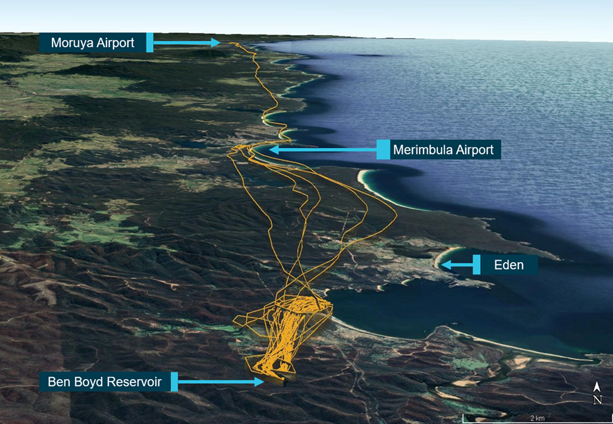
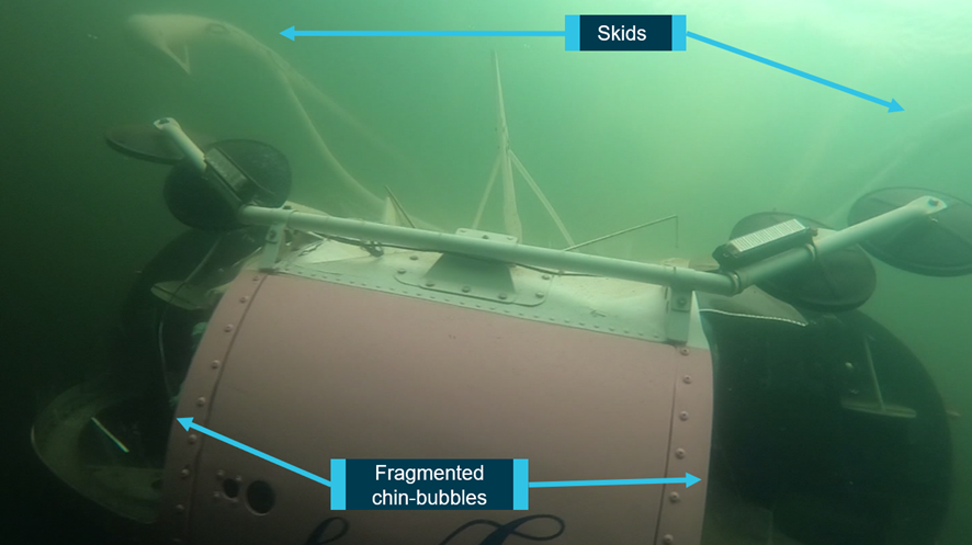
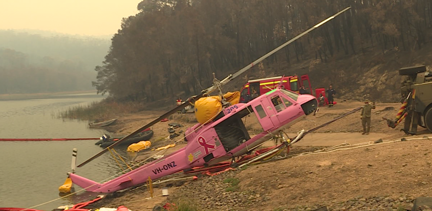
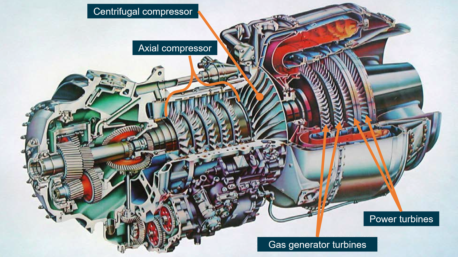
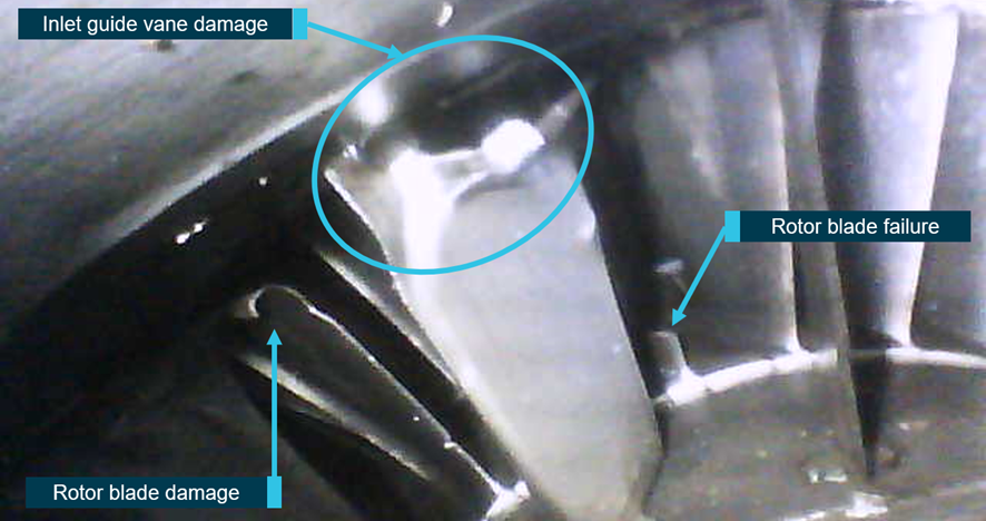
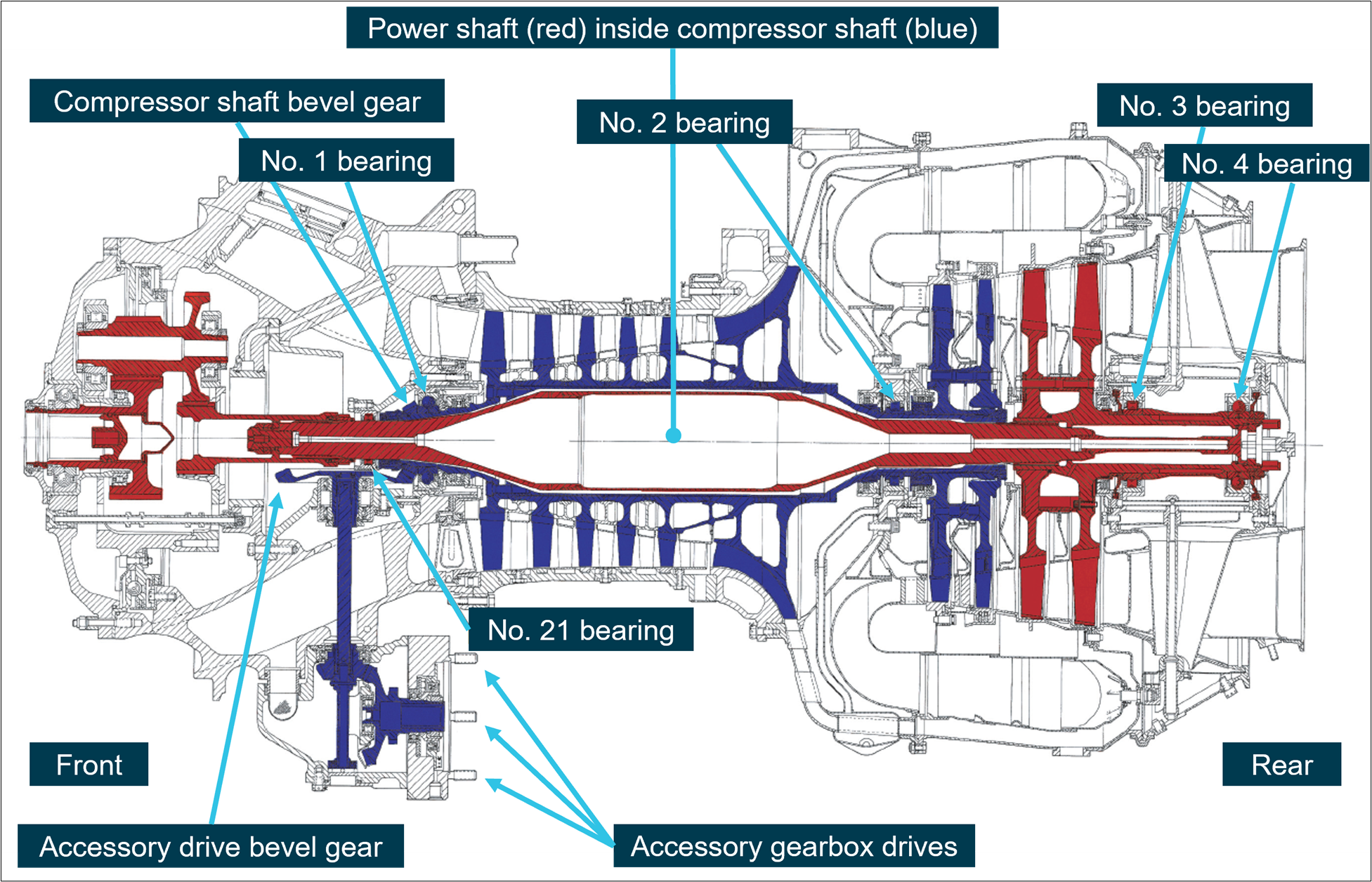
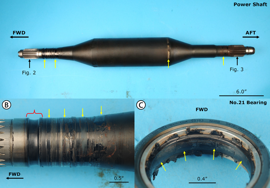
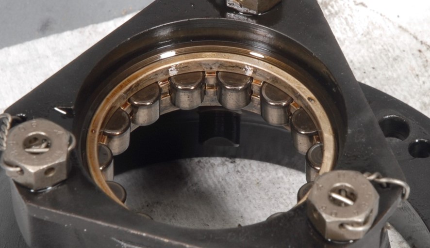
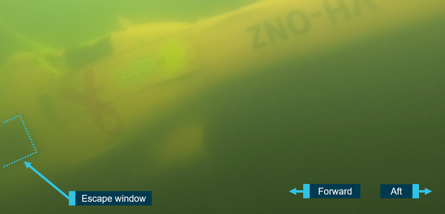

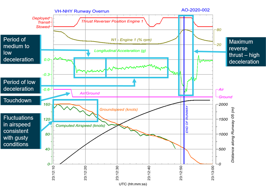
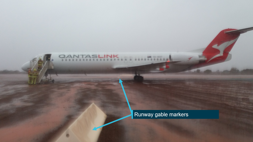
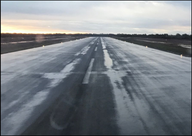
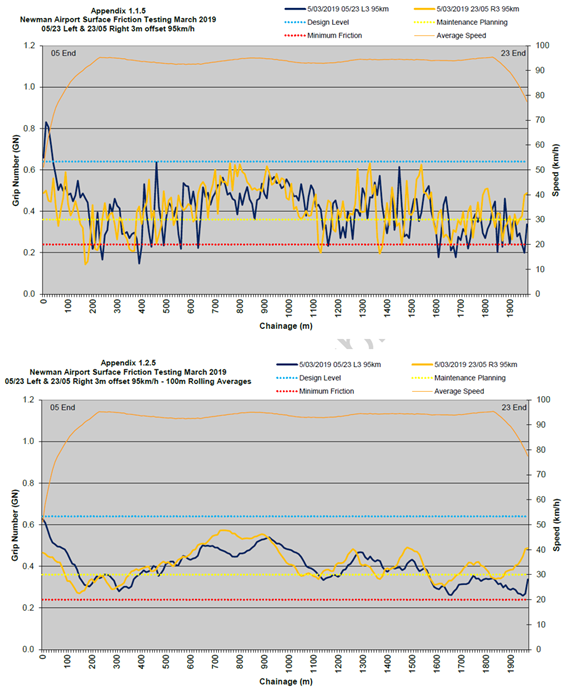
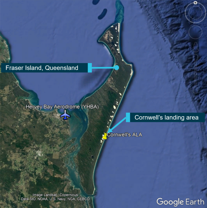
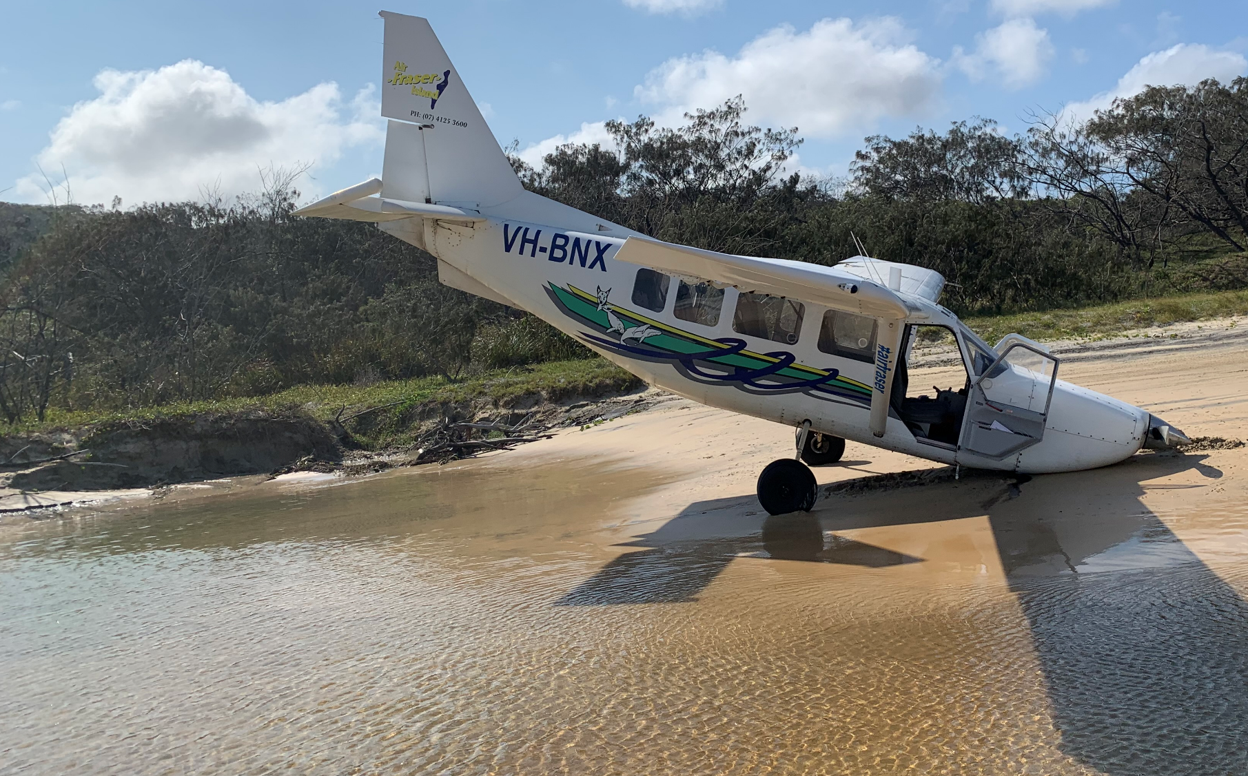
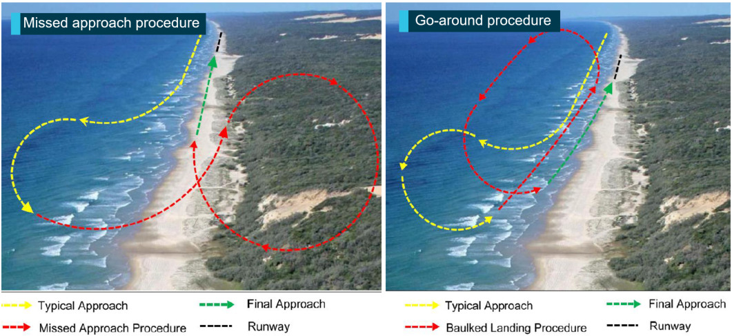
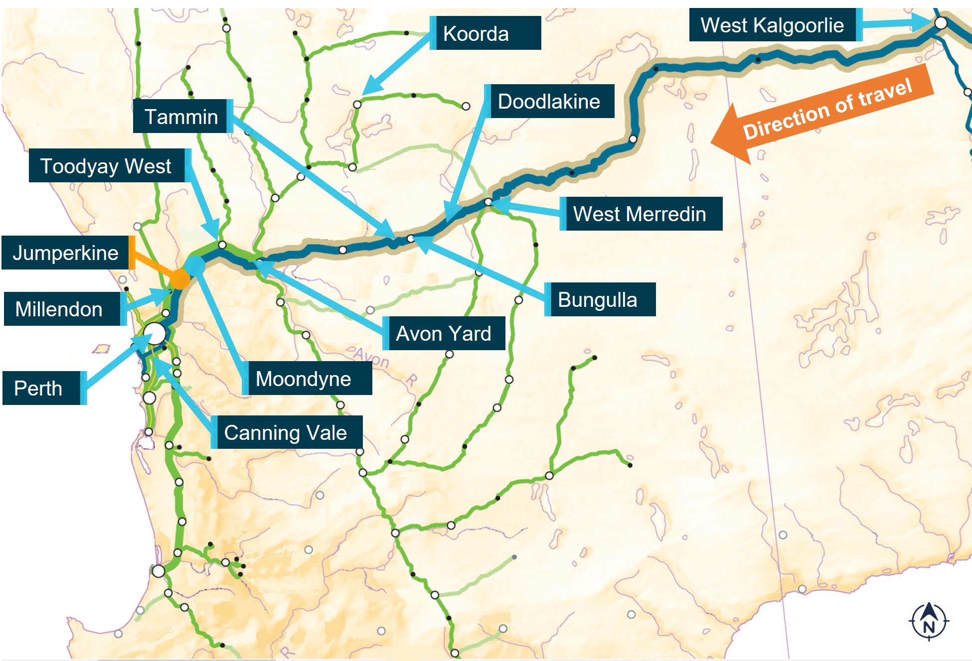
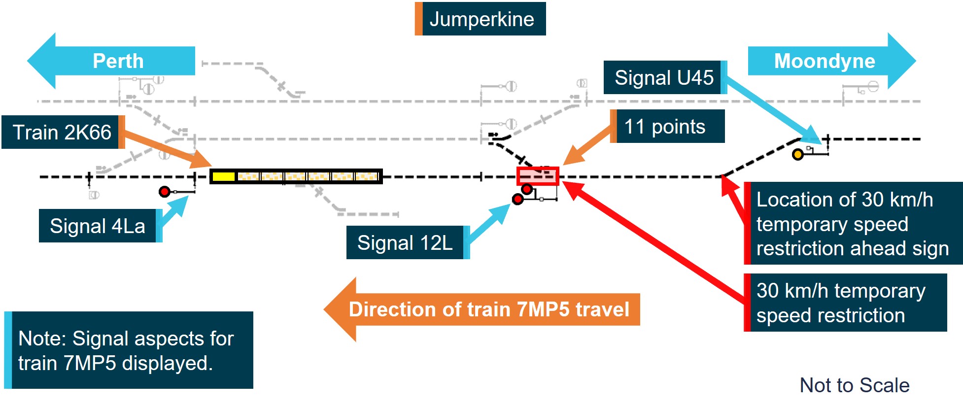
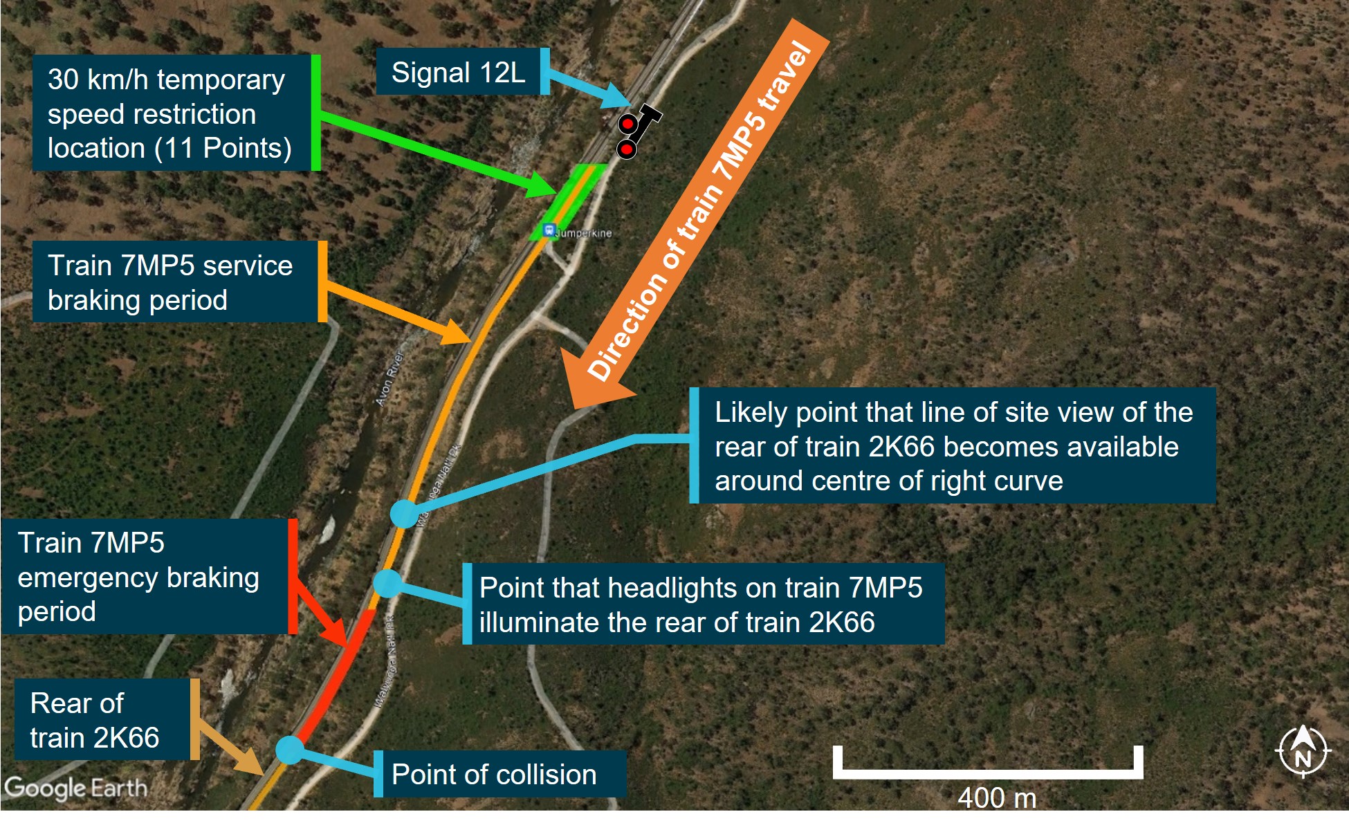
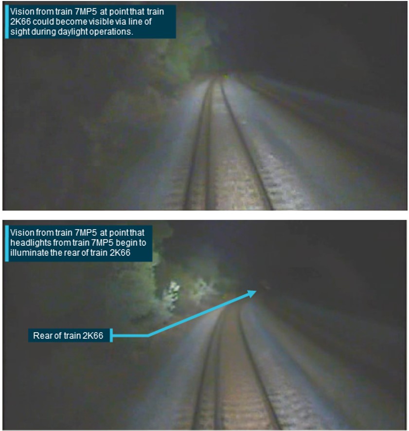
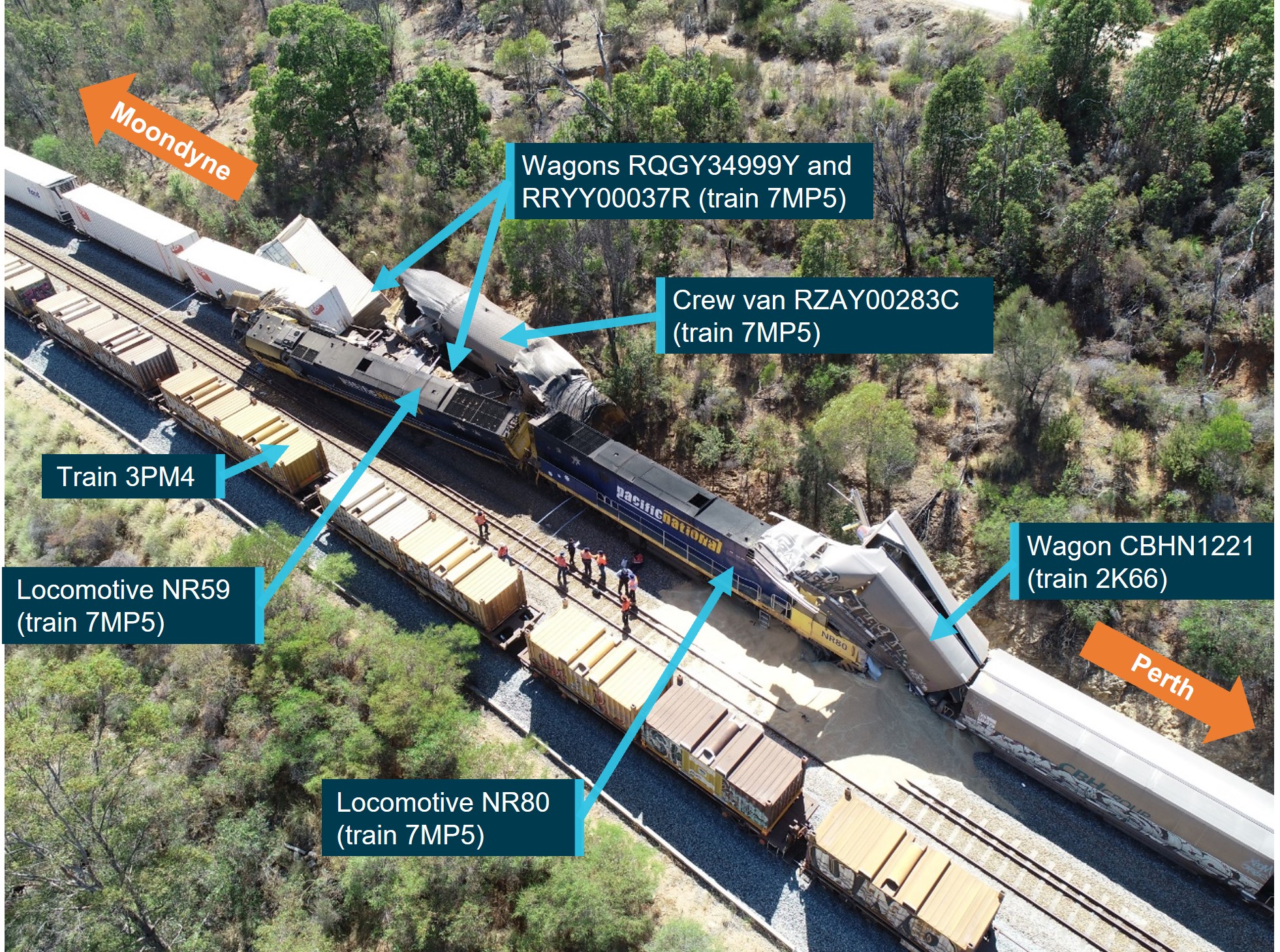
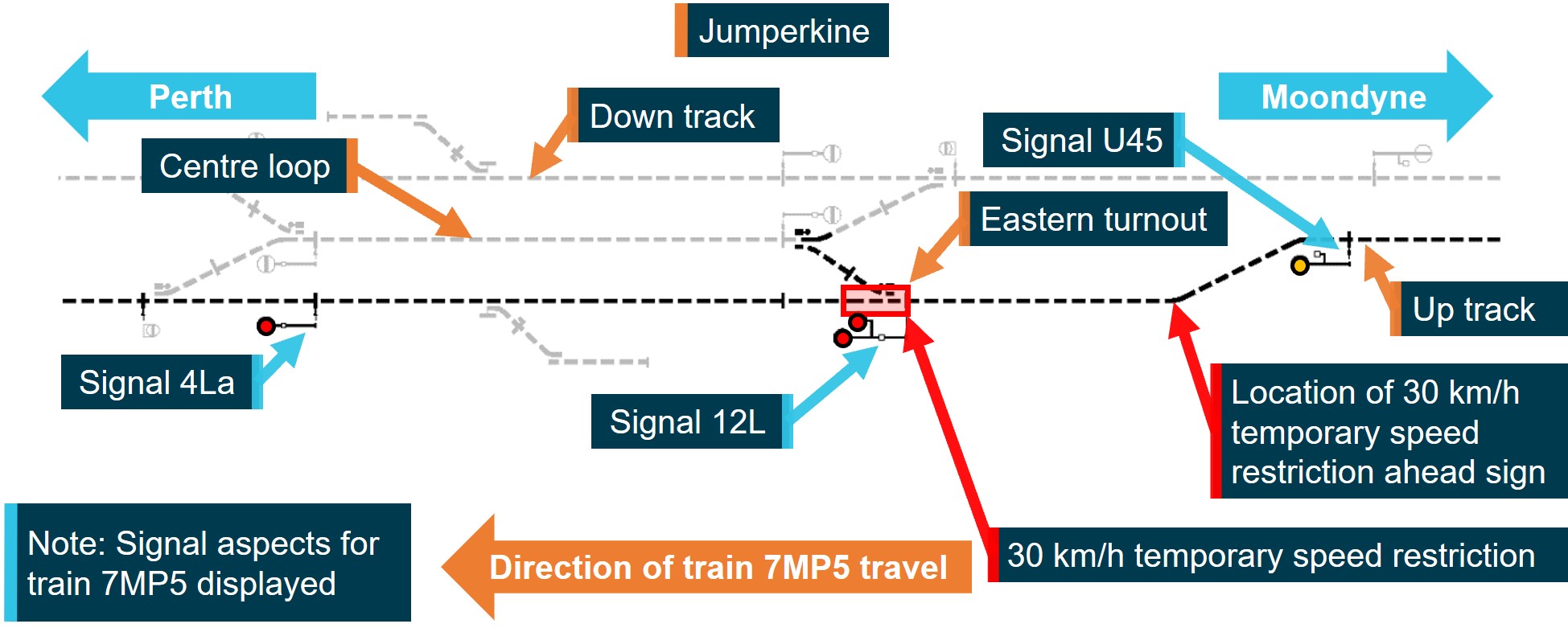
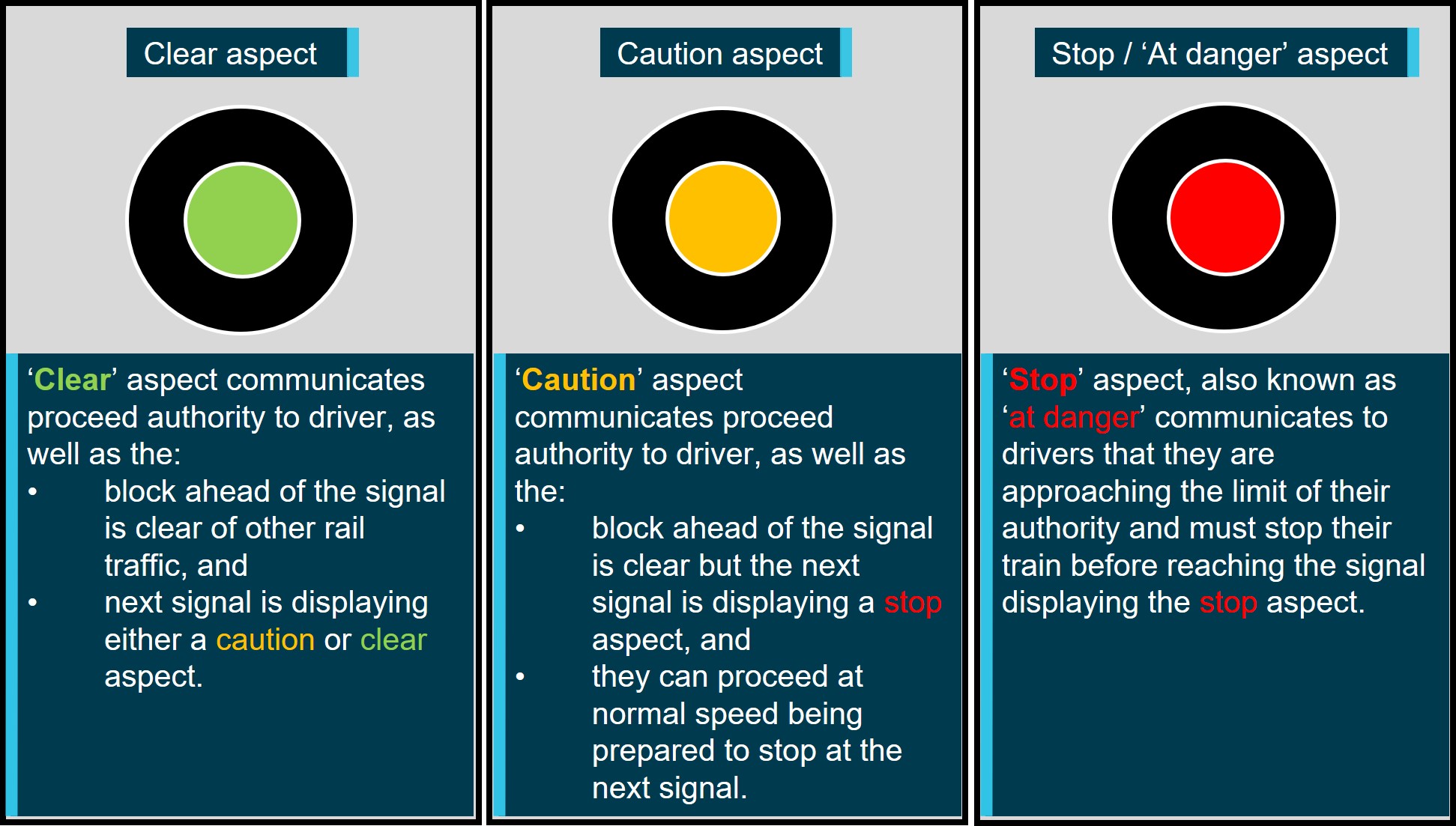
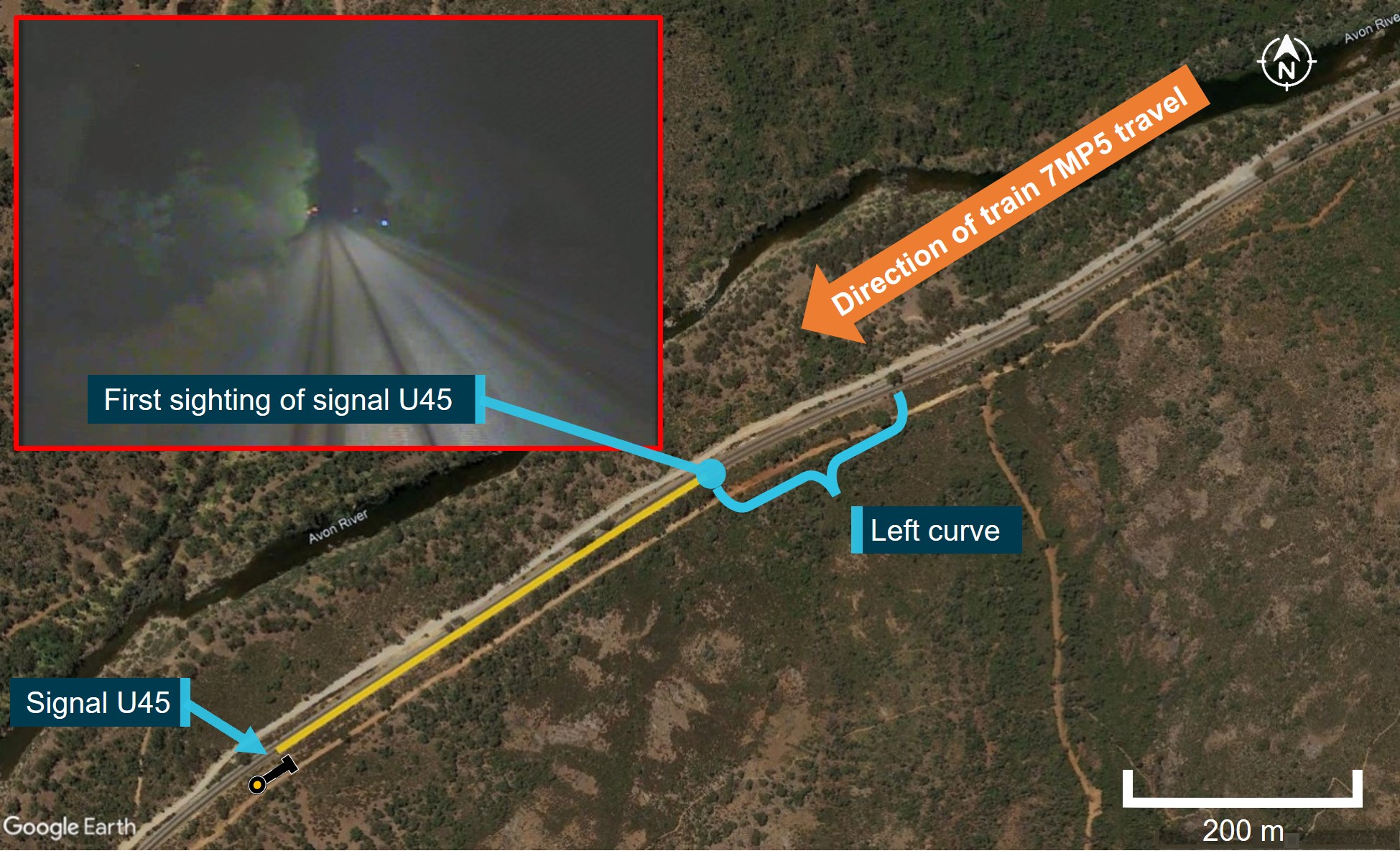
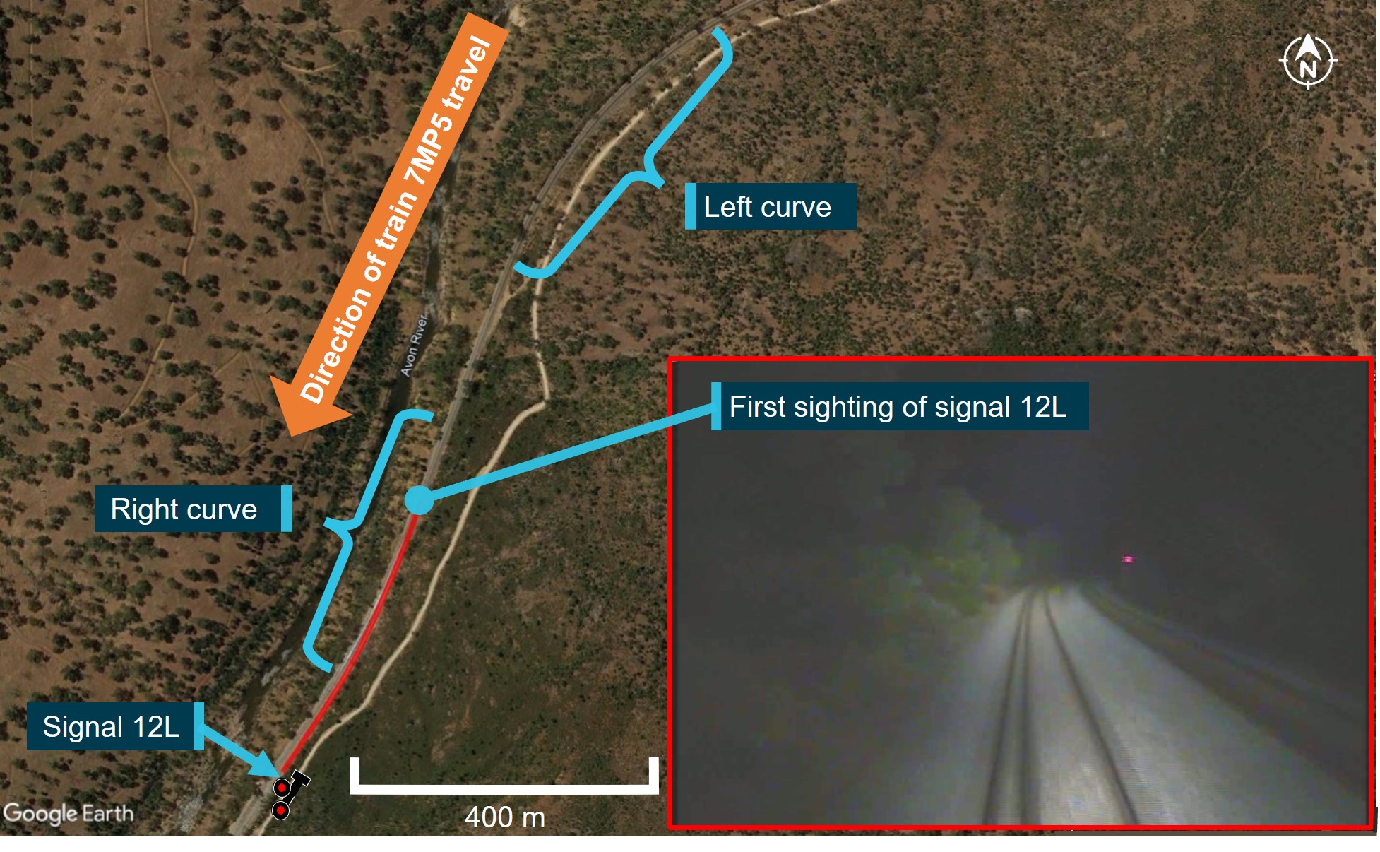
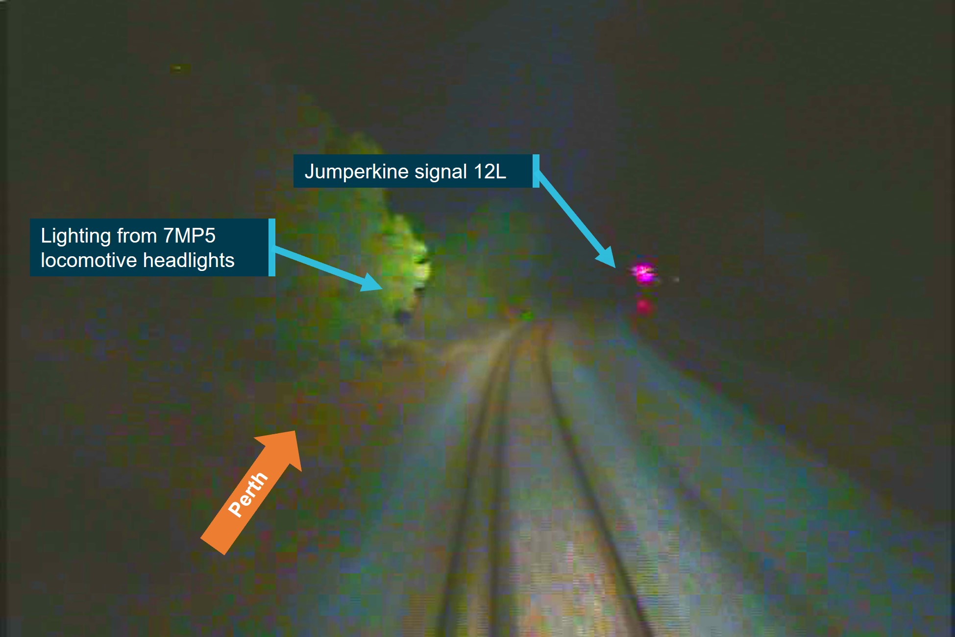
![Figure 11: ARTC minimum full service braking requirement for train type MLF-115[35]](/sites/default/files/inline-images/RO-2019-022%20Figure%2011.jpg)