Derailment of passenger train ST23, Wallan, Victoria, on 20 February 2020
Final report
Report release date: 09/08/2023
Executive summary
What happened
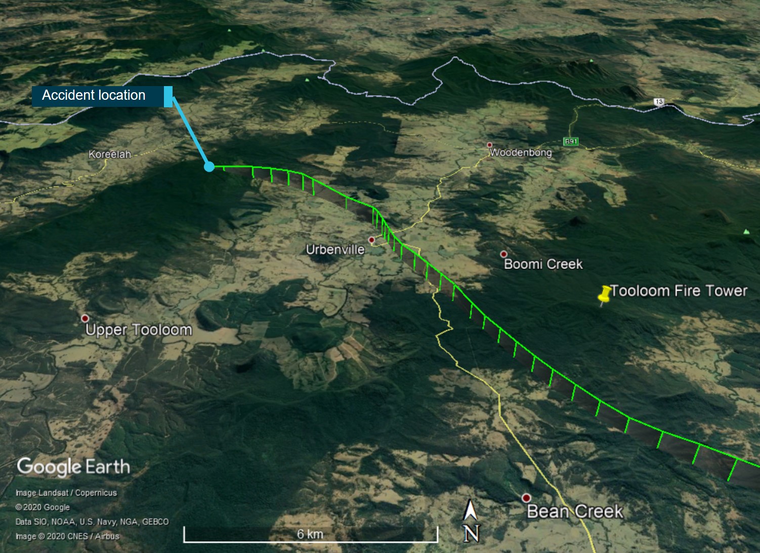
On 3 February 2020, a fire in a signalling equipment hut at Wallan in Victoria resulted in damage to the signalling system on the standard gauge rail network operated by the Australian Rail Track Corporation (ARTC). Repair of the signalling system would take several weeks and ARTC commenced managing rail traffic over a 24 km section between Kilmore East and Donnybrook using administrative systems. The section was predominantly a single bi-directional track which included a crossing loop at Wallan.
Trains were initially being managed through this 24 km section under the existing train working protocols that limited train speeds to no more than 25 km/h. This speed limit led to significant delays and ARTC developed train working arrangements that would permit trains to operate at normal track speeds. For passenger trains, this was up to 130 km/h. The arrangements that were established used (paper-based) train authorities to give drivers permission to travel through the section without signals operational, and also required an accompanying qualified worker (AQW) to ride in the cab with the driver. The first train authority under these new arrangements was issued on the evening of 6 February.
After the initial loss of signalling, the crossing loop at Wallan was not used and the points at either end of the loop were then locked in their normal (straight) position. Then, on 20 February, trains were to be routed through the loop to clean contamination from the rail head in preparation for signalling system testing. Around mid-afternoon, the points at each end of Wallan Loop were changed to their reverse position to route trains through the turnout to the loop track.
That evening, NSW Trains (TrainLink) was operating XPT train ST23 from Sydney to Melbourne. Train ST23 entered the affected section at Kilmore East and after travelling about 15 km derailed in the turnout at the northern end of Wallan Loop. The derailment occurred at about 1943. As a result of the derailment, the leading power car of train ST23 overturned and slid on its side for some distance. The driver and the AQW in the driver’s cab of the power car did not survive the accident. Eight passengers were seriously injured,[1] and a reported 53 passengers and the 5 passenger services crew members sustained minor injuries.
What the ATSB found
The investigation found that train ST23 derailed due to its speed exceeding the infrastructure design speed by a significant margin. The train entered the turnout to Wallan Loop travelling at a speed of between 114 and 127 km/h following an emergency brake application a short distance before the turnout. The maximum permitted operational speed for the turnout was 15 km/h and the train could not negotiate the turnout at its higher speed.
There was no evidence identified to suggest that the driver was incapacitated leading up to the derailment, and no evidence to suggest a rolling stock or a track defect had contributed to the derailment.
Several scenarios that may have led to ST23 not slowing for the loop turnout were considered. The leading power car was not fitted with in-cab voice or video recording devices and the absence of information on the interactions within the driver’s cab reduced the certainty of this finding. On the balance of evidence, it was concluded that the driver of ST23 probably expected to remain on the straight track through Wallan and was operating the train with that expectation.
The driver had likely developed a strong expectation that ST23 would be travelling on the straight track through Wallan. The driver of ST23 had operated the XPT service through the location 8 times in the 12 days prior, and on all occasions the loop track at Wallan was locked out of service consistent with the arrangements not to use the crossing loop at Wallan while signalling was non-operational.
Information on the routing of ST23 through Wallan Loop on the evening of 20 February was provided to the driver in a modified train authority document given to them at Kilmore East. However, the train working arrangements that were established by ARTC on 6 February did not include protocols that would confirm the driver’s understanding of the authority and excluded the requirement for the driver to read back the train authority to the network control officer. Expectations based on past experience influence the perception of information and it is probable that the driver did not recognise the text changes made to the train authority from those issued to them on their 8 previous trips.
The train working arrangements that were established to manage traffic while the signalling system was not functioning deviated from ARTC network rules and there was ineffective management of the risks introduced by this deviation. There were several safety factors that increased safety risk including weaknesses in ARTC risk management, the train working arrangements, risk controls (including a reliance on manual processes), and stakeholder engagement. For the routing of trains through Wallan Loop on 20 February, it was concluded that there were several available and practical risk controls that were not used by ARTC.
Weaknesses were also identified in the distribution and collection of safety information. It was found that NSW Trains did not have a functioning process for obtaining safety critical information for its Victorian operations from the ARTC web portal (WebRAMS).
It was also found that the configuration of the driver’s cab contributed to the adverse outcome for the driver and AQW. The side door of the power car detached when the car overturned. This resulted in track ballast and earth entering the cab and trapping the driver and the AQW. Efforts by members of the train crew and emergency services to assist those trapped was thwarted by a lack of ground-level access to the cab. It was found that contemporary industry standards did not address the loading of the side-doors of driver cabs during overturn, and ground-level access to train crew trapped in an overturned vehicle.
Soon after the derailment, some passengers self-evacuated the train. It was found that the methods of providing safety information to passengers through briefings, onboard guides and signage did not provide reasonable opportunity for all passengers to have knowledge of what to do in an emergency. Systemic weaknesses in the training of passenger services crew by NSW Trains was also identified.
Other findings are made with respect to potential barriers to safety improvements on the ARTC rail network. These address shared risks between the rail infrastructure manager (RIM) and rolling stock operators (RSO) and the slow, and uncoordinated, adoption of technologies. There continues to be a high reliance on administrative controls and a slow take up of technological solutions by ARTC to improve safety.
What has been done as a result
ATSB identified 15 safety issues against which organisations were requested to advise on their proactive safety actions. The details of these actions, and ATSB comment on these actions, are described in the Safety issues and actions section of this report.
Six safety issues were allocated to ARTC. ARTC advised that it has introduced an updated management process for deviations from ARTC Network Rules (for planned or unplanned works). ARTC advised that this process required a risk assessment involving stakeholders, the development of appropriate controls for implementation by each stakeholder, and ARTC Executive approval of the risk assessment and plan. Three safety issues pertaining to network user engagement and distribution of safety information remained open, and updates will be provided on the ATSB website.
Six safety issues were allocated to NSW Trains. NSW Trains advised that it has developed new procedures for the daily access of the ARTC WebRAMS system for safety information and has also amended procedures to include confirmation of receipt of safety critical information by train crew prior to them starting their day of operations. NSW Trains also advised of changes to crew emergency response training, although 2 related safety issues remain open. The ATSB has made one recommendation to NSW Trains that it undertake further work to improve the methods used to provide safety information to passengers.
One safety issue was allocated to ActivateRail, a contractor to ARTC. Relevant to this safety issue, ActivateRail advised that it has introduced additional control processes pertaining to its participation in projects. ActivateRail also committed to ongoing and future risk management awareness training of its consulting and professional services staff.
The Rail Industry Safety and Standards Board (RISSB) has committed to consider the outcomes of this investigation in a review of the Australian Standards for body structural requirements (locomotive) and access and egress. The outcomes of the RISSB review of these standards will be reported on the ATSB website.
Safety message
Central to this occurrence was the breakdown of risk management processes following deviation from established network rules. Critical to successful risk management in degraded network conditions is the involvement of network users in the identification and assessment of emergent risks, and user participation in the development of appropriate risk controls.
This occurrence also highlighted an over reliance on administrative controls and the missed opportunities to use existing and emerging technologies to manage risk associated with human error. To improve safety outcomes, the rail sector must move faster and together in embracing technology to improve its management of safety risks.
The occurrence
Overview
On 20 February 2020, NSW Trains (TrainLink) was operating the express passenger train (XPT) designated ST23 from Sydney, New South Wales (NSW), to Melbourne, Victoria. Train ST23 was operating on the rail network managed by the Australian Rail Track Corporation (ARTC). For a 24 km section between Kilmore East and Donnybrook in Victoria, ARTC was managing rail traffic using temporary train working arrangements while it undertook repairs to the signalling system that had been damaged in early February.
Train ST23 entered the affected section at Kilmore East at about 1935 local time. At about 1943, and after travelling about 15 km into the affected section, ST23 derailed at the northern end of Wallan Loop. As a result of the derailment, the leading power car of ST23 overturned. The driver and an accompanying rail worker in the driver’s cab of the power car did not survive the accident. Several passengers were seriously injured, and a large number of passengers and the passenger services crew sustained minor injuries.
Prior to the occurrence
At about 2343 on 3 February 2020, ARTC identified that the centralised traffic control (CTC) signalling system had been disrupted around Wallan in Victoria. A subsequent investigation by ARTC determined that a road vehicle had struck overhead electrical wires in Wallan, resulting in a ‘power surge’ to the nearby signalling equipment hut. A subsequent fire in the hut resulted in extensive damage to equipment and cabling.
As a result of the damage to the signalling system at Wallan, ARTC commenced managing rail traffic through the affected section using caution orders and other safeworking rules. Under these arrangements, trains were required to proceed cautiously at a speed not exceeding 25 km/h, and as a result there were significant delays to rail services.
To reduce delays through this affected section, ARTC established train working arrangements that used train authorities[2] and permitted higher train speeds. The new arrangements commenced at 1900 on 6 February and the first train authority issued was at 2042 that day. This arrangement was used for the 24 km section between Donnybrook and Kilmore East (Figure 1).
Figure 1: Location of train working between Donnybrook and Kilmore East
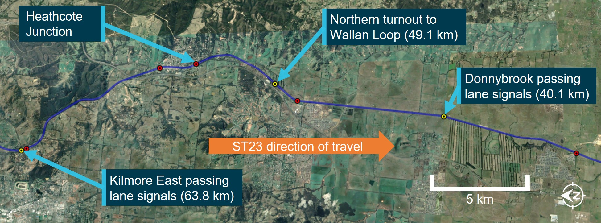
The affected section was between signals within the passing lanes at Donnybrook and Kilmore East. Rail-km shown from Melbourne.
Source: Google Maps, annotated by CITS
Notification to network users of the change in train working was by a train notice[3] issued by ARTC. Train notice 266 (TN 266) describing the change was issued on 6 February, updated on 7 February, and further amended on 13 February. In the arrangements established, the turnouts at either end of Wallan Loop were set to their normal position for the No.1 track (the through route) and clipped in that position.[4]
For the train working arrangements established, ARTC did not impose any additional speed restrictions through the section. The maximum permitted speed for passenger trains travelling on the No.1 track through Wallan was 130 km/h.
On 19 February, TN 266 was supplemented with train notice 367 (TN 367) advising of a change at Wallan Loop. Trains were to be diverted through the loop (No.2 track) for a short period on 20 February. The purpose of routing trains through the loop was to remove any contamination that may have developed on the rail head of the No.2 track while it was not being used.[5] This was in preparation for signal system testing and re-establishment of the CTC signalling system.
Between 1453 and 1536 on 20 February, and with track protection in place,[6] the points at either end of Wallan Loop were manually reconfigured from their normal position to their reverse position.[7] This change meant that rail traffic travelling in either direction after this time would be diverted into the crossing loop (No.2 track). TN 367 reflected this change and also specified a speed limit of 15 km/h for entry into the loop, and a limit of 35 km/h when exiting the loop. On that same day between 1600 and 1837, track force protection was utilised about 1 km south (towards Donnybrook) of Wallan Loop for the laying of conduit.[8]
The first train to pass through Wallan Loop in this altered configuration was southbound V/Line train 8620. Immediately prior to 8620 departing Kilmore East, the network control officer (NCO) advised the driver that they were going to be the first train through Wallan Loop in the past 72 hours. This notification by the NCO was consistent with the NSW practice of advising drivers of the potential unreliability of track circuits if trains have not run on a track in the previous 72 hours, although in this instance the signalling system was not operating at Wallan Loop.[9] Train 8620 departed Kilmore East at about 1623 and its train authority was cancelled for its arrival at Donnybrook at 1647.
The second train through the loop was northbound V/Line train 8625. When stopped at Donnybrook, and during exchanges between the driver and the NCO, there was no mention by either party of transiting through Wallan Loop. The train departed Donnybrook at about 1857 and was in the affected section when ST23 arrived at Kilmore East.
Train ST23 journey from Sydney to Albury
Passenger train ST23, operated by NSW Trains, was to be the third train through Wallan Loop under the modified train working arrangements. The train was comprised of leading power car XP2018, 5 passenger cars of varying configuration, and a trailing power car. It was a single-driver operation.
ST23 departed Central Station in Sydney at 0741 on 20 February 2020, just after the scheduled departure time of 0740. The train service was to travel through NSW, into Victoria, and to arrive at its final destination at Southern Cross Station (Melbourne) at 1830 that evening (Figure 2).
Figure 2: Train route from Sydney to Melbourne
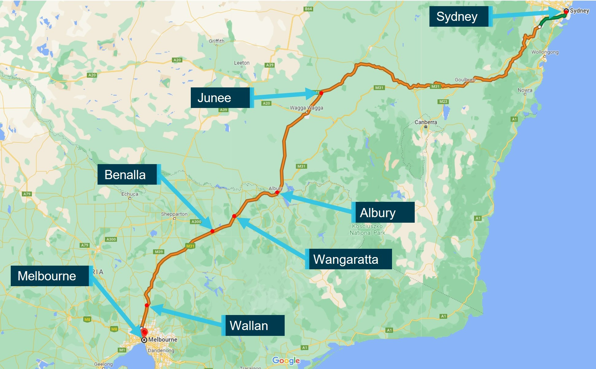
Source: Google Maps, annotated by CITS
The train proceeded south and arrived at Junee in southern NSW at 1452,[10] about 85 minutes behind schedule. There was a change of driver at Junee. The train departed Junee at 1456 and continued south, arriving in Albury on the NSW–Victorian border at 1637. There was a change in passenger services crew at Albury. The new passenger services crew comprised a passenger services supervisor (PSS), a crew member training for the supervisory role, and 3 passenger attendants.
Train ST23 journey from Albury
Train ST23 departed Albury at 1644, about 89 minutes behind schedule, and entered the Victorian section of its journey. After departing Albury, there was an announcement to passengers, tickets were checked, and the passenger services crew walked through the passenger cars checking door locks and equipment. Later, the driver was provided with a snack while the train was stopped at Wangaratta and the train departed that station at 1722, 87 minutes behind schedule.
Beyond Benalla, the focus of several of the passenger services crew was on meal activities in the buffet car. The crew described the journey as normal, although passengers were reported to be frustrated with the delays. ST23’s delay had originated prior to Junee.
At about 1840, the NCO at ARTC Network Control[11] contacted the driver of ST23 regarding a network alarm that had been received.[12] Later in the communication, the NCO advised the driver that ST23 would come into Kilmore East and wait until a V/Line train had passed.[13] As part of this communication, the controller mentioned that ‘you’re going via the loop there at Wallan’. The response from the driver did not reference the train’s route via Wallan Loop.
Train ST23 at Kilmore East
Train ST23 continued south before coming to a stand at about 1856 at intermediate home[14] signal KME28, which was displaying a stop indication. There was a standard-gauge passing lane at Kilmore East, with designated East and West Lines, and ST23 had been routed via the East Line (Figure 3).[15]
Figure 3: Kilmore East standard-gauge passing lane shown in black (not to scale)
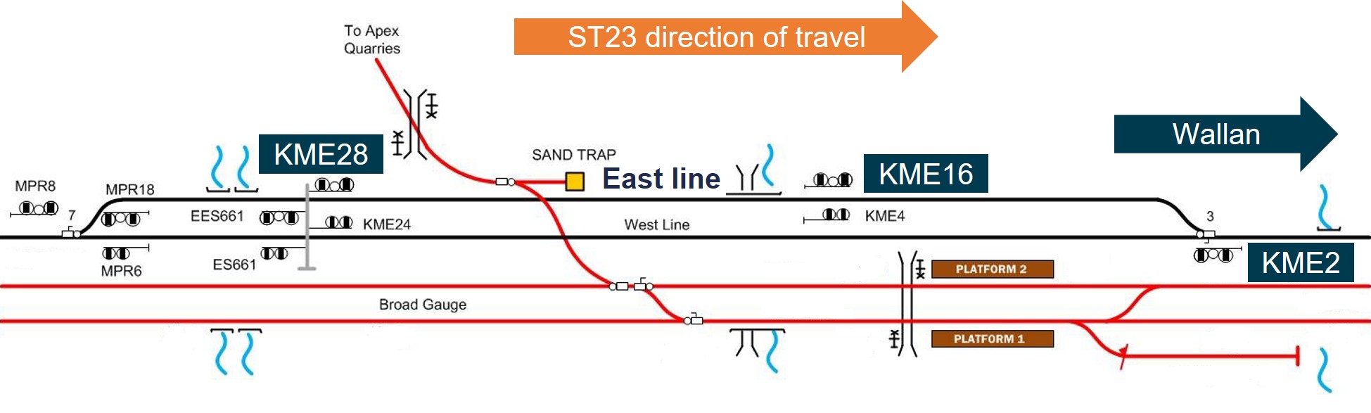
The schematic shows the track at Kilmore East including the passing lane. Only the signalling for the standard-gauge track is shown. NSW Trains’ services did not use the broad-gauge track.
Source: ARTC, modified and annotated by CITS
The driver of ST23 contacted the NCO at about 1904 and inquired when they might receive permission to proceed. ST23 was required to wait until the northbound V/Line train 8625 had cleared the single-line section.
At around this time, several rail workers were preparing for the arrival of ST23 at signal KME16 (at Kilmore East). These rail workers were to assist ST23 with the train working arrangements between Kilmore East and Donnybrook. Among these rail workers were an (in-field) signaller (referred to in this report as the signaller) and an accompanying qualified worker (AQW).[16] The AQW would accompany the driver from Kilmore East to Donnybrook and arrange the activation of level crossing protection at Wallan–Whittlesea Road just south of Wallan Loop.
ST23 was the first train that the signaller and AQW were to assist after commencing their shifts. The signaller had first arrived at Donnybrook at about 1830, and then travelled to Kilmore East to start their shift. The AQW had also first attended Donnybrook before travelling to Kilmore East. At the start of their shift, the AQW was provided with a copy of TN 367 and then briefed on the transit through the loop and the requirement to advise the driver.[17]
At about 1915, while ST23 was stopped at signal KME28, the signaller positioned near signal KME16 contacted the NCO to advise that they had come on shift and taken over from the previous signaller. During this call, train authority 17 (TA 17) for ST23 to proceed between Kilmore East and Donnybrook was issued to the signaller by the NCO. The NCO read TA 17 to the signaller, describing that the authority was issued in accordance with train notices 266 and 367, that the points at Wallan Loop were set and secured for No.2 track, and that there was a maximum speed entering the loop of 15 km/h and a maximum speed exiting the loop of 35 km/h. From this NCO dictation, the signaller completed their copy of the train authority form and then read the completed TA 17 back to the NCO. The NCO noted the time of the readback as 1920.
A condition affecting the network (CAN)[18] notice was then completed by the signaller under the instruction of the NCO. This notice was to warn train crew of the condition of the Wallan–Whittlesea Road level crossing protection, and that the protection was being manually operated. The CAN was designated number 7, and the readback of CAN 7 to the NCO by the signaller was noted by the NCO as being completed at 1921.
ST23 was held at signal KME28 on the East Line until the northbound V/line passenger train 8625 had transited the Donnybrook to Kilmore East single-line section, passed signal KME2, and was travelling along the West Line through Kilmore East. The V/Line train was clear of the single-line section by about 1925 and, soon after, the driver of ST23 was given permission by the NCO to proceed to home departure signal KME16,[19] still on the East Line within the Kilmore East location.
ST23 arrived at signal KME16 at about 1931. The train was met by several rail workers, including the signaller and the AQW. Shortly prior to the train’s arrival, the signaller gave documents TA 17 and CAN 7 to the AQW and briefed the AQW on their content. The AQW boarded the leading power car and joined the driver at the head of the train, and gave TA 17 and CAN 7 to the driver. It was intended that the AQW would accompany the driver for the 24 km section to Donnybrook. The XPT cab was not fitted with a cab voice recording facility (and was not required to be), and there was no record of the conversation between the AQW and driver.[20]
At about 1932, while the train was stopped at signal KME16, the driver and the on-duty NCO communicated via the train radio. This exchange included the NCO asking whether the driver had received all the paperwork, and the driver responding ‘yeah, authority 17 and CAN number 7 filled out ahh the same way it has been for the … rest of the time’.
During this communication between the NCO and driver, the NCO did not read the content of TA 17 to the driver, and the driver did not read back the content of TA 17 to the NCO.[21] The NCO commented ‘points all set for the loop’. The driver’s response to the controller did not reference transiting via the crossing loop (No.2 track) at Wallan. There was no communication between the controller and driver regarding the maximum speed of 15 km/h for entering Wallan Loop.
Derailment of train ST23
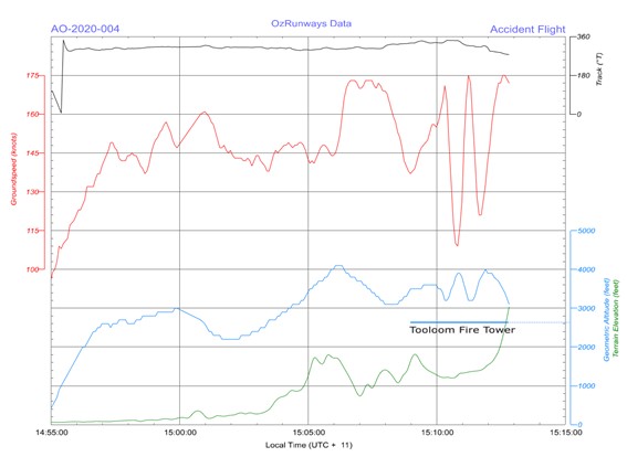
The train departed signal KME16 at about 1934 and entered the single-line section towards Wallan and Donnybrook. The line speed for the XPT between Kilmore East and Donnybrook was 130 km/h.[22] After departing from signal KME16, the speed of the train was increased and initially maintained between 100 km/h and 120 km/h.[23]
The AQW was to ensure that the active level crossing protection at Wallan–Whittlesea Road in Wallan was in place for the passage of the train.[24] A level crossing keeper (LCK)[25] was located at the crossing to activate the crossing protection. The AQW contacted the LCK by phone at approximately 1941, when the train was at about the 52 km mark. The LCK reported activating the crossing protection at Wallan–Whittlesea Road and confirmed its activation to the AQW. This phone call lasted about 53 seconds and the LCK did not recall anything unusual about the communications with the AQW. The call was completed when the train was about 4.5 km from the level crossing and 2.7 km from the entry to Wallan Loop.
The speed of ST23 then increased towards the line speed of 130 km/h as the train approached Wallan. At about 1943, ST23 was approaching the northern end of Wallan Loop when an emergency brake application was made. Brake cylinder pressure was recorded as commencing to rise when ST23 was between 153 and 50 m from the turnout.[26] This slowed the train a small amount before it entered the turnout travelling at a speed estimated to be between 114 and 127 km/h. The train was not able to negotiate the turnout to the No.2 track (loop) at this speed and derailed (Figure 4). The leading power car rolled onto its left side. The trailing 5 passenger cars remained upright although tilted by varying amounts, and the rear power car remained upright on the track.
Figure 4: Aerial photograph of derailment site
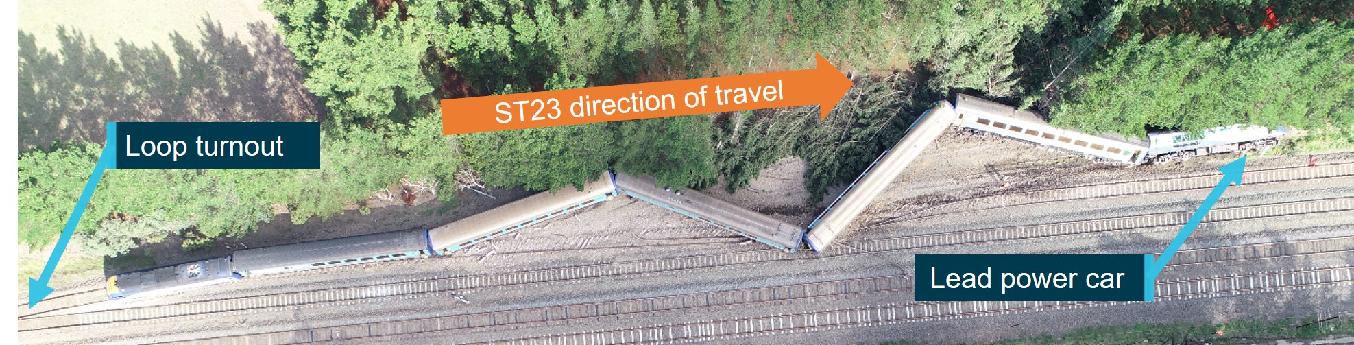
Source: ATSB
Emergency response
At the time of the derailment, there were 155 passengers,[27] the driver, 5 passenger services crew members and the AQW on board the train. The driver and AQW were in the driver’s cab, a passenger services crew member was in the second passenger car and the other 4 passenger services crew members were in the buffet car (the third passenger car).
After the train came to a stop, the passenger services supervisor (PSS) called the train crew on a hand-held radio and received responses from the other members of the passenger services crew. However, the driver did not respond and the AQW was not in possession of a NSW Trains issued radio.
Two members of the passenger services crew then commenced raising the emergency using their hand-held radios.[28] The crew members made several emergency calls seeking assistance, advising that the XPT had derailed and requesting that all trains stop.
A V/Line signaller based at Wallan heard the emergency calls and responded within about 25 seconds of the first recorded ‘emergency emergency emergency’ radio broadcast by the passenger services crew. On confirming the nature of the emergency, the Wallan signaller contacted V/Line network control at Centrol.[29] Centrol then contacted ARTC Network Control at Junee at about 1945, relaying the information that the XPT may have derailed. During this communication, Centrol also advised ARTC Network Control that V/Line would stop trains on the broad-gauge tracks that ran parallel to the standard gauge. In response to the Centrol call, ARTC sought confirmation of what had happened and initiated its response.
Emergency services recorded the first ‘000’ call for assistance from a train passenger, time-stamped 1945:06.[30] This was followed by a series of calls from other passengers, members of the passenger services crew, and members of V/Line and ARTC.
Around this time or soon after, some passengers started to self-evacuate from the train prior to the passenger services crew receiving confirmation that rail traffic in the area had been stopped. Although passengers were told to vacate adjacent tracks and leave their belongings behind, video footage and photographs showed that there were mixed levels of compliance with these instructions.
In response to the emergency, passenger services crew undertook a range of tasks including managing passengers that had evacuated onto the track and attending to passengers on the train. At different times, three passenger services crew members also went to the leading power car to check on the driver and AQW. Two crew members separately entered the power car through its right-side cab door, accessible from the ‘top’ of the car laying on its left side. Finding it difficult from within the cab to assist the driver and AQW, who had both been trapped by track ballast and earth that had entered the cab, the crew attempted to break the cab’s windscreen to gain access from outside.[31] However, attempts by the passenger services crew to gain this ground-level access from outside the cab were unsuccessful.
The first emergency service to arrive on site was Victoria Police at about 2003, followed by further emergency, medical and fire services. However, both the driver and the AQW did not survive.
As a result of the movement of the passenger cars during the derailment sequence, 8 passengers were seriously injured and a reported 53 received minor injuries.[32] The 5 passenger services crew members also received minor injuries.
Context
Train operator
Train ST23 was operated by NSW Trains trading as NSW TrainLink.[33] NSW Trains was established in 2013 as part of a restructure of rail arrangements in New South Wales (NSW). NSW Trains operated regional rail and coach services in NSW and interstate rail passenger services between Sydney (NSW) and the east coast capital cities of Melbourne (Victoria) and Brisbane (Queensland).
In accordance with the Rail Safety National Law (RSNL), NSW Trains was an accredited rolling stock operator (RSO), that was defined (in part) as having ‘… effective control and management of the operation or movement of rolling stock on rail infrastructure for a railway…’.[34] As an RSO, NSW Trains was also defined in the RSNL as a rail transport operator and had defined safety duties.[35]
Train information
The XPT (Express Passenger Train) ST23 operating on 20 February 2020 was comprised of 7 vehicles (Figure 5). The leading 3 vehicles were manufactured by ABB Transportation in Dandenong, Victoria, and were commissioned in 1993. The trailing 4 vehicles were manufactured by Comeng in Granville, NSW, and were commissioned between 1981 and 1984. The fleet of XPT vehicles was maintained by Sydney Trains.[36]
Figure 5: Train configuration
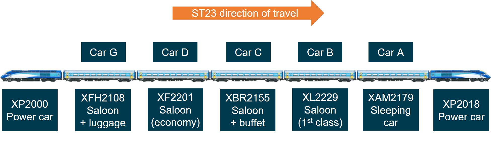
Source: Vehicle images supplied by Sydney Trains, annotated by CITS
The XPT was first introduced into service in 1982 and was based on the InterCity 125/Class 43 design used in the United Kingdom. The power car included a forward driver’s cab that was located ahead of a compartment housing propulsive machinery. Cab features included side doors for primary access (fitted on the left and right sides of the driver’s cab), a rear door to the machinery space, the driver’s seat that was positioned slightly left of the car centreline, and a second seat that was located to its right (Figure 6).
Figure 6: Power car layout and cab seat arrangement
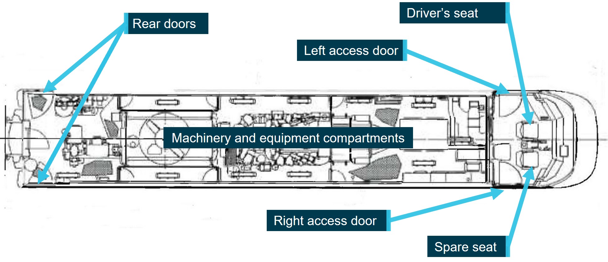
Source: RailCorp (NSW Transport), annotated by CITS
A post-derailment review of the condition of the ST23 rolling stock did not identify any adverse rolling stock condition or defect that was likely to have contributed to the derailment. The review involved inspections, testing and an examination of maintenance records (Appendix A).
Inspections were conducted at several locations and included observations at the derailment site, inspection of vehicles XP2000 and XFH2108 at the Sydenham Maintenance Centre, and inspection of vehicles XP2018, XAM2179, XL2229, XBR2155 and XF2201 at the Auburn UGL facility. Post-occurrence testing conducted by Sydney Trains and witnessed by the Office of Transport Safety Investigations (OTSI) included testing of braking, vigilance and communication systems.
Personnel information
Driver
The driver of train ST23 had been associated with the rail industry for about 40 years, employed in a range of roles including driving, training, and management. They returned to driving in mid-2016 as a regional driver with NSW Trains and were assessed as competent on the route between Junee and Melbourne in July 2019. The driver was qualified to operate the XPT train and had completed continuation training (safeworking).
Typically when driving the XPT services between Junee and Melbourne, they would drive the Junee to Melbourne leg of the Sydney to Melbourne service and, following a period of rest in Melbourne, drive the return journey to Junee. After the commencement of train authority working through Wallan on 6 February 2020, they drove the Junee–Melbourne–Junee round trip (including a rostered rest period in Melbourne) 4 times between 8 and 19 February, including several trips after all signals within the section had been extinguished.
On 20 February, the driver’s shift commenced in Junee at 1315 and their scheduled sign-off in Melbourne was at 1845.[37] As a result of the delayed arrival of ST23 into Junee (85 minutes), the commencement of driving duties were delayed (to 1456) and would have led to a late arrival in Melbourne. A review of the driver’s roster and recent history found there was insufficient evidence to conclude that the driver was experiencing a level of fatigue that would adversely affect their performance (Appendix B).
The driver was medically assessed as fit for duty (unconditional) in accordance with the requirements for a Category 1 Safety Critical Worker[38] and no pre-existing health issues were identified that were likely to have contributed to the occurrence. Further, toxicology results did not identify any substance that may have impaired performance.
There was no evidence of any phone calls to or from the driver or messages sent from the driver’s phone in the period immediately prior to the occurrence.
Passenger services crew
There were 5 passenger services crew members on board ST23, one more than the normal complement. Their years of service ranged between 1 and 13 years. The passenger services crew consisted of:
- a passenger services supervisor (PSS) responsible for overall supervision of the passenger operations and the management of passengers in an emergency[39]
- a senior passenger attendant (SPA) responsible for the buffet operations and ticket sales
- a passenger attendant 4 (PA4) responsible for assisting the SPA in the buffet, and assisting with general passenger duties along the train
- a passenger attendant 2 (PA2) responsible for general passenger duties along the train
- an additional crew member who was shadowing the PSS as part of on-the-job training.
The accompanying qualified worker
The accompanying qualified worker (AQW) on board ST23 was employed by Programmed, a labour-hire organisation that provided skilled workers across a range of industries including transport. Programmed supplied several personnel to ARTC from 4 February 2020 to assist with the management of rail traffic between Donnybrook and Kilmore East.
The AQW was certified to Track Protection Coordination level 3.2, most recently renewed in March 2019. They had completed several safeworking related training modules including (in 2017) the units TLIC2081 (Pilot rail traffic within work on track authority limits)[40] and TLIL3083 (Implement a track work authority and manage rail traffic through worksites).
The AQW had been with Programmed since 2006. Records[41] indicated that the worker had been engaged by several rail operators in Victoria in various roles, and in recent years primarily as a track force protection coordinator or hand signaller. There were no records identified of previous experience in performing the role of an AQW, or in train pilotage.
The AQW had been engaged at Wallan from 4 February, primarily in the role of level crossing keeper (LCK) at the Wallan–Whittlesea Road level crossing. All shifts from February were night shifts that mostly commenced at about 1900. On 20 February, the AQW had just commenced the night shift. A review of the AQW's roster and recent history found there was insufficient evidence to conclude that the AQW was experiencing a level of fatigue that would adversely affect their performance. The AQW was rostered off duty from 16 to 18 February and conducted a night shift commencing 19 February from 1900 to 0500.
The evening of 20 February was the first time this rail worker performed the role of an AQW, and ST23 was to be their first train that evening. Reporting in at Donnybrook for the start of their shift, the AQW received a briefing from a more senior AQW on the tasks to be performed, and the conditions of transiting through the loop described in TN 367. They then travelled to Kilmore East for the start of the shift.
The AQW was medically assessed as fit for duty (unconditional) in accordance with requirements for a Category 1 Safety Critical Worker and no pre-existing health issues were identified that were likely to have contributed to the occurrence. Further, toxicology results did not identify any substance that may have impaired performance.
The network control officer
The network control officer (NCO) on duty at the time of the derailment had worked as a network controller since 2004 and was qualified on all the control boards at ARTC Junee network control. This was the first shift that this NCO had experienced the train authority process being used between Donnybrook and Kilmore East.
The NCO came on shift at about 1445. The NCO advised that they received instruction on how the train authority forms were to be used from the NCO that was previously on shift. A conversation also took place between an ActivateRail representative[42] and the NCO at 1530, during which the NCO was advised of the correct train authority forms that reflected train notice 367 (TN 367). At 1554 a further conversation took place between the NCO and the ActivateRail representative for the issuing of train authority 15 to train 8620, during which the NCO stated that they were ‘still trying to get my head round all of this’.
The NCO had been issued with the new train authority form for use under TN 367 and completed that form with the correct information in train authority 17 (TA 17) for the passage of train ST23. At interview, the NCO referred to the AQW as a ‘pilot’ and advised that they had not spoken to the ‘pilot’ that was issuing TA 17 for service ST23.
The signaller
The (in field) signaller involved in the receipt of TA 17 was employed by labour-hire firm Australian Recruiting Group (ARG Rail) and had been contracted by ActivateRail to perform the duties of a signaller on this project. They were certified to perform signalling duties and were rostered on night shifts from 1900 to 0700. Their first shift on this project was on 16 February and 20 February was their fifth consecutive night shift. At interview, the signaller also referred to the AQW as a pilot.
On the evening of 20 February 2020, the signaller, positioned at Kilmore East, was issued TA 17 and the condition affecting network (CAN) notice 7 from the NCO commencing at 1917. The signaller read back TA 17 to the NCO at 1920, and the train authority and CAN notice were then passed from the signaller to the AQW. The signaller remained at Kilmore East until the AQW had boarded train ST23. The signaller did not board the train or speak to the driver (consistent with the normal process implemented by other signallers involved in the train working arrangements). The signaller then left Kilmore East, by car, for Donnybrook with the intention of receiving the next train authority for a northbound freight train travelling between Donnybrook and Kilmore East.
Infrastructure
Network manager
ST23 was operating on the rail network managed by the Australia Rail Track Corporation (ARTC). This management included track and signalling infrastructure and rail traffic control. ARTC was created following a Commonwealth and mainland State Governments’ Intergovernmental Agreement in 1997 for the establishment of a ‘one-stop shop’ for rail operators seeking access to the standard gauge rail network between Brisbane and Perth.[43] Established in 1998, ARTC was a Government Business Enterprise fully owned by the Commonwealth of Australia.
In Victoria, the standard gauge infrastructure was leased by ARTC from VicTrack.[44] Under the agreement, ARTC was required to maintain, replace and repair the leased infrastructure to a level where its condition was no worse than it was at the commencement of the lease. There was also provision in the lease agreement that, in addition to maintenance, repair and renewal works, ARTC could undertake capital works at its own cost and risk.
In accordance with the RSNL, ARTC was an accredited rail infrastructure manager (RIM), that was defined (in part) as having ‘…effective control and management of the rail infrastructure…’.[45] As a RIM, ARTC was also defined as a rail transport operator in the RSNL and had defined safety duties.[46] ARTC was also accredited as a rolling stock operator.
Track
The XPT service was running on the standard-gauge interstate track that connected Sydney and Melbourne. The standard-gauge track between Donnybrook and Kilmore East was a single, bi‑directional line used by the XPT, V/Line passenger services and rail freight.
On this single-line section, there was a 1,550 m crossing loop located at Wallan (Figure 7). The northern entry to this loop was located about 1.8 km north of Wallan–Whittlesea Road. Towards the southern end of Wallan Loop was Wallan Railway Station, which serviced broad-gauge passenger trains operated by V/Line.[47]
Figure 7: Standard-gauge track and signals at Wallan Loop (not to scale)
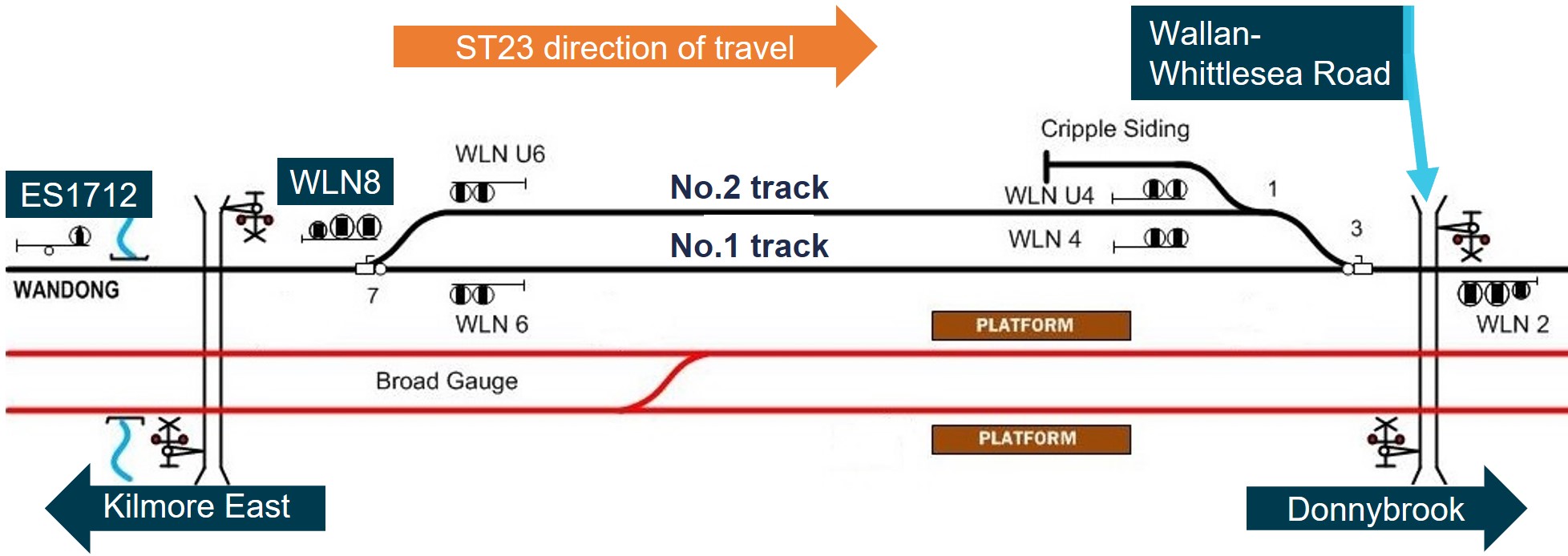
The schematic shows the standard-gauge track at Wallan including the crossing loop. The standard-gauge tracks are shown in black, and the adjacent broad-gauge tracks in red. Only the signalling for the standard-gauge track is shown in this figure.
Source: ARTC, modified and annotated by CITS
Wallan Loop northern turnout
The turnout at the northern end of the Wallan Loop was located at the 49.058 km mark (Figure 8). The turnout design was reported by ARTC as being rated for a train speed of 25 km/h (for entry into the loop) and the maximum operational speed was 15 km/h in accordance with the ARTC operating code of practice.[48] It consisted of 60 kg/m rail on timber bearers, with a cast V-crossing. Following the left turnout, the right curve (in the direction of travel) along the No.2 track had a radius of about 420 m.
Figure 8: Elevated view of northern turnout to No. 2 track at Wallan Loop
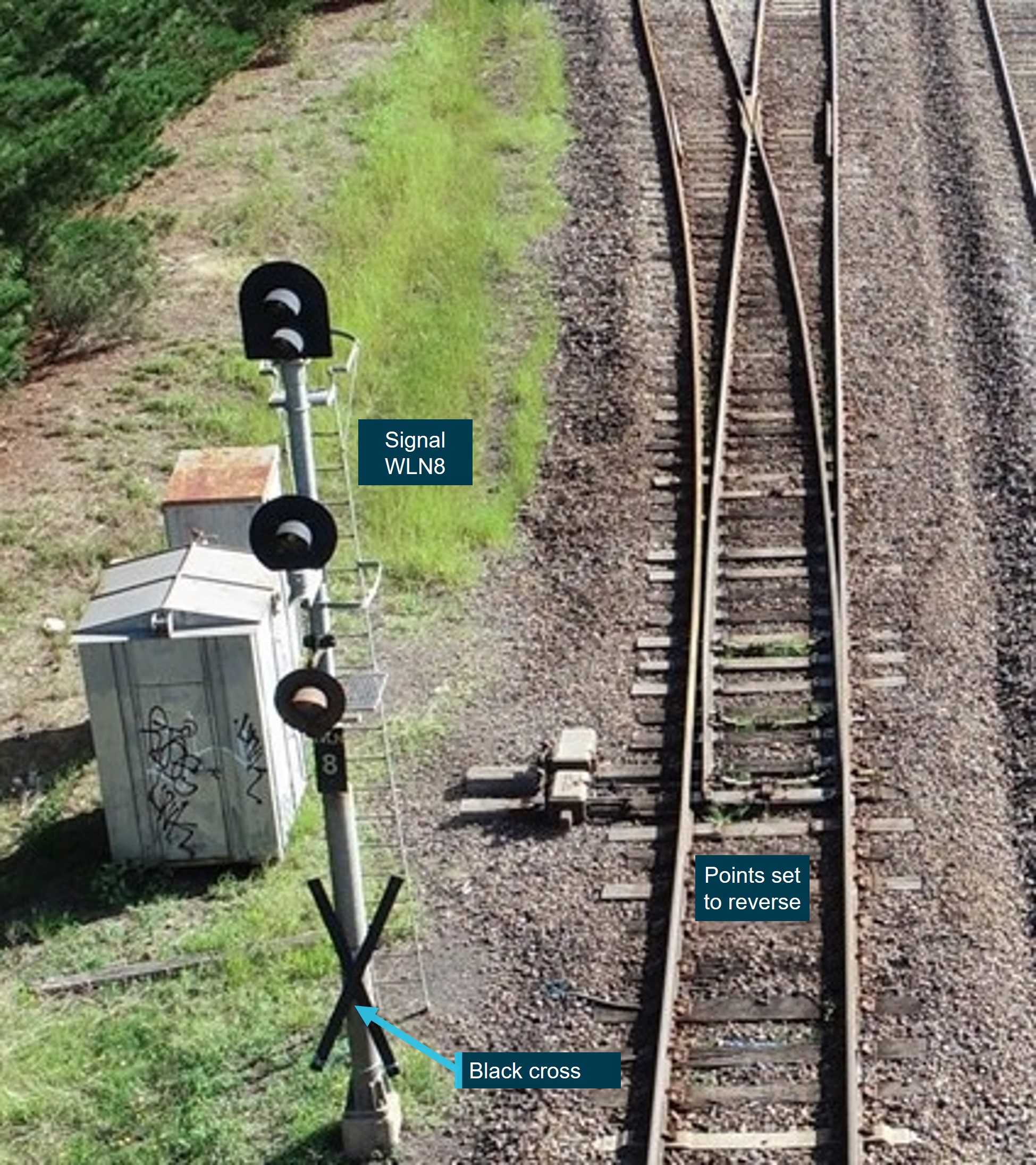
The photograph shows the turnout and signal WLN8 on 21 February 2020 after the passage of train ST23 and its derailment. The points are set for the No.2 track as they were at the time of the derailment.
Source: ATSB
For southbound trains approaching the northern end of Wallan Loop, there was a downhill gradient of approximately 1:150 and the track was tangent (straight) for about the final 800 m of the approach to the turnout with trees lining the rail corridor. The approach track was comprised of 60 kg/m rail, fastened to concrete sleepers.
Wallan–Whittlesea Road level crossing
The Wallan–Whittlesea Road level crossing was located just south of Wallan Loop (Figure 9).
Figure 9: Aerial view of Wallan–Whittlesea Road level crossing and surrounds
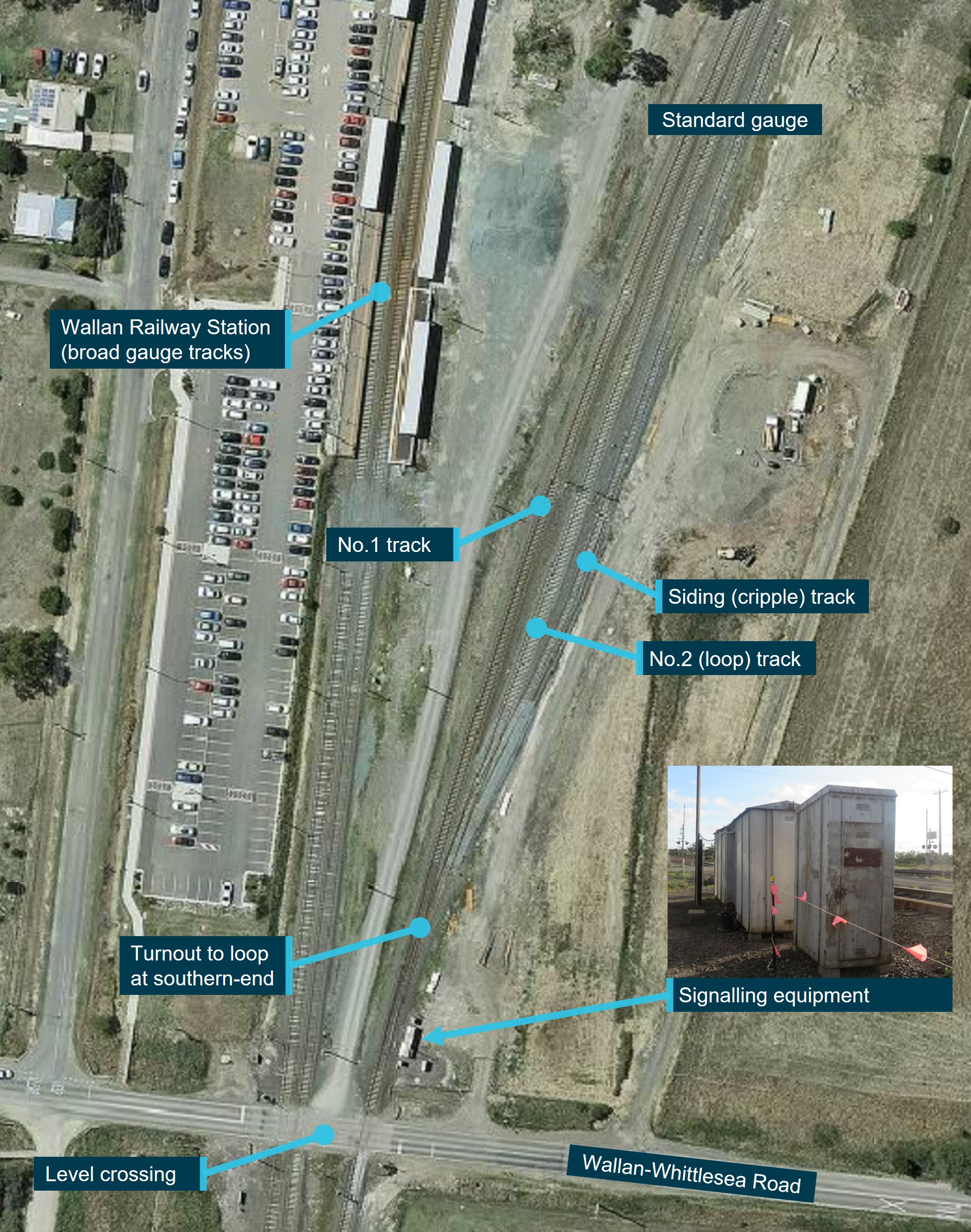
Source: Pass Assets, annotated by CITS
The Wallan–Whittlesea Road level crossing was fitted with active protection that included boom barriers, flashing lights and bells. While the signalling system at Wallan was being repaired, the crossing protection was manually activated by a level crossing keeper (LCK) located at the crossing. The operation of the crossing protection for each train was initiated by a call from the AQW travelling on the approaching train.
Signalling
Approach from Kilmore East towards Wallan Loop
Approaching from Kilmore East, the first signal to advise of the state of the turnout at Wallan Loop was signal ES1712 located about 2.7 km prior to the northern turnout to Wallan Loop.[49] At the time of the derailment, signal ES1712 was extinguished and was fitted with a black cross near its base to indicate that it was not functioning (Figure 10).
Figure 10: Signal ES1712 following derailment, non-operational and with cross affixed
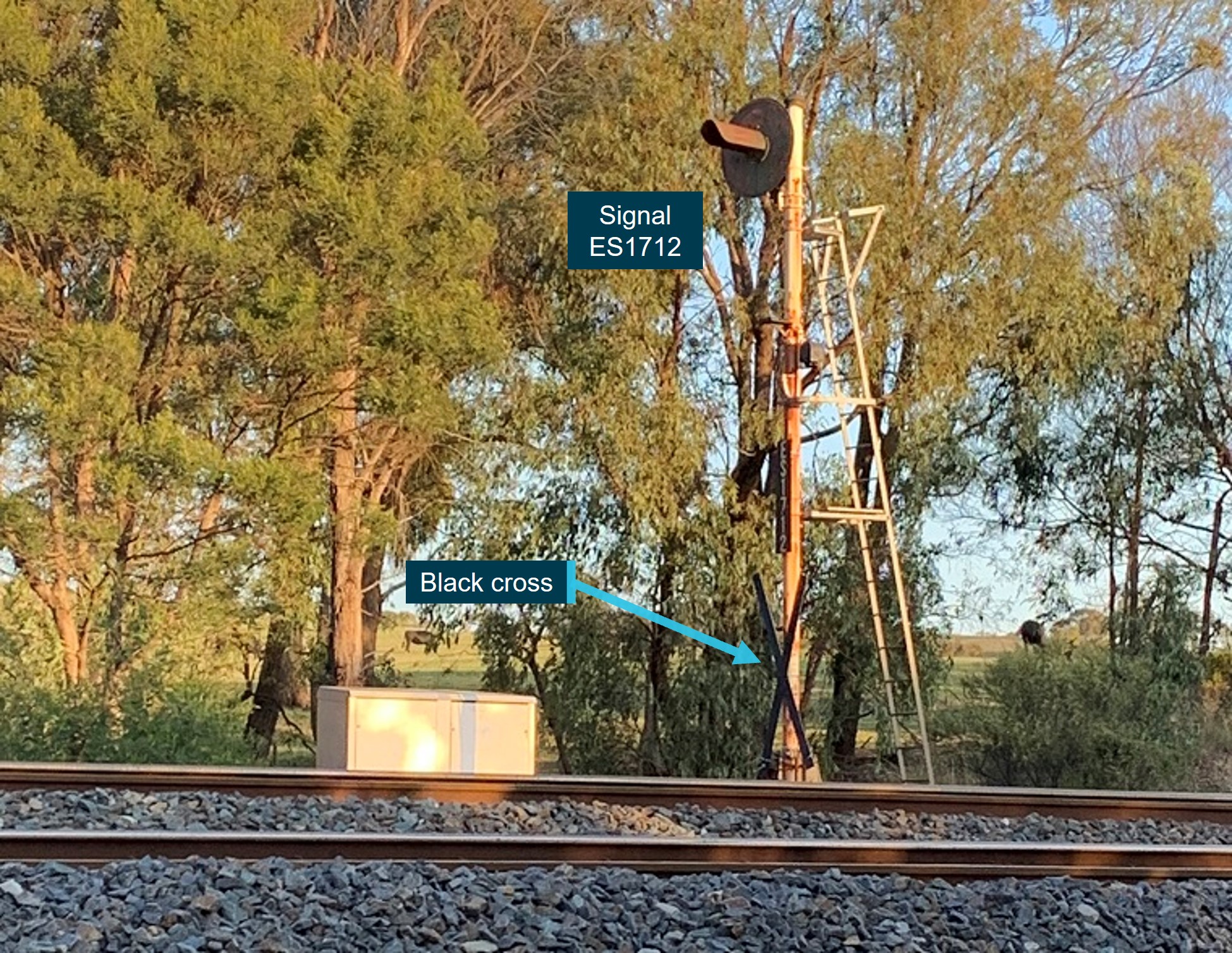
Source: CITS
Signal ES1712 was a 3-position automatic signal. When operational, the signal would provide an indication of any speed reduction required approaching the next signal (WLN8) at Wallan Loop. A normal speed warning indication (yellow over red) at ES1712 would require a driver to be prepared to stop at the next fixed signal (WLN8) at the entry to Wallan Loop. If the train was signalled for the straight (No.1 track) at Wallan Loop, ES1712 would show a clear normal speed indication (green over red).
Wallan Loop Up home signal
Entry to the northern end of Wallan Loop was normally controlled by signal WLN8. At the time of the derailment, signal WLN8 was extinguished and was fitted with a black cross near its base to indicate that it was not functioning (Figure 11).
Signal WLN8 authorised train movements in the Up (towards Melbourne) direction. When operational, signal WLN8 could provide several indications (Figure 11). For train movements routed on the straight track at line speed, signal WLN8 would show a clear normal speed indication. For movements into the crossing loop, the low speed caution indication was used, which meant that trains must not exceed 15 km/h. Trains could also be signalled to stop at signal WLN8.
Figure 11: Signal WLN8 possible indications (left) and on day of occurrence (right)
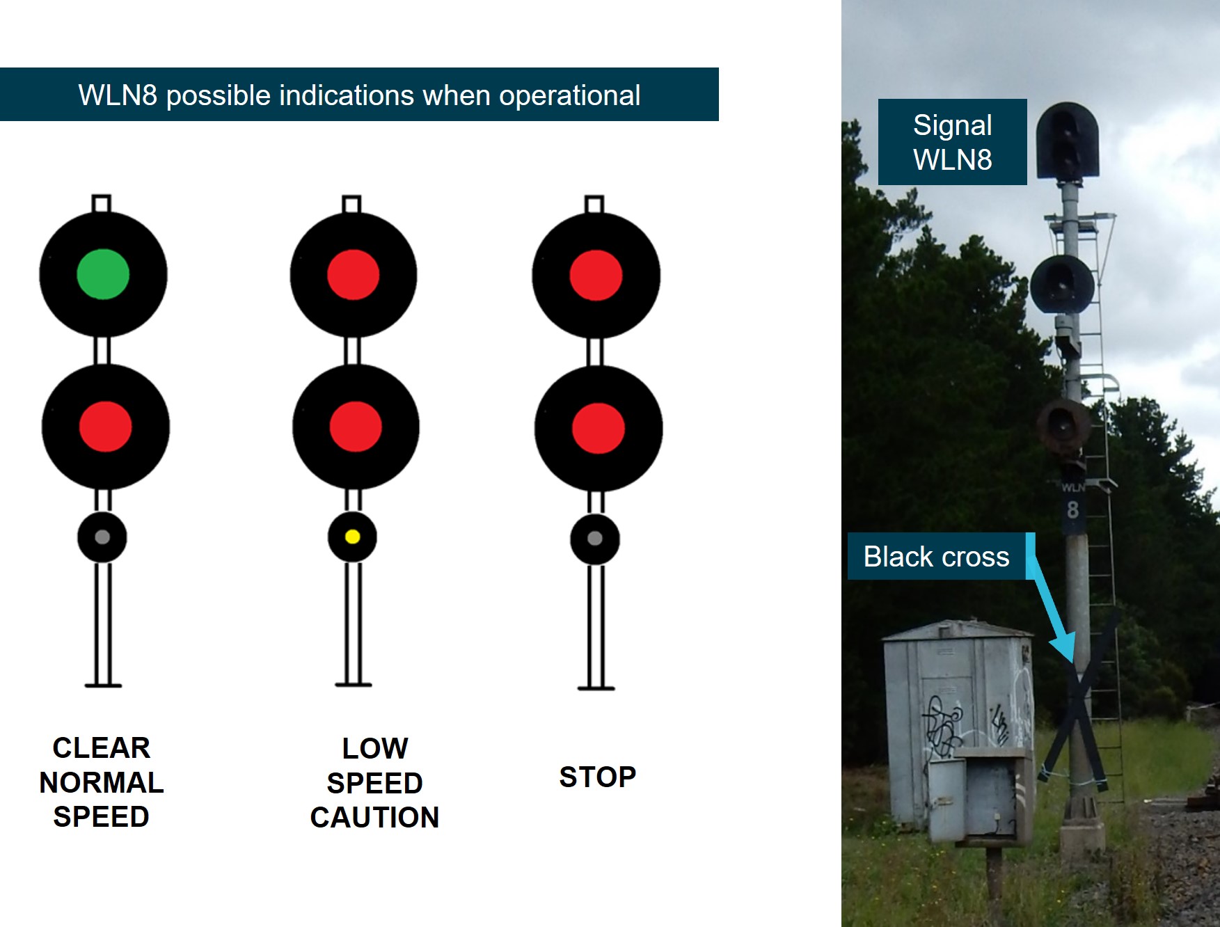
The figure shows the possible indication for signal WLN8 (when operational), and a photograph of the signal extinguished. The photograph of signal WLN8 also shows the black cross that was attached to the signal post.
Source: CITS
Broad-gauge signal near Wallan Loop entry
A broad-gauge distant signal was located about 45 m to the north of WLN8 and was probably indicating a proceed (green) aspect at the time ST23 passed (Figure 12).[50] This broad-gauge signal did not apply to the operation of ST23, which was running on the standard-gauge line.
Figure 12: Probable aspect of broad-gauge signal at the northern end of Wallan Loop
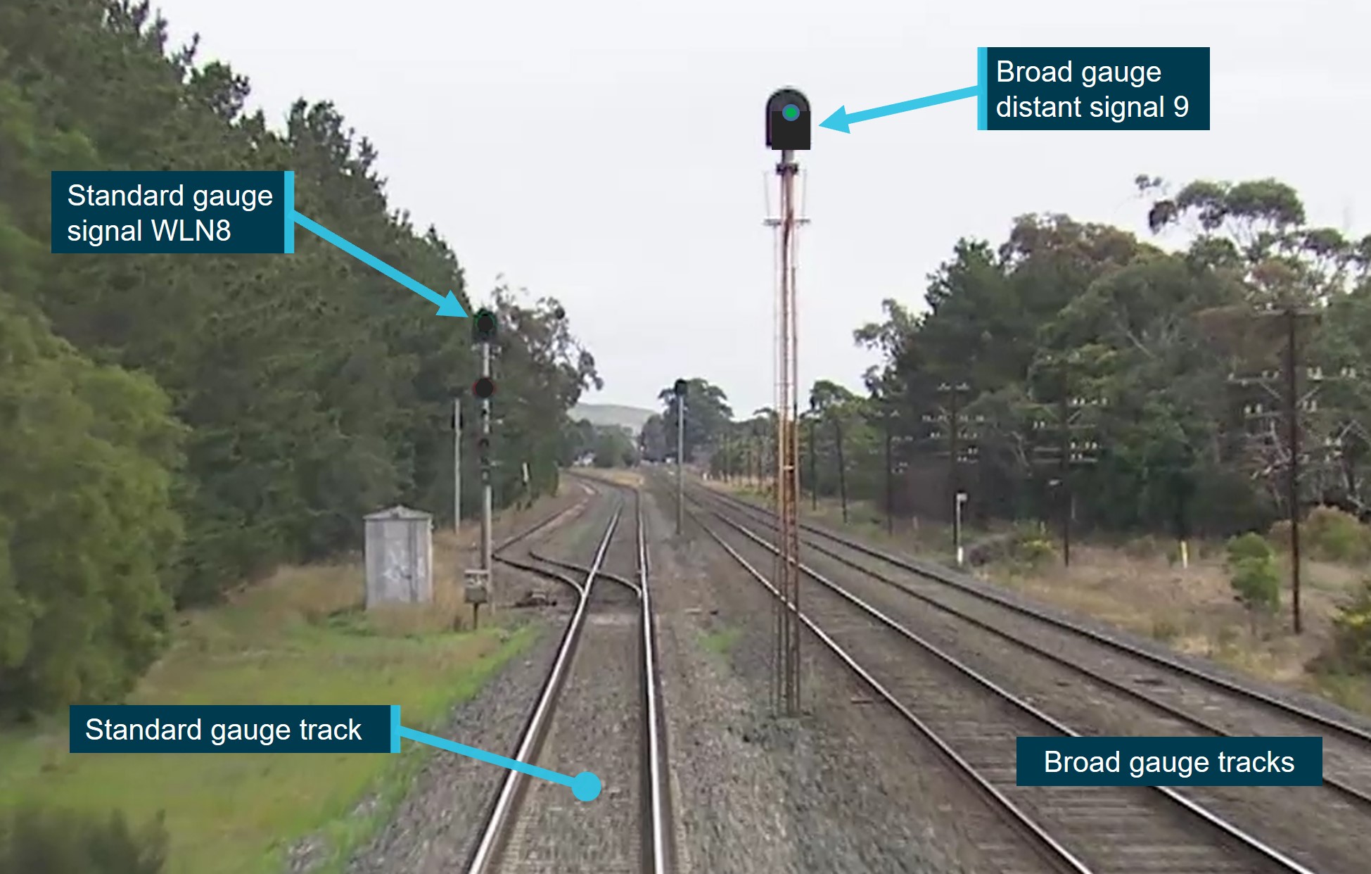
The figure shows the approach to the Wallan Loop turnout. The image has been modified to show the extinguished state of standard gauge signal WLN8 and the probable proceed (green) indication of broad-gauge distant signal at the time of the derailment. In this image, the points are set for the straight and the black cross is not fitted to the base of signal WLN8 as the image was taken prior to the signalling failure.
Source: V/Line training video, with signal aspects modified and annotated by CITS
Environmental conditions
The conditions at the derailment location were dry. At 1930 at the nearest weather station, located at Kilmore Gap,[51] the temperature was recorded as 13°C, and the wind was from the south at 32 km/h. These weather conditions were unlikely to have been a factor in this occurrence.
The derailment occurred about 30 minutes before sunset. At 1943 at Wallan, the sun was at an azimuth[52] of 259°48'28" and altitude[53] of 5°02'59".[54] The direction of travel was 223° from true north, meaning the sun was about 36° to the right of the driver’s direct view ahead and low in the sky.
Photographs taken soon after the derailment showed a mostly cloud-covered sky with a break in the clouds on the southern horizon towards which ST23 was travelling. The sky near the horizon was therefore probably bright (with possible sun glare) when train ST23 approached Wallan. However, the circumstances of this occurrence do not suggest that visibility approaching Wallan Loop was a factor in the overspeed of ST23.
Management of rail traffic between Donnybrook and Kilmore East
Background
Late on 3 February 2020, ARTC identified that signalling had been disrupted around Wallan due to a fire in the signalling equipment hut. As a result of the damage to the signalling system, ARTC commenced managing rail traffic through the section using caution orders and other safeworking rules, consistent with the ARTC Code of Practice for the Victorian Main Line Operations (TA20). The rules associated with caution orders meant that trains were restricted to speeds not exceeding 25 km/h, which contributed to service delays of probably at least 45 minutes.[55]
To reduce delays, ARTC sought an alternative method of managing trains in the 24 km section between the passing lanes at Donnybrook and Kilmore East. The use of caution orders under the CTC safeworking system was then replaced with a method using train authorities that permitted train speeds up to normal line speed. Train authorities had previously been used by ARTC during infrastructure commissioning activities.
In early February, ActivateRail[56] had been engaged by ARTC to assist with a safeworking solution to improve the passage of rail traffic between Donnybrook and Kilmore East. The scope of its services included the development and management of the safeworking solution and the provision of qualified signalling personnel for its implementation. ActivateRail in turn engaged ARG Rail for the provision of an additional 3 qualified signallers.
ARTC also sourced personnel from labour-hire firm Programmed to assist with the implementation of the train working arrangements. Contracted workers included accompanying qualified workers (AQWs), car drivers (to transport personnel), level crossing keepers (LCKs), and track force protection staff.
Train notice 266 description of train working arrangements
Initial issue of Train Notice 266
The use of train authorities between Donnybrook and Kilmore East in February 2020 was notified by train notice 266 (TN 266), issued on 6 February 2020 and effective from 1900 on that day (Appendix C). The train notice was a typed document of 6 pages and provided the following introduction to the change of conditions:
TN 266 advised the details of the signals that were disarranged, and that black crosses were affixed to the posts of disarranged signals. TN 266 advised that within the affected section:
TN 266 also advised that the points at either end of Wallan Loop would be placed in the hand‑operating position and clipped in the normal (straight) position, and that signage would be installed at each end of the section advising of the transition between CTC and train authority working.
TN 266 discussed the roles of the various parties and advised:
TN 266 further specified the processes to be used for the issuing of the train authority to the driver. It described a requirement for the (in-field) signaller to read back the contents of the train authority to the NCO, and for delivery to the driver TN 266 stated:
TN 266 also described the processes for the issuing of a condition affecting the network (CAN) notice, which was required because the Wallan–Whittlesea Road level crossing protection was not operating normally.[58] The described process included the signaller delivering the CAN to the driver.
For the passage through the section under the train working arrangements, TN 266 stated:
Changes to train notice 266
TN 266 was updated and reissued on 7 February. This amended notice introduced reference to the arrangements being in exception of a rule within TA20 and stated:[59]
TN 266 was further amended and re-issued by ARTC on 13 February 2020 (Appendix D). Amendments included:
- removal of the advice that signals in the section may remain lit[60]
- addition of text advising that ‘Repeat Back of the Train Authority is not required to be undertaken by the driver of the rail movement’
- replacement of ‘The rail movement may proceed through the section in the normal manner’ with ‘The rail movement may proceed through the section up to track speed as advised by the Accompanying Qualified Worker’
- addition of the instruction that ‘The driver must approach the level crossing with caution, prepared to stop short of the crossing unless the ‘all clear’ hand signal has been provided’
- that Rule 1, Section 3, did not apply during Train Authority Working.[61]
Train authority form
A train authority form was prepared for use as part of the process described in TN 266 (Appendix E). This form was then to be completed by the NCO and the (in-field) signaller.
Application of train notice 266
In-practice application of TN 266
The method applied for issuing a train authority to a driver travelling in the section between Donnybrook and Kilmore East involved the on-duty ARTC NCO at Junee, an in-field signaller (the signaller) and an AQW. Key steps used by these parties in practice were:
- The NCO and signaller were both provided with train authority forms to be used under TN 266 (Appendix E).
- The signaller positioned themselves at whichever end of the Donnybrook–Kilmore East section that was to receive the next train.
- Prior to the arrival of the next train, the signaller contacted the NCO to obtain details specific to the next train movement and was issued with a train authority.[62] The issuing process involved the NCO dictating the details of the train authority to the signaller and the signaller completing the form accordingly.
- The signaller then read back the completed train authority to the NCO to verify its contents.
- A CAN notice was also completed by the signaller under the instruction of the NCO.[63]
- The signaller gave the completed train authority and CAN notice to the AQW and, on the train’s arrival, the AQW boarded the driver’s cab of the train. There was no contact between the signaller and the driver of the train.
- Once on board, the AQW gave the train authority and CAN notice to the driver. The driver then contacted the NCO to verify the train authority. ARTC network control required the driver to verify the train authority to the NCO by its number only. There was no expectation that the driver would read the content of the train authority to the NCO, and no provision made on the train authority form for the driver to sign the form.
Train authority statistics
Between 6 and 20 February, 255 train authorities were issued for the section between Donnybrook and Kilmore East; 126 were issued at Donnybrook and 129 at Kilmore East.[64] Two of these authorities were cancelled owing to errors, one at each location.
Of the 255 train authorities issued, 55 were issued to XPT drivers, with 8 being issued to the driver of train ST23 prior to the day of the derailment. TA 17 was the ninth train authority that the driver had received. Drivers of other (non-XPT) passenger trains received 59 train authorities.
There were several instances during the two weeks where the signaller was issued a train authority for the single line section between Donnybrook and Kilmore East prior to the previous train authority for the single line section being cancelled. This was contrary to the instructions of TN 266.
Between 6 and 20 February, there were 21 NCOs and 5 signallers involved in the issuing of the authorities.
Driver readback statistics
Even though the train working arrangements did not specify a requirement for drivers to read back the train authority to the NCO, over a quarter of V/Line drivers and some others read the train authority back to the controller. The proportion was about the same before and after the (13 February) amendment of TN 266 that stated explicitly that readback was not required.
The driver of ST23 read back the train authority on their first journey under the altered train working arrangements. On subsequent trips, this driver did not read back the train authority and verified the authority by stating its number.
The reaction of NCOs to driver readback varied; on some occasions they allowed it to continue, and on other occasions they indicated to the driver that the readback was not necessary. At 1322 on 20 February 2020, when a V/Line driver was repeating back the train authority, the NCO on duty on the shift prior to the derailment, advised the driver that they did not need to repeat back. When the driver continued to repeat back the message, the NCO attempted to talk over the driver’s repeat back and instructed the driver to ‘standby’.[65] The driver continued to repeat back and advised the NCO that they were of the understanding that a repeat back to the controller was required.
Other operator queries and feedback
On establishment and the subsequent use of the alternative train working arrangements, there was disquiet within some sectors, and concern that the arrangements introduced were outside the established operating rules of TA20. The expressed concerns were mostly amongst V/Line drivers. The following is a selection of relevant actions and concerns on the train working arrangements in place:
- On 7 February, a northbound NSW Trains driver queried the wording in TN 266 that indicated that drivers should disregard signals between signals DBK8 and KME2. The driver advised the on-duty NCO that DBK8 would be facing trains travelling in the other direction.[66] The NCO advised they would raise the matter, although there was no subsequent change to this part of TN 266.
- On 10 February, a V/Line driver advised ARTC train control that that they would not pass signal WLN8 at stop (that was still lit), as they believed they could not treat it as a signal that could be disregarded. The driver requested separate authority to proceed, or for the lights in the signal to be extinguished, leading to a long delay in train operations through the section. The NCO advised that the instructions in the train notice covered the workings and they would not issue an additional authority as they believed this would be a second authority for the same section. All signals within the section were subsequently extinguished, and TN 266 was revised on 13 February with the text ‘the signal may be lit’ removed.
- On 11 February, a V/Line driver made an inquiry to their management as to why ARTC had implemented train authority working when TA20 section 25.1d did not allow for such use of train authorities.
- On 12 February, a V/Line driver advised the on-duty NCO that they had been instructed by their superiors to travel through the section at 25 km/h ‘due to the rule book’. TN 266 was reissued on 13 February with the text ‘Rule 1, Section 3, did not apply during Train Authority Working’ added and the text ‘The rail movement may proceed through the section in the normal manner’ in the original notice replaced with ‘The rail movement may proceed through the section up to track speed as advised by the Accompanying Qualified Worker.’
- On 14 February, a V/Line driver requested that the signaller give them the train authority directly (as stated in TN 266) rather than via the AQW. This required the signaller (who had by that time departed the handover position) to return to Kilmore East to hand the train authority directly to the driver.
Train notice 367 description of changed conditions
Details of notice
Train Notice 367 (TN 367) (Appendix F) was issued on the evening of 19 February 2020 and contained additional instruction to TN 266. In relation to the changed conditions at Wallan Loop, the notice advised:
TN 367 also provided information on what would be in the train authority with the note:
At the conclusion of TN 367 was the following special note:
The instruction in TN 367 on the maximum speed for entering Wallan Loop was not documented as a temporary speed restriction.[69] Therefore, a CAN warning for the 15 km/h speed limit at entry to Wallan Loop was not issued.
Train authority form for transit through Wallan Loop
A new train authority form was prepared for use by NCOs and (in-field) signallers during train transit through the loop (Appendix G). The form included the additional note that:
Distribution and receipt of TN 367
ARTC distribution
ARTC procedures defined the processes to be followed for preparing, reviewing, approving and issuing operational notices (including train notices) on the ARTC network.[70] Different processes applied to different parts of the ARTC rail network. For its NSW and Queensland network, the ARTC procedures for distribution of operational notices specified direct transmission to selected internal and external stakeholders.
For Victoria, South Australia and Western Australia, approved operational notices were published on the ARTC WebRAMS (Rail Access Management System) portal.[71] Standing train notices were specified as being uploaded to this portal at approximately 1800[72] each evening. There was no specified timeframe in which a notice was to be issued prior to it coming into effect.[73] Access to WebRAMS was available to ARTC customers and stakeholders via an allocated User ID system. For rail operators operating in Victoria, the onus was therefore on them to access ARTC safety notices through this portal.
Formal distribution of TN 367 by ARTC to rail operators was via the WebRAMS portal. ARTC reported that TN 367 was uploaded to WebRAMS as part of an automated system update at 1845[74] on 19 February 2020.
In addition to the formal release (on WebRAMS), a draft of TN 367 was forwarded to V/line for comment at about 1330 on 19 February. There was no reported similar active engagement by ARTC with, or direct release of TN 367 to, NSW Trains or freight operators.
NSW Trains receipt
NSW Trains did not have an active process in place to interrogate the ARTC WebRAMS portal for network operational information related to its Victorian operations. The activity of searching the ARTC portal was inadvertently discontinued around 2017 following a restructure within NSW Trains. For its operations within Victoria, NSW Trains drew on weekly operational notices (WONs) prepared by Metro Trains Melbourne (MTM) that were issued each Tuesday for the week commencing the Wednesday.[75] The WONs included safety information for metropolitan and regional services. The WONs did not, however, typically include ARTC train notices, and reference was instead made within the WON to the ARTC WebRAMS portal.
Each week, NSW Trains extracted information from the WON that was considered relevant to its Victorian operations. This process was used to produce an information pack for NSW Trains regional drivers that would operate in Victorian territory. This information pack was then placed in the pigeonhole of each driver at their Junee base. It was a driver’s responsibility to collect the information from their pigeonhole and assimilate that information.
No evidence was identified to indicate that NSW Trains was aware of TN 367 prior to the occurrence. WON Issue No.07, which was published on 18 February 2020, did not include information from TN 367. This WON did contain TN 266 (as amended on 13 February), which was the ongoing train notice for the Kilmore East to Donnybrook section at the time of the release of WON 07. Its direct inclusion in the WON was not standard practice and was instead the result of V/Line re-issuing ARTC TN 266 (as amended on 13 February) within its own safety information distribution system.
Extracts from WON 07 were prepared for distribution to NSW Trains drivers by 1139 on the morning of 20 February. The information pack (that did not include information on TN 367) was reported as being placed in the pigeonholes of regional drivers (at Junee) by 1247 the same day. It could not be confirmed whether the driver of ST23 had read the information pack issued on that day. There was no functioning system to assure that drivers read and understood the distributed safety information.
For its operations on the NSW portion of the ARTC network, NSW Trains received SAFE notices directly from ARTC.[76]
V/Line receipt and distribution
Normal V/Line process entailed driver supervisors checking the WebRAMS portal after the evening publishing of ARTC notices on that portal and distributing train notices to affected drivers.
In the case of TN 367, V/Line also received pre-information by email at 1333 on 19 February. ARTC provided V/Line with a draft of TN 367, although the distribution was not accompanied by an assessment of risk and risk controls. The notice was then circulated to various staff within V/Line with safety responsibilities. At 1434, a V/Line member of staff responded that:
In response to receiving TN 367, V/Line published a V/Line safe working circular (SW.0024.2020), incorporating TN 367, for distribution to all drivers. The V/Line drivers that were to run through Wallan Loop on 20 February were also contacted by their driver supervisor prior to their shift and advised of the change in operating conditions at Wallan Loop.
The issuing of TA 17 to ST23 under TN 266 and TN 367
On 20 February, the issuing of the train authority (TA 17) for the passage of train ST23 followed the same processes as had been used during the previous 2 weeks. The NCO issued TA 17 to the signaller, and that process included a signaller readback. The copy of TA 17 completed by the signaller was consistent with the TA 17 that was completed by the NCO. The signaller’s copy of TA 17 was then transferred via the AQW to the driver of ST23, again consistent with the processes used in the previous weeks.[77]
Operating rules
Safeworking rules and use of train authorities
ARTC operating rules for Victoria were defined in the ARTC Code of Practice for the Victorian Main Line Operations (TA20).[78] This code described the following safeworking systems for those parts of the ARTC network covered by the code:[79]
- centralised traffic control (CTC)
- the train order system.
Prior to the signalling hut fire at Wallan in early February 2020, rail traffic through this section was managed using the CTC system described in section 17 of TA20. In the case of signal failure, this section provided for the use of caution orders and CTC arrival messages. The caution order form used in conjunction with a CTC system required that traffic ‘proceed cautiously’ …. ‘in accordance with Rule 1, Section 3’.[80]
The use of train authorities in the circumstances that were present between Donnybrook and Kilmore East in February 2020 was not provided for in TA20. The procedures associated with train authorities were specified in section 25 of TA20. This section stated that ‘Train Authority Working[81] must be used as specified by the individual operation of the safeworking system’. For sections with Centralised Traffic Control, the scope of train authority use was specified in TA20 as:[82]
- to assist a disabled train
- train to return to the crossing loop in the rear
- working a train to the point of an obstruction on one or both sides.
For those circumstances where the use of a train authority was permitted, section 25 of TA20 described the methods of delivery, books of train authority forms, and verification protocols. The processes subsequently used in the train working between Donnybrook and Kilmore East were not consistent with those described in section 25 of TA20.
Communication requirements in TA20
Section 25 described that a driver must not proceed into the section unless the train authority was fully understood.[83] Verbal communication requirements were also specified in section 1 of TA20, although the direct applicability of this section to the train working arrangements in use at the time of the derailment is unclear. Section 1 stated that ‘the receiver must confirm the content of a message by repeating the message back exactly as it was received to the sender, if the communication is about: …… special working.[84]
The same clause of TA20 section 1 also addressed the relaying of communications and stated that ‘if it is not possible for a sender to communicate directly with an intended receiver, Competent Workers may relay the content’. In this case, direct communication between drivers (the intended receiver) and the NCO was possible via radio.
Condition affecting the network (CAN)
Within the ARTC operating rules for Victoria (TA20), Section 1, rule 7.a. provided information on the issuing of CAN warnings and stated that the ‘Condition Affecting the Network (CAN) form is used by Network Controllers when giving written warning to rail traffic crews if … faulty or potentially faulty level crossings have been reported’.[85] The use of a CAN to notify drivers of the manual operation of the level crossing protection at Wallan–Whittlesea Road was consistent with this description.[86]
Other rules
Other codes and rules that described potentially relevant safeworking systems and procedures were also reviewed (Appendix H). None were considered directly relevant to this occurrence.
Risk management
ARTC risk management system
ARTC captured operational risks on the ARTC network in its enterprise risk management system (ERMS). The ERMS was a repository of identified risks, risk controls and risk owners.
For the top event of derailment, 44 potential causes were recorded. The top event of derailment was for any train type, and risks associated with passenger operations were not separately considered.
Of the 44 identified causes of derailment, the cause ‘Train driver error (eg. overspeed)’ was listed and was linked to 15 risk controls. ‘Other rail operator’ was identified as the responsible party for 6 of these controls that pertained to the rolling stock operator, and included controls such as driver competency, route knowledge and fatigue management. ARTC was identified as the responsible party for the remaining 9 risk controls. Of these ARTC controls, the first 2 listed were ‘ATMS (where in place)’[87] and ‘Two person train operation (where in place)’. Neither of these controls was applicable to passenger train operations in Victoria. Of the remaining 7 controls allocated to ARTC responsibility, the most significant were ‘Network rules and procedures’, ‘Track signage’ and ‘Train graphs’ that were each rated as ‘partially effective’.
Within other causes for derailment, the risk control of ‘ARTC Safety Management System (SMS)’ was a common risk control and rated as ‘substantially effective’. For the derailment cause of ‘Human Factors’, train notices were listed as an administrative control and rated as ‘minimally effective’.
For operations of the XPT on the ARTC network, the risk management interface between ARTC and NSW Trains was described in a 2011 interface agreement that was agreed between ARTC and RailCorp.[88] The document included a risk review table describing the risk of derailment due to train overspeed, although this document had not been updated since the agreement in 2011.
ARTC risk management procedure
ARTC’s safety management system (SMS) included a risk management procedure that advised that the identification and management of risk occurs at all levels of ARTC.[89] This procedure was described as being consistent with ISO 31000:2018 Risk Management – Guidelines[90] (Standards Australia 2018) and included different types of risk assessment and approaches (Appendix I).
This risk management procedure included requirements for a risk study or assessment for a range of activities and system changes. It specified that formal risk studies were usually undertaken for complex activities where potential impact was likely to be significant. The listed types of activities where the procedure suggested a formal risk study may be considered appropriate included:
- significant civil works, such as tunnel construction, bridge construction
- technical operational changes, such as introduction of new signal/track infrastructure
- safety-critical system changes, such as network control system changes.
Consistent with the overarching procedure, the relevant ARTC work instruction[91] for the application of risk management referenced alignment with ISO 31000. The work instruction specified establishing the objectives, context and scope to be carried out by the workshop convenor prior to a risk workshop taking place.
Application of risk management for train working arrangements
Risk workshop and development of risk management plan
For the train working arrangements between Donnybrook and Kilmore East from 6 February, a risk management plan was prepared. A limited risk workshop was conducted at about 1600[92] on 6 February and involved representatives from ARTC and its contractor, ActivateRail. There was no evidence of involvement of a risk specialist or risk manager in the process. The associated risk management plan was then finalised on 7 February.
This documented risk management plan was not updated for the duration of the temporary train working arrangements. ARTC advised that risks relating to the train working continued to be informally assessed as feedback was received and that changes were reflected in the amendments made to TN 266.
Context described in risk management plan
Within the ‘context setting’ section of the risk management plan, the background of the risk assessment was documented as being the re-signalling of Ararat Junction and referenced documents included the ‘Operations and Safety Commissioning plan for the commissioning of signalling at North Geelong C’. It is probable that previous plans were used as the basis for risk assessment, but not all sections of the risk management plan had been updated for the signalling disruption between Donnybrook and Kilmore East and the planned train operations.
Scope described in risk management plan
The scope documented in the risk management plan stated ‘the scope is specific to the rail operations and safeworking activities for the commissioning’. It is probable that the scope referred to a previous commissioning activity and was not updated for the extended period of train operations between Donnybrook and Kilmore East.
Consultation in risk assessment process
The ARTC risk management procedure stated that ‘a consultative approach with stakeholders must be used to determine the context, risk criteria and structure for the remainder of the process.’ The risk management plan for the train working between Donnybrook and Kilmore East identified rail operators as stakeholders. The risk worksheet associated with the plan was released to V/Line and labour-hire firm Programmed at about 1700 on 7 February, the day after TN 266 and the train working arrangements came into effect. NSW Trains and freight operators were not included in this distribution.
Outcomes of risk assessment described in risk management plan
The risk management plan for the ‘Operation of Train Auth Working between Donnybrook and Kilmore East’ identified 10 risks and associated control measures. The plan documented the treatment for each risk and ARTC was identified as the ‘responsible party’ for each risk and associated control.[93] The plan provided no evidence of treatments that had been considered but rejected.
Several described hazards were associated with works and commissioning of signals. There were no identified hazards or scenarios (and associated risks) specific to passenger train operations.
Risks associated with routing trains through Wallan Loop or derailment due to overspeed were not directly identified in the risk worksheet. There were also no subsequent changes to the risk management plan specific to the routing of trains through Wallan Loop on 20 February.
Of the 10 risk items that were identified in the plan, the risks most relevant to this investigation were:
- rail operator not aware of the altered train working (risk item 2)
- deactivated level crossing protection (risk item 6).
The identified risks and risk controls associated with risk item 6 and the level crossing protection at Wallan–Whittlesea Road are described at Appendix J.
Rail operator not aware of the altered train working (risk item 2)
The risk management plan described the hazard, cause and outcome associated with the operator (driver) not being aware of the altered train working (Table 1).
Table 1: Risk management plan description of risk item 2
| Hazard | Rail Operators not aware of the altered working |
| Caused by | Train notices not received by train crews detailing the processes in place |
| Worst outcome | Train driver accepts the train authority and proceeds into the section not conversant with the altered working |
For this risk, the plan identified 4 controls that were to be implemented, of which 2 controls, the timely issue of train notices and the ‘piloting’ of the train, were also relevant to the management of risks associated with the subsequent routing of trains through Wallan Loop (Table 2).
Table 2: Specified risk controls for risk item 2 and ATSB comment on implementation
| Specified risk control | ATSB comment on the implementation of the control |
|---|---|
| Train notices will be issued in a timely fashion | All train notices were issued a short time prior to them taking effect.
|
| Signals at the interface of the commissioning will have change of safeworking signage to indicate the interface between CTC and train authority working | Signage at Donnybrook and Kilmore East provided a visual cue to drivers at the extremities of the affected section of the transition between CTC and the altered train working. This control was not relevant to the change to route trains through Wallan Loop. |
| Disarranged signals will have black crosses affixed to them | Black crosses were affixed near the base of disarranged signals rather than at the signal head and were reported as difficult to observe. In addition, the deviation from the practice of extinguishing affected signals resulted in confusion until signals were extinguished and the update reflected in the amended TN 266 issued on 13 February. This control was not relevant to the change to route trains through Wallan Loop. |
| Trains are piloted through the section[94] | Although the risk management plan specified that trains would be piloted, a pilot was not made available for the trains operating during the altered working. Instead, an AQW was made available. Differences between the roles of pilot and AQW are discussed below. For the changed conditions and routing of trains through Wallan Loop, this control was augmented by the issue of TN 367, which specified that the AQW was to advise the driver that the train would operate via No.2 track and of the speed limits required. |
A pilot as a risk control
Although the definition of a ‘pilot’ varied across a number of references, descriptions were of a directive role (compared to that of the AQW described in TN 266). Consistent themes were that the role of a pilot involved directing the movement of the train, and that to perform their role the pilot required a full understanding of the route, the infrastructure and operational constraints.
Within the ARTC code of practice for operations in Victoria (TA20), the role of a pilot was mentioned within section 14 (Single Line Working) and section 15 (Infrastructure Works). These sections included detailed requirements for a pilot ranging from identification badges to tasks specific to the safeworking activity. Neither of sections 14 or 15 were applicable to the train operations in place at the time of the derailment of train ST23 and the described process for the AQW did not follow the requirements in these sections. There was no mention of the use of a pilot in section 25 of TA20 (Issue of Train Authorities).
The Rail Industry Safety and Standards Board (RISSB) Glossary defined the title of ‘Pilot’ as:
The ARTC Glossary[95] (applicable to NSW) included the following definitions pertaining to pilotage:
Also applicable to NSW, the ARTC document ANRP 710: Piloting trains and track vehicles[96] contained specific requirements on what a pilot should do. Of note, the procedure advised that:
- The driver was responsible for the safe operation of piloted trains and track vehicles.
- The pilot needed to confirm their knowledge of the route.
- The pilot needed to establish and maintain effective communication with the NCO.
- The pilot needed to give clear directions (to the driver).
Comparing these requirements with the role of an AQW under TN 266 and TN 367:
- The driver was similarly responsible for the safe operation of the train.
- There was no clear requirement for the AQW to confirm their knowledge of the route.
- The AQW was not required to, and did not, communicate with the NCO.
- The AQW was not required to, and did not, direct drivers.
The role of an AQW for the train working arrangements
The role of an AQW was not defined nor referenced in either TA20 or the Code of Practice for the Defined Interstate Rail Network. The role of an AQW (or qualified worker) was also not defined by the industry body, RISSB.[97] The qualifications, knowledge and experience required of an AQW were also not described within the documentation for the train working arrangements between Donnybrook and Kilmore East in February 2020 (TN 266).
A primary task allocated to an AQW was to call (by mobile phone) the level crossing keeper (LCK) to ensure activation of the level crossing protection at the Wallan–Whittlesea Road prior to train arrival. TN 266 also described that the AQW was to advise the driver of the ‘work activities’ and affected infrastructure, and a later amendment to the notice added that ‘the rail movement may proceed through the section up to track speed as advised by the AQW’. Although not documented in TN 266, the AQW also performed the task of delivering the train authority and CAN notice to the driver of the train. There were no defined qualifications or experience requirements to perform the role of an AQW.
The role of an AQW was to provide information rather than be directive and there was no responsibility on the part of the AQW to ensure the driver understood the content of the train authority. Under TN 367, there was an additional requirement for the AQW to remind the driver that the train was to operate via No.2 track at Wallan Loop. However, there was no associated protocol for assuring driver understanding of the train authority, and no readback requirement between a driver and the AQW.
AQW experiences during the train working between Kilmore East and Donnybrook, including interactions with drivers, were explored in interviews. Described experiences included:
- On the shifts prior to the change at Wallan Loop on 20 February, the AQWs told drivers that they could travel at line speed (at the driver’s discretion), that the crossing at Wallan–Whittlesea Road had been disabled, and that the LCK would be contacted to activate the crossing.
- In the period that the disarranged signals were still lit (prior to the 13 February amendment to TN 266), the AQWs would generally inform drivers that they could pass any lit signals at normal speed.
- Experiences and recall of train operating speeds varied across the AQW group. There was reasonable consensus that the XPT would generally operate at speeds around the line speed of 130 km/h, whereas V/Line trains would mostly travel at a lower speed, with one AQW suggesting typically around 75 km/h. The speed of freight operators varied.
- AQWs varied in their recall of the speed of trains approaching the Wallan–Whittlesea Road level crossing. One AQW stated that they would advise the drivers to use caution going through this level crossing.
- Interaction between the AQWs and train crew would vary. Although there were sometimes conversations with the drivers, one AQW described this as ‘cab-chat’.
Application of the role of AQW for train ST23
This shift was the first time the rail worker was performing the role of AQW. At the start of their shift, the AQW allocated to ST23 was briefed by a more senior AQW on the role of the AQW. The briefing included instruction on calling the LCK to facilitate and confirm level crossing protection at Wallan–Whittlesea, and the landmarks for making that call.
The briefing also included discussion on TN 367 that specified a requirement for the AQW to advise the driver that the train would operate via No.2 track at Wallan Loop and of the speed limits at entry to and exit from the loop. The AQW on ST23 was also in possession of a copy of TN 367. When at Kilmore East, the AQW was also briefed by the signaller on the particulars of the train authority and the speed restrictions. Based on this evidence, it is very likely that the AQW on train ST23 was aware that ST23 was being routed through Wallan Loop and of the requirement to advise the driver.
As previously noted, the AQW did not have experience as an AQW or as a pilot prior to this shift. The AQW also did not have front-of-train experience or route knowledge[98] for the section between Donnybrook and Kilmore East.
Also as previously noted, due to the absence of in-cab recordings the nature and content of the conversations that took place between the AQW and driver on ST23 are unknown.
Train recorded information
The Hasler RT recorder
Power cars XP2018 and XP2000 were each fitted with a Hasler RT data recorder. The Hasler RT is an electro-mechanical device that records data onto a waxed paper tape (roll). Data recorded included speed, distance, time, a combined power-vigilance parameter, and brake cylinder pressure. The Hasler equipment included an analogue speedometer located on the driver’s console.
Unlike modern data logger systems that provide digital information for a wide range of operating parameters, the Hasler tapes provide their limited information in graphical format. As a result, there is less precision in the data. GPS data from the train’s installed radio system was used to verify time, speed and position information.
Estimated train speed, throttle and braking
The Hasler and GPS data was analysed to assess recorded driver activities and train speed, including on the approach and into Wallan Loop (Appendix K). It was found that an emergency brake application was made when the train was travelling at about 129 km/h.[99] Brake cylinder pressure began to rise when the train was between 153 and 50 m from the turnout to Wallan Loop. The speed at entry to Wallan Loop was estimated to be between 114 and 127 km/h.
On the approach to Wallan, there was braking and throttle activity consistent with expected driver activity. A power application was made, and speed increased to about line speed after the confirmation was obtained from the LCK that the crossing protection at Wallan–Whittlesea Road was activated. There were no warnings provided by the vigilance system (therefore indicating there was driver activity) after the train departed Kilmore East.
Cab video and voice recording devices
The leading power car (XP2018) was not fitted with in-cab voice or video recording devices, nor was it required. As a result, there was no available evidence with respect to communications or interactions between the driver and AQW prior to the occurrence. Voice recording within the driver’s cab would have assisted the investigation in ascertaining the interactions within the cab, and the potential identification and analysis of any associated safety factors.
Derailment site
Site overview
The derailed train came to rest in a concertinaed arrangement and the leading power car had overturned onto its left side (Figure 13). The 5 passenger cars had derailed and were at various angles of incline. The rear power car was upright and still on track.
Figure 13: Train ST23
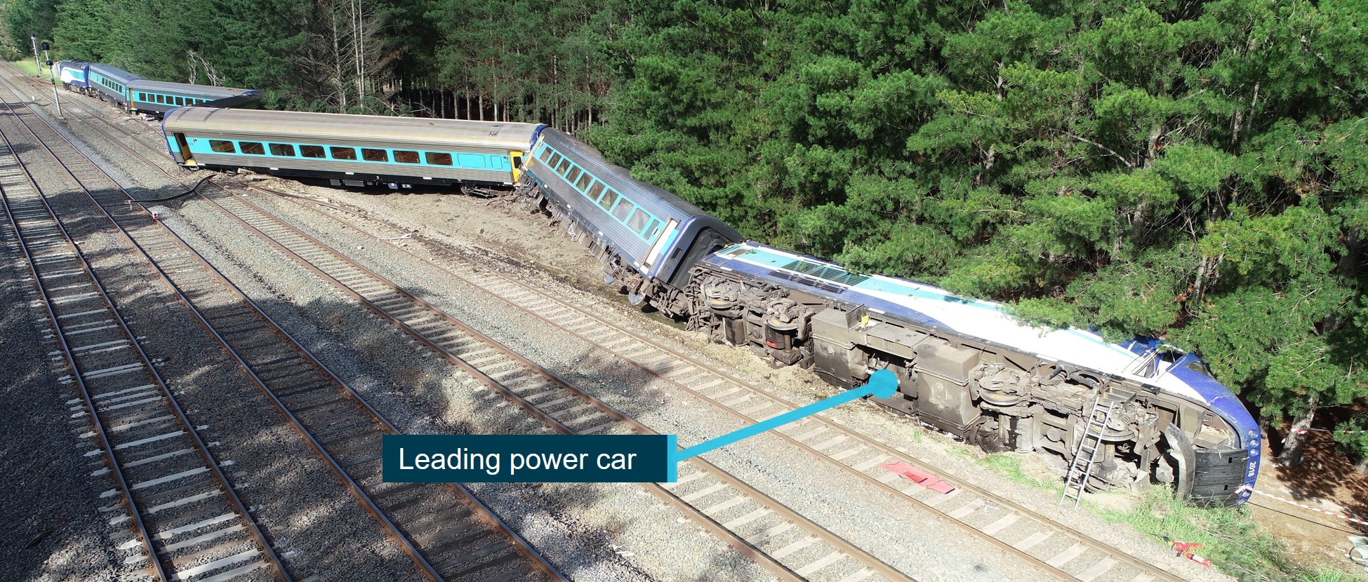
Source: ATSB
Turnout and track
At the time of the derailment, the points at the northern end of Wallan Loop were in their reverse position to provide entry to the loop (Figure 14). The points mechanism had been placed into the hand-operating mode[100] and the points were locked in position. The mechanism was also padlocked. These settings were consistent with the arrangements specified in TN 367 and TA 17.
Figure 14: No. 7 points at the northern entrance to Wallan Loop set to reverse
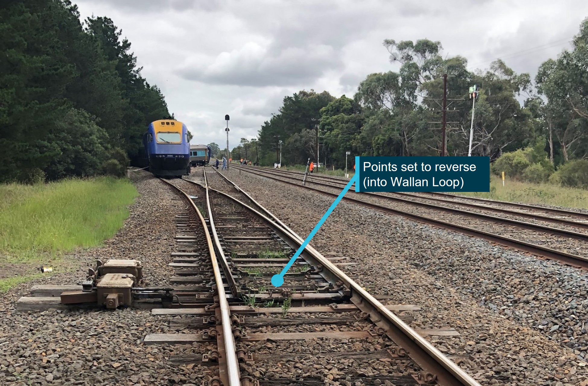
Source: CITS
There was no evidence of derailment prior to the turnout. Inspection identified evidence of derailment within and beyond the turnout. Track damage, including to rail and track formation, was extensive within No.2 track.
There was no evidence identified to indicate that the condition of the track at the northern entry to Wallan Loop was a factor in the derailment, noting also that the speed of the train exceeded the design rating of the turnout by a significant margin. The left rail of the turnout had been lifted a small amount at the commencement of the reverse route, possibly as a result of loading of the right side of the track in the vicinity of the crossing block[101] during the passage of ST23.
Power car XP2018
The leading power car (XP2018) had rolled onto its left side and come to a stop to the left of No.2 track and against a row of pine trees (Figure 15). With the power car on its side, the only reasonable access to the cab was through the right-side driver’s cab door.
At the time the site observations were made, the brake controller in the driver’s cab of power car XP2018 was in the emergency brake position with the power (throttle) controller in OFF and the reverser direction in forward. Both diesel fuel tanks of power car XP2018 had been torn open along their bottom left edge during the derailment and overturn.
Figure 15: Power car XP2018 overturned and access route via right door
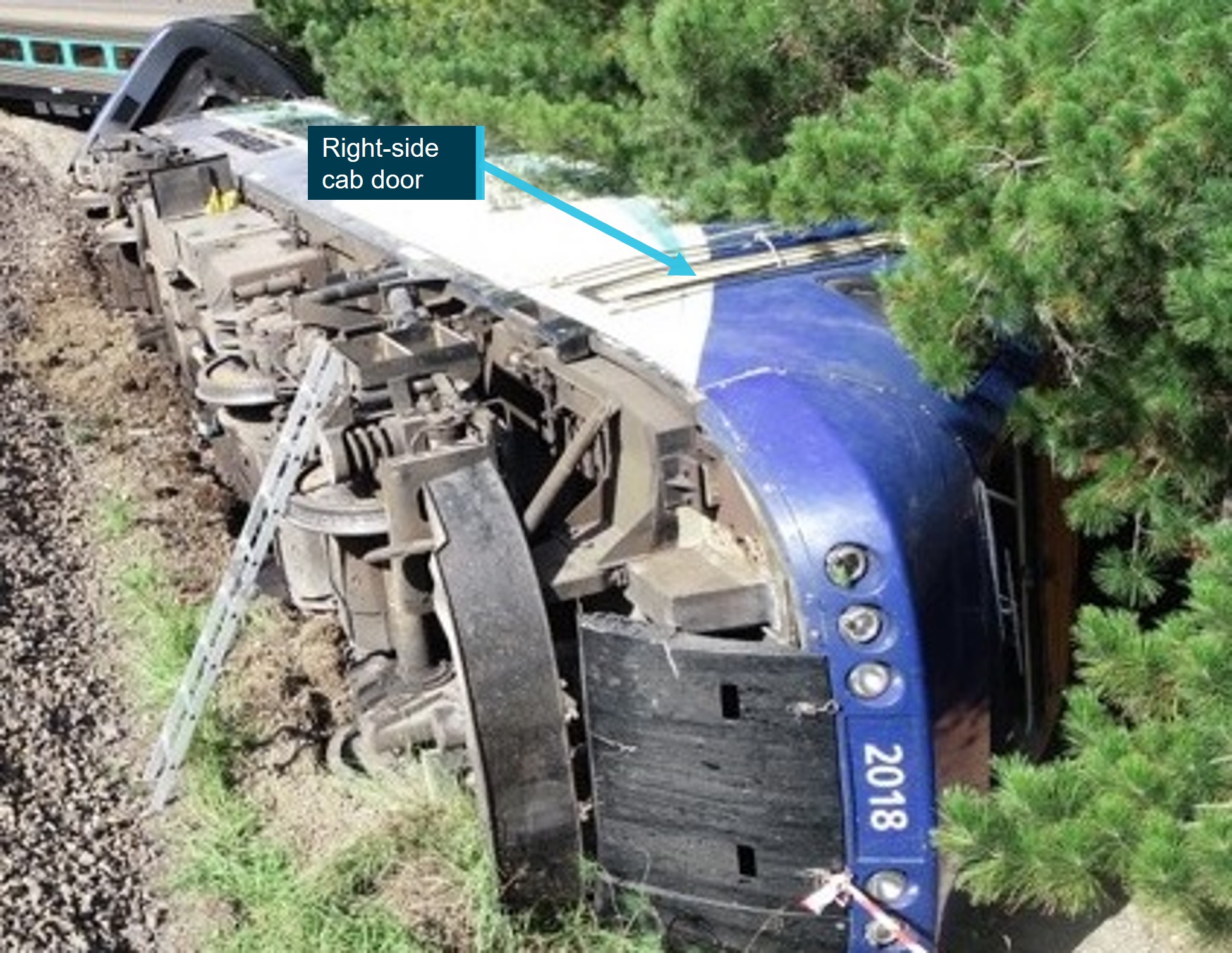
Source: ATSB
Leading passenger car
Of the passenger cars, the first (car A) had the greatest tilt (about 30° from the vertical) and the most extensive exterior damage. It had come to rest on a row of pine trees (Figure 16).
Figure 16: The derailed position of car A (photograph taken after cutting of trees)
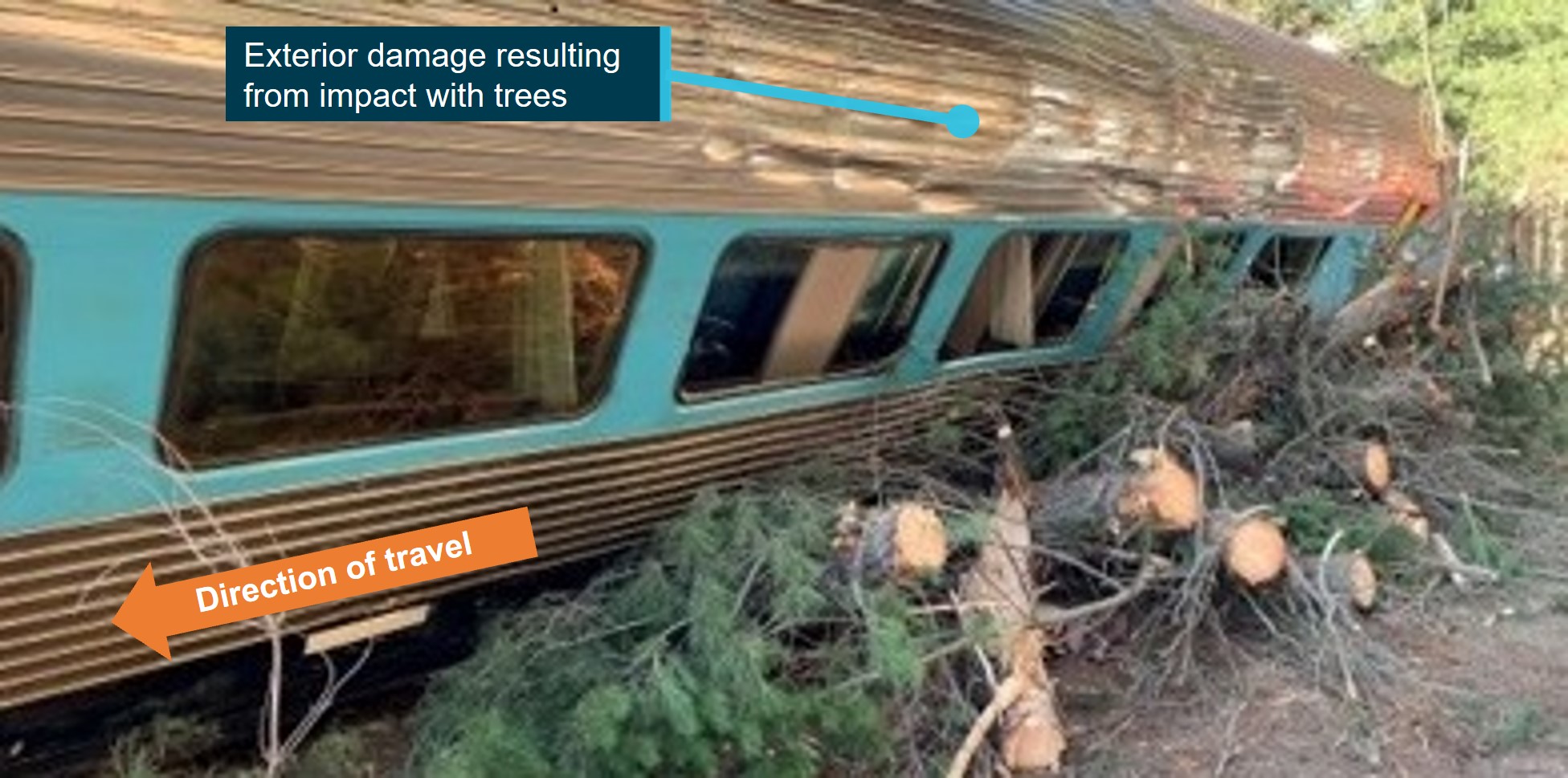
Source: CITS
Power car XP2018 crashworthiness and survivability
General inspection findings
Inspections of power car XP2018 were conducted to examine its crashworthiness performance and crew survivability features. The car was initially inspected at the derailment site, and further examined at the Auburn UGL facility (Figure 17).
Figure 17: Power car XP2018 at Auburn workshops on 10 March 2020
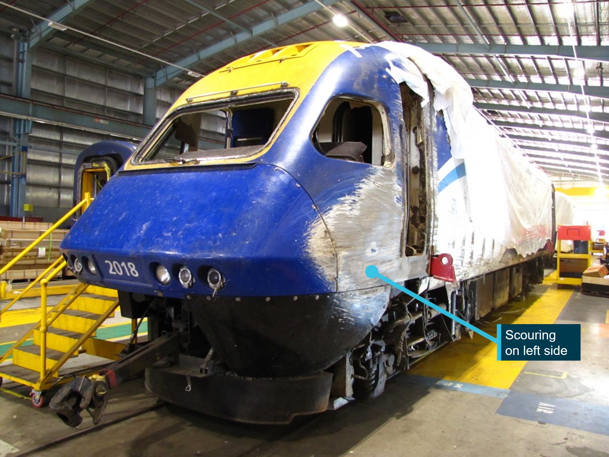
Source: ATSB
Scouring damage was present along the full left side of the power car that suggested the car had slid on its side for a significant distance. The car had retained its whole-body structural integrity, however both doors on the left side had been dislodged. There was evidence of a significant amount of ballast and earth having entered the driver’s cabin through the left-side driver’s cab door opening. Instruments, control panels and interior fittings were mostly intact.
The car’s forward windscreen had remained in place during the derailment.[102] The lower rear corner of the left-side quarter window had detached from the frame, although it was assessed that only a limited amount of ground material had entered the cab through that opening.
Inspection of left-side cab door
The left-side driver’s cab door was made from fibre-reinforced polymer and contained a glass window panel (that remained intact). The door was inward opening, hung with 2 hinges on its rear edge and closed by a single door latch on its forward edge. After the power car overturned onto its left side, the door separated from the door frame and was loose within the cabin.
Inspection identified that the 2 hinges had failed. The upper hinge knuckles had peeled open (Figure 18) and the fastening of the lower hinge to the door frame had failed (Figure 19).
Figure 18: Upper internal hinge of left cab door of XP2018
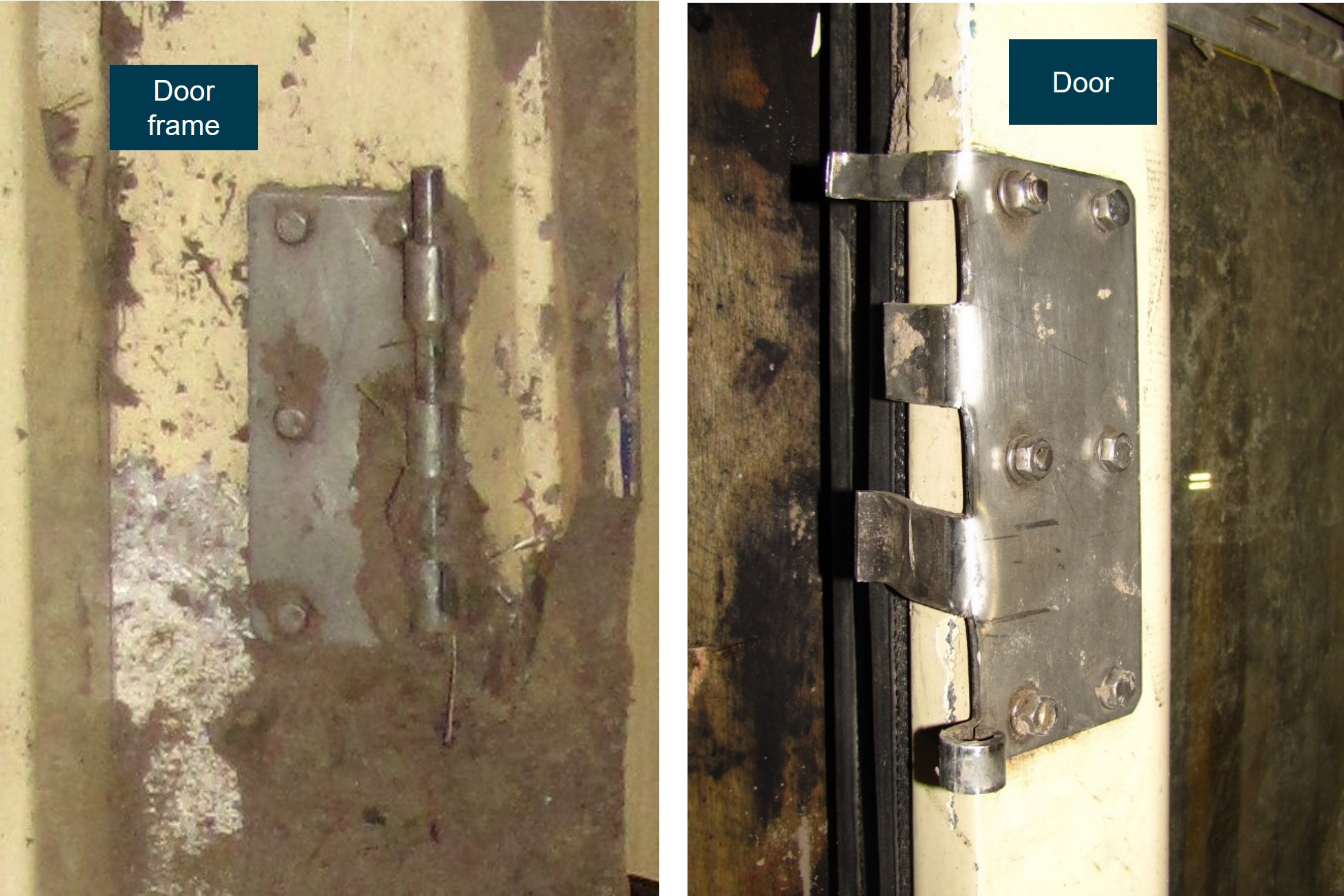
Source: ATSB
Figure 19: Lower internal hinge of left cab door of XP2018
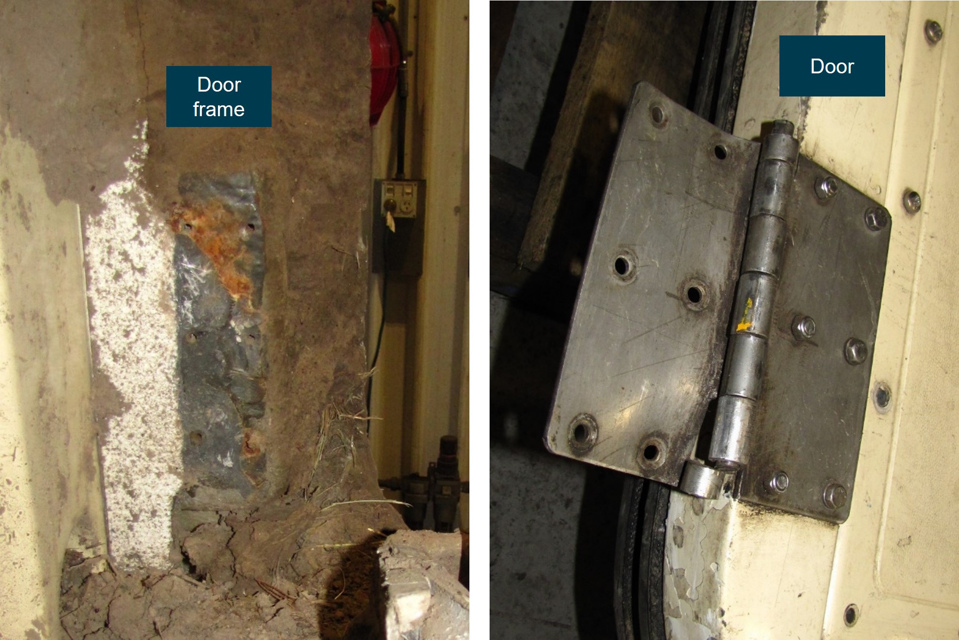
Source: ATSB
Assessment of left-side driver’s cab door separation
Design standards for pressure loading
The configuration of the driver’s cab door and the potential scenarios leading to its separation from the door frame were considered. It was concluded through inspection of the components, and the probable comparative loading on the upper and lower hinges, that the most likely initial failure was of the upper door hinge.
A simplified assessment of the hinge was conducted using design loads from contemporary Australian and overseas industry standards.[103] Australian standard AS 7521:2018 (Standards Australia 2018a) specified that external vehicle doors were required to meet the United Kingdom’s Rail Safety and Standards Board (RSSB) standard GMRT2100. Issue 6 (2020) of that standard specified external static and aerodynamic loads that were both defined as 2.5 kPa for trains travelling up to 200 km/h. Analysis indicated that the upper hinge on the XPT would not be expected to fail with a 2.5 kPa external pressure, applied quasi-statically (Appendix L).
Design standards for loading when overturned
GMRT2100 did not specify loading associated with external impact during rollover but did note that ‘where hinged external doors are used, typically for cabs, it is good practice to pay particular attention to the design of the door frame and locks’. It further noted that ‘there is a risk that, in the event of a derailment resulting in a roll-over, the structure can flex sufficiently to spring the door open, with the subsequent risk of the ingress of ballast and debris’. Assessment of the door and door frame of ST23 concluded that, in this instance, the door probably failed at its hinges rather than opening. Regardless, the result was the same with the entry of debris.
Australian industry standard AS 7520.1-2022 (Standards Australia 2022) specified that:
There were no specific requirements in the standard that related directly to the external loading of doors when the vehicle was on its side, nor dynamic loadings associated with a vehicle impacting the ground.
Although these loading scenarios were not specified for doors, an assessment was made of the upper hinge considering the pressure applied to the cab door if the power car was resting on its side with its own weight evenly reacted across the side profile of the car. This scenario equated to an applied pressure of about 11 kPa. It was found that the upper hinge knuckles would probably unfurl under this applied external pressure or at least commence to plastically deform (Appendix L).
Loading on door of ST23
In the process of overturning and sliding on its side over uneven ground, the dynamic loading of the left-side driver’s cab door would be expected to be significantly higher than the static load case of the car resting on its side (11 kPa). Given the probable commencement of unfurling of the upper hinge knuckles in the static-load case, complete unfurling of the upper hinge knuckles in the higher dynamic-load scenario was considered very likely. Consistent with this finding, it was also concluded that the cab side-door attachments were probably not designed to withstand the power car overturning and sliding on its side.
Survivability assessment of access to/egress from driver’s cab
Access to the driver’s cab on overturned power car
The normal access to and from the XPT driver’s cab was through its side doors. With the power car on its left side, the right-side driver’s cab door, which was now at the top of the overturned power car, was the most accessible access route to the cabin and the train crew inside.
The right-side driver’s cab door of ST23 remained operable and was used by members of the passenger services crew to gain access to the cab. However, this access route was only accessible by able-bodied people climbing on top of the power car and there was no reasonably practical way to extricate any non-ambulatory people from the driver’s cab.
At the rear of the driver’s cab there was an internal door to access the machinery space, and at the rear of that space there were 2 rear door side exits and a rear central door. However, access to the driver’s cab via the machinery and equipment compartments with the power car overturned would be hazardous and probably unrealistic.
Contemporary Australian egress requirements
Australian industry standard AS 7522:2021 (Standards Australia 2021)[104] specified that enclosed cabs of rolling stock shall be fitted with sufficient emergency exits to provide escape paths to the vehicle exterior when the vehicle was upright and when overturned on its side. There was no requirement specified for how a person might move to such exits if the vehicle was overturned. In the case of the overturned ST23, the right-side door at the top of the overturned vehicle was available to able-bodied people.
AS 7522:2021 and a NSW standard (Transport for NSW 2017) contained a number of other egress requirements for passenger train rolling stock. However, requirements generally applied to new passenger cars, or following a major modification, and none were identified as directly applicable to the configuration of the XPT power car.
There were no Australian Standards identified that specifically referred to requirements for ground-level access to overturned locomotives or power cars.
Similar occurrence related to crew survivability in a power car
On 6 November 2004, a 10-vehicle high speed train (HST) was derailed when it struck a motor vehicle at a level crossing at Ufton Nervet, United Kingdom. The accident was investigated by the RSSB (2005).
The HST was travelling at about 160 km/h at the time of the collision. The leading power car and all trailing vehicles derailed. The leading power car overturned and slid on its left side for some distance. Five passengers, the train driver and the motor vehicle occupant were fatally injured.
The XPT was based on the HST design and had similar form and structural configuration (Figure 20). There were differences in the cab internal layout, window arrangement and driver’s cab side door detail.
Figure 20: HST (left) and XPT (right)
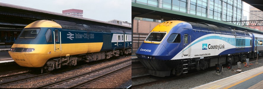
Source: Redditch Railway Interest Group and Government News
In the Ufton Nervet derailment, the leading power car came to rest on its left side with severe abrasions down the side of the car but with the whole-body structure substantially intact. There was structural failure at the top of a left leading pillar, this being the frame to which the left-side driver’s cab door was latched (Figure 21). The cab door had separated from the door frame and earth and ballast had entered the cab through the door aperture. In both the Ufton Nervet and Wallan derailments, the loss of the side cab door (when the power car overturned) resulted in material entering the cabin and impacting the occupants.
Figure 21: Ufton Nevert cab side damage (left) and Wallan cab side damage (right)
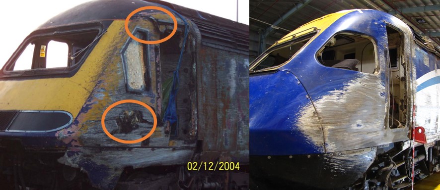
Skin penetrations are circled on the HST damaged at Ufton Nevert. The windscreens and windows have been removed on both trains.
Source: RSSB and ATSB.
The RSSB final investigation report into the Ufton Nevert derailment did not make a direct recommendation on the ingress of materials into the driver’s cab and referred the matter to the RSSB (2007) research project into cabin design and driver protection. The scope of this research project, which had already commenced at the time of the Ufton Nevert accident, was amended to include aspects of that accident; specifically, protecting the driver’s cab occupants from ingress of debris. The released report from this research project acknowledged that the door would open in such an accident and suggested the installation of partitions or reorientation of the door opening to screen the driver from the incoming debris.
Passenger car crashworthiness and survivability
Passenger injuries
There were 155 passengers and 5 crew members in the 5 passenger cars of train ST23. Available data from NSW Trains and Victoria Police was combined with passenger survey response data to estimate a total number of 61 passenger physical injuries.[105] This was comprised of 8 serious injuries and a reported 53 minor injuries.[106]
The estimated number of passengers in each car, the known injuries to passengers in each car, and the associated injury rate are shown in Table 3. The injury status for some passengers could not be determined, and it is possible there were more minor injuries. In addition to passenger injuries, the 5 members of the passenger services crew (1 in Car B and 4 in Car C) all received minor injuries.
Table 3: Estimated number of passengers in each car, known injuries and injury rate
| Passenger car | Serious injuries | Minor injuries | Passengers | Injury rate |
| Car A (cabin / sleeper) | 2 | 1 | 5 | 60% |
| Car B (first class) | 3 | 28 | 52 | 60% |
| Car C (first class / buffet) | 1 | 3 | 12 | 33% |
| Car D (economy class) | 2 | 16 | 57 | 32% |
| Car G (economy class / baggage) | 0 | 5 | 26 | 19% |
| Total | 8 | 53 | 155 | 39% |
Most injuries to passengers were a result of people being unprepared for the sudden deceleration or movement during and following the derailment. Passenger injuries were more prevalent and more severe in the forward passenger cars (as shown in the table above). Loose luggage also became projectile hazards during the derailment. Some luggage fell from overhead racks and there were instances of loose luggage causing injury to passengers and service crew.
Inspections
The 5 passenger cars were inspected to examine crashworthiness performance (Appendix M). Inspection of all passenger cars was conducted at the derailment site, and the leading passenger (sleeper) car (Car A) was further examined at the Auburn UGL facility. Inspections did not identify any passenger car structures that generated injuries by their design.
Evacuation routes from passenger cars
The majority (14) of the 18 exits in the passenger cars were available for use. Four exits were deemed unavailable, either due to obstruction, jamming or excessive height off the ground.[107] Of the 14 usable exits, 6 exits were considered freely available and 8 were operable but with some hindrance to their free use due to the distance from the ground, the angle of the access ladder, or some other hazard.
Most people were able to evacuate with limited assistance although sometimes with difficulty due to the distance to the ground or the angle of the car. Some passengers with special needs were assisted out of the carriages.
Passenger information
Passenger survey
Overview
The ATSB conducted a survey of passengers who were on board train ST23 at the time of the derailment. From 155 passengers reported to be on board, 83 responses to the survey were received: a response rate of 54%. The survey included questions on:
- passenger demographics
- passenger seating location
- safety information and briefings
- experiences during and after the event
- the nature of injuries.
Safety information
On questions pertaining to safety information:
- Most (70%) of the passengers who responded to the question about the provision of safety information reported that they either did not receive any safety information or could not recall receiving any.
- Of the 63 responses about the format of the safety information provided, 8 passengers (13%) reported that they received the information from a briefing card.
- Of the 74 responses to a question related to paying attention to the safety information provided, 57% reported that they did not pay attention.
- Most (70%) of the survey respondents reported that, prior to the derailment, they did not know how to get out of the train in an emergency.
In response to questions on suggestions for improvement in safety information:
- Ten passengers referred to the way in which safety information is provided by airlines.
- Some passengers mentioned that better signage on the seat in front of them or at the end of carriages may have been helpful.
- Other comments included increasing the number of announcements.
The evacuation
There were varied responses from passengers about the communication received from crew members following the derailment. This was at least in part due to the distribution of the crew, with 4 of the 5 crew members being in the buffet car at the time of the derailment and no crew members present in Car A, Car D or Car G. Most of the passengers who responded advised that initial crew instructions were to remain on board the train. Others reported being unsure about what to do. There was no report of any announcements being made via the public address system or the use of megaphones.
Passengers were asked to estimate how long it took to exit the train. The responses ranged from a ‘few minutes’ to up to 30 minutes, supporting other evidence that some passengers self‑evacuated prior to being instructed to do so by the passenger services crew. About half of the respondents indicated having difficulty exiting the train due to carriage orientation and/or difficulty with getting down to the ground. Once passengers were out of the train, crew members were observed instructing passengers to move off the adjacent tracks (due to concern of possible rail traffic).
Sixteen respondents utilised the free text question to provide praise for the handling of the emergency event by members of the train crew and first responders.
Emergency preparedness
Passenger safety information
Verbal safety briefing
The train operator’s procedures provided details of the verbal safety briefing to be conducted by the passenger services crew (Appendix N). Key messages included, but were not limited to:
- to remain seated and wait for instruction from the crew
- to leave luggage if instructed to evacuate
- to refer to the safety card for further information.
Evidence suggested that it was probably the normal practice for crew supervisors to develop their own announcement script rather than using a pre-prepared script developed by NSW Trains.
Operator procedures specified the conduct of announcements at the departure point in Sydney and at selected stations en route to Melbourne, including at Albury. The replacement passenger services crew boarded at Albury and an announcement was made to passengers using the public address system. However, the announcement did not include the full safety briefing. Evidence suggests that some crew members were not familiar with the requirement to provide a safety briefing at Albury.
Written briefing information
Written information about what passengers should do in an emergency was contained in an ‘on‑board guide’ located in the back pocket of passenger seats. This guide was a 10-page booklet that contained general information about the train service and destinations, food and beverage menu items, and emergency procedures.
The messaging on emergency procedures contained in this guide (Appendix N) was consistent with the operator’s procedures for verbal briefings. The instructions on what to do in an emergency included guidance to:
- remain seated until instructed by the crew or emergency services
- leave luggage behind
- be aware of hazards outside the train.
The instructions were in written form only and did not include diagrams or pictorials to supplement the text.
It was reported by passenger services crew members that on some trips there would be a large proportion of onboard guides missing from the back of passenger seats. Although there were a significant number of onboard guides present on ST23 on the day of the derailment, not all seats were provided with a copy. The passenger survey indicated that only a small number of passengers obtained safety information from this guide.
On-board safety signage
There was no onboard safety signage identified on ST23 that provided guidance to passengers on actions for them to take in the case of emergency.
Emergency response procedures
Emergency response plan
The train operator had an emergency response plan that was supported by operational procedures. The emergency response plan was summarised in the Countrylink Incident Response Summary (Appendix O). This summary was contained in onboard logbooks, and displayed on the bulkhead at crew stations (Figure 22).
Figure 22: Onboard incident response summary at a crew station
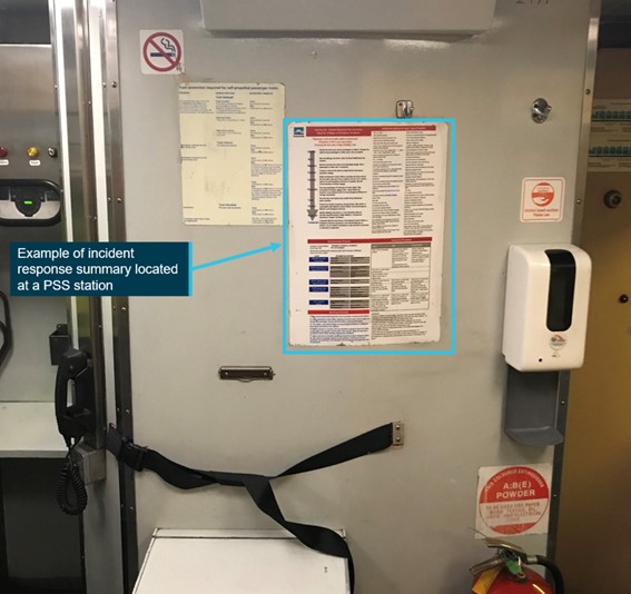
Source: NSW Trains, annotated by the ATSB
The response summary contained a 9-step action plan to be followed by the train crew in the case of a major incident or emergency. This action plan was supplemented by specified additional actions for 15 types of incidents, including derailment. The incident response summary also included guidance on communication protocol, deciding to evacuate, and evacuation procedures. A range of warnings were described, including to ‘evacuate to tracks only after receiving positive confirmation from Network Control Officer that train movements have been stopped …’.
Crew members were also provided with an ‘emergency pocket guide’ that included shortened advice on quickly assessing risk, and communicating with emergency services, the NCO and management.
There was no ready-use guidance available to crew members about what or how they should communicate with passengers in the period prior to the decision being made to evacuate. There were no documented standard phrases or positive commands to instruct passengers to remain seated or on board the train.
Procedures for an evacuation when not at a station
In circumstances where the train was not at a station and the crew had determined the situation to be life-threatening, they were required to conduct a risk assessment to determine the safest course of action. If an evacuation was required, the driver was responsible for securing the train, notifying the NCO and ensuring that all adjacent traffic had been stopped. The driver or PSS was then required to protect the train, determine an evacuation plan (including which doors to use), inform passengers and manage the evacuation.
Use of the public address system
The public address (PA) system was serviceable throughout the train journey prior to the derailment. Following the derailment, it was not utilised by the passenger services crew to communicate to passengers. It was not determined if its serviceability was affected by the derailment. There was also no specific procedure that advised the crew what to do if the PA system was unsuitable for use in an emergency.
Megaphones were available for use on board the train. There was no specific procedure describing when they should be used, and they were not used in this instance.
Passenger services crew training
ST23 crew training and assessment records
NSW Trains provided details of crew training courses that included content related to emergency evacuation (Table 4).
Table 4: Training courses covering derailment and evacuation
| Course name | Frequency |
| Safeworking (PSS only) | Annually |
| CPR | Annually |
| Competency assurance check ride | Annually |
| WF25 Emergency ladder and evacuation | Every 2 years |
| IC01 Emergency and evacuation | Every 2 years |
| NCA01 NSW Operational staff competence assurance: Emergency and evacuation | Every 2 years |
| WX63R0109 Incident response plan | Every 2 years |
| First Aid | Every 3 years |
The individual learning profiles of the passenger services crew on ST23 were compared with the courses required for passenger services crew. The review identified that not all the crew members had completed the required courses, several courses had not been completed at the frequency specified, and none of the passenger services crew members were recorded as having completed the listed course WX63R0109 (Incident response plan).
The facilitator guide for the incident response plan course was reviewed. Except for a specified instruction to use when initiating a passenger evacuation, the course material did not include other standard phrases or commands that the passenger services crew should use in an emergency, such as an instruction to remain on the train following a derailment. In addition, the training courses reviewed did not provide passenger services crew with the opportunity to practice using the PA or megaphone to make announcements, or use standard phrases or commands in an emergency context.
Assessment records were obtained for the passenger services crew members on ST23 and these included the written assessments for their most recent ‘NCA01 NSW Trainlink Operational Staff Competence Assurance: Emergency and Evacuation’ course. Review of these records found inconsistencies and, in some cases, an absence of the use of the marking scale. In several cases there was also an absence of assessor sign-off.
Training needs analysis
NSW Trains provided a report of a training needs analysis completed in April 2019.[108] This review included a detailed task analysis of passenger services crew roles, and the approach to training and assessment of required competencies. It identified that evacuation-related competencies should be trained and assessed practically, with a frequency of every 6–12 months. The report also included driver incapacitation scenarios and the use of high-fidelity mock-ups. The outcomes of this project had not been implemented at the time of the Wallan derailment.
Other information related to training and competency management
Research conducted by the NSW Independent Transport Safety and Reliability Regulator (ITSRR)[109] highlighted, among other things, that accident reports had a reoccurring theme in the deficiency of emergency procedures training provided to train crew (ITSRR 2004).
Published in July 2021 (post the Wallan derailment), the Office of the National Rail Safety Regulator (ONRSR) provided guidance about the management of rail safety worker competencies, which included a rail safety worker competency assessment fact sheet (ONRSR 2021) and various examples (including a competency register) of how organisations could record the competency requirements and expiries of train crew.
Review of regulator activities
Scope
ONRSR was the national rail regulator. A review was undertaken of potentially relevant regulatory activities in the 5 years preceding the Wallan occurrence.[110] Activities examined included reported overspeed occurrences, notified changes to safeworking arrangements, and relevant audit and inspection activity.
Notified occurrences associated with train overspeed from 2015
ONRSR was requested to provide notified overspeed occurrences on the ARTC network in Victoria in the 5 years prior to the Wallan occurrence.[111] Eleven overspeed occurrences were identified in the supplied data, including the following 5 that involved passenger trains:
- 6/1/2015 – an XPT passenger train went through a 40 km/h temporary speed restriction between Somerton and Donnybrook at 130 km/h.
- 11/7/2015 – a V/Line passenger train transited the turnout into Wallan Loop at over 90 km/h compared to the required 15 km/h. This overspeed occurrence was investigated by the ATSB.
- 29/12/2015 – a V/Line passenger train went through a 40 km/h temporary speed restriction at Euroa at 72 km/h.
- 13/3/2018 – an XPT reported travelling through a 40 km/h temporary speed restriction at Violet Town at excessive speed.
- 6/8/2018 – a V/Line passenger train went through a 40 km/h temporary speed restriction between Seymour and Benalla at the line speed of 130 km/h.
Notifications of change to network rules from 2015
ONRSR advised that 5 notifications of change to the Code of Practice for the Victorian Main Line Operations (TA20) were submitted by ARTC in the 5 years preceding the Wallan occurrence. None of these notifications of change related to the processes used at Wallan on 20 February 2020.
Audits and inspections from 2015
Topics not audited
ONRSR used a risk-based approach in its decisions and plans for regulatory activity. As a result, regulatory activity was targeted and operators and topics received different priority. For the ARTC network in Victoria in the 5 years before the Wallan occurrence, ONRSR advised that it did not conduct audits or inspections of ARTC on the following topics:
- caution orders or train authorities
- the use of AQWs or safeworking pilots
- the risk of train derailment due to overspeed[112]
- the overspeed of a V/Line passenger train at Wallan Loop (Victoria) on 11 July 2015.
ARTC risk management
ONRSR was requested to provide audit and inspection reports that included the topics of ARTC risk management systems and/or risk assessment processes associated with safeworking. ONRSR identified 4 audits and 6 compliance inspections conducted across 2017 and 2018 that included either or both of the requested risk topics.
Reports from these regulatory activities referenced concerns with the currency of the centralised risk register and ARTC’s introduction of a new Enterprise Risk Management System (ERMS). Of note, an audit in November 2018 made several observations, including that ARTC should consider the risk of passenger and freight train derailment separately in view of the different potential consequences and required controls.
NSW Trains systems for accessing and distributing safety critical information
ONRSR was requested to provide audit and inspection reports that included the topics of NSW Trains’ systems for accessing safety-critical information (such as train notices) from ARTC for operations on the Victorian network, and NSW Trains’ systems for disseminating such information. In response, ONRSR identified a total of 5 audit and 5 inspection activities between 2015 and 2018 that referred to either or both of these topics.
Consistent through these activity reports was reference to the issue of a Train Crew Weekly Information Pack (WIP) as the primary vehicle for distributing safety-critical information including train notices. There was no commentary or findings identified in the review that discussed the collection and immediate distribution of notices accessed from the ARTC WebRAMS portal.
Other occurrences at Wallan Loop investigated by the ATSB
V/Line high speed entry into Wallan Loop in 2015
In July 2015, a Melbourne to Albury V/Line service entered the southern turnout to Wallan Loop travelling at more than 90 km/h (compared to the required 15 km/h). The train remained on track, however some passengers required medical attention from the onboard service crew due to the rough ride as the train transited the turnout.
This occurrence was investigated by the ATSB (2017). It was found that signalling at the location was operating as designed and there were no signal sighting issues, but that the driver did not demonstrate effective awareness and train handling techniques. The report also made findings related to post-occurrence processes and actions.
As part of the investigation into the derailment of train ST23, further enquires were made into safety actions taken by ARTC and V/Line following the 2015 occurrence, and specifically consideration of train enforcement solutions at Wallan Loop (to automatically enforce train braking if a train was detected as being overspeed).
ARTC advised that consideration of train enforcement solutions at Wallan Loop was a matter for V/Line. Also, ARTC did not introduce any additional risk controls at Wallan Loop in response to the V/Line train overspeed occurrence.
V/Line advised that, following the 2015 occurrence, the potential application of the train protection and warning system (TPWS) on the ARTC Northeast standard gauge line was evaluated.[113] It was concluded by V/Line that (based on safety risk to its operations) there was a case to install TPWS at several locations on the ARTC North-east standard-gauge line (including at Wallan Loop) to protect against a V/Line passenger train overspeed or the passing of a signal at danger. TPWS was used for V/Line trains on the Victorian broad gauge networks and V/Line passenger rolling stock was fitted with compatible equipment.
The project to integrate TPWS (for V/Line trains) on the ARTC network was being funded by the Victorian Government and ARTC confirmed in its response to ATSB that it had been involved in discussions with V/Line and was committed to supporting the implementation of TPWS. TPWS was scheduled to be fitted at Wallan Loop in 2024.
TPWS would not be compatible with the XPT (and its NSW Trains replacement) or freight traffic.
Derailment of freight train at Wallan Loop November 2017
On 4 November 2017, freight train 7MC1 was signalled into the southern entry to the crossing loop at Wallan. Entering the loop, the leading bogie on the 37th wagon derailed.
The occurrence was investigated (ATSB 2019). It was found that the derailment occurred within a rapid transition of track superelevation from the main line to the loop track, resulting in wheel unloading. Following the derailment, ARTC completed rectification works and enhanced its work management processes for the response to geometry conditions. There was no aspect of this occurrence found to be relevant to the derailment of train ST23.
Safety analysis
Introduction
The derailment of the interstate passenger rail service (train ST23) between Sydney and Melbourne resulted in the death of the train’s driver and the accompanying rail worker, and serious injuries to 8 passengers. There was potential for further passenger injury that was probably mitigated by a row of trees limiting the rollover of the leading passenger car.
The report analysis first considers the physical scenario that resulted in the derailment of train ST23 and describes those factors unlikely to have influenced the occurrence.
Potential scenarios that may have led to the train travelling at near the track speed of 130 km/h as it approached the turnout to Wallan Loop are then considered. Evidence supporting the most likely scenario, that the driver of train ST23 was probably unaware of the routing of ST23 through Wallan Loop, is discussed. Other scenarios considered less likely are also presented. The mechanisms for informing the driver of the changed conditions at Wallan Loop and missed opportunities are then introduced.
The analysis further examines the underlying factors that either directly influenced this occurrence or increased the safety risk associated with train operations. The analysis discusses the train working system, risk assessment processes, risk controls, and the distribution of safety critical information. Comment is also made on the risk management of passenger trains on the ARTC rail network.
The remainder of the analysis considers factors associated with events following the derailment, including power car survivability following overturn and the preparedness of passengers and passenger services crew for a major emergency occurrence such as train derailment.
The derailment
At Wallan Loop, the track was configured with low speed turnouts to No.2 track from No.1 track that had a permitted speed of 130 km/h for passenger trains. The significant speed differential at this location created the risk of derailment due to overspeed that was controlled through driver compliance with the signalling system. When the signalling system became non-operational in February 2020, the risk of derailment at the turnouts due to train overspeed was (initially) effectively eliminated by locking the points to their normal position and removing the option to transit through No.2 track. The hazard at the turnouts and the risk of derailment were then re‑established on 20 February when the points were locked in their reverse position to route trains via No.2 track with (only) the implementation of administrative control that relied on ‘paper-based’ information exchange.
The investigation found that train ST23 entered the turnout to Wallan Loop travelling at between 114 and 127 km/h. The turnout was rated by ARTC for a train entry speed of 25 km/h and the maximum permitted operational speed was 15 km/h. In the absence of indications of infrastructure or rolling stock defects, it was concluded that ST23 derailed as a result of its speed significantly exceeding the speed rating of the infrastructure.
Recorded data indicated that ST23 was approaching Wallan Loop at 129 km/h[114] when there was a rise in brake cylinder pressure as a result of an emergency brake application. Assuming a nominal 2 seconds between the cues of the unexpected situation and braking system response,[115] the cues(s) that resulted in the brake application may have arisen when ST23 was between 120 and 220 m from the turnout (Appendix K).[116] Possible reasons for the driver realising the need to brake included recall of the points setting by the accompanying qualified worker (AQW) or the driver, or direct observation of the setting of the points at the turnout to the loop.[117] Given the AQW had no driving experience, the emergency brake application was almost certainly the action of the driver.
Site inspection indicated that the vehicles of the train derailed within the Wallan Loop turnout and No.2 track, and there was no indication of derailment prior to the turnout. Given the leading power car overturned onto its left side, the rolling over of the power car was more likely to have occurred (or commenced) within the right curve transitioning onto the tangent (straight) section of No.2 track. Damage to the exterior of the power car also suggested it had slid on its left side for a significant distance.
Factors unlikely to have influenced the occurrence
Driver incapacitation
There was no evidence identified to suggest that the driver was incapacitated leading up to the derailment, and there was evidence to support the proposition that the driver and AQW were functioning normally. The AQW was in contact with the level crossing keeper (LCK) less than 2 minutes prior to the derailment, had sounded normal in that conversation and did not raise any concerns regarding the condition of the driver. An earlier brake application for a 115 km/h track section, and a power application made shortly after the conversation between the AQW and LCK, also support the proposition that the driver was actively in control of the train.
The derailment occurred about 6.5 hours after the driver started their shift, a little under 5 hours after they commenced driving ST23, and about an hour after the driver’s scheduled end-of-shift. Although the driver may have been tiring towards the end of the train journey, there was no evidence, including in radio communications, that suggested that driver fatigue was a factor. A review of the driver’s roster and recent history found that there was insufficient evidence to conclude that the driver was experiencing a level of fatigue that would significantly affect performance.
There was no pre-existing health condition of the driver that was likely to have contributed to the accident and toxicology results did not identify any substance that may have impaired their performance.
Rolling stock condition
Inspections, testing and a review of maintenance records did not identify any adverse rolling stock condition or defect that was likely to have contributed to the derailment.
Track condition
There was no evidence identified to suggest that the condition of the track or turnout at the northern entry to Wallan Loop was a factor in the derailment, noting also that the speed of ST23 significantly exceeded the ARTC speed rating for the turnout. The facing points were found to be locked and in position for the train movement into No.2 track.
Factors leading to train overspeed
Discussion on potential scenarios
Scope
Having excluded the likelihood of driver incapacitation or defective train braking, this section discusses the evidence for, and likelihood of, the following scenarios that could have led to the overspeed of ST23 at the Wallan Loop turnout:
- The driver of ST23 was not aware of the routing of ST23 via Wallan Loop and expected to travel on the straight track through Wallan.
- The driver was aware of the routing of ST23 via Wallan Loop and forgot this information during the journey between Kilmore East and Wallan.
- The driver lost awareness of their location in the section between Kilmore East and Wallan.
- Approaching Wallan Loop, the driver misinterpreted an adjacent broad gauge signal (that was probably at proceed) as applying to the standard gauge track.
Driver awareness of changed conditions and expectancy
Prior to the derailment, there were a number of radio conversations between the NCO and the driver and there was no instance where the driver of ST23 expressed an understanding that conditions at Wallan Loop were different to what they had been during the previous 12 days, and that ST23 was being routed onto No.2 track on that day. In a radio conversation between the driver and the NCO about an hour before the derailment, the NCO mentioned that ‘you’re going via the loop there at Wallan’. There was no acknowledgement of the routing via the loop by the driver.
In another interaction with the NCO about 11 minutes before the derailment, when at Kilmore East receiving the train authority, the driver commented that they were in possession of the train authority and CAN and stated that they were ‘filled out ahh the same way it has been for the … rest of the time’. This latter interaction suggests that the driver may have believed that the track conditions were the same as they had been and that ST23 would proceed through Wallan in the same way as the driver had experienced in the preceding trips through the location, including on the day before.
Also while ST23 was stopped at Kilmore East for the driver to receive the train authority, the NCO mentioned ‘points all set for the loop’. The driver did not respond directly to this comment and there are a number of ways it could have been interpreted.
Expectations based on past experience strongly influence where a person will search for information and what they will search for (Wickens et al. 2023), and they also influence the perception of information (Wickens et al. 2022). In simple terms, people are more likely to see and hear what they expect to see and hear, and less likely to see and hear what they do not expect to see and hear. After the commencement of the alternative method of train working, the driver of ST23 ran the Junee–Melbourne–Junee round trip 4 times (8 times through the location) between 8 and 19 February. For all previous trips, the points at each end of Wallan Loop had been locked in the straight position, and trains could proceed through this location at normal track speed (130 km/h for the XPT). This experience likely developed an expectancy in the driver that strongly influenced their mental model on the day of the derailment.
Limitations of prospective memory
Another scenario is that the driver correctly assimilated the information from the train authority, the NCO’s mention of the transit through the loop and/or verbal information potentially provided by the AQW, but forgot about the changed conditions at the loop during the short journey between Kilmore East and Wallan Loop.
Remembering information about the use of the loop and associated speed restriction and applying it later would require prospective memory (Loukopoulos et al. 2009). Prospective memory refers to an intention to perform an action at a later time, and a delay between forming the intention and acting on it. It is known to be vulnerable to failure and has been associated with many incidents in aviation and other work domains (Dismukes 2012). Prospective memory errors have also been associated with previous incidents of overspeeding trains due to drivers forgetting a temporary speed restriction (Sato et al. 2020).[118]
Conditions that increase this vulnerability include the delay between the intention to do a task and the execution of the task being filled with other activities, an interruption to a task sequence, and the cues or prompts to retrieve the intention from memory not being explicit (Dismukes 2012). In the case of train ST23, the driver did not have any strong cues or prompts (such as signage or in‑cab alarms) for recalling the speed requirement. Conversely, there would probably not have been excessive task demands on the driver and, as far as is known, there were no distractions or interruptions to their normal driving activities. The interactions between the driver and the AQW during this period and any possible distractions could not be determined.
It is feasible that when ST23 approached the turnout loop, the driver recognised they were now approaching Wallan and remembered that they were being routed through Wallan Loop and made the emergency brake application. However, there was no evidence available to determine whether that scenario may have occurred or instead the driver reacted to being prompted by the AQW or observing the position of the points at the turnout.
Other possible scenarios
It is also possible that after departing Kilmore East, the driver lost awareness of their location within the 15 km section to Wallan, and only made a brake application after realising their proximity to Wallan Loop. Given the driver was familiar with the route and had travelled on this track several times in the preceding 12 days,[119] there was no compelling case to suggest a loss of positional awareness.
It was also considered whether the driver may have been confused by the broad gauge signal, which was probably at proceed. Given the experience of the driver, their familiarity with the route and their recent and repeated transits through the location with the standard-gauge signalling system not operating, there was also no compelling case to suggest that the driver had misread the broad-gauge signal as applying to the standard gauge track.
Summary
Having discounted several other possibilities, the remaining most likely scenarios were that the driver was either unaware of the routing through the No.2 track at Wallan, or the driver was aware of the routing but forgot (prospective memory failure). The recorded driving actions of applying power after receiving confirmation that the level crossing protection at Wallan had been activated and then making a late emergency brake application approaching the loop turnout were both consistent with, and plausible driver actions in the case of, either scenario.
There was, however, no direct evidence to support the proposition that a failure of prospective memory was a factor in this instance. No radio interactions between the driver and NCO suggested recognition by the driver of the routing through the loop, or the differences (compared to previous days) in the train authority that had been issued on that day. It was therefore concluded that there was insufficient evidence of a failure in the driver’s prospective memory.
Considering the radio communications between the driver and the NCO, and in the context of an expectation developed by this driver during 8 trips through the location in the 12 days after the signalling system was disrupted, it was concluded that it was more likely that the driver of ST23 was not aware that ST23 was being routed through Wallan Loop on that evening. Supporting the potential for such a scenario, there were several weaknesses in the delivery of information to the driver to overcome their expectancy, and several missed opportunities to confirm the driver’s understanding of the changed conditions.
Information available to driver and missed opportunities
Scope
This section discusses the information that was available (and not available) to the driver and introduces the missed opportunities for confirming driver awareness. These themes are developed further when discussing risk management and risk controls later in the analysis.
The information that is discussed and the implications for the driver include:
- train notice 266 and its reinforcement of the expectation that the loop was not being used
- train notice 367 and its absence as pre-information for the driver
- train authority 17 and weaknesses in the delivery processes for assuring driver understanding
- communications between the NCO and driver as a missed opportunity
- communications between the AQW and driver as a missed opportunity
- rail resource management as a missed opportunity
- cues in the real-world environment as a missed opportunity.
Train notice 266
Prior to the day of the derailment, the driver of train ST23 had driven through the location several times operating under the altered train working arrangements and the instructions of train notice 266 (TN 266). On 8 February, the driver had also repeated back the associated train authority for this method of working prior to their first transit under these conditions. The driver was therefore very likely familiar with the conditions specified in TN 266, and specifically the condition that the points at either end of Wallan Loop were locked in their normal position for transit on No.1 track. TN 266 did not contain any information suggesting the possible operation of trains through Wallan Loop (No.2 track). This meant that TN 266 had worked to establish a strong expectation (in the driver) that the points would be set to their normal position (for the straight).
Train notice 367
TN 367 was a potential source of pre-information about the change in conditions at Wallan Loop, however, the driver did not have a copy of TN 367 with them on ST23 and was probably unaware of this notice. This removed the opportunity for the driver to familiarise themselves with the changed conditions.
Train authority 17
The driver of ST23 received a copy of train authority 17 (TA 17) while stopped at signal KME16, about 12 minutes before the derailment. TA 17 detailed the changed conditions at Wallan Loop, including the requirement to slow to 15 km/h. However, this added text was towards the end of TA 17 and was not marked or highlighted in any way to indicate it was different to the previous train authorities that had been issued for the same section of track in recent weeks. In addition, the body text of the train authority was in upper case, which can be more difficult to read or scan than lowercase text (Wickens et al. 2022). It is therefore very plausible that the driver did not pick up the change from previous train authorities. The radio communication by the driver that the documentation was ‘…filled out … the same way it has been...’ suggests this was probably the case.
Consistent with the practice that was used during the 2 weeks of the altered train working arrangements, TA 17 was given to the driver by the AQW. It was the practice for signallers to deliver the train authority to the driver via an AQW, although this was inconsistent with the description in TN 266 that specified that the signaller was to deliver the train authority to the driver. Delivery of TA 17 directly to the driver of ST23 would have provided an opportunity for the driver to receive direct verbal advice of the changed conditions from the signaller during the transfer of the authority document.
The driver was also not required to (and did not) read back the contents of TA 17 to the NCO or the signaller, and almost certainly did not read back TA 17 to the AQW. Readback/hearback refers to the process of issuing and confirming track authorisation (Gertner and Acton 2003). Verbal rehearsal can result in the encoding of information in short-term memory (Greene 1987). Readback of safety-critical information is adopted by industries to ensure information is correctly understood by the sender and the (actioning) receiver, in this case the NCO and the driver of ST23 respectively. An industry guideline on safety critical communications (RISSB 2018) stated that to ‘ensure the message has been understood, require the recipient to repeat back the message if not already done by them’. In their similar manual, the Rail Safety Standards Board (RSSB 2017) in the United Kingdom outlined that:
Had the driver of ST23 read back the full content of TA 17 to the NCO, it is probable that they would have realised the changed conditions at Wallan Loop, complied with the speed instruction and this occurrence would probably not have occurred.
NCO – driver communications
In addition to the driver’s acknowledgement of the receipt of train authority 17, there were other conversations between the NCO and driver that were missed opportunities for the NCO to confirm the driver’s understanding of the change in conditions at Wallan Loop. The NCO and driver had conversations that skirted the topic of the routing of ST23 through Wallan Loop, without achieving confirmation of driver understanding. Although these opportunities existed, there was no procedural requirement for the NCO to seek confirmation of the driver’s understanding. In addition, the NCO’s belief that there was a pilot on board probably provided some reassurance with the arrangements.
AQW – driver communications
Tasks of the AQW included delivering the train authority and CAN notice to the driver and organising the activation of level crossing protection at Wallan–Whittlesea Road. These tasks were completed by the AQW on train ST23.
For this day, TN 367 added the instruction for the AQW to remind the driver that the train would operate via No.2 track at Wallan Loop, although the notice did not include any procedural requirement on how this activity was to be conducted by the AQW or how driver understanding was to be ensured (such as by readback). The AQW was briefed on this requirement and would also have expected that the driver was likewise aware of TN 367. There was probably sufficient time from when the AQW boarded ST23 to its departure from KME16 for this exchange of information to occur.
In the absence of voice recordings from the driver’s cab, the details of conversations between the driver and the AQW are unknown. There are many plausible scenarios in which conversations may have occurred but may have been misinterpreted by either party.
The presence of an authority gradient can influence the effectiveness of personal interactions. An authority gradient refers to the perceived difference in status between different members of an organisation (RISSB 2018). Its presence can influence the effectiveness of the delivery and receipt of information between safety-critical personnel. There was insufficient evidence available to examine whether this may or may not have been a factor in this instance.
Rail resource management
Rail resource management (RRM) is the application of non-technical skills of rail safety workers, which includes team communication and co-ordination, planning and contingency management, critical decision-making, situational awareness, and workload management (Klampfer and others 2012). These skills enable operational staff such as drivers, guards, NCOs, signallers and rail workers to effectively manage hazards and errors in the workplace. In this instance, there were missed opportunities for application of RRM principles between the NCO and the driver to assure driver awareness of transit through Wallan Loop. There was insufficient evidence to conclude the nature of the probably missed opportunities to apply RRM principles between the AQW and driver.
Visual and audible cues for the driver
The driver was not provided with visual cues (such as signage or conspicuous warning devices)[120] or audible cues (such as in-cab alarms) to warn of the need to slow to 15 km/h when approaching Wallan Loop. These were significant absent risk mitigants and missed opportunities for cues in the real-world environment to address limitations in transmitting information by administrative systems and mitigate against a failure of prospective memory and expectation bias.
Deviation from established network rules
A safety management system (SMS) is a ‘formalised framework for integrating safety into the daily operations of an organisation and includes the necessary organisational structures, accountabilities, policies and procedures’ (Fox 2009). The Rail Safety National Law described an SMS as providing a ‘comprehensive and systematic assessment of any identified risks’.[121]
The ARTC SMS was listed several times as a risk control for derailment within the ARTC enterprise risk management system (ERMS). The Code of Practice for the Victorian Main Line Operations (TA20) formed part of the ARTC SMS and described the operating rules for the Victorian section of the North-east standard gauge rail corridor.
The use of train authorities in the circumstances that were present through Wallan in February 2020 was not provided for in TA20, and uncoupling from the established procedure and rules was observed. The use of train authorities became sanctioned through train notices and further ‘gained legitimacy through unremarkable repetition’ (Snook 1996). The final ‘drift into danger’ (Rasmussen 1997) was the application of the administrative arrangements to transit through a section that included a low-speed turnout. The effectiveness of the paper-based train authority as a risk control then relied on non-formalised person-to-person interactions.
The effective management of safety during unpredicted situations requires risk management processes that can comprehensively identify and assess risks, effective implementation of those processes, and organisational systems that ensure safety is not compromised at the expense of operations.
Weaknesses in risk management and stakeholder engagement were evident in both the initial establishment of the train working arrangements on 6 February, and then to operate trains through Wallan Loop on 20 February. Each of these phases, including the implemented risk controls is discussed separately in the following 2 sections of the analysis.
Train authority working arrangements established on 6 February
Risk workshop and risk management plan
For the proposed implementation of ‘train authority working’ between Donnybrook and Kilmore East, there was a brief risk assessment workshop involving ARTC and ActivateRail on the afternoon of 6 February, shortly before implementation of the train working solution. The timing of the workshop, the absence of key stakeholders (rail operators) from the process and the preconceived suitability of a previously used arrangement reduced the likelihood of the workshop identifying all risks associated with the proposed rail operations and the controls to appropriately manage those risks.
The risk management plan was finalised on 7 February, the day after release of TN 266 and the commencement of the train working arrangements. The plan had significant weaknesses, including:
- The context setting described in the risk management plan was from a previous assessment that had limited relevance to the risk profile associated with the train operations between Donnybrook and Kilmore East. The context should have reflected the specific environment of the activity to which the risk management process was to be applied (Standards Australia 2018). In addition, ARTC’s risk management procedure specified that ‘Establishment of operational context is a requirement of the risk assessment process. A consultative approach with stakeholders must be used to determine the context’. Deficiencies in stakeholder consultation diminished the likelihood of the context being correctly defined.
- The scope documented in the risk management plan was specific to the rail operations and safeworking activities for (signal) commissioning, referring to previous commissioning activity. This scope was not fully reflective of the extended period of passenger and freight operations between Donnybrook and Kilmore East. This scope definition limited the scope of hazard scenarios and risks being considered.
- The effectiveness of controls at addressing identified risks was not recorded in the risk management plan. The ARTC work instruction for the application of risk management stated that it was essential to ‘determine whether the control (or combination of controls) adequately reduces the risk level’ and ‘identify whether additional control(s) are required’.
- Individual risk control owners were not identified in the risk management plan, either by name or position. ARTC’s work instruction for the application of risk management stated that control owners were responsible for taking remedial action to address identified deficiencies of controls.
- Controls were identified within the risk management plan but not implemented. Specifically, pilotage was identified as a control but was replaced by an AQW in practice.
- Treatments considered but rejected were not documented. ARTC’s procedures stated that ‘It is essential that rejected proposed treatments and information regarding the decision to reject the proposed treatment is recorded against the risk…’.
It was concluded that ARTC risk management and oversight processes resulted in a risk management plan that was limited in context, scope and risk identification and, as a consequence, risk controls had significant weaknesses. The non-integrated and manual aspects of the process design introduced potential points of failure.
Risk controls for train working arrangements
Scope
The risk management plan set out a range of risk controls for 10 risk items that had been identified. The following risk controls used in train working arrangements from 6 February and that were most relevant to this occurrence are discussed in this section:
- the issuing of train notices
- the issuing of a train authority for each train movement
- a rail worker to accompany each train movement.
Train notices
The risk management plan listed ‘train notices detail the commissioning activities’ as an administrative control for network controller officers (NCOs) not being aware of the proposed changes. The train notice being issued in a timely fashion was also listed as an administrative control for rail operators not being aware of the train working arrangements.
A train notice can provide early advice on changed network conditions although notices were acknowledged by ARTC as a ‘minimally effective’ risk control.[122] Weaknesses included potential points of failure in document distribution and receipt (that are discussed later in the analysis).
In addition, the effectiveness of train notices can be influenced by their form, content and complexity. TN 266 was a detailed 6-page document describing processes that deviated from established and accepted practices and was amended and reissued twice. As a result, interpretation of this detail and commitment to memory was likely varied across the driver community.
The risk management plan specified issuing train notices in a ‘timely fashion’. Although TN 266 and its revisions were issued prior to their application, there was limited time made available for operators to distribute the notice to key personnel, including safety and risk management staff and drivers. This in turn limited the opportunity for full consideration of the notice detail, internal consultation, driver briefing and implementation of additional risk controls by rail operators.
The veracity of TN 266 was also undermined by its inconsistency with the in-field processes that were implemented by ARTC and ActivateRail, and a lack of clarity in some areas. Examples included:
- TN 266 specified that the signaller was to deliver the train authority to the driver whereas the practice was to deliver the train authority to the driver via the AQW.
- TN 266 described that the driver must sign for the train authority on the butt of the form. However, there was no provision on the train authority for the driver to sign off.
- TN 266 (original issue) specified that the driver must verify the train authority with the NCO. This requirement was not clear and could reasonably be interpreted as verification of the content of the authority by readback, as was undertaken by a number of drivers. The revised TN 266 (amended 13 February) specified that readback was not required.
- TN 266 (amended 13 February) added the explicit requirement that the driver must approach the level crossing with caution, and be prepared to stop short of the crossing unless the ‘all clear’ hand signal has been provided. The application of the ‘prepared to stop’ clause (in practice) probably varied among drivers, and would have required a significant slowing of trains ahead of the crossing. Verbal (mobile phone) confirmation by the LCK (to the AQW) was probably often used to confirm that the crossing protection was activated and the train was clear to pass.
- Review of train authority records also identified that on several occasions a train authority for the single line section between Donnybrook and Kilmore East NCO was issued prior to the previous train authority being cancelled, and so contrary to the requirements of TN 266.
It was concluded that the effectiveness of the issued train notice TN 266 and its amendments was undermined by their form, their inexactness, the limited consultation with stakeholders, the method of distribution and their release only a short time before coming into effect.
The issuing of a train authority
The processes established under TN 266 was for the train authority to be issued to the signaller rather than to the driver and there was no protocol to confirm that the driver, the actioning ‘receiver’ of the train authority information, understood the contents of that authority. Network rules (TA20) described that the receiver must confirm the content of a message by repeating the message back exactly as it was received, and that the receiver must not act on the communication until the sender confirms that the message has been repeated correctly.[123] However, driver readback of the train authority was actively discouraged, both in the amended TN 266 (13 February) and by ARTC network control.
Readback of safety-critical information is adopted by industries to ensure information is correctly understood by the sender and the (actioning) receiver, in this case the NCO and the driver. The absence of a protocol that would confirm driver understanding of the train authority was inconsistent with industry practice, and a significant weakness in this risk control. This weakness was exposed following the change to the train authority for routing of trains through Wallan Loop on 20 February and the absence of driver readback of the train authority process established on 6 February was probably a contributing factor to this occurrence.
A significantly more reliable method of issuing a train authority was directly from the NCO to the driver. This process would have involved the driver completing their copy of the train authority from the narration of its content by the NCO, and then repeating back its contents to the NCO to confirm its accuracy. Both the completion of the train authority form by the driver and the repeat back process would increase the likelihood of driver understanding. This process would probably have taken 2–3 minutes in this instance.[124]
Although less reliable than the NCO directly issuing the train authority to the driver, there were other enhancements to the process used that would have improved its effectiveness, including a mandated readback of the authority by the driver to the NCO. The repeating back of the information from the driver to the NCO was a practicable control, evidenced by some drivers repeating back the train authority even though this was not a requirement of TN 266.
A second weakness in the train authority process was its indirect delivery to the driver. Even though TN 266 described the signaller issuing the train authority to the driver, the accepted practice was for the train authority to be passed from the signaller to the AQW, and then from the AQW to the driver after boarding the train. This was contrary to the principles of TA20 that described relaying of communications by a competent worker (only) if it was not possible for a sender to communicate directly with an intended receiver.[125] This indirect delivery removed the opportunity for direct dialogue and information exchange between the signaller and the driver.
Although a risk management plan was produced by ARTC for the application of train authorities, there was no human factors assessment that may have identified weaknesses in the control as it was being implemented. In particular, the potential for human error inherent in the indirect method of issuing the train authority to the driver and the absence of readback by the driver to confirm their understanding was not considered by ARTC.
Rail worker to accompany the driver
Two controls in the risk management plan advised of the intended presence of a pilot. The first was that ‘Trains are piloted through the section’, and the second was ‘Level crossing in place to operate test switch, pilot on train announces approach’. However, the risk control of a pilot was not implemented and instead an AQW was provided as the control.
Industry references, including ARTC procedures, described a pilot as having a role that included providing direction to train crews and having interactions with the NCO. The Australian industry standard for the competency of piloting rail traffic (released after this occurrence) required a pilot to have demonstrated detailed knowledge of the route and the operating conditions.[126] Pilotage would therefore be expected to be a broader risk control than an AQW, and there would be less potential for an authority gradient with the driver.
In contrast, AQWs had limited tasks and were not required to have knowledge in train operations, nor be assessed as having route knowledge and front-of-train experience on the section of track between Kilmore East and Donnybrook. The absence of clearly defined qualification, capability and knowledge requirements weakened this control.
Tasks of the AQW included delivery of the train authority and CAN notice to the driver and to call the LCK to activate the level crossing protection at Wallan–Whittlesea Road. Evidence suggests that all AQWs involved in these processes successfully performed these tasks.
Potential risk controls that were not used
For signalling failure within a centralised traffic control (CTC) section, TA20 included train working processes using caution orders and other safeworking processes.[127] These processes were used up to 6 February and could have been continued for the full period of repairs. However, the impact on the service schedule was substantial due to the 25 km/h speed limit, increasing transit times to an hour or more (Table 5).
Table 5: Transit times for different average speeds through the affected 24 km section
| Average train speed | 18 km/h | 24 km/h | 72 km/h | 96 km/h | 120 km/h |
| Transit time (min) | 80 | 60 | 20 | 15 | 12 |
From 6 February, a potential additional risk control was to apply a temporary speed restriction (TSR) to the Kilmore East to Donnybrook section while rail traffic was operating under administrative controls and without signals. Although not formalised as an instruction, several V/Line drivers chose to run at a slower speed through the affected section. Limiting train speed was not a control in the risk management plan nor was the control referenced as being considered and rejected.
Stakeholder engagement for train working arrangements
Consultation with stakeholders was a key component of the Australian and international standard for risk management (Standards Australia 2018). However, there was limited engagement and consultation with rail operators for the establishment of the train working arrangements that deviated from the standing network rules. Risk worksheets were only released to V/Line and labour hire firm Programmed (the day after implementation) and were not distributed to NSW Trains and freight operators.
The timeframe for V/Line to respond to the arrangements and the exclusion of several rail operators from the process, including the XPT operator, was a significant weakness in engagement strategy and risk management. These factors limited the opportunity for network users to influence risk identification and controls to manage those risks, and the opportunity to consider additional (direct) risk controls that operators might implement for their operations.
ARTC engagement with rolling stock operators continued to be limited after commencement of the train working arrangements even though there was disquiet amongst some drivers. Operator queries and feedback on the train working arrangements, while resulting in some amendments to TN 266, did not trigger a deeper review by ARTC of the risks to train operations and the adequacy of the risk controls that were being implemented.
It was concluded that ARTC risk management and oversight processes did not result in effective stakeholder engagement to support risk management and the development of risk controls for train working arrangements that deviated from ARTC network rules (TA20). This increased the safety risk associated with the rail operations.
Contractor involvement in the establishment of the arrangements
ActivateRail was engaged by ARTC to develop and manage a safeworking solution for train working between and Donnybrook and Kilmore East. Industry contracting guidelines (RISSB 2017) discussed the primary safety duty as being with the accredited operator (ARTC in this case), while also acknowledging the shared responsibilities of contractors to achieve safety outcomes.
ActivateRail contributed to the development of train working arrangements that were inadequately supported by risk management processes. ActivateRail did not have systems that ensured that its contributions were consistent with the risk management procedures of the accredited rail infrastructure manager (ARTC) and Australian risk management standards.
Example of increased risk during temporary signal suspension
A 2018 collision in the USA provides an example of increased risk associated with rail operations during signal suspension and highlights the importance of stakeholder engagement and risk assessment to manage these risks.
In February 2018 in Cayce, South Carolina, a train collided head-on with another, resulting in the death of the driver and conductor of an Amtrak Train, and injury to 115 passengers. The accident was investigated by the National Transportation Safety Board (NTSB 2019), and the identified probable cause of this collision was the failure to assess and mitigate the risk associated with operating through a signal suspension. The management of risk during signal outages was a matter considered further by the Federal Railroad Administration (FRA) and a review of FRA incident data showed that operations during suspended signal system presented increased safety risks (DOT 2018).
Arrangements for transit through Wallan Loop on 20 February
Risk management and stakeholder engagement
For the routing of trains through No.2 track at Wallan Loop on 20 February, there was no documented risk assessment or review of risk controls, and there was no review or update of the risk management plan. ARTC risk management and oversight processes did not result in a risk assessment of the (new) introduced risk of derailment at the low-speed turnouts, and implementation of available and practical risk controls that would manage that risk.
There was also limited engagement with rail operators and limited opportunity for operators to contribute to a review of risk controls. During the afternoon of 19 February 2020, ARTC provided V/Line with a draft of the train notice for the changed condition at Wallan Loop, although no assessment of risks or listing of controls accompanied the notice. The draft was circulated within V/Line and an opinion expressed within V/Line that ‘at the very least, there should be track force protection’ due to the changed running from No.1 track to No.2 track. V/Line was subsequently proactive in issuing its own safety circulars on the change and directly advising affected drivers of this changed condition at Wallan Loop.
There was no similar direct issue of pre-information on the changed condition at Wallan Loop provided to NSW Trains or freight operators. NSW Trains was therefore not provided with the opportunity (as had been given to V/Line) to consider the implications of the change during the afternoon of 19 February and consider pre-emptive actions. Their only potential pre-information for the organisation was via the issue of TN 367 on the evening of 19 February, and this notice was not collected by NSW Trains.
It was concluded that for the routing of trains through Wallan Loop on 20 February, ARTC risk management and oversight processes did not result in effective engagement with all rail operators impacted by this change. There was no engagement strategy and passenger train operator NSW Trains was not directly advised of the change.
Risk controls used
Existing controls were utilised for the routing of trains through Wallan Loop, with some expansion as described below:
- the issue of train notices (train notice 367 was issued)
- the issuing of a train authority for each train movement (no change to process, text of train authority updated)
- a rail worker to accompany each train movement (additional tasks allocated to AQW).
TN 367
Issuing train notices was an existing control, and for the change at Wallan Loop TN 367 was issued. TN 367 described the change to operations via No.2 track and was distributed as an additional instruction to TN 266. It was issued on 19 February 2020 on the ARTC web portal, reportedly at about 1815 Adelaide time (1845 in Victoria and NSW). This was 15 minutes later than the listed time of daily publishing of notices on this portal. The issue of this notice on the evening prior to implementation was not consistent with the risk control of train notices in a ‘timely manner’, particularly in the context of the significance of the changed conditions.
This risk control relied on operators accessing the portal after it being published, processing that information internally, distributing the notice to those affected within their organisation, and potentially considering taking additional precautioning action. In the case of V/Line, the earlier awareness of the notice provided greater opportunity for this activity. In the case of NSW Trains, TN 367 was not obtained from the ARTC portal and TN 367 was not known to NSW Trains.
TN 367 was known to the NCO, signaller and AQW who were on duty on the evening of 20 February. They had all received direct copies of the notice, were familiar with its contents and were all aware of the routing of trains through No.2 track at Wallan Loop.
Issuing the train authority
For the changed conditions at Wallan Loop, there were changes to the content of the train authority but no change to the process of issuing the train authority under TN 367. The train authority was accurately updated to include specific detail on the routing of trains through No.2 track and the speed requirements at the entry to, and exit from, the loop. However as noted earlier in the analysis, the changes to the train authority text were not highlighted and the changes were probably missed by the driver of ST23.
The effectiveness of this risk control was already compromised by the existing process weaknesses, including the indirect issuing of the train authority and the absence of a full readback of the content of the train authority by the driver. The gap in confirming driver understanding became a critical weakness when the conditions at Wallan Loop changed. The driver of ST23 did not (and TN 266 instructed that they should not) read back the content of TA 17 prior to entering the affected section. It is very likely that readback would have resulted in the driver becoming aware of the routing of ST23 through Wallan Loop.
Rail worker to accompany the driver
This risk control was already compromised by the use of an AQW rather than pilot, and the absence of clearly defined qualification, capability and knowledge requirements for an AQW. These weaknesses were exposed when additional obligations were placed on the AQW in TN 367, and (for train ST23) the AQW risk control became the final opportunity to ensure the driver understood the changed conditions at Wallan Loop.
It has been concluded that the driver probably never became aware of the changed conditions at Wallan Loop. For such a scenario, the AQW risk control did not ensure that the driver of ST23 understood the changed conditions at Wallan Loop. There was insufficient evidence to conclude the reason for the probable breakdown of this process. A weakness in this control was the absence of any protocol for how driver understanding of the information on Wallan Loop might be confirmed (by the AQW), including no requirement for the driver to read back the train authority to the AQW. The effectiveness of this control was also probably not assessed for potential susceptibility to human error.[128]
In the case of train ST23, the susceptibility to human fallibility was probably augmented by the AQW on duty at the time of the derailment not being familiar with the corridor from the front of the train and this being their first time in the role. Had the AQW been familiar with the rail corridor and key landmarks, they would have been better placed to warn the driver of the overspeed of ST23 as it approached Wallan Loop.
Potential risk controls that were not used
Context
The decision to use Wallan Loop for rail operations on 20 February, and the introduction of low‑speed turnouts into the section, substantially increased the risk of derailment due to overspeed. The risk to passenger trains was heightened due to their line speed of 130 km/h and the potential for serious injury and fatality. The following are examples of additional risk controls that could have been considered to assist with the management of this risk.
Elimination of risk by not running passenger trains through No.2 track
The ARTC SMS identified that in situations where track was not used for some time, such as occurred with No.2 track at Wallan that February, track circuits could be at risk of unreliable detection due to rail head contamination. Trains were routed to run along No.2 track on 20 February to clean the rail head in preparation for testing and recommissioning of the signalling system at Wallan.
Instead of running passenger trains through Wallan Loop for the purposes of cleaning the rails, there were other options available that may have been considered, including a rail vehicle solely for that purpose or another cleaning process. In the absence of any risk assessment where options may have been raised and documented, there was no evidence identified that options other than running passenger trains through the loop were considered.
Temporary speed restriction for section
A potential risk control while routing through the loop was to apply a temporary speed restriction (TSR) to the Kilmore East to Donnybrook section operating under administrative controls. A suitable speed restriction for the full section, or part of the section that included Wallan Loop, would probably have reduced the risk of derailment due to overspeed at the Wallan Loop turnout.
Signage or conspicuous devices ahead of loop as visual cues
Potential (but not used) sources of information to alert the driver were speed signs and/or other conspicuous devices to advise of the reduced speed required to enter Wallan Loop. Without visual cues in the real-world environment, the driver was reliant on obtaining information solely from the administrative controls and remembering to later apply that information. Signage had the benefit of providing in-field cues to mitigate against the scenarios of failed administrative controls (to alert the driver of the changed conditions) and a failure of driver prospective memory. The use of signage was listed as a control for derailment in ARTC’s risk library.[129]
In-cab warnings as visual and audible cues
The XPT train was fitted with an in-cab equipment (ICE) digital train radio system as part of the National Train Communication System (NTCS). This system was used by some other networks for electronic authorities and proximity reminders for speed reduction.[130] ARTC had not implemented such systems on their network.
Track force protection
‘Track Force Protection in place as last form of defence’ was listed as a control in the risk management plan for the altered train working arrangements, although there was no context in the plan as to when, or when not, track force protection was to be applied.[131] TA 20 section 15, rule 3 described several circumstances where track force protection should be applied. These generally related to situations where equipment may be on track and not to the situation that existed at Wallan. Nonetheless, a form of protection through the section was practical and available and had been used for trackside works on the same day, and only a short distance from the loop.
Summary
For the routing of trains through Wallan Loop on 20 February, ARTC risk management and oversight processes did not result in the implementation of available and practical risk controls to manage the risk of derailment at the low-speed turnouts at Wallan Loop. Options included not running passenger trains through Wallan Loop, signage or other visual cues in the real-world environment, track force protection for the Wallan Loop section and a temporary speed restriction for part or all of the section.
Distribution of safety-critical information
Distribution by ARTC
For its Victorian network, each evening ARTC issued train notices (to rail operators) on its web portal.[132] This was a pull communication strategy that required rail operators to check the portal each evening. ARTC had a different method of issuing train notices applicable to its NSW network. In NSW, ARTC used a push communication strategy and SAFE notices were emailed to key contacts within rail operators, including NSW Trains. As a result, rail operators with operations in NSW and Victoria would receive ARTC safety notices in different ways, depending on the location.
Safety notices were a common mechanism for distributing safety information in many modes of transport and there were a range of strategies used to maximise the reach and reliability of information distribution. The methods used by ARTC to distribute safety information were sub‑optimal and there was scope to improve the effectiveness of this risk control and support the safety needs of rail operators.
NSW Trains
Accessing ARTC web portal
NSW Trains did not have a functioning process for accessing the ARTC portal for train notices applicable to its Victorian operations and instead relied on Victorian weekly notices which did not normally include the ARTC train notices. The discontinuation of routine checking of the ARTC portal for Victorian network safety notices followed changes to the NSW Trains internal structures in 2017. The loss of these processes reflects a failure of change management within NSW Trains at the time of restructure.
From 2017, there were very likely gaps in NSW Trains’ awareness of operational information for the ARTC network in Victoria, and gaps in weekly information packs provided to XPT drivers operating on that network. The repercussions were a diminished opportunity for NSW Trains to consider any new operational risks and possible controls, and the absence of pre-information to drivers on changes to network conditions.
Distribution to drivers
For drivers commencing their shift at Junee, NSW Trains prepared weekly information packs that were distributed via pigeonhole. NSW Trains did not have a functioning system to monitor that drivers starting their shift at Junee received and had understood distributed safety information. This potentially weakened the reliability of train notices as a risk control.
V/Line receipt and distribution of safety information
Aided by receiving advance information on the proposed train working arrangements directly from ARTC, V/Line distributed this information within its organisation. Then, following receipt of advance information on the changed conditions at Wallan Loop (in TN 367), V/Line was proactive in distributing TN 367 within its safety information system, and driver supervisors briefed affected drivers of the changed conditions at Wallan Loop.
Risk management on the ARTC rail network
Context
The risks and risk controls associated with overspeed derailment at low-speed turnouts on the ARTC network were considered more broadly in the context of the following occurrences in Victoria:
- the derailment of a freight train at Benalla in June 2006 (ATSB 2007)
- the overspeed of a V/Line passenger service at Wallan in July 2015 (ATSB 2017)
- this most recent occurrence of ST23 derailment at Wallan in February 2020.
During normal operations, the primary risk control at the Benalla and Wallan turnout locations was driver compliance with signalling.[133] In the Benalla (2006) and Wallan (2015) occurrences, driver unawareness was a factor in the overspeed. In all three cases, the common factor was the residual risk of a low-speed turnout within the track section, and a failure of risk controls to manage that infrastructure risk.
As part of this (2020) investigation, the ATSB sought information from ARTC and V/Line on their consideration (following the 2015 occurrence) of train enforcement solutions at Wallan Loop to protect against train overspeed.[134] In response:
- ARTC provided the advice that consideration of train enforcement solutions at Wallan Loop was a matter for V/Line. Following the 2015 overspeed event, there were also no other new risk controls implemented by ARTC at this location. The Office of the National Rail Safety Regulator also provided advice that it did not conduct audits or inspections of ARTC on the topic of the overspeed occurrence at Wallan Loop in 2015.
- V/Line advised that an internal assessment following the 2015 occurrence had identified that there was a case for additional protection at Wallan and several other locations on the ARTC North-east line (in Victoria) to manage the risk of passenger train derailment due to overspeed. The train protection and warning system (TPWS)[135] was subsequently scheduled to be installed at Wallan and several other locations on the ARTC standard gauge corridor between Melbourne and Albury.[136] The installation was to be funded by the Victorian government.
The installation of TPWS on the standard gauge corridor would facilitate enforced braking of V/Line passenger trains at installed locations but would not provide overspeed protection for incompatible rolling stock operated by NSW Trains (for example, the XPT and its replacement) and freight operators.[137]
Potential barriers to improvements in rail safety
Scope
This section of the analysis discusses identified potential barriers to safety improvements on the national rail network. It is beyond the scope of this investigation to quantify the influence of these factors on safety risk and the conclusions are listed as general findings to this report.
The following are discussed:
- ARTC risk management for passenger train safety
- the overlapping safety responsibilities of ARTC and rolling stock operators
- slow adoption of available technologies
- diversity of train protection systems in Australian rail networks.
ARTC risk management for passenger train safety
An operator on the ARTC network (V/Line) found that the residual risk of derailment (due to overspeed) for its passenger services should be reduced at higher risk locations on that network. This raises questions as to the role of the RIM in assessing and managing residual risk to passenger train safety that is primarily a result of hazards associated with infrastructure layout. Review of ARTC risk materials found that the ARTC enterprise risk management system (ERMS) was opaque on the assessment and treatment of the risk of passenger train derailment due to overspeed. This opacity had the potential to result in missed opportunities for ARTC to identify and implement additional risk controls to advance safety for passenger train operations on the ARTC network.
Considering the overspeed occurrences at Benalla and Wallan specifically, it was concluded that there were opportunities for improved safety management at higher risk locations that included low-speed turnouts. Examples of risk controls available to ARTC as the rail infrastructure manager at these higher risk locations included speed limits, changes to track and/or signalling infrastructure, and a variety of technological solutions to reduce the likelihood, or manage the outcome, of human error. In the absence of action by ARTC at these higher risk locations, unilateral action has been taken by one passenger train operator (V/Line) to address the potential for train overspeed at such locations. Other above rail operators will not benefit from these risk controls.
Safety responsibilities of infrastructure managers and rolling stock operators
Rail safety regulation in Australia described safety responsibilities (individually) applicable to the rail infrastructure manager (RIM) and the rolling stock operator (RSO). The mechanism for the management of overlapping regulatory obligations to reduce risk so far as is reasonably practical (SFAIRP) was less clear. The safety interface agreement was one available vehicle to facilitate engagement and potentially achieve joint safety outcomes. In the instance of ARTC and NSW Trains, the (safety) interface agreement had not been updated since 2011 and did not provide evidence of a proactive consultative regime that contributed to improved safety.
Barriers to improved safety on the ARTC rail network include the absence of an effective concept of shared safety responsibility between RIM and RSO, mechanisms that encourage proactive safety improvement where safety responsibilities overlap, and a framework to resolve funding barriers.
Slow adoption of available technologies
Metropolitan and several regional networks in Australia have adopted technological solutions to mitigate the risks associated with human error. Examples of regional applications include train protection and warning systems on the Victorian regional network, and in-cab information and warning systems on the NSW country regional network.
The roll out of available technologies on the ARTC network was slow by comparison. The ARTC advanced train management system (ATMS) was initiated by ARTC in 2005 and was operational on only a small portion of its network, and opportunities to utilise existing train radio systems to enhance in-cab information and warning had not been taken.
Diversity of train management systems in Australian rail networks
Technological advances in train management systems provide opportunities for significant improvements in the safety of rail transport. There are several technical options and rail networks around Australia are adopting an array of solutions to meet their operational needs (RISSB 2021b).[138] Each network solution requires network users (rolling stock) to interface with the management system for that network.
The range of systems being adopted across Australia raises questions around interoperability and the safety implications of an uncoordinated application of train management technologies.[139] An uncoordinated approach may result in lost opportunities for improved safety while also introducing interface risks.
Power car survivability
Detachment of driver’s cab door
When the leading power car overturned and slid on its side, the left-side driver's cab door detached from the door frame. Although the sequence of door component failures could not be ascertained with certainty, analysis confirmed that the knuckles of the upper hinge would probably unfurl during an overturn event, and that the door attachments were probably not designed to withstand such a loading scenario.
The left-side cab door probably detached early in the sequence of the power car overturning and sliding. With the door aperture open, ballast and earth entered the cab, impacting and trapping the driver and the accompanying qualified worker (AQW) who were inside. A similar derailment in Ufton Nevert in the United Kingdom where the train driver died involved the overturn of a power car of similar design (to the XPT) and track material entering the driver’s cabin.
Contemporary Australian industry standards referred to international standards that required cab side doors to meet external pressures that had aerodynamic origins. Neither these standards nor the Australian standard covering structural integrity included requirements for cab doors following overturn. There was no other Australian standard identified that included requirements to prevent or mitigate against the potential ingress of ballast materials into the driver’s cab following overturn.
Access and egress
Access was available to the driver’s cab via the right-side door, however it proved a difficult route to provide assistance to the driver and AQW in the overturned power car. Without ground-level access to the interior of the cab, passenger services crew and emergency first responders were inhibited in their ability to provide effective assistance to the trapped driver and AQW, prolonging the train crew’s exposure to the adverse environment within the cab.
Contemporary Australian rail industry standards did not include requirements for ground-level access to or egress from driver's cabs in the event of a rollover.[140] This can hinder escape by occupants or immediate access to rolling stock interiors by other crew members and first responders.
Fuel tank breach
The lower left-side edge of both fuel tanks on the leading power car were breached, allowing diesel fuel to drain from the tanks. The fuel tanks were single-skinned and exposed to penetrating and abrading materials in the case of derailment.
The derailment and overturn of a CountryLink Xplorer at Baan Baa in May 2004 resulted in the Office of Transport Safety Investigation (OTSI) recommending that the rolling stock owner (Railcorp at that time) review ‘the design, positioning and protection of fuel tanks on its diesel fleet’ (OTSI 2005). A review of records indicated that a response was provided to the rail regulator by Railcorp indicating that its review had found that there was no significant risk reduction to be obtained by changing the design, positioning and protection of fuel tanks on its diesel fleet.
Passenger safety
Scope
Following the derailment, some passengers started to self-evacuate the train onto the adjacent tracks prior to the train crew directing an evacuation, and prior to the crew receiving confirmation that all trains had been stopped.
This section of the analysis considers the factors that may have led to the passengers’ actions, including the safety information provided prior to the derailment, the communication from crew members during the incident and the training received by crew members to be able to manage such incidents.
Passenger safety information
Overview
The post-occurrence passenger survey revealed a low level of assimilation of onboard safety information and it is probable that the majority of passengers on ST23 were not aware of the specified actions for passengers in the case of an emergency event such as derailment. A range of reasons were given by passengers, including not recalling or not paying attention to safety announcements, and not reading the safety information located at the rear of the onboard guide.
Although passenger attention to safety briefings and retention of the information provided is difficult to ensure, it is important that operators provide passengers the best opportunity of receiving and comprehending safety information. NSW Trains provided passenger safety information to passengers in various formats, including verbal and written information. However, the methods used to convey safety information in this case were not effective for probably the majority of passengers. This meant that, following the derailment, there was greater reliance on passenger services crew to provide instructions to passengers on what to do, and specifically the instruction to remain on the train until it was confirmed safe to evacuate.
Verbal briefing
Passenger inability to recall that information had been provided does not mean that they did not receive the information, however it does indicate that the methods used to provide the information had limited effectiveness.
Although there was a standard announcement documented within the operator’s procedures, it was probably not unusual for a passenger services supervisor (PSS) to prepare their own briefing. This meant that it could not be assured that passengers would receive safety information fully consistent with the NSW Trains’ guidelines.
In addition, there were occasions where passengers boarded at intermediate stations where the briefing was not provided, and in the case of ST23 a full safety briefing was not given in Albury. Any gaps in verbal briefing were compounded by ineffective onboard written safety information.
Written information
Printed instructions provide passengers with a greater opportunity to understand emergency information. This is particularly important when not all passengers receive a verbal briefing when they first board a train.
Passengers on the XPT were provided written safety information in an onboard guide that contained other information not relevant to safety. The passenger survey indicated that only a small portion of passengers accessed that information, and some passengers also commented that information presented like that on airlines (as a safety card) may have been helpful.
The safety information in the onboard guide was presented without any pictorials. Research supports the combination of text and pictorials, particularly for information that is not familiar. The use of both text and pictorials can increase a person’s ability to translate meaning (Mandl and Levin, 1989). In addition to the format of the written information, it was reported that the onboard guides were not present in the back of every passenger seat.
In addition, signage containing simple instructions to guide passengers on what to do in an emergency were not present on ST23. Some of the surveyed passengers mentioned that better signage on the seat in front of them or at the end of carriages may have been helpful.
Communication to passengers in an emergency
Following the derailment, not all passengers received immediate instruction to remain on board the train. This was in part due to the location of the passenger services crew members at the time of the derailment, which limited the opportunity to immediately communicate directly with passengers in remote passenger cars. As a result, some passengers decided to self-evacuate, probably within a few minutes of the derailment and prior to the adjacent tracks being confirmed by the passenger services crew as being safe for the evacuation.
This situation highlights the importance of communicating with all passengers quickly, especially when they are physically dispersed in different passenger cars. Crew members might achieve this via the use of the public address (PA) system or megaphones. Neither the PA system nor megaphones were used in this instance.
NSW Trains’ procedures referred to the use of the PA system in an evacuation to advise passengers to be prepared to evacuate, however there was no procedure that provided train crew with standard phrases or positive commands to inform passengers of the need to remain on board the train.
The incident response summary guidance located at the passenger service crew stations on ST23 were comprehensive, however they could not be considered a quick reference. Additionally, there was no reference to the use of the megaphones in an emergency to assist in maintaining control of passengers on board, or once they had been evacuated.
Passenger services crew training in emergency procedures
All the passenger services crew members except one had completed some form of emergency and evacuation training. The training included material related to a train derailment and an opportunity for participants to talk through scenarios. However, none of the scenarios were hands‑on or practical in nature. Research (Arthur et al. 2013) shows the importance of practice for skill acquisition and retention, particularly for those tasks that may not be performed on a regular basis.
It is acknowledged that a 2019 NSW Trains training needs analysis identified that evacuation‑related competencies for passenger services crew should be trained and assessed practically. However, changes recommended by this review had not yet been implemented at the time of the Wallan derailment.
Training and assessment administration
Administrative processes for the conduct of written assessments (in this case for emergency and evacuation training) of the passenger services crew on ST23, such as signing of examinations, recording of marks, and the use of the documented marking system, were not consistent with the principles of assessment and rules of evidence (ASQA 2015).
Not all passenger services crew members had been recorded as having completed the required emergency procedures training and some were outside the recurrency requirements. There was also no matrix or recording system that identified the required training and frequency for different crew roles. This meant that the management of the train crews’ competency in emergency procedures was inconsistent and it was unclear how the standards were being applied.
Findings
ATSB investigation report findings focus on safety factors (that is, events and conditions that increase risk). Safety factors include ‘contributing factors’ and ‘other factors that increased risk’ (that is, factors that did not meet the definition of a contributing factor for this occurrence but were still considered important to include in the report for the purpose of increasing awareness and enhancing safety). In addition ‘other findings’ may be included to provide important information about topics other than safety factors. Safety issues are highlighted in bold to emphasise their importance. A safety issue is a safety factor that (a) can reasonably be regarded as having the potential to adversely affect the safety of future operations, and (b) is a characteristic of an organisation or a system, rather than a characteristic of a specific individual, or characteristic of an operating environment at a specific point in time. These findings should not be read as apportioning blame or liability to any particular organisation or individual. |
From the evidence available, the following findings are made with respect to the derailment of train ST23 at Wallan on 20 February 2020.
Contributing factors
The derailment
- Low-speed (15 km/h) turnouts from the 130 km/h through track at Wallan Loop resulted in a risk of derailment due to train overspeed. This risk was re-introduced into the section on 20 February.
- Train ST23 did not slow sufficiently to negotiate the turnout to Wallan Loop. ST23 was travelling at between 114 and 127 km/h when it entered the turnout compared to the specified operational speed for the turnout of 15 km/h.
- The driver was probably unaware of the routing of ST23 into Wallan Loop and their understanding of this routing was not confirmed. During the preceding 12 days, the driver had very likely developed a strong expectation that while signals were not operating trains were not being routed via No.2 track at Wallan Loop.
Train working arrangements and risk management
- The driver of ST23 did not (and was not required to) read back the content of train authority 17 prior to entering the affected section. Readback of the train authority would likely have resulted in the driver becoming aware of the routing of ST23 through Wallan Loop.
- Train working arrangements established by ARTC on 6 February 2020 excluded communication protocols to confirm driver understanding of the content of the train authority giving them permission to enter that section. This gap in communication protocols became a critical weakness in this risk control when the track configuration was changed to route trains through Wallan Loop on 20 February.
- For the routing of trains through Wallan Loop on 20 February, ARTC did not implement available and practical risk controls to manage the risk of derailment due to overspeed at a Wallan Loop turnout.
- For the routing of trains through Wallan Loop on 20 February, ARTC risk management and oversight processes did not result in a documented assessment of the introduced risks and the application of controls necessary to manage those risks. (Safety issue)
- For the routing of trains through Wallan Loop on 20 February, ARTC processes did not result in its effective engagement with network users that would be affected by this change. (Safety issue)
Power car survivability
- The power car left-side door detached from its frame when the power car overturned and slid on its side. This allowed earth and ballast materials to enter the driver’s cab of train ST23, impacting and trapping the driver and the accompanying qualified worker.
- Passenger services crew and first responders were unable to render immediate and effective assistance to the trapped driver and accompanying qualified worker due to the lack of ground level access to the driver's cabin.
Other factors that increased risk
Risk management
- For the establishment of train working arrangements that deviated from ARTC network rules, ARTC risk management and oversight processes resulted in a risk management plan that was limited in context, scope and risk identification and risk controls that had significant weaknesses. (Safety issue)
- For the establishment of train working arrangements that deviated from ARTC network rules, ARTC stakeholder engagement did not support its management of the safety risks to network users and the development of agreed risk controls. (Safety issue)
- For the establishment of train working arrangements that deviated from ARTC network rules, ActivateRail did not implement processes to ensure its contributions were consistent with the risk management procedures of the accredited rail infrastructure manager (ARTC) and Australian risk management standards. (Safety issue)
Train working arrangements
- ARTC use of train authorities in the circumstances that were present between Donnybrook and Kilmore East in February 2020 was not provided for in the ARTC Code of Practice for the Victorian Main Line Operations (TA20). In the absence of effective risk management and stakeholder engagement, deviation from the established practices introduced the potential for a degraded level of rail safety.
- The effectiveness of the ARTC train notices as a risk control was undermined by their form, their inexactness, the limited consultation with stakeholders that would be affected, their method of distribution, and their release only a short time prior to each coming into effect.
- The practice of the train authority being delivered to the driver by the accompanying qualified worker rather than directly from the signaller removed an opportunity for direct contact and an exchange of safety information between the signaller (who had been issued the train authority by the network control officer) and the driver.
- ARTC did not specify the qualification and knowledge requirements of persons who were to perform the safety critical role of an accompanying qualified worker. (Safety issue)
- The accompanying qualified worker used by ARTC for train ST23 was not familiar with the rail corridor environment between Kilmore East and Donnybrook from front of train.
Distribution of safety critical information
- ARTC distribution of safety information by train notice was sub-optimal. There was scope to improve reliability of safety information distribution and to consider opportunities for operators in Victoria (and SA and WA) to receive direct distribution of train notices for their operations on the ARTC network. (Safety issue)
- NSW Trains did not have a functioning process for obtaining safety information from the ARTC web portal for its rolling stock operations within Victoria and did not routinely obtain ARTC train notices. (Safety issue)
- NSW Trains did not have a functioning system to monitor that drivers starting their shift at Junee received and had understood distributed safety information. (Safety issue)
Power car survivability
- Contemporary Australian industry rail standards did not include structural requirements for cab doors, or other performance-based requirements, that addressed the protection of train crew in the case of vehicle overturn. (Safety issue)
- Contemporary Australian industry rail standards did not include requirements for ground-level access to or egress from driver's cabs in the event of a rollover. (Safety issue)
Passenger safety
- A significant number of passengers self-evacuated onto tracks that had not been confirmed safe by the train crew.
- The majority of passengers on ST23 were probably not aware of the NSW Trains’ specified actions for passengers in the case of an emergency event such as derailment.
- NSW Trains’ methods of providing safety information to passengers (including verbal safety briefings, onboard guides and signage) did not provide reasonable opportunity for all passengers to have knowledge of what to do in an emergency. (Safety issue)
- NSW Trains’ procedures did not provide specific instructions to passenger services crew on when, how and what to communicate to passengers in an emergency. (Safety issue)
- NSW Trains’ training of passenger services crew did not include periodic simulated exercises that would allow crew members to demonstrate and maintain the knowledge and skills required in an emergency. (Safety issue)
- NSW Trains did not have systems in place to achieve outcomes in emergency response training consistent with its competency framework for passenger services crew. (Safety issue)
Other findings
Factors unlikely to have influenced occurrence
- Evidence suggests that both the driver of ST23 and the accompanying qualified worker were fit for normal functioning and were not incapacitated at the time of the derailment.
- Rolling stock testing, inspections, and a review of maintenance records did not identify an adverse condition or defect that was likely to have contributed to the derailment.
- There was no evidence identified to suggest that the condition of the track at the northern entry to Wallan Loop was a factor in the derailment.
Voice recorders on rolling stock
- Voice recording within the driver’s cab would have assisted the investigation to examine the interactions within the cab, and to potentially identify additional safety factors.
Potential barriers to safety improvements on the ARTC rail network
- The ARTC enterprise risk management system was opaque on the assessment and treatment of the risk of passenger train derailment due to overspeed at higher risk locations (such as Wallan Loop). This probably resulted in missed opportunities for ARTC to identify and implement additional risk controls to advance safety for passenger train operations on the ARTC network.
- Where risks were shared between the rail infrastructure manager (RIM) and rolling stock operators (RSO), there was the potential for lost opportunities for safety improvement. A review of the (safety) interface agreement between ARTC and NSW Trains did not identify an active safety interface mechanism for the promotion of improved safety.
- The rollout of technological solutions on the ARTC rail network to mitigate risks associated with human error was slow in comparison with several other regional rail networks in Australia.
- The uncoordinated application of train management technologies on Australian rail networks could result in lost opportunities for improved safety while also potentially introducing interface risks.
Safety issues and actions
Central to the ATSB’s investigation of transport safety matters is the early identification of safety issues. The ATSB expects relevant organisations will address all safety issues an investigation identifies. Depending on the level of risk of a safety issue, the extent of corrective action taken by the relevant organisation(s), or the desirability of directing a broad safety message to the rail industry, the ATSB may issue a formal safety recommendation or safety advisory notice as part of the final report. All directly involved parties were provided with a draft report and invited to provide submissions. As part of that process, each organisation was asked to communicate what safety actions, if any, they had carried out or were planning to carry out in relation to each safety issue relevant to their organisation. Descriptions of each safety issue, and any associated safety recommendations, are detailed below. Click the link to read the full safety issue description, including the issue status and any safety action/s taken. Safety issues and actions are updated on this website when safety issue owners provide further information concerning the implementation of safety action. |
Risk management for routing trains through Wallan Loop
Safety issue number: RO-2020-002-SI-01
Safety issue description: For the routing of trains through Wallan Loop on 20 February, ARTC risk management and oversight processes did not result in a documented assessment of the introduced risks and the application of controls necessary to manage those risks.
Stakeholder engagement for routing trains through Wallan Loop
Safety issue number: RO-2020-002-SI-02
Safety issue description: For the routing of trains through Wallan Loop on 20 February, ARTC processes did not result in its effective engagement with network users that would be affected by this change.
Risk management to deviate from network rules
Safety issue number: RO-2020-002-SI-03
Safety issue description: For the establishment of train working arrangements that deviated from ARTC network rules, ARTC risk management and oversight processes resulted in a risk management plan that was limited in context, scope and risk identification and risk controls that had significant weaknesses.
Stakeholder engagement to deviate from network rules
Safety issue number: RO-2020-002-SI-04
Safety issue description: For the establishment of train working arrangements that deviated from ARTC network rules, ARTC stakeholder engagement did not support its management of the safety risks to network users and the development of agreed risk controls.
Contractor processes to support deviation from network rules
Safety issue number: RO-2020-002-SI-05
Safety issue description:For the establishment of train working arrangements that deviated from ARTC network rules, ActivateRail did not implement processes to ensure its contributions were consistent with the risk management procedures of the accredited rail infrastructure manager (ARTC) and Australian risk management standards.
Definition of knowledge requirements of safety critical workers
Safety issue number: RO-2020-002-SI-06
Safety issue description: ARTC did not specify the qualification and knowledge requirements of persons who were to perform the safety critical role of an accompanying qualified worker.
ARTC distribution of safety information
Safety issue number: RO-2020-002-SI-07
Safety issue description: ARTC distribution of safety information by train notice was sub-optimal. There was scope to improve reliability of safety information distribution and to consider opportunities for operators in Victoria (and SA and WA) to receive direct distribution of train notices for their operations on the ARTC network.
NSW Trains collection of safety information
Safety issue number: RO-2020-002-SI-08
Safety issue description: NSW Trains did not have a functioning process for obtaining safety information from the ARTC web portal for its rolling stock operations within Victoria and did not routinely obtain ARTC train notices.
NSW Trains distribution of safety information to drivers
Safety issue number: RO-2020-002-SI-09
Safety issue description: NSW Trains did not have a functioning system to monitor that drivers starting their shift at Junee received and had understood distributed safety information.
Standards for protection of train crew from debris
Safety issue number: RO-2020-002-SI-10
Safety issue description: Contemporary Australian industry rail standards did not include structural requirements for cab doors, or other performance-based requirements, that addressed the protection of train crew in the case of vehicle overturn.
Standards for accessing crew in overturned vehicle
Safety issue number: RO-2020-002-SI-11
Safety issue description: Contemporary Australian industry rail standards did not include requirements for ground-level access to or egress from driver's cabs in the event of a rollover.
Safety information for passengers of XPT
Safety issue number: RO-2020-002-SI-12
Safety issue description: NSW Trains’ methods of providing safety information to passengers (including verbal safety briefings, onboard guides and signage) did not provide reasonable opportunity for all passengers to have knowledge of what to do in an emergency.
Safety recommendation description: The Australian Transport Safety Bureau recommends that NSW Trains undertake further work to improve the methods used to provide safety information to ensure that passengers are given a reasonable opportunity to gain knowledge of what they may be required to do in the event of an emergency.
Guidance on passenger communications in an emergency
Safety issue number: RO-2020-002-SI-13
Safety issue description: NSW Trains’ procedures did not provide specific instructions to passenger services crew on when, how and what to communicate to passengers in an emergency.
Simulated exercises in emergency management training
Safety issue number: RO-2020-002-SI-14
Safety issue description: NSW Trains’ training of passenger services crew did not include periodic simulated exercises that would allow crew members to demonstrate and maintain the knowledge and skills required in an emergency.
Competency management of passenger services crew
Safety issue number: RO-2020-002-SI-15
Safety issue description: NSW Trains did not have systems in place to achieve outcomes in emergency response training consistent with its competency framework for passenger services crew.
Safety actions not associated with an identified safety issue
| Whether or not the ATSB identifies safety issues in the course of an investigation, relevant organisations may proactively initiate safety action in order to reduce their safety risk. All of the directly involved parties are invited to provide submissions to this draft report. As part of that process, each organisation is asked to communicate what safety actions, if any, they have carried out to reduce the risk associated with this type of occurrences in the future. |
ARTC
ARTC advised that a standing Train Notice has been issued requiring the Network Controller, when issuing a Train Authority to the Rail Traffic Crew, to receive a read back of the Train Authority from the Rail Traffic Crew in full. Confirmation of having read and understood the content of Train Authority is provided by the Rail Traffic Crew via signature, with the time of the Train Authority read back also recorded.
NSW Trains
NSW Trains advised that it has taken the following additional steps to reduce the risks associated with this type of occurrence in the future:
- Introduction of a range of initiatives to enhance safety critical communications including:
- the development of a new program to strengthen the quality of safety critical communication across all NSW Trains rail safety workers (as well as digitisation)
- benchmarking of NSW Trains' systems against safety critical communication systems used by other rail operators
- five risk workshops with key internal and external stakeholders to identify opportunities to strengthen safety critical communications
- exploration of future digital solutions for safety critical communications.
- Additional resources to ensure that NSW Trains has 24/7 shift manager coverage to enhance frontline crew ability to liaise directly with a supervisor.
Programmed
Programmed advised that actions undertaken to strengthen existing controls around placement of rail workers included:
- Receiving job orders from customers and confirming these in writing by the recruitment and placement teams following a verification against recognised competency frameworks and network rules ie RISSB, TA20 etc.
- Employing a dedicated National Rail Training and Compliance Manager who is responsible for monitoring and verifying RIW competencies of Programmed’s rail safe working crews. This extends to arranging RIW refresher training.
- Implementing a new technology platform for undertaking desktop and in field audits that includes a verification of training and qualification to the role types being supplied.
Sources and submissions
Sources of information
The sources of information during the investigation included:
- Australian Rail Track Corporation
- NSW Trains
- Sydney Trains
- ActivateRail
- Programmed
- ARG Rail
- V/Line
- Office of the National Rail Safety Regulator
- Victoria Police
References
ASQA (Australian Skills Quality Authority) (2015) Standards for Registered Training Organisations (RTOs) Table 1.8-1 Principles of assessment [contained in Users Guide to Standards for VET Accredited Courses, Appendix 6: Principles of Assessment]
ATSB (Australian Transport Safety Bureau) (2007) Rail Occurrence Investigation Report 2006005 Derailment of Train 5MB7 at Benalla, Victoria on 2 June 2006, Australia.
ATSB (Australian Transport Safety Bureau) (2017) Investigation RO-2015-011 Over-speed of V/Line passenger train 8625 over points at Wallan loop Wallan, Victoria on 11 July 2015, Australia.
ATSB (Australian Transport Safety Bureau) (2019) Investigation RO-2017-016 Derailment of freight train 7MC1 at Wallan, Victoria on 4 November 2017, Australia.
Arthur W, Day E, Bennett W and Portrey A (2013) Individual and team skill decay. The science and implications for practice, Routledge New York.
Dismukes, RK (2012) ‘Prospective memory in workplace and everyday situations’, Current Directions in Psychological Science, 21(4):215-220.
DOT (Department of Transportation) (2018) Draft Safety Advisory Related to Temporary Signal Suspensions, Federal Register Vol. 83, No. 78: Page 17701, U.S.A.
DOT (Department of Transportation) (2018a) Safety Advisory Related to Temporary Signal Suspensions, Federal Register Vol. 83, No. 224: Page 58685, U.S.A.
DOTARS (Department of Transport and Regional Services) 2002 Code of practice for the defined interstate rail network, Volume 3 (Operations and safeworking) Part 1 (Rules), Australia.
Eames A (2007) RSSB Research Programme - T190 Optimising Driving Cab Design for Driver Protection in a Collision (Debris Ingress), Issue 4, Rail Safety and Standards Board UK
Fox K (2009) How has the implementation of Safety Management Systems (SMS) in the transportation industry impacted on risk management and decision making? Lund University.
Gertner J and Acton S (2003) Railroad dispatcher communications training materials. Technical Report No. DOT/FRA/ORD-03/12. Washington, DC: Federal Railroad Administration.
Greene RL (1987) ‘Effects of maintenance rehearsal on human memory’, Psychological Bulletin, 102(3): 403–413.
ITSRR (Independent Transport Safety and Reliability Regulator) (2004) Train door emergency egress and access and evacuation procedures, NSW.
Klampfer B, Grey E, Lowe A, Hayward B and Branford K (2012) ‘Reaping the benefits – how railways can build on lessons learned from crew resource management’ in Wilson, JR, Mills A, Clarke T, Rajan, J and Dadashi, N (eds) Rail human factors around the world: impacts on and of people for successful rail operations, CRC Press, Leiden.
Loukopoulos LD, Dismukes RK and Barshi, I (2009) ‘The perils of multitasking’, AeroSafety World, 4(8):18-23.
Mandl H and Levin JR (1989) Knowledge acquisition from text and pictures, Elsevier New York.
National Vocational Education and Training Regulator Act 2011 (Cth)
NTSB (National Transportation Safety Board) (2019) Amtrak Passenger Train Head-on Collision With Stationary CSX Freight Train Cayce, South Carolina February 4, 2018. NTSB/RAR-19/02 PB2019-101308, U.S.A.
ONRSR (Office of the National Rail Safety Regulator) (2021) Assessment of rail safety worker competence fact sheet, Australia.
OTSI (Office of Transport Safety Investigation) (2005) Investigation report Road Motor Vehicle Struck by Countrylink Xplorer Service NP23a on Baranbah Street Level Crossing (530.780kms), NSW.
RAIB (Rail Accident Investigation Branch) (2008) Investigation report 22/2008 Train overspeeding through an emergency speed restriction at Ty Mawr Farm Crossing on 29 August 2007, U.K.
RAIB (Rail Accident Investigation Branch) (2016) Investigation Report 14/2016 Overspeed at Fletton Junction, Peterborough 11 September 2015, U.K.M
RISSB (Rail Industry Safety and Standards Board) (2014) ANRP- Centralised traffic control, version 1.2, Australia.
RISSB (Rail Industry Safety and Standards Board) (2014a) ANRP – Network Communication, version 1.3, Australia.
RISSB (Rail Industry Safety and Standards Board) (2017) Contracting in the Rail Industry, Accreditation and Safety Management Systems Guideline, Version 1.0, Australia.
RISSB (Rail Industry Safety and Standards Board) (2018) Guideline - Safety critical communications, Version 1.0, Australia.
RISSB (Rail Industry Safety and Standards Board) (2021) Development and Maintenance of Network Rules, Australia.
RISSB (Rail Industry Safety and Standards Board) (2021a) Interoperability Impact Plan version 1.0, Australia.
RISSB (Rail Industry Safety and Standards Board) (n.d.) Hazard register, RISSB website, accessed 8 March 2022.
RSSB (Rail Safety and Standards Board) (2005) Formal Inquiry: Collision with a Road Vehicle and Subsequent Derailment of Passenger Train 1C92 1735 hrs Paddington to Plymouth at Ufton Automatic Half Barrier Level Crossing on 6 November 2004, UK
RSSB (Rail Safety and Standards Board) (2007) Research Programme T190: Optimising driving cab design for driver protection in a collision (Debris Ingress),U.K.
RSSB (Rail Safety and Standards Board) (2017) Safety critical communications: the manual, U.K.
RSSB (Rail Safety and Standards Board) (2020) Railway Group Standard GMRT2100 Rail Vehicle Structures and Passive Safety, Issue 6, UK
Rasmussen J (1997) ‘Risk management in a dynamic society: a modelling problem’, Saf. Sci. 27 (2–3), 183–213.
Sato A, Onoma N and Masuda T (2020) ‘Prospective calling method to prevent excessive train speed’, Quarterly Report of RTRI, 61(4):290-296.
Snook SA (1996) Practical Drift: The Friendly Fire Shootdown over Northern Iraq, ProQuest Dissertations Publishing.
Standards Australia (2006) Railway Safety Management – Operational systems (AS 4292.5 - 2006), http://standards.org.au
Standards Australia (2017) Management of Network Route Competence (AS 7454:2017), Rail Industry Safety and Standards Board
Standards Australia (2018) Risk management: Principles and guidelines (AS/NZS ISO 31000:2018), http://standards.org.au
Standards Australia (2018a) Interior Crashworthiness (AS 7521:2018), Rail Industry Safety and Standards Board
Standards Australia (2021) Access and Egress (AS 7522:2021), Rail Industry Safety and Standards Board
Standards Australia (2022) Australian railway rolling stock - Body structural requirements - Part 1 - Locomotive (AS 7520.1:2022), Rail Industry Safety and Standards Board
Transport for NSW (2017) Passenger Rolling Stock Access and Egress, Version 1.0 including TN 041:2017 (T HR RS 04001 ST) State of NSW
Wickens CD, Gutzwiller, RS and McCarley JS (2023) Applied attention theory, 2nd edn, CRC Press, Boca Raton.
Wickens CD, Helton WS, Hollands JG and Banbury, S (2022) Engineering psychology and human performance, 5th edn, Routledge, New York.
Submissions
Under section 26 of the Transport Safety Investigation Act 2003, the ATSB may provide a draft report, on a confidential basis, to any person whom the ATSB considers appropriate. That section allows a person receiving a draft report to make submissions to the ATSB about the draft report.
A draft of this report was provided to organisations and individuals to confirm factual accuracy and/or where parties were potentially affected by findings within the report. Submissions from those parties were reviewed and, where considered appropriate, the text of the draft report amended accordingly.
Appendices
Appendix A – Rolling stock condition assessment
Derailment site observations
Observations were made at the derailment site prior to the rolling stock being moved. The preliminary observations did not identify evidence of rolling stock defects or equipment failures potentially causal to the derailment. All vehicles remained mechanically coupled, although some couplers had sustained damage in the derailment. All bogies remained attached to their car body.
Testing of braking and vigilance systems
Static brake testing on the leading power car (XP2018) was conducted at the Auburn UGL facility to determine whether the brakes were degraded prior to the derailment.[141] Testing also included assessment of the vigilance control system that initiates a brake application in the case of driver incapacitation. There was no evidence found that the brake system or vigilance control system on XP2018 was defective or may have contributed to the derailment. Also, the driver of ST23 did not report any issues with the braking system prior to the derailment.
Power car XP2018 twist test
A twist test on power car XP2018 was conducted at the Auburn facility to determine the vehicle’s capacity to negotiate track twist.[142] The twist test arrangements were in accordance with the twist (packing) described in RailCorp Standard ESR0001-200 (2013) that represented the standard current at the time of the derailment. The testing found a maximum wheel unloading of 57.3%, compared to the maximum permissible value of 60%. Given this result, it is unlikely that the twist performance of the leading power car contributed to the derailment.
Train radio performance
The radio system was function tested and radio logs reviewed to assess the condition of the radio system shortly prior to the derailment. During testing, the system was operational although with some degraded performance, probably due to derailment damage and removed antennas. Based on results of this function testing and the review of radio log files, the Sydney Trains specialist maintenance group responsible for the train communications concluded that there was no evidence to suggest that the onboard communications systems were non-operational or defective at the time of the occurrence.
A review of maintenance records also found that the train radio system was within the required maintenance inspection timeframes and compliant at the time of the derailment. The most recent inspection of communications equipment on XP2018 was on 6 February 2020, and for power car XP2000 the inspection was on 4 February 2020.
Bogie and wheel inspections
The strip-down inspection of the bogies of power car XP2018 did not identify defects likely to have contributed to the derailment. There was minor distortion of the bogie frames, possibly as a result of the derailment. Non-destructive testing identified cracking of one brake bracket casting in the trailing bogie, probably a result of the derailment.
There were no pre-existing adverse conditions identified in the bogies of the passenger cars. Review of bogie and wheelset sheets did not identify any areas of concern with the condition of the bogies at the time of overhaul or wheelset change. Bogie weights at time of overhaul were within specification. Braking components including brake levers and cylinders were within specified dimensions and clamping forces at the time of servicing.
Wheel profile measurements taken following the derailment were compared to the WPR2000 profile specified for these vehicles. No sharp flanges were identified, and profiles were within tolerance and generally close to the WPR2000 profile. The most recent routine wheel measurement also indicated flange and rim thickness were within engineering standards.
Maintenance status of ST23 on 20 February 2020
Maintenance of the XPT fleet was managed using the Sydney Trains enterprise asset management (EAM) system. Work orders were generated within the EAM in accordance with the requirements of the technical maintenance plan (TMP). The TMP specified the frequency of tasks required for the power cars and trailer (passenger) cars. Maintenance inspections included major inspections and trip inspections (prior to service). In addition to the maintenance regime, heavy overhauls were conducted at specified frequencies.
Open and closed faults for the 120 days prior to the derailment were reviewed. There were no open faults identified that would suggest the train was operating at increased risk relevant to the derailment sequence. Review of closed faults did not show any recent faults that might have been addressed incorrectly and created increased risk.
At the time of the derailment of ST23, a number of work orders within the TMP were listed as ‘open’ although none of the open orders were found to be relevant to the risk of derailment. It was also found that ST23 entered service with work orders for the Trip Inspection of all cars identified as ‘open’. However, review of records identified that most tasks had been completed prior to the train entering service. Those tasks that were not completed were not considered potential contributors to the derailment.
Appendix B – ST23 driver roster and fatigue assessment
The driver’s actual and scheduled duty hours for the 2 weeks prior to the occurrence are shown in Table 6. The driver commenced a series of duty periods at about 0215 on 19 February, with the second commencing at about 1815 and ending at about 0100 on 20 February. After about 12 hours free of duty, the driver’s third duty period commenced at Junee at 1315 and the scheduled sign-off time in Melbourne was 1845.[143]
Table 6: Scheduled and actual duty times for the driver of ST23
| Date | Work activity | Roster start | Roster finish | Actual finish | Actual hours |
| 7 February | Off | ||||
| 8 February | Junee to Melbourne | 0215 | 0745 | 0859 | 6:44 |
| 8 February | Melbourne to Junee | 1815 | 0100 | 0105 | 6:50 |
| 9 February | Off | ||||
| 10 February | Junee to Melbourne | 0215 | 0745 | 0832 | 6:17 |
| 10 February | Melbourne to Junee | 1815 | 0100 | 0100 | 6:45 |
| 11 February | Off | ||||
| 12 February | Junee to Melbourne | 0215 | 0745 | 0832 | 5:36 |
| 12 February | Melbourne to Junee | 1815 | 0100 | 0127 | 7:12 |
| 13 February | Off | ||||
| 14 Feb 2020 | Off | ||||
| 15 Feb 2020 | Junee to Sydney | 1341 | 2116 | 2231 | 8:50 |
| 16 Feb 2020 | Melbourne to Junee | 0725 | 1340 | Note 1 | Note 1 |
| 17 Feb 2020 | Off | ||||
| 18 Feb 2020 | Off | ||||
| 19 Feb 2020 | Junee to Melbourne | 0215 | 0745 | Note 1 | Note 1 |
| 19 Feb 2020 | Melbourne to Junee | 1815 | 0100 | Note 1 | Note 1 |
| 20 Feb 2020 | Junee to Melbourne | 1315 | 1845 | Note 2 | 6:28 |
Note 1. The driver had not submitted actual worked hours for the period 16 to 20 February as of the day of the occurrence.
Note 2. The derailment occurred at about 1943.
It was reported that the driver normally slept 8 hours a night, though less at times when doing shift work. Information from the driver’s mobile phone included phone calls, messages sent and physical activity (steps taken in each 1-hour period). There was no such phone-related activity for a 5-hour period at night prior to the first shift on 19 February (as well as an earlier period of more than 60 minutes in the afternoon), a 6.5-hour period prior to the second shift on 19 February, and an 8-hour period prior to the shift commencing on 20 February. For the 2 nights prior to these shifts, there were periods of more than 10 hours without such phone activity.
Overall, it was not possible to determine the quantity or quality of sleep obtained by the driver in the days leading up to the occurrence. However, based on the available information (including the length of the duty period and the time of day), there was insufficient evidence to conclude that the driver was experiencing a level of fatigue known to adversely influence performance at the time of the occurrence.
Appendix C – Train Notice 266 initial issue
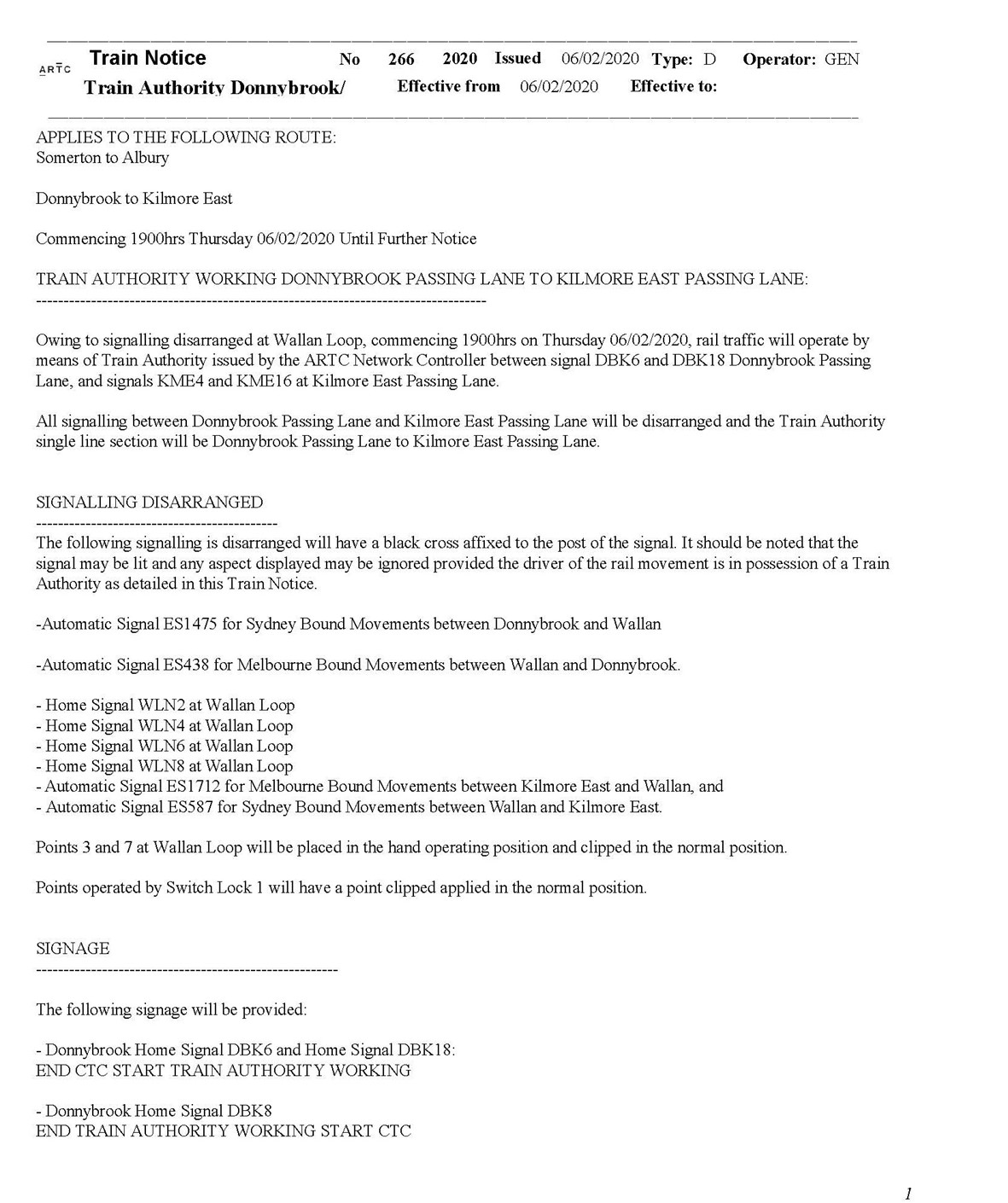
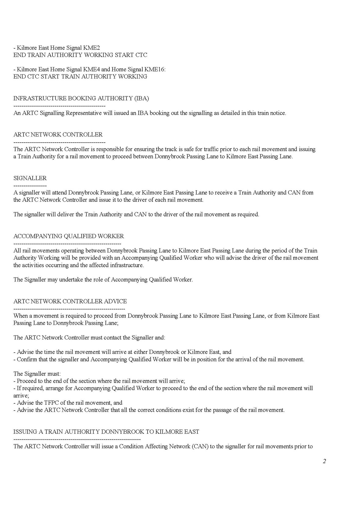
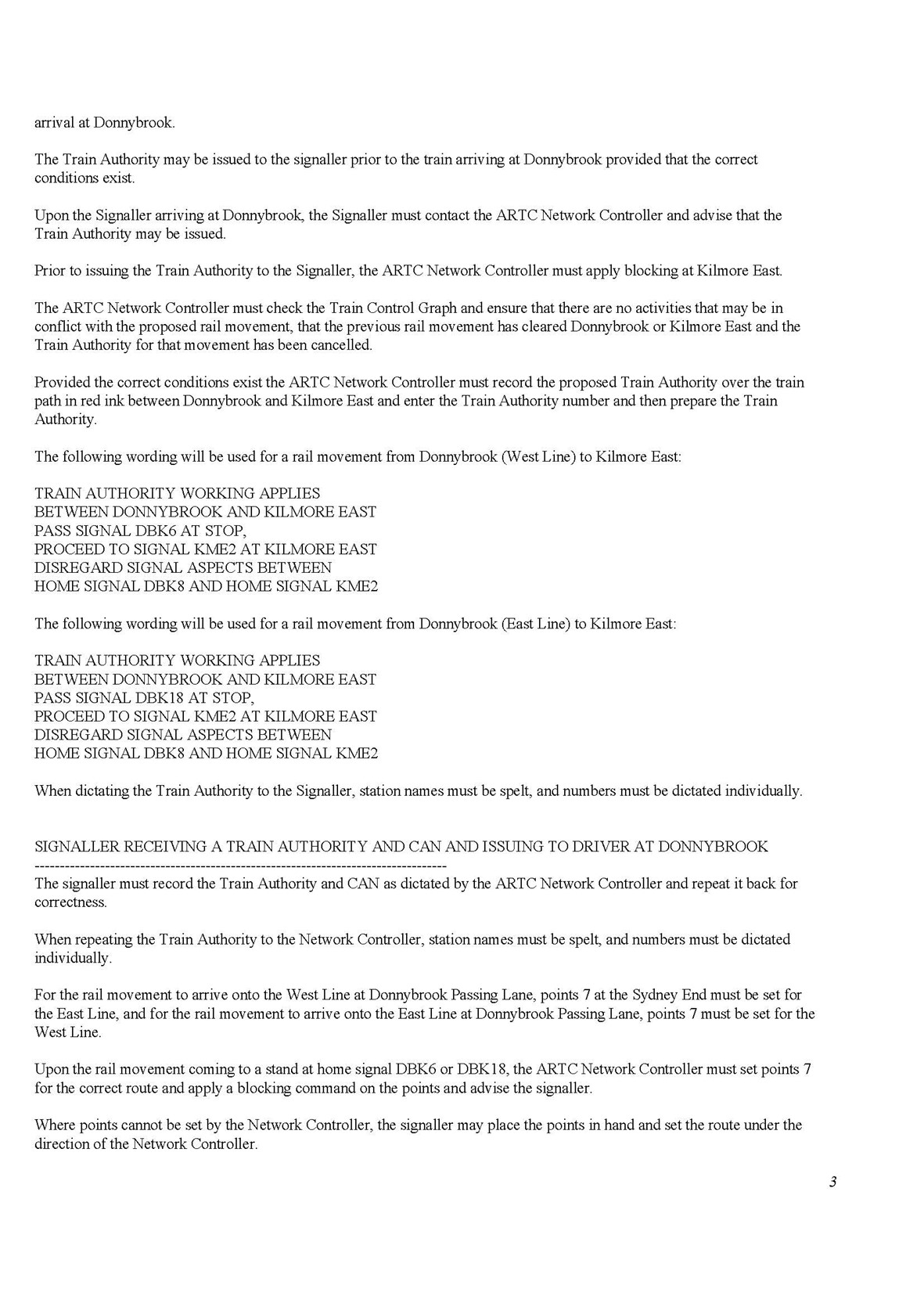
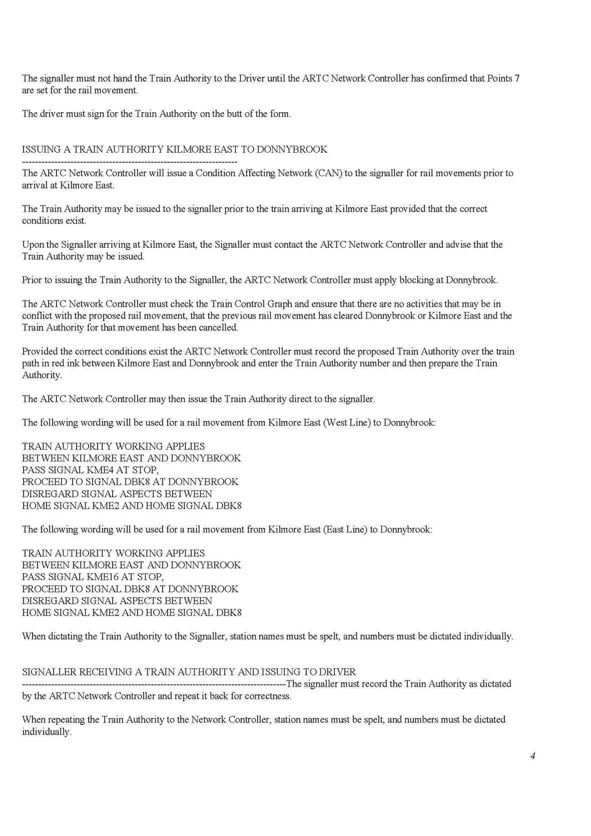
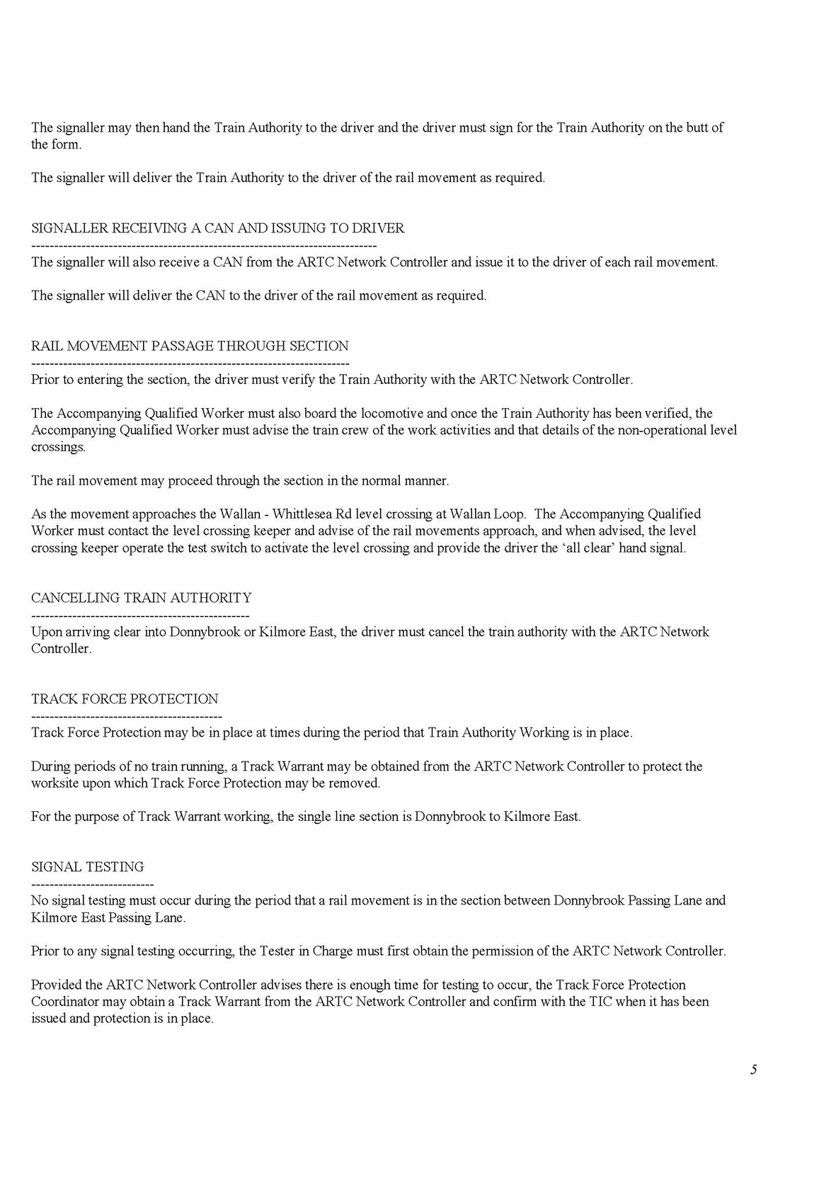
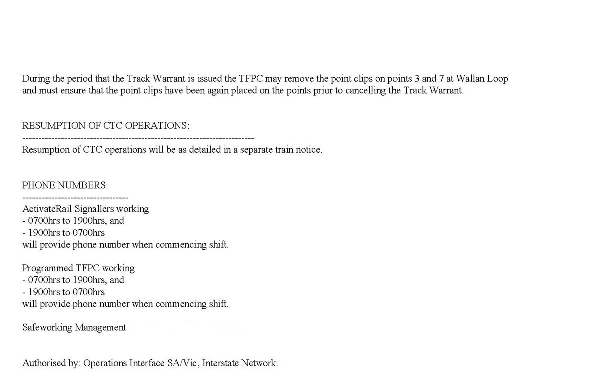
Appendix D – Train Notice 266 as amended 13 February
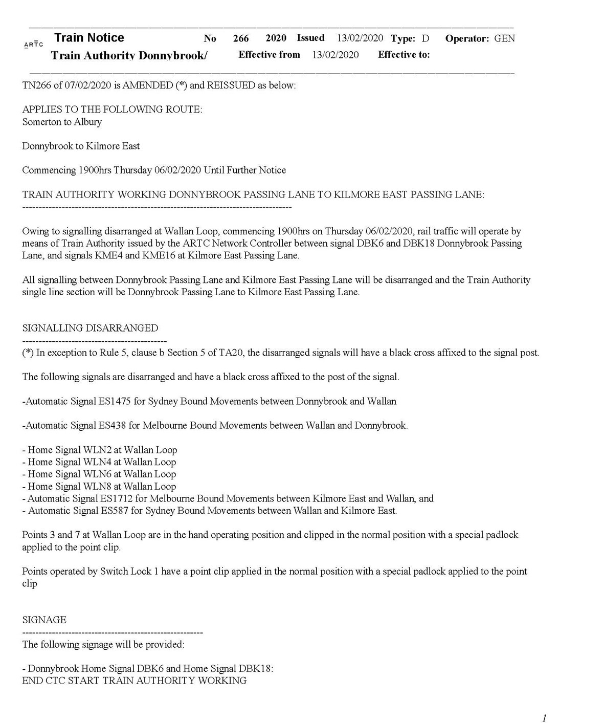
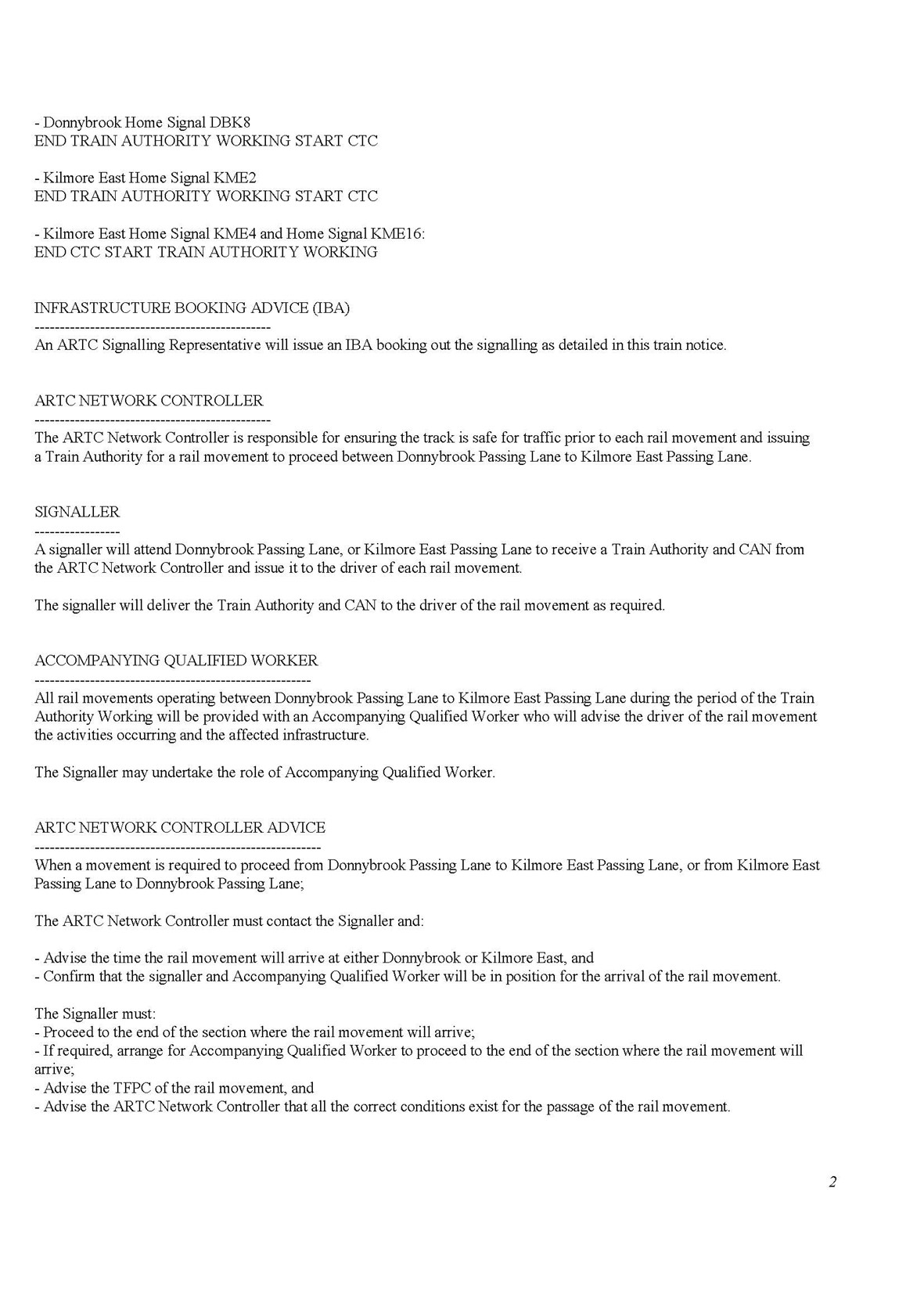
Appendix E – The train authority form used under TN 266
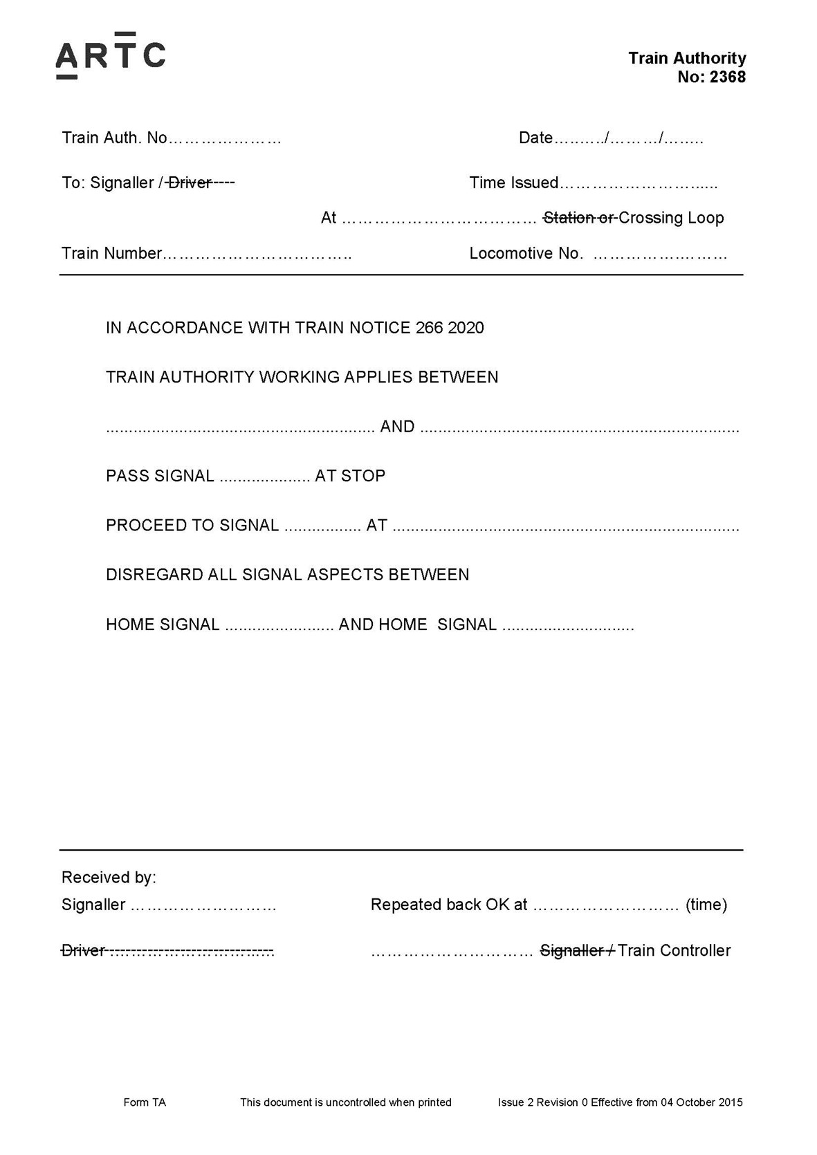
Appendix F – Train Notice 367
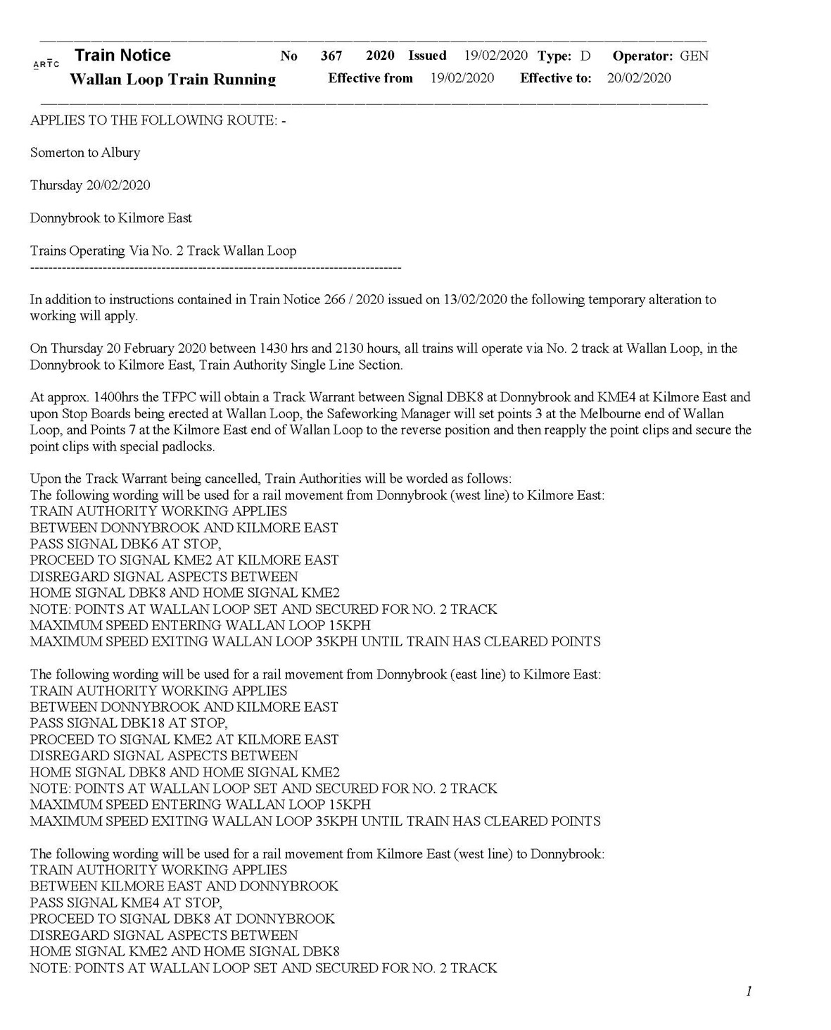
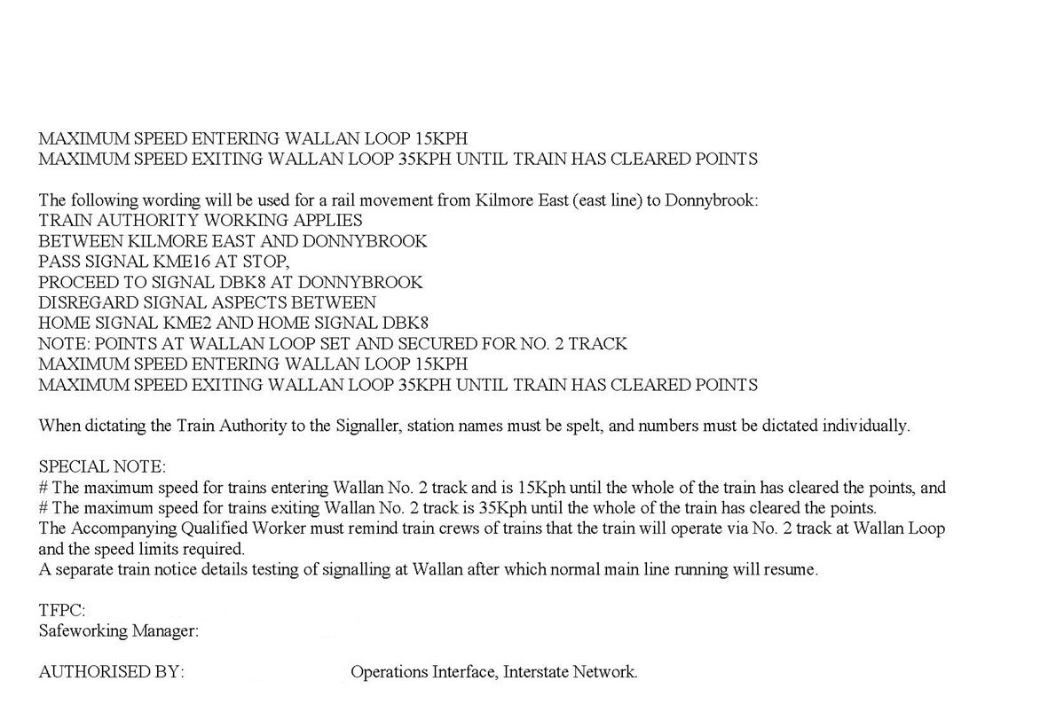
Appendix G – The train authority form used after TN 367
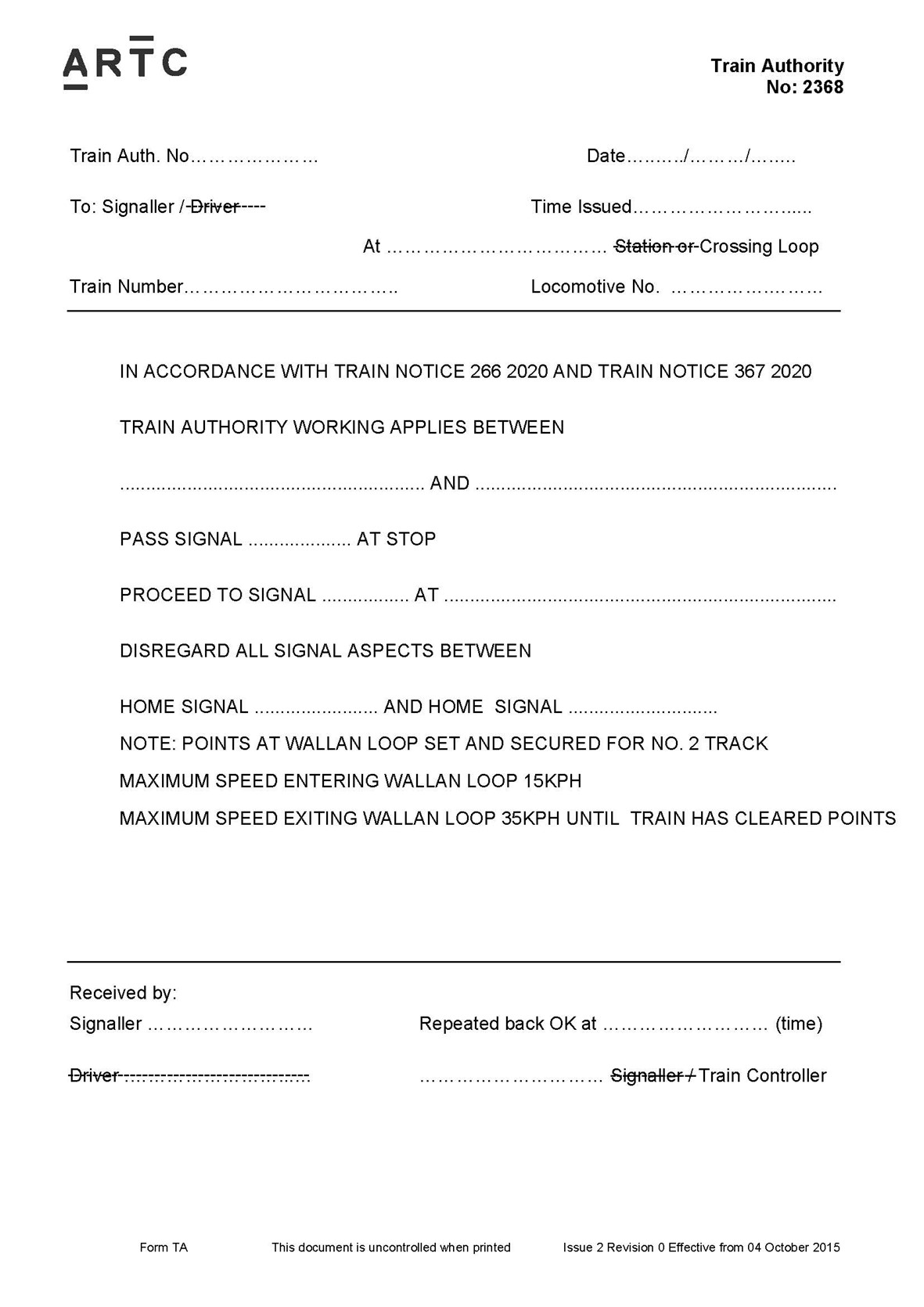
Appendix H – Other rules and codes
Scope
The operating rules for Australian Rail Track Cooperation’s (ARTC’s) Victorian network were described in the ARTC Code of Practice for the Victorian Main Line Operations (TA20). This appendix provides a brief summary of other codes and rules that were reviewed for any possible relevance to the protocols that were established between Donnybrook and Kilmore East in February 2020.
Code of Practice for the Defined Interstate Rail Network
Volume 3 of the Code of Practice for the Defined Interstate Rail Network described safeworking rules and route standards for the Defined Interstate Rail Network in Western Australia, South Australia, parts of New South Wales and a small section of the Victorian network west of Dimboola (DOTARS 2002).[144] The document had the intention to ‘provide a more unified, harmonised and efficient operation’ and was aligned with 'occupancy control systems and occupancy authorities' defined in AS 4292.5 (Standards Australia 2006).
This code described the potential use of train authorities to pass fixed signals at stop through a section during Centralised Traffic Control (CTC) system failure, where the cause was not unsafe track. Section 3.9 of the code also specified a range of procedural requirements for preparing and issuing train authorities, including step by step instructions for the processes of communication between the train controller and the ‘recipient’ of the train authority. There were broad similarities between the train authority format requirements of this code and the train authorities used between Donnybrook and Kilmore East in February 2020, but also some variation in detail and the application of narration and readback requirements. The system used in February 2020 could therefore not be described as being consistent with all the detail of this code.
Australian Network Rules and Procedures for CTC
The Australian Network Rules and Procedures, and the subsequent National Rules Framework, (RISSB) described how access providers and access users could operate safely on the Australian network.[145] Rules for the CTC system were described in ANRP5001 (RISSB 2014) and stated that if the function to control points and signals failed, the network control officer (NCO) could institute a method of special working.
Special working was included in the RISSB glossary and defined as ‘working rail traffic using an Alternate Proceed Authority (APA) or manual block working’. The RISSB glossary stated an APA may be used to authorise rail traffic movements when the proceed authority normally provided by the safeworking system was not available. In the instance at Wallan, the issuing of caution orders and other safeworking requirements specified in TA20 for the CTC system was available and had been applied in the initial days of the signalling failure.
Australian Network Rules and Procedures for Network Communication
Industry guidance on communications (RISSB 2014a) allowed for the relaying of communications when it was not possible to communicate directly with the intended receiver. However, direct communication between train control and train drivers was always available between 6 and 20 February 2020, as evidenced by train drivers confirming receipt of train authorities and CAN forms to train control.
Appendix I – ARTC types of risk assessment

Appendix J – Risk management of level crossing protection
The ARTC risk management plan for the train authority working between Donnybrook and Kilmore East in February 2020 described the controls being used to manage the risks associated with the absence of automated activation of the level crossing protection at Wallan–Whittlesea Road. The risk management plan described the hazard, cause and outcome associated with the deactivated level crossing (Table 7).
Table 7: Risk management plan description of risk item 6
| Hazard | Train operates through non operating level crossing at Wallan |
| Caused by | Level crossing taken out of service and no protection in place |
| Worst outcome | Collision with road vehicle or pedestrian leading to injury or fatality. |
For the identified risk, the risk management plan identified 2 controls that were to be implemented by the on-duty level crossing keeper (LCK) and the accompanying qualified worker (AQW). Those controls and how they were implemented are described in Table 8.
Table 8: Specified risk controls for risk item 6 and ATSB comment on implementation
| Specified risk control | ATSB comment on the implementation of the control |
| Level crossing (keeper) (LCK) in place to operate test switch | An LCK was located at the Wallan–Whittlesea Road level crossing and would communicate with the AQW of the approaching train. When notified, the LCK would activate the crossing protection and confirm its activation with the AQW. There were no instances identified where this process had failed. |
| Pilot on train announces approach | An AQW (not a ‘pilot’) on board the approaching train would contact the LCK by mobile phone at sufficient distance to warn of the train’s approach, confirm successful activation of the crossing protection by the LCK, and advise the driver of its activation. There were no instances identified where this process had failed. |
Appendix K – Train recorder (Hasler) analysis
The Hasler RT recorder
Power cars XP2018 and XP2000 were each fitted with a Hasler RT data recorder and the tapes from the 2 power cars were recovered for analysis (Figure 23). Limited parameters are recorded and included time, speed, throttle and vigilance control (on the same trace), and brake cylinder pressure.
Figure 23: Hasler waxed paper rolls removed from power cars XP2018 and XP2000
The photograph shows the recovered waxed tapes. The centre roll is the tape from power car XP2000. The left and right rolls are the tape from power car XP2018 that jammed during its removal and was torn at one location.
Source: CITS
Data processing
To process the data, both tapes were scanned and examined using photographic software. The traces for each recorded parameter were assessed for alignment with key events, such as start/stop points. Some horizontal re-alignment of parameters was required and both the horizontal and vertical scales of the images were calibrated for measurement.
Wheel diameter corrections
The Hasler used a pre-set (average) wheel diameter to calculate both speed and distance from the measured revolutions of the left wheel on the second axle of the power car (wheel 3).[146] Actual speed may deviate from that recorded (and displayed) due to differences between this pre-set diameter and the diameter of the actual wheel providing the feed to the Hasler system. The actual measured wheel diameter for both power cars was larger than the pre-set value.
The recorded values for speed and distance were corrected for the ratio of actual-to-pre-set wheel diameter (Table 9). The larger actual wheel diameter on the XP2018 (compared to the pre-set) meant that the recorded speed was about 2% lower than the actual train speed.
Table 9: Measurements used for speed and distance correction factor
| XP2018 – leading | XP2000 – trailing | |
| Pre-set diameter (mm) | 1,000 | 1,000 |
| Measured diameter (mm) | 1,019.2 | 1,011 |
| Ratio (correction factor) | 1.0192 | 1.011 |
Uncertainties in recorded data
An initial review identified a likely recording anomaly in the latter part of the XP2018 data. All channels recorded noise in the latter phase, likely associated with the derailment. An overlay of the data from the 2 power cars showed the discrepancy (visible as diverging speed toward the end of the data) and also confirmed that the speed data prior to this occurring was consistent (Figure 24).
Figure 24: Overlay of data recordings from XP2018 and XP2000
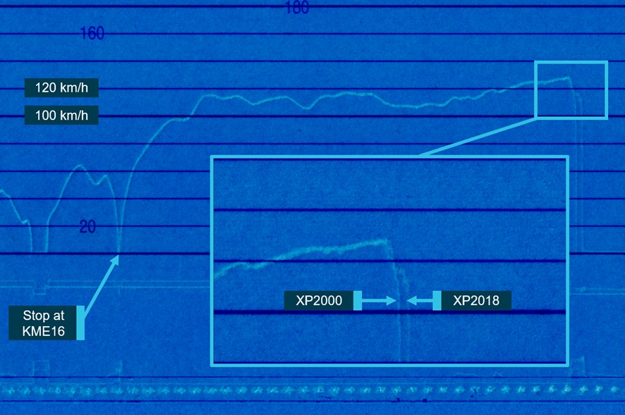
The image shows an overlay of speed records from power cars 2018 and 2000. It indicates consistent speed records after departing Kilmore East, then a consistent initial sharp deceleration of both cars followed by diverging speed records during the derailment.
Source: ST23 Hasler recordings annotated by the ATSB
There were also potential inaccuracies in the XP2000 data in the latter stages due to uncertainty in the measured wheel rotation being an accurate measure of train speed during this phase.
Other sources of train speed
GPS data from the installed ICE radio system[147] was interrogated and used as a comparator for time, speed and position information. Although only coarse GPS data was available due to the system’s polling frequency, it provided a source for comparison with the Hasler data and an enhanced confidence in the assessed train speed. The GPS data was also the primary source for locating the position of ST23 when stopped prior to signal KME16.
Throttle and braking events
One limitation of the fitted Hasler data recorder was that it did not record the positions of the driver’s throttle and brake handles. Instead, it recorded a generic power ON-OFF parameter and brake cylinder pressure.
Between Kilmore East and Wallan, the Hasler recorded that power was applied on departing Kilmore East at approximately 19:34:57. Application of power was maintained until around 19:41:34 and remained off until 19:42:20. During this 46 seconds, 2 periods of brake application were recorded that controlled the speed of the train to between 115 km/h and 120 km/h. The reductions in speed were consistent with permanent speed restrictions of 115 km/h between 55.43 km and 53.52 km at Wondong, and between 52.00 km and 51.21 km at Heathcote Junction. At 19:42:20, application of power was recorded. This was maintained until a power off and brake application was recorded at approximately 19:43:22. No records of vigilance control acknowledgements were recorded for the journey of train ST23 between Kilmore East and Wallan loop as brake and throttle controller movements would have acted as vigilance control system task linked activities.
The data from both power cars indicated that, at a point just prior to the commencement of deceleration, the power moved from ON to OFF and there was a rapid increase in brake cylinder pressure. For each recording, the points at which brake cylinder pressure began to rise and then reached a steady state were determined. The steady state pressures were noted for each record and compared with expected values. For both power cars, the recorded pressure was above that expected for a Notch 7 (full-service) application (345 kPa). The pressure recorded on XP2018, the leading power car, was about 378 kPa, which was in line with the pressure expected for an emergency application (375 kPa). Although the pressure recorded on XP2000 was lower, about 358 kPa, it was still substantially above the full-service value. These results indicated that it was very likely that the brake application was an emergency application. The speed of the train at the commencement of braking was about 129 km/h.[148]
Location of rise in brake cylinder pressure
Due to known limitations and potential anomalies in the Hasler data recording, obtaining position information from the data with respect to fixed points on track was difficult to achieve with high levels of accuracy. Therefore, the position at which brake cylinder pressure began to rise and the speed at which the train entered the turnout could not be directly read from the Hasler data.
Instead, the Hasler speed and distance data was used to calculate estimates of position considering different known stop locations. This was cross-checked using data from other sources to provide greater confidence. The different methods yielded slightly different results, however all indicated that the brake cylinder pressure started to rise before entry to the Wallan Loop (Table 10).
Table 10: Estimated limit points of rise in brake pressure and speed at entry to turnout
| Parameter | Estimated closest braking | Estimated furthest braking[149] |
| Distance from brake cylinder pressure rise to No.7 points | 50 m | 153 m |
| Speed at No. 7 points | 127 km/h | 114 km/h |
The brake cylinder pressure increase was a result of an emergency brake application, presumed to be by the driver in response to a cue or cues. To provide an estimate of when the cue(s) for braking may have presented, a nominal 2 second period from the cue(s) to brake cylinder pressure rise has been used.[150] Based on this figure, the cue(s) may have presented when ST23 was between about 120 and 220 m from the turnout.
Train handling of ST23 during journey
The Hasler recordings and the GPS data were examined to evaluate any potential trend in speed exceedance by ST23 during the Victorian segment of the journey. The ARTC Route Access Standard specified a maximum speed for express passenger trains in Victoria (including the XPT) of 130 km/h in areas where no local speed restrictions applied.[151] The assessment focussed on any identifiable trends and did not include local speed restrictions remote from the event.
Review of the GPS data identified 11 speed peaks of between 133 and 137 km/h in the Victorian section. These exceedances within the GPS data were cross-checked with the Hasler recordings and similar peaks identified, including a maximum actual value of about 139 km/h.[152]
None of the overspeeds identified were for a significant duration. These observations suggest that the driver was targeting line speed and occasionally overshooting. There was no evidence identified to suggest unusual train handling.
Vigilance parameter
The locomotive was fitted with a vigilance system. The installed Hasler data recorder did not record all information on driver activity associated with the vigilance system and its information was therefore of limited value.[153] However, the Hasler did record a vigilance parameter. The last point at which the vigilance parameter was recorded as active was prior to the stop at signal KME28. There were no vigilance parameter events recorded between ST23 departure from signal KME16 and the derailment.
Appendix L - Driver’s cab side door separation
Sequence of door attachment failure
There were 3 potential failure scenarios of the left-side driver’s cab door considered plausible:
- External loading on the door led to the knuckles of the upper hinge unfurling. This was then followed by the failure of the lower-hinge fastening and disengagement of the door latch.
- External loading on the door led to failure of the lower hinge fastening. This was then followed by failure of the upper hinge and disengagement of the door latch.
- External loading on the door and flexing of the car body led to disengagement of the door latch, followed by the failures at both hinges.
Although the sequence of failure cannot be confirmed with certainty, it was concluded through inspection of the components and the comparative loading on the upper and lower hinges that the more likely component to fail first was the upper hinge.
Evaluation of upper hinge
To evaluate the upper-hinge behaviour under defined loads, simplified loading was assumed. The external force was assumed to be an even pressure acting over the entire door, as used in design standards. This was converted to a point load (F) applied at the centroid of the door’s external surface, and resolved into balanced forces acting on the attachments in the frame from the external door surface (Figure 25).
Figure 25: Inside view of cab door opening and fitting locations (dimensions in mm)
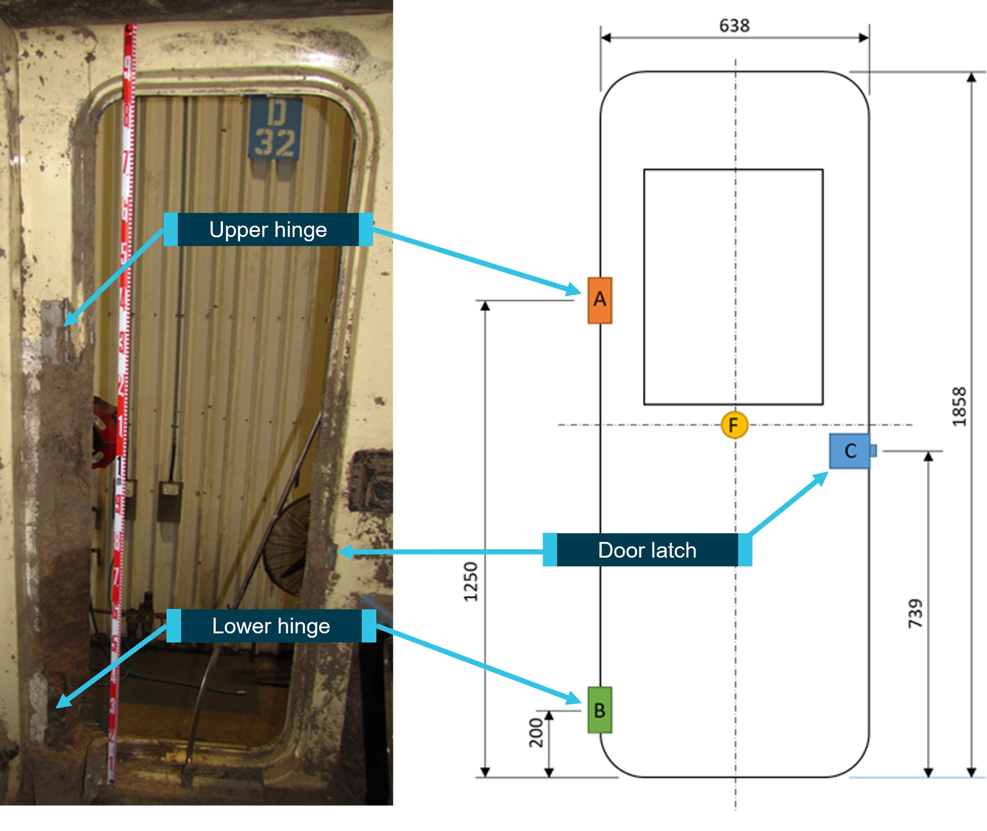
Source: ATSB
The glass fibre composite cab door was a plug shape that rotated inward on the hinges mounted on the inner rear edge of the door frame. The door hinges were fabricated from 3 mm thick stainless steel, and attached to the door frame by bolts into tapping plates (Figure 26).
Figure 26: Door and doorframe section drawing
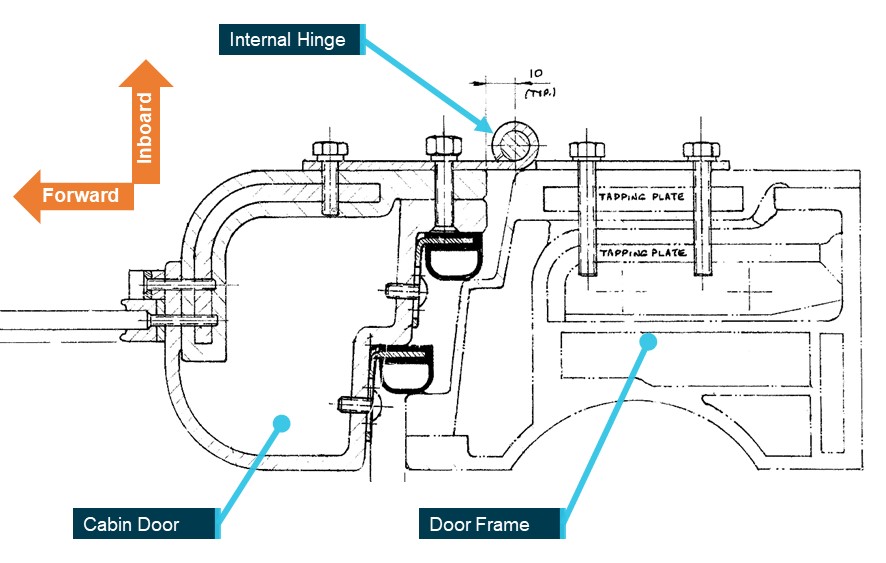
Source: Commonwealth Engineering (NSW) Drawing 022010940-1 annotated by CITS.
Unfurling of upper hinge knuckles
The upper hinge failed through the unfurling of its knuckles from the hinge pin. The lower (still closed) knuckle disengaged from the rotating pin and the 3 upper knuckles unfurled (Figure 27).
Figure 27: Failed hinge knuckles (upper hinge)
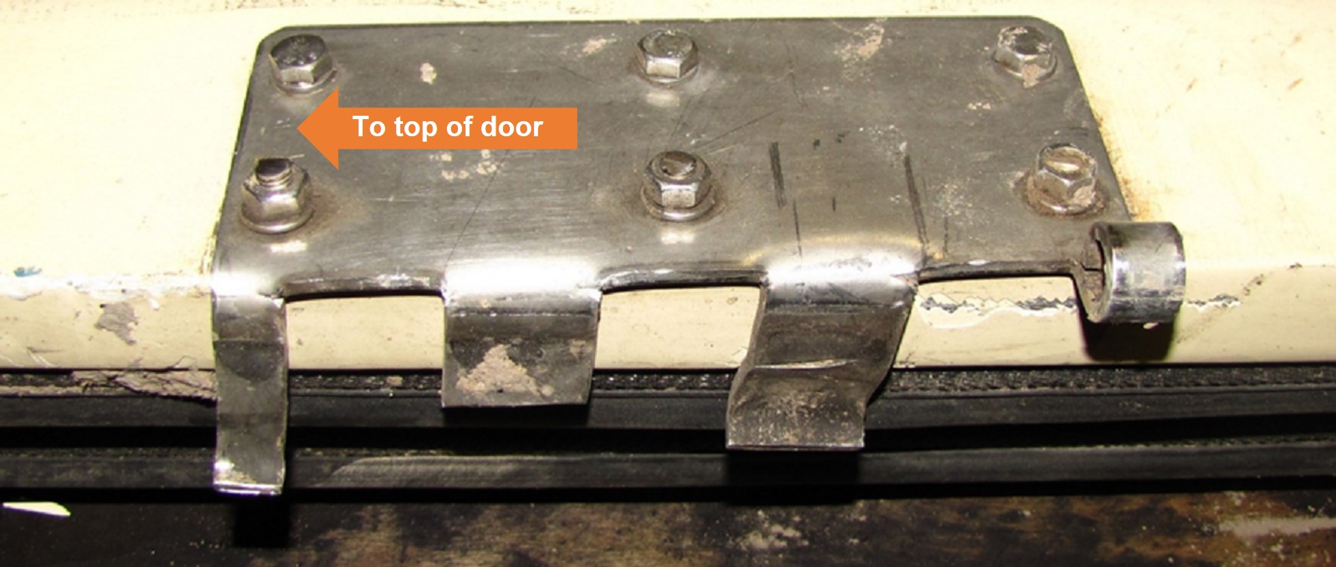
Source: ATSB
The mechanism of the failure of the upper hinge provided a specific failure mode for assessment. Loading of the 3 knuckles that unfurled was assumed for the estimation of material stresses in specified loading scenarios and compared against material yield strength. Dimensional assumptions were also made for the unfurling sequence (Figure 28).
Figure 28: Assumed hinge unfurling sequence
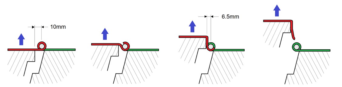
Source: ATSB
Outcomes of simplified load analysis
The potential for hinge failure by unfurling of knuckles was assessed against 2 load scenarios; an externally applied quasi static pressure of 2.5 kPa (GM/RT 2100 aerodynamic loading criteria) and a static pressure based on the power car lying on its side (AS7520.1-2022).
Aerodynamic load case of 2.5 kPa
Considering a 2.5 kPa static external pressure, the simplified analysis indicated that the door attachments would withstand the pressure and the knuckles of the upper hinge would not unfurl.
Load case for power car resting on side
An evenly distributed pressure from the self-weight of the power car when on its side, resulted in a static pressure on the cab door of about 11 kPa. Under this load, the simplified load analysis suggested that the upper-hinge knuckles would probably unfurl, or as a minimum commence plastic deformation.
Load case experienced by ST23
Under the dynamic loading conditions experienced by ST23 during the action of overturning and subsequent sliding, the cab door would be expected to have experienced loading significantly greater that the 11 kPa static (resting on side) load case. Based on the probable failure of the upper hinge (by unfurling) in the static (11 kPa) load case, the knuckles of the upper hinge would be expected to unfurl in the dynamic loading experienced by ST23. This analysis therefore confirmed the plausibility of the failure of the upper hinge by unfurling as the possible first point of failure.
Appendix M – Passenger car crashworthiness information
Introduction
This appendix provides a brief description of the observed damage to internal spaces of the passenger cars that formed part of ST23 (Figure 29).
Figure 29: Passenger cars
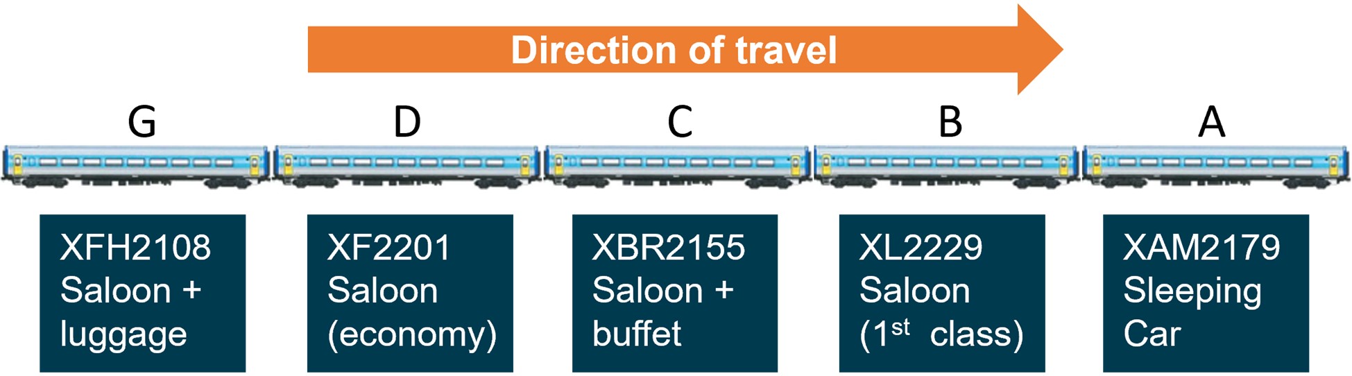
Source: Vehicle images supplied by Sydney Trains, annotated by CITS
Passenger car XAM2179 (Car A)
Car A had a sleeper/cabin configuration and was the leading passenger car. The car had 9 cabins that could each seat 3 passengers. Some cabins were fitted with forward-facing seats and others with rear-facing seats.
The car came to rest at an angle of about 30° to its left. External damage included 4 broken exterior windows on the left (passenger aisle) side of the carriage and exterior damage to the roof line above the windows as a result of the car striking pine trees adjacent to the track. Damage within the sleeper car included collapsed interior lining in the passenger aisle. Two cabins had cracked glass partitions, most likely from being struck by luggage or passengers.
Passenger car XL2229 (Car B)
Car B was a first-class car with 56 forward-facing passenger seats in a single open cabin.
The car came to rest at an angle of approximately 17° to its right. There was no evidence of structural failure or dislodged internal fittings acting as projectiles. The only significant damage to the cabin was exterior binding at the front right corner with the car ahead (Car A). This prevented the use of the exits at this location.
Passenger car XBR2155 (Car C)
Car C was half first-class forward-facing seating with the other half being the buffet section. It was near upright when it came to a stop. The car suffered no interior damage of consequence.
Passenger car XF2201 (Car D)
Car D was an economy-class car with 68 forward-facing passenger seats in a single open cabin. It was near upright when it came to a stop. The car suffered no interior damage of consequence.
Passenger car XFH2108 (Car G)
Car G was half economy class forward-facing seating with the other half being the baggage section. It was at an angle of about 10° when it came to a stop. The car suffered no interior damage of consequence.
Appendix N – Passenger safety information
Extract of operator’s procedures on content of verbal briefing
NSW Trains’ procedures specified the following safety content for the verbal briefing:
If you require assistance in an emergency, push the red emergency call button at either end of your carriage.
In the unlikely event of an emergency, please remain seated, stay calm and wait for instructions from the onboard staff.
Staff are trained in emergency procedures and know how to proceed. We will help you exit the train swiftly and safely if an evacuation is necessary.
If instructed to evacuate, leave your luggage behind.
In an emergency, it is often safer to remain on-board rather than to evacuate.
For further information, please refer to the safety card in the seat pocket or table in front of you
Extract of safety information in onboard guide
The section in the onboard guide on emergency procedures stated:
If you’re unable to locate a nearby emergency exit, ask a crew member to show you. All crew members are trained in emergency procedures and can help you exit the carriage or evacuate the train quickly and safely.
What to do in an emergency
Appendix O – Countrylink incident response summary
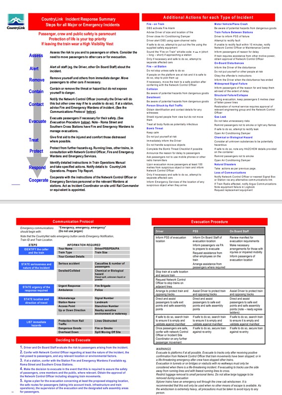
Purpose of safety investigationsThe objective of a safety investigation is to enhance transport safety. This is done through:
It is not a function of the ATSB to apportion blame or provide a means for determining liability. At the same time, an investigation report must include factual material of sufficient weight to support the analysis and findings. At all times the ATSB endeavours to balance the use of material that could imply adverse comment with the need to properly explain what happened, and why, in a fair and unbiased manner. The ATSB does not investigate for the purpose of taking administrative, regulatory or criminal action. TerminologyAn explanation of terminology used in ATSB investigation reports is available here. This includes terms such as occurrence, contributing factor, other factor that increased risk, and safety issue. Publishing informationReleased in accordance with section 25 of the Transport Safety Investigation Act 2003 Published by: Australian Transport Safety Bureau © Commonwealth of Australia 2023 
Ownership of intellectual property rights in this publication Unless otherwise noted, copyright (and any other intellectual property rights, if any) in this report publication is owned by the Commonwealth of Australia. Creative Commons licence With the exception of the Coat of Arms, ATSB logo, and photos and graphics in which a third party holds copyright, this publication is licensed under a Creative Commons Attribution 3.0 Australia licence. Creative Commons Attribution 3.0 Australia Licence is a standard form licence agreement that allows you to copy, distribute, transmit and adapt this publication provided that you attribute the work. The ATSB’s preference is that you attribute this publication (and any material sourced from it) using the following wording: Source: Australian Transport Safety Bureau Copyright in material obtained from other agencies, private individuals or organisations, belongs to those agencies, individuals or organisations. Where you wish to use their material, you will need to contact them directly. |
[1] A serious injury is defined in the Transport Safety Investigation Regulations 2021 as an injury that requires, or would usually require, admission to hospital within 7 days after the day when the injury is suffered.
[2] Train authority: an instruction in the prescribed format issued by a network control officer in connection with the movement of a train.
[3] Train notice: operational information issued by or on behalf of the rail infrastructure manager.
[4] The points at either end of Wallan Loop were placed in the hand operating mode and clipped in the normal position; With the points at either end of Wallan Loop set to their normal positions, trains would continue on the straight track (No.1 track) rather than being diverted into the loop (No.2 track).
[5] Residues such as iron oxides can hamper electrical connection between wheel and rail and therefore impact the performance of a signalling system.
[6] Rail traffic was stopped to permit workers to change the points.
[7] The normal position of the turnouts was for routing on the straight, and the reverse position was for the loop.
[8] For these works, the applied track force protection provided for flagmen to warn approaching trains, and for trains to comply with the signals shown by the flagmen.
[9] ARTC document ANGE 220 Unreliable Track-Circuit Operation dated 11 October 2015 (applicable to NSW).
[10] Stopping times at stations are those recorded by NSW Trains.
[11] The ARTC Network Control office for this section of track was located in Junee, NSW.
[12] An alarm had been received by ARTC Network Control for a possible signal passed at danger (SPAD) at Tallarook, 23 km north-east of Kilmore East. The NCO indicated that there had been power outages at this location, that may have showed up as a SPAD. The driver indicated that all signals had been ‘clear’ through Tallarook.
[13] The decision around the order of trains through the location was made following discussions between the NCO and their supervisor. NSW Trains operations were informed of the holding of ST23 at Kilmore East and the delay to that service.
[14] This signal protected the broad-gauge crossover going into the Apex ballast quarry. It was called an ‘Intermediate Home’ because it was in an intermediate location along the passing lane.
[15] The passing lane (an extended crossing loop) was about 7 km in length.
[16] Accompanying qualified worker: the term used in train notices for the worker that would accompany the driver between Kilmore East and Donnybrook.
[17] The AQW’s copy of TN 367 was found within the driver’s cabin.
[18] A CAN was a warning of an unsafe condition affecting, or potentially affecting, the network.
[19] Home departure signal KME16 was protecting the turnout at the end of the passing lane.
[20] In Australia, locomotive and train operating cabs were generally not fitted with voice recording devices.
[21] The latest version of TN 266 was explicit in not requiring the driver to repeat the contents of the train authority back to the NCO. Also under the train working arrangements described in TN 266, there was no requirement for the NCO to read the content of TA 17 to the driver.
[22] Within this section, there were 115 km/h speed restrictions applied to some sections of track.
[23] Speed maintained until approximately the 51 km mark. There was a 115 km/h permanent speed restriction at Heathcote Junction between the 52.00 and 51.21 rail-km locations.
[24] Active protection on the other level crossings on the Kilmore East-to-Donnybrook section were working normally and it was only the Wallan–Whittlesea Road level crossing that required local operation.
[25] The person who activated the level crossing protection locally at the crossing, colloquially referred to as the bellhop.
[26] Range estimated from train recorded data (Appendix K).
[27] Passenger numbers based on available data from the operator.
[28] For open radio broadcast on this ARTC corridor, crew were to switch their radios to channel 6. Of the two crew members making emergency calls, one immediately changed to channel 6 and the other a short time later, probably following prompting. The remainder of the crew were then required to also switch to channel 6 to maintain ongoing communications among the crew members.
[29] V/Line’s network train control centre located in Melbourne.
[30] The emergency services call centre time stamp.
[31] Using tools sourced from the train’s emergency breakdown kit.
[32] A serious injury is defined in the Transport Safety Investigation Regulations 2021 as an injury that requires, or would usually require, admission to hospital within 7 days after the day when the injury is suffered. A minor injury is any other reported physical injury that does not meet the serious injury threshold.
[33] NSW Trains was an agency of the NSW State Government and was within a division of Transport for NSW (TfNSW).
[34] Schedule—Rail Safety National Law, Part 1—Preliminary, Section 4 - Interpretation (RSNL version: 3.10.2019 to 30.6.2020)
[35] Schedule—Rail Safety National Law, Part 3—Regulation of rail safety, Division 3—Rail safety duties Interpretation (RSNL version: 3.10.2019 to 30.6.2020)
[36] Sydney Trains was part of Transport for NSW.
[37] Due to the delay in the service on this day, arrival in Melbourne would have been later than the rostered end of shift.
[38] Health and fitness requirements for Rail Transport Operators and Rail Safety Workers were governed by the Rail Safety National Law (RSNL) and associated Regulations.
[39] NSW Trains procedures NTTWP100 Responsibilities of Train Crews and NTOSP11 Train evacuation and detraining when not at a station refer to the duties of the driver and the PSS/Guard.
[40] The training was limited to ‘within work on track work authority limits’ and not the arrangements in place for the train working arrangements between Donnybrook and Kilmore East.
[41] Detailed work-placement records were available from 2014.
[42] The ActivateRail representative (contracted by ARTC) was performing the role of signaller at 1530, and had been involved in developing and implementing the safeworking solution for train working between and Donnybrook and Kilmore East.
[43] ARTC Corporate Plan 2021-22
[44] VicTrack was a State-owned organisation that owns Victorian rail land, assets and infrastructure.
[45] Rail Safety National Law, Part 1—Preliminary, Section 4— Interpretation (RSNL version: 3.10.2019 to 30.6.2020)
[46] Rail Safety National Law, Part 3—Regulation of rail safety, Division 3—Rail safety duties (RSNL version: 3.10.2019 to 30.6.2020)
[47] Standard gauge trains did not stop at Wallan.
[48] TA20 ARTC Code of Practice for the Victorian Main Line Operations, Section 2, Rule 13 g.
[49] Signal ES1712 was located at 51.77 km rail-km from Melbourne
[50] The indication of this signal at the time ST23 passed is not known with certainty because its state was not recorded. However, broad gauge rail traffic records indicated that the signal was more likely to be at proceed. If not at proceed, the signal would have been at its alternate ‘caution’ indication, a single yellow light.
[51] 13.7 km from Wallan Railway Station
[52] Azimuth is the clockwise horizontal angle (in degrees, minutes and seconds) from true north to the sun.
[53] Altitude is the vertical angle (in degrees, minutes and seconds) from an ideal horizon to the sun.
[54] Computed using National Mapping Division's sunmoonposn program, version 1.1.
[55] A 45 minute delay would be the result of a 24 km/h average speed compared to a 96 km/h average speed over the 24 km section; The issuing of caution orders and applying other safeworking rules in accordance with TA20 also increased the workload on network control resources.
[56] ActivateRail offered professional advisory services, project managers as well as worksite supervisors, site managers and track safety personnel.
[57] Project representatives suggested signals remained lit to assist electrical testing, and as location markers for drivers.
[58] A CAN notice was issued because the Wallan–Whittlesea Road level crossing protection was affected by the signalling system failure and was being manually operated.
[59] TA20 Section 5 Rule 5 Clause b stated ‘Light signals not in use are distinguished by a black cross on the front of the lights. The lamps are not to be lit’.
[60] Some V/Line drivers and the RTBU (Rail Tram and Bus Union) had expressed concern at signals remaining lit within the affected section. On 10 February, a driver refused to pass a lit signal within the section without authority to proceed.
[61] Rule 1, Section 3, pertained to the process when stopping at and then passing automatic signals that were displaying a stop indication. When applied, the rule required the train to proceed with caution and at a speed not exceeding 25 km/h.
[62] In doing so, the train authority was issued by the NCO to the signaller rather than a driver.
[63] Issued because the Wallan–Whittlesea Road level crossing protection was being manually operated. TA20 section 1, clause 7, described the issuing of a CAN warning in a range of scenarios that included faulty or deactivated level crossing warning equipment.
[64] Figures for train authorities issued includes all notices issued until the derailment of ST23, including those issued after the issue of Train Notice 367.
[65] The NCO involved was not the NCO on duty at the time ST23 transited the affected area.
[66] The same ‘anomaly’ existed in the descriptions for southbound travel
[67] Track Force Protection Coordinator
[68] There was no available evidence with respect to the communications between the driver of ST23 and the AQW.
[69] Temporary speed restriction: a speed, less than the maximum allowable permanent signposted speed, applied for track, signal, train equipment, or environmental conditions.
[70] Preparation and Distribution of Operational Notices OPE-PR-001, Version Number 1.2, 31 May 2019
[71] In ARTC procedure OPE-PR-001, the acronym NRAMS was used.
[72] Australian Central Standard Time
[73] The ARTC procedure specified that proposed standing train notices should be lodged (with ARTC operational staff) at least 10 days prior to their application, although it did not specify a publication timeframe requirement.
[74] The update of WebRAMS was reported to have been actioned in Adelaide at 1815 central daylight time, which was 1845 eastern daylight time.
[75] The WON was published by the Office of Rail Safety Manager (a part of MTM) on behalf of MTM and V/Line.
[76] SAFE Notices are used by ARTC on its NSW and Queensland corridors to give notice of changes or exceptions to ARTC Network information publications.
[77] Although consistent with the process used by signallers and AQWs in the previous weeks, TN 266 described that ‘the signaller will deliver the Train Authority and CAN to the driver of the rail movement as required’.
[78] At the time of the derailment, Issue 2.1, 01 July 2018
[79] Safeworking is an integrated system of operating rules and procedures that defines the interaction between workers and engineered systems. Of primary concern of a rail safeworking system is safe operations including train separation and speed management.
[80] Rule 1, Section 3 specified proceeding at a speed not exceeding 25 km/h.
[81] The phrase ‘Train Authority Working’ was used in section 25 of TA20. ARTC advised that this type of working had previously been used in Victoria during commissioning activities following signalling system upgrade.
[82] The scope of application of train authorities was similarly defined for the Train Order System.
[83] TA20 section 25 rule 2.f.
[84] TA20 section 1 rule 8.b.
[85] There were a number of other scenarios for which a CAN would be issued including a temporary speed restriction.
[86] The application was, however, inconsistent with the rule that specified that the ‘Network Controller must dictate the CAN warning details direct to the rail traffic crew'. There was provision for relaying the message when direct communication between an NCO and a driver was not possible. However, radio communication was possible.
[87] Advanced train management system that monitors and manages rail traffic
[88] ARTC and Rail Corporation New South Wales (RailCorp) entered into an interface agreement in 2011 for RailCorp operations on the ARTC network. The functions of Railcorp were transferred to NSW Trains and other entities on 1 July 2013 and at the time of the derailment of ST23 at Wallan in February 2020, the 2011 interface agreement was the applicable interface agreement between ARTC and NSW Trains.
[89] ARTC (2019) RSK-PR-001 Risk Management, version 1.4
[90] The objective of AS ISO 31000:2018 is described within the standard as being to provide guidelines on managing risk faced by organisations. The application of these guidelines can be customised to any organisation and its context, is not industry or sector specific, and the standard also provides a common approach to managing any type of risk.
[91] ARTC (2019) Application of Risk Management, RSK-WI-001
[92] Approximate time of risk assessment advised by ARTC.
[93] The plan did not identify individual risk owners as required by the ARTC risk management procedure.
[94] The risk assessment reference to ‘piloted’ is different to TN 266 that refers to an accompanying qualified worker (AQW).
[95] ARTC Glossary Issue 4.0, 15 January 2023, (accessed at www.artc.com.au/uploads/Glossary-I-4-Rev-0.pdf)
[96] ANRP 710 Piloting Trains and Track Vehicles, Network Procedures (11 October 2015). This document was only applicable to the NSW portion of the ARTC network.
[97] A competent worker was defined as a worker certified as competent to carry out the relevant task (RISSB).
[98] Route knowledge: Essential knowledge required to enable rail traffic crew to work safely over a route (Standards Australia 2017).
[99] The speed display on XP2018 would have been reading about 127 km/h.
[100] No. 7 points were controlled by a dual-control point machine. They could be operated in motor (remote operation) or hand (manual operation) mode.
[101] Crossing block: a casting or fabricated steel component that enables a wheel travelling along one rail to pass through the rail of a track which crosses its path.
[102] Following the derailment, the windscreen was removed by rescuers to improve access to the driver’s cab.
[103] Given the age of the power car and its apparent compliance with door loading specified in contemporary standards, there was no attempt to assess the door against loading requirements in historical standards.
[104] AS 7522:2021 Access and Egress, Rail Industry Safety and Standards Board, sections 6.1.6 and 6.3.3.9
[105] There were also reports of instances of post-traumatic stress disorder (PTSD) that are not included in this injury total.
[106] A serious injury was defined in the Transport Safety Investigation Regulations 2021 as an injury that required, or would usually require, admission to hospital within 7 days after the day when the injury was suffered. A minor injury was any other reported physical injury that did not meet the serious injury threshold.
[107] Exits were considered not usable (by height) if the bottom rung of the ladder was more than 1.5 m from the ground.
[108] NSW Trains Competence Assurance; NSW Trains Risk Based Training Needs Analysis, NSW Trains, 2019.
[109] The rail safety regulatory functions of this body were transferred to the national regulator, ONRSR.
[110] Activities were reviewed for the period January 2015 to 20 February 2020.
[111] Under the ONRSR reporting scheme, overspeed incidents were captured in the broader category of safeworking rule or procedural breach. ONRSR provided details of 262 incidents in this category, and 11 were identified as overspeed.
[112] Audit activity 3827 (November 2018) referred to the risk of passenger train derailment as a result of overspeed.
[113] Between 2000 and 2006, the Regional Fast Rail (RFR) project in Victoria upgraded track and signalling infrastructure on major regional lines to allow passenger trains to run at speeds of up to 160 km/h. RFR contractors Thiess-Alstom Joint Venture (TAJV) and Regional Rail Link (RRL) offered the TPWS to provide additional protection from the risk of trains passing signals (at stop) without authority and potentially colliding with other trains or derailing. The rail safety regulator at the time of the project was satisfied that TPWS was a suitable system for use in Victoria based on independent advice that TPWS was compatible with Victorian signalling principles and could be implemented with minimal changes to Victorian rail industry signalling standards, operating rules or maintenance practices, and it was a proven system having been in operation in the UK since 2000.
[114] The speed display on XP2018 would have been reading about 127 km/h.
[115] This is a nominal figure incorporating driver reaction to cues and system response. Human reaction times may vary considerably due to individual differences and other factors such as expectation and workload.
[116] The distance range is an estimate only, and the cues to make a brake application may have presented earlier.
[117] The ability to observe the points setting would have depended on several factors including the train’s distance from the points, lighting conditions at the time, the environment of the driver’s cab, and the eyesight of the individuals.
[118] See also (RAIB 2008) and (RAIB 2016).
[119] With signals initially lit and then several trips with all signals within the section extinguished.
[120] A conspicuous warning device is a permanent or temporary indication which provides information to, or requires action to be taken by, train crews.
[121] Rail Safety National Law (SA) Act 2012, Part 3, Division 6.
[122] ARTC enterprise risk management system
[123] TA20 section 1, clause 8 b.
[124] The issuing by NCO of a train authority to the (in-field) signaller and their readback typically took about 2 minutes.
[125] TA20 section 1, clause 8 b.
[126] TLIC0030 (Pilot rail traffic with due consideration of route conditions) released in 2022 (after this occurrence).
[127] For these circumstances, TA20 also specified the use of CTC arrival messages within the section.
[128] As described in the ARTC Risk Management Overview - Workshop participants guide (2018). This stated that ‘two key factors to consider when determining the effectiveness of a control are: whether the control is adequate, and how susceptible the control is to human error or non-compliance’.
[129] ARTC risk library ID: 0559
[130] Such systems can be found on the Country Regional Network (CRN) in NSW that is managed by UGL.
[131] Track Force Protection involves the use of hand signals and audible track warnings to control the movement of rail traffic through a worksite.
[132] The same system was used for distributing notices in South Australia and Western Australia
[133] The ARTC ERMS risk control of advanced train management system (ATMS) was not operating in Victoria, and the risk control of two-person train operation was not applicable to V/Line or NSW Trains passenger train operations which operated with single-person crewing.
[134] Train enforcement pertains to the forced (automated) initiation of train braking in the case of train overspeed.
[135] TPWS was used elsewhere in Victoria (on regional and metropolitan networks) to enforce braking of V/Line trains passing a signal at stop or detected as travelling too fast to comply with the next signal.
[136] TPWS was scheduled for installation at Wallan Loop in 2024.
[137] TfNSW advised that the new NSW TrainLink regional trains (Regional Rail Project) will be fitted with automatic train protection (ATP) systems that are compatible with the Sydney Trains network (ETCS Level 2) and provisioned to allow the future fitment of onboard systems to interface with the ARTC advanced train management system (ATMS).
[138] Examples include the advanced train management system (ATMS) on the ARTC network, the European train control system (ETCS) of various levels, and communications-based train control (CBTC) systems.
[139] The National Transport Commission (NTC) is progressing a rail interoperability framework through an Interoperability Advisory Group. The NTC was established through the National Transport Commission Act 2003 and the Inter-governmental Agreement for Regulatory and Operational Reform in Road, Rail and Intermodal Transport.
[140] While AS 7552:2021 states that ‘enclosed cabs of rolling stock shall be fitted with sufficient emergency exits to provide escape paths to the vehicle exterior when the vehicle is upright and when overturned on the side’, these emergency exits may not be accessible at ground level.
[141] Static testing was conducted on power car XP2018 as the trailer cars immediately behind in the consist were damaged and without significant repairs could not be tested. Some components of XP2018 damaged during the derailment required repair in preparation for the brake testing.
[142] The variation in the cross-level between two track locations separated by a nominated distance interval.
[143] Due to the delay in the service on this day, arrival in Melbourne would have been later than the rostered end-of-shift.
[144] Adopted by ARTC as Code of Practice for the Defined Interstate Rail Network, volume 3 operations and safeworking, Part 1: Rules, ARTC Version 3.0: 01 July 2018 (also referenced Issue 3.0- ARTC Annotated Version)..
[145] RISSB developed the Australian Network Rules and Procedures into a National Rules Framework. The Framework provided a principles-based platform for rail transport operators in development of their own rulebooks.
[146] An average wheel diameter was used to accommodate wear and a reducing diameter during the wheel’s life.
[147] The ICE radio GPS speed is not displayed to the driver in the locomotive cab.
[148] The speed display on XP2018 would have been reading about 127 km/h.
[149] Braking data for XPT full-service braking (with 80% average deceleration), full seated load and a 1:150 descending grade indicates a stopping distance from 130 km/h of 1,120 m.
[150] Includes braking system response and driver reaction. Reaction times of individuals can vary considerably.
[151] ARTC Route Access Standard D53.
[152] Actual speed calculated by correcting the recorded speed for actual wheel diameter. The recorded speed was about 2% lower than this estimated actual.
[153] AS 7527:2015 (amendment 2019) recommended that legacy, tape based data loggers should, as a minimum record the following information: train speed, distance, time, and brake status (i.e. brake pipe pressure or brake cylinder pressure).
Interim report
Report release date: 10/06/2021
This Interim Report details factual information established in the investigation’s evidence collection phase and ATSB interim observations of that evidence. An Interim Report has been prepared to provide progress information to the public and the rail industry, and information on safety actions so far taken. This Interim Report does not contain findings or safety factors, that will be detailed in the Final Report. The information contained in the Interim Report is released in accordance with section 25 of the Transport Safety Investigation Act 2003 (Cth). |
Prior to the occurrence
At about 2343[1] on 3 February 2020, the Australian Rail Track Corporation (ARTC) identified that Centralised Traffic Control (CTC) signalling had been disrupted on the Somerton to Albury line between Donnybrook and Kilmore East. A subsequent investigation by ARTC determined that a road vehicle had struck overhead wiring in Wallan, impacting power supplies to the rail signalling system. A fire in the Wallan signalling hut led to extensive damage to equipment and cabling.
As a result of the damage to the signalling system at Wallan, ARTC commenced managing rail traffic through the location using Caution Orders. Under this instrument, trains were required to proceed cautiously, resulting in significant delays to rail services using this section of the standard-gauge network. As repair of the signalling system was expected to take a significant period of time, alternative train working arrangements to Caution Orders were considered by ARTC.
ARTC commenced managing rail traffic through the location using a Train Authority[2] instrument on the evening of 6 February.[3] The instrument was used for the 24 km section between Kilmore East (at about the 63.8 km[4] mark) and Donnybrook (at about the 40.2 km mark). Wallan Loop was located between these locations, from the 49.058 km mark to the 47.268 km mark.
Notification to network users of the change to the use of Train Authorities was by an ARTC Train Notice.[5] The relevant Train Notice (TN 266) was issued on 6 February, updated on 7 February and further amended on 13 February. In the arrangements established, the points at Wallan Loop had been set for the straight and locked in that position. ARTC did not impose any additional speed restrictions through the section. The maximum permitted speed for the XPT when travelling on the main line through Wallan was 130 km/h.
On 19 February, Train Notice TN 266 was supplemented with a further Train Notice (TN 367) advising of a change at Wallan Loop, with trains to be diverted through the loop for a short period on 20 February. The purpose of routing trains through the loop was to remove any contamination that may have developed on the rail head while the loop track was not being used.[6] This was in preparation for signal system testing and re-establishment of the CTC signalling system over the coming days.
Between 1453 and 1536 on 20 February,[7] the points at either end of Wallan Loop were manually reconfigured from their Normal position to their Reverse position.[8] This change meant that rail traffic travelling in either direction after this time would be diverted from the main line into the crossing loop track (No.2 Road). Train Notice TN 367 reflected this change and also specified a 15 km/h speed limit for entry into the loop, and a limit of 35 km/h when exiting the loop. Between 1600 and 1837, Track Force Protection[9] for the laying of conduit was also in place near Wallan, between the 46.3 km and 45.4 km marks.
The first train to pass through Wallan Loop in this altered configuration was southbound V/Line train 8620. Immediately prior to train 8620 departing Kilmore East, the train controller advised the driver that they were going to be the first train through Wallan Loop in the past 72 hours. It departed Kilmore East at about 1623 and the Train Authority was cancelled at 1647 for its arrival at Donnybrook.
The second train through the loop was northbound V/Line train 8625. When stopped at Donnybrook and during exchanges between the driver and the network controller, there was no mention by either party of transiting through Wallan Loop. The train departed Donnybrook at about 1857. Train ST23 operated by NSW TrainLink was to be the third train through the loop.
Train ST23 from Sydney to Albury
On 20 February 2020, passenger train ST23 departed Central Station in Sydney, New South Wales (NSW) at 0741, just after the scheduled departure time of 0740. ST23 was to travel through NSW, and into Victoria to its destination in Melbourne (Figure 1).The service was scheduled to stop at several stations en-route to arriving at its final destination at Southern Cross Station (Melbourne) at 1830 that evening. ST23 comprised leading power car XP2018, five passenger cars of varying configuration, and a trailing power car.
Figure 1: Train route from Sydney to Melbourne

Source: Google Maps, annotated by CIT
The train proceeded south and arrived at Junee in southern NSW at 1452,[10] about 85 minutes behind schedule. ST23 was a single-driver operation, and there was a change of driver at Junee. The train departed Junee at 1456 and continued south, arriving in Albury on the NSW-Victorian border at 1637. There was a change in passenger services crew at Albury. The new passenger services crew comprised a Passengers Services Supervisor (PSS), a crew member training for the supervisory role, and three passenger attendants.
Train ST23 from Albury
The train departed Albury at 1644, about 89 minutes behind schedule, and entered the Victorian section of its journey. After departing Albury, the PSS made an announcement covering a welcome, the delay, and emergency procedures. Tickets were checked and crew walked through the passenger cars checking door locks and equipment. Later, the driver was provided with a snack while stopped at Wangaratta Railway Station and the train departed that station at 1722.[11] Beyond Benalla, the focus of several attendants was on meal activities in the buffet car. The crew described the journey as normal although passengers were reported to be frustrated with the delays.
At about 1840, ARTC Network Control[12] contacted the driver of ST23 regarding a network alarm that had been received.[13] Later in the communication, the network controller advised the driver that due to the altered train working, ST23 would come into Kilmore East and wait until a V/Line train had passed. As part of this communication, the controller mentioned that ‘you’re going via the loop there at Wallan’. The response from the driver did not reference the train’s route via the Wallan crossing loop.
Train ST23 at Kilmore East
The service continued south before coming to a stand at Intermediate Home[14] signal KME28, that was at Stop. It was about 1856. There was a standard-gauge passing lane at Kilmore East, with designated East and West Lines, and ST23 had been routed via the East Line (Figure 2).[15]
Figure 2: Kilmore East standard-gauge passing lane (shown in black)

The schematic shows the track at Kilmore East including the passing lane. Only the signalling for the standard-gauge track is shown.
Source: ARTC, modified and annotated by CITS
The driver of ST23 contacted ARTC Network Control at about 1904 and inquired when they might receive permission to proceed. ST23 was required to wait until the V/Line train 8625 had cleared the single-line section.
At around this time, several rail workers were preparing for the arrival of ST23 at signal KME16. These rail workers were to assist with the alternate train working that had been implemented between Kilmore East and Donnybrook. Amongst these rail workers were an in-field signaller and an Accompanying Qualified Worker (AQW).[16] The AQW would board the train and accompany the driver from Kilmore East to Donnybrook. Both the signaller and the AQW had just started their shift and ST23 was the first train they were assisting that evening.
At about 1915 while ST23 was stopped at signal KME28, the in-field signaller positioned near signal KME16 contacted ARTC Network Control to advise that he had come on shift and taken over from the previous in-field signaller. During this call, Train Authority number 17 (TA17) for ST23 to proceed between Kilmore East and Donnybrook was issued to the on-ground signaller by the network controller. The controller read TA17, describing that the authority was issued in accordance with Train Notices 266 and 367, that the points at Wallan Loop were set and secured for number 2 track, and that there was a maximum speed entering the loop of 15 km/h, and a maximum speed exiting the loop of 35 km/h. There was then a full read back of TA17 by the in-field signaller. The network controller noted the time of the read back as 1920. A Condition Affecting Network[17] number 7 (CAN7) was then completed by the signaller under the instruction of the controller. This notice was to warn train crew of the condition of the Wallan-Whittlesea level crossing protection, and that the protection was being manually operated. The read-back of CAN7 by the in-field signaller was noted by the controller as being completed at 1921.
ST23 was held at signal KME28 on the East Line until the northbound V/line passenger train 8625 had transited the Donnybrook to Kilmore East single-line section, passed signal KME2 and was travelling along the West Line through Kilmore East. The V/Line train was clear of the single-line section by about 1925 and, soon after, ST23 was given permission by the network controller to proceed to Home Departure signal KME16,[18] still on the East Line within the Kilmore East location.
ST23 arrived at signal KME16 at about 1931. The train was met by several rail workers that included the in-field signaller and the AQW. The AQW boarded the lead power car and joined the driver at the head of the train. It was intended that the AQW would accompany the driver of ST23 for the 24 km section to Donnybrook. The XPT cab was not fitted with a cab voice recording facility (and was not required to be), and there is no record of the conversation between the AQW and driver.[19]
At about 1932 while the train was stopped at signal KME16, the driver and ARTC Network Control communicated via the train radio. This exchange included confirmation by the driver that he was in possession of ‘authority 17 and CAN number 7 filled out the same way it has been’.
During this communication between the network controller and driver, the controller did not read the content of TA17 to the driver and there was no read back of the content of TA17 by the driver.[20] The controller commented ‘points all set for the loop’. The driver’s response to the controller did not reference transiting via the crossing loop or number 2 track at Wallan. There was no communication between the controller and driver regarding the maximum speed of 15 km/h for entering the crossing loop.
The derailment of train ST23
The train departed signal KME16 at about 1934 and entered the single-line section towards Wallan. The line speed for the XPT between Kilmore East and Donnybrook was 130 km/h.[21] After departing from signal KME16, the speed of the train was increased and maintained between 100 km/h and 120 km/h.
The AQW was to ensure that the level crossing protection[22] at Wallan–Whittlesea Road in Wallan was in place for the passage of the train.[23] A Level Crossing Keeper (LCK)[24] was located at the crossing to perform the manual activation. The AQW contacted the LCK at approximately 1941, when the train was at about the 52 km mark. The LCK reported activating the crossing protection at Wallan–Whittlesea Road, and confirmed its activation to the AQW. This phone call lasted about 53 seconds and the LCK did not recall anything unusual about the communications with the AQW. The call had been completed when the train was about 4.5 km from the level crossing and 2.7 km from the entry to Wallan Loop.
At about 1943, ST23 was approaching the northern end of Wallan Loop at about the track’s line speed. A brake application was made a short distance before the turnout, probably between 50 and 153 m from the points. This slowed the train a small amount before it entered the turnout travelling at a speed probably between 114 and 127 km/h. The train was not able to negotiate the turnout to the crossing loop track at this speed and derailed. The leading power car rolled onto its left side. All vehicles derailed excepting the rear power car (Figure 3).
Figure 3: Aerial photograph of derailment site

Source: ATSB
Emergency response
At the time of the derailment, there were 155 passengers,[25] six train crew and the AQW aboard the train. The driver and AQW were in the driver’s cab, four passenger services crew were in the buffet car (the third passenger car) and another passenger services crew member was in the second passenger car.
After the train came to a stop, the PSS called the train crew on a hand-held radio and received responses from the other members of the passenger services crew. However, the driver did not respond and the AQW was not in possession of a NSW Trains issued radio.
Around this time, members of the train crew attempted to report the emergency using their radios. A V/Line signaller based at Wallan heard and responded to one of the emergency calls. The Wallan signaller contacted Centrol[26] and, at about 1945, Centrol contacted ARTC Network Control at Junee relaying the information that the XPT may have derailed. In this conversation, Centrol also advised ARTC that V/Line would stop trains on the broad-gauge tracks that ran parallel to the standard-gauge. In response to the Centrol call, ARTC initiated its response.
Emergency services recorded the first ‘000’ call for assistance from a train passenger, time-stamped 19:45:06.[27] This was followed by a series of calls from other passengers, members of the train crew, and members of V/Line and ARTC.
Around this time or soon after, some passengers started to self-evacuate from the train. A member of the train passenger services crew was allocated to manage passengers on the track, and two services crew members remained on the train to attend to passengers. The other two passenger services crew went to the lead power car. Here, they entered the power car through its the right-side cab door, accessible from the ‘top’ of the car laying on its left side. Finding it difficult to assist from within the cab, they then went to the outside and attempted to gain ground-level access by breaking the windscreen of the driver’s cab.[28] However, attempts by the passenger services crew to gain this ground-level access were unsuccessful.
The first emergency services to arrive on site was Victoria Police at about 2003, followed by further emergency, medical and fire services. However, both the driver and the AQW did not survive the accident.
As a result of the movement of the passenger cars during the derailment, eight passengers were seriously injured and 53 received minor injuries. The five passenger services crew located in the passenger cars also received minor injuries.
__________
- All times are Australian Eastern Daylight Time (AEDT) and use the 24-hour clock.
- An instruction in the prescribed format issued by the Network Control Officer in connection with the movement of a train. RISSB Glossary of Terms, viewed 30 March 2020, <https://www.rissb.com.au/glossary/>.
- The first Train Authority was issued at 2042 on 6 February.
- Rail-km from Melbourne.
- Operational information issued by or on behalf of the Rail Infrastructure Manager. RISSB Glossary of Terms, viewed 30 March 2020,< https://www.rissb.com.au/glossary/>
- Residues such as iron oxides can hamper electrical connection between wheel and rail and impact performance of signalling systems.
- A track warrant for this activity was taken between these times.
- The Normal position of the turnouts was for ‘straight-through’ traffic, and the Reverse position was for the loop.
- A system used to protect a worksite.
- Stopping times at stations are as recorded by NSW TrainLink.
- 87 minutes behind schedule.
- The ARTC Network Control office for this section of track is located in Junee in NSW.
- An alarm had been received by network control for a possible signal passed at danger (SPAD) at Tallarook, 23 km NE of Kilmore East. The network controller indicated that there had been power outages at this location, that may have showed up as a SPAD. The driver indicated that all signals had been ‘clear’ through Tallarook.
- This signal protected the broad-gauge crossover going into the Apex ballast quarry. It is called an ‘Intermediate Home’ because it is in an intermediate location along the passing lane.
- The passing lane was about 7 km in length. A ‘passing lane’ is an extended crossing loop long enough to be considered a short section of bi-directional double track.
- The term used in Train Notices for the worker that would accompany the driver between Kilmore East and Donnybrook.
- A Condition Affecting Network is a warning provided of an unsafe condition affecting, or potentially affecting, the network.
- Home Departure signal KME16 was protecting the turnout at the end of the passing lane. Permission for passing this signal at Stop was included in the Train Authority.
- Currently in Australia, locomotive and train operating cabs are generally not fitted with voice recording devices.
- In the extant version of Train Notice TN 266, read back of the Train Authority by the driver was not required
- Within this section, there were 115 km/h speed restrictions applied to some sections of track.
- Boom barriers and flashing lights at this location.
- Active protection on the other level crossings on the Kilmore East-to-Donnybrook section were working normally and it was only the Wallan-Whittlesea Road level crossing that required local operation.
- The person who activated the level crossing protection locally at the crossing, colloquially referred to as the bellhop.
- Passenger numbers based on available data from the operator.
- V/Line’s network train control centre located in Melbourne.
- The emergency services call centre time stamp.
- Using tools sourced from the train’s emergency breakdown kit.
Context
Train operator
ST23 and the XPT fleet was operated by NSW TrainLink, the operating name of NSW Trains, an agency of Transport for NSW (TfNSW).[29] NSW Trains provided passenger services in regional NSW and between the east coast capital cities of Melbourne (Victoria), Sydney (NSW) and Brisbane (Queensland).
Train crew
The driver
The driver of ST23 had been associated with the rail industry for about 40 years, employed in a range of roles including driving, training, and management. They returned to driving in mid-2016 as a Regional Driver with NSW Trains and were assessed as competent on the Junee - Melbourne route in July 2019.The driver had been medically assessed as fit-for duty (unconditional) in accordance with requirements for a Category 1 Safety Critical Worker.[30]
The driver regularly drove the XPT services between Junee and Melbourne. They would run the Junee to Melbourne leg and, following a period of rest in Melbourne, the return leg to Junee. After the commencement of alternate train working through Wallan on 6 February 2020, the driver ran the Junee–Melbourne–Junee round trip (including a rostered rest period in Melbourne) four times between 8 and 19 February. On 20 February, the driver’s shift commenced at Junee at 1315 and the scheduled sign-off time in Melbourne was 1845.[31]
The accompanying qualified worker
The Accompanying Qualified Worker (AQW) aboard ST23 was employed by Programmed: a labour-hire organisation that provided skilled workers across a range of industries including transport. Programmed supplied several personnel to ARTC from 4 February for the management of rail traffic between Kilmore East and Donnybrook.
The AQW had been with Programmed since 2006. Records[32] indicate that the worker had been engaged by several rail operators in Victoria in various roles, in recent years primarily as a Track Force Protection Coordinator or hand signaller. The AQW was certified to Track Protection Coordination level 3.2, most recently renewed in March 2019. They had been medically assessed as fit-for duty (unconditional) in accordance with requirements for a Category 1 Safety Critical Worker.
The AQW had been engaged at Wallan from 4 February, primarily in the role of Level Crossing Keeper at the Wallan–Whittlesea Road crossing. All shifts from February had been night shifts that mostly commenced at about 1900. On 20 February, the AQW had just commenced the night shift. This was their first shift providing AQW services through Wallan, and this was their first train that evening.
Passenger services crew
There were five passenger services crew aboard ST23, one more than the normal complement of four. The passenger services crew consisted of:
- A Passenger Services Supervisor (PSS) responsible for overall supervision of the passenger operations
- A Senior Passenger Attendant (SPA) responsible for the buffet operations and ticket sales
- A Passenger Attendant 2 (PA2) responsible for general passenger duties along the train
- A Passenger Attendant 4 (PA4) responsible for assisting the SPA in the buffet, and assisting with general passenger duties along the train
- An additional crew member designated acting Passenger Services Supervisor (aPSS) who was shadowing the PSS as part of on-the-job training.
Train information
The XPT (Express Passenger Train) was first introduced into service in 1982 and was based on the InterCity 125/Class 43 design used in the United Kingdom. The fleet of XPT vehicles were maintained by Sydney Trains.[33]
The XPT operating service ST23 on 20 February 2020 comprised seven vehicles that included five passenger cars (Figure 4). The leading three vehicles were manufactured by ABB Transportation in Dandenong, Victoria and commissioned in 1993. The trailing four vehicles were manufactured by Comeng in Granville, NSW and commissioned between 1981 and 1984.
Figure 4: Train configuration

Source: Vehicle images supplied by Sydney Trains, annotation by CITS
The power car comprised a forward driver’s cab with two seating positions, ahead of the compartment housing propulsive machinery (Figure 5). The primary access to the driver’s cab was via its side doors.
Figure 5: Power car layout and cab seat arrangement

Source: RailCorp (NSW Transport), annotation by CITS
Infrastructure
Track
The XPT service was running on the standard-gauge track that connects Sydney and Melbourne. The track was part of the Defined Interstate Rail Network (DIRN) and was managed by the Australian Rail Track Corporation (ARTC).[34]
The standard-gauge track between Kilmore East and Donnybrook was a single, bi-directional line used by the XPT, V/Line passenger services and rail freight. There were passing lanes at Kilmore East and Donnybrook and a 1,550 m crossing loop at Wallan (Figure 6). The northern entry to this loop was located about 1.8 km north of Wallan–Whittlesea Road. At the southern end of the Wallan loop was Wallan Railway Station that serviced broad-gauge passenger trains.[35]
Figure 6: Standard-gauge track and signals at Wallan Loop
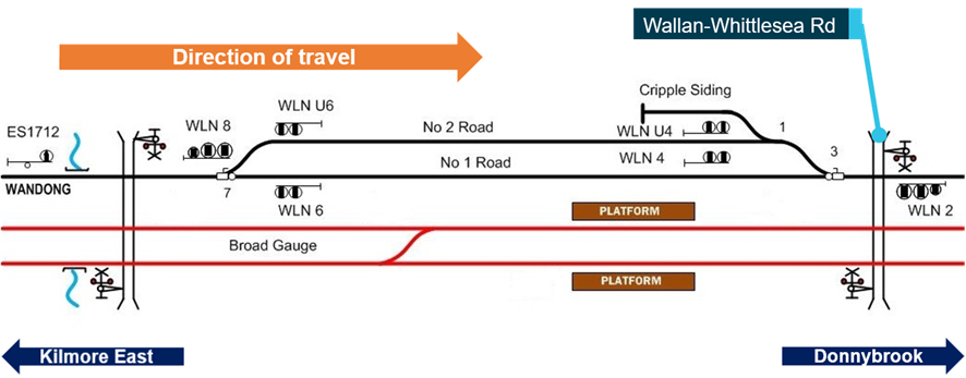
The schematic shows the standard-gauge track at Wallan including the crossing loop. The standard-gauge tracks are shown in black, and the adjacent broad-gauge tracks in red. Only the signalling for the standard-gauge track is shown in this figure.
Source: ARTC, modified and annotated by CITS
Wallan Loop northern turnout
The turnout at the northern end of the Wallan Loop was located at the 49.058 km mark. For southbound trains approaching the northern end of Wallan Loop, there was a downhill gradient of approximately 1:150 and the track was tangent (straight) for about the final 800 m of the approach to the turnout. The approach track was comprised of 60 kg/m rail, fastened to concrete sleepers.
The turnout design was rated for a train speed of 25 km/h and the maximum operational speed was 15 km/h in accordance with the ARTC operating code of practice.[36] It consisted of 60 kg/m rail on timber bearers, with a cast V-crossing.
Following the left turnout, the right curve (in the direction of travel) leading onto the No. 2 Road had a radius of about 422 m.[37][38]
Signals
Entry to the northern end of Wallan Loop was normally controlled by signal WLN8. Signal WLN8 was a 3-position Home signal able to authorise movement in the Up direction. When operational, signal WLN8 could provide ‘Clear Normal Speed’, ‘Low Speed Caution’ or ‘Stop” indications (Figure 7). For movements into the crossing loop, the ‘Low Speed Caution’ indication would be used.
At the time of the derailment, signal WLN8 was extinguished and was fitted with a black cross near its base to indicate that it was not functioning (Figure 7).
Figure 7: Signal WLN8 possible indications (left) and on day of occurrence (right)

The figure shows the possible indication for signal WLN8 (when operational), and a photograph of the signal extinguished on the day of the occurrence. The photograph of signal WLN8 also shows the black cross that was attached to the signal post.
Source: CITS
A broad-gauge distant signal was located about 45 m to the north of WLN8 and was probably indicating a Proceed (green) aspect at the time ST23 passed (Figure 8).[39] This broad-gauge signal did not apply to the operation of ST23 that was running on the standard-gauge line.
Figure 8: The tracks and signalling at the northern end of Wallan Loop

The photograph shows the approach to the Wallan Loop turnout. The photograph has been modified to show the extinguished state of standard-gauge signal WLN8 and the probable Proceed (green) indication of broad-gauge distant signal at the time of the derailment. The black cross that was fitted near the base of signal WLN8 at the time of the derailment is not shown in this figure.
Source: V/Line training video, with signal indications modified and annotated by CITS
Environmental conditions at Wallan
Weather
The conditions at the derailment location were dry. At 1930 at the nearest weather station at Kilmore Gap,[40] the temperature was recorded as 13°C, and the wind was from the south at 32 km/h.
Location of sun
The derailment occurred about 30 minutes before sunset. At 1943 at Wallan, the sun was at an azimuth[41] of 259°48'28" and altitude[42] of 5°02'59".[43] The direction of travel was 223° from true north, meaning the sun was about 36° to the right of the driver’s direct view ahead.
Management of rail traffic (safeworking)
Safeworking systems and rules
Purpose
Safeworking is an integrated system of operating rules and procedures that defines the interaction between workers and engineered systems for the safe operation of a railway.[44] Of primary concern is safe operations including train separation and speed management.
Operating rules
ARTC operating rules for Victoria were defined in the ARTC Code of Practice for the Victorian Main Line Operations (TA20).[45] This Code formed part of ARTC’s Safety Management System (SMS).[46] The Code described two safeworking systems, Centralised Traffic Control (CTC) and the Train Order System.[47]
Centralised Traffic Control
Prior to the signalling hut fire at Wallan in February 2020, standard-gauge rail traffic through this section was managed using the CTC system of safeworking described in section 17 of TA20. In the case of signal failure in a CTC system, this section provided for the use of Caution Orders. The Caution Order form used in conjunction with a CTC system required that traffic ‘proceed cautiously’ …. ‘in accordance with Rule 1, Section 3’.[48]
Train Authorities
The procedures associated with Train Authorities were specified in section 25 of TA20, and also in section 17 for the CTC system. The circumstances specified for the use of Train Authority with a CTC system were:[49]
- To assist a disabled train
- Train to return to the crossing loop in the rear
- Working a train to the point of an obstruction on one or both sides.
The Code specified that ‘Train Authority Working[50] must be used as specified by the individual operation of the safeworking system’.
ATSB observation The use of Train Authorities in the circumstances that were present through Wallan in February 2020 was not provided for in the ARTC Code of Practice for Main Line Operations (TA20). |
Use of Train Authority working in previous projects
ARTC advised that Train Authority working had previously been used during commissioning activities, often following signalling system upgrade.
Implementation of Train Authority working at Wallan
Background
Late on 3 February 2020, the Australian Rail Track Corporation (ARTC) identified that signalling had been disrupted between Donnybrook and Kilmore East. As a result of the damage to the signalling system, ARTC commenced managing rail traffic through the section using Caution Orders. To reduce traffic delays associated with Caution Orders, ARTC commenced managing rail traffic through the location using Train Authorities from 1900 on 6 February.[51]
Resourcing for altered train working arrangements
ARTC implementation of altered train working arrangements between Donnybrook and Kilmore East involved the engagement of several contractors. ActivateRail[52] was contracted to provide specialist rail project services, and labour hire firms Programmed and ARG Rail[53] supplied several rail workers.
Establishment of altered train working arrangements
A system of train working was established between Home Departure signals at Donnybrook and Kilmore East and notified by the issue of Train Notice 266. In this notice, operators were advised that rail traffic would operate by means of Train Authority. The notice included the processes that would be used and also advised that the points at either end of Wallan Loop would be clipped in the Normal position. Signage would be located at either end of the affected section advising drivers of the demarcation between CTC and Train Authority working.
Issuing of Train Authorities in the altered train working
The system used in February 2020 for issuing a Train Authority to a driver travelling between Kilmore East and Donnybrook involved the on-duty ARTC Network Control Officer (NCO) at Junee, an in-field signaller and an accompanying qualified worker (AQW). The key steps used in practice were:
- The in-field signaller was provided with partially completed Train Authority (TA) forms.
- The in-field signaller positioned themselves at whichever end of the Kilmore East – Donnybrook section that was to receive the next train.
- Prior to the arrival of the next train, the in-field signaller contacted the NCO to obtain details of the TA specific to the next train movement. The NCO dictated the details of the TA to the signaller and the signaller completed the form accordingly.
- The in-field signaller would then read back the completed TA to the NCO to verify its contents.
- A Condition Affecting Network (CAN)[54] notice was also completed by the signaller under the instruction of the controller.
- The in-field signaller would give the completed TA to the AQW (together with the CAN) and, on the train’s arrival, the AQW would board the driving cab of the train. There was no contact between the in-field signaller and the driver of the train.[55]
- Once on board, the AQW would give the TA and CAN notice to the driver. The driver would then contact the NCO to verify the TA. ARTC required the driver to verify the TA by its number. There was no expectation that the driver would read the TA to the NCO.[56]
Train Notice 266[57]
The use of Train Authorities between Kilmore East and Donnybrook in February 2020 was notified in Train Notice 266 (TN 266), issued on 6 February 2020 and commenced at 1900 on that day.
TN 266 was amended and reissued on 7 February. This amended notice advised that, in exception of a rule[58] within TA20, some disarranged signals may be lit, and that they would have a black cross affixed to the signal post.[59]
TN 266 was further amended and re-issued on 13 February 2020. Amendments included:
- Removal of the advice that signals in the section may remain lit.[4]
- Addition of text advising that ‘Repeat Back of the Train Authority is not required to be undertaken by the driver of the rail movement’.
- Replacement of ‘The rail movement may proceed through the section in the normal manner’ with ‘The rail movement may proceed through the section up to track speed as advised by the Accompanying Qualified Worker’.
Train Notice 367[61]
Train Notice 367 was issued on the evening of 19 February 2020 and contained additional instruction to TN 266. It advised that ‘In addition to instructions contained in Train Notice 266 / 2020 issued on 13/02/2020 the following temporary alteration to working will apply’.
TN 367 included advice that:
- the points at Wallan Loop would be set for the No. 2 Track and that the maximum speed at entering the loop was 15 km/h and the maximum speed exiting the loop was 35 km/h.
- TN 367 also included advice that ‘The Accompanying Qualified Worker must remind train crews of trains that the train will operate via No. 2 track at Wallan’.[62]
New, part-completed, Train Authority forms that included detail consistent with TN 367 were issued to the in-field signallers and ARTC Network Control, replacing the previous Train Authority forms.
Risk management
Safety Management System
ARTC’s Safety Management Systems (SMS) included procedures requiring risk assessments for standard and ‘out-of-course’ safeworking arrangements.[63] This procedure identified the potential need for a risk study or assessment for a range of activities and system changes. The procedure for risk management specified that formal risk studies were usually undertaken for complex activities where potential impact was likely to be significant. The listed types of activities where a formal risk study may be appropriate included:
- Significant civil works, such as tunnel construction, bridge construction
- Technical operational changes, such as introduction of new signal/track infrastructure
- Safety critical system changes, such as network control system changes.
The procedure also specified that formal risk assessment was undertaken in order to identify potential risks, their causal and contributory factors, the likelihood and consequence of the risk eventuating, and controls that may be implemented to prevent the risk or otherwise minimise the impacts of the risk. It specified that a formal, documented risk assessment must be conducted in various circumstances (including when notifiable changes are planned to the SMS and/or network configuration and as directed in project management procedures). This could include the identification and assessment of risks associated with:
- Achievement of organisational objectives
- Operational activities of the organisation
- Projects
- Impending changes to the organisation, operational environment or systems.
Risk assessments associated with altered train working through Wallan
Initial risk assessment
A risk assessment for the operation of rail traffic between Donnybrook and Kilmore East by Train Authority working was reported as being conducted at approximately 1600[64] on 6 February 2020 and the associated documentation finalised on 7 February. The risk assessment involved representatives from ARTC and ActivateRail and was based on previous applications of Train Authority working by ARTC.
The risk assessment for Wallan contained 10 identified hazards and associated control measures. Hazards and risks associated with routing trains through Wallan Loop were not directly identified in the risk worksheet. Hazard number 2 (Rail Operators not aware of the altered working) was indirectly relevant to any potential train operations through the loop (Table 1).
Table 1: Extracts of risk assessment for altered train working
| Hazard | Caused by | Worst Outcome | Control | Risk Rank | |
|---|---|---|---|---|---|
| 2 | Rail Operators not aware of the altered working | Train notices not received by train crews detailing the processes in place | Train driver accepts the train authority and proceeds into the section not conversant with the altered working | Train Notices will be issued in a timely fashion. Signals at the interface of the commissioning will have change of Safeworking signage to indicate the interface between CTC and Train Authority working. Disarranged signals will have black crosses affixed to them. Train are piloted through the section.[65] | Low |
ARTC reported that the risk worksheet was released to V/Line and Programmed. NSW Trains and freight operators were not included in this distribution. The documented risk assessment was not updated after 7 February 2020. However, ARTC has advised that risks relating to the altered train working continued to be informally assessed as feedback was received and that changes were reflected in the amendments made to Train Notice 266.
Risk assessment for travelling through Wallan Loop
There was no documented risk assessment specific to the routing of trains through Wallan Loop on 20 February and the release of Train Notice 367. The risk controls adopted for this change included the provision of information to operators through the issue of TN 367, and a note within that notice that the AQW was to advise the driver that the train will operate via No. 2 Track at Wallan Loop and of the speed limits required (for entry to and exit from the loop).
ATSB observation Formal risk assessment was not used to identify hazards and available risk controls to manage the risk associated with train overspeed at the entry to Wallan Loop. |
Distribution of safety notices
ARTC
Procedures defined the processes to be followed for preparing, reviewing, approving and issuing Operational Notices (including Train Notices) on the ARTC Network.[66] Different processes applied to different parts of the ARTC network.
Approved operational notices for Victoria, South Australia and Western Australia were published on the ARTC WebRAMS (Rail Access Management System) portal.[67],[68] Standing Train Notices were specified as being uploaded to this portal at approximately 1800[69] each evening. Access to WebRAMS was available to ARTC customers and stakeholders via an allocated User ID system. Rail operators were required to access the safety notices through this portal.
For the New South Wales and Queensland network, the ARTC procedures for distribution of operational notices specified direct transmission to selected internal and external stakeholders.
ARTC Distribution of Train Notice 367
Formal distribution of Train Notice 367 by ARTC to rail operators was via the WebRAMS portal. ARTC reported that TN 367 was uploaded to WebRAMS as part of an automated system update at 1815[70] on 19 February 2020.
In addition to the formal release, information regarding transit via Wallan Loop and the release of TN 367 was shared with V/Line. There was no active engagement by ARTC with, or direct release of TN 367 to, NSW Trains or freight operators.
NSW Trains
Sources of safety information for operation on the Victorian network
For its operations within Victoria, NSW Trains drew on Weekly Operational Notices (WONs) prepared by Metro Trains Melbourne (MTM) and issued each Tuesday for the week commencing the Wednesday.[71] The WONs included safety information for metropolitan and regional services. The WONs did not, however, typically include ARTC Train Notices, and reference was instead made within the WON to the ARTC WebRAMS portal.
NSW Trains did not routinely interrogate the ARTC WebRAMS portal for network operational information related to its Victorian operations. For its operations on the NSW portion of the ARTC network, it received train notices directly from ARTC.
ATSB observation NSW Trains systems for obtaining network safety information for operations within Victoria did not include accessing information via the ARTC web portal. |
Distribution of safety information to drivers
Each week, information considered relevant to its Victorian operations was extracted from the WON. This was used to produce an information pack for its regional drivers that would operate in Victorian territory. This information pack was then placed in the pigeon-hole of each driver at their Junee base. It was the driver’s responsibility to collect information from their pigeon-hole.
NSW Trains distribution of Train Notice 367
No evidence has been identified to indicate that NSW Trains was aware of Train Notice 367 prior to the occurrence. WON Issue No. 07 that was published on 18 February 2020 did not include information from TN 367. Extracts from WON 07 were prepared for distribution by 1139 on the morning of 20 February and were reported placed in the pigeon-holes of regional drivers (at Junee) by 1247 the same day.
ATSB observation NSW Trains and its regional drivers coming on shift were probably not aware of the issuing of Train Notice 367 by ARTC and the possible operation of the ST23 through Wallan Loop on 20 February 2020. |
WON Issue No. 07 that was published on 18 February 2020 did contain Train Notice 266 (as amended on 13 February). This was the ongoing operational notice for the Kilmore East to Donnybrook section at the time of the release of WON 07. It’s direct inclusion in the WON was not standard practice, and was the result of V/Line re-issuing ARTC TN 266 (as amended 13 February) within its own system.
V/Line distribution of Train Notice 367
Normal V/Line process entailed driver supervisors checking the WebRAMS portal after the evening publishing of ARTC notices on that portal and distributing train notices to affected drivers.
In this instance, on the evening of 19 February, V/Line also published a V/Line safe working circular (SW.0024.2020) incorporating TN 367, for distribution to all drivers including those running broad-gauge services. The V/Line drivers that ran through Wallan Loop on 20 February were also contacted by their driver supervisor prior to their shift and advised of the change.
Derailment site information
Position of leading vehicles
The derailed train came to rest in a concertinaed arrangement. The lead power car had rolled onto its left side and decelerated at a higher rate than trailing vehicles (Figure 9).
Figure 9: Leading three vehicles in the derailment

The photograph shows power car XP2018 on its left side, and first two passenger cars A and B.
Source: CITS
Of the passenger cars, the first (Car A) had the greatest tilt of about 30 degrees from the vertical. It had come to rest on a row of pine trees and its trailing end had bound with the next car, Car B (Figure 10). The row of pine trees had probably stopped Car A from rolling onto its side.
Figure 10: The derailed position of Car A (left photograph taken after removal of trees)
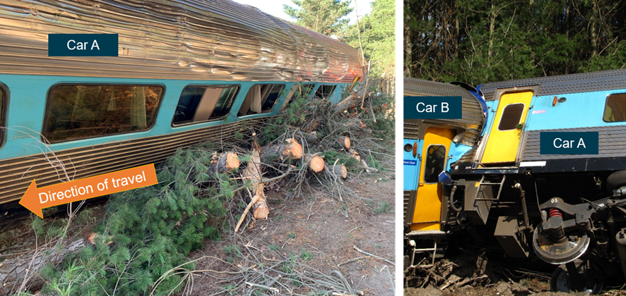
The left photograph shows Car A rolled to its left and supported by pine trees, and the right photograph shows the trailing end of Car A bound with the leading end of the next car, Car B.
Source: CITS
Points position and turnout
At the time of the derailment, the points at the northern end of Wallan Loop were in their Reverse position to provide entry to the loop (Figure 11). The point mechanism had been placed into hand-mode [72] and the points locked in the Reverse position. The mechanism was also padlocked.
There were a number of witness marks on rails and within the track that indicated that wheels had derailed within the turnout. There were no derailment marks identified prior to the turnout.
Figure 11: No. 7 points at the northern entrance to Wallan Loop

Source: CITS
Train recorded information
The Hasler RT recorder
Power cars XP2018 and XP2000 were each fitted with a Hasler RT data recorder. The Hasler RT is an electro-mechanical device that records data onto a waxed paper tape (roll). Data recorded included speed, distance, time, a combined power-vigilance parameter, and brake cylinder pressure. The Hasler equipment included an analogue speedometer located on the driver’s console.
The Hasler tapes from the two power cars were recovered for analysis (Figure 12). During retrieval, the Hasler tape from XP2018 jammed in the recorder and was damaged. However, all information was recovered and data relevant to the investigation was not affected.
Figure 12: Hasler waxed paper rolls removed from power cars XP2018 and XP2000
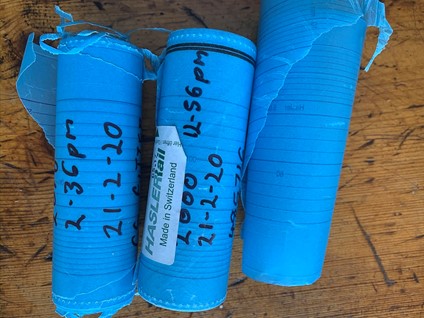
The photograph shows the recovered waxed tapes. The centre roll is the tape from power car XP2000. The left and right rolls are the tape from power car XP2018 that jammed and was torn at one location.
Source: CITS
Data processing
Unlike modern data logger systems that provide digital information for a wide range of operating parameters, Hasler recorders provide limited information in graphical format. In addition to the limited range of information, the format can introduce a loss of precision in the presentation of recorded data.
To process the data, both tapes were scanned and examined using photographic software. The traces for each recorded parameter were assessed for alignment with key events, such as start/stop points. Some horizontal re-alignment of parameters was required and both the horizontal and vertical scales of the images were calibrated for measurement.
Wheel diameter corrections
The Hasler used a pre-set (average) wheel diameter to calculate both speed and distance from the measured revolutions of the left-hand wheel on the second axle of the power car (wheel 3).[73] Actual speed may deviate from that recorded (and displayed) due to differences between this pre-set diameter and the diameter of the actual wheel providing the feed to the Hasler system. The actual measured wheel diameter for both power cars was larger than the pre-set value, hence recorded speed and distance were lower than the actual values.
The recorded values for speed and distance were corrected for the ratio of actual-to-pre-set wheel diameter (Table 2). The larger actual wheel diameter on the XP2018 (compared to the pre-set) meant that the recorded speed was about 2% lower than the actual train speed.
| XP2018 – leading | XP2000 – trailing | |
| Pre-set diameter (mm) | 1000 | 1000 |
| Measured diameter (mm) | 1019.2 | 1011 |
| Ratio (correction factor) | 1.0192 | 1.011 |
Uncertainties in recorded data
An initial review identified a likely recording anomaly in the latter part of the XP2018 data. All channels recorded noise in the latter phase. An overlay of the data from the two power cars showed the discrepancy (visible as diverging speed toward the end of the data) and also confirmed that the speed data prior to this occurring was consistent (Figure 13).
Figure 13: Overlay of data recordings from XP2018 and XP2000
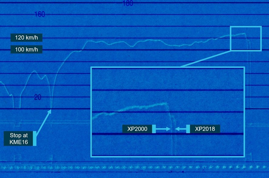
The image shows an overlay of speed records from power cars 2018 and 2000. It indicates consistent speed records after departing Kilmore East, then a consistent initial sharp deceleration of both cars followed by diverging speed records during the derailment.
Source: ST23 Hasler recordings annotated by ATSB
There were also potential inaccuracies in the XP2000 data in the latter stages due to uncertainty in measured wheel rotation being an accurate measure of train speed during this phase.
Other sources of train speed
GPS data from the installed ICE radio system[74] was interrogated and used as a comparator for time, speed and position information. While only coarse GPS data was available due to the system’s polling frequency, it provided a source for comparison with the Hasler data and an enhanced confidence in the assessed train speed. The GPS data was also the primary source for locating the position of ST23 when stopped prior to signal KME16.
Throttle and braking events
One limitation of the fitted Hasler data recorder was that it did not record the positions of the driver’s throttle and brake handles. Instead it recorded a generic power ON-OFF parameter and brake cylinder pressure.
The data from both power cars indicated that, at a point just prior to the commencement of deceleration, the power moved from ON to OFF and there was a rapid increase in brake cylinder pressure. For each recording, the points at which brake cylinder pressure began to rise and then reached a steady state were determined. The steady state pressures were noted for each record and compared with expected values. For both power cars, the recorded pressure was above that expected for a Notch 7 (Full-Service) application (345 kPa). The pressure recorded on XP2018, the leading power car, was about 378 kPa which was in line with the pressure expected for an Emergency application (375 kPa). While the pressure recorded on XP2000 was lower, about 358 kPa, it was still substantially above the Full-Service value. These results indicate that it was very likely that the brake application was an Emergency application. The speed of the train at the commencement of braking was about 129 km/h.[75]
Location of rise in brake cylinder pressure
Due to known limitations and potential anomalies in the Hasler data recording, obtaining position information from the data with respect to fixed points on track was difficult to achieve with high levels of accuracy. Therefore, the position at which brake cylinder pressure began to rise and the speed at which the train entered the turnout could not be directly read from the Hasler data.
Instead, the Hasler speed and distance data was used to calculate estimates of position considering different known stop locations. This was cross-checked using data from other sources to provide greater confidence. The different methods yielded slightly different results, however all indicated that the brake application was commenced before entry to the Wallan Loop (Table 3).
Table 3: Estimated start of braking and speed at entry to turnout
| Parameter | Estimated closest braking | Estimated furthest braking[76] |
| Distance from brake cylinder pressure rise to No.7 points | 50 m | 153 m |
| Speed at No. 7 points | 127 km/h | 114 km/h |
Train handling of ST23 during journey
The Hasler recordings and the GPS data were examined to evaluate any potential trend in speed exceedance by ST23 during the Victorian segment of the journey. The ARTC Route Access Standard specified a maximum speed for express passenger trains in Victoria (including the XPT) of 130 km/h in areas where no local speed restrictions applied.[77] The assessment focussed on any identifiable trends and did not include local speed restrictions that were remote from the event.
Review of the GPS data identified 11 speed peaks of between 133 and 137 km/h in the Victorian section. These exceedances within the GPS data were cross-checked with the Hasler recordings and similar peaks identified, including a maximum actual value of about 139 km/h.[78]
None of the over-speeds identified were for a significant duration. These observations suggest that the driver was targeting line speed and occasionally overshooting. There was no evidence identified to suggest unusual train handling.
Vigilance parameter
The locomotive was fitted with a vigilance system. The installed Hasler does not record all information on driver activity associated with the vigilance system and its information is therefore of limited value.[79] However, the Hasler does record a vigilance parameter. The last point at which the vigilance parameter was recorded as active was prior to the stop at signal KME 28. There were no vigilance parameter events recorded between ST23 departure from signal KME 16 and the occurrence.
Cab video and voice recording devices
Power car XP2018 was not fitted with in-cab voice or video recording devices, nor was it required. As a result, there is no available evidence with respect to any communications or interactions that may have taken place between the driver and AQW prior to the occurrence.
Voice and video recording within the driver’s cab would have assisted the investigation in ascertaining the interactions within the cab, and the potential identification and analysis of associated safety factors.
ATSB observation Voice and video recording within the driver’s cab would have assisted the investigation in the identification and analysis of potential safety factors. |
Rolling stock condition assessment
Overview
Scope of condition assessment
The assessment of rolling stock condition was led by OTSI. The assessment involved vehicle inspections, oversight and review of testing conducted by Sydney Trains on behalf of ATSB, and a review of maintenance records. Specific testing was conducted on braking, vigilance and communication systems. The twist characteristics of power car XP2018 were also assessed.
Assessments were conducted at several locations and included observations at the derailment site on 21 February 2021, inspection of vehicles XP2000 and XFH2108 at the Sydenham Maintenance Centre on 6 March 2020 and inspection of vehicles XP2018, XAM2179A, XL2229, XBR2155 and XF2201 at the Auburn UGL facility on 10 March 2020. Further inspection and testing was witnessed by OTSI at the Auburn UGL facility.
Summary findings of rolling stock condition assessments
Based on post-incident testing of safety critical systems including braking, vigilance and communications systems, vehicle and component inspections, and a review of maintenance records, no rolling stock condition or defect has been identified that was likely to have contributed to the derailment.
ATSB observation Completed post-incident assessment of ST23 rolling stock did not identify a condition or defect that was likely to have contributed to the derailment. This included braking, vigilance control and radio communications systems. |
Incident site observations
General
Observations were made at the derailment site prior to the rolling stock being moved. The preliminary observations did not identify evidence of rolling stock defects or equipment failures potentially causal to the derailment. All vehicles remained mechanically coupled although some couplers had sustained damage in the derailment. All bogies remained attached.
The derailed vehicles exhibited wheel tread damage consistent with (and typical for) running on track ballast. The wheels on the leading passenger vehicle (XAM2179) exhibited significantly more wheel tread damage than those of power car XP2018, suggesting that power car XP2018 had travelled in an upright derailed state for a shorter distance than the following passenger vehicle. This was consistent with the power car overturning early in the derailment sequence.
Brake controller position
At the time the site observations were made, the brake controller in the driver’s cab of power car XP2018 was in the Emergency brake position with the power (throttle) controller in OFF and the reverser direction in Forward.
Sydney Trains maintenance systems
Maintenance of the XPT fleet was managed using the Sydney Trains Enterprise Asset Management (EAM) system. Work orders were generated within EAM in accordance with the requirements of the Technical Maintenance Plan (TMP). The TMP specified the frequency of tasks required for the power cars and trailer cars. Maintenance inspections included Major Inspections and Trip Inspections (pre-release to service). In addition to the maintenance regime, heavy overhauls were conducted at specified frequencies.
The Major Inspection was typically completed at 90-day intervals and inspected the condition of the carriage in greater detail. The task list for each Major Inspection varied with the inspection cycle, with some tasks completed more frequently than others.
Review of maintenance system
Open work orders
At the time of the derailment of ST23, a number of work orders within the TMP were listed as Open. However, none of the Open orders were found to be relevant to the risk of derailment.
It was also found that vehicles of ST23 entered service with work orders for the Trip Inspection of all cars identified as Open. However, review of the task list identified that most tasks had been completed prior to the train entering service. Those tasks that were not completed were not considered potential contributors to the derailment.
Fault management
Open and closed faults for the 120 days prior to the derailment were reviewed. There were no open faults identified that would suggest the train was operating at increased risk relevant to the derailment sequence. Review of closed faults did not show any recent faults which might have been addressed incorrectly and created increased risk.
Bogies and wheelsets
Bogie overhaul and wheelset records
Review of bogie and wheel set sheets did not identify any areas of concern with the condition of the bogies at the time of overhaul or wheelset change. Assessment of bogie weights at time of overhaul were within specification. Braking components including brake levers and cylinders were within specified dimensions and clamping forces at the time of servicing.
Bogie post-incident overhaul
Overhaul of bogies from ST23 has not identified defects relevant to the derailment. Inspection and overhaul of all bogies was not yet complete at the time of finalising the Interim Report.
Condition of wheels
The last routine wheel measurement indicated flange and rim thickness were within engineering standards.
Wheel profile measurements taken following the incident were compared to the WPR2000 profile specified for these vehicles. No sharp flanges were identified, and profiles were within tolerance and generally close to the WPR2000 profile.
Braking and vigilance systems
Static brake testing and vigilance system
Static brake testing on power car XP2018 was conducted at Auburn, NSW.[80] The purpose of this testing was to determine whether the brakes were degraded prior to the derailment. In preparation for the static brake testing, some of the items damaged during the derailment were repaired and the testing supported by workshop services.[81]
Given the damage sustained by the rollover derailment, the performance of the braking system and the vigilance control system was better than expected. There was no evidence found that the brake system or vigilance control system on XP2018 contributed to the derailment.
Review of maintenance records for braking system
During the (pre) Trip Inspection, the braking system was required to be tested. The test consisted of a functionality check of the braking system including brake pipe pressure, automatic and electro-pneumatic brake function, driver safety system (operator enable handle and pedal) and the vigilance control unit. Sydney Trains was unable to provide brake testing capture sheets from the most recent Level 1 or Level 2 brake testing and advised that the tasks were completed and signed off within the EAM but no paper records were available. The absence of these brake testing sheets prevented a more detailed assessment of the brake condition at the time of these maintenance checks. However, a review of the fault history did not show any known faults.
Additional to the testing, there were no known reports of issues with the braking system during the journey of ST23 prior to the derailment.
Power car XP2018 response to track twist
A twist test on power car XP2018 was conducted at Auburn, NSW. The purpose was to determine this vehicle’s capacity to negotiate track twist. The twist test arrangements were in accordance with the twist (packing) described in RailCorp Standard ESR0001-200 (2013) that represented the standard current at the time of the derailment. For testing, vehicle suspension was retained in its as-derailed condition that included some contained debris, and some suspension damage.
The testing found a maximum wheel unloading of 57.3 per cent, compared to the maximum permissible value of 60 per cent. Given this result, it is unlikely the twist performance of this vehicle contributed to the derailment.
Train radio performance
Post incident function testing and log review
The radio system was function tested and logs reviewed to assess the condition of the radio system just prior to derailment. The train radio system had sustained damage during the derailment and antennas had been removed, resulting in some performance degradation during testing.
Based on results of radio function testing and the review of radio log files, the Sydney Trains specialist maintenance group responsible for the train communications concluded that there was no evidence to suggest that the on-board communications systems were non-operational or defective at the time of the incident.
Assessment of recordings of communication between the train driver and ARTC Network Control were consistent with the train radio system operating normally.
Maintenance records of communications system
The maintenance history for the communication equipment fitted to ST23 was reviewed, with the primary focus being power cars XP2018 and XP2000. The review found that the train radio system was within the required maintenance inspection timeframes and compliant at the time of the derailment. The most recent inspection of communications equipment on XP2018 was completed on 6 February 2020, and on 4 February 2020 for XP2000.
Rolling stock crashworthiness and survivability
Scope
The ATSB conducted crashworthiness and survivability inspections of the lead power car and the five passenger cars. Inspections included an examination of features pertinent to the survivability and evacuation of the train crew and passengers. The unoccupied rear power car remained upright and on track and was not inspected for its crashworthiness.
Inspections were conducted at the derailment site on 21 February. Power car XP2018 and the leading passenger (sleeper) car were further examined at the Auburn UGL facility on 10 March 2020.
Power car XP2018
General findings
Damage to the vehicle’s exterior indicated that the lead power car had slid on its side for some distance (Figure 14). The driver’s cab retained its structural integrity. However, the left-side cab door separated from the door frame, and the left-side engine room door at the rear of the power car was dislodged. Fuel tanks on the left side were also breached.
The car’s forward windscreen remained in place during the derailment. The screen was subsequently removed by rescuers to access the driver’s cab. The lower rear corner of the left-side quarter window had detached from the frame, sufficient to allow a limited amount of ground material into the cab.
Internally within the cab, equipment and fittings remained mostly intact. Instruments, control panels and interior linings contained little or no damage. The driver’s side (left-side) headrest was detached from the seat back.
Figure 14: Power car XP2018 at Auburn workshops 10 March 2020
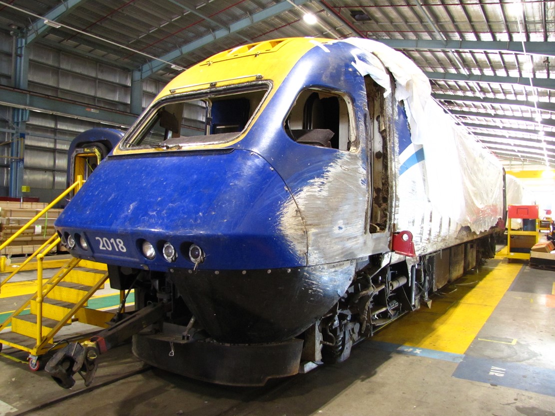
Source: ATSB
Driver’s left-side cab door
The most significant damage to the power car was to the left cab entry door. The cab door had been secured with two hinges on its rear edge and a single door latch on its forward edge. The glass fibre composite doors were a plug shape and rotated inward on the rear door frame. The hinges were attached to the door and frame using bolts secured to embedded plates (Figure 15).
Figure 15: Door and doorframe section drawing
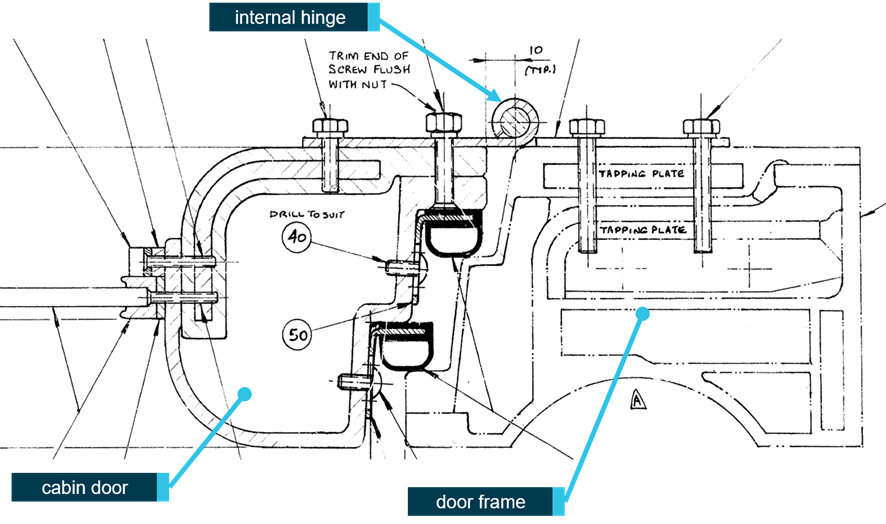
Source: Commonwealth Engineering (NSW) Drawing 022010940-1 annotated by CITS.
The door hinges had failed as a result of the external loading during the sliding event. The door had become disconnected from the door frame and loose within the cabin. The door-side fingers of the upper hinge had peeled open (Figure 16) and the lower hinge had failed by the loss of fastening on the frame-side of the hinge (Figure 17).
With the door aperture open, the rear of the door frame had acted as a scoop for ballast and dirt which accumulated inside the cab. A significant amount of material was found to have entered the cab space.
ATSB observation The left cab door of the power car did not withstand the external loading associated with power car 2018 rolling on to its side. This resulted in materials entering the driver’s cab of the power car. |
Figure 16: Upper internal hinge of left cab door of XP2018

Source: ATSB
Figure 17: Lower internal hinge of left cab door of XP2018
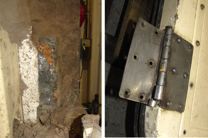
Source: ATSB
Evacuation routes from driver’s cab
The normal access to and from the driver’s cab was through the side doors. At the rear of the cab, there was an internal door to the machinery space and at the rear of that space there were a further two door exits either side of the car, and a rear central door. With the power car on its left side, the right driver’s cab door was the most accessible access route to the cabin and the crew inside. The right driver’s cab door remained operable and was used by members of the crew to gain access to the cab. This access route was only accessible by able bodied people climbing on top of the vehicle and there was no practical way to extricate any survivor if they themselves were not ambulatory.
ATSB observation With power car XP2018 on its left side, there were no points of entry at or near ground-level. |
Rear left door
The rear external machinery space entry door on the left side of the power car had also been dislodged but the top hinge did not fully part from the frame (Figure 18). There was a build-up of ballast and dirt at the base of the door.
Figure 18: The rear left-side door of power car XP2018
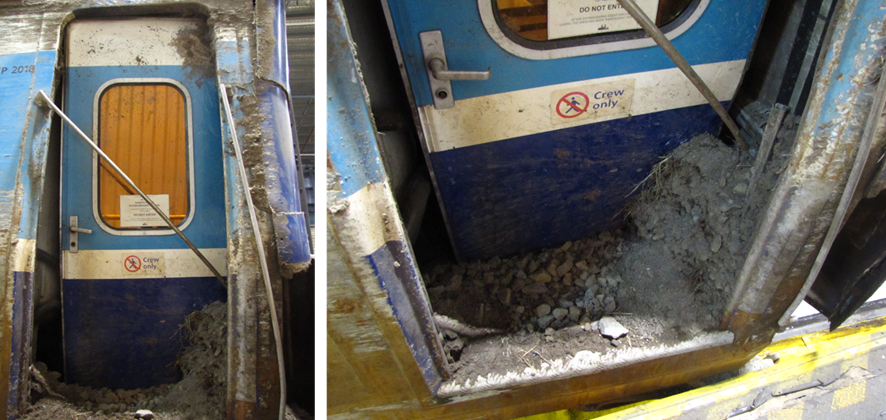
The left photograph shows a full view of the rear left-side door of XP2018, and the right photograph the base of the door pushed-in by track ballast and dirt.
Source: ATSB
Passenger cars
Overview
Inspections did not identify any structures that would have generated injuries by their design. In the lead passenger car, some windows had been shattered introducing a hazard. It was also reported that luggage had fallen from overhead racks, some of which struck passengers and service staff causing injury.
Most injuries to passengers were a result of people being unprepared for the sudden deceleration or losing their balance when their car lurched or tilted. Passenger injuries were more prevalent and more severe in the forward passenger cars.
Passenger car XAM2179 (Car A)
XAM2179 was the leading passenger car and had a cabin/sleeper configuration. It consisted of nine cabins which could seat three passengers each. Some cabins had forward facing seats while others were rear facing. This sleeper car came to rest rolled to about 30 degrees to its left. External damage included four broken exterior windows on the left (passenger aisle) side of the carriage and exterior damage to the roof line above the windows from the passenger car striking pine trees adjacent to the track. The trailing end had also bound with the leading end of the following car, XL2229.
Damage within the sleeper car included collapsed interior lining in the passenger aisle. Two cabins had cracked glass partitions most likely from being struck by luggage or passengers (Figure 19).
Figure 19: Passenger car A, left-side corridor (left) and fractured glass partition (right)
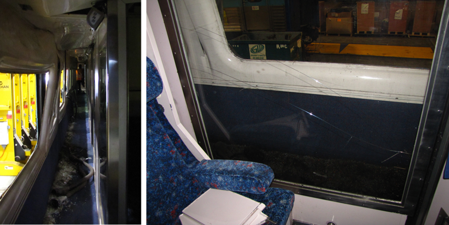
Source: ATSB
Being the most widely spaced seats in the train, these occupants had the largest free-flight distance available that can lead to more serious injuries. The injuries in this car were most likely the result of passengers being thrown a significant distance before impacting structures and fittings. Injuries occurred to people sitting in both forward- and rearward-facing seats.
Passenger car XL2229 (Car B)
This was a first-class car with 56 forward-facing passenger seats in a single open cabin. It was seating an estimated 52 people at the time of the derailment. It was the car with the most reported injuries and the most reported serious injuries. The injuries were most likely the result of passengers being thrown from their seats or being hit by luggage falling from the overhead racks. The car came to rest at an angle of approximately 17 degrees to its right.
There was no evidence of structural failure or dislodged internal fittings acting as projectiles. The only significant damage to the cabin was exterior binding at the front right corner with the car ahead, Car XAM2179. This prevented the use of the exits at this location.
Passenger car XBR2155 (Car C)
This car was half first-class forward-facing seating with the other half being the buffet section. It was near upright when it came to a stop. The car suffered no interior damage of consequence.
Passenger car XF2201 (Car D)
This was an economy-class car with 68 forward facing passenger seats in a single open cabin. It was the most heavily populated car in the set with an estimated 57 passengers in this car at the time of the derailment. Comparatively fewer injuries were reported in this car. It was near upright when it came to a stop. The car suffered no interior damage of consequence.
Passenger car XFH2108 (Car G)
This car was half economy class forward facing seating with the other half being the baggage section. The baggage section was locked meaning there was only one pair of exits (forward) immediately obvious to passengers. A key to the baggage compartment was available behind breakable glass. This would have permitted a second set of exits to be used through the baggage compartment, however in this instance these rear exits were not used. This car was at an angle of about 10 degrees when it came to a stop and had the least number of reported injuries and the lowest injury rate. The car suffered no interior damage of consequence.
Evacuation routes from passenger cars
The majority of exits in passenger cars were available. Six of the 18 exits for passengers could be considered freely available. A further eight exits were operable and available but with some hindrance to their free use due to the distance from the ground, the angle of the access ladder, or some other hazard. Four exits were deemed not to be available, either due to obstruction, jamming or excessive height off the ground.[82]
Most people reported, and general evidence suggests, that the majority of passengers were able to evacuate without or with limited assistance. Some special needs passengers were assisted out of the carriages.
While not obstructing the evacuation, the angle of two carriages slowed some people getting off. The longitudinal angle of most cars was negligible, however the lateral angle (roll) of the front two passenger cars was significant.
Passenger information
Passenger numbers and injuries
Based on information supplied by the rail operator and Victoria Police, the total number of passengers on board ST23 at the time of the derailment was 155.[83]
Available injury information from the operator and police was combined with ATSB passenger survey response data to estimate a total number of passenger physical injuries of 61.[84] ,[85] This total figure was comprised of 8 serious injuries and 53 minor injuries.<[86]
Passenger survey
Overview
The ATSB conducted a survey of passengers that were aboard train ST23 at the time of the derailment. From 155 passengers reported to be on board, 83 responses to the survey were received: a response rate of 54 per cent. The survey included questions on:
- passenger demographics
- passenger seating location
- safety information and briefings
- experiences during and after the event
- the nature of injuries.
Safety information
On questions pertaining to safety information:
- Seventy per cent of passengers who responded to the question about the provision of safety information reported that they either did not receive any safety information or could not recall receiving any.
- Of the 63 responses about the format of the safety information provided, eight passengers reported that they received the information from a briefing card.
- Of the 74 responses to a question related to paying attention to the safety information provided, 57 per cent of passengers reported that they did not pay attention. Some passengers mentioned that the reason for not paying attention was that there was no information provided.
- Seventy per cent of survey respondents reported that, prior to the event, they did not know how to get out of the train in an emergency.
In response to questions on suggestions for improvement in safety information:
- Ten passengers referred to the way in which safety information is provided by airlines.
- Some passengers mentioned that better signage on the seat in front of them or at the end of carriages may have been helpful.
- Other comments included increasing announcements.
The evacuation
There were varied responses about the communication received from crew members following the derailment. This was at least in part due to the distribution of the crew, with four of the five crew being in the buffet car at the time of the derailment. There were no crew members in three of the cars at the time of the derailment. Most of the passengers who responded advised that initial crew instructions were to remain on board the train. Others reported being unsure about what to do. There was no report of any announcements being made via the public address system or the use of loud hailers.
Responses indicated that some passengers self-evacuated before receiving instructions from the crew. Passengers were asked to estimate how long it took to exit the train. The responses ranged from a ‘few minutes’ to up to 30 minutes, supporting other evidence that some passengers self-evacuated prior to being instructed by train crew. About half of the respondents indicated having difficulty exiting the train due to carriage orientation and/or difficulty with getting down to the ground.
Once passengers were out of the train, crew members were observed instructing passengers to move off the adjacent tracks (due to concern of possible rail traffic).
In response to questions on areas for improvement in emergency response, suggestions included:
- a greater number of staff members to manage an emergency
- crew training in emergency management
- leadership and direction, including more information being provided to passengers
- consistency in the information provided.
Sixteen respondents utilised the free text question to provide praise for the handling of the event by members of the train crew and first responders.
__________
- A NSW Government agency constituted by the Transport Administration Act 1988 Part 1A Section 3C.</li
- Health and fitness requirements for Rail Transport Operators and Rail Safety Workers were governed by the Rail Safety National Law (RSNL) and associated Regulations.
- Due to the delay in the service on this day, arrival in Melbourne would have been significantly later than the rostered end-of-shift.
- Detailed work-placement records were available from 2014.
- Sydney Trains is an agency of Transport for NSW.
- ARTC is a statutory corporation fully owned by the Government of Australia.
- Standard-gauge trains did not stop at Wallan.
- TA20 ARTC Code of Practice for the Victorian Main Line Operations, Section 2, Rule 13 g.
- As recorded in the PTV Pass Assets database, viewed 26 October 2020
- A small superelevation of 8 mm was recorded at the commencement of the right-hand curve by the track recording vehicle in August 2019, indicating the left hand rail slightly higher than the right-hand rail in the ‘Up’ (towards Melbourne) direction.
- The indication of this signal at the time ST23 passed is not known with certainty, because its state was not recorded. However, broad-gauge rail traffic records indicate that the signal was more likely to be at Proceed. If not at Proceed, the signal would have been at its alternate ‘Caution’ indication, a single yellow light.
- 13.7 km from Wallan Railway Station
- Azimuth is the clockwise horizontal angle (in degrees minutes and seconds) from true north to the sun.
- Altitude is the vertical angle (in degrees minutes and seconds) from an ideal horizon, to the sun. An ideal horizon exists when the surface forming the horizon is at a right angle to the vertical line passing through the observer's position on the earth. If the terrain surrounding the observer was flat and all at the same height above sea level, the horizon seen by the observer standing on the earth would approximate the ideal horizon.
- Computed using National Mapping Division's sunmoonposn program, version 1.1.
- RISSB Glossary of Terms, viewed 30 March 2020 <https://www.rissb.com.au/glossary/>
- At the time of the derailment, Issue 2.1, 01 July 2018
- A Safety Management System provides a systemic approach to managing safety risks and includes, amongst other items, codes, policies, standards, procedures and documents.
- The CTC system was described in section 17 of TA20 and the Train Order System in section 18.
- Rule 1, Section 3 specified proceeding at a speed not exceeding 25 km/h.
- The scope of application of Train Authorities was similar for the Train Order System.
- The phrase ‘Train Authority Working’ is used in section 25 of TA20.
- The first Train Authority was issued at 2042 on 6 February 2020.
- ActivateRail describes itself as a rail interface solutions business, formed from the specialist rail project services arm of Sterling Infrastructure. It offers professional advisory services, project managers as well as worksite supervisors, site managers and track safety personnel.
- ARG Rail provided labour and recruitment services to the rail infrastructure sector.
- Issued because the Wallan-Whittlesea level crossing protection was being manually operated.
- TN266 specified that the signaller would deliver the Train Authority and CAN to the driver, although in practice this was done via the AQW. On one occasion (Train Authority number 20 on 14 February 2020), the driver requested that the signaller give him the Train Authority directly rather than via the AQW and the signaller complied with this request.
- On this point, the practice of drivers varied. During the period that Train Authority working was being used between Kilmore East and Donnybrook, on 30 occasions out of the 253 Train Authorities issued, the driver ‘repeated back’ the contents of the TA, and had that repeat back verified by the ARTC network controller.
- This section is limited to a brief account of notice TN266 and its amendments. The section does not include detail of the distribution of the notice, nor the receipt of the notice or awareness of its information by organisations or individuals.
- TA20, Section 5, Rule 5.
- TA20 Section 5 Rule 5 Clause b stated ‘Light signals not in use are distinguished by a black cross on the front of the lights. The lamps are not to be lit’.
- Some V/Line drivers and the RTBU (Rail Tram and Bus Union) had expressed concern at signals remaining lit within the affected section. On 10 February, a driver refused to pass a lit signal within the section.
- This section is limited to a brief account of notice TN367. The section does not include detail of the distribution of the notice, nor the receipt of the notice or awareness of its information by organisations or individuals.
- There is no available evidence with respect to the communications between the driver and the AQW.
- r RSK-PR-001 Risk Management, version 1.4, 5 April 2019.
- Approximate time of risk assessment advised by ARTC
- The risk assessment reference to ‘piloted’ is different to TN266 that refers to an Accompanying Qualified Worker.
- Preparation and Distribution of Operational Notices OPE-PR-001, Version Number 1.2, 31 May 2019
- http://webrams.artc.com.au/
- In procedure OPE-PR-001, the acronym NRAMS was used.
- Australian Central Standard Time
- Adelaide time
- The WON was published by the Office of Rail Safety Manager (a part of MTM) on behalf of MTM and V/Line.
- No. 7 points were controlled by a dual-control point machine. They could be operated in motor (remote operation) or hand (manual operation) mode.
- An average wheel diameter is used to accommodate wear and a reducing diameter during the wheel’s life.
- The ICE radio GPS speed is not displayed to the driver in the locomotive cab.
- The speed display on XP2018 would have been reading about 127 km/h.
- To reduce train speed from 130 km/h to 15 km/h at the turnout would require braking at least 800 m before the turnout.
- ARTC Route Access Standard D53.
- Actual speed calculated by correcting the recorded speed for actual wheel diameter. The recorded speed was about 2 per cent lower than the estimated actual.
- AS 7527:2015 (amendment 2019) Legacy, tape based data loggers should, as a minimum record the following information that included train speed, distance, time, and brake status (i.e. brake pipe pressure or brake cylinder pressure).
- Static testing was conducted on XP2018 as the trailer cars immediately behind in the consist were damaged and without significant repairs could not be tested. The main areas of focus were the driver control aspects of XP2018.
- During the derailment and subsequent rollover, some pneumatic equipment was dislodged from the power car or damaged, while other equipment remained intact. In preparation for the static brake testing, approval was provided to Sydney Trains to repair some of the items damaged during the derailment in preparation for the test to be undertaken.
- Considered not usable in cases where the bottom rung of ladder was more than 1.5 m from the ground
- Based on available information.
- Some passenger information was incomplete, and this reported data represents a summary of available information.
- There were also reports of psychological impacts including instances of post-traumatic stress disorder (PTSD) that are not included in the injury total.
- A serious injury is an injury that required, or would usually require, admission to hospital within 7 days of the event.
Safety actions
Australian Rail Track Corporation
ARTC advised[87] that, since the incident, it had taken the following steps to improve the safety of its operations, that are relevant to two ATSB Observations:[88]
- ARTC has developed an amendment to TA20 to facilitate an “Alternative Proceed Authority”. Once implemented, TA20 will provide for a new form of safeworking, similar to Train Authority Working, that can be implemented in circumstances where Centralised Traffic Control (CTC) is not operational for an extended period of time. The proposed amendment to TA20 has been the subject of initial user consultation including internal briefing sessions with operational areas within ARTC’s business and external briefing sessions with rail operators. A Human Factors assessment is scheduled to be undertaken in relation to the proposed amendment in Quarter 4 of Calendar Year 2021. The proposed amendment will then be subject to further formal stakeholder consultation and ARTC’s management of change processes prior to implementation.
- ARTC is developing a new risk assessment tool for abnormal circumstances, to be known as an Event Flow Work Tool, with a focus on risk scoring and authority escalation requirements. A prototype has been developed and is to be further work shopped with Network Controllers prior to implementation.
- Until the steps referred to in 1) and 2) above have been completed, ARTC has implemented an interim requirement that the implementation of any altered method of safeworking, other than Caution Orders, requires a formal Risk Assessment and approval by ARTC’s Executive Risk Committee.
- ARTC has developed an amendment to TA20 to include a new rule titled “Train Notices”. Once implemented, the new rule will clarify the manner and circumstances in which the operation of TA20 may be amended through the issue of Train Notices. Implementation of the new rule is subject to consultation wit
NSW Trains
NSW Trains advised[89] that, since the incident, it had undertaken a number of safety actions. Safety actions taken included:
- The development of new procedures for the daily access of the ARTC WebRams system
- Amendment of procedures to include confirmation of receipt of safety critical information by train crew prior to them starting their day of operations
- Additional resources to ensure that NSW Trains has 24/7 frontline leader coverage across the network
- The review of interface agreement risks from all rail infrastructure managers (RIMs) to identify and assess NSW Trains' systems and procedures for managing interface safety risks with the relevant RIMs
- A range of initiatives to enhance safety critical communications including:
- the development of a new program to strengthen safety critical communication across NSW Trains (TrainLink) rail safety workers
- international benchmarking against safety critical communication systems used by other rail operators
- risk workshops with key internal and external stakeholders to identify opportunities to strengthen safety critical communications
- the development of a business case for future digital solutions for safety critical communications.
____________
- 22 April 2021
- ATSB Observations: • The use of Train Authorities in the circumstances that were present through Wallan in February 2020 was not provided for in the ARTC Code of Practice for Main Line Operations (TA20) • Formal risk assessment was not used to identify hazards and available risk controls to manage the risk associated with train overspeed at the entry to Wallan Loop.
- 22 April 2021
Ongoing investigation
The investigation is continuing and will include further consideration of the following:
- management of train operations, including implementation of altered train working, risk management and communications
- distribution of safety critical operational information
- train operations and further human factors analysis
- survivability and crashworthiness standards relevant to this type of event
- finalisation of derailment sequence analysis
- finalisation of rolling stock and track condition assessments
- passenger services crew training and preparedness for a derailment event
- passenger safety information
- similar occurrences.
Relevant parties are notified of critical safety information identified during the course of the investigation so that appropriate and timely safety action can be taken.
A final report will be released at the conclusion of the investigation.
Purpose of safety investigations & publishing information
Purpose of safety investigationsThe objective of a safety investigation is to enhance transport safety. This is done through:
It is not a function of the ATSB to apportion blame or provide a means for determining liability. At the same time, an investigation report must include factual material of sufficient weight to support the analysis and findings. At all times the ATSB endeavours to balance the use of material that could imply adverse comment with the need to properly explain what happened, and why, in a fair and unbiased manner. The ATSB does not investigate for the purpose of taking administrative, regulatory or criminal action. TerminologyAn explanation of terminology used in ATSB investigation reports is available here. This includes terms such as occurrence, contributing factor, other factor that increased risk, and safety issue. Publishing informationReleased in accordance with section 25 of the Transport Safety Investigation Act 2003 Published by: Australian Transport Safety Bureau © Commonwealth of Australia 2021
Ownership of intellectual property rights in this publication Unless otherwise noted, copyright (and any other intellectual property rights, if any) in this report publication is owned by the Commonwealth of Australia. Creative Commons licence With the exception of the Coat of Arms, ATSB logo, and photos and graphics in which a third party holds copyright, this publication is licensed under a Creative Commons Attribution 3.0 Australia licence. Creative Commons Attribution 3.0 Australia Licence is a standard form licence agreement that allows you to copy, distribute, transmit and adapt this publication provided that you attribute the work. The ATSB’s preference is that you attribute this publication (and any material sourced from it) using the following wording: Source: Australian Transport Safety Bureau Copyright in material obtained from other agencies, private individuals or organisations, belongs to those agencies, individuals or organisations. Where you wish to use their material, you will need to contact them directly. |
Preliminary report
Report release date: 03/04/2020
The information contained in this report is released in accordance with section 25 of the Transport Safety Investigation Act 2003 and is derived from the initial investigation of the occurrence. Readers are cautioned that new evidence will become available as the investigation progresses that will enhance the ATSB's understanding of the accident as outlined in this update. As such, no analysis or findings are included in this report.
The occurrence
On 20 February 2020, passenger train XPT ST23 departed Central Station in Sydney, New South Wales (NSW), at about the scheduled departure time of 0740.[1] The service was scheduled to stop at several stations en-route to its final destination at Southern Cross Station in Melbourne, Victoria that evening at 1830 (Figure 1).
Figure 1: Train route from Sydney to Melbourne
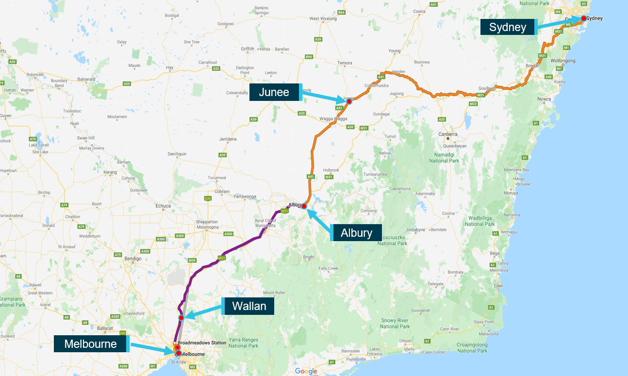
Source: Google Maps, annotated by Chief Investigator, Transport Safety
The train proceeded south and arrived at Junee in southern NSW at 1452,[2] about 85 minutes behind schedule. At Junee there was a change of driver before the train continued south, arriving in Albury on the NSW-Victorian border at 1637, still about 85 minutes behind schedule. There was a change in passenger car crew at Albury.
The train departed Albury at 1644 and entered the Victorian section of its journey. The service continued south, stopping at several stations before coming to a stand at Intermediate Home[3] signal KME28 at Kilmore East, at about 1856. Signal KME28 was at Stop, and the driver contacted Network Control at about 1904 to inquire when he might receive permission to proceed. There was a standard-gauge passing lane at Kilmore East, with East and West Lines (Figure 2).[4]
Figure 2: Kilmore East passing lane (standard-gauge track shown in black, with signals)

Source: ARTC, modified and annotated by Chief Investigator, Transport Safety
The XPT waited at signal KME28 on the East Line until the north-bound V/line passenger train 8625 had transited the Donnybrook to Kilmore East single-line section, passed signal KME2 and was travelling along the West Line through Kilmore East. The V/Line train was clear of the single-line by about 1925 and, soon after, the XPT was given permission by Network Control[5] to proceed to Home Departure signal KME16,[6] still on the East Line within the Kilmore East location.
As a result of damage to signalling equipment, a 24 km section from Kilmore East signal KME16 (at about the 63.8 km mark)[7] to Donnybrook (at about the 40.2 km mark) was being managed using an alternative safeworking system.[8] Wallan was located in this section, about 48 rail-km from Melbourne.
At signal KME16, XPT ST23 was met by several rail workers, including a Signaller and an Accompanying Qualified Worker (AQW).[9] The AQW boarded the lead power car and joined the driver at the head of the train as part of the alternative safeworking system in place for the 24 km section to Donnybrook.
At about 1932 while the train was still stopped at signal KME16, the driver and the Network Control Officer communicated over the radio about the Train Authority[10] for the section through to Donnybrook. The train then departed signal KME16 and entered the single-line towards Wallan. The line speed for the XPT in this section was 130 km/h and after departing, the speed of the train was increased towards this line speed.
One function of the AQW was to ensure that the level crossing protection[11] at Wallan–Whittlesea Road in Wallan was in place for the passage of the train.[12] The Level Crossing Keeper[13] positioned at this level crossing reported receiving a call from the AQW and activating the crossing protection.
The train was now approaching Wallan. Earlier that afternoon, the points at either end of Wallan Loop had been changed from their Normal position to their Reverse position.[14] This change meant that rail traffic, in both directions, would be diverted from the Main Line (straight) into the loop track (No.2 Road). A Train Notice[15] reflected this change and also specified a 15 km/h speed limit for entry into the loop, and a limit of 35 km/h for exiting the loop.
At about 1943, XPT ST23 was approaching the northern end of Wallan Loop at about the track’s line speed. Recordings from the train indicate an Emergency brake application a short distance before the points. This slowed the train a small amount before it entered the turnout travelling at a speed in excess of 100 km/h. The train was not able to negotiate the turnout to the loop track at this speed and derailed. All vehicles derailed excepting the rear power car (Figure 3).
Figure 3: Aerial photograph of derailment site

Source: ATSB
During the derailment sequence, the leading power car rolled onto its left side and the XPT driver and the AQW sustained fatal injuries. Three passengers were seriously injured and 36 received minor injuries.[16] Five train crew that were in the passenger cars also sustained injuries.
Context
Track information
The XPT service was running on the national standard-gauge track that connects Sydney and Melbourne. The track is part of the Defined Interstate Rail Network (DIRN) and is managed by the Australian Rail Track Corporation (ARTC).[17]
The standard-gauge track between Kilmore East and Donnybrook was a single, bi-directional line that serviced the XPT, V/Line passenger services and rail freight. There were passing lanes at Kilmore East and Donnybrook and a 1,550 m crossing loop at Wallan. The northern entry to this loop was located about 1.8 km north of Wallan–Whittlesea Road (Figure 4).
Figure 4: Wallan Loop (standard-gauge track shown in black, with signals)
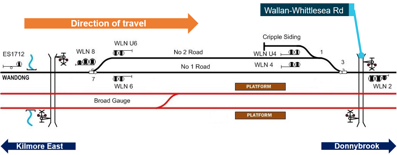
Source: ARTC, modified and annotated by Chief Investigator, Transport Safety
Train information
The first XPT (Express Passenger Train) commenced service in 1982. The XPT fleet is operated by NSW TrainLink[18] and provides passenger services in regional NSW and between the east coast capital cities of Melbourne, Sydney and Brisbane. XPT vehicles are maintained by Sydney Trains[19].
The XPT ST23 running on 20 February 2020 included five passenger cars (Figure 5). The leading three vehicles were manufactured by ABB Transportation in Dandenong, Victoria and commissioned in 1993. The trailing four vehicles were manufactured by Comeng in Granville, NSW and commissioned between 1981 and 1984.
Figure 5: Train configuration
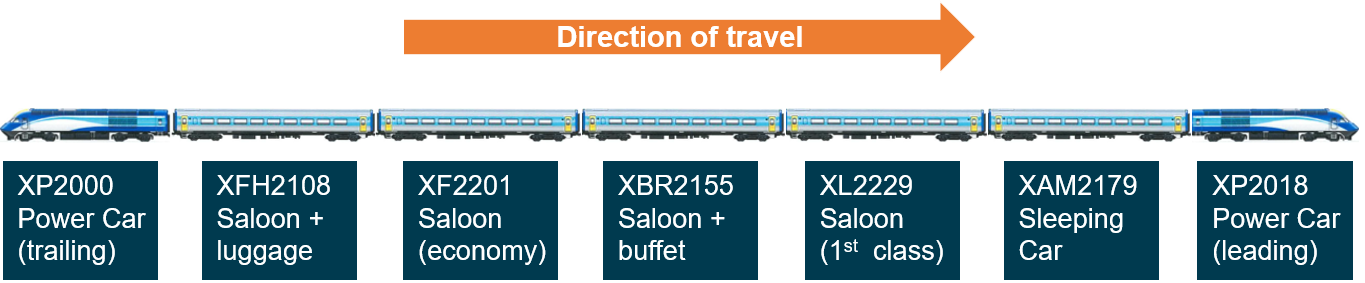
Source: ATSB, vehicle images supplied by Sydney Trains
Train data logger
Both power cars were fitted with a Hasler RT data logger. The data logger is an electro-mechanical device that records speed, distance, time, a combined power-vigilance parameter, and brake cylinder pressure parameters. These parameters are recorded on a waxed paper tape (roll). The Hasler system also included an analogue speedometer located on the driver’s console.
The train’s speed is derived from the measurement of the rotation of the left hand wheel on the second axle of the power car. In order for this rotation to be translated into distance (and speed), an average wheel diameter is assumed. Actual speed may deviate from that recorded (and displayed) due to differences between this assumed diameter and the diameter of the actual wheel providing the feed to the Hasler system.
The Hasler tapes from the two power cars were recovered at the accident scene and examined by the ATSB. Corrections to the recorded speed were made to account for the differences between the assumed wheel diameter and the actual wheel diameter on each power car. The results from both recorders indicated a speed of about 130 km/h approaching Wallan Loop.[20] The Hasler analogue speedometer would have read less than this, probably between the 125 km/h and 130 km/h marks.[21]
The data from both recorders indicate that there was an Emergency brake application nearing the turnout to the loop, and an associated small reduction in speed prior to the train entering the loop. The Hasler recordings will be the subject of further detailed analysis and review against other evidence.
Train crew and passengers
The XPT is a single-driver operation. The driver of the XPT was designated as a Regional Driver, and at the time of the derailment, an AQW was also in the driver’s cab. Both the driver and AQW suffered fatal injuries in the derailment.
Within the passenger vehicles, there were five further crew members including a Passenger Service Supervisor, Senior Passenger Attendant and three Passenger Attendants. All five have reported injuries.
There were 153 passengers recorded as being on the train at the time of the derailment, of which 39[22] have reported injuries.
Management of rail traffic (safeworking)
Safeworking is an integrated system of operating rules and procedures that defines the interaction between workers and engineered systems for the safe operation of a railway.[23] Of primary concern is safe operations including train separation and speed management according to infrastructure.
Relevant to this occurrence, the signalling infrastructure used for standard-gauge traffic through Wallan was damaged as a result of a fire in a track-side equipment hut on 3 February 2020. From 6 February, Train Authority Working was established to manage traffic between Home Departure signals DBK6 and DBK18 at Donnybrook[24] and KME4 and KME16 at Kilmore East.[25] The alternative safeworking arrangements permitted only one train in the section between Donnybrook and Kilmore East at any one time, and Wallan Loop was not being used for trains to cross or pass. From the commencement of Train Authority Working on 6 February, Wallan Loop was configured for trains to travel along No.1 Road.[26] This changed to the No.2 Road on 20 February.
Further investigation
The areas explored and requiring further investigation include:
- Derailment sequence: Further investigation will include a detailed examination and review of available evidence to refine the derailment sequence.
- Track condition: To date, site observations and preliminary review of track data have not identified adverse conditions directly contributing to the derailment. Further investigation will include the detailed examination of post- and pre-occurrence track geometry and maintenance information.
- Rolling Stock condition: To date, site observations and vehicle workshop inspections (that commenced 6 March) have not identified adverse conditions directly contributing to the derailment. Inspections are ongoing and include detailed inspection of vehicles and testing of braking and driver safety systems.
- Crew and passenger survivability: Detailed survivability inspection of the leading power car XP2018 and all passenger vehicles is complete. A passenger survey is being conducted researching passenger experiences of the derailment and subsequent evacuation and emergency response.
- Train operation: Further investigation will include a detailed examination of the operation of the train drawing on a wide range of evidence sources.
- Management of train operations: Further investigation will include a detailed examination of the alternative safeworking systems used to manage rail traffic at this location from 6 to 20 February 2020.
- Other areas of investigation: Further areas of investigation may be identified as the investigation progresses.
Acknowledgements
The ATSB would like to acknowledge the significant assistance provided by all involved parties during the initial investigation, particularly in the context of the impact of COVID-19 on business operations and the community.
Train details
| Train operator: | NSW TrainLink | |
| Persons on board: | Crew: 6 +1 | Passengers: 153[27] |
| Fatalities: | Crew: 1+1 | Passengers: 0 |
| Other Injuries:[28] | Crew: 5 | Passengers: 39 |
| Damage: | Substantial, to train and track |
__________
The information contained in this report is released in accordance with section 25 of the Transport Safety Investigation Act 2003 and is derived from the initial investigation of the occurrence. Readers are cautioned that new evidence will become available as the investigation progresses that will enhance the ATSB's understanding of the accident as outlined in this update. As such, no analysis or findings are included in this report.
Purpose of safety investigationsThe objective of a safety investigation is to enhance transport safety. This is done through:
It is not a function of the ATSB to apportion blame or provide a means for determining liability. At the same time, an investigation report must include factual material of sufficient weight to support the analysis and findings. At all times the ATSB endeavours to balance the use of material that could imply adverse comment with the need to properly explain what happened, and why, in a fair and unbiased manner. The ATSB does not investigate for the purpose of taking administrative, regulatory or criminal action. TerminologyAn explanation of terminology used in ATSB investigation reports is available here. This includes terms such as occurrence, contributing factor, other factor that increased risk, and safety issue. Publishing informationReleased in accordance with section 25 of the Transport Safety Investigation Act 2003 Published by: Australian Transport Safety Bureau © Commonwealth of Australia 2020
Ownership of intellectual property rights in this publication Unless otherwise noted, copyright (and any other intellectual property rights, if any) in this report publication is owned by the Commonwealth of Australia. Creative Commons licence With the exception of the Coat of Arms, ATSB logo, and photos and graphics in which a third party holds copyright, this publication is licensed under a Creative Commons Attribution 3.0 Australia licence. Creative Commons Attribution 3.0 Australia Licence is a standard form licence agreement that allows you to copy, distribute, transmit and adapt this publication provided that you attribute the work. The ATSB’s preference is that you attribute this publication (and any material sourced from it) using the following wording: Source: Australian Transport Safety Bureau Copyright in material obtained from other agencies, private individuals or organisations, belongs to those agencies, individuals or organisations. Where you wish to use their material, you will need to contact them directly. |
__________
- All times are Australian Eastern Daylight Time (AEDT).
- Stopping times at stations are as recorded by NSW TrainLink.
- This signal protected the broad-gauge crossover going into the Apex ballast quarry. It is called an ‘Intermediate Home’ because it is in an intermediate location along the passing lane.
- The passing lane was about 7 km in length.
- ARTC network control for this section of track is located at Junee, NSW.
- This Home Departure signal was protecting the turnout at the end of the passing lane.
- Rail-km from Melbourne.
- Safeworking is described in this report at section, Management of rail traffic (safeworking).
- The term used in Train Notices for the worker that would accompany the driver between Kilmore East and Donnybrook.
- An instruction in the prescribed format issued by the Network Control Officer in connection with the movement of a train. RISSB Glossary of Terms, viewed 30 March 2020, <www.rissb.com.au/glossary>.
- Boom barriers and flashing lights at this location.
- Active protection on the other level crossings on the Kilmore East-to-Donnybrook section were working normally and it was only the Wallan-Whittlesea Road level crossing that required local operation.
- The person who activated the level crossing protection locally at the crossing, colloquially referred to as the bellhop.
- The Normal position of the turnouts was for ‘straight-through’ traffic, and the Reverse position was for the loop.
- Operational information issued by or on behalf of the Rail Infrastructure Manager. RISSB Glossary of Terms, viewed 30 March 2020,<www.rissb.com.au/glossary>
- Injury information accounts for physical injuries and does not include non-physical injury or distress.
- ARTC is a statutory corporation fully owned by the Government of Australia.
- The brand name of NSW Trains, an agency of Transport for NSW.
- Sydney Trains maintains trains on behalf of NSW Trains through a service agreement. Sydney Trains is an agency of Transport for NSW.
- The results of the interim analysis. Further analysis will be undertaken and reviewed against other evidence sources.
- This difference is because the actual wheel diameter was greater than that used as input to the Hasler system.
- This figure may be updated during the investigation.
- RISSB Glossary of Terms, viewed 30 March 2020 <www.rissb.com.au/glossary>
- DBK6 and DBK18 were at a similar km location at Donnybrook, servicing the West Line and East Line respectively.
- KME4 and KME16 were at the same km location at Kilmore East, servicing the West Line and East Line respectively.
- Utilising manual operation and clipping of the points.
- The number of passengers on board at the time of the derailment may be updated during the investigation.
- Injury data may be updated during the investigation.
Occurrence summary
| Investigation number | RO-2020-002 |
|---|---|
| Occurrence date | 20/02/2020 |
| Location | Wallan |
| State | Victoria |
| Report release date | 09/08/2023 |
| Report status | Final |
| Investigation level | Systemic |
| Investigation type | Occurrence Investigation |
| Investigation status | Completed |
| Mode of transport | Rail |
| Rail occurrence category | Derailment |
| Occurrence class | Accident |
| Highest injury level | Fatal |
Train details
| Train operator | NSW TrainLink |
|---|---|
| Train number | ST23 |
| Type of operation | Passenger Service |
| Departure point | Sydney, New South Wales |
| Destination | Melbourne, Victoria |
| Train damage | Substantial |