Occurrence Briefs are concise reports that detail the facts surrounding a transport safety occurrence, as received in the initial notification and any follow-up enquiries. They provide an opportunity to share safety messages in the absence of an investigation. Because occurrence briefs are not investigations under the Transport Safety Investigation Act 2003, the information in them is de-identified.
What happened
On the afternoon of 3 February 2026, an Airbus A350-9 aircraft was in the early stages of baggage loading prior to departure from Sydney, New South Wales, for an international flight.
Prior to the commencement of passenger boarding, the crew received a fire indication for the cargo hold. At the same time, airport ground staff reported observing a small fire in the rear cargo hold and notified emergency services. The 13 crew members on board evacuated from the aircraft and all ground staff were removed from the area. Emergency services then arrived and confirmed the fire had self-extinguished, with only a residual burning smell remaining. No water or fire suppressant was required.
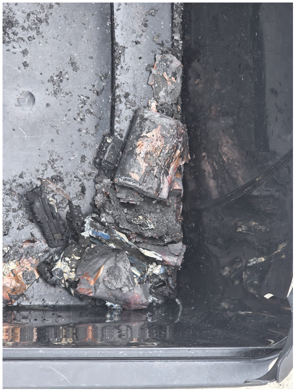
The source of the fire and fumes was traced to a lithium-ion battery power bank which was attached to another personal electronic device that had caught fire (Figure 1). The devices were removed and air quality testing was conducted within the cargo hold.
Figure 1: Power bank and personal electronic device debris
Source: Maintenance provider
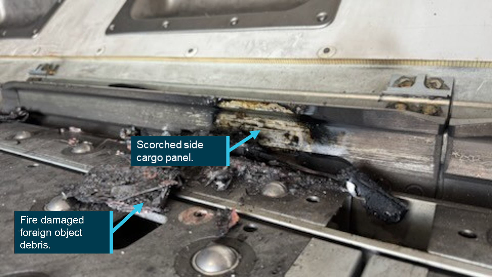
During inspection of the cargo hold by aircraft engineers, minor scorch damage was observed to the cargo floor (Figure 2). Post-occurrence, it was reported that the smoke detectors were found to be in working order and the internal fire extinguisher had not (yet) discharged.
Figure 2: Damage to the cargo compartment floor
Source: Maintenance provider
Operator and ground handling agent investigations
The aircraft operator and the ground handling agency conducted internal investigations, with both being inconclusive as to how the power bank and personal electronic device entered the cargo hold. Only one PMC cargo pallet had been loaded into the rear cargo hold when the fire occurred, and that pallet did not contain any dangerous goods. It was also confirmed that all declared dangerous goods on the cargo manifest were properly documented.
The ground handling agency’s lower deck loader (LDL) operator was interviewed post‑occurrence and stated that they were responsible for both the arrival and departing service, and they did not have or take a power bank into the cargo hold. It was also determined during interview that no other person was in the cargo hold during either service. The LDL operator reported that the fire began immediately after the PMC pallet was loaded, as the rollers were used to transfer the pallet into its position. They are of the belief that this pallet crushed the power bank at this time, resulting in thermal runaway and ignition.
The ground handling agency’s investigation noted that the power bank and personal electronic device could not be linked to any specific passenger baggage, cargo shipment, service provider or ground handling activity. Therefore, the source of introduction into the aircraft environment was unable to be conclusively established.
The aircraft operator’s investigation included a review of CCTV footage at the previous international port prior to the flight to Sydney, with no abnormal handling or suspicious activity observed during cargo loading at that location. It was also noted that ground handlers at that location are prohibited from carrying personal electronic devices airside, and the cargo containment method used was overwrap, as opposed to netting. As a result, the operator determined that the power bank was not introduced at the previous port.
Safety message
Hazards can enter the aircraft environment through multiple sources. Ground handlers should always conduct thorough checks of aircraft cargo holds for loose items or foreign objects both before and during the loading process, and never assume that an unknown item is harmless. It is important that ground handlers act immediately if fire, smoke or fumes are detected to prevent further incident.
Devices containing lithium-ion batteries such as power banks and mobile phones can short circuit and result in fire. A recent ATSB investigation, In-flight fire involving Boeing 737, VH-YFY, 56 km north-north-east of Hobart Airport, Tasmania, on 21 July 2025 (AO‑2025-043) notes that a thermal runaway of a lithium-ion battery can be difficult to manage, particularly when the aircraft is airborne, and presents a risk of in-flight fires. While this incident occurred while the aircraft was being loaded for flight, it serves as a valuable reminder of the risks presented by lithium-ion batteries.
About this report
Decisions regarding whether to conduct an investigation, and the scope of an investigation, are based on many factors, including the level of safety benefit likely to be obtained from an investigation. For this occurrence, no investigation has been conducted and the ATSB did not verify the accuracy of the information. A brief description has been written using information supplied in the notification and any follow-up information in order to produce a short summary report, and allow for greater industry awareness of potential safety issues and possible safety actions.
Occurrence summary
Mode of transport
Aviation
Occurrence ID
AB-2026-012
Occurrence date
03/02/2026
Location
Sydney Airport
State
New South Wales
Occurrence class
Serious Incident
Aviation occurrence category
Fire, Smoke, Warning devices
Highest injury level
None
Brief release date
05/06/2026
Aircraft details
Manufacturer
Airbus
Model
A350-9
Sector
Jet
Operation type
Part 129 Foreign air transport operators
Activity
Commercial air transport - Scheduled - International
Occurrence Briefs are concise reports that detail the facts surrounding a transport safety occurrence, as received in the initial notification and any follow-up enquiries. They provide an opportunity to share safety messages in the absence of an investigation. Because occurrence briefs are not investigations under the Transport Safety Investigation Act 2003, the information in them is de-identified.
What happened
On 23 April 2026, the pilot of a Cessna 402C aircraft was conducting a passenger transport operation from Jandakot to Laverton, Western Australia, with 5 passengers on board. Prior to departure the pilot used the aircraft heater to defrost the windshield for approximately 7 minutes and recalled turning the heater off at approximately 0640.
Following the aircraft’s departure, while in the initial cruise phase of the flight, the pilot noticed a moderate oil leak from the left engine cowling vents. The pilot monitored aircraft performance, observed no abnormal indications, and determined the leak was likely from residual oil. The flight continued as planned at this stage, while the pilot continued to monitor the situation.
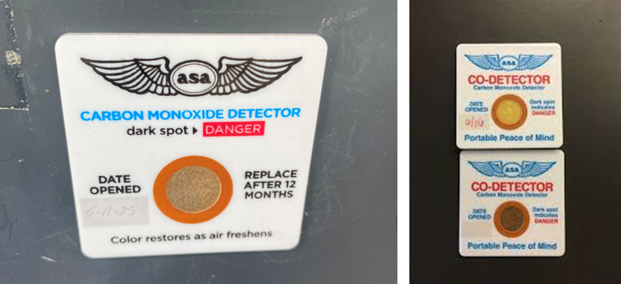
At approximately 0731, the pilot began to feel lightheaded and ‘zoned out’ momentarily. They then observed the carbon monoxide (CO) detection placard on the instrument panel had changed colour, indicating that CO was present (Figure 1). The pilot immediately opened all available air vents, opened the cabin air controls, and confirmed the cabin heater was off.
Figure 1: The aircraft’s carbon monoxide (CO) detection placard and exemplar
Note: Slight darkening indicating some CO was present (left), an example placard showing no detection (top right), and a placard showing detection (bottom right). Source: Operator (left), Civil Aviation Safety Authority (right)
Approximately 2 minutes later, observing no change to the CO indication, the pilot contacted air traffic control (ATC), requested traffic information, and amended their destination to Merredin. The pilot then commenced descent, communicated the change of plan to the nearest passenger, and asked the passenger to instruct all other passengers to open the air vents above their seats.
The pilot continued to self-monitor during descent, and determined their condition was not deteriorating. The wellbeing of the passengers was also confirmed, with none reporting ill effects of CO.
Once established in the circuit at Merredin, the pilot opened the aircraft’s storm window1 and observed no change to the CO indicator and the aircraft landed safely.
Once on the ground, the pilot observed the oil leaks on the left engine. An engine inspection showed numerous components and hoses were covered in oil and a shallow pool of oil had formed at the bottom of the cowling. The upper cowling also showed signs of oil splatter on the inside forward of the vents.
Engineering inspection
The aircraft was subsequently inspected by an engineer flown out to Merredin with the replacement aircraft. No obvious correlation could be made between the oil leak and the CO detector. Ground runs were performed with no abnormal indications or subsequent oil leaks (beyond residual streaks).
As a further precaution, the operator removed the aircraft from service to conduct further engineering assessments. The heater was operated on the ground with the aircraft windows closed, and the engines not running. CO ingress was measured with a handheld CO monitor around the glareshield/demister and excessive CO was observed to ingress into the cabin.
The heater was subsequently removed for closer inspection. A loose item, that looked like a silver crush washer, was discovered inside the heater once the combustion liner cap was removed, and the cap was also found to be dented. The inspection determined the aircraft heater was defective, damaged, and potentially incorrectly reinstalled during servicing.
Safety action
The operator removed the heater from operation and returned the aircraft to service.
Safety message
Carbon monoxide is a colourless and odourless gas that is dangerous to humans, and its presence may not be detected until the development of physical symptoms and cognitive effects. However, sometimes these physical and cognitive effects also impair a pilot’s ability to understand that they may be affected by CO, leading to partial or complete incapacitation.
The aircraft was fitted with a disposable CO chemical spot detector. While these type of detectors are commonly used in general aviation aircraft, they have known limitations. They have a limited shelf-life when removed from their original packaging, which may be further affected by factors such as exposure to harsh direct sunlight, cleaning chemicals, and halogens. In addition, they are a passive device, which relies on the pilot regularly monitoring the changing colour of the detector to show elevated levels of CO.
The use of an attention‑attracting carbon monoxide detector in the cockpit provides pilots with the best opportunity to detect carbon monoxide exposure before it adversely affects their ability to control the aircraft or become incapacitated. The ATSB safety advisory notice Are you protected from carbon monoxide poisoning? (AO-2017-118-SAN-002) strongly encourages operators and owners of piston-engine aircraft to install a carbon monoxide detector with an active warning to alert pilots to the presence of elevated levels of carbon monoxide in the cabin. If not provided, pilots are encouraged to carry a personal carbon monoxide detection and alerting device.
Should any smell or sensation of illness develop, pilots should check their CO detector, ensure cabin heat has been turned off, open all fresh air vents and windows, make prompt decisions to land as soon as possible, such as in this case, and use all available resources for assistance. Further information on CO poisoning and detectors can be found here: Carbon Monoxide: A Deadly Menace.
About this report
Decisions regarding whether to conduct an investigation, and the scope of an investigation, are based on many factors, including the level of safety benefit likely to be obtained from an investigation. For this occurrence, no investigation has been conducted and the ATSB did not verify the accuracy of the information. A brief description has been written using information supplied in the notification and any follow-up information in order to produce a short summary report, and allow for greater industry awareness of potential safety issues and possible safety actions.
^A small triangular cockpit side window that be opened for ventilation.
The ATSB is investigating a descent below minimum safe altitude involving Boeing 767, VH‑XQU, 16 km north of Sydney Airport, New South Wales, on 10 September 2025.
During approach, the aircraft descended below the minimum safe altitude. The approach controller received a minimum safe altitude warning (MSAW) and issued a safety alert. The crew subsequently conducted a missed approach.
In the course of the investigation, the ATSB identified potential limitations in risk controls / organisational factors relevant to the occurrence that potentially contributed to the occurrence. Examination of these factors represent a significant increase in the scope of this investigation, and it has been upgraded from Short to Defined as a result (the ATSB's different levels of investigation are detailed here).
The draft report internal review process has been completed. The draft report has been distributed to directly involved parties (DIPs) to check factual accuracy and ensure natural justice. Any submissions from those parties will be reviewed and, where considered appropriate, the draft report will be amended accordingly.
Following the external review process, any submissions and amendments to the draft report are internally reviewed. Once approved, the final report is prepared for publication and dissemination and released to DIPs prior to its public release.
The final report will be released at the conclusion of the investigation. Should a critical safety issue be identified during the course of the investigation, the ATSB will immediately notify relevant parties, so that appropriate safety action can be taken.
The ATSB is investigating a descent below minimum safe altitude and ground proximity alert involving a Cessna 560, registration VH-OHE, 23 km north-east of Perth Airport, Western Australia, on 13 August 2025.
Prior to commencing an instrument approach for runway 24 at Perth Airport, the aircraft descended below the minimum safe altitude. During this time flight crew reported that the autopilot disengaged and recalled observing an autopilot fail message on the primary flight displays.
The aircraft continued descending, and the flight crew subsequently received a terrain alert from the enhanced ground proximity warning system fitted to the aircraft. After responding to the alert, the flight crew continued the instrument approach and landed on runway 24.
The final report has been drafted and is undergoing internal review to ensure the report adequately and accurately reflects the evidence collected, analysis, and agreed findings.
The final report will be released at the conclusion of the investigation. Should a critical safety issue be identified during the course of the investigation, the ATSB will immediately notify relevant parties, so that appropriate safety action can be taken.
Occurrence Briefs are concise reports that detail the facts surrounding a transport safety occurrence, as received in the initial notification and any follow-up enquiries. They provide an opportunity to share safety messages in the absence of an investigation. Because occurrence briefs are not investigations under the Transport Safety Investigation Act 2003, the information in them is de-identified.
What happened
At about 0800 local time on 1 June 2025, an instructor and student were conducting a training flight from Bankstown Airport, New South Wales in a Piper PA-28-151 aircraft. The aircraft was fitted with a disposable passive carbon monoxide (CO) detector.
During the pre-flight preparations, the CO detector was confirmed to show that there were no signs of carbon monoxide in the cockpit.
Shortly after take-off, while climbing through 300 ft, the instructor noticed that the CO detector had changed colour and was showing full black, indicating a high presence of carbon monoxide in the cockpit. This indication was then verified by the student pilot.
The instructor took over control of the aircraft and asked the student to open the storm window to allow fresh air into the cabin. At the advice of the instructor, the student placed their mouth and nose close to the storm window to breath from the stream of fresh air.
The flight crew requested, and ATC approved, the aircraft to rejoin the circuit and they landed back at Bankstown Airport shortly after with no further event. Prior to landing, the CO detector was noted to have changed colour to light brown, indicating that levels of carbon monoxide in the cockpit had reduced, likely due to the storm window being opened.
Once on the ground, the student pilot reported feeling no symptoms of carbon monoxide poisoning, while the instructor experienced only slight dizziness, but believed this could have been caused by adrenaline from managing the event. Blood tests conducted on both pilots detected only negligible levels of carbon monoxide in their bloodstreams.
A subsequent engineering inspection of the aircraft revealed a rubber boot seal on a nose wheel steering rod had split which was suspected of causing the CO leak. Following rectification, a check flight was performed during which no carbon monoxide was detected inside the cockpit.
Safety message
This incident serves as a salient reminder of the importance of carrying effective carbon monoxide (CO) detection equipment on board aircraft.
CO is a colourless, odourless and tasteless gas found in exhaust gases of piston engine aircraft. While passive CO detectors are commonly used in general aviation aircraft, they have limitations and rely on the pilot regularly monitoring the colour of the detector. In contrast, active electronic CO detectors are designed to attract attention through an audible alert at low CO concentrations, so are more likely to be effective. These devices are now inexpensive and widely available.
Following the fatal crash of a DHC-2 in 2017, in which the pilot was impaired due to carbon monoxide poisoning (Collision with water involving a de Havilland Canada DHC-2 Beaver aircraft, VH‑NOO, at Jerusalem Bay, Hawkesbury River, New South Wales, on 31 December 2017AO-2017-118), and a review of the effectiveness of carbon monoxide detectors by the UK Civil Aviation Authority, the ATSB launched its Know CO campaign.
These resources highlight the limitations of passive carbon monoxide detectors and strongly recommend that operators and owners of piston engine aircraft install active attention‑attracting CO detectors which provide the best opportunity of detecting carbon monoxide exposure before it can adversely impact their ability to control the aircraft.
About this report
Decisions regarding whether to conduct an investigation, and the scope of an investigation, are based on many factors, including the level of safety benefit likely to be obtained from an investigation. For this occurrence, no investigation has been conducted and the ATSB did not verify the accuracy of the information. A brief description has been written using information supplied in the notification and any follow-up information in order to produce a short summary report, and allow for greater industry awareness of potential safety issues and possible safety actions.
On 25 June 2025, the flight crew of a Jetstar Airways Airbus A321-251, VH-OYF, were conducting a scheduled passenger transport flight, JQ38, from Denpasar International Airport, Bali, Indonesia, to Sydney, New South Wales. The first officer was the pilot flying and the captain was the pilot monitoring.
During the landing at Sydney Airport, the aircraft floated for a prolonged period along the runway, was subject to a right crosswind and drifted left of the runway centreline. The captain responded by commanding a go-round which the first officer executed.
The crew proceeded to continue with the published missed approach procedure and subsequently landed without further incident.
What the ATSB found
The ATSB found that after the first officer initiated the flare manoeuvre, their control inputs resulted in a lateral deviation from the runway centreline when the aircraft floated for a prolonged period in crosswind conditions.
After the captain commanded a go-around, they inadvertently manipulated their sidestick control, which resulted in a brief period where simultaneous control inputs occurred. The crew were alerted by a ‘dual input’ generated voice message and the captain took control. There was a moment of preoccupation which resulted in the first stage of flap being retracted out of sequence, however, there were no associated flight envelope exceedances or negative effects on aircraft performance.
Safety message
Sound go-around decision-making is an effective defence against the hazards associated with low-level manoeuvring during the landing phase of flight, such as lateral runway excursions. If adequate safety margins cannot be maintained during an approach and landing, the correct and expected response is to go around.
Being go-around minded improves crew readiness and supports timely, coordinated actions during a period of high workload. This should involve crew members reviewing potential go‑around scenarios, procedures and responses prior to conducting an approach.
When flight crews are faced with the unexpected need to execute a go-around even at the final stages of landing, effective crew resource management, with clear communication between flight crew, is essential. This promotes effective teamwork when responding to disruptions and increased workload under stress, ensuring that the aircraft remains on a safe flight path and is correctly configured for the relevant phase of flight.
The investigation
The ATSB scopes its investigations based on many factors, including the level of safety benefit likely to be obtained from an investigation and the associated resources required. For this occurrence, the ATSB conducted a limited-scope investigation in order to produce a short investigation report, and allow for greater industry awareness of findings that affect safety and potential learning opportunities.
The occurrence
On the evening of 25 June 2025, a Jetstar Airways Pty Limited Airbus A321-251 registered VH‑OYF was operating on a schedule passenger transport Jetstar flight, JQ38, from Denpasar International Airport, Bali, Indonesia, to Sydney, New South Wales. The flight was scheduled to arrive at Sydney Airport the following morning at 0630 AEST.[1] The operating crew included the captain, first officer, 6 cabin crew and 234 passengers. For the flight to Sydney, the first officer was the pilot flying (PF) and the captain was the pilot monitoring (PM).[2]
After departing Denpasar, the aircraft climbed to flight level (FL) 330[3] and later descended to FL310 after reaching Australian airspace due to turbulence en route. Due to the turbulence en route, the captain elected not to take any controlled rest on the nearly 6‑hour flight, while the first officer stated they would not usually take controlled rest in flight.
Prior to descent, the flight crew briefed for the arrival at Sydney, recalling that the turbulent conditions and the crosswind for the approach and landing were the main considerations.
At 0554, the flight crew commenced their descent to the west-south-west of Sydney Airport and was cleared for the approach for runway 16R[4] which was conducted in day visual meteorological conditions[5] using the autopilot. The flight crew recalled there was a 30 kt crosswind down to about 500 ft above mean sea level (AMSL) and the approach up to that point was ‘pretty normal.’ Air traffic control (ATC) advised the crew to expect an 8 kt right crosswind for landing and the first officer chose to land in the flap 3 configuration,[6] which was consistent with guidance for landing in ‘rough’ conditions. (The first officer was procedurally restricted to a maximum crosswind landing component of 20 kt).
The aircraft reached 500 ft at 0621:14 and the captain called ‘stable’ (see Stabilised approach criteria). The first officer disengaged the autopilot 5 seconds later as the aircraft approached 400 ft and recalled encountering turbulence which placed the aircraft ‘a little higher’ on the approach. At 0621:45 at 90 ft, the first officer pitched forward, which they observed resulted in a 900 ft per minute rate of descent.
At 0621:51, the first officer initiated the flare at 50 ft and reduced the thrust levers to idle at around the final approach speed (VAPP)[7] of 150 kt, which included a wind correction of 5 kt. At this point the first officer recalled they ‘over flared’. The captain also observed that the first officer applied the flare technique that was consistent with the technique for landing in the flap full configuration. The aircraft subsequently floated for a prolonged period along the runway after the first officer’s flare manoeuvre.
During the prolonged float, the aircraft was subjected to the crosswind conditions for a greater length of time. After observing the centreline deviation, the captain commanded a go-around approximately 600 m past the runway threshold, just prior to touchdown. The captain recalled they were ‘startled by the need to go around’ as the approach seemed ‘benign’ aside from the crosswind. They also reported a sudden stress response at this time as they had to rapidly transition from landing to commencing the go-around.
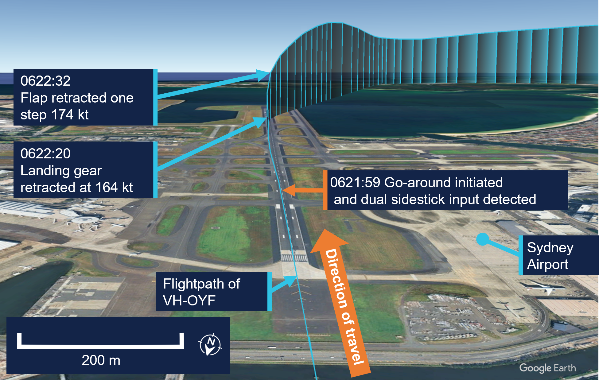
In response to the captain’s command, the first officer set take-off/go-around thrust at 0621:59 (Figure 1), which initiated the published missed approach procedure for the 16R GBAS landing system (GLS)[8] approach in the aircraft flight management system. The first officer also referenced their primary flight display (PFD) to command a target pitch attitude of 15° nose up.
At this point, the captain recalled they instinctively applied control inputs via their sidestick while the aircraft was just above the runway, and the crew were alerted to this by the aircraft’s ‘dual input’ voice message (see Sidestick priority logic).
The captain then engaged their sidestick pushbutton, and the first officer recalled hearing the ‘priority left’ voice message and the captain announce, ‘I have control.’ The captain subsequently took control of the thrust levers and the first officer relinquished control and became PM after the aircraft achieved a positive rate of climb. It was the role of the PM to retract the flap ‘one step’ at this point (see Go-around procedure).
Figure 1: Overview of go-around
Source: Google Earth, annotated by the ATSB
The captain announced the active flight modes on their PFD, which prompted the first officer to call ‘positive climb.’ The captain subsequently instructed the first officer to retract the landing gear, which was accomplished 42 ft above the runway at 0622:20.
At this time, the captain looked up to the flight control unit located on the cockpit glareshield to engage the autopilot. After this was actioned, they looked back to their PFD and was ‘startled’ when they noticed that the aircraft suddenly banked right and responded by disengaging the autopilot at 0622:22. They subsequently realised that the aircraft flight director was providing commands for the published missed approach procedure and subsequently re-engaged the autopilot at 0622:29.
The captain then requested flap 1, but the first officer noticed they were still configured with Flap 3 and retracted the flap by one step and announced, ‘flap 2.’ This occurred at 0622:32 when the airspeed reached 174 kt, which was below the maximum flap 3 speed of 195 kt.
They continued to follow the missed approach procedure, and the first officer advised ATC they were going around. The crew were given instructions to track for a right downwind for runway 16R at 4,000 ft. The captain recalled conducting a welfare check on the first officer, briefed the cabin manager via the interphone and made an announcement to the passengers through the public address system.
The captain elected to remain as PF for the remainder of the flight, with the first officer acting as PM. The crew then conducted a second GLS approach for runway 16R, landing at 0638 without further incident.
Context
Flight crew information
The captain held an Air Transport Pilot Licence (Aeroplane), class 1 aviation medical certificate, and had accrued 5,921 hours total flying time, 1,480 of which were in the Airbus A320 and A321 aircraft types.
The first officer held a Commercial Pilot Licence (Aeroplane), class 1 aviation medical certificate, and had 2,212 hours total flying time, 551 of which were on the Airbus A320 and A321 aircraft types.
Fatigue
The captain reported that they felt 'moderately tired' during the go-around, likely due to the back-of-the clock[9] flight, which departed Denpasar at 0057 local time in Sydney. They also stated there was limited opportunity for controlled rest during the flight and their nap prior to the flight was disrupted due to noise at the hotel. The first officer reported feeling 'ok, somewhat fresh.’
The flight crew also reported they had an adequate rest opportunity the evening prior to the flight and obtained around 6 hours sleep in the previous 24 hours and around 13–14 hours in the previous 48 hours. Their sleep during the rest opportunity was reported to be good quality and the conditions at the hotel where they spent the night were suitable and therefore conducive to obtaining restful sleep. Biomathematical modelling[10] of the flight crew’s roster for the 2 weeks leading up to the flight indicated a low likelihood of fatigue.
The ATSB considered that fatigue was unlikely to have affected the flight crew’s performance at the time of the occurrence.
Aircraft information
General
The Airbus A321-251NX is a modern, fly-by-wire aircraft, powered by 2 CFM International LEAP-1A32 turbofan engines and had seating for 232 passengers in a single-class layout.
All the flight controls are electronically actuated with the pilots using sidesticks to fly the aircraft in pitch and roll during manual flight. The 2 sidestick controllers are not coupled mechanically, and they send separate sets of signals to the flight control computers.
Sidestick priority logic
Jetstar Airways A320-A321 Flight crew operating manual (FCOM) contains the following description of the aircraft sidestick priority logic:
At all times, only one flight crewmember should fly the aircraft. However, if both flight crewmembers use their sidesticks simultaneously, their orders are algebraically added.
The flight control laws limit the combined order to the equivalent of the full deflection of one sidestick.
In this case the two green SIDE STICK PRIORITY lights on the glareshield come on and "DUAL INPUT" voice message is activated.
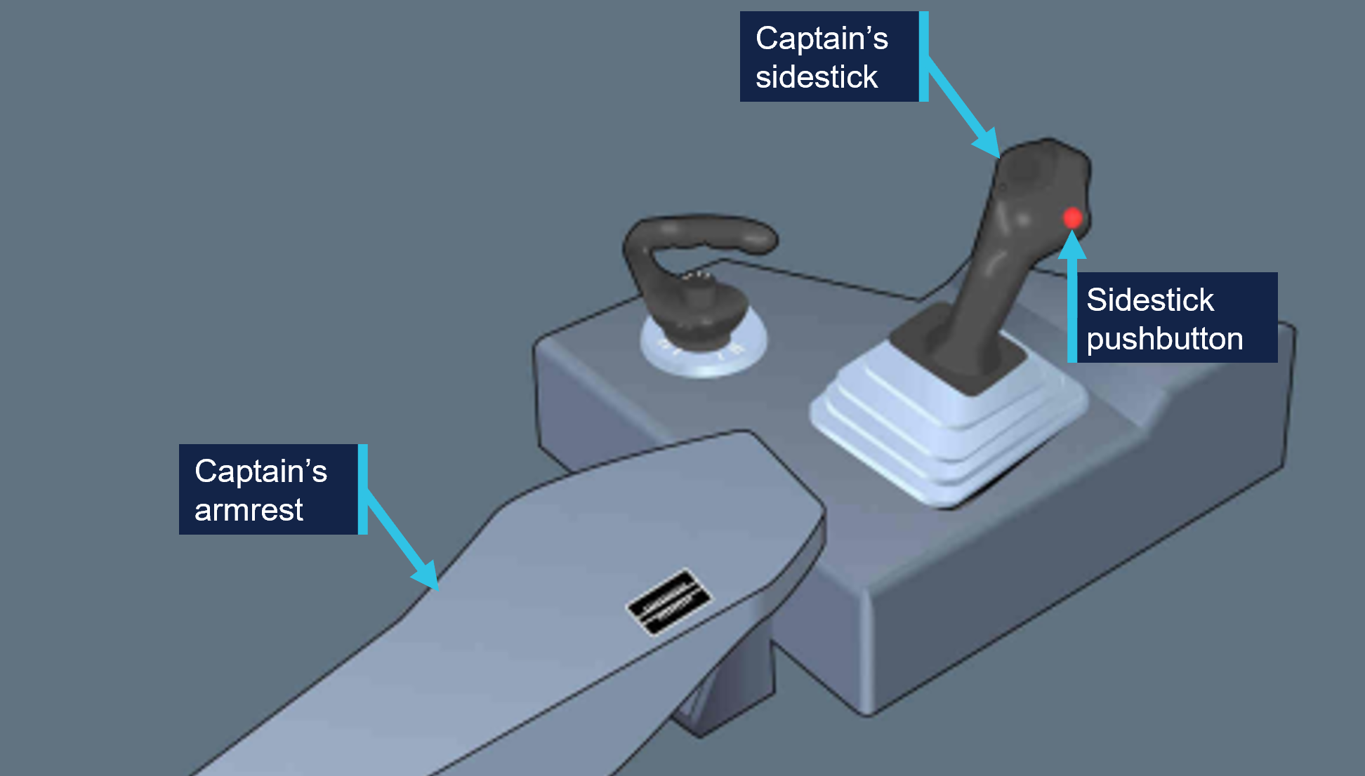
A flight crewmember can deactivate the other sidestick and take full control, by pressing and keeping pressed the sidestick pb (Figure 2).
A “PRIORITY LEFT” or “PRIORITY RIGHT” audio voice message is given each time priority is taken.
Figure 2: Airbus A320/A321 captain's side sidestick and sidestick pushbutton
Source: Operator, annotated by the ATSB
Post-flight maintenance
The operator reported that there were no corrective maintenance actions that were required to be carried out in relation to the occurrence. The aircraft subsequently operated a scheduled passenger service the following day.
Meteorological information
The pre‑flight briefing package provided to the flight crew from the operator’s flight dispatcher included the aerodrome forecast[11] for Sydney Airport. The forecasted weather conditions for the scheduled time of arrival 0630 local time on 26 June indicated:
wind direction of 240° at 15 kt with gusts up to 25 kt
One-minute weather data for Sydney Airport from the Bureau of Meteorology indicated a wind direction of 255° at 17 kt with gusts up 20 kt at the time of the occurrence.
Airport information
Runway 16R at Sydney Airport is oriented on a magnetic heading of 155° and has a declared length of 3,962 metres with a width of 45 metres. A precision approach path indicator system is installed and set to 3° with a threshold crossing height of 64 ft.
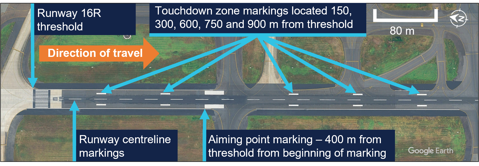
For daytime operations, the runway centreline, aiming point and touchdown zone markings provide visual references to assist pilots with approach and landing (Figure 3).
Figure 3: Sydney Airport runway 16R markings
Source: Google Earth, annotated by the ATSB
Recorded information
The aircraft’s quick access recorder data which captured the incident approach indicated that, as the aircraft descended below 1,000 ft, it maintained an appropriate speed and flightpath with no sustained exceedances of the stable approach criteria throughout the approach.
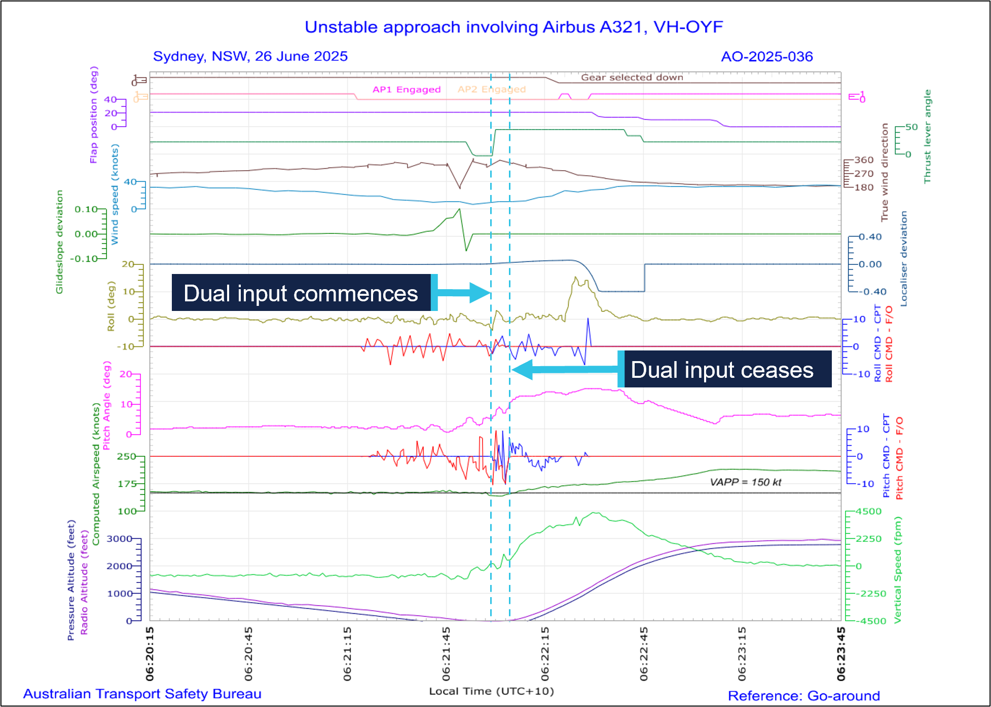
At 0621:59, the recorded data captured the captain’s control inputs commencing concurrently with the initiation of the go-around, while the first officer was actively manipulating their sidestick control. Simultaneous control inputs lasted for a duration of 6 seconds (Figure 4), while the aircraft’s pitch attitude remained below the aircraft’s pitch limit of 11.5° until the aircraft had climbed through about 50 ft.
The recorded data further indicated that the wind direction and speed varied following the flare manoeuvre, however the crosswind component remained well below the first officer’s operational limitation. The wind direction and speed was 315° at 13 kt with a crosswind component of 5 kt when the go-around was initiated.
Figure 4: Graphical representation of the recorded quick access data
Source: Quick access recorder from VH-OYF, annotated by the ATSB
Following the initiation of the go-around, the landing gear was retracted at 06:22:20 and 12 seconds later, the flap was retracted to the flap 2 configuration[14] at 174 kt.
Operational information
Stabilised approach criteria
Jetstar Airways A320-A321 Flight crew operating manual (FCOM) defined a stabilised approach criteria as being established on the correct lateral and vertical flight path by 1,000 ft height above airport (HAA), configured for landing, and within the stated tolerances with the required checklists completed by 500 ft HAA. The FCOM also stated that if these criteria could not be met, or if the approach became unstable below 1,000 ft HAA, a missed approach was required.
The crew reported the approach was stabilised against these criteria, which was consistent with the available recorded data.
Touchdown zone
The FCOM provided the following operational information regarding the touchdown zone:
The touchdown zone commences at 300 m (1000 ft) beyond the threshold and will not normally extend further than 600 m (2000 ft) beyond the threshold.
It is a requirement that the touchdown is planned to occur within the touchdown zone. Should it become apparent that the aircraft will touch down further than 600 m (2,000 ft) beyond the threshold, and the PIC believes that the landing is safe to continue, the PF must apply maximum reverse thrust and sufficient braking to ensure the aircraft stops within the landing distance available. If the PIC decides that a go-around is required, they will without delay, call “Go-Around”. In all cases this must be completed before the PF initiates reverse thrust.
The captain stated that runway 16R in Sydney was long enough to stop the aircraft on the runway if they had continued with the landing during the occurrence. This would have involved requesting maximum reverse and manual braking as necessary after the aircraft touched down.
The FCOM did not specifically reference runway centreline tracking during a visual approach, however the captain stated that it was their personal expectation that a deviation from the runway centreline would lead them to calling for a go-around.
Transfer of control
The operator described procedures for transfer of control within the FCOM as follows:
The pilot relinquishing control of the aircraft shall say “You have control”. The pilot assuming control shall ensure that they have clear and unobstructed access to the flight controls and, when ready, say “I have control”. Only then is the pilot relinquishing control permitted to remove their hands and feet from the flight controls.
In critical phases of flight the PIC must be alert and positioned such that they can assume immediate control of the aircraft.
Following the occurrence, the captain stated the preferable method to conduct a go‑around at low level would have been to announce ‘I have control’ and initiate the go‑around themselves. They stated that their primary consideration when conducting a go‑around at low level was to avoid the risk of tail strike.
Go-around procedure
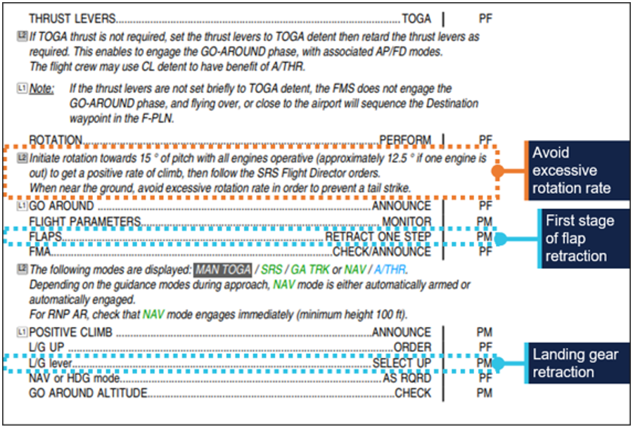
The FCOM defined the go-around procedure for the A320/A321, which specified the task sequence, memory-based crew actions and applicable guidance relating to techniques and navigation (Figure 5).
Following the occurrence, the captain stated that although they could have taken over and landed, they believed that going around was considered the safest option. The first officer also stated, at about that time, that they were in the mindset of preparing to initiate a go-around themselves.
Related occurrences
The following ATSB investigation highlights the importance of pilots maintaining their readiness for a go-around on every approach as it is typically a period of high workload requiring effective crew coordination.
On the morning of 18 May 2018, an Airbus A320 aircraft, registered VH-VQK, was being operated on a regular public transport flight by Jetstar Airways. The flight departed from Sydney for Ballina/Byron Gateway Airport, New South Wales.
The flight crew conducted a go-around on the first approach at Ballina because the aircraft’s flight path did not meet the operator’s stabilised approach criteria. On the second approach, at about 700 ft radio altitude, a master warning was triggered because the landing gear had not been selected DOWN. The flight crew conducted a second go‑around and landed without further incident on the third approach.
The flight crew did not follow the operator’s standard procedures during the first go‑around and subsequent visual circuit at 1,500 ft. In particular, the flaps remained at flaps 3 rather than flaps 1 during the visual circuit. This created a series of distractions leading to a non‑standard aircraft configuration for a visual circuit. Limited use of available aircraft automation added to the flight crew’s workload.
Safety analysis
During the approach to Sydney airport, with the first officer acting as the pilot flying (PF), the flight crew reported experiencing a crosswind of up to 30 kt until descending through about 500 ft above mean sea level. The crew were advised by air traffic control to expect a right crosswind component of 8 kt for landing, which was within the first officer’s operational crosswind limit of 20 kt. The captain confirmed the approach was ‘stable’ at 500 ft and the first officer continued the approach as PF.
At 50 ft, the first officer initiated the flare manoeuvre prior to landing. They recalled they ‘over flared,’ and the aircraft subsequently floated for an extended period along the runway. During this time, the first officer’s control inputs did not counteract the effect of the crosswind, and the aircraft drifted left of the centreline. After observing the lateral deviation from the centreline, the captain commanded the first officer to conduct a go‑around.
This occurred just prior to the aircraft touching down when the flight crew would normally be focused on landing. The flight crew did not expect a go-around at the time and had to rapidly shift their focus to conducting the missed approach procedure. The captain recalled being ‘startled’ by the unexpected need to discontinue the landing, however they were more likely experiencing ‘surprise.’ Surprise is a cognitive-emotional response to something unexpected, which results from a mismatch between one’s mental expectations and perceptions (Rivera, Talone, Boesser, Jentsch, & Yeh, 2014). But their decision was consistent with the expectation that an approach be discontinued if the aircraft departed from the correct lateral flight path.
The unexpected change from landing to conducting a go-around close to the ground also resulted in the captain experiencing a sudden stress response at this time. When experiencing acute stress, people can respond quickly to a situation, but without conscious decision‑making (Wickens, Helton, Hollands, & Banbury, 2022). After the go‑around was commanded, there was a rapid increase in pitch attitude, engine thrust and airspeed, and in response the captain instinctively and inadvertently manipulated their sidestick while the first officer was flying, resulting in a dual-input alert.
The captain reported they only realised they had manipulated their sidestick when they heard the dual input alert. Their primary consideration during the go-around was to avoid an excessive rotation rate to avoid a tail strike, which did not occur. Additionally, operator procedures directed captains to be alert and be positioned to ‘assume immediate control of the aircraft’ during critical phases of flight.
Following the dual input alert, the captain took full control by engaging their sidestick push‑button and announced ‘I have control’, and the first officer assumed the role of pilot monitoring. A consequence of the control handover during the initial stages of the go‑around was the momentary interruption of sequential crew actions during the go‑around procedures. Interruptions typically disrupt the chain of procedure execution so abruptly that pilots turn immediately to the source of the interruption without noting the point where the procedure was suspended (Loukopoulos, Dismukes, & Barshi, 2009).
Additionally, there was a further disruption (rapid task switching) associated with the first officer and captain exchanging pilot flying and pilot monitoring roles. As a result, some of the procedural items were completed out of sequence (flap 3 retraction occurred after gear retraction).
Pilots are highly vulnerable to errors of omission when they must attend to multiple tasks. If one task becomes demanding, their attention is absorbed by these tasks demands and they can forget to switch their attention to other tasks (Loukopoulos, Dismukes, & Barshi, 2009). Although the flap retraction occurred out of sequence during the go-around, there were no associated flight envelope exceedances or negative effects on aircraft performance.
Findings
ATSB investigation report findings focus on safety factors (that is, events and conditions that increase risk). Safety factors include ‘contributing factors’ and ‘other factors that increased risk’ (that is, factors that did not meet the definition of a contributing factor for this occurrence but were still considered important to include in the report for the purpose of increasing awareness and enhancing safety). In addition ‘other findings’ may be included to provide important information about topics other than safety factors.
These findings should not be read as apportioning blame or liability to any particular organisation or individual.
From the evidence available, the following findings are made with respect to the control issues during landing and go-around involving Airbus A321, VH-OYF, at Sydney Airport, New South Wales, on 26 June 2025.
Contributing factors
During the landing after crossing the threshold, the first officer’s control inputs resulted in a lateral deviation from the runway centreline during a prolonged float.
After calling for a go-around, the captain inadvertently manipulated their sidestick while the first officer was the pilot flying, which resulted in a simultaneous control input and the go-around procedure being completed out of sequence.
Sources and submissions
Sources of information
The sources of information during the investigation included:
Jetstar Airways Pty Limited
Bureau of Meteorology
the flight crew
recorded data from the quick access recorder from VH-OYF.
References
Loukopoulos, L., Dismukes, R., & Barshi, I. (2009). The perils of multitasking. AeroSafety World, 4(8), 18-23.
Rivera, J., Talone, A., Boesser, C., Jentsch, F., & Yeh, M. (2014). Startle and surprise on the flight deck: Similarities, differences, and prevalence. In Proceedings of the human factors and ergonomics society annual meeting (Vol. 58, No. 1, pp. 1047-1051). Sage CA: Los Angeles, CA: SAGE Publications.
Wickens, C. D., Helton, W. S., Hollands, J. G., & Banbury, S. (2022). Engineering psychology and human performance, 5th edn. Routledge, doi: 10.4324/9781003177616.
Submissions
Under section 26 of the Transport Safety Investigation Act 2003, the ATSB may provide a draft report, on a confidential basis, to any person whom the ATSB considers appropriate. That section allows a person receiving a draft report to make submissions to the ATSB about the draft report.
A draft of this report was provided to the following directly involved parties:
Civil Aviation Safety Authority
the flight crew
Jetstar Airways Pty Limited
Bureau of Meteorology.
Submissions were received from:
the flight crew
Jetstar Airways Pty Limited.
The submissions were reviewed and, where considered appropriate, the text of the report was amended accordingly.
Purpose of safety investigations
The objective of a safety investigation is to enhance transport safety. This is done through:
identifying safety issues and facilitating safety action to address those issues
providing information about occurrences and their associated safety factors to facilitate learning within the transport industry.
It is not a function of the ATSB to apportion blame or provide a means for determining liability. At the same time, an investigation report must include factual material of sufficient weight to support the analysis and findings. At all times the ATSB endeavours to balance the use of material that could imply adverse comment with the need to properly explain what happened, and why, in a fair and unbiased manner. The ATSB does not investigate for the purpose of taking administrative, regulatory or criminal action.
About ATSB reports
ATSB investigation reports are organised with regard to international standards or instruments, as applicable, and with ATSB procedures and guidelines.
Reports must include factual material of sufficient weight to support the analysis and findings. At all times the ATSB endeavours to balance the use of material that could imply adverse comment with the need to properly explain what happened, and why, in a fair and unbiased manner.
An explanation of terminology used in ATSB investigation reports is available here. This includes terms such as occurrence, contributing factor, other factor that increased risk, and safety issue.
Publishing information
Released in accordance with section 25 of the Transport Safety Investigation Act 2003
Ownership of intellectual property rights in this publication
Unless otherwise noted, copyright (and any other intellectual property rights, if any) in this report publication is owned by the Commonwealth of Australia.
Creative Commons licence
With the exception of the Commonwealth Coat of Arms, ATSB logo, and photos and graphics in which a third party holds copyright, this report is licensed under a Creative Commons Attribution 4.0 International licence.
The CC BY 4.0 licence enables you to distribute, remix, adapt, and build upon our material in any medium or format, so long as attribution is given to the Australian Transport Safety Bureau.
Copyright in material obtained from other agencies, private individuals or organisations, belongs to those agencies, individuals or organisations. Where you wish to use their material, you will need to contact them directly.
[1]Local time in Sydney was Australian Eastern Standard Time (AEST), which is Coordinated Universal Time (UTC) +10 hours. Times in this report are AEST unless otherwise noted.
[2]Pilot flying (PF) and pilot monitoring (PM): procedurally assigned roles with specifically assigned duties at specific stages of a flight. The PF does most of the flying, except in defined circumstances, such as planning for descent, approach and landing. The PM carries out support duties and monitors the PF’s actions and the aircraft’s flight path.
[3]Flight level: at altitudes above 10,000 ft in Australia, an aircraft’s height above mean sea level is referred to as a flight level (FL). FL 330 equates to 33,000 ft.
[4]Runway numbering: the number represents the magnetic heading closest to the runway (runway 16 at Sydney Airport is oriented 155° magnetic) and R indicates the right most of 2 parallel runways.
[5]Visual meteorological conditions (VMC): an aviation flight category in which visual flight rules (VFR) flight is permitted – that is, conditions in which pilots have sufficient visibility to fly the aircraft while maintaining visual separation from terrain and other aircraft.
[6]Flap 3 on the A321-251 is 21° of flap and 22° of slat extension.
[7]Final approach speed (VAPP): the VAPP is the target airspeed for the aircraft when crossing the runway threshold with the aircraft configured for landing. VAPP is equal to the lowest selectable speed with the addition of wind correction. The wind correction is limited to a minimum of 5 kt and a maximum of 15 kt.
[8]GBAS landing system (GLS): a GLS consists of a GBAS ground station located on or in the vicinity of one or more aerodromes and an aircraft subsystem. The GBAS provides data and corrections for the GNSS ranging signals over a digital VHF data broadcast to the aircraft subsystem. The aircraft subsystem translates the position signal into flight guidance similar to that provided for an ILS.
[9]Back of the clock: Work schedules that involve extended periods of night-work between midnight and dawn.
[10]A biomathematical model of fatigue predicts the effect of different patterns of work on measures such as subjective fatigue, sleep, or the effectiveness of performing work, using mathematical algorithms. Each model uses different types of inputs and assumptions and produces different types of outputs, each having limitations. The ATSB used the biomathematical modelling software SAFTE-FAST and FAID Quantum for the analysis.
[11]Aerodrome forecast (TAF): a TAF is a coded statement of meteorological conditions expected at an aerodrome and within a radius of 5 nautical miles of the aerodrome reference point.
[12]Ceiling and visibility okay (CAVOK): visibility, cloud and present weather are better than prescribed conditions. For an aerodrome weather report, those conditions are visibility 10 km or more, no significant cloud below 5,000 ft, no cumulonimbus cloud and no other significant weather.
[13]Moderate turbulence: changes to accelerometer readings of between 0.5 g and 1.0 g at the aircraft’s centre of gravity. Moderate change to aircraft attitude and/or altitude may occur but aircraft remains under positive control. Usually small changes in airspeed. Difficulty in walking. Lose objects move about.
[14]Flap 2 on the A321-251 is 14° of flap and 22° of slat extension.
Occurrence summary
Investigation number
AO-2025-036
Occurrence date
26/06/2025
Location
Sydney Airport
State
New South Wales
Report release date
27/01/2026
Report status
Final
Investigation level
Short
Investigation type
Occurrence Investigation
Investigation status
Completed
Mode of transport
Aviation
Aviation occurrence category
Control issues, Missed approach, Warning devices
Occurrence class
Incident
Highest injury level
None
Aircraft details
Manufacturer
Airbus
Model
A321-251NX
Registration
VH-OYF
Serial number
11529
Aircraft operator
Jetstar Airways Pty Limited
Sector
Jet
Operation type
Part 121 Air transport operations - larger aeroplanes
On 15 April 2025, an Embraer ERJ 190-100, registered VH-UZD, was conducting a passenger transport flight from Sydney, New South Wales, to Launceston, Tasmania. After commencing approach to Launceston, the flight crew received multiple caution messages including a SLAT FAIL caution. The flight crew discontinued their approach and after completing the relevant checklists elected to divert to Melbourne, Victoria, as it was the longest available runway in the region. The remainder of the flight was uneventful, and the aircraft landed safely.
Post-flight troubleshooting determined that a torque tube in the left wing slat drive system had disconnected as it had been incorrectly assembled when it was last refitted.
What the ATSB found
The ATSB identified a similar occurrence with another of the operator’s Embraer ERJ 190‑100 aircraft, VH-UYB, where a torque tube in the left wing flap drive system had disconnected as it had been incorrectly assembled when it was last refitted.
The occurrences were similar in that the locking bolts that secured the torque tubes to their actuators had not been fitted correctly into the holes of the splined shafts, since the torque tubes had been incorrectly positioned during installation.
In both occurrences, those carrying out and certifying for the torque tube installations did not identify that they had been incorrectly assembled.
These errors occurred at different maintenance providers, and reportedly from January 2005–August 2011 in the worldwide fleet of Embraer 170, 175, and 190 aircraft (all sharing similar componentry), there have been 5 similar occurrences related to incorrect torque tube installation.
What has been done as a result
The operator, Alliance Airlines, issued a maintenance notice that detailed the flap torque tube disconnect affecting VH-UYB and the slat torque tube disconnect affecting VH-UZD. This notice reiterated the aircraft maintenance manual information for the correct installation of flap and slat torque tubes.
The maintenance organisation added an additional task card that is automatically issued when work is scheduled on the E190 slat system torque tubes that provides guidance in addition to the aircraft maintenance manual to mitigate the incorrect assembly of torque tubes on their splines. A similar additional task card was being developed for the E190 flap system torque tubes.
Safety message
Historical occurrence and technical information provide an opportunity to review known errors prior to commencing particular maintenance activities, thereby reducing the possibility of further errors occurring. When an error does occur, this information also provides a means to bolster the actions taken to prevent re-occurrences.
This information can be available from multiple sources including the manufacturer, national aviation authorities (such as CASA or the FAA), accident investigation authorities, and the safety management systems of operators and maintenance organisations.
The investigation
The ATSB scopes its investigations based on many factors, including the level of safety benefit likely to be obtained from an investigation and the associated resources required. For this occurrence, the ATSB conducted a limited-scope investigation in order to produce a short investigation report, and allow for greater industry awareness of findings that affect safety and potential learning opportunities.
The occurrence
Previous maintenance
In November 2024, an Embraer ERJ 190-100 aircraft, registered VH-UZD and operated by Alliance Airlines, commenced a heavy maintenance[1] check by Rockhampton Aviation Maintenance in Rockhampton, Queensland. A team comprising 2 aircraft maintenance engineers (AMEs) was tasked with inspecting and lubricating the leading-edge slat drive system (see Embraer E190 slats and flaps). This involved removing, cleaning, lubricating, and refitting each slat torque tube in turn. A licensed aircraft maintenance engineer (LAME) briefed the AMEs on what was required.[2] The LAME was familiar with the task but was unaware of any historical issues with the task (see Maintenance requirements). The work was carried out in a new facility with good lighting. Access to the components was good, and a purpose-built platform allowed the work to be carried out with the relevant components at eye level.
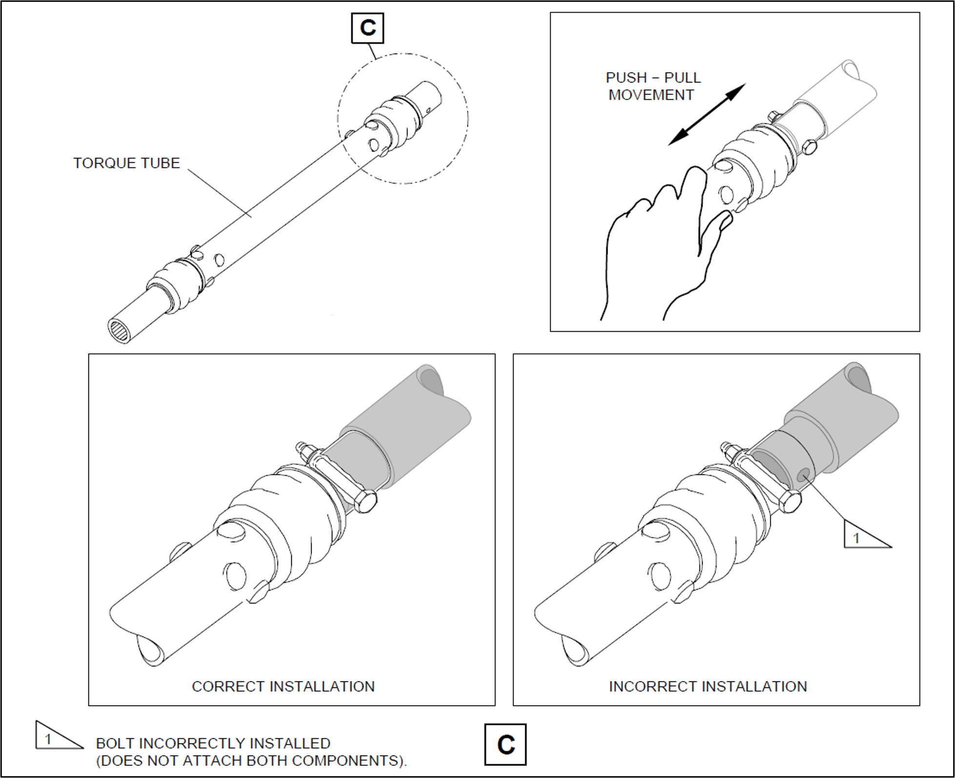
Prior to commencing work, brakes internal to the power drive units (PDUs) (which drive the flap and slat torque tubes) were electrically released as required by the aircraft maintenance manual (AMM) procedure. The AMEs printed a copy of the relevant AMM procedure, and worked together on the torque tube driving the left-wing outboard actuator for slat number 4. The PDU brakes were also required to be released prior to installing the torque tubes, however, it could not be established whether this took place (the PDU brakes reapply when power is removed). After refitting the outboard actuator torque tube, a push-pull check was carried out to ensure it was locked in place, as required by the AMM. Unknown to the AMEs, when this torque tube was refitted, it had not been positioned far enough onto the actuator’s splined shaft for the locking bolt to secure it (Figure 1, lower right). The locking bolt was inadvertently installed beyond the end of the spline (shown in grey) rather than through the hole as required.
One AME then continued work on the left wing and the other moved to the right wing slat drive system to work alone. The remaining slat torque tubes were correctly fitted.
After this work was completed, the LAME inspected the installation of the torque tubes and their locking bolts, and a second LAME carried out an independent inspection[3] of the work. The heavy maintenance check was completed in March 2025, and the aircraft was returned to service.
On 15 April 2025, 50 flights after returning to service from heavy maintenance, the aircraft was being operated on a passenger transport flight from Sydney, New South Wales, to Launceston, Tasmania, by Alliance Airlines for QantasLink. After commencing approach to Launceston, the flight crew received multiple caution messages[4] on the aircraft’s engine indicating and crew alerting system (EICAS) including a SLAT FAIL caution. The flight crew discontinued the approach and requested clearance from air traffic control for vectors[5] so they could action the relevant quick reference handbook (QRH) checklists for the caution messages.
The flight crew completed the QRH checklist. As the slat failure would require landing with the slats and flaps up, the flight crew elected to divert to Melbourne Airport, Victoria, as it had the longest available runway in the region. The flight crew declared a PAN PAN[6] and commenced the diversion to Melbourne. After climbing to 19,000 ft the aircraft was flown to Melbourne at 220 kt as required by the QRH because of the slat failure. The aircraft landed at Melbourne without further incident.
Post-flight inspection
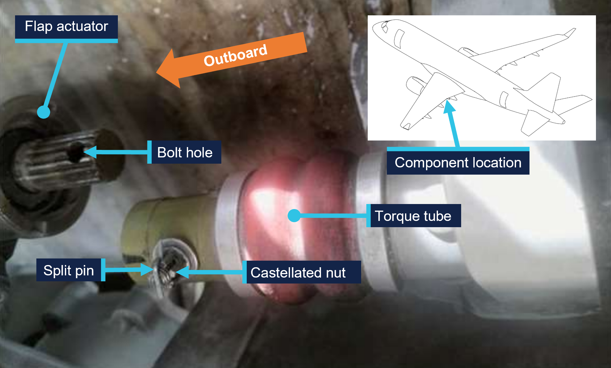
Post-flight inspection determined that the torque tube for the left wing slat number 4 outboard actuator had disconnected as the locking bolt fitted to the torque tube had not passed through the corresponding hole in the actuator’s splined shaft when it was last refitted (Figure 2).
Figure 2: VH-UZD left wing outboard actuator for slat number 4 and torque tube, shown disconnected after the occurrence flight
Source: Alliance Airlines, annotated by the ATSB
Context
Aircraft information
The Embraer ERJ 190-100 IGW (E190) is a narrow-body aircraft used for air transport operations and powered by 2 General Electric CF34-10E5 turbofan engines. VH-UZD was manufactured in Brazil in 2008 and registered in Australia on 31 January 2022.
Embraer E190 slats and flaps
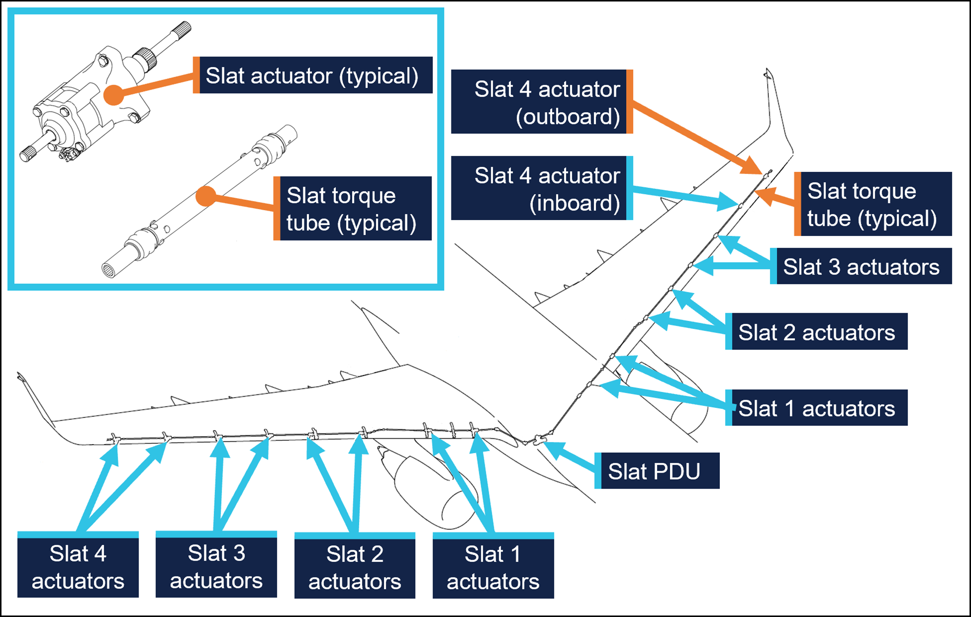
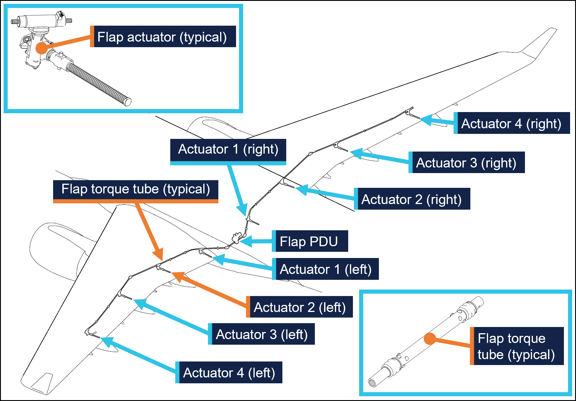
The E190 is fitted with devices to increase the lift produced by its wings during take-off and landing. On the leading edges of the wings there are 8 slat panels and on the trailing edges of the wings there are 4 flap panels (Figure 3), where each set (slats/flaps) extends and retracts together.
Figure 3: Embraer E190 slats and flaps
Source: Embraer, annotated by the ATSB
Slat and flap extension and retraction is controlled from the cockpit by using the slat/flap control lever (SFCL). When the SFCL is moved from its 0 (up) position,[7] the flap and slat power drive units (PDUs) drive torque tubes which in turn drive actuators, transferring the rotary motion of the torque tubes to linear motion that extends the slats and flaps (Figure 4 and Figure 5).
Each PDU has 2 internal brakes that are engaged under spring force and released electrically, such that the brakes would re-engage when power is removed. There are 26 torque tubes in the slat drive system and 22 torque tubes in the flap drive system.
In the event of a slat or flap failure, redundant detection and protection systems prevent them operating in such a way that may compromise safety of flight.
Figure 4: Embraer E190 slat drive system
Source: Embraer, annotated by the ATSB
Figure 5: Embraer E190 flap drive system
Source: Embraer, annotated by the ATSB
Maintenance requirements
The slat and flap torque tubes are removed periodically for the actuator splines to be lubricated with grease. They may also need to be removed to replace associated components. A detailed visual inspection of the slat and flap drive system is also carried out periodically and includes a requirement to check that the torque tubes are correctly secured in place by their locking bolts. No detailed visual inspections of the slat system had been required between the heavy maintenance in November 2024 and the occurrence flight.
The procedure to remove and install the slat and flap torque tubes is detailed in the aircraft maintenance manual (AMM). As part of this procedure, the slat or flap PDU brakes are disengaged electrically to eliminate any residual torque in the system that may impede (through friction) the removal of the torque tubes. For the same reason, the brakes must also be disengaged for their installation.[8] Embraer advised the ATSB of the importance of removing residual torque for the installation.
Rockhampton Aviation Maintenance noted during its investigation into the occurrence that excessive amounts of grease on the actuator splines can produce hydraulic resistance to re-assembly of the torque tube and therefore no more than what is required to lubricate the splines should be applied. It could not be determined whether this occurred during the maintenance of VH-UZD. The installation procedures for torque tubes in the AMM requires the old grease to be removed, new grease to be applied, and any unwanted grease to be removed prior to assembly.
The torque tubes interface with other components via splined shafts and are secured by locking bolts in conjunction with castellated nuts and split pins to prevent their inadvertent disconnection. There are 24 locking bolts in the slat drive system and 18 locking bolts in the flap drive system, all with this configuration.
The AMM describes and illustrates a ‘push-pull’ check to determine the locking bolt has been correctly installed and had showed representative examples of correct and incorrect installation (Figure 1).
The torque tube locking bolts pass through holes close to the end of each actuator’s splined shaft. A correctly installed torque tube is visually apparent by less exposed splines (Figure 6). If a slat torque tube is incorrectly positioned[9] on a slat actuator the locking bolt will not capture the splined shaft and can lead to the torque tube disconnecting and slat failures.
Figure 6: Exemplar slat torque tube correctly fitted (upper image) and incorrectly fitted (lower image) to a slat actuator
A slat actuator and torque tube were correctly and incorrectly assembled on a workbench to create these images. Source: The maintenance organisation, annotated by the ATSB
Actions taken to prevent installation errors
In 2010 the AMM was amended to include the previously mentioned illustration (Figure1) showing the correct and incorrect installation of slat and flap torque tubes along with the push-pull test. This revision also added the requirement to release the PDU brakes.
Embraer communicated these changes by publishing a service newsletter SNL 190‑27‑0050 noting reports of incorrect slat or flap torque tube installation, advising that the AMM had been revised to mitigate future occurrences, and provided an overview of the revisions. This information was also published in Embraer’s safety magazine[10] (available to operators of E190s) and was contained in a document[11] published by the National Civil Aviation Agency of Brazil.
In October 2017 Embraer published an update on the issue in a document[12] that reiterated the previous actions taken to mitigate these occurrences. This document noted that from January 2005–August 2011 in the worldwide fleet of Embraer ERJ170, 175, 190, and 195 aircraft[13] there were 483 reports of slat or flap system failures. Of these, 5 were occurrences related to incorrect torque tube installation. Additionally, the document stated that the subject of incorrect torque tube installation was presented to civil aviation authorities in Europe and the Americas. It was concluded that no additional actions were required, as there were a small number of exposed aircraft, and there had been no reported events since the AMM was revised in 2010, and the manufacturer considered the issue closed.
Related occurrences
Incorrect flap torque tube installation
In late 2024, an Embraer ERJ 190-100 aircraft, registered VH-UYB and operated by Alliance Airlines for QantasLink, commenced a heavy maintenance check at a facility in Singapore. The torque tube driving the left wing flap actuator number 2 (see Embraer E190 slats and flaps) was removed to carry out flap actuator torque limiter checks. When fitted, the torque tube had not been positioned far enough onto the actuator’s splined shaft for the locking bolt to secure it.
On 10 November 2024, 35 flights after returning to service from heavy maintenance, the aircraft departed for a passenger transport flight. After take-off, the flight crew received a FLAP FAIL caution on the EICAS as the flaps were retracting. The flight crew initiated a turnback and the aircraft landed safely.
Engineering personnel later found that the locking bolt for the left wing flap actuator number 2 torque tube had not passed through the corresponding hole in the actuator splined shaft when it was last refitted (Figure 7).
Figure 7: VH-UYB left wing flap actuator 2 and torque tube
Source: Alliance Airlines, annotated by the ATSB
Other flight control event involving VH-UZD
On 18 April 2025, VH-UZD was operating from Adelaide, South Australia, to Canberra, Australian Capital Territory. When flaps were selected down, the slats began to extend but the flaps did not deploy, and the crew received multiple failure warnings. The flight crew diverted to Melbourne. Post-flight troubleshooting determined that the flap power drive unit (PDU) torque limiter had tripped, which is a problem unrelated to the investigation occurrence or the recent heavy maintenance check.
Safety analysis
Incorrect fitment of actuator torque tubes
When the torque tube for the left wing slat number 4 outboard actuator was refitted to VH-UZD in November 2024, it had not been positioned far enough onto the actuator’s splined shaft for the locking bolt to secure it in place. After re-entering service and conducting 50 flights, the torque tube disengaged from the actuator, and the slat system failed. Protection systems ensured the safety of flight was minimally affected.
Similarly, when another E190, VH-UYB, was under heavy maintenance at a different facility at around the same time, the torque tube driving the left wing flap actuator number 2 was incorrectly assembled in that the locking bolt had not passed through the hole in the actuator’s splined shaft. The torque tube disengaged 35 flights after the aircraft re-entered service and the flap system failed.
Non-detection of the error
The 2 AMEs who fitted the torque tube in VH-UZD did not identify that the torque tube had been incorrectly fitted. Further, the LAME checking this work and the second LAME carrying out the independent inspection of this work did not identify that it had been incorrectly assembled. The similar error affecting VH‑UYB also apparently remained undetected by those carrying out and certifying for the work.
As far as could be established, there were no physical or environmental factors that may have influenced the incorrect assembly of the torque tube. The work on VH-UZD was carried out in a new facility with good lighting, and access to the work area was good and could be carried out with the relevant components at eye level.
Ultimately, it is likely that not knowing the subtle difference in appearance of an incorrectly assembled slat torque tube (that is, as little as about 6.35 mm more of the actuator spline visible) contributed to the error not being detected by the 2 AMEs and the 2 LAMEs involved. Further, the remaining torque tubes in the slat drive system were correctly assembled, however their subtly different appearance did not trigger recognition that the original torque tube had been incorrectly assembled.
Available relevant information
Installation of the slat and flap drive system torque tubes is a simple task, but errors have occurred. Embraer noted that from January 2005–August 2011 in the worldwide fleet of Embraer 170, 175, 190 aircraft (all sharing similar componentry) there were 5 occurrences related to incorrect torque tube installation. The Embraer 190 has 24 locking bolts in the slat drive system and 18 in the flap drive system representing a total of 42 opportunities to incorrectly secure the torque tubes.
In 2010, Embraer made amendments to the aircraft maintenance manual to reduce the possibility of assembly errors. These were intended to remove any residual torque loads during removal and installation (by releasing the PDU brake), highlight the possibility of error with an illustration, and through the addition of the push-pull check, provide a means to detect an installation error.
These changes were communicated in multiple documents, such as a service newsletter, that were available to operators and maintainers of E190s. Review of such documents can assist in highlighting known issues and thereby prevent reoccurrence.
Findings
ATSB investigation report findings focus on safety factors (that is, events and conditions that increase risk). Safety factors include ‘contributing factors’ and ‘other factors that increased risk’ (that is, factors that did not meet the definition of a contributing factor for this occurrence but were still considered important to include in the report for the purpose of increasing awareness and enhancing safety). In addition ‘other findings’ may be included to provide important information about topics other than safety factors.
These findings should not be read as apportioning blame or liability to any particular organisation or individual.
From the evidence available, the following findings are made with respect to the flight control event involving Embraer E190, VH-UZD, 29 km south-east of Launceston Airport, Tasmania, on 15 April 2025.
Contributing factors
During scheduled maintenance, the locking bolt for the left outboard slat torque tube was not passed through the hole in the actuator’s splined shaft as the torque tube had been incorrectly positioned. The aircraft was released from maintenance, and 50 flights later, the torque tube disconnected, causing the slat system to fail.
Both licensed aircraft maintenance engineers inspecting the left outboard slat torque tube did not identify that it had been incorrectly assembled.
Safety actions
Whether or not the ATSB identifies safety issues in the course of an investigation, relevant organisations may proactively initiate safety action in order to reduce their safety risk. The ATSB has been advised of the following proactive safety action in response to this occurrence.
Safety action taken by Alliance Airlines
On 17 April 2025, Alliance Airlines issued a maintenance notice that detailed the flap torque tube disconnect affecting VH-UYB on 11 November 2024 and the slat torque tube disconnect affecting VH-UZD on 15 April 2025. This notice reiterated the aircraft maintenance manual information for the correct installation of flap and slat torque tubes.
Safety action taken by Rockhampton Aviation Maintenance
The maintenance organisation added an additional task card that is automatically issued when work is scheduled on the E190 slat system torque tubes. This task card provides guidance in addition to the aircraft maintenance manual to highlight the possibility of hydraulic lock caused by lubricant and the importance of releasing the PDU brake. Additionally, this task details a dimensional check to confirm the correct installation of torque tubes on their splined shafts. A similar additional task card was being developed for the E190 flap system torque tubes.
Sources and submissions
Sources of information
The sources of information during the investigation included:
Alliance Airlines
Centro de Investigação e Prevenção de Acidentes Aeronáuticos (Brazil)
Civil Aviation Safety Authority
Embraer
Rockhampton Aviation Maintenance
licenced aircraft maintenance engineer that made the final certification of the work
both aircraft maintenance engineers.
Submissions
Under section 26 of the Transport Safety Investigation Act 2003, the ATSB may provide a draft report, on a confidential basis, to any person whom the ATSB considers appropriate. That section allows a person receiving a draft report to make submissions to the ATSB about the draft report.
A draft of this report was provided to the following directly involved parties:
Alliance Airlines
Centro de Investigação e Prevenção de Acidentes Aeronáuticos (Brazil)
Civil Aviation Safety Authority
Embraer
Rockhampton Aviation Maintenance
licenced aircraft maintenance engineer that made the final certification of the work
both aircraft maintenance engineers.
Submissions were received from:
Embraer
Rockhampton Aviation Maintenance.
The submissions were reviewed and, where considered appropriate, the text of the report was amended accordingly.
Purpose of safety investigations
The objective of a safety investigation is to enhance transport safety. This is done through:
identifying safety issues and facilitating safety action to address those issues
providing information about occurrences and their associated safety factors to facilitate learning within the transport industry.
It is not a function of the ATSB to apportion blame or provide a means for determining liability. At the same time, an investigation report must include factual material of sufficient weight to support the analysis and findings. At all times the ATSB endeavours to balance the use of material that could imply adverse comment with the need to properly explain what happened, and why, in a fair and unbiased manner. The ATSB does not investigate for the purpose of taking administrative, regulatory or criminal action.
About ATSB reports
ATSB investigation reports are organised with regard to international standards or instruments, as applicable, and with ATSB procedures and guidelines.
Reports must include factual material of sufficient weight to support the analysis and findings. At all times the ATSB endeavours to balance the use of material that could imply adverse comment with the need to properly explain what happened, and why, in a fair and unbiased manner.
An explanation of terminology used in ATSB investigation reports is available here. This includes terms such as occurrence, contributing factor, other factor that increased risk, and safety issue.
Publishing information
Released in accordance with section 25 of the Transport Safety Investigation Act 2003
Ownership of intellectual property rights in this publication
Unless otherwise noted, copyright (and any other intellectual property rights, if any) in this report publication is owned by the Commonwealth of Australia.
Creative Commons licence
With the exception of the Commonwealth Coat of Arms, ATSB logo, and photos and graphics in which a third party holds copyright, this report is licensed under a Creative Commons Attribution 4.0 International licence.
The CC BY 4.0 licence enables you to distribute, remix, adapt, and build upon our material in any medium or format, so long as attribution is given to the Australian Transport Safety Bureau.
Copyright in material obtained from other agencies, private individuals or organisations, belongs to those agencies, individuals or organisations. Where you wish to use their material, you will need to contact them directly.
[1]Heavy maintenance is typically when an aircraft is removed from service for a period of time for more extensive inspections, checks, servicing, and modifications to be carried out.
[2]One of the AMEs had carried out this task previously. The other had experience maintaining E190s including slat and flap drive systems however had they had not previously removed and installed slat and flap torque tubes.
[3]Civil Aviation Regulation (CAR) 42G required independent inspections to be carried out on flight control systems when they were disturbed during maintenance.
[4]The caution messages presented were SLAT FAIL, SHAKER ANTICIPATED, and AOA [angle of attack] LIMIT FAIL.
[5]In this context, a vector is a heading given by air traffic control to a flight crew for navigation guidance.
[6]PAN PAN: an internationally recognised radio call announcing an urgency condition which concerns the safety of an aircraft or its occupants but where the flight crew does not require immediate assistance.
[7]The SFCL has 7 positions ranging from up (retracted) to fully extended slats and flaps.
[8]Embraer advised the ATSB that in a scenario where the PDU brakes had been released, and power was subsequently removed from the aircraft (thus reapplying the PDU brakes) this would not be expected to generate any residual torque in the slat or flap drive system. However, Embraer reiterated the importance of the PDU brakes being released when carrying out these tasks.
[9]These dimensions are for the slat actuator and torque tube interface. Dimensions vary for other components in the slat and flap systems.
At 1021 on 7 April 2025, a Bankstown Helicopters Robinson R44 helicopter, registered VH‑EWM (EWM), with a pilot and 2 passengers on board, departed from Bankstown Airport, New South Wales, for a local scenic flight around Sydney Harbour. Shortly after 1028, as EWM was entering the Parramatta River helicopter lane behind an EC120 helicopter, the occupants of EWM experienced a sudden onset of turbulence followed by an uncontrolled descent.
In response, the pilot applied full collective, which resulted in a low rotor speed condition as the helicopter descended towards the water. The pilot was able to manoeuvre the helicopter and complete a forced landing on the river shoreline.
What the ATSB found
The ATSB found that it is likely that EWM entered the rotor wake from a preceding heavier EC120 helicopter, which resulted in the control difficulties, an uncontrolled descent, low rotor speed warning and the forced landing.
What has been done as a result
Following review of the draft report, the Civil Aviation Safety Authority undertook proactive safety action to improve existing guidance about helicopter wake vortices in Advisory Circular 91-16. The updated advisory circular was released on 17 July 2025 and can be found at the link: AC 91-16 v1.2 - Wake turbulence.
Safety message
Flight tests have demonstrated that helicopter wake turbulence is comparatively larger and less predictable in its behaviour than for aeroplanes of the same weight. Helicopter rotor vortices can descend, remain level or climb, and the duration of their persistence can increase significantly in conducive weather conditions. The United States Helicopter Safety Team website recommends remaining 3 rotor disks clear of a hovering or taxiing helicopter and allowing 3 NM and/or 2 minutes for the rotor wake from a preceding helicopter to dissipate.
The investigation
The ATSB scopes its investigations based on many factors, including the level of safety benefit likely to be obtained from an investigation and the associated resources required. For this occurrence, the ATSB conducted a limited-scope investigation in order to produce a short investigation report, and allow for greater industry awareness of findings that affect safety and potential learning opportunities.
The occurrence
At 1021 local time on 7 April 2025, a Bankstown Helicopters Robinson R44 Raven 1 helicopter, registered VH‑EWM (EWM), with a pilot and 2 passengers on board, departed from Bankstown Airport, New South Wales for a local scenic flight around Sydney Harbour. Bankstown Tower air traffic control (TWR) cleared EWM to depart via ‘Choppers West’, which was a standard procedure for helicopters departing to the north when runway 29 was active at Bankstown.
The pilot reported that they climbed to about 1,000 ft above mean sea level.[1] The pilot’s plan was to join the Parramatta River on the west side of the Ryde Bridge and descend to 500 ft to follow the helicopter lane[2] along the south side of the river to Sydney Harbour (Figure 1).
Figure 1: Key locations
Source: Google Earth, annotated by the ATSB
About 1 minute after EWM departed, an Airbus EC120B helicopter departed Bankstown, also following the Choppers West departure. Shortly after the EC120 departed, TWR advised the EC120 pilot that there was ‘R44 traffic 1 NM ahead’, to which the EC120 pilot reported that they had the traffic sighted. Bankstown TWR then advised the pilot of EWM that they were not receiving their transponder data, which the pilot acknowledged. The pilot of EWM then turned their transponder off and on in an attempt to transmit transponder information, but no data was received from it throughout the incident flight.
As the 2 helicopters tracked north towards the Parramatta River, the EC120 flew to the west of EWM and passed it before reaching the river. The EC120 then turned right to join the Parramatta River helicopter lane, tracking towards the Ryde Bridge and Sydney Harbour, and passed over the Ryde Bridge at a recorded radar altitude of 600 ft.
The pilot of EWM reported that they descended the helicopter to 500 ft as they approached the river. Just before the pilot turned EWM right to join the helicopter lane, another larger helicopter (the EC120) suddenly appeared in front of them (Figure 2). The pilot of EWM estimated the EC120 was about 500–600 ft (150–180 m) in front of them and about 100 ft above them. While there was no recorded altitude for EWM, primary radar data indicated that EWM entered the lane about 9 seconds behind the EC120.[3] Primary radar data for EWM was lost about 10 seconds later, just after 1028, indicating it had descended below radar coverage.
Figure 2: Primary radar return (left) and loss of primary radar return (right) for VH‑EWM
Source: Airservices Australia, annotated by the ATSB
The pilot of EWM made a radio broadcast that they were entering the helicopter lane as they crossed the Ryde Bridge behind the EC120. They then experienced what they described as very strong turbulence from a vertical motion in the atmosphere. A passenger later described it as ‘like heavy turbulence … rolling left and right’ followed by ‘diving towards the water’.
The pilot noted that the helicopter was descending through 400 ft and responded by raising the collective lever.[4] However, the helicopter continued descending towards the water as it tracked behind and below the EC120. A passenger recalled the pilot announced ‘brace for impact’ as the helicopter approached the water. The pilot applied full collective to avoid the water, which caused the rotor speed to decay sufficiently for the low rotor speed warning horn to activate. They also reported feeling that they could not escape what they believed to be the rotor wake from the EC120. The pilot then sighted a suitable forced landing area at Cabarita Park and, using the helicopter’s remaining airspeed and rotor speed, manoeuvred the helicopter to the shoreline for a landing.
Following the landing, the pilot rolled the engine throttle back to idle and proceeded through their after‑start checks and confirmed normal operations on the ground. The pilot then conducted a hover check and again confirmed normal operations. The pilot attempted radio contact with their operations base but received no reply. They then conducted a return flight to Bankstown without further incident.
Context
Pilot information
The pilot held a commercial helicopter pilot licence, issued on 26 November 2024, with a single‑engine helicopter class rating and low‑level rating. The pilot held a class 1 aviation medical certificate with no restrictions and expiration date of 30 May 2025. The pilot had accumulated about 112 hours flying experience and the incident flight was the pilot’s first commercial flight.
Helicopter information
The incident helicopter, EWM, was a piston‑engine 2‑bladed Robinson Helicopter Company R44 Raven 1 with a maximum take‑off weight of 1,089 kg. The weight and balance data provided by the operator indicated it was within limits for the flight.
The Airbus EC120B was a turbine-engine 3‑bladed helicopter with a maximum take‑off weight of 1,715 kg. Therefore, the EC120 was about 57% heavier than EWM at their respective maximum take‑off weights.
The maintenance release for EWM indicated the helicopter was operated by Bankstown Helicopters in the operational category of Part 133 Air Transport. The maintenance release current at the time of the incident was issued on 3 April 2025 at 4,349 hours total time in service with an expiry date of 3 April 2026 or 4,400 hours. A maintenance test flight was certified on the maintenance release as conducted on 3 April with ‘nil defects evident.’
After the incident, the operator’s maintenance organisation inspected the helicopter and found no defects. As the flight hours remaining on the helicopter were close to the next overhaul, the operator elected to remove the helicopter from service and have the maintenance organisation complete the overhaul.
Meteorological information
The METAR[5] recordings for Bankstown Airport at 1000 and 1030 indicated that the wind was westerly at a speed of 9 kt at 1000 and 7 kt at 1030. No cloud was detected. These conditions were consistent with the Bankstown Airport forecast for 8 kt westerly winds. The pilot reported their assessment of the weather was 5 kt of variable wind and CAVOK[6] conditions, but when they encountered the turbulence over the Ryde Bridge it felt like 40 kt of wind.
Rotor wake turbulence
In 1996, the United States Federal Aviation Administration (FAA) produced a report on the subject of Flight test investigation of rotorcraft wake vortices in forward flight. They used a laser doppler velocimeter to measure the vortices and small probe aircraft to test the actual flying conditions. Smoke generation was used to visualise the wake vortices for the probe aircraft. Their investigation concluded that:
The measured vortex circulation diminished with decreasing airspeed for helicopter airspeeds below 40 knots. At these lower speeds, the wake vortex structure begins to break down and changes to a distinct downwash.
Vortex duration depends strongly on ambient weather conditions and a variance of 300% was observed on those days most conducive[7] to vortex persistence and duration compared with those observed on typical days.
Typically, helicopters with higher gross weight, larger rotor diameters, and larger numbers of rotor blades generated vortices of larger core diameters.
Probe tests revealed that helicopter vortices did not descend in the same predictable manner as for fixed‑wing aircraft. Some vortices descended; some remained level; and some initially descended, levelled off, and then ascended above the altitude of the generating helicopter.
Figure 3: Rotor wake vortices visualised with smoke generators
Visualisation of the wake vortices behind an S‑76A helicopter in forward flight with smoke generators from the FAA (1996) flight tests. Source: Reddit
Meiris (n.d.) provided an article for the United States Helicopter Safety Team website, on the subject of Avoiding helicopter wake turbulence. The article referenced the FAA 1996 flight test report and provided the following recommendations:
As a result of these findings and the studies conducted regarding helicopter downwash in a hover, a few guidelines have been developed to increase awareness around helicopter wake turbulence:
• For hovering flight or a hover taxi, stay three rotor diameters away.
• For forward flight, a minimum of 3 nm [NM] separation is recommended, especially from larger helicopters. The investigation we discussed previously discovered that even at 3nm [NM], the planes encountered uncommanded pitch and roll oscillations.
• Leave 2 minutes for the rotor vortices to dissipate behind a helicopter in forward flight.
Related occurrences
The French Bureau of Enquiry and Analysis for Civil Aviation Safety investigation BEA2019-0234, Accident to a paraglider involving the Airbus - EC135 - T2 PLUS registered F-HTIN, examined a fatal paraglider accident in 2019. The paraglider’s wing collapsed after encountering the rotor wake from an Airbus EC135 helicopter, which drifted with the wind from the helicopter’s flightpath onto the paraglider (Figure 4).
Figure 4: Simulation of rotor wake drifting onto the paraglider
Source: YouTube – Bureau of Enquiry and Analysis for Civil Aviation Safety, annotated by ATSB
The 2022 United States National Transportation Safety Board investigation WPR22LA072 found that the pilot of a Cessna 120 attempted a go‑around about 20 seconds behind the passage of a Bell UH‑1H helicopter. During the go‑around the Cessna encountered wake turbulence, resulting in a loss of control and collision with terrain (Figure 5). The report indicated light wind conditions of 4 kt at the airport.
Figure 5: Loss of control accident from rotor wake
Source: YouTube – Aviation Safety Network, annotated by ATSB
Safety analysis
Primary radar data and the pilot’s report indicated that EWM entered the Parramatta River helicopter lane and passed over the Ryde Bridge about 9 seconds behind and slightly below the EC120 helicopter. At this point, EWM encountered heavy turbulence, an uncontrolled descent and a low rotor speed when the pilot applied full collective to avoid a collision with the water.
The uncontrolled descent and low rotor speed condition resulted in the pilot conducting a forced landing on the shoreline of the Parramatta River.
The incident occurred under relatively calm wind conditions and EWM operated in a serviceable condition for the return flight. Subsequent maintenance inspections of the helicopter found no fault. Furthermore, EWM passed overhead the Ryde Bridge in sufficient proximity to a preceding heavier 3‑bladed helicopter to be subject to a rotor wake induced upset. Therefore, the ATSB concluded that the sudden onset of turbulence and uncontrolled descent were likely the result of EWM encountering rotor wake turbulence from a preceding EC120 helicopter.
Findings
ATSB investigation report findings focus on safety factors (that is, events and conditions that increase risk). Safety factors include ‘contributing factors’ and ‘other factors that increased risk’ (that is, factors that did not meet the definition of a contributing factor for this occurrence but were still considered important to include in the report for the purpose of increasing awareness and enhancing safety). In addition, ‘other findings’ may be included to provide important information about topics other than safety factors.
These findings should not be read as apportioning blame or liability to any particular organisation or individual.
From the evidence available, the following findings are made with respect to the wake turbulence encounter and forced landing involving Robinson R44, VH-EWM, about 15 km north‑east of Bankstown Airport, New South Wales, on 7 April 2025.
Contributing factors
It is likely that the incident helicopter entered the rotor wake from a preceding heavier helicopter, which resulted in control difficulties, an uncontrolled descent, low rotor speed warning and a forced landing.
Safety actions
Whether or not the ATSB identifies safety issues in the course of an investigation, relevant organisations may proactively initiate safety action in order to reduce their safety risk. The ATSB has been advised of the following proactive safety action in response to this occurrence.
Safety action by the Civil Aviation Safety Authority
Following review of the draft report, the Civil Aviation Safety Authority undertook proactive safety action to improve existing guidance about helicopter wake vortices in Advisory Circular 91-16. The updated version of the advisory circular was released on 17 July 2025 and can be found at the link: AC 91-16 v1.2 - Wake turbulence.
Sources and submissions
Sources of information
The sources of information during the investigation included:
Airservices Australia
Civil Aviation Safety Authority
the operator and maintenance organisation for VH-EWM
the pilot and passengers of the incident flight
References
Bureau of Enquiry and Analysis for Civil Aviation Safety. (2021). Accident to a paraglider involving the Airbus - EC135 - T2 PLUS registered F-HTIN on 11 May 2019 at Le Conquet (Finistère).https://bea.aero/fileadmin/user_upload/BEA2019-0234.en.pdf
Federal Aviation Administration. (1996). Flight test investigation of wake vortices generated by rotorcraft in forward flight (DOT/FAA/CT-94/117). https://apps.dtic.mil/sti/tr/pdf/ADA318103.pdf
Under section 26 of the Transport Safety Investigation Act 2003, the ATSB may provide a draft report, on a confidential basis, to any person whom the ATSB considers appropriate. That section allows a person receiving a draft report to make submissions to the ATSB about the draft report.
A draft of this report was provided to the following directly involved parties:
Civil Aviation Safety Authority
the maintenance organisation for VH-EWM
the operator and pilot of the incident flight.
No submissions were received.
Purpose of safety investigations
The objective of a safety investigation is to enhance transport safety. This is done through:
identifying safety issues and facilitating safety action to address those issues
providing information about occurrences and their associated safety factors to facilitate learning within the transport industry.
It is not a function of the ATSB to apportion blame or provide a means for determining liability. At the same time, an investigation report must include factual material of sufficient weight to support the analysis and findings. At all times the ATSB endeavours to balance the use of material that could imply adverse comment with the need to properly explain what happened, and why, in a fair and unbiased manner. The ATSB does not investigate for the purpose of taking administrative, regulatory or criminal action.
Terminology
An explanation of terminology used in ATSB investigation reports is available here. This includes terms such as occurrence, contributing factor, other factor that increased risk, and safety issue.
Publishing information
Released in accordance with section 25 of the Transport Safety Investigation Act 2003
Ownership of intellectual property rights in this publication
Unless otherwise noted, copyright (and any other intellectual property rights, if any) in this report publication is owned by the Commonwealth of Australia.
Creative Commons licence
With the exception of the Commonwealth Coat of Arms, ATSB logo, and photos and graphics in which a third party holds copyright, this report is licensed under a Creative Commons Attribution 4.0 International licence.
The CC BY 4.0 licence enables you to distribute, remix, adapt, and build upon our material in any medium or format, so long as attribution is given to the Australian Transport Safety Bureau.
Copyright in material obtained from other agencies, private individuals or organisations, belongs to those agencies, individuals or organisations. Where you wish to use their material, you will need to contact them directly.
[1]All heights in the report are altitudes unless stated otherwise.
[2]The helicopter lane from Ryde Bridge to Sydney Harbour Bridge was contained within Restricted Area R405A.
[3]Radar data did not display speed for the helicopters, but this would correspond to a separation of 556 m at 120 kt.
[4]Collective: a primary helicopter flight control that simultaneously affects the pitch of all blades of a lifting rotor and engine power. Collective input is the main control for vertical velocity.
[5]METAR: a routine report of meteorological conditions at an aerodrome. METAR are normally issued on the hour and half hour.
[6]Ceiling and visibility okay (CAVOK): Visibility 10 km or more, no significant cloud below 5,000 ft, no cumulonimbus cloud and no other significant weather.
[7]Studies have shown that atmospheric turbulence hastens wake breakup, while other atmospheric conditions can transport wake horizontally and vertically (FAA, 2023).
Occurrence summary
Investigation number
AO-2025-018
Occurrence date
07/04/2025
Location
About 15 km north-east of Bankstown Airport
State
New South Wales
Report release date
18/07/2025
Report status
Final
Investigation level
Short
Investigation type
Occurrence Investigation
Investigation status
Completed
Mode of transport
Aviation
Aviation occurrence category
Control issues, Forced/precautionary landing, Turbulence/windshear/microburst, Warning devices
On 1 July 2024, a Cessna 310R, registered VH-ZMB, was returning to Alice Springs from Willowra aircraft landing area, Northern Territory (NT), with only the pilot on board.
During an instrument approach in instrument meteorological conditions, the pilot reported receiving false indications from the attitude indicator and directional gyroscope. The aircraft deviated from the published approach path and tracked perpendicular to the approach track, below minimum sector altitude (MSA).
The pilot notified air traffic control at Alice Springs tower of the situation, before obtaining a clearance to track from their present position back to the initial instrument landing system approach point, for a subsequent attempt at landing.
A second approach was then flown, followed by a successful landing at Alice Springs Airport.
What the ATSB found
The ATSB found that the pilot, whilst established on the ILS approach to Alice Springs, likely experienced spatial disorientation that led to an undesired flight path, below the MSA.
In their state of distress, the pilot did not broadcast a PAN PAN call notifying air traffic control of their situation. Further, air traffic control did not issue a safety alert, which would have alerted the pilot that they were in unsafe proximity to terrain and needed to climb immediately. This was also influenced by the pilot not broadcasting a PAN PAN, but could have been made independently.
Once the pilot was outside of the required tolerances for the instrument approach and below the MSA, the pilot did not conduct a missed approach, remaining below minimum sector altitude for an extended period.
Other factors that increased the risks identified in this investigation include post‑occurrence fault finding that found the artificial horizon exhibited deviations outside the manufacturer’s required tolerances. Additionally, the pilot’s choice to not make use of the autopilot for the approach may have increased their workload and the subsequent risk of spatial disorientation during the instrument approach procedure.
What has been done as a result
The operator has since introduced an automation policy for the use of autopilot in instrument meteorological conditions and in high workload single-pilot operations.
Safety message
Pilots should not hesitate to report an urgent condition when encountering situations that may not be immediately perilous but significantly increase risk. Broadcasting a PAN PAN call when there is uncertainty about the safety status of the aircraft will alert ATC to the need for immediate assistance.
Air traffic control has a duty of care to provide safety alerts to pilots on becoming aware that an unsafe situation such as proximity to terrain has, or may, occur.
Once an aircraft is no longer on an established approach path and doubt exists as to its lateral position and location, a missed approach should be conducted, including an immediate climb to achieve a safe altitude, clear of terrain.
The investigation
Decisions regarding the scope of an investigation are based on many factors, including the level of safety benefit likely to be obtained from an investigation and the associated resources required. For this occurrence, a limited-scope investigation was conducted in order to produce a short investigation report, and allow for greater industry awareness of findings that affect safety and potential learning opportunities.
The occurrence
On the morning of 1 July 2024, a Cessna 310R, registered VH-ZMB, conducted a passenger transport flight[1] to Willowra aircraft landing area, NT, and was repositioning[2] to Alice Springs, NT, with only the pilot onboard.
At approximately 1020 local time, the pilot commenced an instrument landing system (ILS) approach[3] for runway 12 at Alice Springs Airport. This approach was manually flown (not utilising the autopilot system), in instrument meteorological conditions.[4]
At 1022:05, the aircraft was established at 4,250 ft above mean sea level (AMSL) on the approach into Alice Springs Airport on the published ILS approach profile. About 25 seconds later, the pilot recalled receiving erroneous instrument indications from the artificial horizon (AH). At 1022:30, flight data showed the aircraft departing the ILS to the left, and tracking at a perpindicular direction from the approach path with unusual aircraft bank angles (AOB) (Figure 1).
Figure 1: VH-ZMB flight path
Source: ATC recordings and recorded flight data, overlaid on Google Earth and annotated by the ATSB
At 1022:47, the pilot contacted air traffic control (ATC), using their callsign twice. The pilot reported an issue with the instruments and requested clearance to commence a second approach. The ATC controller observed, and ATC recordings indicate, a level of stress in the voice of the pilot at this time.
ATC subsequetly cleared the pilot to climb to 5,500 ft and to track directly to the initial approach fix for the ILS (position LISZT).
At 1023:36, nearly a minute after obtaining a clearance from air traffic control and over a minute from leaving the ILS profile, the pilot commenced a sustained climb.
Recorded flight data indicated that during this time, the aircraft was below the minimum sector altitude of 4,300 ft and tracking towards rising terrain. The aircraft came within its closest proximity to terrain as it passed the ridgeline at about 810 ft above ground level.
At 1024:30 the pilot acheived an altitude of 4,300 ft enroute to position for a second approach.
A subsequent ILS approach was then flown into Alice Springs, followed by a successful landing.
Table 1: Sequence of events
Time: local
Description of event
1022:05
On ILS, wings level, 4,250 ft. Standard rate of descent (ROD)
1022:30
No longer on localiser (LOC), AOB 45° left, ~3,900 ft, descending
1022:35
Tracking greater the 90° off LOC, AOB 65° left, ~3,650 ft descending
1022:43
Tracking greater than 90°of LOC, AOB 45° right, bottom of descent ~3,320 ft
1022:47
ZMB – Tower broadcast
VH-ZMB: ‘ZMB, ZMB we’ve got incorrect AH [artificial horizon] information we have lost glidepath request tracking direct to LISZT…Currently at 3,700…’
ATC: ‘Climb to 5,500 track direct to LISZT’
1023:16
Closest point of approach to the terrain was approximately 810 ft recorded
1023:36-38
Sustained climb begun with >500 fpm climb. Sustained 15° AOB left (controlled), ~3,800 ft
1024:30
10 NM minimum sector altitude (MSA) achieved 4,300 ft
Source: ATC recordings and recorded positional data tabulated by the ATSB
Context
Pilot qualifications and experience
The pilot held a commercial pilot licence (aeroplane) and a valid class 1 aviation medical certificate. The pilot reported a total flying time of 386 hours with about 66 of those being on the Cessna 310. The pilot obtained a multi-engine aeroplane instrument rating in February 2024. The pilot reported accruing 27.3 total hours of instrument flight time with 5.7 hours being accrued in the last 90 days. The pilot had been employed with the operator since April 2024 and had completed their Operator Proficiency Check – IFR [5], on 17 May 2024.
Aircraft
The Cessna 310R is a twin-engine, low-wing, 6-seat, unpressurised aircraft equipped with retractable landing gear. The aircraft was manufactured in 1976 and had greater than 16,600 hours recorded on the maintenance release. VH-ZMB was fitted with Garmin 430W avionics, coupled with a traditional avionics suite (Figure 2).
Figure 2: Photo of cockpit instruments from perspective of left (pilot) seat
Source: Operator annotated by the ATSB
The pilot reported that placement of the standby artificial horizon on the far right‑hand side of the instrument panel (Figure 2) precludes the pilot from observing angles of bank (especially to the left). However, the pilot also reported utilising the standby AH as the primary means of spatial orientation, both during the occurrence and post‑occurrence to fly the second approach and identified that recovery to a safe altitude was ultimately slowed by the significant workload of stabilising the aircraft on a limited instrument panel.
Weather conditions
Weather conditions in the Alice Springs terminal area at the time of the occurrence were identified as a moderate south-easterly wind of 10 kt, with greater than 10 km of visibility. The cloud was reported as scattered (between 3–4 oktas[6]) at 900 ft, broken (between 5–7 oktas) at 1,300 ft and overcast (8 oktas) at 2,400 ft above ground level. The pilot reported the approach was conducted in instrument meteorological conditions and recalled being in stratiform cloud [7] from 7,000 ft to 2,500 ft AMSL.
Instrument landing system approach
The Alice Springs ILS runway 12 initial approach fix is a waypoint designated as LISZT which is about 15 NM (27.8 km) from the end of runway 12. The approach descent commences at 11.5 NM (21.2 km) from the runway 12 threshold, on a standard 3° descent profile. The missed approach procedure is to track 116° magnetic and climb to 5,500 ft AMSL.
Minimum sector altitude
Minimum sector altitude (MSA) is the lowest altitude which will provide a minimum clearance of 1,000 ft above all objects located within a specified area. This specified area is contained within a circle, or a sector of a circle of 25 NM (46.3 km) or 10 NM (18.5 km) radius centred on a significant point.
In the case for Alice Springs, the significant point being used as the datum reference point is the Alice Springs VHF Omni Directional Range (VOR) station[8].
The 10 NM MSA in the area around Alice Springs Airport is 4,300 ft AMSL.
Missed approach procedures
The missed approach procedure plays a pivotal role in instrument approach safety. It provides a standardised procedure for managing an aborted approach and landing attempt, ensuring appropriate terrain clearance to safely conduct flight operations in diverse environmental conditions.
Section 15.11 of the Part 91[9] Manual of Standards contains specific circumstances where a missed approach must be conducted.
A summary of these circumstances is as follows:
during the final segment of an instrument approach, where the aircraft is not maintained within the applicable navigation tolerance for the aid in use
when the required visual reference is not established at or before reaching the missed approach point from which the missed approach procedure commences
when a landing cannot be made from a runway approach, unless a circling approach can be conducted in weather conditions equal to or better than those specified for circling
when visual reference is lost while circling to land from an instrument approach.
Procedures outlined in the Aeronautical Information Publication (AIP) state that a missed approach must be conducted under certain conditions if the aircraft is below MSA. These conditions include, but are not limited to:
• issues arising with the radio aid,
• visual reference not being established, and
• a landing cannot be effected from the runway approach.
Operational procedures require that during a missed approach manoeuvre, an immediate climb is carried out to achieve an altitude that will remove the aircraft’s exposure to the risks of collision with terrain.
Instrument approach procedures
An instrument approach or instrument approach procedure (IAP) is a series of predetermined manoeuvres for the orderly transfer of an aircraft operating under instrument flight rules from the beginning of the initial approach fix to a landing, or to a point from which a landing may be made visually.
An IAP enables a descent below the MSA, positioning the aircraft to safely approach and land.
Operations below MSA increase the risk of collision with terrain or obstacles which are an immediate threat. Maintaining the published instrument approach path assures the pilot of obstacle clearance below the MSA. Outside of these areas, while below the MSA and in instrument meteorological conditions (IMC), separation from terrain and obstacles cannot be guaranteed and the pilot must conduct a missed approach procedure.
Recorded data
Automatic dependant surveillance broadcast (ADS-B) Exchange and Flightradar24 data was collected by the ATSB and was supplemented with OzRunways data provided by the pilot.
ATSB analysis combined the ADS-B flight data and the OzRunways aircraft track data to ascertain the track position and orientation of the aircraft during the occurrence.
At 1022:30 the aircraft deviated significantly to the left of the approach path resulting in the aircraft no longer being established on the ILS approach. The aircraft was below the MSA at 3,900 ft and continued to descend to the lowest point of 3,320 ft.
About 35 seconds later the aircraft crossed a ridgeline, further reducing the vertical separation with terrain to 810 ft above ground level.
Recorded data indicated (Figure 3) that 30–40 seconds after speaking to ATC and approximately 70 seconds after leaving the ILS approach profile, the pilot commenced a sustained climb and began tracking to the initial approach fix of LISZT. During this time the aircraft was operated below the MSA.
Figure 3: Aircraft vertical profile
Source: ADS-B Exchange, Flightradar24 and OzRunways data analysed and annotated by the ATSB
Recorded data identified a significant left turn, greater than 60° AOB, with a subsequent bank to the right of greater than 40° AOB and a further left correction (Figure 4). These occurred while the aircraft was still descending. The descent was arrested, at an altitude of about 3,320 ft. With minimal climb observed for about 30 seconds before approaching rising terrain, the aircraft then passed over the ridgeline at a height of approximately 810 ft (Figure 3). (Note: Graphical figures contain smoothed data profiles that may not precisely reflect the exact data point at an exact period).
Figure 4: VH-ZMB bank angles
Source: ADS-B Exchange, Flight Radar 24 and OzRunways data analysed and annotated by ATSB
The Cessna 310R is fitted with gyroscopic instruments[10] including an artificial horizon (AH), heading indicators and turn coordinators (turn and bank).
The vacuum system instruments on the Cessna 310R consist of 2 directional gyros, 2 AH gyros and the suction gauge.
The artificial horizon is the main instrument pilots use to fly through IMC. This instrument is considered a master instrument because it presents pitch and bank attitude information directly against an artificial horizon. It is a critical instrument to allow pilots to fly through non-visual and low-visibility conditions. It indicates the aircraft's orientation relative to the earth, expressed in pitch, roll, and yaw.[11]
Figure 5: Generic example of an artificial horizon
Source: Wikipedia
The gyroscopic instruments are powered by the vacuum system, consisting of a vacuum pump on each engine, pressure relief valve for each pump, a common vacuum manifold, vacuum air filter and suction gauge. Air pressure is used to rotate vanes to spin the instrument gyroscopes thus utilising gyroscopic forces as a mechanism that keeps the instrument level with respect to the direction of gravity. The AH gyro is mounted in a double gimbal, which allows the aircraft to pitch and roll as the gyro stays vertically upright.
The pilot reported that during the approach they noticed that the suction gauge was indicating ‘low pressure’. A partial blockage or issue in the pilot suction line, immediately after the air filter, could affect the pilot (left-side) AH and the suction gauge, with nil effect on the copilot (right-side) gauges.
However, post‑occurrence maintenance inspections and ground runs could not identify any abnormalities in the vacuum system.
Figure 6: Example of the suction gauge
Source: ATSB
Post occurrence maintenance testing of the artificial horizon identified a gradual drift in pitch, up to 7°, and up to 4° drift in the roll axis over a period of 20 minutes. The AH deviations were gradual, inconsistent and outside the manufacturer’s required tolerances.
Flight automation and operator policy
Flight automation, such as an approved autopilot, utilises different control systems and technologies that reduce the requirements of human interaction.
An autopilot system can reduce the pilot’s workload. This is achieved by the automation taking over routine tasks such as maintaining altitude, heading, and airspeed. Subsequently allowing the pilot mental capacity to focus on other critical aspects of the flight, such as monitoring systems, flight path, weather conditions and communicating with air traffic control. This is particularly useful in times of a high workload environment.
The operator’s policy did not detail requirements on when it was appropriate or required to use the autopilot.
PAN PAN call
A ‘PAN PAN’ transmission is used to describe an urgent situation, but one that does not require immediate assistance. Examples of such situations include instrument malfunctions, deviation from route or entering controlled airspace without a clearance.
When an air traffic controller receives a PAN PAN call from an aircraft, the controller will declare an alert phase.[12] The Safety bulletin What happens when I declare an emergency, released by Airservices Australia, stated that ATC may provide a range of support services including:
• passing information appropriate to the situation, but not overloading the pilot
• allocating a priority status
• allocating a discrete frequency (where available) to reduce distractions
• notifying the Joint Rescue Coordination Centre (JRCC), appropriate aerodrome or other agency
• asking other aircraft in the vicinity to provide assistance.
An aircraft is in an urgency condition the moment that the pilot becomes doubtful about position, fuel endurance, weather, or any other condition that could adversely affect flight safety. The time for a pilot to request assistance is when an urgent situation may or has just occurred.
No ‘PAN PAN call was made by the pilot during the occurrence.
Air traffic control safety alert
A safety alert issued by air traffic control is instructions prefixed by the phrase 'SAFETY ALERT'. The AIP outlines a safety alert as:
ATC will issue a Safety Alert to aircraft, in all classes of airspace, when they become aware that an aircraft is in a situation that is considered to place it in an unsafe proximity to:
1. terrain;
2. obstruction;
3. active restricted areas; or
4. other aircraft.
A safety alert should trigger an appropriate response from the pilot to address and resolve the undesirable state.
When the pilot made contact with ATC, the controller reported observing a level of stress in the pilot’s voice and noticed the pilot tracking perpendicular to the approach path for the runway 12 ILS, below the MSA, towards rising terrain.
No safety alert was made by air traffic control during the occurrence.
Spatial disorientation
Spatial disorientation (SD) occurs when a pilot has a false perception of the motion or orientation of the aircraft with respect to the Earth (Ledegang & Groen, 2018), subsequently incorrectly interpreting the aircraft attitude, altitude or airspeed.
The ATSB publication Accidents involving Visual Flight Rules pilots in Instrument Meteorological Conditions (AR-2011-050) explains the basis of SD.
In order to correctly sense the orientation of the body relative to its environment, a pilot relies on a number of sensory systems in order to establish or maintain orientation: » the visual system » the vestibular system, which obtains its information from the balance organs in the inner ear » the somatic sensory system which uses the nerves in the skin and proprioceptive senses in our muscles and joints to sense gravity and other pressures on the body.
The visual system is by far the most important of the three systems, providing some 80 per cent of the raw orientation information. In conditions where visual cues are poor or absent, such as in poor weather, up to 80 per cent of the normal orientation information is missing. Humans are then forced to rely on the remaining 20 per cent, which is split equally between the vestibular system and the somatic system. Both of these senses are prone to powerful illusions and misinterpretation in the absence of visual references, which can quickly become overpowering.
Pilots can rapidly become spatially disoriented when they cannot see the horizon. The brain receives conflicting or ambiguous information from the sensory systems, resulting in a state of confusion that can rapidly lead to incorrect control inputs and resultant loss of aircraft control.
The ATSB research report, An overview of spatial disorientation as a factor in aviation accidents and incidents (B2007/0063)identified that spatial disorientation is a very common problem and estimates that the chance of a pilot experiencing SD during their career is in the order of 90 to 100%. This report also detailed several international studies showing that SD accounts for some 6 to 32% of major accidents, and some 15 to 26% of fatal accidents. The report also identified that the true prevalence of SD events is almost certainly underestimated.
The FAA Advisory Circular, Pilot’s spatial disorientation (FAA AC60-4A) discussed the challenges associated with recovering from spatial disorientation. The results of a test conducted with qualified instrument pilots found that it took as much as 35 seconds to establish full control by instruments after a loss of an applicable visual reference.
Safety analysis
This analysis will explore the factors that involved aircraft directional changes, resulting in the aircraft deviating from the published ILS approach. The deviations occurred whilst the pilot was manually flying, in instrument meteorological conditions. The consequence of this deviation led to extended flight below the minimum sector altitude with increased pilot workload prior to recovering to a safe altitude.
The pilot reported being concerned with the aircraft’s location in relation to terrain, however, believed the aircraft was under control, attributing the unusual attitudes indicated on the artificial horizon to an instrument error rather than the aircrafts attitude.
The pilot reported that, at the time, false indications by the vacuum instruments were incorrectly indicating a turn to the right, which the pilot believed to be a consequence of erroneous instrument indications. The pilot recalled that their initial response to correct this was a turn to the left and believed that the vacuum instruments were still incorrectly indicating a level of bank even though the aircraft was level.
ATSB analysis of the recorded data reviewed the aircraft pitch and bank angles, descent and climb profiles, and aircraft tracks and timings confirmed that the instrument indications (at this time) correlated with high levels of bank and the aircrafts track.
Furthermore, although the pilot remembered observing a low vacuum pressure indication, a post‑incident system inspection indicated no identified problems with vacuum pumps or the check valves.
As such, it is almost certain that there was no instrument malfunction to the extent believed by the pilot. Rather, with no visual cues due to the IMC, the pilot likely became spatially disorientated and interpreted the real instrument indications as false as they mismatched the pilot’s sensed orientation.
As is common in spatial disorientation, the pilot likely followed their sense of direction rather than the (perceived faulty) instruments, leading to directional changes of up to 90° from the approach track as well as left and right angles of bank up to 65°, whilst continuing to descend.
However, post‑occurrence maintenance fault‑finding of the artificial horizon did identify a gradual drift in pitch, (up to 7°) and roll, (up to 4°) over a period of 20 minutes. While this may have indicated a degree of unserviceability of the instrument, this was not consistent with the reported sudden and absolute failure reported by the pilot.
Prior to the deviations on approach in IMC, the pilot descended below the minimum sector altitude. However, after deviating from the approach and no longer meeting approach tolerances, the pilot did not conduct a missed approach as quickly as practicable to achieve an altitude that would remove the aircraft’s exposure to the risks of collision with terrain.
Subsequently, the pilot was below MSA and no longer offered the protection of being on the approach. This situation was further exacerbated by the aircraft being in unusual attitudes and tracking perpendicular to the approach path, without intent. If this high-risk situation had been identified either by ATC issuing a safety alert or the pilot issuing a PAN PAN call, (a PAN PAN call should have triggered a safety alert to climb), a climb could have been expedited and the risk of proximity to terrain removed sooner than was the case.
Pilots should not hesitate to report an urgent condition when encountering situations that may not be immediately perilous but significantly increase risk.
ATC recordings indicated that the pilot notified ATC that they had incorrect artificial horizon information and had lost glidepath guidance. The pilot used their callsign twice, (which can often precede a distress call), and other verbal cues were also identified by the controller to indicate the pilot was under a level of stress. Being below the MSA and off the ILS, with indications of stress, was an opportunity for the controller to issue a safety alert to the pilot to climb immediately.
In an urgent situation such as this where the safety of the aircraft was uncertain, the broadcast of a PAN PAN call would have been appropriate. Had a PAN PAN call been broadcast, ATC would have almost certainly issued a safety alert. This would have required the pilot to conduct an immediate climb, removing their subsequent risk exposure to collision with terrain.
Flight data and recordings indicated that the aircraft was below MSA, from leaving the approach profile to commencing a sustained climb to a safe altitude, for greater than one minute. Additionally, the time elapsed from notifying ATC (below MSA), to commencing a sustained climb to a safe altitude, was greater than 30 seconds. During this time, in IMC, the aircraft came within 810 ft of terrain.
Instrument flight can be considered one of the more challenging operational environments to which a pilot can be exposed. Single-pilot operations have the potential to increase pilot workload (ALPA 2019).
Manually flying a single pilot approach in IMC increases the workload of any pilot. In this occurrence, the suspected loss of a primary instrument during an instrument flight rules approach, departing the ILS approach, experiencing unusual aircraft attitudes in IMC, and subsequently conducting a second approach all increased the workload of the pilot. Use of the autopilot system has the potential to significantly reduce the workload on pilots during this approach. This is achieved by the autopilot taking over routine tasks such as maintaining altitude, heading and airspeed. Thus, allowing the pilot to focus on other critical aspects of the flight. Whilst compliant with operator procedures at the time, use of the autopilot may have reduced the risk of spatial disorientation of the pilot on approach. The pilot reported that the autopilot could not be engaged post the occurrence, when positioning for the second approach.
Use of automation can afford the pilot spare mental capacity to recognise and address navigational deviations and tolerances. Thus, aiding the pilot to respond to the operational demands of the flight in a correct and timely manner.
Findings
ATSB investigation report findings focus on safety factors (that is, events and conditions that increase risk). Safety factors include ‘contributing factors’ and ‘other factors that increased risk’ (that is, factors that did not meet the definition of a contributing factor for this occurrence but were still considered important to include in the report for the purpose of increasing awareness and enhancing safety). In addition ‘other findings’ may be included to provide important information about topics other than safety factors.
These findings should not be read as apportioning blame or liability to any particular organisation or individual.
From the evidence available, the following findings are made with respect to the flight below minimum sector altitude involving Cessna 310R, VH-ZMB, 14 km west-north-west of Alice Springs Airport, Northern Territory, on 1 July 2024.
Contributing factors
At about 8 NM from Alice Springs whilst established on the ILS approach in instrument meteorological conditions, the pilot likely experienced spatial disorientation that led to directional changes of up to 90° from the approach track as well as left and right angles of bank up to 65°, whilst continuing to descend.
The pilot did not maintain track or glidepath and deviated from instrument landing system below the minimum sector altitude. Once outside of the required tolerances, the pilot did not conduct a missed approach, which increased the risk of collision with terrain.
Air traffic control did not issue a safety alert. This would have alerted the pilot that they were in unsafe proximity to terrain and needed to climb immediately.
The pilot did not broadcast a PAN PAN call notifying air traffic control and other traffic of their situation, leading to the pilot remaining below minimum sector altitude for an extended period without air traffic control instruction to climb.
Other factors that increased risk
Post occurrence fault‑finding of the artificial horizon, identified gradual and inconsistent deviations outside the manufacturer’s required tolerances.
The pilot did not utilise the autopilot for the approach even though they were in a high workload environment. The appropriate use of autopilot can reduce workload and subsequent risk of spatial disorientation such as during an instrument approach.
Safety actions
Safety action by Avcharter
The operator has since introduced an automation policy for the use of autopilot in conditions applicable to instrument meteorological conditions (IMC) and in high workload single-pilot environments.
Sources and submissions
Sources of information
The sources of information during the investigation included:
the pilot of the flight
the head of flight operations for the operator
Civil Aviation Safety Authority
the aircraft manufacturer
the maintenance organisation for VH-ZMB
independent avionics specialists
Airservices Australia
recorded data from the GPS unit on the aircraft.
References
Airservices Australia. (2024) Aeronautical Information Publication Australia.
Airline Pilots Association International (ALPA) (2019) The dangers of single pilot operations Retrieved from
Bailey, R. E., Kramer, L. J., Kennedy, K. D., Stephens, C. L., & Etherington, T. J. (2017, September). An assessment of reduced crew and single pilot operations in commercial transport aircraft operations. InN2017 IEEE/AIAA 36th Digital Avionics Systems Conference (DASC) (pp. 1‑15). IEEE.
Barnum, F., & Bonner, R. (1971). Epidemiology of USAF spatial disorientation aircraft accidents, 1 Jan 1958-31 Dec 1968. Aerospace Med, 42, 896-898.
Braithwaite, M., Durnford, S., & Crowley, J. (1998b). Spatial disorientation in US Army rotary-wing operations. Aviation Space Environ Med, 69, 1031-1037.
Cessna 1976, Pilot’s Operating Handbook, Cessna 310 Skyhawk, model C310R
Cheung, B., Money, K., Wright, H., & Bateman, W. (1995). Spatial disorientation implicated accidents in the Canadian forces, 1982-92. Aviation Space Environ Med, 66, 579-585.
Civil Aviation Safety Authority. (2020) Part 91 (General Operating and Flight Rules) Manual of Standards.
Federal Aviation Authority. (1983). Advisory Circular AC60-4A: Pilot’s spatial disorientation
Gillingham, K., & Previc, F. (1996). Spatial orientation in flight. In R. DeHart (Ed.), Fundamentals of aerospace medicine (2nd ed., pp. 309-397.). Baltimore: Williams & Wilkins
Hixson, W., Niven, J., & Spezia, E. (1972). Major orientation error accidents in regular Army UH-1 aircraft during FY 1969. Accident factors report namrl1169. Pensacola, FL: Naval Aerospace Medical Research Laboratory.
Knapp, C., & Johnson, R. (1996). F-16 class a mishaps in the U.S. Air Force, 1975- 93. Aviat Space Environ Med, 67, 777-783
Ledegang, W. D., & Groen, E. L. (2018). Spatial disorientation influences on pilots’ visual scanning and flight performance. Aerospace medicine and human performance, 89(10), 873-882.
Lyons, T., Ercoline, W., O’Toole, K., & Grayson, K. (2006). Aircraft and related factors in crashes involving spatial disorientation: 15 years of U.S. Air Force data. Aviat Space Environ Med, 77, 720-723.
Moser, R., Jr. (1969). Spatial disorientation as a factor in accidents in an operational command. Aerospace Med, 40, 174-176.
Singh, B., & Navathe, P. (1994). Indian Air Force and world spatial disorientation accidents: A comparison. Aviation Space Environ Med, 65, 254-256.
Submissions
Under section 26 of the Transport Safety Investigation Act 2003, the ATSB may provide a draft report, on a confidential basis, to any person whom the ATSB considers appropriate. That section allows a peon receiving a draft report to make submissions to the ATSB about the draft report.
A draft of this report was provided to the following directly involved parties:
The pilot of the flight
The operator
Air traffic controller
Airservices Australia
Civil Aviation Safety Authority
Purpose of safety investigations
The objective of a safety investigation is to enhance transport safety. This is done through:
identifying safety issues and facilitating safety action to address those issues
providing information about occurrences and their associated safety factors to facilitate learning within the transport industry.
It is not a function of the ATSB to apportion blame or provide a means for determining liability. At the same time, an investigation report must include factual material of sufficient weight to support the analysis and findings. At all times the ATSB endeavours to balance the use of material that could imply adverse comment with the need to properly explain what happened, and why, in a fair and unbiased manner. The ATSB does not investigate for the purpose of taking administrative, regulatory or criminal action.
Terminology
An explanation of terminology used in ATSB investigation reports is available here. This includes terms such as occurrence, contributing factor, other factor that increased risk, and safety issue.
Publishing information
Released in accordance with section 25 of the Transport Safety Investigation Act 2003
Ownership of intellectual property rights in this publication
Unless otherwise noted, copyright (and any other intellectual property rights, if any) in this report publication is owned by the Commonwealth of Australia.
Creative Commons licence
With the exception of the Commonwealth Coat of Arms, ATSB logo, and photos and graphics in which a third party holds copyright, this report is licensed under a Creative Commons Attribution 4.0 International licence.
The CC BY 4.0 licence enables you to distribute, remix, adapt, and build upon our material in any medium or format, so long as attribution is given to the Australian Transport Safety Bureau.
Copyright in material obtained from other agencies, private individuals or organisations, belongs to those agencies, individuals or organisations. Where you wish to use their material, you will need to contact them directly.
[1]Flight operated under Part 135 of the Civil Aviation Safety Regulations. Part 135 of the Civil Aviation Safety Regulations (CASR) covers the air transport rules for smaller aeroplanes.
[2]Flight was operated under Part 91 of Civil Aviation Safety Regulations. Part 91 of the Civil Aviation Safety Regulations (CASR) – General operating and flight rules, sets out the general operating rules for all pilots and operators. It consolidates all of the general operating and flight rules for Australian aircraft.
[3] Instrument Landing System (ILS) approach is defined as a precision runway approach aid based on two radio beams which together provide pilots with both vertical and horizontal guidance during an approach to land.
[4]Instrument meteorological conditions (IMC) means meteorological conditions other thanvisual meteorological conditions.
[5] Instrument proficiency check means an assessment, against the standards mentioned in the Part 61 Manual of Standards, of a pilot’s competency to pilot an aircraft under the IFR
[6] Total cloud amount measured visually by the fraction (in eighths or oktas) of the sky covered by clouds.
[7] Stratus clouds tend to be featureless, low altitude clouds that cover the sky in a blanket of white or grey.
[8] VHF Omni Directional Range (VOR) navigation consists of a ground-based component, called VOR stations, (as well as receivers installed in the aircraft). VOR stations are infrastructure, often located at terminal areas, to aid in navigation and approaches.
[9] Part 91 of Civil Aviation Safety Regulations, General operating and flight rules.
[10]Gyroscopic flight instruments are instruments which have a mechanical gyroscope incorporated into their design.
[11]Rotation around the front-to-back axis is called roll. Rotation around the side-to-side axis is called pitch. Rotation around the vertical axis is called yaw.
[12]Alert phase: a situation where apprehension exists as to the safety of an aircraft and its occupants (this generally equates to a PAN PAN).
On the morning of 23 April 2023, a Saab 340A, registered VH-KDK and owned by Pel-Air Aviation, was being operated by Regional Express Airlines (Rex) for a non-revenue flight from Wagga Wagga, New South Wales, to Charleville, Queensland. While in cruise at 22,000 ft and passing to the east of Cobar, New South Wales, the flight crew received a cargo smoke indication on the central warning panel. As a precaution, the crew fitted their oxygen masks and smoke goggles. Shortly after, the cockpit filled with smoke.
The captain commenced a diversion to Cobar while the first officer made a PAN-PAN[1] call to Melbourne Centre. Thick smoke then filled the flight deck preventing the crew from effectively seeing external visual references or the aircraft’s flight instruments. While completing the emergency checklists, the crew received further warnings for avionics smoke, followed by a cabin depressurisation, and then a right engine fire detection fail indication. The crew landed at Cobar and elected to stop on the runway and evacuate the aircraft.
Shortly after landing, Fire and Rescue New South Wales personnel arrived from the Cobar station and located a heat source at the air cycle machine and in the associated wiring. After gaining access to the cabin underfloor area, the source of the heat was doused with water. An internal inspection of the aircraft found fire damage in the area around the right recirculating fan. The aircraft was substantially damaged, and the crew were not injured.
What the ATSB found
The ATSB found that a likely failure of the right recirculating fan electronic box sub-assembly resulted in an in-flight fire under the cabin floor. The fire filled the cabin with smoke, which then entered the flight deck due to asmoke barrier curtain not being fitted in place and the flight deck door being open.
When the crew fitted their oxygen masks, it was found that the first officer’s mask microphone was not working correctly, which delayed emergency checklists being actioned. The fire also caused substantial structural damage and led to a breach of the fuselage, resulting in a depressurisation of the aircraft.
It was also found that the Rex flight crew had not been trained or had knowledge of the differences in the cargo‑configured Saab 340 aircraft, leading to them having nofamiliarity with specific systems fitted. This prevented them from completing some of the required steps in the emergency checklists.
The flight crew did not receive training on the cargo‑configured aircraft differences prior to conducting freight operations. Further, the operator’s flight crew operating manuals did not reflect the differences in the cargo‑configured aircraft interior checklists, which may have alerted the flight crew to these differences during pre-flight preparation. Additionally, the manufacturer did not have any specific pre-flight check for correct fitment of the smoke barrier curtain for cargo‑configured aircraft preparation.
What has been done as a result
On 13 May 2023, Rex issued an Operations Notice to all pilots, highlighting the guidance on the cross-valve handle as outlined in the Saab Aircraft Operating Manual (AOM). Furthermore, this guidance has been incorporated into the Rex Flight Crew Operating Manual (FCOM).
On 13 November 2024, Rex amended the internal inspection checklist that is contained in their Saab 340 FCOM. The amendment now requires flight crews verify the position of the cross‑valve handle during the pre-flight checks.
Rex have also updated the training information delivered in their ground school to include the cross-valve system for the cargo‑configured Saab 340 aircraft into the training syllabus.
Rex indicated they are implementing a fleetwide inspection of the recirculating fan assemblies at the next aircraft heavy maintenance cycle, with a focus on the electronic sub-assembly module.
Pel-Air have included a revision to their flight crew operating manual with a caution that the smoke barrier curtain must be installed whenever combustible material is carried in the cargo compartment. Due to contract completion, Pel-Air have ceased conducting freight operations using the Saab 340 aircraft and have since sold the aircraft.
Saab has revised their preparatory and walk-around pre-flight checklists to include the fitting of the smoke barrier curtain when carrying cargo in the cargo‑configured aircraft.
Safety message
It is essential for operators to ensure that flight crew are conversant with differences in aircraft configurations when required to conduct operations on aircraft they may be unfamiliar with. It is important that information is readily available and accessible and be delivered in a manner to inform flight crews on the operational requirements of the aircraft.
Operator flight crew operating manuals need to be relevant for the aircraft configuration being utilised. Further, manufacturer checklists for pre-flight inspections are required to cover the modifications fitted, so that this is available to operators to enable them to write the appropriate documentation for their flight crews.
The occurrence
History of the flight
On the morning of 23 April 2023, a Pel-Air Aviation cargo‑configured Saab 340A, registered VH‑KDK and operated by Regional Express Airlines (Rex), was being prepared for the first stage of a non-revenue freight flight from Wagga Wagga, New South Wales, to Charleville, Queensland. The purpose of the flight was to pre‑position a Rex Saab 340 engine to Cairns, Queensland, utilising a Rex crew, consisting of a captain and first officer (FO), and operating under the Part 91 flight rules.
The crew had flown the aircraft from Cairns the previous day, and were tasked to fly the return leg, including a refuelling stop at Charleville. The flight crew arrived at the aircraft at about 0830 local time and conducted their pre-flight checks. The captain performed the interior checks while the exterior walk around checks were conducted by the FO. The aircraft departed Wagga Wagga at about 0949, tracking for Charleville, and cruising at FL 220.[1] The captain was the pilot flying (PF), and the FO was pilot monitoring (PM).[2]
In-flight fire and diversion
At about 1052, the crew was alerted by a cargo smoke detection warning[3] on the central warning panel. They began to manage the warning by identifying and cancelling the indication. The crew then donned their oxygen masks and smoke goggles. However, once fitted, the crew had difficulty communicating due to the FO’s mask microphone not functioning correctly and being very faint. A review of the cockpit voice recorder (CVR) recording showed it took another 57 seconds for the crew to establish effective communications with each other before they could commence the emergency checks.
At 1055 the crew received a right (engine) fire detection fail caution light, followed shortly after by an air conditioner caution light. This was due to the detection of a right distribution duct over temperature which automatically closed the right engine low pressure bleed valve. The crew initially detected no smoke or fumes, however within about 60 seconds, thick black smoke began filling the cockpit.
During the process of establishing the nature of the warnings, the flight crew discussed which airport would best suit their needs for the emergency, and opted to divert to Cobar, New South Wales (Figure 1). The captain had flown to this airport on several previous occasions and was familiar with it, and from their position, they could conduct a direct approach with minimal manoeuvring.
Figure 1: VH-KDK flight overview
Source: Google Earth and Flightradar24, annotated by the ATSB
At 1056, the FO gave a PAN PAN[4] radio call and advised air traffic control (ATC) that they were diverting to Cobar. ATC arranged for emergency services to meet the aircraft upon arrival into Cobar. Due to the radio coverage in the Cobar area, ATC utilised an overflying aircraft to relay communications as the diversion progressed.
While descending through FL 160, the crew received a cabin pressure failure warning, indicating that the aircraft had lost pressurisation. This occurred 4 minutes after the initial warning of the cabin smoke. The cabin depressurisation led to the crew increasing their rate of descent to get below FL 100.
At approximately 1058, they commenced the ‘cargo compartment smoke’ emergency checklist. The CVR indicated the crew completed the first checklist item, which called for the left bleed valve to be closed. The checklist then called for closing the cross-valve handle, however the crew was unable to locate it, with the CVR recording indicating the crew tried to find it for 61 seconds before resuming the checklist flow without actioning the cross-valve handle closure. The crew completed the cargo compartment smoke checklist as visibility on the flight deck reduced to less than 10 cm. The captain recalled sliding their seat forward to enable them to see the instrument panel through the thick smoke.
Five minutes after the PAN PAN call, the crew commenced the checklist for ‘avionic or electrical smoke or fire’.[5] The crew then conducted the ‘smoke removal’ checklist to clear the smoke from the flight deck.
One requirement of the smoke removal checklist called for aircraft speed reduction to below 160 kt, and to open a crew hatch to aid in smoke removal. Due to the unknown severity of the on‑board fire, the crew decided to maintain their speed and not complete all the checklist items as required, enabling them to expedite their landing.
As the crew continued their approach, the volume of smoke in the flight deck began to dissipate. This allowed them to navigate using external visual cues and conduct a visual approach for the landing. Because of the unknown source of the fire, upon arrival in Cobar, the crew elected to stop the aircraft on the runway and evacuate the aircraft.
As part of the emergency evacuation procedure, the crew activated the fire extinguisher system[6] on both engines after shutting down, and then exited the aircraft. The incident had taken 22 minutes from the first smoke warning to landing.
After evacuation, the crew noted smoke to be coming from the vicinity of the right air cycle machine at the right wing root. Shortly after landing, Fire and Rescue New South Wales personnel arrived from the Cobar station and assessed the aircraft. After gaining access to the cabin underfloor area, an electrical harness was initially found melted and smoking. Consequently, the area was doused with water.
Further inspection of the aircraft found significant fire damage concentrated in the area around the right recirculating fan. The right recirculating fan was also significantly fire damaged. An assessment of the right engine found no evidence of a fire. The aircraft underfloor structure was substantially damaged, and the crew were not injured.
Context
Aircraft information
The Saab 340A[7] is a twin-engine turboprop aircraft designed and initially produced by Saab and Fairchild Aircraft. It is designed to seat 30–36 passengers in standard configuration and is powered by 2 General Electric CT7-5A2 turboprop engines.
VH-KDK was manufactured in Sweden in 1984 and first registered in Australia in February 1985. It was operated in passenger configuration by Regional Express Airlines (Rex), before being modified to cargo configuration in 2009. VH-KDK was then owned and operated by Pel‑Air Aviation.[8]
At the time of the accident,[9] VH-KDK had accrued a total time in service of 48,130.6 hours and 60,046 landings and had flown 13.5 hours since the last maintenance.
Flight crew information
Captain
The captain held an air transport pilot licence (ATPL) (Aeroplane), and a valid Class 1 aviation medical certificate. They reported a total flying time of 7,579 hours with about 5,070 of those being on the Saab 340. They had flown for the operator for about 10 years, and previously had flown for another regional airline and had operated into Cobar airport on numerous occasions.
The captain had previously flown the Saab 340A in a passenger configuration but had not flown either the Saab 340A or B variant in a cargo configuration.
First officer
The first officer (FO) held an ATPL (Aeroplane), and a valid Class 1 aviation medical certificate with a restriction for vision correction. They had reported a total flying time of about 18,297 hours, having flown about 1,480.9 in the Saab 340B. The FO had not previously flown any Saab 340 variants in a cargo configuration.
Meteorological conditions
Graphical area forecasts provided by the Bureau of Meteorology (BoM) stated that generally good weather conditions, with little cloud, and visibility greater than 10 km existed during the flight. The terminal area forecast for Cobar indicated light winds from the east at about 10 kt with the flight crew reporting CAVOK[10] conditions existing for the time of the diversion.
Cargo configuration
VH-KDK cargo conversion
The cargo conversion modification was carried out in accordance with Saab service bulletin (SB) 340-25-280. As an overview, the SB involved removal of the passenger fit‑out and replacing it with an interior cargo liner, blanked over windows, additional cargo barrier nets, and a floor roller system (Figure 2). In conjunction with this SB, other SBs were incorporated on the cargo version, which modified the air conditioning system. This was done by removing the left recirculating fan and introducing a cross-valve handle.
A removable smoke barrier curtain was added at the forward section of the cargo compartment. The fire extinguishing system for the passenger cargo area at the rear of the cabin (zones C1 and C2) was also removed, and additional smoke detectors were added to the cabin.
Figure 2: Cargo configuration modification
Source: Saab, annotated by the ATSB
Smoke curtain
A removable smoke barrier curtain was designed to be installed between compartment A and the front-left fuselage (Figure 2). The purpose of the curtain was to provide containment of smoke and fire within the cargo compartment in the event of an on-board fire and prevent smoke ingress to the flight deck (Figure 3). The aircraft carried a placard at the top of the entrance stairs which stated:
Smoke barrier must be installed for all cargo operation flights.
The smoke barrier was constructed of a fibreglass impregnated vinyl which was secured in place by a Velcro perimeter and metal press studs. The aircraft owner stated that the standard procedure was that it would be left attached by the left side attachment points and secured in place by the freight handlers after loading of cargo. It was then to be checked by the FO prior to flight.
During interview, the flight crew stated that they were not aware of the use of the smoke barrier, and that it had been located after the incident in compartment A of the cargo area, and that it was not in place on the left of the cabin. The ATSB did not determine why the engineers who loaded the engine into VH-KDK had not secured the smoke curtain.
Figure 3: Smoke barrier curtain location in exemplar aircraft
Source: Saab, annotated by the ATSB
Air conditioning system
In passenger configuration, the Saab 340 air conditioning system is comprised of a left and right air conditioning pack (ACP) which is supplied by bleed air from its respective engine. Each ACP is mounted externally under a fairing on the lower fuselage near the rear of each wing. The system has 2 recirculating fans under the adjacent cabin floor, ducting for the cabin and flight deck conditioned air supply and return, temperature sensors and controls, and cabin and flight deck air outlets.
The left and right ACPs supply conditioned air to the cabin, and a portion of the right ACP conditioned air is supplied to the flight deck. The left recirculating fan returns the air to the left ACP from the aircraft cabin, while the right fan extracted air from the flight deck. The avionics fan draws air for cooling the avionics from the cabin conditioned air supply. The air is then expelled under floor.
As part of the modification from passenger to cargo configuration, the left recirculating fan and ducting were removed. This resulted in limited extraction and recirculation of any contaminated air from the cabin interior, while the right recirculating fan would extract and recirculate air solely from the flight deck.
Cross-valve handle
In the cargo configuration, a cross-valve and handle were added to the air conditioning system ducting between the left and right ACP (Figure 4), with the manual operating handle being located at floor level, next to the FO seat. Closing of the left bleed valve and cross-valve in accordance with the emergency checklist would isolate the supply of air to the cabin in the event of cargo smoke or fire, and the right ACP would supply only to the flight deck. As part of the emergency checklist for ‘cargo compartment smoke’, the left ACP would also be isolated from supplying the cabin.
Figure 4: Schematic of modified air conditioning system
Source: Saab, annotated by the ATSB
Recirculating fan
The right recirculating fan was a centrifugal impeller type fan and was driven by an AC motor. The fan had an in‑built inverter, supplied by 28-volt DC. The majority of the electronics for the fan unit were contained in the box sub-assembly. This included the inverter, an electromagnetic interference (EMI) filter unit and the electronic card sub-assembly. The box sub-assembly controlled the fan operation, including the thermal control. Each electric motor was equipped with:
a thermal switch[11] located in the cooler which guarded against an abnormal temperature increase. This switch would cut off the power if the motor temperature exceeded 110°C +/− 5° (230°F +/− 41°). The fan would start again when the temperature decreased to 65°C +/− 5° (149°F +/− 41°)
a speed sensor which guarded against an abnormal decrease of nominal speed. If the speed fell below 80% of nominal speed for more than 17 seconds, the fan would be stopped.
In 1987, Saab released a service bulletin which gave operators the option to install an upgraded recirculating fan. The original fan was a brush type motor which required regular maintenance, including brush replacement when they had worn from use. Saab had received reports of smoke and burning smells which were attributed to brushes that were incorrectly installed. The brushless fans were introduced to help eliminate this issue and also required less maintenance.
The fan installed in VH-KDK was the new brushless fan, manufactured in 1990 and fitted in April 1996. The fan history prior to installation was unknown by the operator. The fan accrued 27,585 hours while fitted to VH-KDK.
Recirculating fan examination
Fire damage was found in the area around the right recirculating fan and on the fan itself (Figure 5). There were no other components in the vicinity of the fan with significant fire damage. As such, it is likely the right recirculating fan was the source of the fire.
Figure 5: Damaged recirculating fan
Source: ATSB
An examination of the recirculating fan was conducted at the ATSB’s technical facilities in Canberra. The examination found that the fire damage was most significant at the externalbox sub‑assembly which housed the EMI filter, the resistor support plates and electronic card sub‑assembly. The aluminium cover of the box sub-assembly had melted, the electrical wiring was damaged, and some terminals had disconnected as a result of the fire damage. There was heavy soot and melting of solder in the cooler assembly.
The electronic card sub-assembly was made up 3 circuit boards, mounted to the resistor support plate. The function of the circuit boards was for motor speed detection, timer control, and a logic card. The damage exhibited on the circuit boards showed significant burning, consistent with the other components within the aluminium cover.
The electromagnetic interference (EMI) filter sub-assembly had considerable damage to the filter itself and to the mounting plate with signs of melting and heat tinting of the steel plate structure, indicating a significant heat source. The heat tint was indicative of temperatures of approximately 310° to 330°C.
Of note, the fire did not appear to be associated with the motor and there was no indication of damage to the internal components of the fan and was able to rotate freely. There was carbon and soot observed on the external surface on the motor. The crew stated that there had been no circuit breakers tripped that would be associated with the failure of the electronic card sub‑assembly.
The ATSB examination of the recirculating fan could not determine the cause of the failure of the electronic components attached to the assembly.
Pressurisation system
The Saab 340 cabin is pressurised by the 2 air conditioning packs. The pressurisation system uses bleed air drawn from each engine and was either automatically controlled by a pressurisation controller, or manually controlled by a control valve operated by the flight crew from the flight deck.
Pressure is able to be regulated by the opening and closing of 2 outflow valves, located in the empennage. The primary outflow valve is electro-pneumatically operated by the pressurisation controller, while the secondary outflow valve is pneumatically controlled from the cockpit and used as a manual standby system.
When emergency pressure relief is required, the primary outflow valve is able to be opened with the emergency pressure dump switch. When the crew of VH-KDK experienced the smoke in the cabin and flight deck, dumping cabin pressure as stated in the ‘smoke removal’ emergency checklist was the method used to assist in rapid removal of the smoke.
Aircraft depressurisation
The severity of the fire resulted in significant damage to the surrounding underfloor furnishings, ducting and airframe structure. The damage was then sufficient to rupture the skin (Figure 6) and caused a subsequent depressurisation of the aircraft.
Figure 6: Underfloor fire damage showing fuselage hole
Source: Operator, annotated by the ATSB
Checklists
The pre-flight procedures for the Saab 340A aircraft, including cargo configuration aircraft, were covered by the Aircraft Operations Manual (AOM) normal procedures, produced by the aircraft manufacturer. The AOM pre-flight normal checklist contained a check of the cross-valve handle position prior to flight but did not include a specific check for correct fitment of the smoke barrier curtain.
A flight crew operating manual (FCOM) was carried on board VH-KDK which was developed by Pel-Air, based on the aircraft manufacturer’s AOM. Unlike the aircraft manufacturer's AOM, the pre-flight checks in the operator's FCOM did not contain any reference to the cross-valve handle. Consistent with the aircraft manufacturer’s AOM, the operator’s FCOM also did not include a specific pre-flight check for correct fitment of the smoke barrier curtain. The weight and balance chapter of the FCOM did show a diagram of the smoke curtain fitted but did not include a requirement to ensure the smoke curtain was in place.
The manufacturer had an airplane flight manual supplement in place, implemented as part of the cargo configuration SB, which included fitting the smoke barrier as a limitation (Figure 7 left). There were no identified interior checks in this supplement, which included the checking of the cross-valve handle prior to flight.
The aircraft manufacturer did have emergency checklists specific to cargo‑configured aircraft. These were compiled into the quick reference handbook (QRH) which was available to flight crew in the aircraft (Figure 7 right).
Figure 7: Flight manual supplement (left) highlighting smoke curtain use and QRH checklist (right) highlighting cargo cross-valve handle and cockpit door
Source: Saab, annotated by the ATSB
Flight deck door
The Pel-Air FCOM stated in the Operating Limitations section that during flight, the flight deck door must be kept closed and locked at all times. It is further listed in the engine start checklist that all doors are closed before engine start.
Evidence from the accident flight, however, shows that before the fire, the crew were operating with the cockpit door open. During interview, the flight crew indicated they closed the door, whilst performing the cargo compartment smoke checklist. This was further supported by the CVR review, where the crew were heard to state the door was to be closed as per the checklist steps, which was followed by the sound of the door shutting.
Flight crew training
Rex conducted a ground school, including simulator training, for their new Saab 340 flight crew. Under a commercial agreement, Pel-Air flight crews were also trained by Rex. The ground school covered the 340 variants of A, B and B WT. The aim of the ground school was to provide pilots from both operators with the necessary knowledge to gain a Saab 340 type rating. The type rating covered all Saab 340 aircraft and did not distinguish between any variant or configuration of the aircraft.
Following the Rex ground school, Pel-Air then conducted further training through its line training program for its flight crews allocated to freight operations. Delivery of this training was in a practical environment, with pilots learning the systems and differences of the cargo‑configured Saab 340. This included the use of the smoke barrier and the operation of the cross-valve handle.
The ATSB asked what the process was for Rex pilots to receive this training and knowledge. Pel‑Air advised that a pilot employed by Rex would only receive this if they were to transition to freight operations with Pel-Air in a permanent role.
Crew familiarity of cargo aircraft
The flight crew operating VH-KDK were both Rex pilots, who were normally rostered for passenger operations. The night before the flight to Wagga Wagga, they were rostered to fly the cargo‑configured 340A. The captain recalled asking the scheduler if they needed a briefing for flying the cargo 340A, and was told that they did not, but it could be arranged if needed.
The captain decided to speak to a Rex colleague who had flown the cargo‑configured 340A several times previously. They were told there were no differences other than the removal of the seats and a freight interior being fitted and that there were no special procedures to be aware of.
Both Rex and Pel-Air advised that their respective operations could roster a crew to fly either operator’s aircraft if it was available. Crewing arrangements were such that there was never any mixing of crew, that is that the flight crew would consist of either 2 Rex or 2 Pel-Air flight crew on any flight.
Oxygen mask
The flight crew fitted their oxygen masks and smoke goggles shortly after receiving the cargo smoke warning and smelling the smoke. The FO conducted the functional tests after fitment and found their microphone was barely readable by the captain. The cockpit voice recorder (CVR) indicated that, although muffled, the speech from the FO was recorded and they were also able to be heard by air traffic control (ATC) throughout the emergency.
The pre-flight checks relating to the crew oxygen system were conducted as part of the interior checklist. The FCOM detailed the checks as:
RIGHT OXYGEN MASK .................................................................................CHECKED
Check flight crew oxygen mask and microphone in accordance with the following:
• set BOOM - MASK switch back to the BOOM position, ….
The check on the left oxygen mask was to be performed in the same manner. Although not detected on the CVR, the captain advised the masks were both tested prior to departure.
Aircraft damage
The damage caused by the underfloor fire was substantial. The fire had damaged underfloor air conditioning ducting and electrical wiring (Figure 8).
Figure 8: Underfloor fire damage
Source: Operator, annotated by the ATSB
Structural components in the surrounding area had been distorted by the extreme heat, including the floor panels, which had collapsed when fire crews entered the aircraft and inadvertently walked over the affected area. The seat track support structure had distorted, and the fuselage was weakened by the fire which breached the outer skin, preventing the aircraft from remaining pressurised (Figure 9).
Figure 9: Fuselage skin breach
Source: Operator, annotated by the ATSB
The fuselage in the immediate area above and below the cabin floor was buckled and delaminated. The heat from the fire most likely travelled between the interior panels and freight lining, leading to the damage observed (Figure 10). Following an engineering inspection of the fire damage, the aircraft was withdrawn from service and not repaired.
Figure 10: Right side delamination on fuselage
Source: Operator, annotated by the ATSB
Recorded data
The ATSB was supplied raw data by the operator from the flight data recorder (FDR). This data was analysed and was found to include the previous 4 flights.
The recorded data from the occurrence flight showed that at about 59 minutes after becoming airborne at Wagga Wagga, the FDR stopped recording. The recording stopped at about the same time as the initial smoke indication. This was most likely due to fire damage to the electrical wiring which controlled the FDR.
Flight track information was also obtained from FlightRadar24, which showed the entire flight, including the diversion and landing at Cobar (Figure 11).
Figure 11: VH-KDK flight track and diversion
Source: Google Earth and Flightradar24, annotated by the ATSB based on CVR recordings
The CVR was removed and sent to the ATSB technical facilities in Canberra. The CVR data was downloaded, with the recovery of 4 channels of audio data of about 120 minutes duration which included the in-flight fire event. Reviewing the recorded CVR data also revealed that coincidentally, just prior to the indication of the cargo smoke caution, the flight crew had been discussing alternate airports in the area, and which one they would select if they had a need to divert.
The recording contained information from the end of the previous flight, and from the day of incident. It included the:
flight crew’s initial reaction to the caution warning for the smoke in the cabin
conduct of the emergency checklists
additional warnings as they occurred
crew intercom and communications with Melbourne Centre
landing at Cobar and subsequent exiting of the aircraft.
The recording also revealed that while conducting the emergency checklist for ‘cargo compartment smoke’ the crew closed the cockpit door as a loud bang was heard, indicating it was open during the flight.
Safety analysis
Introduction
On 23 April 2023, the Regional Express (Rex) Airlines flight crew operating a Pel-Air Aviation Saab 340A, registered VH-KDK were conducting an internal revenue cargo flight from Wagga Wagga, New South Wales, to Charleville, Queensland. About 1 hour into the flight, the crew experienced an in-flight fire and diverted to Cobar, New South Wales. After experiencing thick smoke on the flight deck and then a cabin depressurisation, the crew performed a safe landing at Cobar. The aircraft was substantially damaged, and the flight crew were not injured.
This analysis will explore:
origin of the in-flight fire
aircraft preparation for the flight
oxygen mask use and technical problem of the microphone
cabin depressurisation
flight crew knowledge of aircraft systems
flight crew operating with the cockpit door open
Pel-Air and Rex flight crew operating manual information deficiencies
training of Rex flight crews
Saab pre-flight inspection checklists
Rex crew familiarity of cargo aircraft.
Origin of the in-flight fire
The source of the in-flight fire was traced to the right recirculating fan assembly. Although the fan was not damaged internally, the fire damage was most significant at the box sub-assembly, which was mounted external to the fan and housed the electrical control circuit boards. It is likely that an electrical component or components within the box sub-assembly failed, resulting in the underfloor fire. The fire damaged underfloor insulation and plastic air conditioning ducting components, which led to thick smoke filling the cabin and cockpit and aircraft structural damage.
The avionics warning received by the crew during the diversion was most likely associated with the avionics cooling air that was being drawn from the now smoke-filled cabin. This was also stated in the ‘cargo compartment smoke’ checklist.
The ATSB examination of the recirculating fan could not determine a cause for the failure in the electronic control cards which led to the fire.
When the crew received the air conditioning system right duct over temperature caution light, it was most likely due to the distribution duct over temperature being affected by the fire and the melting which occurred as a result. When the over temperature was sensed, the right bleed valve closed automatically as a function of system logic for over temperature protection.
Smoke barrier curtain
Cargo operations can have a greater fire risk than passenger operations due to the carriage of cargo that could be the source of a fire and the lack of cabin crew available to fight a fire. As such, additional protection was available to minimise flight crew exposure to cabin smoke in the form of additional smoke detectors and a smoke curtain.
However, the smoke curtain was not installed into position by anyone involved in the flight preparation. The flight crew, who normally operated the same aircraft type but in a passenger configuration, did not notice there was a placard at the aircraft entrance stating the smoke curtain was to be fitted for all cargo flights. The flight crew remained unaware of the smoke barrier curtain and its use for cargo operations. Further, the engine being transported was positioned in the cargo area of VH-KDK, on both occasions, by Rex engineers. As the curtain was usually installed by freight handlers during normal cargo operations, it is possible the Rex engineers were also unaware of its requirement to be fitted.
In this accident, the source of the fire was an aircraft component rather than the cargo being carried. If a similar fire occurs in a passenger‑configured Saab 340 aircraft, then the smoke curtain would not be in place. However, the smoke curtain was available and was required for use for this flight, so its non-use increased risk for this event.
The flight deck door was not closed during flight as prescribed in the operator’s FCOM operating limitations and checklists. Having the door closed would have likely prevented the smoke being able to flow into the flight deck.
The result of not having the smoke barrier fitted and the flight deck door closed as part of the aircraft pre-flight preparation was that smoke from the fire was not contained to the cabin area and was able to move forwards toward the flight deck.
Oxygen mask fault
The flight crew fitted their oxygen masks and smoke goggles when alerted of the presence of smoke by the central warning panel. This decision may have prevented the crew from being overcome by smoke and fumes in the cockpit in the next several minutes. However, once fitted, the crew had difficulty communicating with each other, as a result of the mask microphone being very faint and difficult for the captain to hear the first officer (FO). This appeared to be an internal fault only, as the cockpit voice recording (CVR) showed that the FO was able to be adequately heard by ATC.
This breakdown of communication delayed the crew by 57 seconds, in which emergency checks were not initiated due to the breakdown of communication. It created confusion and distraction between the crew while trying to execute the emergency checklist.
A review of the CVR captured prior to flight could not positively determine if the pre-flight check action in relation to the oxygen mask was performed. This is an important check of the emergency communication system whilst on oxygen and was designated as a mandatory check item for a daily inspection as required by the Rex and Pel-Air FCOM.
Cross-valve handle
While the flight crew were conducting the emergency checklist items for cargo compartment smoke, they were unable to locate the cross-valve handle. This was due to the combination of the thick smoke obscuring their vision and their lack of knowledge of the differences in the cargo‑configured aircraft.
Had the location and function of the cross-valve handle been known by the flight crew, the time taken to identify it during completion of the emergency checklist would have been minimised, which would have limited the delay of smoke removal from the flight deck.
In this case, the subsequent depressurisation resulted in the smoke dissipating even in the absence of the cross-valve.
Cabin depressurisation
The weakening of the fuselage structure due to the underfloor fire resulted in a breach of the fuselage skin, which led to a subsequent depressurisation of the aircraft during the descent. Although adding to another caution alert indication for the flight crew and subsequent checklist to be conducted, it also benefited in the removal of smoke from the cabin and flight deck.
At the time of the depressurisation, VH-KDK was at FL 160 and descending. The crew, when alerted to the depressurisation, increased the rate of descent to below 10,000 ft. The cabin depressurisation occurred 4 minutes after the initial smoke warning occurred.
Due to the size of the hole created, the smoke removal most likely occurred at a greater rate than using the aircraft pressurisation outflow valves alone. The resulting fortuitous reduction in the amount of smoke in the flight deck improved visibility and allowed the crew to carry out a safe landing into Cobar.
Crew familiarity of cargo‑configured aircraft
The flight crew had not flown or had any prior training on the cargo‑configured Saab 340 and were not familiar with the differences of the passenger configuration. The captain chose to liaise with a colleague to gain information on the cargo‑configured aircraft instead of accepting the company offer for a briefing.
This non-formal approach to understanding the differences between the 2 aircraft types ultimately did not pass on the required operational differences and potential safety aspects of the change of aircraft configuration.
Rex and Pel-Air manuals
Both operators (Rex and Pel-Air) manuals, which were designed to provide essential information to flight crews, did not include the required information to enable the pre-flight checks to be conducted adequately. While the weight and balancechapter of the FCOM showed the smoke barrier curtain location, there was no information on its importance to cargo operations, and as the crew had not been informed of any differences, they would not have been expecting that this section contained this information. The smoke barrier curtain installation information that was contained in the Saab service bulletin and flight manual supplement was not included in the pre‑flight checklists. As a result, the flight crew did not have awareness of its use.
The operators' manuals also did not have a check to verify the position of the cross-valve handle. As discussed above, when the checklist called for the crew to use this handle when the aircraft was already filling with smoke, the crew could not locate it.
Flight crew training
The Rex ground school provided type rating training on the Saab 340 series aircraft to both Rex and Pel-Air pilots. This training was based on the passenger‑configured aircraft. Pel-Air pilots undertook further training which gave them the knowledge and skills for the cargo‑configured aircraft.
In scheduling their flight crews to operate the cargo‑configured Saab 340, Rex did not have a process to ensure that the additional training or knowledge sharing for their crews in the differences applicable to aircraft operated by Pel-Air was delivered.
Saab pre-flight checklists
As discussed above, both operators’ manuals had no inclusion of a pre-flight interior check for the smoke barrier curtain or the cross-valve handle. Likewise, there was no pre-flight interior check for these items in the manufacturer’s documentation. Saab confirmed that there were no checks in the pre-flight checklist for the crew to specifically verify that the smoke barrier curtain was correctly fitted.
The result of the manufacturer’s pre-flight and interior checklists not detailing information for the smoke curtain was that the operator did not detail these in their own FCOM. This information was not available for the flight crew who, even without prior knowledge of the cargo‑configured variant, would have been alerted to these changes while conducting these pre-flight checks in accordance with the FCOM.
Findings
ATSB investigation report findings focus on safety factors (that is, events and conditions that increase risk). Safety factors include ‘contributing factors’ and ‘other factors that increased risk’ (that is, factors that did not meet the definition of a contributing factor for this occurrence but were still considered important to include in the report for the purpose of increasing awareness and enhancing safety). In addition, ‘other findings’ may be included to provide important information about topics other than safety factors.
Safety issues are highlighted in bold to emphasise their importance. A safety issue is a safety factor that (a) can reasonably be regarded as having the potential to adversely affect the safety of future operations, and (b) is a characteristic of an organisation or a system, rather than a characteristic of a specific individual, or characteristic of an operating environment at a specific point in time.
These findings should not be read as apportioning blame or liability to any particular organisation or individual.
From the evidence available, the following findings are made with respect to the in-flight fire and cabin smoke involving a Saab 340A, VH‑KDK, 114 km east-north-east of Cobar, New South Wales, on 23 April 2023.
Contributing factors
It was likely that an electrical component of a control circuit board on the recirculating fan failed, resulting in an in‑flight fire under the cabin floor.
The smoke curtain was not fitted as required for the cargo configuration, and the flight deck door was open, which allowed smoke from the in‑flight fire to enter the flight deck.
The underfloor fire caused weakening of the fuselage structure, which led to a subsequent depressurisation of the aircraft during the descent. However, the depressurisation aided in the removal of enough smoke from the flight deck on approach to allow an unhindered visual approach at Cobar.
Crew were not familiar with the cargo configuration and were unaware of the smoke curtain requirements and location of the cross-valve handle.
The Pel-Air and Rex Saab 340 flight crew operating manuals did not include reference to the location and operation of the cross-valve handle or the operation and use of the smoke curtain. (Safety issue)
Rex did not ensure its flight crews received training in the differences between passenger and freight‑configured Saab 340 aircraft, prior to being scheduled to fly freight operations. (Safety issue)
Saab did not include the smoke curtain fitment in pre-flight documentation for the cargo‑configured Saab 340 aircraft to inform flight crew of this difference from the passenger-configured version. (Safety issue)
Other factors that increased risk
When the flight crew donned their oxygen masks, the first officer's oxygen mask microphone did not function correctly. This led to difficulty in communication between the flight crew and a delay in responding to the emergency.
Due to the combination of the smoke density and lack of prior knowledge, the flight crew were unable to locate the cross-valve handle during the emergency, therefore delaying the removal of smoke from the flight deck.
Safety issues and actions
Central to the ATSB’s investigation of transport safety matters is the early identification of safety issues. The ATSB expects relevant organisations will address all safety issues an investigation identifies.
Depending on the level of risk of a safety issue, the extent of corrective action taken by the relevant organisation(s), or the desirability of directing a broad safety message to the aviation industry, the ATSB may issue a formal safety recommendation or safety advisory notice as part of the final report.
All of the directly involved parties were provided with a draft report and invited to provide submissions. As part of that process, each organisation was asked to communicate what safety actions, if any, they had carried out or were planning to carry out in relation to each safety issue relevant to their organisation.
Descriptions of each safety issue, and any associated safety recommendations, are detailed below. Click the link to read the full safety issue description, including the issue status and any safety action/s taken. Safety issues and actions are updated on this website when safety issue owners provide further information concerning the implementation of safety action.
Safety issue description:Saab did not include the smoke curtain fitment in pre-flight documentation for the cargo‑configured Saab 340 aircraft to inform flight crew of this difference from the passenger‑configured version.
Safety issue description: The Pel-Air and Rex Saab 340 flight crew operating manuals did not include reference to the location and operation of the cross-valve handle or smoke curtain.
Safety issue description: Rex did not ensure its flight crews received training in the differences between passenger and freight‑configured Saab 340 aircraft, prior to being scheduled to fly freight operations.
Safety action not associated with an identified safety issue
Whether or not the ATSB identifies safety issues in the course of an investigation, relevant organisations may proactively initiate safety action in order to reduce their safety risk. The ATSB has been advised of the following proactive safety action in response to this occurrence.
Additional safety action by Regional Express
Rex advised that it is implementing a fleet‑wide inspection of the flight deck and passenger compartment recirculation fans at the next aircraft heavy maintenance visit. The inspection will be focused on the electronic sub-assembly module of the recirculation fan due to this component being identified to have the most significant fire damage on the fan assembly removed from VH‑KDK.
Glossary
AC
Alternating current
ACP
Air conditioning pack
AOM
Aircraft operating manual
ATC
Air traffic control
ATPL
Air transport pilot licence
BoM
Bureau of Meteorology
CASA
Civil Aviation Safety Authority
CVR
Cockpit voice recorder
DC
Direct current
FCOM
Flight crew operating manual
FDR
Flight data recorder
FL
Flight level
FO
First officer
INT/SPKR
Intercom/Speaker
PF
Pilot flying
PM
Pilot monitoring
QRH
Quick reference handbook
SB
Service bulletin
Sources and submissions
Sources of information
The sources of information during the investigation included:
the crew of VH-KDK
Regional Express Airlines
the chief pilot of Pel-Air Aviation
the manager training and checking and head of operations for Regional Express Airlines
Civil Aviation Safety Authority
Bureau of Meteorology
Fire and Rescue New South Wales
Saab
Airservices Australia
the cockpit voice recorder and flight data recorder
Under section 26 of the Transport Safety Investigation Act 2003, the ATSB may provide a draft report, on a confidential basis, to any person whom the ATSB considers appropriate. That section allows a person receiving a draft report to make submissions to the ATSB about the draft report.
A draft of this report was provided to the following directly involved parties:
Civil Aviation Safety Authority
Airservices Australia
Crew of VH-KDK
Regional Express Aviation
Pel-Air Aviation
Swedish Accident Investigation Authority (SHK)
Bureau of Enquiry and Analysis for Civil Aviation Safety (BEA).
Submissions were received from:
the captain of the crew
Regional Express Aviation
Pel-Air Aviation
Swedish Accident Investigation Authority (SHK)
Bureau of Enquiry and Analysis for Civil Aviation Safety (BEA).
The submissions were reviewed and, where considered appropriate, the text of the report was amended accordingly.
Purpose of safety investigations
The objective of a safety investigation is to enhance transport safety. This is done through:
identifying safety issues and facilitating safety action to address those issues
providing information about occurrences and their associated safety factors to facilitate learning within the transport industry.
It is not a function of the ATSB to apportion blame or provide a means for determining liability. At the same time, an investigation report must include factual material of sufficient weight to support the analysis and findings. At all times the ATSB endeavours to balance the use of material that could imply adverse comment with the need to properly explain what happened, and why, in a fair and unbiased manner. The ATSB does not investigate for the purpose of taking administrative, regulatory or criminal action.
Terminology
An explanation of terminology used in ATSB investigation reports is available here. This includes terms such as occurrence, contributing factor, other factor that increased risk, and safety issue.
Publishing information
Released in accordance with section 25 of the Transport Safety Investigation Act 2003
Ownership of intellectual property rights in this publication
Unless otherwise noted, copyright (and any other intellectual property rights, if any) in this report publication is owned by the Commonwealth of Australia.
Creative Commons licence
With the exception of the Commonwealth Coat of Arms, ATSB logo, and photos and graphics in which a third party holds copyright, this report is licensed under a Creative Commons Attribution 4.0 International licence.
The CC BY 4.0 licence enables you to distribute, remix, adapt, and build upon our material in any medium or format, so long as attribution is given to the Australian Transport Safety Bureau.
Copyright in material obtained from other agencies, private individuals or organisations, belongs to those agencies, individuals or organisations. Where you wish to use their material, you will need to contact them directly.
[1]PAN PAN: an internationally recognised radio call announcing an urgency condition which concerns the safety of an aircraft or its occupants but where the flight crew does not require immediate assistance.
[2]Flight level: at altitudes above 10,000 ft in Australia, an aircraft’s height above mean sea level is referred to as a flight level (FL). FL 220 equates to 22,000 ft.
[3] Pilot flying (PF) and pilot monitoring (PM): procedurally assigned roles with specifically assigned duties at specific stages of a flight. The PF does most of the flying, except in defined circumstances, such as planning for descent, approach, and landing. The PM carries out support duties and monitors the PF’s actions and the aircraft’s flight path.
[4]Warnings and cautions: give pilots aural and visual alerts for abnormal conditions. Warnings are highest priority which require immediate action. Cautions are the second priority and give advisory information to pilots.
[5]PAN PAN: an internationally recognised radio call announcing an urgency condition which concerns the safety of an aircraft or its occupants but where the flight crew does not require immediate assistance.
[6]The avionics smoke indication was a result of the avionic bay drawing in smoke from the cargo area.
[7]Activating the fire extinguisher system also closes the fuel shut‑off valves, which removes all supply of fuel to the engines. The fire bottles are then operated, extinguishing fire within the engine cowlings.
[8]Saab manufactured the 340 in A, B and B WT variants.
[9]Both Rex Airlines and Pel-Air were wholly owned subsidiaries of Regional Express Holdings Limited (REX).
[10]Although VH-KDK landed safely, the extent of the damage from the fire is classified by ICAO Annex 13 as an accident due to the nature of major repair work required to the airframe.
[11]CAVOK: Conditions and visibility good, nil significant cloud and excess of 10 kilometres visibility
[12]The thermal switch is designed to detect an overheat of the cooler only. It is not configured or located where it would detect the overheating of the electronic card sub-assembly.
[13]Quick change aircraft are designed so that they can be operated in a passenger configuration and then quickly changed to then operate in a freighter configuration, depending on operator requirements.