Occurrence Briefs are concise reports that detail the facts surrounding a transport safety occurrence, as received in the initial notification and any follow-up enquiries. They provide an opportunity to share safety messages in the absence of an investigation. Because occurrence briefs are not investigations under the Transport Safety Investigation Act 2003, the information in them is de-identified.
What happened
On 14 January 2026 at Brisbane Airport, Queensland, a Fokker 70 aircraft was being pushed back onto the surface movement area by a third party ground handling agent prior to its scheduled departure. The flight crew later reported this to be a typical pushback.
While the aircraft was being pushed back, the ground handling agent supervisor operating the tug vehicle observed what was initially believed to be a small piece of rubber flick up from the main landing gear. The pushback was completed and the supervisor notified aerodrome airside safety operations of potential foreign object debris (FOD). Sometime later, the airside safety officer arrived and confirmed that FOD had been discovered, which was then handed to the aircraft operator’s engineers. The flight crew was not informed of the FOD by the tug operator during pushback which was contrary to published company procedures. The aircraft subsequently departed normally.
During climb, ATC notified the flight crew that the operator’s engineers had requested the aircraft return immediately. It was reported to the ATSB that the crew then contacted company operations, who advised that they were not aware of an incident and were unable to provide further information at that time. The crew then contacted the ground handling agent who advised that a piece of rubber had potentially departed the aircraft during the pushback phase of flight.
Shortly thereafter, company operations contacted the crew to advise that engineers had determined the FOD to be 2 pieces of brake rotor disk, originating from the right main landing gear’s inboard brake assembly (Figure 1). The crew were instructed to conduct a return to Brisbane, and a briefing by the flight crew was conducted to set out expectations for the landing. The briefing involved a discussion about the observed braking effectiveness during taxi out, with the crew stating the brakes felt slightly weaker but did not consider it to be abnormal. The crew elected not to use the brakes during the high-speed portion of the landing roll, applying reverse thrust only.
The aircraft landed safely approximately 50 minutes after the initial departure and proceeded to taxi to the bay without further incident.
Figure 1: Brake rotor FOD
Source: Operator
Safety message
Communication between different representatives of operational organisations is a key component of aviation safety. When new information arises, it is important to promptly communicate to the parties that may be directly affected. In this occurrence, the flight crew were not advised of potential FOD departing the aircraft prior to take‑off. This removed the crew’s ability to make an effective decision on the ground about whether the flight should continue to depart. Although the tug operator notified airside operations, the delay in the flight crew being notified led to the aircraft departing with a compromised braking system, increasing the risk of an abnormal landing. Flight crew should be made aware as soon as practically possible about abnormal situations that may increase risk, no matter the perceived severity.
About this report
Decisions regarding whether to conduct an investigation, and the scope of an investigation, are based on many factors, including the level of safety benefit likely to be obtained from an investigation. For this occurrence, no investigation has been conducted and the ATSB did not verify the accuracy of the information. A brief description has been written using information supplied in the notification and any follow-up information in order to produce a short summary report, and allow for greater industry awareness of potential safety issues and possible safety actions.
Occurrence summary
Mode of transport
Aviation
Occurrence ID
AB-2026-013
Occurrence date
14/01/2026
Location
Brisbane Airport
State
Queensland
Occurrence class
Incident
Aviation occurrence category
Diversion/return, Landing gear/indication
Highest injury level
None
Aircraft details
Manufacturer
Fokker B.V.
Model
F28 MK 0070
Sector
Jet
Operation type
Part 121 Air transport operations - larger aeroplanes
On 22 January 2026, a de Havilland Canada DHC-6-300 Twin Otter, sustained a failure of its nose landing gear as the aircraft departed from Tapini Airstrip in Central Province, Papua New Guinea.
Parts of the landing gear that had fallen to the ground were recovered by local residents at Tapini. The flight continued to Port Moresby and on arrival at Jacksons International Airport, the flight crew completed an emergency landing with the nose gear inoperative.
Ground emergency services had been advised of the emergency and were standing by. The aircraft remained on the runway during the landing, however it sustained substantial damage from contact with the runway surface. There were 21 persons on board: 2 crew members and 19 passengers. No injuries were reported.
The Papua New Guinea Accident Investigation (AIC) has commenced an investigation into the accident in accordance with Annex 13 to the Convention on International Civil Aviation (ICAO). The AIC requested assistance from the ATSB to examine components from the nose landing gear. To facilitate this support and to provide the appropriate protections for the information, the ATSB appointed an accredited representative in accordance with paragraph 5.23 of the ICAO Annex 13 and commenced an investigation under the Australian Transport Safety Investigation Act 2003.
Any enquires relating to the investigation should be directed to the Papua New Guinea Accident Investigation Commission at www.aic.gov.pg(Opens in a new tab/window).
Occurrence summary
Investigation number
AA-2026-003
Occurrence date
22/01/2026
Location
Jacksons International Airport, Port Moresby, Papua New Guinea
State
International
Investigation type
Accredited Representative
Investigation status
Active
Mode of transport
Aviation
Aviation occurrence category
Landing gear/indication
Highest injury level
None
Aircraft details
Manufacturer
De Havilland Canada/De Havilland Aircraft of Canada
The ATSB is investigating a landing gear issue involving a Saab 340, registered VH-VEZ, at Canberra Airport, Australian Capital Territory, on 29 January 2026.
At the point of rotation during take-off, the inboard wheel of the left main landing gear detached from the aircraft. The flight crew returned the aircraft to Canberra.
The draft report internal review process has been completed. The draft report has been distributed to directly involved parties (DIPs) to check factual accuracy and ensure natural justice. Any submissions from those parties will be reviewed and, where considered appropriate, the draft report will be amended accordingly.
Following the external review process, any submissions and amendments to the draft report are internally reviewed. Once approved, the final report is prepared for publication and dissemination and released to DIPs prior to its public release.
The final report will be released at the conclusion of the investigation. Should a critical safety issue be identified during the course of the investigation, the ATSB will immediately notify relevant parties, so that appropriate safety action can be taken.
Last updated:
Occurrence summary
Investigation number
AO-2026-008
Occurrence date
29/01/2026
Occurrence time and timezone
16:09 Australian Eastern Daylight Time
Location
Canberra Airport
State
Australian Capital Territory
Report status
Pending
Anticipated completion
Q2 2026
Investigation level
Short
Investigation type
Occurrence Investigation
Investigation phase
Final report: Approval
Investigation status
Active
Mode of transport
Aviation
Aviation occurrence category
Diversion/return, Landing gear/indication, Objects falling from aircraft
Occurrence class
Incident
Highest injury level
None
Aircraft details
Manufacturer
Saab Aircraft Co.
Model
340B
Registration
VH-VEZ
Serial number
340B-450
Aircraft operator
Vee H Aviation Pty Ltd
Sector
Turboprop
Operation type
Part 121 Air transport operations - larger aeroplanes
Occurrence Briefs are concise reports that detail the facts surrounding a transport safety occurrence, as received in the initial notification and any follow-up enquiries. They provide an opportunity to share safety messages in the absence of an investigation. Because occurrence briefs are not investigations under the Transport Safety Investigation Act 2003, the information in them is de-identified.
What happened
On 4 August 2025, an amateur-built Lancair IV departed Orange Airport, New South Wales, at 0652 local time, intending to fly to Bankstown Airport.
During cruise, the aircraft sustained an electrical system failure, resulting in numerous electrically driven systems failing. The pilot then made the decision to conduct an air return to Orange Airport, rather than continue the flight towards Bankstown.
Orange Airport consists of primary runway 11/29 which is 2,213 m long and is a sealed surface with a secondary runway 04/22 which is a 964 m long unsealed surface.
Due to the electrical malfunction, several systems of the aircraft were impacted, including the landing gear and VHF radio communication systems. The pilot used their mobile phone to communicate with a ground station to aid in facilitating their arrival at Orange Airport.
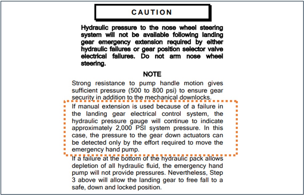
As the landing gear system is electrically controlled and hydraulically operated, due to the electrical failure, the primary method of the gear extension was not functional.
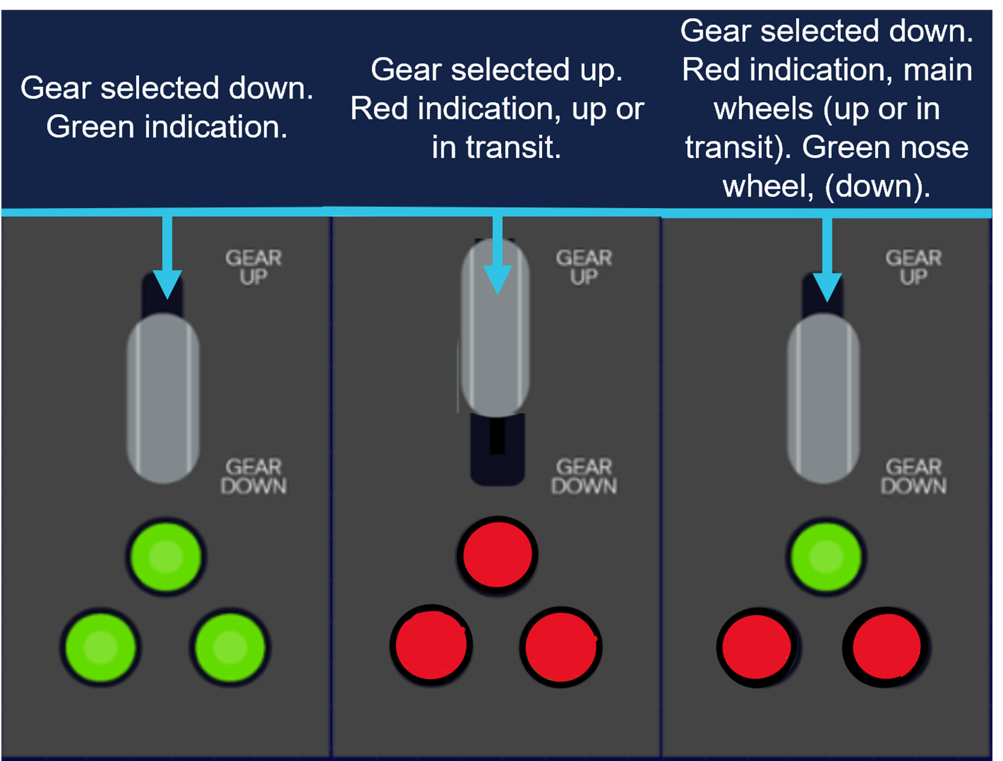
During the initial approach to the primary runway, the pilot manually selected the landing gear ‘down’ to extend the landing gear. Once manually selected ‘down’, the undercarriage extension indicator showed that only the nose gear had locked ‘down’, indicating (green), with the main gear, not indicating that it had ‘locked’ down (Figure 1).
Figure 1: Generic representation of landing gear selection
Source: ATSB representation of landing gear selection and indication. May not be indicative to type of aircraft.
The pilot proceeded to conduct several low passes of the runway to try to ascertain the condition of the landing gear with people on the ground.
However, after not being able to confirm the gear was fully down and locked, the pilot then made the decision to conduct a precautionary landing on the non-sealed cross strip, runway 04.
The pilot conducted the approach and landed, however on touchdown the main undercarriage legs collapsed, and the aircraft slid on the nosewheel (front of the aircraft) and rudder (rear of the aircraft) before coming to rest at the fence at the end of the runway.
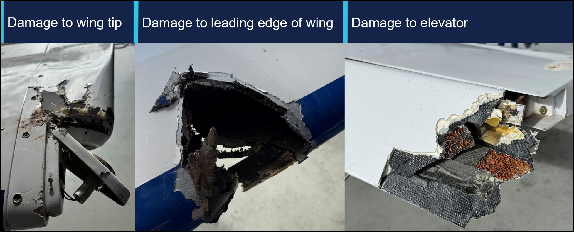
The aircraft incurred some minor damage (Figure 2) to the wingtip and elevator with no injuries to the pilot.
Figure 2: Damage to aircraft
Source: Operator, annotated by the ATSB
Subsequent engineering inspections found the electrical system had failed due to a defective voltage regulator.
Safety message
This occurrence illustrates that a good knowledge of aircraft systems coupled with sound decision‑making can help facilitate a positive outcome to an emergency.
Aircraft rely on hydraulic or electrical systems to extend and retract the landing gear. Should any component in these systems fail, pilots may be left with no choice but to manually extend the undercarriage or potentially execute a wheels-up landing.
Applying a structured and proactive approach to identifying and managing threats and errors, influences the safety of the flight.
In this instance, the pilot was able to identify the aircraft system failure and make several calculated risk-based decisions to manage the emergency. This was achieved by using various resources at their disposal, such as their mobile phone, to seek ground assistance in the absence of normal VHF radio.
In emergency situations, pilots need to utilise all the available resources at their disposal. Maintaining a degree of flexibility and adapting to select the most appropriate landing area can minimise risk, limit damage and maximise survivability.
About this report
Decisions regarding whether to conduct an investigation, and the scope of an investigation, are based on many factors, including the level of safety benefit likely to be obtained from an investigation. For this occurrence, no investigation has been conducted and the ATSB did not verify the accuracy of the information. A brief description has been written using information supplied in the notification and any follow-up information in order to produce a short summary report and allow for greater industry awareness of potential safety issues and possible safety actions.
Occurrence summary
Mode of transport
Aviation
Occurrence ID
AB-2025-039
Occurrence date
04/08/2025
Location
Orange Airport
State
New South Wales
Aviation occurrence category
Collision with terrain, Diversion/return, Electrical system, Landing gear/indication, Runway excursion, Wheels up landing
Occurrence Briefs are concise reports that detail the facts surrounding a transport safety occurrence, as received in the initial notification and any follow-up enquiries. They provide an opportunity to share safety messages in the absence of an investigation. Because occurrence briefs are not investigations under the Transport Safety Investigation Act 2003, the information in them is de-identified.
What happened
On 30 July 2025, at 0741 local time, an Australian-registered amphibious Air Tractor AT‑802, configured for firefighting and with 2 crew members on board, departed from Thessaloniki Airport Makedonia, Greece. The aircraft, along with 2 other company aircraft, was headed to a fire located about 40 km north of the airport. At about 20 km south of the fire location, all 3 aircraft commenced water scooping operations at Lake Koroneia.
The amphibious aircraft was designed to scoop water by lowering a retractable intake hole underneath the aircraft while skimming the surface of a body of water at high speed, using the forward motion to force water into the onboard tanks. Prior to scooping operations, pilots will conduct a visual inspection of the proposed scooping area to look for obstacles both on top of and submerged in the water.
The pilot conducted a water inspection and recalled that the water appeared murky and was difficult to see through. During water uplift, the crew of the aircraft reported hearing an impact and immediately initiated a climb to gain height.
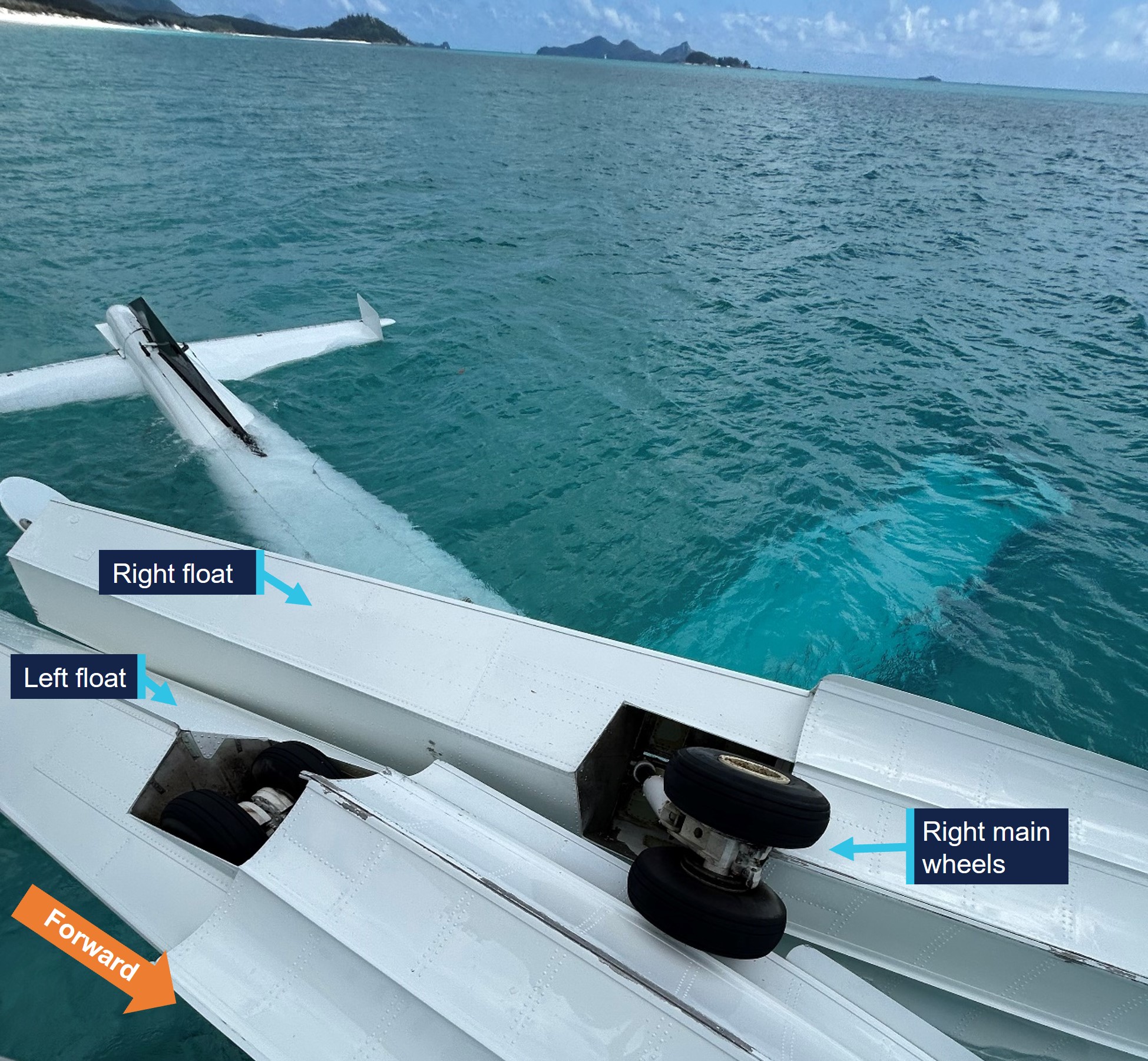
The 2 accompanying aircraft flew alongside the Air Tractor to conduct a visual inspection and reported that the right float had dislodged from its mounts. All 3 aircraft made the decision to return to Thessaloniki Airport, with the pilot of the Air Tractor notifying air traffic control and declaring an emergency.
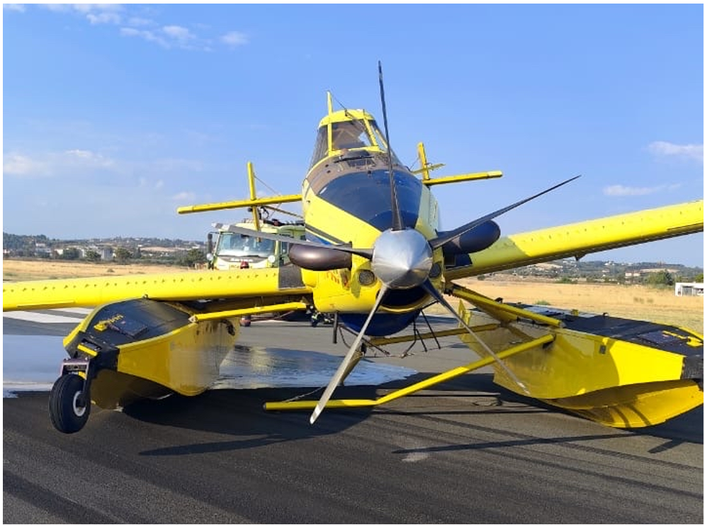
At 0817 the Air Tractor landed on runway 34, however the damaged right float struts were unable to support the weight of the aircraft, and it collapsed onto the right float after landing (Figure 1). The aircraft was subsequently stranded on the runway and emergency services attended. The crew members evacuated the aircraft without injury.
Following the accident, the pilot reported that all 3 aircraft had successfully completed water uplifts from the same location on the previous day. On this occasion, the pilot reported that the glassy water conditions[1] made it difficult to establish the aircraft's height above the water's surface, and the aircraft had hit a submerged object during the scooping run. Due to the risk of unknown hazards at this location, the operator sent a direction to all crew to suspend scooping operations from Lake Koroneia until further notice.
Figure 1: Damaged float struts led to collapse on landing
Source: Operator
Safety message
In murky water, obstructions may not always be visible and the potential for hitting submerged or partly submerged debris is an ever‑present hazard for such operations. Overflying the intended scooping area to scan for such obstacles is always good practice.
In this case, the crew’s quick actions to discontinue operations and pre‑organise emergency services at the airport for their arrival, decreased the risk of injury during their emergency landing.
The hazards that exist in conducting low‑level operations over water have long been recognised (ATSB, 2012) and include the risks of visual illusion and altered depth perception. These factors can make it difficult for pilots to accurately judge the height above water, especially over featureless or reflective surfaces. Flying over calm, glassy water is particularly dangerous, but even choppy water with a constantly varying surface interferes with normal depth perception. Regularly checking the altimeter and establishing smooth descent rates for water alighting during such operations can assist in raising safety margins.
About this report
Decisions regarding whether to conduct an investigation, and the scope of an investigation, are based on many factors, including the level of safety benefit likely to be obtained from an investigation. For this occurrence, no investigation has been conducted and the ATSB did not verify the accuracy of the information. A brief description has been written using information supplied in the notification and any follow-up information in order to produce a short summary report and allow for greater industry awareness of potential safety issues and possible safety actions.
[1]Glassy water can be present across a broad spectrum, from a mirror-like surface to rippled or wavy water, which reflects a distorted image. The reason it presents a challenge for pilots is that without texture on the surface of the water, it is more difficult to judge height.
Occurrence summary
Mode of transport
Aviation
Occurrence ID
AB-2025-036
Occurrence date
30/07/2025
Location
20 km north-north-east of Thessaloniki Airport Makedonia
State
International
Aviation occurrence category
Collision with terrain, Diversion/return, Ground strike, Landing gear/indication
Occurrence Briefs are concise reports that detail the facts surrounding a transport safety occurrence, as received in the initial notification and any follow-up enquiries. They provide an opportunity to share safety messages in the absence of an investigation. Because occurrence briefs are not investigations under the Transport Safety Investigation Act 2003, the information in them is de-identified.
What happened
At about 0800 local time on 1 June 2025, an instructor and student were conducting a training flight from Bankstown Airport, New South Wales in a Piper PA-28-151 aircraft. The aircraft was fitted with a disposable passive carbon monoxide (CO) detector.
During the pre-flight preparations, the CO detector was confirmed to show that there were no signs of carbon monoxide in the cockpit.
Shortly after take-off, while climbing through 300 ft, the instructor noticed that the CO detector had changed colour and was showing full black, indicating a high presence of carbon monoxide in the cockpit. This indication was then verified by the student pilot.
The instructor took over control of the aircraft and asked the student to open the storm window to allow fresh air into the cabin. At the advice of the instructor, the student placed their mouth and nose close to the storm window to breath from the stream of fresh air.
The flight crew requested, and ATC approved, the aircraft to rejoin the circuit and they landed back at Bankstown Airport shortly after with no further event. Prior to landing, the CO detector was noted to have changed colour to light brown, indicating that levels of carbon monoxide in the cockpit had reduced, likely due to the storm window being opened.
Once on the ground, the student pilot reported feeling no symptoms of carbon monoxide poisoning, while the instructor experienced only slight dizziness, but believed this could have been caused by adrenaline from managing the event. Blood tests conducted on both pilots detected only negligible levels of carbon monoxide in their bloodstreams.
A subsequent engineering inspection of the aircraft revealed a rubber boot seal on a nose wheel steering rod had split which was suspected of causing the CO leak. Following rectification, a check flight was performed during which no carbon monoxide was detected inside the cockpit.
Safety message
This incident serves as a salient reminder of the importance of carrying effective carbon monoxide (CO) detection equipment on board aircraft.
CO is a colourless, odourless and tasteless gas found in exhaust gases of piston engine aircraft. While passive CO detectors are commonly used in general aviation aircraft, they have limitations and rely on the pilot regularly monitoring the colour of the detector. In contrast, active electronic CO detectors are designed to attract attention through an audible alert at low CO concentrations, so are more likely to be effective. These devices are now inexpensive and widely available.
Following the fatal crash of a DHC-2 in 2017, in which the pilot was impaired due to carbon monoxide poisoning (Collision with water involving a de Havilland Canada DHC-2 Beaver aircraft, VH‑NOO, at Jerusalem Bay, Hawkesbury River, New South Wales, on 31 December 2017AO-2017-118), and a review of the effectiveness of carbon monoxide detectors by the UK Civil Aviation Authority, the ATSB launched its Know CO campaign.
These resources highlight the limitations of passive carbon monoxide detectors and strongly recommend that operators and owners of piston engine aircraft install active attention‑attracting CO detectors which provide the best opportunity of detecting carbon monoxide exposure before it can adversely impact their ability to control the aircraft.
About this report
Decisions regarding whether to conduct an investigation, and the scope of an investigation, are based on many factors, including the level of safety benefit likely to be obtained from an investigation. For this occurrence, no investigation has been conducted and the ATSB did not verify the accuracy of the information. A brief description has been written using information supplied in the notification and any follow-up information in order to produce a short summary report, and allow for greater industry awareness of potential safety issues and possible safety actions.
On 29 May 2025, a Cessna 310R, registered VH-NXA and operated by Marthakal Yolngu Airline, was conducting a non-scheduled passenger air transport flight from Darwin to Lake Evella, Northern Territory. On board were the pilot and 4 passengers.
During the approach at Lake Evella Aerodrome, recorded data indicated that the aircraft touched down just prior to halfway along the runway. The pilot subsequently applied braking, but the aircraft did not decelerate as expected. This resulted in a runway excursion and the aircraft subsequently collided with a perimeter fence which substantially damaged the left wing. The pilot and 4 passengers were uninjured.
What the ATSB found
The ATSB found that the pilot conducted the approach above the standard profile and crossed the threshold above the normal approach speed. This resulted in the aircraft floating during the landing flare for a prolonged period in ground effect, and a landing beyond the planned touchdown point. After the aircraft touched down, the pilot subsequently commenced braking about halfway along the runway. The long landing reduced the available distance to decelerate on the runway.
At the aircraft’s landing weight, the remaining runway length should have provided sufficient stopping distance, but degraded braking capacity meant the aircraft could not be stopped before the runway end and it subsequently departed the runway.
During a scheduled maintenance event prior to the occurrence, a licensed aircraft maintenance engineer believed an apprentice had replaced the main-wheel brake pads. An inspection after the occurrence found that the right brake reservoir was empty and that the right pads were worn beyond limits, which reduced braking capacity on that side.
The ATSB also identified that the operator’s procedures allowed the use of self-reported passenger weights without additional allowances, and that the electronic weight and balance system had been configured with higher maximum weights applicable to a modification not fitted to this aircraft. In combination with calculation errors on the day, this resulted in the aircraft being operated above the maximum permitted ramp and take‑off weights.
What has been done as result
Marthakal Yolngu Airline advised that all references to the use of self-reported passenger weights for the purposes of weight and balance calculations will be removed in the next amendment of the operations manual.
The operator also advised that the electronic weight and balance system will be amended to reflect the correct maximum weights for VH-NXA prior to its return to service.
The safety manager briefed company personnel about the proposed changes and advised existing pilots that actual weights for passengers must be used for all flights.
The ATSB will monitor these safety actions until the proposed changes to the operations manual and weight and balance system have been formally implemented.
D & T Aircraft Engineering advised that, following the occurrence, a debrief with maintenance personnel highlighted the importance of increased vigilance during inspections conducted after maintenance tasks, and that the organisation also identified opportunities to improve internal processes following similar occurrences.
Safety message
Factors such as additional airspeed over the threshold can result in a landing beyond the intended touchdown point, increasing the risk of a runway overrun excursion. While adherence to a pre-determined stabilised approach criteria can effectively mitigate such risks, pilots should always exercise vigilance and ensure the aircraft is flown within the assumed conditions used to calculate landing performance.
Pilots are therefore encouraged to continue to actively monitor the flight path using cockpit instrumentation and external visual cues until a safe landing is assured. This should include identifying and nominating an appropriate touchdown point on the runway to ensure a go‑around can be executed if a touchdown beyond this point is likely to occur.
Additionally, maintenance organisations should ensure that effective systems are in place to disseminate important information to all maintenance personnel, so that emerging defects are identified and rectified before they affect flight operations.
The occurrence
Pre-flight preparation
On the morning of 29 May 2025, a Cessna C310R, registered VH-NXA and operated by Marthakal Yolngu Airline, was being prepared for a non-scheduled passenger air transport flight from Darwin to Lake Evella, Northern Territory.
When the pilot arrived at the airport, they observed a licensed aircraft maintenance engineer (LAME) and their apprentice performing maintenance on the aircraft braking system. During this period the pilot prepared their flight plan and when they returned to the aircraft, the LAME and the apprentice had completed the maintenance.
The pilot, who was operating their first flight as pilot in command of a multi-engine aircraft, commenced their pre-flight checks. Due to the recent work on the braking system, they taxied to an aircraft bay to conduct a static engine run-up.[1]
With both engines at 1,700 RPM, they recalled that the aircraft moved forward slightly with the brakes applied. They physically increased their braking pressure, after which, the aircraft remained stationary. After completing the run-ups, the pilot taxied back to the terminal where the passengers were waiting. At this time, they also discussed the brakes with another C310 pilot who advised them that quite a lot of brake pressure was required during run-ups.
The pilot reported feeling rushed, and elected to use the self-reported passenger and baggage weights prior to boarding for weight and balance calculations, which were recorded on the manifest. These weights were entered into an electronic weight and balance system, which indicated that the planned load complied with the aircraft weight and balance limitations. The passengers were then taken to the aircraft where the pilot conducted a safety briefing before they boarded.
Occurrence flight
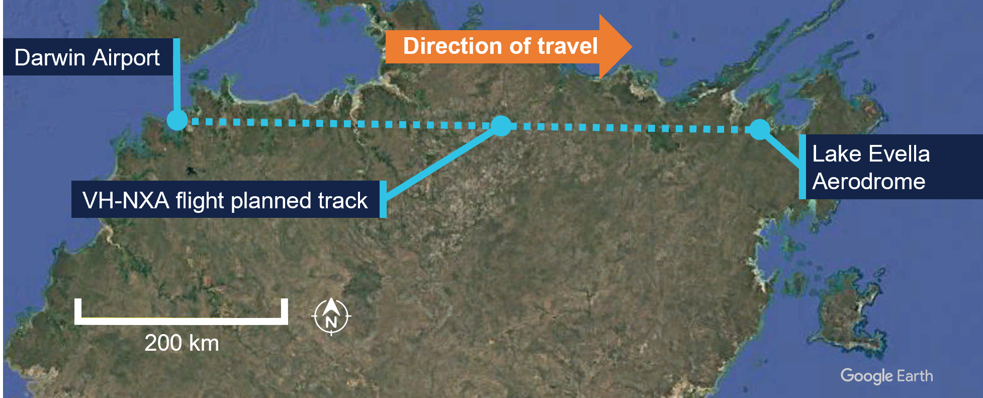
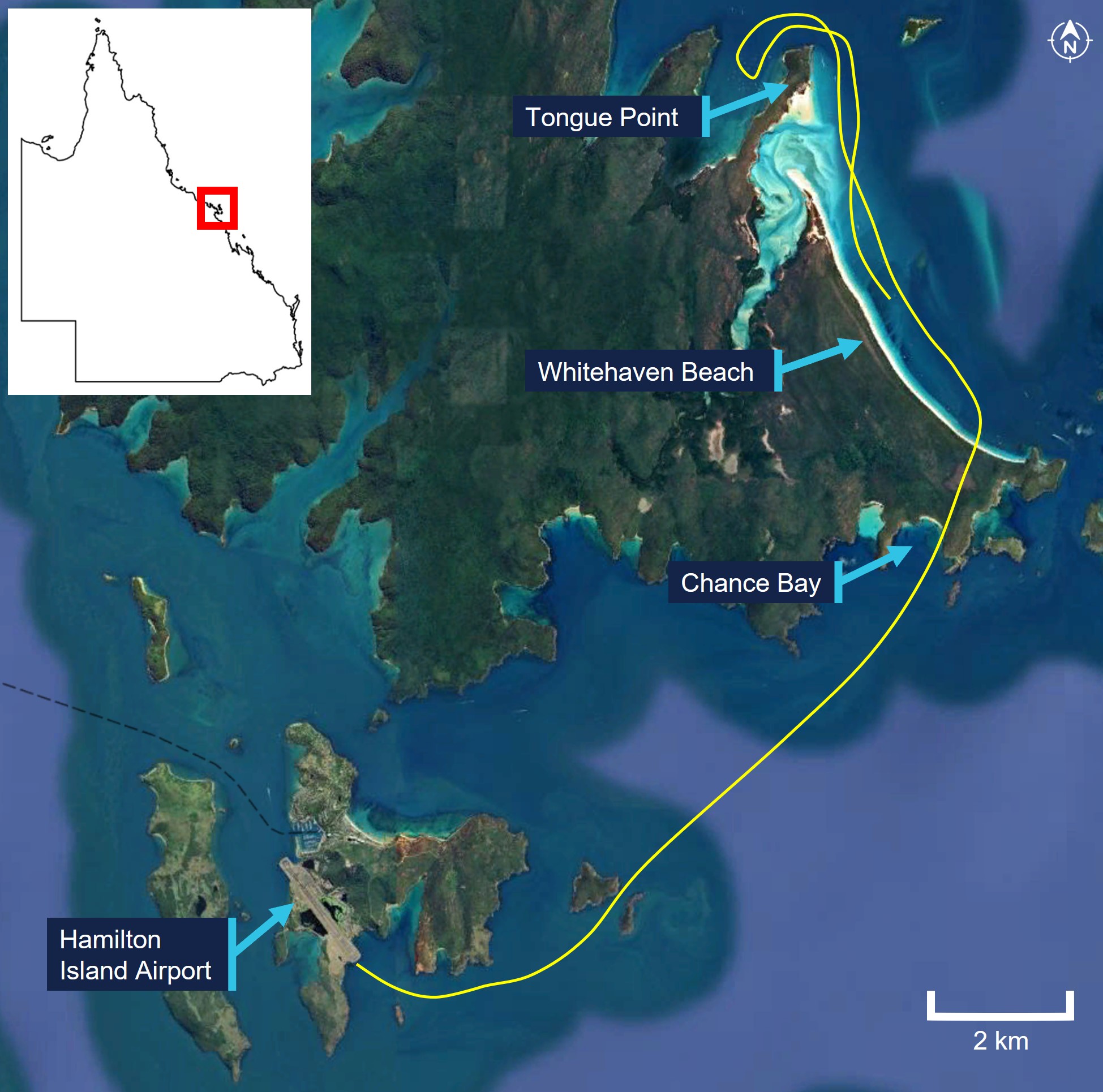
At 0857 local time, VH-NXA departed from Darwin Airport with the pilot and 4 passengers on board for Lake Evella (Figure 1). When approaching the Lake Evella Aerodrome, the pilot reported becoming visual with runway 08 at about 15 NM (28 km) and tracked for a straight in approach. At 1051, the aircraft was established on final approach for runway 08.
Figure 1: VH-NXA flight planned track
Source: Google Earth, annotated by the ATSB
The pilot recalled that there was a south-easterly wind between 8–10 kt for the approach, with a right crosswind component. Another pilot, who arrived at Lake Evella about 3 minutes after VH-NXA, recalled the wind was from an easterly direction at about 10 kt.
The pilot of VH-NXA recalled that the approach ‘seemed stable,’ (see Stabilised approach criteria) and stated that they generally used the runway threshold as their aiming point. They estimated crossing the threshold at their calculated approach speed of 90 kt or ‘just above.’
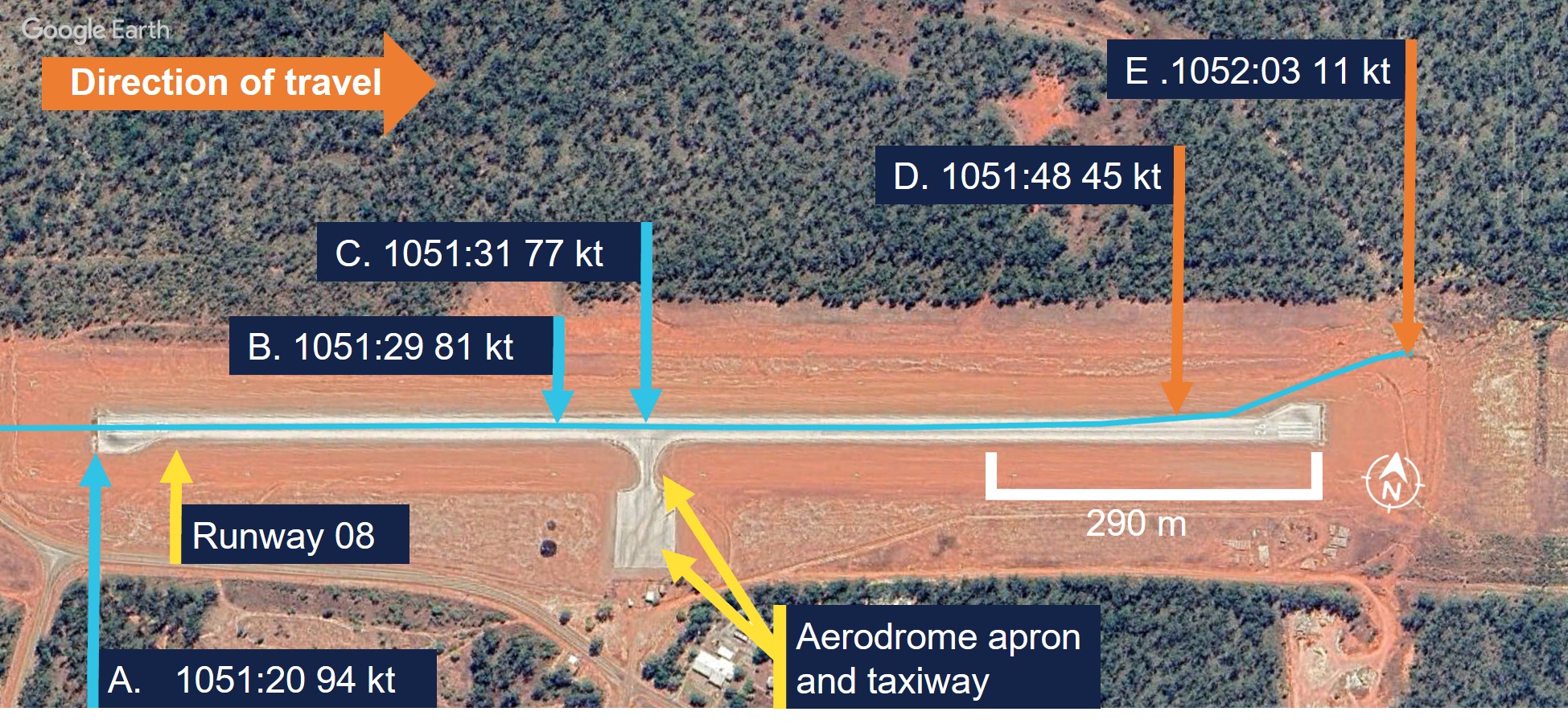
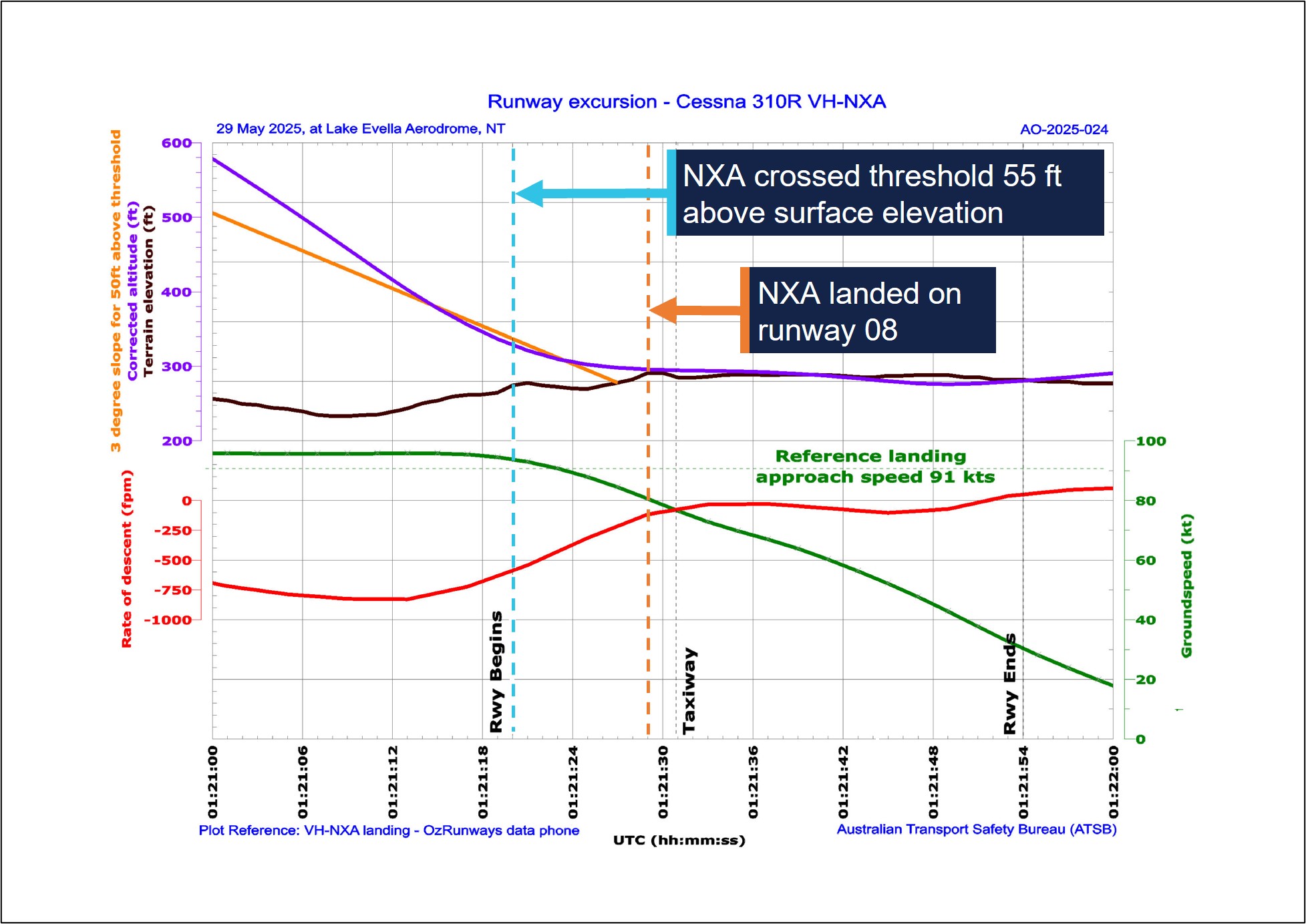
A navigational application (OzRunways) [2] was installed on a tablet computer and an Android phone on board the aircraft and broadcast flight data (see Recorded information). The OzRunways data taken from the Android phone, overlaid on a Google Earth image (Figure 2), showed the aircraft crossing the runway threshold at a height of 55 ft with a ground speed of 94 kt (Figure 2, A). The runway in Lake Evella was not equipped with visual slope guidance and the pilot relied on their visual assessment of ‘how the runway should look at certain height.’
Figure 2: VH-NXA ground speed at key points in landing sequence
Source: Google Earth, annotated by the ATSB
The pilot and the passenger seated directly behind them estimated that the aircraft touched down approximately 200 m past the threshold. ATSB analysis of recorded data indicated touchdown at 1051:29 (the corrected altitude of the aircraft matched the terrain elevation of runway 08), which was 402 m past the threshold (Figure 2, B). The passenger seated in the front row beside the pilot recalled passing the taxiway immediately after touchdown (Figure 2, C).
Another pilot on the ground standing at the apron who witnessed the landing reported observing VH-NXA a few feet above the ground in the ‘flaring attitude’ about a third of the distance along the runway. They also recalled that the aircraft was travelling faster than what they thought was normal and landed just beyond the taxiway (Figure 2, C).
The pilot reported that after touchdown, they applied the brakes passing the apron area about halfway along the runway (Figure 2, C). At that point, they reported that the aircraft did not appear to be slowing as expected and the passenger in the last row recalled the aircraft passing the apron ‘very fast’.
The pilot recalled increasing their braking pressure and when they saw the end of the runway approaching, they shut both engines down by selecting the mixture controls to idle cut-off. The pilot then elected to steer the aircraft to the left of the runway centreline to increase the runway distance for the deceleration required.
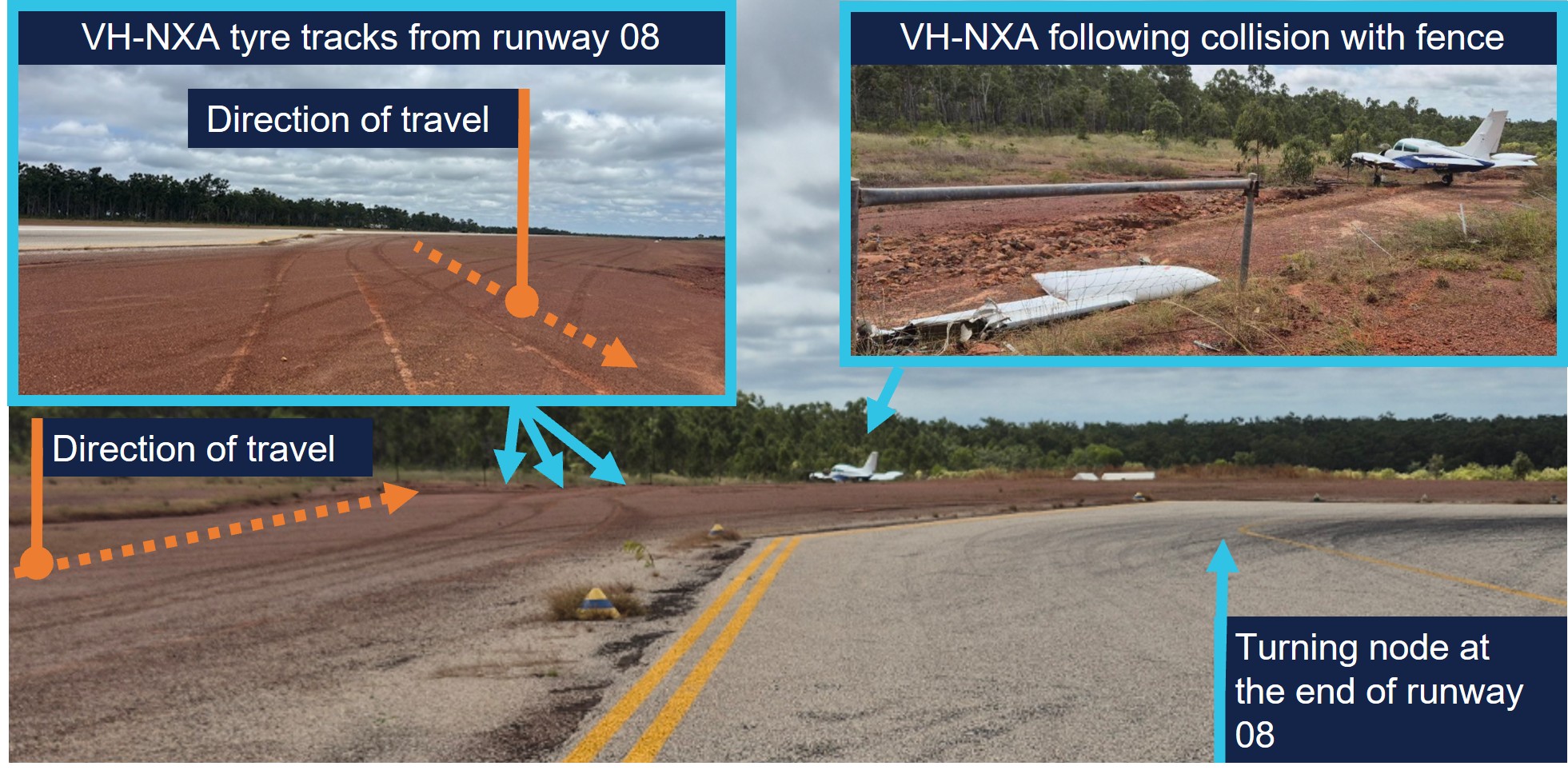
The aircraft departed the left side of the runway, 118 m from the runway end (Figure 2, D) (Figure 3, inset left), while the passenger seated beside the pilot verbally prompted the passengers to ‘brace.’ Recorded data indicated the aircraft was travelling at 45 kt at this point. The left wing subsequently collided with a fencepost (Figure 2, E) (Figure 3, inset right) located 193 m from the point the aircraft departed the runway.
Figure 3: VH-NXA ground roll following runway excursion
Source: Marthakal Yolngu Airline, annotated by the ATSB
Following the collision, the aircraft came to a stop and the pilot and passengers disembarked through the right cabin door. There were no injuries to the pilot or passengers, however the aircraft sustained substantial damage (see Post-accident inspection).
Context
Pilot information
The pilot held a Commercial Pilot Licence (Aeroplane) issued in 2021 and a class 1 aviation medical certificate. They also held a multi-engine aircraft class rating, which was issued in 2022 and renewed with a flight training organisation on 24 May 2025.
The pilot had accumulated 1,066 hours of total aeronautical experience, which included 71 hours of multi-engine time accumulated under the supervision of an instructor.
They reported they had flown about 70 hours in the last 90 days, including a total of 11.7 hours on the Cessna C310R, which was conducted during the course of their training.
The pilot’s training was conducted by a flight training organisation (FTO) in Darwin, on behalf of Marthakal Yolngu Airline. FTO training records detailed that the pilot commenced line training for the C310R on 15 May 2025.
This line training took place over 9.8 flight hours, after which they were assessed as proficient by a flight examiner during a combined line check and operator proficiency check for the C310R on 24 May.
The pilot had not operated the C310R to Lake Evella Aerodrome during the course of their training and had not operated there in any aircraft type prior to the occurrence. They reported sleeping about 8 hours the night before the occurrence and had been awake for about 7 hours at the time of the occurrence and feeling ‘fully alert.’
Aircraft information
The Cessna 310R is a twin-engine, low-wing (with a wingspan of 11.3 m), 6-seat, unpressurised aircraft equipped with retractable landing gear and powered by 2 Continental IO-520 piston engines. VH-NXA was manufactured in the United States in 1978 and first registered in Australia in 1989. A maintenance organisation located in Darwin became the registration holder on 4 March 2020.
Braking system
Section 7 of the Cessna 310R Pilots operating handbook (POH) contained the following description of the braking system:
The airplane is provided with an independent hydraulically actuated brake system for each main wheel. A hydraulic master cylinder is attached to each pilot’s rudder pedal. Hydraulic lines and hoses are routed from each master cylinder to the wheel cylinder on each brake assembly. No manual adjustment is necessary on these brakes. The brakes can be operated from either pilot’s or co-pilot’s pedals.
Meteorological information
The graphical area forecast and the applicable grid point wind and temperature forecast for the flight indicated:
prevailing visibility greater than 10 km
scattered cloud[3] with bases 1,500 ft above mean sea level (AMSL)
isolated areas of smoke reducing visibility to 5,000 m
isolated rain showers and thunderstorms reducing visibility to 2,000 m and 1,000 m respectively, and broken cloud with bases 800 ft above AMSL
moderate turbulence below 4,000 ft in thermals and dust/sand whirls (dust devils)
wind 130° at 21 kt and temperature of 24°C at 1,000 ft above AMSL.
Aerodrome information
Lake Evella Aerodrome (YLEV) is situated at an elevation of 278 ft AMSL and comprised of a single sealed runway, 08/26, measuring 1,065 m in length and 18 m in width and was sloped 0.5% up toward the east. The aerodrome is uncontrolled and operated on a dedicated CTAF,[4] and is subject to animal hazards.
Maintenance information
Aircraft maintenance manual
The Cessna 310R Aircraft maintenance manual (AMM) contained a troubleshooting guide to assist maintenance personnel to rectify defects relating to systems fitted to the aircraft. The section that covered the wheels and brakes included the following information (Table 1):
Check for brake linings worn beyond limits. Replace linings as required
Air in brake system
Check for air trapped in brake system. Bleed the brakes
Brakes spongy
Air in brake system
Check for air trapped in brake system. Bleed the brakes
The AMM also described the brake wear limits on the C310R, which included:
Check back plate and pressure plate linings for wear. If worn to a thickness of 0.125 to 0.100 inch, the linings should be replaced.
Scheduled maintenance
The aircraft was flown to Darwin on 15 February 2025, where the authorising licensed aircraft maintenance engineer (LAME) planned to conduct a corrosion inspection at their maintenance facility. The LAME also performed a ‘check 1’ inspection, which they stated was the equivalent of a 100-hour inspection.
During the inspections, additional maintenance was conducted due to leaking brake callipers, which was common to the brakes on the C310 according to the LAME. This involved the removal, bleeding, resealing and refitting of both callipers and was performed by an apprentice. It was also the LAME’s expectation that the brake pads would be replaced during this maintenance task because this was routine practice, although not in the procedure.
As part of the 100-hour inspection, the LAME performed an engine run-up and observed the aircraft did not hold under brakes at this time. Believing that they had been replaced, they believed that the new brake pads needed to be bedded or burnt in. The AMM stated ‘brake burn in is required to minimize glazing of the friction surfaces’ when new brakes are installed. They subsequently completed the engine run up on one engine at a time, which allowed the aircraft to remain stationary.
Following the completion of the inspections and associated maintenance tasks, including the additional work carried out on the brakes, the LAME certified the aircraft maintenance logbook on 26 May 2025.
The authorising LAME later stated that new brake pads should have been installed before the callipers were refitted to the landing gear, however they did not verify that this had occurred. They reported that the brake pads were last changed on 15 December 2023 and had 494 landings prior to the occurrence.
Pre-departure maintenance
The aircraft underwent a post‑maintenance verification flight the day prior to the accident flight, with a flight instructor and the occurrence pilot as an observer. After the flight, the instructor advised the LAME by text message that the brakes felt ‘spongy.’
On the morning of 29 May, prior to the accident flight, the LAME checked the aircraft brakes, reporting that they were acceptable, even though the brake pedal travel felt more than usual. The decision was made to bleed the brakes to remove any air or water in the brake lines and top up the brake fluid. With assistance from an apprentice during this process, the LAME reported that hydraulic fluid spilled onto the right tyre and was subsequently wiped down. The aircraft was then released back to service.
Post-accident inspection
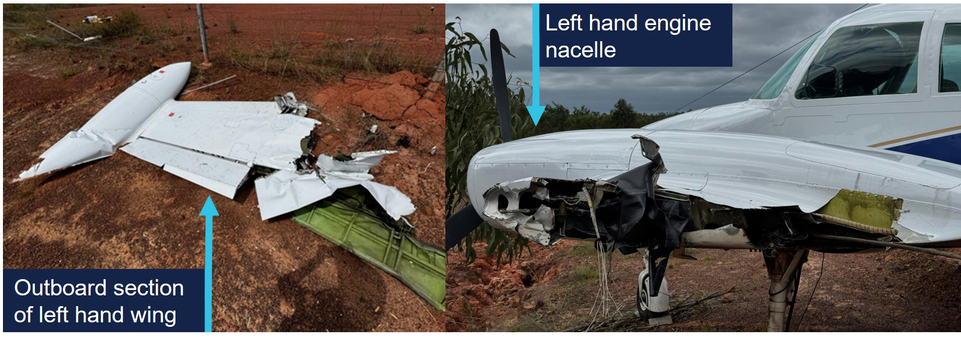
Following the occurrence, the LAME inspected the aircraft at Lake Evella Aerodrome on 18 June 2025 and documented the aircraft damage. The aircraft had sustained significant damage to the left wing (Figure 4), which separated from the fuselage outboard of the left engine nacelle. The pitot tube, right tip tank, propeller and nose gear door were also damaged following the runway excursion.
Figure 4: VH-NXA damaged left wing
Source: Aircraft maintainer, annotated by the ATSB
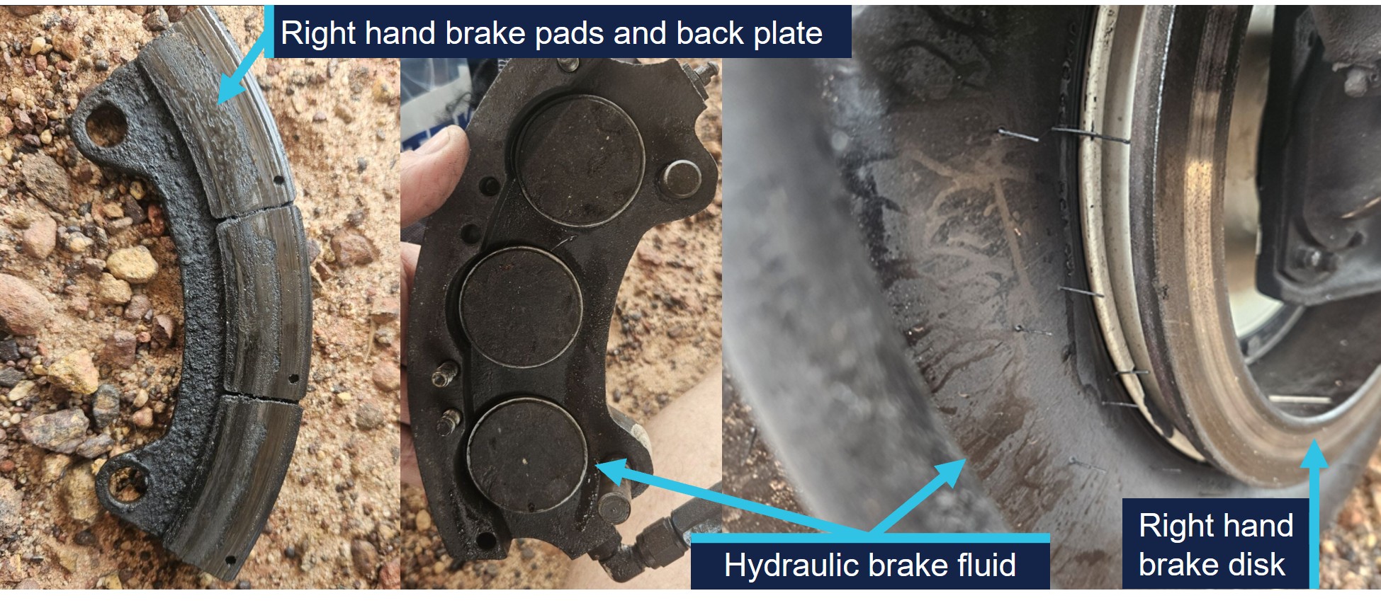
The LAME found that the right brake reservoir was empty, with evidence of hydraulic fluid leakage on the right tyre, however stated that the right brake disc was serviceable.
They identified that the right brake pads were ‘heavily worn.’ Images supplied by the LAME also indicated the presence of hydraulic brake fluid, originating from the brake piston adjacent to the brake line (Figure 5). They also indicated that the hydraulic fluid on the tyre may have been from fluid spilling when the brakes were topped up on the morning of the occurrence flight.
Figure 5: VH-NXA right hand brake components and hydraulic brake fluid
Source: Aircraft maintainer, annotated by the ATSB
No defects were identified on the left brake system and the right brake calliper was removed and tested in Darwin by the LAME. The right brake calliper was bolted onto a brake disc with sufficient pressure applied to prevent calliper movement. After 13 days, sufficient hydraulic fluid had leaked, which allowed the calliper to be moved in relation to the brake disc. The LAME subsequently disassembled the right brake calliper and identified a ‘very small’ hydraulic fluid leak, which they did not consider was the cause of the fluid loss during the occurrence.
Operational information
Weight and balance
The operator’s standard operating procedures(SOP) stated that during the conduct of air transport operations, prior to each sector, the pilot in command must complete an aircraft load and trim sheet.
An operator‑approved electronic load sheet was available to pilots for the purpose of completing weight and balance calculations in accordance with the POH weight and balance limitations.
The operator’s Cessna 310R Flight crew operating manual (FCOM) included the following statement regarding the possible modification of company operated aircraft:
The Company operates C310R aircraft in several possible modification states, which may affect limiting weight.
The only modification listed in the FCOM that affected the weight limitations for VH-NXA was the fitment of a vortex generator (VG)[6] kit. The FCOM also contained information relating to the fitment of the VG kit including increased weight limitations, changes to various airspeeds and stated:
If less than 84 vortex generators are in place or undamaged, the aircraft must be operated in accordance with the original AFM performance data (ie nil VGs).
Electronic weight and balance system
The electronic weight and balance system was developed by a third party to calculate the weight and balance for each flight. In the system, each aircraft was configured with a weight and moment arm[7] when empty.
The pilot would enter the pilot and passengers’ weights, their seating positions and fuel to calculate both the weight and centre of gravity of the aircraft at take-off and landing. The system was designed to alert the user if any weight and balance limitations were exceeded.
For VH-NXA, the electronic weight and balance system incorporated an increase in weight in accordance with a supplemental type certificate number for a C310R VG modification. However, the maintenance organisation that owned and maintained the aircraft stated that VH-NXA had not been fitted with the VG modification, and they were not aware of any modifications that increased the standard maximum permitted weights as prescribed in the POH.
As a result, the weight and balance system contained the following increases to the standard POH weight limitations which were not applicable to the aircraft (Table 2):
Table 2: Cessna 310R maximum weights
POH limitation
Standard weight (kg) applicable for VH-NXA
C310R with VG kit (kg) as listed for VH-NXA
Maximum zero fuel weight
2,222
2,386
Maximum ramp weight
2,510
2,586
Maximum take-off weight
2,494
2,563
Maximum landing weight
2,449
2,449
Passenger-declared weights
The operator’s SOP stated that for the purposes of calculating the aircraft’s weight and balance, ‘passenger weights must be actual, or self-reported.’ Following the occurrence, a passenger reported that their body and baggage weights were requested without the use of a calibrated scale. The pilot did not indicate that any adjustments of additional amounts were applied to the passenger reported weights.
The CASA multi-part AC 121-05, AC 133-04 and AC 135-08 – Passenger crew and baggage weights, described acceptable weight calculation methods that could be defined in operating procedures. The circular stated that:
The use of actual weights is the most accurate method of maximising payload capacity. Appropriately calibrated weighing scales should be used. Actual weighing is more commonly used by Part 133 [helicopter passenger transport] and 135 [smaller aeroplane passenger transport] operators. This is, in part, due to the smaller number of passengers being carried, which makes this option less disruptive than it is for Part 121 [larger aeroplane passenger operations] operators.
Operators should have procedures to identify when passenger-declared weights are not appropriate, such as when operating close to limitations. Under these circumstances, the use of actual weights may be required to ensure limitations are not exceeded.
Passenger-declared weights have inherent inaccuracies as passengers may not know their actual weight, especially when fully dressed. An adjustment allowance should be added to any passenger-declared weight, as a factor or a fixed additional amount.
Weight and balance calculations
Following a review of documentation provided by the operator and pilot, the ATSB identified several discrepancies contained in the operational documentation from the day of the occurrence.
The passenger and baggage weights recorded in the manifest by the pilot indicated a combined weight of 387 kg. However, the corresponding load sheet indicated a combined passenger and baggage weight of 337 kg (excluding the pilot).
Additionally, the fuel plan prepared by the pilot indicated a total fuel figure of 441 kg. By comparison, the fuel figure on the load sheet was recorded as 432 kg.
Due to the identification of the combined discrepancy of 59 kg, the ATSB recalculated the aircraft’s weight and balance for the flight. This identified the following updated weights and exceedances (Table 3) prescribed in the POH for aircraft not fitted with a VG kit.
Table 3: VH-NXA calculated weights and exceedances
Item
POH weight limitation (kg)
Pilot-calculated weight (kg)
ATSB-calculated weight (kg)
ATSB-calculated exceedance (kg)
Zero fuel weight
2,222
2,087
2,137
Nil
Ramp weight
2,510
2,519
2,578
68
Take-off weight
2,494
2,510
2,569
75
Landing weight
2,449
2,339
2,367 [1]
Nil
[1] The re-calculated landing weight was based on pilot reported fuel remaining added to the ATSB calculated zero fuel weight.
Landing performance calculations
The operator’s SOPs stated that company aircraft are subject to the requirements of Civil Aviation Safety Regulations Part 135 Manual of Standards (MOS) with respect to take-off and landing performance requirements. Chapter 10 of the Part 135 MOS stipulated ‘that the aeroplane crosses the runway threshold at a height of 50 ft’ unless an approved short landing operation was being conducted. Additionally for landing, the FCOM stated that the reference landing approach speed (Vref)[8] should be achieved at 50 ft above the landing surface.
For aeroplanes, take-off and landing distance calculations to determine maximum take‑off weight or the maximum landing weight are achieved through a manual calculation using the limitations given in the POH for the specific aircraft type, taking into account:
environmental conditions
runway length.
The FCOM also required pilots to apply landing distance factoring of 1.20 for all calculations. The pilot stated they had calculated their landing performance based on the aircraft’s maximum landing weight and calculated a factored landing distance of 680 m on the flight plan with a Vref of 90 kt for their landing at Lake Evella.
Calculations using the ATSB recalculated landing weight and the estimated ambient conditions at the time of the occurrence determined that the required landing distance (with the 1.20 factoring) with a 50ft threshold crossing height was 659 m. This figure included a landing ground roll distance of 195 m and a corresponding Vref of 91 kt.
Stabilised approach criteria
The SOPs stated that, ‘unless the aircraft meets stabilised approach criteria at the specified altitude, a missed approach must be executed.’
A stabilised approach was described in the SOPs as an approach to land that met a number of criteria by 300 ft above the runway during a visual approach. These included the following:
• the aircraft is on the correct flight path
• only small changes in heading & pitch are required to maintain the correct flight path
• the aircraft speed is Vref to Vref +20 kt
• sink rate is not greater than 1,000 fpm or pre-briefed limits.
Recorded information
The pilot used a flight planning application (OzRunways) on an iPad and an Android phone for en route flight planning and navigation. The flight planning software provider was an approved source of electronic aeronautical charts, however the application could not be used as a primary means of GPS-based navigation as the iPad and Android phone GPS did not meet certification for aviation use. The pilot reported that the iPad was placed on the floor for the approach while the Android phone was in their chest pocket. By examining the combination of groundspeed and derived deceleration data, in addition to the best direct line of sight to satellites, it was assessed that the Android data had the highest positional accuracy.
The recorded data had limitations due to an altitude resolution of 100 ft, while filtering and adjustments were also applied to smooth the data and are known to affect the accuracy of small sections. Additionally, the altitude data of VH-NXA was corrected to match the terrain elevation during the landing ground roll (Figure 6).
Based upon the operator’s stabilised approach criteria, the decision to continue the approach, or conduct a go-around, became applicable by the time the aircraft reached 300 ft above the runway.
The following recorded parameters were observed from below 300 ft to the threshold:
the aircraft crossed the threshold of runway 08 at a height of 55 ft
aircraft speed remained within Vref to Vref +20 kt
sink rate (vertical speed) less than 1,000 fpm.
The recorded data indicated (purple line in Figure 6) that at the 300 ft (578 ft corrected altitude) stabilised approach gate, the aircraft was about 42 ft above the normal 3 degree slope (orange line), and remained above it until reaching 104 ft above the aerodrome elevation. During this period, the sink rate exceeded 800 fpm for 8 consecutive seconds between 1051:06 and 1051:14 local time.
At 1051:20, the aircraft crossed the threshold with a groundspeed of 94 kt. The pilot reported the wind component during the approach was a south-easterly wind between 8–10 kt, which would have resulted in a 3–4 kt headwind component. Accordingly, the aircraft’s airspeed was likely around 97–98 kt as it crossed the runway threshold, which was 6–7 kt above the Vref of 91 kt.
At 1051:29, the corrected altitude of the aircraft matched the terrain elevation, which indicated that the aircraft landed 402 m along the runway with a groundspeed of 81 kt. The pilot reported applying brakes as the aircraft passed the apron area, which occurred about 2 seconds after touchdown. Following a ground roll distance of about 540 m, the aircraft decelerated to a groundspeed of 45 kt when it vacated the left side of the runway at 1051:48.
Figure 6: VH-NXA approach and landing
All times are coordinated universal time (UTC). Local time was Central Standard Time (CST), which was UTC +9 hours and 30 minutes. The aerodrome elevation is 278 ft. Source: ATSB, data provided by OzRunways and Google Earth
On 2 November 2024, a GippsAero GA8-TC Airvan, was being used to conduct a scenic flight from Whitsunday Airport (Shute Harbour), Queensland. During the landing the aircraft departed the upwind end of the runway before entering marshy ground and coming to a stop in a ditch.
The ATSB investigation identified that the aircraft's approach was above profile with a high airspeed and the pilot had an incorrect understanding of the required approach speed. Subsequently, the pilot did not initiate a go-around, resulting in a landing beyond the planned touchdown point. The ATSB also identified that the operator’s weight and balance system used an incorrect empty weight moment arm to calculate the aircraft's centre of gravity, and passengers were not weighed in accordance with its procedures.
Safety analysis
On the morning of 29 May 2025, a Cessna 310R, registered VH-NXA, was being operated by Marthakal Yolngu Airline on a non-scheduled air transport flight from Darwin to Lake Evella, Northern Territory, with a pilot and 4 passengers on board.
During a straight-in visual approach, without visual slope guidance to runway 08 at Lake Evella, the pilot assessed that the approach was stable and continued with the landing. After the aircraft crossed the runway threshold, it floated for a prolonged period and subsequently landed before reaching a taxiway located about halfway along the runway.
When the pilot applied braking passing the airport’s apron area, the aircraft did not decelerate as expected. The aircraft subsequently overran the runway and collided with a fence. The pilot and passengers were uninjured, however, the aircraft sustained substantial damage.
This analysis examines how the condition of the aircraft braking system, and the conduct of the approach and landing, contributed to the runway excursion. It also explores the operator’s self-reported passenger weight procedures and electronic weight and balance system, and how the latter, in combination with incorrect pre-flight weight calculations, led to the aircraft being operated above the weight limits specified in the pilot’s operating handbook.
Pre-flight maintenance
Maintenance which was completed on the aircraft 3 days before the occurrence involved numerous concurrent tasks. These were conducted by a licensed aircraft maintenance engineer (LAME) with the assistance of an apprentice. One of the tasks involved the apprentice conducting maintenance on the braking system due to leaking brake callipers. It was the LAME’s expectation that the apprentice had replaced the main wheel brake pads during this maintenance task.
This expectation influenced their assessment that the aircraft rolled forward during post‑maintenance engine run-ups, due to the new brakes requiring ‘burning in.’ In this case, a physical verification of the brake pads was not conducted as a result.
On the morning of the occurrence, the LAME carried out corrective maintenance in response to the flight instructor text message report of ‘spongy brakes’ the day prior. While the occurrence pilot was aware of this report, they were not aware of the LAME’s experience with the aircraft rolling forward during the engine run-up.
When the pilot commenced the pre-flight engine run-up for the occurrence flight, the brakes failed to keep the aircraft stationary. The pilot physically increased the brake pressure and successfully kept the aircraft stationary, but did not advise maintenance personnel. The pilot’s limited experience on multi-engine aircraft led them to consider that this might be normal, which was reinforced during a brief discussion with another Cessna 310 pilot.
Gaps in communication and incorrect assumptions allowed a latent defect to persist into operation, contributing to the runway overrun in this occurrence.
Contributing factor
The certifying licensed aircraft maintenance engineer did not verify that the brake pads had been replaced by an apprentice during scheduled maintenance, which resulted in the aircraft being returned to service with worn brake pads on the right brake system.
Approach
Lake Evella Aerodrome was not equipped with visual slope guidance, and as a result, the pilot relied on their assessment of visual cues of the runway itself to assess whether they were on the correct approach path while they typically used the runway threshold as their aiming point.
Recorded data from the pilot’s Android phone indicated that the aircraft was higher than the usual 3 degree ‘correct flight path’. The rate of descent exceeded 800 fpm for a period of 8 consecutive seconds until the aircraft descended below 140 ft relative to the runway. At the time, the pilot recalled the approach ‘seemed stable,’ while the operator’s stable approach criteria permitted rates of descent up to 1,000 fpm.
The aircraft subsequently crossed the threshold of runway 08 at a height of 55 ft with a ground speed of 94 kt. ATSB analysis concluded that the aircraft’s airspeed was likely 6–7 kt above the Vref for the recalculated landing weight 91 kt.
When the aircraft neared the point of touchdown, it was subjected to ground effect, which meant that excess airspeed at the point of flare would result in a considerable float distance due to the reduction in drag and lack of power-off deceleration in ground effect (Federal Aviation Administration, 2023).
Additionally, landing distances provided in the aircraft flight manual are based on the aircraft achieving Vref (plus wind and gust additives) at 50 ft above the runway surface. As a result, any additional airspeed will result in a later touchdown and reduce the remaining landing distance available (Federal Aviation Administration, 2023).
In this case, the additional airspeed crossing the threshold likely resulted in a prolonged float in ground effect. This resulted in the aircraft touching down 402 m beyond the runway threshold which was the pilot’s usual aiming point. Subsequently, the pilot applied braking about 2 seconds after the touchdown, at which point, there was about 585 m of remaining distance available to decelerate on the runway.
Contributing factor
The pilot conducted the approach above the standard profile and crossed the threshold above the normal approach speed. This resulted in a landing beyond the planned touchdown point, and the pilot applied braking about halfway along the runway, which reduced the available distance to decelerate on the runway.
Excursion
The pilot first became aware of an issue with the braking system when they applied brake pressure during the landing roll with about 585 m of runway remaining. Witness accounts recalled the aircraft was travelling at high speed as it passed the taxiway and apron area without any significant deceleration. Additionally, recorded data showed the aircraft only slowed from 81 kt at touchdown to 45 kt when it vacated the left side of the runway following a ground roll distance of about 540 m.
At the aircraft’s landing weight, the ATSB calculated ground roll distance required was 195 m, which was sufficient to bring the aircraft to a stop within the remaining length of the runway had the brakes been functioning correctly. However, the loss of hydraulic brake fluid and the worn brake pads on the right-hand brake reduced the available braking capacity. As a result, the braking capacity was insufficient to arrest the aircraft’s forward momentum before the end of the runway. The pilot attempted to increase the available stopping distance by steering left and departing the runway, however it was insufficient, and the aircraft subsequently collided with the perimeter fence.
Contributing factor
Due to the worn right brake pad and the lack of hydraulic fluid in the right brake system, there was insufficient braking capacity available to prevent a runway overrun following the landing and the application of brakes about halfway along the runway.
Passenger weights
The operator’s exposition permitted the use of self-reported passenger weights for weight and balance calculations, without requiring the application of additional allowances or validation. This practice introduced errors into the weight and balance data used for pre-flight planning.
Research has found that people tend to underestimate the weights of themselves and others. Further, people are less accurate at estimating the weight of others than they are of themselves.[9] To cater for the variation in weight, it is recommended that operators weigh passengers or apply adjustment factors to self-reported values (Civil Aviation Safety Authority, 2025). In contrast, the operator’s reliance on unadjusted self-reported passenger and carry-on baggage weights provided no systematic mitigation for potential inaccuracies, which increased the likelihood that the aircraft would be operated overweight or at centre of gravity limits outside the manufacturer’s requirements.
Other factor that increased risk
Marthakal Yolngu Airline’s procedures did not require that additional allowances were applied when using self-reported passenger weights for weight and balance calculations. (Safety issue)
Electronic weight and balance
The operator used an electronic weight and balance system to calculate aircraft loading data for each aircraft in operation. In that electronic system, VH-NXA had been configured with the higher maximum weight limits applicable to aircraft fitted with a vortex generator (VG) modification. However, the aircraft did not have the specified modification installed. Consequently, the programmed maximum zero-fuel, ramp and take-off and weights in the system exceeded those authorised in the aircraft’s POH.
This configuration error meant the electronic weight and balance system allowed VH‑NXA to be loaded in excess of the certified weight limitations, while still indicating that the loading complied with those limitations. This created an ongoing risk that the aircraft could be operated above the approved maximum weights.
Other factor that increased risk
Marthakal Yolngu Airline’s electronic weight and balance system used incorrect maximum weights for the aircraft, which increased the risk of flight crew operating the aircraft above the certified weight limitations. (Safety issue)
Weight exceedances
During the occurrence flight, the aircraft was operated above the certified maximum ramp and take-off weights due to cumulative errors in the pilot’s weight and balance calculations. As a result of the configuration errors in the electronic weight and balance system, no alert to the overweight condition was made.
The pilot, who was conducting their first multi-engine command flight, reported feeling rushed during pre-flight preparation, which likely reduced the opportunity for careful verification of passenger weights, totals and data entry. Review of the weight and balance documentation from the occurrence identified multiple inaccuracies, indicating that the overweight condition arose from a breakdown in the usual cross-checking processes rather than a single isolated error.
Although the overweight condition did not result in the aircraft exceeding its maximum landing weight, operating above certified weight limits is known to increase take-off and landing distances and degrade braking performance. Additionally, excessive weight reduces the available safety margin if an in-flight emergency condition should arise (Federal Aviation Administration, 2016).
Other factor that increased risk
The aircraft was operated overweight due to incorrect weight and balance calculations, as well as errors in the electronic weight and balance system.
Findings
ATSB investigation report findings focus on safety factors (that is, events and conditions that increase risk). Safety factors include ‘contributing factors’ and ‘other factors that increased risk’ (that is, factors that did not meet the definition of a contributing factor for this occurrence but were still considered important to include in the report for the purpose of increasing awareness and enhancing safety). In addition ‘other findings’ may be included to provide important information about topics other than safety factors.
Safety issues are highlighted in bold to emphasise their importance. A safety issue is a safety factor that (a) can reasonably be regarded as having the potential to adversely affect the safety of future operations, and (b) is a characteristic of an organisation or a system, rather than a characteristic of a specific individual, or characteristic of an operating environment at a specific point in time.
These findings should not be read as apportioning blame or liability to any particular organisation or individual.
From the evidence available, the following findings are made with respect to the runway excursion involving Cessna 310, VH-NXA, at Lake Evella Aerodrome, Northern Territory, on 29 May 2025.
Contributing factors
The certifying licensed aircraft maintenance engineer did not verify that the brake pads had been replaced by an apprentice during scheduled maintenance, which resulted in the aircraft being returned to service with worn brake pads on the right brake system.
The pilot conducted the approach above the standard profile and crossed the threshold above the normal approach speed. This resulted in a landing beyond the planned touchdown point, and the pilot applied braking about halfway along the runway, which reduced the available distance to decelerate on the runway.
Due to the worn right brake pad and the lack of hydraulic fluid in the right brake system, there was insufficient braking capacity available to prevent a runway overrun following the landing and the application of brakes about halfway along the runway.
Other factors that increased risk
Marthakal Yolngu Airline’s procedures did not require that additional allowances were applied when using self-reported passenger weights for weight and balance calculations. (Safey issue)
Marthakal Yolngu Airline’s electronic weight and balance system used incorrect maximum weights for the aircraft, which increased the risk of flight crew operating the aircraft above the certified weight limitations. (Safey issue)
The aircraft was operated overweight due to incorrect weight and balance calculations, as well as errors in the electronic weight and balance system.
Safety issues and actions
Central to the ATSB’s investigation of transport safety matters is the early identification of safety issues. The ATSB expects relevant organisations will address all safety issues an investigation identifies.
Depending on the level of risk of a safety issue, the extent of corrective action taken by the relevant organisation(s), or the desirability of directing a broad safety message to the aviation industry, the ATSB may issue a formal safety recommendation or safety advisory notice as part of the final report.
Descriptions of each safety issue, and any associated safety recommendations, are detailed below. Click the link to read the full safety issue description, including the issue status and any safety action/s taken. Safety issues and actions are updated on this website when safety issue owners provide further information concerning the implementation of safety action.
Safety issue description: Marthakal Yolngu Airline’s procedures did not require that additional allowances were applied when using self-reported passenger weights for weight and balance calculations.
Safety issue description: Marthakal Yolngu Airline’s electronic weight and balance system used incorrect maximum weights for the aircraft, which increased the risk of flight crew operating the aircraft above the certified weight limitations.
Safety action not associated with an identified safety issue
Whether or not the ATSB identifies safety issues in the course of an investigation, relevant organisations may proactively initiate safety action in order to reduce their safety risk. The ATSB has been advised of the following proactive safety action in response to this occurrence.
Additional safety action by D & T Aircraft Engineering
D & T Aircraft Engineering advised that, following this occurrence, a debriefing was conducted with maintenance personnel to discuss key learnings. It was acknowledged that increased vigilance would be exercised in the future to ensure that aircraft components are carefully inspected and confirmed to be in a serviceable condition following the completion of maintenance tasks. Additionally, the organisation stated that it would prioritise accessing the aircraft at the earliest opportunity in the future to assist in identifying potential causes of component failure, particularly in cases where perishable evidence plays a critical role in determining the cause.
Glossary
AFM
Aircraft flight manual
AMM
Aircraft maintenance manual
AMSL
Above mean sea level
CASA
Civil Aviation Safety Authority
FCOM
Flight crew operating manual
FTO
Flight training organisation
LAME
Licensed aircraft maintenance engineer
MOS
Manual of Standards
POH
Pilots operating handbook
RPM
Revolutions per minute
SOP
Standard operating procedures
VG
Vortex generator
VMC
Visual meteorological conditions
VREF
Reference landing approach speed
Sources and submissions
Sources of information
The sources of information during the investigation included:
Ramos , E., Lopes, C., & Barros , H. (2009). Unawareness of weight and height – the effect on self-reported prevalence of overweight in a population-based study. The Journal of Nutrition, vol. 13, pp.310–314.
Reed, D., & Price , R. (1998). Estimates of the heights and weights of family members: accuracy of informant reports. International Journal of Obesity, vol. 22, pp.827–835.
Shapiro , J. R., & Anderson, D. A. (2003). The effects of restraint, gender, and body mass index on the accuracy of self-reported weight. International Journal of Eating Disorders, vol. 34, pp.177–180.
Submissions
Under section 26 of the Transport Safety Investigation Act 2003, the ATSB may provide a draft report, on a confidential basis, to any person whom the ATSB considers appropriate. That section allows a person receiving a draft report to make submissions to the ATSB about the draft report.
A draft of this report was provided to the following directly involved parties:
pilot of the accident flight
the operator
maintenance organisation
Civil Aviation Safety Authority
Bureau of Meteorology.
Submissions were received from:
pilot of the accident flight
the operator maintenance organisation
Bureau of Meteorology.
The submissions were reviewed and, where considered appropriate, the text of the report was amended accordingly.
Purpose of safety investigations
The objective of a safety investigation is to enhance transport safety. This is done through:
identifying safety issues and facilitating safety action to address those issues
providing information about occurrences and their associated safety factors to facilitate learning within the transport industry.
It is not a function of the ATSB to apportion blame or provide a means for determining liability. At the same time, an investigation report must include factual material of sufficient weight to support the analysis and findings. At all times the ATSB endeavours to balance the use of material that could imply adverse comment with the need to properly explain what happened, and why, in a fair and unbiased manner. The ATSB does not investigate for the purpose of taking administrative, regulatory or criminal action.
About ATSB reports
ATSB investigation reports are organised with regard to international standards or instruments, as applicable, and with ATSB procedures and guidelines.
Reports must include factual material of sufficient weight to support the analysis and findings. At all times the ATSB endeavours to balance the use of material that could imply adverse comment with the need to properly explain what happened, and why, in a fair and unbiased manner.
An explanation of terminology used in ATSB investigation reports is available here. This includes terms such as occurrence, contributing factor, other factor that increased risk, and safety issue.
Publishing information
Released in accordance with section 25 of the Transport Safety Investigation Act 2003
Ownership of intellectual property rights in this publication
Unless otherwise noted, copyright (and any other intellectual property rights, if any) in this report publication is owned by the Commonwealth of Australia.
Creative Commons licence
With the exception of the Commonwealth Coat of Arms, ATSB logo, and photos and graphics in which a third party holds copyright, this report is licensed under a Creative Commons Attribution 4.0 International licence.
The CC BY 4.0 licence enables you to distribute, remix, adapt, and build upon our material in any medium or format, so long as attribution is given to the Australian Transport Safety Bureau.
Copyright in material obtained from other agencies, private individuals or organisations, belongs to those agencies, individuals or organisations. Where you wish to use their material, you will need to contact them directly.
[1]Run-up: a high power run-up check is carried out in a piston-engine aircraft to check the aircraft’s ignition and other systems before commencing an initial take off.
[2]OzRunways is an approved data provider for Australian pilots for flight planning and in-flight navigation.
[3]Cloud cover: in aviation, cloud cover is reported using words that denote the extent of the cover – ‘few’ indicates that up to a quarter of the sky is covered, ‘scattered’ indicates that cloud is covering between a quarter and a half of the sky, ‘broken’ indicates that more than half to almost all the sky is covered, and ‘overcast’ indicates that all the sky is covered
[4]Common traffic advisory frequency (CTAF): A designated frequency on which pilots make positional broadcasts when operating in the vicinity of a non-controlled aerodrome or within a broadcast area.
[5]Brake linings: brake linings, often referred to as brake pads, are the friction material that, when pressed against the brake discs, slows and stops the aircraft. Over time and with use, these linings wear down and require replacement.
[6]A vortex generator installation typically offers the advantages of reduced stall speeds, reduced minimum single engine control speed (Vmc), improved take-off and landing performance and increased maximum take-off weight.
[7]Moment arm: the horizontal distance from a reference datum to the centre of gravity of an item.
[8]Reference Landing Approach Speed: The airspeed used on approach down to 50 ft above the runway when determining landing distances which is normally 1.3 times the stall speed.
[9]For example, see Ramos and others (2009), Reed and Price (1998), Sahyoun and others (2008) and Shapiro and Anderson (2003).
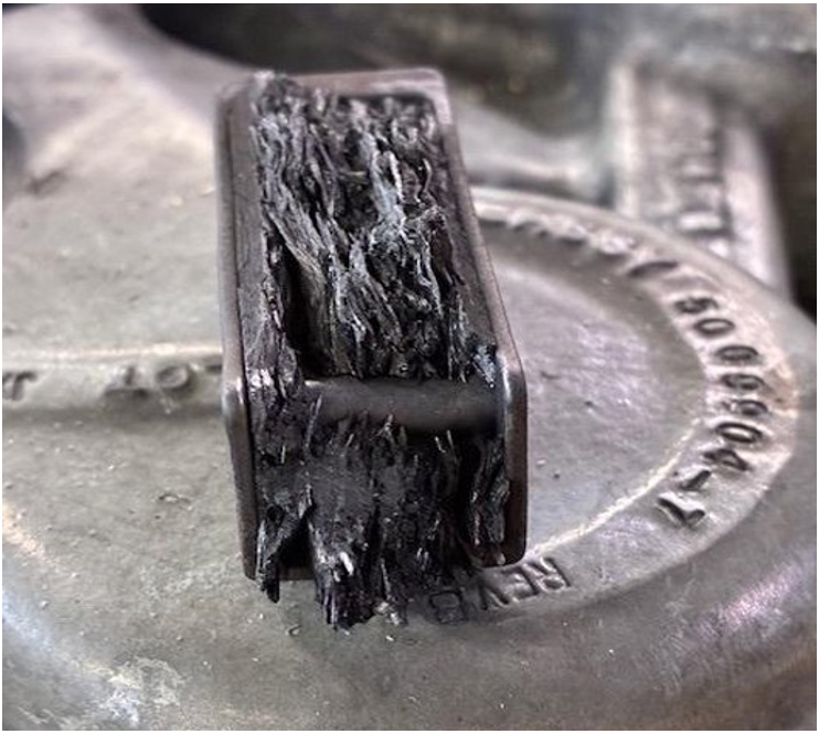
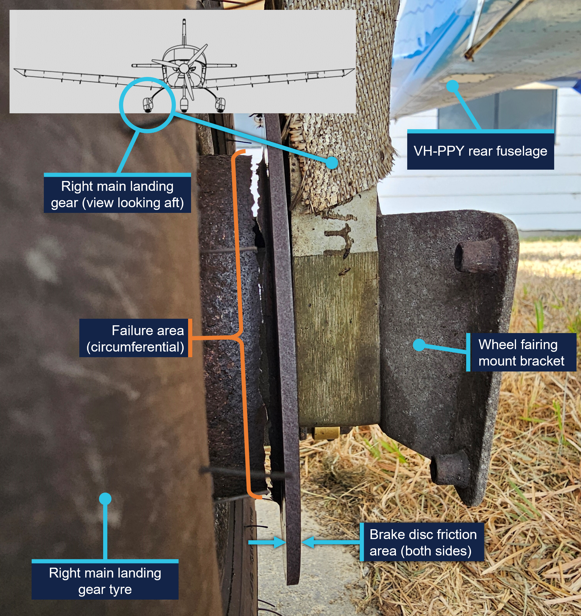
On 14 February 2025, an instructor and student pilot were conducting a training flight using a Sling Aircraft Sling LSA, registered VH‑PPY, operating from Moorabbin Airport in Victoria. After landing and as the aircraft was vacating the runway, there was a jolt and an unusual sound from the right side of the aircraft. After the instructor taxied the aircraft to the operator’s parking area and disembarked, the right main landing gear brake disc was found to have fractured through its entire circumference.
What the ATSB found
The ATSB found that the aircraft brake disc fractured during normal operation due to severe corrosion that compromised its structural integrity. This corrosion was not identified by those maintaining and operating the aircraft as having progressed to a point where failure of the brake disc was possible.
The fractured brake disc fitted to the aircraft was an aftermarket part. Manufacture of the brake disc was consistent with the manufacturer’s specifications, however it had not been approved for fitment to the Sling LSA and therefore assurance that it was a suitable replacement had not been established.
What has been done as a result
The operator replaced all corroded brake discs fitted to its Sling LSA fleet with the correct Matco parts, and the aircraft are now moved onto the apron prior to boarding allowing easier access to inspect the landing gear. Additionally, the operator discussed the occurrence in a safety presentation to instructor pilots which included a description of the event, photos of the corroded brake, possible reasons for the corrosion, and a direction to ensure inspection of the brakes is carried out prior to flight.
Safety message
There are multiple opportunities for those operating aircraft to identify defects such as corrosion, and those maintaining the aircraft should take timely action to prevent its progression or replace that part before the serviceability of the aircraft is affected. Additionally, consideration should be given to the operating environment of the aircraft and whether additional maintenance activities could be employed to limit corrosion development.
The investigation
The ATSB scopes its investigations based on many factors, including the level of safety benefit likely to be obtained from an investigation and the associated resources required. For this occurrence, the ATSB conducted a limited-scope investigation in order to produce a short investigation report, and allow for greater industry awareness of findings that affect safety and potential learning opportunities.
The occurrence
On 14 February 2025, an instructor and student pilot were conducting a training flight from Moorabbin Airport, Victoria, using a Sling LSA, manufactured by Sling Aircraft[1] and registered VH‑PPY.
At about midday, the instructor landed the aircraft on runway 17R.[2] As the aircraft was vacating the runway onto taxiway A4, there was a jolt and an unusual sound from the right side of the aircraft. The instructor continued to taxi, and after noticing that the aircraft’s wheel brakes were less effective, brought the aircraft to a stop and conducted after-landing checks without noting anything significant.
The instructor re-commenced taxiing to the operator’s parking area, and after disembarkation saw that the right main landing gear brake disc had failed (Figure 1). The instructor noted the brake failure on the aircraft’s maintenance release, grounding the aircraft.
Figure 1: VH-PPY right brake disc post-flight
Source: Learn to Fly Australia and Sling Aircraft, annotated by the ATSB
Context
Aircraft information
General information
The Sling LSA is a low-wing, 2-seat aircraft, designed and manufactured in South Africa for private flying and flying training. The aircraft is constructed predominantly from aluminium alloy, has a fixed, tricycle landing gear and is powered by a Rotax 912 ULS2‑01 engine.
VH‑PPY was manufactured in 2018 and was first registered in Australia in March 2019. The aircraft had been first registered by the current operator, Learn to Fly Australia, in October 2020. At the time of the occurrence, the aircraft had accumulated 2,951.2 hours total time in service.[3]
The nose and both main wheels were originally fitted with aerodynamic fairings, however the aircraft’s main wheel fairings were removed[4] from VH‑PPY when the aircraft entered service, for ongoing ease of inspection and tyre changes.
Main landing gear brakes
General information
The Sling LSA main landing gear wheels are fitted with disc brakes (Figure 2). Braking action is achieved by the pilot’s feet acting on the aircraft’s rudder pedals, directing hydraulic fluid to the brake caliper piston to move the lining (pad), which in turn acts on the friction area of the brake disc.
Figure 2: Sling LSA main landing gear and Matco wheel brake assembly
Source: Sling Aircraft, annotated by the ATSB
Aircraft manufacturers prescribe specific approved parts for use on their aircraft. Parts that are not approved by the manufacturer are ineligible for fitment. The brake assemblies approved for fitment to the Sling LSA are manufactured by Matco Aircraft Landing Systems (Matco). They consist of a wheel rim, a brake disc, and a brake caliper assembly. Matco used zinc as the standard corrosion protection coating on the brake disc, however electroless nickel plating[5] is offered as an option. Matco indicated that the nickel plating offers better protection, longevity and high temperature tolerance. The aircraft manufacturer did not specify the type of coating on the Matco brakes fitted to the Sling LSA.
The brake disc fitted to VH‑PPY at the time of the occurrence was manufactured by Rapco (Figure 3). Rapco brake discs are manufactured from forged carbon steel and electroless nickel plated for corrosion prevention. Rapco brake discs are identified with a laser-etched part number and have 2 areas where the section thickness has been reduced, which is not a feature of the approved Matco part.
Figure 3: Brake disc as received at the ATSB’s technical facility
Source: ATSB
The aircraft manufacturer advised that there were no approved alternates to the Matco brake discs for fitment to the Sling LSA. The maintenance organisation reported that they were not aware that the disc fitted to VH‑PPY was an unapproved part and there was no record in the aircraft logbooks of fitment of the Rapco brake disc.
Inspection and maintenance
The aircraft’s pilot operating handbook contained instructions for a pre-flight check to be carried out prior to the first flight of the day and after any maintenance activity. This check included an inspection of the right and left main wheels and brakes for fluid leaks, security, general condition, tyre condition, inflation and wear. The preamble for the pre‑flight check noted that:
The word “condition” in the instructions means a visual inspection of surface for damage deformations, scratching, chafing, corrosion or other damages, which may lead to flight safety degradation.
The operator of VH-PPY required its instructor pilots to carry out a daily inspection prior to the first flight of the day, which encompassed the pre-flight requirements and other inspections such as checking the engine oil level and checking onboard fuel for the presence of water. Instructor pilots then carried out pre-flight inspections prior to every flight and supervised students in carrying out daily inspections prior to every flight they conduct.
VH‑PPY was being used for flying training and in the 2.5 months prior to the occurrence had flown about 140 flights. Periodic inspections and servicing were being carried out on VH-PPY every 100 flying hours, which would typically be accrued in about 2 months. The inspections were carried out in accordance with the Sling 2 and Sling LSA maintenance manual. This included an inspection of all components of the main landing gears for ‘poor condition’. The maintenance organisation, which had been carrying out periodic and other maintenance on the operator’s Sling LSA since 2023, was monitoring the condition of the brakes while it was sourcing replacement parts. It reported that while it was aware of the increasing corrosion on the brake disc, it had not reached a point where it considered it to be critical.
A section of the maintenance manual provided guidelines for corrosion prevention and noted that:
The information supplied here is as a general guideline only, and is by no means intended to be exhaustive, complete or authoritative. For more in depth information refer to an applicable and authoritative publication, such as the [Federal Aviation Administration] FAA Advisory Circular AC 43.13-1B: Acceptable Methods, Techniques and Practices - Aircraft Inspection and Repair.
…
It is highly advisable that expert advice be sought with regard to corrosion related issues.
Included in the general guidance was that:
… If any trace of corrosion is detected it should be removed as soon as possible and the applicable part should be treated immediately to prevent further corrosion.
Treatment consists of mechanically removing as much as possible of any corrosion by-products, applying corrosion inhibitor and replacing any original finish.
Matco published inspection requirements for the approved brake assembly in a technical service bulletin. This document provided methods to remove corrosion from the area where the brake lining contacts the disc and prohibited removal of the plating from other areas of the brake disc. The minimum thickness[6] of the friction area was specified as 0.130 inches (3.303 mm).
Rapco, the manufacturer of the brake disc fitted to VH‑PPY, specified the minimum thickness of the friction area as 0.167 inches (4.242 mm).
Generic inspection and maintenance guidelines
The United States Federal Aviation Administration (FAA) advisory circular AC 43.13‑1B – Acceptable Methods, Techniques and Practices - Aircraft Inspection and Repair[7] provided guidelines for corrosion preventative maintenance, an inspection guide, and procedures for corrosion removal for specific material types such as ferrous alloys. The Civil Aviation Safety Authority (CASA) airworthiness bulletin AWB 02-045 permitted AC 43.13-1B to be used as approved maintenance data for minor repairs of aircraft that meet the eligibility requirements.
The FAA advisory circular AC 43.4B – Corrosion Control for Aircraft[8] also provided guidelines for the identification of corrosion on ferrous metals, information on how it propagates, guidelines for its removal and for the subsequent treatment of those areas. The advisory circular includes instructions for a corrosion prevention plan based on the location of the aircraft. As the Australian coastline is considered a ‘severe’ zone, cleaning, inspection, lubrication, and preservation was suggested to be carried out every 15 calendar days.
Examination of failed brake disc
The brake disc was examined at the ATSB’s technical facility in Canberra.
The brake disc exhibited uniform corrosion[9] with associated material loss and thinning of the base metal. The disc was most severely corroded around the region of failure, which was adjacent to the friction (braking) area and associated with a reduction in part thickness. The measured maximum thickness of the brake disc friction area was 3.63 mm (0.143 inches), making it about 0.612 mm (0.024 inches) less than the minimum thickness specified by Rapco.
Elemental analysis of the disc materials was conducted using energy dispersive spectroscopy (EDS). The materials were consistent with a plain carbon steel base layer and electroless nickel surface coating.
Electroless nickel plating is a barrier coating, meaning that it protects the substrate (in this case the brake disc) by sealing it off from the environment. This can be contrasted with zinc plating where zinc acts as a sacrificial material that corrodes in preference to the substrate, thereby protecting it.
To examine the remaining plating for continuity, a section was taken through the brake disc. The plating was measured to be about 10 µm (0.01 mm) thick and was broadly continuous around the hub but degraded closer to the region of failure. There were examples where cracking in the plating corresponded to sub-plating corrosion of the disc (Figure 4).
Figure 4: Sectioned view of damaged plating
Source: ATSB
Other aircraft
After the occurrence, the operator checked the brake discs fitted to the remaining 6 Sling LSA in its fleet. Those aircraft were first registered in Australia between 2017 and 2021. The disc part numbers were not confirmed, however images showed that most had the same changes in section thickness as the subject Rapco disc. All of the discs were observed to have advanced corrosion with resulting material loss. Additionally, a radial crack was found on the brake discs of 2 aircraft in the friction area. These brake discs were replaced immediately with the correct Matco parts and the remainder during scheduled maintenance.
Matco reported that it had seen corrosion on brake discs in service when there has been a loss of plating, but not to the extent seen on the brake disc from VH‑PPY. The aircraft manufacturer also was not aware of instances of corrosion to this extent.
Aircraft operating environment
The operator conducted flying training from its facility at Moorabbin Airport, which is situated about 3 km from Port Phillip Bay (a large saltwater bay) at its closest point.
The operator’s aircraft were parked outside on concrete pads, surrounded by gravel and grass (Figure 5). Rain reportedly pools on and around these pads.
Figure 5: Parking area for the operator’s aircraft
Source: Learn to Fly Australia, annotated by the ATSB
Safety analysis
The right brake disc of VH‑PPY was severely corroded and its structural integrity had been compromised to the point where it failed during normal aircraft braking after landing. While there were no injuries or further aircraft damage from this occurrence, failure of the aircraft’s braking system could result in a more serious outcome such as a runway excursion or surface movement collision.
The Rapco brake disc fitted to VH-PPY was not approved by the aircraft manufacturer for fitment to the Sling LSA, so assurance that it was a suitable replacement had not been established. However, the materials used in the construction were similar to those offered by the original equipment manufacturer (Matco) and found to be consistent with Rapco specifications.
Rapco employed an electroless nickel barrier coating to prevent corrosion. This meant that corrosion can initiate at any point the plating becomes discontinuous, which was the most likely initiator for the corrosion in this case.
It was not determined when the brake disc had been replaced and, therefore, the time taken for the corrosion to develop was not established. However, VH‑PPY was being parked outside and operated in the vicinity of a saltwater environment, which would have contributed to the corrosion development. The effect of the environment was also demonstrated by the extent of corrosion observed on the brake disc assemblies of the other 6 aircraft in the operator's fleet.
There were multiple opportunities to intervene ahead of the failure, given that the aircraft was being inspected daily by pilots, and typically every 2 months by a maintenance organisation. Importantly, the maintenance organisation was aware of the corrosion, but had not identified that it had progressed to a point where the structural integrity of the brake disc had been compromised, or taken any maintenance actions to limit its progression. There are authoritative publications that provide information for the prevention and maintenance of corrosion and, if needed, guidance can be sought from the aircraft or brake manufacturers.
Findings
ATSB investigation report findings focus on safety factors (that is, events and conditions that increase risk). Safety factors include ‘contributing factors’ and ‘other factors that increased risk’ (that is, factors that did not meet the definition of a contributing factor for this occurrence but were still considered important to include in the report for the purpose of increasing awareness and enhancing safety). In addition ‘other findings’ may be included to provide important information about topics other than safety factors.
These findings should not be read as apportioning blame or liability to any particular organisation or individual.
From the evidence available, the following findings are made with respect to the wheel brake failure involving Sling Aircraft Sling LSA, VH-PPY, at Moorabbin Airport, Victoria, on 14 February 2025.
Contributing factors
The corrosion on the brake disc assembly of VH-PPY was not identified by those maintaining and operating the aircraft as having progressed to the point where the brake's structural integrity had been compromised.
Other findings
The brake disc fitted to the aircraft was not approved for fitment to the Sling LSA and therefore assurance that it was a suitable replacement had not been established.
Safety actions
Whether or not the ATSB identifies safety issues in the course of an investigation, relevant organisations may proactively initiate safety action in order to reduce their safety risk. The ATSB has been advised of the following proactive safety action in response to this occurrence.
Safety action
The operator replaced all corroded brake discs fitted to its Sling LSA fleet with the correct Matco parts, and the aircraft are now moved onto the apron prior to boarding, allowing easier access to inspect the landing gear. Additionally, the operator discussed the occurrence in a safety presentation to instructor pilots which included a description of the event, photos of the corroded brake, possible reasons for the corrosion, and a direction to ensure inspection of the brakes is carried out prior to flight.
Sources and submissions
Sources of information
The sources of information during the investigation included:
the instructor pilot
the aircraft manufacturer
the brake disc manufacturer
Civil Aviation Safety Authority
Learn to Fly Australia
Westernport Aviation Services.
References
ASM International Handbook Committee. (1982). ASM Handbook Volume 5 Surface Cleaning, Finishing, and Coating. Metals Handbook Ninth Edition.
ASM International Handbook Committee. (1987). ASM Handbook Volume 13 Corrosion.
The Airplane Factory, Sling 2 Pilot Operating Handbook, 10 June 2019.
The Airplane Factory, Sling 2 and Sling LSA Maintenance Manual, 26 November 2021.
U.S. Department of Transportation Federal Aviation Administration. (2018). AC 43.4B Corrosion Control for Aircraft. Washington DC: U.S. Department of Transportation Federal Aviation Administration.
U.S. Department of Transportation Federal Aviation Administration. (1998). AC 43.13-1B Acceptable Methods, Techniques and Practices - Aircraft Inspection and Repair. Washington DC: U.S. Department of Transportation Federal Aviation Administration.
Submissions
Under section 26 of the Transport Safety Investigation Act 2003, the ATSB may provide a draft report, on a confidential basis, to any person whom the ATSB considers appropriate. That section allows a person receiving a draft report to make submissions to the ATSB about the draft report.
A draft of this report was provided to the following directly involved parties:
aircraft manufacturer
brake disc manufacturers
instructor pilot
Learn to Fly Australia
maintenance organisation
Civil Aviation Safety Authority
National Transportation Safety Board (United States)
South African Civil Aviation Authority.
The submissions were reviewed and, where considered appropriate, the text of the report was amended accordingly.
Purpose of safety investigations
The objective of a safety investigation is to enhance transport safety. This is done through:
identifying safety issues and facilitating safety action to address those issues
providing information about occurrences and their associated safety factors to facilitate learning within the transport industry.
It is not a function of the ATSB to apportion blame or provide a means for determining liability. At the same time, an investigation report must include factual material of sufficient weight to support the analysis and findings. At all times the ATSB endeavours to balance the use of material that could imply adverse comment with the need to properly explain what happened, and why, in a fair and unbiased manner. The ATSB does not investigate for the purpose of taking administrative, regulatory or criminal action.
About ATSB reports
ATSB investigation reports are organised with regard to international standards or instruments, as applicable, and with ATSB procedures and guidelines.
Reports must include factual material of sufficient weight to support the analysis and findings. At all times the ATSB endeavours to balance the use of material that could imply adverse comment with the need to properly explain what happened, and why, in a fair and unbiased manner.
An explanation of terminology used in ATSB investigation reports is available here. This includes terms such as occurrence, contributing factor, other factor that increased risk, and safety issue.
Publishing information
Released in accordance with section 25 of the Transport Safety Investigation Act 2003
Ownership of intellectual property rights in this publication
Unless otherwise noted, copyright (and any other intellectual property rights, if any) in this report publication is owned by the Commonwealth of Australia.
Creative Commons licence
With the exception of the Commonwealth Coat of Arms, ATSB logo, and photos and graphics in which a third party holds copyright, this report is licensed under a Creative Commons Attribution 4.0 International licence.
The CC BY 4.0 licence enables you to distribute, remix, adapt, and build upon our material in any medium or format, so long as attribution is given to the Australian Transport Safety Bureau.
Copyright in material obtained from other agencies, private individuals or organisations, belongs to those agencies, individuals or organisations. Where you wish to use their material, you will need to contact them directly.
[1]Called ‘The Airplane Factory’ at the time of manufacture.
[2]Runway numbering: represents the magnetic heading closest to the runway orientation (for example, runway 17R is oriented 164º magnetic).
[3]Total time in service (TTIS) for VH-PPY was measured by engine operating hours.
[4]The Sling LSA aircraft maintenance manual allowed the aircraft to be operated with the nose and main wheel fairings installed or removed in any combination.
[5]Electroless nickel plating: a process where nickel is deposited onto the part surface without the use of an electric current.
[6]Material will be lost from the friction area due to wear from the brake caliper action. When its thickness reduces to a point less than the specified minimum, the brake is no longer serviceable and must be replaced.
[9]Uniform corrosion: all metals are affected by this form of attack in some environments; the rusting of steel and the tarnishing of silver are typical examples of uniform corrosion. In some metals, such as steel, uniform corrosion produces a somewhat rough surface by removing a substantial amount of metal, which either dissolves in the environment or reacts with it to produce a loosely adherent, porous coating of corrosion products.
Occurrence summary
Investigation number
AO-2025-006
Occurrence date
14/02/2025
Location
Moorabbin Airport
State
Victoria
Report release date
18/11/2025
Report status
Final
Investigation level
Short
Investigation type
Occurrence Investigation
Investigation status
Completed
Mode of transport
Aviation
Aviation occurrence category
Landing gear/indication
Occurrence class
Incident
Highest injury level
None
Aircraft details
Manufacturer
The Boeing Company
Model
Sling LSA
Registration
VH-PPY
Serial number
282
Aircraft operator
Learn to Fly Australia Pty Ltd
Sector
Piston
Operation type
Part 141 Recreational, private and commercial pilot flight training
On the morning of 26 October 2024, the pilot of a De Havilland Aircraft of Canada DHC‑2 Beaver aircraft, registered VH‑OHU, departed Hamilton Island aerodrome, Queensland, with 4 passengers on board, for a 10-minute scenic flight to Whitehaven Beach, Whitsunday Island. The aircraft touched down on the water with the right main gear not retracted into the float. As a result, the aircraft rapidly yawed to the right, nosed over and became submerged inverted. The pilot self-evacuated and then, when they found no one else on the water surface, promptly returned to help the passengers egress. The pilot and 4 passengers sustained minor injuries, and the aircraft was substantially damaged.
What the ATSB found
The ATSB found that, after departing Hamilton Island, the right main landing gear did not retract and had seized in the extended position, likely due to corrosion. For undetermined reasons, the pilot did not identify that the right main gear had remained extended during their pre-landing checks, either via the landing gear position indication panel, the amphibian gear advisory system (AGAS) annunciation or the wing-mounted mirror.
In addition, the ATSB noted that the AGAS annunciation alert for an asymmetric configuration, which required immediate pilot action, was similar to a normal gear position advisory. This increased the risk that a pilot would not recognise that the gear was in an unsafe condition for a water landing.
Following the collision with water, and with the aircraft submerged and inverted, the left rear cabin door could not be opened by the pilot or passengers, which delayed their egress. However, the pilot opened the right main door and assisted all passengers to evacuate.
As required by the operator, the pilot had completed helicopter underwater escape training about one month prior to the accident and credited this as a life-saving course.
Following several floatplane accidents in Canada, the Transportation Safety Board of Canada recommended the fitment of regular and emergency exits that allowed rapid occupant egress following a survivable collision with the water. Viking Air Limited subsequently developed push-out windows and revised more intuitive automotive-style door latches for the rear cabin door on the DHC‑2 aircraft. These modifications were not fitted to VH-OHU nor were they required by regulations.
What has been done as a result
In response to the accident, Hamilton Island Air advised it has implemented formal initial and refresher training for pilot maintenance tasks, as well as installation of a second mirror on the right wing of its current DHC‑2 aircraft. It has developed a sign-off form to document the daily washdown and preventative maintenance procedures. In addition, it incorporated a minimum weekly systems check flight, including landing gear cycle, where the aircraft had not been recently operated. Further, it introduced annual theory training and 180-day proficiency flight checks, conducted by authorised flight training organisations.
The Civil Aviation Safety Authority has developed airworthiness bulletin AWB 32-029 Issue 1 Supplementary Type Certificated Amphibian Float Main Gear Slide Wear in Marine Environments. The bulletin recommended enhanced vigilance and maintenance actions on the landing gear components to ensure reliability of the landing gear and the actuating system.
Safety message
As shown in this accident, inadvertent water landings in amphibian aircraft with one or more gear extended can rapidly result in the aircraft becoming submerged and inverted. This investigation reinforces the effectiveness of helicopter underwater escape training, not exclusively for helicopter pilots but also for pilots who operate any type of aircraft over water such as floatplanes.
Further, this accident highlights the value of having alternate means of exiting an aircraft post-accident. This is particularly important if the pilot is unable to assist and/or the fuselage is distorted, to increase the occupants’ chance of survival in the event of an impact with water.
The ATSB scopes its investigations based on many factors, including the level of safety benefit likely to be obtained from an investigation and the associated resources required. For this occurrence, the ATSB conducted a limited-scope investigation in order to produce a short investigation report, and allow for greater industry awareness of findings that affect safety and potential learning opportunities.
The occurrence
On the morning of 26 October 2024, a De Havilland Aircraft of Canada DHC‑2 Beaver amphibian floatplane, registered VH‑OHU and operated by Whitsunday Air Services (trading as Hamilton Island Air), was being prepared for a scenic flight from Hamilton Island to Whitehaven Beach (Whitehaven), Whitsunday Island, Queensland. The flight would typically be about 10–15 minutes, with about 75 minutes at Whitehaven, before returning to Hamilton Island.
Prior to boarding the aircraft, the 4 passengers viewed a pre-flight safety briefing video and were fitted with a pouch‑style constant wear lifejacket.[1] The pilot then conducted an additional briefing at the rear left cabin door of the aircraft. The passengers recalled this included being demonstrated how to use their seatbelts, don the lifejackets and operate the rear door handle, among other things. The passengers were seated, in pairs, in the middle and rear seat rows, with the seat to the right of the pilot not utilised.
The aircraft departed to the south-east and made a left turn to track toward Chance Bay, Whitsunday Island (Figure 1). The pilot reported that, during initial climb, they set climb power and selected the landing gear to retract (see Landing gear actuation system). The pilot noted the gear was cycling, as evidenced by the illuminated red ‘hydraulic pump’ lamps.
At about Chance Bay, the pilot spoke with the pilot of a company helicopter that was following, via very high frequency radio transmission, to coordinate with them as they were both heading toward Tongue Point. From this location, the pilot observed the water conditions and location of boats moored along Whitehaven. They described their observation as 7 kt, from the south-east and about 3 or 4 vessels on the water at Whitehaven. They then reported observing 4 blue ‘gear up’ lights on the landing gear panel and they did not see any of the main wheels extended in the mirror mounted on the left wing (see Mirror). The pilot then conducted an orbit over Tongue Point and Hill Inlet, before making a turn and doing a second pass so all passengers could view the beaches and inlets below.
After advising the passengers they would shortly be landing, the pilot commenced the pre-landing cockpit flow checks, including isolating the passengers from the aircraft audio system. The pilot advised they confirmed 4 blue lights, ‘saw no gear visible out the left window’, completed their flow checks and commenced the descent for landing. The pilot broadcast their intent to land at the south end of Whitehaven. They then completed the ‘finals checks’ from memory, which included checking the landing gear position again, before focusing on the landing.
Figure 1: Whitehaven Beach with reference to Hamilton Island, with approximate flight path depicted in yellow
Note: Approximate flight path derived from limited passenger images and video footage. Source: Google Earth, annotated by the ATSB
Upon touching down on the water, the aircraft bounced, then yawed sharply to the right, before nosing over and becoming submerged inverted. With the aircraft quickly filling with water, the pilot released their seatbelt and went to open their door, which they reported required some force. On exiting the aircraft, their leg was caught in the seatbelt, however, they were able to free themselves and swam to the surface. At the same time, 2 of the passengers had released their seatbelts and were both trying to open the left rear cabin door, which was adjacent to where they had both been sitting. They turned the door handle one way, and tried the other way, but could not open the door.
When the pilot did not see any of the passengers on the water surface, they returned to the aircraft to help them. They swam down and attempted to open the rear left door. Despite considerable effort, with their feet positioned on the airframe either side of the door, the door would not open, so they swam over to the right rear cabin door. The right door was able to be opened, again with a degree of force required, and the pilot pulled the nearest person out and took them to the surface. After taking a breath, the pilot returned and retrieved a second person, before assisting the remaining passengers.
One of the passengers, when they realised they could not open the left rear door, and with the cabin now almost completely filled with water, swam to the right side of the aircraft. They saw their partner was still in their seatbelt, so released it and continued to search for the door handle. They then felt their partner being pulled from them and out of the aircraft. They do not recall how they exited the aircraft but found themselves on the surface. The other passenger who was initially attempting to open the left rear door reported observing their partner, but it was very difficult to see. They then recalled being pulled from the aircraft, however, their partner could not remember how they exited the aircraft.
A nearby vessel rendered assistance to the pilot and passengers and transported them to Hamilton Island for medical attention. Once aboard the vessel, the pilot looked at the aircraft and observed the right main gear wheels had not retracted into the float (Figure 2).
Figure 2: VH-OHU underside of floats, showing right main wheels not retracted
Source: Used with permission, annotated by the ATSB
The pilot and passengers sustained minor injuries, and the aircraft was substantially damaged. It was reported that the aircraft sustained further damage during the retrieval from the water, before being transported to Mackay Airport, for storage.
Context
Pilot information
The pilot held a Commercial Pilot Licence (Aeroplane), with single and multi-engine class ratings and design feature endorsements including retractable undercarriage and floatplane. The pilot also held a current class 1 medical certificate with nil restrictions.
Prior to commencement with Whitsunday Air Services (trading as Hamilton Island Air), the pilot had accrued 563 hours total aeronautical experience, with 696 water landings, in a Cessna 182 aircraft on fixed floats. On 3 September 2024, the pilot underwent a familiarisation/transition flight in a fixed float DHC‑2 aircraft with an approved flight training organisation. The pilot was then employed with Hamilton Island Air. On 10 September 2024, the pilot commenced line training through the operator’s in‑command-under-supervision (ICUS) program, operating the DHC‑2 and the GippsAero GA8 Airvan[2] aircraft under the supervision of the operator’s ‘fixed wing specialist’ training pilot (see Operational information).
The pilot completed ICUS training with a line check on 8 October 2024. The training pilot set a 20 kt wind limitation for operations at Whitehaven for the next 25 flight hours, for the pilot to fine‑tune their skills ‘in the air and on the water’. The aircraft daily flight records indicated the pilot conducted solo flights on 15 and 25 October, consisting of circuit training at Hamilton Island. In addition, on 18 October they conducted a flight to Whitehaven, with 5 Hamilton Island Air staff as passengers, similar to the tour that was the accident flight. The accident flight was the pilot’s first flight with fare-paying passengers.
As of the morning of 26 October, the pilot had accrued 28 hours and 84 water landings in VH‑OHU. While the pilot had accrued 84 water landings in an amphibian aircraft, typically, the landing gear was not required to be extended and then retracted during training that consisted of multiple water landings in one session. As such, their gear actuation cycle experience was likely lower.
Helicopter underwater escape training (see Helicopter underwater escape training) was a Hamilton Island Air requirement, for all its helicopter and fixed-wing flight crew, to be completed during their induction and followed by recurrent training every 2–3 years. The pilot completed their initial underwater escape training on 24 September 2024.
The pilot self-reported to being well rested and feeling ‘fully alert’ on the morning of 26 October 2024. In addition, they advised they ‘felt comfortable with the aircraft’ and they had no distractions during the preparations for landing at Whitehaven.
Aircraft information
General
VH‑OHU was an amphibian De Havilland of Canada DHC‑2 Beaver, serial number 826, a predominantly all metal high-wing aircraft manufactured in 1956 and first registered in Australia in 2015.
The DHC‑2 was originally designed and manufactured by De Havilland Aircraft of Canada, Limited. Viking Air Limited was the type certificate holder from 2006 until2024. In August 2024, Viking Air Limited amalgamated with De Havilland Aircraft of Canada Limited, and De Havilland Aircraft of Canada Limited became the type certificate holder.
The aircraft was powered by a Pratt & Whitney ‘Wasp Junior’ R-985 9-cylinder, single row, air‑cooled radial engine, which drove a Hartzell HC B3R30-4B 3‑blade propeller. The aircraft was fitted with Wipline 6100 series amphibious floats, manufactured by Wipaire.
Cockpit and cabin configuration
There were 2 forward cockpit doors and 2 rear cabin doors. The cabin door handle was located along the aft edge of the door and required the row 1 passenger to reach behind the seat to open the door (Figure 3). The front seats were equipped with 3-point lap-sash style restraints and the 3-person cabin bench seats were equipped with 2-point lap-belt restraints.
Figure 3: Seat and door locations
Source: Pilot’s operating handbook, annotated by the ATSB
Maintenance history
The aircraft logbook statement showed the airframe, electrical, engine, instruments and radio were to be maintained in accordance with the Civil Aviation Safety Authority (CASA) Schedule 5.[3] The float system was to be maintained in accordance with Wipaire instructions for continued airworthiness.
On 6 December 2022, VH‑OHU was subject to a forced landing just after take-off from Hamilton Island. The aircraft was subsequently removed from service. The aircraft was partly disassembled and transferred to Mackay in July 2023. Between January and September 2024, the aircraft underwent scheduled maintenance conducted by a CASA‑authorised maintenance organisation. Additional maintenance included treatment of corrosion and replacement of corroded hardware and components. This included inspection of the landing gear carriage assemblies and replacement of both slide tubes and all proximity sensor switches (see Landing gear actuation system). A landing gear system retraction test was also performed at this time.
The current maintenance release was issued on 3 September 2024 and there were no recorded defects at the time of the accident. The aircraft had accrued about 18 hours on the maintenance release, with a total time of 18,342 hours. Landings were recorded on the maintenance release, however, there was no distinction between water or land, nor if the gear had been retracted during water landing training or circuits from Hamilton Island.
Landing gear system
General
The landing gear incorporated within the amphibious floats is a retractable, quadricycle type with 2 free castoring nose (or bow) wheels and 4 (2 sets of dual) main wheels (Figure 4). Steering on the water is accomplished by a water rudder located at the rear of each float, which is cabled into the existing aircraft rudder system. Steering on land is accomplished by differential braking on the main landing gear wheels.
Figure 4: VH-OHU showing the amphibious float components
Source: Maintainer, annotated by the ATSB
Landing gear actuation system
Landing gear operation is initiated by movement of the landing gear handle, with the extension and retraction accomplished by 2 electrically‑driven hydraulic pumps. When the pilot selects the gear handle to UP or DOWN, hydraulic pressure in the system will drop and pressure switches will automatically turn on the hydraulic pump motors to maintain operating pressure in the system. When the gear cycle is completed, pressure in the system will increase to the limit where the pressure switches automatically shut off the pumps. If the pressure in the system drops to a preset value, the pressure switches turn the pump motors back on and build up the pressure to the limit again. Only the main gear system operation will be detailed in this report.
The main gear is mechanically locked in both up and down positions. When the gear is selected to UP, the main gear down hook unlatches from the rear locking pin. Hydraulic pressure exerted on the actuator piston drives the carriage assembly to move forward along the slide tube, with the wheels moving aft, until the gear up hook latches on the forward locking pin (Figure 5). With no further movement once all 4 gear are retracted into the float, hydraulic pressure will increase until the pumps automatically switch off.
Figure 5: Main gear assembly diagrams, including VH‑OHU forward locking pin (inset)
Source: Wipaire and the maintainer (inset), annotated by the ATSB
The landing gear indication panel, to the right of the pilot’s seat (at the base of the control column), contained 10 lamps. Four blue to indicate the 2 nose and 2 main gear were up, 2 red to show hydraulic pump operation and 4 amber to indicate the gear was down. In addition to the standard equipment, VH‑OHU was also fitted with a hydraulic pressure gauge for pilot reference (Figure 6).
Each gear actuation operates independently (no set sequence) and therefore, the main gear UP and DOWN lamps are progressively activated by proximity switches, when the respective latch hook nests over the locking pin. The red hydraulic pump lights should extinguish shortly after all 4 UP or DOWN lamps are illuminated.
The airplane flight manual supplement for the amphibian floats described ‘bulb replacement during flight’. Where a lamp is not illuminated as expected, the pilot can readily remove the lamp and a known functioning lamp can be inserted into that location. This allows the pilot to determine if the non-illumination is a defective bulb, or other system issue.
Figure 6: Typical landing gear panel
Source: Used with permission, annotated by the ATSB
The airplane flight manual supplement for the amphibian floats included the following:
The supplement further included that, where cycling of the gear does not rectify an asymmetric condition, rather than landing on water, the preferred option is to conduct the landing on a hard surface or grass:
Landings of this sort produce little tendency to nose over when checklist procedures are used, even when conducted on hard surface runways, and will result in little or no damage to the floats.
Mirror
In addition to the landing panel gear position indication, the aircraft was also fitted with an optional mirror, installed on the left wing (Figure 7). Wipaire advised the mirror was not part of its float modification, however, it was aware it was a common addition to float planes.
This mirror allowed the pilot in the left seat to view the position of all 4 gear. This was particularly effective to confirm if the right main gear was retracted or extended from the underside of the right float, which was not possible without the mirror. The company pilots the ATSB spoke with reported varying opinions on the effectiveness for observing the right main gear via the mirror (see Operational information). However, all reported the mirror on the aircraft was correctly aligned following the recent maintenance and was effective in determining gear position.
Figure 7: Left wing mirror location, with representation of extended gear visible view
Source: Used with permission, annotated by the ATSB
Amphibian gear advisory system
The aircraft was also fitted with a Wipaire-authorised amphibian gear advisory system (AGAS), which provided the pilot with supplementary gear position information. Following departure, once the aircraft increased through a threshold airspeed, the system was armed. Upon slowing down through the threshold airspeed, in preparation for landing, the AGAS ‘Gear Advisory’ amber lamp (Figure 8), positioned on the instrument panel in front of the pilot, would illuminate. In addition, an audio annunciation, heard through the front seat headset/s, would commence. Where all 4 gear were retracted, the annunciation would consist of ‘gear up for water landing’ (female voice). Conversely, where all 4 gear were extended, the annunciation would be ‘gear down for runway landing’ (male voice). The audio annunciation would repeat every few seconds, until silenced by the pilot pressing the gear advisory lamp. The annunciation was a prompt for the pilot to check their gear configuration was correct for the intended landing surface.
Figure 8: Example of location of gear advisory lamp in DHC‑2 instrument panel
Note: the insert is taken from the AGAS airplane flight manual supplement. Source: Used with permission, annotated by the ATSB
The AGAS also had a ‘check gear’ advisory. In this case, when the aircraft slowed through the threshold airspeed, the gear advisory amber lamp would illuminate and the annunciation of ‘check gear’ would be heard in the same female voice and similar tone as that for the ‘gear up for water landing’ advisory. There were no additional tones associated with this alert. Check gear indicated an asymmetric condition in the landing gear, where one or more proximity switches had not closed. This was designed to prompt the pilot to abort the landing and troubleshoot the discrepancy. The airplane flight manual supplement for the AGAS included the warning:
In addition, to ensure the system was functioning prior to flight, the ‘operational checklists’ detailed the ‘before take-off’ checks as:
annunciator switch – PRESS and HOLD for 2-3 seconds
Wipaire advised that the ‘test’ audio check contained the gear up and gear down messages only. That is, the check gear annunciation was not included in the system test audio.
Wipaire maintenance documentation
The Wipaire instructions for continued airworthiness (ICA) described the general servicing of the floats and landing gear. The manual also included the following warnings to ensure corrosion from saltwater operations was kept to a minimum:
…
The ICA 25-hour maintenance requirements for the landing gear included washing the aircraft and floats with fresh water and inspecting surfaces and hardware for signs of corrosion, especially with saltwater use. In addition to specific nose gear maintenance actions, the main wheel bearings and main gear carriages were to be greased. This maintenance on VH‑OHU was typically conducted by the maintainer. The maintenance documentation recorded that a 25-hour float inspection was conducted by the maintainer on 5 October 2024, about 15 hours since the issue of the maintenance release.
The ICA inspection time limits and checklist section did not include a specific check for corrosion on the slide tube. Wipaire advised it was covered in the servicing section for ‘movable parts’, which detailed the inspection:
For lubrication, servicing, security of attachment, binding, excessive wear, safe-tying, proper operation, proper adjustment, correct travel, cracked fittings, security of hinges, defective bearings, cleanliness, corrosion, deformation, sealing and tension.
The 25-hour inspection was conducted with the aircraft on extended landing gear. In this configuration, the forward end of the slide tube could be inspected. However, the carriage assembly was positioned at the aft end of the slide tube, preventing inspection at this location. A gear retraction test, to check for correct operation of the gear up and down lock hooks, was to be conducted at 200-hour intervals. With the gear retracted, this then provided the opportunity to inspect the aft end of the slide tube.
Wipaire published service letter #80 AT-802 Fire Boss Slide Tube Corrosion in 2006. It described reports from operators of ‘sticking main gear actuators due to corrosion on the slide tube’. It noted that the corrosion was partially caused by gravel or debris from the main landing gear tyres eroding through the hard anodised surface of the slide tube, exposing the underlying aluminium, which was more susceptible to corrosion. Part of compliance included inspecting the slide tube for erosion and/or nicks and wiping the slide tube down with a clean rag soaked in lubricant. Wipaire advised there was no specific service letter to address corrosion for the 6000/6100 series floats.
Pilot maintenance
Due to the salt laden environment and exposure to seawater, the operator reported washing the aircraft with fresh water at the end of each operating day. In addition, greasing of the nose and main gear components, and other aircraft care activities, were periodically carried out. These additional tasks were to be carried out by an appropriately trained pilot, however, it was not recorded on the maintenance release or other formal record. It was also noted that there was no practice of washing the aircraft if it had not been operated for several days.
The maintainer conducted the pilot maintenance training, demonstrating the additional maintenance tasks. The pilot of VH‑OHU had not yet received the formal training prior to the accident but advised that they had been shown these tasks by their training pilots.
Meteorological information
The meteorological conditions reported by the pilot at the time of accident were consistent with the Bureau of Meteorology forecast, with east-south-east winds of about 7–8 kt and good visibility. In addition, the pilot’s report and passenger footage showed the water conditions were ideal for float plane operations and sun glare was not angled into the cockpit and across the instrument panel.
Wreckage information and component examination
The ATSB did not attend the accident site or wreckage examination in Mackay, instead the ATSB liaised with the maintainer and the maintenance organisation that conducted the post-accident examination of the landing gear. The ATSB also reviewed images and video footage taken during these examinations.
Initial examination
The maintainer examined the aircraft, in the presence of the insurance representative, after it was retrieved from the ocean and provided the following observations regarding the landing gear system:
the aircraft was significantly disrupted during the retrieval from the water, including damage to the landing gear panel, which prevented the landing gear selector position to be definitively established
the landing gear appeared undamaged
hydraulic fluid was drained and appeared to be of expected quantity, with no water contamination
the 4 blue lamps were removed for testing, however, their location prior to removal was not recorded
one of the blue lamps failed testing, however, it could not be determined if this was from seawater immersion or a pre-existing fault.
The wreckage was then transferred to Mackay for storage and further examination.
About 2 weeks after the accident, the landing gear was examined by the maintainer and an engineer from another CASA-authorised maintenance facility. They provided a report to the ATSB, with following general observations:
hydraulic pump 1 and 2, AGAS and gear lamps circuit breakers were engaged, indicating the system was operating as expected
it was not possible to carry out a continuity and functional check of the gear panel indication system due to corrosion and moisture from saltwater ingress
fuses for pumps 1 and 2 ‘ON’ lamps tested serviceable
both nose gear assemblies and the left main gear were observed to be up and locked, indicating a complete retraction
the right main gear was extended
some corrosion was noted on the forward face of both the left and right carriage assembly to slide tube interface.
The maintainer advised the ATSB that, when they tried to move the left main gear carriage, it initially did not move. However, ‘a small knock with a hammer freed the carriage’, which then moved freely. The carriage was likely held up by the observed minor corrosion at the slide tube interface. Further, there was ‘little to no damage’ on the slide tube, compared to the same location on the right slide tube.
Right main gear examination
Detailed examination and testing of the right main gear assembly was then conducted. The report included the following observations:
the down hook was found to be free of the locking pin (unlocked)
the right main gear was approximately 1.5–2 mm from fully down
gear position light proximity switches tested for resistance to ground with no issues
continuity testing of the proximity sensor switches showed UP and DOWN ‘open’, which was correct for the current configuration (gear mid travel).
Hydraulic pressure was then applied to the right main gear using a hand pump and calibrated pressure gauge. With 870 psi applied in the retraction direction, the carriage did not move along the slide tube. This was despite progressively adding oil to the slide tube/carriage interface, supplying grease to the carriage, disconnecting the shock strut and applying mechanical assistance via a pry bar.
The hydraulic pressure supply was then transferred to the extend direction. The carriage and slide tube moved together and closed the 1.5–2 mm gap. With this actuation, the actuator piston moved relative to the carriage assembly and the DOWN lock engaged as per design specifications. Testing of the proximity switch showed it to be closed, correct for the configuration. The direction of hydraulic pressure was reversed to retract and the DOWN lock was observed to disengage freely, with the proximity switch again testing correctly.
The report noted that at no time did the carriage move relative to the slide tube during the testing, establishing that the carriage assembly was seized on the slide tube. When the slide tube was removed from the float, a slide hammer and block of wood was successful in separating the carriage assembly from the slide tube. A significant amount of corrosion was then noted on the slide tube.
The ATSB then requested the left and right slide tubes and carriage assemblies be provided for further examination.
Component examination
The ATSB and Wipaire conducted testing and analysis to try to determine the circumstances that allowed the corrosion to develop. Examination of the left and right slide tubes and carriage assemblies was conducted at the ATSB’s technical facilities in Canberra, Australian Capital Territory.
The right slide tube had 2 bands of corrosion that corresponded with the bushing locations in the carriage, at about the fully extended location (Figure 9). The left slide tube showed no similar damage. Both carriage assemblies exhibited grease around the UP and DOWN hooks and internally. The components were not serialised, so the history of the carriages prior to the aircraft entering Australia could not be determined.[4]
Figure 9: Comparison of slide tubes, showing corrosion bands on the right slide tube (on the right) and location of bushings examined by the ATSB
Source: ATSB and used with permission, annotated by the ATSB
Detailed examination of the components was then conducted, with reference to the Wipaire-supplied specifications.
The slide tubes were manufactured from aluminium with an anodised coating. The slide tube dimensions were measured to be within specifications and the anodised layer was the correct thickness. The slide tube surface was non-conductive, as expected for an anodised layer.
The bushings were a tri-layer construction, with a base layer of steel, with sintered (porous) bronze and then coated in a PTFE[5] ‘sliding layer’. The bushing could be replaced and therefore, the carriage time in service did not necessarily correspond to the bushing time in service. The bushings of both carriages were examined, with observations including the internal diameters of all bushings were within drawing tolerances and the right bushings were more worn than the left (Figure 10).
Figure 10: Difference in bushing wear with the left (left) showing largely intact PTFE layer (grey) and right (right) showing significant exposure of the sintered bronze layer
Source: ATSB
The right carriage bushing located near the grease nipple was sectioned. Examination identified areas where the PTFE layer was not present, exposing the bronze layer and showing some evidence of scoring (Figure 11). The PTFE layer was non-conductive in contrast to the bronze.
Figure 11: Right carriage bushing surface showing Teflon/lead layer (grey), exposed bronze layer (copper) and some evidence of scoring (bright lines)
Source: ATSB
The slide tube corrosion patterns were consistent with galvanic corrosion between the exposed bushing bronze layer and the aluminium slide tube base metal, in the presence of salt from coastal operations. The difference in wear between the left and right carriage bushings likely influenced the degree of corrosion on the respective slide tubes. The bushings with a higher amount of retained, non-conductive PTFE layer showed significantly less corrosion on the corresponding slide tube.
The ATSB determined that there were no material or manufacturing issues identified with the slide tubes, and therefore the thin, hard anodised coating was likely damaged or worn through in this area, to allow for the dissimilar metal contact. This type of damage was also observed in discrete locations in deeper score marks on the slide tube, away from the main areas of corrosion.
Damage to the anodise was unlikely to have been directly from the worn bushings, since the bronze is softer than the hard anodise layer, but it was possible for dirt, sand or other abrasive debris to have become entrapped between the bushings and slide tube. While there was no significant entrapped material identified during the ATSB examination, the mechanism was shown to exist, as described in Wipaire service letter #80.
Operational information
Operator overview
Whitsunday Air Services, trading as Hamilton Island Air, conducted tourist charter flights to various locations in the Whitsundays, Great Barrier Reef and Hamilton Island areas, using a variety of fixed-wing and helicopter types. At the time of the accident, it operated a fleet of 17 helicopters and 3 fixed-wing aircraft: VH‑OHU, a GA8 Airvan and a Cessna 208.
Training pilot observations
The operator had an appointed fixed-wing specialist, who oversighted the fixed-wing operations and pilot training. The fixed-wing specialist (training pilot 1 – TP1) had advised the operator their intention to depart the organisation in September 2024. In August, they commenced correspondence with the accident pilot, in preparation for their employment and training.
TP1 collected VH‑OHU from the maintenance organisation in Mackay. Due to the aircraft coming out of extended maintenance, and TP1 having not operated it for a period of time, TP1 reported conducting a series of test flights, including water landings near Mackay and then en route to Hamilton Island. TP1 reported that the landing gear and AGAS were operating as expected. In addition, TP1 advised the mirror was correctly oriented to view all 4 gear. TP1 then commenced training the accident pilot on VH‑OHU, between 10 and 20 September 2024, before leaving the organisation.
Training was then conducted by the current fixed-wing specialist (training pilot 2 – TP2), from 5 October 2024. The training again included land and water landings, with TP2 advising the landing gear and AGAS systems were functioning correctly. TP2 advised the left mirror was correctly oriented, however, the right main gear could sometimes be difficult to distinguish from the background contrast (such as terrain, sky, water). TP2 reported their preference for having an additional right-side mirror, and they were in the process of procuring a second mirror at the time of the accident.
Pilot recollections
Accident day
With regard to the day of the accident, the pilot reported:
they did not feel any operational or time pressure
they were comfortable with operating the aircraft solo, and with passengers
the landing area only contained a few vessels, therefore, workload was not increased
there were no distractions from the passengers during the approach to land and landing
while there was a checklist available, the pre-landing checks were completed from memory, which was permitted by the operator’s procedures
they observed 4 blue lights indicating the gear was up for a water landing
they checked the mirror
they did not recall hearing the AGAS annunciator just prior to landing
during the accident sequence the aircraft flipped ‘within a second and I was underwater, upside down, almost instantly submerged, no air at all’.
Following the aircraft becoming submerged inverted, the pilot advised that, due to their recent helicopter underwater escape training, they ‘came right into action’ and ‘wasted no time’. The pilot advised that they would recommend the training to pilots operating sea planes or ‘any planes over water’.
Further, the pilot reported that, had they observed the extended right wheel, they would not have conducted the water landing, and would have returned the aircraft to Hamilton Island for a runway landing.
Training and aircraft systems
The pilot reported that they were happy with their training from both training pilots. In addition, they did not perceive any difficulties with training on the DHC‑2 and GA8 Airvan concurrently.
When discussing the mirror, the pilot described its importance in determining gear position. However, they also reported that there might be a blind spot that means the right main gear may be difficult to see.
When asked by the ATSB if the AGAS self-test was successful prior to the accident flight, the pilot reported to not being aware of this procedure. The pilot also reported to not have heard the AGAS ‘check gear’ annunciation during their training.
Seaplane operations guidance
The Seaplane Pilots Association published guidance on amphibious gear management best practices, to ‘enhance safe operations within the seaplane community’.[6] The guidance advocated the use of checklists and described triggers or cues, with each phase of flight, ‘to deter landing with the gear in the wrong position’. The ‘on water-based landing’ section included, in part:
several gear-position validation checks, during initial flyover, pre-landing operations (1st power reduction, setting flaps et cetera) and establishing on final approach to land
verbalise each gear position validation while visually confirming
pay attention to the gear advisory system, if installed.
In addition, the guidance stated, ‘it is very important to crosscheck the surface intended for landing with the gear position selected and where the gear actually is positioned’ and included:
As general guidance, an amphibious aircraft should be considered more vulnerable to a catastrophic accident, which may include serious injury and death, with the gear down. While all efforts should be taken to avoid landing on either a runway or a waterway with the gear in the wrong position, landing on a runway with the gear up tends to be much more benign, with minimal damage and injuries, compared with landing on water with the gear down. Avoiding either scenario is best done by being attentive and not complacent.
Survival aspects
Helicopter underwater escape training (HUET)
HUET has been in use around the world since the 1940s and is considered best practice in the overwater helicopter operating industry. HUET is designed to improve survivability after a helicopter ditches or impacts into water. Fear, anxiety, panic and inaction are the common behavioural responses experienced by occupants during a helicopter accident. In addition to the initial impact, in-rushing water, disorientation, entanglement with debris, unfamiliarity with seatbelt release mechanisms and an inability to reach or open exits have all been cited as problems experienced when attempting to escape from a helicopter following an in-water accident (Rice and Greear, 1973).
The training involves a module (replicate of a helicopter cabin and fuselage) being lowered into a swimming pool to simulate the sinking of a helicopter. The module can rotate upside down and focuses students on bracing for impact, identifying primary and secondary exit points, egressing the wreckage and surfacing.
The ATSB has previously emphasised the importance of HUET for all over-water helicopter operators in other investigations including AO-2018-022, AO-2019-008, AO‑2020-003 and AO-2023-044. Further, HUET is included in the ATSB’s Safety WatchReducing the severity of injuries in accidents involving small aircraft.
Safety briefing
The ATSB viewed the safety briefing video and noted it described the operation of door handles from across the operator’s fleet, although the aircraft associated with each handle was not explicitly stated. When the ATSB discussed the briefing process with the passengers, they recalled that the video had a lot of different door handles. One passenger also noted the video seemed to be focused more on helicopters, rather than the floatplane. However, the passengers recalled the pilot briefing them at the aircraft and showing them how the door handles worked on VH‑OHU.
Emergency egress
In this accident, the passengers required assistance from the pilot to egress from the submerged aircraft. Had the pilot been unable to assist, the outcome may have been more severe.
This possibility was reported by the Transportation Safety Board of Canada (TSB) in investigation A09P0397 Loss of control and collision with water involving a DHC‑2 on 29 November 2009. Following the collision with water, the pilot and one passenger survived, however, the other 6 passengers succumbed to injuries from immersion. The report included the following safety issue:
Over the last 20 years, some 70% of fatalities in aircraft that crashed and sank in water were from drowning. Many TSB investigations found that the occupants were conscious and able to move around the cabin before they drowned. In fact, 50% of people who survive a crash cannot exit the aircraft and drown.
The TSB recommended ‘the Department of Transport require that all new and existing commercial seaplanes be fitted with regular and emergency exits that allow rapid egress following a survivable collision with water’ (A11-05).
TSB report A18A0053 Loss of control and collision with water, involving a DHC‑2 on 11 July 2018 noted the aircraft became inverted during the accident sequence. One pilot escaped through the broken front windscreen. The other pilot was unable to open their forward right door nor the cabin door, however, the first pilot was able to open the cabin door from the outside. Neither pilot had undergone emergency egress training, nor was it required. Further, the report included:
Emergency door release mechanisms, better door handles, and push-out windows have been developed for certain types of floatplanes. Some floatplane operators have installed these modifications, but many have not.
Regulatory requirements for mandatory egress training for commercial floatplane pilots may result in some improvement in emergency egress from commercial seaplanes. However, if the regulator does not mandate or promote voluntary modifications to normal exits, seaplanes will continue to operate with exits that could become unusable following an impact, diminishing the chance occupants have to exit the aircraft following a survivable accident.
Push-out windows
Viking Air Limited (the type certificate holder at that time, now held by De Havilland Aircraft of Canada, see Aircraft information) developed ‘push-out windows’ (Figure 12) and published service bulletin V2/0003 New cabin door windows that incorporate a ‘push-out’ feature in July 2010. The service bulletin noted:
- A series of incidents involving float equipped aircraft has highlighted the need to improve emergency egress from the cabin.
- The Cabin Door Push-Out Window Kits contain a rubber-mounted right-hand and/or left‑hand passenger window which affords additional egress opportunities from the aircraft.
- Viking has designed new windows for the passenger doors that incorporate the same ‘push-out’ feature used for many years on helicopters operating overwater.
- Viking Air Limited strongly recommends that this safety improvement be incorporated on aircraft operating on floats and any wheeled aircraft operating over water, or as directed by the operator’s Regulatory Authority.
Figure 12: Example of main cabin door push-out window
Source: De Havilland Aircraft of Canada and Naomi Lacey (inset), annotated by the ATSB
De Havilland Aircraft of Canada advised it has supplied about 130 kits worldwide, with one kit to Australia. VH‑OHU was not fitted with the push-out windows, nor was it required by regulations.
Revised door latches
Viking Air Limited published service bulletin V2/0004 Installation of an automotive style cabin door latch system in November 2010. The service bulletin cited the reason as ‘the dual automotive (pull) style cabin door latch system provides better egress from the cabin in the event of an emergency’ (Figure 13). The service bulletin also noted:
- Viking Air Limited (Viking) has designed a dual automotive (pull) style cabin door latch system that is more familiar and intuitive to passengers. The existing single latch handle (rotating style) at the rear of the door has been replaced by one pull style latch handle at the same location and a second pull style latch handle in the forward portion of the door. This allows passengers in the forward and rear cabin seats to open the cabin doors in an emergency situation.
- Viking strongly recommends that this safety improvement be incorporated on all DHC‑2 aircraft or as directed by the operator’s Regulatory Authority.
De Havilland Aircraft of Canada advised it had supplied 70 door latch kits to date. VH‑OHU was not fitted with the modified door latch system, nor was it required by regulations.
Figure 13: Representation of revised door latches, with VH‑OHU door in inset
Note: the rotational-style door latch, as was in VH‑OHU, operates in one direction only. Source: De Havilland Aircraft of Canada and the operator, annotated by the ATSB
Similar occurrences
There have been a number of occurrences involving DHC‑2 where one or more wheels were extended during a water landing resulting in the aircraft nosing over and becoming inverted. This has been evidenced in several United States National Transportation Safety Board (NTSB) accident reports as summarised below.
N218RD at Oak Island, Minnesota, on 22 May 2021 (CEN21LA244)
The aircraft departed with a known hydraulic leak in the landing gear system. During the flight, the degraded hydraulic system resulted in the inadvertent extension of the left main gear. This was not identified by the pilot and the aircraft nosed over upon landing on the water and became inverted. The pilot and one passenger were not injured, and one passenger sustained serious injuries.
N9558Q at Stehekin, Washington, on 17 May 2008 (LAX08FA144)
The pilot did not raise the landing gear after take-off. The pilot also reported the flight was turbulent and bumpy, with slow airspeed due to the heavy load. This resulted in numerous AGAS annunciations, until the pilot pulled the circuit breaker to disable the ‘nuisance’ alerts. The pilot intended to reset the AGAS prior to landing but did not do so. When the aircraft landed on the water with the wheels extended, it abruptly nosed over and became inverted. The pilot and 2 passengers survived, and 2 passengers were unable to exit the aircraft and succumbed to immersion.
N60TF at Sitka, Alaska, on 30 May 2003 (ANC03LA054)
The pilot advised they forgot to raise the landing gear following departure from land. During the water landing, with the wheels extended from the floats, the aircraft nosed down in the water. The pilot was uninjured.
N4478 at Aleknagik, Alaska, on 28 August 2002 (ANC02FA106)
The NTSB found the pilot did not raise the landing gear following departure from land. During the water landing, with the wheels extended from the floats, the aircraft nosed over and became inverted. The 2 passengers escaped with minor injuries and the pilot sustained fatal injuries attributed to immersion.
Safety analysis
Introduction
On the morning of 26 October 2024, the pilot of a De Havilland Aircraft of Canada DHC‑2, registered VH‑OHU, departed Hamilton Island aerodrome, Queensland, with 4 passengers on board for a short scenic flight to Whitehaven Beach, Whitsunday Island. Upon touching down on the water, the aircraft yawed to the right, nosed over and became submerged inverted. The pilot and 4 passengers sustained minor injuries and the aircraft was substantially damaged.
This analysis will discuss the right main gear failing to retract, the unsafe configuration not being identified by the pilot and delayed egress of the passengers. In addition, the analysis will consider why the pilot did not hear the gear annunciation. Further, the pilot’s recent underwater escape training and availability of enhanced egress aircraft modifications will also be discussed.
Right main landing gear failed to retract
Immediately following the accident, the right main gear could be seen extended from the float. Examination of the aircraft found no evidence of leakage, loss or contamination of the hydraulic fluid, and all landing gear circuit breakers were engaged. Further, the nose and left main gear had successfully retracted, indicating the anomaly was likely isolated to the right main gear.
During retraction, the main gear travels aft as it swings up into the float. Had the gear been mid-travel, such as still cycling, the impact with the water would have forced the gear to retract up into the float. Therefore, it was unlikely the right main gear moved during the impact sequence. This was consistent with the post-accident examination, which identified that the right carriage assembly had seized on the slide tube at the almost fully extended position.
Once removed from the aircraft, forceful removal of the carriage resulted in the identification of advanced corrosion on the right slide tube. The 2 bands of corrosion were coincident with the location of the carriage bushings, near the full gear extension position. This would be expected as the aircraft was predominantly parked on land, with the gear extended.
The investigation considered scenarios conducive to the formation of this corrosion. The maintenance records prior to the aircraft entering Australia in 2015 were not available, as such, the service history of the main gear carriage assemblies, including the bushings, was unknown. While there was a significant difference in the condition of the left and right slide tubes, both tubes were installed at the same time and therefore subject to the same operational and environmental conditions.
The operator advised the aircraft was rinsed with fresh water at the end of the operating day, however, this was not formally recorded and there was no practice for rinsing when the aircraft was not operated for several days. The aircraft records showed the maintainer conducted a 25-hour float inspection on 5 October 2024 and grease was observed on the assemblies during post‑accident examination. However, as there was no requirement to retract the gear for this inspection, the position of the carriage assembly precluded visual examination of the slide tube at the location where the corrosion had developed.
Examination of the carriage bushings identified that the right bushings exhibited more wear and loss of the PTFE ‘sliding layer’, which runs along the slide tube. This had the potential for galvanic corrosion to form, however, required the degradation of the anodised layer on the slide tube to also be present. Insufficient cleaning, inadequate application of grease and/or accumulation of dust or dirt on the slide tube are known contributors to degradation of protective layers. While the extent to which they were contributory in this case was not able to be determined, it was likely that the identified corrosion resulted in the right main gear seizing.
Pilot did not identify extended right main gear
The pilot reported observing 4 blue ‘gear up’ lamps illuminated, at about Tongue Point, and during their pre-landing checks. The passenger footage showed sun glare was not angled in the direction of the landing gear panel and the pilot advised they were able to clearly identify what lamps were illuminated. However, when tested post‑accident, one blue lamp did not illuminate, although it could not be determined if this failure was due to seawater immersion or pre-existing. Further, the location of the failed lamp could not be determined as the lamps were not identified on removal from the landing gear panel. Despite this, failure of any lamp to illuminate requires troubleshooting by the pilot prior to landing. The pilot can readily determine if the lack of illumination of a lamp is due to a failed bulb or other system issue.
The main right gear UP and DOWN proximity switches tested serviceable during the post-accident examination. The examination also noted the right main gear had unlatched from the DOWN location and moved about 1.5–2 mm in the retract direction before becoming seized. During the landing gear retraction sequence, pressure in the hydraulic system would increase until the pumps automatically switched off and the red ‘in-transit’ lamps would extinguish. In this configuration, with nil movement in the right main gear due to the seizure, it was expected that only 3 blue lamps would have been illuminated. Therefore, the investigation could not reconcile the pilot’s recollection of there being 4 blue lamps illuminated.
The mirror provided an additional method to identify the landing gear configuration. Training pilot 1 advised they could observe all wheels in the mirror following the aircraft repairs. Training pilot 2 reported sometimes experiencing difficulty in observing the right main wheels from the mirror. The accident pilot reported a blind spot, which hindered their ability to see the right main gear in the mirror. However, during the pre‑landing checks, the accident pilot reported they checked the mirror and did not observe any wheels protruding from the floats and continued with the water landing.
Another method to identify the gear position was via the amphibian gear advisory system (AGAS), which provided a visual and audio annunciation as the aircraft slowed for landing. The pilot had been communicating via the radio with the helicopter pilot, thereby showing the audio system in VH‑OHU was operational and that the AGAS annunciation was able to be heard through the headset. However, the pilot reported they could not recall hearing any annunciation prior to landing on the water. Due to disruption of the floats during the accident, the system could not be functionally tested. The pilot advised they were not aware of the pre-flight self-test of the AGAS and therefore this was not conducted prior to the accident flight. While it remained a possibility that the AGAS did not alert the pilot to an asymmetric condition prior to the landing, all 3 pilots reported the AGAS had been functioning correctly in the preceding weeks. Therefore, while it could not be conclusively determined, it was more likely the system was operational.
The pilot’s 84 water landings in VH‑OHU did not necessarily represent the number of times they had actuated the landing gear, however, they did select the gear to retract after departing Hamilton Island. In addition, the pre-landing checks required the pilot to utilise the aircraft systems to ascertain gear position prior to each landing, regardless if the gear was cycled. Further, the pilot also reported no issues with distractions, workload or experiencing time pressures.
Therefore, while the aircraft was fitted with multiple systems to confirm the status of the landing gear, for undetermined reasons the pilot did not identify that the configuration was unsuitable for a water landing. This resulted in the aircraft yawing to the right, nosing over and becoming submerged and inverted, a known consequence of water landings with one or more gear extended.
Landing gear annunciator
The pilot advised the ATSB that they did not recall hearing the AGAS annunciation just prior to the landing. The ATSB’s analysis concluded the AGAS was more likely than not operational at the time of the accident. The investigation therefore considered potential reasons for the audio alert not being heard or being dismissed.
The ‘gear up for water landing’ and ‘gear down for runway landing’ are advisory only and an opportunity for the pilot to check the gear selection matches their intended landing surface. In contrast, the ‘check gear’ annunciation was alerting the pilot that the 4 gear were not all fully up or down and in an unsafe configuration for landing. However, the ‘gear up’ and ‘check gear’ both used a similar female voice and there were no additional tones to indicate the heightened importance of the ‘check gear’ alert. Further, when below the threshold airspeed, the amber ‘gear advisory’ lamp would illuminate, irrespective of the gear configuration.
The purpose of auditory warnings is to attract attention to a problem (Salvendy & Karwowski, 2021). Ideally, advisory annunciations would sound distinctly different to other alerts to assist pilots to recognise there is problem requiring their action. Making alerts distinctive from other sounds can also inform the pilot of the priority or urgency of the problem (Yeh et al. 2016, FAA, 2016). During approach to land, with the gear in an asymmetric configuration, the AGAS would have enunciated ‘check gear’, indicating an unsafe condition.
As the pilot would have expected to hear an annunciation with a female voice during landing, there was little to distinguish it from an alert that required action. In addition, the pilot reported they had not heard the ‘check gear’ alert during the training, reinforcing the female annunciation was to be expected and normal. This increased the risk that a pilot would not recognise that the landing gear was in an unsafe condition and removed an opportunity to consider a runway landing, the preferred option in this scenario. However, as the pilot reported not hearing any annunciation prior to landing, there was insufficient evidence to determine if the lack of distinction between the ‘gear up’ and ‘check gear’ annunciations contributed to the accident.
Passengers’ delayed egress
During the accident sequence, the aircraft rapidly filled with water, giving all on board little time to react. Despite being temporarily tangled in their seatbelt, the pilot readily exited the aircraft and swam to the surface. When no passengers appeared, the pilot swam back to the aircraft.
The 2 passengers seated next to the left rear cabin door reported they quickly released their seatbelts, and both attempted to open the door. The pilot was trying to open this door at the same time, without success. The 2 passengers recalled they attempted to locate the right rear cabin door, which was about coincident with the pilot’s decision to also try this door. The pilot managed to open the right rear door and assisted the passengers to the surface.
The ATSB considered the circumstances that prevented the left rear door from being easily opened following the accident. It was possible that water pressure from the outside was greater than inside the cabin, until equalising as the cabin filled with water. Alternatively, distortion to the airframe during the impact sequence could have prevented door operation. While the reason could not be determined, this contributed to the delayed evacuation from the submerged aircraft.
Underwater escape training
The pilot had completed operator-required helicopter underwater escape training about one month prior to the accident. They attributed this training to their prompt escape from the inverted and submerged aircraft, and subsequent assistance to the passengers. As evidenced in previous ATSB investigations, this training has been shown to significantly increase the chances of survival in the event of a collision with water.
Enhanced egress aircraft modifications
Following multiple similar accidents where occupants initially survived but were subsequently fatally injured from immersion, the Transportation Safety Board of Canada recommended the fitment of regular and emergency exits that allowed rapid egress in the event of a collision with water. Consequently, Viking Air Limited developed push-out windows and more intuitive automotive-style door latches for the main cabin door. These modifications were not fitted to VH‑OHU nor were they required by regulations.
In this accident, 2 of the passengers were actively searching for a means of escape, but ultimately required the pilot to open the door. However, if the pilot had been unable to assist, the accident could have resulted in dire consequences. Acknowledging that people behave differently in emergency situations, providing an alternative means of escape where one or more doors cannot be opened, increases the chance of survival. This is most relevant with submerged aircraft, yet can also expediate egress for land‑based accidents, particularly those involving a post-accident fire.
Findings
ATSB investigation report findings focus on safety factors (that is, events and conditions that increase risk). Safety factors include ‘contributing factors’ and ‘other factors that increased risk’ (that is, factors that did not meet the definition of a contributing factor for this occurrence but were still considered important to include in the report for the purpose of increasing awareness and enhancing safety). In addition ‘other findings’ may be included to provide important information about topics other than safety factors.
These findings should not be read as apportioning blame or liability to any particular organisation or individual.
From the evidence available, the following findings are made with respect to the landing gear malfunction and collision with water involving De Havilland Aircraft of Canada DHC‑2 Beaver, VH‑OHU, near Whitehaven Beach, Whitsunday Island, Queensland, on 26 October 2024.
Contributing factors
Likely due to corrosion, the right main landing gear assembly seized near the fully extended position, which prevented retraction after take-off from Hamilton Island.
During preparations for a water landing, for undetermined reasons, the pilot did not identify the landing gear was in an unsafe condition. As a result, the aircraft landed with the right main wheels extended and then yawed to the right, nosed over and became submerged inverted.
Other factors that increased risk
The cautionary 'check gear' annunciation was very similar to the advisory annunciation for a normal water landing, increasing the risk that a pilot would not recognise that the landing gear was in an unsafe condition.
Following the impact, and with the aircraft submerged, the rear left door was unable to be opened by either the pilot or the passengers. As a result, the evacuation of the passengers was delayed.
Other findings
As required by the operator, the pilot had recently completed helicopter underwater escape training, which aided with their prompt underwater egress and subsequent rescue of the passengers from the inverted and submerged aircraft.
Push-out windows and door handles designed to expedite egress in an evacuation were available for retrofit on the DHC‑2 Beaver aircraft. VH‑OHU did not have either fitted and nor were they required to by regulation.
Safety actions
Whether or not the ATSB identifies safety issues in the course of an investigation, relevant organisations may proactively initiate safety action in order to reduce their safety risk. The ATSB has been advised of the following proactive safety action in response to this occurrence.
Safety action by Hamilton Island Air
Hamilton Island Air advised the following safety action was undertaken:
installation of a second mirror on the right wing of its current DHC‑2 aircraft
formal initial and refresher training on the pilot maintenance tasks
implementation of a daily washdown and preventative maintenance procedure checklist, which included a sign-off section to formally record when the activities were completed and by whom
implementation of a minimum weekly systems check flight, including landing gear cycle, where the aircraft had not been recently operated
implemented initial and annual theory ground school training, flight characteristics training and 180-day proficiency flight checks for all floatplane pilots, conducted by authorised flight training organisations.
Safety action by the Civil Aviation Safety Authority
Following review of the draft investigation report, the Civil Aviation Safety Authority advised it was intending to release airworthiness bulletin AWB 32-029 Issue 1 Supplementary Type Certificated Amphibian Float Main Gear Slide Wear in Marine Environments. Reflecting the information contained in the ATSB’s investigation report, the bulletin contains advice to operators and maintainers highlighting the importance of inspection and preventative maintenance aspects for retractable landing gear carriages fitted to amphibious aircraft when operated in a marine environment. The bulletin recommended that:
during scheduled maintenance of the landing gear, particular attention should be applied during a visual inspection for evidence of corrosion or mechanical damage to the hard anodized surface of the slide tubes
during periods of extended non-service, the landing gear slide tubes are lubricated and visually inspected for damage along their full length prior to the aircraft returning to service
during approved pilot maintenance. the main gear slide tubes are wiped clean and lubricated and the gear carriages are completely refreshed with clean grease.
Sources and submissions
Sources of information
The sources of information during the investigation included:
the pilot and passengers of the accident flight
the operator and training pilots
the Civil Aviation Safety Authority
De Havilland Aircraft of Canada
Wipaire
the maintenance organisation for VH‑OHU
the maintenance facility that conducted the post-accident aircraft examination
Bureau of Meteorology
video footage from the accident flight and other photographs taken on the day of the accident.
References
Federal Aviation Administration. (2016). Human factors design standards. US Department of Transportation, United Sates Government.
Rice, E,V., & Greear, J.F. (1973). Underwater escape from helicopters. In Proceedings of the Eleventh Annual Symposium, Phoenix, AZ: Survival and Flight Equipment Association, 59-60. Cited in Brooks C. (1989) The Human Factors relating to escape and survival from helicopters ditching in water, AGRAD.
Salvendy, G., & Karwowski, W. (2021). Handbook of human factors and ergonomics (5th ed.). John Wiley & Sons, Inc, doi: 10.1002/9781119636113.
Yeh, M., Swider, C., Jin Jo, Y., & Donovan, C. (2016). Human factors considerations in the design and evaluation of flight deck displays and controls. Federal Aviation Administration, United States Government.
Submissions
Under section 26 of the Transport Safety Investigation Act 2003, the ATSB may provide a draft report, on a confidential basis, to any person whom the ATSB considers appropriate. That section allows a person receiving a draft report to make submissions to the ATSB about the draft report.
A draft of this report was provided to the following directly involved parties:
the pilot of the accident flight
the operator and training pilots
the maintainer of VH‑OHU
Civil Aviation Safety Authority
De Havilland Aircraft of Canada
Transportation Safety Board of Canada
Wipaire
United States National Transportation Safety Board.
Submissions were received from:
the operator
De Havilland Aircraft of Canada
Civil Aviation Safety Authority.
The submissions were reviewed and, where considered appropriate, the text of the report was amended accordingly.
Purpose of safety investigations
The objective of a safety investigation is to enhance transport safety. This is done through:
identifying safety issues and facilitating safety action to address those issues
providing information about occurrences and their associated safety factors to facilitate learning within the transport industry.
It is not a function of the ATSB to apportion blame or provide a means for determining liability. At the same time, an investigation report must include factual material of sufficient weight to support the analysis and findings. At all times the ATSB endeavours to balance the use of material that could imply adverse comment with the need to properly explain what happened, and why, in a fair and unbiased manner. The ATSB does not investigate for the purpose of taking administrative, regulatory or criminal action.
About ATSB reports
ATSB investigation reports are organised with regard to international standards or instruments, as applicable, and with ATSB procedures and guidelines.
Reports must include factual material of sufficient weight to support the analysis and findings. At all times the ATSB endeavours to balance the use of material that could imply adverse comment with the need to properly explain what happened, and why, in a fair and unbiased manner.
An explanation of terminology used in ATSB investigation reports is available here. This includes terms such as occurrence, contributing factor, other factor that increased risk, and safety issue.
Publishing information
Released in accordance with section 25 of the Transport Safety Investigation Act 2003
Ownership of intellectual property rights in this publication
Unless otherwise noted, copyright (and any other intellectual property rights, if any) in this report publication is owned by the Commonwealth of Australia.
Creative Commons licence
With the exception of the Commonwealth Coat of Arms, ATSB logo, and photos and graphics in which a third party holds copyright, this report is licensed under a Creative Commons Attribution 4.0 International licence.
The CC BY 4.0 licence enables you to distribute, remix, adapt, and build upon our material in any medium or format, so long as attribution is given to the Australian Transport Safety Bureau.
Copyright in material obtained from other agencies, private individuals or organisations, belongs to those agencies, individuals or organisations. Where you wish to use their material, you will need to contact them directly.
[1]Constant wear lifejacket: an uninflated lifejacket worn about the person in a pouch or harness for the duration of the flight.
[2]The GippsAero GA8 Airvan is a single piston-engine powered high-wing utility aircraft, with fixed tricycle landing gear that can seat up to 8 people, including the pilot.
[3]CASA Schedule 5 was developed to provide ongoing airworthiness requirements for certain aircraft with inadequate maintenance schedules. Civil Aviation Order 100.5 General requirements in respect of maintenance of Australian aircraft provided a list of aircraft whose maintenance schedules are inadequate, and the CASA Schedule 5 procedures must be followed. This list included several De Havilland aircraft however, the DHC-2 was not on that list.
[4]The maintenance records from prior to entry into Australia were not provided to the ATSB. In addition, advice from Wipaire indicated the colour of the anodising could vary and was not representative of the manufacture date.
[5]PTFE, commonly known as Teflon™: polytetrafluoroethylene; the plastic produced by the polymerisation of tetrafluoroethylene, which has a low coefficient of friction and high resistance to temperature, chemicals, and radiation and is used for laboratory utensils, bearings, gaskets, non-stick lining for cookware, and as a waterproof fabric.
On the morning of 12 August 2024, a Fairchild SA227-DC was being operated by Skippers Aviation on a non-scheduled air transport passenger flight from Forrestania to Perth, Western Australia. Close to the top of descent into Perth, the crew experienced a complete loss of pressure in the aircraft’s hydraulic system. The crew coordinated with air traffic control for a holding pattern to allow for time to troubleshoot the failure and prepare for an appropriate approach and flapless landing. Ground inspection vehicles were requested to ascertain post-landing if fluid was visibly leaking onto the runway and a tow vehicle was requested to recover the aircraft after landing.
After successfully landing and stopping on the taxiway, the captain was unable to establish contact with the tow vehicle and then decided to continue to taxi to the operator’s apron. As the aircraft approached the operator’s apron, a slight downhill slope caused an increase in speed. However, when the crew applied the brakes, they were ineffective. In an effort to avoid collision with a hangar, the captain applied reverse thrust. However the aircraft continued to roll forward, the captain shut down the engines and feathered the propellors before impacting the hangar. The aircraft sustained damage to the right-side wingtip and propellor, there were no injuries to crew or passengers.
What the ATSB found
During the flight, the captain was supervising the cadet-entry first officer’s flying when a crack in a hydraulic line led to a hydraulic fluid leak and in-flight failure of the hydraulic system.
Consistent with the first officer’s minimal experience, their ability to contribute to the in-flight emergency management was limited, requiring the captain to manage the emergency. The captain was required to take on both the pilot flying and pilot monitoring roles, which reduced their ability to effectively manage the emergency.
The first officer's inexperience limited their ability to contribute to managing the hydraulic system failure. This negatively impacted crew resource management and increased the captain's workload.
After stopping on the taxiway, the captain mistakenly assumed the brakes were functioning. Unable to locate or contact the tow tug, and influenced by self-imposed pressure, they continued the taxi to the apron.
On arrival at the operator’s apron, the aircraft had minimal braking capacity and the crew was not able to stop the aircraft. Due to the proximity of the hangar, the captain had limited opportunity to take corrective action and a collision occurred.
What has been done as a result
The operator has advised it is reviewing maintenance practices for tube repairs and replacements for the fleet. In addition, the following actions have been advised to the ATSB by the operator:
The flight crew received refresher training in human factors, standard operating procedures, workload management and decision‑making. Additionally, the captain has completed remedial training on decision‑making.
The captain has completed a series of simulator exercises to confirm all procedures are followed in accordance with the aircraft quick reference handbook (QRH) and company standards.
During their fleet meeting, all fleet pilots were made aware of the incident and the lessons learnt to prevent reoccurrence.
All fleet pilots have completed theory training and examination on the hydraulic system.
Safety message
This occurrence highlights the necessity for accurate assessment of system functionality following an in-flight system failure and the need to follow standard operating procedures. Vigilance when assessing aircraft performance and an objective assessment of system status are vital to minimise opportunities for error and avoid relying on potentially misleading indicators.
Flight crews are advised to prioritise procedural compliance in uncertain circumstances, especially when perceived pressure is heightened to continue to operate an aircraft in non‑normal situations.
The investigation
Decisions regarding the scope of an investigation are based on many factors, including the level of safety benefit likely to be obtained from an investigation and the associated resources required. For this occurrence, a limited-scope investigation was conducted in order to produce a short investigation report and allow for greater industry awareness of findings that affect safety and potential learning opportunities.
The occurrence
At about 0900 local time on 12 August 2024, a Fairchild SA227-DC Metroliner (Metro) aircraft, registered VH-WAJ and operated by Skippers Aviation, was conducting a non‑scheduled air transport flight with 2 crew and 4 passengers on board from Forrestania to Perth, Western Australia. The first officer (FO), who was completing supervised line flying, was the pilot flying and the captain was in the pilot monitoring role.
At about 1000, the aircraft was close to the top of descent into Perth (Figure 1), when the right hydraulic system low-pressure annunciator light flickered and then subsequently remained solid, which indicated a system failure.
Figure 1: Flightpath and location of VH-WAJ at the time of hydraulic failure
Source: Google Earth and QAR data, annotated by the ATSB
The flight crew consulted the aircraft quick reference handbook (QRH) and followed the standard checklist procedures to manage the indicated hydraulic system failure. The crew identified that the hydraulic pressure remained between 1,700 and 2,100 psi and as per the QRH instruction, the flight should be continued as originally planned. The crew reported following the planned route until, a short time later, the left hydraulic low-pressure annunciator light illuminated. The captain checked the main pressure gauge which displayed 0 psi and identified that there was a total failure of the hydraulic system.[1] The captain requested vectors[2] from air traffic control (ATC) for a holding pattern to allow time to determine the appropriate speed and extra distance required to conduct a flapless landing. This also provided time for the captain to instruct the FO on how to conduct a manual extension of the landing gear using the hand pump, as this was the first time the FO had undertaken this task.
ATC provided vectors for holding, while the captain recalled trying to contact the company maintenance watch directly, however, was unable to find the correct frequency and instead was able to advise other company representatives of the situation.
The captain considered but elected not to broadcast a PAN PAN[3] call to ATC, instead advising them that a tow vehicle (tug) would be required to tow them from the runway to the apron. The captain also requested ATC to provide a vehicle to follow the aircraft after landing for an inspection of any fluid visibly leaking onto the runway.
After finalising details for landing, the captain and first officer swapped ‘pilot flying’ roles due to the limited experience of the FO. The captain then took control of the aircraft and conducted the flapless landing on runway 24 at Perth Airport.
After a successful landing, they exited the runway and stopped on taxiway ‘A’. The captain reported looking for the tow vehicle but could not visually locate it and was unable to establish direct communication with the tug. The captain recalled that at this time the hydraulic system pressure gauge showed a positive pressure and so they elected to test the brakes and found that some braking pressure was evident.
An airport vehicle following the aircraft reported to ATC that no fluid was observed on the runway. ATC requested the crew’s intentions, and the captain informed them that they would continue the taxi back to the operator’s apron without the assistance of a tug.
As the aircraft approached the operator’s apron and turned toward the hangar, the aircraft’s speed increased due to a slight downhill gradient. The captain and FO applied full braking, but neither of their systems responded.
Figure 2: VH-WAJ shown stationary after collision with operator’s hangar
Source: Operator
In an attempt to avoid collision with the hangar, the captain momentarily used reverse thrust, then shut down the engines and feathered[4] the propellers. However, the aircraft’s right wingtip collided with the hangar at low speed, before the right propeller made contact. The impact resulted in minor damage to the right propeller and wingtip (Figure 2). All of the occupants disembarked safely, with no injuries to the crew or passengers.
Context
Aircraft information
VH-WAJ, a Fairchild Industries SA227-DC Metroliner was manufactured in the United States in 1995. The 19-seat aircraft was fitted with 2 Garrett TPE331-12 turboprop engines.
The flight log for the morning of the incident showed that the aircraft was considered serviceable. Maintenance documentation identified the successful repair of a hydraulic leak in April 2024, with no known hydraulic deficiencies prior to the incident flight.
Flight crew
The crew was composed of a training captain and FO. Each pilot held a commercial pilot licence (aeroplane) and a class 1 medical certificate.
The captain had about 3,620 hours total flying experience of which about 1,120 hours were on the Metro.
The FO had 325 hours total flying experience and was a cadet in training, with about 34 hours experience on the Metro.
Cadet training
Skippers Aviation partnered with a training organisation, accepting cadets with little prior aviation experience and providing a training captain for them while conducting Part 121 operations.[5] For this scheme, the operator had identified that new cadet FOs may have little prior aeronautical experience and so may be near capacity in normal operations of the aircraft and possibly unable to effectively handle emergency situations or support other crew during such an event.
The operator confirmed that significant training is conducted with training captains to ensure that pilots’ skills are developed in live operational environments while ensuring safety through operational oversight. Supervised line flying, line training and line checks were used to expose cadets to the operator’s procedures and to enable them to gain real time experience conducting authorised activities on the aircraft over the operator's network. Additional training requirements for cadet FOs included increased simulator training sessions and expanded line oriented flight training to 100 hours from 50 hours to improve preparedness for both routine and emergency scenarios.
Civil Aviation Safety Regulation 119 (Australian air transport operators, certification and management) Subpart 119.E (Training and checking for operational safety‑critical personnel) details how an approved company exposition assesses the competence of a flight crew member and the training and checking system.
Airport information
Perth Airport is the major international aerodrome in Western Australia. The main runway 03/21 is 3,444 m in length and the secondary runway 06/24 is 2,163 m in length; both runways are 45 m wide (Figure 3).
A system of interconnected taxiways connects runways with terminals, aircraft aprons and hangars. The captain reported using asymmetric power to taxi (as nose wheel steering was not functional due to the hydraulics failure) at walking pace via taxiways D and H to the operator’s apron.
Figure 3: Aerial view of Perth Airport showing the route used by VH-WAJ after landing
Source: Google Earth and QAR data annotated by the ATSB. Metro model not to scale.
Meteorological conditions
The terminal forecast for Perth Airport on the day of the occurrence was for intermittent rain showers and scattered low cloud. The wind was mainly from the west at 15–25 kt and visibility was reduced to 5,000 m at times with low cloud down to 1,500 ft.
Recorded information
The aircraft was fitted with a Fairchild model A200S cockpit voice recorder (CVR) which was transported to the ATSB technical facilities in Canberra for download. The recovered audio data contained 5 channels of high-quality audio with about 32 minutes recorded which included the descent, landing and taxi.
The recorded audio is consistent with the crew’s recollection at interview of the event and their discussions with ATC for the descent, landing and taxi.
Hydraulic system
The main hydraulic system on the Metro provides hydraulic pressure for actuation of the landing gear, flaps and nose wheel steering. Without the hydraulic system, the flaps, nose wheel steering and landing gear were inoperable and aircraft braking had limited functionality.
The nose wheel steering system provides directional control while taxiing, however the nose wheel casters move freely when the system is not engaged. Additionally, there is a self‑contained hydraulic power system for brake operation.
The main hydraulic system is pressurised by two engine‐driven hydraulic pumps (EDPs) and there is one manually‑operated hand pump. The hand pump draws reserve hydraulic fluid from the same reservoir as the EDPs and provides pressure for the emergency landing gear extension.
Normal system pressure is 2,000 psi. Two warning lights on the annunciator panel warn of low pump pressure or pump failure and a pressure gauge on the instrument panel is used to monitor the hydraulic system.
The brake hydraulic system is completely independent of the main hydraulic system used for landing gear and wing flap actuation. The power brake system includes master cylinders, brake accumulators and a pressure gauge. The brake accumulators, pre-charged with nitrogen (to 650 psi) and hydraulic fluid (from the aircraft main landing gear extension lines to 2,000 psi), provide back-up to the main hydraulic system in case of hydraulic pressure loss. The brake accumulators allow multiple brake applications without anti-skid protection until the pressure depletes to a minimum level. A pressure gauge monitors the hydraulic pressure in the accumulators showing normal levels during operation and residual pressure in the case of hydraulic fluid loss. When the accumulators bleed down to their minimum pressure, the brakes become unavailable.
If an emergency manual extension of landing gear is needed, the main hydraulic pressure gauge will continue to indicate approximately 2,000 psi system pressure (Figure4). The captain recalled identifying that the hydraulic pressure read about 2,100 psi after landing.
Figure 4: Extract from operator’s QRH describing the pressure reading after landing gear emergency extension
Source: Operator’s Quick Reference Handbook, annotated by the ATSB
QRH procedure for hydraulic pressure loss
The crew reported that they followed the checklist procedures from the operator’s QRH to manage the hydraulic system failure. Figure 5 shows extracts from the QRH detailing the procedure for management of a hydraulic system failure.
Figure 5: Partial extracts from the operator’s QRH for hydraulic failure management
Source: Operator’s Quick Reference Handbook
The QRH also indicated that after landing with hydraulic system failure, the aircraft should have sufficient accumulator pressure to taxi clear of the runway.
Post‑event maintenance inspection
A post‑event maintenance inspection, conducted by the operator, indicated that the hydraulic system failure was due to a stress crack in the hydraulic pipe's union flare (located in the left landing gear wheel well). This crack allowed fluid loss, which then depleted the remaining hydraulic fluid and caused the warning lights to illuminate.
Flight crew workload
Descent, approach and landing phases are periods of high workload during normal operations due to the increase in task demand. In non-normal operations, such as equipment malfunction, workload levels escalate significantly for the crew who must assess and manage the abnormal conditions, complete additional tasks and make timely decisions under pressure.
At interview, the crew reported that the captain’s workload was very high at the time.
Research that has examined unexpected changes in workload during flight indicate that pilots who face abnormal or emergency situations experience a higher workload and increased number of errors, compared to pilots who do not encounter the same scenarios (Johannsen and Rouse, 1983).
During this time the captain was trying to involve the FO in the handling of the emergency situation by instructing them on the manual release of the landing gear.
Crew resource management
Crew resource management (CRM)[6] plays an important role in workload management and communication in the cockpit, particularly during non-normal situations. For the captain, who had to monitor the FO’s actions and provide instruction, this dual role led to task saturation and increased the likelihood of errors. The normal benefits of CRM to load-shed and delegate tasks can be unrealised when supporting flight crew have minimal experience in the aircraft type and low aeronautical experience.
Confirmation bias
Cognitive biases are mental shortcuts used to aid decision-making. Research points to most incidents of cognitive bias in flight operations happening during landing and at the end of their journey, with over 55% of incidents occurring in this phase (Nadri and others, 2024). A common bias is confirmation bias which describes a tendency for people to seek information and cues that confirm a tentatively held belief and not seek (or avoid) information that supports an opposite conclusion (Wickens & Hollands, 2000). Under high cognitive load this is amplified and individuals tend to focus on familiar or expected information reducing their openness to consider all relevant information (Liden, 2023).
Self-imposed pressure
Pilots may experience self-imposed pressure, for a range of reasons, that can form a desire to meet operational expectations. This pressure can manifest as a feeling to expedite tasks to avoid impacting schedules or inconveniencing other operators. The captain described that, after landing and bringing the aircraft to a stop on taxiway A, there was self-imposed pressure to clear the taxiway for incoming and outgoing aircraft.
Safety analysis
During a non-scheduled air transport flight from Forrestania to Perth, the crew of VH-WAJ experienced a complete loss of pressure in the hydraulic system. Without the hydraulic system, the flaps, nose wheel steering, and landing gear were not functional, however limited braking was available from a reserve pressure accumulator. The captain conducted a flapless landing and after stopping on the taxiway for a short moment, opted to continue the taxi to the operator’s hangar, mistakenly believing the hydraulic pressure had returned and that the brakes were functioning. In close proximity to the operator’s hangar, the crew applied the brakes to stop the aircraft while on a slight slope, but they were ineffective and the aircraft collided with the hangar, damaging the right wingtip and right propellor.
The complete loss of hydraulic pressure was identified post-flight as a result of a fluid leak from a hydraulic pipe crack in the union flare in the left main landing gear wheel well.
The training captain ordinarily had an increased physical and cognitive workload due to oversight of the aircraft and providing guidance for the novice FO. However, their workload surged considerably when the illumination of both hydraulic system warning lights required immediate management of the in-flight emergency. In addition to conducting the checklist procedures, the captain had the added responsibilities of all the radio communications and guiding the FO through the emergency task of the manual extension of the landing gear. Additionally, the captain assumed the role of pilot flying from the FO for the approach and landing at Perth. This contributed to the captain’s decision to continue taxiing to the apron after exiting the runway, as the demands of the emergency likely disrupted the typical task prioritisation for post-landing procedures after this event, which would have been to have the aircraft towed.
The FO’s inexperience and low number of hours on the Metro, while completing supervised line‑flying, reduced their capacity to contribute to decision-making, workload and task‑sharing in the same manner as a more experienced FO during the emergency. The FO’s unfamiliarity with non-normal procedures outside of the simulator meant that they were unable to anticipate the needs of the captain to help distribute the workload after the hydraulic system had failed. As a result, this limited their ability to fully support the captain, which negatively impacted CRM and further increased the captain’s workload.
The captain reported that they did not check the brake accumulator gauge after landing. It was likely that after using the brakes during landing, the reserve accumulator pressure became depleted, although this was not obvious based on the feel of the brakes when tested after stopping.
Both the in-flight positive pressure indication observed on the main hydraulic pressure gauge (due to the manual extension of the landing gear) and the report of no fluid on the runway mistakenly supported the captain‘s understanding that the pressure had returned to the aircraft and that the brakes were functional. The absence of establishing contact with a tow vehicle and being aware of other traffic requiring access to the taxiway, it is likely that the captain felt self-imposed pressure to continue to move the aircraft. This likely influenced the captain’s decision to continue to taxi to the hangar.
Findings
ATSB investigation report findings focus on safety factors (that is, events and conditions that increase risk). Safety factors include ‘contributing factors’ and ‘other factors that increased risk’ (that is, factors that did not meet the definition of a contributing factor for this occurrence but were still considered important to include in the report for the purpose of increasing awareness and enhancing safety). In addition, ‘other findings’ may be included to provide important information about topics other than safety factors.
These findings should not be read as apportioning blame or liability to any particular organisation or individual.
From the evidence available, the following findings are made with respect to the hydraulics system failure involving Fairchild SA227-DC, registered VH-WAJ, at Perth Airport, Western Australia, on 12 August 2024.
Contributing factors
A crack in a hydraulic line in flight resulted in a loss of hydraulic pressure and required the crew to manage the emergency.
Following the hydraulic system failure, the captain was required to take-on both the pilot flying and pilot monitoring roles. This reduced the ability to effectively manage the emergency.
The first officer's inexperience limited their ability to contribute to managing the hydraulic system failure. This negatively impacted crew resource management and increased the captain's workload
After stopping on the taxiway, the captain mistakenly assumed the brakes were functioning. Unable to locate or contact the tow tug and influenced by self-imposed pressure, continued the taxi to the apron. Approaching a hangar, the crew applied the brakes, but they were ineffective and resulted in the right wingtip and propellor colliding with the hangar.
Safety actions
Whether or not the ATSB identifies safety issues in the course of an investigation, relevant organisations may proactively initiate safety action in order to reduce their safety risk. All of the directly involved parties are invited to provide submissions to this draft report. As part of that process, each organisation is asked to communicate what safety actions, if any, they have carried out to reduce the risk associated with this type of occurrences in the future. The ATSB has so far been advised of the following proactive safety action in response to this occurrence.
Whether or not the ATSB identifies safety issues in the course of an investigation, relevant organisations may proactively initiate safety action in order to reduce their safety risk. The ATSB has been advised of the following proactive safety action in response to this occurrence
Safety action by the operator
The flight crew received refresher training in human factors, standard operating procedures, workload management and decision‑making. Additionally, the captain has completed remedial training on decision‑making.
The captain has completed a series of simulator exercises to confirm all procedures are followed in accordance with the QRH and company standards.
During their fleet meeting, all fleet pilots were made aware of the incident and the lessons learnt to prevent reoccurrence.
All fleet pilots have completed theory training and examination of the hydraulic system.
Skippers Aviation is carrying out a review of maintenance practices for tube repairs and replacements for the fleet.
Sources and submissions
Sources of information
The sources of information during the investigation included:
the captain and first officer
Skippers Aviation safety manager
video footage of the accident flight and other photographs taken on the day of the accident
cockpit voice recorder.
References
Johannsen, G & Rouse, WB, (1983). Studies of planning behaviour of aircraft pilots in normal, abnormal, and emergency situations. Systems, Man and Cybernetics, IEEE Transactions on, (3), pp.267-278.
Nadri, C., Regalado, J., Ferris, T., & Zahabi, M. (2024). Cognitive Biases in Commercial Aviation: Empirical Review of Accident Reports. Proceedings of the Human Factors and Ergonomics Society Annual Meeting.
Wickens, C. D., & Hollands, J. (2000). Engineering psychology and human performance
(3rd ed.). Upper Saddle River, NJ: Prentice Hall.
Liden, M. (2023). Confirmation bias in criminal cases. Oxford University Press.
Submissions
Under section 26 of the Transport Safety Investigation Act 2003, the ATSB may provide a draft report, on a confidential basis, to any person whom the ATSB considers appropriate. That section allows a person receiving a draft report to make submissions to the ATSB about the draft report.
A draft of this report was provided to the following directly involved parties:
captain and first officer
Skippers Aviation (the operator)
the Civil Aviation Safety Authority
Airservices Australia
There were no submissions received.
Purpose of safety investigations
The objective of a safety investigation is to enhance transport safety. This is done through:
identifying safety issues and facilitating safety action to address those issues
providing information about occurrences and their associated safety factors to facilitate learning within the transport industry.
It is not a function of the ATSB to apportion blame or provide a means for determining liability. At the same time, an investigation report must include factual material of sufficient weight to support the analysis and findings. At all times the ATSB endeavours to balance the use of material that could imply adverse comment with the need to properly explain what happened, and why, in a fair and unbiased manner. The ATSB does not investigate for the purpose of taking administrative, regulatory or criminal action.
Terminology
An explanation of terminology used in ATSB investigation reports is available here. This includes terms such as occurrence, contributing factor, other factor that increased risk, and safety issue.
Publishing information
Released in accordance with section 25 of the Transport Safety Investigation Act 2003
Ownership of intellectual property rights in this publication
Unless otherwise noted, copyright (and any other intellectual property rights, if any) in this report publication is owned by the Commonwealth of Australia.
Creative Commons licence
With the exception of the Commonwealth Coat of Arms, ATSB logo, and photos and graphics in which a third party holds copyright, this report is licensed under a Creative Commons Attribution 4.0 International licence.
The CC BY 4.0 licence enables you to distribute, remix, adapt, and build upon our material in any medium or format, so long as attribution is given to the Australian Transport Safety Bureau.
Copyright in material obtained from other agencies, private individuals or organisations, belongs to those agencies, individuals or organisations. Where you wish to use their material, you will need to contact them directly.
[1]The hydraulic system controls movement of external components including flaps and landing gear.
[2]Specific directions to sequence an aircraft for the safe and efficient movement of aircraft in controlled airspace.
[3]PAN PAN: an internationally recognised radio call announcing an urgency condition, which concerns the safety of an aircraft or its occupants but where the flight crew does not require immediate assistance.
[4]Feathering: the rotation of propeller blades to an edge-on angle to the airflow to minimise aircraft drag following an in‑flight engine failure or shutdown.
[5]Part 121 of Civil Aviation Safety Authority (CASA) regulations cover air transport rules for larger aeroplanes.
[6]Crew resource management (CRM) refers to the effective use of all available resources: human resources, hardware, and information to achieve safe and efficient operation.