Wheels-up landing involving Beechcraft King Air B200, VH-XDV, Williamtown Airport, New South Wales, on 13 May 2024
Final report
Report release date: 13/11/2024
Executive summary
What happened
On the morning of 13 May 2024, a Beechcraft King Air B200, registered VH-XDV and operated by Eastern Air Services was being used for a passenger transport flight from Williamtown Airport to Lord Howe Island, New South Wales. On board the aircraft were the pilot and 2 passengers. Shortly after the aircraft departed Williamtown, the landing gear malfunctioned and jammed in a partially retracted position. The pilot was unable to extend the gear using the emergency procedures.
After approximately 4 hours of holding the pilot completed a wheels-up landing at Williamtown Airport with emergency services standing by. The aircraft sustained minor damage from the landing incident. The pilot and passengers were uninjured.
What the ATSB found
The ATSB identified that during either the take-off roll or landing gear retraction sequence the steering link fractured from a pre-existing fatigue crack, resulting in a mechanical disconnect within the nose landing gear steering system.
When the landing gear retracted, the fractured steering link allowed the nose gear shimmy damper to contact the side of the wheel well and jam the nose landing gear in a partially retracted position. This prevented extension of the landing gear using the published emergency procedure, necessitating a wheels-up landing.
A review of the ATSB database did not identify any similar previous occurrences and no other failures of this type were identified by the aircraft manufacturer.
What has been done as a result
Eastern Air Services reported that in the days following the incident it conducted a maintenance inspection of the landing gear system on the other King Air B200 aircraft (registered VH-MVP) within its fleet. No defects were found. On 28 August 2024, VH-MVP underwent a scheduled maintenance check, during which the nose gear steering link was removed for an additional non‑destructive dye-penetrant crack inspection. No defects were found in the steering system of that aircraft.
The operator further advised that it is reviewing its B200 maintenance program to consider including a non-destructive inspection of the steering link, which would be additional to the manufacturer’s existing maintenance requirements.
Safety message
The ATSB advises King Air B200 operators and maintainers that in this incident, fatigue‑related fracture of a steering link in the nose landing gear system led to the landing gear becoming inoperative. Although scheduled maintenance inspections required general inspection of the nose steering parts, the inspections did not call for a detailed inspection for cracks.
This incident also highlights the value of aircraft system knowledge and resource management in resolving malfunctions and in-flight emergencies. The pilot established that the available fuel endurance allowed time to carefully consider the circumstances and attempted to resolve the issue. They engaged company personnel to provide system troubleshooting information and sought the assistance of the air traffic control personnel to inspect the aircraft.
The pilot also liaised with emergency services and prepared the passengers for the wheels‑up landing. This minimised the risk of injury and ensured the evacuation was conducted safely.
The investigation
| Decisions regarding the scope of an investigation are based on many factors, including the level of safety benefit likely to be obtained from an investigation and the associated resources required. For this occurrence, a limited-scope investigation was conducted in order to produce a short investigation report, and allow for greater industry awareness of findings that affect safety and potential learning opportunities. |
The occurrence
On the morning of 13 May 2024, a Beechcraft King Air B200, registered VH-XDV and operated by Eastern Air Services, was being prepared for a multi-sector passenger transport flight from Williamtown Airport, New South Wales. The flight was to transport 2 passengers from Williamtown to Lord Howe Island, with an intermediate stop at Port Macquarie to collect an additional 6 passengers.
Both passengers boarded at Williamtown and at about 0830 local time the pilot taxied the aircraft from the departure bay to runway 30. A passenger video recording captured the pilot’s actions and cockpit area throughout the departure. No problems were identified with the aircraft during taxi. The recording also identified that, as the pilot retracted the landing gear during the initial climb, mechanical crunching noises were audible. As the aircraft continued to climb, the pilot commenced a right turn and noted that the red indicator lights on the landing gear control handle remained illuminated, signifying that the landing gear remained in transit or was not locked.
The pilot then contacted air traffic control (ATC) and reported a landing gear indication fault. The pilot then cancelled their airways clearance to Port Macquarie and requested clearance from ATC to remain in the Williamtown circuit to complete functional checks of the landing gear system.
The pilot was directed to operate in a southern circuit so that the aircraft would remain visible to the tower controller. The controller visually identified that the landing gear was partially retracted, which they conveyed to the pilot. In response, the pilot declared PAN PAN[1] and the controller initiated the airport emergency plan.[2] Additional controllers were then called to the tower to help manage the emergency.
Emergency management and response
While in the Williamtown circuit, the pilot consulted the abnormal procedures contained in the flight crew operating manual to manually extend the landing gear (see the section titled Landing gear system and nose wheel steering). Only 2 or 3 pumps of the alternate extension lever could be achieved before maximum resistance was encountered. The lever had no effect on moving the gear to the down and locked position, despite additional force applied by the pilot. The red indicator lights on the gear handle also remained illuminated, which provided further indication that a malfunctioned had occurred.
At about 0930, while the aircraft was still in the circuit, the pilot confirmed the problem with ATC and that a wheels-up landing would be required. ATC then upgraded its response to a Level-1 emergency and notified the civil emergency services of the situation. An image of the aircraft as it flew overhead Williamtown Airport was recorded by an observer, it showed the landing gear partially retracted and the nose wheel tilted to the left (Figure 1).
Figure 1: VH-XDV with landing gear partially retracted as it overflew Williamtown Airport

During a normal retraction cycle of the landing gear the nose wheel automatically centres. Source: Department of Defence
The pilot maintained a holding pattern in the southern circuit over Williamtown Airport for approximately 3 hours and 17 minutes. With rain approaching from the south, and a lowering cloud base, the pilot’s desire to remain in visual meteorological conditions[3] and consume additional fuel prompted them to track along the coastline to the north-east while the weather passed (see Figure 2 and the section titled Pilot’s commentary of the emergency). Upon arrival over Hawks Nest, ATC advised the pilot that the Williamtown Airport weather conditions had improved.
While the pilot positioned the aircraft at the instrument approach waypoint[4] for Williamtown Airport, the weather conditions deteriorated and the aircraft entered cloud and heavy rain. During this period the pilot identified that on landing the fuel quantity onboard the aircraft may reduce below the required final reserve.[5] ATC tower recordings identified that the pilot declared a MAYDAY FUEL[6] at 1206.
At 1219 with the gear still jammed in the partially retracted position, the aircraft touched down on runway 30 and came to a sliding stop after about 20 seconds. Airport rescue and firefighting and other waiting services were then cleared to attend and entered the runway.
No injuries were sustained by the pilot or passengers on board. The aircraft sustained minor damage from the landing incident and there was no fire.
Figure 2: VH-XDV completed numerous circuits at Williamtown before transiting to Hawks Nest, then returning to Williamtown

The aircraft track was obtained from the automatic dependent surveillance-broadcast data transmitted from the aircraft. Source: Google Earth, annotated by the ATSB
Context
Aircraft information
The Beechcraft King Air B200 is a pressurised, low-wing, twin turbine-engine aircraft with retractable landing gear. The aircraft had a certified maximum take-off weight of
5,670 kg and could be flown by a single pilot. The aircraft, serial number BB-1100, was manufactured in the United States in 1982 and subsequently registered in Australia in 2008. Eastern Air Services had been the registered operator of the aircraft since February 2018.
Operator’s examination of the aircraft
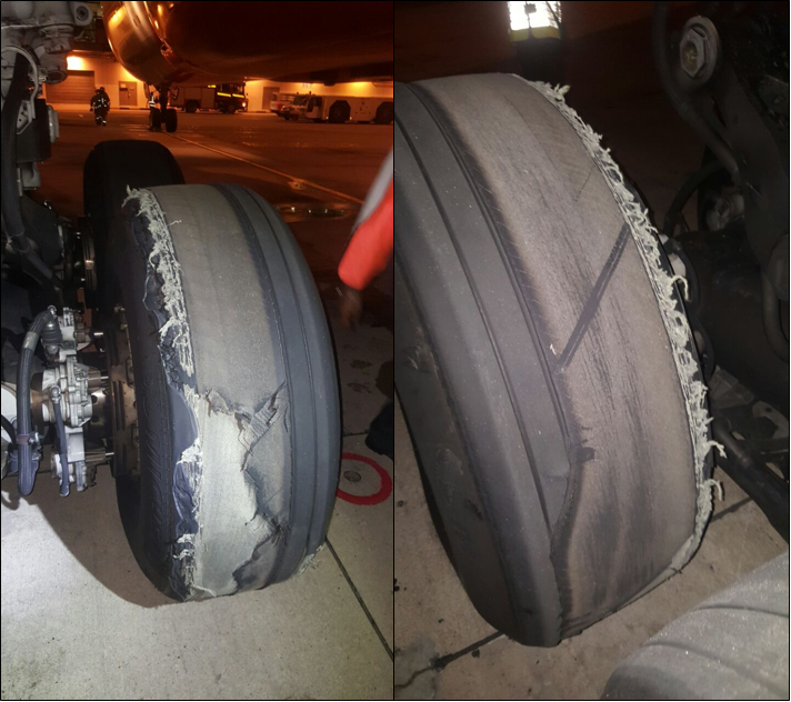
The operator’s post-incident examination of the aircraft identified that it had sustained minor damage during the landing. Both main landing gear, the radio antennas and the underside airframe panels had been abraded. Additionally, both propellors had sustained rotational contact damage from striking the runway.
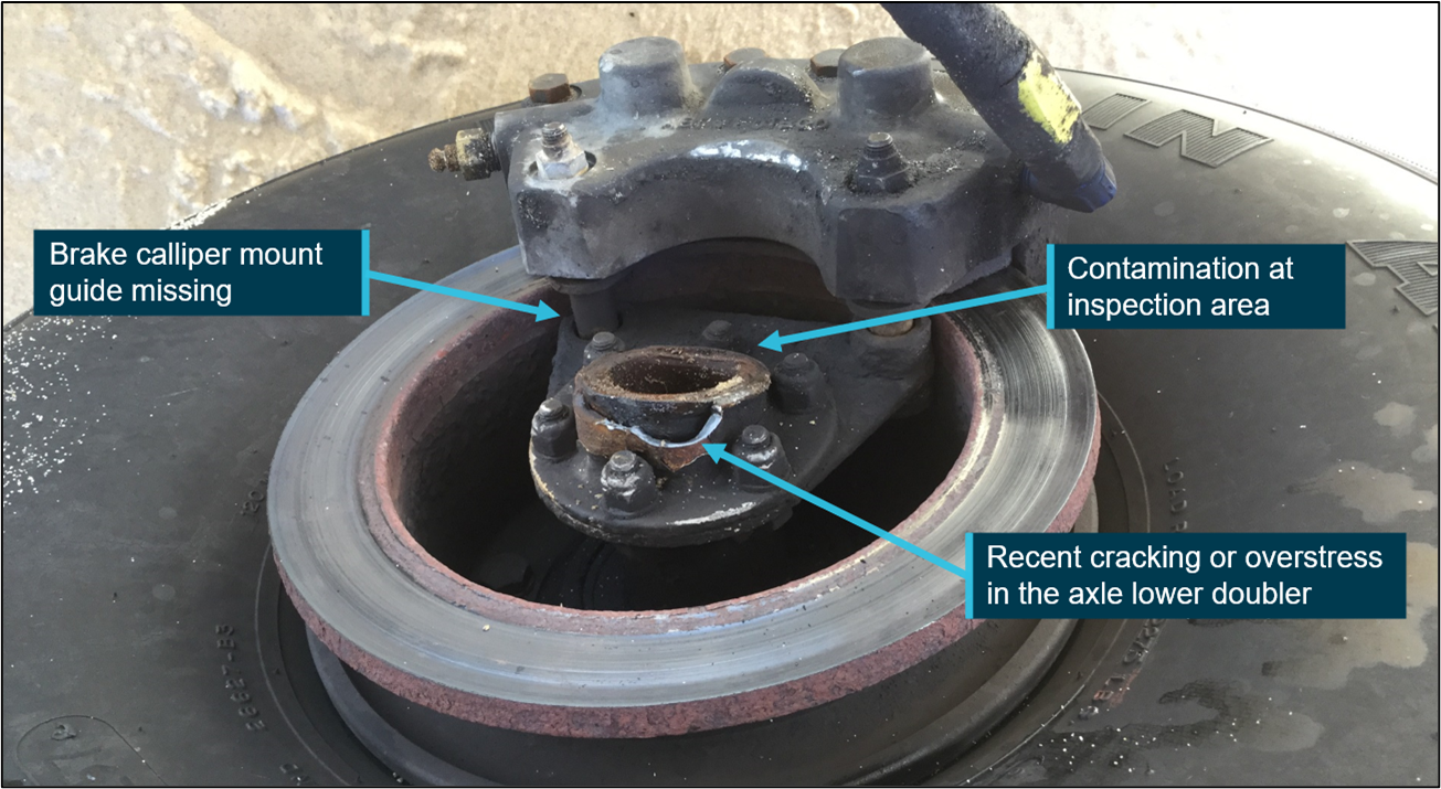
During their examination of the landing gear system, the operator identified that the shimmy damper that was attached to the nose gear leg had become bent and jammed against a door hinge within the wheel bay (Figure 3). A link in the nose steering system had also fractured, resulting in a disconnection between the pilots steering input and the nose landing gear (Figure 4). The steering barrel had bent where it connected to the steering link. The operator’s examination of the electrical system identified that a circuit breaker had opened during the incident flight. They commented that this had likely occurred automatically to prevent electrical overload of the landing gear system.
Following replacement of the fractured steering link, functional testing of the landing gear was completed as part of the operator’s fault-finding investigation. That testing showed that, under normal circumstances during a landing gear retraction sequence, the nose steering shimmy damper remained clear of all components of the wheel bay area. They further identified that the shimmy damper could only contact the wheel bay area if the nose wheel became mechanically disconnected from the steering system. That disconnection enabled the nose wheel to rotate left beyond its operational limit sufficiently for the shimmy damper to contact the undercarriage door bay area during the nose gear retraction sequence.
The operator advised that there were no binding or other defects present in the remainder of the steering or landing gear components fitted to the aircraft. The operator also found that once the circuit breakers were reset, the landing gear system became electrically functional, allowing the gear to lower. One of those required circuit breakers was not accessible to the pilot in flight.
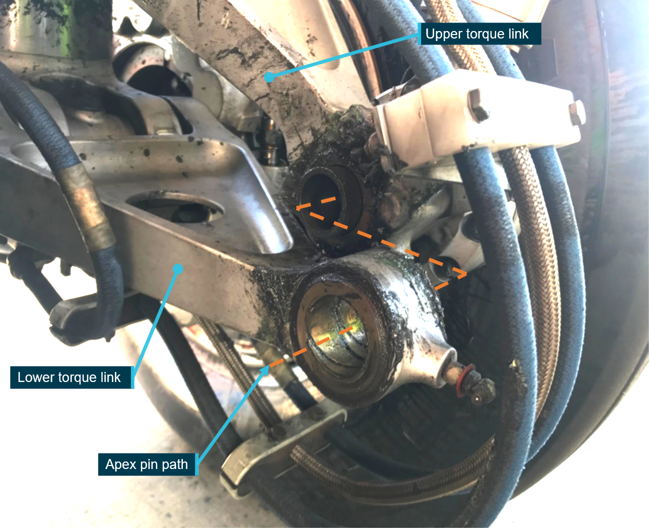
Figure 3: The nose landing gear tilted to the left with the shimmy damper jammed against a hinge in the undercarriage bay

Source: Eastern Air Services, annotated by the ATSB
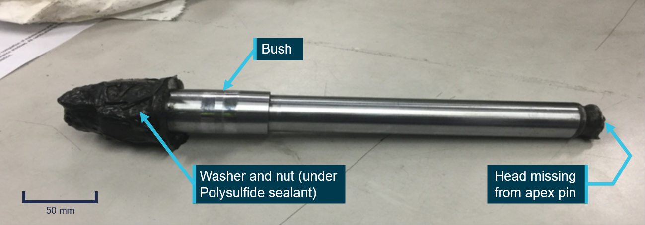
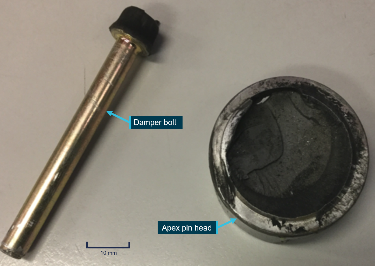
Figure 4: Damaged nose gear steering components

Source: Eastern Air Services, annotated by the ATSB
Landing gear system and nose wheel steering
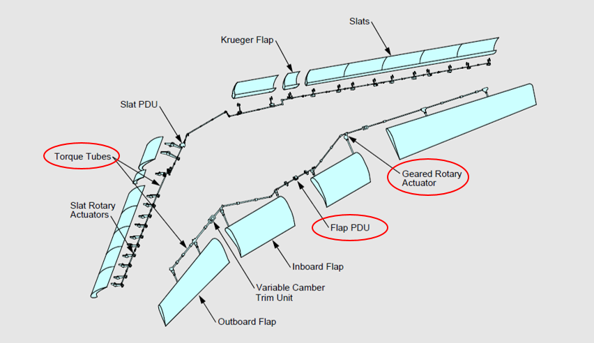
The aircraft has a mechanical landing gear system controlled through a landing gear control handle on the right side of the pilot’s centre panel. When the handle is positioned to either extend or retract the landing gear, an electric motor drives the landing gear gearbox assembly. The main landing gear actuators are driven by torque tubes from the gearbox. The nose gear is driven by a duplex chain from a sprocket on the gearbox torque shaft. Circuit breakers protect the system from electrical overload.
Emergency manual extension of the landing gear is controlled by a floor‑mounted lever centrally located between the left and right pilot seats. When the lever is manually operated, the landing gear electric motor and gearbox drive mechanisms are overridden, allowing extension of the landing gear system. The following procedure for manual extension of the landing gear was listed in the King Air pilot operating handbook:
LANDING GEAR MANUAL EXTENSION (MECHANICAL SYSTEM)
1. Airspeed - ESTABLISH 130 KNOTS
2. Landing Gear Relay Circuit Breaker (Pilot's subpanel) - PULL
3. Landing Gear Control - DOWN
4. Alternate Engage Handle - LIFT AND TURN CLOCKWISE TO THE STOP TO ENGAGE.
5. Alternate Extension Handle - PUMP UP AND DOWN UNTIL THE THREE GREEN GEAR-DOWN ANNUNCIATORS ARE ILLUMINATED.
Note: Additional pumping when all three annunciators are illuminated could damage the drive mechanism and prevent subsequent electrical gear retraction.
If all three green gear-down annunciators are illuminated:
6. Alternate Extension Handle - DO NOT STOW (Proceed to step 8.)
Should the landing gear fail to extend, the next steps in the procedure stated:
If one or more green gear-down annunciators do not illuminate for any reason and a decision is made to land in this condition:
7. Alternate Extension Handle – CONTINUE PUMPING UNTIL MAXIMUM RESISTENCE IS FELT, EVEN THOUGH THIS MAY DAMAGE THE DRIVE MECHANISM
8. Landing Gear Controls – DO NOT ACTIVATE
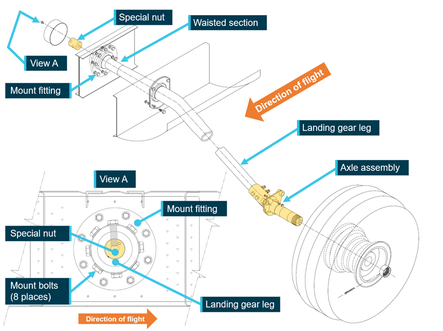
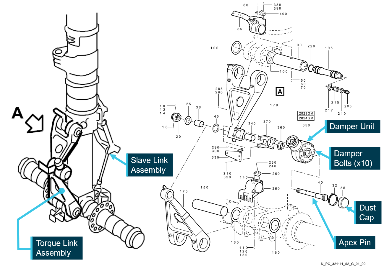
Nose wheel steering is through direct mechanical actuation of the linkages in the system from the rudder pedals that connect to an arm near the top of the nose gear shock strut (Figure 5). A spring mechanism in the steering barrel dampens the transmission of excessive shock loads to the rudder pedals. A strut-mounted roller engages with a centring ramp to automatically centre the nose wheel during retraction of the gear.
Figure 5: King Air B200 nose steering system schematic

Source: Textron Aviation, annotated by the ATSB
Aircraft maintenance
Scheduled maintenance for VH-XDV was based on a 200-hour phased inspection program, the details of which were specified by the aircraft manufacturer and contained within the King Air B200 maintenance manual. The operator’s maintenance records identified that a Phase-4 check was completed on 18 March 2024 at 18,298.4 hours. During that check the landing gear system was overhauled. Parts relating to the nose wheel steering were inspected but not replaced as their continued serviceability was based ‘on-condition’, rather than having a prescribed ‘life-limit’. On that basis the service life of the steering link was not required to be tracked and its service history was unable to be established.
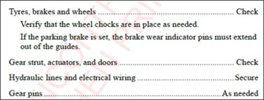
The Phase-4 inspection requirements listed in the maintenance manual for the nose gear components were non-specific and all parts were to be inspected for ‘wear damage and surface corrosion.’ For the steering linkage, it was required to be:
STEERING LINKAGE - Inspect nose gear steering mechanism and attaching hardware for wear, damage and corrosion..
There was no specific requirement to inspect the steering link for cracks.
Pilot information
The pilot held an air transport pilot licence (aeroplane), issued in September 2015, with a multi‑engine aeroplane instrument rating. In addition, they held a current grade 1 flight instructor rating and a multi-engine class flight test examiner rating. They reported approximately 8,500 hours total flying experience, of which 2,500 hours were accrued on the King Air B200.
Pilot’s commentary of the emergency
After the pilot identified that the abnormal procedure for extending the landing gear was ineffective, they assessed that the fuel quantity on board the aircraft was sufficient to troubleshoot the malfunction and prepare for a wheels-up landing by completing or considering the following:
- Throughout, the pilot remained focused on the aircraft fuel quantity and their intention was to land with about 600 lb of fuel remaining onboard. Their reasoning was that a significantly reduced fuel load would minimise the potential fire hazard on landing. They provided numerous status updates to ATC that included remaining fuel quantities.
- They contacted the operator’s chief engineer on several occasions for technical advice and spoke with another pilot colleague to assist with planning the landing.
- They relocated both passengers to the seats aft of the main spar nearer to the main cabin door then briefed them on its emergency operation.
- They communicated with the airport fire and rescue personnel on the most suitable place on the runway to land the aircraft.
- During the final approach to Williamtown Airport they configured the flaps to the approach setting and immediately prior to the aircraft contacting the runway surface, they depressurised the aircraft cabin, shut down both engines, set the propellors to fine pitch, and isolated the aircraft electrical system. Their reasoning was to minimise any potential for the aircraft to remain pressurised and reduce the likelihood of ignition of the fuel onboard after landing.
- Upon tracking to the north-east to Hawks Nest, the pilot was cognisant that instrument meteorological conditions[7] might be entered during the approach back to Williamtown and requested an instrument approach for runway 30. The pilot recalled that the instrument approach required additional distance to be flown and estimated that it could result in the aircraft entering the 45-minute fixed reserve, which then prompted them to declare MAYDAY FUEL.
Williamtown weather
When the aircraft was initially directed to the Williamtown southern circuit, the ATC controller estimated that the cloud base was between 2,000 ft and 2,500 ft AGL. Meteorological observations at Williamtown Airport identified that from 1130 through to 1400, rain showers and drizzle persisted. The ATC controller reported that during that period the cloud base began to lower, making it difficult to sight the aircraft.
In the minutes prior to the wheels-up landing, the meteorological observations indicated visibility greater than 10 km, drizzle in the vicinity of the airport, and a cloud amount of 1–2 oktas[8] at 1,300 ft AGL.
Pilot guidance for wheels-up landing
There was no specific guidance for a wheels-up landing published within the B200 operating handbook. The manufacturer advised that in this emergency situation, it would be expected that a pilot would use their aeronautical decision-making skills, training, knowledge of the aircraft, and knowledge of the situation to determine the best course of action.
The Airplane Flying Handbook produced by the United States Federal Aviation Administration (FAA) was intended to assist pilots to improve their flying proficiency and aeronautical knowledge. Chapter 18 of the Handbook, Emergency Procedures, provides generic advice to pilots for performing a gear up landing. The Handbook advised pilots to:
- select an airport with fire and rescue facilities
- request emergency equipment to stand by
- select a smooth, hard runway surface rather than an unimproved grass strip
- consider burning off excess fuel to reduce fire potential
- consider that the safest course of action may be to land with all three gears in the retracted configuration.
ATSB component examination
The following parts of the damaged nose wheel steering system were removed from the aircraft by the operator and sent to the ATSB’s laboratory facilities in Canberra for metallurgical examination:
- steering link
- shimmy damper
- steering barrel.
The ATSB’s visual examination of the shimmy damper identified that it had sustained bending of the centre shaft. The body of the shimmy damper also contained a significant gouge. The location of that damage was consistent with the operator’s reporting and the post‑occurrence photographs that the shimmy damper had become wedged against a door hinge in the nose wheel bay.
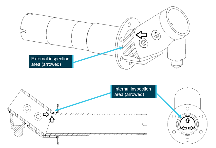
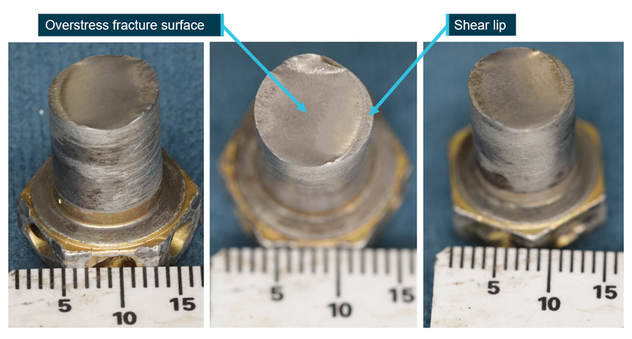
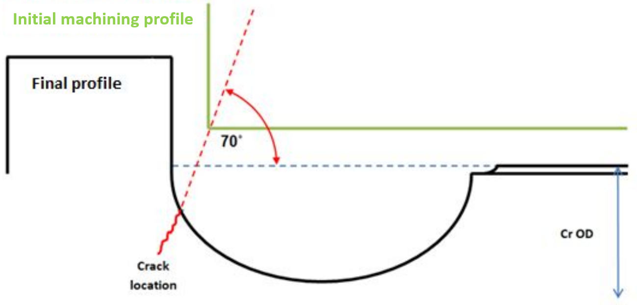
The aircraft manufacturer indicated the steering link had been cast from an aluminium alloy, which was confirmed through chemical analysis of the part by the ATSB. General visual examination of the steering link fracture surfaces was followed by detailed high-magnification examination using a scanning electron microscope. A semi-circular feature was identified on the steering link fracture surface and its aspects were consistent with that of a pre-existing defect (Figure 6). Surface staining on the defect area was also consistent with the development of corrosion.
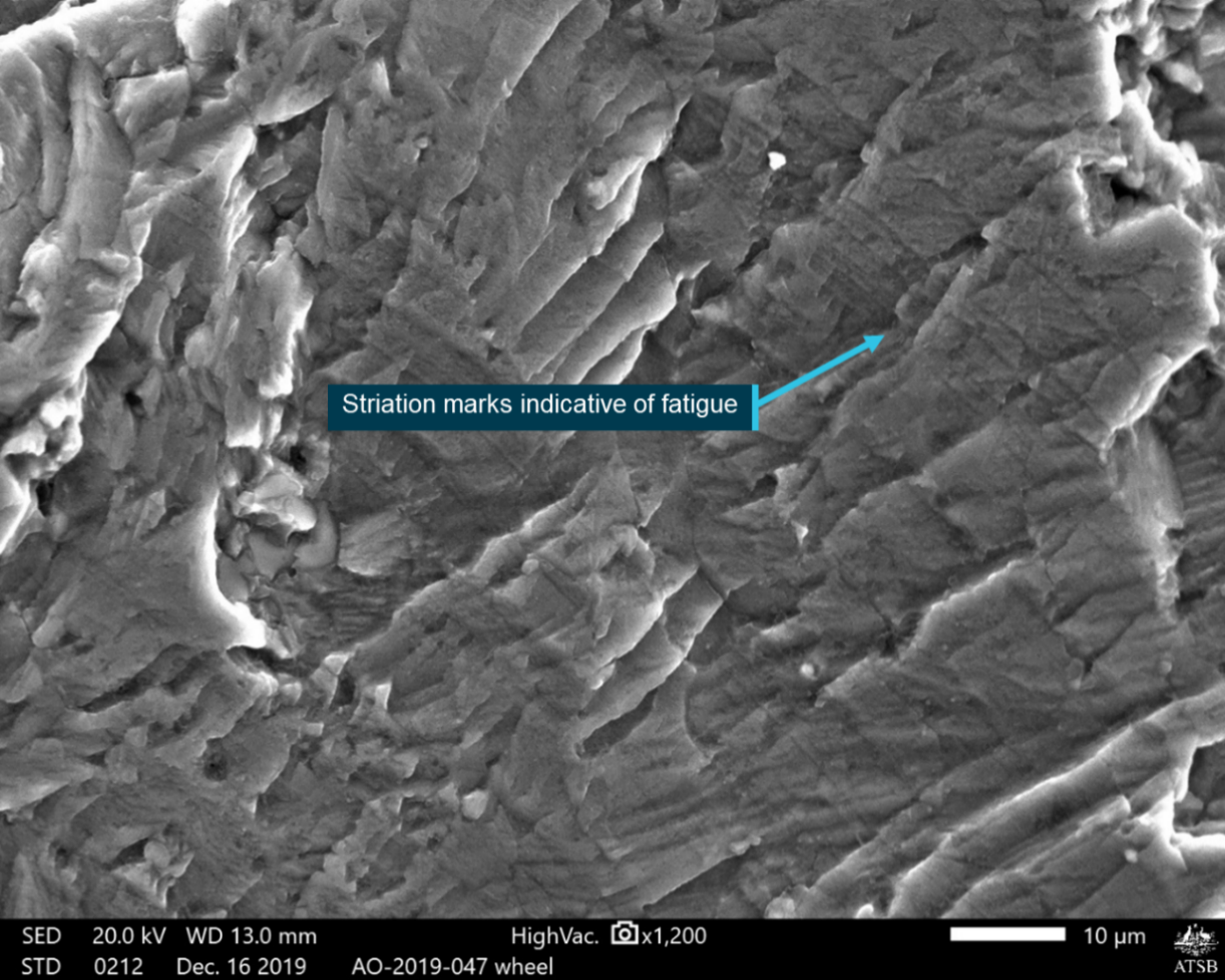
High‑magnification imagery confirmed the presence of very fine crack progression striations throughout the defect area (Figure 7). The striations confirmed that a fatigue crack had progressed into the steering link prior to its complete fracture.
The origin of the fatigue cracking was associated with a region of porosity at the component surface. The porosity was a manufacturing flaw that had been introduced during the casting process. The remainder of the fracture surface was comprised of brittle features produced during overstress of the steering link.
Figure 6: A semi-circular pre-existing defect (labelled) was identified on both halves of the steering link fracture surface

Source: ATSB
Figure 7: Microscopic striations (arrowed) were identified on the steering link fracture surface within the region of the pre-existing defect

The above image was captured using a scanning electron microscope at x4,500 magnification. Source: ATSB
Other occurrences
The ATSB's aviation occurrence database was searched for landing gear malfunctions leading to a wheels-up landing involving King Air B200 aircraft between 2014–2024. No such instances were identified. There were, however, 130 records of a wheels-up landing for all aircraft types, none of which resulted in injuries or fire.
The review of occurrence database records also identified 92 reports of 'gear unsafe' indications for the King Air B200. There was a broad range of reasons attributed for those indications, however, none of them led to a wheels-up landing. There were 12 instances where the emergency manual extension was required to be utilised and in each of those the landing gear was able to be extended.
Additionally, the aircraft manufacturer (Textron Aviation) advised that it was not aware of other instances of this specific malfunction where the mechanical landing gear became jammed leading to a wheels-up landing. It was also unaware of other instances where fatigue cracks had been identified in steering links.
Safety analysis
The ATSB identified that the aircraft was able to be steered by the pilot using the rudder pedals as it was taxied to the departure runway and during the take‑off roll. This indicated that the nose wheel steering system, including the steering linkage, was intact during the taxi and the initial stage of the take-off roll.
ATSB’s laboratory examination of the steering components identified the presence of a fatigue crack on the fracture surfaces of the steering link that had initiated from a surface flaw. The pre‑existing, high-cycle fatigue crack was small in comparison to the overall steering link cross section, indicating that the final fracture likely occurred over a relatively short number of loading cycles.
The nature of the loading that resulted in the final fracture was not identified. However, casting alloys are generally regarded as having relatively low fracture toughness when compared with wrought alloys, predisposing them to brittle fracture. Additionally, it is generally the case that the increase in stress intensity from a pre-existing fatigue crack will lead to fracture at much lower stresses due to the inherently low fracture toughness of a casting alloy.
As the pilot was able to conduct the take‑off without issue, the fracture of the steering link must have occurred either late in the take-off roll or as the gear was retracted. Once the steering link fractured, the nose wheel was able to rotate beyond its normal operational limits. In this instance, the nose wheel rotated significantly to the left. That movement led to the nose gear shimmy damper also rotating beyond normal limits sufficiently to become jammed against a door hinge within the nose wheel well.
When the pilot consulted the procedures for a manual gear extension, their efforts were ineffectual because the shimmy damper had mechanically jammed the operation of that system. Despite numerous attempts, the pilot was subsequently unable to extend the landing gear using the published emergency extension procedure, necessitating a wheels‑up landing.
Findings
ATSB investigation report findings focus on safety factors (that is, events and conditions that increase risk). Safety factors include ‘contributing factors’ and ‘other factors that increased risk’ (that is, factors that did not meet the definition of a contributing factor for this occurrence but were still considered important to include in the report for the purpose of increasing awareness and enhancing safety). In addition ‘other findings’ may be included to provide important information about topics other than safety factors. These findings should not be read as apportioning blame or liability to any particular organisation or individual. |
From the evidence available, the following findings are made with respect to the wheels-up landing involving a Beechcraft King Air B200, VH-XDV, at Williamtown Airport, New South Wales on 13 May 2024.
Contributing factors
- During the take-off roll or landing gear retraction sequence, the steering link fractured from a pre-existing fatigue crack, resulting in a mechanical disconnect within the nose landing gear steering system.
- When the landing gear retracted, the fractured steering link allowed the nose gear shimmy damper to contact the side of the wheel well and jam the nose landing gear in a partially retracted position. This prevented extension of the landing gear using the published emergency procedure, necessitating a wheels-up landing.
Safety actions
| Whether or not the ATSB identifies safety issues in the course of an investigation, relevant organisations may proactively initiate safety action in order to reduce their safety risk. All of the directly involved parties are invited to provide submissions to this draft report. As part of that process, each organisation is asked to communicate what safety actions, if any, they have carried out to reduce the risk associated with this type of occurrences in the future. The ATSB has so far been advised of the following proactive safety action in response to this occurrence. |
Safety action by Eastern Air Services
The operator reported that in the days following the incident, it conducted a maintenance inspection of the landing gear system on the other King Air B200 aircraft (registered VH‑MVP) within its fleet. No defects in the landing gear or steering system were found during that inspection. On 28 August 2024, further maintenance checks were completed on VH-MVP, including the removal of the nose gear steering link for non-destructive crack inspection. No defects were found.
The operator further advised that it is reviewing its B200 maintenance program to consider including a non-destructive inspection of the steering link, which would be additional to the manufacturer’s existing maintenance requirements.
Sources and submissions
Sources of information
The sources of information during the investigation included:
- the pilot of VH-XDV
- Eastern Air Services
- Bureau of Meteorology
- Royal Australian Air Force – 453 Squadron
- Textron Aviation
- ADS-B data from the aircraft.
References
United States Federal Aviation Administration, Airplane Flying Handbook FAA-H-8083-3C
Beechcraft King Air B200 Maintenance Manual
Beechcraft King Air B200 Pilot’s Operating Handbook
Submissions
Under section 26 of the Transport Safety Investigation Act 2003, the ATSB may provide a draft report, on a confidential basis, to any person whom the ATSB considers appropriate. That section allows a person receiving a draft report to make submissions to the ATSB about the draft report.
A draft of this report was provided to the following directly involved parties:
- the pilot of VH-XDV
- Eastern Air Services
- Royal Australian Air Force – 453 Squadron
- Textron Aviation
- Civil Aviation Safey Authority
Submissions were received from:
- the pilot of VH-XDV
- Eastern Air Services
- Royal Australian Air Force – 453 Squadron
The submissions were reviewed and, where considered appropriate, the text of the report was amended accordingly.
Purpose of safety investigationsThe objective of a safety investigation is to enhance transport safety. This is done through:
It is not a function of the ATSB to apportion blame or provide a means for determining liability. At the same time, an investigation report must include factual material of sufficient weight to support the analysis and findings. At all times the ATSB endeavours to balance the use of material that could imply adverse comment with the need to properly explain what happened, and why, in a fair and unbiased manner. The ATSB does not investigate for the purpose of taking administrative, regulatory or criminal action. TerminologyAn explanation of terminology used in ATSB investigation reports is available here. This includes terms such as occurrence, contributing factor, other factor that increased risk, and safety issue. Publishing informationReleased in accordance with section 25 of the Transport Safety Investigation Act 2003 Published by: Australian Transport Safety Bureau © Commonwealth of Australia 2024 
Ownership of intellectual property rights in this publication Unless otherwise noted, copyright (and any other intellectual property rights, if any) in this report publication is owned by the Commonwealth of Australia. Creative Commons licence With the exception of the Commonwealth Coat of Arms, ATSB logo, and photos and graphics in which a third party holds copyright, this report is licensed under a Creative Commons Attribution 4.0 International licence. The CC BY 4.0 licence enables you to distribute, remix, adapt, and build upon our material in any medium or format, so long as attribution is given to the Australian Transport Safety Bureau. Copyright in material obtained from other agencies, private individuals or organisations, belongs to those agencies, individuals or organisations. Where you wish to use their material, you will need to contact them directly. |
[1] Alert phase: a situation where apprehension exists as to the safety of an aircraft and its occupants (this generally equates to a PAN PAN)
[2] The Williamtown Airport emergency plan required on-base fire and ambulance services to respond within 30 seconds of the base alarm being raised.
[3] Visual Meteorological Conditions (VMC): an aviation flight category in which visual flight rules (VFR) flight is permitted – that is, conditions in which pilots have sufficient visibility to fly the aircraft while maintaining visual separation from terrain and other aircraft.
[4] AKLOL was an initial approach fix (waypoint) for instrument navigation to Williamtown Airport.
[5] A turbine-engine aircraft that is operated under the instrument flight rules is required to carry 45 minutes of fuel to allow the aircraft to fly at holding speed, at 1,500 ft above the aerodrome elevation. This must be available at the completion of the flight.
[6] The declaration of a FUEL MAYDAY is an internationally recognised procedure associated with the standards of the International Civil Aviation Organization and designed to assist in the management of aviation safety risks. As this is a distress message, the aircraft will be given priority to land. Where the PIC has calculated that the aircraft will land with less than the final reserve fuel, the flight crew must declare a situation of ‘emergency fuel’ by broadcasting MAYDAY MAYDAY MAYDAY FUEL.
[7] Instrument meteorological conditions (IMC): weather conditions that require pilots to fly primarily by reference to instruments, and therefore under instrument flight rules (IFR), rather than by outside visual reference. Typically, this means flying in cloud or limited visibility.
[8] Cloud amount is given in the international standard format. The terms used are FEW (few) to indicate 1–2 oktas, SCT (scattered) to indicate 3–4 oktas, BKN (broken) to indicate 5–7 oktas, OVC (overcast) to indicate 8 oktas.
Occurrence summary
| Investigation number | AO-2024-031 |
|---|---|
| Occurrence date | 13/05/2024 |
| Location | Williamtown Airport |
| State | New South Wales |
| Report release date | 13/11/2024 |
| Report status | Final |
| Investigation level | Short |
| Investigation type | Occurrence Investigation |
| Investigation status | Completed |
| Mode of transport | Aviation |
| Aviation occurrence category | Landing gear/indication, Wheels up landing |
| Occurrence class | Serious Incident |
| Highest injury level | None |
Aircraft details
| Manufacturer | Beech Aircraft Corp |
|---|---|
| Model | B200 |
| Registration | VH-XDV |
| Serial number | BB-1100 |
| Aircraft operator | Eastern Air Link Pty Ltd |
| Sector | Turboprop |
| Operation type | Part 135 Air transport operations - smaller aeroplanes |
| Departure point | Williamtown Airport, NSW |
| Destination | Port Macquarie Airport, NSW |
| Damage | Substantial |