On the morning of 21 February 2017, the pilot of a Beechcraft B200 King Air aircraft, registered VH-ZCR was conducting a charter passenger flight from Essendon Airport, Victoria to King Island, Tasmania with four passengers on board.
The aircraft’s take-off roll was longer than expected and a yaw to the left was observed after rotation. The aircraft’s track began diverging to the left of the runway centreline before rotation and the divergence increased as the flight progressed. The aircraft entered a shallow climb followed by a substantial left sideslip with minimal roll. The aircraft then began to descend and the pilot transmitted a Mayday call. The aircraft subsequently collided with a building in the Bulla Road Precinct Retail Outlet Centre of Essendon Airport.
The aircraft was destroyed by the impact and post-impact fire, and all on board were fatally injured. The building was severely damaged and two people on the ground received minor injuries.
What the ATSB found
The ATSB found that the pilot did not detect that the aircraft’s rudder trim was in the full nose-left position prior to take-off. The position of the rudder trim resulted in a loss of directional control and had a significant impact on the aircraft’s climb performance in the latter part of the flight.
At the time of the accident, the operator did not have an appropriate flight check system in place for VH-ZCR. Although this did not contribute to this accident, it increased the risk of incorrect checklists being used, incorrect application of the aircraft's checklists, and checks related to supplemental equipment not being performed.
The aircraft’s cockpit voice recorder did not record the accident flight due to a tripped ‘impact switch’, which was not reset prior to the accident flight. This deprived the investigation of potentially valuable recorded information.
The ATSB determined that the aircraft was operated above its maximum take-off weight on the accident flight. This was not considered to have influenced the accident.
The ATSB also found that the presence of the building struck by the aircraft did not increase the severity of the consequences of this accident. In the absence of that building, the aircraft’s flight path would probably have resulted in an uncontrolled collision with a busy freeway, with the potential for increased ground casualties.
Although not contributing to this accident, the ATSB identified that two other buildings within the retail precinct exceeded the airport’s obstacle limitation surfaces. While those exceedances had been approved by the Civil Aviation Safety Authority, the ATSB identified several issues relating to the building approval process for the precinct.
What's been done as a result
It is beyond the scope of this investigation to consider in detail the issues identified with the Bulla Road Precinct building approval processes. These issues will be addressed in the current ATSB Safety Issues investigation The approval process for the Bulla Road Precinct Retail Outlet CentreAI-2018-010.
Safety message
Cockpit checklists are an essential tool for overcoming limitations with pilot memory, and ensuring that action items are completed in sequence and without omission. The improper or non-use of checklists has been cited as a factor in some aircraft accidents. Research has shown that this may occur for varying reasons and that experienced pilots are not immune to checklist errors. This accident highlights the critical importance of appropriately actioning and completing checklists.
This accident also emphasises the importance of having flight check systems in place that are applicable to specific aircraft in their current modification status. In addition, it emphasises:
the value of cockpit voice recorders
the significance of ensuring aircraft weight and balance limitations are not exceeded
the challenges associated with decision-making in critical stages of a flight such as the take-off ground roll.
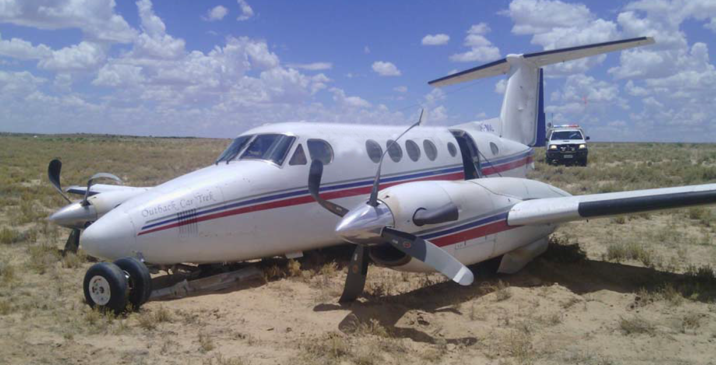
Beechcraft B200 King Air aircraft, registered VH-ZCR immediately prior to collision with a building in the Bulla Road Precinct
Source: Supplied
The occurrence
On 21 February 2017, the pilot of a Beechcraft B200 King Air aircraft, registered VH-ZCR (ZCR), and operated by Corporate & Leisure Aviation, was conducting a charter passenger flight from Essendon Airport,[1] Victoria to King Island, Tasmania. There were four passengers on board.
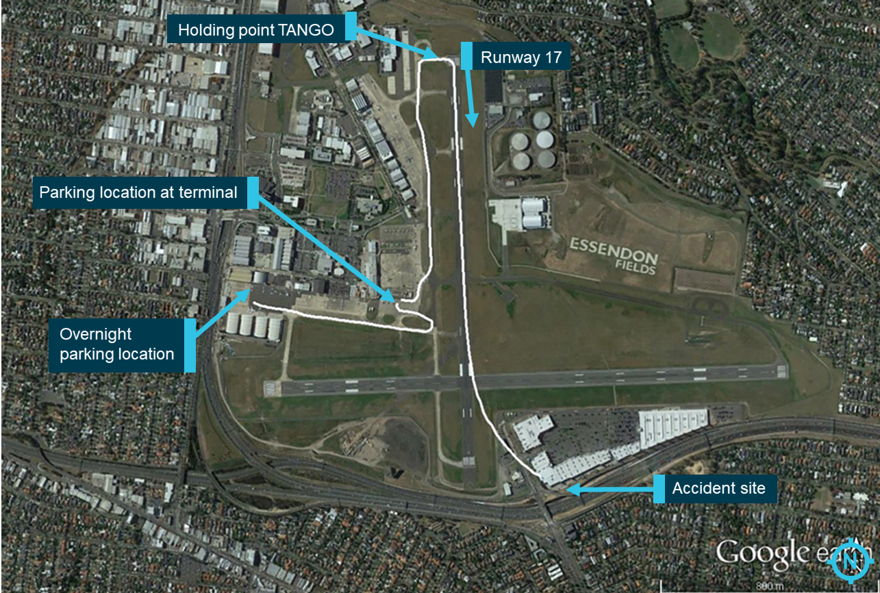
ZCR had been removed from a hangar and parked on the apron the previous afternoon in preparation for the flight (Figure 1). The pilot was first seen on the apron at about 0706 Eastern Daylight-saving Time.[2] Closed-circuit television (CCTV)[3] recorded the pilot walking around the aircraft and entering the cabin, consistent with conducting a pre-flight inspection of the aircraft.
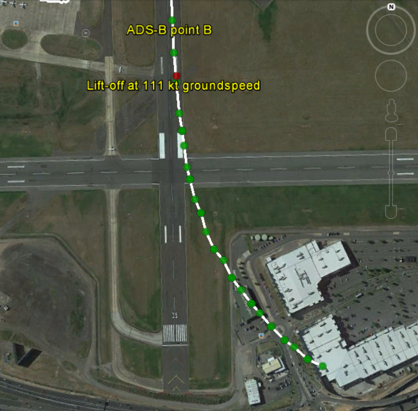
Figure 1: Aircraft taxi and flight track from Airservices Australia ADS-B data
Source: Google, annotated by the ATSB
At about 0712, the pilot entered ZCR’s maintenance provider’s hangar. A member of staff working in the hangar reported that the pilot had a conversation with him that was unrelated to the accident flight. The pilot exited the hangar about 0715 and had a conversation with another member of staff who reported that their conversation was also unrelated to the accident flight.
The pilot then returned to ZCR, and over the next 4 minutes he was observed walking around the aircraft. The pilot went into the cabin and re-appeared with an undistinguishable item. The pilot then walked around the aircraft one more time before re-entering the cabin and closing the air stair cabin door. At about 0729, the right engine was started and, shortly after, the left engine was started.
Airservices Australia (Airservices) audio recordings indicated that, at 0736, the pilot requested a clearance from Essendon air traffic control (ATC) to reposition ZCR to the southern end of the passenger terminal. ATC provided the clearance and the pilot commenced taxiing to the terminal.
At the terminal, ZCR was refueled and the pilot was observed on CCTV to walk around the aircraft, stopping at the left and right engines[4] before entering the cabin. The pilot was then observed to leave the aircraft and wait for the passengers at the terminal. The passengers arrived at the terminal at 0841 and were escorted by the pilot directly to the aircraft. At 0849, the left engine was started and, shortly after, the right engine was started.
At 0853, the pilot requested a taxi clearance for King Island, with five persons onboard, under the instrument flight rules.[5] ATC instructed the pilot to taxi to holding point 'TANGO' for runway 17,[6] and provided an airways clearance for the aircraft to King Island with a visual departure. The pilot read back the clearance.
Airservices Automatic Dependent Surveillance Broadcast (ADS-B)[7] data[8] (refer to section titled Air traffic services information - AutomaticDependent Surveillance Broadcast data) indicated that, at 0854, ZCR was taxied from the terminal directly to the holding point. The aircraft did not enter the designated engine run-up bay positioned near holding point TANGO. At 0855, while holding at TANGO, the pilot requested a transponder code. The controller replied that he did not have one to issue yet. Two minutes later the pilot contacted ATC and stated that he was ready and waiting for a transponder code. The controller responded with the transponder code and a clearance to line-up on runway 17. At 0858, ATC cleared ZCR for take-off on runway 17 with departure instructions to turn right onto a heading of 200°. The pilot read back the instruction and commenced the take-off roll.
The aircraft’s take-off roll along runway 17 was longer than expected. Witnesses familiar with the aircraft type observed a noticeable yaw[9] to the left after the aircraft became airborne. The aircraft entered a relatively shallow climb and the landing gear remained down. The shallow climb was followed by a substantial left sideslip[10], while maintaining a roll[11] attitude of less than 10° to the left. Airservices ADS-B data indicated the aircraft reached a maximum height of approximately 160 ft above ground level while tracking in an arc to the left of the runway centreline (Figure 1). The aircraft’s track began diverging to the left of the runway centreline before rotation and the divergence increased as the flight progressed.
Following the sustained left sideslip, the aircraft began to descend and at 0858:48 the pilot transmitted on the Essendon Tower frequency repeating the word ‘MAYDAY’[12] seven times in rapid succession. Approximately 10 seconds after the aircraft became airborne, and 2 seconds after the transmission was completed, the aircraft collided with the roof of a building in the Essendon Airport Bulla Road Precinct - Retail Outlet Centre (outlet centre), coming to rest in a loading area at the rear of the building.
CCTV footage from a camera positioned at the rear of the building showed the final part of the accident sequence with post-impact fire evident; about 2 minutes later, first responders arrived on-site. At about 0905 and 0908 respectively, Victoria Police and the Metropolitan Fire Brigade arrived.
The pilot and passengers were fatally injured, and the aircraft was destroyed. There was significant structural, fire and water damage to the building. Additionally, two people on the ground received minor injuries and a number of parked vehicles were damaged.
The pilot held a Commercial Pilot (Aeroplane) Licence, issued in September 1994, and attained his rating to operate the B200 aircraft in September 2004. He held a valid Class 1 Aviation Medical Certificate issued by the Civil Aviation Safety Authority (CASA) with a requirement to wear distance vision correction.
The pilot’s logbook showed a total flying experience of 7,681 hours to the last recorded flight on 18 February 2017. In the previous 90 days, the pilot had flown 66 hours and in the previous 30 days, he had flown 16 hours. He had a total of 73 hours in VH-ZCR (ZCR) and last flew the aircraft on 3 January 2017. Other records supplied by the operator indicated the pilot had accrued more than 2,400 hours in B200 aircraft.
Proficiency checks and flight reviews
The pilot had last completed a multi-engine flight review on 7 October 2016, valid to 31 October 2017 in ZCR. Records supplied by the operator also showed that the pilot had satisfactorily completed a Civil Aviation Order 20.11 emergency procedures proficiency check on 10 March 2016, valid until 9 March 2017.
The Civil Aviation Regulations 1988 regulation 224(A)(3)(d) stated that a pilot in command who was 65 years of age or older must successfully complete an instrument proficiency check (IPC) or flight review in an aircraft of the same category or an approved flight simulator for the category of aircraft, within 6 months before the date of a flight. The pilot, who was 67 years old at the time of the accident, last completed an IPC on 7 October 2016, about 4 months prior to the accident.
Following an incident[13] involving the pilot at Mount Hotham, Victoria on 3 September 2015, the pilot accepted CASA’s suggestion to undergo an IPC with a CASA flight operations inspector. That check flight was conducted on 19 October 2015. The pilot did not pass this IPC and it was recommended that the pilot conduct simulator training. There was no record in the pilot’s logbook to indicate that simulator training had been conducted, however, the pilot subsequently passed the IPC with the same CASA flight operations inspector on 3 November 2015.
CASA records stated that, other than the two IPC’s conducted with the CASA flight operations inspectors, the majority of the pilot’s flight tests and proficiency checks, including both instrument rating and Civil Aviation order 20.11 checks, were conducted by the same CASA Approved Testing Officer.
In response to the Mount Hotham incident, CASA compiled an audit report in January 2016. In that report, it was also commented that the pilot would benefit from ongoing training opportunities in a B200 simulator. The report indicated the simulator would have provided:
…an opportunity for non-jeopardy training in a variety of areas not possible in the aircraft. The use of a simulator assists in the development and maintenance of decision-making, situational awareness and practical skills, as well as exposing the pilot to real time scenarios and associated flight management practices.
The ATSB was unable to find any evidence to indicate that the pilot attended a B200 simulator after January 2016, however, CASA did not mandate that the pilot conduct the simulator training.
72-hour history
The pilot’s logbook showed the pilot conducted a flight from King Island to Essendon on 18 February 2017. He was reported to have then had two days away from flying duties. The pilot was also an air operator’s certificate (AOC) holder and, as such, was required to manage a business, including ensuring regulatory compliance. It is not known how much time the pilot spent managing his aircraft charter business during his two days away from flying duties.
The pilot was reported to normally go to bed between 2030 and 2100, or earlier if an early flight was scheduled for the next day. Evidence from Airservices indicated that the pilot’s National Aeronautical Information Processing System (NAIPS) user account was accessed at 2356 on the evening of 20 February 2017, to obtain aerodrome forecasts and Notice(s) to Airmen (NOTAM)[14] for Essendon, Victoria and King Island, Tasmania.
The same NAIPS account was accessed again on the morning of the accident, between 0456 and 0458, to obtain aerodrome forecasts and NOTAM for Essendon, King Island, Launceston, and Devonport, Tasmania. The pilot reportedly woke around this time, had breakfast and a beverage before leaving home for the drive to Essendon Airport. Traffic dependent, this drive was estimated to be between 1 hour 15 minutes and 2 hours.
On the above information, it was considered that the pilot had a sleep window of approximately 8 hours, but had a period of wakefulness during the night, when he briefly checked NAIPS. It is not known how long the period of wakefulness was and therefore not possible to assess the potential for it to have resulted in acute fatigue. Fatigue is a function of both sleep obtained and time awake however, and the pilot had been awake for about 4 hours at the time of the accident. That period of wakefulness is unlikely to have aggravated any feelings of fatigue associated with the previous night’s rest period.
The ATSB was also provided with varying accounts of factors that may have increased the pilot’s level of longer‑term fatigue, however, there was insufficient evidence to determine whether fatigue was a contributing factor to this accident.
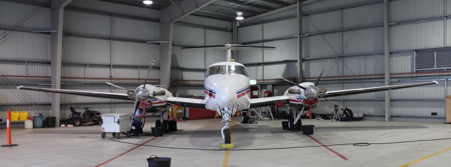
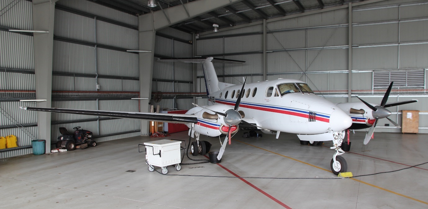
Aircraft information
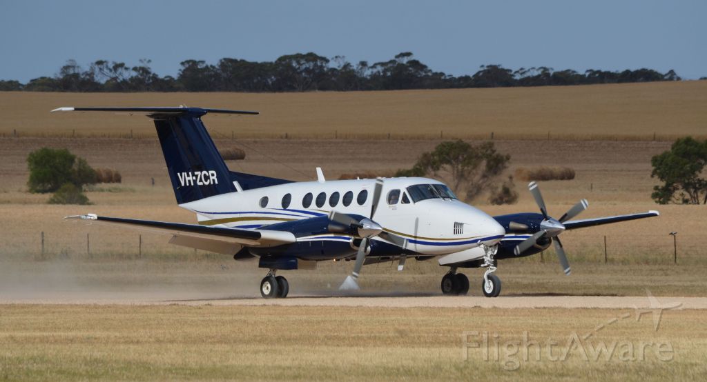
ZCR was a twin-engine turboprop aircraft with retractable landing gear, a pressurised cabin and a T-tail horizontal stabiliser (Figure 2). The aircraft was manufactured in the United States by the Raytheon Aircraft Company in 1996 and was issued with serial number BB-1544. At the time of the accident, Textron Aviation Inc. was the Type Certificate holder[15] for the aircraft. Textron Aviation Inc. branded the aircraft as a Beechcraft B200. The aircraft was imported into Australia and registered as ZCR on 9 October 2014.
After arriving in Australia, ZCR was reconfigured with a corporate-style interior and a passenger cabin seating capacity of seven. The aircraft was operated in the charter category. It had accumulated 6,997 flight hours prior to the accident flight.
Figure 2: Beechcraft B200 King Air, VH-ZCR
Source: Courtesy of FlightAware (flightaware.com)
Aircraft records
ZCR had a current Certificate of Registration and Airworthiness. The aircraft’s current maintenance release was destroyed in the accident. A copy of that maintenance release, at issue, was provided to the ATSB by ZCR’s maintainer. The maintenance release was due to expire on 16 December 2017 or upon 7,188 hours total time-in-service, whichever came first. The maintenance release also indicated that ZCR was equipped to be operated under the IFR and in the charter operational category.
Part 1 of the aircraft’s Logbook Statement specified the aircraft was to be maintained in accordance with aircraft manufacturer’s maintenance schedule and applicable Airworthiness Directives. A review of the maintenance documentation did not reveal any anomalies that may have contributed to the accident.
The following summarises the maintenance and activities conducted in ZCR leading up the accident:
16 December 2016 - major maintenance and rectifications were completed. A subsequent post-maintenance check flight was conducted with the accident pilot and a licenced aircraft maintenance engineer.
28 December 2016 - all the main landing gear tyres were replaced.
3 January 2017 - a flight was conducted by the accident pilot and a co-pilot. This was the last flight captured on the aircraft’s cockpit voice recorder.
12-13 January 2017 - the pilot who flew the aircraft reported experiencing a landing gear malfunction.
31 January 2017 - the landing gear power pack and the emergency locator transmitter battery were replaced. This was the last maintenance recorded in the aircraft’s records.
5 February 2017 - the aircraft operated for 6 hours without any reported defects and did not fly again until the accident flight on 21 February 2017.
20 February 2017 - the aircraft was towed out of a hangar adjacent to the maintenance provider and parked on the tarmac.
The ATSB did not identify any maintenance having been performed between 5 February and the accident flight on 21 February.
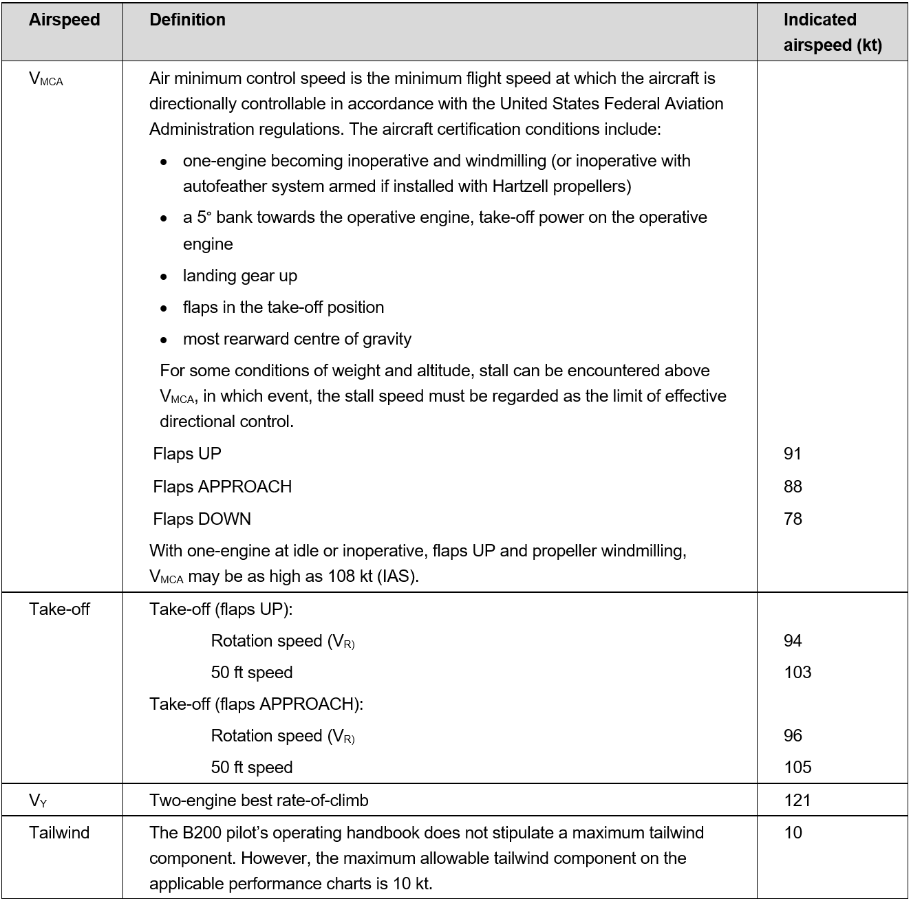
Operating speeds
The following information details the operating speeds and limitations applicable to ZCR (Table 1).
Table 1: Summary of operating speeds
Aircraft systems information
Flight control overview
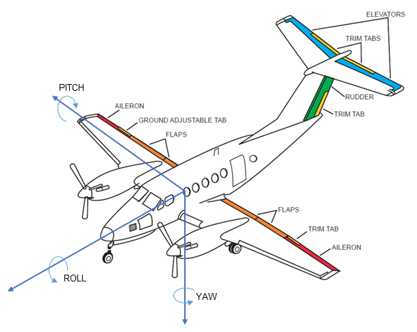
The B200 aircraft is fitted with conventional flight controls connected to the aircraft’s primary flight control surfaces. The primary flight controls consist of the rudder, elevators and ailerons, which control the aircraft about the yaw, pitch and roll axes respectively (Figure 3).
The pilot controls an aircraft by manipulating the control wheel and rudder pedals, which deflect the ailerons, elevators and rudder. Deflection of an aircraft’s primary flight control surfaces changes the aerodynamic shape and therefore the amount of lift generated by the associated part of each wing, vertical stabiliser or horizontal stabiliser. These local variations in lift result in changes to the aircraft attitude and consequently flight path.
Any deflection of the primary flight control surfaces into the adjacent airflow produces aerodynamic forces on the surface and corresponding loads on the control wheel or rudder pedals. The magnitude of the aerodynamic force is principally related to the amount of flight control surface deflection, airspeed, and trim tab deflection.
On the B200 aircraft, adjustable trim tabs are attached to the trailing edge of the primary flight controls. These tabs are used to ‘trim’ or counteract the aerodynamic forces felt by the pilot on the control wheel or rudder pedals. During flight, deflection of an aircraft’s trim tab produces an aerodynamic force on the aft part of the associated primary surface. The tabs have the capacity, when adjusted in the opposite direction to the deflection of the primary surface, to modify the aerodynamic force on the surface and correspondingly, reduce the load felt by the pilot on the control wheel or rudder pedals. The effectiveness of a trim tab is principally related to the amount of deflection and the aircraft’s airspeed.
Figure 3: Position of the elevator, aileron and rudder trims on a B200 aircraft and the pitch, roll and yaw axes
Source: ATSB
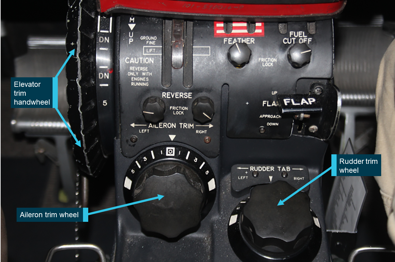
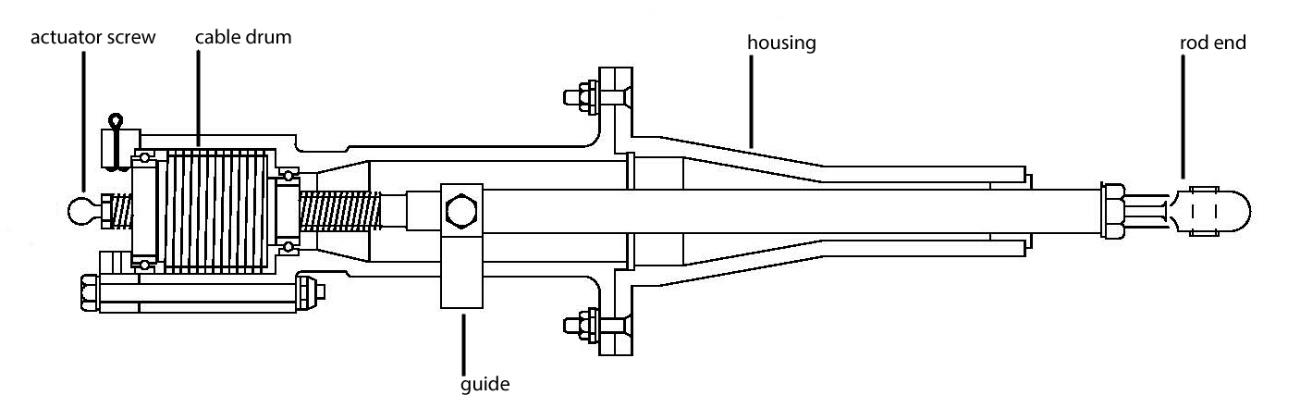
Trim tab positions were adjusted on ZCR by rotating trim wheels, located on the centre pedestal (Figure 4). Moving the trim wheels transmitted rotary motion to screw jack actuators that positioned each tab. A position indicator for each trim tab was integrated with the respective trim control wheel.
Figure 4: Position of the elevator trim wheel, aileron trim wheel and rudder trim wheel on the centre pedestal of a B200 aircraft
Source: Australasian Jet Pty Ltd, annotated by the ATSB
Rudder trim
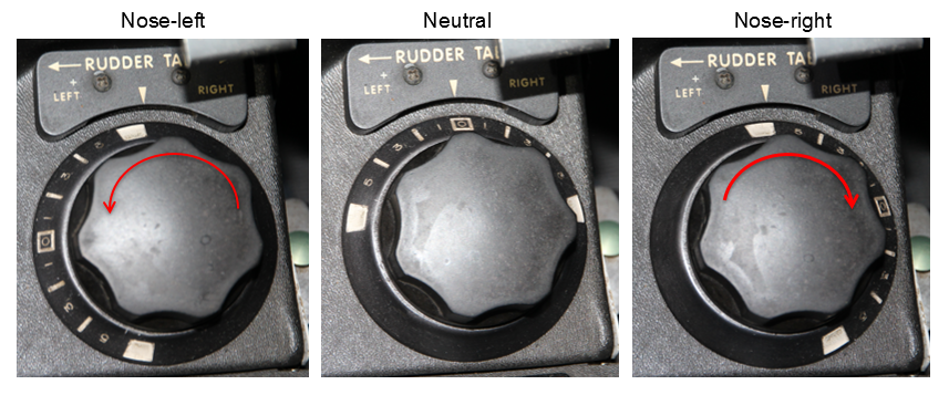
The rudder trim was manually controlled using a trim wheel located on the right side of the centre pedestal (Figure 5). Cables extend rearward from the wheel, through the airframe, to the rudder trim tab actuator. Rotating the wheel to the left moved the trim tab to the right, which in turn moved the rudder to the left, resulting in nose-left movement about the aircraft’s yaw axis. Rotating the wheel to the right results in yaw to the right. Operation of the rudder trim control showed that three turns through about 180 degrees were required in order to achieve full deflection either side of neutral.
Figure 5: Rudder trim indicator in the full nose-left, neutral and nose-right positions
Source: ATSB
Rudder boost system
The aircraft was fitted with a rudder boost system that aided the pilot in maintaining directional control in the event of an engine failure. Two pneumatic-boost servos were incorporated into the rudder system, which actuated the rudder control cables. This assisted the pilot by reducing the required rudder pedal force. The rudder boost system is controlled by a toggle switch on the centre pedestal, below the rudder trim wheel labelled RUDDER BOOST – OFF. The switch is to be turned on before flight.
Autopilot control
The aircraft was fitted with a three-axis autopilot and flight director system. The autopilot used a combination of sensors, electrical servos, guidance displays, mode selectors and flight control computers. These systems provide either full autopilot control of the aircraft, with simultaneous flight director monitoring or manual control in response to flight director steering commands.
The autopilot uses electric servos which are connected directly to the primary aileron, elevator and rudder control cables and to the elevator trim system. The autopilot is not connected to the aileron or rudder trim systems. The elevator trim system had an additional electric servo to control pitch trim independently of the autopilot utilising trim switches on the control wheel.
A component of the autopilot which affects aircraft yaw though the rudder system is called the yaw damper. The yaw damper can be operated independently to the rest of the autopilot system. Its function is to assist the pilot in maintaining directional control, and to increase passenger ride comfort. While the system could be used at any altitude and was required above flight level[16] 170, it should be deactivated for take-off and landing. The yaw damper is actuated through the rudder autopilot servo, which is connected directly to the rudder cables and has no connection to the rudder trim cables.
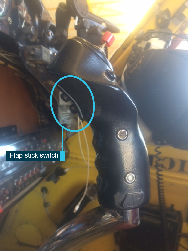
Flap system description
The aircraft had four flaps, one inboard, and one outboard per wing. The flaps are normally in the fully retracted position. They are extended to slow the aircraft and allow it to land at a lower airspeed. They can also be used to aid short field take-off performance in the APPROACH position. The flaps were operated using a sliding selector positioned on the centre pedestal. Flap travel was registered on an indicator above the pedestal, the indicator represents flap position in a percentage. There were three detents in the selector assembly that correspond with:
UP or 0%, representing fully retracted, 0⁰ of travel
APPROACH or 40%, representing 14⁰ of flap down travel
DOWN or 100%, representing full extension, 35⁰ of flap down travel.
The flaps cannot be stopped in-between any of the three positions. If an asymmetric flap condition is detected, power to the electric flap motor is disconnected.
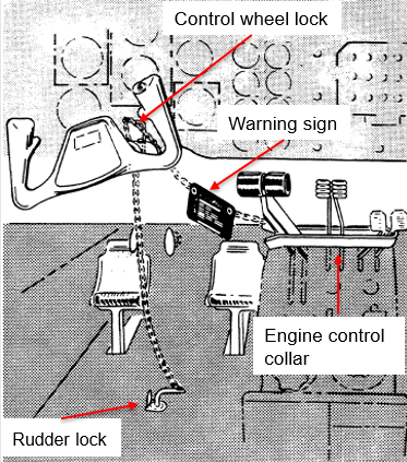
Flight control locks
While parked, the flight and engine controls were mechanically locked by a U-shaped clamp and two pins (Figure 6). The pins lock the control wheel and rudder pedals and the U-shaped collar fits around the engine control levers to prevent movement when the lock is installed. The rudder pin locked the nose wheel steering in the neutral position, making normal ground manoeuvring impossible. The control wheel lock prevents movement of the elevators and ailerons making it unlikely the aircraft could be rotated on take-off. The control lock components were connected together by chain and were to be removed prior to towing the aircraft. The control lock mechanism shown below was consistent with the description of the lock used in ZCR.
Figure 6: Example of the control lock, fitted to a B200 aircraft
Source: Textron Aviation Inc., annotated by the ATSB
Engine controls
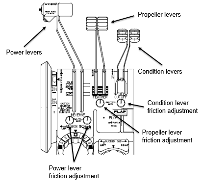
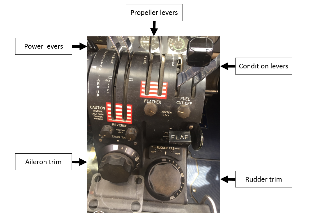
The B200 propulsion system is operated using three sets of controls located in the engine controls section of the centre pedestal (Figure 7):
Power levers control engine power from the idle position through to take-off power. When the power levers are lifted and pulled aft over a gate, they control propeller reverse thrust for slowing the aircraft after landing and for taxi operations.
Propeller levers control propeller revolutions per minute (RPM). The propellers can be feathered by moving the levers past detents and back to the full aft position.
Condition levers are used to select high or low idle and to shut the engines down.
Friction locks
Four friction locks were located on the engine control quadrant. One each for the left and right power levers, one for the propeller levers and one for the condition levers (Figure 7). When rotated in an anti-clockwise direction, the propulsion systems controls moved freely. When rotated in a clockwise direction, the levers progressively become resistant to movement, preventing the levers from moving out of position.
Figure 7: Engine control pedestal showing power levers, propeller levers, condition levers and friction locks
Source: Textron Aviation Inc., annotated by the ATSB
Power lever roll back (creep)
Throughout the investigation, the ATSB spoke with numerous B200 pilots who highlighted the importance of ensuring power lever frictions were adequately tightened prior to take-off. In their experience, if inadequate power lever friction was set, the power levers could ‘creep’ back from the full-power position when the pilot removed their hand from the levers after take-off.
If power lever movement is not noticed, the aircraft may not climb and accelerate normally, and rudder force may be required to keep the aircraft straight. In addition, the auto-feather system will be disarmed if either power lever moves back past the ‘90% engine’ speed position (refer to section titled Autofeather system below).
Autofeather system
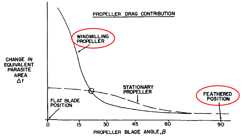
ZCR was equipped with an auto feathering system, which provided a means for automatically feathering the propellers in the event of an engine failure. Feathering reduces drag by increasing the angle of the propeller blades until they are parallel with the aircraft’s line of flight.
Airport information
Essendon Airport is located about 8 km to the south-east of Melbourne Airport. It provided facilities and services for international and domestic corporate aircraft, aircraft maintenance, airfreight, and aircraft charter. It was also the base for emergency services fixed-wing aircraft and helicopters for police, air ambulance and firefighting aircraft operations.
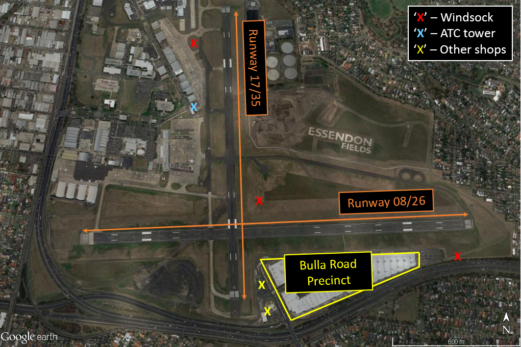
It has two runways aligned 17/35 and 08/26 (Figure 8). Runway 17/35 was the runway-in-use at the time of the accident and was 1,504 m in length, with a 0.9 per cent slope down to the south. Runway 08/26 was 1,921 m in length. Three windsocks were positioned around the airport, one of which was located adjacent to the northern end of runway 17/35.
Airservices provided air traffic services to the flight crew of aircraft operating at Essendon and in the surrounding airspace. At the time of the accident, the pilot of ZCR was communicating with Essendon Tower.
The Airservices publication En Route Supplement Australia (the ERSA) indicated that a bird hazard existed at the airport. A helicopter pilot who had landed shortly before the accident could not recall observing any bird activity in the area. Similarly, a pilot positioned on the eastern side of runway 17/35, who observed ZCR take off, reported that he did not observe birds in the vicinity off the aircraft during take-off and climb.
Figure 8: Essendon Airport and the location of the ATC tower, windsocks, and proximity of the Bulla Road Precinct
ZCR collided with a building constructed on the south-eastern corner of Essendon Airport (Figure 8). This building was one of four, collectively known as the Bulla Road Precinct – Retail Outlet Centre (outlet centre), proposed by the airport lessee in 2003, approved by the Federal Government in 2004, and completed in 2005.
The ERSA, a component of the Aeronautical Information Publication, publishes information about an airport’s infrastructure and, in particular, runway data and airspace obstructions that may affect operations at the airport. The airport data for Essendon included seven obstacles that breached the airport’s obstacle limitation surfaces (OLS). Four of those obstacles infringed the runway 26 transitional surface component of the OLS and were associated with two buildings within the outlet centre that were not struck by the aircraft. CASA accepted the breaches in 2015 after the airport operator applied lighting and colour to the obstacles to mitigate their risk to aircraft operations.
The OLS are a series of surfaces that set the height limits of objects around an airport. The transitional surface is a component of the OLS that is immediately adjacent to the runway area. The runway area includes the runway itself and an adjacent area that is required to be graded and clear of all obstacles. The intent of the OLS is to provide airspace around an airport that is kept as free as possible from obstacles so as to permit the intended aircraft operations at the airport to be conducted safely, as well as to prevent the airport from becoming unusable as a result of growth of obstacles around it. The airport operator is responsible for establishing an applicable OLS. The surfaces of the OLS are based on a complex set of criteria that include whether the runway is used for departures and/or landings, and the types of approaches attached to that runway.
At the request of the investigation, the airport operator produced an OLS based on runway 17/35 only, and mapped the outlet centre obstacles in relation to this particular OLS. That data identified that the listed obstacles did not penetrate the OLS for runway 17/35. The airport operator also identified a further three obstacles that were not listed in the ERSA as breaching the OLS. They were not listed as they were considered minor breaches of the OLS. These obstacles related to light poles in the area of the outlet centre. The aircraft did not collide with any of the obstacles that breached the OLS.
Meteorological information
The automatic terminal information service (ATIS) information current at the time of the aircraft’s departure indicated that runway 17 was being used for departures and runway 26 for arrivals. The wind was reported as 340° at 5 kt, all tailwind on runway 17, the conditions were CAVOK,[17] and the temperature was 12 °C. Subsequent ATIS information issued after the accident indicated the airport was closed, due to the accident, and the wind was variable[18] at 5 kt.
The Bureau of Meteorology provided the ATSB with one-minute interval data recorded by the Essendon automatic weather station. At 0859, the wind was 322° at 4 kt gusting to 5 kt, which would have resulted in about a 4 kt tailwind on runway 17. The temperature was 14 °C.
The Essendon air traffic controllers indicated that, on the morning of the accident, the windsocks were showing nil wind but the anemometer[19] was indicating winds up to 5 kt. Consequently, using the least favourable scenario, the controllers stipulated on the ATIS that the wind speed was 5 kt, which was the maximum allowable tailwind on the nominated runway-in-use. The controllers also reported that, when the anemometer reading was less than about 7-8 kt, the readings became unreliable due to the siting of the anemometer. The automatic weather station was positioned on the eastern side of runway 17/35. The wind anemometer was located about 10 m south-east of the station.
On 14 September 2017, the Bureau of Meteorology advised the ATSB that the anemometer had been in the same position since 2003. Since the accident, however, a potential issue with the anemometer siting had been raised, which they were investigating.
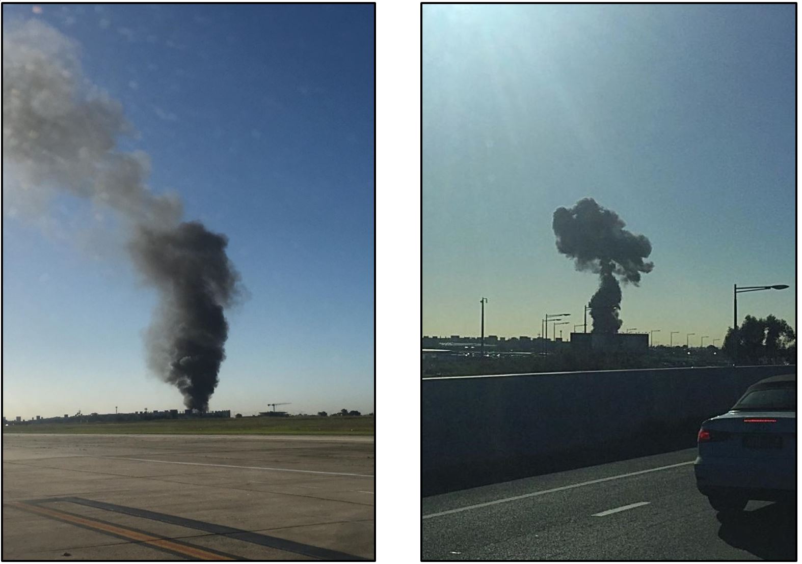
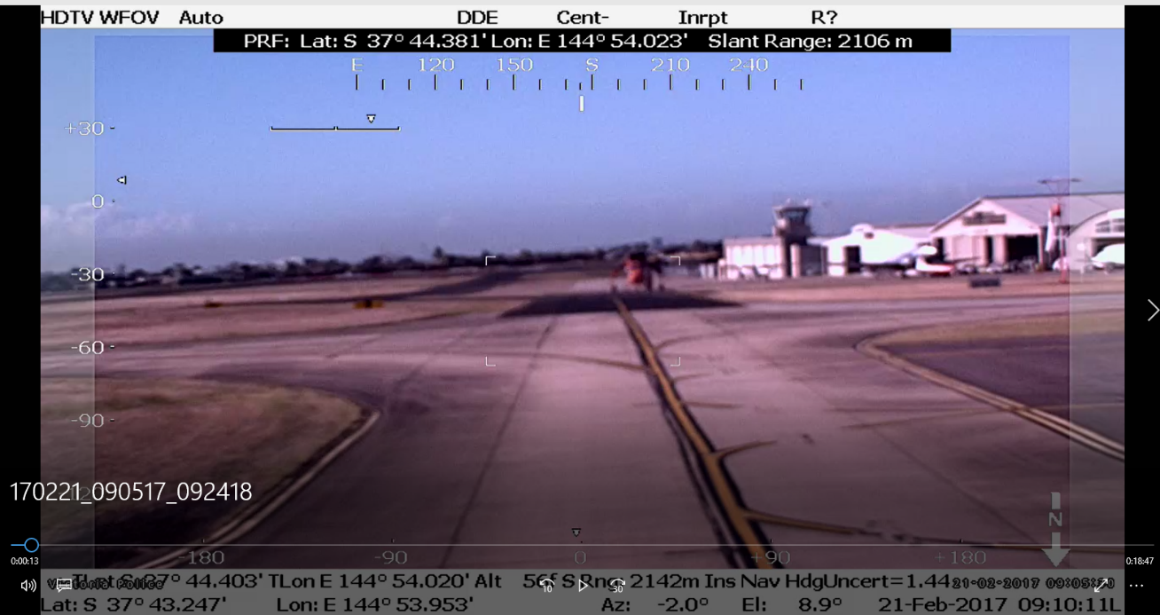
Two witnesses, both of whom were pilots familiar with the B200 aircraft type, were positioned on the eastern side of runway 17/35 at the time of ZCR’s departure. They recalled that the wind was ‘fairly calm’ and there was no adverse weather present at the time. Images of the smoke plume and video footage of the windsock adjacent to the northern end of runway 17/35 taken shortly after the accident also showed that the wind at ground level was negligible (Figure 9 and Figure 10).
Overall, the wind conditions around the time of the accident were likely to have been calm. However, it could not be ruled out that the wind conditions ranged to a maximum of 5 kt tailwind on runway 17, which was within the aircraft’s limitations.
Figure 9: Photographs of the smoke plume that provided an indication of the wind conditions
Source: Alex Poole (left) and David Bell (right)
Figure 10: Indications of wind from the windsock located adjacent to the northern end of runway 17/35
Source: Victoria Police
Air traffic services information
Flight plan
The pilot’s flight plan submitted to Airservices specified a scheduled departure time of 0830 from Essendon and a total estimated elapsed time of 36 minutes to King Island. The plan also indicated that the flight was a ‘non-scheduled air service’ to be conducted under the instrument flight rules, and there was to be five persons on board.
MAYDAY call
The MAYDAY call broadcast by the pilot of ZCR shortly after take-off was reviewed by the ATSB. No additional information regarding the nature of the emergency was identified. In addition, the ATSB’s assessment of the pilot’s speech characteristics was unable to provide any further information.
Automatic Dependent Surveillance Broadcast data
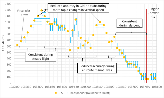
Automatic Dependent Surveillance Broadcast (ADS-B) data was obtained from Airservices. The ADS-B data was transmitted from the aircraft multiple times per second using the aircraft’s mode‑S transponder.[20] ADS-B parameters include latitude, longitude, groundspeed, track angle, vertical speed and pressure altitude. With the exception of pressure altitude, these parameters were sourced from the aircraft’s GPS. Pressure altitude information was sourced from ZCR’s static system.[21]
The ADS-B pressure altitude data was considered more accurate than the GPS vertical rate data. Following the observed sideslip in the latter part of the flight, however, the pressure data was no longer considered reliable. This was due to the local airflow effects near the static ports induced by the substantial sideslip (refer to section titled Aircraft flight path profile).
The following information was derived from the ADS-B data:
ZCR performed a rolling take-off after turning onto runway 17 from holding point TANGO.
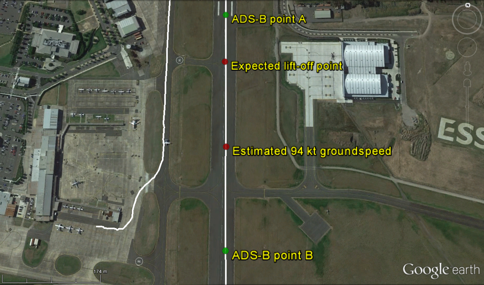
ZCR reached the rotation speed of 94 kt at about 730 m from the threshold of runway 17. The aircraft’s derived acceleration was refined using CCTV footage.
ZCR became airborne about 1,015 m from the threshold of runway 17. The aircraft’s rotation point was confirmed using CCTV footage.
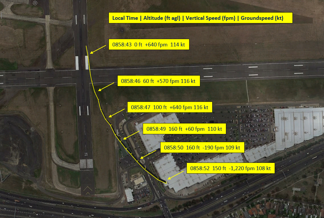
The aircraft began to deviate to the left of the runway centre-line between ADS-B data points A and B (Figure 11). The rate of deviation was initially constant but then increased as the flight progressed (Figure 12).
ZCR became airborne at a groundspeed of about 111 kt.
Using the rate of change in ADS-B pressure altitude data, ZCR’s initial rate of climb was about 1,100 ± 200 feet per minute.
ZCR stopped accelerating about 5 seconds after becoming airborne.
The maximum groundspeed recorded for the flight was 116 kt.
ZCR reached a height, above ground level (AGL), of no more than 160 feet.
The MAYDAY call was initiated about 7 seconds after ZCR became airborne. At this time, ZCR’s airspeed was decreasing, the vertical speed was changing from a climb to a descent and the track was deviating to the left at an increasing rate.
The final ADS-B data point was recorded at 0858:52, about 10 seconds after the aircraft became airborne and about half a second before the collision with the outlet centre building.
Figure 11: ADS-B data showing initiation of ZCR’s divergence from the runway centreline between points A and B
Source: Google, annotated by the ATSB
Figure 12: ADS-B data points showing ZCR’s increasing divergence from the runway centreline as the flight progresses
Source: Google, annotated by the ATSB
Witness observations
A number of witnesses were interviewed by the ATSB and Victoria Police. The following provides a description of the observations by the key witnesses and a combined summary of the other witnesses interviewed.
Key witnesses
Pilots on the eastern side of runway 17
Two B200 pilots were positioned on the eastern side of runway 17, in line with the air traffic control tower (Figure 13). Both witnesses observed the aircraft taxiing past the control tower toward the runway 17 threshold. The witnesses were unable to observe the beginning of the take-off roll; they could, however, hear the aircraft’s engines, which they reported as sounding normal. Shortly after commencing the take-off roll, the aircraft came into view. The witnesses were expecting the aircraft to become airborne around their position, however ZCR continued along the runway. They commented that it appeared that the aircraft became airborne near the runway intersection or about two‑thirds along the runway, which was considered an unusually long take-off roll.
Figure 13: Image showing the key witness positions relative to ZCR’s track
Source: Google, annotated by the ATSB
One of the witnesses reported observing the aircraft in a shallow climb after it became airborne. Immediately after, or possibly several aircraft lengths after, a left turn was observed. The turn was described as a ‘flat’, yawing or skidding turn rather than a rolling turn, with possibly 5-10° angle of bank, at a ‘very slow’ speed. The aircraft then appeared to be at right angles to the runway, heading in an easterly direction. The aircraft was observed climbing no higher than about 100 ft AGL, before descending. The witness stated that he then lost sight of the aircraft behind the buildings. Overall, the witness believed there was something wrong when the aircraft was on the ground as well as when it was airborne.
The other witness reported that, after it became airborne, the aircraft immediately yawed left, similar to that experienced with a strong crosswind. He further reported the aircraft did not climb and the aircraft’s attitude was about 5° nose-up, which was less than half of what he would normally expect. He reported the aircraft’s wings were level and it continued yawing left and climbed to no more than 100-150 ft AGL. The witness then observed the aircraft stop climbing and adopt an almost level attitude, which coincided with the left yaw increasing. The witness stated the aircraft was going ‘extremely slow’ and was almost ‘floating’. The aircraft descended and then disappeared behind the buildings.
Both witnesses reported that the landing gear had remained extended. They further stated that there were no unusual sounds heard during the take-off, such as the propellers trying to stay ‘on speed’, sounds associated with the propellers feathering or changing pitch, and no compressor stall sounds. The aircraft sounded normal.
Refuelling operator
A local refuelling operator had stopped his truck adjacent to runway 17, facing south, to take a phone call. While on the phone, the operator observed ZCR shortly after becoming airborne. The aircraft was at about 30-40 ft AGL and climbing in what he believed to be a normal take-off configuration.
When the aircraft was about over the runway intersection, he saw the aircraft yaw ‘savagely’ left, but stay relatively ‘flat’; the aircraft did not bank. He did not observe any corrections to the yaw. The aircraft climbed to no more than 100-200 ft before it began to descend rapidly. He lost sight of the aircraft as it descended behind the outlet centre buildings.
As the operator remained in his truck with the engine running, he was unable to hear any sounds associated with ZCR. The landing gear was reported to have remained extended.
Air traffic controllers
One of the Essendon Tower air traffic controllers observed ZCR’s take-off roll and reported that the aircraft accelerated as expected and appeared normal. The aircraft appeared to rotate at the correct position. He did not hear any unusual noises from the aircraft as it went past the tower.
After this, the air traffic controller moved his attention to other work-related activities. Shortly after, the controller heard a MAYDAY call, which he recognised as being from ZCR. He was expecting the pilot to continue the MAYDAY call and provide further details. At the same time, he looked at the aircraft and noted that the aircraft was facing east instead of south. The aircraft was in a ‘flat’ orientation and appeared to be travelling ‘very slowly’ compared with what he would expect. The nose then dipped and the aircraft disappeared behind the outlet centre buildings. The controller advised the Melbourne departures controller of the accident, instructed an airport safety vehicle to attend the accident site, and dealt with other aircraft traffic.
Another air traffic controller in the Essendon Tower first sighted ZCR when it was airborne and near the runway intersection, at about 50-100 ft AGL. That controller reported that the aircraft was low, but there was nothing untoward at that time. After hearing the MAYDAY call, the controller observed the aircraft facing east in a nearly level attitude and moving slowly. The aircraft climbed to an estimated 200 ft before descending and disappearing behind the outlet centre buildings.
Helicopter pilot
At the time of the accident, a helicopter pilot had just landed and was positioned on the southern apron, facing in an easterly direction, and preparing to shut down. The pilot saw ZCR shortly after it became airborne and reported that it appeared normal. At that time, he could see the right side of the aircraft. However, when ZCR was around the runway intersection, the aircraft started to yaw left, which the pilot stated was unusual. He was now looking more directly behind the aircraft. He reported the aircraft was possibly rolling left, but only by about 5-10°. The aircraft climbed to about 100-200 ft AGL, before it started to descend. It disappeared behind the outlet centre buildings and seconds later, the pilot saw smoke rising from where the aircraft had disappeared from view. As the helicopter was still running, the pilot was unable to identify any sounds associated with ZCR.
Crane operator
A crane operator was working directly opposite the accident site, on the other side of the Tullamarine Freeway (Figure 14). The crane was facing in a north-westerly direction and the operator had an unobstructed view of Essendon Airport out his right window. The distance between the ground and the operator’s eye level in the cabin was about 24 m.
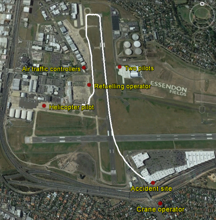
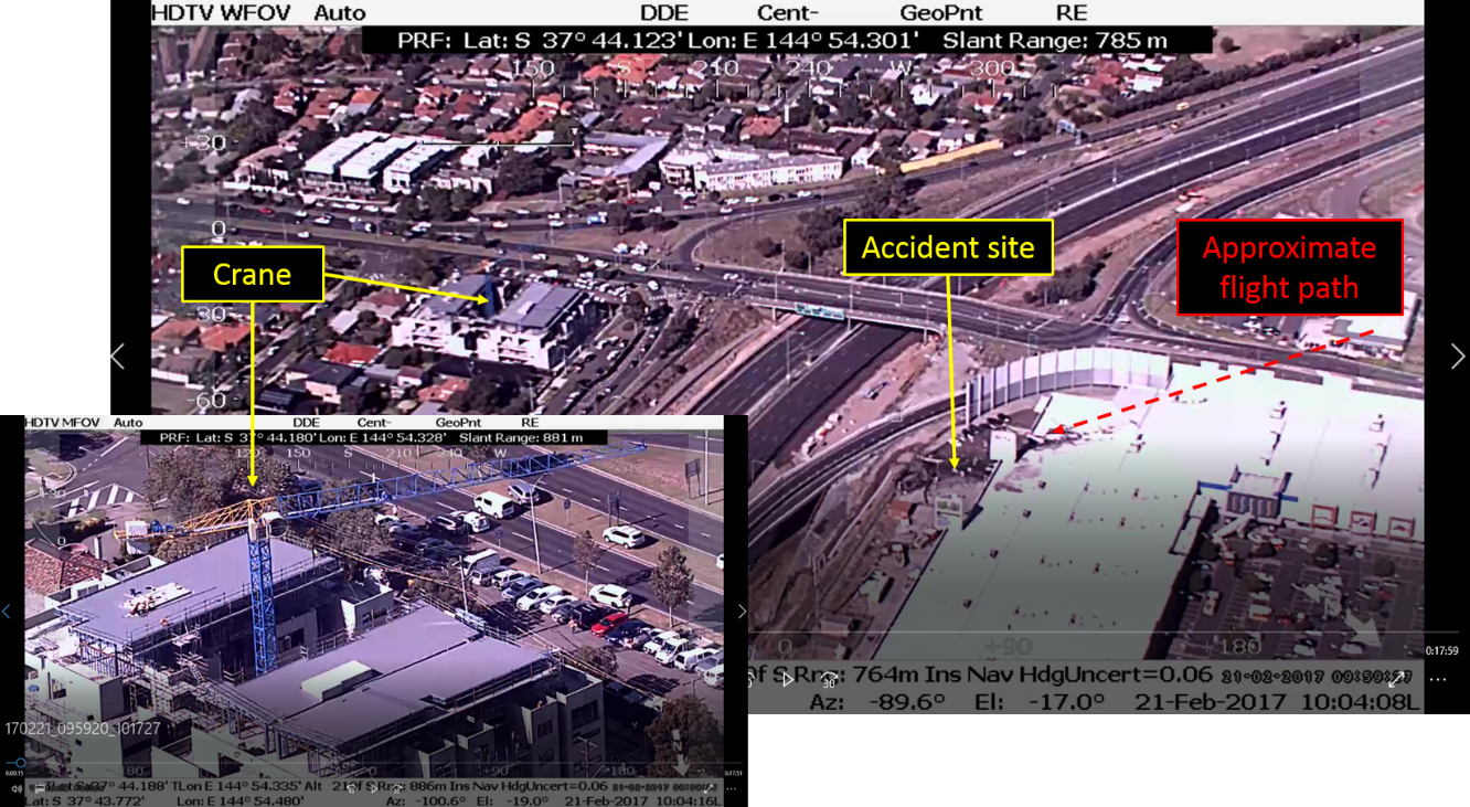
Figure 14: Position of the crane relative to the accident site, with the crane inset
Source: Victoria Police, annotated by the ATSB
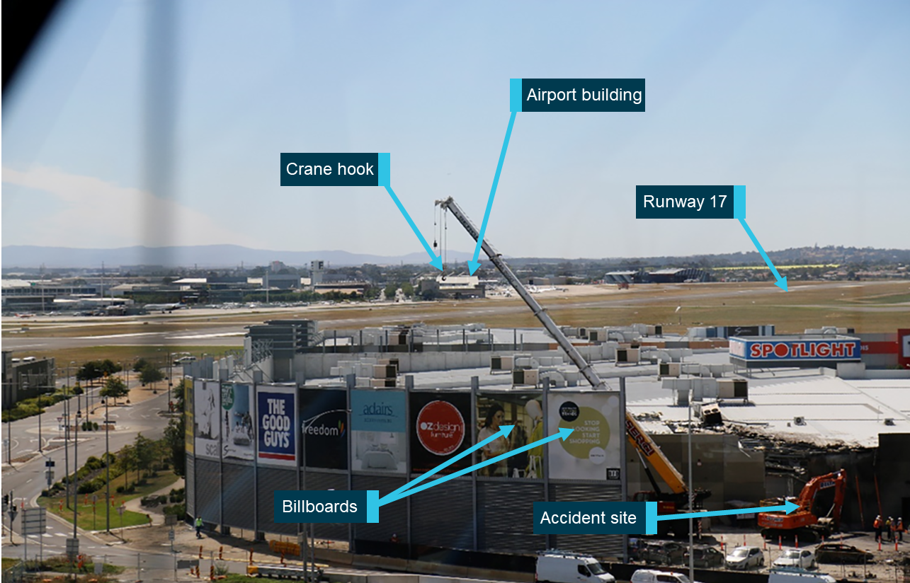
The operator reported hearing the sound of an aircraft’s engines, which sounded loud and in close proximity. The engines appeared to be operating normally and there were no indications of ‘misfiring or distress’. Having been alerted by the sound, the operator looked out the right window and saw the aircraft at about 25-35 m above the ground. Referring to (Figure 15), the aircraft’s initial position was close to being in-line with the hook of the crane at the accident site and the airport building in the background. The operator identified the aircraft as a twin-engine, low‑winged, turboprop aircraft.
The aircraft was described as moving or sliding towards him, but not facing him. The aircraft’s nose was about 10-15° to the left of his position and about 10° or ‘slightly down’. The operator had a view of the right side of the aircraft and believed that the right engine was operating. He was unable to comment if the left engine was also operating or recall if the landing gear was extended.
After this, the aircraft descended to the right over the billboard second from the right. The aircraft yawed further left, possibly an angle of 30-40°, before momentarily disappearing behind the billboard on the far right. The aircraft impacted the roof and parapet wall, and flames ensued immediately after. The aircraft continued moving forward and came to rest in the loading area at the rear of the building.
Figure 15: View of the accident site from the crane operator’s right cabin window
Source: ATSB
General witness observations
Multiple witnesses were interviewed by the ATSB and Victoria Police. These witness observations may have been influenced by the varied physical locations, environmental conditions, and the short time frame within which the accident occurred.
Although there were several inconsistencies, the majority of the witnesses reported that the aircraft was relatively flat with wings level or in a slight bank. They described the aircraft as moving sideways, ‘drifting’ or ‘crabbing’ like in a crosswind or yawing, and that it was low. One witness, who was a pilot, saw the aircraft shortly after becoming airborne. He observed it conduct a 5-10° left bank and veer left, as if ‘full rudder was being applied’. He described the aircraft as initially heading about 150°, but finished facing to the east, with wings level and the landing gear remaining extended.
With regard to the engine sounds, there was some variation in observations between the witnesses. The majority, however, including one familiar with the B200 aircraft, reported that the engine sound was loud and constant.
Aircraft flight path profile
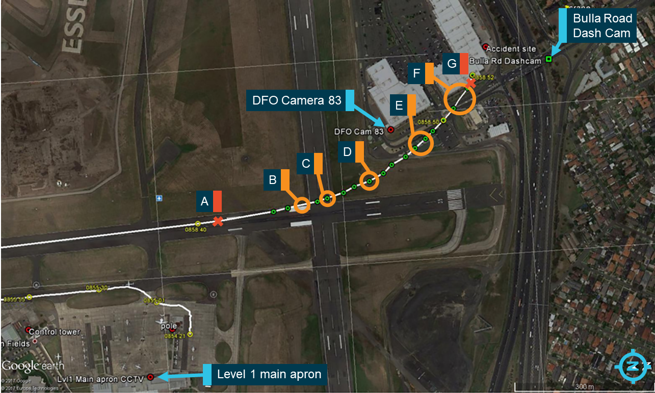
Following witness observations of a significant left yaw, the ATSB attempted to define the aircraft’s sideslip and roll angles at different points along the flight path using video footage from CCTV and a vehicle dashboard camera. Still images were extracted from the CCTV and dashboard camera footage, and the location of the aircraft was determined using ADS-B data at points A through G (Figure 16). ZCR’s track was determined at each point using ADS-B data.
Figure 16: ZCR’s track, location of the cameras and location of ZCR in each analysed image
Source: Google, annotated by the ATSB
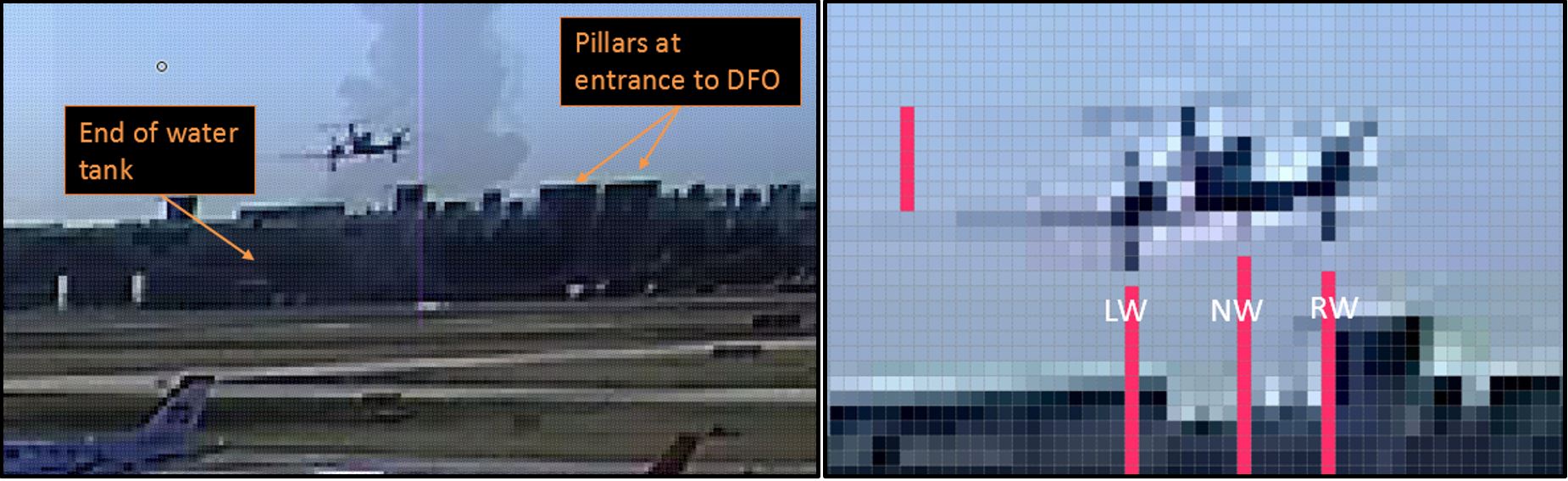
The aircraft’s heading was determined at each point by relating the distance between the landing gear wheels to an angular displacement. The height of the aircraft’s tail was measured in pixels to provide a datum for pixel size (Figure 17).
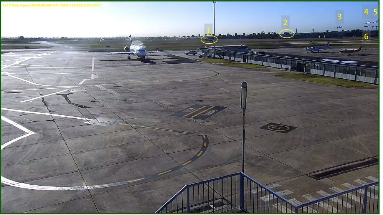
Figure 17: Example of method for estimating sideslip angle, image is from level 1 main apron camera
Left image (a) shows the use of objects in the image to determine the location of the aircraft.
Right image (b) demonstrates measurement of the height of the tail and distance between the left wheel (LW), right wheel (RW) and the nose wheel (NW).
Note: in Figure (a) the smoke has been overlayed on the image to give an approximate location of the accident site in relation to the aircraft.
Source: Essendon Airport, annotated by the ATSB
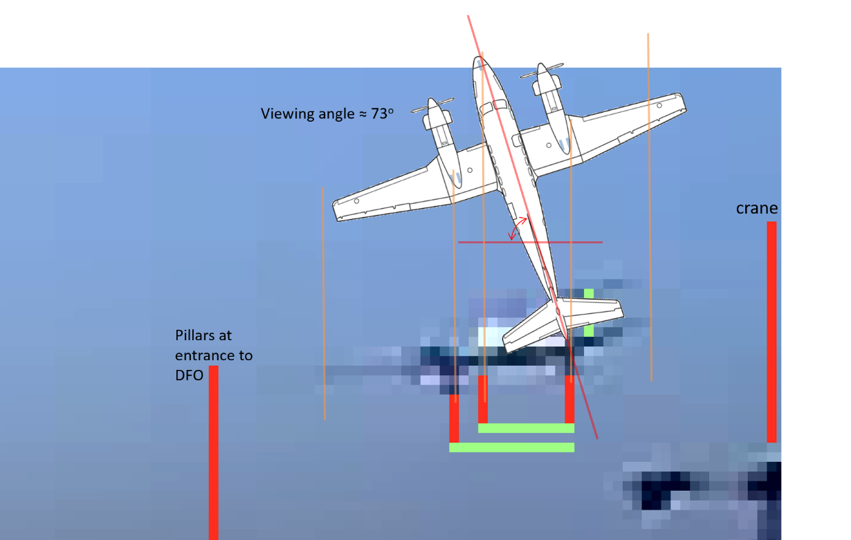
At points E and F, the aircraft was too far away from the camera to use this method. For these two points, an estimated heading was determined graphically by aligning a scaled diagram of the aircraft with the CCTV image (Figure 18).
Figure 18: Example of graphical method for estimating sideslip angle
Source: Essendon Airport, annotated by the ATSB
The angular difference between the aircraft heading and the aircraft track gives the sideslip angle. The methods used to determine the aircraft’s sideslip angle at each point and the probable accuracy are summarised in (Table 2).
Roll was calculated using the following two methods:
The relative height of each wheel was measured and then related to an angular displacement on the aircraft’s roll axis. This method was used for the Bulla Road dashboard camera.
Drawing lines on the still image that were representative of the wing angle and the height difference in the wheels, then determining the aircraft’s rotation by measuring the angular difference between the representative line and a known level surface in the image.
The methods used to estimate ZCR’s sideslip and roll contained the following assumptions and potential errors:
It was assumed that the aircraft was far enough away from the camera that perspective did not introduce significant error.
The tail was assumed to be in a perpendicular plane to the camera and therefore the viewed height of the tail was its actual height.
There were potential errors in measuring distances and heights in pixels, these errors were cumulative.
The error in the calculations varied depending on ZCR’s distance from the camera, picture quality and viewing angle of the aircraft. The more accurate sideslip angles were about ± 5o, with the least accurate calculation about ± 20o.
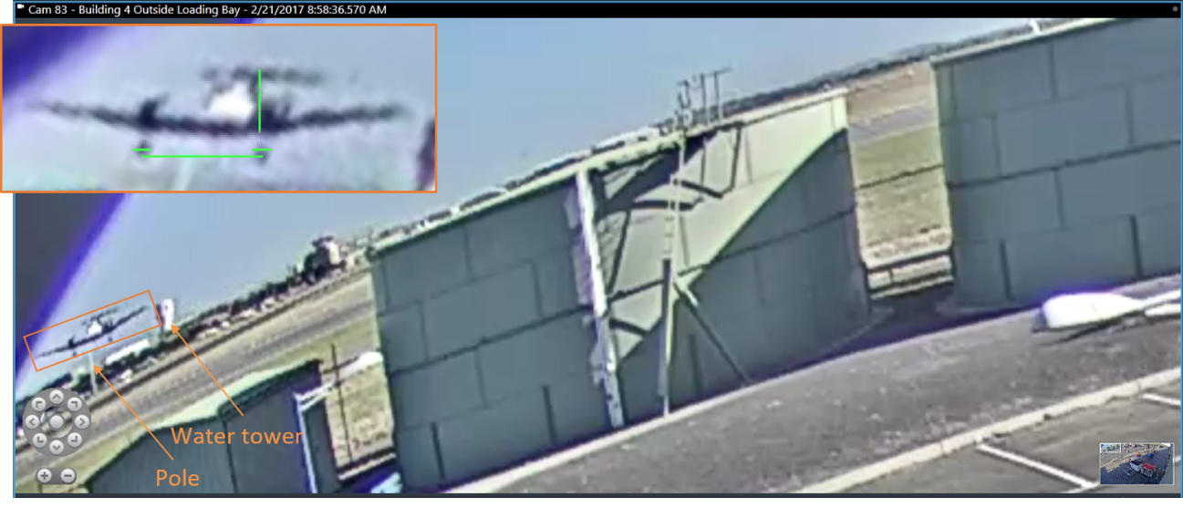
The images were examined to determine the amount of distortion from the lens, in particular fisheye distortion. The outlet centre camera had substantial fisheye distortion and therefore some analysis, roll angle in particular, was limited (Figure 19). The ‘Level 1 main apron’ camera appeared to have minimal distortion, despite having a wide-angle lens (Figure 20).
Figure 19: Outlet centre camera 83 still used for analysis, showing significant fisheye distortion in the image
Horizontal green line in inset image represents the distance between the main landing gear and the vertical green line represents the height of the tail as a reference. Source: Essendon Direct Factory Outlet, annotated by the ATSB
Figure 20: Time-lapse image of the aircraft flight path taken from the Essendon Airport Level 1 main apron camera
CCTV frame rate 30 images/minute, screenshots were taken every 2 seconds. Source: Essendon Airport, annotated by the ATSB
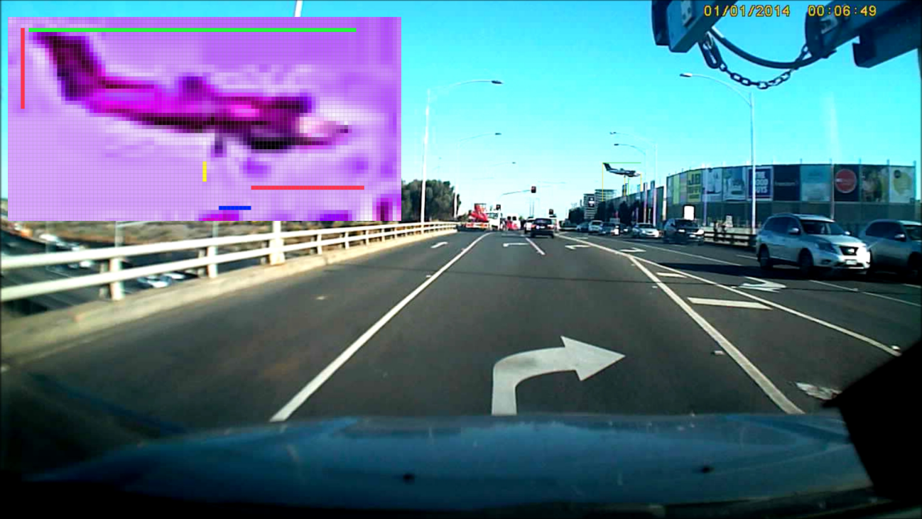
Figure 21: Bulla Road dashboard camera footage with zoomed inset depicting measurements used for sideslip and roll calculations
Source: Supplied
In summary, the results below demonstrate a substantial left sideslip between points D and G with minimal left roll. These results were consistent with witness observations and analysis of the accident site roof impact marks.
Table 2: Results of sideslip study
Identifier
Camera location
Aircraft Track (T)
Left sideslip angle and tolerance
Aircraft roll to the left
Comments/limitations
A
Lvl1 main apron (Figure 20)
176°
2° ± 5°
N/A
Aircraft probably still on runway so unlikely to have any sideslip.
B
Outlet centre camera 83 (Figure 19)
170°
5° ± 10°
N/A
Image contained significant fisheye.
C
Lvl1 main apron
160 - 165°
0 ± 10°
4-6°
The estimated location of the aircraft meant the aircraft track could vary by 5°.
D
Lvl1 main apron
155 - 160°
35° ± 15°
6-9°
A graphical method was used to determine the sideslip angle.
A sideslip of 35° is very high so is more likely to be at the lower end of the error band rather than the upper.
E
Lvl1 main apron
142°
50° ± 20°
Too far away to determine
A graphical method was used to determine the sideslip angle. The distance and the viewing angle reduced accuracy.
A sideslip of 50° is extremely high so is more likely to be at the lower end of the error band.
F
Lvl1 main apron
130°
25o ± 10°
Too far away to determine
A graphical method was used to determine the sideslip angle. The distance and the viewing angle reduced accuracy.
G
Bulla Rd (Figure 21)
115°
25° ± 5°
6°
Correlation of ADS-B data and sideslip information
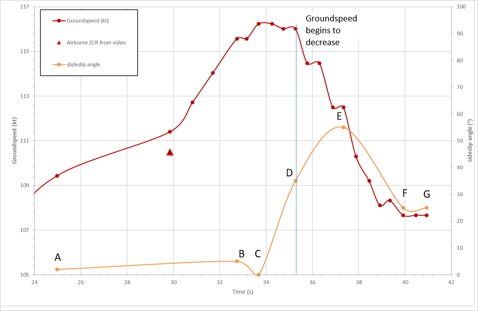
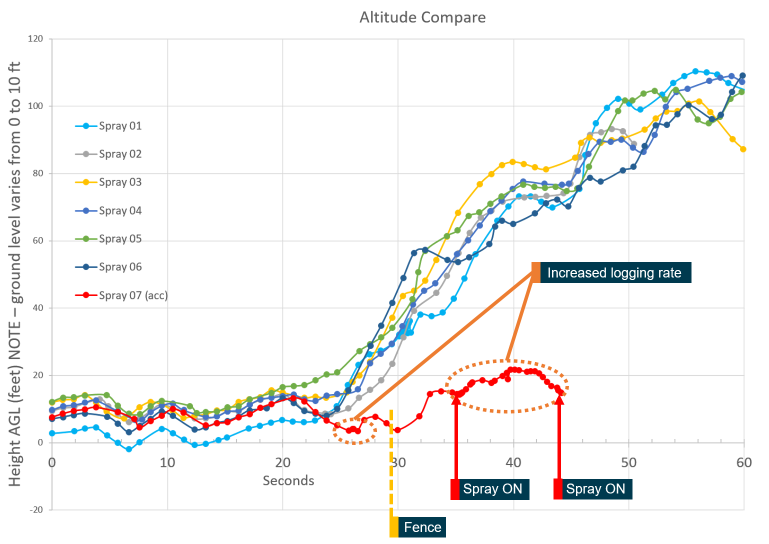
Sideslip information was correlated with Airservices ADS-B data to determine the relationship between the aircraft’s sideslip and performance. This comparison found that the reduction in ZCR’s airspeed, identified by the ADS-B data, correlated with the onset of the sideslip. This was most likely due to the increase in drag from the sideslip (Figure 22).
Similarly, the aircraft’s climb performance also reduced at the same time as the onset of the sideslip. As the ADS-B barometric data was considered unreliable while the aircraft was in a substantial sideslip, a time-lapse image was produced to provide an indicative depiction of the aircraft’s vertical flight path (Figure 23). The substantial sideslip was first observed at point 6 in Figure 23, at this point the image shows the aircraft transitioning from a climb to a descent.
Figure 22: Comparison of groundspeed and sideslip angle against time measured from the beginning of the take-off roll
Source: ATSB
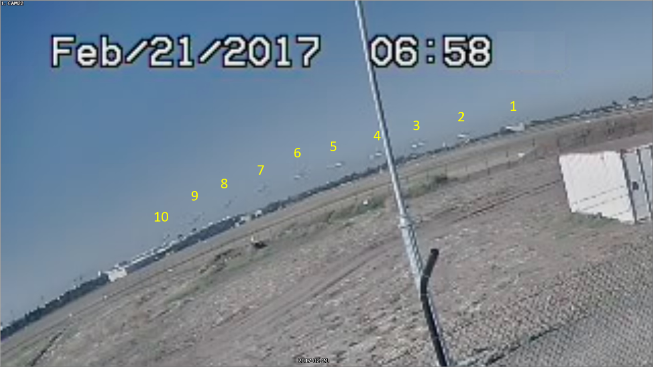
Figure 23: Time-lapse CCTV image of the ZCR’s flight path, with images taken every second
Source: Linfox, annotated by the ATSB
Recorded information
Cockpit voice recorder
ZCR was fitted with a cockpit voice recorder (CVR) as required by Civil Aviation Order 20.18. The aircraft was not fitted with a flight data recorder, nor was it required to be by Australian regulations.
CVR systems provide a record of flight crew conversations. In addition, the CVR can provide a record of the cockpit audio environment, including sounds relating to engine/propeller operation, aural alerts, operation of switches and levers, activation of the landing gear, and the weather such as rain or hail.
The CVR control unit, located in the cockpit, allows a pilot to test the serviceability of the CVR system. The power supply for the CVR unit was fitted with an ‘impact switch’ designed to stop the recorder and prevent any erasure feature from functioning when deceleration forces similar to those expected in an accident are sensed.
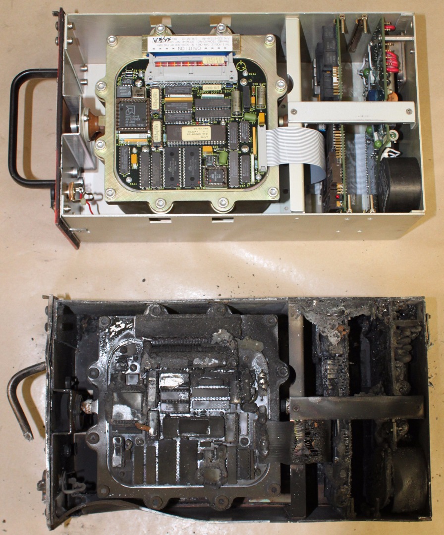
ZCR was fitted with a Fairchild model A100S CVR in June 1996, at about the time the aircraft entered service. The fire-damaged CVR was removed from the wreckage and transported to the ATSB’s technical facilities in Canberra for examination. The CVR was successfully downloaded, however, no audio from the accident flight was recorded. The recovered audio related to a previous flight on 3 January 2017. This recording began at the expected time prior to engine start. The recording stopped, however, at about the time the aircraft landed at the arrival aerodrome. The post-landing taxi and engine shutdowns were not recorded. It was likely that the ‘impact switch’ was activated during the landing and power was removed from the CVR.
CVR serviceability checks and maintenance
An applicable CASA airworthiness directive relating to the CVR, AD/REC/1, (www.casa.gov.au) was carried out by ZCR’s maintenance provider in December 2016. The maintenance action included replacing the ‘impact switch’. No defects were logged following the conduct of the inspection.
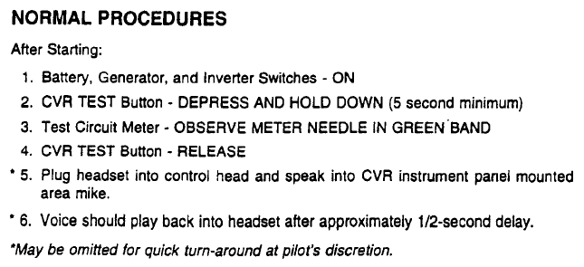
CVR system operating instructions
Following a CVR installation in an aircraft, supplemental material related to the operation of the CVR must be attached to the Pilots Operating Handbook (POH) or approved Airplane Flight Manual (AFM). A copy of the Raytheon Aircraft Company Beechcraft Super King Air B200/B200C AFM supplement was provided by the aircraft manufacturer. That supplement indicated that a self‑test must be successfully accomplished prior to flight. This was to be achieved following the procedure below (Figure 24). Due to fire damage to the aircraft, the ATSB could not determine if the AFM contained this supplement. (For further information on checklists refer to section titled Organisational information – Flight Check System).
Figure 24: Supplemental procedure for testing CVR serviceability
Source: Aircraft manufacturer
A pilot who regularly flew ZCR was aware that it was fitted with a CVR and he would test the system as described above. He could not recall, however, if there was a specific checklist item for this. He also commented that other B200 aircraft he had operated were not fitted with CVRs. Similarly, another pilot who was aware of the CVR was using another company’s checklist and could not recall if there was a checklist item regarding the CVR. That pilot also stated that he did not operate the CVR in ZCR. A CASA-authorised testing officer who had flown ZCR stated that he had used the checklist in the aircraft, but was not aware that it was fitted with a CVR, suggesting the CVR checklist items were not included in ZCR’s checklist.
It is unknown if the accident pilot was aware that ZCR was fitted with a CVR and the requirement to conduct the self-test prior to flight. Of note, the pilot previously flew another B200 aircraft, which was not fitted with a CVR.
Dashboard camera audio frequency analysis
A witness driving on the Tullamarine Freeway provided dashboard camera footage of the accident to the ATSB. The footage featured a sound consistent with an aircraft passing nearby immediately prior to the collision with the outlet centre.
Frequency analysis determined that the aircraft’s engine power was at a high level, loud enough to drown out background noises such as car, road and airflow noise. Only one propeller frequency was present, meaning that either both propellers were at similar RPM or only one propeller was operating at the identified frequency and the other propeller was not detected in the frequency analysis. While the ATSB could not establish if one or both engines were operating at a high level, the analysis determined that the propeller RPM(s) were at the nominal take-off setting of 2,000 RPM.
Wreckage and impact information
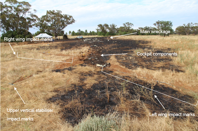
Accident site
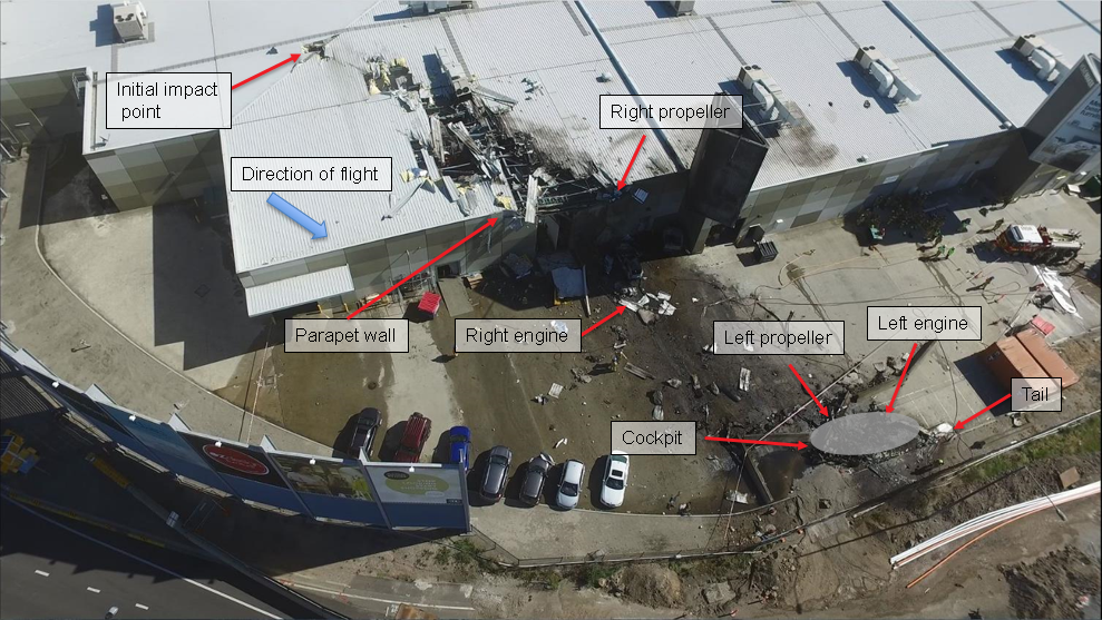
The aircraft intially contacted the roof of a building in the outlet centre adjacent to the southern end of runway 17 (Figure 25). A search of the runway and surrounding area did not identify any items related to ZCR. In addition, there was no evidence of a bird strike under the aircraft’s flight path or at the accident site.
After colliding with the building’s roof and parapet wall, the aircraft came to rest in a loading zone at the rear of the building. A post-impact fuel-fed fire severely damaged the wreckage and initiated a fire in the building.
Figure 25: Accident site overview
Source: Metropolitan Fire Brigade (Melbourne), annotated by the ATSB
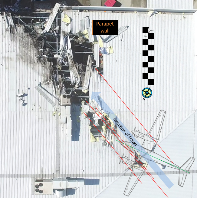
Impact mark analysis
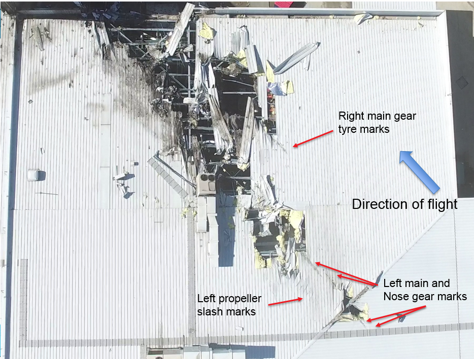
Marks from the landing gear and slash marks from the left propeller’s blades were identified on the building’s roof. These marks were used to determine the aircraft’s initial impact attitude by aligning a scaled diagram of a B200 aircraft with an image of the marks (Figure 26).
Figure 26: Outlet centre roof impact damage with scaled aircraft aligned with impact marks
Note: Landing gear wheels are offset to the right and apparent wingspan is reduced to allow for a slight left bank. Source: Metropolitan Fire Brigade (Melbourne), annotated by the ATSB
Analysis of the roof impact marks indicated that:
the aircraft had a heading angle of about 86 ⁰ (T)
the ground track was about 114 ⁰ (T)
the aircraft was at a sideslip angle of about 28⁰ left of track
the aircraft was slightly left-wing and nose-low with a shallow angle of descent at the initial roof impact
after the initial impact, the aircraft rotated left on its vertical axis until the fuselage was about parallel with the rear parapet wall of the building.
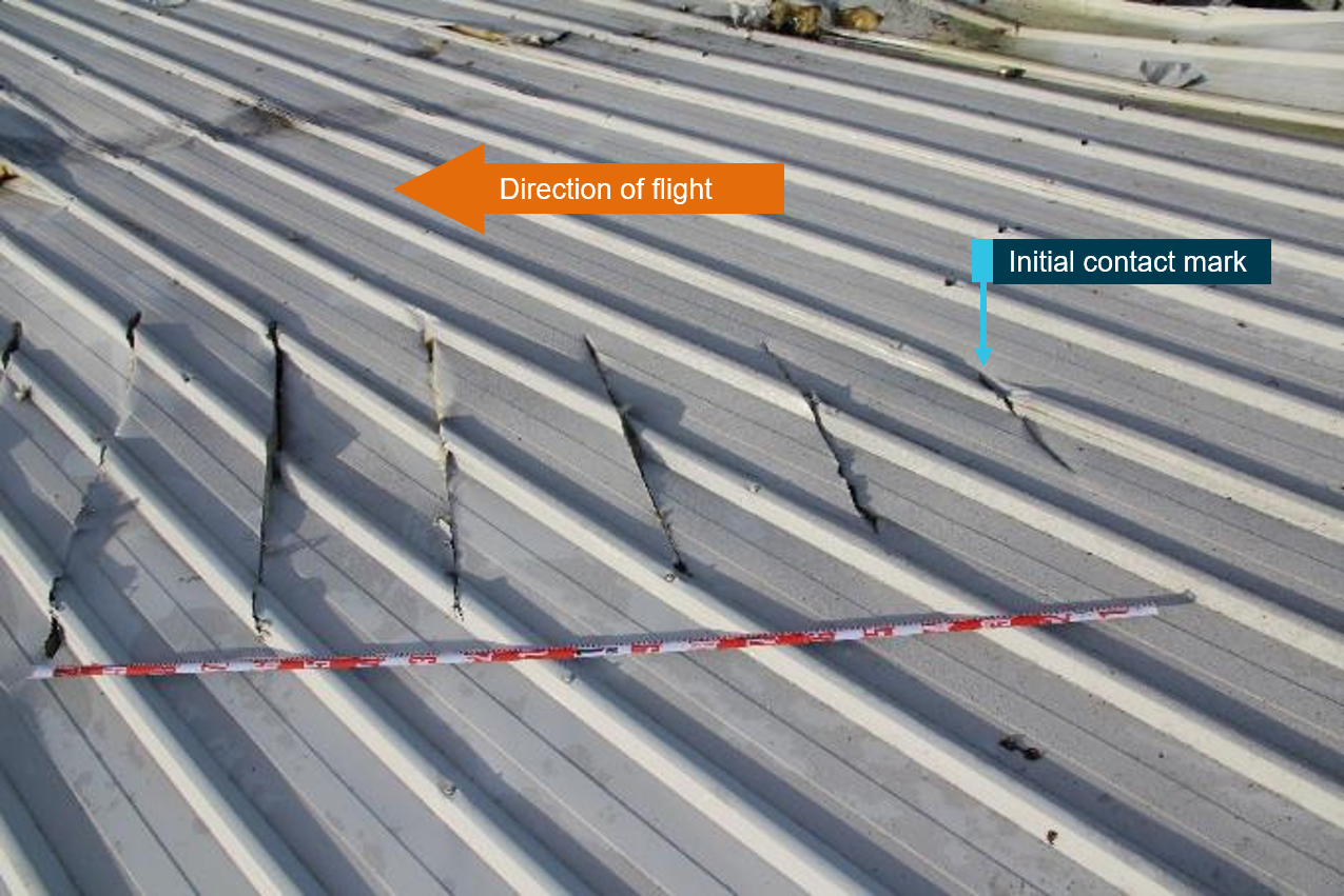
Propeller slash marks
Nine propeller slash marks were located in the building’s roof (Figure 27). Analysis of those slash marks indicated that they had been created by the left propeller blades cutting through roofing material while rotating.
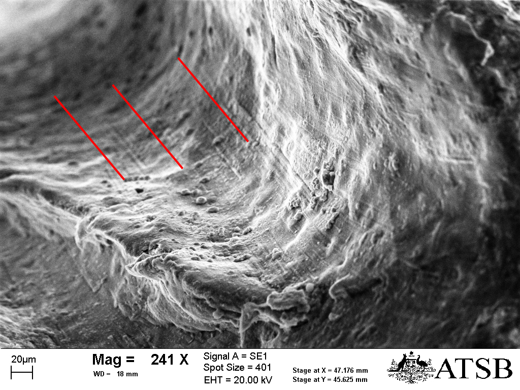
Figure 27: Left propeller slash marks in roofing material with tape measure showing distance between cuts
Source: ATSB
The last 2 seconds of ADS-B data indicated ZCR’s ground speed was about 108 kt. Allowing for potential aircraft deceleration due to the nose landing gear colliding with the roof, prior to the left propeller blades making contact, the left propeller RPM was calculated as being consistent with ZCR’s nominal take-off setting of 2,000 RPM. This was consistent with the estimated propeller RPM established from the dashboard camera audio frequency analysis (refer to section titled Recorded information -Dashboard camera audio frequency analysis).
An estimate of ZCR’s sideslip angle was also obtained by measuring the angle between the flight path and the slash marks, corrected for aircraft speed and propeller RPM. Using this method, the angle of sideslip at impact was calculated as being about 29° to the left. The results of this method to calculate sideslip at impact was consistent with the impact mark analysis above.
Other damage
After the initial impact, the aircraft collided with a concrete parapet wall before coming to rest in the building’s rear loading area. There was significant structural damage to the building, and the retail business operating in that section of the building incurred significant fire and water damage. Several vehicles parked at the rear of the building were also damaged or destroyed.
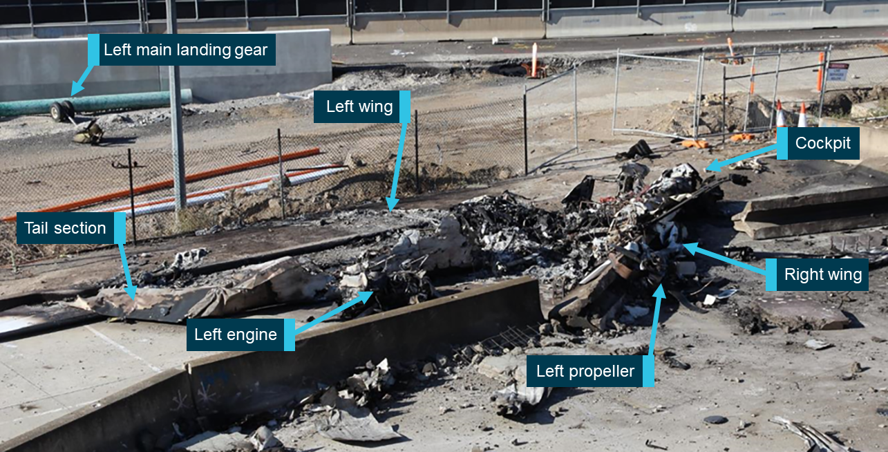
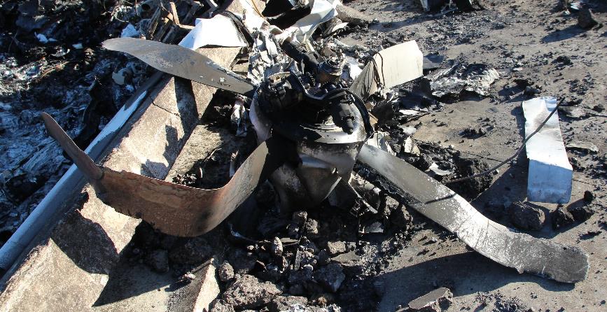
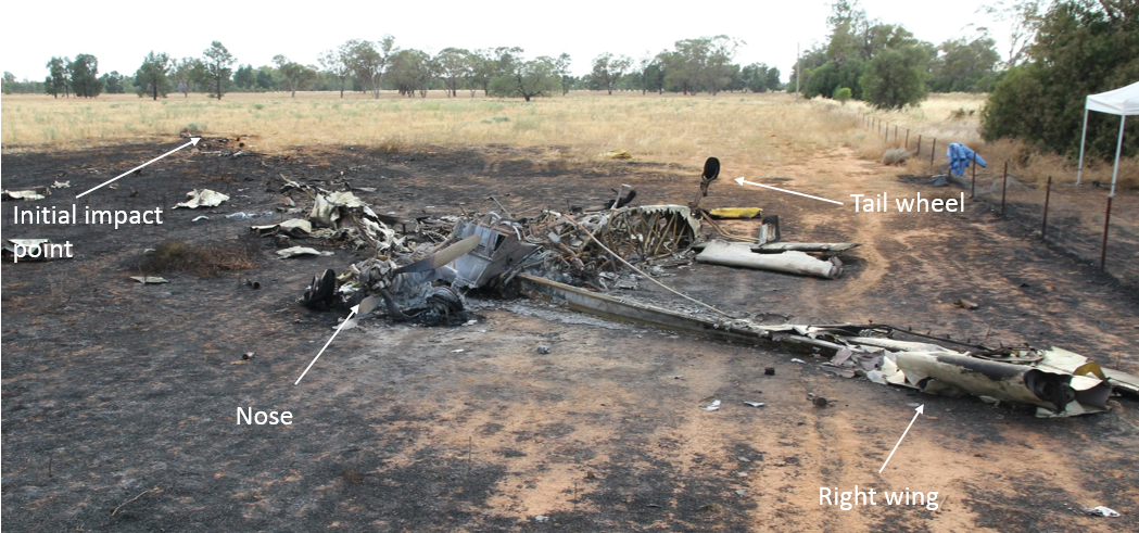
Aircraft wreckage
The majority of the aircraft was damaged or destroyed as a result of the collision with the building and subsequent fire. The damage precluded a complete examination of many components and systems (Figure 28). All major parts of the aircraft were accounted for at the accident site. On-site examination of the wreckage did not identify any pre-impact faults with the aircraft that could have contributed to the accident.
Figure 28: Main wreckage
Source: ATSB
The outboard right-wing sections, main landing gear lower sections, both engines, and both propellers separated from the aircraft during the accident sequence and were located at the accident site. The nose gear oleo and wheel assembly came to rest on the Tullamarine Freeway, about 65 m from the main wreckage, in the direction of the flight.
Tyre marks on the building’s roof and damage to the main and nose landing gear assemblies indicated that the landing gear was down during the accident sequence. Dashboard camera footage of the aircraft just prior to impact, along with witness observations, further supported the landing gear being in the down position.
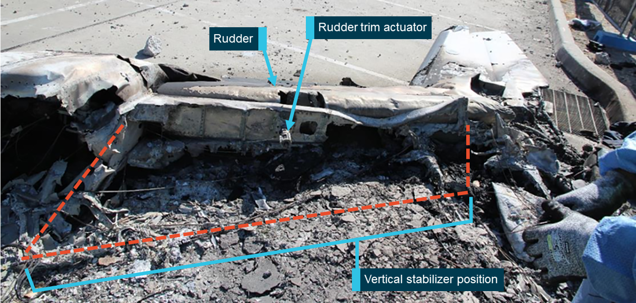
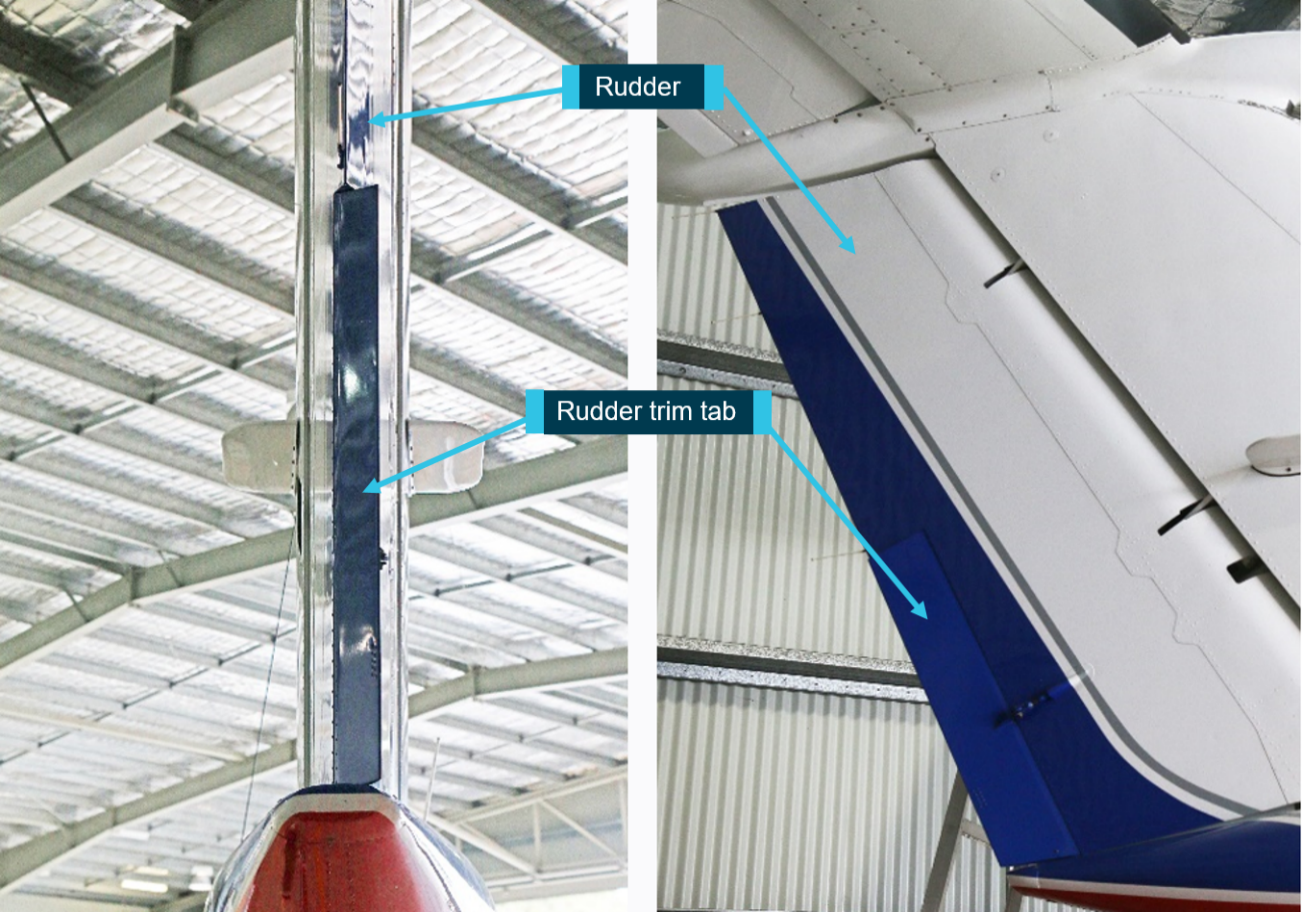
Rudder
The majority of the vertical stabiliser was destroyed by fire (Figure 29). The rudder flight control surface was still attached to what remained of the vertical stabiliser. The rudder control cables, bell cranks, and push-pull tubes were inspected from the cockpit through to the tail with no pre‑impact faults identified.
Figure 29: Remains of the vertical stabilizer on its left side showing position of rudder and trim actuator
Source: ATSB
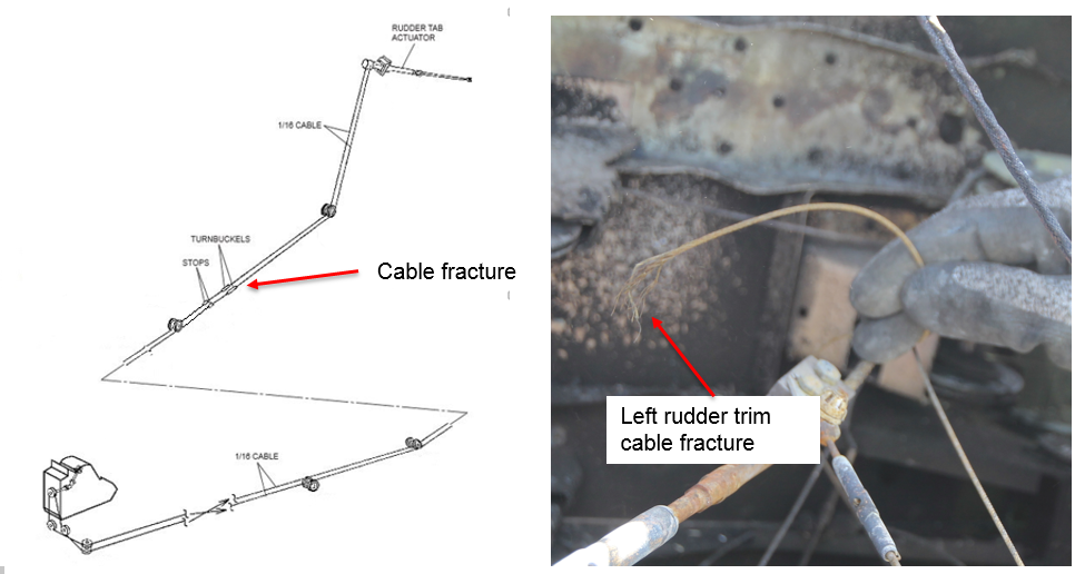
Rudder trim
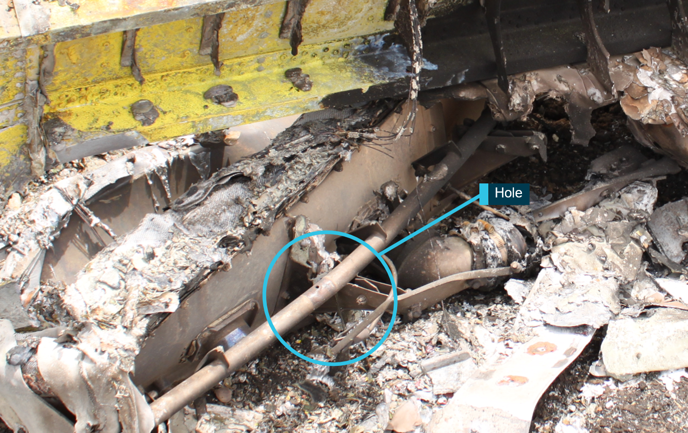
The left rudder trim cable had failed at a position towards the rear of the fuselage. Inspection of the cable fracture revealed necking-type failure of individual strands within the cable. That, and the way the cable was splayed, were indicative of an overstress fracture, likely as a result of the collision (Figure 30).
Figure 30: Schematic of rudder trim system showing the approximate cable fracture point (left) and a picture of the left rudder trim cable fracture (right)
Source: Textron Aviation Inc. and ATSB
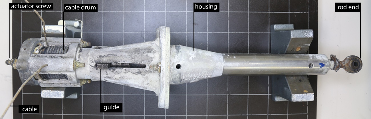
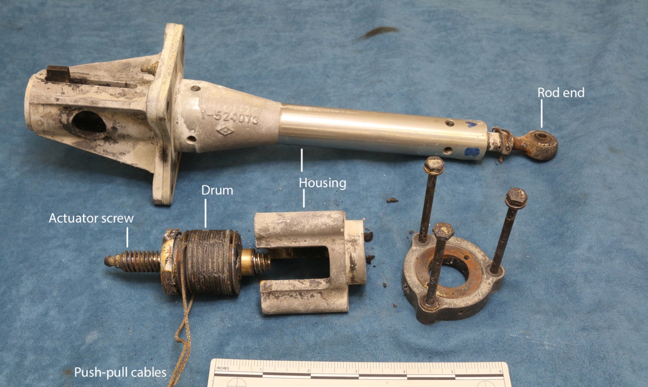
The rudder trim actuator screw jack was extended 43 mm when measured from the actuator body to the center of the rod end, which equated to the rudder trim being in the full nose-left position. Due to the significant yaw observed by witnesses, the rudder actuator was removed from the wreckage for further detailed examination. This examination determined that the rudder trim tab actuator was likely in the full nose-left position at impact (refer to section titled Appendix B – Rudder trim tab actuator examination).
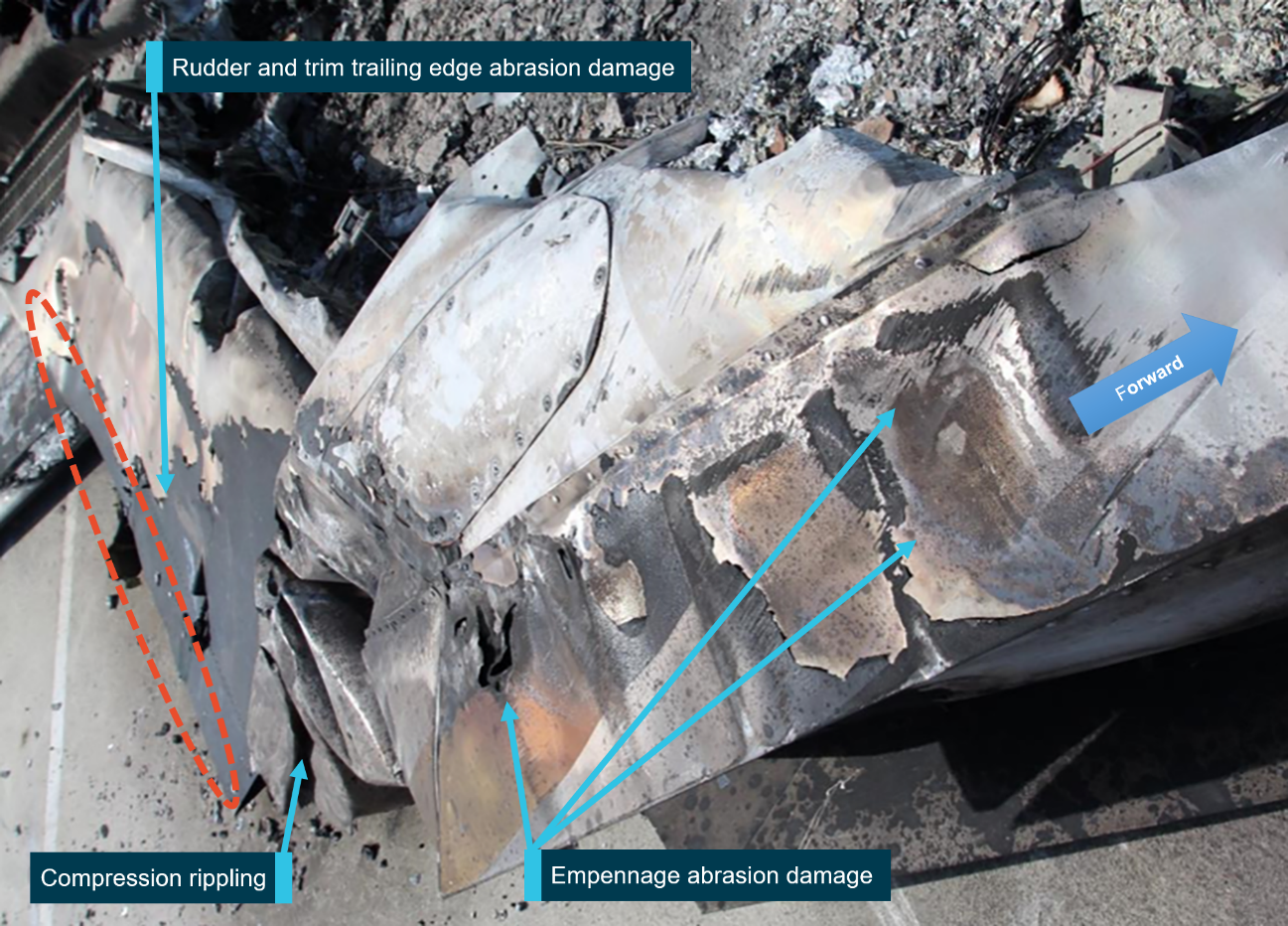
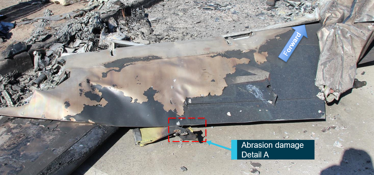
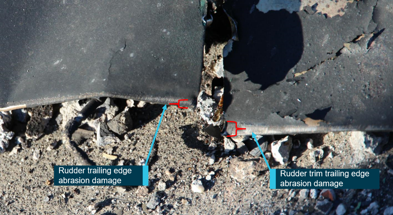
Abrasion marks and compression damage were present on the right side of the empennage, rudder, and rudder trim tab, indicating that the area had come in contact with a hard flat abrasive surface (Figure 31). Abrasion on the rudder trim tab trailing edge was significantly greater than the corresponding abrasion on the rudder trailing edge, shown in Detail A (Figure 32 and Figure 33). The abrasion damage indicated that the rudder trim tab was positioned to the right of the rudder surface during the impact sequence. The angular displacement of the rudder trim tab could not be determined from the abrasion marks, however the displacement indicated that the rudder trim was in a nose-left position at impact.
Figure 31: Empennage and rudder viewed from the right showing abrasion damage
Source: ATSB
Figure 32: Rudder and rudder trim showing abrasion damage
Source: ATSB
Figure 33: Detail A. Close-up of abrasion damage to rudder and upper surface of rudder trim trailing edge
Source: ATSB
Analysis of the roof impact marks and CCTV footage showed that the aircraft had contacted the concrete parapet wall on the right side of the empennage before exiting the roof of the building. It was likely that the impact with the wall caused the abrasion damage to the empennage and rudder.
Rudder boost system
The rudder boost control system was destroyed by fire, however, sections of the rudder boost actuators were located within ZCR’s empennage. No anomalies were identified in the remaining sections of the actuators.
Elevator trim
Both the left and right elevator trim actuators were found in a position that equated to a full nose‑up trim position. Witnesses, CCTV and ADS-B evidence either opposed or did not support ZCR having full nose-up trim at take-off. It is possible that the elevator trim was moved to this position by the pilot in an attempt to control the aircraft’s flight path or the trim may have moved as a result of impact forces. The ATSB determined however, that it was unlikely that the elevator trim was in the full nose-up position at take-off and did not examine the trim tab actuators any further in order to confirm their position at impact.
Flap system
The left inboard and outboard flap control surfaces were destroyed by fire. The right inboard and outboard flaps had separated from the aircraft and broken into numerous sections during the impact sequence.
All four flap actuators were identified in the wreckage. The left inboard and outboard actuator outer bodies had been fire-damaged, however, their internal shafts and attachment points were present.
Initial on-site examination of the aircraft wreckage indicated the flaps were extended approximately 10°. More detailed analysis of the left inboard and outboard actuators, however, found they were likely in the fully retracted, UP position, when the aircraft collided with the building. An accurate assessment of the right-wing flap positions was not possible due to impact and fire damage.
Flight control locks
Remnants of the flight control locks including the locking pin for the control column, some chain and the ‘remove before flight’ warning sign were located to the rear of the co-pilot seat in the cockpit. In addition, the area surrounding the rudder locking pin receptacle was searched and the pin was not located.
Cockpit instruments and switches
Due to significant fire damage, the cockpit switch positions, instrument settings and cockpit trim indicator positions could not be determined. The available cockpit instruments were inspected and none retained any useful information.
Engine controls
An inspection of the remaining sections of the engine control pedestal and engine control linkages was performed from the cockpit through to the engines. There was significant disruption to the engine controls due to fire and impact damage. For that reason, continuity of the engine controls could not be fully established. No pre-impact defects, however, were identified in the remaining control sections.
The position of the power levers, condition levers, propeller levers and corresponding friction control knobs could not be accurately determined due to the extent of the damage.
The propeller control system was inspected in detail. The control system had fractured in overload in several locations due to propeller and engine separation during the accident sequence. There were no pre-impact defects identified within the propeller control system.
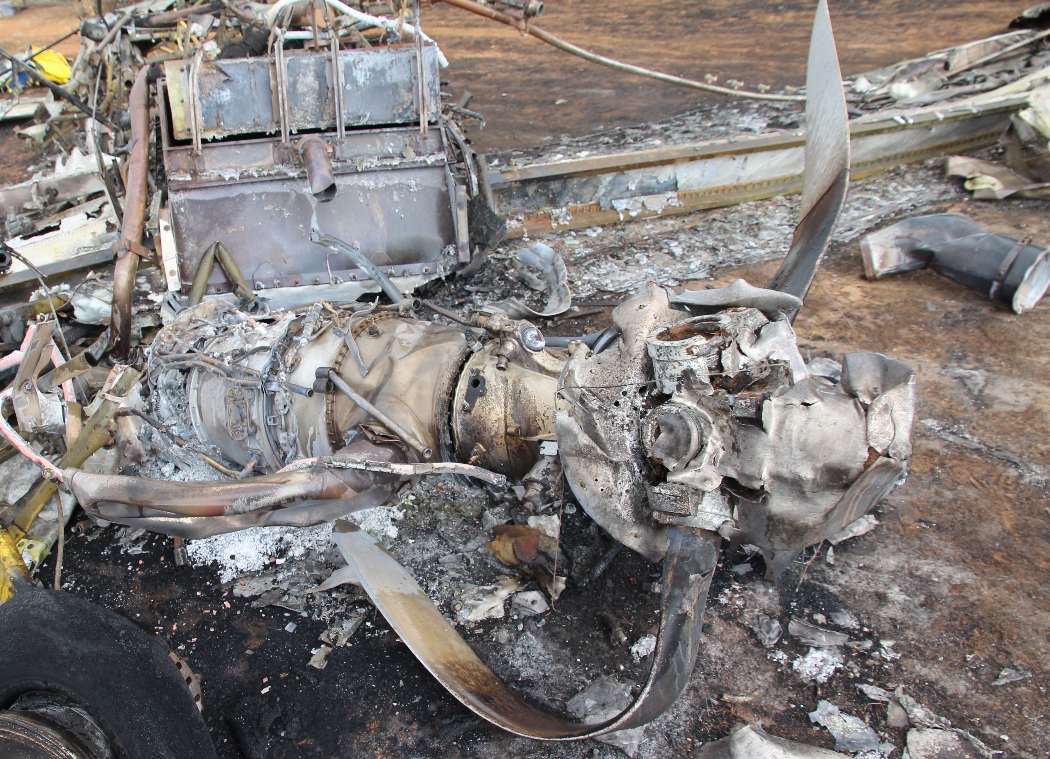
Engines
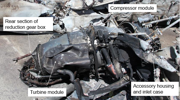
The left engine had separated from the aircraft and broken into three sections: the accessory drive with the compressor inlet, the compressor and turbine modules, and a forward section of the reduction gearbox which remained attached to the propeller (Figure 34). The engine had sustained significant impact and fire damage. An external inspection did not identify any pre‑impact defects.
Figure 34: Right engine assembly, shown upside down and viewed from its left side
Left propeller with attached forward section of reduction gearbox not shown. Source: ATSB
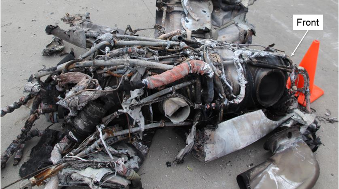
The right engine had detached from the aircraft and separated into two sections at the reduction gearbox. It sustained significant impact and fire damage (Figure 35). An external inspection of the engine was conducted with no pre-impact defects identified.
The engines were removed from the accident site and taken to a secure facility for further examination.
Figure 35: Right engine assembly, shown upside down and viewed from its left side
Right propeller with attached forward section of reduction gearbox not shown. Source: ATSB
Engine examinations
Both engines were retained by the ATSB for further examination in order to determine:
if there were any defects present which could have contributed to the accident
the engine power outputs at impact.
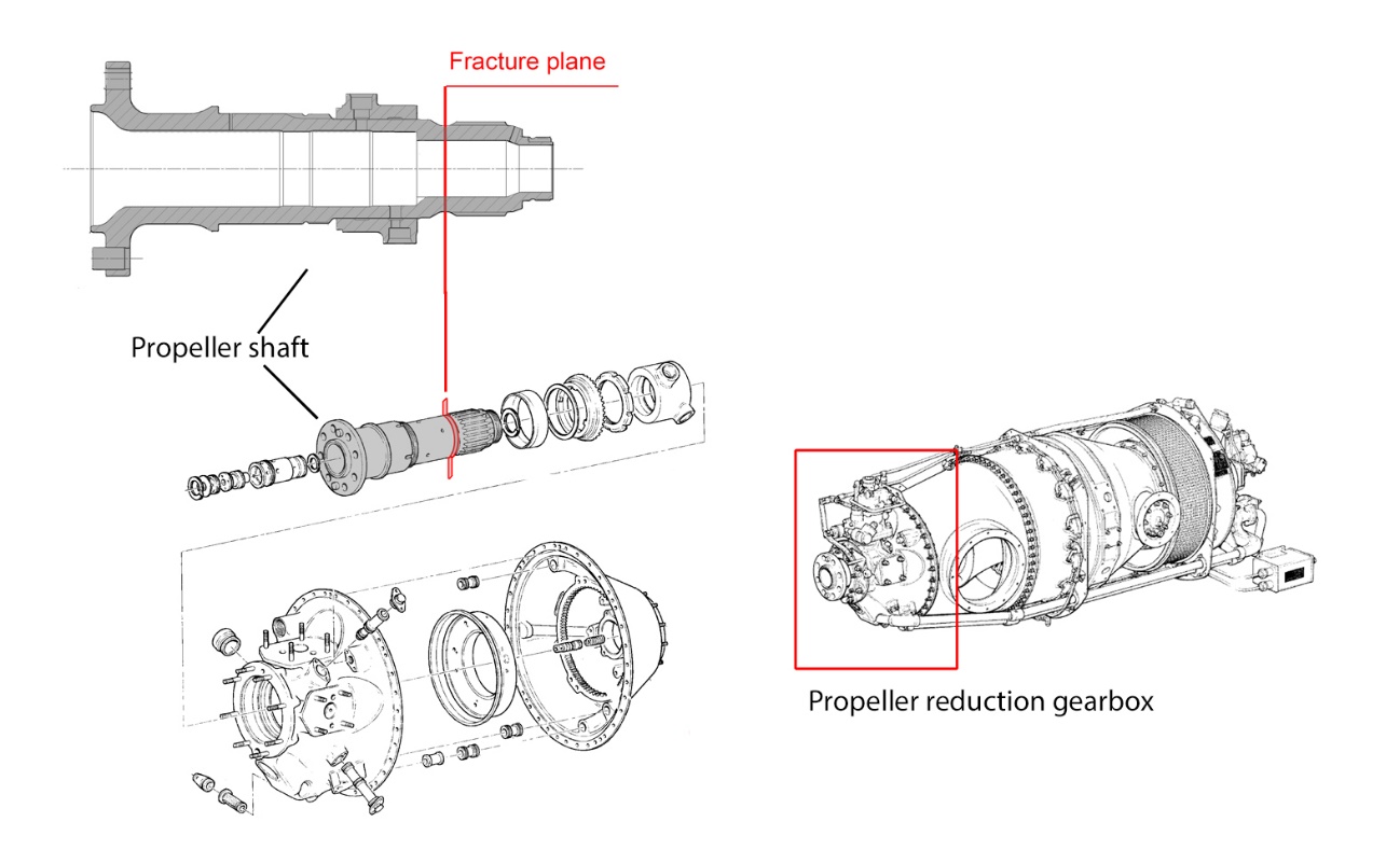
The PT6A-42 engine utilises a two-stage power turbine to drive the propeller shaft via a reduction gearbox (RGB) that is located at the front of the engine. The propeller shaft transmits torque from the engine’s reduction gearbox to the propeller.
The detailed engine examinations found
no defects that were likely to have prevented normal operation of the engines
there was similar evidence of rotation in both engines
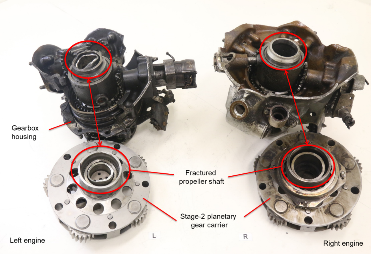
both propeller shafts had fractured at a similar position and the fracture surfaces appeared similar
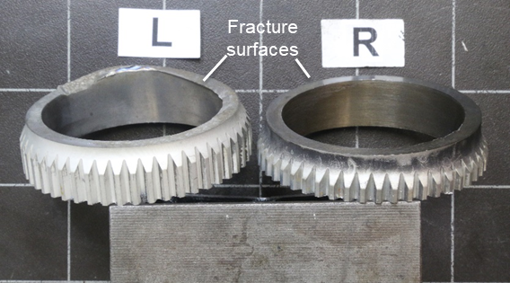
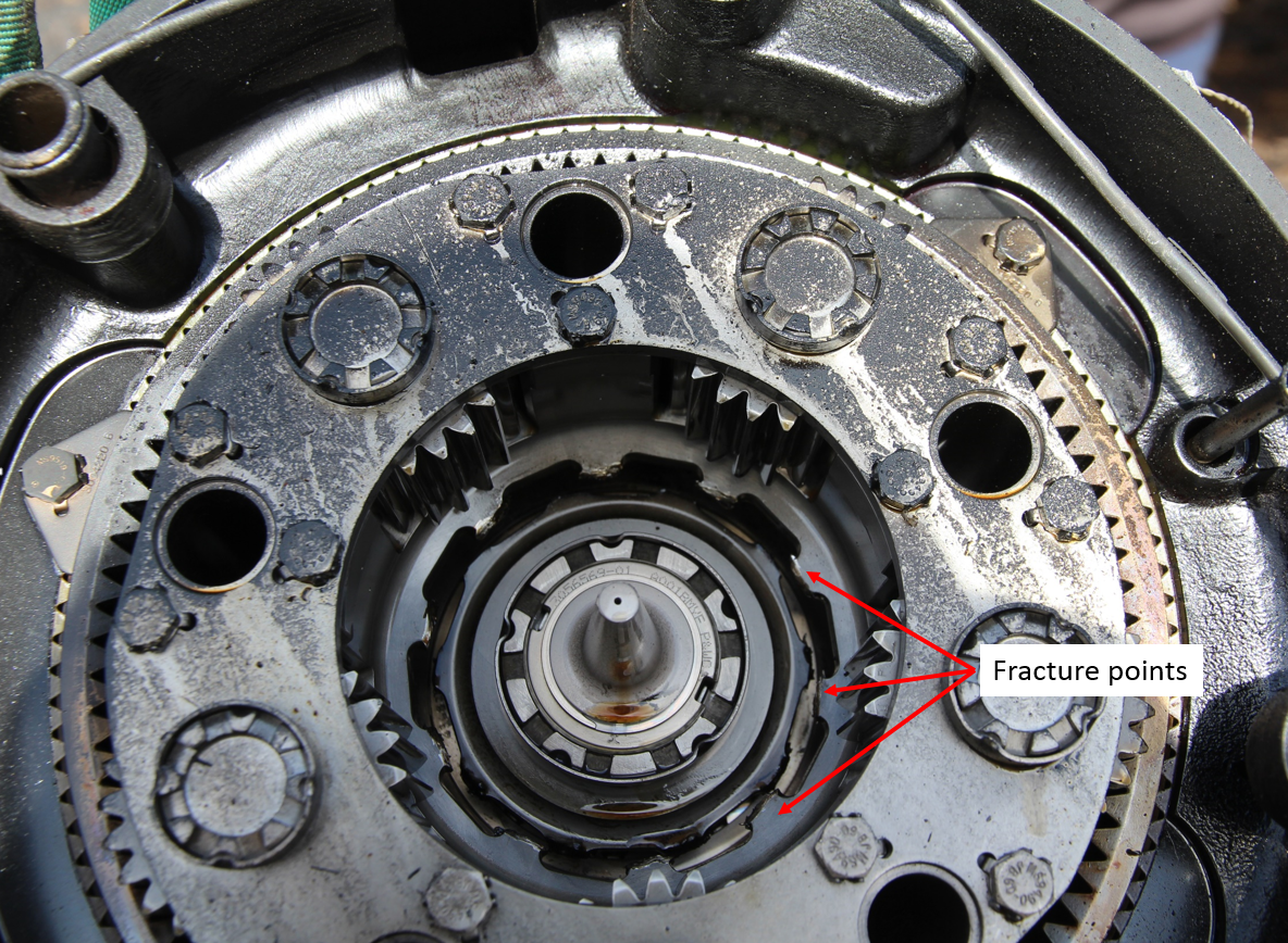
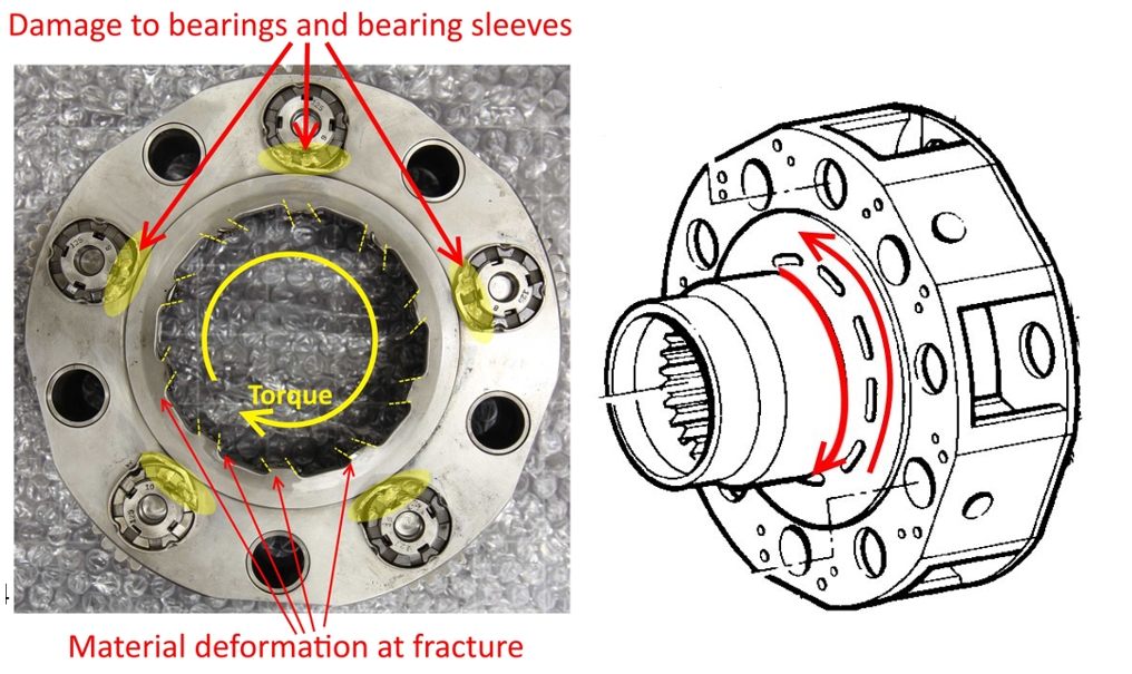
the left engine’s reduction gearbox planetary gears had indentations and tooth bending.
An accident investigator from the engine manufacturer, Pratt & Whitney Canada, travelled to Australia to assist with the examinations. The engine manufacturer’s report concluded that both engines were producing similar power at impact.
The reduction gearboxes were retained for further examination at the ATSB laboratories in Canberra (refer to section titled Appendix A - Reduction gearbox and propeller shaft assembly examinations).
Both engines’ fuel control units, fuel pumps, propeller governors, overspeed governors and torque limiter units were sent to the engine manufacturer for testing, where possible, followed by disassembly and inspection under the supervision of the Transportation Safety Board of Canada. The examinations did not identify any pre-impact faults that would have prevented normal engine operation.
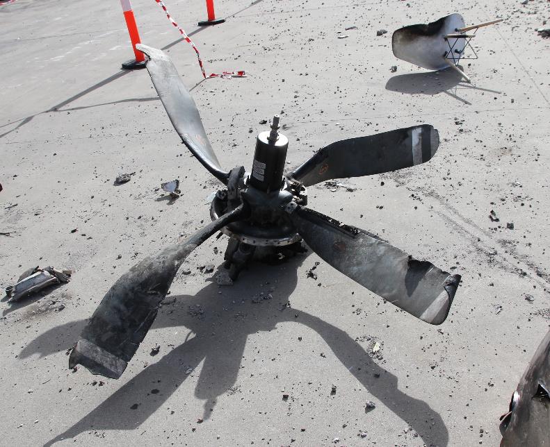
Propellers
The left propeller was connected to a section of the reduction gearbox that had separated from the engine. The connected section housed the overspeed governor and propeller governor with its reversing lever and control linkage still attached. Inspection of those components and remaining controls did not identify any pre-impact issues.
All four blades remained attached to the propeller assembly (Figure 36). The propeller assembly was heavily sooted and charred, with heat damage to the de-ice boots and wiring. Three of the blades had portions of the tips fractured. All blades exhibited varying amounts of chordwise rotational scoring and leading edge gouging.
The propeller cut through roofing material and the supporting structure during the impact sequence, demonstrating significant rotational energy (Figure 37).
Figure 36: Left propeller viewed from the rear, showing blade-tip fractures, blade gouges and blade bending
Source: ATSB
Figure 37: Left propeller cuts through roof structure
Source: ATSB
The right propeller remained connected to a section of the reduction gearbox section that had separated from the engine. The propeller was located on the roof of the building.
The damage to the right propeller was similar to the left propeller but with less apparent heat damage (Figure 38). All four blades remained attached to the propeller assembly. All blades exhibited varying amounts of chord-wise rotational scoring and leading edge gouging.
Both propellers were retained for further examination by the ATSB.
Figure 38: Front view of the right propeller showing bending, chordwise twisting, and leading edge gouging of the propeller blades
Source: ATSB
Propeller examinations
Both propellers were examined in order to determine the level of power being produced by each engine at impact. An accident investigator from Hartzell Propeller travelled to Australia to assist with the subsequent propeller examination at an approved facility.
The propellers were four-blade Hartzell constant speed propellers Model HC-D4N-3A with D9383K blades installed on the aircraft under Raisbeck Engineering Supplemental Type Certificate SA2698NM. They had a feathering and reverse pitch capability.
Oil pressure from the propeller governor is used to reduce the blades’ pitch angles. A feathering spring and blade counterweight forces are used to move the blades to the high pitch/feather direction in the absence of governor oil pressure. The propeller utilises an aluminium hub with aluminium blades. Rotation is clockwise as viewed from the rear.
Both the left and right propellers exhibited similar damage consistent with high power output at impact. There were no discrepancies noted on either propeller that would have prevented or degraded normal operation prior to the impact. Blade and internal impact damage indicated both propellers impacted at positive blade angles of attack. At an estimated impact speed of 108 kt with the propellers at 2,000 RPM, preload plate impact marks suggest a geometric blade angle that was approximately equal to the engines take-off power of 850 horsepower.
Medical and pathological information
The pilot held a Class 1 Aviation Medical Certificate that was valid until 20 May 2017. The pilot was required to wear distance vision correction and have available reading correction while exercising the privileges of his licence.
The pilot’s CASA medical records indicated that he was diagnosed with Type 2 diabetes in 2007. At the time of the accident, the pilot was reportedly on multiple oral medications to manage his diabetes and was considered to have met the CASA requirements for maintaining his medical certificate. The records also showed that, as part of the pilot’s annual medical requirements, an echocardiogram was performed in 2016, which revealed an abnormal mitral valve. This was repaired in July of that year, with a post-operative follow-up identifying nil issues. CASA subsequently reviewed the pilot’s medical history and he was advised on 4 February 2017 that he could continue exercising the privileges of his licence, but should cease flying if there was a change in his treatment or condition.
The pilot’s post-mortem examination established that the pilot succumbed to injuries sustained during the impact sequence. Mild to moderate coronary artery atherosclerosis[22] was noted, along with signs of mitral valve annuloplasty.[23] There was no evidence, however, of any significant natural disease which may have caused or contributed to the accident. Further, the toxicology results did not identify any substance that could have impaired the pilot’s performance or that were not noted in the pilot’s CASA medical records. While post-mortem results for the passengers were not provided to the ATSB at the time of writing, given the injuries sustained by the pilot and the results of his post-mortem, the accident was not survivable.
The pilot’s family described him as being fit for his age and indicated that he regularly exercised.
Organisational information
Corporate & Leisure Aviation
Corporate & Leisure Aviation was solely operated by the accident pilot. The pilot generally flew the B200 aircraft and Piper Chieftains on charter flights, golf and fishing trips, and some corporate flights. A pilot who had previously worked with the accident pilot reported that he was a ‘one-man show’ and that he did not have many ‘outside influences’ or much checking. The accident flight was booked by a specialty golf tour company who had used Corporate & Leisure Aviation on several previous occasions.
Air operator’s certificate
A CASA AOC was re-issued to the accident pilot (certificate holder) on 17 July 2014, valid until 31 July 2017.[24] The AOC schedule stipulated that the certificate holder was approved to conduct charter operations within Australian territory and was authorised to operate several Australian-registered aircraft types and models, including the B200 aircraft.
The accident pilot was approved as the AOC holder’s Chief Pilot on 17 February 1999. A CASA review following the accident found that the AOC holder had no outstanding non-compliance notices (NCNs) or safety alerts.
CASA surveillance and non-compliance notices
A review of CASA records found they had conducted surveillance on the pilot’s AOC on 43 occasions since initial issue. On 5 November 2015, CASA conducted an audit of the AOC, and identified 11 findings, of which nine were NCNs. Of significance to this investigation was:
NCN 713808: The operator did not have a flight check system approval, which was required for the B200 aircraft.
Flight Check System
A flight check system (FCS) is the combination of a specified operator’s activities, processes and documentation that together provide a system for the safe conduct of flight operations in a specified aircraft. Civil Aviation Regulations 1998 (CAR), regulation 232 Flight check system stated that:
The operator of an aircraft shall establish a flight check system for each type of aircraft, setting out the procedure to be followed by the pilot in command and other flight crew members prior to and on take-off, in flight, on landing and in emergency situations.
A flight check system shall be subject to the prior approval of CASA, and CASA may at any time require the system to be revised in such manner as CASA specifies.
The pilot in command must ensure that the check lists of the procedures are carried in the aircraft and are located where they will be available instantly to the crew member concerned.
CASA further define an aircraft checklist and checklist procedure as:
Aircraft checklist is: The physical presentation of an efficient sequence of checks used to verify that the correct aircraft configuration has been established in specified phases of flight.
Checklist procedure for an aircraft is: The process by which the checks and the checklist are implemented efficiently and effectively.
CASA exempts some operators of the requirement to have a CASA-approved FCS, but they are not exempt from the requirement to establish and use a FCS (EX38/2004). With regard to the accident pilot’s AOC, the only aircraft required to have a CASA-approved FCS was ZCR.
In the case of commercial operations, the operator must ensure that the FCS is outlined in their operations manual. Also, if the information, procedures or instructions are contained in the AFM, then the operator must ensure that the operations manual refers to that AFM.
Non-Compliance Notice 713808
CASA records showed that NCN 713808 was issued to Corporate & Leisure Aviation (the operator) on 3 February 2016 and required an acceptable response to CASA within 30 days. CASA worked with the operator to achieve compliance and in December 2016, they received an updated operations manual with a section addressing checklist requirements for the B200 aircraft. Appendix B0-1 to the operations manual stated that, for ZCR:
The currently approved CASA check lists for both Normal and Emergency Procedures will be used at all times. Copies of checklists are readily accessible to pilots in the cockpit of all company Aircraft, and a copy is also available in the company reference library. Checklists are in a tabbed booklet format suitable for use on the pilot’s knee, and include tabbed emergency procedures at the back for easy access. The currently approved CASA checklist is the manufacturer’s checklist P/N 101‐590010‐157E issued July 1996.
CASA indicated this was an acceptable means of compliance and closed NCN 713808 on 20 December 2016 in their internal tracking system. The operator was not formally advised that the NCN had been closed, and a CAR 232 approval was not issued at this time. CASA correspondence with the operator indicated that they intended to inspect the checklist in the aircraft prior to the approval being issued, however, this did not occur before the accident flight.
The ATSB sought further clarification from CASA regarding the acquittal of NCN 713808 and were advised that a CAR 232 approval had been issued to the operator in 2006, however, the FOI who issued NCN 713808 was not aware of this approval. This approval referenced checklist part number 101-590010-157E.
ZCR checklists
The aircraft manufacturer advised the ATSB that the checklist, referenced by part number 101‑590010-157E, in the CASA CAR 232 approval and the operators manual was the incorrect checklist for ZCR. The manufacturer further advised that that they had no record of a quick reference checklist being purchased for ZCR; it was possible, however, that the operator obtained a checklist from another source.
Due to fire damage to ZCR, the ATSB could not determine which checklist was in the aircraft. The aircraft manufacturer provided a copy of the checklist referenced in the operations manual, a copy of the correct checklist by serial number for ZCR, 101-590010-309F, and a copy of a POH applicable to ZCR. The manufacturer advised that the checklists were unlikely to contain checks related to modifications to the aircraft such as the CVR. The three checklist sources were compared and it was found that, in regard to the rudder trim and weight and balance items, the checklists were identical. None of the checklists contained CVR checks.
A summary of checklist items required to be performed before take-off, related to the rudder trim and the aircraft’s weight and balance is below (Table 3). When followed, the checklists required the position of the rudder trim be checked five times and the weight and balance of the aircraft be checked once before take-off.
Table 3: Checklist item summary
Checklist
Rudder trim
Weight and Balance
PREFLIGHT INSPECTION
Trim Tabs - SET TO “0” UNITS & Rudder, Rudder Tab… - CHECK
-
BEFORE ENGINE STARTING
…Rudder trim controls - SET
Weight and C.G. - CHECKED
ENGINE STARTING
-
-
BEFORE TAXI
-
-
BEFORE TAKEOFF (RUNUP)
Trim Tabs - CONFIRM SET
-
BEFORE TAKEOFF (FINAL ITEMS)
Trim - CONFIRM SET
-
Operational information
Yaw damper and rudder boost operation
The ATSB was unable to determine whether the yaw damper was engaged on the accident flight or when the pilot normally engaged the yaw damper (refer to section titled Aircraft wreckage – Cockpit instruments and switches). There was no evidence found to support a rudder boost malfunction (refer to section titled Aircraft wreckage – Rudder boost system inspection).
Both systems could be disconnected by the pilot and the aircraft manufacturer advised that the pilot should have easily been able to overcome forces generated by the rudder boost and yaw damper systems.
B250 flight simulator
In order to determine the effects of full left rudder trim on take-off and climb performance, a flight was performed in a King Air 250 Level D flight training simulator[25]. The simulator performance was similar, though not identical to ZCR. The accident weather, airport location and maximum take-off weight were used to make the flight conditions as similar as possible to the accident flight. The pilot who performed the flight commented that:
The yaw on take-off was manageable but at the limit of any normal control input. Should have rejected the take-off. After take-off the aircraft was manageable but challenging up to about 140 knots at which time because of aerodynamic flow around the rudder it became uncontrollable. Your leg will give out and then you will lose control. It would take an exceptional human to fly the aircraft for any length of time in this condition. The exercise was repeated 3 times with the same result each time. Bear in mind I had knowledge of the event before performing the take-offs.
The pilot also stated that it could be possible for a pilot to misinterpret the yaw as being caused by an engine power loss rather than from a mis-set rudder trim.
Sideslip effects on performance
An increase in an aircraft’s sideslip angle will decrease aerodynamic efficiency and aircraft performance. It was not possible to quantify the effects on ZCR without flight testing or complex engineering modelling. Both these options were outside the scope of the investigation and this information was not held by the aircraft manufacturer.
A sideslip will affect aircraft performance in a number of ways, including by:
reducing thrust, due to the change in propeller inflow angles
increasing form drag[26] as a greater surface area of the aircraft is facing the relative airflow (Figure 39 and Figure 40)
reducing the amount of wing available to produce lift, due to the fuselage and engine cowls blanking airflow to portions of the wing (Figure 41)
creating a rolling moment (in the case of a nose-left yaw it will create a left wing-down rolling moment).
Opposite aileron input would have been required to keep the wings level during the observed sideslip in this event. This aileron input will have the effect of further increasing drag on the aircraft.
Figure 39: Image of exemplar aircraft taken directly front on showing the profile facing into the relative airflow
Source: ATSB
Figure 40: Image of exemplar aircraft taken at an angle of 30o showing the increase in engine cowl fuselage and vertical tail surface that would be exposed to the relative airflow with a sideslip of 30o
Source: ATSB
Figure 41: Diagram showing sections of the wing that will be blanked by a 30o yaw angle excluding the effect of the propeller wash
Note: As a result of the propeller wash straightening out the airflow over sections of the wings, they will not receive as much blanking as is depicted in the diagram. Source: ATSB
Take-off weight estimations
A copy of the passenger/cargo manifest and load sheet for the accident flight, that was required to be left at the aircraft’s departure airport, was not located. Consequently, the ATSB estimated ZCR’s weight and balance based on a combination of known and estimated weights of the pilot, passengers, baggage, and fuel on board. From this, it was estimated that ZCR’s weight at the beginning of the flight was about 240 kg above the aircraft’s maximum take-off weight of 5,670 kg.
The occupant seating positions were established from information provided by Victoria Police. This information indicated the front right or co-pilot seating position was unoccupied. ZCR’s balance charts did not allow a centre of gravity[27] position to be determined for an aircraft above its maximum take-off weight. The charts were extrapolated, however, and assuming the forward and aft centre of gravity limits remained linear at higher weights, ZCR was determined to probably be within the forward and aft centre of gravity limits.
While the golf tour organiser provided their clients with limitations on baggage weights, they reported that the pilot had previously used scales to weigh bags. The organiser indicated, however, that they were not aware of any further checks conducted by the pilot. CCTV footage of the passengers arriving at the airport did not show their bags being weighed. The ATSB was unable to confirm if the pilot had verified the aircraft’s weight and balance prior to departing.
Take-off performance estimations
The ATSB estimated the ground roll distance and climb performance expected for ZCR on the day of the accident. The following conditions were used to establish these estimates:[28]
The pilot was reported to use ‘APPROACH flap’ for take-off. However, as the flaps were found in the UP position and this setting was recommended by the aircraft manufacturer for this take‑off, ‘flaps UP’ was used for the estimates.
The ATSB’s take-off weight estimate (refer to section titled Operational information - Take-off weight estimations).
While a review of the meteorological information identified that the wind conditions could have ranged from 0 kt to no more than a 5 kt tailwind. The worst-case scenario of a 5 kt tail wind was used.
The figures were manually extracted from the performance charts contained in Section V – Performance of the Raisbeck Engineering B200 POH and AFM supplement (85‑116). As the charts did not account for take-off weights greater than the maximum take-off weight, these figures were extrapolated. The resultant figures should not be considered as absolute, but rather as an estimate due to charting errors and extrapolation.
Based on the worst-case scenario of the higher take-off weight and a 5 kt tailwind, the ground roll should have been about 594 m.[29] This was only 5 per cent more than the distance calculated for ZCR at its maximum take-off weight, however the actual ground roll estimated by the ATSB from ADS-B data and CCTV footage was 71 per cent longer (refer to section titled Air traffic services information – Automatic Dependent Surveillance Broadcast data). These calculations demonstrate that the higher take-off weight alone did not result in the delayed take-off.
With regard to ZCR’s climb performance, the expected best rate of climb performance with both engines operating and the landing gear retracted was estimated as 2,360 feet per minute. Textron Aviation Inc. advised the ATSB that the climb penalty for having the landing gear extended was 630 feet per minute. Consequently, ZCR’s expected climb performance should have been about 1,730 feet per minute. These figures assume that maximum continuous power was set on both engines and the two-engine best rate of climb speed of 121 kt was maintained.
The aircraft manufacturer also provided the ATSB with the aircraft’s expected take-off performance. While some of the variables used to establish these figures differed from that used by the ATSB, most likely as the most up-to-date information was not available at that time, a broad comparison of the results showed that they were reasonably consistent.
Fuel-related information
At 0743 on the morning of the accident, a refuelling agent received a telephone request from the pilot for fuel to be uplifted into ZCR. Between 0750 and 0806, a total of 705 L of JetA1 was uplifted to the main tanks and a total of 401 L was uplifted to the auxiliary tanks. The ATSB determined that after refuelling the main tanks were likely full and the auxiliary tanks contained 401 L.
A complete daily check of the fuel quality was conducted at 0550 and 1210. That check established that the fuel from the fuel truck was ‘clear bright’ in appearance, and there was nil water or sediment present. An additional check was conducted soon after the accident, at 1000, which did not identify any contamination.
There were no reports of aircraft having refuelled at Essendon experiencing fuel-related issues around the time of the accident flight.
Pre-flight inspections and before take-off checks
Cockpit checklists are an essential tool for overcoming limitations of pilot memory, and ensuring that action items are completed in sequence and without omission. According to Degani & Wiener (1990):
The major function of the flight deck checklist is to ensure that the crew will properly configure the airplane for any given segment of flight. It forms the basis of procedural standardization in the cockpit.
Nagano (1975), cited in Degani & Wiener (1990), also stated that another objective of an effective checklist was to promote a positive attitude to the use of checklists. This relied on the checklist not only being ‘well grounded’ in the current operating environment, but also the checklist user understanding the importance of the checklist rather than regarding it as a nuisance task.
Checklist devices have evolved over the years and range from paper to electronic formats. The paper checklist is commonly used and consists of a list of items written on paper card. One of the key disadvantages of the paper checklist is that there is no mechanism for pilots to distinguish between checklist items that have been completed and those that have not. Further, pilots, in particular experienced pilots, may be tempted to memorise the checklist to avoid the burden of reading it from the card (Degani & Wiener, 1990). Irrespective of the device employed, generally, there are two distinct checklist methods:
Challenge-response: Flight-phase related actions are performed by the pilot from memory and the checklist is then used to verify that critical items have been correctly performed. For multi‑crew operations, this may involve the pilot monitoring reading the item to be checked and the pilot flying confirming the status or configuration of that item (Hawkins, 1993).
Read-and-do: A method for leading and directing the pilot in configuring the aircraft using as a ‘step-by-step, cookbook approach’. For multi-crew, this may involve one pilot calling for an item, and the other pilot setting that item and verbalising its status (Degani & Wiener, 1990).
With regard to the use of checklists in this accident, the pilot’s operations manual stated that:
The Pilot in Command shall ensure that the aircraft checklist is carried out in detail for every flight – this includes private, aerial work and charter operations. The method of carrying out the checklist shall be “Read and Do” or “Do and Check” for all flights.
PREFLIGHT INSPECTION checklist
As the accident flight was the first flight of the day, all items on the PREFLIGHT INSPECTION checklist [30] had to be completed. CCTV footage captured ZCR parked outside near the maintenance provider’s hangar on the morning of the accident. The pilot was observed arriving at ZCR and walking around the aircraft and entering the cabin. This suggested that the pilot was conducting a pre-flight inspection. The specific details of that inspection could not be determined, however, due to the aircraft’s distance from the camera.
The PREFLIGHT INSPECTION checklist included setting the trim tabs in the cockpit to ‘0’ units then visually checking the rudder and rudder tab when conducting the external walk-around (Figure 42). An example of a B200 checklist used by an Australian operator called for a ‘function check’ of the manual trim system to be performed, which included the rudder trim. A previous employee of this operator indicated that the function check for the rudder trim involved moving the trim wheel from full left to full right deflection and then back to the centre position. Any subsequent checks of the trim were to confirm that they were correctly set. Another pilot who had operated ZCR also indicated that he would exercise the limits of the trim systems during the pre-flight inspection. The ATSB was unable to determine the accident pilot’s practices with regard to checking the trim positions during the pre-flight inspection.
Figure 42: B200 rudder with rudder trim tab set to the full nose-left position
Images taken while standing at the rear of the aircraft. Source: ATSB
BEFORE ENGINE STARTING and BEFORE TAXI checklists
The BEFORE ENGINE STARTING checklist included;
confirming the rudder trim controls were set
checking the aircraft’s weight and centre of gravity
checking that the flight control locks were removed
checking the rudder boost and elevator trim switches were ON.
The BEFORE TAXI checklist included checking and setting the flaps, and checking the flight controls for freedom of movement and proper direction of travel.
BEFORE TAKEOFF (RUNUP) checklist
Similar to the PREFLIGHT INSPECTION checklist, all items on the BEFORE TAKEOFF (RUNUP) checklist were to be completed for the accident flight. Items on this checklist included;
checking the autopilot and yaw damper
checking the electric elevator trim
confirming the trims tabs were set
checking and testing the functionality of the primary governors, overspeed governors and rudder boost system
checking and arming the autofeather system.
Some of these checks required the aircraft’s engines to be increased to a relatively high power setting to test a number of systems. Consequently, the checks would typically be performed away from any persons and other aircraft.
A number of experienced B200 pilots were consulted regarding the conduct of these checks. Some of these pilots reported that the checks should be performed when the aircraft was stationary, such as in the designated run-up bay. While others indicated that the checks could be done while taxiing or at the holding point. Similarly, the Essendon Tower controllers also stated that they have observed pilots of turboprop aircraft utilise both options. They further commented that it was not unusual for pilots to taxi directly to the holding point and report ready for take-off, without entering the run-up bay.
The CCTV footage of ZCR parked outside showed the left engine being started, followed by the right engine 1 minute later. About 2 minutes after this, the taxi toward the passenger terminal was commenced. A person positioned in an adjacent hangar provided no indications that the BEFORE TAKEOFF (RUNUP) checks were conducted at this time. Similarly, there was no indication from the ATC audio recordings that the pilot had requested a clearance to conduct run-ups either on the apron or in the designated run-up bay. Further, the ADS-B data did not show the aircraft stopping at any stage while taxiing to the terminal or, later, the holding point, which would have been consistent with conducting stationary engine run-ups. A pilot who also observed ZCR taxiing to the holding point, stated that he did not hear any run-ups, but had also considered that they may have been completed prior to that time.
BEFORE TAKEOFF (FINAL ITEMS) checklist
The BEFORE TAKEOFF (FINAL ITEMS) checklist included confirming the autofeather was armed, and the trims and flaps were set as required.
TAKEOFF checklist
After take-off, the TAKEOFF checklist called for the landing gear to be retracted when a positive rate of climb was established and then for the flaps to be raised when at a minimum speed of 121 kt (indicated airspeed). The accident pilot had previously advised the ATSB that it was his standard practice for take‑off to use ‘one stage of flap because it gets me off the ground quicker’. The last recorded flight on the cockpit voice recorder and the pilot’s CASA-Approved Testing Officer also confirmed that he used flap for take-off.
Checklist discipline
When discussing the importance of checklists, Hawkins (1993) stated that:
It is widely accepted that the proper, disciplined use of cockpit checklists is an essential element in flight safety. This reflects the view of the aircraft manufacturer, regulatory agencies, pilot bodies and airlines. It is a concept long accepted in civil aviation…In spite of this general agreement on the significance of the checklist to flight safety, lack of proper checklist discipline remains a major issue.
In previous correspondence between the accident pilot and the ATSB when discussing checklists, the pilot stated that:
…You don’t get complacent as a pilot but you get into a routine. The same as your pre-take-off checks, you get a routine and you don’t need to use a checklist because you are doing it every day, you are flying it every day… I take-off with one stage of flap because it gets me of the ground quicker. And I never change my routine...
Given the above comments previously made by the pilot, the ATSB received information from numerous persons who flew with the pilot in order to establish his use of checklists. A summary of their comments is below:
An engineer who flew with the accident pilot on a post maintenance check flight reported that the pilot elected not to conduct the BEFORE TAKEOFF (RUNUP) checks as they had already been done earlier in the day. The engineer also commented that they took off with the pressurisation system incorrectly set and during the flight he noticed that the right wing locker was open. Reportedly, the pilot did not refer to a checklist throughout the flight.
A previous passenger reported that the pilot did not close the main cabin door until he was prompted by that passenger just prior to take-off. The cabin door is required to be checked in the BEFORE ENGINE STARTING checklist. Further, when the door is open, a red DOOR UNLOCKED warning light will illuminate on the annunciator panel in the cockpit to alert the pilot.
Another pilot reported having a conversation with the accident pilot about the use of checklists when hiring a B200 aircraft. When confirming if there was a checklist in the aircraft, the accident pilot indicated that he did not believe in checklists. He further commented that he felt comfortable with flying the aircraft and did not believe the checklist was necessary. However, the ATSB was unable to establish if the accident pilot was indicating that he would use his own checklist or would rely on memory to perform the checklist items.
The accident pilot’s CASA-approved testing officer advised that the pilot would use a checklist the majority of the time, though he could not recall if the pilot used the aircraft’s checklist or his own.
Another pilot who flew with the accident pilot on occasion indicated that he had observed the pilot using the checklist that was approved in his operations manual at that time.
A pilot (co-pilot) who flew with the accident pilot (captain) on the last flight recorded on ZCR’s cockpit voice recorder also stated that they had used a checklist. A review of that recording also showed the captain and co-pilot appeared to be using the ‘challenge and response’ checklist methodology. The co-pilot read the item to be checked and the captain confirmed the status of the item.
During the conduct of the pilot’s instrument proficiency checks in October and November 2015, the CASA flight operations inspector noted that the pilot was using a laminated checklist with what appeared to contain the abbreviated normal procedures.
While there was variable evidence showing the pilot’s checklist discipline, the ATSB was unable to establish if he was using a checklist on the accident flight or if he relied on memory to action checklist items.
Why checklists are not completed
Checklists are an essential defence against pilot errors, however, this can sometimes fail. Various research studies have provided insights as to why checklist procedures may not always be completed, including:
Attitude: Hawkins (1993) highlighted that, ‘probably the greatest enemy of error-free, disciplined checklist use is attitude – a lack of motivation…to use the checklist in the way it should be used’.
Distractions and interruptions: Distractions and interruptions can result in a disruption to the sequential flow of the checklist. This not only means that the pilot will have to memorise the location of that disruption, but it may also lead to a checklist error or omission (Degani & Wiener, 1990).
Expectation and perception: Degani & Wiener (1990) found that, when the same task is performed repetitively, such as a checklist, the process becomes automatic. The user will create a mental model of that task, and with experience, this model will become more rigid, leading to faster information processing and the ability to divide one’s attention. While this will ultimately reduce the user’s workload, this model may adjust or even override ‘seeing what one is used to seeing’. In the study conducted by Degani & Wiener (1990), many of the pilots interviewed commented that they had seen a checklist item in the improper status, but perceived it to be in the correct status. For example, the flaps were set at zero, but the pilot perceived them to be at the 5° position as this was what they were expecting to see.
Time pressures: The speed of performing the checklist may affect the accuracy of the check. For example, if a pilot scans the item to be checked quickly due to time pressures, the accuracy of the pilot’s perception will degrade and the possibility of error will increase (Degani & Wiener, 1990).
A study was conducted by Dismukes & Berman (2010) to explore why checklists (and monitoring) sometimes fail to catch errors and equipment malfunctions. One of the study’s authors conducted 60 observation flights from the cockpit jumpseat of three airlines. These observations identified 899 deviations, of which 22 per cent were related to checklist use. Checklist deviations were mainly associated with the pre-taxi, taxi-out, descent and approach phases of flight. The identified deviations were categorised into six types and the results are presented below and in Figure 43:
Flow-check performed as read-do: Normal checklist procedures generally require pilots to check and/or set the items in a sequence or flow. After completing this flow, the checklist is performed to confirm that the critical items have been correctly actioned. However, if the flow is not performed and only the checklist is completed, items not on the checklist will be omitted.
Responding without looking: The authors described two situations when this may occur. The first is when a pilot responds from memory of having recently set or checked that item as part of the flow. Basically, the current situation may be confused with the previous situation. Secondly, a pilot may look directly at the item to be checked, but perceive it to be in the correct position when it is not. A pilot may respond without looking due to habit or when under time pressures.
Checklist item omitted, performed incorrectly, or performed incompletely: The pilot’s response is incorrectly worded, one or more elements of a multi-item response are omitted or combined into a single response, or the checklist is not verbalised completely. The research found that, while in some cases the checklist item was deferred and later forgotten, in other instances the checklist was interrupted by external influences and an item was disregarded. In contrast, on many occasions an item was omitted when no external disruption occurred.
Poor timing of checklist: The checklist is conducted at the wrong time or at a time that interfered with higher priority tasks, or it was self-initiated at the incorrect time.
Checklist performed from memory: Similar to that identified by Degani & Wiener (1990), when a pilot has completed a checklist many times, performance becomes mainly automatic, fast and fluid, and requires minimal cognitive effort. Forcing oneself to read each checklist item may be awkward, effortful and time-consuming. Therefore, pilots may be inclined to perform the checklist from memory rather than from the physical checklist.
Failure to initiate checklists: Failing to initiate a checklist may be the result of distractions, other competing demands on the pilot’s attention, or due to circumstances forcing procedures to be performed out of sequence.
Source: Dismukes & Berman (2010), modified by the ATSB
The authors also evaluated the consequence of just more than half of the flights observed. Of these, 89 per cent had no discernible outcome other than a minor reduction in the effectiveness of defences. However, 9 per cent resulted in an undesired aircraft state. These included mis‑configuration of an aircraft system from failing to set a switch correctly during a flow. Some of these items were on checklists and were missed in both the flow and checklist. This shows that experienced pilots are not immune to checklist deviations.
Related occurrences
A review of the ATSB’s occurrence database and the United States’ National Transportation Safety Board’s (NTSB) online database identified three potentially similar accidents that involved an aircraft taking off with the rudder trim not correctly set.
Australian occurrence
Loss of control, 7km west-south-west of Tamworth Airport, New South Wales, on 7 March 2005, VH-FIN (ATSB investigation 200501000)
At about 1326 Eastern Daylight-saving Time on 7 March 2005, the pilot of a Cessna Aircraft Company 310R, registered VH-FIN, took off from runway 30 Right at Tamworth Airport, for Scone, New South Wales. Approximately 1 minute after becoming airborne, the pilot reported flight control difficulties. At about 1329, the aircraft impacted the ground in a cleared paddock about 7 km west-south-west of the airport. The pilot was fatally injured and the aircraft was destroyed by the impact forces and post-impact fire.
Examination of the aircraft's mechanical flight control systems, autopilot and electric trim system did not reveal any evidence of pre-impact malfunction. Those results, however, were inconclusive due to the extensive impact and fire damage.
A periodic maintenance inspection carried out in the days before the flight resulted in the rudder trim tab being set at the full right position and possibly aileron and elevator trim tabs being set at non-neutral positions prior to the flight. There were indications that the pilot was rushed and probably overlooked the rudder and aileron trim tab settings prior to takeoff. The aircraft flight path reported by witnesses was found to be consistent with the effect of abnormal rudder and/or aileron trim tab settings.
United States occurrences
Loss of control in-flight, Hayward, California, 16 September 2009, B200N726CB, (NTSB accident number WPR09LA451)
The aircraft had just undergone routine maintenance and this was planned to be the first flight after the inspection. During the initial climb, the pilot observed that the aircraft was drifting to the left. The pilot attempted to counteract the drift by application of right aileron and right rudder, but the aircraft continued to the left. The pilot reported that, despite having both hands on the control yoke, he could not maintain directional control and the aircraft collided into a building. The aircraft subsequently came to rest on railroad tracks adjacent to the airport perimeter.
A post-accident examination revealed that the elevator trim wheel was located in the 9-degree NOSE-UP position; normal take-off range setting is between 2 and 3 degrees NOSE-UP. The rudder trim control knob was found in the full left position and the right propeller lever was found about one-half inch forward of the FEATHER position; these control inputs both resulted in the airplane yawing to the left.
The pilot did not adequately follow the aircraft manufacturer's checklist during the pre-flight, taxi, and before take-off, which resulted in the aircraft not being configured correctly for take-off. This incorrect configuration led to the loss of directional control immediately after rotation. A post‑accident examination of the airframe, engines, and propellers revealed no anomalies that would have precluded normal operation. The pilot was the only person on-board and he was uninjured.
Runway excursion, Oneida, Tennessee, 25 September 2014, Beech C90, N211PC (NTSB accident number ERA14CA458)
According to the pilot's written statement, he departed runway 05 and the airplane veered ‘sharply’ to the right. The pilot assumed a failure of the right engine and turned to initiate a landing on runway 23. Seconds after the aircraft touched down it began to veer to the left. The pilot applied power to the left engine and right rudder, but the aircraft departed the left side of the runway, the right main and nose landing gear collapsed and the aircraft came to rest resulting in substantial damage to the right wing. The pilot reported that he had failed to configure the rudder trim prior to take-off and that there were no pre-impact mechanical malfunctions or anomalies that would have precluded normal operation. The pilot was the only person on-board and he was uninjured.
After a delayed lift-off from runway 17, VH-ZCR (ZCR), was observed in a substantial sideslip to the left. Control of the aircraft could not be maintained, and shortly after, it collided with the roof of a building in the Essendon Airport, Bulla Road Precinct - Retail Outlet Centre (outlet centre).
The ATSB established that the pilot was appropriately qualified to perform the flight. The ATSB did not find any evidence of pilot incapacitation or a mechanical fault with the aircraft that contributed to the accident. Further, it was unlikely that the weather conditions influenced the development of the accident.
This analysis will examine the possible reasons for the left sideslip and its consequence on aircraft control and performance. It will also discuss the serviceability of the cockpit voice recorder (CVR), the aircraft’s take-off weight, and the operator’s flight check system. The proximity of the outlet centre to Essendon Airport will also be analysed.
The occurrence
Ground roll, flight path and aircraft attitude
Automatic Dependent Surveillance Broadcast (ADS-B) data and closed-circuit television (CCTV) footage revealed ZCR reached the required rotation speed of 94 kt when about 730 meters from the threshold of runway 17. The aircraft then remained on the ground for an additional 285 meters and rotated at 111 kt. The data also showed that, at some point between 470 m and 920 m from the threshold, ZCR’s ground track began to veer left from the runway centreline.
At rotation, a witness familiar with the aircraft type observed a yaw to the left followed by a relatively shallow climb. The ATSB’s analysis of ZCR’s flight path profile and the impact sequence found that, the aircraft had minimal sideslip for the initial climb followed by substantial sideslip for the later part of the flight and at impact. The analysis also found there was minimal left roll, not exceeding 10° for the duration of the flight.
Aircraft performance
ZCR’s actual take-off roll, to the required rotation speed of 94 kt, was about 136 m longer than the ATSB’s estimated distance of 594 m. However, the estimated distance did not account for the rolling take-off conducted by the pilot or possible drag penalties resulting from the mis-set rudder trim. Considering these factors, it was likely that ZCR accelerated as expected, with both engines producing take-off power, to 94 kt.
The ADS-B data indicated that ZCR reached a maximum height of no more than 160 ft. The ADS‑B barometric altitude data became unreliable following the onset of the sideslip at 125 ft, however, CCTV footage and Global Positioning System rate data indicated ZCR maintained a brief and shallow climb after this point. The initial climb rate was broadly consistent with the expected performance of the aircraft with the landing gear down, allowing for a minor out of balance condition, not maintaining the best rate of climb airspeed and tolerances in the data. Following the onset of the sideslip, ZCR began a descent followed by the collision with the outlet centre building.
The data also showed an increased divergence from the runway centreline when airborne and a reduction in aircraft acceleration, rate of climb, and airspeed following the commencement of the sideslip. This was consistent with the theoretical effects of a substantial left sideslip on ZCR’s performance.
Engine power
Asymmetric engine power can result in a yawing moment in a twin-engine aircraft. As a substantial sideslip was observed by witnesses and later confirmed through CCTV footage analysis, the possibility of a left engine power reduction was considered.
A reduction in left engine power would have exacerbated the left yaw, however, this was discounted as the key witnesses reported that the engine/s sounded normal and the ATSB’s dashboard camera audio frequency analysis detected no change in engine sound. In addition, engine and propeller impact evidence support the left engine producing take-off power at impact.
There was no evidence to indicate that the left yaw was the result of an asymmetric engine power condition.
Rudder
Given the substantial left sideslip and no evidence of an asymmetric engine power condition, the ATSB considered various inputs to the rudder system that could induce the sideslip. These included:
the yaw damper system
the rudder boost system
manipulation of the rudder pedals by the pilot
rudder trim position.
There was no evidence to support a yaw damper or rudder boost malfunction. In addition, the aircraft manufacturer advised that these systems could be physically overpowered by the pilot or the respective systems turned off. Application of left rudder by the pilot was also considered unlikely as there was no evidence to support, or plausible reason identified to account for the pilot applying left rudder and maintaining this input until impact.
The on-site and post on-site examinations of the aircraft found that the rudder trim was in the full nose-left position at the time of impact. This was consistent with the substantial sideslip at impact, derived from the roof collision marks. As the ATSB established that ZCR’s engines were capable of normal operation and were operating at similar settings, there was no apparent reason identified, such as an asymmetric power condition that would have required the use of full rudder trim by the pilot.
A malfunction of the rudder trim system resulting in a full nose-left setting was also considered unlikely, as the rudder trim control system is manually operated by the pilot. The system has no connection to the autopilot/yaw damper or electric trim systems.
As it was unlikely that the pilot had set full nose-left trim during or after take-off, the rudder trim was probably mis-set in the full nose-left position prior to take-off.
Mis-set rudder trim
Some previous occurrences have shown that a mis-set trim situation has occurred as a result of maintenance performed on the aircraft immediately prior to the flight. It was considered unlikely in this occurrence, however, as maintenance had not been performed on ZCR since 5 February 2017 and the aircraft had flown in the intervening time.
While the ATSB could not exclude the possibility that the rudder trim had been manipulated by unknown persons prior to the accident flight, the aircraft had been stored in a secure hangar until the previous afternoon. After this, ZCR was parked outside the hangar within the confines of the airport. Consequently, the ATSB considered actions performed by the pilot prior to take-off.
Prior to take-off, there were several opportunities in the pre-flight inspection and before take-off checklists for the pilot to set and confirm the position of the rudder trim. A review of the CCTV footage showed the pilot moving in and around ZCR when parked outside the hangar, consistent with performing a pre-flight inspection. The pre-flight inspection required the rudder trim to be set in the cockpit and the external trim tab to be visually inspected. The ATSB was unable to determine if the rudder trim was in full nose-left prior to the pilot arriving at the aircraft or if the pilot inadvertently left the trim in that position. In any case, the visual inspection of the rudder trim tab was an opportunity to identify the mis-set trim. From the footage, it could not be established if the PRE-FLIGHT INSPECTION checklist was followed completely.
Further, a review of the witness observations, ADS-B data and air traffic control audio recordings found no evidence to suggest that the BEFORE TAKEOFF (RUNUP) checks had been completed by the pilot. However, the ATSB could not discount that they were done while parked at the passenger terminal or during taxi.
The pilot’s practices with regard to setting and confirming the position of the rudder trim, such as performing a function check, could not be established. Further, while there was some evidence to indicate that the pilot may have relied on memory to perform checks rather than reference physical checklists or that he did not always complete checklists, it was unknown if this practice was applied on the accident flight.
Previous findings by Dismukes et al (2007) cited in Dismukes & Berman (2010) have found that accidents very rarely occur due to one single error but rather, from the convergence of task demands, coincidental events, organisational factors and human factors. As research has shown, a diverse range of factors can lead to checklist deviations such as distractions, interruptions, time pressures, expectations, and relying on memory. While the ATSB was unable to establish why the rudder trim on ZCR was in the full nose-left position, a distraction or interruption may have influenced the pilot’s check actions. Despite this, however, there were several opportunities in the pre-flight and before take-off checklists to check and correct the trim position.
Of note, the on-site examination of ZCR also found the flaps in the UP position, though it was the pilot’s normal practice to use APPROACH flaps for take-off. It could not be discounted that the flaps were retracted after take-off, but unlikely given the short time frame from take-off to the accident, and the pilot’s likely focus of attention on attempting to control the aircraft with the mis‑set trim condition. However, the ATSB was unable to establish if the pilot had purposely elected not to use flaps for take-off in this case or if this item was possibly missed or forgotten when performing his checks.
Loss of control
As the aircraft’s airspeed increased during the take-off roll, and airflow over the control surfaces increased, the rudder trim would have become more effective. It is likely this would have resulted in an increasing tendency for the aircraft to veer or yaw to the left. This would have required the pilot to apply right rudder pedal input to maintain the runway centreline using the nose wheel steering. The divergence left of centreline observed on the ADS-B data could support the rudder trim having an influence on ZCR’s heading during the take-off roll.
As previously established, ZCR accelerated as expected to the rotation speed of 94 kt. The aircraft was not rotated at this point, however, but rather at 111 kt and 1,015 m along the runway. For the B200 aircraft, the rotation speed is also the take-off decision speed, by which time any decision to reject a take-off must be made. For example, if an engine failure occurs at or below this speed, the take-off should be rejected. Above this speed, however, the take-off must be continued unless the pilot believes the aircraft will not fly.
It was possible that the pilot expected, either through training or previous experience, that the most likely reason for a yaw on the take-off roll was due to asymmetric engine power rather than a mis-set trim. This would not have been reflected on the cockpit instruments, however, as the engines were likely to have been operating normally. This conflicting information could have confused or distracted the pilot resulting in a delay in rotating while troubleshooting. Diagnosing an unknown issue during a critical phase of flight would have been challenging. As the aircraft approached 111 kt, the pilot may have considered that there was insufficient runway remaining to safely reject the take-off without the risk of a runway overrun. There was insufficient evidence to determine why the pilot delayed rotation from 94 kt to 111 kt or why the take-off was not rejected. This accident highlights the decision-making challenges during critical stages of flight, especially when faced with a novel or unusual problem.
After take-off, it was likely that the pilot was applying right rudder pedal in an attempt to compensate for the yaw induced by the mis-set rudder trim. The mis-set trim would have had a stronger influence on the aircraft’s heading once airborne due to the loss of directional control provided by ZCR’s nose wheel steering. While the ATSB was unable to quantify the rudder pedal forces required to overcome the mis-set rudder trim, when tested in a B250 class-D simulator, the forces could only be countered by the pilot for a short period of time. The pilot who flew the simulator commented that he was able to offset the rudder force ‘until his leg gave out’. This happened on three consecutive attempts.
Given the simulator results, once the pilot of ZCR was no longer able to counteract the rudder forces, the yaw resulting from the mis-set trim likely had a significant effect on the aircraft’s climb performance and controllability. The ATSB’s analysis of the ADS-B data and CCTV footage found a clear correlation between ZCR yawing and a reduction in performance. ZCR’s performance degraded to the point at which control could not be maintained and the aircraft subsequently collided with the outlet centre.
The adverse effect on performance and control of a mis-set rudder trim during take-off has also been shown in previous similar occurrences. While these occurrences varied, they all resulted in significant control difficulties and a loss of performance. This was consistent with the results of the B250 simulator flights, where each flight resulted in a loss of control.
Cockpit voice recorder
The ATSB publication Black box flight recorders highlights the benefits of aircraft flight recorders such as the CVR as an invaluable tool in identifying the factors behind an accident. The CVR not only records the pilot’s voice, it creates a record of the total audio environment in the cockpit area.
Checking the serviceability of the CVR is required before the first flight of the day. ZCR’s CVR did not record the accident flight as a result of the impact switch tripping on a previous flight in January 2017. Consequently, ZCR was operated on multiple flights by several pilots in the intervening period with the CVR unserviceable. The ATSB could not determine why the impact switch was not reset, however, it was likely that the checklist being used in ZCR did not alert the pilots to the requirement to check the CVR. While this had no influence on the accident, ZCR’s CVR being inoperable resulted in a potentially valuable source of information not being available to the investigation.
Aircraft take-off weight
The ATSB estimated ZCR’s maximum take-off weight was exceeded by 240 kilograms. The corresponding ground roll distance for this weight was only 5 per cent more than that calculated for the maximum take-off weight. Similarly, ZCR’s climb performance would have reduced only slightly with the additional weight. Further, while ZCR was estimated to be within the forward and aft centre of gravity limits, the ATSB was unable to determine if the overweight condition affected the pilot’s ability to control the left yaw.
ZCR’s actual take-off roll was significantly more, and its climb performance was significantly less, than performance calculations estimated. Therefore, the overweight condition alone did not result in the longer take-off roll and reduced climb performance.
The ATSB was unable to establish if the pilot had verified the aircraft’s weight and balance prior to departing. However, ZCR’s overweight condition was unlikely to have contributed to the likelihood of the accident occurring or to the severity of the outcome of the accident.
Flight Check System
In late 2015, the Civil Aviation Safety Authority (CASA) had identified that the operator did not have an approved flight check system for ZCR. CASA subsequently issued the operator with a non-compliance notice. In late 2016, CASA closed the notice on the basis that the checklist requirements stipulated in the operator’s amended operations manual met the requirements of a flight check system. However, the checklists to be used in ZCR had not been sighted by CASA at that time and the aircraft manufacturer advised the ATSB that the checklist nominated in the operations manual was not applicable to ZCR. In addition, the nominated checklist did not contain checks for supplemental equipment such as the CVR. Incorporating checks for supplemental equipment in a consolidated and easy‑to‑access cockpit checklist is a key requirement for a flight check system.
Consequently, at the time of the accident, the operator did not have an appropriate flight check system in place for ZCR. The ATSB sought further information from CASA regarding the acquittal of NCN 713808 and was advised that a Civil Aviation Regulation 232 approval was issued to the operator in 2006, however, the checklist part number nominated in the approval was not applicable to ZCR and did not contain required checks for supplemental equipment.
B200 checklists reviewed by the ASTB all included identical checks for setting and confirming trim positions. While the ATSB was unable to establish what checklist was being used by the pilot, an appropriate flight check system was unlikely to have varied the checks related to ZCR’s rudder trim. Therefore, it is unlikely that the inappropriate flight check system influenced the accident. It may, however, have been a missed opportunity to ensure the CVR was operational and would have ensured any other checks required as a result of any modifications to ZCR were included in the checklists used by the pilot.
Bulla Road Precinct – Retail Outlet Centre approval process
Although there were exceedances identified with the Essendon Airport overall obstacle limitation surfaces (OLS), ZCR did not collide with the sections of the outlet centre which breached the OLS. In addition, the outlet centre did not impinge on the required obstacle clearance zones for a departure from runway 17.
It was unlikely that the outlet centre had an influence on the severity of the accident. In the absence of the Retail Outlet Centre buildings, the aircraft’s trajectory would likely have resulted in the aircraft colliding with the Tullamarine freeway, east of the Bulla Road overpass. Dashboard camera footage provided to the ATSB indicated that there was a significant amount of traffic on the Tullamarine Freeway at the time, with potential for casualties on the ground.
The reasons for the OLS breaches were complex and related to the airport operator’s obligation to establish an OLS in accordance with applicable standards and CASA advice to, and oversight of, the airport operator. It is beyond the scope of this investigation to adequately examine the issues found with the outlet centre building approval processes. Consequently, the ATSB has initiated a separate investigation, AI-2018-010. That investigation will examine the building approval process from an aviation safety perspective, including any airspace issues associated with the development, to determine the transport safety impact of the development on aviation operations at Essendon Airport.
Findings
From the evidence available, the following findings are made with respect to the collision with terrain involving Beechcraft B200 King Air, registered VH-ZCR that occurred at Essendon Airport, Victoria on 21 February 2017. These findings should not be read as apportioning blame or liability to any particular organisation or individual.
Contributing factors
The aircraft's rudder trim was likely in the full nose-left position at the commencement of the take-off.
The aircraft's full nose-left rudder trim setting was not detected by the pilot prior to take-off.
Following a longer than expected ground roll, the pilot took-off with full left rudder trim selected. This configuration adversely affected the aircraft's climb performance and controllability, resulting in a collision with terrain.
Other factors that increased risk
The flight check system approval process did not identify that the incorrect checklist was nominated in the operator’s procedures manual and it did not ensure the required checks, related to the use of the cockpit voice recorder, were incorporated.
The aircraft's cockpit voice recorder did not record the accident flight, resulting in a valuable source of safety related information not being available.
The aircraft's maximum take-off weight was likely exceeded by about 240 kilograms.
Two of the four buildings within the Bulla Road Precinct Retail Outlet Centre exceeded the obstacle limitation surface (OLS) for Essendon Airport, however, the OLS for the departure runway was not infringed and VH-ZCR did not collide with those buildings.
Other findings
The presence of the building struck by the aircraft was unlikely to have increased the severity of the outcome of this accident.
Both of the aircraft’s engines were likely to have been producing high power at impact.
General details
Pilot details
Licence details:
Commercial Pilot (Aeroplane) licence
Ratings:
Multi-engine aeroplane class and instrument ratings
Endorsements:
Manual propeller pitch control, pressurisation system, retractable undercarriage and gas turbine engine; B200 endorsement issued on 8 September 2004
Medical certificate:
Valid and current Class 1
Aeronautical experience:
7,681.8 hours flying experience
Last flight review:
7 October 2016
Aircraft details
Manufacturer and model:
Beechcraft King Air B200
Year of manufacture:
1996
Registration:
VH-ZCR
Serial number:
BB-1544
Total Time In Service
6,996.7 flight hours as of 5 February 2017
Type of operation:
Charter (passenger)
Certificate of registration:
16 Dec 2013 issue date
Certificate of airworthiness:
9 Oct 2014 issue date
Maintenance release:
A 133390
Time since last maintenance:
6 flight hours
Persons on board:
Crew – 1
Passengers – 4
Injuries:
Crew – 1 (fatal)
Passengers – 4 (fatal)
Damage:
Destroyed
Left engine information
Manufacturer:
Pratt & Whitney Canada
Model:
PT6A-42
Type:
Turboprop
Serial number:
PCE- 93132
Time since overhaul:
497.7 flight hours, fitted on 11 Dec 2012
Total time in service:
13,175.3 flight hours
Right engine information
Manufacturer:
Pratt & Whitney Canada
Model:
PT6A-42
Type:
Turboprop
Serial number:
PCE-93904
Time since overhaul:
499.8 flight hours, fitted on 10 Oct 2012
Total time in service:
8,829.8 flight hours
Left propeller information
Manufacturer:
Hartzell
Model:
HC-D4N-3A
Type:
Constant speed, full feathering & reversing
Serial number:
FY-3552
Total time in service:
509.3 flight hours
Right propeller information
Manufacturer:
Hartzell
Model:
HC-D4N-3A
Type:
Constant speed, full feathering and reversing
Serial number:
FY-3554
Total time in service:
501.5 flight hours
Appendices
Appendix A – Reduction gearbox and propeller shaft assembly examinations
On-site examination determined that both engines were rotating at impact and there were no signs of pre-impact failure. During that examination, the propeller shaft fracture surfaces and reduction gear boxes (RGB)s were examined and it was determined that further detailed inspection at the ATSB laboratories might be able to assist in determining the relative power output of each engine at impact.
Propeller shafts
Visual examination of the propeller shafts from the left and right engines revealed that they had fractured at almost identical locations (Figure 44, Figure 45 and Figure 46). The fracture features from both shafts were also near-identical in appearance. Both were inclined at 900 to the shaft axis with a smooth and regular surface texture. A high-magnification examination of the fracture surfaces was completed using a scanning electron microscope (SEM), which confirmed the presence of ductile tearing from overstress associated with the accident sequence. No evidence of pre-existing defects that might have contributed to the propeller shaft fractures were identified. The fracture surfaces were consistent with torsional loads being the dominant load case that led to the failure of the shafts, rather than bending loads from ground impact.
Figure 44: Pratt & Whitney Canada PT6A-42 engine showing the general layout of the RGB in relation to the location of the propeller shaft fracture
Source: Pratt & Whitney Canada, annotated by the ATSB
Figure 45: Left and right propeller shaft fractures
Source: ATSB
Figure 46: Fractured portion of the propeller shaft from the left and right engines
Note the almost identical planar fracture surfaces. Source: ATSB
The ATSB determined that with little difference between the shaft fractures, and torsion being the dominant load case for both shafts, it was unlikely that there was a significant power difference between the two engines at impact. Further, features identified on the fracture surfaces were characteristic of significant torsional loading at the time of impact.
Reduction gearbox examination
A two-stage sun and planetary gear assembly is contained within the reduction assembly to reduce the engine rpm at maximum continuous power from 38,100 rpm at the gas-generator down to 2,000 rpm at the propeller shaft.
Tooth damage was observed on the stage-2 planetary gears from the left RGB. Three of the five gears from the stage-2 carrier displayed similar levels of tooth damage (Figure 47). Indentations and tooth bending along the planet gear tooth profile suggests significant torsional loads were transmitted into the gearbox at the time of the accident.
Scoring was present on the stage-2 carrier housing end surfaces for both the left and right engines. The scoring was the result of rotational contact between the housing and the respective carrier bearing and its bolts. Such damage is indicative of significant RPM at the time of impact.
Figure 47: Left engine RGB stage-2 planetary tooth deformation
Source: ATSB
Appendix B – Rudder trim tab actuator examination
On-site examination of the aircraft wreckage found the rudder trim tab actuator was in the full nose-left position. The actuator was examined at the ATSB laboratories in order to determine its position at impact.
Rudder trim tab actuator operation
The range of movement of the rudder trim tab is 15 degrees either side of neutral. Adjusting the trim wheel position moves the left and right cables, which in turn either extends or retracts the actuator through its range of movement (Figure 48). Tension on the right cable translates the cable forward along the actuator barrel and retracts the actuator. Conversely, tension on the left cable translates the cable rearward along the barrel and extends the actuator (Figure 49).
When the actuator is fully retracted, the rudder trim tab is at 15 degrees to the right, corresponding to an aircraft nose-left yaw. When the actuator is fully extended, the trim tab is at 15 degrees to the left, corresponding to a nose-right yaw. (Refer to the ‘Aircraft systems information’ section of this report for more details on aircraft flight controls).
Figure 48: Schematic of the B200 rudder trim actuator
Source: Beechcraft, annotated by ATSB
Figure 49: Rudder trim actuator showing the cable position along the barrel
Left image shows the actuator fully retracted and set to full nose-left position, right image shows the actuator fully extended and set to full nose-right. Source: ATSB
Initial observations
The actuator had sustained significant heat damage from the post-accident fire (Figure 50). The rod end was retracted and the guide was noted to be in the full nose-left position, and the cable was in the forward position on the drum. Measurements established that the rod end extended 43mm from the end of the housing, which correlated to a rudder trim tab deflection of approximately 15-degrees to the right. The left cable had fractured forward of the actuator. Right cable damage included kinking and wire strand fracture where it entered the actuator housings.
Figure 50: General view of the rudder trim actuator, as received from the accident site
Source: ATSB
Disassembly
Prior to disassembly, a radiographic examination of the actuator was conducted under the supervision of the ATSB. The examination enabled further understanding of the internal structure of the actuator assembly. No internal anomalies were identified.
In order to examine the internal components of the actuator with minimal disturbance to any potential witness marks that had been created during the accident sequence, the housing was sectioned between the guide and the cable drum. Once sectioned, the drum and cable were removed from the housing (Figure 51).
Figure 51: Disassembled and sectioned rudder trim actuator
Source: ATSB
Examination
Following disassembly, the components were examined using a binocular microscope. Abrasion damage was identified within the housing at the location where the right cable exited the housing, as found at the accident site. The cable was kinked and several individual wires had been overstressed, likely from contact with the housing. The location of the abrasion damage was consistent with the final wrap of cable about the drum (Figure 52 and Figure 53).
Figure 52: Actuator housing showing the location of the abrasion damage
Sliding contact from the right cable (left image) produced abrasion damage within the housing (right image). Source: ATSB
Figure 53: Abrasion damage to the housing attributed to sliding contact from the right cable
Source: ATSB
In order to further characterise the damage, the actuator housing was examined at high magnification using a SEM. The examination confirmed that the damage was consistent with abrasion from sliding contact with the cable (Figure 54 and Figure 55). No additional damage or features were observed on the actuator drum housing to indicate the actuator was in any position, other than fully retracted at the time of the accident.
Cable damage supports both the left and right cables being under high tension as a result of impact forces. In addition, the lack of any additional abrasion damage to the housing from cable contact indicates that the cable had not spooled through the actuator drum during the accident sequence.
Figure 54: High magnification SEM image of the abrasion damage
Source: ATSB
Figure 55: Higher magnification SEM image of the abrasion damage
The red lines highlight the abrasion and scoring resulting from sliding contact between the trim cable and the actuator housing. Source: ATSB
Sources and submissions
Sources of information
The sources of information during the investigation included:
Textron Aviation Inc.
Pratt & Whitney Canada
Hartzell Propeller
the Bureau of Meteorology
the Civil Aviation Safety Authority
Airservices Australia
Victoria Police
the Victorian Institute of Forensic Medicine
the Metropolitan Fire Brigade
a number of witnesses
Corporate & Leisure Aviation records
numerous B200 pilots
Essendon Fields Airport
Bulla Road Precinct Retail Outlet Centre
References
CASA (2015), A review of the case for change: Scientific support for CAO 48.1 Instrument 2013. CASA SMS & HF Section – Fatigue Management Standard Division.
Degani, A. & Wiener, E.L. (1990). Human Factors of Flight-Deck Checklists: The Normal Checklist (NASA Contractor Report 177549). Washington, DC: National Aeronautics and Space Administration.
CASA Air Operator’s Certificate Handbook Volume 2 – Flying Operations (February 2018 Version 2.1).
Civil Aviation Regulations 1998 (Cth), Volume 3, regulation 232 - Flight check system (Austl.).Dismukes, K.R. & Berman, B. (2010). Checklists and Monitoring in the Cockpit: Why Crucial Defenses Sometimes Fail (NASA TM 2010-216396). Washington, DC: National Aeronautics and Space Administration.
Hawkins, F.H. (1993). Human factors in flight (2nd Ed.) Aldershot, England: Ashgate Publishing.
House of Representatives Standing Committee on Communication, Transport and the Arts, (1999), Beyond the Midnight Oil: Managing Fatigue in Transport.
Submissions
Under Part 4, Division 2 (Investigation Reports), Section 26 of the Transport Safety Investigation Act 2003 (the Act), the Australian Transport Safety Bureau (ATSB) may provide a draft report, on a confidential basis, to any person whom the ATSB considers appropriate. Section 26 (1) (a) of the Act allows a person receiving a draft report to make submissions to the ATSB about the draft report.
A draft of this report was provided to the aircraft owner and maintainer, Textron Aviation Inc., Pratt & Whitney Canada, Hartzell Propeller, the Bureau of Meteorology, the Civil Aviation Safety Authority, the Department of Infrastructure, Regional Development and Cities, Essendon Fields Airport, Bulla Road Precinct Retail Outlet Centre, the Victorian Institute of Forensic Medicine, the Transport Safety Board of Canada, the US National Transportation Safety Board and the US Federal Aviation Authority.
Submissions were received from the aircraft owner and maintainer, Textron Aviation Inc., Pratt & Whitney Canada, Hartzell Propeller, the Civil Aviation Safety Authority and Essendon Fields Airport. The submissions were reviewed and where considered appropriate, the text of the report was amended accordingly.
Purpose of safety investigations & publishing information
Purpose of safety investigations
The objective of a safety investigation is to enhance transport safety. This is done through:
identifying safety issues and facilitating safety action to address those issues
providing information about occurrences and their associated safety factors to facilitate learning within the transport industry.
It is not a function of the ATSB to apportion blame or provide a means for determining liability. At the same time, an investigation report must include factual material of sufficient weight to support the analysis and findings. At all times the ATSB endeavours to balance the use of material that could imply adverse comment with the need to properly explain what happened, and why, in a fair and unbiased manner. The ATSB does not investigate for the purpose of taking administrative, regulatory or criminal action.
Terminology
An explanation of terminology used in ATSB investigation reports is available here. This includes terms such as occurrence, contributing factor, other factor that increased risk, and safety issue.
Publishing information
Released in accordance with section 25 of the Transport Safety Investigation Act 2003
Ownership of intellectual property rights in this publication
Unless otherwise noted, copyright (and any other intellectual property rights, if any) in this report publication is owned by the Commonwealth of Australia.
Creative Commons licence
With the exception of the Coat of Arms, ATSB logo, and photos and graphics in which a third party holds copyright, this publication is licensed under a Creative Commons Attribution 3.0 Australia licence.
Creative Commons Attribution 3.0 Australia Licence is a standard form licence agreement that allows you to copy, distribute, transmit and adapt this publication provided that you attribute the work.
The ATSB’s preference is that you attribute this publication (and any material sourced from it) using the following wording: Source: Australian Transport Safety Bureau
Copyright in material obtained from other agencies, private individuals or organisations, belongs to those agencies, individuals or organisations. Where you wish to use their material, you will need to contact them directly.
Preliminary report
Report release date: 29/03/2017
This preliminary report details factual information established in the investigation’s early evidence collection phase and has been prepared to provide timely information to the industry and public. Preliminary reports contain no analysis or findings, which will be detailed in the investigation’s final report. The information contained in this preliminary report is released in accordance with section 25 of the Transport Safety Investigation Act 2003.
The occurrence
On 21 February 2017, the pilot of a Beechcraft King Air B200, registered VH-ZCR, was conducting a flight from Essendon Airport, Victoria to King Island, Tasmania. On board were the pilot and four passengers. The weather was fine with a recorded wind speed of 5 kt (9 km/h) from the north‑north‑west and a temperature of 12 °C.
Witnesses familiar with the aircraft type reported that the take-off roll along runway 17[1] was longer than normal. After becoming airborne, the aircraft was observed to yaw[2] left. The aircraft performed a shallow climbing left turn while maintaining a relatively level pitch[3] and roll[4] attitude. Airservices Australia Automatic Dependent Surveillance Broadcast (ADS-B) data[5] indicated the aircraft reached a maximum height of approximately 160 ft above ground level while tracking in an arc to the left of the runway centreline (Figure 1). The aircraft subsequently collided with a building in the Essendon Airport retail precinct.
The pilot and passengers were fatally injured, and the aircraft destroyed. Additionally, a number of people on the ground received minor injuries.
Figure 1: Aircraft track from Airservices Australia ADS-B data. All heights above ground level
Source: Google earth, modified by the ATSB
Wreckage and impact information
The aircraft collided with the roof of the building and associated concrete parapet before coming to rest in the building’s rear car park (Figures 2 and 3). Examination of the significantly fire- and impact‑damaged wreckage determined that, at impact the:
aircraft was configured with 10° of flap
landing gear was in the extended and locked position.
Examination of the building roof showed evidence of propeller slash marks and nose and main gear tyre marks (Figure 3). Those marks were consistent with the aircraft having significant left yaw and a slight left roll at initial impact.
Figure 2: Accident site overview
Source: Metropolitan Fire Brigade (Melbourne), modified by the ATSB
On-site examination of the wreckage did not identify any pre-existing faults with the aircraft that could have contributed to the accident.
The left and right engines separated from their mounts during the impact sequence. Both engines had varying degrees of fire and impact damage. The engines were removed from the accident site to a secure facility where they were disassembled and inspected by the ATSB with assistance from the engine manufacturer. That examination found that the cores of both engines were rotating and that there was no evidence of pre-impact failure of either engine’s internal components. However, a number of engine components were retained for further examination and testing.
The propellers separated from the engines during the impact sequence. Both propellers exhibited evidence of rotation and have been retained by the ATSB for detailed examination. The ATSB also retained several airframe components, documents and electronic devices for further examination.
Figure 3: Accident site building roof overview
Source: Metropolitan Fire Brigade (Melbourne), modified by the ATSB
Recorded information
Cockpit voice recorder
A Fairchild model A100S cockpit voice recorder (CVR), part number S100-0080-00 and serial number 01211, was fitted to the aircraft. This model of recorder uses solid-state memory to record cockpit audio and has a recording duration of 30 minutes. CVRs are designed on an ‘endless loop’ principle, where the oldest audio is continuously overwritten by the most recent audio. Apart from pilot speech and radio transmissions, CVRs can record control movements (for example flap and gear levers), switch activations, aural warnings and background sounds such as propeller and engine noise.
The aircraft’s fire‑damaged CVR was recovered from the accident site and transported to the ATSB’s technical facility in Canberra, Australian Capital Territory on 23 February 2017 for examination and download (Figure 4).
Figure 4: Comparison of an undamaged Fairchild model A100S CVR (top) with the CVR from VH-ZCR (bottom)
Source: ATSB
The CVR from VH-ZCR was disassembled and the memory board was removed from inside the crash-protected memory module. The memory board was undamaged (Figure 5).
Figure 5: Memory board (removed from inside the crash-protected module)
Source: ATSB
The CVR was successfully downloaded however, no audio from the accident flight was recorded. All the recovered audio was from a previous flight on 3 January 2017. The ATSB is examining the reasons for the failure of the CVR to operate on the accident flight.
Air traffic control audio
Examination of the recorded air traffic control radio calls for Essendon Tower on 21 February 2017 revealed that, shortly after take-off, the pilot broadcast a MAYDAY call.[6] The pilot repeated the word ‘MAYDAY’ seven times within that transmission. No additional information regarding the nature of the emergency was broadcast.
Further investigation
The investigation is continuing and will include:
examination of both propellers to determine the blade angles at impact, their pre-impact condition and to assess the impact damage
further examination of a number of retained engine and airframe components
further interviews with a number of witnesses and involved parties
further analysis of numerous witness reports
review of the aircraft’s maintenance and operational records
review of the meteorological conditions at the time
review of the approval process for the building that was struck by the aircraft
analysis of aircraft performance and other operational factors
review of the pilot’s medical and flying history
review of the operating processes and approvals
determining the reasons for the failure of the CVR to record during the accident flight
further analysis of recorded information, including: - Automatic Dependent Surveillance Broadcast data - dash camera and other video footage provided by witnesses - closed-circuit television video footage - air traffic control audio recordings.
Identification of safety issues
Should any significant safety issues be identified during the course of the investigation, the ATSB will immediately bring those issues to the attention of the relevant authorities or organisations. This will allow those parties to develop safety action to address the safety issues. Details of such safety issues, and any safety action in response, will be published on the ATSB website at www.atsb.gov.au.
_________ The information contained in this update is released in accordance with section 25 of the Transport Safety Investigation Act 2003 and is derived from the initial investigation of the occurrence. Readers are cautioned that new evidence will become available as the investigation progresses that will enhance the ATSB's understanding of the accident as outlined in this update. As such, no analysis or findings are included in this update.
Purpose of safety investigations
The objective of a safety investigation is to enhance transport safety. This is done through:
identifying safety issues and facilitating safety action to address those issues
providing information about occurrences and their associated safety factors to facilitate learning within the transport industry.
It is not a function of the ATSB to apportion blame or provide a means for determining liability. At the same time, an investigation report must include factual material of sufficient weight to support the analysis and findings. At all times the ATSB endeavours to balance the use of material that could imply adverse comment with the need to properly explain what happened, and why, in a fair and unbiased manner. The ATSB does not investigate for the purpose of taking administrative, regulatory or criminal action.
Terminology
An explanation of terminology used in ATSB investigation reports is available here. This includes terms such as occurrence, contributing factor, other factor that increased risk, and safety issue.
Publishing information
Released in accordance with section 25 of the Transport Safety Investigation Act 2003
Ownership of intellectual property rights in this publication
Unless otherwise noted, copyright (and any other intellectual property rights, if any) in this report publication is owned by the Commonwealth of Australia.
Creative Commons licence
With the exception of the Coat of Arms, ATSB logo, and photos and graphics in which a third party holds copyright, this publication is licensed under a Creative Commons Attribution 3.0 Australia licence.
Creative Commons Attribution 3.0 Australia Licence is a standard form licence agreement that allows you to copy, distribute, transmit and adapt this publication provided that you attribute the work.
The ATSB’s preference is that you attribute this publication (and any material sourced from it) using the following wording: Source: Australian Transport Safety Bureau
Copyright in material obtained from other agencies, private individuals or organisations, belongs to those agencies, individuals or organisations. Where you wish to use their material, you will need to contact them directly.
On 21 October 2016, the ATSB was advised that the United States National Transportation Safety Board (NTSB) had commenced an investigation into a collision with terrain involving a Ryan W. Gross Arion Lighting, registered N235SC.
As Australia is the State of Manufacture of the engine, the ATSB requested to be appointed as an accredited representative to the NTSB investigation in accordance with clause 5.18 of Annex 13 to the Convention on International Civil Aviation Aircraft Accident and Incident Investigation. An ATSB investigator was appointed as accredited representative to the NTSB. To facilitate support to the NTSB investigation, the ATSB also initiated an investigation under the Australian Transport Safety Investigation Act 2003.
This preliminary report details factual information established in the investigation’s early evidence collection phase and has been prepared to provide timely information to the industry and public. Preliminary reports contain no analysis or findings, which will be detailed in the investigation’s final report. The information contained in this preliminary report is released in accordance with section 25 of the Transport Safety Investigation Act 2003.
History of the flight
On 10 January 2017, at about 1030 Eastern Standard Time,[1] a Cessna Aircraft Company 172M, registered VH-WTQ (WTQ), departed Agnes Water Airstrip on a charter service to a beach‑landing location about 12 NM (22 km) to the north-west near Middle Island, Queensland. On board were a pilot and three passengers (Figure 1).
The pilot reported that at about 1038, while conducting a low-altitude inspection of the beach‑landing site, the aircraft sustained a sudden loss of engine power. With limited time to respond to the power loss, and in an effort to avoid landing in the water, the pilot elected to turn back and land on the beach. The pilot reported considering this the safest option.
Figure 1: WTQ flight track and accident location with an indication of the general area at inset
Source: Google earth, modified by the ATSB
Two witnesses who observed the accident sequence indicated that the aircraft was flying parallel to the beach before turning left at an increasingly steep bank angle. The left wingtip struck the ground and then the nose, before the aircraft came to rest about 5 m past the nose impact point. One of the rear-seat passengers was fatally injured and the other three occupants sustained serious injuries. The aircraft was destroyed (Figure 2).
The pilot of another aircraft that was also operating a charter service to the same location, and was about 2 NM (4 km) behind WTQ, reported not seeing the accident sequence. When the pilot of the other aircraft observed the wreckage of WTQ during a flypast of the accident site, they immediately radioed air traffic services to advise that there had been an accident. The pilot landed the aircraft on the beach and, in conjunction with witnesses already at the scene, provided emergency assistance.
Figure 2: WTQ wreckage and accident site looking north-east
Source: ATSB
Site and wreckage
Inspection of the site and wreckage identified:
that the aircraft impacted terrain in a left wing-low, steep nose-down attitude
that the aircraft was facing the opposite direction to the initial impact
no sign of rotational damage to the propeller
all of the aircraft components and flight control surfaces
continuity of the flight control systems
that the flaps were in the ‘up’ position when the aircraft impacted the ground.
Several aircraft components, including the engine and a Garmin 296 Global Positioning System (GPS) unit, were removed from the accident site for further examination by the ATSB.
Recorded information
GPS data
Data from the recovered GPS unit was successfully downloaded by the ATSB. This data included recorded values of time, latitude, longitude and altitude about every 10 seconds throughout the accident flight. Using the data, the aircraft’s flight path from Agnes Water to the accident site was overlayed on Google earth (Figure 3).
Figure 3: WTQ GPS-derived flight path, represented by red lines. The red lines are direct connections between each 10-second recording point and do not represent the aircraft’s actual flight path between points. Note that the image shows the local area at about low tide, whereas there was an outgoing high tide at the time of the accident
Source: Google earth, modified by the ATSB
Radar data
A review of the Airservices Australia recorded radar data showed a number of secondary radar returns[2] that were confirmed to be from WTQ. The radar data provided track and altitude information from 1032 until 1038, at which time the radar return was lost.
Video footage
The Queensland Police Service downloaded data from a mobile phone that was located on the accident site. This data was provided to the ATSB and included a video file of the entire flight and accident sequence. The video was taken by the passenger who occupied the front-right seat.
Recovered flight video
Preliminary analysis of the recovered flight video indicated:
a normal take-off and climb to a cruise altitude of about 1,500 ft
at about 4 minutes flight time, the pilot conducted a series of manoeuvres including steep turns, steep climbs and descents, manoeuvres that were consistent with negative g[3] and yawing[4] the aircraft left and right
after about 6 minutes flight time, and after a second series of yawing and other manoeuvres that were consistent with negative g, the engine power momentarily reduced before recovering
a descent down to about 100 ft and flight parallel to the beach over water, consistent with the conduct of a beach-landing site inspection
at about 7 minutes flight time, the engine sustained a sudden power loss and subsequently the:
pilot turned the aircraft to the right momentarily before raising the nose and initiating a left turn with an initial bank angle of about 45°
bank angle increased and the airspeed decreased to a point where the aircraft’s stall warning horn sounded for about 3 seconds
aircraft rolled left and pitched nose down before impacting terrain.
Pilot actions following engine power loss
The circumstances of this accident are still being investigated. However, the ATSB reminds pilots that the risk of injury following a complete or partial engine power loss can be significantly reduced by using strategies such as:
undertaking pre-flight decision making and planning for emergencies and abnormal situations for a particular landing area
taking positive action and maintaining aircraft control, either when turning back to the landing area or conducting a forced landing, while being aware of the variables affecting the success of the forced landing such as any flare energy and the aircraft’s height and stall speed.
Continuing investigation
The investigation is continuing and will include examination of the:
GPS, video and radar data
recovered engine and engine components
pilot information
aircraft, operator, and maintenance documentation and procedures
aircraft weight and balance.
_____________
The information contained in this update is released in accordance with section 25 of the Transport Safety Investigation Act 2003 and is derived from the initial investigation of the occurrence. Readers are cautioned that new evidence will become available as the investigation progresses that will enhance the ATSB's understanding of the accident as outlined in this web update. As such, no analysis or findings are included in this update.
Purpose of safety investigations
The objective of a safety investigation is to enhance transport safety. This is done through:
identifying safety issues and facilitating safety action to address those issues
providing information about occurrences and their associated safety factors to facilitate learning within the transport industry.
It is not a function of the ATSB to apportion blame or provide a means for determining liability. At the same time, an investigation report must include factual material of sufficient weight to support the analysis and findings. At all times the ATSB endeavours to balance the use of material that could imply adverse comment with the need to properly explain what happened, and why, in a fair and unbiased manner. The ATSB does not investigate for the purpose of taking administrative, regulatory or criminal action.
Terminology
An explanation of terminology used in ATSB investigation reports is available here. This includes terms such as occurrence, contributing factor, other factor that increased risk, and safety issue.
Publishing information
Released in accordance with section 25 of the Transport Safety Investigation Act 2003
Ownership of intellectual property rights in this publication
Unless otherwise noted, copyright (and any other intellectual property rights, if any) in this report publication is owned by the Commonwealth of Australia.
Creative Commons licence
With the exception of the Coat of Arms, ATSB logo, and photos and graphics in which a third party holds copyright, this publication is licensed under a Creative Commons Attribution 3.0 Australia licence.
Creative Commons Attribution 3.0 Australia Licence is a standard form licence agreement that allows you to copy, distribute, transmit and adapt this publication provided that you attribute the work.
The ATSB’s preference is that you attribute this publication (and any material sourced from it) using the following wording: Source: Australian Transport Safety Bureau
Copyright in material obtained from other agencies, private individuals or organisations, belongs to those agencies, individuals or organisations. Where you wish to use their material, you will need to contact them directly.
On 10 January 2017, at about 1030 Eastern Standard Time, a Cessna 172M, registered VH‑WTQ, departed Agnes Water aeroplane landing area (ALA), Queensland on a passenger charter flight to a beach ALA on Middle Island. There was a pilot and three passengers on board.
At about 1038, the pilot was conducting an airborne inspection of the beach ALA to ensure that it was suitable for a landing. During the inspection, when the aircraft was at about 60 ft above mean sea level (AMSL), the aircraft’s engine had a sudden and total power loss.
After conducting initial checks, the pilot elected to conduct a significant left turn to the beach. During the continued turn, the aircraft impacted the beach with little or no control and a significant descent rate. One of the rear-seat passengers was fatally injured and the other three occupants sustained serious injuries. The aircraft was destroyed.
What the ATSB found
Despite a detailed inspection of the engine and related systems, the ATSB was unable to identify the reason for the loss of engine power. Nevertheless, the ATSB found that the operator’s procedures and practices for conducting airborne inspections of the Middle Island ALA did not effectively manage the risk of an engine failure or power loss when at a low height. The inspections were generally flown at 50–100 ft AMSL while flying at normal cruise speed towards an area of water at the end of the beach, with no planned consideration of what to do in the event of an emergency.
Although not found to be contributing to the accident, there were a number of other problems identified with the operator’s activities. The documented flight hours for the aircraft underestimated the actual flight hours. In addition, for the accident flight, the aircraft exceeded the maximum take-off weight and the baggage and supplies on the aircraft were not effectively secured. The ATSB also identified safety issues with the operator’s practices for calculating weight and balance, securing loads, and the conduct of near-aerobatic manoeuvres during passenger charter flights with limited controls in place to manage the risk of such manoeuvres. More generally, the operator had no effective assurance mechanisms in place to regularly and independently review the suitability of its activities.
The aircraft’s rear seats were not equipped with upper torso restraints (shoulder belts or harnesses). Such restraints were not required for seats (other than in the front row) of small aeroplanes manufactured prior to December 1986, however, numerous international investigation agencies (including the ATSB) and some aircraft manufacturers have recommended they be fitted. Had such restraints been fitted, the rear-seat passengers’ injuries would very likely have been less severe.
Although the operator’s primary activity since July 2009 was passenger transport flights to beach aeroplane landing areas (ALAs), regulatory oversight by the Civil Aviation Safety Authority (CASA) had not examined the operator’s procedures and practices for conducting flight operations at these ALAs. It was difficult to determine whether additional focus on this topic during surveillance would have identified the problems associated with the operator’s airborne inspections. Nevertheless, the ATSB identified a safety issue with CASA’s procedures and guidance for scoping surveillance events.
What's been done as a result
Following the accident, CASA requested the operator to cease flight operations under its Air Operator’s Certificate (AOC). On 27 January 2017, CASA issued the operator with a notice of immediate suspension of its AOC, and on 10 March 2017 the operator requested that CASA cancel its AOC.
CASA has stated that it will not be mandating the fitment of upper torso restraints, even for air transport flights in small aircraft. Given that a significant number of small aircraft in Australia still do not have upper torso restraints in non-front row seats, the ATSB has issued a safety recommendation to CASA. The ATSB recommends that CASA consider mandating the fitment of upper torso restraints for all seats in small aircraft, particularly those used for air transport operations and/or aircraft where the manufacturer has issued a mandatory service bulletin to fit upper torso restraints for all seats.
While this is being considered by CASA, the ATSB has issued a safety advisory notice to encourage all owners and operators of small aircraft to fit upper torso restraints for all passenger seats to minimise injury risk.
CASA has also advised that air transport operators of small aeroplanes will be required to brief passengers about when and how to adopt a brace position.
Finally, the ATSB has issued a safety recommendation to CASA to improve its procedures and guidance for scoping surveillance events.
Safety message
This accident reinforces standard pilot training and guidance that, following an engine power loss at a low height, an emergency landing should (in most cases) be planned straight ahead with only small changes in direction to avoid obstructions. Operators and pilots should review their flight procedures to ensure that such emergency landings are possible when their aircraft are at a low height. If such landings are not possible, or the lowest risk option available, then the suitability of the flight activity should be evaluated.
Operators and pilots that conduct airborne inspections of landing areas should also ensure that the risk of an engine failure or power loss is considered when planning and conducting such inspections at a low height, particularly when below 500 ft.
The occurrence
Overview
On 10 January 2017, a Cessna 172M, registered VH-WTQ, was being operated by Wyndham Aviation Pty Ltd on a passenger charter flight from Agnes Water aeroplane landing area (ALA), Queensland to a beach ALA on Middle Island, about 12 NM (22 km) to the north-west. There was a pilot and three passengers on board.
The flight departed at about 1030 Eastern Standard Time.[1] At 1036 the pilot commenced descent and soon after he was approaching the landing area from the south to conduct an airborne inspection of the ALA. While flying parallel to the beach and landing area, at about 60 ft above mean sea level (AMSL), the engine sustained a sudden and total power loss.
After conducting initial checks, the pilot turned left towards the beach. During the continued turn, the aircraft impacted the beach. One of the rear-seat passengers was fatally injured and the other three occupants sustained serious injuries. The aircraft was destroyed.
Background information about the flight
On the morning of 10 January 2017, the operator was transporting 12 passengers from Agnes Water ALA to the Middle Island ALA, which was located next to a camp site where the passengers would be staying.
The operator utilised two Cessna 172 aircraft for these flights: VH-JER (flown by the chief pilot) and VH-WTQ (flown by the operator’s other pilot). Each aircraft could carry a maximum of three passengers. Therefore, the operator planned for each of the pilots to conduct two flights from Agnes Water to Middle Island.
The accident involving VH-WTQ occurred on the first flight of the day. VH-WTQ departed first, with VH-JER departing a couple of minutes behind.
The operator’s passenger charter flights were conducted under visual flight rules (VFR). Weather conditions were fine and clear for the flight, and the pilots reported there was a south-easterly wind of about 10–15 kt. VH-WTQ had sufficient fuel on board for the flight.
The ATSB’s examination of the sequence of events during the flight was based on interview information and recorded data. In particular:
Following the accident, the ATSB successfully recovered data from a global positioning system (GPS) unit on board VH-WTQ. This GPS data included recorded values of time, latitude, longitude and altitude, which updated every 6–10 seconds throughout the accident flight.
The passenger in the front right seat recorded a video of the entire flight on a mobile phone. The file primarily included footage of the view outside the aircraft, but also included some footage of inside the aircraft, including occasional footage of cockpit instruments. For the purpose of the investigation, the video footage elapsed time was synchronised with the GPS data time.[2]
Take-off, climb and cruise
The pilot of VH-WTQ commenced the take-off roll at Agnes Water to the north at 1030:06. The aircraft reached an altitude of about 1,000 ft AMSL at about 1032:50, and the pilot levelled off soon after.
Figure 1 shows the track of the aircraft for the whole flight, based on the GPS data.
Figure 1: VH-WTQ’s flight path between Agnes Water ALA and the accident location on Middle Island
The flight path was based on data downloaded from the GPS unit on the aircraft. The insert image shows the location of the accident on a map of Australia. Source: Google earth, modified by the ATSB.
The operator’s passenger charter flights to the beach ALA routinely included various manoeuvres while en route to provide some additional enjoyment for the passengers (see Manoeuvres during flights). Accordingly, while en route to Middle Island, the pilot of VH-WTQ conducted a series of manoeuvres including steep turns, steep climbs and descents and yawing[3] the aircraft left and right. Recorded GPS and radar data indicated that, during these manoeuvres, the aircraft’s altitude ranged between about 600 ft and 1,000 ft.
Descent
At about 1036:15, the pilot commenced the descent. At this time the aircraft was positioned above the main beach on Middle Island at an altitude of about 750 ft, heading north (Figure 1).
The GPS and radar data indicated that, during the descent, the aircraft had a constant groundspeed of about 125 kt and an average descent rate of about 400 ft/min. Audio analysis of the video footage indicated that the engine/propeller speed was about 2,670 revolutions per minute (RPM).
Because the pilot of VH-WTQ was conducting the first of the operator’s flights of the day to Middle Island ALA, he was required by the operator to conduct an airborne inspection of the beach landing area to ensure the landing surface was suitable.
Due to the surface wind direction, the pilot intended to land on the beach heading to the south. Consistent with the operator’s normal practices, he planned to descend close to the beach and inspect the landing area while flying to the north, in a clean configuration (no flap) and at normal cruise speed. He then planned to climb to about 500 ft, conduct a turn around Bustard Head and come back to land to the south (see Review of airborne inspections at Middle Island ALA).
Figure 2 shows the last 36 seconds of recorded GPS data (represented by the red line). As indicated in the figure, at 1037:26, the aircraft was approaching the southern end of the landing area and still descending.
Figure 2: VH-WTQ’s flight path just prior to the accident
This image shows the altitude and position data from the last five recorded data points prior to impact. The red lines are direct connections between each recorded data point and do not represent the aircraft’s actual flight path between points. The landing area is based on reviewing the GPS data for many previous landings; most landings to the south would use the northern end of the area. The Google Earth image was taken in May 2016, and reflects conditions with a lower tide than at the time of the accident.
Source: Google earth, modified by the ATSB.
Engine power loss
The video footage indicated that, at 1037:34, the engine sustained a sudden power loss. At the time of the power loss, the aircraft was above the water and close to the beach abeam the landing area. The aircraft was at about 60 ft (see GPS information) and had a groundspeed of about 124 kt (about 230 km/h). Figure 3 provides a still image from the video footage of the view outside the aircraft at the time of the engine power loss.
Figure 3: A still image taken from the video footage at the time of engine power loss (1037:34)
The image shows Bustard Head in the background (to the north). The vertical, black areas are the propeller blades captured by the video footage.
Source: Queensland Police Service.
The pilot stated that, just prior to the power loss, he had pulled back the throttle slightly. He recalled that as soon as he did this the engine suddenly stopped, and he realised that there had been a total power loss. He later described the power loss as being similar to the mixture control being pulled back.
The pilot reported that, immediately following the power loss, he conducted checks of the aircraft’s systems to identify the reason for the problem. He stated he checked the master switch (ON), magnetos (selected to BOTH), fuel selector (selected to BOTH tanks) and mixture (full rich), and could not identify the problem. He said that he had his right hand on the throttle with full power selected.
The pilot stated that he had very limited time to make a decision about how to respond to the emergency situation. The aircraft was descending and the speed was decreasing, and he did not believe he had any suitable emergency landing options available ahead (within a narrow arc of his current heading). He thought that if he continued straight ahead the aircraft would end up in the channel between the landing area and Bustard Head (given his current position, aircraft configuration, airspeed and tailwind). He also believed that attempting to ditch in the water would involve a very high risk, and therefore he wanted to avoid a water landing.
Figure 4 shows the view of the remaining landing area at 1037:36, 2 seconds after the engine power loss. This shows an area of beach visible ahead, but does not show a further area of beach that was available for an emergency landing around a bend to the left (see Figure 2 and Beach available for an emergency landing north of the landing area).
Figure 4: A still image taken from the video footage 2 seconds after engine power loss (1037:36)
At the time this image was taken the phone camera was oriented to the left of the aircraft’s heading.The image shows an area of sand on Middle Island beach, just prior to a bend to the left with further beach beyond.
Source: Queensland Police Service.
The pilot recalled that, having decided that he wanted to avoid a water landing, he then looked for the best place on the beach to conduct an emergency landing. During this process he raised the aircraft’s nose to gain height and achieve the best glide speed (70 kt), and he decided the safest option was to turn left towards the beach (to a heading about 90º left of the aircraft’s current heading). He stated that his intention at that time was not to land on the beach but to simply get the aircraft to the beach.
The video footage showed that, at 1037:37, the aircraft commenced a slight turn to the right in a nose-high attitude (climbing), and at 1037:43 the aircraft commenced the left turn with a bank angle of about 30–40º back towards the beach (while still climbing).
During the left turn, at 1037:52, the stall warning started to sound intermittently. At about this time the aircraft also started descending. The pilot recalled that, as he approached the beach, he realised the aircraft may hit a large sand dune behind the beach. He therefore continued the left turn, using the rudder to swing the tail of the aircraft around, to avoid the sand dune.
At 1037:59, the aircraft collided with terrain. Based on the video footage, the indicated airspeed just prior to impact was about 60 kt (about 110 km/h) and the indicated descent rate was over 600 ft/min. The aircraft’s bank angle increased to about 60° just prior to impact, and the aircraft had a significant nose-down attitude. The location of the accident site is shown in Figure 2.
One of the rear-seat passengers was fatally injured and the other three occupants sustained serious injuries during the impact. The aircraft was destroyed. Figure 5 shows the aircraft wreckage (see also Wreckage and impact information).
Figure 5: Accident site, facing north-east with Bustard Head in the background
Source: ATSB.
Post-impact events
An employee at the camp site on Middle Island had conducted an inspection of the area of beach where arriving aircraft taxied and parked, and he had placed a marker on the beach to indicate the limit of the suitable taxiing area. He was waiting near the landing area together with a guest staying at the camp site when they observed VH-WTQ fly past and then soon after impact terrain. The employee told the guest to go to the camp site and call emergency services while he proceeded to the aircraft to provide assistance.
The chief pilot, flying VH-JER, was about 2 NM (4 km) behind VH-WTQ. He reported that he did not see the accident sequence or hear a MAYDAY[4] call but observed the wreckage of VH-WTQ as he approached the landing area. He immediately contacted air traffic services and made a PAN PAN[5] call to advise there had been an accident. He landed soon after at the beach ALA. Figure 6 shows the area around the accident site, as viewed from VH-JER immediately following the accident.
Figure 6: Accident site, as viewed from VH-JER
Source: Queensland Police Service.
Following the impact, the aircraft cabin was inverted, and the occupants were all held in place by their restraints. A significant amount of fuel was observed to be leaking from the aircraft’s fuel tanks. The camp site employee, the chief pilot and other first responders extracted the occupants and moved them away from the wreckage to provide first aid. One of the rear-seat passengers was unresponsive, so the first responders provided cardiopulmonary resuscitation (CPR) but she could not be revived. A subsequent post-mortem examination determined that her injuries were not survivable (see also Occupant injuries).
Emergency services arrived on the scene at about 1143.
The pilot of the accident flight was issued with a Private Pilot (Aeroplane) Licence (PPL) in December 1978 and a Commercial Pilot (Aeroplane) Licence (CPL) in October 2008. His licence included a rating for single-engine aircraft under 5,700 kg maximum take-off weight (MTOW). He also had endorsements for manual propeller pitch control and retractable landing gear. The pilot did not hold a low-level flight rating or aerobatic flight activity endorsement.
The pilot had been employed on a casual basis by Wyndham Aviation for about 6 years, primarily conducting passenger charter flights from Agnes Water to Middle Island or the other beach aeroplane landing area (ALA) the operator regularly used (known as Aircraft Beach). Based on figures from his logbook, it was estimated that he had conducted over 1,100 flights from Agnes Water to a beach ALA, with many additional flights between the two beach ALAs.
Overall, the pilot had approximately 3,550 hours total flying experience. He had flown about 62 hours in the last 90 days, which included 35 hours in VH-WTQ conducting flights to and from the beach ALAs.
The pilot of the accident flight and the chief pilot both reported that the pilot of the accident flight normally flew VH-WTQ and the chief pilot normally flew VH-JER. A comparison of the pilot’s logbook and data downloaded from the GPS unit on board VH-WTQ indicated that the pilot conducted almost all of the flights in VH-WTQ during the period from 12 November 2016 to 10 January 2017.
Flight reviews and proficiency checks
To exercise the privileges of his licences and rating, the pilot was required to complete an aeroplane flight review (AFR) every 2 years with an approved instructor. The requirements of a flight review were met when the instructor conducting the review was satisfied the pilot had demonstrated competency for the applicable licences and ratings according to the Civil Aviation Safety Authority (CASA) Part 61 Manual of Standards (MOS). Flight instructors were responsible for designing appropriate content for a pilot’s flight review.
The pilot last completed an AFR on 22 August 2016. The AFR was conducted from Agnes Water ALA in a Beechcraft A36 Bonanza. The instructor recalled that the review covered the basics required for a flight review. He could not recall conducting any simulated engine failures after take-off or having any discussions about such an event (and this was not a formal requirement) 6. However, there was a simulated engine failure flown to a practice forced landing to a beach that was terminated with a go-around from about 200–300 ft.
The instructor who conducted the AFR was familiar with the type of activity undertaken by the operator. However, the AFR was not required to examine the pilot’s knowledge of the operator’s procedures or demonstrate competency in using those procedures, including the procedures for conducting a precautionary search and landing or an airborne inspection of a beach ALA.
Records supplied by the operator showed that the pilot had satisfactorily completed an annual emergency procedures proficiency check on 20 August 2016, which was valid until 20 August 2017 (see Training and checking).
Medical information and recent history
The pilot held a class 1 medical certificate, which was valid until 6 October 2017. The certificate included the restriction that reading correction be available when exercising the privileges of the licence, and the pilot was observed to be wearing spectacles in photographs taken just prior to and during the flight. No significant medical concerns were noted in the pilot’s recent aviation medical examinations, and he reported that he had no medical issues on the day of the accident.
The pilot reported that he was well rested and had been sleeping normally in the days prior to the accident flight. His last recorded flights prior to 10 January 2017 were on 2 January (0.8 hours flight time[7]) and 4 January (1.2 hours flight time). These flights were conducted in VH-WTQ and mostly involved flights between Agnes Water and Middle Island or Aircraft Beach, with the other flight being a scenic flight over the Middle Island area.
Aircraft information
General information
The Cessna 172M is a four-seat, high-wing, all metal, unpressurised aircraft with a fixed landing gear. It has a single, reciprocating piston engine driving a fixed-pitch propeller. The Cessna 172 was certified to carry a maximum of four occupants.
VH-WTQ was manufactured in 1973 and acquired by Wyndham Aviation in October 2013. In 2015 the aircraft was fitted with wider than normal tyres to assist with beach operations.
Tables 1, 2 and 3 provide details of VH-WTQ’s airframe, engine and propeller. The total time in service (TTIS) and other times in the tables are based on the information in the aircraft’s current maintenance release[8] and other maintenance documentation. A detailed review of the available information identified that the documented flight times were less than the ATSB’s estimated flight times, as indicated in the tables (see Airworthiness and maintenance). All flight times in the tables refer to the situation just prior to the accident flight, which involved about 0.1 flight hours prior to the accident.
A166148 valid until 6,904.7 flight hours (documented) or 20 Sep 2017 (whichever came first)
Time since last maintenance:
33.7 flight hours (documented)
43.8 hours (estimated)
Table 2: Engine information
Manufacturer:
Lycoming
Model:
0-320-D2J
Type:
Normally aspirated, four-cylinder piston engine
Serial number:
L-20550-39E
Time since overhaul:
633.5 flight hours (documented)
730.0 flight hours (estimated)
Total time in service:
Unknown
Table 3: Propeller information
Manufacturer:
McCauley
Model:
1C160/DTM7557M1
Type:
Two blade, fixed pitch
Serial number:
A6D44009
Total time in service:
633.5 flight hours since new (documented)
730.0 flight hours since new (estimated)
Airworthiness and maintenance
Relevant information regarding VH-WTQ’s airworthiness and maintenance history included the following:
The aircraft had a current certificate of registration and certificate of airworthiness.
The aircraft was maintained in accordance with CASA’s maintenance schedule 5[10] and all airworthiness directives (ADs) applicable to the aircraft. Maintenance schedule 5 outlined requirements for daily inspections (conducted prior to the first flight of each day) and periodic inspections (conducted every 100 hours or 12 months, whichever came first).
The chief pilot was the operator’s head of aircraft airworthiness and maintenance control (HAAMC) (see also Personnel).
All scheduled and unscheduled maintenance (except daily inspections, oil and oil filter changes and other maintenance allowed to be conducted by pilots) was conducted by an external maintenance organisation.
The engine was required to be overhauled every 2,000 flight hours. An overhauled engine was installed in the aircraft in January 2013.
The last periodic inspection was conducted on 20 September 2016. Each periodic inspection included (among other things) an engine compression check, engine run and functional check, and inspections of the engine, oil system, ignition system, induction system and fuel system. The inspection of the fuel system included (among other things) draining and flushing the carburettor and removing and inspecting the fuel strainer.
The aircraft’s maintenance documentation and worksheets were examined, and there were no ongoing or outstanding defects identified with the aircraft.
There were no outstanding defects or inspections listed on the aircraft’s current maintenance release, issued on 20 September 2016.
The chief pilot and the pilot of the accident flight both reported that they conducted a daily inspection of VH-WTQ prior to the first flight of a day on those days when the pilot of the accident flight was conducting flights.[11] Neither pilot identified any problems with the aircraft prior to the accident flight.
The pilot of the accident flight routinely flew VH-WTQ and had conducted most of the recent flights in the aircraft. He reported that there were no recent or ongoing problems with the aircraft, and that the engine performed well during the flight up until the time of the power loss.
The ATSB identified that it was very likely that the aircraft’s flight time documented on the aircraft’s last three maintenance releases underestimated the aircraft’s actual flight time (see Appendix A). More specifically:
A comparison of the flight time recorded on the GPS unit with the flight time documented on the current maintenance release for the period 14 November 2016 to 4 January 2017 indicated that the maintenance release flight time underestimated the actual (GPS-based) flight time by 5.3 hours (or 28 per cent) during this period. The underestimation was associated with a number of discrepancies, including the flight time associated with many flights between Agnes Water and a beach ALA being slightly underestimated, short flights between the beach ALAs not being included, and some flights between Agnes Water and a beach ALA not being included.
The aircraft was fitted with an hour meter that recorded the aircraft’s flight time. The operator documented the current hour meter readings on the aircraft’s maintenance release up until 29 May 2015.
Based on an hour meter reading documented in maintenance worksheets on 12 November 2015, the flight time documented on the maintenance releases underestimated the actual flight time by 62.2 hours (or about 40 per cent) during the period from the periodic inspection on 1 May 2015 to the next periodic inspection on 12 November 2015.
Based on the hour meter reading after the aircraft impacted terrain on 10 January 2017, the flight time documented on the maintenance releases underestimated the actual flight time by 34.3 hours (or about 20 per cent) during the period from the periodic inspection on 12 November 2015 to 10 January 2017.
Overall, a comparison of the flight time obtained from hour meter readings and the flight time documented on the aircraft’s maintenance releases indicated that the maintenance release figures underestimated the flight time by 96.5 hours (or about 32 per cent) during the period from 1 May 2015 to 10 January 2017. During this period, 207.3 flight hours were documented whereas the ATSB estimated that 303.8 flight hours were conducted.
The chief pilot reported that he normally entered the flight times on the maintenance releases. He advised that he was unaware that the flight hours documented on the maintenance releases underestimated the actual flight times.
Based on the aircraft’s estimated flight time, from 1 May 2015 until 10 January 2017 three periodic (100 hourly) inspections should have been conducted but only two periodic inspections were conducted. However, the last periodic inspection (20 September 2016) was conducted about 43.8 hours prior to the accident flight. Except for the periodic inspections and oil and oil filter changes (see below), no other scheduled maintenance requirements appeared to be affected by the underestimation of the aircraft’s flight time.
An examination of the aircraft’s recent maintenance releases identified some other anomalies. These included:
Between periodic inspections, oil and oil filter changes were required. The requirement for the engine fitted to VH-WTQ was for an oil and oil filter change after 50 hours flight time or 4 months (whichever came first).[12] On all VH-WTQ’s maintenance releases from 22 May 2014 until the time of the accident, part 1 of the maintenance release included a 50-hour requirement for the oil and oil filter change but the 4-month requirement was not stated. The maintenance organisation that conducted the periodic inspections and issued the maintenance releases advised the ATSB that it had not understood there was a 4-month requirement in addition to the 50-hour requirement.
Given the time period between the periodic inspections in November 2015 and September 2016 (over 10 months), two oil and oil filter changes should have been conducted during this period, and both documented on the maintenance release.
Between the second last periodic inspection on 12 November 2015 and the last periodic inspection on 20 September 2016, there was no annotation on the maintenance release to certify that an oil and oil filter change had been conducted. The aircraft continued to be flown after the specified TTIS.[13] When asked in 2019, the chief pilot could not recall whether the oil and oil filter change was conducted, but he believed he would have done it as required by the required time (after 50 hours).
The maintenance release issued on 22 May 2014 also had no annotation to certify that an oil and oil filter change had been conducted after 50 hours, whereas on the aircraft’s other maintenance releases (issued on 3 October 2013, 7 October 2014, 16 December 2014, 1 May 2015), the chief pilot had annotated the maintenance release to certify that the activity had been conducted.
The maintenance release issued on 12 November 2015 listed two Cessna Special Inspection Documents (SIDs), requiring inspections to be completed by 31 December 2015. The SIDs related to inspections of seat rails and door posts. There was no annotation on the maintenance release to certify that these inspections were completed, and the aircraft continued to be flown after the specified date. The inspections were completed during the next periodic inspection (20 September 2016)
There were multiple days on which flights were recorded on the aircraft’s GPS unit and/or the pilot of the accident flight had included flights in VH-WTQ in his logbook, but there was no certification on the maintenance release stating that a daily inspection or flights had been conducted (see Appendix A).
The aircraft’s current maintenance release was not located in the aircraft. The chief pilot (and aircraft owner) advised that he kept the aircraft’s maintenance release in his possession.[14]
Fuel system
The aircraft had two fuel tanks, one in each wing. The integral fuel tanks had a combined maximum capacity of 159 L (or 42 US gallons), with the maximum usable capacity being 144 L (38 US gallons).
Figure 7 provides an overview of the Cessna 172M’s fuel system. As indicated in the figure, fuel from each tank flows by gravity to the fuel selector valve. Depending on the setting of the valve, fuel from the left tank, right tank or both tanks flows through a fuel strainer, the carburettor and then to the engine. If the fuel selector is selected to BOTH and one of the tanks runs out of useable fuel, the engine will keep operating from the fuel flowing from the other tank. If the fuel selector is selected to OFF in flight, the engine will stop very soon after.[15]
Figure 7: Overview of Cessna 172M’s fuel system
Source: Cessna.
The Cessna 172M Owner’s Manual stated:
The fuel selector valve should be in the BOTH position for take-off, climb, landing, and maneuvers that involve prolonged slips or skids. Operation from either LEFT or RIGHT tank is reserved for cruising flight.
The pilot of the accident flight reported that he always conducted the flights from Agnes Water to or from the beach ALAs with the fuel selector switched to BOTH for the whole flight.
The Owner’s Manual also included the following statement:
NOTE: With low fuel (1/8th tank or less), a prolonged steep descent (1500 feet or more) with partial power, full flaps, and 80 MPH or greater should be avoided due to the possibility of the fuel tank outlets being uncovered, causing temporary fuel starvation. If starvation occurs, levelling the nose should restore power within 20 seconds.
Further information about the fuel quantity and fuel quality on VH-WTQ is provided in Fuelinformation.
Recorded information
Review of video footage
The video footage of the flight was taken using an iPhone 5S mobile phone. The Queensland Police Service (police) recovered the phone from the accident site and downloaded the video file.
The video footage provided continuous video and audio information throughout the entire flight. The footage primarily included views outside the aircraft, but also included some footage of inside the aircraft, including occasional footage of cockpit instruments. Where relevant, this information has been included in The occurrence and other sections of this report.
Table 4 provides a more detailed summary of events and observations following the engine power loss at 1037:34 based on the video footage.
Table 4: Summary of events and observations based on video footage after the engine power loss
Time (hhmm:ss)
Observations
1037:34
The engine sustained a sudden and total power loss. The engine/propeller speed immediately reduced and then gradually decreased for the remainder of the flight (see Audio analysis of the engine/propeller speed).
1037:37
The aircraft banked slightly to the right with a nose-high attitude.
1037:42
The aircraft commenced a turn to the left with a nose-high attitude.
1037:48
The altimeter indicated about 120 ft, the vertical speed indicator (VSI) indicated over 500 ft/min rate of climb and the indicated airspeed was 75–80 kt. The aircraft’s artificial horizon indicated a bank angle of 30–40° during most of the remainder of the turn.
The control column was pulled back a significant amount.
1037:52
The stall warning horn sounded for 1 second. It then subsequently sounded three further times prior to impact.
The altimeter indicated about 140 ft, the indicated airspeed was about 65 kt and the indicated bank angle was about 40°. The VSI indicated 0 ft/min.
The control column was pulled back an extensive amount, and the pilot’s right hand was on the throttle, in a position consistent with full or near full power.
1037:54
The aircraft began to skid[16] in the turn (consistent with pilot applying left rudder input).
The indicated airspeed was about 65 kt, the VSI indicated about 550 ft/min descent rate and the indicated bank angle was about 30°.
1037:57
The altimeter indicated about 70 ft, the VSI indicated more than 600 ft/min descent rate, the indicated airspeed was about 60 kt and the indicated bank angle was about 30–35°. The stall warning commenced for the fourth time and remained on until impact.
1037:59
Impact with terrain. The aritifical horizon and other instruments were not visible in the 1–2 seconds prior to impact. However, based on visible terrain features, the bank angle significantly increased during this period, reaching about 60° at impact. The aircraft also had a significant nose-down attitude at impact.
At various times from 1037:48 until impact, some cockpit control settings were observed in the video footage. These included flaps selected UP, master switch ON, magnetos selected to BOTH, mixture full rich and carburettor heat off.
It should be noted that for some of the indicated altitudes the altimeter appeared to be over reading (see Appendix B). In addition, airspeed, altitude and descent rate indications may become less reliable in uncoordinated flight and indicated airspeed may become less reliable as the aircraft approaches a stall (see Stall speed).
Audio analysis of the engine/propeller speed
Audio analysis of the video footage was conducted to examine the engine/propeller speed throughout the flight.[17] Key results were:
during the take-off the engine/propeller speed increased to 1,610 revolutions per minute (RPM)
during the climb the engine/propeller speed was about 2,480 RPM
during the en route and manoeuvring phase the engine/propeller speed was about 2,670 RPM
during the descent, up until the power loss, the engine/propeller speed was the same as during the cruise (about 2,670 RPM)
at 1037:34, there was an initial rapid reduction of engine/propeller speed (over about 1 second) followed by a more gradual reduction for the remainder of the flight, with specific figures including:
2,680 RPM at 1037:33 (1 second prior to the power loss)
1,600 RPM at 1037:37 (3 seconds after the power loss)
770 RPM at 1037:56 (3 seconds prior to impact)
700 RPM just prior to impact.
The low values of RPM after the sudden power loss were consistent with the effect of the propeller windmilling in the airflow (rather than the propeller being driven by reduced engine power). As the airspeed decreased, the windmilling effect that drove the propeller decreased.
RPM values derived from the audio analysis were consistent with images of the RPM indicator present in the video footage in the 13 seconds prior to impact.
Prior to the sudden engine power loss at 1037:34, the only anomaly in the engine/propeller sound during the flight occurred at 1036:13, when there was a momentary reduction of engine/propeller speed before it recovered to its normal setting. This occurred during a rapid though brief pitch-down manoeuvre. The brief reduction in power appeared to be consistent with what would expected with the normal operation of the carburettor in such a manoeuvre and would have had no long-term effect.
This pitch-down was the last in a series on intentional manoeuvres, which also included rapidly pitching the aircraft down then up (three times) and quickly yawing from side to side (two times). The pilot reported that he thought the brief reduction in power was related to the manoeuvres rather than a problem with the engine or the aircraft. He stated that such reductions were not common but he had encountered them before in the same circumstances.
The ATSB received multiple reports from former passengers and/or residents in the area that the operator’s en route manoeuvres sometimes included a pilot briefly cutting the engine power. However, the chief pilot and the pilot of the accident flight both advised the ATSB that they had not conducted that practice.
GPS information
The global positioning system (GPS) unit on board VH-WTQ was a Garmin 296 Portable Aviation Receiver. The unit was hard-wired into the aircraft and connected to an antenna fitted to the aircraft. The chief pilot stated that, as far as he was aware, the unit was never removed from the aircraft and used in other aircraft.
The ATSB downloaded the available data from the unit using the manufacturer’s procedures and software. Data was successfully downloaded for the accident flight and numerous previous flights conducted between 12 November 2016[18] and 4 January 2017.
The Garmin 296 GPS unit has a published accuracy of less than 15 m in both horizontal and vertical planes. In other words, most of the recorded data points will be within 15 m of the actual position in each plane. However, the manufacturer has advised the following in relation to accuracy:
In steady flight the horizontal accuracy is closer to 5 m and the vertical accuracy is typically about 1.5 times the horizontal accuracy (that is, 7.5 m or 25 ft).
The accuracy of the GPS data degrades if the aircraft is accelerating at the time. In other words, the data is less accurate if the aircraft is conducting steep turns or climbing or descending at changing rates. Nevertheless, even with 2 g acceleration, the accuracy would still be within 25 m.
The accuracy of GPS data is affected by the number of satellites visible and their positions, and with ionospheric conditions. The manufacturer’s stated accuracy takes such variations into account, although sometimes there may be unusual conditions where the GPS is less accurate than normal. Based on satellite positions and ionospheric conditions at the time of the accident, the manufacturer’s expected level of accuracy during steady flight should have been achieved.
There was no evidence available to indicate that the specific GPS unit fitted on VH-WTQ was less reliable than any other Garmin 296 unit. Examination of recorded position and altitude data was consistent with the location and elevation of take-off and landing areas for the accident flight and preceding flights. The pilot of the accident flight reported that the aircraft was at about 150–200 ft when he conducted the airborne inspection of the ALA and when the engine power loss occurred. However, the recorded GPS data indicated that the aircraft was at about 70 ft just prior to the power loss (Figure 2) and therefore at about 60 ft when the power loss occurred.
In addition, the pilot reported that the engine power loss occurred at about the position annotated with the time 1037:38 in Figure 2 rather than the position annotated by the time 1037:34. That is, he believed the power loss occurred about 240 m further north than indicated by the recorded GPS data (after calibrating this data with the video footage).
The ATSB conducted a detailed comparison of the GPS data with the video footage, radar data and other sources of information to determine the accuracy of the data. This comparison found that the recorded GPS data was within its expected level of accuracy during the descent and up until the time of the engine power loss. More specifically, the engine power loss occurred at close to the position indicated in Figure 2, while the aircraft was probably between 40 and 80 ft (and therefore probably close to the GPS-based altitude of 60 ft). This altitude was consistent with the GPS data from previous airborne inspections of the ALA flown by the pilot of the accident flight (Review of airborne inspections at Middle Island ALA).
Consistent with the known limitations of GPS data, the recorded GPS altitude data was less accurate earlier in the flight (during the cruise when manoeuvres were conducted) and during the climb and left turn following the engine power loss.
Details of the ATSB’s verification of the recorded GPS data are provided in Appendix B.
Radar data
A review of Airservices Australia recorded radar data showed a number of secondary radar returns[19] that were confirmed to be from VH-WTQ. The radar data provided track and altitude information from 1032 until the accident. The radar data was consistent with that provided by the GPS data, although the altitude had a lower resolution (see Appendix B).
A review of the radar data also showed that another aircraft followed VH-WTQ, with a similar flight path. This aircraft had no associated altitude information, consistent with its transponder’s altitude encoder being unserviceable or turned off during the flight. The operator’s chief pilot was also flying to the same beach location, and was about 2 NM (4 km) behind VH-WTQ, in VH-JER. It was therefore concluded that the other radar returns were from VH-JER.
In 2019 the chief pilot recalled that VH-JER had a transponder failure at about the time of the accident. He identified the problem after 10 January 2017 during a flight conducted through controlled airspace.
Missing recording devices
During the early stages of the on-site investigation, the ATSB became aware that the two passengers who occupied the rear seats had GoPro video recording cameras on board the accident flight. One had a camera fitted with a yellow float handle and one had a camera fitted with a black handle.
During interviews with police officers, a witness stated that about 5 days prior to the flight he observed the owner of the GoPro camera with a black handle install a memory card into that GoPro camera. Furthermore, he recalled that on the morning of the accident flight the two rear- seat passengers stated they were both going to film the flight using their GoPro cameras. Photographs showed the passengers were holding their cameras just before boarding the aircraft, and a photograph of one of the passengers during the flight showed her still holding her camera.
Some photographs taken just after the accident showed a GoPro camera with a yellow float handle in front of the aircraft’s right wing. It was also reported by a first responder that another GoPro camera with a black handle was seen near the nose of the aircraft.
Given the high degree of potential importance as evidence, an extensive search of the accident site for the GoPro cameras was conducted by the ATSB, police and state emergency service volunteers. That search did not locate either of the missing cameras.
Several first responders were interviewed regarding any recording devices found at the accident site. The chief pilot initially provided the ATSB with one of the mobile phones recovered from the site, and other mobile phones were located either at the site or were provided by other first responders to the police. Subsequently, the chief pilot recalled that he had been given a GoPro camera at the accident site, and he advised one of the rear-seat passengers’ friends that he had the camera but it had no memory card in it. The police took possession of the camera from the chief pilot and confirmed there was no SD memory card installed. The camera was in a good condition and was clamped down in a handle cradle and had an access door to the memory card slot closed and secured by a latch.
The reason why there was no memory card in the black-handled GoPro camera could not be determined, and the yellow-handled camera was never located.
Wreckage and impact information
Impact information
The accident site was located above the high tide line on a beach on Middle Island, 12 NM north-west of Agnes Water. A photograph taken by a first responder shortly after the accident showed that the left wingtip had scraped on the beach prior to the aircraft nose impact point (Figure 8). The impact marks were subsequently removed by the next high tide, which occurred before the arrival of ATSB investigators the next day.
The distance between the nose impact point and the main wreckage was about 5 m on a magnetic bearing of 210⁰. The wreckage distribution and distance from the impact point indicated that the aircraft impacted terrain in a significant nose-down and left-wing low attitude. The aircraft came to rest facing in the opposite direction to flight.
Figure 8: VH-WTQ accident site showing impact marks
This image also shows the sand dunes behind the beach, in the direction where the aircraft was headed prior to impact.
Source: Wyndham Aviation chief pilot.
Aircraft structure
The aircraft was significantly disrupted by ground impact forces. The main fuselage structure had fractured at the rear of the engine firewall and just aft of the rear passenger seats. The cabin area was twisted and compressed and both wings had separated from the fuselage structure at the wing root (Figure 9).
The aircraft structure was examined for pre-impact defects, with none identified. All of the aircraft and its components were accounted for at the accident site. There was no indication of any fire.
Figure 9: VH-WTQ aircraft wreckage viewed from the right
Source: ATSB.
Flight controls and cockpit switches and controls
All of the flight control systems were examined from the cockpit through to the control surfaces, and no pre-impact defects were identified. The flap actuator was examined and the flap positon was determined to be in the fully UP position. The elevator trim was in full nose-down position; however, that was not considered to be an accurate reflection of the position set before impact due to wreckage disruption and distortion.
The cockpit was examined to ascertain switch, flight control and engine settings. The following positions were noted:
throttle was in the full power position
mixture was in the full rich position
carburettor heat was fully closed (off)
fuel tank selector was in the BOTH position
master switch was OFF (consistent with it being switched off by the first responders to the accident)
magnetos were in the OFF position (consistent with them being switched off by the first responders to the accident).
Fuel system examination
Examination of the fuel system identified the following:
Both the left and right fuel tank caps were in place and secured. The caps had ventilation holes to prevent negative pressure in the fuel tanks.
The fuel feed and ventilation lines were inspected, with no defects noted.
Both fuel tanks were damaged during the accident sequence and fuel subsequently leaked into sand in the surrounding area. A small amount of fuel remained in both tanks. A sample of the fuel was drained into a purpose-made fuel storage container. The fuel appeared to be clean with no evidence of foreign particles and it had a smell and colour consistent with 100 LL (low lead) aviation fuel. The sample was subsequently sent for laboratory testing (see Fuel quality).
The fuel strainer bowl located on the engine firewall was examined externally for damage. The outlet line to the engine had fractured at the base of its thread as it entered the bowl housing. That fracture was examined and determined to be caused by ductile overload due to impact forces.
The fuel strainer bowl was removed from its housing to determine the amount and quality of fuel that was retained. A clean and dry container was utilised to capture the fuel that came out of the bowl when it was removed. About 80 mL of fuel was drained from the bowl and examined. The fuel had a cloudy appearance and had a section of what appeared to be water and debris in the bottom 20 mL of the sample. Water finding paste was utilised and came back with a positive test for water in the fuel strainer bowl sample (Figure 10).
The fuel strainer filter was removed and examined. A small amount of debris was found in the inlet side of the filter. The amount and type of debris was not considered to be excessive or abnormal.
Figure 10: Fuel strainer bowl and contents showing signs of water and debris
Source: ATSB.
Carburettor examination
The carburettor was examined in order to inspect the fuel inlet finger filter, throttle and mixture controls (in full power and mixture rich position) and air intake filter and by-pass. No pre-impact issues were identified (Figure 11).
Figure 11: Carburettor and air intake assembly
Source: ATSB.
The carburettor was oriented about 80° on its right side with the fuel inlet facing upwards. It was removed from the engine and inspected, with no defects noted.
As part of the removal process, care was taken not to invert the carburettor so as to prevent fuel draining out of the unit. With the carburettor in an upright position, the carburettor bowl drain was removed in order to ascertain if any fuel remained in the unit (Figure 12). No fluid of any kind was drained from the unit. It is possible that some fuel had leaked out of the unit while it was on its side; however, the orientation of the unit meant that some fuel should have remained in the carburettor bowl.
Figure 12: Carburettor showing drain point located at its base
Source: ATSB.
Engine examination
The engine was removed from the aircraft and taken to a certified overhaul facility where it was disassembled and examined under the supervision of the ATSB. Key results from the examination included:
No pre-accident defects were identified with the mechanical components of the engine.
The carburettor was disassembled and inspected, with no faults identified. There were no foreign particles and debris, apart from a small amount of rust-like residue at the drain point reservoir (Figure 13). The fuel metering orifice was also clean and free of foreign particles and debris. Given that no actual particles or debris were found in the carburettor, the presence of this rust-like residue was very unlikely to have contributed to the engine power loss.
The magnetos were checked for correct timing and then removed for functional testing. Both magnetos functioned as designed with no faults identified.
All the spark plugs were removed from the engine, inspected and tested. No faults were identified.
The exhaust system fitted to VH-WTQ at the time of the accident was an aftermarket, tuned exhaust system. The system was different from the standard exhaust in that it did not have a muffler to attenuate noise but rather had four exhaust tubes feeding into one manifold tube. The exhaust was removed from the engine and inspected in the inlet and outlets for obstruction, with no obstructions detected. The exhaust was also shaken in order to ascertain if there were loose items internal to the exhaust; there was no audible sound of loose items in the exhaust system.
The propeller was examined on site for evidence of correct and secure fitment, with no issues identified. The propeller blades were examined for evidence of rotation damage at the point of impact. Only minor abrasion damage was observed on the blades with no other indications of rotation (Figure 14). That damage was consistent with very low or no power being delivered by the engine at impact.
Following inspection and testing of several components and analysis of the available evidence, the ATSB conducted a re-examination of the aircraft wreckage in May 2017, with a particular focus on the fuel storage, fuel ventilation and the airframe side of the engine ignition system. This included an examination of the fuel tanks and a re-examination of the fuel caps, with a test of both caps indicating they were capable of providing ventilation to the tanks. The re-examination did not identify any notable defects within the airframe fuel and ignition systems that may have contributed to the engine power loss.
The fuel selector was removed from the aircraft for detailed examination and testing. The fuel selector was subsequently X-rayed in order to examine the internal components without disturbing any possible defects. The X-ray showed that the selector was in the BOTH position with the left and right fuel inlet ports in the OPEN position. Further, there was no apparent damage to the internal components. A functional test of the selector was conducted by applying fluid to both sides of the inlet ports individually and together. That test showed that the fluid flowed freely through the outlet as designed on all occasions.
The ignition switch was removed from the aircraft for detailed examination and testing. The switch was X-rayed so that an internal inspection of the working components could be conducted without disturbing the internal components. There were no defects identified in the internal components of the switch. The switch was disassembled and inspected with no evidence of internal arcing or defects identified. A resistance test was conducted on the internal poles, with no defects identified.
Following a query from the chief pilot, the ATSB conducted a more detailed examination of the exhaust system. Each of the exhaust components was examined externally and internally. The heater shroud was removed from the exhaust mixer and the tubes were inspected externally with no defects identified. Each exhaust system component was examined internally utilising a borescope fitted with a camera. Viewing access was gained to all parts of each exhaust component. No obstructions or pre-impact defects were identified.
Fuel information
Fuel quantity
The examination of the wreckage could not provide an accurate estimate of the amount of fuel on board the aircraft at impact due to the extent and nature of the damage.
The ATSB reviewed the available information from the video footage, interviews and other sources to determine the best estimate of the fuel on board the aircraft at the time of the engine power loss (1037:34). The following information was considered:
According to the aircraft’s maintenance schedule, VH-WTQ’s fuel quantity gauges were required to be calibrated every 4 years. They were last calibrated on 1 May 2015. The calibration card located in the aircraft indicated that the left and right gauges provided similar indications of the amount of useable fuel in each tank.[20]
The video footage taken during the accident flight showed the aircraft’s fuel quantity gauges on multiple occasions. During the period immediately prior to the engine power loss, the indicated fuel quantity was about one quarter full on the left tank gauge and slightly above half full on the right tank gauge.[21] This equated to a useable fuel load of about 80 L.[22]
There was no record on the aircraft’s maintenance release to indicate that either of the fuel quantity gauges was indicating incorrectly. Both the chief pilot and the pilot of the accident flight stated that the fuel gauges on a Cessna 172 aircraft were not very accurate, but they did not recall any specific problems associated with the gauges on VH-WTQ.
With regard to normal fuel loads and fuel burns:
The operator’s Operations Manual stated that each flight was to carry 45 minutes fixed fuel reserve, with no variable reserve required for short flights (within 30 NM of the departure aerodrome). The manual also stated that a block flight planning fuel burn of 42 L/hour was to be used for short flights.
The chief pilot reported that the operator’s fixed reserve for a Cessna 172 had been calculated to be 27 L.[23] He also said that he did not like operating the aircraft such that the fuel remaining was close to the fixed reserve.
The chief pilot and the pilot of the accident flight both reported that flights from Agnes Water to one of the beach ALAs and return used about 13 L. This equated to a total flight time of about 19 minutes for the two flights (based on a fuel burn of 42 L/hour).[24]
The chief pilot stated that he and the pilot of the accident flight generally used pre-calculated load and trim sheets when conducting flights between Agnes Water and a beach ALA. The most commonly used sheets were sheet 9 (with 66 L of fuel, sufficient for three trips), sheet 10 (with 53 L of fuel, sufficient for two trips) and sheet 11 (with 40 L of fuel, sufficient for one trip).
The chief pilot reported that, depending on the number of trips flown during the day and the fuel remaining, they would often refuel the aircraft at the end of the day to a standard fuel load for two trips (53 L).
The aircraft was normally refuelled from a fuel storage tank at Agnes Water ALA (Figure 15). The fuel storage tank was not fitted with a meter to accurately measure the amount of fuel dispensed when refuelling an aircraft. However, the chief pilot and the pilot of the accident flight stated that 25 turns of the handle produced about 20 L. After refuelling an aircraft, the amount of fuel on board would be checked using a calibrated dipstick.
The pilot of the accident flight stated there was about 53 L (38 kg) of fuel on board at the time of his pre-flight inspection, as per the pre-calculated load and trim sheet 10; sufficient fuel for two trips. However, he initially could not recall if he added additional fuel prior to the flight; he vaguely recalled adding an additional amount of about 20 L but was not sure. He also stated that if he knew he was conducting two trips on the same day (as he did on the day of the accident) he would normally ensure he had enough fuel on board for three trips (outbound and inbound) at the beginning of the day in case there was a requirement to transport additional passengers.[25] The pilot of the accident flight subsequently advised that he did not recall refuelling the aircraft on the day of the accident, but had checked the fuel quantity prior to flight using the dipstick and there was 53 L on board.
The operator’s Operations Manual required a pilot to complete a trip log for the day’s flights conducted in an aircraft. The log required the fuel remaining at the end of a trip, the fuel added, the fuel on board at the start of each trip and the flight time to be recorded. The ATSB did not obtain the trip logs for VH-WTQ after the accident, and the chief pilot was not able to provide the logs when they were requested in 2019. The pilot of the accident flight recalled that he did not complete trip logs, but provided relevant figures to the chief pilot who completed the logs.
In summary, the aircraft’s fuel gauges indicated there was about 80 L of fuel on board during the flight, and therefore a slightly higher figure prior to take-off. The pilot of the accident flight stated that, consistent with the pre-calculated load and trim sheet 10, there would have been 53 L on board at take-off. Overall, the ATSB concluded there was probably more than 53 L on board prior to departure, and potentially up to about 80 L, but the exact amount could not be determined.
Fuel quality
The fuel storage tank at Agnes Water ALA (Figure 15) was utilised by both of the operator’s Cessna 172 aircraft, with the same batch of fuel being used in the period leading up to the day of the accident without any problems being noted.
Figure 15: Fuel storage tank containing aviation grade gasoline
Source: ATSB.
The chief pilot stated that the fuel in the storage tank was checked visually for quality and the presence of water prior to each aircraft refuel. When the fuel storage tank was empty it was taken to Bundaberg Aerodrome and refuelled with 100LL aviation grade gasoline.
On 2 February 2017, inspectors from the Civil Aviation Safety Authority (CASA) conducted an on-site inspection of the operator’s facilities. During this inspection, the chief pilot demonstrated an inspection of the fuel in the storage tank, and no problems were identified.
The chief pilot stated that on the morning of the accident flight he performed a pre-flight inspection of VH-WTQ, which included a water drain check of each of the aircraft’s three fuel drains. He then signed the daily inspection on the aircraft’s maintenance release. The chief pilot stated that he was not present at the time the pilot of the accident flight performed his own pre-flight inspection of VH-WTQ.
The pilot of the accident flight stated that, regardless of whether the chief pilot had conducted a pre-flight inspection, he always conducted his own inspection, including water drain checks. He did not identify any water or other problems with the fuel prior to the accident flight.
As noted in Fuel system examination, a small sample (about 1 L) of fuel was decanted by the ATSB into a purpose-made fuel storage container from the fuel remaining in the wing tanks. That sample was sent to a chemical test facility. The fuel sample test report stated that, apart from high tetra ethyl lead content, the fuel test point specifications fell within the normal limits for 100LL aviation gasoline.
Excessive tetra ethyl lead content can lead to fouling of the spark plugs and build-up of residue on piston heads. The ATSB’s examination of the spark plugs and piston heads during the engine disassembly did not identify any issues due to excessive build-up of residue in relation to lead content.
Weight and balance information
Aircraft loading requirements
Civil Aviation Regulation (CAR) 235 (Take-off and landing of aircraft etc) stated that a pilot in command must not allow an aircraft to take off if its gross weight exceeded its maximum take-off weight (MTOW),[26] and that the load of the aircraft should be distributed so that the centre of gravity of the aircraft was within the limitations specified in the aircraft’s flight manual.
Civil Aviation Advisory Publication (CAAP) 235-1(1) (Standard Passenger and Baggage Weights) provided advisory information about methods to use for determining passenger and baggage weights. It recommended:
Because the probability of overloading a small aircraft is high if standard weights are used, the use of standard weights in aircraft with less than seven seats is inadvisable. Load calculations for these aircraft should be made using actual weights arrived at by weighing all occupants and baggage.
The Operations Manual stated:
Load calculations for all Company aircraft are to be made using actual weights for all passengers and baggage.
The operator used a series of pre-calculated load and trim sheets for its passenger charter flights. The Operations Manual stated that, when using these sheets, the pilot in command must ensure that actual passenger weights were not greater than the weights specified in the sheet being used.
The operator had scales available at Agnes Water to weigh passengers and baggage. The chief pilot advised the ATSB that he and the pilot of the accident flight were experienced at estimating the weights of passengers (by visual inspection) and baggage (by visual inspection and handling the items). They only weighed them if they appeared to be close to or exceed the weights specified in the selected pre-calculated load and trim sheet. He also advised that he and the pilot of the accident flight did not always complete a specific load sheet for each flight by annotating actual (estimated or measured) weights to the standard load and trim sheet; rather they just accepted the standard weights as being applicable.
During an audit of the operator in March 2015, CASA made a finding (observation) that the operator used a standardised loading system for determining aircraft take-off weights that did not include the use of the actual weights of passengers and cargo (see Schedule site inspection in 2015). In response, in May 2015 the chief pilot advised CASA in writing that the operator would weigh all passengers and baggage on future flights. The pilot of the accident flight advised the ATSB that he was not made aware of the CASA finding and the chief pilot’s response, and had he been advised to weigh all passengers and cargo he would have done so.
Pre-calculated load and trim sheet data
The current weight and balance certificate for VH-WTQ was issued on 20 November 2014, following the fitment of an approved landing gear modification. The aircraft’s basic empty weight was recalculated as 679.1 kg (an increase of 22.1 kg from the previous weight of 657 kg). The MTOW was 1,043 kg (2,300 lb).
On 13 January 2017, the chief pilot provided the ATSB with a version of pre-calculated load and trim sheet 10. At that time he stated it was the sheet used for the weight and balance for VH-WTQ on the morning of the accident flight. This version of sheet 10 used the aircraft’s previous basic empty weight (657 kg). It also had figures of 38.2 kg (53 L) for fuel, 88 kg for the pilot, 77 kg for each passenger and 22 kg for baggage. Soon after, the chief pilot provided CASA with a copy of sheet 9, and this document also included a basic empty weight of 657 kg.
Subsequently, in early November 2018, the chief pilot provided the ATSB with a second version of sheet 10. It had the same fuel load as the previous version (53 L) with a slightly modified weight (37.6 kg), but had the correct aircraft basic empty weight (679.1 kg). It also had modified figures for the pilot (85 kg), each passenger (70 kg) and baggage (22 kg).
In mid-November 2018, the chief pilot provided a third version of sheet 10, and stated it was the version used by the pilot of the accident flight on the day of the accident. It had the same fuel weight, basic empty weight and pilot weight as the second version, but had different figures for each passenger (65 kg) and baggage (48 kg).
The chief pilot could not explain why the initial sheets provided to the ATSB and CASA had an incorrect aircraft basic empty weight.[27] For the purpose of the investigation, the ATSB considered the third version of sheet 10 provided by the chief pilot (see Aircraft load on the accident flight).
As noted above, CAAP 235-1(1) stated that standard passenger weights should not be used for aircraft with less than seven seats. It also stated that the use of the same standard weight for all types of aircraft with seven seats or more was inappropriate, because the probability of overloading increases as the capacity of the aircraft decreases. More specifically:
For example, when a standard weight of 77 kg is used in a 12 passenger aircraft instead of actual weights, the statistical probability of overloading the aircraft is as high as 25%. This probability diminishes to 0.0014% if the same standard weight of 77 kg is used on a very large capacity aircraft, such as a 400 passenger Boeing 747.
The CAAP, issued in 1990, suggested weights for an aircraft with 7–9 seats of 86 kg for an adult male, 71 kg for an adult female, 65 kg for an adolescent male and 58 kg for an adolescent female. As the size of the aircraft increased, slightly lighter weights were suggested. For the largest aircraft, weights of 81, 66, 61 and 55 kg were suggested for the four categories of passenger.
The average weight of people has increased over the years. Recent figures from the Australian Bureau of Statistics noted that in 2011–12 the average weight of an Australian male was 86 kg and the average weight of an Australian female was 71 kg, with both increasing about 4 kg since 1995.
Aircraft load on the accident flight
In addition to three passengers, VH-WTQ was loaded with the passengers’ baggage and various camping supplies. One of the passengers on board the operator’s other aircraft (VH-JER) also stated that his baggage was on board VH-WTQ.
Both the chief pilot and the pilot of the accident flight advised the ATSB that, in their opinion, VH‑WTQ was significantly below its MTOW prior to its departure on 10 January 2017. Neither the chief pilot, nor the pilot of the accident flight, used scales to verify the actual passenger weights or the weights of the baggage and supplies loaded on board VH-WTQ. Passengers on board VH‑WTQ and VH-JER did not recall being weighed, being asked for their actual weights or having their baggage weighed.
The copy of sheet 10 that was provided to the ATSB in mid-November 2018 had annotations regarding passenger and baggage weights specific to the accident flight, and it was signed by the pilot of the accident flight. He subsequently advised the ATSB that the sheet had been in his private vehicle, which is why it had not been identified during the on-site investigation. The annotated figures on the sheet indicated that the aircraft’s weight was 1,027.7 kg, or about 15 kg below the MTOW.
During the on-site investigation, the ATSB recovered personal baggage and camping equipment from the baggage compartment of VH-WTQ. The ATSB also recovered camp food and drink supplies from the baggage compartment, as well as some of these supplies from the aircraft cabin and a small number of similar items from the surrounding area that were potentially on board the aircraft (Figure 16). The majority of the items were weighed by the police. For some other items not weighed by the police, including camp food supplies and a 10 L water container, the ATSB used weights provided by and agreed to in writing by the chief pilot. The total weight of all items recovered from the aircraft, or known to be on the aircraft at the time of the accident, was calculated to be 42.4 kg. This was considered to be an underestimate, as some other additional food and drink items close to the wreckage may also have been on board.
Figure 16: Some of the contents from VH-WTQ’s baggage compartment at the accident site
Some other items recovered by the ATSB from the wreckage are not included in this photograph. Those includedcans of alcohol.It was reported that a full carton of rum and cola drink was on board but only 18 cans were recovered and included in the baggage weight. A large (3 kg) pumpkin was found close to the wreckage but not included in the final calculation. Only one of the 1.5 L water bottlesshown in the photograph was included in the ATSB weight calculation (although others were found nearby and were potentially on board). The rubber mat was also not included in the ATSB calculations.
Source: ATSB.
The ATSB obtained the weight of the left rear-seat passenger from the post-mortem report and the right rear-seat passenger from that passenger. The ATSB used the weights of the pilot and the front-seat passenger that the pilot of the accident flight had annotated on his load and trim sheet. The annotated weight for the pilot matched the weight documented in his recent aviation medical examinations.
Table 5 provides a comparison of weights from the operator’s revised pre-calculated load and trim sheet 10, the pilot’s annotated load and trim sheet and the ATSB’s estimates. As indicated in the table, the ATSB estimated that the aircraft’s weight was at least 1,060 kg, or at least 17 kg above the MTOW (rounded to the nearest kg). This was considered to be a conservative estimate, as the fuel load could have been more than 53 L (see Fuel information) and the baggage / camp supplies weight may have been higher than 42 kg.
As indicated in the table, both the baggage / camp supplies weight and the passenger weights were higher than estimated by the pilot of the accident flight. The chief pilot was present at the time the aircraft was being loaded, and he provided similar estimates of the passenger and baggage weights as the pilot of the accident flight.
Table 5: Comparison of loading data for VH-WTQ between operator load and trim sheet weights and actual weights (rounded to the nearest 1 kg except where stated)
Operator’s revised load and trim sheet 10 (kg)
Pilot’s amended load and trim sheet 10 (kg)
ATSB estimated weight (kg)
Difference between pilot estimate and ATSB estimate (kg)
The operator’s other Cessna 172 aircraft, VH-JER, was reweighed in February 2015 and had a basic empty weight of 722 kg. Due to approved modifications associated with the aircraft’s flaps, it had a maximum MTOW of 1,089 kg (2,400 lb).
On the morning of the accident flight, VH-JER departed with the chief pilot, two adult male passengers and one adult female passenger on board. One of the male passengers reported that he was 110–115 kg. The chief pilot’s weight documented during a recent aviation medical examination was 92 kg. The aircraft was also loaded with two of the passengers’ baggage and some camping supplies. A photograph taken prior to the flight and video footage taken during the flight showed that multiple items of baggage were loaded on the aircraft.
The ATSB did not obtain copies of the pre-calculated load and trim sheets for VH-JER, or of any load sheet used for the flight. However, the ATSB estimated the aircraft’s take-off weight as being 1,110 kg based on the following:
basic empty weight: 722 kg
weight of pilot and passengers: 359 kg (based on 92 kg for the pilot, 110 kg for one male passenger, and average passenger weights of 86 kg for the other male passenger and 71 kg for the female passenger)
minimum fuel load for one trip: 29 kg (40 L).
Based on this estimate, VH-JER was 21 kg above the MTOW of 1,089 kg for its first flight on 10 January 2017. Although it is possible that two of the passengers may have been less than the average weights, it should be noted that the ATSB estimate did not include any baggage / cargo, and the fuel load was probably more than 40 L (given that the aircraft was normally refuelled to a standard fuel load of 53 L for two trips).
Aircraft balance and centre of gravity
Aircraft balance refers to the location of the centre of gravity, along the longitudinal and lateral axis. In order to assure predictable aircraft control, the aircraft manufacturer established limitations along the longitudinal axis at fuselage stations measured in inches (in), in relation to a reference point or datum (located at the forward face of the engine compartment firewall).
The centre of gravity limitation for operation of VH-WTQ in the normal category at the MTOW of 1,043 kg (2,300 lb) was a forward limit of 977.9 mm (38.5 in) aft of the datum and rearward limit of 1,201 mm (47.3 in) aft of the datum.
ATSB calculations indicated that the aircraft’s centre of gravity was inside of the allowable aft centre of gravity envelope, regardless of whether the fuel load was 53 L (38 kg) or up to 80 L (58 kg).
Unrestrained cargo
Civil Aviation Order (CAO) 20.16.2 (Air Service Operations – Loading) contained requirements to secure cargo loaded on board an aircraft. The operator’s Operations Manual required the pilot in command to ensure all cargo was ‘properly restrained by the appropriate use of ropes, tie-down straps and/or cargo nets’. The manual also stated:
All cargo carried shall be restrained in a manner which prevents any article from moving under the maximum accelerations to be expected in flight or in the event of an emergency landing or ditching.
During the ATSB on-site investigation, no cargo restraint, net, or barrier was observed in the wreckage and all of the baggage/camp supplies was unsecured. The chief pilot and the pilot of the accident flight confirmed that they did not use cargo nets or similar means to restrain cargo in any of the operator’s aircraft.
Aircraft performance
Stall speed
An aerodynamic stall occurs when the wing’s angle of attack exceeds the critical angle at which the smooth airflow begins to separate from the wing. When a wing stalls, the airflow breaks away from the upper surface, and the amount of lift is reduced to below that needed to support the aircraft.
The speed at which a stall occurs is related to the load factor of the manoeuvre being performed. Load factor increases with the application of nose-up elevator, such as to maintain altitude in a turn, and therefore the level-flight stall speed will also increase with bank angle. An aircraft’s centre of gravity can also influence stall characteristics.
The level-flight stall speeds for the Cessna 172M were contained within the aircraft’s Owner’s Manual (Figure 17). Below these speeds, the aircraft would not be able to maintain altitude. The stall speed guidance was based on the aircraft’s maximum take-off weight (1,043 kg or 2,300 lbs) with the engine power at idle RPM. The stall speeds quoted in the figure are in miles per hour (mph). They were also stated for calibrated airspeed, as indicated airspeeds become less reliable near a stall.
Figure 17: C172M stall speed data
The stall speeds are stated in mph rather than kt, and they are also stated for calibrated airspeed rather than indicated airspeed.
Source: Cessna.
In the context of the VH-WTQ accident, the aircraft’s bank angle during most of the final turn to the left was about 30-40⁰ (see Table 4), and the flaps were selected UP. Therefore, during most of the turn the level-flight stall speed was calculated to be about 61–65 mph (53–56 kt). Just prior to impact, when the bank angle increased to about 60°, the level-flight stall speed was about 81 mph (70 kt). When below these speeds, applying enough nose-up elevator to maintain altitude would cause the aircraft to stall.
If full flap had been selected, the stall speeds would have been reduced by about 10 mph (9 kt) for the same bank angle.
The Cessna 172 Owner’s Manual stated that the aircraft’s stall characteristics were ‘conventional’ and that an aural warning was provided by a stall warning horn, which sounded between 5‑10 mph (4–9 kt) above the stall in all configurations.
As noted in The occurrence, the aural stall warning first sounded at 1037:52 and then sounded intermittently for most of the following 7 seconds until impact. Based on the available information, the aircraft’s stall warning appeared to operate as designed.
Given the stall warning was intermittently sounding for the last 7 seconds, and the indicated airspeed decreased from 65 kt to 60 kt, it is very likely that the aircraft was close to the stall speed during this period. In the last 1–2 seconds, as the bank angle increased to about 60° and the indicated airspeed was about 60 kt, the aircraft may have entered the stall. The pilot’s use of left rudder in this period increased the potential to stall.
Landing distance
The Cessna 172M Owner’s Handbook stated that the landing distance at maximum weight on a hard, dry runway at sea level with no wind and using full flap was 1,250 ft (381 m). This included the distance from 50 ft above ground level (AGL) until the end of the landing roll. The landing roll under the same conditions was 520 ft (159 m).
The landing distance would be longer if the aircraft had a higher groundspeed or no flap was selected. In addition, the landing distance would be shorter if the aircraft encountered soft sand during the landing roll.
Meteorological information
General information
At about the time of the accident, Bureau of Meteorology weather observations recorded at Seventeen Seventy (10 NM south-east of the accident site) were an easterly wind at 9 kt and a temperature of 29 °C. The recorded dewpoint was calculated as being 23.6 °C.
The chief pilot, who landed at Middle Island ALA shortly after the accident, stated the wind was a south-easterly wind between 10 kt and 15 kt. Two witnesses on the ground at the beach ALA who were associated with the charter operation reported that the weather conditions at the time were fine with a light sea breeze.
A video recording of the entire accident flight also provided evidence that weather conditions such as visibility and turbulence did not contribute to the accident.
Carburettor icing
Carburettor icing occurs as a result of vaporisation of fuel and a reduction in pressure as the fuel/air mixture passes through the venturi in the carburettor. These effects cause a drop in temperature which, if it falls below the dew or freezing point of water, will result in ice forming on the sidewalls and the butterfly valve in the carburettor. As the ice builds up, it gradually blocks the venturi and alters the fuel/air balance, which causes the engine to run roughly and lose power.
Given a temperature of 29 °C and a dew point of 23.6 °C, there was only a ‘light’ risk of carburettor icing at cruise power settings.
The Cessna 172 Owner’s Manual stated:
Carburetor ice, as evidenced by an unexplained drop in RPM, can be removed by application of full carburetor heat...
Take-off is made normally with carburetor heat off…
Carburetor heat may be used to overcome any occasional engine roughness due to ice…
A gradual loss of RPM and eventual engine roughness may result from the formation of carburetor ice.
Audio analysis of the video footage did not identify any evidence of a loss of RPM or engine rough running during the descent and airborne inspection prior to the power loss (see Audio analysis of the engine/propeller speed).
The flight time up until the accident was only about 7 minutes in duration. The pilot reported that he had not selected (or needed to select) carburettor heat at any point during the flight.
Tide times
The tide chart for 10 January 2017 at Clews Point (about 3 NM north-west of the accident site) indicated that the last high tide was 3.24 m at 0642 with a low tide of 0.44 m at 1306. The approximate time of the accident was 1038 (about 4 hours after high tide and 2.5 hours before low tide). Therefore the tide height at Clews Point at the time of the accident was about 1.5 m with an outgoing tide.
Aeroplane landing area information
General information about landing areas
An aeroplane landing area (ALA) is an area of ground suitable for the conduct of take-off and landing and associated aeroplane operations under specific conditions. It is not authorised as an ‘aerodrome’ but can be used for aircraft involved in private, aerial work, or charter operations. They are not recommended for aircraft with a MTOW of more than 5,700 kg.
Under Civil Aviation Regulation (CAR) 92 (Use of aerodromes), aircraft may land at a ‘place’ other than an aerodrome if it:
…is suitable for use as an aerodrome for the purposes of the landing and taking-off of aircraft; and, having regard to all the circumstances of the proposed landing or take-off (including the prevailing weather conditions), the aircraft can land at, or take-off from, the place in safety.
Civil Aviation Advisory Publication (CAAP) 92-1(1) (Guidelines for aeroplane landing areas) provided guidance regarding the suitability of landing areas. The CAAP discussed factors such as runway width, runway length, longitudinal and transverse slopes, marking, lighting, runway surface and geographic location.
Civil Aviation Order (CAO) 82.1 (Conditions on Air Operator’s Certificates authorising charter operations and aerial work operations) stated that a charter operator was required to provide various types of documentation, including:
…a catalogue of authorised landing and alighting areas where operations are frequently conducted showing, in diagrammatic form, location by co-ordinates or in reference to prominent geographic features or nearest navigation aid, direction of runways, length and width of runways, nature of surfaces, elevation above sea level, hazards in the area, and the name, and method, of contacting the owner or controlling authority…
Such a catalogue was generally known as an ‘ALA register’.
Middle Island aeroplane landing area
The operator regularly conducted passenger charter flights from Agnes Water ALA to two beach ALAs at Aircraft Beach and Middle Island. Aircraft Beach was located just to the north of Middle Island ALA. The ALA at Middle Island was only used by the operator and was not a publically-listed ALA.
The operator’s Operations Manual included information about all three ALAs in an ALA register. The manual also contained a section written by the chief pilot on operations into both beach ALAs. Basic information about Middle Island ALA in the manual included:
It was oriented in a 17/35 direction.
It was 60-200 m wide and 8,000 m long, varying with tides.
Tide heights were the most critical factor for landing, with the surface below the high tide mark (2.3 m) being sufficiently hard for a landing surface. Landings were only permitted if the tide was 1.7 m or less.
The landing surface was fine, hard sand with a slight transverse slope.
The natural indicator of hard sand was small sand balls made by ghost crabs.
Ruts could be present on the beach after large tides or storm activity.
For landings at Middle Island ALA, the manual discussed hazards associated with the beach landing surface such as large ruts and tide movements. There was no information about the local terrain surrounding the ALA or the position, slope and condition of likely forced landing sites or associated hazards.
The ALA register in the Operations Manual included space for a diagram of each ALA. In the version of the manual submitted to CASA in August 2010, these spaces were blank.[29] CASA advised that, as far as it could determine, it had not received or obtained any ALA diagrams from the operator. The pilot of the accident flight could not recall ever seeing any ALA diagrams, and another pilot who briefly conducted flights for the operator in late 2015 also reported that he had not seen any ALA diagrams and there were none contained in his copy of the Operations Manual. The chief pilot recalled preparing ALA diagrams but could not explain why they were not in the copy of the Operations Manual provided to CASA in August 2010.
Beach available for an emergency landing north of the landing area
A review of Google Earth images over the period from 2013 to 2019 showed that the size and shape of the sand areas around the Jenny Lind Creek inlet varied with tide height and also over time due to longer-term factors. Nevertheless, even though the accident flight arrived 2.5 hours before low tide, there was still a significant amount of beach on the island to the north of the landing area.
Figure 18 shows a Google Earth image of the landing area and beach north of the landing area. This image was taken in May 2016, and it was the Google Earth image that most closely represented the conditions at the time of the accident flight. Based on reviewing video footage taken from the accident flight, and the following flight in VH‑JER, there was significantly less beach area around Jenny Lind Creek inlet at the time of the accident compared to this Google Earth image. The width of the beach near the landing area was also slightly narrower. However, there was still a substantial amount of beach surface north of the landing area at the time of the accident.
Figure 18: Image of Middle Island aeroplane landing area and the beach area to the north
Note; Actual location of the ALA was not documented and the ATSB’s estimation of the ALA’s location is based on GPS locations of previous landings and take-offs. Source: Google earth, modified by the ATSB.
Figure 19 shows the beach area to the north of the accident site as seen just after the accident. As indicated in this image, most of the sand area shown in Figure 18 was present at this time. The beach included an area of shallow water just south of the accident site, areas of hard sand, areas of hard sand with ruts and very shallow puddles and areas of soft sand. Figure 20, also taken from VH-JER just prior to it landing, shows the beach from the accident site up to the camp site.
Figure 19: Image taken from VH-JER soon after the accident showing area of beach to the north of the landing area
Source: Queensland Police Service.
Figure 20: Image taken from VH-JER on approach to land soon after the accident showing area of beach to the north of the landing area
Source: Queensland Police Service.
In summary, most of the beach area north of the ALA indicated in Figure 18 was present at the time of the accident flight. More specifically, as indicated in the video footage from VH-WTQ, the aircraft was almost over the beach at the time of the engine power loss (1037:34). Figure 18 compares this location with the estimated touchdown point of VH-JER (heading south) a few minutes after the accident (see also Figure 6). Based on a review of video footage from VH‑JER, from 1037:38 (just after the pilot commenced a right turn), there was about 440 m (1,440 ft) along the beach until abeam where the aircraft wreckage was located. In addition, there was about 380 m (1,250 ft) from the accident site around to the north-west tip of the beach (past the camp site).
Airborne inspections and precautionary search and landings
General information about precautionary search and landing
The operator advised that its practices for conducting an airborne inspection of a beach ALA were based on the widely-known industry procedure for a precautionary search and landing.
A precautionary search and landing is a procedure for conducting a safe, powered landing away from an aerodrome or an ALA with known suitable landing surface conditions. It is normally conducted for two reasons:
a landing on an unprepared landing surface made necessary due to an abnormal or emergency situation, such as deteriorating weather, insufficient remaining daylight, fuel shortage, technical problem, developing medical condition or any other reason determined by a pilot
a pre-planned landing when the pilot is unfamiliar with the landing area or its condition is unknown.
Conducting a precautionary search and landing was a requirement for obtaining a private pilot licence (PPL). The relevant competency requirement included some key elements for conducting a search, but it did not prescribe the number of inspection circuits or height of each inspection. Pilots were not required to hold a low-level flying rating to conduct a precautionary search and landing procedure.
CASA did not provide pilots or operators with formal guidance material about conducting a precautionary search and landing. However, CASA’s Flight Instructor Manual (version 2, 2006) included the following guidance for flight instructors:
...fly parallel to and normally to the right of the proposed landing path. This run should be made with the optimum flap setting at slow cruising speed. This preliminary inspection should be sufficiently low for the surface to be inspected but not so low that it is necessary to avoid obstacles. If not satisfied with the surface complete at least one other inspection run at a lower height if necessary.
When satisfied with the area, complete a circuit keeping the field in sight.
A subsequent section of the Flight Instructor Manual on conducting an air exercise stated:
When in a suitable area descend to about 500FT above the ground…
Choose a suitable airstrip and demonstrate how to inspect the surface. Fly at low safe cruising speed with the optimum flap setting. Fly over the field slightly to the right of the intended landing path. Fly over the field slightly to the right of the intended landing path at about 100FT to make the first check. On this run check the surface and drift and note any high ground and obstacles in the overshoot area. Climb up to about 500FT and make a circuit keeping the field in sight and placing the aeroplane in a favourable position to make a dummy approach, again to the right of the landing path. On this approach re-check the surface and drift. Repeat the circuit and if quite satisfied with the surface carry out a short field landing procedure or go around procedure.
The information in the manual did not include the number of inspection circuits or recommended heights or configurations for a precautionary search.
CASA advised that many flying training organisations have adopted the guidance provided by the Aviation Theory Centre, a publisher of commonly-used flight training manuals in Australia. This guidance included the following for carrying out a safe approach and landing at an unfamiliar field with engine power available:
conduct a first inspection at 500 ft AGL circuit height, slightly to the right of the landing area (to check for obstacles on approach and departure and general condition of the landing surface)
conduct a second inspection at 200 ft, climb back to 500 ft before turning and conducting a 500 ft circuit (for a closer examination of the landing surface and other hazards)
a third inspection at 50 ft, climb back to 500 ft before turning and conducting a 500 ft circuit (if required for a closer inspection of the landing surface)
conduct the inspections with some flap extended (to provide a slower speed and other advantages, such as a smaller turn radius and better view from the cockpit due to a higher nose attitude).
The ATSB reviewed samples of guidance material about precautionary search and landing provided by or distributed by flying training organisations. The guidance was generally consistent with that provided by the Aviation Theory Centre, although some advocated that the second inspection should be conducted at 250 ft and some advocated that the third inspection should be conducted at 100 ft. Some guidance material advocated two inspections rather than three.
The Civil Aviation Authority of New Zealand (CAANZ) provided formal, detailed guidance for the conduct of a precautionary search and landing procedure. It advocated a first inspection at 500 ft and, if required, a second inspection no lower than 200 ft. It stated that:
Descent below 200 feet agl is not recommended, because it takes considerable concentration to fly the aeroplane level and look at the landing site surface. Also, there is a possibility of unseen obstructions, and since a climb to 500 feet agl will be initiated on completion of this inspection, the climb is minimised.
The major portion of the aeroplane’s inertia will be spent in the first two thirds of the landing roll. Therefore, it is generally recommended that the low-level inspection is not prolonged, but a climb to 500 feet agl initiated about two thirds of the way along the landing site…[30]
None of the guidance material regarding precautionary search and landings reviewed by the ATSB specifically discussed the importance of considering (and managing the risk of) an engine failure while conducting a low-level inspection.
Civil Aviation Regulation 1988 (CAR) 157 (Low flying) stated that a pilot must not fly lower than 1,000 ft over built-up areas, or 500 ft over any other area. It also stated that this height was the height above the highest point of the terrain and any object on it within a radius of 600 m (for aircraft other than a helicopter). These requirements were also specified in the operator’s Operations Manual. CAR 157 also stated that the minimum height requirement did not apply if the aircraft was ‘actually taking-off or landing’ or conducting a baulked landing or missed approach. Flying a precautionary search and landing procedure below 500 ft of an ALA prior to landing was also exempt from the requirement.
Operator’s practices for airborne inspections of a beach landing area
The operator’s normal practice was to conduct an airborne inspection of the Middle Island ALA on the first fight of the day to the ALA and at other times when deemed by the pilot as necessary to inspect the beach landing surface. The chief pilot and pilot of the accident flight stated that between them they normally conducted one inspection each day that flights were conducted.
The chief pilot reported that, following a high tide, the beach conditions could change. The airborne inspection was therefore necessary in order to detect if there were any hazards such as ruts, pot holes, washaways, debris or areas of soft sand. He advised a good indicator of hard sand was the sand balls made by crabs.
The operator’s Operations Manual contained no guidance as to what height or configuration to use when conducting an airborne inspection, or how many passes to conduct. The manual required a pilot to look for the sand balls, and the chief pilot stated that in order to conduct an appropriate inspection (including looking for the sand balls) a pilot had to be at a low level.
In terms of how the operator’s pilots conducted airborne inspections at Middle Island:
The chief pilot stated that he normally conducted the inspections at 50 ft above the landing surface, while flying to the north. He also advised that he conducted the inspections in a clean configuration (that is, with no flap selected and at normal cruise speed). He recalled being trained to conduct a precautionary search in a clean configuration so that there was less drag and more climb performance following the procedure.[31]
The pilot of the accident flight stated that he normally conducted the inspections at 150–200 ft, while flying to the north. As noted in the following section, review of GPS data for previous flights indicated that he normally conducted the inspections at 50–100 ft. The pilot also advised that he conducted the inspections in a clean configuration.
Another pilot who briefly conducted flights for the operator in late 2015 stated that he conducted the inspections at not below 500 ft, while flying to the north, and if necessary would conduct additional passes at a lower height. He stated that he conducted the inspections either with a clean configuration or with 20º of flap, depending on the wind and other conditions at the time.
Both the chief pilot and the pilot of the accident flight advised the ATSB they were aware of the general industry guidance to conduct a precautionary search and landing with inspections at a series of decreasing heights. The pilot of the accident flight stated that such guidance applied to situations where a pilot was dealing with an unknown landing area, whereas their operations to Middle Island ALA involved a known landing area with conditions that could have changed.
The Operations Manual contained no guidance on what to do in the event of an engine failure at low level during an airborne inspection. The chief pilot stated that he had not considered the possibility of an engine failure during a low-level inspection. He also noted that pilots received training for engine failures at low level as well as precautionary search and landing during their basic training, and therefore he had not considered it necessary to require any further training or guidance in these areas.
Both the chief pilot and pilot of the accident flight noted that, at almost all stages of their flights to the beach ALAs, they had more than sufficient height to glide to and safely land on a beach in the event of an engine failure. They stated that the only exception, identified following the accident, was when doing an airborne inspection at the Middle Island ALA to the north (such as during the accident flight) (although see also Review of take-offs from Middle Island ALA and Operations over water and ditching procedures).
The pilot who briefly conducted flights for the operator in late 2015 stated that, depending on the position of the aircraft at the time of an engine failure, the best option would be to land on the remaining area of the ALA or the sand to the east of the camp site. He stated that although the latter area had soft sand, it was still a safer option than landing on the water.
Review of airborne inspections at Middle Island ALA
The ATSB reviewed the data on the GPS unit recovered from the accident site. A total of 19 airborne inspections of the Middle Island ALA were identified during the period from 12 November 2016 to 4 January 2017. Based on a high degree of correlation between the GPS data and the pilot of the accident flight’s logbook, it appeared that all of these inspections were conducted by the pilot of the accident flight.
All of the airborne inspections involved flying slightly to the right of the ALA and heading north, towards Bustard Head. The average (mean) lowest altitude was 70 ft and the median was 56 ft.[32] The lowest altitude for one inspection was 190 ft, two were about 110 ft, four were 70–90 ft, and the remainder (12) were 60 ft or lower.
Of the 19 airborne inspections:
11 were followed by a landing to the south on the ALA
6 were followed by a landing to the north
2 were immediately followed by a landing at the nearby Aircraft Beach ALA (prior to the aircraft returning to land at Middle Island ALA).
No airborne inspections of Aircraft Beach ALA were identified in the GPS data, even though that beach ALA was often used. The pilot of the accident flight advised the ATSB that, due to the firm and consistent nature of that beach, airborne inspections were not required. However, due to the potential for conditions to change at Middle Island ALA, an airborne inspection at that ALA was always required for the first flight after a tide.
Most of the airborne inspections that were followed by a landing on Middle Island ALA to the south involved the following pattern (Figure 21):
the aircraft remained at about 50–100 ft above mean seal level (AMSL) until past the operator’s camp site (located at the northen end of the ALA)
passing the camp site the aircraft climbed over the Jenny Lind Creek inlet
the aircraft reached a maximum altitude of 450–600 ft AMSL while the pilot made a right turn over Bustard Head
the pilot established the aircraft on the beach ALA centreline and conducted an approach and landing to the south.
Figure 21: VH-WTQ GPS-derived regular flight path for an airborne inspection on the southerly beach landing area (green line)
Source: Google earth, modified by the ATSB.
In general, the aircraft passed within 300 m to the east of the lighthouse (which had a focal height of 336 ft) on Bustard Head during the approach to landing, often at an altitude of about 450–500 ft AMSL, passing directly over terrain which was up to 280 ft AMSL. In a small number of cases, the right turn over Jenny Lind Creek was completed to the west of Bustard Head, with the aircraft reaching an altitude of 350–600 ft prior to the approach.
Most of the airborne inspections that were followed by a landing on Middle Island ALA to the north involved the following pattern (Figure 22):
the aircraft remained at about 50–100 ft AMSL and flew past the operator’s camp site
passing the camp site the aircraft commenced a climbing left turn over the Jenny Lind Creek inlet
the aircraft reached a maximum altitude of about 300–400 ft AMSL while the pilot conducted a left circuit
the pilot established the aircraft on the beach ALA centreline and conducted an approach and landing to the north.
Figure 22: VH-WTQ GPS-derived regular flight path for an airborne inspection on the northerly beach landing area (green line)
Source: Google earth, modified by the ATSB.
In all cases, there was a significant segment of the airborne inspection and climb out that had no suitable forced landing areas in the event of an aircraft emergency such as an engine power loss (Figure 21 and Figure 22). In none of the cases was a standard (four-leg) circuit pattern flown after the inspection.
The chief pilot stated that he conducted airborne inspections using similar flight paths as those shown in Figure 21 and Figure 22.
Airborne inspection procedures of another operator
The ATSB obtained the operations manual of another operator that routinely conducted passenger charter flights that involved landings at a beach ALA in small aeroplanes. The manual, last revised in 2015, included specific procedures that stated that beach landing area inspections had to be conducted no lower than 300 ft AGL.
The landing area inspections were generally conducted while flying downwind. However, the operations manual stated that inspections would typically be conducted ‘at an indicated airspeed no greater than 100 knots and it is preferable that a stage of flap is used for this procedure’.
This other operator’s beach ALA had significant areas of beach available at each end, and therefore a pilot could always land straight ahead in the event of an engine power loss during an inspection.
The other operator’s procedures also required that each pilot undergo a proficiency check every 90 days with a check pilot, and that such a check involved conducting a beach inspection.
Procedures following engine failure or power loss
Engine failure rates
A recent ATSB research study examined piston engine failures in small aircraft (up to 800 kg MTOW) in Australia between 2009 to 2014.[33] The reported failure rate for Textron Lycoming engines was about 13 failures per 100,000 flight hours, Continental engines 12 per 100,000 hours and Rotax engines 15 per 100,000 hours. These statistics did not include fuel exhaustion or fuel starvation events.
These statistics indicate that, although engine failures are relatively rare, they do happen. Given the potential severity of the consequences of an engine failure or power loss in a single engine aircraft, such occurrences therefore need to be planned for and managed.
Training and guidance for managing an engine failure or power loss
An engine power loss after take-off is an event that occurs after the aircraft is airborne and on initial climb immediately after take-off, generally below circuit height, while being within close proximity to the departure aerodrome. Pilots are trained to deal with a total power loss scenario with a set of basic checks and procedures before their first solo flight. Furthermore, that training, which emphasises the limited time available to respond, is regularly practiced in an attempt to ensure that decision making and the conduct of appropriate actions by a pilot is second nature.
Pilots are generally taught that, if an engine fails at a low altitude, the safest course of action is to land in the most suitable area within about 30º left or right of the direction of flight. Pilots are also taught to only consider a turnback manoeuvre once they have achieved a minimum height, which may vary depending on the aircraft type and other factors.
A turnback following a low altitude engine power loss requires accurate flying, during a period of high stress and time pressure, to prevent a stall and possibly a spin occurring. If an aerodynamic stall and or spin occur at low level, there is little likelihood of recovery.
Successful completion of a turnback manoeuvre to land on a runway, beach, or other suitable area, requires well-developed procedures and good pilot proficiency to ensure these procedures are effectively applied. The impact of wind and weather conditions must also be accounted for when electing to conduct a turnback. During a turnback, pilots must constantly assess the ability of the aircraft to complete the procedure and be prepared at any time to cease the turn and land ahead.
In terms of minimum heights for considering a turnback, the United States’ Federal Aviation Administration (FAA) Airplane Flying Handbook (FAA-H-8083-3B) provided the following advice:
Consider the following example of an airplane which has taken off and climbed to an altitude of 300 feet above ground level (AGL) when the engine fails [Figure 23]. After a typical 4 second reaction time, the pilot elects to turn back to the runway. Using a standard rate (3° change in direction per second) turn, it takes 1 minute to turn 180°. At a glide speed of 65 knots, the radius of the turn is 2,100 feet, so at the completion of the turn, the airplane is 4,200 feet to one side of the runway. The pilot must turn another 45° to head the airplane toward the runway. By this time, the total change in direction is 225° equating to 75 seconds plus the 4 second reaction time. If the airplane in a power off glide descends at approximately 1,000 fpm, it has descended 1,316 feet placing it 1,016 feet below the runway.
Figure 23: Illustration of altitudes and distances required to conduct a successful turnback to a runway following an engine power loss at 300 ft
Source: Federal Aviation Administration.
A substantial amount of guidance material has been published about managing engine failures after take-off, and such guidance material continually emphasises the importance of not considering a turnback until a pre-determined safe altitude has been reached. For example, a recent article in CASA’s Flight Safety Australia publication (Stobie 2019) provided the following guidance:
If you’ve passed any level of licence, you’ve been taught how to handle engine failure. The specifics vary between types, but generally the doctrine is: maintain control, identify engine failure, conduct critical immediate actions, perform trouble checks which, if unsuccessful, leads into a forced landing procedure…
Something that should have stuck from basic training was that you should never turn back following engine failure immediately after take-off. There’s good reason for this lesson—countless fatal accidents have involved pilots unsuccessfully attempting to turn back to the airport following an engine failure on upwind at low level. It’s often labelled the impossible turn, and it’s a procedure fraught with risk.
At some point after departure though, returning to the airport is the safest option. A concept many single-engine operators use is a minimum turn-back height, which serves as a decision point within the take-off safety brief. The time to decide this is before take-off.
The minimum turn-back height splits a take-off safety briefing into three parts:
An event (engine failure or otherwise) before rotation, necessitating stopping/preparing for an overrun.
Engine failure between rotation and turn-back height, where you accept the off-airport landing and focus on preparing for that (choosing the most suitable area and configuring for the slowest landing and impact possible).
Engine failure above turn-back height, where you focus on a steep turn back and maximising glide performance to make it back to the airport.
A clear, defined plan removes indecision under pressure. You either are above or below your turn-back height; there’s no grey area. Formalising the decision relieves the temptation to attempt the impossible turn, and conducting a structured take-off safety brief diminishes the startle effect by placing the immediate actions in the forefront of your mind.
There are many considerations for nominating a minimum turn-back height—your abilities as a pilot, aircraft characteristics, wind direction and runway length, to name a few. An instructor familiar with your circumstances will be able to give you guidance here. Better yet, a dual training flight specifically on engine failure after take-off will allow you to determine exactly what height or point in the circuit you can consistently achieve a safe turn back.
CASA’s Flight Instructor Manual stated that, following an engine failure after take-off:
Choice of landing area and height available must be considered together. The amount of turn should be restricted to the minimum dictated by obstacles ahead. It must be stressed that the rate of descent and stalling speed will increase in any turn.
The manual included a diagram (Figure 24) showing the usual areas to consider for landing. It noted that the intention should be to have the wings level (after any turn) by no lower than 200 ft AGL.
Figure 24: Landing area selection following an engine failure soon after take-off
Source: CASA.
Responding to a total engine failure or power loss soon after take-off is undoubtedly an emergency situation associated with a high level of stress and time pressure, which can contribute to inappropriate decisions. There is a well-documented tendency for many pilots (including experienced pilots) to not land straight ahead, but rather attempt to turn back and land at the aerodrome. To help overcome this instinctive tendency, it is widely and strongly recommended that pilots mentally prepare for the possibility of an engine failure prior to take-off, and mentally rehearse the appropriate emergency response action immediately prior to take-off (for example, Civil Aviation Authority New Zealand 2015).
In general, managing a partial power loss in a single-engine aircraft can be more problematic than managing a total power loss, because a total power loss commits the pilot to an emergency landing. Guidance for the partial power loss situation has been provided by the ATSB.[34]
Aircraft manufacturer’s procedures for managing engine failures
VH-WTQ was a Cessna 172M and VH-JER was a Cessna 172N. The Owner’s Manuals for these Cessna 172 models contained the following emergency procedure for an engine failure after take-off:
Prompt lowering of the nose to maintain airspeed and establish a glide attitude is the first response to an engine failure after take-off. In most cases, the landing should be planned straight ahead with only small changes in direction to avoid obstructions. Altitude and airspeed are seldom sufficient to execute a 180 degree gliding turn necessary to return to the runway. The following procedures assume that adequate time exists to secure the fuel and ignition systems prior to touchdown.
Operator’s procedures and practices for managing engine failures
The operator’s Operations Manual stated, for each aircraft type (including the Cessna 172):
Manufacturers checklists for both Normal and Emergency Procedures will be used at all times.
In a section on the use of checklists, the manual stated:
The initial emergency check list actions for fire and/or engine failure are to be actioned by memory recall and completed by cross-check with the printed check list when time permits. The remaining emergency and abnormal check list items are generally to be completed by use of the printed check list.
Another section stated:
For all critical emergencies – e.g., engine failure or fire - Company pilots are expected to be capable of completing the initial actions (annotated *) by memory recall. Since in many instances time is of the essence and any delay in initiating the correct and timely action can severely degrade completion of a successful landing, Company pilots are encouraged to formulate an action plan for all critical phases of flight – such as take-off – and self-brief the initial immediate actions to be carried out in the event of a critical emergency.
The Operations Manual contained no information, procedures or instructions for managing specific emergencies, such as an engine power loss at low level after take-off (or during a go-around or airborne inspection). The manual also contained no guidance on minimum heights to achieve during a take-off before attempting a turn back following an engine failure.
Civil Aviation Regulation (CAR) 16(General requirements for aircraft on the manoeuvring area or in the vicinity of a non-controlled aerodrome) required that a pilot conducting a take-off from an uncontrolled aerodrome maintains the same track as the take-off until the aircraft is 500 ft above the terrain, unless it is necessary to avoid terrain.
The chief pilot indicated that his minimum height before conducting turns was 500 ft. He was aware of the guidance information regarding maintaining a straight heading after an engine failure or power loss unless a safe height had been reached, and that at 500 ft a safe turnback could be conducted. The other pilot who briefly conducted flights for the operator in late 2015 also advised that the normal take-off procedure was to reach 500 ft before turning. He also advised that his personal minimum before attempting a turnback would be 600–800 ft depending on the conditions.
The pilot of the accident flight advised that he would normally consider 400–500 ft as a minimum height after take-off before considering a turnback. He said he was aware of the risk associated with attempting a turn back to land following an engine failure soon after take-off, and he was aware of the industry guidance to land straight ahead or within a narrow arc (or ‘cone of commitment’). However, in the case of the accident flight, at the time of the engine power loss he believed a landing straight ahead would result in a ditching (see Engine power loss). He also believed that a ditching would involve a very high risk due to an aircraft with fixed landing gear likely to cartwheel or flip over. In addition, there was risk associated with a significant current in the channel (due to an outgoing tide), no life jackets on board the aircraft and bull sharks known to be in the channel.
The chief pilot advised the ATSB that the operator’s flights were very safe as they almost always had a (beach) runway underneath them. The chief pilot and the pilot of the accident flight stated most take-offs were to the south, so that they always had beach ahead of them during the climb. They also advised that, if they had to take-off to the north, they would taxi down the ALA to the south so that they would fly over the water at a safe height during take-off.
Review of take-offs from Middle Island ALA
The ATSB reviewed the recorded take-offs from Middle Island ALA on the GPS unit recovered from VH-WTQ. A total of 57 take-offs from Middle Island ALA were identified during the period from 12 November 2016 to 4 January 2017, with most (47) being flights to Agnes Water and the other 10 being flights to Aircraft Beach.
Most of the take-offs were conducted to the south on a flight back to Agnes Water ALA, with the aircraft maintaining a climb straight ahead over the beach until well above 500 ft. However, other flights included:
Five flights conducted from Middle Island to Aircraft Beach that commenced with a take-off to the south, followed by a sharp turn to the right over terrain (three flights) or left over water (two flights), with the turns commencing below 200 ft AMSL.
Two flights from Middle Island to Aircraft Beach that commenced with a take-off to the north, with both flights passing over the Jenny Lind Creek inlet at a low height soon after take-off before flying over Bustard Head, just to the right of the lighthouse and at a height of about 200 ft AGL (Figure 25).
Two flights from Middle Island to Agnes Water that commenced with a take-off to the north, before turning to the left at a low height (below 200 ft AMSL) and then proceeding to Agnes Water (Figure 25).
One flight from Middle Island to Agnes Water that commenced with a take-off to the south before turning sharply to the left over water, coming back over the northern end of the Middle Island ALA and descending to a lowest height of about 40 ft abeam the camp site, conducting a right turn around the Bustard Head lighthouse at an altitude of about 500 ft AMSL and then proceeding back to Agnes Water (see Figure 26).
In terms of approaches to Middle Island ALA, many of the approaches that did not involve an airborne inspection involved conducting a turn onto final approach below 500 ft AGL.[35] The most notable flight was an approach to the Middle Island ALA from over the water down to about 80 ft abeam the camp site before a left circuit and return to a landing on Middle Island. During the left circuit the aircraft only reached a maximum altitude of about 200 ft AMSL (when over terrain of about 100 ft) (see Figure 26). This flight was conducted on the same day (1 January 2017) as the last take-off listed above.
Almost all of the specific flights listed above appeared to be conducted by the pilot of the accident flight as they matched flights documented in the pilot’s logbook. However, two of the flights were conducted on 1 January 2017, a day which the pilot did not record any flights in his logbook. There were also no flights certified on the aircraft’s maintenance release that day.[36] The chief pilot stated that he could not recall conducting any flights in VH-WTQ following its last maintenance (on 20 September 2016), and also reported that no other pilots conducted flights for the operator during this period.
Figure 25: GPS flight paths of take-offs to the north flown in VH-WTQ
Source: Google earth, modified by the ATSB.
Figure 26: Additional observed GPS flight paths flown in VH-WTQ on 1 January 2017
Source: Google earth, modified by the ATSB.
In summary, there were several flights in VH-WTQ during the period from 12 November 2016 to 4 January 2017 at Middle Island where turns were conducted at less than 200 ft after take-off, including some flights over water. In addition, a number of flights involved segments where, if there was an engine failure, a forced landing on to water or hazardous terrain could not have been avoided. It was also relatively common practice to conduct manoeuvring below 500 ft AGL prior to being established on final approach.
The ATSB also reviewed some of the flights to or from Aircraft Beach. Most of the take-offs from Aircraft Beach were conducted to the north-west, and almost all of these involved sharp turns to the left after take-off at or below 200 ft. For many of these flights, if there was an engine failure, a forced landing on to water or hazardous terrain could not have been avoided. Many of the flights to Aircraft Beach involved flying the downwind circuit leg over water before conducting a left turn back to land on the beach. For some of these flights, it is very unlikely that the aircraft would have been able to conduct an emergency landing on land in the event of an engine failure towards the end of the downwind leg. In addition, many of the landings involved turns onto final approach below 500 ft AGL.
Manoeuvres during flights
Requirements for aerobatic manoeuvres
Civil Aviation Safety Regulations (CASR) 1998 (Dictionary, Part 1–Definitions) defined aerobatic manoeuvres as those that involve:
(a) bank angles that are greater than 60˚; or
(b) pitch angles that are greater than 45˚, or are otherwise abnormal to the aircraft type; or
(c) abrupt changes of speed, direction, angle of bank or angle of pitch.
To legally conduct aerobatic manoeuvres, pilots were required to have an aerobatics flight activity endorsement on their pilot’s licence. To obtain this endorsement, a pilot was required to have received training and demonstrated competency in relevant course units, including recovery from unusual attitudes and spins. CASR subpart 61.S (Flight activity endorsements) stated the requirements for aerobatic endorsements. These included:
an initial aerobatic endorsement would authorise the pilot to conduct aerobatic manoeuvres in an aeroplane above 3,000 ft above ground level (AGL)
subsequent endorsements were necessary for aerobatic activities at lower altitudes.
Civil Aviation Regulation (CAR) 155 (Aerobatic manoeuvres) stated additional requirements for aerobatics. These included that the only aerobatic manoeuvres that could be conducted were those specified within an aircraft’s certificate of airworthiness and/or flight manual.[37]
The Cessna 172 was certified for operations in the normal and utility categories. The Cessna 172M Owner’s Manual stated:
The normal category is applicable to aircraft intended for non-aerobatic operations. These include any maneuvres incidental to normal flying, stalls (except whip stalls) and turns in which the angle of bank is not more than 60°…
This aircraft is not designed for purely aerobatic flight. However, in the acquisition of various certificates such as commercial pilot, instrument pilot and flight instructor, certain maneuvres are required by the FAA. All of these maneuvres are permitted in this aircraft when operated in the utility category…
Aerobatics that impose high loads should not be attempted… In the execution of all maneuvres, avoid abrupt use of controls…
To conduct manoeuvres in the normal category, the maximum gross weight was 2,300 lb (1,043 kg) and the flight load factors had to be +3.8 g to -1.52 g (with flaps up). The operator’s Cessna 172 charter flights were conducted in the normal category.
If the aircraft was flown in the utility category, the rear seat and baggage compartment had to be empty. The maximum gross weight was 2,000 lb (907 kg) and the flight load factors had to be +4.4 g to -1.76 g (with flaps up). The manual specified the specific types of aerobatic manoeuvres that were permitted, including steep turns, spins, lazy eights and chandelles. However, abrupt use of the controls for such manoeuvres was prohibited above 112 mph (97 kt).
CAAP 155-1(0) (Aerobatics) provided pilots with information and guidance on safety aspects related to aerobatic flight. With respect to low-level aerobatic flight (below 3,000 ft), section 7.3.2 of the CAAP stated:
It is highly probable that the consequence of an error or failure during low-level aerobatics will be fatal to the participants.
Operator’s procedures and practices
The operator routinely conducted passenger charter flights from Agnes Water to either Middle Island ALA or Aircraft Beach ALA. These flights were advertised as including various manoeuvres en route to provide passengers with some ‘thrills’ or excitement.
Prior to such a flight, passengers were required to sign a consent form. The form stated:
Passenger request for the pilot to demonstrate manoeuvres within the “normal” ability of the aircraft. If you wish to experience angles of bank up to 60 degrees of bank and “G” forces from ‘0” G and up to 1.5 G force.
DO NOT SIGN THIS FORM IF YOU HAVE ANY FEARS OF FLYING OR HEIGHTS!
The chief pilot stated that passengers wanting a straight and level flight had to request this specifically. He also advised that the en route manoeuvres were an essential part of his business, as passengers wanted and ‘demanded’ the experience. The chief pilot and the pilot of the accident flight stated that the manoeuvres they conducted during their charter flights did not include aerobatic manoeuvres and they were within the required limits for the aircraft type.
Some of the operator’s passengers on the day of the accident indicated that, before arriving at Agnes Water and signing the consent form, they were aware that their flight would include various manoeuvres not normally performed on a passenger charter flight.
The operator’s Operations Manual contained no specific procedures outlining how the en route manoeuvres were to be conducted. Instead, the manual stated:
Passenger comfort is also complementary to safety and in order to maintain maximum passenger comfort and confidence in the air, pilots should take all reasonable steps to avoid:
• areas of atmospheric turbulence;
• sudden or violent flight manoeuvres;
• steep turns; and
• descending at a rate of more than 1000 feet per minute.
Another section of the manual stated that, during cruise:
No turns exceeding 30° angle of bank.
The operator’s Operations Manual contained a section on the conduct of aerobatic flight. It stated:
Acrobatic[38] flight may only be performed in company aircraft approved for the purpose. Only those pilots specifically authorised by the Chief Pilot are permitted to conduct acrobatic flight, and their personnel records must be certified accordingly.
Acrobatic flight may not be performed at such a height that recovery from any manoeuvre cannot be accomplished by 3000 feet above the highest point of the terrain…
Neither the chief pilot or the pilot of the accident flight held an aerobatics flight activity endorsement on their pilot’s licence.
Manoeuvres conducted during the accident flight
Following the accident, CASA conducted a regulatory review of the operator’s operation and the suitability of the chief pilot and the pilot of the accident flight to maintain their pilot licences. As part of its investigations, it reviewed the video footage of the flight (obtained from the police) and other information. Ultimately, CASA concluded that:
During the flight the pilot engaged in manoeuvres that are capable of being characterised as “aerobatic manoeuvres” as per the definition in Part 1 of the Dictionary in the Civil Aviation Safety Regulations 1998 (CASR). Namely, the observed manoeuvres appear to involve abrupt changes in speed, direction, angle of bank or angle of pitch. The aircraft was observed at various times to bank steeply and to engage in abrupt pitch changes where the aircraft climbs and then steeply descends so as to result in a negative-g situation.
Irrespective of whether the observed manoeuvres were aerobatic in nature, they should not have been engaged in during the course of a charter operation with passengers on board… The act of initiating abrupt pitch control inputs, and high angle of bank manoeuvres below 1000 feet AGL reduces the ability of the pilot to effect a safe outcome subsequent to unexpected aircraft malfunction, or loss of situation awareness leading to altitude loss…
The chief pilot and pilot of the accident flight stated they had reviewed the video footage from the accident flight, and they believed that none of the manoeuvres were aerobatic. The chief pilot analysed a steep right turn conducted during the flight, and believed it to be conducted with a maximum bank angle of 57°.
The ATSB reviewed the video footage. It determined that the steep right bank conducted during the flight briefly reached a maximum bank angle of 65–70°.
Survival aspects
Occupant injuries
The more significant injuries sustained by the four occupants during the impact were (from front to back):
Pilot in front left seat (seriously injured): fractures of the back and legs, lacerations to the head.
Front right-seat passenger (seriously injured): broken feet, hairline fracture of the spine, lacerations to the head.
Rear left-seat passenger (fatally injured): fractured vertebrae in the neck, significant cardiovascular injury, fractured ribs, fractured left upper arm.
Rear right-seat passenger (seriously injured): fractured vertebrae in the neck, significant internal head injury, fractured pelvis, fractured left ankle.
The rear left-seat passenger’s neck and cardiovascular injuries were not survivable. The front-seat occupants were both conscious immediately following the accident, but the right rear-seat passenger was unconscious and in a coma for an extended period.
There was no evidence from the deceased passenger’s post-mortem examination to indicate that she had been struck from behind by any object (such as loose baggage or camp supplies). Similarly, the injuries reported by the other rear-seat passenger were not consistent with being struck from behind.
Impact forces and survivable space
The distance between the nose impact point to where the aircraft came to rest was about 5 m. The angle of impact was calculated to be greater than 45° nose down and about 60° left bank. The aircraft’s airspeed at the time of impact was about 60 kt (or about 110 km/h). Although the aircraft’s forward speed was not high for an aircraft accident, the short wreckage trail distance and high angle of impact in combination indicated that the aircraft decelerated in a short period of time. This meant that significant impact forces would have been imparted on the aircraft’s occupants.
The liveable space in the aircraft was compromised by significant damage to the cockpit and cabin area. This made it more likely that the aircraft occupants would come in contact with the aircraft structure during the accident sequence, particularly for occupants in the front and/or left side.
Seat belts and upper torso restraints (UTRs)
Requirements
CASR 90.105 required that the seats in the front row of an aircraft must be fitted with an approved safety harness. For small aeroplanes (with MTOW less than 5,700 kg) and helicopters, the safety harness needed to consist of a lap belt and at least one shoulder strap. In Australia, this requirement was specified in a 1995 airworthiness directive (AD) for all aircraft, and previous requirements for new aircraft, until transferred to CASR 90.105 in 2010.
CASR 90.110 required that, for small aeroplanes manufactured on or after 13 December 1986,[39] each seat in the aircraft being used during take-off or landing must have an approved seat belt and shoulder harness. CASR 90.115 stated a similar requirement for helicopters manufactured on or after 17 September 1992. These regulatory requirements were based on requirements introduced by the United States’ Federal Aviation Administration (FAA) in response to a series of recommendations and safety studies (see Appendix C).[40] In Australia, these requirements were initially specified in ADs until they were transferred to CASR Part 90 in 2010.
In this report, the term ‘upper torso restraint’ (UTR) is used to refer to a shoulder harness or shoulder strap.
Seat belts in VH-WTQ
Consistent with the regulatory requirements, the two front seats of VH-WTQ (manufactured in 1973) were fitted with a lap belt and UTR (similar to those fitted standard to modern road vehicles) and the two rear seats were fitted with lap belts only. Each of the lap restraints were attached to attachment points on the floor and the UTRs for the front seats were attached to attachment points on the roof structure. If UTRs had been fitted for the rear seats, they would also have been attached to attachment points on the roof structure.
All the occupants were wearing the provided restraints at the time of the accident. There was no indication that any of the restraints had failed. However, during the impact sequence, the floor and roof structures were compromised. In addition, both the front seats and the rear bench seat separated from the floor structure in overload.
The operator’s other Cessna 172 aircraft, VH-JER, was manufactured in 1978 and also did not have UTRs fitted for the rear passenger seats.
Research into the benefits of UTRs
A substantial amount of research has consistently shown that seat belts in small aircraft that include a UTR significantly reduce the risk of injury compared to lap belts only. UTRs minimise the flailing of the upper body and reduce the risk of impacts involving the head and upper body.
For example, a safety study by the United States’ National Transportation Safety Board (NTSB) in 1985 examined 535 accidents involving small aircraft in 1982.[41] It estimated that 20 per cent of the 800 fatally injured occupants would have had only serious injuries or minor injuries if they had been wearing a UTR. In addition, 88 per cent of 229 seriously injured occupants would probably have had less severe head or upper body injuries, only minor injuries or no injuries if they had been wearing a UTR.
A 2011 safety study by the NTSB examined the rate of serious and fatal injuries of pilots in single-engine aeroplanes during the period 1983–2008. It found that pilots wearing only a lap belt had a 49 per cent greater likelihood of a serious or fatal injury compared with pilots wearing a lap belt and a UTR. Another study which examined take-off and landing accidents involving an engine power loss during 1983–1992 found that pilots wearing only a lap belt were 70 per cent more likely to be fatally injured than pilots wearing a seat belt and a UTR (Rostykus and others 1998).
In general, the forces transmitted to occupants in small aircraft involved in an accident are higher than those transmitted in large transport aircraft involved in an accident. This is still the case when taking into account the lower initial impact energy from slower speeds in small aircraft. The higher impact forces transmitted to occupants is primarily due to the lack of protection from a crushable fuselage structure and therefore reduced energy absorption in a small aircraft (CASA 2001). Front seat occupants in small aircraft will generally be exposed to higher impact forces than other occupants (assuming they are wearing the same types of restraints), but the other occupants can still be exposed to significant forces.
Recommendations for the fitment of UTRs in all seats
Based on the substantial body of research, there have been many recommendations over the years for UTRs to be fitted to all seats in small aeroplanes manufactured before December 1986, particularly for passenger transport operations (Appendix C). These recommendations have been made by investigation agencies in the United States, Canada, the United Kingdom and Australia. To date, none of these recommendations have resulted in any changes to the minimum requirements (see Appendix C).
In Australia, the then Bureau of Air Safety Investigation (BASI)[42] issued Recommendation R19980281 to CASA in March 1999, following a fatal accident involving a Cessna 185 floatplane.[43] The recommendation stated:
The Bureau of Air Safety Investigation recommends that the Civil Aviation Safety Authority mandate the compliance of all manufacturers' service bulletins relating to the provision of upper body restraint to occupants of FAR part 23 certified aircraft engaged in fare-paying passenger operations, and emphasise compliance with their instructions on the correct use of the restraint systems.
CASA issued a Discussion Paper for a proposed regulatory change in 2001. In its assessment of the responses to the Discussion Paper, CASA noted that there were difficulties estimating the true costs and benefits, and it concluded that proceeding with a comprehensive cost-benefit analysis was not warranted. It also advised the ATSB in July 2002 that:
The installation and use of shoulder harnesses for all occupants in small aircraft will be strongly recommended to operators and the travelling public, and CASA will publicise the benefits of shoulder harnesses in this class of aircraft. This will be done in the expectation that the air-travelling public will become aware of the desirability of shoulder harnesses; and operators who can make this modification without threatening their economic viability will consider doing so.
The ATSB accepted CASA’s response and closed the recommendation, stating:
While acknowledging the efforts of the Civil Aviation Safety Authority in responding to this recommendation, the Australian Transport Safety Bureau will continue to monitor occurrences involving occupant restraints.
In May 2019, the ATSB asked CASA about what guidance information it had provided operators and/or the travelling public either recommending the use of UTRs or advising of their benefits. CASA replied that, other than the Discussion Paper released in 2001, it could not identify any other guidance information it had provided.
Availability of UTRs for retrofitting aircraft
In September 1992, Cessna issued a mandatory Single Engine Service Bulletin (SEB) SEB92‑28,[44] which stipulated the fitment of seat belt (lap belt) and shoulder harness installation for single engine airplanes not equipped with such equipment in all seat locations. The SEB stated the purpose of the service bulletin was:
To provide a metal connection type seat belt shoulder harness assemblies for all seat locations. The assemblies utilize a metal-to-metal mechanism to latch the shoulder harness to the seat belt.
Beginning with the 1971 model year, seat belts and shoulder harness assemblies incorporating the metal-to-metal connectors were provided as standard equipment for the front seats and optional equipment for all other passenger seats.
Seat belt and shoulder harness assemblies with metal parts as described above are listed in the Material Section of this Service Bulletin and must be installed in all seat locations.
WARNING: FAILURE TO INSTALL AND PROPERLY UTILIZE SEAT BELTS AND SHOULDER HARNESSES COULD RESULT IN SERIOUS OR FATAL INJURY IN THE EVENT OF AN ACCIDENT.
The SEB stated that compliance was mandatory within 400 hours or 12 months, whichever occurred first. The aircraft manufacturer also issued a mandatory multi engine service bulletin (MEB) at that time to cover some types of twin engine aircraft.
Cessna advised that the cost of a UTR kit could vary depending on the aircraft type and the supplier, and that it would normally take about 30–90 minutes to install. Current advertised prices of a UTR kit for a Cessna 172 are well below US$1,000.
Some other major aircraft manufacturers issued similar mandatory service bulletins at about the same time.[45] Although these service bulletins were classified as mandatory by the aircraft manufacturers, Australian operators were not required to comply with the bulletins. During the course of previous investigations, CASA advised the ATSB that mandatory service bulletins from aircraft manufacturers are not mandatory unless the operator was maintaining its aircraft to the manufacturer’s maintenance schedule or the regulator from the country of manufacture issued an airworthiness directive that specifically mandated the service bulletin.
Following a recommendation in 2001 by the United Kingdom’s Air Accident Investigation Board (AAIB) (see Appendix C), the United Kingdom’s Civil Aviation Authority evaluated the costs and benefits involved in retrofitting aircraft with UTRs in all seats. It noted that for some aircraft fitting additional UTRs may be simple but for some aircraft the costs may be more significant. It stated, based on data supplied by Cessna, Raytheon and a Supplemental Type Certificate holder, an average cost per seat in 2003 was about US$1,800 (including US$1,000 for parts). Although this average cost would be higher in 2019, it should be noted that the cost for aircraft where kits are already available (such as for Cessna single engine aircraft) would generally be less.
Extent to which aircraft have been retrofitted with UTRs
It is generally assumed that the proportion of the civil aviation fleet that do not have UTRs in all passenger seats will decrease over time as older aircraft are retired and the proportion of the fleet manufactured after 1986 (for small aeroplanes) or 1992 (for helicopters) increases.
It is difficult to determine how many of the existing fleet being used for passenger transport operations was manufactured prior to 1986 and still do not have UTRs fitted to all passenger seats. At the time of its recommendation in 1999, BASI noted that (at that time) very few of the aircraft had been retrofitted. The ATSB has not identified any evidence to suggest this situation has changed. For almost all (18 of 20) the passenger transport accidents (resulting in fatal or serious injuries) involving small aeroplanes in Australia during 1998–2018, the aeroplanes were manufactured before 1986 (see Appendix C). Even during the last 10 years of this period (2009–2018), the majority of the aeroplanes involved (5 out of 7) were manufactured before December 1986. In the ATSB’s experience, for most of the accidents it has investigated involving small aeroplanes manufactured before December 1986, these aeroplanes had not been retrofitted with UTRs in all passenger seats.
In 2018, Textron Aviation advised the ATSB that, for various reasons, it was unable to state how many UTR kits had been sold for Cessna and Beech aircraft based in Australia.
In a recent safety study, the NTSB (2011) noted that a large proportion (69 per cent) of the active general aviation fleet in the United States in 2008 were manufactured before 1984. It also noted there was still a substantial number of small aeroplanes being used that had not been retrofitted.
Guidance information about UTRs
As previously noted, aircraft manufacturers such as Cessna have published safety information letters and service bulletins, encouraging the fitment of UTRs to passenger seats that did not have UTRs fitted when the aircraft were manufactured.
Regulatory authorities in some countries have also published advisory information about the benefits of installing and using UTRs. For example, the FAA issued Advisory Circular (AC) 21-34 (Shoulder harness – Safety belt installations) in 1993. The AC outlined the justification for installing a UTR, and provided guidance on factors to consider when installing a UTR. The FAA also issued a safety pamphlet in 1995 titled Seat Belts and Shoulder Harnesses: Smart Protection in Small Aeroplanes. The pamphlet advocated for the installation of UTRs in all seats.
Transport Canada Advisory Circular No. 605-004 (Use of seat belts and shoulder harnesses on board aircraft, issue 2, 2014) provided information on the benefits of UTRs and recommended their use in all small aircraft. It stated:
Accident experience has provided substantial evidence that the use of a shoulder harness in conjunction with a safety belt can reduce serious injuries to the head, neck, and upper torso of aircraft occupants and has the potential to reduce fatalities of occupants involved in an otherwise survivable accident…
As noted above, no similar guidance information has been issued in Australia by CASA.
Passenger briefings
Civil Aviation Order (CAO) 20.11 (Emergency & life saving equipment & passenger control in emergencies) stated an operator shall ensure all passengers are provided with an oral safety briefing before each take-off. The briefings were required to include (among other things) the use and adjustment of seat belts, the location of emergency exits and the use of floatation devices (where applicable). There was no requirement to orally brief the brace position.
A safety briefing card was only required for regular public transport and passenger charter flights in aircraft with a seating capacity of more than six (including crew). Such a briefing card was required to include, among other things, the brace position for emergency landing or ditching.
The operator’s Operations Manual stated that the passenger briefing before flight was to include the use and adjustment of seat belts and the location and operation of normal and emergency exits. There was no requirement to brief on the brace position, and no safety briefing cards were used.
The pilot of the accident flight reported that he conducted a passenger briefing prior to the flight, which covered aspects of the seat belts and the exits. He advised that he did not provide advice on the brace position, nor was that required.
Operations over water and ditching procedures
Civil Aviation Regulation (CAR) 258 (Flights over water) stated that a pilot must not fly a single-engine aircraft over water at a distance from land greater than the distance from which the aircraft could reach land if the engine was inoperative. However, operations over water were permitted ‘in the course of departing from or landing at an aerodrome in accordance with a normal navigational procedure for departing from or landing at that aerodrome’. In addition, the Aeronautical Information Publication (AIP) stated in ENR 1.1 that CAR 258 did not apply to charter, aerial work or private operations if each occupant was wearing a life jacket, unless they were exempted from doing so under CAO 20.11 (see Life jackets).[46]
It is a common view that ditching an aircraft with a fixed landing gear is associated with more risk than ditching an aeroplane with retractable landing gear (with the landing gear retracted). In addition, some have expressed the view that ditching an aeroplane with a high wing is associated with more risk than ditching an aeroplane with a low wing.
Civil Aviation Advisory Publication (CAAP) 253-1(1) (Ditching), issued in 2010, provided general guidance to operators and pilots regarding ditching. It included, for aeroplanes with retractable landing gear, ditching with the landing gear selected up. It also stated:
Aeroplanes with fixed undercarriages strike the water wheels first. This is most likely to cause violent nose down pitch with the aeroplane ending up in a near vertical position with the nose buried under the water. Individual aeroplane design may have a significant effect on this outcome with aeroplanes with a significant amount of their structure ahead of the main wheels performing in a less violent manner; however, a misjudged flare may exacerbate the consequences of a ditching…
After the aeroplane has come to rest, high wing aeroplanes may quickly assume an attitude where most of their fuselage, and therefore you, is under water. Low wing aeroplanes are more likely to keep the fuselage above water. How long either type stays in that position before sinking is related to many issues…
The chief pilot and pilot of the accident flight both stated that they had previously discussed the risk associated with ditching a Cessna 172 (with a fixed landing gear) in the water. The chief pilot stated that, because of his concerns about this risk, he included the following statement in the Operations Manual:
Company policy dictates that over water flight are only to be under-taken in aeroplanes with retractable undercarriages.
The Cessna 172 Owner’s Manual included an emergency procedure for ditching (or an intentional emergency landing on water). The procedure included planning the approach into wind, using full flap and sufficient power for a minimum 300 ft/min descent rate at 70 mph (61 kt) and maintaining a continuous descent until touchdown in a level attitude. The procedure also included unlatching the cabin doors prior to touchdown, and placing a folded coat or cushions in front of the occupants’ faces at the time of touchdown.
Research has shown that ditching a high-wing aeroplane with fixed landing gear is normally successful. Newman (1988) conducted a review of ditchings obtained from the NTSB aircraft accident database between 1979 and 1983. There were 144 ditchings in certified single-engine aeroplanes. Of the 77 ditchings involving high-wing aeroplanes with fixed landing gear, eight (10 per cent) resulted in one or more fatalities. There was no significant difference between high-wing (12 per cent) and low-wing aeroplanes (12 per cent), and between aeroplanes with fixed landing gear (13 per cent) and retractable landing gear (12 per cent). The proportion of light, multi-engine aeroplane ditchings that resulted in fatalities appeared to be higher (20 per cent), but the difference was not statistically significant.
Newman noted that using the proportion of ditchings that had fatalities as an indicator of risk was problematic, as in some cases the occupants may have survived the ditching but not survived during the period after egressing the aircraft. The review also noted that the proportion of ditchings with fatalities for retractable landing gear aeroplanes may be confounded by the presence of some high performance aeroplanes (with higher landing speeds) in this sample.
The ATSB reviewed the NTSB aircraft accident database for all occurrences involving Cessna 172 and 182 aircraft with fixed landing gear between 1998 and 2017 where the words ‘ditching’ or ‘ditched’ was used in the available NTSB report. There were 17 ditchings, and 16 resulted in no fatalities or serious injuries.[47] With regard to the other accident, none of the three occupants were injured during the ditching, but two did not survive and the other was seriously injured after egressing the aircraft.
Life jackets
CAO 20.11 paragraph 5.1.1 required that a single-engine aircraft be equipped with a life jacket for each occupant when the aircraft was over water and at a distance from land ‘greater than that which would allow the aircraft to reach land with the engine inoperative’. However, this did not apply to an aircraft ‘departing from or landing at an aerodrome in accordance with a normal navigational procedure for departing from or landing at that aerodrome’.
In addition, CAO 20.11 paragraph 5.1.2 stated that passenger-carrying charter aircraft:
shall be equipped with a life jacket or floatation device for each occupant on all flights where the take-off or approach path was so disposed over water that in the event of a mishap occurring during the departure or the arrival it was reasonably possible that the aircraft would be forced to land onto water.
The operator’s Operations Manual included requirements for life jackets that were consistent with CAO paragraph 5.1.1. However, it did not include any requirement related to paragraph 5.1.2.
The operator’s passenger-carrying charter flights from Agnes Water to Middle Island (including the accident flight) were not equipped with life jackets. The flights frequently involved operations over water at a low altitude for a brief period as part of an airborne inspection (see Operator’s practices for airborne inspections of a beach landing area and Review of airborne inspections at Middle Island ALA). A number of other flights also involved operations over water during approach or take-off (see Review of take-offs from Middle Island ALA), although the extent to which passengers were carried on those flights could not be determined.
Life rafts
CAO 20.11 section 5.2 also stated that life rafts were required to be carried for single-engine aircraft conducting flights more than 30 minutes or 100 miles from land. The operator’s Operations Manual included requirements for life rafts that were consistent with the CAO.
On the operator’s flights from Agnes Water to Middle Island and Aircraft Beach (including the accident flight), aircraft were not equipped with life rafts, nor were they required to under section 5.2 of CAO 20.11.
Emergency locator beacon
CAR 252A (Emergency locator transmitters) required that an aircraft could only begin a flight if it was fitted with an approved fixed emergency locator transmitter (ELT) or an approved portable ELT. Various exemptions applied, which included no requirement to carry an ELT if the flight was to take place wholly within 50 miles of the departure aerodrome. Approved ELTs and approved portable ELTs had to meet various requirements, which included the ELT being registered with the Australian Maritime Safety Authority.
The operator’s Operations Manual detailed the minimum emergency equipment to be carried for a charter flight. This included a portable emergency locator beacon (ELB) if the aircraft was not fitted with a fixed ELT. VH-WTQ was not fitted with a fixed ELT.
The ATSB on-site inspection of VH-WTQ identified a portable ELB was on board the aircraft at the time of the accident. However, its registration expired in August 2015. In addition, it was registered to the previous owner of the aircraft, based in Victoria, who had no connection to the operator. As a result, if the ELB had been activated, a subsequent search may have been adversely affected.
The ELB was not required to be activated for the accident flight, due to people on the camp site and the chief pilot (and pilot of VH-JER) being aware of the accident and notifying emergency services promptly.
Organisational information
Operator history
The operator, Wyndham Aviation Pty Ltd, held an Air Operator’s Certificate (AOC) that authorised it to conduct passenger charter operations in Australian territory in single engine piston aeroplanes not exceeding 5,700 kg maximum take-off weight (MTOW). The AOC was initially issued to the operator in June 2009 (for 3 years) and last reissued in June 2015 (for 3 years).
The operator was based at Agnes Water and it primarily utilised its two Cessna 172 aircraft (VH‑JER and VH-WTQ). The majority of its flights involved transporting passengers from Agnes Water ALA to and from camp sites at two nearby beach ALAs, at Middle Island and Aircraft Beach. The operator had conducted these operations since 2009 as Wyndham Aviation, with the chief pilot conducting similar flights before then under a different arrangement (see Investigation of a complaint in 2007).
The operator conducted flights to the beach ALAs on most days, and transported up to 20 passengers a day.
The operator also carried out a small amount of general charter work utilising a Beechcraft A36 Bonanza. All operations were conducted under visual flight rules (VFR).
Personnel
At the time of the accident, the operator had two operational personnel:
The chief pilot, who was the owner, managing director and chief executive officer of Wyndham Aviation. He controlled the day-to-day management of the organisation as well as supervising its flight operations. In addition, he held the position of head of aircraft airworthiness and maintenance control (HAAMC). The chief pilot conducted most of the operator’s flights, normally in VH-JER. He also managed the commercial side of the operation, and was actively involved in managing the commercial activities at the camp sites.
The pilot of the accident flight, who had conducted many flights for the operator over the previous 6 years, normally in VH-WTQ.
In late 2015, another pilot briefly conducted flights for the operator while acting in the role of chief pilot (when the regular chief pilot was on leave). The regular chief pilot reported that no other pilots conducted flights for the operator during the period from mid 2010 until the time of the accident.
The position of chief pilot was defined in Section 28(3) of the Civil Aviation Act 1988 as being a key position within an AOC holder’s organisational structure.
CAO 82.0 Appendix 1 outlined the responsibilities of a chief pilot. Those included but were not limited to:
ensuring flight operations were conducted in compliance with the legislation
maintaining a record of flight crew licences and qualifications
ensuring compliance with aircraft loading procedures
monitoring operational standards of flight crew
supervising the training and checking of flight crew
maintaining a complete and up-to-date reference library of operational documents.
CASA’s Chief Pilot Guide described the chief pilot position as one requiring:
… a focus on regulatory compliance and is a critical link between the AOC holder and CASA. To be effective in the role, Chief Pilots must have the knowledge, experience and strength of character to balance the sometimes conflicting demands of safety and commercial considerations.
According to the operator’s Operations Manual, the HAAMC was responsible for, among other things, monitoring aircraft hours, scheduling periodic maintenance, arranging defect rectification and unscheduled maintenance and compliance with airworthiness directives.
Operations manual
Civil Aviation Regulation (CAR) 215 (Operations manual) required an operator to provide an operations manual for the use and guidance of its personnel. The manual was required to contain information, procedures and instructions for flight operations of all types of aircraft operated by the operator to ensure their safe conduct. In accordance with the CARs, the operator’s personnel were required to comply with the instructions in the manual. CAAP 215-1(2) (Guide to the preparation of Operations Manuals) provided operators with detailed guidance.
The operator published the first version of its Operations Manual in May 2009, with several sections amended in August 2010. A small number of minor amendments were made after this time.
Training and checking
The operator did not have, and was not required to have, a flight crew check and training system as specified in CAR 217 (Training and checking organisation).[48] The required recurrent reviews and proficiency checks for the operator’s pilots were:
an aeroplane flight review (AFR) conducted every 2 years (which was required to exercise the privileges of the pilots’ licences)
an emergency procedures proficiency check conducted every 12 months, as required by CAO 20.11 (Emergency & life saving equipment & passenger control in emergencies).[49]
No other recurrent reviews or proficiency checks were normally required for a charter operator using small aircraft, unless it was required to have a CAR 217 training and checking organisation (in which case two proficiency checks were required for each pilot a year) or its pilots conducted instrument flight rules (IFR) operations (in which case each pilot was required to conduct a proficiency check to maintain the instrument rating every 12 months).
The chief pilot did not hold, nor was he required to hold, any check or training pilot approval or instructor rating. Both the chief pilot and the pilot of the accident flight normally undertook their AFRs with the same instructor, in either Cessna 172 or Beechcraft A36 aircraft. These flight reviews covered the basic requirements of a flight review for a pilot who held a CPL and held an endorsement to fly single-engine (piston engine) aeroplanes less than 5,700 kg MTOW. The AFRs were not specifically tailored to the operator’s operations, and did not involve conducting an airborne inspection of a beach ALA.
The only check flights referred to in the operator’s Operations Manual was an initial check to be conducted prior to a pilot being able to conduct a landing at either Aircraft Beach or Middle Island. These checks were to be conducted by the chief pilot. There was no record in the pilot of the accident flight’s file to indicate that he had been checked before conducting beach landings. However, he reported that he conducted a number of flights with the chief pilot as an observer and then a number with the chief pilot under supervision before he was allowed to conduct operations in to the beach ALAs alone. The chief pilot and pilot of the accident flight reported that, following this induction period, they rarely flew together in the same aircraft (although they conducted flights at the same times in different aircraft to the same ALAs).
The pilot who briefly conducted flights for the operator in late 2015 reported that he received a briefing from the chief pilot and undertook some supervised flights with the chief pilot prior to being approved to conduct operations alone at the beach ALAs. He reported that when he was acting as chief pilot, he conducted most of the operator’s flights (and the airborne inspections). He observed aspects of some flights conducted by the pilot of the accident flight (when he was flying the operator’s other aircraft), and he did not observe anything that contravened the operator’s Operations Manual or caused him concern. As noted in previous sections, this pilot’s description of how he conducted airborne inspections was significantly different to that provided by the chief pilot and the pilot of the accident flight (see Operator’s practices for airborne inspections of a beach landing area).
The operator did not have, nor was a charter operator required to have, a safety management system (SMS).
Further information regarding the operator’s history is provided in Oversight of Wyndham Aviation and its key personnel.
Regulatory oversight
The function of the Civil Aviation Safety Authority
CASA was responsible, under the provisions of Section 9 of the Civil Aviation Act 1988, for the safety regulation of civil aviation in Australia and of Australian aircraft outside of Australia. Section 9(1) stated the means of conducting the regulation included:
(c) developing and promulgating appropriate, clear and concise aviation safety standards;
(d) developing effective enforcement strategies to secure compliance with aviation safety standards…
(e) issuing certificates, licences, registrations and permits;
(f) conducting comprehensive aviation industry surveillance, including assessment of safety‑related decisions taken by industry management at all levels for their impact on aviation safety…
The two primary means of oversighting a specific operator’s aviation activities were:
assessing applications for the issue of or variations to its AOC and associated approvals (including approvals of key personnel)
conducting surveillance of its activities.
Processes for assessing variations to approvals
CASA was required by Section 28 of the Civil Aviation Act 1988 to satisfy itself about various matters when processing an application for the issue of, or variation to, an AOC. The matters included whether the organisation was suitable and whether it had suitable procedures and practices to ensure that AOC operations were conducted safely.
CASA’s procedures and guidance for assessing an application for the issue of, or variation to, an AOC were contained in the Air Operator Certification Manual (AOCM) up until October 2012, and the Air Operator’s Certificate Process Manual from October 2012 (with industry guidance provided in the Air Operator’s Certificate Handbook).
Processes for conducting surveillance
Introduction
CASA developed a surveillance program to determine whether aircraft operators and other organisations were meeting the regulatory requirements. CASA’s surveillance program was documented in various manuals over the years. From November 2003 the primary manual was the Surveillance Procedures Manual (SPM), and from July 2012 the primary manual was the CASA Surveillance Manual (CSM). With the introduction of the CSM, CASA also started using Sky Sentinel, an information technology tool designed to help manage surveillance activities.
The CSM stated:
Surveillance is the mechanism by which CASA monitors the ongoing safety health and maturity of authorisation holders. Surveillance comprises audits and operational checks involving the examination and testing of systems, sampling of products, and gathering evidence, data, information and intelligence. Surveillance assesses an authorisation holder’s ability to manage its safety risks and willingness to comply with applicable legislative obligations.
The manual also stated that CASA encouraged the aviation industry to adopt standards higher than the minimum required by regulations.
The ATSB investigation report AO-2009-072 (reopened),[50] released in November 2017, provided a detailed overview of CASA surveillance processes relevant to charter operators in the period up to November 2009. The following subsections focus on processes after 2009, although there was a significant amount of similarity.
Types of surveillance events
The SPM outlined the following types of surveillance:
scheduled audits (using a systems audit approach)
special audits (conducted in response to an assessment of the operator’s risk profile or other safety intelligence)
spot checks (or product inspections such as ramp checks, en route inspections, port inspections or checks of approved testing officers).
The CSM outlined a similar set of ‘surveillance events’, including:
systems audits
health checks (which were similar to systems audits but reduced in scope and duration)
post-authorisation reviews (conducted within 6–15 months after initial authorisation)
operational checks (such as site inspections, ramp checks, en route checks, manual reviews or interviews with key personnel).
System audits, health checks and post-authorisation reviews were described as level 1 surveillance events, which meant they were structured, forward-planned and larger in nature. Level 2 events were significantly shorter in duration, and were described as generally being compliance assessments used to verify the process in practice.
Use of periodic assessment tools
Since October 2000, CASA used questionnaire-based tools to assess each operator on a regular basis. Up until 2012, it used the safety trend indicator (STI), which consisted primarily of a series questions requiring yes or no answers about aspects of an operator’s activities and organisation. From mid 2012, it used the authorisation holder performance indicator (AHPI). The AHPI contained a smaller number of questions and used rating scales with word pictures.
The purpose of both the STI and the AHPI were to provide an overall assessment of an operator, which could then be used to help determine surveillance priorities. The tools were required to be completed about every 6 months by an inspector familiar with the operator. If no surveillance or other oversight activity had recently occurred, the inspector was encouraged to make contact with the operator prior to completing the tool.
Frequency of surveillance activities
From 2005 to 2012, the specified frequency of surveillance activities was outlined in the general aviation (GA) surveillance planning matrix. Smaller and less complex GA operators were subject to the ‘functional surveillance’ approach, which did not require systems-based audits. For example, small passenger charter operators did not have a specified audit frequency but required one site visit every 3 years. Other surveillance activities, such as in-flight surveillance or ramp checks, were to be conducted on an ‘opportunity basis only’. Special audits or additional surveillance activity could be planned if there were indications of elevated risk associated with the operator from an STI or other sources.
Under the CSM (from July 2012), the recommended frequency of surveillance activities for a small passenger charter operator was one level 1 health check every 12 months and one level 2 operational check every 12 months. The status of each operator was regularly reviewed, and if required additional surveillance activity would be initiated.
Scoping of surveillance activities
The SPM stated an audit’s scope played a vital role in the development and conduct of a successful audit. It provided guidance for scoping an audit, which involved inspectors reviewing:
the operator’s previous surveillance and entry-control history (such as requests for corrective action and observations)
other safety information (such as incident reports or comments from the assigned auditors)
organisational changes (such as changes or expansion to operations, introduction of new aircraft or equipment, introduction of new procedures, growth or decline in resources, introduction of new staff, changes in key personnel, change in operating environment and introduction of new routes).
Inspectors were provided with a ‘surveillance planning and scoping form’ and guidance for completing the form. The form included sections for:
previous surveillance / entry control history (including the date of the last audit, elements from the scope of the last audit and matters to note)
other safety information (including date, source and details)
organisational changes (including type of change, effective date and how it affects the scope).
The guidance indicated the first section should include significant findings from previous audits that required follow-up and issues from entry-control activities that needed resolution. The final section of the form listed a series of elements to be examined and matters requiring attention.
The CSM provide less guidance than the SPM regarding audit scoping, but still referred to the scoping form. CASA personnel advised the ATSB that (in recent years up to 2017) the scoping form was not commonly used.
The CSM stated that, following a level 1 surveillance event, inspectors were to carry out a control effectiveness review to determine the effectiveness of the authorisation holder’s controls for each of the system risks that were assessed during the surveillance event. The resulting mitigated risk rating formed a system risk profile (SRP). Sky Sentinel stored the results of all system risk assessments, which could be used when scoping future surveillance events. CASA advised that SRPs were not required to be developed following a level 2 surveillance event. CASA personnel noted that utilisation of the SRP process was low.
Associated with the CSM, CASA defined a common set of systems and elements in order to build up a surveillance picture over time and compare authorisation holders. The manual stated:
Taking into consideration the size and complexity of an individual authorisation holder’s operation, all systems and elements must be assessed in a timely manner. As not all system risks are applicable to all authorisation holders, an inspector’s judgement should be used in identifying the most appropriate system risks for which the effectiveness of an authorisation holder’s control is to be assessed…
Within Sky Sentinel, CASA inspectors could select the desired systems and elements to be examined in a surveillance event, and prepare worksheets using a bank of standard questions or questions they developed themselves.
In its AO-2009-072 (reopened) investigation report, the ATSB stated:
… surveillance is a sampling exercise, and each audit cannot examine every aspect of an operator’s activities. In addition, for charter and aerial work operators, CASA did not have the resources to audit each system element within a defined period of time. Therefore, CASA needed to have a sound approach for deciding what to examine in each audit.
With the introduction of the Surveillance Procedures Manual (SPM) in November 2003, CASA’s procedures and guidance for scoping audits required inspectors to consider information such as the results of previous audits, known organisational changes and other known safety information (such as incident reports). All of these are highly-relevant types of information to consider…
However, the use of previous audit findings and incidents reports is largely a reactive approach. Considering organisational changes can be both reactive and proactive, depending on the nature of the change. Another proactive approach, not included in CASA’s procedures and guidance, is to formally consider the nature of the operator’s activities, the inherent threats or hazards associated with those activities, and the risk controls that were important for managing those threats or hazards…
Even though the SPM provided no formal guidance to consider the nature of an operator’s operations when scoping audits, it is possible CASA inspectors were informally considering such aspects. However, the inclusion of appropriate, formal guidance material about proactively scoping audits based on the inherent threats and hazards involved in an operation would provide additional assurance that audits focussed on the most relevant system elements…
The AO-2009-072 (reopened) findings included the following safety issue (AO-2014-190-SI-14):
The Civil Aviation Safety Authority’s procedures and guidance for scoping an audit included several important aspects, but it did not formally include the nature of the operator’s activities, the inherent threats or hazards associated with those activities, and the risk controls that were important for managing those threats or hazards.
CASA’s response to this safety issue in August 2017 included:
In the preparation process, inspectors are required to review a range of information—including the authorisation holder's policy and procedures manuals—and identify specific areas and risks to be assessed or reviewed. The information, data and history known about the authorisation holder assists in determining the scope and depth of each surveillance event.
CASA has developed safety risk profiles for a number of sectors of the aviation industry, and is continuing to develop safety risk profiles for the remaining sectors. These sector safety risk profiles enable a shared understanding between CASA and industry of hazards that sector participants must address in order to manage their risks and enhance safety outcomes for the sector. CASA is working to enhance the use of sector safety risk data to inform the scoping of surveillance activities.
CASA is currently developing and implementing a National Surveillance Selection Process (NSSP), which will be an enhanced systematic approach to the prioritisation of CASA's surveillance activities…
In November 2017 ATSB acknowledged that CASA’s surveillance processes had undergone significant evolution since 2009, and that it was continuing to review and develop its surveillance processes. The ATSB also noted that it would review CASA’s oversight processes since the introduction of the CSM in 2012 during the course of other investigations (as has occurred during the present investigation).
Oversight of Wyndham Aviation and its key personnel
Overview
For the operator involved in the 10 January 2017 accident, the main assessments relating to the operator’s AOC and key personnel were:
approval of the initial AOC in June 2009
approval of the initial chief pilot in June 2009
approval of the subsequent and ongoing chief pilot in September 2010
reissue of the AOC in June 2012
reissue of the AOC in June 2015.
The main surveillance activities conducted were:
investigation of a complaint in October 2009
scheduled site inspection in February 2011
scheduled site inspection in March 2015.
As far as could be determined, there were no ramp checks, spot checks or other surveillance events conducted from July 2009 until the accident on 10 January 2017.
CASA personnel advised that this level of surveillance was consistent with that generally applied to operators of a similar size and complexity conducting passenger charter operations. They also advised that the recommended amount of surveillance activity in the CSM was unrealistic for a small charter operator, given their resources.
CASA inspectors completed three safety trend indicators (STIs) on the operator during the period from July 2009 until mid 2012, and seven authorisation holder performance indicators (AHPIs) from mid 2012 until the end of 2016. None of the scores on these tools indicated a need for elevated surveillance activity on the operator.
Investigation of a complaint in 2007
In 2007, prior to the approval of the operator’s initial AOC for Wyndham Aviation (based at Agnes Water), the organisation Sky Dive 1770 was conducting similar operations, with the person who was Wyndham Aviation’s chief pilot from June 2010 to 2017 being the pilot. The organisation did not hold an AOC.
In late 2007, CASA received a complaint from a concerned pilot regarding the type of operations conducted by Sky Dive 1770. The provided information included a video of a flight conducted on 4 October 2007. CASA documentation stated that this flight involved ‘aerobatic and erratic’ manoeuvres with three passengers on board.
CASA subsequently identified that, in May 2007, two business partners commenced commercial sightseeing flights based at Agnes Water under the operating name Sky Dive 1770, with one of the partners (who held a CPL) conducting the flights in a Cessna 172. (This pilot was the chief pilot of Wyndham Aviation at the time of the January 2017 accident.) The pilot and his business partner stated that they had entered a verbal agreement with another operator to conduct these operations under that operator’s AOC.
After investigating the complaint, CASA suspended the pilot’s PPL and CPL, and required him to undertake an examination and flight test to demonstrate that he continued to possess appropriate aeronautical knowledge and skills. In August 2008, after the pilot completed the examination and flight test, the licence suspension was lifted. CASA documentation indicated that the pilot was informally counselled regarding his actions, and it was noted that he appeared to have learned his lesson and demonstrated a positive attitude to compliance.
Meanwhile, in accordance with its policies, CASA had referred the matter to the Commonwealth Director of Public Prosecutions. In October 2008, the pilot was charged with six offences, including conducting commercial operations without an AOC, giving instruction without holding an appropriate rating, failing to record aircraft total time in service on a maintenance release, failing to record details of each flight in a logbook, reckless operation of an aircraft, and conducting aerobatic manoeuvres outside the provisions of an aircraft’s flight manual. In July 2009 the pilot pleaded guilty to the first four charges and the other two charges were withdrawn by agreement.[51]
Assessment and approval of initial AOC and chief pilot (2008–2009)
In early 2008, the two business partners of Sky Dive 1770 purchased Wyndham Aviation Pty Ltd, an organisation based in Western Australia that held an AOC to conduct passenger charter operations in Beech 58, Cessna 182 and Cessna 206 aircraft. Although its AOC did not expire until July 2008, that organisation did not have a chief pilot at the time and therefore could not conduct operations.
The new owners (and directors) of Wyndham Aviation advised CASA of the purchase and their intention to submit applications to renew the AOC and appoint a chief pilot. They stated their intention was to conduct passenger charter (sightseeing) operations for backpackers in Cessna 172 aircraft based at Agnes Water, which would involve landing on beaches.
In October 2008, the directors submitted an application to reissue the AOC, an application to appoint a chief pilot, an application to appoint a HAAMC, and changes to its Operations Manual. The person nominated as the chief pilot candidate was the pilot who was a director (and the pilot who was the subject of the complaint in late 2007). CASA documentation indicated that he was found to be unsuitable for the position at that time because enforcement action associated with the 2007 complaint was still in progress.
In April 2009 the operator submitted a chief pilot application that nominated a different person for the position (who had previous chief pilot experience). CASA approved the operator’s initial AOC and chief pilot in June 2009.
At that time, the operator’s other pilot was the pilot who was a director. He had applied to CASA to be the HAAMC in May 2009 (although was not assessed by CASA for that position at that time). When Wyndham Aviation commenced operations in late June 2009, he performed the roles of HAAMC, office manager and senior line pilot and he was actively involved in managing the operator’s operations.
Investigation of a complaint in 2009
In October 2009, CASA received a complaint from an industry association regarding the advertising on the website for the organisation 1770 Air Adventures, which was a business name of the operator. The advertising indicated that the operator conducted ‘limited aerobatic’ flights with three passengers in Cessna 172 and Fuji FA-200 aircraft and ‘aerobatic’ flights with one passenger in Fuji FA-200 aircraft.
CASA officers visited the operator and spoke to the initial chief pilot and the pilot who was a director. CASA records indicated that the operator’s personnel were advised about the requirements for aerobatic flights, and the operator’s personnel provided assurances that all flights were conducted in accordance with regulations and the flight manuals of the aircraft operated. In addition, they advised CASA that photographs on the web site had been manipulated to appear more dramatic than actual flights, and they included photographs taken prior to the previous investigation involving the pilot who was a director in late 2007.
CASA’s files on the operator indicated that, during the 2009 investigation, the operator’s personnel advised CASA officers that passenger charter flights to the Middle Island ALA did not carry any of the passengers’ equipment on board the aircraft. Instead, this equipment was transported by an amphibious vehicle, so there were no issues with overloading or carriage of dangerous goods.
Given the assurances provided by the operator’s personnel, CASA concluded there was insufficient evidence to pursue the complaint any further.
Assessment of a chief pilot application in 2010
In November 2009, the pilot who was a director advised CASA that he and the operator’s other director were having difficulties with aspects of the initial chief pilot’s behaviour (unrelated to the conduct of flight operations). Accordingly, the directors submitted a chief pilot application form, nominating the pilot who was a director as the candidate.
CASA’s files on the operator indicated that from December 2009 to January 2010 the suitability of the chief pilot candidate was considered with regard to the previous enforcement action undertaken in 2007–2009. A CASA flying operations inspector (FOI) stated that the candidate had responded positively to the licence suspension and court action, and had realised the importance of regulatory compliance. The inspector also noted that because the candidate was one of the operator’s directors ‘he would seek to be particularly compliant’ as a chief pilot. The FOI stated that progressing the application would be in the best interests of the operator and CASA.
The CASA FOI sought advice from CASA’s legal section regarding whether there was a minimum time period after the conclusion of enforcement action before a candidate could be considered for a chief pilot position. The answer stated there was no prescribed limit, and the assessment should be based on a range of factors. Given the situation, CASA agreed to allow the candidate’s application to be progressed.
The initial chief pilot resigned from the operator in June 2010, at which point the operator was required to cease operations. CASA conducted an assessment of the new chief pilot candidate in July 2010. At that time the candidate was found to be unsuitable because his answers to various questions regarding the operator’s Operations Manual and some regulatory requirements was ‘well below the level expected of a chief pilot’. CASA recommended the candidate undertake extensive preparation prior to another assessment.
The pilot and director who was the chief pilot candidate submitted various Operations Manual amendments in August 2010, and advised that he had been studying with the chief flying instructor of a flying school. CASA conducted a second assessment of the candidate in September 2010, and he was then approved as the chief pilot.
Scheduled site inspection in 2011
In February 2011, CASA conducted a scheduled site inspection of the operator. The inspection was effectively an audit with a very limited scope, and it was conducted by one FOI. It involved a review of several sections of the Operations Manual and a 1-day site visit, which included an interview with the chief pilot and a review of various operational records. The stated areas of interest included pilot flight and duty time records, CAO 20.11 proficiency checks, approvals from stakeholders for landing sites, and maintenance releases.
The inspection report noted that overall the operator had adequate facilities, equipment and aircraft. It also noted that the chief pilot appeared to be appropriately qualified and carrying out duties to an acceptable standard, and that he demonstrated willingness and a ‘mature acceptance of a need to improve’ any identified deficiencies.
The report included four findings; three requests for corrective action (RCAs) and an observation.[52] Two of the RCAs and the observation related to maintenance records and documentation, but there was no indication that required aircraft maintenance had not been conducted. The other RCA related to flight crew records. The findings included:
the hours flown for each day was not entered on the maintenance release for several days (although the progressive total was entered) (RCA)
portable ELBs carried on the operator’s aircraft were not receiving a monthly inspection as required by the ELB manufacturer (RCA).
The report described the findings as minor in nature, but noted that they highlighted ‘a need for better commitment to process and supervision of maintaining accurate records’. The report also noted that the operator had proactively addressed the identified deficiencies by the time of the inspection’s exit meeting.
In addition, the 2011 inspection report noted that even although the chief pilot had applied to be the HAAMC in 2009 and had been acting in that role, he had not yet been assessed by CASA for that role. In 2019, CASA advised the ATSB that, as far as it could determine, the chief pilot was never assessed for the position of HAAMC. It also advised that the position of HAAMC did not require the issue of an approval or instrument, and there was no policy to formally assess and accept a HAAMC candidate until about 2014.
In CASA’s file associated with the site inspection, there were no scoping form, worksheets or other documents that identified the specific aspects of each element that was being assessed during the inspection.
Reissue of AOC and assessment of a complaint in 2012
In May 2012, the operator applied to have its AOC reissued for another 3 years. On 19 June the oversighting office (Eastern Region) stated that it had no objections to the operator’s AOC being reissued for 3 years. CASA subsequently identified that the operator had not formally responded to the RCAs issued in August 2011. This was concluded to be a minor issue that should not preclude the issuing of the AOC.[53]
In addition, in June 2012, CASA received a confidential complaint from a resident of Agnes Water. The complainant alleged that the operator’s chief pilot routinely conducted aerobatic manoeuvres in a non-aerobatic aircraft when flying backpackers to a beach camp site. It noted that such flights were common knowledge in the area, and the complainant stated they had received feedback that many passengers on these flights were ‘genuinely frightened’. The complainant also noted that passengers were apparently not allowed to film the flights, due to a previous warning from CASA. The complainant provided a video, taken from the ground, of a small aeroplane conducting various manoeuvres.
In CASA’s files on the operator, CASA personnel noted that it had insufficient resources and time remaining before the expiry of the AOC (30 June 2012) to conduct a full investigation of the complaint. They considered whether they should renew the AOC for a shorter time period than the standard 3 years. It was noted that it would be very difficult from the video to determine the aircraft registration and operator and the manoeuvres were ‘not excessive’. It was also noted that the operator’s chief pilot had a prior history of conducting aerobatic manoeuvres in non-aerobatic aircraft (see Investigation of a complaint in 2007). Ultimately, CASA personnel concluded that they could reissue the AOC for 3 years and deal with any matters that might arise from an investigation through an enforcement process. The AOC was reissued on 29 June 2012.
On 10 July 2012, CASA completed its assessment of the video. It concluded that the aircraft registration could not be determined, although it appeared to be a high-wing aircraft. It also concluded that the video did not provide sufficient detail of excessive flight attitudes for a Cessna 172 that would require further investigation at that time. However, if a CASA team was programmed to be in the operator’s area, and if time permitted, they would be asked to view flights to verify the assessment.
In May 2013, the author of the June 2012 complaint wrote to CASA, noting that they had not received any feedback on their previous complaint. They stated that the chief pilot was still routinely putting his aircraft in a steep dive during flights so passengers would float around the aircraft. CASA responded to the complainant, and noted it had not previously provided a response because the complainant had stated they were happy to leave the matter in CASA’s hands. It also noted that, in relation to the initial complaint, CASA was unable to take the matter further because ‘there was no clear evidence of a breach of civil aviation regulations’ in the video.
A note on CASA’s files on the operator in December 2013 stated that an FOI had viewed a social media site and identified some ‘unprofessional behaviour’ but no regulatory breaches. CASA later advised the ATSB that CASA management had suggested the FOI review the social media site to see if there was further evidence to substantiate the complaints from the resident of Agnes Water. The inspector had identified some questionable manoeuvres but was unable to determine whether there was a breach of legislation.
Schedule site inspection in 2015
In March 2015, CASA conducted a scheduled, level 2 surveillance event (site inspection) of the operator. The inspection team included two FOIs and an airworthiness inspector (AWI). Prior to the inspection, CASA had noted that the operator had now increased the size of its operation to two aircraft for its passenger charter operations (with the addition of VH-WTQ) and it was transporting up to 20 passengers a day with beach landings.
The inspection involved a 1-day site visit, which included an interview with the chief pilot, a review of various operational records, an inspection of both the operator’s Cessna 172 aircraft and an observation of a briefing provided to a group of passengers prior to them being transported to a beach ALA. The stated scope of the inspection included aircraft load control, AOC operations, operational standards, crew scheduling and various airworthiness aspects.
The inspection report noted that, overall, the operator’s operations were standardised and not complex. It also noted that although the inspection ‘did not reveal an AOC operating in a manner that raised any immediate safety concern there existed a potential for the AOC drifting into a pattern of non-compliance with regulations’. In addition, it noted that the chief pilot, as the owner and manager of a business, had a significant workload and limited time to focus on the responsibilities of the chief pilot and HAAMC. The report also noted that the chief pilot had limited knowledge of the duties and responsibilities outlined in the Operations Manual for the HAAMC position.
The report included nine findings; five non-compliance notices (NCNs)[54] and four observations. Four of the NCNs and one observation related to maintenance records and documentation, but there was no indication that required aircraft maintenance had not been conducted. The other NCN and one observation related to flight crew records. The findings included:
the progress total of the maintenance release for VH-WTQ was the hours meter reading and not the TTIS (NCN, see also Appendix A)
the operator used ‘standard’ load sheets to calculate take-off weight and maximum allowable fuel and these did not include the use of the actual weights of passengers and cargo (observation).
The inspection report was completed in May 2015. The operator promptly responded in May 2015 with action taken or proposed to address all of the findings, including the observations. The response to the observation about standard load sheets stated that the operator would ‘now weigh all passengers and luggage’ and use this data for take-off weight calculations.
In CASA’s documentation associated with the site inspection, there were worksheets developed for the examination of maintenance records. There was no scoping form, worksheets, or other documents that identified the specific aspects of each element that was being assessed in relation to flight operations elements.
Oversight activities from May 2015 until the accident
In May 2015, the operator applied to have its AOC reissued for another 3 years. No concerns were expressed by CASA personnel, and the AOC was reissued on 17 June 2015 for 3 years.
In August 2015, the operator applied to have an alternative chief pilot approved to fill in the role when the chief pilot was on leave. The applicant was a flight instructor who conducted aeroplane flight reviews for the operator’s pilots, and had chief pilot experience. The application was approved by CASA in September 2015.
In late 2015, CASA received a complaint about occupational safety and aviation safety aspects regarding photographs on a social media site showing people climbing on top of the operator’s Cessna 172 aircraft. CASA wrote to the (regular) chief pilot to advise him of the complaint, noting that promotional material of this nature could be perceived as having an impact on the airworthiness of the aircraft, and indicating that CASA would investigate if similar concerns were raised again.
The AHPI completed in December 2015 noted that Wyndham Aviation was an established operator but recent surveillance and reports from third parties had raised awareness of the need to conduct another site inspection of the operator the following year. The two AHPIs conducted on the operator during June and November 2016 did not identify any concerns.
Oversight associated with approaches and landings at beach ALAs
When the operator submitted its initial Operations Manual in 2008, CASA required a number of changes. This included procedures for conducting beach landings. These procedures were included in the copy of the revised manual submitted to CASA in May 2009 and accepted by CASA. No changes were made to these procedures prior to the accident.
There was no indication in the 2011 and 2015 site inspection reports and related documentation that aspects associated with the operator’s approaches, landings and take-offs at the beach ALAs were examined. The CASA inspector who conducted the site inspection in 2011 stated that approaches and landings at beach ALAs were not part of the scope of that inspection and were not considered during the inspection. Two of the three CASA inspectors involved in the 2015 site inspection could not recall approaches and landings at beach ALAs being discussed during the surveillance event.
A comment on the June 2016 AHPI stated that beach landing areas were an ‘identified hazard but risk has been managed’. The CASA inspector who made the comment was familiar with the operator’s operations. He advised the ATSB that no new information had been obtained to indicate that the procedures for beach landings had changed from what had previously been accepted by CASA.
CASA personnel noted that, following the accident, they identified that the operator’s Operations Manual did not fully describe the operator’s practices for conducting airborne inspections. They noted that they may therefore have assumed (prior to the accident) that such activities were conducted in accordance with normal industry guidance for precautionary search and landings. If they were not going to be conducted in accordance with that guidance, they would have expected more detail to be included in the operator’s manual (see for example Airborne inspection procedures of another operator ).
The chief pilot advised the ATSB that he had offered on multiple occasions to take CASA inspectors on one of his flights to observe his operations, but CASA had declined. CASA personnel noted that it would have been logistically difficult to observe the operator’s processes for landing at the beach ALAs unobtrusively. They also noted that, if they had observed any flights, it is quite likely that the performance on such flights would have been different to normal operations.
Additional information
There was no indication in the 2015 site inspection report (or related documentation) about whether the topic of aerobatic or near-aerobatic flight was discussed with the operator. The chief pilot subsequently advised that he believed CASA were well aware of the nature of the en route manoeuvres conducted by the operator to provide passengers with additional enjoyment, as it was discussed during the 2015 site inspection, and CASA FOIs had attended the briefing to passengers where he explained the nature of the flights and the permission form.
CASA personnel from the office oversighting the operator advised that during the 2015 site inspection its inspectors did briefly discuss some aspects associated with aerobatics and en route manoeuvres, and made it clear to the chief pilot that the flights had to conducted within the regulatory requirements. However, the conduct of aerobatic or near-aerobatic manoeuvres was not discussed in CASA’s report on the site inspection. There were no records of any discussion with the operator about the manoeuvres.
The chief pilot also stated that the introduction of the passenger permission form for the en route manoeuvres was at the suggestion of CASA. However, CASA personnel disagreed that this was the case.
Overall, CASA personnel stated that no significant concerns were raised about the operator during its STIs and AHPIs, and the operator was never flagged during monthly planning meetings as an operator that required increased surveillance. They advised that, although CASA had received some complaints about the operator, the evidence associated with these complaints was insufficient to warrant an investigation. They also noted that many complaints it received about operators were vexatious or misguided in nature. Without clear evidence indicating regulatory breaches, or corroborating evidence, it was difficult to justify the resources for an investigation.
CASA personnel noted that CASA generally had very little information available about operator’s like Wyndham Aviation to review when considering surveillance activities or scoping surveillance events. For such operators, CASA conducted very few regulatory service tasks other than the reissue of an AOC. In addition, there were generally very few incident reports or surveillance findings available. CASA personnel also noted that the relatively remote location of the operator in this case increased the logistical difficulty of conducting site inspections.
During the conduct of an airborne inspection of a beach aeroplane landing area (ALA), with the aircraft at about 60 ft above mean sea level (AMSL), the Cessna 172M aircraft lost engine power. After conducting initial checks, the pilot turned left towards the beach. During the continued turn, the aircraft impacted the beach in a significant nose-down and left-wing low attitude and with little or no control.
This analysis will first consider potential reasons for the engine power loss. It will then discuss safety factors associated with managing the risk of an engine power loss during a low-level airborne inspection. It will also consider a range of other safety factors identified during the investigation, relating to maintenance control, aircraft loading, survival factors, organisational factors and regulatory oversight.
The accident involved a passenger charter (air transport) flight and resulted in one fatality and three serious injuries. Although the aircraft involved was a small (four seat) aeroplane, the investigation identified a number of safety factors that highlight important lessons for pilots, operators and regulators.
Engine power loss
Based on the video evidence and the pilot’s recollection, the engine suffered a total and sudden power loss. The aircraft’s maintenance documentation and a post-accident inspection of the aircraft’s engine and related systems did not identify any faults or defects that could explain the power loss. Based on the available information, there appeared to be more than sufficient fuel on board.
Carburettor icing is a potential reason for engine power loss on piston engines, particularly when carburettor heat is not being used. If it occurs it is also difficult to prove because the icing is no longer present after impact. However, in this case, carburettor icing was considered unlikely to have occurred. The sudden and total nature of the power loss was not consistent with icing. In addition, the power setting being used, short duration of the flight and the ambient conditions at the time all indicated that the risk of carburettor icing was relatively low.
The examination of the fuel system identified there was a small amount of water and contaminants present in the fuel strainer bowl. However, no similar contamination was found in the carburettor (or in the fuel in the fuel tanks). Therefore, the fuel strainer appeared to have successfully captured the contamination.
The absence of fuel in the carburettor indicated that some form of fuel starvation occurred (that is, fuel was available on the aircraft but did not get to the engine). However, the reason why there could have been fuel starvation could not be determined. The video footage indicated that, about 80 seconds prior to the engine power loss, there was a momentary reduction in engine/propeller speed. However, this reduction was consistent with the nature of the pitch-down manoeuvre being conducted at that time and it would not cause any later engine power loss.
It is possible that the en route manoeuvres being conducted during the flight briefly unported one of the fuel tanks, resulting in air feeding into the fuel line from that tank. However, all of the available evidence indicates that the fuel selector was selected to both tanks during the flight, and air being fed into the engine from one side should not have led to a total power loss. In addition, the en route manoeuvres stopped about 80 seconds prior to the total engine power loss. Overall, it seems very unlikely that the en route manoeuvres could have introduced sufficient air into the engine from both fuel tanks at the same time, resulting in an engine power loss, particularly one occurring so long after the manoeuvres ceased.
The aircraft manufacturer’s Owner’s Manual included a note stating that under certain conditions a prolonged steep descent could lead to a temporary fuel starvation. However, during the accident flight the descent was not steep, and the circumstances did not match the required conditions for this phenomenon to occur.
In summary, the reason for the engine power loss could not be determined. The most likely explanation is some form of fuel starvation, but the reason for any such fuel starvation could not be ascertained based on the available information.
Significant turn at a low height after engine power loss
Regardless of the reasons why it occurred, an engine power loss should not necessarily lead to very serious consequences, even in a single-engine aircraft. Accordingly, the ATSB examined the pilot’s actions and the operator’s risk controls for managing an engine power loss, particularly during an airborne inspection of an ALA.
The pilot stated that, after the engine power loss occurred, he conducted some basic checks to see if the problem could be rectified. After these checks were unsuccessful, the pilot needed to make a decision about what emergency action to take. His options included:
turn left slightly and land on the remainder of the beach (heading north)
ditch the aircraft (either in the sea to the right of his current flight path or in the channel north of the landing area)
attempt to turn back 180º and land on the landing area (heading south)
gain height to extend the aircraft’s glide distance and identify a suitable area for an emergency landing.
All of the options were likely to result in at least some level of damage and/or injury. However, with the benefit of hindsight and a detailed consideration of all the available information, the option likely to result in the least damage or injury was to land the aircraft ahead on the remainder of the beach (heading north).
At 1037:38 (4 seconds after the power loss), the aircraft was almost over the beach, with at least 820 m (2,690 ft) of beach available ahead for an emergency landing (from a height of close to 50 ft). If the pilot commenced a landing at that time, he should have been able to touch down at the northern end of the normal landing area, albeit at a higher-than-normal landing speed, or even further down the beach. During the landing roll the aircraft would probably have encountered some areas of uneven terrain (with ruts in the sand), puddles of water and/or areas soft sand, all of which would have been unsuitable for a normal landing. It is possible the aircraft’s nose landing gear may have collapsed, and/or the aircraft nosed over or perhaps even flipped over. However, serious injuries would have been unlikely and fatalities would have been very unlikely.
Standard flight training and guidance for pilots is to land straight ahead, or within 30º either side of straight ahead, following an engine failure or power loss at a low height. Although an emergency landing on the beach straight ahead was the lowest risk option in this case, this may not have been readily apparent to the pilot at the time. The pilot was very familiar with the landing area and its surrounds. However, during the period immediately following the power loss, the full length of beach available to use for an emergency landing north of the landing area and up to the camp site was not visible from the cockpit.
The pilot recalled thinking that if he continued straight ahead, he would end up having to ditch in the channel north of the landing area. He emphasised that he did not want to conduct a ditching because he perceived there was a very high level of risk involved. Although a review of previous ditchings of Cessna 172 and similar aircraft shows that most do not result in fatalities (or even serious injuries), there is undoubtedly some risk involved, particularly if the pilot is not prepared for a ditching and does not have time to prepare. In this case, there was additional risk following a ditching due to the absence of life jackets on board the aircraft, and other factors such as the current (if the ditching was conducted in the channel).
A 180º turn back to the landing area would not have been successful, no matter how well the manoeuvre was conducted. Such a manoeuvre from a low height with no engine power will always result in a collision with terrain. Despite pilots being trained not to turn back if an engine fails soon after take-off, unfortunately such turnbacks often still occur, even with experienced pilots.
In this case, the pilot reported that he selected the option to gain height and look for a suitable area for an emergency landing. This ultimately involved a continuous left turn towards the beach, with the resulting heading being about 90º left of the aircraft’s current heading. However, it is not clear that this manoeuvre was his initial intention. Prior to commencing the left turn, the pilot conducted a slight right turn, which took the aircraft further out over the water and away from the beach, while still heading north. The right turn may initially have been associated with the pilot giving the aircraft more lateral spacing to conduct a turn back towards the south, and during this manoeuvre he realised that this was not going to be possible. At this point, he thought simply getting the aircraft back to the beach was the best outcome that could be achieved.
Regardless of his initial intention, a continued turn from a very low height with no engine power would inevitably result in a collision with terrain, either in controlled flight with a significant bank angle or preceded by a stall and loss of control. In this case, the aircraft was close to the stall speed towards the end of the turn and the aircraft may have stalled just prior to impact. Regardless of whether the aircraft stalled, the aircraft impacted terrain with little or no control and a significant descent rate.
If the pilot had selected some or full flap prior to or during the left turn, he would have been able to extend his glide distance further and reduce the aircraft’s stall speed, and potentially the aircraft’s speed at impact.[55] However, given the location of the aircraft when he commenced the left turn, and the nature of the surrounding terrain, it is very unlikely that a collision with terrain could have been avoided.
Stress, time pressure and surprise
There was no evidence to indicate that the pilot’s response to the emergency was affected by fatigue, a medical issue or similar factors. However, the pilot was making decisions under a high level of stress and time pressure. A substantial amount of research has shown that people often do not make optimal decisions in such situations.
Some commonly reported effects of stress and/or time pressure include attentional narrowing, with people searching fewer information sources (Staal 2004), and focusing on cues that are perceived to be the most salient or threatening (Burian and others 2005, Wickens and Hollands 2000). Working memory and the ability to perform complex calculations is impaired (Burian and others 2005), and the ability to retrieve declarative knowledge (or facts) from long term memory is affected (Dismukes and others 2015). People can also act more impulsively (Dismukes and others 2007).
Research has shown that experts under time pressure often make recognition-primed decisions rather than systematically compare all the available options (Klein 1998). That is, experts intuitively evaluate a situation and select a solution based on their experience. In some cases they may need to mentally simulate whether the solution will work, and if not then either refine the solution or consider other options. Although this recognition-primed approach is generally successful when a person has relevant expertise in making the type of decision, high levels of stress and time pressure can still reduce the effective search for information and affect the ability to mentally evaluate a solution.
If a person does not have the relevant expertise to make recognition-primed decisions and instead attempts to identify and compare options, stress and time pressure will usually have more influence. In addition to the effects discussed above, a person will generally consider fewer alternatives, and not be as systematic when evaluating alternatives (Dismukes and others 2015, Staal 2004).
Related to stress and time pressure are the concepts of surprise and expectancy. In general, if a person is not expecting an emergency or abnormal event to occur, their response to the situation will often be slower and more variable. This effect has been demonstrated in several research studies involving experienced pilots (for example, Casner and others 2013, Landman and others 2017).
The exact cognitive mechanisms that lead to the tendency of many pilots to not land straight ahead following an engine failure or power loss soon after take-off have not been researched in detail. However, in addition to the general effects of stress, time pressure and surprise, there is often probably an influence associated with a pilot knowing that landing straight ahead will definitely lead to some adverse outcomes, but instinctively believing (often incorrectly) that turning may lead to an outcome with no or fewer adverse outcomes. Research has shown that when a person is faced with two options that are framed as losses (or with adverse outcomes), they tend to be risk seeking (Kahneman 2011). That is, rather than selecting a loss option that is certain but has a low loss magnitude, people will tend to select a loss option with less likelihood but higher loss magnitude. However, research on the extent to which time pressure influences the tendency to be risk seeking for losses is unclear, and there has been very little research that has examined the influence of this risk seeking tendency in emergency situations.
In summary, the pilot was undoubtedly faced with a very difficult situation. He had limited options available, all of which were likely to result in adverse consequences, and very limited time to make a decision. Ultimately, his decision to gain height over the water and then conduct a significant, continued left turn towards the beach was probably not the option with the lowest risk. However, his decision making during the event was consistent with the known effects of stress and time pressure on human performance. It was also consistent with the limited risk controls put in place by the operator to manage the risk of an engine power loss during an airborne inspection of an ALA.
Airborne inspection procedures and practices
The beach surface on Middle Island that the operator used as an aerodrome landing area (ALA) changed with tidal action. Accordingly, it was important for the operator to have processes in place to inspect the landing area prior to the first landing of the day to ensure it was suitable. However, the operator’s practices and procedures for conducting airborne inspections, and for managing the risk of an engine failure or power loss during these inspections, were problematic for several reasons. These included:
The operator’s normal practice was to conduct these inspections at a very low height, between 50–100 ft, when heading north abeam the landing area and up to crossing the Jenny Lind Creek inlet. During the initial part of the inspection, the pilots always had the option of landing straight ahead on the beach if there was an engine failure or power loss. However, for the latter part of the inspection, there was no suitable land ahead for an emergency landing within 30º either side of straight ahead. Therefore, pilots would have been required to ditch the aircraft or conduct a significant turn to reach land (some of which was potentially unsuitable for an emergency landing). Ditching was the only option available towards the end of the inspection.
The inspections were conducted at normal cruise speed with no flap selected, and often downwind. The resulting groundspeed (in this case 230 km/h) reduced the potential effectiveness of any visual search, and also increased the general risk associated with low flying.
The procedures for conducting an airborne inspection were not clearly specified in the Operations Manual. Although both of the operator’s pilots appeared to have a common understanding of how the task was conducted, clearly specifying the procedures (and the hazards associated with the procedures) would have provided them the opportunity to review their practices and consider their suitability. The operator’s practices were also significantly different to general industry guidance for a precautionary search and landing (in terms of height, configuration and number of inspections). Clearly stating the procedures would have also provided more opportunity for other parties, such as the regulator or temporary pilots, to understand how the task was normally performed and provide feedback on the suitability of the procedures.
There were no clearly specified or understood emergency procedures for responding to an engine failure or power loss at some stages during an airborne inspection. As previously noted, human performance is quite vulnerable to error when people are performing tasks under stress and time pressure. Such errors can be significantly reduced for emergency situations if pilots are provided with clear emergency procedures and regularly practice the procedures, or at least regularly brief or rehearse the required actions. In this case, clearly specified and rehearsed emergency procedures could have included decision points for when it was appropriate to land straight ahead on the beach, conduct an emergency landing on other terrain or conduct a ditching. If a ditching was the most suitable alternative, prior preparation for a ditching, including equipping the aircraft with life jackets, should have been considered.
Engine failures and power losses are rare events, but they need to be planned for, particularly during commonly conducted activities. Based on comments from the chief pilot and the pilot of the accident flight, it appeared that the operator had not systematically considered the risk of an engine failure or power loss during an airborne inspection. Had the operator conducted a risk assessment, it should have identified the problem associated with the limited options available for responding to an engine failure or power loss in the later stages of an inspection.
The operator could have introduced a number of options to reduce the risk, similar to what another charter operator that routinely conducted beach landings had done. For example, the operator could have conducted the inspections such that a beach landing area was always available in the event of an engine failure or power loss. More specifically, inspections could have been conducted to the south, or the landing area could have been moved further south, so that a beach landing was always available during an inspection conducted to the north. In addition, the operator could have provided suitably-trained personnel based at the operator’s camp site to conduct a ground inspection of the landing surface prior to the aircraft arriving, and organised to have these personnel in radio contact with the operator’s pilots.
Furthermore, the minimum height required for an airborne inspection could have been carefully reviewed. Although the chief pilot and the pilot of the accident flight reported that they needed to be at a low level to see cues such as sand balls, it is worth noting that the pilot who conducted operations in late 2015 did not believe that such a low height was required. Conducting the inspections at a slower speed may also have meant that they would have been effective at a greater height.
If none of these options were introduced to change the way the airborne inspections were conducted, the operator could have at least introduced clear guidance on decision points and emergency response actions, and required pilots to self-brief or mentally rehearse those response actions prior to the inspection. It could also have recognised that there was a need to be prepared to conduct ditchings, and ensure that its pilots were prepared to conduct the manoeuvre if required, and the aircraft were equipped with life jackets and passengers were appropriately briefed on their use.
In summary, the operator’s practices for conducting an airborne inspection of the Middle Island ALA placed its pilots in a very difficult situation in the event that an engine failure or power loss occurred during the manoeuvre. Towards the end of their normal inspection, they were placed in the unnecessary position where all the emergency response actions were significantly problematic, with no clear guidance as to what action to take. This created the potential for pilots to not select the lowest risk option when under stress and time pressure. Overall, the operator’s risk controls did not effectively manage the risk of an engine power loss during airborne inspections of the ALA.
Precautionary search and landing guidance
Pilots are provided with training and guidance for conducting precautionary search and landings, and this guidance is generally quite consistent in terms of the minimum height, configuration and number of passes to conduct at different heights.
The ATSB notes that Civil Aviation Safety Authority (CASA) has not provided any formal guidance material regarding the conduct of precautionary search and landings. This should not generally be problematic if there is widespread industry agreement on the procedure. However, it is worth noting that the regulator’s Flight Instructor Manual recommends demonstrating the search at 100 ft, with no other heights mentioned. This could be misinterpreted as indicating that 100 ft is an appropriate height to conduct the first pass of a precautionary search and landing procedure, which is inconsistent with general industry guidance information.
A more significant concern is that none of the guidance material on precautionary search and landings reviewed by the ATSB specifically discussed the importance of considering the risk of an engine failure when conducting the procedure. Pilot training and guidance emphasises the importance of considering engine failure or power loss soon after take-off, because of the significant risk associated with such a scenario due to the low height and limited performance of the aircraft. The same risk also applies to any other manoeuvre conducted at a very low height, including a go-around / missed approach or a precautionary search and landing.
The ATSB recognises that, in many cases, a precautionary search and landing is being conducted in the context of an abnormal or emergency situation. It may also be the case that many pilots would intuitively consider the risk of an engine failure when conducting precautionary search inspections below 500 ft. Nevertheless, it would be useful and important to enhance the guidance, and advise that conducting precautionary search inspections at a low height should be considered the same as a take-off situation in terms of the risk of an engine failure, and that prior planning and preparation for such a scenario should be undertaken. This would be relevant to all situations, but particularly relevant to situations were pilots were conducting precautionary search and landings at the same landing area on a regular basis.
The extent to which the lack of specific guidance for considering the risk of an engine failure during a precautionary search and landing had an influence on the development of this accident is unclear. The pilots both had significant experience and were aware of the general guidance on precautionary search and landings. However, they had adapted their practices at Middle Island to be different to that recommended in general industry guidance material.
Upper torso restraints
A substantial body of research has demonstrated that wearing upper torso restraints (UTRs) in small aircraft significantly reduces the severity of injuries compared to wearing only a lap belt. In particular, UTRs reduce the risk of head, neck and upper body injuries, associated with the person’s upper body flailing forward, and potentially striking seats, the side of the aircraft or other objects. Many studies have concluded that the single biggest improvement that could be made to crashworthiness in small aircraft is the fitment of UTRs. Accordingly, the United States’ Federal Aviation Administration (FAA) mandated that all small aeroplanes manufactured after December 1986 had UTRs fitted to rear seats (with a similar requirement for helicopters manufactured after September 1992).
The proportion of the Australian small aeroplane fleet manufactured before December 1986 is gradually decreasing, but even now a significant proportion of the fleet being used for passenger transport operations was manufactured before this date. Although kits are available to retrofit UTRs to many small aircraft, a large number of aircraft manufactured prior to the specified dates still have not been retrofitted, even for aircraft used for passenger transport operations, such as Wyndham Aviation’s Cessna 172 aircraft. Despite recommendations from numerous investigation agencies around the world, including in Australia in 1999, there has been no change to the regulatory requirements, even for passenger transport operations.
In this accident, both rear-seat passengers suffered significant neck injuries, and the passenger on the left also received a significant cardiovascular injury and the passenger on the right received a significant head injury. Even though the rear bench seat had separated from the floor structure in overload during the impact sequence, UTRs, if fitted and worn, would still have provided some restraint to the passengers’ upper bodies. It is also noteworthy that the two front seats had also separated from the floor in overload, and the front-seat occupants, who were both wearing UTRs, had less serious injuries than the rear-seat passengers.
Overall, it is very likely that the severity of the rear-seat passengers’ neck / head injuries would have been reduced if they had been provided with and were wearing UTRs. Nevertheless, it is difficult to determine whether the fatal outcome for the left rear-seat passenger would have been prevented with the use of a UTR, given her other injuries. The left side of the aircraft was exposed to higher impact forces than the right side.
Requirements for briefing passengers on the brace position
If UTRs are not fitted for all passenger seats, another intervention that can reduce the risk of injury is to ensure passengers use an appropriate brace position. Adopting a brace position can reduce the impact forces associated with the body flailing and can therefore potentially reduce the severity of injuries during an impact. Although using a brace position with a lap belt is not nearly as effective as using a UTR with a lap belt, an appropriate brace position will still reduce the risk of an injury compared to wearing a lap belt only and sitting upright.
At present, there are no requirements for operators of aircraft with six or less seats to demonstrate or brief a brace position for passengers, or to provide passengers with such information. Although many passengers have been exposed to such information when travelling on large airline aircraft, they may not realise that the brace position is also suitable, and the potential benefits are equally as applicable, to a small aircraft.
In this case, it is difficult to determine whether briefing the rear-seat passengers about the brace position prior to flight would have reduced the severity of their injuries in this case. After the engine power loss, the pilot was experiencing a very high workload and did not have time to provide any advice to the passengers about the impending impact or provide a brace call. The extent to which the rear-seat passengers were aware of the severity of the situation, until immediately prior to impact, could not be determined.
Carriage of life jackets
The operator’s Operations Manual stated that overwater flights were only to be conducted in aircraft with retractable landing gear, which did not include the operator’s Cessna 172 aircraft. The chief pilot also stated that he believed a ditching in such aircraft involved a high risk. However, based on a review of Global Positioning System (GPS) data from VH-WTQ, many of the operator’s flights involved segments conducted such that, if an engine failure or power loss occurred, a ditching was the only option available or (in some cases) a ditching was probably the best option available. These segments included most of the airborne inspections, but also some take-offs and approaches.
Civil Aviation Order (CAO) 20.11 stated that life jackets were required for all charter flights when ‘in the event of a mishap occurring during the departure or the arrival it is reasonably possible that the aircraft would be forced to land onto water’. Accordingly, life jackets were required for the accident flight, given the manner in which the airborne inspection was planned to be completed. In addition, life jackets would have been required for most of the airborne inspections conducted by the operator with passengers on board. They would probably also have been required for some of the operator’s other flight segments, if passengers were being carried. However, the extent to which passengers were carried on most of those flights could not be determined.
The operator did not routinely carry life jackets on board its two Cessna 172 aircraft for flights to Middle Island or Aircraft Beach, and no life jackets were on board VH-WTQ for the accident flight. The absence of life jackets would have reduced the chances of survivability and/or rescue of occupants in the event of a ditching.
It should be noted that the operator (and the operator’s pilots) could have conducted airborne inspections, take-offs and approaches at the beach ALAs in such a way as to not be exposed to the need for ditching (and therefore the need to carry life jackets). The manner in which the flight segments were done, and the absence of life jackets, is consistent with the operator (and its pilots) not fully appreciating the risk of its operations at the beach ALAs.
Maintenance control
A comparison of the data on the aircraft’s GPS unit, the pilot of the accident flight’s logbook and the aircraft’s current maintenance release identified that the total flight time documented on the maintenance release underestimated the actual flight time during the period from 14 November 2016 to 4 January 2017. A detailed review of maintenance documentation and other information confirmed that the flight time documented on the aircraft’s maintenance releases underestimated the actual flight time by 96.2 hours (or 32 per cent) from 1 May 2015 until the accident on 10 January 2017.
The underestimation of the aircraft’s flight time was not associated with a small number of errors or one type of error. It appeared to involve a more systematic pattern of not including many flights and also underestimating (slightly) the duration of many flights. It is apparent that even though an hour meter was on board to accurately record flight time, it was not being used during this period.
The effect of the underestimation of the aircraft’s flight time was that, from 1 May 2015 until 10 January 2017, three periodic inspections should have been conducted but only two periodic inspections were conducted. In addition, at least one if not more additional oil and oil filter changes should have been conducted during this period.
It is not possible to conclude that the omission of this scheduled maintenance during this period contributed to the engine power loss. As previously stated, no defects with the actual engine were identified following the accident. In addition, a periodic inspection of the aircraft was conducted about 43.8 flight hours (and just under 4 months) prior to the accident.
Nevertheless, routine maintenance of an aircraft and its engine in accordance with regulatory requirements and manufacturer requirements is vitally important for continuing airworthiness, particularly for passenger transport operations. Given that the aircraft was being operated on beaches (and therefore exposed to salt and salt spray), was conducting short sectors and regularly conducting near-aerobatic manoeuvres, it would have been prudent to do more than the required level of maintenance rather than conduct less.
Aircraft loading
Excessive weight reduces the performance of an aircraft, with the most significant deficiencies of an overweight aircraft being a longer take-off distance required, reduced rate of climb and higher (faster) stalling speed. In addition, continued overweight operations can also accelerate the onset of structural failure induced by metal fatigue.
The operator’s process for managing aircraft weight was based on pre-calculated load and trim sheets, with default weights for fuel, pilot, passengers and baggage. The operator’s pilots relied on estimated weights of passengers and baggage, and they stated they only weighed passengers or baggage (or sought accurate weights) if they believed their estimated weights were more than the pre-calculated load and trim sheet weights.
In this case, both the chief pilot and the pilot of the accident flight believed the passengers and baggage was such that VH-WTQ was loaded well below its maximum take-off weight (MTOW). However, a detailed review of the available information found that the aircraft was at least 17 kg over its MTOW, and the pilots had underestimated the weight of the passengers and the baggage. The available evidence also indicates that the operator’s other aircraft (VH-JER), flown by the chief pilot, was loaded above its MTOW on the first flight of the day.
Guidance material from CASA released in 1990 advised against the practice of using standard weights for aircraft with less than seven seats, and it advocated for the use of accurate weights. CASA had also specifically advised the operator during a site inspection in 2015 against the practice of using standard weights, and the chief pilot had replied in writing that in future the operator’s pilots would weigh all passengers and baggage. Unfortunately, that did not occur.
There was some doubt regarding which version of the operator’s pre-calculated load and trim sheet 10 was used for the accident flight. The old version (initially provided to the ATSB) had an incorrect basic empty aircraft weight, and a later version had the correct basic empty weight but also had a default passenger weight of 65 kg. This default passenger weight was significantly below the Australian average weight for adult males (86 kg) and it was also below the average weight for adult females (71 kg).
If the load and trim sheet was being used as a guide for determining when to weigh passengers, then a default weight of 65 kg would mean that almost all the passengers the operator transported should have been weighed, particularly when three passengers were on a flight. The use of such a weight should have raised a significant concern with the operator (and its pilots) about the suitability of the pre-calculated load and trim sheet.
There was insufficient evidence to determine what, if any, effect the overweight operation of the aircraft had on the flight characteristics or the development of the accident. The excess weight would have had resulted in a minor increase in the stall speed, but even if the aircraft was below the MTOW then similar consequences would very likely have resulted. Although the aircraft was overweight, it was still loaded within balance.
Contrary to both regulatory requirements and the operator’s written procedures, the baggage and camp supplies in the aircraft were not restrained by any means. This increased the risk of load shift in-flight and loss of controlled flight, and/or injuries to the aircraft’s occupants through the movement of unrestrained objects caused by in-flight turbulence or by unusual accelerations during in-flight manoeuvres or a collision. However, in this case, as far as could be determined, the unsecured baggage and camp supplies did not contribute to any of the occupant’s injuries during the collision with terrain. Nevertheless, the operator did not have any cargo nets or similar means for securing loads in its aircraft, and this increased the risk of injury on the operator’s other flights due to unsecured loads.
Aerobatic and near-aerobatic manoeuvres
The operator’s passenger charter flights to the beach ALAs routinely involved various manoeuvres conducted to provide passengers with additional enjoyment. During the accident flight, these manoeuvres included steep turns, steep climbs and descents, quickly pitching down then up and quickly yawing from side to side. One of the turns involved a bank angle of slightly more than 60º, and therefore could be classified as an aerobatic manoeuvre as per the applicable regulations, although this bank angle was only exceeded for a brief period (less than 1 second). The extent to which the other manoeuvres could be classified as aerobatic depends largely on the interpretation of the term ‘abrupt’.
The chief pilot and the pilot of the accident flight stated that their manoeuvres were not aerobatic and were within the specified limits. There was very limited video information available from other flights in recent years to assess the extent to which their flights involved aerobatic manoeuvres.
Regardless of whether the flights involved manoeuvres that could be classified as aerobatic, they were still problematic. Firstly, the manoeuvres were not consistent with the requirements of passenger charter flights specified in the operator’s Operations Manual. The operator had developed a passenger consent form that provided details of some limits for the manoeuvres. However, its manual did not contain any details of how the manoeuvres were to be conducted, the limits for all the manoeuvres and any controls in place to ensure that these limits were not exceeded.
Secondly, the operator did not have appropriate procedures and practices in place to minimise the risk associated with conducting near-aerobatic manoeuvres. As a minimum these should have included securing all loads prior to conducting any manoeuvres. It would also have been prudent to consider removing the controls in the right front-seat position, fitting upper torso restraints (UTRs) to the rear seats, conducting the manoeuvres at a height significantly more than 1,000 ft, and checking each pilot’s performance of the manoeuvres on a regular basis through proficiency checks or flight reviews.
Ultimately, the performance of near-aerobatic (and potential aerobatic) manoeuvres on the accident flight occurred a significant time before the engine power loss. Although these manoeuvres may have unported one of the fuel tanks during the en route phase, there was insufficient evidence to conclude that they contributed to the subsequent engine power loss during the airborne ALA inspection. Nevertheless, the conduct of the manoeuvres was another aspect of the operator’s activities that was not effectively controlled by the operator.
Wyndham Aviation organisational factors
The operator’s passenger charter activities were fairly basic in nature. They involved the use of relatively simple, small aircraft on short visual flight rules (VFR) flights to the same locations, with very little aircraft traffic to consider. Nevertheless, the operations did involve some hazards that had to be effectively controlled. In addition to the normal hazards associated with flying any aircraft, these included conducting take-offs, approaches and landing on beaches and near water, as well as the use of various en route manoeuvres that were not consistent with a normal passenger charter flight.
As already indicated in this safety analysis section, a number of problems were identified with the operator’s procedures and practices. The problem most directly related to the accident was the procedures and practices for airborne inspections of the Middle Island ALA not managing the risk of an engine failure or power loss. In addition, other problems already discussed included:
pilots relying on estimated rather than actual weights of passengers, baggage and cargo when calculating an aircraft’s weight and balance
baggage and cargo routinely not being secured for flight
conduct of near-aerobatic manoeuvres without any procedures specified for such manoeuvres
the documented flight hours for VH-WTQ significantly underestimating the actual flight hours
aircraft not being equipped with life jackets on flights were life jackets were required.
In addition, a number of other problems were identified during the investigation. These included:
no diagrams of the ALAs included in the Operations Manual
departures from the beach ALAs often involving turns after take-off conducted well below 500 ft above ground level (AGL) and approaches to the beach ALAs routinely being conducted with turns onto final approach below 500 ft AGL
manoeuvring in the circuit area at the beach ALAs often below 500 ft AGL, particularly around the lighthouse at Bustard Head
flights being conducted in an aircraft with maintenance requirements listed on the maintenance release not being certified as being completed
the portable emergency locator beacon (ELB) on board VH-WTQ not having a current registration and not being registered to the operator.
These limitations included some routine deviations from regulatory and Operations Manual requirements (such as securing loads), routine deviations from widely-accepted practices (turns below 500 ft) and activities conducted without relevant procedures documented to reduce the risk (such as the near-aerobatic en route manoeuvres). There was also evidence of previously identified problems not being effectively addressed (such as the use of estimated rather than actual weights for passengers). Overall, the number of the problems, and the nature of some of the problems, indicated that the operator’s activities were not being effectively controlled and they were not consistent with the safe conduct of passenger charter operations.
The operator was very small in nature, with the chief pilot holding all the key positions and owning both aircraft. He also managed the commercial side of the operation, and was actively involved in managing the commercial activities at the camp sites. In addition, the chief pilot conducted most of the operator’s flights. The pilot of the accident flight was the only other employee, who conducted a small proportion of the flights, but normally at the same time as flights conducted by the chief pilot. However, even for that pilot’s flights, the chief pilot still completed most of the associated paperwork, including the maintenance release.
There could be many reasons for the number and nature of the limitations with the operator’s procedures and practices. The chief pilot was probably experiencing a significant workload with his many roles and activities, but the extent to which this was excessive or led to any of the problems was difficult to determine. There was also some evidence to indicate that the chief pilot was not familiar with all of the requirements associated with his role of head of aircraft airworthiness and maintenance control (HAAMC). However, the requirements associated with accurately recording flight hours on a maintenance release were not complex. In addition, the nature of the operator’s flights, to take customers to an adventure camp site, provided incentives to entertain the passengers during the flight.
Regardless of the reasons for the number and variety of problems, a salient aspect of the operator’s activities was that there was no regular, independent process of reviewing operations to ensure they met appropriate standards. Without regular review, there was the significant potential for operations to drift away from appropriate standards, particularly when no standards or procedures were actually prescribed in the first place.
One potential mechanism for reviewing operations would have been through the operator conducting regular proficiency checks of the pilots. However, there was no requirement for a small passenger charter operator such as Wyndham Aviation to conduct regular proficiency checks. The pilots were only required to undertake an aeroplane flight review every 2 years with an instructor to maintain the privileges of their licences, but this review covered basic flight operations and was not required to be tailored to the operator’s operations or use the operator’s aircraft.
Because the chief pilot wanted to take some leave, he organised for another pilot to act as chief pilot for a short period in late 2015. However, the extent to which this acting chief pilot was able to provide a review of practices was unclear, as he conducted little observation of the other pilots’ activities during routine operations and, because the procedures for some key tasks were not well defined, he may not have realised exactly how operations were normally conducted. Another potential review mechanism was the oversight by CASA, which is discussed in the next section.
There was no requirement for the operator to have a safety management system (SMS), nor would it be reasonable to expect that an operator this size could have all of the facilities and processes required for a mature SMS. Nevertheless, to help ensure that operations are conducted to an appropriate standard, the use of regular, independent review mechanisms of actual operations would be important for this type of operator to prevent the accumulation of multiple problems increasing the risk associated with the operation.
Regulatory oversight
As noted in ATSB’s investigation report AO-2009-072 (reopened), released in November 2017:
AOC approval and surveillance processes will always have constraints in their ability to detect problems. In particular, there is restricted time and limited resources available for these activities. Regulatory surveillance is therefore a sampling exercise, and cannot examine every aspect of an operator’s activities, nor identify all the limitations associated with these activities. Even when surveillance is conducted on some system elements, problems may subsequently develop as the nature and size of operators change over time…
Given such constraints, the limited number of oversight activities CASA undertakes need to be as effective as possible. With regard to Wyndham Aviation, CASA’s primary surveillance activities were the investigation of a complaint (about advertised aerobatic manoeuvres) in late 2009 and site inspections conducted in 2011 and 2015.
CASA was aware that the operator’s primary activity was conducting passenger charter flights to beach ALAs, and it was aware that there was some specific hazards and inherent risk involved in such activities. Although it had required the operator to include procedures for beach landings in its Operations Manual prior to issuing the operator with its initial air operator certificate (AOC) in 2009, as far as could be determined, it had not examined the operator’s procedures or practices for beach operations at any stage after it commenced operations.
The two site inspections did examine a range of elements that have relevance to many small passenger transport operators using small aircraft, such as maintenance records, pilot records and aircraft loading. However, the lack of any apparent focus on operations at the beach ALAs indicates that the surveillance was not planned with the specific activities, hazards and risk controls of the operator in mind. Unfortunately, the full nature of the considerations undertaken by CASA inspectors when scoping the surveillance events was difficult to determine given the limited documentation available about these events.
Another relatively unique aspect of the operator’s activities that could reasonably have been considered in the scope of the surveillance events was the conduct of near-aerobatic manoeuvres. The available evidence indicates that CASA personnel had awareness that such activities were being conducted, and they were discussed during the 2015 surveillance event to some extent. However, a more detailed examination would have been warranted given previous complaints, and the absence of any associated procedures in the Operations Manual.
The ATSB recently noted limitations with CASA’s surveillance processes of charter operators during the period up to 2009 in its AO-2009-072 (reopened) investigation report (released in November 2017). It concluded there was a safety issue at that time with the procedures and guidance for conducting surveillance events not formally including the nature of the operator’s activities, the inherent threats or hazards associated with those activities, and the risk controls that were important for managing those threats or hazards. With the introduction of the CASA Surveillance Manual in 2012, there appeared to be no additional guidance procedures or guidance that addressed this issue. A review of the available evidence associated with the surveillance of Wyndham Aviation suggests that this safety issue still existed in practice during the period up to 2017.
It is difficult to determine whether additional focus by CASA during surveillance events on operations at beach ALAs would have identified the specific problem associated with the airborne inspections and the management of the risk of engine failures during these inspections. If CASA had identified exactly where the beach landing area at Middle Island was, this should have led to questions regarding how approaches, landings and take-offs (and potentially airborne inspections) were conducted close to the water. However, given some of the evidence discussed in this investigation report, it is possible that the operator’s description of these activities may not have been accurate. It is also possible that any observed activities may not have reflected normal operations.
In summary, CASA conducted a small amount of surveillance of Wyndham Aviation after issuing its initial AOC in June 2009, consistent with its available resources and priorities. However, the effectiveness of these surveillance events could have been enhanced with a more systematic approach to considering the nature of the operator’s activities, the inherent threats or hazards associated with those activities, and the risk controls that are important for managing those threats or hazards. Providing specific procedures and guidance to inspectors about this issue could improve the quality of some future surveillance events.
From the evidence available, the following findings are made with respect to the collision with terrain involving a Cessna 172M, registered VH-WTQ, that occurred at Middle Island aeroplane landing area, Queensland on 10 January 2017. These findings should not be read as apportioning blame or liability to any particular organisation or individual.
Safety issues, or system problems, are highlighted in bold to emphasise their importance. A safety issue is an event or condition that increases safety risk and (a) can reasonably be regarded as having the potential to adversely affect the safety of future operations, and (b) is a characteristic of an organisation or a system, rather than a characteristic of a specific individual, or characteristic of an operating environment at a specific point in time.
Contributing factors
While the pilot was conducting an airborne inspection of the beach aeroplane landing area (ALA) at an altitude of about 60 ft, the aircraft’s engine had a sudden and total power loss.
Under significant time pressure, the pilot elected to conduct a significant left turn to the beach at a very low height. Although he believed it to be the safest option under the circumstances, it was inconsistent with standard training and guidance to land within 30º either side of straight ahead following an engine failure at a low height.
During the continued left turn toward the beach, the aircraft did not have sufficient performance to avoid a collision with terrain, and it impacted terrain with little or no control and a significant descent rate.
The operator normally conducted airborne inspections of the Middle Island aeroplane landing area at about 50–100 ft while flying at normal cruise speed towards an area of water, and its procedures did not ensure the effective management of the risk of an engine failure or power loss when at a low height. [Safety issue]
The aircraft was not fitted with upper torso restraints for the rear passenger seats, which very likely increased the severity of the injuries sustained by the two rear-seat passengers.
Upper torso restraints (UTRs) were not required for all passenger seats for small aeroplanes manufactured before December 1986 and helicopters manufactured before September 1992, including for passenger transport operations. Although options for retrofitting UTRs are available for many models of small aircraft, many of these aircraft manufactured before the applicable dates that are being used for passenger transport have not yet been retrofitted. [Safety issue]
Other factors that increased risk
General industry guidance on the conduct of precautionary search and landings provides information on many important aspects, including recommended heights and configurations. However, little (if any) of the guidance specifically discusses the importance of considering the risk of an engine failure or power loss when conducting precautionary search inspections at a low height.
There was no requirement for operators of passenger transport flights in aircraft with six or less seats to provide passengers with a verbal briefing, or written briefing material, on the brace position for an emergency landing or ditching, even for aircraft without upper torso restraints fitted to all passenger seats. [Safety issue]
The operator routinely conducted passenger charter flights into aeroplane landing areas with airborne inspection, arrival and departure flight paths over water, such that if an engine failure occurred the pilot would have been required to ditch. However, life jackets were not carried on board the aircraft for such flights.
The flight time documented on the aircraft’s maintenance releases often did not reflect the actual flight time, resulting in a total underestimation of the actual flight time by about 96 hours (or 32 per cent) during the period from May 2015 until January 2017. This underestimation resulted in the aircraft receiving less periodic (100 hourly) inspections and oil and oil filter changes than was required.
The aircraft was at least 17 kg above its maximum take-off weight when it departed for the flight, and baggage and camp supplies stored in the baggage compartment were not effectively secured.
Although the operator’s procedures required that actual weights be used for passengers, baggage and other cargo, this procedure was routinely not followed, and pilots relied on estimated weights when calculating an aircraft’s weight and balance. [Safety issue]
Although the operator’s procedures required that baggage and cargo be secured during flight, this procedure was routinely not followed, and the aircraft were not equipped with cargo nets or other means for securing loads in the baggage compartment. [Safety issue]
The operator’s pilots routinely conducted near-aerobatic manoeuvres during passenger charter flights. However, procedures for these manoeuvres were not specified in the operator’s Operations Manual, and there were limited controls in place to manage the risk of these manoeuvres. [Safety issue]
There were a significant number and variety of problems associated with the operator’s activities that increased safety risk, and the operator’s chief pilot held all the key positions within the operator’s organisation and conducted most of the operator’s flights. Overall, there were no effective mechanisms in place to regularly and independently review the suitability of the operator’s activities, which enabled flight operations to deviate from relevant standards. [Safety issue]
Although the operator’s primary activity since July 2009 was passenger charter flights to beach aeroplane landing areas (ALAs), regulatory oversight by the Civil Aviation Safety Authority had not examined the operator’s procedures and practices for conducting flight operations at these ALAs.
The Civil Aviation Safety Authority’s procedures and guidance for scoping a surveillance event included several important aspects, but it did not formally include the nature of the operator’s activities, the inherent threats or hazards associated with those activities, and the risk controls that were important for managing those threats or hazards. [Safety issue]
Other findings
The reason for the sudden and total engine power loss could not be determined. A fault or defect with the engine and carburettor icing were both considered unlikely, and there was more than sufficient fuel on board the aircraft for the flight. However, airframe issues such as fuel supply faults could not be excluded.
Safety issues and actions
The safety issues identified during this investigation are listed in the Findings and Safety issues and actions sections of this report. The Australian Transport Safety Bureau (ATSB) expects that all safety issues identified by the investigation should be addressed by the relevant organisation(s). In addressing those issues, the ATSB prefers to encourage relevant organisation(s) to proactively initiate safety action, rather than to issue formal safety recommendations or safety advisory notices.
Depending on the level of risk of the safety issue, the extent of corrective action taken by the relevant organisation, or the desirability of directing a broad safety message to the aviation industry, the ATSB may issue safety recommendations or safety advisory notices as part of the final report.
All of the directly involved parties were provided with a draft report and invited to provide submissions. As part of that process, each organisation was asked to communicate what safety actions, if any, they had carried out or were planning to carry out in relation to each safety issue relevant to their organisation.
Descriptions of each safety issue, and any associated safety recommendations, are detailed below. Click the link to read the full safety issue description, including the issue status and any safety action/s taken. Safety issues and actions are updated on this website when safety issue owners provide further information concerning the implementation of safety action.
Operator’s procedures and practices for airborne inspections of a landing area
Safety issue description: The operator normally conducted airborne inspections of the Middle Island aeroplane landing area at about 50–100 ft while flying at normal cruise speed towards an area of water, and its procedures did not ensure the effective management of the risk of an engine failure or power loss when at a low height.
Safety issue description: Although the operator’s procedures required that actual weights be used for passengers, baggage and other cargo, this procedure was routinely not followed, and pilots relied on estimated weights when calculating an aircraft’s weight and balance.
Operator’s practices for securing baggage and other cargo
Safety issue description: Although the operator’s procedures required that baggage and cargo be secured during flight, this procedure was routinely not followed, and the aircraft were not equipped with cargo nets or other means for securing loads in the baggage compartment.
Operator’s conduct of near-aerobatic manoeuvres during charter flights
Safety issue description: The operator’s pilots routinely conducted near-aerobatic manoeuvres during passenger charter flights. However, procedures for these manoeuvres were not specified in the operator’s Operations Manual, and there were limited controls in place to manage the risk of these manoeuvres.
Safety issue description: There were a significant number and variety of problems associated with the operator’s activities that increased safety risk, and the operator’s chief pilot held all the key positions within the operator’s organisation and conducted most of the operator’s flights. Overall, there were no effective mechanisms in place to regularly and independently review the suitability of the operator’s activities, which enabled flight operations to deviate from relevant standards.
Requirements for upper torso restraints in small aircraft
Safety issue description: Upper torso restraints (UTRs) were not required for all passenger seats for small aeroplanes manufactured before December 1986 and helicopters manufactured before September 1992, including for passenger transport operations. Although options for retrofitting UTRs are available for many models of small aircraft, many of these aircraft manufactured before the applicable dates that are being used for passenger transport have not yet been retrofitted.
Safety recommendation description: The Australian Transport Safety Bureau recommends that the Civil Aviation Safety Authority consider mandating the fitment of upper torso restraints (UTRs) for all seats in small aeroplanes and helicopters, particularly for those aircraft (a) being used for air transport operations and/or (b) for those aircraft where the aircraft manufacturer has issued a mandatory service bulletin to fit UTRs for all seats (or such restraints are readily available and relatively easy to install).
Safety advisory notice description: The Australian Transport Safety Bureau strongly encourages operators and owners of small aeroplanes manufactured before December 1986 and helicopters manufactured before September 1992 to fit upper torso restraints to all seats in their aircraft (if they are not already fitted).
Requirements for briefing the brace position in small aircraft
Safety issue description: There was no requirement for operators of passenger transport flights in aircraft with six or less seats to provide passengers with a verbal briefing, or written briefing material, on the brace position for an emergency landing or ditching, even for aircraft without upper torso restraints fitted to all passenger seats.
Regulatory surveillance – scoping of surveillance events
Safety issue description: The Civil Aviation Safety Authority’s procedures and guidance for scoping a surveillance event included several important aspects, but it did not formally include the nature of the operator’s activities, the inherent threats or hazards associated with those activities, and the risk controls that were important for managing those threats or hazards.
Safety recommendation description: The Australian Transport Safety Bureau recommends that the Civil Aviation Safety Authority undertake further work to improve its procedures and guidance for scoping surveillance activities to formally include the nature of the operator’s activities, the inherent threats or hazards associated with those activities, and the risk controls that were important for managing those threats or hazards.
Additional safety action
Whether or not the ATSB identifies safety issues in the course of an investigation, relevant organisations may proactively initiate safety action in order to reduce their safety risk. The ATSB has been advised of the following proactive safety action in response to this occurrence.
Civil Aviation Safety Authority
Oversight of the operator following the 10 January 2017 accident
On 11 January 2017 (the day after the accident), the Civil Aviation Safety Authority requested the operator to cease flight operations under its Air Operator’s Certificate (AOC) until CASA could be assured that operations could continue safely. On 27 January 2017, following subsequent investigation by CASA, the operator was issued with a notice of immediate suspension of its AOC. On 10 March 2017, the operator requested that CASA cancel its AOC.
Regulatory changes
In December 2018, Civil Aviation Safety Regulation (CASR) Part 135 (Australian air transport operations–Smaller aircraft) and CASR Part 119 (Australian air transport operators–certification and management) were made. These new regulations come into effect in March 2021 and include some new requirements for operators conducting passenger transport flights using small aeroplanes.
With relevance to some of the safety issues identified with Wyndham Aviation in this investigation, these requirements include more frequent proficiency checks of pilots and safety management requirements. More specifically:
Part 135 includes a requirement for operators to conduct proficiency checks on pilots. The draft Manual of Standards (MOS) for Part 135, publicly consulted in September 2018, includes specific requirements for recurrent proficiency checks. For VFR flights, these include a proficiency check initially between 5 and 7 months after commencing unsupervised line operations for the operator and subsequently at intervals of not more than 12 months. The proficiency checks are required to demonstrate that a pilot is competent to carry the applicable duties of the pilot in the operator’s aeroplane.
Part 119 includes a requirement for an operator to have a safety management system. The requirements for introducing a safety management system for current charter operators will be the subject of public consultation in late 2019.
Part 119 also includes a requirement for an operator to have a safety manager. The same person can not hold the position of safety manager and the position of chief executive officer (except in an unforeseen circumstance). The requirements for engaging a safety manager are included in the rules pertaining to the introduction how a safety management system is to be introduced.
Single engine aeroplanes less than 5,700 kg maximum take-off weight
Medical certificate:
Class 1, valid to October 2017
Aeronautical experience:
Approximately 3,550 hours
Last flight review:
August 2016
Aircraft details
Manufacturer and model:
Cessna 172M
Year of manufacture:
1973
Registration:
VH-WTQ
Operator:
Wyndham Aviation Pty Ltd
Serial number:
17261931
Total time in service
6,838.4 flight hours (documented)
6,934.9 flight hours (estimated)
Type of operation:
Charter - passenger
Persons on board:
Crew – 1
Passengers – 3
Injuries:
Crew – 1 (serious)
Passengers – 3 (1 fatal, 2 serious)
Damage:
Destroyed
Sources and submissions
Sources of information
The sources of information during the investigation included:
the pilot of the accident flight and another pilot who conducted flights for the operator
the operator and the chief pilot of Wyndham Aviation Pty Ltd
the Civil Aviation Safety Authority
the Queensland Police Service
the aircraft manufacturer
the maintenance organisation for VH-WTQ
Airservices Australia
some of the passengers on the operator’s aircraft and people at the camp site on the day of the accident
video footage of the accident flight and other photographs and videos taken on the day of the accident
recorded data from the Global Position System (GPS) unit on the aircraft.
References
Burian BK, Barshi I & Dismukes K 2005, The challenge of aviation emergency and abnormal situations, National Aeronautics and Space Administration Technical Memorandum NASA/TM-2005-213462.
Casner SM, Geven RW & Williams RT 2013, ‘The effectiveness of airline pilot training for abnormal events’, Human Factors: The Journal of the Human Factors and Ergonomics Society, vol. 55, pp.477-485.
Civil Aviation Safety Authority 2001, Proposed Airworthiness Directive, General Series – Upper torso restraints for occupants in small aircraft, Discussion Paper, Document DP 0109CS, December 2001.
Dismukes RK, Berman BA & Loukopoulos LD 2007, The limits of expertise: Rethinking pilot error and the causes of airline accidents, Ashgate Aldershot UK.
Dismukes RK, Goldsmith TE & Kochan JA 2015, Effects of acute stress on aircrew performance: Literature review and analysis of operational aspects, National Aeronautics and Space Administration Technical Memorandum NASA/TM-2015-218930.
Kahneman D 2011, Thinking, fast and slow, Allen Lane London.
Klein G 1998, Sources of power: How people make decisions, Massachusetts Institute of Technology.
Landman A, Groen EL, van Passen VV, Bronkhorst AW & Mulder M 2017, ‘The influence of surprise on upset recovery performance in airline pilots’, The International Journal of Aviation Psychology, vol. 27, pp.2–14.
National Transportation Safety Board 2005, General aviation crashworthiness project: Phase two – Impact severity and potential injury prevention in general aviation accidents, Safety Report NTSB/SR-85/01.
National Transportation Safety Board 2011, Airbag performance in general aviation restraint systems, Safety Study NTSB/SS-11/01.
Newman RL 1988, ‘Ditchings: A case history and a review of the record’, SAFE Journal, vol. 18, pp.6–15.
Rostykus PC, Cummings P & Mueller BA 1998, ‘Risk factors for pilot fatalities in general aviation airplane crash landings’, Journal of the American Medical Association, vol. 280, pp.997-999.
Staal MA 2004, Stress, cognition, and human performance: A literature review and conceptual framework, National Aeronautics and Space Administration Technical Memorandum NASA/TM-2004-212824.
Stobie N 2019, ‘You’re one and only: Mitigating the risk of engine failures in singles’, Flight Safety Australia, uploaded March 2019. Available from www.flightsafetyaustralia.com.
Wickens CD & Hollands JG 2000, Engineering psychology and human performance, 3rd edition, Prentice-Hall International Upper Saddle River, NJ.
Submissions
Under Part 4, Division 2 (Investigation Reports), Section 26 of the Transport Safety Investigation Act 2003 (the Act), the Australian Transport Safety Bureau (ATSB) may provide a draft report, on a confidential basis, to any person whom the ATSB considers appropriate. Section 26 (1) (a) of the Act allows a person receiving a draft report to make submissions to the ATSB about the draft report.
A draft of this report was provided to the operator, the pilot and the Civil Aviation Safety Authority (CASA).
Submissions were received from the operator, the pilot and CASA. The submissions were reviewed and, where considered appropriate, the text of the report was amended accordingly.
Appendices
Appendix A – Review of VH-WTQ’s total time in service
Introduction
A review of data from the Global Position System (GPS) unit on board VH-WTQ identified an apparent discrepancy between the hours documented on the aircraft’s maintenance releases and the flight hours recorded by the GPS unit on several days. A review of maintenance records and other sources of information was undertaken to confirm whether there was a discrepancy.
Comparison of GPS data with other information
The ATSB compared the data from the GPS unit recovered from VH-WTQ for the period from 14 November 2016[57] to 4 January 2017 with other sources of evidence. Relevant information included:
The GPS unit on board VH-WTQ was hard-wired into the aircraft, and the chief pilot stated that, as far as he was aware, the unit was never removed from the aircraft and used in other aircraft.
The pilot of the accident flight documented daily flight times in his logbook using standard amounts of 12 minutes (0.2 hours) corresponding to each standard flight from Agnes Water aeroplane landing area (ALA) to one of the beach ALAs or return (that is, 0.4 hours for a return trip).[58]
Based on this pattern, there was a perfect correspondence between the pilot’s logbook for flights in VH-WTQ and the GPS data for the number of standard flights between Agnes Water and a beach ALA. The number of standard flights was the same for each of the 27 days that flights were documented in the pilot’s logbook and recorded on the GPS unit (a total of 122 flights).[59]
There were 2 other days (a total of four standard flights) where flights were recorded on the GPS unit but no flights were documented in the pilot’s logbook. During this period, the only other pilot conducting flights for the operator was the chief pilot. The chief pilot could not recall conducting any flights in VH-WTQ after the aircraft’s last periodic inspection on 20 September 2016.
The flight time of each flight recorded on the GPS unit was estimated.[60] Overall, the total flight time for the period from 14 November 2016 to 4 January 2017 (the last flights recorded on the GPS unit prior to the accident flight) was 19.3 hours. The total flight time documented on the current maintenance release during this period was 13.95 hours. This difference indicated that the maintenance release flight time underestimated the GPS-based flight time by 5.3 hours (or about 28 per cent) during this period.
In terms of the manner in which the underestimation of the flight time occurred:
For almost all the days with documented flights from November 2016 to January 2017, the daily flight time figure on the maintenance releases was in units of 0.25 hours (or 15 minutes).[61] This appeared to indicate that each trip from Agnes Water to one of the beach ALAs and return was estimated to take 15 minutes. A review of the flight times from the GPS data indicated that such trips averaged 17.5 minutes (0.3 hours).
On many of the trips from Agnes Water to a beach ALA, there was one or more additional short flights from one beach ALA to the other beach ALA. These trips averaged 2.7 minutes (0.05 hours) and did not appear to be included in the figures on the maintenance release (or the pilot’s logbook).
Daily flight times for 3 days on which flights were recorded on the GPS unit and documented in the pilot’s logbook were not included on the maintenance release.
Daily flight times for 2 days on which flights were recorded on the GPS unit but not documented in the pilot’s logbook were not included on the maintenance release.[62]
For several days, the number of standard flights between Agnes Water and a beach ALA recorded on the GPS unit and indicated in the pilot’s logbook was more than that indicated in the daily flight times on the maintenance release.
In summary, a comparison of the flight time recorded on the GPS unit with the flight time documented on the current maintenance release for the period 14 November 2016 to 4 January 2016 indicated that the maintenance release flight time underestimated the actual (GPS-based) flight time by 5.3 hours (or 28 per cent) during this period. The underestimation was associated with a number of discrepancies, including the flight time associated with many flights between Agnes Water and a beach ALA being slightly underestimated, short flights between the beach ALAs not being included, and some flights between Agnes Water and a beach ALA not being included.
Review of maintenance records
In order to confirm whether the discrepancy in estimated flight hours between the GPS data and the maintenance release could be confirmed during the same period and or other periods, the ATSB conducted a review of the aircraft’s maintenance documentation. Relevant information included:
The aircraft was fitted with an Omron H7ET hour meter, which provided a digital display of cumulative time based on output signals received from a sensor (Figure A1).[63] A label next to the meter stated that it displayed ‘FLIGHT SWITCH HOURS’.
It is common and accepted practice to use estimated flight time (or hours flown) rather than engine time for determining the maintenance requirements of small aircraft.[64] The aircraft had an airswitch sensor located under the right wing. The exact mechanism for triggering the recording of hours on the meter was not determined, but it was probably based on the airswitch sensing an air pressure corresponding to an airspeed value (which approximated when the aircraft was airborne).
The aircraft’s maintenance records indicated that the hour meter was last reset to a value of 0 hours in February 1998, when the aircraft total time in service (TTIS) was 3,862.0 hours. Therefore, the hour meter readings should have been about 3,862 hours less than the TTIS.
After Wyndham Aviation acquired the aircraft in November 2013, the progressive total documented on the aircraft’s maintenance releases[65] after a day’s flights was the current figure displayed on the hour meter. The aircraft’s TTIS was calculated at each periodic (100 hours) inspection by maintenance personnel subtracting the current hour meter reading from the documented hour meter reading at the time of the previous periodic inspection, and adding this figure to the TTIS documented at the previous periodic inspection.
In a site inspection conducted in March 2015, the Civil Aviation Safety Authority (CASA) identified that the operator was documenting the current hour meter reading in the progressive total column for VH-WTQ after each day’s flights whereas the TTIS should have been documented in that column. It issued the operator with a non-compliance notice (NCN) to address the deficiency.
On 1 June 2015, the operator started documenting the TTIS in the progressive total column on the maintenance releases after each day’s flights. As of 29 May 2015, the TTIS was 6,631.1 hours and the hour meter reading was 2,773.4 hours. No further hour meter readings were documented on the aircraft’s maintenance releases. The difference between the TTIS and the hour meter reading (3,857.7 hours) at that time was very close to the TTIS when the hour meter was last reset 17 years before (3,862.0 hours), indicating that the hour meter was regularly being used to record the aircraft’s flight time.
During the period from January 2014 to May 2015, the pilot of the accident flight conducted many flights in VH-WTQ. In the vast majority of cases, the flight times documented on the maintenance releases were less than the flight times documented in the pilot’s logbook.[66] This is consistent with the hour meter recording the estimated flight time whereas the pilot’s logbook figures included flight time and taxi time.
The next periodic inspection was conducted on 12 November 2015. At that time the TTIS documented on the maintenance release was 6,704.9 hours, which indicated there had been 93.7 hours flown since the last periodic inspection on 1 May 2015 (see Table A1).
On maintenance worksheets for the 12 November 2015 periodic inspection, an hour meter reading of 2,909.1 hours was documented, which indicated there had been 155.9 hours since the 1 May 2015 periodic inspection. These figures indicated that the flight time documented on the maintenance releases underestimated the actual flight time by 62.2 hours (or 40 per cent) during the period from 1 May 2015 to 12 November 2015. The underestimating only appeared to start from 1 June 2015, after the practice of documenting the current hour meter readings on the maintenance releases was discontinued.
The last periodic inspection prior to the accident was conducted on 20 September 2016. No hour meter reading was documented in the maintenance documentation. The TTIS was documented as 6,804.7 hours, which indicated there had been 99.8 hours since the 12 November 2015 periodic inspection.
The current maintenance release at the time of the accident (issued 20 September 2016) had a TTIS prior to the accident flight of 6,838.4 hours, which indicated there had been 33.7 hours since the 20 September 2016 periodic inspection and 133.5 hours since the 12 November 2015 periodic inspection.
The hour meter reading after the accident was 3,077.0 hours (Figure A1), and this figure was also visible in the video footage of the accident flight at 1037:39 (20 seconds prior to impact). The reading prior to take-off would therefore have been about 3,076.9 hours. This figure indicated there had been 167.8 hours flight time since the 12 November 2015 inspection. It also indicated that the flight time documented on the maintenance releases underestimated the actual flight time by 34.3 hours (or 20 per cent) during the period from 12 November 2015 to 10 January 2017.
There was no evidence in the maintenance records that the hour meter was considered faulty during the period that Wyndham Aviation used the aircraft from 2013 to 2017. The chief pilot and pilot of the accident flight reported that they were not aware of any problems with the aircraft’s hour meter.
Figure A1: Hour meter on VH-WTQ displaying the value at the time of impact
Source: ATSB.
Table A1: Recorded TTIS and hour meter readings during the period VH-WTQ was used by Wyndham Aviation
Date
Event
TTIS
Hourmeter
Comment
05/10/2013
Periodic inspection
6,249.4
2,391.4
During this period, the increments in the documented TTIS matched the increments in the hour meter readings.
22/05/2014
Periodic inspection
6,349.1
2,491.6
07/10/2014
Periodic inspection
6,448.9
2,591.4
16/12/2014
Periodic inspection
6,515.1
2,657.6
01/05/2015
Periodic inspection
6,611.2
2,753.2
29/05/2015
After this time recording TTIS on maintenance release progressive totals
6,631.1
2,773.1
Total (05/10/2015-01/06/2015)
381.7
381.7
12/11/2015
Periodic inspection
6,704.9
2,909.1
During this period, the increments in the documented TTIS were less than the increments in the hour meter readings. Total discrepancy was 96.5 hours.
20/09/2016
Periodic inspection
6,804.7
Not documented
10/01/2017
Prior to accident flight
6,838.4
3,076.9
Total (01/06/2015 -10/01/2017)
207.3
303.8
In summary, a comparison of the flight time obtained from hour meter readings and the flight time documented on the aircraft’s maintenance releases indicated that the maintenance release figures underestimated the flight time by 96.5 hours (or about 32 per cent) during the period from 1 May 2015 to 10 January 2017. During this period, 207.3 flight hours were documented whereas the ATSB estimated that 303.8 flight hours were conducted.
This information was consistent with that provided by the comparison of the documented flight times on the aircraft’s maintenance release with the data recorded on the GPS unit for the period from 14 November 2016 to 4 January 2017 (an underestimation of about 28 per cent).
Other observations
Given a total underestimation of 96.5 hours since 1 May 2015, the aircraft’s TTIS prior to the 10 January 2017 accident flight should have been 6,934.9 hours rather than 6,838.4 hours.
As previously stated, the hour meter reading was not documented during the last periodic inspection conducted on 20 September 2016. The current maintenance release indicated that 33.7 hours flight time was conducted between the inspection and the accident flight.
To estimate the actual flight time since the last maintenance, the ATSB used the GPS data for the period from 14 November 2016 to 4 January 2017 (19.3 hours). For the period from 20 September 2016 to 12 November 2016, the ATSB used the average underestimation based on hour meter data information for the period from 12 November 2015 to the accident flight (20 per cent), after accounting for the period from 14 November 2016 to 4 January 2017.[67] Overall, the estimated flight hours since the last periodic inspection on 20 September 2016 was 43.8 hours.
Appendix B – Verification of the recorded GPS data from the accident flight
Introduction
As outlined in GPS information, the expected level of accuracy of the recorded global positioning system (GPS) data from the Garmin 296 Portable Aviation Receiver fitted to the aircraft when in steady flight was 5 m for position or horizontal accuracy and 7.5 m (or 25 ft) for altitude or vertical accuracy.
Video footage showed that, during the aircraft’s descent and the airborne inspection of the landing area up until the engine power loss, the aircraft was in steady flight. Therefore, the recorded GPS data accuracy during this period should be similar to the expected level of accuracy stated by the manufacturer. After the engine power loss, when the aircraft was turning, climbing and descending, the expected level of accuracy would have been less than in steady flight.
To verify whether the recorded GPS data was within the expected level of accuracy, the ATSB conducted a detailed comparison of the recorded GPS data with other sources.
Verification of the recorded GPS position data
Details of the recorded GPS position data were provided in Figure 1.
The pilot of the accident flight reported that the engine power loss occurred at about the position annotated with the time 1037:38 in Figure 2 rather than the position annotated by the time 1037:34. That is, he believed the power loss occurred about 240 m further north than indicated by alignment of the recorded GPS data with the video footage.
The ATSB compared the recorded GPS position data with radar data obtained from Airservices Australia. The GPS and radar data were independent. The GPS was a standalone unit that determined position and altitude internally using broadcasted satellite signals, whereas the radar data was based on signals sent from the aircraft’s transponder. A composite position derived from multiple secondary surveillance radar returns[68] from VH-WTQ’s transponder was recorded every 5 seconds when the aircraft was above the limits of radar coverage in the area.
The recorded GPS position data and the recorded radar position data were consistent, with reduced accuracy during periods of manoeuvring (consistent with the known limitations of both types of data). The two sources of data agreed within about 50 m for the 1-minute period leading up to the engine power loss. The nearest data points to the engine power loss agreed within 33 m.[69]
The ATSB also compared the recorded GPS position data with the location of terrain features in the video footage. Key results included:
During the take-off roll, the recorded GPS data showed the aircraft moving down the centre of the runway at Agnes Water aeroplane landing area (ALA), consistent with the video footage. The ATSB considered that it would be reasonable to expect that if the recorded positions were accurate at the beginning of the flight they would remain accurate when the aircraft was in steady flight.
At 1037:26, alignment of geographical features in the video footage indicated that the aircraft was close to the recorded GPS point at that time.
At 1037:36, 2 seconds after the engine power loss, the video footage showed that the aircraft was still a significant distance south of the bend in the beach on Middle Island (see Figure B1 and the location of the bend in Figure 2). Given the aircraft’s groundspeed was about 124 kt (or 64 m/s) at that time, the image shown in Figure B1 was taken about 130 m north of the engine power loss. If the engine power loss had occurred at the position reported by the pilot, then the area of beach north of the bend should have been visible in Figure B1. Instead, this image is consistent with what would be expected if the engine power loss occurred at the position indicated in Figure 2 (based on the recorded GPS data).
Figure B1: A still image taken from the video footage 2 seconds after engine power loss (1037:36)
At the time this image was taken the phone camera was oriented to the left of the aircraft’s heading. The image shows an area of sand on Middle Island beach, just prior to a bend to the left with further beach beyond.
Source: Queensland Police Service.
The position of the aircraft indicated by the video footage also appeared to be consistent with the recorded GPS and radar position data at other times during the flight.
In summary, the recorded position data from the GPS unit was confirmed to be within the expected accuracy level based on comparing the data with available information from other sources, including radar data and the video footage.
Verification of the recorded GPS groundspeed data
The GPS calculated and recorded groundspeed data at each data point by dividing the distance between that data point and the previous data point and dividing by the time between the data points. The average recorded groundspeed in the 1-minute period up to 1037:32, 2 seconds prior to the power loss, was 125 kt. The average groundspeed in the 12 seconds up to 1037:32 was 124 kt (or about 230 km/hour).
The pilot of the accident flight reported that he did not think the aircraft was flying with a groundspeed as high as 124 kt during the airborne inspection.
The radar data provided similar groundspeeds to the GPS data in the period leading up to the engine power loss.
In addition, the ATSB considered the following information:
The audio analysis of the video footage found that the engine/propeller speed at this time was about 2,680 RPM.
The Cessna 172M Owner’s Manual stated that at 2,500 ft altitude, 2,700 RPM and a weight of 2,300 lb the aircraft would cruise at 134 miles per hour (116 kt).
The reported wind at the time was 10–15 kt from the south-east, which would have provided a tailwind of about 7-11 kt.
In the 6 seconds up to 1037:32, the aircraft was descending. Without a change in power settings or configuration, a descent will normally result in an increase in the aircraft’s groundspeed.
In summary, the recorded groundspeed data from the GPS unit was confirmed to be within the expected accuracy level based on comparing the data with available information from other sources.
Verification of the recorded GPS altitude data
Details of the recorded GPS altitude data during the later part of the flight were provided in Figure 2. More specifically, the recorded GPS altitudes above mean seal level (AMSL) at key times were:
45 m (148 ft) at 1037:20 (14 seconds prior to the engine power loss)
36 m (118 ft) at 1037:26 (8 seconds prior to the engine power loss)
21 m (69 ft) at 1037:32 (2 seconds prior to the engine power loss)
19 m (62 ft) at 1037:38 (4 seconds after the engine power loss)
42 m (138 ft) at 1037:46 (12 seconds after the engine power loss)
25 m (82 ft) at 1037:56 (22 seconds after the engine power loss and 3 seconds prior to impact).
The pilot reported that the aircraft was at about 150–200 ft when he conducted the airborne inspection and when the engine power loss occurred.
The ATSB compared the GPS data with the available information from radar data, video footage of terrain features, video footage of the altimeter and other sources to determine the best estimate of the altitude of the aircraft at the time of the engine power loss (1037:34).
The recorded radar data included transponder altitude. This is an air pressure measurement from the aircraft, measured by an encoder using the same static pressure lines as the aircraft’s altimeter but with an independent sensor, then transmitted by the aircraft’s transponder. The transponder altitude data was only recorded in 100-ft intervals. Within this limitation, the QNH-corrected[70] transponder altitude was consistent with the GPS altitude during the flight, with the exception of some data points when the aircraft was manoeuvring (Figure B2). In particular, during the aircraft’s descent prior to the engine power loss, the recorded GPS data and radar data were in close agreement.
Figure B2: Comparison of recorded GPS and transponder altitudes
Source: ATSB.
With regard to the video footage of terrain features:
Photogrammetry analysis[71] of the terrain features in the video at about 1037:26 indicated that the altitude was close to that indicated by the GPS data (that is, about 120 ft). More specifically:
The video footage showed a ridge along Middle Island with a distinctive area of sand on top (Figure B3). The top of this ridge was estimated to be at an altitude of about 100–120 ft,[72] and the distance from the aircraft to the ridge was about 1,250 m.
In the video, the top of this ridge had a slightly higher apparent height than a saddle 2,300 m behind the ridge (on the other side of the Jenny Lind Creek inlet) that was about 120–140 ft high. This indicated that the aircraft was at or slightly below the ridge height.
No terrain or horizon was visible behind the high point of the ridge on Middle Island. If the aircraft was significantly higher than the ridge (120 ft), then it would have been possible to see the terrain and/or horizon behind the ridge.
The aircraft’s vertical speed indicator (VSI) indicated a descent rate of about 350 ft/min at 1037:26, which was broadly consistent with the descent rate at the time derived from the GPS data (about 400 ft/min). Analysis of the video footage showed that the aircraft continued to descend steadily until 1037:28, then with the descent rate decreasing until it appeared to level at 1037:36. Given the recorded GPS altitude at 1037:32 was about 70 ft, and the aircraft continued to descend during the 2 seconds after this time, the estimated GPS-based altitude at the time of the engine power loss (1037:34) was about 60 ft.
At 1037:36, 2 seconds after the engine power loss, the video footage showed some trees on Middle Island (Figure B2) at about the location of the bend in Figure 2. The apparent height of the top of these trees was notably higher than the saddle on the other side of the Jenny Lind Creek inlet. Although the exact altitude of the top of these particular trees on Middle Island is not known, they were visible in multiple photos and videos taken after the accident. Using a variety of methods, the height of these trees was estimated to be between 40–80 ft, and more likely to be in the middle of this range. Therefore, the aircraft at this time was almost certainly below 80 ft and probably below 60 ft. Based on the video footage, the aircraft appeared to be in approximately level flight around this time.
Photogrammetry analysis of other terrain features in the video footage between 1037:29 and 1037:44 produced altitudes within about 20 ft of the recorded GPS data during this period. This method used the geometric relationship between the top and base of Bustard Head and the apparent height of the horizon behind it (Figure B4).
Figure B3: Still image from mobile phone video at 1037:26 (altimeter enhanced)
The image shows nearby terrain features: a ridge 100–120 ft high on nearby Middle Island, and a distant saddle 120–140 ft high. An enhanced section of the image shows the altimeter indication at that point, which is about 200 ft and the vertical speed indicator (VSI) showing a 350 ft/min descent. Source: Queensland Police Service.
Figure B4: Video stills at 5-second intervals during descent (last image is 3 seconds prior to engine failure)
Source: ATSB.
With regard to the altimeter indications in the video footage, the last view of the altimeter prior to the engine power loss occurred at 1037:26, when the altimeter indicated about 200 ft (Figure B3). This was significantly higher than the recorded GPS data at the same time (120 ft), and also higher than the transponder altitude and the altitude indicated by an analysis of terrain features in the video footage at the same time.
Figure B5 summarises the available information about the aircraft’s altitude during the last part of the flight. As indicated in the figure, altitude information from the recorded GPS data, radar data, and the analysis of terrain features and the horizon geometry in the video footage was in alignment during the aircraft’s descent up until the engine power loss (at 1037:34).
Figure B5: Summary of information about the aircraft’s altitude from 1037:20 until impact
Source: ATSB.
The GPS altitude and the altimeter both appeared to be higher than the aircraft’s actual altitude in the last 10 seconds of flight (after the engine power loss). This is consistent with the GPS’s reduced accuracy in manoeuvring flight, and possibly with the altimeter being affected by sideslip during that period.
With regard to the accuracy of the altimeter reading of 200 ft at 1037:26 (which was significantly higher than the GPS data and other sources):
Transponder altitude, which was derived from barometric pressure using a different sensor to the altimeter, was within the range 50–150 ft immediately before (1027:23) and after (1027:28) the 200 ft altimeter indication. Given the aircraft was descending during this period, the radar data was therefore indicating that the altitude was significantly below 150 ft at 1027:26.
There was inconsistency between altimeter indications. More specifically:
As indicated above, during the period from 1037:26 until the engine power loss, the video footage showed that the aircraft was descending. Based on recorded GPS data, the ATSB estimated that the aircraft descended about 60 ft during this period. Therefore, if the indicated altitude was 200 ft at 1037:26, it should have been about 140 ft at 1037:34.
Soon after the engine power loss, at about 1037:36, the pilot raised the aircraft’s nose and the aircraft started climbing. The indicated altitude on the altimeter at 1037:48 was about 120 ft (with the VSI indicating a rate of climb over 500 ft/min), and the indicated altitude at 1037:52 was about 140 ft (with the VSI indicating about 0 ft/min). This information suggests that the aircraft was climbing from about 140 ft for up to 15 seconds.
If the aircraft was at 200 ft at 1037:26, then the ATSB would expect the indicated altitude on the altimeter to be significantly more than 140 ft at 1037:52 (at the top of the climb following the engine power loss). Therefore, the altimeter indication at 1037:26 was not consistent with the subsequent indications at 1037:48 and 1037:52.
The altimeter indicated an altitude of about 70 ft just before wingtip impact, when the aircraft’s fuselage was probably 15–20 ft above ground level (which was close to sea level). Given the aircraft may not have been in coordinated flight at that time, the altimeter indication was considered less reliable than the previous indications.
In summary, given the inconsistencies between the altimeter indications and discrepancies between the altimeter indications and other sources of altitude information, none of the altimeter indications could be assumed to provide a high level of accuracy.
In addition to the comparison of the recorded GPS data with radar data and the video footage, the ATSB also considered the following information:
The pilot of the accident flight reported that he normally conducted airborne inspections of Middle Island ALA at 150–200 ft. A review of the GPS data identified 19 previous inspections of Middle Island ALA, all of which were conducted by the pilot of the accident flight. The lowest altitudes recorded during these inspections were generally below 100 ft with a median value of about 60 ft (see Review of airborne inspections at Middle Island ALA ). Given the relatively constant descents and straight flight paths involved in these inspections, the GPS data was probably within the GPS manufacturer’s expected level of accuracy.
On the video recording, at about 1036:37, at the start of the descent to the landing area, the pilot made a statement to the passengers that sounded like ‘going to go down to [indistinct] feet’. The rate of speech was consistent with the indistinct part having one or two syllables with an ‘i' sound (as in ‘bit’) in the first syllable. The pilot subsequently advised that he would have said ‘going to go down to one hundred and fifty feet’. Although it was not possible to ascertain exactly what he said, the short duration of the utterance and its sound was consistent with the word ‘fifty’, and it is unlikely that the utterance included any additional words, such as ‘one hundred’, prior to the word ‘fifty’.
During the initial climb out from Agnes Water, one of the rear-seat passengers took some photos of the cockpit with an iPhone 6 mobile phone, in which the altimeter can be seen. Like the phone used to take the in-flight video, the iPhone 6 is automatically set to network (local) time by default, but it is possible to override this setting. Although it was not possible to confirm that this phone’s time was set correctly, the altimeter indications in the photos (340–360 ft) were consistent with the recorded GPS data at the same time (about 375 ft).
In summary, the comparison between the altimeter indications and the recorded GPS data provided differing values at various times towards the end of the flight. However, in the period prior to the engine power loss, the ATSB concluded that the recorded GPS data was more accurate than the altimeter indication, as it matched the analysis of radar data and terrain features in the video footage. Overall, the ATSB concluded that the altitude at the time of the engine power loss was probably between 40 and 80 ft and therefore probably close to the GPS-based altitude of 60 ft. This altitude was consistent with the recorded GPS data from previous airborne inspections flown by the pilot of the accident flight.
Information about altimeter accuracy
As noted above, the altimeter was indicating about 200 ft at 1037:26 when the aircraft was probably close to 120 ft, and it was indicating 70 ft just before impact. In addition, the indication at 1037:52 was not consistent with the previous indication and the aircraft’s subsequent descent and climb. The reasons for these discrepancies could not be ascertained. The ATSB considered the following information:
During the post-accident inspection, the QNH set on the altimeter subscale was observed to be between 1,013 and 1,014 hPa. This was close to the actual atmospheric pressure recorded by the Bureau of Meteorology for airports in the area at the time. The QNH setting knob had broken off during the impact. It is possible that the setting had moved during impact, but it was considered unlikely that this would have resulted in a significant change in the setting.
The aircraft’s maintenance schedule required that the altimeter be checked every 2 years, and such a check involved ensuring the accuracy of the altimeter at difference simulated air pressures. At a simulated altitude of 0 ft (or 1,013 hPa), the altimeter was required to indicate within 20 ft of that altitude (see CAO 100.5, Attachment 1 to Appendix 1). The altimeter on VH‑WTQ was last checked during a periodic inspection in May 2015, 20 months prior to the accident.
For a visual flight rules (VFR) flight, with an accurate QNH set, an aircraft’s altimeter is only required to be accurate within 100 ft to be considered acceptable by a pilot (see the Aeronautical Information Publication ENR 1.7 section 1.3).
The overall comparison of the altimeter indications and the GPS data suggests the altimeter values had a short period of lag or delay behind the GPS values. Although there can be a lag in altimeter indications, such a lag generally is generally considered to be very small in normal flight manoeuvres.
Sideslip (sideways movement), such as in an uncoordinated turn, can affect altitude measurements. However, this was unlikely to be the case during the steady descent.
In summary, it is possible that there was a slight difference between the actual QNH and that set by the pilot,[73] and the accuracy of the altimeter may have drifted slightly out of tolerance since it was last checked. Although the reasons for the altimeter over reading at 1037:26 could not be determined, it still appeared to be indicating within the required limits for a VFR flight.
Appendix C – A review of research on upper torso restraints in small aircraft
Overview
There have been many research studies into the utility of upper torso restraints on small aircraft. Based on these studies, many recommendations have been issued by government investigation agencies around the world. This appendix discusses many of these studies and recommendations.
In this report, the term ‘upper torso restraint’ (UTR) is used to refer to a shoulder harness or shoulder strap.
Research and recommendations in the United States up to 1980
In the United States, the Civil Aeronautics Board (CAB), responsible for investigating civil aircraft accidents prior to the formation of the National Transportation Safety Board (NTSB), noted there were 826 fatalities in general aviation accidents between January and October 1964. It estimated that about 200 of these fatalities could have been prevented if UTRs had been installed and used. Accordingly, it issued a recommendation to the Unites States’ Federal Aviation Authority (FAA) in 1964:
Shoulder harnesses for each occupant be required on all newly certified general aviation aircraft unless it can be demonstrated that the seatbelt alone will preclude the seat occupant from contacting injurious occupants within striking distance of the head.
The FAA replied at that time that it did not believe there was sufficient justification to revise existing regulations.
The NTSB subsequently issued a recommendation in 1970 (A-70-042), which stated in part:
Shoulder harnesses should be required on all general aviation aircraft at the earliest practical date…
The FAA subsequently issued a Notice of Proposed Rulemaking (NPRM) 73-1 regarding crashworthiness on small aeroplanes. As a result of the NPRM process, the FAA required the installation of UTRs in the front seats of small aeroplanes manufactured after 18 July 1978.
Dissatisfied with the FAA’s response to previous recommendations, the NTSB issued additional recommendations in 1977:
A-77-070: Amend 14 CFR 23.785 to require installation of approved shoulder harnesses at all seat locations as outlined in NPRM 73-1.
A-77-071: Amend 14 CFR 91.33 and .39 to require installation of approved shoulder harnesses on all general aviation aircraft manufactured before July 18, 1978, after a reasonable lead time, and at all seat locations as outlined in NPRM 73-1.
In 1980, the NTSB released a safety report that provided a summary of activities relating to improving the crashworthiness of general aviation aircraft.[74] The report noted that FAA research and other studies since 1944 have shown that UTRs are an essential element to provide effective occupant restraint, even for minor crash forces. The report reviewed many of the research studies, recommendations and responses by the FAA in relation to UTRs. Its conclusions included:
General aviation aircraft are unnecessarily lethal in crash situations which should be survivable.
The majority of serious injuries and deaths in general aviation aircraft crashes result from insufficient occupant restraint systems and inadequate crashworthiness designs of cockpit and cabin interiors.
The installation and compulsory use of shoulder harnesses at each general aviation aircraft occupant seat would be one of the most effective means for markedly reducing the current serious injury and fatality rates.
FAA and industry studies indicate that most effective crashworthiness occupant protection features can be incorporated during aircraft design with little or no increase in manufacturing costs…
Generally, aircraft manufacturers are not voluntarily incorporating proven, effective, and necessary crashworthiness designs into their products…
Private automobile crashworthiness features have improved in comparison with general aviation aircraft, primarily because of government regulatory action…
As a result of the study, the NTSB issued additional recommendations to the FAA:
A-80-125: Require that those general aviation aircraft manufactured to include attachment points for shoulder harnesses at occupant seats be fitted with shoulder harness no later than December 31, 1985 and, in the interim, require this modification as a requisite for change in FAA registration.
A-80-126: Develop in coordination with airframe manufacturers, detailed, approved installation instructions for installing shoulder harnesses at each seat location in current models and types of general aircraft in which shoulder harness attachment points were not provided as standard equipment. Publish and provide there instructions to owners of these aircraft by December 31, 1982.
A-80-127: Require that those general aviation aircraft for which FAA-approved harness installation instructions have been developed be fitted with shoulder harnesses at each seat location no later than December 31, 1985, and, in the interim require this modification as a requisite for change in the FAA registration.
Most of the 1977 and 1980 recommendations were closed in 1986, following regulatory changes by the FAA to require that all small aeroplanes manufactured after 12 December 1986 were fitted with a UTR at each seat. The response by the FAA to recommendation A-77-071 was classified by the NTSB as ‘unacceptable action’.
Research and recommendations in the United States since 1981
In 1982, the FAA released a report[75] examining crashworthiness aspects associated with 47 survivable or partly survivable accidents involving small aeroplanes during 1973–1979. The 47 accidents involved 138 occupants (including two lap-held children), with 47 pilots, 40 occupants of the copilot (front right) seat and 49 additional occupants. Results included:
The greatest damage to the occupiable area of the aircraft was to the forward portion of the cockpit/cabin.
Of the 57 occupants who had a UTR available, only 7 used the UTR, and the use of the restraint appeared to have lessened injuries.
Of the 136 occupants, 121 or 88 per cent would have benefited from using a UTR. This included 91 per cent of the 87 front-seat occupants and 86 per cent of the 49 occupants in other seats.
In noting the benefits of a UTR, the report stated:
The value of restraining the upper torso cannot be overemphasized. For example, a seated passenger is restrained by a lapbelt and his/her upper torso may weigh as much as 120 lb [54 kg]. In an accident, the lapbelt holds the pelvis and acts as a fulcrum about which the upper torso rotates under the force of deceleration. If the deceleration is low, 2 G's, the upper torso will have an apparent weight of 240 lb 109 kg], so that the occupant can barely resist the forward thrust. At 10 G's, well within the survivability envelope, the apparent weight of the upper torso will be 1,200 lb [544 kg] and it will swing forward with great velocity, possibly hitting the head on the instrument panel and the chest against the control wheel. Based on the velocity of the upper torso and head and the stopping distance, a force of several hundred G's may be exerted on the skull or chest.
In 1985 the NTSB published a safety study examining crashworthiness in general aviation aircraft.[76] The study examined 535 accidents involving small aircraft in 1982. The selected accidents included those where at least one occupant was fatally or seriously injured. The accidents were evaluated to determine the extent to which they were survivable, based on whether one occupant either survived or could have survived if shoulder harnesses or energy-absorbing seats were used. The data suggested that a survivable envelope was defined by impact speeds of 45 kt at 90º angle of impact, 60 kt at 45º angle of impact and 75 kt at 0º angle of impact.
The NTSB study estimated that 20 per cent of the 800 fatally-injured occupants would have had only serious injuries or minor injuries if they had been wearing a UTR. In addition, 88 per cent of 229 seriously-injured occupants would probably have had less severe head or upper body injuries, only minor injuries or no injuries if they had been wearing a UTR.
In addition, the study noted that there were five survivable accidents in which UTRs were worn by only one of two front-seat occupants. A comparison was made of the relative injuries of each occupant. It was found in each case that injury severity was less for the occupant who wore the UTR. The occupants who wore UTRs had markedly fewer head injuries.
Following the study, the NTSB issued a series of recommendations, including:
A-85-123: Amend 14 CFR Part 91 and Part 135 to require that all occupants of small airplanes use shoulder harnesses for takeoff and landing when they are available in the airplane.
A-85-124: Issue an Advisory Circular to provide pilots, passengers, and maintenance personnel with information regarding the crash survivability aspects of small airplanes. The Advisory Circular should contain, as a minimum, discussion of the benefits of using lap belts and shoulder harnesses during all phases of flight, discussion of the hazards of modifying seats, appendages to seats, and stowage of articles in space designed or available for energy management, and discussion of the need for regular inspection and maintenance of seats.
Recommendation A-85-124 was closed in 1986 (acceptable action), after the FAA prepared an advisory circular. The FAA issued Advisory Circular (AC) 21-34 (Shoulder harness – Safety belt installations) in 1993. The AC outlined the justification for installing a UTR, and provided guidance on factors to consider when installing a UTR.
In 1985, the NTSB also issued a related recommendation regarding UTRs in helicopters:
A-85-070: Amend 14 CFR Parts 27 and 29 to require that all helicopters manufactured after 12/31/1987 have shoulder harnesses installed at all seat locations.
This recommendation was closed (acceptable action) in 1993, following regulatory changes by the FAA to require that all helicopters manufactured after 16 September 1992 were fitted with a UTR at each seat.
The FAA published a study in 1989 that examined the role of seats in injury causation.[77] The study reviewed 55 accidents involving small aeroplanes during 1981–1986, with the sample accidents involving sufficient energy to test seat performance and cause injury. The study concluded that seat damage by itself did little to define the seat’s role in injury causation. The study concluded that head trauma represented a major manifestation of life-threatening injuries. It also noted that the presence and use of UTRs ‘can improve the injury experience by reducing the likelihood of head trauma’.
A more recent study by the FAA examined fatal and serious injury accidents in Alaska during 2004-2009.[78] There were 97 accidents involving small aeroplanes and helicopters, resulting in 113 fatalities and 75 serious injuries. The study examined many factors contributing to the accidents as well as post-crash survivability. The study concluded that up to 28 lives could have been saved with the use of UTRs, primarily in passenger seats. The study team developed a large number of suggested interventions, with the second priority intervention being to encourage UTR installation in all seats (with an emphasis on passenger seats).
Another study examined take-off and landing accidents in small aeroplanes involving an engine power loss during 1983–1992.[79] It found that pilots wearing only a lap belt had a relative risk factor of a fatality of 1.7 compared with pilots wearing a seat belt and a UTR. That is, pilots wearing a lap belt only had a 70 per cent more chance of a fatal injury than if they were wearing a lap belt and UTR.
In 2011, the NTSB issued a report on a safety study about airbag performance in general aviation restraint systems.[80] This report included an analysis of the effectiveness of UTRs in single-engine, non-amateur built aeroplanes. It compared the rate of fatal or serious injuries for pilots wearing lap belts only versus lap belts and UTRs for accidents during the period 1983–2008 (with the resulting sample size of 8,572 pilots). Pilots wearing only a lap belt had a risk ratio of 1.49 compared with pilots wearing a lap belt and shoulder harness (that is, a 49 per cent greater likelihood of a serious or fatal injury). The risk ratio was higher for take-off/landing accidents (1.95) than other types of accidents (1.24), and also higher for accidents that did not involve a loss of control (1.54) versus loss of control accidents (1.28).
Based on this analysis, the NTSB concluded that lap belt/UTR combinations provided significant protection beyond a lap belt alone, and fatalities and injuries would be reduced if lap belt/UTR combinations were used in all general aviation (GA) airplanes. The NTSB also issued another recommendation:
Require the retrofitting of shoulder harnesses on all general aviation airplanes that are not currently equipped with such restraints in accordance with Advisory Circular (AC) 21-34, issued June 4, 1993. (A-11-4)
In its responses, the FAA noted that thousands of aeroplanes manufactured before December 1986 did not have the structural provisions necessary for the installation of shoulder harnesses. It noted that it was working on an alternative solution involving a two-point inflatable lap belt. The NTSB responded that this would be an acceptable response to the recommendation, if the FAA required owners of all aircraft to either retrofit a UTR or a two-point inflatable lap belt for all seats. The FAA replied that the ‘economic burden levied on the GA fleet with such a mandate would outweigh any potential benefit’, and it was working on a framework to permit aeroplane owners to voluntarily replace lap belts with two-point inflatable restraints. In December 2016, the NTSB closed the recommendation, classifying the FAA response as ‘unacceptable action’.
Research and recommendations in Canada
In Canada, regulatory requirements for UTRs were less comprehensive than in the United States and Australia in the 1980s. In 1987, the Canadian Aviation Safety Board (CASB) conducted a study on UTRs. It concluded that pilots of small aircraft had the responsibility to assist passengers in the event of an accident, and therefore they should be properly restrained. The CASB therefore issued recommendation CASB 87-58 to the Department of Transport, requiring the installation of UTRs, where practicable, in the flight crew seats of all commercial aircraft, regardless of their date of manufacture.
The Canadian National Aeronautical Establishment conducted a literary review of research and development in crashworthiness of general aviation aircraft seats, restraints and floor structures with the results published in February 1990.[81] The report concluded:
An effective way to increase occupant protection in G.A. [general aviation] aircraft in survivable crashes is the promotion of education for the usage and maintenance of currently installed seat and shoulder harnesses. Several studies have shown that the percentage of usage of installed shoulder harnesses is only about 40%. The installation of shoulder harnesses about (60% of G.A. aircraft seats do not have shoulder harnesses) would provide an immediate benefit. Retrofit work entails engineering design of attachment points for the many different models of G.A. aircraft in use. Retrofit kits are available for some G.A. aircraft.
In 1992, following an investigation into a fatal seaplane accident, the Transportation Safety Board (TSB) of Canada (which replaced the CASB in 1990) issued the following recommendation:
A92-01: The Department of Transport expedite legislation to require the use of a seat-belt and shoulder harness during take-off and landing of small, commercial fixed-wing aircraft.
In 1994, the TSB conducted an analysis of seaplane accidents that occurred during 1976–1990. During this period, there were 1,432 accidents with 452 fatalities.[82] The aim of the study was to examine occupant survivability in seaplane accidents; therefore, the scope included 103 accidents where the aircraft terminated in the water. The study’s conclusions included:
Failure to successfully exit a sinking aircraft is common for persons who suffer a trauma sustained because of a lack of appropriate restraint at the time of the accident. Yet, few occupants of seaplanes involved in water-accidents had taken advantage of available upper-torso restraint. Even pilots, who are more aware of the importance of being adequately restrained during an accident, and who are responsible for assisting survivors to exit the stricken aircraft after an accident, were often not using the shoulder harnesses that were available...
Although the majority of fatal seaplane accidents in the water involve drowning, approximately one-tenth of these victims were incapacitated from non-fatal impact forces. The availability and use of personal restraint systems could have facilitated a successful egress for many of these victims…
The TSB issued another recommendation:
A94-08: The Department of Transport require the fitment of lap belts and shoulder harnesses in seaplanes and require their use by all pilots during take-offs and landings before the 1995 seaplane season begins.
After recommendation A94-08 was issued, Transport Canada made changes to regulatory requirements similar to those previously introduced in the United States, requiring UTRs in all front seats, and UTRs in all other seats of small aeroplanes manufactured after 12 December 1986.
Upon completion of these changes, the TSB classified the response to these recommendations as satisfactory.
The loss of control and collision with water of a De Havilland DHC-2 in May 2012 again highlighted the benefits of UTRs for passengers.[83] At the time of the accident, there were no modifications or supplemental type certificate (STC) to incorporate UTRs into this particular aircraft type and therefore no UTRs had been fitted to the rear passenger seats. The rear-seat passenger’s head struck the pilot’s seat, rendering the passenger unconscious, which resulted in drowning.
The TSB noted that the intent of its previous recommendations was not restricted to aircraft manufactured after December 1986. Consequently, the TSB made the following recommendation:
A13-03: The Department of Transport require that all seaplanes in commercial service certificated for 9 or fewer passengers be fitted with seatbelts that include shoulder harnesses on all passenger seats.
Transport Canada’s responses to this recommendation indicated that the redesign and structural modification of these particular types of aircraft would not be feasible for operators. Therefore, it would continue to mitigate through promotion and education. The TSB noted that there were UTR kits available for many of the 600 aircraft referenced by the recommendation, and it was feasible to retrofit other applicable aircraft. Accordingly, the TSB has classified the Transport Canada response as Unsatisfactory (as of September 2018), with the recommendation remaining active pending further responses from Transport Canada.
Research and recommendations in Europe
In 2001, the United Kingdom (UK) Air Accident Investigation Branch (AAIB) published a report on an accident that occurred in 1999 involving a Cessna Titan 404 near Glasgow in 1999.[84] The accident resulted in eight fatalities and three serious injuries. Most of the injuries were chest injuries, and there were also some head injuries. The report noted that there was ‘clear evidence that these injuries were compounded by the separation and collapse of the seats and by the limitations of the passenger seats, where only a lap strap was available’.
At that time, there was a requirement in the UK all aeroplanes with a maximum take-off weight (MTOW) not greater than 5,700 kg and nine passenger seats or less to have a UTR in each passenger seat. However, this only applied for aircraft that had a certificate of airworthiness first issued on or after 1 February 1989. There was no equivalent requirement in in the European Joint Aviation Requirements (JARs) at that time, except for newly manufactured aircraft as of 11 March 1994 to have UTRs for all seats.
As a result of the accident, the AAIB issued the following recommendation to the UK Civil Aviation Authority (CAA):
Recommendation 2001-40: The increased statistical risk in operating FAR/JAR part 23 aircraft, in comparison with the larger FAR/JAR Part 25 ‘Transport Airplanes’, is a strong incentive to incorporate at least some of upgraded seat requirements into existing light aircraft fleet, particularly for those types continuing production. For example, dynamic testing has shown the advantages of fitting upper torso restraints. Similarly, it is possible for seat attachment fittings to be strengthened without imposing a requirement that the FAR/JAR 23.562 injury criteria be demonstrated.
It is therefore recommended the CAA should undertake a study to identify those elements of the current JAR-23 seat standards which may be used for retrofit into existing aeroplanes whose maximum certificated take-off mass is less than 5,700kg. And, separately, for those designs in continuing production which are not covered by the current JAR standards. These elements should then be applied at least to those that are operated in the Transport Category (Passenger).
The CAA accepted the recommendation and conducted a study. The study noted that, in terms of all the potential seat requirements, only the retrospective application of UTRs was worth pursuing. The study conducted a review of accident statistics and other information and concluded:
Upper Torso Restraint systems are widely recognized as a safety enhancing feature which can reduce the number of fatalities following a survivable accident and reduce the number of seriously injured and severity of those injuries. This recognition is reflected in the airworthiness standards of FAR/JAR/CS 23, which now include UTR as a mandatory requirement within the basic design codes.
While these enhancements have benefitted passenger protection on new aeroplanes, the existing fleet is not immediately affected, and accidents continue to occur where passengers may have benefitted if UTR systems had been fitted…
In the UK, retroactive requirements are conditional on the date of first registration. The UKCAA has analysed UK accidents data and estimated the potential life savings that could be achieved by fitting UTR to passenger seats on light aeroplanes on the UK register… The UK-CAA has also estimated the associated costs with modifying the fleet with such additional UTR.
Based on the UK experience, together with similar US experience that led to publication of FAR Part 23 Amendment 23-32, and with the belief that this experience is likely to be applicable throughout Europe, the UK-CAA has concluded that there is sufficient justification to include in JAR-26 a requirement to mandate the provision of Upper Torso Restraint systems to all aeroplanes engaged in Commercial Air Transportation operations.
It is recommended that this proposal be considered by Central JAA for publication as an NPA, with a view to it being adopted within JAR-26.
In 2005 an accident involving a Pilatus Britten-Norman BN2B-26 Islander occurred. The aircraft was engaged in an air ambulance task with a pilot and paramedic on board. Both the pilot and paramedic passenger were fatally injured, but had survived the initial impact. The AAIB investigation report[85] released in 2006 identified that the aircraft was fitted with UTRs; however, the lap straps were not compatible with the shoulder harness attachment points. Therefore, there was no shoulder harness available to the paramedic passenger, nor was there a requirement to have one fitted by the operator at the time. The AAIB concluded that the paramedic was probably rendered unconscious in the impact when his head hit the pilot’s seat due to the lack of a UTR. He subsequently drowned.
As a result of this accident, the AAIB released the following recommendation:
Safety Recommendation 2006-101: The European Aviation Safety Agency [EASA] and Joint Aviation Authorities should review the UK Civil Aviation Authority’s proposal to mandate the fitment of Upper Torso Restraints on all seats of existing Transport Category (Passenger) aeroplanes below 5,700 kg being operated for public transport, and consider creating regulation to implement the intent of the proposal.
In 2011, EASA implemented changes to address the recommendation, which it summarised as follows:
The EASA Opinion 04/2011 on air operations, published 01 June 2011, requires aeroplanes with a maximum certificated take-off mass of less than 5700kg and with a maximum seating configuration of less than 9, operated for Commercial Air Transport (CAT), to be fitted with a seat belt with upper torso restraint system for each passenger seat. If the maximum passenger seating configuration is 9 or more, a seat belt but no upper torso restraint system is required [refer to paragraph CAT.IDE.A.205(a)(3) and (4)].
An amendment to the regulation was made to include a requirement to have aeroplanes within this category have a UTR fitted at each passenger seat by 8 April 2015.
In 2015, following an operator survey and an Air Operations Standardisation meeting, EASA made changes to this requirement and related requirements for flight crew seat restraints due to concerns expressed by some parties about the ability to meet the requirements for some aircraft types. Consequently, the requirement for UTRs was changed to be only applicable to aircraft with an initial individual Certificate of Airworthiness first issued on or after 8 April 2015.
Research and recommendations in Australia
In addition to the accident on 10 January 2017 involving VH-WTQ, during the period 1998–2018, there have been at least three other investigations involving passenger transport flights in Australia in small aeroplanes where the absence of UTRs has been raised:
Investigation 199802830, Cessna 185E Floatplane, VH-HTS, Calabash Bay, NSW, 26 July 1998. During a go-around into a confined area, the aircraft departed from controlled flight and collided with terrain. The pilot and four passengers were fatally injured. The Bureau of Air Safety Investigation (BASI) report found that the pilot and the front-seat passenger were not wearing available UTRs. The other seats were not fitted with UTRs. The BASI report also noted that the type and severity of injuries sustained suggested that, had adequate lap belt and UTRs been fitted and worn, those features would have aided survivability.
Investigation 200002157, Piper PA31-350 Chieftain, VH-MZK, Spencer Gulf, South Australia, 31 May 2000. During a passenger flight from Adelaide to Whyalla, both engines of the aircraft malfunctioned. As a result, the pilot ditched the aircraft into the Spencer Gulf. The pilot and all seven passengers died, mostly due to drowning. The report noted that the pilot, who was wearing a UTR, had minor impact-related injuries, even though he was sitting in that part of the aircraft that suffered the most structural damage. However, the passengers who only had lap belts received comparatively more severe impact-related injuries. The ATSB concluded that the absence of UTRs and life jackets or floatation devices reduced the chances of survival of the occupants.
Investigation 200105446, Cessna 210N, VH-LMX, 11 km east-south-east of Kalgoorlie, Western Australia, 14 November 2001. During a passenger transport flight, the engine lost power. During the forced landing, the pilot lost control and the aircraft impacted terrain. The pilot was fatally injured and the three passengers were seriously injured. The front left of the aircraft was exposed to the full force of the ground impact. The passengers received various injuries. The report noted that the upper body and head injuries sustained by the passengers was probably due to the upper torso flailing contact with interior structure and objects, and fitting UTRs to the passenger seats may have reduced the exposure to some of the serious injuries incurred.
Following the 1998 accident, BASI issued Recommendation R19980281 to the Civil Aviation Safety Authority (CASA) in March 1999. The recommendation stated:
The Bureau of Air Safety Investigation recommends that the Civil Aviation Safety Authority mandate the compliance of all manufacturers' service bulletins relating to the provision of upper body restraint to occupants of FAR part 23 certified aircraft engaged in fare-paying passenger operations, and emphasise compliance with their instructions on the correct use of the restraint systems.
Background information to the recommendation noted that:
An inspection of the Australian aircraft register revealed that the majority of light aircraft (FAR Part 23 certified) in Australia were manufactured prior to 12 December 1986. The major US aircraft manufacturers had ceased light aircraft production in the early to mid-1980s. Consequently, the protection afforded to passengers by the requirement for the provision of upper body restraint has not been extensively provided. Anecdotal evidence suggests that only a small percentage of these aircraft engaged in fare-paying passenger operations in this country meet the amended safety standard (FAR 23.2)…
On 4 September 1992, the Cessna Aircraft Company issued Single Engine Service Bulletin SEB92-28 "Seat belt and shoulder harness installation", which was applicable to all single-engine Cessna aeroplanes including the C185E…
An inspection of other US light aircraft manufacturers revealed the availability of similar installation kits…
General inquiries suggested that a small number of kits were imported at the time the service bulletins were issued. Most of these kits were installed in aircraft held at the time by distributors. Only a few aircraft owners wishing to provide greater protection for their passengers have since installed these kits…
By way of comparison, the requirement for upper body restraint (three-point harness) for rear-seat occupants in motor vehicles was introduced in accordance with Australian Design Rule (ADR) 5A. This was applicable to all new vehicles certified after 1 January 1971. A requirement for coaches greater than 5 tonnes to be fitted with upper body restraint for all occupants was introduced on 1 July 1994 by ADR 68/00.
As with many airworthiness directives, ADRs are not retrospectively applied. However, the much greater attrition rates for motor vehicles, compared to aircraft, means that compliance is achieved in a much shorter period…
Despite the availability of kits from most of the large manufacturers that enable aircraft owners to incorporate upper body restraint for all the passenger seats in many of the aircraft manufactured prior to the 12 December 1986, very few have been modified…
The provision of upper body restraint to all passengers in FAR part 23 aircraft has not been effective through the normal process of fleet attrition and replacement, as originally envisaged by the responsible regulatory authorities. Retrospective application was not mandated, for technical and economic reasons, even though manufacturers made available seat belt and harness installation kits for many of their previous models. Voluntary installation of kits by Certificate of Registration holders (aircraft owners) has not been widely adopted. This has resulted in the majority of the affected fare-paying passenger aircraft being operated without upper body restraint for all occupants, despite the safety enhancement that can be readily achieved by such modification.
CASA issued a Discussion Paper for a proposed regulatory change in 2001. In its assessment of the responses to the Discussion Paper, CASA noted:
Fifty-one responses to the Discussion Paper were received by CASA. Seventeen responses were clearly in favour of the proposal and 14 were clearly opposed. A common theme was that the cost of installation of shoulder harnesses in some aircraft would be significant. For example, at least one respondent advised that the cost to modify a Piper PA 31 aircraft in accordance with the Piper Service Bulletin would be approximately $100,000. Implementation in some aircraft would necessitate replacement of seats, and in some of those it is conceivable that floor strengthening would be required…
In view of the difficulty of estimating the true costs and benefits, CASA believes that proceeding with a comprehensive benefit-cost analysis is not warranted. In light of the significant costs CASA believes that action to mandate installation of shoulder harnesses in Australian aircraft carrying fare-paying passengers cannot be justified…
The installation and use of shoulder harnesses for all occupants in small aircraft will be strongly recommended to operators and the travelling public, and CASA will publicise the benefits of shoulder harnesses in this class of aircraft. This will be done in the expectation that the air-travelling public will become aware of the desirability of shoulder harnesses; and operators who can make this modification without threatening their economic viability will consider doing so.
The ATSB accepted CASA’s response and closed the recommendation. Its assessment of the CASA response stated:
While acknowledging the efforts of the Civil Aviation Safety Authority in responding to this recommendation, the Australian Transport Safety Bureau will continue to monitor occurrences involving occupant restraints.
In May 2019, the ATSB asked CASA about what guidance information it had provided operators and/or the travelling public either recommending the use of UTRs or advising of their benefits. CASA replied that, other than the Discussion Paper released in 2001, it could not identify any other guidance information it had provided.
As noted above, during the period 1998–2018, there were at least four accidents involving Australian passenger transport flights in small aeroplanes in Australia where the presence of UTRs in all passenger seats would have reduced the potential for fatal or serious injuries. The ATSB reviewed the other accidents in Australia during the 21 years between 1998–2018 that involved small aeroplanes being used for passenger transport operations to determine the extent to which UTRs were available in all passenger seats.
Overall, there were 20 accidents involving small aeroplanes with a seating capacity of three to 10 seats engaged in passenger transport operations that resulted in at least one serious or fatal injury. In these 20 accidents, almost all (18) of the aeroplanes were manufactured prior to December 1986, and therefore were not required to have UTRs fitted. For the 11-year period 1998–2011, all of the 13 aeroplanes involved were manufactured prior to December 1986. For the 10-year period 2009–2018, 5 of the 7 aeroplanes were manufactured prior to December 1986 and the other 2 were manufactured after December 1986.
The extent to which UTRs had been retrofitted to all seats in these aeroplanes was not noted in many of the investigation reports. However, where that information was available, it indicated that UTRs had not been retrofitted to all seats.
In addition to passenger transport flights, the ATSB has noted the benefits of UTRs in investigation reports into accidents involving aeroplanes which did not have UTRs fitted being used for other types of flights during 1998–2017 (for example, ATSB investigations AO-2014-068 and AO-2011-043). A review of a sample of other accidents in small aeroplanes during this period which resulted in fatal or serious injuries that involved small aeroplanes manufactured before December 1986 did not identify any aircraft that had been retrofitted with UTRs in all passenger seats.
The ATSB has also found that pilots or passengers in the front seats of small aeroplanes have not always worn the available UTRs, exacerbating the severity of their injuries in many accidents (for example, ATSB investigations 199800442, 200605133, AO-2010-053, AO-2012-083, AO‑2012‑142 and AO-2016-074).
The ATSB has also noted the benefits of UTRs in another investigation where a Gippsland Aeronautics GA-8 Airvan aircraft (manufactured in 2005) being used for a passenger charter flight was fitted with UTRs, which contributed to the passengers’ survival, with no serious injuries experienced (ATSB investigation AO-2010-080).
Purpose of safety investigations & publishing information
Purpose of safety investigations
The objective of a safety investigation is to enhance transport safety. This is done through:
identifying safety issues and facilitating safety action to address those issues
providing information about occurrences and their associated safety factors to facilitate learning within the transport industry.
It is not a function of the ATSB to apportion blame or provide a means for determining liability. At the same time, an investigation report must include factual material of sufficient weight to support the analysis and findings. At all times the ATSB endeavours to balance the use of material that could imply adverse comment with the need to properly explain what happened, and why, in a fair and unbiased manner. The ATSB does not investigate for the purpose of taking administrative, regulatory or criminal action.
Terminology
An explanation of terminology used in ATSB investigation reports is available here. This includes terms such as occurrence, contributing factor, other factor that increased risk, and safety issue.
Publishing information
Released in accordance with section 25 of the Transport Safety Investigation Act 2003
Ownership of intellectual property rights in this publication
Unless otherwise noted, copyright (and any other intellectual property rights, if any) in this report publication is owned by the Commonwealth of Australia.
Creative Commons licence
With the exception of the Coat of Arms, ATSB logo, and photos and graphics in which a third party holds copyright, this publication is licensed under a Creative Commons Attribution 3.0 Australia licence.
Creative Commons Attribution 3.0 Australia Licence is a standard form licence agreement that allows you to copy, distribute, transmit and adapt this publication provided that you attribute the work.
The ATSB’s preference is that you attribute this publication (and any material sourced from it) using the following wording: Source: Australian Transport Safety Bureau
Copyright in material obtained from other agencies, private individuals or organisations, belongs to those agencies, individuals or organisations. Where you wish to use their material, you will need to contact them directly.
On 2 January 2017, the pilot of a Van’s RV-6A aircraft, registered VH-TJM, conducted a private local flight from Starke Field aircraft landing area (ALA), Queensland. At about 1029 Eastern Standard Time (EST), after a flight of about 85 minutes, the aircraft approached to land at the ALA on runway 15. The aircraft landed heavily, bounced back into the air, and as it contacted the ground again, the nose landing gear collapsed. The propeller struck the runway and the aircraft nosed over and came to rest inverted. The pilot and passenger were seriously injured, and the aircraft sustained substantial damage (Figure 1).
Figure 1: Accident site showing damage to VH-TJM
Source: Queensland Police
Structures Study
In response to an accident that occurred on 12 August 2005 in Alaska USA, in which a Van’s RV-9A aircraft nosed over during the landing roll and sustained substantial damage, the US National Transportation Safety Board (NTSB) conducted a finite element analysis (FEA) of the nose gear strut and fork from the Van’s Aircraft series RV-6A, -7A, -8A and -9A. The study examined data from 18 previous accidents and one incident in which a Van’s aircraft became inverted during landing. In all cases, the nose gear struts and forks made contact with the ground, initiating the damage sequence. The FEA concluded that the nose gear strut had sufficient strength to perform its intended function.
The report also found that the risk of the fork contacting the runway surface was increased by:
poor piloting technique
bounced landings
low tyre pressure
heavier engine/propeller weights
forward centre of gravity
heavy braking
runway condition – soft or undulating ground, high grass and depressions of objects on the runway.
The aircraft manufacturer subsequently increased the ground clearance of the nose gear fork by about 2.5 cm (1 inch). The Van’s Aircraft service letter in response to the structures study describes the revisions to the nose gear leg design.
Video footage
Footage from a video recording device, mounted on the underside of the aircraft’s fuselage, showed that the aircraft landed heavily on the initial touchdown. The nose wheel touched very soon after the main wheels and started to vibrate (or shimmy). The aircraft then bounced back into the air and the nose landing gear was still vibrating fore and aft. The nose landing gear was aft of its neutral position when it contacted the ground the second time, just before the main wheels touched again. With that impact, the nose landing gear fork bent and the nose landing gear folded under itself. The aircraft then nosed over.
Figure 2: Landing sequence with collapse of nose landing gear
Source: Video footage supplied by Queensland Police
Safety analysis
Flight data
The ATSB analysed the recorded flight data from the aircraft’s avionics system for the incident flight. Figure 3 shows the final minute of the flight as the aircraft descended from about 600 ft above ground level. At 1029:21, the wind changed from 335° at 5 kt to 098° at 7 kt, the aircraft encountered a crosswind of 6 kt and the tailwind, which had been about 4 kt reduced to about 1 kt. The vertical speed at that time was about 1,100 ft per minute.
At 1029:38, the aircraft first contacted the ground, at an airspeed of about 75 kt, with a tailwind of 2 kt and descending at about 700 ft per minute.
Figure 3: Flight data extract
Source: Aircraft owner
The aircraft had a stall speed[1] of 48 kt without flaps and 43 kt with 40 degrees of flap, therefore the aircraft landed at about 1.6 times the published stall speed. The normal approach speed for an aircraft is about 1.3 times the stall speed in the landing configuration. The high rate of descent and speed relative to the ground at landing probably contributed to the nose landing gear collapse.
The airstrip operator commented that the preferred landing direction was to the south-east (runway 15) particularly in crosswind conditions, due to trees and a road at the southern end of the runway. This may have contributed to the pilot’s decision to land on runway 15, albeit with a light tailwind.
The pilot had flown the aircraft to be hangered at that airfield about two weeks prior to the incident, so had limited experience landing on the runway.
The NTSB Structures Study found the nose landing gear strut had sufficient strength for its intended function. The study also identified a number of operational factors and local conditions that may contribute to Van’s RV nose-over occurrences. While the ATSB did not perform a detailed analysis into the nose gear failure, factors such as the bounced landing and runway condition were probably relevant to this occurrence.
Findings
These findings should not be read as apportioning blame or liability to any particular organisation or individual.
The aircraft landed heavily at a high rate of descent and groundspeed, with the nose wheel touching down very soon after the main wheels. This probably led to the nose landing gear collapsing.
The objective of a safety investigation is to enhance transport safety. This is done through:
identifying safety issues and facilitating safety action to address those issues
providing information about occurrences and their associated safety factors to facilitate learning within the transport industry.
It is not a function of the ATSB to apportion blame or provide a means for determining liability. At the same time, an investigation report must include factual material of sufficient weight to support the analysis and findings. At all times the ATSB endeavours to balance the use of material that could imply adverse comment with the need to properly explain what happened, and why, in a fair and unbiased manner. The ATSB does not investigate for the purpose of taking administrative, regulatory or criminal action.
Terminology
An explanation of terminology used in ATSB investigation reports is available here. This includes terms such as occurrence, contributing factor, other factor that increased risk, and safety issue.
Publishing information
Released in accordance with section 25 of the Transport Safety Investigation Act 2003
Ownership of intellectual property rights in this publication
Unless otherwise noted, copyright (and any other intellectual property rights, if any) in this report publication is owned by the Commonwealth of Australia.
Creative Commons licence
With the exception of the Coat of Arms, ATSB logo, and photos and graphics in which a third party holds copyright, this publication is licensed under a Creative Commons Attribution 3.0 Australia licence.
Creative Commons Attribution 3.0 Australia Licence is a standard form licence agreement that allows you to copy, distribute, transmit and adapt this publication provided that you attribute the work.
The ATSB’s preference is that you attribute this publication (and any material sourced from it) using the following wording: Source: Australian Transport Safety Bureau
Copyright in material obtained from other agencies, private individuals or organisations, belongs to those agencies, individuals or organisations. Where you wish to use their material, you will need to contact them directly.
On 13 December 2016, a Beech Aircraft Corporation B200, registered VH-MVL, conducted a visual approach to Moomba Airport, South Australia (SA), following a medical services flight from Innamincka, SA. As the aircraft turned onto the base leg of the approach, the pilot observed the left engine fire warning activate. The pilot shut down the left engine and continued the approach to the runway. The aircraft landed in the sand to the left of the runway threshold and after a short ground roll, spun to the left and came to rest. There were no injuries, and the aircraft was substantially damaged.
What the ATSB found
The ATSB found that the pilot did not feather the left propeller (rotate the blades to an edge-on angle to the airflow) after the left engine was shut down, causing it to windmill, resulting in considerable drag. In addition, the aircraft was in a right turn, towards the engine developing power, with the landing gear extended and the flaps set to approach. This combination resulted in more thrust being required for continued safe flight than was available.
No engine fire damage was found and it was therefore concluded that the observed fire warning was almost certainly a false warning. The aircraft manufacturer had previously published a service bulletin for the optional replacement of the engine fire detection system with a system less susceptible to false warnings. However, the operator, who had limited experienced with false engine warnings in their fleet which were also considered as low risk, elected not to replace the fire detection system on the accident aircraft.
The accident pilot did not receive the operator’s published syllabus of training for the B200 King Air. Instead, a tailored training program was delivered in consideration of the pilot’s experience on the C90 King Air with another operator and advice the operator received from the Civil Aviation Safety Authority. This training did not cover all the elements required under the Civil Aviation Safety Regulations.
What's been done as a result
As a result of this occurrence, the Civil Aviation Safety Authority (CASA) intends to take steps to refresh industry and CASA officers’ knowledge of particular terms and concepts within the flight crew licencing regulations to remove any doubt that might exist as to their interpretation and applicability.
The operator has undertaken to take safety actions in the areas of pilot recruitment, training and checking, aircraft and systems, safety and quality assurance, and communications.
Safety message
Following the accident, the pilot reported that their biggest lesson was not to hesitate during emergency procedures. They believed that their doubt in the veracity of the warning resulted in their hesitation while completing the four engine fire drill (memory) actions, resulting in them missing the step to feather the propeller.
This accident also highlights the need for organisations to consider all the relevant information available to them when making decisions, such as the process for reviewing non‑mandatory service bulletins. Organisational decision-making should consider the potential consequences of human error when evaluating changes.
The occurrence
On 13 December 2016, a Beech Aircraft Corporation B200, registered VH-MVL, conducted a medical services flight from Innamincka, South Australia (SA) to Moomba, SA. On board the aircraft were the pilot and two passengers.
On arrival at Moomba at about 1250 Central Daylight-saving Time (CDT), the pilot configured the aircraft to join the circuit with flaps set to the approach setting and the propeller speed set at 1900 RPM.[1] They[2] positioned the aircraft at 150–160 kt airspeed to join the downwind leg of the circuit for runway 30, which is a right circuit.[3] The pilot lowered the landing gear on the downwind circuit leg. They reduced power (set 600-700 foot-pounds torque on both engines) to start the final descent on late downwind abeam the runway 30 threshold, in accordance with their standard operating procedures.
At about the turn point for the base leg of the circuit, the pilot observed the left engine fire warning activate. The pilot held the aircraft in the right base turn, but paused before conducting the engine fire checklist immediate actions in consideration of the fact that they were only a few minutes from landing and there were no secondary indications of an engine fire. After a momentary pause, the pilot decided to conduct the immediate actions. They retarded the left engine condition lever[4] to the fuel shut-off position, paused again to consider if there was any other evidence of fire, then closed the firewall shutoff valve, activated the fire extinguisher and doubled the right engine power[5] (about 1,400 foot-pounds torque).
The pilot continued to fly the aircraft in a continuous turn for the base leg towards the final approach path, but noticed it was getting increasingly difficult to maintain the right turn. They checked the engine instruments and confirmed the left engine was shut down. They adjusted the aileron and rudder trim to assist controlling the aircraft in the right turn. The aircraft became more difficult to control as the right turn and descent continued and the pilot focused on maintaining bank angle, airspeed (fluctuating 100–115 kt) and rate of descent.
Due to the pilot’s position in the left seat, they were initially unable to sight the runway when they started the right turn. The aircraft had flown through the extended runway centreline when the pilot sighted the runway to the right of the aircraft. The aircraft was low on the approach and the pilot realised that a sand dune between the aircraft and the runway was a potential obstacle. They increased the right engine power to climb power (2,230 foot-pounds torque) raised the landing gear and retracted the flap to reduce the rate of descent. The aircraft cleared the sand dune and the pilot lowered the landing gear and continued the approach to the runway from a position to the left of the runway centreline.
The aircraft landed in the sand to the left of the runway threshold and after a short ground roll spun to the left and came to rest (Figure 1). There were no injuries, and the aircraft was substantially damaged.
The pilot reported there was a left engine fire warning, which resulted in them performing an emergency engine shutdown and activating the fire extinguisher. On inspection by the operator, the left engine fire bottle was found to be discharged, but there was no evidence of fire damage. The activation of the master warning followed by the separation of the propeller speeds, as detected by the cockpit voice recorder, were consistent with the pilot’s report of a fire warning and left engine shutdown. Therefore, the ATSB concludes that the pilot likely experienced a fire warning, which was almost certainly a false indication.
The ATSB did not establish what initiated the fire indication. However, it was noted that the optical fire detection system fitted to the aircraft was susceptible to false indications. In 1995, Beechcraft issued a service bulletin (SB 2596) for a continuous loop fire and overheat detection system to ‘improve reliability and maintainability.’ In July 2003, after three reports of false engine fire indications earlier that same year, the operator reviewed the bulletin but elected not to incorporate the modification. The operator also decided not to incorporate the modification after a Civil Aviation Safety Authority (CASA) airworthiness bulletin in 2013 recommended incorporating the manufacturer’s modification. Neither review made reference to the flight risk of false engine fire indications. However, the operator’s previous false engine fire warning reports recorded them as low risk and their last report was in 2005.
The earliest safety management manual the operator was able to provide the investigation was dated 2006, some three years after the operator’s review of SB 2596. Therefore the operator’s risk assessment process, as it applied to the earlier false engine fire warnings and review of SB 2596 was not investigated any further.
In consideration of CASA’s findings of the effectiveness of SB 2596 to eliminate false fire indications, it is apparent that the incorporation of the manufacturer’s modification would have reduced the risk of a false fire warning occurring.
One engine inoperative performance
The pilot reported that, following their observation of an engine fire indication, they completed three of the four immediate memory actions, but omitted to manually feather the left propeller. They then experienced considerable difficulty handling the aircraft in the right turn and were unable to reach the runway, despite applying climb power to the right engine.
Although the aircraft was fitted with an autofeathering system for the propellers, the system was only operative at high power settings. As the pilot had reduced power for descent by the time of the engine fire indication, the autofeathering system was inoperative, as per design, when the engine was shutdown.
As a result, the approach was flown with the left propeller unfeathered and windmilling. When combined with the drag from the landing gear, flap and right turn, the additional drag from the windmilling propeller resulted in more thrust required for the approach than was available.
Pilot’s actions
The pilot reported that they hesitated in their decision-making and subsequent engine fire drill actions because of their uncertainty in the veracity of the indication and their proximity to landing. At the time of the master warning, they had just started the base turn on approach to land, which required their attention to be divided between the cockpit settings and indications, and the external cues for the visual approach. It is possible that divided attention, combined with their hesitation while performing the steps of the drill, contributed to them omitting the step to feather the propeller in their immediate actions.
After the pilot shutdown the left engine, they experienced increasing difficulty controlling the aircraft in the right turn. They checked to confirm the left engine was shutdown, applied full right aileron and rudder trim, applied climb power to the right engine, retracted the landing gear and flap, and finally extended the landing gear for the landing. However, they did not attempt to feather the propeller at any stage during the approach. This indicates that the pilot did not recognise that their asymmetric handling difficulties were the result of a windmilling propeller, despite the need for climb power on the right engine. The aircraft configuration and performance on approach resulted in the aircraft operating within the airspeed caution range for a loss of directional control.
The pilot’s training and assessment reports indicated that their asymmetric flight experience on the B200 extensively involved engine failures on take-off and engine fires in cruise. In the case of engine failures on take-off, the autofeather system will feather the propeller of the failed engine. In the case of engine fires in cruise, the propeller is manually feathered by the pilot in the emergency engine shutdown procedure. The operator’s performance standards for asymmetric flight included that the pilot was able to identify the correct control lever and feather the propeller, which was consistent with the performance standards required in the Part 61 Manual of Standards. The pilot was assessed as competent to this standard by the operator with no knowledge deficiencies identified. The pilot’s previous successful handlings of an engine fire in the simulator, and their inability to stop the aircraft descending, likely contributed to them continuing the approach.
Based on the above asymmetric training experience, it is likely the pilot had no prior experience of the B200 handling characteristics with a windmilling propeller, which likely contributed to them not recognising (and recovering) from that condition within the timeframe of the accident sequence. However, the pilot’s C90 training experience with another operator was not investigated for potential knowledge transfer to the B200. The ATSB only offers this as a possible explanation for why the pilot did not associate the performance and handling difficulties with a windmilling propeller. Operating the aircraft with a windmilling propeller was not a competency requirement.
Differences training
Within CASR Part 61, differences training applied to the ‘type rating’ system, but not the ‘class rating’ system. The training requirements for a type rated aircraft are considered more complex than for a class rated aircraft. Therefore, differences training is employed in the type rating system to transition a pilot from the variant[24] the pilot conducted their type rating on, onto another variant covered by the same type rating.[25] The legislative instrument ‘Prescribed aircraft, ratings and variants for CASR Part 61 Instrument 2014’ (Edition 1), indicated when differences training was required for type rated aircraft, in addition to when initial type-specific training was required for class rated aircraft. The instrument identified the Beechcraft King Air 90 series and King Air 200/250 series as aircraft types, which required initial type-specific training.
Within the differences training system, it is permissible to not deliver all the units of competency from the Part 61 Manual of Standards.[26] This avoids unnecessary duplication of training while ensuring the pilot receives the training necessary to operate variants, which are different to the variant the pilot conducted their type rating on. In contrast, a class rated aircraft requires all the units of competency relevant to the aircraft type to be delivered. However, for a class rated aircraft there may be no additional training requirement for a pilot to operate different models (variants) of the same type, as prescribed in the respective legislative instrument. Therefore, the requirement for differences training increases the overall training burden within the type rating system, in line with the greater complexity of the aircraft, when compared to the class rating system.
The ATSB acknowledges that an operator may consider previous qualifications and training in determining the number of sequences required to deliver the units of competency within the class rating system. However, reference to differences training may inadvertently imply that not all units of competency are required to be delivered or assessed. In the case of the accident pilot, the ATSB could not find a training or assessment record for the competency ‘A5.1 – Enter and recover from stall’[27] in addition to the upper air asymmetric sequences.[28] This would have been captured if the operator delivered their B200 syllabus of training to the pilot.
Upper air asymmetric training sequences are used to teach a pilot the performance and handling characteristics, specific to the aircraft type, in various configurations and flight path parameters. It provides the opportunity for the instructor to direct the trainee pilot’s attention to changes in aircraft performance associated with changes in attitude and configuration, without the distraction of checklist actions or instrument approach procedure requirements. This can lead to more effective learning of the underpinning knowledge and skills required to operate a new aircraft type. At the time of the accident, the pilot had operated the B200 for 22 months without training or assessment in stalling.
The ATSB determined that the application of differences training, as defined in CASR Part 61, to the transition of a pilot onto the B200 was inconsistent with the requirement for initial type-specific training in accordance with CASR 61.747. The omission of training or assessment in flight regimes near to or in a loss of control situation (for example, VMCA demonstration and stalling), may result in a degradation of knowledge and skills that are only required in rare, but time-critical, emergency situations.
Whether or not the ATSB identifies safety issues in the course of an investigation, relevant organisations may proactively initiate safety action in order to reduce their safety risk. The ATSB has been advised of the following proactive safety action in response to this occurrence.
Civil Aviation Safety Authority
As a result of this occurrence, the Civil Aviation Safety Authority (CASA) advised the ATSB that they concur that the regulatory requirements for pilots transitioning between aircraft models of a type listed in Schedule 13, including from the Beechcraft King Air 90 series to the King Air 200/250 series aircraft, might be open to misinterpretation, and they are taking the following safety action:
Education
CASA intends to take steps to refresh industry and CASA officers of particular terms and concepts within the CASR 1998 flight crew licensing suite to remove any doubt that might exist as to their interpretation and applicability. For example, terms such as differences training, flight review, competency, competency-based-training, recognition of prior learning, qualifications and experience will be clarified.
Operator
As a result of this occurrence, the aircraft operator conducted an internal investigation and advised the ATSB that they are taking the following safety actions:
Recruitment
Conduct a review of their current recruitment process, including entry standards and consideration of additional processes to the current standard of interview and simulator test.
Engage with a university to study pilot recruitment in order to better understand the ideal pilot traits required for the company’s operations.
Training and checking
Conduct a review of existing pilot induction/training/clearance to line procedures, and increase use of Level D simulator wherever possible for initial and recurrent emergency procedures.
All new pilots will complete the company’s full induction training, including aircraft endorsement training.
Review and rewrite of the company operations manual, and training and checking manual.
Safety and quality assurance
Accelerate the introduction of the flight data analysis program and undertake a trial of line orientated safety audit.
Aircraft and systems
Install flight data recorders on all aircraft and include flight data recorders as a mandatory item for aircraft standards.
Install Pratt & Whitney flight acquisition, storage and transmission (FAST) on all aircraft and include FAST as a mandatory item for aircraft standards.
Communications
In-person briefing program with the pilot workforce to discuss findings and agreed safety actions from the company’s internal investigation with a focus on lessons learned from the accident.
Findings
From the evidence available, the following findings are made with respect to the collision with terrain involving Beech Aircraft Corporation B200, registered VH-MVL that occurred at Moomba Airport, South Australia on 13 December 2016. These findings should not be read as apportioning blame or liability to any particular organisation or individual.
Contributing factors
The operator did not modify the aircraft to include a more reliable engine fire detection system in accordance with the manufacturer’s service bulletin, and as subsequently recommended by the Civil Aviation Safety Authority’s airworthiness bulletin. The incorporation of the manufacturer’s modification would have reduced the risk of a false engine fire warning.
During the approach phase of flight, the pilot shutdown the left engine in response to observing a fire warning, but omitted to feather the propeller. The additional drag caused by the windmilling propeller, combined with the aircraft configuration set for landing while in a right turn, required more thrust than available for the approach.
Other factors that increased risk
The advice from the Civil Aviation Safety Authority to the operator, that differences training was acceptable, resulted in the pilot not receiving the operator’s published B200 syllabus of training. The omission of basic handling training on a new aircraft type could result in a pilot not developing the required skilled behaviour to handle the aircraft either near to or in a loss of control situation.
Other findings
The pilot met the standard required by the operator in their cyclic training and proficiency program and no knowledge deficiencies associated with handling engine fire warnings were identified.
Sources and submissions
Sources of information
The sources of information during the investigation included the:
Civil Aviation Safety Authority
Textron Aviation (B200 Type Certificate Holder)
operator
pilot.
References
Civil Aviation Safety Regulation Part 61, dated 4 November 2014
Civil Aviation Safety Authority legislative instrument ‘Prescribed aircraft, ratings and variants for CASR Part 61 Instrument 2014’ (Edition 1), dated 5 January 2015
Civil Aviation Safety Authority explanatory statement ‘Prescription of aircraft and ratings – CASR Part 61 (Edition 1), dated 5 January 2015
Civil Aviation Advisory Publication 5.23-2(0): Multi-engine aeroplane operations and training, dated July 2007
Civil Aviation Advisory Publication 5.59A-1(0): Competency based training and assessment in the aviation environment, dated July 2009
Raytheon Aircraft Company, Beechcraft King Air B200 & B200C pilot’s operating handbook and FAA approved airplane flight manual, dated 2004
Raisbeck Engineering Company, pilot’s operating handbook and FAA-approved airplane flight manual supplement for the Beechcraft Super King Air models B200/B200C/B200T/B200CT, dated 2016
Operator’s training and checking manual, version 2.1, dated 19 January 2015
Operator’s quick reference handbook for Raisbeck B200/C, dated 15 June 2004
Beechcraft service bulletin 2596, Fire protection – continuous loop fire and overheat detection system installation, dated October 2015
Civil Aviation Safety Authority airworthiness bulletin 26-005, Beech B200 series engine fire detection systems, issue 1, dated 10 April 2013
Super King Air 200 series maintenance manual, propeller autofeathering system – description and operation, revision D4, 1 November 2016, printed from Beechcraft Corporation Interactive Maintenance Library
H. H. Hurt, Jr., Aerodynamics for naval aviators, NAVAIR 00-80T-80, University of Southern California, USA, 1965.
United States Federal Aviation Administration advisory circular (AC 120-53B CHG 1), guidance for conducting and use of flight standardisation board evaluations, dated 5 November 2013
Submissions
Under Part 4, Division 2 (Investigation Reports), Section 26 of the Transport Safety Investigation Act 2003 (the Act), the ATSB may provide a draft report, on a confidential basis, to any person whom the ATSB considers appropriate. Section 26 (1) (a) of the Act allows a person receiving a draft report to make submissions to the ATSB about the draft report.
A draft of this report was provided to the Civil Aviation Safety Authority, Textron Aviation, the operator and the pilot.
The submissions from those parties were reviewed and where considered appropriate, the text of the draft report was amended accordingly.
Context
Cockpit voice recorder key events
Table 1 is a list of key events from the accident flight cockpit voice recorder. Events marked with inverted commas (‘’) are automated voice from aircraft systems, such as the ground proximity warning system. Time is from the start of the recording in minutes and seconds.
Table 1: Key events
Time from start
Event
26:10
Pilot reported joining downwind runway 30 Moomba
26:41-26:47
Sound of mechanical movement (consistent with pilot report of lowering landing gear)
27:32
Warning horn activation (consistent with master warning horn frequency, repetition rate and duty cycle) (consistent with pilot report of observing a left engine fire warning)
27:47-end
Propeller speeds separate – one maintains about 1,900 RPM and the other reduces to and then fluctuates around 1,650 RPM (consistent with pilot report of shutting down left engine)
28:17
Warning horn activation (consistent with master warning horn frequency, repetition rate and duty cycle) (consistent with the pilot report of observing activation of the left engine oil pressure and fuel pressure light after the left engine was shutdown)
28:20-28:26
Sound of mechanical movement (consistent with pilot report of raising the landing gear)
Intermittent warning horn activation (likely stall warning, but different frequency to the frequency supplied by the manufacturer (windmilling propeller is slowing down and flaps are retracted))
30:21-30:27
Sound of mechanical movement (consistent with pilot report of lowering the landing gear)
30:25
Sound of momentary impact
30:29-end
Subsequent sounds of impact
Post-accident aircraft information
Following the accident, an inspection of the left engine revealed the fire extinguisher bottle was discharged, but there were no physical indications of a fire. Damage to the left propeller was consistent with rotation of the propeller at impact and the propeller appeared to be in an unfeathered position (Figure 1). Both propeller control levers were at the 1900 RPM setting (Figure 2). The pilot reported that after the aircraft came to rest, they shut off fuel and activated the firewall shutoff valve for the right engine, but were unsure of any other changes they made to switches and controls in the cockpit.
Figure 2: VH-MVL pedestal
Source: Operator, annotated by ATSB
Engine shutdown information
Engine fire emergency procedure
A left engine fire warning is annunciated by the aircraft master warning system, which activates the master warning horn, master warning light and L ENG FIRE light on the master warning panel. The operator’s emergency checklist procedure applicable for an inflight engine fire was the ‘emergency engine shutdown’. The procedure included boxed bold type immediate actions, which were performed from memory. The company procedure was to complete the immediate actions from memory and then reference the checklist to confirm immediate actions were completed before completing the remainder of the actions. The immediate actions for the emergency engine shutdown were:
Condition Lever……FUEL CUT OFF
Prop Lever...…FEATHER
Firewall Shutoff Valve……CLOSED
Fire Extinguisher……ACTUATE (If required)
The pilot reported that their attention was drawn to the warning light in the top left corner of the master warning light panel (location of the left engine fire warning light).[6] They pulled the condition lever, then paused, then closed the firewall shutoff valve and pressed the extinguisher and confirmed it had discharged, all from memory, but there was no time to reference the checklist during the approach.
Propeller autofeathering system
The aircraft was fitted with an automatic feathering system of the propeller, which required the activation of two electrical interlocks for operation. The first interlock is achieved by setting the autofeather switch in the cockpit to ARM. The second interlock is achieved by advancing the power levers to a position which equates to about a 90 per cent N1[7] power setting. When both power levers are advanced to this position, a mechanical activator, connected to each power lever, will close its respective switch and complete the circuit to the high- and low-pressure switches mounted on each engine. This will activate the green AUOTFEATHER advisory lights for the left and right engine in the cockpit.
The autofeather switch is required to be set to ARM in the approach checks. However, the engine fire warning activated after the pilot had set their descent power of about 600–700 foot‑pounds torque[8] (about 75–80 per cent N1) and the left engine was shut down from this power setting. This was below the setting which would activate autofeather when the system is armed.
One engine inoperative performance
The B200 aeroplane flight manual (AFM) recommended procedure to obtain best performance[9] with one engine inoperative is to bank the aircraft 3° to 5° into the operating engine while maintaining a constant heading. The AFM one engine inoperative best rate of climb speed was 121 kt.
Acceleration and climb performance is a function of the excess thrust and power. Therefore, any increase in drag will reduce the aircraft performance. A windmilling propeller can produce a significant amount of drag, which is estimated to be comparable to a parachute canopy of the same area as the propeller disc area (Figure 3).[10]
Figure 3: Windmilling propeller drag
Source: Aerodynamics for naval aviators, annotated by ATSB
The pilot reported that, from their simulator experience, the aircraft performed well with one engine shut down. If an engine was shut down for an approach, then doubling the power on the other engine was sufficient to maintain the correct profile. In the accident flight they initially set about 1,400 foot-pounds torque on the right engine, but then increased the power to the climb power setting of about 2,230 foot-pounds torque. Based on the ground proximity warning height annunciations, the rate of descent from 1,000 ft to 700 ft was about 1,000 ft/min, which then reduced to about 440 ft/min from 500 ft to 200 ft.
In this configuration,[11] there would be a yawing moment to the left produced by asymmetric thrust, (which would be exacerbated by a windmilling left propeller), and a rolling moment to the left from the right propeller slipstream over the right wing. This results in asymmetric lift. The left engine is the critical engine for asymmetric flight.[12] Consequently, full right rudder trim and full right aileron trim were applied by the pilot during the (right) base leg turn.
A right turn flown against these forces will produce more drag than a left turn, which will produce more drag than maintaining a constant heading (Figure 4). The extension of landing gear and flap will also increase drag. The combination of factors which increase drag can lead to a critical condition where the thrust required to maintain the planned flight path exceeds the thrust available.
Figure 4: Thrust required for asymmetric turning flight
Source: Aerodynamics for naval aviators, annotated by ATSB
The Raisbeck Engineering[13] flight manual supplement for the B200 indicated that the minimum control speed - air (VMCA) is 88 kt (indicated airspeed) with the flaps in the approach setting and 91 kt with the flaps retracted.[14] However, there is a flight manual supplement caution that ‘with one-engine either at idle or inoperative, flaps up and propeller windmilling, VMCA may be as high as 108 kt.’ This was inside the approach airspeed range reported by the pilot (100-115 kt).
Training and checking
Pilot’s training
The pilot joined the operator in early 2015. The operator noted that the pilot had a licence for multi-engine aeroplane with endorsements for gas turbine engine and pressurisation, and had flown the Beechcraft C90.[15]
In February 2015, the operator provided the pilot with 26.1 hours of line training on the B200 aircraft, which started on 10 February. They were also provided with two simulator training sessions of 3.7 hours, which included instrument approaches and asymmetric flight exercises. On completion of the second simulator session, the trainer reported that the pilot had ‘very good asymmetric control of aircraft’ and could progress to the instrument proficiency check (IPC). They progressed to a third simulator session of 1.9 hours, which was their IPC on 22 February. During the IPC, the pilot was exposed to an engine fire in the cruise and engine failure after take-off. The testing officer reported that the IPC was ‘completed to a very good standard.’ The pilot’s line check was conducted on a medical flight on 27 February. They were assessed as ‘all ok’ and cleared to line for clinic operations only.
The pilot completed three further flight checks within the operator’s cyclic training and proficiency program (CTPP) between their conversion and the accident flight. In 2015, the pilot conducted two checks in the simulator. In 2016, the pilot conducted their March check in the aircraft and their August check in the simulator.
The simulator field of view for the pilot is less than what is available in the aircraft. Due to the restricted field of view to the sides, the operator assessed it as inappropriate to initiate emergencies in the simulator from a circuit base leg position. Therefore, critical situation emergencies, such as an engine fire indication on approach, were generally initiated on the final approach of an instrument approach. This provided a critical decision-making scenario for the pilot, in which they could initiate the immediate actions while in the final stages of an approach, or alternatively land the aircraft before initiating the immediate actions.
The pilot was exposed to engine fire indications in the cruise and on instrument approach during the CTPP. No knowledge deficiencies were noted with their immediate actions and the four CTPP checks were assessed as completed to the required standard.
Development of the pilot’s training program
The pilot started training with the operator about five months after the introduction of the then new flight crew licencing regulation, Civil Aviation Safety Regulation (CASR) Part 61. Under the previous regulation for flight crew licencing (Civil Aviation Regulation (CAR) 5), the C90 and B200 aircraft were separate class endorsements (BE-90 and BE‑200, respectively). However, with the introduction of CASR Part 61, both aircraft types were included in the ‘multi-engine aeroplane (MEA) class rating’ and did not require type specific ratings.[16]
In January 2015, the Civil Aviation Safety Authority (CASA) published edition 1 of legislative instrument ‘Prescribed aircraft, ratings and variants for CASR Part 61 Instrument 2014’. Paragraph 25 and Schedule 13 of the instrument identified the Beechcraft King Air 90 series and King Air 200/250 series as aircraft types, for which each required initial type-specific training. The training required was in accordance with all the units of competency published in the Part 61 Manual of Standards[17] for the class rating that are relevant for the aircraft type. Although both aircraft may be referred to as King Air series aircraft, they have different Type Acceptance Certificates and therefore are different aircraft types.
The explanatory statement associated with the legislative instrument indicated that the aircraft listed in Schedule 13 were ‘identified as being sufficiently complex or have performance or handling characteristics[18] that warrant initial type-specific training and a flight review in the specific type’. However, the operator was not aware of this instrument or associated explanatory statement at the time of the pilot’s employment. The pilot started training about one month after the publication of the legislative instrument and the operator developed their training program before the pilot started their training.
The operator tailored the pilot’s training program in consideration of the fact that the pilot was trained on the C90 King Air with a previous operator. Consequently, the pilot did not receive the operator’s B200 syllabus of training, as published in their training and checking manual, which included five simulator training sessions (excluding IPC). The operator’s training and checking manual permitted this for a pilot with previous King Air series experience.[19] This was the operator’s understanding of CASR Part 61 after consultation with their respective CASA Flying Operations Inspector.
During the course of the investigation, the ATSB received several responses from different positions within CASA that ‘differences training’[20] was an acceptable approach to transition a pilot from the C90 to the B200. This included the CASA Flying Operations Inspector assigned to the operator and the CASA Flight Standards Branch. On review of the pilot’s training records, the ATSB could not find evidence that the pilot received training in stalling or upper air asymmetric handling in accordance with the operator’s B200 syllabus.
Civil Aviation Safety Regulation 61.747
The relevant regulation to transition a pilot onto a new aircraft within the multi-engine aeroplane class rating system was CASR 61.747 ‘Limitations on exercise of privileges of class ratings in certain aircraft-flight review’. Regulation 61.747 was a competency-based training regime, which required pilots to be trained in all the units of competency in the Part 61 Manual of Standards relevant for the aircraft type, followed by a flight review. Competency based training allows an operator to consider the pilot’s previous qualifications and experience in developing their training and assessment program to demonstrate all the relevant units of competency.
Civil Aviation Advisory Publication 5.23-2(0)
In July 2007, CASA published Civil Aviation Advisory Publication (CAAP) 5.23-2(0) ‘Multi-engine aeroplane operations and training’. CAAP 5.23-2(0) was the second CAAP written on this subject and has been superseded by CAAP 5.23-1(2), published September 2015. The CAAP was written following ‘a number of multi-engine aeroplane accidents caused by aircraft systems mis‑management and loss of control by pilots.’ The CAAP indicated that during training, ‘pilots should be shown all the flight characteristics[21] of the aircraft, and be given adequate time and practice to consolidate their skills.’
The VMCA (minimum control speed – air) demonstration sequence was identified in the CAAP as one of the ‘more important in asymmetric training.’ The instructor should ‘point out the yaw, wing drop and change to attitude.’[22] When a trainee pilot conducts the VMCA exercise, the instructor should ask them to ‘identify when the aircraft starts to yaw and roll’ to determine if they are ‘recognising these conditions early enough.’ The CAAP also discussed the technique to recover from a critical asymmetric situation, with low airspeed near the ground and a windmilling propeller. The risks associated with VMCA training are explained in the CAAP. The operator had managed the risks associated with VMCA training by moving their syllabus of training for the B200 from the aircraft to the simulator.
The CAAP highlighted that it was important for the pilot to recognise and avoid a stall in any aircraft and that instructors must conduct this exercise in multi-engine aeroplanes. Instructors should ‘stress the characteristics and devices that warn the pilot of the stall’ and allow the trainee pilot to ‘experiment with these characteristics and practice them in different configurations and flight situations.’
The references to CAAP 5.23-2(0), published July 2007, were consistent with the guidance in CAAP 5.23-1(2), which was the current CAAP on the subject at the time of the accident.
Flight review
The pilot successfully completed an instrument proficiency check during their initial B200 training, which the operator believed fulfilled the requirements for a flight review. However, CASR 61.747 required the pilot to demonstrate competency in all the units of competency prescribed for the multi-engine aeroplane class rating. A flight review means an assessment of the competency of a flight crew member to perform an activity authorised by the rating. Following advice from CASA Flight Crew Licencing, an instrument proficiency check could fulfil the flight review requirements of CASR 61.747 provided the check included all the units of competency for the multi-engine aeroplane class rating. If units of competency are missed, then the flight review does not comply with the intent of the CASR 61.747 flight review.
Fire detection system
Beech service bulletin 2596
In 1995, Beech Aircraft Corporation[23] issued a service bulletin, SB 2596, which announced the availability of a ‘continuous loop fire and overheat detection system’ as a replacement for the aircraft engine optical fire detection system. This was the most recent design incorporated into production aircraft to improve reliability and maintainability of the engine fire detection system.
The operator reviewed SB 2596 and the decision was made not to incorporate the modification on 15 July 2003 due to cost considerations. An earlier service bulletin, SB 2005, which relocated one of the fire detectors to an area less susceptible to external light and added an additional light shield to the system, was already incorporated in the aircraft from manufacture.
On 10 April 2013, CASA issued an airworthiness bulletin (AWB 26-005) for the Beech B200 Series engine fire detection systems. The purpose of AWB 26-005 was to ‘provide information to operators and maintainers regarding improved engine fire detection systems to avoid false in-flight engine fire indications’.
AWB 26-005 indicated that operators using the optical flame detectors continue to experience false indications of engine fire warnings and that the continuous loop and overheat detection system kits introduced in 1995, through SB 2596, have proven reliable and eliminated false indications. CASA strongly recommended operators install the continuous loop engine fire detection systems to avoid false in-flight fire warnings.
The operator reviewed AWB 26-005 on 12 April 2013, but elected not to incorporate the modification, based on their prior review and decision on SB 2596.
Previous false engine fire warnings
The operator identified four previous reports of false in-flight engine fire warnings recorded in their database for their B200 aircraft fleet, three incidents in 2003 and one in 2005.
A left engine fire warning, which extinguished after about 30 seconds (13 March 2003).
A left engine fire warning, which extinguished after about 30 seconds. A fire detection probe was replaced (22 March 2003).
A left engine fire warning. The pilot conducted the immediate actions. The response recorded in the report was to check the fire detection probes for serviceability (24 April 2003).
A left engine fire warning which activated momentarily on approach. After landing, the warning activated and remained illuminated. The pilot conducted the immediate actions. There was no evidence of fire found and a fire detector was replaced. The warning light activated three times on the return flight. A fault in the wiring harness connector was recorded as the reason (10 July 2005).
The pilot commented that they were aware that the fire detection system was susceptible to false indications due to sunlight entering the engine compartment, but had not previously experienced such an incident. The operator acquired VH-MVL in 1997 and had no prior reported incidents of false fire warnings for that particular aircraft prior to the accident.
Purpose of safety investigations & publishing information
Purpose of safety investigations
The objective of a safety investigation is to enhance transport safety. This is done through:
identifying safety issues and facilitating safety action to address those issues
providing information about occurrences and their associated safety factors to facilitate learning within the transport industry.
It is not a function of the ATSB to apportion blame or provide a means for determining liability. At the same time, an investigation report must include factual material of sufficient weight to support the analysis and findings. At all times the ATSB endeavours to balance the use of material that could imply adverse comment with the need to properly explain what happened, and why, in a fair and unbiased manner. The ATSB does not investigate for the purpose of taking administrative, regulatory or criminal action.
Terminology
An explanation of terminology used in ATSB investigation reports is available here. This includes terms such as occurrence, contributing factor, other factor that increased risk, and safety issue.
Publishing information
Released in accordance with section 25 of the Transport Safety Investigation Act 2003
Ownership of intellectual property rights in this publication
Unless otherwise noted, copyright (and any other intellectual property rights, if any) in this report publication is owned by the Commonwealth of Australia.
Creative Commons licence
With the exception of the Coat of Arms, ATSB logo, and photos and graphics in which a third party holds copyright, this publication is licensed under a Creative Commons Attribution 3.0 Australia licence.
Creative Commons Attribution 3.0 Australia Licence is a standard form licence agreement that allows you to copy, distribute, transmit and adapt this publication provided that you attribute the work.
The ATSB’s preference is that you attribute this publication (and any material sourced from it) using the following wording: Source: Australian Transport Safety Bureau
Copyright in material obtained from other agencies, private individuals or organisations, belongs to those agencies, individuals or organisations. Where you wish to use their material, you will need to contact them directly.
On 25 November 2016, an Airborne Edge XT-912 microlight, registered 34-8401, collided with terrain at Hadlow, Queensland. Both of the aircraft’s occupants were fatally injured.
The Coroner investigated this occurrence and requested technical assistance from the ATSB, with respect to analysis of CCTV footage and examination of structural components from the accident aircraft. To facilitate this support, on 12 December 2016 the ATSB initiated an external investigation under the provisions of the Transport Safety Investigation Act 2003.
The ATSB completed its technical assistance at the end of April 2017. Any enquiries in relation to the investigation should be directed to the Central Queensland Coroner’s office.
___________ The information contained in this web update is released in accordance with section 25 of the Transport Safety Investigation Act 2003.
On 18 November 2016, a Robinson R44 helicopter, registered VH-HHZ, was operating to support fire-fighting personnel near Sleisbeck, Northern Territory.
At about 1600 Central Standard Time (CST), the pilot conducted an approach to a landing site they had already landed at twice that day. The landing site was a flat rocky surface, but one side had a slight downwards slope. The pilot confirmed the wind direction from smoke nearby and approached the landing site into wind. As the pilot lowered the collective[1] and the helicopter’s skids touched down, the helicopter started to slide to the right. The pilot attempted to correct the sideways movement, but the main rotor blade struck a rock, and the helicopter started vibrating. The pilot rolled off the throttle and applied right pedal, but the helicopter rotated to the left and the horizontal stabiliser struck a rock. The helicopter sustained substantial damage (Figure 1). The pilot and two passengers were not injured.
Figure 1: Accident site showing damage to VH-HHZ
Source: Helicopter operator
Findings
These findings should not be read as apportioning blame or liability to any particular organisation or individual.
The helicopter landed on a portion of rock, which had a slight downwards slope. The actions taken by the pilot, when the helicopter started to slide, did not prevent the main rotor blades and the horizontal stabiliser from striking a rock.
Safety action
Whether or not the ATSB identifies safety issues in the course of an investigation, relevant organisations may proactively initiate safety action in order to reduce their safety risk. The ATSB has been advised of the following safety action in response to this occurrence.
Helicopter operator
As a result of this occurrence, the helicopter operator has advised the ATSB that they are taking the following safety actions:
The company issued a notice to flight crew emphasising the importance of conducting a thorough aerial assessment before committing to landing at any remote location including confined areas.
The company also reminded pilots that in hot humid conditions, fatigue can occur a lot sooner that during the cooler months. They should make every effort to remain hydrated and inform the chief pilot immediately if they feel adversely affected.
, sets out factors that may be used to assess the suitability of a site for helicopters to land and take off. The guidelines include the recommendation that helicopter operators conduct thorough risk and hazard assessments for a basic helicopter landing site and implement controls to manage identified hazards.
The objective of a safety investigation is to enhance transport safety. This is done through:
identifying safety issues and facilitating safety action to address those issues
providing information about occurrences and their associated safety factors to facilitate learning within the transport industry.
It is not a function of the ATSB to apportion blame or provide a means for determining liability. At the same time, an investigation report must include factual material of sufficient weight to support the analysis and findings. At all times the ATSB endeavours to balance the use of material that could imply adverse comment with the need to properly explain what happened, and why, in a fair and unbiased manner. The ATSB does not investigate for the purpose of taking administrative, regulatory or criminal action.
Terminology
An explanation of terminology used in ATSB investigation reports is available here. This includes terms such as occurrence, contributing factor, other factor that increased risk, and safety issue.
Publishing information
Released in accordance with section 25 of the Transport Safety Investigation Act 2003
Ownership of intellectual property rights in this publication
Unless otherwise noted, copyright (and any other intellectual property rights, if any) in this report publication is owned by the Commonwealth of Australia.
Creative Commons licence
With the exception of the Coat of Arms, ATSB logo, and photos and graphics in which a third party holds copyright, this publication is licensed under a Creative Commons Attribution 3.0 Australia licence.
Creative Commons Attribution 3.0 Australia Licence is a standard form licence agreement that allows you to copy, distribute, transmit and adapt this publication provided that you attribute the work.
The ATSB’s preference is that you attribute this publication (and any material sourced from it) using the following wording: Source: Australian Transport Safety Bureau
Copyright in material obtained from other agencies, private individuals or organisations, belongs to those agencies, individuals or organisations. Where you wish to use their material, you will need to contact them directly.
On 21 November 2016 at about 0730 Eastern Daylight‑saving Time, the pilot of an Air Tractor Inc. AT-802A, registered VH-NIA, was conducting aerial spraying activities from Trangie airfield near Narromine, New South Wales. The planned activities included spraying a small area of crop on a property about 30 km west of Narromine. The crop spraying was a continuation of the previous day’s activities that had been discontinued due to the weather becoming unsuitable for spraying conditions.
The property owner reported observing the aircraft arrive and that the pilot appeared to be experienced in the way he was manoeuvring the aircraft while spraying the crop. The property owner assumed that the pilot had completed spraying the crop as, after about 30 minutes, the aircraft departed in the direction of Trangie airfield.
At about 0810, witnesses briefly observed the aircraft to be in a nose-down attitude before impacting the ground, resulting in an intense fuel‑fed fire. The accident site was located about 5 km from the spray area. The pilot was fatally injured, and the aircraft was destroyed.
What the ATSB found
The ATSB found that the aircraft departed controlled flight, from which the pilot was unable to recover, leading to the collision with terrain. Based on the available evidence, it was not possible to determine the reasons for the loss of control.
The ATSB identified a number of observed incidents or potentially unsafe aircraft operations involving the accident pilot that were not reported to the operator’s chief pilot. This decreased the opportunity for the operator to identify and address risks that could affect the safety of operations.
What's been done as a result
The operator advised that meetings with staff have been beneficial in highlighting the importance of reporting incidents and accidents despite any concerns about an employee’s seniority or role in the company. Additionally, induction processes and documented safety reporting procedures have been reinforced.
Safety message
Operators must ensure that all personnel have an understanding of the importance of timely reporting of events that increase safety risk. A good safety reporting culture can assist operators with monitoring trends, identifying operational issues, and providing a timely response to reduce risk within the operating environment.
Air Tractor AT-802A, VH-NIA
Source: Jayden Laing
Sources and submissions
Sources of information
The sources of information during the investigation included the:
operator
maintenance provider
witnesses
engine manufacturer
aircraft manufacturer
Civil Aviation Safety Authority (CASA).
Submissions
Under Part 4, Division 2 (Investigation Reports), Section 26 of the Transport Safety Investigation Act 2003 (the Act), the Australian Transport Safety Bureau (ATSB) may provide a draft report, on a confidential basis, to any person whom the ATSB considers appropriate. Section 26 (1) (a) of the Act allows a person receiving a draft report to make submissions to the ATSB about the draft report.
A draft of this report was provided to the aircraft and engine manufacturer, Rebel Ag, the maintenance provider, National Transportation Safety Board, Transportation Safety Board of Canada and the CASA.
A submission was received from CASA. The submission was reviewed and where considered appropriate, the text of the report was amended accordingly.
The occurrence
On 21 November 2016, the pilot of an Air Tractor Inc. AT-802A, registered VH-NIA (NIA), was preparing to conduct aerial crop spraying activities from Trangie airfield near Narromine, New South Wales. The planned crop spraying was a continuation of the previous day’s spraying activities that were conducted on a property about 30 km west of Narromine (Figure 1). The previous day’s spraying had not been completed because of deteriorating weather conditions.
The operations manager recalled meeting the pilot at Trangie airfield at 0630 Eastern Daylight‑saving Time[1] where about 1890 L of chemical solution was loaded into the aircraft’s hopper. The operations manager reported that the pilot considered this adequate to complete the job as there was only a small spray area remaining. A loader reported that the aircraft’s fuel tanks were likely to have been full before take-off as they were routinely filled at the end of each day’s flying.
The property owner reported observing the aircraft arrive and commence spraying the remaining paddocks at about 0730. He reported that, judging by the way the aircraft was manoeuvred while spraying the crop, the pilot appeared to be experienced and there did not appear to be any difficulties with the operation of the aircraft. The property owner observed the aircraft leave the spray area after about 30 minutes. They assumed that the pilot had completed the spraying, as the aircraft was flying in the direction of Trangie.
Figure 1: Accident location
Source: Google Earth, modified by the ATSB
At about 0800, a contractor driving away from the property witnessed the pilot spraying alongside Doonside airstrip (Figure 2), which was bordered by a crop thought to have been sprayed on the previous day. The contractor reported observing the aircraft flying beside the airstrip with some up and down movements, before the spray stopped and the aircraft commenced a climb and continued north.
A farmer located between the airstrip and a short distance (2 km) from the accident site reported seeing the aircraft fly overhead at an altitude ‘that was quite high for an agricultural aircraft’. The farmer estimated the aircraft to have been at about 150 ft (45 m). Although the farmer could not clearly hear the aircraft because of machinery noise, the aircraft flew overhead in a level attitude and appeared to be in normal, controlled flight.
Figure 2: Location of witnesses and approximate flight path
Source: Google Earth, modified by the ATSB
At about 0810, witnesses driving along a nearby road observed the aircraft above a tree line in a steep, almost vertical, nose-down attitude. Some witnesses reported the aircraft also having a slow, right to left roll, as it quickly descended. The aircraft was destroyed by the impact and a subsequent post-impact fire. The pilot was fatally injured.
Personnel
Pilot
The pilot was appropriately qualified for the flight, holding a Commercial Pilot Licence with Aeroplane and Helicopter category ratings, an Aerial Application Rating (Aeroplane and Helicopter) and a Low-Level Rating. The pilot also held an Aerobatic endorsement. The pilot’s most recent logbook recorded a total aeronautical experience in excess of 23,967 hours, with the majority of these hours accumulated conducting agricultural flying activities.
The pilot was endorsed on the Air Tractor Inc. AT-802 (AT-802). The most recent logbook, which commenced in 2011, did not record any hours in this aircraft type. The operator records show that the pilot advised of having accrued about 1,500 hours of flying experience on the AT-802 and 700 hours on the Air Tractor Inc. AT-502/504 (AT-502). Further, the operator had employed the pilot to fly the AT-502/AT-802 on a casual basis over many years and considered him to be a highly experienced and proficient agricultural pilot.
The operator reported that proficiency checks were normally conducted yearly with the company pilots. An additional proficiency check was not required as the pilot’s logbook recorded that a proficiency check had been conducted by another operator on the 30 August 2016 flying an AT-502. The operator that conducted the pilot’s last proficiency check recorded that the pilot had no difficulty operating the AT-502.
The pilot held a valid class 1 medical certificate. Highlighted in the medical records was a pre‑existing medical condition that was medically managed through a CASA-approved medical officer. There was good evidence that the pilot was taking the prescribed medication used to manage the condition. Reports by work colleagues, friends, and relatives indicated that the pilot appeared well on the morning and in the days leading up to the accident.
Operations
The operator was approved to conduct aerial spraying activities in accordance with an air operators certificate issued by CASA.The air operators certificate authorised the operator to engage in aerial work operations, and the requirements of Civil Aviation Order 82.0 and Civil Aviation Safety Regulations Part 137 were applicable. The operator had not implemented, nor was it required to implement, a safety management system.
In accordance with the requirements of their air operators certificate, the operator was required to provide an operations manual for the use and guidance of their personnel. In the performance of their duties, personnel were required to comply with all instructions in the operations manual.The operations manual included a requirement for company personnel to report accidents and incidents. This included the reporting of any occurrence associated with the operation of the aircraft that affects, or had the potential to affect the safety of the operation. To assist with the management of accident and incidents reported to the supervisor, the operator used a software database. Completed reports were to be forwarded to the chief pilot for investigation and follow up corrective action as considered necessary.
Incidents and accidents
During the investigation, it was identified that the pilot in command of the accident flight had been involved in a number of operational events in the six days leading up to the accident flight. These events all occurred while the pilot in command was performing his flying duties in the AT‑802.
Most of the identified operational events had the potential to compromise safety, and met the operator’s definition of an incident included in the company operations manual. The events observed by company personnel included:
A runway excursion during landing that required the aircraft to be towed from the runway edge drain
A subsequent landing incident that resulted in the aircraft deviating from the centreline with the pilot regaining control prior to the aircraft again departing the runway
An airborne event that involved a tight/aggressive 180-degree turn that, according to a witness who was also a pilot, resulted in a possible stall with the pilot recovering control at a very low altitude
A downwind take-off approaching maximum take-off weight, which resulted in the aircraft narrowly missing trees at the departure end of the runway
During a spray run, the aircraft’s right wing spray equipment was damaged due to contacting the crop being sprayed. The pilot was reported to have removed the vegetation from the spray equipment, conducted a repair, and recommenced spraying operations.
The ATSB requested all of the operator’s accident and incident reports recorded in the company’s safety database in the 12 months prior to the VH-NIA accident. There was one unrelated incident report recorded in the database.
Despite being a company requirement, none of the incidents detailed above were reported to the chief pilot or management. Witnesses to the incidents had either discussed the events with other pilots, or were intending to discuss these matters with management at the first available opportunity. In the absence of incident reports associated with these events, there was no ability for the operator to undertake an investigation and subsequently determine if corrective action was required.
Spraying activities
The operator’s fleet primarily consisted of AT-502 and AT-802 aircraft. It was reported by the operator that each aircraft would have a specific pilot allocated to each aircraft.The recent spraying season, however, had been busy and the operator employed additional experienced pilots on a casual basis. The use of casual pilots allowed the permanent pilots the opportunity to rest and have a break from flying activities, in preparation for the next aerial spraying and fire season.
Loaders supported pilots conducting aerial spraying and were generally located at an airfield central to spraying operations. Primarily, the loaders were responsible for refilling the aircraft’s spray tank (hopper) and refuelling the aircraft. A loading truck was used to refuel the aircraft in addition to mixing and transferring chemicals into the aircraft’s hopper.
The spraying operation on the day before the accident required a loader to be at the Doonside airstrip (Figure 2), and the accident pilot to reposition NIA from Trangie airfield, to load the first quantity of chemicals. Spraying commenced at about 0730, and a number of loads were applied during the morning’s operations. The loader reported that the pilot uplifted a full hopper of about 3,000 L of chemical mix, and that each load took about 30 minutes to spray.
The loader reported that during the morning, the pilot advised the spraying conditions had deteriorated and a remaining load would need to be applied the following day. The pilot subsequently completed the spray activities and returned to Trangie airfield at about 1030. In accordance with the reported standard company practice, the loader completely filled the aircraft’s fuel tanks after returning with the loading truck to Trangie airfield.
Meteorological information
On-site evidence, and data recorded at a nearby agricultural recording weather station indicated a 9 kt (16 km/h) wind from the north-east, and a temperature of 26 °C at about the time of the accident.
Aircraft information
The Air Tractor Inc. AT-802A aircraft was of tail wheel, fixed landing gear design. The aircraft was powered by a Pratt & Whitney Canada PT6A-67A turboprop engine and was purpose-built for use in aerial agricultural applications and fire control operations.
VH-NIA was manufactured in 2003, and had a current special certificate of airworthiness, certificate of registration, and maintenance release. The last maintenance inspection was conducted about two weeks and 50 flight hours prior to the accident. The maintenance release was identified at the accident site, and indicated that the aircraft had a total time in service of 2812.9 flight hours before the accident flight. There were no outstanding maintenance requirements or defect endorsements entered on the maintenance release. Examination of the aircraft’s maintenance documentation did not identify any issues that would have been detrimental to the operation of the aircraft.
Site and wreckage
Site examination
The accident site was located adjacent to a road on cleared flat farmland, about 33 km west of Narromine, NSW. The wreckage trail was about 70 m long, towards the south-west. The initial ground impact marks were from the upper part of the vertical stabiliser, left and right wings, upper cockpit area, engine and propeller (Figure 3). Those marks and items such as navigation lights, tail and cockpit components indicated that the aircraft impacted with terrain inverted, with the left wing striking the ground first, oriented on the right side of the wreckage trail.
Figure 3: Accident site, showing ground impact marks and the main wreckage in the background
Source: ATSB
Wreckage examination
A post-impact fuel-fed fire began during the accident sequence and consumed the majority of the aircraft wreckage. Figure 4 shows the remaining sections of the main wreckage, which were inverted. The level of disruption and fire damage significantly reduced the amount of evidence available to be examined.
Figure 4: Main wreckage inverted with the nose (engine and propeller) in the foreground
Source: ATSB
Inspection of the remaining wreckage indicated that:
there was no evidence of impact with trees, powerlines, or birds
all of the aircraft’s main structural components were in the immediate area of the accident site
the main support structure had no identified pre-impact defects
the left wing had bending damage to the main and rear spars that was greater than that observed on the right wing structure, indicating that the left wing most likely struck the ground first
the vertical stabiliser had separated from the empennage due to downward and back bending forces, which was a further indication of an inverted impact with terrain
sections of the upper cockpit area, vertical stabiliser, and wing secondary structure had separated from the fuselage.
The aircraft’s approximate angle of entry was calculated using the position of aircraft components and angled crush damage to the tail section of the aircraft (Figure 5). The aircraft most likely impacted the ground inverted, at an angle of about 30-40° nose down.
Figure 5: Side view of an AT-802 aircraft with superimposed tail and rudder showing angled crush damage
Source: Air Tractor Inc., modified by the ATSB
Flight controls
Examination of the flight control surfaces, control cables and push rods did not identify any pre-impact defects. The fire damaged flap actuator was located within the wreckage, and its attachment points were destroyed by fire. A measurement was taken on the threaded portion of the actuator to ascertain flap position. That measurement indicated that the flaps were in the fully extended position at the time of impact with terrain. Based on the trim actuator and trim control surface positions, the trim position was calculated as being almost fully nose up. Given the wreckage disruption and trim cable disconnection from the actuator, the trim position prior to impact could not be confirmed.
Engine
An external examination of the engine did not identify any pre-impact defects (Figure 6). The engine first stage compressor was inspected through the inlet and the second stage power turbine through the exhaust outlet. No pre-impact defects that would indicate an internal failure were identified.
Figure 6: Engine and propeller assembly
Source: ATSB
The engine reduction gearbox was removed from the accident site for further examination of the engine to propeller drive components, in an area of what appeared to be overload failure (Figure 7).
Figure 7: Reduction gearbox drive section viewed from the rear with three of the ten fracture points arrowed
Source: ATSB
Detailed examination of the drive components showed that:
the fractures observed were overstress, due to high torsional loads
the direction of overstress failure was consistent with a sudden propeller stoppage while the engine was driving the propeller (Figure 8).
The engine manufacturer confirmed that the damage observed in the drive components was indicative of the engine producing power at the time of impact.
Figure 8: Reduction gearbox drive section showing fracture points, damage to bearing sleeves and an illustration showing direction of failure.
Source: ATSB and P&WC, modified by the ATSB
Propeller
The propeller was inspected on-site. Two of the five blades had been liberated from the hub and were located in the vicinity of the first impact point. The propeller was removed from the accident site, disassembled and examined at a propeller overhaul facility, under the supervision of the ATSB. The examination revealed that:
the internal components of the propeller hub did not have any pre-impact defects
only one blade did not have its pitch link broken at impact. Its pitch angle was calculated to be 43 degrees, which was reported by the propeller overhaul facility staff as being in the cruise power pitch range
all other blades either had broken pitch linkages or were liberated from the hub, which precluded an accurate measurement of their positions
two of the propeller blades showed signs of either double bending (forward at the tip and rearward through the mid-section) or bending in the opposite direction to rotation. That indicated that the engine was driving the propeller on impact with terrain.
Recorded data
The aircraft was not fitted with a flight data or cockpit voice recorder, nor was it required to be according to Australian regulations.
The aircraft was equipped with a satellite-based Global Positioning System (GPS) SATLOC AirStar system (SATLOC) to provide guidance for aerial spraying operations. The system also recorded position and spray information. Unfortunately, the data logging card that stores the recorded information was destroyed by the post-impact fire.
Wreckage inspection summary
Although there were no pre-impact defects identified during the wreckage examination, the possibility of an in-flight mechanical failure could not be discounted due to the level of disruption and fire damage.
Examination of the aircraft and accident site concluded that the aircraft impacted terrain in an inverted and uncontrolled state. The ATSB considered several scenarios that might explain why the aircraft departed from controlled flight after the pilot had appeared to have completed all low-level spraying activities.
There was no evidence of any mechanical defect or failure within the aircraft or engine that may have contributed to the accident.The level of impact and fire damage, however precluded a detailed examination of all of the aircraft systems. Therefore, a mechanical failure could not be discounted.
A review of the probable environmental conditions indicated that it was unlikely that the weather had an adverse effect on the operation of the aircraft. In addition, there was no evidence of a birdstrike or wirestrike.
A review of the pilot’s recent AT-802 flying experience and incidents prior to the accident indicated that the pilot was not as proficient flying the AT-802 as the AT-502. Although both aircraft are similar, the flying characteristics of the AT-802 are different. The manual tail wheel lock mechanism, increased weight, increased inertia, and reported slower manoeuvring characteristics would all require some degree of pilot adaptation. These differences may not have been fully appreciated by the pilot, and were likely manifested in the way the aircraft was flown on previous flights. Despite this, the pilot conducted the morning’s planned spraying activities successfully, with nearby witnesses reporting that this was done with no apparent difficulty.
After completing the planned spraying and a spray run along a paddock near the Doonside airstrip, the pilot climbed the aircraft to a higher altitude and flew away from the spray area. A farmer located close to the accident site reported the pilot appeared to be in control of the aircraft, and was maintaining level flight moments before the accident.
No conclusive evidence was available to determine how the aircraft went from what appeared to be controlled, level flight, at a reasonable altitude above terrain, to an apparent loss of control and a steep nose down attitude prior to impact with terrain.
Incident reporting
Despite the operator implementing a safety reporting system, the ATSB became aware that a number of incidents and concerns by pilots and loaders about the accident pilot were not reported to the operator using the prescribed procedure.
The inclusion of reporting requirements in the operations manual was intended to assist the operator and management personnel to manage safety outcomes. Company personnel were made aware of these requirements through an induction program, however the investigation noted that in relation to events concerning the accident pilot, these requirements were not followed.
While it could not be established if that affected the outcome in this accident, the accurate and timely reporting of incidents and accidents is essential for organisations to be able to manage safety outcomes. Such reports from operational personnel directly involved in operational activities enable management to take action as necessary to manage risk.
The establishment of a reporting system is only one aspect of effective safety reporting within an organisation. It establishes the platform which enables reporting to occur, but does not provide assurance that personnel will comply with the requirements. Effective reporting systems require integration into the broader management systems of an organisation.
As such, the reporting system of the operator was not effective on its own in ensuring that hazards or perceived risks that existed in the operational environment were reported to management. It is probable that the effectiveness of the established reporting system was decreased by a lack of a systemic approach to its management. As it is possible that concerns held by some operating personnel of the pilot’s flying were perceived by them as being unduly critical, they may not have reported out of a sense of fairness to the pilot. A focus on the need to report, despite common obstacles such as time, distance from the office and ease of reporting, along with stated management support for this process will help to ensure it is followed.
While the lack of reporting of safety events represented a missed opportunity to improve safety outcomes, given the unknown reason for the accident and limited time between the events and the accident, it is not possible to determine if better reporting would have prevented this accident.
Findings
From the evidence available, the following findings are made with respect to the departure from controlled flight and collision with terrain of Air Tractor Inc. AT-802A, registered VH-NIA, that occurred 33 km west of Narromine, New South Wales, on 21 November 2016. These findings should not be read as apportioning blame or liability to any particular organisation or individual.
Safety issues, or system problems, are highlighted in bold to emphasise their importance. A safety issue is an event or condition that increases safety risk and (a) can reasonably be regarded as having the potential to adversely affect the safety of future operations, and (b) is a characteristic of an organisation or a system, rather than a characteristic of a specific individual, or characteristic of an operating environment at a specific point in time.
Contributing factors
Shortly after departing the spray area, and for reasons that could not be determined, a loss of control occurred from which the pilot was unable to recover before impacting terrain.
Other factors that increased risk
Several aircraft incidents involving the accident pilot were not reported to the operator’s management as per the documented procedure. This limited the operator’s awareness of potential operational risks.
The operator's documented procedure for company personnel to report accidents and incidents was in itself not sufficient to ensure that occurrences that had affected, or had the potential to affect safety, were reported to management. This decreased the opportunity for the operator to identify potential operational risks and take appropriate action to minimise them[Safety issue].
Safety issues and actions
The safety issue identified during this investigation is listed in the Findings and Safety issues and actions sections of this report. The Australian Transport Safety Bureau (ATSB) expects that all safety issues identified by the investigation should be addressed by the relevant organisation(s). In addressing those issues, the ATSB prefers to encourage relevant organisation(s) to proactively initiate safety action, rather than to issue formal safety recommendations or safety advisory notices.
All of the directly involved parties were provided with a draft report and invited to provide submissions. As part of that process, each organisation was asked to communicate what safety actions, if any, they had carried out or were planning to carry out in relation to each safety issue relevant to their organisation.
Descriptions of each safety issue, and any associated safety recommendations, are detailed below. Click the link to read the full safety issue description, including the issue status and any safety action/s taken. Safety issues and actions are updated on this website when safety issue owners provide further information concerning the implementation of safety action.
The operator's documented procedure for company personnel to report accidents and incidents was in itself not sufficient to ensure that occurrences that had affected, or had the potential to affect safety, were reported to management. This decreased the opportunity for the operator to identify potential operational risks and take appropriate action to minimise them.
Purpose of safety investigations & publishing information
Purpose of safety investigations
The objective of a safety investigation is to enhance transport safety. This is done through:
identifying safety issues and facilitating safety action to address those issues
providing information about occurrences and their associated safety factors to facilitate learning within the transport industry.
It is not a function of the ATSB to apportion blame or provide a means for determining liability. At the same time, an investigation report must include factual material of sufficient weight to support the analysis and findings. At all times the ATSB endeavours to balance the use of material that could imply adverse comment with the need to properly explain what happened, and why, in a fair and unbiased manner. The ATSB does not investigate for the purpose of taking administrative, regulatory or criminal action.
Terminology
An explanation of terminology used in ATSB investigation reports is available here. This includes terms such as occurrence, contributing factor, other factor that increased risk, and safety issue.
Publishing information
Released in accordance with section 25 of the Transport Safety Investigation Act 2003
Ownership of intellectual property rights in this publication
Unless otherwise noted, copyright (and any other intellectual property rights, if any) in this report publication is owned by the Commonwealth of Australia.
Creative Commons licence
With the exception of the Coat of Arms, ATSB logo, and photos and graphics in which a third party holds copyright, this publication is licensed under a Creative Commons Attribution 3.0 Australia licence.
Creative Commons Attribution 3.0 Australia Licence is a standard form licence agreement that allows you to copy, distribute, transmit and adapt this publication provided that you attribute the work.
The ATSB’s preference is that you attribute this publication (and any material sourced from it) using the following wording: Source: Australian Transport Safety Bureau
Copyright in material obtained from other agencies, private individuals or organisations, belongs to those agencies, individuals or organisations. Where you wish to use their material, you will need to contact them directly.
On 12 November 2016, a Robinson R44 helicopter, registered VH-YMJ, departed from a landing site on the Riversleigh Station property for the return leg of a private sight-seeing flight to Adels Grove aircraft landing area (ALA), Queensland. On board the helicopter were the pilot and three passengers.
The pilot used the helicopter to ferry two groups of people from Adels Grove ALA, to a dirt road landing site near a river in the morning for swimming, and then ferried the first group back to Adels Grove after lunch. At about 1420 Eastern Standard Time (EST), the pilot attempted the last planned departure of the day from the landing site for the return flight. The take-off direction followed the road, which was a south-south-east direction. The pilot reported that there were no power performance issues in the hover, but then during the initial climb, at about 100–130 ft above ground level (AGL) and between 15–20 kt airspeed, the helicopter started to experience a loss of performance. The helicopter started to descend and the pilot advised there was insufficient engine power to prevent the descent.
As the helicopter approached the ground, the pilot raised the collective lever[1] to cushion the landing. The right skid of the helicopter landed first, on the side of the road and the left skid landed off the side of the road below the right skid, which resulted in the helicopter rolling onto the left side before coming to rest (Figure 1). One passenger received minor injuries and the helicopter was substantially damaged.
Figure 1: VH-YMJ accident site
Source: Operator
Terrain and weather conditions
Riversleigh Station is located in the north-west quarter of Queensland, about 200 km south-west of the southern corner of the Gulf of Carpentaria. The countryside along the river in the vicinity of the accident site was described by the pilot as hilly with plateaus and escarpments and tall gumtrees.
The pilot reported that the weather conditions started fine in the morning, but changed late in the morning with a hot wind, which was gusting in strength and varying in direction. Wind strength varied from 0–20 kt, and wind direction varied between south and south-east. The temperature was about 38 °C, the elevation of the landing site was about 430 ft above mean sea level (AMSL), and the QNH[2] was about 1010 hPa. There were also rain showers in the vicinity.
Aircraft performance
The maximum take-off weight (MTOW) published for the Robinson R44 in the rotorcraft flight manual is 1,088 kg. The weights of the occupants and estimated fuel on board at the time of the accident indicate the all-up weight (AUW) of the helicopter was about 1,041 kg. With an estimated elevation of 430 ft, QNH of 1010 hPa and maximum height on take-off of 130 ft, the pressure altitude was about 650 ft when the pilot noticed there was insufficient power to continue the climb. The pilot reported that they started the take-off with about 10 kt of head wind and the helicopter had just passed through translational lift[3] and was at about 15–20 kt before the descent started.
If the wind speed dropped during the initial climb, then the helicopter could have been below translational lift at 100-130 AGL when the descent started. In this case the helicopter would have been in the hover out of ground effect[4] (HOGE) flight regime (Figure 2). At the reported temperature and AUW, this would place the helicopter at the limit of the hover altitude for the power available (point B, Figure 2).
In comparison, the hover in ground effect (HIGE) performance chart indicated the helicopter could maintain a hover at about 4,500 ft pressure altitude at the AUW and 38 °C.
Air density
The power produced by the engine and the lift produced by the helicopter rotors are influenced by air density. Low atmospheric pressure[5] and hot and humid conditions decrease air density. A decrease in air density decreases power available from the engine, but increases the power required for rotor thrust, because a larger angle of attack[6] is required from the rotor blades to produce the same lift.
Tail rotor and demand for power
The helicopter tail rotor is an anti-torque device, which is controlled by the tail rotor pedals to increase or decrease the angle of attack of the tail rotor blades. The engine provides the power for the tail rotor drive. Therefore, an increase in demand for anti-torque ‘bleeds off’ engine power. When the relative wind is directly in front of the nose of the helicopter, the helicopter airframe behaves like a weathervane, holding the nose of the helicopter into the wind and reducing the requirement for anti-torque. However, if the wind strikes the helicopter from the right side, this will increase the demand for left tail rotor pedal to maintain heading, which will bleed off engine power.
Figure 2: R44 HOGE performance
Source: Manufacturer, annotated by ATSB
Previous incidents
Previous ATSB reports of Robinson R44 helicopters descending with insufficient power in low airspeed and low air density (high density altitude) conditions include the following:
Collision with terrain involving a Robinson R44, VH-HLB (AO-2014-154)
Collision with terrain involving a Robinson R44, VH-UGC (AO-2013-203)
Collision with terrain 10 km west of Gunpowder Mine, Qld, 21 February 2006, VH-HBS (200600979)
Safety analysis
The AUW of the aircraft was below the published MTOW and within the published limits for HIGE operations. At the time of take-off, there were no unusual noises or vibrations, the engine was delivering power to the rotors and the rotor speed did not decrease below limits. The pilot estimated they had a 10 kt headwind component, but that the wind was gusting in strength and variable in direction. Therefore, it is likely that the forced landing was the result of insufficient power for the prevailing environmental conditions at the helicopter’s AUW.
Two possible scenarios for insufficient power are a shift in wind direction to the right side of the helicopter or a decrease in head wind strength. In the first scenario, a shift in wind direction to the right would demand more left tail rotor pedal to maintain take-off heading and decrease the power available from the engine for main rotor thrust. In the second scenario, a decrease in wind strength just after translational lift would place the helicopter inside the HOGE flight regime and at the limit for the take-off AUW and temperature.
Findings
These findings should not be read as apportioning blame or liability to any particular organisation or individual.
The forced landing was the result of power required to continue flight in excess of power available for the take-off AUW, temperature and wind conditions.
The helicopter was within the published maximum take-off weight limit.
Safety message
This incident highlights the effect of high AUW, high air temperature and gusting wind conditions on the R44 helicopter’s performance. In particular, the combination of high AUW and high air temperature increase the power required and decrease the power available, which can lead to a significant difference between the HIGE and HOGE performance. In addition, the pilot reported that it is important to keep a close eye on changing wind conditions as they had never previously experienced a similar loss of performance.
The objective of a safety investigation is to enhance transport safety. This is done through:
identifying safety issues and facilitating safety action to address those issues
providing information about occurrences and their associated safety factors to facilitate learning within the transport industry.
It is not a function of the ATSB to apportion blame or provide a means for determining liability. At the same time, an investigation report must include factual material of sufficient weight to support the analysis and findings. At all times the ATSB endeavours to balance the use of material that could imply adverse comment with the need to properly explain what happened, and why, in a fair and unbiased manner. The ATSB does not investigate for the purpose of taking administrative, regulatory or criminal action.
Terminology
An explanation of terminology used in ATSB investigation reports is available here. This includes terms such as occurrence, contributing factor, other factor that increased risk, and safety issue.
Publishing information
Released in accordance with section 25 of the Transport Safety Investigation Act 2003
Ownership of intellectual property rights in this publication
Unless otherwise noted, copyright (and any other intellectual property rights, if any) in this report publication is owned by the Commonwealth of Australia.
Creative Commons licence
With the exception of the Coat of Arms, ATSB logo, and photos and graphics in which a third party holds copyright, this publication is licensed under a Creative Commons Attribution 3.0 Australia licence.
Creative Commons Attribution 3.0 Australia Licence is a standard form licence agreement that allows you to copy, distribute, transmit and adapt this publication provided that you attribute the work.
The ATSB’s preference is that you attribute this publication (and any material sourced from it) using the following wording: Source: Australian Transport Safety Bureau
Copyright in material obtained from other agencies, private individuals or organisations, belongs to those agencies, individuals or organisations. Where you wish to use their material, you will need to contact them directly.
On 5 November 2016, the pilot of an Air Tractor AT-502 aircraft, registered VH-LIK, was conducting aerial spraying operations from an airstrip at Cryon, New South Wales. After completing six spray loads, the pilot loaded liquid chemical into the aircraft’s hopper and refuelled the aircraft. At 0953 Eastern Daylight-saving Time,[1] the pilot commenced a take-off to the north.
About 44 seconds after commencing the take-off, the aircraft collided with trees and the ground before coming to rest inverted. The pilot was fatally injured, and the aircraft was destroyed by impact forces and a fuel-fed fire.
What the ATSB found
The flaps were retracted at some point during the take-off, which significantly degraded the take‑off and climb performance. This effect was compounded by the estimated weight of the aircraft, the local temperature and wind conditions at the time of the flight. The combined effect probably resulted in the aircraft having insufficient take-off performance. The reason the flaps were retracted was not able to be determined.
The aircraft reached a height above the ground where the reduced benefit of ground effect further degraded the aircraft’s performance. The low height and airspeed precluded the pilot from turning the aircraft towards a clear area and the aircraft descended into trees.
Recorded data from the aircraft indicated that the pilot attempted to dump the hopper contents after becoming airborne, which would have achieved significant gains in climb performance, however a complete dump was not achieved. The reason for this could not be determined.
What has been done as a result
The aircraft manufacturer is updating the maintenance section of the aircraft owner’s manual to specify that the gatebox and emergency dump controls are to be inspected periodically for condition, function and adjustment.
Safety message
Acknowledging that the pilot was unable to dump the load on this occasion, the performance benefits in quickly and significantly reducing the aircraft weight means that the requirement to dump the hopper load, when the aircraft performance is not as expected, should be at the forefront of the minds of agricultural pilots. As with all emergency procedures, it is essential that pilots have a well-rehearsed plan, appropriate training and recent practice in conducting an emergency hopper load dump in the aircraft they are operating.
Proper functioning of the emergency jettison system is vital as pilots rely on it in case performance is inadequate, particularly when taking off with a heavy load. Therefore, registered operators should ensure adequate ongoing maintenance and regular checks to maintain serviceability of the system.
Pilots are reminded to monitor weather conditions like temperature and wind and anticipate the potential adverse effects of local conditions on aircraft performance. Where performance data is available for an aircraft, pilots should make active use of it to have the best opportunity to assess the expected performance of the aircraft for the given weight and environmental conditions before take‑off.
The ATSB did not identify any organisational or systemic issues that might adversely affect the future safety of aircraft operations. However, relevant organisations may proactively initiate safety action in order to reduce their safety risk. The ATSB has been advised of the following safety action in response to this occurrence.
Air Tractor
As a result of this occurrence, Air Tractor advised the ATSB that the following inspection will be added to the maintenance section of the owner’s manual, to be completed every 100 hours:
Check gatebox controls and emergency dump controls for proper function and adjustment. Check all components and hardware for condition, wear, and/or cracking.
This requirement will apply to all three types of emergency dump system that can be fitted to Air Tractor aircraft.
The occurrence
On 5 November 2016, at about 0641 Eastern Daylight-saving Time,[2] the pilot of an Air Tractor AT‑502 aircraft, registered VH-LIK (LIK), commenced a flight from Wee Waa Airport, New South Wales, to position the aircraft at an agricultural airstrip near Cryon, about 20 minutes flying time away. The aircraft was carrying full fuel (794 L) but the hopper, which had the capacity to carry about 1,892 L of liquid, was empty.
The aircraft landed at Cryon at about 0700 in preparation for aerial spraying of a crop about 5 km north of the airstrip. A loader[3] filled the aircraft’s hopper with between 1,650 L and 1,670 L of liquid chemical, which was a solution of fungicide and insecticide in water.
At about 0721, the pilot commenced the first of seven planned loads of aerial spraying. After the aircraft landed from spraying the fifth load, the loader loaded the aircraft’s hopper for the sixth load. The loader reported that a similar quantity of chemical was loaded on each of those flights.
Following completion of the seventh flight, the intention was to reposition to a property about 50 km away and continue spraying activities. In order to avoid delaying commencement of the next job, the loader mixed the seventh batch of liquid chemical and arranged for the pilot to load the hopper and refuel the aircraft himself. At about 0907, the loader observed the aircraft take off on the sixth load and then left the airstrip to drive to the next property.
Data recorded by the aircraft’s GPS showed that the aircraft landed after completing the sixth load at 0930. About 24 minutes later, the aircraft commenced a take-off run to the north, consistent with previous departures. The last recorded aircraft position was 44 seconds later, 2 km north of the runway threshold.
The aircraft clipped the top of a fence 1,300 m beyond the start of the runway, struck multiple trees about 700 m beyond the fence and subsequently collided with terrain. The aircraft flipped over and came to rest inverted.
The pilot sustained fatal injuries and the aircraft was destroyed by the impact with terrain and a subsequent fuel-fed fire.
Pilot experience
The pilot held a commercial aeroplane pilot licence, was appropriately endorsed for the aircraft, and held aerial application and low-level ratings applicable to operation of the accident flight. At the start of the accident day, the pilot had logged a total of 9,896.8 flying hours. Over 8,000 hours of that time were low-level flying, including survey, firebombing and about 2,500 hours of aerial agricultural operations. The pilot had accrued over 4,600 hours in turbine-engine aircraft and had about 450 hours on AT-502 aircraft.
The pilot had successfully completed a flight review and agricultural flight proficiency check on 7 June 2016.
Medical and pathological information
The pilot held a current Class 1 medical certificate without restriction that was valid to 22 December 2016. The pilot had also passed medical testing for entry into the Australian Defence Force as a military pilot within the previous two months.
The post-mortem examination did not identify any conditions that could have contributed to the accident. Toxicology results were negative for alcohol and commonly-tested drugs.
Aircraft
LIK was an Air Tractor Incorporated AT-502 single-seat agricultural aircraft manufactured in 1990 in the United States (US), (serial number 502-0115). It was powered by a Pratt & Whitney PT6A-15AG turboprop engine that drove a Hartzell HC-B3TN-3D three-bladed constant speed, reversible pitch propeller.
The aircraft was fitted with a fuel tank in each wing and had a total capacity of 817 L, of which 794 L was useable. The aircraft was also fitted with dispersal equipment for spraying and spreading, and a system that allowed the hopper contents to be dumped if required.
Maintenance
The aircraft was maintained under a Civil Aviation Safety Authority (CASA)-approved system of maintenance (SOM) by a CASA-approved maintenance organisation. The last scheduled 75‑hourly was on 16 August 2016 at which time the aircraft had 13,000.4 hours total time in service (TTIS) and 150- and 300-hourly inspections were carried out on 15 October 2016 at 13,150.6 TTIS. The aircraft had flown about 40 hours since the last inspection.
Previous recent maintenance
30 November 2015: the maintenance records stated that a ‘flap system fault caused a take-off accident.’ The flap system was found to be intermittent and a new flap motor was installed and the ‘up’ relay was replaced.
8 April 2016: the flap actuator pivot bearing and right flap middle attachment bracket were identified as unserviceable and replaced.
16 August 2016: the flap motor was replaced in accordance with the operator’s requirement to replace it every 450 hours. The motor had accumulated about 150 hours of operation at the time of the accident.
15 October 2016: the hopper dump door boot was found unserviceable and was replaced.
The SOM specified that the daily pre-flight walk-around inspection was to be conducted in accordance with the AT-502 flight manual. The manual identified various checks relating to the dispersal equipment, however there was no reference to checking the integrity or operation of the hopper dump system.
The SOM specified that the airframe, electrical and instrument categories were to be maintained in accordance with the latest revision of the AT-502 owner’s manual, inspection section. Additionally, agricultural role equipment was to be maintained to the applicable manufacturer’s schedule when installed on aircraft. As with the daily inspection, the Air Tractor inspection information specified a number of checks relating to the dispersal equipment, but no specific reference to maintenance and operation of the hopper dump mechanism.
Registration holders of class B aeroplanes may optionally use the CASA Maintenance Schedule to maintain their aircraft. In contrast to LIK’s SOM, the CASA Maintenance Schedule Daily Inspection included the following items specific to agricultural aeroplanes:
1. Check that the agricultural equipment (e.g. hopper, hopper lid and fasteners, spray tanks, spray pump and lines, booms and boom supports, dump doors, fan and fan brake) is secure.
2. Check that the dump and fan brake mechanisms are free from obstructions and operate correctly.
The CASA Maintenance Schedule for Periodic Inspection – The Airframe specified additional items for agricultural aeroplanes:
1. Inspect the hopper, hopper lid and fasteners, baffles and internal braces.
2. Inspect the spreader, spreader gate and controls.
3. Inspect the spray pump fan, fan mount, fan brake, spray pump lines booms and boom supports.
4. Inspect the emergency dump doors and dump controls.
Agricultural operations
The AT-502 is a specialised aircraft designed for agricultural operations. Liquid or granular chemical for aerial spraying or spreading can be carried in the aircraft’s hopper. With a load in the hopper, a pilot can use the performance benefits of flying the aircraft close to the ground (in ground effect)[4] while it accelerates to a safe airspeed prior to climbing. If the pilot assesses the aircraft’s performance is inadequate, particularly during the take-off, a jettison system enables them to dump the load, which quickly reduces the aircraft’s weight and increases performance.
Regulations
The US Federal Aviation Administration (FAA)-approved Airplane Flight Manual (AFM) for the AT‑502 specified an original maximum agricultural gross take-off weight of 3,296 kg. However, the AFM for LIK had revised weight and balance data, specifying a maximum agricultural gross take‑off weight of 8,000 lb (3,629 kg). Additionally, the AT-502, like most agricultural aircraft, had provision in its Type Certificate Data Sheet (TCDS)[5] for operators to approve a higher maximum (gross take-off) weight. The TCDS applicable to LIK stated that the aircraft type and model had demonstrated satisfactory operation, at a maximum (gross take-off) weight of 9,200 lb (4,173 kg) under the following conditions:
1,300 ft altitude
32 °C outside air temperature
a stall speed of 77 kt calibrated airspeed (CAS) and maximum speed 122 kt (CAS).
Australian Civil Aviation Regulations 1988 (CAR) 138 requires that the pilot must comply with the aircraft’s flight manual. CAR 235(4) prohibits taking off in an aircraft if its gross weight exceeds its maximum take-off weight. However, to facilitate overweight operations in Australia, CASA has issued exemptions against the requirements of CAR 138 and 235. The exemption current at the time of the accident was EX217/15, which allowed operations up to weights where jettisoning the hopper load would reduce the gross weight to below the maximum take-off weight. However, the gross weight at take-off was not permitted to exceed the highest of the weights shown on:
the aircraft TCDS
a placard (with a weight certified by CASA)
the approved flight manual.
Under the exemption, LIK was permitted to operate at the maximum demonstrated weight of 9,200 lb (4,173 kg) specified in the TCDS.
The aircraft operator reported that although the aircraft had capacity to carry 800 L of fuel and 1,800 L of liquid in the hopper, they carried a maximum of 600 L and 1,600 L respectively, in accordance with regulatory requirements. However, they also advised that LIK had successfully operated at its maximum capacity of about 400 kg higher than the demonstrated maximum take‑off weight, with the same engine and propeller combination, for many years under an earlier exemption that did not specify a gross weight limit.
Effect of increased weight
An increase in aircraft weight reduces aircraft performance. In the take-off phase, increased weight for the same power setting:
increases induced drag and rolling resistance
slows acceleration
lengthens the ground run.
An increase in weight also increases the stalling speed and means that the aircraft has to reach a higher groundspeed (for the same configuration and wind conditions) before it can safely fly. That in turn also increases the length of the required ground run.
Induced drag is proportional to the weight of the aircraft squared, so an increase in weight of 10 per cent increases induced drag (in all flight conditions) by about 20 per cent and the power required to overcome that drag increases similarly.
Flaps
To increase lift and aid in overcoming the increased induced drag, the aircraft was fitted with large Fowler-type flaps, interconnected to the ailerons. Fowler flaps extend rearwards before extending downwards, increasing the wing surface area and then the camber. The initial rearwards extension means in the partially extended or take-off position, the flaps increase lift without significantly increasing the drag. That flap design particularly assists agricultural aircraft operating at high weights, close to the ground and for short take-off performance. The flaps are operated electrically and may be stopped at any position from 0° to the maximum of 26° of travel. The flaps had external markings visible from the cockpit at 10° and 20° of travel.
For take-off with a load or for short-field take-offs, 10 to 20° flap was used. Up to 10° of flap was also used during turns. The AFM stated that for take-off with a full hopper load, ‘lower flaps to 10° position…after breaking ground do not retract the flaps until at least 91 kt indicated airspeed is reached.’ This was consistent with the manual’s stated best rate of climb speed[6] for a heavy load, which was between 86 kt and 91 kt indicated airspeed.
When fully extended (to 26°), the flaps significantly increased drag. Following reports of pilots attempting to use full flap on take-off, the aircraft manufacturer added the following warning to the AFM:
Full flaps should not be used during the takeoff sequence. The use of full flaps creates large amounts of drag and will lengthen the ground roll and impair climb performance.
Flap switch position
The AT-502 aircraft are fitted at manufacture with a flap switch near the throttle quadrant. The pilot presses the electric switch and holds it until the desired amount of extension or retraction is achieved. The pilot can verify the amount of flap extended based on two markings on the flap.
In Australia, it is common to fit an additional flap switch in accordance with an engineering order. The setup comprises either a rocker switch or, in the case of LIK, two buttons on the control stick (Figure 1). This allows the flaps to be operated with the pilot’s right hand, leaving the left hand free to operate the throttle and/or dump lever.
Figure 1: Flap stick switch
Source: Aircraft operator
The aircraft manufacturer advised that, although the additional flap switch position was convenient, very few US operators placed one on the control stick due to safety concerns associated with this setup. Specifically, it was reported that during high stress, high workload events, pilots had squeezed the control grip tightly and unintentionally actuated the switch and raised or lowered the flap.
The ATSB received notification in September 2017 of inadvertent flap retraction during take-off, using the flap stick switch, which resulted in the aircraft descending and colliding with terrain (see also ATSB investigation 199800640 in Similar occurrences).
Operations
The day’s planned operation
The task for the pilot was to spray a combination of insecticide and fungicide over an area of 390 hectares, at a volume rate of 30 L per hectare. Seven loads were programmed, with each load area 55.7 hectares and each load volume 1,671 L.
The loader reported loading 1,650–1,670 L of water-based chemical into the hopper for each spray run. In preparation for the seventh spray load, the loader had mixed 400 L of chemical, which the pilot was to load into the hopper along with water to make up the total volume. The exact volume loaded was not witnessed but there was no reason for it to have varied from the quantity loaded on the previous runs.
Fuel
The pilot refuelled the aircraft and refilled the hopper after the loader had left and therefore the amount of fuel and chemical on board at the time of the accident was estimated, based on the available evidence.
The aircraft fuel tanks were full (794 L usable fuel) at the start of the first flight that day. Based on a planned fuel consumption of 225 L per hour, the usable fuel remaining after the sixth spray load would have been 160 L. This was a conservatively high consumption figure used for fuel planning so the fuel remaining may have been greater.
The aircraft operator had a supply fuel tank with a capacity of 14,000 L situated at the airstrip. On 26 October 2016, 12,940 L of Jet A1 fuel was delivered to fill the supply tank. Two days prior to the accident, the job record obtained for a company aircraft showed that 594 L of fuel was taken from the tank to refuel that aircraft. There was no other known refuelling from the supply tank prior to the day of the accident.
After the accident, the supply tank contained about 13,000 L. This indicates that the pilot likely added approximately 400 L of fuel to LIK. In consideration of the conservatively low estimated fuel remaining value (160 L), and the reported normal procedure of filling to a visible indicator, it was therefore estimated that the pilot filled aircraft to between 560‑600 L at the start of the seventh take-off.
Weight and balance
Using the estimated fuel and chemical load at the start of the seventh take-off run, the aircraft take-off weight was probably between 4,214‑4,246 kg (Table 1). This weight was about 41‑73 kg above the TCDS weight of 4,173 kg. At the estimated weight, the aircraft’s centre of gravity would have been within the fore and aft limits.
The stalling speed at the TCDS demonstrated weight was 77 kt CAS (equivalent to 75 kt indicated airspeed).[7]
Table 1: Estimated take-off weight range
Source
Weight (kg)
Basic empty weight
2,007
Pilot
95
Hopper load
1,670
Fuel (using specific gravity of 0.79 for jet A1 fuel at 29 °C)
442‑474
Estimatedlikely take-off weight
4,214‑4,246
Meteorological conditions
As part of the investigation, the ATSB obtained weather data for 5 November 2016 recorded at 10-minute intervals at:
Cryon Station, which was about 7 km south-west of the accident airstrip
Burren Junction (40 km east)
Rowena (40 km north-northeast).
Recorded 1-minute interval data was also obtained for Walgett Airport (50 km west of the accident airstrip).
The weather recorded between 0720 and 1000 at those locations showed the temperature increased from 19 °C to 29 °C and the wind changed from north-westerly, through westerly to south-westerly. As the wind changed direction, it became gustier and the wind speed increased.
The average wind speed and direction for each 10-minute period was recorded at Cryon Station, about 7 km south-west of the accident airstrip. Figure 2 shows the recorded 10-minute data divided into the crosswind and tailwind components for the runway heading 017° True. During the 24 minutes the pilot was on the ground between the sixth and seventh loads, the average wind speed increased to about 11 kt and changed direction so that there was a tailwind of about 6 kt and a crosswind of about 8 kt for the final take‑off. Shortly after take-off, the aircraft turned to track in a more north‑easterly direction (Figure 6), which would have increased the tailwind component by about 1.5 kt.
Figure 2: Recorded wind data at Cryon showing headwind and crosswind components for a runway heading 017° T
Source: Delta Ag – analysed by ATSB
South-westerly winds at Walgett were at 14 kt, gusting to 20 kt between 0930 and 1000. Figure 3 shows the crosswind and tailwind components for the runway heading 017° True if the wind at the accident site was similar to that recorded at Walgett Airport.
Figure 3: Recorded wind data at Walgett Airport showing tailwind and crosswind components for runway heading 017° T
Source: Bureau of Meteorology – analysed by ATSB
A pilot who was operating about 11 km east-south-east of the accident site reported that the wind changed suddenly at the time of the accident, and that he had just ceased spraying operations for the day because of the strong wind. He estimated the wind was gusting about 30 to 35 km per hour (16–19 kt) and potentially over 40 km per hour (22 kt).
Based on the pilot’s assessment and the recorded 1-minute wind data at Walgett, the aircraft may have encountered wind gusts stronger than the 10-minute average recorded at Cryon during take‑off for the seventh run.
Density altitude
Density altitude is pressure altitude corrected for non-standard temperature. As density altitude increases, aircraft and engine performance decrease. The pressure altitude decreased by 30 ft during the morning’s flights from 575 to 545 ft, and the density altitude increased due to an increase in temperature.
The temperature at the time of the accident was 29 °C and the density altitude for the airstrip (elevation 485 ft above mean sea level) was 2,405 ft above mean sea level. The 10 °C increase in temperature and slight decrease in pressure altitude since the first spray run of the day increased the density altitude by 1,170 ft (from 1,235 ft). AT-502B performance data indicated (no performance data was available for the AT‑502) that this would have increased the length of the take-off ground run by about 15% and the distance to clear a 50 ft obstacle by about 17%. As the performance of the AT-502 and 502B is comparable, the required ground run and obstacle clearance distance for LIK would have been similarly affected.
Recorded information
The aircraft was equipped with a satellite navigation system that provided tracking guidance to the pilot to facilitate accurate spray coverage of the crop. The system recorded in-flight data to a compact flash (CF) memory card that included the time and the aircraft’s position, speed, track and altitude.
Data from the seven flights (loads) that day were recovered from the device and the accident flight was compared with the first minute of the six previous flights (Figure 4). On each flight, the system started recording when the aircraft reached 50 kt on the take-off run and stopped when the aircraft decelerated below 50 kt during the landing roll.
The aircraft’s recorded groundspeed on the accident take-off was comparable to the six previous flights, except that the acceleration was slower — between about 70 and 80 kt. The ATSB combined the recorded 10-minute wind data at Cryon with the system data to derive the approximate airspeed for all of the day’s flights. The accident flight showed significantly reduced airspeed and slower acceleration between about 60 and 80 kt airspeed. The previous six flights had similar profiles to each other. Fuel consumption reduced the aircraft’s weight over the six flights, which would have offset the decreasing headwind component to some extent during the morning’s operation.
Based on the recorded groundspeed and 10-minute average wind data at Cryon, the aircraft’s maximum airspeed on the accident flight was about 87 kt (and 80 kt based on the Walgett 1‑minute data) immediately before impact.
Figure 4: Comparison of LIK’s seven flights from the day of the accident – groundspeed (left) and airspeed (right) calculated from recorded groundspeed and adjusted for recorded wind
Source: ATSB analysis of VH-LIK navigation system data
Altitude data from the day’s flights revealed that the aircraft did not climb more than 20 ft above the ground on the final take-off. The data does not depict the exact flight profile and height due to data accuracy limitations (the ‘ground level’ for the accident take-off varies between about 5 and 10 ft), but provides a reliable comparison of the flights (Figure 5).
Figure 5: Navigation system recorded data comparing the aircraft’s recorded height above ground on the day’s flights
Source: ATSB analysis of VH-LIK navigation system data
The data contained a discrete recorded spray on/off parameter. The spray ON is actuated through a pressure switch on the spray boom, as well as a micro-switch at the bottom of the dump handle (for spreading granular chemical or jettisoning the hopper load). The normal data recording rate was about one record per second. However, if the system was actively spraying or spreading, the data recorded at a higher rate of 4 to 5 times per second.
During the first six flights, the spray ON parameter remained on during the spray runs, and then OFF as the aircraft turned for the next run or was taking off and landing. Consistent with the spray ON activating, the data logging rate was higher than once per second.
At 0954:19 on the final take-off, 26 seconds into the recording the system briefly recorded at a higher rate without the spray discrete parameter activating (Figure 5). This occurred just before the aircraft reached a one-metre high fence, about 1.3 km beyond the start of the runway.
Nine seconds later, at 0954:28, the system again recorded at a higher rate, and the spray discrete parameter activated ON once only and then immediately returned to OFF. The discrete parameter activated once more (for one data record) at 0954:37, and the recording ended 0.25 seconds later.
The aircraft’s recorded flight path on the accident flight showed the aircraft’s take-off and a turn gradually to the right, consistent with previous flights and in the direction of the target area to be sprayed on that load (Figure 6).
Figure 6: Recorded aircraft track for accident flight
Source: ATSB
Site and wreckage information
Witness information
A pilot who was conducting aerial spraying about 11 km east-southeast of Cryon saw black smoke and flew towards it. He found LIK inverted and on fire, and radioed for assistance.
The pilot landed his aircraft at the Cryon airstrip and met a farm worker with a vehicle and they travelled together to the accident site. He reported that he could not see any evidence that the pilot had dumped the load.
Wreckage information
The accident site was about 2 km north of the southern end of the runway and the general spread of wreckage indicated the aircraft had been tracking to the north-northeast. Examination of the accident site determined that the aircraft’s left wing struck a tree about 9 ft above the ground, then a second tree about 6 ft above the ground (Figure 7). The right wingtip struck the ground and the aircraft then collided with a third tree dislodging the propeller and engine. The main landing gear struck the ground and separated from the airframe, and the fuselage then collided with the ground nose first, flipped over and came to rest inverted. The debris trail extended about 80 m from the first tree impact to the fuselage. A fuel-fed, post-impact fire destroyed most of the aircraft.
About 1.3 km from the start of the runway, a 1.2 m high wire fence ran across the flight path. The top two fence wires were broken in line with the aircraft’s flight path, suggesting contact with part of the aircraft. The fence was noted to have been undamaged about a week prior to the accident.
The impact forces and post‑impact fire destroyed many of the aircraft components, however all major components of the aircraft were identified.
Figure 7: Accident site showing tree impacts
Source: ATSB
Engine and propeller
Examination of the engine outer combustion case identified evidence of twisting associated with engine torque. Additionally, the compressor blades at the engine inlet were bent opposite to the direction of rotation and the power turbine blades were fractured around the entire circumference of the disc. All of those indications were consistent with the engine rotating at the time of the accident.
The propeller separated from the engine upon striking a tree, with only one of the blades remaining within the hub. One of the two detached propeller blades was located at a right angle to the aircraft’s flight path, approximately 90 m from the tree strike. The significant distance of travel by the ejected blade required significant energy, which was only likely to occur under conditions of high engine power/torque.
That blade had fractured at the blade tip and displayed rearward bending that was indicative of a ground or tree strike while rotating. There was a hand file mark along the edge of the blade but no indication of pre-existing cracking or other defects.
All of the propeller blades exhibited a general level of bending, twist and leading edge impact damage that was consistent with the propeller being driven with significant torque at the time of impact.
Flight controls
Examination of the aircraft’s flight controls verified that they were continuous prior to the collision. The flaps were found in the retracted position. The flap controls were heavily damaged by impact forces and fire, but the remaining identifiable parts appeared to be in place. The flap micro‑switches and relays had melted, so their positions could not be verified.
Flap actuator
The flap actuator was in the fully retracted position (Figure 8) and the flap actuator motor had broken free from the gearbox.
Figure 8: Flap actuator
Source: ATSB
When fully retracted, the manufacturer specified that there should be a gap of 1/16” to 1/8” (1.6‑3.2 mm) between the striker and the end of the up travel. If the flap micro-switch is not set correctly, and the gap is insufficient, the flap motor may stop the ‘up’ travel. If this occurs, it can jam the actuator and prevent the flaps from extending. An appropriate gap was identified on the occurrence actuator. The aircraft’s maintenance records indicate that the aircraft had flown 150 hours without any related issues since the flap micro-switch was set.
Air Tractor Service Letter 260 reported a case of the rubber coupling between the flap actuator motor and gearbox tearing. This occurred during take-off with the flaps extended and allowed the actuator to back-drive, which resulted in an uncommanded flap retraction. The service letter recommended that the coupling be replaced upon condition and inspected every 400 hours to prevent a similar event occurring. Due to the extent of damage, the condition of the rubber coupling prior to the impact could not be assessed.
Hopper
The emergency hopper dump mechanism appeared to be continuous except for a rod end fracture, consistent with impact damage. The dump lever (handle) was found in the closed position, but was not locked and was free to move. Its pre-impact position could not be determined. The over-centre latch of the hopper gate box was in the unlocked and fully-open position; however, it was not clear whether it had moved to that position during the impact sequence.
A modification, involving a sleeve bolted to the hopper gate box push rod, was identified during the wreckage examination (Figure 9). No documentation for the modification was available and therefore an assessment of its suitability could not be made. However, the operator advised that the modification had been made to extend the rod, and that the aircraft had flown over 10,000 hours since, without any issue relating to the dump mechanism. The push rod was bent at the sleeve modification but it had not fractured. It was likely that the damage was a result of the accident impact. The hopper gate mechanism had been used in this configuration during spreading operations and cleaning.
Examination also identified that a bolt was missing from one of two gate box push rod attachments (Figures 10 and 11). The bolt was not recovered and therefore the failure mode could not be assessed. The aircraft manufacturer advised that those bolts and clamps were known to separate from the torque tube during the majority of impact sequences. In any event, testing showed that failure or absence of one of the bolts would not prevent the transfer of sufficient force to open the hopper door, providing the associated clamp was tightened securely.
At the time of writing, the aircraft manufacturer reported that there were no known failures of the hopper dump mechanism.
Figure 9: Gate box push rod showing modification
Source: ATSB
Figure 10: Gate box wreckage showing hole in gate box torque tube where bolt was missing
Source: ATSB
Figure 11: Image of gate box torque tube bolt in place
Source: ATSB
Survivability
The webbing of the seat harness was entirely destroyed in the post-impact fire. Despite this level of damage, various buckle and harness adjust mechanisms were identified. The lap-belt harness buckle was found in the secured, or closed position. The pilot’s helmet was located in the wreckage and seriously damaged by fire. The loader reported that the pilot was wearing the helmet throughout the morning’s flights, and it was therefore very likely he was wearing it at the time of the accident. The cockpit survivable space was relatively intact but severely burnt.
Previous occurrences
Occurrence involving VH-LIK
On 16 November 2015, the pilot of VH-LIK was conducting the ninth load of a spray job. There was 1,500 L of chemical in the hopper, and 400 L of fuel on board (about half fuel capacity). The pilot reported that the start of the take-off roll was normal – the first performance check point was reached with the tail wheel off the ground at approximately 400 m, the second check point at 600 m was achieved. At the 800 m mark, the pilot selected additional flap to try to get the aircraft to climb out of ground effect (break ground) and applied back pressure on the control stick. The aircraft failed to break ground so the pilot selected the dump lever and jettisoned the chemical load. The pilot descended onto the remaining airstrip and attempted to land, but the aircraft collided with a fence.
The operator reported that aircraft likely encountered windshear during the take-off run and once airborne. An engineering inspection found a faulty relay on the flap system such that the flaps could be raised but not lowered. In response to that accident, the operator implemented a periodic inspection for the flap relay to be replaced every 1,000 hours. Prior to that, the flap motors were routinely replaced at 450 hours but the relays were not routinely replaced, nor were they required to be.
On 1 March 1998, the pilot of VH-ODL was conducting a fire-fighting demonstration at an air show. The pilot started the drop run and at a height of about 40 ft, the load release commenced at, or close to, the maximum rate. During the load release, the nose of the aircraft pitched up and the aircraft entered a climb. On completion of the load release, the aircraft nose continued to pitch up and the climb angle increased. The aircraft climbed straight ahead for a short distance before commencing to yaw and roll to the left. The bank angle increased to a maximum of about 90 degrees, while the nose attitude dropped to almost horizontal. At about 450 ft and a very low airspeed, the aircraft rolled inverted and entered the incipient stages of an inverted spin. Recovery to controlled flight was not achieved and the aircraft impacted the ground inverted. The pilot sustained fatal injuries and impact forces and the ensuing fire destroyed the aircraft.
Among other findings, the investigation found that the flaps were fully extended (to 30 degrees), which could be selected by the pilot using either a switch mounted just below the throttle quadrant, or by a toggle switch mounted on the control stick. Experienced AT-802A pilots reported that it was possible to inadvertently extend the flaps by unintentionally activating the control stick switch. Extending the wing flaps resulted in a nose-up pitching moment.
200600851 Aircraft loss of control – 20 km SSW of Cootamundra, NSW, 16 February 2006, VH‑FVF PZL M-18A, Dromader
The pilot was fatally injured when the aircraft stalled and impacted terrain during fire-bombing operations. The pilot was an experienced agricultural pilot with previous fire-bombing experience, but had limited familiarity with the handling characteristics of the modified and heavily-loaded aircraft. The pilot had not jettisoned the load of retardant when the aircraft stalled. The ensuing loss of control occurred at a height that did not permit recovery before the aircraft collided with the ground.
Review of occurrence data
For the period September 2000 to September 2018, the ATSB identified 26 take-off accidents involving aircraft in agricultural operations, where inadequate aircraft performance was a factor. These included stalling shortly after take-off, tailwind conditions, and several occurrences where the pilot dumped or attempted to dump part or all of the hopper load. Three of the accidents resulted in serious injuries and another three in minor injuries.
Of the accident aircraft, at least 18 had take-off performance data available. Five involved AT-502 aircraft, which did not have published take-off performance data. Given that the majority of the accidents occurred in aircraft with performance data available, this suggests that a lack of performance data is not associated with an increased likelihood of take-off accidents. However, a lack of reference to performance data may have contributed to these accidents.
Having failed to gain any significant altitude, the aircraft clipped the top of a fence about 1,300 m beyond the start of the runway. The aircraft subsequently descended and collided with trees and the ground a further 700 m along the flightpath. Despite the impact and fire damage to the aircraft, there was no evidence of failure of the engine, or structural failure of the aircraft that may have contributed to the accident. The pilot was suitably qualified and experienced in low-level and agricultural operations and the investigation did not identify any preconditions with the pilot that may have contributed to the accident.
The investigation identified some operational factors that would have contributed to decreased aircraft performance during the accident flight. These included high outside air temperature and aircraft weight, tailwind conditions, combined with the flaps being retracted at some point prior to the impact. Apparently unable to maintain height, the aircraft descended into the trees. Although it is evident that the pilot attempted to dump the hopper load, which would have significantly improved the aircraft’s performance, no significant dump of the contents occurred. These factors are explored in detail below.
Aircraft performance
Aircraft weight
After refuelling, the estimated weight of the aircraft at the start of the accident flight take-off run was likely at, or about 70 kg above, the aircraft’s maximum demonstrated weight and within the aircraft’s centre of gravity fore and aft limits. The additional weight of the aircraft, due to refuelling after the previous load, would have comparatively lengthened the ground run, slowed acceleration, increased the stalling speed and reduced the rate and angle of climb. However, the aircraft had reportedly been operated at that airstrip previously at the same weight and in similar conditions and therefore the weight alone was not considered to have affected the performance sufficiently to have resulted in the accident.
Environmental conditions
Similar to the effect of aircraft weight, the 10 °C increase in temperature across the day’s operations would have resulted in a significant reduction the aircraft’s performance, including a 15 per cent increase in the length of the ground roll, for an equivalent weight, over that time.
The take-off distance and climb gradient would have been further increased by the effect of the probable tailwind. The aircraft was on the ground for 24 minutes before the start of the accident take-off. The pilot may not have been aware of the wind change as he was refuelling and refilling the aircraft and there was no fabric on the windsock frame. A gusty tailwind can cause sudden reductions in airspeed and increase the pilot’s workload to control the aircraft. There would have been an increase of 16 per cent in the take-off distance for a tailwind of 6 kt based on the wind conditions measured at Cryon, and a greater effect if the wind conditions were similar to those recorded at Walgett Airport and reported by a nearby witness.
Effect of retracted flap
The combined effect of the likely weight and local environmental conditions was considered in terms of overall effect on aircraft performance. There was no performance data available for the 502 aircraft. However, based on performance data for the 502B aircraft with the same engine model, there was sufficient runway distance available for the aircraft to take off with the estimated weight, temperature and density altitude, with the flaps extended 20 degrees. When the effect of the recorded average tailwind component was considered, there was still likely sufficient runway distance available for the take-off. Although if the aircraft encountered the witnessed stronger wind gusts during the take-off, this may have resulted in the ground roll extending to the fence.
The distance required to climb to a height of 50 ft above ground level was sufficient even at the highest likely aircraft weight, in nil wind, with the flaps extended to 20 degrees. However, with a tailwind of 6 kt (or more), the aircraft may not have achieved 50 ft by 2,000 m beyond the start of the runway – the distance at which the aircraft struck a tree. The recorded data identified that the aircraft was not climbing at that time, and that it struck the tree about 9 ft above the ground while descending.
In summary, the aircraft had reportedly taken off successfully at that airstrip on previous occasions, with similar weight and environmental conditions, with the flaps extended in the take‑off position of between 10 and 20 degrees. However, with the flaps retracted, as found at the accident site, the aircraft would likely have had insufficient take-off performance in the distance available.
While the evidence from the engine and propeller damage at the accident site indicated the engine was making significant power at the time of impact, a partial power loss that may have reduced the aircraft performance could not be ruled out.
Reduction of ground effect
According to the recorded data, the aircraft descended in the last 3–4 seconds while continuing to accelerate. This likely occurred as a result of diminishing ground effect.
After lift-off and before the aircraft reaches the best rate of climb speed, induced drag is nearly all of the total drag. Remaining in ground effect significantly reduces the induced drag. The normal take‑off technique for heavily loaded agricultural aircraft is to hold the aircraft in ground effect as it accelerates until the airspeed approaches the best rate of climb speed, which is the speed where the aircraft has the most excess power.
The best rate of climb speed for the likely weight of the aircraft was 91 kt indicated airspeed. The highest recorded groundspeed of about 93 kt was the last recorded interval on the accident flight. Assuming a 6 kt tailwind, the aircraft’s highest airspeed was about 87 kt immediately prior to impact, so it never reached the best rate of climb speed, and therefore the best available performance was not achieved.
As the aircraft approached trees, it effectively climbed gradually as the ground sloped away. This height above the ground resulted in the aircraft losing some of the benefit of ground effect – less than half the reduction in induced drag of that achieved near the ground. As the induced drag increased, the aircraft performance would have reduced, further reducing the excess power available to climb.
In discussing ground effect on take-off, the United States Federal Aviation Administration Airplane Fling Handbook (section 5-9 page 107) stated:
Due to the reduced drag in ground effect, the airplane may seem to be able to take off below the recommended airspeed. However, as the airplane climbs out of ground effect below the recommended climb speed, initial climb performance will be much less than at [best rate of climb speed] Vy or even [best angle of climb speed] Vx. Under conditions of high-density altitude, high temperature, and/or maximum gross weight, the airplane may be able to lift off but will be unable to climb out of ground effect. Consequently, the airplane may not be able to clear obstructions. Lift off before attaining recommended flight airspeed incurs more drag, which requires more power to overcome. Since the initial take-off and climb is based on maximum power, reducing drag is the only option. To reduce drag, pitch must be reduced which means losing altitude. Pilots must remember that many airplanes cannot safely take off at maximum gross weight at certain altitudes and temperatures, due to lack of performance.
With insufficient performance available to climb or maintain altitude, despite accelerating, the aircraft descended. The small margin above the stalling speed and low height above ground would have precluded any turn away from the trees ahead in the flight path, as an increase in bank angle would have increased the load factor and further reduced the margin.
Retracted flaps
With the flaps retracted, the stalling speed would have increased by about 10 kt. Retracting the flaps would also have increased the angle of attack to achieve the same lift coefficient. If the pilot was not aware the flaps were retracted, the higher nose attitude may have led the pilot to perceive the aircraft was climbing and would out-climb the trees. Several scenarios for when and how the flaps were retracted were considered.
The pilot may have omitted to extend the flaps prior to take-off due to oversight. Normal pre‑take‑off checks included that the pilot looks out to a mark on the left flap and checks the 10 degrees of extension prior to commencing take-off. However, some highly experienced pilots reported that they extend the flaps based on feel and, rather than looking outside to check, extend (or retract) small amounts of flap and assess how the aircraft responds.
Based on interviews with a number of pilots of Air Tractor aircraft, the ATSB assessed that the experienced pilot would have been well aware of the importance of flap for take-off with a heavily‑loaded aircraft. Therefore, he was unlikely to have commenced the take-off run if he knew that the flaps were retracted or would have quickly assessed that the weight was excessive for the conditions (and no flap) and dumped the hopper load.
The flaps may have been extended at the start of the take-off run but then retracted at some point during the flight. It was considered unlikely that the pilot would have deliberately retracted the flaps during the take-off, given his experience and knowledge of performance degradation that would have ensued. Previous occurrences have shown that it was possible to inadvertently retract the flaps using the flap stick switch however, there was insufficient evidence to determine if that occurred.
It was possible that the flaps may have suffered a technical failure. Failure of a flap relay or the flap motor, or jamming of the flap actuator would result in the flaps being stuck in whatever position they were in at the time of failure. The likelihood of this was reduced by the fact that the flap relay had been replaced after failing 12 months earlier and the flap motor had been replaced on schedule, 150 flying hours prior to the accident flight.
There was one known means for the flaps to retract uncommanded. That is, if the rubber coupling in the flap actuator perished (as per Air Tractor Service Letter 260), which should be inspected for during scheduled maintenance. The condition of the coupling prior to the accident was unable to be assessed, however, based on previous occurrences, the likelihood of this occurring was considered low.
Ultimately, there was no conclusive evidence to determine how and when the flaps were retracted. In any event, if the pilot was aware that the flaps were retracted, based on his experience he is very likely to have recognised the adverse effect on the take-off and climb performance, and dumped the chemical load.
Emergency hopper dump
If the aircraft is not achieving the required performance for take-off, particularly to clear obstacles in the flight path, the pilot can dump all or a portion of the hopper load and/or abort the take-off. When the pilot pushes the dump handle forward and the hopper door opens fully, the entire liquid load should jettison in about 8 seconds. Dumping the hopper load will significantly, and almost immediately, reduce the aircraft’s weight and increase performance. In the context that agricultural aircraft are often operated near their maximum capability, pilots should be prepared to dump the load if the expected performance is not realised during take‑off.
About 26 seconds after the start of the recorded data (50 kt groundspeed) there was an increased logging rate, but no activation of the spray ON discrete parameter. For this to occur, it was possible that the pilot moved the spray lever down, but not enough to activate the spray pressure switch or that the pilot moved the dump lever forwards slightly very briefly and then returned it to closed. Normal procedure was to take-off with the spray pump off, so activation of the spray lever would not result in any liquid dispersal. The ATSB analysed data from a test flight where the spray lever was activated with the pump off, and no Spray ON or increased logging rate occurred in the data. This indicated that the accident data was not consistent with the pilot inadvertently pushing the spray lever instead of the dump lever.
About 9 seconds before the recording ceased, the spray ON discrete parameter activated and the logging rate increased. The operator conducted a flight test by setting the unit to liquid (spraying) and then pushing the dump lever forwards to jettison the contents of the hopper during the take-off run and again in level flight. The data from the test flight exhibited the same characteristics of the accident flight. The Satloc manufacturer advised that the accident and test dump data is consistent with the pilot pushing the dump lever forward far enough to activate the micro-switch. The data was therefore consistent with one positive dump handle micro-switch activation during the accident flight.
This indicated that the pilot pushed the dump handle forward far enough to activate the micro‑switch, in an attempt to jettison at least a portion of the hopper load. However, the recorded data did not show any significant aircraft performance improvement at the time the micro-switch activated (or at any time during the flight), and the airspeed and groundspeed continued to increase at a comparable rate to the previous six flights. In addition, there was no evidence of chemical residue other than at the main wreckage site. Based on those factors, it was determined that, at most, only a small amount of liquid was jettisoned.
The ATSB considered the following potential factors contributing to why that may have occurred.
Timing of the micro-switch activation
The micro-switch activation consistent with the pilot initiating a jettison of the hopper contents occurred 35 seconds after the data started recording and about 5 seconds after the aircraft clipped the fence. The delay in the pilot’s initiation of the dump may have been due to the pilot experiencing high workload controlling the aircraft in gusty conditions.
The pilot may also have expected that the aircraft would fly when it accelerated to 80 kt. About 40 seconds into the recorded data, the derived airspeed (based on a tailwind of 6 kt) reached 85 kt, and although the speed continued to increase, the aircraft then started to descend. A number of AT-502 pilots reported that once the airspeed reached 80 kt (with the take-off flaps extended) the aircraft would normally climb away and this may have also been the pilot’s expectation, particularly if he was unaware that the flaps were retracted.
Hopper door malfunction
The aircraft manufacturer advised that there was no known malfunction of the dump lever that would have prevented a successful dump and that the mechanical jettison system had never been known to fail. Despite this, the data indicated that the pilot pushed the lever far enough forward to activate the micro-switch, which would ordinarily effect a hopper dump. Therefore, while a detailed examination of the dump system functionality was not possible due to accident damage, a technical failure or malfunction could not be ruled out. The effect, if any, that the apparently unapproved modification of the dump mechanism had on the ability to jettison the chemical could not be determined.
Hopper dump mechanism checks
Civil Aviation Advisory Publication (CAAP) 42B-1(1.1), January 2016, stated that the manufacturer’s maintenance schedule is generally more appropriate than the alternative Civil Aviation Safety Authority (CASA) maintenance schedule. However, in this instance, the aircraft’s system of maintenance (in referencing the aircraft flight manual and owner’s manual) was less specific than the CASA alternative in relation to required daily or scheduled inspection of the dump mechanism and controls.
The reason for the unsuccessful hopper dump was unknown, as was the extent of any pre-flight or periodic inspections leading up to the accident. Therefore, the potential influence of dedicated checks of the dump system in this occurrence could not be established. Nevertheless, daily and scheduled inspections do provide an established and effective means of providing improved assurance around component and system integrity. Additionally, the majority of aeroplanes used in agricultural operations rely on operation of the dump mechanism to reduce weight if there is insufficient available performance.
Take‑off performance
Successive approvals to operate the AT‑502 aircraft at weights higher than that originally certified indicate that the aircraft is often operated at the upper end of its load capacity. That situation increases the risk that the aircraft may not have adequate take‑off performance for certain weight/operating conditions. This has been partially recognised by publication of a revised stall speed associated with the Type Certificate Data Sheet that demonstrated safe operation of the aircraft at weights 877 kg (27 percent) higher than the originally‑approved limit. However, and although not required, that approval was not accompanied by access to performance data to assess the runway length required to take off for given aircraft weights/environmental conditions.
A review of performance‑related accidents involving agricultural aircraft identified that performance data was available for the overwhelming majority of the involved aircraft. While that indicated that the absence of performance data for the AT‑502 was not itself a safety issue, it did indicate that this important source of planning information may not be widely used during agricultural operations.
The majority of agricultural aircraft have the advantage of a dump mechanism to rapidly reduce weight if the pilot assesses that there is insufficient available performance during the take‑off. While this does provide some mitigation, pilots may still be exposed to degraded performance situations, with the associated risk that control of the aircraft may be lost before the load can be jettisoned. Past performance‑related accidents have demonstrated this does occur. All of the aircraft involved in the 26 accidents reviewed by the ATSB had the capacity to jettison the load however, in all cases this either did not commence or the dump was unable to prevent the accident.
As environmental conditions change throughout the day, take-off performance can change significantly. In addition, variations in runway surfaces used in agricultural operations can also significantly affect the required runway distance required. For those reasons, pilots need to monitor changes in operating conditions and use all means to assess the effect on the aircraft’s performance. These include the use of experience, local knowledge and published take‑off data (including documented take‑off configuration).
The Australian Aerial Application Association’s Aerial Application Pilots Manual advises pilots that:
if you are operating off an unfamiliar strip, always take a light load first time and then build up gradually to a load that is heavier but still safe.
Further, the manual reminds pilots that environmental conditions will change throughout the day and the pilot must constantly monitor these.
Additional details
Pilot details
Licence details:
Commercial pilot (aeroplane) licence issued 24 February 2015 (first issued 4 September 1990)
Relevant ratings and endorsements:
Aircraft ratings and endorsements:
Class ratings: single and multi-engine aeroplane Design feature endorsements: gas turbine engine, tailwheel undercarriage
Operational ratings and endorsements:
Aerial application rating aeroplane (day and night)
Low level rating
Medical certificate:
Class 1 valid to 22 December 2016; Restrictions: none
Aeronautical experience:
9896.8 hours at the start of the accident day
Last flight review:
7 June 2016
Aircraft details
Manufacturer and model:
Air Tractor Incorporated AT-502
Year of manufacture:
1990
Registration:
VH-LIK
Serial number:
502-0115
Total Time In Service
13150.6 (at last inspection 15 October 2016)
Type of operation:
Aerial work – Aerial agriculture
Persons on board:
Crew – 1
Passengers – 0
Injuries:
Crew – 1 Fatal
Passengers – N/A
Damage:
Destroyed
Findings
From the evidence available, the following findings are made with respect to the collision with terrain involving an Air Tractor AT-502 aircraft, registered VH-LIK, which occurred at an agricultural airstrip 50 km east of Walgett Airport, New South Wales, on 5 November 2016. These findings should not be read as apportioning blame or liability to any particular organisation or individual.
Contributing factors
The flaps were either never extended, or were retracted at some point during the take-off sequence. This probably resulted in insufficient take-off performance when combined with the high aircraft weight and environmental conditions. The ATSB could not determine at what point during the take-off the flaps were retracted.
The pilot attempted to jettison the hopper contents but no significant dump of the chemical occurred and therefore the associated performance gains were not realised. It could not be determined why the load did not dump.
The aircraft reached a height above the ground where the reduced benefit of ground effect further reduced the aircraft's performance, at a height and airspeed which precluded the pilot from turning the aircraft towards a clear area. This probably resulted in the aircraft descending into trees.
Other factors that increased risk
There was no evidence of appropriate approvals for the modification to the hopper gate box push rod.
There was no performance data available for the AT-502 aircraft to calculate the required departure runway length.
The aircraft was operated under a Civil Aviation Safety Authority‑approved system of maintenance that did not explicitly require a daily or periodic inspection of the hopper dump system.
Sources and submissions
Sources of information
The sources of information during the investigation included:
recorded meteorological information
the Civil Aviation Safety Authority
Satloc US
Air Tractor US
the aircraft operator and operator records
a number of Air Tractor pilots
the aircraft maintainer and maintenance records
the pilot’s medical records and logbook.
Submissions
Under Part 4, Division 2 (Investigation Reports), Section 26 of the Transport Safety Investigation Act 2003 (the Act), the Australian Transport Safety Bureau (ATSB) may provide a draft report, on a confidential basis, to any person whom the ATSB considers appropriate. Section 26 (1) (a) of the Act allows a person receiving a draft report to make submissions to the ATSB about the draft report.
A draft of this report was provided to the aircraft operator, aircraft maintainer, Civil Aviation Safety Authority, Air Tractor via the United States National Transportation Safety Board, Bureau of Meteorology, and a number of Air Tractor pilots.
Submissions were received from the aircraft operator, the Civil Aviation Safety Authority and the aircraft manufacturer. The submissions were reviewed and where considered appropriate, the text of the report was amended accordingly.
Purpose of safety investigations & publishing information
Purpose of safety investigations
The objective of a safety investigation is to enhance transport safety. This is done through:
identifying safety issues and facilitating safety action to address those issues
providing information about occurrences and their associated safety factors to facilitate learning within the transport industry.
It is not a function of the ATSB to apportion blame or provide a means for determining liability. At the same time, an investigation report must include factual material of sufficient weight to support the analysis and findings. At all times the ATSB endeavours to balance the use of material that could imply adverse comment with the need to properly explain what happened, and why, in a fair and unbiased manner. The ATSB does not investigate for the purpose of taking administrative, regulatory or criminal action.
Terminology
An explanation of terminology used in ATSB investigation reports is available here. This includes terms such as occurrence, contributing factor, other factor that increased risk, and safety issue.
Publishing information
Released in accordance with section 25 of the Transport Safety Investigation Act 2003
Ownership of intellectual property rights in this publication
Unless otherwise noted, copyright (and any other intellectual property rights, if any) in this report publication is owned by the Commonwealth of Australia.
Creative Commons licence
With the exception of the Coat of Arms, ATSB logo, and photos and graphics in which a third party holds copyright, this publication is licensed under a Creative Commons Attribution 3.0 Australia licence.
Creative Commons Attribution 3.0 Australia Licence is a standard form licence agreement that allows you to copy, distribute, transmit and adapt this publication provided that you attribute the work.
The ATSB’s preference is that you attribute this publication (and any material sourced from it) using the following wording: Source: Australian Transport Safety Bureau
Copyright in material obtained from other agencies, private individuals or organisations, belongs to those agencies, individuals or organisations. Where you wish to use their material, you will need to contact them directly.